Hybrid methods for combined experimental and computational ...

International Communications in Heat and Mass Transfer 39 (2012) 1416–1424
Contents lists available at SciVerse ScienceDirect
International Communications in Heat and Mass Transfer
j ourna l homepage: www.e lsev ie r .com/ locate / ichmt
A combined experimental and computational study on the melting behavior of amedium temperature phase change storage material inside shell and tubeheat exchanger☆
M.J. Hosseini, A.A. Ranjbar ⁎, K. Sedighi, M. RahimiDepartment of Mechanical Engineering, Babol University of Technology, P. O. Box 484, Babol, Iran
☆ Communicated by W.J. Minkowycz.⁎ Corresponding author at: School of Mechanical En
Technology, P.O. Box 484, Babol, Iran.E-mail address: [email protected] (A.A. Ranjbar).
0735-1933/$ – see front matter © 2012 Elsevier Ltd. Allhttp://dx.doi.org/10.1016/j.icheatmasstransfer.2012.07.0
a b s t r a c t
a r t i c l e i n f oAvailable online 2 August 2012
Keywords:Enthalpy methodMeltingNatural convectionParaffin RT50PCM
A combined experimental and numerical study is performed aiming to understand the role of buoyancy-driven convection during constrained melting of phase change materials (PCMs) inside a shell and tubeheat exchanger. A series of experiments is conducted to investigate the effect of increasing the inlet temper-ature of the heat transfer fluid (HTF) on the charging process (melting) of the PCM. The computations arebased on an iterative, finite-volume numerical procedure that incorporates a single-domain enthalpy formu-lation for simulation of the phase change phenomenon. It was observed from experimental results that themelting front appeared at different times at positions close to the HTF tube and progressing at differentrates outwards towards the shell. The computational results show that by increasing the inlet water temper-ature to 80 °C, the total melting time is decreased to 37%.
© 2012 Elsevier Ltd. All rights reserved.
1. Introduction and literature review
In the recent years, due to problems of fast depletion of conventionalenergy sources and ever increasing demand of energy, the implementa-tion of proper thermal energy storage is one of the most importantissues in energy conversion systems. Indeed storage is an importantelement to improve the efficiency of thermal energy utilization invarious branches of industries. In general, there are three types for storingthe thermal energy: sensible, latent and thermo-chemical heat or coldstorage. Among these energy storage types, the most attractive form islatent heat storage in a phase change material (PCM) due to havingmany useful properties including heat source at constant temperature,heat recovery with small temperature drop, low vapor pressure at theoperational temperature and chemical stability and non-corrosiveness.There are several promising developments going on in the field ofapplication of phase change material (PCM) for heating and coolingof buildings.
Many authors have reported the results of researches on PCMthermal specifications during melting and solidification processes inenergy storage systems. Zalba et al. [1] performed a detailed reviewon thermal energy storage that dealt with PCM, heat transfer studies,
gineering, Babol University of
rights reserved.28
and applications. Farid et al. [2] also presented a review on the analysisof PCM, hermetic encapsulation, and application of PCM. Khodadadi andZhang [3] numerically studied the effect of buoyancy-driven convectionon constrained melting of PCM in a spherical container. Their resultsshowed that the rate of melting at the top region of sphere is fasterthan at the bottom region due to increasing in conduction. Duan et al.[4] experimentally investigated the solidification processes of puren-hexadecane as a PCM inside a rectangular enclosure based on anenthalpy formulation of the energy equation. The effects of the coldwall temperature, initial liquid superheat and aspect ratio of the enclo-sure were studied. It is found that for an enclosure with a larger aspectratio, the slope of the phase front is confined only to the top end of theenclosure. Khillarkar et al. [5] numerically studied melting process of aphase change material in tube geometries of two various configura-tions, (I) square external tube with a circular tube inside and (II)circular external tubewith a square tube inside. Their results showedthat because of the natural convection, the thermal stratification isobtained in the upper section of the cavity. Assis et al. [6] conductedexperimental and numerical study on melting process in a sphericalshell. They provided a correlation for the melting fraction versus anappropriate combination of the Grashof, Stefan and Fourier numbers.Also, they performed another combined experimental and numericalstudy on the solidification of PCM inside a spherical shell withvarious diameters [7]. Tan et al. [8] conducted experimental andcomputational study on melting of PCM inside a spherical capsule.They compared the computed and measured temperatures in thetop half of the sphere point with the stable nature of the moltenliquid layer in that zone. Results showed that the numerical resultsstart to deviate from the experimental results. They found that this
Nomenclatures
Cp Specific Heath Sensible EnthalpyH Total Enthalpyk Thermal ConductivityL Latent HeatP Pressurer Radial distances from the center of HTF tubeS→
Source Termt TimeT TemperatureV→
Velocity Vector
Greek symbolsλ Liquid Fractionβ Volumetric Expansion Coefficientθ Angular directionμ Dynamic Viscosityρ Density
Subscriptsh Hot waterm Meltingmush Mushy Zoneref Reference
1417M.J. Hosseini et al. / International Communications in Heat and Mass Transfer 39 (2012) 1416–1424
minor disagreement could be related to the thermal stratificationwithin the constant temperature bath that enclosed the capsule.
Medrano et al. [9] experimentally studied heat transfer character-ization of five small heat exchangers working as latent heat thermalstorage systems during the charge and discharge processes. The re-sults indicated that the double pipe heat exchanger with the PCMembedded in a graphite matrix had the highest values. Seeniraj etal. [10] investigated transient behavior of high temperature PCMsstored in shell and tube heat exchanger. They observed that if anunfinned tube is used, then some quantity of PCM nearer to theexit of the tube would remain in solid state. This is because, nearerto the exit, the difference between HTF temperature and PCM's melt-ing point would be very small. It is also reported that the presence ofa few number of annular fins maintains relatively high temperaturedifference between HTF and melting point and thus melting couldbe found everywhere in the axial direction. Castell et al. [11] experi-mentally studied to investigate the behavior of the PCMmodules in adomestic hot water (DHW) tank. They found that the use of externalfins in PCM modules increased rate of heat transfer to the surround-ing water. Also, they reported that the bigger the fins were, the fasterwas the heat transfer process, but the heat transfer coefficient wasreduced. Sari and Kaygusuz [12] carried out an experimental studyon melting and solidification in a vertical double pipe energy storagesystem. They observed that the average heat transfer coefficient andthe heat flow rate weremore affected during themelting process dueto the natural convection effect. In order to investigate the wasteheat recovery from diesel engine exhaust, the experiments areconducted by Pandiyarajan et al. [13]. They studied heat recoverysystem consisting of a finned shell and tube heat exchanger and athermal energy storage tank with paraffin as PCM storage material.They compared performance of the enginewith andwithout heat ex-changer and results showed that nearly 10–15% of total heat is
recovered with this system. Liu et al. [14] have experimentally investi-gated thermal and heat transfer characteristics of stearic acid duringthe solidification processes in a vertical annulus energy storage sys-tem. They studied movement of the solid–liquid interface in the radialdirection, and the effects of Reynolds number on the heat transfer pa-rameters. Also, the effects of the fin with various widths on the en-hancement were reported. Their results indicated that the fin canenhance both the conduction and the natural convection heat transferof the PCM. Ettouney et al. [15] conducted experimental study to in-vestigate the solidification and melting on shell and tube arrangement.In their study, the heat transfer fluid flows in the inner tube and thewax, as a phase change material is stored on the shell side. The resultsshowed that the melting and solidification processes are dominated bynatural convection and conduction, respectively. Akgün et al. [16]conducted an experimental study to investigate the melting and solid-ification processes of paraffin as PCM in a tube in the vertical shell heatexchanger system. Their study focused on the possibility of the heattransfer enhancement in the heat storage container. The results showedthat inlet temperature increase of the HTF leads to a decrease in themelting time. It is also reported that lower energy consumptions,lower values of the mass flow rate of the HTF are needed. Vyshak andJilani [17] numerically analyzed the effect of different configurationsof latent heat thermal storage (LHTS) having the same volume and sur-face area of heat transfer. They presented a comparative study of thetotal melting time of a phase change material (PCM) packed in threecontainers of different geometric configurations: rectangular, cylindri-cal and shell and tube. Obtained results showed that cylindrical shellcontainers take the least time for equal amounts of energy storage,and this geometric effect is more pronounced with an increase in themass of the PCM. In order to enhance the heat transfer exchange duringmelting, Adine and Qarnia [18] studied the effect of multiple PCMswithdifferent melting temperatures in shell and tube heat exchanger. Theyused two PCM system (LHSU2) and single PCM system (LHSU1) duringcharging process and compared the thermal performances of the latentheat storage units. Their results showed that when the mass flow ratewas increased, the two PCM system was efficient only for lowest HTFinlet temperature. Therefore, multiple PCM unit is more efficient forlow values of mass flow rate and inlet temperature of HTF.
The focus of this study is to evaluate natural convection effectsduring melting of paraffin wax in double pipe heat exchange systems.The main feature of this study is the detailed measurement of thetemperature field within the PCM. The effects of the inlet temperatureof HTF on the enhancement heat transfer were studied and arereported.
2. Experimental apparatus and procedure
2.1. Experimental apparatus
An experimental set-up was designed and built in order to inves-tigate the melting process of a latent heat storage system. Fig. 1 showsa schematic diagram of the experimental set-up.
The PCM store consisted of a 1 m long horizontal cylinder made of2.5 mm thick iron with inner diameter of 85 mm. A 22 mm coppertube located centrally in the cylinder was the heat transfer tubethrough which hot water flows to exchange heat with the PCM. Theoutside surface of the PCM container was well insulated by a glasswool of 60 mm thickness in order to prevent heat losses to thesurroundings. The system consisted of a charging loop, which trans-ferred heat from the hot water to the PCM in the system during thecharging process. The data acquisition system consisted of an arrayof K-type thermocouples (measured at 0.3% accuracy), a rotameterwith a measuring accuracy of 0.02 l/min, data logger and personalcomputer system to measure and record temperatures in the PCMand the mass flow rate of the heat transfer fluid.

Fig. 1. Diagram of the experimental set-up.
Table 1Thermophysical properties of RT50.
RT50
Tsolidus [K] 318Tliquidus [K] 324ρ [kg/m3] 780cp [J/kg K] 2000k [W/m K] 0.2L [J/kg] 168,000β [1/K] 0.0006
1418 M.J. Hosseini et al. / International Communications in Heat and Mass Transfer 39 (2012) 1416–1424
Sixteen thermocouples were embedded in the PCM system tomeasure temperature variations. The location of the thermocouplesin the PCM along the axis annotated by A, B, and C is given in Fig. 2.In addition, two thermocouples were also placed at the inlet and out-let of the HTF tube to measure the inlet and outlet temperatures ofthe heat transfer fluid.
For the charging experiments, three different values for the inlettemperature of the water have been tested, which are all above themelting temperature of the paraffin under consideration: Th=70,75 and 80 °C. Flow rates were selected as 1 l/min.
2.2. Heat storage material
In the present study, commercial paraffin RT50 (RubithermGmbH) was used as a latent heat energy storage material. RT50 ischemically stable, non-poisonous and non-corrosive over a large
Fig. 2. Locations of thermocoup
storage period, long life product, with stable performance throughthe phase change cycles. Table 1 depicts the thermophysical proper-ties of RT50.
2.2.1. Viscosity measurementViscometer (VL7-100B-d21) which is a vibrational instrument for
instant measurement of viscosity was used in this study. Water at aconstant temperature over the melting (T>51 °C) range is circulatedon the outer surface of the sample cup from a constant temperaturehot water bath for preventing the solidification of the sample in thecup and maintaining the temperature constant. Fig. 3 shows theexperimental data of the dynamic viscosity for the RT50 at differenttemperatures. As shown in this figure the dynamic viscosity decreaseswith increasing temperature. Dynamic viscosity as a function oftemperature was also studied. It is evident from Fig. 3 that the exper-imental correlation is:
μ ¼ AeB T ð1Þ
where A=0.819, B=−1.546×10⁻², and 326 K≤T≤353 K.
2.3. Experimental procedure
Before the experimental runs, the heat exchanger was filled with4 kg liquid PCM and no leakage was observed. A few runs weremade in order to calibrate the system. A charging experiment wasstarted in the morning, with the solid PCM at thermal equilibrium
les in the control system.
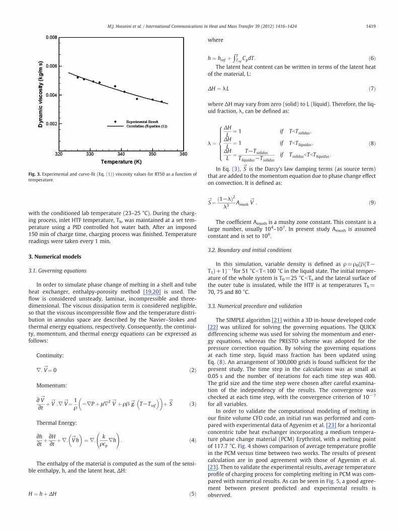
Fig. 3. Experimental and curve-fit (Eq. (1)) viscosity values for RT50 as a function oftemperature.
1419M.J. Hosseini et al. / International Communications in Heat and Mass Transfer 39 (2012) 1416–1424
with the conditioned lab temperature (23–25 °C). During the charg-ing process, inlet HTF temperature, Th, was maintained at a set tem-perature using a PID controlled hot water bath. After an imposed150 min of charge time, charging process was finished. Temperaturereadings were taken every 1 min.
3. Numerical models
3.1. Governing equations
In order to simulate phase change of melting in a shell and tubeheat exchanger, enthalpy-porosity method [19,20] is used. Theflow is considered unsteady, laminar, incompressible and three-dimensional. The viscous dissipation term is considered negligible,so that the viscous incompressible flow and the temperature distri-bution in annulus space are described by the Navier–Stokes andthermal energy equations, respectively. Consequently, the continui-ty, momentum, and thermal energy equations can be expressed asfollows:
Continuity:
∇: V→¼ 0 ð2Þ
Momentum:
∂ V→
∂t þ V→
:∇ V→¼ 1
ρ−∇P þ μ∇2 V
→ þ ρβ g→
T−Tref
� �� �þ S
→ ð3Þ
Thermal Energy:
∂h∂t þ
∂H∂t þ∇: V
→h
� �¼ ∇:
kρcp
∇h
!: ð4Þ
The enthalpy of the material is computed as the sum of the sensi-ble enthalpy, h, and the latent heat, ΔH:
H ¼ hþ ΔH ð5Þ
where
h ¼ href þ ∫TTref
CpdT : ð6ÞThe latent heat content can be written in terms of the latent heat
of the material, L:
ΔH ¼ λL ð7Þ
where ΔH may vary from zero (solid) to L (liquid). Therefore, the liq-uid fraction, λ, can be defined as:
λ ¼
ΔHL
¼ 1 if TbTsolidus;
ΔHL
¼ 1 if TbTliquidus;
ΔHL
¼ T−Tsolidus
Tliquidus−Tsolidusif TsolidusbTbTliquidus:
8>>>>><>>>>>:
ð8Þ
In Eq. (3), S→
is the Darcy's law damping terms (as source term)that are added to the momentum equation due to phase change effecton convection. It is defined as:
S→¼ 1−λð Þ2
λ3 Amush V→
: ð9Þ
The coefficient Amush is a mushy zone constant. This constant is alarge number, usually 104–107. In present study Amush is assumedconstant and is set to 106.
3.2. Boundary and initial conditions
In this simulation, variable density is defined as ρ=ρ0(β(T−T1)+1)−1for 51 °CbTb100 °C in the liquid state. The initial temper-ature of the whole system is T0=25 °CbTs and the lateral surface ofthe outer tube is insulated, while the HTF is at temperatures Th=70, 75 and 80 °C.
3.3. Numerical procedure and validation
The SIMPLE algorithm [21] within a 3D in-house developed code[22] was utilized for solving the governing equations. The QUICKdifferencing scheme was used for solving the momentum and ener-gy equations, whereas the PRESTO scheme was adopted for thepressure correction equation. By solving the governing equationsat each time step, liquid mass fraction has been updated usingEq. (8). An arrangement of 300,000 grids is found sufficient for thepresent study. The time step in the calculations was as small as0.05 s and the number of iterations for each time step was 400.The grid size and the time step were chosen after careful examina-tion of the independency of the results. The convergence waschecked at each time step, with the convergence criterion of 10−7
for all variables.In order to validate the computational modeling of melting in
our finite volume CFD code, an initial run was performed and com-pared with experimental data of Agyenim et al. [23] for a horizontalconcentric tube heat exchanger incorporating a medium tempera-ture phase change material (PCM) Erythritol, with a melting pointof 117.7 °C. Fig. 4 shows comparison of average temperature profilein the PCM versus time between two works. The results of presentcalculation are in good agreement with those of Agyenim et al.[23]. Then to validate the experimental results, average temperatureprofile of charging process for completing melting in PCM was com-pared with numerical results. As can be seen in Fig. 5, a good agree-ment between present predicted and experimental results isobserved.

Fig. 5. Comparison of average temperature profile for completing melting in the PCMbetween numerical study and experimental study.
Fig. 6. Repeatability of experimental results at Th=70 °C. (a) The average tem
Fig. 4. Comparison of average temperature profile in the PCM between present studyand Agyenim et al. [23].
1420 M.J. Hosseini et al. / International Communications in Heat and Mass Transfer 39 (2012) 1416–1424
4. Results and discussion
To illustrate repeatability and the effect of temperature gradienton the heat transfer process of the studied heat storage system, re-sults for Th=70 °C are presented. Similar trends are found in theother inlet HTF temperatures (not shown). Fig. 6 shows PCM temper-ature profiles and inlet–outlet water temperature difference profilesfor three repetitions of a charge process. A good repeatability isobserved.
Using the apparatus and procedures described above, several ex-periments have been conducted to study the behavior of the PCMunit during its charging. The experiments are performed for differentinlet temperatures of the HTF, water.
To determine the melting temperature and time in the axial,radial and angular directions in the system, the measured PCMtemperatures were plotted versus time as shown in Figs. 7 and8 for Th=70 °C. For the other values of Th same results wereachieved.
The average temperature readings in the axial direction werecalculated using time average readings from locations A, B, andC. The radial temperature readings were calculated by thermocou-ple readings of equal distances from the center of HTF tube (r=15 mm and 35 mm). In the angular direction, temperature readingswere calculated from thermocouples of the same angles, 0°, 90° and180°.
Fig. 7 shows the temperature variation in the radial direction inthe system. The differences in temperature along the radial directionindicate that the melting front appeared at different times with melt-ing occurring at positions close to the HTF tube and progressing at dif-ferent rates outwards.
Also, Fig. 7 indicates that, the sharp rise in temperature takesplace at location 0°, located at the uppermost section of the store,because of the effect of buoyancy. Thus, two regions exist duringthe charging processes: (Ι) solid region and (ΙΙ) molten region. Inthe solid region, conduction inside the solid matrix of the PCM is re-sponsible for the heat transfer process, and this region receives heatfrom the melted section by convection. When the solid melts, theconvection mechanism of the heat transfer drives the recirculationinside the molten region, which is due to the buoyancy forces in-duced by the density gradients as a result of the temperature differ-ences. This inner recirculation enhances the heat transfer within the
perature profile in PCM .(b) Water temperature difference (Outlet–inlet).
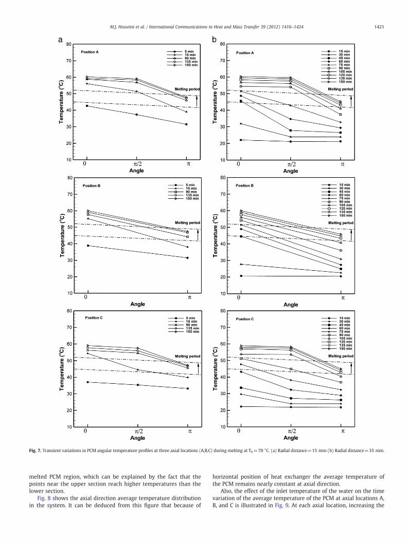
Fig. 7. Transient variations in PCM angular temperature profiles at three axial locations (A,B,C) during melting at Th=70 °C. (a) Radial distance=15 mm (b) Radial distance=35 mm.
1421M.J. Hosseini et al. / International Communications in Heat and Mass Transfer 39 (2012) 1416–1424
melted PCM region, which can be explained by the fact that thepoints near the upper section reach higher temperatures than thelower section.
Fig. 8 shows the axial direction average temperature distributionin the system. It can be deduced from this figure that because of
horizontal position of heat exchanger the average temperature ofthe PCM remains nearly constant at axial direction.
Also, the effect of the inlet temperature of the water on the timevariation of the average temperature of the PCM at axial locations A,B, and C is illustrated in Fig. 9. At each axial location, increasing the

Fig. 8. Transient variations in PCM average temperature profiles during melting atthree axial locations.
Fig. 10. Variation of liquid fraction versus time at various water inlet temperatures.
1422 M.J. Hosseini et al. / International Communications in Heat and Mass Transfer 39 (2012) 1416–1424
inlet temperatures of the HTF leads to smaller melting times and givesmore enthalpy flow from the HTF into the PCM.
As observed, an increase in the inlet temperature of the water re-sults in a higher temperature gradient near the HTF tube. Fig. 10shows the effect of the inlet temperature of the HTF on the time var-iation of liquid fraction of PCM. Again, as a result of the increasing en-thalpy flow due to an increase in the inlet temperature, the meltingtimes decrease. One can observe that the total melting time was de-creased from 19% to 37% when the inlet water temperature was in-creased from 70 to 75 and 80 °C.
The instantaneous contours of the streamlines and colorized tem-perature fields in midway along the length of cylindrical shell con-tainer after 30, 60, 90, 120, 150, and 180 min are given in Fig. 11.The streamlines are drawn on the right half of each circle, whereasthe colorized temperature contours are shown on the left half. It isobserved that the recirculation regions create in the narrow meltingarea which shows the Benard formation in natural convection. At thebeginning of the process small recirculation region was created be-cause of the small melting area. Then by advancing in time the mol-ten region develops due to raising of buoyancy effect, so byincreasing the melting area, several recirculation regions merge togather and create a main recirculation region and the convectionwill be the dominant heat transfer mechanism. It should be men-tioned that the rate of PCM melting and the size of recirculation
Fig. 9. Transient variations in PCM average temperature profiles at three a
regions increase as inlet temperature of HTF increases. Fig. 11shows this phenomena clearly in Th=70 °C and Th=80 °C after60 min. Also, the temperature distribution in the melting area is af-fected by recirculation formation.
5. Conclusion
Based on the findings of the present experimental/computationalstudy of the melting inside shell and tube heat exchanger, the follow-ing conclusions are drawn:
• Heat transfer from the heat exchanger (heat transfer pipe) to thePCM is largely influenced by natural convection at the meltinglayer section.
• It was observed that the melting Front appeared at different timesat positions close to the HTF tube and progressing at differentrates outwards.
• Experimental studies show that the sharp rise in temperaturestakes place at the uppermost section of the store (0°), because ofthe buoyancy effects.
• The present computations demonstrated that by increasing the inletwater temperature to 80 °C, the total melting time is decreased to 37%.
• The findings of the visualization study are substantiated by the com-putational results that show strong thermal stratification of the mol-ten liquid in the upper half of the heat exchanger.
xial locations during melting with different water inlet temperatures.

Fig. 11. Computed streamlines and temperature contours in midway along the length of cylindrical shell container during melting for different water inlettemperatures.
1423M.J. Hosseini et al. / International Communications in Heat and Mass Transfer 39 (2012) 1416–1424

1424 M.J. Hosseini et al. / International Communications in Heat and Mass Transfer 39 (2012) 1416–1424
References
[1] B. Zalba, J.M. Marin, L.F. Cabeza, H. Mehling, Review on thermal energy storagewith phase change materials, heat transfer analysis and applications, AppliedThermal Engineering 23 (3) (2003) 251–283.
[2] M.M. Farid, A.M. Khudhair, S. Al-Hallaj, A review on phase change energy storage,materials and applications, Energy Conversion and Management 45 (9–10)(2004) 1597–1615.
[3] J.M. Khodadadi, Y. Zhang, Effects of buoyancy-driven convection on melting with-in spherical containers, International Journal of Heat and Mass Transfer 44 (2001)1605–1618.
[4] Q. Duan, F.L. Tan, K.C. Leong, A numerical study of solidification of n-hexadecanebased on the enthalpy formulation, Journal of Materials Processing Technology120 (2002) 249–258.
[5] D.B. Khillarkar, Z.X. Gong, A.S. Mujumdar, Melting of a phase change material inconcentric horizontal annuli of arbitrary cross-section, Applied Thermal Engi-neering 20 (2000) 893–912.
[6] E. Assis, L. Katsman, G. Ziskind, R. Letan, Numerical and experimental study ofmelting in a spherical shell, International Journal of Heat and Mass Transfer 50(2007) 790–1804.
[7] E. Assis, G. Ziskind, R. Letan, Numerical and experimental study of solidification ina spherical shell, Journal of Heat Transfer 31 (1) (2009) 24502–24507.
[8] F.L. Tan, S.F. Hosseinizadeh, J.M. Khodadadi, L. Fan, Experimental and computa-tional study of constrained melting of phase change materials (PCM) inside aspherical capsule, International Journal of Heat and Mass Transfer 52 (2009)3464–3472.
[9] M. Medrano, M.O. Yilmaz, M. Nogués, I. Martorell, Joan Roca, Luisa F. Cabeza, Ex-perimental evaluation of commercial heat exchangers for use as PCM thermalstorage systems, Applied Energy 86 (2009) 2047–2055.
[10] R.V. Seeniraj, R. Velraj, N.L. Narasimhan, Thermal analysis of a finned-tube LHTSmodule for a solar dynamic power system, Heat and Mass Transfer 38 (2002)409–417.
[11] A. Castell, C. Sole, M. Medrano, J. Roca, L.F. Cabeza, D. Garcia, Natural convectionheat transfer coeffcients in phase change material (PCM) modules with externalvertical fins, Applied Thermal Engineering 28 (2008) 1676–1686.
[12] A. Sari, K. Kaygusuz, Thermal and heat transfer characteristics in a latent heatstorage system using lauric acid, Energy Conversion and Management 43(2002) 2493–2507.
[13] V. Pandiyarajan, M.C. Pandian, E. Malan, R. Velraj, R.V. Seenira, Experimental in-vestigation on heat recovery from diesel engine exhaust using finned shell andtube heat exchanger and thermal storage system, Applied Energy 88 (2011)77–87.
[14] Z. Liu, X. Sun, C. Ma, Experimental study of the characteristics of solidification ofstearic acid in an annulus and its thermal conductivity enhancement, Energy Con-version and Management 46 (2005) 971–984.
[15] H.M. Ettouney, I. Alatiqi, M. Al-Sahali, S.A. Al-Ali, Heat transfer enhancement bymetal screens and metal spheres in phase change energy storage systems, Re-newable Energy 29 (6) (2004) 841–860.
[16] M. Akgün, O. Aydın, K. Kaygusuz, Experimental study on melting/solidificationcharacteristics of a paraffin as PCM, Energy Conversion and Management 48 (2)(2007) 669–678.
[17] N.R. Vyshak, G. Jilani, Numerical analysis of latent heat thermal energy storagesystem, Energy Conversion and Management 48 (2007) 2161–2168.
[18] H.A. Adine, H.E. Qarnia, Numerical analysis of the thermal behavior of a shell andtube heat storage unit using phase change materials, Applied MathematicalModelling 33 (2009) 2132–2144.
[19] A.D. Brent, V.R. Voller, K.J. Reid, Enthalpy-porosity technique for modelingconvection–diffusion phase change: application to the melting of a pure metal,Numerical Heat Transfer Part B 13 (1988) 297–318.
[20] Z.X. Gong, S. Devahastin, A.S. Mujumdar, Enhanced heat transfer in freeconvection-dominated melting in a rectangular cavity with an isothermal verticalwall, Applied Thermal Engineering 19 (1999) 1237–1251.
[21] S.V. Patankar, Numerical heat transfer and fluid flow, Hemisphere, Washington,DC, 1980.
[22] M. Rahimi, A.A. Ranjbar, M.J. Hosseini, M. Abdollahzadeh, Natural convection ofnanoparticle-water mixture near its density inversion in a rectangular enclosure,International Communications in Heat and Mass Transfer 39 (1) (2012) 131–137.
[23] F. Agyenima, Ph. Eames, M. Smyth, A comparison of heat transfer enhancement ina medium temperature thermal energy storage heat exchanger using fins, SolarEnergy 83 (2009) 1509–1520.
Copyright © 2022 FDOKUMEN