Experimental and computational anlaysis of welding residual buckling distortion in bead on plate...
12
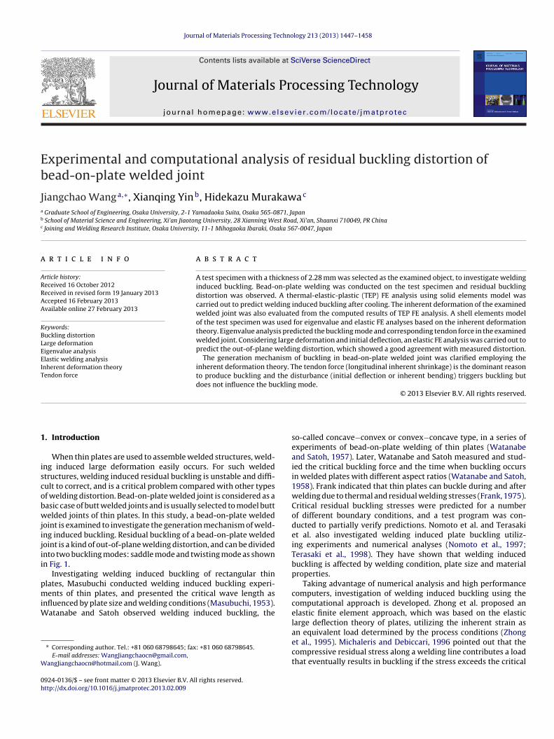
Journal of Materials Processing Technology 213 (2013) 1447–1458 Contents lists available at SciVerse ScienceDirect Journal of Materials Processing Technology jou rnal h om epa g e: www.elsevier.com/locate/jmatprotec Experimental and computational analysis of residual buckling distortion of bead-on-plate welded joint Jiangchao Wang a,∗ , Xianqing Yin b , Hidekazu Murakawa c a Graduate School of Engineering, Osaka University, 2-1 Yamadaoka Suita, Osaka 565-0871, Japan b School of Material Science and Engineering, Xi’an Jiaotong University, 28 Xianning West Road, Xi’an, Shaanxi 710049, PR China c Joining and Welding Research Institute, Osaka University, 11-1 Mihogaoka Ibaraki, Osaka 567-0047, Japan a r t i c l e i n f o Article history: Received 16 October 2012 Received in revised form 19 January 2013 Accepted 16 February 2013 Available online 27 February 2013 Keywords: Buckling distortion Large deformation Eigenvalue analysis Elastic welding analysis Inherent deformation theory Tendon force a b s t r a c t A test specimen with a thickness of 2.28 mm was selected as the examined object, to investigate welding induced buckling. Bead-on-plate welding was conducted on the test specimen and residual buckling distortion was observed. A thermal-elastic-plastic (TEP) FE analysis using solid elements model was carried out to predict welding induced buckling after cooling. The inherent deformation of the examined welded joint was also evaluated from the computed results of TEP FE analysis. A shell elements model of the test specimen was used for eigenvalue and elastic FE analyses based on the inherent deformation theory. Eigenvalue analysis predicted the buckling mode and corresponding tendon force in the examined welded joint. Considering large deformation and initial deflection, an elastic FE analysis was carried out to predict the out-of-plane welding distortion, which showed a good agreement with measured distortion. The generation mechanism of buckling in bead-on-plate welded joint was clarified employing the inherent deformation theory. The tendon force (longitudinal inherent shrinkage) is the dominant reason to produce buckling and the disturbance (initial deflection or inherent bending) triggers buckling but does not influence the buckling mode. © 2013 Elsevier B.V. All rights reserved. 1. Introduction When thin plates are used to assemble welded structures, weld- ing induced large deformation easily occurs. For such welded structures, welding induced residual buckling is unstable and diffi- cult to correct, and is a critical problem compared with other types of welding distortion. Bead-on-plate welded joint is considered as a basic case of butt welded joints and is usually selected to model butt welded joints of thin plates. In this study, a bead-on-plate welded joint is examined to investigate the generation mechanism of weld- ing induced buckling. Residual buckling of a bead-on-plate welded joint is a kind of out-of-plane welding distortion, and can be divided into two buckling modes: saddle mode and twisting mode as shown in Fig. 1. Investigating welding induced buckling of rectangular thin plates, Masubuchi conducted welding induced buckling experi- ments of thin plates, and presented the critical wave length as influenced by plate size and welding conditions (Masubuchi, 1953). Watanabe and Satoh observed welding induced buckling, the ∗ Corresponding author. Tel.: +81 060 68798645; fax: +81 060 68798645. E-mail addresses: [email protected], [email protected] (J. Wang). so-called concave−convex or convex−concave type, in a series of experiments of bead-on-plate welding of thin plates (Watanabe and Satoh, 1957). Later, Watanabe and Satoh measured and stud- ied the critical buckling force and the time when buckling occurs in welded plates with different aspect ratios (Watanabe and Satoh, 1958). Frank indicated that thin plates can buckle during and after welding due to thermal and residual welding stresses (Frank, 1975). Critical residual buckling stresses were predicted for a number of different boundary conditions, and a test program was con- ducted to partially verify predictions. Nomoto et al. and Terasaki et al. also investigated welding induced plate buckling utiliz- ing experiments and numerical analyses (Nomoto et al., 1997; Terasaki et al., 1998). They have shown that welding induced buckling is affected by welding condition, plate size and material properties. Taking advantage of numerical analysis and high performance computers, investigation of welding induced buckling using the computational approach is developed. Zhong et al. proposed an elastic finite element approach, which was based on the elastic large deflection theory of plates, utilizing the inherent strain as an equivalent load determined by the process conditions (Zhong et al., 1995). Michaleris and Debiccari, 1996 pointed out that the compressive residual stress along a welding line contributes a load that eventually results in buckling if the stress exceeds the critical 0924-0136/$ – see front matter © 2013 Elsevier B.V. All rights reserved. http://dx.doi.org/10.1016/j.jmatprotec.2013.02.009
-
Upload
carleton-ca -
Category
Documents
-
view
0 -
download
0
Transcript of Experimental and computational anlaysis of welding residual buckling distortion in bead on plate...
Eb
Ja
b
c
a
ARRAA
KBLEEIT
1
iscobwjijii
pmiW
W
0h
Journal of Materials Processing Technology 213 (2013) 1447– 1458
Contents lists available at SciVerse ScienceDirect
Journal of Materials Processing Technology
jou rna l h om epa g e: www.elsev ier .com/ locate / jmatprotec
xperimental and computational analysis of residual buckling distortion ofead-on-plate welded joint
iangchao Wanga,∗, Xianqing Yinb, Hidekazu Murakawac
Graduate School of Engineering, Osaka University, 2-1 Yamadaoka Suita, Osaka 565-0871, JapanSchool of Material Science and Engineering, Xi’an Jiaotong University, 28 Xianning West Road, Xi’an, Shaanxi 710049, PR ChinaJoining and Welding Research Institute, Osaka University, 11-1 Mihogaoka Ibaraki, Osaka 567-0047, Japan
r t i c l e i n f o
rticle history:eceived 16 October 2012eceived in revised form 19 January 2013ccepted 16 February 2013vailable online 27 February 2013
eywords:uckling distortion
a b s t r a c t
A test specimen with a thickness of 2.28 mm was selected as the examined object, to investigate weldinginduced buckling. Bead-on-plate welding was conducted on the test specimen and residual bucklingdistortion was observed. A thermal-elastic-plastic (TEP) FE analysis using solid elements model wascarried out to predict welding induced buckling after cooling. The inherent deformation of the examinedwelded joint was also evaluated from the computed results of TEP FE analysis. A shell elements modelof the test specimen was used for eigenvalue and elastic FE analyses based on the inherent deformationtheory. Eigenvalue analysis predicted the buckling mode and corresponding tendon force in the examined
arge deformationigenvalue analysislastic welding analysisnherent deformation theoryendon force
welded joint. Considering large deformation and initial deflection, an elastic FE analysis was carried out topredict the out-of-plane welding distortion, which showed a good agreement with measured distortion.
The generation mechanism of buckling in bead-on-plate welded joint was clarified employing theinherent deformation theory. The tendon force (longitudinal inherent shrinkage) is the dominant reasonto produce buckling and the disturbance (initial deflection or inherent bending) triggers buckling butdoes not influence the buckling mode.
© 2013 Elsevier B.V. All rights reserved.
. Introduction
When thin plates are used to assemble welded structures, weld-ng induced large deformation easily occurs. For such weldedtructures, welding induced residual buckling is unstable and diffi-ult to correct, and is a critical problem compared with other typesf welding distortion. Bead-on-plate welded joint is considered as aasic case of butt welded joints and is usually selected to model buttelded joints of thin plates. In this study, a bead-on-plate welded
oint is examined to investigate the generation mechanism of weld-ng induced buckling. Residual buckling of a bead-on-plate weldedoint is a kind of out-of-plane welding distortion, and can be dividednto two buckling modes: saddle mode and twisting mode as shownn Fig. 1.
Investigating welding induced buckling of rectangular thinlates, Masubuchi conducted welding induced buckling experi-
ents of thin plates, and presented the critical wave length asnfluenced by plate size and welding conditions (Masubuchi, 1953).atanabe and Satoh observed welding induced buckling, the
∗ Corresponding author. Tel.: +81 060 68798645; fax: +81 060 68798645.E-mail addresses: [email protected],
[email protected] (J. Wang).
924-0136/$ – see front matter © 2013 Elsevier B.V. All rights reserved.ttp://dx.doi.org/10.1016/j.jmatprotec.2013.02.009
so-called concave−convex or convex−concave type, in a series ofexperiments of bead-on-plate welding of thin plates (Watanabeand Satoh, 1957). Later, Watanabe and Satoh measured and stud-ied the critical buckling force and the time when buckling occursin welded plates with different aspect ratios (Watanabe and Satoh,1958). Frank indicated that thin plates can buckle during and afterwelding due to thermal and residual welding stresses (Frank, 1975).Critical residual buckling stresses were predicted for a numberof different boundary conditions, and a test program was con-ducted to partially verify predictions. Nomoto et al. and Terasakiet al. also investigated welding induced plate buckling utiliz-ing experiments and numerical analyses (Nomoto et al., 1997;Terasaki et al., 1998). They have shown that welding inducedbuckling is affected by welding condition, plate size and materialproperties.
Taking advantage of numerical analysis and high performancecomputers, investigation of welding induced buckling using thecomputational approach is developed. Zhong et al. proposed anelastic finite element approach, which was based on the elasticlarge deflection theory of plates, utilizing the inherent strain as
an equivalent load determined by the process conditions (Zhonget al., 1995). Michaleris and Debiccari, 1996 pointed out that thecompressive residual stress along a welding line contributes a loadthat eventually results in buckling if the stress exceeds the critical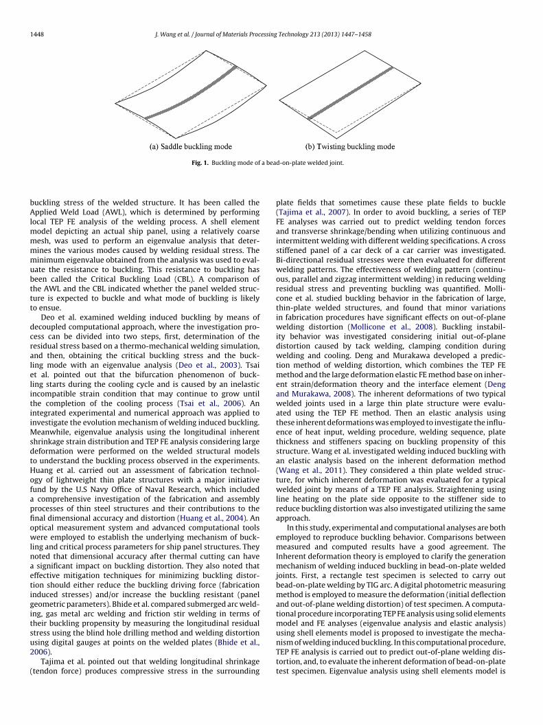
1448 J. Wang et al. / Journal of Materials Processing Technology 213 (2013) 1447– 1458
a bea
bAlmmmmubttt
dcralelitiiMsdtHofapfiowlnaetigitsu2
(
Fig. 1. Buckling mode of
uckling stress of the welded structure. It has been called thepplied Weld Load (AWL), which is determined by performing
ocal TEP FE analysis of the welding process. A shell elementodel depicting an actual ship panel, using a relatively coarseesh, was used to perform an eigenvalue analysis that deter-ines the various modes caused by welding residual stress. Theinimum eigenvalue obtained from the analysis was used to eval-
ate the resistance to buckling. This resistance to buckling haseen called the Critical Buckling Load (CBL). A comparison ofhe AWL and the CBL indicated whether the panel welded struc-ure is expected to buckle and what mode of buckling is likelyo ensue.
Deo et al. examined welding induced buckling by means ofecoupled computational approach, where the investigation pro-ess can be divided into two steps, first, determination of theesidual stress based on a thermo-mechanical welding simulation,nd then, obtaining the critical buckling stress and the buck-ing mode with an eigenvalue analysis (Deo et al., 2003). Tsait al. pointed out that the bifurcation phenomenon of buck-ing starts during the cooling cycle and is caused by an inelasticncompatible strain condition that may continue to grow untilhe completion of the cooling process (Tsai et al., 2006). Anntegrated experimental and numerical approach was applied tonvestigate the evolution mechanism of welding induced buckling.
eanwhile, eigenvalue analysis using the longitudinal inherenthrinkage strain distribution and TEP FE analysis considering largeeformation were performed on the welded structural modelso understand the buckling process observed in the experiments.uang et al. carried out an assessment of fabrication technol-gy of lightweight thin plate structures with a major initiativeund by the U.S Navy Office of Naval Research, which included
comprehensive investigation of the fabrication and assemblyrocesses of thin steel structures and their contributions to thenal dimensional accuracy and distortion (Huang et al., 2004). Anptical measurement system and advanced computational toolsere employed to establish the underlying mechanism of buck-
ing and critical process parameters for ship panel structures. Theyoted that dimensional accuracy after thermal cutting can have
significant impact on buckling distortion. They also noted thatffective mitigation techniques for minimizing buckling distor-ion should either reduce the buckling driving force (fabricationnduced stresses) and/or increase the buckling resistant (paneleometric parameters). Bhide et al. compared submerged arc weld-ng, gas metal arc welding and friction stir welding in terms ofheir buckling propensity by measuring the longitudinal residualtress using the blind hole drilling method and welding distortion
sing digital gauges at points on the welded plates (Bhide et al.,006).Tajima et al. pointed out that welding longitudinal shrinkagetendon force) produces compressive stress in the surrounding
d-on-plate welded joint.
plate fields that sometimes cause these plate fields to buckle(Tajima et al., 2007). In order to avoid buckling, a series of TEPFE analyses was carried out to predict welding tendon forcesand transverse shrinkage/bending when utilizing continuous andintermittent welding with different welding specifications. A crossstiffened panel of a car deck of a car carrier was investigated.Bi-directional residual stresses were then evaluated for differentwelding patterns. The effectiveness of welding pattern (continu-ous, parallel and zigzag intermittent welding) in reducing weldingresidual stress and preventing buckling was quantified. Molli-cone et al. studied buckling behavior in the fabrication of large,thin-plate welded structures, and found that minor variationsin fabrication procedures have significant effects on out-of-planewelding distortion (Mollicone et al., 2008). Buckling instabil-ity behavior was investigated considering initial out-of-planedistortion caused by tack welding, clamping condition duringwelding and cooling. Deng and Murakawa developed a predic-tion method of welding distortion, which combines the TEP FEmethod and the large deformation elastic FE method base on inher-ent strain/deformation theory and the interface element (Dengand Murakawa, 2008). The inherent deformations of two typicalwelded joints used in a large thin plate structure were evalu-ated using the TEP FE method. Then an elastic analysis usingthese inherent deformations was employed to investigate the influ-ence of heat input, welding procedure, welding sequence, platethickness and stiffeners spacing on buckling propensity of thisstructure. Wang et al. investigated welding induced buckling withan elastic analysis based on the inherent deformation method(Wang et al., 2011). They considered a thin plate welded struc-ture, for which inherent deformation was evaluated for a typicalwelded joint by means of a TEP FE analysis. Straightening usingline heating on the plate side opposite to the stiffener side toreduce buckling distortion was also investigated utilizing the sameapproach.
In this study, experimental and computational analyses are bothemployed to reproduce buckling behavior. Comparisons betweenmeasured and computed results have a good agreement. TheInherent deformation theory is employed to clarify the generationmechanism of welding induced buckling in bead-on-plate weldedjoints. First, a rectangle test specimen is selected to carry outbead-on-plate welding by TIG arc. A digital photometric measuringmethod is employed to measure the deformation (initial deflectionand out-of-plane welding distortion) of test specimen. A computa-tional procedure incorporating TEP FE analysis using solid elementsmodel and FE analyses (eigenvalue analysis and elastic analysis)using shell elements model is proposed to investigate the mecha-
nism of welding induced buckling. In this computational procedure,TEP FE analysis is carried out to predict out-of-plane welding dis-tortion, and, to evaluate the inherent deformation of bead-on-platetest specimen. Eigenvalue analysis using shell elements model is
essing
ufcbbTfib
2
a
2
RoUgai
mttmniTtaitfiya
tiesmbfac(aiicb
2
tsdfL
J. Wang et al. / Journal of Materials Proc
sed to compute buckling mode and corresponding critical tendonorce. Elastic FE analysis using the same shell elements model is alsoarried out to predict buckling distortion of test specimen. Finally,ased on computational results, the dominant cause of bucklingehavior and influential factors that affect buckling are presented.he tendon force (longitudinal inherent shrinkage force) is con-rmed to be the dominant cause of buckling and may influence theuckling mode of examined test specimen.
. Computational analysis methods
Theories and methods employed in computational analysispplied in this study are presented in the following.
.1. FE analysis using JWRIAN program suit
The in-house program suit JWRIAN (Joining and Weldingesearch Institute ANalysis) was developed by the research groupf mathematical modeling and computational analysis, JWRI, Osakaniversity leaded by Prof Hidekazu Murakawa. This in-house pro-ram suit consists of a TEP FE analysis, using solid elements models,nd an elastic FE analysis, using shell elements model based onnherent deformation theory.
In the TEP FE analysis, two processes are considered, the ther-al process and the mechanical process. Despite the fact that the
hermal process has a decisive effect on the mechanical process,he mechanical process has only a small influence on the ther-
al process, and a coupled thermal mechanical analysis is notecessary. Therefore, thermal-mechanical behavior during weld-
ng is analyzed using uncoupled thermal/mechanical formulation.his uncoupled formulation considers the contribution of theransient temperature field to stress through thermal expansion,s well as, temperature-dependent thermal-physical and mechan-cal properties. The solution procedure consists of two steps. First,he temperature distribution history is computed using heat trans-er analysis. Then, the obtained transient temperature distributions employed as a thermal load in the subsequent mechanical anal-sis, in which residual stresses, plastic strains, and displacementsre computed.
Elastic FE analysis can be employed to predict welding dis-ortion of welded structures when the inherent strain or thenherent deformation is evaluated using a computational or anxperimental approach. In this elastic FE analysis, the inherenttrain/deformation is applied to the welding lines in shell ele-ents models of welded structures. Meanwhile, the interaction
etween the parts to be welded together is represented by Inter-ace Elements. Bonding strength, gaps, and misalignments thatrise during different assembly processes are considered throughontrolling the stiffness and deformation of the interface elementMurakawa et al., 2009; Deng et al., 2012). Also, eigenvalue FEnalysis using shell elements models is used to investigate thedealized buckling problem of welded structures. This analysiss carried out to compute the buckling mode and correspondingritical welding forces applying inherent deformation evaluatedeforehand.
.2. Large deformation theory
The equation relating the strain and displacement is essentialo describe the buckling behavior. If small deformation is assumed,
trains are given as linear functions of displacements. When theeformation is large, Green-Lagrange strain, which is a nonlinearunction of displacements, must be used. Eq. (1) shows the Green-agrange strain. From the expression of strain, the first order termTechnology 213 (2013) 1447– 1458 1449
represents the linear response; the second order term is essentialto the non-linear behavior under large deformation.
εx = ∂u
∂x+ 1
2
{(∂u
∂x
)2
+(
∂v∂x
)2
+(
∂w
∂x
)2}
εy = ∂v∂y
+ 12
{(∂u
∂y
)2
+(
∂v∂y
)2
+(
∂w
∂y
)2}
εz = ∂w
∂z+ 1
2
{(∂u
∂z
)2
+(
∂v∂z
)2
+(
∂w
∂z
)2}
�xy = ∂u
∂y+ ∂v
∂x+{(
∂u
∂x
)(∂u
∂y
)+(
∂v∂x
)(∂v∂y
)+(
∂w
∂x
)(∂w
∂y
)}
�yz = ∂v∂z
+ ∂w
∂y+{(
∂u
∂y
)(∂u
∂z
)+(
∂v∂y
)(∂v∂z
)+(
∂w
∂y
)(∂w
∂z
)}
�xz = ∂u
∂z+ ∂w
∂x+{(
∂u
∂x
)(∂u
∂z
)+(
∂v∂x
)(∂v∂z
)+(
∂w
∂x
)(∂w
∂z
)}
(1)
where εx, εy and εz are the normal Green-Lagrange strain in x, y andz directions; �xy, �yz and �xz are the shear Green-Lagrange strainon the x−y, y−z and z−x planes; u, v and w are the displacement inthe x, y and z directions, respectively.
2.3. The inherent deformation theory
The total strain produced during the heating and cooling cycleof the welding process can be divided into the strain componentsgiven by Eq. (2), which are elastic strain, thermal strain, plasticstrain, creep strain and strain produced through phase transfor-mation, respectively (Murakawa et al., 2010). It means that thetotal strain can be rearranged as a summation of elastic strainand inherent strain ε*, which is defined as a summation of plasticstrain, thermal strain, creep strain and phase transformation strainas shown in Eq. (3). The inherent strain is considered to be the causeof welding residual stress and distortion. The magnitude and dis-tribution of inherent strain, produced during the welding process,mainly depend on the highest temperature reached in the thermalcycles and the constraint at each point.
εtotal = εelastic + εthermal + εplastic + εcreep + εphase (2)
εinherent = εthermal + εplastic + εcreep + εphase ≡ ε∗ (3)
A welded joint in a plate structure has an inherent amount oflocal deformation caused by welding, which mostly depends onwelding and joint parameters, such as configuration, material prop-erties, plate thickness and heat input. The influence of the lengthand the width of the welded joint are small when the plate sizeis large enough, and the welding line is long enough. In this case,the distribution of inherent deformation is fairly uniform along thewelding line in the middle part of the welded joint. Therefore, ifthe welding line is long enough, the end effect can be ignored,and the inherent deformation may be approximated with piece-wise constants or just one constant magnitude over the wholelength of the welding line, without significant loss of computational
accuracy.The inherent deformation is defined as the integration of inher-ent strain on each cross section normal to the welding line. Theinherent deformation has four components as summarized by Eq.
1 essing
(a
wtbdtd
2
aucaiClw
tdbi
wao
ε
w
mor
�
450 J. Wang et al. / Journal of Materials Proc
4) using the longitudinal inherent strain ε∗x in the welding direction
nd the transverse inherent strain ε∗y in the transverse direction.
ı∗x = 1
h
∫ ∫ε∗
xdydz
ı∗y = 1
h
∫ ∫ε∗
ydydz
�∗x = 12
h3
∫ ∫(z − h
2)ε∗
xdydz
�∗y = 12
h3
∫ ∫(z − h
2)ε∗
ydydz
(4)
here ı∗x and ı∗
y are the inherent in-plane deformation in the longi-udinal and the transverse directions, �∗
x and �∗y are the inherent
ending deformation about the longitudinal and the transverseirections; h is the thickness of the welded joint; x, y and z arehe welding direction, the transverse direction and the thicknessirection, respectively.
.4. Buckling eigenvalue analysis
Eigenvalue analysis is employed to predict the buckling load ofn elastic structure. In the classical eigenvalue analysis, eigenval-es are computed with regard to the applied compressive loads andonstraints of a given system. Theoretically, there are eigenvaluesnd modes equal in number to the number of degrees of freedomn the considered system. The minimum eigenvalue refers to theBL at which the structure buckles, and the corresponding buck-
ing mode. Eigenvalue analysis is also useful to predict buckling ofelded structures.
In this case, eigenvalue analysis predicts the inherent deforma-ion at which the structure buckles. The basic variables, that is,isplacement ut+�t, strain εt+�t, and stress �t+�t at time t + �t cane decomposed into the sum of their magnitudes at time t and their
ncrements during the time increment �t, i.e.
ut+�t = ut + �u
εt+�t = εt + �ε = εt + �1ε + �2ε
�t+�t = Dεt+�t = �t + D�ε = �t + D�1ε + D�2ε
(5)
here D is the elastic matrix (stress−strain matrix), �1ε and �2εre the first order (linear) and the second order (non-linear) termsf strain increment.
Using Green-Lagrange strain and taking εx as an example,x(t + �t) may be expressed as follows
εx(t + �t) = ∂ut+�t
∂x+ 1
2
(∂ut+�t
∂x
)2
+ 12
(∂vt+�t
∂x
)2
+ 12
(∂wt+�t
∂x
)2
= εx(t) + �1εx + �2εx
(6)
here
εx(t) = ∂ut
∂x+ 1
2
(∂ut
∂x
)2
+ 12
(∂vt
∂x
)2
+ 12
(∂wt
∂x
)2
�1εx = ∂�u
∂x+ ∂ut
∂x
∂�u
∂x+ ∂vt
∂x
∂�v∂x
+ ∂wt
∂x
∂�w
∂x
�2εx = 12
(∂�u
∂x
)2
+ 12
(∂�v∂x
)2
+ 12
(∂�w
∂x
)2
(7)
To derive the governing equation for eigenvalue analysis, theinimum potential energy theorem is employed. The total energy
f the system at times t and t + �t is given by Eqs. (8) and (9),
espectively.(ut) =∫
12
εTt Dεtdv −
∫ftutds (8)
Technology 213 (2013) 1447– 1458
� (ut + �u) =∫
12
(εt + �1ε + �2ε
)TD
(εt + �1ε + �2ε
)dv
−∫
(ft + �f ) (ut + �u) ds
= �(ut) + ��(�u)
(9)
Because the potential energy at time t is already known andfixed, the condition for the potential energy � (ut + �t) to be aminimum is equivalent to that condition for its increment �� (�u)given by Eq. (10), in which the higher order terms are neglected.Eq. (10) can be rewritten in matrix form as shown in Eq. (11).
�� (�u) = �(ut + �t) − � (ut)
=∫
12
{(�1ε)
TD(�1ε) + 2Dεt�
1ε + 2Dεt�2ε
}dv
−∫
(ft�u + �fut)ds
=∫
12
{(�1ε)
TD(�1ε) + 2�t�
2ε}
dv −∫
�futds
+∫
�t�1εdv −
∫ft�uds
(10)
�� (�u) = 12
{�u
}T[K1 (ut)]
{�u
}+ 1
2
{�u
}T[K2 (�t)]
{�u
}
−{
�f}T {
�u}
+{
F}T {
�u}
−{
ft}T {
�u}
(11)
where
12
{�u
}T[K1(ut)]
{�u
}=
∫12
(�1ε
)TD
(�1ε
)dv
12
{�u
}T[K2(�t)]
{�u
}=
∫Dεt�
2εdv =∫
�t�2εdv
{F}T {
�u}
=∫
Dεt�1εdv
{�f
}T {�u
}=
∫�f�utdv
{ft}T {
�u}
=∫
ft�udv
From the condition for the minimum value of �� (�u), the fol-lowing equation is derived.
∂�� (�u)∂�u
= [K1 (ut)]{
�u}
+ [K2 (�t)]{
�u}
+{
F}
−{
ft}
−{
�f}
= 0 (12)
Due to the equilibrium of the system at time t,{F}
−{
ft}
= 0 (13)
Because of the fact that buckling occurs without increase ofexternal forces,{
�f}
= 0 (14)
If the system buckles under an internal force {�t}, Eq. (12) isreduced to an eigenvalue problem as given by Eq. (15).{ } { }
[K1(ut)] �u + [K2 (�t)] �u = 0 (15)In case of welding, the stress �t is the stress produced by theinherent deformation associated with welding and the parameter is the eigenvalue to be determined. When the stress becomes
essing Technology 213 (2013) 1447– 1458 1451
es
urbsundb
2
lbgnsofter
tpp
F
wu
wtbwta
F
w�
ae
F
wdw
3
tiT
ltd
Table 1Welding condition.
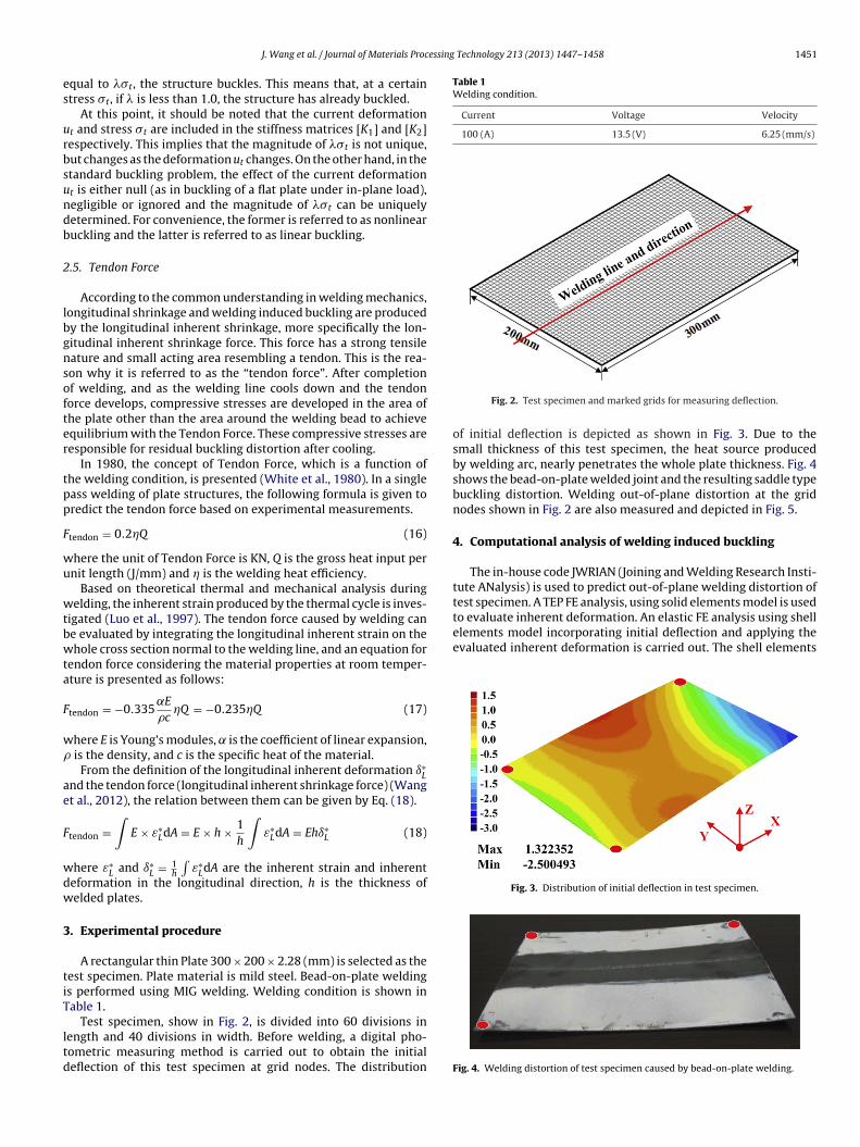
Current Voltage Velocity
100 (A) 13.5 (V) 6.25 (mm/s)
test specimen. A TEP FE analysis, using solid elements model is usedto evaluate inherent deformation. An elastic FE analysis using shellelements model incorporating initial deflection and applying theevaluated inherent deformation is carried out. The shell elements
Fig. 3. Distribution of initial deflection in test specimen.
J. Wang et al. / Journal of Materials Proc
qual to �t, the structure buckles. This means that, at a certaintress �t, if is less than 1.0, the structure has already buckled.
At this point, it should be noted that the current deformationt and stress �t are included in the stiffness matrices [K1] and [K2]espectively. This implies that the magnitude of �t is not unique,ut changes as the deformation ut changes. On the other hand, in thetandard buckling problem, the effect of the current deformationt is either null (as in buckling of a flat plate under in-plane load),egligible or ignored and the magnitude of �t can be uniquelyetermined. For convenience, the former is referred to as nonlinearuckling and the latter is referred to as linear buckling.
.5. Tendon Force
According to the common understanding in welding mechanics,ongitudinal shrinkage and welding induced buckling are producedy the longitudinal inherent shrinkage, more specifically the lon-itudinal inherent shrinkage force. This force has a strong tensileature and small acting area resembling a tendon. This is the rea-on why it is referred to as the “tendon force”. After completionf welding, and as the welding line cools down and the tendonorce develops, compressive stresses are developed in the area ofhe plate other than the area around the welding bead to achievequilibrium with the Tendon Force. These compressive stresses areesponsible for residual buckling distortion after cooling.
In 1980, the concept of Tendon Force, which is a function ofhe welding condition, is presented (White et al., 1980). In a singleass welding of plate structures, the following formula is given toredict the tendon force based on experimental measurements.
tendon = 0.2Q (16)
here the unit of Tendon Force is KN, Q is the gross heat input pernit length (J/mm) and is the welding heat efficiency.
Based on theoretical thermal and mechanical analysis duringelding, the inherent strain produced by the thermal cycle is inves-
igated (Luo et al., 1997). The tendon force caused by welding cane evaluated by integrating the longitudinal inherent strain on thehole cross section normal to the welding line, and an equation for
endon force considering the material properties at room temper-ture is presented as follows:
tendon = −0.335˛E
�cQ = −0.235Q (17)
here E is Young’s modules, ̨ is the coefficient of linear expansion, is the density, and c is the specific heat of the material.
From the definition of the longitudinal inherent deformation ı∗L
nd the tendon force (longitudinal inherent shrinkage force) (Wangt al., 2012), the relation between them can be given by Eq. (18).
tendon =∫
E × ε∗LdA = E × h × 1
h
∫ε∗
LdA = Ehı∗L (18)
here ε∗L and ı∗
L = 1h
∫ε∗
LdA are the inherent strain and inherenteformation in the longitudinal direction, h is the thickness ofelded plates.
. Experimental procedure
A rectangular thin Plate 300 × 200 × 2.28 (mm) is selected as theest specimen. Plate material is mild steel. Bead-on-plate weldings performed using MIG welding. Welding condition is shown inable 1.
Test specimen, show in Fig. 2, is divided into 60 divisions inength and 40 divisions in width. Before welding, a digital pho-ometric measuring method is carried out to obtain the initialeflection of this test specimen at grid nodes. The distribution
Fig. 2. Test specimen and marked grids for measuring deflection.
of initial deflection is depicted as shown in Fig. 3. Due to thesmall thickness of this test specimen, the heat source producedby welding arc, nearly penetrates the whole plate thickness. Fig. 4shows the bead-on-plate welded joint and the resulting saddle typebuckling distortion. Welding out-of-plane distortion at the gridnodes shown in Fig. 2 are also measured and depicted in Fig. 5.
4. Computational analysis of welding induced buckling
The in-house code JWRIAN (Joining and Welding Research Insti-tute ANalysis) is used to predict out-of-plane welding distortion of
Fig. 4. Welding distortion of test specimen caused by bead-on-plate welding.
1452 J. Wang et al. / Journal of Materials Processing Technology 213 (2013) 1447– 1458
Fig. 5. Measured out-of-plane welding distortion caused by bead-on-plate welding.
mm
4
mfict
cmdl
strain) along the transverse direction of the cross section normal tothe welding line.
Using the integration method, inherent deformations are eval-uated on each transverse cross section, and the distributions of all
Fig. 6. Test specimen solid elements model.
odel is also used to investigate the buckling load and bucklingode through an eigenvalue analysis.
.1. Evaluation of inherent deformation
A solid elements model for TEP FE analysis is shown in Fig. 6. Theodel consists of 17,675 nodes and 13,600 elements. The model is
xed at 6 DOFs, to prevent only rigid body motion. The weldingondition given in Table 1 is used, and welding direction is alonghe positive direction of the X axis.
Applying heat input corresponding to experimental weldingondition, TEP FE analysis is carried out considering large defor-
ation. Fig. 7 shows an example of the transient temperatureistribution, when the welding arc is at 3/4 of the weldingine, obtained from thermal analysis. Mechanical analysis result
Fig. 7. Transient temperature distribution during bead-on-plane welding.
Fig. 8. Computed out-of-plane welding distortion caused by bead-on-plate welding.
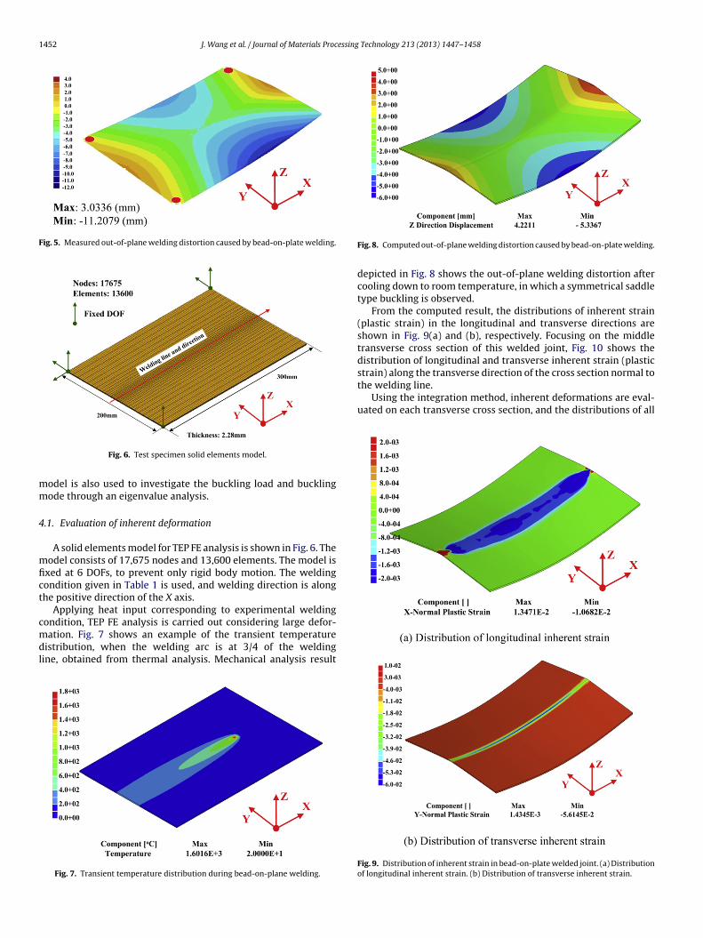
depicted in Fig. 8 shows the out-of-plane welding distortion aftercooling down to room temperature, in which a symmetrical saddletype buckling is observed.
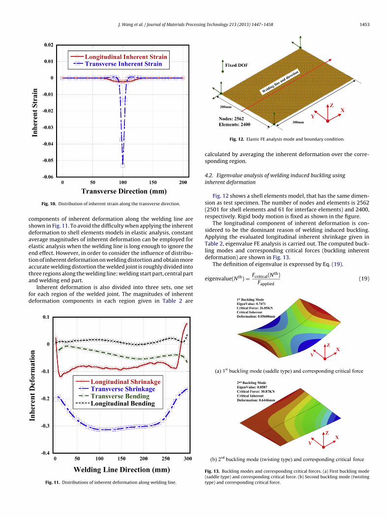
From the computed result, the distributions of inherent strain(plastic strain) in the longitudinal and transverse directions areshown in Fig. 9(a) and (b), respectively. Focusing on the middletransverse cross section of this welded joint, Fig. 10 shows thedistribution of longitudinal and transverse inherent strain (plastic
Fig. 9. Distribution of inherent strain in bead-on-plate welded joint. (a) Distributionof longitudinal inherent strain. (b) Distribution of transverse inherent strain.
J. Wang et al. / Journal of Materials Processing Technology 213 (2013) 1447– 1458 1453
csdaeetata
fd
The definition of eigenvalue is expressed by Eq. (19).
eigenvalue(Nth) = Fcritical(Nth)(19)
Fig. 10. Distribution of inherent strain along the transverse direction.
omponents of inherent deformation along the welding line arehown in Fig. 11. To avoid the difficulty when applying the inherenteformation to shell elements models in elastic analysis, constantverage magnitudes of inherent deformation can be employed forlastic analysis when the welding line is long enough to ignore thend effect. However, in order to consider the influence of distribu-ion of inherent deformation on welding distortion and obtain moreccurate welding distortion the welded joint is roughly divided intohree regions along the welding line: welding start part, central part
nd welding end part.Inherent deformation is also divided into three sets, one setor each region of the welded joint. The magnitudes of inherenteformation components in each region given in Table 2 are
Fig. 11. Distributions of inherent deformation along welding line.
Fig. 12. Elastic FE analysis mode and boundary condition.
calculated by averaging the inherent deformation over the corre-sponding region.
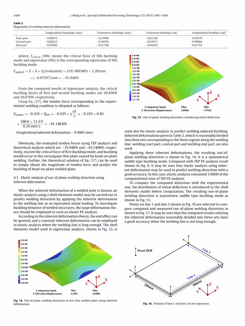
4.2. Eigenvalue analysis of welding induced buckling usinginherent deformation
Fig. 12 shows a shell elements model, that has the same dimen-sion as test specimen. The number of nodes and elements is 2562(2501 for shell elements and 61 for interface elements) and 2400,respectively. Rigid body motion is fixed as shown in the figure.
The longitudinal component of inherent deformation is con-sidered to be the dominant reason of welding induced buckling.Applying the evaluated longitudinal inherent shrinkage given inTable 2, eigenvalue FE analysis is carried out. The computed buck-ling modes and corresponding critical forces (buckling inherentdeformation) are shown in Fig. 13.
Fapplied
Fig. 13. Buckling modes and corresponding critical forces. (a) First buckling mode(saddle type) and corresponding critical force. (b) Second buckling mode (twistingtype) and corresponding critical force.
1454 J. Wang et al. / Journal of Materials Processing Technology 213 (2013) 1447– 1458
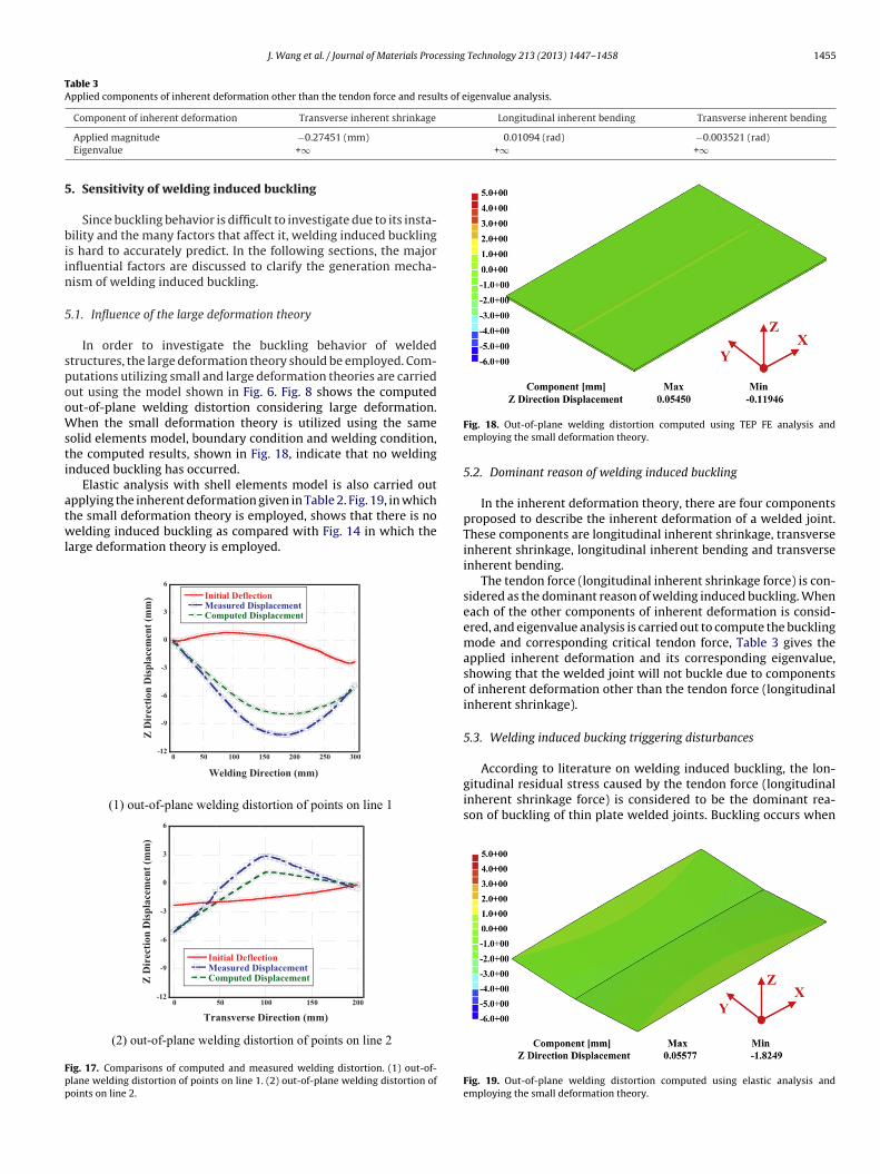
Table 2Magnitudes of welding inherent deformation.
Longitudinal shrinkage (mm) Transverse shrinkage (mm) Transverse bending (rad) Longitudinal bending (rad)
−0.01329 0.01070−0.03972 0.00868−0.04363 0.01793
mb
F
ba
m
F
ttwwtb
4i
eptbo
bie
Fd
Start part −0.08876 −0.23998
Central part −0.08222 −0.30503
End part −0.03992 −0.21748
where, Fcritical (Nth) means the critical force of Nth bucklingode and eigenvalue (Nth) is the corresponding eigenvalue of Nth
uckling mode.
applied = E × h × ı∗L(evaluated) = 210, 000 MPa × 2.28 mm
× (−0.07507) mm = −35.94KN
From the computed results of eigenvalue analysis, the criticaluckling forces of first and second buckling modes are 26.85KNnd 30.87KN, respectively.
Using Eq. (17), the tendon force corresponding to the experi-ental welding condition is obtained as follows:
tendon = −0.235 × Qnet = −0.235 × UI
v= −0.235 × 0.85
× 100 A × 13.5 V6.25 mm/s
= −43.146 KN
(longitudinal inherent deformation : 0.0901 mm)
Obviously, the evaluated tendon forces using TEP analysis andheoretical analysis which are −35.94KN and −43.146KN, respec-ively, exceed the critical force of first buckling mode, and bucklingould occur in this rectangular thin plate caused by bead-on-plateelding. Further, the theoretical solution of Eq. (17) can be used
o simply obtain the magnitude of tendon force and predict theuckling of bead-on-plate welded plate.
.3. Elastic analysis of out-of-plane welding distortion usingnherent deformation
When the inherent deformation of a welded joint is known, anlastic analysis using a shell elements model may be carried out toredict welding distortion by applying the inherent deformationo the welding line as an equivalent initial loading. To investigateuckling behavior of welded structures, the large deformation the-ry should be employed in such an elastic FE analysis.
According to the inherent deformation theory, the end effect cane ignored, and a constant inherent deformation can be employed
n elastic analysis when the welding line is long enough. The shelllements model used in eigenvalue analysis, shown in Fig. 12, is
ig. 14. Out-of-plane welding distortion in test thin welded plate using inherenteformation.
Fig. 15. Out-of-plane welding distortion considering initial deflection.
used also for elastic analysis to predict welding induced buckling.Inherent deformations given in Table 2, which is reasonably dividedinto three sets corresponding to the three regions along the weldingline: welding start part, central part and welding end part, are alsoused.
Applying these inherent deformations, the resulting out-of-plane welding distortion is shown in Fig. 14. It is a symmetricalsaddle type buckling mode. Compared with TEP FE analysis resultshown in Fig. 8, it may be seen that elastic analysis using inher-ent deformation may be used to predict welding distortion with agood accuracy. In this case, elastic analysis consumed 1/6600 of thecomputational time of TEP FE analysis.
To compare the computed distortion with the experimentalone, the distribution of initial deflection is introduced to the shellelements model before computation. The resulting out-of-planewelding distortion is asymmetric saddle type buckling mode asshown in Fig. 15.
Points on line 1 and line 2 shown in Fig. 16 are selected to com-pare computed and measured out-of-plane welding distortion asshown in Fig. 17. It may be seen that the computed results utilizing
the inherent deformation reasonably divided into three sets havea good accuracy when the welding line is not long enough.Fig. 16. Position of line 1 and line 2 in test specimen.
J. Wang et al. / Journal of Materials Processing Technology 213 (2013) 1447– 1458 1455
Table 3Applied components of inherent deformation other than the tendon force and results of eigenvalue analysis.
Component of inherent deformation Transverse inherent shrinkage Longitudinal inherent bending Transverse inherent bending
0.01094 (rad) −0.003521 (rad)+∞ +∞
5
biin
5
spooWsti
atwl
Fpp
Applied magnitude −0.27451 (mm)
Eigenvalue +∞
. Sensitivity of welding induced buckling
Since buckling behavior is difficult to investigate due to its insta-ility and the many factors that affect it, welding induced buckling
s hard to accurately predict. In the following sections, the majornfluential factors are discussed to clarify the generation mecha-ism of welding induced buckling.
.1. Influence of the large deformation theory
In order to investigate the buckling behavior of weldedtructures, the large deformation theory should be employed. Com-utations utilizing small and large deformation theories are carriedut using the model shown in Fig. 6. Fig. 8 shows the computedut-of-plane welding distortion considering large deformation.hen the small deformation theory is utilized using the same
olid elements model, boundary condition and welding condition,he computed results, shown in Fig. 18, indicate that no weldingnduced buckling has occurred.
Elastic analysis with shell elements model is also carried out
pplying the inherent deformation given in Table 2. Fig. 19, in whichhe small deformation theory is employed, shows that there is noelding induced buckling as compared with Fig. 14 in which thearge deformation theory is employed.
-12
-9
-6
-3
0
3
6
0 50 100 150 200 250 300
Initial DeflectionMeasured DisplacementComputed Displacement
Z D
irec
tion
Dis
pla
cem
ent
(mm
)
Welding Direction (mm)
(1) out-of -plane welding distortion of points on line 1
-12
-9
-6
-3
0
3
6
0 50 100 150 200
Initial DeflectionMeasure d Displa cementCompu ted DisplacementZ
Dir
ecti
on
Dis
pla
cem
ent
(mm
)
Transverse Dire ctio n (mm)
(2) ou t-of-plane welding dist ortion of po ints on line 2
ig. 17. Comparisons of computed and measured welding distortion. (1) out-of-lane welding distortion of points on line 1. (2) out-of-plane welding distortion ofoints on line 2.
Fig. 18. Out-of-plane welding distortion computed using TEP FE analysis andemploying the small deformation theory.
5.2. Dominant reason of welding induced buckling
In the inherent deformation theory, there are four componentsproposed to describe the inherent deformation of a welded joint.These components are longitudinal inherent shrinkage, transverseinherent shrinkage, longitudinal inherent bending and transverseinherent bending.
The tendon force (longitudinal inherent shrinkage force) is con-sidered as the dominant reason of welding induced buckling. Wheneach of the other components of inherent deformation is consid-ered, and eigenvalue analysis is carried out to compute the bucklingmode and corresponding critical tendon force, Table 3 gives theapplied inherent deformation and its corresponding eigenvalue,showing that the welded joint will not buckle due to componentsof inherent deformation other than the tendon force (longitudinalinherent shrinkage).
5.3. Welding induced bucking triggering disturbances
According to literature on welding induced buckling, the lon-gitudinal residual stress caused by the tendon force (longitudinalinherent shrinkage force) is considered to be the dominant rea-son of buckling of thin plate welded joints. Buckling occurs when
Fig. 19. Out-of-plane welding distortion computed using elastic analysis andemploying the small deformation theory.
1456 J. Wang et al. / Journal of Materials Processing Technology 213 (2013) 1447– 1458
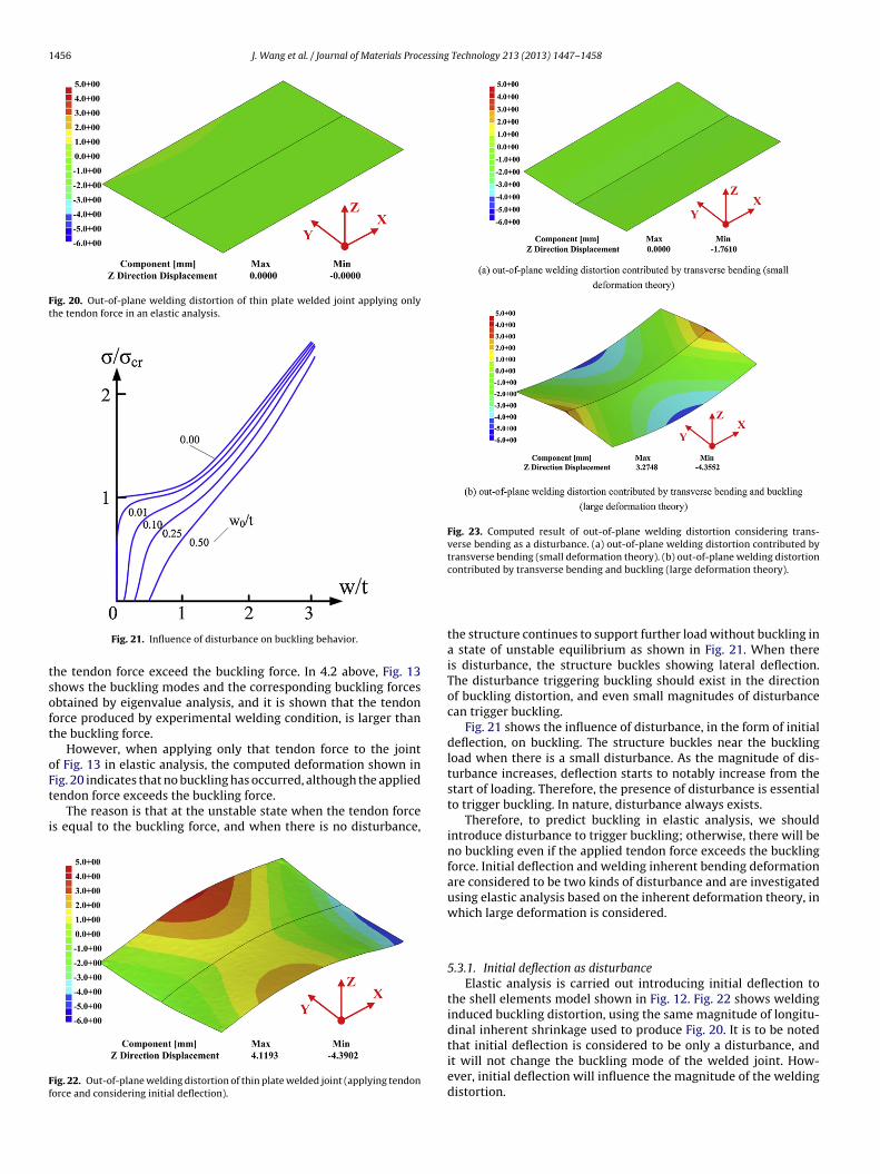
Fig. 20. Out-of-plane welding distortion of thin plate welded joint applying onlythe tendon force in an elastic analysis.
tsoft
oFt
i
Ff
Fig. 23. Computed result of out-of-plane welding distortion considering trans-verse bending as a disturbance. (a) out-of-plane welding distortion contributed bytransverse bending (small deformation theory). (b) out-of-plane welding distortion
Fig. 21. Influence of disturbance on buckling behavior.
he tendon force exceed the buckling force. In 4.2 above, Fig. 13hows the buckling modes and the corresponding buckling forcesbtained by eigenvalue analysis, and it is shown that the tendonorce produced by experimental welding condition, is larger thanhe buckling force.
However, when applying only that tendon force to the jointf Fig. 13 in elastic analysis, the computed deformation shown in
ig. 20 indicates that no buckling has occurred, although the appliedendon force exceeds the buckling force.The reason is that at the unstable state when the tendon forces equal to the buckling force, and when there is no disturbance,
ig. 22. Out-of-plane welding distortion of thin plate welded joint (applying tendonorce and considering initial deflection).
contributed by transverse bending and buckling (large deformation theory).
the structure continues to support further load without buckling ina state of unstable equilibrium as shown in Fig. 21. When thereis disturbance, the structure buckles showing lateral deflection.The disturbance triggering buckling should exist in the directionof buckling distortion, and even small magnitudes of disturbancecan trigger buckling.
Fig. 21 shows the influence of disturbance, in the form of initialdeflection, on buckling. The structure buckles near the bucklingload when there is a small disturbance. As the magnitude of dis-turbance increases, deflection starts to notably increase from thestart of loading. Therefore, the presence of disturbance is essentialto trigger buckling. In nature, disturbance always exists.
Therefore, to predict buckling in elastic analysis, we shouldintroduce disturbance to trigger buckling; otherwise, there will beno buckling even if the applied tendon force exceeds the bucklingforce. Initial deflection and welding inherent bending deformationare considered to be two kinds of disturbance and are investigatedusing elastic analysis based on the inherent deformation theory, inwhich large deformation is considered.
5.3.1. Initial deflection as disturbanceElastic analysis is carried out introducing initial deflection to
the shell elements model shown in Fig. 12. Fig. 22 shows weldinginduced buckling distortion, using the same magnitude of longitu-dinal inherent shrinkage used to produce Fig. 20. It is to be notedthat initial deflection is considered to be only a disturbance, andit will not change the buckling mode of the welded joint. How-
ever, initial deflection will influence the magnitude of the weldingdistortion.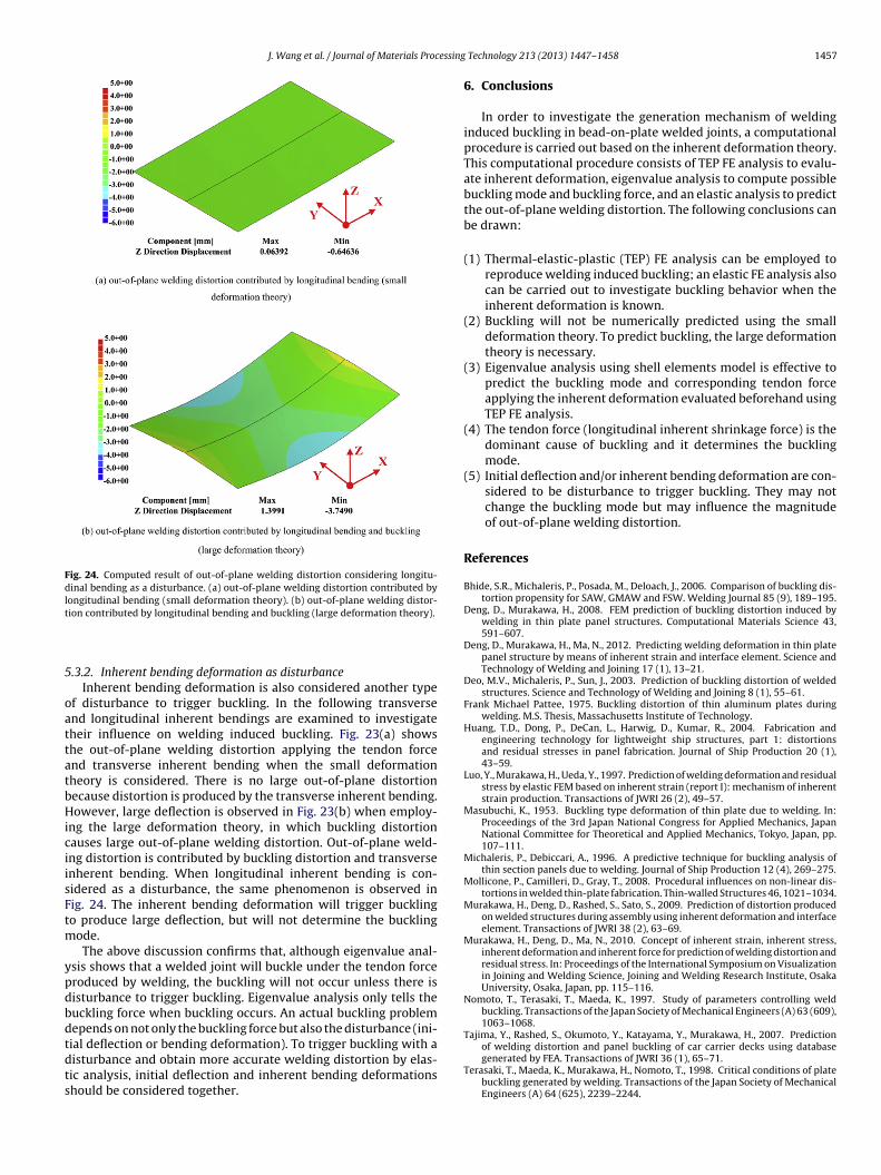
J. Wang et al. / Journal of Materials Processing
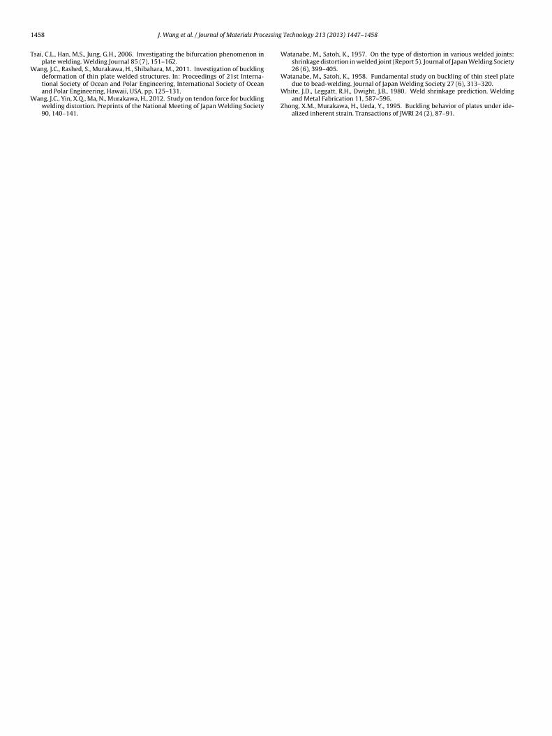
Fig. 24. Computed result of out-of-plane welding distortion considering longitu-dinal bending as a disturbance. (a) out-of-plane welding distortion contributed bylongitudinal bending (small deformation theory). (b) out-of-plane welding distor-t
5
oattatbHiciisFtm
ypdbdtdts
of welding distortion and panel buckling of car carrier decks using databasegenerated by FEA. Transactions of JWRI 36 (1), 65–71.
ion contributed by longitudinal bending and buckling (large deformation theory).
.3.2. Inherent bending deformation as disturbanceInherent bending deformation is also considered another type
f disturbance to trigger buckling. In the following transversend longitudinal inherent bendings are examined to investigateheir influence on welding induced buckling. Fig. 23(a) showshe out-of-plane welding distortion applying the tendon forcend transverse inherent bending when the small deformationheory is considered. There is no large out-of-plane distortionecause distortion is produced by the transverse inherent bending.owever, large deflection is observed in Fig. 23(b) when employ-
ng the large deformation theory, in which buckling distortionauses large out-of-plane welding distortion. Out-of-plane weld-ng distortion is contributed by buckling distortion and transversenherent bending. When longitudinal inherent bending is con-idered as a disturbance, the same phenomenon is observed inig. 24. The inherent bending deformation will trigger bucklingo produce large deflection, but will not determine the buckling
ode.The above discussion confirms that, although eigenvalue anal-
sis shows that a welded joint will buckle under the tendon forceroduced by welding, the buckling will not occur unless there isisturbance to trigger buckling. Eigenvalue analysis only tells theuckling force when buckling occurs. An actual buckling problemepends on not only the buckling force but also the disturbance (ini-ial deflection or bending deformation). To trigger buckling with aisturbance and obtain more accurate welding distortion by elas-
ic analysis, initial deflection and inherent bending deformationshould be considered together.Technology 213 (2013) 1447– 1458 1457
6. Conclusions
In order to investigate the generation mechanism of weldinginduced buckling in bead-on-plate welded joints, a computationalprocedure is carried out based on the inherent deformation theory.This computational procedure consists of TEP FE analysis to evalu-ate inherent deformation, eigenvalue analysis to compute possiblebuckling mode and buckling force, and an elastic analysis to predictthe out-of-plane welding distortion. The following conclusions canbe drawn:
(1) Thermal-elastic-plastic (TEP) FE analysis can be employed toreproduce welding induced buckling; an elastic FE analysis alsocan be carried out to investigate buckling behavior when theinherent deformation is known.
(2) Buckling will not be numerically predicted using the smalldeformation theory. To predict buckling, the large deformationtheory is necessary.
(3) Eigenvalue analysis using shell elements model is effective topredict the buckling mode and corresponding tendon forceapplying the inherent deformation evaluated beforehand usingTEP FE analysis.
(4) The tendon force (longitudinal inherent shrinkage force) is thedominant cause of buckling and it determines the bucklingmode.
(5) Initial deflection and/or inherent bending deformation are con-sidered to be disturbance to trigger buckling. They may notchange the buckling mode but may influence the magnitudeof out-of-plane welding distortion.
References
Bhide, S.R., Michaleris, P., Posada, M., Deloach, J., 2006. Comparison of buckling dis-tortion propensity for SAW, GMAW and FSW. Welding Journal 85 (9), 189–195.
Deng, D., Murakawa, H., 2008. FEM prediction of buckling distortion induced bywelding in thin plate panel structures. Computational Materials Science 43,591–607.
Deng, D., Murakawa, H., Ma, N., 2012. Predicting welding deformation in thin platepanel structure by means of inherent strain and interface element. Science andTechnology of Welding and Joining 17 (1), 13–21.
Deo, M.V., Michaleris, P., Sun, J., 2003. Prediction of buckling distortion of weldedstructures. Science and Technology of Welding and Joining 8 (1), 55–61.
Frank Michael Pattee, 1975. Buckling distortion of thin aluminum plates duringwelding. M.S. Thesis, Massachusetts Institute of Technology.
Huang, T.D., Dong, P., DeCan, L., Harwig, D., Kumar, R., 2004. Fabrication andengineering technology for lightweight ship structures, part 1: distortionsand residual stresses in panel fabrication. Journal of Ship Production 20 (1),43–59.
Luo, Y., Murakawa, H., Ueda, Y., 1997. Prediction of welding deformation and residualstress by elastic FEM based on inherent strain (report I): mechanism of inherentstrain production. Transactions of JWRI 26 (2), 49–57.
Masubuchi, K., 1953. Buckling type deformation of thin plate due to welding. In:Proceedings of the 3rd Japan National Congress for Applied Mechanics, JapanNational Committee for Theoretical and Applied Mechanics, Tokyo, Japan, pp.107–111.
Michaleris, P., Debiccari, A., 1996. A predictive technique for buckling analysis ofthin section panels due to welding. Journal of Ship Production 12 (4), 269–275.
Mollicone, P., Camilleri, D., Gray, T., 2008. Procedural influences on non-linear dis-tortions in welded thin-plate fabrication. Thin-walled Structures 46, 1021–1034.
Murakawa, H., Deng, D., Rashed, S., Sato, S., 2009. Prediction of distortion producedon welded structures during assembly using inherent deformation and interfaceelement. Transactions of JWRI 38 (2), 63–69.
Murakawa, H., Deng, D., Ma, N., 2010. Concept of inherent strain, inherent stress,inherent deformation and inherent force for prediction of welding distortion andresidual stress. In: Proceedings of the International Symposium on Visualizationin Joining and Welding Science, Joining and Welding Research Institute, OsakaUniversity, Osaka, Japan, pp. 115–116.
Nomoto, T., Terasaki, T., Maeda, K., 1997. Study of parameters controlling weldbuckling. Transactions of the Japan Society of Mechanical Engineers (A) 63 (609),1063–1068.
Tajima, Y., Rashed, S., Okumoto, Y., Katayama, Y., Murakawa, H., 2007. Prediction
Terasaki, T., Maeda, K., Murakawa, H., Nomoto, T., 1998. Critical conditions of platebuckling generated by welding. Transactions of the Japan Society of MechanicalEngineers (A) 64 (625), 2239–2244.
1 essing
T
W
W
458 J. Wang et al. / Journal of Materials Proc
sai, C.L., Han, M.S., Jung, G.H., 2006. Investigating the bifurcation phenomenon inplate welding. Welding Journal 85 (7), 151–162.
ang, J.C., Rashed, S., Murakawa, H., Shibahara, M., 2011. Investigation of bucklingdeformation of thin plate welded structures. In: Proceedings of 21st Interna-
tional Society of Ocean and Polar Engineering, International Society of Oceanand Polar Engineering, Hawaii, USA, pp. 125–131.ang, J.C., Yin, X.Q., Ma, N., Murakawa, H., 2012. Study on tendon force for bucklingwelding distortion. Preprints of the National Meeting of Japan Welding Society90, 140–141.
Technology 213 (2013) 1447– 1458
Watanabe, M., Satoh, K., 1957. On the type of distortion in various welded joints:shrinkage distortion in welded joint (Report 5). Journal of Japan Welding Society26 (6), 399–405.
Watanabe, M., Satoh, K., 1958. Fundamental study on buckling of thin steel plate
due to bead-welding. Journal of Japan Welding Society 27 (6), 313–320.White, J.D., Leggatt, R.H., Dwight, J.B., 1980. Weld shrinkage prediction. Weldingand Metal Fabrication 11, 587–596.
Zhong, X.M., Murakawa, H., Ueda, Y., 1995. Buckling behavior of plates under ide-alized inherent strain. Transactions of JWRI 24 (2), 87–91.