Influence of lens distortion and perspective error
20
123 Schofield, D., Evison, M.P. and Goodwin, L. (2010). Influence of lens distortion and perspective error. In, Evison, M.P. and Vorder Bruegge, R.W. (Eds.) Computer-aided forensic facial comparison. New York: Taylor and Francis, pp 101-117. ISBN 9781439811337 This text is the Accepted Manuscript only. The final volume can be found here. Schofield, D., Evison, M.P. and Goodwin, L. (2010). Influence of lens distortion and perspective error. In, Evison, M.P. and Vorder Bruegge, R.W. (Eds.) Computer-aided forensic facial comparison. New York: Taylor and Francis, pp 101-117. ISBN 9781439811337
-
Upload
independent -
Category
Documents
-
view
0 -
download
0
Transcript of Influence of lens distortion and perspective error

123
Schofield, D., Evison, M.P. and Goodwin, L. (2010). Influence of lens distortion and
perspective error. In, Evison, M.P. and Vorder Bruegge, R.W. (Eds.) Computer-aided
forensic facial comparison. New York: Taylor and Francis, pp 101-117. ISBN
9781439811337
This text is the Accepted Manuscript only. The final volume can be found here.
Schofield, D., Evison, M.P. and Goodwin, L. (2010). Influence of lens distortion and perspective error. In, Evison, M.P. and Vorder Bruegge, R.W. (Eds.) Computer-aided forensic facial comparison. New York: Taylor and Francis, pp 101-117. ISBN 9781439811337

124
CHAPTER 7
INFLUENCE OF LENS DISTORTION AND PERSPECTIVE ERROR
Lorna Goodwin, Martin Evison and Damian Schofield
A. INTRODUCTION
In an anthropometric landmark based approach to forensic facial comparison, a 2D image of an
offender typically will be compared with a 2D or, potentially, 3D image of a suspect.
Stereophotography (see Chapter 3) offers a precise means of locating anthropometric landmarks
in 3D. The origin of 2D images is likely to be diverse and could arise from a variety of analogue
or digital photographic or video sources. The sources of potential error in accurate landmark
location are similarly diverse, although one factor, that of lens distortion, has the potential to
affect all systems.
Aberrations in optical systems were the subject of early research in the field (for an introduction,
see Ray 2002). Distortion, in particular, is defined as the displacement of an image point from
where is should be if the object plane were mapped at a constant magnification on to the image
plane. Displacement is typically curvilinear. If the point is displaced inward (toward the optical
axis) this is known as pincushion distortion, if the point is displaced outward (away from the
optical axis) this is known as barrel distortion (see Figure 7.1).
FIGURE 7.1 HERE
Schofield, D., Evison, M.P. and Goodwin, L. (2010). Influence of lens distortion and perspective error. In, Evison, M.P. and Vorder Bruegge, R.W. (Eds.) Computer-aided forensic facial comparison. New York: Taylor and Francis, pp 101-117. ISBN 9781439811337

125
There are two forms of non-optical distortion that will affect the position of landmarks in a 2D
image. Perspective distortion is a form of non-optical distortion, where nearby subjects are
rendered larger than faraway subjects of the same size, leading to a sense of depth or
convergence of lines that are parallel. Perspective is not affected by the lens focal length or
camera distance: it depends on the perspective projection as determined by the viewpoint of the
camera in relation to the subject.
Geometric distortion results when a 3D object is projected onto a flat plane. A well known
example occurs when a sphere at the centre of an image is rendered as a round disk on the film,
while a sphere at the periphery of an image is elliptically elongated.
This Chapter describes and investigation of the potential influence of lens distortion on landmark
positioning, with a view to developing guidelines for 2D image capture and measurement, and—
in particular—to determining the distance that a camera has to be from the subject before the
perspective view matches the orthogonal projection.
B. METHOD OF ANALYSIS
An investigation of the effects of lens distortion on manual landmarks placed on 2D images in a
sample of live subjects captured with a variety of different lenses whilst controlling for
perspective distortion, would present a prohibitively laborious and time consuming challenge.
For this reason, an in silico approach using visualization modeling software was chosen,
permitting automation of much of the analytical process.
Schofield, D., Evison, M.P. and Goodwin, L. (2010). Influence of lens distortion and perspective error. In, Evison, M.P. and Vorder Bruegge, R.W. (Eds.) Computer-aided forensic facial comparison. New York: Taylor and Francis, pp 101-117. ISBN 9781439811337

126
Twelve 3D images were provisionally assessed, which represented extremes of y and z (width
and depth, respectively) dimensions in the 3D image database collected using the Geometrix
FaceVision® FV802 Series Biometric Camera (ALIVE Tech, Cumming, GA). From this set of
twelve, five 3D images were selected which showed the fewest scanner anomalies (see Chapter
2).
The five 3D images were landmarked at 30 sites (see Table 7.1) in the 3ds MAX® modeling
software (Autodesk®, San Rafael, CA).
After the remaining landmarks had been placed, the head was orientated into consistent planes in
each axis. The 3D head geometry was manually aligned into a consistent plane in 3ds MAX®.
Using the midline landmarks, the facial midline was orientated vertically in the coronal (x-y)
plane from the front viewport window and in the transverse (x-z) plane from the lateral viewport
window. The pronasale (prn) was not used, as this was observed to move off the midline in many
individuals.
In the front viewport, the position of the endocanthions (en l and en r) and exocanthions (ex l and
ex r) can be used for guidance as a line through these points (an inter-orbital line) will be at
approximately 90° to the midline. These landmarks, and the superaurales (sa l and sa r) and
subaurales (sba l and sba r), can also be used in the lateral view to provide similar guidance.
Similarly, the landmarks of the circumoral or mouth region: the labiale superius (ls), labiale
inferius (li), stomion (sto) and cheilion (ch) were located using lateral, anterior and user selected
Schofield, D., Evison, M.P. and Goodwin, L. (2010). Influence of lens distortion and perspective error. In, Evison, M.P. and Vorder Bruegge, R.W. (Eds.) Computer-aided forensic facial comparison. New York: Taylor and Francis, pp 101-117. ISBN 9781439811337

127
views, where left and right bilateral landmarks were again checked for plane alignment. The
position of these landmarks can not be expected to correspond perfectly with the midline as the
head is not a symmetric geometric form.
In the front viewport, the position of the endocanthions (en l and en r) and exocanthions (ex l and
ex r) can be used for guidance as an inter-orbital line will be at approximately 90° to the midline.
These landmarks, and the superaurales (sa l and sa r) and subaurales (sba l and sba r), can be
used in the lateral view to provide similar guidance. Similarly, the landmarks of the circumoral
or mouth region—the labiale superius (ls), labiale inferius (li), stomion (sto) and cheilion (ch)
were located using lateral, anterior and user selected views, where left and right bilateral
landmarks were again checked for plane alignment. The position of these landmarks will not
correspond perfectly with the midline or plane: the head is not a symmetric geometric form.
The landmarks are the optimal set identified in Chapter 3—without substitution of the alares (al l
and al r) for the alar crests (ac l and ac r). The landmarks were located manually on the 3D head
geometry in 3ds MAX®. Following Aung et al. 1995, the nasal landmarks were located in
columella view—with the head tilted back about 30°—after the remaining landmarks had been
placed and the head orientated into a consistent plane.
The landmarks were assigned individual, distinct RGB colors. Original landmark geometry was
measured by algorithmic calculation (using software written in the MAX Script® programming
language) of pairwise distances between landmarks, yielding 435 pairwise distances between the
30 sites.
Schofield, D., Evison, M.P. and Goodwin, L. (2010). Influence of lens distortion and perspective error. In, Evison, M.P. and Vorder Bruegge, R.W. (Eds.) Computer-aided forensic facial comparison. New York: Taylor and Francis, pp 101-117. ISBN 9781439811337

128
The influence of lens distortion was assessed in silico via rendering of 2D anterior views of the
five subjects’ 3D image datasets at different lens parameter settings in the 3ds MAX® modeling
software. The pronasale (prn) approximates to the most central point of the face in the anterior
view and was chosen as the focal point for the virtual camera.
The following parameters were used:
subject to camera distance: 0.5, 1.0, 1.5 or 2.0 m
lens: 15mm, 35mm or 50mm (CCTV camera lenses usually range approximately from
less than 10 mm up to 50 mm; 15 mm is the minimum offered in the modeling software)
view: orthographic or perspective
Each of the 24 possible camera combinations for the five subjects was rendered in 2D in
uncompressed bitmap format. A 4000 × 3000 pixel resolution was used: since in tests not all
visible landmarks were rendered from the 15 mm lens at 2 m distance when lower resolutions
were used. Similarly, it was established during testing that the OpenGL® rendering drivers
yielded the best quality alignment of rendered textures to the original wireframe.
The pixel coordinates at the centre of each landmark in the rendered image were manually
measured and then recorded in Microsoft® Office 2003 Excel spreadsheets. If necessary,
reference was made to the 3D image to ensure correct texture alignment and the proper location
of the landmark.
Schofield, D., Evison, M.P. and Goodwin, L. (2010). Influence of lens distortion and perspective error. In, Evison, M.P. and Vorder Bruegge, R.W. (Eds.) Computer-aided forensic facial comparison. New York: Taylor and Francis, pp 101-117. ISBN 9781439811337

129
The 435 pairwise distances between landmarks were calculated automatically using Microsoft®
Office 2003 Excel spreadsheet macros and programs written using Visual Basic. For each view,
a pixel scaling factor in pixels per mm was calculated trigonometrically from the original 3D
model in order to convert pixel distances to mm for both perspective and orthogonal views.
In order to assess perspective error, differences between pairwise distances measured from
perspective and orthogonal projections were calculated for all 24 camera combinations. The
minimum and maximum values, ranges, and standard deviation were also calculated.
Minimum and maximum values were also calculated for each pixel scaling factor, and for
differences in pairwise pixel distances between landmarks measured in perspective and
orthogonal views. These values were used to check for possible pixel measurement errors.
Perspective errors were calculated as the ratio of perspective distance to orthogonal distance
between each pair of landmarks in pixels, converted into mm using the pixel scaling factor for
any particular pairwise measurement.
C. RESULTS
Figure 7.2 shows a plot of perspective error, calculated as the difference between pairwise
distances in orthographic and perspective views, versus pairwise distance in 3D. It can be seen
clearly from the figure that perspective error affects the landmarks of the ear to a greater extent
than other landmarks.
Schofield, D., Evison, M.P. and Goodwin, L. (2010). Influence of lens distortion and perspective error. In, Evison, M.P. and Vorder Bruegge, R.W. (Eds.) Computer-aided forensic facial comparison. New York: Taylor and Francis, pp 101-117. ISBN 9781439811337
130
FIGURE 7.2 HERE
Figures 7.3 to 7.7 show plots of perspective error in mm for each pairwise distance for each of
the five subjects, in ascending order of 2D Euclidean distance between landmarks for 435
landmark pairs.
FIGURE 7.3 HERE
FIGURE 7.4 HERE
FIGURE 7.5 HERE
FIGURE 7.6 HERE
FIGURE 7.7 HERE
Figures 7.3 to 7.7 show clear overall patterns of results, irrespective of the subject, these are:
Perspective errors decrease roughly exponentially with camera distance
There is a close correlation between perspective error and 2D pairwise distance
The relationship between perspective error and 2D pairwise distance begins as a roughly
linear relationship and shows a sudden rise, which appears proportionally greater for
smaller camera distances, and continues as a line or slope with a sudden rise at the final
Schofield, D., Evison, M.P. and Goodwin, L. (2010). Influence of lens distortion and perspective error. In, Evison, M.P. and Vorder Bruegge, R.W. (Eds.) Computer-aided forensic facial comparison. New York: Taylor and Francis, pp 101-117. ISBN 9781439811337
131
and longest distances which again appears proportionally greater for smaller camera
distances
Close inspection of Figures 7.3 to 7.7 indicates that there are some differences in the general
influences of perspective error between individual subjects, however. This order of ascending
error closely matches the order of ascending facial depth, as described in greater detail below,
which suggests a relationship between the two factors.
Figure 7.8 shows a plot of the per cent ratio of perspective distance versus orthogonal distance
for each landmark where no adjustment is made against the original 3D pairwise distance, for
subject four only.
FIGURE 7.8 HERE
Figure 7.8 illustrates that when perspective error is not considered relative to the 3D pairwise
distance, shorter measurements, such as around the mouth, eyes or nose, show significantly
higher perspective errors and perspective error ranges than others. This is because a small
measurement error, for example, of ±1 pixel on each landmark coordinate, confers an apparent
perspective error ratio of greater magnitude for orthogonal distances constituting a smaller
number of pixels. Shorter distances are more subject to measurement error, but less subject to
perspective error relative to longer ones.
Schofield, D., Evison, M.P. and Goodwin, L. (2010). Influence of lens distortion and perspective error. In, Evison, M.P. and Vorder Bruegge, R.W. (Eds.) Computer-aided forensic facial comparison. New York: Taylor and Francis, pp 101-117. ISBN 9781439811337

132
Figure 7.9 shows an alternative plot form for 145 of the 435 pairwise comparisons, illustrating
the measurement error effect on adjacent landmarks on the eyes, nose, mouth and ears for subject
three.
FIGURE 7.9 HERE
In addition to lens setting and camera distance, fundamental dimensionality, width, height and
depth, are anticipated to influence perspective error. Figures 7.10 to 7.14 show plots of
perspective error ranking (see Figures 7.3 to 7.8) versus z-axis difference (or depth) for each
pairwise measurement for subjects one to five.
FIGURE 7.10 HERE
FIGURE 7.11 HERE
FIGURE 7.12 HERE
FIGURE 7.13 HERE
FIGURE 7.14
The Figures (7.10 to 7.14) illustrate the influence of dimensionality in the x and z dimensions, as
well as the y dimension shown in the Figures. It is possible to distinguish a general relationship
Schofield, D., Evison, M.P. and Goodwin, L. (2010). Influence of lens distortion and perspective error. In, Evison, M.P. and Vorder Bruegge, R.W. (Eds.) Computer-aided forensic facial comparison. New York: Taylor and Francis, pp 101-117. ISBN 9781439811337

133
between the gross dimensionality (width, height or depth) and the perspective error ranking,
which could be anticipated given the finding of a correlation between perspective error and
orthogonal distance. There are exceptions, however. The greatest y-coordinate distance (or
height) peaks near the centre of the perspective error ranking, with the glabella (g) to pogonion
(pg) distance. This measurement is noticeably close to the midline and camera focal point at the
pronasale (prn) or nasal tip.
The z-coordinate distance (or depth) illustrates further patterns, which appear to split the
Euclidean distances into two large groups (see Figures 7.10 to 7.14).
In both groups, the pairwise distances with the highest z-dimensionality (i.e. those which span
the greatest depth) rank highest in perspective error. The second group (incorporating the
landmarks of the ear region) has markedly higher perspective error, but with some clear
exceptions. These exceptions are pairwise distances between opposite ear region landmarks.
Although these distances have little depth, they will be subject to perspective error correlated
with dimensionality in other axes. The same pattern is evident for all five subjects, although
there are general trends relating to the individual size and shape of each head. In Figures 7.10 to
7.14 it is variation in the z dimension or depth that is shown.
As a consequence of these observations, the influence of the distance between the landmarks and
the camera focal point on the pronasale or nasal tip was investigated directly.
Schofield, D., Evison, M.P. and Goodwin, L. (2010). Influence of lens distortion and perspective error. In, Evison, M.P. and Vorder Bruegge, R.W. (Eds.) Computer-aided forensic facial comparison. New York: Taylor and Francis, pp 101-117. ISBN 9781439811337

134
Figures 7.15 to 7.19 show plots of 3D pairwise distances from each landmark to the pronasale
(prn) versus cumulative perspective error for pairwise distance for all five subjects.
Combinations of the x, y and z dimensionality (width, height and depth) relating to each pairwise
distance from the pronasale (prn) is also plotted.
FIGURE 7.15 HERE
FIGURE 7.16 HERE
FIGURE 7.17 HERE
FIGURE 7.18 HERE
FIGURE 7.19
Figures 7.15 to 7.19 show a very subtle increase in perspective error from those landmarks on the
facial midline to those in the bilateral regions of the eyes and lips. There is a marked increase in
perspective error when the landmarks of the ear region are encountered. Here, an underlying
relationship between 3D (x, y, z) distance and perspective error can be correlated with z
dimensionality, or depth, and then x dimensionality, or width. The y dimension (height) does not
appear to have noticeable influence.
Schofield, D., Evison, M.P. and Goodwin, L. (2010). Influence of lens distortion and perspective error. In, Evison, M.P. and Vorder Bruegge, R.W. (Eds.) Computer-aided forensic facial comparison. New York: Taylor and Francis, pp 101-117. ISBN 9781439811337

135
It is tempting to anticipate that for the landmarks close to the pronasale (prn), lack of obvious
correlation with fluctuations in dimensionality is due to very low perspective error being
associated with landmarks subject to random measurement error (see above).
Table 7.2 illustrates the cumulative perspective error in mm calculated for each landmark for
each subject. Note that this is derived form the pairwise distance errors associated with the
landmark in combination with the other 29 pairings.
The ranking in Table 7.2 reflects the correlation between perspective error and pairwise distance.
Although the pronasale (prn) is located at the camera focal point, which has no perspective error,
it is also consistently distant from all its peripheral landmarks, leading to a cumulative
perspective error correlating with those distances.
D. SUMMARY
The influence of both lens distortion and perspective error on pairwise distances between
landmarks have been investigated and, as would be anticipated, follow the classic model, the
influence of which varies in reflection to the unique geometry of the human facial form. The
subjects chosen in the investigation tended toward the extremes of overall dimensionality in the
large sample database.
Observations are a combination of the effects of lens distortion, perspective error and
measurement error:
Schofield, D., Evison, M.P. and Goodwin, L. (2010). Influence of lens distortion and perspective error. In, Evison, M.P. and Vorder Bruegge, R.W. (Eds.) Computer-aided forensic facial comparison. New York: Taylor and Francis, pp 101-117. ISBN 9781439811337

136
there is an increase in perspective error correlated with distance from the camera focal
point
there is an inverse exponential correlation between lens distortion and camera distance
pairwise distance measurement error is inversely correlated with pairwise distance
measurement error has its greatest effect on shorter pairwise distances
the influence of lens distortion and perspective error affects pairwise distances in a
pattern reflecting the 3D geometry of the face:
o pairwise distances involving the ear landmarks are most susceptible to error as
they are furthest from the camera focal point at the pronasale (prn, in both x and z
(width and depth) dimensions, and form the greatest pairwise distances
o pairwise distances between landmarks on the facial midline are the least affected
as they are closest to the camera focal point at the pronasale (prn) and have little
relative depth (z dimensionality)
o pairwise distances between adjacent landmarks on the nose, eyes and mouth are
susceptible to the greatest influence of measurement error
o measurement error is greater at lower pixel resolutions
The approach taken in this investigation (visualization modeling) offers a structure within which
the effects of lens distortion, perspective error and measurement error on anthropometric facial
measurement may be simulated for different lens settings and camera distances. It may be used
to estimate the camera distance at which lens distortion and perspective error will become
negligible in proportion to measurement error—this appears to be greater than 2.0 m for a 50 mm
Schofield, D., Evison, M.P. and Goodwin, L. (2010). Influence of lens distortion and perspective error. In, Evison, M.P. and Vorder Bruegge, R.W. (Eds.) Computer-aided forensic facial comparison. New York: Taylor and Francis, pp 101-117. ISBN 9781439811337
137
lens. The approach also offers a means via which the optimum camera focal point could be
identified in order to minimize the affects of lens distortion and perspective error, after which
existing algorithms for the correction of lens distortion could then be applied (see, for example,
Farid and Popescu 2001).
E. REFERENCES
Aung, S.C., Ngim, R.C.K. and Lee, S.T. 1995. Evaluation of the Laser Scanner as a Surface
Measuring Tool and Its Accuracy Compared with Direct Facial Anthropometric Measurements.
British Journal of Plastic Surgery 48(8): 527–621.
Farid, H. and Popescu, A.C. 2001. Blind removal of lens distortion. Journal of the Optical
Society of America A 18: 2072-78.
Ray, S.F. 2002. Applied Photographic Optics, 2nd
ed., St. Louis: Focal Press.
Schofield, D., Evison, M.P. and Goodwin, L. (2010). Influence of lens distortion and perspective error. In, Evison, M.P. and Vorder Bruegge, R.W. (Eds.) Computer-aided forensic facial comparison. New York: Taylor and Francis, pp 101-117. ISBN 9781439811337
138
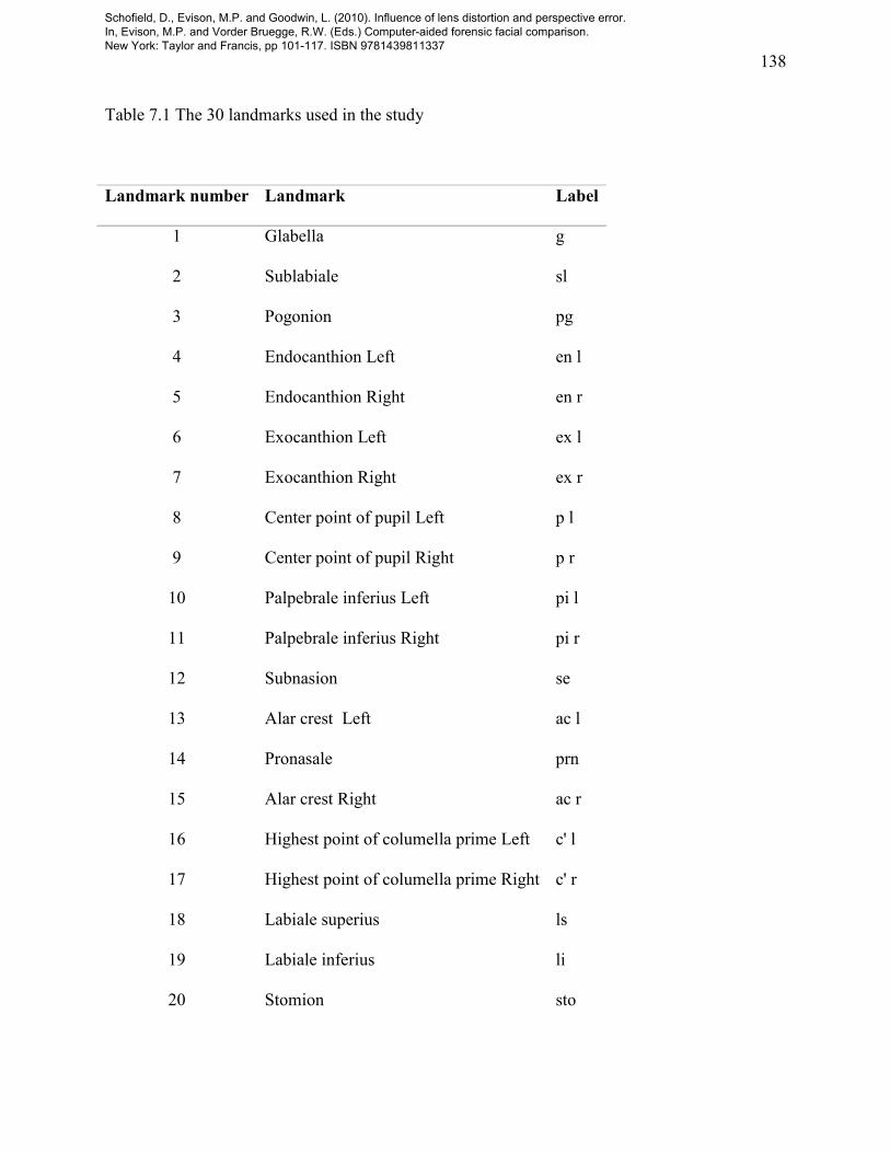
Table 7.1 The 30 landmarks used in the study
Landmark number Landmark Label
1 Glabella g
2 Sublabiale sl
3 Pogonion pg
4 Endocanthion Left en l
5 Endocanthion Right en r
6 Exocanthion Left ex l
7 Exocanthion Right ex r
8 Center point of pupil Left p l
9 Center point of pupil Right p r
10 Palpebrale inferius Left pi l
11 Palpebrale inferius Right pi r
12 Subnasion se
13 Alar crest Left ac l
14 Pronasale prn
15 Alar crest Right ac r
16 Highest point of columella prime Left c' l
17 Highest point of columella prime Right c' r
18 Labiale superius ls
19 Labiale inferius li
20 Stomion sto
Schofield, D., Evison, M.P. and Goodwin, L. (2010). Influence of lens distortion and perspective error. In, Evison, M.P. and Vorder Bruegge, R.W. (Eds.) Computer-aided forensic facial comparison. New York: Taylor and Francis, pp 101-117. ISBN 9781439811337

139
21 Cheilion Left ch l
22 Cheilion Right ch r
23 Superaurale Left sa l
24 Superaurale Right sa r
25 Subaurale Left sba l
26 Subaurale Right sba r
27 Postaurale Left pa l
28 Postaurale Right pa r
29 Otobasion inferius Left obi l
30 Otobasion inferius Right obi r
Schofield, D., Evison, M.P. and Goodwin, L. (2010). Influence of lens distortion and perspective error. In, Evison, M.P. and Vorder Bruegge, R.W. (Eds.) Computer-aided forensic facial comparison. New York: Taylor and Francis, pp 101-117. ISBN 9781439811337

140
Table 7.2 Cumulative perspective error in mm for each landmark for each subject
Landmark
Cumulative perspective error in mm for each subject
1 2 3 4 5 Total
Pg 1859 1506 1557 2130 1553 8605
Sl 1931 1596 1603 2156 1759 9047
G 2001 1653 1601 2032 1838 9125
Li 2006 1630 1580 2166 1815 9196
Sto 2027 1678 1653 2193 1838 9387
Se 2061 1674 1660 2226 1907 9528
Ls 2103 1747 1725 2226 1860 9661
En-l 2076 1733 1758 2256 1924 9747
En-r 2110 1694 1746 2328 1986 9864
Ch-l 2082 1796 1750 2310 1997 9935
Ch-r 2137 1760 1767 2308 2021 9993
P-l 2207 1794 1880 2366 2020 10268
Pi-l 2209 1811 1926 2381 2017 10346
Al-r 2266 1798 1849 2401 2048 10361
P-r 2209 1795 1829 2423 2114 10370
Pi-r 2207 1756 1845 2455 2133 10396
Al-l 2277 1885 1980 2395 1972 10509
C-r 2383 1926 1952 2466 2109 10836
C-l 2421 1953 2009 2497 2082 10961
Ex-l 2421 1934 2081 2567 2184 11187
Ex-r 2411 1954 1984 2689 2350 11388
Schofield, D., Evison, M.P. and Goodwin, L. (2010). Influence of lens distortion and perspective error. In, Evison, M.P. and Vorder Bruegge, R.W. (Eds.) Computer-aided forensic facial comparison. New York: Taylor and Francis, pp 101-117. ISBN 9781439811337

141
Prn 2586 2040 2112 2699 2238 11676
Obi-r 4361 3599 3471 4990 4290 20711
Obi-l 4563 3832 3632 4735 4086 20848
Sba-r 5150 4131 3997 5292 4683 23252
Sba-l 5118 4567 4439 5131 4434 23690
Sa-l 6314 5230 5214 7195 5587 29540
Sa-r 6476 5358 5219 7710 6545 31309
Pa-l 6733 6175 6043 7780 6724 33455
Pa-r 7201 6007 5788 8230 7573 34798
Schofield, D., Evison, M.P. and Goodwin, L. (2010). Influence of lens distortion and perspective error. In, Evison, M.P. and Vorder Bruegge, R.W. (Eds.) Computer-aided forensic facial comparison. New York: Taylor and Francis, pp 101-117. ISBN 9781439811337

142
Figure 7.1. Distortion of a rectangular grid. Left: undistorted grid; Center: pincushion distortion;
Right: barrel distortion.
Schofield, D., Evison, M.P. and Goodwin, L. (2010). Influence of lens distortion and perspective error. In, Evison, M.P. and Vorder Bruegge, R.W. (Eds.) Computer-aided forensic facial comparison. New York: Taylor and Francis, pp 101-117. ISBN 9781439811337