Biomass co-firing under oxy-coal conditions: A computational fluid dynamics modelling study and...
12
Biomass co-firing under oxy-fuel conditions: A computational fluid dynamics modelling study and experimental validation L. Álvarez a , C. Yin b , J. Riaza a , C. Pevida a , J.J. Pis a , F. Rubiera a, ⁎ a Instituto Nacional del Carbón, INCAR-CSIC, Apartado 73, 33080 Oviedo, Spain b Department of Energy Technology, Aalborg University, 9220 Aalborg East, Denmark abstract article info Article history: Received 12 March 2013 Received in revised form 29 November 2013 Accepted 1 December 2013 Available online 22 December 2013 Keywords: Biomass co-firing Synergy effects CO 2 capture Oxy-fuel combustion Below-zero CO 2 emissions CFD This paper presents an experimental and numerical study on co-firing olive waste (0, 10%, 20% on mass basis) with two coals in an entrained flow reactor under three oxy-fuel conditions (21%O 2 /79%CO 2 , 30%O 2 /70%CO 2 and 35%O 2 /65%CO 2 ) and air–fuel condition. Co-firing biomass with coal was found to have favourable synergy effects in all the cases: it significantly improves the burnout and remarkably lowers NO x emissions. The reduced peak temperatures during co-firing can also help to mitigate deposition formation in real furnaces. Co- firing CO 2 -neutral biomass with coals under oxy-fuel conditions can achieve a below-zero CO 2 emission if the released CO 2 is captured and sequestered. The model-predicted burnout and gaseous emissions were compared against the experimental results. A very good agreement was observed, the differences in a range of ±5–10% of the experimental values, which indicates the model can be used to aid in design and optimization of large-scale biomass co-firing under oxy-fuel conditions. © 2013 Elsevier B.V. All rights reserved. 1. Introduction The combustion of coal in power plants generates a large amount of CO 2 which is one of the major contributors to global climate change. A diverse power generation portfolio including Carbon Capture and Storage (CCS) technologies and renewable energies is needed to reduce current atmospheric CO 2 concentration of 393 ppm to below 354 ppm in 1990. During oxy-coal combustion, coal is burnt in a mixture of oxygen and recycled flue gas (mainly CO 2 and H 2 O), to yield a rich stream of CO 2 which, after purification and compression, is ready for sequestration [1]. Co-firing biomass with fossil fuels in existing utility boilers is also a feasible technology which can not only significantly reduce CO 2 emissions but also increase the share of renewable energy sources in energy systems [2,3]. The combination of oxy-coal combus- tion with biomass co-firing could afford a way to increase CO 2 capture efficiency [4]. Biomass co-firing has been successfully performed in over 200 installations worldwide for a large number of combinations of fuels, either in pilot tests or as part of commercial enterprises [5]. Though problems may arise in relation to biomass transport costs and difficulties in milling, these can be manageable if adequate consider- ation is given to the fuels, design and operating conditions used in the burners and boilers [6]. Compared with biomass co-firing, oxy-fuel combustion is still in the demonstration stage, with plans for industrial scale-up to come into effect in the near future [4]. The successful implementation of oxy-fuel combustion depends on fully understanding the difficulties that can arise from replacing nitrogen by CO 2 in the oxidizer stream. Oxy-fuel conditions strongly promote radiative heat transfer, as a result of the much higher levels of CO 2 ,H 2 O, and in-flame soot, as well as the differ- ent CO 2 /H 2 O ratio to that of air-firing combustion [7]. Other aspects of combustion, such as volatile combustion, flame ignition and stability, or pollutant formation, may also be affected [8]. Biomass co-firing under oxy-fuel is likely to bring up more uncertainties. Biomass co- firing under oxy-fuel conditions is an attractive option to simultaneously increase the use of renewable energy sources, exploit the favourable synergy effects of biomass/coal co-firing and achieve below-zero CO 2 emissions, which has been very little investigated so far [9–12]. For instance Smart et al. [11] evaluated the impact of co-firing biomass on pollutant formation, burnout and heat transfer under oxy-fuel conditions in a 0.5 MWt combustion test facility. Experiments at laboratory scale have been focused on the effects of different co-firing ratios on burnout and NO emissions [12]. Computational Fluid Dynamics (CFD) models have been used to simulate pulverised coal and biomass co-firing in conventional combus- tion systems [13–15]. In recent years, on the basis of the accumulated knowledge of the fundamental differences between air-fuel and oxy- fuel combustion, much effort has been devoted to developing and validating sub-models for the new combustion environment. For instance, new approaches have been developed for heat transfer modelling in environments with high concentrations of CO 2 and H 2 O vapour, e.g., the Weighted-Sum-of-Gray-Gases-Model (WSGGM) refined for oxy-fuel combustion modelling [16,17]. Specific models for volatile combustion in CO 2 –rich environments [18] and for char Fuel Processing Technology 120 (2014) 22–33 ⁎ Corresponding author. Tel.: +34 985 119090. E-mail address: [email protected] (F. Rubiera). 0378-3820/$ – see front matter © 2013 Elsevier B.V. All rights reserved. http://dx.doi.org/10.1016/j.fuproc.2013.12.005 Contents lists available at ScienceDirect Fuel Processing Technology journal homepage: www.elsevier.com/locate/fuproc
Transcript of Biomass co-firing under oxy-coal conditions: A computational fluid dynamics modelling study and...

Fuel Processing Technology 120 (2014) 22–33
Contents lists available at ScienceDirect
Fuel Processing Technology
j ourna l homepage: www.e lsev ie r .com/ locate / fuproc
Biomass co-firing under oxy-fuel conditions: A computational fluiddynamics modelling study and experimental validation
L. Álvarez a, C. Yin b, J. Riaza a, C. Pevida a, J.J. Pis a, F. Rubiera a,⁎a Instituto Nacional del Carbón, INCAR-CSIC, Apartado 73, 33080 Oviedo, Spainb Department of Energy Technology, Aalborg University, 9220 Aalborg East, Denmark
⁎ Corresponding author. Tel.: +34 985 119090.E-mail address: [email protected] (F. Rubiera).
0378-3820/$ – see front matter © 2013 Elsevier B.V. All rihttp://dx.doi.org/10.1016/j.fuproc.2013.12.005
a b s t r a c t
a r t i c l e i n f oArticle history:Received 12 March 2013Received in revised form 29 November 2013Accepted 1 December 2013Available online 22 December 2013
Keywords:Biomass co-firingSynergy effectsCO2 captureOxy-fuel combustionBelow-zero CO2 emissionsCFD
This paper presents an experimental and numerical study on co-firing olive waste (0, 10%, 20% on mass basis)with two coals in an entrained flow reactor under three oxy-fuel conditions (21%O2/79%CO2, 30%O2/70%CO2
and 35%O2/65%CO2) and air–fuel condition. Co-firing biomass with coal was found to have favourable synergyeffects in all the cases: it significantly improves the burnout and remarkably lowers NOx emissions. The reducedpeak temperatures during co-firing can also help to mitigate deposition formation in real furnaces. Co-firing CO2-neutral biomass with coals under oxy-fuel conditions can achieve a below-zero CO2 emissionif the released CO2 is captured and sequestered. The model-predicted burnout and gaseous emissionswere compared against the experimental results. A very good agreement was observed, the differencesin a range of ±5–10% of the experimental values, which indicates the model can be used to aid in design andoptimization of large-scale biomass co-firing under oxy-fuel conditions.
© 2013 Elsevier B.V. All rights reserved.
1. Introduction
The combustion of coal in power plants generates a large amountof CO2 which is one of the major contributors to global climate change.A diverse power generation portfolio including Carbon Capture andStorage (CCS) technologies and renewable energies is needed to reducecurrent atmospheric CO2 concentration of 393 ppm to below 354 ppmin 1990. During oxy-coal combustion, coal is burnt in a mixture ofoxygen and recycled flue gas (mainly CO2 and H2O), to yield a richstream of CO2 which, after purification and compression, is ready forsequestration [1]. Co-firing biomass with fossil fuels in existing utilityboilers is also a feasible technology which can not only significantlyreduce CO2 emissions but also increase the share of renewable energysources in energy systems [2,3]. The combination of oxy-coal combus-tion with biomass co-firing could afford a way to increase CO2 captureefficiency [4]. Biomass co-firing has been successfully performed inover 200 installations worldwide for a large number of combinationsof fuels, either in pilot tests or as part of commercial enterprises [5].Though problems may arise in relation to biomass transport costs anddifficulties in milling, these can be manageable if adequate consider-ation is given to the fuels, design and operating conditions used inthe burners and boilers [6].
Compared with biomass co-firing, oxy-fuel combustion is still in thedemonstration stage, with plans for industrial scale-up to come intoeffect in the near future [4]. The successful implementation of oxy-fuel
ghts reserved.
combustion depends on fully understanding the difficulties that canarise from replacing nitrogen by CO2 in the oxidizer stream. Oxy-fuelconditions strongly promote radiative heat transfer, as a result of themuch higher levels of CO2, H2O, and in-flame soot, as well as the differ-ent CO2/H2O ratio to that of air-firing combustion [7]. Other aspects ofcombustion, such as volatile combustion, flame ignition and stability,or pollutant formation, may also be affected [8]. Biomass co-firingunder oxy-fuel is likely to bring up more uncertainties. Biomass co-firing under oxy-fuel conditions is an attractive option to simultaneouslyincrease the use of renewable energy sources, exploit the favourablesynergy effects of biomass/coal co-firing and achieve below-zero CO2
emissions, which has been very little investigated so far [9–12]. Forinstance Smart et al. [11] evaluated the impact of co-firing biomass onpollutant formation, burnout andheat transfer under oxy-fuel conditionsin a 0.5 MWt combustion test facility. Experiments at laboratory scalehave been focused on the effects of different co-firing ratios on burnoutand NO emissions [12].
Computational Fluid Dynamics (CFD) models have been used tosimulate pulverised coal and biomass co-firing in conventional combus-tion systems [13–15]. In recent years, on the basis of the accumulatedknowledge of the fundamental differences between air-fuel and oxy-fuel combustion, much effort has been devoted to developing andvalidating sub-models for the new combustion environment. Forinstance, new approaches have been developed for heat transfermodelling in environments with high concentrations of CO2 and H2Ovapour, e.g., the Weighted-Sum-of-Gray-Gases-Model (WSGGM)refined for oxy-fuel combustion modelling [16,17]. Specific models forvolatile combustion in CO2–rich environments [18] and for char

N2
Gas cylinders
Cooled injector
Feeding system
Samplingprobe
Cyclone
O2
CO
CO2
Mass flowcontrollers
To vent
Filter
Pre-heater
Reaction tube
O2 CO2
NO
SO2
N2
O2
CO
CO2
Gas analysers
O2 CO2
NO
SO2
Fig. 1. Schematic diagram of the entrained flow reactor (EFR).
23L. Álvarez et al. / Fuel Processing Technology 120 (2014) 22–33
combustion under oxy-fuel conditions [19] have also been developed.In terms of modelling of biomass co-firing under oxy-fuel conditions, arecent paper by Holtmeyer at al. [20] could be the only effort in litera-ture, in which the effect of co-firing sawdust and a subbituminouscoal on NO emissions in air and oxy-fuel conditions was studied.
The main objective of this paper is to comprehensively study co-firing biomass with coals under air-fuel and oxy-fuel conditions in alab-scale entrained flow reactor (EFR). The computational fluid dynam-ics (CFD) study is the main workhorse and the experimental study isused to validate theCFDmodelling. Among others, the effects of biomassshares in co-firing (from 0 to 20 wt.% of biomass), firing conditions, anddifferent coals to be separately used in co-firing on the overall combus-tion behaviour and NO emissions are investigated and discussed.
2. Experimental setup
All the combustion experiments of this study were performed in adown-fired EFR, which has been introduced in detail in Riaza et al.
Table 1Proximate and ultimate analyses of the samples used in this work.
Sample OW HVN SAB
Origin Spain Spain S. Africa
Rank sa hvb
Proximate analysis (wt.%)Moisture 9.0 1.1 2.4Volatile matter (db) 71.9 9.2 29.9Ash (db) 7.6 10.7 15.0Fixed carbona (db) 20.5 80.1 55.1
Ultimate analysis (wt.%, db)C 50.2 81.9 69.3H 6.1 3.1 4.2N 1.8 1.7 1.8S 0.2 1.4 0.8Oa 34.1 1.2 8.9High heating value (MJ/kg, db) 19.9 31.8 27.8
sa: semi-anthracite; hvb: high-volatile bituminous coal.db: dry basis.
a Calculated by difference.
[21]. Fig. 1 shows a schematic diagram of the reactor. The EFR has aninternal diameter of 4 cm and a length of 200 cm. For the experimentsreported in this work a reaction zone of 140 cm was used. The EFRwas electrically heated and the preheated gases were introducedthrough flow straighteners to ensure laminar flow conditions. The ex-periments were performed at a heated furnace temperature of 1273 K.The gas flow was set to 22.4 L/min, which corresponds to a residencetime of 2.5 s. The amount of excess oxygen in the oxidant over therequired stoichiometric oxygen was set to O2,ex = 25%. The excessoxygen was then used to calculate the required fuel mass flowrate,mF ¼mF;st= 1þ O2;ex
� �, where mF;st represents the stoichiometric
fuel mass flow rate. Four different combustion atmospheres wereemployed: air (21%O2/79%N2), and three binary gas mixtures of O2
and CO2 (21%O2/79%CO2, 30%O2/70%CO2 and 35%O2/65%CO2).Two coals of different rankwere used in thiswork: a semi-anthracite
from the Hullera Vasco-Leonesa in León, Spain (HVN); and a SouthAfrican high-volatile bituminous coal from the Aboño power plant(350 MWe) in Asturias, Spain (SAB). A biomass, olive waste (OW) wasalso employed. This biomass is the solid waste that remains after theprocess of pressing and extraction of olive oil. The coal and biomasssamples were ground and sieved to obtain a particle size fraction of75–150 μm. The proximate and ultimate analyses together with thehigh heating values of the fuel samples are presented in Table 1.
The fuel samples in a hopper were fed into the EFR reaction zonethrough a cooled injector. The fuel particles were then injected intothe centre of the preheated gas stream. The reaction products werequenched by aspiration in a stream of nitrogen by means of a water-
Table 2Inputs of the CFD code for the gases and coal and biomass blends feed rates.
Atmosphere Gas inlet(g/min)
Coal and biomass blends mass flow rate (g/min)
HVN-OW blends SAB-OW blends
0%OW 10%OW 20%OW 0%OW 10%OW 20%OW
21%O2/79%N2 1.548 0.110 0.114 0.119 0.105 0.135 0.13921%O2/79%CO2 2.118 0.110 0.114 0.119 0.105 0.135 0.13930%O2/70%CO2 2.058 0.157 0.164 0.171 0.147 0.194 0.19635%O2/65%CO2 2.016 0.182 0.190 0.198 0.175 0.225 0.231

Table 3Devolatilisation data inputs for the CFD code.
Sample A (s−1) Ead (kJ mol−1)
OW 1.9 × 10⁹ 127.0HVN 3.60 × 10¹⁴ 229.7SAB 4.68 × 10¹¹ 155.9
Table 5Nitrogen content (%mass) in char and volatiles after coal devolatilisation in the EFR in N2
and CO2.
Coal Char obtained in N2 Char obtained in CO2
N-char N-volatile N-char N-volatile
OW 2.25 1.57 2.11 1.67HVN 1.93 1.94 1.90 2.31SAB 2.38 2.64 2.26 2.70
24 L. Álvarez et al. / Fuel Processing Technology 120 (2014) 22–33
cooled probe. The particles were removed by means of a cyclone and afilter, and the coal burnout was determined by the ash tracer method.The exhaust gasesweremonitored using a battery of analyzers EmersonX-Stream X2GP with non-dispersive infrared photometers detectorsfor CO, CO2, SO2, and NO; and a paramagnetic sensor for O2.
The experimental findings on burnout (defined in this study as theratio of mass loss of a fuel sample during its combustion to the originalmass of the fuel feed) and NO emissions have been reported in a previ-ous paper on experimental study [12]. Here, the results were used tovalidate the CFD simulations, in order to evaluate the effect of biomassco-firing on burnout and NO emissions under various conditionsand to establish the modelling capability for oxy-fuel combustion ofbiomass/coal blends.
3. Numerical modelling
When solid fuel particles are injected into the reactor, some inter-dependent processes (e.g., gas and particle phase dynamics, turbulence,heat transfer, pollutants formation, and homogenous and hetero-geneous reactions) take place and need to be appropriately taken intoaccount in modelling. In this study, the simulations were performedusing a commercial CFD package, Ansys Fluent version 13 [22].Most of the principal equations of the combustion sub-models were ex-plained in detail in the Fluent Theory Guide. Here, only the user-definedsubmodels (i.e., for oxy-coal radiation) or the significant reactions andtheir kinetics which are very dependent on fuel and operation condi-tions (i.e., char and volatile combustion or fuel devolatilisation), aredescribed in detail. Details of the mesh and boundary conditions arealso given.
Because of the symmetrical conditions at two perpendicular mid-planes, only a quarter of the total reaction zone of the EFR (4 cm i.d.,140 cm height) was used in the simulations. The simulation domainwas meshed into a high-quality structured grid consisting of about75,000 hexahedral cells, which was same as that used in our previousoxy-coal combustion study [23]. The mesh was found fine enough toassure grid-independent simulation results. Totally 24 different com-bustion tests were performed in our experimental study, i.e., six differ-ent fuel samples or blends under four atmospheres, respectively.Table 2 shows in detail the share of biomass (on mass basis) in thefuel blend, feeding rate of the blend, composition and mass flowrate ofthe gaseous reactant into the reactor for each of the test cases. The tem-perature of the reactorwall and the injectorwall was 1273 K and 373 K,respectively. All the 24 test cases were numerically simulated here.
3.1. Gas and particle phase dynamics
Transport equations for the continuous phase were solved using anEulerian approach and the fuel particles were tracked in a Lagrangian
Table 4Char combustion kinetic parameters employed.
Coal Char obtained in N2 Char obtained in CO2
A (s−1) Ead (kJ mol−1) A (s−1) Ead (kJ mol−1)
OW 1 × 10⁸ 89.4 – –
HVN 5.09 × 10⁴ 127 8.10 × 10³ 117SAB 9.48 × 10⁴ 120 2.31 × 10⁵ 125
frame of reference through the calculated gas field. The trajectories ofsolid fuel particles were computed using the discrete phase model, byassuming spherical particles and retaining only the drag and gravityforces in the equation ofmotion of the particles. The effect of turbulencewas accounted for by the RNG k-ε turbulence model. Although thismodel was developed and mainly used for high-Reynolds number tur-bulent flows, the use of a differential equation for turbulent viscosity,which is derived from the scale elimination procedure in RNG theory,also enables the model to better and successfully handle low-Reynoldsnumber and near-wall flows [22,24,25]. The size distribution ofthe coal particles was fitted to a Rosin–Rammler distribution. Theminimum, mean and maximum particle diameters are 75, 115 and150 μm, respectively. The spread parameter is unity and 5 size groupsare considered. The effect of turbulence on particle dispersion wastaken into account using the discrete random walk model. Totally2400 particle streams are tracked in each case.
Here it has to be mentioned that in this study both the tracking andconversion of biomass particles were modelled in the samemethodolo-gy as coal particles. In general, biomass particles are often fibrous andnon-friable. Therefore, biomass particles prepared and used for suspen-sion co-firing are often much larger in size and more irregular in shapethan pulverised coal particles. Yin et al. [13] developed a model to tracklarge, nonspherical particles in fluid flows, which was validated usingtheir experimental results of the motion of a large cylindrical particle(length of 50 mm and aspect ratio of about 9) in a water flow andthen applied to biomass/natural gas co-firing modelling. They alsoextended their efforts to large biomass particle conversion by account-ing for various intra-particle processes in modelling and found forpulverised biomass particles of a few hundred microns in diametersthe intra-particle heat and mass transfer was a secondary issue atmost in particle conversion under suspension-firing conditions [26,27].Gubba et al. [28] developed amodel to evaluate the influence of particleshape and internal thermal gradients on biomass suspension co-firingflames. In this study, the biomass particles are tiny in size (below200 μm) and near-spherical in shape. Under the conditions of all thetest cases, the Biot number is well below 0.1, i.e., Bi≡ h � 1
6dp=kbb0:1,where h, dp and k represent convection heat transfer coefficientbetween the gas and solid fuel particle, diameter of solid fuel particle,and heat conductivity of solid fuel particle, respectively. So the particlescan be considered to be under isothermal conditions. This is also in linewith the conclusion that isothermal particle assumptionmay be no lon-ger valid when the pulverised particle size exceeds 150–200 μm [29].The biomass particles are assumed to be spherical, so only the gravityand the standard drag force were retained in the equation of motionfor biomass particles, which is the same way used for coal particletracking in this study.
3.2. Coal and biomass devolatilisation
In this study the devolatilisation rate of the solid fuels wasmodelledusing a single stepfirst-order Arrhenius equation. For both the coals, thepre-exponential factor (A) and activation energy (Ea) were obtained bymeans of the FG-DVC (Functional Group-Depolymerisation VaporisationCrosslinking) code [30], and the values were estimated assuming a finaltemperature of 1273 K and a heating rate of 105 K/s. For the biomass, thekinetic values of A and Ea were obtained from an extensive review paper

Table 6Experimental and predicted burnouts and NO emissions for HVN-OW and SAB-OW combustion in air and oxy-fuel atmospheres (21–35% O2).
Burnout (%) 21%O2/79%N2 21%O2/79%CO2 30%O2/70%CO2 35%O2/65%CO2
Exp Pred Exp Pred Exp Pred Exp Pred
HVN 79.5 79.5 77.1 77.1 81.0 80.8 82.9 82.390HVN-10OW 80.5 80.6 79.5 78.5 83.3 84.3 85.4 86.780HVN-20OW 83.0 84.0 81.1 81.0 83.9 84.0 85.9 85.6SAB 92.5 92.3 90.2 89.7 93.9 92.7 94.7 94.690SAB-10OW 93.9 93.5 92.7 91.4 95.0 94.9 95.7 95.080SAB-20OW 95.2 94.3 93.0 93.1 95.8 95.6 97.8 95.7
NO emissions (ppm) 21%O2/79%N2 21%O2/79%CO2 30%O2/70%CO2 35%O2/65%CO2
Exp Pred Exp Pred Exp Pred Exp Pred
HVN 384 390 360 362 578 573 626 61390HVN-10OW 392 398 346 350 547 542 633 58580HVN-20OW 395 390 339 343 548 551 633 578SAB 400 388 359 360 498 504 474 52790SAB-10OW 333 346 290 295 418 430 436 42280SAB-20OW 270 293 181 237 330 340 350 354
25L. Álvarez et al. / Fuel Processing Technology 120 (2014) 22–33
on biomass pyrolysis [31]. Table 3 summarises the kinetic data used asthe devolatilisation model inputs in the modelling study.
It is necessary to point out that the FG-DVC predictions were deter-mined for an inert atmosphere. The release rate of the volatiles was notremarkably affected by the high CO2 concentrations [32], although in
80HVN
Tem
pera
ture
(K
)
HVN 90HVN
Tem
pera
ture
(K
)
HVN 90HVN 80HVN
a) b
c) d
Fig. 2. Predicted temperature (K) in the EFRwhen co-firingHVN-OW in (a) 21%O2/79%N2, (b) 21respectively.
the later stages of combustion theremay be a certain degree of char gas-ification with CO2. In a previous work of Álvarez et al. [33], comparisonof coal devolatilisation in N2 and CO2 atmospheres was conducted ina thermogravimetric apparatus. Before devolatilisation was finishedat around 1150 K, the mass loss curves in the N2 and CO2 atmospheres
80HVNHVN 90HVN
Tem
pera
ture
(K
)T
empe
ratu
re (
K)
90HVN 80HVNHVN
)
)
%O2/79%CO2, (c) 30%O2/70%CO2 and (d) 35%O2/65%CO2. Length scale is 140 cmand 40 cm
21%O2/79%N2
1000
1100
1200
1300
1400
0.0 0.2 0.4 0.6 0.8 1.0 1.2 1.4
Distance (m)
Tem
pera
ture
(K
)
HVN
90HVN-10OW
80HVN-20OW
21%O2/79%CO2
1000
1100
1200
1300
1400
0.0 0.2 0.4 0.6 0.8 1.0 1.2 1.4
Distance (m)
Tem
pera
ture
(K
)
HVN
90HVN-10OW
80HVN-20OW
30%O2/70%CO2
1000
1100
1200
1300
1400
0.0 0.2 0.4 0.6 0.8 1.0 1.2 1.4
Distance (m)
Tem
pera
ture
(K
)
HVN
90HVN-10OW
80HVN-20OW
35%O2/65%CO2
1000
1100
1200
1300
1400
0.0 0.2 0.4 0.6 0.8 1.0 1.2 1.4
Distance (m)
Tem
pera
ture
(K
)
HVN
90HVN-10OW
80HVN-20OW
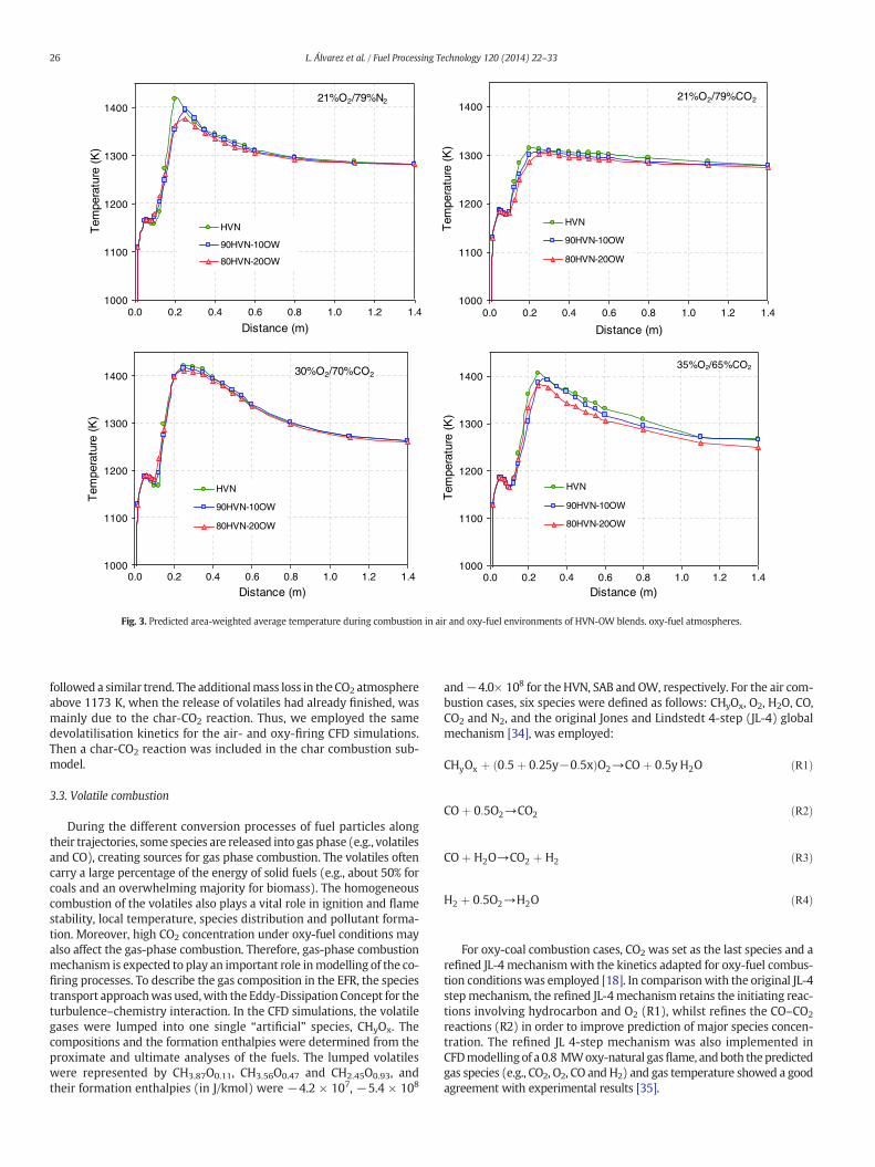
Fig. 3. Predicted area-weighted average temperature during combustion in air and oxy-fuel environments of HVN-OW blends. oxy-fuel atmospheres.
26 L. Álvarez et al. / Fuel Processing Technology 120 (2014) 22–33
followed a similar trend. The additionalmass loss in theCO2 atmosphereabove 1173 K, when the release of volatiles had already finished, wasmainly due to the char-CO2 reaction. Thus, we employed the samedevolatilisation kinetics for the air- and oxy-firing CFD simulations.Then a char-CO2 reaction was included in the char combustion sub-model.
3.3. Volatile combustion
During the different conversion processes of fuel particles alongtheir trajectories, some species are released into gas phase (e.g., volatilesand CO), creating sources for gas phase combustion. The volatiles oftencarry a large percentage of the energy of solid fuels (e.g., about 50% forcoals and an overwhelming majority for biomass). The homogeneouscombustion of the volatiles also plays a vital role in ignition and flamestability, local temperature, species distribution and pollutant forma-tion. Moreover, high CO2 concentration under oxy-fuel conditions mayalso affect the gas-phase combustion. Therefore, gas-phase combustionmechanism is expected to play an important role inmodelling of the co-firing processes. To describe the gas composition in the EFR, the speciestransport approachwas used,with the Eddy-Dissipation Concept for theturbulence–chemistry interaction. In the CFD simulations, the volatilegases were lumped into one single “artificial” species, CHyOx. Thecompositions and the formation enthalpies were determined from theproximate and ultimate analyses of the fuels. The lumped volatileswere represented by CH3.87O0.11, CH3.56O0.47 and CH2.45O0.93, andtheir formation enthalpies (in J/kmol) were −4.2 × 10⁷, −5.4 × 10⁸
and−4.0× 10⁸ for the HVN, SAB and OW, respectively. For the air com-bustion cases, six species were defined as follows: CHyOx, O2, H2O, CO,CO2 and N2, and the original Jones and Lindstedt 4-step (JL-4) globalmechanism [34], was employed:
CHyOx þ ð0:5 þ 0:25y−0:5xÞO2→CO þ 0:5y H2O ðR1Þ
CO þ 0:5O2→CO2 ðR2Þ
CO þ H2O→CO2 þ H2 ðR3Þ
H2 þ 0:5O2→H2O ðR4Þ
For oxy-coal combustion cases, CO2 was set as the last species and arefined JL-4 mechanismwith the kinetics adapted for oxy-fuel combus-tion conditionswas employed [18]. In comparisonwith the original JL-4
stepmechanism, the refined JL-4mechanism retains the initiating reac-tions involving hydrocarbon and O2 (R1), whilst refines the CO–CO2reactions (R2) in order to improve prediction of major species concen-tration. The refined JL 4-step mechanism was also implemented inCFDmodelling of a 0.8 MWoxy-natural gasflame, andboth thepredictedgas species (e.g., CO2, O2, CO andH2) and gas temperature showed a goodagreement with experimental results [35].

Tem
pera
ture
(K
)
90SABSAB
Tem
pera
ture
(K
)
Tem
pera
ture
(K
)T
empe
ratu
re (
K)
80SAB 90SABSAB 80SAB
90SABSAB 80SAB 90SABSAB 80SAB
c)
a)
d)
b)
Fig. 4. Predicted temperature (K) in the EFRwhen co-firing SAB-OW in (a) 21%O2/79%N2, (b) 21%O2/79%CO2, (c) 30%O2/70%CO2 and (d) 35%O2/65%CO2. Length scale is 140 cm and 40 cmrespectively.
27L. Álvarez et al. / Fuel Processing Technology 120 (2014) 22–33
3.4. Char oxidation
For char oxidation, the multiple-surface-reaction char model wasemployed. At the temperatures of this EFR, CO is the dominant productin char oxidation C(s) + O2 → CO/CO2. Therefore, only the reaction(R5) was considered in char oxidation modelling. The CO formed in(R5) will undergo further reactions as shown in (R2) and (R3).
CðsÞ þ 0:5O2→CO ðR5ÞGlobal kinetics for the coal char combustion rates, represented as
Arrhenius expressions, were based on the activation energies andpre-exponential factors as determined by Gil et al. [36], as summarisedin Table 4.
At the temperature of this work (1273 K), combustion takes place inRegime II (kinetics and diffusion control). The effectiveness factor (η),defined as the ratio of the diffusion rate to the maximum diffusionrate, is a measure of the extent of penetration of the oxidant into thechar matrix. It was determined via the Thiele modulus as calculatedbyGharebaghi et al. [19] for a large number of defined oxy-fuel combus-tion cases. At elevated temperature and CO2 concentrations, char CO2
gasification could become more important particularly in the laterstages of the oxy-fuel combustion process. As long as the oxygen
concentration is higher, the contribution of the gasification reactionswill be much smaller than that of the oxidation reactions. Nevertheless,char gasification was also considered in the modelling study (R6), andits kinetic data was obtained from the literature [37,38]. In the currentsimulations, the effect of CO2 gasification reaction accounted for lessthan 1% on coal burnout.
CðsÞ þ CO2→2CO ðR6Þ
The combustion of biomass char is more complicated since it isaffected not only by the composition of the biomass, but also by theshape and size of the particle. Different approaches can be found inliterature, such as the diffusion-limited surface reaction rate modelmodified by the aspect ratio-dependent enhancement factor [13], orSmith's intrinsic model modified by a constant enhancement of 4 torepresent the higher burning rate of the biomass char particles [14]. Inthis study, both the raw biomass particles and the resulting biomasschar particles are near-spherical and the carbon content in the biomassis relatively low (about 20%). Therefore, no special enhancement factorwas used for biomass char oxidation. The kinetics for biomass charcombustion were obtained from [39,40].

21%O2/79%N2
1000
1100
1200
1300
1400
0.0 0.2 0.4 0.6 0.8 1.0 1.2 1.4
Distance (m)
Te
mp
era
ture
(K
)
SAB
90SAB-10OW
80SAB-20OW
21%O2/79%CO2
1000
1100
1200
1300
1400
0.0 0.2 0.4 0.6 0.8 1.0 1.2 1.4
Distance (m)
Te
mp
era
ture
(K
)
SAB
90SAB-10OW
80SAB-20OW
30%O2/70%CO2
1000
1100
1200
1300
1400
0.0 0.2 0.4 0.6 0.8 1.0 1.2 1.4
Distance (m)
Te
mp
era
ture
(K
)
SAB
90SAB-10OW
80SAB-20OW
35%O2/65%CO2
1000
1100
1200
1300
1400
0.0 0.2 0.4 0.6 0.8 1.0 1.2 1.4
Distance (m)
Te
mpe
ratu
re (
K)
SAB
90SAB-10OW
80SAB-20OW
Fig. 5. Predicted area-weighted average temperature during combustion in air and oxy-fuel environments of blends SAB-OW.
28 L. Álvarez et al. / Fuel Processing Technology 120 (2014) 22–33
3.5. Heat transfer model
In a pulverised fuel chamber, radiation is often the dominant modeof heat transfer. The most widely used model for gaseous radiativeproperties is the Weighted-Sum-of-Gray-Gases-Model (WSGGM),which represents a reasonable compromise between an oversimplifiedgray gas model and a comprehensive approach addressing high-resolution dependency of radiative properties and intensity uponwave-length. The model parameters derived by Smith et al. [41] for severalpartial pressures of CO2 and H2O vapour in typical air–fuel combustionare often used in combustion modelling. The original Smith et al.WSGGM is a one-clear-gas, three-gray-gas model. However, it is oftenimplemented in a further simplified way in which constant propertiesover the entire spectrum are assumed and only one single radiativetransfer equation per direction is solved for the entire spectrum,e.g., as implemented in Ansys Fluent.
Recently, someefforts aremade to refine and extend theWSGGM foroxy-fuel conditions. For instance, Yin et al. [16] used the exponentialwide band model, the same reference model as Smith et al. used intheir derivation, to generate a much broader emissivity database cover-ing also oxy-fuel conditions, and derived new WSGGM parameters byusing an improved data-fitting technique. The refined WSGGM alsoincluded more representative conditions to better account for the vari-ations in H2O/CO2 molar ratio in an oxy-fuel flame. The importance ofnongray-gas effects in modelling of large-scale oxy-fuel combustionwas also well demonstrated and nongray calculation of an appropriateWSGGM was highly recommended for combustion modelling [42].
In this study, the Discrete Ordinates model was employed forradiative transfer equation for both oxy- and air–fuel combustion.
In the oxy-fuel combustion modelling, non-gray calculation of theoxy-fuel WSGGM [16] was performed to evaluate the gaseous radiativeproperties. Compared to the conventional gray calculation of the Smithet al. air-fuel WSGGM, it does not remarkably compromise computa-tional efficiency while has inherent potentials to improve simulationsof oxy-fuel combustion processes, in which the degree of improvementdepends on the scale or the beam length of the furnace under study.For the simulations in the oxy-fuel atmosphere with the highest CO2
content (i.e., 21% O2/79% CO2) non-gray oxyfuel WSGGM and gray air–fuel WSGGM calculations were both performed. Since the reactorunder simulation is small (in terms of beam length), using new gaseousradiation properties led to little differences in CFD predictions, just asexpected. The deviations in temperature profiles for both cases wereless than ±1%.
3.6. NOx formation
NOX simulations were carried out as a post-processor. For air-firingconditions, both the thermal and fuel-NO were considered. For oxy-firing conditions, fuel-NO formationwas considered to be the dominantmechanism.
Fuel-NO is formed from the oxidation of molecular nitrogen organi-cally bound within the fuel mass. Fuel-bound nitrogen can either bereleased during devolatilisation (referred to as volatile-N), or canremain in the char (referred to as char-N). The partitioning of nitrogenbetween char and volatiles, summarised in Table 5, was determined ex-perimentally. Usually, it is assumed that HCN andNH3 are the dominantspecies formed as nitrogen-bearing intermediates at rates that dependboth on the local combustion conditions and on the nitrogen content

Bur
ning
rat
e (k
g/s)
Bur
ning
rat
e (k
g/s)
Bur
ning
rat
e (k
g/s)
Bur
ning
rat
e (k
g/s)
HVN 90HVN 80HVNHVN 80HVN90HVN
HVN 90HVN 80HVNHVN 80HVN90HVN
c)
b)a)
d)
Fig. 6. Predicted burning rate (kg/s) in the EFR when co-firing HVN-OW in (a) 21%O2/79%N2, (b) 21%O2/79%CO2, (c) 30%O2/70%CO2 and (d) 35%O2/65%CO2. Length scale is 140 cm and40 cm respectively.
29L. Álvarez et al. / Fuel Processing Technology 120 (2014) 22–33
of each specific fuel [43]. For biomass, it was assumed that NH3 was theonly nitrogen intermediate, whereas for coals the HCN and NH3 releaserates were based on the predictionmade by Álvarez et al. [44]. HCN andNH3 are competitively oxidised and reduced to formNO and N2, respec-tively, according to DeSoete's scheme:
HCNþ O2→NOþ… R ¼ 1 � 1010 � XHCN � XO2 � e−280451:95=RT 1=sð Þ ðR7Þ
HCNþ NO→N2 þ… R ¼ 3 � 1012 � XHCN � XNO � e−251151=RT 1=sð Þ ðR8Þ
NH3 þ O2→NOþ… R ¼ 4 � 106 � XNH3 � XO2 � e−133947:2=RT 1=sð Þ ðR9Þ
NH3 þ NO→N2 þ… R ¼ 1:8 � 108 � XNH3 � XNO � e−113017:95=RT 1=sð ÞðR10Þ
where RHCN,RNH3, X, Ru and T represent the conversion rate of HCN (1/s),
conversion rate of NH3 (1/s), molar fraction, universal gas constant(=8.315 J/(mol K)), and gas temperature (K), respectively.
The fuel nitrogen partitioning between the char and the volatiles canbe estimated by pyrolysis network codes, obtained from the literatureor determined experimentally. In this work, the partitioning of thefuel-bound nitrogen between the char and volatileswas determined ex-perimentally during the devolatilisation of the samples in N2 and CO2 inthe EFR at 1273 K. From the analysis of N content of the parent samples
and that of the chars, and using the ash as a tracer method, the char andchar-N yields can be determined and, thus, the nitrogen content in charand volatiles was estimated. Char-Nwas assumed to be heterogeneouslyoxidised to NO, for both coal and biomass char particles, with anassumed conversion factor of 20% (mass/mass%) [45].
4. Results and discussion
4.1. Overall combustion behaviour
In biomass combustion, the higher volatile yields produce more off-gas, which causes the off-gas to proceed to a much larger volume in thereactor beforemixingwith the oxidizer and completing gas-phase com-bustion. Therefore, biomass flame tends to occupy a much larger flamevolume (i.e., the regions with low O2 and high CO concentration) thancoal flame [27,28]. The large flame volume effectively evens out thetemperature distribution and lowers the peak temperatures, whichfavours a lower pollutant formation (e.g., lower NOx emission) and areduced deposition potential. The comparatively low (relative to thepeak temperature in a coal flame, still high enough) and uniformtemperature distribution in a much larger flame volume also favours ahigher burnout. Both improved burnout and decreased NOx emissionswere observed in this study when the coals were co-fired with biomassunder different operating mode.
SAB 80SAB
d)
Bur
ning
rat
e (k
g/s)
90SAB80SABSAB
Bur
ning
rat
e (k
g/s)
c)
90SAB
80SABSAB
Bur
ning
rat
e (k
g/s)
a)
90SAB
Bur
ning
rat
e (k
g/s)
80SABSAB
b)
90SAB
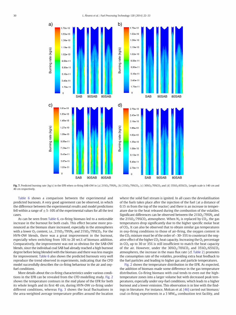
Fig. 7. Predicted burning rate (kg/s) in the EFR when co-firing SAB-OW in (a) 21%O2/79%N2, (b) 21%O2/79%CO2, (c) 30%O2/70%CO2 and (d) 35%O2/65%CO2. Length scale is 140 cm and40 cm respectively.
30 L. Álvarez et al. / Fuel Processing Technology 120 (2014) 22–33
Table 6 shows a comparison between the experimental andpredicted burnouts. A very good agreement can be observed, in whichthe difference between the experimental results and model predictionsfell within a range of ±5–10% of the experimental values for all the testcases.
As can be seen from Table 6, co-firing biomass led to a noticeableincrease in the burnout for both coals. This effect became more pro-nounced as the biomass share increased, especially in the atmosphereswith a lower O2 content, i.e., 21%O2/79%N2 and 21%O2/79%CO2. For theHVN-OW blends, there was a great improvement in the burnout,especially when switching from 10% to 20 wt.% of biomass addition.Comparatively, the improvement was not so obvious for the SAB-OWblends, since the individual coal SAB had already reached a high burnoutdegree before being blendedwith the biomass and therewas lessmarginfor improvement. Table 6 also shows the predicted burnouts very wellreproduce the trend observed in experiments, indicating that the CFDmodel successfully describes the co-firing behaviour in the air and oxy-fuel conditions.
More details about the co-firing characteristics under various condi-tions in the EFR can be revealed from the CFD modelling study. Fig. 2shows the temperature contours in the mid plane of the EFR for bothits whole length and its first 40 cm, during HVN-OW co-firing underdifferent conditions, whereas Fig. 3 shows the local fluctuations inthe area-weighted average temperature profiles around the location
where the solid fuel stream is ignited. In all cases the devolatilisationof the fuels takes place after the injection of the fuel (at a distance of0.15 m from the top of the reactor) and there is an increase in temper-ature due to the heat released during the combustion of the volatiles.Significant differences can be observed between the 21%O2/79%N2 andthe 21%O2/79%CO2 atmosphere. When N2 is replaced by CO2, the gastemperatures drop significantly due to the higher specific molar heatof CO2. It can also be observed that to obtain similar gas temperaturesin oxy-firing conditions to those of air-firing, the oxygen content inthe CO2mixturemust be of the order of ~30–35% to counteract the neg-ative effect of the higher CO2 heat capacity. Increasing theO2 percentagein CO2 up to 30 or 35% is still insufficient to match the heat capacityof the air. However, under the 30%O2/70%CO2 and 35%O2/65%CO2
atmospheres, the increase in the mass flux rate (cf. Table 2) promotesthe consumption rate of the volatiles, providing extra heat feedback tothe fuel particles and leading to higher gas and particle temperatures.
Fig. 2 shows the temperature distribution in the EFR. As expected,the addition of biomass made some difference in the gas temperaturedistribution. Co-firing biomass with coal tends to even out the high-temperature zones into a larger volume but with decreased peak tem-peratures, especially under oxy-fuel conditions, which leads to a higherburnout and a lower emission. This observation is in line with the find-ings in literature. For instance, Molcan et al. [46] carried out biomass/coal co-firing experiments in a 3 MWth combustion test facility, and
80HVN90HVNHVN
NO
(pp
m)
d)
HVN
NO
(pp
m)
a)
80HVN HVN
NO
(pp
m)
b)
90HVN 80HVN
HVN
NO
(pp
m)
c)
90HVN 80HVN
90HVN
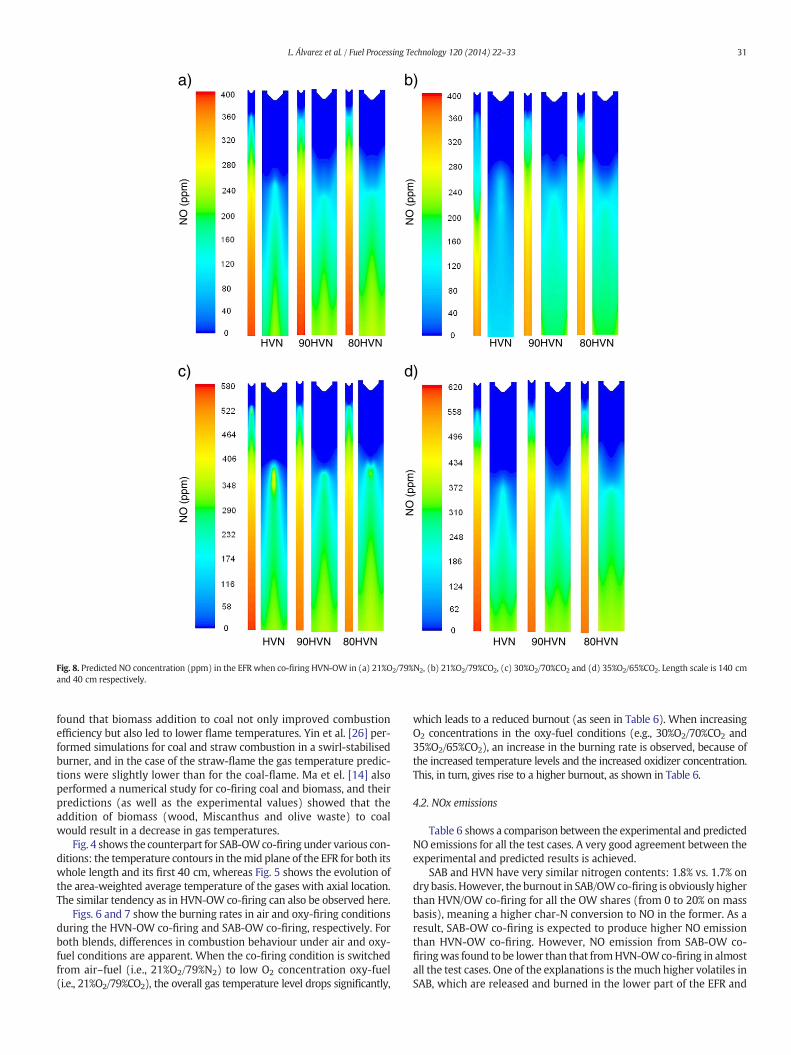
Fig. 8. Predicted NO concentration (ppm) in the EFR when co-firing HVN-OW in (a) 21%O2/79%N2, (b) 21%O2/79%CO2, (c) 30%O2/70%CO2 and (d) 35%O2/65%CO2. Length scale is 140 cmand 40 cm respectively.
31L. Álvarez et al. / Fuel Processing Technology 120 (2014) 22–33
found that biomass addition to coal not only improved combustionefficiency but also led to lower flame temperatures. Yin et al. [26] per-formed simulations for coal and straw combustion in a swirl-stabilisedburner, and in the case of the straw-flame the gas temperature predic-tions were slightly lower than for the coal-flame. Ma et el. [14] alsoperformed a numerical study for co-firing coal and biomass, and theirpredictions (as well as the experimental values) showed that theaddition of biomass (wood, Miscanthus and olive waste) to coalwould result in a decrease in gas temperatures.
Fig. 4 shows the counterpart for SAB-OWco-firing under various con-ditions: the temperature contours in themid plane of the EFR for both itswhole length and its first 40 cm, whereas Fig. 5 shows the evolution ofthe area-weighted average temperature of the gases with axial location.The similar tendency as in HVN-OW co-firing can also be observed here.
Figs. 6 and 7 show the burning rates in air and oxy-firing conditionsduring the HVN-OW co-firing and SAB-OW co-firing, respectively. Forboth blends, differences in combustion behaviour under air and oxy-fuel conditions are apparent. When the co-firing condition is switchedfrom air–fuel (i.e., 21%O2/79%N2) to low O2 concentration oxy-fuel(i.e., 21%O2/79%CO2), the overall gas temperature level drops significantly,
which leads to a reduced burnout (as seen in Table 6). When increasingO2 concentrations in the oxy-fuel conditions (e.g., 30%O2/70%CO2 and35%O2/65%CO2), an increase in the burning rate is observed, because ofthe increased temperature levels and the increased oxidizer concentration.This, in turn, gives rise to a higher burnout, as shown in Table 6.
4.2. NOx emissions
Table 6 shows a comparison between the experimental and predictedNO emissions for all the test cases. A very good agreement between theexperimental and predicted results is achieved.
SAB and HVN have very similar nitrogen contents: 1.8% vs. 1.7% ondry basis. However, the burnout in SAB/OWco-firing is obviously higherthan HVN/OW co-firing for all the OW shares (from 0 to 20% on massbasis), meaning a higher char-N conversion to NO in the former. As aresult, SAB-OW co-firing is expected to produce higher NO emissionthan HVN-OW co-firing. However, NO emission from SAB-OW co-firingwas found to be lower than that fromHVN-OWco-firing in almostall the test cases. One of the explanations is themuch higher volatiles inSAB, which are released and burned in the lower part of the EFR and
NO
(pp
m)
SAB
NO
(pp
m)
d)
90SAB 80SAB
SAB
NO
(pp
m)
b)
90SAB 80SAB
a)
SAB 90SAB 80SAB
80SABSAB
NO
(pp
m)
c)
90SAB
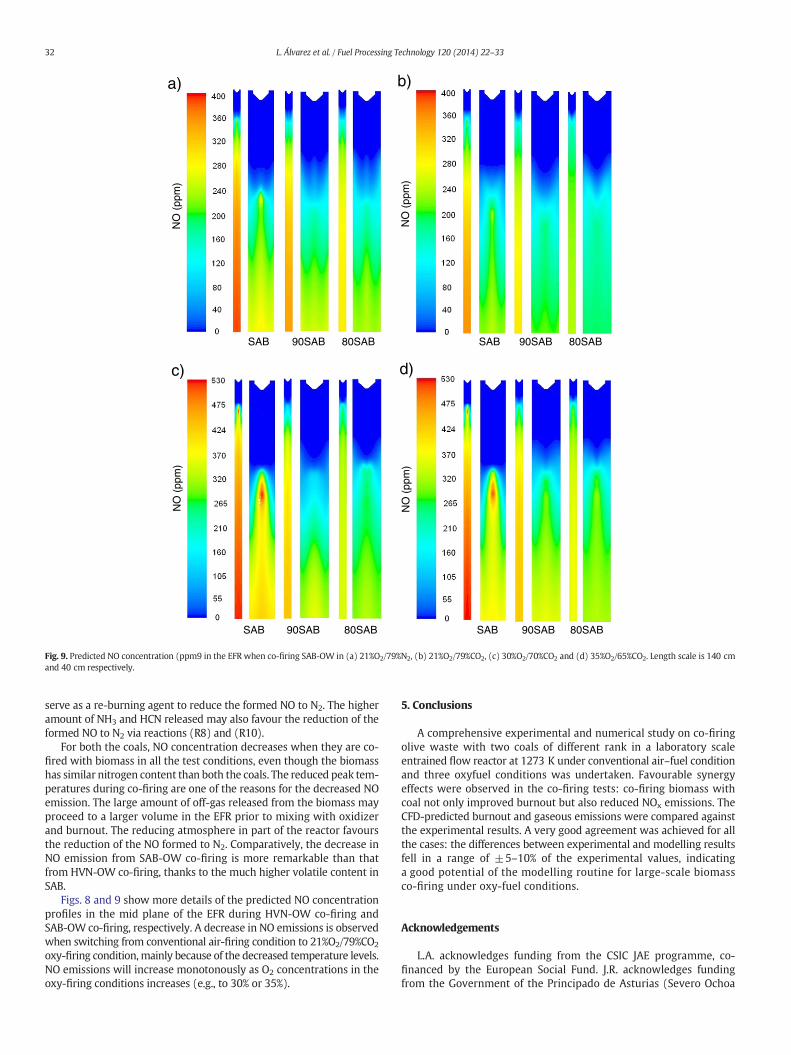
Fig. 9. Predicted NO concentration (ppm9 in the EFR when co-firing SAB-OW in (a) 21%O2/79%N2, (b) 21%O2/79%CO2, (c) 30%O2/70%CO2 and (d) 35%O2/65%CO2. Length scale is 140 cmand 40 cm respectively.
32 L. Álvarez et al. / Fuel Processing Technology 120 (2014) 22–33
serve as a re-burning agent to reduce the formed NO to N2. The higheramount of NH3 and HCN released may also favour the reduction of theformed NO to N2 via reactions (R8) and (R10).
For both the coals, NO concentration decreases when they are co-fired with biomass in all the test conditions, even though the biomasshas similar nitrogen content than both the coals. The reduced peak tem-peratures during co-firing are one of the reasons for the decreased NOemission. The large amount of off-gas released from the biomass mayproceed to a larger volume in the EFR prior to mixing with oxidizerand burnout. The reducing atmosphere in part of the reactor favoursthe reduction of the NO formed to N2. Comparatively, the decrease inNO emission from SAB-OW co-firing is more remarkable than thatfrom HVN-OW co-firing, thanks to the much higher volatile content inSAB.
Figs. 8 and 9 show more details of the predicted NO concentrationprofiles in the mid plane of the EFR during HVN-OW co-firing andSAB-OW co-firing, respectively. A decrease in NO emissions is observedwhen switching from conventional air-firing condition to 21%O2/79%CO2
oxy-firing condition, mainly because of the decreased temperature levels.NO emissions will increase monotonously as O2 concentrations in theoxy-firing conditions increases (e.g., to 30% or 35%).
5. Conclusions
A comprehensive experimental and numerical study on co-firingolive waste with two coals of different rank in a laboratory scaleentrained flow reactor at 1273 K under conventional air–fuel conditionand three oxyfuel conditions was undertaken. Favourable synergyeffects were observed in the co-firing tests: co-firing biomass withcoal not only improved burnout but also reduced NOx emissions. TheCFD-predicted burnout and gaseous emissions were compared againstthe experimental results. A very good agreement was achieved for allthe cases: the differences between experimental and modelling resultsfell in a range of ±5–10% of the experimental values, indicatinga good potential of the modelling routine for large-scale biomassco-firing under oxy-fuel conditions.
Acknowledgements
L.A. acknowledges funding from the CSIC JAE programme, co-financed by the European Social Fund. J.R. acknowledges fundingfrom the Government of the Principado de Asturias (Severo Ochoa
33L. Álvarez et al. / Fuel Processing Technology 120 (2014) 22–33
programme). Financial support from the CSIC (Project PIE 201080E09) isgratefully acknowledged.
References
[1] T. Wall, Y. Liu, C. Spero, L. Elliott, S. Khare, R. Rathnam, F. Zeenathal, B. Moghtaderi, B.Buhre, C. Seng, R. Gupta, T. Yamada, K. Makino, J. Yu, An overview on oxyfuelcoal combustion—state of the art research and technology development, ChemicalEngineering Research and Design 87 (2009) 1003–1016.
[2] A. Williams, M. Pourkashanian, J.M. Jones, Combustion of pulverised coal and bio-mass, Progress in Energy and Combustion Science 27 (2001) 587–610.
[3] A. Demirbas, Combustion characteristics of different biomass fuels, Progress inEnergy and Combustion Science 30 (2004) 219–230.
[4] T.F. Wall, R. Stanger, S. Santos, Demonstrations of coal-fired oxy-fuel technology forcarbon capture and storage and issues with commercial deployment, InternationalJournal of Greenhouse Gases Control 5S (2011) S5–S15.
[5] IEA Bioenergy Task 32: Biomass combustion and co-firing, database of biomassco-firing, http://www.ieabcc.nl/(last visit November 2013).
[6] S. Van Loo, J. Koppenjan, The Handbook of Biomass Combustion and Co-firing, 2008.[7] J. Andersson, R. Johansson, S. Hjärtstam, F. Johnsson, B. Leckner, Radiation intensity
of lignite oxy-fuel flame, Experimental Thermal Fluid Science 33 (2008) 67–76.[8] L. Chen, S.X. Yong, A.F. Ghoniem, Oxy-fuel combustion of pulverized coal. Character-
ization, fundamentals, stabilization and CFD modelling, Progress in Energy andCombustion Science 38 (2012) 156–214.
[9] S. Black, J. Szuhánszki, A. Pranzitelli, L. Ma, P.J. Stanger, D.B. Ingham, M. Pourkashanian,Effects of firing coal and biomass under oxy-fuel conditions in a power plant boilerusing CFD modelling, Fuel 113 (2013) 780–786.
[10] J. Szuhánszki, S. Black, A. Pranzitelli, L. Ma, P.J. Stanger, D.B. Ingham, M. Pourkashanian,Evaluation of the performance of a power plant boiler firing coal, biomass and a blendunder oxy-fuel conditions as a CO2 capture technology, Energy Procedia 37 (2013)1413–1422.
[11] J.P. Smart, R. Patel, G.S. Riley, Oxy-fuel combustion of coal and biomass, the effect onradiative and convective heat transfer and burnout, Combustion and Flame 157(2010) 2230–2240.
[12] J. Riaza, M.V. Gil, L. Álvarez, C. Pevida, J.J. Pis, F. Rubiera, Oxy-fuel combustion of coaland biomass blends, Energy 41 (2012) 429–435.
[13] C. Yin, L. Rosendahl, S.K. Kær, T.J. Condra, Use of numericalmodeling in design for co-firingbiomass in wall-fired burners, Chemical Engineering Science 59 (2004) 3281–3292.
[14] L. Ma, M. Gharebaghi, R. Porter, M. Pourkashanian, J.M. Jones, A.Williams, Modellingmethods for co-fired pulverised fuel furnaces, Fuel 88 (2009) 2448–2454.
[15] M. Agraniotis, N. Nikolopoulos, A. Nikolopoulos, P. Grammelis, E. Kakaras, Numericalinvestigation of Solid Recovered Fuels' co-firing with brown coal in large scaleboilers—evaluation of different co-combustion modes, Fuel 89 (2010) 3693–3709.
[16] C. Yin, L.C.R. Johansen, L.A. Rosendahl, S.K. Kær, Newweighted sum of gray gases modelapplicable to computational fluid dynamics (CFD)modeling of oxy-fuel combustion:derivation, validation, and implementation, Energy and Fuels 24 (2010) 6275–6282.
[17] R. Johansson, B. Leckner, K. Andersson, F. Johnsson, Account for variations in the H2Oto CO2 molar ratio when modelling gaseous radiative heat transfer with theweighted-sum-of-grey-gases model, Combustion and Flame 158 (2011) 893–901.
[18] J. Andersen, C.L. Rasmussen, T. Giselsson, P. Glarborg, Global combustionmechanisms for use in CFD modeling under oxy-fuel conditions, Energy and Fuels23 (2009) 1379–1389.
[19] M. Gharebaghi, R.M. Irons, M. Pourkashanian, A. Williams, An investigation into acarbon burnout kinetic model for oxy-coal combustion, Fuel Processing Technology92 (2011) 2455–2464.
[20] M.L. Holtmeyer, B.M. Kumfer, R.L. Axelbaum, Effects of biomass particle size duringcofiring under air-fired and oxyfuel conditions, Applied Energy 93 (2012) 606–613.
[21] J. Riaza, L. Álvarez, M.V. Gil, C. Pevida, F. Rubiera, J.J. Pis, Effect of oxy-fuel combustionwith steam addition on coal ignition and burnout in an entrained flow reactor,Energy 36 (2011) 5314–5319.
[22] Ansys Fluent, Ansys Inc., USA, 2011.[23] L. Álvarez, M. Gharebaghi, M. Pourkashanian, A. Williams, J. Riaza, C. Pevida, J.J.
Pis, F. Rubiera, CFD modelling of oxy-coal combustion in an entrained flowreactor, Fuel Processing Technology 92 (2011) 1489–1497.
[24] W.P. Jones, B.E. Launder, The prediction of laminarization with a two-equationmodel of turbulence, International Journal of Heat and Mass Transfer 15 (1972)301–314.
[25] S.A. Orszag, V. Yakhout, W.S. Flannery, F. Boysan, D. Choudhury, J. Maruzewski, B. Patel,Renormalization groupmodelling and turbulence simulations, International Conferenceon Near-Wall Turbulent Flows, Editorial: Elsevier Science Ltd., Tempe, Arizona, 1993.
[26] C. Yin, S.K. Kær, L. Rosendahl, S.L. Hvid, Co-firing strawwith coal in a swirl-stabilizeddual-feed burner: modelling and experimental validation, Bioresource Technology101 (2010) 4169–4178.
[27] C. Yin, L. Rossendahl, S.K. Kær, Towards a better understanding of biomasssuspension co-firing impacts via investigating a coal flame and a biomass flamein a swirl-stabilized burner flow reactor under same conditions, Fuel ProcessingTechnology 98 (2012) 65–73.
[28] S.R. Gubba, L. Ma, M. Pourkashanian, A. Williams, Influence of particle shape andinternal thermal gradients of biomass particles on pulverised coal/biomassco-fired flames, Fuel Processing Technology 92 (2011) 2185–2195.
[29] Y.B. Yang, V.N. Sharifi, J. Swithenbank, L. Ma, L. Darwell, J.M. Jones, M. Pourkashanian,A. Williams, Combustion of a single particle of biomass, Energy and Fuels 22 (2008)306–316.
[30] P.R. Solomon, T.H. Fletcher, Impact of coal pyrolysis on combustion, Symposium(International) on Combustion 15 (1994) 463–474.
[31] C. Di Blasi, Modeling chemistry and physical processes of wood and biomasspyrolysis, Progress in Energy and Combustion Science 34 (2008) 47–90.
[32] R.K. Rathman, L.K. Elliot, T.F. Wall, Y. Liu, B. Moghtaderi, Differences in reactivity ofpulverised coal in air (O2/N2) and oxy-fuel conditions (O2/CO2), Fuel ProcessingTechnology 90 (2009) 797–802.
[33] L. Álvarez, C. Yin, J. Riaza, C. Pevida, J.J. Pis, F. Rubiera, Oxy-coal combustion inan entrained flow reactor: application of specific char and volatile combustionand radiation models for oxy-firing conditions, Energy 62 (2013) 255–268.
[34] W.P. Jones, R.P. Lindstedt, Global reaction schemes for hydrocarbon combustion,Combustion and Flame 73 (1988) 233–249.
[35] C. Yin, L.A. Rosendahl, S.K. Kær, Chemistry and radiation in oxy-fuel combustion.A computational fluid dynamics modelling study, Fuel 90 (2011) 2519–2529.
[36] M.V. Gil, J. Riaza, L. Álvarez, C. Pevida, J.J. Pis, F. Rubiera, Oxy-fuel combustion kineticsand morphology of coal chars obtained in N2 and CO2 atmospheres in an entrainedflow reactor, Applied Energy 91 (2012) 67–74.
[37] G.-S. Liu, S. Niksa, Coal conversion submodels for design applications at elevatedpressures. Part II. Char gasification, Progress in Energy and Combustion Science 30(2004) 679–717.
[38] J. Fermoso, C. Stevanov, B. Moghtaderi, A. Arias, C. Pevida, M.G. Plaza, F. Rubiera,J.J. Pis, High-pressure gasification reactivity of biomass chars produced atdifferent temperatures, Journal of Analytical and Applied Pyrolysis 85 (2009)287–293.
[39] J.M. Encinar, F.J. Beltrán, A. Ramiro, J.F. González, A. Bernalte, Combustion kinetics ofagricultural wastes, Journal of Chemical Technology and Biotechnology 64 (1995)181–187.
[40] M.V. Gil, J. Riaza, L. Álvarez, C. Pevida, J.J. Pis, F. Rubiera, Kinetic models for theoxy-fuel combustion of coal and coal/biomass blends chars obtained in N2 andCO2 atmospheres, Energy 48 (2012) 510–518.
[41] T.F. Smith, Z.F. Shen, J.N. Friedman, Evaluation of coefficients for the weighted sumof gray gases mode, Journal of Heat Transfer-Transmission ASME 104 (1982)602–608.
[42] C. Yin, Nongray-gas effects in modeling of large scale oxy-fuel combustionprocesses, Energy and Fuels 26 (2012) 3349–3356.
[43] P. Glarborg, A.D. Jensen, J.E. Johnsson, Fuel nitrogen conversion in solid fuel firedsystems, Progress in Energy and Combustion Science 29 (2003) 89–113.
[44] L. Álvarez,M. Gharebaghi, J.M. Jones,M. Pourkashanian, A.Williams, J. Riaza, C. Pevida,J.J. Pis, F. Rubiera, CFD modelling of oxy-coal combustion: prediction of burnout,volatile and NO precursors release, Applied Energy 104 (2013) 653–665.
[45] J.M. Jones, M. Pourkashania, A. Williams, L. Rowlands, Q. Zhu, K.M. Thomas,Conversion of char nitrogen to NO during combustion, Journal of the Energy Institute77 (2004) 82–89.
[46] P. Molcan, G. Lu, T. Le Bris, Y. Yan, B. Taupin, S. Caillat, Characterisation of biomassand coal co-firing on a 3 MWth Combustion Test Facility using flame imaging andgas/ash sampling techniques, Fuel 88 (2009) 2328–2334.