Repair of Reinforced Concrete Elements using Fiber Reinforced Polymers
Upload
khangminh22Category
view
1download
0
The New Boundaries of Structural Concrete Session B - Controlled-performance Concrete
Keynote Lecture
First published in electronic proceedings: ASEC 11, KFUPM, Dharan, Saudi Arabia, Oct. 2009.
Evolution in Ferrocement and Thin Reinforced Cementitious Composites
Antoine E. Naaman 1
ABSTRACT: Following a brief history and definition, this paper focuses on the evolution, mostly over the past five decades, of ferrocement and thin cement based composites which are defined here as having less than about 50 mm in thickness. While conventional reinforcements for these products are steel wire meshes or metal lath, new forms of reinforcements have emerged over the years with the objective of improving performance and minimizing total product cost. They include: 1) fiber reinforced polymeric (FRP) reinforcements (or textiles or fabrics) which use high performance fibers such as carbon, Kevlar, Spectra and the like; 2) new steel unidirectional reinforcing mats made with extremely high strengths wires or strands; 3) 3D textiles or fabrics using polymeric fibers; 4) 3D textiles using combination of polymeric fibers and steel; and 5) reinforcement using shape-memory materials to induce self-stressing. Over the same period, the cement matrix has evolved enormously in its compressive strength and durability properties in the hardened state, and flow-ability and ease of casting in the fresh state leading to new qualifications such as high strength or high performance, ultra high strength or ultra high performance, self-consolidating and self-compacting, etc... Adding fibers or micro-fibers to the cement matrix of ferrocement adds another dimension to the resulting composite as well as potential for improved performance. After describing the limits so far achieved using the above materials, the paper presents the current challenges and sets the limits to exceed in future developments.
1 BACKGROUND - DEFINITION This paper focuses on the evolution of thin cement based composites which are defined here as products having less than about 50 mm in thickness. They are considered made of two main components, a cement-based matrix and reinforcement. The reinforcement may be made of different materials, and can be continuous, discontinuous or a hybrid combination of both. Related products include cement boards, corrugated cement sheets, pipes, cladding, shells, roofs, domes, water tanks, water channels, boats, housing elements and the like. The first such material was invented by Lambot, and patented in France as “ferciment” in 1855. It can be considered the first patent on reinforced concrete. Today, the commonly used English term is “ferrocement”. While ferrocement implies the use of cement and, at first, steel (fer in French) reinforcement, other reinforcements have been used or implied in thin cement products. In its state-of-the-art report on ferrocement the American Concrete Institute defines ferrocement as follows [ACI Committee 549, 1997]: “Ferrocement is a type of thin wall reinforced concrete commonly constructed of hydraulic cement mortar reinforced with closely spaced layers of continuous and relatively small size wire mesh. The mesh may be made of metallic or other suitable materials.” This last sentence opens the field to the use of polymeric reinforcements such high performance carbon, glass, or aramid fibers, and also encompasses some modern applications such as “Textile Reinforced Concrete”.
1 Emeritus Professor, Department of Civil and Environmental Engineering, University of Michigan, USA

In a classic book on the subject of ferrocement and laminated cementitious composites, Naaman [Naaman 2000] suggested to extend the definition by adding the two following sentences: “The fineness of the mortar matrix and its composition should be compatible with the mesh and armature systems it is meant to encapsulate. The matrix may contain discontinuous fibers.”. These two sentences were added to ascertain the compatibility of the matrix with the reinforcement in order to build a sound composite, and to accommodate the use of discontinuous fibers or microfibers to improve performance in hybrid composites when desirable. Figure 1 illustrates a typical cross section of ferrocement and should be distinguished from what is generally defined as reinforced Stucco as illustrated in Figure 2.
Figure 1 - Typical section of ferrocement: a) showing several layers of distributed welded wire mesh reinforcement; b) showing a combination of wire mesh and skeletal steel reinforcement in the form of a two-directional grid; and c) showing a combination
of wire mesh and reinforcing bars in only one direction.
Figure 2 - Typical section of Stucco where one layer of metal lath or wire mesh is used
in a matrix about 7/8 in (22 mm) thick (note differences from Figure 1).

Note in particular, that the reinforcement of ferrocement does not need to be made of same small size wire mesh only but can also comprise skeletal steel reinforcement of larger diameter such as illustrated in Figures 1b and 1c. Several simple rules are spelled out in [Ferrocement Model Code 2001, Naaman 2000] to help the designer in the appropriate selection and detailing of the skeletal reinforcement. Note that the skeletal reinforcement offers a transition for continuity between ferrocement and conventional reinforced concrete. While hundreds of references can be found addressing ferrocement and thin cement-based composites, only a select number of reports and books are cited at the end of this paper and should be considered a starting point [ACI Committee 549, 1988, ACI Committee 549, 1997, ACI Committee 549, 2004, Balaguru et al. 2002, Balaguru 1994, Daniel and Shah 1990, Djausal et al. 2009, Dubey 2004, Ferrocement Model Code 2001, Mansur and Ong 2001, Naaman 1998, Naaman 2008, Nedwell and Swamy 1994, Nimityongskul et al. 2006, Oberti and Shah 1981, Robles-Austriaco et al. 1985, Wainshtok Rivas 1991].
2 STRUCTURAL CONCRETE FAMILY Although ferrocement was the first type of reinforced concrete, it is considered today a member of the broad family of structural concrete materials, or using a different terminology, of cement-based composites. The family includes conventional reinforced concrete, prestressed concrete, partially prestressed concrete, fiber reinforced concrete and several of their combinations. The flow chart of Figure 3 places ferrocement and thin cement composites within this family and shows that each member can stand alone or in combination with other members. Applications where a combination of materials is used include for instance the case where ferrocement is used as a jacket to confine a reinforced concrete column, or the case where discontinuous fibers are used in the matrix (fiber reinforced mortar) to improve shear resistance when high performance fiber reinforced polymeric meshes are used.
CEMENT BASED COMPOSITES
REINFORCEMENT (steel; FRP; etc)
CEMENT MATRIX (concrete; mortar;
paste; slurry COMPOSITE
CONTINUOUS REINFORCEMENT
DISCONTINUOUS REINFORCEMENT
REINFORCED CONCRETE PRESTRESSED
CONCRETE
PARTIALLY PRESTRESSED
CONCRETE
FERROCEMENT (and other mesh reinforced thin
sheets)
FIBER REINFORCED
CONCRETE (premix; shotcrete;
slurry infiltrated)
STAND-ALONE APPLICATIONS OR IN COMBINATION
(continuous plus discontinuous reinforcements, hybrid composites)
Figure 3 - Cement-based composites and possible hybrid combinations [Naaman 2000].

3 TYPICAL APPLICATIONS Applications of ferrocement and laminated cement composites encompass possibly all constructed terrestrial structures on the smaller scale end of conventional reinforced concrete applications, and some in marine applications. These include housing, roofing, water tanks, boats and the like. Extensive background can be found in several symposia proceedings [Mansur and Ong 2001, Naaman 1998, Nedwell and Swamy 1994, Nimityongskul et al. 2006, Oberti and Shah 1981, Robles-Austriaco et al. 1985, Wainshtok Rivas 1991]. Some examples are shown in Figures 4 to 8 and will not be expanded upon. It suffices to say that all these structures utilize a ferrocement with skeletal steel reinforcement with a cross section similar to that shown in Figure 1. Note that a key feature of ferrocement is that it can adapt itself to broad levels of technologies ranging from self-help construction to advanced prefabrication, and, in some instances, it offers the best way to achieve a difficult shape cost-effectively such as in the case of Figure 4.
Figure 4 - Ferrocement roof of the Siger Landmark, South Lampung, Indonesia
(courtesy A. Djausal and Bayzoni, Lampung, Indonesia).
Figure 5 - Ferrocement house with water collection roofing system (courtesy Owen Waldshlaegel, New York, Intact Structures Inc.).

Figure 6 - Solar house with shell entirely made out of ferrocement
(courtesy M. Milinkovic, Belgrade, Serbia).
Figure 7 - Ferrocement pedestrian bridge
(courtesy P. Nedwell, UMIST, U.K, and Cass and Associates, Liverpool, UK).
Figure 8 - Ferrocement boat LARINDA – replica of 1770’s British coastal shoner
(courtesy Larry Mahan, Cape Cod, USA).
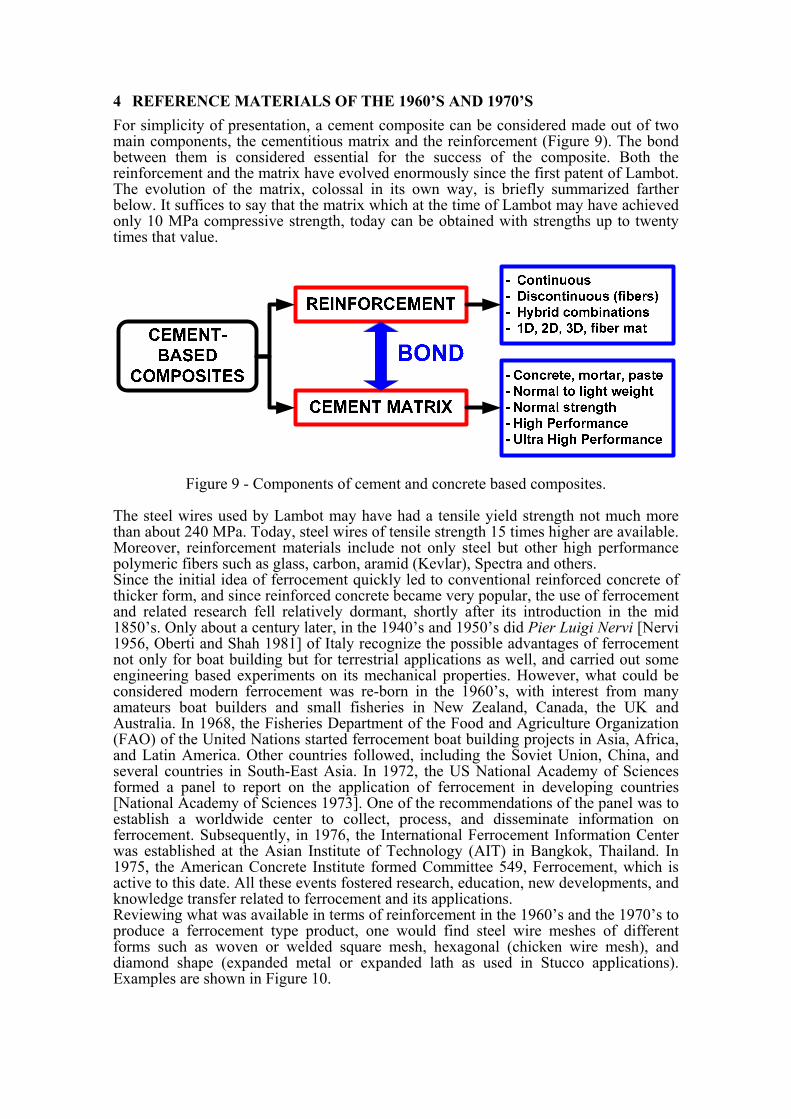
4 REFERENCE MATERIALS OF THE 1960’S AND 1970’S For simplicity of presentation, a cement composite can be considered made out of two main components, the cementitious matrix and the reinforcement (Figure 9). The bond between them is considered essential for the success of the composite. Both the reinforcement and the matrix have evolved enormously since the first patent of Lambot. The evolution of the matrix, colossal in its own way, is briefly summarized farther below. It suffices to say that the matrix which at the time of Lambot may have achieved only 10 MPa compressive strength, today can be obtained with strengths up to twenty times that value.
Figure 9 - Components of cement and concrete based composites.
The steel wires used by Lambot may have had a tensile yield strength not much more than about 240 MPa. Today, steel wires of tensile strength 15 times higher are available. Moreover, reinforcement materials include not only steel but other high performance polymeric fibers such as glass, carbon, aramid (Kevlar), Spectra and others. Since the initial idea of ferrocement quickly led to conventional reinforced concrete of thicker form, and since reinforced concrete became very popular, the use of ferrocement and related research fell relatively dormant, shortly after its introduction in the mid 1850’s. Only about a century later, in the 1940’s and 1950’s did Pier Luigi Nervi [Nervi 1956, Oberti and Shah 1981] of Italy recognize the possible advantages of ferrocement not only for boat building but for terrestrial applications as well, and carried out some engineering based experiments on its mechanical properties. However, what could be considered modern ferrocement was re-born in the 1960’s, with interest from many amateurs boat builders and small fisheries in New Zealand, Canada, the UK and Australia. In 1968, the Fisheries Department of the Food and Agriculture Organization (FAO) of the United Nations started ferrocement boat building projects in Asia, Africa, and Latin America. Other countries followed, including the Soviet Union, China, and several countries in South-East Asia. In 1972, the US National Academy of Sciences formed a panel to report on the application of ferrocement in developing countries [National Academy of Sciences 1973]. One of the recommendations of the panel was to establish a worldwide center to collect, process, and disseminate information on ferrocement. Subsequently, in 1976, the International Ferrocement Information Center was established at the Asian Institute of Technology (AIT) in Bangkok, Thailand. In 1975, the American Concrete Institute formed Committee 549, Ferrocement, which is active to this date. All these events fostered research, education, new developments, and knowledge transfer related to ferrocement and its applications. Reviewing what was available in terms of reinforcement in the 1960’s and the 1970’s to produce a ferrocement type product, one would find steel wire meshes of different forms such as woven or welded square mesh, hexagonal (chicken wire mesh), and diamond shape (expanded metal or expanded lath as used in Stucco applications). Examples are shown in Figure 10.

Other potential reinforcements were also available including meshes made of natural fibers (jute or sisal) and polymeric meshes (or textiles or fabrics) of various forms such as nylon, polypropylene, and polyester. These were considered of low performance because of their low elastic modulus in comparison to steel and concrete, and of their relatively low strength in comparison to advanced synthetic fibers such as glass and carbon. Moreover, composites using these polymeric meshes exhibited large creep effects under permanent loading. The yield strength of most available steel meshes ranged from about 240 MPa to about 600 MPa. While the elastic modulus of steel does not depend on its strength, that is, it remains almost constant at about 200 GPa, steel meshes may show an equivalent elastic modulus of lower value (than that of steel) because of the weaving or other manufacturing process. Thus a woven square steel wire mesh could be considered to act as if its equivalent elastic modulus is half to two thirds that of the steel from which it is made. A chicken wire mesh or aviary mesh would have an even lower equivalent modulus.
(a)
(b)
(c)
Figure 10 - Conventional steel meshes used in ferrocement: (a) Square woven or welded mesh. (b) Hexagonal or chicken wire mesh. (c) Expanded metal lath.
4.1 Bending Strength Limits with Conventional Steel Wire Mesh Reinforcements Going back to steel wire meshes on the market in the 1970’s, high yield strengths were not available and could not be obtained beyond a certain level. Indeed, in the production of woven wire meshes, the use of high strength wires leads to very “springy” wires that deform little during bending making the weaving process difficult to control. In the case of welded meshes, the welds at the joints weakened the wires and thus again led to reduced strength. Thus in the 1970’s most available wire meshes on the market showed tensile strengths less than 700 MPa, while tensile strengths close to 1000 MPa could be obtained only exceptionally, such as for research. The total volume fraction of steel mesh reinforcement in ferrocement generally ranges from about 2% to 8% [Naaman 2000]. Physically, it is difficult to put more than 8%. Typically such a value may be obtained by packing together as much layers of mesh as possible within the composite. Both the tensile and bending resistance of the composite increase with the volume fraction of reinforcement. In particular, analysis of the section suggests that the bending resistance increases almost proportionatly to the volume fraction of reinforcement (or the number of layers of mesh) primarily because the steel
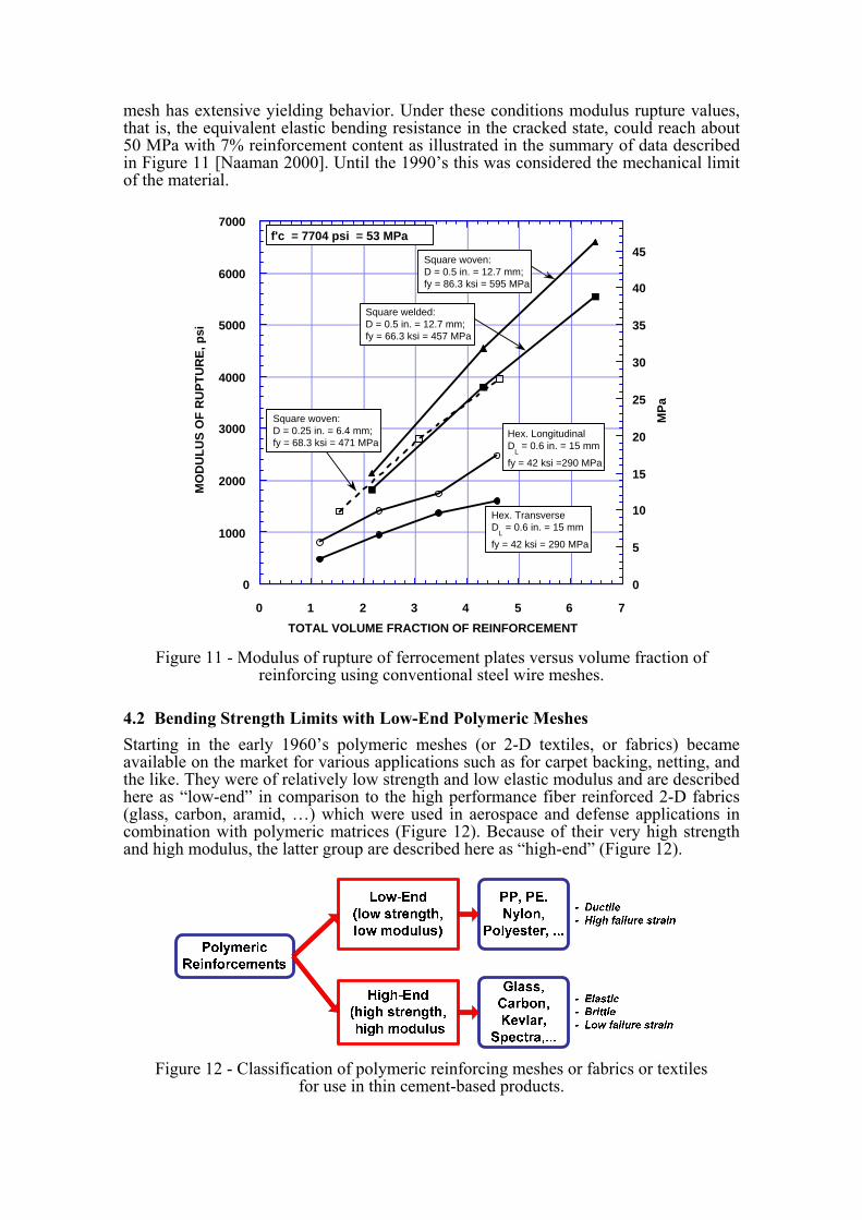
mesh has extensive yielding behavior. Under these conditions modulus rupture values, that is, the equivalent elastic bending resistance in the cracked state, could reach about 50 MPa with 7% reinforcement content as illustrated in the summary of data described in Figure 11 [Naaman 2000]. Until the 1990’s this was considered the mechanical limit of the material.
0
1000
2000
3000
4000
5000
6000
7000
0 1 2 3 4 5 6 7
0
5
10
15
20
25
30
35
40
45
MO
DU
LU
S O
F R
UP
TU
RE
, psi
TOTAL VOLUME FRACTION OF REINFORCEMENT
MP
a
Hex. TransverseD
L = 0.6 in. = 15 mm
fy = 42 ksi = 290 MPa
Hex. Longitudinal D
L = 0.6 in. = 15 mm
fy = 42 ksi =290 MPa
Square woven: D = 0.25 in. = 6.4 mm; fy = 68.3 ksi = 471 MPa
Square welded:D = 0.5 in. = 12.7 mm; fy = 66.3 ksi = 457 MPa
Square woven:D = 0.5 in. = 12.7 mm; fy = 86.3 ksi = 595 MPa
f'c = 7704 psi = 53 MPa
Figure 11 - Modulus of rupture of ferrocement plates versus volume fraction of
reinforcing using conventional steel wire meshes.
4.2 Bending Strength Limits with Low-End Polymeric Meshes Starting in the early 1960’s polymeric meshes (or 2-D textiles, or fabrics) became available on the market for various applications such as for carpet backing, netting, and the like. They were of relatively low strength and low elastic modulus and are described here as “low-end” in comparison to the high performance fiber reinforced 2-D fabrics (glass, carbon, aramid, …) which were used in aerospace and defense applications in combination with polymeric matrices (Figure 12). Because of their very high strength and high modulus, the latter group are described here as “high-end” (Figure 12).
Figure 12 - Classification of polymeric reinforcing meshes or fabrics or textiles
for use in thin cement-based products.

Several low-end type polymeric meshes were tried as reinforcement in thin cement based applications such as ferrocement. By and large, they led to a relatively poor performance in comparison to conventional steel wire meshes, namely: low elastic stiffness in the cracked state, large crack widths, large creep deformations, and low modulus of rupture. For all practical purposes, modulus of rupture (MOR) values in excess of 25 MPa were difficult to achieve even with high amount of reinforcement. Typical bending stress versus deflection response curves of cement plates reinforced, respectively, with Polypropylene and PVA (poly-vinyl-alcohol) meshes are shown in Figures 13 and 14 and illustrate such behavior. Note that PVA has a relatively high modulus and high strength compared to other “low-end” meshes made from polypropylene or nylon.
Figure 13 - Typical stress-deflection response of thin cement plates
reinforced with polypropylene meshes.
(a) (b)
Figure 14 - (a) Typical stress-deflection response of thin cement plates reinforced with PVA meshes. ( b) close-up view of PVA mesh used [Guerrero and Naaman 1998].

Thus using low-end polymeric meshes as reinforcement, the maximum value of MOR or bending resistance that could be attained in a thin cement based composite was about 25 MPa. That is essentially half of what could be obtained with conventional steel wire meshes.
5 ADVANCED FIBER REINFORCED POLYMERIC MESHES OR TEXTILES OR FABRICS – 2D SYSTEMS
During the mid-1980’s and early 1990’s polymeric meshes (or textiles or fabrics) made with high performance fibers such as carbon, glass, Kevlar, or Spectra (high molecular weight polyethylene fiber) were tested for ferrocement applications. Since they exhibited high tensile strength in comparison to the conventional low yield strength of steel wire meshes on the market, and since they have a relatively high modulus compared to low-end polymeric meshes, they were immediately viewed as a solution to increasing the performance of ferrocement composites. Some examples are shown in Figure 15.
Carbon mesh
Kevlar mesh, leno weave
Aragrid© mesh (aramid)
Spectra© mesh
Figure 15 - Examples of high performance 2D polymeric meshes (or textiles or fabrics).
However, both analytical and experimental studies showed that adding FRP meshes (or textiles or fabrics) to cement plates, in excess to the two extreme layers, with the goal to improve bending resistance did not lead to a sufficient improvement to justify the additional cost of the intermediate layers [Mobasher et al. 2000, Naaman and Chandrangsu 2000, Naaman 2003, Naaman 2005, Naaman 2006, Parra-Montesinos and Naaman 2001, Peled et al. 1999]. This is because, unlike steel meshes, fiber reinforced polymeric meshes using high performance fibers, such as carbon, Kevlar or glass, show a linear elastic stress-strain response in tension up to failure, with no yielding. Thus the addition of intermediate layers of mesh for bending leads to successive failures of the mesh layers at ultimate, instead of allowing for the simultaneous combination of forces from different layers of mesh (as is the case with yielding steel wire mesh).

Nevertheless, using only two extreme layers of reinforcement, fiber reinforced polymeric meshes demonstrated that their higher tensile strength can be indeed an asset and led to composite moduli of rupture - MOR (equivalent elastic bending resistance) - close to 25 MPa with less than 1.5% total volume fraction of reinforcing mesh [Naaman and Chandrangsu 2000, Naaman 2000]. Furthermore, to remedy for the absence of the intermediate layers of FRP meshes, and to improve shear resistance, discontinuous fibers were added to the mortar matrix leading to hybrid combinations of reinforcement [Naaman 2003]. The fibers were primarily needed to improve shear resistance, both vertical and inter-laminar, and help utilize the tensile strength of the mesh as much as possible by increasing the strain capacity of the mortar matrix in compression. Such an increase would allow increasing the compressive force in the compression zone, thus the tensile force to maintain equilibrium, and thus the bending resistance. Moduli of rupture close to 40 MPa were thus obtained using only 2.26% total volume fraction of reinforcement, comprised of two extreme layers of carbon mesh (1.26% reinforcement) and 1% discontinuous PVA micro-fibers [Naaman and Chandrangsu 2000, Naaman 2000, Naaman 2003, Naaman 2005, Naaman 2006, Naaman 2008]. Examples of bending stress versus deflection curves of 12.5 mm thick plates reinforced with a Kevlar mesh and fibers are given in Figure 16b, while the loading set-up is shown in Figure 16a. It can be observed that with a total of 2.15% reinforcement (1.15% mesh plus 1% fiber), a modulus of rupture close to 37 MPa is obtained.
L = 9 inches = 228.6 mm.
LVDT
3 in. 3 in. 3 in.
Load Cell
Machine Cross-head
Specimen
0
10
20
30
40
50
0 5 10 15 20 25 30
Mid-span Deflection (mm)
Equi
vale
nt E
last
ic B
endi
ng S
tres
s (M
Pa)
With Spectra fibers Vf = 1.5%L = 12.5 mm
With PVA fibers 6mm longVf = 1%
Control:no fibers
HYBRID COMPOSITEKevlar Mesh2 layers: Vr = 1.15%
(a) (b)
Figure 16 - (a) Test set-up; b) Typical example of bending response of a hybrid composite reinforced with Kevlar mesh.
Thus, comparing the maximum modulus of rupture of ferrocement with conventional steel meshes (that is, 50 MPa with 7% reinforcement), to that with hybrid ferrocement containing high performance carbon meshes and fibers (that is, 40 MPa with 2.26% total reinforcement) one can conclude that the hybrid combination offers overall a better efficiency (about 250%) in terms of volume of reinforcement used. Still, however, equivalent bending strengths in excess of 50 MPa could not be easily achieved with high performance fiber reinforced polymeric reinforcements. Cost related issues are not discussed here but should be also taken into consideration for real applications [Naaman 2003].

In summary, the most efficient model for a thin cement composite reinforced with high-end polymeric meshes (or textiles or fabrics) would have only two extreme layers of mesh reinforcement and a matrix reinforced with micro-fibers as illustrated in Figure 17. Of course the extreme layers should be as strong and dense as possible, or in textile terminology, their yarns would have an as high denier as permitted given other design criteria and practical constraints.
Figure 17 - (a) Typical section of thin cement composite with several layers of FRP
mesh. (b) Typical section of efficient fiber reinforced polymeric hybrid composite with only two extreme layers of mesh and fibers to replace intermediate layers of mesh.
6 ADVANCED STEEL REINFORCEMENTS FOR THIN CEMENT COMPOSITES: 1D AND 2D SYSTEMS
As mentioned above, producing 2D steel wire meshes with high strength wires, whether woven or welded, was not practical from a manufacturing view-point. However, pseudo-meshes were developed for other purposes and found their way in ferrocement. Bekaert S.A. (Belgium) marketed in the early 1990’s a mesh like product called Fleximat®, made out in one direction of high strength fine steel strands, and in the other direction of low end polymeric yarns in a leno weave process (Figure 18a). Fleximat® was initially used as reinforcement of conveyor belts used in quarries, mines, and similar applications. Thus, as Fleximat® fabric would offer very high tensile strength in only one direction, one would have to place two layers of Fleximat® in ferrocement normal to each other to obtain equal strengths in two directions similar to a conventional square steel mesh.
(a) (b)
Figure 18 - Unidirectional high strength steel reinforcements: (a) Fleximat©. (b) Hardwire®.

Early during the first decade of the 21st century, a new very high strength steel-based product trade-named Hardwire© was also introduced on the market in the US (Figure 18b). It is somewhat similar in purpose to the Fleximat® mesh. It was initially marketed as a substitute to adhesively bonded fiber reinforced polymeric (FRP) sheets or plates such as carbon or Kevlar, used for repair of reinforced concrete members, where bonding is achieved through an epoxy resin. Hardwire© is similar to a 2D mesh but is only strong in one direction. In the primary direction, it comprises parallel steel strands spaced at approximately 6.25 mm (different spacing is also available); the strands are held in place (adhesively bonded) by a square mesh or scrim made from glass fibers. Thus the product looks like a wire mesh. However the glass fiber scrim is not strong or significant and is used only as support to the steel strands. The strands are made each from five steel wires with approximate diameter of 0.3 mm each. The wires have very high tensile strength of the order of 3150 MPa and are typically produced to fabricate tire cord for high performance tires. To simulate a two dimensional mesh similar to conventional steel wire meshes used in ferrocement, two layers of Hardwire© placed normal to each other can be used. Tests carried out by the author on 12.5 mm thick ferrocement plates reinforced with only two extreme layers of Hardwire© mesh and fibers (as in Figure 16a) led to moduli of rupture in bending close to 105 MPa (Figure 19) with only 1.76% Hardwire© reinforcement (2 extreme layers) and 1% PVA fiber [Naaman 2005, Naaman 2006]. If we adjust the reinforcement to include equal bending strength in two directions, it would lead to a total volume fraction of reinforcement of 4.52% including the fibers. Similar tests using Fleximat® fabric led to a modulus of rupture of 127 MPa with an equivalent total volume of reinforcement of 3.7%. Adjusted to two directions, the total volume would become 6.4%.
0 0.2 0.4 0.6 0.8 1 1.20
20
40
60
80
100
120
0 5 10 15 20 25 30
Equi
vale
nt E
last
ic B
endi
ng S
tres
s (k
si)
Deflection (in.)
Equi
vale
nt E
last
ic B
endi
ng S
tres
s (M
Pa)
Deflection (mm)
Flexural tests of thin plateswith Hardwire steel strands
and PVA micro-fibers
Reinforcement: Hardwire Steel (Top and Bottom Layers, 11 Strands Each Layer) PVA Fibers (L = 4 mm; d = 14µm; V
f = 1.0%)
Matrix: Cement = 1.0 Fly Ash = 0.15 Flint Shot Sand = 0.6 Water = 0.30 Superplasticizer = 0.02 (maximum)
Size: 0.5x3x12 in. (12.5x75x300 mm)Span Length = 9 in = 225 mm
5
10
15
Figure 19 - Typical unidirectional high strength steel reinforcement for ferrocement and typical bending response of hybrid ferrocement using Hardwire© and PVA microfibers.
Thus, comparing the maximum modulus of rupture of ferrocement with conventional steel meshes (that is, 50 MPa with 7% total reinforcement, Figure 11), with the above results (say 105 MPa at 4.52% total reinforcement) one can achieve more than a double in modulus of rupture at about 2/3 the total volume of reinforcement. This is almost three times more efficiency. More importantly, this shows that a modulus of rupture of 125 MPa in thin cementitious products can be achieved and represents, at time of this writing, a record high performance limit to exceed.
7 TRIDIMENSIONAL (3D) REINFORCEMENTS Cost Issues It is important to have in perspective common cost issues encountered in the manufacturing of ferrocement and thin concrete products. There are three main sources of cost for a typical product: 1) cost of the cementitious matrix, 2) cost of the reinforcement, and 3) cost of labor. Typically the cost of the cementitious matrix is less than 10% of total cost even when the matrix is enhanced by several additives and admixtures. Most likely the matrix cost is less than 5%. Thus, the combined cost of reinforcement and labor amounts to more than 90% of total cost [Naaman 2000, Naaman 2006]. In developing countries the cost of reinforcement and labor are almost equally divided. Indeed placing several layers of mesh reinforcement, and possibly spacing them according to design, is labor intensive and thus costly. While some industrial processes were developed to handle the use of synthetic mesh reinforcements, no such process exists to handle steel wire meshes. It becomes clear from the above that: 1) any improvement in the efficiency of the reinforcement (to reduce the number of layers of mesh needed for design), and 2) any improvement in the production process to reduce labor cost, will both have significant effect on the final cost of the product. The reduction of the number of layers of mesh can be resolved by using only two layers of high performance steel wires meshes or advanced FRP (Fiber Reinforced Polymeric) meshes and adding micro fibers to the matrix, such as described above in Figure 17b. The reduction in labor cost can be resolved by the use of 3D instead of 2D reinforcement. The idea behind the design of a 3D reinforcement is to develop a single armature system which when placed in a mold and infiltrated by a cement matrix will lead to the desired product. Moreover, 3D reinforcement systems can be designed and tailored to satisfy particular performance requirements.
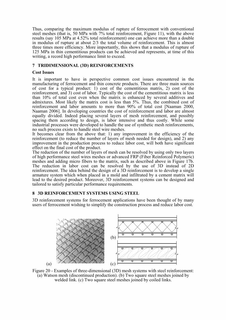
8 3D REINFORCEMENT SYSTEMS USING STEEL 3D reinforcement systems for ferrocement applications have been thought of by many users of ferrocement wishing to simplify the construction process and reduce labor cost.
(b)
(a)
(c) Figure 20 - Examples of three-dimensional (3D) mesh systems with steel reinforcement:
(a) Watson mesh (discontinued production). (b) Two square steel meshes joined by welded link. (c) Two square steel meshes joined by coiled links.

Tri-dimensional reinforcement systems in the form 3D meshes (Watson mesh, Figure 20a), and 3D meshes made simply by connecting two parallel 2D steel meshes together (using welded links or coil spacers) were tried (Figures 20b and c). These turned up to be costly and their use was limited. In particular, the Watson mesh (Figure 20a) was discontinued in the late 1980’s. Another idea which was suitable for both steel and fiber reinforced polymeric meshes, was to use an armature system made out of a fiber mat taken in sandwich between two layers of reinforcing mesh (Figure 21). The sandwich is placed in a mold and infiltrated by a fine cement based matrix. Besides the advantage of ease of construction, the system produces a composite with reinforcement spaced exactly as needed, with minimum labor, and the fiber mat improves the shear and bending resistance of the composite.
(a)
(b)
Figure 21 - Typical sandwich type reinforcing system using a fiber mat core between two extreme layers of mesh: (a) Concept. (b) Example with steel mesh
and PVA fiber mat.
9 3D REINFORCEMENT USING POLYMERIC MESHES It is only in the late 1990’s and early 2000 that 3D meshes (or fabrics or textiles) derived from the technology of textiles and fabrics became available for research studies in ferrocement type products. In particular, the Institute of Textiles in Aachen (ITA), Germany, in collaboration with the Technical University in Dresden, Germany, is pioneering a number of 3D textiles for applications in cement and concrete composites; they use the terminology “textile reinforced concrete, or TRC.” [Hegger 2001, Hegger et al. 2006, Kurbach 2003]. The 3D fabrics have the advantage of placing the reinforcement exactly where it is needed and tailoring its properties for particular applications. They also offer a tremendous advantage in simplifying the construction process and saving on labor cost. Such 3D meshes can be readily produced in thicknesses from about 10 to 50 mm, a range perfectly suitable for ferrocement and thin cement composites applications. Moreover, textile technology offers the advantage of placing as much reinforcement as needed by design (generally less than 4% by volume), and exactly where it is needed, and tailoring the fabric properties and exterior shell volume for particular applications. Examples are shown in Figures 22 and 23. Note that the 3D textiles in Figure 23 allow the production of composites with holes or cavities thus leading to reduced weight of the final product. By using similar 3D textiles and polystyrene inserts, floating plates were built at the University of Michigan. Analytical modeling suggests that bending resistance (or MOR) close to 30 MPa can be achieved with these 3D systems using current FRP materials. So far the above 3D systems, while definitely reducing production labor, did not demonstrate high performance (i.e. high bending resistance) as expected. This is because bundles of fibers, or strands, or yarns made from high performance polymeric fibers, do not show the same tensile strength when in group, as the fibers from which they are made.

(a)
(b)
Figure 22 - Examples of three-dimensional (3D) mesh systems with FRP (textile) reinforcements fabricated at the ITA in Aachen, Germany: (a) 3D spacer textile.
(b) 3D spacer stiff textile – both about 15 mm thick.
(a)
(b)
(c)
(d)
Figure 23 - (a and b) 3D ribbed textile section and as produced by ITA in Aachen,
Germany for preliminary testing. Resulting thin cement composite can be either solid or with cavities; (c and d) which can be filled with Styrofoam to reduce weight. Panels can
be made to float.

Typically a glass fiber may have a tensile strength of 3500 MPa. Textiles or fabrics or meshes use strands containing a large number of fibers, typically ranging from 200 to 12000 fibers. A glass fabric made with strands containing about 200 fibers per strand and used in a cement composite may show an equivalent tensile strength of only 800 MPa. This is because under tensile loading, the fibers are not loaded all simultaneouslyat the same level, and progressive fiber fracture occurs. If the strand is made with fibers embedded in a polymeric resin, it is likely that the equivalent strength would increase to 1200 MPa. On the other hand, if the fibers are perfectly aligned and embedded in a resin leading to a rigid and perfectly straight strand structure, a much higher tensile strength can be achieved similarly to a conventional FRP bar. Roughly one can get 60% to 70% of the strength of the fiber. However, in such a case the fabric will be extremely costly and likely very difficult to manufacture. This prompted the investigators at the ITA in Aachen, Germany, and at the University of Michigan, to look at introducing high strength steel cord within the textile to replace some of the glass yarns, thus taking advantage of the strength and toughness of steel while preserving the inherent constructional advantage offered by the 3D textile. Recently, the research team at ITA in Aachen was able to produce such a 3D textile, a world first integrating steel and FRP reinforcements. The textile uses glass fibers for the fill (transverse direction), polypropylene fibers for the vertical spacing (acting as spacers and shear reinforcement) and high strength steel strands inserted in the weft (longitudinal direction). The vertical PP fibers can be made to protrude beyond the plane of the main longitudinal reinforcing wires, thus allowing to achieve automatically the desired net cover of cement matrix desired over the main reinforcement. Such a textile offers the best possible performance by taking advantage of the strength and ductility of steel while using conventional polymeric fibers permitting a 3D textile machine to indeed fabricate the textile. The contribution of the polymeric fibers remains effective and provide the support armature for the steel reinforcement and the shell of the armature. A typical such 3D FRP-steel hybrid textile is shown in Figure 24.
Figure 24 - New 3D textile incorporating steel strands produced by ITA in Germany;
note steel strands showing at left end of textile.
10 EVOLUTION IN THE CEMENT MATRIX While the evolution of reinforcement has been impressive over the past four decades, the evolution of the matrix has been as impressive, if not spectacular. Typically the conventional mortar matrix for ferrocement is made of cement, water, and sand; various proportions have been used depending on application, but a proportion containing 1

cement, 0.5 water, and 2 to 3 sand was often a starting trial mixture. The cement matrix has however evolved enormously. Today the cement itself may be blended, that is, containing supplementary cementitious materials, such as flash ash, ground furnace slag, etc.. Mineral components such as silica fume and fly ash are now commonly used either as additives to or as replacement of cement. They help provide a denser composite, reduce porosity, improve fresh properties, improve strength, corrosion resistance, durability, etc. Chemical admixtures, such as water reducing agents, superplasticizers, and viscosity agents, help control and improve a host of other properties in the fresh state to help in the fabrication and manufacturing phase. Today, self-consolidating and self-compacting cementitious mixtures are common and allow us to rethink and expand construction procedures for ferrocement and thin cement based products. 10.1 High Performance and Ultra High Performance Cement and Concrete
Matrices (HPC and UHPC) For several decades now, there has been some unwritten competition among scientists and engineers to achieve record compressive strengths in cement and concrete composites. Related research became particularly active after the initial development of effective dispersants and various admixtures for cement systems during the 1970’s. In the 1980’s the term “high performance concrete” or HPC was used to describe concretes with compressive strength exceeding only about 40 MPa in the US and 50 MPa in Europe; later HPC also implied higher durability. HPC used conventional materials and mixers, and generally allowed compressive strengths up to about 70 MPa with little change in the basic component materials. Above such value, and up to 100-120 MPa special aggregates, special additives, and extreme quality control were needed in bulk applications. Simultaneously, between the 1970’s and the end of the century, in research laboratories around the world, a race for high compressive strength was going on. Compressive strengths up to 800 MPa [Richard and Cheyrezy 1995] have been attained for relatively small controlled samples, but required unusual combinations of mixtures as well as exotic treatments such as high temperature curing, under vacuum and/or pressure, and the addition of steel aggregates and polymers. Cementitious materials with compressive strength over 150 MPa (22 ksi) produced in bulk quantities have aroused particular interest around the world since their introduction in the early 1990s. Known first as reactive powder concrete (RPC) [Richard and Cheyrezy 1995], they are now more generally described as Ultra High Performance Concrete or UHPC. To date, two international technical symposia have specifically addressed UHPC [Fehling et al. 2004, Fehling et al. 2008]. While no clear definition was so far agreed upon among researchers, the following definition was proposed by Rossi [Rossi 2008]: “ultra high strength” or “ultra high performance” cement composites use a relatively high binder ratio, a water to cementitious ratio (or water to binder ratio) less than 0.2, and show a compressive strength in excess of 150 MPa (about 22 ksi). In order to increase compressive strength in today’s more practical research and for bulk applications, the objective is to optimize particle packing within the composite [Ulm and Acker 2008]. Note that the high compressive strength, obtained through dense particle packing, implies high durability, improved freeze-thaw resistance, increased resistance against various chemicals, and higher penetration resistance [Fehling et al. 2004, Fehling et al. 2008, Ulm and Acker 2008]. Thus the potential of UHPC in various applications, including blast and impact resistant structures, has attracted high interest by both the research and professional communities. 10.2 Particular Affinity and Compatibility Between UHPC and Thin Cement
Based Composites Figure 25 illustrates the progress that has been made on the compressive strength of the cement matrix since the first patent of Lambot and the range of strengths available

today for practical applications, particularly for thin cementitous products. The higher strength range would be defined as UHPC.
cf ′
Figure 25 - Progress in concrete compressive strength for bulk applications.
Note that most common UHPC mixtures so far developed should be called “mortar” not “concrete” because they do not use large aggregates. Instead they utilize very fine particles including cement, glass powder (or silica powder) silica fume, fly ash, and sand with a maximum particle size of less than about 1 mm. The finest particles in the mixture come from silica fume and are on average about 0.5 micron in diameter and generally less than 1 micron in diameter (1 micron = 10-3 mm). Moreover, even with a low water-to-binder ratio, given the help of superplasticizers and viscous agents, these mixtures are commonly self-consolidating or self-compacting, that is, they can easily flow on their own inside a mold and entirely encapsulate existing reinforcement without any vibration. Such self-consolidating UHPC mixtures are particularly suitable for ferrocement and thin cement based composites products, constructed using molds, because the armature systems (multiple layers of mesh, 3D textile, etc…) in these composites have very small openings and thus require a matrix with very fine particles to pass through such openings.
11 LOOKING AHEAD: ACTIVE REINFORCEMENT AND SELF STRESSING It is clear from the above discussion that cement composites with higher performance (qualified here as high strength and high ductility), necessitate the use, on the one hand, of high performance cement matrices and, on the other hand, of high performance reinforcements characterized by both a high tensile strength and a high tensile elastic modulus. Such criteria favor high strength steel products and high performance polymeric fibers such as carbon, Kevlar, Spectra and the like. Since manufacturing and labor cost consume a large portion of the cost of these composites, the use of 3D reinforcing systems may play a key role in future expansion and developments. In comparing high performance FRP meshes (or textiles or fabrics) with steel meshes, it is likely that the race will be very close and that the advantage of one over the other will depend on criteria other than strength or moduli of rupture [Naaman 2005]. For instance the fact that, at time of this writing, FRP materials can be made into 3D textiles that form or support the armature system, and can be simply placed into a mold and infiltrated by a mortar matrix, gives FRPs a significant advantage in terms of savings on labor cost. FRPs are also significantly lighter in weight than steel, and thus easier to handle in the field. However, the bottom line is total cost, and steel remains very competitive not only in terms of performance (such as equivalent bending strength) but also in terms of total cost of the product. Manufactured 3D steel meshes or hybrid combination of steel and textile 3D meshes may offer optimized solutions in the future. Clearly the manufacture-ability of a particular 3D textile at reasonable cost will provides a key advantage. In most of the above discussion, it was assumed that the reinforcement remains relatively passive. That is, the reinforcement is stressed only when the structure is stressed. However, it is possible to make the reinforcement more active by creating self-stressing thin cement composites. Self stressing in cement composites can be obtained by either an expansion of the matrix, or a contraction of the reinforcement, or both.

Bond and or anchorage between the two components is assumed perfect. The advantages of prestressing are similar to those of conventional prestressed concrete and include a higher resistance to cracking, thus improved corrosion resistance, impermeability and durability. Smart reinforcing materials currently available for self stressing include shape memory alloys (SMA) and some special polymeric fibers which possess the unique property of being able to be frozen temporarily in a particular state and then, with proper heat or radiation treatment, go back to their previous equilibrium condition. For instance a shape memory wire mesh is first stretched to a certain strain level and stabilized in that state; then it is used in a cement based matrix. Once the matrix has hardened, the reinforcement is relaxed from its induced deformation by heat or radiation or the like; thus in attempting to shrink back to its previous state, it provides, through bond and or anchorage, the needed stressing of the matrix. In some tests carried out on thin cement sheets, an initial prestress of about 7 MPa was achieved [Krstulovic-Opara and Naaman 2000, Naaman 2000]. The challenge, of course, is to go much higher. Note that besides using the reinforcement, self-stressing can also be obtained by chemical expansion of the cement matrix; however such a technique has led so far to only low levels of prestress and is used successfully in shrinkage compensating cements. It is expected that, with increased research, a higher level of success will be achieved in the future.
12 CONCLUDING REMARKS While this paper has presented crucial progress in the main materials components of ferrocement and thin cement composites since their inception, the author hopes that it will inspire new researchers to take up the challenge and introduce improvements in order to exceed the limits so far achieved: so we need to exceed a modulus of rupture of about 125 MPa; we need to find ways to reduce labor cost; we need to produce optimized 3D reinforcements at least cost; we need to take advantage of self-stressing reinforcements by inducing internal prestress levels exceeding 7 MPa; and we need to inform and educate the public and the profession about the advantages and potential applications of these composites. We need to always keep dreaming at least slightly beyond the borders of current reality.
13 AKNOWLEDGMENTS The developments described in this paper as related to 3D textiles and fabrics with polymeric fibers were carried out primarily at the RWTH University in Aachen, Germany, with Thomas Gries and Andreas Roye from the Institute of Textiles, Aachen, (ITA), Wolfgang Brameshuber from the Ibac (Institute of Building Materials), and Josef Hegger from the IBM (Structural Engineering Institute). Their collaboration is gratefully acknowledged. The author would like to acknowledge past financial support from the University of Michigan, the US National Science Foundation, and the German Alexander von Humboldt Foundation. Special thanks are also due to the many graduate students who have contributed over time to the subject of this paper.
REFERENCES No list of references can be sufficiently complete and do justice to the many areas reviewed in this paper. The following list is limited but each document contains by itself a number of references which would guide the reader in search of more complete information. ACI Committee 549, (1988, …). “Guide for the Design, Construction and Repair of
Ferrocement.” ACI 549.1R -88, ACI Structural Journal, May - June, 1988, pp. 325 - 351. Also reinstated as 549.1R-93 and published in ACI Manual of Concrete Practice, American Concrete Institute, Farmington Hills, Michigan, 27 pages.

ACI Committee 549 (1997). “State-of-the-Art Report on Ferrocement.” Concrete International, Vol. 4, No. 8, Aug. 1982, pp. 13-38. Reinstated as ACI 549-R97, in Manual of Concrete Practice, American Concrete Institute, Farmington Hills, Michigan, 26 pages.
ACI Committee 549 (2004). “Report on Thin Reinforced Cementitious Products.” 549.2R-04, American Concrete Institute, Farmington Hills, Michigan.
Balaguru, P., Editor (1994). “Thin Reinforced Concrete Products and Systems.” SP-146, American Concrete Institute, Farmington Hills, Michigan, 106 pages.
Balaguru, P., A.E. Naaman, and W. Weiss, Co-Editors (2002). “Concrete: Material Science to Application – A Tribute to Surendra P. Shah.” American Concrete Institute, SP-206, Farmington Hills, Michigan, 580 pages.
Daniel, J.I, and S.P. Shah, Editors (1990). “Thin-Section Fiber Reinforced Concrete and Ferrocement.” SP-124, American Concrete Institute, Detroit, Michigan, 448 pages.
Djausal, A., F. Alami, and A.E. Naaman, Co-Editors, (2009). “Ferrocement and Thin Reinforced Cement Composites: Green Technology for Housing and Infrastructure Construction.” Proceedings of Ferrocement 9, The University of Lampung, Bandar Lampung, Indonesia, 506 pages. ISBN 978-979-1165-93-8.
Dubey, A., Editor (2004). “Thin Reinforced Cement-Based Products and Construction Systems.” American Concrete Institute, Special Publication SP-224, Farmington Hills, Michigan.
Fehling, E., Schmidt, M., Geisenhanslueke, C., Editors, (2004). “International Symposium on Ultra High Performance Concrete,“ Kassel University Press, (Schriftenreihe Baustoffe und Massivbau 3), GmbH, Germany.
Fehling, E, Schmidt, M., and Sturwald, S., Editors, (2008). “Ultra High Performance Concrete (UHPC)”, Proceedings of Second International Symposium on Ultra High Performance Concrete, Kassel University Press, (Schriftenreihe Baustoffe und Massivbau 10), GmbH, Germany, 902 pages.
Ferrocement Model Code, (2001), by IFS Committee 10-01. International Ferrocement Society, Asian Institute of Technology, Bangkok, Thailand, 95 pages.
Guerrero, P. and Naaman, A. E., (1998). “Bending behavior of hybrid ferrocement composites reinforced with PVA meshes and PVA fibers.” in Ferrocement 6 - Lambot Symposium, Proceedings of Sixth International Symposium on Ferrocement, A.E. Naaman, Editor, University of Michigan, CEE Department.
Hegger, J., Editor, (2001). "Fachkolloquium der Sonderforschungsbereiche 528 und 532“ RWTH, AACHEN (in German).
Hegger, J., Brameshuber, W., and Will, N., Editors, (2006). “Textile Reinforced Concrete.” Proceedings of 1st International RILEM Symposium, PRO 50, RILEM Publications, Bagneux, France.
Krstulovic-Opara, N., and Naaman, A.E., (2000), "Self-Stressing Fiber Composites," ACI Structural Journal, Vol. 97, No. 2, March-April 2000, pp. 335-344.
Kurbach, M., Editor, (2003). Proceeding of Second “Colloquium on Textile Reinforced Structures – CTRC2.” Dresden, Germany.
Mansur, M.A., and Ong, K.C.G., Editors (2001). Ferro-7: Proceedings of the “Seventh International Symposium on Ferrocement and Thin Reinforced Cement Composites.” National University of Singapore, 558 pages.
Mobasher, B., Pahilajani, J., and Peled, A., (2000). “Analytical simulation of tensile response of fabric reinforced cement based composites,” Cement and Concrete Composites, Vol. 28, pp. 77-89.

Naaman, A.E., Editor, (1998). “Ferrocement 6: Lambot Symposium.” Proceedings of the Sixth International Symposium on Ferrocement, University of Michigan, Ann Arbor, 699 pages.
Naaman, A.E., (2000). “Ferrocement and Laminated Cementitious Composites.” Techno Press 3000, Ann Arbor, Michigan, USA, 2000, ISBN0-9674939-0-0, 370 pages.
Naaman, A.E., (2003).“Progress in Ferrocement and Hybrid Textile Composites.” Proceeding of Colloquium on Textile Reinforced Concrete – CTRC2, Dresden University, Germany, Edited by M. Kurbach.
Naaman, A.E., (2005). “Thin Cement Composites: Performance Comparison between Steel and Textile Reinforcements,” in Composites in Construction, Edited by P. Hamelin, D. Bigaud, E. Ferrier and E. Jacquelin, University of Lyon, France, Vol.2, pp. 1155-1164.
Naaman, A.E., (2006). “Ferrocement: Four Decades of Progress,” Journal of Ferrocement, Vol. 36, No. 1, January 2006, pp. 741-756. Also in proceedings of International Symposium on Ferrocement and Thin Cement Products, Bangkok, Thailand, February 2006.
Naaman, A.E., (2008). “High Performance Fiber Reinforced Cement Composites,” in High Performance Construction Materials – Science and Applications, Edited by Caijun Shi and Y.L. Mo, World Scientific Publishing Co. Pte. Ltd,, Singapore, pp. 91-153.
Naaman, A.E., and Chandrangsu, K., (2000). “Bending Behavior of Laminated Cementitious Composites Reinforced with FRP Meshes.” ACI Symposium on High Performance Fiber-Reinforced Concrete Thin Sheet Product, Edited by A. Peled, S.P. Shah and N. Banthia, American Concrete Institute, Farmington Hills, ACI SP 190, 97-116.
Naaman, A.E., and Guerrero, P., (1996) “Bending behavior of thin cement composites reinforced with FRP meshes.” Proceedings of First International Conference on Fiber Composites in Infrastructures ICCI 96, Edited by H. Saadatmanesh and M. Ehsani, University of Arizona, Tucson, pp. 178-189.
National Academy of Sciences (1973). “Ferrocement: Applications in Developing Countries.” Report by the Ad Hoc Panel of the Advisory Committee on Technological Innovations, Board of Science and Technology for International Development, Washington, D.C., USA, 90 pages.
Nedwell, P.J., and Swamy, R.N., Editors (1994). “Ferrocement: Proceedings of the Fifth International Symposium.” Manchester, E & FN Spon, London, 508 pages.
Nervi, P.L., (1956). "Ferrocement: Its Characteristics and Potentialities," Library Translation No. 60, Cement and Concrete Association, London, July, 1956, 17 pages.
Nimityongskul, P., A.E. Naaman, J.E. Bolander, C. Jaturapitakkul, C. Sujirovakul, and S. Sayamipuk, Editors, (2006). “Ferrocement and Thin Reinforced Cement Composites,” Proceedings of International Conference and NSF Workshop, FERRO-8, Bangkok, Thailand, Published by International Ferrocement Society, Asian Institute of Technology, Thailand, 645 pages. ISBN/ISSN 974-93905-1-X.
Oberti, G., and Shah, S.P., Editors, (1981). “RILEM International Symposium on Ferrocement.” ISMES (Publisher), Bergamo, Italy.
Parra-Montesinos, G., and A.E. Naaman, (2001). “Parametric evaluation of the bending response of ferrocement and hybrid composites with FRP reinforcements.” Proceedings of Seventh International Symposium on Ferrocement and Thin Reinforced Cement Composites, M.A., Mansur and K.C.G. Ong, Editors, Singapore.

Peled, A., Bentur, A., Yankelevsky, D., (1999). “Flexural performance of cementitious composites reinforced with woven fabrics." Journal of Materials in Civil Engineering, ASCE, pp. 325-330.
Richard, P. and Cheyrezy, M., (1995). “Composition of reactive powder concretes,” Cement and Concrete Research, Vol. 25, No. 7, pp. 1501-1511.
Robles-Austriaco, L., Pama, R.P., Sashi Kumar, K., Mehta, E.G., Editors (1985). “Proceedings of the Second International Symposium on Ferrocement.” Asian Institute of Technology, Bangkok, Thailand, International Ferrocement Information Center, 773 pages.
Rossi, P., (2008). “Ultra High Performance Concretes – A Summary of the Current Knowledge,” Concrete International, February 2008, pp. 31-34.
Ulm, F.-J., and Acker, P., (2008). “Nanoengineering UHPC Materials and Structures,” in Fehling et al. 2008, pp. 3-9.
Wainshtok Rivas, H., Editor, (1991). “Proceedings of the Fourth International Symposium on Ferrocement.” La Havana, Cuba; CETA, La Havana, Cuba.
Copyright © 2022 FDOKUMEN