ERDC/CERL TR-02-14 - DTIC
187
ERDC/CERL TR-02-14 Preliminary Design of a Ventilation System Scrubber To Reduce Sulfur Dioxide Emissions at the Watervliet Arsenal Industrial Wastewater Treatment Plant June 2002 Construction Engineering Research Laboratory Joyce C. Baird, June Pusich-Lester, and Dan Brown Approved for public release; distribution is unlimited.
-
Upload
khangminh22 -
Category
Documents
-
view
1 -
download
0
Transcript of ERDC/CERL TR-02-14 - DTIC
ERD
C/C
ERL
TR-0
2-14
Preliminary Design of a Ventilation System Scrubber To Reduce Sulfur Dioxide Emissions at the Watervliet Arsenal Industrial Wastewater Treatment Plant
June 2002
Con
stru
ctio
n E
ngin
eeri
ng
Res
earc
h La
bora
tory
Joyce C. Baird, June Pusich-Lester, and Dan Brown
Approved for public release; distribution is unlimited.

2 ERDC/CERL TR-02-14
Foreword
This research was funded under 622720960, “Congressional – Watervliet Arsenal Pollution Projects.” The project was co-developed under the Value Engineering Program of the U.S. Army Corps of Engineers. The project described in this re-port was conducted at Watervliet Arsenal (WVA) during Fiscal Year 2001. The technical monitor at WVA was Dan Brown.
The work was performed by the Environmental Processes Branch (CN-E), Instal-lations Division (CN), Construction Engineering Research Laboratory (CERL), and by consultants MSE Technology Applications, Inc. (MSE-TA), Butte, MT. The principal investigator was Joyce C. Baird, CERL, Champaign, IL, and June Pusich-Lester was project manager for MSE services. Michelle Hanson is Acting Branch Chief, CN-E, and Dr. John Bandy is Chief, CN. The technical editor was Linda L. Wheatley, Information Technology Laboratory—Champaign. The asso-ciated CERL Technical Director was Gary W. Schanche. The Director of CERL is Dr. Alan W. Moore.
CERL is an element of the U.S. Army Engineer Research and Development Cen-ter (ERDC), U.S. Army Corps of Engineers. The Commander and Executive Director of ERDC is COL John W. Morris III, EN, and the Director of ERDC is Dr. James R. Houston.
DISCLAIMER: The contents of this report are not to be used for advertising, publication, or promotional purposes. Citation of trade names does not constitute an official endorsement or approval of the use of such commercial products. All product names and trademarks cited are the property of their respective owners. The findings of this report are not to be construed as an official Department of the Army position unless so designated by other authorized documents. DESTROY THIS REPORT WHEN IT IS NO LONGER NEEDED. DO NOT RETURN IT TO THE ORIGINATOR.
ERDC/CERL TR-02-14 3
Contents
Foreword ............................................................................................................................................2
List of Figures and Tables................................................................................................................5
1 Introduction.................................................................................................................................7 Background .........................................................................................................................7
Present Situation at WVA’s IWTP ..................................................................................................8 Past Work Conducted at WVA’s IWTP...........................................................................................8 Site Investigation............................................................................................................................9
Objective ...........................................................................................................................10 Approach...........................................................................................................................10 Mode of Technology Transfer............................................................................................10 Units of Weight and Measure............................................................................................10
2 Process Analysis of Multiple Technologies .........................................................................11 The IWTP Waste Treatment Processes............................................................................ 11
The Acid Treatment Line ..............................................................................................................11 The Soluble Oil Treatment Line....................................................................................................12 The Cyanide Treatment Line........................................................................................................13
Criteria for Design Selection .............................................................................................13 Description of Designs for the Process.............................................................................14
First Alternative Design ................................................................................................................14 Second Alternative Design...........................................................................................................17 Recommended Design ................................................................................................................18
3 Vendor Quotations ...................................................................................................................19
4 Recommendations...................................................................................................................20 Equipment Description......................................................................................................20 Plan Views of Equipment Installation................................................................................20 Site Preparation Requirements.........................................................................................21 Electrical Requirements ....................................................................................................21 Piping and Mechanical Requirements ..............................................................................21 Instrumentation Requirements..........................................................................................22 Operating and Maintenance Requirements ......................................................................22
5 Cost Worksheets ......................................................................................................................23
4 ERDC/CERL TR-02-14
6 Conclusions..............................................................................................................................26
Appendix A: Extracts of Reports and Regulations Relating to Air Emissions................27
Appendix B: Air Scrubber Design Corresponding to E17-36FS-002................................93
Appendix C: Equipment Data Sheet ....................................................................................145
Appendix D: Vendor Quote – Rocky Mountain Process Group ......................................151
Appendix E: Vendor Quote – Met-Pro Corporation Duall Division .................................159
Appendix F: Chemcad Model of The Met Pro Scrubber Bid............................................175
Appendix G: Process Flow Diagrams .................................................................................181
CERL Distribution .........................................................................................................................190
Report Documentation Page .......................................................................................................191
ERDC/CERL TR-02-14 5
List of Figures and Tables
Figures
1 Industrial Wastewater Treatment Plant at WVA...........................................................7 2 WVA's three IWTP treatment processes (1995)........................................................12
Tables
1 Air emissions inventory report data ...........................................................................14 2 Vendor sources..........................................................................................................19 3 Cost estimate for installation and operation of scrubber system...............................23


ERDC/CERL TR-02-14 7
1 Introduction
Background
The Industrial Wastewater Treatment Plant (IWTP) (Figure 1) was built in the early 1960s at Watervliet Arsenal (WVA) in New York, and the chrome plating wastewater treatment control system was upgraded in the early 1980s. This control system upgrade did not include consideration of emissions from ventila-tion of the reaction tanks or clarifiers.
Figure 1. Industrial Wastewater Treatment Plant at WVA.
http://www.globalsecurity.org/military/library/report/enviro/WVA_IAP.pdf
WVA has a large hexavalent chromium electroplating facility that generates chromic acid wastewater. WVA’s IWTP treats the industrial wastewater and discharges it into the Hudson River. The current acid waste treatment process uses a large sulfur intake. Sulfuric acid (H2SO4) is added to the waste stream to lower the pH, sulfur dioxide (SO2) is added to reduce the hexavalent chromium to trivalent chromium, and aluminum sulfate (alum) is used to aid in the precipita-tion of the trivalent chromium. Although the IWTP possesses a New York State air permit, the odor the plant generates has been a concern. The generation of
7
8 ERDC/CERL TR-02-14
hydrogen sulfide (H2S) or the addition of excess SO2 to the acid waste treatment process may cause the odors.
Present Situation at WVA’s IWTP
The IWTP at WVA provides chrome plating wastewater and oily wastewater treatment for all waters produced during manufacturing at the WVA. All reac-tion tanks and clarifier tanks at the IWTP have polycarbonate covers. Fans were added to ventilate the air space between the process water and the tank covers. The ventilation fans exhaust from chimneys that extend above the roof of the IWTP.
The SO2 used in the treatment of the chrome plating wastewater is injected into the process stream using a sulphonator system. The SO2 tanks and sulphonator are in a room adjacent to the reaction tanks. Past concerns from operation per-sonnel indicate that the IWTP process generates odors during chromic acid wastewater treatment. The odor has been variously attributed to the generation of H2S or the addition of excess SO2 to the acid waste treatment process.
Past Work Conducted at WVA’s IWTP
The overall scope of this project had three parts. These parts included:
2.
3.
4.
Implementing an investigation to determine the nature and cause of any sulfur emissions as well as determining potential solutions,
Development of a chosen solution method, and
Implementing the chosen method.
The scope of the work reported here addressed part two by developing a method to solve the problem.
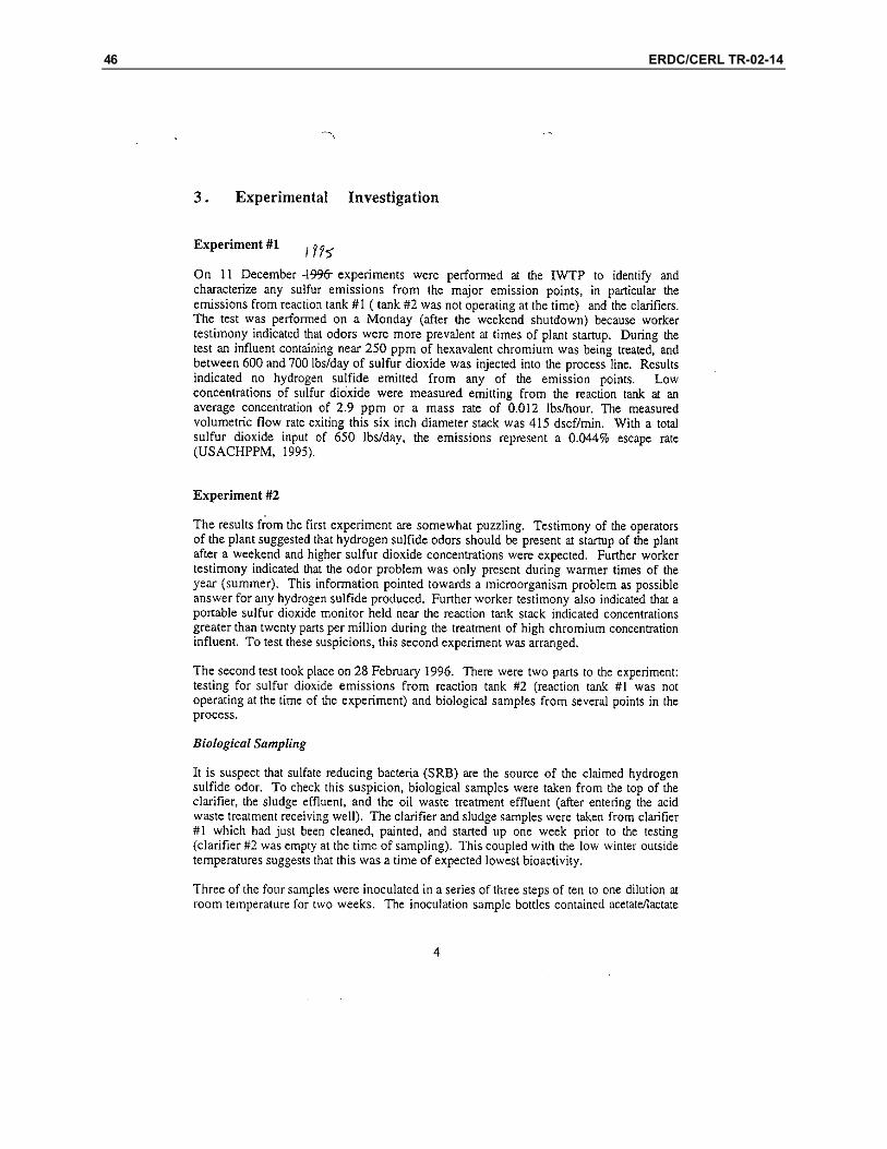
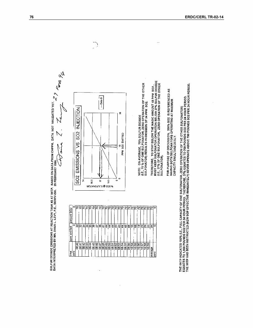
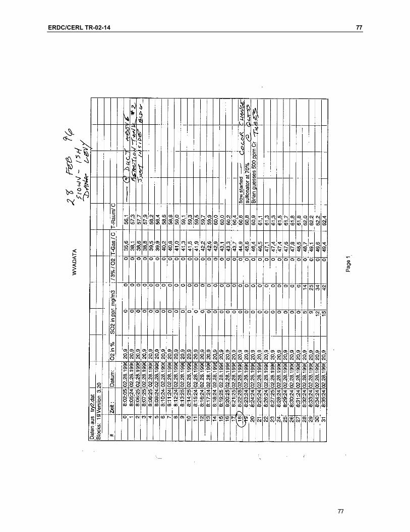
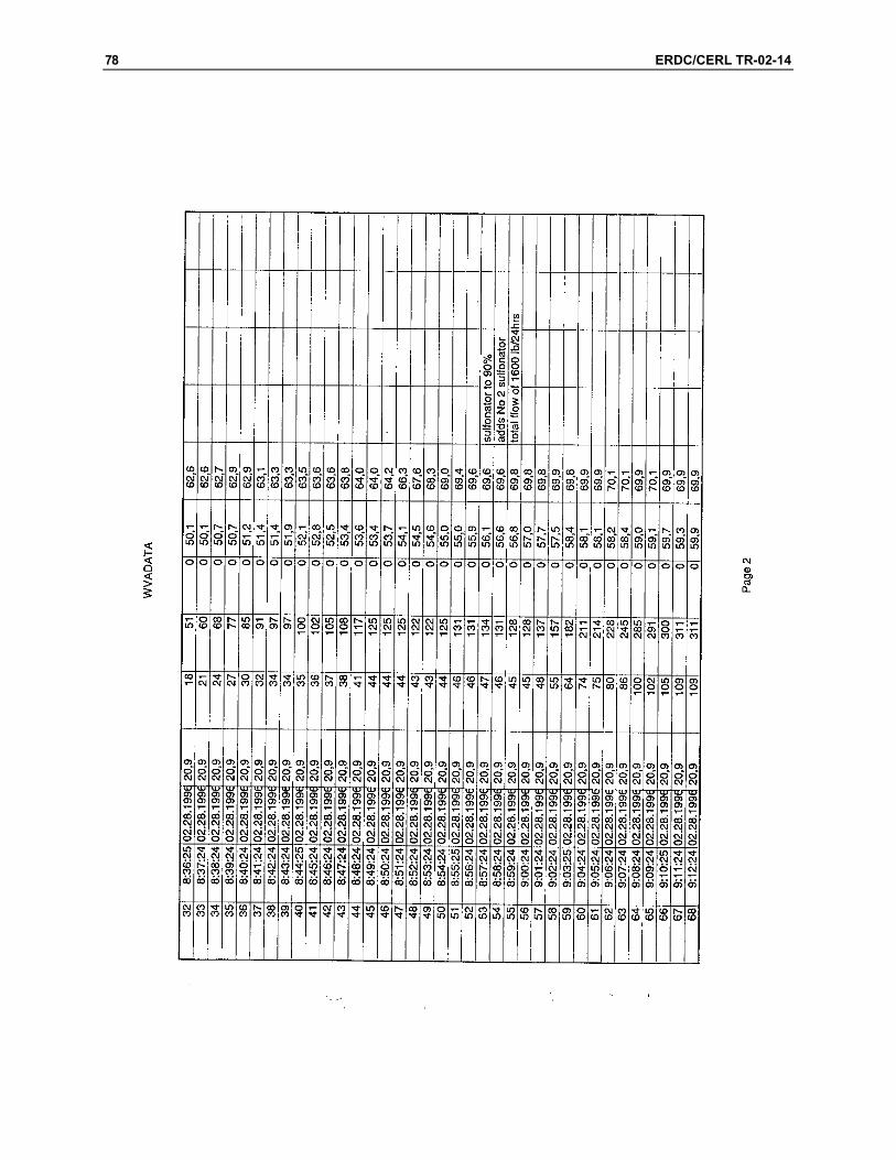
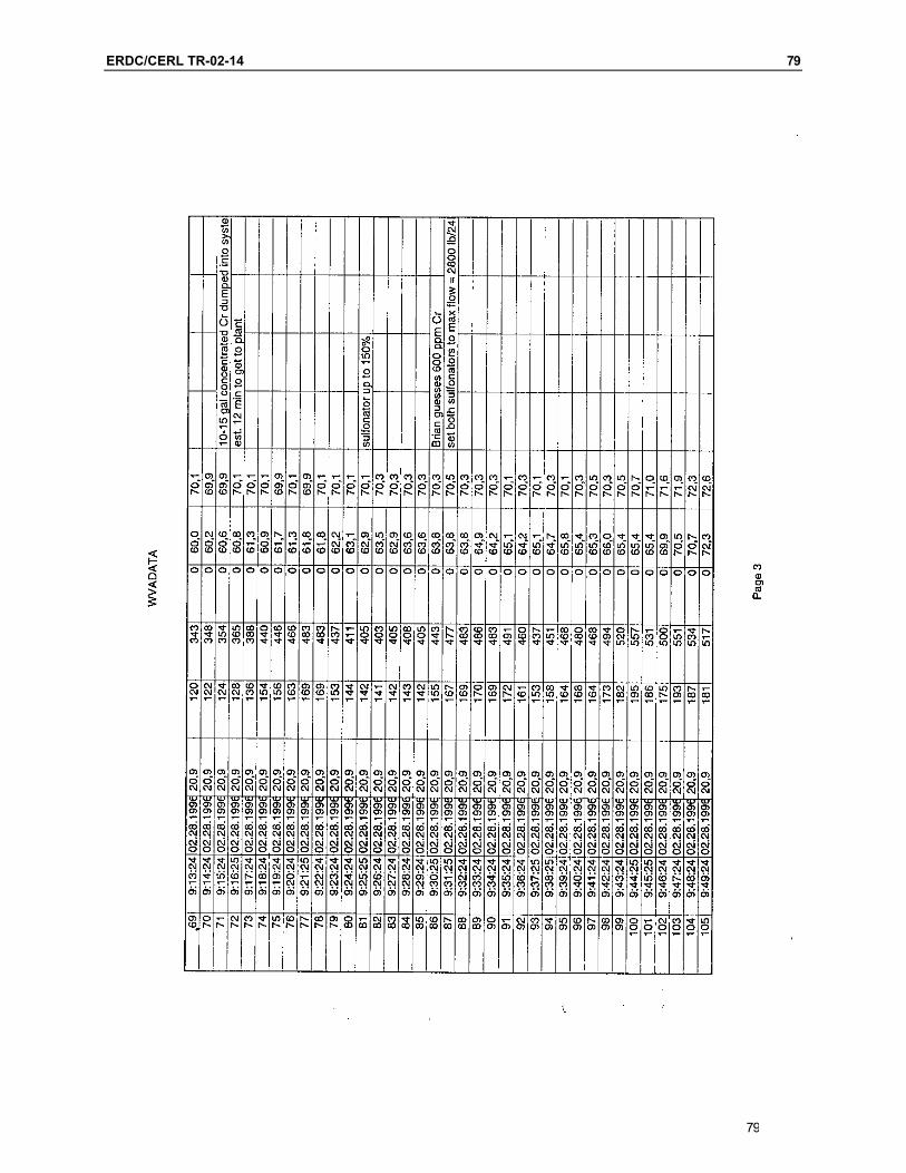
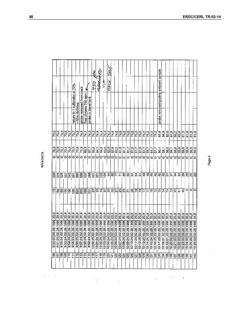
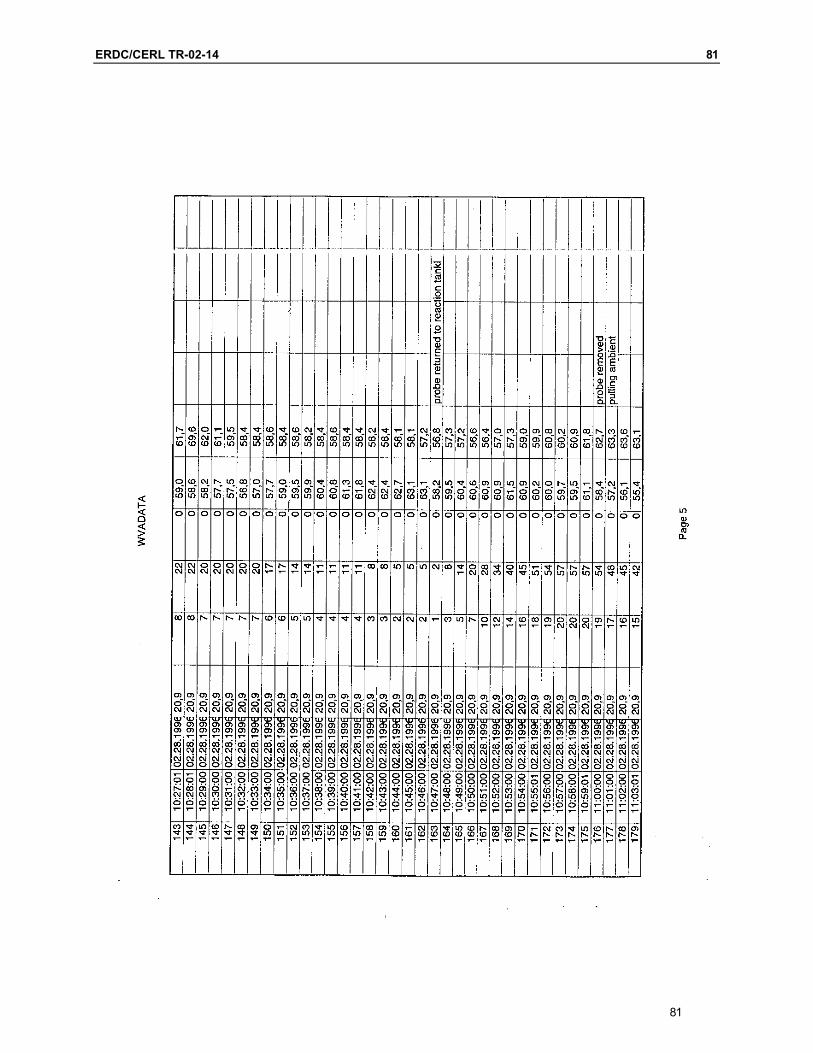
Dr. James Hay of CERL completed part one of the project in 1996. Results of Dr. Hay’s Experiment #1 performed on 11 December 1995 at WVA’s IWTP indicated no H2S from any of the emission points. Researchers did record measurements of SO2 emissions. These results were puzzling as workers stated that H2S odors should be present when the plant was started up after a weekend and higher SO2 concentrations were expected.
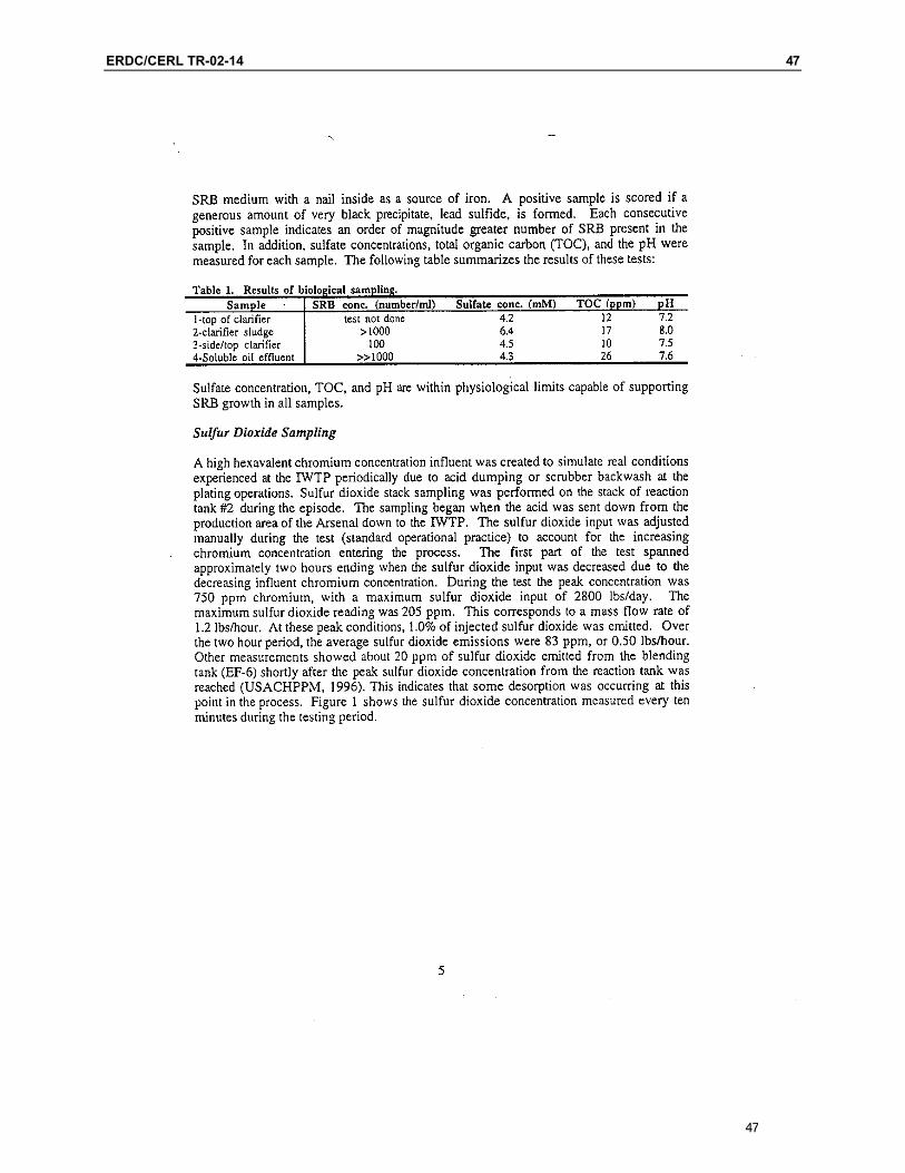
Researchers performed Experiment #2 on 28 February 1996. This two-part ex-periment included tests for SO2 emissions from reaction tank #2 and biological samples from several points in the process. Results from the biological samples

ERDC/CERL TR-02-14 9
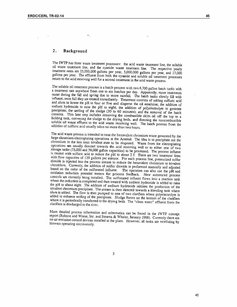
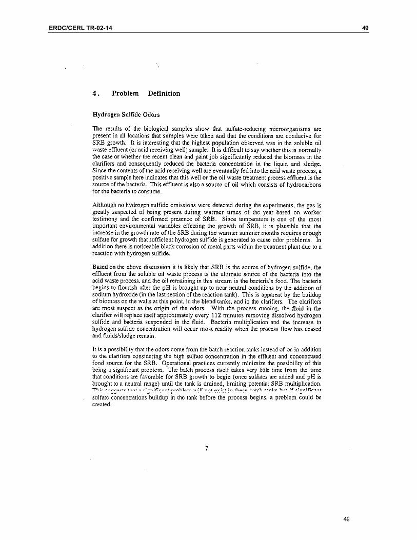
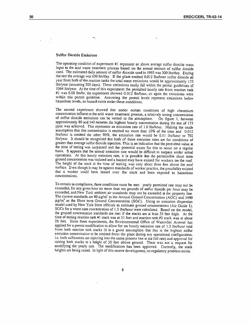
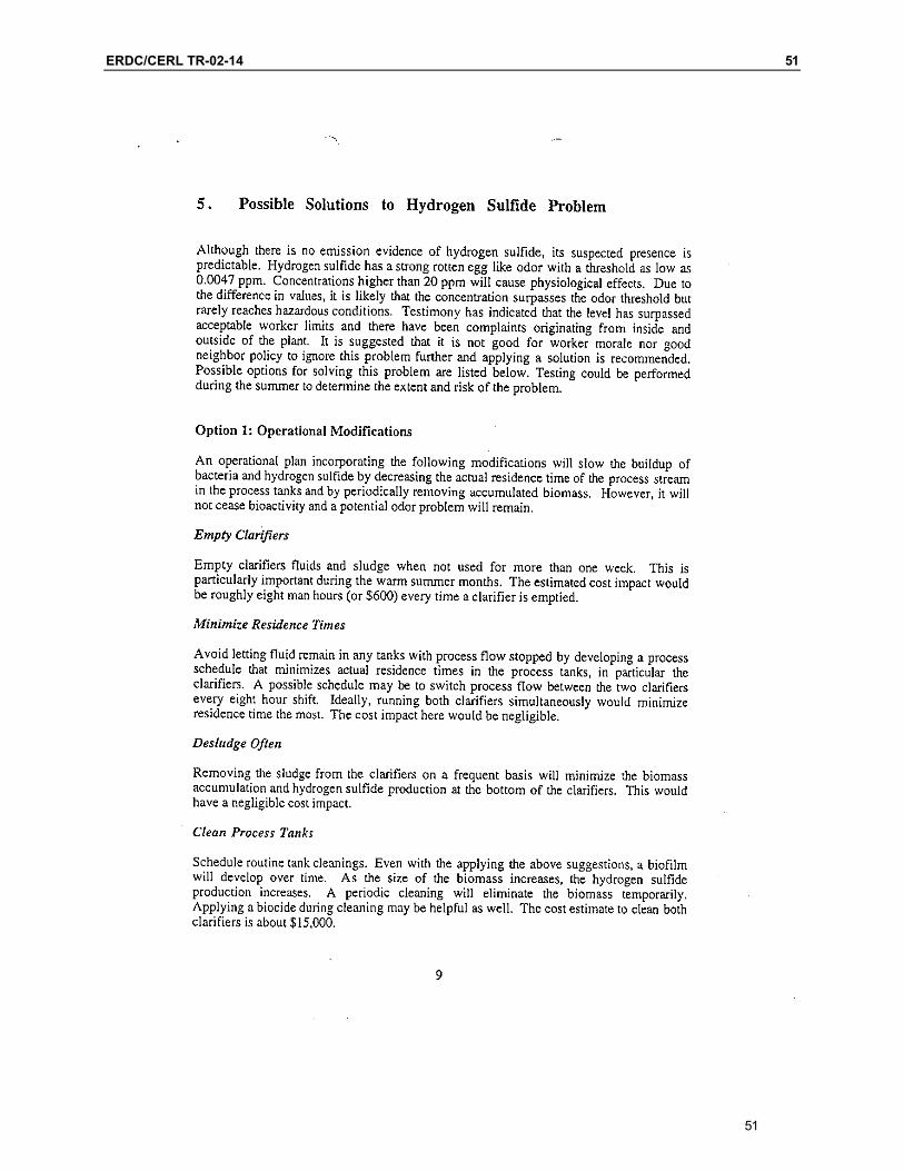
showed that sulfate reducing bacteria (SRB) were present at all locations from where samples were taken and that conditions were conducive to SRB growth. Although researchers did not detect any H2S emissions during experiments, it was suspected that the gas was present during the warmer months of the year. This suspicion was based on worker testimony and the confirmed presence of SRB. The second experiment also showed that, under conditions of high chro-mium concentration influent to the acid waste treatment process, a relatively strong concentration of SO2 emissions could be vented to the atmosphere. The Hay’s report suggested a number of solutions to the H2S problem including: operational modifications; treatment of SRB; removal of food source; or a combi-nation of the above options. The full results of Dr. Hay’s work are included as Appendix A.
Site Investigation
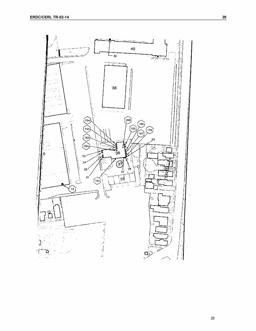
MSE Technology Applications, Inc. (MSE-TA) and WVA personnel conducted a site survey in August 2001. During the 2001 survey, MSE personnel toured the IWTP, discussed real-time operation of the plant with operations personnel, and documented operating streams such as emission point locations, stack locations, and stack diameter and height. At a later visit, MSE personnel examined and proposed piping routes and equipment locations. From the survey, and at a sub-sequent meeting of all parties involved, MSE and WVA decided to consider sev-eral options for the design of a system to reduce emissions that cause nuisance odors.
The IWTP had at one time been used to treat wastewaters containing cyanide from the plating process. Because of environmental concerns, however, WVA no longer uses the cyanide treatment process. It was decided during the site visit that the cyanide treatment room would be available to house the proposed venti-lation air treatment equipment.
Three designs for the process were developed. The first two were completed prior to solicitation of proposals from vendors. The third design was developed using vendor-provided information following solicitation. The first design used an SO2 wet scrubber, absorber, and an H2S adsorber. The second design elimi-nated the adsorber in favor of drawing all vent streams into a common header and using a wet scrubber for both SO2 and H2S absorption. The recommended design was developed from the second alternative design by adding specific manufacturer equipment operating parameters. The first option was to design a wet scrubber to remove SO2 and an adsorber to remove H2S from the ventilation air streams. The second option would incorporate H2S scrubbing into the wet
9
10 ERDC/CERL TR-02-14
scrubber design. As explained later in this report, the second option was found to be the best solution to mitigate the problem.
Objective
The objective was to develop a design to eliminate emission of SO2 and H2S from the chrome plating wastewater treatment process, which was causing nuisance odors at WVA’s IWTP.
Approach
The approach to the project was to provide specifications for systems and compo-nents to absorb or adsorb SO2 and H2S from the ventilation air effluent streams at the IWTP.
Mode of Technology Transfer
It is anticipated that this report and accompanying documentation will be avail-able on the CERL and WVA Intranet web pages.
The CERL web site address is: http://www.cecer.army.mil/
The WVA web site address is: http://www.wva.army.mil/
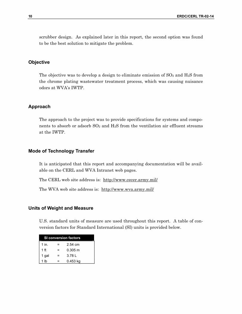
Units of Weight and Measure
U.S. standard units of measure are used throughout this report. A table of con-version factors for Standard International (SI) units is provided below.
SI conversion factors
1 in. = 2.54 cm 1 ft = 0.305 m 1 gal = 3.78 L 1 lb = 0.453 kg
ERDC/CERL TR-02-14 11
2 Process Analysis of Multiple Technologies
The IWTP Waste Treatment Processes
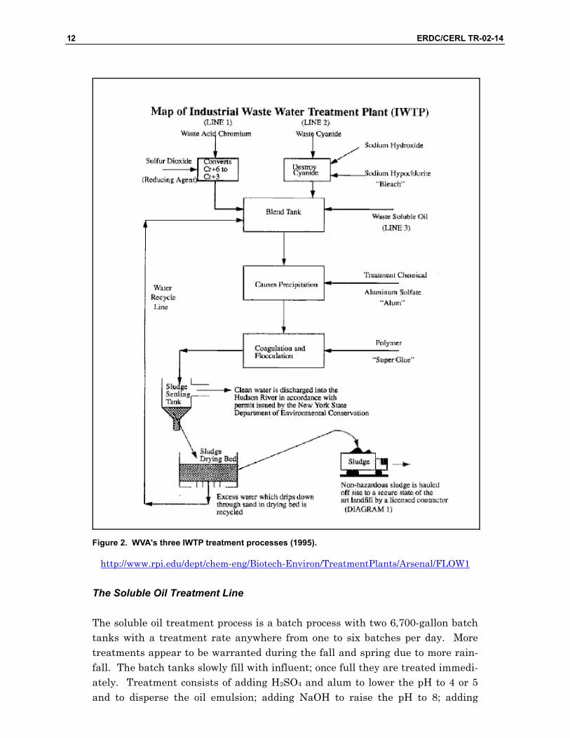
The purpose of the IWTP at WVA is to clean and rejuvenate the water used in the machining process. The IWTP originally had three treatment processes: acid, cyanide, and soluble oil. The yearly treatment rates for the acid treatment line, the cyanide treatment line, and the soluble oil line were, respectively, 25,000,000 gallons per year, 17,000 gallons per year, and 5,000,000 gallons per year (1996). Figure 2 is a flowchart of the three original treatment processes. Due to environmental concerns, WVA no longer uses cyanide treatment.
The Acid Treatment Line
The acid waste process treats the hexavalent chromium waste generated by the large chromium electroplating operations at WVA. The concept is to precipitate out the chromium for disposal in the less toxic trivalent state. Wastes from the electroplating operations are usually directed towards the acid receiving well or to either of two storage tanks (75,000 and 39,000 gallon capacities) to be proc-essed. The process influent is treated with H2SO4 to reduce the pH to about 2.5. There are two treatment lines with flow capacities of 120 gallons per minute (gpm). For each process line, pressurized SO2 is injected into the process stream to reduce hexavalent chromium to trivalent chromium. The sulfonated influent flows into a reaction tank where reduction is completed and then treated with sodium hydroxide (NaOH) to raise the pH to about 8. The addition of NaOH ini-tiates the production of the trivalent chromium precipitate. The stream is then directed towards a blending tank where alum is added. The flow is then pumped to one of two clarifiers where polyelectrolyte is added to enhance settling of the precipitate. Sludge forms on the bottom of the clarifiers and is periodically transferred to drying beds. The “clean water” effluent from the clarifiers is dis-charged to the river.
11
12 ERDC/CERL TR-02-14
Figure 2. WVA's three IWTP treatment processes (1995).
http://www.rpi.edu/dept/chem-eng/Biotech-Environ/TreatmentPlants/Arsenal/FLOW1
The Soluble Oil Treatment Line
The soluble oil treatment process is a batch process with two 6,700-gallon batch tanks with a treatment rate anywhere from one to six batches per day. More treatments appear to be warranted during the fall and spring due to more rain-fall. The batch tanks slowly fill with influent; once full they are treated immedi-ately. Treatment consists of adding H2SO4 and alum to lower the pH to 4 or 5 and to disperse the oil emulsion; adding NaOH to raise the pH to 8; adding
ERDC/CERL TR-02-14 13
polyelectrolyte to generate precipitate; allowing the sludge to settle for 30 to 60 minutes; and removing the batch contents. The last step includes removing the combustible skim oil off the top to a holding tank, conveying the sludge to the drying beds, and directing the noncombustible soluble oil waste effluent to the acid waste receiving well. The batch process from the addition of H2SO4 usually takes no more than 2 hours. The effluent from the soluble oil treatment process returns to the acid receiving well for a second treatment in the acid waste proc-ess.
The Cyanide Treatment Line
The waste cyanide line, when active, carried cyanide-laden rinse waters. The line carried the waste into a tank where it was destroyed by adding sodium hy-pochlorite and NaOH. This product then moved into a blend tank into which the line carrying the waste soluble oil also entered. The effluent from the cyanide treatment process returned to the acid receiving well for a second treatment in the acid waste process.
Criteria for Design Selection
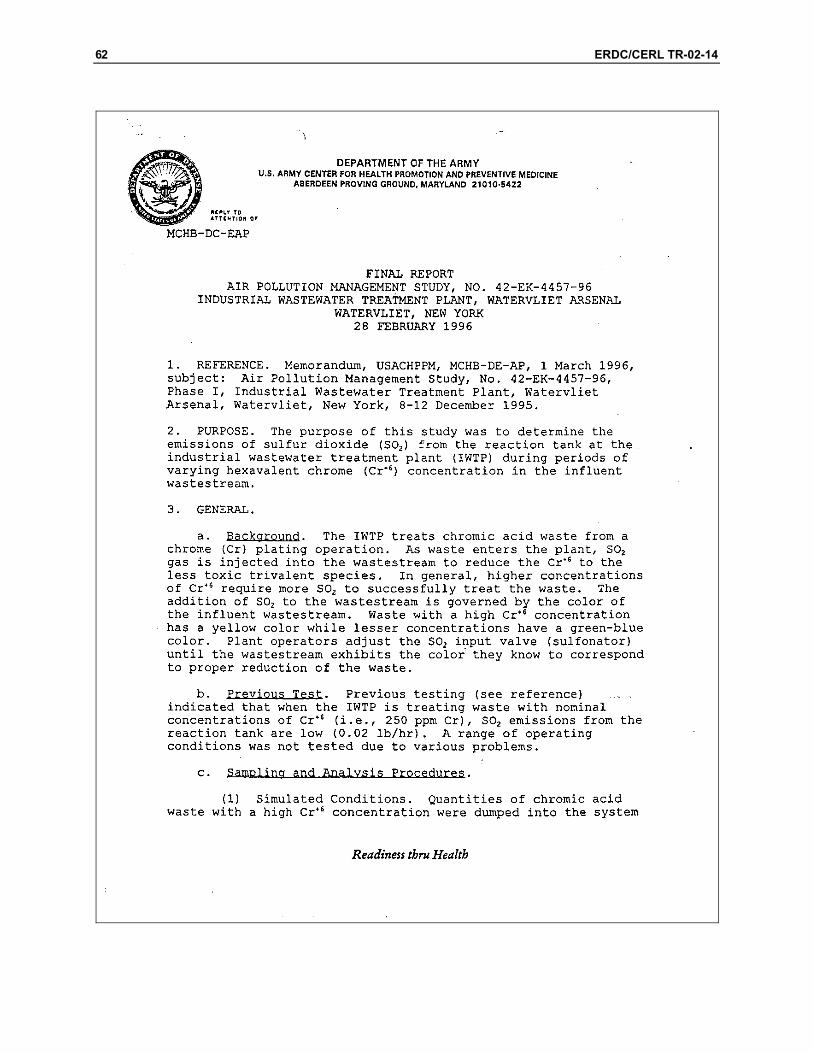
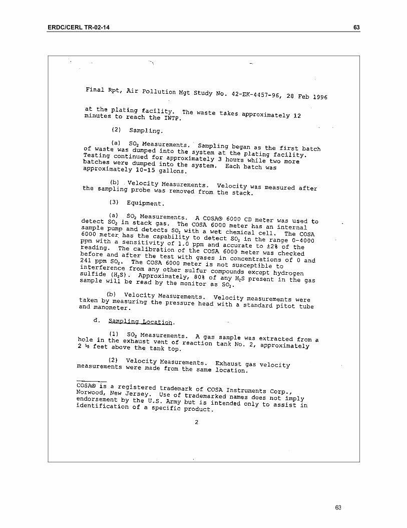
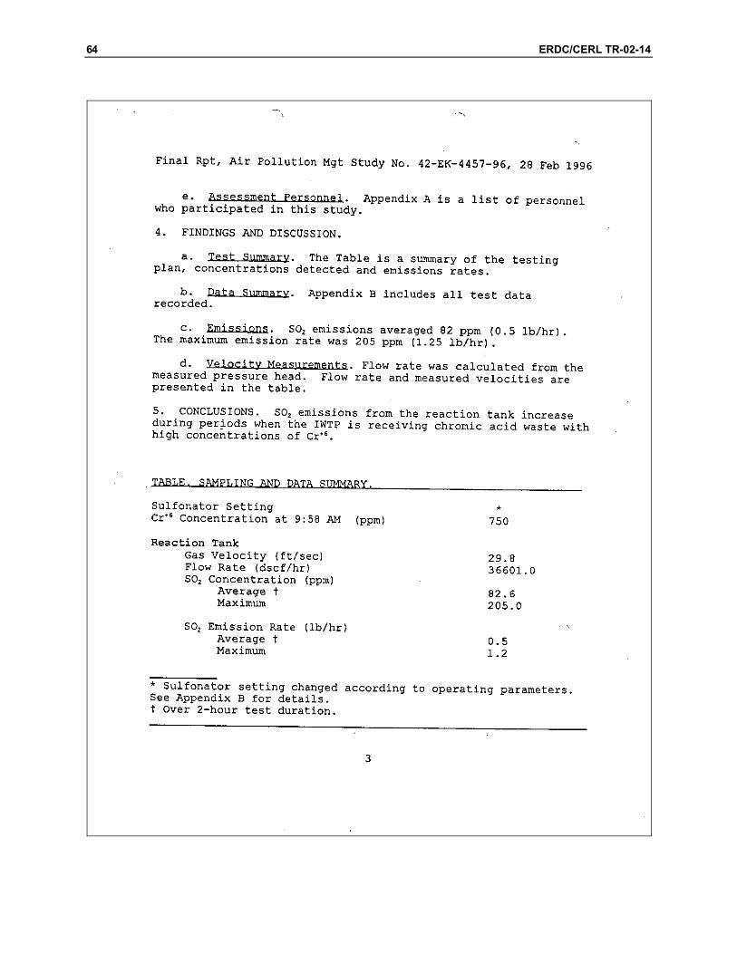
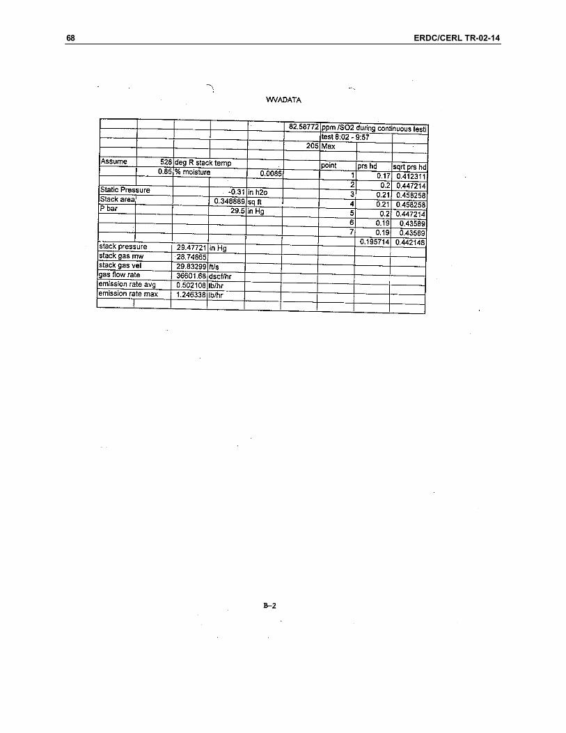
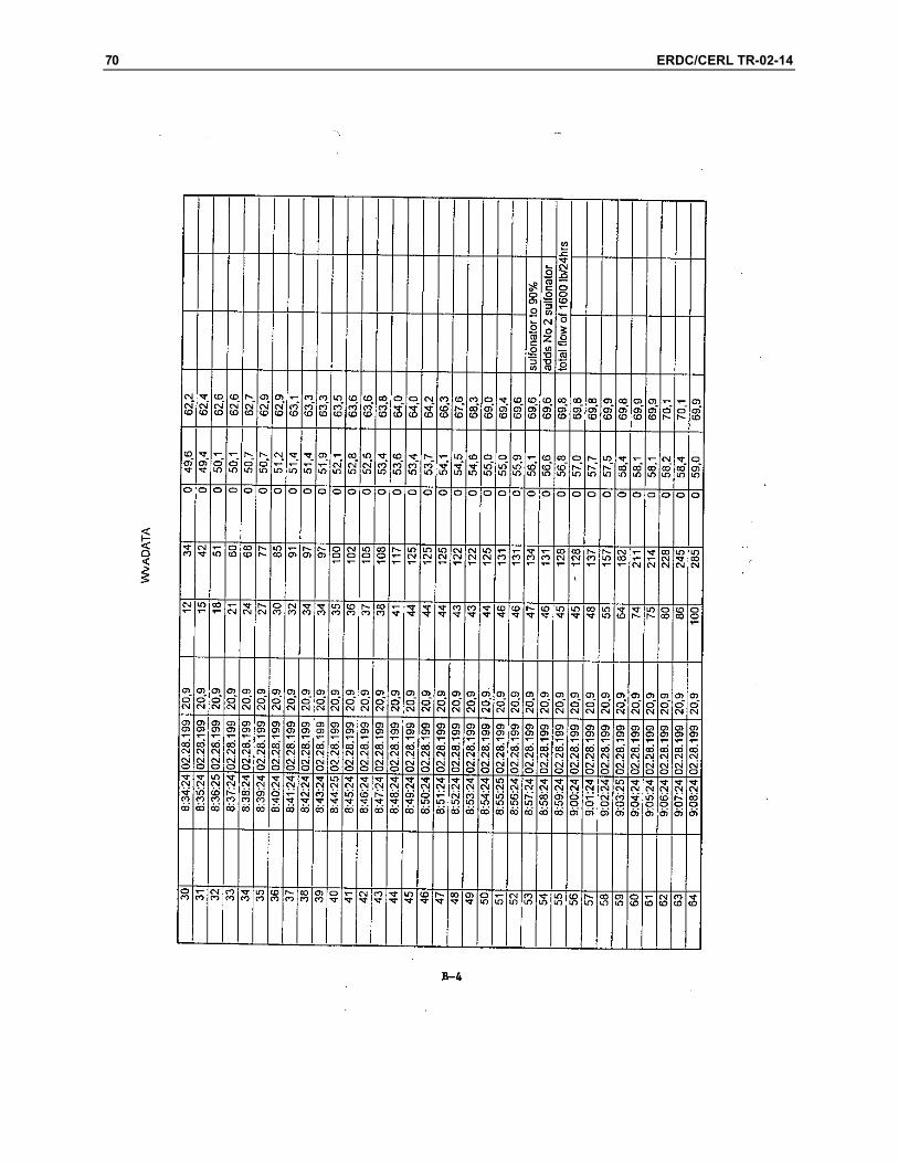
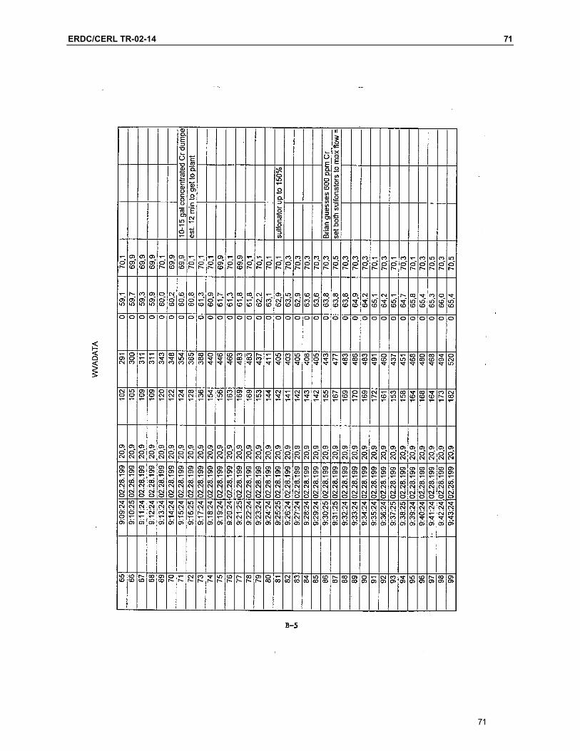
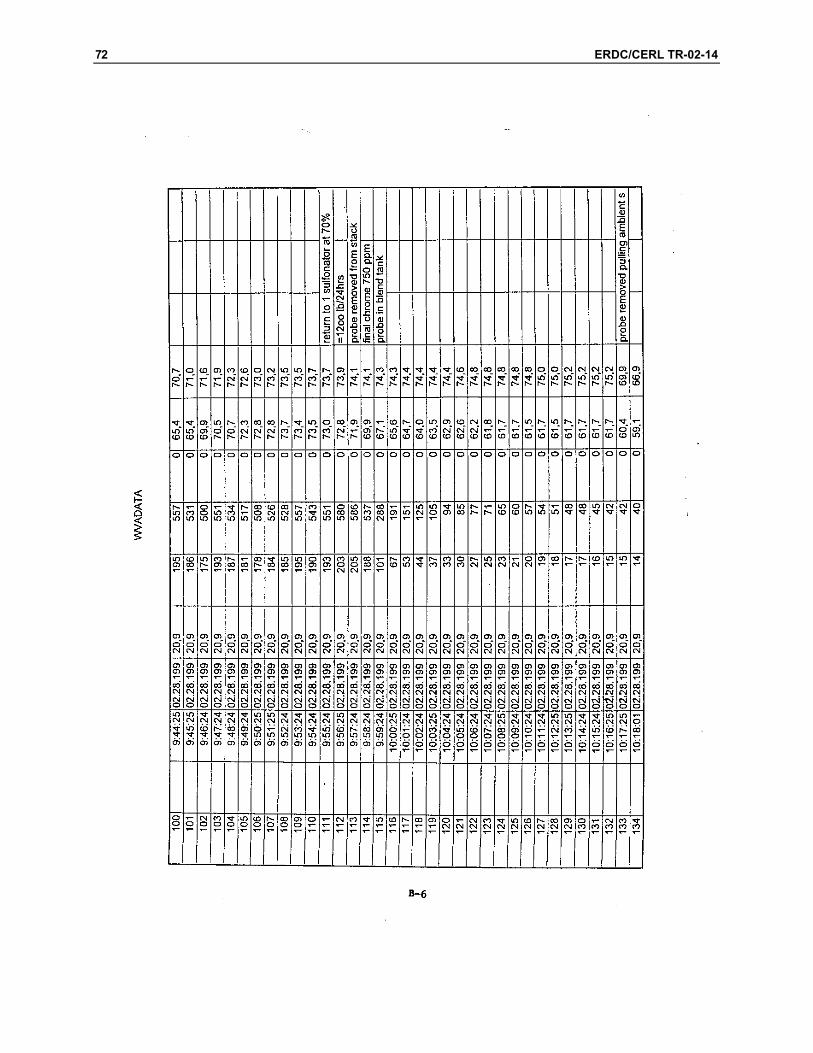
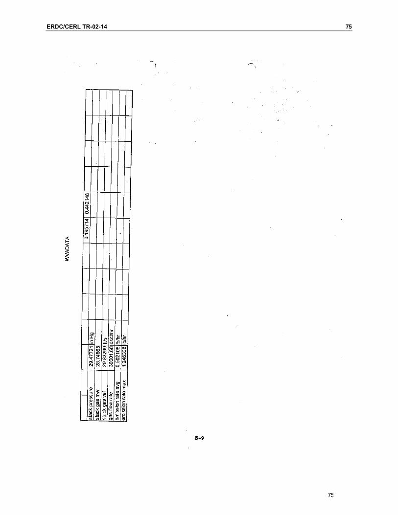
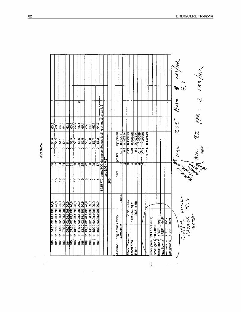
The criteria for design selection of ventilation air SO2 control for the WVA IWTP were developed from the Air Pollution Management Study No. 42-EK-4457-96,U.S. Army Center for Health Promotion and Preventative Medicine (Appendix A). This report included multiple studies conducted at the plant over the last 5 years. One study reported the flow rate and SO
2 concentration of the exhaust air from Reaction Tank Number 2 during chrome processing. The maximum con-centration of SO2 was 205 ppmv. The flow rate of air from the tank was 36,601 dscf/h. Another study indicated that an estimate of H2S concentration to be be-tween 2 – 5 ppmv.
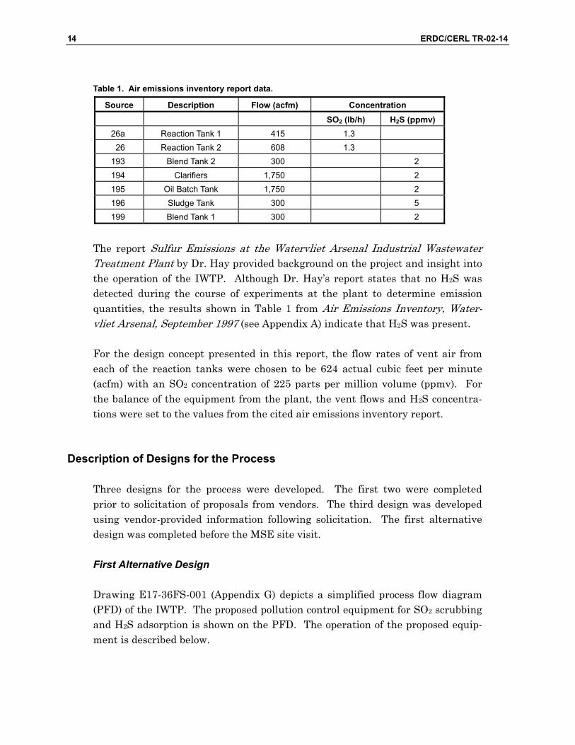
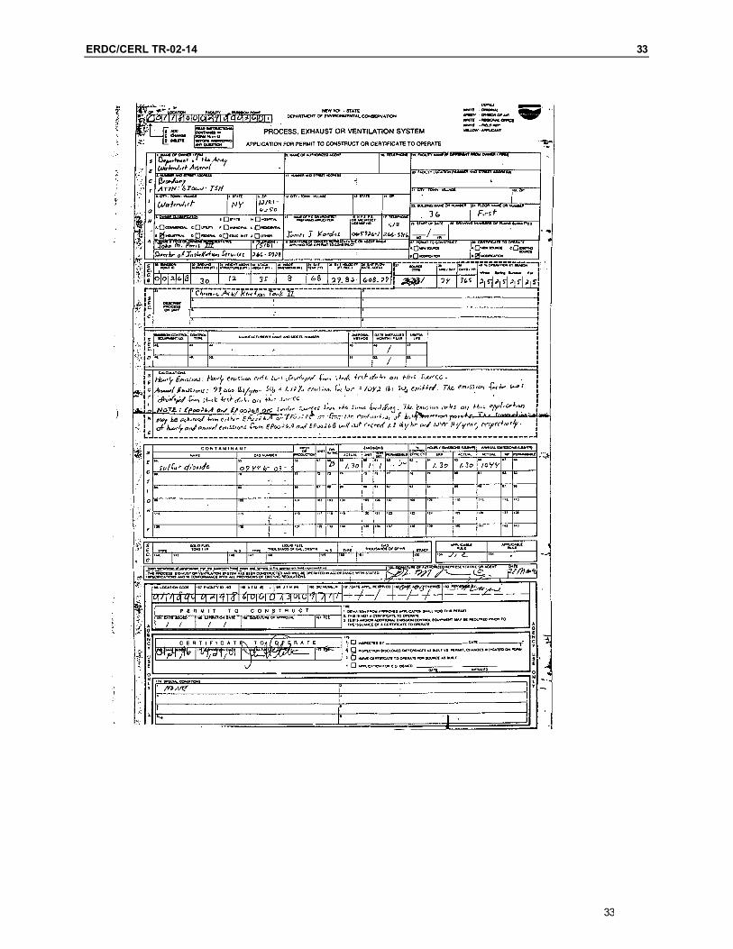
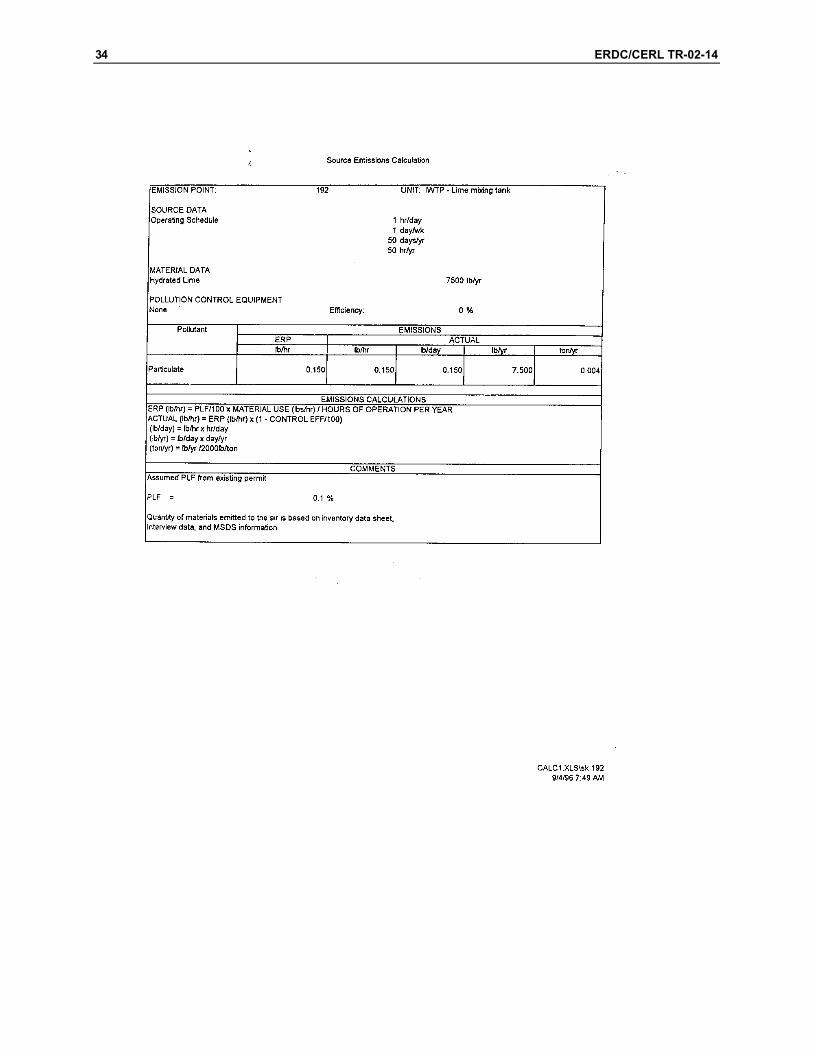
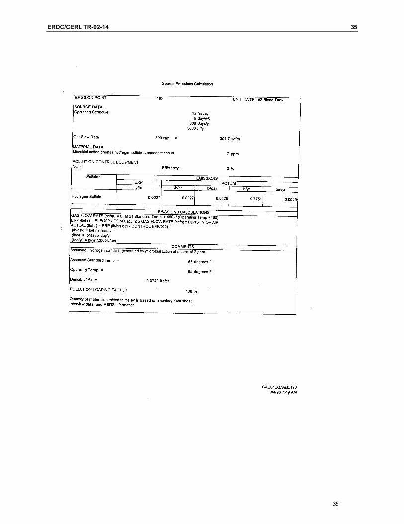
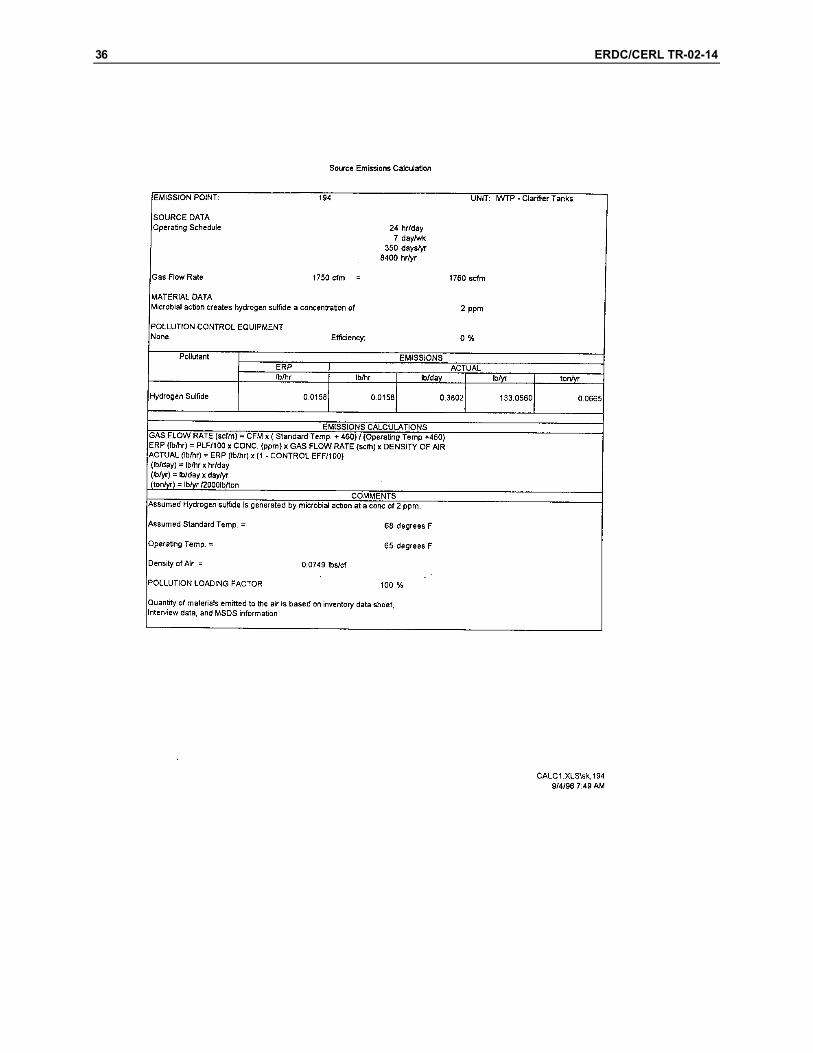
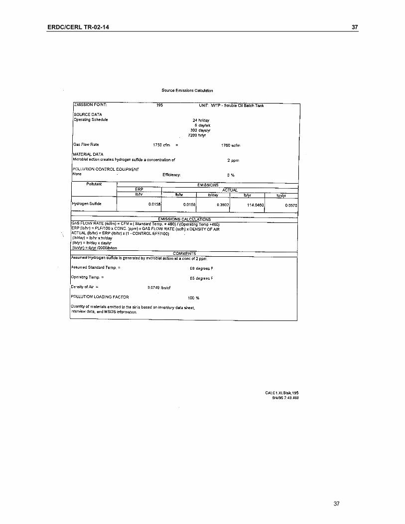
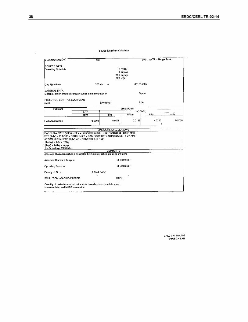
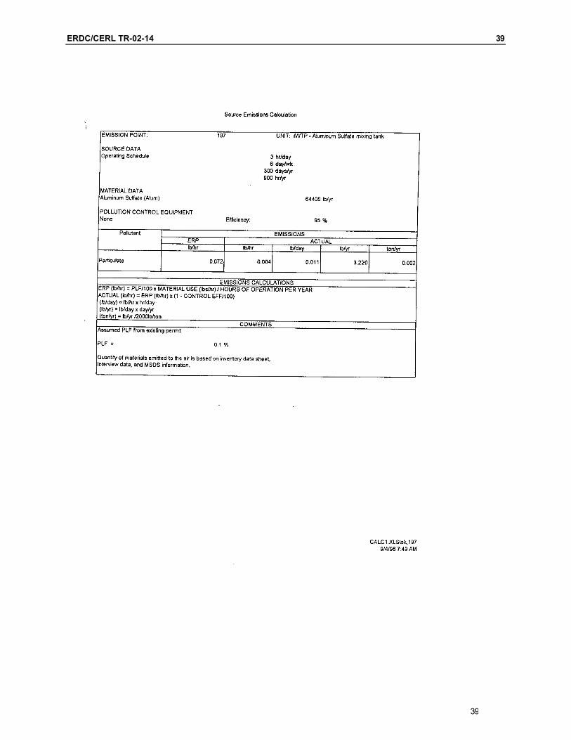
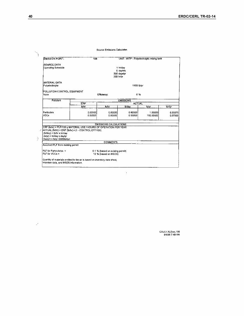
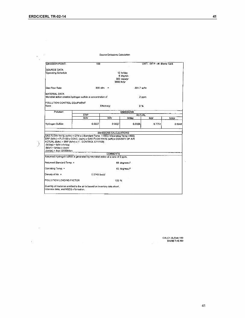
The report Air Emissions Inventory, Watervliet Arsenal, September 1997 con-tains additional information used as criteria for the design. This report is also provided in Appendix A. The report gave ventilation fan flow rates and SO2 emission rates at point source locations at the IWTP. An estimate of H2S con-centration was also included in the report. Table 1 repeats the data from this report.
13
14 ERDC/CERL TR-02-14
Table 1. Air emissions inventory report data.
Source Description Flow (acfm) Concentration SO2 (lb/h) H2S (ppmv)
26a Reaction Tank 1 415 1.3 26 Reaction Tank 2 608 1.3
193 Blend Tank 2 300 2 194 Clarifiers 1,750 2 195 Oil Batch Tank 1,750 2 196 Sludge Tank 300 5 199 Blend Tank 1 300 2
The report Sulfur Emissions at the Watervliet Arsenal Industrial Wastewater Treatment Plant by Dr. Hay provided background on the project and insight into the operation of the IWTP. Although Dr. Hay’s report states that no H2S was detected during the course of experiments at the plant to determine emission quantities, the results shown in Table 1 from Air Emissions Inventory, Water-vliet Arsenal, September 1997 (see Appendix A) indicate that H2S was present.
For the design concept presented in this report, the flow rates of vent air from each of the reaction tanks were chosen to be 624 actual cubic feet per minute (acfm) with an SO2 concentration of 225 parts per million volume (ppmv). For the balance of the equipment from the plant, the vent flows and H2S concentra-tions were set to the values from the cited air emissions inventory report.
Description of Designs for the Process
Three designs for the process were developed. The first two were completed prior to solicitation of proposals from vendors. The third design was developed using vendor-provided information following solicitation. The first alternative design was completed before the MSE site visit.
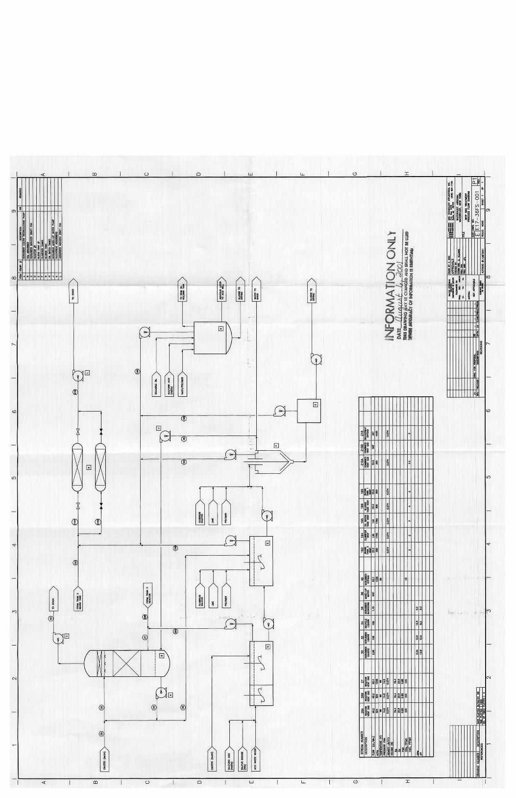
First Alternative Design
Drawing E17-36FS-001 (Appendix G) depicts a simplified process flow diagram (PFD) of the IWTP. The proposed pollution control equipment for SO2 scrubbing and H2S adsorption is shown on the PFD. The operation of the proposed equip-ment is described below.

ERDC/CERL TR-02-14 15
Sulfur dioxide wet scrubber (absorber)
Due to phase equilibrium, a partial pressure of SO2 will always be in the head-space of the reaction tanks. From the documents inspected while developing the design, it appears that SO2 emission fluctuates in the vent gas from the reaction tanks because SO2 concentrations exceed what is necessary for the chromate re-duction reaction. This was just a supposition, however, since no information had been supplied that stated the concentration requirements for the reduction reac-tion. In addition, there was no evidence that the emission of SO2 exceeded any air-permit limitation.
To remove the SO2 from the vent gas, using a packed column scrubber (equip-ment list item A) was proposed. Aqueous NaOH would be used to absorb and neutralize the SO2. Since the concentration of SO2 is low in the vent gas, the quantity of caustic required is also low.
As shown in the PFD, the vent gas from the two reaction tanks (streams 26a and 26b) are combined and are drawn into the bottom of the scrubber by the induced draft fan (item C). The combined gas stream, at approximately 92.4 pounds per minute (approximately 1,248 acfm), flows upward in the tower’s packing and is counter-currently contacted by recycled scrubber liquor. The scrubber liquor flows into a sump at the bottom of the tower and is recycled to the top. The level of the liquor in the sump is controlled by blowing down the excess through stream 36 to the blend tanks. If the sump level is low, additional clarifier over-flow water can be added through stream 38.
NaOH is used as a reagent for SO2 absorption and to maintain the pH of the scrubber at about 8. The quantity of caustic shown on the PFD is minimal; the system will be designed to inject at least 10 times the required amount to allow for fluctuations in SO2 concentration, and to allow rapid pH adjustment.
The level of scrubber liquor in its sump controls blows down from the absorber. The blow-down quantity shown is essentially the water coming into the system with the aqueous caustic. Since Watervliet is a humid location, the quantity of scrubber blow-down will increase from that shown in the PFD, especially in the summer. In the winter, make-up should be added at approximately the same rate as the caustic to keep the total dissolved solids (TDS) concentration in the liquor relatively low.
15
Blow-down reports to the blend tanks through stream 36. By rejecting blow-down to the blend tanks, installation of the scrubber will not increase plant waste streams. The blow-down quantity is sufficiently low and should not have
16 ERDC/CERL TR-02-14
an effect on the action of the blend tanks, especially since it will consist of the same components entering the blend tanks from the reaction tanks.
Absorber equipment design
A performance specification was written for the SO2 scrubber and sent as a Re-quest for Quotation (RFQ). There are many scrubbing equipment vendors on the market who have built competitive equipment. Typically, a scrubber such as the one proposed for the IWTP would be made of fiber-glass reinforced plastic (FRP) and would require weatherization to prevent freezing (unless it is installed in-side a building).
A preliminary sizing of a typical SO2 scrubber had been made based on the in-formation shown in the PFD. The packed bed scrubber would be in the range of 30 to 36 inches in diameter. The height of the packing in the scrubber would be between 4 to 6 feet and the overall height would be between 12 to 15 feet. The scrubber was designed at a liquid to gas ratio of about 10 gpm of liquor to 1,000 acfm of inlet gas; this ratio is a minimum for good wetting of the packing, and may need to be increased to 20 gpm/acfm in a final design.
Vendors’ designs may vary from the above because of operating experience and proprietary information. This application is nontypical due to the low inlet con-centration of SO2.
Hydrogen sulfide adsorption
The proposed control for H2S is the commercial adsorbent process “SulfaTreat.” Information on the process is available from the company’s Web site (http://www.sulfatreat.com); information from that site is abstracted below.
The SulfaTreat process is a fixed bed or batch type granular hydrogen sulfide reactant consistent in shape and size contained in a pressure ves-sel. The starting material and spent product are safe and stable. Gas or vapor flows through the granular product in the bed chemically reacting with hydrogen sulfide forming a stable and safe byproduct. Consumption of the SulfaTreat product is only dependent on the amount of hydrogen sulfide that passes through the bed economically matching the need for H2S removal with variations in system flow conditions and outlet specifi-cation regardless of the total volume or other common components of the gas. Computer assisted vessel design specifications are based on highest gas flow rates, minimum operating temperature, inlet H2S content and
ERDC/CERL TR-02-14 17
maximum outlet specification, minimum operating pressure and allow-able pressure drop, water content of the gas, and convenient operation. Flexibility of this process allows the system to adapt to variations in H2S outlet specifications that may result from changes in operating prefer-ences or tighter regulations often without additional capital equipment or system retrofitting. Predictable pressure drops, long bed life, easy and safe to handle, and a simple reliable operation are a few of the features of the SulfaTreat process.
The output of the ventilation fans from the blend tanks, the clarifiers, the oil batch tanks, and the sludge tank (equipment items E, F, G, and H) will be com-bined and will report to a set of parallel SulfaTreat reactors (item K). The flows from the fans are assisted by the adsorber-induced draft fan (item L). Since the concentration of H2S is reportedly low, the size of the reactors will be minimal and operation long-term. Depletion of each reactor is indicated by H2S break-through at the exit of the reactor.
Adsorber equipment design
The best description of the required equipment is available on the company’s Internet site, as mentioned above.
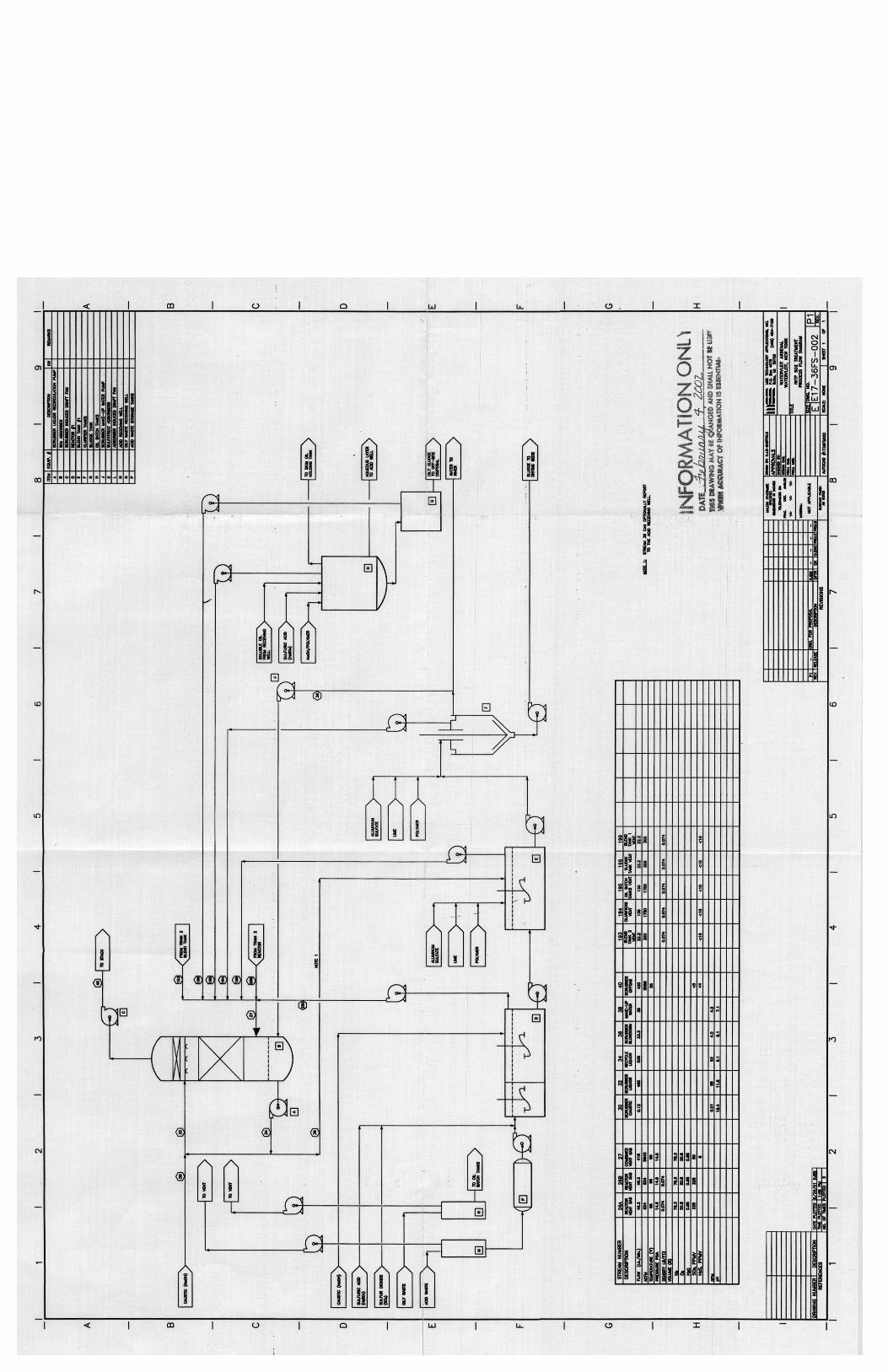
Second Alternative Design
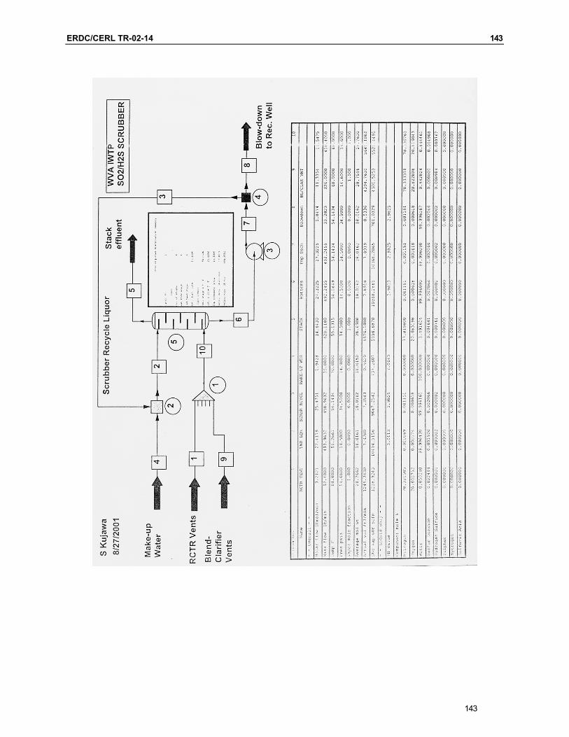
After evaluation of the first design, a second design was developed to eliminate the Sulfa-Treat adsorbers in favor of drawing all vent streams into a common header and using a wet scrubber for both SO2 and H2S absorption. The resulting design is depicted in PFD E17-36FS-002 (Appendix G) and a ChemCad model of the scrubber is included in Appendix B.
For this alternative design, a wet scrubber was considered that used only clari-fier water to scrub the SO2; no NaOH (caustic) was added. It was found that us-ing water alone to scrub the vent streams would remove only about 8 percent of the SO2 and no H2S. It was concluded, therefore, that caustic would be needed to ensure complete scrubbing of the vent streams.
17
The flow sheet E17-36FS-002 depicts the system using caustic to effect scrubbing of SO2 and H2S. The operational description of the process is similar to that of the first alternative. Initial absorber equipment design estimated a larger di-ameter absorber, at about 42 inches inside diameter, and a packing depth of nearly 12 feet of 2-inch pall rings. This design was used as a basis for developing the performance specification that was sent out for quotation. It was felt that
18 ERDC/CERL TR-02-14
commercial suppliers would propose a similar absorber that may be shorter if based on operational experience.
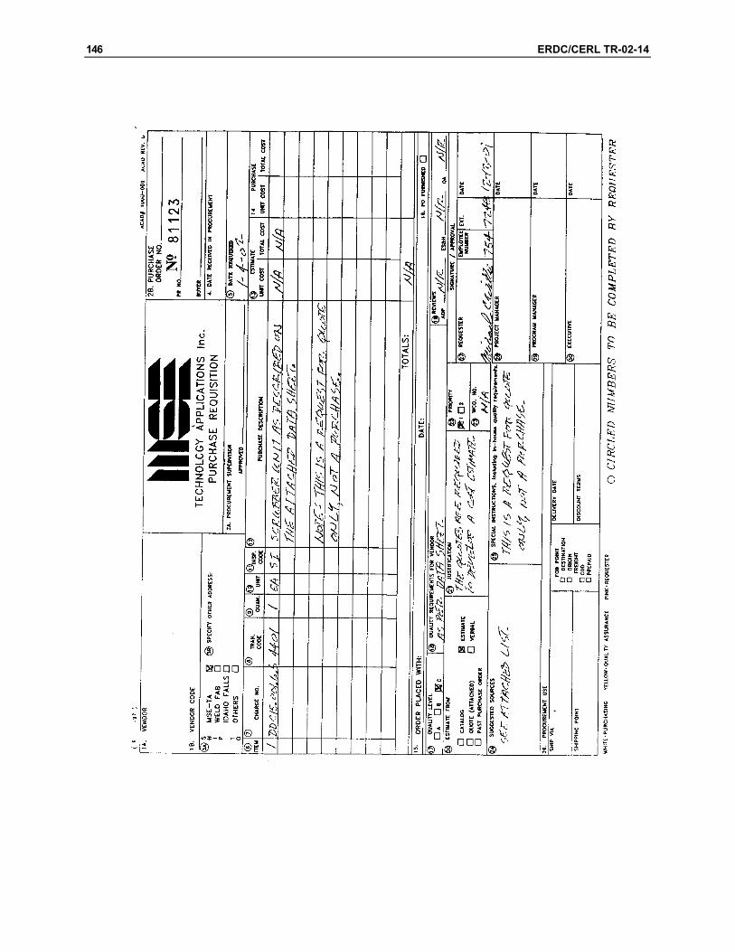
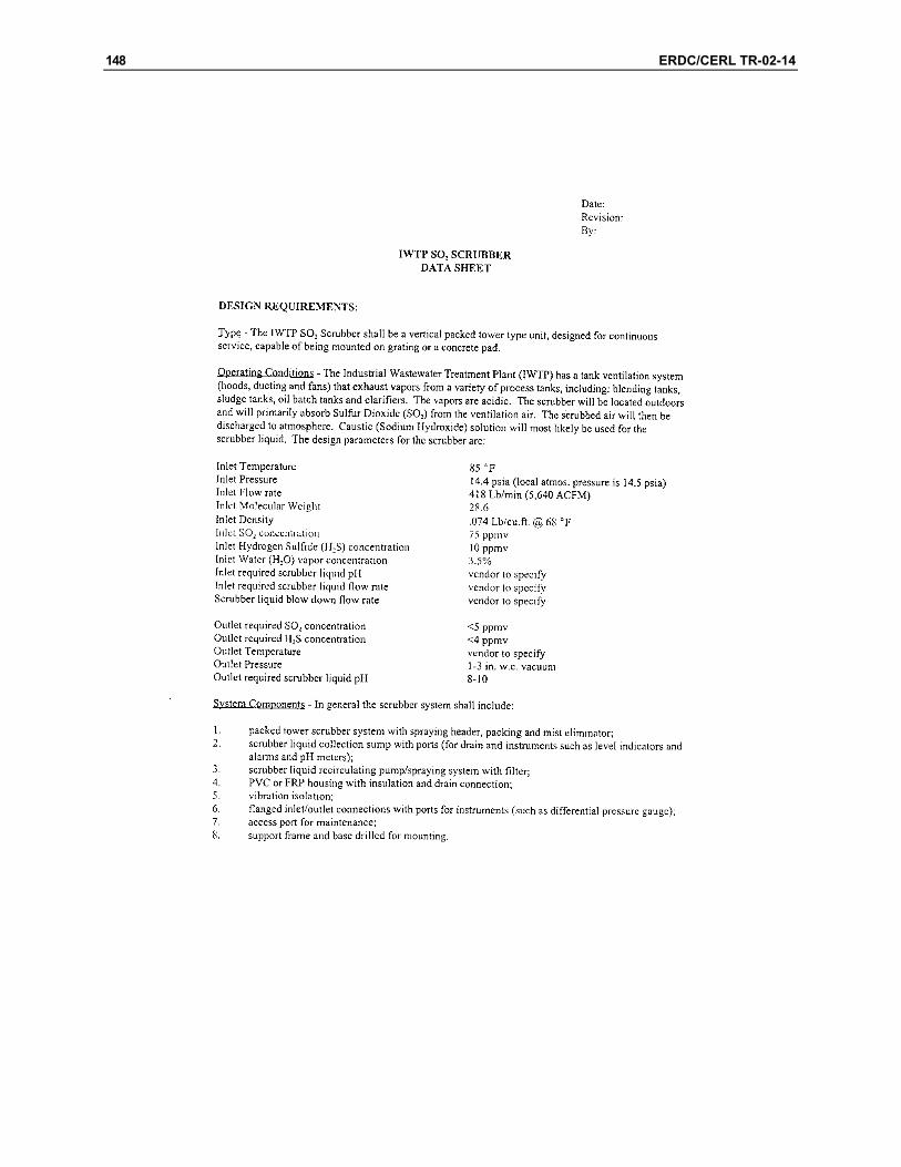
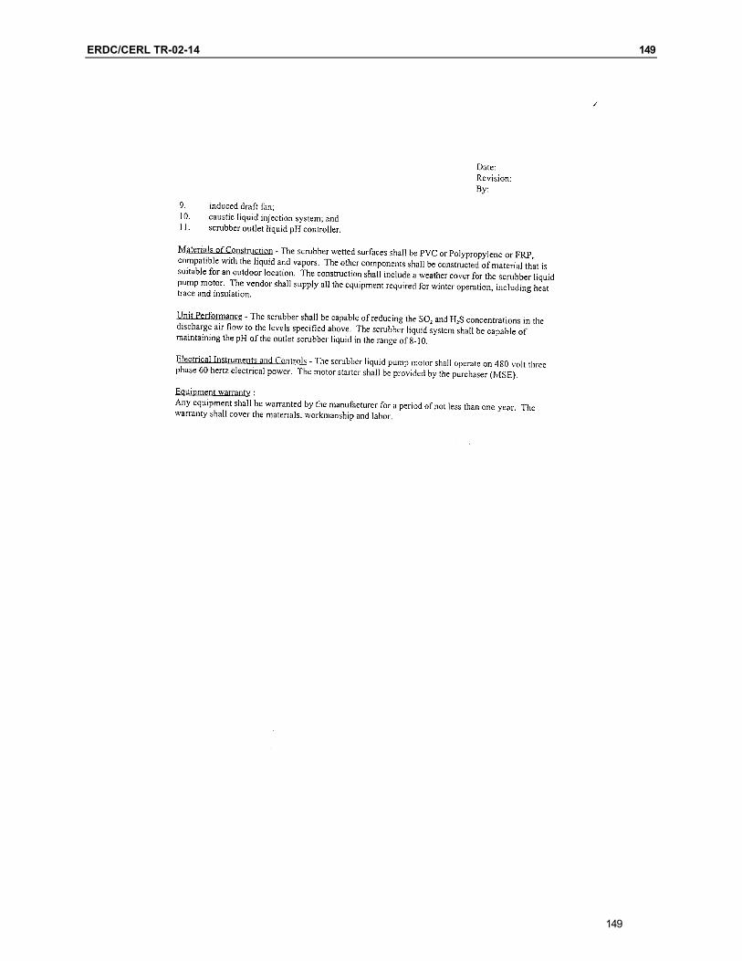
An equipment data sheet was developed that outlines the operating conditions, system components, construction materials, unit performance, controls, and equipment warranty. This data sheet (Appendix C) was developed using results of the ChemCad model and prior experience in designing and selecting packed column scrubbers.
Recommended Design
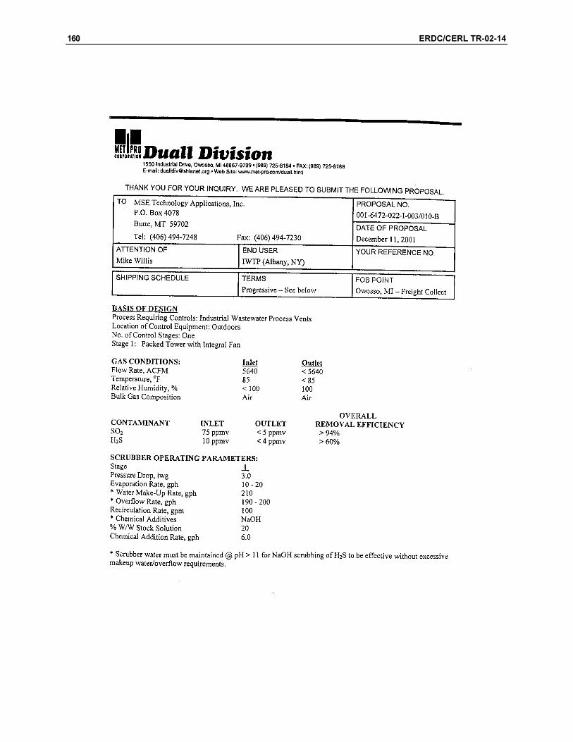
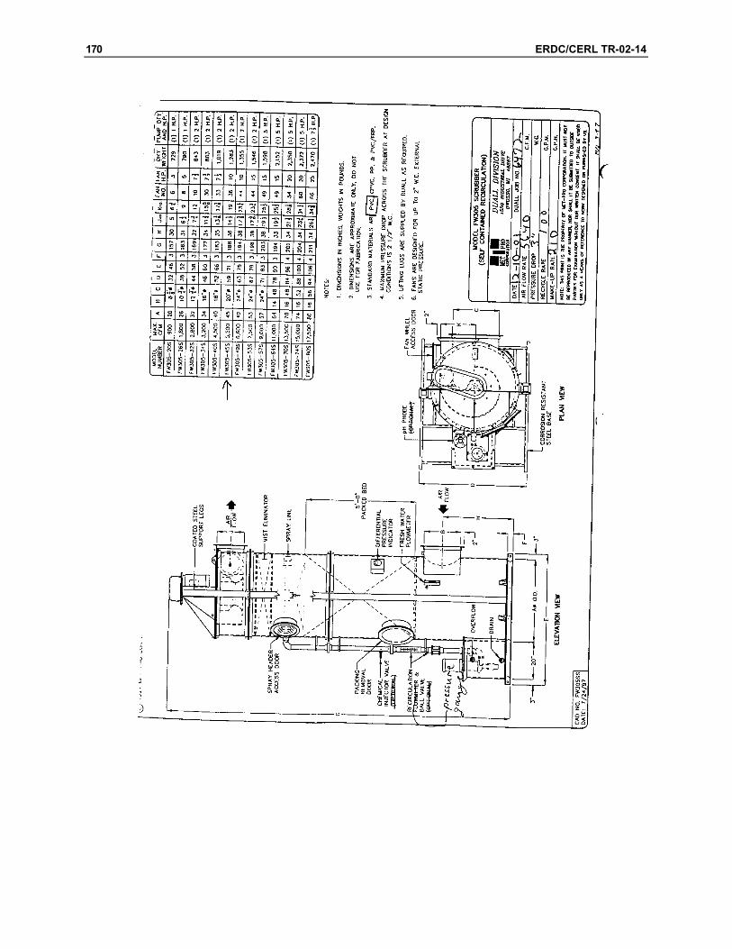
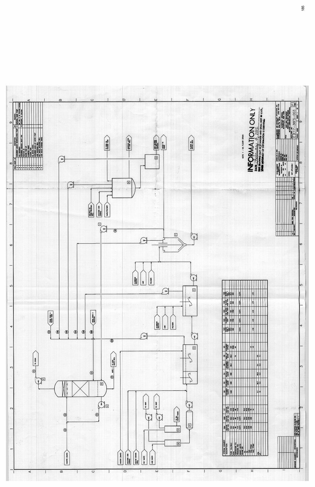
Drawing E17-36FS-003 (Appendix G) depicts the design recommended by MSE and proposed by the Duall Division of Met Pro Corporation. The flow sheet de-picts the operating parameters and inlet concentrations from the performance specification that were to be used for design.
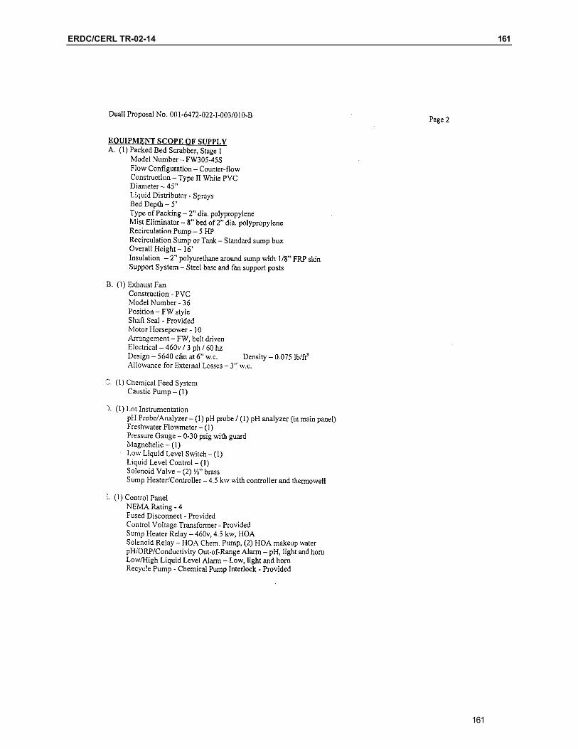
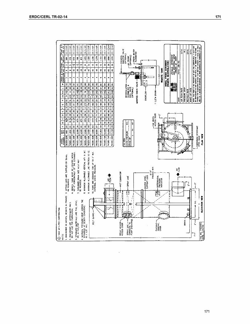
Met Pro proposed a 45-inch-diameter scrubber with 5 feet of 2-inch polypropyl-ene packing. The system can remove better than 94 percent of the SO2 and more than 60 percent of the H2S from the combined vent stream. The makeup water rate from the clarifier is higher than that estimated from the second alternative flow sheet. The higher water rate may be caused by the need to keep ionic strength or TDS concentration low. The blow-down water is higher as a conse-quence. Since the make-up water is from the clarifier, and the blow-down water reports back to the acid receiving well, there is no net use or disposal of water from the scrubbing system. Some water losses will occur due to evaporation, however.
The Met Pro design uses a somewhat higher flow rate of caustic solution. The higher caustic usage is needed to keep the recycle liquor pH above 11, a level needed to effectively scrub H2S without excessive make-up water requirements.
The Met Pro design depicts blow-down overflowing to a drain. Level in the sump of the scrubber is controlled by make-up water flow. Drawing E17-36FS-003 (Appendix G) depicts the overflow water draining to an existing building sump from where it is pumped or drained to the acid receiving well. If the building sump cannot be used for this purpose, a pump would need to be added to accom-plish transport of the blow-down to the well.

ERDC/CERL TR-02-14 19
3 Vendor Quotations
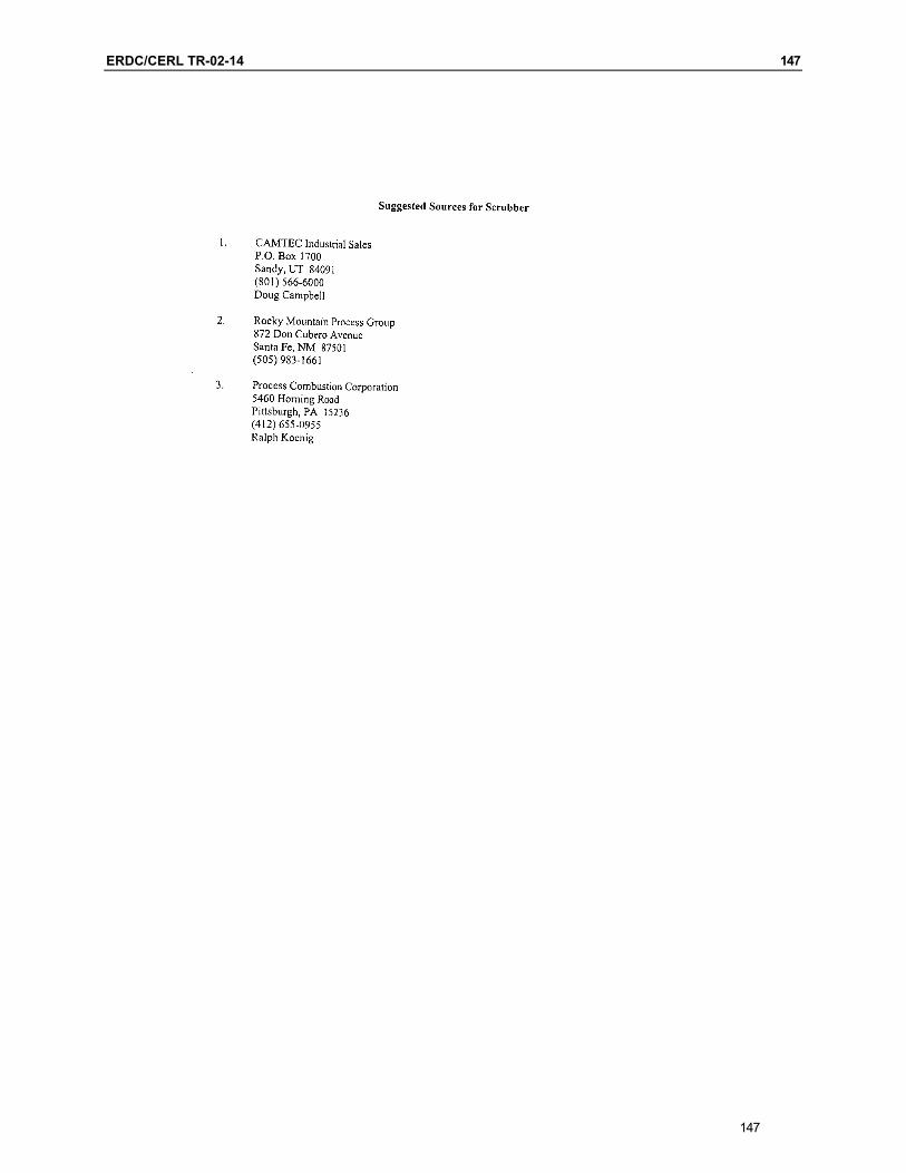
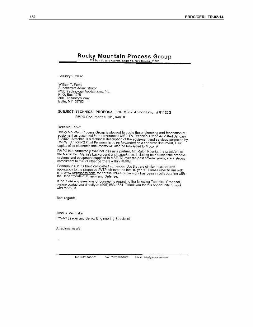
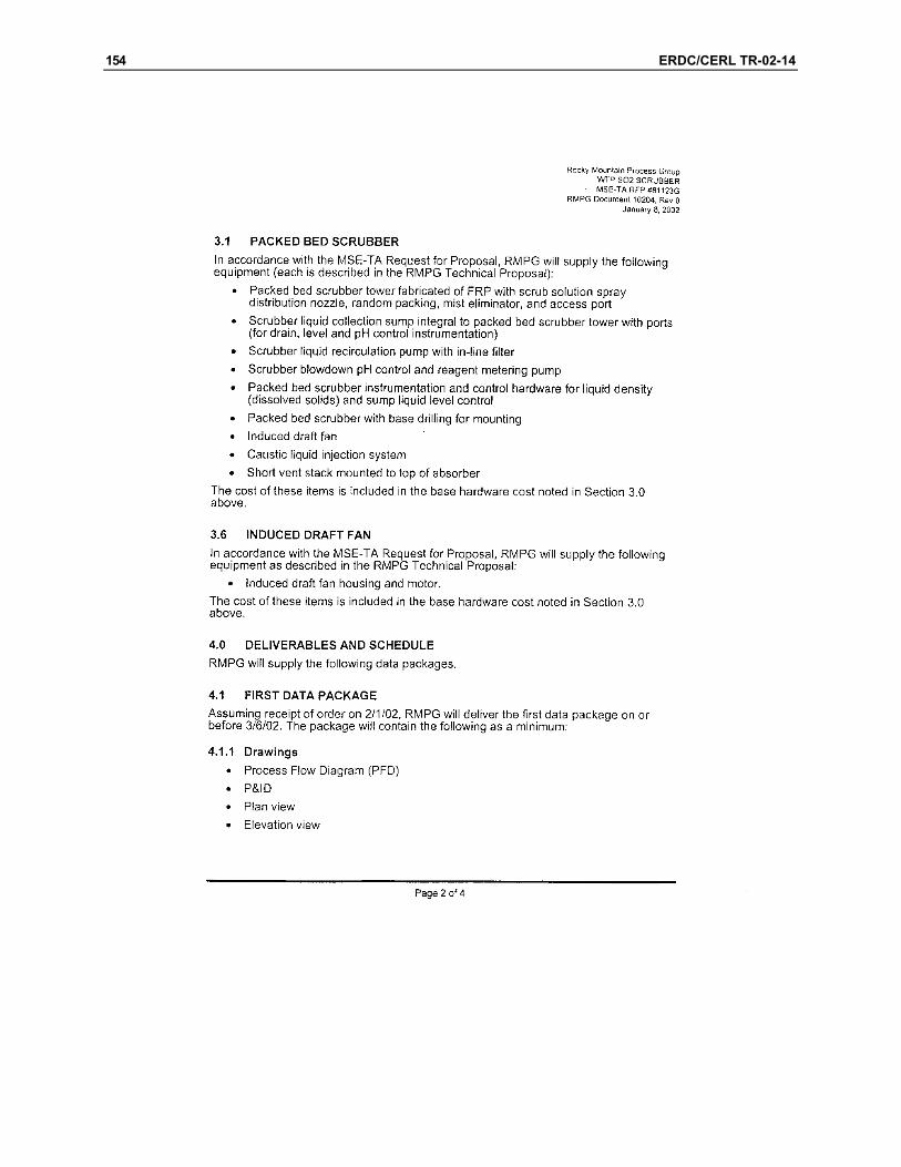
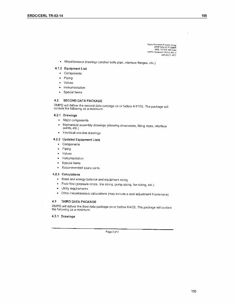
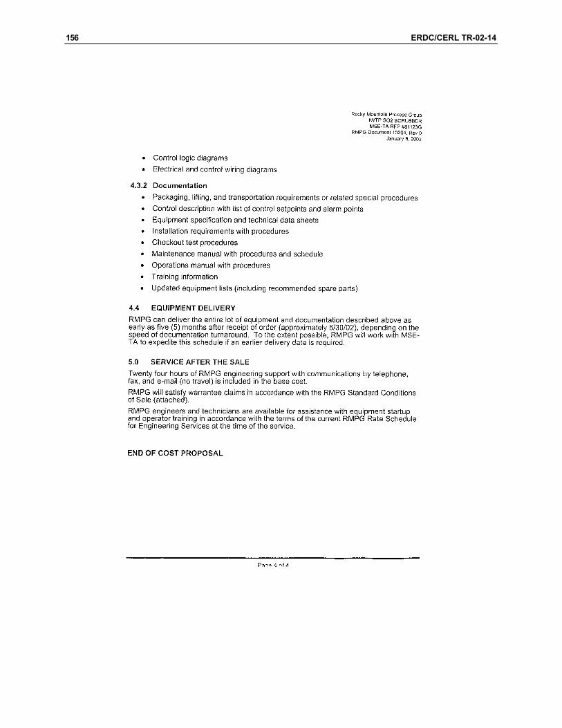
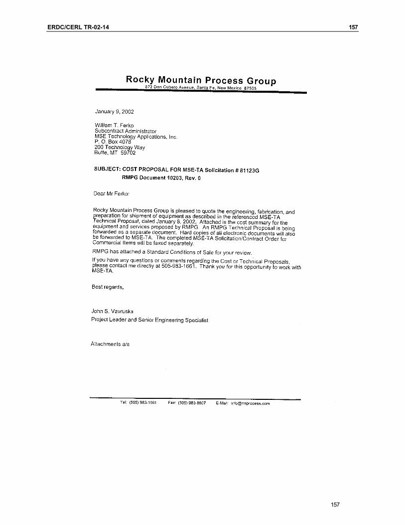
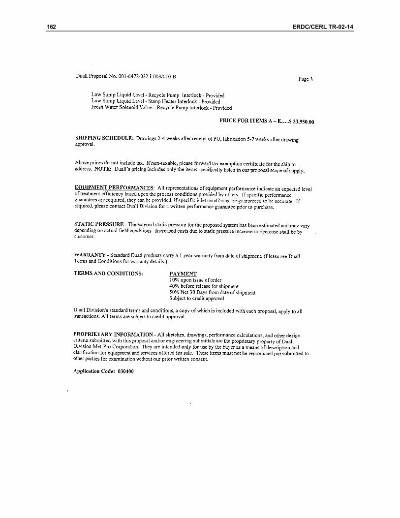
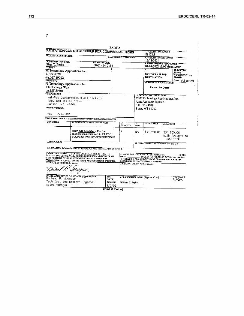
A list of vendors was developed and an RFQ was sent to the equipment provid-ers. The three sources selected to receive an RFQ are shown in Table 2. The vendors were asked to submit a quote within 21 days of receipt of the technical proposal. Two companies responded with a quote, and one of the companies, Met-Pro Corporation Duall Division, provided equipment drawings with their quote. The vendor quotes received are included in Appendixes D and E.
Review of the two vendor quotes revealed a large cost differential between the proposed equipment. This difference can be attributed to the following factors:
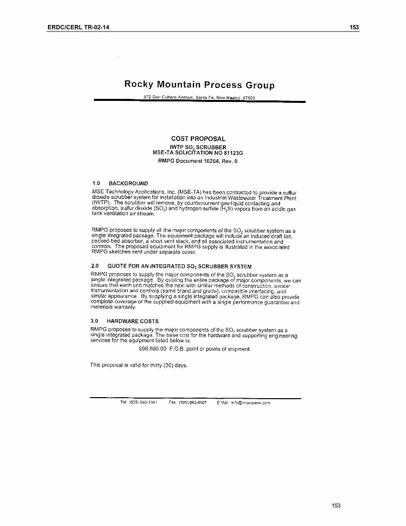
Met-Pro Corporation Duall Division produces an off-the-shelf item. • • Rocky Mountain Process Group (RMPG) manufactures custom-built equip-
ment and provides engineering design services with all contracts. The scope of work from RMPG also included extensive engineering review, operator training, start-up assistance, and documentation, which were not required.
Table 2. Vendor sources.
Vendor Name Address/Phone CAMTEC Industrial Sales P.O. Box 1700
Sandy, UT 84091 (801) 566-6000
Rocky Mountain Process Group 872 Don Cubero Avenue Santa Fe, NM 87501 (505) 983-1661
Process Combustion Corporation 5460 Horning Road Pittsburgh, PA 15236 (412) 655-0955
Met-Pro Corporation Duall Division 1550 Industrial Drive Owosso, MI 48867 (989) 725-8184
19
20 ERDC/CERL TR-02-14
4 Recommendations
Based on the lower cost of the Met-Pro Corporation Duall Division equipment, a preliminary design and a cost estimate were developed using the equipment in-dicated in Appendix E. A ChemCad model of the scrubber conforming to the specification operating parameters is included in Appendix F.
Equipment Description
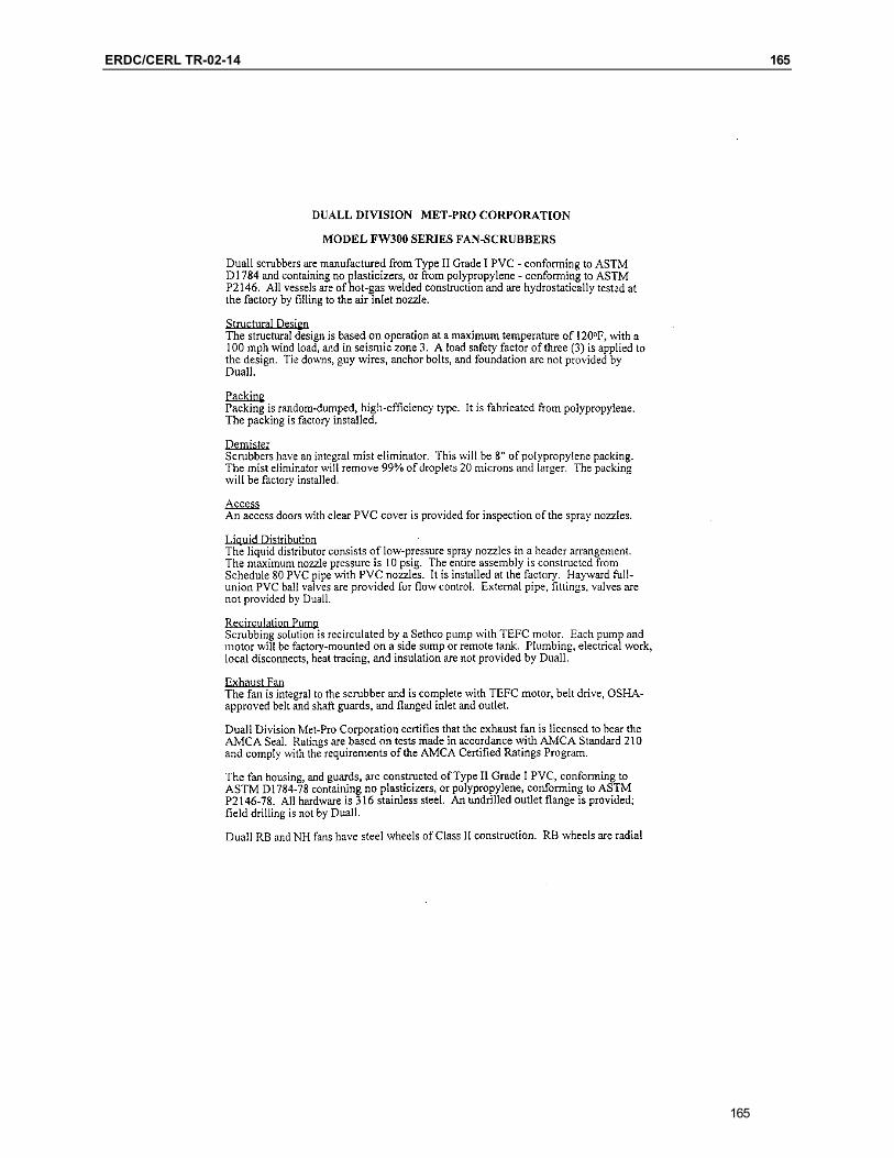
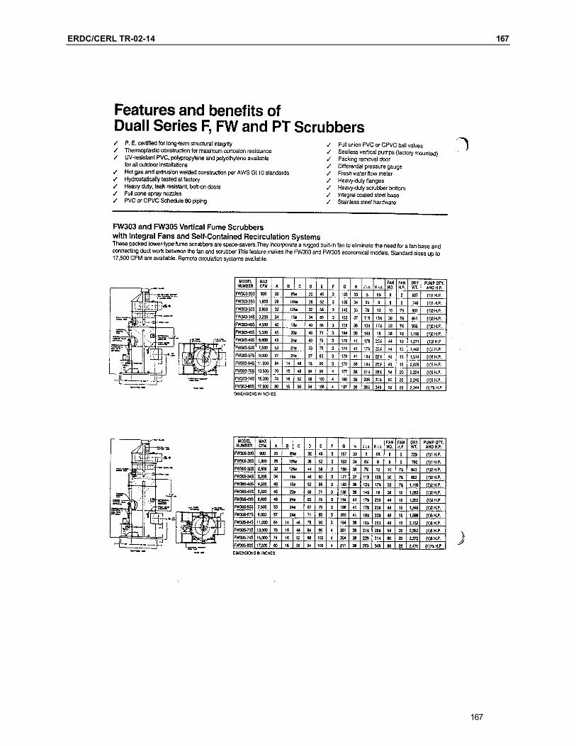
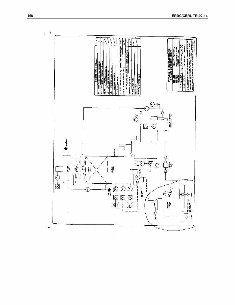
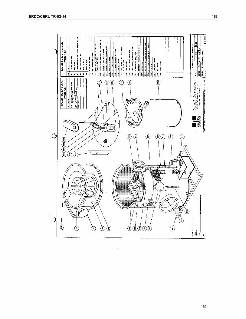
The Met-Pro Corporation Duall Division equipment uses a single stage packed tower scrubber with an integral exhaust fan. Additional equipment includes a chemical feed pumping system, instrumentation to operate and monitor the process, and a control panel that contains a supply power, parameter indication, alarms, controls, and process interlocks.
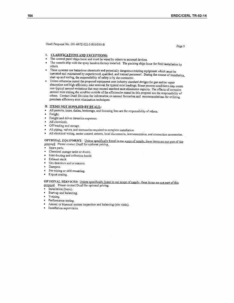
Additional costs associated with the equipment but not included in the base price estimate: • • •
• •
• •
installation of packing into tower, connection of control panel to existing plant controls and alarms, electrical wiring, motor control centers, local disconnects, instrumentation and connection accessories, chemicals, additional piping, valves, and accessories required for connection to the IWTP, installation, start-up, balancing, and training services, and performance testing and scheduled system inspections.
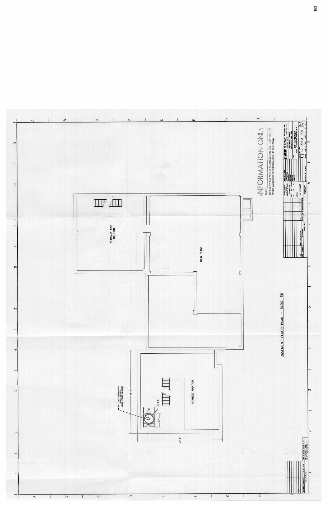
Plan Views of Equipment Installation
Installation of the equipment in the cyanide room at the IWTP is indicated in Drawing No. EE17-36GA-001 (Appendix G). As shown in the drawing, the equipment can be located inside the building with the exception of the exhaust stack exiting through the roof.
ERDC/CERL TR-02-14 21
Site Preparation Requirements
To use the cyanide room, existing process equipment will need to be removed and disposed of according to facility disposal methods. Additionally, some modifica-tion of the building structure will need to be completed prior to the equipment installation. The installation of a door opening of at least 8 feet needs to be added to the room. Also, a crane capable of lifting at least 1,500 pounds is re-quired temporarily.
A partial listing of the existing equipment that requires removal prior to instal-lation includes:
21
• • • • •
• • •
• • • •
two cyanide wastewater storage tanks, one instrumentation panel, two cyanide wastewater pumps, miscellaneous piping and grating, and associated instruments and alarm signals.
Electrical Requirements
Additional plant electrical utilities required to install and maintain the unit in-clude:
460 volt/3 phase/60 Hertz power, 120 volt/1 phase/60 Hertz power, and pump motor start circuits.
Piping and Mechanical Requirements
The design of the system requires water and aqueous NaOH be added to the sys-tem to perform the necessary scrubbing. Additionally, a unit drain line is re-quired to circulate the spent water back through the chromic acid wastewater treatment process. The main advantage of using the proposed system is the use of the existing plant-clarifier water for the process water supply and the ability to add the spent water back into the process.
The process piping requirements are: one Plant Service Water (PSW) supply line for cleaning of equipment, one water supply line from the two plant clarifier units, one unit drain line that runs from the unit to the IWTP intake sump, one drain line pump (if required),
22 ERDC/CERL TR-02-14
• one clarifier supply pump, and •
• • • • • •
one NaOH injection pump (supplied by Duall).
The exhaust from the scrubber will be vented to the outside atmosphere through the roof of the IWTP. This will require a stack to be installed that runs from the exhaust line of the equipment through the roof and extends approximately 10 feet above the roof in a similar manner as the existing vents. Additionally, the ventilation air from the process equipment has to be brought to a common header into the proposed equipment.
After installation of the equipment on the basement floor of the facility (elevation 17.0 feet), new grating will need to be installed on the ground floor at elevation 34.0 feet (above the proposed equipment).
Instrumentation Requirements
The proposed system is capable of operating using local controls. A local control panel contains the instruments shown in Appendix E. To ensure the proposed equipment is operating properly, all operating parameters should be tied into the IWTP alarm system and Line One Control Panel. This will allow operations per-sonnel to monitor the status of the equipment, and will provide an audible alarm if a problem occurs during operation.
Operating and Maintenance Requirements
The operating and maintenance requirements for the proposed scrubber system are:
replenishment of caustic solution, inspection and replacement of the polypropylene packing, inspection and maintenance of the spray header piping, inspection and maintenance of the caustic pumping system, inspection and maintenance of the drain piping, and inspection and maintenance of the exhaust fan and exhaust stack.
ERDC/CERL TR-02-14 23
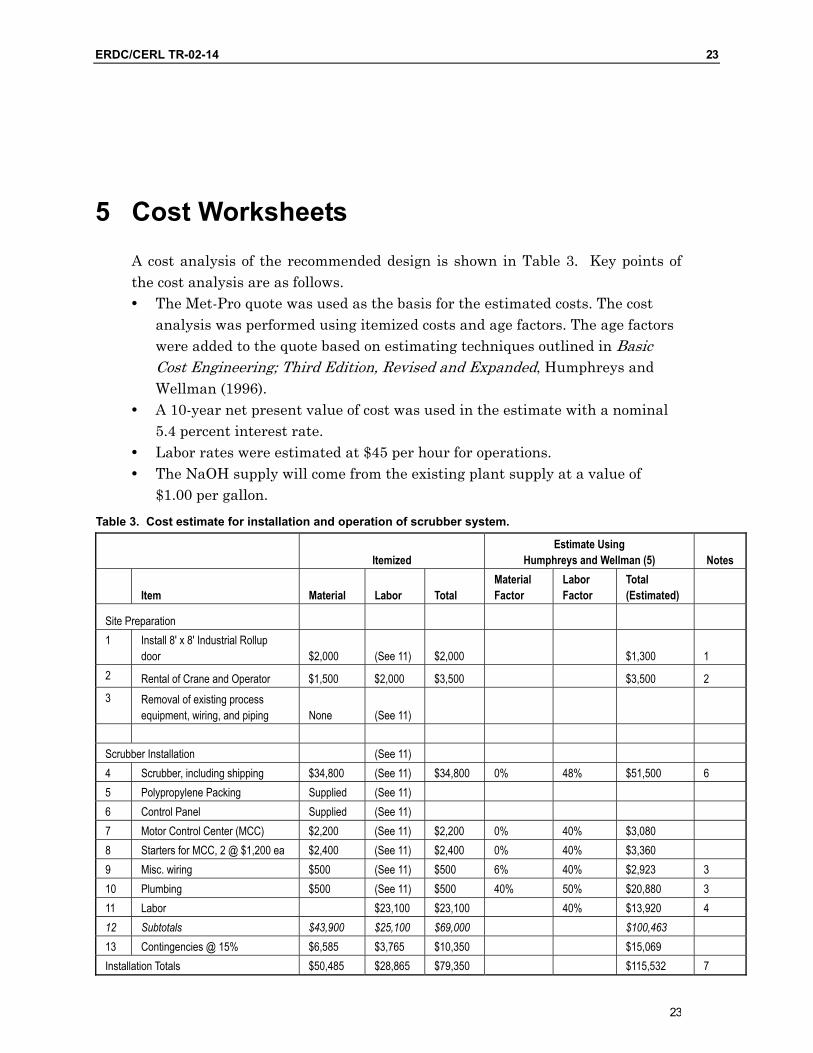
5 Cost Worksheets A cost analysis of the recommended design is shown in Table 3. Key points of the cost analysis are as follows.
The Met-Pro quote was used as the basis for the estimated costs. The cost analysis was performed using itemized costs and age factors. The age factors were added to the quote based on estimating techniques outlined in Basic Cost Engineering; Third Edition, Revised and Expanded, Humphreys and Wellman (1996).
•
•
• •
A 10-year net present value of cost was used in the estimate with a nominal 5.4 percent interest rate. Labor rates were estimated at $45 per hour for operations. The NaOH supply will come from the existing plant supply at a value of $1.00 per gallon.
Table 3. Cost estimate for installation and operation of scrubber system.
Itemized Estimate Using
Humphreys and Wellman (5) Notes
Item Material Labor Total Material Factor
Labor Factor
Total (Estimated)
Site Preparation 1 Install 8' x 8' Industrial Rollup
door $2,000 (See 11) $2,000 $1,300 1 2 Rental of Crane and Operator $1,500 $2,000 $3,500 $3,500 2 3 Removal of existing process
equipment, wiring, and piping None (See 11) Scrubber Installation (See 11) 4 Scrubber, including shipping $34,800 (See 11) $34,800 0% 48% $51,500 6 5 Polypropylene Packing Supplied (See 11) 6 Control Panel Supplied (See 11) 7 Motor Control Center (MCC) $2,200 (See 11) $2,200 0% 40% $3,080 8 Starters for MCC, 2 @ $1,200 ea $2,400 (See 11) $2,400 0% 40% $3,360 9 Misc. wiring $500 (See 11) $500 6% 40% $2,923 3 10 Plumbing $500 (See 11) $500 40% 50% $20,880 3 11 Labor $23,100 $23,100 40% $13,920 4 12 Subtotals $43,900 $25,100 $69,000 $100,463 13 Contingencies @ 15% $6,585 $3,765 $10,350 $15,069 Installation Totals $50,485 $28,865 $79,350 $115,532 7
23
24 ERDC/CERL TR-02-14
Itemized Estimate Using
Humphreys and Wellman (5) Notes
Item Material Labor Total Material Factor
Labor Factor
Total (Estimated)
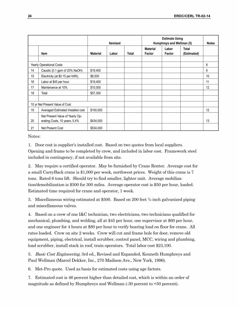
Yearly Operational Costs 8 14 Caustic (0.1 gpm of 20% NaOH) $19,400 9 15 Electricity (at $0.15 per kWh) $8,500 10 16 Labor at $45 per hour. $19,400 11 17 Maintenance at 10% $10,000 12 18 Total $57,300 10 yr Net Present Value of Cost 19 Averaged Estimated Installed cost $100,000 12
20 Net Present Value of Yearly Op-erating Costs, 10 years, 5.4% $434,000 13
21 Net Present Cost $534,000
Notes:
1.
2.
3.
4.
5.
6.
7.
Door cost is supplier’s installed cost. Based on two quotes from local suppliers. Opening and frame to be completed by crew, and included in labor cost. Framework steel included in contingency, if not available from site.
May require a certified operator. May be furnished by Crane Renter. Average cost for a small CarryBack crane is $1,000 per week, northwest prices. Weight of this crane is 7 tons. Rated 6 tons lift. Should try to find smaller, lighter unit. Average mobiliza-tion/demobilization is $500 for 300 miles. Average operator cost is $50 per hour, loaded. Estimated time required for crane and operator, 1 week.
Miscellaneous wiring estimated at $500. Based on 200 feet ¾-inch galvanized piping and miscellaneous valves.
Based on a crew of one I&C technician, two electricians, two technicians qualified for mechanical, plumbing, and welding, all at $45 per hour, one supervisor at $60 per hour, and one engineer for 4 hours at $80 per hour to verify bearing load on floor for crane. All rates loaded. Crew on site 2 weeks. Crew will cut and frame hole for door, remove old equipment, piping, electrical, install scrubber, control panel, MCC, wiring and plumbing, load scrubber, install stack in roof, train operators. Total labor cost $23,100.
Basic Cost Engineering, 3rd ed., Revised and Expanded, Kenneth Humphreys and Paul Wellman (Marcel Dekker, Inc., 270 Madison Ave., New York, 1996).
Met-Pro quote. Used as basis for estimated costs using age factors.
Estimated cost is 46 percent higher than detailed cost, which is within an order of magnitude as defined by Humphreys and Wellman (-30 percent to +50 percent).
ERDC/CERL TR-02-14 25
8. Based on operating schedule of 15 hours per day, 18 days per month, two shifts. Yearly operation is thus 3,240 hours.
9.
10.
11.
12.
13.
Source will be facility, where reported cost is $1.00 per gallon.
Power considered only for 5 hp and 10 hp motors. Will be estimated at maximum output of 15 hp. Electrical draw is 17.4 kw. This will absorb other power requirements of system.
Based one technician inspecting system for 1 hour per shift.
Taken as 10 percent of average of installed cost estimates ($100,000).
10 years of operating costs discounted at nominal interest rate of 5.4 percent as per OMB Circ. 094, Appendix C, January 2001.
25
26 ERDC/CERL TR-02-14
6 Conclusions
This preliminary design provides a basis for the development of a ventilation system scrubber at the IWTP. Key points developed during the design include: •
•
t
•
•
Use of the existing cyanide treatment room will allow the proposed equip-ment to be located inside the building and will reduce the cost of heating the equipment if it were located in the outside environment. Additionally, electri-cal power, plant service water, a building sump, and easy access to the plant control panel in the cyanide room will reduce the overall scope and cost of the project. Use of the reports Air Pollution Management Study No. 42-EK-4457-96, U.S. Army Center for Health Promotion and Preventative Medicine and Air Emis-sions Inven ory, Watervliet Arsenal, September 1997 for the basis of design for ventilation air SO2 control eliminated the need to perform sampling at the site during the preliminary phase. Additionally, these reports verified that only a small amount, 2 – 5 ppmv, of H2S gas is present in the process tanks. The use of a single process equipment technology, a wet-scrubber for both SO2 and H2S absorption, reduces the physical size and the cost of the treat-ment process. Use of commercial off-the-shelf (COTS) technology reduces the capital equipment cost by approximately one-third. The tradeoff of using COTS technology versus custom-built equipment occurs with operator training, start-up assistance and documentation. The custom-built equipment pro-vides these services as part of the contract cost. The Met-Pro Corporation Duall Division equipment includes a chemical feed pumping system, instrumentation to operate and monitor the process, and a control panel that contains a supply power, parameter indication, alarms, and process interlocks. Installation of this equipment requires additional site preparation, electrical, piping, mechanical, instrumentation and operating and maintenance requirements. Factoring in these additional requirements increases base equipment cost from $34,800 to $79,350 for installation and $57,300 for yearly operation.
ERDC/CERL TR-02-14 27
Appendix A: Extracts of Reports and Regulations Relating to Air Emissions
27
28 ERDC/CERL TR-02-14
ERDC/CERL TR-02-14 29
29
30 ERDC/CERL TR-02-14
ERDC/CERL TR-02-14 31
31
32 ERDC/CERL TR-02-14
ERDC/CERL TR-02-14 33
33
34 ERDC/CERL TR-02-14
ERDC/CERL TR-02-14 35
35
36 ERDC/CERL TR-02-14
ERDC/CERL TR-02-14 37
37
38 ERDC/CERL TR-02-14
ERDC/CERL TR-02-14 39
39
40 ERDC/CERL TR-02-14
ERDC/CERL TR-02-14 41
41

42 ERDC/CERL TR-02-14
ERDC/CERL TR-02-14 43
43

44 ERDC/CERL TR-02-14
ERDC/CERL TR-02-14 45
45
46 ERDC/CERL TR-02-14
ERDC/CERL TR-02-14 47
47

48 ERDC/CERL TR-02-14
ERDC/CERL TR-02-14 49
49
50 ERDC/CERL TR-02-14
ERDC/CERL TR-02-14 51
51
52 ERDC/CERL TR-02-14
ERDC/CERL TR-02-14 53
53
54 ERDC/CERL TR-02-14

ERDC/CERL TR-02-14 55
55

56 ERDC/CERL TR-02-14
ERDC/CERL TR-02-14 57
57

58 ERDC/CERL TR-02-14
ERDC/CERL TR-02-14 59
59
60 ERDC/CERL TR-02-14
ERDC/CERL TR-02-14 61
61
62 ERDC/CERL TR-02-14
ERDC/CERL TR-02-14 63
63
64 ERDC/CERL TR-02-14
ERDC/CERL TR-02-14 65
65
66 ERDC/CERL TR-02-14
ERDC/CERL TR-02-14 67
67
68 ERDC/CERL TR-02-14

ERDC/CERL TR-02-14 69
69
70 ERDC/CERL TR-02-14
ERDC/CERL TR-02-14 71
71
72 ERDC/CERL TR-02-14

ERDC/CERL TR-02-14 73
73

74 ERDC/CERL TR-02-14
ERDC/CERL TR-02-14 75
75
76 ERDC/CERL TR-02-14
ERDC/CERL TR-02-14 77
77
78 ERDC/CERL TR-02-14
ERDC/CERL TR-02-14 79
79
80 ERDC/CERL TR-02-14
ERDC/CERL TR-02-14 81
81
82 ERDC/CERL TR-02-14
ERDC/CERL TR-02-14 83
83
84 ERDC/CERL TR-02-14
ERDC/CERL TR-02-14 85
85
86 ERDC/CERL TR-02-14
ERDC/CERL TR-02-14 87
87
88 ERDC/CERL TR-02-14
ERDC/CERL TR-02-14 89
89
90 ERDC/CERL TR-02-14
ERDC/CERL TR-02-14 91
91

ERDC/CERL TR-02-14 93
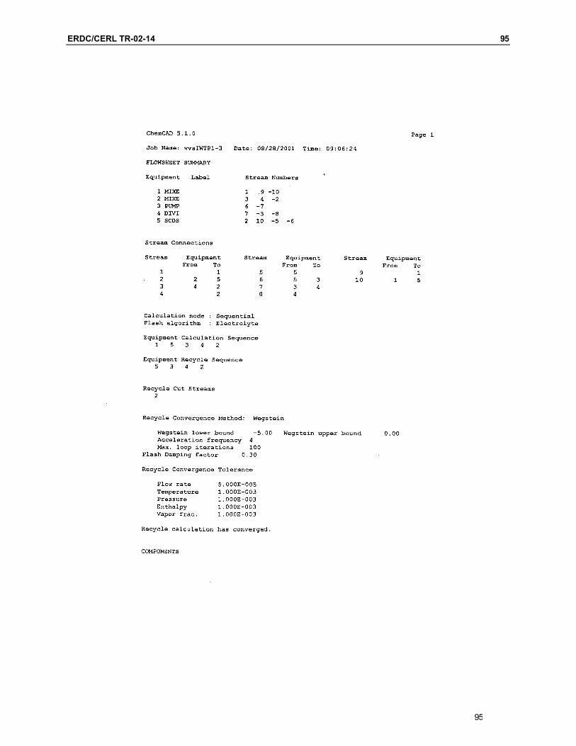
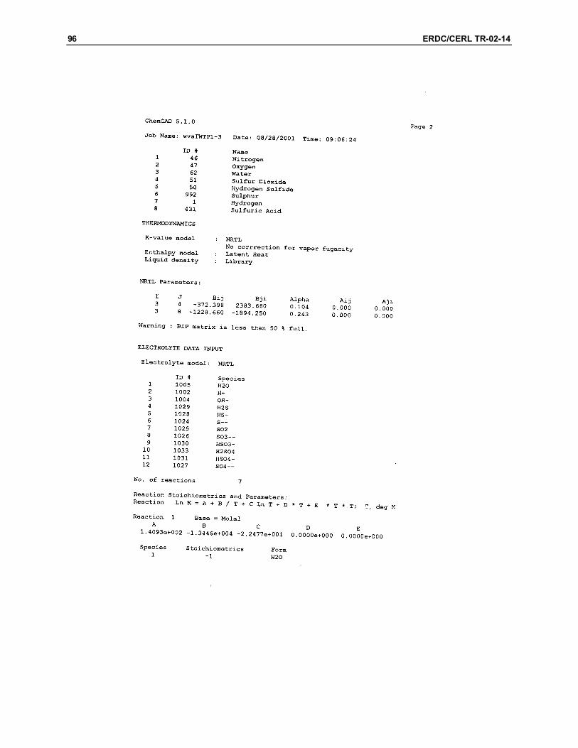
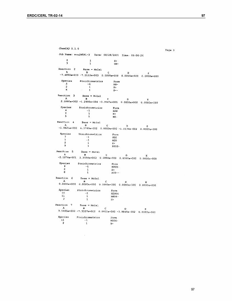
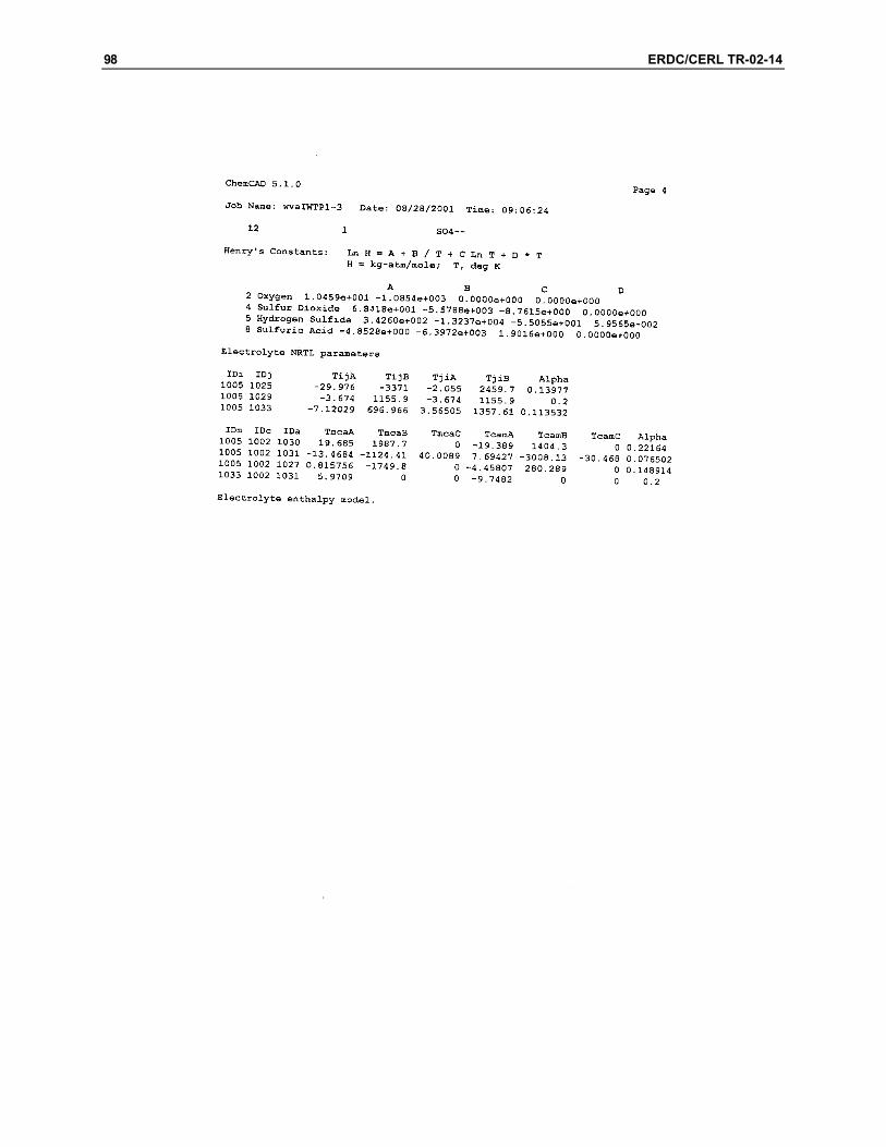
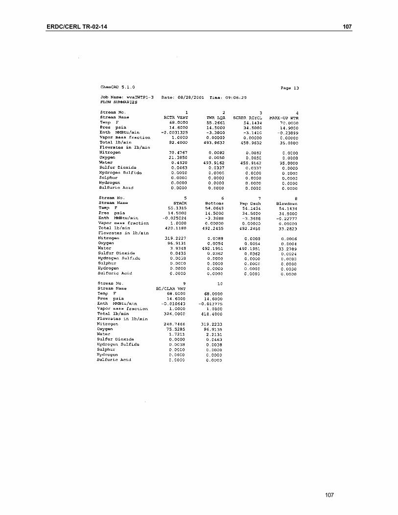
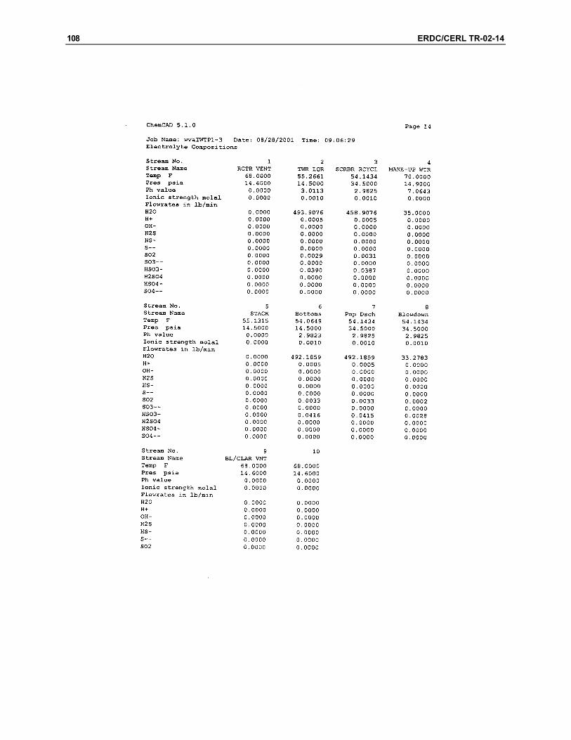
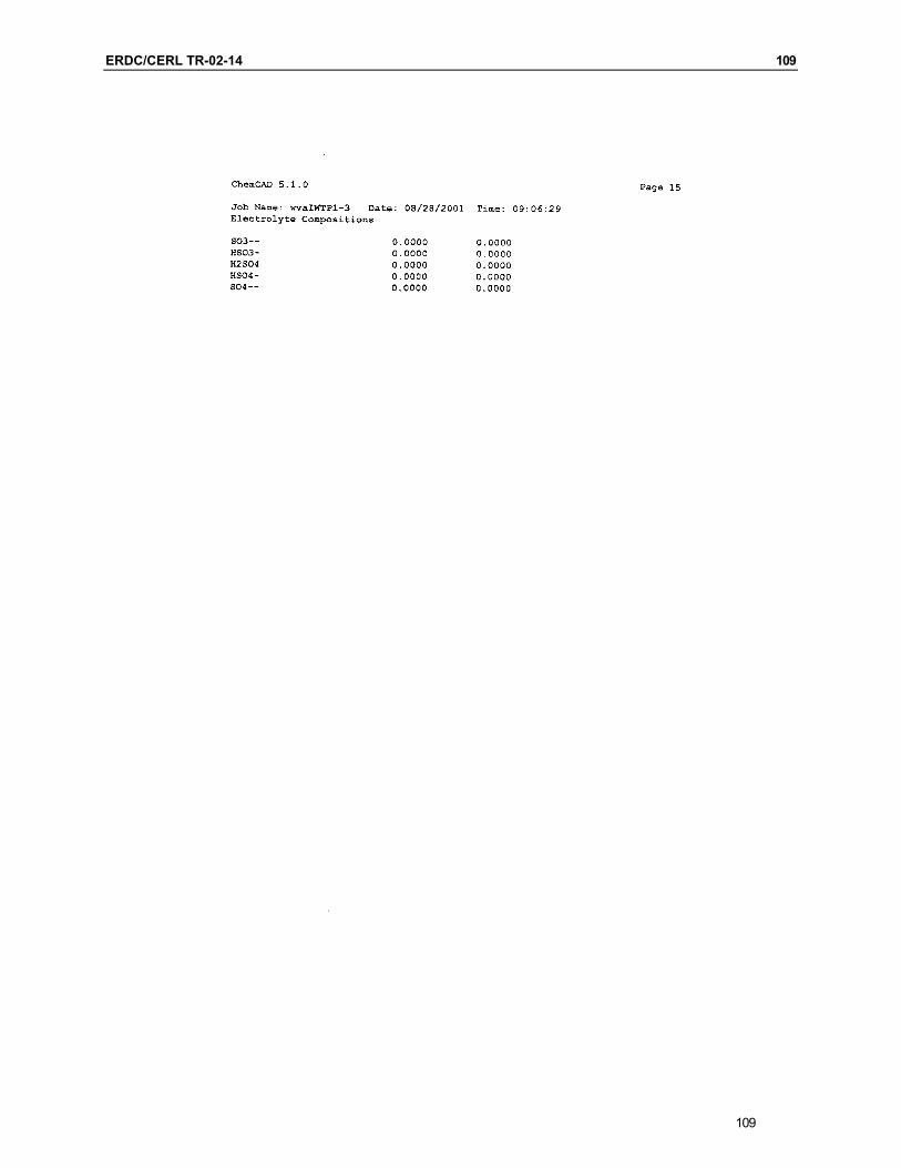
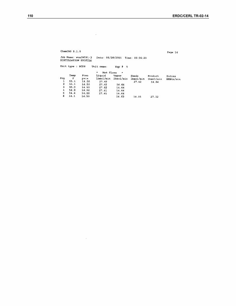
Appendix B: Air Scrubber Design Corresponding to E17-36FS-002
93
94 ERDC/CERL TR-02-14
Form MSE-135 (Rev. 10-95) Prepared S. Kujawa 9/10/01
Checked
MSE Technology Applications, Inc.
File P.O. Box 4078 Project WVA IWTP Butte, MT 59702
Subject Absorber Design (406) 494-7100 FAX (406) 494-7230
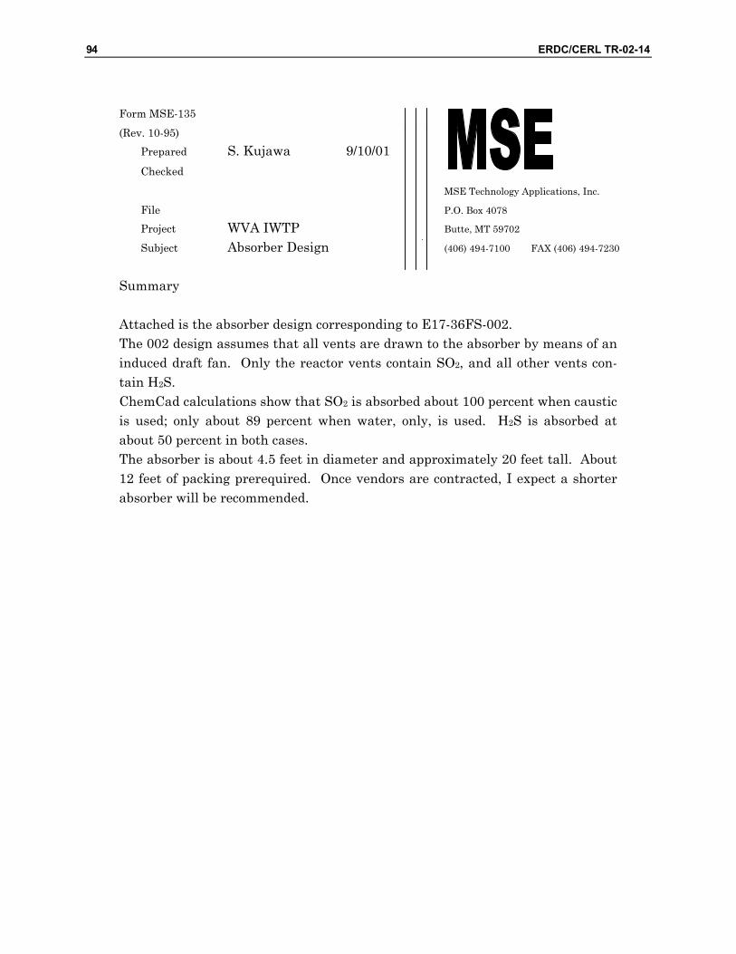
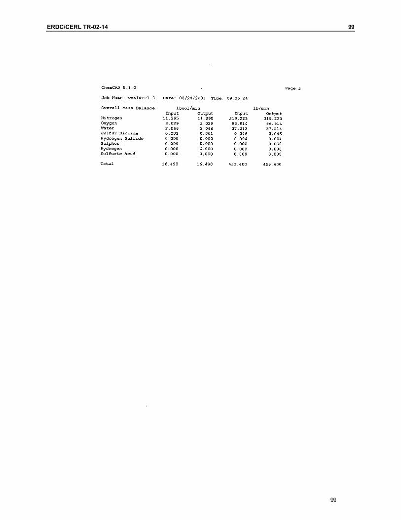
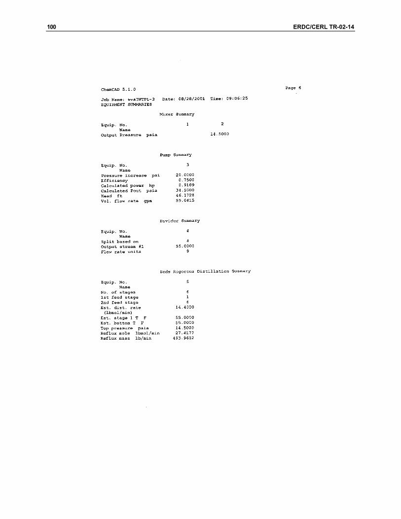
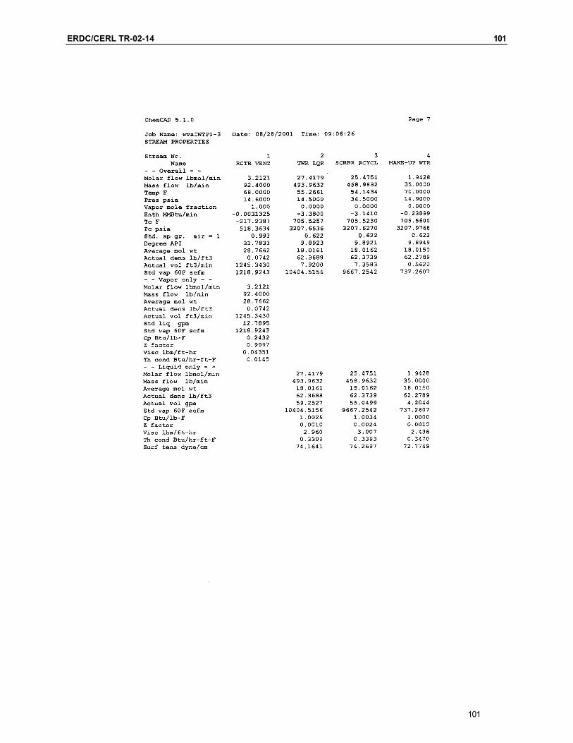
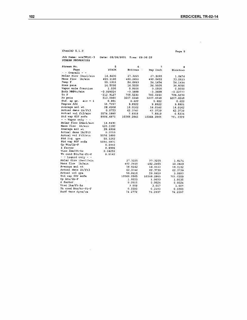
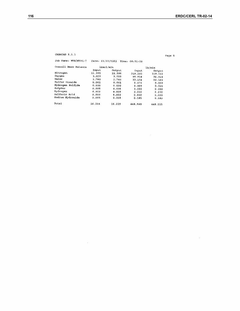
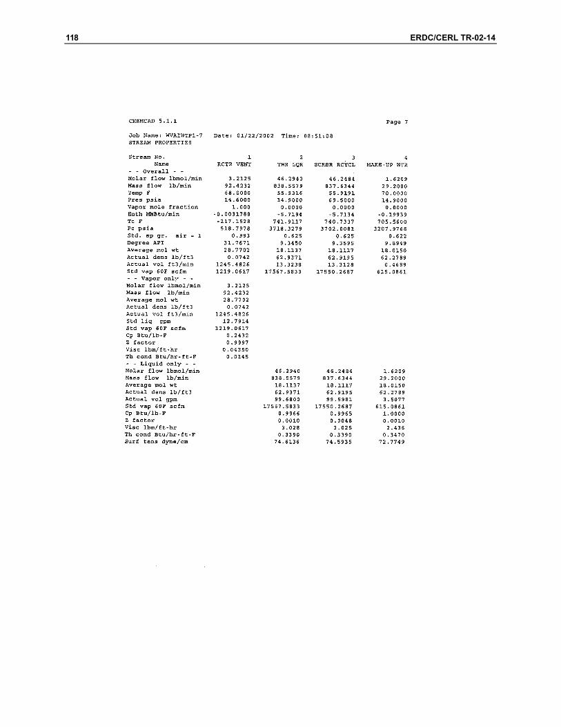
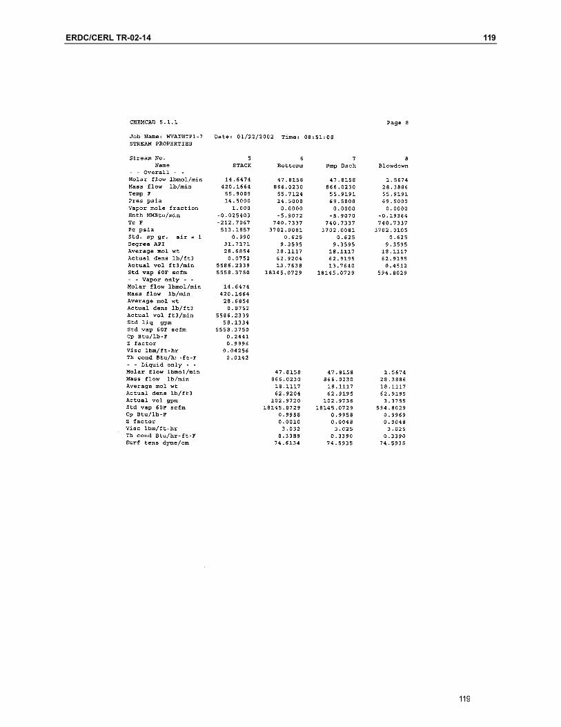
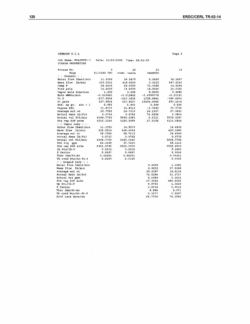
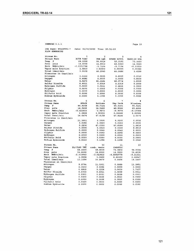
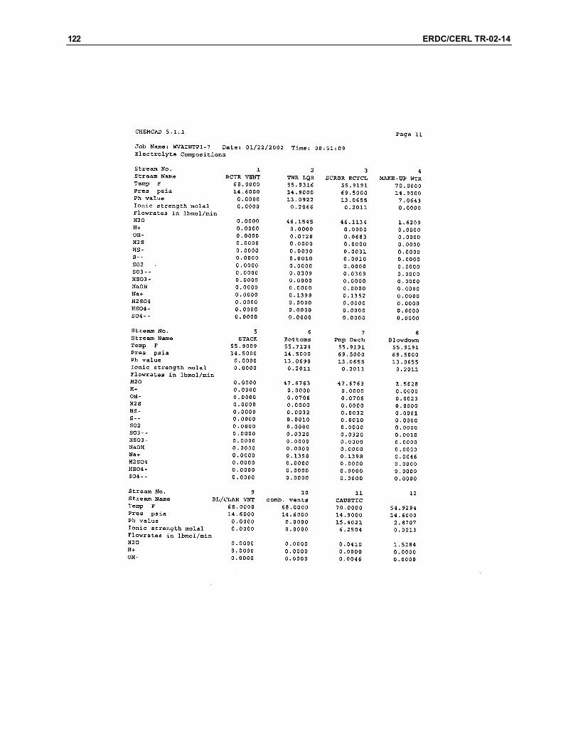
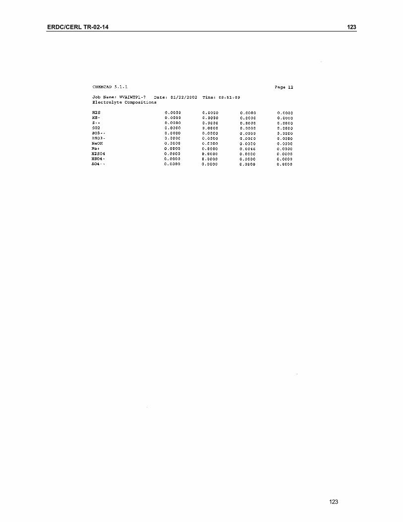
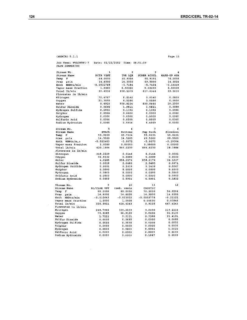
Summary Attached is the absorber design corresponding to E17-36FS-002. The 002 design assumes that all vents are drawn to the absorber by means of an induced draft fan. Only the reactor vents contain SO2, and all other vents con-tain H2S. ChemCad calculations show that SO2 is absorbed about 100 percent when caustic is used; only about 89 percent when water, only, is used. H2S is absorbed at about 50 percent in both cases. The absorber is about 4.5 feet in diameter and approximately 20 feet tall. About 12 feet of packing prerequired. Once vendors are contracted, I expect a shorter absorber will be recommended.
ERDC/CERL TR-02-14 95
95
96 ERDC/CERL TR-02-14
ERDC/CERL TR-02-14 97
97
98 ERDC/CERL TR-02-14
ERDC/CERL TR-02-14 99
99
100 ERDC/CERL TR-02-14
ERDC/CERL TR-02-14 101
101
102 ERDC/CERL TR-02-14
ERDC/CERL TR-02-14 103
103
104 ERDC/CERL TR-02-14
ERDC/CERL TR-02-14 105
105
106 ERDC/CERL TR-02-14
ERDC/CERL TR-02-14 107
107
108 ERDC/CERL TR-02-14
ERDC/CERL TR-02-14 109
109
110 ERDC/CERL TR-02-14
ERDC/CERL TR-02-14 111
111
112 ERDC/CERL TR-02-14
ERDC/CERL TR-02-14 113
113
114 ERDC/CERL TR-02-14

ERDC/CERL TR-02-14 115
115
116 ERDC/CERL TR-02-14

ERDC/CERL TR-02-14 117
117
118 ERDC/CERL TR-02-14
ERDC/CERL TR-02-14 119
119
120 ERDC/CERL TR-02-14
ERDC/CERL TR-02-14 121
121
122 ERDC/CERL TR-02-14
ERDC/CERL TR-02-14 123
123
124 ERDC/CERL TR-02-14
ERDC/CERL TR-02-14 125
125
126 ERDC/CERL TR-02-14
ERDC/CERL TR-02-14 127
127
128 ERDC/CERL TR-02-14
ERDC/CERL TR-02-14 129
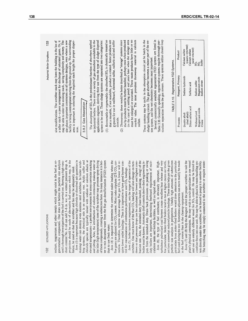
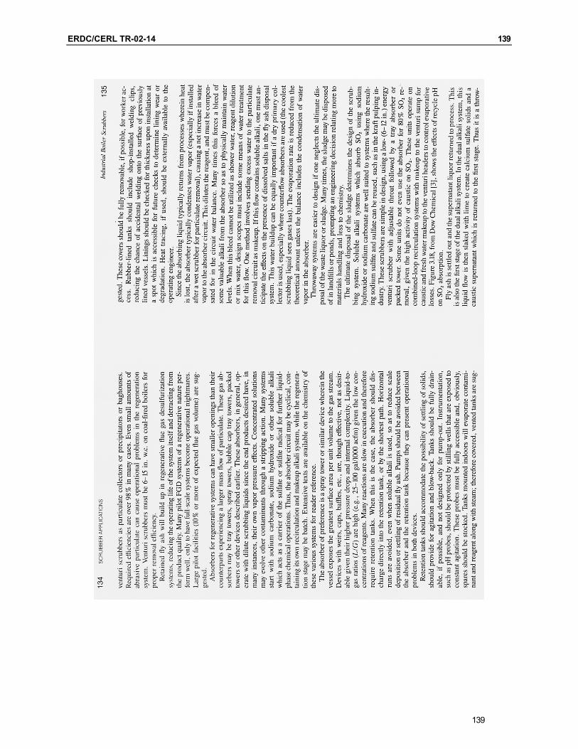
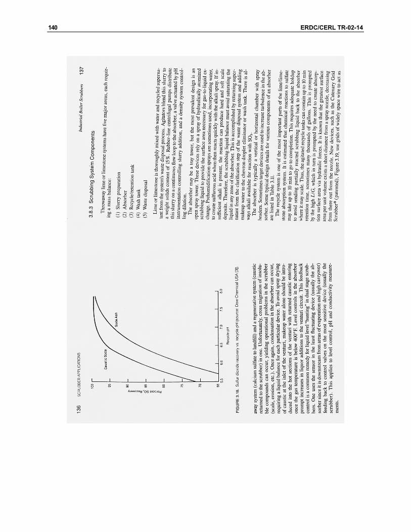
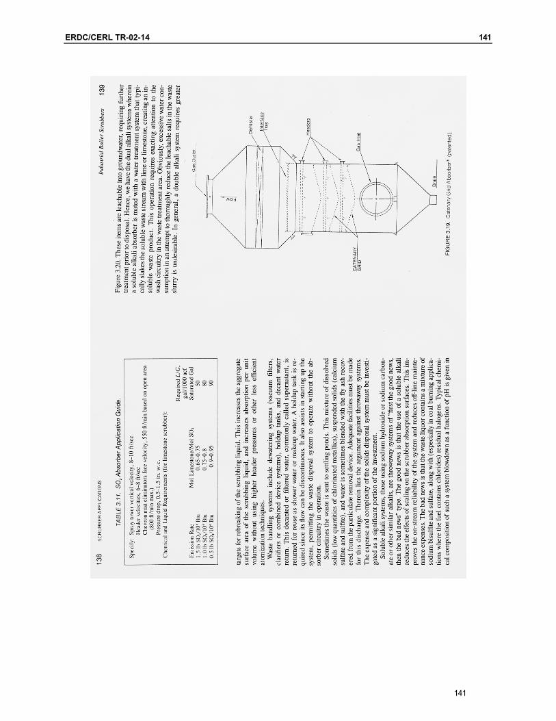
Reprinted with permission from Wet Scrubbers, 2nd edition, pp 46-61 and 137-141. Copyright CRC Press, Boca Raton, FL.
129
130 ERDC/CERL TR-02-14

ERDC/CERL TR-02-14 131
131
132 ERDC/CERL TR-02-14
ERDC/CERL TR-02-14 133
133
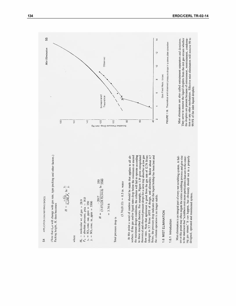
134 ERDC/CERL TR-02-14
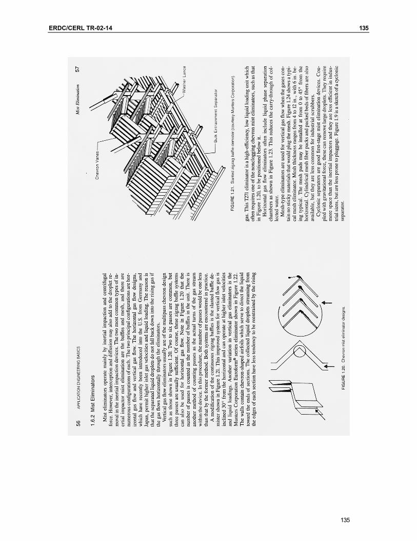
ERDC/CERL TR-02-14 135
135
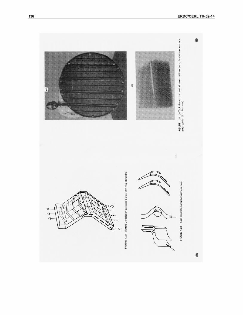
136 ERDC/CERL TR-02-14
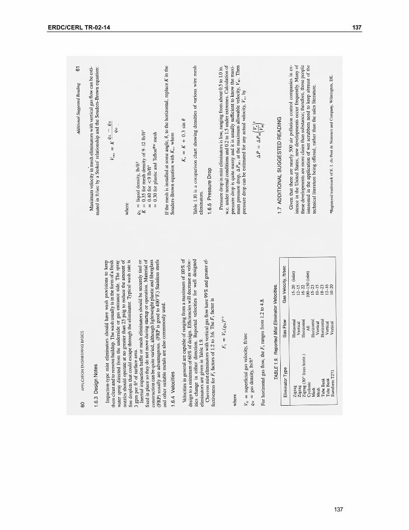
ERDC/CERL TR-02-14 137
137
138 ERDC/CERL TR-02-14
ERDC/CERL TR-02-14 139
139
140 ERDC/CERL TR-02-14
ERDC/CERL TR-02-14 141
141

142 ERDC/CERL TR-02-14
ERDC/CERL TR-02-14 143
143

ERDC/CERL TR-02-14 145
Appendix C: Equipment Data Sheet
145
146 ERDC/CERL TR-02-14
ERDC/CERL TR-02-14 147
147
148 ERDC/CERL TR-02-14
ERDC/CERL TR-02-14 149
149


ERDC/CERL TR-02-14 151
Appendix D: Vendor Quote – Rocky Mountain Process Group
151
152 ERDC/CERL TR-02-14
ERDC/CERL TR-02-14 153
153
154 ERDC/CERL TR-02-14
ERDC/CERL TR-02-14 155
155
156 ERDC/CERL TR-02-14
ERDC/CERL TR-02-14 157
157


ERDC/CERL TR-02-14 159
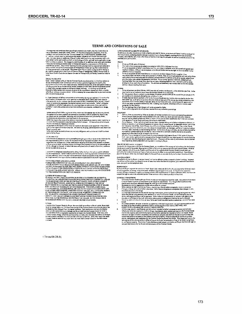
Appendix E: Vendor Quote – Met-Pro Corporation Duall Division
159
160 ERDC/CERL TR-02-14
ERDC/CERL TR-02-14 161
161
162 ERDC/CERL TR-02-14

ERDC/CERL TR-02-14 163
163
164 ERDC/CERL TR-02-14
ERDC/CERL TR-02-14 165
165

166 ERDC/CERL TR-02-14
ERDC/CERL TR-02-14 167
167
168 ERDC/CERL TR-02-14
ERDC/CERL TR-02-14 169
169
170 ERDC/CERL TR-02-14
ERDC/CERL TR-02-14 171
171
172 ERDC/CERL TR-02-14
ERDC/CERL TR-02-14 173
173

ERDC/CERL TR-02-14 175
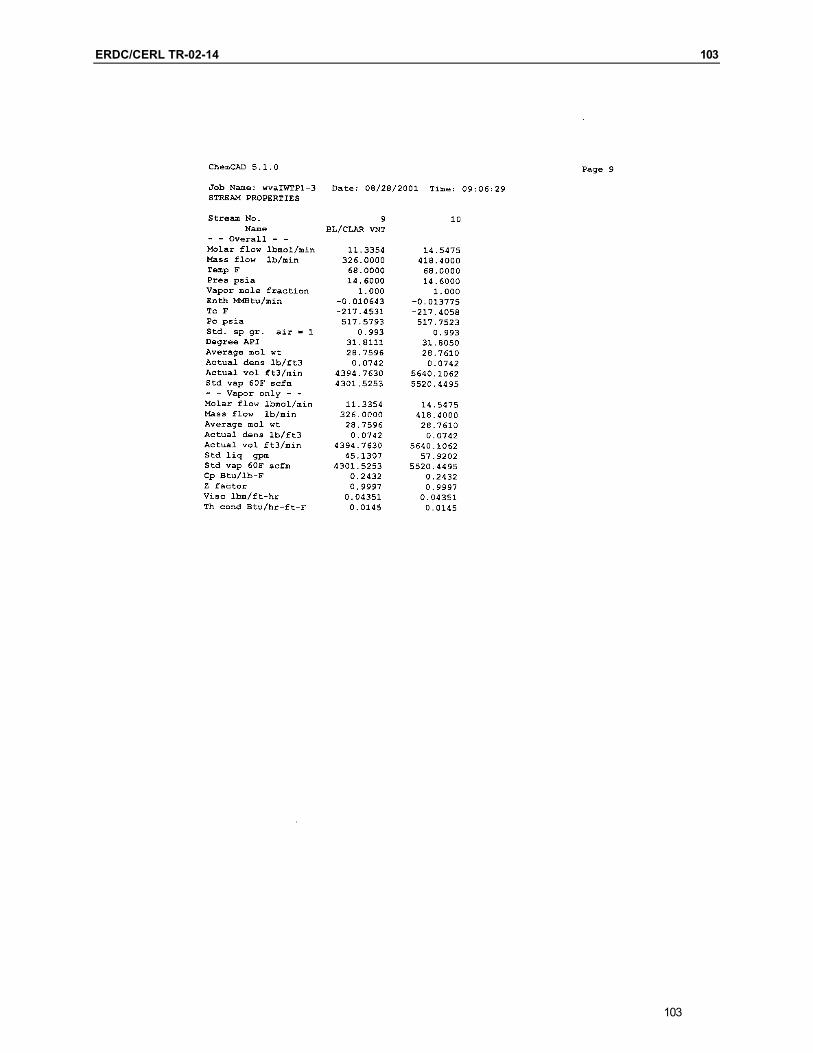
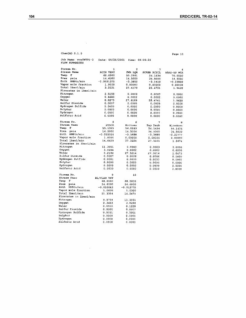
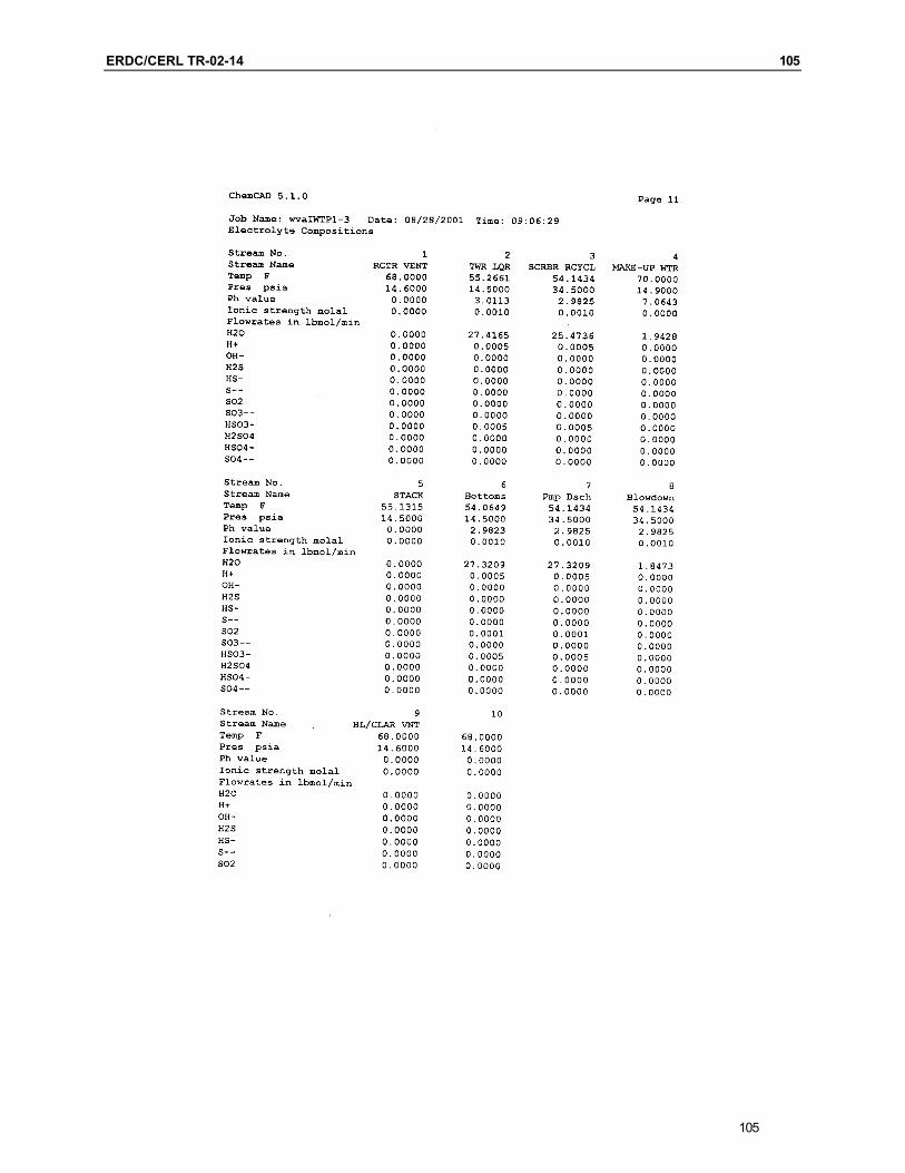
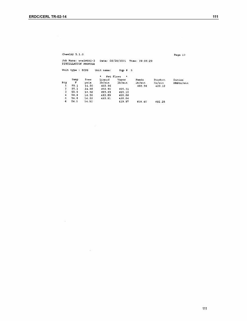
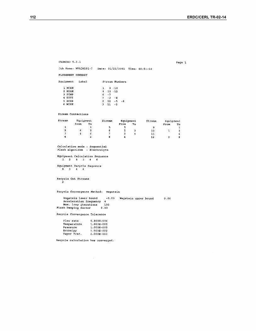
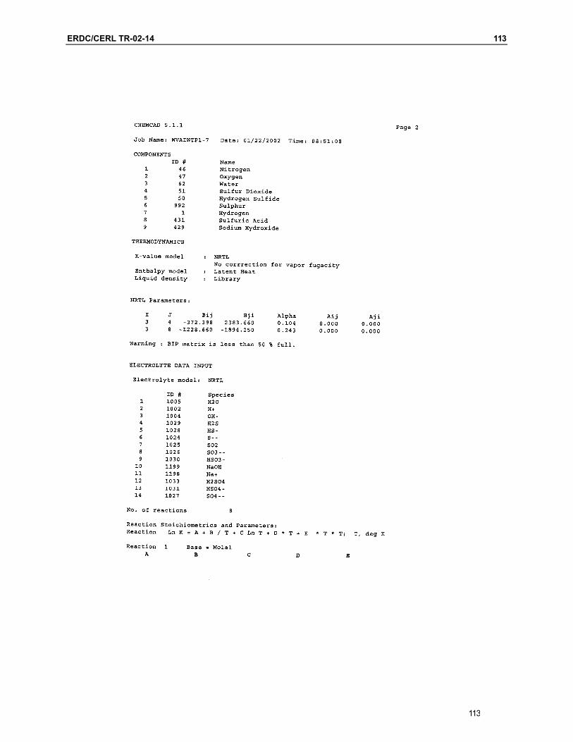
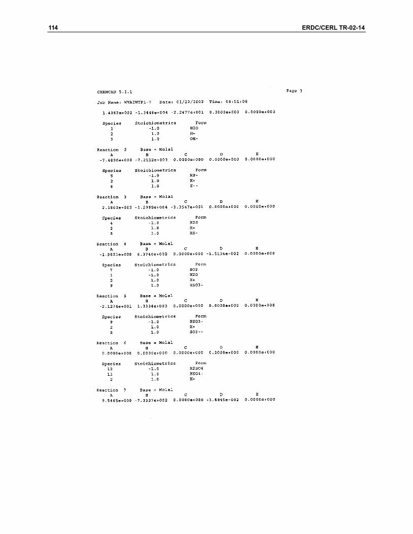
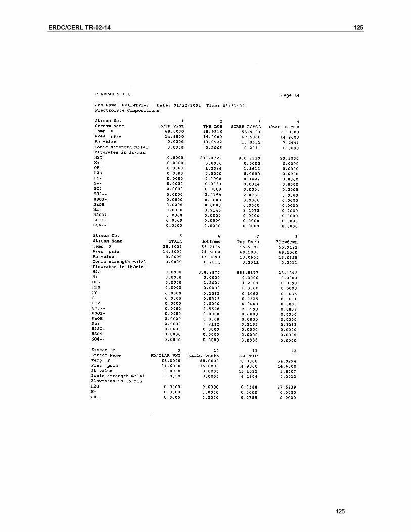
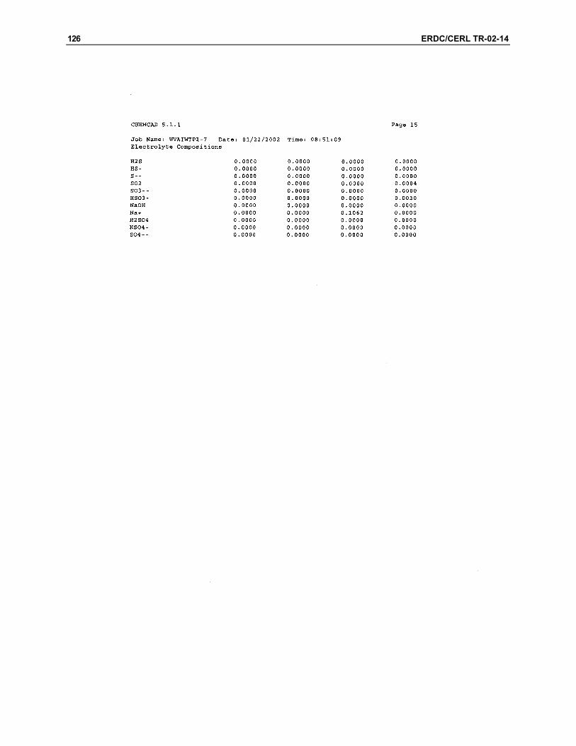
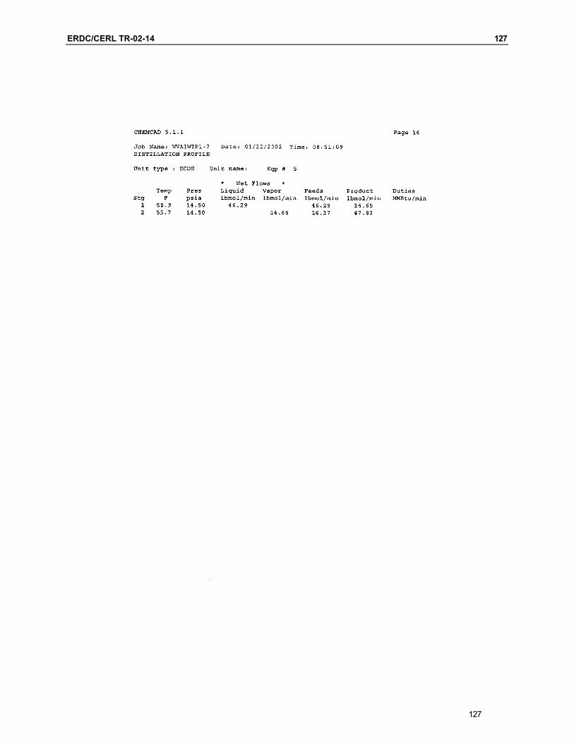
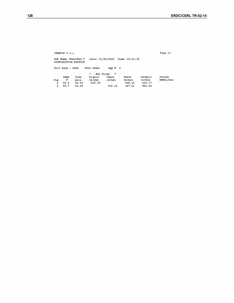
Appendix F: Chemcad Model of The Met Pro Scrubber Bid
175

176 ERDC/CERL TR-02-14
Form MSE-135 (Rev. 10-95)
Prepared S. Kujawa 2/22/02
Checked MSE Technology Applications, Inc.
File P.O. Box 4078
Project WVA SO2 Scrubber Butte, MT 59702
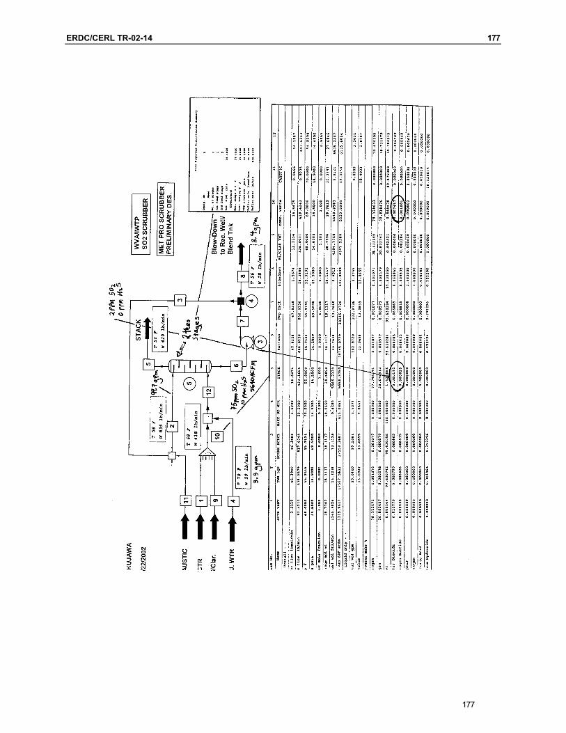
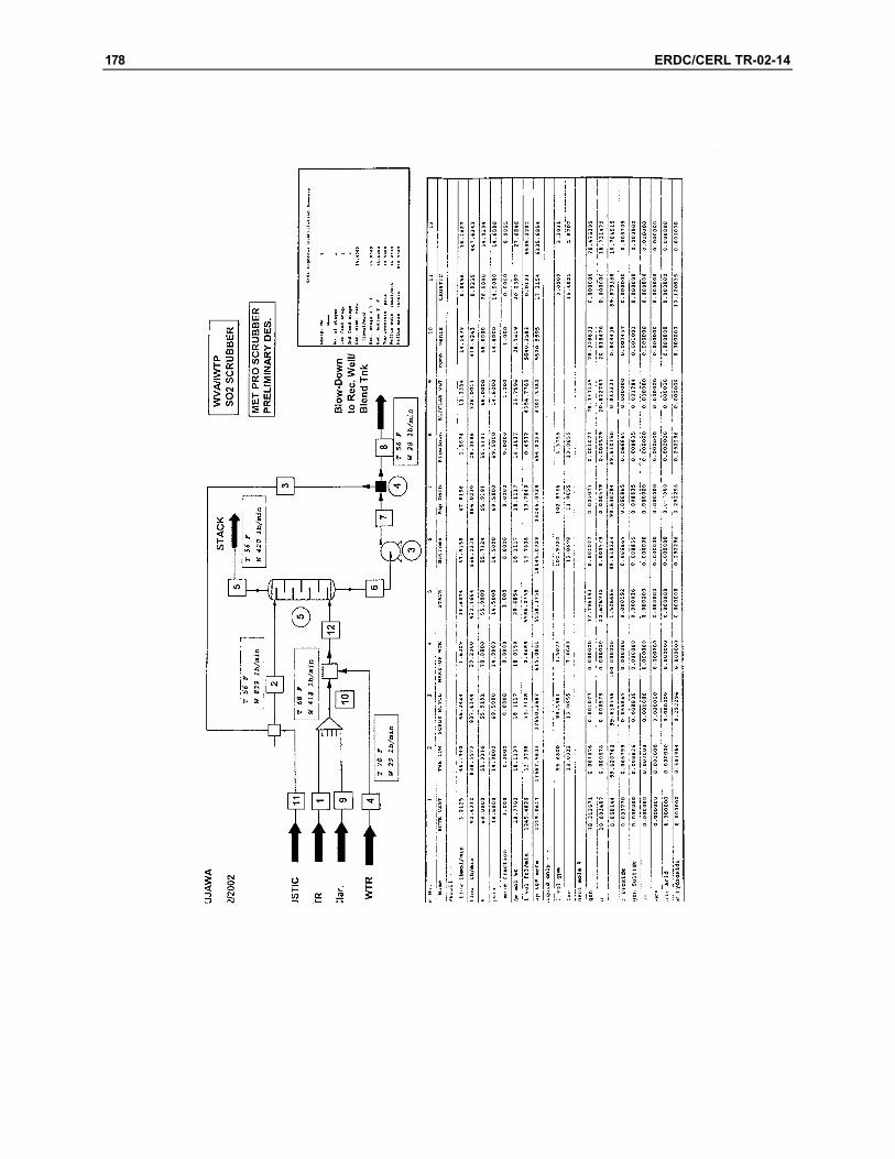
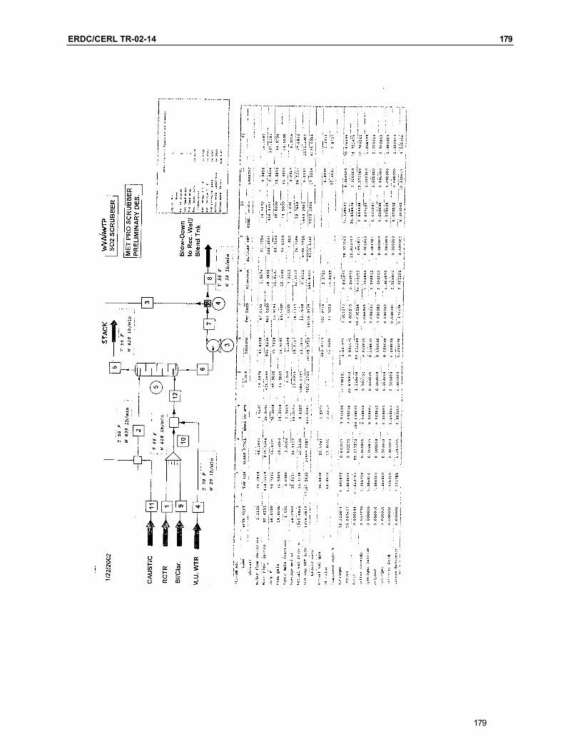
Subject MET PRO Scrubber bid (406) 494-7100 FAX (406) 494-7230
ChemCad Simulator attached.
The Duall Division of MET PRO corporation bid was evaluated for conformance to MSE-TA’s RFQ and process performance. A ChemCad Simulation of the proposed process parameters and MSE’s specified inlet conditions verified that the proposed scrubber would meet the performance requirements. The proposal states that the scrubber will be packed with six feet of 2 inch polypropylene packing; the simulator assumes that this depth of pack-ing will be equivalent to at least 2 theoretical equilibrium stages. My calculations of 9/10/01 concluded that about 12 feet of packing would be needed. These were based on about half the reflux rate, a lower NaOH input and a less efficient packing material. Given Duall’s parameters, I feel their design is adequate. (This page was transcribed from handwritten notes.)
ERDC/CERL TR-02-14 177
177
178 ERDC/CERL TR-02-14
ERDC/CERL TR-02-14 179
179

ERDC/CERL TR-02-14 181
Appendix G: Process Flow Diagrams
181
183
185
190 ERDC/CERL TR-02-14
CERL Distribution
Chief of Engineers ATTN: CEHEC-IM-LH (2) Engineer Research and Development Center (Libraries) ATTN: ERDC, Vicksburg, MS ATTN: Cold Regions Research, Hanover, NH ATTN: Topographic Engineering Center, Alexandria, VA Defense Tech Info Center 22304 ATTN: DTIC-O 6 6/02
REPORT DOCUMENTATION PAGE Form Approved
OMB No. 0704-0188 Public reporting burden for this collection of information is estimated to average 1 hour per response, including the time for reviewing instructions, searching existing data sources, gathering and maintaining the data needed, and completing and reviewing this collection of information. Send comments regarding this burden estimate or any other aspect of this collection of information, including suggestions for reducing this burden to Department of Defense, Washington Headquarters Services, Directorate for Information Operations and Reports (0704-0188), 1215 Jefferson Davis Highway, Suite 1204, Arlington, VA 22202-4302. Respondents should be aware that notwithstanding any other provision of law, no person shall be subject to any penalty for failing to comply with a collection of information if it does not display a currently valid OMB control number. PLEASE DO NOT RETURN YOUR FORM TO THE ABOVE ADDRESS. 1. REPORT DATE (DD-MM-YYYY)
06-2002 2. REPORT TYPE
Final 3. DATES COVERED (From - To)
5a. CONTRACT NUMBER 5b. GRANT NUMBER
4. TITLE AND SUBTITLE A Preliminary Design of a Ventilation System Scrubber To Reduce Sulfur Dioxide Emissions at the Watervliet Arsenal Industrial Wastewater Treatment Plant
5c. PROGRAM ELEMENT NUMBER 5d. PROJECT NUMBER Congressional 5e. TASK NUMBER
6. AUTHOR(S) Joyce C. Baird, June Pusich-Lester, and Dan Brown
5f. WORK UNIT NUMBER 622720960 8. PERFORMING ORGANIZATION REPORT
NUMBER 7. PERFORMING ORGANIZATION NAME(S) AND ADDRESS(ES) U.S. Army Engneer Research and Development Center (ERDC) Construction Engineering Research Laboratory (CERL) PO Box 9005 Champaign, IL 61826-9005
ERDC/CERL TR-02-14
9. SPONSORING / MONITORING AGENCY NAME(S) AND ADDRESS(ES) 10. SPONSOR/MONITOR’S ACRONYM(S) SOSWV-IMI-E Watervliet Arsenal
Watervliet, NY 12189
11. SPONSOR/MONITOR’S REPORT
NUMBER(S)
12. DISTRIBUTION / AVAILABILITY STATEMENT Approved for public release; distribution is unlimited.
13. SUPPLEMENTARY NOTES Copies are available from the National Technical Information Service, 5285 Port Royal Road, Springfield, VA 22161.
14. ABSTRACT
The intent of this project was to develop a preliminary design of a ventilation system scrubber at the Watervliet Arsenal Industrial Wastewater Treatment Plant to eliminate emissions, which cause nuisance odors.
15. SUBJECT TERMS emissions control, air pollution control, Watervliet Arsenal, NY, chromium, industrial wastewater treatment plants (IWTPs), sulfur dioxide (SO2), hydrogen sulfide (H2S)
16. SECURITY CLASSIFICATION OF: 17. LIMITATION OF ABSTRACT
18. NUMBER OF PAGES
19a. NAME OF RESPONSIBLE PERSON Joyce C. Baird
a. REPORT Unclassified
b. ABSTRACT Unclassified
c. THIS PAGE Unclassified
SAR
191
19b. TELEPHONE NUMBER (in-clude area code)
(217)373-4469 Standard Form 298 (Rev. 8-98) Prescribed by ANSI Std. 239.18