Equipment specifications for the capacitor installation project
47
TENDER NO KP1/9AA-2/PT/16/13-14 FOR THE DESIGN, MANUFACTURE, SUPPLY, CONSTRUCTION INSTALLATION, TESTING AND COMMISSIONING OF SWITCHED POLE MOUNTED REACTIVE POWER COMPENSATORS FOR NAIROBI REGION TECHNICAL SPECIFICATIONS AND DRAWINGS MAY, 2014 ALL TENDERERS ARE ADVISED TO READ CAREFULLY THIS TENDER DOCUMENT IN ITS ENTIRETY BEFORE MAKING ANY BID THE KENYA POWER & LIGHTING COMPANY LIMITED CENTRAL OFFICE, STIMA PLAZA, KOLOBOT ROAD, PARKLANDS, P.O. BOX 30099-00100, NAIROBI, KENYA. Telephones: 254-020-3201000 Pilot Line Mobiles : 254 -720-600070/1-5, 733-755001/2-3 Facsimiles: 254-20-3514485, 3750240 Telegrams: “ELECTRIC” Website: www.kplc.co.ke Vol II Page 1/46
-
Upload
khangminh22 -
Category
Documents
-
view
0 -
download
0
Transcript of Equipment specifications for the capacitor installation project

TENDER NO KP1/9AA-2/PT/16/13-14
FOR THE DESIGN, MANUFACTURE, SUPPLY, CONSTRUCTION INSTALLATION,TESTING AND COMMISSIONING OF SWITCHED POLE MOUNTED REACTIVE
POWER COMPENSATORS FOR NAIROBI REGION
TECHNICAL SPECIFICATIONS AND DRAWINGS
MAY, 2014
ALL TENDERERS ARE ADVISED TO READ CAREFULLY THIS TENDER DOCUMENTIN ITS ENTIRETY BEFORE MAKING ANY BID
THE KENYA POWER & LIGHTING COMPANY LIMITED CENTRAL OFFICE, STIMA PLAZA,KOLOBOT ROAD, PARKLANDS,P.O. BOX 30099-00100,NAIROBI,KENYA.
Telephones: 254-020-3201000 Pilot LineMobiles : 254 -720-600070/1-5, 733-755001/2-3 Facsimiles: 254-20-3514485, 3750240Telegrams: “ELECTRIC”Website: www.kplc.co.ke
Vol II Page 1/46
CONTENTS
SECTION 1:.................................................................................................................................................................4
ELECTRICAL WORK AND EQUIPMENT............................................................................................................4
GENERAL SPECIFICATIONS
...................................................................................................................
41.General............................................................................................................................................ 42.Document Priority............................................................................................................................. 43.Completeness of Contract................................................................................................................44.Space Requirement......................................................................................................................... 55.Documentation and Drawings..........................................................................................................56.Contractor's Quality Assurance Procedures.....................................................................................87.Guarantees and Particulars.............................................................................................................88.Manufacturing and Shipment...........................................................................................................89.Erection, Installation and Commissioning.......................................................................................1110.Time of Delivery and Completion.................................................................................................1311.On the Job Training...................................................................................................................... 1312.Tools............................................................................................................................................. 1313.Spare Parts.................................................................................................................................. 13
PROJECT SPECIFIC DATA
.....................................................................................................................
141.Definitions...................................................................................................................................... 142.Design Data, Medium and low Voltage..........................................................................................142.3 Phase Relationship..................................................................................................................... 152.4 Colour Coding............................................................................................................................. 152.5 Environment................................................................................................................................ 162.6 Noise........................................................................................................................................... 162.7 Operation and Control.................................................................................................................162.8 Interface between Contractors and towards Employer................................................................17
PARTICULAR TECHNICAL SPECIFICATIONS
......................................................................................
18FOREWORD..................................................................................................................................... 18
PARTICULAR EQUIPMENT SPECIFICATION
........................................................................................
19A. CAPACITORS............................................................................................................................... 191.SCOPE.......................................................................................................................................... 192. REFERENCES.............................................................................................................................. 193. TERMS AND DEFINITIONS..........................................................................................................214. REQUIREMENTS.........................................................................................................................215. TESTING AND INSPECTION.......................................................................................................297. ADDITIONAL REQUIREMENTS...................................................................................................318. DOCUMENTATION.......................................................................................................................32
DESCRIPTION...........................................................................................................................................................34
B. 12kV SURGE ARRESTERS.........................................................................................................34 1. SCOPE........................................................................................................................................ 341.2. REFERENCES........................................................................................................................... 352.3. TERMS AND DEFINITIONS.......................................................................................................353.4. REQUIREMENTS...................................................................................................................... 35
NOMINAL DISCHARGE CURRENT AND LONG DURATION DISCHARGE CLASS
.....................................................
375. TESTS AND INSPECTION...........................................................................................................376. MARKING, LABELLING AND PACKING.......................................................................................38C.12 KV VOLTAGE TRANSFORMERS............................................................................................39
Vol II Page 2/46

1.SCOPE.......................................................................................................................................... 402. REFERENCES.............................................................................................................................. 403. DEFINITIONS............................................................................................................................... 401.REQUIREMENTS.......................................................................................................................... 402.TESTS AND INSPECTION............................................................................................................425.1 The voltage transformer shall be inspected and tested in accordance with the requirements of this specification and IEC 60044-2....................................................................................................425.3 Test Reports for the Voltage Transformers to be supplied shall be submitted to KPLC for approval before shipment/delivery.....................................................................................................423.MARKING...................................................................................................................................... 42D.ISOLATOR (DISCONNECTOR) -12kV..........................................................................................431. SCOPE......................................................................................................................................... 432. REFERENCES.............................................................................................................................. 433. TERMS AND DEFINITIONS..........................................................................................................43 4 REQUIREMENTS.........................................................................................................................445. TESTS AND FACTORY INSPECTION..........................................................................................456. TECHNICAL DOCUMENTATION..................................................................................................46
Vol II Page 3/46
SECTION 1: ELECTRICAL WORK AND EQUIPMENT
GENERAL SPECIFICATIONS
1. General
The scope of work, data sheets, special and general specifications constitute the completetechnical specifications and must be read as a whole. If more than one contractor contributes to the completion of the plant each contractor isobliged to cooperate, adapt solutions and exchange information so that the plant formsfunctional and optimized entirety.
2. Document PriorityIf in conflict, the ranking of documents in the technical specifications, in decreasingpriority, is as follows:
1. Scope of Works2. Particular technical specifications3. Project Specific Design Data4. General technical specifications5. General specifications6. Standards
In the event of any difference between the Drawings and the Specifications, the latter shallprevail. In the event of any difference between scaled dimensions and figures on thedrawings, the figures shall prevail.
If the Bidder is of the opinion that there is conflict or disagreement between the particularsof the documents, standards etc., this must be clearly stated in the Bid, failing which, thematerials and equipment offered shall be deemed to comply in every respect with thecurrent Specification both in manufacture and in performance, and compliance thereofshall be insisted upon without additional cost to the Employer.
3. Completeness of Contract1.3.1 All apparatus, accessories or fittings which may not have been specifically
mentioned, but which are usual or necessary in the respective equipment for thecompleteness of the finished work in an operable status, shall be deemed to beincluded in the Contract and shall be provided by the Contractor without any extracharge. All equipment shall be complete in all details, whether or not such detailsare mentioned in the Specifications. This includes fixation details and connectionclamps and/or terminals.
Vol II Page 4/46
1.3.2 All materials and skilled labour, whether of temporary or permanent nature,required by the Contractor for the design, manufacture, erection and testing at siteof the equipment shall be supplied and paid for by the Contractor. All computerequipment shall be delivered with all software and licenses necessary to achievethe specified functionality as well as the software necessary for programming,testing, service and maintenance through the lifetime of the equipment.
1.3.3 Any reference in the quantity and price schedules, the delivery period schedule orin the various clauses and schedules of the text of either the Specification or theBid, to any equipment shall imply equipment that is complete with all accessories,apparatus and fittings as outlined in sub clause 1.3.1 and 1.3.2 above.
The Bidder shall be responsible for ensuring that the equipment supplied is fit for thepurpose intended. Available information on the characteristics of the system, to which theworks will be connected and associated, will be supplied on request to the Bidder whoshall be responsible for obtaining and determining all applicable knowledge relevant to theworks.
4. Space RequirementThe Bidder shall check the dimensions of rooms and outdoor plots where electricalequipment is proposed to be erected. The rooms and plots must accommodate theequipment as well as having workspace for operators and maintenance personnel.
The Bidder shall in his bid present arrangement drawings showing how he intends to adaptthe equipment to the space available. If the space is not sufficient the Bidder shall indicatenecessary enlargements; failing to do so the Bidder must bear the cost of latermodifications of the facilities.
5. Documentation and Drawings
5.1 General
Contractor's obligations with regard to preparation and submission of drawings,calculations, samples, patterns, models, etc. are stated in the Conditions of Contract.
The Contractor shall prepare and submit to the Project Manager for approval dimensionedgeneral and detailed design drawings and other pertinent information of all the Plant andequipment specified in the Bid Documents. Unless otherwise agreed the information shallbe exchanged on paper.
Approval of drawings shall not relieve the Contractor of his obligations to supply thePlant in accordance with the Specifications. The Contractor is responsible for anyerrors that may appear in the approved documents. He shall as soon as an error hasbeen detected, deliver the corrected documents to the Project Manager forre-approval.
If the plant is to be connected to existing equipment the connection shall be documented ina coherent and overlapping way at least containing terminal identification in old
Vol II Page 5/46
equipment. Schematic diagrams shall contain complete loops within new and oldequipment.
All text on documents provided by the Contractor shall be in the English language inaddition, if necessary, to that of the country of origin. All drawings shall be dimensioned inmillimeter.
The Contractor shall, during the total project time, maintain a List of Documentation to beupdated by him whenever needed. The List of Documentation shall include the date oforiginal issue of each document submitted as well as the dates of every revision. The Listof Documentation shall also include a time schedule for the submittal of thedocumentation.
Symbols used for electrical equipment shall be in accordance with IEC 60617. TheContractor shall establish a coherent system for physical and functional referencedesignation in accordance with IEC61346. A similar systematic scheme shall be defined forcable numeration. These schemes shall be used throughout on the drawings anddocumentation and the designation shall be labeled on the components and cables.
In addition to what is stated in Conditions of Contract, the following shall apply:
• The sizes of all documents and drawings shall conform to the ISO standard, i.e.:A1 594mm x 841mm A2 420mm x 594mmA3 297mm x 420mm A4 210mm x 297mm
• Sizes larger than A1 shall be avoided. The schematic diagrams and, apparatus andcable lists shall be of size of A4 except for one original and possible transparencycopies of schematic diagrams that shall be in A3. Scales to be used on the drawingsshall be 1:10, 1:20, 1:40, 1:50 and multiples of this series.
• All drawings made special for this project including civil works drawings,mechanical drawings, layout drawings and circuit diagrams shall be compiled on acomputer aided drawing system and as part of the as built documentation be handedover on a CD with a format readable in AutoCAD version 14 or another format to beagreed upon in addition to the paper copies.
• All drawings shall be bound in hard covers.
5.2 Bid Drawings
The Employer’s drawings attached to the Bid Documents are of informative character.These drawings are intended to illustrate the basic requirements to be satisfied. It is theresponsibility of the Contractor to prepare a detailed layout showing the manner in whichthe various items of equipment offered can be accommodated to best advantage within theavailable area.
The Contractor is at liberty to offer arrangements based on significantly different principleswhere it is considered that these offer economic or technical advantages. It is emphasized,however, that the main Bid should comply with the principles shown in the encloseddrawings, other arrangements being submitted solely as alternatives to the main offer.
Vol II Page 6/46
Significant changes in the layouts caused by the Employer may warrant price adjustments.However, no adjustments will be applied for minor changes due to incorporation of theContractor's equipment.
The Bidder shall in his Bid enclose overall drawings showing dimensions, main workingprinciples, and internal components and fixing methods to a detail level allowing theEmployer to evaluate the functionality and completeness of the plant and equipment.
The following specific drawings shall be enclosed with the Bid:• Single Line Diagram for each pant• Layout proposals for each plant• Proposal for arrangement of the apparatus and machinery• Topological drawings of the Control System
5.3 Progress Plans
The Progress Plans shall at least contain the following milestones:• Essential information delivered from Employer• Documentation for approval from Contractor to Employer• Release of factory documentation• Factory Tests• Shipment• Site ready for erection• Start erection• Ready for pre-commissioning• Ready for commissioning• Test run• Taking over• Submittal of final documentation
5.4 Exchange of Interface Information
The Contractors shall in due time supply interface information to other sub-contractorswhere needed. The Contractor is in particular required to check that all foundations andfixations of his equipment are sufficiently dimensioned to meet the forces acting upon it. Ifthe Contractor feels that he lacks such information from other contractors he is obliged torequest such from the Project Manager. The Contractor cannot claim liability exemptionfor his own contractual responsibilities because of actions performed or omitted by othersub-contractors.
5.6 Final Documentation
The Contractor shall supply final “as built” documentation taking into account allchanges done under erection and commissioning (within 6 months of completion of thework and within the reliability period).
Vol II Page 7/46
The Contractor shall also deliver manuals for operation and maintenance (within the periodstated above). These shall at least contain the following information:
• Detailed description of the equipment, the individual components, relevantclearances, tolerances, allowable temperatures, settings etc.
• Descriptions of main principles including flow diagrams, single line diagrams,circuit diagram, connection diagram, cable schedules, software documentation etc.
• Operational instruction. These shall illustrate the operational sequences in aclear and concise way.
• Test and adjustment procedures containing instruction for test and adjustmentof the equipment under operation, after inspection and maintenance
• Test reports• Spare part lists• Maintenance instructions split into:
o Manuals for preventive maintenance indicating periodic inspections,cleaning, lubrication and other routine maintenance.
o Repair manuals describing fault location, dismantling, re-assembly etc.The documentation shall leave the operators and maintenance personnel in position tooperate the plant in a safe and optimal way and to perform repairs usual to be done by suchpersonnel. The Project Manager shall approve the manuals before final submission.
6. Contractor's Quality Assurance Procedures
The Contractor shall have established a quality assurance system based on ISO 9001 alsocovering sub-contractors. The Bidder shall include in the Bid a documentation of thesystem with a list of current procedures, an organization-chart of the quality organizationand the name of the quality manager. He shall also submit a list of quality revisionsperformed in the last twelve months with a list of closed and unclosed findings as well asplanned revisions during the coming twelve months as well as a list of findings. Thedocumentation shall give special emphases on how subcontracts are included in the qualityassurance system. The Employer shall be entitled to perform quality revision at theContractor or any subcontractor with two weeks’ notice.
7. Guarantees and Particulars
The Works shall comply with the Technical Guarantee Data stated in the Bid. TheContractor shall be responsible for any discrepancies, errors and omissions in theparticulars and guarantees.
8. Manufacturing and Shipment
8.1 Places of Manufacture and Sub-Contractors
All equipment offered should be the product of recognized and experienced manufacturersand shall be of basic design and size similar to such that has been in successful continuousoperation for at least three years preferably under similar climatic conditions. Proven plant
Vol II Page 8/46
reliability and high availability are of prime importance and the attention of the Bidder isdrawn to these particular requirements.
The manufacturer's identity and places of manufacture, testing and inspection beforeshipment for the various portions of the Contract Works shall be specified in the TechnicalSchedules and shall not be departed from without the agreement of the Project Manager.
As soon as practicable after entering into the Contract, the Contractor shall, havingobtained the Project Manager's consent in accordance with the Conditions of Contract,enter into the Sub-contracts he considers necessary for the satisfactory completion of theContract Works.
All Sub-contractors and Sub-suppliers of components and materials shall be subject to theapproval of the Project Manager. Information shall be given on each Sub-order sufficient toidentify the material or equipment to which the sub-order relates, stating that the materialis subject to inspection by the Project Manager before dispatch.
If the Employer at any stage in the design and production period finds out that thesub-contractors do not fulfill the requirements in the specifications and it is obvious thatthe required quality cannot be achieved by corrective measure he can request thesubcontract to be suspended and the works to be produced elsewhere without extra cost forthe Employer.
8.2 Inspection and Testing
The Contractor shall submit for approval a program of quality control and inspectionprocedures to assure that the product during manufacture and on completion comply withthe specified requirements. The program shall relate the quality control and inspectionactivities to the production cycle. The Contractor shall provide details of quality controland inspection procedures used. The Contractor shall retain responsibility for qualitycontrol and inspection activities made by his sub-contractors and shall indicate on theprogram, which items are to be sub-contracted and how they are to be inspected and testedboth at subcontractor’s works and by Contractor’s acceptance control.
All materials used in the Contract Works are subject to inspection by the Project Managerand it is the Contractor's responsibility to advise the Project Manager when equipment andmaterials are available for inspection, at least one month in advance. Factory tests onequipment shall be made according to the applicable IEC Standards, or as specificallyspecified or according to standards approved by the Project Manager. Routine tests shallbe made on each unit of all equipment.
Type tests shall be made on one unit of each type of different equipment. Instead of carryingout the type tests the Contractor may submit suitable certificates of tests made on equipmentof the same type; however, the Purchaser reserves the right of accepting these certificates orto reject them partially or totally.
On complex systems the Bidder shall propose factory acceptance tests (FAT) to beperformed.
Vol II Page 9/46
The Project Manager shall be at liberty to demand any additional testing at themanufacturer's works, at site or elsewhere in order to verify that the equipment complieswith the conditions of the Specifications.
A test program shall be submitted to the Project Manager for approval at least one monthahead of the commencement of testing. The program shall include tests to be performed atsub contractor’s works.
Measuring apparatus shall be approved by the Project Manager and if required shall becalibrated at the expense of the Contractor at an approved laboratory.
8.3 Packing, Transportation and Storage
The Supplier shall provide such packing of the Goods as is required to prevent theirdamage or deterioration during transit and temporary storage up to their final destination asindicated in the Contract. The packing shall be sufficient to withstand, without limitation,rough handling and exposure to extreme temperatures, salt and precipitation. Packing casesize and weights shall take into consideration, where appropriate, the remoteness of theGoods' final destination and the absence of heavy handling facilities at all points in transit.Indoor electrical equipment must be enclosed in welded polythene envelopes insidepacking cases and the envelopes shall be evacuated or have a desiccant inside.
The following information must be clearly stenciled or printed on each packing case, crate,cask, drum, bundle or loose piece, care being taken that the number and other particularson each package agree with those entered in the packing list accompanying the Invoice:
• Employer's Identity• Supplier's Identity• Destination• Contract No.• Package No.• Item Code• Weight, dimensions• Sub-Project (Plant Identity).
The marking shall be durable. The marking shall be upon the body of the package.Marking upon a batten fastened on the case, etc. shall not be used.
In the case of bags, bundles and loose pieces, the shapes of which do not permit the marksto be put on the actual package, each bag, bundle or loose piece shall have two metal labelseach with two holes, securely fastened by independent wires. Each label shall bedie-stamped with the above particulars.
Goods belonging to different plants shall not be mixed, but kept in separate packing cases,bundles or similar.
Vol II Page 10/46
The Contractor shall be responsible for all transportation; from works to port of shipmentand onwards to port of unloading, as well as all handling and transport to sites andhandling on site.
9. Erection, Installation and Commissioning
9.1 Storage at Site
The Contractor shall be responsible for proper storage of equipment when delivered at thedifferent sites until taking over. Care shall be taken to assure adequate storage to avoiddamage to equipment due to rain or strong sunshine. The responsibility also covers securitymeasures against theft and vandalism.
9.2 Work on Live Lines
If work is to be done on lines in operation the following factors are of paramountimportance:
(i) Minimization of outage time (ii) Adaptation to operational constraints.
All work must be planned with this in mind. The Contractor must obey to all instructionsand safety rules given by the Government and the Employer and must strictly follow allinstructions from the Employer’s supervisory personnel. The Contractor shall appoint hisProject Manager/Technician who will be authorized to receive work permits at the worksites as required by safety rules. All outages shall be discussed with the Employer and theProject Manager at least two weeks before the outage is required. The Contractor willnormally only be allowed to have only one high voltage circuit out of operation at a time.No work must start before Employer’s site manager has authorized the work, establishedthe required earthing and marked the safe area. All switching on live parts shall be done bythe Employer. In the rare cases where more than one circuit have to be taken out ofoperation the Contractor must be prepared to do the work during nights or at off-peak time.The Contractor and his personnel must respect the physical constraints as well asconstraints for scheduling set by these circumstances. However, the Employer willco-operate in making the work conditions and the scheduling as efficient as possible for theContractor and keep a responsible person with switching authority at site during allworking hours (including night time).
If physical constraints make it necessary to replace cabinets needed for operation, theContractor must as far as possible erect and connect the new cabinets temporarily adjacentto the one in operation. A quick disconnection and removal of the old cabinets can then beperformed and the new cabinets pulled in with most of its cables already fitted. Location ofnew cabinets shall be approved by the Project Manager and a proposal for such shall begiven by the Contractor one month prior to erection.
9.3 Erection, Testing at Site, Commissioning
Vol II Page 11/46
The Contractor shall carry out erection, testing at site and commissioning of the Plantsspecified in the Specifications. All work, methods of work and workmanship, whether fullyspecified herein or not, shall be of the highest order in all respect; the generally acceptedrequirements and commonly recognized good practice for first-class work of the nature areto be adhered to.
The Contractor shall provide all staff, such as engineers, supervisory staff, skilled andunskilled labor necessary to carry out and complete the Contract Works on schedule asspecified. Information regarding site staff shall be shown in the relevant Schedule.
The Contractor shall provide all vehicles, erection, tools and equipment necessary to carryout the Contract Works, including personnel transport. At the completion of the Contract,the Employer reserves the right, at his discretion, to take over vehicles, any tools, specialtools, test equipment and other construction equipment used by the Contractor inconnection with the Contract, at depreciated prices to be mutually agreed upon at that time.
Testing at site shall be carried out by experienced test engineers. Functional tests shall beinherent in all test procedures. The Contractor shall record the test results in an approvedform in such a manner that the test reports can be used as the basis for future maintenancetests. Test methods and equipment shall be noted on the test sheets.
A complete test report in 4 sets shall be handed over to the Project Manager not later thanone month after the Plant being commissioned. The test engineers shall at site keep acomplete record of correction made during testing and one set of corrected drawings shallbe kept at site after commissioning and one set handed over to the Project Manager.
Commissioning shall be carried out by the Contractor in the presence of the Employer'sengineers and the Project Manager. The Contractor shall prior to commissioning draw up adetailed commissioning schedule for approval showing the sequence to follow step bystep in all connections, including control of phase sequence and other pertinent factors.Switching of energized components will be performed by the Employer.
9.4 Accommodation of Contractor's Personnel
The Contractor shall make his own full provision for temporary accommodation of ownand sub-contractor’s employees to suit their requirements.
9.5 Health, environment and safety
The Contractor shall follow all local rules and regulations related to workers’ safety andhealth as well as regarding protection of the environment.
The Contractor is responsible for employing a health worker to inform the workforce andaffected villages about the increased health risks, especially HIV/AIDS.
The Contractor is also responsible for equipping all his workers with necessary safetyequipment as helmets, eye protection glasses and safety belts and enforces the use of such.
Vol II Page 12/46
No toxic material (such as Halon, PCB and Asbestos) shall be utilized neither during construction nor under operation and maintenance.
The Contractor shall at all times during the course of work prevent accumulation of debriscaused by the work. He shall also remove all debris and temporary structures whenfinishing the work. The Contractor shall also be responsible for removal of old equipmentand cables. All surplus material should be disposed in an environmental satisfying way.Particular attention should be given to safe disposal of environmentally hazardoussubstances such as battery acid, transformer oil and capacitors. Workable equipment shallbe handed over to the Employer.
10. Time of Delivery and Completion
The Implementation Schedule shown in the Bid Documents shows the completion of theproject of which the equipment forms an integral part. The equipment must thus bedelivered and erected in accordance with this schedule.
The guaranteed completion and delivery times shall be stated in the Bid and theguarantee therein signed by the Bidder. In addition the Bidder shall submit an erectionprogram and estimate the necessary man-weeks for erection, alternatively erectionsupervision, testing and commissioning.
11. On the Job Training
The Employer shall be allowed to take part in erection, pre-commissioning andcommissioning thus taking part in a transfer of knowledge scheme. Before the erectionstarts, the Contractor shall arrange a one-day course in understanding of the Contractorsdocumentation and reference system.
The contractor shall also demonstrate to the operators all the operations of the substationbefore the tests run of the station.
12. Tools
The Supplier shall supply in lockable boxes, for the Employer’s use, any special tools thatmay be required for assembly, dismantling adjustments and maintenance of the equipment.The tools shall be unused and in new condition at the time of handover. Suitable specialspanners shall be provided for bolts and nuts, which are not properly accessible bymeans of an ordinary spanner.
13. Spare Parts
Spare parts supplied under the contract shall be packed and preserved for long timestorage.
Vol II Page 13/46
PROJECT SPECIFIC DATA
1. DefinitionsWhenever the following terms or words are found in the specifications and/or otherdocuments, they shall have the following meaning:
1.1 "Medium Voltage Equipment" (MV):Equipment provided for a maximum operating voltage higher than 1000 V and up to 52.5kV.
" Low Voltage Equipment" (LV ):Equipment provided for operation at 1000 V or below. (For transformers the term LowVoltage Winding is used for the side with lowest rated voltage regardless value)
AC means Alternating Current, DC means Direct Current, where protection degree IP xx ismentioned it shall generally be according to IEC 60529 “Degree of Protection Provided byEnclosure”.
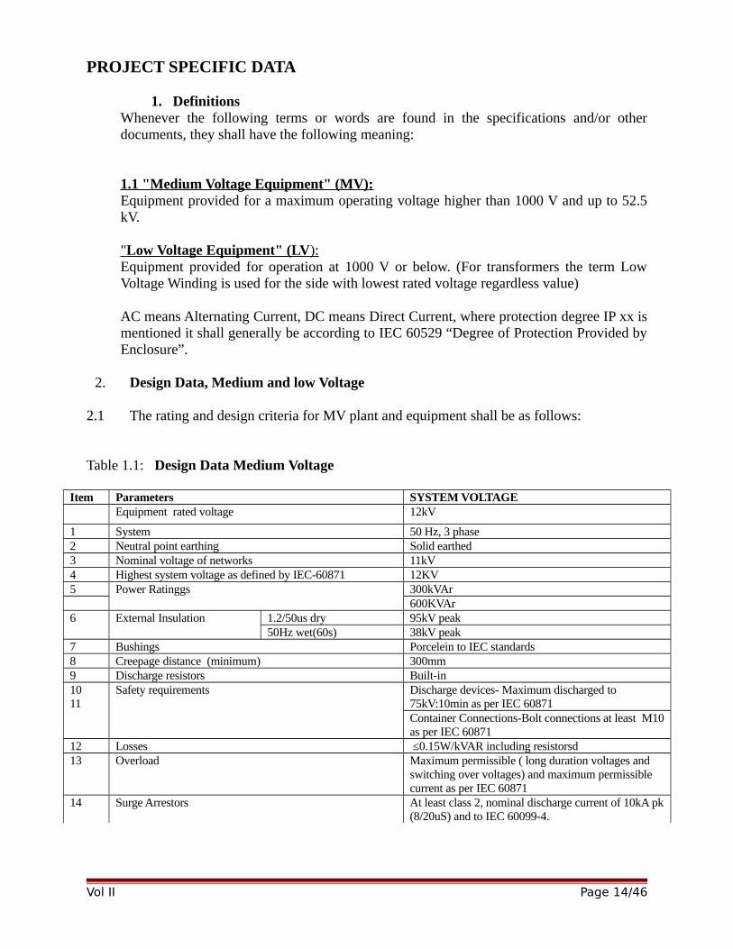
2. Design Data, Medium and low Voltage
2.1 The rating and design criteria for MV plant and equipment shall be as follows:
Table 1.1: Design Data Medium Voltage
Item Parameters SYSTEM VOLTAGEEquipment rated voltage 12kV
1 System 50 Hz, 3 phase2 Neutral point earthing Solid earthed3 Nominal voltage of networks 11kV4 Highest system voltage as defined by IEC-60871 12KV5 Power Ratinggs 300kVAr
600KVAr6 External Insulation 1.2/50us dry 95kV peak
50Hz wet(60s) 38kV peak7 Bushings Porcelein to IEC standards8 Creepage distance (minimum) 300mm9 Discharge resistors Built-in1011
Safety requirements Discharge devices- Maximum discharged to 75kV:10min as per IEC 60871Container Connections-Bolt connections at least M10as per IEC 60871
12 Losses ≤0.15W/kVAR including resistorsd13 Overload Maximum permissible ( long duration voltages and
switching over voltages) and maximum permissible current as per IEC 60871
14 Surge Arrestors At least class 2, nominal discharge current of 10kA pk(8/20uS) and to IEC 60099-4.
Vol II Page 14/46
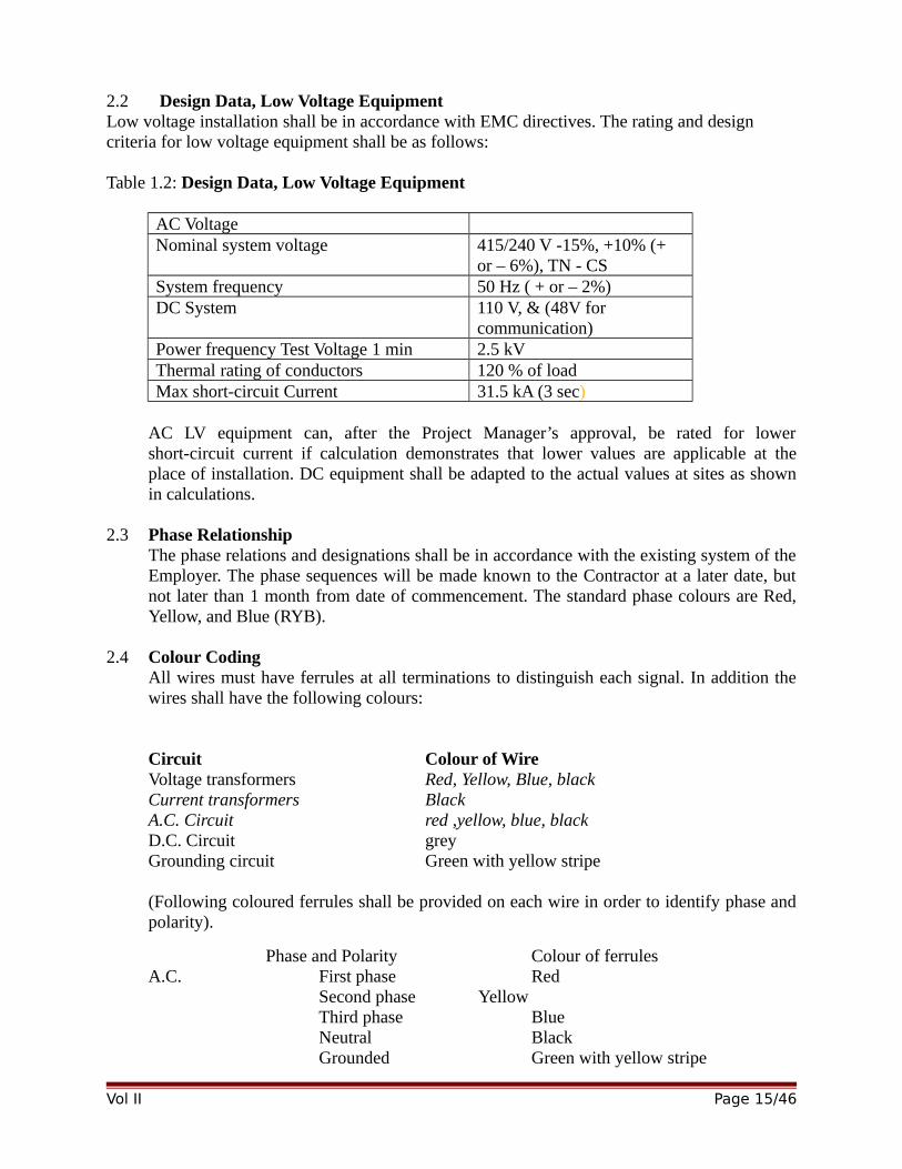
2.2 Design Data, Low Voltage EquipmentLow voltage installation shall be in accordance with EMC directives. The rating and design criteria for low voltage equipment shall be as follows:
Table 1.2: Design Data, Low Voltage Equipment
AC VoltageNominal system voltage 415/240 V -15%, +10% (+
or – 6%), TN - CSSystem frequency 50 Hz ( + or – 2%)DC System 110 V, & (48V for
communication)Power frequency Test Voltage 1 min 2.5 kVThermal rating of conductors 120 % of loadMax short-circuit Current 31.5 kA (3 sec)
AC LV equipment can, after the Project Manager’s approval, be rated for lowershort-circuit current if calculation demonstrates that lower values are applicable at theplace of installation. DC equipment shall be adapted to the actual values at sites as shownin calculations.
2.3 Phase RelationshipThe phase relations and designations shall be in accordance with the existing system of theEmployer. The phase sequences will be made known to the Contractor at a later date, butnot later than 1 month from date of commencement. The standard phase colours are Red,Yellow, and Blue (RYB).
2.4 Colour Coding All wires must have ferrules at all terminations to distinguish each signal. In addition thewires shall have the following colours:
Circuit Colour of WireVoltage transformers Red, Yellow, Blue, blackCurrent transformers BlackA.C. Circuit red ,yellow, blue, blackD.C. Circuit greyGrounding circuit Green with yellow stripe
(Following coloured ferrules shall be provided on each wire in order to identify phase andpolarity).
Phase and Polarity Colour of ferrulesA.C. First phase Red
Second phase YellowThird phase BlueNeutral BlackGrounded Green with yellow stripe
Vol II Page 15/46
Auxiliary DC Supply Positive RedNegative Black
Ferruling system should be submitted to the Employer for approval before commencementof works.
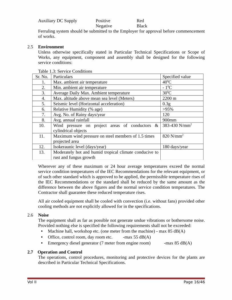
2.5 Environment Unless otherwise specifically stated in Particular Technical Specifications or Scope ofWorks, any equipment, component and assembly shall be designed for the followingservice conditions:
Table 1.3: Service ConditionsSr. No. Particulars Specified value
1. Max. ambient air temperature 400C2. Min. ambient air temperature - 10C3. Average Daily Max. Ambient temperature 300C4. Max. altitude above mean sea level (Meters) 2200 m5. Seismic level (Horizontal acceleration) 0.3g 6. Relative Humidity (% age) >95%7. Avg. No. of Rainy days/year 1208. Avg. annual rainfall 900mm
10. Wind pressure on project areas of conductors &cylindrical objects
383-430 N/mm2
11. Maximum wind pressure on steel members of 1.5 times projected area
820 N/mm2
12. Isokeraunic level (days/year) 180 days/year13. Moderately hot and humid tropical climate conducive to
rust and fungus growth
Wherever any of these maximum or 24 hour average temperatures exceed the normalservice condition temperatures of the IEC Recommendations for the relevant equipment, orof such other standard which is approved to be applied, the permissible temperature rises ofthe IEC Recommendations or the standard shall be reduced by the same amount as thedifference between the above figures and the normal service condition temperatures. TheContractor shall guarantee these reduced temperature rises.
All air cooled equipment shall be cooled with convection (i.e. without fans) provided othercooling methods are not explicitly allowed for in the specifications.
2.6 NoiseThe equipment shall as far as possible not generate undue vibrations or bothersome noise.Provided nothing else is specified the following requirements shall not be exceeded:
• Machine hall, workshop etc. (one meter from the machine) - max 85 dB(A)• Office, control room, day room etc. -max 55 dB(A)• Emergency diesel generator (7 meter from engine room) -max 85 dB(A)
2.7 Operation and ControlThe operations, control procedures, monitoring and protective devices for the plants aredescribed in Particular Technical Specifications.
Vol II Page 16/46
The Contractor shall take all measures and furnish all requirements necessary for affectingthe intended method of operation and control.
2.8 Interface between Contractors and towards Employer
For substations to be extended, all connections shall be made and all equipment anddrawings be provided by the Contractor to ensure proper operation of the complete plants.
The Contractor shall pay special attention to the Power Transformers. All necessaryequipment and connections required to form a complete working plant and not mentionedunder the Power transformer shall be included in the switchgear contract whether or notspecifically mentioned in these Particular Technical Specifications.
The Contractor shall supply and execute all cable connections between the control roomand the transformer marshalling boxes and cabinets as well as supply all AC power formotors and DC voltage for control, indication and alarm purpose. The Contractor shallalso provide all necessary connections to the control system from other sources likevoltage and current transformer terminals, etc.
All the control cables laid in panels and trenches shall be armored cables that willallow the glanding of the cables at the panels.
Vol II Page 17/46
PARTICULAR TECHNICAL SPECIFICATIONS
FOREWORD
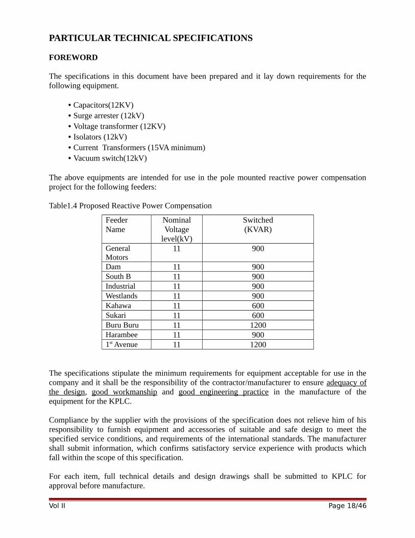
The specifications in this document have been prepared and it lay down requirements for thefollowing equipment.
• Capacitors(12KV)• Surge arrester (12kV)• Voltage transformer (12KV)• Isolators (12kV)• Current Transformers (15VA minimum) • Vacuum switch(12kV)
The above equipments are intended for use in the pole mounted reactive power compensationproject for the following feeders:
Table1.4 Proposed Reactive Power Compensation
FeederName
NominalVoltage
level(kV)
Switched(KVAR)
GeneralMotors
11 900
Dam 11 900South B 11 900Industrial 11 900Westlands 11 900Kahawa 11 600Sukari 11 600Buru Buru 11 1200Harambee 11 9001st Avenue 11 1200
The specifications stipulate the minimum requirements for equipment acceptable for use in thecompany and it shall be the responsibility of the contractor/manufacturer to ensure adequacy ofthe design, good workmanship and good engineering practice in the manufacture of theequipment for the KPLC.
Compliance by the supplier with the provisions of the specification does not relieve him of hisresponsibility to furnish equipment and accessories of suitable and safe design to meet thespecified service conditions, and requirements of the international standards. The manufacturershall submit information, which confirms satisfactory service experience with products whichfall within the scope of this specification.
For each item, full technical details and design drawings shall be submitted to KPLC forapproval before manufacture.
Vol II Page 18/46
Prior to the manufacture of the items on order, KPLC reserves the right to inspect themanufacturing facility and the quality management system at no extra cost. It is theresponsibility of the supplier to confirm if this right is to be exercised. Such visit/inspection shallin no way prejudice the purchaser’s rights and privileges.
Upon completion of the manufacturing process, KPLC reserves the right to send two Engineersto inspect the items on order at the place of manufacture where inspection and acceptance testsshall be carried out in their presence. Tests shall be done in accordance with the test standardspecified and the Technical Specification for each item. It is the responsibility of the supplier toconfirm if this right is to be exercised.
Test Reports shall be completed for each item and made available to KPLC for approval beforepackaging and shipment of the materials. No material or equipment shall be shipped/delivered without written approval from KPLC.
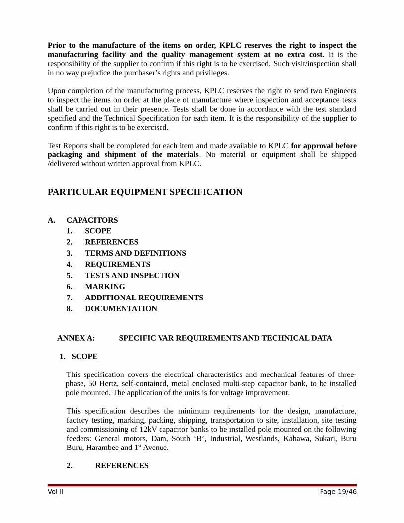
PARTICULAR EQUIPMENT SPECIFICATION
A. CAPACITORS
1. SCOPE
2. REFERENCES
3. TERMS AND DEFINITIONS
4. REQUIREMENTS
5. TESTS AND INSPECTION
6. MARKING
7. ADDITIONAL REQUIREMENTS
8. DOCUMENTATION
ANNEX A: SPECIFIC VAR REQUIREMENTS AND TECHNICAL DATA
1. SCOPE
This specification covers the electrical characteristics and mechanical features of three-phase, 50 Hertz, self-contained, metal enclosed multi-step capacitor bank, to be installedpole mounted. The application of the units is for voltage improvement.
This specification describes the minimum requirements for the design, manufacture,factory testing, marking, packing, shipping, transportation to site, installation, site testingand commissioning of 12kV capacitor banks to be installed pole mounted on the followingfeeders: General motors, Dam, South ‘B’, Industrial, Westlands, Kahawa, Sukari, BuruBuru, Harambee and 1st Avenue.
2. REFERENCES
Vol II Page 19/46
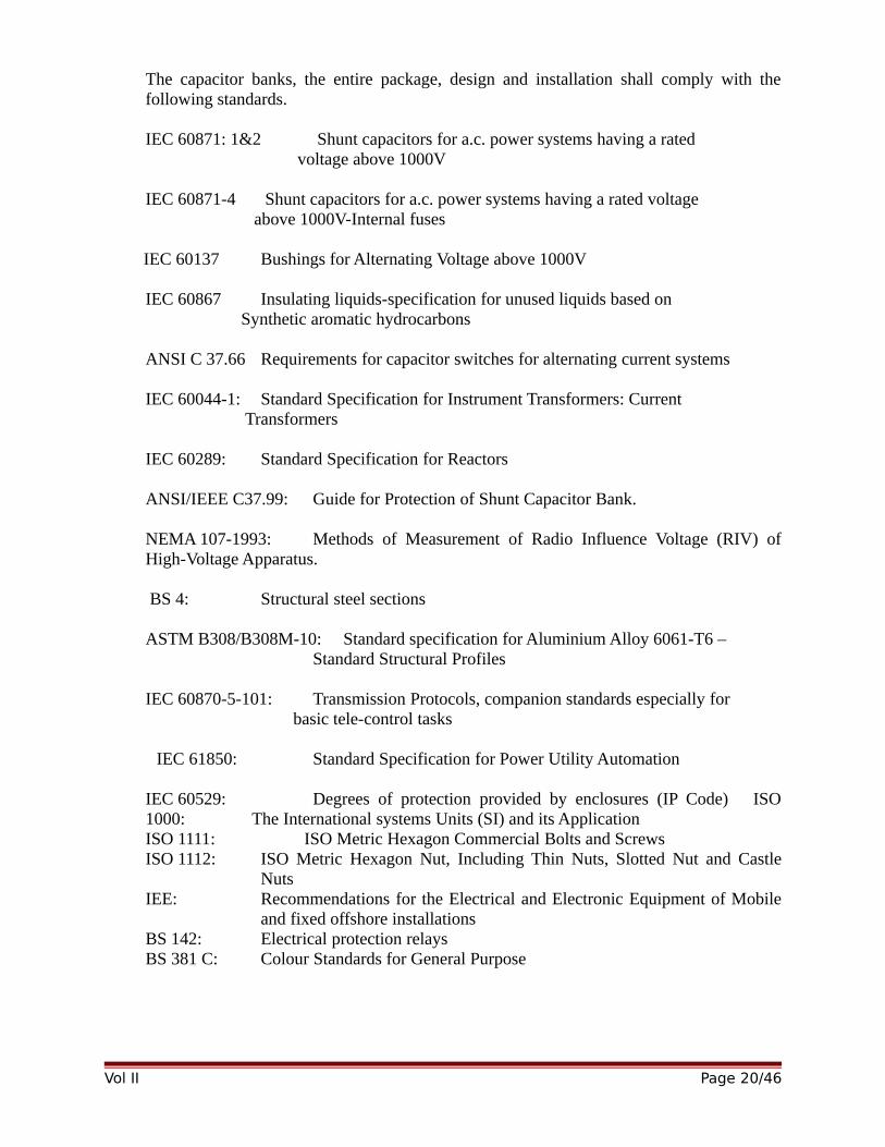
The capacitor banks, the entire package, design and installation shall comply with thefollowing standards.
IEC 60871: 1&2 Shunt capacitors for a.c. power systems having a rated voltage above 1000V
IEC 60871-4 Shunt capacitors for a.c. power systems having a rated voltage above 1000V-Internal fuses
IEC 60137 Bushings for Alternating Voltage above 1000V
IEC 60867 Insulating liquids-specification for unused liquids based on Synthetic aromatic hydrocarbons
ANSI C 37.66 Requirements for capacitor switches for alternating current systems
IEC 60044-1: Standard Specification for Instrument Transformers: Current Transformers
IEC 60289: Standard Specification for Reactors
ANSI/IEEE C37.99: Guide for Protection of Shunt Capacitor Bank.
NEMA 107-1993: Methods of Measurement of Radio Influence Voltage (RIV) ofHigh-Voltage Apparatus.
BS 4: Structural steel sections
ASTM B308/B308M-10: Standard specification for Aluminium Alloy 6061-T6 – Standard Structural Profiles
IEC 60870-5-101: Transmission Protocols, companion standards especially for basic tele-control tasks
IEC 61850: Standard Specification for Power Utility Automation
IEC 60529: Degrees of protection provided by enclosures (IP Code) ISO1000: The International systems Units (SI) and its ApplicationISO 1111: ISO Metric Hexagon Commercial Bolts and ScrewsISO 1112: ISO Metric Hexagon Nut, Including Thin Nuts, Slotted Nut and Castle
NutsIEE: Recommendations for the Electrical and Electronic Equipment of Mobile
and fixed offshore installationsBS 142: Electrical protection relaysBS 381 C: Colour Standards for General Purpose
Vol II Page 20/46

3. TERMS AND DEFINITIONS
The definitions given in the reference standards shall apply.
4. REQUIREMENTS
4.1 SERVICE CONDITIONS
4.1.1 The capacitor banks shall be suitable for continuous operation outdoors in tropicalareas at altitudes of up to 2200m above sea level, humidity of up to 90%, averageambient temperature of +30ºC with a minimum of -1ºC and a maximum of +40ºC,and annual mean isokeraunic level of up to 180 thunderstorm days.
4.1.2 The capacitors shall be suitable for installation as a bank on a three phase 11kVpole mounted, frequency 50Hz. The highest system voltage is 12 kV.
The neutral of the 11 kV systems is earthed at the power transformer.
4.2 GENERAL REQUIREMENTS
4.2.1 Design and Construction Requirements
The capacitor banks shall be connected/ installed pole mounted as specified.The equipment shall be suitable for use in tropical climatic conditions and shall becapable of operating at its full ratings in service conditions as specified in clause 4.1.
The capacitor banks shall be factory pre-assembled as far as possible to minimize workrequired at site.
The 12kV capacitor banks offered shall be complete in all aspects necessary for theireffective and trouble free operation when connected to the system.
The capacitor bank shall not require periodic inspection. Maintenance such asreplacement of failed capacitor units shall be done as required, but major maintenanceintervals should not be less than 15 years.
The capacitor Bank control system complete with alarms and indications shall beprovided.
4.2.2 Capacitor Banks
4.2.2.1 General
The equipment shall be factory assembled and tested prior to shipment and shallcomprise:
Incoming Section with provisions for:
Incoming line lugs
Vol II Page 21/46
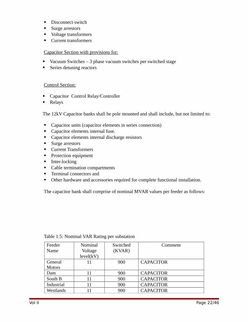
Disconnect switch Surge arrestors Voltage transformers Current transformers
Capacitor Section with provisions for:
Vacuum Switches – 3 phase vacuum switches per switched stage Series detuning reactors
Control Section:
Capacitor Control Relay/Controller Relays
The 12kV Capacitor banks shall be pole mounted and shall include, but not limited to:
Capacitor units (capacitor elements in series connection) Capacitor elements internal fuse. Capacitor elements internal discharge resistors Surge arrestors Current Transformers Protection equipment Inter-locking Cable termination compartments Terminal connectors and Other hardware and accessories required for complete functional installation.
The capacitor bank shall comprise of nominal MVAR values per feeder as follows:
Table 1.5: Nominal VAR Rating per substation
FeederName
NominalVoltage
level(kV)
Switched(KVAR)
Comment
GeneralMotors
11 900 CAPACITOR
Dam 11 900 CAPACITORSouth B 11 900 CAPACITORIndustrial 11 900 CAPACITORWestlands 11 900 CAPACITOR
Vol II Page 22/46
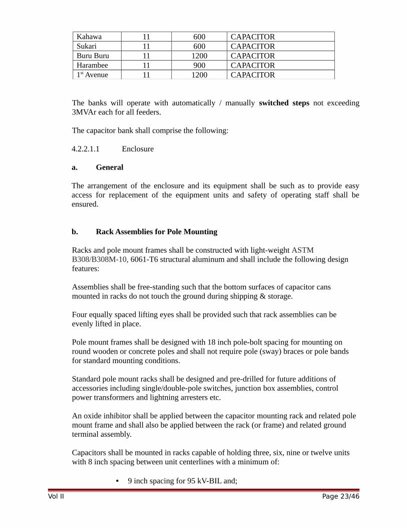
Kahawa 11 600 CAPACITORSukari 11 600 CAPACITORBuru Buru 11 1200 CAPACITORHarambee 11 900 CAPACITOR1st Avenue 11 1200 CAPACITOR
The banks will operate with automatically / manually switched steps not exceeding3MVAr each for all feeders.
The capacitor bank shall comprise the following:
4.2.2.1.1 Enclosure
a. General
The arrangement of the enclosure and its equipment shall be such as to provide easyaccess for replacement of the equipment units and safety of operating staff shall beensured.
b. Rack Assemblies for Pole Mounting
Racks and pole mount frames shall be constructed with light-weight ASTM B308/B308M-10, 6061-T6 structural aluminum and shall include the following design features:
Assemblies shall be free-standing such that the bottom surfaces of capacitor cans mounted in racks do not touch the ground during shipping & storage.
Four equally spaced lifting eyes shall be provided such that rack assemblies can be evenly lifted in place.
Pole mount frames shall be designed with 18 inch pole-bolt spacing for mounting on round wooden or concrete poles and shall not require pole (sway) braces or pole bands for standard mounting conditions.
Standard pole mount racks shall be designed and pre-drilled for future additions of accessories including single/double-pole switches, junction box assemblies, control power transformers and lightning arresters etc.
An oxide inhibitor shall be applied between the capacitor mounting rack and related pole mount frame and shall also be applied between the rack (or frame) and related ground terminal assembly.
Capacitors shall be mounted in racks capable of holding three, six, nine or twelve units with 8 inch spacing between unit centerlines with a minimum of:
• 9 inch spacing for 95 kV-BIL and;
Vol II Page 23/46
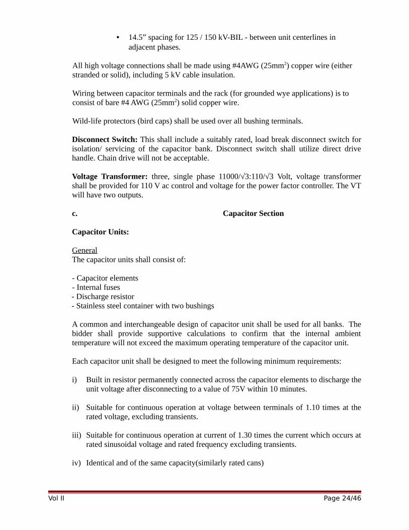
• 14.5” spacing for 125 / 150 kV-BIL - between unit centerlines in adjacent phases.
All high voltage connections shall be made using #4AWG (25mm2) copper wire (either stranded or solid), including 5 kV cable insulation.
Wiring between capacitor terminals and the rack (for grounded wye applications) is to consist of bare #4 AWG (25mm2) solid copper wire.
Wild-life protectors (bird caps) shall be used over all bushing terminals.
Disconnect Switch: This shall include a suitably rated, load break disconnect switch forisolation/ servicing of the capacitor bank. Disconnect switch shall utilize direct drivehandle. Chain drive will not be acceptable.
Voltage Transformer: three, single phase 11000/√3:110/√3 Volt, voltage transformershall be provided for 110 V ac control and voltage for the power factor controller. The VTwill have two outputs.
c. Capacitor Section
Capacitor Units:
GeneralThe capacitor units shall consist of:
- Capacitor elements- Internal fuses- Discharge resistor- Stainless steel container with two bushings
A common and interchangeable design of capacitor unit shall be used for all banks. Thebidder shall provide supportive calculations to confirm that the internal ambienttemperature will not exceed the maximum operating temperature of the capacitor unit.
Each capacitor unit shall be designed to meet the following minimum requirements:
i) Built in resistor permanently connected across the capacitor elements to discharge theunit voltage after disconnecting to a value of 75V within 10 minutes.
ii) Suitable for continuous operation at voltage between terminals of 1.10 times at therated voltage, excluding transients.
iii) Suitable for continuous operation at current of 1.30 times the current which occurs atrated sinusoidal voltage and rated frequency excluding transients.
iv) Identical and of the same capacity(similarly rated cans)
Vol II Page 24/46
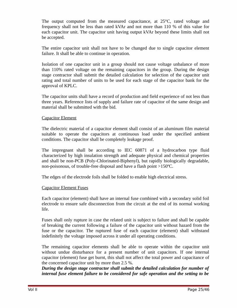
The output computed from the measured capacitance, at 25°C, rated voltage andfrequency shall not be less than rated kVAr and not more than 110 % of this value foreach capacitor unit. The capacitor unit having output kVAr beyond these limits shall notbe accepted.
The entire capacitor unit shall not have to be changed due to single capacitor elementfailure. It shall be able to continue in operation.
Isolation of one capacitor unit in a group should not cause voltage unbalance of morethan 110% rated voltage on the remaining capacitors in the group. During the designstage contractor shall submit the detailed calculation for selection of the capacitor unitrating and total number of units to be used for each stage of the capacitor bank for theapproval of KPLC.
The capacitor units shall have a record of production and field experience of not less thanthree years. Reference lists of supply and failure rate of capacitor of the same design andmaterial shall be submitted with the bid.
Capacitor Element
The dielectric material of a capacitor element shall consist of an aluminum film materialsuitable to operate the capacitors at continuous load under the specified ambientconditions. The capacitor shall be completely leakage proof.
The impregnant shall be according to IEC 60871 of a hydrocarbon type fluidcharacterized by high insulation strength and adequate physical and chemical propertiesand shall be non-PCB (Poly-Chlorinated-Biphenyl), but rapidly biologically degradable,non-poisonous, of trouble-free disposal and have a flash point >150ºC.
The edges of the electrode foils shall be folded to enable high electrical stress.
Capacitor Element Fuses
Each capacitor (element) shall have an internal fuse combined with a secondary solid foilelectrode to ensure safe disconnection from the circuit at the end of its normal workinglife.
Fuses shall only rupture in case the related unit is subject to failure and shall be capableof breaking the current following a failure of the capacitor unit without hazard from thefuse or the capacitor. The ruptured fuse of each capacitor (element) shall withstandindefinitely the voltage imposed across it under all operating conditions.
The remaining capacitor elements shall be able to operate within the capacitor unitwithout undue disturbance for a present number of unit capacitors. If one internalcapacitor (element) fuse get burnt, this shall not affect the total power and capacitance ofthe concerned capacitor unit by more than 2.5 %.During the design stage contractor shall submit the detailed calculation for number ofinternal fuse element failure to be considered for safe operation and the setting to be
Vol II Page 25/46
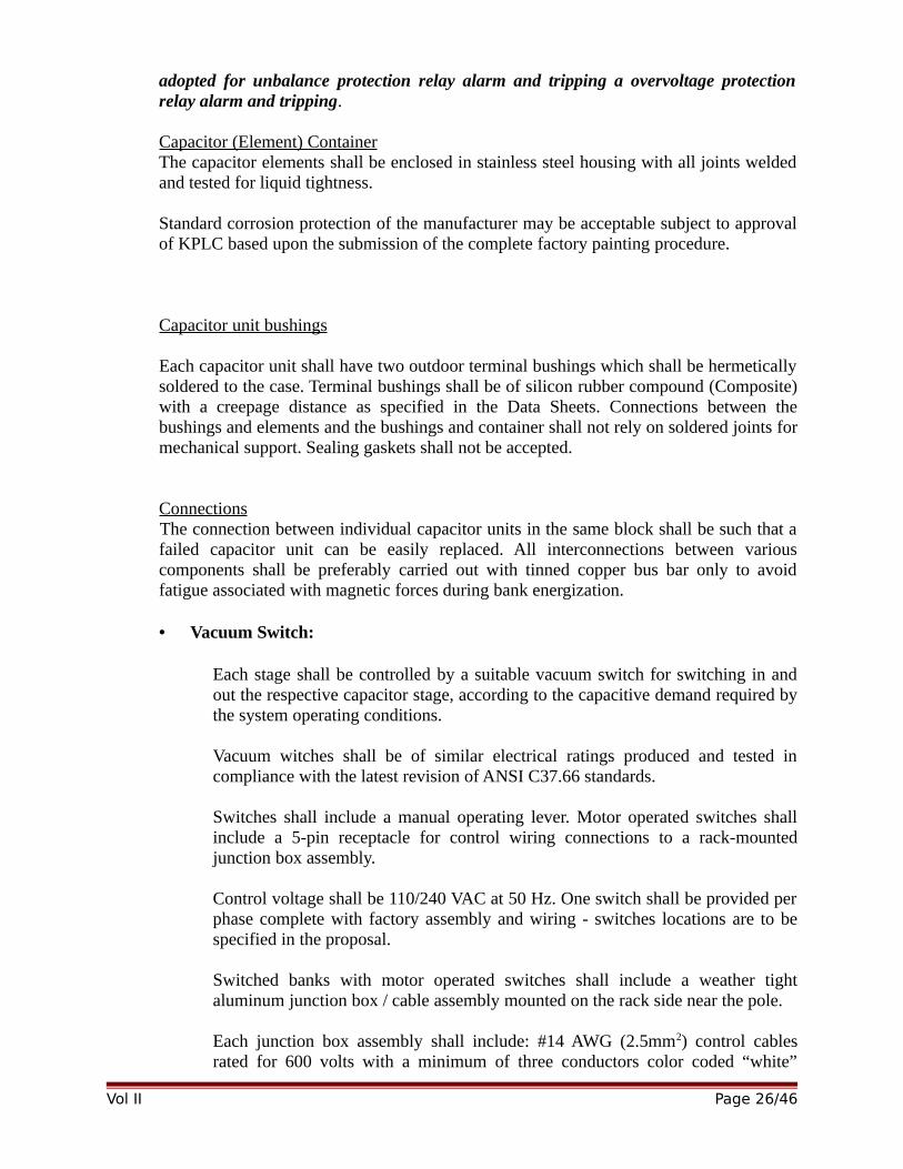
adopted for unbalance protection relay alarm and tripping a overvoltage protectionrelay alarm and tripping.
Capacitor (Element) ContainerThe capacitor elements shall be enclosed in stainless steel housing with all joints weldedand tested for liquid tightness.
Standard corrosion protection of the manufacturer may be acceptable subject to approvalof KPLC based upon the submission of the complete factory painting procedure.
Capacitor unit bushings
Each capacitor unit shall have two outdoor terminal bushings which shall be hermeticallysoldered to the case. Terminal bushings shall be of silicon rubber compound (Composite)with a creepage distance as specified in the Data Sheets. Connections between thebushings and elements and the bushings and container shall not rely on soldered joints formechanical support. Sealing gaskets shall not be accepted.
ConnectionsThe connection between individual capacitor units in the same block shall be such that afailed capacitor unit can be easily replaced. All interconnections between variouscomponents shall be preferably carried out with tinned copper bus bar only to avoidfatigue associated with magnetic forces during bank energization.
• Vacuum Switch:
Each stage shall be controlled by a suitable vacuum switch for switching in andout the respective capacitor stage, according to the capacitive demand required bythe system operating conditions.
Vacuum witches shall be of similar electrical ratings produced and tested incompliance with the latest revision of ANSI C37.66 standards.
Switches shall include a manual operating lever. Motor operated switches shallinclude a 5-pin receptacle for control wiring connections to a rack-mountedjunction box assembly.
Control voltage shall be 110/240 VAC at 50 Hz. One switch shall be provided perphase complete with factory assembly and wiring - switches locations are to bespecified in the proposal.
Switched banks with motor operated switches shall include a weather tightaluminum junction box / cable assembly mounted on the rack side near the pole.
Each junction box assembly shall include: #14 AWG (2.5mm2) control cablesrated for 600 volts with a minimum of three conductors color coded “white”
Vol II Page 26/46
(common), “red” (closing) & “black” (tripping). These cables shall include 5-pinplugs to mate with switch receptacles and shall terminate in a 6-position terminalblock mounted within the junction box.
Terminal blocks shall be marked: “L” (for Line), “G” (for Ground), “C” (forclosing), “T” (for Trip) & “5”, “6” (for last two positions).
Junction box covers shall slide into position and shall not require screws for attachment. A captive chain shall be attached between the cover and box.
The tenderer shall provide details of the proposed vacuum switch in his tender, together with evidence that they are suitable for switching duties and that the switch and associated power equipment will not be subject to damaging over-voltages when switching.
Each switched stage shall be switched via a capacitor rated switching device withcurrent and voltage ratings appropriate for the system design.
The vacuum switches will have been tested for capacitor switching and meet thefollowing criteria:
Solenoid operated, rated for 50,000 operations (open & close), do not utilize oil orgas insulation and utilize porcelain housing.
c. Control Section
• Current Sensor
The current sensor (CS) shall be of line post insulator type for VAr control and shall alsobe supplied with switched capacitor type and its cost shall be included in the respectivebid price.
A suitable ultraviolet-resistant cable, at least 5 m long, shall be provided for theconnection between the CS and the junction box. If longer cables are required, the lengthwill be specified in the tender documentation.
It shall be possible to disconnect the cable from the CS, at the controller, while thenetwork is under load, without the risk of damage to personnel, the CS, and /or any otherequipment that may come into contact with the bare wires.
Insulator profile characteristics shall comply with the guidelines in annex D of IEC60044-1.
The minimum bushing creepage distance from phase-to-earth (in mm) shall be 744 mm.
The bushing material shall be either porcelain or silicone rubber.
• Control cabinet
Vol II Page 27/46
The control cabinet shall be suitable for mounting on a single wood pole. The necessarymounting bolts, nuts, etc. shall be supplied with the cabinet. The cabinet shall be easilyremovable for workshop repair purposes.
A suitable ultraviolet-resistant cable, at least 3 m long, shall be provided for connectingthe capacitor bank to the control cabinet. If longer cables are required, the length will bespecified in the tender documentation.
It shall be possible to disconnect the cable at the capacitor controller while the capacitorbank is connected to the energized power system, without causing a dangerous conditionto field staff, damage or mal-operation. Care shall be taken to ensure that the currentsensor is not open-circuited. A robust, multi-pin, weatherproof connector shall be fitted.The female part of the connector shall be mounted on the capacitor bank and the malepart shall be mounted on the cable.
Cabinets shall be adequately sealed and dust protected and shall be internally treated toprevent moisture condensation. The degree of protection shall be IP 55 or better inaccordance with IEC 60529.
The supplier shall ensure that the equipment housed in the control cabinet can withstandthe heating effect of direct solar radiation without causing failure and/normal-operation.Details shall be provided in the tender documentation.
The cabinet shall be provided with an external M12 earthing stud with a nut and aserrated washer. A suitable arrangement shall be provided to ensure that earth continuityis maintained between the cabinet and the door.
The door of the cabinet shall be fitted with a robust fastening arrangement that is capableof being secured by a padlock that has a shackle of 8 mm diameter. Pewter or other brittlemetal type handles will not be acceptable.
Provision shall be made in the cabinet for mounting of a cell phone modem. Themaximum modem dimensions are 150mm long, 80mm wide and 50mm thick. (Themodem will be supplied and installed by KPLC).
The cabinet shall make provision for bottom entry for the lead for the modem’s aerial. A10 mm diameter hole blanked off with blanking plugs shall be provided.
Means shall be provided to secure the blanking plug to the inside of the cabinet to ensurethat the plug is not lost during transport.
d. Capacitor Protection
The capacitor banks/units shall be provided completely with its internal andexternal protection which is considered as part of the capacitor equipment.
Vol II Page 28/46
Fuses shall be provided internally for protection of individual capacitor units. Thefuses shall not deteriorate when the capacitor is subjected to discharge testing orthe currents associated with service operations of the capacitor equipment.
Fuses shall only rupture in case the related unit is subject to failure and shall becapable of breaking the current following a failure of the capacitor unit withouthazard from the fuse or the capacitor.
The ruptured fuse of each element shall withstand indefinitely the voltageimposed across it under all operating conditions.
The remaining capacitor units shall be able to operate within the capacitor bankwithout undue disturbance for a present number of unit capacitor failures.
5. TESTING AND INSPECTION
5.1 Testing and inspection for capacitor bank
Type testsCertified type test certificates and reports from an ISO/IEC 17025 accredited laboratoryshall be submitted with this tender.
The design tests shall conform to IEC and must include at least the following tests:
a) Complete assembled capacitor banks according to IEC 62271-200 and IEC 60694recommendations. In all cases the design of the completed equipment shall beverified by Temperature Rise Tests, LI Withstand Test and Ingress Protection Test.
b) Capacitor UnitsThe capacitor units shall be subjected to the following type tests as per IEC 60871:
i. Thermal stability testii. Capacitor loss angleiii. A.C. voltage test between terminals and containeriv. Lightning impulse voltage test between terminals and containerv. Short circuit discharge testVi. Disconnecting test on internal fuses
c) Capacitor Contactorsi. Insulation (dielectric) testii. Short time current testiii. Rated making current testiv. Operating duty testv. Temperature rise testvi. Radio influence voltage testvii. Mechanical life testviii. Control wiring test.
Fuses shall be tested according to IEC 60549 / 60282 recommendations.
Routine tests
Vol II Page 29/46
Routine tests shall be performed according to the relevant IEC Standards and shall bewitnessed by KPLC representatives unless otherwise waived in writing:
Site tests
Not less than one month prior to the commencement of site testing, the Bidder/Contractorshall submit to KPLC the Site Test and commissioning procedure (SAT).
The tests shall be carried out as per approved SAT document. No testing shall commenceuntil the test procedures are agreed. All results shall be submitted on the approved form.
Testing shall be carried out during normal working hours as far as practicable. Tests,which involve existing apparatus and outages, may be carried out outside normal workinghours. The Bidder/Contractor shall give sufficient notice to allow for the necessaryoutage arrangements to be made in conformity with the testing program.
The Bidder/Contractor shall advise KPLC in writing at the time of commencement of siteerection of the site supplies, which will be required for the operation of the testequipment.
The Bidder/Contractor shall provide the requisite experienced test personnel and allrelevant test equipment, unless otherwise agreed by KPLC or stated in the Schedules.
On completion of any group of tests the Bidder/Contractor shall submit two clean copiesof the test results recorded on the approved form. KPLC shall countersign the test sheetsfound to be satisfactory and retain one copy.
The Bidder/Contractor shall subsequently provide to KPLC six bound copies of all sitetest sheets as final records. The test sheets shall be grouped by substation subdivided byplant type and further on a circuit-by-circuit basis.
So that the records may be used for maintenance tests the final records shall be providedas soon as possible after completion of testing.
No tests as agreed under the program of tests shall be waived except upon the instructionof KPLC in writing.
All tests shall be carried out in the presence of KPLC unless otherwise agreed. TheBidder/Contractor shall carry out all the necessary tests for the capacitor bank units,cables and other associated equipment and submit a report that they are ready forcommissioning.
Tests on the capacitor bank units will be carried out by the Bidder/Contractor under thesupervision of the manufacturer and energized by the Engineer from KPLC, afterwitnessing necessary commissioning tests carried out by the Bidder/Contractor.
Any defects noticed during commissioning due to poor workmanship, wrong phasing orany other reason shall be made good by the Bidder/Contractor immediately.
Any defects noticed due to poor workmanship in the guarantee period must be rectifiedby the Bidder/Contractor to the satisfaction of KPLC.
Tests on Capacitor Bank Units and Auxiliary Equipment
Vol II Page 30/46
General Checks
A general check of all the main switchgear, labeling and ancillary equipment shall bemade and shall include a check of the completeness, correctness and condition of earthconnections, painted surfaces, cables, wiring, plates and all other auxiliary and ancillaryitems. Checks shall be made for any leaks, and that insulators are clean and free fromexternal damage. A check shall be made that loose items which are to be taken over byKPLC, e.g. tools, spares, are in order and are correctly stored for taking over.
Shutters, interlocking, earthing procedures and the interchangeability of components shallbe checked.
Isolator/SwitchesIsolator / switches (panel side mounted) shall be subject to operational tests to confirmcontact pressures, contact resistance and the ease of operation.
The test to confirm the opening and closing sequences and Checks on earth mat,indicators and manual locking devices shall be performed. Checks shall be made of thelocal and remote indications and operation of auxiliary contacts.
Continuity of Cable Connections and PhasingContinuity of cable connections and phasing sequence to be checked
Insulation between Phases, Insulation to EarthInsulation resistance between phases and to earth shall be measured.
Testing of Current and Voltage Transformers on the Capacitor BankThe Bidder/Contractor shall be responsible for performing all required tests on thecurrent and voltage transformers installed in the capacitor bank unit.
6. MARKING
Markings on the unit and the bank shall be in accordance with IEC 60871-1. Themarkings shall be permanent.
7. ADDITIONAL REQUIREMENTS
• One remote current transformer (15VA minimum) for the VAr controller to beprovided for each bank.
• Equipment shall be neatly constructed and finished.• Bank shall be supplied with appropriate cautionary nameplates.• Any miscellaneous components not specifically named, but required for
proper operation, shall be included.• Capacitor bank manufacturer to have over 20 years of experience as a
supplier to major utilities and industrial partners. References shall be provided withproposal.
Vol II Page 31/46
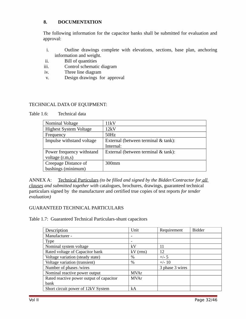
8. DOCUMENTATION
The following information for the capacitor banks shall be submitted for evaluation andapproval:
i. Outline drawings complete with elevations, sections, base plan, anchoringinformation and weight.
ii. Bill of quantitiesiii. Control schematic diagramiv. Three line diagramv. Design drawings for approval
TECHNICAL DATA OF EQUIPMENT:
Table 1.6: Technical data
Nominal Voltage 11kVHighest System Voltage 12kVFrequency 50HzImpulse withstand voltage External (between terminal & tank):
Internal:Power frequency withstand voltage (r.m,s)
External (between terminal & tank):
Creepage Distance of bushings (minimum)
300mm
ANNEX A: Technical Particulars (to be filled and signed by the Bidder/Contractor for all clauses and submitted together with catalogues, brochures, drawings, guaranteed technical particulars signed by the manufacturer and certified true copies of test reports for tender evaluation)
GUARANTEED TECHNICAL PARTICULARS
Table 1.7: Guaranteed Technical Particulars-shunt capacitors
Description Unit Requirement BidderManufacturer - -Type -Nominal system voltage kV 11Rated voltage of Capacitor bank kV (rms) 12Voltage variation (steady state) % +/- 5Voltage variation (transient) % +/- 10Number of phases /wires 3 phase 3 wiresNominal reactive power output MVArRated reactive power output of capacitor bank
MVAr
Short circuit power of 12kV System kA
Vol II Page 32/46
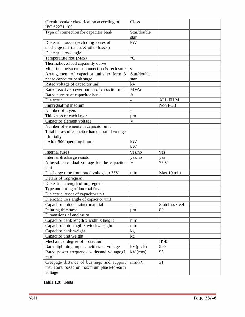
Circuit breaker classification according to IEC 62271-100
Class
Type of connection for capacitor bank Star/double star
Dielectric losses (excluding losses of discharge resistances & other losses)
kW
Dielectric loss angleTemperature rise (Max) °CThermal/overload capability curveMin. time between disconnection & reclosure sArrangement of capacitor units to form 3phase capacitor bank stage
Star/doublestar
Rated voltage of capacitor unit kVRated reactive power output of capacitor unit MVArRated current of capacitor bank ADielectric - ALL FILMImpregnating medium Non PCBNumber of layers -Thickness of each layer μmCapacitor element voltage VNumber of elements in capacitor unitTotal losses of capacitor bank at rated voltage- Initially- After 500 operating hours kW
kWInternal fuses yes/no yesInternal discharge resistor yes/no yesAllowable residual voltage for the capacitorunit
V 75 V
Discharge time from rated voltage to 75V min Max 10 minDetails of impregnantDielectric strength of impregnantType and rating of internal fuseDielectric losses of capacitor unitDielectric loss angle of capacitor unitCapacitor unit container material - Stainless steelPainting thickness μm 80Dimensions of enclosureCapacitor bank length x width x height mmCapacitor unit length x width x height mmCapacitor bank weight kgCapacitor unit weight kgMechanical degree of protection IP 43Rated lightning impulse withstand voltage kV(peak) 200Rated power frequency withstand voltage,(1min)
kV (rms) 95
Creepage distance of bushings and supportinsulators, based on maximum phase-to-earthvoltage
mm/kV 31
Table 1.9: Tests
Vol II Page 33/46
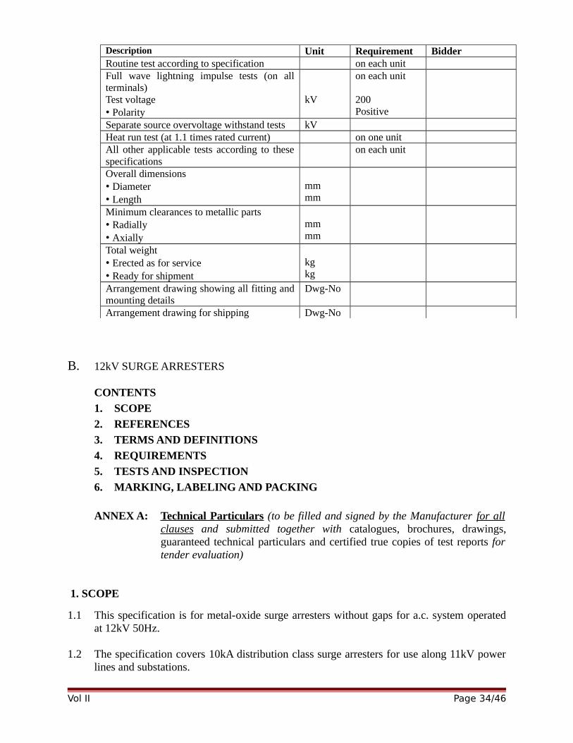
Description Unit Requirement BidderRoutine test according to specification on each unitFull wave lightning impulse tests (on allterminals)Test voltage • Polarity
kV
on each unit
200Positive
Separate source overvoltage withstand tests kV Heat run test (at 1.1 times rated current) on one unitAll other applicable tests according to thesespecifications
on each unit
Overall dimensions• Diameter • Length
mmmm
Minimum clearances to metallic parts• Radially • Axially
mmmm
Total weight• Erected as for service • Ready for shipment
kgkg
Arrangement drawing showing all fitting andmounting details
Dwg-No
Arrangement drawing for shipping Dwg-No
B. 12kV SURGE ARRESTERS
CONTENTS
1. SCOPE
2. REFERENCES
3. TERMS AND DEFINITIONS
4. REQUIREMENTS
5. TESTS AND INSPECTION
6. MARKING, LABELING AND PACKING
ANNEX A: Technical Particulars (to be filled and signed by the Manufacturer for allclauses and submitted together with catalogues, brochures, drawings,guaranteed technical particulars and certified true copies of test reports fortender evaluation)
1. SCOPE
1.1 This specification is for metal-oxide surge arresters without gaps for a.c. system operatedat 12kV 50Hz.
1.2 The specification covers 10kA distribution class surge arresters for use along 11kV powerlines and substations.
Vol II Page 34/46
2. REFERENCES
The following standards contain provisions which, through reference in this text constituteprovisions of this specification. Unless otherwise stated, the latest editions (includingamendments) apply.
ISO 1461: Metallic Coatings – Hot dip galvanized coatings on fabricated ferrous products – Requirements.
KS IEC 60099-4: Metal-oxide surge arresters without gaps for a.c. systems
IEC 60099-4: Metal-oxide surge arresters without gaps for a.c. systems
IEEE Std C62.22: Guide for the application of metal-oxide surge arresters for alternating current systems.
3. TERMS AND DEFINITIONS
Terms and definitions given in IEC 60099-4 shall apply.
4. REQUIREMENTS
4.1 Service Conditions and System Data
The surge arresters shall be suitable for continuous operation outdoors in tropicalareas at altitudes of up to 2200m above sea level, humidity of up to 90%, averageambient temperature of +30ºC with a minimum of -1ºC and a maximum of +40ºC,heavy saline conditions along the coast and annual mean isokeraunic level of up to180 thunderstorm days.
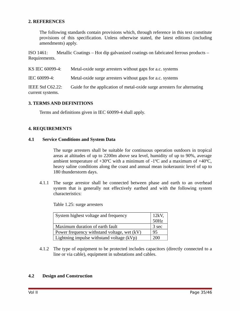
4.1.1 The surge arrestor shall be connected between phase and earth to an overheadsystem that is generally not effectively earthed and with the following systemcharacteristics:
Table 1.25: surge arresters
System highest voltage and frequency 12kV,50Hz
Maximum duration of earth fault 3 secPower frequency withstand voltage, wet (kV) 95Lightning impulse withstand voltage (kVp) 200
4.1.2 The type of equipment to be protected includes capacitors (directly connected to aline or via cable), equipment in substations and cables.
4.2 Design and Construction
Vol II Page 35/46
4.2.1 The surge arrester shall be designed and constructed in accordance with IEC60099-4 and the requirements of this specification. It shall be suitable forover-voltage protection of distribution networks.
4.2.2 The metal-oxide used shall be of quality to ensure thermal stability under serviceduty of the surge arrester.
4.2.3 The arrester shall be single column; self-supported and be installed between phaseand earth.
4.2.4 The housing of the surge arrester shall be made of high quality silicone rubber ofthe following minimum properties:a) hydrophobicb) insensitivity to ultra-violet radiationc) excellent tracking resistanced) excellent mechanical impact, abrasion and shear resistancee) Excellent long-term stability and resistance to ageing under climatic and
electrical stresses.
4.2.5 The surge arrester shall be sealed (end caps) with a controlled permanent seal toensure no moisture absorption or deterioration of the metal-oxide element of thesurge arrester.
4.2.6 The surge arrester shall be designed and constructed in a manner so as to preventexplosive shattering of the housing in the event of the arrester failure.
4.2.7 The surge arrester shall be supplied complete fitted with a mechanical faultindicator. Details on the operation shall be submitted with the offer.
4.2.8 The surge arrester shall be supplied complete with mounting bracket, fixingaccessories and clamp connector suitable for both copper and aluminum conductorsof up to 12.5mm diameter. All parts shall be protected against corrosion.
The mounting brackets for distribution class surge arresters shall be suitable forboth horizontal and vertical mounting on a steel cross arm (U-channel).
Station class surge arrester, when required, shall be suitable for pedestal mountingwith a suitable pitch circle diameter.
4.2.9 The steel plates or straps and all ferrous parts shall be hot dip galvanized inaccordance to ISO 1461.
4.3 Characteristics
4.3.1 The surge arresters shall be of the following minimum characteristics:
Table 2.6: surge arresters’ minimum characteristic
Vol II Page 36/46
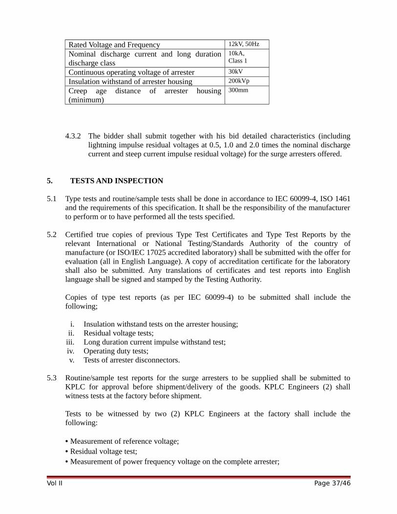
Rated Voltage and Frequency 12kV, 50Hz
Nominal discharge current and long durationdischarge class
10kA, Class 1
Continuous operating voltage of arrester 30kV
Insulation withstand of arrester housing 200kVp
Creep age distance of arrester housing(minimum)
300mm
4.3.2 The bidder shall submit together with his bid detailed characteristics (includinglightning impulse residual voltages at 0.5, 1.0 and 2.0 times the nominal dischargecurrent and steep current impulse residual voltage) for the surge arresters offered.
5. TESTS AND INSPECTION
5.1 Type tests and routine/sample tests shall be done in accordance to IEC 60099-4, ISO 1461and the requirements of this specification. It shall be the responsibility of the manufacturerto perform or to have performed all the tests specified.
5.2 Certified true copies of previous Type Test Certificates and Type Test Reports by therelevant International or National Testing/Standards Authority of the country ofmanufacture (or ISO/IEC 17025 accredited laboratory) shall be submitted with the offer forevaluation (all in English Language). A copy of accreditation certificate for the laboratoryshall also be submitted. Any translations of certificates and test reports into Englishlanguage shall be signed and stamped by the Testing Authority.
Copies of type test reports (as per IEC 60099-4) to be submitted shall include thefollowing;
i. Insulation withstand tests on the arrester housing;ii. Residual voltage tests;
iii. Long duration current impulse withstand test;iv. Operating duty tests;v. Tests of arrester disconnectors.
5.3 Routine/sample test reports for the surge arresters to be supplied shall be submitted toKPLC for approval before shipment/delivery of the goods. KPLC Engineers (2) shallwitness tests at the factory before shipment.
Tests to be witnessed by two (2) KPLC Engineers at the factory shall include thefollowing:
• Measurement of reference voltage;• Residual voltage test;• Measurement of power frequency voltage on the complete arrester;
Vol II Page 37/46
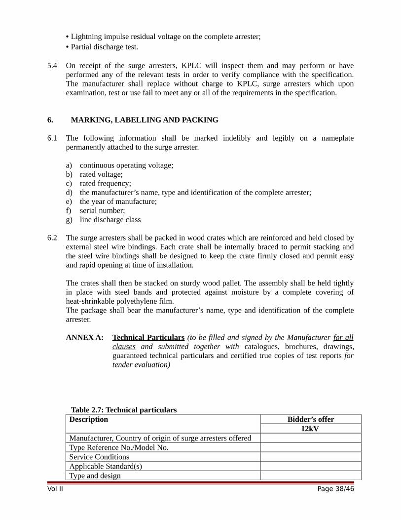
• Lightning impulse residual voltage on the complete arrester;• Partial discharge test.
5.4 On receipt of the surge arresters, KPLC will inspect them and may perform or haveperformed any of the relevant tests in order to verify compliance with the specification.The manufacturer shall replace without charge to KPLC, surge arresters which uponexamination, test or use fail to meet any or all of the requirements in the specification.
6. MARKING, LABELLING AND PACKING
6.1 The following information shall be marked indelibly and legibly on a nameplatepermanently attached to the surge arrester.
a) continuous operating voltage;b) rated voltage;c) rated frequency;d) the manufacturer’s name, type and identification of the complete arrester;e) the year of manufacture;f) serial number;g) line discharge class
6.2 The surge arresters shall be packed in wood crates which are reinforced and held closed byexternal steel wire bindings. Each crate shall be internally braced to permit stacking andthe steel wire bindings shall be designed to keep the crate firmly closed and permit easyand rapid opening at time of installation.
The crates shall then be stacked on sturdy wood pallet. The assembly shall be held tightlyin place with steel bands and protected against moisture by a complete covering ofheat-shrinkable polyethylene film.The package shall bear the manufacturer’s name, type and identification of the completearrester.
ANNEX A: Technical Particulars (to be filled and signed by the Manufacturer for allclauses and submitted together with catalogues, brochures, drawings,guaranteed technical particulars and certified true copies of test reports fortender evaluation)
Table 2.7: Technical particulars Description Bidder’s offer
12kV Manufacturer, Country of origin of surge arresters offeredType Reference No./Model No.Service ConditionsApplicable Standard(s)Type and design
Vol II Page 38/46
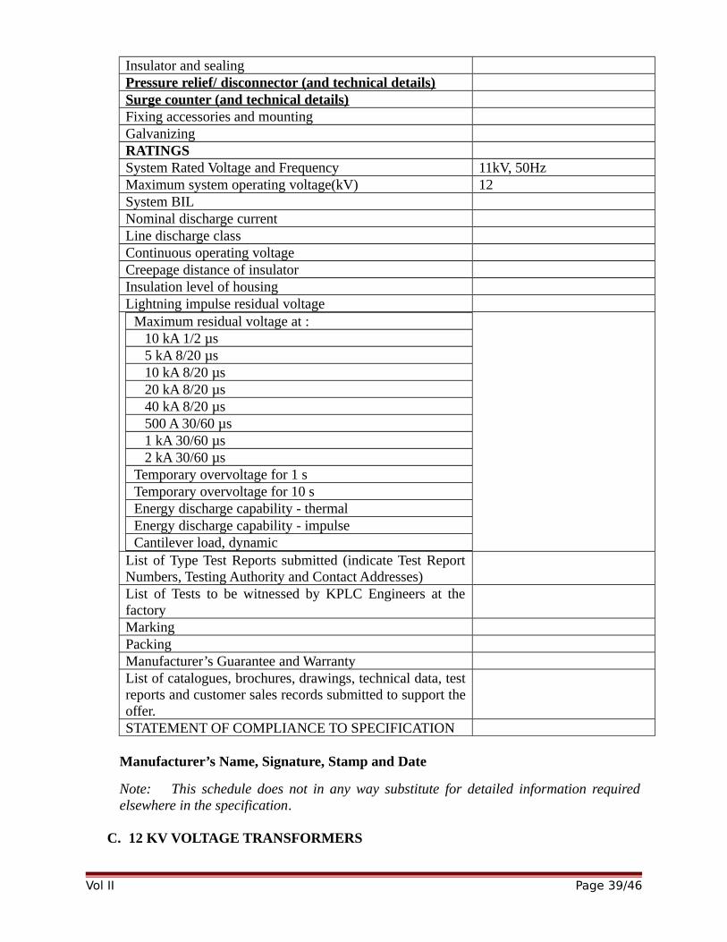
Insulator and sealingPressure relief/ disconnector (and technical details)Surge counter (and technical details)Fixing accessories and mountingGalvanizingRATINGSSystem Rated Voltage and Frequency 11kV, 50HzMaximum system operating voltage(kV) 12System BIL Nominal discharge currentLine discharge classContinuous operating voltageCreepage distance of insulatorInsulation level of housingLightning impulse residual voltage
Maximum residual voltage at : 10 kA 1/2 µs 5 kA 8/20 µs 10 kA 8/20 µs 20 kA 8/20 µs 40 kA 8/20 µs 500 A 30/60 µs 1 kA 30/60 µs 2 kA 30/60 µsTemporary overvoltage for 1 sTemporary overvoltage for 10 sEnergy discharge capability - thermalEnergy discharge capability - impulseCantilever load, dynamic
List of Type Test Reports submitted (indicate Test ReportNumbers, Testing Authority and Contact Addresses)List of Tests to be witnessed by KPLC Engineers at thefactoryMarkingPackingManufacturer’s Guarantee and WarrantyList of catalogues, brochures, drawings, technical data, testreports and customer sales records submitted to support theoffer.STATEMENT OF COMPLIANCE TO SPECIFICATION
Manufacturer’s Name, Signature, Stamp and Date
Note: This schedule does not in any way substitute for detailed information requiredelsewhere in the specification.
C. 12 KV VOLTAGE TRANSFORMERS
Vol II Page 39/46
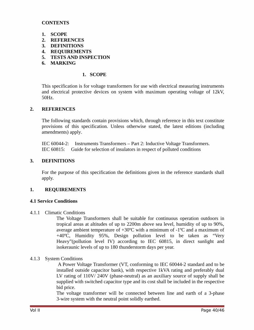
CONTENTS
1. SCOPE2. REFERENCES3. DEFINITIONS4. REQUIREMENTS5. TESTS AND INSPECTION6. MARKING
1. SCOPE
This specification is for voltage transformers for use with electrical measuring instrumentsand electrical protective devices on system with maximum operating voltage of 12kV,50Hz.
2. REFERENCES
The following standards contain provisions which, through reference in this text constituteprovisions of this specification. Unless otherwise stated, the latest editions (includingamendments) apply.
IEC 60044-2: Instruments Transformers – Part 2: Inductive Voltage Transformers.IEC 60815: Guide for selection of insulators in respect of polluted conditions
3. DEFINITIONS
For the purpose of this specification the definitions given in the reference standards shallapply.
1. REQUIREMENTS
4.1 Service Conditions
4.1.1 Climatic ConditionsThe Voltage Transformers shall be suitable for continuous operation outdoors intropical areas at altitudes of up to 2200m above sea level, humidity of up to 90%,average ambient temperature of +30ºC with a minimum of -1ºC and a maximum of+40ºC, Humidity 95%, Design pollution level to be taken as “VeryHeavy”(pollution level IV) according to IEC 60815, in direct sunlight andisokeraunic levels of up to 180 thunderstorm days per year.
4.1.3 System Conditions A Power Voltage Transformer (VT, conforming to IEC 60044-2 standard and to beinstalled outside capacitor bank), with respective 1kVA rating and preferably dualLV rating of 110V/ 240V (phase-neutral) as an auxiliary source of supply shall besupplied with switched capacitor type and its cost shall be included in the respectivebid price. The voltage transformer will be connected between line and earth of a 3-phase3-wire system with the neutral point solidly earthed.
Vol II Page 40/46
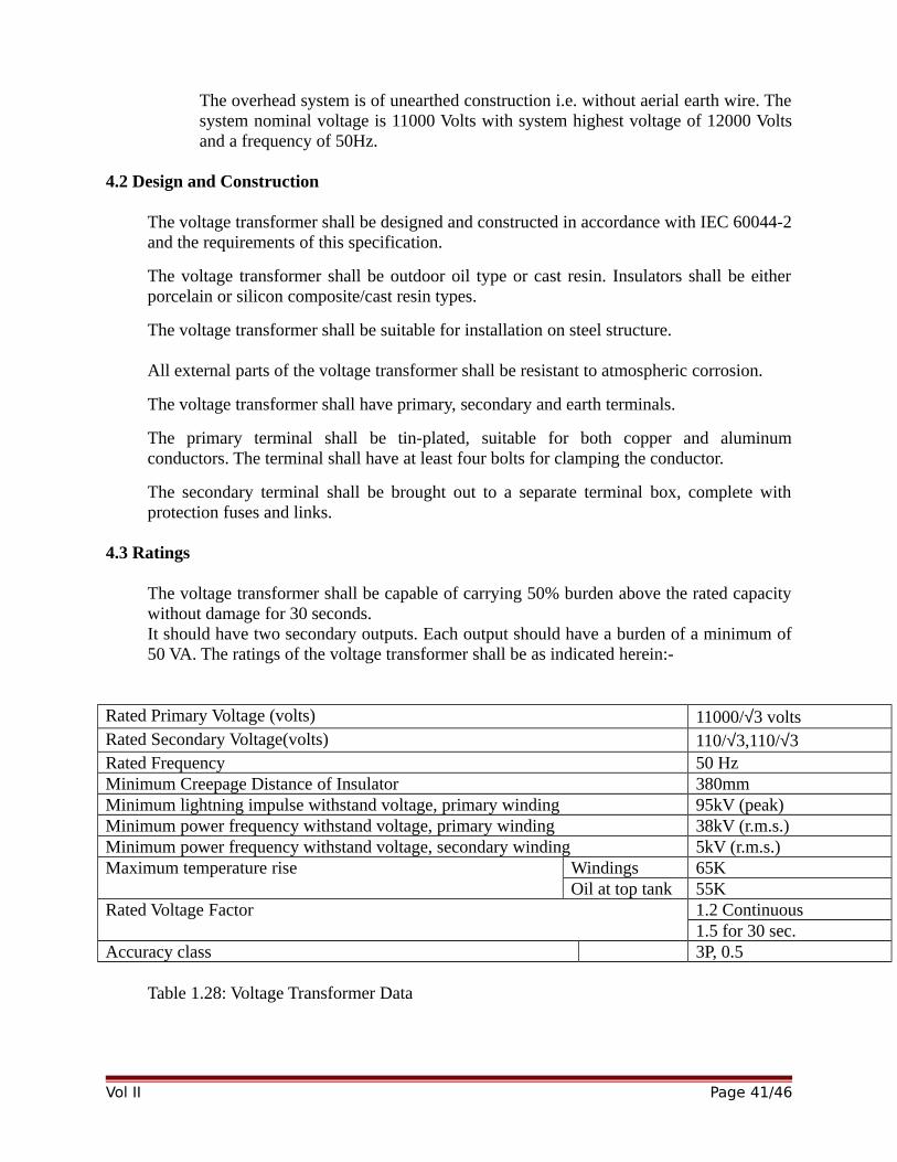
The overhead system is of unearthed construction i.e. without aerial earth wire. Thesystem nominal voltage is 11000 Volts with system highest voltage of 12000 Voltsand a frequency of 50Hz.
4.2 Design and Construction
The voltage transformer shall be designed and constructed in accordance with IEC 60044-2and the requirements of this specification.
The voltage transformer shall be outdoor oil type or cast resin. Insulators shall be eitherporcelain or silicon composite/cast resin types.
The voltage transformer shall be suitable for installation on steel structure.
All external parts of the voltage transformer shall be resistant to atmospheric corrosion.
The voltage transformer shall have primary, secondary and earth terminals.
The primary terminal shall be tin-plated, suitable for both copper and aluminumconductors. The terminal shall have at least four bolts for clamping the conductor.
The secondary terminal shall be brought out to a separate terminal box, complete withprotection fuses and links.
4.3 Ratings
The voltage transformer shall be capable of carrying 50% burden above the rated capacitywithout damage for 30 seconds.It should have two secondary outputs. Each output should have a burden of a minimum of50 VA. The ratings of the voltage transformer shall be as indicated herein:-
Rated Primary Voltage (volts) 11000/√3 voltsRated Secondary Voltage(volts) 110/√3,110/√3 Rated Frequency 50 HzMinimum Creepage Distance of Insulator 380mmMinimum lightning impulse withstand voltage, primary winding 95kV (peak)Minimum power frequency withstand voltage, primary winding 38kV (r.m.s.)Minimum power frequency withstand voltage, secondary winding 5kV (r.m.s.)Maximum temperature rise Windings 65K
Oil at top tank 55KRated Voltage Factor 1.2 Continuous
1.5 for 30 sec.Accuracy class 3P, 0.5
Table 1.28: Voltage Transformer Data
Vol II Page 41/46
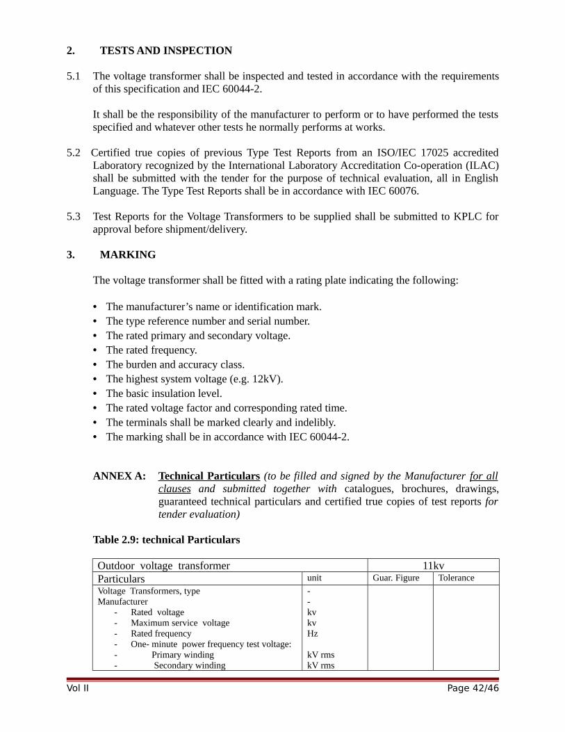
2. TESTS AND INSPECTION
5.1 The voltage transformer shall be inspected and tested in accordance with the requirementsof this specification and IEC 60044-2.
It shall be the responsibility of the manufacturer to perform or to have performed the testsspecified and whatever other tests he normally performs at works.
5.2 Certified true copies of previous Type Test Reports from an ISO/IEC 17025 accreditedLaboratory recognized by the International Laboratory Accreditation Co-operation (ILAC)shall be submitted with the tender for the purpose of technical evaluation, all in EnglishLanguage. The Type Test Reports shall be in accordance with IEC 60076.
5.3 Test Reports for the Voltage Transformers to be supplied shall be submitted to KPLC forapproval before shipment/delivery.
3. MARKING
The voltage transformer shall be fitted with a rating plate indicating the following:
• The manufacturer’s name or identification mark.• The type reference number and serial number.• The rated primary and secondary voltage.• The rated frequency.• The burden and accuracy class.• The highest system voltage (e.g. 12kV).• The basic insulation level.• The rated voltage factor and corresponding rated time.• The terminals shall be marked clearly and indelibly.• The marking shall be in accordance with IEC 60044-2.
ANNEX A: Technical Particulars (to be filled and signed by the Manufacturer for allclauses and submitted together with catalogues, brochures, drawings,guaranteed technical particulars and certified true copies of test reports fortender evaluation)
Table 2.9: technical Particulars
Outdoor voltage transformer 11kvParticulars unit Guar. Figure Tolerance
Voltage Transformers, typeManufacturer
- Rated voltage - Maximum service voltage- Rated frequency- One- minute power frequency test voltage: - Primary winding- Secondary winding
--kvkvHz
kV rmskV rms
Vol II Page 42/46
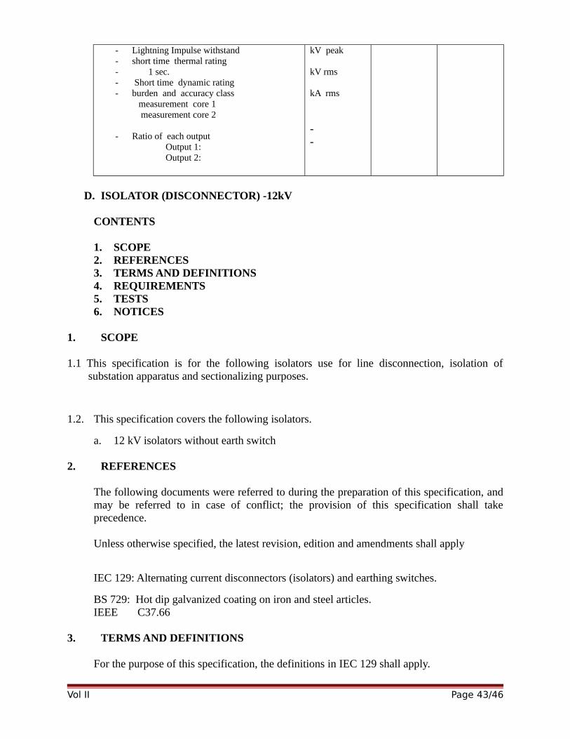
- Lightning Impulse withstand- short time thermal rating- 1 sec.- Short time dynamic rating - burden and accuracy class measurement core 1 measurement core 2
- Ratio of each output Output 1:Output 2:
kV peak
kV rms
kA rms
--
D. ISOLATOR (DISCONNECTOR) -12kV
CONTENTS
1. SCOPE2. REFERENCES3. TERMS AND DEFINITIONS4. REQUIREMENTS5. TESTS6. NOTICES
1. SCOPE
1.1 This specification is for the following isolators use for line disconnection, isolation ofsubstation apparatus and sectionalizing purposes.
1.2. This specification covers the following isolators.
a. 12 kV isolators without earth switch
2. REFERENCES
The following documents were referred to during the preparation of this specification, andmay be referred to in case of conflict; the provision of this specification shall takeprecedence.
Unless otherwise specified, the latest revision, edition and amendments shall apply
IEC 129: Alternating current disconnectors (isolators) and earthing switches.
BS 729: Hot dip galvanized coating on iron and steel articles.IEEE C37.66
3. TERMS AND DEFINITIONS
For the purpose of this specification, the definitions in IEC 129 shall apply.
Vol II Page 43/46

4 REQUIREMENTS
4.1. Service Conditions
The Isolator shall be suitable for continuous outdoor operation in tropical areas with thefollowing atmospheric conditions.
Altitude:- From sea level up to 2200m above mean sea level.
Humidity:- Heavily polluting saline atmosphere in coastal areas and where humidity is inexcess of 90% and up country area where air is relatively clean and humiditynot below 50%.
Ambient:- temperature of +30 °C average, (+40 °C Max. -1° C Min)
4.2. Construction
4.2.1 The isolator shall be vertical or side opening, single break or double Centre breakrotating post type for use on a 11kV, 50 Hz, three phase system.
The isolator shall be complete with supporting base, phase coupling details,operating rod, unions and guides.
The operating mechanism shall be provided with a universal joint to allow for areasonable degree of out-of alignment of the operating rod.
4.2.2 The supporting under base shall be hot dip galvanized steel as per the requirementof BS 729.
The underbase shall be suitable for mounting on a steel structure.
4.2.3 All the three switches shall be arranged so that the phase units are mountedindependently and then finally interconnected with coupling tubes so as to ensuresimultaneous operation of all switches by drive rods and operating handle, bothmanual and motor operation. Motor operating voltage shall be 110volts DC.
4.2.4 The operating mechanism shall be fixed at the base frame, in a weather proof,vermin proof and dust proof housing. The degree of protection shall be class IP 53.
The operating mechanism shall be provided with off/local/remote selector switch. Theselection of local operation shall inhibit the operation from any remote source.
4.2.5 Auxiliary switches, five normally open and five normally closed at 110 volts DC.shall be provided for electrical interlocks with a circuit breaker.
4.2.6 Each phase shall be mounted on a spiral type solid cone insulator and shall be fittedwith clamp connector for ACSR conductor up to 18.2 mm diameter.
Vol II Page 44/46
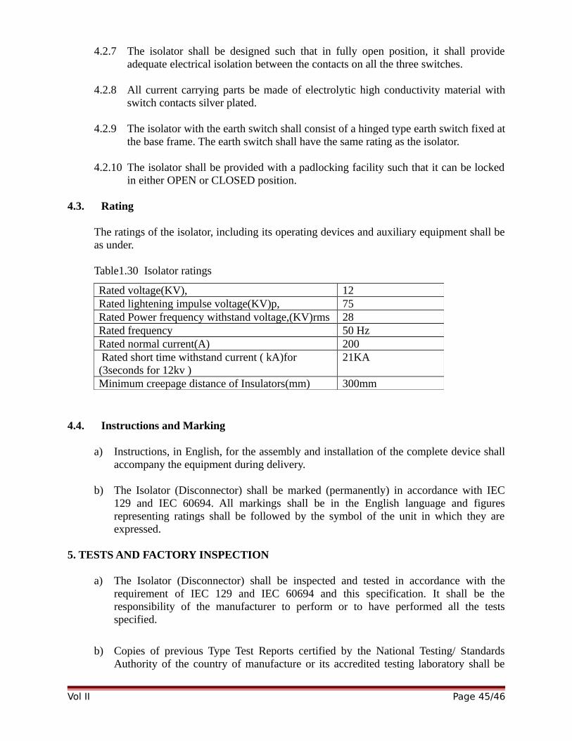
4.2.7 The isolator shall be designed such that in fully open position, it shall provideadequate electrical isolation between the contacts on all the three switches.
4.2.8 All current carrying parts be made of electrolytic high conductivity material withswitch contacts silver plated.
4.2.9 The isolator with the earth switch shall consist of a hinged type earth switch fixed atthe base frame. The earth switch shall have the same rating as the isolator.
4.2.10 The isolator shall be provided with a padlocking facility such that it can be lockedin either OPEN or CLOSED position.
4.3. Rating
The ratings of the isolator, including its operating devices and auxiliary equipment shall beas under.
Table1.30 Isolator ratings
4.4. Instructions and Marking
a) Instructions, in English, for the assembly and installation of the complete device shallaccompany the equipment during delivery.
b) The Isolator (Disconnector) shall be marked (permanently) in accordance with IEC129 and IEC 60694. All markings shall be in the English language and figuresrepresenting ratings shall be followed by the symbol of the unit in which they areexpressed.
5. TESTS AND FACTORY INSPECTION
a) The Isolator (Disconnector) shall be inspected and tested in accordance with therequirement of IEC 129 and IEC 60694 and this specification. It shall be theresponsibility of the manufacturer to perform or to have performed all the testsspecified.
b) Copies of previous Type Test Reports certified by the National Testing/ StandardsAuthority of the country of manufacture or its accredited testing laboratory shall be
Vol II Page 45/46
Rated voltage(KV), 12Rated lightening impulse voltage(KV)p, 75Rated Power frequency withstand voltage,(KV)rms 28 Rated frequency 50 HzRated normal current(A) 200 Rated short time withstand current ( kA)for (3seconds for 12kv )
21KA
Minimum creepage distance of Insulators(mm) 300mm

submitted with the tender (including certificate of accreditation for laboratory) for thepurpose of technical evaluation, all in English.
c) Prior to the manufacture of Isolators (Disconnectors) on order, the purchaser (KPLC)reserves the right to inspect the manufacturing facility and the quality managementsystem at no extra cost save for the air travel (of two Engineers) to the nearestinternational airport in the country of manufacture.
d) Upon completion of manufacturing process, the Isolators (Disconnectors) shall besubject to inspection by two KPLC Engineers at place of manufacture and tests carriedout on samples picked at random in their presence. Test reports shall be completed andmade available for approval before shipment/delivery of the Isolators (Disconnectors).
The cost of inspection and witnessing of tests (except the cost of air travel to the nearestinternational airport) shall be borne by the manufacturer.
6. TECHNICAL DOCUMENTATION
The Bidder shall submit a clause by clause statement of compliance with these specifications
together with copies of the manufacturer’s catalogues, brochures, technical data, drawings, bill of
materials and test certificates clearly marked to support each clause, all in English for evaluation.
The manufacturer’s type reference/designation of the item offered shall be indicated.
In the case of tender award, technical details and detailed drawings for the Isolator
(Disconnector) to be supplied shall be submitted to the purchaser (KPLC) for approval before
manufacture commences. The drawings shall include all the accessories and components to be
supplied.
The manufacturer’s certified Declaration of Conformity to Reference Standards and detailed list
of previous customers (utilities) outside the country of manufacture shall also be submitted.
ANNEX A: Statement of Compliance (to be filled by the Supplier for all clauses andsubmitted for tender evaluation)
Table 1.31: Isolators Technical ParticularsClause Number Bidder’s offer Manufacturer’s catalogue, drawing,
technical data or tests certificateReference Page to support the offer.
4.1
5. d)
Vol II Page 46/46
NB: - This schedule does not in any way substitute for detailed information required elsewhere inthe specification.
Vol II Page 47/46