Engineering Geological Assessment of Granular Material from ...
93
Addis Ababa University school of Graduate Studies, Faculty of Science Engineering Geological Assessment of Granular Material from Weathered Adigrat Sandstone as Filter Material - Special Consideration to Shumbrit Dam, Western Amhara A Thesis Submitted to The School of Graduate Studies of Addis Ababa University In Partial Fulfillment of the Requirements for the Degree of Master of Science in Engineering Geology By T am i ru Kebede July 2009
-
Upload
khangminh22 -
Category
Documents
-
view
7 -
download
0
Transcript of Engineering Geological Assessment of Granular Material from ...

Addis Ababa University school of Graduate Studies,
Faculty of Science
Engineering Geological Assessment of Granular Material from Weathered Adigrat Sandstone as Filter Material
- Special Consideration to Shumbrit Dam, Western Amhara
A Thesis Submitted to The School of Graduate Studies of Addis Ababa University
In Partial Fulfillment of the Requirements for the Degree of Master of Science in
Engineering Geology
By
T amiru Kebede
July 2009
Addis Ababa University school of Graduate Studies,
Faculty of Science
Engineering Geological Assessment of Granular Material from Weathered Adigrat Sandstone as Filter Material
- Special Consideration to Shumbrit Dam, Western Amhara
A Thesis Submitted to The School of Graduate Studies of Addis Ababa University
In Partial Fulfillment of the Requirements for the Degree of Master of Science in
Engineering Geology
By
Tamiru Kebede
July 2009

Abstract
(i)
Abstract
Granular filters are used in embankment dams to prevent impermeable materials from
internal erosion, while draining seepage water to prevent saturation of the downstream
embankment. Such materials are usually assessed from courses of rivers or streams that
contain alluvial sand and gravel materials and their suitability or performance has been
evaluated using existing filter design criteria based on particle size ratios. During this work
same assessment of a granular material which derived from weathering of the Lower
Sandstone unit of the Mesozoic Rock Formation of Ethiopia in protecting red tropical clayey
silt soil has been done. Its overall characteristics, especially those relevant to filter design,
have been studied. It is also compared with respect to an alluvial source, found at relatively
distant place from research site. The geometrical criteria have been mainly checked using the
formulas and recommendations proposed by many scholars and standards. In addition to this,
the final gradation or grain size distribution of a suitable filter material has been prepared
based on the gradation of the base material following the design procedures prepared by
United States Soil Conservation Service (USSCS).
The residual granular material, which was sampled and analyzed for grain size distribution,
nearly satisfies most of the filter criteria, but it is a little bit finer. Of the various criteria
available, the USSCS method and Sherard recommendations have been given more emphasis
as they consider the type of base material and accordingly proposed different approaches and
ratios for design of the filter. The gradation curve for the average residual filter (averaging
three samples from different localities) prepared and also checked with the empirical criteria
and design rules together with one alluvial soil from the distant source. The assessment result
(especially USSCS method) indicates that the residual material almost satisfies the
geometrical criteria, except it becomes a little bit finer. Whereas, the average residual soil and
the alluvial sediment satisfies completely both requirements of filtration and draining. As to
the other characteristics of the filter, all materials (residual and alluvial) have satisfactory
quality; the grains of the residual sand are dominated with quartz, while the alluvial is
fragments of basaltic rocks.
The behaviour of the base soil, which is related to its dispersive nature, also examined in a
laboratory test. The result indicates that the base soil can be categorized as non-dispersive.

Acknowledgements
(ii)
Acknowledgements
First of all, I would like to thank ‘Almighty God’ who made it possible, to begin and finish
this work successfully.
I do not have adequate words to express my feelings of gratitude to my advisor Dr. Tarun
Kumar Raghuvanshi whose benevolent guidance and constant encouragement helped me to
complete the present research work successfully. He is the person who has always helped me.
His constant encouragement made me strong enough to face every ups and down with
confidence during the present research study.
I am grateful to Dr. Balemual Atenafu, Head of the Earth Science Department, Addis Ababa
University and other members of the department for their help, encouragement and
cooperation which gave me enough strength to carry out the present research study.
I am also thankful to the Ministry of Water Resource and Amhara Water Resource Bureau,
from where I received all kind of resource support.
I would like to convey my special thanks to my friend Ato Getinet Assfaw and my brother
Ashenafi Kebede for their constant encouragement and help.

List of Tables
(v)
LIST OF TABLES
S.No Contents Page No.
Chapter I Table 1.0 General Designation of Subsurface Exploratory Holes at Dam Site 8 Table 1.1 General description of Exploratory Augur Holes Bored at Fill Material
Borrow Areas 8
Table 1.2 Soil Samples Designations
Chapter IV Table 4.1 Laboratory Test Result Summary for Impervious Fill Material 28 Table 4.2 Laboratory Test Results for Granular Filter Material (Residual
Sand) 31
Chapter VI Table 6.1 Soil Classification Test Results and Determined Engineering Properties
of the Fill Materials 56
Table 6.2 Summary of the Parameters of the Filter materials 59 Table 6.3 Base Soil Category 62 Table 6.4 Segregation Criteria 63 Table 6.5 USBR Filter Criteria Checking Result 67 Table 6.6 Summary of Results of Filter Checking Using Terzaghi’s Criteria 68 Table 6.7 Filter Criteria Checking Result as Per Indian Standard 69 Table 6.8 Filter Criteria Checking Result as Per Sherard Recommendations 70 Table 6.9 Result for Filter Clogging Check for Proposed Filter Materials 71 Table 6.10 Filter Related Parameter Comparison Result between Residual and
Alluvial Sand 73

List of Figures
(vi)
LIST OF FIGURES
S.No Contents Page No.
Chapter II Figure 2.1 Location Map of Research Project Site 13 Figure 2.2 Proposed Dam Section 14
Chapter III Figure 3.1 Regional Geology Map of North Western Plateau of Ethiopia 18 Figure 3.2 Geology of the Research and Surrounding Areas 19 Figure 3.3 Engineering Geological Map of Dam site and Reservoir Area 20 Figure 3.4 Geological Cross section along the Dam axis 21
Chapter IV Figure 4.1 Geological Cross-sections along the Dam Axis 25 Figure 4.2 Engineering Geological Map of Reservoir Area 27
Chapter VI Figure 6.1 Geological Cross-sections along the Dam Axis 47 Figure 6.2 Proposed Dam Section 50 Figure 6.3 Gradation Curves of Base Soil Samples SHHO-1 and SHHO-2 55 Figure 6.4 Classfication of Embankment Fill Soils Using Plastcity Chart 55 Figure 6.5 Gradation Curves of the Granular Filter Soils 58 Figure 6.6 Gradation Limits for Filters for Base Soil SHHO-1 64 Figure 6.7 Gradation Curves of Base Soil, Filter Limits and Natural
Granular Filters 65
Figure 6.8 Grain Size Distribution Curve for the Average Residual Filter Material
66

List of Plates
(vii)
List of Plates
S.No Contents Page No.
Chapter IV Plate 4.1 Research project Dam Site 24 Plate 4.3 Residual Sand from Adigrat Sandstone Unit 29 Plate 4.3 Alluvial Granular Sediment from ‘Talia’ Stream 31 Plate 4.4 Rock Quarry Site 33
Chapter VI Plate 6.1 Dam Site with its Components 46 Plate 6.2 Top Jointed and Underlying Massive Foundation Basalt Rock 48 Plate 6.3 Portion of the Alluvial Soil Foundation at the left valley floor
area 49
Plate 6.4 Soil/Rock Profile at Right Abutment Foundation Area (from pit SHFOTP-2)
49
Plate 6.5 Granular Filter Materials from Lower Sandstone Unit and Stream Sediments
50
Plate 6.6 Road Cut Exposure Base Soil in the surroundings of the Research Area
53
Plate 6.7 Impermeable Soil Borrow Area1; Sampling and Auguring/Logging
54
Plate 6.8 Residual and Alluvial Sand/Sand-gravel Mixtures for Local Constructions
57

Table of Contents
(iii)
TABLE OF CONTENTS
Contents Page No.
Abstract i Acknowledgements ii List of Tables Vi List of Figures Vii List of Plates Viii
Chapter I Introduction 1 1.1 Background 1 1.2 Research Area 4 1.3 Significance of the Research 5 1.4 Research Objectives 6 1.5 Research Methodology and Approach 6 1.5.1 Data Collection 7 1.5.2 Soil Sampling and Laboratory Testing 8 1.5.3 Data Analysis and Synthesis/ Interpretation 9 1.6 Limitation of the Research 10 1.7 Presentation Schemes 10
Chapter II - Overview of the Project Area 12 2.1 Preamble 12 2.2 Location and Accessibility 12 2.3 Proposed Engineering Structure 12 2.4 Physiography and Climate 14
Chapter III - Geological Setting 15 3.1 Regional Geology 15 3.2 Local Geology and Structure 19 3.3 Geology of the dam site and Reservoir Area 20
Chapter IV - Engineering Geological Setup of the Dam Site 22 4.1 Preamble 22 4.2 Foundation Investigation of Dam Site 22 4.2.1 Valley Floor Area 22 4.2.2 Left Abutment 23 4.2.3 Right Abutment 23 4.2.4 Spill Way 24 4.2 Reservoir Area Condition 24 4.3 Natural Construction Materials 26 4.3.1 Impervious Fill 26 4.3.2 Granular filter and Fine aggregate 28 4.3.3 Coarse Aggregate 31 4.3.4 Masonry Stone, Rock Toe and Rip Rap 31 4.3.5 Water 32 4.4 Overall Engineering Geological Assessment 32
Table of Contents
(iv)
Chapter V - Literature Review 34
5.1 Preamble 34 5.2 Granular Filters in Embankment Dams 35 5.3 Factors Influencing Granular Filter Performance 36 5.4 Focus of Current Study 40
Chapter VI - Data Collection, Analysis and Interpretation 44
6.1 Preamble 44 6.2 Data Collection 46 6.2.1 Dam Foundation Condition 46 6.2.2 Embankment Condition 51 6.3 Data Analysis and Interpretations 59 6.3.1 Geometrical Factors Analysis 60 6.3.1 Clogging Criteria Analysis 71 6.3.2 Physical Factors Analysis 71 6.4 Dispersivity Analysis of Base Soils 71 6.5 Overall Assessment and Interpretation 72
Chapter VII - Conclusions and Recommendations 74 7.1 Conclusion 74 7.2 Recommendations 76 References 79 ANNEXTURE – 1 Test Pit/Augur Hole Logs ANNEXTURE – 2 Laboratory Test Results

Chapter I Introduction
1
Chapter I - Introduction
1.1 Background Systematic study, design and construction of embankment dams for water harvesting
purposes requires a thorough understanding of the geological, engineering geological and
geotechnical properties of foundation and construction soils/rocks. Soils are the main natural
construction materials used for the various zones of the embankment dam body, more than
any other natural or fabricated ones like rock, concrete, iron bars, etc. Naturally, soils are
formed from insitu weathering of rocks that underlain a given geological environment. These
soils may either remain where they are formed (residual soils) or transported by various
agents (water, wind, or glaciers).
Embankment dams are generally of two types depending on the dominant materials used for
their construction. These are earth fill and rock-fill dams. Further, earth fill dams are
classified in to homogeneous and zoned types based on whether they are made up of mainly
one kind or various kinds of materials placed systematically, respectively. In the design and
ultimately for safety and stability of embankment dams, suitable quality and properly placed
or designed natural construction materials are two of the basic considerations. It is; however,
equally important to consider or assess sufficient quantity of the various required materials
within economic distance from the proposed dam site (Bharat Singh, 1995).
For safe design of embankment dams certain criteria must be satisfied. These criteria have
evolved from the study of the causes of failures of dams, elsewhere, in past. An exhaustive
list of dams which had suffered damage or had failed up to 1950 was prepared by
Middlebrooks in 1953 and has been cited by Sherard (Bharat Singh, 1995).
According to the list, the causes of failure could be overtopping (30%), seepage effects,
piping and softening (25%), slope slides (15%), conduit leakage (13%), damage to slope
paving (5%), miscellaneous (7%) and other unknown reasons (5%). The criteria for safe
design have to be specified that they cover all possible causes of failure. The main criteria
that are commonly accepted for safe design of embankment dams include;
• There should be no risk of overtopping. The most important aspect of this criterion is
estimation of the design flood and provision of adequate spillway.

Chapter I Introduction
2
• The seepage line should be well within the downstream face of the dam section. If the
dam section is homogeneous and no drainage arrangements are made, seepage
through dam body is going to emerge on the downstream face. This results in
‘sloughing’ or softening of the downstream face and may lead to local toe failure. The
failure may progressively develop upwards. This can be safeguarded against by
providing a free draining zone on the downstream face or by intercepting the seepage
inside the dam section by internal drainage.
• There should be no possibility of piping through the embankment or foundations. In
the dam section the main protection against piping is provided by filters which
prevent migration of soil particles with seepage water. In the case of pervious
foundations, seepage control measures comprising curtailment of seepage on the one
hand and a safe, filter - protected exist on the other are used to safeguard against
piping failure.
As indicated in the previous paragraphs, one of the main aspect that require due
considerations in the design consideration of embankment dams is seepage and its control
mechanisms. A sufficiently large percentage of earth dam failures reported by Sherard et al.
(1984) was due to seepage. Water seeping under pressure through soil voids is accompanied
by a mechanical drag on the soil particles. When these drag forces exceed the resistive forces
of the soil grains, movement of the grains may take place. It is of fundamental importance to
limit the seepage through earth dams not only to keep the water loss within acceptable limits,
but also to take adequate control measures to ensure the safety of the dam. The adverse
effects of seepage can be divided into two categories: migration of soil particles resulting in
piping, and embankment failure caused by saturation forces. The first category is due to lack
of filter protection or faulty filter through which soil grains can pass. Some other reasons
may be poor compaction, cracks in impermeable soil due to differential settlements, and
leaching of dispersive soils leading to defloculation.
Seepage through embankments and its foundations can be controlled by either preventive or
curative approaches. Usually these approaches are combined in earth dam design practice.
The former approach involves keeping the water out in so far as possible or reduction in
quantity of seepage. Some of the methods in the approach are impermeable zone for
embankment and cut-off trenches and grout curtains in foundation. The second approach
strives to provide a safe outlet to water which has entered in spite of the measures taken in the
first approach. The most known method in this category is a drainage system such that

Chapter I Introduction
3
seepage forces will not be able to cause soil migration (filters). In addition, the position or
direction of the drainage systems will be such that they cannot cause embankment sliding or
foundation blow out (Bharat Singh, 1995).
Accordingly, filter materials that can be used for seepage control within the embankment
and/or foundation need to be explored. Generally, in the engineering geological exploration
of required natural construction materials for embankment dam, both quantity and quality
considerations are important. In case of filter materials; however, the quality aspect is more
important than the quantity as the stability of the dam depends mainly on seepage force
control mechanisms.
Many engineering structures require granular filters to control erosion due to the damaging
action of seepage and groundwater. Filters are provided to prevent erosion of base soils, to
provide adequate drainage without excessive build-up pressure and eliminate the occurrence
of clogging and piping. Base soil is defined as a layer of soil within an embankment dam to
form an impermeable zone. It may be of natural materials such as clay or silt or prepared
materials such as cement, asphaltic concrete, plastic or rubber. A granular filter is typically
sand or sandy gravel. It is generally considered that failure of a dam can be prevented if
filters are provided according to modern design criteria and well constructed practicies
(Sherard and Dunnigan 1989; Peck, 1990).
In other words, almost all dams have some seepage as the impounded water seeks paths of
least resistance through the dam and its foundation. Most of current granular dam filters
design guidelines in practice are based on the experimental investigations and empirical
reasoning. Filters fail when such criteria are often too coarse or too fine (over conservative).
If filters are too coarse, erosion will continue which may result in failure. Over-conservative
filters on the other hand result in uneconomical design. There may be other problems in filter
performance if the materials are segregated during placement or construction.
Filters are used in different locations within a dam, the downstream filter being the most
critical. The filters control internal erosion by retaining eroded particles from the dam
impermeable fill, while controlling the seepage flow and forming a drainage layer for the
purpose of preventing saturation of downstream fill.
For filters having an impermeable fill (base) of cohesive soils, designers have applied design
principles originally developed for cohesionless soils. This has resulted in over- conservative

Chapter I Introduction
4
design, as cohesive soils provide resistance to erosion (Sherard et al. 1984). Vaughan (2000)
on the other hand suggested that design rules applicable for cohesionless soils were not
conservative for use in cohesive soils for two reasons. The cohesive force in clays does not
prevent filter failure; instead it allows cracks to stay open while their walls are eroded,
sometimes even by a small flow of water. Moreover, due to segregation, self-filtration does
not protect loss of materials and fine fraction gets washed through the filter.
In order to investigate the variation of filter performance, two different conditions in cohesive
impermeable fill base soil can be considered; the base is intact and no cracks present, and the
soil has developed a settlement crack. In this study, the first condition is considered as the
dam is founded almost entirely on uniform rock foundation (see Chapter 4). In the case of
intact base soil, the required seepage condition (hydraulic gradient) is significantly high for
erosion to occur. In this situation filter design becomes over-conservative if carried out in line
with the criteria for cohesionless soils. However, filter performance varies significantly when
a crack develops in cohesive base soil as a result of either foundation settlement, or shrinkage
due to the presence of vegetation. It takes a smaller seepage force (lower hydraulic gradient)
to erode particles through filter pores, resulting in piping failure. Sometimes in cases where
segregation occurs, coarse particles settle near the walls of cracks and only finer particles
arrive at the base filter interface, which does not allow self-filtration to activate.
1.2 Research Area In this particular research the suitability or quality of sand obtained from both slightly
weathered sandstone and conventional streambed will be assessed for filter material of an
earth fill dam identified in East Gojam zone of Amhara National Regional State. The area is
relatively elevated part of the Western Highlands of Ethiopia, where sand from streams/
rivers is scarce. Most of the nearby streams in the area are at their upper or younger stages
that it is difficult to get sufficient quantity and quality of granular (sand and gravels)
sediments that can be used for filter materials and even for fine aggregate within their beds.
The stream’s bed is covered either with rock outcrops or boulders. Due to this nature of the
streams, the local people engaged in small scale construction activities are also using sand
from weathered and crushed sandstone, which is exposed in the nearby areas. The sandstone
is part of the Mesozoic litho-stratigraphy of Ethiopia classified as Adigrat or Lower
Sandstone unit. It covers sufficiently large areas in the vicinity of the research site. It is
believed that this sandstone can be one option for source for filter material that can be used in
the embankment section of the homogeneous earth fill dam proposed within the zone at

Chapter I Introduction
5
Debre Eliase Woreda.
The dam is proposed on a stream called Shumbrit found within the Lower Jedeb basin, which
is one of the main rivers in the zone that drains to Abay (Blue Nile) River. For this particular
dam and probably for any other sites identified in the area, source areas for sand and gravel
materials have been proposed from the weathered Sandstone unit and stream bed. The first
source area is found at relatively closer distance to the dam site than any stream/ river source
areas that could also be used. Here the material is found as residual soil and/or crushed
soil/aggregate from the weathered sandstone. Streams that can deliver filter material are, on
the other hand, located at distant areas and their quantity is limited as shared by many
construction demands in the area. The alluvial sediment grains are originated from mainly
volcanic rocks, particularly from basaltic rocks, which are part of the Cenozoic Formation of
the Central Western Highlands of Ethiopia. On the other hand, quartz or silica minerals
dominate the sand grains from the weathered sandstone unit.
1.3 Significance of the Research In this research the two sources for filter materials will be investigated, particularly for
quality by various empirical and mainly geometrical filter criteria, like Terzaghi, USBR,
India Standard and others with respect to the homogeneous fill material. In addition to this
the filter materials would be evaluated for their physical and chemical properties that may
contribute for deterioration during the filter service times. On the other hand the physical,
chemical and other geotechnical properties of the fill material that may play important role in
relation to erosion resistance would also be evaluated. Finally, the chemistry of the water that
will be stored in the reservoir and expected to seep through the embankment/ foundation, and
have contact to the filter, will be analyzed for its influence on the degradation of the filter
material and influence on the impermeable fill material.
This research has two basic significances, particularly for design engineers and geologists/
engineering geologists who are involved in the design and exploration activities of
embankment dams in the region. The first is to give general idea about the relative suitability
or quality of the filter material obtained from two source areas; firstly, from in-situ weathered
Sandstone/ crushed sandstone and secondly alluvial sediment. The second is to generate
actual design input data with respect to filter material quality and core material gradation or
soil class for this particular project. In addition to this, the result of the research can be used
as an initial guide for the selection of which one of the two types of filter materials for a

Chapter I Introduction
6
particular project proposed or planned in the vicinity of the area and any other similar places
of the region.
1.4 Research Objectives The main objective of the research is to characterize the Lower Sandstone unit exposed
nearby to the study area from its degree of weathering and resulting soil type(s), and their
consequent quality for filter material for dominant fine soil (reddish brown silty clay soil). Its
quality is compared with alluvial origin sand soil, which can also be used as filter material,
located/ proposed at relatively distant source area(s). Besides, the engineering geological/
geotechnical characterization, relevant to filter design, of the impermeable homogeneous fill
soil and foundation material will be done so as to apply various filter criteria or design.
This research project has the following specific objectives:-
Generate a general textural, gradational and mineralogical characteristic data of soils
derived from the weathered (at various degrees) or crushed portion of the lower
Sandstone Formation of the study area.
Characterize, similarly, the alluvial sediments or sand deposits found in the beds of some
streams/ rivers of the area which could be proposed as source to filter or sand material.
Generate some design input data for the particular research project site about filter and
homogeneous fill material, and recommend some solutions for their deficient quality (if
any).
Characterize the impervious fill zone material and the foundation material (soil part) of
the dam for its gradation, index and engineering properties, and relation to the proposed
filter material(s).
Besides attempts will also be made to assess the mineralogical and chemical properties of
the proposed filter material, fill soil and foundation material, so as to assess their general
suitability in relation to filter design.
1.5 Research Methodology and Approach To fulfill the objectives of this study, the following systematic research methodology has
been followed;

Chapter I Introduction
7
1.5.1 Data Collection Both secondary and primary data have been used to characterize the Lower Sandstone unit.
Various available secondary data sources related to the rock unit and also resulting soils and
other soils types (found in the study area and the vicinity) required for embankment
construction has been collected. In addition data sources that reveal the general condition of
the study area have been gathered. These include the following sources;
• Geological Maps of the area of scale 1: 2, 000,000
• Geological reports, dam design documents, drawings and existing laboratory reports
about the research area and nearby places
• Topographic map of the area at 1: 50,000 scale
• Books, journals, articles, and other unpublished documents related to filter materials
and design procedures, and geological condition of the area
Primary data have been collected and results generated concerning the required engineering
and index properties of the various soil types derived from the Lower Sandstone and stream/
river sediments that can be possible sources for filter, and from impermeable embankment
soils. For these the following investigation techniques have been implemented:-
• Test pitting and auguring at dam site and borrow areas for impermeable embankment
fill soil
• Disturbed sampling from the proposed borrow areas for the fill and filter/fine
aggregate materials
• Geotechnical laboratory testing of soils secured from proposed borrow areas
• Mineralogical studies (visual) of Soils and Rocks
• Chemical studies of soils and water
Concerning subsurface explorations at the dam site, about four hand-dug test pits (usually
helpful to investigate to maximum depth of 5m) and an auger hole using an augur (which is
capable of boring to depth of 4.5 m in fine moist soil) were excavated and bored along the
proposed dam axis of the projects. The designation or description of these exploratory holes
can be referred in Table1.1 below.
On the contrary, only augur holes were utilized to characterize borrow areas for the
impermeable fill soil. A total of thirteen augur holes were bored within two proposed borrow
areas (Borrow Area -1 and -2) located within the reservoir area of the project. The first eleven

Chapter I Introduction
8
holes were bored in the Borrow Area-1, main source (See Chapter 4), and they were located
in rectangular grid system on the right side of the reservoir area. Whereas, the last two were
bored randomly within second borrow area proposed at left portion of the reservoir. The
general description of the holes is presented in Table 1.2.
Table 1.1 General Designations of Subsurface Exploratory Holes at Dam Site
S/N Exploratory Hole Name Depth(m) Location Remark
1 SHFOTP-1 3.5 Right Abutment slope, Test Pit
2 SHFOTP-2 3 Right Abutment feet Test Pit
3 SHFOTP-3 1.5 Left Abutment feet Test Pit
4 SHFOTP-4 1 Left Abutment slope Test Pit
5 SHFOAH-1 2 Left valley floor Augur Hole
Table 1.2 General description of Exploratory Augur Holes Bored at Fill Material Borrow Areas
S/N Augur Hole Name Depth (m) Location Remark
1 SHBOAH-1 4.3
Borrow Area 1, right
portion of the reservoir
area
Located in
rectangular grid
system of 70 by
50meter interval
commencing from
50m upstream of
the right peak point
of dam axis.
2 SHBOAH-2 2.2
3 SHBOAH-3 3.5
4 SHBOAH-4 3.0
5 SHBOAH-5 2.5
6 SHBOAH-6 4.3
7 SHBOAH-7 3.6
8 SHBOAH-8 3.0
9 SHBOAH-9 3.5
10 SHBOAH-10 3.2
11 SHBOAH-11 3.4
12 SHBOAH-12 3.0 Borrow area-2, left
portion of the reservoir
Randomly spaced
13 SHBOAH-13 3.2
The geological logs of all exploratory holes are presented as Annexure – 1.
1.5.2 Soil Sampling and Laboratory Testing
To achieve the main objective of the research, soil samples were collected and analyzed in
laboratory to determine relevant geotechnical properties or parameters. The samples were
taken from proposed borrow areas for homogeneous fill and filter zones. Two samples were
from the former and four from the later borrow areas were taken. In addition to soil, a water
Chapter I Introduction
9
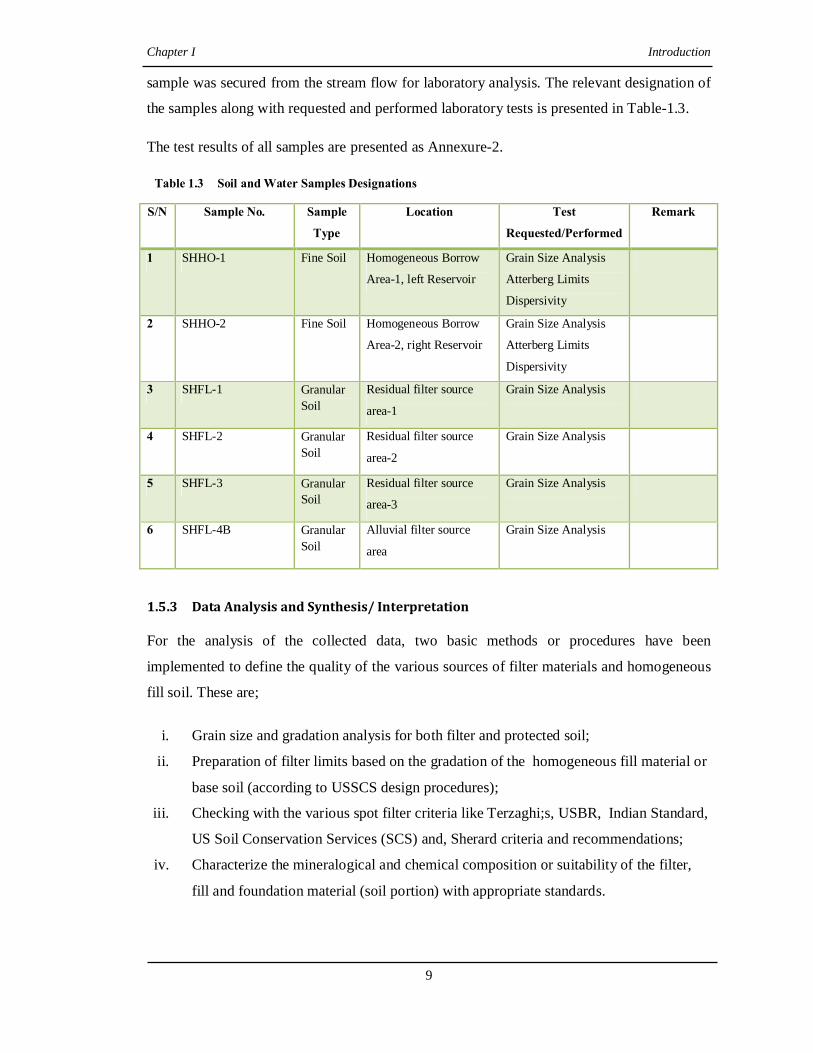
sample was secured from the stream flow for laboratory analysis. The relevant designation of
the samples along with requested and performed laboratory tests is presented in Table-1.3.
The test results of all samples are presented as Annexure-2.
Table 1.3 Soil and Water Samples Designations
S/N Sample No. Sample
Type
Location Test
Requested/Performed
Remark
1 SHHO-1 Fine Soil Homogeneous Borrow
Area-1, left Reservoir
Grain Size Analysis
Atterberg Limits
Dispersivity
2 SHHO-2 Fine Soil Homogeneous Borrow
Area-2, right Reservoir
Grain Size Analysis
Atterberg Limits
Dispersivity
3 SHFL-1 Granular Soil
Residual filter source
area-1
Grain Size Analysis
4 SHFL-2 Granular Soil
Residual filter source
area-2
Grain Size Analysis
5 SHFL-3 Granular Soil
Residual filter source
area-3
Grain Size Analysis
6 SHFL-4B Granular Soil
Alluvial filter source
area
Grain Size Analysis
1.5.3 Data Analysis and Synthesis/ Interpretation For the analysis of the collected data, two basic methods or procedures have been
implemented to define the quality of the various sources of filter materials and homogeneous
fill soil. These are;
i. Grain size and gradation analysis for both filter and protected soil;
ii. Preparation of filter limits based on the gradation of the homogeneous fill material or
base soil (according to USSCS design procedures);
iii. Checking with the various spot filter criteria like Terzaghi;s, USBR, Indian Standard,
US Soil Conservation Services (SCS) and, Sherard criteria and recommendations;
iv. Characterize the mineralogical and chemical composition or suitability of the filter,
fill and foundation material (soil portion) with appropriate standards.

Chapter I Introduction
10
v. Finally, the ground water and river water chemistry particularly for exchangeable
sodium percentage’ and corrosivity will be analyzed and the impact on filter material
deterioration described.
vi. Prepare a report about all research activities and results.
1.6 Limitation of the Research Conducting this research requires thorough understanding of the theoretical or empirical or
any other experimental activities regarding filter design for impermeable cohesive base soil.
Availability and access to such previous works is main constraint, especially recent design
procedures or standards. Most of the available literatures or previous works in the area of
filter characterizations and design are based on experiments conducted in other countries, and
totally there is no local material or existing works in this respect. It is hence the research
which is based on totally on available literatures and criteria developed in other countries,
like United States of America. In addition to absence of domestic design criteria, there is
other limitation regarding data analysis and interpretation. This research mainly focuses on
characterization of the granular soil derived from the Lower Sandstone unit for its relative
suitability as filter to alluvial granular sediment. The characterization is mainly based on
geometrical, physical and chemical factors, and not includes the hydraulic factors due to lack
of well indicated relevant information or data.
1.7 Presentation Schemes The results of the research work are presented in this report. The chapter outlines of the
report and main issues discussed are indicated as follow:-
Chapter 2 is dedicated to give an overview about the project area. Here the area is described
in terms of its location & accessibility, type of proposed engineering structure & design
considerations and other salient features of the research project.
Chapter 3 presents the geological, structural and physiographical setting of the region and the
area. In the section, the general stratigraphy of the various rock formations underlying the
region is discussed. In addition to this, the main rock units that cover and underlain the
specific project area are described.
Chapter 4 describes all engineering geological aspects of the project site. The foundation
condition of the dam site is defined and all observed/explored rock and/or soil units are
explained in and their geotechnical characteristics are determined. In addition to these, all
Chapter I Introduction
11
required natural construction materials are described for their quantity, quality and
accessibility & location.
Chapter 5 is a review of literatures about filtration of cohesive soil through granular filters,
and it contains a summary of available or existing filter design guidelines (empirical)
applicable to cohesive soils. Factors influencing filter effectiveness are discussed. In addition
to this other factors that are recommended to be considered while designing filters for
embankment base soil are also described. These include the geometrical, physical, chemical
and compaction characteristics of the filter, and also the protected base soil.
Chapter 6 presents data collections, test results, synthesis and interpretations pertaining to
filter material, base soil, and both surface & groundwater in relation to filter design for the
project site. Here, all data required for the physical, chemical, and geotechnical
characterization of the proposed filter materials are well indicated. The protected base soil is
described for its index and dispersivity properties. Surface water from stream flow and
groundwater from nearby springs are also analyzed for chemical and physical properties and
their impact on the deterioration or long time effect on filter materials are emphasized.
Chapter 7 Sets Out conclusions and recommendations based on the findings of the current
study. The chapter also describes limitations and recommendations for further investigations
of filter design with respect to other types of cohesive soils. References used for the
completion of this study are listed thereafter.
*****

Chapter II Overview of the Project Area
12
Chapter II - Overview of the Project Area
2.1 Preamble Food security in the country is presently a major challenge. Tackling this problem is
considered as main goal for the Amhara National Regional State (ANRS). To achieve the
goal one of the strategies followed by the government is water harvesting at different scales;
from household level storage ponds/ tanks to small scale or micro earth dams that benefit a
community, and presently even larger projects. Since 1995 GC (1988EC), several such small
earth dams have been studied, designed and implemented in the various woredas of the
region. These dams range from 10 to 25 m in height and 200 to 500 m crest length. Similar
types of micro earth fill dams are also being studied, designed and implemented in present in
the different areas of the region, and the research project, Shumbrit homogeneous fill dam, is
one of them.
2.2 Location and Accessibility The research area is located in East Gojam zone, in Debre Elias woreda of ANRS. The dam
site is found within the Blue Nile river basin at the lower part of Jedeb river, which is one of
the main tributaries of Abay (Blue Nile) in the zone. Specifically, the dam is proposed along
a small stream called Shumbrit, left tributary of Jedeb River. The dam site and reservoir area
lie at borderline between three peasant association (PA) kebeles namely Yegedad, Densee
and Yewober PA. The project area is defined by Geographic co-ordinates (UTM) of
11473000m N and 0324999.95m E, at damsite. The project site is found at about 270 Km
from Bahir Dar city, capital of ANRS. Of this, 255 Km is all weather asphalt and gravel road
until Elias town (woreda capital). From the town it is necessary to follow a dry weather clay
road in the North West for about 13 Km that leads to a locality called Yegedad Micheal
church. Finally, to reach the dam site one has to walk through a foot path for about 2 km
along gentle to moderate slope or topography (Fig.2.1).
2.3 Proposed Engineering Structure Based on the types and quantity of locally available natural construction materials, especially
embankment fill soils, homogeneous earth fill dam type is proposed. In the immediate
vicinity of the site there is relatively large quantity of impervious fine soil (clay to silty clay
texture). Here, granular and free draining soil that can be used for shell or casing material is

Chapter II Overview of the Project Area
13
very scarce that zoned type of dam is uneconomical. The dam has crest length of about 312.5
m and maximum height of about 13 m with a free board of 2 m (Fig.2.2). With these
dimensions, the dam will inundate (reservoir area) a land of about 35 hectare, which is almost
entirely grazing and bush land.
Fig. 2.1 Location Map of Research Project Site For removal of surplus run off that is excess of the reservoir capacity, a spillway is also
proposed on the left abutment side of the dam. It is an Ogee type spillway at the control
section and with natural ground control of the left side and guide wall at the right part.
The dam is proposed mainly for irrigation purpose, though it may help also for watering
livestock. In this project a net of about 425 hectare of farmland is going to be irrigated.

Chapter II Overview of the Project Area
14
The project stream watershed size above the dam axis is estimated to be about 15 Km2. The
stream drainage basin has longest length of about 5 km. It has slope range of 0.4 to 2.84%
(Biruk Alemayhu, 2008).
Fig. 2.2 Proposed Dam Section
2.4 Physiography and Climate Ethiopia can be, widely, divided into four major physiographic regions. These are the
Northwestern plateau, Southeastern Plateau, the Main Ethiopia Rift, and Afar Depression.
The research area is found near to the central portion of the Northwestern plateau. This
landmass is characterized mainly by rolling mountains associated with deep valleys at some
places, like the Blue Nile Gorge. It is highly dissected at many places with surface drainages,
which generally shows dendritic patterns. The drainage system of the area is dominantly part
of the Blue Nile basin, though there is minor portion of the Awash basin in the extreme east.
Wide flat plains bounded by the rolling mountains are not uncommon, forming wide
farmlands and grazing fields.
The north western plateau of the country is characterized by having relatively heavy rainfall.
This area has a mean annual rainfall up to 1200 mm, though it is variable, becomes higher in
the south western portion. The central portion of the plateau receives mean annual rainfall of
about 1000 mm. The area is categorized into hot and dry environment, which has a daily
mean temperature that ranges from 200 C to 250 C.
The research project stream has a catchment area of about 15 km2. Most part of the watershed
has gentle to moderate slope. It is covered mainly with farmlands, though wide grazing lands
and swamps are not uncommon especially following the drainage boarders. Beside to these
major land covers, limited extent natural bush lands and areas covered with homestead
eucalyptus trees are observed. There are three drainage lines above the dam site, which form
nearly denderitic pattern.

Chapter III Geological Setting
15
Chapter 3 - Geological Setting 3.1 Regional Geology The bedrock geology of Ethiopia embraces a great variety of rock types within a wide age
range (Mohr 1971, Kazmin 1972, Mengesh et al. 1996). Precambrian metamorphic and
igneous rocks cover 23% of the country and include rocks such as gneiss, schist, marbles,
granitoids and soapstone. Thick successions of Palaeozoic and Mesozoic sediments (25%)
overlie the Precambrian. These include limestone and sandstone. A large part of the country
is covered by Tertiary and Quaternary volcanic rocks (44%), and in these areas, basalts, tuffs
and ignimbrites are extensively observed. The Precambrian rocks can be divided into a
Lower, Middle and Upper Complex (Kazmin 1972). The Lower Complex comprises possibly
Archaean gneisses, migmatites and granitoids, forming a basement to the volcano-
sedimentary successions of the Middle and Upper Proterozoic Complexes.
The Late Palaeozoic(?) to Mesozoic sedimentary rocks of Ethiopia were deposited during a
regional transgression of the Indian Ocean, followed by Late Mesozoic uplift and erosion
(Kazmin 1972). In the western-central part of the country, the lower portion of the Mesozoic
succession is represented by the Adigrat Sandstone of Triassic to Jurassic age. This rests
unconformably on the Precambrian basement, or slightly unconformably on locally
developed Palaeozoic sedimentary rocks. The Adigrat sandstone varies in thickness from a
few to 800 m, and consists essentially of red to yellow, well-sorted quartz sandstone. The
upper part, however, is in places calcareous, particularly close to the transition to the
overlying limestones of the Antalo Group. Thick limestones are developed in the middle part
of this group. These vary from near-shore, oolithic limestones, through fossiliferous, pale
limestone and marl to black limestones deposited in deeper water.
A large portion of Central Ethiopia is covered by volcanic rocks, ranging from the extensive
plateau basalts within the Early to Middle Tertiary Trap Series, to Quaternary lavas, tuffs and
ignimbrite.
The Blue Nile Gorge (the river Abay Gorge as locally known) contains a complete
stratigraphy of the Ethiopian geology starting with a Precambrian rock unit at the base
overlain by a thick sequence of Mesozoic sediments caped by the tertiary trap basalts making
up the Ethiopian plateau (A. Mogessie, and et. als, 2001).

Chapter III Geological Setting
16
The basement up on which all younger formation were deposited contains the oldest rocks in
the country, the Precambrian, with ages of over 600million years. The Precambrian contains a
wide variety of sedimentary, volcanic and intrusive rocks which have been metamorphosed to
varying degrees. At the end of the Precambrian time uplift occurred, which was followed by a
long period of degradation (weathering), erosion and deposition. Sediments which were
deposited during the palaeozoic time interval, which lasted 375 million years, have been
largely removed by erosion, except for shales and deposits partly of glacial origin laid down
in northern Ethiopia towards the end of this period. Subsidence occurred in the Mesozoic,
which began some 225 million years ago, and a shallow sea spread initially over the south
east part of Ethiopia and then extended farther north and west as the land continued to
subside. As a consequence sandstone was deposited. Deposition of mudstone and limestone
followed as the depth of water increased.
In western Ethiopia sedimentation ended with the deposition of clay, silt, sand and
conglomerate brought in from the land as the sea receded due to due to uplift of the land
mass. In the southeast gypsum and anhydrite were precipitated on inter tidal flats. Again there
was a fresh invasion of the sea in the south-east in Late Mesozoic times during which the
sequence of sedimentation was repeated in the south east in the Ogaden during the Tertiary
period. It ended with the deposition of conglomerates, sandstones and mudstones with some
interbeded marls, and finally erosion as the area was uplifted.
Extensive fracturing occurred early in the Cenozoic, the earliest rocks of which are dated 65
million years, although major displacement along the fault systems which approximates to
the alignment of the Red Sea, Gulf of Aden and East African rift system did not occur until
later in the Tertiary. Faulting was accompanied by widespread volcanic activity and the two
processes, which are partly related, have largely determined the form of the landscape in the
western half of Ethiopia and in the Afar Depression.
The outpouring of vast quantities of basaltic lave over the western half of the country was
accompanied by, and alternated with, the eruption of large amounts of ash and coarser
fragmental material, forming the Trap Series (Kazmin, 1975).
The Northwestern and Southeastern plateaus of Ethiopia are separated by the Rift Valley.
Along the western margin of the Northwestern Plateau in the Blue Nile Gorge, a 2000m
section of Mesozoic strata capped by massive Tertiary volcanic is exposed. The altitude of
the plateau ranges from 3000 to 4000m in the northeast and around 1500m in the south west,

Chapter III Geological Setting
17
with an average height between 1800 to 2500m. Between the Ordovician and Early Mesozoic
a system of northerly as well as northwesterly trending troughs were filled with continental
sediments. Early Jurassic marine sediments filled these troughs and at Late Jurassic time, the
transgressive sea was widespread over a part of Ethiopia. Regression happened at the end of
the Jurassic (Getaneh, 1991).
Mesozoic sediments are widely deposited in Ethiopia during a continuous subsiding period of
the land and migration of the sea from east, in the Ogaden towards the west and north
covering the central part and northern areas of the country. Today a large part of these
Mesozoic sediments are exposed on the Eastern Ogaden, central dissected plateau areas in the
Blue Nile river basin and in northern Tigray around Mekele.
As part of the Northwestern Plateau, the Blue Nile Basin covers 204000 square kilometers.
The typical Mesozoic succession of the basin is about 1200m thick and includes from bottom
to top five formations:-
(i) Lower Sandstone or Adigrat Sandstone (Triassic),
(ii) Gohatsion Formation or Abay Beds,
(iii) Antalo Limestone (Jurassic),
(iv) Muddy Sandstone (Mugher Sandstone) and
(v) Upper Sandstone (Cretaceous)
The sediments are overlain by thick massive flood lavas, mainly basalt, which are generally
Post-Oligocene in age and reach a maximum thickness of 5500 meters. (Scan the
Stratigraphic column of this document at page 48, File: Mesozoic Units)
The Lower Sandstone unit unconformably overlies the basement and in some places
Paleozoic continental sediments. The thickness ranges from about 100m to 700m; in the
Abay river Basin. This unit is formed by several layers with the thickness of the layers
varying from 30cm at the bottom to 1m near the top. They appear as fine grained sandstones
intercalated with reddish shales and siltstones, mudstones and beds of conglomerates.
Medium-to coarse-grained sandstone including planar cross-bedding structures are
characteristic. The boundary with the overlaying gypsum-shale unit is transitional, and
consists of inter-bedded sandstone, siltstone, mudstone and shales at its lower part.
Gohatsion Formation, at its lower part represented by greenish, grey or brown colored
dolostones and shales. The dolostones are characterized by flute casts at the base of beds,
Chapter III Geological Setting
18
ripples and falser bedding at the lower part and parallel lamination at the top. Probably they
represent deposits in shallow ponds and lagoons. At the top occur mudstones with thin layers
of angular quartz.
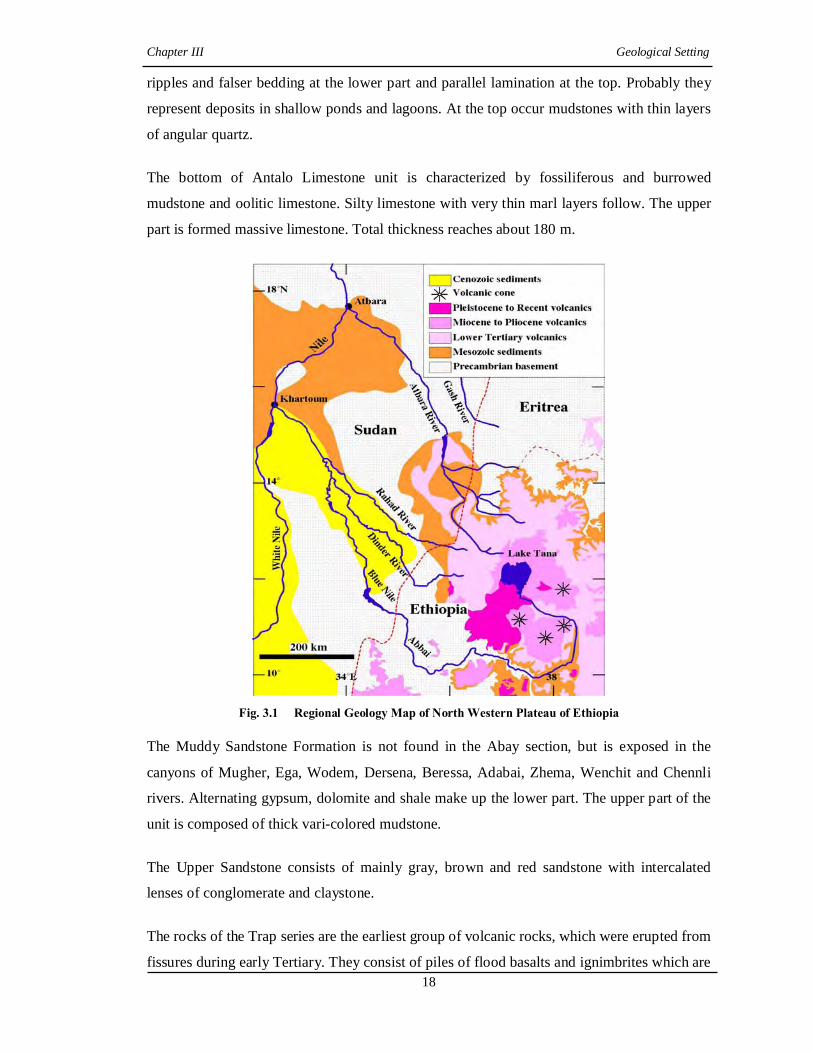
The bottom of Antalo Limestone unit is characterized by fossiliferous and burrowed
mudstone and oolitic limestone. Silty limestone with very thin marl layers follow. The upper
part is formed massive limestone. Total thickness reaches about 180 m.
Fig. 3.1 Regional Geology Map of North Western Plateau of Ethiopia
The Muddy Sandstone Formation is not found in the Abay section, but is exposed in the
canyons of Mugher, Ega, Wodem, Dersena, Beressa, Adabai, Zhema, Wenchit and Chennli
rivers. Alternating gypsum, dolomite and shale make up the lower part. The upper part of the
unit is composed of thick vari-colored mudstone.
The Upper Sandstone consists of mainly gray, brown and red sandstone with intercalated
lenses of conglomerate and claystone.
The rocks of the Trap series are the earliest group of volcanic rocks, which were erupted from
fissures during early Tertiary. They consist of piles of flood basalts and ignimbrites which are

Chapter III Geological Setting
19
overlain by shield volcanoes and mainly consist of porphyritic olivine basalt. The basalts are
transitional from alkaline to tholeiitic. 3.2 Local Geology and Structure The solid geology of the project site is characterized by uniform or one kind of rock. The
rock unit is a volcanic rock of basic composition. It is named as basalt, based on field
observation. Out crops of the rock are observed mainly along the stream beds, banks and
nearby sloppy or hilly terrains.
!
!
!
!
Lake Tana
Bure
Chagni
D/ Markos
Bahir Dar
37°0'0"E 38°0'0"E10°0'0"N
11°0'0"N
12°0'0"N
Fig. 3.2 Geology of the Research and Surrounding Areas
It has dark gray color, and fine texture. Characteristically, the rock unit shows a primary
structure of columnar jointing having well developed rectangular to hexagonal shape top
surfaces. Except along the stream bed, the rock out crops reveal some degree of physical
weathering that is defined also by development of secondary joint sets. These joints are
dominantly developed along the existing primary structure. The secondary joints are observed
for some limited depth (not more than a meter), especially near to the stream banks and beds.
At nearby sloppy terrain the depth to joint penetration is relatively high (may reach more than
2 to 3m at some places). The joints result in fragmentation of the rock unit in to boulders to
LegendQuaternary Sediments
Quaternary Volcanics
Miocene to Oligocene Volcanics
Sandstone and Tilites
Undifferentiated Sediments
Low grade metamorphic Rocks
High Grade metamorphic Rocks
Granite and Tonalites
Lake Tana
Diorites
! Towns
Road
Drainage
1:1,000,000
Chapter III Geological Setting
20
pebbles that cover the surface of many areas of the sloppy terrains bounding the stream
course.
The majority of uphill and gentle valley areas are covered by superficial soils. Based on
origin there are two types of soil in the project area. These are residual and alluvial/
floodplain deposit. The residual soil is formed from in situ chemical weathering of the local
rock unit. It is observed at relatively elevated areas and upslope or upper parts of hill sides. It
is characteristic reddish brown in color. The soil is clay to silty clay in texture, but at
restricted areas it is laterized. The alluvial soil is found along the gentle and curve areas
following the stream banks. It is a soil deposited by the stream during flood times. It is dark
brown in color having dominantly silt to clayey silt texture.
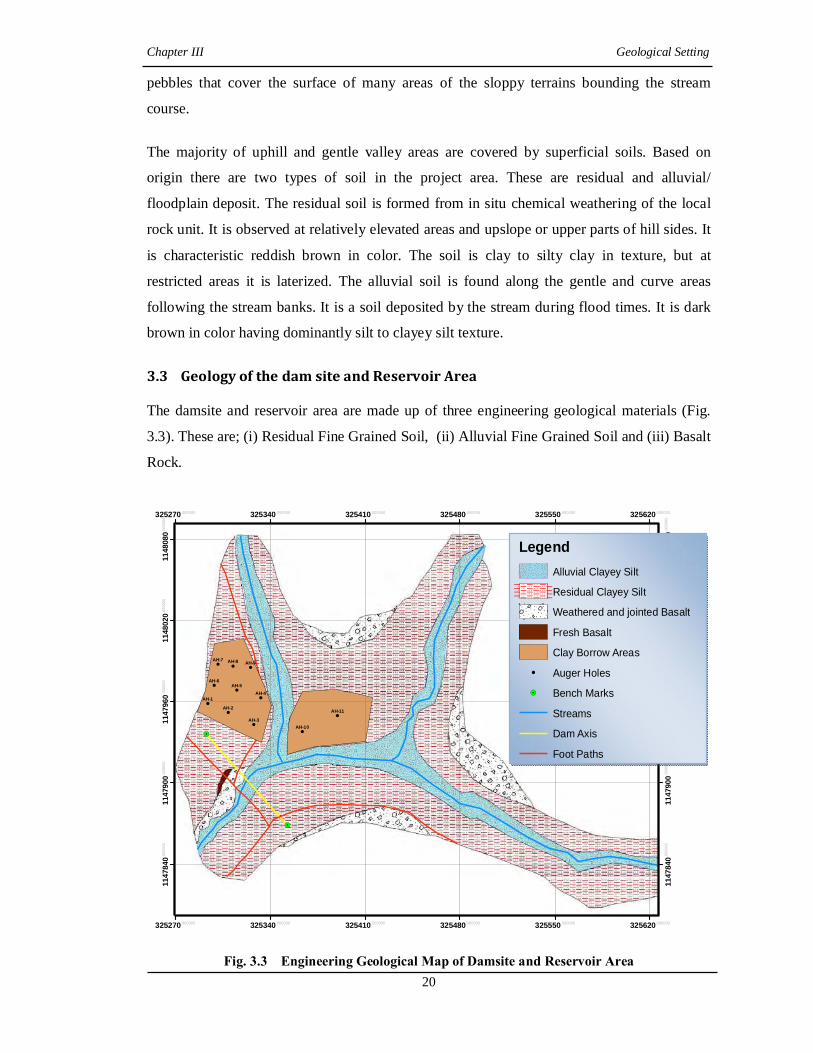
3.3 Geology of the dam site and Reservoir Area The damsite and reservoir area are made up of three engineering geological materials (Fig.
3.3). These are; (i) Residual Fine Grained Soil, (ii) Alluvial Fine Grained Soil and (iii) Basalt
Rock.
!.
!.
!
!
!
!
!
!
!! !
!
!
AH-9AH-8AH-7
AH-6AH-5
AH-4
AH-3
AH-2
AH-1
AH-11
AH-10
325270.000000
325270.000000
325340.000000
325340.000000
325410.000000
325410.000000
325480.000000
325480.000000
325550.000000
325550.000000
325620.000000
325620.000000
1147
840.0
0000
0
1147
840.0
0000
0
1147
900.0
0000
0
1147
900.0
0000
0
1147
960.0
0000
0
1147
960.0
0000
0
1148
020.0
0000
0
1148
020.0
0000
0
1148
080.0
0000
0
1148
080.0
0000
0
Fig. 3.3 Engineering Geological Map of Damsite and Reservoir Area
LegendAlluvial Clayey Silt
Residual Clayey Silt
Weathered and jointed Basalt
Fresh Basalt
Clay Borrow Areas! Auger Holes
!. Bench Marks
Streams
Dam Axis
Foot Paths

Chapter III Geological Setting
21
(i) Residual Fine Grained Soil This soil unit covers most part of the damsite and reservoir area, which are away from the
streams bed and nearby gentle flood plains. The slope and rim or peripheries of the reservoir
area and abutments of the damsite are entirely covered with the residual soil. Naturally, the
soil is developed from the underlying local geology (Basalt) through chemical weathering. It
has characteristic reddish brown color. It is clay to silty clay soil. This soil is normally
underlain by weathered (mainly physical) bedrock, the basalt unit (Fig. 3.4).
(ii) Alluvial Fine Grained Soil This soil unit is observed along the flood plain areas, banks, and at some places on beds of
the streams (Fig 3.3). It is alluvial sediment that is transported and deposited by the streams
flood for several years. It has dark to reddish brown color, and similar clay to silty clay grain
size.. From the natural stream bank cuts, the thickness of this soil ranges from 1.5 m to about
4 m. It is also underlain by the basalt bedrock unit (Fig.3.4).
Fig. 3.4 General Geological cross Section along the proposed dam axis.
(iii) Basalt Rock Some portions of the streams bed found in the reservoir and dam site (right side) are covered
by the underlying bedrock, basalt. Elsewhere, the rock is covered with variably thick either
the residual or alluvial soil horizons. It has dark gray color, and fine grains.

Chapter IV Engineering Geological Setup of the Dam Site
22
Chapter IV - Engineering Geological Setup of the Dam Site 4.1 Preamble To collect engineering geological data that are required for the safe design of the dam, both
surface and subsurface explorations have been performed. The data were collected from both
foundation and borrow areas/ quarry sites. At the foundation of the dam site, information
related to overburden soil and bedrock were collected. These include thickness, index and
engineering properties, and surface extent of overburden soil, and depth to and nature of the
bedrock. To get these data, outcrops and cuts of stream banks were visually examined, and
exploratory holes (test pits and augur holes) were implemented. About four test pits and an
augur hole have been dug/ bored manually along the proposed dam axis, and their detail
description or logs are presented in the coming sections.
Within the main proposed homogeneous fill borrow areas and also examination of natural
cuts and augur holes have been carried out to determine the quantity and quality of the soil.
About 11 augur holes were bored in a grid along the lines. For further study and
determination of required engineering properties/ or various design parameters with
laboratory testing of the soil of the borrow area, representative disturbed sample has been
taken. In addition to these activities, source areas for granular filter material and fine
aggregate were investigated and sampled for laboratory testing. In this field, quarry site(s) for
rock are identified and examined for the rock’s quality, quantity and other relevant
information. To characterize the quality of the stream water, samples were also taken for
laboratory physical and chemical testing. During the field work emphasis was given on
collecting data, mainly related to or required for the design of filter zone for the embankment.
4.2 Foundation Investigation of Dam Site 4.2.1 Valley Floor Area The valley floor area includes the streambed and gentle areas until abutment feet on both
sides. It is covered and made up of either the basalt rock unit or the alluvial sediment. The
stream bed and right side of the valley are totally made up of the rock unit, whereas the
surface of left portion is covered by the alluvial sediment. The rock is columnar basalt. It is
dark gray in color and fine grained. It is affected by shallow depth physical weathering that
result in secondary joints. The joints have shallow depth, maximum of 1m. Such joints are

Chapter IV Engineering Geological Setup of the Dam Site
23
not observed within the stream bed, rather seen at nearby gently sloping side. These are
dominantly oriented across the stream flow, though there are few joints parallel to the flow.
At many places these are filled by secondary materials, like fine soils. Due to the physical
weathering surface fragments of the rock are observed in some amount. Here the rock is not
affected by chemical weathering, and it is strong.
On the other hand the left bank of the stream and nearby gentle valley portion is covered with
the alluvial soil. It has dark brown color and dominantly silty to clayey silt texture. To define
its thickness and some of the geotechnical properties, an augur hole has been bored. From the
holes log (Annexure - 1), the soil has thickness of about 1.5 m. It is dry at top, but gets moist
to wet to depth. It is underlain by the basalt rock unit. It is stiff and impermeable fine soil.
4.2.2 Left Abutment The left abutment of the dam site has moderate slope. It is covered uniformly by the residual
soil with variable thickness. To explore the nature and thickness of the soil, and depth to the
bedrock, two hand - dug test pits were excavated (Annexure - 1).
The pits are located near the abutment foot (SHFOTP-3) and upper slope (SHFOTP-4) areas.
The first pit has depth of about 1.5 m. The pit profile reveals that the top 1.5 m is residual
fine soil with few rock fragments of pebble to boulder size. The soil is dry to moist, stiff and
impermeable. The bottom of the pit is covered by un-excavatable, strong basalt rock that
underlies the local geology.
4.2.3 Right Abutment The right abutment has relatively steeper slope. Unlike the left abutment, it is covered with
variable soil types (grain size or texture), though all are residual in origin. Here also two test
pits, one (SHFOTP-2) near to the foot and the other (SHFOTP-1) to peak, were dug.
Test pit number SHFOTP-1 has depth of about 3 m. Its profile (Annexure -1) shows that the
first 1 m is the residual fine soil. It has reddish brown color, and clay to silty clay texture.
This soil has medium to low plasticity. It is dry to moist, stiff and impermeable. It is
underlain by a lateritic hard pan zone of thickness 2 m. This horizon has dark gray to reddish
to yellowish brown variegated colors. It is not easily workable or excavatable, and limits the
depth of the pit. From local, geological observations of outcrops, the lateritic zone overlies
the bedrock. Here, the depth to bedrock is expected within 4 m from the surface.

Chapter IV Engineering Geological Setup of the Dam Site
24
4.2.4 Spill Way The spillway site is selected or proposed on the left abutment side by considering the relative
suitability in terms of topography and geology. Naturally, the spillway route has moderate
downstream slope starting from the control point, near the abutment, till it joins the
streambed. From surface observation and nearby test pits profile, the route is covered by the
residual and alluvial soils at near initial portions and where it is joining the stream,
respectively. The soils thickness is variable, but not more than 1.5m (near to stream bank).
Below the soil horizon the underlying basalt rock is found. It is strong and only affected by
shallow depth of physical weathering. If the required depth of excavation is beyond the soils
thickness (maximum 1.5m), there will be workability problem and special rock excavating
equipments (like Jack hammers) are required (Plate 4.1).
Plate 4.1 The Dam Site
Based on the surface and subsurface investigation results at the dam site, an engineering
geological cross-section along the proposed dam axis is prepared (Fig. 4.1).
4.2 Reservoir Area Condition The reservoir area, where the run-off will be impounded, has nearly circular to ellipsoidal
shape. It is covered with bush and grazing lands, with small extent of farmland. The slope of
the reservoir is moderate. It is covered and made up of three engineering geological materials.

Chapter IV Engineering Geological Setup of the Dam Site
25
Figure 4.1 Generalized Geological Cross-sections along the Dam Axis
These are; (i) Residual Fine Grained Soil
(ii) Alluvial Fine Grained Soil
(iii) Basalt Rock
Residual Fine Grained Soil This soil unit covers most part of the reservoir area, which is away from the stream bed and
nearby gentle flood plains. The slope and rim or peripheries of the reservoir area are entirely
covered with the residual soil (Fig. 4.2). Naturally, the soil is developed from the underlying
local geology (Basalt) through chemical weathering. It has characteristic reddish brown color.
It is clay to silty clay soil, having dry to moist water content, stiff consistency and low
permeability. From natural gully cuts and performed visual and subsurface investigations/
explorations, the thickness of the soil is variable; ranges from a meter to more than 4m (see
next section). This soil is normally underlain by weathered (mainly physical) bedrock, the
basalt unit.
Alluvial Fine Grained Soil This soil unit is observed along the flood plain areas, banks, and at some places on beds of
the streams (Fig. 4.2). It is alluvial sediment that is transported and deposited by the streams

Chapter IV Engineering Geological Setup of the Dam Site
26
flood for several years. It has dark to reddish brown color, and similar clay to silty clay grain
size. It is also dry to most, stiff and impermeable. From the natural stream bank cuts, the
thickness of this soil ranges from 1.5m to about 4m. It is also underlain by the basalt bedrock
unit.
Both the residual and alluvial fine soils found in the reservoir are proposed for the
homogeneous impermeable fill material for the dam. These have been sampled and
laboratory tested for the required index and engineering properties (See next section).
Basalt Rock Some portions of the streams bed found in the reservoir, especially near to the dam site, are
covered by the underlying bedrock, basalt. Elsewhere, the rock is covered with variably thick
either the residual or alluvial soil horizons (Fig. 4.2). It has dark gray color, and fine grains.
The top surface of the rock at some places shows both columnar (primary) and secondary
joints (due to the physical weathering). The joints are believed to have shallow depth as
massive part also exposed in nearby areas (at dam site). This top jointed section of the rock
unit is pervious and need to be stripped to a depth to massive rock surfaces.
The reservoir is covered with mainly impermeable soil and rock units, except at few places
near to the dam site where jointed rock section observed. The areas covered with the jointed
basalt rock needs proper remedial measures to avoid leakage from the reservoir water. At
these places the top jointed rock sections must be either stripped out or need to be blanketed.
4.3 Natural Construction Materials 4.3.1 Impervious Fill The proposed dam section has large size impervious homogeneous fill. This section is
selected because there is no free draining coarse material, which can be used as shell or
casing zone, at an economical distance from the dam site.
On the other hand, impermeable fine grained soil is found as ample quantity within less than
a kilometer radius. For the present project borrow areas for homogeneous fill material are
proposed within the reservoir and nearby areas. Two borrow areas are selected. The first
(Borrow Area 1) and main one is located in the right portion of the reservoir and immediate
nearby areas, whereas the second (Borrow Area 2) or supplemental source is proposed on the
left side (Fig. 4.2).

Chapter IV Engineering Geological Setup of the Dam Site
27
!.
!.
!
!
!
!
!
!
! ! !
!
!
AH-9AH-8AH-7
AH-6AH-5
AH-4
AH-3
AH-2
AH-1
AH-11
AH-10
325270.000000
325270.000000
325340.000000
325340.000000
325410.000000
325410.000000
325480.000000
325480.000000
325550.000000
325550.000000
325620.000000
325620.000000
1147
840.0
0000
0
1147
840.0
0000
0
1147
900.0
0000
0
1147
900.0
0000
0
1147
960.0
0000
0
1147
960.0
0000
0
1148
020.0
0000
0
1148
020.0
0000
0
1148
080.0
0000
0
1148
080.0
0000
0
Fig. 4.2 Engineering Geological Map of Reservoir Area
To explore the quantity and quality of the soil found in the borrow areas both surface and
subsurface methods were implemented. Small gully cuts were examined and about 13 augur
holes (named as AH-1 to AH-11) were bored (Annexure -1 & Fig. 4.2) within the areas. The
holes were bored nearly on grids of four by four lines in the first borrow area. The second
area is mainly explored from stream and gully cuts, but also two augur holes were bored at its
central portions (Fig. 4.2). The investigation shows that, the soils has variable depth within
the reservoir area and borrow sites. It ranges from 2.2 to more than 4m and their bottom is
marked by the underlying bedrock. Areas having more than 1.5m thick soil is delineated as
borrow areas for the impermeable fill section and indicated in Fig.4.2. By considering the
surface areal extent, average depth of the soil, and porosity of 30%, available quantity of the
soil has been estimated. In the first borrow area about 77700 m3 of soil is expected, whereas
at the second area about 28900 m3 impermeable soil is estimated. Totally, about 106,500 m3
of impermeable fill material is expected from the two borrow areas.
LegendAlluvial Clayey Silt
Residual Clayey Silt
Weathered and jointed Basalt
Fresh Basalt
Clay Borrow Areas! Auger Holes
!. Bench Marks
Streams
Dam Axis
Foot Paths

Chapter IV Engineering Geological Setup of the Dam Site
28
Almost the augurs’ profiles reveal nearly similar soil type above the bedrock. The soil is
residual that develops from the bedrock through in situ chemical weathering. It has
characteristic reddish brown color. From visual examination and simple field index tests, the
soil has silt to clayey silt texture with medium to high plasticity. It is dry to moist to depth,
stiff to very stiff and impermeable soil. To determine the required soil parameters by
laboratory testing, representative samples have been taken from two portions of the borrow
areas. The samples were taken, one (SHHO-1) from the first borrow area and one (SHHO-2)
from the second one. The test results are summarized in Table 4.1.
Table 4.1 Laboratory Test Result Summary for Impervious Fill Material S/N Test Types Test Results Remark
SHHO-1 SHHO-2 1 Sand Content (%) 4 3.8 Annexure -
2 2 Silt Content (%) 51 51 3 Clay Content (%) 45 44.8 4 Liquid Limits (%) 55.51 54.48 5 Plastic Limits (%) 30.69 31.56 6 Plasticity Index (%) 24.82 22.92 7 USCS Soil Class MH MH Using
Plasticity Chart
8 Maximum Proctor Dry Density (g/cc)
1.25 – 1.37 1.25 – 1.37 Average properties based on soil class (Baharat Singh, 1995)
9 Optimum Moisture Content (%) 33.1 -39.5 33.1 -39.5 10 Cohesion (Kg/cm2) 0.44 -1.4 0.44 -1.4 11 Angle of Internal Friction (Degree) 6 - 41 6 - 41 12 Permeability (Cm/s) 2.6 x10⁻⁵ to 6 x 10⁻⁴
(impermeable) 2.6 x10⁻⁵ to 6 x 10⁻⁴ (impermeable)
4.3.2 Granular filter and Fine aggregate
Critical filters with a simple but effective job is one of the principal parts in an embankment
dam which is able to immune the dam against erosion, prevent water escape and seal
unfavorable cracks that may occur through the impermeable fill. In addition to assess source
areas with economical aspects, choosing a proper, optimum and fit – to-need filter should be
taken into account. Gradation curve and its properties, relative density of filter, soil
compaction, grain shape, hydraulic head, physic-chemical properties, fine content,
problematic soils, etc. are some of the factors that influence suitability of filter materials.
For this particular project two possible sources, from mode of origin point of view, for
granular filter materials were proposed. The first source area is located at about 30km south
east of the dam site. It is found in the same woreda, but in a different PA named as Jabi Genet
or simply Genet, which is located at about 15Km south of Debre Elias town. The site is
accessed by dry weather clay road. This source area is an existing borrow area for sand/ fine

Chapter IV Engineering Geological Setup of the Dam Site
29
aggregate for local construction activities. Presently, three specific legal production sites are
operating which are 2 to 3km far each other. In this particular investigation, the nearer one is
named as Borrow area 1 and the middle as Borrow area 2, and the farthest as Borrow area 3.
At these sites, the sand is obtained from similar geological unit that is classified as Mesozoic
Lower or Adigrat Sandstone unit (Getanh, 1989). It is being excavated from the slightly
weathered portion of the unit after uncovering the top fine soil, which has thickness ranges of
few centimeters to about 2m (Plate 4.2). The rock unit at these particular areas exposed on the
surface in large surface extent, a total sum of about 10 hectare. By considering/estimating the
weathered section, from which granular soil can be extracted, as having thickness of about 4
to 5m, the quantity of residual in the area is calculated. From these existing borrow areas;
hence, about 200,000 to 300,000m3 of residual sand soil can be exploited. Here, the porosity
of sand is taken as 40%.
Plate 4.2 Residual Sand from Adigrat Sandstone Unit
Visual examination of this residual sand at these sources reveals different grain size. Borrow
area 1 is dominated by fine to medium grained sand with significant amount of fines (mainly
silts), whereas Borrow area 2 is characterized by medium sand with relatively some fines. At
Borrow area 3, medium to coarser sand grains are dominant, with relatively lower fines. The
sand grains at all sites are dominated by quartz or silica minerals, which are coated or stained
with reddish to yellowish secondary minerals (probably oxides of iron).
To define the important geotechnical properties of the sand source in the laboratory,
representative samples, one from each source area, were taken. The sample taken from
Borrow area 1 is designated as SHFL-1 and that from Borrow area 2 as SHFL-2, and that of
from Borrow area 3 as SHFL-3. The various important laboratory conducted tests required
for filter design and specifications, and test results on the three samples are summarized in
Table- 4.2 (Annexure- 2).
Based on the laboratory test results of both the filter and impervious soil, the design criteria
and specifications of the filter zone are determined in Chapter 6. The second alternative
source area for granular soil that can be used for filter material is proposed in different zone

Chapter IV Engineering Geological Setup of the Dam Site
30
and woreda to the project site. It is located in West Gojam zone, in Jabi Tena/ Korit woredas
boarder, near to Genete Abo village. The source is found inside the bed of a stream called
‘Talia’. It is situated at about 90Km North West of the dam site. From Debre Elias town, this
stream sediment source is accessed by dry weather gravel and asphalt roads that connect
small towns like Amanuel – Dembecha – Jiga – and to finally Genete Abo Village. The
village is located (at about 17km) alongside a road (under upgrading during the study) that
connects Jiga to Koarit towns. The specific source area is found at about a kilometer from the
village in south west direction.
The granular material at this site is found as stream sediment within bed of ‘Talia’ stream
(Plate -3). The deposit is observed as isolated patches along restricted portion of the
streambed where such materials are subjected to deposition due to change in bed slope,
become relatively gentler (Plate 4.2). This source area covers the demand of constructions in
many of the towns or small cities like Debre Markos and Fenot Selam.
Plate 4.3 Alluvial Granular Sediment from ‘Talia’ Stream
The stream sediment has been examined visually during this field trip. It is dominated by
medium to coarse sand, with some extent of fines and oversize (gravels) materials. The
individual grains are dominated by fragments of basaltic rock that gives characteristic dark
gray color to the sediment. Similarly, a representative sample (SHFL-4B) was taken from this
source area to determine the important geotechnical properties of the sediment with
laboratory testing. The tests and results are also summarized in Table 4.2 (Annexture-2).
In the same manner, the suitability or quality of this granular material as filter material for the
impervious fill soil has been evaluated using appropriate methods (Chapter 6).

Chapter IV Engineering Geological Setup of the Dam Site
31
Table 4.2 Laboratory Test Results for Granular Filter Material (Residual Sand)
S/N Test Types Test Results Remark
SHFL-1 SHFL-2 SHFL-3 SHFL-4B
1 Gravel Content (%) 0.6 0.39 3.5 6.2
2 Sand Content (%) 99.17 99.4 96.8 93.62
3 Fine Percentage (%) <1 <1 <1 <1
4 USCS Soil Class SP SP SP SP Poorly graded Sand
5 Permeability (Cm/s) 0.78 x 10⁻¹ 0.9 x 10⁻¹ 1.5 x 10⁻¹ 1.0 x 10⁻¹ Determined by Hazen
method, and all are
classed as pervious
7 Mineralogy (Major) Quartz Quartz Quartz Basaltic liths
Finally, the two main proposed source areas for filter material can also be used for fine
aggregate in mortar and concrete works.
4.3.3 Coarse Aggregate Coarse aggregate source areas that are readily available as natural deposit are not found in the
vicinity of the project area. The field exploration rather identified another option for source
for coarse aggregate used in concrete works. Such materials can be easily produced by
crushing the local rock type as there is sufficiently large quantities of fragments of the rock is
available within economic distance (not more than 2km downstream of the dam site).
The fragments are result of in situ physical weathering of the columnar basalt. The
weathering results in various size fragments that range mainly from pebbles to cobbles, but
there are also some boulders and gravels. The individual fragments are sufficiently strong as
they are affected by very slight chemical weathering discerned as surface coating of oxides of
copper or iron that can be removed during crushing. The rock type possesses the quality
required for coarse aggregate.
4.3.4 Masonry Stone, Rock Toe and Rip Rap The rock type exposed and found as field fragments in the project area (mainly within 2km
radius downstream of the dam site) is very suitable for masonry work, rip rap and rock toe as
far as its natural quality is concerned. This is because the rock is basalt, which is one of the
strongest volcanic rocks. The nature of occurrence of the rock unit; however, is not suitable
to develop or acquire sufficient quantity of appropriate size that can be used for these
purposes. The observed primary and secondary joints result in dominantly pebble to cobble
sizes, and even finer fragments. The amount of boulders suitable for the intended works are
limited and found mainly as disseminated manner in the area.

Chapter IV Engineering Geological Setup of the Dam Site
32
One such quarry site is proposed at about 200m downstream of the dam axis in the left side,
near to a relatively smaller stream (left tributary of Shumbrite) named as ‘Deber Minch’.
Here some limited amount of rock that can be used for the itended purposes can be quarried
out. Similarly, the downstream valley slopes of Shumbrit stream, until it join to the main river
(Jedeb) can also be used as quarry areas for rock, but the required size fragments are limited.
As a result of this nature of the country rock, other relatively distant source area is proposed
to supplement or as an alternative source. The alternative quarry site is located at about 25km
from the dam site in south east direction or at about 7km south of Debre Elias town,
alongside to the road to Genet Kebele near to a stream called ‘Tishet’. The rock type is the
same basalt, but here sufficiently large fragments can be easily quarried out (Plate 4.4). The
quantity is also sufficient.
Plate 4.4 Rock Quarry Site
4.3.5 Water Water that can be used for compaction and concrete/ mortar works can be found from the
project stream. The stream is a perennial one that has base flow of more than 10 liter per
second. From visual observation during the field work (mid March, 2009), the stream water
looks clear, except at few places where it is turbid due to animal contamination while
drinking.
The water quality of the stream flow can be attributed by a groundwater that comes out from
the volcanic rocks of the north western plateau of Ethiopia. It does not have substantial
quality problem which endangers the construction activities, and overall stability of the dam
(Dorsh Consult, 2006).
4.4 Overall Engineering Geological Assessment The study area can be defined by a rock type, which is part of the Cenozoic volcanic rocks of
Ethiopia geology. From examination of the outcrops along the stream course and banks at

Chapter IV Engineering Geological Setup of the Dam Site
33
and nearby areas of the proposed dam site, the underlying rock is basalt. It is one of the rocks
having good quality as far as its engineering properties are concerned, if it is unaffected by
secondary processes like physical and chemical weathering. At the proposed dam site the
rock; however, is affected by different degree of weathering and jointing that its original
geotechnical properties are somehow reduced. The depth of influence of these secondary
processes is variable along the dam axis, and generally it is shallow that it is not be beyond
3m from the surface. Fresh part of rock is exposed few meters downstream of the dam axis in
the right side of the stream course. This indicates the ultimate strong rock is expected at
shallow depth, especially at valley floor area.
The effect of weathering, especially chemical weathering, on the rock is pronounced that
most part of the dam site are covered by variably thick (a few centimeters to about 2m)
clayey silt residual soil. This soil is impermeable, but has low strength. On the other hand the
valley floor area, particularly the left side, is covered with alluvial silt to clayey silt soil of
maximum 2m thickness, overlying directly on the basalt rock. This alluvial soil has nearly
similar texture and permeability with the residual soil, but it has relatively lower stiffness.
******

Chapter V Literature Review
34
Chapter V - Literature Review
5.1 Preamble Granular filters are used in embankment dams to prevent erosion of base and simultaneously
to allow seepage. One of the first approaches to filter design was probably made by PRINZ in
1923 (Brauns et al, 1993), who idealized a filter as a regular packing of spheres and on the
basis of geometrical considerations. He derived a rule where the filter particles (represented
by the diameter d50F, for which 50% by weight are smaller) should not exceed the size of base
particles (represented by the diameter d50B) smaller with a factor 4.42.
Terzaghi (1922) was the next to specify the requirements for selecting filter materials. He
proposed design criteria based on cohesionless base soils. Two basic requirements he
identified were related to particle distribution of base and filter materials: retention ratio
(D15/d85 <= 4-5) and permeability ratio (D15/d15 >= 4-5), where D15 is the diameter of
filter particles for which 15% by mass is finer , d15 and d85 are the diameters of base particles
for which 15% and 85% by mass respectively finer.
Developments in filter design continued and Bertram (1940), United States Army of Civil
Engineers (USACE) (1953), Karpoff (1955), Zweck and Davidenkoff (1957), Sherard et al.
(1984b) greatly contribute to the filter requirements related to Particle Size Distribution.
Extensive laboratory testing programs were done, beginning with work by Bertram (1940)
who worked under the direction of Terzaghi and Casagrande, followed by the work of United
States Bureau of Reclamation (USBR) and US Corps of Engineers (1941). These experiments
showed that the basic requirements could best be met by designing the particle size of the
granular filters in relation to the particle size of the soil being protected (Fell et al. 1992). The
USBR method which has been modified from time to time, for example USBR (1977) has
been used widely and successfully for design of filters. Most recently further experiments
have been carried out by the United States Soil Conservation Service (Sherard et al. 1984a, b
and Sherard and Dunnigan 1985) and by Kenney and Lau (1985).
In many cases filter design rules originally developed for cohesionless soils have been used
for dam sections made up of cohesive soil. The studies involving cohesive soils are relatively
few in number and are mostly empirical. Although it has been generally recognized that
retention ratio is an effective criterion, some doubts have been expressed (Vaughan and

Chapter V Literature Review
35
Soares, 1982; Sherard et al., 1984b; International Commission on Large Dams (ICOLD),
1994). As relevant factors cannot be determined directly, various design criteria for safe
filters have been developed considering different approaches. Various factors such as
retention ratio, permeability of filters, hydraulic gradient, erosion resistance, particle sizes
and shapes are not treated with equal importance. For example, traditional filter design has
involved the retention ratio (i.e. Terzaghi’s criteria), while filter permeability has been
considered as the main design factor by some researchers (Vaughan and Soares, 1982;
Vaugham, 2000). According to Mullner (1993), most available filter rules neglected
hydraulic parameters, which influenced erosion of cohesive soils.
5.2 Granular Filters in Embankment Dams In embankment dams, pervious materials are generally used as filters to dissipate excess pore
pressures, and to eliminate wash out of fine base particles under piping conditions. If filters
are improperly design, particles from base layers might penetrate them.
Progressive accumulation of fines may result in the clogging of filters thus considerably
affecting the drainage, which leads to build up of excessive pore pressures and consequently
to instability of earth structures.
To minimize crack and piping failure, Sherard and Dunnigan in 1985 (Fell et. al., 1992)
proposed multiple lines of defense to guard against leaks in cracks. These include reducing
differential settlement cracking and sealing concentrated leaks. Measures for reducing
settlement include the following;
• Using rock abutments to achieve flatter slopes instead of sharp slopes
• Reducing the compressibility of impervious fill material by compacting the bottom half at
lower water content
• Compacting the upper half of the fill at a higher water content to provide both flexibility
and the capability to take an imposed load without cracking
• Improving flexibility by using plastic clay instead of silty sand and others
Measures to seal concentrated leaks include the following;
• Using conservative downstream filters to prevent leaks
• Using plastic clay for greater erosion resistance and others

Chapter V Literature Review
36
5.3 Factors Influencing Granular Filter Performance The process of filtration, which includes prevention of base soil erosion and permitting
controlled seepage, is not a simple but a complex phenomenon. Filtration is considered as
particle migration in porous medium, where all involved factors such as particle sizes, pore
sizes and seepage and other forces vary in wide ranges as stated by Schuler and Brauns, in
1993. Contributing factors are divided into five different groups: Geometrical, physical,
hydraulic, chemical and biological factors.
Geometrical filter criteria determine whether mobilized (detached) soil particles will pass
through filter openings. If the geometrical filter criterion is not met by a grain size
distribution, no erosion will occur until seepage forces exceed the resisting forces. For
cohesive soils, the resisting force is generally represented by cohesion, which plays a
significant role in filtration. Geometrical factors include particle size distribution (PSD),
shape of grains of both base and filter materials. The uniformity coefficient and internal
stability of base and filter materials are described below. The constriction size distribution
(CSD) and non-homogeneity (Segregations) of filter materials during placement are also
included as geometrical factors (Schuler and Brauns, 1993; Mullner, 1993).
Sherard et al. in 1984 had conducted filter tests for cohesive base soils considering filter
action only (properties of filters needed to prevent erosion of base soils) but not considering
permeability factors (properties needed for a filter to act as a drain). Base soils consisting of
silts and clays were tested by three different methods;
(i) Conventional filter tests with compacted base,
(ii) Slot test with a central pinhole, and
(iii) Slurry tests mixing a known amount of clay with water about2.5 times of liquid limit.
Identical results were reported for each method tested. Although there was a general
correlation between d85 and D15, there was a wider scatter. For all kinds of cohesive base
soils, ratio D15/d85 was in excess of 9, for some clay the ratio was 25 and for some, it even
exceeds 50. For typical clays without content of sand sized particles, with d85 = 30 to 80µm,
the retention ratio, D15/d85 ranges from 19 – 56, and this indicates that the requirements of
filter design for cohesive soils do not correlate with general criteria used for cohesionless
soils, where D15/d85 <= 4 – 5.

Chapter V Literature Review
37
According to Sherard et al. the slot and slurry tests are very severe in the sense that the
velocity of the initial concentrated leak imposed on base (10m/s) is much larger than that
occur in leak through a dam. Vaughan and Soares in 1982 stated that due to slow leak, only
fine particles reached the filter face and silt- sized particles were left behind as debris in the
leakage channel. Contradicting the concepts of perfect filter, Sherard et al. (1984b) noted that
the perfect filter approach was unduly conservative; the main reason being that nearly all clay
soils contain a considerable amount of silt sized particles with diameter 50- 80µm and these
particles are easily available to the filter face, even for a slow flow. It is not necessary to
provide a filter to protect clay flocs of 10µm. They summarized that for fine –grained clays, a
sand filter with D15<= 0.5mm was conservative. For sandy clays and silts, a filter criterion
D15/d85 <= 5 is conservative and reasonable.
A soil is said to be internally stable when its finer particles do not move through pores of
coarse particles (Kovacs, 1981). Internal stability of soils has great effect on clogging. It is
generally considered that coarse broadly graded soils are internally unstable. Lafler et al.
(1989) showed that internally unstable soils, which were safely protected by fine filters,
might self-clog. Particles move from base layers, accumulate at interface, and produce a layer
of very low permeability thereby initiating clogging. This finally results in an increase of
pore pressures at interface. A further problem associated with broadly graded soils is that
they are very difficult to place without segregation (Milligan, 2003).
Indraratna et al. in 1990 reported a relationship between the coefficient of uniformity and
clogging. They studied the effectiveness of cohesionless granular filters for protection of
lateritic residual soils. Several series of tests were conducted in fine to medium sand filters,
and a clogging filter was detected with uniformity coefficient Cu = 3.8. It is summarized that
fine to medium sand filters are effective for lateritic soils and clogging only occurs when the
uniformity coefficient is close to 4.
The following are considered as physical factors that affect filter performances; (i) Base soils- cohesion, weight of grains, particle surface roughness, density, and specific
gravity,
(ii) Filter particles fines content and surface roughness.
For the base soils, among all other physical factors, cohesion plays the major role in filtration
performance. It is generally recognized that when conventional filter design criteria based on

Chapter V Literature Review
38
PSD are used for cohesive dam fill sections, it ignores the resistance to erosion owing to
cohesive forces. A small quantity of water seeps through compacted clay soils, which has
little energy and subsequent little chance for fine clay particles to enter into filter pores as
indicated in Sherard et al., in 1984. Kassif et al. in 1965 also mentioned that the flux was
small through the clay layers, hence design criteria may be less stringent and range of
possible filter materials becomes wider.
Kassiff in 1965 carried out experimental investigation of filtration of cohesive soils through
coarse granular filters. Their experimental results were compared with the results of the
analytical model of Zaslavsky and Kassiff in 1965. The critical hydraulic gradient (icr) from
both methods showed surprisingly high values. Tests had been carried out for compacted
clays in contact with actual filter materials as well as perforated plate simulating filter
materials. Experimental results indicated that a fair coarse filter could protect fat clay. Higher
average gradients were required to cause failure, even when clay was allowed to swell under
zero pressure.
Theoretical analysis of piping in cohesive soils by Zaslavasky and Kassiff in 1965 revealed
that pore sizes of filter had no influence on erosion behavior of cohesive soils, and the soil
layers would not fail entirely , but aggregate clay particles would start to move. Their
theoretical model thus related directly to the floc size of soils, which was separated from the
clay surface. Such aggregates influenced filtration performance significantly.
Wolski in 1970 examined erosion resistance of silty clay at base-filter interface by measuring
the changes in porosity and pore pressures through x-ray examination. The results were
reported in two stages. In the first stage, at relatively low hydraulic gradient, removal of base
particles at filter interface was observed until arching of several small particles over the filter
pores stopped erosion. Later on, at higher hydraulic gradients, breakdowns of arches and
further erosion were reported trough progressive particle loss and formation of piping failure.
Thus, it was recommended that filter design based on PSD was conservative if used for intact
soils. However, there were two problems with filter design for cohesive soils: the formation
of cracks, and the dispersion of clays with flow water.
Filters should be given minimal compaction. Excessive compaction, particularly of crushed
rock, can lead to the criterion of fines to result the filters susceptible to cracking.
Chapter V Literature Review
39
When there is a crack in a cohesive soil fill, a filter, to become effective must be non-
cohesive. A filter with cohesive properties may sustain an open crack without collapse and
thus fail to prevent the base material crack. The inclusion of more fines might result in a more
cohesive filter. Mantz in 1977 found that quartz particles possessed surface attraction at sizes
less than 50microns (coarse silt). However, provided that filters do not contain surface-active
clay minerals, filter cohesion is very small compared to cohesion in the base impermeable
zone as mentioned by Vaughan and Soares in 1982. Milligan in 2003 reported that when a
core cracked, a downstream filter became a secondary interface. If both base and filter crack,
it is inevitable that piping and subsequent erosion will occur. To avoid filter materials
becoming cohesive, there is a maximum limit of fines content of 8%.
The chemical composition of both seepage water and soil, which influence particle sizes
(dispersion and flocculation), are chemical factors. These are ionic strength, pH, and
temperature of flowing fluid. Likewise the moisture content of base soil greatly influences
dispersion and flocculation. It has an important effect on permeability, which was discussed
by Aitchison and Wood in 1965. Compactions at 2% dry of optimum moisture content result
in permeability 50% higher than when compaction is carried out at different levels of
moisture content. Permeability and flocculation (dispersivity) of clay soils can be reduced
exceedingly when compaction is carried out on the wet side of optimum moisture content.
The main hydraulic factors that have influence on filter design are total hydraulic head,
hydraulic gradient, pore fluid velocity, and the angle between direction of flow and gravity.
Mullner in 1993 pointed out that the well- known filter rules neglected hydraulic parameters,
which are influenced by the erosion resistance of cohesive soils. If hydraulic factors are not
taken into consideration, this leads to an economical design of filters. Water flowing
through porous media may cause the destabilization of soil structures, if the filter is not
geometrically stable. Stability is also affected by changes in hydraulic load conditions.
Variation in seepage pressure due to a sudden change in hydraulic head has a great impact on
particle movement. Compressibility of filter media due to sudden increase in hydraulic load
affects particle movement too. Transport of moveable soil particles is greatly dependent on
the hydraulic gradient.
The US Army of Corps of Engineers (USACE, 1971) performed extensive filtration
experiments varying hydraulic gradient. At higher gradients, susceptibility to piping increases
when the filter is subjected to vibrations.

Chapter V Literature Review
40
Kenny and Lau in1985 their study of granular filters stated that stability based on grading
curve basically depended on three factors: PSD, porosity and the severity of seepage and
vibration.
5.4 Focus of Current Study The current research focuses on engineering geological assessment of the various proposed
granular materials as filter/drain for the reddish brown fine soil that will be used for
homogeneous embankment fill. This quality performance assessment is based mainly on the
geometrical, physical and chemical factors or criteria proposed by the various scholars. All
proposed granular filters are examined for their relative suitability and analyzed accordingly.
In addition to this, the impermeable fill soil also examined to its chemical nature, especially
whether it is dispersive or not. To do this samples of the soil are analyzed in laboratory for
dispersion by dispersion test, by double hydrometer test.
In the geometrical suitability analysis or criteria checking the following most popular
empirical criteria have been used;
A. USDA-SCS Method The geometrical suitability of the granular soils suggested for filter is analyzed using
basically the USDA-SCS, Engineering Division 1986 design procedures. It is based on the
type of base soil in terms of its grain size or gradation. These showed that the basic
requirements could best be met by designing the particle size of the granular filters in relation
to the particle size of the soil being protected. There are about 12 steps to design the lower
and upper limits or envelops of filter gradations for a certain base soil category. This
procedure determines the filtration capacity or base soil retention suitability of the granular
soils or the piping requirement. The second important function of the soils, i.e. the
permeability criteria or the requirement that seepage move more quickly through the filter
than through the protected soil, is again analyzed by a grain-size relationship criterion based
on experience.
The design manual presents criteria for determining the grain size distribution (gradation) of
sand and gravel filters needed to prevent internal erosion or piping of soil in embankments or
foundations of hydraulic structures. These criteria are based on results of an extensive
laboratory filter study carried out by the Soil Conservation Service at the Soil Mechanics

Chapter V Literature Review
41
Laboratory in Lincoln, Nebraska, from 1980 to 1985 (USDA National Engineering
Handbook, 1994).
B. USBR (1977) Method The USBR method or criteria used here is as follows (Fell et al.1992);
(i) D15F/d15B = 5 to 40, provided that the filter does not contain more than 5% passing
0.075mm. This criterion ensures that the filter is more permeable than the base soil.
(ii) D15F/d85B <= 5, and the grain Size of the filter should be roughly parallel to that of the
base material. This criterion ensures that the filter is sufficiently fine to control erosion
of the base.
(iii) Maximum size particles in filter equal to 75mm to prevent segregation during
placement.
(iv) For base materials which include gravel particles, the base material d15B, d85B, etc.
should be analyzed on the basis of the gradation of the soil finer than 4.75mm.
C. Terzaghi Criteria These criteria have been used since 1930 for the design of filters for dams and other works.
Although known to be conservative and originally developed for cohensionless uniform base
soil and filter materials, the well known Terzaghi retention criteria are given by (Baharat
Singh, 1995);
1) The 15% size of the filter material, D15, must not be more than 4 or 5 times the 85%
size, d85 of the protected soil to prevent the piping, i.e
54Pr85
15 toLayerotectedofD
filterofD<
2) The 15% size of the filter material, D15, must be at least 4 or 5 times the 15% size, D15
of the protected soil, to ensure adequate permeability or,
54Pr15
15 toLayerotectedofD
filterofD>
Other requirements for a good filter are;

Chapter V Literature Review
42
i) Its gradation curve should be approximately parallel to the gradation curve of the
protected soil, especially in the finer range.
ii) Filters should not contain more than 5% fines (-0.075 mm) and fines should be cohesion
less. This is to ensure that filter remains adequately pervious and does not sustain a
crack.
iii) The filter does not have particles larger than 75 mm so as to minimize segregation.
iv) If the base material ranges from gravel (over 10% > 4.75 mm) to silt (over 10% passing
75 µm), the base material should be analyzed on the basis of gradation of fraction
smaller than 4.75 mm.
D. Recommendations as Per Indian Standard The recommendations for filter selection as per IS code are as follows (Baharat Singh, 1995);
I. 585
15 <baseofDfilterofD
II. 20415
15 <> andbaseofDfilterofD
III. 2550
50 <baseofDfilterofD
IV. The gradation curve of filter material should be nearly parallel to the gradation curve of the
base material.
E. Sherard’s Recommendations Experiments conducted at the Soil Mechanics Laboratory, in USDA-SCS on different soils
revealed the following criteria (Baharat Singh, 1995);
i) The filter is successful in its function of arresting particles migration if;
985
15 <baseofDfilterofD
This shows that Terzaghi’s criterion includes a factor of safety of 2 and conservative.
ii) The size of the pore channel, which governs permeability is determined by the size of
finer filter particles and will be represented by D15 size.
iii) The coefficient of permeability (K) of dense filters is generally in the range of K = 0.2
to 0.6 D215 with average 0.35 D2
15 (K in cm/s and D15 in mm)

Chapter V Literature Review
43
iv) The filter gradation curve need not necessarily be parallel to the base material.
Comparing the various indicated filter design criteria, an emphasis is given on the USSCS
and related Sherard and Dunnigan recommendations for this particular research work. This is
because the methods considers to the type of base soil to be protected, and accordingly
proposes unique procedures for the filter design or criteria.
Filters are required to be constructed of sand and gravel which is sufficiently durable so as
not to breakdown excessively during mechanical action of placement in the dam, under the
chemical action of seepage water, or under wetting and drying within the dam (Fell et. al
1992). The Los Angeles abrasion and wet strength, wet/ dry strength variations largely assess
the susceptibility to breakdown during the placement. The sodium sulphate soundness test
assesses the susceptibility to breakdown under wetting and drying, with the added
involvement of sodium sulphate in the solution used for soaking. These tests and
recommended standards are likely to be more rigorous for high hazard dams, and dams with
seepage water which is highly acidic or has high salt content (example, some tailings dams).
The other mineralogical consideration is proportion of carbonate minerals in the filter
material. It is probably not suitable for use in filter zones because of susceptibility to solution
and redeposition as cement between the particles. Filters from rocks containing significant
amount of gypsums are highly susceptible to the same solution problem.
In the light of the above it is recommended that (Fell et. al. 1992) the following should
always be considered in characterizing the proposed filter material;
The mineral composition of the particles should be determined,
If the material is found to contain even small amounts (e.g. 1-5%) of carbonate, gypsum
or sulphide minerals, then care has to be taken while designing the filters.
In the field the proposed filter materials should be visually examined for their constituting
minerals, especially the above indicated, and in the laboratory the mineralogy of the grains
need to be determined.
*****

Chapter VI Data Collection, Analysis and Interpretation
44
Chapter VI - Data Collection, Analysis and Interpretation
6.1 Preamble Nearly every fill dam or embankment contains filters and drainage elements as elements for
controlling seepage and for preventing erosion of soil due to the drag forces of seeping water.
As these elements are very important for the safety of the structure in question and as the
interaction between seeping water and soil still remains an element of uncertainty, great
efforts have been made in the past to understand the complicated filtration phenomenon. Thus
a large number of filter criteria have been derived in the past, including the well known
criterion by Terzaghi.
Various filter criteria are known to determine the dimension of granular filters. Filter rules
are mainly derived from experiments or laboratory test results. As a consequence of this
empirical approach, various influences have to be considered due to different test set-ups and
evaluations of experiments, and therefore the rules are applicable only in connection with the
respective test conditions. Many parameters influence the dimensioning of a granular filter.
Therefore it is necessary to set-up filter rules to determine certain basic assumptions
concerning suffusion, granular curve and range of grain sizes, grain shape, density of packing
of base and filter, and finally condition of seepage flow (direction, gradient, laminar or
turbulent) in the considered filter range. This indicates the necessity to use different filter
criteria depending on conditions of those basic parameters, mainly gradation curve of the
protected soil (Brauns et. al. 1993).
Filtration phenomena exist in various forms. Ground surface forms a very important interface
as far as the condition of filter stability is concerned. Above ground surface, the dam body is
a structure built with selected materials according to appropriate rules including filter criteria.
On the contrary, below ground surface, it is accepted what nature has prepared as a
foundation for any structure intended to build.
As long as there is well defined soils both in the embankment and foundations, simple
geometrical filter criteria may serve the needs well. Hence, data concerning embankment
soils and foundation materials need to be secured before any criteria checking or design of
filters.

Chapter VI Data Collection, Analysis and Interpretation
45
The next step is to identify possible sources of filter materials that satisfy the requirements
defined for both foundation and embankment sections. The purpose of a filter in earth dams is
to protect soil against erosion, while being permeable to seepage. As simple as the desired
effect may be, as complex is the process of filtration. This is not astonishing, when
considering that filtration can be compared with particle migration in a porous medium,
where all involved factors (particle size, pore sizes and acting forces) vary in wide ranges.
Filtration or effective retaining of base material can occur due to geometrical conditions, i.e.
filter openings smaller than base particles, or due to static conditions, i.e. retaining forces
stronger than driving forces, while geometrical conditions allow particles to pass through,
(U.Schuier & J. Brauns, 1993). Filter criteria, that take into consideration a geometrical
comparison of base and filter material, are called geometrical filter criteria. The involved
parameters for these criteria or geometrical properties for the base soil are grain sizes and
their distributions, and shape of grains. For filter materials, the properties are constriction
sizes of the pores and their distribution, and shape of constriction, which are in turn depend
on particle size and its distribution. In addition to these, homogeneity of both materials is also
one of the influencing parameters in geometrical filter criteria.
On the other hand, criteria that are based on static conditions are called physical and
hydraulic filter criteria. In these criteria, the influencing properties include; soil cohesion,
effective stress, and weight of grains of the base soil. For the filter, internal stability is the
influencing one. In addition to these, hydraulic gradient, pore flow velocity and angle
between direction of flow and gravity are also parameters in the physical and hydraulic
criteria (Brauns et al, 1993). For certain reasons, geometrical criteria are preferable: they
provide the highest degree of safety, because they are independent of flow conditions (Brauns
et al, 1993). In this research project, hence, only the phenomena of filters/ drains of granular
masses with special regard to geometrical aspects will be considered.
For procedural design of filter for the main impermeable homogeneous embankment fill soil
of the project dam, both existing secondary and new primary data have been collected. The
data were collected from the various parts or components of the project, which are directly
related to filter design. These components include, dam foundation, borrow areas for the fill
soil and proposed filter materials, and stream surface water flow. These data consists mainly
of index and engineering properties of the various soils units/ horizons found at the dam
foundation, and borrow areas for various zones of the embankment. The properties of the
soils have been determined by visual field observation, laboratory tests and with some

Chapter VI Data Collection, Analysis and Interpretation
46
empirical relationships. The results of these identification methods of soil have been analyzed
and interpreted using various existing geometrical design procedures/ criteria that are related
to filter design for cohesive embankment fill soil.
6.2 Data Collection 6.2.1 Dam Foundation Condition Both surface and subsurface investigations have been conducted along the proposed dam axis
or site to define and characterize the foundation geological materials (soil and rock).
Outcrops of rocks, and soil cuts along stream banks were visually examined for their extent,
index and general engineering properties. To understand the subsurface condition along the
dam site, both hand dug test pits and an augur hole were dug and bored along the assumed
axis of the dam (Plate - 6.1). All performed explorations and results have already been
indicated/ discussed in chapter 4. In this particular section foundation data related to filter
design are presented and discussed.
Plate - 6.1 Dam Site with its Components The central valley floor area (especially the right side of the stream) is covered mainly with
jointed basalt rock, occasionally covered with thin top fine residual soil. From close
observation of outcrops of the rock unit, the origin of the joints are related mainly to physical

Chapter VI Data Collection, Analysis and Interpretation
47
weathering though there are some primary ones (columnar joints) formed during the cooling
of the lava (Plate - 6.2). Here, the depth of influence of the joints is believed to be shallow,
not more than a meter or one and half a meter, as there are also nearly massive outcrops in the
vicinity (Plate - 6.2). This jointed portion of the bedrock is considered to be pervious,
whereas the underlying massive basalt is impermeable. Both sections of the rock unit are
strong enough to support the proposed embankment without shear failure and pronounced
settlement. It is hence, necessary to design an impervious cut off trench with impervious soil
that will be in contact with the lower massive part of the bedrock (Fig 6.1).
For this segment of the dam, minor seepage through the cut-off wall is expected and may
erode some soil grains from the trench material to the jointed foundation rock, which is
pervious, and in addition it should be drained safely to the downstream toe or relief well of
the dam. For these functions, a horizontal filter and drain zone is necessary to be designed
between the downstream cut-off wall/ embankment base and jointed rock.
Fig. 6.1 Geological Cross-sections along the Dam Axis
The left valley floor area of the dam site, on the other hand, is covered relatively by
significantly thick soil. From nearby stream bank cut observation and an augur hole boring
(SHFOAH-1), the thickness of the soil unit reaches to maximum of 2m, decreases toward the
stream left bank (Plate 6.3). It is an alluvial soil deposited by the stream during flood times
(flood plain deposit). It has dark brown color. It is fine grained soil of high to medium
plasticity, having stiff consistency and dry to moist moisture content. It is impermeable soil

Chapter VI Data Collection, Analysis and Interpretation
48
(Chapter 4). This soil layer is underlain by the basalt bedrock encountered at depth of 2m
(from the augur hole). The top part of the bedrock (1 to 1.5 m) is jointed below which it is
massive (similar to the right valley side).
Plate 6.2 Top Jointed and Underlying Massive Foundation Basalt Rock (at right valley floor)
Though the area is covered with the impermeable alluvial soil having maximum of 2m
thickness, some seepage is expected through the soil and underlying jointed rock zone. Here
also, a cut-off trench connected to the underlying massive portion of the bedrock and made
up of impermeable soil need to be designed. To control seepage water through foundation
both inclined and horizontal filter/ drain sections are necessary.
Samples from proposed soil borrow areas (SHHO-1) for cut of trench, and the alluvial soil
foundation (SHHO-2) at the dam site, and also samples (SHFL-1, SHFL-2, SHFL-3 and
SHFL-4B) from proposed source areas for filter material were taken to secure required data
for the design of the filter. The respective data from both protected and filter materials are
already presented in Chapter 4 and restated in the coming sections. The engineering
geological foundation conditions at both abutments are nearly similar, except variation in
extent or dimensions of the various soil/ rock units. The surfaces of both abutments are
covered with variably thick (ranges from some centimeters to maximum of 1.5 m) residual
fine grained soil.
The soil has characteristic reddish brown color, and is dominantly clayey silt in grain size. It
is stiff to very stiff, dry to moist to depth, impermeable and locally laterized. At the abutment
slopes and foot areas or portions, hand dug test pits were dug to understand the subsurface
soil/ rock units underlying the residual fine soil (Chapter 4). The pits show that the top soil is
underlain by slightly to moderately weathered, and jointed part of the bedrock, basalt. This

Chapter VI Data Collection, Analysis and Interpretation
49
weathered and jointed rock part has also variable thickness, which ranges from some
centimeters to about 2m. It is particularly thick in the right abutment, where about 2m
thickness is observed (log of test pit number SHFOTP-2, Annex-1 and Plate - 6.4). It is dry,
dense, strong horizon, though it is believed to be pervious to semi-pervious.
Plate - 6.3 Portion of Alluvial Soil Foundation at the left valley floor area
Plate - 6.4 Soil / Rock Profile at Right Abutment Foundation Area (from pit SHFOTP-2)
Ultimately, the massive part of the bedrock is encountered (hard to dig) under these two
horizons, within depth ranges of 1.5 to 3m from the surface (Geological cross-section, Fig
6.1). To avoid seepage of water through the weathered/ jointed foundation horizon, the cut
off trench (preventive measure) at both abutments should be keyed with the underlying
massive part of the bedrock. In spite of this seepage preventive measure, some amount of

Chapter VI Data Collection, Analysis and Interpretation
50
water may leak through the foundation soils. This leakage should be safely drained without
causing internal erosion (most unlikely), and development of excessive pore pressures within
the foundation. In this case, a filter/ drain zone between the foundation and the downstream
embankment base is necessary or proposed (Fig. 6.2).
Fig.6.2 Proposed Dam Section
For the design of the filter/ drain that will help to control seepage through foundations, the
protected soil is represented by two samples taken from the two proposed borrow areas for
the embankment homogeneous fill soil (SHHO-1 and SHHO-2). This is because, the
foundation fine soils (both alluvial and residual) found at the dam site has similar origin to
these borrow area soils and visually they have similar characteristics. On the other hand,
about four possible source areas were identified and sampled for filter material. Three of the
samples (SHFL-1, SHFL-2, and SHFL-3) were taken from various portion of the weathered
Lower Sandstone unit, whereas the fourth (SHFL-4B) was taken from stream bed sediment
(Chapter 4 and Plate – 6.5).
Plate - 6.5 Granular Filter Materials from Lower Sandstone Unit and Stream Sediments

Chapter VI Data Collection, Analysis and Interpretation
51
6.2.2 Embankment Condition The availability, quantity, quality and location within economic distance are main governing
criteria regarding the choice of embankment type of any earth fill dam. In this regard, fine
grained soils, which are both residual and alluvial flood plain deposit, are available in
sufficiently large quantity within short distance from proposed dam sites or stream courses in
the project area as a whole (Plate - 6.6 below). These soil units (base soil) have sufficient
imperviousness for either impermeable homogeneous fill or core section in the case of zoned
dam. On the other hand, natural free draining granular soil, like gravel and/ or sand gravel
mixtures with sufficient binders, are found in limited quantity in close range, and if
sufficiently available, located at distant places from possible dam sites in the area. Seeing to
these, homogeneous impermeable fill type of embankment has been proposed for this
particular dam project, and may be any possible similar sites in the zone (Fig. 6.2).
Though the homogeneous fill section is made up of dominantly with impermeable fine
grained soils, there are relatively thin seepage control sections within it and at its base in the
downstream portion. The control sections/ zones are made up of granular soil; sand and/ or
sand –gravel mixtures, and act as filter/ drains for possible seepage through the main
embankment and foundation soils.
For this particular research project, the samples taken from the Borrow areas for impermeable
fill soil represent base soil, whereas, those from Lower Sandstone and stream sediments are
possible granular filter/ drain materials for the base soil. Accordingly, the filter design
procedures and analysis will be done and presented in the succeeding sections. Those data or
parameters about both materials (base and filter) obtained directly from laboratory tests and
literatures, and derived from empirical relationships that are relevant to the design of the filter
and checking of its performance are presented in the next sections (Test results, Annexure -
2).
A. Base Soil Parameters (Red Tropical Soil) The main embankment soil is part of a general soil category, which is broadly classified as
Tropical or African Red Clay Soils (Dumbleton, 1967). The red clay soils are residual soils
produced by weathering of rocks at the land surface under relatively high temperature and
rainfall and good drainage. Bases and silica are leached, leaving the soil rich in iron and
aluminum. In many parts of the tropics, the clay minerals and iron oxides occur respectively
as metahalloysite and hematite under dry conditions, and as hydrated halloysite and goethite

Chapter VI Data Collection, Analysis and Interpretation
52
under moisture conditions (Dumbleton, 1967). The plasticity of the clay minerals is modified
by the iron oxide. Black montmorillonitic clays, rich in bases and silica, occur in association
with the red clays but on lower ground.
It is very useful to understand the mode of origin and mineralogy of the particles of deposits
of engineering importance, like embankment fill material. There are two main reasons for
studying these two natures of certain material. The first is to help to distinguish different
types of soils, so as to be able to correlate their engineering properties with those of similar
soil types occurring in different parts of the country or the world. This will enable
engineering techniques developed in one region to be applied to another region where
materials and conditions are similar. The second reason is to aid in explanation of the origin
of the engineering properties of different types of deposit, and to help to interpret engineering
test results.
The Tropical red soils, from which the embankment impermeable fill zone is designed, are
formed from many kinds of rocks, if the weathering conditions are suitable. These are formed
from rocks like Basalt, phonolite, volcanic lava, volcanic ash and pumice. In the present
research area, the soils are developed from basaltic bedrock. The tropical red clay soils are
true soils that occur at the surface, except where they have been covered, for instance, by
volcanic material, when they mark periods of volcanic inactivity. These are formed in regions
of relatively high temperature, under conditions of moderate to high rainfall and good
drainage, when the rate of leaching is high. This means, these occur mainly on higher and
sloping ground, where drainage conditions are good. Leaching removes the more soluble
bases and silica, leaving the soil rich in less soluble components, i.e. iron in the form of iron
oxide, and aluminium in the form of clay minerals. The clay minerals are of the kaolin group
of halloysite type. The iron oxide in these soils, which accounts for the dark red to red color,
occurs in an unhydrated form, hematite, and a hydrated form goethite (Dumbleton, 1967).
Kaolin in the form of halloysite has disordered structure, which gives rise to a material of
higher potential plasticity than well ordered kaolinites. This higher plasticity is modified by
the iron oxide (Dumbleton, 1967). Soil classification tests have been performed on these
tropical red soils in Kenya by P. T. Sherwood 1967 (Sherwood, 1967). The classification test
comprises the determination of the particle size distribution and of the liquid and plastic
limits of the soils. If these properties are known, a reasonable knowledge of the permeability,
compaction properties and several other characteristics can be inferred from data obtained

Chapter VI Data Collection, Analysis and Interpretation
53
with others soils of similar classification properties. Accordingly, samples from proposed
borrow areas were taken and classification tests were done, and thus important engineering
properties were determined.
Plate- 6.6 Road Cut Exposure of Fine Grained Residual Soil in
the surroundings of the Research Area
Specific source areas, which satisfy the required quantity, for impermeable fill soil have been
assessed, identified and delineated. Two possible borrow areas for the fill soil have been
selected within the project reservoir area at different or opposite portions. These areas were
explored with augur holes, and representative samples (SHHO-1 and SHHO-2) were
collected for laboratory classification testing of relevant parameters that can be used for both
the dam design, including the filter section (Chapter 4, and Plate - 6.7).
The results of the classification tests and determined important engineering properties are
presented in Fig.6.3.
Another important property of the impermeable fill soil that needs to be considered especially
in the case of seepage control study and design is its dispersivity. Dispersive clays are a
particular type of soil in which the clay fraction erodes in the presence of water by the
process of deflocculation (USDA_SCS, 1980).
This occurs when the inter-particle forces of repulsion exceed those of attraction, so that clay
particles are detached and it goes in suspension. If water is flowing, as in pores or cracks in
earth dams, the detached clay particles are carried away and piping occurs.
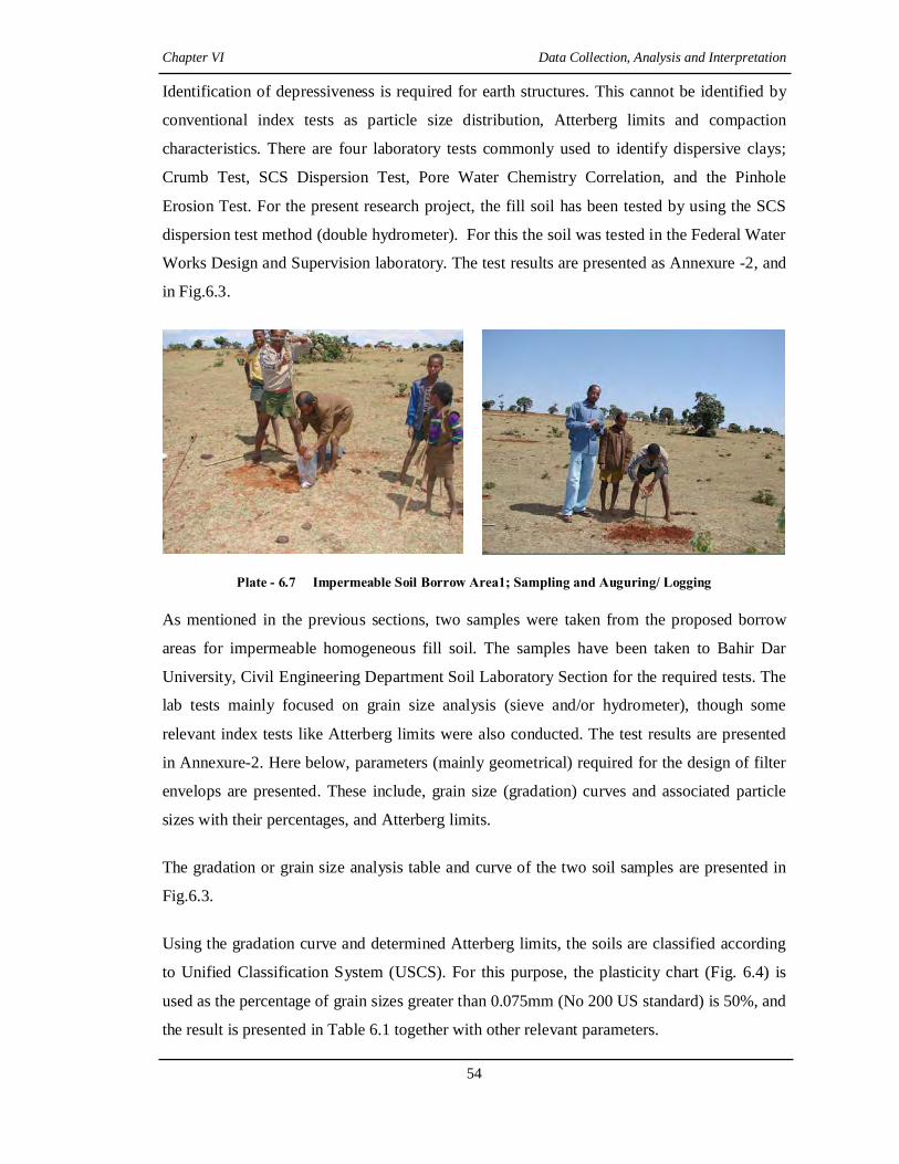
Chapter VI Data Collection, Analysis and Interpretation
54
Identification of depressiveness is required for earth structures. This cannot be identified by
conventional index tests as particle size distribution, Atterberg limits and compaction
characteristics. There are four laboratory tests commonly used to identify dispersive clays;
Crumb Test, SCS Dispersion Test, Pore Water Chemistry Correlation, and the Pinhole
Erosion Test. For the present research project, the fill soil has been tested by using the SCS
dispersion test method (double hydrometer). For this the soil was tested in the Federal Water
Works Design and Supervision laboratory. The test results are presented as Annexure -2, and
in Fig.6.3.
Plate - 6.7 Impermeable Soil Borrow Area1; Sampling and Auguring/ Logging As mentioned in the previous sections, two samples were taken from the proposed borrow
areas for impermeable homogeneous fill soil. The samples have been taken to Bahir Dar
University, Civil Engineering Department Soil Laboratory Section for the required tests. The
lab tests mainly focused on grain size analysis (sieve and/or hydrometer), though some
relevant index tests like Atterberg limits were also conducted. The test results are presented
in Annexure-2. Here below, parameters (mainly geometrical) required for the design of filter
envelops are presented. These include, grain size (gradation) curves and associated particle
sizes with their percentages, and Atterberg limits.
The gradation or grain size analysis table and curve of the two soil samples are presented in
Fig.6.3.
Using the gradation curve and determined Atterberg limits, the soils are classified according
to Unified Classification System (USCS). For this purpose, the plasticity chart (Fig. 6.4) is
used as the percentage of grain sizes greater than 0.075mm (No 200 US standard) is 50%, and
the result is presented in Table 6.1 together with other relevant parameters.

Chapter VI Data Collection, Analysis and Interpretation
55
Gradation for Fill Material
SHHO-1 SHHO-2 Particle Size (mm) Percent Finer (%) Particle Size
(mm) Percent Finer (%)
2 100 2 100 1.18 99.8 1.18 99.8 0.6 99 0.6 99.2 0.3 98.2 0.3 98.4 0.15 97.6 0.15 97.4 0.075 69 0.075 96.2 0.03147 58.6 0.02981 52 0.01999 56.4 0.01892 51.2 0.0116 54 0.01095 50.8 0.00822 52 0.00778 50.4 0.00583 49 0.00548 48 0.00412 49 0.00391 46.4 0.00309 48.2 0.00318 46 0.00306 47.6 0.00292 45.2 0.00123 42 0.00267 45.2
0.00116 42
Fig. 6.3 Gradation Curves of Base Soil Samples SHHO-1 and SHHO-2
Fig. 6.4 Classfication of Embankment Fill Soils Using Plastcity Chart

Chapter VI Data Collection, Analysis and Interpretation
56
Table 6.1 Soil Classification Test Results and Determined Engineering Properties of the Fill Materials
S/N
Classification Test Results and Determined Engineering Properties
Sample Number Remark SHHO-1 SHHO-2
1 Particle Size Distribution (%):- Gravel Sand Silt Clay
- 4 51 45
- 3.8 51 44.8
2 Atterberg Limits (%):- Liquid Limits Plastic Limits Plasticity Index
55.51 30.69 24.28
54.48 31.56 22.92
Plasticity Chart
3 Unified Soil Classification Soil Group MH (Highly plastic silt)
MH
4 D85B (mm) 0.059 0.057 5 D15B (mm) - - No meaningful
value 6 Compaction Characteristics:-
Maximum Dry Density (g/cc) Optimum Moisture Content (%)
1.25 to 1.37 33.1 to 39.5
1.25 to 1.37 33.1 to 39.5
Baharat Singh, 1995
7 Shear Strength Parameters:- Cohesion (kg/cm2) Angle of Internal Friction (degree)
0.44 to 1.4 0.11 to 0.29
0.44 to 1.4 0.11 to 0.29 (tan phi)
8 Permeability (Cm/s) 2.6 x 10⁻⁵ to 6 x 10⁻⁴ 2.6 x 10⁻⁵ to 6 x 10⁻⁴
* D15B, D85B are particle size of the base soil finer than 15% and 85% respectively. B. Filter Material Parameters (Residual and Alluvial) Similarly, data on soils, used in the seepage control sections (filters/ drains), have been
collected. As indicated in the previous chapters, two possible sources (in terms of mode of
origin) have been selected for these filtration and drainage purposes. The first is from in-situ
weathering products (residual granular soil) of the Lower Sandstone Unit of the Mesozoic
geology of Ethiopia exposed nearby to the research project area. The second source is from
alluvial sediment found within a stream/ river located at relatively very distant place. Four
possible borrow areas, three for the residual soil and one for the alluvial sediment, have been
identified, and representative samples were secured for laboratory tests. Four different
samples representing the borrow areas were taken. Three of these samples (SHFL-1 to SHFL-
3) were taken from the weathered portion of Lower Sandstone unit; whereas the last sample
(SHFL-4B) was taken from the stream sediments (Chapter 4).
In other words, in the research area, there are two main types of granular soils, which can be
performing the seepage controls through the base soils. The first is a sand or/ and sand-gravel
mixtures that is derived from moderately weathered sandstone, which is the lower

Chapter VI Data Collection, Analysis and Interpretation
57
stratigraphic unit (Adigrat Sandstone) in the Mesozoic Formations of the Ethiopia geology.
This unit is widely exposed in the vicinity of the research area, and its weathered product is
being utilized by local construction activities parallel with stream sediment or alluvial sand
deposits found at relatively very distant areas (Plate-6.8). The Adigrat Sandstone unit is
variegated quartos sandstone of fluvial or littoral origin. It consists typically of yellowish to
reddish brown to pink, fine to medium grained non-calcareous, well sorted quartz sandstone
(Abay River Basin Master Plan Report, MoWR, 1998).
In the surroundings of the research area, there are several existing borrow areas (owned by
licensed local farmers) from which the residual sand is being exploited. Of these, three of
them are now active, therefore representative samples were taken from each of them. These
borrow areas are located in close proximity to each other and are not more than 2km gap.
They are found at about 28 to 30km from the research project site, in south east direction, and
accessible by dry weather road. On the contrary, the source area for alluvial sand is located at
relatively distant areas of 90 to 95 kms from the project site (Chapter 4).
Plate - 6.8 Residual and Alluvial Sand/ Sand-gravel Mixtures
for Local Constructions (in Debre Markos City)
A sample is also secured from this source. All the samples were taken to Amhara National
Region State Rural Road Authority Soil Laboratory Section. In this lab, mainly grain size
analysis and determination of percentages of fines were conducted (Annexure -2).
The grain size analysis table and curves of the granular soils are summarized and presented in
Fig. 6.5. Here the average grain size distribution of the filter materials secured from the

Chapter VI Data Collection, Analysis and Interpretation
58
weathered sandstone unit is also presented, and suitability analysis is performed on this
material.
Gradation for Filter Materials
Percent Finer (%)
Particle
Size (mm)
SHFL-1 SHFL-2 SHFL-
3
SHFL-4B Average Residual Sample
9.5 100 100 100 100 100.00
6.3 99.75 99.86 98.87 97.12 99.49
4.75 99.39 99.61 96.95 93.8 98.65
2 96.84 98.3 79.27 79.57 91.47
1.18 90.45 96.06 56.15 64.37 80.89
0.6 55.92 56.53 26.07 33.57 46.17
0.425 28.07 21.82 13.71 16.97 21.20
0.3 11.67 6.81 7.05 7.49 8.51
0.15 2.12 1.35 1.6 1.12 1.69
0.075 0.22 0.21 0.15 0.18 0.19
pan 0 0 0 0 0.00
Fig. 6.5 Gradation Curves of the Granular Filter Soils
In addition to the grading characteristics, the filters were examined for mineralogy, physical
and chemical composition. From visual observation and previous works, the sand grains are
dominated by silica or quartz. These grains, however, are thinly coated with reddish stains,
probably iron oxides.

Chapter VI Data Collection, Analysis and Interpretation
59
The relevant parameters required for the design or checking of filter are summarized in
Table-6.2. These are either determined directly from laboratory tests or derived from
empirical relations or taken from standard relevant literatures. Table 6.2 Summary of the Parameters of the Filter materials
S/N Required
Parameters Sample Numbers
Remark SHFL-1 SHFL-2 SHFL-3 SHFL-4B Average 1 D15 (mm) 0.32 0.38 0.44 0.4 0.38 2 D10 (mm) 0.28 0.32 0.36 0.34 0.32 3 D60 (mm) 0.66 0.62 1.4 1.1 0.78 4 D30 (mm) 0.41 0.46 0.68 0.56 0.48 5 Uniformity
coefficient (Cu) 2.36 1.93 3.9 3.2 2.4
6 Coefficient of Curvature (Cc)
0.94 1.06 0.92 0.84 0.92
7 USCS Soil Group SP SP SP SP SP Poorly graded Sand
8 Permeability (cm/s)
0.7 x10⁻¹ 0.9 x 10⁻¹ 1.5 x 10⁻¹ 1 x10⁻¹ 0.9 x 10⁻¹ Hazen method, classed as pervious
9 Percent fines (%) < 1 < 1 < 1 < 1 < 1 6.3 Data Analysis and Interpretations The basic requirements of filters are that they are sufficiently fine grained to prevent erosion
of the soil they are protecting, and are sufficiently permeable to allow drainage of seepage
water. Extensive laboratory testing programs, beginning with work by Bertram, 1940, who
worked under the direction of Terzaghi and Casagrande, followed by the work of the USBR
and others, showed that the basic requirements could best be met by designing the particle
size gradation of the filters in relation to the particle size gradation of the soil being protected.
More recently further experiments have been carried out by the United States Soil
conservation Services (USSCS). These experiments led to recommended modifications of the
design rules suggested by USBR (Fell et al, 1992).
Important properties of the filter material are gradation, compacted density, and permeability.
Filters are designed to permit free passage of water and prevent migration of fines through
the filter. The average in-place relative density of the filter should be at least 85 percent and
no portion of the filter should have a relative density less than 80 percent. Special care must
be taken to assure that compaction does not degrade the filter material (by grain breakage
and/or segregation) and reduce its permeability. When the filter material is sand or contains
significant portions of sand sizes, the material should be maintained in as saturated a
condition as possible during compaction to prevent bulking. The filter material should pass
the 3-in. screen for minimizing particle segregation and bridging during placement. The

Chapter VI Data Collection, Analysis and Interpretation
60
permeability of sands and gravels varies significantly with the amount and type of fines
present (material smaller than the No. 200 sieve). Also, the amount and type of fines present
influence the capacity of a filter to self-heal by collapsing any cracks within the filter
(USACE Design Manual, 1886).
To analyze the relative suitability of the residual, and also the alluvial sands to filter/ drain
material for the base red tropical soil (impermeable homogeneous fill soil), filter design
procedures provided by USSCS Engineering Division is basically utilized. In addition to this,
design criteria suggested and recommended by other scholars, and various standards available
for this purposes are implemented, and analyzed for their applicability. Based on these design
procedures and criteria, the relative suitability of the granular soils, obtained from the
different proposed source areas, is analyzed and interpreted. In general, all relevant
parameters considered during the design of critical granular filter/ drains are analyzed with
respective empirical approaches. The granular materials, in this regard, are examined mainly
for their geometrical suitability as filter/ drain materials for the base soil.
Filters and drains allow seepage to move out of a protected soil more quickly than the
seepage moves within the protected soil. Thus, the filter material must be more open and
have a larger grain size than the protected soil. Seepage from the finer soil to the filter can
cause movement of the finer soil particles from the protected soil into and through the filter.
This movement will endanger the embankment. Destruction of the protected soil structure
may occur due to the loss of material. Also, clogging of the filter may occur, causing loss of
the filter’s ability to remove water from the protected soil. Criteria developed by many years
of experience are used to design filters and drains which may prevent the movement of
protected soil into the filter.
This criterion, piping or stability criterion, is based on the grain-size relationship between the
protected soil and the filter. In the following, the small character “d” is used to represent the
grain size for the protected (or base) material and the large character “D” for the grain size for
the filter material.
6.3.1 Geometrical Factors Analysis Geometrical factors (filter openings smaller than base particles) are mainly influenced by
particle size distribution (PSD) and the shape of grains of both base and filter materials. The
constriction size distribution (CSD) and non-homogeneity (segregation) of filter materials
Chapter VI Data Collection, Analysis and Interpretation
61
during placement are also included as geometrical factors (Schuler and Brauns; Mullner,
1993). Designing, and checking the PSD factors for the materials of the present research
project have been done in the coming sections using various known criteria.
A. USDA-SCS Method The geometrical suitability of the granular soils suggested for filter is analyzed using USDA-
SCS, Engineering Division 1986 design procedures. It is based on the type of base soil in
terms of its grain size or gradation. This showed that the basic requirements could best be met
by designing the particle size of the granular filters in relation to the particle size of the soil
being protected. There are about 12 steps to design the lower and upper limits or envelops of
filter gradations for a certain base soil category. This procedure determines the filtration
capacity or base soil retention suitability of the granular soils or the piping requirement. The
second important function of the soils, i.e. the permeability criteria or the requirement that
seepage move more quickly through the filter than through the protected soil, is again
analyzed by a grain-size relationship criterion based on experience.
The design manual presents criteria for determining the grain size distribution (gradation) of
sand and gravel filters needed to prevent internal erosion or piping of soil in embankments or
foundations of hydraulic structures. These criteria are based on results of an extensive
laboratory filter study carried out by the Soil Conservation Service at the Soil Mechanics
Laboratory in Lincoln, Nebraska, from 1980 to 1985 (USDA, 1994).
The first step is to determine the gradation curve (grain-size distribution) of the base soil
material, by using enough samples to define the range of grain sizes for the base soil or soils
and design the filter gradation based on the base soil that requires the smallest D15F size. For
this research work two samples (designated as SHHO-1 and SHHO-2) were used to define
the range of grain sizes for the base soil.
They have almost similar gradation curves, and the data analysis or filter design is performed
based on one of them, namely SHHO-1. The next step is to determine the base soil category
based on the percentage of soil finer than US standard sieve No. 200 (0.075mm) (Table 6.3).
Based on the gradation curves of the two base soil samples (SHHO-1 and SHHO-2), the soils
are classified as Category 1(fine silt and clays) as more than 96% of the soils are finer than
0.075mm.

Chapter VI Data Collection, Analysis and Interpretation
62
Table 6.3 Base Soil Category
Base Soil Category % finer than No. 200 Sieve (0.075mm)
Base Soil Description
1 >85 Fine silt and clays 2 40 - 85 Silty and clayey sands 3 15 - 39 Silty and Clayey Sand and gravel 4 <14 Sand and Gravel
Following this procedure, soil categorization is done to determine the maximum allowable
D15 size of the filter to satisfy the filtration requirement. For this soil category the maximum
D15 size is less than and equals to 9 times the d85. Using the appropriate value of d85 (0.056
mm) of SHHO-1, the maximum D15 is calculated as 0.5 mm. Similarly, the minimum
allowable size for D15 is determined to satisfy the permeability requirement.
For the same soil category, the minimum D15 is greater than or equals to 4 times d15, but not
less than 0.1. This base soil has no meaningful d15 size, and a default value of 0.1mm is used.
The following step focuses on the width of the filter band. The width of the allowable filter
design band must be kept relatively narrow to prevent the use of possibly gap-graded filters.
To achieve this, two criteria should be considered; the width of the designed filter band
should be such that the ratio of the maximum to the minimum diameter at any given
percentage passing values less than and equal to 60% is 5 or less.
In addition to this the coarse and fine limits of the filter band should each have a coefficient
of uniformity of 6 or less. The first criterion is satisfied for the maximum and minimum D15
sizes as their ratio is 5. Here, the maximum D10 is determined by dividing the maximum D15
by 1.2 by assuming the slope of the line connecting D10 and D15 should be on a uniformity
coefficient of about 6. Hence, the value of maximum D10 is 0.42mm. This value enables to
determine the maximum allowable D60 by multiplying 0.42 with 6, and equals to 2.52mm. In
turn, the minimum allowable D60 for the fine side of the filter band can be calculated by
dividing 2.52 with 5, and equals to 0.5mm.
The next step is to determine the minimum D5 and maximum D100 sizes of the filter. These
maximum and minimum particle size criteria are defined, for all base soil categories, as D5
greater or equal to 0.075mm, and D100 less than or equal to 75mm. Following this step,
criteria for filter segregation during construction is considered. To minimize segregation
during construction the relationship between the maximum D90 and the minimum D10 of the
filter is important. In this step a preliminary minimum D10 size is calculated by dividing the

Chapter VI Data Collection, Analysis and Interpretation
63
minimum D15 size by 1.2, and the maximum D90 is determined based on range of this
calculated D10 (Table 6.4). Accordingly, the values of the D10 and D90 are 0.083mm and
20mm, respectively.
Table 6.4 Segregation Criteria
Base Soil Category
If D10 (mm) is: Then Maximum D90 (mm) is:
All Categories
< 0.5 20 0.5 – 1.0 25 1.0 – 2.0 30 2.0 – 5.0 40 5.0 - 10 50 > 10 60
Following the rest of the finalizing steps for this category base soil, the gradation limits or
envelops of granular filters are designed by connecting respective determined values, and by
extrapolating the coarse and fine curves to the 100% finer values. The design filter band
limits are presented in Fig.6.6.
After completing the design of both the fine and coarse size bands or envelops of the filter,
the relative suitability of the various selected natural filter materials have been inserted or
drawn with respect to the envelops (Fig. 6.7). Based on their gradation curve position with
respect to the limits, the relative suitability of each of the granular materials is described.
Except filter materials SHFL-1 and SHFL-2, which become a little bit finer than the grading
limits, the rest falls within the designed filter grading limits.
This indicates that for this particlular base soil, filters materials SHFL-3, SHFL-4B, and the
average of the residual material, which is derived from the Lower Sandstone unit, can be
safely used for the intended purposes.
Filter materials SHFL-1 and SHFL-2 , on the other hand, can be utilized by improving their
gradation through mixing with relatively coarser sand from borrow areas of SHFL-3.
The average filter material gradation (indicated as yellow, in Fig.6.8), which is developed
from the mean grain size distributions of the materials proposed from the weathered products
of the Adigrat Sandstone units, reveled a good result.
This gradation distribution can be specified as suitable filter material for the protection of the
base soil and also as appropriate drainage, both as chimmeny and horizontal filters.

Chapter VI Data Collection, Analysis and Interpretation
64
Determined Particle Sizes
Fine side of the filter band Coarse side of the filter band Particle Sizes (mm) Percent Finer (%) Particle Sizes (mm) Percent Finer (%) 0.06 0 0.3 0 0.075 5 0.38 5 0.083 10 0.42 10 0.1 15 0.5 15 0.5 60 2.52 60 2 100 20 90 75 100
Fig.6.6 Gradation Limits for Filters for Base Soil SHHO-1

Chapter VI Data Collection, Analysis and Interpretation
65
Fig. 6.7 Gradation Curves of Base Soil, Filter Limits and Natural Granular Filters
Similarly, the alluvial sediment filter soil (SHFL-4B) shows good result or satisfy the
requirements of filteration and permability for the red fine base soil, proposed for the
homogeneous fill for the dam. The borrow area or source of this filter material; however, is
very far from this particular research project area and here economical aspects need to be
analyzed. The economic question in this regard is that whether it will be economical to blend
the residual sands (located within 30Km) according to the specifications or to transport the
alluvial sediment from distant source (about 92 to 95Km). It is believed that blending the
residual filter materials, especially from the source area for SHFL-3 to the other, will be more
economical than transporting from disant places. However, for this a systematic detailed
economic analysis is required which is beyond the scope of present study. Through the
present study an attempt has been made to highlight some of the facts with following resons;
(i) The gradation curves for SHFL-1 and SHFL-2 shows that these soils are a little bit
finer than the specfication, wheras SHFL-3 is coarser. Blending of small amount of
SHFL-3 to the two finer sand soils will satisfy the criteria and met the gradation
specfication.
(ii) The source area for the alluvial sediment is being under over exploitation, as it
satisfies the demands of construction activities in the sorrounding areas. This may
limit the available quantity.
B. USBR (1977) Method
The USBR method or criteria used here is as follows (Fell et al.1992);

Chapter VI Data Collection, Analysis and Interpretation
66
(i) D15F/d15B = 5 to 40, provided that the filter does not contain more than 5% passing
0.075mm. This criterion ensures that the filter is more permeable than the base soil.
(ii) D15F/d85B <= 5, and the grain Size of the filter should be roughly parallel to that of the
base material. This criterion ensures that the filter is sufficiently fine to control erosion
of the base.
(iii) Maximum size particles in filter equal to 75mm to prevent segregation during
placement.
(iv) For base materials which include gravel particles, the base material d15B, d85B, etc.
should be analyzed on the basis of the gradation of the soil finer than 4.75mm.
Average Soil Gradation for Residual Filter Material (Specification)
Particle Size (mm) Percent Finer (%) 9.5 100.00 6.3 99.49 4.75 98.65 2 91.47 1.18 80.89 0.6 46.17 0.425 21.20 0.3 8.51 0.15 1.69 .075 0.19
Fig. 6.8 Grain Size Distribution Curve for the Average Residual Filter Material
Accordingly, the criteria are checked for the entire proposed filters/drains used to protect the
base soil and drain the seepage safely. The analysis result is presented in Table 6.5.

Chapter VI Data Collection, Analysis and Interpretation
67
C. Terzaghi Criteria These criteria have been used since 1930 for the design of filters for dams and other works.
Although known to be conservative and originally developed for cohesion less uniform base
soil and filter materials, the well known Terzaghi retention criteria are given by (Baharat
Singh, 1995);
Table 6.5 USBR Filter Criteria Checking Result
Soils Sample No
Required Particle Sizes (mm)
Criteria Remark
D15 D85 D15 (i) (ii) (iii) (iv) SHHO-1 0.1 0.059 - - - - Nil SHFL-1 - - 0.32 3.2 5.4 10 - Nearly Satisfied
SHFL-2 - - 0.38 3.8 6.4 10 - Nearly Satisfied
SHFL-3 - - 0.44 4.4 7.5 10 - Nearly Satisfied
SHFL-4B - - 0.40 4.1 6.8 10 - Nearly Satisfied
Average Residual Soil
0.38 3.8 6.4 10 -
(i) The 15% size of the filter material, D15, must not be more than 4 or 5 times the 85%
size, d85 of the protected soil to prevent the piping, i.e
54Pr85
15 toLayerotectedofD
filterofD<
(ii) The 15% size of the filter material, D15, must be at least 4 or 5 times the 15% size, D15
of the protected soil, to ensure adequate permeability or,
54Pr15
15 toLayerotectedofD
filterofD>
Other requirements for a good filter are; (i) Its gradation curve should be approximately parallel to the gradation curve of the
protected soil, especially in the finer range.
(ii) Filters should not contain more than 5% fines (-0.075 mm) and fines should be
cohesion less. This is to ensure that filter remains adequately pervious and does not
sustain a crack.
(iii) The filter does not have particles larger than 75 mm so as to minimize segregation.

Chapter VI Data Collection, Analysis and Interpretation
68
(iv) If the base material ranges from gravel (over 10% > 4.75 mm) to silt (over 10% passing
75 µm), the base material should be analyzed on the basis of gradation of fraction
smaller than 4.75 mm.
Accordingly, the proposed filter materials for the present research have been analyzed or
checked, and the results are presented in Table - 6.6.
Table 6.6 Summary of Results of Filter Checking Using Terzaghi’s Criteria
Criteria Proposed Filters Remarks SHFL-1 SHFL-2 SHFL-3 SHFL-4B Residual
Average
1 3.2, Not ok!
3.8, Not ok!
4.4, Ok!
4.1, Ok!
3.8, Not ok!
2 5.4, Not ok!
6.4, Not ok!
7.5, Not ok!
6.8, Not ok!
6.4, Not ok!
(i) Nearly Parallel
Nearly Parallel
Nearly Parallel
Nearly Parallel
Nearly Parallel
(ii) < 1%, Ok!
< 1%, Ok!
< 1%, Ok!
< 1%, Ok!
< 1%, Ok!
(iii) <10mm, Ok!
<10mm, Ok!
<10mm, Ok!
<10mm, Ok!
<10mm, Ok!
(iv) Clayey Silt Clayey Silt Clayey Silt Clayey Silt Clayey Silt Ok! The second criterion ensures that the fraction of the protected base soil of size d85 or larger
cannot pass through the pores of the filter. In this case none of the filters satisfies the
requirements, however the values are very near to the values set in criteria. Since this
criterion is conservative to cohesive soils like this research fill or base material, it is believed
that all of the filters can generally protect the base soil.
The permeability of a soil is approximately proportional to the square of its D15 size (Baharat
Singh, 1995). The first criterion thus ensures that the filter is 16 to 25 times more pervious
than the protected soil and the hydraulic gradient correspondingly smaller.
For the proposed filters, SHFL-3 and SHFL-4B satisfies the requirements, whereas the rest
failed with narrow limits.
By the same reasoning, those proposed filter materials that failed to satisfy the requirements,
can be used with some level of confidence, at least 80 to 90%.
D. Recommendations as Per Indian Standard
The recommendations for filter selection as per IS code are as follows (Baharat Singh, 1995);

Chapter VI Data Collection, Analysis and Interpretation
69
I. 585
15 <baseofDfilterofD
II. 20415
15 <> andbaseofDfilterofD
III. 2550
50 <baseofDfilterofD
IV. The gradation curve of filter material should be nearly parallel to the gradation curve
of the base material.
Similarly, the soil samples for the proposed filters and base soils are analyzed with these
criteria. The results of filter criteria checking are presented in Table 6.7.
Table 6.7 Filter Criteria Checking Result as Per Indian Standard
Criteria Proposed Filters Remarks SHFL-1 SHFL-2 SHFL-3 SHFL-4B Residual
Average
I 5.4, Not ok!
6.4, Not ok!
7.5, Not ok!
6.8, Not ok!
6.4, Not ok!
II 3.2, Not ok!
3.8, Not ok!
4.4, Ok!
4.1, Ok!
3.8, Not ok!
III 80, Not ok!
80, Not ok!
157.14, Not ok!
122.86, Not ok!
91.43, Not ok!
IV Nearly Parallel
Nearly Parallel
Nearly Parallel
Nearly Parallel
Nearly Parallel
OK!
From the above table, the retention criterion and D50 ratio are not satisfied by all of the
filters, whereas the permeability one is met only by SHFL-3 and SHFL-4B. Relaxation in this
criteria is recommended for cohesive soils (Baharat Singh, 1995), like this research base soil,
which by virtue of cohesion, can withstand higher seepage gradients and resisting piping
action. For dams of a height more than 10m (as this project) it is recommended that, the
criteria for filters protecting cohesive soils may be relaxed by the designer according to his
judgment and experience.
E. Sherard’s Recommendations
Experiments conducted at the Soil Mechanics Laboratory, in USDA-SCS on different soils
revealed the following criteria (Baharat Singh, 1995);
i) The filter is successful in its function of arresting particles migration if;

Chapter VI Data Collection, Analysis and Interpretation
70
985
15 <baseofDfilterofD
This shows that Terzaghi’s criterion includes a factor of safety of 2 and conservative.
ii) The size of the pore channel, which governs permeability is determined by the size of
finer filter particles and will be represented by D15 size.
iii) The coefficient of permeability (K) of dense filters is generally in the range of K = 0.2
to 0.6 D215 with average 0.35 D2
15 (K in cm/s and D15 in mm)
iv) The filter gradation curve need not necessarily be parallel to the base material.
Accordingly the various filter materials proposed for the homogeneous fill base soil have
been evaluated by these recommendations, and the results are indicated in the following table
(Table 6.8).
Table 6.8 Filter Criteria Checking Result as Per Sherard Recommendations
Criteria Proposed Filters Remarks
SHFL-1 SHFL-2 SHFL-3 SHFL-4B Residual
Average
I 5.4, Ok! 6.4, Ok! 7.5, Ok! 6.8, Ok! 6.4, Ok!
II 0.32 0.38 0.44 0.4 0.38
III 0.03584 0.05054 0.06776 0.056 0.05054 K values
IV Nearly
Parallel
Nearly
Parallel
Nearly
Parallel
Nearly
Parallel
Nearly Parallel OK!
The first criterion recommended by Sherard is satisfied by all proposed filter materials. In
addition to the above recommendations, Sherard came to the following general conclusions
for fine grained soils similar to this research base soil:-
a) For fine clays (d85B = 0.03 to 0.1mm), sand or gravelly sand filters with average D15
not exceeding about 0.5mm are conservative and reasonable.
b) For fine silts without significant sand content (d85B = 0.03 to 0.1mm) and low
plasticity, sand or gravelly sand filters with average D15 not exceeding 0.3mm are
conservative.
The base soil considered in this particular research work lies in between the soils indicated in
the criteria. It is silt with significant clay and very less sand, having D85 that ranges from
0.057 to 0.059 mm, with medium to high plasticity.

Chapter VI Data Collection, Analysis and Interpretation
71
The proposed filters have D15 that ranges from 0.32 to 0.44mm, which almost satisfy the
requirements. Since the recommendations have some degree of conservatism or safety factor,
the proposed filter can be used safely for the intended purposes according to these Sherard’s
recommendations.
6.3.2 Clogging Criteria Analysis
Indraratna et al. (1990) reported a relationship between the coefficient of uniformity and
clogging. They studied the effectiveness of cohesionless granular filters for the protection of
lateritic residual soils that is similar to this research base soil. Several series of tests were
conducted, and in fine to medium sand filters, a clogging filter was detected with uniformity
coefficient, Cu, equals to 3.8. It is summarized that fine to medium sand filters are effective
for lateritic residual soils and clogging only occurs when the uniformity coefficient is close to
4. Accordingly, the proposed filter materials for this research project have been checked for
clogging criteria or problems by determining their Cu values as indicated in Table 6.9.
Table 6.9 Result for Filter Clogging Check for Proposed Filter Materials
Sample No. D60 D10 Cu Value Remark
SHFL-1 0.66 0.28 2.36 Except SHFL-3, the rest are well far from 4, and there is no problem of clogging of the filters.
SHFL-2 0.62 0.32 1.93 SHFL-3 1.4 0.36 3.9 SHFL-4 1.1 0.34 3.2 6.3.3 Physical Factors Analysis The following are considered as physical factors as far as filter materials are concerned; fines
content and relative density. When there is a crack in a cohesive soil core, a filter, to become
effective must be non-cohesive. A filter with cohesive properties may sustain an open crack
without collapse and thus fail to prevent a core crack. Milligan (2003) reported that when a
core is cracked, a downstream filter became a secondary interface. If both base and filter
crack, it is inevitable that piping and subsequent erosion will occur. To avoid filter materials
becoming cohesive, there is a maximum limit of fines content of 5 to 8%. The entire filter
materials proposed for this research project, in this regard, satisfies this criterion as the
percentage of fines in the materials is less than 1% (Gradation curves of Filters, Annexure-2).
6.4 Dispersivity Analysis of Base Soils
To identify the dispersivity nature of the base soil (represented by sample SHHO-1), the
result of the double hydrometer laboratory test has been analyzed. The double hydrometer

Chapter VI Data Collection, Analysis and Interpretation
72
test or percent dispersion test involves two hydrometer tests on soil sieved through a 2.36mm
sieve. The hydrometer tests are carried out with dispersant and without (Fell et.al. 1992). The
percent dispersion is equal to:
(P/Q) x 100
Where P is percentage of soil finer than 0.005mm for the test without dispersant, and Q is
percentage of soil finer than 0.005mm for the test with dispersant. Sherard, in 1976, indicated
that soils with a percent dispersion greater than 50% are susceptible to dispersion and piping
failure in dams, and those with a percent dispersion less than 15% are not susceptible (Fell et
al, 1992). Accordingly, the base soil proposed for this research work has been evaluated. The
value of P for this soil is determined to be 6.0, while for Q is 58.5. The calculated percent
dispersion; hence, is 10.26. In this regard, the soil is classified as non dispersive.
6.5 Overall Assessment and Interpretation The various well known criteria have been implemented to check the suitability of the filter
material derived from the sandstone unit in comparison to the alluvial sand and gravel
deposit, which is found at relatively distant place from the project area. Almost each
empirical criterion has their own condition of applicability, and the filter materials are
examined accordingly, and a selection of criteria which considers base soil type is found
reasonable and so the analysis results from such criteria is used to conclude and recommend
for the final design of the filter. Most of the design rules or criteria used for this research do
not themselves entirely allow selection of the particle distribution of filters. The emphasis in
those rules is on ‘spot’ limitations within the grading curve. In this regard the criterion
developed by USSCS, which is reported by Sherard and Dunnigan in 1985, is basically
implemented.
Based on the first prioritized design rule for filters, the samples from residual sand nearly
satisfy or fall within the designed grading limits or envelops. It is; however, found that two of
the samples are a little bit finer that the permeability requirement may seem to be a little bit
affected. The alluvial and the average residual filter materials, on the other hand, fall totally
within the envelops of fine and coarse grading limits designed by USSCS design procedures.
The physical characteristics of all proposed filters are in the acceptable quality since the
grains are made up of dominantly quartz mineral in the case of residual material, and of
basaltic fragments for the alluvial sediment.

Chapter VI Data Collection, Analysis and Interpretation
73
Comparison have been made between the residual and alluvial sand based on parameters
related to grain size distributions, accessibility, mineralogical compositions and some filter
related engineering properties. The comparison result is presented in Table 6.3.
Table 6.10 Filter Related Parameter Comparison Result between Residual and Alluvial Sand
S/N
Compared Parameters Filter Materials Remark
Residual Sand Alluvial Sand
1 Particle Size Distribution
Gravel
Sand
Fines
0.4 to 3.5
97 to 99
< 1
6
94
< 1
2 Uniformity Coefficient (Cu) 1.93 to 3.9 3.2
3 Coefficient of Curvature (Cc) 0.92 to 1.06 0.84
4 USCS Soil Group SP SP Poorly Graded Sand
5 Permeability (cm/s) 9 x 10⁻² to 1.5 x 10⁻¹ 1 x 10⁻¹ Hazen Method, both classed as pervious
6 Mineralogical Composition Dominantly quartz Dominantly basaltic liths
Accessibility 25 to 30Km 90 to 95 Km From research site
7 Filter/Drain Suitability The average is very suitable
Suitable
The sand from the weathered section of the sandstone unit satisfies well the basic
requirements of filter for this particular base soil category if an average grain size distribution
is able to be produced from the existing borrow areas. This average grain size
*****

Chapter VII Conclusion and Recommendations
74
Chapter VII - Conclusions and Recommendations
7.1 Conclusion The present research work mainly aims at characterizing the residual granular material or soil
that results from the in-situ weathering of the lower Sandstone rock unit of the Mesozoic
Formation of Ethiopia, exposed in the area. The material is assessed for its suitability as
filter/ drain for a red fine grained soil mainly residual soil developed from the volcanic rocks.
The sandstone unit is exposed near to the research project area and is being utilized as fine
aggregate for local construction activities in the surrounding towns and cities, including
Debre Markos, zonal capital. The fine soil, on the other hand, is a residual soil developed
from complete weathering of the Cenozoic volcanic rocks, mainly basalt, of the area. The
suitability analysis is based on or considers mainly geometrical empirical criteria, which are
developed using comparison results of the grain size distribution of the filter and protected
base soils.
The various well known criteria have been applied to check the suitability of the filter
material derived from the sandstone unit in comparison to the alluvial sand and gravel
deposit, which is found at relatively distant place from the project area. Almost each
empirical criterion has their own condition of application, and the filter materials are
examined accordingly. Selection of criteria, which considers base soil type, is found
reasonable and so the analysis results from such criteria is used to conclude and recommend
final design of the filter. Most of design rules or criteria used for this research do not entirely
allow selection of the particle distribution of filters. The emphasis in those rules is on ‘spot’
limitations within the grading curve. In this regard the criterion developed by USCS, which is
reported by Sherard and Dunnigan (1985), is basically implemented.
The available empirical criteria implemented for this research work have been compared to
each other to differentiate which one of them are more applicable and practical for the
suitability analysis of a filter material for a given base soil. Most of them depend or considers
the relationship of spot grain size ratios of the two types of soils; the filter and the base. The
USCS method and Sherard et.al. recommendations, on the contrary, considers or aims to
design the whole gradation limits, in which a filter need to be bounded based on a give type

Chapter VII Conclusion and Recommendations
75
of base soil category. The proposed filter materials for this particular research project have
been analyzed using the filter gradation design procedures of USCS, and their relative
suitability in protecting or filtering the base soil, and at the same time draining the seepages
(through the foundation and/or embankment) safely have been evaluated. Based on this
evaluation the following conclusions have been drawn;
In this design procedure the lower or finer, and upper or coarser gradation limits of the
filter/drain material suitable for this particular red residual fine (silts and clays) soil have
been drawn. Then each proposed filter materials, both the residual and alluvial granular
soils’ gradation curves are examined with respect to the limits. In addition to this, an
average granular soil for the residual material has been prepared theoretically and its
suitability was also checked in the same manner. The result indicates that almost all
selected and tested granular materials fall generally within the limits, except two of the
residual filter soils (SHFL-1 and SHFL-2) which become a little bit finer.
The final output of the design procedure is to define or specify the grain size distribution
ranges for the filter/ drain material which successfully protect the base soil and drain
seepages safely. It is; hence, specification in respect to the limit of gradation of the filter
based on the American Standard for Testing of Materials (ASTM) standard sieve sizes
has been prepared. This specification indicates that the proposed residual granular
materials can be mixed in some ratios; especially mixing SHFL-3 to the other ones will
improve the soils (become coarser) and change the finer filters as successful filter for the
base soil.
The alluvial soil proposed for filter and used for relative suitability checking as filter
totally falls within the grading limits. It is a suitable material as both a filter and drain for
this particular soil type. The problem associated to this material is that the source area is
located at relatively very distant place. Besides to this the source is now under
overexploitation that there may be some shortage of the material in the coming times.
The other criteria, other than the gradation limits /geometrical factors, considered in the
design of the filter are also well satisfied by both of the proposed type of granular soils.
The percentage of fines in the materials is less than 1%. The grains of the residual
materials are dominated with quartz minerals which are very strong and durable as a
result resistant to deteriorations during the construction and also the life times of the

Chapter VII Conclusion and Recommendations
76
filter. The alluvial material grains are composed mainly of lithe or fragments of basaltic
rock. The grains become strong and durable as these have to be transported for some
distances and experienced sufficient abrasions, and then durability.
As far as the nature of the base soil is concerned, it is normally important to assess the
dispersive property. In this regard, the soil was tested for its dispersive character using double
hydrometer laboratory test. The result indicates that the soil is not dispersive.
7.2 Recommendations
The present work has some limitations, especially financial. It is therefore the work focuses
mainly on one single issue in the design of filter procedures or considerations, i.e. on the
geometrical suitability checking using existing empirical approaches developed for other
country cases. The design of filter in embankment needs assessment of several parameters of
both the filter and base or protected soil. Considering the limitation, the following
recommendations are proposed for further study;
Since the existing filter design procedure in the country, and also for this research work is
based on empirical approach devised for other country cases, it is necessary to conduct a
compressive research to come out for local filter criteria. This may comprises
categorization of the various engineering soils of the country, and conduct the research
for each soil class.
In the process of filter design there are generally three stages, each of which has its own
outcome. These stages are study, design and construction activities. Generally, in the first
two stages the filter material is identified and designed or checked with the empirical
rules whether it satisfies the basic requirements or not. The third stage, on the other hand
focuses on aspects related to the specifications that should be performed in the placement
of the filter in the fill section. This includes the placement density measured with relative
density. In this research work only the first two stages are considered. It is hence required
to conduct a relative density test for the selected filter materials and prepare a suitable
specification on the placement density.
As a source for granular materials that can be used for the intended purpose (filter/drain)
and also for fine aggregate, both the residual and alluvial sand can be used. In addition to

Chapter VII Conclusion and Recommendations
77
these sources, there is an alternative material that can be used for similar purposes. This is
crushed sand from nearby basaltic rock. Such rock unit is exposed in large quantity within
2 to 3km downstream of the dam site. Here, an economical analysis has to be performed
prior to utilizing or choosing the three source areas.
The physical criteria or requirement for the granular material that has to be considered
during filter design, especially the mineralogical composition of the filter, for the residual
sand is analyzed based on secondary data. It is; hence, necessary to conduct petrography
study of the parent (the sandstone) rock, and also mineralogical examination of the sand
grains.
Other important consideration in filter/drain material is its durability. The materials need
to be durable during placement from the action of compaction equipment, water that will
have contact with it, and from wet and dry conditions during reservoir operations. For
these, there are recommended tests to check the durability of the proposed filter/drain
materials. It is necessary to conduct durability test before the utilization of the materials.
In this research no attempt has been made regarding to determination of the thickness of
the filter zone. For this determination the construction requirement is the basic
consideration. Based on the type of construction method the thickness has to be fixed.
Breakdown of particles occurs during placement and compaction. Specifications should
apply to the filter after placement in the dam. This means that the contractor may have to
manufacture the filters coarser than the specifications.
It is necessary to sample the stream water together with (if possible) the groundwater in
the area, and conduct some important quality tests. This will help to analyze the effect of
the seeping water through both the foundation and embankment on the performance of
the filter and also on the base soil (especially its dispersive nature). During this research a
sample was taken from the stream flow and a quality test was conducted with the limited
financial support. The result, however, is not reliable as it indicates high quality water
having very low cation and TDS percentages, consequently it is discarded.
The geological formation (the Adigrat Sandstone) assessed to its weathering product of
granular material is exposed at many part of the Ethiopia. The resulting granular material

Chapter VII Conclusion and Recommendations
78
is also being used for different engineering construction purposes at various places. This
particular research focuses on characterizing the formation exposed at one specific
location, and one specific purpose. It is important to conduct extensive research work that
comprising overall engineering geological aspects of the material derived from
weathering of the formation and by considering wide geographical and sampling domain.
Similarly the base soil in this research work was analyzed mainly from grain size
distribution and its dispersive nature (using one method of laboratory test). This African
red soil (general soil category) need to be examined further for its all engineering
geological aspects related to filter design, study and construction requirements.
The weathering and consequent soil, jointing and the alluvial sediment make the dam site
having non-uniform foundation; though seepage problem is only related to the jointed
portion of the rock. To make uniform foundation and prevent seepage through the
defected rock zone, a cut-off trench having sufficient bottom width and keyed with the
underlying fresh basalt rock should be designed.
The recommendations made through the present study must be considered as indicative
only as the study was conducted under the constraints of limited time, restricted resources
and financial deficiency. These limitations might have affected the quality of the results
marginally. Thus, it is strongly recommended to perform elaborate tests on various
aspects before implementing results or findings of the present study.
*****
References
79
References
Antonio Russo, Modena, Getaneh Assefa and Balemwal Atnafu (1994): Sedimentary Evolution of Abay River (Blue Nile) Basin, Ethiopia, , N.Jb. Geol. Palaomt. Mh., H.5, pp 291-308, Stuttgart, Mai 1994, Germany.
BCEOM Engineering Consultants (1998): Abay River Master Plan project Phase 2,
Unpublished Report, , 1998, pp 1-51 Bharat Singh and R.S. Varshney (1995): Engineering Geology for Embankment Dams,
Book, Oxford and IBH Publishing CO. PVt. Ltd, pp 132-170, New Dehli, India. Dorsch Consult, MS consultancy, Gitec Consult (2006): Water Supply and Sanitation three
Twons Project in Amhara Region (Dangla, Debr Markos and Kobo), Unpublished Report, pp5-22
Getaneh Assefa (1991): Lithostratigraphy and environment of deposition of the Late Jurassic
–Early Cretaceous sequence of the central part of the Northwestern Plateau, Ethiopia. – N. Jb. Geol. Palaont., Abh., 182: pp 255 – 284, Stuttgart, Germany.
J. Brauns, M. Heibaum and U. Schaler (1993): Filters in Geotechnical and Hydraulic
Engineering, Book, A.A. Balkema, Netherlands. Ilfios Tesfaye (2006): Peterogenesis of the volcanic Rocks of Debre Elias, Debre Markos and
Chagni Areas, Un published MSc Thesis, , pp 4 -15, AAU, Earth Science Department, Addis Ababa.
Michael John Dumbelton (1967): Origin and Mineralogy of African Red Clays and Keuper Marl, Quaternary Journal of Engineering Geology Vol. 1 No 1, Geological Society of London, pp 39 – 45, England.
Michael John Dumbelton (1967): Classfication Tests on African Red Clays and Keuper Marl,
Quaternary Journal of Engineering Geology Vol. 1 No 1, Geological Society of London, pp 47 – 56, England.
Robin Fell, Patric Mac Gregor and David Stappledon (1992): Geotechnical Engineering of
Embankment dams, book, A.A. Balkema, Netherlands, 1992 pp 253 -317

Annexture-1
81

Annexture-1
82

Annexture-1
83
Augur Hole Log Form
Project name: Shumbrit Micro Earth Dam Augur Hole No. AH-1 to AH-11 Location: Clay Borrow Areas Slope: Gentle Co-ordinates: Logged by: Tamiru K. Date: 19/07/2001 EC Symbol Description Depth (m)
- .-. .-.-.
-. -. -. -.
-. -. -. -.
-. -. -. -.
-. -. -. -.
Clayey silt soil,
medium to
highly plastic,
reddish to dark
brown,
impermeable soil
AH-
1
AH-2
AH-3
AH-4
AH-5 AH-6
AH-7 AH-8 AH-9
AH-10
AH-11
4.3 2.2 3.5 3.0 2.5 4.0 3.6 3.0 3.5 3.2 3.4

Annexture-1
80
ANNEXTURE -1
Test Pit/Augur Hole Logs

Annexture-2
84
ANNEXTURE -2
Laboratory Test Results