
Underground Storage - - British Geological Survey
22
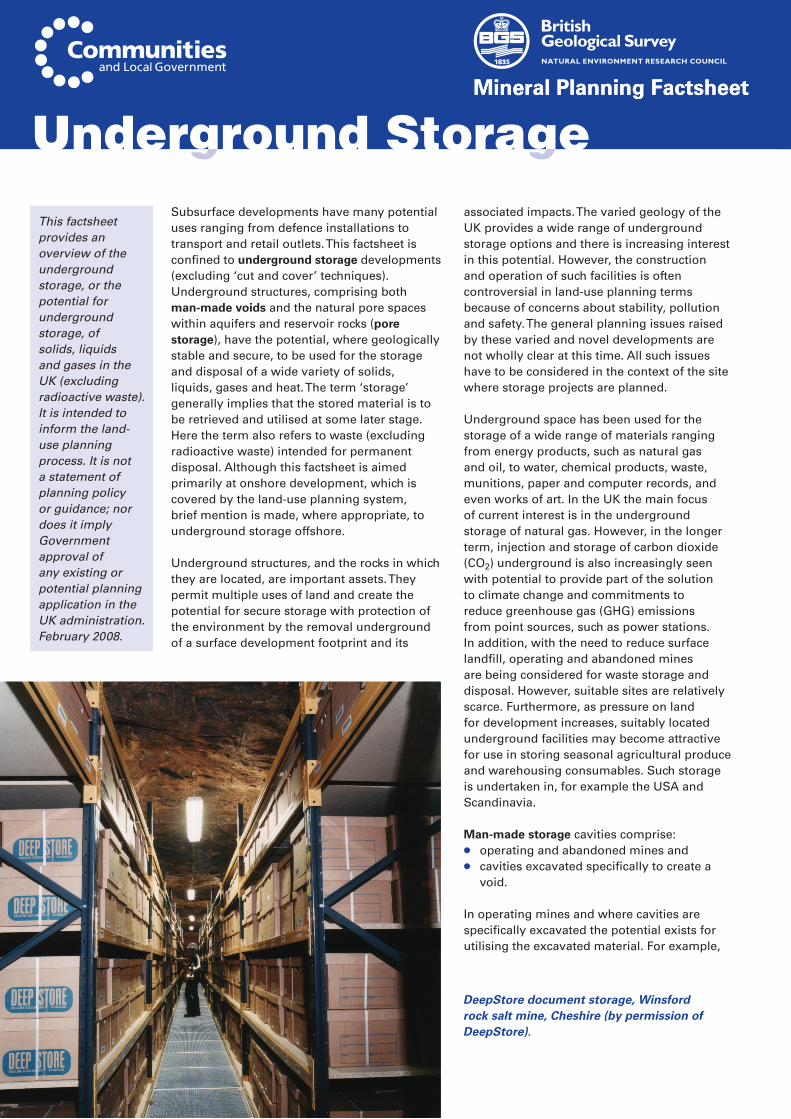
Mineral Planning Factsheet Mineral Planning Factsheet Underground Storage Subsurface developments have many potential uses ranging from defence installations to transport and retail outlets. This factsheet is confined to underground storage developments (excluding ‘cut and cover’ techniques). Underground structures, comprising both man-made voids and the natural pore spaces within aquifers and reservoir rocks (pore storage), have the potential, where geologically stable and secure, to be used for the storage and disposal of a wide variety of solids, liquids, gases and heat. The term ‘storage’ generally implies that the stored material is to be retrieved and utilised at some later stage. Here the term also refers to waste (excluding radioactive waste) intended for permanent disposal. Although this factsheet is aimed primarily at onshore development, which is covered by the land-use planning system, brief mention is made, where appropriate, to underground storage offshore. Underground structures, and the rocks in which they are located, are important assets. They permit multiple uses of land and create the potential for secure storage with protection of the environment by the removal underground of a surface development footprint and its associated impacts. The varied geology of the UK provides a wide range of underground storage options and there is increasing interest in this potential. However, the construction and operation of such facilities is often controversial in land-use planning terms because of concerns about stability, pollution and safety. The general planning issues raised by these varied and novel developments are not wholly clear at this time. All such issues have to be considered in the context of the site where storage projects are planned. Underground space has been used for the storage of a wide range of materials ranging from energy products, such as natural gas and oil, to water, chemical products, waste, munitions, paper and computer records, and even works of art. In the UK the main focus of current interest is in the underground storage of natural gas. However, in the longer term, injection and storage of carbon dioxide (CO 2 ) underground is also increasingly seen with potential to provide part of the solution to climate change and commitments to reduce greenhouse gas (GHG) emissions from point sources, such as power stations. In addition, with the need to reduce surface landfill, operating and abandoned mines are being considered for waste storage and disposal. However, suitable sites are relatively scarce. Furthermore, as pressure on land for development increases, suitably located underground facilities may become attractive for use in storing seasonal agricultural produce and warehousing consumables. Such storage is undertaken in, for example the USA and Scandinavia. Man-made storage cavities comprise: ● operating and abandoned mines and ● cavities excavated specifically to create a void. In operating mines and where cavities are specifically excavated the potential exists for utilising the excavated material. For example, This factsheet provides an overview of the underground storage, or the potential for underground storage, of solids, liquids and gases in the UK (excluding radioactive waste). It is intended to inform the land- use planning process. It is not a statement of planning policy or guidance; nor does it imply Government approval of any existing or potential planning application in the UK administration. February 2008. DeepStore document storage, Winsford rock salt mine, Cheshire (by permission of DeepStore).
-
Upload
khangminh22 -
Category
Documents
-
view
0 -
download
0
Transcript of Underground Storage - - British Geological Survey
Mineral Planning FactsheetMineral Planning Factsheet
Underground StorageSubsurface developments have many potential uses ranging from defence installations to transport and retail outlets. This factsheet is confined to underground storage developments (excluding ‘cut and cover’ techniques). Underground structures, comprising both man-made voids and the natural pore spaces within aquifers and reservoir rocks (pore storage), have the potential, where geologically stable and secure, to be used for the storage and disposal of a wide variety of solids, liquids, gases and heat. The term ‘storage’ generally implies that the stored material is to be retrieved and utilised at some later stage. Here the term also refers to waste (excluding radioactive waste) intended for permanent disposal. Although this factsheet is aimed primarily at onshore development, which is covered by the land-use planning system, brief mention is made, where appropriate, to underground storage offshore.
Underground structures, and the rocks in which they are located, are important assets. They permit multiple uses of land and create the potential for secure storage with protection of the environment by the removal underground of a surface development footprint and its
associated impacts. The varied geology of the UK provides a wide range of underground storage options and there is increasing interest in this potential. However, the construction and operation of such facilities is often controversial in land-use planning terms because of concerns about stability, pollution and safety. The general planning issues raised by these varied and novel developments are not wholly clear at this time. All such issues have to be considered in the context of the site where storage projects are planned.
Underground space has been used for the storage of a wide range of materials ranging from energy products, such as natural gas and oil, to water, chemical products, waste, munitions, paper and computer records, and even works of art. In the UK the main focus of current interest is in the underground storage of natural gas. However, in the longer term, injection and storage of carbon dioxide (CO2) underground is also increasingly seen with potential to provide part of the solution to climate change and commitments to reduce greenhouse gas (GHG) emissions from point sources, such as power stations. In addition, with the need to reduce surface landfill, operating and abandoned mines are being considered for waste storage and disposal. However, suitable sites are relatively scarce. Furthermore, as pressure on land for development increases, suitably located underground facilities may become attractive for use in storing seasonal agricultural produce and warehousing consumables. Such storage is undertaken in, for example the USA and Scandinavia.
Man-made storage cavities comprise:● operating and abandoned mines and ● cavities excavated specifically to create a
void.
In operating mines and where cavities are specifically excavated the potential exists for utilising the excavated material. For example,
This factsheet provides an overview of the underground storage, or the potential for underground storage, of solids, liquids and gases in the UK (excluding radioactive waste). It is intended to inform the land-use planning process. It is not a statement of planning policy or guidance; nor does it imply Government approval of any existing or potential planning application in the UK administration. February 2008.
DeepStore document storage, Winsford rock salt mine, Cheshire (by permission of DeepStore).
Underground Storage 2
Mineral Planning Factsheet
brine produced from creating salt caverns by solution mining may be used as a chemical feedstock where a market exists. Rock produced in constructing caverns could be used as a source of aggregate, building stone or for other mineral products. The potential also exists to design a storage facility or a mine to meet both objectives of providing mineral and storage space as part of an on-going development.
Pore storage uses the porous nature of certain rocks, such as sandstones in depleted reservoirs, for natural gas and CO2 storage, or in aquifers for groundwater recharge, thermal exchange systems, natural gas and, potentially, CO2
storage. Injection of CO2 into oil and gas reservoirs is already used elsewhere in the world in a process referred to as tertiary enhanced oil recovery (EOR).
MAN-MADE CAVITIES
Britain has a very long history of mining and there are very few minerals that have not been worked underground at some stage in the past. Coal mining was by far the most extensive, but metal mining formerly also covered large areas. However, many other minerals, including oil shale, fireclay, ball clay, fuller’s earth, limestone, building stone, silica sand, fluorspar, barytes, slate and, notably the evaporite minerals salt, gypsum/anhydrite and potash have all been mined to a greater or lesser extent. All these activities have created voids of varying size and shape in a wide range of geological settings. For most minerals this has produced voids, which are unstable, particularly where early mining methods were employed. Indeed the legacy of mining in Britain is a potential hazard to surface development in many parts of the country.
The type of void created and its suitability for storage use depends on the rock worked and the type of mining method used. Modern room and pillar mining is used for generally flat-lying, sedimentary strata. Typically 25–50% of the rock is left in the form of square pillars to provide a permanent support for the roof. Rock salt mining is a good example. Modern salt solution mining techniques also
have the capacity to produce stable cavities ideally suited for certain types of storage. The underground storage potential (actual or potential) of the main minerals mined in Britain is reviewed below.
Salt
Salt occurs in nature either in solid form as rock salt (halite) in beds ranging from a few centimetres to hundreds of metres thick, or in solution as brine (see Salt factsheet). The UK has huge resources of salt present in strata
Underground Storage Underground Storage
Triassic saltfields
Permian saltfieldLarne Basin(includes Permianhalite)
Cheshire Basin
North & SouthStaffordshire basins
Worcester Basin
Somerset Basin
Wessex Basin
Welton
Saltfleetby
Humbly Grove
Caythorpe
Hatfield Moors/Hatfield West
Albury
Bletchingley
Storrington
Preesall
Portland
Saltholme & Wilton,Teesside
Byley/Holford, Stublach &King Street (Holford Brinefield)
Holford H-165
Gainsborough
Hornsea/Atwick
Aldbrough South &Aldbrough North(Whitehill)
Hole House(Warmingham Brinefield)
Depleted oil/gasfield, operational
Depleted oil/gasfield - planned
Salt cavern storage - planned
Salt cavern storage, operational
Gas discovery (not developed) - planned
Walney Island
LNG underground storage site (chalk)- operational
Winchester
Cliffe
Stamford
Nene
HuntingdonBrackley
Napton
Chipping NortonSarsdenStow
Whichford
Town gas exploration wells (early 1960s)
storage
Killingholme
Point of Ayre
ëGatewayí projectRough
Larne(on andoffshore)
Esmond-Forbes-Gordon
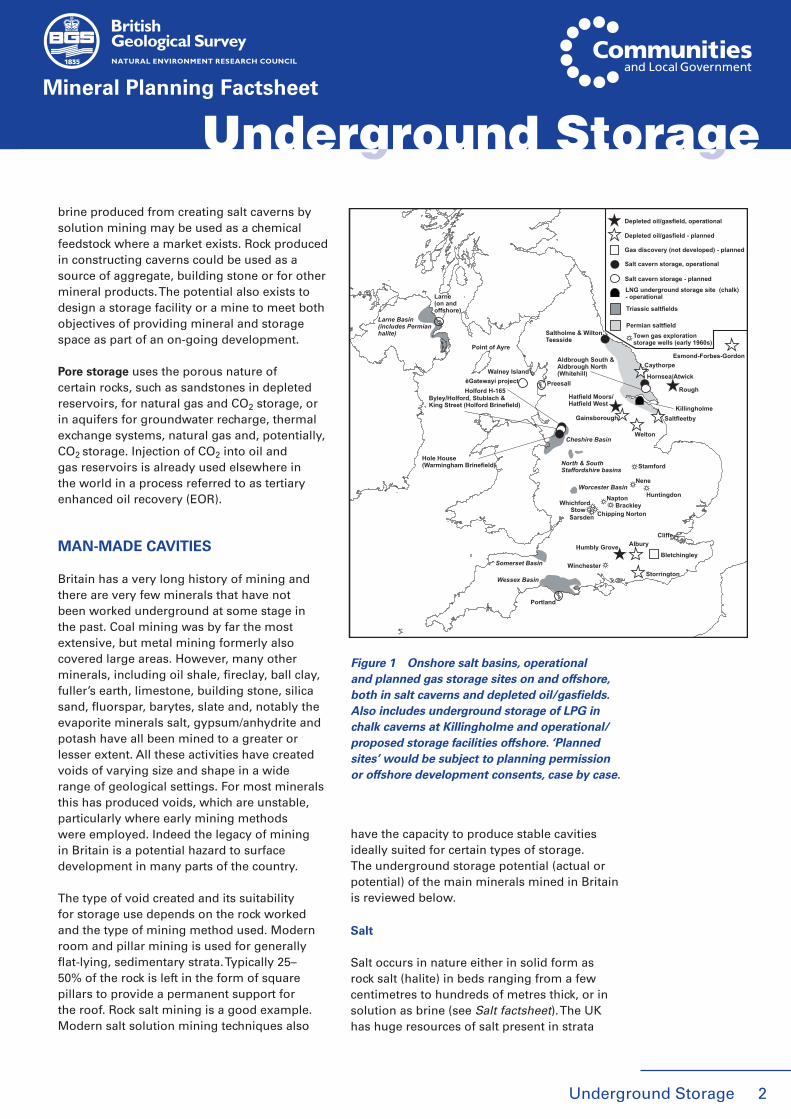
Figure 1 Onshore salt basins, operational and planned gas storage sites on and offshore, both in salt caverns and depleted oil/gasfields. Also includes underground storage of LPG in chalk caverns at Killingholme and operational/proposed storage facilities offshore. ‘Planned sites’ would be subject to planning permission or offshore development consents, case by case.
of Permian and Triassic age and underlying extensive areas in north-west and north-east England (Figure 1). Economically the most important deposits occur in the Cheshire Basin and north-east England. Other smaller saltfields occur in Staffordshire, Worcestershire, Lancashire, Somerset and Dorset. There are also important salt resources in Northern Ireland.
Salt beds do not crop out at surface in the UK because of solution by groundwater. Salt extraction is both by conventional underground mining to produce rock salt for de-icing roads, and solution mining to produce brine used as a chemical feedstock and to manufacture white salt. Rock salt is currently mined at three locations in the UK; the Winsford Mine
in Cheshire, the Boulby Mine in the North York Moors National Park (a by-product of potash mining) and the Kilroot Mine in Northern Ireland. Earlier methods of natural brine pumping caused extensive subsidence, particularly in Cheshire, but virtually all solution mining is now by controlled brine pumping. This method, originally introduced by ICI in the 1920s, involves the creation of caverns of pre-determined size and shape to maintain the stability of the overlying strata and so avoid surface subsidence (Figure 2). Controlled brine pumping takes place at the Holford and Warmingham brinefields in Cheshire and was formerly undertaken at Preesall in Lancashire and on Teesside. Completed solution cavities are left full of saturated brine but may be used for storage and waste disposal.
Un
der
gro
un
d S
tora
ge
Mineral Planning Factsheet
3 Underground Storage
Underground Storage
GB offshore GB (on- and offshore) Possible use in GB? Domal salt Thick bedded salt Thin bedded salt
c. 240 -2400 m
Few 100 -1000 m
c. 240 -1000 m
Start of solutionmining
Gas injection, continuedsolution mining
Solution miningcomplete
Compressedgas displaces brine
Storageoperations
Drilling borehole
Salt
Gas cap
Freshwaterinjection
Brinereturn
Partially developed cavern
Cavernnear completion
Initialborehole
bottom ofcementcasing
BrinereturnTop of
insolubles
Saltroof
Blanket level
Construction of sump
Hangingtubing
Conventional salt cavern solution mining Solution mining under gas (SMUG)
Salt Salt
Salt
Salt
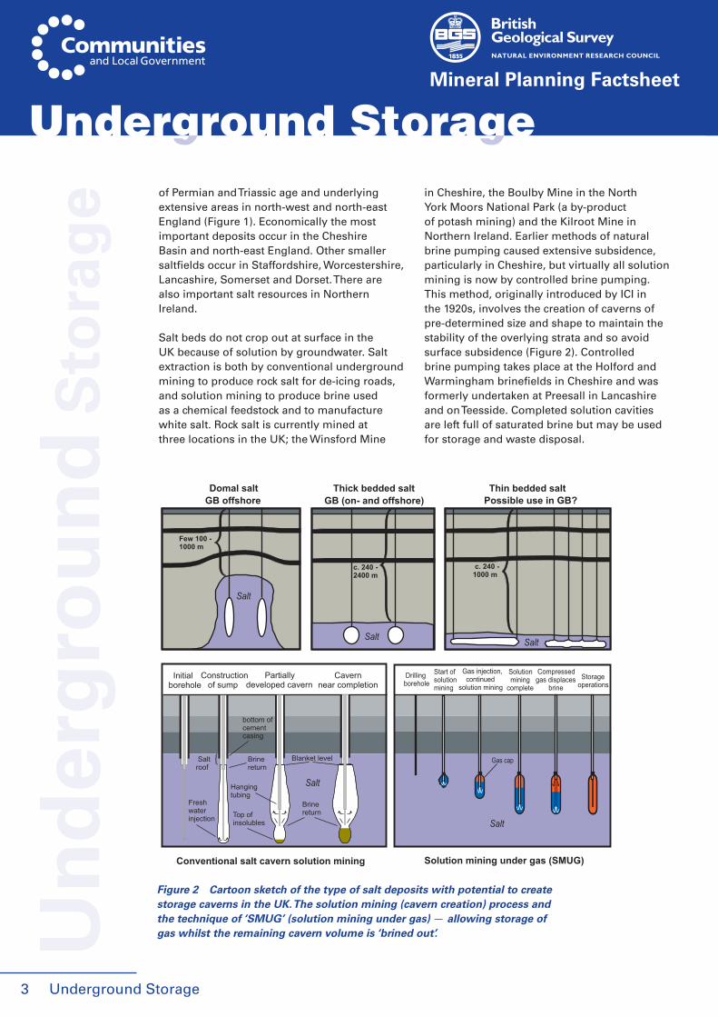
Figure 2 Cartoon sketch of the type of salt deposits with potential to create storage caverns in the UK. The solution mining (cavern creation) process and the technique of ‘SMUG’ (solution mining under gas) — allowing storage of gas whilst the remaining cavern volume is ‘brined out’.
Underground Storage
Storage potentialRock salt (NaCl) exhibits unique physical properties and mechanical behaviour that makes it an ideal host for the development of (large) caverns for the storage of materials that do not themselves react with or dissolve salt. Salt-bearing strata are, therefore, an important resource, not only as a source of salt, but also as a host for the construction of salt caverns. The wide distribution of salt (Figure 1) also makes it a resource of potentially strategic importance, notably for natural gas storage. In Cheshire the nationally important chemical industry in the region provides a ready market for the brine produced by creating caverns. However, it is unlikely that brines produced elsewhere in the construction of storage facilities could ever find use in chemical or other industries. Such brines would be likely to be regarded as construction waste, requiring appropriately managed disposal.
Large underground salt caverns produced by solution mining may be used for the storage of liquids (oil, natural gas liquids, and liquefied petroleum gas), gaseous hydrocarbons and compressed air. Currently there is particular interest in their use for natural gas storage.
This is considered in greater detail later in the factsheet in the section dealing specifically with natural gas storage. Completed solution caverns in the Triassic salts of Cheshire and Permian salts of north-east England have also been used for storage and waste disposal for many decades. In Cheshire, in addition to storing natural gas, cavities are used to dispose of the insoluble waste residues left from the purification of brine for subsequent chemical use. On Teesside, salt caverns have been used for the storage of natural gas, hydrogen,
Mineral Planning Factsheet
4
Underground Storage Underground Storage
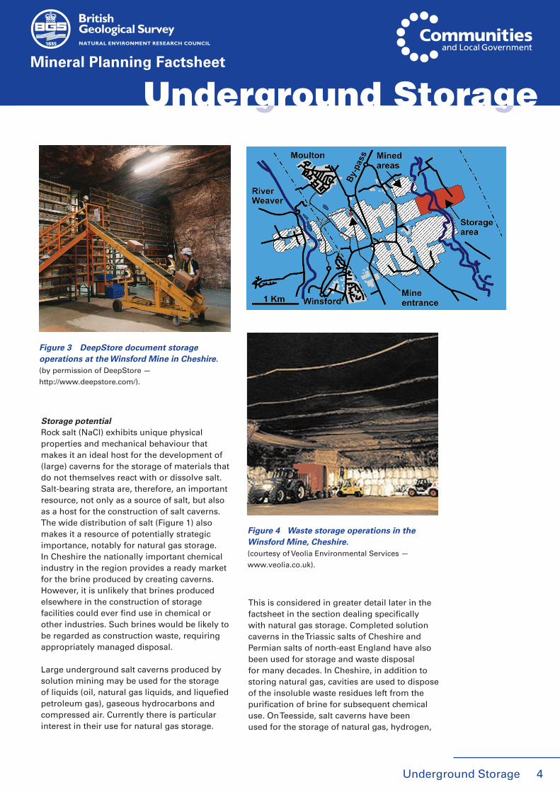
Figure 4 Waste storage operations in the Winsford Mine, Cheshire.(courtesy of Veolia Environmental Services —
www.veolia.co.uk).
Figure 3 DeepStore document storage operations at the Winsford Mine in Cheshire.(by permission of DeepStore —
http://www.deepstore.com/).

Underground Storage
Un
der
gro
un
d S
tora
ge
Mineral Planning Factsheet
various liquid hydrocarbons, other fluids, solids and waste products. At Preesall in Lancashire most of the brine cavities on abandonment were filled with brine. However, one of the old brine caverns has been used for the storage of brine sludge containing mercuric sulphide.
The Winsford Mine in Cheshire, with around 26 million m3 of space, has a constant temperature and humidity and is dry and gas free. Part of the mine is currently in use for the secure, long-term and ‘active’ storage of a wide range of documents and sensitive or fragile materials (Figure 3).
Part of the Winsford Mine is also being used by Veolia Environmental Services for the disposal of selected wastes. The need for such a facility was created in 1997 as a response to the EU Landfill Directive which required the ending of co-disposal of waste in surface landfills. In 2003 the company received planning permission for this storage facility in part of the disused mine area about 170 m underground. The mine began accepting waste in the summer of 2005 (Figure 4). Planning permission allows for the disposal of up to 100 000 t/y of suitably packaged wastes, the range of which is defined in the Integrated Prevention Pollution and Control (IPPC) permit issued by the Environment Agency. All waste must be in either solid, granular or powder form, but must not include flammable, reactive, volatile, biodegradable or radioactive waste products. The principal waste stream is residues from energy and waste plants.
Gypsum/anhydrite
Gypsum (CaSO4.2H2O) and anhydrite (CaSO4) are, respectively, the hydrated and anhydrous forms of calcium sulphate (see Gypsum/anhydrite factsheet). In nature they occur as beds or nodular masses up to a few metres thick.
Gypsum is used mainly in the manufacture of plaster and plasterboard. Most of the production of natural gypsum in the UK is by underground mining (pillar and stall methods), with five extensive mines currently in operation. Anhydrite was formerly mined on a large scale for the manufacture of sulphuric
acid and fertilisers but the principal mines all closed in the 1970s when this became uneconomic. A mixture of gypsum/anhydrite is used in cement manufacture.
Storage potentialIn the past, gypsum mines have been used to store munitions, notably at Fauld Mine in Staffordshire. However, gypsum mines are generally considered unsuitable for storage, as they are relatively shallow, often have water ingress and on abandonment generally suffer flooding. Older, near surface mines, have locally suffered some collapse, although more modern mines do not have this problem. With the exception of the Barrow Mine in Leicestershire, most operating mines require ongoing pumping of water. There are no current plans to use gypsum mines for storage purposes.
The Billingham Mine on Teesside was formerly the largest anhydrite mine in Britain. It was worked between 1927 and 1971 and produced 32 million tonnes of anhydrite, creating about 11 million m3 of underground space. The mine was accessed by two 240 m deep shafts. It was decommissioned in 1978, following which it has been under a management regime undertaken by owners ICI. In the early 1980s it was considered for the disposal of Intermediate and Low Level radioactive waste, but this proposal was withdrawn following significant local opposition. However, the non-radioactive storage potential of the mine is being considered by NPL Estates Ltd. The mine was inspected in September 2007 to assess whether it was in a suitable condition for use as a long-term facility for low-hazard waste. A report of the findings will be published in 2008. NPL Estates have agreed conditional terms with ICI to take over responsibility for managing the former mine.
Potash
Potash is principally used as a fertiliser (see Potash factsheet). It is only mined in Britain at the Boulby Mine in the North York Moors National Park. Mining operations extend around 13.5 km and cover an area of 20 km2. The mine extends 5 km offshore to the north
5
Mineral Planning Factsheet
Underground Storage
Underground Storage
Un
der
gro
un
d S
tora
ge
Mineral Planning Factsheet
6
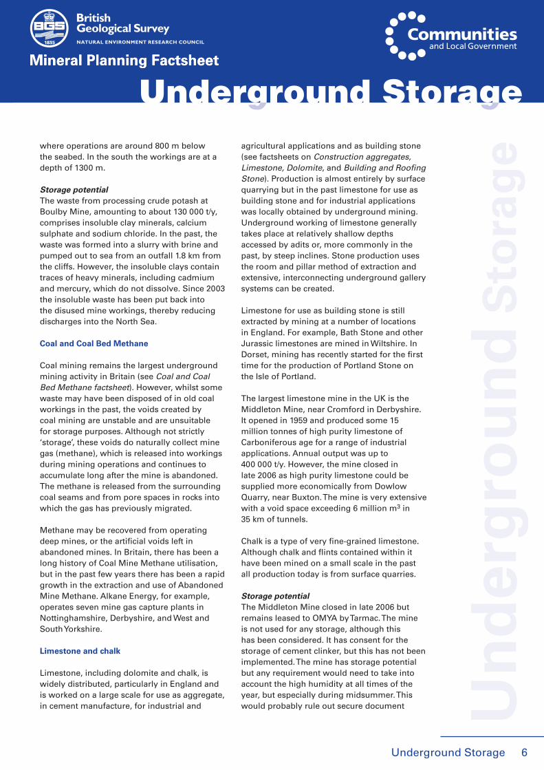
where operations are around 800 m below the seabed. In the south the workings are at a depth of 1300 m.
Storage potentialThe waste from processing crude potash at Boulby Mine, amounting to about 130 000 t/y, comprises insoluble clay minerals, calcium sulphate and sodium chloride. In the past, the waste was formed into a slurry with brine and pumped out to sea from an outfall 1.8 km from the cliffs. However, the insoluble clays contain traces of heavy minerals, including cadmium and mercury, which do not dissolve. Since 2003 the insoluble waste has been put back into the disused mine workings, thereby reducing discharges into the North Sea.
Coal and Coal Bed Methane
Coal mining remains the largest underground mining activity in Britain (see Coal and Coal Bed Methane factsheet). However, whilst some waste may have been disposed of in old coal workings in the past, the voids created by coal mining are unstable and are unsuitable for storage purposes. Although not strictly ‘storage’, these voids do naturally collect mine gas (methane), which is released into workings during mining operations and continues to accumulate long after the mine is abandoned. The methane is released from the surrounding coal seams and from pore spaces in rocks into which the gas has previously migrated.
Methane may be recovered from operating deep mines, or the artificial voids left in abandoned mines. In Britain, there has been a long history of Coal Mine Methane utilisation, but in the past few years there has been a rapid growth in the extraction and use of Abandoned Mine Methane. Alkane Energy, for example, operates seven mine gas capture plants in Nottinghamshire, Derbyshire, and West and South Yorkshire.
Limestone and chalk
Limestone, including dolomite and chalk, is widely distributed, particularly in England and is worked on a large scale for use as aggregate, in cement manufacture, for industrial and
agricultural applications and as building stone (see factsheets on Construction aggregates, Limestone, Dolomite, and Building and Roofing Stone). Production is almost entirely by surface quarrying but in the past limestone for use as building stone and for industrial applications was locally obtained by underground mining. Underground working of limestone generally takes place at relatively shallow depths accessed by adits or, more commonly in the past, by steep inclines. Stone production uses the room and pillar method of extraction and extensive, interconnecting underground gallery systems can be created.
Limestone for use as building stone is still extracted by mining at a number of locations in England. For example, Bath Stone and other Jurassic limestones are mined in Wiltshire. In Dorset, mining has recently started for the first time for the production of Portland Stone on the Isle of Portland.
The largest limestone mine in the UK is the Middleton Mine, near Cromford in Derbyshire. It opened in 1959 and produced some 15 million tonnes of high purity limestone of Carboniferous age for a range of industrial applications. Annual output was up to 400 000 t/y. However, the mine closed in late 2006 as high purity limestone could be supplied more economically from Dowlow Quarry, near Buxton. The mine is very extensive with a void space exceeding 6 million m3 in 35 km of tunnels.
Chalk is a type of very fine-grained limestone. Although chalk and flints contained within it have been mined on a small scale in the past all production today is from surface quarries.
Storage potentialThe Middleton Mine closed in late 2006 but remains leased to OMYA by Tarmac. The mine is not used for any storage, although this has been considered. It has consent for the storage of cement clinker, but this has not been implemented. The mine has storage potential but any requirement would need to take into account the high humidity at all times of the year, but especially during midsummer. This would probably rule out secure document
Mineral Planning Factsheet
Underground Storage Underground Storage
Underground Storage
Mineral Planning Factsheet
storage. There is now no ventilation or power infrastructure.
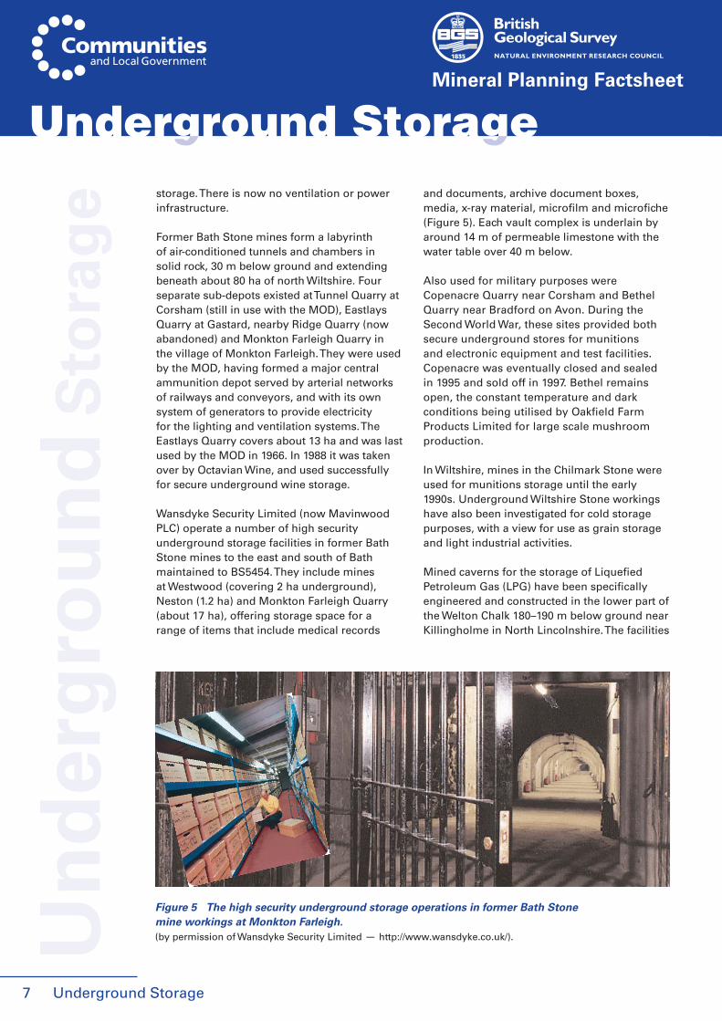
Former Bath Stone mines form a labyrinth of air-conditioned tunnels and chambers in solid rock, 30 m below ground and extending beneath about 80 ha of north Wiltshire. Four separate sub-depots existed at Tunnel Quarry at Corsham (still in use with the MOD), Eastlays Quarry at Gastard, nearby Ridge Quarry (now abandoned) and Monkton Farleigh Quarry in the village of Monkton Farleigh. They were used by the MOD, having formed a major central ammunition depot served by arterial networks of railways and conveyors, and with its own system of generators to provide electricity for the lighting and ventilation systems. The Eastlays Quarry covers about 13 ha and was last used by the MOD in 1966. In 1988 it was taken over by Octavian Wine, and used successfully for secure underground wine storage.
Wansdyke Security Limited (now Mavinwood PLC) operate a number of high security underground storage facilities in former Bath Stone mines to the east and south of Bath maintained to BS5454. They include mines at Westwood (covering 2 ha underground), Neston (1.2 ha) and Monkton Farleigh Quarry (about 17 ha), offering storage space for a range of items that include medical records
and documents, archive document boxes, media, x-ray material, microfilm and microfiche (Figure 5). Each vault complex is underlain by around 14 m of permeable limestone with the water table over 40 m below.
Also used for military purposes were Copenacre Quarry near Corsham and Bethel Quarry near Bradford on Avon. During the Second World War, these sites provided both secure underground stores for munitions and electronic equipment and test facilities. Copenacre was eventually closed and sealed in 1995 and sold off in 1997. Bethel remains open, the constant temperature and dark conditions being utilised by Oakfield Farm Products Limited for large scale mushroom production.
In Wiltshire, mines in the Chilmark Stone were used for munitions storage until the early 1990s. Underground Wiltshire Stone workings have also been investigated for cold storage purposes, with a view for use as grain storage and light industrial activities.
Mined caverns for the storage of Liquefied Petroleum Gas (LPG) have been specifically engineered and constructed in the lower part of the Welton Chalk 180–190 m below ground near Killingholme in North Lincolnshire. The facilities
7
Un
der
gro
un
d S
tora
ge
Underground Storage
Figure 5 The high security underground storage operations in former Bath Stone mine workings at Monkton Farleigh.(by permission of Wansdyke Security Limited — http://www.wansdyke.co.uk/).
Underground Storage
opened in 1985 and are jointly operated by ConocoPhillips and Calor Gas Ltd. They have been designed to meet peak winter demand for LPG. The principle of LPG containment in the unlined chalk caverns requires the groundwater (hydrostatic) pressure in the chalk surrounding the cavern to exceed the maximum vapour pressure of the propane.
Slate
Slate mining on an industrial scale developed in the late 18th Century and expanded dramatically in the 19th Century, with peak output in 1898 (see Building and Roofing Stone factsheet). The mining of slate involved the construction of shallow adits and underground workings. These were sometimes accessed by tunnels, which were then enlarged to remove the slate - pillars up to 18 m being left to hold up the roof. Mine workings are most common in areas of steeply-dipping beds, as around Nantlle and Maenofferen in North Wales. They were worked in a series of underground chambers accessed by horizontal or steeply sloping levels following the slate beds. Chambers some 8–9 m high and 12 m wide were constructed on one or more levels with pillars to support the roofs. In some areas, one elevation was mined through to the next, leaving vast chambers and old workings, which were later reworked to extract the remaining slate of the roofing pillars (a process known as ‘untopping’).
Slate has also been mined at Carnglaze, St Neots in Cornwall, with large caverns left supported by pillars of unworked slate. The mine operated for around 200 years, finally closing in the early 20th Century, but is now open to the public. Caverns may be 100 m by 16 m in area and 16 m high, with pillars supporting the roof.
Storage potentialMost old slate mines are now disused and offer little prospect of use for storage. A few have been opened as tourist attractions.
Whilst not storage the Dinorwig power station in North Wales utilises the old Dinorwig slate quarry and a system of tunnels and caverns excavated inside the mountain Elidir Fawr to generate hydro-electric power. The tunnels and
caverns assist in pumping the water back to the top of the mountain during off peak periods.
Bunkers
In recent years, some data storage companies have bought up secure Ministry of Defence bunkers, constructed underground all over the country during the Cold War. The end of the Cold War saw many of them sold off, including one in Lincolnshire sold to a storage company, which spans three floors and has over 100 rooms. It was first operational in the early 1940s, and is one of ten bunkers sold off by the Ministry of Defence in the 1990s.
Another such bunker complex is in a former Bath Stone mine near Corsham in Wiltshire. The underground complex, covering 97 ha and with 100 km of roads, was built in the 1950s and is at a depth of about 36 m.
PORE STORAGE
Sedimentary basins contain porous and permeable rocks that hold and permit the flow of groundwater (aquifers) and hydrocarbons (reservoir rocks). In rocks such as sandstones, porosity and permeability is provided by the natural pore spaces that occur between the constituent grains and which form an interconnecting network of minute channels in the rock. Fracture systems (in e.g. limestones and igneous rocks) may also provide porosity and permeability. Porous and permeable rocks, therefore, offer potential for the storage of liquids and gases, and also heat using fluids to transport that energy.
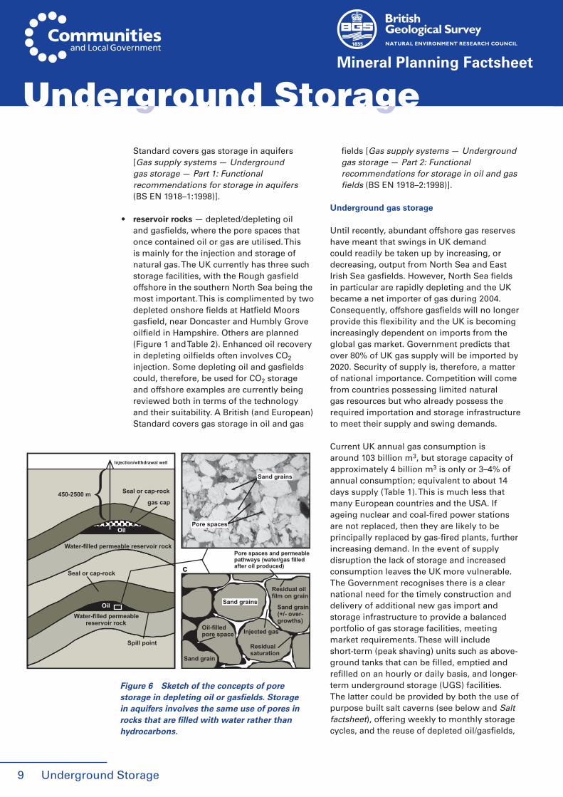
Pore storage potential occurs in (Figure 6):
● aquifers - aquifers are the natural storage reservoirs for groundwater. This storage is naturally recharged and discharge provides baseflow for streams. Storage is exploited in the provision of groundwater supplies but aquifers are also being assessed for their thermal energy and thermal storage potential. Other possibilities include natural gas, hydrogen, compressed air and perhaps CO2 storage. A British (and European) U
nd
erg
rou
nd
Sto
rag
e
Mineral Planning Factsheet
8
Underground Storage Underground Storage
Underground Storage
Mineral Planning Factsheet
Standard covers gas storage in aquifers [Gas supply systems — Underground gas storage — Part 1: Functional recommendations for storage in aquifers (BS EN 1918–1:1998)].
• reservoir rocks — depleted/depleting oil and gasfields, where the pore spaces that once contained oil or gas are utilised. This is mainly for the injection and storage of natural gas. The UK currently has three such storage facilities, with the Rough gasfield offshore in the southern North Sea being the most important. This is complimented by two depleted onshore fields at Hatfield Moors gasfield, near Doncaster and Humbly Grove oilfield in Hampshire. Others are planned (Figure 1 and Table 2). Enhanced oil recovery in depleting oilfields often involves CO2 injection. Some depleting oil and gasfields could, therefore, be used for CO2 storage and offshore examples are currently being reviewed both in terms of the technology and their suitability. A British (and European) Standard covers gas storage in oil and gas
fields [Gas supply systems — Underground gas storage — Part 2: Functional recommendations for storage in oil and gas fields (BS EN 1918–2:1998)].
Underground gas storage
Until recently, abundant offshore gas reserves have meant that swings in UK demand could readily be taken up by increasing, or decreasing, output from North Sea and East Irish Sea gasfields. However, North Sea fields in particular are rapidly depleting and the UK became a net importer of gas during 2004. Consequently, offshore gasfields will no longer provide this flexibility and the UK is becoming increasingly dependent on imports from the global gas market. Government predicts that over 80% of UK gas supply will be imported by 2020. Security of supply is, therefore, a matter of national importance. Competition will come from countries possessing limited natural gas resources but who already possess the required importation and storage infrastructure to meet their supply and swing demands.
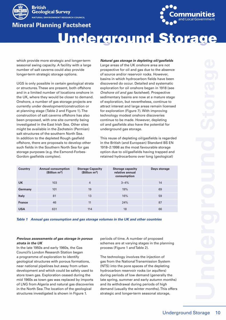
Current UK annual gas consumption is around 103 billion m3, but storage capacity of approximately 4 billion m3 is only or 3–4% of annual consumption; equivalent to about 14 days supply (Table 1). This is much less that many European countries and the USA. If ageing nuclear and coal-fired power stations are not replaced, then they are likely to be principally replaced by gas-fired plants, further increasing demand. In the event of supply disruption the lack of storage and increased consumption leaves the UK more vulnerable. The Government recognises there is a clear national need for the timely construction and delivery of additional new gas import and storage infrastructure to provide a balanced portfolio of gas storage facilities, meeting market requirements. These will include short-term (peak shaving) units such as above-ground tanks that can be filled, emptied and refilled on an hourly or daily basis, and longer-term underground storage (UGS) facilities. The latter could be provided by both the use of purpose built salt caverns (see below and Salt factsheet), offering weekly to monthly storage cycles, and the reuse of depleted oil/gasfields,
9
Underground Storage
Pore spaces
Sand grains
Sand grain(+/- over-growths)
Injected gas
Residualsaturation
Oil-filledpore space
Pore spaces and permeablepathways (water/gas filledafter oil produced)
Sand grain
Water-filled permeable reservoir rock
Water-filled permeable reservoir rock
Seal or cap-rock
Oil
gas cap
Spill point
Oil
Seal or cap-rock
450-2500 m
c
Residual oilfilm on grain
Injection/withdrawal well
Sand grains
Figure 6 Sketch of the concepts of pore storage in depleting oil or gasfields. Storage in aquifers involves the same use of pores in rocks that are filled with water rather than hydrocarbons.
Underground Storage
Mineral Planning Factsheet
10
which provide more strategic and longer-term seasonal swing capacity. A facility with a large number of salt caverns could also provide longer-term strategic storage options.
UGS is only possible in certain geological strata or structures. These are present, both offshore and in a limited number of locations onshore in the UK, where they would be closer to demand. Onshore, a number of gas storage projects are currently under development/construction or at planning stage (Table 2 and Figure 1). The construction of salt caverns offshore has also been proposed, with one site currently being investigated in the East Irish Sea. Other sites might be available in the Zechstein (Permian) salt structures of the southern North Sea. In addition to the depleted Rough gasfield offshore, there are proposals to develop other such fields in the Southern North Sea for gas storage purposes (e.g. the Esmond-Forbes-Gordon gasfields complex).
Previous assessments of gas storage in porous strata in the UKIn the late 1950s and early 1960s, the Gas Council’s London Research Station began a programme of exploration to identify geological structures with porous formations, near national pipelines but away from urban development and which could be safely used to store town gas. Exploration ceased during the mid 1960s as town gas was replaced by imports of LNG from Algeria and natural gas discoveries in the North Sea. The location of the geological structures investigated is shown in Figure 1.
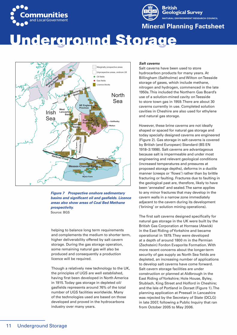
Natural gas storage in depleting oil/gasfieldsLarge areas of the UK onshore area are not prospective for oil and gas due to the absence of source and/or reservoir rocks. However, basins in which hydrocarbon fields have been discovered do occur. Detailed and systematic exploration for oil onshore began in 1918 (see Onshore oil and gas factsheet). Prospective sedimentary basins are now at a mature stage of exploration, but nevertheless, continue to attract interest and large areas remain licensed for exploration (Figure 7). With improving technology modest onshore discoveries continue to be made. However, depleting oil and gasfields also have the potential for underground gas storage.
This reuse of depleting oil/gasfields is regarded in the British (and European) Standard BS EN 1918–2:1998 as the most favourable storage option due to oil/gasfields having trapped and retained hydrocarbons over long (geological)
periods of time. A number of proposed schemes are at varying stages in the planning process (Figure 1 and Table 2).
The technology involves the injection of gas from the National Transmission System (NTS) into the pore spaces of the depleting hydrocarbon reservoir rocks (or aquifers) during periods of low demand (generally the late spring, summer and early autumn months) and its withdrawal during periods of high demand (usually the winter months). This offers strategic and longer-term seasonal storage,
Underground Storage Underground Storage
Un
der
gro
un
d S
tora
ge
Country Annual consumption (Billion m3)
Storage Capacity (Billion m3)
Storage capacity relative annual consumption
Days storage
UK 103 4 3 – 4% 14
Germany 101 19 19% 69
Italy 81 13 16% 59
France 46 11 24% 87
USA 631 114 18 66
Table 1 Annual gas consumption and gas storage volumes in the UK and other countries
Underground Storage
Mineral Planning Factsheet
11
helping to balance long term requirements and complements the medium to shorter term, higher deliverability offered by salt cavern storage. During the gas storage operation, some remaining natural gas will also be produced and consequently a production licence will be required.
Though a relatively new technology to the UK, the principles of UGS are well established, having first been developed in North America in 1915. Today gas storage in depleted oil/gasfields represents around 76% of the total number of UGS facilities worldwide. Many of the technologies used are based on those developed and proved in the hydrocarbons industry over many years.
Salt cavernsSalt caverns have been used to store hydrocarbon products for many years. At Billingham (Saltholme) and Wilton on Teesside storage of gases, which include methane, nitrogen and hydrogen, commenced in the late 1950s. This included the Northern Gas Board’s use of a solution-mined cavity on Teesside to store town gas in 1959. There are about 30 caverns currently in use. Completed solution cavities in Cheshire are also used for ethylene and natural gas storage.
However, these brine caverns are not ideally shaped or spaced for natural gas storage and today specially designed caverns are engineered (Figure 2). Gas storage in salt caverns is covered by British (and European) Standard (BS EN 1918–3:1998). Salt caverns are advantageous because salt is impermeable and under most engineering and relevant geological conditions (increased temperatures and pressures at proposed storage depths), deforms in a ductile manner (creeps or ‘flows’) rather than by brittle fracturing or faulting. Fractures due to faulting in the geological past are, therefore, likely to have been ‘annealed’ and sealed. The same applies to any minor fractures that may develop in the cavern walls in a narrow zone immediately adjacent to the cavern during its development (‘brining’ or solution mining operations).
The first salt caverns designed specifically for natural gas storage in the UK were built by the British Gas Corporation at Hornsea (Atwick) in the East Riding of Yorkshire and became operational in 1979. They were developed at a depth of around 1800 m in the Permian (Zechstein) Fordon Evaporite Formation. With more recent concerns about the longer-term security of gas supply as North Sea fields are depleted, an increasing number of applications to develop salt caverns have come forward. Salt cavern storage facilities are under construction or planned at Aldbrough in the East Riding of Yorkshire; Hole House, Byley, Stublach, King Street and Holford in Cheshire; and the Isle of Portland in Dorset (Figure 1). The planning application at Preesall in Lancashire was rejected by the Secretary of State (DCLG) in late 2007, following a Public Inquiry that ran from October 2005 to May 2006.
Underground Storage
GaTWA
Variscan Front
Marginally prospective areas
Unprospective areas, onshore UK
Oil fields
Gas fields
Licence blocks
Northumberland - Solway
B
asin
Midland Valley
of S
cotland
West Lancashire Basin
NE EnglandProvince
East MidlandsProvince
Welton
Saltfleetby
Wessex-Channel Basin
Wytch Farm
Humbly Grove
Wor
cest
er B
asin
Cheshire Basin
North Sea
IrishSea
Figure 7 Prospective onshore sedimentary basins and significant oil and gasfields. Licence areas also show areas of Coal Bed Methane prospectivity.Source: BGS
Underground Storage 12
Mineral Planning Factsheet
Un
der
gro
un
d S
tora
ge
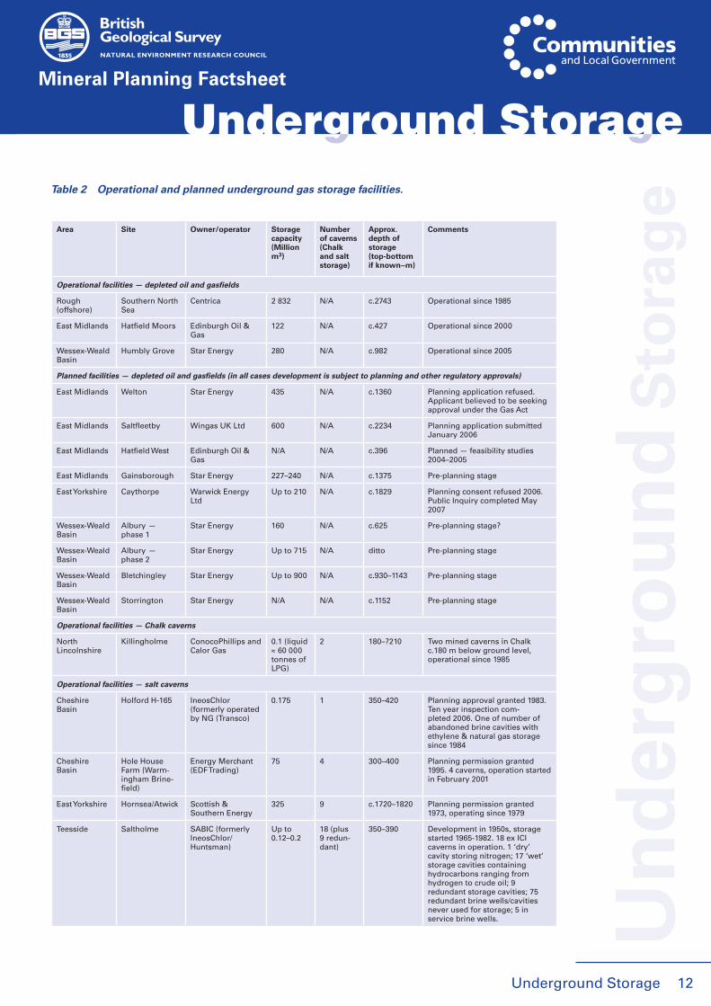
Underground Storage Underground StorageTable 2 Operational and planned underground gas storage facilities.
Area Site Owner/operator Storage capacity (Million m3)
Number of caverns (Chalk and salt storage)
Approx. depth of storage (top-bottom if known – m)
Comments
Operational facilities — depleted oil and gasfields
Rough (offshore)
Southern North Sea
Centrica 2 832 N/A c.2743 Operational since 1985
East Midlands Hatfield Moors Edinburgh Oil & Gas
122 N/A c.427 Operational since 2000
Wessex-Weald Basin
Humbly Grove Star Energy 280 N/A c.982 Operational since 2005
Planned facilities — depleted oil and gasfields (in all cases development is subject to planning and other regulatory approvals)
East Midlands Welton Star Energy 435 N/A c.1360 Planning application refused. Applicant believed to be seeking approval under the Gas Act
East Midlands Saltfleetby Wingas UK Ltd 600 N/A c.2234 Planning application submitted January 2006
East Midlands Hatfield West Edinburgh Oil & Gas
N/A N/A c.396 Planned — feasibility studies 2004–2005
East Midlands Gainsborough Star Energy 227–240 N/A c.1375 Pre-planning stage
East Yorkshire Caythorpe Warwick Energy Ltd
Up to 210 N/A c.1829 Planning consent refused 2006. Public Inquiry completed May 2007
Wessex-Weald Basin
Albury — phase 1
Star Energy 160 N/A c.625 Pre-planning stage?
Wessex-Weald Basin
Albury — phase 2
Star Energy Up to 715 N/A ditto Pre-planning stage
Wessex-Weald Basin
Bletchingley Star Energy Up to 900 N/A c.930–1143 Pre-planning stage
Wessex-Weald Basin
Storrington Star Energy N/A N/A c.1152 Pre-planning stage
Operational facilities — Chalk caverns
NorthLincolnshire
Killingholme ConocoPhillips and Calor Gas
0.1 (liquid ≈ 60 000 tonnes of LPG)
2 180–?210 Two mined caverns in Chalk c.180 m below ground level, operational since 1985
Operational facilities — salt caverns
Cheshire Basin
Holford H-165 IneosChlor (formerly operated by NG (Transco)
0.175 1 350–420 Planning approval granted 1983. Ten year inspection com-pleted 2006. One of number of abandoned brine cavities with ethylene & natural gas storage since 1984
Cheshire Basin
Hole House Farm (Warm-ingham Brine-field)
Energy Merchant (EDF Trading)
75 4 300–400 Planning permission granted 1995. 4 caverns, operation started in February 2001
East Yorkshire Hornsea/Atwick Scottish & Southern Energy
325 9 c.1720–1820 Planning permission granted 1973, operating since 1979
Teesside Saltholme SABIC (formerly IneosChlor/ Huntsman)
Up to 0.12–0.2
18 (plus 9 redun-dant)
350–390 Development in 1950s, storage started 1965-1982. 18 ex ICI caverns in operation. 1 ‘dry’ cavity storing nitrogen; 17 ‘wet’ storage cavities containing hydrocarbons ranging from hydrogen to crude oil; 9 redundant storage cavities; 75 redundant brine wells/cavities never used for storage; 5 in service brine wells.

Compressed air energy storage (CAES)
Compressed air energy storage is used and being considered in many countries, including
the UK. The basic concept of CAES is more than 30 years old and involves using off peak electrical energy from renewable sources such as wind, or excess output of power plants,
Underground Storage13
Mineral Planning Factsheet
Underground StorageU
nd
erg
rou
nd
Sto
rag
e
Teesside Saltholme IneosChlor/ Northern Gas Networks
0.08 4 340–370 4 ex ICI natural gas cavities. Development started 1959-1983, storage started 1959-1983. Now owned by IneosChlor & operated by NGN for natural gas
Teesside Wilton SABIC (formerly IneosChlor/ Huntsman)
Up to 0.04 5(plus 3 redun-dant)
650–680 Storage started from 1959 to 1983. 8 caverns leached, 5 op-erational cavities in total leached for storage purposes: 4 cavities storing ethylene, 1 cavity storing mixed C4’s. 3 cavities redundant or never in service for storage
Teesside Wilton SembCorp/BOC N/A 2 650–680 2 ex ICI cavities - operational & storing nitrogen (for BOC Nitrogen)
Planned facilities — salt caverns (in all cases development is subject to planning and other regulatory approvals)
Cheshire Basin
Byley/Holford (southern end of Holford Brinefield — Drakelow Lane area)
Scheme initiated by Scottish Power, sold to E. On UK plc
160–170 8 630–730 Secretary of State reversed Public Inquiry decision. Under construc-tion. Salt caverns to be leased from Ineos who own the salt & will construct caverns
Cheshire Basin
Stublach (Holford Brinefield between Drakelow Lane and Lach Dennis)
Ineos Enterprises Ltd
540 28 550–560 Planning permission granted late 2006. Under construction
Cheshire Basin
King Street (Holford Brine-field)
King Street Energy (NPL Estates)
216 9 >400 Pre-planning stage. Proposed construction of 9 cavities
East Yorkshire Aldbrough South — Phase 1
Scottish & Southern Energy and Statoil
420 9 1800–1900 Planning permission granted 2000, 2 sites with 3 and 6 cavern. Under construction?
East Yorkshire Aldbrough South — Phase 2
Scottish & Southern Energy and Statoil
420 9 1800–1900 Consent sought for extension to phase 1 development, with consent to increase storage ca-pacity granted by East Riding of Yorkshire Council in May 2007
Lancashire Preesall Canatxx GasStorage Ltd
c.1200 20–24 245–510 Public Inquiry held (late 05-early 06). Planning permission refused by Secretary of State (DCLG) October 2007
East Yorkshire North of Aldbrough (Whitehill)
E.ON UK 420 10 c.1800 Planning application submitted to East Riding of Yorkshire Council, January 2007.
Wessex-Weald Basin, Dorset
Isle of Portland Portland Gas Ltd. (subsidiary Egdon Resources)
1000 14 2100–2300 Planning permission applied for in March 2007. Decision expected in 2008.
Larne,N Ireland
Larne Lough Portland Gas NI Ltd (subsidiary Egdon Resources)
N/A N/A 1680 Feasibility study stage, seismic acquisition in October 2007
Table 2 Continued.
Source: JESS and DTI 2006 reports and company websites
Underground Storage 14
to compress air, which is then stored under pressure underground. The compressed air is then released through a gas turbine to generate electricity during periods of peak demand.
Storage can be in porous rocks (aquifers or depleted oil/gasfields) or, more commonly, in large voids such as salt caverns or former mine workings. The first CAES facility using salt caverns was created in the Huntorf salt dome near Hamburg in Germany in 1978. A second plant near Mobile in Alabama, USA was constructed in 1991 and others are being planned around the world. Similar facilities could be developed in the UK in conjunction with, for example, near shore wind farms. CAES facilities are being developed in large (unlined) limestone caverns in Ohio, USA and in an aquifer to be jointly used for gas storage (Iowa, USA). CAES feasibility studies have been undertaken in the UK, including by the Central Electricity Generating Board (CEGB) in the 1980s. However, no development has yet taken place.
Similar proposals, but using rock caverns to store water at different levels for closed loop pump storage, have been suggested for Scotland.
If renewable energy is to become an important element of the energy mix, then options for energy storage, including CAES, may have to be considered. This might be facilitated by distributed generation and microgrids, in which small CAES plants distributed around the UK could play an important role in the storage of off peak renewable energy.
Carbon dioxide (CO2) storage
Carbon dioxide capture and storage (CCS) is a potentially crucial technology that could reduce, perhaps by 80–90%, the CO2 emissions released to the atmosphere from large, new and existing fossil fuel-fired power stations and some industrial plant. At its simplest CCS consists of three main steps: the capture (using a variety of techniques) and compression of CO2; its transport to a storage location most likely by pipeline (due to the large volumes that would be
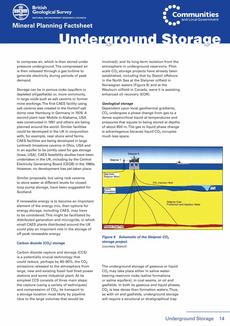
involved); and its long-term isolation from the atmosphere in underground reservoirs. Pilot-scale CO2 storage projects have already been established, including that by Statoil offshore in the North Sea at the Sleipner oilfield in Norwegian waters (Figure 8) and at the Weyburn oilfield in Canada, were it is assisting enhanced oil recovery (EOR).
Geological storageDependent upon local geothermal gradients, CO2 undergoes a phase change from gas to a dense supercritical liquid at temperatures and pressures that equate to being stored at depths of about 800 m. The gas to liquid phase change is advantageous because liquid CO2 occupies much less space.
The underground storage of gaseous or liquid CO2 may take place either in saline water-bearing reservoir rocks (saline formations or saline aquifers), in coal seams, or oil and gasfields. In both its gaseous and liquid phases, CO2 is less dense than formation waters. Thus, as with oil and gasfields, underground storage will require a structural or stratigraphical trap
Mineral Planning Factsheet
Underground Storage Underground Storage
Figure 8 Schematic of the Sleipner CO2 storage project.(courtesy Statoil)
Underground Storage15
Un
der
gro
un
d S
tora
ge
Mineral Planning Factsheet
and a combination of a porous and permeable reservoir (storage) rock and a low permeability geological barrier (caprock), such as beds of mudstone or salt, to seal and isolate the CO2 from escape.
Studies in the USA and Canada have considered the storage of CO2 in large salt caverns. However, this represents poor use of resources, as once filled, the salt cavern can no longer be used again.
CO2 enhanced oil recovery (EOR)CO2 can be injected into hydrocarbon reservoirs where it acts as a solvent, mixing with the oil and reducing its viscosity. Further oil, which otherwise would be permanently trapped in the reservoir formation, is thus recovered along with some of the injected CO2. The CO2 is separated from the oil and the process repeated several times to recover still more oil. Ultimately, the CO2 used in the recovery process is either trapped in the pores of the reservoir formation, or is simply left underground upon completion of the project. In a typical oilfield, 30% to 50% of the oil in place can be extracted during primary and secondary (water flooding) recovery operations. CO2 injection in tertiary operations leads to an additional 10% to 16% of the original oil in place being recovered, often extending the productive life of already mature fields by up to 30 years. In the USA CO2 EOR flooding recovers 206 000 barrels of oil per day representing 12% of US oil production. During the early 1980s, EOR projects using CO2 were undertaken in the UK at the Egmanton and Bothamsall oilfields in Nottinghamshire. Limited response, problems with injecting CO2 and prohibitive costs at the time meant that the project was terminated. The process of EOR is already undertaken in various forms in the North Sea. Whilst CO2-EOR is undertaken in a number of countries (e.g. America), it has not yet been applied to depleting oilfields in the North Sea. However, BP, Shell and StatoilHydro have undertaken comprehensive studies on its application at, for example, the Miller, Gullfaks, Ekofisk, Forties and Fulmar fields.
UK onshore storage potential The best onshore CO2 storage potential in England and Wales is likely to be in the Permian
and Triassic successions of the main onshore sedimentary basins. These were sites of thick sediment accumulation and they overlap with the areas and sedimentary sequences that contain the main oil and gasfields. However, the potential reservoir rocks may be of different ages and would require site-by-site evaluation of their suitability for storage. This is because older (e.g. Carboniferous) strata are generally compacted and cemented rocks with reduced porosity and permeability thus offering limited storage potential. Younger (e.g. Cretaceous) strata locally have suitable reservoir rocks but in general are too shallow and have poor caprock seals. Much better prospects for CCS occur offshore.
The status and future of CCS onshore is uncertain and likely to face major obstacles in aquifers and depleting oil or gasfields. The Environment Agency will require the full protection of drinking water aquifers from pollution, either by migration of CO2 from storage, or by failure to adequately isolate an injection borehole that penetrates a water supply aquifer to reach a deeper, saline storage target aquifer.
Groundwater storage
Groundwater is the largest store of accessible fresh water on Earth and an important source in the UK. The major aquifers are the Cretaceous Chalk and the Triassic Sherwood Sandstone which are mainly found in central and south-east England. Groundwater is recharged from precipitation percolating into the ground where it is stored in aquifers for years, decades or millennia, depending on the length of the flow path to discharge points into surface water bodies — springs, streams, lakes or the sea. Depending on the geology, aquifers can store and slowly discharge groundwater to form a significant component of streamflow. For example, the Chalk aquifers of southern and eastern England are highly porous (up to 40%) resulting in high percolation of precipitation, little surface runoff and groundwater storage providing baseflow to streams and rivers through extended dry periods. Conversely, a low porosity and hence low storage aquifer, such as granites in the west of England, will
Underground Storage
Underground Storage 16
Mineral Planning Factsheet
have high flash runoff in streams, which will rapidly reduce to very low flows during dry periods.
Managed aquifer recharge
As water supply and environmental demands increasingly compete for finite groundwater resources, managed aquifer recharge (MAR), also called artificial recharge, is increasingly becoming a viable and attractive option. MAR occurs when natural recharge to aquifers is augmented through interventions to increase the volume of water stored. Schemes are largely intentional — hence ‘managed’ — but unintentional recharge also occurs from, for example, leaky pipe work and irrigation seepage.
MAR is practiced throughout the world using a wide range of techniques ranging from spreading water over the land surface in ponds or basins, modifying drainage systems to promote recharge, to the use of wells, shafts and boreholes to get water into aquifers. One variant is termed aquifer storage recovery (ASR) where potable water is injected via a borehole into an aquifer for subsequent recovery and use. Operational schemes in the UK include the North London Artificial Recharge Scheme (NLARS), where the Chalk aquifer underlies Tertiary sands and the London Clay, and a scheme at the Loftsome Bridge Water Treatment Works in Yorkshire, using storage in the Sherwood Sandstone aquifer lying beneath alluvial clays.
An assessment of the potential for ASR in the UK was undertaken by BGS in 2002 in collaboration with the EA and UKWIR and was followed by evaluations by several water companies. These trials led to a better understanding of the constraints imposed by complex geology and geochemistry and focused attention on aquifers where success is more likely — the Sherwood Sandstone and the Lower Greensand aquifers. The work also highlighted the regulatory framework through which licensing should be obtained.
Geothermal energy
Geothermal energy is a potential source of renewable energy in the UK. Although not
‘underground storage’ of a material, it makes use of the natural heat energy stored in the Earth’s crust and could become a component of the required response to climate change.
The UK has very few examples of geothermal emanations at ground surface, the most significant being the hot springs at Bath where groundwater flows from a Carboniferous limestone aquifer at 46°C. On average, the temperature of groundwater in the UK is remarkably stable, ranging from about 10°C to 12°C, and below about 15 m depth the temperature is little affected by seasonal variations. Below 15 m, and where unaffected by groundwater flow, the temperature increases with depth due to heat generated in the Earth by the decay of radioactive minerals. The resultant average geothermal gradient is about 25°C/km.
In the 1980s the high costs of conventional sources of energy saw a series of investigations into the possibility of tapping the sources of energy represented by moderate to low temperature hydrothermal systems that exist in deep sedimentary basins around the UK. Studies were undertaken on Permian and Triassic sandstones in the Carlisle Basin and adjacent areas, the Larne Basin (Northern Ireland), in south Wales, the Cheshire and west Lancashire basins, in east Yorkshire and Lincolnshire and in the Wessex Basin. At the same time a series of Hot Dry Rock (HDR) studies on deep Hercynian and Caledonian granite intrusions with high heat flows were also undertaken in Cornwall, the Lake District and Weardale and in the eastern Highlands of Scotland. A number of wells were drilled at identified sites within the sedimentary basins, including Cleethorpes, Marchwood and Southampton, and Larne. Temperatures of greater than 80°C were recorded in some of the basins.
Only one of the research sites was taken into production. Southampton City Council pursued a heating scheme with a private company and led the way in the development of the first geothermal energy and combined heat & power (CHP) district heating and chilling scheme in UK. The scheme now heats a number
Underground Storage Underground Storage
Un
der
gro
un
d S
tora
ge

Underground Storage17
Mineral Planning Factsheet
of buildings in the city centre, including the Southampton Civic Centre, and has helped prove the technologies of ground source heat pumps (GSHP) in the UK.
In December 2004, the first deep geothermal exploration borehole to be drilled in the UK for over 20 years was completed at Eastgate, Weardale, Co. Durham. Unlike previous geothermal investigations of UK radiothermal granites that focused on the HDR concept, the Eastgate Borehole was designed to intercept deep fracture-hosted brines associated with the major, geologically ancient, hydrothermal vein systems. Reports are that abundant brine (≤ 46°C) was encountered within natural fracture networks of very high permeability within granite. The Eastgate Borehole demonstrates the potential of hydrothermal vein systems within radiothermal granites as geothermal resources for direct heat uses.
Aquifer thermal energy storage
The relatively constant temperature of groundwater, although not high, makes it a valuable resource for both heating and cooling as well as a repository to store energy. The ground has proved to be an ideal medium for storing heat in large quantities and over long time periods. Heat can be transferred to underground storage, to be retrieved, either continuously or seasonally, when demand for space and water heating is greater in the process termed Underground Thermal Energy Storage (UTES).
The heat to be stored can be either waste heat, or heat produced from a renewable source, such as solar energy, with three main forms
(Figure 9): Aquifer Thermal Energy Storage (ATES), Borehole Thermal Energy Storage (BTES) and Cavern Thermal Energy Storage (CTES). In an ATES system (often referred to as an open system) groundwater is pumped out of the ground, used for cooling and the hotter water then re-injected. In a BTES system (often referred to as a closed system) a series of closed pipes are placed in vertical boreholes or horizontal loops. The fluid in the pipes, usually water, is heated and the heat is transferred to the ground by conduction. The advantage of a BTES system is that it is not dependent on an aquifer and can therefore be used more widely than ATES systems. ATES systems often have a higher heat transfer capacity than closed systems and often represent the cheapest alternative. A CTES system uses underground caverns to store hot water.
Utilisation of the ground, including aquifers, as a source of low-grade energy that is boosted using ground source heat pumps (GSHP) can take several guises depending on the demand and the hydrogeological setting;
● GSHP Horizontal closed loop. Pipes buried in shallow trenches through which water is pumped to transport energy to a heat pump where it is extracted, typically for space heating.
● GSHP Vertical closed loop. As above but the loop takes the form of a U-tube in a borehole drilled to, typically, greater than 60 m. This type of system benefits from the increase in temperature with depth.
Horizontal closed loops have the benefit of being cheap and easy to install in trenches, if the land area is available, and vertical loops are the preferred option in built-up areas where land is at a premium. Both systems do not consume water but only use it to transport heat.
GSHP can also be operated as open systems where water is pumped from either a shallow or deeper aquifer to transport the energy to the heat pump. The water is then disposed of to surface drainage or reinjected into the same or another aquifer.
Underground Storage
Borehole storage Aquifer storage Cavern storage
Figure 9 Three different types of underground thermal energy storage.
Underground Storage 18
Un
der
gro
un
d S
tora
ge
Mineral Planning Factsheet
Ground Source Heat Pumps (GSHP) and Aquifer Thermal Energy Storage (ATES) are technologies that are now well developed in Scandinavia, the Netherlands and the USA. In the last few years, they have also been implemented in the UK in both domestic and business premises. The objective is to reduce energy usage for heating and cooling from conventional sources by using renewable energy and hence reduce CO2 emissions. GSHP schemes typically produce three times the amount of energy invested to extract that energy.
Utilisation of aquifers for storage of water and/or energy requires a good understanding of the 3D geology, the thermal properties of the rocks and the hydrogeology. This not only includes rock type characterisation and the groundwater levels, fluctuations and flow regimes, but also the distribution of hydraulic and thermal properties of the rocks and water quality.
NON-PLANNING REGULATORY ISSUES
Non-regulatory issues relating to onshore underground gas storage in depleting oil and gasfields are covered under existing petroleum exploration and production legislation and licensing. This has been described in the Onshore oil and gas factsheet and is not considered further here. A consultation document on offshore natural gas storage and LNG import facilities was published by the DTI (BERR) in November 2006. In scenarios where no hydrocarbons have been produced from underground structures but gas may be stored, the concepts of a proposed Natural Gas Storage Licence may become applicable in the future.
In addition, all establishments wishing to hold stocks of certain hazardous substances above a threshold quantity must apply to the Hazardous Substances Authority (HSA) (usually the local planning authority) for hazardous substances consent under the Planning (Hazardous Substances) Regulations 1992. For natural gas the threshold is 15 tonnes. The Health and Safety Authority is one of eleven organisations
that the HSA must consult as to the advisability or otherwise of locating a major hazard establishment in the location designated.
With respect to CO2 capture and storage (CCS), no detailed and specific regulatory framework for the full chain of CCS activities yet exists and the interpretation of existing international environmental law is under discussion at national and international levels (e.g. European levels). A key requirement is to establish a national regulatory framework to control the full chain of CCS activities at the domestic level (i.e. capture, transport, storage and decommissioning). Early in 2006 the UK Government established a Regulatory Task Force, with membership across Government. The aim was to address the issues of removing uncertainties for those industries and regulators likely to be involved with CCS projects. Specifically it set out to clarify the application of existing regulations, to identify gaps and the need for new regulation, and to initiate the development of new regulation as required. This initial work was completed in November 2006.
The Environment Agency is the leading public body for improving the environment in England and Wales. With its responsibilities for water supply protection, pollution control and waste management regulation it plays an important role in regulating underground waste storage and disposal. Offshore the proposed new Marine Management Organisation, with its core functions of marine spatial planning and integrated licensing, would be heavily involved.
PLANNING ISSUES
Underground storage has substantial planning and sustainability advantages in land-use terms within the UK. Essentially these advantages include (i) the removal underground of a potentially large surface development footprint, including installations such as gas holders, warehouses and reservoirs leaving land available for other purposes; (ii) the reduction in adverse amenity and landscape impacts arising from the construction and operation of such surface structures; and
Underground Storage Underground Storage
Underground Storage19
Un
der
gro
un
d S
tora
ge
Mineral Planning Factsheet
(iii) potentially much improved safety during storage compared to above ground facilities. In addition, utilising ‘worked-out’ underground space is in accordance with sustainability principles by maximising the use of a given resource. However, not all underground storage developments in the future will utilise ‘worked-out’ space as:
● some storage may involve the prior or on-going extraction of rock or fluids which may or may not be of economic value when brought to the surface, and will need management as either mineral or industrial waste;
● some may involve injection of fluids into existing pore space for storage; and
● some may involve injection of fluids as part of a recharge or a continuous injection/extraction process.
Underground storage may involve substantial construction works, including major surface infrastructure provision (access roads, rail links, pipelines, head works buildings) and not just restricted to the immediate locality. All of these may create more or new impacts in terms of amenity and traffic. Offshore storage may require new or expanded onshore installations and infrastructure. Concerns in relation to stability, pollution and safety will also need to be addressed.
A wide range of existing and potential underground storage facilities is described in this Factsheet. These include development proposals that may, or may not, be tied to a particular locality and which raise new planning issues. Present Government views on the planning considerations which should be applied to underground gas storage are set out in Mineral Planning Policy Statement 1: Annex 4. Onshore oil and gas in England. With respect to other forms of underground storage there is currently no specific national planning guidance or policy, and only limited relevant policy at the local level, though the policies in Planning Policy Statement 10: Sustainable Waste Management would apply to underground waste management in England. Due to the novel nature of the developments it may not be possible to set out clear policy for
use at the local level. The current situation is one, therefore, where most developments are likely to be unique or have unique elements. Whatever the applicable policy all will need to be determined on a case-by-case basis in the light of local circumstances. The Government signalled in its 2007 Planning White Paper that it intends a radical reduction in the volume of planning policy and guidance in England, so further material on underground development is not expected. However, underground gas storage (including natural gas) and major hazardous waste in deep storage facilities will, for example, come within the purview of The Infrastructure Planning Commission if the relevant legislation is enacted. This would then require the drafting of National Policy Statements including a description of the amount, type and size of development appropriate nationally or in a specified area. In some situations underground storage can be considered as a three stage activity; a short-term development stage (the ‘temporary’ works involved in construction of the void and the associated surface works including infrastructure); a long-term operational stage (the permanent use of the resulting void); and finally a decommissioning and post abandonment stage (when the planning impacts arising from the presence of the facility and infrastructure may be relevant considerations for a considerable period of time). In the case of permanent disposal of waste there is likely to be, at least, an ongoing monitoring and security requirement if not active management. However, some underground storage will rely on pre-constructed voids arising from the extraction of minerals. In that situation the planning considerations for that mineral extraction will have normally been determined, perhaps many years ago, probably without any consideration of a subsequent after use for storage. In other situations the provision of storage space may not be a two-stage activity but be a continuous operation, with new voids being constructed and used following the extraction of mineral such as salt, limestone or oil and gas.
The construction and planning issues involved will vary substantially according to the actual
Underground Storage
Underground Storage 20
Un
der
gro
un
d S
tora
ge
Mineral Planning Factsheet
project involved and its location. The planning considerations relating to underground storage can cover a diverse range of factors. Some underground storage may be capable of being located away from any specially designated areas, e.g. for habitats, water or landscape protection, or distant from settlements. However, storage may relate to an existing void, which itself exists solely in that location because of the presence of a particular mineral, or the suitability of the geology of the proposed location. Despite the wider advantages in underground storage, some potential facilities may, therefore, not be acceptable in planning terms due to location and likely impacts on designated areas, amenity or settlements. Alternatively the testing of proposals through the planning process may establish that the need for a facility over-rides such impacts.
The disposal of the material excavated to create a void for underground storage may become a planning issue. In those cases where the excavation is the result of prior approved mineral extraction this issue does not arise. Other proposed operations might produce ‘mineral’, either purposely for sale as part of the planned development, or indirectly due to the geology of the area proposed for underground storage. Where any such ‘mineral’ can be utilised, as in the case of limestone for aggregate, then subject to access and planning considerations, such use would comply with sustainability and should be supported. However, location or market conditions, even for aggregate, might limit or wholly preclude the use of the ‘mineral’ such that the excavated material has to be disposed as waste creating further planning and environmental considerations. Potentially this material may fall within the scope of the EU Mine Waste Directive 2006, which is due to be implemented in the UK in 2008.
Storage of fluids and solids underground can reduce construction costs and offer protection from storms, accidents, arson, acts of terrorism and also prevent ‘shrinkage’ (loss by theft). It may also provide an ideal ambient environment in terms of stable humidity and temperature and be dry, reducing energy costs in heating or air conditioning. However, some
storage facilities may be wet, hot or very dry with issues of air quality inhibiting access and might raise concerns about managing fire or pollution events. Ventilation, access and fire escape structures may be required at the surface. Surface stability is also a major planning consideration.
In planning and development terms there are common features in the surface issues involved in underground storage of fluids (liquids and gases). Other than stability and risk, it is the construction works, which produce the main planning issues. Storage of fluids, including offshore storage, will not involve major traffic movements and perhaps only minor additional plant at existing extraction/injection complexes, but may require new long distance pipelines and booster stations away from the injection site. New injection facilities may be required. The planning issues therefore substantially relate to the routing and construction of pipelines and the construction stage of new injection facilities. The works may also include facilities to dispose of waste such as brine.
The planning impacts for the storage of solids may be fewer at the construction stage but could involve more significant transport and amenity impacts during the longer operational phase. An extremely diverse range of solid objects may be stored underground. These could include the long-term, no access or infrequent access, secure storage of bulk waste. Other materials, such as documents and artefacts, may be accessed more frequently but involve only minor movement of materials. However, if storage involved manufactures or frozen food there could be a continuous flow in and out of storage. The storage space could also change from one form of storage to another or to other uses such as laboratories, libraries and sports halls, in a manner that may not be easily identifiable at the surface, but which could produce substantial changes in surface activities and transport impacts.
All these options have different planning implications. The main planning considerations that arise with the storage of solids (wastes and goods) underground relate to the level and frequency of access, the requirements
Underground Storage Underground Storage
Underground Storage21
Un
der
gro
un
d S
tora
ge
Mineral Planning Factsheet
for any treatment, ventilation and pollution control works. An infrequently accessed secure store will generate limited traffic and may well be of limited planning concern wherever located. However, a major waste or goods storage facility could require new or improved access roads, traversed frequently by large goods vehicles, a new rail link, substantial new buildings and a number of ventilation/pollution control works. These requirements or impacts could limit the acceptable locations of such a facility.
Conversion into storage facilities may be a sensible use of the voids created by mining but location may not necessarily be ideal in a planning context due to surface impacts not generated by the mining phase. This situation could also arise where the storage operation is undertaken in a worked out part of a currently operational site. In other situations the works involved in storage (structures, infrastructure and scale of activity) may not be significantly different, or require any extra facilities, from that required for the extraction operation. The planning considerations could then be limited to the issue of the proposed change in use.
A planned approach to the provision of both minerals and storage may provide opportunities which are highly desirable in planning terms by reducing the impact of both these activities separately and limiting the need for surface development.
Further information:
Planning and Minerals. Minerals Policy Statement 1: Annex 4. Onshore oil and gas in England. Department for Communities and Local Government. November 2006.
Planning for Sustainable Waste Management: Planning Policy Statement 10. Office of the Deputy Prime Minister, July 2005.
The Department for Business, Enterprise and Regulatory Reform website contains background and detailed information on onshore oil and gas production and licences. www.og.dti.gov.uk
Guidance notes for gas storage in onshore oil and gas fields. DTI. January 2006. http://www.og.dti.gov.uk/regulation/guidance/onshorefdpguidegasstorage060707.doc
The Energy Challenge: Energy Review Report 2006. Department of Trade and Industry, July 2006.
Meeting the Energy Challenge. A White Paper on Energy. Department of Trade and Industry, May 2007.
Offshore natural gas storage and liquefied natural gas import facilities: Improving the regulatory framework for offshore natural gas storage andoffshore LNG unloading — a consultation. Department of Trade and Industry. November 2006.
JESS — Long-Term Security of Energy Supply. Joint Energy Security of Supply Working Group (JESS) December 2006 Report. http://www.dti.gov.uk/energy/reliability/security-supply/jess/reports/index.html
Gas supply systems — Underground gas storage — Part 1: Functional recommendations for storage in aquifers (BS EN 1918–1:1998)
Gas supply systems — Underground gas storage — Part 2: Functional recommendations for storage in oil and gas fields (BS EN 1918–2:1998)
Gas supply systems- Underground gas storage — Part 3: Functional recommendations for storage in solution-mined salt cavities (BS EN 1918–3:1998)
Gas supply systems — Underground gas storage — Part 5: Functional recommendations for surface facilities (BS EN 1918–5:1998)
Appraisal of underground energy storage potential in Northern Ireland. British Geological Survey report to DETI, 2006 (IR/06/095).
Preliminary geological assessments of compressed air storage (CAS) sites. British Geological Survey report to CEGB, 1987 (WZ/87/004).
Underground Storage
Underground Storage 22
IPCC Special Report on Carbon Dioxide Capture and Storage (IPCC 2005) provides an excellent review of CCS technology — http://www.ipcc.ch/activity/srccs/
Geothermal Energy — the Potential in the United Kingdom, London: HMSO, 1986.
ASR — UK: Elucidating the hydrogeological issues associated with aquifer storage and recovery in the UK. British Geological Survey Report (CR/02/156/N). 2002. UKWIR Report Ref. No. 02/WR/09/2. http://www.bgs.ac.uk/reference/asr-uk/home.html
Printed copies of this report may be obtained from UKWIR
UNESCO IHP, 2005. Strategies for Managed Aquifer Recharge (MAR) in semi-arid areas. http://www.iah.org/recharge/pdf/MAR_strategies.pdf
USGS Open File Report 01–28 January 2001
Authorship and acknowledgements
This factsheet was produced by the British Geological Survey (BGS) for the Department
for Communities and Local Government as part of the research project ‘DCLG — BGS Joint Minerals Programme.’
It was compiled by David Evans, David Highley and Ian Gale (BGS) and John Cowley (Mineral & Resource Planning Associates), with the assistance of Debbie Rayner and Amanda Hill (BGS).
The advice and assistance of the Department for Communities and Local Government and the Department for Business, Enterprise and Regulatory Reform is gratefully acknowledged. The compilers would also like to thank Lester Hicks CBE for his valuable and constructive comments.
Mineral Planning Factsheets for a range of minerals produced in Britain are available for download free of charge from http://www.bgs.ac.uk/mineralsuk/free_downloads/home.html
© Crown copyright 2008
Unless otherwise stated all illustrations and photographs are BGS © NERC. All rights reserved.
Un
der
gro
un
d S
tora
ge
Mineral Planning Factsheet
Underground StorageUnderground Storage