Seismic Design Aspects of Underground Structures
91
Seismic Design Aspects of Underground Structures Asrat Worku (Dr-Ing) Gibb International, Nairobi Kenya (Formerly, Associate Professor at Addis Ababa University, Addis Ababa, Ethiopia)
-
Upload
addisababa -
Category
Documents
-
view
2 -
download
0
Transcript of Seismic Design Aspects of Underground Structures
Seismic Design Aspects of Underground Structures
Asrat Worku (Dr-Ing) Gibb International, Nairobi Kenya (Formerly, Associate Professor at Addis Ababa University, Addis Ababa, Ethiopia)
Outline 1. Types of UG Structures Addressed 2. Earthquake Effects on UG Structures 3. Performance of UG Structures to Earthquakes 4. Seismic Design Procedures 5. Seismic Hazard Analysis 6. Seismic Design Load Criteria 7. Ground Motion Parameters 8. Response of UG Structures to Ground Shaking 9. Large Ground Deformations 10. Conclusions

1. Types of UG Structures • The presentation focuses on tunnels
▫ Cut-and-cover tunnels ▫ Bored tunnels ▫ Immersed tunnels
• Most issues are applicable to other UG structures including ▫ Cut-and-cover structures ▫ Portal Structures ▫ Deep Chambers ▫ Waste Repositories (e.g.: nuclear)
2. Earthquake Effects on UG Structures
• Two major effects 1. Ground Shaking (major concern) Due to seismic waves
2. Ground Failure Liquefaction Slope instability Fault Displacement
2. Earthquake Effects on UG Structures
• Severity in both Effects depends on ▫ Structure geometry ▫ Depth to structure ▫ Soil properties ▫ Structural properties ▫ Ground motion characteristics

2. Earthquake Effects on UG Structures
• On-ground structures ▫ Inertia of the structure and resonance are
important
• UG structures ▫ Inertia of structure (γgross≈11kN/m3) is less than the
inertia of surrounding soil - mostly disregarded
2. Earthquake Effects on UG Structures
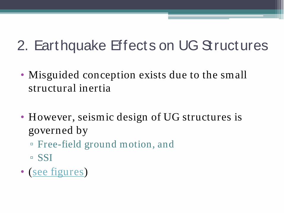
• Misguided conception exists due to the small structural inertia
• However, seismic design of UG structures is governed by ▫ Free-field ground motion, and ▫ SSI
• (see figures)

2. Earthquake Effects on UG Structures
(Kawashima 2006)
Significant inertia effect

2. Earthquake Effects on UG Structures
(Kawashima 2006)
Insignificant inertia effect
Similar frequency content
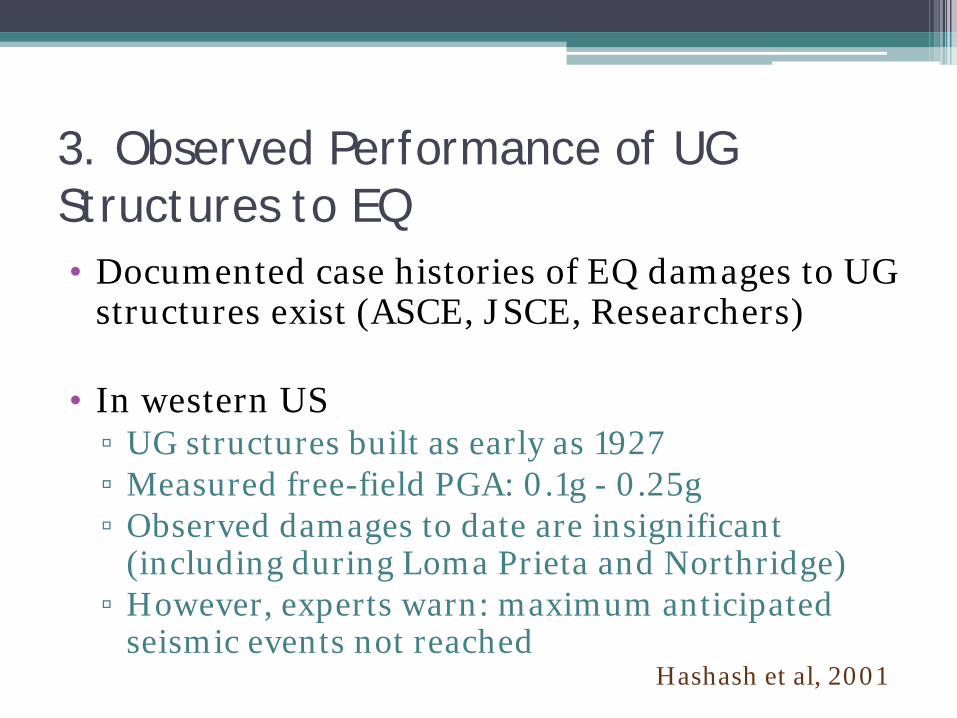
3. Observed Performance of UG Structures to EQ • Documented case histories of EQ damages to UG
structures exist (ASCE, JSCE, Researchers)
• In western US ▫ UG structures built as early as 1927 ▫ Measured free-field PGA: 0.1g - 0.25g ▫ Observed damages to date are insignificant
(including during Loma Prieta and Northridge) ▫ However, experts warn: maximum anticipated
seismic events not reached Hashash et al, 2001
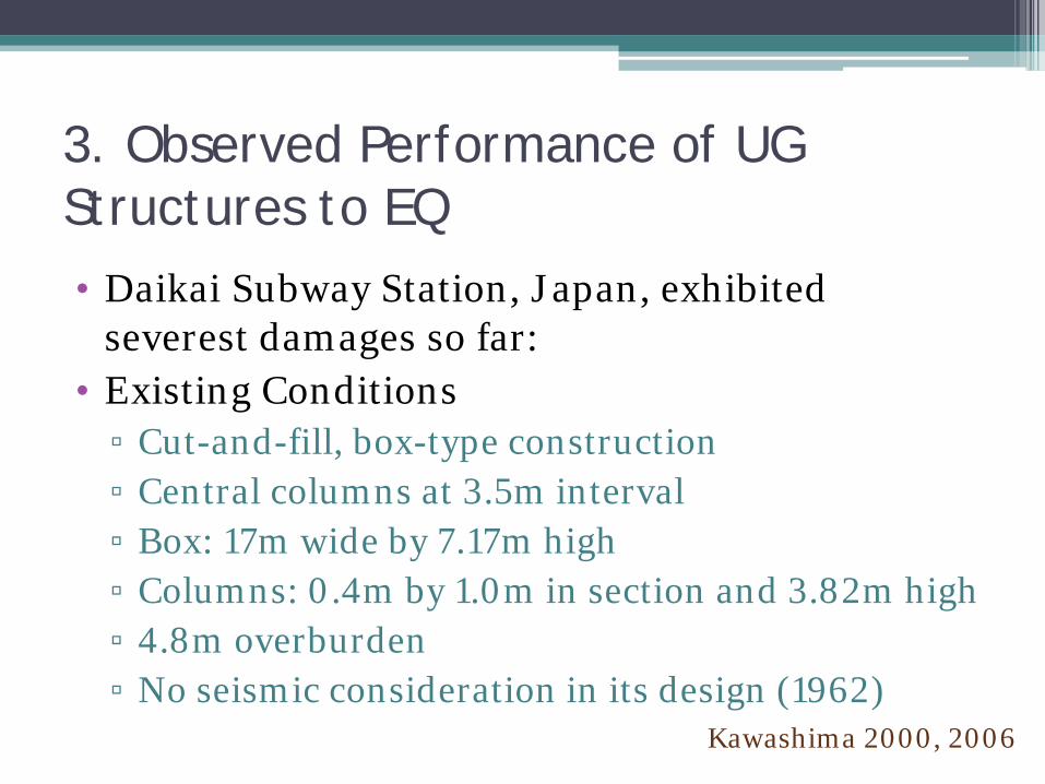
3. Observed Performance of UG Structures to EQ • Daikai Subway Station, Japan, exhibited
severest damages so far: • Existing Conditions
▫ Cut-and-fill, box-type construction ▫ Central columns at 3.5m interval ▫ Box: 17m wide by 7.17m high ▫ Columns: 0.4m by 1.0m in section and 3.82m high ▫ 4.8m overburden ▫ No seismic consideration in its design (1962)
Kawashima 2000, 2006
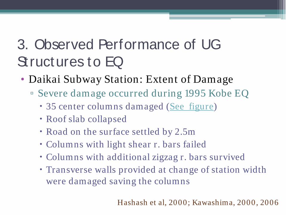
3. Observed Performance of UG Structures to EQ • Daikai Subway Station: Extent of Damage
▫ Severe damage occurred during 1995 Kobe EQ 35 center columns damaged (See figure) Roof slab collapsed Road on the surface settled by 2.5m Columns with light shear r. bars failed Columns with additional zigzag r. bars survived Transverse walls provided at change of station width
were damaged saving the columns
Hashash et al, 2000; Kawashima, 2000, 2006

3. Observed Performance of UG Structures to EQ Center column failure Mechanism of failure
Kawashima 2000, 2006
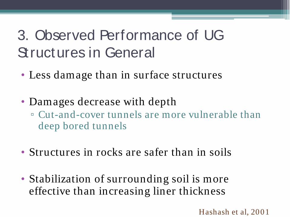
3. Observed Performance of UG Structures in General • Less damage than in surface structures
• Damages decrease with depth
▫ Cut-and-cover tunnels are more vulnerable than deep bored tunnels
• Structures in rocks are safer than in soils
• Stabilization of surrounding soil is more
effective than increasing liner thickness
Hashash et al, 2001
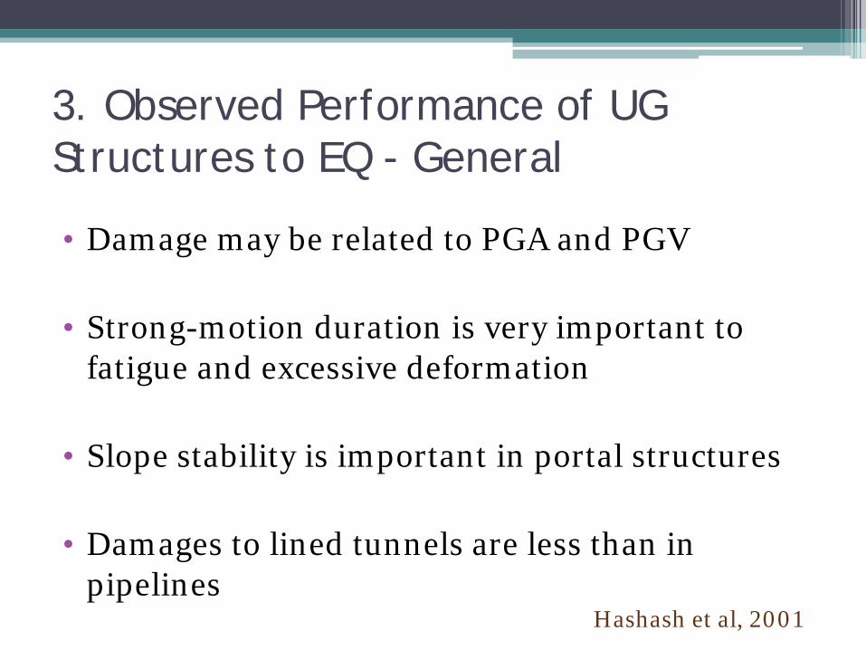
3. Observed Performance of UG Structures to EQ - General
• Damage may be related to PGA and PGV
• Strong-motion duration is very important to fatigue and excessive deformation
• Slope stability is important in portal structures
• Damages to lined tunnels are less than in pipelines
Hashash et al, 2001

4. Seismic Design Procedure
• Step 1: Defining the Seismic Environment
• Step 2: Evaluation of Ground Response to Shaking
• Step 3: Assessment of Structural Behavior

4. Seismic Design Procedure
• Step 1: Defining the Seismic Environment ▫ Conducting Seismic Hazard Analysis (SHA)
▫ Establishing Design Criteria
▫ Establishing Design Ground Motion Parameters

4. Seismic Design Load Procedure
• Step 2: Evaluation of Ground Response
• It involves evaluating ▫ Ground Shaking: the main focus here
▫ Ground Failure
4. Seismic Design Load Procedure
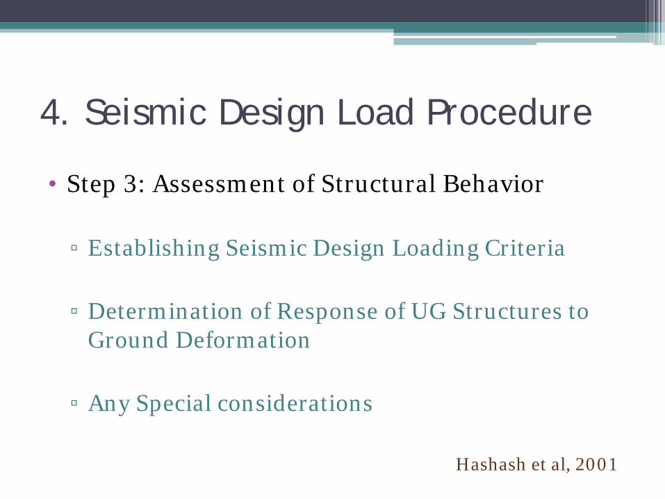
• Step 3: Assessment of Structural Behavior
▫ Establishing Seismic Design Loading Criteria
▫ Determination of Response of UG Structures to Ground Deformation
▫ Any Special considerations
Hashash et al, 2001
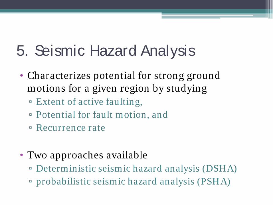
5. Seismic Hazard Analysis
• Characterizes potential for strong ground motions for a given region by studying ▫ Extent of active faulting, ▫ Potential for fault motion, and ▫ Recurrence rate
• Two approaches available ▫ Deterministic seismic hazard analysis (DSHA) ▫ probabilistic seismic hazard analysis (PSHA)
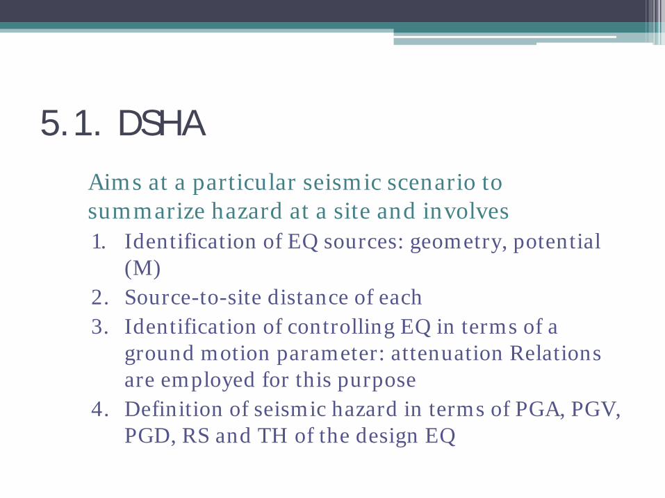
5.1. DSHA Aims at a particular seismic scenario to
summarize hazard at a site and involves 1. Identification of EQ sources: geometry, potential
(M) 2. Source-to-site distance of each 3. Identification of controlling EQ in terms of a
ground motion parameter: attenuation Relations are employed for this purpose
4. Definition of seismic hazard in terms of PGA, PGV, PGD, RS and TH of the design EQ
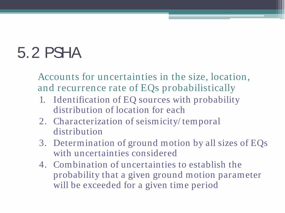
5.2 PSHA Accounts for uncertainties in the size, location,
and recurrence rate of EQs probabilistically 1. Identification of EQ sources with probability
distribution of location for each 2. Characterization of seismicity/temporal
distribution 3. Determination of ground motion by all sizes of EQs
with uncertainties considered 4. Combination of uncertainties to establish the
probability that a given ground motion parameter will be exceeded for a given time period
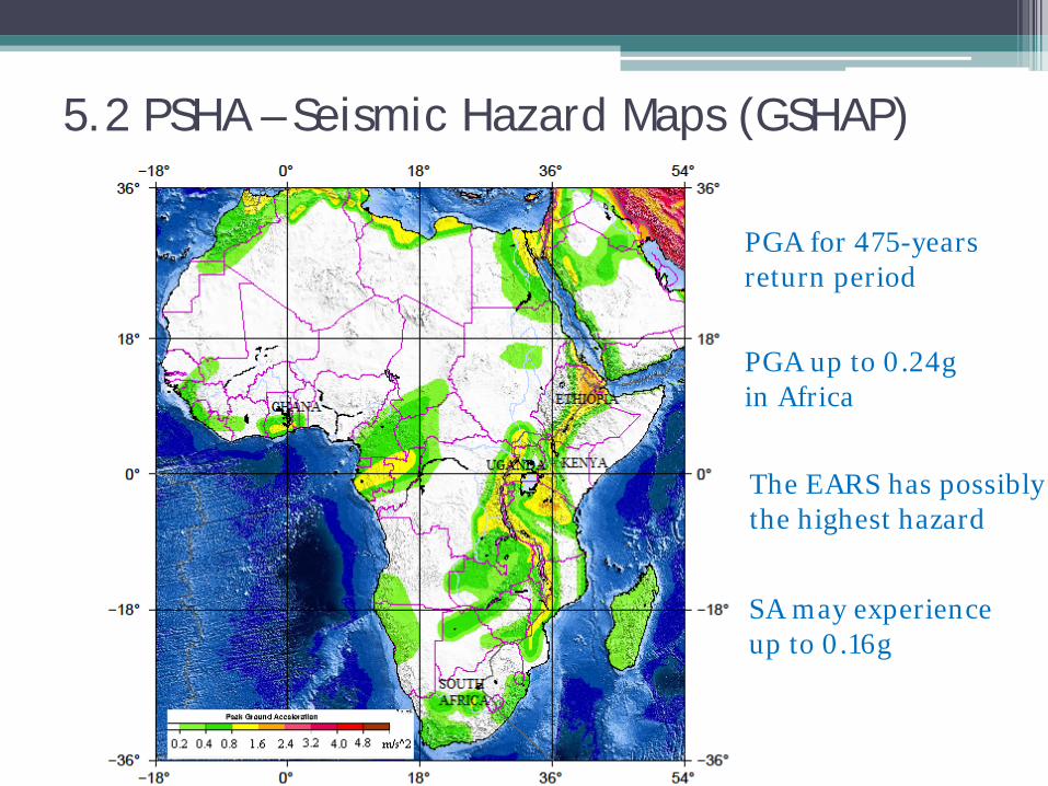
5.2 PSHA – Seismic Hazard Maps (GSHAP)
PGA up to 0.24g in Africa
The EARS has possibly the highest hazard
SA may experience up to 0.16g
PGA for 475-years return period

5.2 PSHA – Seismic Hazard Maps
PGA up to 0.24g In EARS region
Many vulnerable populous cities and towns in EARS region
Capital cities with high hazard: Asmara, Djibouti, Addis Ababa, Juba, Kampala, Bujumbura
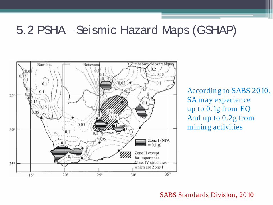
5.2 PSHA – Seismic Hazard Maps (GSHAP)
According to SABS 2010, SA may experience up to 0.1g from EQ And up to 0.2g from mining activities
SABS Standards Division, 2010
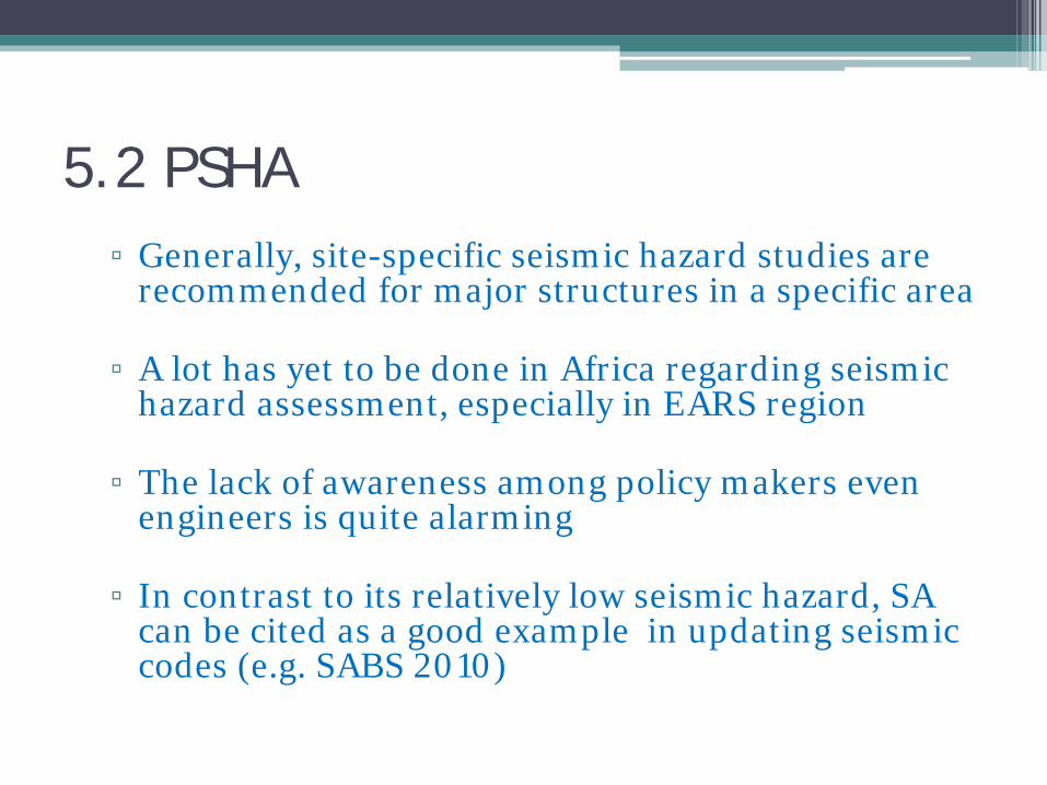
5.2 PSHA ▫ Generally, site-specific seismic hazard studies are
recommended for major structures in a specific area
▫ A lot has yet to be done in Africa regarding seismic hazard assessment, especially in EARS region
▫ The lack of awareness among policy makers even engineers is quite alarming
▫ In contrast to its relatively low seismic hazard, SA can be cited as a good example in updating seismic codes (e.g. SABS 2010)

6. Seismic Design Load Criteria
Dual Criteria: 1. MDE: aims at life safety (corresponds to ULS)
In PSHA, 3 – 5% probability of exceedance in the
life span of the facility (usually 50 years)
Worst combination of DL, LL, EQ to be considered
6. Seismic Design Load Criteria
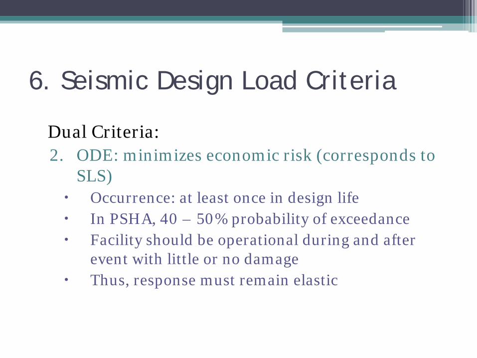
Dual Criteria: 2. ODE: minimizes economic risk (corresponds to
SLS) Occurrence: at least once in design life In PSHA, 40 – 50% probability of exceedance Facility should be operational during and after
event with little or no damage Thus, response must remain elastic

6. Seismic Design Load Criteria
Load Combinations: 1. MDE
▫ Cut-and-cover tunnels
U=DL+LL+E1+E2+EQ
▫ Bored tunnels U=DL+LL+EX+H+EQ

6. Seismic Design Load Criteria
Load Combinations: 2. ODE ▫ Cut-and-cover tunnels
U=1.05DL+1.3LL+1.05(E1+E2)+1.3EQ
▫ Bored tunnels U=1.05DL+1.3LL+1.5EX+H+1.3EQ
7. Design Ground Motion Parameters
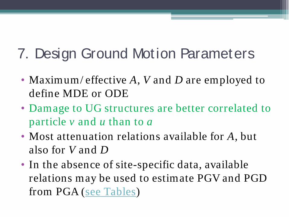
• Maximum/effective A, V and D are employed to define MDE or ODE
• Damage to UG structures are better correlated to particle v and u than to a
• Most attenuation relations available for A, but also for V and D
• In the absence of site-specific data, available relations may be used to estimate PGV and PGD from PGA (see Tables)
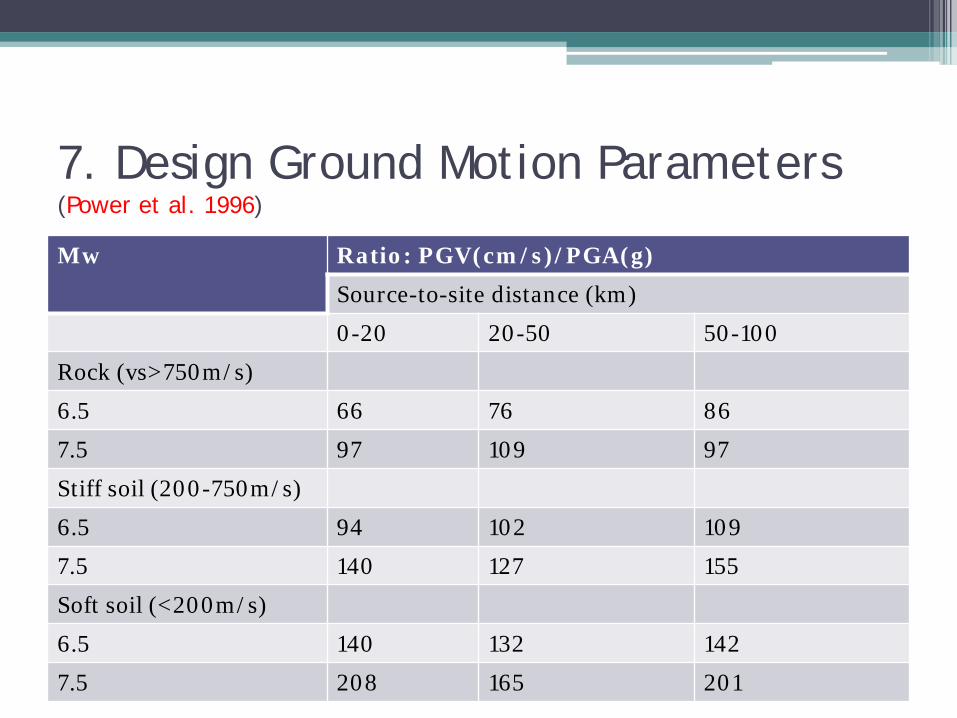
7. Design Ground Motion Parameters (Power et al. 1996)
Mw Ratio: PGV(cm/s)/PGA(g)
Source-to-site distance (km)
0-20 20-50 50-100
Rock (vs>750m/s)
6.5 66 76 86
7.5 97 109 97
Stiff soil (200-750m/s)
6.5 94 102 109
7.5 140 127 155
Soft soil (<200m/s)
6.5 140 132 142
7.5 208 165 201

7. Design Ground Motion Parameters (Power et al. 1996)
Mw Ratio: PGD(cm)/PGA(g)
Source-to-site distance (km)
0-20 20-50 50-100
Rock (vs>750m/s)
6.5 18 27 30
7.5 43 56 69
Stiff soil (200-750m/s)
6.5 35 41 48
7.5 89 99 112
Soft soil (<200m/s)
6.5 71 74 76
7.5 178 178 178
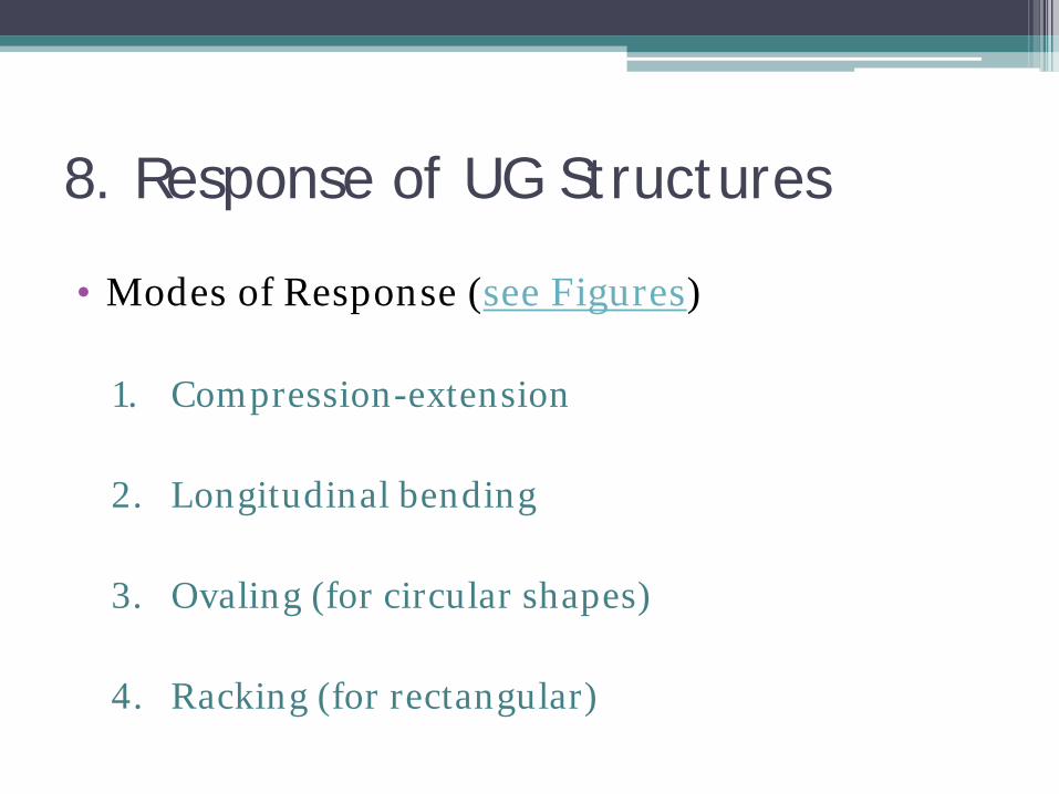
8. Response of UG Structures
• Modes of Response (see Figures)
1. Compression-extension
2. Longitudinal bending
3. Ovaling (for circular shapes)
4. Racking (for rectangular)
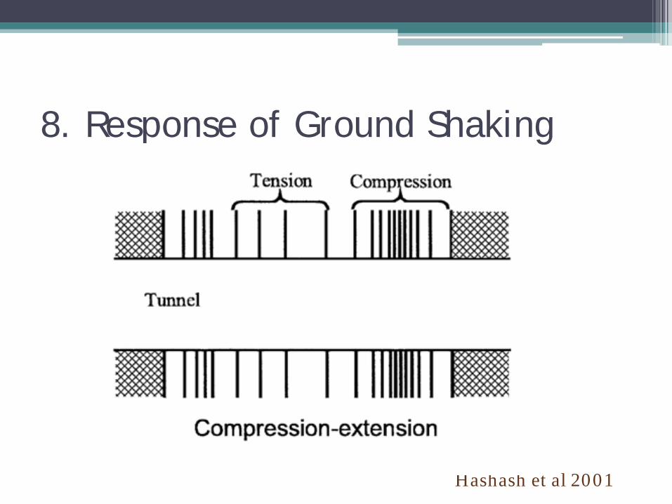
8. Response of Ground Shaking
Hashash et al 2001
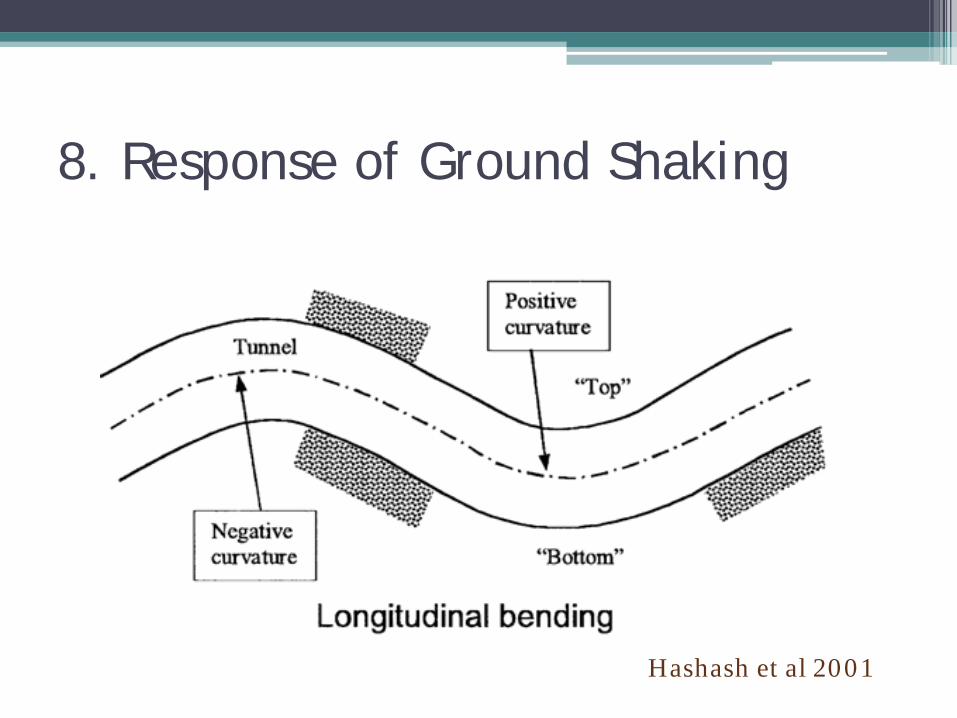
8. Response of Ground Shaking
Hashash et al 2001
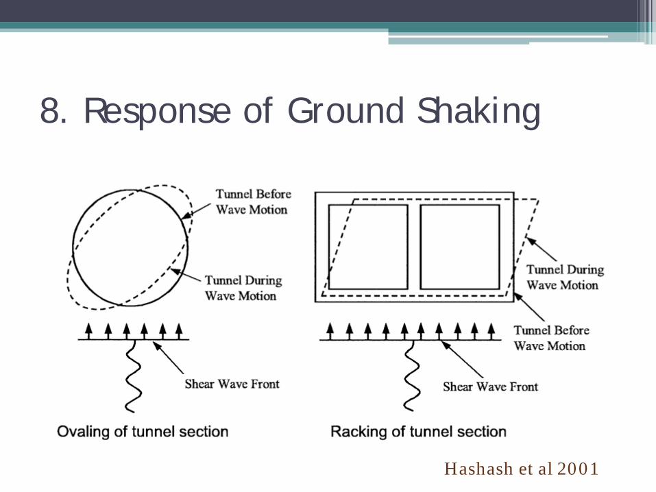
8. Response of Ground Shaking
Hashash et al 2001
8. Response of UG Structures
• MAIN Focus: Response to ground shaking • A number of approaches available
1. Free-field deformation Approach 2. SSI Approach 3. Seismic Deformation Method (for soft ground) 4. Numerical Approaches

8.1 Free-Field Deformation (FFD) Approach • FFD describes strains due to elastic plane
waves in the absence of structures • It imposes the free-field deformation on the UG
structure • Does not account for SSI • Provides first-order estimate of structural
response • Closed-form relations available • FFD is effective tool for small soil deformations
(low-seismic areas, stiff soils)

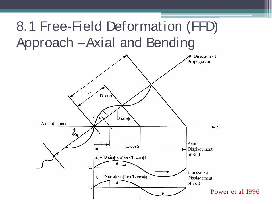
8.1 Free-Field Deformation (FFD) Approach – Axial and Bending • FFD is based on Newmark’s (1968) idealization of
elastic waves (see sketch)
• St. John and Zahrah (1987) used this to calculate axial and curvature strains analytically due to the three wave types shown schematically (see sketch)
• All solutions are available in closed form: longitudinal, normal and shear strains and curvature due to P-, S- and Rayleigh waves
8.1 Free-Field Deformation (FFD) Approach – Axial and Bending
Power et al 1996

8.1 Free-Field Deformation (FFD) Approach – Axial and Bending
Power et al 1996
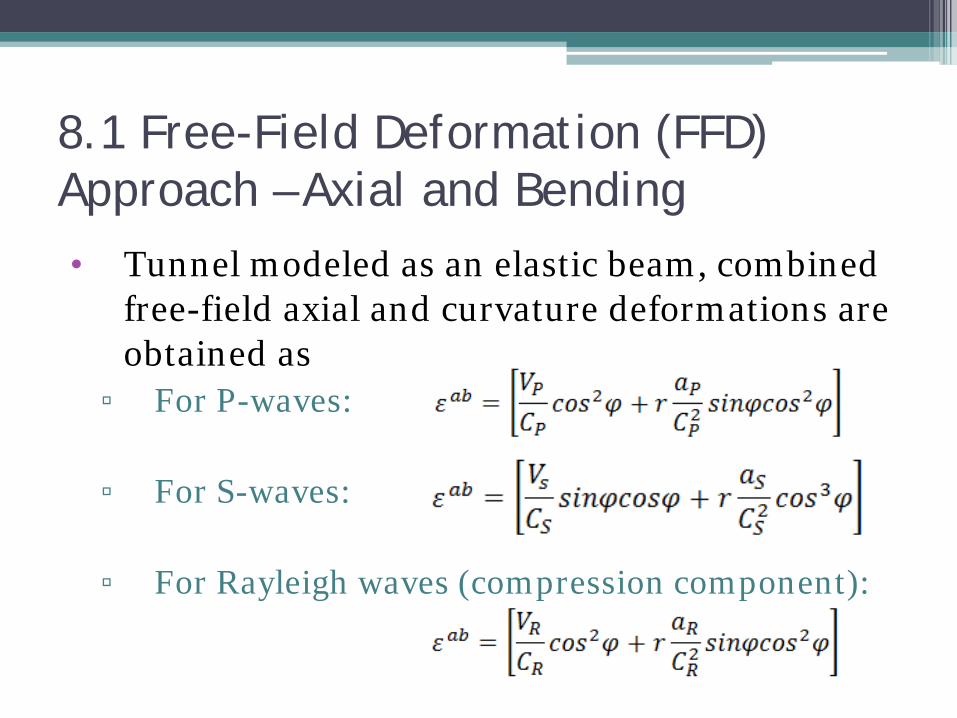
8.1 Free-Field Deformation (FFD) Approach – Axial and Bending • Tunnel modeled as an elastic beam, combined
free-field axial and curvature deformations are obtained as
▫ For P-waves:
▫ For S-waves:
▫ For Rayleigh waves (compression component):

8.1 Free-Field Deformation (FFD) Approach - Axial and Bending
• With increasing r, the curvature contribution increases
• However, this component is generally small
• Note: ▫ the apparent wave velocities, VP and VS, fall in
the range of 4-8km/s and 2-4km/s, respectively ▫ These are close to wave velocities in deep rock
than in the shallow soil
8.1 Free-Field Deformation (FFD) Approach – Ovaling Deformation
• Ovaling
▫ refers to the distortion of circular tunnels (see Figure)
▫ is caused by waves inducing transverse strains
▫ Is predominantly due to vertically propagating shear waves
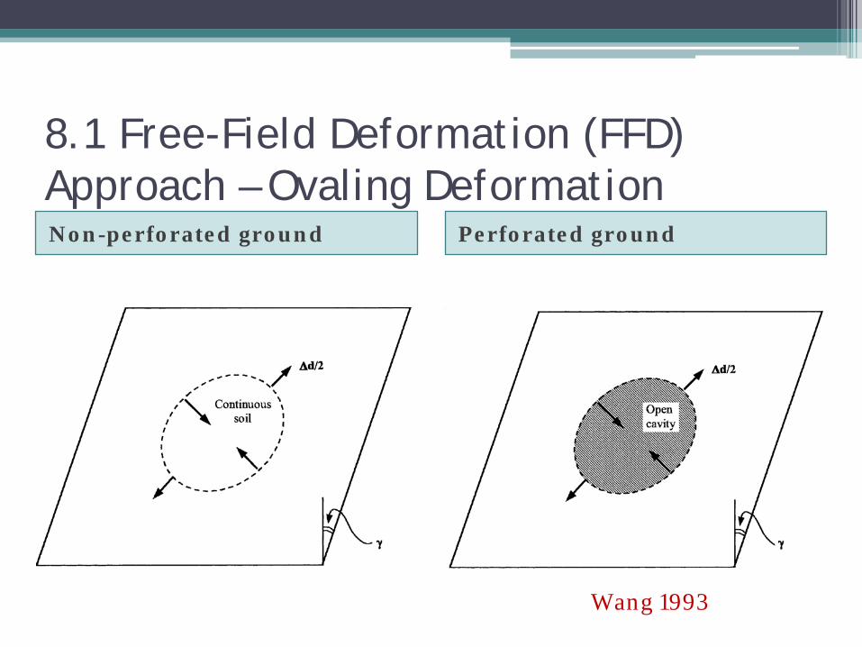
8.1 Free-Field Deformation (FFD) Approach – Ovaling Deformation Non-perforated ground Perforated ground
Wang 1993
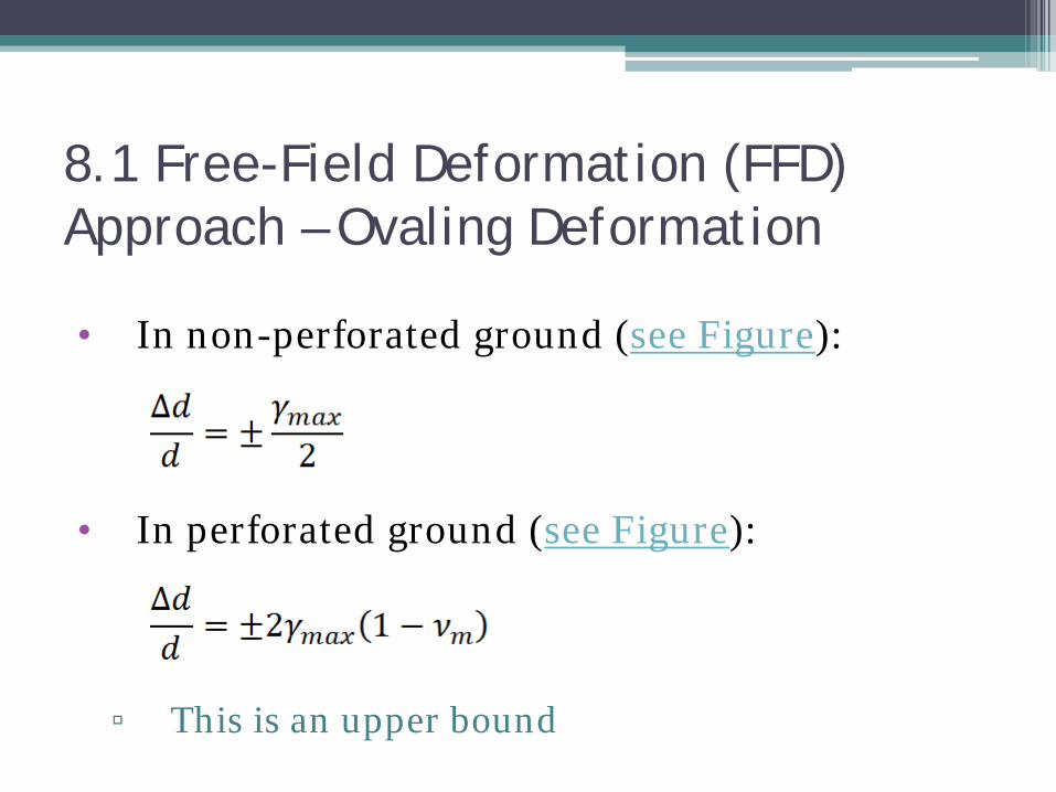
8.1 Free-Field Deformation (FFD) Approach – Ovaling Deformation
• In non-perforated ground (see Figure):
• In perforated ground (see Figure):
▫ This is an upper bound

8.1 Free-Field Deformation (FFD) Approach – Ovaling Deformation
• The perforated ground scenario
▫ gives 2 to 3 times larger distortion than the non-perforated case
▫ gives an upper bound distortion criterion
▫ Provides a good estimate for thin linings
8.1 Free-Field Deformation (FFD) Approach – Ovaling Deformation
• The non-perforated ground scenario ▫ gives better estimate for lining stiffness
comparable with the medium
• For stiffer linings, distortion can even be less than in the non-perforated case
8.1 Free-Field Deformation (FFD) Approach – Racking Deformation
• Racking
▫ refers to the distortion of rectangular tunnels (see Figure)
▫ Associated deformations can be computed from shear strains available in closed form
▫ Alternatively, numerical site response analysis can be used

8.1 Free-Field Deformation (FFD) Approach – Racking Deformation
8.2 Soil-Structure-Interaction (SSI) Approach
• Accounts for soil-structure interaction
• Tunnels are modeled as beams on elastic foundation (see Figure)
• SSI is accounted for quasi-statically through use of linear springs
• No dynamic inertia interaction is considered
• The internal forces are as shown (see Figure)
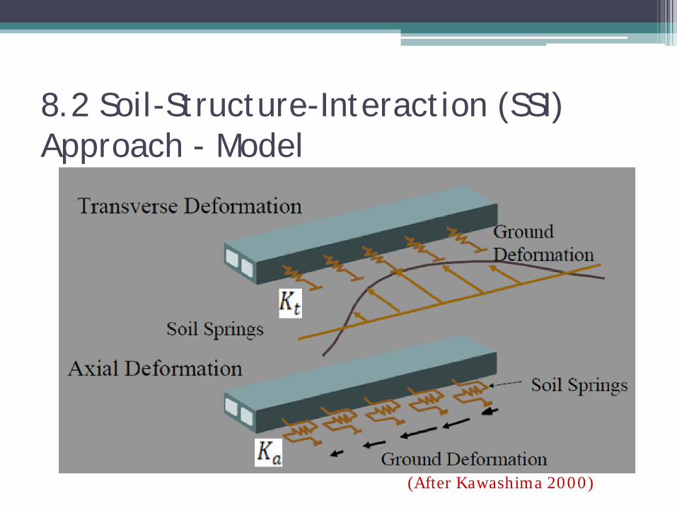
8.2 Soil-Structure-Interaction (SSI) Approach - Model
(After Kawashima 2000)

8.2 Soil-Structure-Interaction (SSI) Approach: Internal Forces Sectional forces Circumferential forces
Hashash et al . 2001

8.2 Soil-Structure-Interaction (SSI) Approach - Axial and Bending
• The maximum axial strain (due to a 45-degrees incident shear wave):
• A= free-field displacement response amplitude of idealized sinusoidal shear wave; Q= frictional force; L=Wave length; Ka= longitudinal spring stif
Hashash et al . 2001

8.2 Soil-Structure-Interaction (SSI) Approach - Axial and Bending
• The maximum bending strain due to a zero-degree incident shear wave:
• The maximum shear force:
▫ Kt= transversal spring stiffness; Ic=mom. of inertia
Hashash et al . 2001
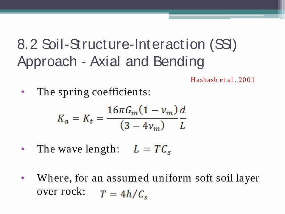
8.2 Soil-Structure-Interaction (SSI) Approach - Axial and Bending
• The spring coefficients:
• The wave length:
• Where, for an assumed uniform soft soil layer over rock:
Hashash et al . 2001
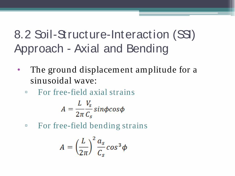
8.2 Soil-Structure-Interaction (SSI) Approach - Axial and Bending
• The ground displacement amplitude for a sinusoidal wave:
▫ For free-field axial strains
▫ For free-field bending strains
8.2 Soil-Structure-Interaction (SSI) Approach - Axial and Bending
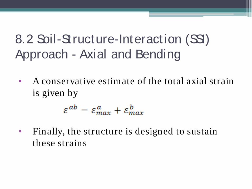
• A conservative estimate of the total axial strain is given by
• Finally, the structure is designed to sustain these strains
8.2 Soil-Structure-Interaction (SSI) Approach - Ovaling
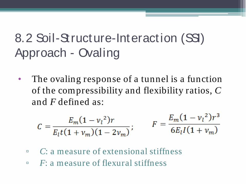
• The ovaling response of a tunnel is a function of the compressibility and flexibility ratios, C and F defined as:
▫ C: a measure of extensional stiffness ▫ F: a measure of flexural stiffness

8.2 Soil-Structure-Interaction (SSI) Approach - Ovaling
• Assuming full slip conditions (for soft soils and severe shaking):
▫ The diametric strain:
▫ Maximum thrust: ▫ (see Figure) ▫ The maximum b. moment:
Where (See Plots)
K1= Lining response coefficient
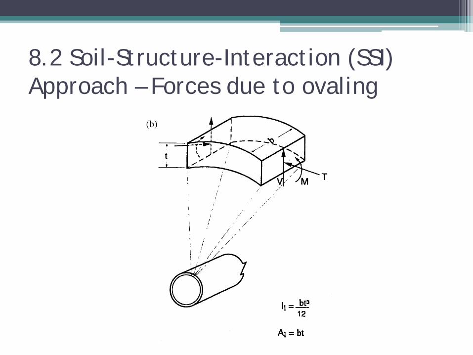
8.2 Soil-Structure-Interaction (SSI) Approach – Forces due to ovaling

8.2 Soil-Structure-Interaction (SSI) Approach – Forces due to ovaling

8.2 Soil-Structure-Interaction (SSI) Approach - Ovaling
• For most tunnels, the interface condition is between the full-slip and no-slip cases
• The full-slip case may cause significant underestimation of Tmax
8.2 Soil-Structure-Interaction (SSI) Approach - Ovaling
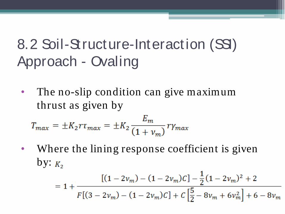
• The no-slip condition can give maximum thrust as given by
• Where the lining response coefficient is given by:
8.2 Soil-Structure-Interaction (SSI) Approach - Ovaling
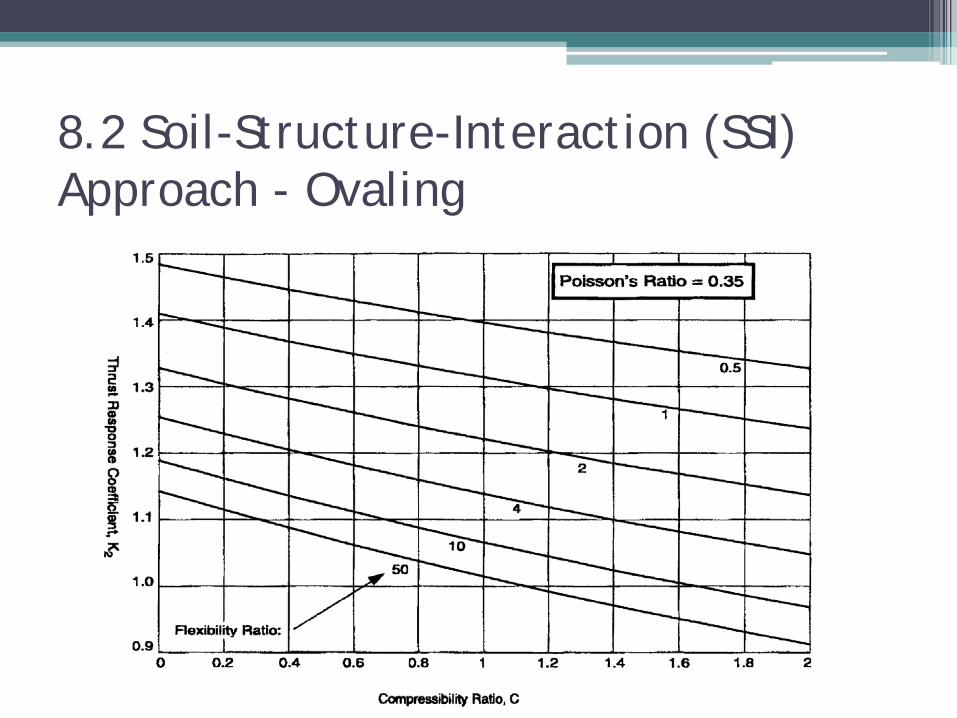
• Variation of K2, and thus of Tmax, against C and F for ν=0.35 is as plotted (see graph)
8.2 Soil-Structure-Interaction (SSI) Approach - Ovaling

8.2 Soil-Structure-Interaction (SSI) Approach - Ovaling
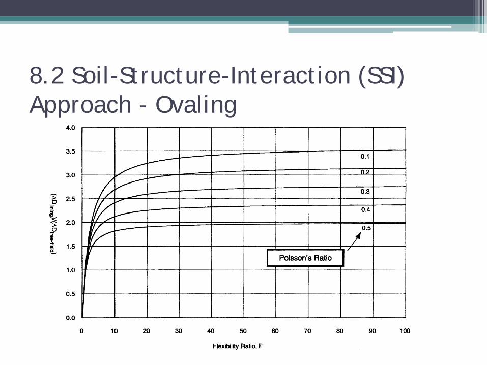
• The normalized lining deflection:
▫ (see Plots)
8.2 Soil-Structure-Interaction (SSI) Approach - Ovaling

8.2 Soil-Structure-Interaction (SSI) Approach - Ovaling
• Observations from the plots: ▫ For F<1 (stiff lining in soft soil): The lining will
deform less than the free field
▫ For F>1 (softer lining in stiffer soil): The lining deforms more than the free field
▫ For F→∞: lining deflection equals that of the perforated ground
8.2 Soil-Structure-Interaction (SSI) Approach - Racking • Box-type structures are less efficient to transmit
static loads • Thus,
▫ the walls and slabs are thicker and the structure stiffer ▫ SSI is more important than in circular tunnels
• Besides, ground deformations may be larger due to ▫ Site amplification at shallow depth ▫ Decreased soil stiffness due to lower overburden
pressure ▫ Different nature of backfill

8.2 Soil-Structure-Interaction (SSI) Approach - Racking
• The increased rigidity for statics reduces structural strains
• Hence, design based on free-field strains is too conservative
• Closed-form solutions are not available due to variable geometric characteristics
• The stiffness of the soil in simple shear relative to the structure is the most important factor
(Wang 1993)

8.2 Soil-Structure-Interaction (SSI) Approach - Racking
• It can be easily shown that the soil-to-structure flexibility ratio is given by (see Figure) ▫ Where W is the width and S1 is the unit racking
stiffness of the structure given by (see Figure)
(Hashash et al 2001)

8.2 Soil-Structure-Interaction (SSI) Approach - Racking
(Hashash et al 2001)

8.2 Soil-Structure-Interaction (SSI) Approach - Racking • For simple structures the racking stiffness can be
determined from ordinary frame analysis
• Thus, F for a one-barrel frame with moments of inertia, IR=IS and IW, for the slabs and walls is
• F can similarly be obtained for other common forms
8.2 Soil-Structure-Interaction (SSI) Approach - Racking
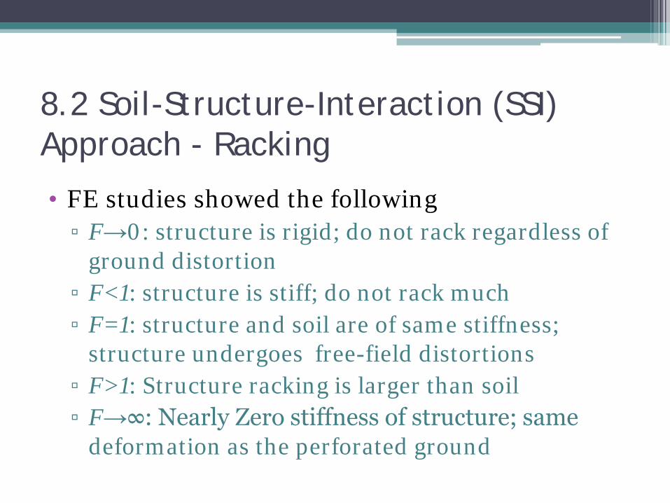
• FE studies showed the following ▫ F→0: structure is rigid; do not rack regardless of
ground distortion ▫ F<1: structure is stiff; do not rack much ▫ F=1: structure and soil are of same stiffness;
structure undergoes free-field distortions ▫ F>1: Structure racking is larger than soil ▫ F→∞: Nearly Zero stiffness of structure; same
deformation as the perforated ground
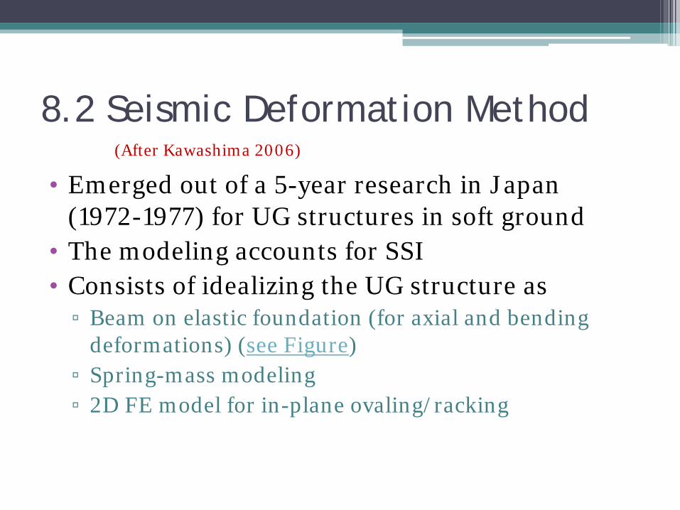
8.2 Seismic Deformation Method
• Emerged out of a 5-year research in Japan (1972-1977) for UG structures in soft ground
• The modeling accounts for SSI • Consists of idealizing the UG structure as
▫ Beam on elastic foundation (for axial and bending deformations) (see Figure)
▫ Spring-mass modeling ▫ 2D FE model for in-plane ovaling/racking
(After Kawashima 2006)
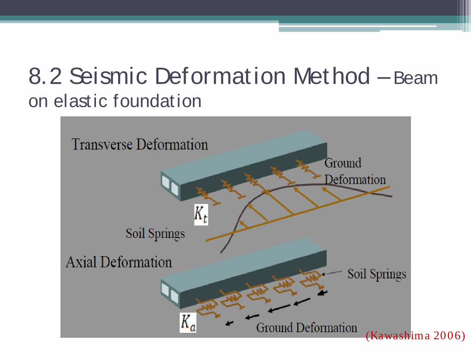
8.2 Seismic Deformation Method – Beam on elastic foundation
(Kawashima 2006)
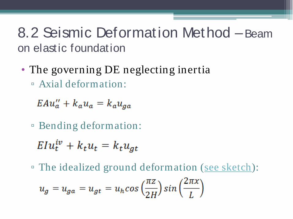
8.2 Seismic Deformation Method – Beam on elastic foundation
• The governing DE neglecting inertia ▫ Axial deformation:
▫ Bending deformation:
▫ The idealized ground deformation (see sketch):

8.2 Seismic Deformation Method – Beam on elastic foundation
(Kawashima 2006)
8.2 Seismic Deformation Method – Beam on elastic foundation
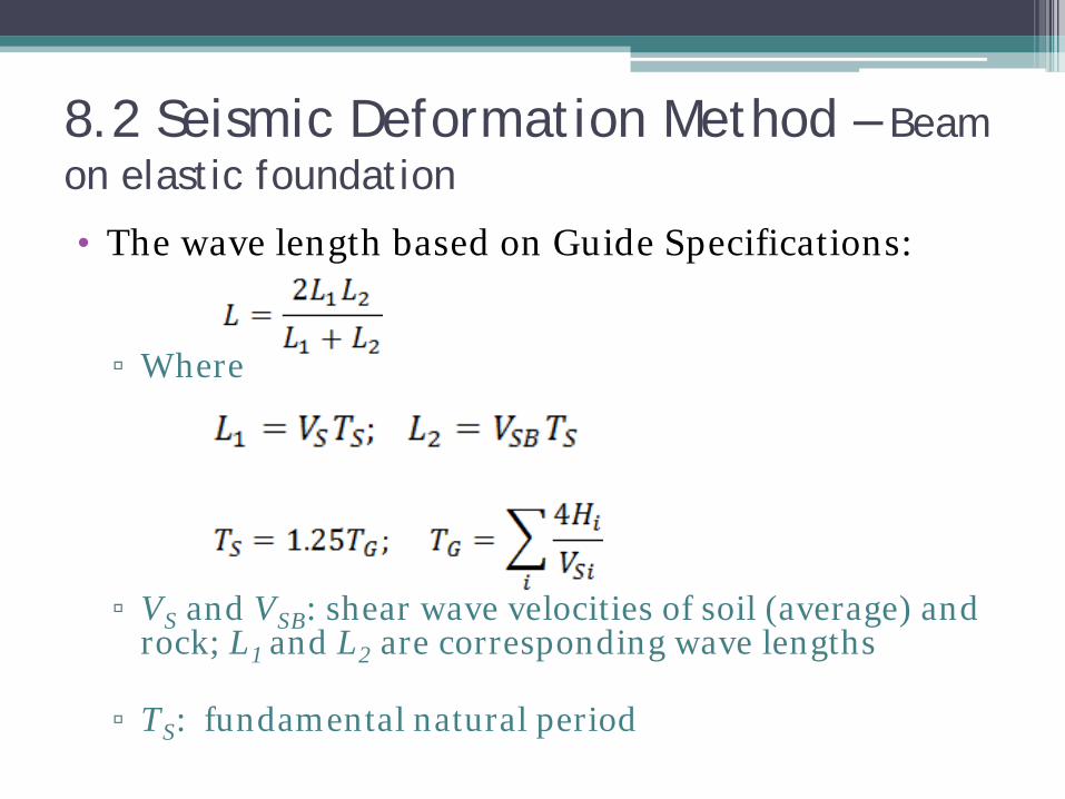
• The wave length based on Guide Specifications: ▫ Where
▫ VS and VSB: shear wave velocities of soil (average) and
rock; L1 and L2 are corresponding wave lengths
▫ TS: fundamental natural period

8.2 Seismic Deformation Method – Beam on elastic foundation
• The ground surface displacement amplitude: ▫ SV: design velocity response spectrum at bedrock
level • The surface strains are determined by
differentiating the surface deformation, the amplitudes being
8.2 Seismic Deformation Method – Beam on elastic foundation
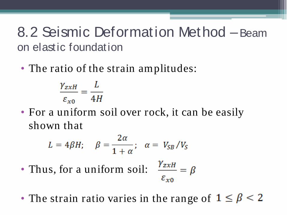
• The ratio of the strain amplitudes:
• For a uniform soil over rock, it can be easily shown that
• Thus, for a uniform soil:
• The strain ratio varies in the range of
8.2 Seismic Deformation Method – Beam on elastic foundation
• The deformation of the structure is determined by solving the DEs
• The internal forces for design easily follow from the constitutive laws

8.2 Seismic Deformation Method – Spring-mass system
(Kawashima 2006)
• Soil mass is included
• 3D analysis is possible
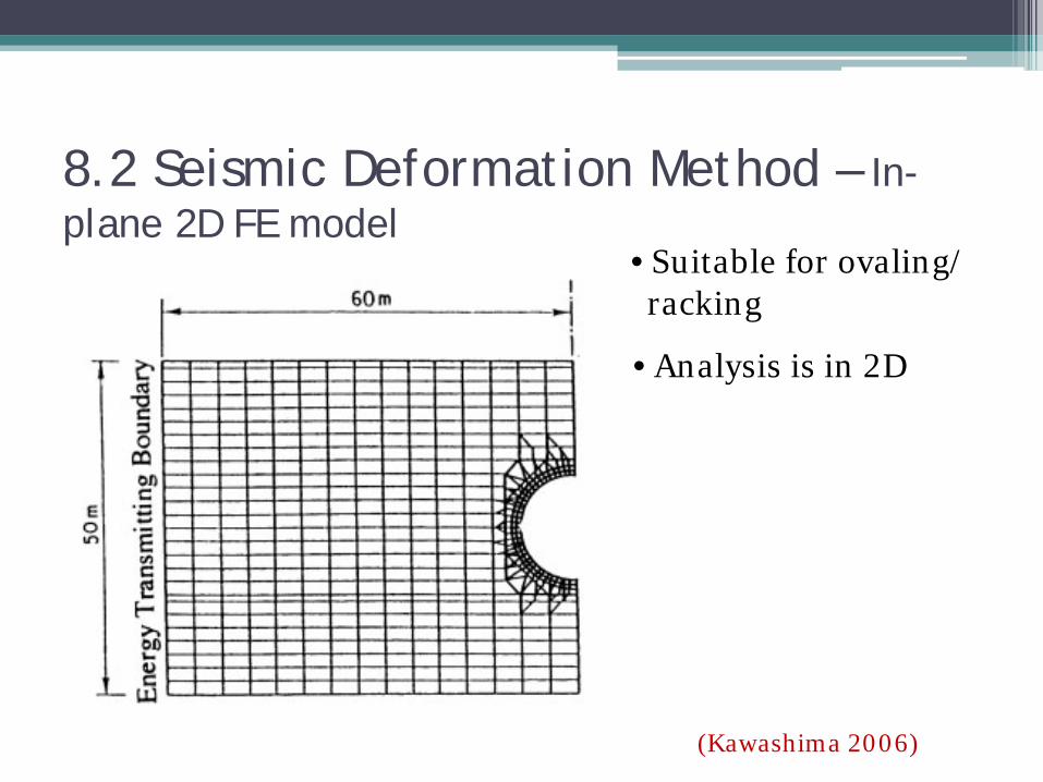
8.2 Seismic Deformation Method – In-plane 2D FE model
(Kawashima 2006)
• Suitable for ovaling/ racking
• Analysis is in 2D
9. Large Ground Deformations • Large ground deformations during EQ are
associated with ▫ Liquefaction ▫ Fault displacement ▫ Slope Instability
• Since UG structures are commonly long, ▫ They may generally cross soil formations susceptible
to liquefaction ▫ Crossing active faults may not be avoidable ▫ Certain structures like portals ca be susceptible to
slope instability • Hence, considerations for these issues are equally
important as for the ground shaking

10. Conclusions • Knowledge is not as well established as in on-
ground structures
• Measured data and studies are fewer
• A few state-of-the-art reviews are available
• Seismic loadings on UG structures are not as insignificant as commonly perceived
• FFD and SSI are very important considerations
• In contrast, structure inertia plays a minor role

10. Conclusions
• The FFD Approach is sufficient for anticipated small ground deformations (case in point: Africa?)
• The SSI approach and SDM are also easy to use
• For the continent: ▫ FFD, SSI and SDM approaches are recommendable ▫ Complicated numerical modeling do not appear to be
necessary, at least currently
10. Conclusions
• Considerations for large ground deformations are equally important
• Adaptation of design guides is not difficult and is recommendable
• Regular follow-up of the global state-of-the-art is helpful for improvement

Thank You