Energy and Exergy Analyses of a Zero Emission Power Plant for Coproduction of Electricity and...
12
Energy and Exergy Analyses of a Zero Emission Power Plant for Coproduction of Electricity and Methanol 13 Canan Acar and Ibrahim Dincer Abstract In this study, we study and evaluate a zero emission integrated system, as taken from the literature, for coproduction of electricity and methanol. The investigated integrated system has three subsystems: water electrolysis, Matiant power plant (oxy-fuel combustion of pure methane), and methanol production unit. The system and its components are analyzed energetically and exergetically. The rates of exergy destructions, relative irreversibilities, and sustainability indexes of each subunit of each subsystem, as well as the overall system are analyzed to identify the greatest exergy losses and possible future research directions. The total rate of exergy destruction of the overall system is calculated to be around 280 MW. The greatest rate of exergy destruction, therefore the greatest irreversibility, occurs within the power plant unit (about 60 % of the total rate of exergy destruction). The energy efficiencies of electrolysis, power plant, and methanol synthesis unit are found to be 30 %, 76 %, and 41 %, respectively. The exergy efficiencies of electrolysis, power plant, and methanol synthesis unit are found to be 30 %, 64 %, and 41 %, respectively. Depending on the utilization of the heat rejected from the different units of each subsystem, the overall system could have energy and exergy efficiencies up to 68 % and 47 %, respectively. Keywords Methanol Carbon capture Cogeneration Electricity Energy Exergy Efficiency Introduction During the twentieth and the beginning of the twenty-first century, world’s energy consumption has increased steadily due to global rise in population and standards of living. The increasing trend in world’s energy need is expected to continue in the future. As a result, a growth in energy generation capacity will be needed [1]. One of the main sources of CO 2 emissions is power generation [2]. Therefore, reduction of fossil fuel utilization by increasing efficiency and decreasing emissions by converting CO 2 into valuable products offer some potential solutions to world’s current energy-related problems. There have been several studies focusing on coproduction of fossil fuels with CO 2 utilization. A comparative study of electricity and hydrogen production systems by CO 2 capture and storage has been presented by Damen et al. [3]. Minutillo and Perna [4] studied a tri-reforming process in fossil fired power plants to generate a synthesis gas for production of chemicals including methanol. Energy analysis, economy, and policy scenarios of electricity/methanol synthesis coproduction systems’ are taken into account in Guang-jian et al. and Chen et al.’s[5, 6] work. Katayama and Tamaura [7] and Takeuchi et al. [8] C. Acar (*) I. Dincer Faculty of Engineering and Applied Science, University of Ontario Institute of Technology, 2000 Simcoe Street North, Oshawa, ON, Canada L1H 7K4 e-mail: [email protected]; [email protected] I. Dincer et al. (eds.), Progress in Exergy, Energy, and the Environment, DOI 10.1007/978-3-319-04681-5_13, # Springer International Publishing Switzerland 2014 145
Transcript of Energy and Exergy Analyses of a Zero Emission Power Plant for Coproduction of Electricity and...
Energy and Exergy Analyses of a Zero Emission PowerPlant for Coproduction of Electricity and Methanol 13Canan Acar and Ibrahim Dincer
Abstract
In this study, we study and evaluate a zero emission integrated system, as taken from the literature, for coproduction of
electricity and methanol. The investigated integrated system has three subsystems: water electrolysis, Matiant power
plant (oxy-fuel combustion of pure methane), and methanol production unit. The system and its components are analyzed
energetically and exergetically. The rates of exergy destructions, relative irreversibilities, and sustainability indexes of
each subunit of each subsystem, as well as the overall system are analyzed to identify the greatest exergy losses and
possible future research directions. The total rate of exergy destruction of the overall system is calculated to be around
280 MW. The greatest rate of exergy destruction, therefore the greatest irreversibility, occurs within the power plant unit
(about 60 % of the total rate of exergy destruction). The energy efficiencies of electrolysis, power plant, and methanol
synthesis unit are found to be 30 %, 76 %, and 41 %, respectively. The exergy efficiencies of electrolysis, power plant,
and methanol synthesis unit are found to be 30 %, 64 %, and 41 %, respectively. Depending on the utilization of the heat
rejected from the different units of each subsystem, the overall system could have energy and exergy efficiencies up to
68 % and 47 %, respectively.
Keywords
Methanol � Carbon capture � Cogeneration � Electricity � Energy � Exergy � Efficiency
Introduction
During the twentieth and the beginning of the twenty-first century, world’s energy consumption has increased steadily due to
global rise in population and standards of living. The increasing trend in world’s energy need is expected to continue in the
future. As a result, a growth in energy generation capacity will be needed [1]. One of the main sources of CO2 emissions is
power generation [2]. Therefore, reduction of fossil fuel utilization by increasing efficiency and decreasing emissions by
converting CO2 into valuable products offer some potential solutions to world’s current energy-related problems.
There have been several studies focusing on coproduction of fossil fuels with CO2 utilization. A comparative study of
electricity and hydrogen production systems by CO2 capture and storage has been presented by Damen et al. [3]. Minutillo and
Perna [4] studied a tri-reforming process in fossil fired power plants to generate a synthesis gas for production of chemicals
including methanol. Energy analysis, economy, and policy scenarios of electricity/methanol synthesis coproduction systems’
are taken into account in Guang-jian et al. and Chen et al.’s [5, 6] work. Katayama and Tamaura [7] and Takeuchi et al. [8]
C. Acar (*) � I. DincerFaculty of Engineering and Applied Science, University of Ontario Institute of Technology,
2000 Simcoe Street North, Oshawa, ON, Canada L1H 7K4
e-mail: [email protected]; [email protected]
I. Dincer et al. (eds.), Progress in Exergy, Energy, and the Environment,DOI 10.1007/978-3-319-04681-5_13, # Springer International Publishing Switzerland 2014
145
considered methanol synthesis via CO2 recovery and renewable hydrogen from water electrolysis unit by renewable energy
sources as a zero emission integrated system. Mignard et al. [9] proposed an integrated system for coproduction of electricity
and methanol in small scale/partial carbon capture in common fossil fuel power plants. The utilization of renewable hydrogen
for methanol production is investigated by Cifre and Badr [10].
This chapter aims to study and evaluate a zero emission integrated system for coproduction of electricity and methanol
as originally proposed and studied by Soltanieh et al. [11]. The characteristics and performance of electricity–methanol
cogeneration system with water electrolysis, Matiant power cycle, and methanol synthesis unit are energetically and
exergetically evaluated. Energy, exergy, and sustainability analyses of every component of the system as well as the overall
system are performed. The performance of the system is assessed for various environmental parameters such as relative
irreversibility and sustainability index. In the end, recommendations for better performance in terms of environmental and
sustainability issues are provided.
System Description
Overall System
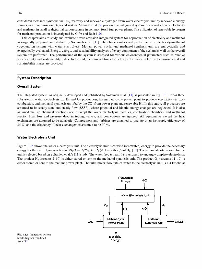
The integrated system, as originally developed and published by Soltanieh et al. [11], is presented in Fig. 13.1. It has three
subsystems: water electrolysis for H2 and O2 production, the matiant-cycle power plant to produce electricity via oxy-
combustion, and methanol synthesis unit fed by the CO2 from power plant and renewable H2. In this study, all processes are
assumed to be steady state and steady flow (SSSF), where potential and kinetic energy changes are neglected. It is also
assumed that no chemical reactions occur except the water electrolysis modules, combustion chambers, and methanol
reactor. Heat loss and pressure drop in tubing, valves, and connections are ignored. All equipments except the heat
exchangers are assumed to be adiabatic. Compressors and turbines are assumed to operate at an isentropic efficiency of
85 %, and the efficiency of heat exchangers is assumed to be 90 %.
Water Electrolysis Unit
Figure 13.2 shows the water electrolysis unit. The electrolysis unit uses wind (renewable) energy to provide the necessary
energy for the electrolysis reaction is 3H2O ! 3/2O2 + 3H2 (ΔH ¼ 286 kJ/mol H2) [12]. The technical criteria used for the
unit is selected based on Soltanieh et al.’s [11] study. The water feed (stream 1) is assumed to undergo complete electrolysis.
The product H2 (streams 2–10) is either stored or sent to the methanol synthesis unit. The product O2 (streams 11–19) is
either stored or sent to the matiant power plant. The inlet molar flow rate of water to the electrolysis unit is 1.4 kmol/s at
Fig. 13.1 Integrated system
block diagram (modified
from [11])
146 C. Acar and I. Dincer

80 �C and 1 bar. 0.75 kmol/s of this amount comes from the power plant and methanol synthesis units while 0.65 kmol/s is
the fresh feed. H2 and O2 are desired to be stored at 140 �C and 10 bar. O2 is sent to the power plant at 160 �C and 40 bar.
Then, H2 is sent to the methanol synthesis at 180 �C and 50 bar.
Matiant-Cycle Power Plant
The Matiant-cycle power plant is presented in Fig. 13.3. In this subsystem, the fuel (pure methane) is burned with pure oxygen
from the electrolysis unit and undergoes complete combustion. The combustion reaction is CH4 + 2O2 ! CO2 + 2H2O
(ΔH ¼ �800 kJ/mol CH4) [12]. The technical criteria used for the plant is selected based on Soltanieh et al.’s [11] study. The
products of two combustion chambers (CO2 and H2O) are separated; the H2O is sent back to the electrolysis unit, and about
92 % of the CO2 is used as a thermodynamic fluid within the Matiant cycle while the remaining part is sent to the methanol
synthesis unit. 70 % of the O2 from the electrolysis unit is sent to the combustion chamber H, and the remaining is sent to the
combustion chamber K. The CH4 inlet temperature and pressure are 30 �C and 2 bar, respectively. The output temperature and
pressure of water from the flash drum are 80 �C and 2 bar. CO2 is sent to the methanol synthesis unit at 180 �C and 50 bar.
Methanol Synthesis Unit
Figure 13.4 presents the methanol synthesis unit. The methanol reactor converts CO2 to CH3OH according to the following
reaction: CO2 + 3H2 ! CH3OH + H2O (ΔH ¼ �49.51 kJ/mol CH3OH). The technical criteria used for the unit are
selected based on Soltanieh et al.’s [11] study. 0.25 kmol/s CO2 is fed to the unit from the power plant. The CO2 to
CH3OH conversion ratio in the methanol reactor is 20 %. Methanol and water are leaving the distillation column at 1 bar and
40 �C and 80 �C, respectively.
Storage Compressor
8
3 4 5
67
1615
14
1312
1718 19
2
1
11
9 10Heat Exchanger
HydrogenStorageTank
OxygenStorageTank
Heat Exchanger
Storage Compressor
Oxygen
Electrolysis Modules
Water
Hydrogen
O2 Compressors
H2 to Methanol Reactor
O2 to The Matiant Cycle
H2 Compressors
Fig. 13.2 Process flow diagram of the water electrolysis unit (modified from [11])
13 Energy and Exergy Analyses of a Zero Emission Power Plant for Coproduction of Electricity and Methanol 147

Compressor
CH4
11
12
10
CombustionChamber K
CombustionChamber H
Expander G
Expander LExpander I
Compressor14
8
4
5
76
O2
CH4
Pre Heater
Compressor Stage
19
20
PumpFlashDrum
18CO2
CO2
117
16
15
2
3
13
Water
HeatExchanger
Synthesis UnitCO2 to
O2
9
Fig. 13.3 Process flow diagram of the matiant-cycle power plant (modified from [11])
Compressor
14
5
1 2
4
3FlashDrum
MethanolReactor
ReactorOutput
ReactorFeed
Valve
7
6
8
9
10 11
12 13 Water
DistillationTower
Methanol
Fig. 13.4 Process flow diagram of the methanol synthesis unit (modified from [11])
148 C. Acar and I. Dincer
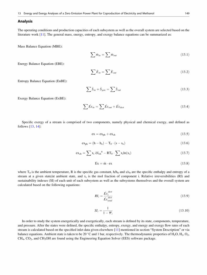
Analysis
The operating conditions and production capacities of each subsystem as well as the overall system are selected based on the
literature work [11]. The general mass, energy, entropy, and exergy balance equations can be summarized as:
Mass Balance Equation (MBE):
X_min ¼
X_mout ð13:1Þ
Energy Balance Equation (EBE):
X_Ein ¼
X_Eout ð13:2Þ
Entropy Balance Equation (EnBE):
X_Sin þ _Sgen ¼
X_Sout ð13:3Þ
Exergy Balance Equation (ExBE):
X_Exin ¼
X_Exout þ _Exdest ð13:4Þ
Specific exergy of a stream is comprised of two components, namely physical and chemical exergy, and defined as
follows [13, 14]:
ex ¼ exph þ exch ð13:5Þ
exph ¼ h� hoð Þ � T0 � s� soð Þ ð13:6Þ
exch ¼X
xi exch0 � RT0 �
Xxiln xið Þ ð13:7Þ
Ex: ¼ _m � ex ð13:8Þ
where T0 is the ambient temperature, R is the specific gas constant, h/h0 and s/s0 are the specific enthalpy and entropy of a
stream at a given state/at ambient state, and xi is the mol fraction of component i. Relative irreversibilities (RI) and
sustainability indexes (SI) of each unit of each subsystem as well as the subsystems themselves and the overall system are
calculated based on the following equations:
RIi ¼_Ex
dest
i
_Exdest
total
ð13:9Þ
SIi ¼ 1
1� Ψ ið13:10Þ
In order to study the system energetically and exergetically, each stream is defined by its state, components, temperature,
and pressure. After the states were defined, the specific enthalpy, entropy, exergy, and energy and exergy flow rates of each
stream is calculated based on the specified inlet data given elsewhere [11] mentioned in section “System Description” or via
balance equations. Ambient state is taken to be 20 �C and 1 bar, respectively. The thermodynamic properties of H2O, H2, O2,
CH4, CO2, and CH3OH are found using the Engineering Equation Solver (EES) software package.
13 Energy and Exergy Analyses of a Zero Emission Power Plant for Coproduction of Electricity and Methanol 149
Results and Discussion
Water Electrolysis Unit
Overall, the electrolysis unit needs 1.4 kmol/s of water (in total 0.75 kmol/s of this water comes from the matiant power
cycle and methanol production units). After the complete electrolysis, 0.75 kmol/s of H2 is sent to the methanol production
unit while 0.65 kmol/s of H2 is sent to the storage tank. Similarly, 0.35 kmol/s of O2 is sent to the matiant power cycle unit
while 0.35 kmol/s of O2 is sent to the storage tank.
Table 13.1 summarizes the energy and exergy efficiencies as well as the energy input/output (either work or heat) of
electrolysis modules and compressors and heat exchangers and the overall subsystem itself. The empty cells can be assumed
to be 0 or “not applicable.”
The electrolysis unit’s total work input is around 46 MW; this amount is required to drive the electrolysis reaction and
compress the products H2/O2. Heat exchangers’ load indicates the total amount of cooling required following the compres-
sion processes. The system has an energy and exergy efficiency of 30 %. The overall sustainability index of the water
electrolysis subsystem is 1.43. These energy and exergy efficiencies are calculated by the following equations:
η ¼_EO2
þ _EH2
_Ewater þ _Welectrolysis þ _Wcompressors
ð13:11Þ
Ψ ¼_ExO2
þ _ExH2
_Exwater þ _Welectrolysis þ _Wcompressors
ð13:12Þ
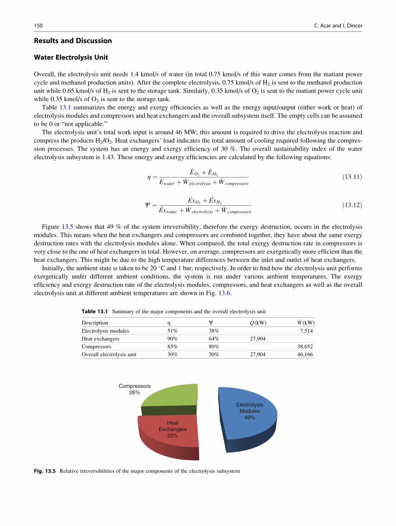
Figure 13.5 shows that 49 % of the system irreversibility, therefore the exergy destruction, occurs in the electrolysis
modules. This means when the heat exchangers and compressors are combined together, they have about the same exergy
destruction rates with the electrolysis modules alone. When compared, the total exergy destruction rate in compressors is
very close to the one of heat exchangers in total. However, on average, compressors are exergetically more efficient than the
heat exchangers. This might be due to the high temperature differences between the inlet and outlet of heat exchangers.
Initially, the ambient state is taken to be 20 �C and 1 bar, respectively. In order to find how the electrolysis unit performs
exergetically under different ambient conditions, the system is run under various ambient temperatures. The exergy
efficiency and exergy destruction rate of the electrolysis modules, compressors, and heat exchangers as well as the overall
electrolysis unit at different ambient temperatures are shown in Fig. 13.6.
Table 13.1 Summary of the major components and the overall electrolysis unit
Description η Ψ _Q(kW) _W (kW)
Electrolysis modules 51% 38% 7,514
Heat exchangers 90% 64% 27,904
Compressors 85% 80% 38,652
Overall electrolysis unit 30% 30% 27,904 46,166
Compressors26%
HeatExchangers
25%
ElectrolysisModules
49%
Fig. 13.5 Relative irreversibilities of the major components of the electrolysis subsystem
150 C. Acar and I. Dincer

Figure 13.6 shows that, with increasing ambient temperature, a slight increase is observed in the exergy destruction rate of
heat exchangers and compressors. This increase is less than 6 % when the ambient temperature is increased from 2 to 28 �C.However, there is a slight decrease in the exergy destruction rate of electrolysis modules. This decrease is less than 2 % when
the ambient temperature is increased from 2 to 28 �C. The overall system’s exergy destruction rate increases with increasing
ambient temperature. This increase is less than 2 % as the ambient temperature is increased from 2 to 28 �C.Furthermore, it can be seen from Fig. 13.6 that an increase in the ambient temperature has a negligible effect on the
exergy efficiencies of the electrolysis modules and the compressors (1 % change as the ambient temperature increased from
2 to 28 �C). However, the exergy efficiency of the heat exchangers decreases with increasing ambient temperature (3 %
decrease as the ambient temperature increased from 2 to 28 �C), and the exergy efficiency of the overall electrolysis unit
increases with increasing ambient temperature (2 % increase as the ambient temperature increased from 2 to 28 �C). Takingthe small percentage of the change of rate of exergy destructions and the exergy efficiencies, it can be concluded that the
ambient temperature doesn’t have a dramatic effect on exergetic performance of the system within the studied temperature
interval.
Matiant-Cycle Power Plant
In power plant, 0.5 kmol/s of the O2 from the electrolysis unit is used for complete combustion of 0.25 kmol/s of natural gas
(pure methane). As a result, 0.50 kmol/s of H2O is produced and sent back to the electrolysis unit. About 0.25 kmol/s of
the CO2 is sent to the methanol synthesis unit while about 3 kmol/s of CO2 is used as thermodynamic working fluid in
the system.
Table 13.2 summarizes the energy and exergy efficiencies, as well as the energy input/output (either work or heat) of the
major components and the overall system itself. The empty cells can be assumed to be 0 or “not applicable.” From
25%
35%
45%
55%
65%
75%
85%
2
7
12
17
22
27
32
0 5 10 15 20 25 30
Exer
gy E
ffic
ienc
y
Rate
of E
xerg
y D
estr
uctio
n (M
W)
Ambient Temperature (°C)
Electrolysis ExergyDestruction Rate
Compressors ExergyDestruction Rate
HEX ExergyDestruction Rate
Overall ExergyDestruction Rate
Electrolysis ExergyEfficiency
Compressors ExergyEfficiency
HEX Exergy Efficiency
Overall ExergyEfficiency
Fig. 13.6 The effect of ambient temperature on exergy destruction rates and exergy efficiencies of major components of the electrolysis unit
Table 13.2 Summary of the major components and the overall matiant-cycle power plant
Description η Ψ _Q(kW) _W (kW)
Heat exchangers 95% 78% 35,579
Expanders (turbines) 85% 80% 132,588
Combustion chambers 79% 69%
Compressors and pumps 85% 75% 11,426 16,710
Flash drum 95% 78%
Overall unit 76% 64% 47,005 115,878
13 Energy and Exergy Analyses of a Zero Emission Power Plant for Coproduction of Electricity and Methanol 151

Table 13.2, it can be seen that the matiant-cycle power plant has an overall energy efficiency of 76 % and an exergy
efficiency of 64 %. The sustainability index of the overall power plant is around 2.76. The total heat removal (from the heat
exchanger used before the flash drum and the compressor stage) is about 47 MW, and the network output (the work output of
the turbines—the work required by compressor and pumps) is around 115 MW. The total exergy destruction rate is about
168 MW. The energy and exergy efficiency of the matiant-cycle power plant unit is calculated based on the following
equations:
η ¼_Wturbines
_Emethane þ _Wcompressors,pumps
ð13:13Þ
Ψ ¼_Wturbines
_Exmethane þ _Wcompressors,pumps
ð13:14Þ
Figure 13.7 shows that the greatest irreversibilities occur at combustion chambers (combined together, 58 % of the exergy
destruction happens at the combustion chambers). The temperature and pressure difference in combustion chambers is
significant; also the chemical exergy destruction has a considerable effect on the irreversibility at the combustion chambers.
Following the combustion chambers, turbines, compressors and pumps, and heat exchangers have similar relative irreversi-
bilities, between 11 and 15 %. Flash drum has a small effect on the system’s irreversibility. One of the reasons of this result
might be because almost no temperature/pressure change is observed between the inlet/outlet streams of the flash drum.
From Fig. 13.8, it can be seen that as ambient temperature is increased from 2 to 28 �C, the total exergy destruction rate ofthe turbines increases by 2.7 %. Combustion chambers’ total exergy destruction rate also increases by 5.9 %. Overall, the
HeatExchangers
11%
Expanders(Turbines)
15%
CombustionChambers
58%
Compressorsand Pumps
13%
Flash Drum3%
Fig. 13.7 Relative
irreversibilities of the major
components of the matiant-cycle
power plant
60%
65%
70%
75%
80%
85%
30405060708090
100110120130140150160170180
0 5 10 15 20 25 30Ex
ergy
Eff
icie
ncy
Rate
of E
xerg
y D
estr
uctio
n (M
W)
Ambient Temperature (�C)
Turbines ExergyDestruction Rate
CombustionChambers ExergyDestruction Rate
Overall ExergyDestruction Rate
Turbines ExergyEfficiency
CombustionChambers ExergyEfficiency
Overall ExergyEfficiency
Fig. 13.8 The effect of ambient temperature on exergy destruction rates and exergy efficiencies of major components of the power plant
152 C. Acar and I. Dincer

total exergy destruction rate of the power plant system increases by 1.6 %. The different effect of the ambient temperature on
exergy destruction rates of various major components can be explained by the different temperature and pressures of inlet/
outlet streams of each component. Since each stream’s exergetic potential depends on how close/far they are to/from the
ambient (dead) state, some streams’ exergetic potential increases as the ambient temperature is increases, while some of
them decrease. A decrease in exergy efficiency with increasing ambient temperature occurs in combustion chambers. Within
the defined temperature range, the decrease in exergy efficiency of combustion chambers is about 1 %. The turbines’ exergy
efficiency decreases by about 0.4 % as the temperature increased within the defined range. Overall, the power plant’s exergy
efficiency decreases by 2 % within the defined ambient temperature range.
Methanol Synthesis Unit
The methanol synthesis unit uses the H2 from the water electrolysis unit and the CO2 from the power plant. Overall, the
methanol synthesis unit needs 0.25 kmol/s of CO2 (from power plant unit) and 0.75 kmol/s H2 (from electrolysis unit). As a
result, 0.25 kmol/s of H2O is produced and sent back to the electrolysis unit. The methanol synthesis unit produces
0.25 kmol/s of CH3OH.
Table 13.3 summarizes the energy and exergy efficiencies, as well as the energy input/output (either work or heat) of the
major components and the overall system itself. The empty cells can be assumed to be 0 or “not applicable.”
Overall, the methanol synthesis unit requires about 2 MW of heat and about 2.2 MW of work input. At given ambient
conditions (20 �C and 1 bar), the synthesis unit has an energy and exergy efficiency of around 41 %. As a result, the
sustainability index of the methanol synthesis unit is 1.7. The energy and exergy efficiency of methanol synthesis unit is
calculated based on the following equations:
η ¼_Emethanol þ _Ewater
_ECO2þ _EH2
þ _Wcompressor þ _Qinput
ð13:15Þ
Ψ ¼_Exmethanol þ _Exwater
_ExCO2þ _ExH2
þ _Wcompressor þ _Qinput 1� T0
Tavg
� � ð13:16Þ
During the process, the rate of exergy destruction is about 80 MW, and Fig. 13.9 shows that 25 % of the irreversibility
occurs at the methanol reactor. However, combined together, heat exchangers have a significant effect on exergy destruction
rate of the overall system, which means the greatest irreversibility occurs at heat exchangers, combined. Following the heat
exchangers, methanol reactor has the second highest irreversibility. Compressors, distillation tower, and the flash drum have
similar relative irreversibilities, around 12–14 %. One of the reasons of the low irreversibility at flash drum and distillation
column is almost no temperature/pressure change is observed between the inlet/outlet streams of the flash drum and
distillation tower. The compressor’s pressure difference is not significant either. The overall system requires additional
heat, which is provided by the rejected heat and is not mentioned here.
Figure 13.10 shows that ambient temperature has different effects on different major units of the methanol synthesis unit.
For instance, as ambient temperature is increased from 2 to 28 �C, the exergy destruction rate of heat exchangers (combined)
decreases by about 6 %. The exergy destruction of the reactor increases by 12 %. Overall, the exergy destruction rate of
the methanol synthesis unit increases by about 1 % within the given ambient temperature range. The different effect of the
ambient temperature on exergy destruction rates of various major components can be explained by the different temperature
and pressures of inlet/outlet streams of each component. Since each stream’s exergetic potential depends on how close/far
Table 13.3 Summary of the major subunits and the overall methanol synthesis unit
Description η Ψ _Q(kW) _W (kW)
Heat exchangers 87% 78% 1,934
Methanol reactor 68% 68%
Flash drum 90% 82%
Compressor 85% 76% 2,284
Distillation tower 89% 90%
Overall synthesis unit 41% 41% 1,934 2,284
13 Energy and Exergy Analyses of a Zero Emission Power Plant for Coproduction of Electricity and Methanol 153
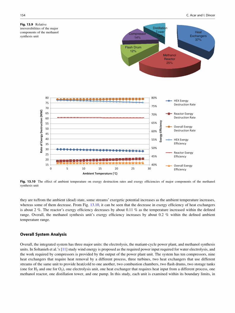
they are to/from the ambient (dead) state, some streams’ exergetic potential increases as the ambient temperature increases,
whereas some of them decrease. From Fig. 13.10, it can be seen that the decrease in exergy efficiency of heat exchangers
is about 2 %. The reactor’s exergy efficiency decreases by about 0.11 % as the temperature increased within the defined
range. Overall, the methanol synthesis unit’s exergy efficiency increases by about 0.2 % within the defined ambient
temperature range.
Overall System Analysis
Overall, the integrated system has three major units: the electrolysis, the matiant-cycle power plant, and methanol synthesis
units. In Soltanieh et al.’s [11] study wind energy is proposed as the required power input required for water electrolysis, and
the work required by compressors is provided by the output of the power plant unit. The system has ten compressors, nine
heat exchangers that require heat removal by a different process, three turbines, two heat exchangers that use different
streams of the same unit to provide heat/cold to one another, two combustion chambers, two flash drums, two storage tanks
(one for H2 and one for O2), one electrolysis unit, one heat exchanger that requires heat input from a different process, one
methanol reactor, one distillation tower, and one pump. In this study, each unit is examined within its boundary limits, in
HeatExchangers
37%
MethanolReactor
25%
Flash Drum12%
Compressor14%
DistillationTower12%
Fig. 13.9 Relative
irreversibilities of the major
components of the methanol
synthesis unit
40%
45%
50%
55%
60%
65%
70%
75%
80%
15
20
25
30
35
40
45
50
55
60
65
70
75
80
0 5 10 15 20 25 30
Exer
gy E
ffic
ienc
y
Rate
of E
xerg
y D
estr
uctio
n (M
W)
Ambient Temperature (�C)
HEX ExergyDestruction Rate
Reactor ExergyDestruction Rate
Overall ExergyDestruction Rate
HEX ExergyEfficiency
Reactor ExergyEfficiency
Overall ExergyEfficiency
Fig. 13.10 The effect of ambient temperature on exergy destruction rates and exergy efficiencies of major components of the methanol
synthesis unit
154 C. Acar and I. Dincer
order to see where the greatest irreversibilities occur and how the ambient temperature affects the system exergetically; the
overall system is also investigated.
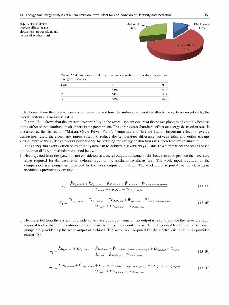
Figure 13.11 shows that the greatest irreversibility in the overall system occurs at the power plant; this is mainly because
of the effect of two combustion chambers in the power plant. The combustion chambers’ effect on exergy destruction rates is
discussed earlier in section “Matiant-Cycle Power Plant”. Temperature difference has an important effect on exergy
destruction rates; therefore, any improvement to reduce the temperature difference between inlet and outlet streams
would improve the system’s overall performance by reducing the exergy destruction rates, therefore irreversibilities.
The energy and exergy efficiencies of the system can be defined in several ways. Table 13.4 summarizes the results based
on the three different methods mentioned below:
1. Heat rejected from the system is not considered as a useful output, but some of this heat is used to provide the necessary
input required for the distillation column input of the methanol synthesis unit. The work input required for the
compressors and pumps are provided by the work output of turbines. The work input required for the electrolysis
modules is provided externally:
η1 ¼_EH2, stored þ _EO2, stored þ _EMethanol þ _Wturbines � _Wcompressors,pumps
_Ewater þ _EMethane þ _Welectrolysis
ð13:17Þ
Ψ 1 ¼Ex:H2, stored
þ _ExO2, stored þ _ExMethanol þ _Wturbines � _Wcompressors,pumps
_Exwater þ _ExMethane þ _Welectrolysis
ð13:18Þ
2. Heat rejected from the system is considered as a useful output; some of this output is used to provide the necessary input
required for the distillation column input of the methanol synthesis unit. The work input required for the compressors and
pumps are provided by the work output of turbines. The work input required for the electrolysis modules is provided
externally:
η2 ¼_EH2, stored þ _EO2, stored þ _EMethanol þ _Wturbines�compressors,pumps þ _Qrejected � _Qinput
_Ewater þ _EMethane þ _Welectrolysis
ð13:19Þ
Ψ 2 ¼_ExH2, stored þ _ExO2, stored þ _ExM þ _Wturbines�compressors,pumps þ _Ex Q, rejected�Q, inputð Þ
_Exwater þ _ExMethane þ _Welectrolysis
ð13:20Þ
Electrolysis11%
Power Plant60%
Methanol29%
Fig. 13.11 Relative
irreversibilities of the
electrolysis, power plant, and
methanol synthesis unit
Table 13.4 Summary of different scenarios with corresponding energy and
exergy efficiencies
Case η Ψ1 35% 42%
2 64% 46%
3 68% 47%
13 Energy and Exergy Analyses of a Zero Emission Power Plant for Coproduction of Electricity and Methanol 155

Case Study Soltanieh et al. [11] propose to use the work output of the turbines for the work required in compressors and
pumps. The paper uses wind energy to run the electrolysis unit. If electrolysis unit also used the work output of the turbines,
the energy and exergy efficiencies become
η3 ¼_EH2, stored þ _EO2, stored þ _EMethanol þ _Wturbines�compressors,pumps�electrolysis þ _Qrejected�input
_Ewater þ _EMethane
ð13:21Þ
Ψ 3 ¼_ExH2
þ _ExO2þ _ExMethanol þ _Wturbines�comp,pumps�electrolysis þ _Ex Q, rejected�Q, inputð Þ
_Exwater þ _ExMethane
ð13:22Þ
Conclusions
The integrated system, as modified from a literature work, electrolyzes water using wind energy and stores 46 % of the
produced H2 and 28 % of the produced O2. The remaining O2 is sent from the electrolysis unit to the Matiant-cycle power
plant and goes into complete combustion with natural gas (pure methane). The combustion product water is sent back to the
electrolysis unit, and CO2 is sent to the methanol synthesis unit. In the methanol synthesis unit, CO2 reacts with the H2
coming from the electrolysis unit and produces methanol. The overall system does not release CO2 to the environment, and
the heating requirement of the system is met by the rejected heat within the integrated system. Exergy efficiency of the
overall system increases by 2 % if the rejected heat is used as a product, such as water or space heating. This amount
increases by 1 % if the work requirements of not only the compressor and pumps but also the electrolysis modules are met by
the work output of the turbines. The integrated system’s outputs are about 133 MW of electricity energy (60 MW, if the
pumps, compressors, and electrolysis modules’ input is provided) and 0.25 kmol/s methanol. By converting the CO2 to
methanol, the methanol synthesis unit avoids the release of 0.25 kmol/s CO2 into the atmosphere. If the system is assumed to
work 8,000 h, the avoided CO2 emissions could reach around 160 tons.
References
1. International Energy Agency Technical Report (2012) Key world energy statistics. Website: http://www.iea.org/publications/freepublications/publication/kwes.
pdf. Accessed 10 Jan 2013
2. Davison J (2007) Performance and costs of power plants with capture and storage of CO2. Energy 32:1163–1176
3. Damen K, Troost T, Faaij A, Turkenburg W (2006) A comparison of electricity and hydrogen production systems with CO2 capture and storage, Part A: Review
and selection of promising conversion and capture technologies. Prog Energy Combust Sci 32:215–246
4. Minutillo M, Perna A (2010) A novel approach for treatment of CO2 from fossil fired power plants, Part B: The energy suitability of integrated tri-reforming power
plants (ITRPPs) for methanol production. Int J Hydrogen Energy 35:7012–7020
5. Guang-jian L, Zheng L, Ming-hua W, Wei-dou N (2010) Energy savings by coproduction: a methanol/electricity case study. Appl Energy 87:2854–2859
6. Chen Y, Adams TA II, Barton PI (2011) Optimal design and operation of static energy polygeneration systems. Indus Eng Chem Res 50:5099–5113
7. Katayama Y, Tamaura Y (2005) Development of new green-fuel production technology by combination of fossil fuel and renewable energy. Energy
30:2179–2185
8. Takeuchi M, Sakamoto Y, Niwa S et al (2001) Study on CO2 global recycling system. Sci Total Environ 277:15–19
9. Mignard D, Sahibzada M, Duthie JM, Whittington HW (2003) Methanol synthesis from flue-gas CO2 and renewable electricity: a feasibility study. Int J Hydrogen
Energy 28:455–464
10. Cifre PG, Badr O (2007) Renewable hydrogen utilization for the production of methanol. Energy Convers Manage 48:519–527
11. Soltanieh M, Azar KM, Saber M (2012) Development of a zero emission integrated system for co-production of electricity and methanol through renewable
hydrogen and CO2 capture. Int J Greenh Gas Control 7:145–152
12. Perry RH, Green DW (2000) Perry’s chemical engineering handbook, 7th edn. McGraw-Hill, New York, NY
13. Dincer I, Rosen MA (2007) Exergy: energy, environment and sustainable development. Elsevier, Oxford
14. Kotas TJ (1995) The exergy method of thermal plant analysis. Krieger, London
156 C. Acar and I. Dincer