
Using Exergy to Understand and Improve the Efficiency of ...
16
Entropy 2009, 11, 820-835; doi:10.3390/e11040820 entropy ISSN 1099-4300 www.mdpi.com/journal/entropy Article Using Exergy to Understand and Improve the Efficiency of Electrical Power Technologies Marc A. Rosen 1, * and Cornelia Aida Bulucea 2 1 Faculty of Engineering and Applied Science, University of Ontario Institute of Technology, 2000 Simcoe Street North, Oshawa, Ontario, L1H 7K4, Canada 2 Faculty of Electromechanical and Environmental Engineering, University of Craiova, Romania; E-Mail: [email protected] * Author to whom correspondence should be addressed; E-Mail: [email protected]. Received: 21 September 2009 / Accepted: 2 November 2009 / Published: 6 November 2009 Abstract: The benefits are demonstrated of using exergy to understand the efficiencies of electrical power technologies and to assist improvements. Although exergy applications in power systems and electrical technology are uncommon, exergy nevertheless identifies clearly potential reductions in thermodynamic losses and efficiency improvements. Various devices are considered, ranging from simple electrical devices to generation systems for electrical power and for multiple products including electricity, and on to electrically driven. The insights provided by exergy are shown to be more useful than those provided by energy, which are sometimes misleading. Exergy is concluded to have a significant role in assessing and improving the efficiencies of electrical power technologies and systems, and provides a useful tool for engineers and scientists as well as decision and policy makers. Keywords: exergy; electricity; power generation; energy conversion; electricity use 1. Introduction The use of energy as a measure for understanding and improving the efficiencies of energy systems can be misleading and confusing. The quantity exergy can be used to assess and improve the efficiencies energy systems, and can help better understand the losses in energy systems by providing more useful and meaningful information than energy provides. Exergy is the maximum work (or electricity) producible from a system or a flow of matter or energy relative to a reference environment. Exergy is a measure of the potential of the usefulness or value of a system or flow. Exergy is also a measure of the OPEN ACCESS
-
Upload
khangminh22 -
Category
Documents
-
view
8 -
download
0
Transcript of Using Exergy to Understand and Improve the Efficiency of ...
Entropy 2009, 11, 820-835; doi:10.3390/e11040820
entropy ISSN 1099-4300
www.mdpi.com/journal/entropy
Article
Using Exergy to Understand and Improve the Efficiency of
Electrical Power Technologies
Marc A. Rosen 1,* and Cornelia Aida Bulucea
2
1 Faculty of Engineering and Applied Science, University of Ontario Institute of Technology, 2000
Simcoe Street North, Oshawa, Ontario, L1H 7K4, Canada 2 Faculty of Electromechanical and Environmental Engineering, University of Craiova, Romania;
E-Mail: [email protected]
* Author to whom correspondence should be addressed; E-Mail: [email protected].
Received: 21 September 2009 / Accepted: 2 November 2009 / Published: 6 November 2009
Abstract: The benefits are demonstrated of using exergy to understand the efficiencies of
electrical power technologies and to assist improvements. Although exergy applications in
power systems and electrical technology are uncommon, exergy nevertheless identifies
clearly potential reductions in thermodynamic losses and efficiency improvements. Various
devices are considered, ranging from simple electrical devices to generation systems for
electrical power and for multiple products including electricity, and on to electrically driven.
The insights provided by exergy are shown to be more useful than those provided by energy,
which are sometimes misleading. Exergy is concluded to have a significant role in assessing
and improving the efficiencies of electrical power technologies and systems, and provides a
useful tool for engineers and scientists as well as decision and policy makers.
Keywords: exergy; electricity; power generation; energy conversion; electricity use
1. Introduction
The use of energy as a measure for understanding and improving the efficiencies of energy systems
can be misleading and confusing. The quantity exergy can be used to assess and improve the efficiencies
energy systems, and can help better understand the losses in energy systems by providing more useful
and meaningful information than energy provides. Exergy is the maximum work (or electricity)
producible from a system or a flow of matter or energy relative to a reference environment. Exergy is a
measure of the potential of the usefulness or value of a system or flow. Exergy is also a measure of the
OPEN ACCESS
Entropy 2009, 11
821
potential to cause change, as a consequence of not being in equilibrium relative to the
reference environment.
Exergy can clearly identify efficiency improvements and reductions in thermodynamic losses. Exergy
can also identify better than energy the environmental benefits and economics of energy technologies.
Thus, exergy has an important role to play in increasing efficiencies of energy systems and technologies.
Many feel that exergy is applicable only to systems or studies involving extensive thermodynamics, in
areas like mechanical and chemical engineering. Thus the full value of exergy is not achieved because it
is neglected or underutilized in other fields. One such area is electrical engineering, where exergy
applications are uncommon.
One reason that exergy is not used extensively in electrical engineering studies is that general
thermodynamic assessments often deal with many energy forms, e.g., electricity, work, heat, chemical,
kinetic, potential, etc., while electrical engineering assessments often focus on electricity, and sometimes
work. In such situations, energy and exergy flows are identical (since exergy is the work or electrical
equivalent of energy), so efficiencies tend to be the same and the benefits of using exergy methods are
less obvious. Nevertheless, there are benefits. First, losses are identified in terms of cause and located
more accurately with exergy. Second, in systems where non-electrical quantities are involved,
efficiencies on energy and exergy bases differ, sometimes markedly.
This paper goes on to describe exergy and exergy methods and their applicability to electrical
systems. Examples are used to illustrate the use of exergy as a tool to understand and improve
efficiency. The objective is to improve how efficiencies and losses are understood for electrical systems,
thereby assisting efforts to improve them.
2. Exergy and Exergy Analysis
Exergy is defined as the maximum amount of work which can be produced by a system or a flow of
matter or energy as it comes to equilibrium with a reference environment. Exergy is a measure of the
potential of the system or flow to cause change, as a consequence of not being completely in stable
equilibrium relative to the reference environment. Unlike energy, exergy is not subject to a conservation
law (except for ideal, or reversible, processes). Rather exergy is consumed or destroyed, due to
irreversibilities in any real process. The exergy consumption during a process is proportional to the
entropy created due to irreversibilities associated with the process.
Exergy analysis [1-9] is a methodology that uses the conservation of energy principle (embodied in
the first law of thermodynamics) together with non-conservation of entropy principle (embodied in the
second law) for the analysis, design and improvement of energy and other systems. The exergy method
is useful for improving the efficiency energy-resource use, for it quantifies the locations, types and
magnitudes of wastes and losses. In general, more meaningful efficiencies are evaluated with exergy
rather than energy analysis, since exergy efficiencies are always a measure of the approach to the ideal.
Therefore, exergy analysis identifies the margin available to design more efficient energy systems by
reducing inefficiencies.
In exergy analysis, the characteristics of the reference environment must be specified completely.
This is commonly done by specifying the temperature, pressure and chemical composition of the
reference environment. The results of exergy analyses, consequently, are relative to the specified
Entropy 2009, 11
822
reference environment, which in most applications is modelled after the actual local environment. The
exergy of a system is zero when it is in equilibrium with the reference environment. This tie between
exergy and the environment leads to some of the implications regarding environmental impact that are
discussed subsequently.
Exergy also can be applied beyond assessing efficiencies and losses, in areas such as
economics [10-12] and environmental impact assessment [13-15]. The relationship between exergy and
economics, particularly the trade-offs that normally occur between efficiency and costs, has been an
important concern for decades and continues to be so. Economic methods based on exergy, e.g.,
exergoeconomics, have evolved and are applied in some areas. The environmental impacts and
non-sustainability of energy use have become of significant concerns recently, and exergy methods can
assist improvement efforts by (1) reducing environmental emissions and lengthening the lives of
resources through increasing efficiencies, and (2) assessing the potential impacts of emissions. The
linkages between exergy and economics and environmental impact are beyond the scope of this article
and thus not considered further here.
Many engineers and scientists suggest that energy systems are best evaluated using exergy analysis
because it provides more insights, especially for efficiency improvement, than energy analysis. Exergy
analysis and its application to many processes and systems are discussed further elsewhere [1-9]. As
energy policies increasingly play an important role in addressing development and sustainability issues,
decision and policy makers would also benefit from an appreciation the exergy concept and
its applications.
3. Applications of Exergy to Electrical Systems
Exergy can be applied to electrical systems in much the same way as it is to general thermodynamic
systems. Usually, since there are fewer energy forms involved, the analyses are less involved and
complex for electrical systems.
The range of devices that can be considered is extensive, ranging from generators and transformers
to power plants. Here, we consider four categories of electrical systems:
Simple electrical conversion devices.
Electrical generation systems.
Generation systems for multiple products including electricity.
Electrical storage systems.
Devices and systems that use or are driven by electricity.
Many examples can be used to demonstrate how exergy methods improve understanding of
efficiencies and help increase them. Several examples in each of the above categories are presented in
subsequent sections for illustrative purposes.
Entropy 2009, 11
823
4. Illustrations for Various Electrical Systems
4.1. Simple Electrical Conversion Devices
Simple electrical conversion devices include transformers, alternators, generators, motors and static
converters, and these are considered here. In such devices, electrical energy is being converted to other
type of electrical energy, or work and electricity quantities are being interchanged.
Since electricity and work are the same on energy and exergy bases, the overall energy and exergy
efficiencies for such devices are the same. The losses differ greatly on energy and exergy bases,
however, as all energy losses are typically associated with waste heat. Most exergy losses are associated
with internal consumptions of exergy due to irreversibilities and little with waste thermal
exergy emissions.
Electrical losses often involve resistive losses, which appear as waste heat. Electric generator losses
usually include losses in the winding and magnetizing losses in the core, plus rotational losses. Power
transformer losses are usually of the same kind as electric generator losses. Transformer losses have two
main components: (1) Core loss (or no-load loss), due to magnetizing and de-magnetizing the core
during normal operation; this loss occurs whenever the transformer is energized and does not vary with
load. (2) Coil loss (or load loss), which occurs in the primary and secondary coils of the transformer.
This loss is a function of the resistance of the winding materials and which varies with the transformer
load. Losses in these devices are also caused friction.
4.2. Electrical Generation
Idealized and actual electrical power plants are considered here, including thermal power plants,
hydroelectric plants and fuel cells.
Ideal Thermal Power Plant
A Carnot heat engine represents an ideal power plant. Energy efficiencies for this device are
counter-intuitive. For a Carnot power plant operating between a heat source at a temperature of 600 K
and a heat sink at 300 K, for example, the energy efficiency is 50% (i.e., 1 – 300/600 = 0.5). Yet a
Carnot engine is ideal. Clearly, the energy efficiency is misleading as it indicates that a significant margin
for improvement exists when in fact there is none. Although a significant amount of waste heat is
emitted, it is rejected at the temperature of the reference environment, where heat is freely available in
abundance. Thus the waste heat is useless for processes. The exergy efficiency of an ideal device
is 100%, properly indicating its ideal nature in a straightforward and clear manner. Zero exergy is
associated with the waste heat, reflecting its value or usefulness.
Coal and Nuclear Power Plants
Actual coal-fired and nuclear electricity generation plants are considered.
First, we consider the coal-fired Nanticoke generating station, which has been operating since 1981
in in community of Nanticoke, Ontario (Canada). Each of the eight station units has net outputs of 505
MW of electricity. A single station unit (see Figure 1) can be divided into four main sections [15,16]:
Entropy 2009, 11
824
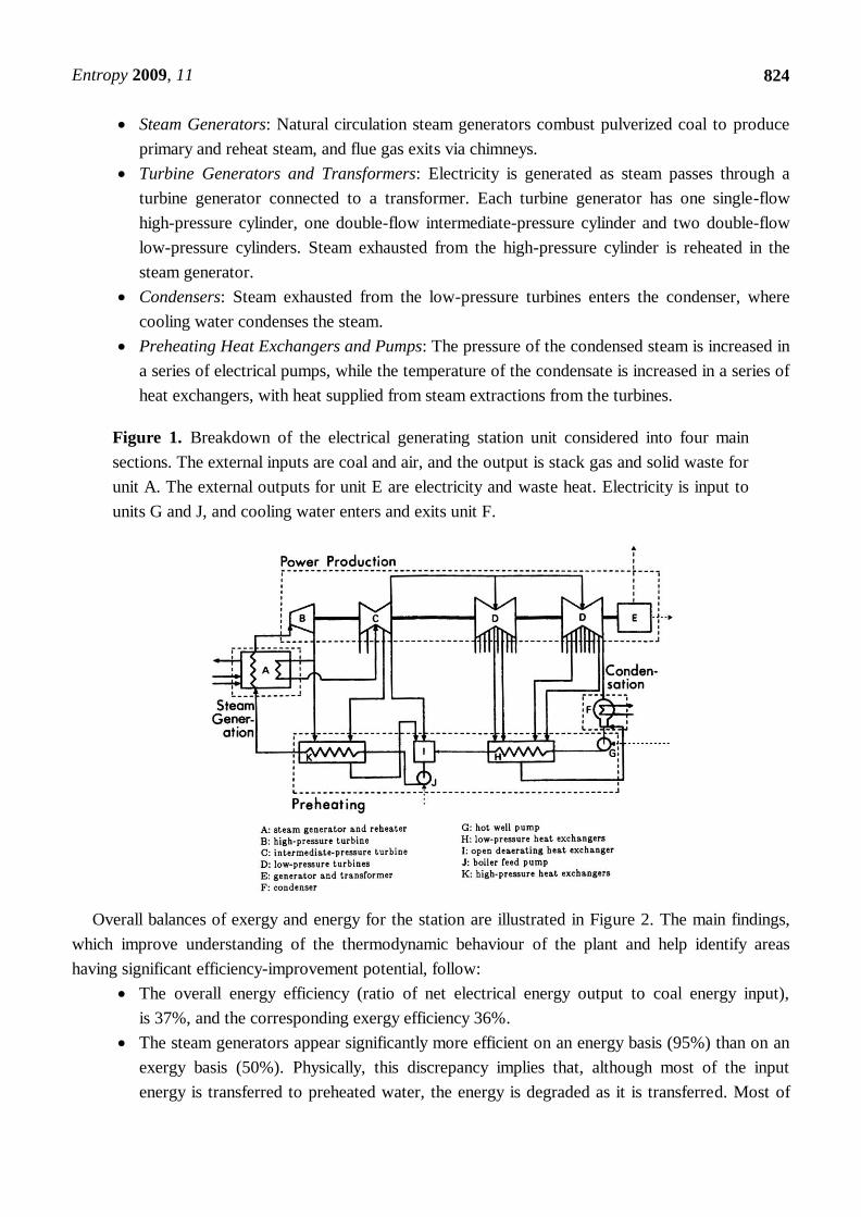
Steam Generators: Natural circulation steam generators combust pulverized coal to produce
primary and reheat steam, and flue gas exits via chimneys.
Turbine Generators and Transformers: Electricity is generated as steam passes through a
turbine generator connected to a transformer. Each turbine generator has one single-flow
high-pressure cylinder, one double-flow intermediate-pressure cylinder and two double-flow
low-pressure cylinders. Steam exhausted from the high-pressure cylinder is reheated in the
steam generator.
Condensers: Steam exhausted from the low-pressure turbines enters the condenser, where
cooling water condenses the steam.
Preheating Heat Exchangers and Pumps: The pressure of the condensed steam is increased in
a series of electrical pumps, while the temperature of the condensate is increased in a series of
heat exchangers, with heat supplied from steam extractions from the turbines.
Figure 1. Breakdown of the electrical generating station unit considered into four main
sections. The external inputs are coal and air, and the output is stack gas and solid waste for
unit A. The external outputs for unit E are electricity and waste heat. Electricity is input to
units G and J, and cooling water enters and exits unit F.
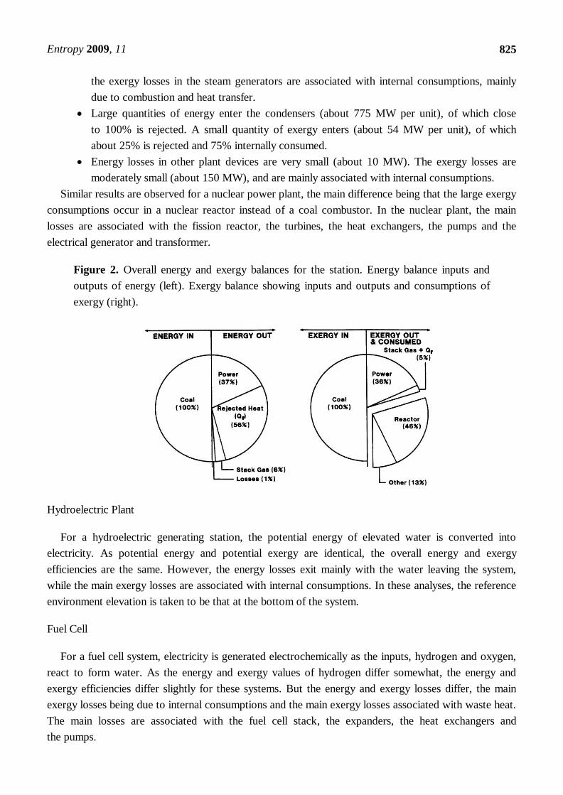
Overall balances of exergy and energy for the station are illustrated in Figure 2. The main findings,
which improve understanding of the thermodynamic behaviour of the plant and help identify areas
having significant efficiency-improvement potential, follow:
The overall energy efficiency (ratio of net electrical energy output to coal energy input),
is 37%, and the corresponding exergy efficiency 36%.
The steam generators appear significantly more efficient on an energy basis (95%) than on an
exergy basis (50%). Physically, this discrepancy implies that, although most of the input
energy is transferred to preheated water, the energy is degraded as it is transferred. Most of
Entropy 2009, 11
825
the exergy losses in the steam generators are associated with internal consumptions, mainly
due to combustion and heat transfer.
Large quantities of energy enter the condensers (about 775 MW per unit), of which close
to 100% is rejected. A small quantity of exergy enters (about 54 MW per unit), of which
about 25% is rejected and 75% internally consumed.
Energy losses in other plant devices are very small (about 10 MW). The exergy losses are
moderately small (about 150 MW), and are mainly associated with internal consumptions.
Similar results are observed for a nuclear power plant, the main difference being that the large exergy
consumptions occur in a nuclear reactor instead of a coal combustor. In the nuclear plant, the main
losses are associated with the fission reactor, the turbines, the heat exchangers, the pumps and the
electrical generator and transformer.
Figure 2. Overall energy and exergy balances for the station. Energy balance inputs and
outputs of energy (left). Exergy balance showing inputs and outputs and consumptions of
exergy (right).
Hydroelectric Plant
For a hydroelectric generating station, the potential energy of elevated water is converted into
electricity. As potential energy and potential exergy are identical, the overall energy and exergy
efficiencies are the same. However, the energy losses exit mainly with the water leaving the system,
while the main exergy losses are associated with internal consumptions. In these analyses, the reference
environment elevation is taken to be that at the bottom of the system.
Fuel Cell
For a fuel cell system, electricity is generated electrochemically as the inputs, hydrogen and oxygen,
react to form water. As the energy and exergy values of hydrogen differ somewhat, the energy and
exergy efficiencies differ slightly for these systems. But the energy and exergy losses differ, the main
exergy losses being due to internal consumptions and the main exergy losses associated with waste heat.
The main losses are associated with the fuel cell stack, the expanders, the heat exchangers and
the pumps.
Entropy 2009, 11
826
Wind Turbine System
For a wind generating station, the kinetic energy of moving air is converted to electricity. As
potential energy and kinetic exergy are identical, the overall energy and exergy efficiencies are the same.
However, the energy losses exit mainly with the air leaving the device, while the main exergy losses are
associated with internal consumptions. In these analyses, the reference environment for velocity is taken
to be a non-moving point on the earth.
Solar Photovoltaic System
For a solar photovoltaic generating station, the energy of sunlight is converted directly to electricity.
As the energy and exergy of sunlight are very close, they are assumed identical here. Thus, the overall
energy and exergy efficiencies are the same. However, the energy losses exit mainly with the waste heat
leaving the system, while the main exergy losses are associated with internal consumptions.
Solar Thermal Power Generation
For a solar thermal power generation, the energy of sunlight is converted indirectly to electricity,
using a thermal power cycle that often is similar to a Rankine cycle. Again, the overall energy and
exergy efficiencies are the same since the energy and exergy of sunlight are assumed identical, and
energy losses exit mainly with the waste heat emissions while internal consumptions are responsible for
the main exergy losses.
4.3. Cogeneration and Trigeneration
Cogeneration and trigeneration systems are considered. These systems generate multiple products
including electricity.
Cogeneration Systems
Cogeneration, or combined heat and power (CHP), systems generate co-products: electricity and
useful heat. The energy and exergy efficiencies for such systems vary due to the thermal product, for
which energy and exergy differ. The energy and exergy efficiencies are nearer when the temperature of
the product heat is higher, and deviate more as the temperature of the product heat decreases toward
the reference environment temperature. The energy and exergy losses for such systems are identified to
be in different locations and due to different causes. The main losses are associated with the furnace and
boiler, the turbines, the heat exchangers, the electrical generator and transformer, the stack gas and
the pumps.
Trigeneration Systems
Trigeneration systems are extended cogeneration systems which generate a cold product in addition
to electricity and useful heat. The energy and exergy efficiencies for such systems vary due to the hot
and cold thermal products. For each of these commodities, energy and exergy differ. The energy and
exergy efficiencies are deviate more when the temperatures of the product thermal quantities are further

Entropy 2009, 11
827
removed from the reference-environment temperature (i.e., the hot product is hotter and the cold
product colder). The energy and exergy efficiencies are nearer as the temperatures of the thermal
quantities approach the reference-environment temperature. There are particular difficulties in
evaluating the energy efficiencies of such systems due to the cold product, and the difficulty in assessing
its energy. The exergy of cold are hot thermal products are straightforwardly evaluated, so meaningful
exergy efficiencies are readily determined.
As for cogeneration systems, the energy and exergy losses for such systems are identified to be in
different locations and due to different causes. The main losses are associated with the furnace and
steam generator, the turbines, the heat exchangers, the stack gas, the electrical generator and
transformer, and the chiller.
4.4. Electrical Storage Systems
Electrical storage systems are considered here, the most common of which are batteries. The energy
efficiency on a fractional basis of an electrical storage device is usually determined as the ratio of the
quantity of electricity obtained from the storage while discharging divided by the electrical energy
supplied to the storage while charging. For a battery, the energy loss is observed as heat, which warms
the battery and the surroundings. Low charging and discharging rates help keep a battery cool and
improve the battery life. Given that the inputs and outputs are both electricity for electrical storage
systems, the energy and exergy efficiencies are equal.
4.5. Electrically Driven Devices and Systems
Space and Hot Water Heaters
Space and hot water heating can be accomplished in many ways. Two competing technologies are
considered here:
Electrical Resistance Space Heater: In an electrical resistance space heater, almost all of the
electricity that enters the unit is dissipated to heat within the space. Thus the energy efficiency
is nearly 100% and there are almost no energy losses. Yet the exergy efficiency of such a
device is typically less than 10%, indicating that the same space heating can in theory be
achieved using one-tenth of the electricity.
Heat Pump: Some of the savings in electricity use identified in the previous point can be
attained using a heat pump. The use of even a relatively inefficient heat pump can reduce the
electricity used to achieve the same space heating by one-third. A high-efficiency heat pump
can achieve even greater reductions electricity usage. The main losses occur in the motor and
compressor, the condenser, the heat exchangers and the throttle valve.
Efficiencies for hot water heating are also markedly different for different technologies and losses
differ in characteristics and amount. For electrical hot water heaters, the efficiencies are low and wastes
are mainly attributable to waste heat (on an energy basis) and to internal consumptions (on an exergy
basis). For natural gas-fired, as an alternative, the results are similar, although the technologies differ.
Clearly the use of energy efficiencies and losses is quite misleading for heating.
Entropy 2009, 11
828
Industrial Furnaces and Heaters
Energy efficiencies for industrial process heating vary slightly depending on the heat retention
characteristics of the heater. Exergy efficiencies for industrial process heating vary significantly,
depending primarily on the temperature of the product heat. Typically, the exergy efficiency is high
when a high-quality input such as electricity is used for a high-quality task (like producing
high-temperature heat). Thus, the use of energy efficiencies and losses is quite misleading for
industrial heating.
A breakdown of the exergy losses for such systems often reveals that the exergy losses are divided
among those due to irreversibilities associated with the combustion reaction (even if done adiabatically)
and those due to heat transfer from the peak theoretical combustion temperature to the actual
temperature of the working fluid.
Refrigeration Systems
Refrigeration systems operate like heat pumps, but with the heat removal from the cold space, rather
than the warmer heat rejected, being the product. As for trigeneration systems which involve a cold
product, the energy and exergy efficiencies for such systems vary due to the dependence of the exergy
of the cold thermal product on temperature. The energy of the cold product is also difficult to
determine, so the energy-based figure of merit used for refrigeration systems is the coefficient of
performance (COP), which is simply the energy efficiency divided by 100. The energy and exergy
efficiencies differ markedly for refrigeration systems, but the exergy efficiencies are more
intuitively meaningful.
The energy and exergy losses for such systems are identified to be in different locations and due to
different causes. The main losses occur in the motor and compressor, the condenser, the heat
exchangers and the throttle valve.
Pumps and Fans
Electric pumps and fans convert electricity to mechanical energy in the form of pressure rise and
kinetic energy. The energy and exergy of the products are usually similar, leading to similar
device efficiencies.
Lights
Not only does lighting consume a significant amount of energy in society, it is also extremely
inefficient. Light bulbs convert electricity to visible light. As the product electromagnetic radiation can
be taken to have similar energy and exergy contents, the energy and exergy efficiencies of lighting are
similar. Lighting efficiencies differ markedly from the efficiencies of many home appliances. The
potential for energy and exergy savings from lighting is large, due to its inefficiency and large
contribution to societal energy use.
Entropy 2009, 11
829
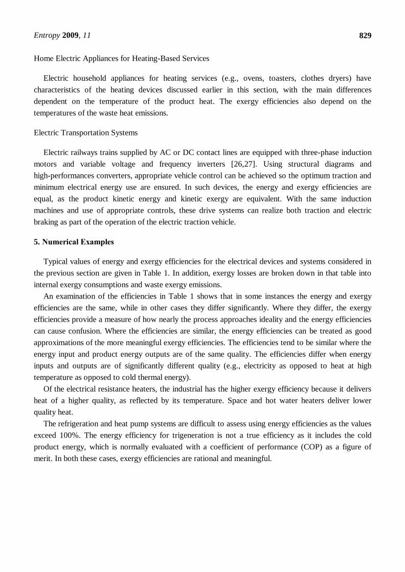
Home Electric Appliances for Heating-Based Services
Electric household appliances for heating services (e.g., ovens, toasters, clothes dryers) have
characteristics of the heating devices discussed earlier in this section, with the main differences
dependent on the temperature of the product heat. The exergy efficiencies also depend on the
temperatures of the waste heat emissions.
Electric Transportation Systems
Electric railways trains supplied by AC or DC contact lines are equipped with three-phase induction
motors and variable voltage and frequency inverters [26,27]. Using structural diagrams and
high-performances converters, appropriate vehicle control can be achieved so the optimum traction and
minimum electrical energy use are ensured. In such devices, the energy and exergy efficiencies are
equal, as the product kinetic energy and kinetic exergy are equivalent. With the same induction
machines and use of appropriate controls, these drive systems can realize both traction and electric
braking as part of the operation of the electric traction vehicle.
5. Numerical Examples
Typical values of energy and exergy efficiencies for the electrical devices and systems considered in
the previous section are given in Table 1. In addition, exergy losses are broken down in that table into
internal exergy consumptions and waste exergy emissions.
An examination of the efficiencies in Table 1 shows that in some instances the energy and exergy
efficiencies are the same, while in other cases they differ significantly. Where they differ, the exergy
efficiencies provide a measure of how nearly the process approaches ideality and the energy efficiencies
can cause confusion. Where the efficiencies are similar, the energy efficiencies can be treated as good
approximations of the more meaningful exergy efficiencies. The efficiencies tend to be similar where the
energy input and product energy outputs are of the same quality. The efficiencies differ when energy
inputs and outputs are of significantly different quality (e.g., electricity as opposed to heat at high
temperature as opposed to cold thermal energy).
Of the electrical resistance heaters, the industrial has the higher exergy efficiency because it delivers
heat of a higher quality, as reflected by its temperature. Space and hot water heaters deliver lower
quality heat.
The refrigeration and heat pump systems are difficult to assess using energy efficiencies as the values
exceed 100%. The energy efficiency for trigeneration is not a true efficiency as it includes the cold
product energy, which is normally evaluated with a coefficient of performance (COP) as a figure of
merit. In both these cases, exergy efficiencies are rational and meaningful.
Entropy 2009, 11
830
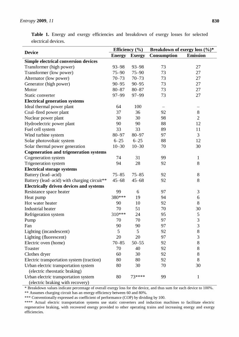
Table 1. Energy and exergy efficiencies and breakdown of exergy losses for selected
electrical devices.
Device Efficiency (%) Breakdown of exergy loss (%)*
Energy Exergy Consumption Emission
Simple electrical conversion devices
Transformer (high power) 93–98 93–98 73 27
Transformer (low power) 75–90 75–90 73 27
Alternator (low power) 70–73 70–73 73 27
Generator (high power) 90–95 90–95 73 27
Motor 80–87 80–87 73 27
Static converter 97–99 97–99 73 27
Electrical generation systems
Ideal thermal power plant 64 100 – –
Coal–fired power plant 37 36 92 8
Nuclear power plant 30 30 98 2
Hydroelectric power plant 90 90 88 12
Fuel cell system 33 33 89 11
Wind turbine system 80–97 80–97 97 3
Solar photovoltaic system 6–25 6–25 88 12
Solar thermal power generation 10–30 10–30 70 30
Cogeneration and trigeneration systems
Cogeneration system 74 31 99 1
Trigeneration system 94 28 92 8
Electrical storage systems
Battery (lead–acid) 75–85 75–85 92 8
Battery (lead–acid) with charging circuit** 45–68 45–68 92 8
Electrically driven devices and systems
Resistance space heater 99 6 97 3
Heat pump 380*** 19 94 6
Hot water heater 90 10 92 8
Industrial heater 70 51 70 30
Refrigeration system 310*** 24 95 5
Pump 70 70 97 3
Fan 90 90 97 3
Lighting (incandescent) 5 5 92 8
Lighting (fluorescent) 20 20 97 3
Electric oven (home) 70–85 50–55 92 8
Toaster 70 40 92 8
Clothes dryer 60 30 92 8
Electric transportation system (traction) 80 80 92 8
Urban electric transportation system
(electric rheostatic braking)
80 30 70 30
Urban electric transportation system
(electric braking with recovery)
80 73****
99 1
* Breakdown values indicate percentage of overall exergy loss for the device, and thus sum for each device to 100%.
** Assumes charging circuit has an energy efficiency between 60 and 80%.
*** Conventionally expressed as coefficient of performance (COP) by dividing by 100.
**** Actual electric transportation systems use static converters and induction machines to facilitate electric
regenerative braking, with recovered energy provided to other operating trains and increasing energy and exergy
efficiencies.

Entropy 2009, 11
831
The energy loss can be found using the corresponding energy efficiency as 100% minus the energy
efficiency. The exergy loss can be found similarly. The overall energy loss is made up entirely of waste
energy emissions from the system. The overall exergy loss differs significantly, as it consists of both
waste exergy emissions from the system and internal exergy consumptions (or destructions) due
to irreversibilities.
An examination of the breakdown of exergy losses in Table 1 shows that in most instances, the
exergy losses are mainly associated with internal exergy consumptions. The waste exergy emissions tend
to be smaller, usually less than 30% of the total exergy loss.
Table 1 is a compilation of data from different sources, which has been modified to be comparable
and illustrative. Some details on the values presented in Table 1 are as follows:
The reference-environment temperature is taken to be 20 °C.
Energy efficiency values are presented for the transformer, generator, alternator motor and
static converter which are typical of some types. Heat losses from the transformer, generator,
alternator and motor are taken to occur at 130 °C. These values can also vary markedly
among devices.
Data for the coal-fired plant is based on the Nanticoke generating station [15,16].
Data for the nuclear plant is based on the Pickering nuclear generating station [16], located in
Pickering, Ontario (Canada). The input is taken to be the net heat of fission delivered to the
reactor (rather than the uranium).
The ideal thermal power plant is taken to be operating using a heat source at a temperature
of 550 °C, which roughly corresponds to the temperature of the high-pressure superheated
steam exiting the steam generator of the coal-fired Nanticoke generating station [15,16].
For the hydroelectric power plant, water is assumed to exit at the elevation of the reference
environment with negligible kinetic energy, thus having zero exergy and energy. It is also
assumed that waste heat is released at an average temperature of 60 °C.
The fuel cell system is based on an automotive fuel cell system assessed previously by
Cownden et al. [18]. The system includes the fuel cell stack and the balance of plant, which
includes pumps, compressors, heat exchangers, etc.
Wind turbine system energy efficiencies vary significantly with wind speed, and are usually
designed for highest efficiency operation at a given wind speed. Values are reported here for
typical operating energy efficiencies for wind turbine systems at wind speeds that are
reasonable in terms of systems operation. The main component of the system is the wind
turbine itself, which has energy efficiencies typically ranging from 75% to 94% [20,21]. The
device is assumed to emit waste heat at 30 °C, a temperature near the ambient condition.
Energy efficiencies values for photovoltaic electricity generation are based on confirmed
efficiencies for terrestrial solar cells and modules, measured under the global AM1-5 spectrum
(1,000 W/m2) at 25 °C [22,23]. These devices are assumed to emit waste heat at 60 °C, a
temperature between ambient conditions and waste heat flows for industrial heating.
Solar thermal energy conversion devices use the energy in sunlight to heat a working fluid to a
temperature sufficiently high to drive a thermal power cycle. Such systems usually utilize
concentrating solar collectors so that reasonably high temperatures can be attained. The mean
Entropy 2009, 11
832
annual efficiencies reported are about 10%–20% for systems built over the past two decades
and 30% for more recent systems [23]. The devices are taken to emit waste heat at a
temperature of 145 °C, which is typical for industrial heating systems and some solar
thermal systems.
The cogeneration plant is based on the steam cycle-based plant analyzed in Section 6.3 of
Kotas [2]. The plant has an electrical power output of 6 MW and a useful thermal output of
25 MW delivered at a mean temperature of 133 °C. The high-pressure steam temperature and
pressure are 400 °C and 40 bar, respectively.
The trigeneration system is based on a design for a cogeneration-based heating and cooling
project in downtown Edmonton, Alberta (Canada) [17]. The system design has an initial
supply capacity of 230 MW (thermal) for heating and 100 MW (thermal) for cooling and used
electric centrifugal chillers. The efficiency data are based on a previous analysis by
Rosen et al. [17]. The exergy loss breakdown is assumed the same as for the coal power
generation example.
The electrical storage systems considered are common lead-acid batteries, without and with a
charging circuit. The energy efficiency represents the percentage of electricity supplied to the
battery system that is recovered on discharging. Energy efficiency values for typical lead-acid
batteries and charging circuit are obtained from a company [19]. For the battery, the charging
circuit and the combination of the two, the exergy efficiency is identical to the energy
efficiency. The heat loss from the battery is assumed released at 45 °C.
The electrical resistance space heater is assumed to deliver product heat at 40 °C, and to emit
waste heat at 30 °C.
The electrical hot water heater is assumed to deliver product heat at a temperature of 55 °C,
and to emit waste heat at 45 °C.
The electrical industrial heater is assumed to deliver product heat at a temperature 800 °C,
and to emit waste heat at 145 °C.
The refrigeration system is based on the vapour-compression plant analyzed in Section 5.4 of
Kotas [2]. The plant, which uses ammonia as the working fluid, has a refrigerating duty
of 93 kW and maintains the cold space at –1 °C. The waste from the refrigeration system is
taken to be the heat released from evaporator, which is assumed to occur at 35 °C. The plant
efficiency is relatively low compared to systems available presently.
The heat pump taken to be same as refrigeration system, except that the heat delivered is the
product. Waste from the heat pump system includes miscellaneous heat releases from all
devices and assumed to be small (10% of the exergy loss), which are assumed to occur
at 40 °C. The plant efficiency is relatively low compared to available systems.
Pump and fan efficiencies vary greatly, depending on capacity and other characteristics of the
device. Values are taken for pumps used in variable air volume systems for an office
building [25], while typical values are used for fans [24]. Waste heat emissions for both
devices are assumed to occur at 30 °C.
Lighting efficiencies vary significantly. Incandescent light bulbs and compact fluorescent
lamps (a phosphor-coated gas discharge tube) convert about 5% and 20%, respectively, of the
Entropy 2009, 11
833
electricity they use to visible light [24]. Waste heat emissions from incandescent bulbs are
assumed to occur at 45 °C and from compact fluorescent lamps at 30 °C.
The home electric appliances for heating-based services considered here are electric ovens,
clothes dryers and toasters. All convert electricity to useful heat with a typical energy
efficiency of at least 60% [24]. The product heat and waste heat emission temperatures vary,
depending on the device. The device temperatures are taken to be between the temperatures
for industrial and hot water heating, while waste heat emissions are all assumed to
occur 45 °C, for simplicity.
The electric transportation systems on the basis of variable voltage and frequency static
converters and induction machines facilitate improved electric braking, with energy recovery.
In that operating regime, the vehicle provides energy to the DC network through an inverter.
The recovered energy is used by other running trains, increasing energy and exergy
efficiencies. For the traction-based electric transportation system, the energy and exergy
efficiencies are calculated on basis of the efficiencies of static converters, electric transformers
and induction motors. For the urban electric transportation system with electric braking,
braking regimes with and without energy recovery are shown. The exergy efficiency is low for
the system with rheostatic braking and high for the case of braking with energy recovery. The
braking regime is only of significance for urban vehicles, when it is performed often.
6. Discussion
The efficiencies and losses for the electrical technologies and systems considered in this article can be
compared. Clearly the energy efficiencies of such systems are inconsistent, in that some use a simple
efficiency, others a coefficient of performance and others a different figure of merit. Also, the energy
losses are misleading, in that they focus attention on areas where the main deviations from ideality are
not occurring.
The exergy efficiencies and losses describe the efficiencies of the electrical technologies and systems
better and provide more meaningful information. With these insights, a better understanding is attained
of the factors affecting efficiency, and efforts to improve performance can be better allocated
and directed.
In particular, low values of exergy efficiencies, or high exergy losses, indicate that a significant
margin for efficiency improvement exists in theory. Realizing this efficiency improvement requires
ingenuity and creativity, and involves trade offs with other factors such as economics and environmental
impact. The breakdown in exergy losses allows the causes, locations and magnitudes of the exergy
losses to be understood better, so that efficiency-improvement efforts can focus more directly on those
factors likely to be causing efficiency losses.
7. Conclusions
The benefits of using exergy to understand the efficiencies of electrical technologies systems and to
guide improvement efforts have been demonstrated. It is concluded that the concepts encompassing
exergy have a significant role to play in evaluating and increasing the efficiencies of such technologies.
Entropy 2009, 11
834
Exergy should prove useful in such activities to engineers and scientists, as well as decision and
policy makers.
Acknowledgements
Financial support for this research was provided by the Natural Sciences and Engineering Research
Council of Canada.
References and Notes
1. Moran, M.J. Availability Analysis: A Guide to Efficient Energy Use, revised ed.; American
Society of Mechanical Engineers: New York, NY, USA, 1989.
2. Kotas, T.J. The Exergy Method of Thermal Plant Analysis, reprint ed.; Krieger: Malabar, FL,
USA, 1995.
3. Moran, M.J.; Sciubba, E. Exergy analysis: principles and practice. J. Eng. Gas Turb. Power 1994,
116, 285-290.
4. Szargut, J.; Morris, D.R.; Steward, F.R. Exergy Analysis of Thermal, Chemical and Metallurgical
Processes; Hemisphere: New York, NY, USA, 1988.
5. Szargut, J. International progress in second law analysis. Energy 1980, 5, 709-718.
6. Edgerton, R.H. Available Energy and Environmental Economics; D.C. Heath: Toronto, Canada,
1992.
7. Dincer, I.; Rosen, M.A. Exergy: Energy, Environment and Sustainable Development; Elsevier:
Oxford, UK, 2007.
8. Sato, N. Chemical Energy and Exergy: An Introduction to Chemical Thermodynamics for
Engineers; Elsevier: Oxford, UK, 2005.
9. Brodyanski, V.M.; Sorin, M.V.; Le Goff, P. The Efficiency of Industrial Processes: Exergy
Analysis and Optimization; Elsevier: London, UK, 1994.
10. Yantovskii, E.I. Energy and Exergy Currents: An Introduction to Exergonomics; Nova Science
Publishers: New York, NY, USA, 1994.
11. Mazur, V.A. Fuzzy thermoeconomic optimization. Int. J. Exergy 2005, 2, 1-13.
12. Dincer, I.; Rosen, M.A. Thermoeconomic analysis of power plants: An application to a coal-fired
electrical generating station. Energ. Conver. Manage. 2003, 44, 2743-2761.
13. Connelly, L.; Koshland, C.P. Two aspects of consumption: Using an exergy-based measure of
degradation to advance the theory and implementation of industrial ecology. Resour. Conserv.
Recycl. 1997, 19, 199-217.
14. Szargut, J. Exergy Method: Technical and Ecological Applications; WIT Press: Southampton,
UK, 2005.
15. Dincer, I.; Rosen, M.A. Exergy analysis of waste emissions. Int. J Energ. Res. 1999, 23,
1153-1163.
16. Rosen, M.A. Energy- and exergy-based comparison of coal-fired and nuclear steam power plants.
Exergy 2001, 1, 180-192.
17. Rosen, M.A.; Le, M.N.; Dincer, I. Efficiency analysis of a cogeneration and district energy system.
Appl. Therm. Eng. 2005, 25, 147-159.
Entropy 2009, 11
835
18. Cownden, R.; Nahon, M.; Rosen, M.A. Exergy analysis of a fuel cell power system for
transportation applications. Exergy 2001, 1, 112-121.
19. Sealed Lead Acid Battery Application. Transtronics, Inc.: Lawrence, KA, USA. Available online:
http://xtronics.com/reference/batterap.htm. (Accessed on 24 June 2009).
20. Hau, E. Wind Turbines: Fundamentals, Technologies, Application, Economics, 2nd ed.; Springer:
New York, NY, USA, 2006.
21. Polinder, H.; van der Pijl, F.F.A.; de Vilder, G.-J.; Tavner, P.J. Comparison of direct-drive and
geared generator concepts for wind turbines. IEEE Trans. Energy Convers. 2006, 21, 725-733.
22. Green, M.A.; Emery, K.; Hisikawa, Y.; Warta, W. Solar cell efficiency tables (version 30).
Progress in Photovoltaics: Research and Applications 2007, 15, 425-430.
23. Crabtree, G.W.; Lewis, N.S. Solar energy conversion. Phys. Today 2007, 60, 37-42.
24. Humphreys, C.J. Solid-state lighting. MRS Bull. 2008, 33, 459-470.
25. Wei, Z.; Zmeureanu, R. Exergy analysis of variable air volume systems for an office building.
Energ. Conv. Manage. 2009, 50, 387-392.
26. Mohan, N.; Undeland, T.M.; Robbins, W.P. Power Electronics, Converters, Applications and
Design, 2nd ed.; John Wiley & Sons: New York, NY, USA, 1997.
27. Perticaroli, F. Sistemi Elettrici per i Transporti: Trazione Elettrica (Electrical Systems for
Transportation: Electric Traction); MASSON Publishing House: Barcelona, Spain, 1994.
© 2009 by the authors; licensee Molecular Diversity Preservation International, Basel, Switzerland. This
article is an open-access article distributed under the terms and conditions of the Creative Commons
Attribution license (http://creativecommons.org/licenses/by/3.0/).