
Energy, Entropy and Exergy Concepts and Their Roles in Thermal Engineering
34
© 2001 MDPI. All rights reserved. Entropy 2001, 3, 116-149 entropy ISSN 1099-4300 www.mdpi.org/entropy/ Energy, Entropy and Exergy Concepts and Their Roles in Thermal Engineering Ibrahim Dincer 1 and Yunus A. Cengel 2 1 Department of Mechanical Engineering, KFUPM, Box 127, Dhahran 31261, Saudi Arabia. Tel: 966-3-860-4497, Fax: 966-3-860-2949, E-mail: [email protected] http://www.geocities.com/ibrahimdincer 2 Department of Mechanical Engineering, University of Nevada, Reno, NV 89557 USA Received: 22 March 2001 / Accepted: 15 August 2001 / Published: 21 August 2001 Abstract: Energy, entropy and exergy concepts come from thermodynamics and are applicable to all fields of science and engineering. Therefore, this article intends to provide background for better understanding of these concepts and their differences among various classes of life support systems with a diverse coverage. It also covers the basic principles, general definitions and practical applications and implications. Some illustrative examples are presented to highlight the importance of the aspects of energy, entropy and exergy and their roles in thermal engineering. Keywords: Energy, entropy, environment, exergy, thermodynamics Introduction Thermodynamics is broadly viewed as the science of energy, and thermal engineering is concerned with making the best use of available energy resources. The name thermodynamics stems from the Greek words therme (heat) and dynamics (force), which is most descriptive of the early efforts to convert heat into power. Today the same name is broadly interpreted to include all aspects of energy and energy transformations, including power production, refrigeration, and relationships among the properties of matter. The science of thermodynamics is built primarily on two fundamental natural laws, known as the first and the second laws. The first law of thermodynamics is simply an expression of the conservation of energy principle. It asserts that energy is a thermodynamic property, and that during an interaction,
-
Upload
independent -
Category
Documents
-
view
0 -
download
0
Transcript of Energy, Entropy and Exergy Concepts and Their Roles in Thermal Engineering

© 2001 MDPI. All rights reserved.
Entropy 2001, 3, 116-149
entropyISSN 1099-4300
www.mdpi.org/entropy/
Energy, Entropy and Exergy Concepts and Their Roles inThermal Engineering
Ibrahim Dincer 1 and Yunus A. Cengel 2
1 Department of Mechanical Engineering, KFUPM, Box 127, Dhahran 31261, Saudi Arabia.Tel: 966-3-860-4497, Fax: 966-3-860-2949, E-mail: [email protected]://www.geocities.com/ibrahimdincer2 Department of Mechanical Engineering, University of Nevada, Reno, NV 89557 USA
Received: 22 March 2001 / Accepted: 15 August 2001 / Published: 21 August 2001
Abstract: Energy, entropy and exergy concepts come from thermodynamics and areapplicable to all fields of science and engineering. Therefore, this article intends to providebackground for better understanding of these concepts and their differences among variousclasses of life support systems with a diverse coverage. It also covers the basic principles,general definitions and practical applications and implications. Some illustrative examplesare presented to highlight the importance of the aspects of energy, entropy and exergy andtheir roles in thermal engineering.
Keywords: Energy, entropy, environment, exergy, thermodynamics
Introduction
Thermodynamics is broadly viewed as the science of energy, and thermal engineering is concernedwith making the best use of available energy resources. The name thermodynamics stems from theGreek words therme (heat) and dynamics (force), which is most descriptive of the early efforts toconvert heat into power. Today the same name is broadly interpreted to include all aspects of energyand energy transformations, including power production, refrigeration, and relationships among theproperties of matter.
The science of thermodynamics is built primarily on two fundamental natural laws, known as thefirst and the second laws. The first law of thermodynamics is simply an expression of the conservationof energy principle. It asserts that energy is a thermodynamic property, and that during an interaction,
Entropy 2001, 3 117
energy can change from one form to another but the total amount of energy remains constant. Thesecond law of thermodynamics asserts that energy has quality as well as quantity, and actual processesoccur in the direction of decreasing quality of energy. The high-temperature thermal energy is degradedas it is transferred to a lower temperature body. The attempts to quantify the quality or “work potential”of energy in the light of the second law of thermodynamics has resulted in the definition of theproperties entropy and exergy.
The first and second laws of thermodynamics emerged simultaneously in the 1850s, primarily out ofthe works of William Rankine, Rudolph Clausius, and William Thomson (later Lord Kelvin). Althoughthe principles of thermodynamics have been in existence since the creation of the universe,thermodynamics did not emerge as a science until the construction of the first successful atmosphericsteam engines in England by Thomas Savery in 1697 and Thomas Newcomen in 1712. These engineswere very slow and inefficient, but they opened the way for the development of a new science.
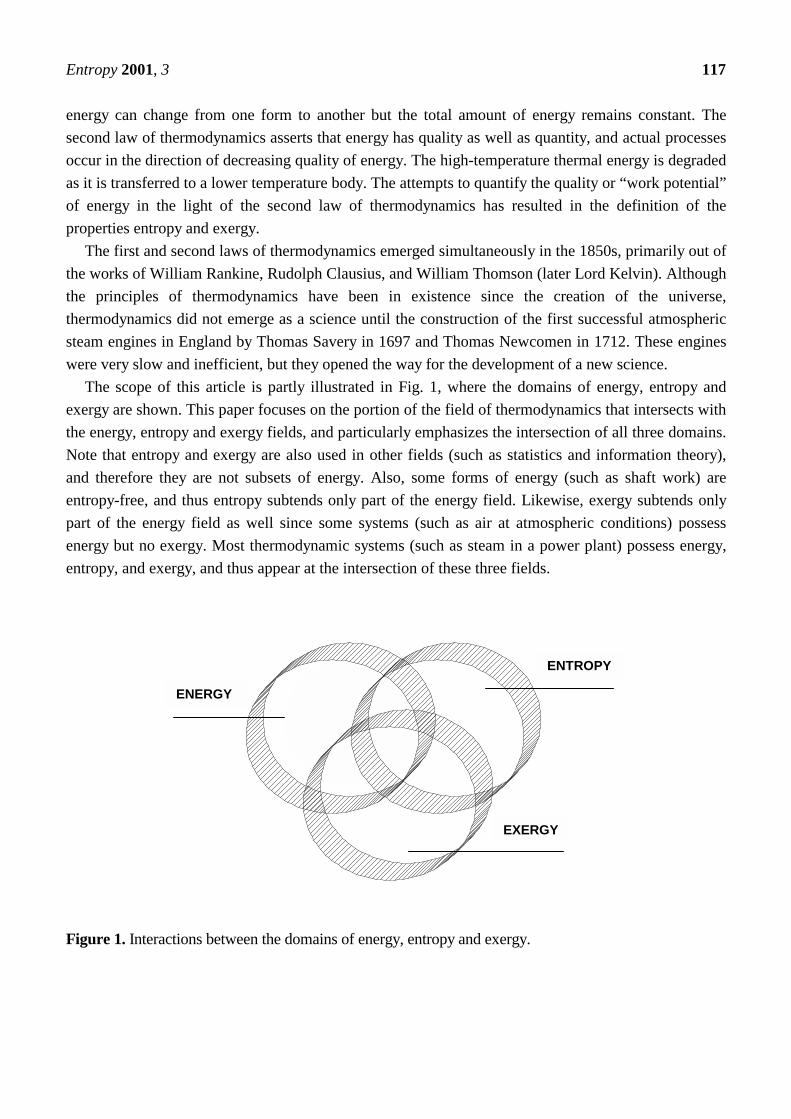
The scope of this article is partly illustrated in Fig. 1, where the domains of energy, entropy andexergy are shown. This paper focuses on the portion of the field of thermodynamics that intersects withthe energy, entropy and exergy fields, and particularly emphasizes the intersection of all three domains.Note that entropy and exergy are also used in other fields (such as statistics and information theory),and therefore they are not subsets of energy. Also, some forms of energy (such as shaft work) areentropy-free, and thus entropy subtends only part of the energy field. Likewise, exergy subtends onlypart of the energy field as well since some systems (such as air at atmospheric conditions) possessenergy but no exergy. Most thermodynamic systems (such as steam in a power plant) possess energy,entropy, and exergy, and thus appear at the intersection of these three fields.
Figure 1. Interactions between the domains of energy, entropy and exergy.
ENERGY
ENTROPY
EXERGY

Entropy 2001, 3 118
2. Energy2.1 IntroductionThermodynamics plays a key role in the analysis of systems and devices in which energy transfer andenergy transformation take place. Thermodynamics' implications are far-reaching, and its applicationsspan the whole range of the human enterprise. All along our technological history, the development ofsciences has enhanced our ability to harness energy and use it for society's needs. The industrialrevolution is a result of the discovery of how to exploit energy and how to convert heat into work.Nature allows the conversion of work completely into heat, but heat is taxed when converted intowork. For this reason, the return on our investment of heat transfer is compared with the output worktransfer and attempts are made to maximize this return.
Most of our daily activities involve energy transfer and energy change. The human body is a familiarexample of a biological system in which the chemical energy of the food or body fat is transformedinto other forms of energy such as heat transfer and work transfer. Our encounter with the environmentalso reveals a wide area of engineering applications. These include power plants to generate electricity,engines to run automobiles and aircraft, refrigeration and air conditioning systems, and so on.
In the hydroelectric power system the potential energy of the water is converted into mechanicalenergy through the use of a hydraulic turbine. The mechanical energy is then converted into electricenergy by an electric generator coupled to the shaft of the turbine. In a steam power generating plant,chemical or nuclear energy is converted into thermal energy in a boiler or a reactor. The energy isimparted to water, which vaporizes into steam. The energy of the steam is used to drive a steamturbine, and the resulting mechanical energy is used to operate a generator to produce electric power.The steam leaving the turbine is then condensed, and the condensate is pumped back to the boiler tocomplete the cycle. Breeder reactors use uranium-235 as a fuel source and can produce some more fuelin the process. A solar power plant uses solar concentrators (parabolic or flat mirrors) to heat a workingfluid in a receiver located on a tower. The heated fluid then expands in a turbogenerator in a similarmanner as in a conventional power plant. In a spark-ignition internal combustion engine, the chemicalenergy of the fuel is converted into mechanical work. An air-fuel mixture is compressed andcombustion is initiated by a spark device. The expansion of the combustion gases pushes against thepiston, which results in the rotation of the crankshaft. Gas turbine engines, commonly used for aircraftpropulsion, convert the chemical energy of the fuel into thermal energy that is used to run a gas turbine.The turbine is directly coupled to a compressor that supplies the air required for combustion. Theexhaust gases, upon expanding in a nozzle, create the necessary thrust. For power generation, theturbine is coupled to an electric generator and drives both the compressor and the generator. In a liquid-fuel rocket, a fuel and an oxidizer are combined, and the combustion gases expand in a nozzle creatinga propulsive force (thrust) to propel the rocket. A typical nuclear rocket propulsion engine offers ahigher specific impulse when compared to chemical rockets. The fuel cell converts chemical energyinto electric energy directly making use of an ion-exchange membrane. When a fuel such as hydrogenis ionized, it flows from the anode through the membrane toward the cathode. The released electrons atthe anode flow through an external load. In a magnetohydrodynamic generator, electricity is produced

Entropy 2001, 3 119
by moving a high-temperature plasma through a magnetic field. The refrigeration system utilizes worksupplied by the electric motor to transfer heat from a refrigerated space. Low-temperature boiling fluidssuch as ammonia and refrigerant-134a absorb energy in the form of heat transfer, as they vaporize inthe evaporator causing a cooling effect in the region being cooled.
These are only a meager number of engineering applications, and the study of thermodynamics isrelevant to the analysis of a much wider range of processes and applications not only in engineering,but also in other fields of science. Therefore, a careful study of this topic is required to improve thedesign and performance of energy-transfer systems.
2.2 Concept of EnergyThe concept of energy was first introduced in mechanics by Newton when he hypothesized aboutkinetic and potential energies. However, the emergence of energy as a unifying concept in physics wasnot adopted until the middle of the 19th century and was considered one of the major scientificachievements in that century. The concept of energy is so familiar to us today that it is intuitivelyobvious, yet we have difficulty in defining it exactly. Energy is a scalar quantity that can not beobserved directly but can be recorded and evaluated by indirect measurements. The absolute value ofenergy of system is difficult to measure, whereas its energy change is rather easy to calculate. In ourlife the examples for energy are endless. The sun is the major source of the earth's energy. It emits aspectrum of energy that travels across space as electromagnetic radiation. Energy is also associatedwith the structure of matter and can be released by chemical and atomic reactions. Throughout history,the emergence of civilizations has been characterized by the discovery and effective application ofenergy to society's needs.
2.3 Forms of EnergyEnergy manifests itself in many forms, which are either internal or transient, and energy can beconverted from one form to another. In thermodynamic analysis, the forms of energy can be classifiedinto two groups:• The macroscopic forms of energy are those where a system possesses as a whole with respect to
some outside reference frame such as kinetic and potential energies. For example, the macroscopicenergy of an upmoving object changes with velocity and elevation. The macroscopic energy of asystem is related to motion and the influence of some external effects such as gravity, magnetism,electricity and surface tension. The energy that a system possesses as a result of its motion relativeto some reference frame is called kinetic energy. The energy that a system has as a result of itselevation in a gravitational field is called potential energy. Kinetic energy refers to the energypossessed by the system because of its overall motion, either translational or rotational. The word"overall" is italicized because the kinetic energy to which we refer is the kinetic energy of the entiresystem, not the kinetic energy of the molecules in the system. If the system is a gas, the kineticenergy is the energy due to the macroscopic flow of the gas, not the motion of individual molecules.The potential energy of a system is the sum of the gravitational, centrifugal, electrical, and magnetic
Entropy 2001, 3 120
potential energies. To illustrate using gravitational potential energy, a one-kilogram mass, 100 mabove the ground, clearly has a greater potential energy than the same kilogram mass on the ground.That potential energy can be converted into other forms of energy, such as kinetic energy, if themass is allowed to fall freely. Kinetic and potential energy depend on the environment in which thesystem exists. In particular, the potential energy of a system depends on the choice of a zero level.For example, if the ground level is considered to be at zero potential energy, then the potentialenergy of the mass at 100 m above the ground will have a positive potential energy equal to themass (1 kg) multiplied by the gravitational constant (g = 9.807 m/s2 at sea level) and the heightabove the ground (100 m). Its potential energy will be 980.7 (kgm2)/s2 = 980.7 Newton-meters(Nm), that is, 980.7 J. The datum plane for potential energy can be chosen arbitrarily. If it had beenchosen at 100 m above the ground level, the potential energy of the mass would have been zero. Ofcourse, the difference in potential energy between the mass at 100 m and the mass at ground level isthe same independent of the datum plane.
• The microscopic forms of energy are those related to the molecular structure of a system and thedegree of the molecular activity, and they are independent of outside reference frames. The sum ofall the microscopic forms of energy is called the internal energy of a system. The internal energy ofa system depends on the inherent qualities, or properties, of the materials in the system, such ascomposition and physical form, as well as the environmental variables (temperature, pressure,electric field, magnetic field, etc.). Internal energy can have many forms, including, sensible andlatent (i.e., thermal), chemical, nuclear, electrical, mechanical, magnetic, and surface energy. Forexample, a spring that is compressed has a higher internal energy (mechanical energy) than a springthat is not compressed, because the compressed spring can do some work on changing (expanding)to the uncompressed state. As another example, consider two identical vessels, each containinghydrogen and oxygen. In the first, the gases are contained in the elemental form, pure hydrogen andpure oxygen in a ratio of 2:1. In the second, the identical number of atoms is contained, but in theform of water. One can appreciate that the internal energy of the first is different from the second.A spark set off in the first container will result in a violent release of energy. The same will not betrue in the second. Clearly, the internal energy present differs in these two situations. Any energybalance will have to take this difference into account.The science of thermodynamics is built on the concept of equilibrium states and the postulate that
the change in the value of thermodynamic quantities, such as internal energy, between two equilibriumstates of a system does not depend on the thermodynamic path the system took to get between the twostates. The change is defined by the final and beginning equilibrium states of that system. This meansthat the internal energy change of a system is determined by a knowledge of all the parameters thatspecify the system in its final state and in its initial state. The parameters are pressure, temperature,magnetic field, surface area, mass, and so on. If a system changes from a state labeled 1 to a statelabeled 2, the change in internal energy (∆U) will be (U2 -U1), the internal energy in the final state lessthe internal energy in the initial state. The difference does not depend on how the system proceeded

Entropy 2001, 3 121
from state 1 to state 2. The internal energy thus is referred to as a state or point function, since it is afunction of the state of the system only, and not the history of the process.
On the question of thermal energy, it is intuitive that the internal energy of a system increases as itstemperature is increased: We know that we have to add energy to a bar of iron to raise its temperature.The form of internal energy of a material that is related to its temperature is called sensible thermalenergy, and the form of energy related to the change of phase is called latent thermal energy. Thesensible and latent thermal energy (usually referred to as heat in daily life) can be transferred to or froma system due to a temperature difference. Therefore, heat transfer is thermal energy in transition.
2.4 The First law of Thermodynamics (FLT)The FLT stands for the first law of the conservation of energy. This is stated as energy can be neithercreated nor destroyed; it just changes form. The FLT defines internal energy as a state function andprovides a formal statement of the conservation of energy. However, it provides no information aboutthe direction in which processes can spontaneously occur, that is, the reversibility aspects ofthermodynamic processes. For example, it cannot say how cells can perform work while existing in anisothermal environment. It gives no information about the inability of any thermodynamic process toconvert heat into mechanical work with full efficiency, or any insight into why mixtures cannotspontaneously separate or unmix themselves. An experimentally derived principle to characterize theavailability of energy is required to do this. This is precisely the role of the second law ofthermodynamics that we will explain later.
2.5 FLT vs EnergyThe total energy E represents the sum of all forms of energy a system possesses, and the change in theenergy content of a system during a process is expressed as ∆Esystem . In the absence of electrical,
magnetic, surface, etc effects, the total energy in that case can be expressed as the sum of the internal,kinetic, and potential energies as
E = U + KE + PE and PEKEUEsystem ∆+∆+∆=∆ (1)
Energy can be transferred to or from a system in three forms: heat Q, work W, and mass flow m.Energy interactions are recognized at the system boundary as they cross it, and they represent theenergy gained or lost by a system during a process. Then the FLT or energy balance for any systemundergoing any kind of process can be expressed as
E E Ein out− = Net energy transferby heat, work, and mass
system
Change in internal, kinetic, potential, etc. energies
! "# $# !"# $#∆ (2)
That is, the net change (increase or decrease) in the total energy of the system during a process isequal to the difference between the total energy entering and the total energy leaving the system duringthat process. This relation can also be expressed per unit mass, differential, and rate forms as

Entropy 2001, 3 122
e e ein out− = ∆ system (3)
δ δ δ δE E dE e e dein out in out− = − =system system or (4)
% % %E E Ein out− =Rate of net energy transfer by heat, work, and mass
system
Rate of change in internal,kinetic, potential, etc. energies
! "# $# !"# $#∆ (5)
The only two forms of energy interactions associated with a fixed mass or closed system are heattransfer and work.
For a closed system undergoing a cycle, the initial and final states are identical andthus ∆E E Esystem = − =2 1 0 . Then the energy balance for a cycle simplifies to E E E Ein out in out− = =0 or .
Noting that a closed system does not involve any mass flow across its boundaries, the energy balancefor a cycle can be expressed in terms of heat and work interactions asW Q W Qnet out net in net out net in, , , ,
% %= = or . That is, the net work output during a cycle is equal to net heat input
for a cycle.For a control volume that involves a fluid stream at pressure P, the fluid upstream acts like a piston,
doing boundary work Pv per unit mass of fluid to maintain flow. For convenience, the flow work andinternal energy are combined into enthalpy, h = u + Pv, which represents the microscopic forms ofenergy for a flowing fluid (as opposed to non-fluig fluid in a container). Then the energy transfer bymass flowing into or out of a system per unit mass of the fluid stream can be expressed as
htot = h + ke + pe
Energy balance for an adiabatic steam turbine with negligible kinetic and potential energies, forexample, can be expressed as 21 hmWhm out %%% += where 1 is the inlet state of steam, 2 is the exit state,m% is the mass flow rate, and outW% is the power output.
3. Entropy3.1 IntroductionWithin the past 50 years our view of Nature has changed drastically. Classical science emphasizedequilibrium and stability. Now we see fluctuations, instability, evolutionary processes on all levelsfrom chemistry and biology to cosmology. Everywhere we observe irreversible processes in which timesymmetry is broken. The distinction between reversible and irreversible processes was first introducedin thermodynamics through the concept of "entropy".
In the modern context, the formulation of entropy is fundamental for understanding thermodynamicaspects of self-organization, evolution of order and life that we see in Nature. When a system isisolated, energy increase will be zero. In this case the entropy of the system will continue to increasedue to irreversible processes and reach the maximum possible value, which is the state ofthermodynamic equilibrium. In the state of equilibrium, all irreversible processes cease. When a systembegins to exchange entropy with the exterior then, in general, it is driven away from equilibrium, andthe entropy producing irreversible processes begins to operate. The exchange of entropy is due to
Entropy 2001, 3 123
exchange of heat and matter. The entropy flowing out of an adiabatic system is always larger than theentropy flowing into the system, the difference arising due to entropy produced by irreversibleprocesses within the system. As we shall see in the following chapters, systems that exchange entropywith their exterior do not simply increase the entropy of the exterior, but may undergo dramaticspontaneous transformations to "self-organization." The irreversible processes that produce entropycreate these organized states. Such self-organized states range from convection patterns in fluids to life.Irreversible processes are the driving forces that create this order.
Much of the internal energy of a substance is randomly distributed as kinetic energy at the molecularand sub molecular levels and as energy associated with attractive or repulsive forces betweenmolecular and sub molecular entities, which are moving closer together or further apart in relation totheir mean separation. This energy is sometimes described as being 'disordered' as it is not accessible aswork at the macroscopic level in the same way as is the kinetic energy or gravitational potential energythat an entire system possesses owing to its velocity or position in the gravitational field. Althoughenergy is the capacity to do work, it is not possible directly to access the minute quantities ofdisordered energy possessed at a given instant by the various modes of energy possession of the entitiesso as to yield mechanical shaft work on the macroscopic scale. The term 'disorder' refers to the lack ofinformation about exactly how much energy is associated at any moment with each mode of energypossession of each molecular or sub molecular entity within the system.
At the molecular and sub molecular level there is also 'ordered energy' associated with attractive orrepulsive forces between entities that have fixed mean relative positions. Part of this energy is, inprinciple, accessible as work at the macroscopic level under very special conditions, which are beyondthe scope of this manuscript. Temperature is the property that determines whether a system that is inequilibrium will experience any decrease or increase in its disordered energy if it is brought intocontact with another system that is in equilibrium. If the systems do not have the same temperature,disordered energy will be redistributed from the system at the higher temperature to the one at thelower temperature. There is then less information about precisely where that energy resides, as it isnow dispersed over the two systems.
Heat transfer to a system increases the disordered energy of the system. Heat transfer from a systemreduces the disordered energy. Reversible heat transfer is characterized by both the amount of energytransferred to or from the system and the temperature level at which this occurs. The property entropy,whose change between states is defined as the integral of the ratio of the reversible heat transfer to theabsolute temperature, is a measure of the state of disorder of the system. This 'state of disorder' ischaracterized by the amount of disordered energy and its temperature level. When reversible heattransfer occurs from one system to another, both systems have the same temperature and the increase inthe disorder of one is exactly matched by the decrease in disorder of the other. When reversibleadiabatic work is done on or by a system its ordered energy increases or decreases by exactly theamount of the work and the temperature level changes in a way that depends on the substancesinvolved. Reversible work is characterized by the amount of energy transferred to or from the system,irrespective of the temperature of the system. Irreversible work, such as stirring work or friction work,
Entropy 2001, 3 124
involves a change in the disorder of the system and, like heat transfer to a system, has the effect ofincreasing the entropy.
3.2 Entropy AspectsIt is now important to introduce a new thermodynamic property, entropy, that is simply a measure ofthe amount of molecular disorder within a system. In this regard, a system possessing a high degree ofmolecular disorder (such as a high temperature gas) has a very high entropy value and vice versa. It isimportant to note that numerical values for specific entropy are commonly listed in thermodynamictables along with values for specific volume, specific internal energy, and specific enthalpy. Therefore,entropy is known as the core of the second law thermodynamics. Here, we have to highlight thefollowing facts:• The entropy of a system is a measure of the amount of molecular disorder within the system.• A system can only generate, not destroy, entropy.• The entropy of a system can be increased or decreased by energy transports across the system
boundary.Heat and work are mechanisms of energy transfer. They are measures of the change in the internal
energy in one body as energy is transferred to it or from it to another. Work is accomplished by a forceacting through a distance. Heat requires a difference in temperature for its transfer. The definition ofheat energy can be broadened to include the energy stored in a hot gas as the average kinetic energy ofrandomly moving molecules. This description enabled us to understand the natural flow of heat energyfrom a hot to a cooler substance. The concept of random motion was translated into a notion of orderand disorder. The key linkage of order/disorder with probability followed. Energy transfers orconversions are changes of the state of a system. The natural direction of a change in state of a systemis from a state of low probability to one of higher probability. That is what probability means. Anddisordered states are more probable than ordered ones. Thus the natural direction of change of state ofa system is from order to disorder. This is the "something" that is changing in all the energy transfersand conversions we have described. Finally, we gave that something a name-entropy. The entropy of astate of a system is proportional to (depends on) its probability. Thus the SLT can be expressed morebroadly in terms of entropy in the following way:
In any transfer or conversion of energy within a closed system, the entropy of the system increases.The consequences of the second law can thus be stated positively as the spontaneous or naturaldirection of energy transfer or conversion is toward increasing entropy, or negatively as all energytransfers or conversions are irreversible. Or, in keeping with our paraphrasing of the FLT as "You can'tget something for nothing," the SLT asserts: You can't even get all you pay for.
It is low-entropy energy sources that are being used up, and low-entropy energy is "useful" energy.The energy sources in the universe were rated on an entropy/usefulness scale from the zero-entropy,highly useful mechanical forms such as gravitational potential energy, which are easily converted towork, to the high-entropy, unusable heat of our surroundings.
Entropy 2001, 3 125
In summary, this broader interpretation of the SLT suggests that real "energy conservation" shouldinclude the practice of thermodynamic economy. Each energy transfer or conversion, all else beingequal, should be arranged so that the total change in entropy (entropy generation) is a minimum. Thisrequires that energy sources be matched in entropy to energy end use.
3.3 Significance of EntropyThe "entropy" of the state of a system is a measure of the probability of its occurrence. States of lowprobability have low entropy; states of high probability have high entropy. With this definition we see,from the previous discussion and examples, that in any transfer or conversion of energy, because thespontaneous direction of the change of state of a closed system is from a less to a more probable state,the entropy of the system must increase. That is the broader statement we have been seeking for thesecond law, "In any energy transfer or conversion within an isolated closed system, the entropy of thatsystem increases."
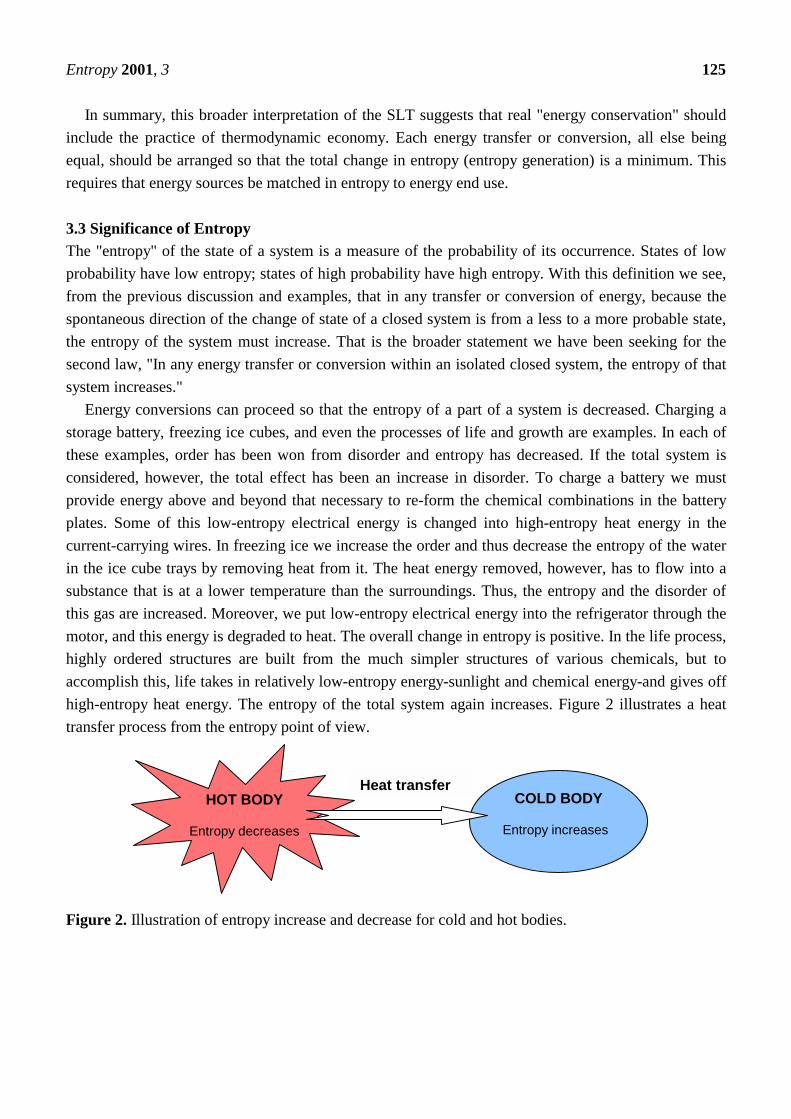
Energy conversions can proceed so that the entropy of a part of a system is decreased. Charging astorage battery, freezing ice cubes, and even the processes of life and growth are examples. In each ofthese examples, order has been won from disorder and entropy has decreased. If the total system isconsidered, however, the total effect has been an increase in disorder. To charge a battery we mustprovide energy above and beyond that necessary to re-form the chemical combinations in the batteryplates. Some of this low-entropy electrical energy is changed into high-entropy heat energy in thecurrent-carrying wires. In freezing ice we increase the order and thus decrease the entropy of the waterin the ice cube trays by removing heat from it. The heat energy removed, however, has to flow into asubstance that is at a lower temperature than the surroundings. Thus, the entropy and the disorder ofthis gas are increased. Moreover, we put low-entropy electrical energy into the refrigerator through themotor, and this energy is degraded to heat. The overall change in entropy is positive. In the life process,highly ordered structures are built from the much simpler structures of various chemicals, but toaccomplish this, life takes in relatively low-entropy energy-sunlight and chemical energy-and gives offhigh-entropy heat energy. The entropy of the total system again increases. Figure 2 illustrates a heattransfer process from the entropy point of view.
Figure 2. Illustration of entropy increase and decrease for cold and hot bodies.
HOT BODY
Entropy decreases
COLD BODY
Entropy increases
Heat transfer
Entropy 2001, 3 126
We point out from Fig. 2 that during a heat transfer process, the net entropy increases. As a matterof fact, the increase in entropy of the cold body more than offsets the decrease in the entropy of the hotbody. The SLT requires that the increase in entropy of the cold body be greater than the decrease inentropy of the hot body. The conclusion is that processes can occur only in the direction of increasedoverall entropy or molecular disorder. That is, the entire universe is getting more and more chaoticevery day.
Another way of stating the consequence of the SLT is to say that all energy transfers or conversionsare irreversible. They will go spontaneously in the direction of increasing entropy. They will not gospontaneously toward a state of lower entropy. For example, in a power plant some of the losses, as wehave said earlier, can be minimized, but none of them can be eliminated. Entropy must increase. Theusual mechanism is for some low-entropy energy to be converted, through friction or electricalresistance, for instance, or through leakage of high-temperature, low-entropy heat energy and itsdegradation to high-entropy heat energy at the lower environmental temperature.
3.4 Carnot's ContributionThe final understanding and statement of the SLT was the result of a sometimes brilliant but moreoften tedious set of theoretical and experimental investigations over a hundred or so years. One of themost brilliant contributions was made early on by a young French engineer, Sadi Carnot, in thenineteenth century. Carnot, studying the early steam engines, was able to abstract from the pumpingpistons and spinning wheels the basic property that the conversion of heat energy into mechanical workrequires a difference of temperature. The purpose of a heat engine, as he described it, is to take heatfrom a high-temperature source, convert some of this to mechanical work, and then reject the rest ofthe heat energy to a lower-temperature source (or "heat reservoir" as we call it). Carnot described heatengines in a crude analogy to waterwheels. The energy available for conversion in a waterwheel is thegravitational energy contained in water as it flows from some height (behind a dam or from a mountainlake) down through the wheel. The amount of energy available depends on the difference in height-the"head" as it is called-between the source and the pool below the wheel. The energy available to a heatengine depends on the "temperature head." Just as a high dam can provide more energy than a low one,a large temperature difference can provide more energy to be converted by a heat engine than can asmall temperature difference. In the example of a heat engine, the high-temperature reservoir would bethe hot steam coming from the power plant furnace. The low-temperature reservoir to which the engine(in our example, the steam turbine) rejects the unconverted energy is the condenser cooled bycirculating water. The important temperature difference is thus the difference in temperature betweenthe steam-which is usually at about 625°C- and the water in the condenser-which is typically at theenvironment temperature of about 25°C. The "temperature head" in this example would therefore be600°C. Carnot's brilliant explanation of this basic property of heat engines thus led immediately towardthe second law. Once energy is in the form of heat energy, we can never hope to convert all of it backinto mechanical energy. Some heat energy will always remain in the exhaust.
Entropy 2001, 3 127
3.5 The Second Law of Thermodynamics (SLT)Although a spontaneous process can proceed only in a definite direction, the FLT gives no informationabout direction; it merely states that when one form of energy is converted into another, identicalquantities of energy are involved regardless of feasibility of the process. In this regard, events could beenvisioned that would not violate the FLT, e.g., transfer of a certain quantity of heat from a low-temperature body to a high-temperature body, without expenditure of work. However, the reality showsthat this is impossible and FLT becomes inadequate in picturizing the complete energy transfer.Furthermore, experiments indicated that when energy in the form of heat is transferred to a system,only a portion of heat can be converted into work.
The SLT establishes the difference in quality between different forms of energy and explains whysome processes can spontaneously occur, whereas other can not. It indicated a trend of change and isusually expressed as an inequality. The SLT has been confirmed by experimental evidences like otherphysical laws of nature.
The SLT defines the fundamental physical quantity entropy as a randomized energy stateunavailable for direct conversion to work. It also states that all spontaneous processes, both physicaland chemical, proceed to maximize entropy, that is, to become more randomized and to convert energyinto a less available form. A direct consequence of fundamental importance is the implication that atthermodynamic equilibrium the entropy of a system is at a relative maximum; that is, no furtherincrease in disorder is possible without changing by some external means (such as adding heat) thethermodynamic state of the system. A basic corollary of the SLT is the statement that the sum of theentropy changes of a system and that of its surroundings must always be positive, that is, the universe(the sum of all systems and surroundings) is constrained to become forever more disordered and toproceed toward thermodynamic equilibrium with some absolute maximum value of entropy. From abiological standpoint this is certainly a reasonable concept, since unless gradients in concentration andtemperature are forcibly maintained by the consumption of energy, organisms proceed spontaneouslytoward the biological equivalent of equilibrium-death.
The SLT is quite general. However, when intermolecular forces are long range, as in the case ofparticles interacting through gravitation, there are difficulties because our classification into extensivevariables (proportional to volume) and intensive variables (independent of volume) does not apply. Thetotal energy is no longer proportional to the volume. Fortunately gravitational forces are very weak ascompared to the short range intermolecular forces. It is only on the astrophysical scale that this problembecomes important. The generality of the SLT gives us a powerful means to understand thethermodynamic aspects of real systems through the usage of ideal systems. A classic example isPlanck's analysis of radiation in thermodynamic equilibrium with matter (blackbody radiation) inwhich Planck considered idealized simple harmonic oscillators interacting with radiation. Planckconsidered simple harmonic oscillators not merely because they are good approximations of moleculesbut because the properties of radiation in thermal equilibrium with matter are universal, regardless ofthe particular nature of the matter with which the radiation interacts. The conclusions one arrives at
Entropy 2001, 3 128
using idealized oscillators and the laws of thermodynamics must also be valid for all other forms ofmatter, however complex.
What makes this new statement of the SLT valuable as a guide to energy policy is the relationshipbetween entropy and the usefulness of energy. Energy is most useful to us when we can get it to flowfrom one substance to another, e.g., to warm a house and we can use it to do work. Useful energy thusmust have low entropy so that the SLT will allow transfer or conversions to occur spontaneously.
3.6 SLT StatementsAlthough there are various formulations of the SLT, two of them are better known such as the Clausiusstatement and the Kelvin-Planck statement.• The Clausius statement. It is impossible for a system to transfer heat from a lower temperature
reservoir to a higher temperature reservoir. Simply, heat transfer can only occur spontaneously inthe direction of temperature decrease. For example, we can not construct a refrigerator that operateswithout any work input.
• The Kelvin-Planck statement. It is impossible for a system to receive a given amount of heat froma high-temperature reservoir and provide an equal amount of work output. While a systemconverting work to an equivalent energy transfer as heat is possible, a device converting heat to anequivalent energy transfer as work is impossible. For example, we can not build a heat engine thathas a thermal efficiency of 100%.
3.7 The Clausius InequalityIt is a mathematical statement of the second law as a precursor to the definition of a difference in aproperty known as entropy. It was first stated by the German physicist R.J.E. Clausius (known as oneof the founders of thermodynamics) and is expressed as
( )∫ ≤ 0/TQδ (6)
where the cyclic integral symbol ∫ shows the integration should be done over the entire cycle, and thesign of heat transfer is determined with respect to the system (positive if to the system, and negative iffrom the system). The cyclic integral of δQ/T is always less than or equal to zero. If it is equal to zero,it is for a system undergoing or containing only reversible processes (or cycles). If it is less than zero, itis for a system undergoing or containing only irreversible processes (or cycles).
The inequality given above can be eliminated by
( )∫−= TQSgen /δ (7)
where the quantity Sgen is the entropy generation associated with a cycle as a measure of theirreversibilities which occur during the cycle. It can be summarized as follows:
• Sgen = ∆Stotal = ∆Ssys + ∆Ssurr = 0 for a reversible process.• Sgen = ∆Stotal = ∆Ssys + ∆Ssurr > 0 for an irreversible process.
Entropy 2001, 3 129
It is important to note that for a reversible process:
∆Ssys = (Q/T)rev and ∆Ssurr = - (Q/T)rev (8)
and for an irreversible process:
∆Ssys > (Q/T)irr (9)
due to entropy generation within the system as a result of internal irreversibilities. Hence, although thechange in entropy of the system and surroundings may individually increase, decrease, or remainconstant, the total entropy change or the total entropy generation can not be less than zero for anyprocess.
3.8 Useful RelationshipsIt is important to list some useful relations and Tds equations for any process of a pure substance,assuming the absence of electricity, magnetism, solid distortion effects, and surface tension. Therefore,we list four equations and highlight their implications and restrictions as follows:• δq = du + δw: This is a statement of the FLT and is applicable to any simple compressible
closed system.• δq = du + pdv: This is a statement of the FLT and is restricted to reversible processes of a closed
system only.• Tds = du + δw: This is a combined statement of the FLT and SLT (with Tds = δq).• Tds = du + pdv: This is a combined statement of the FLT and SLT and is valid for all processes
between equilibrium states.
4. Exergy4.1 IntroductionA very important class of problems in engineering thermodynamics concerns systems or substancesthat can be modelled as being in equilibrium or stable equilibrium, but that are not in mutual stableequilibrium with the surroundings. For example, within the earth there are reserves of fuels that are notin mutual stable equilibrium with the atmosphere and the sea. The requirements of mutual chemicalequilibrium are not met. Any system at a temperature above or below that of the environment is not inmutual stable equilibrium with the environment. In this case the requirements of mutual thermalequilibrium are not met. It is found that any lack of mutual stable equilibrium between a system and theenvironment can be used to produce work. The SLT allows the maximum work that could be producedto be determined.
The exergy of a system is defined as the maximum shaft work that could be done by the compositeof the system and a specified reference environment that is assumed to be infinite, in equilibrium, andultimately to enclose all other systems. Typically, the environment is specified by stating itstemperature, pressure and chemical composition. Exergy is not simply a thermodynamic property, butrather is a co-property of a system and the reference environment. The term exergy comes from the
Entropy 2001, 3 130
Greek words ex and ergon, meaning from and work: the exergy of a system can be increased if work isdone on it. The following are some terms found in the literature that are equivalent to or nearlyequivalent to exergy: available energy, essergy, utilizable energy, available work, availability.
Exergy has the characteristic that it is conserved only when all processes of the system and theenvironment are reversible. Exergy is destroyed whenever an irreversible process occurs. When anexergy analysis is performed on a plant such as an entire power station, a chemical processing plant ora refrigeration plant, the thermodynamic imperfections can be quantified as exergy destruction, whichis wasted work or wasted potential for the production of work. Like energy, exergy can be transferredor transported across the boundary of a system. For each type of energy transfer or transport there is acorresponding exergy transfer or transport. In particular, exergy analysis takes into account thedifferent thermodynamic values of work and heat. The exergy transfer associated with shaft work isequal to the shaft work. The exergy transfer associated with heat transfer, however, depends on thetemperature level at which it occurs in relation to the temperature of the environment.
4.2 Exergy AspectsIt is also important to illustrate some meanings of exergy by the following simple examples:• A system in complete equilibrium with its environment does not have any exergy. No difference
appears in temperature, pressure, or concentration etc. for running any processes.• The more a system deviates from the environment, the more exergy it carries. Hot water has a
higher content of exergy during the winter than it has on a hot summer day. A block of ice carrieshardly any exergy in winter while it does in summer.
• When the energy loses its quality, it results in exergy destroyed. The exergy is the part of the energywhich is useful in the society and therefore has an economic value and is worth taking care of.
• Almost all energy, converted in the thin layer on the earth’s surface, where life can be found,derives from the sun. Sunlight, rich in exergy, reaches the earth. A lot of it is reflected but theenergy absorbed on the earth is converted and finally leaves the earth as heat radiation with noexergy relative to the earth. The net exergy absorbed by the earth is consequently graduallydestroyed but during this destruction it manages to drive the water/wind system and the life onearth. The green plants absorb exergy from the sunlight and convert it via photosynthesis intochemical exergy. The chemical exergy then passes through different food chains in the ecosystems.On every tropical level exergy is consumed and micro-organisms live on the last level in this foodchain. There exists no waste.
• A concentrated deposit of mineral ‘contrasts’ with the environment and this contrast increases withthe concentration of the mineral. The mineral is thus a carrier of exergy. When the mineral is minedthe exergy content of the mineral is kept constant, and if it is enriched the exergy content increases.A poor deposit of mineral contains less exergy and can accordingly be utilised only through a largerinput of external exergy. Today this substitution of exergy often comes from exergy forms such ascoal and oil. When a concentrated mineral is dispersed the exergy content is decreased (item 3).
Entropy 2001, 3 131
• An apparent difficulty in the definition of exergy is that it depends on the environment. Thisdifficulty could, however, be solved through conventions, one could define a ‘standardenvironment’ with a given chemical composition at a certain temperature and pressure. A possiblestandard environment for global use could, for instance, be a standard atmosphere, a standard seaand a standard bed-rock. One principal problem is, however, that these systems are not inequilibrium with each other. Sometimes one should, in addition to this, use local standardsdepending on the season (item 2).
• An engineer designing a system is expected to aim for the highest possible technical efficiency at aminimum cost under the prevailing technical, economic and legal conditions, but also with regardto ethical, ecological and social consequences. Exergy is a concept that makes this work a greatdeal easier. Thus, exergetics offers a unique insight where losses and possible improvements can bedetermined, and Life Cycle Exergy Analysis (LCEA) is suggested as a method to better meetenvironmental conditions.
Before getting into details of the linkages between energy and exergy, exergy and theenvironment, energy and sustainable development, we provide some key points to highlight theimportance of the exergy and its utilization:• It is a primary tool in best addressing the impact of energy resource utilization on the environment.• It is an effective method using the conservation of mass and conservation of energy principles
together with the second law of thermodynamics for the design and analysis of energy systems.• It is a suitable technique for furthering the goal of more efficient energy-resource use, for it enables
the locations, types, and true magnitudes of wastes and losses to be determined.• It is an efficient technique revealing whether or not and by how much it is possible to design more
efficient energy systems by reducing the inefficiencies in existing systems.• It is a key component in obtaining sustainable development.
4.3 Exergy vs EnergyThe traditional method of assessing the energy disposition of an operation involving the physical or
chemical processing of materials and products with accompanying transfer and/or transformation ofenergy is by the completion of an energy balance. This balance is apparently based on the FLT. In thisbalance, information on the system is employed to attempt to reduce heat losses or enhance heatrecovery. However, from such a balance no information is available on the degradation of energy,occurring in the process and to quantify the usefulness or quality of the heat content in various streamsleaving the process as products, wastes, or coolants.
The exergy method of analysis overcomes the limitations of the FLT. The concept of exergy isbased on both FLT and SLT. Exergy analysis can clearly indicate the locations of energy degradation ina process that may lead to improved operation or technology. It can also quantify the quality of heat ina reject stream. So, the main aim of exergy analysis is to identify the causes and to calculate the truemagnitudes of exergy losses. Table 1 presents a general comparison of both energy and exergy.

Entropy 2001, 3 132
Table 1. Comparison of energy and exergy.ENERGY EXERGY• is dependent on the parameters of matter
or energy flow only, and independent ofthe environment parameters.
• has the values different from zero (equal tomc2 upon Einstein’s equation).
• is governed by the FLT for all theprocesses.
• is limited by the SLT for all processes(incl. reversible ones).
• is motion or ability to produce motion.• is always conserved in a process, so can
neither be destroyed or produced.• is a measure of quantity only.
• is dependent both on the parameters of matteror energy flow and on the environmentparameters.
• is equal to zero (in dead state by equilibriumwith the environment).
• is governed by the FLT for reversible processesonly (in irreversible processes it is destroyedpartly or completely).
• is not limited for reversible processes due to theSLT.
• is work or ability to produce work.• is always conserved in a reversible process, but is
always consumed in an irreversible process.• is a measure of quantity and quality due to
entropy.
To begin with, we must distinguish between exergy and energy in order to avoid any confusion withthe traditional energy-based methods of thermal system analysis and design. Energy flows into and outof a system via mass flow, heat transfer, and work (e.g., shafts, piston rods). Energy is conserved, notdestroyed: this is the statement made by the FLT. Exergy is an entirely different concept. It representsquantitatively the "useful" energy, or the ability to do work-the work content-of the great variety ofstreams (mass, heat, work) that flow through the system. The first attribute of the property "exergy" isthat it makes it possible to compare on a common basis interactions (inputs, outputs) that are quitedifferent in a physical sense. Another benefit is that by accounting for all the exergy streams of thesystem it is possible to determine the extent to which the system destroys exergy. The destroyed exergyis proportional to the generated entropy. In actual systems, exergy is always destroyed, partially ortotally: this is the statement made by the SLT. The destroyed exergy, or the generated entropy isresponsible for the less-than-theoretical efficiency of the system.
Example-I: for Difference Between Energy and Exergy DescriptionThe exergy concept is today extensively used within the steam power engineering, where energy
forms of different qualities are dealt with. It is shown here that for hot steam, district heating and wasteheat the quality index, i.e. the exergy in relation to the energy content, becomes lower and lower. Thismust be taken into account by those engineers who work with these different energy forms. Let usexamine how a power plant works. The upper part of Fig. 3 is the schematic of a basic power plant, inthis case a condensing power plant, where the combustion of oil or coal takes place. It could alsoillustrate a nuclear power plant, where uranium is used instead for supplying heat. The heat produced isused to boil water under high pressure in a large boiler, in principle a large pressure-cooker (steamproduction unit). The steam is supplied to a turbine, where the energy of the steam is converted into

Entropy 2001, 3 133
rotation of the turbine shaft. At the other end of the shaft, an electric generator is located, producingelectricity. The electricity is then supplied to the consumer to accomplish various tasks.
Figure 3. The energy- and exergy flow through a condensing power plant [1, 2].
When the steam passed through the turbine it transmitted exergy to the electric generator. After theturbine, the steam is chilled in a condenser to water, and brought back to the boiler. This cooling isnecessary to optimize the power transmission in the turbine, since the turbine can work with maximaldifference in pressure when the steam is condensed immediately after passing through it. The chemicalenergy in oil and coal, or the nuclear energy in uranium, is thus transformed into electrical energy, butnot without losses. The losses are great in a power plant, no less than about 40%, and in a nuclearpower plant they are no less than about 70%. Counting the total system, from the preparation of theenergy raw material to the finishing treatment of the waste products, there are even greater losses.
Let us now see what happens to the losses in the power plant itself. In the bottom part of Fig. 3 thereare two diagrams of flows, so-called Sankey-diagrams [1]. In the top diagram, the width of the flow isproportional to the energy content for the respective energy form, in the bottom diagram, the width isproportional to the exergy content. The first thing we notice is that the widths of the inflows andoutflows in the two diagrams are almost equal. This is due to the fact that both the inflows and theoutflows are very high quality energy forms. The quality indexes for the energy forms in question liebetween 90% and 100%. For electrical energy the exergy content is as large as the energy content. Thelosses in the two diagrams are, however, quite different. At first we have losses in the furnace. The fuelis here converted into heat. In an oil or coal fueled power plant we get a flame temperature of abouttwo thousand degrees (°C). In a nuclear power plant the temperature is instead a few hundred degrees(°C). The heat is then transmitted through heat exchangers to boiling water. The pressure is high, withthe result that the water does not boil until it reaches a temperature of a few hundred degrees. Throughthe walls of the furnace, and through pipes, heat is transmitted to the environment, where it is lost.Heat is also discharged with the exhaust gases, to keep the chimney of an oil and coal power plant freefrom condensed water. These furnace losses represent only a small percentage of the total energy
Entropy 2001, 3 134
conversion. We see, however, from the exergy diagram that something drastic happens. At this point,more than one third of the exergy is lost. We also see that it is lost in the process itself, i.e. only a verysmall part of the lost exergy leaves the power plant. The exergy flow just becomes narrower. Largequantities of entropy are created. This is due to the fact that the steam that leaves the boiler has a lowertemperature and pressure than should be physically possible. The reason for this is limitations in thefatigue strength of the components included in the process, principally in the boiler and the turbineblades. In a nuclear power plant, more than half the exergy is lost at this stage of the process.
The width of the flows of thermal energy and thermal exergy as hot steam in Fig. 3, show thegreatest difference between energy and exergy flow. This is also a completely different view of how thelosses in the process arise. In a diagram of energy flows, the losses are heaviest in the condenser. Agreat deal of the energy is lost in the condenser through waste heat in the cooling water. Waste heat is,however, heat at a very low temperature and therefore energy of a very low quality. This is clearlyshown in the exergy diagram. The exergy content of the waste heat is just a small percentage of theenergy content. To make it clearer we can picture the following process. Let us suppose that we convertthe thermal energy in the waste heat into mechanical energy by an ideal process. From the waste heat,we would then only be able to convert that part of the energy content that corresponds to mechanicalwork, i.e. the exergy content. At such a conversion process the loss would be waste heat at the sametemperature as the environment, i.e. with the exergy content equal to zero. It is by no means possible toattain more mechanical or electrical energy out of the thermal energy than what is determined by thethermal exergy. When changing from mechanical energy to electrical energy, both with an exergycontent of 100%, small losses arise through friction. These losses are on the whole equally small inboth diagrams. Part of the friction losses consists of mechanical fatigue, i.e., wearing out of shafts andbearings [2].
The conclusion we can draw from the diagrams will thus be that in the diagrams of energy flows,the heaviest losses appear in the condenser but from the exergy flow, the heaviest losses seem tohappen already at the combustion in the boiler. We also see from the diagram of exergy flows thatthese losses in the boiler cannot be extracted. Thus, the exergy is used in the process itself. It is aninevitable “internal loss”, in the process and is dependent on the technical solutions available.
Example-II: Difference Between Energy and Exergy DescriptionThe diagrams in Fig. 4 illustrate the differences between energy and exergy flows, and thereby
efficiency, for 4 conversion systems: an oil furnace, electric heater, an electric heat pump and acombined power and heat plant. At the top we see the conversion of fuel into heat in an ordinary oilfurnace. The energy efficiency is limited to about 85%, principally through stack losses. The low valueof the exergy efficiency, about 4%, is, however, due to the fact that the fall in temperature when athousand degree flame heats water to 60°C is not utilized. As we can see, electric heating has an energyefficiency of 100%. In the diagram for the electric heat pump we see that this is not a top limit ofenergy efficiency at the conversion of electricity into heat. A heat pump can, of course, also be run withfuels by connecting it to a combustion engine. The heat pump can also in this way take the place of an

Entropy 2001, 3 135
ordinary furnace for space heating. If the environment is ignored, the conversion of electrical energy orfuels into heat can be well over 100%. We see that in looking at exergy the picture becomes quitedifferent. The exergy efficiency for electric heat is about 5% and for the heat pump 15% [2].
Figure 4. Energy and exergy efficiency for an oil furnace, an electric heater, an electric heat pump anda combined power and heat plant [2, 3].
4.4 Interdisciplinary Nature of ExergyUnder the facts listed in Section 4.2, we earlier introduced a new concept and defined exergy as a
distinct discipline, because of its interdisciplinary character as the confluence of energy, environment andsustainable development (Fig. 5). Energy production, transformation, transport and use have importantimpacts on the earth's environment. Energy and environment policies increasingly play a prominentrole in relating to a broad range of local, regional and global environmental concerns.
Figure 5. The interdisciplinary triangle of exergy [4].
4.5 Exergy AnalysisExergy is defined as the maximum amount of work which can be produced by a system or a flow of
matter or energy as it comes to equilibrium with a reference environment. Exergy is a measure of the
EXERGY
ENERGY ENVIRONMENT
SUSTAINABLEDEVELOPMENT

Entropy 2001, 3 136
potential of the system or flow to cause change, as a consequence of not being completely in stableequilibrium relative to the reference environment. Unlike energy, exergy is not subject to aconservation law (except for ideal, or reversible, processes). Rather, exergy is consumed or destroyed,due to irreversibilities in any real process. The exergy consumption during a process is proportional tothe entropy created due to irreversibilities associated with the process [5-10].
For exergy analysis, the state of the reference environment, or the reference state, must be specifiedcompletely. This is commonly done by specifying the temperature, pressure and chemical compositionof the reference environment. The results of exergy analyses, consequently, are relative to the specifiedreference environment, which in most applications is modelled after the actual local environment [5].
Exergy analysis is a method that uses the conservation of mass and conservation of energyprinciples together with the SLT for the analysis, design and improvement of energy and other systems.The exergy method is useful for furthering the goal of more efficient energy-resource use, for it enablesthe locations, types, and true magnitudes of wastes and losses to be determined. In general, moremeaningful efficiencies are evaluated with exergy analysis rather than energy analysis, since exergyefficiencies are always a measure of the approach to the ideal case. Therefore, exergy analysis canreveal whether or not and by how much it is possible to design more efficient energy systems byreducing the inefficiencies in existing systems. Many engineers and scientists suggest that thethermodynamic performance of a process is best evaluated by performing an exergy analysis inaddition to or in place of conventional energy analysis because exergy analysis appears to provide moreinsights and to be more useful in efficiency improvement efforts than energy analysis.
It is important to highlight that exergy analysis can lead to a substantially reduced rate in the use ofnatural resources and the environmental pollution by reducing the rate of discharge of waste products.
4.5 Exergy ModelsExergy is a measure of how far a certain system deviates from equilibrium with its environment and
therefore, the following expressions can be written for exergy contained in a system.
• Ex = T0(St,eq - St) (10)
where T0 is the temperature of the environment and (St,eq - St) is the deviation from equilibrium of thenegentropy (=minus the entropy) of the system and its environment, i.e., the total system. (‘eq’ denotesequilibrium with the environment.)
• Ex = U + P0V – T0S – Σi µi0ni (11)
where U, V, S, and ni denote extensive parameters of the system (energy, volume, entropy, and thenumber of moles of different chemical components) and P0, T0, and µi0 are intensive parameters of theenvironment (pressure, temperature, and chemical potential which also may include gravitational andelectromagnetic potentials etc.). The subscript "o" denotes conditions of the reference environment. It isevident from this equation that the exergy of a system is zero when it is in equilibrium with the referenceenvironment (i.e., when T = To, p = po, and µk = µko for all k).

Entropy 2001, 3 137
• Ex = (U – Ueq) + P0(V – Veq ) – T0 (S – Seq ) – Σi µi0(ni – nieq) (12)
where on the right side easily determined quantities appear. It is thus an easy task to determine theexergy content of a given system in a given environment. For a substance which has an exergy contentderiving only from its concentration the following relation holds:
• Ex = RT0nln(c/c0) (13)
where n is the number of moles of the substance, R is the gas constant, T0 is the temperature of theenvironment, c is concentration of the substance in the material considered, and c0 = concentration ofthe substance in the environment.
For materials like inert gases or other not chemically active materials this concept of exergy isapplicable. The chemically reacting materials receive an additional exergy contribution from thechange in the chemical potential. The exergy content in a material can thus be summarized by thefollowing formula:
• Ex = n[µ – µ0 + RT0ln(c/c0)] (14)
where µ0 is chemical potential for the material in its reference state, i.e. in equilibrium with theenvironment. The chemical potential values for most materials can be found in a tabular form in somereference books.
4.7 Definition of EnvironmentIt is noted that the natural environment does not possess the theoretical characteristics of a reference
environment. The natural environment is not in equilibrium, and its intensive properties vary spatially andtemporally. Many chemical reactions in the natural environment are blocked because the transportmechanisms necessary to reach equilibrium are too slow at ambient conditions. Thus, the exergy of thenatural environment is not zero, as work could be obtained if it were to come to equilibrium. Indeveloping reference-environment models for exergy analysis, a compromise is often made between thetheoretical requirements of the reference environment and the actual behavior of the natural environment.
Several reference-environment models have been proposed. The most significant classes of these aredescribed below [4-6]:• Natural-environment-subsystem models: These models attempt to simulate realistically subsystems of
the natural environment. This model consists of saturated moist air and liquid water in phaseequilibrium. An extension of that model was proposed to allow sulphur-containing materials to beanalyzed. The temperature and pressure of this reference environment (Table 2) are normally taken tobe 25°C and 1 atm, respectively, and the chemical composition is taken to consist of air saturated withwater vapor, and the following condensed phases at 25°C and 1 atm: water (H2O), gypsum(CaSO4•2H2O), and limestone (CaCO3). The stable configurations of C, O and N respectively aretaken to be those of CO2, O2 and N2 as they exist in air saturated with liquid water at T0 and P0 (thetemperature and pressure for the reference environment); of hydrogen is taken to be in the liquid phase

Entropy 2001, 3 138
of water saturated with air at T0 and P0; and of S and Ca respectively are taken to be those ofCaSO4•2H2O and CaCO3 at T0 and P0.
• Reference-substance models: With this model, a "reference substance" is selected for every chemicalelement and assigned zero exergy. This is the model in which the reference substances are selected asthe most valueless substances found in abundance in the natural environment. The criterion forselecting such reference substances is consistent with the notion of simulating the naturalenvironment, but is primarily economic in nature, and is vague and arbitrary with respect to theselection of reference substances. Part of this environment is the composition of moist air, includingN2, O2, CO2, H2O and the noble gases; gypsum (for sulphur) and limestone (for calcium). This modelis not similar to the natural environment. Consequently absolute exergies evaluated with this model donot relate to the natural environment, and can not be used rationally to evaluate efficiencies orenvironmental impact.
Table 2. A reference-environment model.
T0 = 25°C = 298.15 KP0 = 1 atmComposition: (i) Atmospheric air saturated with H2O at T0 and P0 (having the following composition):
Air Constituents Mole Fraction———————————————————————————
N2 0.7567O2 0.2035H2O 0.0303Ar 0.0091CO2 0.0003H2 0.0001
———————————————————————————(ii) The following condensed phases at T0 and P0:
Water (H2O)Limestone (CaCO3)Gypsum (CaSO4•2H2O)
• Equilibrium and constrained-equilibrium models: It is the model in which all the materials presentin the atmposphere, oceans and a layer of the crust of the earth are pooled together and anequilibrium composition is calculated for a given temperature. The selection of the thickness ofcrust considered is subjective and is intended to include all materials accessible to technicalprocesses. Thicknesses varying from 1 m to 1000 m, and a temperature of 25°C were considered.For all thicknesses, the model differed significantly from the natural environment. Exergy valuesobtained using these environments are significantly dependent on the thickness of crust considered,and represent the absolute maximum amount of work obtainable from a material. Since there is notechnical process available which can obtain this work from materials, this equilibrium model doesnot give meaningful exergy values when applied to the analysis of real processes. Its modifiedversion of the equilibrium environment was proposed later in which the calculation of an

Entropy 2001, 3 139
equilibrium composition excludes the possibility of the formation of nitric acid (HNO3) and itscompounds. That is, all chemical reactions in which these substances are formed are in constrainedequilibrium, and all other reactions are in unconstrained equilibrium. When a thickness of crust of 1m and temperature of 25°C are used, the model is similar to the natural environment.
• Process-dependent models: This is the model which contains only components that participate inthe process being examined in a stable equilibrium composition at the temperature and pressure ofthe natural environment. This model is dependent on the process examined, and is not general.Exergies evaluated for a specific process-dependent model are relevant only to the process. Theycan not rationally be compared with exergies evaluated for other process-dependent models or usedin environmental assessments.
An understanding of the relations between exergy and the environment may reveal the fundamentalpatterns and forces that affect and underlie changes in the environment, and help researchers to dealbetter with environmental damage.
4.8 Exergy EfficienciesHere, we introduce another concept of SLT efficiency, referring to the exergy eficiency and to show itsuse in assessing the efficiency or energy utilization. Engineers make frequent use of efficiencies togauge the performance of devices and the effectiveness of processes. Many of these expressions arebased on energy-they are FLT efficiencies. Also useful are measures of performance that take intoaccount limitations imposed by the second law. Efficiencies of this type are called here SLTefficiencies.
To illustrate the idea of a performance parameter having to do with the SLT and to contrast it withan analogous energy-based efficiency, consider a control volume at steady-state for which the energyand availability equations can be written, respectively, as
(Energy in) = (Energy out in product) + (Energy loss) (15)
(Availability in) = (Availability out in product) + (Availability loss) + (Availability destruction)(16)
In these equations, the term product might refer to shaft work or electricity developed, a certain heattransfer, some desired combination of heat and work, or possibly a particular exit stream (or streams).Losses are understood to include such things as waste heat and slack gases vented to thc surroundingswithout use. The destruction term in the availability equation refers to availability destruction due tointernal irreversibilities. From either viewpoint, energy or availability, a gauge of how effectively theinput is converted to the product is the ratio (product/input), that is
η= Energy out in product/Energy in = 1 - [Loss/Input] (17)
Entropy 2001, 3 140
ψ = Availability out in product/Availability in = 1 - [(Loss + Destruction)/Input] (18)
Here, the exergy efficiency ψ frequently gives a finer understanding of performance than η. Incomputing η, the same weight is assigned to energy whether it becomes shaft work or a stream of lowtemperature fluid. Also, it centers attention on reducing 'losses" to improve efficiency. The parameterψ weights energy flows by accounting for each in terms of availability. It stresses that both losses andinternal irreversibilities need to be dealt with to improve performance. In many cases it is theirreversibilities that are more significant and the more difficult to deal with.
Efficiency equations each define a class of efficiencies because a judgment has to be made aboutwhat is the product, what is counted as a loss, and even what is regarded as the input. Differentdecisions about these lead to different efficiency expressions within the class.
Other kinds of second law efficiency expressions also appear in the literature. One of these,appropriate only for devices at steady-state, is calculated as the ratio of the sum of the availabilityexiting to the sum of the availability entering. Another class of second law efficiencies is composed oftask efficiencies.
5. Illustrative ExamplesNext we provide four illustrative examples on (i) entropy generation during heat transfer processes,
(ii) entropy generation in a wall, (iii) entropy generation associated with heat transfer and finally (iv) asensible energy storage system. These examples will highlight the importance of these concepts andshow the facts in thermal engineering applications.
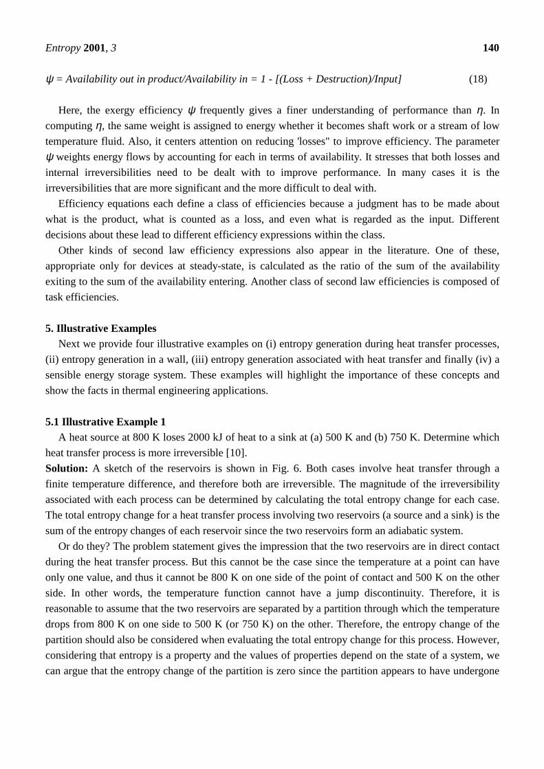
5.1 Illustrative Example 1A heat source at 800 K loses 2000 kJ of heat to a sink at (a) 500 K and (b) 750 K. Determine which
heat transfer process is more irreversible [10].Solution: A sketch of the reservoirs is shown in Fig. 6. Both cases involve heat transfer through afinite temperature difference, and therefore both are irreversible. The magnitude of the irreversibilityassociated with each process can be determined by calculating the total entropy change for each case.The total entropy change for a heat transfer process involving two reservoirs (a source and a sink) is thesum of the entropy changes of each reservoir since the two reservoirs form an adiabatic system.
Or do they? The problem statement gives the impression that the two reservoirs are in direct contactduring the heat transfer process. But this cannot be the case since the temperature at a point can haveonly one value, and thus it cannot be 800 K on one side of the point of contact and 500 K on the otherside. In other words, the temperature function cannot have a jump discontinuity. Therefore, it isreasonable to assume that the two reservoirs are separated by a partition through which the temperaturedrops from 800 K on one side to 500 K (or 750 K) on the other. Therefore, the entropy change of thepartition should also be considered when evaluating the total entropy change for this process. However,considering that entropy is a property and the values of properties depend on the state of a system, wecan argue that the entropy change of the partition is zero since the partition appears to have undergone
Entropy 2001, 3 141
a steady process and thus experienced no change in its properties at any point. We base this argumenton the fact that the temperature on both sides of the partition and thus throughout remained constantduring this process. Therefore, we are justified to assume that ∆Spartition = 0 since the entropy (as well asthe energy) content of the partition remained constant during this process. Since each reservoirundergoes an internally reversible, isothermal process, the entropy change for each reservoir can bedetermined from ∆S = Q/T0 where T0 is the constant absolute temperature of the system and Q is theheat transfer for the internally reversible process.
(a) For the heat transfer process to a sink at 500 K:
∆Ssource = Qsource/Tsource = -2000 kJ/800 K = -2.5 kJ/K
∆Ssink = Qsource/Tsource = 2000 kJ/500 K = +4.0 kJ/K
and
Sgen = ∆Stotal = ∆Ssource + ∆Ssink = (-2.5 + 4.0) kJ/K = +1.5 kJ/K
Therefore, 1.5 kJ/K of entropy is generated during this process. Noting that both reservoirs haveundergone internally reversible processes, the entire entropy generation took place in the partition.
(b) Repeating the calculations in part (a) for a sink temperature of 750 K, we obtain
∆Ssource = -2.5 kJ/K
∆Ssink = +2.7 kJ/K
and
Sgen = ∆Stotal = (-2.5 + 2.7) kJ/K = +0.2 kJ/K
The total entropy change for the process in part (b) is smaller, and therefore it is less irreversible. Thisis expected since the process in (b) involves a smaller temperature difference and thus a smallerirreversibility.Discussion: The irreversibilities associated with both processes could be eliminated by operating aCarnot heat engine between the source and the sink. For this case it can be shown that ∆Stotal = 0.
Figure 6. Schematic for the example on entropy generation during heat transfer processes.
Source800 K
Sink A500 K
Source800 K
Sink B750 K
2000 kJ(a)
(b)

Entropy 2001, 3 142
5.2 Illustrative Example 2Consider steady heat transfer through a 5-m×6–m brick wall of a house of thickness 30 cm. On a
day when the temperature of the outdoors is 0°C, the house is maintained at 27°C. The temperatures ofthe inner and outer surfaces of the brick wall are measured to be 20°C and 5°C, respectively, and therate of heat transfer through the wall is 1035 W. Determine the rate of entropy generation in the wall,and the rate of total entropy generation associated with this heat transfer process [10].Solution: We first take the wall as the system (Fig. 7). This is a closed system since no mass crossesthe system boundary during the process. We note that the entropy change of the wall is zero during thisprocess since the state and thus the entropy of the wall do not change anywhere in the wall. Heat andentropy are entering from one side of the wall, and leaving from the other side.Assumptions: (i) The process is steady, and thus the rate of heat transfer through the wall is constant.(ii) Heat transfer through the wall is one-dimensional.Analysis: The rate form of the entropy balance for the wall simplifies to
systemgenoutin SSSS⋅⋅⋅⋅
∆=+
−
Rate of net entropy Rate of Rate of changetransfer by heat entropy of entropyand mass generation
W/K191.0 0 K) W/278(1035K) W/293(1035 0// =⇒=+−⇒=+
−
⋅⋅⋅⋅⋅
gengengenoutin
SS STQTQ
Therefore, the rate of entropy generation in the wall is 0.191 W/K.Note that entropy transfer by heat at any location is Q/T at that location, and the direction of entropy
transfer is the same as the direction of heat transfer.To determine the rate of total entropy generation during this heat transfer process, we extend the
system to include the regions on both sides of the wall that experience a temperature change. Then oneside of the system boundary becomes room temperature while the other side becomes the temperatureof the outdoors. The entropy balance for this extended system (system immediate surroundings) will bethe same as that given above, except the two boundary temperatures will be 300 and 273 K instead of293 and 278 K, respectively. Then the rate of total entropy generation becomes
W/K341.0 0 K) W/273(1035K) W/300(1035 ,, =⇒=+−⋅⋅
totalgentotalgen SS
Discussion: Note that the entropy change of this extended system is also zero since the state of air doesnot change at any point during the process. The differences between the two entropy generations is0.150 W/K, and it represents the entropy generated in the air layers on both sides of the wall. Theentropy generation in this case is entirely due to irreversible heat transfer through a finite temperaturedifference.
0

Entropy 2001, 3 143
Figure 7. Schematic for the example on entropy generation in a wall.
5.3 Illustrative Example 3Consider a frictionless piston-cylinder device contains a saturated liquid–vapor mixture of water at
100°C. During a constant-pressure process, 600 kJ of heat is transferred to the surrounding air at 25°C.As a result, part of the water vapor contained in the cylinder condenses. Determine (a) the entropychange of the water and (b) the total entropy generation during this heat transfer process [10].Solution: We first take the water in the cylinder as the system (Fig. 8). This is a closed system since nomass crosses the system boundary during the process. We note that the pressure and thus thetemperature of water in the cylinder remain constant during this process. Also, the entropy of thesystem decreases the process because of heat loss.Assumptions: (i) There are no irreversibilities involved within the system boundaries, and thus theprocess is internally reversible. (ii) The water temperature remains constant at 100°C everywhere,including the boundaries.Analysis: (a) Noting that water undergoes an internally reversible isothermal process, its entropychange can be determined from
∆Ssystem = Q/Tsystem = -600 kJ/(100 + 273) K = -1.61 kJ/K
(b) To determine the total entropy generation during this process, we consider the extended system,which includes the water, the piston-cylinder device, and the region immediately outside the systemthat experiences a temperature change so that the entire boundary of the extended system is at thesurrounding temperature of 25°C. The entropy balance for this extended system (system immediatesurroundings) yields
Sin − Sout + Sgen = ∆Ssystem ⇒ Qout/Tb + Sgen = ∆Ssystem
Net entropy Entropy Change intransfer by heat generation entropyand mass
or Sgen = Qout/Tb + ∆Ssystem = 600 kJ/(25 + 273) K + (-1.61 kJ/K) = 0.40 kJ/K
The entropy generation in this case is entirely due to irreversible heat transfer through a finitetemperature difference.
Brick Wall
⋅
Q0°C
0°C20°C
27°C
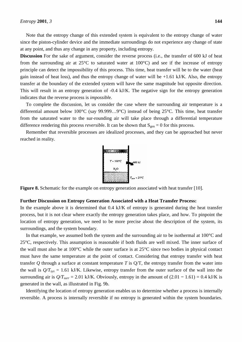
Entropy 2001, 3 144
Note that the entropy change of this extended system is equivalent to the entropy change of watersince the piston-cylinder device and the immediate surroundings do not experience any change of stateat any point, and thus any change in any property, including entropy.Discussion For the sake of argument, consider the reverse process (i.e., the transfer of 600 kJ of heatfrom the surrounding air at 25°C to saturated water at 100°C) and see if the increase of entropyprinciple can detect the impossibility of this process. This time, heat transfer will be to the water (heatgain instead of heat loss), and thus the entropy change of water will be +1.61 kJ/K. Also, the entropytransfer at the boundary of the extended system will have the same magnitude but opposite direction.This will result in an entropy generation of -0.4 kJ/K. The negative sign for the entropy generationindicates that the reverse process is impossible.
To complete the discussion, let us consider the case where the surrounding air temperature is adifferential amount below 100°C (say 99.999…9°C) instead of being 25°C. This time, heat transferfrom the saturated water to the sur-rounding air will take place through a differential temperaturedifference rendering this process reversible. It can be shown that Sgen = 0 for this process.
Remember that reversible processes are idealized processes, and they can be approached but neverreached in reality.
Figure 8. Schematic for the example on entropy generation associated with heat transfer [10].
Further Discussion on Entropy Generation Associated with a Heat Transfer Process:In the example above it is determined that 0.4 kJ/K of entropy is generated during the heat transferprocess, but it is not clear where exactly the entropy generation takes place, and how. To pinpoint thelocation of entropy generation, we need to be more precise about the description of the system, itssurroundings, and the system boundary.
In that example, we assumed both the system and the surrounding air to be isothermal at 100°C and25°C, respectively. This assumption is reasonable if both fluids are well mixed. The inner surface ofthe wall must also be at 100°C while the outer surface is at 25°C since two bodies in physical contactmust have the same temperature at the point of contact. Considering that entropy transfer with heattransfer Q through a surface at constant temperature T is Q/T, the entropy transfer from the water intothe wall is Q/Tsys = 1.61 kJ/K. Likewise, entropy transfer from the outer surface of the wall into thesurrounding air is Q/Tsurr = 2.01 kJ/K. Obviously, entropy in the amount of (2.01 − 1.61) = 0.4 kJ/K isgenerated in the wall, as illustrated in Fig. 9b.
Identifying the location of entropy generation enables us to determine whether a process is internallyreversible. A process is internally reversible if no entropy is generated within the system boundaries.
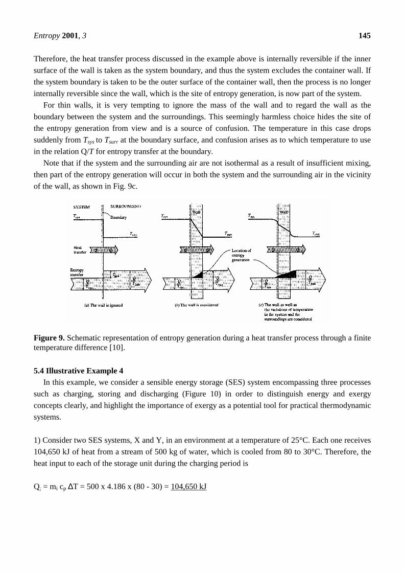
Entropy 2001, 3 145
Therefore, the heat transfer process discussed in the example above is internally reversible if the innersurface of the wall is taken as the system boundary, and thus the system excludes the container wall. Ifthe system boundary is taken to be the outer surface of the container wall, then the process is no longerinternally reversible since the wall, which is the site of entropy generation, is now part of the system.
For thin walls, it is very tempting to ignore the mass of the wall and to regard the wall as theboundary between the system and the surroundings. This seemingly harmless choice hides the site ofthe entropy generation from view and is a source of confusion. The temperature in this case dropssuddenly from Tsys to Tsurr at the boundary surface, and confusion arises as to which temperature to usein the relation Q/T for entropy transfer at the boundary.
Note that if the system and the surrounding air are not isothermal as a result of insufficient mixing,then part of the entropy generation will occur in both the system and the surrounding air in the vicinityof the wall, as shown in Fig. 9c.
Figure 9. Schematic representation of entropy generation during a heat transfer process through a finitetemperature difference [10].
5.4 Illustrative Example 4In this example, we consider a sensible energy storage (SES) system encompassing three processes
such as charging, storing and discharging (Figure 10) in order to distinguish energy and exergyconcepts clearly, and highlight the importance of exergy as a potential tool for practical thermodynamicsystems.
1) Consider two SES systems, X and Y, in an environment at a temperature of 25°C. Each one receives104,650 kJ of heat from a stream of 500 kg of water, which is cooled from 80 to 30°C. Therefore, theheat input to each of the storage unit during the charging period is
Q; = mi cp ∆T = 500 x 4.186 x (80 - 30) = 104,650 kJ

Entropy 2001, 3 146
For the system X:After one day, heat in the amount of 94,185 kJ is recovered during the discharging period from thestorage system X by a stream of 4500 kg of water being heated from 30 to 35°C. That is,
Qo = mo cp ∆T = 4500 x 4.186 x (35 - 30) = 94,185 kJ
Therefore, the energy efficiency for SES system X becomes
ηx = Qo/Qi = 94,185/104,650 = 0.90
Heat rejection to the surroundings during storage is:
Qr = Q; – Qo = 104,650 – 94,185 = 10,465 kJ
For the system Y:For the storage system Y, the heat recovered during discharging, the energy efficiency and the heatrejection to the surrounding can be evaluated in a similar way. In this regard, the storage system Ystores the heat for 90 days, after which an energy quantity of 94 185 kJ is recovered during thedischarging period by heating a stream of 500 kg of water from 30 to 75°C, with the resulting energyefficiency of the storage cycle as follows:
Qo = mo cp ∆T = 500 x 4.186 x (75 - 30) = 94,185 kJ
Thus, the energy efficiency for SES system Y can be found as same as the storage X.
ηx = Qo/Qi = 94 185/104 650 = 0.90
The value of heat rejection to the surroundings during storage is:
Qr = Q; – Qo = 104 650 – 94 185 = 10,465 kJ
It is useful to mention that the ability of storing sensible heat in a given tank (or container) stronglydepends at the same time on the value for the material of ρcp.
As a result, both storage systems have the same energy efficiency when calculated by consideringthe first-law of thermodynamics, but storage system Y, which stores the heat for 90 days rather thanone day, and which returns the heat at the much more useful temperature of 75 rather than 35°C, givesa considerable high performance. It is clear that a more perceptive measure of comparison than thatprovided by the energy efficiency of the storage cycle is needed if the true usefulness of a SES is to beassessed and a rational basis for the optimization of its economic value established. Therefore, it isnecessary to introduce the exergy efficiency which is a measure of the effectiveness of the SES system.An efficiency defined simply as the percentage of the total energy stored in a system which can berecovered ignores the quality (availability) of the recovered energy, and so cannot provide a measure ofideal performance as mentioned earlier. It is obvious that the exergy efficiency definition provides abetter measure.

Entropy 2001, 3 147
2) Consider the aforementioned example of SES systems X and Y. For the corresponding cases, anexergy analysis is conducted below. The exergy efficiencies can easily be obtained using the equationslisted in Table 3. The exergy change during the charging period can be obtained as
Ai = mjcp[(T1 – T2) – T0(ln(T1/T2)] = 500 x 4.186 x [(353 - 303) – 298 x (In(353/303)] = 9386.88 kJ
For the system X:The exergy change during the discharging period for the storage system X can be calculated as follows:
Ao = mocp[(T1 – T2) – T0(ln(T1/T2)] = 4500 x 4.186 x [(308 - 303) - 298 x(In(308/303)] = 2310.18 kJ
Therefore, the exergy efficiency for storage X becomes
ψx = Ao/Ai = 2310.18/9386.88 = 0.25
For the system Y:As mentioned earlier, heat is recovered from the storage after 90 days by a stream of 500 kg of waterentering at 30°C and leaving at 75°C. The exergy change and efficiency of storage system Y can beobtained as follows:
Figure 6. Schematic of three subprocesses of a sensible energy storage system.
iQr,1
o
1. Charging period
Qr,2
2. Storing period
o Qr,3
i
3. Discharging period

Entropy 2001, 3 148
Ao = mocp[(T1 – T2) – T0(ln(T1/T2)] = 500 x 4.186 x [(348 - 303) - 298 x(In(348/303)] = 7819.52 kJ
ψy = Ao/Ai = 7819.52/9386.88 = 0.83
As a result, it can be seen in the example that for both storage systems the energy efficiencies becamethe same as 90% despite having two different storage periods. It means that the first law ofthermodynamics is not sufficient to distinguish these two separate SES systems running on twodifferent storage periods. This requirement brings exergy forefront as a more capable tool. For thisreason, the distinction can easily be made between two storage systems (X and Y) by using exergyanalysis, resulting in two different exergy efficiencies as 25% for the system X and 83% for the systemY. This is due to Y having the advantage over SES system X, because of the higher temperature andthus greater availability content. This example gives some practical illustrations of the more abstractconcepts discussed before and highlights the importance of understanding and considering the exergy,rather than energy in which exergy is more effective and more efficient tool for the performanceanalysis of SES systems. The results are reliable for energy storage systems
To summarize, some intuitive advantages of exergy analysis can be listed as follows:• It provides more proper accounting of the loss of availability of heat in SES system using the
conservation of mass and energy principles together with the second law of thermodynamics for thegoals of design and analysis.
• It gives more meaningful and useful information than energy analysis regarding the efficiency,losses and performance of SES systems.
• It is more correct reflecting the thermodynamic and economic values of the operation of SESsystems.
• It is an efficient technique revealing whether or not and by how much it is possible to design moreefficient SES systems by reducing the inefficiencies in the existing units.
6. ConclusionsIn a broader perspective (except for the zeroth and third law of thermodynamics), we can define thethermodynamics as a science of energy, exergy, and entropy. Apparently, the FLT refers to the energyanalysis which only identifies losses of work and potential improvements or the effective use ofresources, e.g., in an adiabatic throttling process. However, the SLT, i.e., exergy analysis takes theentropy portion into consideration by including irreversibilities. During the past decade exergy relatedstudies have received considerable attention from various disciplines ranging from chemicalengineering to mechanical engineering, from environmental engineering to ecology and so on. As aconsequence of this, recently, international exergy community has expanded greatly.

Entropy 2001, 3 149
7. References
1. Wall G. (1977). Exergy—A Useful Concept within Resource Accounting, Institute of TheoreticalPhysics, Göteborg. Report No. 77-42.
2. Wall G. (1983). Exergy Flows in Industrial Processes, Physical Resource Theory Group, ChalmersUniversity of Technology and University of Göteborg.
3. Wall, G. (1986). Exergy–A Useful Concept, Ph.D. Thesis, Chalmers University of Technology, S-412 96 Göteborg, Sweden.
4. Dincer, I. and Rosen, M.A. (1999). The Intimate Connection between Exergy and the Environment.In Thermodynamic Optimization of Complex Energy Systems (Edited by A. Bejan and E. Mamut),Kluwer Academic, the Netherlands, 221-230.
5. Rosen, M.A. and Dincer, I. (1999). Thermal storage and exergy analysis: the impact of stratification,Transactions of the CSME 23(1B), 173-186.
6. Szargut, J., Morris, D.R. and Steward, F.R. (1988). Exergy Analysis of Thermal, Chemical, andMetallurgical Processes, Hemisphere, 332 pp.New York.
7. Kotas, T.J. (1995). The Exergy Method of Thermal Plant Analysis, Reprint Ed., Krieger, Malabar,Florida.
8. Moran, M.J. (1982). Availability Analysis: A Guide to Efficient Energy Use, 263 pp. Prentice-Hall,New Jersey.
9. Bejan, A. (1997). Advanced Engineering Thermodynamics, John Wiley & Sons, New York.
10. Cengel, Y.A. and Boles, M.A. (2001). Thermodynamics: An Engineering Approach, 4th edition,1056 pp. McGraw-Hill, New York.
© 2001 by MDPI. All rights reserved.