Electrostatic Desalter Optimisation - 九州大学
7
九州大学学術情報リポジトリ Kyushu University Institutional Repository Electrostatic Desalter Optimisation Dreher, Trina Suez Oil & Gas Systems http://hdl.handle.net/2324/1566256 出版情報:MI lecture note series. 67, pp.24-29, 2016-02-05. 九州大学マス・フォア・インダストリ 研究所 バージョン: 権利関係:
-
Upload
khangminh22 -
Category
Documents
-
view
0 -
download
0
Transcript of Electrostatic Desalter Optimisation - 九州大学
九州大学学術情報リポジトリKyushu University Institutional Repository
Electrostatic Desalter Optimisation
Dreher, TrinaSuez Oil & Gas Systems
http://hdl.handle.net/2324/1566256
出版情報:MI lecture note series. 67, pp.24-29, 2016-02-05. 九州大学マス・フォア・インダストリ研究所バージョン:権利関係:

Mathematics for Materials Science and Processing 2016
February 15-17, 2016, Institute for Advanced Study, La Trobe University, Australia
Electrostatic Desalter Optimisation
Trina Dreher
Suez Oil & Gas Systems
As crude oil is extracted from the ground it is usually accompanied by emulsifiedwater and dissolved salts that must be removed to avoid downstream production is-sues. Electrostatic desalters are typically employed to purify the crude oil before furtherprocessing. As such, the phase separation of water in crude oil emulsions is an essen-tial process in oil production however, it is a highly complex and poorly understoodphenomenon.
A long list of operating variables and physical properties affects the efficiency ofelectrostatic desalters and given the difficulty of isolating individual factors it is unsur-prising that no comprehensive theory has yet been developed. Instead, it is acceptedthat many different mechanisms work simultaneously on an emulsion subjected to anelectric field such that the overall droplet growth is a balance between the hydro-dynamic, electrostatic, chemical and physical properties of the emulsion. Given thedifficulty in modelling these processes it is not surprising that, in general, the designof commercial electrostatic desalter equipment is performed using lab and pilot plantdata and empirical correlations.
Even so desalter operation is governed by the general principles of drop coalescenceand phase separation. Electrostatic desalters are essentially gravity separation devicesgoverned by Stokes law so coalescing drops to form larger drops that settle more rapidlyis a key to operational efficiency. In general, the coalescence of drops consists of threesteps: (1) motion and approach of drops due to electrostatic force, (2) drainage of thefilm separating the drops and (3) breakdown of the film and coalescence of the drops.The electrical effect is primarily related to the first step, i.e. an increased rate of motionof the drops where the dipolar force induces mutual attraction between neighbouringdrops due to the interaction of the dipoles induced by the electric field. Therefore, asecond key to operational efficiency is adequate mixing of the emulsion to ensure thehighest chance of contact and coalescence between the drops when subjected to theelectric field.
Suez Oil & Gas Systems designs electrostatic desalters via a proprietary calculationspreadsheet based on a combination of theoretical and empirical data, which has provenaccurate for relatively straight-forward design cases (mid-range API gravity crude oil,low basic sediment and water [BS&W]). However, to meet current market demandswe wish to extend the spreadsheet for light and heavy crude oils and higher levels ofBS&W. As we have little access to field data that could be used to correlate the designcalculations, which is the preferred way to adjust the calculations, we seek a betterunderstanding of electrostatic desalter theory and how it and experimental lab datarelates to practical package design in order to remain competitive in the electrostaticdesalter market.
24
1. Introduction
Crude oil produced from most oil fields is accompanied by water. The water isusually emulsified and contains dissolved salts such as chlorides of sodium, calciumand magnesium. This emulsified water and salts must be removed from the crude oilto avoid downstream processing issues such as corrosion, scaling, complications dueto increased viscosity due to finely dispersed water drops in the crude oil, and thedeactivation of catalysts by water. Furthermore, the presence of water adds to thetransport and production costs hence there are a number of commercial reasons forremoving emulsified water from the crude oil. The emulsified water drop diameter istypically in the order of 20 microns and as such, will not separate under gravity in areasonable length of time so alternate methods are required to separate the water fromthe oil.
There are several methods available to remove a dispersed water phase from acontinuous phase such as chemical demulsification, gravity or centrifugal settling, pHadjustment, filtration, heat treatment, membrane separation and electrostatic demul-sification. Each of these methods has its own advantages and disadvantages however,electrostatic treatment has proven to be an efficient means of separating water in oilemulsions and the most suitable for crude oil emulsions [1]. The terms dehydrationand desalting are used synonymously to describe the removal of water and/or salt fromcrude oil. In addition, during the desalting process solids present in the emulsion settleand are removed from the bottom of the vessel.
During crude oil desalting, water is mixed with the oil so that the salts can be dilutedin water and washed from the organic phase. Some of the mixed water then forms anemulsion that must be demulsified to separate the water from oil. The emulsion entersa desalter vessel where it is subjected to a high voltage electric field. The field isinduced by AC or DC current, although AC is more common. The electrostatic forcesgenerated cause the drops to become polarised and attracted to each other causing thedrops to collide and coalesce forming larger drops, which then settle due to gravity
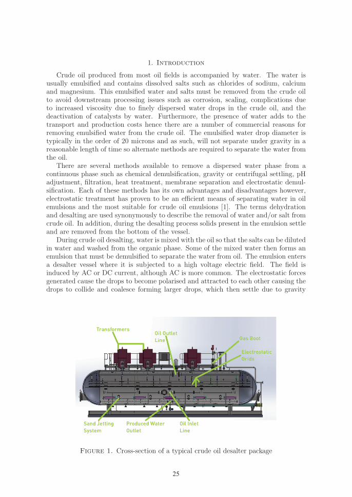
Figure 1. Cross-section of a typical crude oil desalter package
25
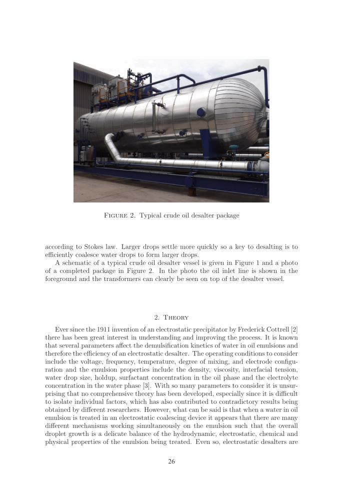
Figure 2. Typical crude oil desalter package
according to Stokes law. Larger drops settle more quickly so a key to desalting is toefficiently coalesce water drops to form larger drops.
A schematic of a typical crude oil desalter vessel is given in Figure 1 and a photoof a completed package in Figure 2. In the photo the oil inlet line is shown in theforeground and the transformers can clearly be seen on top of the desalter vessel.
2. Theory
Ever since the 1911 invention of an electrostatic precipitator by Frederick Cottrell [2]there has been great interest in understanding and improving the process. It is knownthat several parameters affect the demulsification kinetics of water in oil emulsions andtherefore the efficiency of an electrostatic desalter. The operating conditions to considerinclude the voltage, frequency, temperature, degree of mixing, and electrode configu-ration and the emulsion properties include the density, viscosity, interfacial tension,water drop size, holdup, surfactant concentration in the oil phase and the electrolyteconcentration in the water phase [3]. With so many parameters to consider it is unsur-prising that no comprehensive theory has been developed, especially since it is difficultto isolate individual factors, which has also contributed to contradictory results beingobtained by different researchers. However, what can be said is that when a water in oilemulsion is treated in an electrostatic coalescing device it appears that there are manydifferent mechanisms working simultaneously on the emulsion such that the overalldroplet growth is a delicate balance of the hydrodynamic, electrostatic, chemical andphysical properties of the emulsion being treated. Even so, electrostatic desalters are
26
essentially gravity separation devices governed by Stokes law:
V =2r2∆ρ g
9µ0
where V = settling rate, ms−1
r = drop radius, m
∆ρ = density difference between aqueous and organic phases, kgm−3
g = gravity, ms−2
µ0 = viscosity of oil, kgm−1s−1
Therefore, it is clear that an increased settling rate results from increasing the wa-ter drop diameter, increasing the density difference between the phases and decreasingthe oil viscosity. The density and viscosity can be altered via temperature and thedrop size controlled via the applied electric field. The practical operating temperaturerange is around 100–250 ◦C to avoid vaporization of the crude oil. In addition, crudeoil conductivity increases with temperature thereby increasing power requirements andheating costs. It should be noted that although the above equation requires modifi-cation to account for multiple drops in a vessel the important point to note is thatthe settling velocity is proportional to the square of the drop size which indicates theimportance of drop coalescence prior to phase separation. However, the electrical coa-lescence of drops is poorly understood due to the complexity of the hydrodynamic andelectrical phenomenon of interfacial polarization.
In general, the coalescence of drops consists of three steps: (1) motion and ap-proach of drops due to electrostatic force, (2) drainage of the film separating the dropsand (3) breakdown of the film and coalescence of the drops. The electrical effect isprimarily related to the first step, i.e. an increased rate of motion of the drops inan electric field. It is know that an electric field will assist in the separation of wa-ter in oil dispersions. Although many possible mechanisms have been proposed themechanisms are not clearly understood other than the electrical forces facilitate thecoalescence between small drops in order to attain larger drops that separate rapidlyunder gravity separation. Generally the coalescence rate increases as the applied elec-tric field strength increases however, if the strength becomes too high then various dropbreakup mechanisms can occur.
The dipolar force is considered to be one of the principal causes of drop coalescence.It induces mutual attraction between neighbouring drops due to the interaction of thedipoles induced by the electric field. The classical equation for dipole-dipole interactionbetween two similar spherical drops is:
F =24π01r
6E2
(d+ 2r)4
where F = electrostatic force, N
0 = permittivity of vacuum, Fm−1
1 = dielectric constant of the continuous phaser = drop radius, m
E = the electric field strength, Vm−1
d = distance between the near surfaces of the two drops, m
Although this equation is only a first order approximation to the actual short rangeforce and ignores drop deformation, it indicates that the dipolar force is strongly de-pendent on the water drop size and the space between the drops. Therefore, as the
27

water content of the emulsion is reduced during the desalting process, due to ongoingphase separation, the effect of dipolar attraction will decrease as the distance betweendrops increases. In addition, large drops will separate quickly leaving small drops dis-persed in the emulsion resulting in a further decrease in the contribution of dipolarattraction.
As electrostatic forces are essentially short range forces, when the drop spacing islarge other forces are needed to bring the drops into close proximity and to allow theelectrostatic forces to contribute to coalescence. This is primarily achieved via mechan-ical mixing of the emulsion prior to entry into the desalter vessel and via optimisingthe shape of the vessel to favour turbulence and mixing. However, too high turbulencewill induce drop breakup and re-dispersion thereby decreasing the desalter efficiency.
3. Process design
Electrostatic desalting is a complex but poorly understood process within the Oiland Gas industry. As such, most commercial designs are based on one of the firstsuccessfully operating units and few major design advances have been made since theinstallation of these original units. In addition, due to the difficulty in modelling theprocesses that occur during electrostatic desalting, in general the design of electrocoa-lescer equipment is carried out using lab and pilot plant data and empirical correlations.
Electrostatic desalters may encompass a one or two stage treatment (i.e. one or twodesalter vessels operated in series) depending on the inlet and outlet water, salinityand sediment specifications. Typically the dehydration efficiency for one and two stageunits is 95% and up to 99% respectively. Electrostatic desalters reduce basic sedimentand water (BS&W) content from 5–10 v/v% to approximately 1.4–2.8 v/v%, which inthe units conventionally used by the industry is equivalent to 5–10 PTB (pounds perthousand barrels of crude oil). The inlet salt concentration is typically in the order of3–200 PTB and has to meet an outlet concentration of less than 10 PTB.
Suez Oil & Gas Systems (SOGS) has been designing and supplying electrostaticdesalters for many years, principally to the Middle East region. Sizing of the desalteris calculated via a proprietary design spreadsheet where the inputs include the oildensity, viscosity, water salinity, operating temperature, oil flow rate, water flow rateand vessel diameter. Various calculations then determine the required electrostaticgrid area, vessel length and power based on the drop settling velocity. An adjustmentfor BS&W is made by factoring the base case settling velocity.
This design spreadsheet has proved accurate for relatively straight-forward designcases where the API gravity of the crude oil is mid-range and the BS&W is low.However, we are seeing more applications for light or heavy crude oils and higher levelsof BS&W and need to have confidence in the design output for these cases.
The design spreadsheet has been used by SOGS for many years and over that timedetails as to its origins have been lost and various modifications made to the extentthat at this point we are unable to determine the exact source of the theory and/orempirical data used in the various calculations. As such, currently we are unable tooptimise the design calculations or determine if correction factors are required for themore difficult design cases we now regularly see. We suspect that the calculationsare largely based on empirical data however, as we do not know the data?s originwe are unsure of its validity range. As a consequence we are currently forced to addrelatively large design margins to our desalter equipment that has the potential to makeour packages uncompetitive, especially in the current tight economic market that the
28
Oil and Gas industry is experiencing. Although there is much theory published onelectrostatic coalescence and its application to desalters it is not clear how this theoryrelates to practical desalter design.
Given the industry’s traditional reliance on empirical correlations for electrostaticdesalter design SOGS approached various clients to obtain field data from installedpackages. Unfortunately little information has been forthcoming either because thepackages are yet to be commissioned or due to the reluctance of Oil and Gas compa-nies to share highly confidential operating information or adjust parameters away fromoperating values for the purposes of testing. Therefore, SOGS seeks a better under-standing of electrostatic desalter theory and how it and experimental lab data relatesto practical package design in order to remain competitive in the electrostatic desaltermarket.
4. Conclusion
Electrostatic demulsification is commonly used in the Oil and Gas industry to re-move water and salts from crude oil before further processing. Since the invention ofthe electrostatic precipitator in the early 20th century much work has been done onthe use of electrostatic forces to enhance phase separation however, it remains a highlycomplex and poorly understood process. From the current body of work it appears thatthere are many different mechanisms working simultaneously on a water in oil emulsionsubjected to an electric field such that the overall droplet growth is a delicate balanceof hydrodynamic, electrostatic, chemical and physical properties of the emulsion beingtreated. Given the difficulty in modelling these processes it is not surprising that, ingeneral, the design of commercial electrocoalescer equipment is performed using laband pilot plant data and empirical correlations.
Suez Oil & Gas Systems designs electrostatic desalters via a proprietary calculationspreadsheet based on a combination of theoretical and empirical data, which has provenaccurate for relatively straight-forward design cases (mid-range API gravity crude oil,low BS&W). However, we wish to extend the spreadsheet for light and heavy crudeoils and higher levels of BS&W in order to meet current market demands. As we havelittle access to field data that could be used to correlate the design calculations we seeka better understanding of electrostatic desalter theory and how it and experimentallab data relates to practical package design in order to remain competitive in theelectrostatic desalter market.
References
[1] Eow, J., Ghadiri, M., Sharif, A., Williams, T., Electrostatic enhancement of coalescence of waterdroplets in oil: a review of the current understanding, Chem. Eng. J., 84 (2001), 173–192.
[2] Cottrell, F., Process for separating and collecting particles of one liquid suspended in anotherliquid, US Patent 987114, 1911.
[3] Hano, T., Ohtake, T., Takagi, K., Demulsification kinetics of W/O emulsion in an A.C. electricfield, J. Chem. Eng. Jpn., 21 (4) 1988, 345–351.
29