Electrical Efficiency of Electrolytic Hydrogen Production
13
Int. J. Electrochem. Sci., 7 (2012) 3314 - 3326 International Journal of ELECTROCHEMICAL SCIENCE www.electrochemsci.org Review Electrical Efficiency of Electrolytic Hydrogen Production Kaveh Mazloomi 1,* , Nasri b. Sulaiman 1 , Hossein Moayedi 2 1 Department of Electrical and Electronic Engineering, Faculty of Engineering, University Putra Malaysia 2 Department of Civil Engineering, Estahban Branch, Islamic Azad University, Estahban, Iran * E-mail: [email protected] Received: 12 January 2012 / Accepted: 6 March 2012 / Published: 1 April 2012 Common industrial electrolyzers have a nominal hydrogen production efficiency of around 70%. High power dissipation value is the most important drawback of such systems since electric power expense has the largest share in the price of electrolytic hydrogen. The electrical impedance of an electrolysis cell causes a fraction of the applied energy to be wasted as heat while the electric current passes through it. As the prior publications show, many efforts are made to reduce this effect. According to the available literature, several internal and external variables are pointed out to have an influence on the electrical behavior of such cells. This paper provides an insight to these factors in regards to minimize the energy loss of the process of water electrolysis. Keywords: Water electrolysis, Hydrogen production, Electrical power, Efficiency, power dissipation 1. INTRODUCTION Electrolytic hydrogen production has been scientifically studied for more than a century [1, 2]. According to the literature, hydrogen has been used by for military, industrial and commercial purposes since late 19 th century [3]. Nowadays, electrolytic hydrogen has a share of only 4% [4, 5] in the global production of the most abundant element of the universe [6, 7]. Electricity expense constitutes the largest fraction of hydrogen production costs [9]. High hydrogen production expenses count as the main deficiency of commercial and industrial electrolyzers. Hence electrolytic methods are usually outperformed by other approaches such as steam methane reformation. An electrolyzer is usually subjected to massive current values in order to break the water molecules into oxygen and hydrogen. The reaction equation is noted as below: 2H 2 O → 2H 2 + O 2 (1)
-
Upload
independent -
Category
Documents
-
view
0 -
download
0
Transcript of Electrical Efficiency of Electrolytic Hydrogen Production

Int. J. Electrochem. Sci., 7 (2012) 3314 - 3326
International Journal of
ELECTROCHEMICAL SCIENCE
www.electrochemsci.org
Review
Electrical Efficiency of Electrolytic Hydrogen Production
Kaveh Mazloomi1,*
, Nasri b. Sulaiman1, Hossein Moayedi
2
1 Department of Electrical and Electronic Engineering, Faculty of Engineering, University Putra
Malaysia 2 Department of Civil Engineering, Estahban Branch, Islamic Azad University, Estahban, Iran
*E-mail: [email protected]
Received: 12 January 2012 / Accepted: 6 March 2012 / Published: 1 April 2012
Common industrial electrolyzers have a nominal hydrogen production efficiency of around 70%. High
power dissipation value is the most important drawback of such systems since electric power expense
has the largest share in the price of electrolytic hydrogen. The electrical impedance of an electrolysis
cell causes a fraction of the applied energy to be wasted as heat while the electric current passes
through it. As the prior publications show, many efforts are made to reduce this effect. According to
the available literature, several internal and external variables are pointed out to have an influence on
the electrical behavior of such cells. This paper provides an insight to these factors in regards to
minimize the energy loss of the process of water electrolysis.
Keywords: Water electrolysis, Hydrogen production, Electrical power, Efficiency, power dissipation
1. INTRODUCTION
Electrolytic hydrogen production has been scientifically studied for more than a century [1, 2].
According to the literature, hydrogen has been used by for military, industrial and commercial
purposes since late 19th
century [3]. Nowadays, electrolytic hydrogen has a share of only 4% [4, 5] in
the global production of the most abundant element of the universe [6, 7]. Electricity expense
constitutes the largest fraction of hydrogen production costs [9]. High hydrogen production expenses
count as the main deficiency of commercial and industrial electrolyzers. Hence electrolytic methods
are usually outperformed by other approaches such as steam methane reformation. An electrolyzer is
usually subjected to massive current values in order to break the water molecules into oxygen and
hydrogen. The reaction equation is noted as below:
2H2O → 2H2 + O2 (1)

Int. J. Electrochem. Sci., Vol. 7, 2012
3315
Electrochemical decomposition energy of water is relatively high since water molecules have a
stable structure at ambient temperature [8]. Approximately, a minimum voltage of 1.23V is required to
be applied to a water molecule at laboratory conditions to break the bonds between hydrogen and
oxygen atoms. This voltage is also known as the equilibrium voltage of water. However, much higher
voltage levels are used in industrial electrolysis cells. The excess voltage is referred to as the
“overpotential” of the process reaction [10]. The overpotential value is affected by different factors,
which are going to be discussed in the following sections of this paper.
In addition, by following the Ohm’s law (equation 2) the electric power can be calculated as in
equation 3.
U=RI (2)
P=UI (3)
Where U is the electrical potential in volts, I is the electric current in Amperes, R is the
electrical resistance in Ohms and P is the electric power in Watts. Obviously, for very large current
levels, any slight increase of the cell voltage can cause a drastic raise in the power demand. Moreover,
technical data show electrolyzers to usually perform their process under low voltage and high current
level conditions.
Massive current densities cause a noticeable value of unwanted ohmic voltage drop between
the electrodes. As a result, formation of unwanted electrical power loss and less process efficiency
values are inevitable. Many efforts are made in order to force an electrolysis cell to reach a certain
current level by applying lower voltage levels to it. Major causes of the overvoltage requirement are
introduced and discussed in the following sections of this paper. Moreover, possible modifications are
pointed out in order to minimize the unwanted negative effects of each parameter.
2. FACTORS WITH AN INFLUENCE ON ELECTRICAL EFFICIENCY
2.1. Electrolyte quality
Bases and acids are known to change the nonconductive nature of pure water. These
compounds have a great reducing effect on the overvoltage value of an electrolyzer [11, 12] due they
improve the ionic conductivity aqueous electrolyte compounds. However, the concentration level of
acidic and alkali solutions are limited in practice due to the highly corrosive behavior of such
materials. A 25% to 30% KOH aqueous solution is reported to have a wide use in electrolyzers [13].
On the other hand, the electrocatalytic performance of water electrolysis cell is known to be
limited [14, 15]. This limitation is mainly cause the overall electrical resistance of a cell to rise and
will cause the efficiency to fall. Therefore, substitute electrolytes such as ionic liquids have been
introduced to improve the conductivity and stability factors of electrolytic baths [16, 17]. de Souza et
al. [18] performed a series of experiments on the use of the ionic liquid of 1-butyl-3-methyl–

Int. J. Electrochem. Sci., Vol. 7, 2012
3316
imidazolium-tetrafluoroborate (BMI.BF4) [19] in water at ambient temperature. The electrode plates
of these cases were selected from a number of easily found metals such as carbon steel (CS), Nickel
(Ni), Nickel-Molybdenum (Ni-Mo) alloy and Molybdenum (Mo). A maximum efficiency value of
96% was reported for the case of low carbon steel electrodes [20] in 10 vol.% aqueous solution of
MBI.MF4. All tests took place at the current density value of 44mA cm-2
. The reported efficiency
levels of this research are much higher than the average 73% efficiency of common commercial and
industrial electrolyzers [21]. However, it should be considered that such electrolyzers usually function
at much higher current densities than the mentioned experimental value.
Moreover, any existence of impurities may cause unwanted side reactions in an electrolysis cell
[22]. Magnesium, chloride and calcium ions can be named as a few common examples of these
impurities. In addition, contaminations can block and passivate the electrode plates and/or separator
surfaces [11, 23] and sabotage the inter-electrode mass and electron transfer. The latter-mentioned is
another formation cause for the excess ohmic resistance of the electric current path.
2.2. Temperature
Temperature is known to be one of the most effective variables on the electric power demand
of an electrolysis cell. Electrolysis process is much more efficient at raised temperatures [20]. The
reasons of this behavior can be discussed according to the thermodynamic characteristics of a water
molecule, as its splitting reaction potential is known to reduce as the temperature increases. Moreover,
ionic conductivity and surface reaction of an electrolyte rise directly with temperature [24]. High
temperature water electrolysis requires less energy to reach any given current density in analogy with a
low temperature process [25, 26]. As a practical example of the latter, Bailleux [27] tracked the
operation of a test hydrogen production plant for two years. Implemented plant technology of this case
was much simpler back in early 1980’s in contrast with current most recent electrolyzers. The case
study plant of this report used a 40%wt potassium hydroxide alkaline solution as an electrolyte to be
decomposed under the pressure, current density and temperature range conditions of 20bar, 10kA m-2
and 120°C to 160 °C respectively. Data scanners were used to monitor the mentioned parameters as
well as the purity of the output gasses in order to determine the unwanted contents of oxygen and
hydrogen outlets. The report shows a voltage reduction of 120mV as the temperature was raised from
120°C to 150°C. However, the increased temperature and pressure were mentioned to cause some
“stability problems” such as container cracks and gasket leaks.
In more recent experiments, high temperature electrolysis is referred to cases with much higher
temperature ranges. As an example of such, we can mention a work of Mingyi et al. [28]. Their tests
were conducted for the analysis of the electrochemical behavior and thermodynamic characteristics of
a high temperature steam electrolyzer (HTSE). They expressed high temperature water electrolysis to
need less energy than conventional low temperature electrolysis processes. More efficient process was
observed as a result.
Moreover, they divided the total electrolysis efficiency to three separate and individual factors
of: electrical efficiency, electrolysis efficiency and thermal efficiency. They calculated the share of

Int. J. Electrochem. Sci., Vol. 7, 2012
3317
each parameter to be 70%, 22% and 8% respectively from the total efficiency. According to their
discussion, increased cell temperature leads to a higher thermal and lower electrical efficiency values
where the electrolysis efficiency remains without any significant changes. The authors also reported
the possibility of coupling the HTSE device with a high temperature gas cooled reactor (HTGR).
When the electrolysis temperature was increased to 1000°C, an overall efficiency of the process of
59% was recorded which was remarkably higher than the 33% initial value. The process efficiency
was stated to be more than twice of those of the conventional low temperature electrolyzers of the
time.
In addition, Ganley [29] studied the process efficiency of high temperature/ high pressure
electrolyte solutions (steam state). The experiments were carried out in a chemical resistant container
since the sample electrolyte was a highly concentrated KOH solution heated up to 400 °C. During the
studies, the electrolyte was subjected to different values of compression during the experimental work.
The electrolyte concentration was set at 19 M at the starting phase of each experiment which is highly
corrosive to many metals and alloys. Another varying condition of the experimental work was the
electrodes material which is the subject of discussion in following sections. Lower voltage level was
required to reach any given current density for temperatures between 200 °C and 400 °C. The results
show that a voltage level of 1.8 V was enough to cause a current density of 200 mA cm-2
at 200 °C.
This value was only 1.5V when the electrolyte was heated up to 400 °C at the same pressure and
current density.
As Nagai et al. [30] expressed, heat can reduce the “reversible” potential of water (also known
as the equilibrium voltage). This parameter also enlarges the size of the gas bubbles and reduces their
rising velocity. The latter-mentioned causes a larger void fraction in the electrolyte and decreases the
efficiency as a result. The void fraction is the subject of discussion in section 2.3.
In another case, Ulleberg [14] developed models for the process. Their thermodynamic and
electrochemical models show noticeable cut downs in both over voltage and reversible potential of the
heated cells. This expression is also supported by comparing the voltage versus current curves for both
cases of low and high temperature electrolysis. They reported remarkably improved efficiency levels
to be a resultant of conducting the electrolysis process in high temperatures.
Conducting such processes in drastically high temperature levels on gas state electrolyte is
expressed to be more efficient than the low temperature processes although, mechanical, stability and
physical properties of such systems are still a concern for manufacturers and designers of industrial
and commercial electrolyzers.
2.3. Pressure
Appleby et al. [31] tried to lower the costs of hydrogen production by creating higher current
density conditions in conventional electrolyzers According to their research, high pressure electrolytes
will consume less power in the process of electrolytic decomposition. The main reason was stated to be
the shrinking effect of pressure on the gas bubbles which cause the ohmic voltage drop and power
dissipation to reduce. Moreover, high pressure electrolysis has less power demand for the phase of

Int. J. Electrochem. Sci., Vol. 7, 2012
3318
product compression. These experiments were conducted in a typical three compartment electrolyzer
with a varying temperature between 25°C and 90°C. Cell current density was kept at 1 mA cm-2
with
an electrolyte of either a 34%wt or 25%wt KOH solution in distilled water. The electrodes were
chosen from pure platinum (99.99%) and smooth nickel (Ni 200) plates with a 1 cm2 surface area.
Authors noted an overall voltage drop of up to 100mV when the conversion process was conducted at
a pressure level of under 30 atm. No significant further voltage drop was recorded at higher pressure
values (up to 40 atm). The cell voltage vs pressure graph has its highest reduction slope when the
pressure was raised from 1atm to 10atm despite of the process temperature.
Referring to a similar work, Onda et al. [32] calculated the energy consumption of compressing
a liquid electrolyte to be much less than those of gas state hydrogen compression. These calculations
were based on the results of an earlier research of LeRoy et al. [33]. They estimated the ideal
temperature and pressure conditions for electrolytic hydrogen production to be around 70 MPa and 250
°C relatively. High temperature and intense pressure will change both Gibbs energy and enthalpy
levels of an electrolysis process. Hence, lower voltage level will be required as the temperature rises in
high pressures and vice versa. However, in pressure levels higher than 20MPa, they found the voltage
rise to be negligible. This behavior became more sensible at lower temperatures. Finally, an
electrolysis efficiency enhancement of 5% was observed. Another 50% of energy was saved at the
compression phase of high pressure electrolytic hydrogen production.
2.4. Electrical resistance of the electrolyte
Electrical resistance of an object is an evaluation of its opposition to the passage of electric
current. The level of this force is proportional to the cross section area and the length of the current
path and the material resistivity of the conducting material. The relationship between the mentioned
variables is shown in equation 4 as bellow.
R= (4)
Where A is the cross section area, ρ is the material resistivity, R is the electrical resistance, and
l is the length of the current path. Inside and electrolysis cell, electrons start their travel from the
surface of an electrode, move through the electrolyte and end their journey at the surface of the other
electrode. We can assume the path as an object with the same length as the distance between
electrodes, the cross section of the area of electrodes overlap and an equivalent resistivity value. The
equivalent resistivity consists of different variables such as the electrodes resistivity, electrical
admittance of the electrolyte and the reaction between electrodes surfaces and electrolyte. Hence, the
equivalent resistivity is a function of the following variables:

Int. J. Electrochem. Sci., Vol. 7, 2012
3319
2.4.1. Space between the electrodes
According to equation 4, by reducing the distance between electrodes, lower electrical
resistance can be obtained. However, the question may occur that how much proximity of electrode
plates is practically possible?
Nagai et al. [30] carried out a series of experiments to find the optimum space between
electrodes. They examined the effects of the void fracture between electrodes which is caused by the
formation of gas bubbles.
These experiments were conducted at ambient pressure with Ni-Cr-Fe alloy electrodes in a
10%wt potassium hydroxide aqueous solution. They varied the current density, system temperature
and the distance between electrodes, their size, wettability and inclination. The results clearly depict
that placing the electrodes too close to each other will increase the value of the void fracture and will
lead to a less efficient process. This phenomenon became more sensible at high current density levels.
By placing the electrodes at different distances and comparing the result values of cell voltage and
current, the authors concluded that positioning the electrodes too close to each other will decrease the
process efficiency. LeRoy et al. [34] also reported the same effect. They expressed larger electrical
resistance of an electrolyte is a result of gas bubbles accumulation in the inter-electrode area.
Therefore, this accumulation will cause the process to be less efficient.
2.4.2. Size and alignment of the electrodes
Another variable of equation 4 is the cross section area of an object. Less resistive current path
is known to be a result of using electrodes with larger surface areas. Again, in this case, it would be
useful to define the term “larger surface area” in more details. This definition will help us to know the
practical dimension limits of an electrode plate?
A series of experiments have been conducted in order to test the effects of using electrodes of
different sizes on the process efficiency [30]. As the results show, at the same electrode width, larger
electrode height will cause additional power dissipation in a cell. The reason was expressed to be the
formation of a larger volume of void fraction. The models of gas bubbles movement [35] clearly depict
larger amounts of bubble accumulation in higher parts of the electrodes.
These experiments also show that higher efficiency levels can be obtained by placing the
electrodes in a vertical position. The latter is caused by reduced ohmic resistance due to the “optimum
bubble departure rate”.
2.4.3. Forcing the bubbles to leave
Ohmic resistance in an electrolysis bath is related to the bubble coverage of all surfaces since
gas bubble accumulation on each surface will reduce its conductivity. Hence, it causes a higher level of
ohmic voltage drop [36]. On the other hand, bubbles diameter depends on the current density,
temperature and pressure. Pressure value has an inverse correlation with the bubbles size where current
density and temperature have an opposite affect it [37]. Moreover, the disengagement rate of gas

Int. J. Electrochem. Sci., Vol. 7, 2012
3320
bubbles from the surfaces and their departure velocity play a significant rule in the value of the
electrical resistance of an electrolytic bath. Figure 1 justifies this subject. In this figure, the distance
between electrodes “l” is broken into n smaller segments “li”. Equation 4 can be used to calculate the
resistance for each partial length of li. The presence of gas bubbles significantly reduces the efficient
cross section area for each li. Therefore, it increases the total value of R.
Figure1. The formation of void fraction
Hence, equation 4 could be re-written as bellow:
R= ( li ) (5)
Equation 5 and figure 1 depict the effect of void fracture which has been discusses earlier.
Many efforts are made to force the bubbles leave the cell environment. As an instance, De Li et al. [38]
exposed their experimental electrolysis apparatus to an ultrasonic field in this regard. System
efficiency and energy consumption were recorded in both cases of presence and absence of such field.
Subjecting the electrolyzer to such fields caused a remarkable cell voltage reduction. The latter was
more obvious in the cases of high current density and low electrolyte concentration. An improvement
rate of 15% to 18% was observed in high current density experiments. Hence, the authors were able to
achieve a maximum energy saving rate of 10% to 25%. Forcing the bubbles to Disengage from
electrodes, membrane and electrolyte surface is known to improve the local mass and heat transfer as
well as the process efficiency. Power consumption of the ultrasonic generator is expressed to be
negligible in contrast with the power demand of the cell itself. A 0.05kW ultrasonic generator provided
a field strong enough for a 100kA electrolysis cell. In this case, the field was able to deduct up to 30
kW from the total power demand of the system.
Wang et al. [39] conducted another set of experiments to force the adsorbed gas bubbles on the
electrodes and membrane surfaces to detach. They exposed the cell to a super gravity field in this
regard. Super gravity condition was simulated by placing the cell in a centrifugal (rotating) installation.
In this experiment cell temperature was maintained at 333 °K throughout the process. High gravity
acceleration environment is known to increases both velocities of convection flow and inter-phase slip
[40]. Therefore, better multiphase separation in gas-liquid and gas-solid phases [41] is a result of

Int. J. Electrochem. Sci., Vol. 7, 2012
3321
subjecting an electrolysis cell to a super-gravity field. Such improved separation leads to easier gas
bubble disengagement and faster departure from the electrolyte surface. Lower ohmic loss and over
potential are the predicted result of this approach. Wang et al. [39] measured the required level of cell
voltage to reach a given current density for different gravity conditions. The results show remarkably
lower voltage levels for the cases with higher gravity values. The difference became more significant
for increased current densities. Authors reported improved levels of efficiency for the cells which are
performing under super gravity conditions. According to this report, a centrifuge installation with a
nominal power of 3 kW was able to deduct up to 51 kW from the power demand of a 100 kA industrial
electrolyzer.
2.5. Electrode material
A wide range of materials are being used as electrodes. Each metal has a different level of
activity, electrical resistance and corrosion resistivity. Platinum and gold are known to be two of the
best choices for being used as electrodes. However, high prices limit their usage in industrial and
commercial electrolyzers. Aluminum, Nickel, Raney nickel and cobalt are the most common electrode
materials for being used in alkaline electrolytic baths. This popularity is the result of their satisfactory
price range, corrosion resistance and chemical stability [21].
Appleby et al. [31] conducted a set of experiments by utilizing different electrodes such as
99.99% pure Ni, Pt, Ir and Rh as well as Ni cloth, Ni sinter, Ni-Cd and low impregnation Nickel and
cobalt molybdate catalyst on nickel sinter. Each electrode was pre-anodized in order to obtain stable
potential characteristics. The results express nickel to show more desirable potential characteristics
among the mentioned materials. In addition, authors found woven or porous sintered electrodes to be
30 times more active those with a smooth surface. Larger electrode surface area causes an “Apparent
exchange current density”. The latter is known to be the main reason of the excess observed activity.
There is a wide range of variations in the value of electrode-electrolyte activity for
different materials. For example, platinum electrodes show higher activity levels in contact with KOH
aqueous solutions in comparison with molybdenum plates. Literature show utilization of 1-butyl-3-
methylimidazole tetrafluoroborate (BMI.BF4) ionic liquid will lead to exceptional efficiency levels for
almost all electrode plates [18].
2.6. Separator material
Placing a separator plate in a cell, blocks the free movement of mass and ions to some extent.
Moreover, the presence of such barrier increases the void fracture by further accumulating of gas
bubbles in the electrolyte [30]. In addition, the effective electrical resistance of a separator plate is
frequently calculated to be as large as three to five times of those of the electrolyte solutions [42].
Electrical resistance of a separator depends on different variables such as corrosion,
temperature and pressure [43]. Back in middle 1990’s many scientists named asbestos to be the best
choice for being used as a diaphragm due to its highly wettable and porous structure. These features

Int. J. Electrochem. Sci., Vol. 7, 2012
3322
cause a plate to show electrical resistance in practice [44] . However, asbestos is known to be a toxic
and hazardous material [44-47]. These characteristics caused the researchers to start looking for
substitute materials. Nowadays there are different materials and technologies available to reduce the
negative electrical effect of separators [45, 46, 48-50].
2.7. Applied voltage waveform
It is almost common for electrolysis systems to use a steady (Figure 2a) or smooth (Figure 2b)
DC voltage to decompose an electrolyte.
Figure 2. (a) Steady DC voltage waveform. (b) Smooth DC voltage waveforms
Accoring to the Ohm’s law, applied DC voltage U causes the current I to pass through the
electrolyte with the resistance of R (refer equation 2). Hence, the common method of current or current
density regulation is by the application of a certain voltage to a cell. Shimizu et al. [51] conducted their
experiment to test the behavior of a cell while the voltage was applied in the form of ultra short pulses.
Their goal was to reach higher cell power (increase the gas production rate) without reducing the
efficiency. They placed platinum electrode plates 3 cm apart from each other in a 1M KOH aqueous
solution. Electrolyte temperature was maintained to 293 ± 2 °K throughout the experiment. The results
were compared for the cases of using a conventional DC, and an ultra-short pulse power supply with
an output pulse width of about 300 ns. Output frequency and peak voltage of this power supply were
adjustable from 2 kHz to 25 kHz and 7.9 V to 140 V respectively.
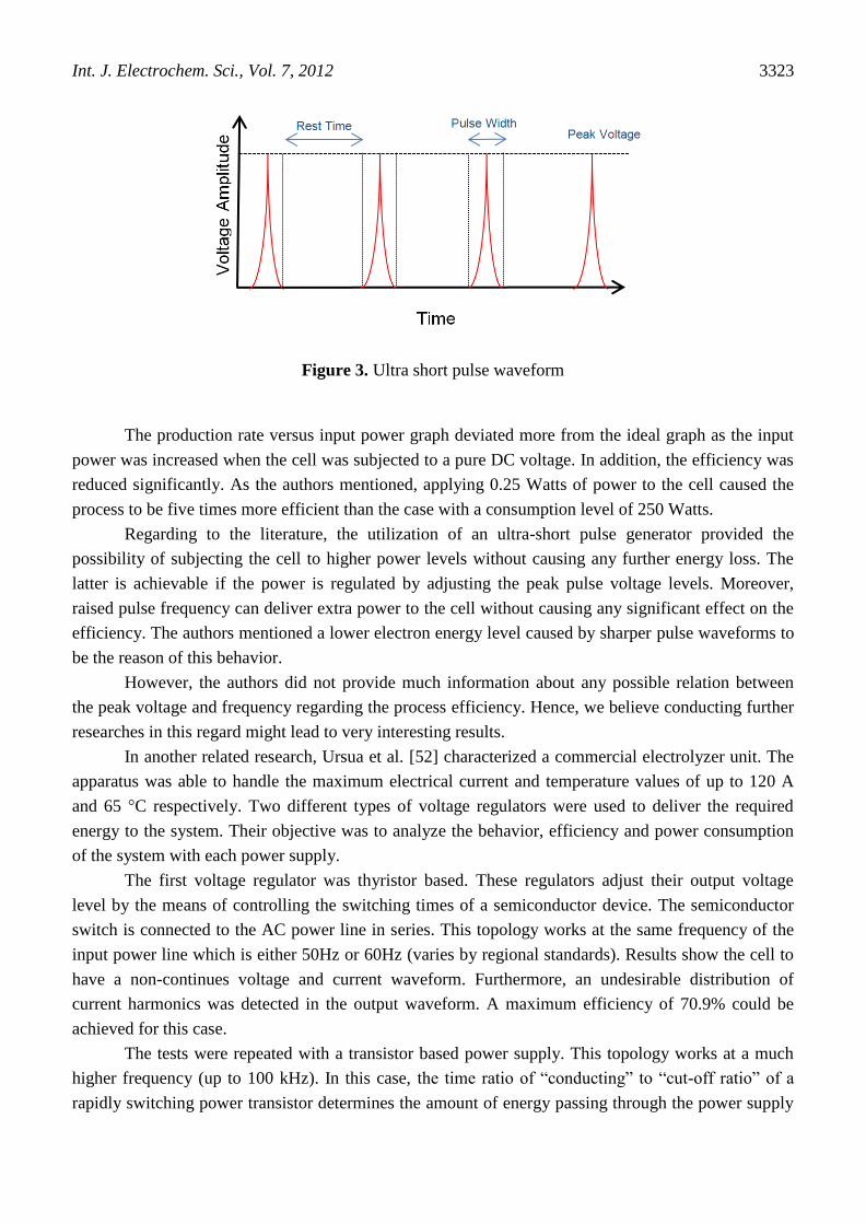
In the case of applying ultra-short pulses to an electrolysis cell, there will not be enough time
for formation of stable double-layers or diffusion-layers. A formation period of 3 μs is known to be
required by the authors for diffusion-layers. Moreover, a pulse width of 3 ns is also much less than the
time requirement of formation of a stable double-layer which is known to be not larger than several
hundred milliseconds. A sample waveform of applied ultra short pulse is illustrated in figure 3.
Int. J. Electrochem. Sci., Vol. 7, 2012
3323
Figure 3. Ultra short pulse waveform
The production rate versus input power graph deviated more from the ideal graph as the input
power was increased when the cell was subjected to a pure DC voltage. In addition, the efficiency was
reduced significantly. As the authors mentioned, applying 0.25 Watts of power to the cell caused the
process to be five times more efficient than the case with a consumption level of 250 Watts.
Regarding to the literature, the utilization of an ultra-short pulse generator provided the
possibility of subjecting the cell to higher power levels without causing any further energy loss. The
latter is achievable if the power is regulated by adjusting the peak pulse voltage levels. Moreover,
raised pulse frequency can deliver extra power to the cell without causing any significant effect on the
efficiency. The authors mentioned a lower electron energy level caused by sharper pulse waveforms to
be the reason of this behavior.
However, the authors did not provide much information about any possible relation between
the peak voltage and frequency regarding the process efficiency. Hence, we believe conducting further
researches in this regard might lead to very interesting results.
In another related research, Ursua et al. [52] characterized a commercial electrolyzer unit. The
apparatus was able to handle the maximum electrical current and temperature values of up to 120 A
and 65 °C respectively. Two different types of voltage regulators were used to deliver the required
energy to the system. Their objective was to analyze the behavior, efficiency and power consumption
of the system with each power supply.
The first voltage regulator was thyristor based. These regulators adjust their output voltage
level by the means of controlling the switching times of a semiconductor device. The semiconductor
switch is connected to the AC power line in series. This topology works at the same frequency of the
input power line which is either 50Hz or 60Hz (varies by regional standards). Results show the cell to
have a non-continues voltage and current waveform. Furthermore, an undesirable distribution of
current harmonics was detected in the output waveform. A maximum efficiency of 70.9% could be
achieved for this case.
The tests were repeated with a transistor based power supply. This topology works at a much
higher frequency (up to 100 kHz). In this case, the time ratio of “conducting” to “cut-off ratio” of a
rapidly switching power transistor determines the amount of energy passing through the power supply

Int. J. Electrochem. Sci., Vol. 7, 2012
3324
unit. The load voltage or current is regulated as a result of this action where they usually have an
almost pure DC wave form. In addition, the output harmonics of such units are negligible in contrast
with those of thyristor based devices. A maximum efficiency rate of 77.6% was observed for the case
of using the latter-described power supply. The results of this experimental work show a 10% more
efficient conversion process by using a transistor based power regulator.
Unfortunately, experiments on the pure electrical characteristic of electrolysis process are very
rare to find. Electrical variables are very common for measuring the electrochemical characteristics of
electrolytic baths. However, we believe more study is required to analyze the behavior of such cells as
a pure electrical load in order to develop more reliable equivalent circuits.
We should mention that the available equivalent circuits for electrochemical systems usually
contain a few non-electrical components such as faradic impedances which are not easily analyzed by
electrical approaches. Brad [53], and Armstrong and Henderson [54] Introduced very similar
equivalent circuits for an electrolysis cell. These circuits consider the electrical impedance of the
electrolysis system to be in a non-linear form. Existence of capacitive and faradic elements is the
reason of such consideration. Moreover, it is more common to conduct the electrolysis process by
applying a pure DC waveform to the cell which is suitable to test linear impedances and ohmic loads.
Therefore, according to the mentioned equivalent circuits, the effect of applying other forms of voltage
might lead to interesting and important findings.
3. CONCLUSION
This study provides information about the physical, chemical and electrical propertied of water
electrolysis cells with a view on their effects on the efficiency of the process. The possible
modifications can be done on a cell in order to minimize its electrical power dissipation.
a. High temperature and pressure processes are more efficient. These parameters can be raised
as much as the physical strength of the apparatus allows.
b. Utilization of highly concentrated electrolytes will lead to less impedance values. On the
other hand, the use contaminated solutions cause side reactions to take place in the cell and will reduce
the lifespan of the apparatus.
c. Placing the electrodes in an absolutely vertical position at a certain distance from each other
will reduce the ohmic resistance between them. Moreover, the utilization of metals with high degrees
of activity and porous materials will enhance electric and ionic conductivity of the system.
d. Forcing gas bubbles to detach from the electrode and separator surfaces and to leave the
system will decrease the void fraction. Lower impedance and higher efficiency levels will be achieved
as a result.
e. Selecting the electrodes of larger sizes is an important factor for to enlarge their overlap
surface area and therefor the current path. However, since gas bubbles will accumulate in higher
altitudes of the cell, certain considerations are recommended to limit the height of the electrode plates.
f. Since the equivalent circuit of a water electrolysis cell contains non-linear elements, more
research is required to study the best method of power application to a cell.

Int. J. Electrochem. Sci., Vol. 7, 2012
3325
References
1. J. W. Richards, Journal of the Franklin Institute, 152 (1901) 201.
2. J. W. Richards, Journal of the Franklin Institute, 141 (1896) 192.
3. J. W. Richards, Journal of the Franklin Institute, 160 (1905) 377.
4. Seth Dunn, Worldwatch paper 157, august 2001, 3 (2002) 16.
5. R. F. de Souza, J. C. Padilha, R. S. Gonçalves, M. O. de Souza and J. Rault-Berthelot, J. Power
Sources, 164 (2007) 792.
6. C. E. Gregorio Padro and F. Lau, ADVANCES IN HYDROGEN ENERGY. New York: Kluwer
Academic Publishers, 2002.
7. University of Wisconsin. Periodic Table Live. Available:
http://genchem.chem.wisc.edu/lab/ptl/ptl/Elements/h/H.html.
8. F. N. Lin, W. I. Moore and S. W. Walker, Int J Hydrogen Energy, 10 (1985) 811.
9. Ivy J. Summery of electrolytic hydrogen production: milestone completion report, NREL/MP-560–
36734; September 2004.
10. H. Matsushima, T. Nishida, Y. Konishi, Y. Fukunaka, Y. Ito and K. Kuribayashi, Electrochim.
Acta, 48 (2003) 4119.
11. P. Millet, F. Andolfatto and R. Durand, Int J Hydrogen Energy, 21 (1996) 87.
12. S. P. S. Badwal, S. Giddey and F. T. Ciacchi, Ionics, 12 (2006) 7.
13. Guttman F and Murphy OJ, Modern Aspects of Electrochemistry. New York: Plenum Press, 1983.
14. Ø. Ulleberg, Int J Hydrogen Energy, 28 (2003) 21.
15. G. W. Crabtree, M. S. Dresselhaus and M. V. Buchanan, Phys Today, 57 (2004) 39.
16. C. Lagrost, D. Carri , M. Vaultier and P. Hapiot, Journal of Physical Chemistry A, 107 (2003) 745.
17. R. F. De Souza, J. C. Padilha, R. S. Gonçalves and J. Dupont, Electrochemistry Communications, 5
(2003) 728.
18. R. F. de Souza, G. Loget, J. C. Padilha, E. M. A. Martini and M. O. de Souza, Electrochemistry
Communications, 10 (2008) 1673.
19. R. F. De Souza, J. C. Padilha, R. S. Gonçalves and J. Rault-Berthelot, Electrochemistry
Communications, 8 (2006) 211.
20. V. M. Nikolic, G. S. Tasic, A. D. Maksic, D. P. Saponjic, S. M. Miulovic and M. P. Marceta
Kaninski, Int J Hydrogen Energy, vol. In Press, Corrected Proof.
21. Z. D. Wei, M. B. Ji, S. G. Chen, Y. Liu, C. X. Sun, G. Z. Yin, P. K. Shen and S. H. Chan,
Electrochim. Acta, 52 (2007) 3323.
22. K. Zeng and D. Zhang, Progress in Energy and Combustion Science, 36 (2010) 307.
23. C. Belmont, R. Ferrigno, O. Leclerc and H. H. Girault, Electrochim. Acta, 44 (1998) 597.
24. J. Udagawa, P. Aguiar and N. P. Brandon, J. Power Sources, 166 (2007) 127.
25. D. L. Stojic, M. P. Marceta, S. P. Sovilj and S. S. Miljanic, J. Power Sources, 118 (2003) 315.
26. Bockris JOM, Conway BE, Yeager E and White RE, Comprehensive Treatise of Electrochemistry.
New York: Plenum Press, 1981.
27. C. Bailleux, Int J Hydrogen Energy, 6 (1981) 461.
28. L. Mingyi, Y. Bo, X. Jingming and C. Jing, J. Power Sources, 177 (2008) 493.
29. J. C. Ganley, Int J Hydrogen Energy, 34 (2009) 3604.
30. N. Nagai, M. Takeuchi, T. Kimura and T. Oka, Int J Hydrogen Energy, 28 (2003) 35.
31. A. J. Appleby, G. Crepy and J. Jacquelin, Int J Hydrogen Energy, 3 (1978) 21.
32. K. Onda, T. Kyakuno, K. Hattori and K. Ito, J. Power Sources, 132 (2004) 64.
33. R. L. LeRoy, C. T. Bowen and D. J. LeRoy, J. Electrochem. Soc., 127 (1980) 1954.
34. R. L. LeRoy, M. B. I. Janjua, R. Renaud and U. Leuenberger, J. Electrochem. Soc., 126 (1979)
1674.
35. P. Mandin, A. A. Aissa, H. Roustan, J. Hamburger and G. Picard, Chemical Engineering and
Processing: Process Intensification, 47 (2008) 1926.

Int. J. Electrochem. Sci., Vol. 7, 2012
3326
36. K. Qian, Z. D. Chen and J. J. J. Chen, J. Appl. Electrochem., 28 (1998) 1141.
37. R. M. de Jonge, E. Barendrecht, L. J. J. Janssen and S. J. D. van Stralen, Int J Hydrogen Energy, 7
(1982) 883.
38. S. Li, C. Wang and C. Chen, Electrochim. Acta, 54 (2009) 3877.
39. M. Wang, Z. Wang and Z. Guo, Int J Hydrogen Energy, 35 (2010) 3198.
40. P. Mandin, J. M. Cense, B. Georges, V. Favre, T. Pauport , Y. Fukunaka and D. Lincot,
Electrochim. Acta, 53 (2007) 233.
41. C. Ramshaw, Heat Recovery Systems and CHP, 13 (1993) 493.
42. Pickett DJ, Electrochemical Reactor Design. Amsterdam: Elsevier, 1979.
43. R. Renaud and R. L. LeRoy, Int J Hydrogen Energy, 7 (1982) 155.
44. V. M. Rosa, M. B. F. Santos and E. P. da Silva, Int J Hydrogen Energy, 20 (1995) 697.
45. J. Kerres, G. Eigenberger, S. Reichle, V. Schramm, K. Hetzel, W. Schnurnberger and I. Seybold,
Desalination, 104 (1996) 47.
46. P. Vermeiren, W. Adriansens, J. P. Moreels and R. Leysen, Int J Hydrogen Energy, 23 (1998) 321.
47. P. Vermeiren, W. Adriansens and R. Leysen, Int J Hydrogen Energy, 21 (1996) 679.
48. Nunes SP and Peinemann K-V, Membrane Technology. Weinheim: Wiley- VCH Verlag GmbH &
KGaA, 2007.
49. E. Montoneri, L. Giuffr , G. Modica and E. Tempesti, Int J Hydrogen Energy, 11 (1986) 233.
50. S. Li, C. Wang and C. Chen, J. Membr. Sci., 330 (2009) 334.
51. N. Shimizu, S. Hotta, T. Sekiya and O. Oda, J. Appl. Electrochem., 36 (2006) 419.
52. A. Ursúa, L. Marroyo, E. Gubía, L. M. Gandía, P. M. Di guez and P. Sanchis, Int J Hydrogen
Energy, 34 (2009) 3221.
53. Brad A.J., Electrochemical Methods-Fundamentals and Applications. New York: John Wiley,
1980.
54. R. D. Armstrong and M. Henderson, J Electroanal Chem, 39 (1972) 81.
© 2012 by ESG (www.electrochemsci.org)