Basic Electrical Engineering
216
A publication under Free Textbook Programme of Government of Tamil Nadu Department of School Education Basic Electrical Engineering THEORY & PRACTICAL Untouchability is Inhuman and a Crime GOVERNMENT OF TAMIL NADU HIGHER SECONDARY SECOND YEAR VOCATIONAL EDUCATION BEE_ENG_FM.indd 1 08-03-2019 18:02:12
-
Upload
khangminh22 -
Category
Documents
-
view
1 -
download
0
Transcript of Basic Electrical Engineering

A publication under Free Textbook Programme of Government of Tamil Nadu
Department of School Education
Basic Electrical Engineering
THEORY & PRACTICAL
Untouchability is Inhuman and a Crime
GOVERNMENT OF TAMIL NADU
HIGHER SECONDARY SECOND YEAR
VOCATIONAL EDUCATION
BEE_ENG_FM.indd 1 08-03-2019 18:02:12

ii
Tamil NaduTextbook and Educational Services Corporationwww.textbooksonline.tn.nic.in
State Council of Educational Research and Training© SCERT 2019
Printing & Publishing
Content Creation
The wisepossess all
NOT FOR SALE
Government of Tamil Nadu
First Edition - 2019(Published under New Syllabus)
BEE_ENG_FM.indd 2 08-03-2019 18:02:12
iii
Preface
We are living in a modern world where all the systems are interconnected for effective performance. By the year 2050, the demand of electrical energy is double or even become triple due to the advancement in Electrical Technology. Now-a-days affordable knowledge is essential in the field of electrical sciences for better understanding of electrical appliances.
This book has been written primarily as a text book for the higher secondary vocational students and is designed to serve the introductory part of electrical engineering. The basic concepts of electrical sciences are explained with neat diagrams for better understanding. This book is intended for the clear understanding of electrical engineering and its applications.
This book has been written in a simple language and easy to understand by the students. Various stages of the electrical system such as generation, transmission, distribution and utilization of electrical power is clearly written and the concepts are described by color diagrams. This book is made to meet the requirements of International standards and made to compete with the global level.
The chapters are designed and formulated from the inspiration and interaction of experts from India and abroad in the field of Electrical Engineering. The design of the book is based on bloom’s taxonomy which is a learning tool for all students. The concepts available in this text book obviously motivate the students for better understanding. The contents of this book are mainly confined to the content of syllabus fulfilling the objectives an electrical engineer.
I originally undertook the task of writing the text book for the vocational group students as basic subject in the field of electrical engineering due to the knowledge which I shared my experienced in three decades.
As a result, the students will definitely follow along with the subject teacher in demonstrating an example while handling the classes. I hope this book will definitely satisfy the primary needs of the student’s community to pursue higher level courses.
Myself with our subject experts’ team have provided this text book a more knowledgeable and readable one fulfilling the needs of students. Consequently, the teacher will feel more comfortable using the book because it reflects the electrical engineering concepts in a pedagogy way.
BEE_ENG_FM.indd 3 08-03-2019 18:02:12

iv
I would like to extend my sincere appreciation to the teachers who cooperated with me to form and frame the new book in a successful way. Also, I express my thanks to the faculty from various academic and technical institutions for the improvement of this book writing.
Finally, it is immense pleasure to express the gratitude and sincere thanks to State Council of Educational Research and Training faculty who gave this opportunity to write this book for vocational stream students.
Dr.R. AZHAGUMURUGAN Associate Professor,Department of Electrical and Electronics Engineering, Sri Sairam Engineering College,West Tambaram,Chennai.
BEE_ENG_FM.indd 4 08-03-2019 18:02:12

v
How to Use the Textbook?
Learning ObjectivesLearning objectives are brief statements that describe what students will be expected to learn by the end of school year, course, unit, lesson or class period.
Chapter Outline Illustrate the complete overview of chapter
Do You KnowAmazing facts, Rhetorical questions to lead students to biological inquiry
ActivityDirections are provided to students to conduct activities in order to explore, enrich the concept.
Infographics Visual representation of the lesson to enrich learning.
EvaluationAssess students to pause, think and check their understanding
To motivate the students to further explore the content digitally and take them in to virtual world
Carrier Corner List of professions related to the subject
References List of related books for further details of the topic
Web Links List of digital resources
Glossary Explanation of scientific terms
Competitive Exam Questions
Model questions to face various competitive exams
BEE_ENG_FM.indd 5 08-03-2019 18:02:12

vi
VOCATIONAL STREAM
After completion of Higher Secondary course (+2), Vocational stream,
LATERAL ENTRY FOR DIPLOMA IN ENGINEERING: (FOR +2 Students)
The Vocational stream students, on completion of Higher Secondary, are eligible to continue their educational career to Polytechnic Colleges by Lateral entry.
(i.e.,) They can directly join in the Second year of the concerned Diploma courses. They can also join in the Engineering colleges by councelling.
After that, they can register their names in the “Board of Apprenticeship training, No. 4th Cross street, CIT Campus, Taramani, Chennai – 13” for employment opportunities.
LATERAL ENTRY FOR BE / B.TECH: (FOR DIPLOMA HOLDERS)
On completion of Diploma courses of any trade, the students can directly join in the SECOND YEAR of the Engineering course (BE / B.TECH) in Anna University and Affiliated colleges, by lateral entry.
Then, they can register their names in the “Board of Apprenticeship training, No. 4th Cross street, CIT Campus, Taramani, Chennai – 13” for employment opportunities.
NATIONAL CAREER SERVICE
The students who need for employment opportunities and career guidance, including counseling both in Government, Private and Public sector can see the website of www.ncs.gov.in for further details.
Career Guidance
BEE_ENG_FM.indd 6 08-03-2019 18:02:12

vii
Contents (Theory)
1. Power transmission and distribution 1
2. Illumination 20
3. Electric heating appliances 37
4. Motor appliances 54
5. Electrical drives and its control 75
6. Electrical measuring instruments 86
7. Transducers 103
8. Starters and controlling equipments 117
9. DC and AC windings 134
10. Maintenance and repairs of electrical machines 154
Glossary 171
Higher Secondary Second Year — Basic Electrical Engineering — Model Question Paper 174
Lets use the QR code in the text books ! How ?• Download the QR code scanner from the Google PlayStore/ Apple App Store into
your smartphone• Open the QR code scanner application• Once the scanner button in the application is clicked, camera opens and then bring
it closer to the QR code in the text book.• Once the camera detects the QR code, a url appears in the screen.Click the url and
goto the content page.
E-book Assessment DIGI-Links
BEE_ENG_FM.indd 7 08-03-2019 18:02:12
viii
Contents (Practical)
1. Dismantling and assembling of steam iron box 177
2. Electric coffee percolator 180
3. Dismantling and assembling of an electric geyser 182
4. Table fan 186
5. Ceiling fan 188
6. Water pump 191
7. Measurement of energy of the given electrical equipment 193
8. Determination of winding resistance by Ammeter- Voltmeter method 195
9. Determination of insulation resistance value of motor windings 198
10. Dismantling, testing and assembling of AC 3 phase squirrel cage induction motor 201
Case study 1 205
Case study 2 206
Case study 3 207
BEE_ENG_FM.indd 8 08-03-2019 18:02:12

1 - Power transmission and distribution1
1Chapter
Power transmission and distribution
Learning Objectives
In our everyday life, alternating current (AC) and direct current (DC) supply play a vital role and are more important to study the applications of these supplies. This lesson has dealt with the methods of power supply for both AC and DC power transmission and distribution, advantages and disadvantages. Students will learn how electricity is transmitted from one place to another.
All the strength and succour you want is within your selves. Swami Vivekananda
BEE_ENG_Chapter_01.indd 1 08-03-2019 18:06:48

1 - Power transmission and distribution 2
1.1 IntroductionPlanning of the power distribution
is one of the most important components of power system. Sub transmission is the efficient and economical method of power between power distribution and transmission. The power is transmitted through the overhead line distribution system and underground cable. These types of transmission have their own electrical properties and have significant effects during power distribution.
In this chapter, the properties of various types of electrical power stages are specifically explained as high voltage and low voltage transmission, overhead transmission and underground cables. From this lesson, various types of poles, insulators, and protective devices are explained clearly.
1.2 Power transmissionElectrical Power transmission is
one of the major concern in the power supply system. There are three main areas of power system. They are power generation, transmission and distribution. Transmission is done by
i. Overhead linesii. Underground cables
1.2.1 Power generation station
Electricity is produced in power plants, which goes through different levels to reach consumers. Generated p ow e r i s s t e pp e d up a n d s t e pp e d down by using transformers and it is transmitted. In Tamil Nadu, power plants are far from consumers who use power. For example, the important places of power plants are located at Kalpakkam, Koodankulam (Nuclear power station), Neyveli (Thermal power station), Bhavani sagar Dam, Pykara, Kunda Dam (Water power station) and Kamuti (Solar power station) etc, The generated power is distributed to the consumers through the substations.
1.2.2 Various system of power transmission
i. DC systema) DC two wireb) DC two wire with mid point
earthedc) DC three wire system
ii. Single phase AC systema) Single phase two wireb) Single phase two wire with
midpoint earthedc) Single phase three wire
Table of Content
1.1 Introduction1.2 Power transmission1.3 Direct current transmission1.4 Alternative current transmission1.5 Overhead line transmission1.6 Types of poles
1.7 Effects of transmission1.8 Types of overhead lines1.9 line insulators 1.10 Power distribution system1.11 Underground cables
BEE_ENG_Chapter_01.indd 2 08-03-2019 18:06:48

1 - Power transmission and distribution3
iv. The corona loss is lower as compared to AC system.
v. Voltage drop is very low.
1.3.2 Disadvantages of DC transmission
i. It is difficult to produce high voltageii. The voltage cannot be increased or
decreased by using a transformer
1.4 Alternative transmission
Generators
Transmission level (132,220, 400 kV)
Sub transmission level (66Kv)
Very large consumer
Large consumers Large consumers
Medium consumer
Medium consumer
Small consumers (400/230 V)
Primary distribution (33, 11kV)
Secondary distribution (400 V)
The lines to other grids
Fig. 1.2 AC power supply system
From the power generating stations, a large amount of AC supply is produced and is transmitted through transmission lines. Figure 1.2 shows the layout of a typical AC power supply system. The transmission is done caried by 3 phase 3 wire and 3 phase 4 wire systems. Other methods are also used for some special reasons.
iii. Three phase AC systema) Three phase three wiresb) Three phase four wires
1.3 Direct Transmission
Rectifier
AC ACHVAC HVACHVDC
Inverter
Fig. 1.1 Schematic diagram of DC transmission
let us see the transmission of DC power from the AC power.
The single line diagram of high voltage direct current transmission is given in figure 1.1. Alternative current is generated and stepped up to high voltage through the sending end transformer. This high voltage alternating current is converted to the direct current by a mercury arc rectifier. The transmission of electric power is carried out at high DC voltage. At the receiving end, the DC voltage is converted into alternating current through the help of thyratrons. This alternating current is reduced to the low voltage through the receiving end transformer for distribution.
1.3.1 Advantages of DC transmission
i. Two conductors are sufficient for distribution of power supply
ii. There is no inductance and capacitance.iii. No skin effect in DC transmission
lines.
BEE_ENG_Chapter_01.indd 3 08-03-2019 18:06:48

1 - Power transmission and distribution 4
1.5 Overhead line transmission
The overhead lines are used to transmit electricity from power plants to consumers. A network of electrical power lines are used to transmit the electricity over a geographic area is called power grid.
1.5.1 Main components used in overhead lines
i. Electric conductorsii. Poles and towersiii. Insulatorsiv. Cross arm that holds e l e c t r i c a l i nsu l at i on materials
v. Transformer, l ightning arrester, blocking barriers to the pole, and circuit breakers
Two types of transmission are
i. Primary transmission andii. Secondary transmission
1.4.1 Primary transmissionIn the primary transmission, the
voltage produced from power plants, transmitted over the transmission lines to the substations with the help of step up transformer.
1.4.2 Secondary transmissionThe voltage transmitted by the
primary transmission is reduced by a step down transformer, and is transmitted to the sub-stations in the city.
1.4.3 Advantages of AC transmission
i. Alternate current can produce voltage (33 KV) at the highest level.
ii. The voltage can be increased or decreased.
iii. High voltage transmission reduces losses.
iv. It is easy to maintain sub-stations and less expensive.
1.4.4 Disadvantages of AC transmission
i. The AC line has the capactive and inductive effect.
ii. Due to skin effect, it requires more effective conductors.
iii. The construction of AC transmission is complicated.
iv. More copper conductors are required for transmitting AC.
Do you Know?
T h e v o l t a g e occurs when the solar light on the system with two semi conductors. P h o t o n s a r e a b s o r b e d i n solar light when sunlight shines i n o n e s e m i -
conductor. Thus the electrons are energized and move to another semi-conductor. A small voltage is produced between two semi-conductors. This is called Solar cell.
BEE_ENG_Chapter_01.indd 4 08-03-2019 18:06:48

1 - Power transmission and distribution5
c) ACSR (Aluminium Conductor with Steel Reinforced)
Fig. 1.3 ACSR conductor
An aluminium conductor having a central core of galvanized steel wires is used for high voltage transmission purposes as shown in figure 1.3. This conductor is mostly used for power transmission because, it has less sag and high tensile strength of steel and conductivity of aluminium.
1.6 Types of polesLine supports or the poles which
hold the conductors to a height they are above the ground level. In general, four types of poles are used, depending on the size and shape of the conductor used.
i. Wooden polesii. Concrete polesiii. Tubular steel polesiv. Latticed steel tower
i. Wooden poles
Fig. 1.4 Wooden poles
1.5.2 Transmission line conductors
Electric power is transmitted from power plant to the load (consumers) through conductors. Copper, aluminum, steel, Aluminum Conductor with Steel Reinforced (ACSR), and cadmium copper are invariably used for transmission line conductors.
1.5.3 Properties of conductors
i. High electrical conductivityii. High tensile strengthiii. Low costiv. Less weight
The propert ies of copper and aluminium conductors are discussed below.
a) CopperCopper is used to transmit large
quantity of electricity from one place to another. Hard-drawn copper is often used for power transmission, because it is twice as strong as soft drawn copper. Hard drawn has a high conductivity. Lesser cross-sectional area of conductor is reduced, because the current density of copper is high. It has low specific resistance. Its life is very long.
b) AluminiumAluminium conductor is next to
copper in its conductivity. It is cheaper than copper and lighter in weight. But conductivity of aluminium is 60% as that of copper. Its diameter is about 1.27 times thicker than that of copper. The melting point of aluminium conductor is less. Hence it creates short circuit.
BEE_ENG_Chapter_01.indd 5 08-03-2019 18:06:48

1 - Power transmission and distribution 6
The iron tubular pipe is shown in Figure 1.6. This structure is stronger than the concrete pole. The poles are coated with zinc plating. In the same tube, more than one pipe is plugged or attached. Since the tube is circular shape, the air pressure attack is less than the concrete pole. These types of poles are required to be earthed. These are suitable for low voltage areas such as street lighting. This type of pole is suitable for the span between 50 m to 80 m.
iv. Latticed steel tower
Fig. 1.7 Latticed steel tower
A Latticed steel tower is shown in figure 1.7. These are designed to be of greater strength and longer life. The purpose of this tower is to carry a high voltage through the conductor to a long distance of high level. The span of the tower is 100m to 300m.
1.7 Effects of transmission
1.7.1 Skin effectWhen an a l ter nat ing c ur rent
flows through a conductor, a flux will be produced in it. This flux will be higher at the center of the conductor than outer
Figure 1.4 shows the wooden pole structure used for LV transmission lines. The limitations of wooden poles are that they must be straight, strong with gradual tapper and free from knots. These poles are cheap. Some portion of the pole below the ground level is impregnated with preservative compounds like creosote oil. These poles are suitable for shorter spans between 40 m to 50 m and voltage level of 11 KV.
ii. Concrete poles
Fig. 1.5 Concrete pole
The concrete poles are strong and reinforced with iron rods and it is shown in figure 1.5. They have high mechanical strength, long life, durability and working conditions. These poles are used for longer spans (80 m to 100 m). The maintenance cost is very low. These types of poles are used to transmit up to 33 KV.
iii. Tubular steel poles
Single arm Double arms Dislocation arms
Fig. 1.6 Tubular poles
BEE_ENG_Chapter_01.indd 6 08-03-2019 18:06:50

1 - Power transmission and distribution7
a. Factors affecting coronai. Atmosphereii. Size of conductoriii. Spacing between conductorsiv. Line voltage
b. Advantages of coronai. Due to corona formation, the air
surrounding the conductor becomes conducted and hence virtual diameter of the conductor is increased. Due to this, the static voltage between conductors is reduced.
ii. Corona reduces the effect of transient produced by surges.
c. Disadvantages of coronai. The corona is accompanied by power
loss. This affects the transmission efficiency of the line.
ii. Ozone is produced by corona. The conductor may corrode due to chemical action of ozone.
iii. The inductive current interferes with the nearby telecommunication transmitters.
iv. Most of the areas where the dirty and rag in the conductor, the light is produced.
v. When corona occurs, charging current increases due to the harmonic current.
1.8 Types of overhead lines
The transmission line has three parameters, resistance, inductance and capacitance distributed uniformly along the whole length of the line. The resistance and inductance forms series impedance. The capacitance existing between conductor for single phase line and a conductor, to
surface. The high reactance of center area causes the alternating current to flow near the surface of the conductor. This is called skin effect. Due to skin effect, the effective area of cross-section of the conductor through which current flow is reduced. When the diameter of the wire is increased, skin effect will also increase.
1.7.2 Corona
Fig. 1.9 Corona
When an alternating voltage is applied across two conductors, whose space is large in comparison with the diameter, the atmospheric air is subjected to electrostatic stresses. So, a faint luminous bluish glow appears to the conductors. This blu ish discharge i s known as corona.
Cross-section area of conductor
Current flows over the surface of conductor
Core of wire carries little current
Fig. 1.8 Skin effect
BEE_ENG_Chapter_01.indd 7 08-03-2019 18:06:51

1 - Power transmission and distribution 8
1.8.1 GuardingLow, medium and high voltage
conductors are caused by natural disasters, such as rain or storm which cause electrical accidents. This accident causes damage to life. If a live conductor is cut down, the earthed cradle part is used to hold the conductor and protects lifes. This part is called as guarding. When the conductor touches the guarding, the circuit breaker automatically disconnects the supply.
Types of guarding
i. Cradle guardingii. Cage guarding
1.9 Line insulatorsThe overhead l ine conductors
should be supported with the poles or towers by means of insulators. These insulators act as supports in order to avoid any leakage of current from the conductor to earth.
1.9.1 Properties of insulatorsHere are some of the properties of
line insulators
i. Mechanical strength should be very high.
ii. Its dielectric strength should be very high.
iii. Insulators must be free from internal defects such as impurities to leakage current.
iv. Electrical insulation value of resistance must be high.
v. Environmental conditions should not be affected.
vi. Do not have porous.vii. Price should be cheaper.
neutralize the three-phase line, forms a shunt path through the length of the line. Therefore, capacitance effects introduce compl icat ions in t ransmiss ion l ine calculations.
The overhead transmission lines are classified as
i. Short transmission linesii. Medium transmission linesiii. Long transmission lines
i. Short transmission linesWhen the length of an overhead
transmission line is about 50 metres and line voltage about 20 KV is usually called as a short transmission line. Due to smaller length and low voltage, the capacitance effects are small. The total resistance and inductance are assumed to be at one point for calculation purpose.
ii. Medium transmission linesWhen the length of an overhead
transmission line is to a span of 50 m to 150 m and line voltage 20 KV to 100 KV. It is usually called as a medium transmission line. Due to sufficient length and voltage of the line, the capacitance effects are taken into account. For the purpose of calculation, the distributed capacitance of the line is divided in the form of condensers shunted across the line at one or more points.
iii. Long transmission linesT h e l e n g t h o f a n o v e r h e a d
transmission line is more than 150 metres and line voltage is 100 KV, it is called as a long transmission line.
BEE_ENG_Chapter_01.indd 8 08-03-2019 18:06:51

1 - Power transmission and distribution9
ii. Suspension insulators
Arcing horn
Conductor
Insulator
Cup
Fig. 1.11 Suspension type insulator
The suspension type line insulator is shown in figure 1.11. This insulator is in hanging shape and is connected to the steel tower. The line conductor is connected in the base. In suspension type insulator, a number of similar units are connected one by one with bi-metallic links. Each suspension insulator is designed for 11KV. Therefore, by connecting a number of such insulator discs, a string of insulator can be designed for any required voltage.
a. Hewlett type
Fig. 1.12 Hewlett type insulator
The Hewlett type line insulator is shown in figure 1.12. The insulator part
1.9.2 Line insulator materialsPorcelain, glass, magnesium silicate
etc. are used to produce line insulators. The porcelain is used to produce the insulating material. It is made by suitable heat in combination with plastic, white clay and glass. It is also made with good stability and smooth surface and free from porosity.
1.9.3 Types of insulatorsi. Pin type insulatorii. Suspension insulators
a. Hewlett suspension typeb. Cemented cap typec. Core and link type
iii. Strain insulatoriv. Shackle insulatorv. Stay type insulator
i. Pin type insulator
Fig. 1.10 Pin type insulator
This type of insulator is fixed in the crossing arm of the pole as shown in figure 1.10. The conductor is placed in the top of semicircular groove and the conductor is placed on it. This type of insulator is used to capture straight conductors
BEE_ENG_Chapter_01.indd 9 08-03-2019 18:06:51

1 - Power transmission and distribution 10
iii. Strain type insulatorsStrain insulator
Conductor
Pole
Fig. 1.14 Strain type insulator
Strain type insulator is as shown in figure 1.14. These insulators are used in places where there are very high tensions such as dead ends, sharp curves, corners and line which crosses the river. This type of insulator can be used for low voltages up to 11 KV. For the longer spans across river, two or more strings of insulators are used in series. Two or more strings of insulators are used in parallel where having high tensions.
iv. Shackle insulator
Bolt
Shackle insulator
D-Strap
Pole
Fig. 1.15 Shackle insulator
A Shackle type insulator is as shown figure 1.15. This type of insulator mostly used for low voltage distribution lines. Such insulators can either be used in a horizontal position or in a vertical position.
is made up of porcelain material. In the middle of the structure, a U shaped groove is provided. Using metal connectivity on it, more than one circular plates are connected through the screws. If the insulator is broken the conductor does not fall down.
b. Cemented cap type
Galvanized steel for locking pin
Cementing
Galvanized steel pinPorcelain
Disc insulator
254 mm
120
mm
Fig. 1.13 Cemented cap type insulator
Cemented cap type insulator is shown in figure 1.13.This insulator unit is made up of porcelain. The galvanized cast iron cap is cemented to the top. A steel screw is cemented to the cavity at the bottom. The other end of the steel screw is placed in the ball shape to fit into the pit in the back of the iron cap.
c) Core and link typeIt is a combination of both the
above two types of suspension insulators. It is better than the above two types. In this type, porcelain discs are placed symmetrically. The metallic cylinder is pressed and tied to the fringe circular of porcelain plate. This type of insulators are unaffected by temperature.
BEE_ENG_Chapter_01.indd 10 08-03-2019 18:06:51
1 - Power transmission and distribution11
1.10.3 Classification of distribution system
i. According to scheme of connections the distribution system is classified as,a. Radial distribution systemb. Ring main distribution systemc. Grid or interconnected distribution
system
1.10.4 Radial distribution system
In this system, each load junctions are connected through separate feeders and they are controlled by the sub-stations. This method is used when the low voltage exists in the center of the city. If there is a fault in any feeder, the whole circuit will be affected.
1.10.5 Ring main distribution system
This system designed like a closed ring. Each load junctions were constructed one after another. Electricity is provided from two supply sources in different places for each load junctions. If one gets faulted, the other can be used to get power supply. This system is used in places where low and medium voltage is required. In this way there may be a chance of low voltage fluctuations happening for the consumers. Power supply can be provided by more than one feeder. Reliability can be generated by supply of electricity through each of the two feeders. Sub-distributors cannot directly access main distributors. The number of feeders are depending upon the maximum requirement of the suppliers, the length of the ring main distributors and the voltage drop.
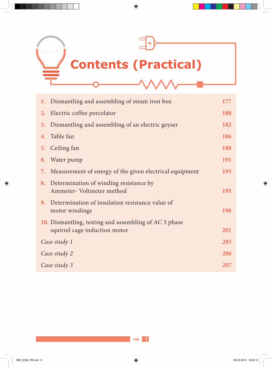
v. Stay insulator
Fig. 1.16 Stay insulator
The insulator used in the stay wire is called a stay insulator. This type of insulator is as shown in figure 1.16 is made of porcelain. The size of insulator depends upon the tensile strength of stay wire. It is used to prevent the leakages from the poles up to 33KV. These are provided at a height of 3m from the ground level.
1.10 Power distribution system
The medium voltage transformer using transmission lines are reduced by step down transformer (415V, or 240V) are used to the consumer. This system includes the feeder lines, distributors and service mains.
1.10.1 Feeder lineThe feeder line is nothing but similar
as power transmission conductors. It connects the power from sub-station and power supply to the consumers. The voltage is uniform throughout the conductor.
1.10.2 DistributorElectric power is distributed to the
consumer by tapings. Since electric power is taken from many tappings and the current is not uniform in all. Therefore, when designing the distribution system, care must be taken to the voltage drop.
BEE_ENG_Chapter_01.indd 11 08-03-2019 18:06:51

1 - Power transmission and distribution 12
ii. As there is no tension on the conductor, it will not break due to mechanical reasons after being installed. Hence there are very few chances for a power failure. It reduces accidents.
iii. Less maintenance is required.iv. There is no interference with tele
communication circuits.
1.11.2 Disadvantages of cables
i. The installation cost is high.ii. High voltage cables are difficult to
manufacture due to the insulation problem.
iii. Joining of underground cables is difficult.
iv. Fault location is not easy.
1.11.3 Classification of cables
a. According to the rating of voltage the cables are classified intoi. Low tension cables up to 1 KVii. High tension cable up to 11KViii. Super tension cables 22 KV to
33KViv. Extra high-tension cables 33KV to
66 KVv. Oil filled cables 66KV to 132 KVvi. Extra super voltage cables beyond
132 KVb. According to insulation, cables are
classified intoi. PVC insulated cablesii. Mineral insulated cableiii. Paper insulated lead sheathed
cableiv. Cross linked poly ethylene cablev. Paper insulated lead covered
double tap armored cable
1.10.6 Grid or interconnected distribution system
More than one power plants and sub-stations are connected in series feeders are called as ‘Interconnected distribution system.’ It is also called as grid. In this system, the power plant and sub-station are connected together, and the voltage is reduced to 33KV, by using transformer. This method increases the reliability and efficiency. Electricity can be provided from different power plants during high power consumption.
1.10.7 Service linesService line is low length connecting
conductor. These service lines act as conductor between distribution pole and consumer.
1.11 Underground cables
By us ing underg round cable , the p ower i s t ransmitted f rom the generating station to the consumers. When electr ica l power is unable to transmit by overhead lines or in a thickly populated area, underground cables are used. An underground cable consists of one or more conductor covered with suitable insulation and surrounded by a protecting core. Normally the number of cores in underground cables are 1, 2, 3, 3 ½ and 4.
1.11.1 Advantages of cablesi. Underground cables are not subjected
to lightning discharges, thunder, storms, birds and other severe weather conditions.
BEE_ENG_Chapter_01.indd 12 08-03-2019 18:06:51

1 - Power transmission and distribution13
moisture. In this one or more layers are shielded and protected. These types of electric cables are used to transmit voltage up to 11 KV and sometimes voltage can be extended upto 22 KV.
b. Screened cableIt is of two types
i. H – type cable (Hochstadter type)ii. S.L. type cable (Separate lead type)
i. H Type cables 22 KV to 66 KV
Lead sheath
Conducting belt
Paper insulation
Metallic screen
Outer sheath
Bedding
Armouring
Fig. 1.18 H type cable
Figure 1 .18 shows the H type s cre ene d c able . E ach conduc tor i s insulated by separate layers of impregnated paper. Then it wil l be wrapped with metal insulation separately. The metal shield is made of thin aluminum and made to touch each other. These three containers are wrapped in copper fabric tape. There will be a lead sheath casing on it. There is one or more armors on it. These types of cables are used to transmit low and medium voltages. It is used to transmit 33 KV and sometimes to carry up to 66 KV.
c. According to number of conductors, cables are classified intoi. Single core cableii. 2 core cableiii. 3 core cableiv. 4 core cablev. 3 ½ core cable
1.11.4 Three phase cableCommonly, underground cables are
used to transmit three phase power supply. For three phase service, the following cables are used.
a. Belted cable up to 11 KVb. Screened cable 22KV to 66 KVc. Pressure cable above 66 KV
a. Belted cable up to 11 KV
ArmouringLead sheath
Conductor
Paper insulationBedding
Serving
Fig. 1.17 Belted cable
Figure 1 .17 shows t he cross-section view of the belted cable. Each conductor is insulated by separate layers of impregnated paper. Thus, the insulated 3 conductors are set up as a part in the same set and then wrapped in an impregnated paper tape called a paper belt. Between insulated containers, it is f i l led with insulating material like jute or fiber. A lead sheath is laid on the paper bar to protect from mechanical damage and
BEE_ENG_Chapter_01.indd 13 08-03-2019 18:06:51

1 - Power transmission and distribution 14
T h e p ip e s are s e t up for o i l circulation in oil-filled cables as shown in figure 1.20. The oil under pressure is kept supplied to the channel from a tank. The oil tank is set at a distance of about 500m along the cable route. Pressure oil is prevented from vacuum by pressing the paper insulation. This type of cable is used for distributing voltages from 66 KV to 230 KV.
ii. Gas filled cable
Pressurised gas
Steel pipe
Fig. 1.21 Gas filled cable
G a s f i l l e d c ab l e i s s h ow n i n f igure 1.21. The construction of gas pressure cable is similar to that of ordinary solid cable. It is designed in a triangular shape. The thickness of lead sheath of gas pressure cable is 75% of solid cable. The sheath is protected by a thin metal tape. The cable is kept in a gas tight steel pipe. The pipe is filled with dry nitrogen gas at 12 to 15 atmospheric pressure. The gas pressure produces radial compression and closes the voids formed between the layers of paper insulation. These cables carry more load current and operate at higher voltage than a normal cable. The nitrogen gas helps in quenching any flame. Its maintenance cost is low.
ii. S.L. type cable (22KV to 66KV)
(1) Core
(2) Insulation
(3) Lead sheath
(4) Filler
(5) Bedding
(6) Armouring
(7) Serving
Fig. 1.19 SL type cable
The structure of SL type cable is shown in figure 1.19 Even though this type is similar to that of H-type, each conductor is constructed with separate lead sleeves. Hence this cable can be handled easily for bending.
c) Pressure cablesA vacuum occurs when the solid
power cord is used. It causes an electro chemical breakdown. Therefore, these pressure cables are used for distributing the voltage over 66 KV. The pressure of joint components used in these cable is increased and vacuum is reduced.
There are two types of pressure cables:i. Oil filled cablesii. Gas pump/pressure cables.
i. Oil filled cablesOil channels
Paper insulation
Conductor
Grooved sheath
Fig. 1.20 Oil filled cables
BEE_ENG_Chapter_01.indd 14 08-03-2019 18:06:51

1 - Power transmission and distribution15
1.11.5 Difference between Overhead line and Underground cables
Sl. No. Overhead Lines Underground cables
1 To increase the load, conductors can be included easily. To increase the working voltage, it is enough to change the insulator.
Change the new cable for two reasons like to increase the load and the conductors cannot be included easily.
2 If need, load can be easily increased. Load cannot be increased, otherwise cable will gets damage.
3 More space is required to install. Less space is required to install.4 Maintenance is easy. Maintenance is complicated.5 Easy to find the fault. Difficult to find the fault.6 Power factor loss is high. Power factor loss is low.7 It is suitable for long transmission It is suitable for short transmission8 It can be affected by lightning. It cannot be affected by lightning. 9 Installation cost is low. Installation cost is high.10 It is cheap It is costly
• The power supply from power plants to the consumers is called power transmission.
• A large amount of alternating current is produced at power stations.• The specific resistance of copper is less than aluminum.• Aluminum Conductor with Steel Reinforced is extensively used for power
transmission.• Wooden poles are not currently used.• The Lattice steel tower is suitable for the distance between 100 meters and 300
meters.• Bluish green sparking around the conductor is called corona.• Types of guarding i. Cradle guarding ii. Cage guarding• The insulator used in the stay wire is called stay insulator.• When electrical power is unable to transmit by overhead lines area underground
cables are used.• The underground cable is not affected by lightning
Points to remember
BEE_ENG_Chapter_01.indd 15 08-03-2019 18:06:52

1 - Power transmission and distribution 16
Evaluation
Corona – வெளிசசுடவொளிDi-electric strength – மினொபபு ெலிமைFeeder lines – ஊடடளிபபுத வொடரGrid – ெமையிமைபபு (அ) மினடடமைபபுInsulator – மினொபொனPeak load – உசசகடட ளுRegulation – ஒழுஙகு முமைPower factor – திைனொணிReceiving station – ஏறபு நிமையம
Glossary
1. Students to make their own solar to turn a small generator capable of lighting an array of LEDs or giving an output voltage measured on a voltmeter.
2. Students to make their own wind-mill to turn a small generator capable of lighting an array of LEDs or giving an output voltage measured on a voltmeter.
Activities
PART-AChoose the correct answer (1 Marks)
1. Which of the following is usually not the generating voltage?a) 6.6 kVb) 9.9 kVc) 11 kVd) 13.2 kV
2. Which of the following is not the distribution system normally used?a) 3 phase - 4 wireb) 3 phase - 3 wirec) Single phase - 3 wired) Single phase - 4 wire
BEE_ENG_Chapter_01.indd 16 08-03-2019 18:06:52

1 - Power transmission and distribution17
3. The disadvantage of constant voltage transmission isa) short circuit current of the
system is increasedb) load power factor in heavy
loadsc) large conductor area is
required for same power transmission
d) less current during short circuit
4. The voltage of low-tension transformer is a) 132 KVb) 220 KVc) 33 KVd) 400 KV
5. Generally which conductor is used for power transmission _________a) Steelb) Copperc) Aluminiumd) ACSR
6. Pin type insulators are normally used up to voltage of abouta) 100 kVb) 66 kVc) 33 kVd) 25 kV
7. For 66 KV lines, the number of insulator disc used area) 3b) 5c) 8d) 12
8. Which type of insulator is used on 132 KV transmission lines?a) Pin typeb) Disc typec) Shackle typed) Pin and shackle type.
9. The effect of corona isa) increased energy lossb) increased reactancec) increased inductanced) increased resistance
10. Wooden poles for supporting transmission lines are used for voltages up toa) 440 Vb) 11 kVc) 22 kVd) 66 kV.
11. Which of the following regulation is considered to be the best?a) 2%b) 30%c) 70%d) 98%.
12. The power transmitted will be maximum whilea) sending end voltage is moreb) receiving end voltage is morec) reactance is highd) corona losses are least.
13. Stranded conductors arc used for transmitting, power at high voltages because ofa) increased tensile strengthb) better wind resistancec) ease-in handlingd) low cost.
BEE_ENG_Chapter_01.indd 17 08-03-2019 18:06:52

1 - Power transmission and distribution 18
PART-BAnswer the questions in brief (3 Marks)
1. What is meant by power transmission?
2. State some electrical power generating stations.
3. What are the advantages of DC transmission?
4. What are the disadvantages of AC transmission?
5. What are the advantages of high voltage transmission?
6. What are the properties of overhead line conductors?
7. Write short notes on ACSR conductor.
8. Write the name of four types of electrical poles.
9. What is skin effect?10. What are the methods used to
reduced corona effect?11. What are uses of guarding?12. What is meant by service lines?
PART-CAnswer the questions in one page (5 Marks)
1. What are the various methods of power transmission?
2. Draw the power transmission diagram and point out the parts.
3. Explain the metal conductors used for power transmission.
4. Draw the shackle type insulator diagram and label the parts.
5. Write down the types of distributors.
6. What are the main objectives, advantages and disadvantages of underground cable for power distribution?
7. Draw the diagram of suspension type insulator.
PART-DAnswer the questions in two page (10 Marks)
1. Explain with a neat sketch the various types of electrical poles.
2. Explain the reasons, advantages and disadvantages of corona?
3. Tabulate the differences between the overhead transmission lines and underground cables.
BEE_ENG_Chapter_01.indd 18 08-03-2019 18:06:52

1 - Power transmission and distribution19
1. A text book of ‘Electrical Technology’ Volume-III B.L.Theraja and A.K.Theraja, S.Chand & Company Ltd.
Reference Book
1. http://www.wikipedia.org 2. https://www.electrical4u.com
Reference Internet Source
BEE_ENG_Chapter_01.indd 19 08-03-2019 18:06:52
2 - Illumination 20
2Chapter
Illumination
Learning Objectives
In this lesson, students will get to know the various terms regarding illumination and can easily understand the concept of light. Various types of lighting systems and their uses are given. One of the main objectives is the study of various types of lamps and their merits and demerits. According to new trend, it is necessary to know the various types of lights used in shops, industries, streets and in homes. Students have to know, what are the factors to be considered, while designing good lighting system. This is the right time to think for saving electrical energy by using low wattage bulbs like CFL, LED by adopting new techniques.
The best way to win is the lack of tension. A.P.J. Abdul Kalam
BEE_ENG_Chapter_02.indd 20 08-03-2019 18:25:43

2 - Illumination21
2.1 IntroductionAlmost all human activities are
based on light. Natural light is obtained by the sun. Art if icia l l ight plays an important role in our everyday life. In places where natural light is not available, artificial light is obtained by electric lamps. Lighting plays an important role because of its belief, consistency, simple control and low price. The electrical lighting is mainly used for domestic purpose, decorative purpose, advertising, traffic- control, medical field and for street lighting also.
When light falls on a surface, it becomes visible and the phenomenon is called as illumination. It is denoted by E and is measured in lumen per square meter.
2.2 Important terms in illumination
2.2.1 Plane angleThe angle subtended at a point by
two converging lines lying in the same plane is called plane angle, and is measured in radians. It is shown in figure 2.1. It is equal to the ratio of the length of the arc to its radius.
AB
r = Radius l = Length of the arcθ = Plane angle
ro
θ
I
Fig. 2.1 Plane angle
θ = radius
radiansArc
θ = lr
radians
2.2.2 Solid angle
r = radiusω = solid angle
Fig. 2.2 Solid angle
S o l i d a n g l e i s m e a s u re d i n steradians. Solid angle is the ratio of area of the surface to the square of radius of sphere. It is shown in figure 2.2.
ω =Area of surface Square of radius
steradians
ω =Ar2 steradians
Table of Content
2.1 Introduction 2.2 Important terms in illumination2.3 Laws of illumination2.4 Arc lamp2.5 Incandescent lamp2.6 Sodium vapour lamp and mercury
vapour lamp
2.7 Fluorescent lamp and compact fluorescent lamp
2.8 Neon and halogen lamp2.9 LED lamp2.10 Lighting schemes
BEE_ENG_Chapter_02.indd 21 08-03-2019 18:25:44

2 - Illumination 22
2.2.9 Space height ratioSpace height ratio is defined as the
ratio of the distance between adjacent luminaries (center to center) to their height above the working plane.
2.2.10 Utilization factorUtilization factor or coefficient of
utilization is defined as the ratio of total lumens reaching the working plane to the total lumens given out by the lamp.
Utilization factor =
Lumens reaching at the working place
Tottal lumens emitted by the source
It usually varies from 0.5 to 0.8.
Do you Know?
An American inventor, Thomas Alva Edison, discovered 1368 inventions. His most popular invention is electric bulb. He invented many devices in the field such as mass communication, electric power generation, sound recording and motion pictures. Edison designed a system of conductors, meters, lamp fixtures, sockets, fuses and current switches.
2.2.3 Luminous fluxIt is the light energy radiated out
per second from the body in the form of luminous light waves. The unit of luminous flux is lumen (lm).
In LED lamps,
15 Watts= 900 Lumens
2.2.4 LumenIt is the unit of luminous flux. One
lumen is defined as the luminous flux emitted per unit solid angle from a point source of one candle power.
2.2.5 Luminous intensity (I)Luminous intensity or Candle-
power of a point source in any particular direction is given by the luminous flux radiated out per unit solid angle in the direction.
2.2.6 LuxThe amount of light that causes a
luminous flux over a square meter surface is called lux.
2.2.7 Mean Horizontal Candle Power (MHCP)
It is the mean of the candle powers in all directions in the horizontal plane containing the source of light.
2.2.8 GlareGlare is difficulty seeing in the
presence of bright light such as direct or reflected sun light or artificial light. It causes annoyance, discomfort or interference with vision or eye fatigue.
BEE_ENG_Chapter_02.indd 22 08-03-2019 18:25:44

2 - Illumination23
2.4 Arc lampThe principle of an arc lamp is that
when two electrodes carrying current are separated through a small distance, an arc is struck between them. The arc lamps were used in the past for street lighting purposes but nowadays these are used when extreme brightness is required. Carbon arc lamp is most commonly used arc lamp.
2.4.1 Carbon arc lamp
Envelope
Anode end cap Cathode end capAnode Cathode
Fig. 2.3 Arc lamp
Arc lamp is shown in figure 2.3. Carbon arc lamp is the oldest type of lamp and is still being implied in cinema projectors and searchlights. It consists of two hard carbon rods (Electrodes). The diameter of positive electrode is double to that of negative electrode. The negat ive e lec trode is genera l ly fixed and positive electrode is placed in adjustable holder and the process is manually or automatic. The arc consists of carbon vapours surrounded by orange red zone of burning carbon and pale green flames.
When the lamp is switched OFF, the two electrodes touch each other due to spring pressure on positive electrode. When the supply is ON a large current is flows through electrodes. The temperature of carbon electrode is increased and thus
2.3 Laws of illuminationThe i l lumination on a surface
depends upon the luminous intensity, distance between the source and surface and the direction of rays of light. It is governed by following laws.
1. Inverse square law2. Lambert’s cosine law
2.3.1 Inverse square lawIt states that the illumination of a
surface is inversely proportional to the square of the distance of the surface from the source.
Eα 12d
2.3.2 Lambert’s cosine lawThis law states that the illumination
on any surface is proportional to the cosine of angle between the directions of the incident flux and perpendicular to the area.
E = cos 12d
θ
2.3.3 LightThe radiant energy from a hot body
which produces the visual sensation on human eye is called light.
2.3.4 Electrical method of producing light
Fol lowing are the methods of producing light:
1. D e ve loping arc b e t we en t wo electrodes.
2. Passing a current through a filament.3. Electric discharge through vapours or
gases.
BEE_ENG_Chapter_02.indd 23 08-03-2019 18:25:44

2 - Illumination 24
Fig. 2.4 Vacuum lamp
Cap
Fuse
Lead-In wires
Glass stem
Spider for supportingfilament
Fig. 2.4(a) Line diagram of vacuum lamp
When the filament is heated, due to the current that passes through the high resistance filament, the moving electron creates friction. So the heat is generating in the filament when the heat raises up to the incandescent stage, the light is emitted from the filament. The emitted light is reflected by a sphere-shaped glass cover.
2.5.2 Gas filled lampIt is shown in figure 2.5. In the
evacuated lamp, the filament evaporates and deposits on inside of the glass cover after long use and makes black shade on
the positive electrode is pulled away against its spring pressure through a small distance by coil and thus an arc is struck between electrodes. This arc is maintained by transfer of carbon particles from one electrode to other electrode. These particles travel from positive electrode to negative electrode, thus after sometime of operation positive electrode become hollow and negative become pointed. That’s why positive electrode is made double than negative electrode. In carbon arc lamp 85 % of light is given by positive electrode which produces high intensity light and only 10% by negative electrode and 5% by air. The temperature of the positive electrode is 4000°C and that of the negative electrode is about 2500°C. The luminous efficiency of such lamps is approximately 9 lumen / watt.
2.5 Incandescent lampThe filament of this lamp is heated
up to the incandescent stage of heat. So these types of lamps are called as incandescent lamps. There are two types.
1. Vacuum type lamp and 2. Gas filled type lamp
In this type of lamp, the sphere shaped glass cover is used. The glass stem is fixed in the centre of the lamp. This stem supports wires in holding the filament. The top of the lamp is sealed. Pins are used for holding the lamp in the holder.
2.5.1 Vacuum lamp
In this lamp, the air is evacuated to protect the filament from burning by oxygen mixed in the air. Vacuum lamp is shown in figure 2.4 and 2.4(a).
BEE_ENG_Chapter_02.indd 24 08-03-2019 18:25:45

2 - Illumination25
b. Properties of metal for filament
1. It can be operated at a high temperature, since it has a high melting point.
2. It produces more heat because it has a high specific resistance.
3. Filament resistance may not change at the operating temperature because it has a low temperature co-efficient.
4. Because of low vapour pressure, it may not get vapour.
5. Because of high ductility, it may withstand mechanical vibrations.
2.6 Sodium vapour lamp and mercury vapour lamp
2.6.1 Sodium vapour lampSodium vapour lamps are some of
the most efficient lamps in the world. They have an efficiency of up to 190 lumens per watt compared to an incandescent street lamp which has between 15 and 19 lumens per watt.
This sodium vapour lamps comes in two major groups:
1. High pressure sodium vapour lamps (HPS)
2. Low pressure sodium vapour lamps (LPS)
This lamp consists of discharge tube made from special heat resistance glass, containing a small amount of metallic sodium, neon gas and two electrodes. Neon gas is added to start the discharge and to develop enough heat to vapour sodium. A long tube is required to get more light from this lamp. To reduce overall dimensions of the lamp, the tube is generally bent into U‐shape.
the glass cover. To rectify this disadvantage, inert gases are filled in this lamp. Presence of inert gas causes heat loss. To compensate the heat loss, the filament is made as coiled wire. Increase in length of the filament leads to an increase in power.
Glass bulb
Gas filling
Tungsten filament
Support wires
Lead wires
Exhaust tube
Stem
Dumet wire
Cap
Fuse
Fig. 2.5 Gas filled lamp
a. Working principle of a filament or an incandescent lamp
As we know, when a room heater is switched on, it gives out red light with heat at the working temperature of 750oC. At this temperature, the radiations are produced by infra red rays.
When an electric current is passed through a f ine metallic wire, it raise the temperature of the wire. At low temperature, only heat is produced but at a higher temperature light radiation goes on increasing. The filament lamp consists of fine wire of high resistive material placed in an evacuated glass bulb. This type of lamp is operated at the temperature of 2500oC. A tungsten filament is covered in an evacuated glass bulb. But to improve the life of the filament, some chemicals like argon or nitrogen, neon gases are filled.
BEE_ENG_Chapter_02.indd 25 08-03-2019 18:25:45

2 - Illumination 26
1. MA type (Mercury vapour lamp with auxiliary electrode)
These are operated at 220 ‐ 250 volt, AC supply and manufactured in 250 to 400 watts.
2. MAT type (Mercury vapour lamp with tungsten filament)
These are manufactured between 300 to 500 watts and works at 200 to 250V (Both AC and DC)
3. MB type (Mercury vapour lamp with auxiliary electrode and bayonet cap)
This type is operated at 200 – 250 volt, (AC and made in 80 watts and 125 watts)
a. Construction
R
A B
Choke
A.C. Supply
Capacitor
S
Fig. 2.7 Mercury vapour lamp
The construction of mercury vapour lamp is shown in figure 2.7. It consists of hard glass tube enclosed in outer bulb of ordinary glass. The space between two bulb is completely evacuated to prevent heat loss by convection from the inner bulb. The outer bulb absorbs harmful ultraviolet rays. The inner bulb contains argon gas with a certain quantity of mercury. In addition to two electrodes, starting electrode having high resistance, connected in series is also provided. The main electrodes are made of tungsten wire in a helical shape. The lamp has a screwed cap and is connected to supply with a choke. A capacitor is connected across supply to improve power factor.
a. Working principle
Discharge tube
Highreactance
transformer
Condenser forp.f. correction
A.C.supply
Fig. 2.6 Sodium vapour lamp
The construction of sodium vapour lamp is shown in figure 2.6. Electric discharge lamps require a high voltage at start and a low voltage during operation. The tungsten-coated electrodes are connected across auto-transformer, having high leakage reactance. The open-circuit voltage of this transformer is about 450 V which is sufficient to initiate a discharge through the neon gas.
After 10 to 15 minutes, the voltage falls to 150 V, due to low power factor. A capacitor is connected across the supply to improve the power factor. The colour of light produced is yellowish.
b. Applications1. LPS lamps are rarely used for indoor
lighting and are best suited for outdoor lighting.
2. LPS lamps are used in security lighting as their high efficiency.
3. LPS lamps are also often used in long tunnels.
2.6.2 Mercury vapour lampOn the basis of pressure inside the
discharge tube, the mercury vapour lamps are classified as High pressure mercury vapour lamp and Low pressure mercury vapour lamp. High pressure mercury vapour lamps are classified as:
BEE_ENG_Chapter_02.indd 26 08-03-2019 18:25:45

2 - Illumination27
tube is coated with phosphorous. The tube contains argon gas at low pressure and a drop of mercury is added. The choke, two filaments and the starter are connected in series as shown in the figure 2.8. The standard wattage of a 3 feet fluorescent lamp is 100 watts.
a. Working principle
Double walledenclosure
Ballast
Source
Filament Glass tube Starter Mercury Inert gas
Fig. 2.8 Connection diagram a fluorescent lamp
Fluorescent lamp function based on the principle of current passing through air medium. In the air medium the resistance falls down heavily. When the current passes to the lamp, circuit is closed through choke, filament and starter. So the 230V supply voltage is applied between the starter terminals. Due to this voltage, current starts flowing through the inert gas in the starter. Now the bimetallic strips raised touch each other as the temperature of inert gas has increased. Once the circuit is completed through the bimetallic strips and filaments in the tube light, the bulb will start glowing.
The inert gas in the starter cools down and the bimetallic strip opens again. Therefore the current through the choke decreases and hence the magnetic flux decreases. The decreasing (or alternating) flux is cut by the choke winding which causes self induced EMF in the choke coil.
b. Working principle When the supply is switched on,
full voltage is applied across main and starting electrodes. This voltage fills the gap between the electrodes and discharge through argon gas. As the lamp warms up, mercury is vaporized, which increases the vapour pressure. After 5 minutes, the lamp gives full light. It gives a greenish blue colour light. This lamp is always kept in vertical. Otherwise the inner glass tube may break due to excess heat.
c. Advantages1. Mercury vapour lamps are more energy
efficient than incandescent lamps.2. It has high luminous efficacies of 35 to
65 lumens / watt.3. It is durable. (in the range of 24,000
hours)4. It has a high intensity.5. It gives clear white light output which
has made them ideal for outdoor use
d. Applications1. Mercury vapour lamps are used in
lighting applications.2. It is used in streets and parking places.3. It is used for landscape lighting.4. It is used in factories.5. It is used in gymnasiums.
2.7 Fluorescent lamp and compact fluorescent lamp
2.7.1 Fluorescent lampIt is a low pressure
mercury vapour lamp. It consists of a glass tube 25 mm in diameter and 0.6 m, 1.2 m and 1.5 m in length. The inner portion of the
BEE_ENG_Chapter_02.indd 27 08-03-2019 18:25:45

2 - Illumination 28
2.7.2 Compact Fluorescent Lamp (CFL)
The compact fluorescent lamps are becoming very useful nowadays, because of consumption of power, cost, longer life, attractive look, smooth light and low maintenance. These lamps are available in different sizes and designs. They have single rod, double rod, triple rod or spiral rod. These lamps are available in different power ratings like 5, 7, 9, 11, 18 and 24 watts in 220 V. It is shown in figure 2.10.
Fig. 2.10 Compact Fluorescent Lamp (CFL)
It is basically a low pressure mercury vapour lamp having two electrodes coated with an electron-emitting material placed in a glass tube. The tube is coated internally with some fluorescent material in the form of powder. In the tube one drop of mercury and argon gas is filled at low pressure. Compact f luorescent lamps are now available in the same popular sizes as incandescent and are used as an energy-saving alternative in homes
a. Advantages1. Low energy consumption.2. Low maintenance cost3. It starts instantly4. It does not heat the surroundings5. Excellent colour properties
Phosphorcoated
Argon andmercury vapour
MercuryUltra violetradiation Filament
Electron
Tube
Fig. 2.9 Fluorescent tube
The induced EMF is nearly about 1200V. This voltage is applied between the filaments of the tube light, causing electron flow between the filament and the inert gas of the tube light. The electron collision in to the inert gas produces the ultra violet rays. These rays impinge on the phosphorous coating. Light is emitted by the coating. After light started at 110V is enough for the light to retain the supply voltage 120 volt, which is dropped across the choke. The luminous efficiency of a fluorescent lamp is 60 lumens / watt.
b. Advantages
1. Voltage fluctuation has very small effect on light output.
2. The luminous efficiency is more as length of rod is more.
3. It gives light close to natural light.4. Heat radiations are negligible.
c. Disadvantages
1. Its brightness is less.2. Initial cost is more3. Overall maintenance cost is high.
d. Applications
1. Fluorescent lamp is available in required designs and sizes. Hence it is used largely in residential areas.
2. It is used for good lighting. 3. Special fluorescent lights are used in
stage lighting for films and in video camera lighting.
BEE_ENG_Chapter_02.indd 28 08-03-2019 18:25:46

2 - Illumination29
and a cathode). When adequate voltage is applied and sufficient current is supplied between the electrodes, the lamp produces an orange glow discharge. The glowing portion in the lamp is a thin region which is near to the cathode.
b. Applications 1. Neon lamps are generally used for
advertising.2. It is used as an indicator lamps3. It is used for night lamps
2.8.2 Halogen lampHalogen lamp is a special type
of tungsten filament lamp which was developed in 1959. In this, a small amount of halogen vapour is added to the inert gas of the bulb. The bulb is made of glass small in size. It operates at a temperature of 3000°C
Glass bulb
Tungsten
Halogen
Cap
Fig. 2.13 Halogen lamp
Working principleH a l o g e n l a m p i s s h o w n i n
figure 2.13. When the supply is given to the lamp, a filament glows, producing light. The halogen, an inert gas, causes the evaporated tungsten to settle back on the filament during cooling. That’s why lamps
6. Low operating cost7. More life
b. Applications 1. The compact size, longer life, low
running and maintenance cost, instant glow makes these lamps suitable for all places where uniform illumination is required.
2. It is used in offices, shops, hotels, hospitals, cinema halls, residential buildings etc.
2.8 Neon and Halogen lamp
2.8.1 Neon lamp
Fig. 2.11 Neon lamp
Gas
Glassenvelope
Electrodes
Leads
Pip
Pinch
Fig. 2.12 Line diagram of neon lamp
a. ConstructionThe construction of neon lamp is
shown in figure 2.11. A neon lamp is a small gas discharge lamp. The lamp commonly consists of a small glass capsule that contains a mixture of neon and different gases at a low pressure, and two terminals (an anode
BEE_ENG_Chapter_02.indd 29 08-03-2019 18:25:47

2 - Illumination 30
The construction of LED Lamp is shown in figure 2.14. An LED lamp is a light-emitting diode (LED) product that is assembled into a lamp (light or bulb) for use in lighting fixtures. The line diagram of a LED lamp is shown in figure 2.15.
LED lamps have a lifespan and electrical efficiency which are several times greater than incandescent lamps, and are s ignif icant ly more ef f icient than most fluorescent lamps. General purpose l ight ing needs white l ight . LEDs emit light in a very narrow band of wavelengths. To emit white l ight from LEDs require either mixing light from LEDs of various colours, or using phosphorous to convert some of the light to other colours.
Basic components for LED lighting are:
1. LED2. Driver (power conversion device)3. Control devices (dimming controls,
colour mixing controls)4. Fixture
a. LED driverRequired by the LED system to
convert a system voltage into power. The driver also regulates power delivered to LEDs to counter any fluctuations in system conditions. Drivers also isolate the LED system from the high voltage system to reduce shock hazards and make the lighting system safer.
b. Advantages 1. It has a long life.2. It reduces energy costs.3. It reduces maintenance costs 4. LEDs produce very little heat.
can be operated at a high temperature. It provides a high intensity light.
a. Advantages1. It is smaller in size.2. It does not need any ballast.3. Good colours can be obtained.4. Excellent optical control.5. It gives same output throughout life6. It has long life
b. Disadvantages 1. During maintenance the handling of
lamp is very difficult.2. Radiation is more which heats the
surroundings also.3. Operating temperature is high which
affects its life.
2.9 LED lamp
Fig. 2.14 LED Lamp
a = anode(+)
c = cathode(−)
Fig. 2.15 Line diagram of LED lamp
BEE_ENG_Chapter_02.indd 30 08-03-2019 18:25:47

2 - Illumination31
iii. Semi direct lighting
This is also an efficient system of lighting and chances of glare are also reduced. Here transparent type shades are used through which about 60% of light is directed downward and 40% is directed upward. This also provides a uniform distribution of light and is best suited for room with high ceilings.
iv. Semi indirect lightingIn this system about 60 to 90%
of total light is thrown upward to the ceiling for diffused reflection and the rest reaches the working plane directly. A very small amount of light is absorbed by the bowl. It is mainly used for interior decoration.
v. General lightingThis system employs such type
of luminaries, shades and ref lectors which give equal illumination in all the directions.
2.10.1 Design of indoor light scheme
While designing a good lighting scheme, the following points must be kept in mind:
i. It s h o u l d p r ov i d e a d e q u at e illumination.
ii. It should provide uniformly distributed light all over working plane.
iii. It should avoid glare and shadows as far as possible.
iv. It should provide light of suitable colours.
c. Applications 1. It is used in homes2. It is used in hotels and restaurants3. It is used in shops4. It is used in offices5. It is used in roads, streets and parks6. It is used in hospitals7. It is used in commercial premises
2.10 Lighting schemesLighting schemes are classified
according into their locations requirement and purposes etc., as stated under:
i. Direct lightingii. Indirect lightingiii. Semi direct lightingiv. Semi indirect lightingv. General lighting
i. Direct lightingIn this system almost 90 to 95%
of light falls directly on the object or the surface. The light is made to fall upon the surface with the help of deep reflectors. Such a type of lighting scheme is mostly used in industries and commercial lighting. Although this scheme is most efficient, it is liable to cause glare and shadows.
ii. Indirect lightingIn this system, the light does not fall
directly on the surface but more than 90% of light is directed upwards by using diffusing reflectors. Here the ceiling acts as a source of light and this light is uniformly distributed over the surface and glare is reduced to minimum. It provides shadow-less illumination which is useful for drawing offices and composing rooms. It is also used for decoration purposes in cinema halls, hotels, etc.
BEE_ENG_Chapter_02.indd 31 08-03-2019 18:25:47

2 - Illumination 32
vi. Better reliabilityvii. Suitable for almost all purposes etc.
C. Type of work recommended and illumination level
Places Illumination LevelOffices 100‐400 lumens/ meter
squareSchools 250‐400 lumens/ meter
squareIndustry 1000 lumens/ meter
squareShops 250‐500 lumens/ meter
squareHotels 80‐100 lumens/ meter
squareHospitals 250‐3500 lumens/ meter
square
a. Factors required for good lighting scheme
The following factors are required to be considered while designing a lighting scheme
i. Illumination levelii. Quality of lightiii. Coefficient of utilizationiv. Depreciation factorv. Space height ratio
b. Advantages of electrical lighting
i. Cleanlinessii. Easy to controliii. Economicaliv. Easy to handlev. Steady output
• The unit of solid angle is steradians
• The unit of plane angle is radians
• The unit of luminous flux is lumen
• In LED lamps, 15 watts = 900 lumens
• Glare causes annoyance, discomfort or interference with vision or eye fatigue.
• Law of illumination
i. Inverse square law
ii. Lambert’s cosine law
• Carbon arc lamp is most commonly used arc lamp.
• Types of incandescent lamp
i. Vacuum lamp
ii. Gas filled lamp
Points to remember
BEE_ENG_Chapter_02.indd 32 08-03-2019 18:25:47

2 - Illumination33
• Types of sodium vapour lamps are
i. High pressure sodium vapour lamps (HPS)
ii. Low pressure sodium vapour lamps (LPS)
• Neon lamps are operated at a very low temperature of about 2000C.
• LED lamps are used in homes, hotels, restaurants, shops, offices, hospitals, roads, streets and parks.
• Types of lighting schemes
i. Direct lighting
ii. Indirect lighting
iii. Semi direct lighting
iv. Semi indirect lighting
v. General lighting
Plane angle - தளக கோணமSolid angle - திணமக கோணமLuminous flux - ஒளிரவுப போயமLuminous intensity - ஒளி விளகச ெசறிவுLuminous efficacy - ஒளிரவுததிறன விகிதமLux - ஒளிததிறனGlare - கூெசோளிDepreciation factor - கதயமோனக ோரணிSpace height ratio - இடைெெளி - உயர விகிதமUtilization factor - பயனபோடடுக ோரணி
Glossary
1. To know about how the electric lamp is controlled by a remote.
2. To know about how the electric lamp is controlled by Passive infra red sensor. (PIR Sensor)
Activities
BEE_ENG_Chapter_02.indd 33 08-03-2019 18:25:47

2 - Illumination 34
Evaluation
PART-AChoose the correct answer (1 Marks)
1. Luminous efficacy of a fluorescent lamp isa) 10 lumens / wattb) 20 lumens / wattc) 40 lumens / wattd) 60 lumens / watt.
2. In LED lamps, how many watt is equal to 900 Lumens?a) 15 wattsb) 0.16 wattsc) 0.016 wattsd) 0.0016 watts
3. Standard wattage of 3 ft. fluorescent lamp isa) 10 Wb) 40 Wc) 65 Wd) 100 W
4. A solid angle is expressed in terms ofa) radiansb) radians/meterc) sterediand) steredian/meter
5. Which of the following lamp has a low initial cost?a) Incandescent lampb) Fluorescent lampc) Mercury vapour lampd) Sodium vapour lamp
6. An incandescent lamp can be used ina) AC supplyb) DC supplyc) Both AC and DC supplyd) No supply
7. Filament lamps operate normally at a power factor ofa) 0.5 leadingb) 0.8 leadingc) 0.8 laggingd) Unity
8. The filament of incandescent lamp isa) Tungstenb) Copperc) Aluminumd) Carbon
9. The average working life of a fluorescent lamp is abouta) 1000 hoursb) 3000 hoursc) 4000 hoursd) 5000 hours
10. The luminous efficacy of a sodium vapour lamp is abouta) 10 lumen/wattb) 30 lumen/wattc) 50 lumen/wattd) 70 lumen/watt
BEE_ENG_Chapter_02.indd 34 08-03-2019 18:25:47

2 - Illumination35
11. Colour of light is depend upon a) Frequencyb) Wave lengthc) Speed of lightd) Both a) and b)
12. In houses the illumination is in the range ofa) 2-5 lumens/wattb) 10-20 lumens/wattc) 35-45 lumens/wattd) 60-65 lumens/watt
13. The colour of sodium vapour discharge lamp isa) Redb) Green
c) Bluish greend) Yellow
14. Which of the following will need the highest level of illumination?a) Proof readingb) Living roomsc) Hospital wardsd) Railway platforms.
15. The illumination level in houses is in the rangea) 10-20 lumen/mb) 30-50 lumen/m2
c) 40-75 lumen/m2
d) 100-140 lumen/m2.
PART-BAnswer the questions in brief (3 Marks)
1. Define solid angle.
2. What is meant by luminous flux?
3. What is glare?
4. Define space height ratio.
5. State the two laws of illumination.
6. What are the various electrical method of producing light?
7. Where sodium vapour lamps are used?
8. What are the advantages of mercury vapour lamp?
9. What are the disadvantages of a fluorescent lamp?
10. What are the advantages of a CFL lamp?
11. Briefly describe the working principle of a neon lamp.
12. List out the types of lighting schemes.
13. What are the applications of LED lamps?
BEE_ENG_Chapter_02.indd 35 08-03-2019 18:25:47
2 - Illumination 36
PART-CAnswer the questions in one page (5 Marks)
1. Write a short note on a carbon arc lamp.
2. Explain the construction of an incandescent lamp.
3. Write down the advantages and applications of a mercury vapour lamp.
4. Explain about neon lamp.
5. Explain the advantages and disadvantages of a halogen lamp.
6. Write short notes on compact fluorescent lamp.
7. Write down the advantages and applications of CFL lamp.
8. What are the factors required for a good lighting scheme?
9. Write short notes on LED.
PART-DAnswer the questions in two page (10 Marks)
1. With a neat sketch explain the construction and working principle of sodium vapour lamp.
2. With a neat sketch explain the construction and working principle of mercury vapour lamp.
3. With a neat diagram explain the construction and working principle fluorescent lamp.
1. A text book of ‘Electrical Technology’ Volume-III B.L.Theraja and A.K.Theraja, S.Chand & Company Ltd.
Reference Book
1. http://www.wikipedia.org2. https://www.electrical4u.com
Reference Internet Source
BEE_ENG_Chapter_02.indd 36 08-03-2019 18:25:47

3 - Electric heating appliances37
3Chapter
Electric heating appliances
Learning Objectives
Electric heating is a process in which electrical energy is converted into heat energy. It is essential for the students to know, how the electrical energy is being utilized in heating appliances. The main objective of this chapter is to make students, to understand the working of various heating appliances through the types of conductive methods.
Furthermore, this lesson also aims to aid the students, to gain practical experience about defects, their reasons and its corrective measures of the heating appliances.
Be the change that you want to see in the world. Mahatma Gandhi
BEE_ENG_Chapter_03.indd 37 08-03-2019 18:27:02
3 - Electric heating appliances 38
3.1 IntroductionElectricity plays major role in our
everyday life. One of the main applications of electricity is to produce heat from heating elements. In this chapter, we shall learn about the types of heaters and its working procedure such as
i. Electric iron boxii. Induction stoveiii. Bread toasteriv. Coffee percolator and v. Electric water geyser.
3.2 Electric iron boxAn Electric iron box is an appliance
used to remove the wrinkles in the clothes when heated. It is of three types.
i) Non-automatic or Ordinary type iron box
ii) Automatic iron boxiii) Steam automatic iron box
a) Clothes and its temperatureThe operating temperature of the
iron box for different types of cloths is tabulated below
Nylon - 70°C -90° C Rayon - 100°C - 120°C Silk - 130°C - 150°C Wool - 160°C - 180°C Cotton - 200°C - 220°C Linen - 230°C - 260°C
According to the range of heat required to clothes, the thermostat can be fixed and the wrinkles were removed from the washed clothes.
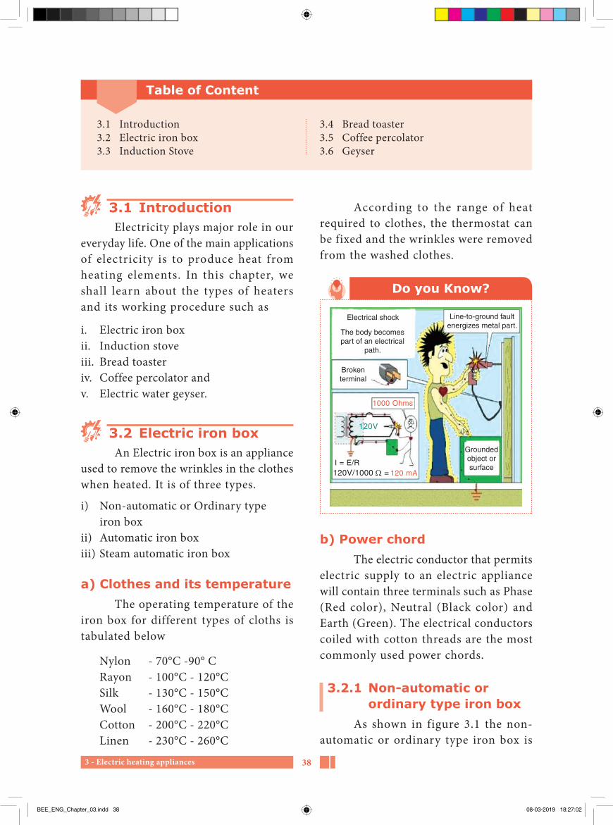
Do you Know?
1000 Ohms
I = E/R120V/1000 = 120 mA
120V
Electrical shock
Brokenterminal
The body becomespart of an electrical
path.
Line-to-ground faultenergizes metal part.
Groundedobject orsurface
b) Power chordThe electric conductor that permits
electric supply to an electric appliance will contain three terminals such as Phase (Red color), Neutral (Black color) and Earth (Green). The electrical conductors coiled with cotton threads are the most commonly used power chords.
3.2.1 Non-automatic or ordinary type iron box
As shown in figure 3.1 the non-automatic or ordinary type iron box is
Table of Content
3.1 Introduction3.2 Electric iron box3.3 Induction Stove
3.4 Bread toaster3.5 Coffee percolator3.6 Geyser
BEE_ENG_Chapter_03.indd 38 08-03-2019 18:27:02

3 - Electric heating appliances39
d) Pressure platePressure plate is made up of hard
cast iron and it g ives weight to the appliance. Due to this, the wrinkles in the clothes are removed.
e) Mica sheetMica is an insulator of electricity. It
is kept in top and bottom of the heating element for safety purpose. Mica is also good to resist the heat.
f) Heating elementThe heating element of the iron box
is made from mixed alloy of Nichrome. Usually in all the heating appliances, it is used as heating element. The heating element here used is of ribbon type.
Heating element is of two types.
1. Coiled type and2. Ribbon type.
g) Sole plateSole plate is plated with chromium
and made up of cast iron. The bottom of the sole plate is surface grained for smoothness.
Working principleThe power chord of the iron box is
connected to the main supply. The electric energy is converted into heat due to this heating element. The heating element is having the property of high resistivity. According to the law of conservation of energy the heat energy produced is proportional to the square of current without any loss. This heat energy makes the sole plate to hot and with that the wrinkles in the cloth are removed.
an appliance, where we control the heat of the appliance by simply putting the switch ‘ON’ and ‘OFF’ only according to the types of cloths used.
Fig. 3.1 Non-automatic iron box
The main parts of the iron box are listed below
a) HandleHandle is made up of bakelite a hard
type of plastic in the iron box. Bakelite is having resistive power of heat and non-conductor of electricity. A rubber tube is provided at the top of the handle, to avoid the damage of power chord while in use.
b) Top coverTop cover is at the top of the
appliance and it covers all the inner parts of the appliance. It is made of metal which is chromium plated to look attractive.
c) StandStand is made up of strong iron to
make the appliance to keep stand when not in use.
BEE_ENG_Chapter_03.indd 39 08-03-2019 18:27:03

3 - Electric heating appliances 40
time of supply, the indicating lamp glows. After attaining the fixed level in the regulating knob (or) Selector knob the indicating lamp turns off automatically. This shows the availability of supply in the appliance.
c) ThermostatThermostat is a bi-metallic strip
made up two different metals. Generally, due to heat, the metals get expanded. After setting the required value in the regulating knob, the heat increases gradually and gets saturated. Then the bi-metallic strip will bend automatically and to stop the supply to the heating element. This can be viewed in the figure 3.3.
After the heat gets reduced in the sole plate, the bi-metallic strip, again contacts with electric supply and makes the appliance to get heated as shown in figure 3.4. The expansion of the strip will vary, according to the strip which the bi-metal was made.
d) Working principle of automatic iron box
The electric input is given to the iron box by putting the switch in ON position. The current goes to the heating element of the iron box through power chord. The heating element gets heated up due to its heat production property. The heat was absorbed by the sole plate and gets heated gradually. This heat removes the wrinkles in the clothes.
3.2.6 Steam iron boxThe construction and working
principle of a steam iron box is similar to
In this type of iron box, according to the type of cloth, the heat can be controlled manually, by connecting or disconnecting the supply through switch.
3.2.5 Automatic iron boxIn an automatic iron box, the
temperature of the cloths can be selected to the required quantity of heat. The temperature is controlled by the thermostat in the appliance automatically. Hence this appliance is called as Automatic Iron Box.
Fig. 3.2 Electric automatic iron box
a) ConstructionAs shown in figure 3.2, the construction
and operation of automatic iron box is similar to that of an Ordinary iron box. In an automatic iron box, the temperature is controlled with the help of thermostat. The thermostat is a bi-metallic strip. In addition to this, an indicating lamp is connected in series with the heating element.
b) Indicating lampIn the iron box LED lamp is used
as an indicating lamp. Indicating lamp is provided to know whether the supply is going into the appliance or not. During the
BEE_ENG_Chapter_03.indd 40 08-03-2019 18:27:03

3 - Electric heating appliances41
fitted with thermostat with wattage of around 1000 to 1600 watts. Steam ironing is one of the easiest methods to iron clothes. For the removal of the wrinkles from the clothes and ironing is in better way.
that of automatic iron box. The internal construction is shown in figure 3.5.
A steam iron is an electric iron that produces steam from water. The steam removes the wrinkles in the clothes. It is
Bimetallic strip
Contact spring
Contact point(Closed)
Fig. 3.4 Thermostat in open position
Water tank
Steam seal
Bi-metallic strip
Sole plateSeal
Thermostat
Fig. 3.5 Steam iron box
Bimetallic strip
Contact point(open)
Fig. 3.3 Thermostat in closed position
BEE_ENG_Chapter_03.indd 41 08-03-2019 18:27:03

3 - Electric heating appliances 42
3.2.6 Trouble shoot chart
Sl. No. Defects Reasons Remedies1. Iron box not gets
heated.1. No electric supply. 1. Correct the electric
supply.2. Heating element is not
connected with supply.2. Connect the supply to
the heating element properly.
3. Loose connection in heating element.
3. Heating element should be connected properly.
2. Heat produced in the iron box is not adequate.
1. Voltage drop. 1. Correct the voltage.2. Thermostat knob not
fitted properly.2. Proper fitting of
thermostat knob should be done.
3. Loose connection in thermostat.
3. Thermostat connection should be done properly
3. Heat produced is exceeding the setting point kept.
1. Short circuit in thermostat.
1. Short circuit in thermostat is corrected.
2. Emery sheet should be used for cleaning the terminal ends to avoid short circuit.
the knob is kept in it. Any defects in the heating element may cause the unit to be replaced by a new one.
a) Maintenance1. In steam iron box, distilled water
should only be used. 2. After the use of iron box, the water
in the container should be removed completely with the help of steam control valve.
3. The salt deposits inside the iron box should be cleaned with the help of vinegar. The vinegar is mixed with water and is rinsed inside two or three times to clear the salt depositions in it.
The steam iron requires more duration to get heated when compared to the other types of iron the clothes.
In this, a small water container is kept above heating element and it supplies water to sole plate through the holes provided in it. The water steam flow is controlled by a press valve kept near the handle. The valve control is provided in handle in order to control the water flow easily. The valve will not allow the water or steam to back side. The water in the tank comes through holes in sole plate in the form of steam. Once the valve gets opened, the steam reaches the cloth and the wrinkles in the cloth will be cleared. The flow of steam upon the position of
BEE_ENG_Chapter_03.indd 42 08-03-2019 18:27:03

3 - Electric heating appliances43
no smokes and flames will be produced. The utensils kept over the induction will not get much heated. Only the things kept inside the utensil alone gets heated. Now-a-days, these types of stoves are widely used in Asia, Europe and America.
Induction heating is the process of heating an element or appliance electrically by the principle of electromagnetic induction. The heat is generated in this type of stove is by means of the eddy currents produced in the induction coils.
According to the types of the Induction stove are classified as
a) Single typeb) Dual type and c) Four type
3.3.1 ConstructionInduction stove is made up of non-
corrosive stainless steel. Heating element
3.3 Induction stove
Heated objectEddy current
Induction coil Current
Magnetic flu
x
Fig. 3.6 Induction stove
Induction stove is widely used in places where there is no LPG gas connection facility. Induction stove is commonly used in hospitals and temporary exhibitions. The construction is shown in the figure 3.6. In this type of stove
Sl. No. Defects Reasons Remedies4. Clothes are
sticking in the sole plate while ironing.
1. Abnormal heat produced. Due to that thermostat terminals contact with one another.
1. Terminals of thermostat should be connected correctly.
2. Bottom of the sole plate is corroded.
2. The corrosion in the sole plate should be cleaned by applying non corrosion things.
5. Iron box is getting electric shock.
1. Supply wire may contact with body of the iron box.
1. Connect the supply wire without touching the metal parts of the iron box.
2. Earth connections should be properly checked.
BEE_ENG_Chapter_03.indd 43 08-03-2019 18:27:04
3 - Electric heating appliances 44
iv. Cost is less.v. No noise occurs while functioning. vi. Burns or wounds will not be caused
when touched.
3.3.4 Difference between regular stove tops and induction cook tops
Regular stove tops heat pots and pans through contact, flames or electrical heating elements of regular stovetops generate heat, and the heat is transferred through the contact from the burner to the base of the pot. This process is known as thermal conduction.
On the other hand, the Induction cook tops do not generate heat. Induction burners have a coiled wire just below the ceramic surface, which generates an oscillating magnetic field. The key to induction cooks tops is that the pots and pans used must be made of magnetic material to work with this system.
The induction cook top will induce the electrons in a magnetic material to move around, creating an electric current. This current generates heat in the pot. If you place your hand, or a glass pot on an induction cook top, neither will heat up because they are not magnetic and therefore not affected by the alternating magnetic field of the induction burner.
3.4 Bread toasterA Bread toaster, or a toast maker,
is an electric small appliance designed to toast sliced breads by exposing it to radiant heat, thus converting it into toast. It is a portable device.
is fixed on the top of the stove, in which utensils were kept. Three pin plugs are used as supply terminal in this stove. Rubber bush is kept at the bottom of the stove for grip. In this, various facilities like child lock safety, timer, temperature indicator and cooking options were included.
3.3.2 Working principle An alternating supply is made to
flow through the resonant coil, which leads to the generation of oscillating magnetic f ield. The magnetic f ield induces an electric current inside the cookware. The induction cook top works with cookware made of certain materials which have specific properties. The Induction stove transfers electrical energy by induction from a coil of wire into a metal vessel that must be ferromagnetic. The coil is mounted under the cooking surface, and a high frequency of alternating current is passed through it. The current in the coil creates a dynamic magnetic field. The magnetic field induces whirling electrical eddy currents inside the pan, turning into a heater. Heat from the pan flows directly into the food or water kept inside the container, by conduction method of heat.
High production of heat is the specialty of this stove. No heat losses will occur. This type of stove can be used in all climatic condition.
3.3.3 Usesi. Function is faster than other types
of stoves. ii. Easy to clean.iii. Stains produced in this can be easily
cleaned with cloth.
BEE_ENG_Chapter_03.indd 44 08-03-2019 18:27:04

3 - Electric heating appliances45
tray is kept below the toaster, in order to collect the waste particles of bread.
Fig. 3.7 Bread toaster
b) Working principleThe bread slices are kept in the place
of bread resting container, and put the lever down to make the bread slices to get in. Then close the top of the toaster with lid, and allow the supply to get toasted. After the bread slices gets toasted, the thermostat which is connected in series with electric supply disconnect the supply and pushes the lever up. Now the toasted slices came out with golden colour.
The use of Thermostat is to allow and disconnect the power supply when the toaster is in use.
3.4.1 TypesThe most common household toaster is classified as
i. Ordinary type bread toaster, and ii. Automatic type.
Ordinary type of bread toaster is not used in now-a-days.
3.4.2 Automatic bread toaster
a) ConstructionElectric bread toaster looks like a
rectangular box and is used for toasting the bread slices as shown in figure 3.7. In this, two gaps are provided, in which two bread slices are put for toasting. The gap is adequate for bread slices to go inside. Bread toaster contains three heating elements and they are in front, middle and back side of the toaster. The centre heating element is the main element for toasting. A resting thick sheet is kept inside the toaster and is attached with a lever. A Thermostat, the heat control device is connected in series with heating element and to the supply. Three pin power chords are used as supply wire for the appliance. Handle is made of hard plastics which insulates the heat and electric supply. A
Sl. No. Defects Reasons Remedies1. Supply is
given, but the toaster not functioning
1. There may be open circuit or short circuit in the power chord.
1. Open circuit or Short circuit in the power chord should be checked before giving the supply.
2. The supply terminals not connected with heating element.
2. Connect the terminals of the heating element correctly.
3.4.3 Defects, reasons and remedies of electric bread toaster
BEE_ENG_Chapter_03.indd 45 08-03-2019 18:27:04

3 - Electric heating appliances 46
Sl. No. Defects Reasons Remedies2. Getting
electric shock while using the toaster
Electric supply terminal is contacting with metal parts of the toaster.
The contact of supply terminal on the metal part should be properly insulated.
3. When switch is ‘ON’, the fuse gets melted
Short circuit in the toaster.
Short circuit should be identified and gets rectified.
made up of nichrome and is used as heating element. Because of its high resistance in the coil, the electrical energy is converted into heat energy. The appliance is cylindrical in shape and is made up of iron coated with lead. Water is poured into the container. A coffee basket is kept above the vertical tube. In some appliances, the lid is made up of glass. In certain type of coffee percolator, the chamber for hot water and coffee water are seprated. Handle is made up of non-conductive materials like bakelite, which resists heat produced in it.
Top chamber
Central column
Funner filter
Stem releasevalue
Bottomchamber
Fill water belowthis point
Gasket
Filter plate
Fig. 3.8 Coffee percolator
3.4.4 Timer switchTimer switch is a safety switch for
the bread toaster. It limits the electric supply and saves electric energy.
3.5 Coffee percolatorWater is heated through electric
supply, and that hot water is mixed with coffee powder, coffee water is prepared. This appliance is called coffee percolator.
3.5.1 PartsThe main parts of coffee percolator
are listed below
1. Heating element2. Cylindrical shape body3. Water container4. Vertical tube or Percolating tube5. Coffee basket6. Top cover7. Container for coffee water8. Outlet for coffee water 9. Handle
3.5.2 ConstructionCoffee percolator is portable device
as shown in figure 3.8. In this, the coil is
BEE_ENG_Chapter_03.indd 46 08-03-2019 18:27:04

3 - Electric heating appliances47
and the steam of the water goes towards percolating tube, and soaks the coffee powder in the basket. Now the essence of coffee water is collected from the bottom of the container through a tap. Any leakage or holes in the tube, this percolator will not function.
3.5.3 Working principleFirst the percolator lid is opened,
and water is poured inside, through the percolating tube. Coffee powder was poured to the required quantity in the coffee basket and the lid was closed. If the supply is given, the water in the container gets heated
Sl. No. Defects Reasons Remedies1 Supply is given, coffee
percolator is not functioning
1. There may be open circuit or short circuit in the power chord.
1. Open circuit or Short circuit in the power chord should be checked before giving the supply.
2. The supply terminals not connected with heating element.
2. Connect the terminals of the heating element correctly.
2 Getting shock while using the coffee percolator
Electric supply terminal is contacting with metal parts of the coffee percolator.
The contact of supply terminal on the metal part should be properly insulated.
3 When we switch ‘ON’ the supply, the fuse gets melted
Short circuit in the coffee percolator.
Short circuit should be identified and gets rectified.
3.5.4 Defects, reasons and remedies of coffee percolator
3.6 GeyserA geyser is a heating appliance
which is used in the places where hot water is required. Normally tubular type of heating element is used in this appl iance. Nichrome is the heat ing element used in all heating appliances. D u e to t h e h i g h re s i s t an c e i n t h e heating element, the electrical energy is converted into heat energy, and the water gets heated. Thermostat, in the
appliance regulates the heat produced in it.
The geyser is available in various rating of 15, 25, 35 and 50 litres and is also available from 1000 to 5000 watts.
Construction
1. ContainerGeyser is an appliance used for
getting huge quantity of hot water for
BEE_ENG_Chapter_03.indd 47 08-03-2019 18:27:05

3 - Electric heating appliances 48
6. Vent pipeWhen we want to shift the geyser
or replace the heating element, the water in the geyser is to be removed completely. During that time, this vent pipe is used to drain the water inside the container.
7. Pressure release valveIn order to release the pressure
inside the geyser from explosion, pressure, release valve is used. Also, it maintains the level of water inside the container.
8. Positive plateThe positive rod itself accepts the
corrosion produced and preserves the steel container from corrosion.
Geyser is of two types. They are
i. Non pressure type geyser andii. Pressure type geyser
3.6.3 Non pressure type geyserNon pressure type geyser is used in
places where small quantity of hot water is required.
Fusible plug Vent pipe 12mm
Heatingelement
Glass wool
Thermostat
Pressurerelease valueOutlet
12 mmIntlet
12 mm
Drain pipecover
Fig. 3.9 Non pressure type geyser
domestic purposes. It is cylindrical in shape and contains two containers such as
1. Inner container 2. Outer container.
Inner container is made up of brass and is coated with lead to avoid corrosion. Outer container is made of steel coated with paint. In between the inner and outer container a glass wool is used to protect the hot water from the outer atmosphere and moisture. Also, it prevents the hotness from inner container to outer container.
2. Water inlet pipeThe inlet pipe is provided to allow
the water to go inside the inner container. A valve is fixed to regulate the flow of water into it.
3. Water outlet pipeOutlet pipe is the pipe used for
collecting the hot water from the geyser. The outlet pipe is bent on the top, in order to collect hot water uniformly.
4. Heating elementTubular type of heating element is
used as a heating element. Nichrome, the mixed alloy, is used as a heating element in all heating appliances.
5. ThermostatThermostat is a bi-metallic strip
used to control the heat and is connected in series with the heating element to get the determined value of heat fixed in the setting position.
BEE_ENG_Chapter_03.indd 48 08-03-2019 18:27:05

3 - Electric heating appliances49
Ballvalve
Overflow
Vent pipe
Cold waterinlet
Cistern
Cold water
Hot wateroutlet
Thermostat
Element
Fig. 3.10 Pressure type geyser
a) Working principleThe working principle of this type is
similar to that of non-pressure type geyser. In this water pressure is controlled by a floating valve. Being the outlet pressure is high, this type of geyser is used in multi-storied building for getting hot water. This type of geyser is fixed in one place and hot water can be collected in various rooms.
a) Working principleWhen an electric supply is given
to the geyser, the electrical energy makes the heating element gets heated gradually. The conversion of electrical energy into heat energy is due to nichrome, which is having a very high resistance value. Now the heat conducts water and makes it hot. The setting position of thermostat automatically stops the electrical input in the appliance. After the heat gets reduced, the thermostat immediately connects with electric supply and makes the water again to get heated. The density of hot water is lesser than cold water. Hence the hot water is on the top and cold water in the bottom of the geyser.
3.6.4 Pressure type geyserFor requirement of large quantity
of hot water, in a multi-storied building, pressure type of geyser is used. It is shown in figure 3.10. The water in the appliance is controlled by float valve.
Pilot lamp - அறிகுறி விளககுThermostat - வெபபநிலைபபிBi-metallic strip - ஈருலைோகத தகடுPressure release valve - அழுததம அகறறும ெோலவுInduction stove - தூணடல அடுபபுGeyser - நர சூலடறறும கைனFusible vent plug - உ௫கி ெழிவிடும அலடபபோன
Glossary
BEE_ENG_Chapter_03.indd 49 08-03-2019 18:27:05

3 - Electric heating appliances 50
Part–AChoose the correct answer (1 Marks)
1. Which is not connected with heating appliances?a. Electric stoveb. Electric iron boxc. Room heaterd. Electric fan
2. In which appliance, a small water tank is kept over the heating element.a. Pressure type geyserb. Steam iron boxc. Coffee percolatord. Electric soldering iron
3. The use of control valve in an electric steam iron box is a. prevents water and steam not
to go top b. control water alone.c. control steam aloned. control heat alone.
4. What type of water can be used in steam iron box?a. Ordinary waterb. Hot waterc. Cold waterd. Pure distilled water
5. Mica sheet is aa. non-conductive material.b. non-resistive to heat.
c. conductive material.d. easily combustible.
6. Which metal, the heating element is made up of?a. Brassb. Nichromec. Aluminiumd. Copper
7. Due to ----------, the electric energy is converted into heat energy.a. low electric supplyb. low resistancec. high resistanced. high electric supply
8. The ratio of heat in heating appliances is a. I2Rt b. I2R2tc. IR2t d. IRt2
9. Under which law, the heating appliances will function?a. Ohms lawb. Law of conservation of energyc. Current lawd. Voltage law
10. ---------- is used in indicating lamp.a. Incandescent lampb. Light emitting diode lamp
Evaluation
BEE_ENG_Chapter_03.indd 50 08-03-2019 18:27:05

3 - Electric heating appliances51
c. Tube lightd. Compact fluorescent lamp
11. The appliance which induces hot waves from electromagnetic field is a. Electric iron boxb. Hair drierc. Induction stoved. Electric kettle
12. According to ---------- rule, induction stove will function.a. Law of conservation of energyb. Ohms lawc. Flemings ruled. Faraday’s law
13. How many Bread slices are toasted in a Bread toaster simultaneously?a. 2b. 3c. 4d. 5
14. In heating appliances, thermostat is connected in ----------a. Seriesb. Parallelc. Series – paralleld. Earth
15. Use of percolating tube in coffee percolator is a. to get coffee waterb. outlet for steamc. to get hot waterd. to store coffee powder.
16. To avoid corrosion in an inner container of geyser ---------- coating is used.a. Leadb. Chromium c. Nickeld. Copper
17. Use of glass wool in geyser is ------a. to retain the water hotness as
it is.b. to retain the water chillness as
it isc. to get more heatd. to get less heat.
18. The use of fusible plug in geyser is to a. increase pressureb. release pressure c. get more heatd. get less heat
PART–B Answer the questions in brief (3 Marks)
1. State the types of electric iron box.2. What is the use of small water tank
in steam electric iron box?3. What is the use of control valve in
steam electric iron box?
4. State the maintenance tips of steam electric iron box.
5. What is the use of pressure plate in electric iron box?
BEE_ENG_Chapter_03.indd 51 08-03-2019 18:27:05

3 - Electric heating appliances 52
6. What is the use of sole plate in electric iron box?
7. State indicating lamp.8. What is called induction stove?9. What are the uses of induction stove?10. Define bread toaster.11. What is the use percolating tube in
coffee percolator?
12. Define coffee percolator.13. State geyser.14. Write down the types of geyser?15. What is the use of fusible plug in
geyser?16. What is the insulation value of the
geyser? In which instrument it is measured?
PART–C Answer the questions in one page (5 Marks)
1. Explain the functions of thermostat in an electric steam iron box?
2. Draw and explain the construction diagram of automatic iron box?
3. State the defects and rectification of the faults happening in induction stove?
4. Tabulate the troubles, reasons and remedial measures of an electric bread toaster?
5. Explain the pressure type geyser?6. Draw and explain the construction
of coffee percolator?
PART–DAnswer the questions in two page (10 Marks)
1. Draw and explain the construction and working principle of an electric steam iron box.
2. Tabulate the defects, reasons and remedial measures of an electric steam iron box.
3. Explain the construction and working principle of an electric induction stove with suitable sketch.
4. Explain the construction and working principle of an electric bread toaster with sketch.
5. Explain the construction and working principle of an electric coffee percolator with sketch.
6. Explain the construction and working principle of pressure type geyser with neat diagram.
7. Explain the construction and working principle of non-pressure type geyser with neat diagram.
BEE_ENG_Chapter_03.indd 52 08-03-2019 18:27:05

3 - Electric heating appliances53
1. A text book of ‘Electrical Technology’ volume III B.L. Theraja and A.K. Theraja.
Reference Book
1. http://www.wikipedia.org 2. http://www.electricl4u.com
Reference Internet Source
BEE_ENG_Chapter_03.indd 53 08-03-2019 18:27:05

4 - Motor appliances 54
4Chapter
Motor appliances
Do not be afraid of defeat. Swami Vivekananda
Learning Objectives
Electric power supply is the most essential in our day to day life. In this lesson, we learn about the electric motor appliances such as fan, washing machine, and water pump. The main objectives of this lesson is to study about its construction, working principle, types, advantages, disadvantages, faults, reasons and its remedial measures.
Table of Content
4.1. Introduction4.2. Electric fan
4.3. Electric washing machine4.4. Electric pump
BEE_ENG_Chapter_04.indd 54 08-03-2019 18:28:30
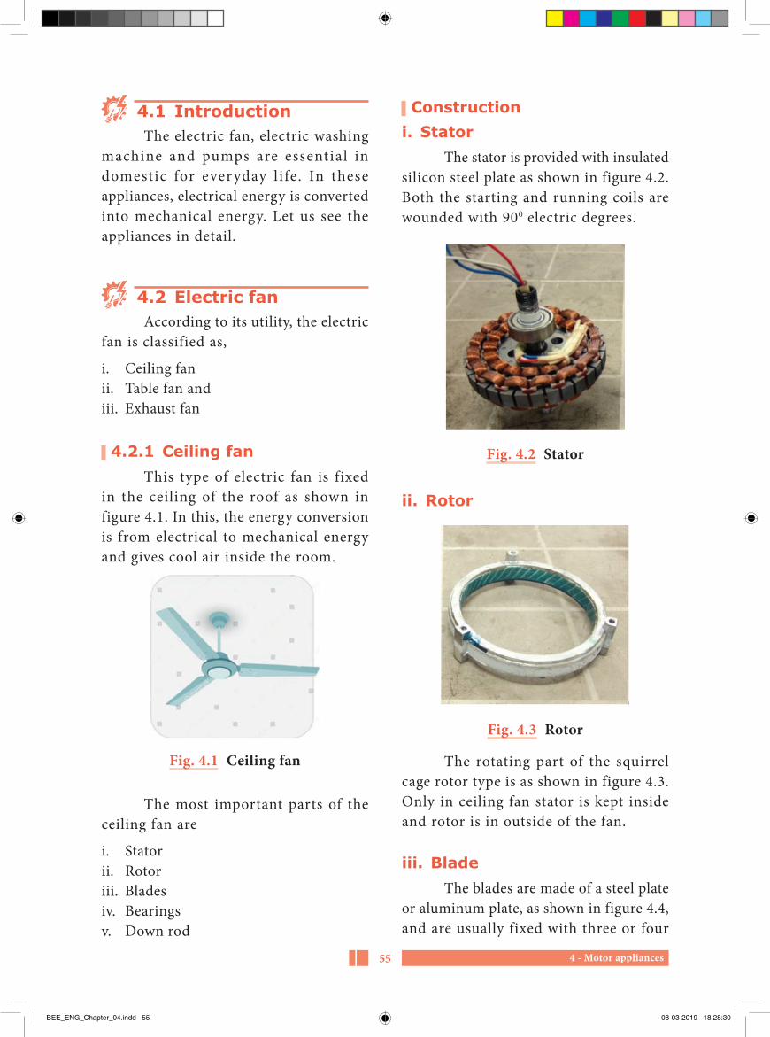
4 - Motor appliances55
4.1 IntroductionThe electric fan, electric washing
machine and pumps are essential in domestic for ever yday l i fe. In these appliances, electrical energy is converted into mechanical energy. Let us see the appliances in detail.
4.2 Electric fanAccording to its utility, the electric
fan is classified as,
i. Ceiling fanii. Table fan andiii. Exhaust fan
4.2.1 Ceiling fanThis type of electric fan is fixed
in the ceiling of the roof as shown in figure 4.1. In this, the energy conversion is from electrical to mechanical energy and gives cool air inside the room.
Fig. 4.1 Ceiling fan
The most important parts of the ceiling fan are
i. Statorii. Rotoriii. Bladesiv. Bearingsv. Down rod
Constructioni. Stator
The stator is provided with insulated silicon steel plate as shown in figure 4.2. Both the starting and running coils are wounded with 900 electric degrees.
Fig. 4.2 Stator
ii. Rotor
Fig. 4.3 Rotor
The rotating part of the squirrel cage rotor type is as shown in figure 4.3. Only in ceiling fan stator is kept inside and rotor is in outside of the fan.
iii. BladeThe blades are made of a steel plate
or aluminum plate, as shown in figure 4.4, and are usually fixed with three or four
BEE_ENG_Chapter_04.indd 55 08-03-2019 18:28:30

4 - Motor appliances 56
One side of rod is fitted in ceiling hook, and the other side is fitted to the fan.
Cotter pin/split pin
NutShackle
Down rodBottom canopyTop canopy
Split (safety) pin
Hanger clampFan blade flange
Terminal block for L.N& E
Spindle
Capacitor
Bolt & nut
Bolt & nut
Rubber grommet
Fig. 4.7 External structure of the fan
a) Working principleFigure 4 .8 shows the internal
structure of an electric fan. When an electric supply is given to the fan, the current passes to the main winding and auxiliary winding and produces rotating magnetic f ield. The 2.5 micro farad capacitor is connected in series with the auxiliary winding. Due to the production of rotating magnetic field, the blades connected with the rotor rotate and air flow will be circulated to the area where required. Usually the blades are available in various sizes like 900 mm, 1050 mm, 1200 mm, and 1400 mm respectively.
Ceilng fan speed control switch wiring diagramand installation
Main winding Speed control switch
Red Black
Rotor
Auxiliary winding
ACSupply
OFF
3
21
L
1.5uF 2.5uFP
N
Fig. 4.8 Circuit diagram
blades. The blades cover the stator and rotor of the end plates.
Fig. 4.4 Blade
iv. BearingsThe bearings are placed on the top
and bottom of the fan, used to reduce friction in rotating parts and also to reduce the noise while in motion.
Fig. 4.5 Bearing
v. Down rodThe down rod is made up of hard
steel, according to the length required.
Top canopy
Bottom canopyDown rod
Top cover
Cover fixscrew
Spindle Ball bearing
Stator
Rotor
Blade
Bottom cover
Fig. 4.6 Internal structure of the fan
BEE_ENG_Chapter_04.indd 56 08-03-2019 18:28:30

4 - Motor appliances57
This type of fan is portable and can be used at any place where we required. In this, single phase permanent capacitor motor is used. Table fan is available in various colours as shown in 4.11. Table fans are also available in various types like pedestal type, wall fitting type etc.,
The most important parts of the table fan are
i. Statorii. Rotoriii. Bladesiv. Bearingsv. Oscillating mechanism
i. Stator
Fig. 4.12 Stator
b) Ceiling fan regulatorCeiling fan regulator is used to control
the speed of the fan to a required position. Its structure is shown in figure 4.10. It is connected in series connection with an electric supply. Now a days electronic type regulator is used in advanced level.
Fig. 4.10 Ceiling fan regulator
4.2.2. Table fan
Fig. 4.11 Table fan
Connecting wireNeck ceiling fan
Capacitor
Insulation paper
Main winding(99.9% copper)
Rotor(Electrical steel sheet)
Stator(Electrical steel sheet)
Auxiliary winding(99.9% copper)
Steel ball bearing
Decorative cover
Axle(Shaft)Steel ball bearing
Aluminium housing(Power coated)
Fig. 4.9 Internal cross section of the fan
BEE_ENG_Chapter_04.indd 57 08-03-2019 18:28:30
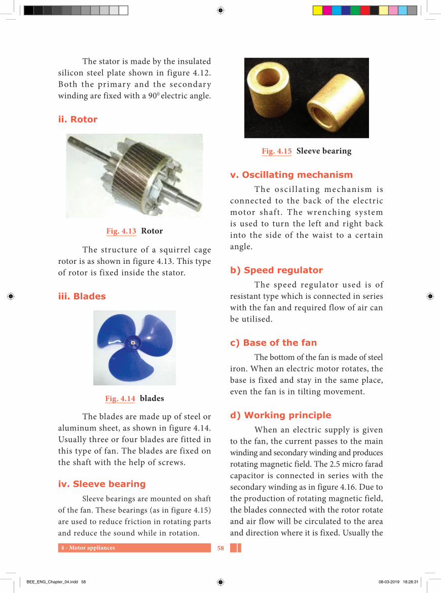
4 - Motor appliances 58
Fig. 4.15 Sleeve bearing
v. Oscillating mechanismThe osci l lat ing mechanism is
connected to the back of the electric motor shaft . The wrenching system is used to turn the left and right back into the side of the waist to a certain angle.
b) Speed regulatorThe speed regulator used is of
resistant type which is connected in series with the fan and required flow of air can be utilised.
c) Base of the fanThe bottom of the fan is made of steel
iron. When an electric motor rotates, the base is fixed and stay in the same place, even the fan is in tilting movement.
d) Working principleWhen an electric supply is given
to the fan, the current passes to the main winding and secondary winding and produces rotating magnetic field. The 2.5 micro farad capacitor is connected in series with the secondary winding as in figure 4.16. Due to the production of rotating magnetic field, the blades connected with the rotor rotate and air flow will be circulated to the area and direction where it is fixed. Usually the
The stator is made by the insulated silicon steel plate shown in figure 4.12. Both the primary and the secondary winding are fixed with a 900 electric angle.
ii. Rotor
Fig. 4.13 Rotor
The structure of a squirrel cage rotor is as shown in figure 4.13. This type of rotor is fixed inside the stator.
iii. Blades
Fig. 4.14 blades
The blades are made up of steel or aluminum sheet, as shown in figure 4.14. Usually three or four blades are fitted in this type of fan. The blades are fixed on the shaft with the help of screws.
iv. Sleeve bearingSleeve bearings are mounted on shaft
of the fan. These bearings (as in figure 4.15) are used to reduce friction in rotating parts and reduce the sound while in rotation.
BEE_ENG_Chapter_04.indd 58 08-03-2019 18:28:31

4 - Motor appliances59
The exhaust fan is as shown in figure 4.17, is used to exhaust the unwanted air present inside rooms, cinema theatres, marriage halls, factories, homes, industries, kitchens and toilets.
a) Construction
i. StatorThe stator is made up of a silicon
steel plate and is small. Both the primary and secondary coils are located with 900 electric angles.
ii. Rotor
Squirrel cage type rotor is used in this exhaust type of fan.
iii. Blades
The blades are made up of a steel or aluminum sheet. It contains three or four blades. The blades are fixed on the shaft and fitted with screws.
b) Working principleIts structure is similar to that of
table fan. Capacitor is not used in this type. This fan exhausts heats produced during the summer season, creating low pressure inside of the room and causes cool air to enter in. The sweep of the fans are available from 230 mm to 380 mm.
blades are available in various sizes from 100 mm to 400 mm. The revolution of the blade will be around 1000 RPM and are covered with plastic or metallic grill.
Stator
Motor bodySquirrel cage
rotor
Runningwinding
Startingwinding
Capacitor
Stand
3 pins plug top
Supply cordRegulator
Base
Fig. 4.16 Table fan
4.2.3 Exhaust fan
Fig. 4.17 Exhaust fan
Trouble shoot chart of an electric fanSl. No. Reasons Defects Remedies1. The fan is not
rotatingThe connection may be loose or in open circuit.
Connections are tested with test lamp and open circuit in it is rectified.
Open circuit in the coils. Check the coils with test lamp and change the coil.
Fault in capacitor Change the capacitor.
BEE_ENG_Chapter_04.indd 59 08-03-2019 18:28:31

4 - Motor appliances 60
4.3.1 Semi automatic washing machine
Fig. 4.18 Semi automatic washing machine
a) ConstructionSemi-automatic type of washing
machine is for washing the clothes and is shown in figure 4.18. This appliance is controlled by timer which control and regulate the time of washing according to the type of cloths and also dries the cloth after washing.
Capacitor start induction motor is used in this type of washing machine.
4.3 Electric washing machine
Nowadays, electric washing machines are used by middle class family in large number. We use washing machine for washing and drying of clothes.
Do you Know?
Who invented electric motor first?
In 1831 Joseph Henry, a physicist, creates machine movement of the f irst motor by using electricity.
Types i. Semi-automatic washing machineii. Automatic washing machine
A. Top loading washing machine
B. Front loading washing machine
2 Fan rotates in low speed.
Low voltage Check the voltage.Fault in capacitor. Change the new capacitor.Bearing is tight Check the bearing and apply
lubricants.3 The fan is not
rotating. If we rotate it, then only it runs.
Problems in starting coil Replace or rewind the starting coil.
Low voltage Check the voltage, and then switch ‘on’
Due to the weakness of the capacitor.
Change the capacitor
4 More noise while rotating.
Worn out bearings. Change and put new bearing
The spacing gap of the bearing.
Spacing should be made right in bearing.
Blade ia not fitted properly Connect the blades properly.
BEE_ENG_Chapter_04.indd 60 08-03-2019 18:28:31
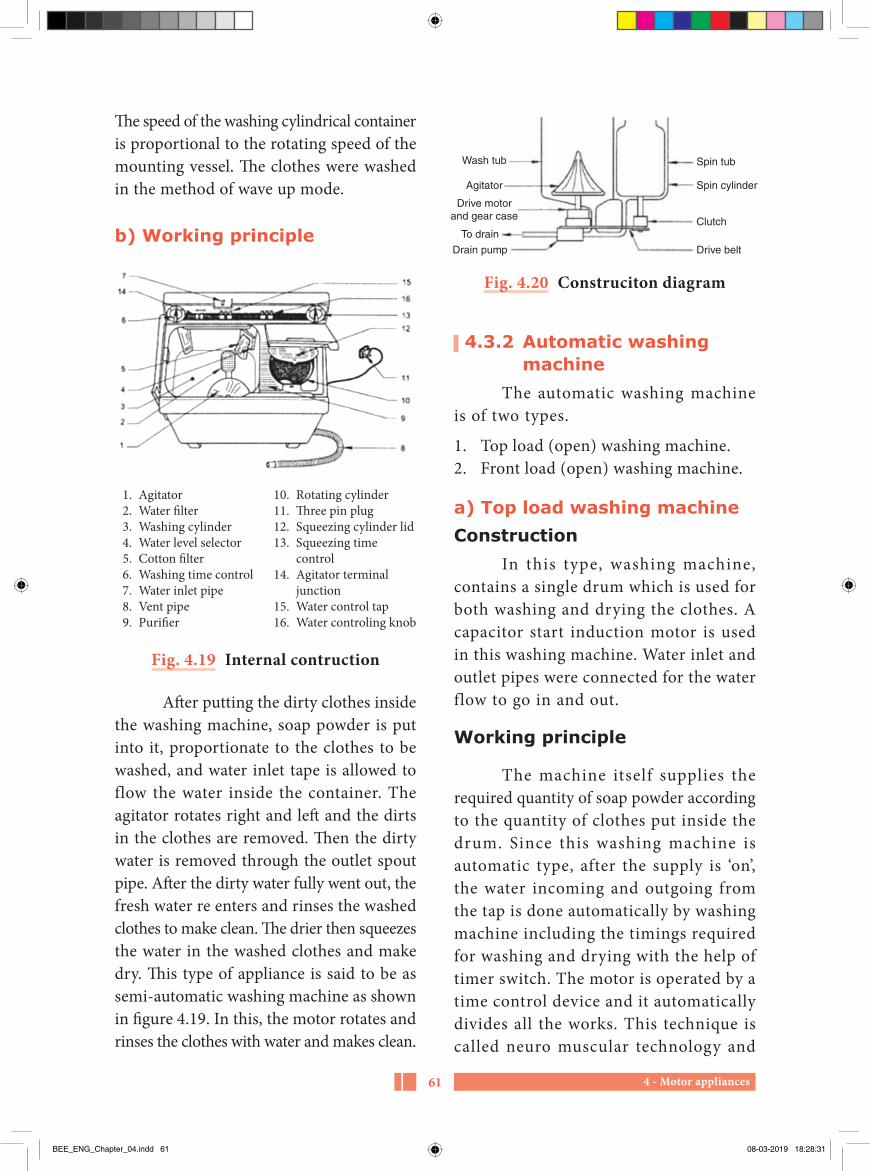
4 - Motor appliances61
Wash tub
Agitator
Drive motorand gear case
To drain
Drain pump Drive belt
Clutch
Spin cylinder
Spin tub
Fig. 4.20 Construciton diagram
4.3.2 Automatic washing machine
The automatic washing machine is of two types.
1. Top load (open) washing machine. 2. Front load (open) washing machine.
a) Top load washing machineConstruction
In this type, washing machine, contains a single drum which is used for both washing and drying the clothes. A capacitor start induction motor is used in this washing machine. Water inlet and outlet pipes were connected for the water flow to go in and out.
Working principle
The machine itself supplies the required quantity of soap powder according to the quantity of clothes put inside the drum. Since this washing machine is automatic type, after the supply is ‘on’, the water incoming and outgoing from the tap is done automatically by washing machine including the timings required for washing and drying with the help of timer switch. The motor is operated by a time control device and it automatically divides all the works. This technique is called neuro muscular technology and
The speed of the washing cylindrical container is proportional to the rotating speed of the mounting vessel. The clothes were washed in the method of wave up mode.
b) Working principle
1. Agitator 2. Water filter 3. Washing cylinder 4. Water level selector 5. Cotton filter 6. Washing time control 7. Water inlet pipe 8. Vent pipe 9. Purifier
10. Rotating cylinder 11. Three pin plug 12. Squeezing cylinder lid 13. Squeezing time
control 14. Agitator terminal
junction 15. Water control tap 16. Water controling knob
Fig. 4.19 Internal contruction
After putting the dirty clothes inside the washing machine, soap powder is put into it, proportionate to the clothes to be washed, and water inlet tape is allowed to flow the water inside the container. The agitator rotates right and left and the dirts in the clothes are removed. Then the dirty water is removed through the outlet spout pipe. After the dirty water fully went out, the fresh water re enters and rinses the washed clothes to make clean. The drier then squeezes the water in the washed clothes and make dry. This type of appliance is said to be as semi-automatic washing machine as shown in figure 4.19. In this, the motor rotates and rinses the clothes with water and makes clean.
BEE_ENG_Chapter_04.indd 61 08-03-2019 18:28:31

4 - Motor appliances 62
Water tanks are made up of steel sheet coated with zinc to prevent corrosion inside the tank. Put the clothes in the inner tub and washing machine perform the tasks like washing, rinsing and squeezing. The inner tank contains small holes in this pot which is used for removal of dirty water. The outer tank is made up of steel and painted to protect from corrosion. In between inner and outer tank, Glass wool is provided in order to protect the hotness from the inner tank, and protect from chillness not to affect the inner tank.
e) AgitatorThe agitator is a roller shaped hard
plastic and is placed in the middle of the inner tank. The knife edge part of agitator makes the cloths to rotate it, in front and back with soap mixed water. This removes the dirty in the clothes.
f) Electric motorThe fractional horse power motor
is used in washing machine. When the supply is given, the agitator rotates along with motor with the setting position according to the quantity of the cloth. Single phase 230-volt, 50 Hz supply is given to this motor.
g) Circuit boardThe circuit board combines various
electronic components. The mechanism of the machine will be set in advance according to the size and type of fabric used in the washing machine. This circuit determines the duration of washing the clothes, quantity of water, detergent quantity and time duration.
works in the micro operating system. This method of functioning depends upon the type of clothes used and its dirty.
Fig. 4.21 Top loading washing machine
b) Water inlet tube time control
In this type of washing machine, a controlling device is mounted. The machine is automatically operated with the washing machine and the water is inserted into the inlet tube.
c) Water outlet tube time control
It works in two ways.
1. Drip out the washed dirty water 2. It is also used to squeeze and remove
water from the cloth.
d) Water tankThis washing machine has two
tanks.
1. Inner tank2. Outer tank
BEE_ENG_Chapter_04.indd 62 08-03-2019 18:28:32

4 - Motor appliances63
2. Front loading washing machine
Fig. 4.22 Front loading washing machine
a) ConstructionThe structure and functioning
of front loading washing machine are similar to that of top loading washing machine.
A cylindrical type of vessel is used in the front loading washing machine instead of the agitator in the upper loading washing machine. With the help of a roller-shaped container, the cylinder spins. As this event continues, the clothes are well washed in soapy water.
T h e i mp e l l e r i s f i xe d i n t h e cylindrical vessel inside a front loading washing machine. This cylinder vessel is in horizontal position. The impeller fixed to this rotating vessel mixes detergent with water and rubs the clothes together to remove the dirt.
In some types of front loading washing machine, a heating element is placed on the bottom of the pipe to get warm water. Washing the clothes with warm water cleans the clothes quickly.
Working principle
To watersource
Tub
Agitator
Agitatortransmission
Drive belt
To drain
Motor
Drain pump
Rubber hose
Fig. 4.22
In this, clothes to be washed along with soap powder are put in the inner container of the washing machine. Dirty clothes are rotated up and down with soap powder by water. This process takes place for a fixed time duration.
The inner tub of the washing machine has many holes. Water is sucked out to the outer tub from the inner container by centrifugal force. Water is drained out from the outer tub through a drain vent pipe. When the dirty water is drained out, fresh water is filled into the inner tub again. Agitator rinses the clothes. In this process the chemicals present in the soap are removed. After this process is completed, water in the machine is again drained out through the outer pipe.
After water is drained, the clothes kept in the container are rotated at a high speed and the water in the clothes is removed by the centrifugal force. After this cycle takes place for a certain period of time, the excess water in the clothes are squeezed out with the help of a t i m e c ont ro l l i n g d e v i c e . Now t h e clothes are washed and are ready to be dried.
BEE_ENG_Chapter_04.indd 63 08-03-2019 18:28:32

4 - Motor appliances 64
iv. Shaftv. Rope and boxvi. Bearings
Fig. 4.24 Centrifugal pump
i. Basement plateThe basement plate is made up
of cast iron or hard steel metal. It is fitted over the base plate with bolts and nuts.
ii. Water pump box This is usually made up of close-
grained cast iron. The vertical plane at the centre of the casing is split into two halves with flanges tightened together by bolts and nuts with gasket for leak proof.
4.4 Electric pump Water pump is used to suck water
from underground to tank. When the motor is turned on, due to the vacuum created by the centrifugal force, water is sucked out to a required place. A single phase motor is sufficient for domestic level, since 2000 to 5000 litres of water per day is required.
Based on the structure, the various types are given below:
1. Centrifugal pump2. Jet pump3. Submersible water pump4. Air compressor
4.4.1 Centrifugal pumpThe centrifugal pump is a simple
electric motor appliance as in figure 4.24. Normally, 0.5 to 3 horse power single phase capacitor start induction motor is used in centrifugal pump. By using centrifugal force, water is sucked and delivered. This is called a centrifugal pump.
Parts of a centrifugal pump
i. Base plateii. Water pump boxiii. Impeller
Comparison with top load and front load washing machine
Sl. No. Top load washing machine Front load washing machine1. Low efficiency. High efficiency.2. The washing drum is a simple type. The washing drum is complicated
type of cylinder3. Normal soap powder is used. Special soap powder is used4. Only certain machines have a heating
element inside.All machines have a heating element inside.
5. Cost is low Cost is high
BEE_ENG_Chapter_04.indd 64 08-03-2019 18:28:33
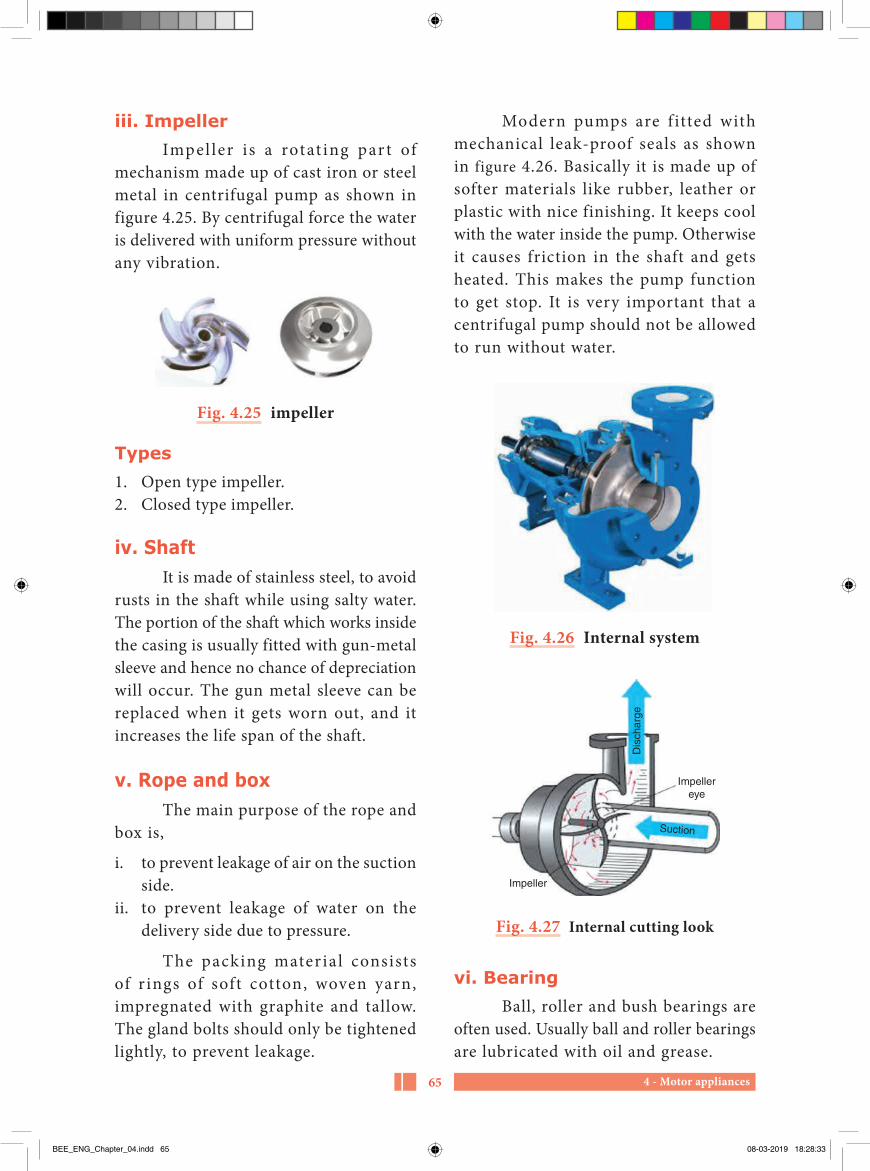
4 - Motor appliances65
Modern pumps are f itted with mechanical leak-proof seals as shown in figure 4.26. Basically it is made up of softer materials like rubber, leather or plastic with nice finishing. It keeps cool with the water inside the pump. Otherwise it causes friction in the shaft and gets heated. This makes the pump function to get stop. It is very important that a centrifugal pump should not be allowed to run without water.
Fig. 4.26 Internal system
Impellereye
Impeller
Dis
char
ge
Suction
Fig. 4.27 Internal cutting look
vi. BearingBall, roller and bush bearings are
often used. Usually ball and roller bearings are lubricated with oil and grease.
iii. ImpellerImpel ler is a rotat ing par t of
mechanism made up of cast iron or steel metal in centrifugal pump as shown in figure 4.25. By centrifugal force the water is delivered with uniform pressure without any vibration.
Fig. 4.25 impeller
Types1. Open type impeller.2. Closed type impeller.
iv. ShaftIt is made of stainless steel, to avoid
rusts in the shaft while using salty water. The portion of the shaft which works inside the casing is usually fitted with gun-metal sleeve and hence no chance of depreciation will occur. The gun metal sleeve can be replaced when it gets worn out, and it increases the life span of the shaft.
v. Rope and boxThe main purpose of the rope and
box is,
i. to prevent leakage of air on the suction side.
ii. to prevent leakage of water on the delivery side due to pressure.
The packing materia l consists of r ings of soft cotton, woven yarn, impregnated with graphite and tallow. The gland bolts should only be tightened lightly, to prevent leakage.
BEE_ENG_Chapter_04.indd 65 08-03-2019 18:28:33

4 - Motor appliances 66
length of the suction pipe is less. The flow of water in higher diameter produces less friction.
b. Suction powerSuction conditions are some of
the factors which affect the centrifugal pump operation. A pump cannot pull or “suck” water up into suction pipe, because water does not have tensile strength. When a pump creates suction, it is simply reducing local pressure by creating a partial vacuum (Sucks out the air above the water). External pressure acting on the surface of the liquid pushes the liquid up the suction pipe into the pump.
i. Static suction headThe static suction head refers to
the vertical height of the water absorbed in well or the horizontal center at the water pump from the water level of the underground tank. Suction head does not depend upon the length of the pipe. It is from the water level to the pump centre and not from the foot valve or the bottom of the well.
ii. Static delivery head
The static delivery head indicates the vertical height from the horizontal line of the water to the water delivered to the water tank. This does not indicate the length of the delivery pipe.
iii. Priming
When the suction pipe and pump is filled with water, the air inside the pipe should be removed. This method is said
Working principle of centrifugal pump
The impeller starts rotating after the pump is filled with water and is run by a generator or a steam engine as shown in figure 4.27. When the impeller rotates, due to the centrifugal force, low pressure will be produced. Due to the low pressure, water is sucked in.
T h e i m p e l l e r c o n v e r t s t h e mechanical power into rotating force. Due to conversion of rotating force into pressure force, the water is delivered with the help of water pump box. The amount of energy on the surface of the water is directly proportional to the velocity of the impeller.
If the speed and size of the impeller is high, the force produced in the water will be high. When the water delivers from impeller, primarily it creates friction in the pump box. Secondly, the speed of water is converted into pressure force due to the friction produced in the delivery side. Hence, the pressure of the water is equivalent to the speed of rotation by the impeller.
a. Friction power
When the water passes through the pipe, it creates friction inside the pipe. The friction produced inside the pipe wil l be according to the speed of the water. Due to this, more power i s required to pump the water up. Because of friction produced inside the water pipe, power loss is occurred. The power used to compensate this is called as friction force. It will be good, if the
BEE_ENG_Chapter_04.indd 66 08-03-2019 18:28:33

4 - Motor appliances67
Fig. 4.29 Internal structure of submersible pump
to be priming. Before starting the pump, ensure that the pipe and pump is filled with water. The centrifugal pump should not run without water.
Friction occurs when the shaft is rotated. The water is used as a cooling agent to reduce the heat.
If the pump runs without water, the excess heat will be produced and the rotor will burn and cause damage. Therefore, the pump does not run without water in the suction pipe.
4.4.2 Submersible pump
Fig. 4.28 Submersible pump
BEE_ENG_Chapter_04.indd 67 08-03-2019 18:28:34

4 - Motor appliances 68
feet , only 45 l iters of water wi l l be delivered. But the cost of the electric motor is double.
ii. Installation of water pump
The good quality of motor and PVC pipes has to be selected and fit it in required depth. The air valve should be placed correctly. Otherwise, the electric motor is rotated in reverse. It will damage the bearing and more maintenance is required for the motor.
iii. Use of water pump
This type of pump is used in places where the water level is below 1000 feet.
4.4.3 Air compressor
Fig. 4.31 Air compressor
The air compressor shown in figure 4.31 is a water pump used in the bore well. It creates water bubbles when going into the foot valve with air pressure. It has slightly special features than jet pump. It is used to pump water up to 300 feet with a capacity of 2 HP. The
Figure 4.29 and 4.30 shows the picture of the modern electric water pump. It consumes less power and run smoothly without noise. This type of pump works to a level of water below 1000 feet. These types of pumps are commonly used in all places.
Checkvalue
Pumpcasing
Inletscreen
Motor
Lubricantseal
ShaftPower leads
Diffusersand
impellers
Fig. 4.30 Inner system
i. Selecting methodsJet pumps are used to suck water to
a depth of 500 feet in deep wells. According to the quantity of water required, the motor should be selected. Proper selection of the motor consumes less electric power and time.
In the present modern technology, 1 HP motor is commonly used. This will function up to 200 feet, and 100 liters of water can be obtained per minute. If we use 1.5 HP motor, it can deliver water to a level up to 500 feet in bore wells. If the motor is placed below 350
BEE_ENG_Chapter_04.indd 68 08-03-2019 18:28:34

4 - Motor appliances69
4.4.4 Faults, causes and remedies of electric pumpSl. No. Faults Causes Remedies1. No movement in
the pump.1. Packing of the rope in
the pump is tight.1. Loose the tightened packing.
2. The bearings are damaged.
2. Check the bearing and lubrication or change the bearing.
3. No power supply. 3. Check whether the supply is live.2 Pump is working.
But water is not delivered.
1. No water in the suction pipe.
1. The suction pipe must be filled with water.
2. Delivery pipe valve is closed.
2. Open the valve in the delivery pipe.
3. Water level is below foot valve.
3. Increase the length of the suction pipe or increase the blow-up efficiency and set it below the water level.
3 Pump works on short time and deliver small quantity of water and then stopped.
1. Water leakage. Water level decreased in the suction pipe.
1. Leakage in the water pipe is rectified. The pipe length in the suction area should be increased.
2. There is a defect in the electric motor and the starter.
2. Test the circuit of the electric motor and starter with the help of test lamp.
4. Excessive vibration and noise in the pump
1. Alignment is changed. 1. Check alignment.2. Loose fitting in
connecting screws.2. Tight the screws.
3. No lubrication in the bearing.
3. Apply the grease on the bearing or change the bearing.
4. Shaft is slightly bent. 4. Change the shaft.5. Block in the impeller
and friction is in the box.
5. Clean the rusts in the impeller and check before to fit.
5 Cracks in the impeller
1. Cracks due to soil or hard objects.
1. Clean it and then fix it.
2. Holes on the top of the impeller
2. The holes should be closed with the washer.
1.5 HP pumps can deliver water up to a level of 275 feet.
When the compressor pump is running, the noise will be slightly higher.
When depreciation occurs in either shaft or bearing in the compressor, oil ring will get damaged and possibility of water gets mixed with oil. Hence, proper maintenance is essential.
BEE_ENG_Chapter_04.indd 69 08-03-2019 18:28:34

4 - Motor appliances 70
Sweep - வசசுOscillation mechanism - அலைய லைககும அலைபபுExhaust fan - காறலறை வைளிததளளும மினவிசிறிSemi – automatic type - குலறைத தானியஙகி ைலகRinsing - அைசுதலCentrifugal pump - லையவிைககு நரேறறிShaft - சுழறதணடுImpeller - துருததிPriming - கிடடிததலSubmersible motor - நர மூழகி மினரனாடிPump - நரேறறி
Glossary
PART-AChoose the correct answer (1 Marks)
1. Rotating diameter of the fan is calleda) Fan connectionb) Length of the fanc) Fan sweepd) Fan size
2. Which type of motor is used in the electric fana) Capacitor start induction
motorb) Capacitor start and capacitor
run induction motorc) Shaded pole motord) Universal motor
3. Which type of fan is used to release smokes and dust?a) Ceiling fanb) Table fanc) Pedestal fand) Exhaust fan
4. Name the washing machine which contains agitator technique.a) Semi-automaticb) Automaticc) Top loading washing machined) Front loading washing
machine
Evaluation
BEE_ENG_Chapter_04.indd 70 08-03-2019 18:28:34

4 - Motor appliances71
5. In which function the soap powder is removed in the clothes?a) Washing functionb) Rinsing functionc) Dryer functiond) Exhaust function
6. How many drums are in semi-automatic washing machinea) 1b) 2c) 1 or 2d) 3
7. Which part is used to produce centrifugal forcea) Scroll coverb) Blocking boxc) Shaftd) Impeller
8. The purpose of the gland packing rope is toa) Prevent impeller from coming
out b) Prevent leakage of water from
the casing near the spindlec) Provide lubrication to the
spindle d) Prevent air leakage from the
casing.
9. Impeller is made up ofa) Galvanized steel.b) Brass.c) Cast iron or gun metal.d) Copper metal alloy.
10. Velocity imparted by the impeller to the water is converted to pressure by thea) Casing or volute b) Stuffing box c) Spindle d) Gland box
11. Maximum suction lift that is possible for water isa) 24 feet b) 28 feet c) 34 feet d) 38 feet
12. To ensure that the pump remains always primed it is necessary to havea) valve on delivery side should
be open b) suction side should not be kept
openc) foot valve is not leaking d) gland packing should not be
leaking.
13. When using automatic operation of the pump, it should be ensured thata) water level is always above the
foot valve b) delivery valve is closed at the
time of startingc) suction side is not less than 20
feet. d) water level is always below the
foot value.
BEE_ENG_Chapter_04.indd 71 08-03-2019 18:28:34

4 - Motor appliances 72
14. Pressure developed by the centrifugal pump is always specified ina) feet b) feet/min c) litres d) kg/cm2
15. Static suction head and static delivery head is always represented bya) feet b) Kg/cm2 c) vertical height d) distance measured along the
pipes
PART-BAnswer the questions in brief (3 Marks)
1. What is the function of the fan?
2. Name the type of motor used in the ceiling fan and table fan?
3. What will happen if the condenser of the fan is in short circuit or in open circuit?
4. What are the parts of a ceiling fan?
5. Define - sweep.
6. What are the types of fan?
7. What is the use of regulator in an electric fan?
8. Write two sweeps of the ceiling fan?
9. How the speed of the table fan can be changed?
10. What is the use of a capacitor in ceiling fan?
11. What are the two types of automatic washing machine?
12 What type of technology is used in semi-automatic washing machine?
13. What is called agitator in the washing machine?
14. List out the maintenances of the washing machine.
15. Why hot water is used in the washing machine?
16. Which material the rope is made upof?
17. What are the types of bearings used in pump?
18. What type of force makes fluid’s rotation in the centrifugal pump?
19. What is priming in centrifugal pump?
20. What happens when the pump is rotated in the opposite direction?
21. What is called the suction head and delivery head of the water pump?
BEE_ENG_Chapter_04.indd 72 08-03-2019 18:28:34

4 - Motor appliances73
PART-CAnswer the questions in one page (5 Marks)
1. Explain briefly the construction of an electric motor used in the fan?
2. Explain the oscillating mechanism of a table fan.
3. What are the differences between the table fan and the exhaust fan?
4. Explain the working principle of the exhaust fan and state its use.
5. What are the differences between the ceiling fan and the exhaust fan?
6. What is the working principle of the rope in pump?
7. What is impeller? What are its types?
8. What are the functions of the impeller?
9. Briefly explain about friction power.
10. What is the suction head?
11. What is the delivery head?
12. What is foot-valve?
PART-DAnswer the questions in two page (10 Marks)
1. Write short notes for the followinga) Bearingb) Down rodc) Regulator
2. Tabulate the common defects, causes and its remedies in the table fan.
3. Explain the construction and working principle of top loading washing machine.
4. With a neat sketch explain the construction and working principle of the semi-automatic washing machine.
5. Explain the construction and working principle of the centrifugal pump with neat diagram?
BEE_ENG_Chapter_04.indd 73 08-03-2019 18:28:34

4 - Motor appliances 74
1. A text book of ‘Electrical Technology’ Volume-III B.L.Theraja and A.K.Theraja, S.Chand & Company Ltd.
Reference Book
1. http://www.wikipedia.org2. https://www.electrical4u.com
Reference Internet Source
BEE_ENG_Chapter_04.indd 74 08-03-2019 18:28:34

5 - Electric drives and its controls75
5Chapter
Electric drives and its controls
We should not give up and we should not allow the problem to defeat us. A. P. J. Abdul Kalam
Learning Objectives
In this lesson, students have to learn about the electric drives needed for various requirements and its control systems.
Table of Content
5.1 Introduction5.2 Types of electric drives5.3 Selection of motors
5.4 Controller5.5 Electric vehicles5.6 Electric traction
BEE_ENG_Chapter_05.indd 75 08-03-2019 18:30:04

5 - Electric drives and its controls 76
5.1 IntroductionElectric drive or electric motor is
a device which converts electrical energy into mechanical energy to do a particular work connected to it.
The electric drive designed electric train is shown in figure 5.1. It is operated by a high-torque electric DC series motor. The system used to control the speed is called power drive. While using this electric motor, its speed is controlled by the current, voltage and frequency.
Fig. 5.1 Electric train
5.2 Types of electric drives
Coolingair flow FanStator
Rotor
Non-drive end
Drive end
Fig. 5.2 Electric motor
The internal construction of a motor is shown in figure 5.2. Depending on the applications, the motor can be divided
into different categories. According to the design, the drives are classified as
i. Individual drive,ii. Group drive and iii. Multi-motor drive.
5.2.1 Classification of electrical drives
1. Depending on the power supply,A. Direct Current electric drive B. Alternating Current electric drive
2. According to the process of electric drives,A. Continuous duty driveB. Short-term duty driveC. Intermediate duty drive
3. According to the control of Drives,A. ManualB. Semi automaticC. Automatic
4. According to the number of machines,A. Individual driveB. Group driveC. Multi-motor drive
5. Based on speed controlA. Reversible and non reversible
speed controlB. Variable speed control
5.2.2 DC driveThe drive is nothing but one type of
electric machine. This converts electrical energy into mechanical energy.Its structure is similar as in figure 5.3. The speed of the drive will depend on the amount of voltage given to it. Small type motor is used in sports equipment such as toys. Large size of electric motor is used in electrical vehicles such as Hoists and Steel rolling mills.
BEE_ENG_Chapter_05.indd 76 08-03-2019 18:30:04

5 - Electric drives and its controls77
5.2.4 Comparison of DC and AC drives
Sl. No. DC drive AC drive1 Energy and
method of control is simple
Energy and method of control is difficult
2 More maintenance is required.
Less maintenance is required.
3 Commutator is required
Commutator is not required
4 Rapid speed control
Gradual speed control
5 Speed and design ratings are less
Speed and design ratings are high
5.2.5 Advantages of electric drives
i. It has flexible control characteristics.ii. Drives with fixed and dynamic
characteristics changed according to load requirements.
iii. Computers can be used to control the drive movements automatically by closed loop operation.
iv. Available with wide range of torque, speed and power.
v. It is applicable to function in the state such as explosion and radiation.
vi. It can start immediately even at full load of the drive.
vii. To control the speed and also simplest way to start and stop the drive.
Rotor coils
Commutator
Shaft Brushes
Statormagnets
Fig. 5.3 DC motor
5.2.3 AC driveAC drive are a type of electric
machines, and it is shown in figure 5.4. It changes the electrical energy into mechanical energy. The inner appearance of the AC Motor is shown in figure 5.5. AC motors are used in electric fan, electric pump, air compressor and automobile industries.
AC motors has two parts.
1. Stator.2. Rotor.
Fig. 5.4 AC motor
Fig. 5.5 Internal structure of AC motor
BEE_ENG_Chapter_05.indd 77 08-03-2019 18:30:06

5 - Electric drives and its controls 78
ii. Group drive
Fig. 5.7 Group electric drive
This drive has an electric motor. It is connected with one or more roller bearing and axis as shown in figure 5.7. This axis is fitted with belts or gears. With this, a group of electrical machines are operated.
Group drive
Fig. 5.8 Block diagram of group drive
a. Advantagesi. A large size of motor can be used insted
of using small number of motors ii. Low price.
b. Disadvantagesi. If the motor is in fault, the entire
operation will be stoppedii. The efficiency will be reduced due to
losses by conduction of energy.
5.2.6 Selection of driveThe choice of an electric drive
depends on many factors. Some of the key factors are given below:
i. Depending on the nature cycle of the speed, torque characteristics, speed control, speed limit, performance and obligation, the level of operation, speed of performance.
ii. Uninterrupted operating requirements will depend on the acceleration and initial loss and performance change.
iii. The source and the ability to meet the source will consist of voltage, voltage optimization, power factor compatibility and other loads, and restoration of power adaptability
iv. Basic capital and running cost and maintenance is required.
v. Space and weight should be less.vi. Environmental and area of the space
be selected.vii. Reliability.
i. Individual driveAs shown in figure 5.6, this drive
is driven by an electric machine with an individual machine. It provide movement to various areas and all the operations are done by the individual machine.
A separate machine will change the direction and size. It is applicable in automobile systems, molecular machines, computers, radios, and television.
LOAD
Fig. 5.6 Individual electric drive
BEE_ENG_Chapter_05.indd 78 08-03-2019 18:30:06

5 - Electric drives and its controls79
Eccentricity
Slide block
Outlet
Maximum volumestop screw
Compensator
InletCompensatorspring
Fig. 5.9
5.3.1 Different speed loadsSome of the specific mechanical
devices that has the same advantage are low speed, and torque requirement. These are in figure 5.10. Some drives require a more speed limits.
Fig. 5.10
I. Crane II. Hoist
Fig. 5.11
iii. Less security measures. iv. No flexibility.v. There will be more noise in the
working area.
iii. Multi motor driveMany electric drives combined with
a single common controlled structure is known as multi motor drive system.
a. Advantages
i. Each drive is powered by a single electric motor. It can only stop or use the required motor.
ii. Individual drives can be controlled.iii. If any drive fails, it will not affect the
other drives.
b. Applications
i. Rolling millsii. Paper millsiii. Escalatorsiv. Mixer metal works.
5.3 Selection of motorsBased on its speed, torque and
accuracy, an electric machine should be chosen. It should be similar for the speed-torque characteristics of the machine loads.
Types of mechanical loads can be classified as follows:
1. Fixed speed loadsAs shown in figure 5.9, some loads
require steady speed when load varies. These are called fixed speed loads.
i. Mechanical Toolsii. Hydraulic pumpsiii. Paper industries
BEE_ENG_Chapter_05.indd 79 08-03-2019 18:30:06

5 - Electric drives and its controls 80
as shown in figure 5.13 on the lowest electric bike in the world. This bike will ride at a speed of 25 km, and can drive up to 30 km for single charge. This vehicle, like a bicycle is also used as a smart bike. The weight of the smart bike is 10.3 kg.
Fig. 5.13 Two wheeler electric vehicle
5.5.2 Electric vehicle
Fig. 5.14 Electric vehicle
Increasing air pollution in India, there are a number of attempts were going on to run vehicle with electricity is as source instead of petrol or diesel. The hyper car type in figure 5.14 is enhanced by the power of the turbine power that does not affect the environment. Such a system is a rare use in electric vehicles. The top of the cover is made of very light metal. The hyper car has been developed with all the features of beautiful design and smooth running.
5.5.3 Solar vehicleAs shown in figure 5.15, the solar
vehicle is a vehicle that runs with solar
Fig. 5.12
5.4 ControllerController is used to control the
torque and speed of the electrical drives.
a. AC - DC controllerAC / DC controllers are of electronic
system. A steady state speed and voltage of the device can be used to convert it to the desired limit. This allows to control the speed, rotation, horse power, and direction of rotation. It is used more effectively because of the energy savings of the drive.
b. DC - DC controllerThe control of the DC - DC driver
is used for heavy load traction. The speed control and rotation direction is essentially modified based on the voltage level normally connected to a fixed power voltage supply.
5.5 Electric vehicles5.5.1 Two wheeler electric
vehicle
The UK-based Humming bird company discoverd weight less a two-wheeler
BEE_ENG_Chapter_05.indd 80 08-03-2019 18:30:07

5 - Electric drives and its controls81
5.5.4 BatteryStorage battery packs in a solar
system carries 250 miles (400 km) without the rays of sun. More cars have enough power to allow them to travel at a speed upto 60 miles (97 km/h).
5.6 Electric tractionThe electric traction is divided
into two types.
1. The Urban train and2. The Sub-urban train.
1. Urban trainIn this way the drives are given
necessary power for two ways, as shown in figure 5.17.
1. Getting power from the overhead lines.
2. Getting power from the diesel drive.
The collector is mounted and the current passes through the overhead transmission line.
Fig. 5.17 Electric train
2. Sub-urban trainSub-urban trains are used to travel
short distances. The train is called the local train. The sub-urban train can be used to stop and park to a distance of 2 to 5 km intervals.
power as input to drive. The electric current required for this vehicle is obtained from sunlight through light voltage cells. These batteries convert solar power into electricity.
It has been incorporated into alternative energy and vehicle technologies. Most solar vehicles are used for car races. Nowadays, solar car systems are designed for the use on roads.
Fig. 5.15 Solar vehicle
When sunlight falls on photo voltaic cell, it induces electrons and converts it as electrical energy. Photo voltaic cells consist of silicon and alloys such as indium, gallium and nitrogen, with huge quantity of silicon.
Fig. 5.16 Solar vehicle
BEE_ENG_Chapter_05.indd 81 08-03-2019 18:30:08
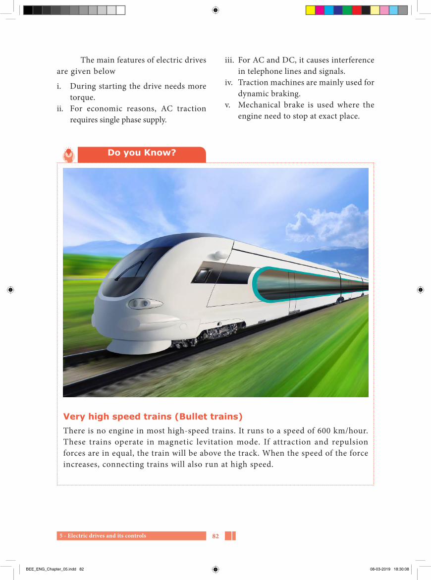
5 - Electric drives and its controls 82
iii. For AC and DC, it causes interference in telephone lines and signals.
iv. Traction machines are mainly used for dynamic braking.
v. Mechanical brake is used where the engine need to stop at exact place.
The main features of electric drives are given below
i. During starting the drive needs more torque.
ii. For economic reasons, AC traction requires single phase supply.
Do you Know?
Very high speed trains (Bullet trains)There is no engine in most high-speed trains. It runs to a speed of 600 km/hour. These trains operate in magnetic levitation mode. If attraction and repulsion forces are in equal, the train will be above the track. When the speed of the force increases, connecting trains will also run at high speed.
BEE_ENG_Chapter_05.indd 82 08-03-2019 18:30:08

5 - Electric drives and its controls83
Squirrel cage motor - அணில கூடு மினனோடிSynchronous motor - ஒததியஙகு மினனோடி Induction motor - தூணடு மினனோடிStepper motor - படிநிலை மினனோடிVariable motor - மோறு ேக மினனோடிMotor shaft - மினனோடி அசசுததணடு
Glossary
1. Create a small toy for children with an electric motor.
2. See the types of electric motor used in home appliances.
3. Take a car with a drive used in electric vehicle.
Activities
PART- AChoose the correct answer (1 Marks)
1. Elements of electric drivea) Electric motor and control
systemb) Electric motorc) Control systemd) Voltage
2. In electric drive the energy convertion is ____________ a) mechanical energy converted
into electrical energyb) electrical energy converted
into Mechanical energy
c) electrical energy converted into chemical energy
d) mechanical energy converted into sound energy
3. The individual drive is used in ____________a) computersb) vacuum cleanerc) cranesd) jet pump
Evaluation
BEE_ENG_Chapter_05.indd 83 08-03-2019 18:30:08

5 - Electric drives and its controls 84
4. The speed of the DC drive depends on ____________a) currentb) voltagec) frequencyd) Power
5. Depending upon the load current the power ____________ in the motor gets changed.a) voltageb) currentc) speedd) Power
6. Low and medium electric motors area) 400-440V
b) 200-230Vc) 150-180Vd) Above 11KV
7. Some electric drive run througha) capacitorb) resistancec) batteryd) inductance
8. ____________ type of energy is used in electric trains.a) wirelessb) Direct coupling exchangec) with wired) remote control
Part–BAnswer the questions in brief (3 Marks)
1. What is an electric drive?
2. Define speed control methods.
3. What is called multi motor drive?
4. Define DC electric drive.
5. Define AC electric drive.
6. What are the characteristics of mechanical loads?
7. What is meant by different voltage controller?
Part–C Answer the questions in one page (5 Marks)
1. Explain individual electric drive functions.
2. What is electric group drive?
3. Compare the DC and AC electric drives.
4. What are the types of electric drives?
BEE_ENG_Chapter_05.indd 84 08-03-2019 18:30:08

5 - Electric drives and its controls85
Part–DAnswer the questions in two page (10 Marks)
1. What are the advantages of electric drives, and how are they selected?
2. Explain with diagram about electric vehicles.
1. http://www.wikipedia.org 2. https://www.electrical4u.com
Reference Internet Source
1. A text book of ‘Electrical Technology’ Volume-III B.L.Theraja and A.K.Theraja, S.Chand & Company Ltd.
Reference Book
BEE_ENG_Chapter_05.indd 85 08-03-2019 18:30:08

6 - Electrical measuring instruments 86
6Chapter
Electrical measuring instruments
Learning Objectives
Measuring instruments are used in electrical engineering to measure the electrical quantities like current, voltage, energy, resistance and frequency. Electrical measuring instruments are used to measure electrical quantities of any value and range.
The main objectives of this chapter is to learn the basic types of electrical measuring instruments, torques acting on indicating instruments, construction and operation of various types of electrical measuring instruments.
There is no lack of courage or no other virtues — Mahatma Gandhi
BEE_ENG_Chapter_06.indd 86 08-03-2019 18:31:38

6 - Electrical measuring instruments87
6.1 IntroductionMeasurement is the act or the result
of a quantitative comparison between a given quantity of same kind chosen as a standard. A device or mechanism used for comparing the unknown quantity with the unit of measurement or a standard quantity is called a measuring instrument.
I n s t r u m e n t s w h i c h m e a s u r e electrical quantities like voltage, current, power, energy etc. are called electrical instruments. These instruments are generally named after the electrical quantity to be measured. The instruments which measure voltage, current, electrical power and energy are called voltmeter, ammeter, wattmeter and energy meter respectively.
6.2 Classification of electrical measuring instruments
The various electrical measuring instruments may broadly classified into two groups, namely
1. Absolute instruments2. Secondary instruments
6.2.1 Absolute instrumentsThose instruments which indicate
the quantity to be measured in terms of the
instruments constants and its deflection are known as absolute instruments. It requires no previous calibration or comparison.
Example: Tangent galvanometer
6.2.2 Secondary instrumentsT h o s e i ns t r u m e nt s i n w h i c h
the value of electrical quantity to be measured can be measured from the deflection of instruments only are called secondary instruments. These instruments are calibrated by comparison with an absolute instrument or another secondary instrument which has a lready been calibrated against an absolute instrument.
Example: Voltmeters, ammeters and watt meters.
Secondary instruments are classified as:
i. Indicating instrumentsii. Integrating instruments
iii. Recording instruments
i. Indicating instrumentsAn instrument which indicates
the magnitude of the electrical quantity being measured at the time at which it is being measured is called as an indicating instrument. It has a pointer which moves
Table of Content
6.1 Introduction6.2 Classification of electrical measuring
instruments6.3 Torques in indicating instruments6.4 Types of electrical measuring
instruments based on principle of operation
6.5 Dynamometer type wattmeter
6.6 Induction type wattmeter6.7 Multimeter6.8 Megger6.9 Tong tester
BEE_ENG_Chapter_06.indd 87 08-03-2019 18:31:38

6 - Electrical measuring instruments 88
6.3 Torques in indicating instruments
The following three types of torques are essential for the satisfactory operation of indicating instruments.
i. Deflecting torqueii. Controlling torque andiii. Damping torque
6.3.1 Deflecting torqueThis torque is required in an
indicating instrument for moving the pointer from its zero position. Deflecting torque is produced by utilizing the effects of electric current.
6.3.2 Controlling torqueThis torque is required in an
indicating instrument to ensure that the deflection is proportional to the magnitude of the quantity being measured. The controlling system produces a torque equal and opposite to the deflecting torque in order to make the deflection of pointer at a definite magnitude. The controlling system brings the moving system back to zero when the torque causing the deflection is removed.
(A) Controlling devicesThere are two types of controlling
devices.
i. Spring controlii. Gravity control
i. Spring controlFigure 6.1 shows a commonly used
spring control arrangement. Two hair springs made of phosphor bronze are attached to the moving system which
over a calibrated scale and indicates the magnitude of electrical quantity.
Example: Ammeter, voltmeter and wattmeter.
ii. Integrating instrumentsThe instruments which measure the
total quantity of electricity delivered over a specified time are called as integrating instruments.
Example: Energy meters (KWH meters) and ampere-hour meters
iii. Recording instrumentsInstruments which give a continuous
record of the variations of an electrical quantity over a period of time are called as recording instruments. The variations of the quantity being measured are recorded by a pen on a sheet of paper put over a moving drum.
Example: Electrocardiogram machine, pressure and temperature recorders.
6.2.3 Classification of measuring instruments according to the quantity being measured
Sl. No. Name of the instrument
Quantity being measured
1 Voltmeter Voltage2 Ammeter Current3 Ohm meter Resistance4 Wattmeter Power5 Watt-hour
meterEnergy
6 Power factor meter
Power Factor
7 Frequency meter
Frequency
BEE_ENG_Chapter_06.indd 88 08-03-2019 18:31:38

6 - Electrical measuring instruments89
PointerSpindle
Balanceweight
Control weight
Nonuniformscale
θ
Fig. 6.2 Gravity control
6.3.3 Damping torqueThe deflecting torque provides
some deflection and controlling torque acts in the opposite direction to that of deflecting torque. So before coming to the rest, pointer always oscillates due to inertia, about the equilibrium position. So to bring the pointer to rest within short time, damping torque is required.
If the moving system reaches to its final position rapidly but smoothly without oscillations, the instrument is said to be critically damped. If the damping torque is more than what is required for critical damping, the instrument is said to be over damped. In over damped case the response of the system is very slow and lethargic.
If the instrument is under damped, the moving system will oscillate about the final steady position with decreasing amplitude and will take some time before it comes to rest.
The following three methods are used for producing damping torque.
i. Air friction dampingii. Fluid friction dampingiii. Eddy current damping
exerts controlling torque. The two coils are coiled in opposite directions.
The inner ends of both the hair springs are attached to the spindle. The outer end of spring A is attached to lever which is actuated by a set screw mounted at the front of the instrument. So zero setting can be easily done without removing the cover. The outer end of spring B is fixed.
When the pointer moves under the influence of deflecting torque, one of the spring unwind itself while the other gets twisted. The twist produces the controlling torque which is directly proportional to the angular deflection of the pointer.
Uniform scale
Controlsprings
B
S
Jewelledbearing
Balanceweight
Spindle
A
Fig. 6.1 Spring control
ii. Gravity controlThe arrangement of gravity control
system is shown in figure 6.2, in which two adjustable weights, control weight and balance weight are attached to the spindle. The control weight provides a controlling torque due to gravity while the balance weight is used for balancing the weight of the moving system.
BEE_ENG_Chapter_06.indd 89 08-03-2019 18:31:39

6 - Electrical measuring instruments 90
iii. Should be non-evaporating.iv. Should be non-corrosive.
In this method, a disc attached to the spindle of moving system is immersed in damping oil as shown in figure 6.4. When the moving system moves, the disc moves in oil and a frictional drag is produced which opposes the motion of the moving system. Damping force due to fluid is greater than that of air due to more viscosity.
Spindle
Rotation
Dampingoil Vane or
disc
Fig. 6.4 Fluid friction damping
iii. Eddy current damping In this method, an aluminium or
copper disc is connected to the spindle. The disc is positioned between the poles of a permanent magnet as shown in figure 6.5. If the disc moves, it cuts the flux which causes an induced e.m.f. in the disc. As the disc is a closed path, induced emf circulates eddy currents in the disc.
Dampingmagnet
Aluminiumdisc
Spindle
Fig. 6.5 Eddy current damping
i. Air friction dampingFigure 6.3 shows an arrangement
for obtaining air friction damping. This arrangement consists of a light aluminium piston which is attached to the moving system. The piston moves in a fixed air chamber which is closed at one end. The clearance between piston and wall chamber is uniform and small.
Piston
Airchamber
Spindle
PointerScale
Fig. 6.3 Air friction damping
Whe n t he pi s ton move s i nto the chamber, air inside the chamber is compressed and thus the pressure inside the chamber opposes the motion of the piston and hence whole of the moving system. When the piston moves out of the chamber, the pressure inside the chamber falls and the pressure on open side becomes greater than on the other side and thus there is again an opposition to motion of the piston.
ii. Fluid friction dampingThis method is similar to air friction
damping. In this only air is replaced by damping oil. The damping oil employed must have the following properties:
i. Must be a good insulator.ii. Viscosity of oil should not change with
temperature.
BEE_ENG_Chapter_06.indd 90 08-03-2019 18:31:39

6 - Electrical measuring instruments91
aluminium former which is pivoted on jeweled bearings. The coil is placed in the magnetic field of a permanent magnet in the shape of a horse-shoe. Two spiral shaped phosphor bronze hair springs are fixed. They are used to carry the coil current and give the controlling torque to the coil. The damping torque is provided by eddy current damping. It is obtained by movement of the aluminium former, moving in the magnetic field of the permanent magnet.
It works on the principle that when a current carrying coil (or conductor) is placed in the magnetic field, the coil (or conductor) experiences a force and moves. The amount of force experienced by the coil is proportional to the magnitude of current through the coil.
Thus deflecting torque is directly proportional to the current passing through the coil and hence the scale is uniform. The direction of deflection is according to the direction of current through the coil.
(A) Advantagesi. The scale is uniformii. No hysteresis lossiii. Low power consumptioniv. No effect of stray magnetic fieldv. High torque-weight ratio vi. Effective and efficient eddy current
dampingvii. Range can be extended by using shunts
and multipliers
(B) Disadvantagesi. Can be used for DC measurements only.ii. Cost is higher than that of moving
iron instruments.
The direction of such eddy currents is so as to oppose the cause producing it which is the relative motion between disc and field. Thus it produces an opposing torque so as to reduce the oscillations of pointer. This is the most efficient method of damping.
6.4 Types of electrical measuring instruments based on principle of operation
1. Moving coil type(a) Permanent magnet moving coil
instruments(b) Dynamometer type instruments
2. Moving iron type(a) Attraction type (b) Repulsion type
6.4.1 Permanent Magnet Moving Coil (PMMC) instruments
Pivot and jewelbearing
Spring
Balancingweight
Permanentmagnet Coil and
formerCore
Pointer
Scale
Mirror
Fig. 6.6 Permanent magnet moving coil instrument
The permanent magnet moving coil instrument is shown in the figure 6.6. It is the most accurate type of instrument and is used for DC measurements.
The moving coil is wound with many turns of fine enameled or silk covered copper wire. The coil is mounted on rectangular
BEE_ENG_Chapter_06.indd 91 08-03-2019 18:31:39

6 - Electrical measuring instruments 92
small current. The galvanometer may be converted as an ammeter by connecting a very low value of resistance called shunt in parallel with the instrument. The shunt is used to bypass major part of current so that the current through the moving coil not exceed the value of full scale deflection current. An ammeter measures the current through the circuit and hence connected in series to the load.
Let,
Rsh = the value of shunt resistanceIsh = current through the shuntIm = full scale deflection current of the
instrumentRm= resistance of the moving coil of the
instrumentI = current of the circuit to be measured
I R I Rm m sh sh=
∴ RI R
Ishm m
sh
=
RI RI Ish
m m
m
=−
6.4.3 Moving iron type instruments
The moving iron instruments are used to measure both AC and DC voltages and currents. They are classified into two types:
(i) Attraction type (ii) Repulsion type
(i) Attraction type moving iron instruments
The construction of the attraction type instrument is shown in the figure 6.7. Attraction type moving iron instrument
6.4.2 Extension of rangea) DC voltmeters
A D C mi l l i ammeter may b e converted as a voltmeter by connecting a high resistance called multiplier in series with the instrument. The multiplier limits the current through the meter so that the current through it not exceed the value of full scale deflection current. A voltmeter measures the voltage across two points and hence connected in parallel to the terminals.
Let,
Rs = multiplier resistance
Im = full scale deflection current of the instrument
Rm= resistance of the moving coil of the instrument
V = voltage of the circuit to be measured
V I R I Rm m m s= +
I R V I Rm s m m= −
∴−
RV I R
Ism m
m
=
Do you Know?
Ammeters must always be connected in series in a circuit and have a very low internal resistance. Voltmeters must always be connected in parallel in a circuit and have a very high internal resistance
b) DC ammetersThe moving coil of PMMC instrument
is light and small and hence can carry very
BEE_ENG_Chapter_06.indd 92 08-03-2019 18:31:40

6 - Electrical measuring instruments93
(ii) Repulsion type moving iron instruments
R e pu l s i on t y p e m ov i n g i ron instrument is shown in figure 6.8. It has two vanes inside the coil, one fixed and the other movable. The vanes are radial stripes of iron. The fixed vane is attached to the coil and the movable vane to the spindle of the instrument.
The fixed coil carries the current or the current proportional to the voltage to be measured. When the current flows through the coi l , the two vanes are magnetized in the same direction and there is a force of repulsion between the two vanes resulting in the motion of moving vane. As the moving iron is fixed with the spindle, the pointer moves on the scale when the spindle moves. The controlling torque is provided by springs and the damping torque is produced by Air friction. Whatever may be the direction of current in the coil, the two vanes are magnetized in the same direction. So the spindle always moves in one direction. Therefore, these instruments can be used on both AC and DC.
Controlspring
Magneticpoles induced
by field flux
Movingvane
Fixedvane
Fixedcoil
Pointer
Fig. 6.8 Repulsion type moving iron instrument
consists of a fixed coil and moving iron piece. The fixed coil is wounded on a former. The fixed coil carries the current proportional to the voltage to be measured or the current to be measured. The moving iron is a flat disc which is eccentrically mounted on the spindle. The spindle is supported between the jewel bearings. A pointer is also attached to the spindle which moves over a graduated scale.
Piston
Scale PointerCoil winding
Control weight
Moving ironD
C
W3W1
W2
Airdampingchamber
Balanceweight
Fig. 6.7 Attraction type moving iron instrument
T h e b a s i c pr i n c ip l e o f t h e s e instruments is that when a soft iron piece if brought near the magnet gets attracted by the magnet. When the current flows through the coil, a magnetic field is produced. Thus the moving iron gets attracted and moves into the coil, causing the spindle and the pointer to rotate.
The controlling torque is provided by the springs but gravity control may be used for vertically mounted panel type instruments. Damping torque is provided by air friction. A light aluminium piston is attached to the moving system. It moves in a fixed air chamber which is closed at one end. The movement of piston provides the required damping torque.
BEE_ENG_Chapter_06.indd 93 08-03-2019 18:31:41

6 - Electrical measuring instruments 94
Voltagecoil
Seriesresistor
To Load
Watts
F.C.
M.C.
F.C.
P
V
O
2
4 6
8
10
Fig. 6.9 Connection diagram of dynamometer type wattmeter
In this meter, the current coil carries the load current and the pressure coil carries the current proportional to the voltage across the circuit. The interaction of two magnetic fields produced by the current flowing through the fixed coils and moving coil causes the moving coil to turn about its axis. It is directly proportional to the product of voltage and current. The controlling torque is provided by the hair springs. These hair springs also lead the current into and out of the moving element. Air friction damping is used. Dynamometer type watt meters are suitable for both DC and AC power measurements.
a) Advantages1. The scale is uniform. 2. High degree of accuracy can be
obtained by careful design.3. It is used both in AC and DC.
b) Disadvantages1. The error due to the inductance of the
pressure coil at low power factor is very serious.
2. Stray field may affect the reading of the instrument.
a) Advantagesi. It can be used for both AC and DC
measurements.ii. Robust and simple in construction.iii. The cost is low.iv. Possess high operating torque.v. Less friction errors.vi. These can withstand over loads
momentarily.vii. The range of instruments can be
extended.
b) Disadvantagesi. This Scale is not uniform and is
cramped at the lower end. ii. There are serious errors due to
hysteresis, frequency changes and stray magnetic fields.
iii. Power consumption is higher for low voltage range.
iv. There is a difference between AC and DC calibrations on account of the effect of inductance of the meter and eddy currents on AC.
6.5 Dynamometer type wattmeter
Dynamometer type watt meters are generally used for the measurement of power. It has two coils, one is a fixed coil and other is a moving coil. Both the fixed and moving coils are air cored. The fixed coil is divided into two equal portions in order to provide uniform field. The fixed coil is used as current coil and is connected in series with the load. The moving coil is used as pressure coil and is connected in parallel with the load. A high non-inductive resistance is connected in series with the moving coil to limit the current through it.
BEE_ENG_Chapter_06.indd 94 08-03-2019 18:31:41
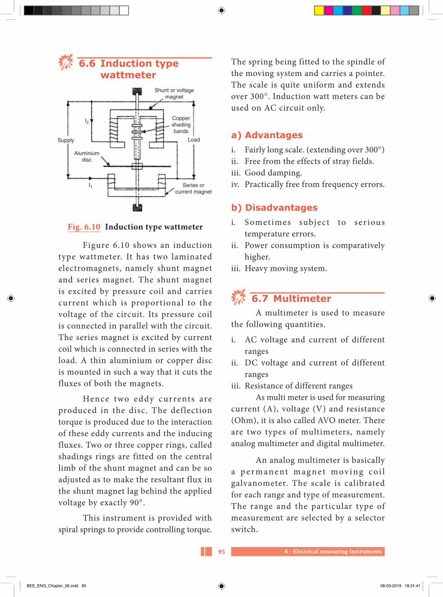
6 - Electrical measuring instruments95
The spring being fitted to the spindle of the moving system and carries a pointer. The scale is quite uniform and extends over 300°. Induction watt meters can be used on AC circuit only.
a) Advantagesi. Fairly long scale. (extending over 300°)ii. Free from the effects of stray fields.iii. Good damping.iv. Practically free from frequency errors.
b) Disadvantagesi. S omet imes subjec t to ser ious
temperature errors.ii. Power consumption is comparatively
higher.iii. Heavy moving system.
6.7 MultimeterA multimeter is used to measure
the following quantities.
i. AC voltage and current of different ranges
ii. DC voltage and current of different ranges
iii. Resistance of different rangesAs multi meter is used for measuring
current (A), voltage (V) and resistance (Ohm), it is also called AVO meter. There are two types of multimeters, namely analog multimeter and digital multimeter.
An analog multimeter is basically a p e r m a n e nt m a g n e t m ov i n g c o i l galvanometer. The scale is calibrated for each range and type of measurement. The range and the particular type of measurement are selected by a selector switch.
6.6 Induction type wattmeter
Supply Load
I2
I1
Aluminiumdisc
Series orcurrent magnet
Coppershadingbands
Shunt or voltagemagnet
Fig. 6.10 Induction type wattmeter
Figure 6.10 shows an induction type wattmeter. It has two laminated electromagnets, namely shunt magnet and series magnet. The shunt magnet is excited by pressure coil and carries current which is proportional to the voltage of the circuit. Its pressure coil is connected in parallel with the circuit. The series magnet is excited by current coil which is connected in series with the load. A thin aluminium or copper disc is mounted in such a way that it cuts the fluxes of both the magnets.
Hence two eddy currents are produced in the disc. The deflection torque is produced due to the interaction of these eddy currents and the inducing fluxes. Two or three copper rings, called shadings rings are fitted on the central limb of the shunt magnet and can be so adjusted as to make the resultant flux in the shunt magnet lag behind the applied voltage by exactly 90°.
This instrument is provided with spiral springs to provide controlling torque.
BEE_ENG_Chapter_06.indd 95 08-03-2019 18:31:41

6 - Electrical measuring instruments 96
deflecting) coil and compensating coil which are mounted rigidly to a pivoted central shaft. The compensating coil is connected in series with the pressure coil in order to provide better scale proportions and to make the arrangement a static. The moving system is free to rotate over a C-shaped iron core. The magnetic field is produced by a pair of permanent magnets for both generator and the moving system.
a. Working principleNow when the resistance under
measurement is connected to the test terminals L and E, the deflecting torque and the controlling torque are produced which oppose each other. At balance, the pointer rests at some intermediate point on the scale. The scale is calibrated in mega ohm and kilo ohm and therefore the value of the resistance under test is indicated by the position of the pointer on the scale.
The required test voltage is generated by a small handle operated permanent magnet DC generator. The generator armature is rotated by hand using the handle at a constant speed which induces the required voltage for testing.
T h e re s i s t a n c e u n d e r t e s t i s connected between the terminals L and E and the hand driven generator is rotated at a uniform speed until the pointer shows a stead def lection. In order to maintain constant voltage, a centrifugal clutch is usually provided in the generator drive mechanism which slips at predetermined speed. The test voltages of hand driven megger are 250V, 500V and 1000V.
To me asure t he res i s t ance of an external resistor, the test leads are connected across the external resistor. The pointer moves on the scale and shows the value of resistor. Different electrical quantities can be measured by inserting the test leads in different jacks for each quantity and range.
Fig. 6.11 Multi meter
6.8 MeggerA n i n s t r u m e nt u s e d f o r t h e
measurement of high resistance or the insulation resistance is called as megger or insulation tester. The simplified connection diagram of megger is shown in figure 6.12. It has three terminals, namely, the line (L), the earth (E), and the guard.
T h e m ov i n g s y s t e m c on s i s t s of three coils known as, the pressure (or control) coil and the current (or
BEE_ENG_Chapter_06.indd 96 08-03-2019 18:31:41

6 - Electrical measuring instruments97
measure the current f lowing through lines. Because, to connect the ammeter along the path of the current, the line has to be opened at that point and then the ammeter has to be connected in series in the line. Once the testing is over the line has to be rewired. This is not an efficient or feasible method.
Current carryinginsulated conductor
Magnetic field
Current reading
Fig. 6.13 Tong tester
Tong tester is helpful in measuring the alternating current without interrupting the circuit. It consists of a current transformer in its jaw, usually a bar CT. When the instrument is clamped on a conductor,
6.9 Tong Tester
A tong tester is shown in figure 6.13. Ammeters cannot be used directly to
N
S
S
N
Compensatingcoil
Guardring
Guard terminal(when fitted)
Ligament
Magnet
Magnet
Scale
Pointer
Iron core
Fig. 6.12 Megger
BEE_ENG_Chapter_06.indd 97 08-03-2019 18:31:42
6 - Electrical measuring instruments 98
the conductor itself acts as primary and the magnetic flux due to current flowing through the conductor cuts the secondary of CT. With the help of ammeter connected to the handle of the tong tester, the current flowing through the circuit can be measured. It is also called as clamp-on meter. This is also used to measure high voltage across any two points.
Handling procedurei. Open the jaws of the tong tester and
place them around the conductor.ii. To avoid any harm in the circuit, select
a higher scale-value first.iii. Slowly decrease the scale value using
selector switch if current is less.iv. Measure the current of each line one
by one.
Deflecting torque - விலகக சுழறறுமை
Controlling torque - கடடுபபடுததும சுழறறுமை
Damping torque - ஒடுககல சுழறறுமை
Moving iron - இயஙகு இருமபு
Absolute instruments - தனிநிமலக கருவிகள
Spring control - வில கடடுபபபாடு
Gravity control - ஈரபபு விமைக கடடுபபபாடு
Piston - உநதுத தணடு
Multiplier - பபருககி
Shunt - இமைததடம
Analog multimeter - குறிமுள பலநபாககு அளவுைபானி
Digital multimeter - எணணிலகக பலநபாககு அளவுைபானி
Eddy current - சுழல மினனபாடடம
Range - பநடுககம
Galvano meter - மினனபாடட அளவி
Glossary
BEE_ENG_Chapter_06.indd 98 08-03-2019 18:31:42

6 - Electrical measuring instruments99
PART-AChoose the correct answer (1 Marks)
1. Which of the following are integrating instruments?a) Ammeters b) Voltmeters c) Watt meters d) Ampere-hour and energy
meters
2. Which of the following essential feature is possessed by an indicating instrument?a) deflecting system b) controlling systemc) damping system d) recording system
3. Damping of deflecting type instrument is done toa) reduce the angle of deflection
of the pointerb) reduce the oscillations of the
pointer in the final deflected position
c) make the moving system go slowd) make the moving system move
fast on the graduated scale
4. The permanent magnet moving coil type instruments are best suited fora) DC Measurement b) AC measurement
c) DC/AC measurement d) frequency measurement
5. For measurement of direct current, we may usea) a galvanometer b) a hot-wire-type ammeterc) a moving-iron-type ammeter d) a permanent magnet moving
coil type ammeter
6. The moving iron type instruments are suitable fora) DC measurements only b) AC measurements onlyc) DC/AC measurement d) resistance measurement
7. When a permanent magnet moving coil (PMMC) instrument is connected to AC voltagea) the instrument will get
damaged.b) the pointer will not move at all.c) the pointer will oscillate to and
fro.d) the instrument will indicate
zero.
8. The extension of range of an ammeter and a volt meter can be made respectively by
Evaluation
BEE_ENG_Chapter_06.indd 99 08-03-2019 18:31:42

6 - Electrical measuring instruments 100
a) reducing the spring tension of the deflecting system
b) using series capacitor and a series inductor
c) using multiplier and shuntd) using shunt and multiplier
9. Ammeter is connected with load in a) series b) parallel c) series and parallel d) opposite to each other
10. Voltmeter is connected in a circuit ina) series b) parallel c) series and parallel d) opposite to each other
11. The dynamometer wattmeter can be used to measurea) DC power only b) AC power onlyc) AC or DC power d) milli values only
12. Induction wattmeter can be used to measurea) AC power only b) DC power onlyc) AC or DC power d) milli values only
13. In induction-type wattmeter,a) voltage coil is the moving coilb) current coil is the moving coil
c) both are moving coilsd) none are moving coils
14. A megger is used for the measurement ofa) low valued resistances.b) medium valued resistances.c) high valued resistances,
particularly insulation resistance.
d) power only.
15. The electrical power to a megger is provided bya) battery b) permanent magnet DC
generatorc) AC Generator d) DC motor
16. Multi meter is called asa) watt meter b) tong tester c) AVO meter d) energy meter
17. Tong testers are used because a) it is possible to measure
current flowing in a line without breaking the circuit.
b) for accurate measurement of electrical quantities.
c) for accurate measurement of energy.
d) for accurate measurement of resistance.
BEE_ENG_Chapter_06.indd 100 08-03-2019 18:31:42

6 - Electrical measuring instruments101
PART-BAnswer the questions in brief (3 Marks)
1. How are secondary instruments classified?
2. Describe the various operating forces needed for proper operation of an analog indicating instrument.
3. What is multimeter?
4. What is the use of tong tester?
5. How is watt meter connected in a circuit?
6. How will you convert a moving coil instrument into a voltmeter?
7. How will you convert a moving coil instrument into an ammeter?
8. What will happen if a voltmeter is connected in series with the load and ammeter in parallel with the supply?
9. What are the advantages of induction type watt meters?
10. How will you connect an ammeter and a voltmeter in an electric circuit?
PART-CAnswer the questions in one page (5 Marks)
1. Write short notes on (i) air friction damping (ii) eddy current damping.
2. Explain the working principle of moving iron instruments?
3. Explain the construction and operation of dynamometer type wattmeter.
4. Describe with a neat sketch the construction and working of tong tester.
PART-DAnswer the questions in two page (10 Marks)
1. Explain the constructional details and principle of working of a permanent magnet moving coil instrument.
2. Explain with the help of a neat sketch the construction and working of megger.
BEE_ENG_Chapter_06.indd 101 08-03-2019 18:31:42

6 - Electrical measuring instruments 102
1. A text book of ‘Electrical Technology’ Volume-I B.L.Theraja and A.K.Theraja, S.Chand & Company Ltd.
2. A course in Electronics and Electrical Measurements and Instrumentation-J.B.Gupta, S.K.Kataria & Sons
3. Electrical Measurements and Measuring Instruments-R.K.Rajput, S.Chand & Company Ltd.
Reference Book
1. http://www.wikipedia.org 2. https://www.electrical4u.com
Reference Internet Source
BEE_ENG_Chapter_06.indd 102 08-03-2019 18:31:42

7 - Transducers103
7Chapter
Transducers
Learning Objectives
The main objectives of this lesson is how to change non-electrical Parameters into electrical parameters according to law of conservation of energy. We have to learn how to convert mechanical parameters into electrical parameters in detail.
Peace begins with a smile — Mother Theresa
Table of Content
7.1 Introduction7.2 Principle of operation of transducers7.3 Classifications of transducers7.4 Factors to be considered for the
selection of transducers
7.5 Resistive, inductive and capacitive transducers
7.6 Piezo electric transducers7.7 Thermocouples7.8 Photo voltaic cells
BEE_ENG_Chapter_07.indd 103 08-03-2019 18:32:53

7 - Transducers 104
7.1 IntroductionInstrumentation is the heart of
an industry for the measurement of the parameters like pressure, temperature, force, displacement and rotation etc. A basic instrumentation system consists of major devices for its operation. One of these categories is transducers and it acts as major role in the measurement and instrumentation systems.
Transducers are energy conversion devices which transforms non-electrical quantity into electrical quantity. The transducers are very important in our day to life to measure the electrical parameters such as current, voltage etc., and physical parameters are pressure, load, torque etc.
Non-electrical physical quantity
Electrical signal
TRANSDUCER
Fig. 7.1 Transducer
7.2 Principle of operation of transducers
All electrical instrumentation system consists of operating elements to perform a measurement and to display its results. The major elements of an instrumentation system is
i. Input devices ii. Processing devices and iii. Output devices
The input devices receive the qu ant i t y u nd e r me asu re me nt . T he processing devices transmit the signal from the input devices to the output devices. The output device gives the value of output sensed by the transducers. So, in a broad category the transducers convert the non-electrical quantity such as temperature, pressure, sound etc into electrical quantity like voltage, current and capacitance etc.
7.3 Classification of transducers
The transducer can be classified as,
i. On the basis of transduction form used
ii. As primary and secondary transducersiii. As passive and active transducersiv. As Analog and digital transducersv. As transducers and inverse transducers
i. The transducers are classified based on the method of transduction such as resistive, inductive and capacitive
For resistive transducers, variation of input causes the resistance to change.
For inductive transducers, variation of input causes the inductance to change.
For capacitive transducers, variation of input causes the capacitance to change.
ii. Primary and Secondary transducers
The transducer connected on the detector stage is called Primary transducer and the output of primary transducer is
BEE_ENG_Chapter_07.indd 104 08-03-2019 18:32:54

7 - Transducers105
7.4 Factors to be considered for the selection of transducers
The selection of transducers is based on the applications where it is used. The following important factors are to be considered for the selection of transducers.
i. It should have high input impedance and low output impedance, to avoid loading effect.
ii. It should have good resolution over is entire selected range.
iii. It must be highly sensitive to desired signal and insensitive to unwanted signal.
iv. Preferably small in size.v. It should be able to work in corrosive
environment.vi. It should be able to withstand pressure,
shocks, vibrations etc...vii. It must have high degree of accuracy
and repeatability. viii. Selected transducer must be free from
errors.
converted into a usable output is called secondary transducers.
iii. Passive and active transducers
The transducers which are externally powered are called passive transducers and self-generating types are called as active transducers.
iv. Analog and digital transducers
The transducer which gives output in analog form is called analog transducers and transducer which gives output in digital form is called digital transducers.
v. Transducers and inverse transducers
The transducers which converts non-electrical quantity into electrical quantity is called transducers and the transducers which converts electrical quantity into non-electrical quantity is called inverse transducers.
Do you Know?
A bi ome tri c d e v i c e i s a s e c ur i t y identification and authentication device. Such devices use automated methods of verifying or recognizing the identity of a living person based on a physiological or behavioral characteristic. These characteristics include finger prints, facial images, iris and voice recognition. Biometrics are being used to establish better and accessible records of the hours employee’s work
BEE_ENG_Chapter_07.indd 105 08-03-2019 18:32:54

7 - Transducers 106
7.5 Resistive, inductive and capacitive transducers
7.5.1 Resistive transducersThe types of transducers which work
by changing its resistance are called resistive transducers. This type of transducer works both in AC and DC supply.
The resistance of metal conductor
is given by R = r lA
Ω
Where R = resistance
l = length of conductorA = cross-sectional area of conductorr = Resistivity of conductor material
Any method of varying the above said parameters by applying external force in the relationship is the very basic principle of operation for an electrical resistive transducer.
The Appl icat ions of res i s t ive transducers are discussed below.
7.5.2 Measurement of displacement, pressure and force using resistive transducers
a. Potentiometers type transducers for linear displacement
A potentiometer is a three-terminal resistor with a sliding or rotating contact that forms an adjustable voltage divider. A resistive potentiometer or simply POT, consists of a resistive element provided with a sliding contact. Potentiometer transducers used to measure translational and rotational.
For example, let us consider the measurement of l inear displacement
7.4.1 Advantages of electrical transducers
T h e a dv ant a ge s o f e l e c t r i c a l transducers compared with other types of transducers are numerous. As to say some of the points
i. Electrical amplification is simple and easy.
ii. Frictional effects are minimized.iii. Mass-inertia effects are minimized.iv. Small power is used to control.v. Transmission of electrical signal is easy.
The physical quantity is under measurement is first connected to primary transducers. This primary transducer changes the positions due to the external applied quantity. This variation is then connected to one of the arms of a Wheatstone bridge. Before applying the pressure, the bridge is brought to a balanced condition. The change in the resistance causes the bridge to unbalance. This deviation in the unbalance is measured in terms applied force. This is the basic principle of operation of transducers using wheatstone bridge method.
In a wheatstone bridge method, the four arms are connected as shown in figure 7.2 then one of the arm is connected to the unknown parameter to be find.
gauge
Fig. 7.2 Wheatstone bridge for strain gauge
BEE_ENG_Chapter_07.indd 106 08-03-2019 18:32:54

7 - Transducers107
quantity which we want measure. The rotating arm causes output voltage to change. This change in output is measured in terms of the applied rotary motion.
c. Strain gaugeThe strain gauges are used to
measurement of strain and associates stress. It works on the principle of piezo-resistivity. If a metal conductor is stretched or compressed, is resistance changes on account of the reason length and diameter changes.
d. Unbonded strain gauge
Diaphram
Force rod
Strain guage
Mounting rings
Sapphire post
Spring element
Strain guagewindings 3 & 4
windings 1 & 2
Fig. 7.5 Unbonded strain gauge
This gauge consists of a wire stretched between two points in an insulat ing medium such as air. The unbonded wires may be made up of various copper nickel, chrome nickel or nickel ion alloys.
The unbonded strain gauge wire acts as the four arms of a wheatstone bridge. Before applying pressure, the bridge is brought under balanced condition. Pressure is applied on the top of the diaphram as shown in figure 7.5. This makes unbonded wire to stretch along
through POT. The linear displacement is connected to the sliding contact. The sliding contact is called as wiper. First, the wheatstone bridge is brought to balanced condition. At that time the galvanometer in the bridge shows null deflection.
Now the displacement is connected to the wiper. This linear displacement makes bridge to unbalance. The unbalance causes deflection in the galvanometer. This deflection is calibrated in terms of the applied displacement.
Inputvoltage
Outputvoltage
Fig. 7.3 Linear displacement
b. Potentiometers for rotary displacement
OutputVoltage
Fig. 7.4 Potentiometer for rotary pot
The input voltage is given to the two terminals of the potentiometer. The output voltage is taken from the output terminals as shown in figure 7.4. The slider arm is connected to the rotating
BEE_ENG_Chapter_07.indd 107 08-03-2019 18:32:55

7 - Transducers 108
used for the measurement of temperature being it can withstand high temperature. These types of temperature detector are having positive temperature coefficient.
The platinum element is placed inside the RTD and connecting wires are pulled out from the RTD to the external circuit . The external circuit may be wheatstone bridge. The temperature variation causes the deflection in the bridge which is the measure of temperature. The mounting threads are used to mount this detector to the equipment of temperature measurement.
Fig. 7.7 Industrial platinum RTD
g. Thermistor
Fig. 7.8 Thermistor
Another type of resistive transducer is thermistor whose resistance depends on temperature. Thermistors are available in the form of beads, rods and discs.
is length and corresponding change in diameter. Therefore, the resistance of the wire is changed. This change in resistance is measured in terms of applied pressure.
e. Bonded strain gaugeThese gauges are directly bonded
(that is pasted) on the surface of the structure under study. Hence, they are termed as bonded strain gauges. Bonded strain gauges offer a rugged assembly and good accuracy that is not degraded by shock and vibration. However, bonded strain gauges are limited in their pressure and temperature ranges. The three types of bonded strain gauges are
i. Fine wire strain gaugeii. Metal foil strain gaugeiii. Semi-conductor gauge
Alignment marks
Carrier
Active gridlength
Solder tabs
Fig. 7.6 Bonded strain gauge
f. Resistance thermometersThe resistance of a conductor
changes when its temperature is changed. This property is utilized for measurement of temperature. The resistance thermometer detector (RTD) uses the change in electrical resistance of conductor to determine the temperature. Platinum and nickel are
BEE_ENG_Chapter_07.indd 108 08-03-2019 18:32:55

7 - Transducers109
displacement. The following figures shows the schematic diagram of linear and rotary type inductive transducers.
Output
DisplacementWiper Output
Fig. 7.9 Inductive transducers
b. Linear variable differential transformer (LVDT)
T h i s i s m o s t widely used inductive transducer for translating l inear movement into electrical signal. The basic construction of LVDT is shown below.
Primarycoil
Core
Insulatingform orbobbin
Coil 1(secondary)
Motion
ConstantAC voltage
Difference voltagevo = v1 - v2
Coil 2(secondary)
Fig. 7.10 LVD transformer
LVDT is working on the principle of a Transformer only. Like a transformer LVDT has both primary and secondary. Primary winding is connected to an AC supply. The secondary has two identical windings which are connected in series opposition. A soft iron core is attached
Thermistors are rugged in construction, cheaper in cost and highly sensitive devices.
h. Advantages of resistance transducers
i. Simple in constructionii. High outputiii. Less expensiveiv. Available in different shapes and
rangesv. High electrical efficiency
7.5.3 Inductive transducersInductive transducers are passive
transducers which operate generally one of the following parameters.
i. Variation of self-inductance of the coilii. Variation of mutual-inductance of the
coiliii. Production of eddy currents
a. Working principleThe self inductance of a coil is
given by,
L Nl A
N Al
2 2
/
where L = self inductance N = Number of turns μ = permeability of magnetic
materials A = Area of cross-section of
magnetic path l = lengnth of mean turn
From the above expression it is clear that, the self-inductance of the coil can be varied by varying the number of turns on the coil (N), permeability µ , Area of cross-section (A) and length of mean turn (l). These transducers are usually used for the measurement of linear and rotary
BEE_ENG_Chapter_07.indd 109 08-03-2019 18:32:55

7 - Transducers 110
d. Disadvantages
i. Relatively large displacement is needed to make output.
ii. Affected by vibrations.iii. Temperature affects the performance
of LVDT.
7.5.4 Capacitive transducersThe capacitance of a parallel plate
is given by,
C 0 r A
d
Where,
∈0 = permittivity of free space.∈r = the relative permittivity of free
spaceA = Area of platesd = Distance between the plates.
As the capacitance of a capacitor depends on the above parameters, such transducers can be used to measure the non-electr ica l quant ity such as displacement, force, pressure etc.
to the sensing element of displacement is to be measured. This core is movable with respect to the applied displacement.
When there is no force, the central core occupies null position as shown in figure 7.11. At this time the magnetic coupling of primary to secondary are equal. Hence the two output voltages of secondary windings V1 and V2 are equal.
As the core is moved towards the left from its null position, the secondary winding voltage V1 increases over V2. This is shown in figure 7.11.
As the core is moved towards the right from its null position, the secondary winding voltage V2 increases over V1. This is shown in figure 7.11.
In this way the displacement is measured by LVDT.
c. Advantages of LVDTi. LVDT has high sensitivity.ii. Consumes very less power.iii. Good frequency response.iv. LVDT is more reliable device.v. It is very rugged device.
Fig. 7.11 LVD Transformer
Vin
Primary Primary
Left position Null position Right position
Primary
core core core
Secondary 1 Secondary 2 Secondary 1 Secondary 2 Secondary 2
Output voltagevo = v1 – v2
Output voltagevo = v1 – v2
Output voltagevo = v1 – v2
Vin
v1 v2 v1 v2 v1 v2Secondary ary1
Vin
BEE_ENG_Chapter_07.indd 110 08-03-2019 18:32:56

7 - Transducers111
Capacitance changes withchanges in plate overlap
Capacitance changes withchanges in distance
Capacitance changes withchanges in dielectric
Fig. 7.12 Capacitive transducers
d. Advantages of capacitive transducers
i. Good frequency response.ii. These are not affected by stray
magnetic fields.iii. These are extremely very sensitive.iv. Operates at a very little force.
e. Disadvantagesi. The output changes with temperature.ii. Adequate design is needed for accurate
measurements.iii. Electrostatic screening is needed.
7.6 Piezo electric transducers
The piezo electric sensors are based on the principles of electro mechanical energy conversion. The mechanical input is converted to the electrical output and that is the basis of this transducers and this transducer shows piezo electric effect.
In some crystalline materials, a potential is developed across the opposite faces of the material when a mechanical force is applied on it. This is called piezo electric effect and the materials which exhibit this behavior is called as piezo electric materials. This effect is used to measure the dynamic pressure, force, shock and vibratory motion. Common piezo-electric materials are rochelle salt, ammonium de-hydrogen phosphate, lithium sulphate, quartz ceramic.
7.5.5 Types of capacitive transducers
a. Capacitive transducers - By variation overlapping area
This type of transducers operates on the fact that capacitance of the capacitor is proportional to the overlapping area of plates. As shown in the figure 7.12, one plate is fixed and the other is movable. If the displacement is taken place, one of the plates connected to displacement moves over the fixed plate, thereby changing the overlapping area.
b. Capacitive transducers - By variation of distance between the plates
This type of transducers operates on the fact that capacitance of the capacitor is inversely proportional to the distance between the plates. Such type of transducers are used to measure the linear displacement as shown in figure 7.12.
c. Capacitive transducers - By variation of permittivity of the di-electric material
This type of transducers operates on the fact that capacitance of the capacitor is varied by varying the permittivity of the dielectric material. In this arrangement, a dielectric material of permittivity ‘e’ moves between the two fixed plates as shown in figure 7.12.
Capacitance changes withchanges in plate overlap
Capacitance changes withchanges in distance
Capacitance changes withchanges in dielectric
BEE_ENG_Chapter_07.indd 111 08-03-2019 18:32:56
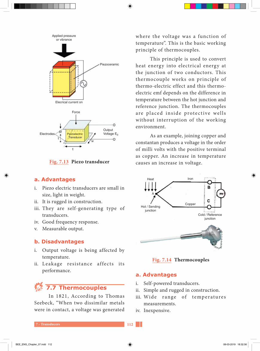
7 - Transducers 112
where the voltage was a function of temperature”. This is the basic working principle of thermocouples.
This principle is used to convert heat energy into electrical energy at the junction of two conductors. This thermocouple works on principle of thermo-electric effect and this thermo-electric emf depends on the difference in temperature between the hot junction and reference junction. The thermocouples are p l a c e d i ns i d e prote c t ive we l l s without interruption of the working environment.
As an example, joining copper and constantan produces a voltage in the order of milli volts with the positive terminal as copper. An increase in temperature causes an increase in voltage.
Heat Iron
CopperHot / Sending
junctionCold / Reference
junction
A
Fig. 7.14 Thermocouples
a. Advantagesi. Self-powered transducers.ii. Simple and rugged in construction.iii. Wi d e r ange of t e mp e r atu re s
measurements.iv. Inexpensive.
Applied pressureor vibrance
Piezoceramic
Elecrical current on
Force
ElectrodesOutputVoltage E0Piezoelectric
Transducer
Fig. 7.13 Piezo transducer
a. Advantagesi. Piezo electric transducers are small in
size, light in weight.ii. It is rugged in construction.iii. They are self-generating type of
transducers.iv. Good frequency response.v. Measurable output.
b. Disadvantagesi. Output voltage is being affected by
temperature.ii. Leakage res istance af fec ts i t s
performance.
7.7 ThermocouplesIn 1821, According to Thomas
Seebeck, “When two dissimilar metals were in contact, a voltage was generated
BEE_ENG_Chapter_07.indd 112 08-03-2019 18:32:56

7 - Transducers113
iv. Use batteries to store extra power for use at night.
v. Solar can be used to heat water, power homes and building, even power cars.
vi. Safer than tradit ional electr ic current.
b. Disadvantages
i. High initial costs for material and installation.
ii. Needs a lot of space.iii. No solar power at night. Hence there
is a need for a large battery bank.iv. Cloudy days do not produce much
energy.
b. Disadvantagesi. Non-linear characteristics.ii. Low-voltage only generated.iii. Least – sensitivity to temperature
changes.
7.8 Photo voltaic Cells (Solar cells)
Photo voltaic cells may be used in a number of applications. The silicon solar cell converts the radiant energy of the sun into electrical power. The solar cell consists of a thin slice of single crystal p-type silicon, up to 2cm square, into which a very thin layer of n-type material is diffused. The conversion efficiency depends on the spectral content and intensity of the illumination.
a. Advantagesi. Simple and green environment.ii. Pollution free.iii. Renewable electric power generation.
Piezo resistivity - தகவுததடைPotentiometer - மினனழுததமானிSignal - சிகனலStrain gauge - திரிபளவுமானிThermistor - வெபபததடையகமPermeability - ஊடுருவும தனடமLinear variable differential transformer - நேரியல மாறி மாறுபடைமினமாறறிThermocouple - வெபபமினனிரடடை
Glossary
Fig. 7.15 Photo voltaic Cell
BEE_ENG_Chapter_07.indd 113 08-03-2019 18:32:56

7 - Transducers 114
PART-AChoose the correct answer (1 Marks)
1. Which type of devices are used to estimate the parameters to be measureda. Input devicesb. Processing devicesc. Non processing devicesd. Output devices
2. Which device is converts non-electrical quantity into electrical quantitya. Generatorb. Transducerc. Motord. Transformer
3. The display of quantity to be measured is in these types of devicesa. Input devices b. Processing devicesc. Non processing devicesd. Output devices
4. Transducers are classified according to a. resistance onlyb. inductance onlyc. capacitance onlyd. resistance, inductance and
capacitance
5. hich one of the following is not advantage in electrical transducers
a. Electrical amplification is easyb. Less frictional effects c. Less mass-inertia effectsd. Transmission of electrical
signal is not easy
6. At starting time, wheatstone bridge is in which positiona. deflectionb. null deflectionc. balancedd. unbalanced
7. Resistive transducers are used to measurea. displacement onlyb. pressure onlyc. displacement, pressure, forced. force only
8. Which parameter is measured from strain gauge meter a. resistanceb. Strainc. stressd. strain and stress
9. Which one of the following is not correct in thermistor transducersa. rust in constructionb. low costc. high sensibled. Simple in construction
Evaluation
BEE_ENG_Chapter_07.indd 114 08-03-2019 18:32:56

7 - Transducers115
10. The advantage of photo voltaic cell isa. rust in construction
b. not safetyc. Pollution freed. more polluted
PART-BAnswer the questions in brief (3 Marks)
1. Define primary and secondary transducers.
2. Write short notes on analog and digital transducers.
3. Write about Strain gauge transducer.
4. What are the advantages of resistive transducers?
5. What are the advantages of linear variable differential transformers?
6. What are the disadvantages of linear variable differential transformers?
7. What are the various types of capacitive transducers?
8. What are the advantages of capacitive transducers?
PART-CAnswer the questions in one page (5 Marks)
1. What are the advantages of electrical transducers?
2. Write short notes on piezo electric transducers?
3. What are the advantages of piezo electric transducers?
4. What are the advantages of photo voltaic cell?
PART-DAnswer the questions in two page (10 Marks)
1. What are the factors to be considered for the selection of transducers?
2. Explain about thermocouple.
3. Explain with neat diagram of linear variable differential transformer.
BEE_ENG_Chapter_07.indd 115 08-03-2019 18:32:56

7 - Transducers 116
1. A text book of ‘Electrical Technology’ Volume-III B.L.Theraja and A.K.Theraja, S.Chand & Company Ltd.
Reference Book
1. http://www.wikipedia.org2. http://www.electrical4u.com
Reference Internet Source
BEE_ENG_Chapter_07.indd 116 08-03-2019 18:32:56

8 - Starters and controlling equipments117
8Chapter
Starters and controlling equipments
Learning Objectives
Starters and protective equipments are used to control the electrical machines for proper operation and their long life. It is necessary for the operators of electrical machines and students to know about starters and controlling equipments. Starters and controlling equipments topic has been introduced in the new curriculum for the benefits of students.
You have to dream before your dreams can come true — APJ Abdul Kalam
Table of Content
8.1 Introduction8.2 Direct current motor starters8.3 Alternating current motor starters8.4 Electrical isolator
8.5 Electrical circuit breaker8.6 Miniature circuit breaker8.7 Moulded case circuit breaker8.8 Earth leakage circuit breaker
BEE_ENG_Chapter_08.indd 117 08-03-2019 18:34:16

8 - Starters and controlling equipments 118
8.1 IntroductionIn direct current and alternating
current motors, starters are generally used for initial starting and safety purposes.
8.2 Direct current motor starters
8.2.1 Essential of starter In general, all the motors, while
starting, takes heavy starting current from the supply. Let us see the reason how the DC motors take heavy current during starting.
The armature current of the DC motor is given by the relation, Ia
Ia-
=V ER
b
a
V = line voltage Eb = Back e.m.f or counter e.m.f Ra = Armature resistance
When the motor is at rest, the induced back emf (Eb) in the armature is zero because the back emf is directly proportional to the speed of the motor, (Eb α N). At starting time, the armature current is limited only by the resistance of the armature circuit. The armature resistance is very low and if full voltage is applied across the motor terminals, the armature will draw heavy current, since the armature current is inversely proportional to the resistance of armature circuit.
Example10 H.P, 200 volt shunt motor has
full load rated current 40A and armature
resistance is about 0.2Ω. If the motor is directly switched on to supply, it would take armature current.
I
I A
a
a
=
=
200 00 2
2000 2
1000
−
=
.
.
At starting, the back emf is zero. The value of this current is 25 times the full load current. This high starting current may result in:
i. Large current flowing through the armature winding causing production of heat and it will damage the armature winding.
ii. Excessive sparking of the commutator.iii. Excessive voltage drops in the line
to which the motor is connected. Thus, the operation of the appliances connected to the same line, may refuse to work.
To avoid this excessive current at start, a variable resistance is connected in series with the armature circuit. This additional resistance limits the starting current. This creates the necessity of starters.
The starter has two basic functions.
i. Reducing starting current.ii. Ensuring safe operation during next
start.
8.2.2 Types of DC motor starter
i. Three point starter.ii. Four point starter.
BEE_ENG_Chapter_08.indd 118 08-03-2019 18:34:16

8 - Starters and controlling equipments119
soon as the field circuit gets supply, this is energized. It holds the handle in the ‘ON’ position. As explained above, in case of a failure of the supply, this de-energizes and the handle is released from ‘ON’ position. The handle returns to ‘OFF’ position, due to the action of the spring. If this provision is not provided, the supply restores, the current through the armature becomes high and this will damage the armature windings.
Over load release (OLR)OLR is also consists of an electro
magnet . This e lec tromagnet coi l i s energized by the line current. When the load on the motor is increased above pre-determined value, the magnetizing force established is sufficient to lift the movable iron. When it is lifted by the electro magnet of OLR, it short circuits the terminals of the coils of the no volt release. Hence, the no volt coil is de-energized and the starter handle returns to ‘OFF’ position. Thus the overload release protects the motor against overloads.
This starter is not generally used where the field current is often adjusted for a higher speed than the normal speed, the handle returns to the ‘OFF’ position. This may cause for reduction in field current.
DisadvantagesThe 3 point starter suffers from a
serious drawback for motors with a large variation of speed by adjustment of the field rheostat. To increase the speed of the motor, the field resistance should be increased. Therefore, the current through
8.2.3 Three point starterThree point starters
are used to start the shunt motor. The diagram of the three point starter is shown in figure 8.1. In three point starter, three terminals L, A and F (Line, Armature and Field) are available. In this starter, the resistance elements are mounted on the back side of a slate board. On the front side of the board, brass studs are provided and the resistance junctions are connected with each brass stud. Two protective devices overload release and no volt release is incorporated in the circuit as shown in the diagram. The handle of the starter is fixed in such a way to move the brass studs.
When the handle touches the first stud, the full resistance is connected in series with the armature. The field circuit is connected across the full supply voltage. The handle is moved over the studs, the resistance connected in series with the armature circuit is gradually cut off. The handle movement is controlled by the tension of the spring as shown in the figure 8.1.
A soft iron piece is attached to the handle. The soft iron piece is attached by the electro-magnet (NVR) when the handle reaches the ‘ON’ position. In case of a failure of the supply or the voltage is very low, the electro magnet de-energizes and releases the armature. The spring forces bring the handle to ‘OFF’ position.
Protective devicesNo-Volt Release (NVR)
NVR consists of an electromagnet. It is connected in the field circuit. As
BEE_ENG_Chapter_08.indd 119 08-03-2019 18:34:16

8 - Starters and controlling equipments 120
Hence, to overcome this difficulty, a four point starter is used.
8.2.4 Four point starterThe four point starter is used for
starting shunt and compound motors. The diagram of four point starter is shown in figure 8.2.
The four point starter, the four terminals L+, L-, A and F (Line +, Line-, armature and field) are available.
the shunt f ield is reduced. The f ield current may become very low because of the addition of high resistance to obtain a high speed. A very low field current will make the holding electromagnet too weak to overcome the force exerted by the spring. The holding magnet may release the arm of the starter during the normal operation of the motor and thus, disconnecting the motor from the line. This is not a desirable action.
Startingresistance
OFFSoft Ironpiece
Starterhandle
Spring
OLR coil
L
Lever Triangular iron
DC supplyF1
A1
A2
M Motor
F A
Run
No volt coil
R1
R2
R3 R4
R5
12
3 45
F2
Fig. 8.1 Three point starter
BEE_ENG_Chapter_08.indd 120 08-03-2019 18:34:16

8 - Starters and controlling equipments121
The constructional details and operational details are the same as that of the three point starter, except the following difference.
In three point starter, the coil of the no volt release is connected in series with the field circuit. But in a four point starter, it is connected across the supply line through a protective resistance RP. The no volt coil is independent from field current,
so any change in shunt field current does not affect the current through the no volt coil. The current through the no volt coil does not decrease even when the field rheostat is adjusted for speed variations. The electromagnetic pull produced by the no volt coil will always be the same and sufficient to hold the handle in ‘ON’ position. Thus, the operation in three point starter never takes place in four point starter.
StartingResistance
OFF
Soft ironPiece
Starter handle
SpringOver loadrelease
Lever
Triangulariron
DCSupply
Run
No volt coil
Parallel connectionof NVC and field
Brass arc
Fig. 8.2 Four point starter
BEE_ENG_Chapter_08.indd 121 08-03-2019 18:34:16

8 - Starters and controlling equipments 122
8.2.5 Differences between three point starter and four point starter
Sl. No. Three point starter Four point starter1 It has three terminals.
(L, F and A)It has four terminals.(L+, L-,A and F)
2 NVR is connected in series with the field coil.
NVR is connected in parallel with the field coil.
3 Used for DC shunt motors Used for DC shunt and compound motors.
8.3 Alternating current motor starters
8.3.1 Types of induction motor starters
i. Full voltage direct on line starter.ii. Star- delta starter.iii. Auto transformer starter.iv. Rotor resistance starter.
i. Full voltage direct-on-line starter
It is recommended that large three phase squirrel cage induction motors be
started with reduced voltage applied across the stator terminals by starting. But small motors up to 5 HP ratings may however be started Direct-On-Line (DOL).
Direct-On-Line method of starting of induction motor is applicable upto a rating of 5 HP is as shown in figure 8.3. In the circuit, in addition to fuses, thermal overload relay has been used to protect the motor windings against over load.
When the ‘Start’ push button is pressed, the contactor coil ‘A’ becomes energized and its open contacts are closed.
Three phase supply
Fuses
Motor
StartStop
Remote stop
Fig. 8.3 DOL starter
BEE_ENG_Chapter_08.indd 122 08-03-2019 18:34:17

8 - Starters and controlling equipments123
current drawn by the motor from the line is reduced to 1/3 as compared to the current it would have drawn if connected in delta.
3 Phase supply1
1
Stator
Rotor
Runningposition
Startingposition
3 2
1′
1′
3′
3′
2′
2′
2 3
1 2 3
Fig. 8.4 Star delta starter
Reduce torque due to star connection
Torque developed by an induction motor is proportional to the square of the applied voltage. As the phase voltage is reduced to 1/3 t imes that in star connection, the starting torque will be reduced to one third. To get full torque in the motor it must be switched over to delta connection. A simple manual star-delta starter is shown in figure 8.4.
While making connections for star delta starting, care should be taken such that sequence of supply connections to the winding terminals does not change, while changing from star-connection to delta connection. Otherwise the motor will start rotating in the opposite direction when connections are changed from star to delta. Star-delta starters are available for manual operation using push button
The motor gets connected across the supply mains through the main contactor. The motor continues to get supply even when the pressure on the push button is released. The contactor coil will then get supply through the sealing contact ‘A’ of the contactor.
Contactor ‘A’ is therefore called the hold on contact. When the ‘STOP’ push button is pressed, the coil gets de-energized, the main contacts of the contactor open and the motor stops. In case of over load on the motor, the contact of the over load relay (OLR) will open and subsequently the motor will stop. Fuses are provided for short circuit protection.
Advantages of DOL starteri. Simple in construction.ii. Easy to install.iii. Easy to maintain.iv. Inexpensive.
Disadvantages of DOL starteri. Used only for fractional horse power
motors.ii. Starting current is high.iii. Suitable only for the motors which
attains rated speed in a very short time.
ii. Star-Delta method of starting
In this method, the stator-phase windings connected in ‘Star’ and full voltage is connected across its three terminals. As the motor picks up speed, the windings are disconnected through a switch and they are reconnected in ‘Delta’ across the supply terminals. The
BEE_ENG_Chapter_08.indd 123 08-03-2019 18:34:17

8 - Starters and controlling equipments 124
When the switch ‘S’ is put in start position, a reduced voltage is applied across the motor terminals. When the motor picks up speed, say to 80 percent of its normal speed, the switch is put to run position. Then the auto transformer is cut of f the c ircuit and ful l rated voltage gets applied across the motor terminals.
The circuit diagram in figure 8.5 is a manual auto-transformer starter. This can be made push button operated automatic controlled starter so that the contact switches over from start to run position as the motor speed picks up of 80% of its speed. Over load protection relay has not been shown in figure 8.5.
The switch ‘S’ is an air break type for small motors. There are more than one tapping to enable the user to select any suitable starting voltage depending upon the conditions.
iv. Rotor resistance starter
The easiest method of starting slip ring induction motor is to connect some extra resistance in the rotor circuit as shown in figure 8.6.
Connection of extra resistance in the rotor circuit decreases the starting current and at the same time increases the starting torque.
As the motor starts rotating the extra resistance is cut off. When the motor attains rated speed, the resistance is fully cut off and slip ring terminals are short circuited. The motor now operates on its own characteristic which gives rise to maximum torque at a low slip.
control. In an automatic star-delta starter, time delay relay is used (TDR) through which star to delta connections take place automatically with some pre-fixed time delay. The delay time of the TDR is fixed, keeping in view the starting time of the motor.
Advantagesi. Inexpensive.ii. Starting current reduced to one-third
of direct online starting current.iii. Easy to operate.
Disadvantagesi. Low starting torque.ii. S ix termina l motor required.
(delta connected)iii. It requires 2 sets of cables from starter
to motor.
iii. Auto-transformer starterAn Auto transformer starter consists
of an auto transformer and a switch as shown in figure 8.5.
3 PhaseSupply
StartingPosition
RunningPosition
Stator
Rotor
Fig. 8.5 Auto transformer starter
BEE_ENG_Chapter_08.indd 124 08-03-2019 18:34:17
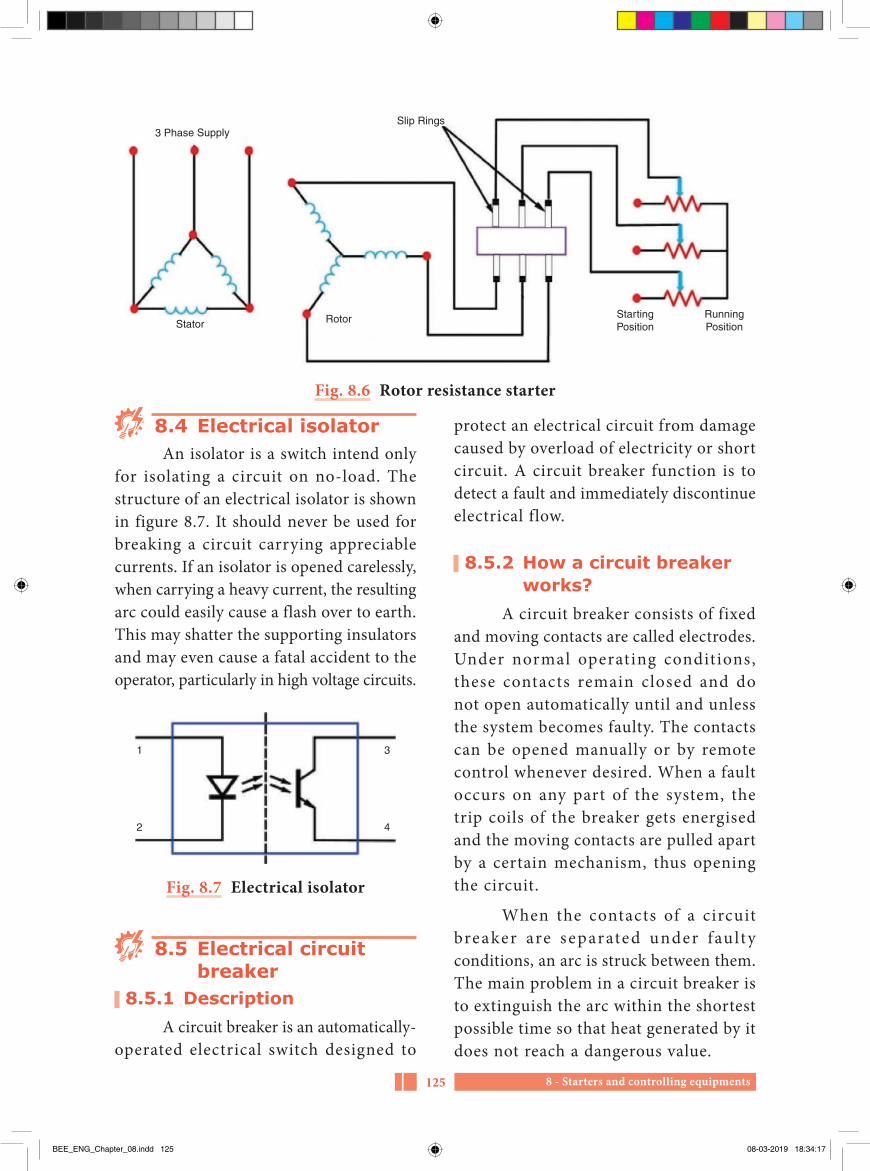
8 - Starters and controlling equipments125
protect an electrical circuit from damage caused by overload of electricity or short circuit. A circuit breaker function is to detect a fault and immediately discontinue electrical flow.
8.5.2 How a circuit breaker works?
A circuit breaker consists of fixed and moving contacts are called electrodes. Under normal operating conditions, these contacts remain closed and do not open automatically until and unless the system becomes faulty. The contacts can be opened manually or by remote control whenever desired. When a fault occurs on any part of the system, the trip coils of the breaker gets energised and the moving contacts are pulled apart by a certain mechanism, thus opening the circuit.
When the contacts of a circuit breaker are separated under fau lty conditions, an arc is struck between them. The main problem in a circuit breaker is to extinguish the arc within the shortest possible time so that heat generated by it does not reach a dangerous value.
8.4 Electrical isolatorAn isolator is a switch intend only
for isolating a circuit on no-load. The structure of an electrical isolator is shown in figure 8.7. It should never be used for breaking a circuit carrying appreciable currents. If an isolator is opened carelessly, when carrying a heavy current, the resulting arc could easily cause a flash over to earth. This may shatter the supporting insulators and may even cause a fatal accident to the operator, particularly in high voltage circuits.
1
2
3
4
Fig. 8.7 Electrical isolator
8.5 Electrical circuit breaker
8.5.1 DescriptionA circuit breaker is an automatically-
operated electrical switch designed to
Slip Rings3 Phase Supply
Stator Rotor StartingPosition
RunningPosition
Fig. 8.6 Rotor resistance starter
BEE_ENG_Chapter_08.indd 125 08-03-2019 18:34:17

8 - Starters and controlling equipments 126
8.5.5 Difference between electrical isolator and electrical circuit breaker
Sl. No. Electrical isolator Electrical circuit breaker1 Used only in no-load condition. Used in either no-load or on-load condition.2 Manual operation. Automatic operation.3 Mechanical equipment. Electro-mechanical equipment.4. It break outs a portion of a
substation when a fault occurred.It trips the entire system, if any fault occurs.
8.5.3 Methods of arc extinction
T h e r e a r e t w o m e t h o d s o f extinguishing the arc in circuit breakers.
1. High resistance method.2. Low resistance method.
Sl. No. Type Medium used for arc extinction
Voltage range
1 Air break circuit breaker. Air Up to 1000 V2 Tank type oil circuit breaker. Transformer oil Up to 33 KV 3. Minimum oil circuit breaker. Transformer oil Up to 132 KV4. Air blast circuit breaker. Compressed air Up to 132 KV5 Sf6 circuit breaker. Sf6 gas 400 KV to 760KV6 Vacuum circuit breaker. Vacuum 11 KV to 33 KV7 High voltage direct current
circuit breaker.sf6 gas or vacuum + 500 KV DC
Do you Know?
A redox flow battery uses excess solar- and wind-based energy to charge solutions of chemicals that can subsequently be stored for use when sunshine and wind are scarce. At that time, the chemical solutions of opposite charge can be pumped across solid electrodes, thus creating an electron exchange that provides power to the electrical grid.
8.5.4 Classification of circuit breakers
Circuit breakers are classif ied depending upon the medium use for arc extinction.
Power sourceLoad
Cathode
Catholytestorage
Catholyte Anolytestorage
Anolyte
Pipe Pipe
Anode
Switch
BEE_ENG_Chapter_08.indd 126 08-03-2019 18:34:17

8 - Starters and controlling equipments127
providing power for lamps or general purpose electric outlets.
ii. A single–pole low voltage circuit breaker occupies only one space in a fuse box.
2. Double–pole miniature circuit breaker
i. It is used for devices that operate with two live conductors, such as domestic air conditioner models.
ii. When a double–pole circuit breaker is tripped, both lines are disconnected even if only one of them was involved in the electrical fault.
iii. A double–pole low voltage circuit breaker occupies two spaces in a fuse box.
3. Triple–pole miniature circuit breaker
i. It is used to protect electric equipment that works with three-phase power.
ii. The electric motors of elevators and large air conditioning units typically work with three-phase power and are protected with triple pole low voltage circuit breakers.
iii. A triple-pole MCB low voltage circuit breaker occupies three spaces in a fuse box.
8.7 Moulded Case Circuit Breaker (MCCB)
This circuit breaker is an electro mechanical device which guards a circuit from short circuit and over current. The short circuit and over current protection for circuits ranging from 63 Amps-3000 Amps. The primary functions of MCCB
8.6 Miniature Circuit Breaker
MCB is an electro mechanical device which guards an electrical circuit from an over current that may effect from short circuit, overload or imperfect design. The structure of miniature circuit breaker is shown in figure 8.8.
• Normally work with currents below 100 amperes.
• They are the type of low voltage circuit breaker that is typically found in the fuse box of a residential or commercial building.
Fig. 8.8 Circuit breaker
8.6.1 Types of miniature circuit breaker
1. Single pole miniature circuit breaker
i. Single–pole circuit breakers are typically used for electric circuits with low power requirements that only use one live conductor, such as those
BEE_ENG_Chapter_08.indd 127 08-03-2019 18:34:18

8 - Starters and controlling equipments 128
are to open a circuit under short circuit or overload conditions.
i. It is used in higher current ratings when compared to miniature circuit breakers.
ii. The breaking current ratings of a moulded circuit breaker can be modified.
8.7.1 Comparison between miniature circuit breaker and moulded case circuit breaker
Sl. No. Miniature circuit breaker
Moulded case circuit breaker
1 Suitable for electrical circuit less than 100 Amperes
Suitable for electrical circuit between 63 to 3000 Amperes
2 It protects the electrical circuit from short circuit fault and over load
It protects the electrical circuit from short circuit fault and over load
3 Mostly used in homes
Used in industries, commercial buildings and hospital
8.8 Earth Leakage Circuit Breaker (ELCB)
The ELCB is used to protect the circuit from the electrical leakage. When someone gets an electric shock, then this circuit breaker cuts off the power at the time of 0.1 second for protecting
the personal safety and avoiding the fear from the short circuit and overload.
ELCB is a security device used in electrical system with high earth impedance to avoid shock. The main principle of earth leakage protector is to stop injury to humans and nature due to electric shock.
In figure 8.9, the ELCB is connected between the conductor and earth. The ELCB notices fault currents from live to the ground wire inside the installation it guards. If enough voltage emerges across the search coil in the circuit breaker, it will turn off the supply, and stay off until reset by manual.
Test push button
Circuitbreaker
Testresistor
Load
Trip coil Searchcoil
Load casingand frameare earthed
Fig. 8.9 Earth leakage circuit breaker
8.8.1 Types of earth leakage circuit breaker
1. Voltage operated earth leakage circuit breaker (Voltage – ELCB)
2. Current operated earth leakage circuit breaker (Current – ELCB)
8.8.2 Voltage operated earth leakage circuit breaker
One terminal of the relay coi l is connected to the metal body of the equipment to protect against earth leakage
BEE_ENG_Chapter_08.indd 128 08-03-2019 18:34:18

8 - Starters and controlling equipments129
8.8.3 Current operated earth leakage circuit breaker
This breaker operates due to the current flow in the earth wire caused by the short circuit in electrical equipment. It also protects from earth leakage fault. When short circuit occurs, different values of current flow in three phases, which make circuit breaker to operate and protect from the fault.
and the other is connected to the earth directly. If any insulation failure occurs or live phase wire touches the metal body of the equipment, there must be a voltage difference of 50 V and it produces a current to flow in the relay coil and disconnect the power supply to the equipment. In this way, the circuit is protected from earth leakage fault.
Armature : மினனகமBack electro motive force : எதிர மின இயககு விசைInduction motor : தூணடல மினனோடிThree point starter : மூனறு முசன துவககிSymmetrical fault : ைமசசர பழுதுகளElectrical circuit fault : மின சுறறு பழுதுElectrical circuit isolator : மின சுறறு பிரிபபோனElectrical circuit breaker : மின சுறறு துணடிபபோனOver load relay : மறிய மின பளு உணரததிTime delay relay : ேரக கடடுபபோடு உணரததிAir break type circuit breaker : கோறறு முறிவு வசக மினசுறறு
துணடிபபோன
Glossary
Part–AChoose the correct answer (1 Marks)
1. On starting, value of current taken by all the motor is a. Zerob. Lessc. Highd. Very high
2. The value of armature current depends upona. Capacitanceb. Inductancec. Resistanced. Impedance
Evaluation
BEE_ENG_Chapter_08.indd 129 08-03-2019 18:34:18

8 - Starters and controlling equipments 130
3. Due to the high current flow in the armature, which of the following effect does not occur?a. Over heatb. Sparkingc. Voltage dropd. Increase in efficiency
4. In which DC motor, the three point starter is useda. Shunt motorb. Compound motorc. Shunt and compound motord. Series motor
5. The terminal of the three point starter isa. Line, Armature, Field coilb. Line, Resistance, Field coilc. Armature, Field coil,
Resistanced. Resistance, Line, Armature
6. The protective devices used in the three point starters area. No volt release coilb. Over load release coilc. No volt and over load release
coild. Electromagnet coil
7. What should be done to obtain the increase speed in three point starter?a. Increase resistance valueb. Field current value should be
changec. Decrease resistance valued. Voltage should be maintained
8. In four point starter, how the no volt release coil should be connected with field coil.a. in seriesb. in shuntc. directlyd. parallel
9. The current taken by the induction motor in the order of ------- times that of full load current at starting time.a. 1 to 8b. 5 to 8c. 1 to 10d. 5 to 10
10. Induction motor is operated with full voltage ina. Star-delta starterb. Rotor resistance starterc. Direct-on-line starterd. Auto-transformer starter
11. ---------- induction motor is operated with low voltage.a. Direct-on-line and auto
transformer starterb. Star-delta and rotor resistance
starterc. Star-delta and auto transformer
starterd. Direct-on-line and rotor
resistance starter
12. In which starter, the starting current is reduced to one – third value?a. Direct-on-line starterb. Star delta starter
BEE_ENG_Chapter_08.indd 130 08-03-2019 18:34:18

8 - Starters and controlling equipments131
c. Rotor resistance starterd. Auto transformer starter
13. Electrical isolator should be used in ---------- condition.a. No loadb. With loadc. With less loadd. With very high load
14. Electrical circuit breaker is like a ----------a. resistanceb. capacitancec. switchd. inductance
15. The main function of a circuit breaker is a. to identify the faultb. to rectify the faultc. to identify and rectify the faultb. safety device
16. The example of low voltage operated circuit breaker is a. Electric isolatorb. Electric circuit breakerc. Miniature circuit breakerd. Moulded case circuit breaker
17. The moulded case circuit breaker is used in electrical circuit having the current ratinga. 100 Ampereb. 1000 Ampere
c. 3000 Ampered. 2000 Ampere
18. In which circuit breaker, the breaking capacity of the current can be changed?a. Miniature circuit breakerb. Moulded case circuit breakerc. Earth leakage circuit breakerd. Electric circuit breaker
19. The ---------- circuit breaker is used to protect circuit from the leakage current.a. Miniature circuit breakerb. Earth leakage circuit breakerc. Moulded case circuit breakerd. Open circuit breaker
20. The earth leakage circuit breaker breaks the circuit in ----- minutes.a. 1 b. 0.1c. 0.5 d. 0.7
21. The earth leakage circuit breaker connects which two parts?a. Conductor – conductorb. Conductor – bodyc. Conductor – earthd. Earth – earth
22. The operating voltage of voltage operated earth leakage circuit breaker is a. 100 volt b. 50 voltc. 5 volt d. 10 volt
BEE_ENG_Chapter_08.indd 131 08-03-2019 18:34:18

8 - Starters and controlling equipments 132
PART–BAnswer the questions in brief (3 Marks)
1. State the effects caused by the flow of heavy armature current in DC motor without starters.
2. What are the two basic functions of starter?
3. What are the draw backs of three point starter?
4. State the difference between three point starter and four point starter.
5. What are the different types of starters used in induction motor?
6. Write short notes on electrical isolator.
7. How the circuit breaker functions?
8. State the difference between the electrical isolator and electrical circuit breaker.
9. What are the difference between the miniature circuit breaker and moulded case circuit breaker?
PART–CAnswer the questions in one page (5 Marks)
1. State the necessity of starters in DC motor with example.
2. Draw the circuit diagram of four point starter.
3. With a neat sketch, explain the operation of auto-transformer starter.
4. Compare the different types of electrical circuit breaker.
5. Explain the different types of miniature circuit breaker.
6. Explain the operation of voltage operated earth leakage circuit breaker.
PART–DAnswer the questions in two page (10 Marks)
1. Explain the construction and operation of three point starter with a neat sketch.
2. With a neat diagram, explain the construction and working principle of star-delta starter.
3. Explain the construction and operation of direct-on-line starter with a neat sketch.
BEE_ENG_Chapter_08.indd 132 08-03-2019 18:34:18

8 - Starters and controlling equipments133
1. A text book of ‘Electrical Technology’ Volume-III B.L.Theraja and A.K.Theraja, S.Chand & Company Ltd.
Reference Book
1. http://www.wikipedia.org
2. https://www.electrical4u.com
Reference Internet Source
BEE_ENG_Chapter_08.indd 133 08-03-2019 18:34:18

9 - DC and AC Windings 134
9Chapter
DC and AC windings
Learning Objectives
Winding is the heart of motors and generators. It is important to keep the windings in good condition for the satisfactory operations of the electrical machines used in our houses and industries. If we have basic knowledge and experience in knowing all details about motor’s rewinding procedure, not only it helps to know the operation of motors and generators but also to the self-employment. There are number of persons in the motor rewinding field by their own experience, without any proper studies in the electrical engineering field. If our students get good experience with proper knowledge details about motor rewinding, there is no doubt in becoming great achievers this field.
You cannot believe in God until you believe in yourself. - Swamy Vivekanadar
Table of Content
9.1 Introduction9.2 Winding materials 9.3 Wire gauge plate
9.4 Details about coils 9.5 DC windings 9.6 AC windings
9 - DC and AC Windings
BEE_ENG_Chapter_09.indd 134 08-03-2019 18:35:40

9 - DC and AC Windings135
9.1 Introduction Windings are used in the electrical
f i e l d s u c h a s m o t or s , g e n e r at or s , transformers, loud speakers and in all kinds of electrical measuring instruments. The main objective of the use of winding is to produce the magnetic field according to the capacity of the electrical machines. In this lesson, we have to learn about the materials needed for making the windings and different types of DC and AC windings.
9.2 Winding materialsGenerally two types of important
materials are used in the process of winding the motors and generators. They are,
i. Electric conductorsii. Electrical insulating materials.
i. Electric conductorsMaterials having low resistance
allows the electric current to flow easily through conductors are called as electric conductors. Generally, it is made up of metals. For winding, copper conductors are mainly used for making coils and aluminium conductors are used next.
a. Types of conductorsFor the following windings are the
types of conductors commonly used.
i. Cotton covered winding wires.ii. Silk covered winding wires.iii. Paper covered winding wires.iv. Varnished glass paper covered winding
wires.v. Enamel coated round shaped winding
wires.Enamel coated round wires are
mainly used in small and medium type of motors having semi-closed slots while
rectangular conductors are used in larger types of motors having open type slots.
ii. Electrical insulating materials
Materials having very high resistance and also having property not to permit the electric current through them are called insulating materials.
a. VarnishesIt helps the winding to improve the
insulation resistance, dielectric strength and mechanical strength. It is used to protect the windings from dust and moisture. It is also used to give coating on the moisture absorbing materials.
9.3 Wire gauge plate9.3.1 Methods of
representing the size of the winding wires
The sizes of the conductors may be notified in two ways as follows,
i. By SWG numbers – a steel “Wire Gauge Plate” is used
ii. By its diameter in millimeter by metric method – An instrument micrometer (Screw gauge) is used.
To Find gauge number of a conductor by using standard wire gauge plate
The sizes and the gauge of the wires can be found by a device called standard gauge plate, which consists of a circular steel plate having notches of different widths around their edges. The diameter of the plate will be generally in 3 ¾ inches (95mm) with thirty six notches. Each notch is stamped with a number. The size
BEE_ENG_Chapter_09.indd 135 08-03-2019 18:35:40

9 - DC and AC Windings 1369 - DC and AC Windings
the exact size of the wire. The number represented near that notch will be the gauge number of that wire.
By finding gauge number of a wire, we can determine the amount of electric current the wire can safely carry, as well as its electrical resistance and weight per unit length.
We can measure the diameter of the winding wire by using the instrument micrometer (screw gauge). After measuring the diameter of the wire, using the above instrument, we can find the gauge number of the wire from the following table given below.
S.W.G No
Standard wire gauge SWG SWG No
Standard wire gauge SWGInch mm Area mm2 Inch mm Area mm2
0 0.324 8.23 53.17 26 0.018 0.457 0.1641 0.3 7.62 45.6 27 0.016 0.417 0.1362 0.276 7.01 38.6 28 0.015 0.376 0.1113 0.252 6.401 32.2 29 0.014 0.345 0.09374 0.232 5.893 27.3 30 0.012 0.315 0.07795 0.212 5.385 22.8 31 0.012 0.295 0.06826 0.192 4.877 18.7 32 0.011 0.274 0.05917 0.176 4.47 15.7 33 0.01 0.254 0.05078 0.16 4.064 13 34 0.009 0.234 0.04299 0.144 3.658 10.6 35 0.008 0.213 0.0357
10 0.128 3.251 8.3 36 0.008 0.193 0.029311 0.116 2.946 6.82 37 0.007 0.173 0.023412 0.104 2.642 5.48 38 0.006 0.152 0.018213 0.092 2.337 4.29 39 0.005 0.132 0.013714 0.08 2.032 3.24 40 0.005 0.122 0.011715 0.072 1.829 2.63 41 0.004 0.112 0.009816 0.0064 1.626 2.07 42 0.004 0.102 0.008217 0.056 1.422 1.59 43 0.004 0.091 0.006518 0.048 1.219 1.17 44 0.003 0.081 0.063619 0.04 1.016 0.811 45 0.003 0.071 0.055720 0.036 0.914 0.657 46 0.002 0.061 0.047921 0.032 0.813 0.519 47 0.002 0.051 0.0422 0.028 0.711 0.397 48 0.002 0.041 0.032223 0.024 0.61 0.292 49 0.001 0.03 0.023624 0.022 0.559 0.245 50 0.001 0.025 0.019625 0.02 0.508 0.203 BASIS: IS 13730-0-1/IEC 317-0-1
Fig. 9.1 Standard wire gauge plate
of the conductor to be found is inserted into the notches. The wire which just fits with a particular notch, stated to be
BEE_ENG_Chapter_09.indd 136 08-03-2019 18:35:40

9 - DC and AC Windings137
EMF is induced in this part and hence it is called as active side of the coil.
9.4.3 Inactive side of a coil The part of the coil which comes
out from the slots of a motor is called as inactive side. Here no magnetic field and emf is induced and hence it is called as inactive side of the coil. It is also called as “overhang” part of the coil.
9.4.4 Winding
Winding is made up of many coils with proper connections between them.
9.4.5 Winding diagram
The diagram which descr ibes the type of winding, coil group, coil group connection, phase connection etc. for doing winding is called winding diagram.
9.4.6 Types of winding
Winding types are mainly classified into two types. They are,
i. DC winding (for DC machines)ii. AC winding (for AC machines)
9.5 DC windings Windings are placed in two parts
of the DC machines, they are
i. Field winding placed in main poles.ii. Ar mature w inding p l ace d in
armature.
9.4 Details about coils9.4.1 Coils
A coil consists of a single turn or it may consists of many turns connected in series. Each coil having two coil sides as shown in the figure 9.2.
Back endside
Front side
Active side
Fig. 9.2 Winding coil representation
9.4.2 Active side of a coil A part of the coil placed in the slots
is called as active side. Magnetic field or
Do you Know?
The electrical energy to earth for one year can be produced by the sun in 15 minutes.
BEE_ENG_Chapter_09.indd 137 08-03-2019 18:35:40
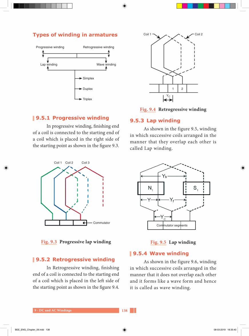
9 - DC and AC Windings 138
Coil 1 Coil 2
1 2
YC
Fig. 9.4 Retrogressive winding
9.5.3 Lap windingAs shown in the figure 9.5, winding
in which successive coils arranged in the manner that they overlap each other is called Lap winding.
b
f
Commutator segments
Fig. 9.5 Lap winding
9.5.4 Wave windingAs shown in the figure 9.6, winding
in which successive coils arranged in the manner that it does not overlap each other and it forms like a wave form and hence it is called as wave winding.
Types of winding in armatures
Progressive winding
Lap winding
Simplex
Duplex
Triplex
Wave winding
Retrogressive winding
9.5.1 Progressive windingIn progressive winding, finishing end
of a coil is connected to the starting end of a coil which is placed in the right side of the starting point as shown in the figure 9.3.
Coil 1 Coil 2 Coil 3
Commutator
Fig. 9.3 Progressive lap winding
9.5.2 Retrogressive windingIn Retrogressive winding, finishing
end of a coil is connected to the starting end of a coil which is placed in the left side of the starting point as shown in the figure 9.4.
BEE_ENG_Chapter_09.indd 138 08-03-2019 18:35:40

9 - DC and AC Windings139
Coils for the 1st circuit - 1,3,5,7, …..Coils for the 2nd circuits - 2,4,6,8, ...
9.5.7 Back pitch (Yb)The distance between two coil sides
of a coil is referred to as back pitch. It is always an odd number.
9.5.8 Winding pitch (or) coil pitch (y)
The distance between two starting leads of successive coils is referred to as winding pitch or coil pitch. It should be always an even number.
9.5.9 Front pitch (yf)It is the distance between two coil
sides connected to the same commutator segment. It should be an odd number.
9.5.10 Necessary details needed for DC winding
i. First calculate the number of coils. The number of coils must be equal to the number of commutator segments.
ii. According to the formula concerned to the lap or wave winding, calculate the Back pitch (Yb) Coil pitch (Y), and the Front pitch (Yf)
iii. Back pitch and front pitch must be of odd number only and the coil pitch must be of even number.
iv. Formula for lap winding
Back pitch, Yb = 2CP
K±
Here, C – number of coils P – number of poles
Commutator segments
Fig. 9.6 Wave winding
9.5.5 Simplex lap winding In simplex lap winding, finishing
end of the first coil is connected with the starting end of the adjacent coil as shown in the figure 9.7.
Here, only one circuit is available.
Fig. 9.7 Simplex lap winding
9.5.6 Duplex lap winding
Fig. 9.8 Duplex lap winding
In duplex lap winding, finishing end of the first coil is connected with the starting end of the third coil as shown in the figure 9.8. There are two separated circuits in duplex windings.
BEE_ENG_Chapter_09.indd 139 08-03-2019 18:35:41

9 - DC and AC Windings 140
vii. To find the current directions, use Fleming’s right hand rule for generators and use Fleming’s left hand rule for motors.
viii. The number of brushes must be equal to the number of parallel paths. For lap winding, the number of parallel paths will be equal to the number of poles and for wave winding, the number of parallel paths should be equal to 2
Hence, for lap winding,
Number of brushes = number of poles
For wave winding, Number of brushes = 2
ix. Mark positive brush connected lead as ‘A’ and negative brush connected lead as “AA”
These two leads will be the armature leads of the D.C machine.
x. Draw solid vertical lines of equal length for the top layer coil sides and draw dotted vertical lines of same length for the bottom layer coil sides.
9.5.11 Double layer simplex Lap winding diagram
Draw the double layer simplex lap winding diagram for a 2 poles , 6 slots DC machine having 6 commutator segments. Indicate the position of brushes.
SolutionNumber of poles P = 2Number of slots S = 6Number of commutator segments = 6
K–whole number a decimal or a fraction needed for making back pitch as an odd number.
Coil pitch, Y = ± 2mm = 1 for simplex windingm = 2 for duplex winding
Here ‘+’ symbols denotes the progressive winding while ‘-’ sign denotes the retrogressive winding. Generally all machines are winded by progressive method and hence we are using this type of winding methods in this lesson.
Front pitch, Yf = Yb – Y
v. Formula for wave winding
Back pitch, Yb = 2CP
K±
Here also ‘C’ denotes the number of coils and ‘P’ denotes the number of poles and the ‘K’ may be a whole number or a decimal or a fraction needed for making back pitch as an odd number.
Coil pitch, Y C mP
2 2
2/Here, m = 1 (for simplex)
m = 2 (for duplex)
Front pitch, Yf = Y-Yb
In wave winding, back pitch and front pitch must be equal.
Hence, Yb = Yf
vi. In double layer windings, the top layer coils should be numbered by odd numbers and the bottom layer should be numbered by even numbers.
BEE_ENG_Chapter_09.indd 140 08-03-2019 18:35:41

9 - DC and AC Windings141
Winding table
Sl. No. Yb = 7 Yf = 5
1 1 8
2 3 10
3 5 12
4 7 14(2)
5 9 16(4)
6 11 18(6)
Fig. 9.9 Winding-commutator connection
We know, No. of coils C = No.of commutator
segmentsHence, C = 6
Back pitch, Yb = 2CP
K±
2 6
2X K
= 6 + 1 = 7 (or) 6-1 = 5
Coil pitch, Y = ±2mm = 1 (for simplex)
Then, Y= 2 X 1 =2
Front pitch, Yf = Yb – Y
= 7 – 2 = 5 (or) 5 - 2 = 3
Selected Yb and Yf are
Yb = 7 Yf = 5
Fig. 9.10 2 Poles 6 slot simplex lap winding diagram
BEE_ENG_Chapter_09.indd 141 08-03-2019 18:35:42

9 - DC and AC Windings 142
Coil pitch Y C mP
2 2
2
m = 1 (for simplex)
Then Y =× ± ×2 6 2 1
2 2/ = 12 ± 2 = 12 +2 = 14 (or) 12 – 2 = 10
Front pitch Yf = Y – Yb
Also Yf = Yb
So Yf = 14 -7 = 7 (or) 10 – 5 = 5
Selected Yb and Yf are Yb = Yf =7 (or) (Yf = Yf = 5)
Winding table (Yf = Yf = 5)
Sl. No. Yb = 5 Yf = 5
1 1 – 6 6 – 11
2 11 – 4 4 – 9
3 9 – 2 2 – 7
4 7 – 12 12 – 5
5 5 – 10 10 – 3
6 3 – 8 8 – 1
In ma k i ng w i nd i ng t ab l e for wave winding, it is important that we must add back pitch and front pitch to obtain back end side and front end side respectively.
The winding of DC machines shorts from the first coil side and finally ended with the same and hence the DC machines windings are generally called as “closed coil winding”.
In making winding table for lap winding, it is important that we must add back pitch to obtain back end side and subtract front pitch to obtain front end side.
9.5.12 Double layer simplex wave winding diagram
Develop a double layer simplex wave winding diagram for a 2 poles, 6 slots, DC machine having 6 commutator s egments . Indicate the p os it ion of brushes.
SolutionNumber of poles P = 2
Number of slots S = 6
Number of commutator segments = 6
We know
No. of coils C = No. of commutator segments
Hence C = 6
Back pitch Yb = 2CP
K±
2 6
2 K
= 6+1 = 7 (or) 6-1 = 5
BEE_ENG_Chapter_09.indd 142 08-03-2019 18:35:42

9 - DC and AC Windings143
Fig. 9.12 Concentric winding
9.6.4 Coil groupCoil group consists of one coil
or more than one coi l connected in series.
When we carried out AC winding calculation, the number of coils per pole should be calculated. Then the coils in a pole should be separated for three phases also. Thus the coils per pole per phase is made into a coil group. By making coil groups, the number of end connections can be reduced and hence we can prevent short circuits in the end connection areas.
9.6 AC windingsThe winding made in the AC
machines are called as AC windings.
9.6.1 Types of AC windingsGenerally three types of winding
methods were carried out in AC machines. They are
i. Lap windingii. Wave winding andiii. Concentric winding
9.6.2 Lap and wave windingLap windings are generally used in low
voltage and high current electrical machines. But the wave windings are used in high voltage and low current electrical machines.
9.6.3 Concentric windingThe centre of all the coils in a
coil group confined to a constant centre as shown in the f igure 9.12 is called concentric winding.
Fig. 9.11 2 Poles 6 slots simplex wave winding
BEE_ENG_Chapter_09.indd 143 08-03-2019 18:35:42

9 - DC and AC Windings 144
9.6.10 Short pitched winding or short chorded winding
If we reduce the coi l pitch by one or two in number than the pole pitch, then it is called as short pitched winding. The reducing value should not exceed 1/3 rd of the pole pitch value. Electrical degree between two coil sides of short pitched winding will be less than 180°. This reduced angle is represented by short pitch angle (α). Here pitch factor will be less than one. This process reduces the weight of copper needed for winding the motors.
9.6.11 Long chorded windingIf we extend the coil pitch by one
or two than the pole pitch, it is called as long chorded winding. Electrical degree between two coil sides of long chorded winding will be more than 180°. Here pitch factor will be more than one. This method of winding is rarely used.
9.6.12 Single layer windingIf each slot of a motor contains
one coil side, then it is called single layer winding. Here the number of coils will be equal to the half of the total number of slots.
Hence,
Number of coils = Total number of slots.2
9.6.13 Double layer windingIn double layer winding , two
different coil sides of two coils are inserted in the same slot. Here the number of coils will be equal to the total number of slots.
9.6.5 Pole pitchIt is the distance between the center
of two adjacent poles. It is also denoted by the number of slots per pole.
Pole pitch = number of slotsnumber of poles
9.6.6 Winding pitch or coil pitch or coil span
It is the distance between the two coil sides of a coil.
Coil pitch = 1+ pole pitch
9.6.7 Full pitched windingIn full pitched winding, pole pitch
and coil pitch are equal. There will be 180° (electrical degree) between the coil sides.
9.6.8 Fractional pitched winding
If we reduce or increase the coil pitch by one or two in number than the pole pitch, then it is called as fractional pitched winding. The angle (electrical degree) between the coil sides may be less than or more than 180°.
Fractional pitched winding may be divided into two types. They are
i. Short pitched winding (or) short chorded winding
ii. Long chorded winding
9.6.9 Pitch factor (Kc)It is the ratio between the coil pitch
and pole pitch. It is denoted by ‘Kc’.
Pitch factor, Kc = coil pitchpole pitch
= cosα2
BEE_ENG_Chapter_09.indd 144 08-03-2019 18:35:43

9 - DC and AC Windings145
called as half coil winding. This type of winding is used in three phase concentric winding.
9.6.18 Concentrated winding If all the conductors of one coil
side are inserted in single slot for making one complete pole or if we place a single coil for making one complete pole, it is called as concentrated winding.
Three phase half coil winding, f ield winding on pole of DC & AC generators are the examples of concentrated winding.
9.6.19 Distributed windingHere the coils for a pole should not
be made as a single coil and hence the pole contains several coils and inserted in several slots. This type of winding is known as distributed winding. All the stators and rotor windings of AC machines and armature winding of DC machines followed this type of winding.
9.6.20 AC single phase concentric winding
A.C, 1ϕ, 4 poles, 24 slots concentric winding for a split phase capacitor type motor.
Pole pitch = Number of slotsNumber of poles
= 244
= 6
Coil pitch = 1 + pole pitch = 1+6 = 7 =1-7 (full pitched) 1-6 (short pitched)
Hence,
Number of coils = Total number of slots
9.6.14 Balanced windingIf the number of coils in all coil
groups per phase are equal, then this type of winding is referred to as balanced winding.
9.6.15 Unbalanced windingIf the number of coils in all coil
groups per phase are unequal, it is called unbalanced winding.
Do you Know?
M e t a l - A i r b a t t e r i e s a r e small in size and have light weight batteries.
But its ranges are high. When not in use, they quickly disrupt.
Because metal electrodes are affected by corrosion.
9.6.16 Whole coil windingIf the number of coil groups per
phase is equal to the number of poles, then the winding is called as whole coil winding. All the three phase lap windings and single phase concentric windings are belonging to this type.
9.6.17 Half coil windingIf the numb er of coi l g roups
per phase is equal to the half of the number of poles, then the winding is
BEE_ENG_Chapter_09.indd 145 08-03-2019 18:35:43

9 - DC and AC Windings 146
No. of coils per coil groups
= No of coils
No of coil groups
(coils / coil group)
= 124
= 3
Pole 1 Pole 2 Pole 3 Pole 43 3 3 3
K - calculation (No of slots for 90°)
Electrical degree for a slot
(or)Electrical degree between adjacent slots
β = PS
180
= 4 18024
= 72024
30
No of slots for 90° (K) = 9030
= 3
Hence,
Starting slot of the starting winding = 1st slot
Starting slot of the running winding = 1 + K
= 1 + 3 = 4th slot
So the star t ing winding must be inserted from the 1st slot and the running winding must be inserted from the 4th slot.
Fo r s i n g l e p h a s e c o n c e nt r i c winding, we choose pole pitch as short pitch.
Total no. of coils = No of slots 2
(Single layer)
= 242
= 12
No. of coils per pole = No of coilsNo of poles
(coils / pole)
= 124
= 3
No. of coils per phase = No of coils
phases
(coils / phase)
= 121
= 12
No. of coils per pole per phase
= No of coils
poles phases ×
(coils / pole / phase)
= 12
4 1×
= 124
= 3
Total no. of coil groups = poles × phases
= 4 x 1 = 4
BEE_ENG_Chapter_09.indd 146 08-03-2019 18:35:45
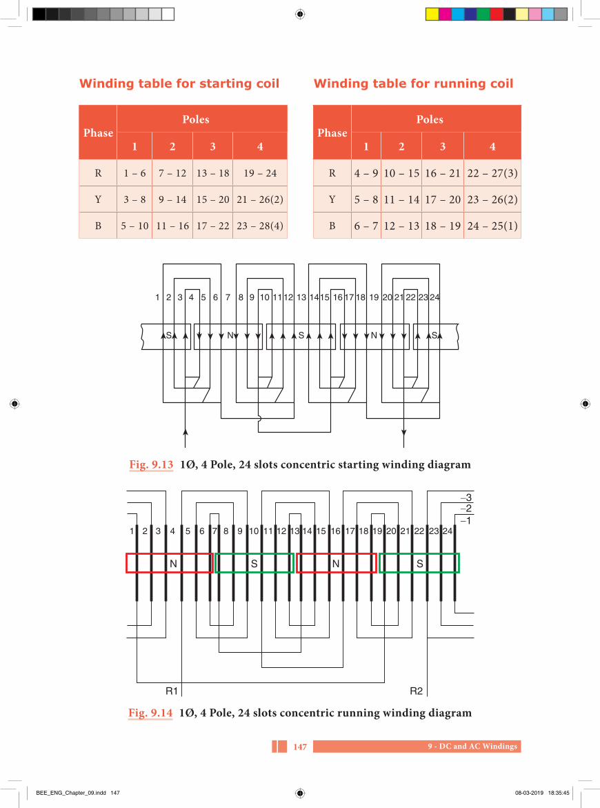
9 - DC and AC Windings147
Fig. 9.14 1Ø, 4 Pole, 24 slots concentric running winding diagram
1 2 3 4
N NS S
R1 R2
5 6 7 8 9 10 11 12 13 14 15 16 17 18 19 20 21 22 23 24
321
Fig. 9.13 1Ø, 4 Pole, 24 slots concentric starting winding diagram
S
1 2 3 4 5 6 7 8 9 10 1112 13 1415 16 17 18 19 20 21 22 23 24
SSN N
PhasePoles
1 2 3 4
R 1 – 6 7 – 12 13 – 18 19 – 24
Y 3 – 8 9 – 14 15 – 20 21 – 26(2)
B 5 – 10 11 – 16 17 – 22 23 – 28(4)
PhasePoles
1 2 3 4
R 4 – 9 10 – 15 16 – 21 22 – 27(3)
Y 5 – 8 11 – 14 17 – 20 23 – 26(2)
B 6 – 7 12 – 13 18 – 19 24 – 25(1)
Winding table for starting coil Winding table for running coil
BEE_ENG_Chapter_09.indd 147 08-03-2019 18:35:45

9 - DC and AC Windings 148
No of coils per phase = No of coils
phases.
(coils / phase)
= 123
= 4
No. of coils per pole per phase
= No of coilspoles phases
. ×
(coils / pole / phase)
= 124 3×
= 1212
= 1
Because of the coils per pole per phase is a whole number, this winding is a balanced winding.
Total no. of coil groups = poles × phases = 4 × 3 = 12
No. of coils per coil groups
= No of coils
No of coil groups.
(coils / coil group)
= 1212
= 1
Pole1 Pole2 Pole3 Pole4
R Y B R Y B R Y B R Y B
1 1 1 1 1 1 1 1 1 1 1 1
9.6.21 AC Three phase single layer lap Winding
AC, 1ϕ, 4 poles, 24 slots single layer lap winding diagram for an induction motor
Pole pitch = Number of slotsNumber of poles
= 244
= 6
Coil pitch = 1 + pole pitch
= 1 + 6 = 7
= 1-7 (full pitched)
1-6 (short pitched)
In single layer winding, successive coils must be placed by leaving one slot between them. Hence the left coil sides should be inserted in odd slots and the right coil sides should be inserted in even slots.
So, coil pitch = 1 – 8 (or) = 1- 6
Total no. of coils = No of slots. 2
(Single layer)
= 242
= 12
No. of coils per pole = No of coilsNo of poles
..
(coils / pole)
= 124
= 3
BEE_ENG_Chapter_09.indd 148 08-03-2019 18:35:47
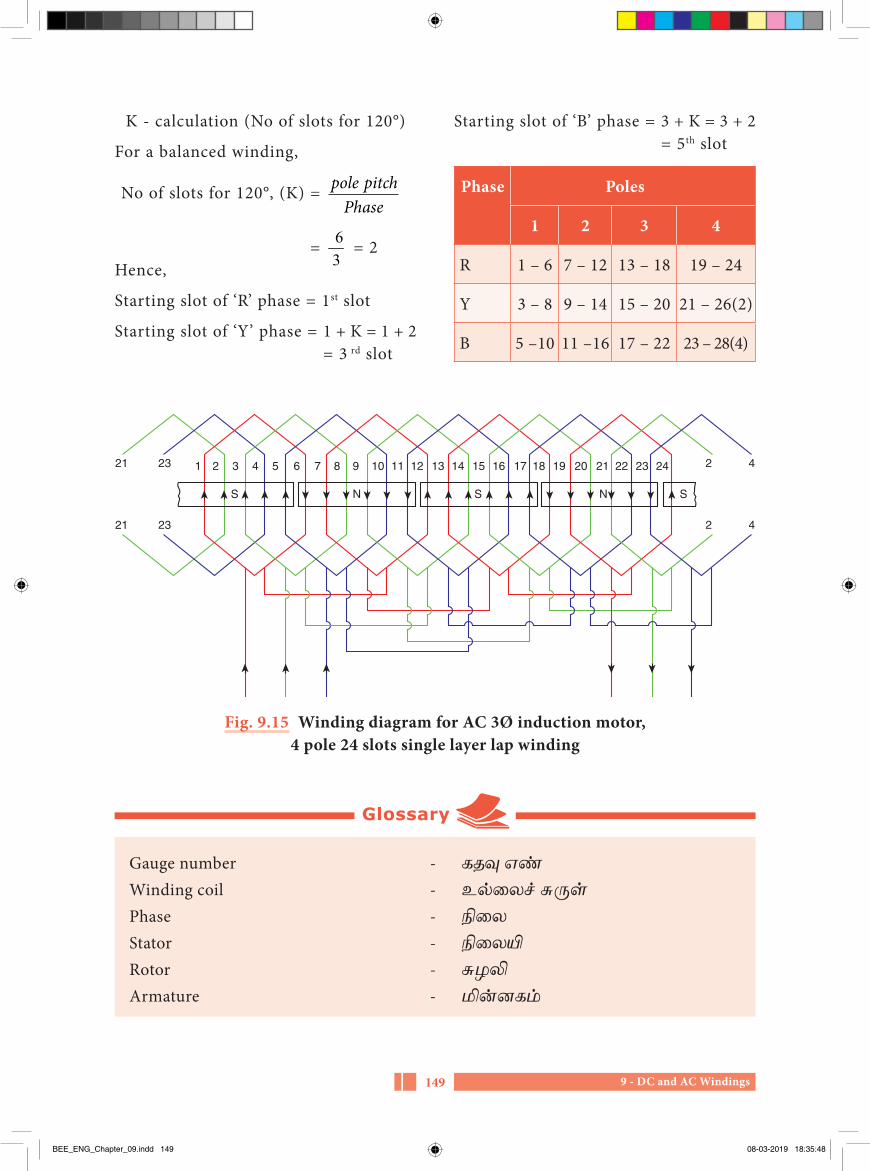
9 - DC and AC Windings149
Gauge number - கதவு எணWinding coil - உலலைச சுருளPhase - நிலைStator - நிலையிRotor - சுழலிArmature - மினனகம
Glossary
Fig. 9.15 Winding diagram for AC 3Ø induction motor, 4 pole 24 slots single layer lap winding
21 23
S S SN N
21 23
2 4
2 4
1 2 3 4 5 6 7 8 9 10 11 12 13 14 15 16 17 18 19 20 21 22 23 24
K - calculation (No of slots for 120°)
For a balanced winding,
No of slots for 120°, (K) = pole pitchPhase
= 63
= 2Hence,
Starting slot of ‘R’ phase = 1st slot
Starting slot of ‘Y’ phase = 1 + K = 1 + 2 = 3 rd slot
Starting slot of ‘B’ phase = 3 + K = 3 + 2 = 5th slot
Phase Poles
1 2 3 4
R 1 – 6 7 – 12 13 – 18 19 – 24
Y 3 – 8 9 – 14 15 – 20 21 – 26(2)
B 5 –10 11 –16 17 – 22 23 – 28(4)
BEE_ENG_Chapter_09.indd 149 08-03-2019 18:35:48

9 - DC and AC Windings 150
PART-AChoose the correct answer (1 Marks)
1. Heart of a motor isa) Statorb) Rotorc) Windingd) Bearings
2. The basic property needed for a good conductor isa) Low resistanceb) High mechanical strengthc) Best soldering propertyd) High dielectric strength
3. The diameter of the wire guage plate is generally a) 3 ¼ inchesb) 3 ½ inchesc) 3 ¾ inchesd) 4 ¾ inches
4. The instrument used to measure the diameter of a conductor isa) Wire guage plateb) Feeler guagec) Dial guaged) Screw guage
5. Example for the liquid insulating material is a) Asbestosb) Varnishc) Glassd) Mercury
6. The winding placed in the rotating part of DC machine isa) Main field winding
b) Armature winding
c) Inter pole winding
d) Compensating winding
7. The closed type of slots are used in a) Stators of small size
motors b) Stators of medium size
motors
c) Stators of squirrel cage induction motors
d) Rotors of squirrel cage induction motors
8. The value of back pitch will be a) Odd number
b) Even number
c) Fraction
d) Decimal
9. The value of ‘m’ in simplex winding is a) 1b) 2c) 3d) 4
Evaluation
BEE_ENG_Chapter_09.indd 150 08-03-2019 18:35:48

9 - DC and AC Windings151
10. If a DC machine works as a motor, the law used to find the direction of flow of current in armature winding is a) Fleming’s right hand ruleb) End rulec) Fleming’s left hand ruled) Ohm’s law
11. The number of parallel paths of a DC lap winding is a) P/2b) 2Pc) 2Pd) 2
12. The number of parallel paths of a DC wave winding isa) Pb) 2Pc) P/2d) 2
13. The number of brushes in DC machines are a) Equal to the number of parallel
paths.b) Equal to the number of slots.c) Equal to the half of the number
of slots. d) Equal to the half of the number
of poles.
14. The distance between two active sides of a coil in DC winding is a) Front pitchb) Coil pitchc) Back pitch d) Fractional pitch
15. The distance between the starting ends of two adjacent coil is a) Front pitchb) Back pitchc) Coil pitchd) Pole pitch
16. The type of winding used in DC armature is a) Main field windingb) Inter pole windingc) Open type windingd) Closed type winding
17. Pole pitch is referred to asa) The number of slots per
pole b) The number of slots per
phasec) The number of slots per pole
per phased) Half of the number of slots
18. In full pitched winding, the electrical degree between two coil sides of a coil is a) 60°b) 120°c) 180°d) 360°
19. The number of coils in single layer winding isa) Equal to the half of the number
of slotsb) Equal to the number of slotsc) Equal to the half of the number
of polesd) Equal to the number of poles
BEE_ENG_Chapter_09.indd 151 08-03-2019 18:35:48

9 - DC and AC Windings 152
20. If the number of coils are equal to the number of slots, then the type of winding is a) Single slot windingb) Double slots windingc) Single layer windingd) Double layer winding
21. If the coil groups of a phase winding having unequal number of coils, then the winding is called as a) Half coil winding
b) Whole coil windingc) Unbalanced windingd) Balanced winding
22. The number of coil groups in a phase of a full pitched winding is a) Equal to the number of polesb) Equal to the half of the number
of polesc) Equal to the number of slotsd) Equal to the half of the number
of slots
PART-B
Answer the questions in brief (3 Marks)
1. What is the necessity of winding in motors?
2. What is conductor?
3. Mention the types to notify the size of the conductors and the instruments used to measure it.
4. With a neat diagram, explain the parts of a single turn coil.
5. What is lap winding?
6. What are the three types of windings used in AC machines?
7. What is concentric winding?
8. What is pole pitch?
9. Define pitch factor.
10. What is whole coil winding?
PART-C
Answer the questions in one page (5 Marks)
1. Draw the diagram of a gauge plate and explain the method of finding the guage number by it.
2. Explain the different type of pitches used in DC armature windings.
3. Explain the method of calculation for finding the number of coils and coil groups in AC winding.
BEE_ENG_Chapter_09.indd 152 08-03-2019 18:35:48

9 - DC and AC Windings153
1. A text book of ‘Electrical Technology’ Volume-III B.L.Theraja and A.K.Theraja, S.Chand & Company Ltd.
Reference Book
1. http://www.wikipedia.org 2. https://www.electrical4u.com
Reference Internet Source
PART-D
Answer the questions in two page (10 Marks)
1. Draw the double layer simplex lap winding diagram for a DC machine having 2 poles, 6 slots and 6 commutator segments. Also mention the brush positions.
2. Draw the simplex wave winding diagram for a DC machine having
2 poles, 6 slots and 6 commutator segments. Also indicate the position of brushes.
3. Develop the winding table for a single layer lap winding of a 4 poles, 24 slots, AC three phase induction motor.
BEE_ENG_Chapter_09.indd 153 08-03-2019 18:35:48

10 - Maintenance and repairs of electrical machines 154
10Chapter
Maintenance and repairs of electrical machines
Learning Objectives
Electrical equipments plays major role in domestic work, industries and workshops. Electric motors are mainly used in all these electrical equipments. Hence we must briefly know about the operating methods, maintenance, repairs and testing of electrical machines
Life is the most beautiful gift of god – Mother Theresa
Table of Content
10.1 Introduction10.2 Electrical machines maintenance10.3 Faults in a power system10.4 General defects in machines
10.5 Testing of new machines10.6 Precautionary measures to be taken
before using electrical machines10.7 Testing of windings
BEE_ENG_Chapter_10.indd 154 08-03-2019 18:38:49

10 - Maintenance and repairs of electrical machines155
10.1 IntroductionIn this lesson, we have to learn about
the periodical maintenance procedure for our house holding electrical equipments, motors and e lec t r ica l machines in industries. Also we have to learn briefly about the reasons for the faults, rectification methods and avoiding methods.
10.2 Electrical machines maintenance
10.2.1 Aim of maintenanceIt is essentia l to maintain the
electrical machines and their secondary instruments in our houses, workshops and industries for their proper operation. If we maintain properly there will not be any longer from the equipment’s and they will function for the long period with high efficiency.
10.2.2 MaintenanceMaintenance is the process of
operation needed for the functioning of the motors and other electrical machines with good efficiency. When the electrical machines work, they deliver mechanical power from it. So, it causes to worn out in their rotating parts. Hence the proper maintenance should be needed for the electrical machines.
10.2.3 Planned maintenanceThe structure, operating methods,
load level of the electrical machines, can be maintained daily, weekly, monthly and yearly. This process of inspection and proper maintenance work is called as planned maintenance.
10.2.4 Types of maintenancei. Routine maintenanceii. Preventive maintenanceiii. Break down maintenanceiv. Capital repairs or corrective
maintenance
i. Routine maintenanceBased on the electric machines
type, age and workload, the process such as cleaning, greasing, minor repairing works and minor adjustments done are called routine maintenance.
ii. Preventive maintenanceTo prevent the sudden failure of the
machines and to protect from major repairs, the planning of preventive maintenance should be followed. It will reduce the losses.
If the electric machine undergoes sudden breakdown, then two types of losses will occur.
a. Direct losses
It is defined as the repair charges for electric machines.
b. Indirect losses
It is based on the worth of loss of work, labour salary and unable to supply the production materials in particular time.
iii. Breakdown maintenanceIf breakdown occurs suddenly
after doing the routine maintenance and preventive maintenance, the machine is to be immediate ly repaired to a good condition is cal led breakdown maintenance.
BEE_ENG_Chapter_10.indd 155 08-03-2019 18:38:49
10 - Maintenance and repairs of electrical machines 156
10.2.6 Importance of maintenance
Proper maintenance, acquires the following advantages.
i. The problems caused in machines are prevented.
ii. Sudden breakdown in the machines are prevented.
iii. Major complaints and expenses are reduced.
iv. Electrical machines with rated efficiency can be achieved.
v. Achieve the target of proper production with materials without any interruption.
10.2.7 General maintenance works made in electrical machines
i. Open the terminal box once in six months and test the terminals whether they are tight.
ii. Remove the grease completely for once in a year and apply the new grease. The process of removing the grease is called as “Degreasing”. After cleaning the bearings, apply new grease on it. This process is called “Greasing”.
iii. If the electrical equipment does not use for six months, then the old grease should be removed and apply new grease before to start it.
iv. Over hauling should be done on electrical machines for a period of once in three years.At that time, dismantle the all parts of the machines and clean the stator, rotor, bearings, grease cups, front and back end covers and assemble it.
iv Capital repairs or corrective maintenanceAfter many years of working, the
machine operation should be stopped and dismantling the machines for doing this maintenance for replaced the damaged parts. It should be done in number of days with more cost.
10.2.5 Planned maintenance Project
If the electric machine is working continuously, properly and efficiently, then the following planned maintenance be carried.
i. The new motor should be placed in proper and give proper connection to it.
ii. The hand tools, instruments and part of the motor should be readily kept for immediate maintenance.
iii. If the efficiency of the machine is reduced, then dismantle and overhaul it properly.
iv. Do the emergency repairs immediately.
v. Replaced the old machines with a new one.
vi. The maintenance consists of the layout , connect ion and construction of the machines, lubrication materials, planned mai nte nanc e l i s t , pre v i ous maintenance list etc.
vii. Proper training should be given to the workers about new machineries.
viii. The cost for one year maintenance should be planned and submitted.
BEE_ENG_Chapter_10.indd 156 08-03-2019 18:38:49

10 - Maintenance and repairs of electrical machines157
Symmetrical fault The faults are of symmetrical in
nature and occurs to symmetrical current, i.e., equal fault current in all the three phases with 120º displacement.
Types of faulta. Ground fault in all three phasesb. Short circuit fault between phases
a. Ground fault in all three phases
It occurs due to a breakdown of insulation between all the phases as well as to the earth. It is the most severe type of the fault and rarely occurs in the power system.
b. Short circuit fault between phases
It mainly occurs due to a breakdown of insulation between all the three phases. It occur is rarely 2% to 3% in the power system.
Asymmetrical faultThis fault are asymmetrical nature
and occurs to asymmetrical current, i.e., different currents in the three phases.
Typesi. Single Phase to ground faultii. Phase-to-Phase faultiii. Two phases to ground faultiv. Phase to phase and third phase to
ground fault
1. Single phase to ground fault i. It is also called a line-to-ground fault. ii. It mainly occurs due to insulation
breakdown between one of the phase and earth.
Do you Know?
Feeler Gauge is an instrument which is used to measure the air gap between the stator
and the rotor of the motors. The air gap value may be from few mils to 50 mills. 1 ml is equal to 0.025 mm or 1/1000 inch. Generally, the air gap is value of d.c. machines is more than a.c. machines.
10.3 Faults in a power system
DefinitionFault in electrical equipment or
apparatus is defined as an imperfection in the electrical circuit due to which current is deflected from the intended path. In other words, the fault is the abnormal condition of the electrical system which damages the electrical equipment and disturbs the normal flow of the electric current.
The most common and dangerous fault that occurs in a power system is the short circuit or shunt fault. During short circuit fault, heavy current flow through the circuit which damages the insulation of current carrying phase conductors corresponding to earth or in the insulation between phases.
Types of electrical faultTypes of electrical fault can be
classified into two major type
i. Symmetrical fault ii. Asymmetrical fault
BEE_ENG_Chapter_10.indd 157 08-03-2019 18:38:49

10 - Maintenance and repairs of electrical machines 158
4. Phase to phase and third Phase to ground fault
i. It is the combination of phase to phase and phase to phase to ground fault.
ii. Such types of fault occur due to the breakdown of insulation between two phases and simultaneous breakdown of insulation between the third phase and earth.
iii. The chance of such type of fault is hardly 2% to 3%.
10.4 General defects in machines
According to the supply, machines are classified into two major types.
1. DC machines2. AC machines
General defects and its remedy for DC machine are given below.
In DC machine, end connection and poles are very important. In DC machines terminal should be connected correctly (positive terminal to positive terminal and negative terminal to negative terminal), otherwise DC machines does not work.
iii. Similarly this type of fault is most frequently occurs in the power system.
iv. Their chances of appearance in the power system 70%.
2. Phase-to-Phase fault i. It is also called line-to-line fault. ii. It occurs when two conductors are
short circuited.iii. Such type of fault rarely occurred on
the power system.iv. Their chance of appearance is hardly
15% in the power system.
3. Two phases to ground fault
i. It is also called Line-to-line-to-ground fault (L-L-G).
ii. In this type of fault breakdowns of insulation between two phases and earth occur.
iii. It is the most severe type of fault but rarely occurs in the power system.
iv. Their chance of occurrence is hardly 10%.
10.4.1 General defects and its remedies for DC machinesDefects Reasons Remedies
1. When an electric supply is given to the DC motors, it is not running
1. Low voltage. Check each and every phase supply voltage and measure the required voltage value and correct it.
2. No voltage. Ensure whether voltage supply is in live.
3. Over load. Reduce the over load
4. Fault occurs in winding coils.
Check the winding coils and correct it
BEE_ENG_Chapter_10.indd 158 08-03-2019 18:38:49

10 - Maintenance and repairs of electrical machines159
Defects Reasons Remedies
5. Open circuit fault occurs.
Check the winding coils and correct it.
6. The wrong connection of the coil.
Check the coil connection test and connect it properly.
7. Check whether the brushes are having contacts with the slip rings.
Check the brush contacts properly
2. When the electric supply is given to the DC motors, the fuse wire is melted.
1. Over load. Reduce the over load.
2. Short-circuit in winding coils.
Check the winding coils, test and correct it.
3. Short-circuit in supply voltage.
Test the supply voltage and correct it.
3. Get the electric shock when we touch the motors
1. Due to low insulation resisting winding coil touches the motor body.
Check the insulation resistance and insulate the motor.
2. Coil touches the body (or) core.
Check the slot insulation and correct it properly.
4. Sparking at the commutator.
1. Low quality carbon brushes.
Quality brushes can be replaced.
2. Pressure on the brushes are not proper.
Proper pressure should be applied.
3. Wear and tear of brushes.
Brushes can be replaced.
5. Vibration in machines. 1. Motor is not fixed properly.
Proper fixation is to be made.
2. No proper alignment. Check the alignment.
3. No proper balancing. Check the balancing.
4. Worn out bearings. Replace the bearings.
BEE_ENG_Chapter_10.indd 159 08-03-2019 18:38:50

10 - Maintenance and repairs of electrical machines 160
10.4.2 General defects and remedies for AC motorsSl. No.
Defects Reasons Remedies
1. Motor not gets started.
1. Open circuit. Trace the open circuit and correct it properly.
2. Low voltage. Operate with proper (or) rated voltage.
3. Damaged rotor. Replace the rotor.4. Over load. Reduce the load.5. Bearings are fitted
with tight.Lubricate the bearings and check it.
2. Motor is not running at rated speed.
1. Low voltage Check the wiring
3. When motor is started, the fuse gets melted.
1. Over load. Reduce the load.2. Short-circuit in motor
circuit.Check the short circuit and rectify it.
4. Motor stops when started.
1. Major fault in motor Replace the motor.2. Over load Reduce the load.
5. Motor is getting heat when runs with load.
1. Dust in air passage Clean the air passage and check the outgoing hot air.
2. Grounded wiring Check and rectify the fault.3. Over voltage Motor should be operated only
with rated voltage.4. Rotor touches with
the statorCheck alignment and correct it.
6. Vibration of electrical motors
1. Motor is not fixed properly
Fix it properly.
2. Fault in bearings Replace the bearings.
3. No proper alignment of bearings
Adjust the alignment of bearings.
4. No proper end play Replace the washers.7. Bearings gets heat
when motor rotates.1. Dust in oil ways of
bearingsClean the oil ways and replace it with new oil.
2. Damaged bearings Replace the bearings3. Low (or) high
viscosity of lubricant.Apply new lubricant.
4. Lubricantion is not enough.
Enough lubricantion should be applied.
5. Higher end thrust. Rectify the fault.8. Rotor rotates in
opposite directions.1. Wrong winding
connectionMake the proper connection.
BEE_ENG_Chapter_10.indd 160 08-03-2019 18:38:50

10 - Maintenance and repairs of electrical machines161
10.6.2 AirgapThe gap between stator and the rotor
of a machine is called ‘Air gap’. The air gap is increased when the bearing is worn out and depreciation is bearing housing. To measure air gap, feeler gauge is used.
10.6.3 Armature balancingThe rotor or armature of the
machine is in roller shape. The weight of armature should be equal in all sides at all parts is called balancing. If weight is not equal then it is called unbalancing. i.e, one side of armature has more weight and the other side has less weight. This is called unbalanced rotor.
10.6.4 Importance of balancingIf the armature or rotor is not in
balanced condition, the rotor will hit the stator and bearing gets damaged while rotating. If there is any damage in bearing, the alignment will get change. If the a l ignment is not proper, the air gap between stator and rotor will become unequal. Hence balancing is very important.
10.6.5 Types of balancing1. Static balancing2. Dynamic balancing
1. Static balancing
Rotor to be balancedRolls or
knife edges
Heavy spot
Fig. 10.1 Static balancing
10.5 Testing of new machines
It is important to note the following points.
a. In a motor, check whether the terminal connections and wiring are correct or not as in the wiring diagram.
b. Open the terminal box once in six months to test the terminals for tightening
c. Measure the insulation resistance value.
d. Do the continuity test.e. The protective device which is used
to control the motor is fixed at the ‘minimum current value’ and ‘minimum time setting’ before the motor is used.
f. If the rotor rotates in the opposite direction, switch off the supply and change any two connections of the wire. Check whether the rotor is rotating in same direction.
g. Initially the rotor is rotated in low speed and after some time, the speed is increased step by step. Then check there is any vibration or sound in the motor.
10.6 Precautionary measures to be taken before using electrical machines
10.6.1 Alignment W h e n t h e m o t o r s h a f t a n d
load shaft are connected through the flange, note that the shafts are placed in one line. Plum bob, Try square and Dial guage are used to measure the alignment.
BEE_ENG_Chapter_10.indd 161 08-03-2019 18:38:50

10 - Maintenance and repairs of electrical machines 162
the weight is added to the required to balance the rotor.
In large type machines, the armature balancing is tested by using electronic de v ice , os c i l los cop e and v ibrat ion detectors. If balance is not correct, it will damage the bearings and the laminated core in the armature and the commutator becomes loose. This makes the armature to vibrate fast and produces sound. The motor star ts to move f rom its position. If it is not in proper. bolt it with ground.
The fan kept in the motor is used to reduce the heat. The weight can be added on the fan’s wing for balance. For balancing the method of adding weight is better than reducing the weight.
10.6.6 End playThe motor shaft is fixed without
moving front and back position in length wise. The end play occurs while the shaft is moving more than 1/64th part of inch is called end play.
10.6.7 End thrustUnwanted force acting on the shaft
sides of the motor or towards the one end of the motor is called end thrust.
10.6.8 BearingTo support and noiseless rotation of
shaft, bearing are used. The place where the bearing are installed are known as housing of bearing. Bearing are used in the end cover of the machine and shaft. With bearing puller, we can easily remove the bearing.
The armature or rotor is placed on the two equal knife edges which are fitted on the flat surface. If the rotor is balanced it should not rotate. If it is unbalanced, it will stand in a slanting position. After one rotation is completed, The part or side which has more weight is placed in bottom side and the side which has light weight is placed on the upper side. Hence some weight should be added to the upper side for balance or reduce some weight from the lower side. Again do the test, if it is unbalance then add or remove the weight till it is balancing.
2. Dynamic balancing
Fig. 10.2 Dynamic balancing
The dynamic balancing machine is used to find the vibrations of armature or rotor when it rotates fast and it also gives the details of unbalance condition. i.e, which the part has more weight or less weight in the armature.
The accurate balancing of armature is not possible in static balancing method. But in dynamic balancing method, it can be done properly. While testing, the rotor is rotated fast. If it is unbalance,
BEE_ENG_Chapter_10.indd 162 08-03-2019 18:38:50
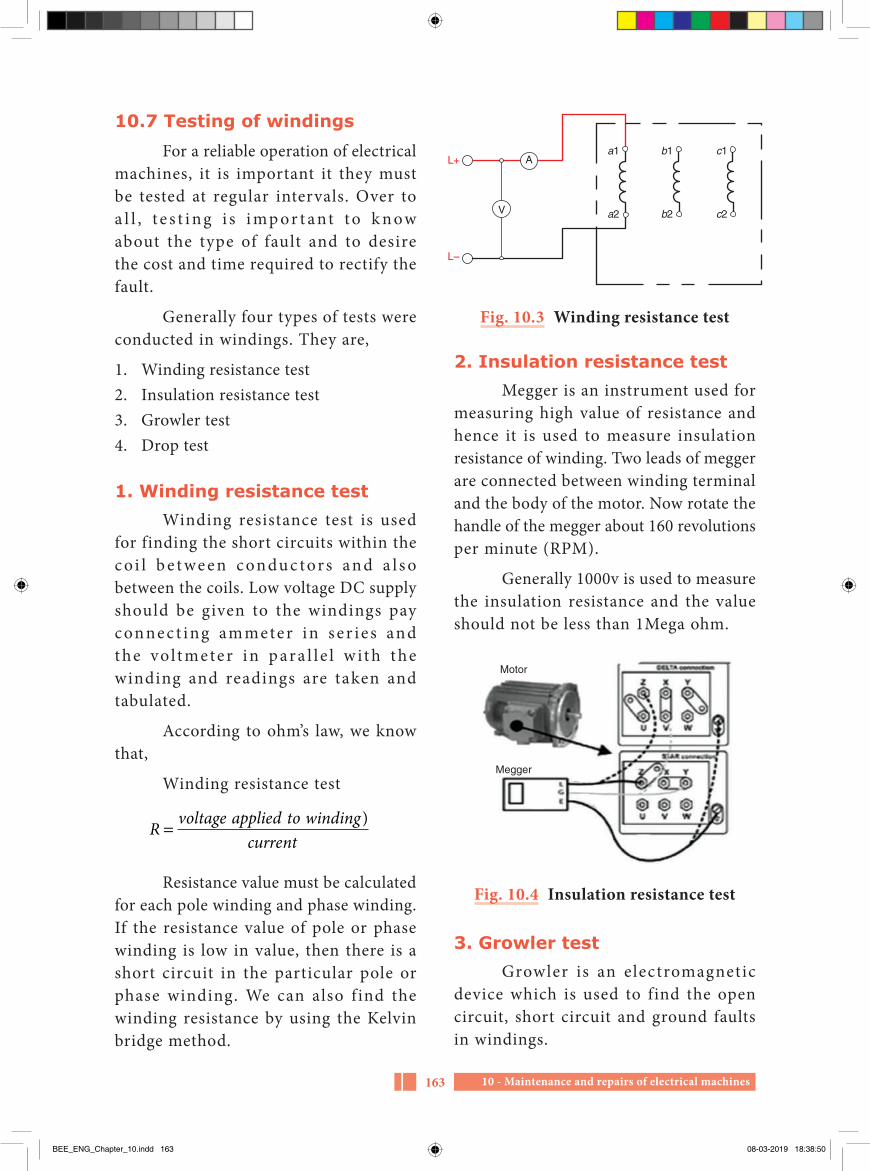
10 - Maintenance and repairs of electrical machines163
Aa1
a2
b1
b2
c1
c2V
L+
L–
Fig. 10.3 Winding resistance test
2. Insulation resistance testMegger is an instrument used for
measuring high value of resistance and hence it is used to measure insulation resistance of winding. Two leads of megger are connected between winding terminal and the body of the motor. Now rotate the handle of the megger about 160 revolutions per minute (RPM).
Generally 1000v is used to measure the insulation resistance and the value should not be less than 1Mega ohm.
Motor
Megger
Fig. 10.4 Insulation resistance test
3. Growler testGrowler is an electromagnetic
device which is used to find the open circuit, short circuit and ground faults in windings.
10.7 Testing of windingsFor a reliable operation of electrical
machines, it is important it they must be tested at regular intervals. Over to a l l , t e s t i n g i s i mp or t a nt t o k n ow about the type of fault and to desire the cost and time required to rectify the fault.
Generally four types of tests were conducted in windings. They are,
1. Winding resistance test2. Insulation resistance test3. Growler test4. Drop test
1. Winding resistance testWinding resistance test is used
for finding the short circuits within the c o i l b e t we e n c on du c t or s an d a l s o between the coils. Low voltage DC supply should be given to the windings pay conne c t ing ammeter in s er i e s and t he vo l t me te r i n p ar a l l e l w i t h t he winding and readings are taken and tabulated.
According to ohm’s law, we know that,
Winding resistance test
R voltage applied to windingcurrent
= )
Resistance value must be calculated for each pole winding and phase winding. If the resistance value of pole or phase winding is low in value, then there is a short circuit in the particular pole or phase winding. We can also f ind the winding resistance by using the Kelvin bridge method.
BEE_ENG_Chapter_10.indd 163 08-03-2019 18:38:50

10 - Maintenance and repairs of electrical machines 164
b. External growler
Laminated core
Supply
240 V AC
Insulated winding
Fig. 10.6 External growler
External growler consists of a winding over ‘H’ shaped laminated iron core. One side of its leg is cut out on the top in slantingly to place the rotor or armature winding.
c. Working principle When we give AC, 1ϕ, 230v, supply
to the growler winding, it works in transformer principle (Mutual induction). Growler winding acts like a primary of the transformer and the winding to be tested acts like secondary. Due to this, magnetic field voltage is induced.
For testing stator and rotor windings of AC motors, hacksaw blade is used and the fault can be identified by its vibrations.
For testing the armature windings of DC machines AC mili voltmeter is connected with the commutator segment and the fault can be identified by readings.
d. Testing of armature winding by growler
i. Open circuit test
The armature to be tested is placed on the growler as shown in the figure 10.7. AC supply is given to the growler. Now
There are two types of growlers. They are
1. Internal growler2. External growler
Internal growler is used to find faults in the stationary parts i.e, stator windings of motor, where as external growler is used to find faults in rotating parts i.e, rotor windings and armature windings of DC machines
Growler
Fig. 10.5 Internal growler
Construction of growlera. Internal growler
Internal growler consists of a winding over ‘V’ shaped laminated iron core. The legs were cut out on the top slantingly, to insert the legs into the stator slots easily. Internal growler has two types. They are
1. Internal growler with feeler2. Internal growler without feeler
This type of growler with feeler is used in small size stators where we cannot insert growler to test the windings. In large type stators, there will be more space to test the winding and hence growler without feeler can be used. Here hacksaw blade is used instead of a feeler
BEE_ENG_Chapter_10.indd 164 08-03-2019 18:38:50

10 - Maintenance and repairs of electrical machines165
noise. If the blade remains stationary, it is an indication that no short exist in the coil under test.
iii. Body short circuit test or Ground fault test
The armature to be tested is placed on the growler as shown in the figure 10.9 and AC supply is given to the growler. Now voltage is induced in the armature winding according to the transformer action. And it can be measured by AC milli voltmeter. The two leads of the milli voltmeter is connected between the commutator segment and the shaft of the armature.
MV
Test leads
To line
Growler consists of alaminated core on whicha coil of wire is wound
Armature placed on growlerfor testing purpose
Fig. 10.9 Earth fault test
voltage is induced in the armature windings according to the transformer action and it can be measured by AC milli voltmeter. The two leads of the AC milli voltmeter is connected with the adjacent bars as shown in the figure 10.7.
The pointer of the milli voltmeter must deflect to any value when we made test on all commutator segments. If the pointer does not deflect, the coil connected with the particular commutator segment is subjected to open circuit fault. The fault may be inside the coil or in the soldering part of the commutator segment.
This test can be made without the meter. For example, by shorting the top two bars with a piece of wire instead of meter. If there is a spark, it indicates the armature coil is in good condition. Absence of spark indicates that the coil is open.
240 VOLTS AC
TO LINE
MV
Fig. 10.7 Open circuit test
ii. Short circuit test The armature to be tested is placed
on the growler as shown in the figure and AC supply is given to the growler. Hold a hacksaw blade over the top slots of the armature as shown in the figure 10.8. If the coil in the slot is shorted, the blade will vibrate rapidly and create a growling
Fig. 10.8 Short circuit test
Hacksaw blade
Growler
BEE_ENG_Chapter_10.indd 165 08-03-2019 18:38:51

10 - Maintenance and repairs of electrical machines 166
Insert a variable resistance in series as shown in the figure. For example, in two pole machines DC supply is given to the opposite brushes, and in four pole machine DC supply is given to the adjacent brushes.
Now place the DC millimeter leads with the adjacent bars and find the readings for all commutator segments. From the meter readings, we can conclude that
1. If all the readings are same, the windings is in good connection
2. If the meter reads zero or low voltage, the coil connected to the particular segment is short.
3. If the milli voltmeter reads high voltage, the coil connected to the segment is open.
4. If the milli voltmeter deflects in the reverse directions as shown in the figure, the coil connected with the segment is reversed.
Generally armatures are tested for insulation resistance and for shorted coils. Only when a fault in the armature winding is suspected, drop test is conducted. But the results from the drop test are more reliable.
The pointer of the mili voltmeter must deflect to any value when we made test on all commutator segments. If the pointer does not deflect, the coil connected with the particular segment is subjected to contact with iron parts of the armature.
iv. Drop testThe most accurate method of testing
the armature for open circuit, short circuit, ground fault, and reversal of connection can be done by the Drop test. Connect a low voltage DC supply across the commutator segment at distance of pole pitch.
Cottontape
Counter
Reverse reading
Fig. 10.10 Drop test
1. Dismantle and assemble the electric machines.
2. Alignment test for Direct coupled machines.
Activities
Motor - மினனோடிStator - நிலையிRotor - சுழலிBearings - தோஙகிகள
Glossary
BEE_ENG_Chapter_10.indd 166 08-03-2019 18:38:51

10 - Maintenance and repairs of electrical machines167
Part–AChoose the correct answer (1 Marks)
1. In motor electrical energy is converted in to ---------- energya. Electricalb. Mechanicalc. Heatd. Magnetic
2. In electrical motor stator are made up of ---------- materiala. Silicon steelb. Cast-ironc. Mild steeld. Stainless steel
3. Bush bearings are lubricated with
---------- material a. Lubrication oilb. Greasec. Vegetable oild. Transformer oil
4. Core is made up ---------- materiala. Silicon steelb. Cast-ironc. Mild steeld. Stainless steel
5. ---------- bearings are used at load sidea. Ballb. Rollerc. Sleeved. Ball & Sleeve
6. ----------is the instruments used to remove the bearinga. Bearing pullerb. feeler gaugec. Plum bobd. Tri square
Pulley - சகதி மோறறுச சககரமBalancing - சமநிலைப படுததுதல அலைது சம
எலைப பகிரவுAlignment - ஒததலமவுCommutator - திலசமோறறிBrush - ததோடுவிEnd play - முலன இடிபபுEnd trust - முலன அலசவுGrowler - உருள அலை உருமி
Evaluation
BEE_ENG_Chapter_10.indd 167 08-03-2019 18:38:51

10 - Maintenance and repairs of electrical machines 168
7. Major repair is called----------a. Minor repairb. Preventive maintenancec. Routine maintenanced. Overhauling
8. To avoid direct and indirect loss which maintenance should be followed? a. Routine maintenanceb. Preventive maintenancec. Major repaird. Breakdown maintenance
9. Alignment is called----------a. Gap between stator and rotorb. Motor shaft and load shaft
should be in one line c. Motor shaft and load shaft
should not be in one lined. Motor shaft and load shaft
should be in opposite direction
10. Which effect was caused by fault in electrical circuit?a. high currentb. damage of equipmentsc. increasing in efficiencyd. High voltage
11. The lubrication should be applied to a electrical machine for
---------- once.a. Six monthb. one yearc. Two yeard. Three months
12. Electrical test is ----------a. To measure insulation
resistanceb. To measure air gapc. Lubricating oild. Alignment testing
13. End play is ----------a. The motor shaft is fixed
without moving front and back position in length wise
b. Abnormal load operated in motor
c. Improper alignmentd. Unbalanced load
14. Which instrument is used to measure the air gap ----------a. Feeler gaugeb. Bearing pullerc. Meggerd. Voltmeter
15. In symmetrical fault, the value of current in three phase is ----------a. Lessb. equalc. highd. Unequal
16. ---------- test gives the accurate result for testing the armature.a. Growlerb. Winding resistancec. Dropd. Insulation resistance
BEE_ENG_Chapter_10.indd 168 08-03-2019 18:38:51

10 - Maintenance and repairs of electrical machines169
PART-BAnswer the questions in brief (3 Marks)
1. Write the importance of maintenance in electrical machines?
2. What is meant by preventive maintenance?
3. What is an overhauling?
4. Define short notes on alignment?
5. What is meant by air gap?
6. What is the necessity of balancing?
7. What is end play?
8. What is meant by fault in electrical circuit?
9. Define short notes on bearing?
PART-CAnswer the questions in one page (5 Marks)
1. Explain about planned maintenance procedure.
2. Explain the symmetrical fault in detail.
3. Write the reason for the vibration of electrical machines and its rectification methods.
4. Explain about the dynamic balancing method.
5. Explain about the static balancing method.
6. State aim and importance of maintenance.
7. Explain the various test conducting in electrical machines.
8. Write the construction and working g principle of growler.
9. Describe the method of conducting open circuit test by using growler
10. Explain the drop test with neat sketch.
PART-DAnswer the questions in two page (10 Marks)
1. Explain the different types of maintenance
2. Explain the causes for the common defects occurred in DC
machines and its rectification methods
3. Explain the causes for the common defects occurred in AC machines and its remedies.
BEE_ENG_Chapter_10.indd 169 08-03-2019 18:38:51

10 - Maintenance and repairs of electrical machines 170
1. A text book of ‘Electrical Technology’ Volume-III B.L.Theraja and A.K.Theraja, S.Chand & Company Ltd.
Reference Book
1. http://www.wikipedia.org 2. https://www.electrical4u.com
Reference Internet Source
BEE_ENG_Chapter_10.indd 170 08-03-2019 18:38:51

- Glossary 171
Glossary
Corona – வெளிசசுடவொளிDi-electric strength – மினொபபு ெலிமைFeeder lines – ஊடடளிபபுத வொடரGrid – ெமையிமைபபு (அ) மினடடமைபபுInsulator – மினொபொனPeak load – உசசகடட ளுRegulation – ஒழுஙகு முமைPower factor – திைனொணிReceiving station – ஏறபு நிமையமPlane angle - ளக கொைமSolid angle - திணைக கொைமLuminous flux - ஒளிரவுப ொயமLuminous intensity - ஒளி விளகச வசறிவுLuminous efficacy - ஒளிரவுததிைன விகிமLux - ஒளிததிைனGlare - கூவசொளிDepreciation factor - கயைொனக ொணிSpace height ratio - இமடவெளி - உய விகிமUtilization factor - யனொடடுக ொணிPilot lamp - அறிகுறி விளககுThermostat - வெபநிமைபபிBi-metallic strip - ஈருகைொத டுPressure release valve - அழுதம அறறும ெொலவுInduction stove - தூணடல அடுபபுGeyser - நர சூகடறறும ைனFusible vent plug - உ௫கி ெழிவிடும அமடபொனSweep - வசசு

- Glossary 172
Oscillation mechanism - அமைய மெககும அமைபபுExhaust fan - ொறமை வெளிதளளும மினவிசிறிSemi – automatic type - குமைத ொனியஙகி ெமRinsing - அைசுலCentrifugal pump - மையவிைககு நகறறிShaft - சுழறணடுImpeller - துருததிPriming - கிடடிதலSubmersible motor - நர மூழகி மினகனொடிPump - நகறறிSquirrel cage motor - அணில கூடு மினகனொடிSynchronous motor - ஒததியஙகு மினகனொடி Induction motor - தூணடு மினகனொடிStepper motor - டிநிமை மினகனொடிVariable motor - ைொறு கெ மினகனொடிMotor shaft - மினகனொடி அசசுதணடுDeflecting torque - விைக சுழறறுமைControlling torque - டடுபடுததும சுழறறுமைDamping torque - ஒடுகல சுழறறுமைMoving iron - இயஙகு இருமபுAbsolute instruments - னிநிமைக ருவிளSpring control - வில டடுபொடுGravity control - ஈரபபு விமசக டடுபொடுPiston - உநதுத ணடுMultiplier - வருககிShunt - இமைதடமAnalog multimeter - குறிமுள லகநொககு அளவுைொனிDigital multimeter - எணணிைக லகநொககு அளவுைொனிEddy current - சுழல மினகனொடடமRange - வநடுகமGalvano meter - மினகனொடட அளவிPiezo resistivity - வுதமடPotentiometer - மினனழுதைொனிSignal - சிகனலStrain gauge - திரிளவுைொனி

- Glossary 173
Thermistor - வெபதமடயமPermeability - ஊடுருவும னமைLinear variable differential transformer - கநரியல ைொறி ைொறுடடமினைொறறிThermocouple - வெபமினனிடமடArmature : மினனமBack electro motive force : எதிர மின இயககு விமசInduction motor : தூணடல மினகனொடிThree point starter : மூனறு முமன துெககிSymmetrical fault : சைசசர ழுதுளElectrical circuit fault : மின சுறறு ழுதுElectrical circuit isolator : மின சுறறு பிரிபொனElectrical circuit breaker : மின சுறறு துணடிபொனOver load relay : மறிய மின ளு உைரததிTime delay relay : கநக டடுபொடு உைரததிAir break type circuit breaker : ொ ற று மு றி வு ெ ம மி ன சு ற று
துணடிபொனGauge number - வு எணWinding coil - உலமைச சுருளPhase - நிமைStator - நிமையிRotor - சுழலிArmature - மினனமMotor - மினனோடிStator - நிலையிRotor - சுழலிBearings - தோஙகிகளPulley - சகதி மோறறுச சககரமBalancing - சமநிலைப படுததுதல அலைது சம எலைப
பகிரவுAlignment - ஒததலமவுCommutator - திலசமோறறிBrush - ததோடுவிEnd play - முலன இடிபபுEnd trust - முலன அலசவுGrowler - உருள அலை உருமி

- 174
PART AANSWER ALL QUESTIONS 15 X 1 = 15 MARKS
1. The voltage of low-tension transformer is a) 132 KV b) 220 KVc) 33 KV d) 400 KV
2. An incandescent lamp can be used ina) AC supplyb) DC supplyc) Both AC and DC supply d) No supply
3. According to ---------- induction stove will function.a) Law of conservation of energyb) Ohms lawc) Flemings ruled) Faraday’s law
4. Velocity imparted by the impeller to the water is converted to pressure by thea) Casing or volute b) Stuffing box c) Spindle d) Gland box
5. Which type of fan is used to release smokes and dust?a) Ceiling fanb) Table fanc) Pedestal fand) Exhaust fan
6. Which of the following will need the highest level of illumination?a) Proof reading b) Living roomsc) Hospital wards d) Railway platforms.
7. The independent drives are used ina) computersb) vacuum cleanerc) cranesd) jet pump
8. Tong testers are used becausea) it is possible to measure
current flowing in a line without breaking the circuit.
Higher Secondary Second YearBasic Electrical Engineering
Model Question Paper
TIME: 2.30 Hrs MARKS: 90
BEE_ENG_MQ.indd 174 08-03-2019 18:41:38
- 175
b) for accurate measurement of electrical quantities.
c) for accurate measurement of energy.
d) for accurate measurement of resistance.
9. The moving iron type instruments are suitable fora) DC measurements onlyb) AC measurements onlyc) DC/AC measurementd) resistance measurement
10. Resistive transducers are used to measurea) displacement onlyb) pressure onlyc) displacement, pressure, forced) force only
11. In which starter, the starting current is reduced to one – third value?a) Direct-On-Line starterb) Star delta starterc) Rotor resistance starterd) Auto transformer starter
12. In which DC motor, the three point starter is useda) Shunt motorb) Compound motorc) Shunt and compound motord) Series motor
13. Which instrument is used to find faults in winding?a) Watt meter b) Multi meterc) Growlerd) Megger
14. The instrument used to measure the diameter of a conductor isa) Wire gauge plate b) Feeler gauge c) Dial gauge d) Screw gauge
15. The lubrication is used a) to increase heat b) to rotate without noise c) to increase friction d) for power loss
PART BAnswer any ten questions briefly 10 X 3 = 30 Marks
16. What are the uses of guarding?17. What are the disadvantages of a
fluorescent lamp?18. What is the use of percolating tube
in coffee percolator?19. Write short notes on Oscillation
mechanism in table fan
20. Define speed control methods.21. What are the advantages and
disadvantages of induction type wattmeter?
22. What is the principle of operation of electrical transducers?
BEE_ENG_MQ.indd 175 08-03-2019 18:41:38

- 176
23. Write short notes on electrical isolator.
24. What are the draw backs of three point starter?
25. What is the necessity of varnishing in winding?
26. What is the necessity of winding in motors?
27. Write the importance of electrical machine maintenance.
PART CAnswer any five questions about one page 5 X 5 = 25 Marks
28. Write short notes on a carbon arc lamp.
29. Explain the pressure type geyser.30. What are the types of electric
drives?31. Explain the working principle of
moving iron instruments.
32. What are the factors to be considered for selection of transducers?
33. Explain the symmetrical faults in detail?
34. What are the properties of insulating materials?
PART DAnswer all questions about two pages 2 X 10 = 20 Marks
35. Draw and explain the construction and working principle of an electric steam iron box.
(OR) Explain the construction
and working principle of the centrifugal pump with neat diagram.
36. Explain the construction and operation of three point starter with a neat sketch.
(OR) With neat sketch, explain various
types of DC armature winding.
BEE_ENG_MQ.indd 176 08-03-2019 18:41:38
1 - PRACTICALS177
Additional informationAn iron box is the household
appliance and commonly used by all people. From child to elders, all are not wearing the dress without ironing. This appliance plays a vital role in the modern world.
Electric Iron box is classified into three types.
a. Simple or ordinary iron boxb. Automatic iron boxc. Steam iron box.
1. Ordinary iron boxAn ordinary electric iron box has
the following parts which are assembled together.
i) Sole plateThe sole plate is the base plate of
the iron box, which is in the bottom side and is laminated with nickel or chromium
to make the surface shining. There are two threaded holes at the top of the sole plate, in which heating element and pressure plate are kept and got fitted with top cover of the iron box.
ii) Heating elementThe heating element is made up
of Nichrome, the metal alloy which is completely wound inside the mica sheet.
iii) Pressure plateThe pressure plate is made up of
a cast iron plate of the shape of heating element. Its size is slightly larger than the heating element. It keeps the heating element in a compact and stationary, when the iron box is in motion.
iv) Top coverIt is made up of a sheet cover used
to cover heating element and pressure
1Practical
Dismantling and assembling of steam iron box
PRACTICALS
AIM
1. To dismantle and assemble the steam iron box.
2. To know the parts of the appliance.
3. To learn about various defaults and remedial measures.
BEE_ENG_Pratical.indd 177 08-03-2019 18:43:11
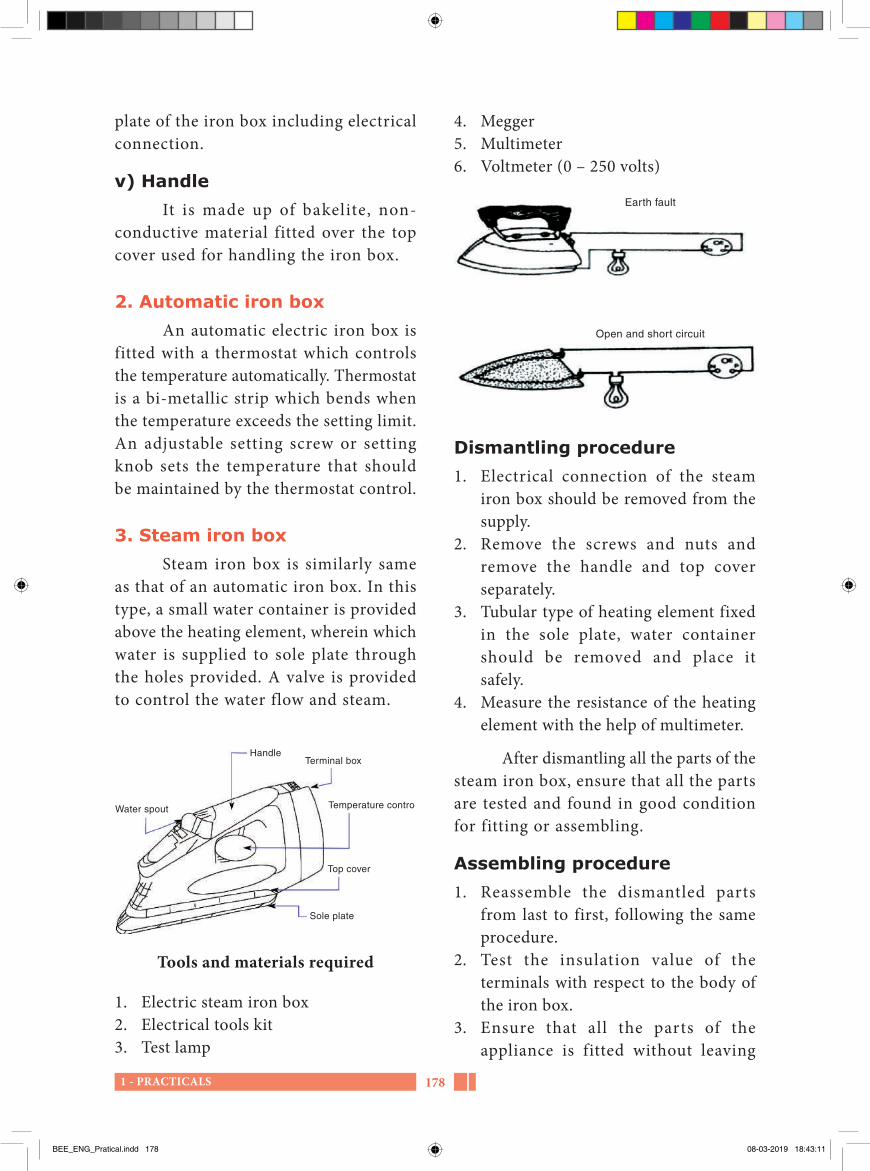
1 - PRACTICALS 178
4. Megger5. Multimeter6. Voltmeter (0 – 250 volts)
Earth fault
Open and short circuit
Dismantling procedure1. Electrical connection of the steam
iron box should be removed from the supply.
2. Remove the screws and nuts and remove the handle and top cover separately.
3. Tubular type of heating element fixed in the sole plate, water container should be removed and place it safely.
4. Measure the resistance of the heating element with the help of multimeter.
After dismantling all the parts of the steam iron box, ensure that all the parts are tested and found in good condition for fitting or assembling.
Assembling procedure1. Reassemble the dismantled parts
from last to first, following the same procedure.
2. Test the insulation value of the terminals with respect to the body of the iron box.
3. Ensure that all the parts of the appliance is fitted without leaving
plate of the iron box including electrical connection.
v) HandleIt is made up of bakelite, non-
conductive material fitted over the top cover used for handling the iron box.
2. Automatic iron boxAn automatic electric iron box is
fitted with a thermostat which controls the temperature automatically. Thermostat is a bi-metallic strip which bends when the temperature exceeds the setting limit. An adjustable setting screw or setting knob sets the temperature that should be maintained by the thermostat control.
3. Steam iron boxSteam iron box is similarly same
as that of an automatic iron box. In this type, a small water container is provided above the heating element, wherein which water is supplied to sole plate through the holes provided. A valve is provided to control the water flow and steam.
Handle
Temperature control
Terminal box
Top cover
Sole plate
Water spout
Tools and materials required
1. Electric steam iron box2. Electrical tools kit3. Test lamp
BEE_ENG_Pratical.indd 178 08-03-2019 18:43:11

1 - PRACTICALS179
4. Measure the value of current flowing into the heating element.
anything and connect the supply wire to the appliance.
Open circuit Short circuit EarthingTest lamp Won’t glow / Glow Bright / Dim Glow / Won’t glowFault Occurred / Not occurred Occurred / Not occurred Occurred / Not occurred
Observation recorda. Voltage value of steam iron box = voltsb. Power of steam iron box = wattsc. Frequency of the iron box = hertzd. Current value of the iron box = amperee. Resistance value of the heating element = ohms
Precautionary tips1. Ensure that the iron box is disconnected
from the main supply before handling it.
2. Select the proper range of instruments for measuring current and voltage.
3. While assembling the iron box, ensure that the heating element is placed in proper position with insulated intact.
4. Check the earth connection of the iron box properly fitted.
5. The electric iron box should not be allowed to get too heated. It will spoil
the sole plate nickel plating and will get damaged.
ResultThe method of dismantling the
given Iron box and identify the parts, testing the Iron box, identifying and rectifying its faults, and assembling their on box was carried with proper tools. Now the Iron box is working in good condition.
BEE_ENG_Pratical.indd 179 08-03-2019 18:43:12

2 - Electric coffee percolator 180
2Practical
Electric coffee percolator
Related informationCoffee percolator is a heating
appliance used for domestic purpose. This appliance is similar to electric kettle. In this appliance a percolating tube is in centre of the container and coffee basket is kept over it. After coffee powder is put on the basket, the lid is closed and electric supply is given. Then the water in the container gets heated, and the steam soaks the coffee powder and coffee water is collected in the container and can be used when required. In some appliances, the lid is made of glass to know the thickness of the coffee water.
Hand tools and apparatus required
Sl. No.
Hand tools and apparatus required
Quantity
1 Insulated cutting plier 12 Screw driver 20 cm and
10 cm1
3 Spanner set 14 Test lamp 15 Coffee percolator 1
Dismantling procedurei. Remove the g lass l id of the
coffee percolator and keep in safe place.
ii. Remove the percolating tube and coffee basket and keep them separately.
iii. Remove the screws in the bottom of the percolator.
iv. Disconnect the electrical supply leads of the percolator.
v. Remove the heating element, mica sheet and asbestos sheet and place them separately.
vi In this, the heating element coil is made of nichrome and is turned around mica sheet.
AIM
1. To dismantle and know the parts of electric coffee percolator.
2. To test, identify and rectify the faults in the coffee percolator, and
3. To reassemble electric coffee percolator.
BEE_ENG_Pratical.indd 180 08-03-2019 18:43:12

2 - Electric coffee percolator181
Re-assemblingi. In bottom chamber, the heating
element, mica sheet and asbestos sheet are tightened with metal plate, and electrical connection be given.
ii. The connection should be in proper to avoid short circuit. Then close the bottom cover of the coffee percolator.
iii. Before starting the appliance, ensure that the appliance is in good condition by making all the tests like open, short and earth fault.
Open circuit
Short circuit
Earthing
Test lamp
Won’t glow / Glow
Bright / Dim
Glow / Won’t glow
Fault Occurred / Not occurred
Occurred / Not occurred
Occurred / Not occurred
Precautionary tips1. Ensure that the coffee percolator is
disconnected from the main supply before handling it.
ResultIn this experiment, I have come to
know the parts of electric coffee percolator, the dismantling and reassembling and identifying and rectifying the faults in the coffee percolator. Now the appliance is in good condition.
Testing procedure
Glass lid
Coffee basket
Coffee chamber
Perculating tube
Inverted cupTap
Heating chamber
C onnec t the heat ing e lement terminals in test lamp. If the lamp won’t glow, it indicates open circuit. If the lamp glows in maximum brightness, it indicates short circuit. If the lamp glows in dim, it indicates that the heating element is in good condition.
Open and short circuit test
Earth fault test
BEE_ENG_Pratical.indd 181 08-03-2019 18:43:12

3 - Dismantling and assembling of an electric geyser 182
3Practical
Dismantling and assembling of an electric geyser
Related informationAn electric geyser is an appliance
used to heat the water with electric supply. Generally electric geysers are available with the capacity of 5, 10, 15, 25 and 50 liters. The ratings of the geyser are ranging from 500 watts to 2000 watts.
The inner tank of the electric geyser is made up of copper with tinned coating in the inner side. In some other geyser, the tanks are made up of steel with nickel coating inside. The outer side of the geyser is made up of metal and painted to avoid rusting.
In order to protect the hotness of the water including heat loss inside the tank, a metallic cover is provided around it. Between inner and outer tank 8cm wide space is left around the tank, in which filled with glass wool. This glass wool acts as the heat insulation for the geyser.
According the capacity of the geyser, various size and type of heating elements are used. Commonly tubular type of heating element is used in geyser. The heating element is fitted inside the tube which is f i l led with magnesium oxide. This magnesium oxide acts as an insulator and prevents the element from touching inside the wall of the tube. The bottom head of the tube is fitted with Bakelite which is fitted with connecting pins of the heating element. The heating element, thermostat and indicating lamp are fitted in the bottom cover as in figure below.
The hot water outlet pipe is arranged in siphon manner, so that the initial water level must reach level ‘A’. The water level cannot be reduced below level ‘B’ which ensures that the heating element will always be inside the water.
AIM
1. To dismantle and assemble an electric geyser.
2. To examine the various parts of an electric geyser.
3. To study the construction and working principle of geyser
4. To find out the various faults in the geyser.
BEE_ENG_Pratical.indd 182 08-03-2019 18:43:12

3 - Dismantling and assembling of an electric geyser183
The thermostat fitted in the geyser controls the temperature of the water automatically and thus, safeguards the whole unit from overheating. As soon as the temperature of the water inside the tank reaches to the temperature of 85 degree, the heating element is automatically disconnected. Electric connection is restarted as soon as the temperature of the water falls. According to the size and capacity of a geyser, the power consumption vary. A typical rating for a geyser is 230 to 250 volts.
Hand tools and apparatus required
Sl. No. Hand tools and apparatus required
Quantity
1 Electric geyser 12 Tools box 13 Tester 14 Megger 15 Multimeter 1
Thermostat Heatingelement
Supply open
Supply
Testing lamp
Connection diagram of an electric geyser
Dismantling procedure1. Disconnect the main supply of the
geyser.2. Drain out the stored water from the
geyser.
Fusible plug Vent pipe 12 mm
Glass wool
Thermostat
Pressure releasevalveOutlet
12 mm
Inlet12 mm
Drain pipecover
Heating element
BEE_ENG_Pratical.indd 183 08-03-2019 18:43:12

3 - Dismantling and assembling of an electric geyser 184
3. Fit the bottom cover of the geyser properly. (In this heating element, thermostat and indicating lamp are fixed)
4. With the help of megger, check out the electrical leakage, if any.
5. Then connect the electrical supply to the geyser and make sure that it was connected properly and firmly.
Observations made after completion of installation or fitting of the geyser1. After installation of the geyser, open
the inlet tap of the control valve, until the water tank is filled.
2. Switch ‘on’ the supply and wait for few minutes and then open the hot water tap.
3. Check the continuous flow of warm water is coming properly.
4. Close the tap of hot water when not in use and turn off the supply
3. With the help of megger, test the leakage in the appliance.
4. Remove the bottom cover which contains heating element, thermostat and indicating lamp.
5. Remove the earth connection from the body of the geyser.
6. Remove the fitting clamps of the geyser.7. Check the continuity of the heating
element.8. After removing the heating element,
clean the scale formation by using hydro chloric acid solution.
After verification of all these above, ensure that all the parts and materials of the geyser are in good condition.
Assembling procedure1. Check the geyser is clean and fit it with
clamps.2. Connect the earth wire with the body
of the geyser.
Open circuit Short circuit EarthingTest lamp Won’t glow / Glow Bright / Dim Glow / Won’t glowFault Occurred / Not
occurredOccurred / Not occurred
Occurred / Not occurred
Observation recorda. Voltage of the geyser :b. Storage capacity of the geyser :c. Power supply of the geyser :d. Frequency supply of the geyser :e. Current of the geyser :f. Fuse rating :
BEE_ENG_Pratical.indd 184 08-03-2019 18:43:12
3 - Dismantling and assembling of an electric geyser185
5. When the geyser is not to be used for a long time, the water in the tank should be drained out by unscrewing the drain plug.
ResultThe method of dismantling the
given Geyser and identify the parts, testing the Geyser, identifying and rectifying its faults, and assembling the Geyser was carried with proper tools. Now the Geyser is working in good condition.
Precautions1. Do not touch the geyser, when the
power supply is ‘ON’.2. Check the body of the geyser is
electrically insulated, before and after dismantling of the geyser.
3. Before switching ‘ON’ the electric supply, ensure that the inner water tank of the geyser is filled with water.
4. After completion of the necessity of hot water, disconnect the electrical supply of the geyser.
BEE_ENG_Pratical.indd 185 08-03-2019 18:43:12

4 - Table fan 186
4Practical
Table fan
Related informationNormally, the sweep of the table
fan is available in 220mm, 300mm and 350mm. In some table fans shaded pole motors are used. Generally permanent capacitor induction run motors are used. Table fans are used to circulate the air to the required area. The blades are mounted on the rotating shaft. The blades are covered with a cage for safety purposes. In a table fan the motor is placed at the top of the body and the regulator is fitted on the base. The power consumption of the table fan is 60 watts.
Apparatus Required
Sl. No. Equipments Quantity1 Table fan 12 Insulation tape 13 Grease 1 pocket4 Kerosene 100 ml
5 Bearing Puller 16 Waste cotton Required
quantity7 Wooden board Required
quantity
Practical procedureDismantling
Fan blade
Wire guard(Cage for blades)
Oscllating gear box
Motor body
Regulator
Base
AIM
1. To dismantle the given table fan and identify the parts.
2. Testing the table fan, identifying and rectifying its faults, and reassembling the table fan
3. Test the table fan with supply and run it.
BEE_ENG_Pratical.indd 186 08-03-2019 18:43:12

4 - Table fan187
coils. The stator winding is tested with the use of test lamp. Test the capacitor and check whether it is in good condition.
Assemblingi. Fix the back side end cover of the rotor
and gear box properly.ii. Fit the blades and cage in front side
properly. iii. Open circuit test, short circuit test
and earth test is to be done by test lamp.
Testing procedurei. Connect the test lamp to the two
terminals of the table fan. If the lamp glows dim, it means the table fan is in good condition. If it glows brightly, it means short circuit fault occurs and the lamp does not glow, it means open circuit fault occurs in the table fan.
ii. Connect the one lead of the test lamp to the one terminal of the table fan and connect the other lead of the test lamp to the body of the table fan. If the test lamp glows, it means earth fault occurs in the table fan.
i. Open the clips of the cage.ii. Cage should be kept separately.iii. Unscrew the blade mounting screws
and remove the blades from shaft.iv. Unscrew the back cover and remove it. v. Take out the gear box by removing the
mounted screws.vi. Remove the rotor and keep separately.
DO’s after dismantling
Flexible cord
Flexible cord
Testlamp
Testlamp
Supplysource
Supplysource
Testing lead
Testing lead
Open and short circuit test
Earth fault test
Rotor shaft and bearing are cleaned with kerosene and waste clothes. Clean the rotor carefully without damaging the
Open circuit Short circuit EarthingTest lamp Won’t glow / Glow Bright / Dim Glow / Won’t glowFault Occurred / Not occurred Occurred / Not
occurredOccurred / Not occurred
Precautioni. D o n o t u s e h a m m e r w h e n
dismantling and assembling the parts.
ii. Handle the bearings carefully.iii. Conduct the test carefully.
ResultThe method of dismantling the given
table fan and identify the parts, testing the table fan, identifying and rectifying its faults, and assembling the table fan was carried with proper tools. Now the table fan run with normal speed and it is in good condition.
BEE_ENG_Pratical.indd 187 08-03-2019 18:43:12

5 - Ceiling fan 188
5Practical
Ceiling fan
Related informationThe information of a ceiling fan is
obtained from name plate which is fixed on the body of the fan. It helps us to know details of the fan correctly. Generally in ceiling fan, permanent capacitor induction run motor is used. The inner portion of ceiling fan is stator. The outer rotating portion is rotor. Ceiling fan is fitted in the ceiling by conduit metal pipe. When the power supply is given, the blade of the fan rotates and air is circulated around the area where the fan is connected. Regulator is connected in series with the motor to control the speed.
Tools required
Sl. No. Hand tools Quantity1 Insulated cutting
plier1
2 Insulated screw driver 15 cm
1
3 Insulated screw driver 25 cm
1
4 Test lamp 15 Spanner set 1
Apparatus required Sl.
No.Equipments Quantity
1 Ceiling fan 12 Insulation tape 13 Grease 1 pocket4 Kerosene 100 ml5 Bearing puller 16 Waste cotton Required quantity7 Wooden board Required quantity
AIM
1. To dismantle the given ceiling fan and identify the parts.
2. To test the ceiling fan, identify and rectify its faults, and assemble the ceiling fan.
Practical procedureDismantlingi. Separate the fan from ceiling clips.ii. Unscrew the screws in canopy.iii. Remove the condenser from its
housing.
BEE_ENG_Pratical.indd 188 08-03-2019 18:43:12

5 - Ceiling fan189
Testing procedurei. Connect the test lamp to the two
terminals of the ceiling fan. If the lamp glows dim, it means the table fan is in good condition. If it glows brightly, it means short circuit fault occurs in the ceiling fan and if the lamp does not glow, it means open circuit fault occurs in the ceiling fan.
ii. Connect the one lead of the test lamp to the one terminal of the ceiling fan and connect the other lead of the test lamp to the body of the ceiling fan. If the test lamp glows, it means earth fault occurs in the ceiling fan. Otherwise earth fault does not occur in it.
iv. Remove the blades from the fan.v. Remove the cover, separate the stator
and rotor.
DO’s after dismantlingRotor shaft and bearing are cleaned
with kerosene and waste clothes. Clean the rotor carefully without damaging the windings. The stator winding is tested with the use of test lamp. Test the capacitor and check whether it is in good condition.
Assemblingi. Fix the end covers with stator.ii. Connection is given to the windings
and capacitor.iii. Open circuit test, short circuit test and
earth test is to be done by test lamp.
Open and short circuit test
Test lamp
Test lamp
Earth fault test
BEE_ENG_Pratical.indd 189 08-03-2019 18:43:13
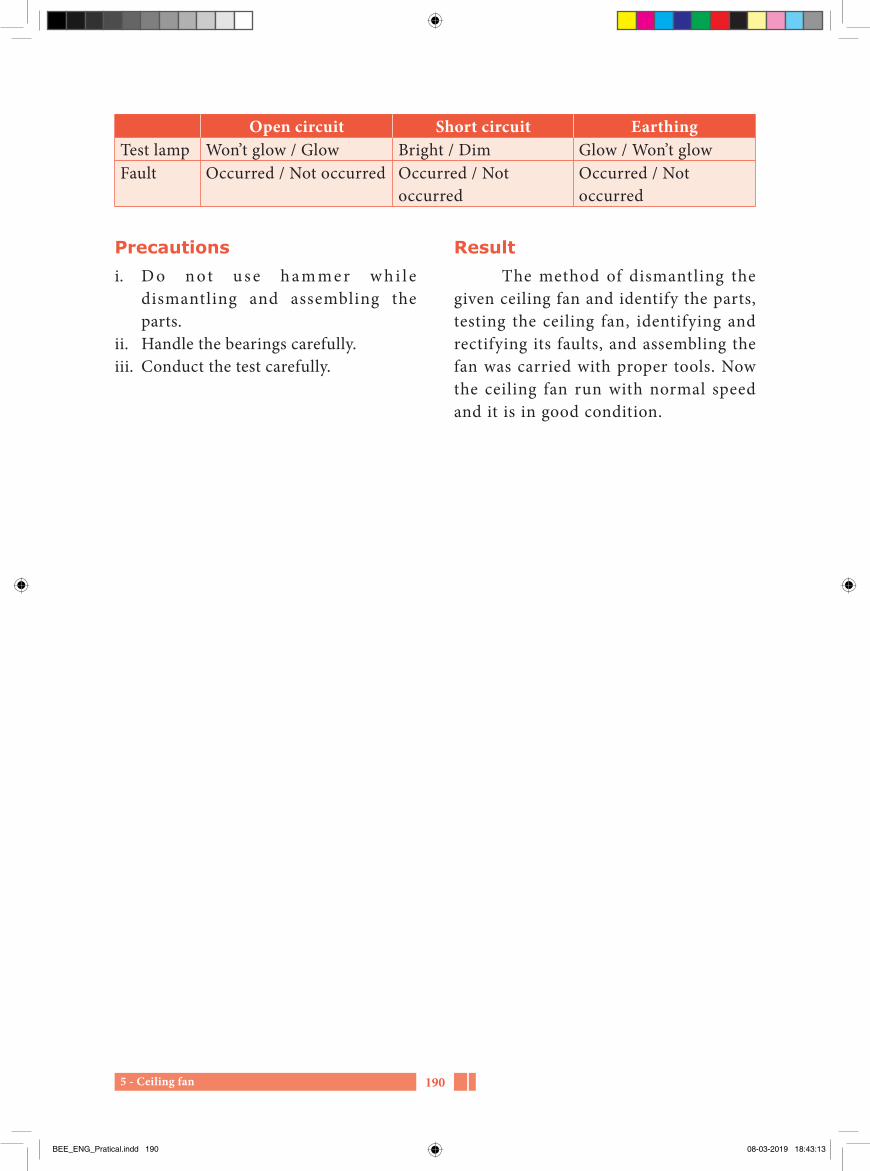
5 - Ceiling fan 190
Open circuit Short circuit EarthingTest lamp Won’t glow / Glow Bright / Dim Glow / Won’t glowFault Occurred / Not occurred Occurred / Not
occurredOccurred / Not occurred
Precautionsi. D o n o t u s e h a m m e r w h i l e
dismantling and assembling the parts.
ii. Handle the bearings carefully.iii. Conduct the test carefully.
ResultThe method of dismantling the
given ceiling fan and identify the parts, testing the ceiling fan, identifying and rectifying its faults, and assembling the fan was carried with proper tools. Now the ceiling fan run with normal speed and it is in good condition.
BEE_ENG_Pratical.indd 190 08-03-2019 18:43:13

6 - Water pump191
6Practical
Water pump
AIM
1. To dismantle the given faulty domestic water pump.
2. To Test, identify the fault and rectify it.
Related informationIn domestic pump set, capacitor
start induction run motor is used. Two windings are wounded in the stator.
i. Main winding ii. Starting winding
Starting capacitor and centrifugal switch are connected in series with the starting winding.
Practical procedureDismantlingi. Separate the axis of motor and pump.ii. Dismantle the rotor from the stator.iii. Disconnect the connection from the
starting winding.iv. Test the winding.iv. Test the capacitor.v. Dismantle the pump.vi. Dismantle the impeller.
Impeller
Impellervanes
Air cock
Suctioneye
Deliverypipe
BEE_ENG_Pratical.indd 191 08-03-2019 18:43:13

6 - Water pump 192
Testing procedurei. Connect the series test lamp with
the main and starting winding. Then conduct open circuit and short circuit test.
ii. Do the earth fault test on the main winding and starting winding by connecting one end of the test lamp to the winding terminal and the other end to the body.
iii. Dismantle the centrifugal switch and check the spring condition.
iv. Conduct the test on the capacitor
ResultThe method of dismantling the
given water pump, identifying the parts, testing the water pump, causes, reasons and remedies of its faults, and assembling the water pump was carried with proper tools. Now the water pump run with normal speed and it is in good condition.
Testing
P OE
P OE N
N
POE N
Run
ning
Run
ning
Run
ning
Open and short circuit test in starting winding
Earth Test
Open and short circuit test in running winding
Capacitor
Sta
rtin
gS
tart
ing
Sta
rtin
g
BEE_ENG_Pratical.indd 192 08-03-2019 18:43:13

7 - Measurement of energy of the given electrical equipment193
7Practical
Measurement of energy of the given electrical equipment
AIM
To measure the energy of the given electrical equipment (pure resistive load).
Apparatus required
S.No. Equipment Required
Quantity
1 Voltmeter 12 Ammeter 13 Electrical
equipment (lamp load)
1
4 ICDP switch 15 Connecting wire as required
Procedure1. Connections are made as per the
circuit diagram. 2. After checking the connections, close
the ICDP switch. 3. Note down the readings of voltmeter
and ammeter. 4. Switch of f the supply after 5
minutes. 5. Calculate the energy consumed.
(0-5) A
A
ICDP Switch
Lamp load
1φ,240 VAC V
(0-300) V
L
N
BEE_ENG_Pratical.indd 193 08-03-2019 18:43:13
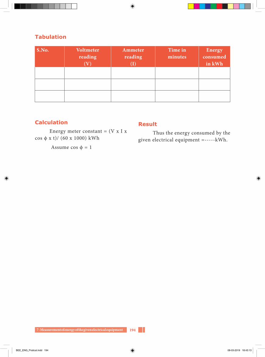
7 - Measurement of energy of the given electrical equipment 194
Tabulation
S.No. Voltmeterreading
(V)
Ammeterreading
(I)
Time inminutes
Energy consumed
in kWh
CalculationEnergy meter constant = (V x I x
cos ϕ x t)/ (60 x 1000) kWh
Assume cos ϕ = 1
ResultThus the energy consumed by the
given electrical equipment =-----kWh.
BEE_ENG_Pratical.indd 194 08-03-2019 18:43:13

1958 - Determination of Winding Resistance
8Practical
Determination of winding resistance by Ammeter- Voltmeter method
AIM
To determine the value of winding resistances of starting and running windings of the given AC, single phase capacitor type Induction motor by Ammeter – Voltmeter method.
Instruments and materials requiredSl. No. Apparatus Type Quantity1 Capacitor type induction motor - 12 Ammeter (0-10A) M.C type 13 Voltmeter (0-30V) M.C type 14 Rheostat 50Ω 15 Line tester - 16 Cutting plier - 17 Screw driver - 18 1/18 SWG connecting wires - Sufficient length
BEE_ENG_Pratical.indd 195 08-03-2019 18:43:13

1968 - Determination of Winding Resistance
voltmeter and ammeter readings are noted and tabulated.
v The average resistance value of the starting and running winding is calculated and compared with the original values.
vi. If the calculated average value of resistance is equal to the original values, there is no short circuit in the windings and if it is low, then there will be a short circuit in the concerned winding.
Procedurei. Connections are made as shown in the
figure and the supply is given.ii. Starting winding is connected first
with the circuit to find its resistance value.
iii. The voltage applied and current through the starting winding is measured by voltmeter and ammeter respectively and tabulated.
iv. S imi lar ly running winding is connected with the circuit. Then
Table for starting winding Sl. No. Voltmeter reading
(V)Ammeter reading
(I)Resistance
R = V/I123Total resistance value
Average resistance value of the starting winding
Rav =Total Resistance value
No of readings taken RT( )
.
Table for running windingSl. No. Voltmeter
Reading (V)Ammeter
Reading (I)Resistance
R = V/I123Total resistance value
BEE_ENG_Pratical.indd 196 08-03-2019 18:43:14

1978 - Determination of Winding Resistance
ResultThe starting and running winding
resistance of the given AC single phase c ap ac i tor t yp e induc t ion motor i s determined by Ammeter-Voltmeter method, and also known about the short circuits in the windings.
Average resistance value of the Running winding
Rav =Total Resistance value
No of readings taken R
( )
.T
BEE_ENG_Pratical.indd 197 08-03-2019 18:43:14

9 - Determination of insulation resistance value 198
AIM
To determine the insulation value of a resistance of a given motor winding by using megger.
Instruments and apparatus required S.no Apparatus Quantity1 Given motor 1
2 Megger (1000 V) 13 Cutting plier 14 Screw driver 15 Double end
spanner set1
Connection diagram
0
Winding
Yoke
Handle
Megger
Testprobes
Procedurei. Megger is an instrument used to
measure high value of resistance and
it can also be used to measure the insulation value of the resistance of the motor windings.
ii. To find the value of insulation resistance, one terminal of the megger is connected with anyone terminal of winding and another terminal of motor is connected with the body of the motor.
iii. Rotate the handle of the megger about 160 revolutions per minute.
iv. Now the pointer of the megger moves gradually and shows the reading. That is the insulation value of the resistance of the winding.
v The reading should not be less than 1 mega ohm.
Measurement of insulation resistance value in DC machines
The windings in a DC machine are
1. Field winding
9Practical
Determination of insulation resistance value of motor windings
BEE_ENG_Pratical.indd 198 08-03-2019 18:43:14

9 - Determination of insulation resistance value199
iv. Remove the faulted winding and rewind it.
Measurement of IR value of armature winding i. Connect one terminal of the megger
with anyone commutator segment and another lead with the shaft or body of the machine.
ii. Rotate the handle of the megger and find the value of IR.
iii. If the IR value is less than 1 mega ohm, rewind it.
Measurement of IR value of AC 1 Φ capacitor type motor windings
There are two types of windings in the AC 1Ø capacitor type of motor. They are,
1. Starting winding 2. Running winding
Measurement of IR value Before conducting the test, the
terminal of the starting winding should be splited separately from the terminal box connections.
To measure the winding insulation resistanceof single phase AC capacitor type motor
Starting winding Running winding
Yoke
Handle
Megger
Testprobes
0
S1
S2
R1
R2
2. Inter pole winding 3. Armature winding
Measurement of IR value of field windingi. Connect one terminal of the megger
with anyone terminal of the field winding and another terminal with the body of the motor.
ii. Rotate the megger handle and find IR value.
iii. If the IR value is the less than 1 mega ohm, separate the end connections of the field winding and carry out the test for each pole winding, to identify the defaulted pole winding.
iv. Remove the faulted winding and rewind it.
Field windingterminals
Poles
DC machinefield windings
F
F1
Measurement of IR value of inter pole windingi. Connect one terminal of the megger
with one terminal of the inter pole winding and the other terminal with the body of the motor.
ii. Rotate the handle of the megger and find IR value.
iii. If the IR value is the less than 1 mega ohm, separate the end connections of the inter pole winding and carry out the test for each inter pole winding to identify the defaulted inter pole winding.
BEE_ENG_Pratical.indd 199 08-03-2019 18:43:14
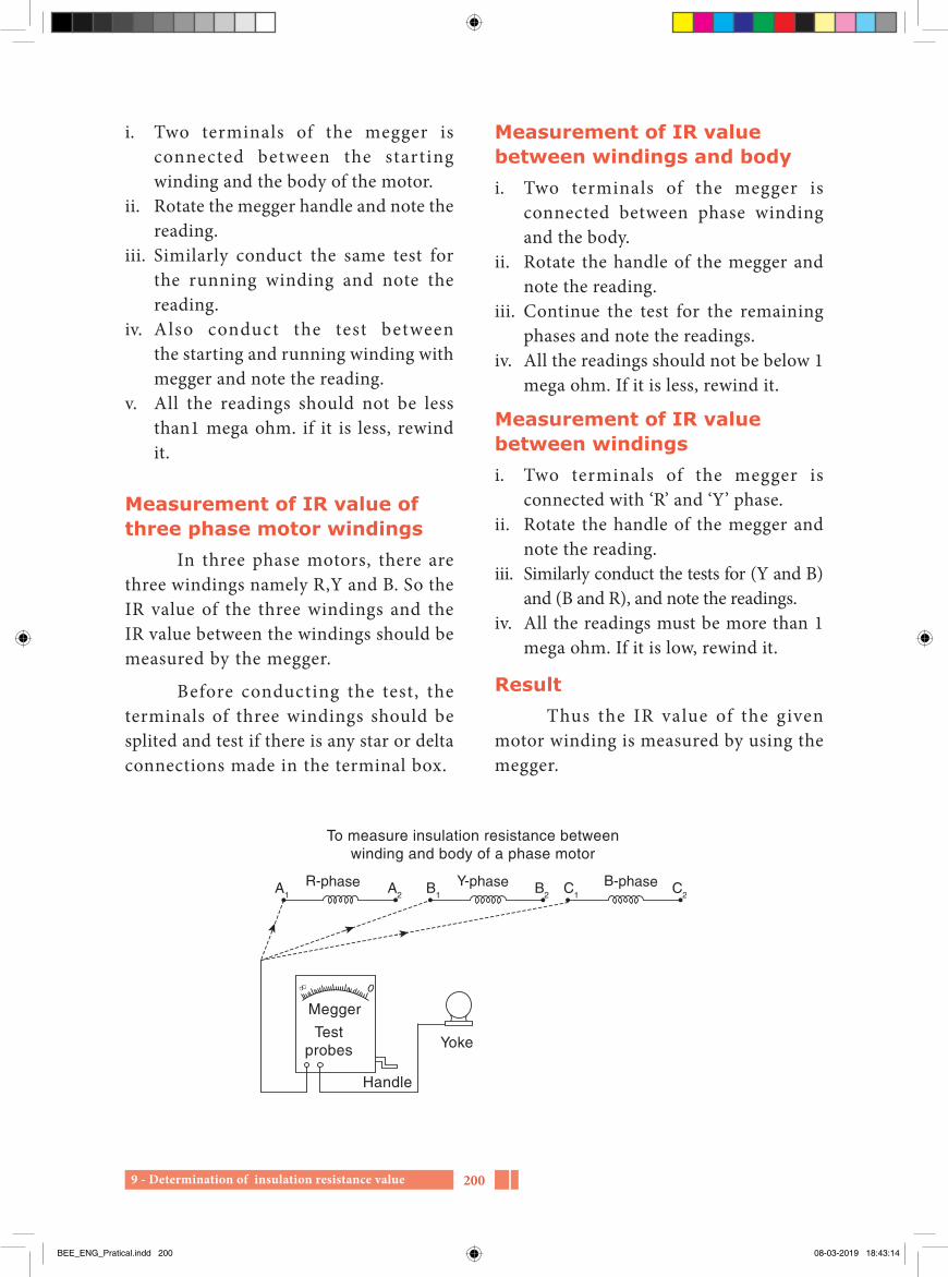
9 - Determination of insulation resistance value 200
Measurement of IR value between windings and body i. Two terminals of the megger is
connected between phase winding and the body.
ii. Rotate the handle of the megger and note the reading.
iii. Continue the test for the remaining phases and note the readings.
iv. All the readings should not be below 1 mega ohm. If it is less, rewind it.
Measurement of IR value between windingsi. Two terminals of the megger is
connected with ‘R’ and ‘Y’ phase.ii. Rotate the handle of the megger and
note the reading.iii. Similarly conduct the tests for (Y and B)
and (B and R), and note the readings.iv. All the readings must be more than 1
mega ohm. If it is low, rewind it.
Result Thus the IR value of the given
motor winding is measured by using the megger.
i. Two terminals of the megger is connected between the starting winding and the body of the motor.
ii. Rotate the megger handle and note the reading.
iii. Similarly conduct the same test for the running winding and note the reading.
iv. Also conduct the test between the starting and running winding with megger and note the reading.
v. All the readings should not be less than1 mega ohm. if it is less, rewind it.
Measurement of IR value of three phase motor windings
In three phase motors, there are three windings namely R,Y and B. So the IR value of the three windings and the IR value between the windings should be measured by the megger.
Before conducting the test, the terminals of three windings should be splited and test if there is any star or delta connections made in the terminal box.
To measure insulation resistance betweenwinding and body of a phase motor
Yoke
Handle
Megger
Testprobes
0
A1
A2
R-phase Y-phase B-phaseB1
B2
C1
C2
BEE_ENG_Pratical.indd 200 08-03-2019 18:43:14

20110 - Dismantling, testing and assembling of AC motor
ProcedureRemove the shaft key screw by
holding the pulley as shown below.
Tools and materials required
Sl.No. Equipment’s and materials
Nos.
1. 3 Phase A.C 400/440 V squirrel cage induction motor
1
2. Bearing puller 13. Insulated cutting plier 14. Screw driver 15. Cutter 16. Scissor 17. Nylon hammer 18. Megger 19. Knife 110. Test lamp 111. Grease 112 Feeler gauge 1
AIM
To dismantle the given AC Three phase 400/440 V squirrel cage induction motor by using proper tools and to measure the insulation resistance by using megger and also check the condition of bearing and apply the quality grease in correct quantity for the bearing. Assemble and run the motor.
10Practical
Dismantling, testing and assembling of A.C. 3 phase squirrel cage induction motor
BEE_ENG_Pratical.indd 201 08-03-2019 18:43:14

20210 - Dismantling, testing and assembling of AC motor
Remove the pul ley by using a suitable pulley puller as shown below.
Make a center punch mark on both the end covers and stator as shown below. To avoid confusion, make a single punch mark on one side and a dual punch mark on the other side of the motor
Remove the grease cup cover and loosen the end cover bolts as shown in the figure given below.
End covers should be removed by using chisel and nylon hammer gently as shown below
Without any damage to the rotor and the stator windings, remove the other end shield cover together with rotor as shown in the figure given below.
Hold the shaft in one hand, rotate the end cover and tap it lightly with a nylon mallet, to remove it from the rotor as shown below.
BEE_ENG_Pratical.indd 202 08-03-2019 18:43:14

20310 - Dismantling, testing and assembling of AC motor
Remove the other end shield cover also by gently priming it out.
Inspect the condition of the rotor and bearing that it contains any defects in it.
If the bearing is worn out, replace it with a new one. All fitting devices should be kept in a separate tray.
Dismantling the parts areas shown below.
Endbell
Endbell
Wiring coverStator
Motorframe
Statorelectro
magnets
Rotorelectro
magnets
RotorFan
bladesBearingon each
end
Table 1Sl. No. Insulation resistance Insulation resistance value1. Between core and R phase2. Between core and Y phase3. Between core and B phase
Measure the insulation resistance value between a winding and the stator core with a 500V Megger and record it in table 1, and the value of insulation resistance should be more than 1 MΩ
Table 2Sl. No. Insulation resistance Insulation resistance value1. Between R phase and Y phase2. Between Y phase and B phase3. Between B phase and R phase
BEE_ENG_Pratical.indd 203 08-03-2019 18:43:15

20410 - Dismantling, testing and assembling of AC motor
is measured by feeler gauge. Test run is to be done in the motor.
ResultAC three phase squirre l cage
induction motor is dismantled by using proper tools. Insulation resistance is measured by megger and tabulated as above. Bearing are tested and grease is applied. Now the motor is running smoothly in good condition.
Measure the insulation resistance between the two windings with a 500 V megger and record it in table 2, and the insulation value should be more than 1 MΩ
Testing after re-assemblingApply go o d qua l i ty greas e in
correct quantity inside the bearing. Then assemble the motor in reverse order as dismantled. Now the air gap
BEE_ENG_Pratical.indd 204 08-03-2019 18:43:15

Case Study 1205
Case Study 1
Name : K. Balakumar
Father’s Name : R. Kesavan
Date of Birth : 25.10.1972
Age : 46
Educational qualifications
Qualifications Year of passing Main subjects School/ College PercentageS.S.L.C April 1998 General Govt. Boys Hr Sec
School, Katpadi, Vellore district
51%
H.S.C Mar 1990 Vocational (EDA)
Govt. Boys Hr Sec School, Katpadi, Vellore district
71%
B.Com April1994 Commerce Annamalai University, Chidambaram
49%
PGDFM May 1998 Finance Management
Annamalai University, Chidambaram
54%
Work experience
Designation Company Service in yearsSenior Manager Susee motors, Vellore 6 YearsManger Overseas sanmar finance ltd, Vellore 5 YearsExecutive Manager Shruthi milk products 6 YearsDirector Shruthi milk products From 2008
BEE_ENG_Case Study.indd 205 08-03-2019 18:05:00

Case Study 2 206
Case Study 2
Name : S. Ramki
Father’s Name : Soundarrajan
Date of Birth : 10/04/1987
Age : 31
Educational qualifications
Qualifications Year of passing Main subjects School/ College PercentageS.S.L.C April 2002 General Govt. High
School, Periya vadagampattu, Salem district
65%
H.S.C Mar 2004 Vocational (EDA)
Govt. Hr Sec School, Nadupatti, Salem district
75%
Diploma April 2006 Electronics and Communication Engineering
Rajaji Polytechnic College, Salem
81%(First Class with honour)
Work experience
Designation Company Service in years
Nature of work Special
Quality control Lab Technician
Firm industries, Hosur 2 Years Quality Control Lab
Team Leader Siemens Dubai airport 8 Years Airport Operations and Maintenance
Dubai International airport, 3
Team Leader(Technical services)
Emirates airline From Last 3 Years
Airport Operations and Maintenance
Dubai International airport, Sky Cargo.
BEE_ENG_Case Study.indd 206 08-03-2019 18:05:00

Case Study 3207
Case Study 3
Name : G. Vijayaraj
Father’s name : VA. Govindarajan
Date of birth : 17.05.1972
Age : 46
Educational qualifications
Qualifications Year of passing Main subjects School/ College PercentageS.S.L.C April 1987 General Govt. Boys Hr Sec
School, Katpadi, Vellore district
56%
H.S.C Mar 1990 Vocational (EDA) Govt. Boys Hr Sec School, Katpadi, Vellore district
68%
DRAC 1991 Refrigeration and Air-Conditioning
Datamatics Business and Secretarial School
60%
B.Com April1995 Commerce University of Madras, Chennai
62%
Auto CAD 1997 Auto CAD Auto Desk Aacademy (USA)
80%
PGDCA May 1999 Computer Applications
St Marks Academy 84%
Work Experience
Designation Company Service in YearsAC Installation Technician ARTEC – Dammam, Saudi Arabia 2 YearsAC Installation Foreman ARTEC – Dammam, Saudi Arabia 2 YearsAC Installation and Service Foreman
ARTEC – Dammam, Saudi Arabia 3 Years
AC Installation, Operation and Maintenance Foreman
Turbine Services – Riyadh, Saudi Arabia
5 Years
Project coordinator National try generation Since 2007 to till date
BEE_ENG_Case Study.indd 207 08-03-2019 18:05:00

Higher Secondary – Second YearVocational Subject
Basic Electrical EngineeringAcademic Advisor & ExpertDr. PON KUMARJoint Director (Syllabus)SCERT,ChennaiDomain ExpertDr. R AZHAGUMURUGAN Associate ProfessorDepartment of Electrical and Electronics Engineering,Sri Sairam Engineering College,West Tambaram, Chennai
ReviewerDr. M. VENKATESHKUMARAssociate Professor,Department of Electrical and Electronics Engineering,Arupadai Veedu Institute of Technology,Payanoor, Chennai
J. HARINARAYANANAssistant Professor,Department of Electrical and Electronics Engineering, Sri Sairam Engineering College,West Tambaram, Chennai
AUTHORSDr. N. GNANASEKARAN,Professor & Head,Department of Electrical and Electronics Engineering,Misrimal Navajee Munoth Jain Engineering College,Thoraipakkam, ChennaiK. RAJA(State Awardee – 2018)Vocational Teacher, Government (B) Higher Secondary School,Katpadi, Vellore.S. VALLINAYAGAMVocational Teacher,Government Higher Secondary School, Nadupatti, Salem.P. MANOGAR,Vocational Teacher,Government Higher Secondary School,Kunnagampoondi, Tiruvannamalai.N. KARIGALANLecturer, EEE Department,Sri Sairam Polytechnic College,West Tambaram, Chennai.V. YOGANVocational Teacher,KVS Higher Secondary SchoolVirudhunagar
N. RAVIVocational Teacher,National Higher Secondary School,NagapattinamP. THIRUNAVUKKARASUVocational Teacher,Government Higher Secondary School,Thiruneipair, Thiruvarur.N. GOVINDARAJANVocational Teacher,Government Higher Secondary School,Vembakkam, Tiruvannamalai.
Academic CoordinatorsDr. A. ILANGOVAN(State Awardee – 2018)Assistant Professor,State Council of Educational Research and Training,Chennai.P. MALARVIZHIBT Assistant,State Council of Educational Research and Training,Chennai.
QR Code Management TeamR. Jaganathan , SGT,PUMS, Ganesapuram, Polur, Tiruvannamalai.M. Saravanan, B.T. Asst.,GGHSS,Puthupalayam, Vazhapadi, SalemV. Padmavathi, B.T. Asst.,GHS,Vetriyur, Ariyalur.
LayoutUdhaya Info, Chromepet, ChennaiData OperatorM. Aswini Thirumalpadi, TiruvannamalaiIn House- QC Pakkirisamy AnnaduraiWrapper Design Kathir ArumugamCo Ordination Ramesh Munisamy
This book has been printed on 80 G.S.M. Elegan Maplitho paper.Printed by offset at:
BEE_ENG_Contributors.indd 208 08-03-2019 18:24:07