
ELECTRICAL ENGINEERING - World Radio History
732
-
Upload
khangminh22 -
Category
Documents
-
view
0 -
download
0
Transcript of ELECTRICAL ENGINEERING - World Radio History

EL E C T RI C A L E N GI N E E RI N G T E X T S
A COURSE IN
ELECTRICAL ENGINEERING
VOLUME II
ALTERNATING CURRENTS

ELECTRICAL ENGINEERING
TEXTS HARRY E. CLIFFORD p Consulting Editor
Berg HEAVISIDE'S OPERATIONAL CALCULUS
Chaffee THEORY OF THERMIONIC VACUUM TUBES
Cobine GASEOUS CONDUCTORS
Dawes COURSE IN ELECTRICAL ENGINEERING
Vol. 1. —Direct Currents Vol. II.— Alternating Currents
INDUSTRIAL ELECTRICITY— PART I
INDUSTRIAL ELECTRICITY— PART II
Glasgow PRINCIPLES OF RADIO ENGINEERING
Langsdorf PRINCIPLES OF DIRECT-CURRENT MACHINES
THEORY OF ALTERNATING-CURRENT
MACHINERY
Lawrence PRINCIPLES OF ALTERNATING CURRENTS
PRINCIPLES OF ALTERNATING-CURRENT
MACHINERY
Laws ELECTRICAL MEASUREMENTS
Lyon APPLICATIONS OF THE METHOD OF SYM-
METRICAL COMPONENTS
Moon THE SCIENTIFIC BASIS OF ILLUMINATING
ENGINEERING
Shilling TRANSIENT ELECTRIC CURRENTS
Stephens THE ELEMENTARY THEORY OF OPERATIONAL
MATHEMATICS

E L E C T RI C A L E N GI N E E R I N G T E X T S
A COURSE IN
ELECTRICAL ENGINEERING
VOLUME II
ALTERNATING CURRENTS
BY
CHESTER L. DAWES. S. B., A. M., Dr. Eng. Associale Professor of Electrical Engineering, The Graduate
School of Engineering, Harvard University; Fellow, American Institute of Electrical Engineers, Etc.
FOURTH EDITION FIFTH IMPRESSION
NE W YOR K AND LONDON
McGRAW-HILL BOOK COMPANY. INc.
1947

A COURSE IN ELECTRICAL ENGINEERING
COPYRIGHT, 1922, 1928, 1934, 1947, BY THE
MCGRAW-HILL BOOK COMPANY, INC.
PRINTED IN THE UNITED STATES OF AMERICA
All rights reserved. This book, or parts thereof, may not be reproduced in any form without permission of
the publishers.

PREFACE TO THE FOURTH EDITION
Since the last revision of this volume, in 1934, there have been many important developments in the field of electrical engineering, a great number being stimulated by war. In addition, the great impor-tance of science in our present-day life and economy has increased greatly the number of those studying in the field of electrical engineer-ing. These factors not only have made essential a broader foundation in the education of the electrical engineer, but also have made it necessary to raise the level of the electrical-engineering curriculum. In the present revision the author has attempted to meet these require-ments by expanding the fundamental material and by showing in more detail its application to the study of electrical machinery and apparatus. For example, the scope of the properties of alternating-current
circuits has been expanded to include further developments in series and parallel resonance, harmonics, power as related to circuit param-eters, and conjugate method of computing watts and vars; and the application of subscript notation and complex operators to polyphase circuits has been extended further than in prior editions. In the field of instruments, there have been added the thermal and
rectifier types of voltmeter and ammeter and the cathode-ray oscillo-scope, all of which are now in common use. Also, late improvements in instrument design have been described. The illustrations showing the design and construction of apparatus
such as alternators, transformers, induction motors, and rectifiers are representative of modern practice. For example, in the chapter on Transformers the development of cold-rolled high-reduction trans-former steel and its effect in making a radical change in the construc-tion of transformer cores from the method of using flat iron punchings to that of using rolled and bent iron are discussed in some detail. In the analysis of alternator testing and operation there are now
included single-phase pulsating armature reaction, the Potier method, and its development into the American Standards Association method for determining alternator regulation. The operation of the synchronous motor is studied in greater
detail, and in view of the wide use of selsyns, and the application of V

vi PREFACE TO THE FOURTH EDITION
synchronous motors to electric ship propulsion, these also have been added. The large number of long, very high-voltage transmission lines, such as those at Boulder Dam, has led to the inclusion of line calculations that take into consideration their distributed capacitance. Likewise, the rapid expansion of the low-voltage three-phase networks has prompted the addition of these in the text. In the chapter on Electron Tubes, the discussion of the theory of
emission and vacuum-tube operation has been expanded, together with the measurements of amplification and the dynamic characteris-tics of tubes. The methods of measuring transconductance, amplifi-cation, and plate resistance have been given in greater detail, particularly in the matter of dynamic measurements. Frequency modulation and frequency-modulation detection have been added. New developments in rectifier practice, such as the selenium rectifier, the ignitron, and the electronic control of motors have also been added to the chapter on Rectifiers. All the problems are entirely new and, as in former editions, they
follow closely the analyses developed in the text. The author is indebted to so many who have made helpful sugges-
tions, or who have assisted him in other ways in this revision, that he can hope to include the names of only a limited number. Chapter XIV on Electron Tubes was written by R. F. Field and
A. G. Bousquet, both of the General Radio Company of Cambridge,
Mass. The author has been helped by R. T. Gibbs, Dr. E. C. Easton, and
John P. Newton of the Graduate School of Engineering at Harvard University, and by A. L. Russell of the Franklin Technical Institute of Boston, who contributed to the preparation and solution of the problems. The author is indebted also to the Department of Chemistry and
Electricity of the United States Military Academy at West Point, formerly in charge of Col. C. L. Fenton and now in charge of Col. B. W. Bartlett. The members of the instructing staff have contributed much useful material and have reviewed parts of the manuscript during its preparation. The names of Lt. Col. R. I. Heinlein, Jr., Associate Professor of Electricity, Lt. Col. C. R. Nichols, Assistant Professor of Electricity, and Lt. Col. L. E. Johnson, Assistant Professor of Electricity, should be mentioned particularly. Helpful suggestions were received from Professor C. V. 0. Ter-
williger of the United States Naval Academy and from Comdr. W. E. Creeden and Lt. E. P. Rivard of the United States Coast Guard Academy.

PREFACE TO THE FOURTH EDITION vii
The author is indebted to Professor R. W. Ahlquist of Iowa State College, Professor Harry Baum of the College of the City of New York, Professor Paul C. Cromwell of New York University, Professor Segismundo Gerszonowicz of the University of Montevideo, Professor J. Hugo Johnson of the University of Idaho, Dean J. H. Lampe of North Carolina State College, Professor T. C. Seidell of the Georgia School of Technology, Professor F. N. Tompkins of Brown University, and Professor Gordon F. Tracy of the University of Wisconsin. Also, the assistance of the several manufacturers who contributed
data and illustrations is acknowledged. The author must express his deep appreciation and gratitude to
Professor H. E. Clifford, Consulting Editor, formerly Dean of the Graduate School of Engineering, Harvard University, for his valuable collaboration and assistance throughout the preparation of this revision.
CHESTER L. DAWES. CAMBRIDGE, MASS., December, 1946.

. .. . ..... .• ..-

PREFACE TO THE FIRST EDITION
This volume is intended for those who have such a knowledge of direct currents as is given by Volume I. It presupposes no knowl-edge of alternating currents. The first two chapters are devoted to the development of the fundamental laws of alternating currents and alternating-current circuits. Subsequent chapters consider the appli-cation of these fundamental laws to alternating-current measurements, to polyphase circuits, to alternating-current machinery, and to power transmission. A chapter on illumination and photometry has been included, as a brief discussion of the underlying principles of light and of light measurements is important in a general course in electrical engineering. The development of the various alternating-current formulas and
of the operation of various types of machinery, transmission lines, etc., are based on the fundamental laws of electricity and magnetism as set forth in Volume I. Mathematical developments are occasionally introduced, as supplementary to the descriptive matter. As in Volume I, numerous illustrative problems and methods of making laboratory tests are given throughout the text. This volume is intended to be elementary in character and to act
as a stepping stone to the more advanced texts of this series. In many cases rigorous and detailed analysis is not given, particularly in the chapter on alternating-current measurements and in the discussion of certain types of alternating-current apparatus. A thorough analysis of these subjects is found in "Electrical Measurements" by F. A. Laws, and "Principles of Alternating-current Machinery" by R. R. Lawrence, both of which volumes are included in this series of Electrical Engineering Texts. The author is indebted to various manufacturing companies for
their cooperation in supplying material and illustrations for the text; to Professor R. R. Lawrence of the Massachusetts Institute of Tech-nology, for his careful review of the manuscript and his many helpful suggestions given during its preparation; and particularly to Professor H. E. Clifford of The Harvard Engineering School, for his helpful advice during the preparation of the manuscript and for the thorough manner in which he has edited the material contained in this volume.
CHESTER L. DAWES. CAMBRIDGE, MASS., January, 1922.
ix

-

CONTENTS Preface to Fourth Edition
Preface to First Edition ix
CHAFFER I
ALTERNATING CURRENT AND VOLTAGE
1. General Field of Use of Alternating Current 1 2. Sine Waves 3 3. Cycle; Frequency 6 4. Commercial Frequencies 8 5. Equation of Sine Wave of Current 8 6. Alternating-current Ampere 9 7. Current-squared Wave; Average Current 11 8. Scalars and Vectors 14 9. Ohm; Volt 16 10. Phase Relations 16 11. Addition of Currents 17 12. Vector Representation of Alternating Quantities 18 13. Vector Addition of Sine Waves 20 14. Addition of Sine Waves 21
CHAPTER II
ALTERNATING-CURRENT CIRCUITS 24
15. Alternating-current Power; Voltage and Current in Phase 24 16. Alternating-current Power; Voltage and Current in Quadrature . 26 17. Alternating-current Power; Voltage and Current Differ in Phase by
Angle 8 27 18. Circuit with Resistance Only 29 19. Circuit with Inductance 30 20. Circuit with Capacitance Only 34 21. Resistance and Inductance in Series 38 22. Power 40 23. Resistance and Capacitance in Series 41 24. Resistance, Inductance, and Capacitance in Series 42 25. Resonance in Series Circuit 45 26. Resonance Characteristics of Series Circuits 46 27. Selectivity of Resonant Circuit 47 28. Parallel Circuits 49 29. Resonance in Parallel Circuit 51 30. Resonance Characteristics of Parallel Circuits 53 31. Effective Resistance 55 32. Polygon of Voltages; Three Voltages 55 33. Capacitive Impedance 58
xi

CONTENTS
34. Polygon of Voltages; Four Voltages 59 35. Polygon of Currents 61 36. Energy and Quadrature Currents 62 37. Reactive Volt-amperes 64 38. Impedances in Parallel 64 39. Maximum Power in a Series Circuit 66 40. Harmonics 67
CHAPTER III
( ;OM PLEX QUANTITIES 70 41. Rectangular Notation of Complex Quantit ies 70 42. Rectangular Vectors 71 43. Addition and Subtraction of Rectangular Vectors 72 44. Multiplication of Rectangular Vectors 73 45. Reciprocals of Rectangular Vectors 73 46. Division of Rectangular Vectors 74 47. Exponential Vectors 74 48. Polar Notation 75 49. Addition of Exponential and of Polar Vectors 75 50. Multiplication of Polar Vectors 76 51. Reciprocals of Polar Vectors 76 52. Division of Polar Vectors 76 53. Powers and Roots of Polar Vectors 76 54. Operators for Rotation of Vectors 77
Application of Complex Quantities to Alternating Currents 78 55. Simple Series Circuits 78 56. Power Determination 81 57. Conjugate Method for Power 83 58. Parallel Circuits 84 59. Equivalent Parallel Impedance 85 60. Series-parallel Circuit 86 61. Solution of Series-parallel Circuits with Polar Vectors 88 62. Admittance, Conductance, Susceptance 88 63. Parallel Circuit Using Admittances 91 64. Series-parallel Circuit Using Admittances 91
CHAPTER IV
ALTERNATING-CURRENT INSTRUMENTS AND M EASUREM ENTS 94
65. Electrodynamometer Principle 94 66. Electrodynamometer Voltmeter 95 67. Inclined-coil Voltmeters 96 68. Dynamometer Ammeters 96 69. Wattmeter 97 70. Wattmeter Connections 98 71. Wattmeter Ratings 100 72. Polyphase Wattmeter 100 73. Wattmeter Calibration 102
Icon-vane Instruments 102 74. Voltmeters 102 75. Ammeters. . 104

CONTENTS xiii
76. Thermocouple Instruments 104 77. Rectifier-type Instruments 105 78. Alternating-current Watt-hour Meter 106 79. Calibration of the Induction Watt-hour Meter 110 80. Frequency Indicators 111 81. Power-factor Indicators 112 82. Synchroscope 114 83. Electromagnetic Oscilloscope and Oscillograph 115 84. Cathode-ray Oscilloscope 118 85. Impedance Bridge 121
CHAPTER V
POLYPHASE SYSTEMS 123
86. Reasons for Use of Polyphase Systems 123 87. Double-subscript Notation 124 88. Generation of Three-phase Emfs 127 89. Y-connection 130 90. Currents in Y-system 131 91. Power in Y-system 132 92. Delta Connection 134 93. Load Currents in Delta System 136 94. Power in Delta System 137
Methods of Measuring Power in Three-phase Systcm 138 95. Three-wattmeter Method 138 96. Two-wattmeter Method 139
Two-phase Systems 146 97. Two-phase and Four-phase (Sometimes Called Quarter-phase)
Systems 146 98. Measurement of Power in Two-phase and Four-phase Systems. 149 99. Addition of Loads by the Kilovolt-ampere Method 150 100. Applications of Complex Algebra to Polyphase Circuits 151 101. Equivalent Delta Systems and Y-systerrs 154
CHAPTER VI
THE ALTERNATOR 157
102. Rotating-field Type 157 Alternator Windings 158 103. General Principles 158 104. Single-phase Windings 152 105. Two-phase Full-pitch Lap Winding 161 106. Three-phase Full-pitch Lap Winding 162 107. Fractional-pitch Windings 162 108. Spiral and Chain Windings 165
Alternator Construction 167 .109. Types of Alternators 167 110. Stator or Armature 167 111. Slots 170 112. Ventilation 172 113. Rotating-field Structure 173

xiv CONTENTS
Alternator Electromotive Forces and Outputs 176 114. Induced Electromotive Force 176 115. Wave Shape 179 116. Magnetomotive Force of Distributed Field Windings 181 117. Phasing Alternator Windings 182 118. Rating of Alternators 183
CHAPTER VII
ALTERNATOR REGULATION AND OPERATION 184
119. Alternator Regulation 184 120. Armature Leakage Reactance 185 121. Armature Resistance 186
Single-phase Armature Reaction 187 122. Current and Electromotive Force in Phase 187 123. Current in Quadrature Lagging 189 124. Current in Quadrature Leading 191 125. Pulsation of Single-phase Armature Reaction 192 126. Polyphase Armature Reaction 194 127. Field, Armature, and Resultant NInifs 197 128. Armature Impedance Drop 199 129. Alternator Regulation 203 130. Space and Time Vectors 204 131. Space and Time Vector Diagram 206 132. General Method 209 133. Synchronous-impedance Method, or Electromotive-force Method 210 134. Determination of Synchronous Reactance 211 135. Three-phase Application 214 136. Regulation of Y-connected Generator 215 137. Regulation of a Delta-connected Generator 217 138. Magnetomotive-force Method 218 139. Potier Diagram 222 140. American Standards Association Method 225 141. Efficiencies of Alternators 229 142. Voltage Regulators 232 143. Parallel Operation of Alternators 234 144. Synchronizing Power 237 145. Reactive Power 238 146. Synchronizing 240 147.- Hunting 242
CHAPTER VIII
('HE TRANSFORMER 244
148. Transformer Principle 244 149. Induced Electromotive Force 245 150. Ampere-turns 247 151. Leakage Reactance 250 152. Transformer Vector Diagram 252 153. Simplified Diagram 254 154. Equivalent Resistance and Reactance 255 155. Open-circuit Test 258

CONTENTS xv
156. Short-circuit, or Impedance, Test 260 157. Regulation 262 158. Efficiency 263 159. Unit Values 266 160. All-day Efficiency 266 161. Commercial Transformers 267
Types of Transformer 267 162. Core- and Shell-type Transformers 267 163. Wound-core Transformer 270 164. Spirakore Transformer 272 165. Hipersil Cores 275 166. Other Wound- and Bent-iron Transformers 276 167. Cooling of Transformers 278 168. Breathing of Transformers 281 169. Three-phase Transformers 282 170. Autotransformers 285 171. Phasing Transformer Windings . 289 172. Y and Delta Transformer Connections 290 173. V-connection 292 174. V-connection and Single-phase Load . 293 175. Scott Connection, or T-connection. . 294 176. Tap Changing under Load 296 177. Constant-current Transformers 299
Instrument Transformers 300 178. Electrical Measurements at High Voltages 300 179. Potential Transformers 300 180. Current Transformers 301
CHAPTER IX
THE INDUCTION MOTOR 305
181. Principle 305 182. Rotating Field 307 183. Rotating Fields 308 184. Synchronous Speed; Slip 313 185. Rotor Frequency and Induced Electromotive Force 314 186. Alternating-current Torque 315 187. Stator and Slots 319 188. Squirrel-cage Motor 321 189. Operating Characteristics of Squirrel-cage Motor. 322 190. Torque Characteristics of Squirrel-cage Motor. 324 191. Wound-rotor Induction Motor 326 192. Double-squirrel-cage Rotors. . 331 193. Starting Squirrel-cage Motors 333 194. Motor Classification 336 195. Induction-motor Air Gap 338 196. Equivalent Circuit of Induction Motor 338 197. Induction-motor Vector Diagram 341 198. Circle Diagram 343 199. Speed Control of Induction Motors 348 200. Induction Generator 352

xvi CONTENTS
201. Measurement of Slip 356 202. Induction Regulator 358
CHAPTER X SINGLE-PHASE MOTORS 360
203. Series Motors 360 204. Interpoles 364 205. Series-motor Vector Diagram 365 206. Repulsion Motor 367 207. Single-phase Induction Motor 372 208. Reactions in a Single-phase Induction Motor 375 209. Operation of Polyphase Motor as Single-phase Motor 376
Starting Single-phase Induction Motors 377 210. Split-phase Methods 377 211. Capacitor Motor 378 212. Shaded-pole Method 379 213. Repulsion-motor Start 380 214. Induction Motor as Phase Converter 382
CHAPTER XI THE SYNCHRONOUS MOTOR 385
215. Synchronous Motor 385 216. Principles of Operation 385 217. Effect of Loading Synchronous Motor 386 218. Effect of Increasing Field Excitation 390 219. Effect of Decreasing the Field Excitation 391 220. Motor and Alternator 393 221. Excitation in Constant-potential System 394 222. Interlocking Action of Salient Poles 395 223. Synchronous-motor Vector Diagram 396 224. Synchronous-motor V-curves 399 225. Synchronous-motor Excitation Diagram 402 226. Amortisseur, or Damper, Windings 403 227. Starting the Synchronous Motor 405
Starting Synchronous Motor Under Load 407 228. High-starting-torque Motors 407 229. Synchronous Condenser 409 230. Power-factor Correction with Synchronous Condenser 409 231. Synchronous Motor as Corrector of Power Factor 412 232. Kilowatt and Kilovar Method 414 233. Synchronous Motor as Regulator of Voltage 414 234. Industrial Applications of Synchronous Motor 417 235. Electric Ship Propulsion 418 236. Frequency Converters 420 237. Synchronous Motors for Timing 421 238. Selsyns 423
CHAPTER X II THE SYNCHRONOUS CONVERTER 426
239. Methods of Obtaining Direct Current from Alternating Current. 426 240. Principle of Synchronous Converter 427 241. Polyphase Converters 428

CONTENTS xvii
242. Voltage Ratio in Single-phase Synchronous Converter 429 243. Voltage Ratios in Polyphaec Synchronous Converter 430 244. Current Ratios in Synchronous Converter 431 245. Conductor Currents in Armature of Converter 434 246. Effect of Number of Phases and of Power Factor on Output of
Synchronous Converter 437 247. Effect of Power Factor on Converter Rating 437 248. Armature Reaction in Converter 438 249. Voltage Control 440 250. Efficiency 444 251. Experimental Determination of VcItage and Current Relations in
Converter 445 252. Synchronous-converter Connections 445 253. Inverted Synchronous Converter 447 254. Starting Synchronous Converter from Alternating-current Side . 448 255. Methods of Obtaining Correct Polarity 450 256. Starting Synchronous Converter by Means of an Auxiliary Motor 452 257. Starting Synchronous Converter from the Direet-current Side. . . 452 258. Parallel Operation of Synchronous Converters 452 259. Converter Dampers 453 260. Three-wire Converter 454
CHAPTER XIII
TRANSMISSION OF POWER BY ALTERNATING CURRENT 456
261. Transmission Systems 456 262. Transmission-line Reactance, Single-phase 459 263. Transmission-line Reactance, Three-phase 461 264. Transmission-line Capacitance, Single-phase 462 265. Transmission-line Capacitance, Three-phase 464 266. Three-phase System; Conductors Spaced Unsymmetrically 465 267 Single-phase Line Calculations 465 268. Three-phase Line Calculations 468 269. Lines Having Considerable Capacitance 470 270. Solution by Complex Quantities for Lines Having Considerable
Capacitance 472 271. Lines with Distributed Capacitance 474 272. Corona 77 273. Corona Power 479
Lightning and Transients 480 274. Lightning 480 275. Lightning and Surge Protection 482 276. Horn Gaps 483 277. Oxide-film Arrester 484 278. Pellet Type 485 279. SV Autovalve Lightning Arrester 485 280. Thyrite 487 281. Protector Tube 487 282. Lightning-arrester Connections 488
Transmission-line Construction 488 283. Pin-type Insulators 488

xviii CONTENTS
284. Suspension-type Insulators 489 285. Transmission Structures 490
Substations and Distribution 492 286. Transformer Substations 492 287. Distribution Circuits 494 288. Three-wire Systems 495 289. Low-voltage Alternating-current Networks 496 290. Motor-generator and Synchronous-convert er Substations 499 291. Circuit Breakers 499 292. De-ion Grid Circuit Breaker 501 293. Automatic Substations 502 294. Outdoor Stations 503
CHAPTER XIV
ELECTRON TUBES 504
295. Electrons 504 296. Emission 504 297. Critical Velocity 505 298. Richardson's Law 505 299. Thermionic Efficiency 506 300. Space Charge 507 301. Two-electrode Tube 508 302. Space-charge Saturation 508 303. Child's Three-halves Power Law 509 301. Edison Effect 510 305. Fleming Valve 511 306. Full-wave Rectification 511 307. Rectifier Tubes 513 308. X-ray Tubes 513 309. Three-electrode Tube 513 310. Static Characteristics of Three-electrode Tube 514 311. Tube Coefficients 517 312. Measurement of Tube Coefficients 519 313. Three-electrode Receiving Tubes 522 314. Amplification 523 315. Dynamic Characteristics 524 316. Power and Efficiency 525 317. Voltage Amplification 526 318. Measurement of Voltage Amplification 528 319. Four-electrode Tubes 529 320. Five-electrode Tubes 531 321. Multielectrode Tubes 532 322. Regeneration 533
Oscillators 534 323. Oscillation 534 324. Power Tubes 538
Modulation 539 325. Modulation 539 326. Amplitude Modulation 540 M. Frequency Modulation 542

CONTENTS xix
Detection 544 328. Rectification with Two-electrode Tube 544 329. Detection with Three-electrode Tube with Polarized Grid. 546 330. Detection with Three-electrode Tube with Grid Resistance 546 331. Detection and Regeneration 548 332. Heterodyne, or Beat, Reception 548 333. Frequency-modulation Discriminators 550
Receivers 551 334. Receiving Circuits 551 335. Superheterodyne Receiver 552
CHAPTER XV RECTIFIERS 554
336. Half- and Full-wave Rectification ...... 555 337. Mechanical Rectifiers 556 338. Electrolytic Rectifiers 557 339. Copper-oxide Rectifier 557 340. Selenium Rectifier 558 341. Hot-cathode Rectification 559 342. Hot-cathode Gaseous Rectifiers 561
Mercury-arc Rectifiers 563 343. Mercury Arc 563 344. Operation of Single-phase Rectifiers 563 345. Voltages and Currents with Resistance Load 565 346. Battery Load 566 347. Anode Inductance 568 348. Smoothing Inductance 569 349. Single-phase Glass-tube Rectifier 570 350. Three-phase Rectifier 571 351. Six-phase Rectifier and Anode Inductance 573 352. Voltage and Current Ripple 576 353. Average Direct-current Electromotive Force 577
Grid-controlled Gaseous Rectifiers and Inverters 578 354. Hot-cathode Thyratron 578 355. General Electric Thyratron 578 356. Grid Control 580 357. Methods of Grid Control 581 358. Thyratron as Rectifier 583
Thyratron as Inverter 584 359. Simple Inverter Action 584 360. Inverter Circuit 586 361. Ratings of Thyratrons 587 362. Power Rectifiers with Grid Control 588 363. Connections for Grid Control 590 364. Grid Control in Power Rectifier 592 365. Ignitron 592 366. Ignitron Connections 594 367. Excitron 596 368. Backfiring 596 369. Efficiencies of Rectifiers 597 370. Electronic Control of Motors 598

xx CONTENTS
APPENDIX A Circular Measure—The Radian 601
APPENDIX B Trigonometry —Simple Functions 601
APPENDIX C
Functions of Angles Greater than 90° 603
APPENDIX 1) Simple Trigonometric Formulas 605
APPENDIX E Natural Sines and Cosines 606
APPENDIX F Natural Tangents and Cotangents 608
APPENDIX G Logarithms of Numbers 610
APPENDIX H
Resistance of Copper Wire, Ohms per Mile, 25°C (77°F) 612
APPENDIX I
Properties of Aluminum Cable Steel-reinforced (ACSR) 613
APPENDIX J
Inductive Reactance per Single Conductor, Ohms per Mile 614
APPENDIX K
Charging Current per Single Wire, Amperes per Mile per 100,000 Volts from Phase Wire to Neutral 615
APPENDIX Identifying Code Letter • 616
QUESTIONS AND PROBLEM' 617
Questions on Chapter I—Alternating Current and Voltage 617 Problems on Chapter I—Alternating Current and Voltage 618 Questions on Chapter II—Alternating-current Circuits 622 Problems on Chapter II—Alternating-current Circuits 624 Questions on Chapter III —Complex Quantities 633 Problems on Chapter III —Complex Quantities 634 Questions on ChapterIV —Alternating-current Instruments and Measurements 639 Questions on Chapter V—Polyphase Systems 640 Problems on Chapter V—Polyphase Systems 642 Questions on Chapter VI —The Alternator 648 Problems on Chapter VI —The Alternator 650 Questions on Chapter VII —Alternator Regulation and Operation 652 Problems on Chapter VII —Alternator Regulation and Operation 655

CON7'EN TS xxi
Questions on Chapter VIII—The Transformer 659 Problems on Chapter VIII—The Transformer 661 Questions on Chapter IX—The Induction Motor 665 Problems on Chapter IX—The Induction Motor 667 Questions on Chapter X—Single-phase Motors 670 Problems on Chapter X—Single-phase Motors 672 Questions on Chapter XI—The Synchronous Motor 673 Problems on Chapter XI—The Synchronous Motor 675 Questions on Chapter XII—The Synchronous Converter 678 Problems on Chapter XII—The Synchronous Converter 681 Questions on Chapter XIII—Transmission of Power by Alternating Cutrent 682 Problems on Chapter XIII—Transmission of Power by Alternating Current 684 Questions on Chapter XIV—Electron Tubes 688 Problems on Chapter XIV—Electron Tubes 690 Questions on Chapter XV—Rectifiers 691 Problems on Chapter XV—Rectifiers 694
/ ndex 696

- .- = ,,I M..-.

A COURSE IN
ELECTRICAL ENGINEERING
VOLUME II
ALTERNATING CURRENT S
CHAPTER I
ALTERNATING CURRENT AND VOLTAGE
1. General Field of Use of Alternating Current.—At the present time over 90 per cent of the electrical energy used for commercial purposes is generated as alternating current. This is not due primarily to any superiority of alternating over direct current so far as appli-cability to industrial and domestic uses is concerned. In fact, there are many instances where direct current is absolutely necessary for industrial purposes, ,Ngja.j3,a.J212.tuiaipal-traet,ien, electrolytic vrocesses, and certain t of arc lamps; also, direat-current motors are superior fmagyaturs, printing Dresses, and many variable-speed drives. How-ever, for these various purposes the energy is generated and trans-mitted almost always as alternating current and then converted to direct current. Some of the reasons for generating electrical energy as alternating
current are the following: Aittwating, current can generated
__aL_Aisi.1,11cae.azoltagea..ca,n_be raised and lowered readilylay_rneans-of stia—trrrrrsfermem_ This permits the economical transmission of alternating-current energy over considerable distances by using high transmission voltages, since the weigilt of transmission conductor varies inversely as the spare of the transmission voltage, when the power, distance, and loss are fixed (Vol. I, Chap. XV), and high trans-mission voltages can be reduced efficiently at the receiving end of the transmission line. So far (1946) no practical method has been devised for raising and lowering direct-current voltage involving large amounts of power. Rotating commutators can be used to raise and lower the voltage, but both voltage and power are limited.' There are experi-
1 ALEXANDERSON, E. F. W. and E. L. PHILLIPI, "Electronic Power Converters, Their History and Development," Gen. Elec. Rev., September, 1944, p. 41.
1

2 ALTERNATING CURRENTS
mental lines in which high-voltage alternating current is rectified by vapor-type electronic rectifiers for transmission as direct current. At the receiving end of the transmission line the direct-current power is inverted by electronic inverters to alternating-current power for com-mercial uses (see Chap. XV). However, this system thus far has not been applied on a large scale. It is possible to build alternating-current generators in large units
to run at high speeds so that the construction and operating costs per kilowatt are low, and such generators are admirably adapted to high-speed turbine drive. The largest alternators operating today (1946) have a rating of 200,000 kva.1 Owing to commutation difficulties, direct-current generators cannot be designed in large units, particularly for high speeds. At 1,000 rpm, it is difficult to design a direct-current generator having a rating of even 1,000 kw. On the other hand, alter-nators with ratings as high as 81,250 kva now (1946) operate at 3,600 rpm, and a 100,000-kva 0.85-power-factor 3,600-rpm unit is under construction. For constant-speed work, the alternating-current induction motor
is more efficient than the direct-current motor and is less in first cost and in maintenance, owing in part to the fact that the induction motor has no commutator. It is occasionally desirable, therefore, to generate power as alternating current in order to be able to use induction motors. The high transmission efficiencies obtainable with alternating cur-
rent make it economical to generate electrical energy in large quan-tities in a single station and to distribute it over a large territory. The large boilers, automatic stokers, superheaters, recording instru-ments, etc., that are possible in large stations result in high boiler-room efficiency. Large turbines have an economy which may be three or four times as good as that of the steam units in a small plant. The alternating-current generator in the larger sizes has an efficiency of 96 to 98.5 per cent (see pp. 231, 232). Then, again, as the boilers and large turbine units require few attendants per kilowatt, the labor and super-vision charges per kilowatt-hour are small. For these reasons, it is often more economical to generate electrical
energy with large units, to transmit it long distances, and even to convert it into direct current rather than to generate direct current at the place where it is to be utilized.
1 There are two 200,000-kva 0.8-power-factor 4-pole 60-cycle 1,800-rpm 16,500-volt single-shaft turbine alternators in operation at the Hudson Avenue Station of the Consolidated Edison Company, New York. They were manufactured by the General Electric Company.

ALTERNATING CURRENT AND VOLTAGE 3
It must be remembered, however, that the reduced generating costs are balanced in part at least by distribution costs resulting from investment charges in lines, cables, substations, machinery, etc., in addition to the labor and maintenance costs of the distribution system.
FIG. 1.—Coil rotating in uniform field.
Alternating current owes its importance to the fact that it can be generated economically with large units; its voltage can be readily raised and lowered, so that energy can be transmitted economically for considerable distances. Alternating-current motors for constant-speed work are usually preferable to direct-current motors. 2. Sine Waves.—It is shown in Vol. I, Chap. XI, that when a single
coil rotates at constant speed in a uniform field, Fig. 1, an alternating
4
(b) FIG. 2.—Coil inducing sine-wave emf.
emf is generated. The successive values of the emf may be represented by a smooth curve called a sine wave, Fig. 2(b), since the values of the emf are proportional to the sine of the angle x that the coil makes with a plane through its axis and perpendicular to the direction of the magnetic field, Fig. 1. This may be shown as follows: The emf induced in a single conductor that cuts a magnetic field
(Vol. I, Chap. XI) is given by
e = Bit' • 10-8 volts, (1)
where B. 1, v are mutually perpendicular. However, when the conductor is in the position with respect to the flux shown in Fig.

4 ALTERNATING CURRENTS
2(a), the velocity v is not perpendicular to the direction of the flux. It may be resolved, however, into two components, v" parallel to the direction of the flux and v' perpendicular to this direction. Since the component v" is parallel to the direction of the flux, it cannot cause an induced emf. The component v' = v sin x, being perpendicular to the flux, does produce an emf. Hence, from (1), the induced emf is given by
e = Blv sin x • 10-8 volts, (2)
where x is the angle through which the conductor has moved from position 1. Thus the emf induced in such a conductor may be repre-sented by a sine wave. When the top of the coil, Fig. 2(a), is at
Emf wave
It Radians 27r
Le Alternation -a:4
Cycle
1(Y Degrees- X 360"
nu. 3.--Sine-wave induced end.
position 1, the emf is zero; when at position 2, the emf is a positive maximum; when at position 3, the emf is zero; when at position 4, the emf is a negative maximum, Fig. 2(b). When a periodic wave, such as a sine wave, has gone through one complete set of positive or of negative values, Figs. 2(b) and 3, it is said to have completed an alternation, Fig. 3. If it has gone through one complete set of positive and one complete set of negative values, it is said to have completed a cycle. The emf waves of some commercial alternators, particularly the
older ones, may differ materially from a sine wave, but with most commercial alternators the emf wave is sufficiently near to a sine wave to warrant its being treated as such. (For wave shapes in alternators, see Sec. 115, p. 179.) Alternating-current theory and analysis are based on sine (or
cosine) waves of voltage, current, and power. This is due to the fact that the sine and cosine functions are simple and accordingly are readily expressed mathematically. Also, sine and cosine waves of voltage and current are the only types of waves that can pass through all types of linear circuits (that is, circuits whose parameters such as resistance and inductance do not change) without distortion.

-0.5
ALTERNATING CURRENT AND VOLTAGE 5
If a periodic wave is not a sine wave, it may be resolved into a series of sine waves of fundamental and higher frequencies. Each one of these sinusoidal components, or harmonics, then may be treated as a sine wave at its particular frequency (see Sec. 40, p. 67). Unless otherwise specified, the methods of analysis and the equations that follow apply to sine waves of voltage and current.
a Maximum
1 2 4 6
-r 1,TlternaTion.1
12
'cycle —04 nal• aao•
4. —Graphical construction of sine wave.
The sine wave may be produced graphically as follows: Draw a circle, Fig. 4, whose radius A is equal to the maximum value of the sine wave. Divide the circumference of this circle into any number of equal parts, in this case 12, and number them 1, 2, . . . 12. Draw a horizontal line ab that, if extended, would pass through the center of the circle. Divide ab into the same number of equal parts as there are
_1.0
0 60 120 180 240 300 80 90 150 10 270 Degrees
-1.0 -40
(a) (b) Fin. b. —Numerical values of ordinates of sine waves for definite angles.
on the circumference of the circle, and give the points corresponding numbers. Erect a perpendicular ordinate at each point. Project the points on the circle horizontally to intersect perpendiculars having corresponding numbers. A smooth curve drawn through the inter-sections will be a sine wave. The sine wave may also be plotted from a table of sines (Appen-
dix E, p. 606). Mark a horizontal axis, Fig. 5(a), in degrees. At

6 ALTERNATING CURRENTS
each point erect an ordinate equal to the sine of the corresponding angle. Thus, at 30° the ordinate ab is 0.5; at 60° the ordinate cd is 0.866; at 90° it is 1.0; etc. The wave passes through zero at 180°, because the sine of 180° is zero. When the angle becomes greater than 180°, the sine becomes negative and the wave falls below the line, as the sine is negative between 180° and 360° (see p. 604). The above is equivalent to plotting the sine of the angle x, Fig. 2(a). If the wave has a maximum value B, Fig. 5(b), the value of the
ordinate at any point may be found by multiplying B into the sine of the corresponding angle. That is,
= B sin x, (3)
where x is expressed in degrees.
Example. —Find the ordinates of a sine wave at points corresponding to 65° and 210°, the maximum ordinate being 40 units, Fig. 5(b).
From p. 607, sin 65° = 0.906.
40 • 0.906 = 36.24. Ans. sin 210° = — (sin 210° — 180°) = — sin 30° = —0.5 [(31), p. 604i.
40 • ( —0.5) = —20. Ans.
These values are shown in Fig. 5(b).
3. Cycle; Frequency —pawn the romilintitr lansia_rnmplet o-lution, Fi 2 h an angle of 360° or 2r radians. e emf wave then has gone through an angle of 360 ig. 2(b), or
2r radians, Fig. 3. If the speed in revolutions per second jaw) is 6, the frequency of the emf wave in cycles per second f is equal to s, since for each revolution the emf induced in the conductor goes through one complete set of positive and one complete set of negative values. If the conductor has been rotating for a time t sec from position 1, it will have gone through st revolutions, or ft cycles. Hence,
x = 27st = 241 radians, or 360ft deg. (I)
Since at constant speed or frequency, 24 or 360f is constant, alternat-ing-current waves may be plotted with time as abscissas as well as with radians or degrees. If the angular velocity is w (in radians per second), then from
(I),
or w = 27f radians per sec, (II) 360f deg per sec (III)
since 24 is the radians per second through which the wave goes and 360f is the degrees per second through which the wave goes. If the alternator is a multipolar machine, for example, 4 poles,

ALTERNATING CURRENT AND VOLTAGE 7
Fig. 6(a), as soon as the conductor a has passed a north and a south pole, that is, has gone from 1 to 5, the emf wave has completed 1 cycle, or 360 electrical time degrees. Thus a cycle is completed every time the conductor pa.sses one pair of poles. Therefore the frequency in
co°
(a) (b) FIG. 6.—Two cycles per revolution in 4-pole alternator.
cycles per second is equal to the number of pairs of poles passed per second. That is,
PS or f = —120 cycles per sec (4)
where s rps, S = revolutions per minute (rpm), and P = number of poles. "Thus if the speed of a 2-pole alterna , t _he frgguenc,y_iaflfl cycles per sec The following table shows the relation of speed, frequency, and
number of poles for a few typical cases.
Poles
2 4 6 8 40
Speed, rpm
GO cycles 25 cycles
3,600 1,800 1,200 900 180
1, 5tx)
500 375 75
Example.—A 60-cycle engine-driven alternator has a speed of 120 rpm. How many poles has it? Using (4) and solving for P,
120f 120.60 _ P = 120 GO poles. A7U1.
S
This example may be solved also without using (4) directly. A 2-pole 60-cycle alternator rotates at 3,600 rpm. Therefore the alternator must have
3,600 120 — 2 = 60 poles. Ana.

8 ALTERNATING CURRENTS
In practice, nearly all alternators have stationary armatures and rotating fields, and the above relations apply. When the conductor a has gone from 1 to 5, Fig. 6(a), that is,
through 180 space degrees, the emf has gone through 360 electrical degrees, Fig. 6(b). When the coil has completed 1 revolution, it has gone through 360 space degrees and the emf has gone through 720 electrical degrees, Fig. 6(b). aJzpsk,..Laseline..1.440ie&ree euuals 2 electrical elpg,P0. With 6 poles, 1 space degree equals 3 electrical degrees, Pfe I
4. Commercial Frequencies.—In the United States, frequencies are standardized at 60 cycles and at 25 cycles per sec, although other frequencies are used. In California, for example, and also in Mexico, 50 cycles is used on some of the large transmission systems. In the early days of alternating-current development 133 cycles was common, but few if any plants now generate at this frequency. The principal advantage of higher frequencies is that transformers require less iron and copper and so are lighter and cheaper. The flicker of lamps is not perceptible at 60 cycles, but at 25 cycles it is evident. On the other hand, the volta/LL•rop in transmission lines and in apparatus varies almost directly as the frequency so that better voltage regulation throughout the system is obtained with low frequency. Power appa-ratus, such as induction motors, synchronous converters, and alternat-ing-current commutator motors, operates better at low frequencies. With one or two exceptions, however, the operation is satisfactory at 60 cycles per sec. A power and fighting company would operate ordinarily at 60 cycles per sec, because the fficker of lamps at 25 cycles per sec is objectionable and the transformers at this lower frequency are heavier and more costly than they are at the higher frequency. On the other hand, an electric utility generating strictly for power purposes may use 25 cycles. This frequency is used by the New York, New Haven & Hartford Railroad for its electric locomotives; by the Norfolk and Western Railway for operating electric locomotives; and by the Boston Elevated Railway Company for transmitting high-voltage power to its direct-current substations. In Europe, frequencies as low as 163i, 15, and even 12% cycles per sec are common. 5. Equation of Sine Wave of Current.—If 2r ft [Eq. (I), p. 6] is
substituted in Eq. (3) or if co = 2rf [Eq. (II)] is used, the equation of a sine wave of alternating current may be written
= t = I. sin cot, (5)
where i is the value of the current at any time t, I. is the maximum value of the current, and co = 2rf. The quantity co is equal to 2r times

AL7'ERNA7'1NG CURRENT AND VOLTAGE 9
the frequency f and is the angular velocity in radians per second of the rotating vector that may be used to construct the sine wave (Appendix, p. 601). For example, if the vector A, Fig. 4, be considered as rotating in a
counterclockwise direction and taking successive positions 1, 2, 3, etc., it will produce 1 cycle for each revolution. In each revolution, it goes an angular distance of 2er radians. If it rotates 60 times a second, its 'angular velocity is 2r60, or 377, radians per sec. The sine wave pro-duced from this rotating vector has a frequency of 60 cycles per sec. Hence, for a 60-cycle wave, CO = 377. For a 25-cycle wave, co = 2r25, or 157, radians per sec. Similarly the equation of a sine wave of emf will be given by
co [see (6a), p. 16]. (6)
Example. —What is the equation of a 25-cycle-current sine wave, having an rms value of 30 amp, and what is the value of the current when the time is 0.005 sec? Assume that the wave crosses the time axis in a positive direction when
the time is equal to zero.
1 „, = 30 = 42.4 amp. 225 = 157 = w.
i -= 42.4 sin 1571. Ans. i= 42.4 sin 157 • 0.005 = 42.4 sin 0.785 radian
2r -= 6.28 radians = 360° (p.
(0.785/6.28) • 360° = 45°. Also, as the wave completes 360° in 15, or 0.04 sec, in 0.005 sec, it will have completed 0.005/0.040 = ig cycle.
360 e 45° (check).
8
= 42.4 sin 45° = 42.4 • 0.707 = 30 amp. Ans.
6. Alternating-current Ampere.—Figure 7(a) shows an alter-nating-current sine wave, having a maximum value of 1.414 amp. At first thought it might seem that the value in amperes of such a wave should be based on the average value. If the wave is considered over one complete cycle, the average value is zero, as there is just as much negative as positive current. .4.Akegisarx.ent...aalraeter.,..3,Lccax-nected to measure this current would indicate zero as such a!j!tru-fié U sures average values. 4
The value of an alternating current is based not on its average value but on its heating effect and may be defined as follows:
-current am a rent ampere.

10 ALTERNATING CURRENTS
Assume that a resistance unit is immersed in a calorimeter and that when a direct-current ampere is sent through this resistance the tem-perature of the water is raised 20° in 10 min. An alternating-current ampere, if sent through this same resistance unit, will raise the tem-perature of the water by the same amount in the same time, other conditions such as radiation, for example, being the same; that is, both currents produce heat at the same rate. :The heatins effect varies as the square of thtlauxenigkaiduALapy
instant it is proportional to PRI
2.0
10
1.0
Time
i 2
Time
•
•
(a) (b) FIG. 7. — Maximum and ruts values of sine-wave alternating current.
Figure 7(b) shows the current wave of Fig. 7(a), together with its squared values. That is, each ordinate of the i wave is squared, and these values are plotted to give the i2 wave shown. The maximum value of this new wave will be 2.0 (= 1.4142), since the maximum value
of the original current wave is 1.414, or The squared wave also lies entirely above the zero axis, because the square of a negative value is positive. This squared a frequency twice that of th iiginsl
(Sec. 7) and has its horizontal axis of symmetry ab at a distance of 1.0 unit above the zero axis, as shown in Fig. 7(b). The ordinate of the i2 wave, Fig. 7(b), when multiplied by the
resistance gives the instantaneous power. However, in practice, the average power, rather than the instantaneous power, is usually desired. The average value of power will be equal to the average value of the i2 wave multiplied by the resistance. The average value of this squared wave is 1.0 amp, as shown by the dashed line ab, because the areas above the dashed line will just fit into the shaded valleys below the dashed line. If, therefore, an equivalent rectangle were made from this wave, its height would be 1.0 unit. This value, 1.0, is the average

ALTERNATING CURRENT AND VOLTAGE 11
of the squares of the current wave. Average heating varies as the average of the squares of the current. The squared current represented by the dashed line, therefore, is equivalent to the square of a direct current that would produce the same heating effect as this alternating current. Hence, to obtain in amperes the value of the current given by the
wave of Fig. 7, the square root of the average square must be taken.
That is, I (in amperes) = N/1.0 = 1.0 amp. This value of the current is called the root-mean-square (rms) or effective value of the current. An alternating-current-ampere sine wave, which produces heat at
the same rate as a direct-current ampere, has therefore a maximum
value of 1.414 (= .0) amp. In fact, for any sine-wave current, the
ratio of maximum to rms value is equal to .N/, or 1.414. The ratio of rms to maximum value is 1/1.414 = 0.707. To obtain the rms value of any current wave, not necessarily a sine
wave: a. Plot a wave whose ordinates are equal to the squares of the
ordinates of the given current wave. b. Find the average value of this squared wave by obtaining the
area of its loops, as with a planimeter, and dividing this area by the base. c. Find the square root of the average in (b). The same result may be obtained by erecting equidistant ordinates
on the original wave. This divides the area under the wave into small areas having equal bases. The ordinates at the centers of these small areas are measured, their squares are averaged, and the square root of this average then is obtained. This will give the rms value of the wave. The rms value may also be found by integration (Sec. 7). 7. Current-squared Wave; Average Current.—Let the equation
of a current wave be i = /„, sin cut. (I)
Let it be required to find the equation of the current-squared wave.
i2 = J, sins wt. (II)
cos (x y) = cos x cos y — sin x sin y [(38), p. 605]. Letting x = y =
cos (wt wt) = cos wt cos WI — sin 0.1 sin wt, ros 2011 = cos' wt — sins wt, (III) cos' wt = 1 — sins wt [(34), p. 805]. (IV)
From (III) and (IV), cos 2wt = 1 — 2 sins wt. (V)
Hence, 1 — cos 20/1
sins wt = 2 (VI)

12 ALTERNATING CURRENTS
Hence, from (II) and (VI),
/2 a — n n t, si 2 /2 1 COS 20.4
2 ' (7)
This is a cosine wave having a frequency 2f, where f is the frequency of the current given by f = 0.)/2r. When t = 0, i2 = 0; when t ir/4e, r/8/rf = 1/8f, t2 r„,/2, Fig. 8. i2 is a maximum when lut = r radians = 180°. The cor-responding value of time,
If 1 . = -47 , Fig. 8.
Under these conditions, is = Pm. It follows that the axis of the cur-
rent-squared wave is at a distance ./?,12 above the axis of reference.
FICI. 8.—Current and current-squared sine waves.
From (7) the rms value is determined readily. The area of the differential strip at time t, Fig. 8, is is dl, and the total area
fT under the i2 wave is I i2 dl.
Jo The average of the is wave is its area divided by its base, the time T being
chosen as the time of one cycle. That is,
1 Average i2 0 s' dt = y,1 L T I2„. sin' cut dt. (VII)
Substituting (VI) in (VII) and taking the square root,
= _ 11 fT _ 1 — cos 2u1 dl \ tn. fr Jo iL 2 = 27' JO (1 — C°8 2w1) dl
--- [t — - sin 20.1t]lor Nc224--11 RT — 0) — (0 — 0))
since sin 2got = 0 when t = 0, and when t = T.
I \ 12 V5 [T] — I „,• Q.E.D. 2T -
(8)

ALTERNATING CURRENT AND VOLTAGE 13
• It is frequently desirable to know the average value of a sine wave for one half-cycle. This average value has limited uses—rectifier-type instruments (p. 105), electroplating, battery charging, where the results are proportional to the number of coulombs flowing in the circuit rather than to the power, being typical applications. Under these conditions the a-c wave must be rectified (Chap. XV). The average value, which is applicable to full-sine-wave rectification, Fig. 9(a), is equal to 2/r, or 0.637 times the maximum value. This may be proved as follows:
150
-100
t -,4 4-dt I —150
(a) (b) Du. 9. — Maxinann, rins, and average values of sine wave.
The equation of the first positive half-cycle of the current wave, Fig. 9(a), is i I. sin 0.4 where t varies between 0 and T/2 and the area of a differential strip
T/2 at time t is i dl. The area under the positive loop is I dl, and the average
0 value is given by this area divided by the base T/2. Hence,
— f 772 I sin dt " T/2 Jo '"
[_ 1 1772 21. [
— 174 cos We 0 vos + COS (0)]
7,-it -( -1 ) + (1)1 = -1. = 0.6371..
[cos = cos 7 = ( 1) j f 7' = 1, since 7' =
ratio of rms to average value is then 0.707/0.637 = 1.11 and t ratio of average to rms value is 0.9., The ratio of rms to average value enters into computations of induced ends in alternators, transformers, and other types of alternating-current machinery. The _ratio of rms to averttge.ir.al m factor of the
The form factor of a sine wave is 1.11. The maximum, rms, and average values for a sine wave of voltage whose rms value is 100 volts are shown in Fig. 9(b). Tj crag values of voltages and _eurre_nts should not be used in com-
puting power.
(9)

14 ALTERNATING CURRENTS
8. Scalars and Vectors.—Quantities, in general, are divided into two classes, scalars and vectors. A scalar is a quantity that is completely determined by its magni-
tude alone. Examples of scalar quantities are energy, gallons, mass, temperature, etc. Such quantities are added algebraically. For example, 2 gal of water plus 5 gal of water equals 7 gal of water.
F2
(a) Sum of Two Vectors by Parallelogram Method
Fo'= Fi — F2 • • • • • • • •
F2
IC) Difference of Two Vectors by Parallelogram Method
Ft
td Sum of Two Vectors by Triangle Method
F2
(d( Difference of Two Vectors by Triangle Method
le) Sum and Difference of Two Vectors
10.--Suan and difference of two vectors.
- F2
A vector has direction as well as magnitude. A common example of a vector is force. When a force is under consideration, not only its magnitude but its direction as well must be considered. When two or more forces are added, they are not necessarily added algebraically but must be combined in such a way as to take into consideration their
directions as well as their magnitudes. Figure 10(a) shows two forces acting at the point 0 and repre-
sented by the vectors F1 and F2. The length of each of these vectors, to scale, is equal to the magnitude of the force that it represents. The direction of each of these vectors shows the direction in which the force acts. ft is the angle between F1 and F2. Their sum Fo, or the single force that would have the same effect at their point of application 0 as

ALTERNATING CURRENT AND VOLTAGE 15
F1 and FY acting in conjunction, is called their resultant. F 0 is one diagonal of the parallelogram having F1 and F2 as adjacent sides. Figure 10(b) shows a triangle having F1 and Fy as two of its sides,
F1 and FY being parallel to and acting in the same directions as F1 and F2 of Fig. 10(a). The exterior angle between F1 and F2 in Fig. 10(b) is, therefore, equal to $. The third side of the triangle Fo is equal in magnitude to and in the same direction as Fo of Fig. 10(a). The result-ant of two vectors, therefore, may be found by means of a triangle properly constructed, of which two sides are the to component vectors and the third side is their sum. Such a triangle is called a triangle of vectors or a vector polygon. It is usually simpler to use the vector polygon rather than the parallelo-gram of vectors. F 3
To subtract one vector from an-other, reverse the first vector and add it vectorially to the second vector. For example, in Fig. 10(c), it is desired to subtract F2 from F1. F2 is reversed, giving —F2. F4, the
F, vector sum of F1 and —F2, found by completing the parallelogram,
is equal to F1 — Fy. Vectors may be subtracted by the triangle method, as shown in Fig. 10(d). The vector F4, connecting the ends of the two vectors F1 and Fy whose difference is desired, is their vector difference. If a parallelogram, Fig. 10(e), having vectors F1 and F2 as adjacent
sides, be completed, one diagonal Fo of the parallelogram is the vector sum of F1 and Fy. The other diagonal Fic of the parallelogram is the vector difference of FI and F2.
A vector is often indicated by placing a dot under its symbol. For example, in Figs. 10(a) and 10(b),
Fo = Fi FE
shows that Fo is the vector sum of F1 and F2 and not their algebraic sum. When more than two vectors are added, the resultant of two is
first found, and this resultant is combined with a third vector, etc. This is illustrated in Fig. 11, in which three vectors F1, F2, Fa, are added. F1 and F2 are first combined, and their resultant F' is found. Then
F' is combined with F3, giving Fo as the sum of all three vectors, F1, F2, F3. That is,
n u. 1 I. SIIIII of three vectors.
Po = ri + F2 + F3. (10)
F' is an intermediate vector and does not appear in the ultimate result.

16 ALTERNATING CURRENTS
9. Ohm; Volt.—If a resistance of 1 ohm, as measured with direct current, has no inductance or capacitance and is so designed that alternating current in flowing through it does not produce any second-ary effects, such as eddy currents or skin effect, it offers a resistance of 1 ohm to alternating current. When an alternating-current ampere flows through such a resist-
ance, the drop across its terminals is equal to 1 alternating-current volt.
If the current in a pure resistance R be given by i = I. sin cot, the voltage across
the resistance is given by
e = iR = I „,R sin 6.4 = E. sin wt. (6a)
This is similar to (6), p. 9 and is a sine function like Eq. (5) (p. 8) for current.
Hence, the relation between maximum and rms volts is the same as the relation between maximum and rms amperes. For a sine wave, the maximum voltage is NA or 1.414, times the rms voltage.
(a) (b) FIG. 12. - Phase relations of alternating currents.
10. Phase Relations.—The current and voltage in the ordinary alternating-current system have the same fundamental frequency under normal operating conditions, although they do not necessarily pass through their corresponding zero values at the same instant of time. Figure 12(a) shows two sine-wave currents, one having the rms value of 8 and the other of 12 amp. Their maximum values are, accordingly, 8 0, or 11.3, amp and 12 0, or 17.0, amp. Both cur-rents go through zero, increasing positively, at the same instant and, therefore, are said to be in phase with each other. Figure 12(b) shows two sine-wave currents having rms values of 8
and 12 amp, but not passing through zero at the same instant. The 8-amp current passes through zero, increasing positively, later than does the 12-amp current. It must be remembered that time is increas-ing from left to right. If the 12-amp current is passing through its zero value at 2.00 o'clock, the 8-amp current is passing through its corresponding zero value some time later, for any value of time to the

14. —Addition of two currents in phase.
ALTERNATING CURRENT AND VOLTAGE 17
right of 2.00 is later than 2.00 o'clock. The 8-amp current, therefore, lags the 12-amp current. The time of lag shown in Fig. 12(b) corresponds to 60° and is repre-
sented by the angle 0. The 8-amp current, therefore, lags the 12-amp current by an angle 0, or by 60°. Or the ii= 12 Amp 12-amp current leads the 8-amp current by an angle 0, or by 60°. If, the frequency is 13
60 cycles, the time corresponding to 60° is (6%6 o)(io), or %60 sec. Hence in time 4=8 Amp"
the 8-amp current lags the 12-amp current Fiu. 13. —Alternating currents meeting at junction.
by 3i6O sec. In Fig. 12(a), the two currents are in phase. In Fig. 12(b), the
two currents have a phase difference of 60°. These phase differences may exist between currents and voltages,
between two or more voltages, or between two or more currents.
Rms Value 11=12 a h= 8 a 13=20a
11. Addition of Currents.—Figure 13 shows two currents, having rms values of 8 and 12 amp uniting to flow in a common wire. If these two currents were direct currents, then, by Kirchhoff's first law (Vol. I, Chap. III), the current /3 could have only two possible numerical values, 12 + 8 = 20 amp, if the two currents flow in the same direc-tion, and 12 — 8 = 4 amp, if they flow in opposite directions. If the two currents, Fig. 13, are alternating, their sum /3 may be

IS ALTERNATING CURRENTS
equal numerically to any value front 20 amp to 4 amp, depending on the phase relation existing between Ii and L. Figure 14 shows these two currents plotted in phase. Their sum 13
is found by adding their ordinates at each instant. The resulting cur-rent obtained in this manner will be a sine wave and will have a maxi-mum value of 28.28 amp corresponding to an rms value of
28.28 — 20 amp.
That is, when two currents are in phase, their sum is found arithmetically. Figure 17 (p. 20) corresponds to the condition of Fig. 12(b), where
the two currents differ in phase by 60°. Their sum is found in the same
1.5. —Instantaneous values of current from rotating radius-vector.
manner as in Fig. 14 by adding the two, point by point, and obtaining the resulting current /3. The resultant /3 will not have a maximum value of 28.28 amp as it did when the currents were in phase, but its maximum value will be less, actually being 24.7 amp. This corre-sponds to a rms value of 17.45 amp for the sum of the two, rather than of 20 amp as before. Therefore, the sum of any number of alternating currents or voltages depends on their phase relations as well as on their magnitudes.
If voltages rather than currents be added, it follows that their sum depends on their phase relations as well as on their magnitudes. 12. Vector Representation of Alternating Quantities.--It is shown
in Fig. 4 (p. 5) that a sine wave can be drawn by projecting a rotating radius, in its successive positions, to meet corresponding equally spaced ordinates. The value of the current or voltage may be found at any instant by projecting the radius upon a vertical line. This is illustrated in Fig. 15. A current has a maximum value
/.. This value In, is laid off as a radius, and this radius rotates at a

ALTERNATING CURRENT AND VOLTAGE 19
speed in rps equal to the frequency of the current. The angular velocity will be co radians per sec, where co = 2arf. For example, if the current has a frequency of 60 cycles, the radius /„, must make 60 complete rps or 2T60 = 377 radians per sec, in a counterclockwise direction. Counterclockwise rotation has been adopted internation-ally as the positive direction of rotation. When the radius /,„ is at the right-hand horizontal position, the
value of the current is zero. When /„, has advanced 30°, the point b on the current wave has been reached. The value of the current at this instant is ab, or, which is the same thing, the current value is given by the distance a'b' , the projection of the rotating radius /„, on the vertical axis. At this particular instant, the distance
ab = a' b' = /„,/2, since sin 30° = 0.5. Consider two currents /i„, and /2,,,, Fig. 16, having rms values of
12.0 and 8.0 amp. The current /2„„ whose maximum value is 11.3
'14-6o°
di
16.---Current waves produced by two current radius-vectors differing in 'base by 60°.
amp, lags current /1„„ whose maximum value is 17.0 amp, by 60°. When the radius /1„, is in the horizontal position, the value of /in, is zero at this instant. At this same instant, the radius 12,„ will not have reached its horizontal position, the value of the current being repre-sented by cd. In fact, the radius /2„, does not reach its horizontal or zero position, corresponding to point e on its current wave, until I I. has advanced 60° beyond the horizontal. Further, the horizontal distance ce is 60°, the same as the phase angle between the two rotating
radius vectors. These two current waves, therefore, can be constructed in their
proper phase relation by means of two rotating radii, or radius vectors,

20 ALTERNATING CURRENTS
having lengths of 17.0 and 11.3 amp, having equal angular velocities, and differing in phase by 60°. 13. Vector Addition of Sine Waves.—Assume that it is desired to
add the two currents of Fig. 16. This may be done by adding the ordinates of the two curves at each point, Fig. 17, and plotting a new curve /3. This new curve is the sum of the two currents whose maxi-mum values are 17.0 and 11.3 amp and rms values 12 and 8 amp,
FIG. 17. —Relation of vector addition of vectors to scalar addition of ordinates.
and whose phase difference is 60°. The maximum value of this result-ant, if measured accurately, is 24.7 amp. This corresponds to an rms value of 17.45 amp. The sum, therefore, of two sine-wave alternating currents having rms values of 12 and 8 amp, and differing in phase by 60°, is 17.45 rms amp. If the rotating vectors, Fig. 17, be added vectorially by completing
the parallelogram, a third vector /3m results. This vector /3m is found to be 24.7 amp, the value of the maximum of the resultant current wave as just found. If a sine wave be plotted using /8. as the rotat-ing vector, projecting horizontally as before, it will coincide with /3
as obtained by the addition of the ordinates for the 12- and 8-amp (rms) waves. The angle 0 by which the radius vector /2„, leads /2,., equals the angle 0 by which the current wave /2 leads the current wave /3. Hence, this problem can be solved without going through the
somewhat lengthy process of plotting the waves and adding their ordinates, it is necessary merely to lay off the maximum values of the waves 60° apart and add them vectorially, just as forces are com-bined. The resulting vector will be the maximum value of the wave as obtained also by adding the waves of Ii and /2. In practice, one generally has to do with rms rather than maximum
values. If the rms values of the waves be added in this same manner, their vector sum is the sum of the two alternating currents in rms

ALTERNATING CURRENT AND VOLTAGE 21
amperes. This is illustrated in Fig. 18, where the 12- and 8-amp vectors are laid off 60° apart, the 12-amp vector leading. By com-pleting the parallelogram, the resultant current Oc is obtained. This has a value of 17.45 amp. Its value is readily found as follows: Project ac upon Ob, where ac = 8.
ab = ac cos 60° = 4.00. bc = ac sin 60° = 6.93. Oc = V(12 4.00)2 (6.93)2 = 17.45 amp. Ans.
The angle 0 can be readily de- o h=l2a termined.
6.93 tan 0 — 12 +4 — 0.433.
0 = 23.4°.
Exam plc. —Each of two alternator coils Oa and Ob, Fig. 19(a), is generating an emf of 160 volts. These voltages differ in phase by 90°. Determine the voltage across their open ends if they are connected together at 0 es shown. Let E.. and Lo„ Fig. 19(b), represent the voltages across coils Oa and ob. Let
the voltage across the open ends a and b be denoted by E.b. To obtain the voltage E„,„ it is necessary to use E.., displaced 180° from E.. (Chap. V). Then, vectori-ally, VW, E.. -I- Combining E.. and Li, vectonally, the voltage Eob is
;4-160 V.-41 160 V. 160 V.
a-E -4 T-1-
\ 60°
Co
6.93
18. —Vector addition of currents, using rms values.
160 V.
(a) E (b) E a,
19.—Vector addition of two equal voltages having 90° phase difference.
obtained. As E.. and E.r, are at right angles, their resultant, which is the hypot-enuse of a right triangle, is
Li, VII: -1- EL = N/1602 + 1602 226 volts. Ans.
It must be kept constantly in mind that alternating voltages and cur-rents must be combined vectorially. The only occasions when arithmetical addition is permissible are
when the voltages or the currents are in phase.
14. Addition of Sine Waves.—Although the resultant of two or more sine waves may be found by the use of vectors, by the method described in Sec. 13, it is often useful to combine sine waves directly.

22 ALTERNATING CI' RRENTS
First consider the addition of a sine and a cosine wave or of two sine waves differing in phase by 90°. Let the waves be given by A sin x and B cos x, Fig. 20. Their sum, found by adding the ordinates of the two waves, is given by C sin (x 0) having a maximum value C, and the phase with respect to the Y-axis of reference is 0°. In order to
360'
FIG. 20.--Addition of sine and cosine
determine the resultant wave the parameters C and 0 may be deter-mined as follows:
A sin x B cos x = C sin (x 0).
Expanding the right-hand side of the equation by (36) p. 605,
A sin x B cos x = C sin x cos 8 + C_ cos x sin 0.
Equating the coefficients of sin x and of ens x on the two sides of the equation,
A = C cos 0; B = C sin 0.
Squaring (III) and (IV) and adding,
A 2 + B2 = C2(COS2 0 + sin 2 0)
Since coal 8 sin2 9= 1,
C = V A2 + B2. Dividing (IV) by (III),
B C sin 0 1-1 = r' os 0 = tall 0'
Hence,
A sin x B cos x = VA' ± B2 sin (x tan-1 -1-)• (11)
Example. —A 60-cycle current 9 sin Lot is added to a 60-cycle current
8 cos wt, where co = 21-60.
Determine the resultant, current /3. From (11),
/3 = -V92 82 sin (wt 0), tan 0 =- = 0.888 8= 46.1°. i3 = 12.05 8111 + 46.1°). Ans.
(I)
(Il)
(III) (IV)
(V)

ALTERNATING CURRENT AND VOLTAGE 23
Waves Differing in Phase by Angles Other Than 90°.—If waves differ in phase by angles other than 90°, their sum may be found by means of (11), it being necessary first to apply the equation in reverse.
Example. —Two 25-cycle emfs differing in phase by 60° are given by
= 120 sin (sot — 30°) and e2 = 100 sin (sot — 90°),
where io = 2w25, Fig. 21.
290
120
100
34;1.-
Radians ir
—100
I I I .1
—.127 1.--
200 113tat—.1
Flu. 2! --Addition of sine waves differing in phase by 600.
Determine their sum cs.
e3 = 120 sin (0.4 — 30°) -I- 100 sin (cot — 90°). (I)
Expanding (I) [(37), p. 60 4
es = 120 (sin sot ens 30° — ens WE sin 30°) 100 (sin sot ens 90' — ens sot sin 90°1, (I I)
cos 30° = 0.866; sin 30° = 0.5; ens 90° = sin 90° = 1, es = 104 sin sot — 60 cos (00'4- 0 — 100 ens cot , (III) = 104 sin sot — 160 cos (.24. (IV
Using (11),
es = v/104 2 -I- 1602 sin (sot tan-, 716° ) 104
= 191 sill (sot — 57.0°),
—57.0° = tan-1 ( —160/104) = tan ' — 1.538). Since the numerator is negative and the denominator positive, 0 must be negative and in the fourth quadrant (see p. 603). The angle between the 120-volt wave el and the resultant wave e3 is 57.0° — 30.0° = 27.0°.

C H APT E R II
ALTERNATING-CURRENT CIRCUITS
15. Alternating-current Power; Voltage and Current in Phase.— The power in a direct-current circuit under steady conditions is given
by the product of the volts across the circuit and the current in
a mperes in the circuit. This sa me rule applies to alternating-
current circuits, provided that instantaneous values of volts and a mperes are considered. The product of volts and a mperes at any
instant does give the instantaneous po wer in watts. The average
1 $
N4e
1 A .: B C t A
7 120
80
1 ,
IIiMI U Av. =
Pow. = Ej=1850 w.
o 80 60 90
D. 7 DO 1 20
ly2
21,0
Time
270 I
2800
2400
I 2000 16 1600 f.
12 1200 1;
8 802
4 400
0 0
FIG. 22. —Power curve; voltage and current in phase.
power, however, is not necessarily given by the product of the rms volts and rms a mperes, the values of which are ordinarily deter mined
with instru ments.
Figure 22 shows a voltage wave e and a current wave i in phase. This condition occurs w hen there is only resistance in the circuit. T hus,
in Sec. 9 (p. 16) it is sho wn that the relation bet ween instantaneous
voltage and current is e = iR. T hat is, the voltage at any instant is equal to the current at that instant ti mes a constant, so that the voltage
wave m ust be in phase with the current wave.
24

ALTERNATING-CURRENT CIRCUITS 25
The voltage has an rms value of E volts and the current an rms value of / amp; hence their maximum values are E. = E and I„, = -V2 I. To obtain the instantaneous power p, the amperes and volts at the particular instant are multiplied together. Hence, the ordinates, obtained by multiplying together instantaneous values of e and i, give a power curve p. The curve p gives the power in the circuit cd any instant. The ordinates of this power curve will always be positive when e and i are in phase. During the entire first half-cycle the voltage and current are both positive. During the entire second half-cycle the voltage and current are both negative, and the product of two negative quantities is positive. Quite apart from this mathematical reason, it is true that the sign of the power does not change if both current and voltage are reversed. For example, if a direct-current voltage impressed across a resistance be reversed, the current also reverses. The power dissipated in the resistance does not change, for it is well known that the power dissipated in a constant resistance with fixed voltage is constant, irrespective of the polarity. That is, the power is positive so long as the voltage and current act
in the same direction. Under the conditions shown in Fig. 22 the current and the voltage
act in conjunction throughout the cycle, and the ordinates of the power curve are always positive. It will be noted that this power curve is a sine wave having double
the frequency of either the voltage or the current. In fact, this power wave is identical in character with the current-squared waves (i2) of
Figs. 7 (b) and 8.
Its equation is
p ,=g (E„, sin cot)(/m sin cot) ( 0 E sin Lot)( 0 1 sin Lot) = 2E1 sine cot
= 2E1 1 — cos 2" [see Eq. (VI), p. 111. (12) 2
For every cycle of either voltage or current, the power wave touches the zero axis twice, so that in such a circuit the power is zero twice during each cycle. Since the maximum values of the voltage and cur-rent waves occur at the same instant, the corresponding maximum value of the power curve is
E) (-V2 I) = 2E1,
where E and / are the rms values of voltage and current. In Fig. 22 the maximum value P. of the power curve occurs when
cos lot in (12) equals —1 so that lot = r and cot = 7r/2, or 90°. The

26 ALTERNATING CURRENTS
maximum value E„, of the voltage is 180 volts, and the maximum value I „, of the current is 15 amp, so that the maximum value of the power is 180 • 15 = 2,700 watts.
Even though the power may vary over wide limits during the cycle, its effect will be determined usually by its average value. That is, the energy over a complete cycle is equal to the average power (or average ordinate of the power curve) multiplied by the time required to complete a cycle. The average power is determined as follows: The horizontal axis of symmetry of the power curve is at a distance
Earn/2 = El above the zero axis, Fig. 22. Consequently, El = P
200 2U IS+
160
120
80
40
.3
c ---I„,
a z >
i .4
.
16 1600
12 1200
8 800
4 400
0 0
FIG. 23.—Power curve; voltage and current in quadrature, current lagging.
must be the average value of the power, since areas A, B, C of the upper half-waves will just fill the corresponding areas A', B', C' in the valleys below the axis of symmetry P of the power curve. Hence, when the current and the voltage are in phase, the average power is their product, just as with direct currents.
Example. —An incandescent-lamp load takes 30 amp from 115-volt 60-cycle mains. (In this type of load, the current and voltage are substantially in phase.) Determine (a) maximum value P,„ of power curve; (b) average power P. (a) P„, v'• 115 • V2" • 30 = 2 • 115 • 30 = 6,900 watts. Ans. (b) P = El = 115 • 30 = 3,450 watts. Ans.
16. Alternating-current Power; Voltage and Current in Quadra-ture.—Figure 23 shows the voltage wave e and the current wave i 90° out of phase, or in quadrature, the voltage wave leading. Let it be required to determine the power curve for this condition. At points a, b, c, d, e, either the voltage or the current is zero, and the power therefore must he zero at each of these points. Between a and h the

ALTERNATING-CURRENT CIRCUITS 27
voltage is positive, and the current is negative. The product of a positive and a negative quantity is negative. Alio, the voltage and the current are acting in opposition. Hence the power between points a and b must be negative. This means that the circuit is giving power to the source of supply. Between points b and c both voltage and current are positive and, therefore, are acting in conjunction. Hence the power between these two points must be positive. Between c and d the current is positive, but the voltage is negative. The power is again negative, therefore, between these two points. Between d and e both the current and the voltage are negative, and the power is
positive. The resulting power curve p is a sine wave having double the
frequency of either the voltage or the current. Its axis of symmetry coincides with the axis of voltage and current. Hence, there must be as much of the power curve above the zero axis as there is below that axis, or the positive energy above the axis must be equal to the negative energy below the axis. That is, all the positive energy received from the source of supply is returned to that source. The net power (and energy also), therefore, is zero. When voltage and current differ in phase by 90°, or are in quadrature, the average power is zero. If the current leads the voltage by 90°, the average power is zero, as is shown in Fig. 34 (p. 38). In Fig. 23, the equations of the voltage and current waves are
E. sin cot and I. sin (cut — 90°) or — I. cos wt so that the equation of the power curve
p = —E„,I„, sin wt cos wt.
But since sin 2x = 2 sin x cos x [(42), p. 603]
p = — „,” sin 2wt. (13)
Thus, Fig. 23, E. = 180 volts, and /. = 15 amp, so that the maximum value P. of the power curve p is (180 • 15)/2 = 1,350 watts. 17. Alternating-current Power; Voltage and Current Differ in
Phase by Angle 0.—If voltage and current differ in phase by an angle 0 that lies between +90° and — 90° and is greater than 0, which occurs with resistance together with inductance or capacitance in the circuit (Secs. 21 and 23), the average power is neither El nor zero but is given by
P = El cos 0. (14)
In Fig. 24, the current wave i lags the voltage wave e by an angle 0. 'rhe power curve p is obtained by multiplying the ordinates of the two

28 ALTERNATING CURRENTS
waves at each instant. At points a, b, c, d, e, either the voltage or the current is zero, and' the power is zero at each of these points. Between a and b, and between c and d, the current and voltage are in opposition, and the power is negative. Between b and c and between d and e, they are in conjunction and the power is positive. It will be noted that the positive areas AA under the power curve are greater than the negative areas BB shown shaded. Therefore the average power P
1 — f-11. --7°-.. zt
1 ...5 e — — in
.;°. A i , a 12 $ a
4
f S j b Time --e- C .
d 0
7 ,
I
% 4
0-1.1 I
8 1
E,riao v i„p15 a pm.oiozo w. 1 I
0=60°
12
— 16
en
160
so
40
1600
1200
800
400
Flo. 24.—Power curve; current lags vo tage by angle O.
is positive, and its value is obtained by dividing the net area under the power curve by its base.
The power curve p = (E. sin corn/. sin (wt — e)J,
which on expanding becomes
p = E.I. (sin' wt cos 0 — sin wt cos wt sin 0)
[(1 — cos 2wt) cos 0 — sin 2wt sin 0]. 2 The average power
1 T E " sin 2wt cos 2wt sin P = p dt — Et cos 0 cos 0 + T' o 2T 2w 2w 110
cos 0 ET Cos 8. Q.E.D. 2T Nr2
(sin 204 = 0 when t 0 and t T; cos 2wt 3= 1 when t 0 and I T)
cos 0 is the power factor of the circuit. P is the true watts and El the apparent watts, or volt-amperes (va). The power factor
watts P P.F. = cos 0 = = —• (15) va El

ALTERNATING-CURRENT CIRCUITS 29
The power factor never can be greater than unity. It should be noted that, when 8 is zero (current and voltage in phase), (14) reduces to P = El • 1 = El as shown in Sec. 15. (This is always the case with resistance only in the circuit.) When 0 is 90° (cur-rent and voltage in quadrature), (14) becomes P = El • 0 = 0 as shown in Sec. 16. 18. Circuit with Resistance Only.—Figure 25
shows an alternating-current circuit containing re- E sistance only in which is a current
= /„, sin cot,
where co is the angular velocity of the rotating vector in radians per second [see Sec. (5), p. 8]. As one revolution of the rotating vector corresponds to 27 radians, the vector must complete Zrf radians per sec, where f is the frequency. Hence, co = 24. (For 60 cycles, w = 377; for 25 cycles, = 157.)
160
100
50
-5 0
50
100
150
0 Time—b•
20
10
0 s 0
10
20
FIG. CI& with only.
25. —Cir-resistance
1- I =IR
(a) FIG. 20. — Voltage and current waves in phase, with vector diagram.
Let it be required to determine the impressed emf having an instan-taneous value e and an rms value E. From the definition of an alter-nating-current volt (Sec. 9),
e = Ri = RIm sin cut = Em sin cot, (16)
where E. is the maximum value of the wave. The current and the voltage have the same frequency co/2w. They
are also in phase; for when t = 0, sin cot = 0 and both the voltage and current waves are crossing the zero axis and increasing positively, as shown in Fig. 26(a). To illustrate with numerical values, the voltage wave has a maximum value of 150 volts, and the current wave a maxi-mum value of 20 amp, so that the rms values are 106.0 volts and 14.14

30 ALTERNATING CURRENTS
amp. From (16), E. I
E. = I„,I?; = R or E = IR. (17)
That is, if rms values are used, E = II?. Figure 26(b) shows the vector diagram for this circuit, using rms values, the scale being larger than that of (a). The IR drop is in phase with the current I and is equal to the voltage E, since no other voltage exists in the circuit. For convenience, the positions of the voltage and current vectors are taken along the X-axis. They may have any position in the coordinate plane, it being merely necessary that they be in phase and have their proper magnitudes. They may be considered as the rotating vectors,
Time Ti (a) (b)
FIG. 27. —Increase and decrease of current in inductive circuit.
Figs. 16 and 17 (pp. 19 and 20), divided by V2- and photographed at the desired position by a high-speed camera. As voltage and current are in phase, the power
P= EI (18)
as is shown in Fig. 22. Also,
P = PR. (19)
Note that, with resistance only, the alternating-current circuit follows the same laws as the direct-current circuit in regard to the relations existing among voltage, current, resistance, and power. 19. Circuit with Inductance.—It is shown in Vol. I, Chap. VIII,
that inductance always opposes any change in the current. For example, when the current starts to increase in a circuit with induct-ance, the emf of self-induction opposes this increase. This is illus-trated in Fig. 27(a), which shows the rise of current in a direct-current circuit containing resistance and inductance, when a steady voltage is impressed. The current rises gradually to its ultimate value. On the other hand, when the current starts to decrease in the
circuit, the inductance tends to prevent this decrease, as is shown in Fig. 27(b). In other words, if inductance is present in a circuit, it always opposes any change in the current. With a steady direct cur-rent. however, the inductance has no effect.

ALTERNATING-CURRENT CIRCUITS 31
If, in Fig. 27(a), the voltage across the circuit be lowered when the current reaches point a, the current will not reach its Ohm's-law value. An effect similar to the foregoing occurs in an a-c circuit containing
resistance R and inductance L in series. For example, when the voltage is increasing positively, the current tends to increase also in the same direction. However, the emf of self-induction —L di/dt causes the current to lag; and before the current can attain its Ohm's-law value of E/R, the voltage begins to decrease in a manner similar to that at a, Fig. 27. Hence the current cannot reach the value E/R.
800 E m •
/200
L 100
;4_90 100
200
, 300 - -
gm Line Voltage
rm b'
a b e
_
e!=Emf of Self-Induction 1
20
20
0.01 0.02 Second
(b) Voltage and current waves FIG. 28.— Waves and vector diagram with inductance only.
Consider a circuit with inductance only, such as is shown in Fig 28(a), in which there is a sinusoidal current i. Starting at a, Fig. 28(b), the current is changing at its maximum rate in a positive direc-tion. At this instant, therefore, the emf of self-induction e' must be at its negative maximum. At instant b, the current is at its maximum value so that its rate of change is zero. Hence, at this instant the emf of self-induction is zero. At c the current is changing at its maximum rate negatively, and the emf of self-induction must be at its positive maximum because of the negative sign in —L di/dt. Continuing in this way, the induced-emf curve a'b'c' is obtained. This curve is a sine wave and lags the current by 90°. This is the only emf in the circuit, and it opposes change in the cur-
rent. It is somewhat similar in effect to the counter emf in a motor. The line, in the case of the motor, must supply a voltage opposite and equal to the counter emf before any current can flow to the arma-ture. The same condition exists in the alternating-current circuit Before any current can flow to a circuit containing inductance only,
E=LccI
90•
(c) Vector diagram •
(a) Circuit

32 ALTERNATING CURRENTS
a voltage opposite and equal to the emf of self-induction must be
supplied. In Fig. 28(b), therefore, the voltage e, which is the line voltage,
is opposite and equal to the emf of self-induction e'. In Fig. 28(c) is shown the vector diagram in which the voltage vector E leads the current vector I by 90°, the vectors representing rms values, the scale
being different from that in (a). Note that the impressed voltage leads the current by 90°, or the
current lags this voltage by 90°. With inductance only in the circuit, the current lags the impressed voltage by 90°. (In practice, it is impossible to obtain a pure inductance, as inductance must necessarily be accompanied by a certain amount of resistance.)
The foregoing also may be proved as follows: Let the current be given by
i .. I. sin wt. The emf of self-induction
di e' = —L -d-t --- —La,, cos cot (1)
= La. sin (wt — 90°) (II)
is a cosine or sine wave lagging 90° with respect to I., sin wt and is shown by —e',
Fig. 28(b). The line voltage that balances this emf,
e = La. sin (cot ± 90°) = E. sin (wt ± 90°) (III) = La. cos cut = E., cos wt (IV)
is a cosine or sine wave leading the current I. sin tot by 90° and is shown by e. Example. —In a circuit of pure inductance of 0.35 henry the current has a
maximum instantaneous value of 20.0 amp; and the frequency is 50 cycles per sec, Fig. 28(b). Determine (a) equation of current wave i; (b) equation of induced-emf wave e'; (c) equation of impressed emf e; (d) maximum rate at which current in (a) changes; (e) maximum value EL of induced emf e' as computed from (d) .
(a) I. = 20.0 amp. i = 20 sin 21-50t = 20 sin 314t. Ans.
di d (b) e = —L — = —0.05 d—t (20 sin 3140
dt = —0.05 • 20 • 314 cos 314/ = —314 cos 314t. Ans.
(e) e 3. —e' = 314 cos 314t = 314 sin (314/ + 90°). Ans.
(d) Rate of change of current
di ire — 20 • 314 cos 314/ = 6,280 cos 314t,
which is a maximum when cos 314t is unity. Hence,
6,280 amp per sec. Ans.

ALTERNATING-CURRENT CIRCUITS 33
(e) E = —L (1) —0.05 • E,280 = —314 volts. Ana.
These values are shown in Fig. 28(b).
The quantitative effect of self-inductance on the current is deter-mined as follows:
In (IV) the maximum value of e oceurs when cos cot is unity. Hence,
E,,, =
I = (V) " Lco
Dividing both sides of (V) by
E„, 1,
Lo, E E
I = = (20) 27fL
where I and E are rms values of current and voltage.
Hence, in a circuit having inductance only, the current is directly proportional to the impressed voltage and is inversely proportional to the frequency and the self-inductance. That is, 2.7rfL is the choking effect, or the,
resistance to the_flow of current, offered by 110 V. L= 0.2H
inductance and is called the inductive react-ance of the circuit., It is denoted by X L and is expressed in ohms. 29.—Circuit with in-
ductance only. The impresseTvoltage is
E = 2rfLI = IXL volts. (21)
Ezample. —Figure 29 shows a pure inductance of 0.2 henry connected across 110-volt 60-cycle mains. What is the current?
XL = 2760 • 0.2 = 377 • 0.2 = 75.4 ohms. 110
I = = 1.46 amp. Ans. 75.4
E
/XL=E1,-E
90°
90°
(a) (b) FIG. 30.—Vector diagrams with inductance only.
Figure 30 shows vector diagrams for a pure inductive circuit. In (a) the positive horizontal axis is chosen as the reference position for

34 ALTERNATING CURRENTS
the current vector. In (b) the same axis is chosen as the reference position for the voltage vector. In each case the impressed voltage leads the current by 90°, and either convention may be used. In fact, it is not necessary to confine either vector to one of the coordinate axes, but the diagram may have any position in the coordinate plane so long as the voltage leads the current by 90° and the vectors have
the correct magnitudes. The impressed voltage leads the current by 90°. 20. Circuit with Capacitance Only. When a
direct-current voltage is impressed across the plates of a perfect capacitor (Vol. I, Chap. X), there is an initial rush of current that charges the capacitor to the impressed voltage. After this
Fzo.31. —Circuit with there is no further current if the impressed voltage capacitance only.
remains constant. If the capacitor plates now are short-circuited, making the capacitor voltage zero, current flows from the positive plate of the capacitor. Figure 31 shows an alternating emf e impressed across the plates
of a capacitor C. When the voltage starts from its zero value at a, Fig. 32, and increases positively, current flows into the capacitor from
0.5
0.5
1.0
e
i 7
a e Time
I
150
100
50
0
0
50
100
Flu. 32. —Current and emf waves with capacitance only.
the positive wire. This current, therefore, is positive. As long as the emf across the capacitor plates continues to increase, current must flow into the capacitor from the positive wire and this current will be positive in sign. When time b is reached, the increase of emf ceases and the current decreases to zero. Between b and c the emf is decreas-ing, and current is flowing out of the capacitor into the positive wire;

ALTERNATING-CURRENT CIRCUITS 35
and as the current has reversed its direction, the sign of the current is now negative. This reversal of current is shown by the current wave i in Fig. 32. After e goes through zero at c, the emf is negative and the charge in the capacitor is reversed, so that the current still remains negative. This continues until the emf reaches its negative maximum. At this instant, the current reverses and again becomes positive. An examination of Fig. 32 shows that, when an alternating emf
is impressed across a capacitor, the current to the capacitor leads the
E =1Xc E
(a) (b) Flo. 33.—Vector diagrams with capacitance only.
impressed emf by 90°. This is illustrated by Fig. 33, in which the relation is shown vectorially. As in Fig. 30, in (a) the positive hori-zontal axis is chosen as the reference position for the current vector, and in (b) the same axis s chosen as the reference position for the voltage vector. In each case the current vector leads the voltage vector by 90°.
These relations of current and voltage in a capacitive circuit also may be proved as follows: Let e be the instantaneous emf across the capacitor, C the capacitance in
farads, and q the charge in coulombs at any instant. Let e = E„, sin Lot be the equation of the emf. Then q = Ce.
dq ,, de , i= - = - U W G dt dt cos cut = CarE. sin (cut ± 90°). (I)
On the other hand, if the current i = I „, sin cot be given,
q = fidt .1 I „, sin cot dt,
e = sin cot dt (— cos wt)
I„, = sin (cot — 90°). Cco
(I) shows that the sine wave of current leads the impressed voltage wave by 90°, and (II) shows that the voltage lags the current by 90°, Fig. 32.

36 ALTERNATING CURRENTS
It will be seen from the foregoing that alternating current does not actually flow conductively through the insulation of the capacitor. A perfect capacitor offers an infinite resistance to alternating as well as to direct current. With alternating current, however, the capacitor is alternately charged and discharged, so that a quantity of electricity flows into the positive plate and then out again, etc. It is this quan-tity of electricity that flows to charge and to discharge the capacitor that constitutes the alternating current. An ammeter placed in the line to such a capacitor indicates a current. The more rapidly the voltage alternates, the greater the quantity of electricity charged and discharged per second and the greater the current. Hence, the current must be proportional to the frequency. This is further shown by (22). In (I), the current reaches its maximum when cos cot = 1.0 or,
in (II), when sin (cot — 90°) = 1.0. Hence, in either case,
and
Im Em =
Co)
I. = E.C.
Dividing both sides of (IV) by V2,
I. E. — Co),
I = ECo) = EC(2rf) = 24110E,
where / and E are rms values and C is in farads. The current is directly proportional to the voltage and capacitance as well as to the frequency. In Fig. 32 the maximum instantaneous value of the emf is 150
volts, the frequency is 50 cycles, and the capacitance is 20 pf. Hence from (IV) the maximum instantaneous current is
/„, = 150 • 20 • 10-6 • 27-50 = 0.942
amp as shown. The rms value of the emf is 150/ V2 = 106.0 volts,
and the rms value of the current is 0.942/ V2 = 0.666 amp. Capacitance in an alternating-current circuit is somewhat analo-
gous to conductance in the direct-current circuit. For example, in the direct-current circuit the current / = EG, where G is the conduct-ance; likewise, with capacitance in the alternating-current circuit, the current / = E(C0). The quantity Co) corresponds to G and is called capacitive susceptance.

ALTERNATING-CURRENT CIRCUITS 37
Equation (22) may also be written
I — 1 /27rfC Xc (23 )
Xc is the capacitive reactance of the circuit, is expressed in ohms, and is equal to 1/2NIC. Also,
E — 2x-fe — IX. (24 )
If the capacitance C is expressed in microfarads, Xc may be readily determined as follows:
Xc — 1 _ 106
22IC • 10—'1 2rfe ohms. (25)
Example. —What is the capacitive reactance of a 1O-5f capacitor at 60 cycles per sec, and how much current will it take from 110-volt 60-cycle mains?
10 Af = 0.00001 farad.
1 X 100'000 2760 0.00001 2760 = 265 ohms. c = Ans. •
Also, using Eq. (25), 106
Xc 265 ohms. Ans. 2760 • 10
I 110265 -•--•• 0.415 amp. Ans. •
The average power in a circuit containing capacitance only is zero. This may be shown by plotting the power curve from the current
and voltage curves, Fig. 34, as is done for a circuit with inductance only, Fig. 23. In Fig. 34, as in Figs. 22, 23, 24, the maximum value of the emf is
180 volts, and the maximum value of the current is 15 amp. If the equations of the emf and current waves are e = E. sin cot and = Im cos cut, the equation of the power curve is
p = Eml„, sin cot cos cot — Em2im sin 20,1
(see p. 27). This is a double-frequency sine wave with the zero axis as its axis of symmetry, so that, as with inductance only, the average power is zero. In Fig. 34,
180 • 15 . p — 2 sin 21•120t = 1,350 sin 7541.
Also at instants a, b, c, d, e, Fig. 34, either the emf or the current is zero so that the power is zero at each of these instants. Between a

38 ALTERNATING CURRENTS
and 6, both emf and current are positive, the power is positive, and the capacitor is taking and storing energy from the source; between b and c the emf is positive and the current negative, so that the power is
CA N
160
120
so
40
o
40
80
120
160
200
Eg- - -
P.
a 1; P g
i .4
a b Time
—
_ E„=,iso v 1, 0.5 a pm=1350
I I
w.
i
20
16 1600
12 1200
8 b00
4 400
0 0
4
12
16
20
Flo. 34. —Voltage, current and power waves with capacitance only.
negative and the capacitor is returning energy to the source. Between c and d both emf and current are negative, the power is positive, and the capacitor again is taking energy; bet ween d and e, where the power
is negative, the capacitor returns this energy to the source. Although the average power is zero, there is a transfer of energy alter-nately from the source to the capacitance
rfL and fro m the capacitance to the source. 21. Resistance and Inductance in Series.
Figure 35 shows a circuit of resistance R and inductive reactance XL connected in
FIG. 35. —Circuit with re- series across an alternating-current circuit .4stance and inductance in whose frequency is f cycles per sec. The series.
voltage impressed across the circuit is E, and the current is I. Let it be required to determine the relations among I, E, R, XL. Figure 36(a) shows a vector diagram for this circuit. As the
current I is the same in both R and XL, it is laid off horizontally to scale. The position of the current vector I is arbitrary (it is given the position shown merely for convenience). From Fig. 26(b) (p. 29), the voltage ER across the resistance R is in phase with the current. It is laid off, therefore, along the current vector, Fig. 36(a).

ALTERNA7'ING-CURRENT CIRCUITS 39
From Fig. 30(a) (p. 33), the voltage EL across the inductance leads the current I by 90° and is equal to /XL, Fig. 36(a).
IXL
ER=IR IR (a) (b)
36.—Vector diagram for circuit with resistance and inductance in series.
The line voltage E must be the vector sum of the voltages ER and EL. Hence, the parallelogram is completed, and the diagonal, which is the vector sum of ER and EL, gives the line voltage E. The same result is obtained if /X L is laid off perpendicular to / at the end of the vector IR, using a triangle rather than a parallelogram, Fig. 36(b). In the right triangle formed by these three voltages, the hypotenuse
is
and
E = (I R)2 ± (I X L)2 = VP(R2 = I VR2 + X2L,
I — — • /R2 ± A-21, v R2 ± ( 241)2 Z
(26)
Z = VR2 + X 2,, is the impedance of the circuit, is expressed in ohms, and ordinarily is denoted by Z. Equation (26) corresponds to Ohm's law for the direct-current circuit. The current in an alternating-current circuit is directly proportional to the voltage across the circuit and inversely proportional to the impedance of the circuit. That is, if the voltage in volts be divided by the impedance in ohms, the value of the current in amperes is obtained. Also, the voltage
E IZ. (27)
An inspection of Fig. 36 shows that the angle 0 by which the current lags the voltage may be determined by
/XL XI 24L tan 0 = = =
IR R R II? _ R. cos 0 =
'OW (/XL)2 VR2 -1- X Z
(28)
(29)
Example. —A circuit with 0.1 henry inductance and 20 ohms resistance in series is connected across 100-volt 25-cycle mains. Determine (a) impedance;

40 ALTERNATING CURRENTS
(b) current; (c) voltage across the resistance; (d) voltage across the inductance; (e) angle by which voltage leads current.
XL = 2725 • 0.1 = 157 • 0.1 = 15.7 ohms. (a) Z = V(20)2 (15.7)2 = •N/€46 = 25.4 ohms. Ans.
E 100 (b) I = z = 25.4 = 3.94 amp. Ans.
(c) ER = IR = 3.94 • 20 = 78.8 volts. Ans. (d) EL = IXL = 3.94 • 15.7 = 61.8 volts Ans. As a check, V(78.2)2 ± (61.8)2 = 100 volts.
X 1, (e) tan 8 = — le = 15.7 = 0'785' From p. 608, 8 = 38.1°. Ans.
22. Power.—It has been shown already that a pure inductance consumes no power. During those periods when the current is increas-ing from zero to its maximum value, the energy received from the source is stored in the magnetic field of the inductance; during those periods when the current is decreasing from its maximum value to zero, all the energy stored by the inductance is returned to the source. Therefore, over a cycle the net energy taken by a pure inductance is zero. Hence, the inductance of Fig. 35 consumes no power. All the power expended in the circuit must be accounted for in the resist-ance. That is,
P = I2R = I(IR).
IR is obviously equal to E cos 0, Fig. 36. Therefore, the power
P = I(IR) = IE cos 0 = El cos 0, (30)
which is the same as Eq. (14), p. 27. As is shown in Sec. 17, cos 0 is the power factor of the circuit and is
equal to the power divided by the volt-amperes.
cos 0 = P.F. = El
The power factor cos 0 can never exceed 1.0. It is usually less than 1.0.
Example. —Determine the power and the power factor in the circuit (Sec. 21).
P = I2R = (3.94)2 • 20 = 310 watts. Ans.
Also,
310 P.F. = = El 100 3.94 0.787. Ans.
•
R 20 cos P.F. — Z = 25.4 = 0.787. Ans.
P = El cos 0 = 100 • 3.94 • 0.787 m. 310 watts. Ans.

ALTERNATING-CURRENT CIRCUITS 41
23. Resistance and Capacitance in Series.--Figure 37 shows a circuit with resistance R and capacit lye reactance Xc in series. An alternating voltage E, of frequency f cycles per sec, is impressed across the circuit, and a current I results. It is required to deter-mine the relation existing among E, I, R, Xc.
l T The current I is the same in both R and
Xc and is laid off horizontally in the vector diagram, Fig. 38. The voltage ER = IR e across the resistance is in phase with the cur- FIG. 37. —Circuit with re-rent. The voltage Ec = IX c across the ca- sistance and capacitance in pacitive reactance lags the current I by 90° series. [see Fig. 33(a) p. 35]. The line voltage E is the vector sum of IR and /Xc and is, therefore, the hypotenuse of the right triangle having these two voltages as sides. Hence,
E = V (I R)2 (I X 0)2 = I VR2 + X = I Z , (31)
where Z is the impedance of the circuit.
I— V R2 +.4
Mo. 38. —Vector diagram with resistance and capacitance in series.
Solving for the current I,
_ E (32)I = v re2 v R2 /2.4c)2 Z
The power taken by the circuit is
P = I2R = I (I R)
as the power taken by the capacitive reactance is zero.
IR = E ens 0.
Therefore, P = El Cos 0, which is the same expression for power as with inductance and resistance in series. The angle 0 may be determined by
—/Xc —Xc —1 tan 0 = IR R = 2arfCR (33)

42 ALTERNATING CURRENTS
Hence 0 is negative, being in the fourth quadrant (p. 603).
cos 0 = = — = P.F. N/R2 ± N/R2 (1 / 2z1C)2 Z
C must be expressed in farads.
Example. —A capacitance of 20 of and a resistance of 100 ohms are connected in series across 120-volt 60-cyCle mains. Determine (a) impedance of the circuit; (b) current; (c) voltage across resistance; (d) voltage across capacitance; (e) angle
between voltage and current; (f) power; (g) power factor.
20 )af = 0.000020 farad. 1 106
Xc = 132.6 ohms. 2•60 • 0.000020 = 2•60 • 20 =
(a) Z = -V(100)2 + (132:6), = V27,600 = 166.0 ohms. ATM
io 120 / = = 0.723 amp. Ans.
(R) ER = IR = 0.723 • 100 = 72.3 volts. .4 us.
(d) Ec = I Xc = 0.723 • 132.6 = 95.9 volts. Ans. VC72.3)2 (95.9) , = 120 volts (check).
—Xc —132.6 (e) tan 8 = = 100 — 1.326.
/I 8 = — 53.0°. Ans.
(f) P = 121? = (0.723), • 100 = 52.2 watts. .4 us.
R 100 (g) cos 8 = = 166:0 = 0.602. Ans.
Also, P = 120 • 0.723 • cos (-53.0°) = 52.2 watts. Ans.
Also. 52.2
120 • 0.723 = 0.602 (check). • El
24. Resistance, Inductance, and Capacitance in Series.—Figure 39 shows resistance R, inductive reactance XL, and capacitive reactance
"Cc, connected in series. The voltage across the circuit is E volts, the frequency is f cycles per sec, and the current is / amp.
ER As this is a series circuit, the current is the same in all parts of the circuit, and for convenience the current vector I is laid off horizontal in the circuit vector diagram, Fig. 40. [In (a) the parallelogram of wee-
Ec T x tors is used, in (b) the polygon of vectors is used.] The voltage ER = IR across the
• FIG. 39.—Circuit with re- resistance is in phase with the current and
sistance, inductance, and ca- is laid off to scale along the current vector. pacitance in series.
The voltage EL = IXL across the induct-ance is laid off at right angles to the current and leading. The voltage

Solving for I,
A L7'ERN AT I NU-C URRENT C I RC U ITS 43
Ec = IX c across the capacitance is laid off at right angles to the cur-rent and lagging.
The voltage across the inductance and that across the capacitance are in opposition, Fig. 40, so that the resultant voltage of these two is their arithmetical difference. In Fig. 40, /XL is shown greater than /Xc. /Xc, therefore, is subtracted directly from I X I., or added
/2/c
ix,
R2+ (XL—Xcr (a) Parallelogram (b) Vector polygon
Fich 40. —Vector diagrams with resistance, inductance, and capacitance in series.
vectorially to /XL. The line voltage must be the vector sum of the three voltages and is the hypotenuse of a right triangle of which II? and IX,. — /Xc are the sides. Therefqre - - _
# IL— =(V (I R)2 + (I — I X c)....)
= I VR2 ± (XL — Xc)2 = IZ. (34)
= + — xer — z (35)
which is the equation for the series alternating-current circuit in the steady state.
The values of XL and Xc may be substituted in (35). which becomes
I =
VR2 ± (241, 2rirfC
The phase angle 0 is found by
XL — Xc tan =
(36)
(37)
• If XL is greater than Xc, the tangent is positive and 0 is positive, as in Fig. 40. This shows that the current lags. If Xe is greater

44 ALTERNATING CURRENTS
than XL, the tangent is negative and the angle 0 is negative. This shows that the current leads. The power factor of the circuit
I? I? P.F. = cos 0 = (38)
VR2 + (X L — Xc)2 Z
Example. —A series circuit with a resistance of 50 ohms, a capacitance of 25 pf, and an inductance of 0.15 henry is connected across 120-volt 60-cycle mains.
Determine (a) impedance of the circuit; (6) current; (c) voltage across resist-ance; (d) voltage across inductance; (e) voltage across capacitance; (II phase angle of circuit; (g) power factor of circuit; (h) power given to circuit.
XL = M O • 0.15 = 377 • 0.15 = 56.6 ohms.
1 Xe = — 106 ohms.
2r60 • 0.000025
(a) Z = V(50)2 (56.6 — 106)2 = V(50)2 (-49.4)2 = 70.2 ohms. A us.
(b) I = —7102.02 = 1.71 amp. Ans.
(C) ER = IR = 1.71 • 50 = 85.5 volts. Ans. (d) EL = I X L = 1.71 • 56.6 = 96.8 volts. Ans. (e) Ec = I Xc = 1.71 • 106 = 181.1 volts. Ans.
X — XL. _ 56.6 — 106 —49.4 (f) tan = I? 50 50 — 0.988.
= —44.7°. Therefore, the current leads. Ans. 50
(g) cos 8 = ,.,„ts = 0.711. Ana. v, R: (XL _ t.x
146 cos 8 = El = 120 • 1.71 — 0.711 (check).
(h) P = 120 • 1.71 • 0.711 = 146 watts. Ans.
Also, P = PR = (1.71)2 • 50 = 146 watts (check).
0
-84.3 V.
E 96 .8 V
EL= 96.8 V.
4-, 90'
\, ER= 86.6 V. ),
0=44.7° 1=1.71 A.
=120 V.
Ec=181.1 V.
Flo. 41. —Vector diagram for series circuit, with numerical values.
Figure 41 gives the vector diagram for the circuit conditions of this ex-ample. It will be noted that the magni-
tude of the voltage across the capaci-tance is greater than the line voltage by a considerable amount. This would be impossible in a direct-cur-rent circuit, for the voltage across any part of the circuit cannot exceed the line voltage. This condition can exist in an alternating-current circuit, be-cause the capacitance voltage and the

ALTERNATING-CURRENT CIRCUITS 45
inductance voltage are in phase opposition. Both may be large, pro-vided that their difference is less than the line voltage. 25. Resonance in Series Circuit.—The general equation (36) for
the current in a series circuit in the steady state shows that for fixed values of resistance and impressed voltage the current is a maximum when the expression in the parentheses under the square-root sign is equal to zero. That is, in the equation
2
\IR2 ( fl. — 24r1C7)
the current is a maximum when
1 2nrfL — 2arfc = 0
and then is E = E
its Ohm's-law value. Under these conditions,
2.7fL1 = 612 V.
2ar/L— 27/C
and E=IR r =Nov. 5.00.
1 2wfL = 2arfe (39)
2nrfLI = (40) r
That is, the voltage across the inductance is equal 612 V. to the voltage across the capacitance. As these two FIG. 42. —Vec-
voltages are in phase opposition, they balance each tor diagram for series circuit in
other, so that the IR drop is equal to the line volt- resonance. age. This is illustrated in Fig. 42. When the foregoing conditions exist, the circuit is said to be in
resonance. The current is then in phase with the line voltage, and the power P = El. Solving Eq. (39) for the resonant frequency f„
.1721.07 = 1, 1
It follows from (41) that
where ur = 2w1..
= 27
(41)
Lew; = 1, (42)

46 ALTERNATING C U RREN 7'S
As the voltage across the inductance equals the voltage across the capacitance when the circuit is in resonance and the two are in opposition, each may reach a high value, even with moderate line voltage. This is illustrated by the following example:
Example. —A circuit has a resistance of 20 ohms, an inductance of 0.3 henry, a capacitance of 20 at*, and the current is 5.0 amp. Determine (a) frequency at which circuit will be in resonance; (b) line voltage; (c) voltage across inductance; (d) voltage across capacitance; (e) power to circuit. (f) Draw vector diagram.
(a) 1 = 65 eveles. .ins. 2r N/0.3 • 0.000020
(b) E = IR = 5 • 20 = 100 volts. .4 as. (e) EL = 22f,LI = 6.28 • 65 • 0.3 • 5 = 612 volts. Ans.
(d) Ec = (274,C) — 612 volts. A ns.
(e) P = El = 100 • 5 = 500 watts. A us. (f) The vector diagram is shown in Fig. 42.
It is to be noted that the voltage across the inductance and that across the capacitance are equal, each being 612 volts, or more than six times the line voltage. It should be noted also that the current is a maximum when a
series circuit is in resonance. 26. Resonance Characteristics of Series Circuits.—In any circuit
whose frequency is fixed, there is an infinite number of combinations of inductance and capacitance that will give resonance. This may be seen from an examination of Eq. (41). It is merely necessary that the product LC remain constant. For example, after the circuit has been adjusted to resonance, if the inductance be halved and the capacitance be doubled, the resonant condition still exists. But the manner in which the current alters as the frequency changes depends on the relation of the inductance to the capacitance. This is illustrated in Fig. 43. The voltage across a circuit having 10 ohms resistance is maintained constant at 100 volts. The circuit is first tuned to 60 cycles by adjusting the inductance and capacitance to 0.02 henry and 352 µf. The variation of current with frequency under these condi-tions is shown by curve I. The current is zero at zero frequency, since the capacitor gives an open circuit for direct current. The cur-rent reaches its maximum when the frequency becomes 60 cycles per sec. The current is zero at infinite frequency, since, with inductance, the inductive reactance is infinite at infinite frequency. Curve II shows the variation of current with frequency when the inductance is 0.05 henry and the capacitance is 140.8 if. The values of current, except at the resonant frequency, are now considerably less than those

ALTERNATING-CURRENT CIRCUITS 47
given by curve I. Curve III shows the variation of current with frequency when the inductance is 0.1 henry and the capacitance is 70.4 id (LC = 7.04 • 10-6 ), curve IV shows the variation of current with frequency when the inductance is 0.4 henry and the capacitance is 17.6 if (LC = 7.04 • 10-6 ). It is to be noted that, as the inductance is increased and the
capacitance is correspondingly decreased, the tuning of the circuit
10
oo
I-L=0.02 h..C=352.1.1.2 II L- 0.05 h.,C= I40.8p f-III-L=0.1 h.. C=70.4 /42 -L=0.4 h.. C=17.6/42—
II
II
20 40 60 80 100 120 140 160 Frequency. Cycles per Second FIG. 43. —Resonance curves.
180 200
becomes sharper; that is, a small variation of frequency on either side of the resonant frequency causes a large decrease in current. The tuning with curve IV is very sharp. This relation is particularly useful in communication circuits, for
example, in radio receiving sets, where sharp tuning is often essential. It is to be noted that for all the curves I to IV the product of L
and C is constant and is equal to 7.04 • 10-6 . 27. Selectivity of Resonant Circuit.—In Fig. 43 it is shown that
for a given value of resistance the sharpness of tuning or the selectivity of an a-c circuit depends on the relative values of L and C. To have some means for comparing the selectivity of different circuits, a value
of current equal to the maximum or Ohm's-law value divided by V2 is chosen arbitrarily, and the frequency range f2 — Fig. 44, over which the current will exceed this value is determined. If the resonant frequency is f,, the measure of selectivity of the circuit, given by Q, is defined as
(43)
In Fig. 44, let the maximum rms value of the current be hi where bi = E/R. E is the impressed voltage and R is the effective, resistance of the circuit. fi and f: are the frequencies corresponding to /m/- 0.
I See Sec. 31 p. 55.

48 ALTERNATING CURRENTS
Then, Im E l E
(1 )
(Lw — a ,
where w "- 274 has two values, 2741 and 21f2, fl and 12 being the two roots of the
IA,
11 fT .4 Frequency Flo. 44.—Selectivity of tuned circuit.
quadratic equation. Squaring the two right-hand terms of (I) and equating the ienominators, since the numerators E2 are the same,
2R2 = R2 -I- (2TfL 1 2 )1. rfC (II)
1; earranging (II) and taking the square root,
1 2N/L (III) 2TfC
\I ultiplying (III) by 2irfC, 47r2PLC — I = ±2rfCR, (IV)
4-r2f2LC 2NICR = 1. (V)
Dividing (V) by 47r2LC and completing the square,
P 2714'11 f (41:02 (4wRL)2 41 6 (VI)
f ± 441 ± NI( 410 2 (VII)
The term under the radical is obviously greater than R/47rt so that if the negative sign before the radical were used a negative value of frequency would be obtained, which is physically impossible. Hence only the positive sign can be used.
/2 = 4RwL ( 0 2 + 4w 21L C
R ,It R V + 4 I = 4wL V A,/ 7r5LC
=
(VIII)
(IX)

(a)
ALTERNATING-CURRENT CIRCUITS 49
Hence, from (43), - fr _ Jr 2rfrl,
Q - R/2.„1. 04)
Reference is frequently made to the Q of a circuit, meaning its selectivity as measured by (44). Usually in such tuned circuits, there is no appreciable resistance except that of the wire in the inductance coil. Hence, from Eq. (28) (p. 39), Q is equal to the tangent of the phase angle 0 of the coil. (Also see Sec. 31). At radio frequencies particularly, there may be appreciable losse, in the capacitor, and R
r„
IL 1.0
(b) 45. —Resistance and inductance in parallel, with vector diagram.
may not be constant but will change with frequency Owing to skin effect and other similar effects. The dissipation factor D of a circuit is defined as 1/Q, so that
D = cot 0. 28. Parallel Circuits.—In practice, parallel circuits are more com-
mon than series circuits, because of the extended use of the multiple system of transmission and distribution. The solution of problems with two or more loads in parallel involves finding the current in each branch of the circuit and then combining these currents vectorially to give the resultant current. This is illustrated in Fig. 45, which shows resistance and inductance
in parallel, and the vector diagram. The voltage E is common to both branches so that its position is taken along the positive axis of abscissas. The resistance current IR is in phase with E, and the inductance cur-rent IL lags E by 90°. The resultant current /() is their vector sum.
/0 = V1,1+ J. (45)
tan 0 — —IL = —E/XL —R E/ XL (46)
Similarly, Fig. 46 shows resistance and capacitance in parallel, together with the vector diagram. The capacitive current /c leads E by 90°.
I„ = /3 (47) /c E/Xe R
t"" = = F.,'/R - X (48)

50 ALTERNATING CURRENTS
Equations (46) and (48) should be compared with Eqs. (28) and (33), (pp. 39 and 41) for the series circuit. Also, see (50), (52), (54) for cos O.
11, 4-00.
C
10
(a) (6)
46.—Resistance and capacitance in parallel, with vector diagram.
The following example illustrates the method for finding the cur-rents with resistance, inductance, and capacitance in parallel:
Example. —A resistance of 10 ohms, an inductive reactance of 8 ohms, and a capacitive reactance of 15 ohms are connected in parallel across 120-volt 60-cycle
R=12 a.
E =i20 V.
IL= 16 a• (a)
Flo. 47.—Resistance, inductance, and capacitance in parallel, with vector diagram.
mains, Fig. 47(a). Determine (a) total current; (b) circuit power factor; (c) power. The currents taken by the resistance, inductive reactance, and capacitive
reactance are
/R = 129i0 = 12 amp in phase with E. IL = 129g = 15 amp in quadrature with E and lagging. /0 = 1291 5 _= 8 amp in quadrature with E and leading.
These currents are shown vectorially in Fig. 47(b). The voltage E is the same for all three branches of the circuit and is laid off as a
horizontal vector. The resistance current IR is in phase with the voltage E. The inductive current /L lags the voltage by 90°, and the capacitive current lc leads the voltage by 90°. As the inductive current and capacitive current are in phase opposition, they subtract arithmetically from each other, giving 7 amp lagging by 90°. The resultant current /0 is the vector sum of the 7 amp and the 12 amp.

ALT ERN AT I NG-C U RRENT CIRCUITS 51
(a) /0 = VU2 + 7'2 = 13.9 amp lagging. Ana. From Fig. 47(b), (b) The cosine of the angle 0 between the voltage and the current is
IR 12 cos 0 = T; = 13.9 = 0.864 = P.F. Ana.
0 = — 30.2°.
(c) P = El R = 120 • 12 = 1,440 watts. Ana. Also,
P = Eh cos 0 = 120 • 13.9 • 0.864 = 1,440 watts. Ans.
For convenience, the following equations are given for parallel
circuits:
R and L in parallel: 1 RXL
Z — V (1 / R)3 -I- (1 / X L)2 201,
IR E/R Z Io = 2; CO8 = E/Z =
R and C in parallel:
Z 1 — RXc
= V(1/R)' (1/X0' VR2 +
Io = 2 ; CO8 =
R, L, and C in parallel:
Z
NIG / rc:1 )1 Z
lo t ; CO8 „ = Te
where /0 is the total current and E is the circuit voltage.
In (49) to (54), R is the value in ohms of the resistance element R of the circuits in Figs. 45 to 47 and is not the equivalent resistance of
the entire circuit. (See Sec. 59, p. 85.)
29. Resonance in Parallel Circuit.—Resonance (or antiresonance)' in a parallel circuit occurs when the resultant current and the line volt-
age are in phase. Under these conditions, the capacitive current must be equal to the inductive current. These two, being opposite
and equal, will balance each other, leaving only the resistance current.
This is illustrated in Fig. 48(a). e is the voltage wave; i, is the current in the resistance; i1 is the current in the inductance; i, is the current in the capacitance and is equal and opposite to it. As the inductive current lags the voltage by 90' and the capacitive current leads the
1 This is frequently called the antiresonance, to distinguish it from the resonance, which, in a generalized network, occurs when the current is a maximum.
1 RXLXc VX1,X0 R2(Xc — 24)2
(49)
(50)
(51)
(52)
(53)
(54)

52 ALTERNATING CURRENTS
voltage by 90°, they are in phase opposition; and, being equal, they balance. Figure 48(b) illustrates vectorially these circuit conditions, rms
values being used and the scale in (b) being different from that in (a). E is the line voltage, IR the current in the resistance, II, the current in the inductance, and /c the current in the capacitance.
200
150
100
50
0
50
100
150
200
3
2
1
0 E *4
1
2
3
ia =- 1•81
(a) FIG. 48. —Antiresonattre in parallel circuit.
(b)
120 V.
It is to be noted that the total current is a minimum when the parallel circuit is in resonance (or antiresonance), whereas in the series circuit the current is a maximum at resonance. (Compare Figs. 49 and 43.) In the parallel circuit the inductive and capacitive currents are opposite and equal at resonance; in the series circuit the inductive and capacitive voltages are opposite and equal at resonance. If a pure capacitance and a pure inductance were connected in parallel and adjusted for resonance, the line current would be zero, even though the inductance and capacitance were each taking current. Since at resonance the inductive current is E/27frl, and the capacitive current is 24,CE,
27f,CE, 24rf,/,
and
cycles per sec. (55)

ALTERNATING-CURRENT CIRCUITS 53
Also, LC04. = 1, (56)
where fr and cur are the resonant frequency and the resonant angular velocity. These relations are the same as those for resonance in the series
circuit [Eqs. (41), (42), P. 45)]. Equations (55) and (56) are valid when the inductive and capacitive branches contain only pure induct-ance and pure capacitance. When there is resistance in either the inductive or the capacitive branch, this relationship does not hold (see Sec. 62, p. 88).
Example. —A resistance of 80 ohms, an inductance of 0.176 henry, and a capacitance are connected in parallel across 120-volt 60-cycle mains. Determine (a) value of capacitance for antiresonance; (b) total current; (c) power. (a) lc must be equal to /L.
120 IL — — 1.81 amp.
27r60 • 0.176
/c = 120 • 27(.60 • C = 1.81 amp.
1.81 — 0.0000400 farad C = 120 • 2w60
= 40.0 if. Ans.
(b) Since IL and lc are opposite and equal, they cancel, leaving only IR Hence,
= = 12% 0 = 1.50 amp. Ans.
(c) The inductance and capacitance take no total power, and all the power is accounted for by the resistance. Hence,
P = 120 • 1.5 = 180 watts. Ans.
The instantaneous values of these quantities are shown in Fig. 48(a), where = 120 0 = 170 volts; /„,s = 1.5 s/2 = 2.11 amp;
I.L = I.0 = 1.81 N/2 =2.56 amp.
The corresponding vector diagram is shown in (b). 30. Resonance Characteristics of Parallel Circuits.—In Fig. 43
the current in a circuit with resistance, inductance, and capacitance in series is shown as a function of the frequency. The current is zero at zero and at infinite frequency and is a maximum at the resonant fre-quency. In Fig. 49 the current in a circuit with resistance, inductance, and capacitance in parallel is shown as a function of the frequency. The applied voltage is 50 volts. The inductance is 0.00531 henry, and the capacitance is 4.78 Alf so that the resonant frequency is 1,000 cycles [Eq. (55)]. There are two current curves, one for the circuit when the parallel resistance R, Fig. 47 (a), is 100 ohms and the other for the circuit when the parallel resistance is infinite, that is, R, Fig. 47(a),

54 ALTERNATING CURRENTS
is open-circuited. There are also two impedance curves shown by dashed lines, one corresponding to 100 ohms parallel resistance and the other corresponding to infinite parallel resistance. The data for these curves were computed from Eq. (53). At zero frequency the reactance of the inductance is zero so that the impedance of the circuit is zero and the current is infinite. At infinite frequency the reactance of the capacitance is zero so that the impedance of the circuit again is
6
4
1
0
Tow. I Tow I I iN I / ‘ R—No12
4
I / I
‘ \ 1 I
0 i li
\ I \ l i
1 z v vr
i III' AA
\\ 1 a
/ \\ \\ \ fr \\
i I .......... -....... i / R=lool2 --
...
, T a-
1000 2000 Cycles
Flo. 49.—Resonance characteristics of parallel circuit.
zero and the current is infinite. At the resonant frequency of 1,000 cycles the current is a minimum, rather than a maximum as it is with the series circuit. With the 100-ohm resistance, the current at the resonant frequency is 0.5 amp; with the infinite resistance, the impedance is infinite and the current is zero. This latter condition is repre-sented by the vector diagram in Fig. 48 (b) if the current IQ to the resist-ance is assumed to be zero. Under these conditions the inductive and capacitive current are opposite and equal, and the resultant current is zero. In practice, these conditions cannot be attained. There must be losses in the inductance and in the capacitance so that always there will be a resultant current, although it may be small. The resemblance of the 100-ohm impedance curve, Fig. 49, to the
current curves of Fig. 43 should be noted. Similarily, if impedance curves were drawn, Fig. 43, they would resemble the current curve, Fig. 49.
100
20
0 3000

ALTERNATING-CURRENT CIRCUITS 55
31. Effective Resistance.—A coil of copper wire with an air core is connected across a direct-current source, and its resistance is measured. The voltage across the coil is 22 volts when the current is 4.6 amp. This makes its resistance 4.78 ohms. This same coil is connected across 110 volts, 60 cycles. It then takes 1.2 amp, and a wattmeter in circuit shows that the coil is taking 7.3 watts. If the direct-current resistance were used, the power should be only
(1.2)2 • 4.78 = 6.89 watts.
The greater loss with alternating current is due to the fact that the alternating..c.urzent inot over the cross section of the wire (skin effect); also, the resultin_g flux induces eddy currents in the conductor. If an iron core be inserted in this coil, the voltage and frequency
being maintained constant, the current drops to 0.20 amp and the power becomes 0.26 watt. The power calculated on the basis of the direct-current resistance would be (0.20)2 • 4.78 = 0.191 watt. The excess power over the calculated direct-current power is accounted for not only by the effects just mentioned but also by the eddy-current and hysteresis losses in the iron caused by the alternating flux. It is seen that, with a given value of current, the losses with alternating current may be greater than with direct current. Under such condi-tions the apparent resistance of the circuit with alternating current is greater than with direct current. The apparent resistance with alternating current is called effectinciesistance. If R. be the effective resistance of a circuit, the power loss P for a
current / is P = PR.
and
(57)
For example, in the illustration just given the effective resistance of the coil without iron is 7.3/(1.2)2 = 5.07 ohms, which is 6 per cent greater than the direct-current resistance. With iron, the effective resistance is 0.26/(0.20)2 = 6.5 ohms, or 36 per cent greater than the direct-current resistance. 32. Polygon of Voltages; Three Voltages.—The inductances and
capacitances so far considered have been assumed as perfect, that is, as having no losses, so that the phase angle of current with respect to voltage is exactly 90°. In practice, this condition is impossible of realization. It is shown in Sec. 31 that because of the resistance of the wire and because of iron losses, if an iron core is used, there must

56 ALTERNATING CURRENTS
be losses in any inductor or impedance coil. With a moderately care-ful design the phase angle of impedance coils may be made as great as 87°, but coils having larger angles than this are very difficult to design, and the expense of construction becomes relatively large. Capacitors, as a rule, have very small losses, and their phase angles
are nearly 900; but even such capacitors are not pure. Carefully constructed air capacitors may have an angle that differs from 90° by only 2 or 3 minutes. Losses in inductors and capacitors may be taken into consideration
by assuming a _pure inductance or capacitance and then adding, series resistance, called the effective resistance (Sec. 31) and sometimes the
x'
0 , al ,
JR0 '1
4- -ER=IR —+-IR31
(a) (b) Flo. 80. —Circuit with resistance and impedance in series, and vector diagram.
g_uivakat resistanee to. account for the losses, The equivalent resist-ance may be combined with other resistances in the circuit to obtain the total resistance of the circuit. Figure 50 (a) shows a series circuit connected across an alternating
voltage E, of frequency f. This circuit has a resistance R and an impedance coil Z', of an effective resistance R' and inductance L. The reactance X' of the impedance coil is 27fL. Figure 50(b) shows the vector diagram for this circuit. The voltage IR is in phase with the current I. The voltage Er across the impedance coil leads the current by an angle 4, that is less than 90°, owing to the effective resistance IV of the impedance coil. The circuit voltage E is the vector sum of IR and Er. The impedance voltage Er consists of two components, IR' in phase with the current and IX' in quadra-ture with the current. The impedance coil itself may be considered as a simple series circuit consisting of a resistance R' and a reactance X', Fig. 36 (p. 39). Therefore the projection on the current vector of the voltage Er across the impedance is the voltage drop due to the resistance of this impedance. Divide this projected voltage by the current and the effective resistance R' of the impedance coil is obtained. The circuit may be considered as consisting of an equivalent pure

ALTERNATING-CURRENT CIRCU17'S 57
resistance Ro = R R' and a pure reactance X' in series, Fig. 50(b). A voltmeter across the resistance R measures the voltage ER;
across the impedance, it measures the voltage Er; across the line, it measures the voltage E. To construct the vector diagram for this circuit, the current
vector I is laid off horizontally, as shown in (b). The voltage ER = IR = Oa is laid off to scale in phase with the current I; from the outer end a of ER an arc ac is swung upward having Er for its radius. Then with 0, the origin, as a center, another arc Oc having
(-4.0 A.
(a) (b) 51.—Circuit with resistance and inductive impedance in series and polygon of
voltages.
E for its radius is swung to intersect the arc ac at c. Lines drawn from the end of ER and from 0 to the intersection c of the arcs ac and Oc complete the vector diagram. Thus the line voltage E is made to equal the vector sum of the two component voltages ER and Er; 0, the circuit power-factor angle, and ch, the impedance-coil power-factor angle, can both be found by trigonometry, as is illustrated in the following example. The line voltage E and the current I are known. Hence, after 0 is determined, it is a simple matter to find the power and the power factor of the circuit.
Example. —A resistance and an impedance coil are connected in series across a 60-cycle alternating-current circuit, Fig. 51(a); the current is 4.0 amp. The voltage across the resistance is found to be 60 volts; that across the impedance coil 80 volts; and the line voltage 110 volts. Determine (a) resistance R; (b) circuit power-factor angle 0 and power factor; (c) impedance-coil power-factor angle .0 and the corresponding coil power factor; (d) circuit power; (e) impedance-coil power; (f) impedance-coil effective resistance; (g) impedance-coil reactance; (h) equivalent resistance R. of the circuit. The vector diagram, Fig. 51(6), is constructed jn the same manner as Fig. 50(b).
ER 60 (a) R = = T = 15.0 ohms. .1tts.
(b) Applying the law of cosines (p. 605) to Fig. 51(6),

58 ALTERNATING CURRENTS
F702 = 1102 + -6-02 - 2 -110 • 60 cos O.
cos 0 93°° = 13,200 = 0.704.
= 45.2°. Ans. P.F. = cos 0 = 0.704. Ans.
(c) bc = IX' = E sin 0 = 110 • 0.7096 = 78.05 volts.
bc 78.05 sin 4, =
ac 80
= 77.35°. Ans. cos 4, = 0.219. Ans.
(d) Circuit power
P = 110 • 4 • cos 0 = 440 • 0.704 = 310 watts. Ans.
(e) Impedance-coil power
P'= El • I • cos 4, = 80 • 4 • 0.219 --= 70.0 watts. ATM.
Power in the resistance P, = 60 • 4 = 240 watts.
P, P' = 310 watts = P (check).
(f) ab = IR' = at, cos 4. = 80 • 0 219 -= 17.52 volts. 17.52
R' - 4.38 ohms. ATM.
From (c), (g) the reactance voltage in the impedance coil,
IX' = be = 78.05 volts.
78.05 - 19.5 ohms reactance. ATM.
4
(h) Ro = R R' = 15.0 + 4.38 = 19.38 ohms. Ans.
33. Capacitive Impedance.—As is stated in Sec. 32 the phase angle of capacitors ordinarily does not depart very much from 90°;
.1 (a) (b)
Fro. 52.—Resistance and capacitive impedance in series with vector polygon.
and under many conditions where low-loss dielectrics are used, the angle may be considered to be 90°. However, the method of Sec. 32 may be applied to such capacitors. In Fig. 52(a) a capacitive imped-ance Z' is shown in series with a resistance R. The impressed emf is

ALTERNATING-CU RRENT CIRCUITS 59
E volts and the current is / amp. The vector diagram is shown in (b). The reference vector I is laid off horizontally, and the voltage ER (= Oa) across the resistance is laid off to scale in phase with I. From a an arc ac having Er, the voltage across the capacitor, for its radius, is swung downward. From the origin 0 another arc Oc having E as its radius is swung to intersect the arc ac at c. The vectors ac = Er and Oc = E complete the vector diagram, which may be solved in the same manner as Fig. 51(6). The angle if) is usually so nearly 90° that considerable care must be taken in making the measurements if reasonable precision is to be obtained. 34. Polygon of Voltages; Four Voltages.—If the three sides of a
triangle are fixed, the triangle itself is fixed as regards both its area
•
(a)
53. —Circuit with resistance, inductive impedance, and capacitance in series, and polygon of voltages.
and its angles. If the four sides of a polygon are given, however, the polygon itself is not determined. In order to determine the polygon, some other factor, such as the angle included between two of its sides, must be known. The indeterminate condition exists in the vector diagram with resistance, inductive impedance, and capacitive impedance in series. These give three voltages, which together with the line voltage make four voltages. These four voltages in them-selves would constitute an indeterminate polygon. If, however, the angle between two of these voltages is known, the polygon and its angles are uniquely determined. This is illustrated in Fig. 53, in which resistance R, inductive
impedance Z', and capacitive impedance Xe are connected in series, and the current is I amp. Assume that the capacitive power-factor angle is 90°, which is practically the case with most commercial capacitors. This constitutes the angle that makes the polygon of

EC=9°V. Ec-I-ER.12o.5v.
60 ALTERNATING CURRENTS
voltages determinate. Along / lay off ER to scale, Fig. 53(b). Lagging / by 90°, lay off Ec to scale. Add these two vectorially, giving = VR+ V C. From the end of E' swing upward an arc of radius
Er, and from 0 swing an arc of radius equal to the line voltage E. Complete the polygon where these two arcs intersect. Then from 0 draw Er parallel to the Er swung from the end of E'. It is seen that
That is, the vector sum of the three component voltages is equal to the line voltage, which verifies the method.
1=5.0 a
54.—Polygon of voltages for altertinting-eurrent series eireuit.
It is not necessary to assume that the angle of the capacitance is 90°, provided that this angle is known. For example, the angle may be determined by the triangle of voltages as in Fig. 52 or by other means; the angle between Ec and / can then be made equal to this known value. Likewise, the angle between the impedance voltage Er and I may be the known angle.
Example. —A resistor, an impedance coil, and a capacitor are connected in series. The voltage ER across the resistor is 80 volts; that across the impedance coil Er is 70 volts; that across the capacitor Ec is 90 volts: and the line voltage E is 120 volts. The current to the circuit is 5 amp, and the capacitor current leads its voltage by 90°. Determine (a) circuit power-factor angle 0; (b) power of circuit; (c) effective resistance of impedance coil; (d) power factor and power-factor angle of impedance coil; (e) reactance of impedance coil. The voltage polygon is shown in Fig. 54.
(a) E' V902 ± 802 = N/14,500 = 120.5 volts:
tan a = 99i0 = 1.125; a = 48.4°.

ALTERNATING-CURRENT CIRCUITS
Applying the law of cosines (see p. 605) to triangle oab,
702 = 120.52 + 1202 — 2 • 120.5 • 120 cos #, 24.000
cos # = 28,900 = 0.8305,
# = 33.8°. = a — = 48.4° — 33.80 = 14.6°. Ans.
cos 14.6° = 0.968 (current leads).
(b) P = 120 • 5 • 0.968 = 580.8 watts. Ans. (c) The distance ad = 120 cos 0 = 120 • 0.968 = 116.2 volts. oc = c'd.
since oc is the projection of or on od, and cd is the projection of ab on od, and ab is equal and parallel to or. Therefore,
oc = od — 80 = 116.2 — 80 = 36.2 volts.
36.2 —5 = 7.24 ohms effective resistance in impedance coil. Ans.
oc 36.2 (d) cos = = = 0.517 = Ans.
Oe 70.0
= 58.8°. .4 as. (e) cc = IX' = 70 sin 45 = 70 • 0.856 = 59 92 volts.
59.92 X' = ••= 11.98 ohms. Ans.
In making these circuit measurements it must be remembered that the ordinary voltmeter takes appreciable current; unless this
IC
0
(a)
Iz Fla. 55.—Parallel circuit with resistance, inductive impedance, and capacitance all in
parallel, with vector diagram.
z
current is small compared with the circuit current, considerable error may result. Hence a high-resistance voltmeter should be used when the impedances of the circuit elements are relatively high. 35. Polygon of Currents.—If the resistances, impedances, etc.,
are in parallel, the voltage is the same for each branch of the circuit, but the currents may differ. The polygon is composed of currents, therefore, rather than of voltages. Figure 55(a) shows a circuit

62 ALTERNATING CURRENTS
with resistance R, inductive impedance Z, and capacitance C in parallel. Assume that the capacitance current is in quadrature with its voltage. Figure 55(b) represents the polygon of currents. The voltage E, being common to all branches, is laid off horizontally. The current IR is laid off in phase with E, and the current /c leads E by 90°. These two are combined, giving I'. From the end of I', Iz is swung down-ward to meet I, which is swung from 0. This completes the polygon, which is similar to those shown in Figs. 53 and 54, except that the vectors represent currents rather than voltages. With only three currents, the diagrams are analogous to those of Figs. 50 to 52, except
that the polygons are of currents rather Energy Current re f > > E than of voltages.
0 Quadrature 36. Energy and Quadrature Currents. Current Figure 56 shows the vector diagram for a
load connected across an alternating-/ current supply. This load is typical of
116. 56. —Energy and quadra- most commercial loads, except incandes-tare currents.
cent lamp loads. It takes a current I agging the voltage E by the angle 0. The current I may be resolved, into two components, 1„ in phase with the voltage and I, in quadrature with the voltage. / is the vector sum of I, and /g. The power taken by the load is
P = El cos 0,
I cos 0 =
P = El,. (58)
/, is the energy component of the current, because this component multiplied by the voltage gives the circuit power. The component I, in quadrature with the voltage can contribute
no power. I, is the quadrature, or wattless, component of the current. If this load is being supplied over a transmission line, the line
loss is proportional to
= (1: I:)R = 1:1? I:R, (59)
where R is the transmission-line resistance. It will be noted that the quadrature component produces line
loss yet contributes no power to the load. It is ordinarily desirable, therefore, to make I, as small as possible, in other words, to have the system operate at high power factor. For example, when 0 = 45°, P.F. = 0.707, the energy and quadrature currents are equal. The
where
Therefore

ALTERNATING-CURRENT CIRCUITS 63
quadrature current contributes as much to the line loss, therefore, as the energy current does, but it contributes nothing to the power supplied to the load.
Example. —A transmission line Fig. 57(a) supplies 50 kw at 220 volts, single phase, to a load having a power factor of 0.60, lagging current. Each wire has a resistance of 0.02 ohm. Determine (a) energy current; (6) quadrature current;
0.0212
:lc
Tc •
(a)
Flo. U.—Energy and quadrature currents in transmission line.
(c) line loss due to energy current; (d) line loss due to quadrature current; (r • total line loss; (f) line loss thz...t would exist if the load power factor were unity. The total current
50,000 I = — = 379 amp.
220 • 0-.-6
(a) 1. = 379 cos 8 = 379 • 0.6 = 227 amp. Ans. (6) I, = 379 sin 8 = 379 • 0.8 = 303 amp. Aria. (C) I! • 0.04 = 2,070 watts. Arts. (d) 1,2 • 0.04 = 3,680 watts. Ans. (e) It • 0.04 = 5,750 watts. Ans. (f) If the power factor of the load were unity, the quadrature current I. would
he zero and the line current I = L. Therefore, the loss would be
/2 • 0.04 = 2,070 watts. Ans.
In this particular case, the line loss due to the quadrature current. is much greater than that due to the energy current, yet the quadrature current contributes no power to the load. The quadrature current in the line may be reduced or eliminated by connecting a capacitor C, shown dotted, in parallel with the load as indicated in Fig. 57(a). If the capacitor current Ic is equal to the quadrature current 1,, the resultant current in the line is the energy current, as is indicated in (b). Ordinarily it is satisfactory if the power factor is raised to 0.8 or 0.9 by the capacitor current (see p. 410). From the foregoing it must not be inferred that the energy and
quadrature currents exist separately. Only one current actually flows, but this current may be resolved into two components, which

64 ALTERNATING CURRENTS
produce different effects in the circuit. The effect of each component then can be studied, resulting in a much better understanding of the circuit relations than if an attempt is made to consider the current as a whole. • 37. Reactive Volt-amperes.—It is shown in Sec. 36 that the aver-
age power in an alternating-current circuit is given by the product of the circuit voltage and the energy current. This is the power which is actually delivered, such as the power to some motor or to a lamp load, or the power lost as l'R. Also, during each cycle energy may be exchanged between a part of the circuit and the source, as, for example, between an electromagnetic field and the source (see Sec. 16, p. 26). This energy does not leave the system and so does not appear in the average power delivered from the source to the circuit. It does have important effects on the system, such as causing a loss of energy in flowing through resistance; in Sec. 36 it is shown that this power loss is given by the product of the quadrature current squared and the resistance. The effects on the system of this exchange of energy may be attributed to a quantity called reactive volt-amperes. The reactive volt-amperes are equal to the product of the voltage and the quadrature current, or the.product of the current and the quadra-ture voltage. The quadrature voltage is the voltage represented by the length of the perpendicular to the current vector from the end of the voltage vector. The var (volt-ampere reactive) has been standardized as the unit of reactive volt-amperes. The kilovar (kvar) is equal to 1,000 vars. It follows that the watts and the vars may be added in quadrature to give the total volt-amperes; that is,
Va = V(watts)2 (vars)2. (60)
The performance of power-transmission systems frequently can be analyzed much more readily if the total volt-amperes be resolved into the two components watts and vars (see Sec. 99, p. 150, and Sec. 232, p. 414).
Example. —Determine the reactive volt-amperes, or vars, in the example, Sec. 36.
220 • 303 = 66,660 vars = 66.66 kvars. Ans. Also,
V(220 • 379)2 — (50,000)2 = 66,660 vars. 1 rts.
38. Impedances in Parallel.—A method of solving circuits in which there are two or more impedances in parallel is to determine the current in each impedance, and resolve each current into an energy and a quadrature component. All the energy components are added, and all the quadrature components are added, thus giving the total

ALTERNATING-CURRENT CIRCUITS 65
energy current and the total quadrature current. The total current then is the resultant of the total energy and total quadrature currents.
Example. -In Fig. 58(a) are shown three impedances Z 1, Z2, and Z3 in parallel and connected across a 120-volt 60-cycle supply. Determine (a) each impedance;
(a)
/3= 4.11 a
9
13q 11=5.0 a I, =14.41 a E=
120 V.
24
at) FIG. 58.-Impedances in parallel, with vector diagram.
(6) each current; (c) energy and quadrature components of each current; (d) resultant energy and quadrature currents; (e) total current; (f) power factor and power-factor angle; (g) total watts; (h) total vars.
(a) Z1 = 24 ohms. Ans.
Z2 = Nr81-1 102 = V64 + 100 = 12.80 ohms. Ans.
Z = V g3 + 152 = V625 225 = 29.15 ohms. Ans. (b) J 12(/).2, 4 = 5.0 amp. Ans.
120 /. = 12.80 = 9.38 amp. Ans.
120 is - 29.15 - 4.11 amp. Arm (c) cos 0, = 1; I, = I = 5.0 amp; /1, = 0. Ans.
8.0 cos 8 - = 0.6250; /2g = 9.38 • 0.6250 = 5.89 amp. Ans.
12.80 -10
sin 02 - 0.7804; /2,1 = 9.38 • (-0.7804) = -7.32 amp. Ans. 12.80 25
cos 0$ - 29.15 = 0.857; /3, = 4.11 • 0.857 = 3.52 amp. .4ns.
15 sin 83 = 29.15 = 0.5145; /3, = 4.11 • 0.5145 = 2.12 amp. An.,.
Ig= -5.20 a
12e = 6.89 a 12,1=-7.32 a
/3e= 3.52 a ,13g= 2.12 a
Oz= 03 = 31.0°

66 ALTERNATING CURRENTS
(d) I. = 5.0 + 5.89 3.52 = 14.41 amp. Ana. Iq = —7.32 + 2.12 = —5.20 amp. Ans.
(e) I = "V14.412 + (-5.20)2 = V207.4 27.0 = 15.33 amp. Ana. —5.20
(f) tan 8 = = —0.361; 8 = —19.85°. Ans. 14.41
cos ( —19.85°) = 0.9406 = P.F. Ans. (g) P = 120 • 14.41 = 1,730 watts. Ans. (h) Q = 120 • (-5.20) = —624 vars. Ans.
The vector diagram for the circuit is shown in Fig. 58(b).
39. Maximum Power in a Series Circuit.—If a series circuit across constant voltage has a variable resistance R and a fixed reactance X, the power taken by the circuit will vary as R is varied. When R = 0, the power is zero; when R = 00, the power is zero. With a finite value of voltage, the power between these two values of R is not zero but must be finite. If the power is plotted as a function of R, it is zero when R = 0, increases to a maximum when R = X, and decreases to zero when R = 00. The fact that the maximum power occurs when R = X is shown by the following example.
Example. —A circuit having a fixed reactance of 12 ohms (either inductive or capacitive) in series with a variable resistance I? is connected across 100-volt 60-cycle mains. Determine (a) value of I? for maximum power; (b) maximum power. (a) The current
100 I —
VR2 ± (12) 2
(100)211 P 121? =
112 + 144
Differentiating (I) with respect to I? and equating to zero,
dP ,2 (112 ± 144) — R(2R) (II? = nn (112 ± 144)2 =
R 2 = 144; R = 12 ohms = X. Ans. 1? = X.
FIG. 59.—Maxi mum power in a-c circuit.
(I)
(II
Thus, the maximum power taken by such a circuit or-'curs when the resistance is equal to the reactance.
(b) From (I), the power,
12 12 P = (100)2 144 + 144 = 10,000 w8 = 417 watts. Ans.
If the impressed voltage is constant and the resistance R is in series with an impedance Z' whose resistance is l?' and reactance is X' (either inductive or capacitive), Fig. 59, R takes the maximum power when R = Z'.

4
ALTERNATING-CURRENT Cl W U I7'S 67
The current
I — /(R R')2 (X')2
P = I2R -- E2 (R R')2 (X')2' (II) dP = (1? R')2 (X')2 - R • 2(1? ± R')
E2 - 0, (III) dl? RR ± R')2 UCH' R2 ± 2RR' R'2 X'2 - 2R2 - 2RR' = 0, (IV)
R2 = R'2 X'2 (V) R = VR12 X'2 = Z'. Q.E.D.
40. Harmonics.—Thus far, only sine or cosine waves have been considered. In practice, nonsinusoidal waves frequently occur. For example, the flux distribution along the air gaps of alternators usually is nonsinusoidal so that the emf in the individual armature conductor likewise is nonsinusoidal (p. 179). Also, with a sinusoidal emf wave the current wave may be nonsinusoidal owing to a saturated core in an inductance or a transformer, Fig. 104, p. 118. Fourier showed that any periodic wave may be expressed as the sum of a d-c com-ponent (zero frequency) and sine (or cosine) waves having fundamental and multiple or higher frequencies, the higher frequencies being called harmonics. The d-c component or any of the other frequencies may be absent. In the usual a-c power circuit only odd harmonics occur since the circuit conditions are such that the positive and negative loops of both the voltage and the current waves are ordinarily similar. With even harmonics, the positive and negative loops of the waves are dissimilar since the phase of any even harmonic with respect to the fundamental will be opposite in the positive and negative loops of the wave. This is illustrated in Fig. 60(a) and (b), where an emf wave e is shown as being composed of a fundamental el and a second harmonic e2. The resultant wave e is found by adding the ordinates of el and e2. In (a) the second harmonic e2 is in phase with the fundamental el, and in (b) it lags the fundamental el by 90° in terms of its own scale of angles. It is to be noted that in each case the positive and negative loops
of the resultant wave e differ from each other. In (a), for example, the peak of the wave is at the left-hand side of the positive and the right-hand side of the negative loop. Such dissymmetrical loops do occur occasionally in a-c power circuits when, for example, d-c and a-c magnetization of a saturated iron core occur simultaneously. However, such circumstances are rare so that for the most part only odd harmonics occur in power circuits.
(I)

68 ALTERNATING CURRENTS
In Fig. 60(c) is shown an emf wave e consisting of a fundamental component el having a maximum value of Eim volts and a third harmonic e3 having a maximum value of Eam volts, the third harmonic lagging the fundamental by a° in terms of its own scale of angles.
180 Degrees (a)
Cl
0
E,„,
E3,7,
360
oo°-
180 Degrees (b)
0
ei
(
180 Degrees
(c)
0 360
360
FIG. 80. —Harmonics in alternating-voltage waves: (a) and (6) illustrate waves with fundamental and second harmonic; (c) illustrates wave with fundamental and third harmonic.
The equation of the resultant emf is
e = EI„, sin wt + Ea. sin 3(0.4 — a) volts. (61)
The shape and the ratio of maximum to rms value of such non-sinusoidal waves depend on the phase relation of harmonic and funda-mental, as well as on their amplitudes. It can be shown that the rms value or the value of voltage measured

ALTERNATING-Cf . RRENT CIRCUITS
on an a-c instrument that measures rms values is
E = VE1 ± Ei ± El • • •
69
volts, (62)
where E1, E3, E5 are the rms values of the fundamental, the third, and the fifth harmonies.
Example. —In a nonsinusoidal emf wave having a fundamental frequency of 60 cycles the rills values of the fundamental, third harmonic, and fifth harmonic are 120 volts, 30 volts, and 15 volts. What will an a-c voltmeter that measures rms values indicate when connected across the circuit?
E = —1202 + 302 +152 = -V15,525 = 124.6 volts. Ans.
Since d-c voltage and current have a frequency zero, a d-c voltage may also be included in (62).
Example. —A d-c battery having an enif of 100 volts is connected in series with a 120-volt 60-cycle power supply. What will an a-c voltmeter that measures rms values indicate when connected across the two voltages in series?
E = V1002 + 1202 = 0 4,400 = 156.2 volts. Arts.
Nonsinusoidal currents may be treated in the same manner as nonsinusoidal voltages.
A study of (a), (b), and (c), Fig. 60, shows that with nonsinusoidal
waves the ratio of maximum to rms value usually is not N/2. (For a more comprehensive treatment, see "Principles of Alternating Currents" by R. R. Lawrence.)

CHAPTER III
COMPLEX QUANTITIES
From the two preceding chapters, it is apparent that alternating-current problems cannot be solved ordinarily by the use of simple algebra, since geometrical relations must be taken into considera-tion. That is, the solutions of alternating-current circuits involve vector rather than scalar operations, and simple algebra is not ade-quate to obtain the desired results. By means of complex algebra, however, it is possible to solve alternating-current circuits by algebraic
Axis of linairinaries
+ y 4=144= + jA
-X -A
+X +A -A
Axis of fteals
+A
- jA -Y
Flo. 61. —Operating on vector with ( —1). Fm. 62. —Operating on vector with •‘,/ — I.
operations alone. It is not necessary to employ directly the usual trigonometric operations on vector quantities. Furthermore, with-out complex algebra, many problems would be difficult to solve. 41. Rectangular Notation of Complex Quantities.—In Fig. 61 the
usual coordinate axes XX and Y1' are shown. Consider a vector +A lying along the X-axis in the positive direction. If this vector is operated upon by the factor (-1), it becomes - A and its position is now along the X-axis in the negative direction. That is, by operat-ing on +A with the factor ( -1), A is caused to rotate through an angle of 180°. Since ( - 1) is equal to (V1--1 -N -1), this same result may be obtained by operating on +A with the operator (N/ -i. That is by operating on +A twice with the operator V=71, the vector +A is caused to rotate through 180°. Hence, if the vector +A is operated on but once by the operator V -1, it is caused to rotate
70

COMPLEX QUANTITIES 71
through 90°. It has been agreed that causes rotation in a positive, or counterclockwise, direction. That is, the vector +A when operated on once by V -1 takes a position along the Y-axis in a positive direction, Fig. 62. It is well known that the square root of a negative quantity
as it is used in simple algebra does not denote a physical entity. No real quantity bquared, whether positive or negative, can be equal to a negative quantity. Because in simple algebra V -2 1 does not represent a physical quantity, it is known as a pure imaginary. Since all vectors that lie along the Y-axis are designated by this operator + the Y-axis is called the axis of imaginaries. The X-axis is called the axis of reals. The term axis of imaginaries is somewhat unfortunate, for it implies a nonexistent quantity. In complex algebra, however, quantities along the axis of imaginaries are just as much physical entities as quantities along the axis of reals. Hence with the usual rectangular coordinate axes V -1 as a coefficient indicates that the quantity to which it is applied as a coefficient lies along the positive Y-axis, or axis of imaginaries.
In electrical engineering, the operator + is represented by +j.' The factor +j therefore is an operator which causes the vector on which it operates to be rotated through an angle of 90° in a counterclockwise direction. The operator (— —1)( — V -1) also rotates the vector +A
through an angle of 180°, as does the operator (-V . V 7-71). If V -1 causes positive, or counterclockwise, rotation through 90°,
— causes negative, or clockwise, rotation through 90°. As a coefficient — or —j, indicates that any real quantity to which it is applied as a coefficient lies along the negative Y-axis, or negative axis of imaginaries, as shown in Fig. 62. Also —j causes any vector on which it operates to be rotated through an angle of 90° in a clock-wise direction. Since complex algebra deals with points in a plane rather than
with points on a line, the plane represented by the coordinate axes, Figs. 61, 62, is called the complex plane. 42. Rectangular Vectors.—A vector can be resolved into two or
more components, and ordinarily each component may be operated on independently. If the two components are at right angles to each other, it is usually more convenient to take the direction of one along the X-axis and the other along the Y-axis. In complex algebra,
1 In mathematics, / i is usually represented by the symbol 1. The fact that in electrical engineering i stands for current has caused the adoption of the Rymbolj for s/—i.

72 ALTERNATING CURRENTS
each vector is resolved into two components at right angles to each other. The component along the Y-axis is designated by +j. For example, Fig. 63, the vector A lying in the first quadrant is resolved into two components, al along the axis of reals and +ja, along the axis
+jb2
x Axis of +ai Reels
FIG. 63. —Itectangular, complex vectors.
of imaginaries. That is 4 = al ± ja2. For vector B in the second quad-rant, V = —bi jb2; vector C in the third quadrant, c = —ci — ic2; vector D in the fourth quadrant, .4.) d1 — 02. Vectors defined by their components along the axis of reals and axis of imaginaries will be termed rectangular vectors.
FIG. 64. —Addition of rectangular vectors.
In the algebra of complex quantities, ordinary algebraic operations are followed. The operator j is treated as a coefficient and is given its algebraic value of •N/. 1 (for example, j2 = —1). 43. Addition and Subtraction of Rectangular Vectors.—Let it be
required to add the vectors 4 and V, Fig. 64, where 4 = al ja2 and /3 = bi jb2. The addition involves merely the adding together

COMPLEX QUANTITIES 73
of the real components and of the imaginary components of these two vectors. For example,
= 4 + L = (al b1) + j(a2 b2). (63)
If any of the quantities al, b1, a2, bz are negative, they are given the negative sign.
Example. —Add 8 — j10 to 6 j4. (8 — PO) -I- (6 j4) = 14 — j6. Ans. This vector has a magnitude of V(14)2 + (6)2 = 15.23 and lies in the fourth
quadrant. It makes an angle tan-, ( —6/14) = —23.2° with the positive direction of the axis of reals.
Subtraction is accomplished in the same manner as addition.
Example. —Subtract 12 — j10 from 7 ± j4.
(7 + j4) — (12 — DO) = 7 j4 — 12 +j10 = —5 +i14 . Ans.
This vector lies in the second quadrant and makes an angle with the positive direction of the axis of reals of tan-, (14/ —5) = tan-, ( —2.80) = 109.7°.
44. Multiplication of Rectangular Vectors.—Let it be required to multiply vector 4 = al + ja, by vector = b1 jb2. Ordinary algebraic procedure is followed. That is,
413 = (ai ja2)(bt ibs) = a1b1 ± jaibz jazbi Pa2b2 = — azbz) + si(aibz a2bt)•
If = — jbz, 413 = (aibi a262) — t — a2191).
(64)
(65)
(Also see Sec. 50 for the geometrical relations among two vectors and their product.)
Example .—Determine the product of 8 — j10 and 6 j4.
(8 —j10)(6 j4) = 48 + j32 — j60 j240 = 88 — j28. Ans.
This vector has a magnitude of V(88)2 + (28)2 = 92.3 and lies in the fourth quadrant. It makes an angle tan-' ( —28/88) = —17.6° with the positive direction of the axis of reals.
45. Reciprocals of Rectangular Vectors.—Let it be required to determine
1 1 — al jaz
(I) is rationalized by multiplying numerator and denominator by al — ja2. That is,
1 _ 1 al — jaz _ al — jaz 4 al ± jaz at — jaz ai — jalaz jaial — 324
. az a2 a' al + a2 1 2
(I)
(66)

74 ALTERNATING CURRENTS
1 Example. —Find
8 — j10
1 8 + 110 8 10 8 — j10 8 +j10 = 64 + me + .7. 64 + 100 = 0.0488 +10.0610. Ana.
46. Division of Rectangular Vectors. Let it be required to deter-mine
_ al ja2 bi jb2
The denominator of (I) is rationalized, as was done in Sec. 45.
4 = al ja2 b1 — jb2 aibt — jalb2 ja2bi atb2
bi jb2 — jb2 b2 b2 2 a2b2 .a1b2 — a2bi
(67) bl A- bi bl bi
Example. —Divide the quantity 8 — 110 by 6 + j4,
8 — j10 6 — j4 48 — j32 — j60 — 40 _ 8 — j92 _ 0.1 M — j1.77. Ans.
6 + j4 6 — j4 36 + 16 52
This is a vector whose magnitude is
V(0.154)2 + (1.77)2 = 1.78 4 =A(cos a+ jbina) and lies in the fourth quadrant.
47. Exponential Vectors.—A vector 2 such as 4 = al ± ja2, Fig. 65, may be ex-
pressed by 4 = A (cos a ± j sin a), known as DeMoivre's theorem. The quantity A is called the modulus or mag-nitude, and the parenthesis term the am-plitude or argument.
In the argument cos a and j sin a may be expanded by Maclaurin's theorem as follows:
65.—Relation of rectangular, exponential, and polar vectors.
(I)
cos Of 1 a2 a4 — a' -i- (68) 2! 4! • • • •
j sin a = ja — +al (69) 3! 5! — • •
where 4! = 1 • 2 • 3 • 4. Similarly,
ja + — • • • , (70)
where e is the Napierian logarithmic base = 2.718. Hence,
Also, Aeia = A (cos a j sin a). (71)
Acia = A (cos a —j sin a). (72)

COMPLEX QUANTITIES 75
Thus the vector Aeia = A/a and is defined as an exponential vector.
(Agia)(Beili) = ABei(a-1-41 ')• = _ia. Atia A 4 Ae ja A e -A = YeTO =
3" = (Aem)" = </AO. = VA' ,;(ain).
48. Polar Notation.—A vector in the complex plane may also be defined by its magnitude and direction angle with respect to the X-axis. For example, the vector .1, Fig. 66, is defined as A/a; vector B is defined as BV1; vector C is defined as C . Vector C may also be defined as C/ It follows that \-y = / --y, etc. Vectors defined by the forego-
ing notation will be termed polar vectors. The method of designat-ing a polar vector is in reality a shorthand method of designating an exponential vector, the angular notation such as /a being equiva-lent to ea. As will be shown, the methods of operating on the two types of vectors are identical. Also, the magnitudes such as A or B are called the modulus or absolute value of the vector; the quantities /a or /0 are called the argument of the vector.
66. —Polar notation FIG. for vectors.
Flo. 67. —Polar vectors expressed as rectangular vectors.
In the foregoing notation, A/a is not a product and cannot be treated as such. 49. Addition of Exponential and of Polar Vectors.—Exponential
and polar vectors cannot be added or subtracted without first con-verting them into rectangular vectors. For example, Fig. 66, let it be required to add vectors ij and /J. Referring to Fig. 67,

c=AB
76 ALTERNATING CURRENTS
4 = al 302 = A (cos a + j sin a), (73) = —bi + jb2 = B(cos j sin /3), (74)
+ = (A cos a ± B cos 13) j(A sin a + B sin 0). (75)
Example. —In Fig. 67, add 4 = 1207° = 12/27° and g = IsN1124. 10\124°.
= 12(cos 27° + j sin 27°) = 12(0.891 +10.454) = 10.69 + j5.45, = 10(cos 124° +1 sin 124°) = 10( —0.559 + 10.829) = —5.59 + j8.29,
4 + B = (10.69 — 5.59) + j(5.45 + 8.29) = 5.10 +113.74. Ans. 13.74 4 + -05.10), + (13.74)2 /tan-, = 14.65/69.6°. Ans. 5.10 - -
50. Multiplication of Polar Vectors.—The product of two polar vectors is found by taking the product of their magnitudes and the sum of their angles (see Sec. 47). Thus, Fig. 68,
C = 4 = Ala • BM = AB/a + (76)
Example. —Determine the product of 16/32° and 20\72°.
16/32° • 20\72° = 320/32° — 72° = 320/ —40° = 320\40°. Ans.
This vector lies in the fourth quadrant.
61. Reciprocals of Polar Vectors.— The reciprocal of A ,/(y
1 1 1 1 (77)
Example. —Determine the reciprocal of
25/32°. This is 1/(25/32°) .= 0.04 W5, which
lies in the fourth quadrant.
It follows that an angle may be transferred from denominator to num-
FIG. 68.— Multiplication of polar erator and from numerator to denomi-nator, if its sign be reversed.
52. Division of Polar Vectors.—The quotient of two polar vectors is found by taking the quotient of their magnitudes and the difference of their angles, thus:
_ -4/a _ A / (78)
Example. —Divide 30\115° by 6\50-6, Fig. 69.
30\115° = 5\115° + 50° = 5\165°. Ana. 6\50°
53. Powers and Roots of Polar Vectors.—To find the nth power of a polar vector, take the nth power of its magnitude and n times its
vectors.

COMPLEX QU AN1 I TI ES 77
angle. For example = (4L )' = .•1" /na. (79)
Example. —Find (4\64-6)3.
(4\64°) 3 = 43\3 • 64° = 64/192°
= 64\168°. Ans.
To find the nth root of a polar vector, take the nth root of its magnitude and 1/nth of its angle.
= 717a = VT n (80 )
Example. —Determine ‘41—\64°.
V'4\64° = 2\3T°. Ans.
54. Operators for Rotation of Vectors.—To rotate a polar vector A/a through an angle +13, the angle ± /3 is merely added to the angle a. Thus,
(A / a)(1 / = A/a ± 13. (A /a)(1/ )3) = A/a —
Hence, +/13 is a rotational operator.
115'
69.—Division of polar vectors.
(81a)
(81b)
Flo. 70.—Rotation of rectan-gular vector through angle.
To rotate a rectangular vector through a positive angle 0, with-out changing its magnitude, it is multiplied by cos /3 j sin #. This may be proved as follows:
In Fig. 70, the vector 4 = al + ja2 is shown making an angle a with the axis of abscissas. The vector 4' is of the same magnitude as vector 4 but rotated in a counterclockwise direction through the angle from 4.
4' = Alcos (a + 0) + sin (a + ft)] [Eq. (73), p. 76] = .4 '(cos a cos # — sin a sin # + j sin a cos # + j cos a sin /3)
[see (38) and (36), p. 605]
A'[cos /3(cos a j sin a) + j sin /3(cos a j sin a)] A'(cos a + j sin a)(cos ft + j sin 0). (82)

78 ALTERNATING CV RRENTS
Since 4' = A numerically, = 4 (cos 13 j sin /3) Q.E.D.
Also, from Eqs. (73) and (81a),
(A / a) (1 /13) = A (cos a + j sin a)(cos 13 j sin 0).
In a similar manner, cos # — j sin # rotates any vector 4 through an angle # in a clockwise direction with no alteration in magnitude. Hence, cos # + j sin ft is a rotational operator.
Example. —Rotate the vector —6.0 — j8.5 in a clockwise direction through an angle of 72°.
cos 72° = 0.309; sin 72° = 0.951. ( —6.0 — j8.5)(0.309 — /0.951) = —1.854 + j5.706 — j2.63 — 8.08
= —9.93 + j3.08 = 10.41\162.8°.
Since the vector —6.0 — j8.5 = 10.41/125.2°, it has been rotated from the third into the second quadrant through an angle of 72° without changing its
magnitude.
Summary.--To add or subtract vectors, they must be expressed first as rectangular vectors, that is, vectors having their components along the axes of reals and imaginaries. This is the more convenient method of expressing vectors when addition or subtraction is to be performed. It is possible with rectangular vectors to multiply, to take the
reciprocal, to divide, to rotate, and to raise to a power. It is very much simpler to perform these operations with the vectors expressed either in exponential or in polar form. It is necessary to use either polar or exponential notation in finding roots of vector quantities. Sometimes it is simpler to multiply and divide quantities when
expressed in rectangular vectors than to convert them into polar quantities and back again, etc.
APPLICATION OF COMPLEX QUANTITIES TO ALTERNATING CURRENTS
55. Simple Series Circuits.—In Fig. 71(a) is shown a simple series circuit consisting of a noninductive resistance ft and an inductive reactance XL. This circuit is identical with that shown in Fig. 35 (p. 38). Let the direction of I be so chosen that I lies along the axis of reals, Fig. 71(b). That is, J = I + j0. Since the /R-vector is in phase with I, its complex expression is IR + j0. The /XL-vector is at right angles to I and leads; therefore, its complex expression is +j/XL. Hence, the line voltage is
e IR + jIXL = l(R jX) = IZ. (8:3)

,
COMPLEX QUANTITIES 79
It is seen from (83) that the impedance Z is expressed as a complex quantity. Although expressed as a complex quantity, impedance itself is not a vector quantity. Impedance, however, does resolve the resistance and reactance voltage drops into two voltage vectors at right angles to each other so that it is actually a complex operator.
IR (a) (b)
FIG. 71.-- --Series inductive circuit and its complex-vector diagram.
Because it is expressed algebraically as a complex quantity and treated as a complex quantity, impedance is defined as vector impedance' or complex impedance. To be certain that impedance will be treated as a complex quantity a dot is placed beneath its symbol In the foregoing example, the direction of the current is chosen
along the axis of reals. Let the direction of the voltage now be taken along the axis of reals, that is, = E j0 volts. By using the impedance as a complex operator, the current may
he found as follows:
E + j0 R — — E(R — jXL) (84) — = . • . R + R + 3.XL R - 3XL R2 +
Example. —In a series circuit, the impressed voltage is 110 volts, 60 cycles, the resistance is 15 ohms, and the inductive reactance is 18 ohms. With the voltage vector taken along the axis of reals, determine the current.
— 110 110 15 —j18 /
15 +j18 15 +j18 15 —j18 110(15 —j18) _ 1,650 — j1,980 225 -I- 324 549
= 3.01 — j3.61 amp. Ans.
fl V3.012 ± 3.61 3 = 4.70 amp. Ans.
1 American Standard Definitions of Electrical Terms. C42 (1941), Definition 05.20.196. "The vector impedance of a portion of an electric circuit for simple sinusoidal current and potential difference is the ratio of the corresponding com-plex harmonic potential difference to the corresponding complex-current." (A dash over the symbol 2 is also frequently used.)

80 ALTERNATING CURRENTS
The vector diagram is shown in Fig. 72.
—3.61 tan 9 = 3.01 — 1.20; 9 •• —50.2°.
In Fig. 73(a)
3.01 a
FIG. 72.—Current
is shown a resistance R and a capacitive reactance Xc in series. If the current I be
E=110V. taken along the axis of reals, /Xc
will be lagging 90°, Fig. 73(b), and the emf
= (/ j0)(R — j X c) = IR — j1X c = j(R — jXc)
= I(R — jXc), (85)
since = I ± j0. Hence, with capacitance the
impedance operator Z = R — jXc. If, however, the emf E be taken along the axis of reals,
I ( = _ E R jXc E(R jXc) 86) R — jX c R — jXc R jXc R 2 ±
The current will be given by
= E R2 ± j R2 + X 3 ) — j/2 amp (87) Xc
and will be leading Fig. 73(c).
•
as a complex vector.
-7 — Xc
(a) (b) (c)
Fin. 73.—Series capacitive circuit and its complex-vector diagram.
It is to be noted that inductive reactance is denoted by -1-jXi, and capacitive reactance by —jXc. Impedance also may be expressed as a polar operator, a positive
angle (L) being used for inductive reactance and a negative angle () for capacitive reactance.
Example. —A capacitance of 20 14 and a resistance of 100 ohms are connected in series across 120-volt 60-cycle mains. Determine the current, choosing the

COMPLEX QUANTITIES 81
position of the voltage vector so that it lies along the positive axis of reals (see
example, p. 42). 1
Xc = = 132.6 ohms. 20 • 377 • 10-6
120 120 100 + j132.6 100 - j132.6 100 - j132.6 100 j132.6 12,000 . 15,910 10,000 4- 17,600 -F 10,000 + 17,600 12,000 .15,910
= 27— +3,600 27,600
= 0.435 + j0.577 amp. Ana.
The absolute value of I is
= V(0.435)2 + (0.577)2 = V0.523 = 0.723 amp.
The phase angle is
tan-2(15 7 = tan-2 1.326 = 53.0°. Ans. 0.435
The impedance may be expressed in the polar form as follows:
100 - j132.6 = V27,600 \53° = 166\53°. 1
I = 20 0.723/§3° amp (check). Ans. 166\53°
In the application of the complex method, it is not necessary that either current or voltage be taken along the axis of reals. This is illustrated by the intermediate voltages and currents, (d) and (e) in the example, Sec. 60, p. 87. 56. Power Determination.—If the voltage and current of a circuit
are expressed as rectangular vectors, it is a simple matter to determine the power. For example, in Fig. 72, 3.01 amp is the energy current, and the
power P = 110 • 3.01 = 331 watts. In Fig. 73(c), L is the energy current, and the power P = El"' watts. However, if voltage and current are not along the axis of reals, each may be resolved into real and imaginary components and the power readily deter-mined. Consider Fig. 74, in which the volt-age J = El+ jE2 lies in the first quadrant and the current f = Ii — j./2 lies in the fourth quadrant. A study of Fig. 74 shows that the component voltage Ei and the component current I are in phase. Since component voltages and currents may be treated as if they were acting alone, the power contributed by El and Ii is
P1 = E111.
FIG. 74.—Power = El cos 0 = Eal -

82 ALTERNATING CURRENTS
The coefficient of Ey is +j, and the coefficient of /2 is —j. Hence, these two components are in phase opposition, and their product gives negative power. That is,
Pi =
Components E1 and /2, and likewise components Ey and II, contribute no power, since they are in quadrature. The total power under the foregoing conditions is, therefore,
P = Pi + Ps = Ei — E212. (88)
If the complex expressions for voltage and current be written as
= Ei + :7E2, = 1.1 + 12,
the total power is the sum of the product of the real quantities (E1 and and the product of the imaginary quantities (E2 and /2), the signs being determined in the ordinary algebraic manner. The operator j, however, must not be included in the multiplication of the imaginary quantities. For example, in the expressions
= jE
and / = /2 — j/2, the plus sign before jE2 and the minus sign before j15 show that Ey and /2 are in opposition. Yet their algebraic product, including the operator, is plus. That is, jE2(—g2) = +E212, which is incorrect when used to determine the power. A study of Fig. 74 shows that the phase angle between E and I
Ei 0 = a ± = tan-1 ± tan-1 /2 (89)
With polar vectors, the power is obtained in the usual manner, that is, by taking the product of the voltage and current magnitudes and multiplying this result by the cosine of the angle between them. Thus, if E = E / a and / = ///3,
P = El cos (a — )9).
Example. —When a voltage 60 + 380 is acting on a circuit, the current is —3 + 35. Determine (a) complex expression for impedance of circuit; (b) whether impedance is capacitive or inductive; (c) power; (d) phase angle between current and voltage.
7 60 + j80 60 + 380 —3 -35 (a) V —3 -I- 35 = —3 -I- 35 —3 — j5
—180 — 3240 — j300 -I- 400 220 — j540 9 25
— 6.47 — j15.88 ohms. 34
17.15\67.9*ohms Ans.

COMPLEX QUANTITIES 83
(b) Capacitive, since imaginary term is minus. Ans. (c) P = [60 • ( —3)] 180 • 5] = 220 watts. Ana. (d) tan a = 8940 = 1.333, a = 53.1°.
5 tan ft = = —1.667, = 121°.
= 121° — 53.1° = 67.9°. Ans.
Example. —Express the voltage and current in the foregoing example as polar vectors, and repeat (a) and (c).
5 = ‘46-0)2 ± (80)2 /tan -' 8" tio = 100/53.1° volts.
j = ‘ 7(3) \tan-1 53 = 5.83\121° amp.
e 100/53.1° (a) Z 1 = 5.83\121° = 17.15/53.1° — 121° = 17.15/ —67.9° ohms. Ana.
(c) P = 100 • 5.83 cos ( —67.9°1 = 583 • 0.376 = 220 w t'-. A ns. (check).
57. Conjugate Method for Power.—Conjugate complex quantities are complex quantities with the same real and imaginary components but with the imaginary components of opposite sign. Thus, El jE2 and El — jEz are conjugate complex quantities. Likewise, conjugate polar quantities are polar quantities with the angles differing in sign, such as E/a and EVa. The difficulty in Sec. 56 of not being able to multiply together the complex expressions for voltage and current to obtain the power is eliminated if the conjugate of either quantity is used, preferably the voltage. Moreover, the imaginary term in the product gives the ears of the circuit. Thus, in the example, Sec. 56, V = 60 j80 volts. The conjugate
of is represented by = 60 — j80 volts.
ti = (60 — j80)( —3 + j5) = (-180 400) -I- j(300 ± 240) = 220 j540 = 220 watts ± 540 vars. Ans.
The value of vars may be verified since
vars = El sin 0 = 100 • 5.83 sin 67.9°-= 583 • 0.9265 = 540 vars (check).
When the conjugate of the voltage is used, capacitive vars have a positive sign and inductive vars a negative sign. These signs are in accordance with the ASA' C42 definitions, the accepted American electrical standards. If the conjugate of the current rather than of the voltage is used, capacitive vars have a negative sign and inductive vars a positive sign. 'American Standard Definitions of Electrical Terms, 1941; Definition
05.21.050.

84 ALTERNATING CURRENTS
58. Parallel Circuits.—When two or more circuits are in parallel, the current in each may be found in complex. The total current in
complex then is found by adding all real components and all imaginary compo-
R2 nents. Consider Fig. 75, in which is shown a parallel circuit of two branches connected across voltage E. One branch
Irc consists of a resistance R1 in series with an inductive reactance XL; the second branch consists of a resistance R2 in series
with a capacitive reactance Xc. The currents are Ii and /2; the line current is I. Let the voltage E be along the axis of reals, or
FIG. 75.—Cireuits in parallel.
= E j0.
_ E _ E .R1 — jXL jXL RI+ jXL — jXr.
= E ( H1 . XL _ \In -I- X1 '1 In X2,)
/1„ — jli, (90a)
(see p. 79).
E E R2 ± jXC 12 = R2 jXe RE — jXe R2 + jXC
= E ( R2 . XC ± 3 2 2 12, (90b) E 'Si ± ,Q R + X
The total current
= Ii ± I! = + i(-11. + 120 = Ie +
tan 0 = —2. re Example. —In Fig. 75, let RI = 8 ohms, Xi = 12 ohms, R2 = 15 ohms, X 2 = 20
ohms, E = 120 volts, 60 cycles. Determine (a) current in each branch; (b) total current; (c) equivalent impedance of circuit; (d) power in each branch; (e) total power; (f) total power factor.
120 + 30 = 120 + 30 8 —j12 = (a) /I -= 4.61 — 36 92 amp. An.,.
8 +j12 8 +312 8 —j12 '
= V(4.61)2 + (6.92)2 = 8.32 amp. Ans. 120 + j0 120(15 + 320)
12 — — 2.88 + 33.84 amp. An.,. 15 — j20 225 + 400
1/21 = V(2.88)2 + (3.84)2 = 4.80 amp. An.,.
(b) 1 = +12= (4.61 — 36.92) + (2.88 +33.84) = 7.49 — 33.08 amp. An.,.
Ill = V(7.49)2 ± (3.08)2 = 8.10 amp. An.,.
E 120 + 30 (c) .1, 7.49 — j3.08 13.68 + 35.64 ohms. Z = Ans. 1

COMPLEX QUANTITIES 85
-V(13.68)2 + (5.64)2 =
(d) PI = 120 • 4.61 = (8.32)28 =-P2 = 120 • 2.88 = (4.80)215
(e) P = P + P: = 553 + 345 R 13.68
(f) cos 0 = 2 = 14.80 = 0.924.
14.80 ohms. Ana.
553 watts. Ans. = 345 watts. Ans. = 898 watts. Ans.
Ans.
59. Equivalent Parallel Impedance.-The solution of parallel circuits may be accomplished in the same manner as with d-c parallel circuits (see Vol. I, Chap. II), except that complex impedances rather than simple resistances are involved. With resistances in parallel, the reciprocal of the equivalent resistance is
1 = 1 1 1 _ • • • R R: R2 R3
With two resistances in parallel,
RiR2 R =
RI -I- R:
Likewise, with impedances in parallel,
1 _ 1 1 1
- ±
With two impedances in parallel,
ZIZ* Z1 g2
Each of the foregoing impedances must be expressed in complex (in rec-tangular, polar or exponential form).
In Fig. 75, let R1 = 80; XL = 120; R2 = 150; Xe = 200; E = 120 volts, 60 cycles. Determine (a) impedance in complex and magnitude; (b) current; (e) power factor; (d) power-factor angle.
1 1 1 1 1 8 - j12 15 +120 (a) - = = g gt g, 8 4- j12 15 - j20 - (8)2 (12)2 ▪ (15)2 + (20)2
= 0.03845 - j0.0577 + 0.0240 + j0.0320 = 0.06245 - j0.0257 mho. 1 0.06245 j9.0257
= 0.06245 - j0.0257 - (0.06245)2 (0.0257)2 - 13 '68 + 0.64 ohms
IZi = V(13.68)2 (5.64)2 = 14.80 ohms. Ans. 7 _ 120 13.68 - j5.64
(b) g - 13.68 +15.64 13.68 - j5.64 1,644 - j677 1,644 - j677 187.6 31.2 218.8
= 7.52 - j3.09 amp.
I/1 = V(7 52)2 4 (3.09)2 8.14 amp.
(91)
(92)

(a)
86 ALTERNATING CURRENTS
13.68 (c) cos 0 = = 0.924 = P.F.
14.80
(d) 0 = 22.3°.
The equivalent impedance may also be found by (92).
(8 +j12)(15 — j20) (8 + 112) + (15 — j20) 120 — j160 +1180 + 240 360 +120
23 — j8 23 — j8 360 + j20 23 + j8 _ 81 120 . 31 340 23 — j8 23 +18 593 + 4 593
= 13.69 + j5.64 ohms. Ans.
With two impedances in parallel the use of (92) has the advantage that decimal quantities having several ciphers immediately following the decimal point are avoided. This condition occurs with impedances whose values are in the hundreds of ohms or greater. With more than two impedances in parallel, however, the method given by (91) is to be preferred. 60. Series-parallel Circuit.—The solution of series-parallel circuits
is accomplished in the same manner as for direct-current series-parallel circuits (see Vol. I, Chap. II), except that complex impedances rather than simple resistances are involved. The impedance of the parallel circuit is first found by the methods of Sec. 58 or 59. This impedance, in complex, is then added to the impedance (in complex) in series with the parallel part of the circuit to find the total impedance of the circuit. The problem is then solved by the method of Sec. 55.
Example. —Figure 76(a) shows a series-parallel circuit consisting of two impedances RI + jX, = 6 +13 and 112 — j.Y2 = 5 — j8 ohms in parallel and in
E =66.9 +j32.7 Ro =4 a
,=5.3S+12.04
X0=611
R2=5E1 no V.
X2=f
"". Eat,' 43 .1- i J2-7 Li= 3.57- P.23
j=8.92—j5.20
(b) Flo. 76.—Series-parallel circuit.
series with the impedance Ro + /X0 = 4 + j6 ohms. The entire circuit is con-nected across 110-volt 50-cycle mains. Determine (a) impedance of parallel

COMPLEX QUANTITIES 87
circuit; (b) impedance of entire circuit; (c) total current I; (d) voltage E„b across parallel circuit; (e)current in each impedance; (f) power in each circuit element.
1 1 j_ 1 1 1
r g. z2 = 6 + j3 + 5 - j8 (6)2 (3) + (5)2 = 0.1333 - j0.0667 + 0.0562 + j0.0899
2 + (8)2
(a)
r = = 0.1895 + j0.0232 mho.
1 0.1895 - J0.0232 0.1895 + /0.0232 (0.1895) = 2 + (0.0232) 2 5.20
- j0.637 ohm. Ans. IZ'I = V(5.20)2 + (0.637) 2 = 5.23 ohms. Ans.
(b) Z =- (5.20 - j0.637) + (4 + j6) = (5.20 + 4) +j(-0.637 + 6)
= 9.20 + J5.36 ohms. Ans. 1Z = V(9.20)2 + (5.36) 2 = 10.65 ohms. Ans.
(c) The line-voltage vector is taken along the axis of reals.
110 110 9.20 - j5.36 9.20 +j5.36 - 9.20 + j5.36 9.20 - j5.36
110 • 9.20 . 110 • 5.36 (9.20)2 + (5.36) 2 (9.20) 2 + (5.36)2 - 8.92 - j5.20 amp. Ana.
V(8.92)2 + (5.20) 2 = 10.33 amp. Ans.
110 = 110/10.65 = 10.33 amp (check).
1Z I = = (8.92 - j5.20)(5.20 - j0.637) = 43.1 - j32.7 volts. Ans. -= V(43.1)2 + (32.7)2 = 54.1 volts. Ans.
Also, the voltage across Ro + iXo
= (8.92 - j5.20)(4 + j6) = 66.9 + j32.7 volts. Ans.
O + ob = 110 + /0 (check). 1
(e) 11 = = " • Ti•
From (a),
1 - = 0.1333 - /0.0667 mho. Zi = (43.1 - j32.7)(0.1333 - j0.0667) = 3.57 - j7.23 amp. Ans.
11 d = V(3.57)2 + (7.23) 2 = 8.06 amp. Ans.
/ 2 = = (43.1 - /32.7)(0.0562 +10.0899) = 5.36 +j2.04 amp. Ans. 4.2
since, from (a), 1/ 2 = 0.0562 +.3110899,
1121 = Y(5.36)2 + (2.04) 2 It + 12
(f) Po = (66.9 • 8.92) - (32.7
Also,
PI = (43.1 • 3.57) + (32.7 • P2 = (43.1 • 5.36) - (32.7 •
-= 5.73 amp. Ans. = ( (check). • 5.20) (see Sec. 56)
= 597 - 170 = 427 watts. Ans. 7.23) = 153.7 + 236 = 389.7 watts. Ans. 2.04) = 231 - 66.7 = 164.3 watts. Ans.
1'0 = 1:R0; P1 = 111; P2 = 1.1k2 (duck.

88 ALTERNATING CURRENTS'
The total power P = 427 389.7 + 164.3 = 981.0 watts = (110 • 8.92) = (10.33)2 • 9.20 (check).
The vector diagram for this circuit is shown in Fig. 76(b). To avoid con-fusion, the individual resistance and reactance drops I2R2, I 2X2 are
omitted.
61. Solution of Series-parallel Circuits with Polar Vectors.—The method of equivalent impedance given in Sec. 59 is equally applicable to quantities expressed in polar form. For example, let it be required to solve the series-parallel circuit of Sec. 60 by means of polar operators.
(a) Zi = •V(6)I (3)2/tan-1 = 6.71/26.6°.
Z2 = V(5)2 + (8)2\tarci = 9.42\S W.
Using Eq. (92), (p. 85),
6.71/26.6° • 9.42V5/r0 _ 63.2\31.4 Z'
(6 + 5) +j(3 — 8) 12.08\24.4°
= 5.23\7.0°. Ans. = 5.23(cos 7.0° — j sin 7.0°) = 5.20 — j0.637 ohms. Ans.
(6) = (4 5.20) + j(6.0 — 0.637) = 9.20 + j5.36 ohms = 10.65/30.2° ohms. Ans.
110/0° (e) / 10.65/30.2° = 10.33\30.2' -
= 10.33 (cos 30.2° — j sin 30.2°) =- 8.92 — j5.20 amp. Ans.
(d) = 10.33\30.2° • 5.23\7.0°
= 54.0\37.2° volts. Ans.
54.0\37.2° (e) = 8.06\63.8° amp. Ans.
6.71/26.6°
54.0\37.2° 12 = = 5.73/20.8° amp. Ans. 9.42\58.0°
(f) P, = (10.33)24 = 427 watts. Ans. PI = 54.0 • 8.06 cos (63.8° — 37.2°) = 389 watts. Ans. P2 = 54.0 • 5.73 cos (37.2° 20.8°) = 164 watts. Ans.
PI = P2 =
62. Admittance, Conductance, Susceptance.—Admittance, conduct-ance, and susceptance are parameters similar to impedance, resistance, and reactance. Admittance is the reciprocal of impedance, and thus the two are related in the same manner as conductance and resistance are related in the d-c circuit. As is shown in the preceding sections, a-c circuits and networks can be solved by means of impedances expressed as complex quantities. However, the solutions of such problems often are facilitat c(1 by t ht. use of admittance.
Also,

COMPLEX QUANTITIES 89
In (87) (p. 80), the current / in an inductive circuit,
I = e [Ri i-?1-1X2L ; Xi] amp, [ (87 ) I
and in (88) for the capacitive circuit,
I = [ R2 ± 4 Xc I + + xj amp. [(88)1
The quantity within each of the brackets is called the admittance of the circuit and is denoted by y. Since current is equal to the product of voltage and admittance, admittance is in the nature of d-c conductance and is expressed in reciprocal ohms or mhos (B). Hence
(93) Since
(94)
and 1
= y (95)
It is also apparent that 11'1 = VIZI and IZI = 1/I YI. Omitting subscripts in (87) and (88) the quantity
R2 + X2 — G mhos (96)
is the conductance of the circuit. Note that, when X = 0,G = 1/R, as with d-c circuits. Also,
X — B mhos (97) R2 + .Y2
is the susceptance of the circuit. Note that, when R = 0, B = 1/X. It follows from (87), (88), (96), (97) that
Y = G + jB mhos. (98)
The negative sign is used for the inductive circuit and the positive sign for the capacitive circuit. Note that, with an inductive circuit, the susceptance is negative, whereas the reactance is positive; with a capacitive circuit, the susceptance is positive, and the reactance is negative.

90 ALTERNATING CURRENTS
From (87), (88), (98),
= = V(G ± iB) amp. (99)
In Fig. 77(a) is shown the vector diagram for the inductive circuit in which jB is negative and tie current lags; in Fig. 77(b) is shown the vector diagram for the capacitive circuit in which jB is positive and the current leads. In both diagrams the voltage is taken along the axis of reals and V = E + j0. From Fig. 77(a) and (b) it follows
EG
+JEB
1 (a) EG (b)
FIG. 77. —Complex-vector diagram with voltage along axis of reals.
that with an inductive circuit the susceptance must be negative in order that the current may lag and with a capacitive circuit the susceptance must be positive in order that the current may lead. From Fig. 77(a) and (b),
(100)
(101)
Note that EG is the energy current (Sec. 36, p. 62). Hence, power
P = E • EG = E3 watts. (102)
The quadrature current is EB and the reactive power
Q = E • EB = E2B vars. (103) For unity power factor,
ZB = B1 + B2 ± B3 • • • = 0. Since Z = 1/y,
7 = 1 1 G — jB G + jB G + jB G — jB
B
Hence,
ohms.
(104)
R — ± B 2 ohms, (105) G 2
X = 02 + B2 ohms. (106)

COMPLEX QU AN TI TI ES 91
63. Parallel Circuit Using Admittances.—The parallel circuit, Fig. 75 (p. 84), may be solved by means of admittances, the voltage being taken along the axis of reals.
R 1 —XL G = R ± • — B 1 — R? mhos. I Xr
)7, = Gi — j131 mhos.
G = • B2 = X, R? mhos.
/2 = G2 + j/32 mhos.
The total circuit admittance
= 11 + 12 = (GI G2) .i( —Bi -I- B2) = G ± jB mhos. = = E(G ± jB) amp.
P = E • EG = E2G watts. Power factor
P.F. = cos 0 = —G • Yi
64. Series-parallel Circuit Using Admittances.—The series-parallel circuit also may be solved by the use of admittances, the method being not unlike that described in Sec. 60 (p. 86). - The admittance of the parallel-circuit element is first found. The impedance, the reciprocal of the admittance, is then obtained and is added to the series impedance, giving the total impedance of the circuit. This treatment of the parallel circuit is similar to that used in the d-c circuit when the conductance of each parallel element is first found and then these are added to give the total con:luctance of the parallel circuit. The resistance is the reciprocal of this conductance. The procedure is illustrated by solving the example of See. 60, Fig. 76.
Example. —In Fig. 76 determine (a) admittance of each parallel branch; (b) admittance of parallel circuit; (c) impedance of parallel circuit; (d) impedance of entire circuit; (e) admittance of entire circuit; (f) current; (g) voltage E .b across parallel circuit; (h) current in each parallel branch.
(a) T =Gi — j13 1 = 6 36 + 9 j 3, 3+ 0.1333 — j0.0667 mho. Ans.
5 , 8 Ti Gy + / By — + 64 j 25 + 64 — 0.0562 ± j0.0899 mho. A ns.
(b) r = Ti + Y2 = G ' + jB' = 0.1895 -I- j0.0232 mho. Ans. 1 0.1895 0.0232
.? (c) ' = = i r (0.1895)2 -1- (0.0232)2 (0.1895) 2 + (0.0232)2 [see Eq. (95) p. 891
0.1895 . 0.0232 = 5.20 — j0.637 ohm. An.
=' 0.0364 0.0364

92 ALTERNATING CURRENTS
(d) Z = (5.20 - j0.637) (4 j6) = 9.20 4- j5.36 ohms. Atm.
1 1 9.20 - j5.36 (€) - Z 9.20 ± j5.36 9.20 - j5.36
9.20 . 5.36 0.0811 - j0.0473 mho. Ans.
84.7 28.7 3 84.7 ± 28.7 -
(f) I = = (110 /0)(0.0811 - 3.0.0473) = 8.92 - j5.20 amp. Ans.
(9) E.? = I?' = (8.92 - j5.20)(5.20 - j0.637) = 43.1 - j32.7 volts. Ans.
(h) Ii = c,by = (43.1 - 312.7)(0.1333 - j0.0667) = 3.57 - 37.23 amp. Ans.
Is eabY2 = (43.1 - j32.7)(0.0562 j0.0899) = 5.36 ± j2.04 amp. Ans.
These results may be compared with those in Sec. 60. Other quantities such as Po, PI, P5, P, and power factor are found in the same manner as in Sec. 60.
The foregoing methods illustrate the fact that alternating-current networks in the steady state may be solved by means of complex quantities, expressed either in terms of real and imaginary components or in polar (or exponential) form. Problems are solved exactly as are similar direct-current problems, complex impedances being sub-stituted for resistances.
Example. -Consider the example of Sec. 58, Fig. 75, in which RI = 8 ohms, XL - 12 ohms, R2 = 15 ohms, Xc = 20 ohms. Determine (a) admittance of each branch; (b) admittance of entire circuit;
(c) impedance of entire circuit; (d) current in each branch; (e) total current; (f) power in each branch; (g) total power; (h) power factor of entire circuit.
8 8 (a) = 64 + 144 = 208 = 0.0384 mho.
-12 B1 = 12 - 0.0577 mho.
= 0.06348 4+ - 1 j404. 05772 0m8h o. Ans.
15 15 G2 = 225 + 400 - 625 - 0.0240 mho.
20 20 B2 = 225 ± 400 625 - 0.0320 mho.
Y2 = 0.0240 + j0.0320 mho. Ans. (b) y = G jB = (0.0384 0.0240) j( -0.0577 + 0.0320)
0.0624 - j0.0257 mho. Ans. IYI = V(0.0624)2 + (0.0257)2 = 0.0676 mho. Ans.
0.0624 (c) R - = 13.68 ohms. 1(105)]
(0.0624)2 + (0.0257)2 0.0257
X = (0.0624)2 ± (0.0257)2 - 5.64 ohms. [(106)1 Z = 13.68 + 55.64 ohms. Ans.
17.1 = V(13.68) 2 (5.64)2 = 14.80 ohms. Ans. 1
14.80 = 0.0676 (check).

COMPLEX QUANTITIES 93
(d) /1 = 120(0.0384 - j0.0577) = 4.61 - j6.92 amp. Ans.
= 1/(4.61)2 + (6.92)2 = 8.32 amp. A 118.
(2 = 120(0.0240 + j0.0320) = 2.88 + j3.84 amp. Aug.
1121 = V(2.88) 2 + (3.84) 2 = 4.80 amp. Ans. (e) 1 = 11 + 12 = (4.61 2.88) + j( -6.92 3.84)
= 7.49 - j3.08 amp. Ans.
111 = V(7.49) 2 -1- (3.08)2 = 8.10 amp. Ans. Also,
(I)
Also,
= = 120(0.0624 - j0.0257) 7.49 - j3.08 amp (check).
PI = E2G, = (120)20.0384 = 553 watts. Ans. P: = E2G2 = (120)20.0240 = 346 watts. Ans.
PI = r RI; P2 = nR2. (g) P = 553 -r 346 = 899 watts. Ans.
G 0.0624 (h) cos 0 - = - 0.924. Ans.
Y 0.0676 Also,
899 cos 8 = El = 120 8.10 = 0.924 (check).
•
(Compare these results with those obtained in Sec. 58.)

CHAPTER IV
ALTERNATING-CURRENT INSTRUMENTS AND MEASUREMENTS
With direct-current ammeters and voltmeters the magnetic field in which the moving coil operates is unidirectional and constant in magnitude, so that a very strong field can be produced by a permanent magnet. Hence, for a given torque, the current in the moving coil can be small, and the instrument consumes but little power. How-
ever, with alternating currents the magnetic field must be alternating and must be pro-duced by the current being measured. Also, except where great accuracy is not desired, iron cannot be used in the magnetic circuit. Hence, alternating-current instru-
M ) ments require much more power to operate 4), / than do direct-current instruments. Also,
F F there are the effects of inductance, induced currents in metal adjacent to the coils, and there are frequency errors that are not pres-ent with direct-current instruments. Hence the design of alternating-current instru-
ments is more involved than the design of direct-current instruments. 65. Electrodynamometer Principle. —Some alternating-current
instruments operate on the electrodynamometer principle, Fig. 78. Two fixed coils FF' are in series and so connected that their mag-
netic fields act in conjunction. These coils may be considered as two parts of a single coil opened in the middle to allow the spindle of the moving coil to pass through. M is a movable coil mounted on a vertical spindle. There is a
hardened steel pivot at each end of the spindle, which turns in jeweled bearings. Two spiral springs similar to those used with direct-current instruments (Vol. I, Chap. V) oppose the turning of coil M and at the same time conduct current to the coil. As the springs can conduct but a very small current, the movable coil is wound with fine wire. Assume that at some instant the direction of the magnetic field
01, due to the fixed coils, is from left to right. At the same instant, the current in coil M produces a field 02 whose direction is along the
94
Flu. 78. —Principle of electro-dynamometer.

ALTERNATING-CURRENT INSTRUMENT'S 95
axis of M. Coils tend to align themselves so that the number of magnetic linkages in the system is a maximum. The moving coil M, therefore, tends to turn in a clockwise direction so that its field will act in conjunction with 01. The turning of M is opposed by the control springs. The torque developed is proportional to 4)1, 4)2, and sin ft, where P
is the angle between the axis of coil M and the axis of coils FF'. As 4,1 and 02 are proportional to the currents in the coils FF' and M, the torque is proportional to the product of the two currents and sin P. 66. Electrodynamometer Voltmeter.—
Some alternating-current voltmeters operate on the electrodynamometer principle. The fixed coils FF', Fig. 79, are wound with fine wire and are connected in series with the mov-ing coil M. A high resistance R is connected in series with the dynamometer to limit the current when the instrument is connected across the line. The current in the dyna-mometer, therefore, is proportional to the line voltage. The current causes coil M to turn, and the' pointer attached to it moves over a scale graduated in volts. The scale is • not divided uniformly, as is that of the direct-current voltmeter, for the deflections are very nearly proportional to the square of the voltage. The divisions at the lower part of the scale are crowded so that poor precision is obtained. The divisions at the middle and upper portions of the scale, however, are usually such that they may be read with precision.
This dynamometer type of voltmeter takes about five times as much current as a direct-current voltmeter of the same rating and consumes an appreciable amount of power. As the moving coil operates in a comparatively weak field, this type of instrument is very susceptible to stray fields. Unless the instrument is shielded, wires carrying currents, inductive apparatus, and even iron alone, if brought too near, may cause large errors in the indications of this type of voltmeter. This instrument may be used for direct current as well as for
alternating current. Reversed direct-current readings should be taken in order to eliminate the effect of the earth's field and of any stray fields. As the deflections depend on the square of the voltage, the instrument reads rms values.
F'
79. —Diagram of dyna-mometer voltmeter.

96 ALTERNATING CURRENTS
67. Inclined-coil Voltmeters.—The inclined-coil type of voltmeter operates on the electrodynamometer principle. It differs from the type described in Sec. 66 only in the geometrical relations of its fixed and moving coils. The axis of the fixed coil, Fig. 80, is set at a considerable angle with the vertical. The axis of the moving coil makes a considerable angle with the spindle. This moving coil is connected in series with the fixed coil, the current being conducted to the moving coil through light springs. A resistance to limit the current is connected in series with the instrument. When the pointer is at the zero position, there is a considerable
angle between the axes of the fixed and moving coils. When current flows through the instrument, the moving coil tends to take such a
Moving Col
Pointer
pindle
Fixed Coil
80. —General Electric inclined-coil instrument.
position that its axis coincides with the axis of the fixed coil, so that their magnetic fields act in conjunction. In turning, the moving coil is opposed by flat spiral springs. The scale is calibrated in volts.
As this instrument is of the electrodynamometer type, it is adapted to both direct and alternating currents. 68. Dynamometer Ammeters.—Owing to the difficulty of conduct-
ing even moderately large currents into the moving coil, dynamometer ammeters of the portable type and of the switchboard type are not common. It is not a simple matter to use a shunt, since the division of current between the moving coil and the shunt depends on the respective impedances and the impedances depend on the frequency. Hence, in its simplest form, the instrument would be accurate at one frequency only and with irregular wave shapes would be in error since such waves contain currents of higher frequencies. With the dynamometer-type ammeter, usually the entire current
flows in the fixed coil, and only the movable coil is connected across the shunt. This reduces the voltage drop in the shunt. However, for most purposes the iron-vane type of instrument described in Secs. 74 and 75 is so much simpler and less expensive that the shunted
type is little used.

ALTERNATING-CURRENT INSTRUMENTS 97
69. Wattmeter.—Alternating-current power is equal to the product, of the rms current and the rms voltage only when the power factor is unity. The ammeter and voltmeter method, therefore, as used with direct currents, seldom can be used to measure alternating-current power. Consequently, a wattmeter is necessary for measuring alter-nating-current power. The wattmeter, Fig. 81, operates on the electrodynamometer
principle. A/ is a moving coil wound with fine wire and is practically identical with the moving coil of the dynamometer voltmeter, Fig. 79. It is connected across the line in series with a high resistance R. The current is led into this coil through springs. The two fixed coils FF' are wound with a few turns of heavy wire, capable of carrying the load current. As there is no iron in the magnetic circuit, the field due to the cur-rent coils FF' is proportional to Supply the load current at every instant. MO-Volts
The current in the moving coil is proportional to the volt-
age at every instant. For any given position of the moving coil, therefore, the torque is proportional at every instant to the prod-uct of the current and voltage or to the instantaneous power of the circuit. If the power factor is other than unity, there is negative torque for part of the cycle. That is, during the periods when there are negative loops in the power curve, Fig. 24 (p. 28), the current in the fixed coil and the current in the moving coil are in such direc-tions as to produce negative torque. The torque varies from instant to instant and the torque-time curve is a double-frequency sine wave similar to the power wave, Fig. 24 (p. 28). Because of its relatively large moment of inertia, the moving-coil system assumes a deflec-tion proportional to the average torque or average power. The torque is also a function of the angle between the fixed- and moving-coil axes, but this factor is taken into account by the scale calibration.
Where intermediate accuracy is satisfactory, the recent improve-ments in magnetic materials have made it possible to employ laminated iron in the magnetic circuit of wattmeters, including a fixed cylindrical core within the moving coil. Such wattmeters, called electrodynamic wattmeters, can be made more compact than the noniron type, and the instrument losses are materially reduced.
Flo. M. —Connections for wattmeter.

98 A LTERNA TING CURRENTS
When correctly adjusted, a wattmeter reads the product
E. • I„ • cos a,
where E. is the voltage across the potential circuit, i the current in the current coil, and a the angle between E., and I„,. It should be noted in Fig. 81 that the voltage terminal marked
0 is connected directly to one end of the moving coil. This terminal always should be connected directly to that side of the line to which the current coil is connected. The fixed and moving coils are then at the same potential. If the moving coil is connected to the other
FIG. 82. —Incot rect method for connecting wattmeter.
side of the line, the potential difference between fixed and moving coils is equal to the full-line potential, Fig. 82. In this diagram, the fixed coils are considered as being at zero or ground potential. The moving coil is then at the potential of the other side of the line, or 550 volts, and this is the difference of potential that exists between fixed and moving coils. This is dangerous from the insulation stand-point, and electrostatic forces existing between the fixed and moving coils may cause an error in the instrument reading. (The wattmeter is described briefly in Vol. I, Chap. V.) 70. Wattmeter Connections.—In Fig. 83(a), wattmeter W is shown
measuring the power taken by a load. In order to measure this power correctly, the wattmeter current coil should carry the load current, and the wattmeter voltage coil, in series with its resistance, should be connected directly across the load. The current in the wattmeter current coil is the same as the load
current; the wattmeter potential circuit is not connected directly across the load, however, but is measuring a potential in excess of the load potential by the amount of the impedance drop in the watt-meter current coil. The wattmeter reads too high, therefore, by the amount of power consumed in its own current coil. Under these conditions, the true power
J) = — 12Re, (107)

ALTERNATING-CURRENT INSTRU MENTS 99
where P' is the power indicated by the wattmeter, I is the current in the wattmeter current coil, and R, is the resistance of this coil. This loss ordinarily is of the magnitude of 1 to 3 watts at the rated current of the instrument and often may be neglected. If the wattmeter be connected as in Fig. 83(b), the wattmeter
potential circuit is connected directly across the load, but the watt-meter current coil carries the potential-coil current in addition to the load current. In fact, the wattmeter potential circuit may be
(a) (b) Flo. 83.—Methods for connecting wattmeter.
considered as a small load in parallel with the actual load whose power is to be measured. The power consumed by this potential circuit must be deducted, therefore, from the wattmeter reading. The true power taken by the load is
E2 P = P' — —
R,' (108)
where P' is the wattmeter reading, E the load voltage, and R, the resistance of the wattmeter potential-coil circuit. An idea of the magnitude of this correction may be obtained
from the following example.
Example. —A wattmeter indicates 157 watts when connected as shown in Fig. 83(b). The line voltage is 120 volts, and the resistance of the wattmeter potential circuit is 2,000 ohms. What power is taken by the load?
2 P = 157 — 2 = 157 — 7.2 = 149.8 watts. ,120000
It will be noted that a considerable percentage error would result in this case if the wattmeter loss were neglected. When correction for instrument loss is necessary, the connection
of Fig. 83(b) is preferable since the voltage, hence the potential-circuit loss, is usually constant. Also, the resistance of the potential circuit usually is given with the instrument. Compensated tvattmeters have a small auxiliary coil, of the same
number of turns as the fixed coils and interwound with them, con-nected in series with the potential circuit, opposing the mmf of the

100 ALTERNATING CURRENTS
fixed coils. This auxiliary coil produces a small countertorque that compensates for the power loss in the potential circuit. 71. Wattmeter Ratings.—The current and potential circuits of a
wattmeter must, each have a rating corresponding to the current and voltage of the circuit to which the wattmeter is connected. A watt-meter is rated in amperes and volts rather than in watts, because the indicated watts show neither the amperes in the current coil nor the voltage across the potential circuit.
Load
nu. 84. — Wattmeter, ammeter, and voltmeter connections for measuring power.
If the current in an ammeter or the voltage across a voltmeter exceeds the rating of the instrument, the pointer goes off scale and so warns the user. A wattmeter may be overloaded considerably and yet the load power factor be so low that the needle is well on the scale. For this reason, a voltmeter and an ammeter should be used ordinarily in conjunction with a wattmeter, so as to determine if either voltage or current exceeds the wattmeter rating. Corrections for the power taken by ammeters and voltmeters often
are necessary. For example, in Fig. 84, the /2R-loss of the ammeter and the E2/R-loss of the voltmeter must be deducted from the watt-meter reading, in addition to the wattmeter potential-circuit loss. The ammeter reads too high by the current taken by the voltmeter. This voltmeter current must be subtracted vectorially from the ammeter reading in order to obtain the true load current. 72. Polyphase Wattmeter.—Ordinarily, it requires two or more
wattmeters to measure the total power of a two- or a three-phase circuit (Chap. V). If the load fluctuates, it is difficult to obtain accurate simultaneous readings of two wattmeters. At power factors less than 0.5, in a three-phase circuit, one of the wattmeters reverses its reading (Sec. 96, p. 139). This necessitates reversing the con-nections of one of the wattmeters, which is often inconvenient. If both wattmeters be combined in one, that is, if both moving coils he mounted on the same spindle, the turning moments for the two ele-

ALTERNATING-CURRENT INSTRUMENTS 101
ments add or subtract automatically, and the total power is read on a single scale. Figure 85(a) shows the construction of a Weston switchboard-type
polyphase wattmeter in which the two elements are clearly shown, and Fig. 85(b) gives the interior connections. Figure 86 shows one method for connecting a General Electric polyphase wattmeter in
(a) Internal mechanism. (6) Internal connection, front view. FIG. 85.— Weston switchboard-type polyphase wattmeter.
Series Resistance
Load
FIG. 86. —Connections for General Electric polyphase wattmeter on three-phase circuit.
a 3-wire 3-phase circuit. Note the symmetry of the connections. The two outer lines from the source connect to the two front current binding posts. Each of the two potential binding posts o, o connects to the source side of its current line. With this connection the watt-meter measures only the power consumed in its current coils. Although it is often more convenient to use a polyphase wattmeter,
two single instruments are better adapted to precision work since it is a simple matter to apply individual scale corrections. Each element of a polyphase wattmeter must be carefully shielded so that there is no mutually inductive action of one element on the other.

102 ALTERNATING CURRENTS
73. Wattmeter Calibration.—A dynamometer wattmeter ordi-narily is calibrated with direct current, the connections for calibration being shown in Fig. 87. The voltage across the potential circuit is measured with a standard direct-current voltmeter. The current. is measured accurately by means of a potentiometer, although a standardized direct-current ammeter is often sufficiently accurate.
Battery or Other Constant- , Voltage Source —,--
7
IReversing Switch
Rheostat
j‘41"dr
= Battery Standard Resistance
versin Switch
To Potentiometer
Flo. 87. —Connections for calibrating wattmeter.
Both current and potential are reversed at each reading to eliminate the effect of the earth's field or of any stray field. [One position of the switches must give the connection of Fig. 82, so that the calibration voltage should not be high.] The true power in watts is given by the product of current and voltage, since direct current is used.
IRON-VANE INSTRU MENTS
74. Voltmeters.—In Vol. I (Chap. V), it is pointed out that d-c instruments depending on the solenoid action of an iron plunger are not satisfactory as ammeters. By the use y bearings, etc., satisfactory t pes of commercial tilliermating..eurient instruments, based on e priiicjple of ma_gme,tized iron, have been develoytd__ One such type, manufactured by the Weston Electrical Instru-
g A small strip of soft iron M, bent into cylindrical form, is mounted
axially on a spindle, which is free to turn. Another similar strip F, more or less wedge-shaped and with a larger radius than 111, is fixed within a cylindrical coil. The cylindrical coil is wound with fine wire and is in series with a high resistance. When connected across the

ALTERNATING-CURRENT INSTRU MENTS 103
line, the current through the instrument is proportional to the circuit voltage. When current flows _through this exc ik coil, bottLiron vanes become magnetized. The upper edges of the two strips will always have the same magnetic polarity; and the lower edges will always have the same magnetic polar-ity, but when the upper edges are n-poles, as shown, the lower edges are s-poles.
s 13e a repulsion allerefure, bet gtiij)le, jayslLiiper edges and .also_be-tween the two lower edges of the iron strips. This rezilsion tends to rotate the tpliLge against the action of two atiringg. A pointer mounted on the spindle moves over a graduated scale and indicates the voltage. This type of instrument can be used
for direct current with a precision of 1 or 2 per cent. Its obvious advantages are its simplicity, its low cost, and the fact that there is no current conducted to the moving element. When carefully calibrated, a precision of 0.5 per cent and better can be obtained with alternating current. This I-v_ne_of _in-strum en f.. en n n (4
be calibrated with Itligh_degree_a_qacesision with direct current on account of the effect of ysteresis on the vanes. It should be call-'Grated by comparison with an alternating-current standard. Air damping is 'obtained by the use of a light aluminum vane moving in a restricted space. The iron-vane principle has been applied
to the inclined-coil type of instrument. A small iron vane, mounted obliquely on the spindle, Fig. 89, replaces the inclined moving coil of Fig. 80 (p. 96). When the pointer is at zero, this vane lies at an angle to the coil axis,
as at a. When current flows in the coil, the vane attempts to take such a position that the direction of its axis shall coincide with that of the magnetic field, which acts along the coil axis. This position is shown at b. The vane, in seeking this position, turns the spindle that carries the pointer. The turning moment is opposed by springs. Iron laminations that surround the coil shield the instrument from stray magnetic fields. Magnetic damping produced by a light aluminum vane moving between the poles of perfnanent magnets is employed.
89. —Inclined coil, iron-vane type of instru-!Rent.
no. 88. — Veston iron-vane type instrument.

104 ALTERNATING CURRENTS
75. Ammeters. —Owing to the difficulty of conducting any except the smallest currents into the moving system of dynamometer instru-ments, iron-vane ammeters are practically the only type used for com-mercial instruments. The Weston iron-vane ammeter operates on the same principle as the iron-vane voltmeter (Sec. 74). The magnetiz-ing coil in the ammeter is wound with a few turns of larger size wire rather than with the large number of turns of fine wire used in the
voltmeter. The General Electric Company's inclined-coil ammeter is of the
same construction as the voltmeter, except that the coil is wound with larger size \vire rather than with fine wire, Fig. 89. 76. Thermocouple Instruments.—Alternating currents are also
measured by means of the thermocouple principle. It is well known that if the junction of two wires of unlike metals (such as iron and a copper-nickel alloy) be heated and the free, or "cold," ends are con-nected to a millivoltmeter, an emf results (Seebeck effect). In thermo-couple instruments the heater is a wire of resistor alloy connected between two metal blocks, Fig. 90(a), and through which the current to be measured flows. The heater wire has practically zero tem-perature coefficient of resistance, and the instrument scale can be calibrated in terms of the current in the heater circuit. The thermal emf is proportional to the difference of temperature between the hot junction and the points at which the thermoleads are connected to the copper leads. Temperature changes, due to ambient conditions, which affect the cold ends to a different degree from the hot junction, introduce error. To avoid such errors, it is common practice to ter-minate the resistor wire or heater in rather massive metal blocks and then bring the points at which the thermo-leads connect with the copper leads into good thermal contact with the blocks. Usually this is accomplished by connecting the leads to thin copper plates, Fig. 90(a), and separating the plates from the blocks by thin mica. This is called
cold-junction compensation. The millivoltmeters used with thermocouples must be necessarily
much more sensitive than those used with shunts, for the output volt-age of the thermocouple may be only 15 my and the internal resistance 5 ohms. Accordingly, thermocouple instruments are delicate and should be handled carefully. (With ordinary shunts the full-scale
voltage drop is 50 my.) Since the heater temperature increases as the square of the current
(/2R), if the usual d-c millivoltmeter with uniform scale were used the scale would follow a square law, which is undesirable for many applications. To correct for this, the air gap is increased so that the

ALTERNATING-CURRENT INSTRUMENTS 105
flux density is diminished as the coil moves toward the upscale posi-tion, Fig. 90(b). This diminishes the sensitivity as the pointer moves upscale, and thus a nearly linear scale is obtained. Since the operation of the instrument is based on the heating
effect of the current (PR), its indications are proportional to rms values. By using a small heater wire and a high resistance in series, the instrument can be used as a voltmeter. This type of instrument is used commonly for radio-frequency measurements; and since its indications are based on the heating effect of the current, it can be calibrated with direct current.
Millivoltmeter
Copper Leads to Instrument
Hot Junction Heater
Copper Metal Block
Resistor
Thermo-Leads
Mica
Soft-iron (a) Core (b)
FIG. 9C. —Thermocouple instrument. (General Electric Co.)
77. Rectifier-type Instruments.—Another method of using a d-c instrument of the permanent-magnet type for measuring alternating current is to employ a rectifier. The indications of the d-c instrument will be proportional to the average value of the rectified wave, Fig. 91(b) (see Sec. 7, p. 13). With a sine wave the ratio of rms value to aver-age value, or the form factor, is 1.11 so that for a sine wave under these conditions the instrument indications have a definite rms value. The copper-oxide or selenium type of rectifier is employed ordinarily, and the bridge connection, Fig. 91(a), is used since it gives full-wave rectification, Fig. 91(b) (see Sec. 336, p. 555). In Fig. 91(a), the arrows show the direction of current when terminal a is positive. It is clear that when terminal b is positive the directive action of the rectifiers still causes the current to enter the positive terminal of the instrument. In using the instrument, it must be remembered that except for
sine waves the form factor is usually other than 1.11 so that the instru-ment may be considerably in error with nonsinusoidal waves. Also, some aging of rectifiers occurs in service, and the instrument is affected by temperatures of 50°C or greater. Hence, with such instruments

106 ALTERNATING CURRENTS
the stated accuracy is given usually as + 5 per cent of full scale. How-ever, because of their sensitivity and uniform scale, they are widely used. The circuit to the instrument never should be opened when the rectifier is connected to the line, since this causes full voltage to be impressed across the rectifier plates, which may damage them. The instrument may be used with a shunt to measure current or in series with a high resistance to measure voltage. Rectifier instru-ments are widely used for radio-frequency measurements.
Rms Value
-r Average Value
(b) Rectified waves
(a) Bridge rectifier circuit 91. —Rectifier-type a-c instrument.
78. Alternating-current Watt-hour Meter.—The direct-current watt-hour meter can be used with alternating current, as the reversal of line voltage reverses both its armature and field current simul-taneously and the direction of the torque remains unchanged. At low power factors, however, considerable error may be introduced by the inductance of the armature circuit. This causes the armature current to lag the line voltage by a small angle; and although this has negligible effect at or near unity power factor, the error at low power factor is quite pronounced. This error may be compensated by shunting the current coils of the meter with a low noninductive resistance. The induction watt-hour meter is so much cheaper and so superior
to the direct-current type that there is little necessity for using the direct-current type on alternating-current circuits. A rear view of a typical induction meter is shown in Fig. 92. P is
a potential coil that is highly inductive and is placed on one lug of the laminated magnetic circuit, this lug being over the aluminum disk D. CC are two series or current coils placed on two projecting lugs beneath the disk. These coils are so wound that, if one tends to send flux upward, the other tends to send it downward. A small auxiliary or compensating winding cu' is placed on the potential lug, and its ends are connected to the resistance R. In order that the meter may register correctly, the potential-coil flux must lag the line voltage by

ALTERNATING-CURRENT INSTRUMENTS 107
90°. As it is impossible to make the resistance of the potential coil zero, its current will lag by an angle less than 90°. At low power factors, this introduces considerable error in the meter registration. By properly adjusting the resistance R, however, the potential-coil flux may be brought into the 90° relation, and the meter will register substantially correctly at all power factors. To adjust the compensa-tion, the meter is made correct at unity power factor, and then the power factor is dropped to some low value, as 0.5. If the registration
FIG. 92. —Diagram of induction watt-hour meter.
is now in error, this is due to improper compensation. The meter is again made to register correctly by changing the resistance R, the two small wires of this resistance being either twisted or untwisted and then soldered. If the meter underregisters when the load current lags, the resistance R should be decreased; if the meter overregisters with lagging current, the resistance R should be increased. The reverse is true with leading current. L is a small metallic stamping placed under the potential lug and
can be moved laterally by means of the lever K. Its function is to provide the small torque necessary to compensate the friction of the meter. The operation of this adjustment is as follows: Figure 93 shows the stamping under the lug, set off center. When the flux begins to increase downwardly through the lug, a current is induced in the short-circuited stamping. This current, by Lenz's law, opposes the flux entering the stamping, so that during this period the flux is crowded to the left-hand side of the lug, as shown. When the flux begins to decrease, the current in the short-circuited stamping tends to oppose the decrease in the flux. This retards the time phase of the

108 ALTERNATING CURRENTS
flux in the right-hand side of the lug with respect to that in the left-hand side of the lug. The result is a sweeping of the flux from left to right across the lug. This sliding flux cuts the disk and causes eddy currents to be induced in it. These currents, reacting with the flux, produce a torque tending to drive the disk in the direction in which the stamping is displaced from its position of symmetry. This is the "shaded-pole" principle, which is also used to start small single-phase induction motors (see Sec. 212, P. 379).
FIG. 93. —Shaded-pole principle of light-load adjustment.
The meter operates on the induction-motor principle (p. 305) although the field "glides" linearly along the air gap rather than hav-ing a circular direction about a cylindrical armature. The production of the driving torque at unity power factor is illustrated in Fig. 94. The line voltage E, the instantaneous values of which are shown in (a), is impressed across the potential circuit of the watt-hour meter. If the meter is properly lagged, the potential flux op lags E by 90°. The current wave I is in phase with the voltage wave E; also, the flux chi, due to the current coil, is in phase with I. In (b) is shown the magnetic polarities of the meter poles for the various times indicated in (a). At 1, the current is zero so that no flux is produced by the current coils. The potential-coil flux is a negative maximum so that the potential pole is S. The two current lugs, therefore, must be N-poles. At 2, the potential-coil flux is zero, but the current is a maximum. Therefore, the lower poles will be S and N as shown, and the potential lug will have an N on one side and an S on the other. At 3, the upper lug is N, and the two lower ones S. Times 4 and 5 also are shown, 5 corresponding to 1. In (1), the entire upper lug is an S-pole. In (2), this S-pole has
diminished in magnitude and has moved toward the right-hand side of the lug, and an N-pole appears on the left-hand side of this lug. In (3), an N-pole occupies the entire upper lug; in (4), this has dimin-ished and moved toward the right side of the lug.

ALTERNATING-CURRENT INSTRUMENTS 109
A similar cycle takes place on the two lower lugs. In (1), both lugs are N-poles, making one large N-pole. In (2), this large N-pole has diminished and moved toward the right, being followed by an S-pole appearing on the left. In (3), the N-pole has disappeared on the lower lug, both lugs becoming S-poles, etc. By following the
I or
(1) (2) (3)
(a)
(4) (0 (b)
Flo. 94. —Gliding field in air gap of induction watt-hour meter.
cycle, it will be observed that an N-pole moves from left to right on both the upper and the lower lugs. Similarly, an S-pole does likewise, following the N-pole. The field, therefore, "glides" laterally through the gap. In so doing, it cuts the disk and induces eddy currents therein. These eddy currents react with the gliding field, and by Lenz's law the disk tends to follow the field (Sec. 182, p. 307). If the power factor be zero, cin, Fig. 94(a), either will be in time
phase with Op if the current lags or will be 180° out of phase with if the current leads. In either case, if instantaneous values of flux be taken, Fig. 94(b), it will be found that there is no lateral displacement of the field in the gap but merely a sinusoidal pulsation of flux in the

110 ALTERNATING CURRENTS
gap. Under these conditions, the torque acting on the disk is zero. Just as in the d-c meter, the retarding torque is produced by the disk's cutting a field of constant strength produced by permanent magnets. This causes a retarding torque that is proportional to the angular velocity of the disk. Both the driving torque (motor action) and the retarding torque (generator action) are produced on the same disk. 79. Calibration of the Induction Watt-hour Meter.—The induc-
tion watt-hour meter is calibrated in much the same manner as the
Fio. 95. —Connections for testing alternating-current watt-hour meter.
d-c watt-hour meter. A standard indicating wattmeter is used to measure the average power over a stated interval, and the revolutions of the disk of the watt-hour meter are counted with the aid of a stop watch. The average meter watts are calculated by means of the equation
K • N • 3,600 H7 t (109)
where K is the meter constant, N the revolutions of the disk, and t the time in seconds. The connections for making the test are shown in Fig. 95.' As a
rule, an ammeter and a voltmeter are used with such a test in order to determine the power factor. Instrument losses should be carefully investigated and corrections made if necessary. After the meter is adjusted at full load and unity power factor by
means of the retarding magnets, it is adjusted at light load by means of the light-load adjustment. The power factor is lowered. Any error occurring now must be due to improper lagging. The registration then is made correct by adjusting the resistance R, Fig. 92, which is in series with the lagging coil. If the meter registers low with lagging current, the resistance R should be decreased; if it registers high, the
I Most laboratories are provided with phase shifters for changing the phase angle between voltage and current so that any desired power factor may be obtained. (See F. A. LAWS, " Electrical Measurements.") Where several meters are calibrated simultaneously, as by manufacturers and utilities, one method is to compare the angular velocities of the disks of the meters under test with the angular velocity of the disk of a rotating standard. Stroboscopic methods also are employed.

ALTERNATING-CURRENT INSTRUMENTS 111
resistance R should be increased. With leading current these opera-tions should be reversed. The induction watt-hour meter has advantages over the d-c meter.
As there is no coil-wound armature in addition to the disk, the rotating element of the induction meter is much lighter than that of the d-c meter. It has, moreover, no commutator or delicate brushes, which increase friction and are frequent sources of trouble with the d-c meter. The induction meter also is made in the polyphase type. Two
single-phase elements act on a common spindle. There are two sets of damping magnets.' 80. Frequency Indicators.—Some types of frequency indicators
are based on the effect of frequency upon the current in electric cir-
no. 96. —Frahmvibrating-reed frequency meter.
cuits. The moving element is actuated by the joint effect of the cur-rents in two shunt circuits, one containing inductance and the other either resistance or capacitance. A change of frequency produces opposite effects on phase and magnitude of the currents in the two circuits and causes the moving element to deflect. Hence the instru-ment scale may be calibrated in terms of frequency. In another type, current is supplied to the moving element through
three circuits having different resonant frequencies, such as 72, 58, and 36 cycles for a 60-cycle instrument. As the frequency changes, the current in the moving element changes in both phase and magni-tude, which causes the element to change its position, and the scale can be graduated in cycles.' A simpler but less precise type of frequency indicator is based on
the principle of mechanical resonance. A number of steel reeds, each having a white index on its end, are clamped between two metal strips.
I For a more detailed analysis, see F. A. LAWS, "Electrical Measurements," or "Standard Handbook," Sec. 3.

112 ALTERNATING CURRENTS
The mechanical frequency of vibration of each reed is different. Behind this bank of reeds there is an electromagnet, the coil of which is excited by the circuit whose frequency it is desired to measure. The reed whose natural frequency is the same as the frequency of the cir-cuit will vibrate with the greatest amplitude, Fig. 96. With the exception of one or two reeds whose natural frequency is near this value, none of the others will be affected. The frequency is deter-mined, therefore, by noting the scale reading opposite the reed that vibrates with the greatest amplitude, Fig. 96. Were the reeds unpolar-ized, they would be attracted equally well by either a north or a south pole. An adjacent permanent magnet keeps the reeds polarized, so that the reed of a particular mechanical frequency will respond to the
Flo. 97.— Principle of Tuma phase zneter.
same electrical frequency. The reeds are usually arranged so that there is a reed for every half-cycle. 81. Power-factor Indicators.—Power-f actor indicators and syn-
chroscopes are based on the principle of the Tuma phase meter. In Fig. 97, F is a fixed coil carrying the circuit current. MM' are two flat coils wound with fine wire; they are fastened together rigidly and mounted on a spindle free to rotate. There is no mechanical control whatever of this moving element. The angle between the coils is 90°, or nearly so. The windings of the two coils MM' are connected together at the common point A, and A is connected to the same side of the circuit as F. A noninductive resistance R is con-nected between M and the other side of the line. A high inductance L is connected between M' and the side of the line opposite A. Assume for the moment that the currents in M and M' differ by 90° in time phase. Also assume that the power factor of the load is unity. Under the assumed conditions, the current in coil M' lags the line voltage by 90°, hence lags the flux due to coil F by 90°, and therefore exerts no

ALTERNATING-CURRENT INSTRUMENTS 113
torque. The current in coil M is in time phase with the line voltage and hence with the flux due to coil F; coil M, therefore, will move into the plane of coil F, as there is no restraining torque. Hence, at unity power factor, the entire moving element takes such a position that the coil M is in the plane of coil F. If the power factor of the load is zero, the current and the
voltage differ in phase by 90°. Hence, the current in coil M and the flux due to coil F have a time-phase difference of 90°, and coil M exerts no turning moment. The current in coil M', however, is now in time phase with the flux due to coil F, and, therefore, coil M' will move
98. —Three-phase power-factor indicator.
into the plane of coil F. The moving system then will have a position 90° from its position at unity power factor. That is, when the current changes its time phase by 90°, the moving element of the indicator changes its space position by 90°. The direction in which the element turns depends on whether the current lags or leads the voltage. For intermediate power factors, it can be shown that the angle of the mov-ing system corresponds to the circuit power-factor angle. If the scale is calibrated in degrees, the pointer can be made to indicate the power-factor angle of the circuit. To make the indicator read power factor, it is necessary merely to make the scale divisions proportional to the cosine of the power-factor angle. In practice, the current is led into the moving system through strips of annealed silver foil, which exert no appreciable control on the moving system. As it is impossible to obtain either a pure resistance or a pure
inductance, the currents in coils M and M' will not differ by exactly 90° in time phase. It can be shown that, if the space angle between coils M and M' be made equal to the angle of phase difference of their currents, the instrument indicates correctly. If the angle between the two coils MM' be made 120°, Fig. 98, the
instrument can be made to indicate 3-phase power factor, if the system is balanced. A noninductive resistance R now is connected in series with each of the moving coils. The fixed coil is connected in one line

114 ALTERNATING CURRENTS
of the 3-phase system, and the common terminal of the two moving coils connects to this same line. The other terminal of each of the moving coils connects to one of the other two lines of the 3-phase system, Fig. 98. This is the scheme of connections for the power-factor indicator of the General Electric Company, so often seen on switchboards. The instrument indicates the 3-phase power factor if the system is very nearly balanced. If the system is unbalanced, the reading has little if any significance. 82. Synchroscope.—Beforf-co mecting an alternator to the bus bars
and in parallel with thralt na s7-i4-is--nscessary not only . that its
Running Machine (Bus)
Pointer
UM-
-L c T CA
I?
Incoming Machine
Flo. 99. —Cross section of General Electric synchro,cone.
olta e e the bus bars but that it b, in Laws o2p1:2)...fit _ion d&lull. This corresponds to having -c generators of the same polarity before connecting them in parallel. A synchroscope is an instrument for indicating IN hen machines are
in the proper phase relation for connecting in parallel and at the same time for showing whether the incoming machine is running fast or slow. This type of instrument is based on the principle of the power-factor indicator (Sec. 81). A diagram of the General Electric type of synchroscope is shown in
Fig. 99. A and D show the cross section of the 2-phase windings of a small cylindrical stator similar to an induction-motor stator. A cross section of the iron core is shown crosshatched as S. There are two distributed windings, displaced 90° from each other (see Fig. 265, p. 308). One of these windings is energized by current IA and the other by In, which are displaced 90° in time-phase by the resistance-ca-

ALTERNATING-CURRENT INSTRUMENTS 115
pacitance phase-splitting network R, R,CA,CD. Thus a true rotating field is produced within the stator. The moving element consists of two light nickel-iron vanes V, V, connected by a sleeve of the same material and mounted on a horizontal spindle with no mechanical control. The vanes point in opposite directions. The moving system is excited from the running machine by a coil P concentric with the sleeve. Thus, when the end of one vane is an N-pole, the end of the other is an S-pole. Assume that the field produced by the winding energized by IA
is parallel to the paper and that energized by II) is perpendicular to the paper. Also assume that the cur-rent /p in coil P is in phase with the voltage of the running machine and that IA is in phase with the voltage of the incoming machine. When the emf of the incoming ma-chine is in phase with that of the running machine, the field due to IA will be in time-phase with and the vanes V, V will assume a position parallel to the paper as shown and the pointer can be ad-justed to the position over the in-dex, Fig. 100. The field due to Fia. 100.—Exterior hview, General Elec-
tric syncroacope. ID will have no effect under these conditions since the flux is displaced 90° in time-phase from the cur-rent /p. On the other hand, if the phase of the emf of the incoming machine differs by 90° in time-phase from that of the running machine, current ID will be in phase with Ip and the vanes V, V, and pointer will assume a position 90° to that shown in Figs. 99 and 100. Thus the pointer indicates the phase angle between the incoming and running machines. If there is a difference between the frequencies of the incoming and running machines, the pointer rotates at a speed which is equal to this difference, the direction of rotation showing whether the incoming machine is "fast" or "slow." The generator switch usually is thrown when the pointer is rotating slowly in the "fast" direction and is approaching the index. In Fig. 100 is shown the exterior view of the assembled synchroscope. 83. Electromagnetic Oscilloscope and Oscillograph.L—It is often
desired to investigate transient conditions in electric circuits, such,
The term "oscillograph" is used when a photographic or other record of a varying electrical quantity is made. The term "oscilloscope" is used when the instrument only makes visible the varying electrical quantity.

116 ALTERNATING CURRENTS
for example, as the current and voltage relations during the blowing of a fuse or during the short circuit of an alternator or in oscillations produced by switching, etc. Further, it is desirable to have apparatus that will show the current and voltage waves in alternating-current circuits during steady conditions. The oscillograph is an instrument that is capable of meeting these requirements. Its principle is quite simple, being that of a D'Arsonval galvanom-
eter (Vol. I, Chap. V), Fig. 101. A small phosphor-bronze or silver-alloy strip, or filament, is stretched over two clefts CC, around a small pulley P and back again. The spring S acting on the pulley keeps the two lengths of the strip in tension. This strip is placed between the poles of a strong permanent magnet or an electromagnet. When a
FIG. 101. —Vibrating ele-ment of oseillograph.
FIG. 102. —Method of drawing out vibrating beam into wave.
current flows through the filament, one length of the filament moves outward and the other inward: A very small mirror M is cemented across the two lengths of the filament and is given a rocking motion by the movement of the filament. If a beam of light be reflected from the mirror, it will be drawn out into a straight line by the mirror vibra-tion. If the beam of light be made to strike a rotating mirror, in the manner shown in Fig. 102, the rotation of the mirror introduces a time element and the wave is drawn out so that its characteristics are shown. The instrument is merely a galvanometer having a single turn and
a very light moving element whose moment of inertia is very small. Also, the filament is under considerable tension so that its natural frequency of vibration is high, being from 3,000 to 10,000 cycles per sec. These characteristics are necessary in order that the filament may respond accurately to the comparatively high frequency varia-tions which it is called upon to follow. The moving element is usually immersed in oil so that its movement is properly damped and the filament is kept cool. Figure 103 shows the general arrangement of a typical oscilloscope or

ALTERNATING-CURRENT INSTRUMENTS 117
oscillograph. The light from the filament of an automobile headlight first passes through two spherical focusing lenses and then strikes the two total-reflecting prisms. These prisms deflect the beams at right angles and direct them through the slits to the vibrator mirrors. The slits are adjustable and serve to reduce the section of the ',earn so that a fine line is obtained when the wave is traced or photographed, Fig. 104. The mirrors reflect the light back to the rotating mirror, which in turn reflects it, drawn out as a wave, through cylindrical lenses to the viewing screen and also to the camera if a photographic record is desired. The cylindrical lenses further concentrate the beam, but in one plane only. The rotating mirror is driven usually by a small syn-
Line Voltage
Load
Voltage-Vibrator Resistance
Voltage Vibrator
Viewing Camera Screens
Slits Prisms
Cylindrical Focusing Lenses
Current Shunt Permanen
Magnets Revolving Mirror
Current Focusing Lenses Variable-Speed Vibrator • D.-C. Motor
Auto Headlight —,
RL Synchronous Motor
103. —Optical system and connections of oscillograph.
chronous motor operated from the same circuit to which the vibrators are connected, so that the waves on the viewing screen remain station-ary in position. A standard roll-film camera casing may be used for photographing, Fig. 103. It is necessary to provide a suitable attach-ment to hold it and a properly timed shutter for giving but a single exposure. Another method of obtaining a photographic record is to wind the
film about a cylindrical drum within a light-tight casing provided with a narrow transverse opening and a shutter. The casing and cylinder are located so that the light comes directly from the mirrors to the film without striking the rotating mirror. Were the film drum station-ary, only a straight line would appear on the film, due to the deflec-tions of the vibrators. When the drum is rotated, however, a time axis is provided by the motion of the film. In some designs a resistance RL in series with the automobile head-
light is momentarily short-circuited by the shutter mechanism when a photograph is being taken, thus momentarily giving an intense beam. In viewing and in photographing, speeds other than the fixed speed
provided by the synchronous motor frequently are desired. To obtain

118 ALTERNATING CURRENTS
such flexibility of speed a variable-speed direct-current motor also is provided for driving the film drum and the mirror. The oscillograph vibrators are connected into the circuit in the same
manner as d-c ammeter and voltmeter coils are connected, Fig. 103. As the current vibrator can carry but a small current—about 0.1 amp—it is connected in parallel with a noninductive shunt that is in series with the line. The voltage vibrator is connected across the
Flo. 104. ,—Oscillogram showing voltage wave, and exciting-current wave to saturated transformer core. (Courtesy of C. T. Weller, General Eledric Co.)
line in series with a high noninductive resistance. The current vibra-tor then will vibrate with an amplitude proportional to the circuit current and in phase with it. The current through the voltage vibra-tor will be proportional to the circuit voltage and in phase with it. Figure 104 shows an oscillogram of a sinusoidal voltage wave E,
applied to a saturated transformer core, and the resulting exciting current I. Note that the saturated core "peaks" the current wave, introducing harmonics (see p. 67 and footnote, p. 253). 84. Cathode-ray 0 scillo scope.—Although the electromagnetic-type
oscilloscope, or oscillograph, can respond accurately to frequencies as high as 5,000 cycles per sec, even the small moment of inertia of the vibrating system is too great for accurate response to high frequencies,
' From "Deviation Factor vs. Output of Sine-wave Generators" by C. T. Weller, Gen. Elec. Rev., March, 1946, pp. 60-65.
.... . .... ..-

ALTERNATING-CURRENT INSTRU MENTS 119
particularly those in higher audio range and in the radio range. Also, the magnetic oscillograph has far too much inertia to follow ultra-high-speed transients such as lightning and lightning-generator dis-charges. In the cathode-ray oscilloscope, however, the deflected element is an electron beam, whose inertia is sensibly zero, so that the oscilloscope can respond accurately to transients that occur even in a fraction of a microsecond (millionth of a second).
Accelerating Electrode Intensity Control Electrode Foeu.ing Anodes
Cathode
Intens ty Focue
Po ential Divide .1.
Sync. Selector External Sync.
leetron Cu
T p-Pos tion
I V-Position
Internal Fluorescent Ise —g m —920 — 580 —130 0 +130 Screen
Cathode-Ray Tube
A-Platen V.
V-Amplifle
V-Input
tee Anode to Collect k_—Returning Electrons
—4-- Cathode-hay Beam I—
Selector
Intryglat i
np t
Sawtooth Voltage Generator
Fm. 105.—Basic components of representative cathode-ray oscillograph.
A block-and-circuit diagram of the oscilloscope is shown in Fig. 105. The left-hand end of the tube contains the "electron gun," one element of which consists of an indirectly heated tungsten cathode. The heated oxide coating on the end of the cathode sleeve emits electrons. These are accelerated and drawn into a thin beam by the electric field produced by the intensity-control electrode and the focus-ing electrodes. The beam converges and has a minimum cross section in the vicinity of the intensity-control electrode or grid. The beam then diverges until it passes through the focusing anodes. The electric field produced by these anodes causes the beam to converge so that it reaches the fluorescent screen "focused" in a small spot. The intensity-control electrode usually is operated at a potential of about 100 volts below or negative to that of the cathode. By varying this bias by means of the intensity control, the beam current and brightness of the spot on the screen may be regulated and even shut off entirely. By varying the potential of the first focusing anode with respect to that of the accelerating electrode, by means of the focus control, the spot may be properly focused on the screen. The
without Deflection
Evacuated G ISMS Envelope

120 ALTERNATING CURRENTS
different potentials that are applied to the foregoing electrodes are obtained from a potential divider supplied with direct current from a rectifier and filter, not shown. After the electron beam leaves the electron gun, it passes between
two horizontal and between two vertical electrostatic-deflection plates designated as the H and the V plates. Also the symbols X and Y are used by some manufacturers to designate these plates and their associated control circuits and amplifiers. By impressing poten-tial on these plates the beam may be deflected both horizontally and vertically. Since the electron beam consists of negative charges in motion, it deflects toward the positive plate. Usually, the wave whose amplitude is to be observed is impressed on the vertical deflect-ing plates, which cause the beam to be deflected in a vertical plane in proportion to the amplitude of the wave. The time axis is produced by a saw-tooth voltage generator, or "sweep circuit," which applies a practically uniformly increasing potential to the horizontal deflecting plates and so causes the beam to sweep across the tube, usually from left to right. The beam is quickly "snapped" back from the right position to the left. The return may be "trace-blanked" by applying a suitable potential to the intensity-control electrode at the instant of the return. The sweep may be internally synchronized with the a-c input to the vertical deflection plates or synchronized with any desired external signal by means of the synchronizing selector switch. The beam may be positioned in both the horizontal and the vertical
direction by means of the horizontal and vertical positioning controls, which adjust the magnitude of the d-c polarizing potentials applied to the horizontal and vertical plates. The "deflection factor" of the cathode-ray tube is about 20 to 200 d-c volts per in. Where the signal voltage is too low to give sufficient deflection of the beam on the screen, it may be amplified by means of wide-range amplifiers built into the oscilloscope as conveniently available auxiliary devices. The d-c polarizing voltages necessary for the cathode-ray-tube
electrodes and the plate voltages for the amplifiers and saw-tooth-voltage generator are supplied by electronic rectifiers also incorporated within the oscilloscope. The screen material, which is coated on the inside wall at the right-
hand end of the tube, fluoresces, usually green, when struck by the electron beam. The waves may be photographed, if desired. In order to prevent accumulation of charge on the inner wall of the tube, which would cause the beam to deflect erratically, a conducting coat is applied to the inner wall, and the coat is connected to the common ground.

ALTERNATING-CURRENT INSTRUMENTS 121
Since the electron beam consists of electric charges in motion, and hence constitutes a current, it deflects in a magnetic field in accordance with Fleming's left-hand rule (Vol. I, Chap. XIII). Hence the beam may be focused or made to deflect in response to current waves by causing the current to flow in coils placed outside the tube and produc-ing a magnetic field within the tube. Magnetic focusing and deflec-tion are used primarily in television applications and other services requiring larger tubes with higher accelerating potentials. If the saw-tooth-voltage generator, or sweep circuit, is disconnected
from the horizontal-deflecting plates and two separate external a-c signals are impressed simultaneously on the vertical and horizontal deflection plates, the resulting figure on the screen, known as a Lissajous figure, may be analyzed to determine the frequency ratio of the two signals, their phase angle, and the ratio of their amplitudes. A "translating" device that is capable of converting the inherent voltage scales of the os-cilloscope into current or flux or any other desired scale makes it possible to use the cathode-ray oscilloscope for such applications as the instan-taneous determination of vacuum-tube characteristics, examination of hysteresis loops, and many other applications. The cathode-ray oscilloscope and also oscillograph have become important and versatile instruments for research and for observing the characteristics of both electrical and mechanical equipment. 85. Impedance Bridge.—Impedances may be measured with a
bridge in the same manner that resistances are measured by direct current with the Wheatstone bridge (Vol. I, Chap. V). The usual connections are shown in Fig. 106. The unknown impedance Zz, whose resistance is R. and inductance L, forms one arm of the bridge. Two of the arms M and N are noninductive resistances. One arm, such as M, should be variable over a wide range. N may be adjustable to decimal values such as 1, 10, 100, etc., ohms. The fourth arm L of the bridge consists of a variable inductance standard, or variometer, L, whose resistance is RL. The variable resistance R may be connected in either bridge arm L or Z. by moving the detector contact to either a or b. If the frequency is in the sensitive audio range, from 200 to 2,500 cycles, headphones T may be used as a detector. If low fre-
Fta. M. —Impedance bridge.

122 ALTERNATING CURRENTS
quencies are used, such as from 20 to perhaps 200 cycles, a tuned vibra-tion galvanometer may be used as a detector. If the impedances and resistances remain constant, the bridge balance will be inde-pendent of frequency. If the bridge is in balance and the detector contact is at a,
L. _ M R. _ 3/1. - -Kr and R + RL N' (110)
if the detector contact is at b,
L. M R. + R _ M -E = -Iv as before, and N (111)
These equations show that the inductance balance is independent of any resistances in the Z, L-arms of the bridge. With the values of M and N that are necessary to balance the inductances, it may be impossible at the same time to balance the resistances. Hence, it is necessary to be able to connect R in either arm and adjust it for a balance. It is not necessary that L be variable. A balance may be obtained
with L a fixed standard by adjusting M, N, and R. The impedance Z. may be a capacitive impedance 1/wC., R. where w is 2ar times the frequency and C. is the unknown capacitance. A capacitance C in the arm L is then necessary for a balance (see Vol. I, Chap. V). When the bridge is in balance,
Cr _ N C -
(112)
Obviously, the positions of the alternating-current supply and the detector may be interchanged. There are many modifications of this bridge.'
1 See F. A. Laws, "Electrical Measurements."

CHAPTER V
POLYPHASE SYSTEMS
86. Reasons for Use of Polyphase Systems.—In many applica-tions of alternating current, there are objections to the use of single-phase power. In a single-phase circuit, the power delivered is pulsating. Even
when the current and voltage are in phase, the power is zero twice in each cycle, Fig. 22 (p. 24). When the power factor is less than unity, not only is the power zero four times in each cycle, but it is negative twice in each cycle. This means that the circuit returns power to the source for a part of the time. This is analogous to a single-cylinder gasoline engine in which the flywheel returns energy to the cylinder during the compression part of the cycle. Over the complete cycle, both the single-phase circuit and the flywheel receive an excess of energy over that which they return to the source. The pulsating nature of the power in single-phase circuits is objectionable for many applications. A polyphase circuit is somewhat like a multicylinder gasoline
engine. With the engine, the power delivered to the flywheel is practically steady, as one or more cylinders are firing when the others are compressing. This same condition exists in polyphase electrical systems. Although the power of any one phase may be negative at times, the jatal_power is constant if the loads are balanced. Tluj makes ol hase s ste particularly for power loads. The rating of a given motor, or generator, increases with the num-
ber of phases—an important consideration. Below are the approxi-mate power ratings of a given machine for different numbers of phases, the single-phase rating being assumed as 100.
Single-phase 100 2-phase 140 3-phase 148 6-phase 148 Direct-current 154
The same machine operating_3- hase or 6- h ehnsi About 50 par cent greater rating than when operating single-nhase. A machine has the same rating whether connected 3-phase or 6-phase, because the same windings are used in the same manner for each. [The fore-
123

124 ALTERNATING C1TRENTS
going table does not apply to synchronous converters. The ratio of polyphase to single-phase rating in converters is much greater than that shown in the table (see p. ,137).] Single-phase synchronous and induction motors, without auxiliary
means, have no starting torque, whereas the starting torque of such motors when operating polyphase is substantial. In single-phase synchronous machines, a pulsating armature
reaction induces eddy currents in the field structure, causing heating. This effect is negligible in polyphase machines with balanced loads. A minor consideration in favor of 3-phase power transmission is
the fact that, with a fixed voltage between conductors, the 3-phase system requires but three-fourths the weight of copper of a single-phase system, other conditions such as distance, power loss, etc., being fixed. 87. Double-subscript Notation.—The solution of problems involv-
ing circuits and systems containing a number of currents and voltages is simplified and less susceptible to
a b C error if the current and voltage vec-tors are designated by some system-atic notation, of which the following E.,- E..- I GG
(b) is one type: Fm. 107. —Subscript notation applied The system is based on a simple to voltage and current vectors.
geomet rical proposition involving the relations among the segments into which a line may be divided. For example, consider the line ac, Fig. 107(a). The distance
ac = ab bc. (I)
Note that the first and last letters on the left-hand side of the equation are the same as the first and last letters on the right-hand side. Also, the last letter of the first term of the right-hand side is the same as the first letter of the second term of the right-hand side. These relations among the letters may be applied, for example, in determin-ing the length of the segment ab. Applying the relations cited for (I), ab = ac cb. Transposing (I) algebraically, ab = ac - bc. It therefore follows that cb = -bc, or reversing the order of the letters reverses the sign of the quantity that they represent. The foregoing relations among letters denoting points on a line are applicable also to the addition and subtraction of d-c voltages and currents and also of alternating vector quantities, the letters, however, under these condi-tions being /used as subscripts. If a voltage in a circuit acts in such a direction as to cause a current
to flow from a to b, the positive direction of voltage is from a to b, and the voltage may be represented by .E.b, the order of the subscripts

POLYPHASE SYSTEMS 125
denoting that the voltage is acting from a to b. For example, if a d-c emf be impressed across a simple resistance ab, the end a of the resist-ance being positive, the direction of current will be from a to b. Hence this emf is denoted by E ab and the resulting current by I. At first sight it might appear that with alternating current a definite
direction cannot be assumed, since both voltage and current reverse in sign during every cycle. As a matter of fact, the direction of a voltage or of a current by itself is not important, but rather the phase rela-tions among voltages and currents. For example, if a horizontal vec-tor E.„ to the right, Fig. 107(b), is a given voltage vector, the voltage vector E„„ to the left represents a voltage equal in magnitude but in
a
(a)
a
0
A B
(b) (c) 108. —Subscript reversal.
opposition to .E. That is, ea. = —.For,. This is illustrated as follows:
In Fig. 108(a) is shown a coil oa of an alternator armature in which a sinusoidal emf is being induced. This emf is represented in (b) by the sine curve e„.. At the instant o the instantaneous emf e induced in the coil is given by the ordinate oa, the terminal a being positive and the terminal o negative. Assume that a zero-center d-c voltmeter is capable of measuring the instantaneous emf e. When the volt-meter is connected with its right-hand binding post B to the terminal o and its left-hand binding post A to the terminal a as shown in (a), the voltmeter reads positive, the pointer deflecting to the right of center. That is, the emf ex, is positive. If the value of the instan-taneous emf eac is desired, the binding post A of the voltmeter must be transferred from the terminal a to the terminal o of the coil and likewise the binding post B must be transferred from the terminal o to the terminal a, as shown in (c). Obviously, the voltmeter pointer
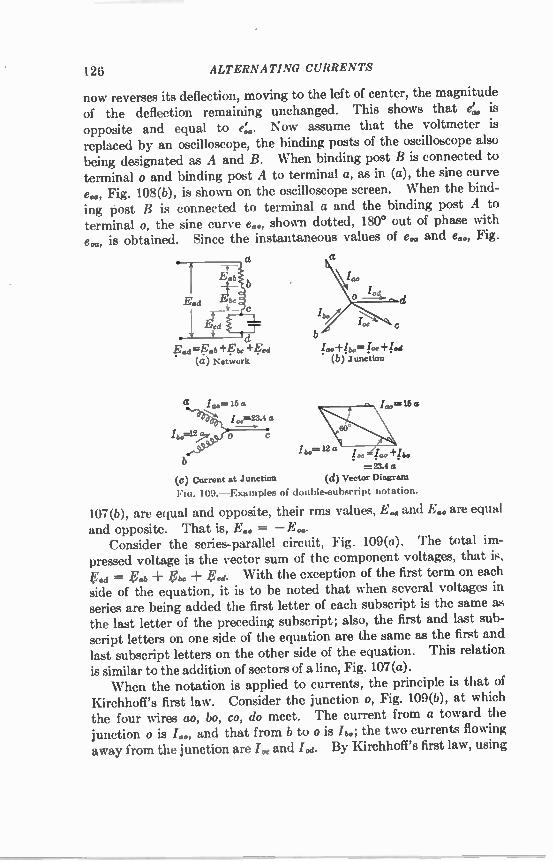
126 ALTERNATING CURRENTS
now reverses its deflection, moving to the left of center, the magnitude of the deflection remaining unchanged. This shows that 4 is opposite and equal to 4. Now assume that the voltmeter is replaced by an oscilloscope, the binding posts of the oscilloscope also being designated as A and B. When binding post B is connected to terminal o and binding post A to terminal a, as in (a), the sine curve e., Fig. 108(b), is shown on the oscilloscope screen. When the bind-ing post B is connected to terminal a and the binding post A to terminal o, the sine curve e60, shown dotted, 180° out of phase with e., is obtained. Since the instantaneous values of e. and e60, Fig.
a
Fad= Eab+. be "i" ed
(it) Network
a
o-
1>
fao, + !.d. lb.= lee +l to) Junction
„e=16a

POLYPHASE SYSTEMS 127
vectors, the total current flowing toward a junction must be equal to the total current flowing away from the junction. Hence
too ± jbo = too + jod•
Reversing the order of a subscript reverses the algebraic sign of a quantity. Reversing the subscripts on the right-hand side of the equation and transferring the quantities on the right-hand side to the left-hand side of the equation give
too ± bo + I co ± I do = 0. (113)
Multiplying through by —1 and reversing the subscripts give
(114)
Hence, if the currents at any junction are all placed on the same side of the equation, either all the first letters of the subscripts or all the last letters of the subscripts are the eame. To illustrate the use of the notation, consider Fig. 109(c), which
shows two transformer secondaries, ao and bo, connected at o, to which the wire oc to the external circuit is also connected. A current /.., equal to 15 amp rms flows from a to o, a current h. of 12 amp rms flows from b to o, and I„„ leads h o by 60°, as shown by the vector diagram in (d). It is required to determine the current La in the wire oc. By Kirchhoff's first law, using vectors, I ..a = irao + bo• The vector diagram is shown in (d). By trigonometry, Lc is found to be 23.4 amp rms. It is to be noted that by using this system of notation the likelihood
of error is minimized. Further details involving the use of this system of notation are
given in its application to polyphase currents in the following sections. 88. Generation of Three-phase Etnfs.—The 3-phase system is the
most used of the polyphase systems. This is due to the fact that the 3-phase system has the least number of wires of any symmetrical polyphase system,' the line voltages are equal, and with a neutral conductor two different values of voltage are available. The generation of 3-phase emfs by simple coils rotating in a bipolar
magnetic field is shown in Fig. 110(a). Three simple coils aia, bib, cic, fastened rigidly together 120° apart, rotate in a counterclockwise direction. The shaded sides of the three coils are 120° apart, and the terminals a, b, c from these sides may be said to be correspond-ing terminals, the significance of which will be shown later. Likewise,
I There are only three wires in the 2-phase 3-wire system shown in Fig. 132 (p. 148), but this is an unsymmetrical system.

128 ALTERNATING CURRENTS
terminals al, b1, ci, also 120° apart, are corresponding terminals. Figure 110(d) shows similar coils aia, b1b, cic placed on a cylindrical laminated iron core rotating counterclockwise in a bipolar field. In (d) the turns of the coils can be seen more clearly than in (a), and the direction of the instantaneous induced emfs is shown by arrows.
(b) (c) (a)
0--
(e)
A
(d) FIG. 110. —Generation of three-phase emfs and currents.
The current can be conducted from each of the three coils to the external circuit by means of a pair of slip rings, &LI, bbi, cci, Fig. 110(e), the terminals a and al of coil aia being connected to rings a and al, etc. At the instant shown in (a) and (d), the emf induced in coil aia
is zero and is increasing in a positive direction; the emf induced in coil bib is approaching its maximum negative value, terminal b being negative; the emf induced in coil cc with terminal c positive has passed its maximum positive value, and is diminishing, Fig. 110(c), 0-deg. These three emfs also can be considered as generated by the three rotat-ing vectors EL., E 1 b, Fig. 110(b), the three vectors being parallel to coils aia, bib, cic, in (a) and (d). Also, the right-hand end of vector ELa corresponds in position to terminal a, the lower end of vector gib corresponds in position to terminal b, etc. (see Fig. 15, p. 18).

POLYPHASE SYSTEMS 129
In (c) are shown the three emf waves ea.., eb,b, et,., induced in the coils aia, bib, cic. It will be noted that at the instant under consideration the emf in coil aia is zero and increasing positively; that in coil bib is negative and approaching its negative maximum value; that in coil cc is positive and decreasing in value, the three values of emf thus corresponding to the positions of the coils in (a) and (d). The emf er„b lags emf ea,„ by 120°, and emf e„, lags ea,. by 240°, corresponding to the angles between the ends a and b and a and c of the coils. Figure 110(c) shows that, for any particular instant of time, the
algebraic sum of the three emfs is zero. When one emf is zero, each of the other two has 86.6 per cent of its maximum value and these two have opposite signs. When any one emf is at its maximum, each of the other two has the opposite sign to this maximum and is 50 per cent of its maximum value. The equations of the three emf waves are
= r2E sin cut, eb,b = sin (cot — 120°), eric = O E sin (cut — 240°),
where E is the rms value of each emf. Each of the coils of Fig. 110(a) and (d) can be connected through its
two slip rings to a single-phase circuit. This gives six slip rings and three independent single-phase circuits, such as phase A, phase B, phase C, Fig. 110(e). With the type of alternator having a rotating field and stationary armature, the usual type, the six slip rings would not be necessary, but six leads would be taken directly from the armature. - In practice, however, a 3-phase alternator seldom supplies three independent circuits by the use of six wires, but the phases are com-bined to give 3- or 4-wire 3-phase systems. It is to be noted in Fig. 110(a), (b), (c), (d) that, when side a of
coil a,a is under the center of the N-pole, the emf of terminal a is positive maximum, and under these conditions ea,a is positive, Fig. 110(c). [This corresponds to 90° in Fig. 110(c)]. At a later time, corresponding to 120 electrical degrees after coil side a is under the center of the N-pole, the side b of coil bib comes under the center of the N-pole, the emf of terminal b is positive maximum, and under these conditions eb,b is positive and lagging e„,„ by 120°; likewise, at a still later time corresponding to 240° after coil side a is under the center of the N-pole, the emf of terminal c becomes positive, and the emf ecie lags ea,. by 240°. Hence, the maximum values of these three emfs may be represented by the three vectors Ea',„, E,b,roc, Fig. 110(b),
(115a) (115b) (115c)

130 ALTERNATING CURRENTS
which differ in phase by 120°. In Fig. 111 the three vectors E, E., E., differing in phase by 120°, represent to scale the rms values. (The terminals al, b1, ci are connected together to form terminal o.)
Eoc
cf FIG. 111. —Three-phase voltage FIG. 112. —Y-connection of generator
vector diagram. coils.
89. Y-connection.—The three coils of Fig. 110(a) and (d) are shown in simple diagrammatic form in Fig. 112. The three correspond-ing terminals ai, b1, c1 are now connected at the common junction o. This is the Y-connection. Ordinarily, only three wires, aa', bb', cc', lead to the external circuit, although a neutral wire oo' is sometimes carried along, giving a 3-phase 4-wire system.
E =Eb.-1-.Eoe
+E ao o b E °° Eco Em=Eco+Eoa
(a) (b) Flo. 113. —Y-connection and corresponding voltage vector diagrani.
Figure 113(a) shows the three coils of Fig. 112 connected in Y to give a 3-phase system of which the three line wires are ad, bb', cc'. In Fig. 113(b) are shown the voltage vectors E., Et,b, E., cor-responding to the ernfs in the three coils oa, ob, and oc. These three emfs are the phase or Y -voltages. Let it be required to find the three line voltages Ea, E., E. The line voltage ab = ± J0ô (Sec. 87). E. is not on the original diagram but is obtained by reversing E.. E. is then added vectorially to E., giving E..

POLYPHASE SYSTEMS 131
From geometry, Ea lags the phase voltage E.* by 30° and the coil voltage E. by 150°. Also, Bob is numerically equal to
= 1.732E„b.
In a similar manner, ft. = Vb. ± V., and V. = V. + V.. These three line voltages are shown in Fig. 114a. In a balanced Y -system, the three line voltages are equal and differ in
phase by 120°. Each line voltage differs in phase by 30° from one of its phase voltages. The three line voltages are each equal in magnitude to
or 1.732, times the phase voltage. It is evident from Fig. 113(a) that the three phase, or coil currents
/0„, /,,b, /0, are equal to the three line currents Lid, Iw, I(e, as coil and line are in series.
Therefore, in a V-system the line and phase currents are equal. As the three coils meet at a common junction o, by Kirchhoff's
first law the sum of the three currents must be zero, provided that there is no neutral current. That is, J. + f„b = 0. This is true whether or not the currents are balanced. 90. Currents in Y-system.—At the right, Fig. 114(a), is shown a
Y-connected load consisting of three equal resistors a'o', b'o', c'o' This load is supplied by the Y-connected energy source at the left, which is similar to that shown in Figs. 112 and 113(a). A neutral conductor o'o, of negligible resistance, connects the neutral of the load with that of the source. The three conductors aa', bb', cc' connecting the source and the load have negligible resistance. Inasmuch as the three loads are balanced, the current in the neutral is zero, as will be shown later. Although it is pointed out in Sec. 87 that the order of subscripts
does not purpose to show the direction of alternating-current flow, the order of the subscripts is frequently used to show the direction of energy flow. Thus in the source at the left, Fig. 114(a), the emfs E., E., E., as well as the corresponding currents /".„„ Lb, I„c, indicate that the energy flows out of the source and since it flows into the load the terminal voltages to neutral at the load are given by V dd , red. Upon applying Kirchhoff's second law to circuit oaa'o'a and remembering that V dd is a voltage drop (= —LedZed)
— Vdd = 0
or E. = Vdd . This is shown in Fig. 114(b), where V dd is in phase with E. in Fig. 113(b). Similarly, Vbe,e is in phase with Ea, and Veie with E.. The three terminal voltages at the load, View, Ved, are found by adding veetorially the resistor voltages. Thus,

132 ALTERNATING CURRENTS
Vet? = V dd Vet'. If V dd, VWd, V ed are reversed and then are compared with Fig. 113(b), = E; Vey = E k; V de, =
The opposite order of subscripts is due to the fact that one system is a source of induced emf and the other is a load. It is customary to use E in dealing with an induced emf and V in dealing with a load or a terminal voltage.
(b) Flo. 114. —Y-connected power source and load.
A study of Fig. 114(a) shows that 1 T Oa = l a d = t e e; = b e = h e;
1 ,4 = 1 , e = led again showing that in a Y-system the coil, or phase, current is also the line current. The currents Idd, I,„,, l,',,, for unity power factor, are shown vectorially in Fig. 114(b). Since the three currents led, Idd, led are equal and differ in phase by 120°, their vector sum is zero and hence the neutral current Ido is zero, since Id° = Ito' ± two, ± = 0. 91. Power in Y-system.—Figure 115 shows the three currents
Io„, I., I., of coils oa, ob, oc, Fig. 113(a) [also see Fig. 113(b)]. Unity power factor is assumed, and the three currents, therefore, are in phase with their coil voltages. A balanced system is assumed, and the three currents, therefore, are equal in magnitude. As is shown in Sec. 90, the coil current I. and the line current
lad are the same current. The line current Ica, therefore, is 30° out

POLYPHASE SYSTEMS 133
of phase with the line voltage Ee,a, when the power factor is unity. This relation holds for each phase.
E.
ob
100
B..
Eab Eoe Eia 1I th Bob E ggi
Fin. 115. —Relation of line to coil volt- FIG. 116. —Relation of line to age and current in a Y-system, unity power coil voltage and current in a Y-factor. system. Power factor = cos O.
The power delivered at unity power factor by coil oa, which is equal to that delivered by each of the other two coils, is
P' = watts,
and the total power delivered by the generator is three times P', or
P = 3E,,„itI coil watts.
As the power delivered to the line is the same as that delivered by the generator, upon substituting Eu.,./ V3 for the value of Loa.
3 „ , P = — = -0 Elm ,Ili.,
-0
the coil current and the line current being the same. In a kalaneed_342basse_ sustem, the line power at unity power factor
issgual to -Va times the product of line voltage and line currents_ Figure 116 shows the same 3-phase system when the power factor
differs from unity. Each coil current lags its respective coil voltage by the angle 0.
The total coil power is now three times that in the individual coil, or
P = 3Ecoa l i cos 0„„ii The system power is
P = .0 Eii„Iiine cos 0,,,a
and the system kilowatts are
L., 1 y 0 00 nikei tine COS Ocoa
watts, (116)
watts.
watts, (117)
watts. (118)

134 ALTERNATING CURRENTS
Therefore, in a balanced 3-phase system, the system power factor is the cosine of the angle between coil current and coil voltage. The angles between line currents and line voltages are not power-
factor angles, for they involve the factors 0 — 30°, Fig. 116, and ± 30°, 0 being the coil power-factor angle.
I
(a) (b) FIG. 117.—Delta-connection of alternator eoilb.
The system power factor, which is the coil power factor, is
P.F. — (119) , v 3 Elinei line
where P is the total system power in watts and E and I are E8 and
'line. It follows that the system volt-amperes,
Va = EI, (120)
and the kva, E Kva = -‘75 l (121)
1,000
If the system is unbalanced, that is, if the currents or voltages are not equal or do not differ in phase by 120°, the question arises as to just what the system power factor is under these conditions. Where such unbalancing is not very great, (119) is used, line currents and voltages being averaged. The system pom er factor has practically no significance when the unbalancing is considerable.
Example. —A 3-phase alternator has three armature coils each rated at 1,330 volts and 150 amp. What is the voltage, kva, and current rating of this alternator
if the three coils are connected in Y?
= .V3 • 1,330 = 2,300 volts. Ans. Kva rating = -0 • 2,300 • 150 = 600,000 va -- 600 kva. Ans.
Current rating = 150 amp. Ans.
92. Delta Connection.—The three coils of Fig. 113 may be con-nected as shown in Fig. 117(a), the diagram being simplified in Fig. 117(b). The end of each coil, which, in Fig. 113, was connected to the

POLYPHASE SYSTEMS 135
neutral o, is now connected to the outer end of the next coil. As points o and a are now connected directly together (E. = E., etc.), the o 's are now superfluous and are dropped. Figure 118(a) shows vectorially
the three voltages Eba, Ea, E., act-ing from b to a, c to b, a to c, re-spectively. At first sight, Fig. 117 looks like
a short circuit, the three coils, each containing a source of emf, being in series and short-circuited. The actual conditions existing in this 'bb' L.' closed circuit may be shown by the use of the subscript notation. As-sume that the coil bc is broken at c', Fig. 119(a). The emf
.6 = ba -I- Vat'.
Epb 118. —Relation of line voltage
and current to coil values in delta-con-nected generator, unity power factor.
The vector sum of these two emfs, shown in Fig. 119(b), lies along volt-age Ebe and is equal to it. The emf = 0, therefore, and points c and c' can be connected without any resulting current. This is the same condition that exists when two d-c generators having equal emfs are connected in parallel. No current flows between the two if the proper polarity is observed.
(a) Epb (b)
Mo. 119.—Sum of three delta ends is zero.
Since the three emfs E , E„,-, Ed, (= E., Eo„ E.), Fig. 117(a), are in series, it follows, from a study of Fig. 110(c) (p. 128) that their sum at every instant is zero. The three coil currents Ibpo I., I, of Fig. 117 are shown vectorially
in Fig. 118, in phase with their respective voltages (power-factor unity), a balanced system again being assumed. The line current
= 1 +

136 ALTERNATING CURRENTS
This addition is made vectorially in Fig. 118, giving Le, differing in phase from Eb. by 30°. It will be noted that in magnitude Le is Ni3- times the coil current. Line currents IW and Ice may be found in a similar manner, Fig. 118. In the delta system, therefore, there is a phase difference of 30° between line current and line voltage at unity power factor, just as in the Y-system. It is obvious that line voltage is equal to coil voltage in a delta
system. Moreover, the sum of the three voltages acting around the delta must be zero, by Kirchhoff's second law.
C 1 ,
KV FIG. 120. —Delta-connected power source and load.
93. Load Currents in Delta System.—In Fig. 120(a) is shown a delta-connected load receiving energy from a delta-connected genera-tor, the resistance of the connecting leads being negligible. At the load the positive direction of current is a' to b', b' to c', c' to a'. Upon applying Kirchhoff's second law to circuit baa'bib and remembering that Vey is a voltage drop, ek, — Vow = 0 or lcb, = Vba. Simi-larly, !Tv., = Vcb, vc, = Vac. The three voltage drops Vey, Vve, V ed are shown in the vector diagram; Fig. 120(b).

POLYPHASE SYSTEMS 137
By applying Kirchhoff's first law to junction a', line current [eke = Lev ± bee. Similarly, [w = ± lbw ; = leo, + ev. These relations are shown vectorially in Fig. 120(b), unity power factor being assumed. Again note that at unity power factor there is a phase difference of 30° between line voltage and line current, as between Vet/ and [also compare Fig. 120(b) with Fig. 118].
10 a
115-Volt Lamp Banks Connected in Y
17.3 a
115-Volt Lamp Banks Connected in Delta
Flo. 121. —Lamp loads in Y and in delta.
To recapitulate, in a delta system the line voltage is equal to the phase voltage, and by Kirchh.off's second law the sum of the three voltages around the delta is zero. In a balanced delta system the line current is Vg times the phase current. Although Fig. 114(a) shows a Y-load with a Y-connected source
and Fig. 120(a) shows a delta load with a delta-connected source, the load may be connected in either Y or delta, irrespective of the connec-tion of the source. Figure 121 shows three lamp loads, each requiring 10 amp, at 115
volts. They are connected first in Y and then in delta. In order to supply the proper voltage in each case, there are 199 volts across lines in the Y-system and 115 volts in the delta system. There are 10 amp per line in the Y-system and 17.3 amp per line in the delta system. The power supplied is the same in each system. 94. Power in Delta System.—The total power in a delta system is
P = 3Ecool cod cos °coil. (I)
This power is equal to that in the line, as there is no intervening

138 ALTERNATING CURRENTS
loss. Also, the line current
and = V 3 Lit,
E line = E coil.
Hence, substituting in (I),
P = Eiineliin, Co. ocai. This equation is the same as Eq. (117) (p. 133) for the Y-system.
This should be so, for the relations in a 3-phase line are the same whether the power originates in a delta- or in a Y-connected generator. • The power factor of the delta system is the same as that for a Y-system.
P.F. — — cos 00„ii, (122)
where P is the total power of the system in watts and E and I are the line voltage and line current. The denominator Nia El [(122)] gives the volt-amperes of the three-
phase system. The kva of the 3-phase system is given by
‘15 EI 1,000 [see (121), p. 134].
METHODS OF MEASURING PO WER IN THREE-PHASE SYSTEM
95. Three-wattmeter Method.—Let (1), (2), (3), Fig. 122(a), be the three coils of either a Y-connected alternator or a Y-connected load.
(a) FIG. 122. —The three-wattmeter method of measuring three-phase power.
If the neutral of the Y is accessible, it is possible to measure the power of each coil, or phase, by connecting the current coil of a wattmeter in series with the phase and the wattmeter potential coil across the phase, Fig. 122(a). W1, W2, Ws, therefore, measure the power in loads 1, 2, 3, regardless of power factor, degree of balance, etc.
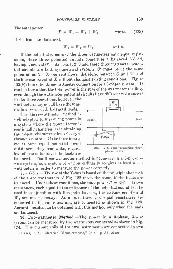
POLYPHASE SYSTEMS 139
The total power P = W1 -I- W 2 + Wa watts. (123)
If the loads are balanced,
W 1 = W 2 = WS watts.
If the potential circuits of the three wattmeters have equal resist-ances, these three potential circuits constitute a balanced Y-load, having a neutral 0'. As coils 1, 2, 3 and these three wattmeter poten-tial circuits are both symmetrical systems, 0' must be at the same potential as 0. No current flows, therefore, between 0 and 0'. and the line can be cut at X without changing existing conditions. Figure 122(0 shows the three-wattmeter connection for a 3-phase system. It can be shown that the total power is the sum of the wattmeter readings even though the wattmeter potential circuits have different re,i,tances.' Under these conditions, however, the wattmeters may not all have the same reading, even with balanced loads. • The three-wattmeter method is
yell adapted to measuring power in Source Load
a system where the power factor is continually changing, as in obtaining the phase characteristics of a syn-chronous motor. If the three instru-
Y-Box
ments have equal potential-circuit . resistances, they read alike, regard- FIG. 123. —Y-box for measuring three-less of power factor, if the loads are phase power.
balanced. The three-wattmeter method is necessary in a 3-phase 4-wire system, as a system of n wires ordinarily requires at least n — I wattmeters in order to measure the power correctly. The Y-box. —The use of the Y-box is based on the principle that each
of the three wattmeters of Fig. 122 reads the same, if the loads are balanced. Under these conditions, the total power P = 3W1. If two resistances, each equal to the resistance of the potential coil of W 1, be used in conjunction with this potential coil, the wattmeters W 2 and W 3 are not necessary. As a rule, these two equal resistances are mounted in the same box and are connected as shown in Fig. 123. Accurate results can be obtained with this method only when the loads are balanced. 96. Two-wattmeter Method.—The power in a 3-phase, 3-wire
system can be measured by two wattmeters connected as shown in Fig. 124. The current coils of the two instruments are connected in two
'Laws, F. A. "Electrical Measurements," 2d ed. p. 341 et seq.

140 ALTERNATING CURRENTS
ei the lines, and the potential coil of each instrument is connected from its own current coil to the line in which there is no current coil. Under these conditions, the total power passing through the system is
P = W j + W2 watts. (124)
regardless of power factor, balance, etc. The choice of the plus or the minus sign will be explained later.
a
is
i
VI—Vs
'V —V 2 3 C,
is (a)
raw=
I
(b.)
FIG. 124. —Two-wattmeter method for measuring 3-phase power.
One method of proving that these instruments give the correct power is as follows: In Fig. 124(a) let vi, v2, v3, and i1, i2, i3 be the volt-ages and currents of the three loads at any particular instant. These being instantaneous values, the power at the instant under considera-tion is equal to the sum of their products, regardless of power factor. That is, the instantaneous power
p = viii V2i2 113 4 watts. (I)

POLYPHASE SYSTEMS
At junction o, by Kirchhoff's first law,
it is 4- ia = 0, is = — (i1 + is).
Substituting (II) in (I)
p = viii V2i2 V3(il i2) (VI — V3)il -I- (V2 — V3)i2
141
watts. (III)
As the line voltages in a Y-system are the differences of the proper coil voltages (Sec. 89 p. 130), that is, one coil voltage is reversed when added to find the line voltage [also see Fig. 125(b)], the instantaneous values of power measured by the wattmeters are
WI 2= (171 V3)ii W2 == (V2 V3)i2
watts, watts.
Hence, at every instant the power tvi 4- tv2 measured by the two wattmeters is equal to the total instantaneous power p of the system. A similar proof for a delta-connected load is as follows: In Fig.
124(b), let the instantaneous values of the line, or delta, voltages be v1, v2, v3, and let the delta currents be ii, i2, is. Again, the instantane-ous power is
p == viii V2i2 vsis watts. (IV)
By Kirchhoff's second law, around the delta,
vi -IF V s -E V3 == 0, vi = — (v2 ± v3). (V)
Substituting (V) in (IV),
p = — (v2 + v3)ii v2i2 vaix, = —v3(ii — i3) v2(i2 — i1) watts. (VI)
The current to WI is I..; and, at junction a', = (i1 — is)• Likewise, the current to W 2 is lw; and, at junction b',
lw == (i2 il).
The voltage to WI is V = —v3, and the voltage to W2 is
VtIeo = 112.
[Note the direction of vs and v2 arrows, Fig. 124(b)]. Hence the first term in (VI) gives the reading of WI, and the second
term gives the reading of W2. That is, the instantaneous values of power measured by the two
wattmeters are

142 ALTERNATING CURRENTS
tvi = —vs(ii — is) 11)2 " vs(i2 il)
watts. watts.
Hence, at every instant the sum w1 iD2 gives the total instantaneous power p. Y-connected Load. It is shown, Secs. 89, 91, and 92, that a phase
difference of 30° exists between line voltage and line current at unity power factor. For power factors other than unity, this phase difference becomes 30° + 0, where 0 is the power-factor angle of the coil.
(a)
125. —Two-wattmeter method and vector diagram for balaneed Y-load.
Figure 125(a) shows two wattmeters, W 1 and W 2, measuring the power taken by a balanced 3-phase Y-connected load. The watt-meter W I is connected so that the current I„d = Id. flows in its cur-rent coil, and the voltage V., = Foy (the voltage drop in the current coil being neglected) is across its potential circuit. The reading of W I, therefore, is equal to the product of L., Vay, and the cosine of the angle between them. Figure 125(b) gives the vector diagram for the load. The three coil voltages Vdd, Vted, Ve,,, are equal in magnitude and differ in phase by 120°. The coil currents Idd , I, Ie., are equal in magnitude and lag their coil voltages by the angle O. The voltage Vde is found by reversing giving Vee, and then adding Tido, and Voy vectorially (yd, = + y"). The current Led is given. The angle between V„,,, and is 30° — 0. Hence, the reading of W I is
Wi = cos (30° — 0) = Vii.Jun,. cos (30° — 0) watts. (125)
Likewise, the wattmeter W2 reads the product of VW', lb,d, and the cosine of the angle between them. From the vector diagram, Fig. 125(b), VII,. is found by adding veetorially Vlid and V de
(VW = b'o' Ye.').

POLYPHASE SYSTEMS 143
The current /v„, is given. The angle between Vby and lye is 30° O. The reading of Wy is, therefore,
W2 = VtleIby cos (30° + 0) = Vikehine cos (30° + 0) watts. (126)
Summarizing,
W 1 = VI cos (30° — 0) W2 = VI cos (30° + 0)
watts, (127) watts, (128)
where V and / are line voltage and line current, the system being balanced. Delta-connected Load. —A similar proof for a delta-connected load is
given as follows: In Fig. 126(a) is shown a balanced delta-connected
Vase' (a) (b)
128. —Two-wattmeter method and vector diagram for balanced delta-connected load.
load a'b', b'c', c'a' similar to that in Fig. 124(b). The power factor is cos 0, the current lagging. Two wattmeters W1 and W2 measure the power and are connected in the same manner as in Fig. 125(a). The current coil of W1 is in conductor aa' and that of W2 in conductor bb'. The potential circuit of W 1 is connected across conductors ac and that of W2 across conductors bc. The vector diagram is shown in (b). The three line voltages Vo'b', Vea, are equal in magnitude and differ in phase by 120°; the three currents la'b', 'tic', Ic'a, are equal in magnitude and lag their line voltages by the angle 0. The current to W I is Ld, and the voltage is V,de = V,,,, the voltage drop in the wattmeter current coil being neglected. The current
is found by reversing Ie„, and adding. V,,'' is found by reversing V,,'. The angle between Vde and /„„, is 30° — O. Hence the reading

144 ALTERNATING CURRENTS
of W 1 is WI = Veda., cos (30° — 0) watts. (125a)
Likewise, W2 reads the product of V b'e' = V1,, the current I by, and the cosine of the angle between them. by = /we iv„, is found by reversing /ow and adding. The angle between Vve and /w is 30° 0. Hence the reading of Wg is
W2 = VbYIW cos (30° -I- 0) watts. (126a)
Equations (125a) and (126a) are the same as Eqs. (125) and (126) so that (127) and (128) apply to both Y-connected and delta-con-nected loads. W I and Wg will have the same reading when 0 = 0 and 0 = 180°.
Both conditions correspond to unity power factor. When 0 equals 180°, however, the power has reversed. The two instruments also read the same at zero power factor (0 = 90°), although this condition is seldom realized. When 0 is greater than 30°, Eq. (127) becomes
W 1 = VI cos (0 — 30°).
But cos (0 — 30°) equals cos (30° — 0) since cos A = cos ( — A) (p. 604). With leading current, W I = VI cos (30° -I- 0), and
W2 = VI cos (30° — 0).
When 0 = 60°, corresponding to a power factor of 0.5 lag, W21 Eq. (128), reads zero, as cos (30° 60°) = cos 90° = 0. In this case, the reading of W I, Eq. (127), gives the total power. For angles greater than 60°, corresponding to power factors less than 0.5, cos (30° -I- 0) is negative, Wg reads negative, and the total power is
P = W1 — Wi watts. (129)
Discretion must be used, therefore, when two single instruments are employed, as the total power may be either the sum or the differ-ence of the readings. It may also be shown that
— Wg tan 0 = (130)
WI -I- W2'
where 0 is the coil power-factor angle. It is possible, therefore, to obtain the power factor in a balanced 3-phase system by means of the wattmeter readings alone. Another convenient method for determining the power factor from
the wattmeter readings for a balanced load is to divide the smaller

POLYPHASE SYSTEMS 145
wattmeter reading by the larger,
W 2 cos (30° -I- 0) W1 cos (30° — 0)
The power factor corresponding to this ratio is obtained by sub-stituting different values of 0 and solving for cos O. The power factors corresponding to different values of W2/ WI are plotted as ordinates, Fig. 127. For example, when 0 = 30°, cos 30° = 0.866, and
W 2 = cos 60° = 0.500. WI cos 0°
(131)
By the use of Fig. 127, the power factor is read directly, the ratio Wil W1 being known. It is seen that, when W2/ WI = 1.0, the power
1..i/
0.9
0.8
0.7
0.6 0.6
JacWr
AA
0.9
0.9
0.1
0.6 0.5 0.4 0.2 0.2 0.1 0
Three-Phase Power Balanced System
Two- Wattmeter Method
0.4 0.8 0.2 0.1 0 -10-09-08 -0 7-06-05-04-03-02-01 0 1.0 1,02.03,0 4+0 5+06+-0 7+081.09+10
Rat co. Smaller Reading Cos (30°4- 0) Larger Reading 17.3os:-- iT)= W
Flo. 127.—Power-factor diagram, two-wattmeter method.
factor is 1.0; when W2/W1 = 0, the power factor is 0.5; when W2/W1 is negative, that is, when it becomes necessary to reverse W 2, the power factor is less than 0.5.
Example. —In a test of a 3-phase induction motor, two wattmeters are used to measure the input. Their readings are 1,900 and 800 watts. Both instruments are known to be reading positive. What is the power factor of the motor at this load? Using (130),
r- 1 900 — 800 100 tan 0 = v3 ' 0.705,
1,900 -I- 800 2,700 0 = 35.3°,
cos 8 = cos 35.3° = 0.816. Ans.
Also W 2/WI = 800/1,900 = 0.421, which may be used in Fig. 127 to verify the foregoing result.
If a polyphase wattmeter is used, Fig. 85 (p. 101), the adding or subtracting is done automatically, as both elements of the instrument

146 ALTERNATING CURRENTS
act on the same spindle. The polyphase instrument, therefore, if properly connected, reads the total power. The two-wattmeter method cannot be used to measure power in a
3-phase 4-wire system unless the current in the neutral wire is zero. When the current in the neutral wire of Fig. 128 is zero, the power is correctly indicated by W1 + Wg. Now apply load B'0 between line B and the neutral. The current to this load will complete its circuit from wire B through the neutral without going through the current coil of either wattmeter. As neither wattmeter, therefore, indicates this additional load, the two wattmeters are not sufficient to measure
Neutral
128. —Two-wattmeter method not applicable generally to 4-wire system.
tl..a power in such a 4-wire system under all conditions of load (also, see Fig. 122, p. 138, and Sec. 98, p. 149).
T WO-PHASE SYSTE MS
97. Two-phase and Four-phase (Sometimes Called Quarter-phase) Systems.—Although 3-phase systems for the most part have super-seded other systems, there are still some 2-phase and 4-phase systems in operation. The 2-phase system is rarely used for transmission but is used for distribution, and in some instances it is specially advantage-ous to use 2-phase machines. Two-phase emfs are induced in the elementary generator, Fig.
129(a), by two coils A and B, 90° apart. Figure 129(b) shows the emf waves induced by these coils. The emf of A leads that of B by 90°. When one emf is a maximum, the other is zero. Figure 129(c) shows these 2-phase emfs vectorially (also, see Figs. 265 and 266, pp. 308 and 310). The two phases may be carried along, insulated from each other, to
supply two separate single-phase circuits, or they may supply a com-mon load such as an induction motor shown diagrammatically in Fig. 130. The two phases are entirely insulated from each other in Fig.

POLYPHASE SYSTEMS 147
130 and no single load can be supplied between the two phases. Only one value of voltage is obtainable moreover, as the voltages of the two phases are equal.
(a) Generation of 2-phase etas.
A
B
(:7) Vector representation of 2-phase ends.
(b) Two-phase end waves.
129. —Two-phase einfs.
If, however, the generator coils be connected at their neutral points, a 4-phase star system results. If a neutral conductor be carried along with the other four conductors. a 4-phase, or quarter-phase, 5-wire
Flo. 130. —Two-phase circuit with phases isolated.
system results, Fig. 131(a). Three different voltages, moreover, are available. If the voltages between the outer wires of each phase be 200 volts, then 200, 100, and 141 volts are available, Fig. 131(b). This system is more readily unbalanced than the 3-phase system,

148 ALTERNATING CURRENTS
a fact that constitutes an objection to its use. Another objection is the greater number of wires. If one end of the coil A be connected to one end of the coil B,
a 3-wire 2-phase system results, Fig. 132. This gives two different values of voltage, 200 and 283 (= 200 0) volts. This system is
A / W \
,r' 1 : r
a 0 B > i.•• i l 4e., 8
Neutral 14-400 V:-.4- i-100 V.•-•141
-200 v 1, I.
o"
.\ :' \Li A
VA V
(a) (6)
FT°. 131. —Two-phase interconnected system giving 4-phase, 5-wire star system.
little used because of the considerable amount of voltage unbalancing that results, even when moderate loads are applied. It should be noted that the common wire N carries a current I where I is the current in each of the two outer wires. The wire N is not a true neutral conductor since its potential is not the center of gravity of the potentials of the system.
132. —Two-phase, 3-wire system.
200 V.
A 2-phase or 4-phase alternator may have a winding that consists of four coils. These coils may be connected in mesh, Fig. 133. This corresponds to the delta connection in a 3-phase system. As in the case of the delta, if these coils are properly connected, the winding is not short-circuited on itself. The line voltage is equal to the coil voltage. The diametrical
voltage is equal to -0 times the coil voltage. The line current is

POLYPHASE SYSTEMS 149
equal to V2 times the coil current, because the line current is the resultant of two equal coil currents having 90° phase difference. In Fig. 133, the coil voltage is 200 volts, and the diametrical voltage
is 200 r2 = 283 volts. The coil current is 100 amp, and the line
141 A.
133. —Mesh-connected, 2-phase winding.
current is 141 amp. The total kva rating of this system is
4 • 200 • 100 1,000 = 80 kva.
Considering the system from the point of view of the four line wires, it may be assumed to consist of two isolated systems similar to those in Fig. 130. The rating is computed as follows:
K 2(200 -0) (100 .‘/) — 80. va = 1,000
Ft°. 134. —Measurement of power in isolated 2-phase 4-wire system.
98. Measurement of Power in Two-phase and Four-phase Sys-tems.—In a 2-phase 4-wire system, consisting of two isolated single-phase systems, Fig. 134, the total power may be measured by two watt-meters, one in each of the single-phase systems, regardless of unbalance,

150 ALTERNATING CURRENTS
power factors, etc. If the system is interconnected to form a 4-phase system, Fig. 135, the loads must be balanced or this method is incorrect. If the loads of a 4-wire interconnected system are not balanced, at
least three wattmeters must be used, Fig. 135. The power is the algebraic sum of their readings (Fig. 122, p. 138). The power in a
Flo. 135.— Measurement of power in 4-phase or 2-phase interconnected system (or any 4-wire system).
FIG 136.— Measure!' ent of power in 2-phase, :3-wire system (or any 3-wire system).
2-phase 3-wire system (or any 3-wire system) may be measured by two wattmeters connected as shown in Fig. 136. The wattmeter current coils may be connected, however, in either two of the three wires, (see Figs. 124(a), 125(a), 126(a), etc.).
99. Addition of Loads by the Kilovolt-ampere Method.—Frequently the poly-phase loads on a line or feeder are specified by the kva and the power factor. However, they may be expressed also in kilowatts and power factor, or in amperes and power factor, if the voltage is constant and its value is known. Under the

POLYPHASE SYSTEMS I 5 1
last two conditions the loads are readily converted into kva and power factor. Since in a 3-phase system the kva are equal to E//1,000, where E and I are line volts and line amperes (Sec. 91, P. 132, and Sec. 94, p. 137), and the voltage of the usual distribution system is substantially constant, the kva are equal to the product of a constant and the current. Hence the kva may be added like currents, the phase relations being taken into consideration. This is also true with other constant-potential polyphase systems, the constant differing from that of the 3-phase system. The method of determining the total kva on a line or feeder under these conditions is illustrated by the following example:
Example. —The following loads are connected along a 2,300-volt 3-phase line in which the voltage drop may be neglected: (1) 60 kva at 0.75 power-factor lag; (2) 80 1p,ra at 0.9 power-factor lead; (3) 100 kw at 0.80 power-factor lag; and (4) 120 kva at unity power factor. Determine (a) total kilowatts; (b) total kva; (c) total amperes; (d) resultant power factor of system.
To compute the total kva and kilowatts, each load is resolved into kilowatts and kilovars (see Sec. 37, p. 64) as follows:
(1) cos 01 = 0.75; el = 41.4°; sin 01 = 0.661; kw = 60 • 0.75 = 45; kvar = 60 • 0.661 = 39.7( —).
(2) cos 02 = 0.90; 02 = 25.8°; sin 02 = 0.435; kw = 80 • 0.9 = 72; kvars = 80 • 0.435 = 34.8(+).
(3) cos 03 = 0.80; 03 = 36.9°; sin Oa = 0.600; kw = 100; kvars = 125 • 0.600 = 75.0( —).
(4) cos 04 = 1.0; 04 = 0; sin 84 = 0; kw = 120; kvars = 0.
Total kvars = 79.9( —). kw = 337.
Lagging kilovars are considered ( —) and leading kilovars (±). (a) KW = 337. A 118 . (b) Kva =-• a/(337)2 + (79.9)2 = 346. Ans. (c) I = 346,000/(2,300 V .3) 86.9 amp. Ans.
337 (d) kw/kva = 0.974, current lags. Ana.
346 The foregoing problem may be solved by the use of complex algebra. For
example, the kva may be expressed as follows:
kva = kw ± j(kvars).
100. Applications of Complex Algebra to Polyphase Circuits. —The solution of simple polyphase networks is generally not difficult if complex algebra is used. The methods of solving such problems are best illustrated by actual numerical examples.
Example 1.—Three impedances a, b, c, Fig. 137(a), having resistances 20, 15, 10 ohms and reactances of +00, —j15, -Fj20 ohms, are connected in delta across the three conductors A'A, B'B, C'C of a 110-volt 3-phase 60-cycle system. Impedance a is connected between conductors A-B, impedance b between con-ductors B-C, impedance c between conductors C-A. The sequence of phase rotation is AB, BC, CA. A wattmeter W I is connected with its current coil in conductor A'A and its potential coil between conductors A and C; wattmeter 11's is connected with its current coil in conductor B'B and its potential coil between

152 ALTERNATING CURRENTS
conductors B and C. Determine (a) current in each impedance; (b) current in
each line conductor; (c) reading of each wattmeter.
15-115 rBc
(a) (b) 137.-Unbalanced delta-connected loads and vector diagram.
(a) Assume that VAB lies along the axis of reals, Fig. 137(6). Hence,
VAS = 110 +10 = 110/0° volts, Vac -= -55 -195.3 = 110/120° volts, YcA --- -55 +195.3 = 110\12.2° volts.
(b)
ia = JAB
1'01
lb = IBC
I. ICA
11,1 14A = JAB
110 +10 20 - j10 = 2,200 . 1,100 3 = 20 + j10 20 - /10 500 500 4.40 -12.20 amp,
= V(4.40)2 + (2.20)2 = 4.92 amp. Ans.
-55 - j95.3 15 +115 605 - j2,255 = . = 1.345 - j5.01 amp, la - 215 15 +115 450
= V(1.345)2 + (5.01)2 = 5.18 amp. An.,. -55 +195.3 10 -120 1,356 +12,053 = 2.71 + 0.11 amp, 10 +3.20 10 - j20 500
= V(2.71)2 + (4.11)2 = 4.92 amp. An.,. + IBC = (4.40 -12.20) + ( -2.71 - j4.11) = 1.69 -j6.31 amp, 1/4,41 = V(1.69)2 + (6.31)2 = 6.54 amp. Ans.
is's = Jac + IBA = (1.345 - j5.01) + ( -4.40 + j2.20) = -3.055 -j2.81 amp, j/B,B1= V(3.055)2 + (2.81)2 = 4.15 amp. Ans.
= (CA + ice = (2.71 +14.11) + ( -1.345 +15.01) = 1.365 +19.12 amp, ilc.ci = V(1.365)2 + (9.12)2 = 9.23 amp. An. 1.4•A + bra + ic.c = 0 (check).
(c) The voltage across the potential circuit of W1 is Vec, and the current is IA'A. VAC = 55 - j95.3 volts, and /A,A = 1.69 - 16.31 amp. Hence, by Sec. 56 (p. 81),
WI = 55 • 1.69 + 95.3 • 6.31 = 694 watts. Ans.
The voltage across the potential circuit of W 2 is V BC , and the current B,B.
V BC = -55 - j95.3 volts and Iva = -3.055 - j2.81 amp.
Hence,
W 2 =. (-55) • (-3.055) + (-95.3) • ( -2.81) = 436 watts. Ans.
The total power P WI + 11-2 = 1,130 watts. Arm

POLYPHASE SYSTEMS 153
Since the wattmeters are connected to measure the power by the two-wattmeter method, 1,130 watts is the power taken by the entire system. This may be checked by determining the PR-loss in each impedance. That is,
Ps Pb = (4.92)220 + (5.18)215 + (4.92)210 = 1,130 watts (check).
The foregoing example may also be solved using the polar-vector method, although a transformation to rectangular vectors is necessary in order to find the line currents. For example,
VAR = 110 /0e • Y BC 110/120°; YCB = 110\120°.
Z AB = 22.37/26.6'; Xac 21.2\ ; CA = 22.37/63.40°. 110/0°
lAs = 22.37/26.6° 4.92\26.6° 4.40 4.40 -12.20 amp, etc.
Example 2.-Three loads having resistances 20, 40, 50 ohms and reactances -j50, JO ohms are connected from conductors A' A, B'B, C'C to the neutral
204-530 SZ
50 +A fl
138.-Lnbalanced loads in 3-phase, 4-wire system.
0'0 of a balanced 600-volt 60-cycle 3-phase 4-wire system in which all system voltages are balanced, Fig. 138. Three wattmeters WI, W2, 11-2 are connected with their current coils in conductors A'A, B'B, 0'0 and their potential circuits between conductors A, B, 0, and conductor C. The sequence of phase rotation is AO, BO, CO. Determine (a) current in each line conductor; (b) current in neutral; (c) reading of each wattmeter. (d) Chow that the sum of the wattmeter readings is equal to the total power of the system, and compare with Fig. 122 (p. 138). The voltage to neutral is 600/- 0 346.4 volts.
17 AO = 346.4 ± X); 17 BO = -173.2 - j300; Vco = -173.2 + /300 volts. 346.4 346.4 • 20 . 346.4 • 30
(a) b° 20 + j30 1,300 .7 1,300 - 5.33 - j8.00 amp.,
!IA, el ----ifAOt •• V(5.33)2 -I- (8.00)2 9.61 amp. Ans. -173.2 - j300 ( -173.2 - j300) (40 +150)
iso = 40 - j50 4,100 = 1.968 - j5.04
ils'si l/sol = V(1.968)2 -I- (5.04)2 = 5.41 amp. An.,. -173.2 -1- j300
tco = = -3.464 -I- j6.0 amp, 50 +10
1/e•cj /col V(3.464)2 -I- (6.0)2 6.93 amp. Ans.
amp,

154 ALTERNATING CURRENTS
(b) too. = lAo lac) + !co = (5.33 — j8.00) (1.968 — j5.04) ( —3.464 -I- j6.0) =
3.834 — j7.04 amp,
ilood = V(3.834)2 -I- (7.04)2 = 8.02 amp. Ana.
(c) The current in wattmeter WI is[so = 5.33 — j8.00, and its potential circuit is connected across !'Ac = VAG. VOC 519.6 — j300. Hence, by Sec. 56 (p. 81),
113 = 519.6 • 5.33 + 300 • 8.00 = 5,170 watts. Ans.
The current in 112 is /so = 1.968 — j5.04, and the potential across 11'2 is
V BC V BO + VOC = —j600. Hence, 142 = 600 • 5.04 = 3,024 watts. Ans.
The current in W 3 is 10'0 —3.834 + 37.04, and the potential across 11'3 is yoc. = 173.2 — j300. Hence,
W s = 173.2 • ( —3.834) ( —300 • 7.04) = —2,776 watts. Ans.
The total power
P WI ± WS ± WI = 5,170 3,024 — 2,776 = 5,418 watts. Ans.
(d) The total power is also equal to the sum of the /2R-losses in the impedances. That is,
P = I2Ao • 20 ± n o • 40 40 • 50
= (9.61)2 • 20 + (5 41)2 • 40 + (6.93) 2 • 50 = 5,418 watts (check). Ans.
Hence, the three wattmeters as connected in Fig. 138 measure the total power of the system, even though Wg would normally read back-ward. The current connection of W 3 must be reversed, therefore, and its reading substracted from the sum of the other two readings. In Fig. 122(a) (p. 138) the current coils of the three wattmeters are
connected in the three line conductors, and the common potential connection is made to the neutral conductor of the system. Although this connection is the most usual one, the foregoing example illustrates the fact that the three current coils may be connected in any three of the system conductors and the common potential connection made to the fourth (also see Fig. 135, p. 150). Hence, to measure the power in any polyphase system of n conductors, the n — 1 wattmeters may have their current coils connected in any n — 1 of the conductors and the potential circuits to the remaining conductor. 101. Equivalent Delta Systems and Y-systems.—In Vol. I (Chap.
III), it is shown that a delta connection of resistances may be replaced by an equivalent Y, and vice versa. By these means many more or less complicated passive networks may be reduced to more or less simple ones. With alternating current, similar transformations may

POLYPHASE SYSTE MS 155
be made, the resistances being replaced by impedances expressed in complex. Thus, in Fig. 139 the delta system in (a) may be replaced by the Y-system in (b) as follows:
gi - 12. 3t , (132) Z2 = • • • (133) Z3Ig23 3 = • (134)
where Z. = 12 + g23 Z31.
1
Z23 (a) (b)
Fla. 139. —Equivalent delta and Y-systems.
Likewise, the Y-system may be replaced by the delta system,
Z12 = —Z 0, (135) Xo 23 = (136) g g 1
g31 =
where Zo = ZiZo g2Z3 gsgi• In the network, Fig. 140(a), where there are three unbanlaced
Y-connected loads and no neutral conductor, the voltages to neutral
IA'A
Z31 70.0 —1132.5 SI
/ciC
Z 40+ 120E2
2 C 2
lee ze 25 —j60 ----223=109- 118n (a)
Fm. 140. —Y-system converted to equivalent delta system.
Z12= 87.6+564.3
(b)
are unknown. Hence, if Kirchhoff's laws are used, three simultaneous equations involving complex quantities are necessary. However, by converting the Y-system in (a) into the equivalent delta system in (b), a direct solution is made possible.
Example. —In the 'V-connected system, Fig. 140(a), determine (a) equivalent delta; (b) three line currents I A,A, I B,B, I c,c; (c) three voltages to neutral, FAO, V BO, V CO. The sequence of phase rotation is VAR, Vc, VCA.

156 ALTERNATING CURRENTS
(a) Using (135), (136), (137),
Zo = (50 + j0)(40 + /20) + (40 + j20)(25 - j60) + (25 - j60)(50 + JO) = 5,450 - j3,900 ohms, 5,450 - j3,900 25 + j60 =
ZI2 25 - j60 25 + j60 87.6 + j54.3 ohms. Ans.
Z = 5,450 - j3 900
- 109.0 - 378.0 ohms. Ans. 23 50 + JO
5,450 - /3,900 40 - 120 = Z3I 40 +120 40 - j20 70.0 - j132.5 ohms. Ans.
The equivalent delta system is shown in Fig. 140(b). (b) Let YAB = 200 + JO volts; !IBC = -100 - j173.2 volts;
YCA = -100 + j173.2 volts.
JAB = 200 + j0 87.6 - j54.3 j54.3 = 1.649 - j1.022 amp,
87.6 + j54.3 87.6 Jac -100 - j173.2 109.0 +378.0
109.0 - j78.0 109.0 + /78.0 0.1453 - /1.485 amp,
-100 +1173.2 70.0 +1132.5 ICA = 70.0 - /132.5 70.0 +j132.5 1.329 - /0.0501 amp,
fA A = ho = LoB + (AC = (1.649 - /1.022) + (1.329 +10.0501) = 2.978 - j0.972 amp. Ara.
IB•B = IBO = IBC ± IBA = (0.1453 - /1.485) + ( -1.649 +11.022) = -1.504 - /0.463 amp. Ans.
jc,c Ico = Ica -I- Ica = (-1.329 - /0.0501) + ( -0.1453 +11.485) = -1.474 + 11.435 amp. Ans.
IAA' + ± (cc, = 0 (check).
(C) V.40 = AO.Fi = (2.978 - /0.972)(50 + /0) = 149.0 - j48.6 volts. Ans. Y BO = 1842 = (- 1.504 - j0.463)(40 + j20) = -50.9 - j48.6 volts.
Ans. Vco = IcoZa = (-1.474 + j1.435)(25 -160) = 49.2 + 1124.3 volts.
Ans. It will also be found as a further check that essentially
VAR = Y AO + YOB = 200 +10 volts; Y BC = Y BO ± YOC = -100 - j173.2 volts; Yes = YCO YOA = -100 +1173.2 volts

CHAPTER VT
THE ALTERNATOR
102. Rotating-field Type.—In commercial alternators, in general, the armature is stationary, and the field rotates. The generation of emf in an armature conductor depends only on relative motion of con-ductor and field flux so that either armature or field may be the rotating member. In direct-current machines, the commutator makes neces-sary either that the armature be the rotating member or that the brushes revolve with the field. As alternators have no commutator, it is not necessary that the armature be the rotating member. The stationary armature is illustrated in Figs. 153, 154, 155, etc.
(a) (b) 141. —Effect of slot depth on the width of tooth necks in rotor and in stator.
This construction has two distinct advantages A rotating arma-ture requires two or more slip rings for conducting the current from the armature to the external circuit. Such rings must be more or less exposed and are difficult to insulate, iiiirticularly for the higher volt-ages of 6,600 and 13,200 volts at which alternators are commonly operated. These rings are a frequent source of trouble, owing to arc-overs, short circuits, etc. A stationary armature requires no slip rings, and the armature leads can be continuously insulated conductors from the armature coils to the bus bars. It is more difficult to insu-late the conductors in a rotating armature than in a stationary one, because of centrifugal force and the vibration resulting from rotation. When the field is the rotating member, the field current must be
conducted to the field winding through slip rings. As the field voltage 157

158 ALTERNATING CURRENTS
seldom exceeds 250 volts and the amount of power is small, no particu-lar difficulty is encountered in the operation of such slip rings. Usually, it is difficult to find sufficient space for the copper on the
surface of an armature. This is particularly true with high-speed high-voltage machines having armatures of small diameter. Increased space for copper may be obtained by deepening the slots. If the armature be the rotating member, the deepening of the slots is limited by the contraction of the tooth necks, as shown in Fig. 141(a). No such difficulty is encountered if the armature be stationary, since the tooth necks increase in width with the deepening of the slots, Fig. 141(b). Since the armature usually operates at much higher voltage than the field, much more insulation is required. Space for this increased insulation is readily obtainable in the deep stator slots.
ALTERNATOR WINDINGS
103. General Principles.—The usual direct-current armature generates alternating current; and if properly connected slip rings are provided, alternating current may be obtained. Hence, windings of the direct-current type, if provided with proper taps, are suitable for alternators and such windings are used (see Synchronous Converter, p. 426). However, the requirements of alternating-current systems make it advantageous in most cases to depart from the direct-current winding. For example, the usual direct-current winding is a closed-coil winding (see Vol. I, Chap. XI). Alternator windings may be either closed or open, the delta connection giving a closed-coil winding and the Y-connection an open-coil winding. The general principles that govern direct-current windings hold
for windings of alternators. The span of each coil must be approxi-mately one pole pitch; that is, the two sides of any coil must lie under adjacent poles. The coils must be so connected that their emfs add. In addition, it is desirable that the winding be designed to give a sine wave, at least approximately. The cost of the winding should be low, so that it is important that the coils be formed and insulated before they are placed in the slots. Alternator windings may be divided into two general classes, the
barrel type, Figs. 143 to 147, in which diamond-shaped coils, usually formed, are used; and the spiral type, Figs. 150, 151. The barrel type may be half-coil, Fig. 143(a); whole coil, Fig. 143(b); single-layer, Figs. 142, 143(a); or two-layer, Figs. 143(b), (c) to 147. However, in the United States the two-layer lap winding is used almost exclusively. In Europe, diamond-shaped coils are not used so extensively, spiral windings being used to a considerable extent.

THE A 1,7'E RN A TOR 159
104. Single-phase Windings.—Single-phase windings are prac-tically never used. As a matter of fact, single-phase power is gener-ated only occasionally, such as for single-phase railroad supply. Even then, the generators are usually wound 3-phase, and single-phase power is taken from two terminals of a Y-connection. Since the rating of a given alternator when operated single-phase is only approximately 60 per cent of its rating when operated polyphase, polyphase operation is almost universal. Since polyphase windings are merely two or more single-phase
windings symmetrically spaced on the armature, single-phase wind-ings will be described first. If the principle of the single-phase wind-ing is understood, little difficulty is experienced in understanding the polyphase winding.
(a) single-phase (b) Single-phase partially distributed lap winding partially distributed wave winding
142. —Single-phase lap and wave windings.
In d-c dynamos the wave winding gives a higher emf than the lap winding, if the number of armature conductors, poles, and other condi-tions are the same. In the alternator, the wave and lap windings give the same emf, if the number of armature conductors, poles, and other conditions are the same. This is illustrated in Fig. 142, where a single-layer 6-pole distributed lap winding is shown in (a) and a wave winding, otherwise similar, is shown in (b). An inspection of the two windings shows that each has the same number of series-connected conductors between terminals. Hence, other conditions being the same, equal emfs must be induced. Because the connections of the lap winding are somewhat simpler than those of the wave winding,
winding is used almost exclusi y. Figure 14 (a) shows a single-ph —w single-layer half-coil winding
for a 4-pole alternator having 4 slots, making 1 slot per pole. This

160 ALTERNATING CURRENTS
winding is called a half-coil winding, because there is but one half-coil or coil group per pole, or one-half as many coils or coil groups as there are poles. The two coils are shown connected in series, and T1, T2 are the terminals of the winding. In Fig. 143(b) is shown a development of the winding, two coils B
and D being added. There are now four coils and four poles so that there is the same number of coils or coil groups as poles. Hence, this is a whole-coil winding. Also, one side of each coil, shown as a solid
(a) Single-layer, half-coil winding, I slot per pole
(b) Two-layer, whole-coil winding, 1 slot per pole 143. —Barrel-type single-phase windings with diamond-shaped coils.
line, lies in the top of a slot, and the other side, shown dotted, lies in the bottom of a slot. Hence this is a two-layer winding. The winding of (a) may be obtained by swinging coil B into the plane of coil A and coil D into the plane of coil C. The method of connecting the coils should be noted, the connections of coils B and D being reversed with respect to those of coils A and C, so that their emfs are additive, as is indicated by the arrows. One slot per pole is almost never used, as thus the surface of the
armature is not used economically, and, in addition, a poor voltage wave results. In Fig. 144 is shown a single-phase winding, similar to that of Fig. 143(b) except that there are 2 slots per pole. Since the coils of each coil group are connected in series before being connected

7'HE ALTERNATOR 161
to the next group, the winding is lap-connected. The winding is also two-layer. In practice, a much larger number of slots per pole is used, two being shown in Fig. 144 in order to illustrate the principle.
T2
Fm. 144. —Barrel-type single-phase lap winding, 2 slots per pole.
105. Two-phase Full-pitch Lap Winding.—A 2-phase full-pitch lap winding may be obtained by placing on the armature two windings of the type shown in Fig. 144, spaced 90 electrical space degrees apart (see Figs. 129, 130, p. 147). Such a winding is shown in Fig. 145, in which there are 8 slots per pole, making 4 slots per pole per phase.
145. —Two-phase full-pitch two-layer lap winding, 4 slots per pole per phase.
This is a full-pitch winding, the coil pitch being 8 slots, which is the number of armature slots per pole. The connections of phase B are omitted for the sake of clearness, as they are identical with those of phase Note that both coil sides in any one slot are always of the same phase, which is not the case with fractional-pitch windings. The reversed connection of the center phase belt should also be noted.

162 ALTERNATING CURRENTS
106. Three-phase Full-pitch Lap Winding.—A 3-phase full-pitch lap winding may be obtained by placing on the armature three wind-ings of the type shown in Fig. 144, each winding being spaced 120 electrical space degrees from the two adjacent windings. A typical winding of this type is shown in Fig. 146, in which there are 12 slots per pole, or 4 slots per pole per phase. For each pole, therefore, there are 4 slots devoted to each phase. Since one pole .represents 180 electrical space degrees, the slot pitch corresponds to, 180°/12, or 15 electrical space degrees. In the armature, Fig. 146, there are three phases, A, B, C; for clearness the connections of the A-phase only are shown. The connections of the B- and C-phases are identical with those of A. Since this is a full-pitch winding, the pitch of each coil must be 12 slots. For example, if the left-hand side of a coil lies in
146. —Three-phase full-pitch two-layer, lap winding.
the top of slot 1, the right-hand side must lie in the bottom of slot 13. The conductor belt +A corresponds to the shaded side a of the coil am, Fig. 110(a) (p. 128). The +B-belt, corresponding to the shaded side b of the coil, Fig. 110(a), must be displaced 120 electrical space degrees from the +A-belt. Since each slot corresponds to 15 electrical space degrees, the +B-belt must begin 120°/15°, or 8 slots, from the beginning of the +A-belt, as shown in Fig. 146. Likewise, the ±C-belt must begin 8 slots to the right of the
beginning of the +B-beit. Note that the — C-belt, which is only 60° to the right of the +A-belt, corresponds to the ci side of the coil cie, Fig. 110(a), which is displaced 60° from the a side of coil ala. That is, in Fig. 146, coil sides +A, +B, +C correspond to coil sides a, b, c, Fig. 110, and coil sides —A, —B, —C correspond to coil sides al, bl, cl. Note that in this type of winding the two coil sides in any one slot are of the same phase, which is true of all such full-pitch windings. 107. Fractional-pitch Windings.—In a fractional-pitch winding
the coil span is less than 180 electrical degrees. For example, in Fig. 147 is shown a five-sixths-pitch 3-phase winding. A coil, instead of

THE ALTERNATOR 163
having a pitch of 12 slots, now has a pitch of 10 slots, so that its spread is no longer equal to a full pole pitch. Aside from the pitch, this wind-ing is in every way similar to the winding shown in Fig. 146.
tNote that the top layer F. .. top layer, F. 146. (The letters denoting phase belts apply to the to laver_only.) The bottom layer, Fig. 147, is similar to that shown in Fig. 146 but is slid two slots to the left. This results in there being in each phase belt only two slots con-t aining conductors of the same phase. The advantages of this type of winding are that it improves the
wave form, there is an appreciable saving of copper in the coil ends, and the inductance of the winding is reduced because of the lesser mutual inductance between those conductors which lie in slots con-taining also conductors of either of the other two phases (see Fig.
NAT
+A -C +B -A +C -B +A -C +B 1 2 3 4 6 6
147. —Three-phase five-sixths-pitch two-layer lap winding, 4 slots per pole per phase.
147). The coil-end inductance is also reduced because of the lesser length of coil ends. Such windings generate slightly less emf than full-pitch windings under the same conditions, since the two coil sides do not lie under corresponding parts of the poles at any given instant and hence the phase displacement of their emfs is slightly less than 180°. This is illustrated in Fig. 148, in which El is the emf induced in the conductors comprising one side of a coil and E2 is the emf induced in the conductors comprising the other side of the coil. El is equal to
E2 numerically, as each is induced by the same number of conductors cutting the same flux at the same speed. Figure 148(a) gives the relation of the induced emfs E1 and E2 in the two coil sides when a full-pitch coil is used. When one side of a coil is under an N-pole, the other side is in a corresponding position under an S-pole. The induced emfs differ by 180° in phase, but the coil connection is such that these emfs add, their sum being E as shown in Fig. 148(a). When a five-sixths pitch is used, the coil spread is equal to 5A of
180°, or 150 electrical space degrees. The emfs E1 and E2 will differ

164 ALTERNATING CURRENTS
in phase by 30 electrical time degrees, as shown by the angle 13, 149(b). The total emf E, which is their vector sum, is slightly
less than when a full-pitch coil is used.
E1
E 2 .30e
fi E (a) Full pitch (b) Fractional pitch
148.—Relation of coil-side emfs in full-pitch and fractional-pitch windings.
The ratio E/(E1 E2) = E/2E1 is the pitch factor lc,. A study of Fig. 148(b) shows that
E 2E 2E1 cos 0/2 k = 0 ' —2 = 1 — LOS -- (138) E1 2
For example, for five-sixths pitch, # = 30°,
k, = cos 15° = 0.966 (see p. 178)
The pitch factors for the harmonics are considerably less than that for the fundamental so that the harmonics are reduced much more,
149. —Showing winding and end connections of alternator armature.
proportionately, than the fundamental. For example, a two-thirds pitch will eliminate the third harmonic, a four-fifths pitch the fifth, etc. Hence, with a fractional-pitch winding the wave form is improved.

THE A 1,TE RN ATOR 165
Note that, with the fractional-pitch winding of Fig. 147, only two of the slots of each phase under a pole contain coil sides of the same phase. In the other slots the two coil sides are of different phases. For example, slots 1 and 2 contain both phase A and phase B conduc-tors; slots 3 and 4 contain phase A conductors only; slots 5 and 6 contain both phase A and phase C conductors. Of this group, slots 3 and 4 contain phase A conductors only. The fact that certain slots contain conductors of different phases reduces slightly the inductance of the winding, as has already been pointed out (p. 163). In Fig. 149 is shown a portion of a finished lap winding of a water-
wheel-driven alternator. The end connections, the binding down of
(5)
(a)
— • (C) Plan View showing Single
Range
(d)
Fm. 150. —Single-phase sing e-range spiral winding and equivalent barrel-type winding.
the coil ends, the slot wedges, and the ventilating ducts are clearly shown 108. Spiral and Chain Windings.—Instead of making the coils
lap one another, the winding may be placed on the armature in the manner shown in Fig. 150(a). This is called a spiral winding, since the coils of each group are connected to form a spiral winding, as is shown in (b). Note that the coils themselves have a pitch of less than 180 electrical space degrees. Notwithstanding this lesser pitch, the winding is not considered as having the properties peculiar to a fractional-pitch winding. The slot conductors may be reconnected by barrel-type end connections, as shown in (d), without changing the electrical characteristics of the winding. This gives a full-pitch half-coil barrel-type winding. The differential action of the coil sides

166 ALTERNATING CURRENTS
of Fig. 150(a), owing to their not having a full pitch, is taken into consideration in (d) by the belt-factor constant (see Sec. 114, p. 176). An inside coil, shown dotted, at a may be added to the winding
under each pole, but it contributes so little to the induced emf, because of its small pitch, that to use it is wasteful. As the ends of the coils may be bent so that they all lie in a single vertical plane, Fig. 150(c), the winding in (a) is a single-range winding. In Fig. 151 are shown spiral windings connected to form a 3-phase
chain winding, in which there are 6 slots per pole, making 2 slots per pole per phase. This is a two-range winding, for the coil ends in order to pass one another must lie in two different planes perpendicu-lar to the shaft. If the ?umber of coil groups per phase is odd, which
Phase B Phase A Phase C
(a) Fto. 151. —Three-phase chain winding, requiring special coils.
occurs if the number of poles is not a multiple of 4, coils having one long side and one short side, or trapezoidal in shape, such as coils del' in Fig. 151(a), must be used in order that they may pass the coil ends of one phase such as A and complete the winding. Since there are 6 slots per pole, the slot pitch represents 180/6, or
30, electrical space degrees. If the poles, Fig. 151, are assumed to move from left to right and the phase sequence is A-B-C, the left-hand sides of the coils of phase B must start 120/30, or 4, slots to the right of the left-hand sides of the coils of phase A, as shown in the figure. The coils of phase C have a similar relation to those of phase B. The chief advantage of a chain winding is the considerable space
between the coil ends, so that there is little opportunity for electrical breakdown at these points. They are admirably adapted, therefore, to high-voltage machines. Although coils of several different sizes must be kept in stock as spares, a coil may be replaced more easily than in the lap winding, where it is necessary to remove a large num-

THE ALTERNATOR 167
ber of coils in order to replace a single coil. In the United States at present the chain winding is scarcely ever used, having been replaced by the lap winding.
ALTERNATOR CONSTRUCTION
109. Types of Alternators.—The general design and construction of alternators are roughly divided into three classes, depending on the type of prime mover. The direct-connected engine-driven (steam or internal-combustion) type must operate necessarily at low speeds. In order to obtain the desired uniformity in angular speed, consider-able flywheel effect' (Wit') is necessary. This may be obtained by the use of a separate flywheel or by incorporating sufficient flywheel effect in the rotating element of the alternator. The speeds of water-wheel alternators vary over a wide range, from near 60 to 500 rpm, the lower speeds being used at the lower heads. Both the engine-driven and the water-wheel-driven types of alternators have salient poles, Fig. 153 (p. 169). Owing to the considerable interval that may elapse from the time a
water-wheel alternator loses its load to the closing of the gates, such alternators are designed to operate safely at approximately twice the rated speed. The turbine-driven type of alternator (unless driven through a reduction gear as is sometimes done with small units) runs at very high speed (750 to 3,600 rpm). Because of high windage losses and high centrifugal stresses, the rotors are of the smooth-cylindrical type in which the field turns are embedded in slots, Fig. 160 (p. 175). Water-wheel-driven alternators are made in both vertical and horizontal types. Because of the much better mechanical arrangement of alternator above and water wheel beneath, the vertical type is by far the most common. However, Pelton-wheel-driven alter-nators are usually of the horizontal type. In the early days turbine-driven alternators were made in the ver-
tical type, but because of balance and vibration this type has been practically superseded by the horizontal type. 110. Stator or Armature.—The stator or stationary member of the
alternator is almost always the armature, the field structure being the rotating member or rotor. When the machine is in operation, the armature iron is continuously cut by the flux of the rotating field and must be laminated in order to reduce eddy-current losses. In machines of small diameter, each lamination is usually a single circular punching. In the larger sizes of rotating machinery the stator iron is built up
'In the United States, flywheel effect is expressed by WR2, where W is the weight of the rotor in pounds and R its radius of gyration in feet.

168 ALTERNATING CURRENTS
of overlapping circular segments either dovetailed or bolted to the frame. In Fig. 152(a) is shown a segmented stator punching of the bolted type for a medium-speed machine, and in (b) is shown a seg-ment of the dovetailed type for a turbine-driven alternator. The large depth of iron behind the slot should be noted. In (c) is shown a ventilating segment to be used with segments like that shown in (b) in order to secure ventilating duct , through the stator core, Fig. 155.
Fto. 152.—Segmented stator punchings: (a) slow speed; (b) turbine driven; (c) vent 'lut-ing segment. (Allis Chalmers Mfg. Co.)
Frequently the laminations such as are shown in (b) are perforated to produce longitudinal air ducts (see Fig. 157). Engine-driven alternators must rotate at comparatively low speeds
and must have a large number of poles, and the armatures must be of comparatively large diameter. The pole pieces are made up of lamina-tions riveted together and are dovetailed to the field spider, Fig. 153. The armature is built up of small overlapping segments, dovetailed to the frame of the machine in much the same manner as the armature of engine-driven direct-current generators is assembled (see Vol. I, Chap. XI) except that in the alternator the armature laminations are a part of the stationary member. Figure 153 shows the general con-struction of such an alternator. The frame itself may be a hollow box

THE ALTERNA7OR 169
casting, Fig. 153, or it may consist of fabricated steel plates between which the laminations are bolted, Fig. 154. Both constructions give
Eram
Larninationa
Field Coil Pole Piece
Dove-Tai Field Spider
FI.G. I - ill I
the necessary mechanical stiffness with small weiOit, and with either frame there is ample opportunity for the discharge of the cooling air, which passes out through the cooling ducts.
_ Flo. 154. —Coni1,letely %%mind stator of engine-driven alternator. t Iredinghouse Electric
Corp.)
In Fig. 155, is shown the stator of a high-speed turbine-driven alternator without the winding. Because of their low reactance the short-circuit current of turbine-driven alternators is abnormally large,

170 ALTERNATING CURRENTS
and the mechanical stresses due to these currents are extremely great. (Such electromagnetic stresses are proportional to the current squared.) Unless well supported, the coil ends are likely to be pulled out of posi-tion under short circuit. Braces for supporting such coil ends are shown in Fig. 155. Some of the bracing is removed to show the man-ner in which the spiral ventilating duets are alternated so as to provide uniform temperature throughout the stator [also see Fig. 152(c) j.
Air discharge
155. —End view of turbogenerator stator showing manner in which the spiral ventilating duets are alternated so as to provide uniform temperatures throughout the stator. (Allis-Chalmers Mfg. Co.)
111. Slots.—Two general types of slot are used for alternating-current machines, the open slot and the semiclosed slot. The open slot, shown in Fig. 156(a), is the more common, because the coils can be form-wound and insulated prior to being placed in the slots, giving the least expensive and most satisfactory method of winding. The semiclosed, or overhung, type of slot, shown in Fig. 156(b),
is often necessary, especially in induction motors. The larger area of tooth face reduces the air-gap reluctance and also reduces the tufting of the flux, which tends to produce ripples in the emf wave. It is usually necessary to place the conductors in the slot one at a time, which is expensive and uneconomical of slot space. It is also difficult to apply insulation.

THE ALTERNATOR 171
In both types of slot, the conductors are usually held in the slot by fiber wedges, Fig. 156. The effect of the semiclosed slot may be obtained by the use of open slots and magnetic wedges. These wedges are only partly of iron, so that the slot is not entirely closed. Coil insulation is divided into two general classes, A and B. Class
A insulation, such as paper and cambric, is of organic material and when impregnated with varnishes or fillers has a limiting operating temperature of 100°C, as measured with an embedded detector (see Vol. I, Chap. XIV). Class B insulation, of which mica tapes and fiber glass (fabric woven with glass fibers) are examples, can operate at a limiting temperature of 120°C, as measured with an embedded detec-tor. Until recently, low-temperature organic varnishes were used to bind the mica films and to impregnate the fiber glass, which is usu-ally applied in the form of tape. Recently, new silicone varnishes
Conductors usually stranded
Wedge
U.,ivitictor insulation 1111Ca or fiberglass tape varnish treated
Coil insulation of mica tape Outer wrapper of treated asbestos. fiberglass tape or fiber
(a) Open slot (b)Semiclosed slot
FIG. 156. —Cross sections of typical a-c machine slots.
have been developed that have very much higher operating tempera-tures. The limiting temperatures of mica and fiber-glass insulation employing this material are as yet uncertain. The slot in Fig. 156(a) is shown as being insulated with class B insulation, which is common for alternators, since the output increases with the operating temperature. If the mica and fiber glass are replaced with varnished cambric or cotton, class A insulation results. The conductors or parts of conductors nearer the top of the slots
have lesser self-inductance than those nearer the bottom of the slots (see pp. 171 and 332). Hence, the current tends to flow in the top portions of each conductor. To prevent such unequal distribution of current the large conductors in alternator armatures are stranded, as indicated in Fig. 156(a), and each strand is insulated with enamel. Each conductor is made up so that all strands occupy top, inter-mediate, and bottom positions for equal distances, thus equalizing their self-inductances. In order to prevent corona formation in the voids between the
conductors and the grounded laminations, such as would occur when

172 ALTERNATING CURRENTS
the voltage is high, the slot insulation is covered with a semiconducting paint, and the surfaces are connected to ground. 112. Ventilation.—The problem of ventilating slow-speed salient-
pole alternators is not a difficult one. The length of embedded con-ductor is not large, the exposed dissipating surface is large, and the fan action of the salient poles provides circulating air. However, the output of turbine-driven alternators is so great for their size, the length of embedded conductor is so large, and so little ventilating action is obtained from the smooth cylindrical rotor that the problem of proper ventilation is a difficult one. Also, since ventilating ducts in the solid-steel rotor are impracticable, all ventilating gas must flow in axially through the air gap or through axial ducts in the stator laminations. In the stator, special ventilating ducts must be provided, Fig. 157 (also see Fig. 155). Totally enclosed systems of ventilation are now used. In addition to eliminating the accumulations of dirt
-- Itnt171-111-11--
Rotor
FIG. 157. —Paasage of ventilating air through the duets of a turboalternator.
in the ventilating system that would result if outside air were circu-lated, this method minimizes fire hazard by eliminating the available supply of oxygen. Means are also provided for releasing carbon dioxide if fire should start. The cooling medium, which may be either air or hydrogen, is cooled by passing over pipes through which cooling water is circulated; the cooling medium itself circulates con-tinuously through the alternator ventilating system. Nearly all the turbine-driven alternators and large-sized syn-
chronous motors that are now being built are hydrogen-cooled. The primary reason for using hydrogen rather than air is to reduce windage loss to about one-tenth the value with air, which increases the efficiency 0.6 per cent or more at rated load, and to provide better cooling, which increases the rating about 20 per cent. Other advantages of hydrogen are the reduction of oxidation of the insulation and the reduction of fire hazard and of windage noise. The properties of hydrogen that make it advantageous as a cooling medium are that its density is only 7 per cent that of air, hence the decreased windage loss, and that

7'HE ALTERNATOR 173
it has 7.5 times the thermal conductivity of air and for a given tem-perature difference will transfer 30 per cent more heat units from a given surface than air. Because of its explosive nature, it must be used in a gastight enclosure. Since synchronous condensers have no protruding shaft, they were the first type of machine to employ hydro-gen cooling, Fig. 340 (p. 412). With alternators, a special oil seal in the bearings has been developed, and the loss of hydrogen by leakage is thus negligible. The danger of explosion is practically eliminated by maintaining the hydrogen pressure slightly above atmospheric. Also, the explosive range of hydrogen-air mixtures is between 5 and 75 per cent hydrogen, and the normal percentage under operating conditions is 95 to 98 per cent. This mixture also will not support combustion.
•b
no. 158. —Salient-pole piece with two types of coil.
In Fig. 157 is shown in simplified form the longitudinal system of ventilation. The cooling air flows longitudinally or axially through the air gap and the perforations in the laminations and is discharged radially through the ventilating ducts. The paths of the cooling air or hydrogen for a radial ventilating system are indieated in Fig. 155. 113. Rotating-field Structure.—In order to reduce pole-face losses
and at the same time to facilitate construction and mounting, the cores of practically all salient poles are made of laminations riveted together, Fig. 158. With slow-speed alternators, these are either dovetailed, Fig. 153, or bolted, Fig. 159, to the rotor spider. The spider may be of east iron or steel, or it may be of fabricated steel construction, Fig. 159. The field coils of the smaller capacity machines are usually wound
with wire of rectangular section, cotton-covered, and thoroughly impregnated; with machines of larger ratings, edge-wise-wound strap field coils are used, and these are frequently insulated with high-tern-

174 ALTERNATING CURRENTS
perature bonded mica strip. Both types of coil are shown in Fig. 158. In order to damp any pulsation or hunting, particularly when the
alternator is driven by a reciprocating prime mover, cage dampers arc built into the pole faces, as shown in Fig. 159 (see Sec. 226, p. 403). The nonsalient-pole or cylindrical type of rotor is necessary for
direct-driven turbine-driven alternators, which run at I.igh speed. The rotor is a cylindrical solid-steel forging, Fig. 160, in which longi-tudinal slots for holding the field winding are milled. The rotor shown in Fig. 160 is for two poles. The narrow longitudinal slots cut along the pole faces are for purposes of dynamic balance. Were it not for
lit.. 159. —Salient-pole rotor wit It dampers itt pole faces. (Westinghouse Electric Corp.)
such slots the rotor would be more resilient along the pole axis, because of the material removed for the slots, than along an axis at right angles to the pole axis. The two different degrees of resiliency would produce vibration. The rotor is wound with strip copper. Figure 160(b) is a close-up
view of one end of the rotor and the field winding. The copper end connections must be supported by metallic end flanges to resist centrifugal force. In order to minimize windage losses, which tend to be high at turbine speeds, the surfaces of the finished rotor are made as smooth as possible. Excitation. —The excitation voltage is usually 120 or 250 volts and in
the larger stations is supplied by an individual exciter driven directly or through a gear reduction or by a motor or is supplied by bus bars devoted to excitation only. The excitation bus is usually supplied by a

THE ALTERNATOR 175
motor-generator set, which takes its energy from the main station bus. In smaller installations, the exciter is mounted directly on the alternator
(a) Before winding. (6) Details of end connections. 160. —Two-pole rotor for 43,750-kva 13,800-volt 80 per cent power factor 3,600-rpm
turbine-driven alternator. (Allis Chalmers Mfg. Co.)
shaft or else is belt-driven from the alternator shaft. Large central stations usually have a storage battery floating on the exciter bus and. in addition, may have steam-driven exciters for emergencies.

176 ALTERNATING CURRENTS
ALTERNATOR ELECTROMOTIVE FORCES AND OUTPUTS
114. Induced Electromotive Force.—Figure 161(a) shows the magnetic flux between the armature surface and a north and a south pole of an alternator. Assume that the flux distribution is sinusoidal, Fig. 161(b), the flux density being a maximum under the center of the pole. Let B' be the average value of the flux density. B' is equal to 2/w times the maximum value B (see p. 13). Let a be a conductor cutting this flux with a velocity of v cm per sec. Assume this con-ductor a to have a length 1 cm perpendicular to the plane of the paper. The maximum emf induced in conductor a occurs when it is
Flo. 161. —Generation of alternating ernt.
directly under the center of the pole in the maximum flux density B (See Vol I, Chap. XII). That is, in the cgs system
em = Blv10-8 volts. (I)
Let D be the pole pitch in centimeters and f the frequency in cycles per second. The time in seconds necessary for the conductor a to move the
distance D is 1/2f sec. Therefore,
v = 1/2f = 2fD cm per sec. (11)
The total flux cut per pole is
= .13'1D = -2 BID maxwells,
rct. B = -2TD gausses '

THE AL7'ERNATOk 177
The rms emf is 1/ 0 times the maximum for a sine wave. The rms induced volts per conductor, by substituting (II) and (III) in (I), is
e„, 1 E, = = (14 )1(2fD)10-8 volts.
V2 2/
If there are Z conductors in series per phase, the rms emf per phase is
E = 2.22 4';1.10-8 volts
[2.22 = 2 times 1.11, the form factor for a sine • If the emf wave is not a sine wave, the be correspondingly changed. If the mks' system is used, (139) becomes
E = 2.22Z41 volts,
(139)
wave (se p. 13)]. form factor should
where 4. is the flux in webers (1 weber = 108 maxwells). Owing to the fact that the emfs
in the different coils of a phase belt are 1101. in time phase with one :mother, Fig. 164, the conductor emfs do not add algebraically. A factor kb, therefore, called the breadth factor or belt factor, must be introduced to correct for this rela-tive phase displacement. This factor is unity for a concentrated winding and less than unity for a distributed winding. Its value is readily determined.
(140)
no. 162.—Determ •nat ion of bread t It In Fig. 162 let be the emf per coil or belt factor.
side and n the number of slots per pole per phase or the number of coil sides per phase belt. (n = 4 in Fig. 162.) If the electrical angle between slots is a°, the resultant emf E is found by vector addition of the coil-side emfs ab, be, cd, df. Draw perpendiculars at the centers p, q, etc., of the vectors ab,bc, etc. These perpendiculars will intersect at o. Draw radii oa, ob, etc. Zpoq = a;
Zpob = a/2. E, = 2oa sin (a/2).
E = 2 (oa sin nil-•
E sin (not/2) kb —nE, n sin (a/2)
I Meter-kilogram-second system. See Vol. I, 4th ed.
(141)

178 ALTERNATING CURRENTS
Example. —Determine kb for a 3-phase winding in which there are 12 slots per pole.
180° n = 4, a .• 15°. 12
4.15 sin 2 sin 30° 0.5
k 0.958. AM. b = 4 sin (15°/2) 4 sin 7.5° 0.522 =
The table gives values of kb fcr a few typical windings.
VALUES OF BREADTH FACTOR kb
Slots per pole.per phase
Single-phase 2-phase
2 3 4
1.000 0.707 0.667 0.653
1.000 0.924 0.910 0.907
3-phase
1.000 0.966 0.960 0.958
If fractional pitch is used, the emfs in the two coil sides are out of phase, as shown in Fig. 148(b) (p. 164). This again reduces the emf. Correction for this may be made by multiplying the voltage equation by k, the pitch factor. Equation (138) (p. 164) may be written as
follows: k, = cos 180°(1 — p)
2
where p is the pitch, expressed as a fraction. For example, with five-sixths pitch,
180*(1 — %) k„ = cos 2 = cos 15° = 0.966.
VALUES OF PITCH FACTOR k„
(142)
Pitch iio fii % i 31, h
0.866 k, 0.988 0.974 0.966 0.951 0.924
Inserting kb and k, in (139), (140), gives the complete emf equations
E = 2.22kbk,Z410-3 volts. E = 2.22kbirpZ41 volts.
(143) (144)
Example. —A 6-pole 3-phase 60-cycle alternator has 12 slots per pole and four conductors per slot. The winding is five-sixths pitch. There are 2,500,000 maxwells (= 0.025 weber) entering the armature from each north pole, and this flux is sinusoidally distributed along the air gap. The armature coils are all con-

THE ALTERNATOR 179
nected in series. The winding is Y-connected. Determine the open-circuit emf of the alternator. The total number of slots is 72. The series conductors per phase, therefore, are
4 • 72 Z = = 96.
3
Slots per pole per phase = 72/(6 • 3) -- 4. kb (from table) = 0.958. k, = 0.966. The total induced end per phase is
E = 2.22 • 0.958 • 0.906 • 96 • 2,500,000 • 60 • 10-8 = 296 volts.
As the winding is Y-connected, the terminal voltage is
296 A/5 = 513 volts. Ans.
B j
if 163.—Flux density in air gap of salient-pole machine.
115. Wave Shape.—Ordinarily, the flux distribution in a generator is not sinusoidal, especially with salient-pole machines, the flux wave at no-load being flat-topped, as shown in Fig. 163. The emf wave per conductor has the same shape as the flux-density curve, B. This fol-lows from the fact that the induced emf e = Blv10-8 volts; at constant frequency v is constant, hence e is proportional to B (also see Vol. I, Chap. XII). If the coil is a full-pitch coil, the emfs in the two sides of each coil will be 180° out of phase in space but electrically in phase, and of the same magnitude, as at any instant these coil sides both lie under corresponding parts of opposite poles. Therefore the emf wave induced in each coil will have the same shape as the emf induced in each coil side. If but one slot per pole per phase is used, the resulting emf wave will have the same shape as the flux-density curve, which may be flat-topped, as shown in Fig. 163. Figure 164(a) shows a phase belt, consisting of four coils, of a
3-phase alternator having 12 slots per pole or 4 slots per pole per phase. The shape of the emf wave for each of the four full-pitch coils forming

180 ALTEILVATLVG CCRRENTS
one phase of the winding is the same as the shape of the flux-density curve, Fig. 164(b), at No. 1, 2, 3, 4. As 12 slots represent 180 electrical space degrees, 180/12, or 15, is the interval in electrical space degrees
between successive slots. The t- iso four emfs, therefore, are 15 elec-1, Coil 4 t I I trical time degrees apart, as t
Con 1 shown in Fig. 164(b). As the Coil 2 Coil coils are connected in series, the
o. Na
5
3
16°
Repoltfant
(b) 164. —Resultant end wave in four-coil 3 • 15°, or 450; for the fifth the
phase belt. angle a5 will be 5 • 15°, or 75° (see
Fig. 164). Hence the breadth factor for the harmonics is very much less than for the fundamental, so that they are materially reduced in
the resultant emf wave. With a fractional-pitch winding, the emf in each coil side, Fig. 148
(p. 164), must first be added graphically to obtain the coil emf. The coil emfs are then added as in Fig. 164(b) to obtain the belt emf. As a result, the emf wave form with fractional pitch is more nearly sinu-soidal than with full pitch.'
1For a more complete discussion of wave form, see R. R. LAWRENCE, "Principles of Alternating Currents" and "Principles of Alternating-current Machinery"; also, "Standard Handbook," 7th ed., See. 7.
resultant emf is found by adding the ordinates of the four waves. The resultant emf wave, E, in-stead of being flat-topped, like the emf wave of the individual coil, is very nearly a sine wave. This is the reason why a distrib-uted winding gives a better wave shape than a concentrated winding. The approach to a sine curve
of the resultant emf wave may also be considered as due to a much greater proportionate re-duction in the harmonics, which are substantial in the coil-side emf waves No. 1, 2, 3, 4, Fig. 164(b). The angle between ad-jacent coil sides for the funda-mental is 15°, but the angle a3 for the third harmonic will be

7'HE ALTERNATOR 181
(In Fig. 148, /33 = 30, OD = 50, etc., where 03, 135 are the angles for the third and fifth harmonics. Hence a fractional-pitch winding will make a greater proportionate reduction in the harmonics than in the fundamental.) 116. Magnetomotive Force of Distributed Field Windings.—The
pole winding for a nonsalient-pole rotor such as is used with turbine-driven alternators is usually of the form shown in Fig. 165(a), although the number of slots per pole is frequently greater than the six shown in the figure (see Fig. 160). This type of winding gives a flux-density curve that much more nearly approaches a sine wave than does that of the salient-pole rotor with a uniform air gap. Fig. 163. Consider
(a)
(1)
(2)
u u tir tiru,u, a b c b a
177////71 utiru
a b c c'
(3) tuuu uulis a b c c' b' a'
Magnetomotlye MMF NI Force
(4) 1±1 a b c c' b' a'
(b) (c) Fin. 165.—Distributed field winding and resulting mud and flux wave-,.
Fig. 165(b), which shows the section of a single coil embedded in the surface of a field pole. If the current is considered as concentrated at the centers of the conductors, the mmf of the coil is a rectangle, its height being equal to the ampere-turns of the coil. Figure 165(c) shows cross-sectional views of the coils in (a), con-
sisting of aa', bb', and cc'. The mmf of coil cc' acting alone is shown in (1) ; that of coil bb' acting alone is shown in (2); that of coil ad acting alone is shown in (3). In (4) all three mmfs are active, and they are combined to form the resultant mmf wave, which is "stepped." Actually, the current is not concentrated at the centers of the con-ductors as assumed so that the mmf rectangles are actually trapezoids. Also, the resulting flux will fringe at the tooth tips. Both effects cause the flux-density curve to be much smoother than the stepped mmf curve indicated in (4). Also, with the large number of slots per pole such as occurs in practice the effect of the " steps" on the flux-density curve is hardly noticeable.
Resultant Flux Density

182 ALTERNATING CURRENTS
Hence the induced emf wave in each armature conductor will be nearly sinusoidal. Any irregularities that do occur in the coil emfs will be almost entirely eliminated when the emfs of the belt are com-bined, as in Fig. 164(b). Thus a field winding may be distributed in the same manner as
an armature winding [compare with Fig. 150(a), p. 1651. As a matter of fact, the armature current itself produces mmf waves similar to those shown in Fig. 165(c), although their amplitudes vary with the time. This constitutes the armature reaction of the alternatori (see Sec. 126, p. 194). Moreover, if, in the usual 3-phase armature wind-ing, direct current flows between any two terminals or between any one terminal and the other two connected together, north and south poles for which the flux distribution is nearly sinusoidal will be pro-duced in the air gap. Some distributed field windings therefore are wound in the same manner as 3-phase armatures. 117. Phasing Alternator Windings.—Three-phase alternator wind-
ings may be connected in either Y or delta. However, owing to the fact that, with the delta connection, third-harmonic voltages and multiples thereof are short-circuited in the winding, and also no neutral connection is avail-able, the Y-connection is used almost universally with alternators. In practice, instances often occur where six leads come from the machine, these leads being the three pairs of terminals from the three phases. The proper phase relations must
c' be observed in making the connections, 166. —Connecting alterna- whether they are to be in Y or delta.
tor coils in Y. Let aa', bb', cc', Fig. 166, be the three coil windings of a 3-phase alternator. Assume that these three windings are to be connected in Y. First,
connect ends a and b together. Measure E dij, the emf across their open ends. This should equal V3 times the coil emf. It may be equal to the coil emf, in which case one coil should be reversed. Next, connect the end c of coil cc' to point ab. The emfs Eve and Ea'c'
should each be times the coil emf. If not, the coil cc' should be reversed. If it is desired to connect the coils in delta, the ends a and b', Fig.
167, should first be connected. The emf Ea% across their open ends
I See Vol. I, Chap. XII, the section on Armature Reaction in Multipolar Machines.

THE ALTERNATOR 183
should be equal to the coil emf. If not, one of these two coils should be reversed. End c' of coil cc' should then be connected to b. The emf Ea across the open ends should be zero, as shown by the vector diagram in (b) (see Sec. 92, p. 134). If this emf is practically zero, the two ends c and a' may be closed. The emf Z., may be twice the coil emf, as shown in (c). If this is the case, coil cc' should be reversed.
E. ,. a
(a)
tea
Ell (b)
C'e
Emf Across c'a
(c) Ece ,
Flo. 167. —Connecting alternator coils in delta.
118. Rating of Alternators.—The rating of electric machinery is determined, in general, by its temperature rise. This temperature rise is caused by the losses in the machine. The PR-loss in the arma-ture, due to the load current, limits the output of a machine. This loss depends on the value of the armature current and is independent of power factor. For example, 100 amp in a single-phase 200-volt generator will produce the same /2R-loss if the load power factor be unity, 0.4, or any other value. The output in kilowatts, however, is proportional to the power factor. If the above generator is limited to 100 amp, its output will be 20 kw at unity power factor but only 8 kw at 0.4 power factor. The rating is 20 kva regardless of power factor. For the foreg_oing_leasonsa nators are ordinarily rated in km.
If a machine is rated in kilowatts, unity power factor is assumed unless otherwise specified. In stating the output of a machine, it is always well to state the power factor. The rating of the prime mover driving an alternator is determined
entirely by the kilowatt load. The same turbine could be used to drive a 200-kva alternator operating at 0.5 power factor or a 100-kva alternator operating at unity power factor, although the first alterna-tor would have double the kva rating of the second.

CHAPTER VII
ALTERNATOR REGULATION AND OPERATION
119. Alternator Regulation.—It is shown in Vol. I (Chap. XII) that the terminal voltage of a shunt generator drops as load is applied. This is due to three causes—the /0R-drop in the armature, armature reaction, and the drop in field current that results from the decrease in terminal volts. As commercial alternators are excited from a separate source, there is no decrease of field current due to the drop in the alternator terminal voltage. Both the /R-drop in the alternator armature and armature reaction, however, ordinarily cause a drop of terminal voltage as load is applied. Another factor that causes the alternator voltage to drop with application of load is the leakage reactance of the alternator armature. This Will be discussed later. The regulation of direct-current generators is inherently better
than the regulation of alternators. For example, shunt generators of commercial size regulate very closely, and it is usually possible to compound a shunt generator so that its terminal voltage is practically constant at all loads. In the alternator, the armature leakage-react-ance drop, which is not present in the direct-current generator, and the greater effect of armature reaction together result in poorer regula-tion. In addition, alternators cannot be compounded readily. The regulation of the alternator depends not only on the mag-
nitude of the current but on the power factor as well. A knowledge of the regulation of an alternator at various power factors is usually essential, since the amount by which the voltage varies with the load has an important bearing on the operation of the system as a whole. If the alternator supplies incandescent lamps, it must regulate very closely, or else special regulators are necessary on the lighting circuits. Alternators, moreover, may regulate well at unity power factor, while at low power factors the regulation may be very poor, even if the cur-rent be the same in the two cases. In the larger types of alternator, the large values of current that
result from short circuit may cause serious damage to the machine and to the system. The value of this short-circuit current is closely related to the regulation of the alternator, so that a knowledge of the regula-tion is helpful in designing the circuit breakers, switches, power-limiting reactances, etc. Furthermore, the loads at which power
184

.1 L7'ERN ATOR REGULATION A N I) OPP:R.47'10N 185
systems become unstable, that is, drop their load entirely or pull out of synchronism, is determined in part by the regulation characteristics of the alternators. Hence, engineers investigate carefully these characteristics in selecting the alternators that are best adapted to a power-system project (see p. 456).
The excitation power and the rating of the exciter also depend on the regulation. These are also important.
It is very desirable, therefore, to understand the factors and the reactions that affect the regulation and the operation of alternators. As it is usually impossible to obtain the requisite loads for testing an alternator under actual load conditions, it becomes necessary, in deter-mining the regulation, to employ methods that do not require actual loading. These methods will be described later. 120. Armature Leakage Reactance.—When current flows in the
conductors of an alternator armature, it produces magnetic flux which links these conductors. The ma gives int-hi/414n,-.e
to the armature conductgrs. This inductance when multinlies Uly 21-1- .eac.ars, of e con ia_cssattAlter-
nating current in the conductors, therefore, encounters not only resist-ance but reactance as well. In modern alternators, the conductors are embedded in slots; and since the iron surrounding the slots is a path of low reluctance, the leakage flux is relatively large. Therefore, armature conductors have considerable self-inductance. In Fig. 168(a) is shown the slot leakage flux with a single slot. The path of the flux is almost directly across the slot and around through the iron behind the slot. The reluctance of this local magnetic circuit lies almost entirely in the slot itself, as the reluctance of that part of the path which lies in the iron is practically negligible. In (b) is shown
the slot leakage flux in a phase belt. The magnetic lines go trans-versely through all the slots and complete their circuit through the iron behind the slots. A deep, narrow slot, such as is shown in (a) and (b), has lower reluctance than a shallow and wider slot, such as is shown in (c), so that the flux per ampere conductor will be greater.
However, such shallow slots are seldom used since, with the reduced slot section, the maximum amount of copper cannot be applied to the armature.
In (d) the leakage flux of a single semiclosed slot is shown. Owing to the low reluctance at the overhanging tooth tips, the slot leakage flux per ampere conductor is much greater than in the open slot, such as is shown in (a) and (b), other conditions being the same. It is to be noted that the conductors nearer the bottom of the slot, which are

186 ALTERNATING CURRENTS
linked by all the flux crcssing the slot above them, have greater flux linkages and hence higher self-inductance than the conductors nearer the top of the slot. Hence, in such armature conductors the current density is greatest at the top of the conductor. It is for this reason that, in the larger alternators, the armature conductors are composed of insulated, transposed strands. In addition to the foregoing slot leakage flux, there is additional
leakage flux about the coil ends, as is indicated in (e). Whereas, in the slot, leakage may be 10 maxwells per amp-in, of conductor in the slot, the coil-end leakage may be 1 or 2 maxwells per amp-in.
i ft
0 0 III, 1,1,1
ITI 0 0 1111411 1111.
ta) Single-slot leakage flux
,7 72i-g 7- 27 00
.Y,i
- -0-0- :il0 A 1 li, .z.2):0 g0.,ililii
1'.:' 0 0 — , ,e'es.-'-f-1 A : —
:::::, 6 -0- ‘:,!. 11
(d) Leakage flux with semi-closed slot
(b) Phase-belt leakage flux
(e) Coil-end leakage flux
FIG. 168.— Slot and coil-end leakage flux.
(C) Leakage flux with shallow slot
It is pointed out in Vol. I that inductance varies as the squars_uf the number of turns. t This same law applies to the conductors in alternator slots. If the number of series conductors in a slot is d AtlbjA,._the-liaakage--r-eastance_per slot is four times as great, other conditions remaining unchanffed.. As the leakage reactance is proportional to the frequency
(X = 24L),
the leakage reactance of a 25-cycle alternator will be considerably less than that of a 60-cycle alternator, other conditions being the same. 121. Armature Resistance.—The armature iron forms a consider-
able portion of the path of the flux that links the armature conductors, Fig. 168. Since this flux is alternating, it is accompanied by hysteresis

AL7'ERNA7'OR REGULA7VON AND OPERATION 187
and eddy-current losses, which occur in the iron immediately surround-ing the slots. As this flux is produced by the armature current, the power represented by this loss must be supplied by the armature current.
and the h steresis loss varies as the 1.6 power of the flux density,__As e eakage flux is nearly proportional to the current, the eddy-current
loss varies as the square of the current and the hysteresis loss as the 1.6 power of the current, practically. The combined loss varies nearly as the square of the current.,
The effect of these local iron losses is to increase the total loss due to the flow of current through the armature. As these local losses vary nearly as the current squared, their effect is practically the same as if the resistance of the armature were increased (see Sec. 31, p. 55). Unless the armature conductors are small in cross section, the effect
of the slot leakage flux is to force the current toward the top of the slot, so that the current density in the portions of a conductor near the top of the slot is greater than in those portions near the bottom of the slot. This also increases the effective resistance of the armature. The effective resistance of an armature, therefore, is greater for
alternating than for direct current, owing to the alternating flux that accompanies the alternating current. The percentage increase depends, to a large extent, on the shape of the slots and teeth and on the size of the conductors and ranges from 20 to 60 per cent. As the armature resistance drop is very small as compared with the voltage drops due to armature leakage reactance and armature reaction, con-siderable error in determining the resistance introduces little error in most computations. The effective armature resistance may be determined by measuring the change in input with and without current flowing in the armature (see Sec. 141, p. 229). A more common, though less accurate, method is to measure the ohmic resistance with direct current and to increase this value by an estimated factor, such as 40 per cent, to cover the indeterminate losses.
SINGLE-PHASE ARMATURE REACTION
122. Current and Electromotive Force in Phase.—In direct-current machines, the armature ampere-turns act on the magnetic circuit of the machine in such a way as to distort the air-gap flux and to change its magnitude. For a given armature current, the direction and mag-nitude of this armature reaction depend on the position of the brushes (see Vol. I, Chap. XII). In an alternator, somewhat similar condi-tions exist. For a given armature current, the magnitude and direction of the armature reaction cannot depend on brush position

188 ALTERNATING CURRENTS
but do depend on the phase relation existing between current and voltage and, hence, on the power factor of the load. Figure 169 shows the paths of the magnetic flux in the poles and
armature of a single-phase multipolar salient-pole alternator at no-load. The armature moves from left to right. At the instant shown,
Flux Densit l.
Flo. 169. —Flux distribution at no-load.
Fto. 170. —Flux distribution with in-phase current.
the coil sides are directly under the pole centers, and the induced emfs must have their maximum values. Since the armature current is zero, the armature can have no effect on the flux distribution. Hence, the flux distribution in (a) is determined entirely by the mmf of the field coils. The flux-density curve is symmetrical and is usually flat,-

ALTERNATOR REGULATION AND OPERATION 189
topped, similar to that of a d-c generator (see Vol. I, Chap. XII, Armature Reaction in Multipolar Machines). If the armature circuit be closed, the armature will deliver current.
If this current is in phase with the no-load induced emf, or excitation voltage, the power factor at the alternator terminals will be somewhat less than unity. Under these conditions the current will have its maximum value when the coil sides are directly under the centers of the poles, Fig. 170. The direction of the current will be inward in the conductors that lie under the N-poles. In coil a, the direction of the current is such that its mmf acts downward, as shown. On the other hand, the direction of the current in coil b is such that its mmf acts upward. The effect of the current in these coils on the main magnetic circuit is shown by the flux-density curve. The flux is in-creased on the right-hand side of each pole and decreased on the left-hand side. Were there no effect of saturation, the total flux A would not be changed, as the increase on one side of the pole would be balanced by the decrease on the other side. This occurs also in direct-current genera-tors when the brushes are in the geometrical neutral (see Vol. I, Chap. XII), when cross magnetization alone results. The mmf vector diagram is shown in Fig. 171. The field mmf is
represented by the vector F1, the armature mmf vector A is at right angles to F1, and the resultant mmf is given by the vector F displaced from F1 by the angle )9' in a clockwise direction. This vector diagram is identical with that for a d-c generator with the brushes in the geometrical neutral (Vol. I, Chap. XII). Under the conditions of Fig. 170 the mmfs of the armature coils are
acting principally on the interpolar space, whose reluctance is high. When the coils are in this position, therefore, the effect of the coil ampere-turns upon the magnetic flux of the alternator is a minimum. This does not apply to a nonsalient-pole alternator where the air gap is substantially uniform. 123. Current in Quadrature Lagging.—Figure 172 shows the
conditions when the current lags the no-load emf by 90°. When the coil is in position (1), Fig. 172(a), the emf is a maximum, as in Fig. 170. The current is zero at this instant because it lags the induced emf by 90°. The current does not reach its maximum value until the coil has traveled 90 electrical space degrees farther and has reached position (2). The coil then lies directly under an S-pole. It will be noted that the mmf of this coil is downward and is, therefore, in direct opposition
Fto. I 71. —M nit vector dia-gram —in-phase current.

190 ALTERNATING CURRENTS
to the magnetic flux entering the south pole, as shown in (b). Dixdfac, when the curren llags the n‘frloact pint lay 90°4 its m mj gets in dircet
opposition to the main field. As a result, the field is weakened by a lagging current, and this is accompanied by a reduction of the induced
emf.
‘-1 s --A \ /
(4) Emf (I) 1 Max.
k___ 90 ._JCurrent
(a)
No Load__
Flux Density j
Direction of
Rotation
Coil Mini
(b)
S. (c)
Flo. 172. —Armatur reactior 1 90°.
This result is similar to the effect of moving the brushes forward 90° in a d-c generator. All the armature ampere-turns are then demagnetizing, weakening the field. When the current is a maximum in the coils, their mmfs are acting
directly on the field poles rather than on the
A i' - 1 i interpolar space as in Fig. 170 . Hence the y are )F e
A • acting on a magnetic path of low reluctance, PI and their effect on the magnetic flux of the
Fin. 173. —Vector diagram showing effect alternator is much greater than when the of armature reaction with current is in phase with the no-load emf. With current lagging 90°. smooth-core or nonsalient-pole rotors such as are used in turbine-driven alternators, the air gap is essentially uniform so that a given armature mmf has practically the same effect at all positions of the armature coils.

ALTERNATOR REGULATION AND OPERATION 191
The foregoing effect of armature reaction may be represented by a vector diagram, Fig. 173. The vector F1 represents the field nunf and A the armature mmf in direct opposition. Their vector sum F is the resultant mmf. In Fig. 172(c) is shown the resultant, or load flux-density, curve
together with the no-load curve, which is given for comparison. The total flux, represented by the area under the load flux-density curve, has been substantially reduced.
Max. (2) Current
Flux Denaity fi
_...t. .......0_,..Diro/tion ...
— —I. — - - max . Rotation 1 1 (1) Era 1. -90*--j 1 I
(a)
If \v—No Load I
Coil mud (b)
Rotation
(e) 174. —)!zasturezeaction —eurrent lead, no-load emf
124. Current in Quadrature Leading.—Figure 174 shows the conditions existing when the current leads the no-load emf by 90°. As before, the emf reaches its maximum value when the coil sides are directly under the pole centers [position (1), Fig. 174(a)]. The current, however, reaches its maximum value 90 electrical space degrees ahead of this position, or at (2). The ampere-turns of the coil now assist or strengthen the main field, as they are acting in conjunction with it. This is illustrated in (b), in which the coil is directly under an N-pole and its mmf is acting in conjunction with the mmf of the N-pole. As with the current lagging 93°, the coil is in the most favorable position so far as its effect on the magnetic circuit of the alternator is concerned.

192 AL7'ERNATING CURRENTS
This effect of diagram, Fig. 175.
armature reaction may be represented by a vector The mmf of the field is Fi, that of the armature is A, and the resultant mmf is their sum F, because the two are acting in the same
A direction. In Fig. 174(c) is shown the resultant, or
load flux-density, curve together with the no-load flux-density curve, which is given for comparison. The total flux, represented by
the area of the load flux-density curve, has been substantially increased. 125. Pulsation of Single-phase Armature Reaction.—The armature
mmfs acting in the alternator field, such as are shown in Figs. 170, 172, 174, are not steady but pulsating. This is due to the fact that not only are the armature coils moving in space but simultaneously the current in them is changing with time. Pulsating armature reac-tion may be explained by considering the conditions that exist when a single armature coil rotates with angular velocity co in a bipolar field, Fig. 176. The curreut is :1,siitneil ti. he in plei.e with the no-load or excitation voltave, and th:. eorr,•ut time. In its initial position the plane of the coil lies in the plane x — x', perpendicular to the pole axis (cot = 0). In (b), the coil is shown as having turned through an angle wiz = 90°, and the current has reached its maximum value. Hence the armature mmf A 2 is a maximum, and its direction is downward perpendicular to the plane of the coil and to the pole axis, as shown. In (a), the coil has turned through an angle cot' = 45°, and the magnitude of the mmf, which is proportional to the current, is A1 = A, sin 45° = 0.70721 2. The vectors A1 and A, are shown in the vector diagram in (e). A1 can be resolved into two components, a in the direction of A,, and al, which lies in the direction of the main field and hence strengthens it. In (c), cots = 135°, and the mmf A2 = A 2 sin 135° = 0.707A 3. The vector it2 is also shown in (e), and it too can be resolved into two components, a in the direction of 442 and a3 opposing the main field. Similar analysis shows that over every half-revolution, for every component, such as ai, that aids the main field, there is an equal and opposite component, such as all, which opposes it. Hence the average mmf will lie along i12. In (d), o)14 = 225°, but the position of the coil and the current are identical with those in (a) so that the mmf vector A4 will coincide with Al. Hence in one half-revolution of the coil the variable armature mmf
has completed one cycle. In one revolution of the coil it will have
A ) a
F 175. —Vector dia-
gram showing effect of armature reaction with current leading by 90°.

ALTERNATOR REGULATION AND oPP,witT ION I 93
completed two cycles so that the frequency of the mmf is double that of the current. Over each half-cycle the resultant mmf will be per-pendicular to the pole axis and will vary sinusoidally with time but of double frequency. The average over each half-cycle of the compo-nents of armature reaction that lie along the pole axis is zero. They alternately strengthen and weaken the field at double frequency,
A
t
(c)
(e)
(f) Current lass 90°
FIG. 176. —Pulsating armature reaction in a bipolar alternator.
but their net effect on the field strength is zero. These double-fre-quency pulsations produce hysteresis and eddy currents in the field structure. However, the induced eddy currents in the iron, particu-larly in the solid portions, and in the pole-face dampers, Fig. 159 (p. 174), tend to damp out the pulsations (Lenz's law). The double-frequency pulsations of flux when cut at synchronous speed by the

194 ALTERNATING CURRENTS
armature conductors cause third harmonics to be induced in the armature, but these harmonics usually are small. In Fig. 176(f) the conditions for the current lagging the excitation
voltage by 90° are shown. The induced emf is a maximum when the coil is in position (1), and the current is a maximum when the coil is in position (2). The average double-frequency mmf is in opposition to the main field, and the pulsating cross-magnetizing components, whose average is zero, act perpendicular to the pole axis (compare with Fig. 171). With the current leading the excitation voltage by 90°, the average armature mmf strengthens the field. It will be shown in Sec. 126 that with balanced and constant poly-
phase currents in the armature the armature mmf is steady and with constant power factor is stationary with respect to the field. 126. Polyphase Armature Reaction.--In Sec. 125 it is shown that
single-phase armature reaction pulsates at double frequency. With a constant balanced polyphase load, however, the fundamental com-ponent of armature reaction is constant in magnitude and has a constant space relation to the field poles. For example, if the field is stationary and the armature rotates, the mmf is stationary in space; if the field rotates and the armature is stationary, the armature mmf rotates synchronously with the field. Consider Fig. 177. At (a) are shown three equal 3-phase currents 14, In, Ir, as functions of time. In (b) is shown a full-pitch 3-phase two-layer lap winding, similar to that in Fig. 146 (p. 162). It is assumed that when a current is positive in (a) the current is inward in the +phase belts in (b) and (c), and accordingly when a current is negative in (a) the current is outward in the +phase belts. Consider the conditions for time (1) in (a). /A is positive maximum,
and II, and /c are negative and each equal to one-half its maximum value. Hence the currents will be inward in the +A-, —B-, —C-belts and outward in the — A-, +B-, +C-belts. Also, the mmfs due to currents in the A-belts will be twice those due to currents in the B-and C-belts. Consider slots a and b. The current is outward in a and inward in b, and the slot currents are equal, so that the two slots can be considered as acting like a single coil. The direction of the mmf will be upward, and the mmf can be represented by the rectangle ceb' whose altitude to scale is equal to the ampere-turns (see Fig. 165, p. 181, and also Vol. I, Chap. XII, Armature Reaction in Multipolar Machines). Slots c, d act in a similar manner, and their mmf may be represented by rectangle c'd'. Similar relations hold for the other slots in the +C-, — B-belts. In slots e, fin the —A-, +A-belts the

ALTERNATOR REGULATION A ND OPERATION 195
(a)
1 1 B ---)4i 4— + A --)+r 0.— — C—.-- +B —414- AI
1 i
a Ild I l f h II I I I I
II I I I
(b)
— +C. B-44— +A -44— --C I I
e a
0' c' a' f'h' p
A=0.9 kbI
I I
(c)
Fm. 177. —Three-phase armature mints.

196 ALTERNATING CURRENTS
current is twice that in the B—, C — belts; hence the rectangles and g'h' have twice the altitude of a'b', c'd', as shown. Magnetomotive relations similar to the foregoing hold for the slots
in, n and k, 1, the direction of their mmfs being downward. The resultant mmf is obtained by adding the several rectangles and con-sists of a stepped wave, as shown. Actually, owing to the fringing of the flux, the resultant wave will not have rectangular steps but rather will have rounded ripples. The harmonics are so small that they can be neglected, and the fundamental can be represented by a smooth curve as indicated. It can be shown that its maximum value
A = 0.9kbk „NI ampere-turns per pole, (145) •
where kb is the breadth factor (p. 177), kr the pitch factor, N the total series armature turns per pole, and I the rms current.' In (c) are shown the conditions occurring at time (2) in (a), when
the electrical angle between (1) and (2) is 30°. /4 is still positive and equal to 0.866 of its maximum value; ID is zero; /c is still negative and also equal to 0.866 of its maximum value. Hence the currents in all the slots of the A- and C-belts are of the same polarity as in (a) and are now equal so that the mmf rectangles will all have the same altitude. Thus the mmf of slots a, f can be represented by rectangle a'f', of slots c, h by c'h' , of slots o, p by o'p', etc. Again the resultant mmf is a stepped wave, and its fundamental can be represented by a sine wave having the same amplitude as that in (b). Note that the wave also has moved 30 electrical degrees to the right, as indicated, which corresponds to the angle between (1) and (2) in (a). [The portion of the dotted wave is from (b)]. Since Fig. 177 represents a rotating-field type of alterna-tor, the field poles must have rotated 30 electrical degrees in the inter-val (1-2) in (a). Hence the fundamental component of armature mmf rotates nchronous rlandltasaconstanteometricalrelaTa
(This rotating armature mmf constitutes the rotatiz—V —fiela---7 the induction motor, p. 308.) The fact that the armature minis in Fig. 177 are sine waves and
those in Figs. 170, 172, 174 are irregular, or nonsinusoidal, waves may raise the question as to whether the latter can be represented by vectors to be combined with the vectors representing sine waves. As is shown on p. 178, owing to the effect of breadth and pitch (see p. 180) and also owing to the Y-connection, the harmonics in the flux wave are reduced to small values in the resultant emf wave. Since in the performance of the alternator the fundamental component only of
I See V. KARAPETOFF, " M agnetic Circuit," p. 127; R. R. LAWRENCE, " Principles of Alternating-current Machinery," 3d ed., p. 60.

ALTERNATOR REGULATION AND OPERATION 197
the voltage and current waves usually need be considered, it is neces-sary to consider only the fundamental component of the flux wave. With salient-pole alternators the variable reluctance along the air gap does distort the wave shape and introduces effects that give only approximate results in the simpler methods of analysis and that can be taken into consideration only in the more involved methods. With smooth-core field rotors the air-gap feluctance is substantially uniform, and owing to the distributed field winding the field mmf is nearly sinu-soidal, Fig. 165 (p. 181). Hence, since only sine waves of mmf are involved, the performance of such alternators can be calculated quite accurately. 127. Field, Armature, and Resultant Mmfs.—The vector diagrams
for single-phase armature reaction are given in rigs. 171, 173, 175, 176, for currents either in phase with the excitation voltage or lagging or leading it by 90°. These same diagrams are even more precise for polyphase alternators operating under the same conditions, since the pulsating component of armature reaction does not exist. All vector diagrams of mmfs are only approximate unless the mmfs are distributed sinusoidally, since vector operations apply only to sine or cosine waves (Sec. 12, p. 18). In Fig. 178 are shown the conditions in a 3-phase alternator when
the current lags the terminal voltage by an angle 0. Under these conditions the actual emf E. induced in the armature lags the excita-tion voltage by the angle fi, and the terminal voltage lags the induced emf by the angle a. This is all explained with the alternator vector diagram (see Fig. 188). The armature, Fig. 178(a), is identical with that of Fig. 177, and the conditions correspond to those in (a), where the current in phase A is at its maximum value. The poles are shown in Fig. 178(a), and their faces are rounded so that a sinusoidal flux-density curve F1 is obtained. F1 could, however, be the fundamental component of nonsinusoidal flux-density curves such as are shown in Figs. 170, 172. As an approximation it is assumed that the air-gap reluctance is uniform, such as exists with smooth-core rotors. Under these conditions the mmf and flux density are proportional to each other so that to scale F1 may be considered as representing the flux density along the air gap at no-load. Under the load conditions in Fig. 178(a) the current is a maximum
in phase A, and the armature mmf is represented by the curve A, which is derived in Fig. 177(b). The resultant mmf F is obtained by adding at each point the ordinates of the curves F1 and A. In Fig. 178 it is assumed that the load power factor is cos 0, that the no-load, or excitation, voltage E leads the emf E. induced under load by the

198 ALTERNATING CURRENTS
angle 13, and that Ea leads the terminal voltage V by the angle a. Since the power factor of the load is cos 0, V must lead the current / by the angle 0 (see Figs. 188, 189, pp. 209, 211). Hence the angle between the current / and the emf Ea must be 0 + a, and the angle between / and the excitation voltage E must be 0 + a ± Refer again to Fig. 178(a). The maximum value of emf induced in a con-ductor occurs when the maximum value of the flux-density wave is cutting that conductor. The maximum value of excitation voltage
la
se+0 +13 A Ac
(b) Vector diagram (c) Cross and demagnetizing components
Fin. 178. —Field, armature, and resultant mmfs in 3-phase armature.
E occurs in phase A when the top b of the flux-density wave F1 is at the center of the +A-belt at line aa. Since the current / lags E by the angle 0 + a + /3, the current in the +A-belt will not reach its maximum value until the point b has moved along the gap by the angle 0 + a + $, the conditions shown in (a). It follows that the maximum value of emf Ea induced in the armature under load will occur when the center c of the resultant mmf curve F is at line aa. Since the current / lags this emf by the angle 0 + a, F will have moved along the gap by the angle 0 + a before the current in the +A-belt is a maximum. This condition also is shown in (a).

ALTERNATOR REGULATION AND OPERATION 199
It now becomes possible to draw the mmf vector diagram for the general condition of current / lagging terminal voltage V by the angle 0. Each of the sine waves in (a) may be represented by a vector (Sec. 12, p. 18). Hence, if F1 is laid off horizontally to the right, F lags F1 by the angle # and A lags F by the angle 90° + 0 + a. Hence, the resultant mmf F is the vector sum of the no-load mmf F1 and the armature mmf A, a result that also has been obtained by adding the ordinates of the waves F1 and A in (a). Note that under these conditions of lagging current the direction of
the armature-reaction mmf A is such that it has considerable demag-netizing effect on the magnetic circuit of the alternator. In fact, as shown in (c), A may be resolved into a cross-magnetizing component A c (see Fig. 171) and a demagnetizing component A (see Fig. 173). Were the current, Fig. 178(a), in phase with the excitation voltage,
or no-load emf, the maximum point b of the wave F1 would be directly under the center of the + A -belt so that the emf and current in phase A would reach their maximum values simultaneously. Hence A would lag F1 by 90°, corresponding to Figs. 170, 171. Were the current lag-ging the excitation voltage by 90°, the angle 0 ± a + id would be 90° and F1 and A would be in opposition, corresponding to Figs. 172, 173. Were the current leading the excitation voltage by 90°, point b would be 90° to the left of line aa, and F1 and A would be in conjunction, corre-sponding to Figs. 174, 175. The vector diagram, Fig. 178(b), is important in that it is the basis
of nearly all the methods of analysis of alternator operation. 128. Armature Impedance Drop.—In a direct-current generator,
the induced armature emf is obtained by adding numerically the IR drop in the armature and the terminal voltage. In the alternator, the armature leakage-reactance drop /X as well as the armature resist-ance drop must be added to the terminal voltage in order to obtain the induced armature emf. These voltage drops must be added vectorially to the terminal voltage, in order to obtain the induced emf. That is, the emf induced in an alternator armature is the terminal voltage plus the armature impedance drop, this addition being per-formed vectorially.
Current in Phase with Terminal Voltage.—Figure 179(a) shows the conditions existing when the load power factor is unity. V is the generator terminal voltage, and I is the armature current in phase with V. The /R-drop in the armature is in phase with the current I, R being the effectire resistance of the armature. The /X-drop leads the current by 90° and is laid off at the end of IR. The vector sum of these two gives the /Z-drop in the armature. This impedance drop

200 ALTERNATING CI TREN7'S
when added vectorially to the terminal voltage V gives the emf Ea induced in the alternator armature. The vector addition is performed by completing the parallelogram having V and /Z for its adjacent sides. The diagonal E. is the vector sum of /Z and V and represents
the induced emf. The same result is obtained by adding the /R-drop directly to V,
Fig. 179(b), and then adding the IX-drop, at right angles to I and lead-ing, at the end of IR. The vector addition in this case is made by the use of the polygon of vectors described in Chap. I (p. 14). The impedance drop /Z is shown dotted in Fig. 179(b), as it is not used in obtaining E. by this particular method. It is to b noted that,,ilf a_a load of unit r power factor, the current
is in p Ilse with the terminal voltage but lags t w induced emf Witn
ang e a.
Ix
IR (a) (b)
179.—Alternator vector diagram for unity power factor.
It is a simple matter to find E. if the other quantities are known. E. is the hypotenuse of a right triangle of which V ± IR is one side and IX the other.
E. = V(V IR)2 (IX)2. (146)
Example. —A 60-kva 220-volt 60-cycle alternator has an effective armature resistance of 0.016 ohm and an armature leakage reactance of 0.070 ohm. Deter-mine induced emf when the machine is delivering rated current at a load power
factor of unity.
60 000 The current / = 2'20 — 273 amp,
IR = 273 • 0.016 = 4.37 volts, /X = 273 • 0.070 = 19.1 volts, E„ = -V(220 + 4.4) 2 ± (19.1)2 = 225 volts. Ans.
Lagging Current.—When the current lags the terminal voltage by the angle 8, the same method is employed to calculate the induced emf. Figure 180(a) shows the current I lagging terminal voltage V by the angle O. The /R-drop is in phase with the current vector I, and the /X-drop is in quadrature with I and leading, as before. The resulting impedance drop /Z is then found, being the resultant of IR and /X. This impedance drop is then added vectorially to V, giving

ALTERNATOR REGULATION AND Ol'El1A7'10N 201
the armature induced emf Ea. It will be noted, Figs. 179, 180, that the position of the armature impedance triangle is determined by the current and not by the voltage. When, therefore, the current lags, this impedance triangle swings clockwise with the current. As before, the impedance drop may be added at the end of V, if
the correct phase relations are observed. The most direct method of finding the induced emf E. is to use the method described under the triangle of vectors (p. 14). IR, which is in phase with the current, is first added vectorially at the end of the terminal voltage V, Fig. 180(b). Then the reactance drop IX, at right angles to the current and leading, is added at the end of IR. The resultant emf E. is found by completing the polygon. The geometrical solution of the diagram Fig. 180(b), is quite simple. If IR is projected on the current vector I, a right triangle of voltages, Obd, is formed, of which E. is the hypote-
• led (b) 180.—Alternator vector diagram for power factor cos 8, current lagging.
nuse. The values of the two legs of this right triangle may be found as follows:
Oa = V cos 0, ab = IR, aV = bc = V sin 0, cd = IX,
E. = V0b2 = V(0a +ab)2 (bc +cd)2 = V(V cos 0 ± 111)2 + (V sin 8 ± I X)2. (147)
The current lags the induced emf E. by the angle a', which can be readily determined.
tan a' = bd V sin 0 ± IX Ob V cos 0 ± IR
Example. —Determine E. for a load in which the power factor is 0.7, current lagging, using the constants of the example on p. 200. The rating of an alternator, as has been pointed out, depends on the current or
kva rather than the kilowatts. The current rating of the generator, therefore, will remain unchanged, although the kilowatts in this example are reduced to 0.7 of their former value.

202 ALTERNATING CURRENTS
cos 0 0.70, 45.6°.
sin 0 = 0.7145,
IR 4.37 volts as before.
IX = 19.1 volts as before.
E. -V(220 • 0.70 ± 4.4)' ± (220 • 0.7145 1).1) 2 = 237 volts. Ans.
It is to be noted that the value of the induced emf is now much larger than before, although the value of the impedance drop is the :4ame. For a fixed value of induced emf, therefore, the terminal volts become less with increasing lag of the current, even though the value
of the current remains un--1-/Xsin 0 changed. This is due to the
angle at which the Impedance Dijcos 0 drop subtracts from the induced
emf. It would be expected, therefore, that the regulation of
—jII sin° an alternator would be poorer for lagging current. At unity power factor, the
armature resistance drop is the important factor in determining the value of E.. With a lagging current the resistance drop plays but a small part, and the armature leakage-reactance drop becomes the important factor.
181.—Alternator vector diagram in complex for lagging current.
The foregoing relations also may be determined by the use of complex algebra. That is,
f. = V + I (cos 0 — j sin 0) (R jX) = V ± IR cos 0 — jIR sin 0 + jIX cos 0 ± IX sin 0. (148)
Each of these quantities is given in Fig. 181.
= (V + IR cos 0 + IX sin e) ± AIX cos — IR sin 6) = el je2.
In the foregoing example,
= 220 273(0.70 — j0.7145)(0.016 j0.070) = 220 + 3.06 — j3.12 j13.38 + 13.65 = 220 16.72 j10.26 = 236.7 j10.3 volts,
1E.1 = V(236.7)2 (10.3) 2 = 237 volts. Ans.
Leading Current.—Figure 182 shows the alternator vector diagram when the current leads the terminal voltage by an angle 0. As the current changes its phase relation to lead with respect to the voltage V, the impedance triangle swings with the current in a counterclock-wise direction about the end of V. E. is found in the same manner as in Fig. 180. The voltage drop IR, parallel to the current, is projected on the current vector.

AL7'ERNA7'OR REGULATION AND OPERATION 203
Oa = V cos 0, ab = Ill, aV = bc = V sin 0, cd = IX,
E. = + .67-12 = (Oa ab)2 (bc — cd)2 =
-NAT cos 0 ± IR)* ± (V sin 0 — I X) 2. (149)
This differs from (147) only in the sign of /X, which is now negative.
Example. —Repeat the foregoing example when the power factor is 0.7, current leading.
cos 8 = 0.70, IR = 4.37 2. 4.4 volts. sin8 = 0.7145, /X = 19.1 volts.
E. = •OY20 • 0.70 ± 4.4) 2 (220 • 0.7145 — 19.1)2 = 210 volts. Ans.
The induced emf in the armature is now less numerically than the terminal voltage. This is a condition that cannot exist in a direct-
-/Xsin
fix... 64 _1 +jIR sin 0
0 /R I CO3 +IR cos 0 152.—Alternator vector Fiu. 183.—Alternator vector diagram in
diagram for pov.cr factor cos 8, complex for leading current. leading current.
current generator. It results from the phase position of the /Z-drop with respect to V. The foregoing relations may likewise be determined by complex
algebra. E. = V ± I (cos j sin 0)(R jX) = V + IR cos 0 jIR sin 0 + jIX cos 8 — IX sin O. (1501
Each of these quantities is given in Fig. 183. In the foregoing example,
= 220 + 273(0.70 j0.7145)(0.016 j0.070) = 220 + 3.06 -I- j3.12 j13.38 — 13.65 = 220 — 10.59 +j16.50 = 209.4 +116.5 volts,
lEoi = V(209.4)2 + (16.5) 2 = 210 volts. Ans.
129. Alternator Regulation.'—The voltage E., determined in the preceding sections, is the voltage induced in the alternator armature
The ASA (American Standards Association) standard specifies regulation as follows: In synchronous generators, the regulation is the rise in voltage when the rated load at rated power factor is reduced to zero, expressed in per cent of rated voltage. The excitation shall remain constant during the test at a value that gives rated voltage at rated current and rated power factor. (Rule 3.210, Rotating Electrical Machinery Standard C50-1943.)

204 ALTERNATING CURRENTS
under load conditions. In practice, it is a quantity difficult to measure and can be calculated only approximately. There is no simple method of making a direct measurement of the armature leakage reactance X although it may be computed or determined from the Potier diagram (p. 222). In several of the methods of computing alternator per-formance it is not necessary to know either the value of E. or that of the armature leakage reactance X. A knowledge of the voltage regulation is important, because it
shows how closely a machine will maintain its voltage under the various conditions of load, from no-load to full load. If there were no armature reaction, E. would be the no-load voltage
of the alternator, just as in a separately excited direct-current generator the induced emf under load would be equal to the no-load emf if there were no armature reaction. As has just been shown the effect of armature reaction is to change the value of the magnetic flux, and this is accompanied by a corresponding change in the value of the induced emf E.. The effect of armature reaction on the operation of the alternator is analyzed in the methods for determining regulation. It is usually impossible to find the regulation of an alternator by
actual loading, particularly in the larger sizes, until after the machine has been put into service, and even then it may be difficult to secure the desired adjustment of the load. To make an actual load test of an alternator, a machine of about equal capacity for driving purposes is essential, and usually considerable power must be supplied and then absorbed. With polyphase alternators, there is the added difficulty of obtain-
ing a balanced load. The regulation of an alternator, however, may be calculated with
sufficient accuracy from data obtainable from open-circuit and short-circuit tests. These tests involve very little power supply and do not require any power-absorbing devices. There are five common methods for determining regulation—the general method; the syn-chronous-impedance, or emf method; the mmf method; the 1925 AIEE (American Institute of Electrical Engineers) method; and the ASA method. The application and limitations of each method will be discussed in some detail; but before this can be done, an understanding of the space and time relations among alternator mmfs, fluxes, and emfs is necessary. 130. Space and Time Vectors.—The terminal voltage of an alter-
nator depends on the flux cut by the armature conductors, the arma-ture resistance drop, the armature leakage-reactance drop, and the power factor. As has just been shown, the flux is the resultant of two

ALTERNATOR REGULATION AND OPERATION 205
mint's, one produced by the field ampere-turns and the other produced by the armature ampere-turns (armature reaction). Moreover, as the armature or the field rotates, the space values of the flux, the armature current, and the induced emf are all closely related. Consider Fig. 184 which shows two positions of an armature coil
with relation to a pair of N- and S-field poles. A sine distribution of flux along the air gap is assumed. The line ab is the coil axis. When the coil axis lies along the axis oo of the N-pole, as shown in (a), the flux linking the coil is a maximum. When the coil axis ab reaches
(a) Max. Flux Linkage; Zero Emf. (b) Zero Flux Linkage: Max. Emf.
Flux=0.
Emf.= Ea
Degrees along the Armature
(c) (d) Flo. 184. —Relation of flux linking alternator to induced emf in coil.
position a'b' midway between pole centers, as shown in (b), the flux linking the coil is zero. The flux linking the coil varies, therefore, with the time as the coil moves along the air gap. The frequency at which this flux varies is the same as the frequency of the induced emf. In position (a), the flux linking the coil is a maximum, and the induced emf is zero. In position (b); the flux linking the coil is zero, and the induced emf is a maximum. It is seen that the emf induced in the coil reaches its maximum value 90 electrical space degrees later than the maximum flux linking the coil and, therefore, later in time. The flux linking the coil may be said to lead by 90° the emf that it induces.

206 ALTERNATING CURRENTS
This relation of flux and emf, as the coil moves along the gap, is shown graphically in Fig. 184(c). When the coil axis ab lies along the pole axis oo, the flux linking the
coil is a maximum and the induced emf E. is zero. As the coil axis ab moves to the right, the flux cki linking the coil decreases sinusoidally and the induced emf E. increases sinusoidally. When the coil axis ab reaches cell, midway between pole centers, the flux linking the coil is zero and the induced emf E. is a maximum. Therefore, in an alterna-tor, the flux wave, which represents the flux linking the coil at each instant, leads the induced emf wave by 90°, as shown. These space relations may also be shown by rotating vectors, Fig.
184(d). The vector oi is equal to the maximum value of the flux linking the coil, and the vector E. is equal to the maximum value of the induced emf. Each position of these two rotating vectors repre-sents a different position of the armature coil relative to the field poles. The instantaneous value of either quantity, 44 or E., is found by pro-jecting its vector on the vertical axis 1'I'. It is seen that the flux 4.1 reaches its maximum value 90 space degrees in advance of the emf E.. Figures 184(c), (d) are space-phase diagrams. Figure 184(c) shows
the flux linking the coil and the induced emf in the coil for different space positions of the coil as it moves relative to the field poles. Fig-ure 184(d) shows these same quantities as rotating vectors. Although 01, the flux linking the armature coil, and E., the induced
emf in the coil, vary with the space position of the coil, they vary also with the time. When the coil moves through 360 electrical degrees in space with respect to the poles, the emf wave passes through 360 electrical degrees in time. The time of doing this is 1/f see, where f is the frequency in cycles per second. The time required, therefore, for the coil to pass through a given number of electrical space degrees is equal to the time required for the emf to pass through an equal number of electrical time degrees. For this reason, a space-phase diagram and a time-phase diagram may often be combined, just as the angular variation of emf, Fig. 3 (p. 4), can be changed to a time variation of emf, Sec. 3 (p. 6). The space-phase diagrams of Fig. 184(c), (d) may also be considered as time-phase diagrams. 131. Space and Time Vector Diagram.—Consider the conditions
when the current is in phase with the induced emf E.. In Fig. 171, which gives the mmf vector diagram when the current is in phase with the no-load emf E, the armature mmf vector A lags the no-load mmf F1 by 90°. When there is current I in the armature, however, the flux is displaced by armature reaction from its no-load direction by the angle 13' in the direction of lag, Fig. 171. Hence the emf E. induced

ALTERNATOR REGULATION AND OPERA 7'10N 207
under load reaches its maximum value #'° in the direction of lag from the no-load emf E. If the current is in phase with E„, the current will also reach its maximum value by an angle # later in time. The angle # will differ somewhat from #' since the current is now in phase with E. rather than E. Hence the vector F in Fig. 171 and its cor-responding flux 4) will be displaced from F1 and 4>i by some angle #
Ick 14) a
peg, along armature
I85. —Relation among fluxes, etas, and current.
in a clockwise direction, as is shown in Figs. 185 and 186. In Fig. 185, 4)1 is the no-load flux as in Fig. 184(c), and 40 is the resultant flux displaced #° to the right of 4)i. The induced emf wave E. now lags 4) by 90°, and the current wave I, under the assumed conditions, is in phase with E„. Hence the current I also lags 4) by 90°. In the vector diagram, Fig. 186, the mmfs F1 and F produce fluxes
4,1 and cb, Fig. 185. The emf E. lags 4) by 90° and hence lags F by 90°.
4),
A Flo. 15° -Vector diagram of alternator nunfs and °infs.
a
Were the current la phase with the no-load emf E, from Fig. 171, the armature reaction would lag F1 by 90°, as shown dotted at A', Fig. 186. However, the armature mmf A now lags the resultant mmf F by 90°, as shown. This brings the space position of A in phase with Ea. I as a time vector is also in phase with E„. Hence A is in phase with I. I may also be considered as being a space vector.

208 ALTERNATING CURRENTS
That is, the current wave I, Fig. 185, may be considered as giving the instantaneous values of current for different positions of the coil along the armature, as is done with E., Fig. 184. Also, the flux produced by the armature nunf A acting alone links any one armature coil as a function of time, as does 01, Fig. 184. Hence, A also may be con-sidered as a time vector. When the current lags the induced emf E. by 90°, the armature
reaction is in exact opposition to the resultant field, Figs. 172, 173 (p. 190). Figure 187 shows the nunf and emf vector diagram for this condition. F1 is the no-load mmf and A the armature mmf in direct opposition
(see Fig. 173). The resultant mmf is F, found by adding F1 and A vectorially. The fluxes corresponding to F1 and F are omitted, but
a
nu. 187. —Relation of induced emfs to alternator field mmfs, current lagging by 900.
they may be assumed to be proportional to and in phase with F1 and F. From Sec. 130 the induced emfs E and Ec, lag F1 and F by 90°, and they are in phase with each other. The current I is assumed to lag E. by 90°. Hence, again / is in phase with A. Figures 186, 187 show that in alternator vector diagrams the
armature mmf vector A is in phase with the current vector I. Also, in Figs. 186, 187, F1, F, and A constitute a space diagram of
mmf vectors such as Figs. 173, 175, 178(b). E. is also a space vector under the conditions of Figs. 184(c), (d), 185, where its value is a function of the space position of the coil. As the linking of the result-ant flux (1, with the armature coils also varies with time, as described on p. 205, 4), and hence its minf vector F, may be considered as time vectors also. E. is also a time vector, just as I and E are time vectors, so that E. may be combined with them. Hence, E. and F or ¢, may be considered as connecting links between the space diagram of mmfs

Al/l'ERN:17'OR REGULATION OPERA 7'10N 209
and the time diagram of currents and emfs. The space and the time diagrams, therefore, may be combined in one diagram as is done in Figs. 186 and 187. In Figs. 177 and 178 a rotating-field structure is assumed, whereas
in several other figures the armature is assumed to be the rotating member. The assumption made in each case seems best adapted to the particular reaction being analyzed. However, as explained on p. 157, it is immaterial which member rotates, since the operation of the alternator depends only on the relative motion of field and armature. Hence the conclusions that have been reached apply equally to the rotating-field and to the rotating-armature type of alternator. 132. General Method.—In this method the values of the armature
reaction and the armature leakage reactance must be known. The
13
Fm. 188.—Vector diagram for general method.
armature reaction A may be computed quite accurately from Eq. (145) (p. 196). 1 The armature leakage reactance may be computed or measured. Both the armature reaction and leakage reactance may be determined from the Potier diagram (p. 222). Consider Fig. 188, in which the armature terminal voltage V. the
power factor cos 0, and the current I, usually the rated value, are given. The vectors V and I are therefore determined. The IR- and IX-drops are added vectorially to V, Fig. 180 (p. 201), to give the load induced emf E.. The flux that will induce the emf E. leads E. by 900; in the diagram the mmf F, which produces this flux, is found on the saturation curve corresponding to E. (also see Fig. 186). The arma-ture reaction mmf A is in phase with I, Figs. 186, 187. The impressed field F1 is found by adding — A vectorially to F. The calculated no-load emf E is found from the saturation curve, its value correspond-ing to the ampere-turns F1, and E lags F1 by 90°, Fig. 186. If F1, A, and F are expressed in ampere-turns, they are readily converted into
LAWRENCE, R. R., "Principles of Alternating-current Machinery"; and also "Standard Handbook," 7th ed., Sec. 7.

210 ALTERNATING CURRENTN
terms of field current by dividing each by 1S11, the field turns per pole. The regulation then is (E — V)/V (p. 203).
The value of X may be determined experimentally as follows: The alternator is operated at short circuit, Fig. 192(b), the current being /; amp. The cor-responding value of armature reaction is A1, Fig. 191, and the value of the field mmf is F. On open circuit with the field current unchanged, the induced emf is El. Hence the impressed field F; leads Et by 90°. On short circuit, however, the armature reaction reduces the mmf acting on the field, and the resultant field becomes F', the vector sum of F; and Al. Hence the actual induced emf at short circuit is E: lagging F' by 90°. To find F', A, is computed by (145), p. 196, and F', the resultant of F; and Al, then is determined. For most practical purposes, F' — AI numerically. E: is found on the saturation curve, corresponding to F'; the armature impedance,
Z = E:/I;; X = N/Z2 —
Although this method gives more precise results than the syn-chronous-impedance or the mmf method, these less precise methods are preferred in many instances because of their greater simplicity. 133. Synchronous-impedance Method, or Electromotive-force
Method.— This method is often called the pessimistic method, because it gives a value of the regulation poorer than the actual regulation. An inspection of Fig. 188 shows that, with lagging current, both
the armature leakage-reactance drop and the armature reaction oper-ate to reduce the terminal voltage. Under ideal conditions, that is, if saturation is neglected and the air gap is uniform, as occurs with smooth-core rotors, the armature leakage-reactance drop and the armature reaction are both proportional to the armature current. Also, under these conditions, the phase position of armature reaction is such that it has the same effect on the voltage relations as the arma-ture leakage-reactance drop does. This makes it possible to combine the effect of armature reaction with armature leakage reactance. Accordingly, in this method armature reaction as such is omitted, but its effect is retained by increasing the armature reactance by an appropriate amount over its actual value. Consider Fig. 189, the solid lines of which are identical with
the alternator diagram of Fig. 188. If the same constant of propor-tionality exists between each emf and the field that produces it, E./F = E/Fi. Under these conditions, the point b at the terminal of E lies at the intersection of IX extended and E. Now consider A as acting alone. The flux that it produces will induce an emf Oa' lagging A by 90°. Under the foregoing conditions ba is equal to Oa' and is in phase with it. Hence, ba may be considered as being an emf in phase with IX and tending to reduce the terminal voltage of the

ALTERNATOR REGULATION AND OPERATION 211
alternator, thus taking the place of the armature reaction, which causes an equal diminution in terminal voltage by reducing the field. Thus ba is a fictitious emf that replaces the effect of armature reaction on the main flux of the alternator. It is also evident that if IX be increased in value to IX,, where
IX, = IX ab, E may be computed without E. being known. This assumes that the emf ab is always proportional to the armature current, which is not strictly true. The foregoing is the principle of the emf, or synchronous-impedance,
method. X. is called the synchronous reactance of the alternator. The corresponding impedance Z. = X; is called the syn-chronous impedance of the alternator.
F, ss F
-A 0
' A
189. —Complete vector diagram for aynclirmious-impedance method.
The mmf vectors F1, F, A, — A are not necessary to the method and may be omitted. They are given merely to assist in the development of the method. 134. Determination of Synchronous Reactance.—The synchronous
reactance is determined experimentally as follows. The saturation curve of the alternator, E vs. If, is first determined in the usual manner and the curve plotted, Fig. 190. The field then is made very weak, and the alternator armature is short-circuited through an ammeter. The field is then gradually strengthened, and a curve of armature current / vs. If is determined. The field is increased until the armature current is about twice its rated value. These two curves are shown plotted in Fig. 190. Consider some value of field current I. On open circuit, this
field current produces an emf El. On short circuit, the terminal voltage of the machine is practically zero. The voltage E1 does not actually exist in the armature at short circuit, because of armature reaction. (The voltage actually induced is Fz, Fig. 191.) If, how-ever, the effect of the armature reaction is replaced by an armature-reactance drop, the voltage E1 may be considered as used entirely in

212 ALTERNATING CURRENTS
sending the current I; through the synchronous impedance of the armature. That is,
Ei =
where Z. is the synchronous impedance of the armature. This short-circuit condition is represented vectorially in Fig. 191, where is the short-circuit current and El the assumed internal emf of the armature. The synchronous-impedance drop is made up of two components,
0 .r;
Flo. 190. —Open-circuit and short-circuit characteristics of alternator.
za
X. a'
A1 191. —Short-circuit vector diagram of alternator.
I;R, where R is the effective resistance of the armature, and IX., where X. is the synchronous reactance of the armature. Obviously,
and
(151)
X. = — R2. (152)
In practice, fl is small compared with Z. and they combine almost in quadrature, so that
X' = - - very nearly. (153)

.10' ERN A TO ItEG 11, A TION AND O1' ERA TION 213
The value of the synchronous reactance depends to a large extent on the degree of saturation of the iron. For example, at low flux densities the armature mmf will have a much greater effect on the magnetic circuit than if the iron were saturated. Under short-cir-cuit conditions, therefore, where the iron is operating at low flux density, the synchronous reactance will be too large. The variation of synchronous impedance with field current is shown in Fig. 190. As the iron becomes more saturated, the synchronous impedance decreases. Under operating conditions, the iron is considerably more saturated than it is under short-circuit test conditions. In order to approach as nearly as possible to operating conditions, it is desirable to obtain the synchronous impedance at the highest possible value of armature current, as at lf, Fig. 190. Also, the synchronous impedance is determined at very low power factor, corresponding to short-circuit conditions, as shown by Fig. 191, where the angle a' between the current and the emf E1 is nearly 90°. The armature current is a maximum, therefore, when the axes of the armature coils are almost opposite the pole centers, as shown in Fig. 172 (p. 190). Under these conditions and with salient poles, the permeance of the magnetic circuit is a maximum so that the value of the synchronous impedance so determined is too large and substantially greater than for other positions of the coil, as shown, for example, in Fig. 170 (p. 188). From the foregoing it follows that the value of synchronous imped-
ance determined at short circuit is too large and will make the calculated value of regulation too large. The synchronous-impedance method, therefore, is called the pessimistic method. It is a safe method to use in making a guaranty, because the alternator always regulates better than the computed values indicate. The following example will illustrate the use of this method:
Example. —A 50-kva 550-volt single-phase alternator has an open-circuit emf of 300 volts when the field current is 14 amp. When the alternator is short-circuited through an ammeter, the armature current is 160 amp, the field current still being 14 amp. The ohmic resistance of the armature between terminals is 0.16 ohm. The ratio of effective to ohmic resistance may be taken as 1.2. Deter-mine (a) synchronous impedance; (b) synchronous reactance; (c) regulation at 0.8 power factor, current lagging.
The rated current I = 50,000/550 = 91 amp. (a) The synchronous impedance Z. = 3”iso = 1.87 ohms. The effective resistance = 1.2 • 0.16 = 0.192 ohm. (b) X. = .V(1.87)2 — (0.192)2 = 1.86 ohms.
(c) cos 8 = 0.8, sin 0 = 0.6. Applying Eq. (147) (p. 201), E V[(550 • 0.8) (91 • 0.192)12 -1- [(550 • 0.6) + (91 • 1.86)12 n. A/209,000 -1- 249,000 = 677 volts.

214 ALTERNA7'ING CURRENTS
As the synchronous reactance was used in computing E, the armature reaction was taken into consideration, so that the no-load voltage of the alternator is presumably 677 volts. The regulation (p. 203), therefore, is
677 — 550 127 550 100 = 100 = 23.1 per cent. Ans.
It is to be noted in the foregoing example that the synchronous impedance Z. is practically equal to the synchronous reactance X,, and in most cases it may be assumed as being equal to it without appreciable error.
(,-.) Open-Circuit Test
(6) Short-Circuit Test-Ammeters in Y
(C) Short-Circuit Test, Ammeters in Delta
192. —Connections for making open- and short-circuit tests of alternator.
135. Three-phase Application.—The methods of determining alternator performance give much more satisfactory results with polyphase than with single-phase. This is due to the fact that, with a constant balanced load, polyphase armature reaction is steady and has constant relation to the field poles (Sec. 126). On the other hand, single-phase armature reaction is pulsating and causes a double-fre-quency pulsation of the flux (Sec. 125). Following are the applications of the synchronous-impedance
method to 3-phase alternators.

,TERNATOR REGULATION AND OPERATION 215
192 are shown the connections for determining the syn-mpedance and armature reactance. Although the alter-iown as Y-connected, it is immaterial whether the alternator is delta- or Y-connected. 4) are shown the connections for making the open-circuit test rhase alternator. This is substantially the same method as is dith direct-current generators. The field is excited from some
direct-current source, and the field current is measured with an ammeter. The armature is driven at the rated or synchronous speed, and the open-circuit ernf is measured for different values of field cur-rent. The emf of one phase only need be measured, as the phase voltages should all be equal. A frequency indicator F may be used for determining the speed of the alternator. An additional resistance R1 in the field circuit is often necessary for obtaining the points on the lower part of the saturation curve. In the short-circuit test, all three phases must be short-circuited.
There are two methods of connecting the ammeters. They may be connected in Y, Fig. 192(b), in which case the ammeters read the line current directly, or they may be connected in delta, Fig. 192(c), in which case the line current is obtained by multiplying the ammeter reading by V3 or 1.73. With the delta connection, the ammeters need have only about half the range (1/1.73 or 0.58) necessary for the Y-connection. The average of the ammeter readings is usually taken, although there should be little difference in the three readings. In calculating the regulation of a 3-phase alternator, only one of
its three phases is considered in making computations. The regula-tion, efficiency, etc., of one phase is determined; the alternator being symmetrical, the other phases have similar characteristics. Only the single-phase calculations already described are necessary. Two conditions arise, one when the alternator is considered as Y-connected, and the other when it is considered as delta-connected. In each case, only coil values of current and voltage are used. 136. Regulation of Y-connected Generator.—It is impossible to
determine whether an alternator is Y-connected or delta-connected unless the winding itself be inspected. Fortunately, it makes no dif-ference, so far as calculation of the regulation is concerned. It may be assumed to be either, and the result is the same if the work is consistent. If the alternator is considered as Y-connected, the coil volt
eqt ral to t me voltage divided by 3. The coil current and the There the same. method Ud iiig with such a problem
is illustrated by the following example.

216 ALTERNATING CURRENTS
Example. —Figure 193 shows the open- and short-circuit characteris 1,500-kva 2,300-volt 60-cycle alternator. Terminal volts and line curre. plotted as ordinates with values of field current as abscissas. Assume that machine is Y-connected. The resistance between each pair of terminals measured with direct current is 0.12 ohm. Assume that the effective resistance is 1.5 times the ohmic repistance. Determine the synchronous reactance of the alternator and its regulation at 0.85 power factor, current lagging.
2800
2600
2400
2200
2000
1800
1600
1400
El 1200
1000
,
;,- e0. e
* 1500-k va. 2300-Volt
60-Cycle, Alternator ,k.
4e, , 40-
i,
1200
1000
800
600
4 400
200
0 40 80 120 180 200 240 280 320 360 400 440 480 Field Current - Amp.
193. —Open- and short-circuit characteristics of 1,500-kva alternator.
From Fig. 193, the maximum value of the short-circuit current is 1,409 amp, which is equal to the coil current, since the Y-connection is assumed. This cor-responds to 240 amp in the field, and at 240 amp field current the open-circuit terminal emf is 2,180 volts. The corresponding coil emf is
2'180 = 1,260 volts,
1.260 Z. (per coil) = _ 0.90 ohm = X., nearly. 1,400 —
If the resistance between terminals is 0.12 ohm, it includes two coils in series, as the Y-connection is assumed, so that the ohmic resistance per coil is
0.12 = 0.06 ohm.
2

ALTERNATOR REGULATION AND OPERATION 217
'Ile effective resistance per coil is equal to 1.5 • 0.06 = 0.09 ohm.
Rated current = 1'5°0'000 = 376 amp per terminal. 2,300 0
300 Rated emf per coil = 1 330 volts.
cos 8 = 0.850, 8 = 31.8°, sin 8 = 0.527.
No-load emf per coil is found by applying Eq. (147) (p. 201).
E -0(1,330 • 0.850) + (376 • 0.09)12 [(1,330 • 0.527) + (376 • 0.90)12 = 1,560 volts.
Percentage regulation per coil = 1,560 — 1,330 uu = 17.4 per cent. Ans. 1,330
Open-circuit terminal emf = 1,560 0 = 2,700 volts. 2,700 — 2,300
Percentage regulation using this value = 2,300 100 = 17.4 per vent.
Or, applying Eq. (148) (p. 202),
= 1,330 + 376(0.85 — j0.527)(0.09 j0.90) = 1,537 j269,
1E1 = V(1,537)2 + (269)2 = 1,560 volts.
137. Regulation of a Delta-connected Generator.—In the delta-connected alternator, the line voltage and the coil voltage are equal, but the coil current is the line current divided by The ammeters connected in delta, as shown in Fig. 192(c), measure the coil current directly.
Let it be assumed in the example of the preceding section that the alternator is delta-connected. If 240 amp, the same value of field current as before, is used the coil emf in the open-circuit test is now 2,180 volts and the corresponding coil Res. current in the short-circuit test is 1,400/ 0 = 808 amp. The synchronous impedance per coil
Z 218° Z. = 808 = 2.70 ohms,
or three times its previous value. Figure 194 shows the circuits of the delta
when the ohmic resistance is measured with direct current. Let the resistance per coil be I? and the resistance measured between any two terminals be Ro. The circuit consists of two parallel branches, one of R ohms and the other of 2R ohms. Therefore,
D-C Supply
1
R =
Fm. 194.—Measurement of delta coil resistance with direct current.

218 ALTERNATING CURRENTS
Therefore, the ohmic resistance per coil
R • 0.12 = 0.18 ohm,
or three times its previous value. This must be increased 50 per cent, in order to obtain the effective resistance.
1.5 • 0.18 = 0.27 ohm effective resistance.
Rated coil current of the machine = 376/ 0 = 217 amp. Applying (147), E = -0(2,300 • 0.85) ± (217 • 0.27)12 ± [(2,300 • 0.527) + (217 • 2.7)12 = 2,700 volts,
which checks the result obtained on the assumption that the alternator is Y-connected.
Therefore, an alternator may be assumed to .be either Y- or delta-con-nected when it is desired to calculate the regulation. 138. Magnetomotive-force Method.—In the synchronous-imped-
ance method of determining regulation, a voltage is substituted for
—3-1-171 —A' +A' I V jj
Fto. 195--Vector diagram for non( method at unity power factor.
armature reaction or for a mmf. In the mmf method, a mmf is substituted for a voltage, this voltage being the IX-drop in the armature of the alternator. In other words, the armature leakage reactance is considered as being zero, but the armature reaction is increased a sufficient amount to compensate for this. The method involves a short-circuit and an open-circuit test and
in this respect is similar to the synchronous-impedance method. Figure 195 shows the principle of the method. This diagram is con-structed for unity power factor. V is the terminal voltage. To t hi, is added the /R-drop, giving the voltage VI. A certain field mmf F1 is required to produce this voltage VI. The value of this mmf in terms 2L tile field current_ is,..fouyt on_the-saturatiou curve, E. 196. Cor-responding to the value of VI, the field current F1 is found. F1 is
laid off at right angles to VI and leading it, as a mmf leads by 90° the emf that its flux induces. In the short-circuit_tgst the field currellt ad•usted until the rated current flows. The corresponding value of field current A', Fig. 196, is then read. The mmf represented by this

ALTERNATOR REGULATION AND OPERATION 219
field current is necessary to send rated current through the armature leakage reactance and at the same time overcome the armature reac-tion, if the resistance be neglected. This mmf A' replaces the com-bined effect of the armature leakage reactance and the armature reaction. It is laid off 180° from the current, as shown at —A', Fig. 195. (The total mmf that is assumed to produce the total voltage drop is +A'. The component that must balance this mmf is — A' .) The resultant mmf is F, which, at unity power factor, is the square root of the sum of the squares of F1 and —A'. F is the mmf that
b Field Current
196. —Open- and short-circuit tests, mmf method.
exists at no-load under the assumptions made. The no-load emf E lags F by 90°, Fig. 195, and is found on the saturation curve corre-sponding to field current F, Fig. 196. To summarize the method at unity power factor, the /R-drop is
added to the terminal voltage, and the field current corresponding to this sum is found on the saturation curve. The alternator is then short-circuited, and the field current necessary to send rated current through the armature is determined. The square root of the sum of the squares of these field currents then is found. The value of emf on the saturation curve corresponding to this resultant field current is assumed to be the no-load emf of the alternator. When the power factor is less than unity, the diagram is similar to
that shown in Fig. 197.

220 ALTERNATING CURRENTS
The voltage V1 is the vector sum of V and IR. Its value is readily found by projecting these voltages on the current vector. Thus,
= V cos 0 + IR)2 -I- (V sin 0)2. (154)
In most eases, a numerical addition of V and IN is sufficiently accurate. The value of the angle a may be found by finding the angle 0.
V sin 0 sin =
a = 0 —
a is usually so small that it may be neglected.
90°1-0 I (nearly)
-A
'Vt, (nearly)
/ /
197.—Vector diagram for mmf method, lagging current.
The vector F1 leads V by 90° — a°, but a is so small that it may be neglected. The armature reaction vector —A' is 180° from the cur-rent vector. By geometry, the angle between —A' and F1 is
X = 180° — (90° ± 0 — a) = 180° — (90° ± 0) nearly = 90° — 0 nearly.
By the cosine law,
F2 = Ff A'2 — 2F1A' cos (90° ± 0). (155)
The emf E corresponding to F and found from the saturation curve, Fig. 196, is the no-load emf of the alternator.
Example. —Consider the example of Sec. 136. The exact method will be used first. The alternator will be considered as Y-connected.
2 300 Coil emf ' _ = 1,330 volts.
N/3 /R-drop is 376 • 0.09 = 33.8 volts. cos 0 = 0.85, sin 0 = 0.527.
V1 -= .V[(1,330 • 0.85) (34)P + [1,330 • 0.527P = 1,359 volts.

ALTERNATOR REGULATION AND OPERATION 221
Algebraic addition would have given 1,364 volts.
sin = 1,33° • 0.527 1,359 = 0.516,
0 = 31.1°, 0 = 31.8°, a -= 31.8° — 31.1° = 0.7°, which is negligible.
From Fig. 193, the field current corresponding to 1,359 coil volts, or 2,350 volts on the saturation curve (2,350 = 1,359 0), is
F1 = 266 amp.
The rated coil current is 376 amp. Corresponding to this current, Fig. 193. the field current is 64 amp from the short-circuit test.
F2 = 2662 + 642 — 2 • 266 • 64 cos (90° + 31.8°), F2 = 92,840, F = 305 amp.
From the saturation curve, the terminal voltage corresponding to 305 amp field current is 2,580 volts across the terminals, or 1,490 coil volts.
Regulation = 149° — 133° — 0.120, or 12.0 per cent. Am. 1,330
Because of the low saturation on short circuit, a given mmf will produce a greater increase of flux than an equal mmf will produce under operating conditions, where the saturation of the iron is greater. The emf corresponding to a given increase in mmf at short circuit will be much greater, therefore, than the emf corresponding to an equal increase in mmf taken higher up on the saturation curve. This is illustrated in Fig. 196. On short circuit, the emf ab corresponds to the mmf A'. The additional emf de corresponds to a mmf bc equal to A' but taken higher up on the saturation curve. The emf de is obviously much less than the emf ab. Hence, that part of the mmf A' which replaces an emf is too small under load conditions. The no-load emf E found on the saturation curve is, therefore, too low, and the regulation as determined by this method is ordinarily less than the actual regulation. For this reason, this method is often called the optimistic method. This is illustrated by the foregoing example, where the regulation as obtained by the synchronous-impedance method is 17.4 per cent, whereas that obtained by the mmf method is 12.0 per cent. That part of the mmf A' which actually is armature reaction is
too high on short circuit, owing to low saturation and to the favorable position of the armature coils with respect to the field poles. As in the synchronous-impedance method, this factor tends to give too high a value of regulation. These two sources of error tend to offset each other in the mmf method, whereas they both produce errors in the same direction in the synchronous-impedance method. The mmf

222 ALTERNATING CURRENTS
method, therefore, usually gives results closer to the actual regula-tion than does the synchronous-impedance method. The actual value of the alternator regulation ordinarily lies between the two values just determined. Were the saturation curve a straight line, both methods would give nearly the same result. 139. Potier Diagram.—On p. 213 it is shown that the value of
synchronous reactance, determined at short circuit, is too large, since it is obtained at low saturation of the magnetic circuit of the alternator. For this reason, synchronous reactance determined under these conditions is termed unsaturated synchronous reactance. There are methods for determining synchronous reactance that in large measure take saturation into consideration. Among these is the Potier method. In Fig. 198 is shown the alternator vector diagram for very low power factor, the current / lagging the terminal voltage
V
198. —Alternator vector diagram at low power factor.
V by nearly 93°. Note that the terminal voltage vector V, the induced-emf vector E., and the excitation-emf vector E are nearly in phase with one another. The resistance-drop vector IR is small and is practically at right angles to the other voltage vectors. Hence it has negligible effect on their sums and differences so that
/X. = E — V
and /X = E — V, practically. In the Potier method a no-load saturation curve OAG and a satura-
tion curve at or near zero power factor EBF, Fig. 199, and usually at rated current, are determined. The low-ninver-fa tor curve may be obtained _ witha nderearited-svnchronous motor as load t e_motor operating satisfactorily to well_below p..er cent rated voltage If the synchronous motor can be driven mechanically to simply its losses, the entiFi Tharacteristic to zero voltage and at zero power factor may be- oblameA The FiT•sa-Traiation curves. Fig. 199, must be similar since the magnetic circuit is the same for both. This is illustrated for the salient-pole alternator in Fig. 172 (p. 190), which shows that at zero power factor the armature mmf acts directly on the poles them-

ALTERNATOR REGULATION AND OPERATION 223
selves and is in direct opposition to the field mmf. Hence, the two curves, Fig. 199, must be similar, being displaced horizontally by the mmf of armature reaction (in terms of field current).' It is therefore not necessary to obtain low values for the low-power-factor character-istic since the upper portions of the two characteristics may be super-posed and the lower portion of the low-power-factor characteristic is identical with the corresponding portion of the no-load characteristic. As a matter of fact, since the two charactecistics are similar and
G 5.
5.
4.
4.0
3.
152 3.0
:= 2.5
2.0
1.5
1.0
0.5
imeld di , Ai
-- , i Er-
, I,M /7
IpP m.
M O M . . KV I= 837 a I =
a r , is•1 .F .= o. i -
4-1-I
I i
i
_ I
OH 40 80 120 160 2C0 210 280 Field Current-If-Amp.
Flo. 199.—Open-circuit and low-power-factor characteristics of alternator.
parallel, two points or so on the upper portion of the low-power-factor characteristic will permit the location of the no-load characteristic when superposed and the low-power-factor characteristic may then be traced. Also, the lower portion of the low-power-factor character-istic is essentially a straight line, so that it can be drawn quite accu-rately. Referring to Fig. 199, which gives the two characteristics for a 10,000-kva 6,900-volt 514-rpm 60-cycle water-wheel alternator, note that OE is the field current which produces rated-load current at short circuit (see Figs. 191 and 196). Let point A on the no-load characteristic OAG and B on the low-
I Unless otherwise stated, armature mmfs will be given in terms of field current. If A is the armature mmf, then A = N fl I, where Nf and If are the field turns and field current. Hence, If AIN/.

22.1 URREN TS
power-factor characteristic EBF correspond to the same degree of saturation. That is, if the curve EBF were moved so that point B coincided with A, the coordinate axes remaining parallel, the two curves would coincide. Draw BC parallel to the horizontal axis and AC parallel to the vertical axis. Since both points A and B correspond to the same degree of saturation, the net mmf acting on the magnetic circuit must be the same for both. The total field mmf corresponding to point B is OD, and that corresponding to C is OC'. Since the net mmfs must be the same, the mmf BC = DC' must be the demagnetiz-ing armature mmf A. Curve EBF gives terminal voltage, and curve OAG gives induced emf. If points B and C are made to coincide by moving curve EBF to the left parallel to itself, armature reaction is eliminated. The terminal voltage at zero power factor would be DB = C'C. Since the corresponding mmf is OC', the induced emf corresponding to terminal voltage CC' is C'A. The difference AC between the induced emf and the terminal voltage therefore must be the /X-voltage drop, Fig. 198. Hence, with a Potier triangle such as ABC, it is possible to determine the armature reaction and armature leakage reactance for any point of operation on the saturation curve. To determine points A and B, which correspond to the same satura-
tion, the curve EBF may be traced on thin paper and superposed to coincide with curve OAG. A pin point over point A will locate B. This method frequently is not accurate, particularly if the saturation is low, for the coincidence of the curves is not critical. Another method is as follows: Since the curves OAG and EBF are parallel, Potier triangles ABC and AiEH must be equal. A10, being at the bottom of the saturation curve, is essentially a straight line. Draw BJ equal to EO, and through J draw JA (A not being known) parallel to the lower part of the saturation curve. The intersection of JA with curve OAG locates point A. For accuracy, point A should be well up on the saturation curve.
Example. —Ref erring to Fig. 199, which shows the no-load and low-power-factor characteristics for a 10,000-kva 6,900-volt 514-rpm Y-connected 0.8-power-factor 60-cycle water-wheel alternator, the curves give voltages to neutral. The voltages DB and C'C are the terminal voltages to neutral, 3,980 volts. The effective resistance of the armature is 0.06 ohm per phase, and the field
voltage is 240 volts. Determine by means of the Potier diagram (a) armature leak-age reactance; (6) armature reaction in terms of field current; (c) induced emf E. at 0.8 power factor, lagging current; (d) regulation at 0.8 power factor, lagging
current. 1
Rated current / 0,°°° _ 837 amp. 6,900 -V3

ALTERNATOR REGULATION AND OPERATION 225
(a) Rated terminal voltage to neutral V = 3,980 volts; Distance
AC = 500 volts; X = 3 9i 3 7 r1=.-07697-ohm. Ans.
(b) Distance BC = 107 amp = A. Using Eq. (148) (p. 202),
E. = 3,980 + 837(0.8 — /0.6)(0.06 + 50.597) = 3,980 + 40.2 — 530.1 +1399.5 + 299.5 = 4,320 + 5369.4 volts,
LI = V(4,320)2 + (369.4)2 = 4,330 volts, or 4.330 kv (shown at A:). Ans.
From Fig. 199, the field current corresponding to 4,330 volts = 167 amp = F1
tan a, Fig. 181 (p. 202) 369.4 'm 0.0855; a = 4.90; 4,320
cos 0 = 0.80; 8 = 36.9°; 8 +a = 41.8°.
Referring to Fig. 188 (p. 209),
+ 90° + a + 180°; 7 .= 90° — (a + 8) = 90° — 41.8° = 48.2°.
Applying the law of cosines (p. 605) to the mmf diagram, Fig. 188, —A being considered a positive magnitude,
= 1%2 + A2 — 2FA cos (180° — 7) = 1672 + 1072 — 2 • 167 • 107 cos 131.8° = 27,890 + 11,450 + 35,740 sin 41.8° = 66,000.
PI = 251 amp.
From the no-load characteristic, Fig. 199, for If = 251 amp, E = 5,230 volts, or 9,060 terminal volts.
Regulation = 43° 1 3—3 01 '330 — 0.314, or 31.4c, . ,
Note that point A corresponds to an induced emf of 4,500 volts, whereas the com-puted E. is 4,330 volts, shown at A 2. Hence, strictly speaking, another triangle having A 2 at 4,330 volts should be used and the computation repeated, which again would give an emf slightly different for A l. However, the result obtained from the first recomputation will differ only slightly from that obtained originally, and usually the general precision of the method does not warrant recomputation.
140. American Standards Association Method.—Referring to Fig. 199, DB is the terminal voltage V at zero power factor for field current OD, and DG is the corresponding no-load emf E. Hence, from Fig. 198, GB = E — V is equal to IX, for this degree of saturation. Hence, the saturated synchronous reactance X, = GB/I. For example, in Fig. 199, GB = 1,470 volts. Hence,
, X, = 1470 = 1.76 ohms.
837
The unsaturated synchronous reactance such as is obtained in the synchronous-impedance method also may be determined. OE gives the value of field current with rated armature current at short circuit.

226 ALTERNATING CURRENTS
The open-circuit emf corresponding to OE is EE'. Hence the unsatu-rated synchronous reactance X. = EE1I = 3,670/837 = 4.39 ohms, or approximately 2.5 times the value of the saturated reactance. This illustrates the errors that saturation produces in the different methods. The armature /R-drop, which is very small and at right angles to the reactance drop, has been neglected. In the method given in the AIEE Standard of 1925, the saturated
synchronous reactance was determined from the difference of the curves, Fig. 199, as described above, and then was used to obtain the
regulation. This method has been superseded by the ASA method, first given in an ASA standard in 1936 and later in 1943.' The method is in reality the mmf method applied to a nonsaturated condition, resist-ance being neglected, and then
ss correction made for saturation. I ix In Fig. 200, OP is the arma-.
ture-current axis as well as the V IR field-current axis, and the termi-
nal voltage V is laid off 0°, where cos 0 is the power factor of the load. Then IR and IX are added vectorially to give the
internal induced emf E., X being 0 Field Current D P the leakage reactance deter-FIG. 200. -Saturation eurve and vectors in mined from AC in the Potier
ASA method. diagram, Fig. 199. OG is the
no-load saturation curve. OK is tangent to the straight portion of the saturation curve and is called the air-gap line. The horizontal difference between the air-gap line and the saturation curve at any emf is a measure of the saturation at that emf. Arcs with the origin as a center are swung to make OB = V and OC = E4 on the voltage axis. /,. is the field mmf necessary to produce V, were there no saturation. (In the discussion of this method mmfs will be given in terms of field current.) Line CA is drawn parallel to the axis of abscissas. The distance KA = J8 is the increase in mmf that is necessary to take into account the saturation at emf
Ki A
American Standard 50, Rotating Electrical Machinery, American Standards Association, Mar. 29, 1943.

ALTERNATOR REGULATION AND OPERATION 227
In Fig. 201, I; is the field current necessary to produce rated arma-ture current at short circuit, in Fig. 199 is equal to OE, and in Fig. 196 is equal to A'. Iv is laid off at an angle 0 to the right of a per-pendicular to I. I, is the resultant of I; and Iv. I., Fig. 200, is added in phase with IT, giving If = F. The emf OE corresponding to If or OD, Fig. 200, is the no-load emf E. The regulation then is (E — V)/V.
; • If 201. —Minf vector diagram for ASA method.
lf = F
202. —Vector diagram for ASA method.
IR
The basis of the ASA method is given in Fig. 202. The terminal voltage V, the current I lagging V by the angle 0, the field current = A' necessary to produce rated current at short circuit are shown
vectorially. The vectors IR, IX, E. are shown dotted since they are not involved directly. As in Fig. 231, Iv, which leads V by 90°, is added vectorially to —I;. Since ac = Iv is perpendicular to V and ab is perpendicular to I, angle bac = O. I. is the resultant of Iv and — I;, as in Fig. 201. The vector I, is added to I, and in phase with it to

228 ALTERNATING CURRENTS
give If, or F, the resultant mmf. Hence the vector diagram Oac and I. is similar to the vector diagram of Fig. 201, except that /v is added to — I; rather than to I; making the direction of Jr and If upward to the left rather than to the right.
Example. —Determine, by the ASA method, the regulation at 0.8 power factor, lagging current, of the 10,000-kva 6,900-volt 60-cycle alternator (Sec. 139).
In Fig. 199, OE = I; = 122 amp; the field current corresponding to the
terminal voltage V, on the air-gap line, IV 118 amp. Applying the cosine law
(p. 605) to the diagram, Fig. 201,
= I it' + I - 21'fIv cos (90° + 8),
where 8 = cos-, 0.80 = 36.9°.
= 1222 + 1182 - 2 • 122 • 118( - sin 0) [see Eq. (29), p. 604l
= 14,880 13,920 + 17,270, = 215 amp,
I., Fig. 199, = 38 amp, I. = 215 + 38 = 253 amp = If.
On curve OAG, Fig. 199, corresponding to 253 amp, E = 5,250 volts.
Regulation - - 0.319, or 31.9%. ATM 3,980
This is in close agreement with the 31.4 per cent obtained in See. 139.
From the foregoing it follows that for a given current the regula-tion depends on the power factor. The highest values of regulation occur at low power factors, lagging current. At unity power factor the values of regulation are nominal. With leading current, the terminal voltage tends to rise as load is applied, and the regulation may become zero or even negative. Figure 203 shows three typical load curves of an alternator, one
being taken at unity power factor, the second at 0.8 power factor, lagging current, and the third at 0.8 power factor, leading current. The regulation in each case is
Regulation = ac — ab ab
(156)
It should be kept in mind that for a fixed kilowatt output the regula-tion with lagging current is even poorer than the values obtained for fixed current output. The Potier and ASA methods minimize errors due to saturation.
However, they do not take into consideration the wide variation of air-gap permeance occurring in salient-pole alternators. In the Blonde!, or two-reaction, method this is taken into consideration. The arma-ture mmf is resolved into two components, a direct component acting

ALTERNATOR REGULATION AND OPERATION 229
directly along the pole axis as in Fig. 172 (p. 190) and a quadrature component acting at right angles (in electrical space degrees) to the direct component or acting on the interpolar space midway between pole axes, Fig. 170 (p. 188). Because of the much lower permeance associated with the quadrature component, it is multiplied by a coef-ficient taking this factor into consideration. This method has been developed further by Doherty and Nickle in a method that bears their names. One source of error, difficult to eliminate by simple methods, is the fact that when the mmf curves are nonsinusoidal they cannot be represented correctly by vectors.'
Amperes a 203.—Characteristics of alternator at different power factors.
141. Efficiencies of Alternators.—Just as with direct-current gener-ators, the input to alternators is not readily measured (see Vol. I, Chap. XIV). The direct measurement of efficiency by actual loading is accompanied by the difficulties of providing the necessary power and finding suitable load. Hence, the efficiencies of alternators are usually determined from their losses. In ASA Standard 502 (p. 31) the losses are divided as follows: (a)
field loss I)] f; (b) rheostat loss /)R,; (c) brush-contact (electrical) loss in field collector-ring brushes; (d) exciter losses; (e) friction and wind-age; (f) brush-friction loss; (g) ventilation loss; (h) core loss; (i) /2R-loss in armature windings; (j) stray-load loss, due to eddy currents in copper and additional core losses in the iron produced by distortion of the magnetic flux by the load current.
'LAWRENCE, It R., "Principles of Alternating-current Machinery," and LANGSDORF, A. S., "Theory of Alternating-current Machinery," McGraw-Hill Rook Company, Inc.
See footnote 1, p. 226.

230 ALTERNATING CURRENTS
The foregoing losses are corrected to 75°C. (a) Field loss (= may be obtained by multiplying the field current by the field winding voltage and is equal to M f, where If is the field current and R f the resistance of the field winding; (b) the rheostat loss is chargeable to the plant and not to the alternator; (c) usually neglected; (d) as with (b), exciter loss is chargeable to the plant and not to the alternator; (e) friction and windage loss (= Pi.) is caused by mechanical friction and the fanning action of the alternator rotor. Windage loss is high in high-speed turbine-driven alternators, although it is greatly reduced by hydrogen cooling (p. 172). It is defined as the mechanical power required to drive the alternator at rated speed with no excitation. It can be measured by driving the alternator with an auxiliary motor and measuring the input to the latter with and without the alternator being mechanically connected, correction being made for the change in losses in the driving motor. (f) This is included with (e); (g) ventila-tion loss (= Pr) is the power required to circulate the cooling air, in addition to windage loss. If there are long ducts external to the alternator, the losses in these are not included. (h) Core loss ( = Pci) is due to eddy currents and hysteresis caused by the main magnetic field. It is the difference in power required to drive the alternator with and without the field excited. In ASA Standard 50, Rule 2.112, it is stated that the alternator shall be excited so that the voltage at the terminals corresponds to the calculated internal emf which is equal to the rated terminal voltage corrected for resistance drop only. Since the air-gap flux is determined by the internal induced emf (Secs. 128, 129, pp. 199 and 203) this emf would seem to be a more correct criterion. (i) Armature PR-loss (= PR) is defined as the sum of the /2R-
losses in all the armature current paths, the resistance R being meas-ured with dc and corrected to 75°C. Thus, R is not the effective resistance. (j) Stray-load losses (= PO are defined as the difference between the mechanical power input and the sum of the friction and windage loss (PA) and the PR-loss (PR) at the temperature of the winding during the test, when the alternator is driven at rated speed with excitation adjusted to cause in the short-circuited armature a value of current corresponding to the load at which the loss is to be determined. Note that no correction is made for the core loss due to the resultant field, which acts to induce the short-circuit current. However, this field F', Fig. 191 (p. 212), and the corresponding loss are relatively small. The sum of the losses in (i) and (j) gives the loss due to the effective armature resistance (Sec. 121, p. 18(). A convenient method for measuring the mechanical input in (e),

ALTER VA TOR REG1'LATION AND OPERA 7'10N 231
(j) is to use a small d-c motor. Its armature input may be meas-ured for each condition of operation of the alternator and the output found by subtracting the armature copper loss and the stray power. If the friction and windage loss are known, the core loss (h) may be determined by measuring the input to the alternator operating as a synchronous motor and subtracting the friction and windage loss and the effective armature resistance loss. The efficiency becomes
- nVI cos 0 + Pf Pf, P, ± PR ± P; "57)
where n is the number of phases; V :Ind I, coil voltage and current ; cos 0, power factor; Pf, field loss; Pf„, friction and windage loss; Pv, ventilation loss; Pci, core loss; PR, armature d-c resistance loss; P1, stray load loss.
The following tables give percentage efficiencies and other data for typical synchronous generators.
nVI cos 0
CHARACTERISTICS or THREE-PHASE 60-CYCLE GENERATORS Single continuous rating, 50°C, 80% power factor, 240, 480, 600, 2,400 volts
Manufactured by Westinghouse Electric Corporation
Rating, poles kva
62.5 24 125 24 500 40
1,000 52
- 62.5
125 500
1,125 2,188
6
6 10 10 10
Speed, rpm
Exciter kw at
125 volts
Load
Half Three- Full quarters
Efficiency at 80% power factor
Net weight, lb
Horizontal engine-driven type
300 5.0 300 5.0 180 15 138 25
84.6 87.5 90.6 91.9
86.2 88.8 91.5 92.6
Horizontal high-speed coupled type
1,200 , 1.5
1,200 720 720 720
2.0 7.5 10.0 15.0
87.3 89.7 92.0 93.0
2,590 3,750 15,690 28,080
85.1* 86.9t 87.9 st 91.6t 93.3t 94.6t
88.4 88.0 90.5 93.1 94.5 95.4
89.9 89.7 91.6 93.7 95.0 95.7
2,445
3,125 7,920 16,300 19,950
*240 to 480 volts. t 2.400 yoke.

232 ALTERNATING CURRENTS
Turbine-driven direct-connected type
Armatures, 60° rise. Fields, 25° rise Cu ft of air per min
1,000t 2 3,600 15 93.7 95.8 95.6 3,500
2,0001 2 3,600 20 94.7 95.7 96.1 5,000
5,000t 2 3,600 35 94.7 95.9 96.5 12,000
15,000t 2 3,600 100 95.1 96.2 96.8 36,000
Kilowatts.
HYDROGEN-COOLED TURBINE-DRIVEN DIRECT-CONNECTED AIEE-ASME STANDARD RATINGS
85% power factor, 0.85 short-circuit ratio, psi* H2 All 2 poles, 3,600 rpm, 13,800 voltst
llating (1,i psi), kw
Rating (li psi), kva
Turbine capabil- ity, kw
Rating at 15 psi E , xc iter,
kw
Efficiency at i psi
Kw Kva M N Full
20,000 23,529 22,000 23,000 27,058 110 97.8 98.0 98.1
30,000 35,294 33,000 34,500 40,588 145 97.8 98.0 98.1
40,000 47,058 44,000 46,000 54,117 155 98.0 98.1 98.3
60,000 70,588 66,000 69,000 81,176 200 98.0 98.5 98.5 (15% above i psi)
*Psi HS pounds per square inch of hydrogen. I Machines over 100,000 kw are usually 1,800 rpm, 4 poles.
142. Voltage Regulators. -Voltage regulators for d-c generators are described in Vol. I (Chap. XII). With alternators, such regulators are more necessary even than with d-c generators, since the regulation of alternators is much greater than for d-c generators, as is illus-trated by the examples, pp. 216 and 228.) Furthermore, there is no satisfactory method of compounding alternators. The Tirrill regula-tor described in Vol. I, with a few changes to adapt it to alternating current, is also applicable to alternators. The principle of operation is the same, that is, the exciter field rheostat is intermittently short-circuited by vibrating relay contacts, the duration of the short-circuit period depending on how far the voltage has departed from its pre-scribed value. A number of regulators have been developed having some advan-
tages over the Tirrill type. Typical of such regulators is the Silverstat, developed by the Westinghouse Electric Corporation. A diagram is shown in Fig. 204. The main control element consists of an open C-type magnet with an iron armature capable of being drawn into the air gap. The armature system consists of a pivoted arm that swings

ALTERNATOR REGULATION AND OPERATION 233
on an axis, and the spring AS, by lever action, tends to pull the armature out of the air gap. The regulating system consists of a number of leaf springs mounted
close together but insulated from each other. A connection is made from the fixed end of each spring to a tap on the regulating resistance in series with the shunt field of the exciter. The tap connections an
Exciter Shunt Field
Taps
Regulating Resistance
Leaf Springs
Driving Member'
Armature
Magnet
Main Control Element
Magnet Coil
Voltage Adjusting Rheostat
Exciter Field C.IS — VMAWV —
Rheostat
Voltage Control Circuit
Exciter
LiDamping lternator TransformerI Field
Rheostat
Rectos Rectifier
Alternator Field
Alternator
Potential Transformer
no. 204. —Silverstat voltage regulator. (Westinghouse Eledric Corp)
made consecutively. Silver contact buttons are mounted on the free ends of the springs, so arranged that when the driving member is exerting little or no pressure the buttons are all out of contact and there is no shunting of the regulating resistance. When the driving member exerts its greatest pressure, the buttons are all in contact, thus short-circuiting the entire regulating resistance. Hence, as the moving arm moves through its travel, depending
on its direction, it closes or opens the contacts of the silver buttons in sequence, cutting out or inserting resistance by small steps in the exciter shunt-field circuit. Since the resistance between buttons

234 ALTERNATING CURRENTS
depends on the pressure, the resistance in the field circuit is actually varied in almost infinitesimal steps. The voltage control circuit is connected across one phase of the
alternator whose voltage is to be controlled, a potential transformer being used if the voltage exceeds 125 volts. A Rectox rectifier, bridge-connected to give full-wave rectification (p. 558), converts the alternat-ing current to direct current. This current flows through the magnet coil, the voltage-adjusting rheostat, and the secondary of the damping transformer all in series. Thus the control mechanism is operated
with direct current. If the voltage of the alternator rises, the armature is drawn further
into the air gap of the magnet, causing the driving member to reduce the pressure on the leaf springs, opening some of the short-circuiting silver buttons, thus inserting more resistance into the exciter field, and bringing the voltage back to its correct value. If the voltage of the alternator drops, the process is reversed. To stabilize the regu-lated voltage and prevent excessive oscillations or swinging with excita-tion change, a damping transformer is connected with its primary across the field circuit of the generator being regulated and its second-ary in series with the regulator coil. When the excitation changes, a transfer of energy by induction occurs between the primary and secondary circuits. Because of the direction in which the two wind-ings are connected, the energy exerts a damping action on any tendency toward oscillations in the two circuits. The transformer is of special design, having a short air gap in its laminated magnetic circuit. As the transformer is connected between d-c circuits, it does not operate when the system is in a balanced condition. The advantages of this regulator are as follows: It is simple and
direct acting. There are no vibrating contacts, the only moving contacts being the silver buttons supported by the leaf springs. Since the moving element has little inertia and the maximum travel of the driving member is only a fraction of an inch, the regulator functions quickly, and the maintenance is low. 143. Parallel Operation of Alternators.—The same reasons that
make it necessary to operate direct-current generators in parallel (see Vol. I, Chap. XIV) apply to alternators. Since there are no commutation difficulties, alternators are made in units of very much greater rating than is possible for direct-current machines. The largest single alternating-current unit at the present time has a rating nf 200,000 kva (see p. 2). In order to operate satisfactorily in parallel, direct-current gen-
erators must have drooping voltage characteristics. In order that

ALTERNATOR REGULATION AND OPERATION 235
alternators may operate satisfactorily in parallel, their prime movers must have drooping speed-load characteristics. The reason for this is as follows: Two alternators 1 and 2, Fig. 205(a), which for simplicity are
shown as single-phase, are operating in parallel. If they are operating in parallel, the terminal voltage and frequency are necessarily the same. -- Figure 205(b) shows the speed-load characteristic of each of the prime movers driving the alternators. (Instead of plotting speed in
(a) Alternators in parallel
No. 2
No. 1
No. 2
No. 1
a b Load 0 a' Load (b) Speed-load characteristics (C) Change of speed-load characteristic of No. 1
FIG. 205. — Parallel operation of alternators.
rpm, the frequency or electrical speed is plotted. For example, a 6-pole alternator running at 1,200 rpm would have the same electrical speed as an 8-pole alternator running at 900 rpm.) The load is given in terms of the output of the alternators, the dif-
ference between prime-mover output and alternator output being the small losses in the alternators, exclusive of field loss. For clarity, the change of speed is exaggerated. The speed-load curves of the prime movers are determined by their
governors, if they are steam-, water-, or gas-driven units. If they are motor-driven the speed-load characteristics depend on the motor speed-load characteristics.

236 ALTERN AT1NG CURRENTS
The prime-mover governors are adjusted, Fig. 205(b), so that the no-load frequency fo of the two alternators is the same. Unt.... lajtil conditions of load the alternajors,heing-in-4.1azallel, must operate at
_th__e sanl _e fre u tisl,y. Let oc, Fig. 205(b), be the frequency at which the system is operat-
ing. By projecting horizontally to intersect the speed-load curves, the load taken by each alternator at this frequency is obtained. oa is the load on alternator 1, and ob is the load on alternator 2, as both alternators must be operating at system frequency. Let the field of 1 be strengthened by means of its field rheostat. At the same time, weaken the field of 2 so that the line voltage does not change. If these were direct-current generators, generator 1 would immediately take more load. But 1 cannot take more load because its prime movv can deliver only the Toad oa at thi e ue . Alternator 2 cannot rop an load because its prime mover can deliver onl y__t_l22_214Ltdob a t is fre u ey. Both alternators must always operate at the same e . , which is not true of direct-current get- 7ra (-17—•s. Thereforej,
the kilowatt load delivered by alternators in parallel cannot be shifted appreciably by means of the generator fields. To change the kilowatt load of either alternator, the sa esLI_-_l_o__ad
ch racteristic of its rime mover must-be changed. In engine- and ur in riven units, this is done by changing the tension in the governor spring or altering in some manner the governing device. Assume, in Fig. 205(c), that it is desired to make alternator 1 take the same load as 2. The governor spring of 1 is adjusted so that the characteristic of 1 is raised, as shown in Fig. 205(c). Both alternators now deliver the same load oa' at a frequency oc'. Under the conditions shown, Fig. 205(c), the frequency oc' is higher than the original fre-quency oc in (b). If the original frequency is to be maintained, the speed-load
characteristic of 2 must he lowered at the same time that the character-istic of 1 is raised. Therefore, to adjust the power load between alternators in parallel, the speed-load characteristics of the prime movers must be changed. If the alternators are driven by shunt motors, the speed-load characteristics of the motors may be changed by adjusting the motor field rheostats. It will be noted, in Fig. 205(c), that the loads of the two alternators are equal at one frequency only. Also, the no-load frequencies are now different, that of 1 being h and that of 2 still being Jo.
If the speed-load characteristics of the prime movers were flat, the operation of the alternators in parallel would be unstable. That is, very small disturbances or changes of frequency would cause very

ALTERNATOR REGULATION AND OPERATION 237
large fluctuations in the kilowatt load delivered by each alternator. This condition would result in serious operating difficulties. 144. Synchronizing Power.—It has been shown that direct-current
shunt generators operating in parallel are in stable equilibrium (see Vol. I, Chap. XIV). That is, any circumstance that tends to throw machines out of parallel is counteracted by reactions opposing this tendency. In the same way, any action tending to throw alternators out of parallel is opposed by reactions that tend to prevent the alterna-tors pulling out. This is most clearly illustrated by the conditions
Eo
_ -----Erc ) El FIG. 206. —Synchronizing current of alternators in parallel.
existing when neither alternator is supplying external load. If the two alternators are considered as a local series circuit, their emfs are ) • in opposition. These emfs are represented in Fig. 206 by E1 and E2. E1 and El are equal and opposite, so that the net emf acting in the local circuit of the two alternators is zero. There is, therefore, no current flowing between the alternators, just as there is no current circulating between two batteries having equal emfs and with terminals of like polarity connected together. Assume that the prime mover of generator 1 speeds up temporarily.
The internal induced voltage of generator 1 al will advance an angle a with respect. to E2. e =10 4-2 _.t • 8 v.
That is, E 1 will advance to position E. The r=0.5SIT- - Tr= o.5s1 vector sum of the two alternator emfs and E2 will no longer be zero; but, owing to No. 1 No. 2
the change in their phase relation, the vector FIG. 207. —Batteries in par-sum ll of El and E2 will be Eo. a el.
The result is the same as with the two batteries of Fig. 207. Bat-tery 1 has an emf of 10 volts, and 2 has an emf of 8 volts. If the load current is zero, the current circulating between these batteries is found by dividing the sum of the two emfs, giving each the proper sign, by the sum of the resistances of the two batteries. That is,
10 + ( — 8) /0 — = 2 amp.
0.5 -I- 0.5
In the same way, the current circulating between the two alterna-tors is given by the resultant voltage divided by the sum of the imped-ances of the two alternators.
— ± V2 if I r 0 1 + g 22 0( =
E 0
N/(E1 + R2) 2 ± (Xi -I- X2) 2 , (158)

238 .1LTERN A TING rl'IiIIEN TS
where Z1, Z2; RI, R2; X1, X2 are the impedances, resistances, and reactances of the two machines. As the resistance of an alternator armature is very small compared with its reactance, this circulatory current will lag by an angle 13, nearly 90°, with respect to the emf E0 producing it, as shown in Fig. 206. This causes /0 to be nearly in phase with the emf C. It therefore puts a power load on alternator 1, which tends to slow it down. On the other hand, /0 is nearly 180° from Ey, that is, it is acting in opposition to Ey. Jo therefore develops motor action in alternator 2, as the induced emf acts in opposition to the current. This motor action tends to speed up alternator 2. [Therefore, if two alternators in parallel attempt to pull out of step, a current is developed that circulates between the two machines. This current tends to accelerate the lagging alternator and to retard the leading alternator and so acts to prevent the alternators from pulling out of synchronism. If the alternators are operating under load, /0 merely puts more
load on the alternator that tends to lead and takes load from the alternator that tends to lag. The lagging alternator will not ordinarily operate as a motor, as it did under no-load conditions, but as its load is reduced, its angular position will be advanced. Because Jo tends to hold the two generators in synchronism, it is
called the synchronizing current. 145. Reactive Power.—It is stated in Sec. 143 that changing the
field current does not vary appreciably the distribution of power load between two alternators. It does, however, affect the current and the reactive volt-amperes (vars) delivered by the two alternators. Figure 208(a) shows the vector diagram for two similar alternators having a common terminal voltage V. The alternators are delivering equal currents Ii and /2, which are in phase with the terminal voltage V. The resultant load current is their sum /', which is in phase with V. As the alternators have equal resistances and reactances, their internal emfs El and Ey are equal. (In this diagram, the alternators are treated with reference to the external circuit, in which case the voltages and currents are acting in conjunction.) Let the field of alternator 1 be weakened and that of 2 be strength-
ened. It has been shown already that this cannot affect appreciably the division of the kilowatt load between the alternators. When the field of alternator 1 is weakened, its internal emf decreases; and when the field of 2 is strengthened, its internal emf increases. The alterna-tors must continue to have equal terminal voltage. It has been shown already that, if an alternator delivers a leading current, its internal emf is less than when it delivers a lagging current (see Sec. 128, p. 199).

1,-12 I' (a)
ALTERNATOR REGULATION AND OPERATION 239
Through armature reaction, a leading current in an alternator tends to strengthen the field, and a lagging current tends to weaken the field. For alternator 1 to operate with a reduced internal emf, it must
deliver a leading current, making El, Fig. 208(b), less in magnitude than its previous value, Fig. 208(a). On the other hand, E2, Fig. 208(b), is greater in magnitude than in Fig. 208(a), because alternator 2 now delivers a lagging current. Also, through armature reaction, the leading current in generator 1 tends to strengthen its field, and the lagging current in generator 2 tends to weaken its field. In both cases, the change of flux produced by change in field current is opposed by armature reaction. The load current I' cannot change in phase or in magnitude, as the phase and magnitude of I' are determined entirely by the character of the system load. Therefore I and / 2 will adjust
I,X1=I, X2 ri
V IiR1=1.2 R2
/2 (b) 208. —Vector diagram of voltages and currents with alternators in parallel.
)3' E0
10 El E,
V F'iu. 209. —Vertor diagram showing effect of excitation on alternator circulatory current.
their magnitudes and phase relations so that their vector sum is equal to /' in phase with V. If I and /2 are equal, as shown in (b), they must make equal angles 0 with V so that their resultant /' will still lie along V.
It will be noted that each alternator is delivering a larger current than it did before and yet the kilowatt output of each has not changed. This means that the heating (121?) loss in each alternator has been increased with a corresponding decrease in efficiency and power rating. This is not, therefore, the best condition of operation. Figure 209 shows the diagram of Fig. 208(b) with the voltage drops
eliminated. Et) is now the difference of El and E2, and /0, the circulat-ing current, lags E0 by nearly 90°, as in Fig. 206. Note that /0, the difference of Ii and 12 in Fig. 208(b), is nearly in quadrature with the terminal voltage V, so that it transfers practically no power from one alternator to the other. This substantiates what has been demon-

240 ALTERNATING CURRENTS
strated already, that changing the field current cannot transfer appreciable power load from one alternator to the other. It does, however, transfer lagging (negati% e) vars from the overexcited to the underexcited alternator, causing the latter to deliver leading, or positive vars. In the preceding discussion the reactions incident to parallel opera-
tion have been analyzed with respect to the leakage-reactance drop IX and the internal induced emf E.. Synchronous reactance X, may be substituted for the leakage reactance X if the effect of armature reaction is omitted. The no-load, or excitation, emf E is then obtained, rather than the internal emfs El and E2. 146. Synchronizing.—Before direct-current generators can be con-
nected safely in parallel, two conditions must be fulfilled. The two minal voltages must be equal, or substantially so, and the proper
must e observed . The same two conditions must be fulfilled when alternators are
connected in parallel. The equality of voltages can be readily determined by connecting a voltmeter first to one alternator and then to the other. The voltmeter, when so connected, does not give any indication of the instantaneous polarity, as the indications of an alternating-current voltmeter are independent of polarity. Lamps, however, can be used to determine the correct polarity.
Figure 210 shows the connections for phasing a 3-phase alternator with the bus bars. A lamp is connected across each pole of the 3-pole switch that connects the alternator to the bus bars. Strictly speaking, the voltage rating of the lamps should be 15 per cent greater than that of either alternator or bus bars. For example, if the system is 220 volts, two 115-volt lamps in series may be used across each pole, although these lamps will be subjected to overvoltage during a part of the synchronizing period. If the incoming alternator is properly connected, the three lamps should all become bright and dim together. If they brighten and grow dim in sequence, this means that the phase rotation of the alternator is opposite to that of the bus bars, so that any two of the leads from the alternator must be reversed. The lamps flicker at a frequency equal to the difference in the fre-
quencies of the alternator and the bus bars. As the frequency of the alternator approaches that of the bus bars, te, flicker hPeomps slower and_slower. When the lamne are all dark the switch may be sloged...4' The fact thaitl ps are all dark indicates that the poten-tial difference between each switch blade and its clip is nearly zero and the..t.wo altar4444,t,caxLare in opposition so far as their local series circuits are concerned. Two points across which the potential difference is

ALTERNATOR REGULATION AND OPERATION 241
zero may be connected without any resulting disturbance, so that the, SW1
m_parallek.
The disadvantage of this method is that an incandescent lamp is dark even though a considerable voltage may exist across its terminals and the alternators may be connected in parallel, therefore, when considerable voltage difference exists between them. This may do no harm with slow-speed or small-capacity units; but with high-speed turbine-driven units, which have little armature reactance and are
no trietwo alterna ors are thus
Bus-Bars
Polyphase Wattmeter
Alternator
Field Incoming Alternator
210. —Connections for " three-dark " method Fm. 211. —Connections for " two-of synchronizing with lamps. bright-and-one-dark" method of syn-
chronising with lamps.
quite "sensitive," there may be considerable disturbance if there exists a substantial phase difference at the time of connecting in paral-lel. Another objpotinn to this "three-dark" method is thnt thp lampa_ do not show nitprna for_istf.a.st or slow g
he foregoing difficulties may be eliminated in part if the con-nections of two of the lamps, as 1 and 2, Fig. 211, be crossed. When the alternator and bus bars are in synchronism, 1 and 2 are bright and 3 is dark. As one of the bright lamps is increasing and the other is decreasing in brilliancy near the point of synchronism, it is possible to determine very accurately the instant at which the switch should be closed. This is called the Siemens-Halske or two-bright-and-one-dark
Synchronizing Lamps

242 ALTERNATING CURRENTS
method. By noting the sequence of brightness of the lamps, it can be determined whether the incoming alternator is fast or slow. The best method is to use the synchronism indicator, or syn-
chroscope, described in Chap. IV (p. 114). Such an instrument shows accurately the position of synchronism. The synchroscope is con-nected across one phase only. It is possible that one phase of each alternator may be in synchronism while the other two are out of phase owing to incorrect phase rotation. The correct phase rotation must be determined by lamps or by other means before depending entirely on the synchroscope. Synchronizing lamps are often used in con-junction with a synchroscope so that the operator has a check on the instrument. 44
In central stations, alternators ordinarily operate at voltages of 600 to 13,800 volts and higher, so that it becomes necessary to use potential and current transformers (p. 300) with the instruments. The lamps and synchroscope then would be connected to the secondar-ies of the potential transformers, which usually operate at 115 volts or thereabouts. Also, the lamps and synchroscope are usually con-nected directly to a synchronizing bus, which in turn is connected to the secondaries of the potential transformers whose primaries are connected to the main bus. Connections then are made between the incoming alternator (through the potential transformers) and to the synchronizing bus by means of a plug connector. 147. Hunting.—The driving torque of a reciprocating engine, or
of a gas engine, is not uniform during a revolution of the flywheel but varies from zero at the dead centers to a maximum at some inter-mediate position. Even with a heavy flywheel, this variation of torque may impart impulses to the induced emf, causing it to be ahead of its correct position at some instants and behind it at other instants. This causes large synchronizing currents to flow between alternators in parallel and often causes their rotating members to " oscillate" about their average speed as they are rotating. The angular effect of the crank position can be appreciated when it is realized that in a 60-pole alternator a displacement of 1 mechanical degree, or space degree, in the rotating member makes a difference of 30 electrical degrees in the phase angle of the emf. The impulses often are communicated to the system, causing synchronous motors and converters to oscillate. These oscillations are called hunting. Hunting may become serious if the engine governors have a natural frequency of oscillation nearly the same as that of the machine rotors. The oscillations may then become cumulative and may even cause the alternators to go out of synchronism.

ALTERNATOR REGULATION AND OPERATION 243
Remedies for hunting are to use heavy flywheels, to put da,shpots on the engine governors, and to use amortisseur or squirrel-cage wind-ings around the field (see Fig. 159, p. 174). Where several engine-driven units are used, they are often paralleled when their cranks occupy different angular positions. This minimizes the effect of the engine impulses on the system, although this effect is increased so far as the local interchange currents between alternators is concerned.

CHAPTER VIII
THE TRANSFORMER
The static transformer is a device for transferring electrical energy from one alternating-current circuit to another without a change in frequency. This transference is usually, but not always, accompanied by a change of voltage. A transformer may receive energy at one voltage and deliver it at a higher voltage, in which case it is called a step-up transformer. A transformer may receive energy at one voltage and deliver it at a lower voltage, in which case it is called a step-down transformer. A transformer may receive energy at one voltage and deliver it at the same voltage, in which case it is called a one-to-one
transformer. A static transformer has no rotating parts; therefore, it req_dress
little attention, and its maintenance is low. The cost per kilowatt of transformers is low as compared with other apparatus, and the efficiency is much higher. As there are no teeth, slots, or rotating parts, and the windings can be immersed in oil, it is not difficult to insulate transformers for very high voltages. Because of these many desirable characteristics, the transformer is
a very useful piece of apparatus. As it can transform from low to high voltage, and from high to low voltage economically, it is largely
responsible for the extensive use of alternating current. 148. Transformer Principle.—The transformer is based on the
principle that energy may be efficiently transferred by induction from one set of coils to another by means of a varying magnetic flux, pro-vided that both sets of coils are on a common magnetic circuit. Electromotive forces are induced by a change in flux linkages. In
the generator, the flux is substantially constant in magnitude. The flux linking the armature coils is changed by the relative mechanical motion of flux and coils. In the transformer, the coils and magnetic circuit are all stationary with respect to one another. The emfs are induced by the change in the magnitude of the flux with time. This is
illustrated in Fig. 212. A core such as is shown in Fig. 212 is made up of rectangular
stampings of sheet steel, clamped together. A continuous winding P is placed on one side, or leg, of the iron
core. Another continuous winding S, which may or may not have 244

THE TRANSFORMER 245
the same number of turns as P, is shown diagrammatically as being placed on the opposite side, or leg.' An alternator A supplies current to the primary winding P. As this winding is linked with an iron core, its mmf produces an alternating flux 4) in the core. This alternating flux links the turns of the winding S. As this flux is 'alternating, it induces in the winding S an emf of the same frequency as the flux. Because of this induced emf, the secondary winding S is capable of delivering current and energy. The energy, therefore, is transferred from P, the primary, to S, the secondary, by means of the magnetic flux.
At the instant shown in Fig. 212 the upper conductor is positive so that the direction of the flux in the core is clockwise. The v. The
windin he Rernn4ncy— In a trans-
_Secondary
Alternator
FIG. 212. —Simple transformer, secondary open circuited.
former, either winding may be the primary, the other being the second-ary, depending upon which winding receives and which delivers energy. 149. Induced Electromotive Force.-11121haj...callefithe nutual
flux, in passing through the magnetic circuit formed by the iron core, links not only the turns of the secondary winding S but also the turns of the primary winding P. Aasauf, thnr.rw—itumust he induced in both t vindings S and P. As this flux 4) is the sam windings, mus in me the same emf ,E0,Icra n-eareit-wiiifling-r- The tole7l7Zuced emf in each winding then must be proportional to the number of turns in that winding; that is,
EI E 2 N2'
(159)
where El and E2 are the primary and secondary induced emfs and NI and N2 are the nurnber of turns in primary and secondary, respec-tively. In the ordinary transformer, the terminal voltage differs
Actually, the primary P and the secondary Swill be on the same leg to reduce magnetic leakage (see p. 268 et seq.

246 ALTERNATING CURRENTS
from the induced emf only by a \cry small percentage, so that for most practical purposes it may be said that the primary and secondary terminal voltages are proportional to the respective number of turns. The induced emf in a transformer is proportional to three factors—
the frequency f, the number of turns N, and the maximum instantane-ous flux 44,,. The equation for the induced emf, assuming a sine wave of flux may be derived as follows: Figure 213 shows the mutual flux ch varying sinusoidally with the
time. Between points a and b the total change of flux is 20„, maxwells. This change of flux occurs in a half-cycle, or in a time T/2 sec, where T is the period, or the time required for the wave to complete one cycle.
The time T/2 is equal to 1/2f sec.
Fin. 213. —Sinusoidal variation of flux with time.
• The average induced emf is equal to the total change of flux divided
by the time (see Vol. I, Chap. IX). That is,
e' = —N 10-8 volts T/2 24)„,
= 0—N f- 1 -8 volts
= —4fNo„,10-8 volts
Since with a sine wave the ratio of rms to average volts is 1.11 (see Sec. 7, p. 13), the nu:induced emf ii
E = 4.44fArcP„,10-8 volts, (160) •
the negative sign being dropped. Thg factor 4.44 is four times the fyarn3 factor, which is 1.11 for a sine wave (see Chap. I, Sec. 7, p. 13).'
I Compare (160) with (139) (p. 177), using 2N instead of Z in (139).

THE TRANSFORMER 247
If the flux varies other than sinusoidally with the time, a factor kf called the form factor must be substituted for 1.11 in Eq. (160).
Equation (160) may be proved more rigorously as follows:
so cp„, sin tot (I)
e = —N -dt 10-8 = —No„, w cos w/(10-8 ) volts. (II)
The maximum emf
E„, = No.,w 10-8 = 2rfN 10-5 volts.
E = —2r M 0.10-8 = 4.44fN4).10-8 volts.
Ifjt rnIsss k ed, so and on, are expressed in webers and (160) becomes
E = 4.44fATO. volts. (160a) ,
CThe maximum flux 4)„, = B„,A, where B. is the maximum flux density and A is the core cross section. (160) may then be written
E = 4.44fNB„,A10-8 volts. (161) • •
Frequently, this equation is more convenient to use, for transformer cores are designed on the basis of permissible flux density. The use of (161) is illustrated in the following example:
Example. —The core of a 60-cycle transformer has a net cross section of 20 sq in., and the maximum 4pr density in the core is 60 (300 maxwells per sa ip. There are 700 turns in the primary and 70 turns in the secondary. -Determine the induced emf in primary and secondary.
= 4.44 • 60 • 700 • 60,000 • 20 • 10-8 = 2,237 volts. Ans. E2 = 4.44 • 60 • 70 • 60,000 • 20 • 10-8 = 223.7 volts. Ans.
Also,
Ey = 2'237 = 223.7 volts. Ans. 10
Equation (I) giving the flux co is a sine function, and Eq. (II) giving the induced emf is a negative cosine function. Hence, a sinusoidal emf lags the flux inducing it by 90°. 160. Ampere-turns.--Figure 214 shows a transformer having a
primary and a secondary winding. The directions of the flux, of the voltages, and of the currents, as indicated in the figure, are those at the instant when the upper primary conductor is positive and the current is increasing. Assume, first, that there is no load on the secondary. Under these conditions a very small current /0 flows in the primary, usually from 1 to 3 per cent of rated current.

248 ALTERNATING CURRENTS
This no-load current, Jo, called the exciting current, supplies the mmf that produces the mutual flux 4, and also supplies the core, or no-load, losses (see Sec. 155). It can be resolved therefore into two components, one /„„ in phase with the flux 0, which supplies the mmf that produces 4,, and the other, /e, in quadrature with /„„ which sup-plies the losses, Fig. 221 (p. 260). Since the losses are small and the primary circuit is a highly inductive one, JO lags the terminal voltage V1 by nearly 90°. Also, at all ordinary loads the emf El, induced in the primary by the mutual flux 4), is nearly equal in magnitude to the primary terminal voltage V1, differing only by the small impedance drop in the primary. Hence, since VI is constant, the induced emf El must be nearly so. It follows then from (160) or (160a) that since El is nearly constant the mutual flux 4, also must be nearly constant at all normal loads and therefore the mmf producing it as well as the
A-C V Supply
Primary
Load
— .6- -
Secondar y
214. —Simple transformer, load applied to secondary.
iron losses must be nearly constant. Thus, the exciting current Ig
must be nearly constant at all normal loads on the transformer. Also, Ig is small in magnitude, ordinarily being only 1 to 3 per cent of the rated current. The primary induced emf E1 is a counter emf that opposes current
ent:Ting the primary and is analogous to the counter emf of a motor. At no load it is identical with the emf of self-induction e', Fig. 28 (p. 31), which also opposes the current. The magnetizing current /„, produces flux 4, in the core, Fig. 212,
the direction of the flux at the instant under consideration being as shown (corkscrew rule). The value of this flux must be such as to make the emf induced in the primary practically equal to the primary terminal voltage. Apply load to the secondary, Fig. 214. Now there will be a second-
ary current II whose magnitude and phase relation with respect to the secondary terminal voltage Vg will be determined by the character of the load. However, at every instant the direction of the secondary current must be such as to oppose any change in the flux. This is in accord with Lenz's law that an induced current always has such a

THE TRANSFORMER 249
direction as to oppose the cause which produces it. In Fig. 214 it is assumed that the direction of the flux 4) is clockwise and is increasing. If the secondary current /2 were producing the flux 4,, the current by the corkscrew rule would flow in at the upper terminal, Fig. 214. Since 1g opposes the flux 4), it must actually flow out at the upper terminal. The secondary current It then tends to reduce the value of the mutual flux 4) in the transformer core. If the flux is reduced, the counter emf of the primary also is reduced. This permits more current to flow into the primary, which supplies the increase in power due to a load being applied to the secondary and also restores the flux to nearly its initial value. This is the sequence of reactions that follow the application of load to the secondary, enabling the primary to take from the line the increased power demanded by the secondary. The change in the counter emf in the primary from no load to full
load is ordinarily about 1 or 2 per cent. As the counter emf is pro-portional to the mutual flux 4,, the value of 4), therefore, changes only slightly over the working range of the transformer. If this flux changes only slightly, the net ampere-turns acting on the core remain sub-stantially constant. The increased ampere-turns due to the secondary load must be balanced, therefore, by the additional ampere-turns due to the increase in primary current. Since the flux remains practically constant, it follows that the exciting current must remain substantially constant. The effect of any increase of primary ampere-turns, when not
opposed by equal secondary ampere-turns, would be to increase the mutual flux. This would increase the counter emf and tend to cause the primary to deliver power to the power source, which is in viola-tion of the law of the conservation of energy. Any primary ampere-turns in excess of the exciting ampere-turns, therefore, must be balanced by equal and opposing secondary ampere-turns. The exciting current is of small magnitude and generally differs
considerably in phase from the total primary current, as shown by /0 in Fig. 216 (p. 252). It is usually neglected, therefore, in comparison with the total primary current. If it be neglected, the primary and secondary ampere-turns are equal and opposite, and
Therefore,
(162)
that is, the primary and secondary currents are inversely as the respective turns.

250 ALTERNA TING CURRENTS
The above relation also follows from the law of the conservation of energy. If the transformer losses be neglected and unity power factor be assumed,
VIII = V212, .12 V2 N 2
12 = Ni.
151. Leakage Reactance.—In the preceding discussion, it has been assumed that all the flux which links the primary also links the second-ary. In practice, it is impossible to realize this condition. All the flux produced by the primary does not link the secondary, but a part completes its magnetic circuit by passing through the air rather than around through the core, as shown by 01, Fig. 215. That is, between planes a and b, Fig. 215, there is a mmf due to the primary ampere-turns, plane a being at a higher magnetic potential than plane b at
215. —Mutual flux, primary-leakage flux, and secondary-leakage flux in transformer.
the instant shown. This mmf is proportional to the primary current and tends to send flux from a to b through the air and around through the core. That part of the flux which passes from a to b through the air follows a magnetic circuit that is acted upon by the primary ampere-turns only. This flux is called the rimary leakage flux. ,11 is _proportional toViiotal ampere-turns of th,e_primary alone, as the second-ar turns do not link the magnetic circuit of 4)1, which...therefore,
not in the s The flux ctii is in time phase with the total primary current Ii. The emf ei induced by 01 must lag 01 and /1 by 93° (see p. 247). The emf necessary to balance this counter emf is opposite and equal to it and, therefore, leads the current /1 by 90°. As this emf, induced by the primary leakage flux, is proportional to the current and lags it by 90°, it is nothing more than a reactance voltage and is denoted by —11X1. The component of line voltage that balances this emf is +/1X1, Fig. 216(a). A reactance drop exists in a transformer primary, therefore, in precisely the same manner that a reactance drop exists in an alterna-

THE TRANSFORMER 251
tor armature. The effect of the primary leakage flux, therefore, is to induce an emf that opposes the current to the transformer. The mmf of the secondary coil, Fig. 215, acting alone, is such that
the top of the coil is at a higher magnetic potential than the bottom of the coil. That is, plane c is at a higher magnetic potential than plane d; therefore, a flux 02 tends to pass from c to d through the air, as shown. Flux 02 is called the secondary leakage flux. As its path is not linked by the primary, the secondary leakage flux is proportional to the secondary ampere-turns only. 4,2 induces an emf in the secondary, lagging the secondary current .12 by 90° [see e2, Fig. 216(a)]. This is also a reactance voltage, and the component that balances it leads the secondary current by 90°. This last voltage is denoted by /2X2, Fig. 216(a). The secondary reactance opposes the current flowing out of the secondary, just as the armature reactance of an alternator opposes the current flowing out of the armature. Both the primary and secondary leakage reactances of the transformer have the same effect on the regu-lation of the transformer as the armature leakage reactance of the alternator has on the regulation of the alternator. In that part of the core which is surrounded by the secondary
winding, the mutual flux 4, and the secondary leakage flux 02 are shown in opposition. As 4, is produced by the joint ampere-turns of primary and secondary and 02 by the ampere-turns of the secondary alone, 4, and 02 are almost never in direct opposition but are usually out of phase by an angle less than 180°, Fig. 216(a). Two separate fluxes in the core actually do not exist at the same instant, but merely the resultant flux, found by combining 4, and 02. The primary leakage flux oi and the secondary leakage flux 02 have the same general direc-tion in the space between the primary and secondary coils. In actual transformers, the primary and secondary windings are
not placed on separate legs, as in Figs. 212, 214, 215; for as they are widely separated, large primary and secondary leakage fluxes would result. These large leakage fluxes would cause the transformer regula-tion to be too poor for commercial use. To reduce the leakage, the primary and secondary should be interleaved. Each is usually split, therefore, into a number of coils, and alternate primary and secondary coils are placed close together, as in Figs. 226 to 228 (pp. 269 and 270). Hence, in actual transformers, the leakage-flux paths are not so
simple as those indicated in Fig. 215. Because of the small spaces between primary and secondary windings, the paths of the leakage fluxes are much more restricted. The entire primary and secondary leakage fluxes oi and 02, moreover, link, not all the turns of their respective windings, but only a portion of them. The equivalent

252 ALTERNATING CURRENTS
effect of (fil and 4)2, however, is readily determined in the ordinary transformer by simple measurements, as is described later. 152. Transformer Vector Diagram.—Figure 216(a) shows the
relations existing among the currents, voltages, and fluxes in a trans-former, when the secondary is delivering a current /2 at terminal voltage V2 and power factor cos 02. A one-to-one ratio of transforma-tion is assumed, in order that the lengths of all the vectors in the diagram shall be of the same order of magnitude. The same diagram may be made applicable to any ratio of transformation, merely by multiplying the proper vectors by the ratio of transformation.
(1)
e2= 4 2X2 (Ng) 4
(a) Complete vector diagram
90 01 / I
—Ere—
(b) Energy and magnetizing components of no-load or exciting current Flo. 21.1 —Vector diagrams for transformer.
°
The secondary induced-emf vector Eg along the X-axis is chosen as the reference vector. The secondary current vector /2 lags Vg by the angle 02, the power-factor angle of the secondary load. The secondary resistance drop /2R2, in phase with /2, is added vectorially to Vg. The secondary leakage flux 02 is in time phase with 12 and induces an emf e2 lagging the flux 412 by 90°. This emf opposes the current to the external circuit and must be counteracted by a com-ponent of the secondary induced emf, or /2X2, leading /2 by 90°. The induced emf Eg of the secondary is determined by adding vectorially to V2 the secondary resistance drop /24 and the secondary reactance drop /2X2, due to 02, in quadrature with /2 and leading. As both the primary and secondary induced emfs are induced by the same mutual flux 45, Figs. 212 and 214, and as both windings have the same

THE TRANSFORMER 253
number of turns, since the ratio is one-to-one, the primary and second-ary induced emfs will be equal in magnitude and will be in phase with each other. Therefore, E1 = Ey. An emf induced by a flux varying sinusoidally with time is a sine wave and lags the flux by 90° (Sec. 19, P. 30; also, rigorous proof, p. 247). In Fig. 216(a), therefore, the mutual flux (I) leads the induced emfs El and Ey by 90°. The line must supply a voltage equal to the primary induced emf
and in opposition thereto, before current can flow into the primary. This is analogous to the direct-current motor, where the line must supply a voltage equal to the counter emf and in opposition thereto, before current can flow into the armature. A voltage or emf —El, therefore, opposite and equal to Ei, must first be supplied by the line. The emf —El is the counter emf of the primary, discussed in Sec. 150. If the mutual flux (I) is not to change appreciably, Sec. 150, the
primary must supply a sufficient number of ampere-turns to balance the ampere-turns of the secondary. These primary ampere-turns and secondary ampere-turns are equal and opposite. If there are
N2I2 ampere-turns in the secondary, therefore, there must be at least an equal number of ampere-turns in the primary to balance these. These primary ampere-turns (N1)/[, Fig. 216(a), are 180° out of phase with (N2)/2. It is not customary to show the ampere-turns on the diagram, however, but only the currents, Fig. 216. The ampere-turns may be obtained by multiplying each current by its proper number of turns as indicated by the terms NI and N 2, which are shown in parentheses. [In Fig. 216(a), NI = N2.1 Since N1 and N 2 are numerics, the vectors that represent (NOP,
and (N2)/2 will be changed only in magnitude but not in phase if (NI) and (N2) are omitted. Hence the vectors (Ni)/[ and (N2)/2 to scale can represent also the primary and secondary currents. In addition to the (Ni)r, ampere-turns of the primary, there must be ampere-turns Ni/„, to produce the mutual flux 4, (Sec. 150), where I„, is the magnetizing component of the exciting current /0. Also, there must be an energy component of Jo to supply the core losses. This is illustrated in Fig. 216(b), which shows I „, in phase with the mutual flux (NI being omitted) and I „ the energy component of /0, which sup-
plies the core losses and is in phase with —El. The exciting current /0, the resultant of I „, and I.., is in (b) and is also in the vector diagram in (a).'
Owing to the fact that the permeability of the iron of the transformer varies widely during each cycle, the magnetizing current l„, is not sinusoidal, Fig. 104 (p. 118), and strictly cannot be represented by a vector. However, I „, is so small compared with the load current that negligible error results if its equivalent sine
wave or fundamental component is represented by a vector.

254 ALTERNATING CURRENTS
The total primary current Ii is the vector sum of .10 and I. The primary leakage flux oi is in phase with Ii and induces emf
el = — /IX'. The primary terminal voltage V1 may now be found by adding to —E1, vectorially, /IR' in phase with II and /iXi leading /1 by 90°. The angle 01 between V1 and Ii is the power-factor angle of the transformer. By means of the vector diagrams, Figs. 216(a) and 217, it becomes
possible to determine the regulation of transformers. This is discussed in detail in Sec. 157 (p. 262). In most transformer vector diagrams, it is necessary to exaggerate
greatly the magnetizing-current and voltage-drop vectors. For example, /2 is 1 to 3 per cent of Ii; /2R2, 1 per cent of V2; etc. If these quantities be drawn in their actual proportions, they will be too small to be significant. Hence, changes in — E1 and E2 with changes in load are usually very small.
--).--- — ---........ _...---- ---. ,..... „..... -2, — ./ _.--' ---.. N. ../ .../ -.4,- — -- ---.... 'N. N.
/ / .,- ---- -N... --.. N. ss, \ N \ , \ \ \ \ \ \
)( / if /1 (-7k1) \ 44, E2= 1 ( 9 \ — 44\ \ NI \ \ ,
I I-El Tv; 1 / / (N2) 2' I", j‘,Tif
/ / / / / / / / / /
N2 I, RI (-1,4) 171 (TiT)
217. —Transformer diagram with primary voltages diagram.
./2X. 12112 -
rotated to secondary aide of
153. Simplified Diagram.—The diagram of Fig. 216(a) may be materially simplified if the exciting current /0 be neglected. As ,To is usually 1 to 3 per cent of II and the two are considerably out of phase, /0 may be neglected ordinarily without serious error. Figure 217 shows the diagram of Fig. 216 with /0 omitted. The ratio of trans-formation, however, is no longer one to one. The primary has NI turns, and the secondary N2 turns. Hence the ratio of transforma-tion is Ni/N2. With usual transformers it is not practicable to use the same scale for primary and secondary voltages and currents. For example, with only a 20-to-one ratio of transformation, either one scale would be so small as to be useless or the other so large as to be impracticable. In Fig. 217, V2, /2, 02 are given, and E2 is obtained by adding
vectorially /2R2 and /2X1 to Vg. Each of the primary voltages, how-

THE TRANSFORMER 255
ever, is multiplied by the inverse ratio of transformation N2/Ni, and the primary current is multiplied by Ni/N2, the ratio of transfor-mation. Hence, Ei(N2/Ni) = E2, etc., and now both primary and secondary vectors are of the same order of magnitude. Thus the diagram for any ratio of transformation can be made substantially the same as that for a one-to-one ratio. Referring to Fig. 217, —EI(N2/Ni) is 180° from E2 and is equal in
magnitude to E2; /1( N1/ N2) is 180° from /2; /iRi(N2/Ni) is 180° from
(a)
(k)2] = 4 R Ca
(b) 218. —Equivalent diagram of transformer.
/2R2; and /0(1.(N2/N1) is 180° from /2X2. If, therefore, the entire left-hand side of the diagram be rotated through 180° about the origin, Fig. 217, —Ei(N2/Ni) and E2 coincide and /i/ii(N2011) and /iXi(N2/Ni) become parallel to /2R2 and /2X2, respectively. The right-hand side of the diagram, Fig. 217, now gives a simple
method for determining the regulation of the transformer, as will be shown in the following sections. 154. Equivalent Resistance and Reactance.—Figure 218(a) gives
the right-hand side of the transformer diagram of Fig. 217, E2 and

256 ALTERNATING CURRENTS
EVN2/Ni) being omitted. The resistance drop /IRI(N2/Ni) is parallel to 12112; and since Ii = (N2/Ni) /2, this resistance drop is also equal to /2RI(N2/N1)2. Likewise, the reactance drop /iXi(N2/Ni), parallel to I2 X2, is equal to /2X1(N2/N1)2. The two separate resistance drops may be combined into a single
resistance drop; the two separate reactance drops likewise may be combined into a single reactance drop, Fig. 218(b), without in any way affecting the relation of V2 to Vi(N2/Ni). The equivalent resistance drop, for the transformer as a whole,
becomes /2[R2 RI(N2/N1)21; the equivalent reactance drop becomes '2[1(2+ XI(N2/3/1)21. The quantity
R 2 ± R 1 ( ) AT 2
= R 02 N
is the equivalent resistance of the transformer referred to the secondary. The quantity
2 X 2 + X 1 N )2 = X 02
NI
(163)
(164)
is the equivalent reactance of the transformer referred to the secondary. The secondary voltage vectors on the right-hand side might equally
well be rotated 180° and then combined with the primary voltage vectors on the left-hand side. Since primary and secondary are inter-changeable,
AT 2
RI + R2 ( 11 ) = R01,- N 2
X 1 + X 2 ( .77 2 = X 01
(165)
(166)
are the equivalent resistance and equivalent reactance referred to the primary. It follows that
RO2 X 02 N 2 ( ) 2
ROI = X01 = NI
The equivalent impedance referred to the primary
Zoi = -V(Roi)2 ± (X01)2.
The equivalent impedance referred to the secondary
Also, ZO2 = V ( R02) 2 + ( X02) 2.
Zoi _ (Nly Zo2 \N2) •
(167)
(168)
(169)
(170)

THE TRANSFORMER 257
That is, the equivalent resistance, reactance, and impedance, referred to the primary, are to the equivalent resistance, reactance, and impedance, referred to the secondary, as the ratio of primary to secondary turns squared. Consider the copper loss in a transformer
Pc = /iR2 watts.
Since /2 = /1(N1/N2), and Ii = I2(1%12/Ni)
Pc = 11[R1 + R2 ( TN ) ] = /iRoi (171)
2 N 2
= /3 [ R2 ± R1 (-Tcr) = nRo2 watts. (172)
That is, the total copper loss in a transformer is equal to the pri-mary current squared, multiplied by the equivalent resistance of the transformer referred to the primary; likewise, the total copper loss in a transformer is equal to the secondary current squared, multiplied by the equivalent resistance of the transformer referred to the secondary. It is thus seen that the equivalent resistance of a transformer,
when used in conjunction with the current in the side to which this resistance is referred, may be used to determine the equivalent resist-ance drop in both primary and secondary combined; the equivalent resistance may be used to determine the total copper loss in the trans-former. The equivalent reactance may be used in a similar way to determine the equivalent reactance drop in the transformer. It is interesting to note that, if the copper losses of primary and
secondary are equal, = IiR2,
R1 _ I _ (N N R2 - \ N21
(173)
or the primary and secondary resistances are proportional to the squares of their numbers of turns. (173) also holds when the mean lengths of primary and secondary turns are equal, the primary and secondary current densities in the copper also being equal.
Example. —A 50-kva 4,400- to 220-volt transformer has a primary resistance and reactance of 3.45 and 5.40 ohms, respectively. The secondary resistance and reactance are 0.0085 and 0.014 ohm, respectively. Determine (a) equivalent resistance referred to primary; (6) equivalent resistance referred to secondary; (c) equivalent reactance referred to both primary and secondary; (d) equivalent impedance referred to both primary and secondary; (e) total copper loss, using individual resistances of two windings and using equivalent resistance referred
to each side.

(a) (b)
Also,
258 ALTERNATING CURRENTS
50,000 Primary current /1 = - 11.36 amp.
4,400 50,000
Secondary current /2 220 = 227 amp.
NI 4,400 20 Ratio of transformation = =
N2 220
Rol = 3.45 ± (2%)2 0.0085 = 3.45 ± 3.40 = 6.85 ohms. Ans. RO2 = 0.0085 -I- (io)2 3.45 = 0.00850 + 0.00863 = 0.0171 ohm. An.,.
Rol = Rol (1 )2 = -6A.5 = 0.0171 ohm (check). 20 400
(c) Xo1 = 5.40 + (2%) 20.014 = 5.40 + 5.60 = 11.00 ohms. Ans. X02 = 0.014 + (i o)25.40 = 0.014 + 0.0135 = 0.0275 ohm. An.,.
Also,
(d)
Also,
(e)
x02 = (1)2X°1 = 11 " == 0.0275 ohm (check). 20 400
Zoi = V(6.85)2 ± (11.0)2 = 12.96 ohms. An.,.
Zo2 = 11(0.0171)2 + (0.0275)2 = 0.0324 ohm. Ans.
ZOS
P,
P,
1 ▪ Z 01 )2 = 12.96 - 0.0324 ohm (check). 20 400
= (11.36) 23.45 ± (227)20.0085 = 883 watts. Ans.
(11.36)26.85 = 883 watts. Ans. =• IR.,2= (227)20.0171 = 883 watts. Ans.
The equivalent resistance, reactance, and impedance referred to either side may be used in determining the transformer characteristics, such as regulation, efficiency, etc. (see Secs. 156 and 157). 155. Open-circuit Test.-Figure 219 shows a transformer having
the low side connected to an alternating source of supply and the high side open-circuited. Either an autotransformer or a voltage divider is a means of varying the voltage supplied to the low side of the trans-former, Fig. 219. A voltmeter, an ammeter, and a wattmeter are connected in the primary circuit. The voltmeter gives the voltage across the primary terminals, the ammeter gives the no-load current, and the wattmeter reads the power taken by the transformer under these conditions. As connected, however, the ammeter measures also the current to the wattmeter potential circuit and to the volt-meter. Since the core loss ordinarily is small, this error cannot be neglected as a rule. Either these two potential circuits should be opened when the ammeter is read, or correction should be made. Likewise, the wattmeter as connected measures the power loss in its own current coil and the power to the voltmeter, and correction is usually necessary (see p. 98). The power (corrected) goes to supply the primary /2R-loss and the core loss of the transformer. As the exciting current is very small, the primary /2R-loss due to it may be

THE TRANSFORMER 259
neglected. The wattmeter, therefore, when corrected for instrument losses, measures the transformer core, or excitation, loss. If the primary voltage be varied and the core loss be determined for different values of voltage, a curve is obtained showing the relation of core loss to voltage. At no-load, the flux is practically proportional to the terminal voltage, as the primary impedance drop due to the no-load
Low High 219.--C'onneetions for open-cireuit test.
eurrent is negligible [see Eq. (160), p. 246]. The eddy-current loss varies as the square of the flux and hence of the voltage and the hysteresis loss as the 1.6 power of the flux and hence of the voltage. The core loss will increase, therefore, nearly as the square of the volt-age, as shown in Fig. 220(a). Transformers are designed usually so that the most economical
use of materials is obtained. The core is operated, therefore, at a flux
Hated Voltage
Voltage im (Magnetizing Current (a) (b)
220. —(a) Relation of core loss to voltage in transformer; (b) relation of magnetizing current to voltage in transformer.
density as high as the allowable core loss will permit. A study of Fig. 220(a) shows that a slight increase of voltage, above rated voltage, produces a large percentage increase in core loss. As most commercial transformers are rated by their maximum safe operating temperatures, this increased core loss may cause overheating of the transformer. The effect, therefore, of operating such transformers at overvoltage is to produce a marked increase in temperature.

260 ALTERNATING CURRENTS
If the magnetizing current be plotted as abscissas and the voltage as ordinates, a saturation curve similar to that of Fig. 220(b) is obtained. The point marked " rated voltage" is the point on the saturation curve at which transformers are generally operated and is well beyond the knee of the curve. Outside the question of increased core loss, the usual transformer cannot be operated at a voltage very much in excess of its rated voltage, for the magnetizing current increases very rapidly with small increase in voltage, Fig. 220(b). The flux density in the core is determined primarily by the per-
missible core loss. Open-hearth annealed sheet steel, such as is used in dynamos, can be used for transformer cores. For a given flux density and frequency, however, silicon steel has much less core loss per unit volume than open-hearth steel, the effect of the
V=-E, silicon being to increase the electrical resistance and, hence, to reduce the eddy-current loss. Because of its small core loss, silicon steel may
I. be operated safely at high flux densities. The 4,
greater cost of silicon steel is more than offset by FIG. 221.— Magnet-izing and core-loss cur- the saving in iron and copper and in the general rents in transformer, reduction of the transformer dimensions. To obtain the value of the magnetizing current, the exciting current
Jo, measured by the ammeter, Fig. 219, should be resolved into two components, one of which is in phase with the voltage —Ei or V and is shown as I, in Fig. 221 ( —E1 and V are practically equal at no-load). This current I, = Jo cos 0 is the energy component of the exciting cur-rent and supplies the core losses. The quadrature component
I„, = /0 sin 0
is the true magnetizing current, shown plotted in Fig. 220(b). In most commercial transformers, /0 = ./„, very nearly [also see Fig. 216(b)]. 156. Short-circuit, or Impedance, Test.—Figure 222 shows the
transformer of Fig. 219 reversed and the low side short-circuited. The reversal is made in order that the line current may not be excessive and also in order that a reasonable voltage drop may be obtained. In a transformer, the impedance drop seldom exceeds 5 per cent of the rated voltage. If the 2,200-volt side of a transformer, Fig. 222, be used as the primary, the voltage necessary to send rated current through the windings on short circuit is about 5 per cent of 2,200, or 110 volts, which is a standard voltage for instrument coils. If the secondary of

THE TRANSFORMER 261
the transformer were rated at 220 volts, its voltage at short circuit would be only 11 volts and also the current would be high. At this low voltage, high precision would not be readily obtainable with ordinary instruments. When the primary current is Ii amp, Fig. 222, the secondary
current /2 is equal to ii(Ni/N2) amp. An ammeter to measure Ig is therefore not necessary. In fact, such an ammeter, particularly if used in connection with a cur-rent transformer, may introduce more error than it is intended to correct. The power to the trans-former, Fig. 222, goes to supply three losses: the primary copper loss, /IR': the secondary copper loss, liRz; and the core loss at short circuit. As in the open-
222. —Connections for circuit test, instrument losses usually are not negligible, and correction should be made if necessary. The core loss is negligible, as 5 per cent primary voltage means only about 2.5 per cent of the rated value of flux, since approximately half the impressed voltage on short circuit is consumed in the primary impedance drop. The core loss at 2 or 3 per cent of the rated flux is so small as to be negligible, for the core loss varies nearly as the square of the flux, Fig. 220(a). The power at short circuit, therefore, is
High Low
short-circuit test of transformer.
P, = PR2 = Rol = nR02, where Rol and R02 are the transformer equivalent effective resistances referred to the primary and secondary, respectively (Sec. 154).
ROI
Roz
P, If P, 12 2
(174) • • •
(175)
The values of equivalent effective resistances found in this manner may be checked with the values determined by measuring the resist-
• ance of each winding with direct current and applying (163) or (165) (p. 256). The ratio of equivalent effective to equivalent ohmic resistance so determined varies from a few per cent greater than unity in smaller transformers to as high as 20 to 25 per cent in transformers having conductors of large cross section.

262 ALTERNATING CURRENTS
Figure 223 shows the equivalent-circuit vector diagram for the short-circuit test. This diagram is that of Fig. 218 except that now Vy equals zero and all quantities are referred to the primary side. It will be recognized, in Fig. 223, that the entire voltage Ez is consumed in the impedance drops of the two windings. That is,
Ez = /iZoi = V./1 [RI +6E2 (1r12)2]2 /f [X 1 + 1C2 ( 02]'
= xg,. Hence,
Et Zo1 = 17 ; (176)
where Zoi is the equivalent impedance of the transformer referred to the primary side. Also, from Eq. (170) (p. 256),
11 Xi
It Rt
1,T2 - =i, 2 ( N 2) v . NI v NI 2
/2 R2 72 = R() Flo. 223.—Vector diagram for short-
circuited transformer.
C /2 (L.;17ii )
Zo2 = Z01 ( -2 ) • (177)
T he equivalent resistance [(174) and (175)] and the equiv-alent impedance [(176) and (177)] being known, the equiva-lent reactance is readily found.
Xo = vizg - Rg (178) for either primary or secondary side. In making the short-circuit and the open-circuit tests, the question
of instrument losses should be investigated and correction made if this be found necessary. As the losses in a transformer are very small, the power taken by the instruments may be a considerable percentage of the power being measured. 157. Regulation.— ' The regulation of a constant-potential transformer
is t e change in seco ary voltage, expressed in per cent of rated secondary voltage, which occurs when rated kva output at a specified power factor is reduced to zero, with the primary impressed voltage maintained constant. Thus, if the no-load secondary terminal voltage is V!, volts, the
regulation is 17; — V2
100 per cent. (179) V2
'American Standards for Transformers, Regulators, and Reactors, AS: C757.1, 57.2, 57.3 of 1942, Standard 1.065. This corresponds to Standard 15.20.235 of the American Standard Definitions of Electrical Terms C42 (1941).

THE TRANSFORMER 263
In a one-to-one transformer the regulation becomes,
V1 Vg 100 per cent.
Vg (180)
practically. Knowing the equivalent resistance and the equivalent reactance of
the transformer, it is possible to determine the regulation. Referring to Fig. 218(b) (p. 255), the no-load secondary voltage is Vi(N2/Ni), since at no-load the impedance drop in the transformer is negligible. Hence, with lagging current,
VI (-N2 ) = N/( Vg COS 02 ± /2 R02) 2 (Vg sin 02 ± /2 X02) 2, (181) N1 •
Also,
Vi( Ng/ N1) V2 Regulation = 100 per cent. (182)
Vg
V1 (-2N -) = V2 + 12(COS 02 j sin 02)(R02 jXo2), N (183)
the sign being used for leading current. i Also, in (181), with leading current, +/2X02 becomes —/2X02. (181) and (183) should be compared with (147) and (148) (pp. 201 and 202); also, see Eqs. (149) (150) (p. 203).
(181) to (183) are applicable to the primary side if the subscripts are changed. The regulation is the same in either case. The vector diagram, Fig. 218(b), shows that after the correction
for ratio is made the transformer is a low impedance in series with its load. This is illustrated in Fig. 224, in which the secondary quan- 1
tities are expressed in terms of the Roi Transformer
primary (see example, Sec. 158, p. X0iJ Zoi 264).
ciency (see table, p. 268). Hence, transformer has a very high effi- p.FI:acdos0
158. Efficiency.—The ordinary
2 N2
the efficiency cannot be determined with high p re c isi on by direct measurement of output and input, Fio. 224.—Equivalent circuit of trans-
former. since the losses are of the order of only 1 to 3 per cent. The difference between the readings of the out-put and input instruments is then so small that an instrument error as low as 0.5 per cent would cause an error of the order of 15 per cent in the losses. It is easier, therefore, and more precise to determine the efficiency from the losses. It has been pointed out that with constant voltage the mutual

264 ALTERNATING CURRENTS
flux of the transformer is practically constant from no-load to full load. It usually does not vary more than from 1 to 3 per cent. The core loss, therefore, is practically constant at all loads and may be determined by the open-circuit test, Fig. 219. For most purposes, it is necessary merely to measure the loss at the rated voltage of the transformer. The only other losses are the primary and secondary copper losses.
These can be calculated readily, knowing the resistances of primary and secondary, or they may be computed from the equivalent resist-ance determined at short circuit. The efficiency of the transformer then may be computed, since the losses are known. That is, the efficiency
V2/2(P.F.) n V2I2(P.F.) ± core loss ± /ZR2
V2/2(P.F.) = V2/2(P.F.) core loss 4- /iRo2
(184)
(185)
Example. —A 20-kva 2,200- to 220-volt 60-cycle distributing transformer is tested for efficiency and regulation as follows: A wattmeter, an ammeter, and a voltmeter are used to measure the input to the low side, the high side being open-circuited, Fig. 219 (p. 259). The corrected instrument readings are 148 watts; 4.2 amp; 220 volts. The transformer is then reversed, the low side being short-circuited and 86.0 volts applied to the high side. Instruments having the proper ranges are connected in circuit, Fig. 222 (p. 261). The corrected instrument readings are now 360 watts; 10.5 amp; 86.0 volts. Determine (a) transformer core loss; (b) equivalent resistance referred to high
side; (c) equivalent resistance referred to low side; (d) equivalent reactance referred to high side; (e) equivalent reactance referred to low side; (f) regulation of trans-former at 0.8 power factor, lagging current; (g) efficiency of transformer at full load and half load, at 0.8 power factor, lagging current.
(a) Core loss is given directly by the corrected wattmeter reading and is 148 watts. Ans.
360 R" (10.5)2 — 3.26 ohms. Ans. — Ro, = 3.26 ( 2220 )2 =
0.0326 ohm. Ans. ,200
86.0 8.19 ohms.
Z" = 10.5 = X 0, = Ni(-8.19) 2 — (3.26) 2 = N/ W.4-5. -- 7.51 ohms. Ans.
X02 = 7.51 ( 22° )2 — 0.0751 ohm. A ns.
High-side quantities will first be used.
The rated high-side current is 20000 2 200 = 9.10 amp. ,
= V(2,200 • 0.8 + 9.10 • 3.26) 2 -I- (2,200 • 0.6 9.1 • 7.51)2 N/5,131,000 = 2,265 volts [see (181)].
— 2 Regulation = 2,265 ,200 0.0295, or 2.95% [Eq. (179)1. AM. 2,200

THE TRANSFORMER 265
The same result is obtained using the low-side constants.
(@) = V(220 • 0.8 + 91.0 • 0.0326)2 + (220 • 0.6 + 91.0 • 0.0751) 2
= = 226.5 volts.
5 - 220 Regulation - 226. 100 = 0.0295, or 2.95%.
220
Also, using (183),
= 220 + 91.0(0.8 - j0.6)(0.0326 j0.0751)
= 220 + 6.50 -I- J72.5 = 226.5 +17.25.
1171 ( )1 = V(226.5)2 + (7.25) 2 = 226.5 volts (check).
(g) Full-load efficiency (using high-side constants)
20,000.0.80 16,000 = 20,000•0.80 + 148 (9.1012.3.',6 - 16,420 = 0.974, or 97.4%. Am?.
10,000• 0.80 8,00() = 10,000•0.80 1413 (4.55)2.3.26 - 8716) = 0.973, or 97.3%. .4 1LS .
The same values of efficiency are obtained if the low-side current and resistance are used.
130
C?.. 3°
20
10
III .__I Ili jiSee L__ ondary Termina Voltage, P.F. 1.0
, Efficiency
( --1
100 Kva 60-Cyc e. 2220/122-14 Volts 1 (Core Loss =465 Watts I 1
Copper Loss. Full Load =1440 Watts
17- 1 11 1 1 1 Efficiency at Full Load = 98.1%
1 1 1 Regulation P.F.=1.0 15% P.F.=0.7 3.4%
0 10 20 30 40 50 60 70 80 90 Kilowatt Output: P.F. =1.0
Flo. 225.—Characteristics of 100-kva 60-cycle transformer.
100 110 120
Figure 225 sho ws the voltage characteristic and the efficiency, plotted against load, of a 100-kva 60-cycle 2,200/122- to 144-volt
transfor mer. It will be noted that the efficiency is high and is practi-cally constant from one-eighth load to 25 per cent overload.

266 ALTERNATING CURRENTS
Regulations and efficiencies for typical transformers are given on p. 268. 159. Unit Values.—Regulation computations are frequently simpli-
fied if unit values are used. The resistance and reactance drops are then expressed as a proportion of rated voltage and are called resistance factor and reactance factor.' For example, the resistance factor
I2R02 r —
V2
the reactance factor x = I2X02/172; the power factor cos sin 02 = q = 292. Factoring the right-hand side of Eq. (181) with V2,
2R 02 ± 102)2 ± en 02 ± N1 V2
= V2 V ( p ± ( q ± 4 2 .
Regulation — N/ (73 ± 7.)2 (q x)2 — V2 V 2 = . V( p + (q x )2
the minus sign being used for leading current. In ASA C57' this is given as
02 = P;
/2X02) 2 V2 )
(186)
Regulation = V(r p)2 (x ± q)2 — 1. (187)
When the power factor changes from lag to lead, 02 changes sign. Since the second parenthetical term is squared, it is immaterial which term is negative.
Example. —Determine (f) in the example, Sec. 158.
r = 91.0 • 0'0326 — 0.0135. 220
91.0 • 0.0751 — 0.0310. x
220
Regulation = .V(0.0135 0.8)2 + (0.0310 + 0.6)2 — 1
= V(0.8135)2 ± (0.6310)2 — 1
= V1.060 — 1 = 0.0295 (check).
160. All-day Efficiency.—Transformers frequently must be con - aected to give service 24 hr a day, although the load may be light for a considerable portion of the time. This is particularly true of lighting transformers, which must be ready always to give service but which are lightly loaded except during the house-lighting period. The
I See ASA C57, p. 69 (footnote, p. 262).

THE TRANSFORMER 267 •
performance of a transformer under these conditions must be judged by its all-day efficiency. This is equal to the ratio of the energy output over 24 hr to the energy input over the same period.
Example. —Determine the all-day efficiency of the transformer (p. 264) with the following unity-power-factor loads: five-fourths load, 2 hr; full load, 6 hr; half load, 5 hr; one-eighth load, 7 hr; no-load, 4 hr. Energy output
11-1 = 25.000 • 2 20,000 • 6 + 10,000 • 5 -1- 2,500 • 7 = 237,500 watt-hr.
Energy input , - , r, t _;,.- • RP) r i ,.
11*2 = 237,500 -I- [( • 9.10)2 • 3.26 • 21 -I- (9.102 • 3.26 • 6) -I- [C PI • 3.26 • 5 I
+ [(9. 0)2 . 3.26 • 7] + (148 • 24)
i• - = 237,500 -1- 844 + 1,620 ± 338 -1- 30 + 3,550 ( i P''' = 237,500 -I- 6,380 = 244,000 watt-hr, nearly. 237,500
7? = 244,000 — 0.974.
At rated load and unity power factor the efficiency is 0.979. Note that at rated kilowatt load the core loss is 148 watts and the copper loss is 270 watts. Since the core loss exists 24 hr a day irrespective of load, it is desirable for most services that the core loss be substantially less than the copper loss in order to obtain high all-day efficiency. In the foregoing example even with small core loss, the copper loss is only 55 per cent of the 24-hr loss.
161. Commercial Transformers.—Constant-potential transformers are classified, for convenience, as power transformers and distribution transformers. Power transformers are used on primary transmission lines for the transformation and distribution of relatively large amounts of power. Distribution transformers are used for distributing the power from transmission lines and networks for local consumption. In the table on page 208 are the efficiencies and other operating data for typical power and distribution transformers.
TYPES OF TRANSFORMERS
162. Core- and Shell-type Transformers.—Transformers are divided into two general types, the core type and the shell type. These two types differ in the arrangement of the iron and copper with respect to each other. In the core type, the winding or the copper nearly surrounds the
iron core. Figures 212, 214, 215 (pp. 245, 248, 250) are diagrammatic

268 ALTERNA71NG CURREN7'S
SINGLE-PHASE 55°C SELF-COOLED OIL-IMMERSED TRANSFORMER Manufactured by Westinghouse Electric Corporation
Kva Iron loss, watts
Total loss, watts
% efficiency % regulation
Total weight, lb Half
load
Three- quarter load
Full load
P.F. 1.0
P.F. 0.8
2,400-volt primary: 60 cycles, 480/240-volt secondary
5 40 136 15 83 320 50 186 810
200; 760 2,865 5001 1,590 6,240
97.3 98.1 98.6 98.7 98.9
97.4 98.1 98.5 98.7 98.8
97.2 97.9 98.4 98.6 98.7
2.0 1.7 1.4 1.2 1.0
2.4 2.2 2.3 3.3 3.6
175 282 811
2,685 4,960
13,200-volt primary: 60 cycles, 2,400-volt secondary
1,000' 2.730 2,500 5.750 5,000 10,600
10.350 21,850 39,700
99.00 99.18 99.29
99.00 99.17 99.28
98.00 99.07 99.21
1.0 0.95 0.81
4.2 4.2 4.1
7,600 15,000 26,000
2,400-volt primary: 25 cycles, 240/120-volt secondary
5 50 200
48 253 700
193 1,303 4,320
96.7 96.7 97.9 97.8 98.4 93.2
96.3 97.5 97.9
3.0 2.2 2.0
3.0 3.2 4.4
310 1,550 4,800
13,200-volt primary: 25 cycles, 2,400-volt secondary
1,000 2,210 12,910 98.98 98.84 5,000 9,700 60,000 99.11 i 98.99
98.62 98.81
1.49 1.2
4.7 14,500 4.5 43,000
merely, representing core-type transformers. Figure 226(a) shows the general arrangement of the core-type transformer. The core is in the form of a hollow square made up of sheet-steel laminations about 14 mils thick. The core may be built up with rectangular lamina-tions the joints of which butt in the individual layers. The joints lap in alternate layers, however, Fig. 226(b), which shows the arrangement of joints in two adjacent layers. When a large number of transformers of a single type are being manufactured, the laminations are often made of L-shaped punchings, Fig. 226(c), stacked so that the joints
alternate, (also see Fig. 229). If a transformer were made with the primary and secondary coils
on separate legs, as indicated in Figs. 212, 214, 215, an unsatisfactory transformer would result, as the large leakage flux for both primary and secondary would give very poor regulation. By having both a pri-

THE TRANSFORMER 269
mary and a secondary on each leg, as shown in Figs. 226(a) and 228(a), the leakage flux is reduced to a small value. If the high-voltage wind-ing were placed next the core, it would be necessary to insulate it from both the core and the low-veltage winding and two layers of
Low-Voltage Insulation
High-Voltage Insulation
Low-Side Winding
-High-Side Winding
(a) Arrangement of coils and cores
(b)Arrangement of joints in adjacent (C) Core made of L-shaped lamination layers punchinga
FIG. 226. —Core-type transformer.
high-voltage insulation would be necessary. By placing the high-voltage winding outside and around the low-voltage winding, only one layer of high-voltage insulation, that between the high- and low-voltage windings, is necessary. In the shell type of transformer, the iron nearly surrounds the
copper, Fig. 227. The core has the form of a figure 8. The entire flux passes through the central part of Insulation the core, but outside of this central Core core it divides, half going in each Low-Side
Coil direction, Fig. 227. The coils are made in the shape of pancakes and High-Sidecons are usually wound with strip copper. Low-Sid These coils are taped, and the pri- Coil
Insulation mary and secondary usually are stacked so that each primary is adjacent to a secondary. In this manner the leakage flux of both primary and secondary is reduced to a very small value. The second-aries, or low-side coils, are placed adjacent to the iron in order to minimize the amount of high-voltage insulation required.
227. —Coils and core, shell-type transformer.

270 ALTERNATING CURRENTS
To compare the two types of transformer in general, the core type has a longer mean length of core and a shorter mean length of turn. The core type has a lesser cross section of iron and therefore a greater number of turns. The core type is better adapted for high voltage since there is more space for insulation. In the shell type the coils are better braced mechanically so that they are less easily displaced by the high electromechanical forces that frequently develop during short circuits.
(a) Core type (b) Shell type FIG. 228. —Core and windings of distribution transformers. (Wagner Electric Corp.)
In Fig. 228(a) are shown the assembled core and winding of a core-type distribution transformer and in Fig. 228(b) are shown the assembled core and windings of a shell-type distribution transformer. The method of clamping the laminations and bringing out the leads should be noted. In (a) the vertical insulated handle is a rotary tap changer by means of which the ratio may be changed without draining the oil. A position finder permits the desired ratio to be selected. 163. Wound-core Transformer.—In the construction of a trans-
former it is necessary that the coils and the core link each other. In

THE TRANSFOR MER 271
the past the almost universal method has been to assemble the flat laminations by hand through and around preformed coils (See. 162). This method has the disadvantage of the considerable cost of punching the laminations, including the necessary wastage and the time and labor involved in the assembly. Other disadvantages are the magnetic reluctance at the joints and the difficulty of making a mechanically rigid core construction. The improved methods of producing silicon steel have so decreased
the losses and increased the permeability in the direction of grain orientation that there have developed methods of assembling the cores with the coils so as to avoid flux transverse to the grain. For example, in the pack-rolling process of manufacture, silicon-steel sheets, about 120 by 30 in., are stacked and rolled hot. This process develops an orientation of the grain in the direction of rolling that makes the losses 10 to 15 per cent greater when the flux is transverse to the direction of
Fto. 229. —Flux and grain direction in high-reduction cold-rolled silicon steel.
the grain than when it is in that direction. However, when the flux makes an angle of 45° with the direction of grain orientation, the losses are increased but little. Hence the L-stampings, Figs. 226(c) and 229, are cut at 45°. In order to avoid waste at the end of the sheet, a process was developed whereby the sheets were welded end to end. However, in L-stampings cut at 45° the flux at the corners crosses the grain at right angles, introducing the extra loss. The foregoing rolling process was followed by the cold-rolled high-
reduction process whereby the steel could be produced in continuous sheets, 100 ft or more in length. However, although this process improved markedly the magnetic characteristics in the direction of rolling or of the orientation of the grain, the losses transverse to this direction, or even at 45° were now increased by 40 to 60 per cent, Fig. 229. This made it uneconomical to use such steel for either straight or L-stampings. Hence, in order to utilize the excellent magnetic characteristics of
this new type of steel, it became necessary to develop cores in which the direction of flux was always in the direction of the grain. The

272 ALTERNATING CURRENTS
only types of core that meet this condition are either the wound-strip core or the bent-iron core. Many attempts had been made to utilize the wound-strip core, but it had been found impracticable to assemble the coils with the cores on a production basis. To be sure, such wound cores had been used in transformers where the turns were few and winding could be done by hand, such, for example, as the bar-type current transformers (p. 301) and also the bushing type. Recently the General Electric Company, the Line Material Com-
pany, and the Westinghouse Electric Corporation have each developed a practicable method of manufacturing transformers using wound-
strip cores. 164. Spirakore Transformer.—In the General Electric Spirakore
transformer the coils and core are assembled by coiling the steel strip or ribbon rapidly about preformed transformer coils. In this method,
(c) 230. — Winding core about coil in spirakore transformer. (General Electric Co.)
the high-reduction cold-rolled steel, which is received in rolled sheets, is unrolled and at the same time is slitted to the required width and is then wound rapidly in a tight spiral on a metal mandrel the cross section of which is identical in size and shape with the coil section about which it is to be ultimately assembled. The winding process distorts or so strains the steel that its magnetic properties are seriously impaired. However, the strains are relieved and the good magnetic properties are restored by annealing at high temperature, and in the annealing process at the same time the steel becomes "set" to the coiled form or shape to which it is wound. The annealed coiled steel strip must now be wound about the pre-
formed coil assembly without subjecting the steel to sufficient mechanical strain to impair its magnetic properties again. In its final disposi-tion, the turns must have the same relation to one another as when the coil was removed from the annealing furnace, that is, the inside turn must still be inside and the outside turn outside. Also, the dimensions of the coil must not change. The method of doing this is shown in Fig. 230. In (a) the wound core C, which has been taken from the

THE TRANSFOR MER 273
annealing furnace and the mandrel removed, is placed over a roller E, and the end of the strip is carried in a clockwise direction through the coil window A and brought around to form a rather large loop F, the end of the strip being tack-welded to the next underlying turn at G. The core and large loop are then rotated rapidly by means of the rollers E and H. When this process is completed, the core is left in the form of a large, loose coil linking the preformed winding coils, as shown in (b). Two rollers K then press in against the outer turn, then rotate rapidly and tighten the loose spiral into a compact core C,
FIG. 231. —Assembled core and coils for single-phase Spirakore distribution transformer. 3 kva, 6,900/115/230 volts, 60 cycles. (General Eledric Co.)
shown in (c), fitting tightly around the coil section at B. The spiral is prevented from unrolling by spot-welding the end to the adjacent turn. By reason of the set imparted by the heat-treatment, the core tends to assume the same shape that it had when annealed. The foregoing process is repeated in winding the second spiral-wound core about the other side of the coil assembly through the other half of the window A. In Fig. 231 are shown a completed coil and core assembly. The advantages of this construction are that the direction of the flux is always in the direction of the orientation of the grain so that the iron losses are a minimum, there is no wastage, practically there are no joints in the path of the flux, the core is rigid, there are no strains produced in the iron as in the clamping of punchings, and the assembly

274 ALTERNATING CURRENTS
requires only a fraction of the time required to stack punchings by hand. This type of core is used for distribution transformers of 5 kva and under. Spirakore for Rectangular Coils.—In the larger transformers, better
characteristics and performances are obtained when the coils are rectangular in cross section and the ratio of length to width is large. This necessitates that the opening, or " window," in the core also must
be rectangular. This makes the foregoing method of core and coil assembly impractic-able. However, a second method involving, in part, the foregoing method has been de-veloped, whereby large rectangular wound-iron cores may be assembled with preformed coils without straining the iron so as to impair its magnetic properties. As with the round spiral core, the steel
sheet as received is slitted to the desired width and is then wound on an iron mandrel having a section that is the same as the section of the coil assembly about which the core is to be assembled. As before, the core is then an-nealed to remove the strains and to "set" the core. After annealing, however, the core is unwound and simultaneously cut in two-turn lengths, no care being taken as to exactly where the cuts are made. When being cut the two-turn lengths are "nested" in the order in which they are cut. They are then assembled by hand about the preformed coil assembly, the innermost two-turn length first being "snapped" about the coil assembly and the others in order. These two-turn lengths
spring readily back into their original form without being subjected to undue bending strains. A butt joint occurs in alternate layers, but, owing to the manner of cutting, the butt joints are more or less stag-gered throughout the core and have negligible effect on the permeance. This type of core has most of the advantages of the round core, that is, the direction of the flux is the same as the direction of the orientation of the grain, the permeance is high, the core is rigid, and clamping strains are negligible. In Fig. 232 are shown the assembled core and coils of a 500-kva
Spirakore transformer with coils of rectangular cross section. The
232. —Assembled core and coils for single-phase, distributed-core Spirakore transformer, 500 kva, 2,400/4160 Y to 240/480 volts, 60 cycles. High-voltage-side view. (General Electric Co.)

THE TRANSFOR MER 275
magnetic circuit of the transformer consists of a central core and four outer legs 90° apart. This is a distributed-core type of transformer. Several different core sections are used so that when the four cores are combined at the center the central core will nearly fill the circular window of the winding. The cores of the transformer of Fig. 232 are wound with two different widths of strip, Q and P, Fig. 233, giving cross sections that are readily combined in the central core.
233.--Core sections, Spirakore transformer with distributed core. (General Eledric Co.)
165. Hipersil Cores.—Hipersil (high-permeability silicon steel) is a grain-oriented low-loss steel developed by the Westinghouse Electric Corporation. Unlike the Spirakore and Line Material core the wound core is cut transversely and opened in order to assemble it with the windings, which have been made into preformed coils. The material is prepared by (1) winding the steel strip continuously on a mandrel having the dimensions of the coil leg; (2) annealing the core at high temperature to remove the winding strains and make the form per-manent; (3) while at high temperature, vacuum impregnating with a molten glass, w hich when cooled leaves a microscopically thin glass layer between laminations, which insulates them and because it is so hard and adhesive makes the core a solid unit that can be cut and machined; (4) cutting the core into two parts and machining the ends to make closely coinciding surfaces when reassembled. The two parts of the core are then assembled with t he preformed coils, after which they are clamped and held tightly together with metal bands, Figure 234 illustrates the Hipersil assembly.

276 ALTERNATING CURRENTS
166. Other Wound- and Bent-iron Transformers. Line Material Round-wound Transformer.—In this type of transformer, strip steel
Fia. 234. —Coil and core assembly of Hipersil distribution transformer with one section of core removed. (Westinghouse Electric Corp.)
Flu. 235(a). —Method of winding transformer. (Linc Material Co.)
is wound about a mandrel into a closed core, and the core is then annealed to remove the mechanical strains. Aside from removing the mandrel, the core is not disturbed after annealing. In order to pro-

THE TRANSFORMER 277
duce a core cross section that approaches a circle, Fig. 235(b), three different widths of strip, joined end to end during winding, are used. Coil-form flanges, Fig. 235(a), are installed on one core leg, and the core is then clamped in the winding machine. The form flanges are
..--------/ ..... / \
/ \ / \ /
...---- ----., / \ /
/ \ / \
(b) Core section Fm. 235(b). —Round-wound transformer. (Line Maderial Co.)
centered between idle rollers and a drive roller, and the core is adjusted to permit free rotation of the form flanges around the core leg. Insu-lating paper is wound on the form flanges, making a paper-tube wind-ing form, which becomes a permanent part of the coil. The winding is then accomplished by the rotation of the form flanges driven by the
(a) Core open for winding (b) Core closed around coil 236. —Kuhlman bent-iron core and coil.
gears, and after completion of the winding the flanges are removed. The process is repeated for the other core leg. Kuhlman Transformer.—Instead of employing a continuously
wound core of strip steel, the cores of the Kuhlman BI (bent-iron) transformer are made of steel strips or laminations formed or bent

278 ALTERNATING CURRENT'S
around a mandrel to form an opening, or window, for the winding. When bent around, the strips overlap at the ends so as to make a low-reluctance joint. To relieve the bending strains and "set" the strips in their ultimate form, the core is then annealed. Two bent-iron core units, placed back to back, are then opened, Fig. 236(a), being held by two clamps. The coils are wound around the core in a lathe and the clamps then removed, allowing the laminations to be returned to their initial position, alternately lapping one another, Fig. 236(b). Because of overlapping, the thickness of the core at the joint is twice that of the remainder of the core. Again, in this type of core the direction of the flux is the same as that of the orientation of the grain. 167. Cooling of Transformers.—All the energy lost in a trans-
former must be dissipated as heat. Although this energy is but a small proportion of the total energy undergoing transformation, it becomes quite large in amount in transformers of higher kva ratings. The greater the rating of a transformer, the more difficult it becomes to dissipate the heat, for the kilowatt capacity of the transformer increases much more rapidly than the heat-dissipating surface. It is necessary that the heat be transferred from the points at which
it is produced, that is, within the windings and core, to the heat-dissipating surfaces of the transformer. Then the heat must be removed from these heat-dissipating surfaces. In most commercial transformers some of the heat is transferred from its point of origin to the surface by conduction, but a far greater portion is transferred by convection. Transformers' are classified in accordance with the method of
insulating and cooling, as follows: (a) dry type; (b) oil-immersed, self-cooled; (c) oil-immersed, forced-air-cooled; (d) oil-immersed, water-cooled; (e) oil-immersed, forced-oil-cooled; (f) air-blast. a. The dry type is cooled by the circulation of air and is not oil-
immersed. Instrument transformers (p. 300), except for those for the highest voltages, are ordinarily of the dry type (also see f). Dry-type transformers are frequently used indoors since it is not necessary to install them in fireproof vaults. Such vaults are required for oil-immersed transformers on account of fire hazard. b. In oil-immersed self-cooled transformers, the cooling is effected
by the natural circulation of the oil through the cooling ducts in the windings and core, carrying the heat to the heat-dissipating surfaces, whence it is carried away by the natural cooling action of the air. On being heated in the ducts, the specific gravity of the oil decreases, and it rises, forcing the oil in the top of the tank either down against
ASA Standard 50 (1942), pp. 25, 15, 16.

THE TRANSFORMER 279
the relatively cool inside surface of the tank or out through the tubes or radiator, where it is cooled and descends to the bottom of the tank to repeat the cycle. This is called thermosiphon circulation. The power ratings and the heat losses of transformers increase
much more rapidly than the normal surface area. Since with natural circulation of air it is possible to dissipate not more than one-fourth to one-third of a watt per square inch of surface, it becomes necessary, with increasing power ratings (35 kva and greater), to increase the
Fm. 237.— -375-kva 12,000-volt (+10 per cent) 3-phase 60-cycle power transformer with tubular cooling and tap-changing mechanism. (Westinghouse Electric Corp.)
heat-dissipating surface beyond the normal area of the case. With transformers of moderate rating, the heat-dissipating area may be nearly doubled by fluting the sides of the case; with larger ratings, return tubes are welded between the top and bottom of the case, Fig. 237.
Transformers having tubular coolers are limited in size by shipment considerations, such as their total weight and also the side and over-head clearances of the railroads. The tubular principle can be utilized, however, by bolting radiators to the casing to take the place of the tubes. As these radiators are held by bolts, they may be removed during shipment and bolted in place when the transformer is installed.

280 ALTERNATING CURRENTS
c. An oil-immersed forced-air-cooled transformer is one in which the core and coils are immersed in oil and the cooling is increased by forced air over the cooling surfaces. The air is forced over the exterior cooling surfaces, such as the case, tubes, and radiators, usually by means of fans mounted external to the transformer, frequently on the
radiators.
Flo. 238. -12,500-kya, 138,000/69,000/13.800-yolt, 60-cycle power transformer with radiator bank (Southwestern Light and Power Co.). (Westinghouse Electric Corp.)
d. An oil-immersed water-cooled traneformer is one in which the core and coils are immersed in oil, the cooling being effected by the circula-tion of water through a coil installed in the transformer tank and immersed in the oil. The coil is necessarily located near the top of the tank, where the temperature of the oil is the highest. In freezing temperatures, precautions must be taken against freezing of the
water. e. An oil-immersed forced-oil-cooled transformer is one in which the
core and coils are immersed in oil and the cooling is effected principally by forced-oil circulation through some external cooling means. This

THE TRANSFORMER 281
method of cooling is one of the latest to be adopted and is employed with the radiators separately tanked from the transformers and con-nected to them with headers at the top and bottom, Fig. 238. This development resulted from the fact that, as transformer ratings increased, it became more difficult to find room on the transformer case for the necessary radiators, particularly when the surface of the tank was also needed for such auxiliaries as tap changers and lightning arresters.
A pump in the lower header forces the oil through the windings and tank and back through the radiator. Forced-air cooling by fans blow-ing on the radiator can also be employed. This system has many advantages. Forced oil raises the rating by one-third and forced air by another third. Whereas with natural cooling it requires a tem-perature difference of 17 to 18°C to circulate the oil through the wind-ings, with forced oil the difference is only 2 or 3°. The tank can be made more compact and the radiator placed wherever space is most available, 10 ft away if necessary. The radiator can be factory-assembled, saving field expense in installation, and the radiator need not be torn down for inspection or repair. Valves in the headers permit the radiator to be readily separated.
f. An air-blast transformer is a dry-type transformer cooled by a forced circulation of air through the core and coils. This type of transformer is limited to voltages not exceeding 25,000 volts. Its principal use is in substations located in thickly settled districts, where oil is considered a fire hazard. Common practice is to locate such transformers over an air chamber in which the air is maintained under pressure by blowers. The air is forced up through the core and wind-ings and is discharged through the top of the case. A filter to remove the dust from the cooling air, thus preventing its deposit in the trans-former ducts, is desirable. 168. Breathing of Transformers.—When transformers become
warm, the oil and gas expand. The gas at the top of the oil is expelled. When the transformer cools, air is drawn into the transformer. Hence, the transformer "breathes." Unless preventive measures are taken, moisture is drawn in during this process; this moisture is readily absorbed by the oil, and the dielectric properties of the oil are corre-spondingly reduced. Moreover, the oxygen in contact with the oil oxidizes it, forming a thick sludge, which adheres to the windings, clogging the oil ducts and sometimes resulting in burnouts. Also, oxygen in contact with the oil gives opportunity for fires and explosions in case of internal flashovers. With transformers rated at less than approximately 2,000 kva or

282 ALTERNATING CURRENTS
44,000 volts, breathing may be prevented by sealing the cover and case with a gasket and the bushings and leads with an insulating com-pound. With large transformers, effective sealing becomes difficult. Hence, breathers are installed. The Westinghouse Electric Corporation uses an Inertaire breather
in which a dehydrating substance such as calcium chloride and an oxygen-removing substance leave essentially only dry nitrogen, which is inert to oil. This method has been superseded in large measure by an Inertaire equipment in which nitrogen contained in a cylinder is admitted by a valve to the gas space above the oil when the pressure falls below 34 psi (lb per sq in.) and shuts off when the pressure is slightly above this value. In order to conserve nitrogen, by reducing breathing to a minimum, the pressure is allowed to build up to 10 psi above atmospheric pressure before gas is released to the atmosphere. With such equipment, explosive mixtures cannot form over the oil, and deterioration of the oil by oxidation, causing sludging, is prevented. Another method for preventing the deterioration of the oil is to
mount an expansion tank, or conservator, on top of the transformer case. This tank is connected by pipe to the transformer and is always partly filled with oil. It absorbs the expansion and contraction of the oil so that the main transformer is always full and the surface of the oil is not exposed to oxygen. The conservator is provided with a breather containing a drying agent such as calcium chloride. With most transformers, mineral oil is used for cooling and insula-
tion. The General Electric Company, however, has developed a synthetic noninflammable compound called Pyranol, as a substitute for oil where fire hazard prevents the use of oil, as indoors in factories. The compound is also nonsludging. It is more expensive than oil and more volatile and therefore generally is used with sealed tanks. It reacts chemically with certain insulating and other materials and can be used only in transformers designed specially for its use. The Westinghouse Electric Corporation also uses a similar synthetic cooling compound called Inerteen as a substitute for oil where fire hazards exist. 169. Three-phase Transformers.—Three-phase transformers have
considerably less weight and occupy much less floor space than three single-phase transformers of equal rating. For this reason they are used commonly in practice. The principle of the 3-phase core-type transformer is illustrated by Fig. 239. Three single-phase trans-formers (secondaries not shown) have each a primary winding upon one leg. These transformers are symmetrically wound, and each winding is connected to one wire of a 3-phase system. The three

THE TRANSFORMER 283
cores are placed 120° apart so that the empty legs of the three are in contact. The center leg formed by these three carries the sum of the three fluxes produced by the 3-phase currents I, /2, /3. As the sum
FIG. 239. —Principle of 3-phase, core-type transformer.
FIG. 240.—Practical arrangement of windings on 3-phase core-type transfornier, connecfed Y-Y.
of the three currents at any instant is zero, the sum of the three fluxes must also be zero. Hence, no appreciable flux exists in the common leg, and this leg may be eliminated, therefore, without disturbing eyisting conditions. That is, any two legs act as the return for the

284 ALTERNATING CURRENTS
third, just as in a 3-phase system any two wires act as the return for the current in the third wire. A more practicable arrangement, from the construction standpoint,
is shown in Fig. 240. The reluctance of the magnetic circuit for
Fto. 241. -83,333-kva 24,500-12,000-volt Y-connected 3-phase core-type trans-former with ease removed. (General Eledrie Co.)
the center coil is less than it is for the two outer coils. This makes the magnetizing current of the middle phase slightly less than that of the
two outer phases, but the magnetiz-ing currents are so small that this has no noticeable effect on the operation of the transformer. Figure 241 shows the core and
the low-voltage coils assembled of a General Electric 83,333-kva 25 cycle 24,500- to 12,000-volt Y-connected core-type 3-phase transformer. Figure 242 shows a 3-phase
shell-type transformer. It does not differ from three single-phase shell-
Flo. 242. —Arrangement of coils type transformers laid side by side. and laminations in 3-phase shell-type Owing to the joint use of the mag-transformer.
netic paths between the coils, there is less iron in this type of transformer than in three equivalent single-phase units. As each phase has a magnetic circuit independent of the others, the three phases are more independent of one another than they are in the core type.

THE TRANSFORMER 285
The lower cost of 3-phase transformers and the smaller space occupied by them are often balanced by the fact that, if any one phase becomes disabled, the whole transformer ordinarily must be removed from service. (The shell type may be operated open delta at 58 per cent of its rating, but this is not always feasible.) If one transformer of a 3-phase bank of single-phase transformers becomes disabled, the system may run open delta at reduced capacity or the transformer may be replaced by a single spare, which can be readily substituted. 170. Autotransformers.—An autotransformer is defined as a trans-
former in which part of the winding is common to both the primary and secondary circuits.' Such a transformer is shown in Fig. 243(b). However, before analyzing the operation of the autotransformer, consider the conventional two-to-one transformer shown in Fig. 243(a).
a, 10 Amp
100 V. 20 Amp__.,.d
2.512
-10 Amp C C '4-20 Amp 4-10 Amp C 4-20 Amp (a) Conventional Transformer (b)Autotransformer
F . 243.— Currents and voltages in autotransformer supplying load at 50 per cent voltage.
The primary ac is connected across a 100-volt alternating-current supply. The secondary b'c' has just half the number of turns of the primary ac, and, therefore, the voltage across the secondary is 50 volts. This secondary b'c' supplies a 2.5-ohm resistance, so that the secondary current is 20 amp. Instantaneous directions of currents are indicated. Neglecting the magnetizing current, the primary current I is 10 amp, flowing downward as indicated. It will be noted that the secondary current let,' is 20 amp, flowing upward. If the secondary winding b'c' be combined with the part bc of the
primary winding, w here b is the mid-point of the winding ac, no disturb-ance will occur; for the voltage 17,1, is equal to the voltage Vet>, and the two are substantially in phase. (The current flows against the induced emf in winding bc and with the induced emf in winding b'c'.) Assume that the windings bc and b'c' are in contact at every point, giving a single winding cb, Fig. 243(b). The current IA will now be the algebraic sum of the original primary current I be and the secondary current I or 10 amp, as shown. Instead, therefore, of
1 American Standard Definitions of Electrical Terms, C42 (1941); 15.20.015.

286 ALTERNATING CURRENTS
having two windings, one of which carries 10 amp and the other 20 amp, a single winding only is necessary, and its rating need not be greater than 10 amp. The copper represented by the 20-amp second-ary, Fig. 243(a), in this case may be eliminated, and yet there is suf-ficient copper to transfer the same power from one circuit to the other. Such a transformer is called an autotransformer or compensator. Voltage and Power Relations in Autotransformers. —The primary
voltage, Fig. 243(b), is Eac, and the winding ac receives the power; the secondary voltage is Ebc; the ratio of transformation is E0/E,,; the magnetizing current flows through winding ac. The winding ac, therefore, could be considered as the primary and the winding bc as the secondary. In discussing the current and power relations within the transformer itself, the treatment is simplified by considering the winding ab as the primary and the winding bc as the secondary, the magnetizing current being neglected. The coil bc supplies power to the load and is the secondary of a
transformer of which ab is the primary. Neglecting losses and magnetizing current, both of which are small,
Power delivered to the load is 50 • 20 = 1,000 watts, Power in the primary ab is 50 • 10 = 500 watts, Power in the secondary bc is 50 • 10 = 500 watts.
Only 500 watts is transformed, but 1,000 watts is delivered to the load. The extra 500 watts is not transformed but flows conductively from
the line a'a to the line bd. In this case, only half the total power is transformed. In the winding ab, the current of 10 amp undergoes a drop in
potential of 50 volts, which represents power (500 watts in this case). this power being supplied by the circuit ac. By the law of the con-servation of energy this power must appear elsewhere. It is actually being transferred to the magnetic field and again appears in the wind-ing bc where a current of 10 amp is raised 50 volts in potential. That is, by transformer action, power is transferred from winding ab to winding bc. In the foregoing discussion magnetizing current and losses, both of which are small, have been neglected. Although diagrammatically the autotransformer has the appear-
ance of a resistance-type voltage divider (see Fig. 219, p. 259), its operation is quite different. In the voltage divider the power in the different resistances is lost in heating, whereas in the autotransformer all the power, except the small losses, is transferred from one circuit to another.

THE TRANSFOR MER 287
Figure 244(a) shows a conventional transformer, which transforms 1,500 watts from 100 volts and 15 amp to 75 volts and 20 amp, that is, the voltage is stepped down in the ratio 4 to 3. The primary current La is 15 amp, and the secondary current ieb, is 20 amp, as shown. When the windings bc and bic' are combined to make an autotrans-former, Fig. 244(b), the net current in bc is only 5 amp. The winding b'c' in (a) may he eliminated entirely, and winding bc in (b) need be only one-third the cross section of the winding bc in (a). Again there
a, 15 Amp a
100 V.
I 20 Amp —0.
<-16 Amp C C 4-20 Amp 4-15 Amp C -4-20 Amp
(a) Conventional Transformer (b) Autotranaformer
244. —Currents and voltages in autotransformer supplying load at 75 per cent voltage.
is a considerable saving in copper, and hence in iron, in the autotrans-former over the conventional transformer. In Fig. 244(b),
Primary power in ab = 25 • 15 = 375 watts, Secondary power in bc = 75 • 5 = 375 watts, Transformed power = 375 watts, Power conducted must be 1,500 — 375 = 1,125 watts.
Only one-fourth the total power involved is transformed, whereas in Fig. 243 one-half the total power is transformed. The autotransformer is therefore a type of transformer that trans-
forms a portion of the power and allows the remainder to flow con-ductively through its windings. If m be the ratio of the low-voltage emf to the high-voltage emf,
the ratio of the power transformed magnetically to the total power delivered is 1 — m. Thus in Fig. 244(b), m = and the autotrans-former transforms only one-fourth the power that would be required of the conventional transformer. As m becomes smaller, the rating of the autotransformer approaches that of the conventional trans-former until the saving by the use of the autotransformer becomes negligible. Hence the autotransformer is economical only when the ratio of transformation is moderate. An autotransformer can be used to obtain the neutral of an a-c
3-wire system in the same manner as a balancer set is used to obtain

288 ALTERNATING CURRENTS
the neutral in a d-c 3-wire system (Vol. I, Chap, XV). The connec-tions of an autotransformer used in this manner are shown in Fig. 245 for a 230-115-volt 3-wire system. If the load on the lower half of
a the system is greater than on the upper half, the winding ab acts as the primary and the winding bc as the secondary to supply the needed extra power required by the lower half of the system. Hence the winding ab acts as the motor and the winding bc as the generator in the balancer set. When used in
245.—Autotransformer or bal-ance coil used to obtain 3-wire lighting system. this manner the autotransformer is called a balance coil. The balance coil costs less and is much more efficient than the balancer set. Autotransformers are used to start induction motors and syn-
chronous motors (see pp. 334 and 405). When so used they are fre-quently called starting compensators or autostarters. It is shown that autotransformers lose much of their advantage
when the ratio of transformation is high. Also, they have the dis-advantage that the primary and secondary are conductively con-nected. This is a potential danger if the voltage is high. Therefore under these conditions the low side should be grounded.
An ordinary lighting transformer can he used as an autotransformer to change the voltage by a moderate amount. Figure 246 shows a 20-kva 2,200- to 220-volt
transformer. The rated primary current 100.1 A. 91 A.
20 000 /1 = 2, ' = 9.1 amp,
200
and the rated secondary current
20 000 12 = 2'20 = 91 amp.
2200 V.
9.1 A.
220 V. 2420 V. Load
The high and low sides can carry 9.1 and Fig.246.—Lighting transformer used as booster.
91 amp, respectively, without exceeding their ratings. The low side may be connected to raise the voltage, Fig. 246. Ninety-one amperes can flow to the load without overloading the low-voltage coil. This requires 9.1 amp in the high-voltage coil, which is now acting as primary. The line current from the supply must be 100.1 amp. If the transformer losses
are neglected,
Power supplied PI = 2,200 • 100.1 = 220,220 watts Power delivered P2 = 2,420 • 91 = 220,220 watts Power transformed = 91 • 220 = 20,000 watts.

are connected properly for series operation. If the voltmeter reads
TH E TRANSFORM ER 289
Assume 97 per cent efficiency for the transformer. This means that the loss is 0.03 • 20,000 = 600 watts. The efficiency of the system is
220,220 or 99.8%.
220,220 ± 600
It is to be noted that a device of this type is much like the series booster described in Vol. I, (('hap. XII) but is much simpler and much more effi-cient. When an ordinary lighting transformer is used in this manner, the low-side winding should be grounded at one point, for the insulation between the low side and core is not designed to withstand full high-side potential.
171. Phasing Transformer Windings.—Both primary and second-ary of transformers usually consist of two or more windings, which may be connected in series or in parallel, thus giving the transformer a wider range of voltage and current ratings. If these windings are not connected properly with relation to each other, a virtual short circuit may result when the transformer is put into operation. There are many methods of phasing such windings. Assume, Fig. 247, that ab and cd are the two 115-volt windings of a step-up transformer. It is desired to connect ab and cd in series for 230-volt operation. If 115 volts is available, connect one winding ab across this voltage. Connect terminal c of cd to termi-nal b of ab. If the voltmeter across ad reads 230 volts, the windings
230-volt supply only is available,
zero, a may be connected to d for 115-volt parallel operation. If a 230 v.
c'
d' and the two windings should be con- d Low High nected across it in series opposition, Flu. 247.--Methods of phasing trans-
former coils. a virtual short circuit would result. Hence, a resistance R (or a reactance) must be connected in series to limit the current, if by chance the windings should be in opposition. It follows that when the windings are in opposition the voltmeter V reads low and the ammeter A reads high. To phase the high-side coils a'b' and c'd', use the connections of
Fig. 247 and connect a' to d'. (Be certain to disconnect the power source when making this connection.) If the coils a'b' and c'd' are connected properly for series operation, they become short-circuited when a' is connected to d'. The ammeter A in the primary reads high, and the voltmeter V reads low. If the secondary coils are connected

290 ALTERNATING CURRENTS
properly for parallel operation, the ammeter A reads low and the volt-meter V reads high. Also, these secondary coils may be phased in the same manner as the primary coils by reversing the transformer. Moreover, they too may be phased by measuring with a voltmeter (and potential transformer, if necessary) the voltage across aid', etc. 172. Y and Delta Transformer Connections.—There are several
methods of connecting 3-phase transformer banks, as, for example, Y-Y, A-A, A-Y, Y-A, V-V, T-T, etc. The primaries of single-phase transformers may be connected at
will in Y or in delta, as the case may be. But the secondaries must be so connected that the proper phase relations exist. This may be accomplished by the same method used for alternator coils (p. 182). The primaries of 3-phase transformers, having parts of the mag-netic circuit in common, must be phased. Phasing is frequently
*". :•Load
3 Flo. 248. —Y-Y connection of transformers.
avoided when primary and secondary leads are brought out of the case symmetrically. Figure 248 shows a Y-Y-connected transformer bank, with a
secondary neutral. The transformer bank may be either step-up or step-down. With secondary loads connected to neutral, this con-nection has the objection of having a "floating neutral," unless the primary neutral is connected to the neutral of the energy source, such as an alternator. The effect of unbalanced loads to neutral is illus-trated by placing a single load from wire 2 to the neutral, on the secondary side. The power to the load must be supplied by primary coil 2. This primary coil cannot supply the power because it is in series with primaries 1 and 3, whose secondaries are open-circuited. The two primaries 1 and 3 under these conditions act as very high impedances, so that primary 2 can obtain but very little current through them from the line. Transformer 2, therefore, can supply no appreciable power. In fact, the secondary of 2 may be short-circuited and only a small current will flow unless the cores of transformers 1 and 3 become too highly saturated. The short circuit merely pulls the primary and secondary neutrals over to wire 2.

THE TRANSFORMER 291
This difficulty of the floating neutral may be obviated by con-necting the primary neutral back to the generator so that the primary of transformer 2 can take its power from between its line and the neu-tral. Another objection to the Y-Y-connection is the fact that the secondary coil voltages usually contain large third harmonics. The delta-delta bank, Fig. 249, is often used, especially for moder-
ate voltages. Its chief advantage is that if one transformer becomes
Primaries Secondaries FIG. 249. —Delta-delta connection of transformers.
disabled the system may operate in V or open delta. In both the Y-Y-and the delta-delta connections, the ratio between the primary and secondary line voltages is the same as the individual transformer ratio. The delta-Y-connection, Fig. 250, is a very useful connection for
stepping up the voltage. It is not open to the objections of a floating neutral and wave distortion, such as the Y-Y-connection involves.
Primaries Secondaries
250. —Delta-Y connection of transformers.
Another distinct advantage of the delta-Y-connection over the delta-delta connection is that for high voltages less insulation is required. For a 100,000-volt system, the Y-connected transformers need be insulated for only 58,000 (100,000/ 0) volts, whereas delta-connected transformers must be insulated for 100,000 volts. The Y-delta system is often used for stepping down the voltage (see Fig. 374, p. 458). The ratio between line voltages in these two systems is not tile
in Qidttal_ transformer ratio, for the line voltage_ on the Y-side 4,4 Q iimes that_givert by the transformer ratioi A delta-Y-bank can-

292 ALTERNATING CURRENTS
not be paralleled with a Y-Y- or a delta-delta bank, even though the voltage ratios are correctly adjusted, as there will be a 30° phase dif-ference between corresponding voltages on the secondary side. 173. V-connection.—It is pointed out in Sec. 117 (p. 182) that
line voltage must exist between the open ends of the two coils of the delta before the third coil is connected. At no-load, with only two transformers, three equal 3-phase voltages exist around the secondaries, and a 3-phase transformation is possible, therefore, with only two transformers. This is called the V- or open-della connection, Fig. 251. Even under balanced loads the voltages may become slightly unbal-anced. This is not serious in commercial transformers, as their regula-tion is seldom poorer than 2 or 3 per cent. At first thought, it might appear that the V-connection would have
two-thirds the rating of the delta connection. Both transformers
Primaries Secondaries
FIG. 251. —V- or open-delta connection of transformers.
work at a reduced power factor when connected in V, even though the power factor of the load remains fixed. The kva rating of the V-con-nection, therefore, is less than two-thirds of the kva rating of the delta connection having individual transformers of equal rating. The
ratio the V-capacity to the delta capacity 1....L.i.thes_thanSa ager...cent. This can be proved as follows:
Let I be the rated current of each transformer and E the line voltage. The power P1 at unity power factor, Fig. 251, is El. As the transformer rating is determined by the current, the...ei lit
power factor of three of these transformers in delta would he 1ART,..
"Therefiiie,
= •s El 1
P2 3E1 or 58%.
Often, in practice, a V-bank of transformers is first installed. The third transformer is added when the increase in load on the system warrants it. The rating of the bank is then increased 73. per cent with an investment increase of but 50 per cent.

THE TRANSFORMER 293
174. V-connection and Single-phase Load. —In Fig. 252(a) are shown two secondary coils ab and be of an open-delta or V-connection. A resistance load is connected across the terminals ca of the open delta. The three no-load emfs
El., E. are balanced, Fig. 252(6). The two transformers are identical, and each has an equivalent resistance R ohms, referred to its secondary, an equiva-lent leakage reactance X ohms, referred to its secondary, and an equivalent impedance Z ohms, referred to its secondary. It is required to determine the terminal voltage V,. across the open end ca, as a result of the resistance load c'a' across ca. For simplicity, the current in resistance c'a' will be assumed to be in phase with the no-load voltage E., although, if it is a pure resistance load, the
/,. (2X) r.(2B Eca
Icy es — I- a'
a
Vb.
(a) Single-Phase Load across V-Connection
Vb.
lob X 7o. ;ob
= /be
Ibc R
Ebe„, ku) Vector Diagram for (a)
Ibe-x
(Verrite ) Ica X
,f Ica R ca Ica R
Vca Ica X
Vca=E: ea —Ic.a R—Ica X (0) Equivalent Circuit (d) Vector Subtraction with
for Terminals ca Similar Subscripts 252.—Single-phase load across open ends of V-connected transformers.
current will actually be in phase with the resulting terminal voltage V,., which is not as yet known. This in no way alters the fundamental problem; and if capaci-tance were combined with the resistance, the current could be brought in phase with E.. The problem will be solved using the double-subscript notation (See. 87, p. 124). First consider Fig. 252(c) in which the emf E. is supplied by a simple trans-
former coil. The current /„. is assumed to be in phase with emf E.. If it were desired to determine the terminal voltage V,s of coil ca, the resistance drop I.R in phase with L. and the reactance drop I X leading l ,„ by 90°, shown at the origin in (d), would be subtracted vectorially from E., Fig. 252(d), giving V. This operation is that shown in Fig. 179 (p. 200) and Fig. 218(6) (p. 255), except that the induced cid is now given, to find the terminal voltage. For examples if in Fig. 252(d), V. were given to find E., the and L.X-drops would be added in the manner shown in Figs. 179 and 218(6). It is to be noted that in making the subtraction the voltage drop I,„R is in opposition to the current and that the drop L.X lags the current by 90°. If this fact is kept in mind, the determination
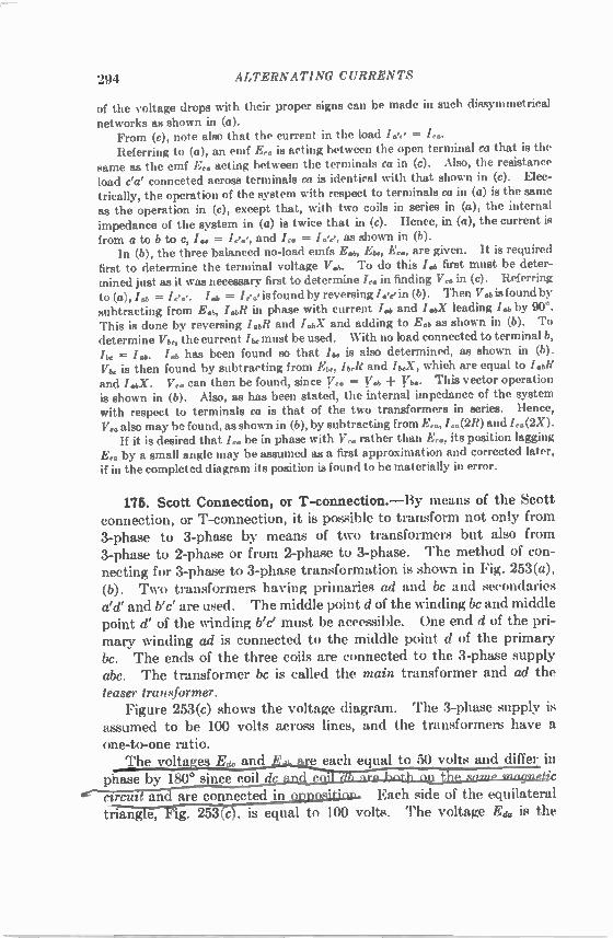
294 ALTERNATING CURRENTS
of the voltage drops with their proper signs can be made in such dissymmetrical
networks as shown in (a). From (c), note also that the current in the load I = I. Referring to (a), an emf E. is acting between the open terminal ca that is the
same as the emf E. acting between the terminals ca in (c). Also, the resistance load c'a' connected across terminals Ca is identical with that shown in (c). Elec-trically, the operation of the system with respect to terminals ca in (a) is the same as the operation in (c), except that, with two coils in series in (a), the internal impedance of the system in (a) is twice that in (c). Hence, in (a), the current is from a to b to c, I., = lee, and I,. = I.,',', as shown in (b). In (b), the three balanced no-load emfs E cab, Ebe, E., are given. It is required
first to determine the terminal voltage V. To do this /a, first must be deter-mined just as it was necessary first to determine I,. in finding V,. in (c). Referring to (a), = L.., is found by reversing /we in (b). Then Val, is found by subtracting from Lb, LbR in phase with current Lb and L a leading I by 90°. This is done by reversing /.bR and I.oc and adding to E.b as shown in (b). To determine Vbe, the current I be must be used. With no load connected to terminal b, = lab. Li, has been found so that /b, is also determined, as shown in (b).
Vire is then found by subtracting from Ebe, I beR and /b,X, which are equal to LAB and /. a. V,. can then be found, since V,. = y Vb. This vector operation is shown in (b). Also, as has been stated, the internal impedance of the system with respect to terminals ca is that of the two transformers in series. Hence, V,. also may be found, as shown in (b), by subtracting from E., 1,„(2R) and L.(2X). If it is desired that be in phase with V,,, rather than its position lagging
E. by a small angle may be assumed as a first approximation and corrected later, if in the completed diagram its position is found to be materially in error.
175. Scott Connection, or T-connection.—By means of the Scott connection, or T-connection, it is possible to transform not only from 3-phase to 3-phase by means of two transformers but also from 3-phase to 2-phase or from 2-phase to 3-phase. The method of con-necting for 3-phase to 3-phase transformation is shown in Fig. 253(a), (b). Two transformers having primaries ad and be and secondaries aid' and b'c' are used. The middle point d of the winding be and middle point d' of the winding b'c' must be accessible. One end d of the pri-mary winding ad is connected to the middle point d of the primary bc. The ends of the three coils are connected to the 3-phase supply abc. The transformer be is called the main transformer and ad the teaser transformer. Figure 253(c) shows the voltage diagram. The 3-phase supply is
assumed to be 100 volts across lines, and the transformers have a one-to-one ratio. The voltages Ede and_E.u..are each equal to 50 volts and differ in
phase by 180° since coil C2Telit an are connected in uulasitiou. Each side of the equilateral triangTe; Fig. 253ccl, is equal to 100 volts. The voltage Ed. is the

THE TRANSFORMER 295
altitude_of th pgjiilnt.ernl trianadr and is. therefore, equal to i00 32 Ar,...84.61—epeits. The same relations hold in the secondary , so that calc' is a symmetrical 3-phase system. The full rating of the transformers is not utilized however. The teaser transformer operates at only 86.6 per cent oLits rated vialtage, and in the coils bd and dc ttejurrent lags 30° in one and leads 30° in the other at unity power factor. This gives a power factor of 0.866 in the transformer coils and is therefore equivalent to the transformers' operating at only 86.6 per cent of their kva rating. If, however, the teaser is designed
a
C.
a'
(a) Main Transformer Primary and secondary voltages
Teaser Transformer
a'
c'
d' I Edb d Ede: 100 Volts
(c) Main Transformer
Method of connecting transformer coils Vector diagram 253. —T-eonneeted transformers, 3-phase to 3-phase.
for 86.6 per pnt. Itoge it operte at full roti on,l the roting..allx system is then (100 • 0.866 ± 86 6) /(10(1_±..Sfai L-7...a.a2,8_42 Ljiht. total transformer rating. If the ends b' and d' of the secondaries be connected, as shown in
Fig. 254(a), a 2-phase 3-wire system results. The voltage Eda, is equal to only 86.6 volts, whereas the voltage Ewe, equals 100 volts. The resulting 2-phase system, therefore, has unequal voltages. This may be corrected, however, if the line a be connected to point al on the primary of the teaser transformer, the point al being such that dai represents 86.6 per cent of the total winding of the teaser trans-former, as shown in Fig. 254(b). This will increase the volts per turn in the ratio of 100 to 86.6 and will raise the secondary voltage a cot-

296 ALTERNATING CURRENTS
fesponding amount, thus producing a symmetrical 2-phase 3-wire system. By connecting the middle points of the secondaries, a sym-metrical quarter-phase 4- or 5-wire system may be obtained, Fig. 255. • In any of the foregoing connections, d is not the neutral of the primary system, as it is not tile center of gravity of the voltages. The
(b)
Fm. 254. —Scott or T-connection. 3- to 2-phase.
voltages from the point 0, Figs. 253(c), 254(6), to a (or al), b, c are equal. Point 0, therefore, is the neutral of the primary system. Point 0 is two-thirds the way down the teaser transformer winding from al to d, Fig. 254(b). In these connections, the voltages become slightly unbalanced
even under balanced loads. This is due to the unsymmetrical phase relations among the voltages and currents in the individual coils.
-t
FIG. 255. —T-conneeterl transformers giving quarter-phase 4-wire system with balanced voltages.
176. Tap Changing under Load.—When required, it has always been the custom to provide transformers with taps in either primary or secondary by means of which the ratio of transformation can be changed by moderate amounts. Such tap changing has been accom-plished by such manual operations as changing links or by unbolting

THE TRANSFORMER 297
the line terminal from one tap and bolting it to another. In making such changes it is necessary to disconnect the transformer from the line, and usually it is necessary to open the ease, lower the oil level, etc. With transformers of small rating, tap changing may be accomplished by means of an insulated switch, Fig. 228(a) p. 270, although the circuit is opened momentarily. Many applications make it desirable to change the voltage in
transformers of large power ratings while the transformer is under load and without opening the circuit. For example, the voltage on feeders can be regulated automatically by tap-changing mechanisms on the feeder transformers, induction regulators being thus elimi-nated (Sec. 202, P. 358). Interconnected systems ordinarily require control of the voltage at the point of interconnection. [Reactive kva but not kilowatts thus can be controlled (see Secs. 143, 145, pp. 234, 238).] Also, voltage adjustment is desirable with synchronous converters and electric furnaces. In order not to open the circuit while changing taps, it is necessary
to provide some means by which the section of the transformer winding between taps is not short-circuited during the transition period. The connections for a common and simple method of tap changing
are shown in Fig. 256(a). The transformer winding is represented by ab with taps connecting to circuit breakers 1, 2, 3, 4, 5. One line wire A is connected to terminal a. cd is a preventive autotransformer whose function is to prevent the short circuiting of the taps when a change of connection is made and also to make available a voltage midway between tap voltages. A circuit breaker s is connected across the preventive transformer cd. The other line wire connects to the mid-point e of the preventive transformer. In order to obtain the maximum voltage the circuit breakers 1
and s are closed. Under these conditions, the load current from B divides, half going through winding ce and the other half going through winding de of the preventive transformer. Since the mmfs of these two currents are in opposition, there is an almost negligible impedance drop in the preventive transformer. To obtain a voltage midway between taps b2b, circuit breaker s is opened, and circuit breaker 2 is closed. The voltage at the midtap e is midway between the voltages of taps b and b2. In the transition, before circuit breaker 2 is closed. the entire load current flows in winding ce of the preventive trans-former. The core is designed to become saturated so that the emf across cd does not reach high values. After 2 is closed, the load cur-rent / divides equally between the windings ce and de as shown in (b). Hence one-half the load current adds vectorially to the exciting cur-

298 ALTERNATING CURRENTS
rent /0 in ce and subtracts from it in de, so that the currents in ce and de are unequal. The same procedure is followed in connecting to other taps. For
example, to connect to tap b2, open circuit breaker 1 and close s. These tap-changing operations may be controlled automatically by a contact-making voltmeter so as to hold the circuit voltage to any desired value.
A
Main Transformer
(a)
Line
Preventive Autotransformer
b3 62 b c
Fin. 256. —Connections for tap changing under load.
In order to avoid the high surge voltages to which the end turns of transformers sometimes are subjected in single-phase and delta-con-nected transformers, the taps frequently are located at the center of each winding. In grounded Y-systems they are at the grounded end of each winding. In order to obtain the advantages of tap changing for transformers
not having taps brought out, auxiliary tap-changing transformers operating as boosters are used and are con-nected with their secondaries in series with the main transformer and their primaries across the line. (See Fig. 246, p. 288. The 220-volt winding would be tapped.) Sometimes with system interconnections,
phase as well as voltage control is necessary, particularly when it is desired to transfer power load. Phase control may be effected by taps in auxiliary secondary windings
in the main transformer of the 3-phase system. For example. in Fig. 257, ab, be, ca are three-delta-connected secondaries of the power transformers. The auxiliary secondaries a'b', b'c', c'a' are wound on the same cores as secondaries ab, be, ca, respectively. Hence, the emfs of a'b' , b'c', c' a' are in phase with the emfs of the main secondaries ab, be, ca, respectively. If these auxiliaries are connected as shown, phase shift may be obtained by moving simultaneously the three taps
FIG. 257. —Phase control.

THE TRANSFORMER 299
.4, B, C. No attempt is made to show the tap-changing mechanism, which would be the same as in Fig. 256. It is almost always neces-sary to have ratio control with phase control. 177. Constant-current Transformers.—The transformers here-
tofore considered are constant-potential transformers; that is, the secondary voltage remains substantially constant, and a change of load is accompanied by a corresponding change of current. There are conditions where a constant current is desired, the most common being series street lighting. It will be recalled that constant direct current is obtained from a series generator. Constant alternating current ordinarily is obtained from a constant-current transformer. The construction of the transformer is such that the primary and
secondary can move with respect to each other. The primary coil may be fixed, and the secondary may move; or the secondary coil
Secondary
Ammeter
Starting Resistance
Primary Series Lamps
(a) Connections (b) Flux paths
Flu. 258. Constant-eurrent transformer.
A
Secondary Leakage Flux
Mutual Flux
Primary Leakage Flux
may be fixed, and the primary may move. Both types are found in practice. Figure 258(a) shows a transformer in which the primary is stationary and the secondary is movable. The load consists of a number of lamps connected in series. The secondary is suspended from a lever, which is counterweighted. A dashpot is provided to prevent rapid fluctuations in the position of the moving coil. The operation of the transformer is as follows: Assume that the
secondary coil is "floating," that is, is free to move either up or down, and is delivering a certain current to a series load. The currents in the primary and secondary flow in opposite directions, Fig. 258(6). There is repulsion, therefore, between the two coils. Assume that the load changes, for example, decreases. This change of load would be produced by short circuiting one or more lamps, causing a decrease in the load resistance. Because of the decreased load resistance, first the secondary and then the primary current tends to increase. This increases the repelling force between the two coils, resulting in the secondary's moving farther away from the primary. The leakage

300 ALTERNATING CURRENTS
flux between the two coils is thus increased, and this reduces the secondary induced volts. The secondary coil will move away from the primary until the secondary current is again at its normal value. The action of such a transformer depends on the change in leakage flux of both primary and secondary, Fig. 258(b). In starting the transformer the movable coil should be as far away as possible from the fixed coil and the secondary should be short-circuited. Because of its large proportionate leakage flux, this type of trans-
former has a very low power factor except at about maximum load. This is one objection to its use.
INSTRUMENT TRANSFORMERS
178. Electrical Measurements at High Voltages.—It is not usually practicable to connect instruments and meters directly to high-voltage circuits. Unless the high-voltage circuit is grounded at the instru-ments, their potential to ground may be high, which makes them a source of danger to anyone coming near the instruments or switch-board. Further, instruments become inaccurate when connected directly to high voltage, because of the electrostatic forces that act on the indicating element. Specially designed instruments may be con-structed so that they can be connected directly to high-voltage cir-cuits, but these instruments are usually expensive and are not suitable for commercial work. By means of instrument transformers, instruments may be entirely
insulated from the high-voltage circuit and yet indicate accurately the current, voltage, power, etc., in the high-voltage circuit. Low-voltage instruments having standard current and voltage ranges thus may he used for all high-voltage circuits, irrespective of the voltage and current ratings of the circuits. 179. Potential Transformers.—Potential transformers do not differ
materially from the constant-potential power transformers already discussed, except that their power rating is small and they are designed for minimum ratio and phase-angle error. At unity power factor the impedance drop from no-load to rated load should be not over 1 Der cent. Below 5,000 volts, potential transformers are usually of the dry type; between 5,000 and 13,800 volts they may be either of the dry type or oil-immersed, above 13,800 volts they are oil-immersed. As only instruments, meters, and sometimes pilot lights ordinarily
are connected to their secondaries, such transformers have ratings of 40 to 500 watts. For primary voltages of 34,500 volts and higher, the secondaries are rated at 115 volts. For primary voltages less than 34,500 volts, the secondaries are rated at 120 volts. For example,

THE TRANSFOR MER 301
a 14,400-volt potential transformer would have a ratio of
14,400 _ 120 120 1 •
The ratio of turns may vary 1 per cent or so from this value to allow for the transformer impedance drop under load. Figure 259 shows a simple connection for measuring voltage in a 14,400-volt circuit by means of a potential transformer. The secondary always should be grounded
14,400 Volts 120:1
Potential Transformer
Ground FIG. M. —Connections of potential and current transformers to 14,400-volt circuit.
at one point to eliminate " static " from the instrument and further to ensure safety to the operator. Figure 262 shows a potential trans-former used in conjunction with a current transformer for measuring power by means of a wattmeter. 180. Current Transformers.—To avoid connecting alternating-
current ammeters and the current coils of other instruments and meters as well as relay coils directly in high-voltage lines, current transformers are used. In addition to insulating from high volt-
Primary age, they step down the current in a known tatio. This enables a lower range
Secondary Flux ammeter to be used than ordinarily would tin. 260. —Bar-type
transformer.
Bus-Bar or Cable
current be required if the instrument were con-nected directly into the primary line.
The current, or series, transformer has a primary, usually of few turns, wound on a core and connected in series with the line, Fig. 259. When the primary has a large current rating, it may consist of a straight conductor passing through the center of a hollow core, (bar type), Fig. 260. The secondary, consisting of several turns, is wound around the laminated core. The ratio of current transformation is

302 ALTERNATING CURRENTS
approximately the inverse ratio of turns. For example, the primary, Fig. 260, has 1 turn, and if the secondary has 60 turns the ratio will be 60 to 1. The ratio may vary slightly from this value, owing to the magnetizing current. In Fig. 261(a), the primary current 11 consists of two components, —12, the component necessary to balance the secondary ampere-turns, and /0, the exciting current. The exciting current introduces a slight error in the ratio as well as causing /2 to depart by the angle $ from the 180° phase relation to /1. The angle fl
-12
(a) vector diagram
1 Secondary Current (reversed) Leads
10 20 30 40 60 60 70 80 90 100 Per Cent Rated Current
(h) Phase angle and ratio curves for typical current transformer FM. 281. —Current-transformer characteristics.
110 120 130 140
is defined as the phase angle' of the transformer and is positive when — /2 leads II, Fig. 261(a). At light loads the exciting current may cause considerable error. Figure 261(b) shows the variation of phase angle and ratio with load for a typical transformer. Both the ratio and the phase angle are affected by the impedance
of the secondary load, or the burden on the transformer. As the bur-den increases, the ratio increases and the secondary current /2 lags more, which ordinarily reduces the value of The ratio correction factor (R.C.F.) is the quotient obtained by dividing the true ratio, Fig. 261(b), by the nominal or name-plate ratio. For example, if the
I ASA Standard 57 (1942). 1.131.

THE TRANSFORMER 303
nominal ratio is 100 to 1 and the true ratio 100.5 to 1, the ratio correc-tion factor is 100.5/100 = 1.005. The phase angle has no effect when the transformer is used for measuring current only, but it does intro-duce error into power and energy measurements when wattmeter and watt-hour-meter current coils are connected in the secondary. The error may be small near unity power factor, but it may becomes serious at low power factors. (Likewise, the phase angle of the potential transformer introduces a similar error.) The secondaries of practically all current transformers are rated
at 5 amp regardless of the primary current rating. For example, a 2,000-amp current transformer has a ratio 400 to 1, and a 60-amp transformer has a ratio 12 to 1.
Potential Transformer
Current Transformer
282. —Typical connections of instrument transformers and instruments for single-phase measurements.
The insulation between the primary and the secondary of a current transformer must be sufficient to withstand full circuit voltage. The current transformer differs from the ordinary constant-
potential transformer in that its primary current is determined entirely by the load on the system and not by its own secondary load. If its secondary becomes open-circuited, a high voltage will exist across the secondary, because the large ratio of secondary to primary turns causes the transformer to act as a step-up transformer. Also, since the counter ampere-turns of the secondary no longer exist, the flux in the core, instead of being due to the difference of the primary and secondary ampere-turns, will now be due to the total primary ampere-turns acting alone. This causes a large increase in the flux, producing excessive core loss and heating, as well as a high voltage across the secondary terminals. Therefore, the secondary of a current transformer should not be open-
circuited under any circumstances. Figure 262 shows the method of connecting a typical instrument
load, through instrument transformers, to a high-voltage line. The

304 ALTERNATING CURRENTS
load on the instrument transformers includes an ammeter, a voltmeter, a wattmeter, and a watt-hour meter. Each secondary is grounded at one point. Corfection for ratio of transformation must be applied to all the instrument readings, the wattmeter and watt-hour meter involving the ratio of both current and potential transformers. Usu-ally, in permanent installations, as on switchboards, the instrument scales themselves are marked so as to take into consideration these ratios. The primary voltage, current, and power therefore may be read directly. Polarity Markings.—In order to be able to connect instruments,
meters, and relays so that the correct phase relations exist between their potential and current circuits, it is convenient in instrument transformers to know the relation of the instantaneous polarities of the secondary terminals to the primary terminals. It has become standard to designate or mark the primary terminals and the secondary terminals that have the same instantaneous polarity. The primary terminals are marked 111, H 2 . . , and the secondary terminals X1, X 2 . . . , Figs. 259 and 262. When a primary terminal and a sec-ondary terminal are simultaneously positive, current will he entering the primary terminal and leaving the secondary terminal, Figs. 259 and 262.

CHAPTER IX
THE INDUCTION MOTOR
181. Principle.—The induction motor is the most widely used type of alternating-current motor. This is due to its ruggedness and simplicity, to the absence of a commutator, and to the fact that its operating characteristics are well adapted to constant-speed work. The principle of the motor may be illustrated as follows: A metal
disk, Fig. 263(a), is free to turn upon a vertical axis. The disk may be of any conducting material, such as iron, copper, or aluminum. A magnet, free to rotate on the same axis as the disk, is placed above the disk, and its ends are bent down so that its magnetic flux cuts through the disk. When this magnet is rotated, the magnetic lines cut the disk and induce currents in it, as shown in the figure. As these cur-rents find themselves in a magnetic field, they tend to move across this field, just as the currents in the conductors of a direct-current motor tend to move across its magnetic field. By Lenz's law, the direction of the force developed between these currents in the disk and the magnetic field producing them will be such that the disk tends to follow the magnet, as shown in the figure. To illustrate this more in detail, consider Fig. 263(a), (b), (c). In
(a), the north pole of the rotating magnet is shown as moving in a counterclockwise direction. The conductor beneath the magnet also moves in a counterclockwise direction, but more slowly than the mag-net. The relative motion between the magnet and the conductor is the same, therefore, as if the magnet were stationary and the conductor moved in the clockwise direction. This relative motion of the magnet and the conductor is illustrated in Fig. 263(b), in which the disk is viewed from the position of the arrow A. The N-pole is considered as being stationary, and accordingly the disk and hence the conductor are moving from right to left. Applying Fleming's right-hand rule (see Vol. I, Chap. XI), the direction of the induced current is toward the observer. The lines of force about the conductor, due to its own current, are therefore counterclockwise, and the resultant field is found by combining the conductor field and the field produced by the magnet. The appearance of this resultant field is shown in Fig. 263(c) (also, see Vol. I, Chap. XIII). As the magnetic field is increased in intensity to the left of the conductor and reduced in intensity to the
305

306 ALTERNATING CURRENTS
right of the conductor, there is a force developed which urges this conductor from left to right, that is, the conductor tends to follow the magnet. Actually, the magnet rotates in a counterclockwise direction. The disk, therefore, rotates in the same direction, but at a speed less than that of the magnet. Thus, in induction apparatus of this character there exists generator
action, which causes currents to be induced, and motor action, which causes the induced currents to follow the inducing field.
Motion
Force
Direction of rotation of disc with respect
to magnet
(c)
Direction of rotation .v.s. of magnet
Relative motion of conductor with respect to magnetic pole
(6)
Direction of rotation of disc
263. —Rotation of metal disk produced by rotating magnet.
The disk can never attain the speed of the magnet; for, were it to attain this speed, there would be no relative motion of the disk and the magnet and, therefore, no induced emf in the disk due to cutting of the disk by the magnetic flux. The disk current then would become zero, and no torque would be developed, a situation that would result in the disk speed becoming less than that of the magnet. Because the disk cannot attain the speed of the magnet, there must always exist a difference of speed between the two. This difference of speed is called the revolutions slip. It is to be noted that the currents in the disk, or armature, of this
type of motor are induced therein, rather than being conducted into the armature, as in the ordinary direct-current motor.

THE INDUCTION MOTOR 307
A cylinder may be used instead of the disk, Fig. 264. In the figure are shown 4 poles, the magnetic lines of which cut the cylinder. If the frame carrying these poles be revolved by mechanical means, the currents induced in the cylinder will cause the cylinder to rotate in the same direction as that of the rotating frame. This cylinder is more representative of the commercial induction motor than is the disk, although both operate on the same principle. 182. Rotating Field.—The field of Fig. 263 is a sliding-type field.
Although this type of field is used in the induction watt-hour meter (Sec. 78, p. 106), a rotating field acting on a cylindrical armature is
Direction of rotation of
armature with respect to field Direction of
rotation of field
structure
Induced armature-currents
264. —Rotation of conducting cylinder due to induced currents.
much better adapted to motors. Such a field is shown in Fig. 264. There are 4 poles mounted on the yoke or frame, and the magnetic flux due to the 4 poles passes through the conducting cylinder, which is free to rotate. If the entire field structure be rotated mechan-ically in a counterclockwise direction as indicated, the flux due to the poles will cut the conducting cylinder and induce currents as shown. The paths and directions of these currents should be noted, for they are identical with those of the induction motor with a similar rotating flux. By applying Fleming's right-hand rule the direction of the induced currents may be determined, the relative direction of motion of the rotating member with respect to the poles being used. Flem-ing's left-hand rule then may be applied to determine the direction of rotation of the cylinder or armature. With the relation of poles and

308 ALTERNATING CURRENTS
currents in Fig. 264, the direction of torque, or rotation, is counter-clockwise. The induction motor operates on the principle of the rotating field,
Fig. 264, but the rotating field is produced by polyphase currents in polyphase windings, such as alternator windings. Such rotating fields are produced entirely by electrical means, there being no mechan-ical rotation of the pole pieces themselves. A simple type of such rotating field is that produced by 2-phase currents in a 2-phase 2-pole winding described in the next section. 183. Rotating Fields. a. Two-phase.—In Fig. 265(a) are shown
sectional views of an induction motor with a 2-phase 2-pole stator
(1)
(b) 265. —Rotating field by 2-phase currents in 2-pole winding.
(a) (3) (4)
winding. For simplicity, slots are omitted, and a single-layer winding is shown. A two-layer winding could be obtained by adding a second layer like the winding shown, but the electrical effect would not be changed. In (a) the phase belts are designated as +A, —A, +B, —B. The (-1-) and ( — ) signs designate opposite sides of the armature coils of any one phase. When a current is positive, it is assumed that its direction is inward in a (+) phase belt and outward in a ( —) phase belt. When a current is negative, its direction will be outward in a (±) phase belt and inward in a ( —) phase belt. In (b) are shown the vectors and sine waves of current /A and 18, differing in phase by 90° and supplied to the windings A and B. At instant 1, the current IA is zero, and the current Ili is negative
maximum. Hence, the current will be outward in the -1-B-belt and inward in the —B-belt, as shown in (1). By applying the corkscrew

THE INDUCTION MOTOR 309
rule, the direction of the mmf is found to be 45° downward to the left, and a N- and S-pole are created as shown. At instant 2, 45 time degrees later than instant 1, the current IA is positive and 0.707 of its maximum value, and Ig is negative and also 0.707 of its maximum value. Hence, the two currents are equal numerically, and according to assumption the currents are inwards in the —B- and +A-belts and outward in the +B- and —A-belts. The resultapt mmf is now hori-zontal and acts from right to left, producing the N- and S-poles shown in (2). Note that as the currents have gone through 45 time degrees, the N- and S-poles have advanced 45° in a clockwise direction. At instant 3, the current IA is a maximum, and IR is zero. The current is still inward in the +A-belt and outward in the — A-belt, and the direction of the mmf is now 45° upward to the left, as shown in (3). Note that the N- and S-pole have advanced 90° from their initial position. At instant 4, the two currents are positive, and each is equal to 0.707 of its maximum value. The direction of the current in the B-belts is the reverse of that in (2), and the mmfs combine to produce a field acting vertically upward. If a similar analysis is made for time degrees 5, 6, 7, 8, 9, the N- and S-poles will advance 45° in each interval; and at 9, the completion of a cycle, the field will be in the same position as at 1 and will have made one revolution. Hence, in a 2-pole stator the rotating field makes one revolution for every cycle of current, or its speed in rps is equal to the frequency of the supply in cycles per second. In Fig. 266(a) is shown a section of an induction motor similar to
that in Fig. 265(a), except that the stator is wound for 4 poles. The connections of the winding are shown in (b). Although for simplicity the winding is shown as a single-layer one, it behaves electrically the same as a two-layer winding. The phase belts are designated as (±) and ( — ), and as in Fig. 265 positive current is inward in the (+) belts and outward in the ( —) belts. At instant 1, the current IA is zero, and In is a negative maximum,
Fig. 265 (b). By applying the corkscrew rule for determining the rela-tion of magnetic flux to the current producing it, 4 poles are formed in the stator, two N-poles in the vertical plane and two S-poles in the horizontal plane, as shown in (1). At instant 2, the current IA is positive, and Ig is negative and of the same polarity as in 1. The resulting N- and S-poles are again determined by the corkscrew rule, and it will be noted that these two poles have advanced 22.5 space degrees in a clockwise direction, whereas the currents have undergone a change corresponding to 45 time degrees. Conditions (3), (4), (5), are taken at time degrees 90, 135, 180 of the two currents. Between

+A
(1)
310 ALTERNATING CURRENTS
points (1) and (5), the rotating field has advanced only 90 space degrees, whereas the currents have gone through 180 time degrees. Therefore, the speed of this rotating field in rps is one-half that of the
-A -A
+A
+A
+A (2)
(a)
+A
(51
,A
(b) Single-layer, 4-pole 2-phase lap winding
266. —Rotating field by currents in 4-pole winding.
+A
Phase A Phase B i A
-A
2-pole motor of Fig. 265 and is therefore equal to one-half the fre-quency of the supply in cycles per second. b. Three-phase.—The production of rotating fields with 3-phase
currents is illustrated in Fig. 267 (also see Fig. 177, p. 195). In (a) is shown a sectional view of an induction motor with a 3-phase 4-pole

+A
(I)
3-Phase Supply as a single-layer one, the connections
being shown in Fig. 268. For sim-plicity, only the A-phase is shown as being completely connected, the B-and C-phases being connected in a manner similar to A. With a two-layer full-pitch winding, the relations of current and flux would be iden-tical with those of Fig. 267(a). In Fig. 267(b) are shown the 3-phase currents as vectors and as sine waves.
Fla. 268. —Single-layer 3-phase The currents in the windings (1), (2), 4-pole induction-motor winding, lap (3), (4) in (a) correspond to the connected.
instants 1, 2, 3, 4 in (b). In (1), the current IA is zero, so that Ig and Ic are opposite and
equal. The position of the field is shown at this instant. In (2), the currents /A and /c are but half their maximum positive values,
THE INDUCTION MOTOR 311
stator winding. The phases are designated as +A, —A, +B, —B, +C, —C. As in Figs. 265 and 266, the (±) sign on a conductor belt
+C
-A
+A +A +A -B -C -B -C -B -C
+B+C 000 +B+C +B+C
'00 C+L K.
-B -C -B -C B - C +A +A
(2) (3) (a)
+A
+A
(4)
1 23 4
(b) 267.— Rotating field produced by 3-plia.se currents in 4-pole induction-motor
winding.
signifies that the current flows into the conductors of that belt when the currents are positive and outward when the currents are negative.
The reverse is true of the ( —) belts. For simplicity, the winding is shown
Phase A Phase B Phase 0

312 ALTERNATING CURRENTS
and the positions of their phase belts on the stator are at each side of the B-belt, in which the current is a negative maximum. The field, therefore, is symmetrical at this position. It will be noted, also, that the time angle between successive
values of current in 1,2,3 is 30 electrical degrees, whereas the field advances only 15 space degrees between (1) and (2) and also between (2) and (3). From diagrams (1) to (4), the currents have advanced 90 electrical time degrees, but the rotating field has advanced only 45 space degrees; that is, the advance of the rotating field in space degrees is equal to one-half the advance of the currents in electrical time degrees. The speed of such a field in rps is equal, therefore, to one-half the circuit frequency in cycles per second. From Figs. 177 (p. 195), 265 to 267 and the accompanying dis-
cussion the following conclusions may be drawn: In order to produce a 2-pole rotating field, the angular space
degrees between the phase belts of the winding must be the same as the electrical time degrees between their respective currents. If the motor has p poles, the angular space degrees between phase belts is 2/p times the electrical time degrees between their respective currents. (In a 2-pole motor, 1 electrical degree equals 1 space degree; in a 4-pole motor, 2 electrical degrees equals 1 space degree; etc.) For example, in Fig. 266 the motor has 4 poles, and the time angle between the cur-rents IA and /8 is 90°. Hence, the space angle between the A- and B-phase belts is VI • 90° = 45°. In Fig. 267 the motor has 4 poles, and the time angle among the currents IA, IB, Ic ir3 120°. Hence, the space angle between the successive +A-, +B-, +C-phase belts is % • 120° = 60°. In a 6-pole 3-phase motor there is an angle of 40° between successive ( + ) phase belts, that is, 2/6 • 120° = 40°. In the ordinary drum windings, however (see Figs. 146, 147, pp. 162 and 163), the coil sides lap back, solhat in Fig. 267(a) the angles between reversed phase belts, that is, between (+) and ( — ) phase belts, are 30°. For example, in the 6-pole motor the angles between reversed phase belts are 20°. The currents in such adjacent belts are 60 time-degrees apart. It also follows that in a 2- pole motor, irrespective of the number of
phases, the speed of the rotating field in rps is equal to the frequency in cycles per second; in a 4-pole motor the speed of the rotating field in rps is one-half the frequency in cycles per second. It would follow that in a 6-pole motor the speed would be one-third the frequency and in an 8-pole motor the speed would be one-fourth the frequency in cycles per second. The N- and S-poles, produced by the currents in the stator wind-
ings, in rotating around the air gap cut the rotor or armature conduct-

THE INDUCTION MOTOR 313
tors, inducing currents in them. The currents, reacting with the stator poles, develop torque tending to produce rotation of the armature, just as in Fig. 263 the induced currents in the disk and the flux pro-ducing them react and cause the disk to rotate. To reverse the direction of rotation of a 2-phase rotating field,
reverse the leads of either phase; to reverse the direction of rotation of a 3-phase rotating field, interchange any two leads. 184. Synchronous Speed; Slip.—It has just been shown that the
speed in rps of a 2-pole rotating field is equal to the frequency in cycles per second, the speed of a 4-pole field is one-half this value, the speed of a 6-pole field is one-third this value, etc. It follows that the speed of the rotating field in rpm must be
N = f 120 P (188)
where f is the frequency in cycles per second and P the number of poles. The speed N of the rotating field is called the synchronous speed
of the motor. The common synchronous speeds for commercial motors at 25 and at 60 cycles per sec are as follows:
Poles Rpm = N
f = 25 f = 60
2 1,500 3.600 4 750 1,800 6 500 1.200 8 375 900 12 250 600
Slip.—If an armature whose conductors form closed circuits be placed in a rotating field, it will develop torque because of the induced currents acting in conjunction with the rotating magnetic field. As has been pointed out, the armature can never attain the speed
of the rotating field; for if it did, the cutting of conductors by flux would cease and there would be no rotor current and, therefore, no torque. The difference between the speed of the rotating field and that of
the rotor is called the revolutions slip of the motor. For example, if the rotor of a 4-pole 60-cycle motor has a speed of 1,730 rpm, its revolutions slip is 1,800 — 1,730 = 70 rpm, where 1,800 rpm is its synchronous speed.

314 ALTERNATING CURRENTS
It is more convenient to express the slip as a fraction of the syn-chronous speed. Denote the speed of the rotor by N2 and the syn-chronous speed by N. Then the slip
S = (189)
For example, the slip in the above motor is
1,800 — 1,730 = S = 70 = 0.039, or 3.9%.
1,800 1,800
The rotor speed is N2 = N(1 — s) rpm [from (189)]. (190)
The full-load slip in commercial motors varies from 1 to 10 per cent depending on the size and type. 185. Rotor Frequency and Induced Electromotive Force.—If the
rotor of a 2-pole 60-cycle motor is at standstill and a 60-cycle voltage is applied to the stator, each rotor conductor will be cut by an N-pole 60 times per second and by an S-pole 60 times per second, as this is the speed of the rotating field. If the stator be wound for four poles, the speed of the rotating field is halved, but each conductor is then cut by two N- and two S-poles per revolution of the field and, therefore, by 60 N- and 60 S-poles per second, the same as in the 2-pole motor. Consequently, in each case, the frequency of the rotor currents at standstill (s = 1.0) will be the same as the stator frequency. This holds true for any number of poles. At standstill the motor is a simple polyphase static transformer, the stator being the primary and the
rotor being the secondary. If the rotor of the above 60-cycle motor revolves at half syn-
chronous speed in the direction of the rotating field (s = 0.5), the rotor conductors are cut by just one-half as many N- and S-poles per second as when standing still and the frequency of the rotor current is,
therefore, 30 cycles per sec. By taking other rotor speeds, it can be shown that the rotor
frequency 12 = 81, (191)
where f2 is the rotor frequency, s the slip, and f the stator frequency. The rotor frequency is equal to the stator frequency multiplied by the slip.
Example. —Determine the frequency of the currents in the rotor of a CO-cycle 6-pole induction motor, if the rotor speed is 1,164 rpm. The synchronous speed
60 • 120 N = 1,200 rpm (Eq. (188), p. 3131. 6

THE INDUCTION MOTOR 315
The slip 1 200 — 1 164
8 = 1,200 = 0.03.
12 = 0.03 • 60 = 1.8 cycles per see. Ans.
The rotor frequency has a very important bearing on the operating characteristics of the induction motor. The induction motor can be used as a frequency changer, provided
that the rotor is driven mechanically at the proper speed. Current is taken from the rotor, or secondary, through slip rings. Under these conditions, some of the power is supplied electrically and some mechanically. 186. Alternating-current Torque. a. When the Slip Is Small.—lt
has been pointed out, in connection with the direct-current motor, that the torque is proportional to the current and to the density of the magnetic field in which the current finds itself. This same law holds for alternating-current motors, provided that the instantaneous values of current and flux are considered. Figure 269(a) shows the space distribution of flux from one N-pole
as it glides from left to right along the air gap of an induction motor. This flux is distributed sinusoidally along the air gap, as is shown by the flux-density curve B, Fig. 269(b). If the slip be small, the reactance of the rotor conductors is low
because /2 = sf and 4 = 2112L2, where f is the stator frequency, 4 the rotor reactance at slip s, and L2 the rotor inductance. Because of the rotor reactance, the rotor current lags the induced emf of the rotor by an angle a. At low values of slip, this angle a is very small, since tan a = 2rfsL2/R2, where R2 is the rotor resistance. The induced emf in any single conductor, 1 cm in length, in a field
having a density of B gausses, the conductor moving at a velocity of v cm per sec with respect to the field, is e = Blv 10-8 volts, the flux, the conductor, and the velocity being mutually perpendicular (see Vol. I, Chap. XI). When, therefore, a conductor is cutting flux at a uniform velocity, the flux being sinusoidally or otherwise distributed in space, the emf in the conductor is zero when it is moving in a region where B, the flux density, is zero; the emf is a maximum when the conductor is moving in a region where B, the flux density, is a maximum. As the emf e is proportional to B at every instant if v is con-stant, e will be a maximum when B is a maximum, etc. (see p. 176). The emf e per conductor, is therefore in space phase with the flux density. It follows further that the wave shape of the emf in a single conductor is the same as the shape of the space-distribution curve of the flux.

316 ALTERNATING CURRENTS
At small values of slip, the angle a, between the induced emf in each conductor and the current in the conductor, is small, and therefore the current in each of the conductors, Fig. 269(a), is practically in phase with its induced emf. As the induced emf is a maximum when the conductor is in that part of the field where the flux density is greatest, the current will be a maximum at practically the same instant.
1' I
6
(a) Current belt in space phase with flux-density when rotor reactance is low
(b) Space distribution of current and flux-density, when in space
phase with each other.
Stator
Fin. 269. —Relation among flux, current, and torque when current belt is in space phase with flux wave.
The current in each conductor then is in time phase with its emf, and hence the current-distribution curve I will be in phase with the flux-density curve B. Under these conditions, the current in the par-ticular conductor that is under the center of the pole, Fig. 269(a), is a maximum, and that in the other conductors is less, decreasing sinusoidally as indicated. Figure 269(b) shows both the flux-density distribution in the gap
and the current distribution in the conductors of Fig. 269(a), the cur-

Rotor
THE INDUCTION MOTOR 317
rent in each conductor being proportional to the flux density of that part of the field in which the conductor finds itself. (For simplicity, a smooth current-distribution curve is shown. This would hold true only with a uniform metal sheet about the rotor.) The force acting on each conductor is proportional to its current and to the flux density of that part of the field in which the conductor finds itself (see Vol. I, Chap. XIII). The force due to each conductor, Fig. 269(a), is indi-
-8!
ale;
O A.
V,
10
(a) Current belt a space-degrees out of phase with flux-density curve, when rotor reactance is high.
Stator
Torque
Torque developed by a
egative Torque
1
(b) Space distribution of current and flux-density, differing in space phase by angle a.
Flu. 270. —Relation among flux, current, and torque when current belt is not in space phase with flux wave.
cated in direction by an arrow attached to that conductor. The torque curve is obtained by taking the product of the current and flux density at each point, multiplied by a constant. The torque curve for the conductor belt shown in Fig. 269(a) is given in Fig. 269(b). This curve is obtained by multiplying the current at each point by the flux density at that point. That is, the ordinate of the torque curve at any point, Fig. 269(b), is equal to the product of the ordinate of the flux-density curve and the ordinate of the current curve at that point,

318 ALTERNATING CURRENTS
multiplied by a constant. It will be noted that this torque curve is of double frequency, is always positive, reaches zero twice each cycle, and is similar to the power curve of Fig. 22, (p. 24). The direction of the torque is the same as the direction of motion of the field. b. When the Slip Is Large.—As the slip increases, the reactance of
the rotor increases, the reactance being proportional to the rotor fre-quency and, hence, to the slip. Therefore, the angle a by which the current lags its induced emf increases, since tan a = 2rfsL2/R2. The current in any conductor will not reach its maximum value until a time degrees after the induced emf has reached its maximum value. In the interval between the time when the induced emf reaches its maximum and the current reaches its maximum, the maximum point of the flux wave has moved by the conductor by a electrical space degrees, Fig. 270(a). As a result, some conductors, as a, Fig. 270(a), find themselves in a reversed field and so develop a torque opposite to that of the other conductors in the belt. Also, conductor a' in an adjacent current belt, because of the direction of its current, exerts a torque opposite to that of the other conductors in its belt. The torques exerted by conductors such as a and a' produce the negative loops of the torque curve, Fig. 270(b). The torque curve T obtained by multiplying the ordinates of the flux-density curve B and the cur-rent-distribution curve I is less than it is in Fig. 269(b), even with the same value of current and flux. This is due to the negative values of torque, Fig. 270(b). Therefore, in order to have maximum torque with fixed values of
current and flux, the rotor-current curve must be in space phase with the flux-density curve, Fig. 269. The average torque
T = T„,„. cos a, (192)
where T.: is the average torque when the rotor current curve I and the flux-density curve B are in space phase, and a is the space angle between current-distribution curve I and flux-density curve B. Figure 271' gives for the complete 360 electrical degrees the condi-
tions of Fig. 270 for a 2-pole motor, the electrical and geometrical space degrees being equal. The vector B gives the space position of the center of the N-pole flux; the vector El gives the space position of the center of the belt of emfs induced by the N-pole flux, and g is in space phase with vector B; the vector 12 gives the space position of the center of the secondary current belt, the current being due to E; and lagging El by the angle a. The stator currents are also shown in this figure;
Diagram from Fig. 83, "Standard Handbook," 7th ed., See. 7, p. 698.

THE INDUCTION MOTOR 319
and since the vector /2 corresponds to currents flowing into the paper, the space position of the vector II, representing the center of a stator current belt, must also correspond to currents flowing into the paper. Thus, as in a transformer, I and 12 differ in phase by nearly 180°. In order that lag may be shown in the conventional clockwise direc-tion, the field is shown rotating counterclockwise so that the N-pole is moving from right to left. In Figs. 269(a) and 270(a) the field is shown moving from left to right, in order that time may be shown as increasing toward the right, the usual convention.
271. —Semipictorial space representation of current and flux in induction motor.
187. Stator and Slots.—The construction and assembly of induc-tion-motor stators are identical with those of alternators of the same size. Likewise, the windings are identical with those of alternators (Sec. 182) for the same voltage, synchronous speed, and number of poles (see Chap. VI). However, in order to make the air-gap reluctance a minimum and
to prevent excessive tooth losses, the stator slots in nearly all induction motors, except in those of large rating are of the semiclosed type. Fig. 272(a), (b). In the larger ratings open slots such as are used for alternators, Fig. 156(a), (p. 171), are used. The stator punching, Fig. 152(a) (p. 168), is also used for induction motors of large rating. The chief advantage of the open slot is that form-wound coils can be used. With large high-speed motors it is not so necessary to reduce air-gap reluctance by the use of semiclosed slots. The pole pitch is large; therefore the number of ampere conductors per pole is large. Consequently, the desired flux density in the gap may be obtained

320 ALTERNATING CURRENTS
readily without an excessive magnetizing current, even if open slots are used. In practically all motors of the squirrel-cage type, the slots of the
rotor are semiclosed or totally closed, Fig. 272(a), (b), (c), as there is little difficulty in placing the rotor bars in these types of slots. The totally
Stator
Slot Insulation
Wedge -
Rotor (b)
(c)
Fro. 272. —Stator, and rotor slots of squirrel-cage induction motor.
OWN
Flo. 27.. 1:“1 stator for 125-1,1, 340-rpm blower, and filter motor. (Reliance Electric and Engineering Co.)
enclosed slot is particularly well adapted to the casting of aluminum rotor windings. Except in motors of large rating, the slots of wound rotors are of the semiclosed type (also see Figs. 273, 274, 281, and 285, pp. 332, 337). The advantage of semiclosed and totally closed slots is that the
effective sectional area of the air gap is increased and the magnetizing current therefore, is reduced. Such slots also reduce the pulsations of

THE INDUCTION M OTOR 321
flux in the individual teeth and therefore reduce the tooth losses, which otherwise might be serious. On the other hand, semiclosed and totally closed slots give a much higher slot inductance than the open slot, and this inductance in the stator and in the rotor lowers the power factor and decreases the starting and the breakdown torques of the motor. Figure 273 shows the stator of a 125-hp 340-rpm motor whose
fabricated construction is typical of modern methods. The feet and other parts are welded to the stator frame. The rotor used with this stator is 30 in. diameter and is the largest rotor heretofore made by the die-casting process. Some manufacturers are making the motor frames of cast iron. 188. Squirrel-cage Motor.—The squirrel-cage motor is the simplest
type of induction motor n nd the most generally used. The core of the
I
a •
a
•
Fin. 274. —Cast rotor with shaft and hearings for 60-hp 1150-rpm 60-cycle induction motor. (Reliance Electric and Engineering Co.)
rotor, or armature, Fig. 274, like that of the d-c armature, usually is built up of slotted steel punchings. The winding consists either of copper or alloy bars placed in the slots or of die-cast aluminum. In the bar type of winding the ends of the bars are connected together by conducting rings called end rings. The bars are usually electrically welded or brazed to the end rings. Formerly, solder was used, but con-siderable trouble was encountered by its melting and being thrown out of the joint by centrifugal action. Either stator or rotor slots fre-quently are skewed to minimize locking action of the teeth. For example, the rotor bars in the rotor of Fig. 274 are skewed. With motors up to 30 hp and even greater, it has become common
practice to make the entire rotor winding of die-cast aluminum, Fig. 274. The rotor bars, the end rings, and even the rotor fans are all cast integral with one another. With such rotors the slots must be closed to encase the molten metal. If semiclosed slots are used,

322 ALTER NA TI NG CURRENTS
the narrow opening must be closed during the casting process. In the cast rotor, Fig. 274, ventilating ducts also have been provided. The cast type of rotor construction is now widely employed by leading manufacturers, since it produces a uniform and very rugged rotor. Because of the capital investment and the lesser production, it usually is not economical to manufacture this type of rotor in the largest sizes. 189. Operating Characteristics of Squirrel-cage Motor.—The
squirrel-cage motor, like the d-c shunt motor, operates at substantially
5.
14
50
>: N be
g g 200 200
1800 46 180 80 180
1600 40 160 80 160
1400 35 140 70 140
1290 30 120 60 120
1000 25 100 50 100
800 20 80 40 80
600 15 60 30 60
400 10 40 20 40
200 5 20 10 20
Squiriel•Cage I I ,
Induction Motor 20 HP. 1745 rpm, 3 Ph., 60 Cycle 220/440 Volts
Century Electric Company
,
— .......6-
... R P.M.-Hp. --- opos
4 f.
-.; ....1 4O
rc i a;
....N.,
4 .
. /
I /•
I
(r I
..4 ''/.. , ',Rated Load \,..
5 10 15 29 25 30 35 40 45 50 Horse Power 100 200 Per Cent Full-Load Torque
275. —Perforniance characteristics of 20-lip 1745-rpm squirrel-cage induction motor. (Century Electric Co.)
SOO
constant speed. As the rotor cannot reach the speed of the rotating magnetic field, it must at all times operate with a certain amount of slip. At no load, the slip is very small. As load is applied to the rotor, more rotor current is required to develop the necessary torque in order to carry the increased load. Consequently, the rotating magnetic field must cut the rotor conductors at an increased rate, in order to produce the necessary increase of current. Accordingly the slip of the rotor must increase, and the rotor speed must decrease. The slip is equal to the ratio of the I2R loss in the rotor to the total power delivered to the rotor. As the resistance of the squirrel cage is low, the PR loss is low, and therefore the slip for ordinary loads is small. In large

THE INDUCTION MOTOR 323
motors-50 hp or greater—the slip is of the order of 1 to 2 per cent at full load. In the smaller sizes of motor the slip may be as high as 8 to 10 per cent at full load. Figure 275 shows the usual characteristic curves of a 20-hp squirrel-
cage motor in which torque, power factor, efficiency, amperes, kilo-watts, and rpm are plotted as functions of horsepower output up to 200 per cent load. The power factor increases with the load and reaches a maximum at a point that usually is not far from rated load. With further increase in load the power factor decreases. An approxi-mate explanation of the power-factor characteristic is as follows: At no-load, the motor takes a current /0, Fig. 276. IP is mostly
magnetizing current, although there is a small energy component neces-sary to supply the no-load losses. The power factor at no-load is cos 00, and may be as low as 0.10 to 0.15. The counter emf of the motor remains nearly constant from no-load to full load. The flux, therefore, must remain substantially con-stant, just as it does in the transformer, so that the magnetizing current changes but slightly from no-load to full load. As load is applied to the motor, a load current 1; nearly in phase with the terminal voltage V, but lagging slightly, is required to carry the load. This current, when combined with /0, gives the total current II at this load, and the resulting power factor is cos 01. As the load increases, a larger load current /; is required. The total current then becomes 12, and the corresponding power factor becomes cos 02. It will be noted that the power-factor angle decreases, and therefore the power factor increases as the load on the motor increases. (The successive load currents I; and I; lag V by larger and larger angles owing to the increasing reactance drops in stator and rotor. The locus of the vectors /0, II, 12 is an arc of a circle such as the arcs PE and NQ in the circle diagrams, Figs. 289, 292 (pp. 344, 353).) The increasing reactance drops in the stator and rotor with increase of load tend to produce a decrease in power factor and, when the load exceeds a certain value, may even bring about a decrease of power fac-tor as shown by the circle diagram, Fig. 289 (p. 344). At first, the efficiency increases rapidly and reaches a maximum value for the same reason that it does in other electrical apparatus. At all loads, there are certain fixed losses, such as core loss, friction, and windage. In addition, there are the load losses (12R), which increase nearly as the square of the load. At light loads, therefore, the efficiency is low,
Fit:. 276. - Increase of power factor with increase of load.

324 ALTERNATING CURRENTS because the fixed losses are large as compared with the input. As the load increases, the efficiency increases to a maximum, the fixed and variable losses being equal at this point. Beyond this point, the /2R-losses become relatively large, causing the efficiency to decrease. In addition to the foregoing characteristics, with horsepower as
abscissas, a speed-torque characteristic is plotted, the abscissas being percentage full-load torque. This characteristic shows both the break-down torque (270 per cent) and the starting torque (280 per cent), which are discussed in Sec. 190. 190. Torque Characteristics of Squirrel-cage Motor.—One dis-
advantage of the normal-type squirrel-cage motor is that on starting it takes a large current at low power factor and, in spite of this large cur-rent, develops but little torque. When the motor is at standstill, the squirrel cage acts as the short-circuited secondary of a transformer, causing the motor to take an excessive current on starting, if full volt-age is applied. Figure 277 shows the variation of torque with slip for three different
values of line voltage. It will be noted that for small values of slip up to and beyond full load, which is the ordinary range of operation,
the torque is substantially pro-320 portional to the slip. At higher ao values of slip, however, the torque
i2 240 curve bends and finally reaches a
Breakdown Torques
1 Starting Torques
' Rio "d Vatteee
I I 1 50% Rated oltage
zoo • maxi mu m. This maximum is 160
.120
8° a. 4' 40 a.
0 10 20 30 40 50 50 70 Per Cent Slip
Fm. 277. —Slip-torque characteristics for squirrel-cage motor. (Data from Wagner Elee,tric Corp.)
80 90 1
called the breakdown torque. Be-yond this maximum point, the torque decreases as the slip in-creases. For most types of load this maximum is a point of in-stability, as an increase in load is accompanied by an increase in slip and, therefore, by a decrease in torque. As the motor now
develops a decreased torque with an increased load, it must come to a standstill unless the load is removed. At standstill (s = 1.0, or 100 per cent), the torque is comparatively small. The underlying cause of this small starting torque is the reactance
of the stator and of the rotor. The rotor reactance is proportional to the rotor frequency (4 = 2arf2L2). The rotor frequency f2 is propor-tional to the slip. As the rotor slip increases, the rotor reactance increases proportionately, whereas the resistance does not change materially. The effect of this increased reactance is to produce a

THE INDUCTION MOTOR 325
greater phase difference between the rotor currents and the induced emfs that produce them (tan a = xVR2). As these currents at the same time differ in space phase with the flux, less torque per ampere is developed (see Sec. 186). In fact, the current-distribution curve and the flux-distribution curve may become so far out of space phase with each other that, even with four or five times rated current, only a fraction of full-load torque is developed. It can be shown that the breakdown torque of an induction motor is decreased by an increase in the rotor reactance (x2 = 2rfL2), where x2 is the rotor reactance at standstill. It is desirable, therefore, that the rotor reactance x2, and, hence, the rotor inductance, be as low as possible [see (193)]. It can be shown also that the torque of an induction motor for a given
slip is proportional to the square of the line voltage [(193)]. If the line voltage is halved, the flux is halved, the stator impedance drop being neglected, and the rotor current for a given value of slip is halved. The torque is quartered, therefore, the torque being proportional to the current times the flux, other factors remaining constant. In general, it may be said that the torque for a given slip is proportional to the square of the line voltage. For this reason, a 10 per cent drop in voltage may cause a 19 per cent reduction in the breakdown and starting torques. The effect of line voltage on torque is shown in Fig. 277, the torque at 80 per cent rated line voltage being 0.64 the torque at rated line voltage for each value of slip. The torque at one-half rated line voltage is one-quarter the torque at rated line volt-age for each value of slip. It will be noted that with this type of motor the breakdown torque is approximately three times full-load torque. The stator impedance reduces the breakdown torque. A high
stator impedance means a comparatively large impedance drop in the stator for a given current. This decreases the counter emf E; hence, the air-gap flux becomes less, and therefore the value of the rotor cur-rent at any given slip is reduced. This results in a reduction of torque for each value of slip. The effect of each of these various factors upon the breakdown
torque is shown in the following equation:
ItiV2 Breakdown torque,' T... = , (193)
r1 VII + (xi + x2)2
where K is a constant, V the terminal voltage, r1 the stator resistance, xl the stator reactance, and x2 the rotor reactance at standstill.
LAWRENCE, R. R.., "Principles of Alternating-current Machinery," 3d ed., p. 487.

326 ALTERNATING CURRENTS
The preceding equation shows that The breakdown torque is proportional to the square of the line voltage. The breakdown torque is reduced by an increase in the stator resistance
and by an increase in the stator and rotor reactances. The breakdown torque is independent of the rotor resistance. The stator reactance and the rotor reactance at standstill are pro-
portional to the frequency and to their inductances. It is desirable, therefore, that the stator and rotor inductances be kept low and that the frequency be not too high in order that the breakdown torque be not reduced unduly. As the squirrel-cage motor is started frequently at low voltage, it
develops small starting torque; for the flux is small, and the rotor cur-rents are considerably out of space phase with the flux. It is desirable that the stator and rotor inductances be as low as
possible. This is accomplished by having the slots partly open and thereby reducing the value per ampere of the leakage flux that links the individual conductors. Ordinarily it is not desirable that the slots be entirely open; for this increases the reluctance of the air gap, and more magnetizing current is required. This, in turn, reduces the power factor. Also, with open slots, the tooth losses may become exces-sive, particularly in large motors. The rotor-slot design is actually a
compromise. Because of the lower reactance accompanying a lower frequency.
a 25-cycle motor will have, in general, greater starting and breakdown torques than a 60-cycle motor. On the other hand, the magnetizing current, in general, is higher, because of the higher flux densities employed in the 25-cycle design. Because of its low rotor resistance, the squirrel-cage motor has
excellent operating characteristics for constant-speed work. The slip is small, and the speed regulation is good. In addition, the motor is simple and rugged and requires but little attention. Some of its fields of application are in machine shops, in wood-working shops, in cement mills, in textile mills; in fact, it is used in most cases where the load requires constant speed with but little starting torque. As this type of motor develops very little starting torque, it cannot
be used where it must be started under considerable load. Another disadvantage is that its speed is not adjustable. In the accompanying table are given some typical operating data
for squirrel-cage induction motors. 191. Wound-rotor Induction Motor.—If resistance be introduced
in the rotor circuit of an induction motor, the slip for any given value of torque will increase.

THE INDUCTION MOTOR 327
SQUIRREL-CAGE INDUCTION-MOTOR I/MEA 3-phase, 40° open, 220 to 440 volts
Manufactured by the Westinghouse Electric Corporation
Hp Poles
Weight Speed, of rpm motor
alone, lb
Efficiency, % load Power factor, % load
Ilalf Three-quarters
60 cycles
Full Half Three-quarters
Full
1 4 1,750 75 70 75 77 47 60 70 3 4 1,750 115 78 81 83 59 71 78 5 4 1,735 147 81 83 83 70 78 82 7.5 6 1,160 275 83 84 84 70 81 85 10 6 1,155 305 86.5 86 83.5 77 86 88 20 6 1,165 515 87 88 87 74 82 85 50 6 1,175 1,110 87 88 88 80 85 87 106 8 870 1,910 89 90 90.5 77 86 ' 89
2 3 5 7.5 10 20 50 100
25 cycles
2 2 2 2 2 2 2 4
1,430 130 1,435 147 1,433 203 1,432 305 1,432 380 1,452 515 1,437 1,220 715 2,930
76 85 80 85 87 88 86 88
78 86 82 86 87 89 88 89
78 86 82 84 86 89 87 89
65 72 68 76 83 84 87 85
75 79 79 85 89 88 91 91
83 84 86 89 91 90 93 93
The torque is proportional to the flux, to the armature current, and to the cosine of the space angle a between the flux and the current (Sec. 186, p. 315). The flux of the induction motor is practically constant since the counter emf is practically constant. If resistance be introduced in the rotor circuit, the rotor impedance is increased. (At slips that give the ordinary values of torque, the armature react-ance is small as compared with its resistance; hence, the armatura impedance is practically all resistance.) If the slip remains constaiit, the induced emf of the rotor does not change. The armature current, which is equal to this emf divided by the rotor impedance, decreases. Since cosine a [Eq. (192), p. 318] does not increase so rapidly as the armature current decreases, the torque must decrease. To bring the torque back to its original value, the armature current
must be increased. To increase the armature current, the armature induced emf must increase. Since the flux is constant, the increase in the induced emf may be obtained only by this flux cutting the rotor

328 ALTERNATING CURRENTS
conductors at a greater rate. For a given value of torque, therefore, the slip must increase when resistance is introduced in the rotor circuit. The effect of introducing resistance into the rotor circuit is illus-
trated in Fig. 278, in which the torque for a typical motor is given as a function of percentage of synchronous speed, as well as slip, the abscissas for slip being read from right to left. The number on the curves gives the rotor circuit resistance in percentage of value to give rated-load
260
240
550 220
500 200
"4 450 180
cj 400 1° 160
A 140
3 c's 120
,5 350 -6 3 300
S.
04 200
150 60
100 40
60 29
(c) 20
(b) 10 (a) 1%
- - - ___ ........
— — 40
1%
....
-.. N
N... .....N. ...
N 10 N. \ _.• . .. . • •• ui" •-.. -... %.
\ •
......
100 ik. \
N....N.
N
N N.
_
-....... .. .... 40
\ N
-- ""' --- - — — — — — - . - - •...100
\
0 10 30 30 40 60 60 70 Per Cent Synchronous Speed
so 90 100
100 90 80 70 60 50 40 30 20 10 0
441
Per Cent Slip Torque Current - -
Numbers give rotor-circuit resistance in per cent of value to give rated-load torque at standstill.
FIG. 278. —Speed-torque and slip-torque characteristics of typical wound-rotor induc-tion motor. (General Electric Co.)
torque at standstill. With curve a, there is no external resistance in the rotor circuit. Curve b shows the effect of introducing 10 per cent resistance into the rotor circuit. The values of slip for a given torque are now greater, and maximum torque occurs at approximately 50 per cent slip. Curve c shows the effect of introducing 20 per cent resistance.
With this particular type of motor, 20 per cent resistance produces maximum torque at starting; with 40 per cent resistance, 205 per cent rated-load torque is obtained at starting; with 100 per cent resistance,

THE INDUCTION MOTOR 329
rated-load torque is obtained at starting. The maximum torque is not affected by rotor resistance; but, with 40 per cent and 100 per cent resistance, maximum torque occurs at values of slip considerably greater than 100 per cent. Note that, as the rotor resistance is increased, rated load and maximum torque occur at increased values of slip. The value of maximum torque is not affected by rotor resistance but occurs at greater values of slip as the rotor resistance is increased. By making the resistance R2 of the rotor circuit equal to its reactance at standstill (X2 = 27rfL2), maximum torque can be made to occur at starting, curve c. As the rotor resistance is increased, the rotor runs at reduced speed,
but the reduced speed is obtained at the expense of efficiency, for the PR-losses in the rotor circuit are increased. It is evident that speed control may be obtained by the introduction
of resistance in the rotor circuit. This method of speed control is similar to the armature-resistance method of speed control in the direct-current motor (see Vol. I, Chap. XIII). The lowering of the speed is accompanied by a material lowering of the efficiency and by poor speed regulation. The electrical efficiency of the rotor is equal to the ratio of actual speed to synchronous speed. For example, at 25 per cent slip, the rotor efficiency is 75 per cent; that is, of the power transmitted across the air gap, 25 per cent is lost as heat in the rotor resistance. The remaining 75 per cent is converted into mechanical power, although this is not all available at the pulley because of rotor friction and core losses. Figure 278 also shows the current as functions of speed and slip.
Note that with no external resistance the starting current is 470 per cent of its rated- or full-load value and the starting torque is 86 per cent rated-load value. With 40 per cent resistance, 205 per cent rated-load torque is obtained with only 160 per cent rated current. The rotor winding need not be necessarily of the same number of
phases as the stator winding since the rotating field in which the rotor operates is the same irrespective of the number of phases on the stator. The number of poles for which the rotor is wound, however, must be the same as the number of stator poles. The torque developed by the rotor depends on the relative position of the rotor phase belts with respect to the stator phase belts. Hence, at times the starting torque may be abnormally low. However, if there is high resistance in the rotor circuit on starting, the reduction of torque usually is not serious. An adjustable resistance cannot be placed readily in the squirrei-
cage rotor, so that 3-phase rotors requiring external resistance usually

330 ALTERNATING CURRENTS
are wound either 2-phase or 3-phase. The 2-phase windings may be connected either star or mesh, and the 3-phase windings may be con-nected either Y or delta. Such rotor windings are in every way similar to stator windings. The three ends of the 3-phase windings are brought out to three slip rings, Figs. 279, 280. Brushes, bearing on each of these three rings connect to Y-connected external resistances, usually through a controller. The entire resistance of each phase is in circuit on starting. This causes the rotor current to be more nearly in space phase with the air-gap flux, so that a large torque is obtained with a moderate value of current. In addition to producing a very good starting torque, the starting current of the motor does not greatly
Start Push Button
Across-the-Line Starting Switch
Thermal Overload
Protective Heaters
Speed Regulating or Starting Rheostat for
Wound-rotor Induction Motor
FIG. 279.—Across-the-line starter.
exceed the full-load current. As the motor comes up to speed, the external resistance is cut out. The motor then operates on curve a, Fig. 278. Even without the controller, the wound-rotor type of motor is
more expensive than the squirrel-cage motor, owing to the greater cost of winding and connecting the rotor coils. The controller and resistors add further to the cost. In the running position, this type of motor has a greater slip than the ordinary squirrel-cage motor, because it is not possible to secure the very low resistance obtainable with the squirrel-cage winding. As has been pointed out, such exter-nal resistance may be used to obtain speed control at reduced efficiency and with poor speed regulation. Hence, this type of motor has better starting characteristics but poorer running characteristics than el:, squirrel-cage motor.

THE INDUCTION MOTOR 331
Wound-rotor induction motors are used where considerable starting torque is required, and frequently where speed adjustment is desired. Common applications of this type of motor are in cranes, elevators, pumps, hoists, railways, calenders, etc. Wound-rotor induction motors are also used for the electric pro-
pulsion of battleships. The motors are connected directly to the propeller shafts. Two synchronous speeds are obtained by changing the number of poles. Intermediate speeds are obtained by changing the frequency of the generator.
Fla. 280. —Three-phase wound rotor for hydraulic-dredge service. (General Electric Co.)
192. Double-squirrel-cage Rotors.—The simple squirrel-cage induction motor is rugged anti has excellent running characteristics; on the other hand, it has poor starting characteristics, developing low torque and at the same time taking a large current. The wound-rotor induction motor (Sec. 191) has large starting and good running charac-teristics, hut the added cost of the controller and external resistor, together with the fact that the resistance must be cut out as the motor accelerates, makes this type impracticable in many applications. From the early development of the induction motor, efforts have
been made to combine the characteristics of the squirrel-cage and wound-rotor types in a single motor. For example, high-resistance rotors have been used with motors for intermittent hoist duty to increase the starting torque, Fig. 285 (class D, p. 337); but naturally under running conditions the slip is large, and with continuous duty the rotor winding overheats. Also, attempts have been made to cut out resistance within the rotor by centrifugal action as the motor comes up to speed, but the complications involved are objectionable.

332 ALTERNATING CURRENTS
There are many types of load, such as compressors, where a squirrel-cage-motor drive is ideal but which require a greater starting torque than is provided by the normal squirrel-cage motor. Increasing the resistance of the rotor gives higher values of torque
at higher values of slip or lower values of speed, Fig. 278, but with high rotor resistance the running efficiency is low. By using two wind-ings or cages in the rotor, one of high resistance located at the top of the slots and one of low resistance embedded deeply in the slots, both high starting torque and efficient running characteristics may be obtained in the same motor. A typical slot is shown in Fig. 281(a). The slot is deep, with an
intermediate contracted section. The high-resistance winding, which may be of high-resistivity material such as brass, is placed near the top of the slot so that relatively little leakage flux per ampere links it and its self-inductance is small. The low-resistance winding is placed
(a) (b)
281. —Types of slut for double-squirrel-cage windings.
in the bottom of the slot. The permeance of the paths of the leakage flux is low, particularly the path across the contracted section of the slot, so that the leakage flux per ampere linking the deeply embedded conductors is relatively large and hence the inductance is also large (also see class C, Fig. 285). In Fig. 281 (b) is shown another method of accomplishing the same
result, using a rectangular slot. A magnetic bridge of iron laminations is placed between the upper and lower bars, thus making the self-inductance of the lower bar much greater than that of the upper bar. The upper bar may be of either copper or resistor material, depend-ing on whether a lessened operating slip or an increased starting torque is desired. On starting, the rotor frequency is that of the line. This makes
the reactance 27f2L of the lower portion of the slot much higher than that of the upper portion. Hence the greater portion of the current will flow through the higher resistance of the top bars. This produces high starting torque. As the rotor approaches synchronism, the rotor frequencies become low and the division of current between the two

THE INDUCTION MOTOR 333
bars is determined almost entirely by their resistances. Hence the greater proportion of the current now flows in the low-resistance lower bars, and small slip results. During acceleration, the current divides in varying degrees between the two windings, the adjustment being automatic. With proper design the division is such that a large torque is always developed. 193. Starting Squirrel-cage Motors. a. Across-the-line Starting.--
A squirrel-cage winding has such low resistance that at standstill it corresponds to the short-circuited secondary of a transformer. There-fore, if the motor is connected directly across the line, the no-load current is large, and with large motors the resulting disturbance to the line voltage may be greater than is permissible. Induction motors of class A. taking normal starting current (see Sec. 194) up to 7.5
Lt Li
(a) starting (b) Running FIG. 282. —The Y-delta method of starting induetion motor.
hp, usually may be connected directly across the line without undue disturbance to the line voltage, although on starting they may take momentarily as much as six or seven times rated-load current, Fig. 285(a). By some modifications in the design of conventional motors, such as the use of a double squirrel cage (Sec. 192) or high reactance (Sec. 194), motors of much higher ratings than 7.5 hp can be connected directly across the line. Also, in many instances general-purpose motors of higher ratings than 7.5 hp may be connected directly across the line if conditions warrant. For example, with some power mains, the temporary drop in voltage may not be objectionable, or the mains may have such high power capacity that the voltage disturbance on connecting the motor may be negligible. The connections for the wound-rotor induction motor, Fig. 279, are
standard for across-the-line starting of squirrel-cage motors if the terminals F are short-circuited. b. Y -delta Method. —As the squirrel-cage motor at starting is
equivalent to a short-circuited transformer, it is necessary to reduce the starting current in the larger sizes. One simple method, Fig. 282, is to use a delta-connected motor. By means of a triple-pole double-throw (T.P. D.T.) switch, the windings are first connected in Y across

334 ALTERNATING CURRENTS
the line, thus applying only 1/ Vg, or 58, per cent of the normal volt-age to each coil. This makes the line current one-third the value that it would have if the motor were directly across the line. When the motor has attained sufficient speed, the switch is thrown over, con-necting the motor in delta across the line. Another similar method, where it motor has two windings, is to connect the windings in series on starting and in parallel when running. With this method the line current on starting is one-fourth the value that it would have if the
3-Phase Motor
Li
Overload Relay - -4-11
Stop Button
Undervoltage Coil
Running Contacts (Back)
Movable Contacts
Starting Contacts (Front)
Autotransformer Finish Tap No. 3—
Tap No. 2
Tap No. 1
Ti L3
Start -
Linea
—L2 L A
B B B
1 A A A
Flu. 283. —Autostarter for squirrel-cage induction motor. (General Electric Co.)
motor were connected directly across the line with the windings in parallel. The objection to these methods is the lack of flexibility. c. Autostarter.—When " across the line" starting is not permissible,
a common method of starting the squirrel-cage motor is to use an autostarter, or starting compensator, similar to those shown in Figs. 283 and 284. In the General Electric compensator, Fig. 283, the three coils of a 3-phase autotransformer are connected in Y. When the switch is in the starting position, the compensator is connected across the line with only the line fuses for protection. Under these con-ditions, the three motor lines are connected to three taps, one in each phase of the autotransformer. Hence, the motor voltage is reduced, usually to about one-half its rated value. When the switch is in the

THE INDUCTION MOTOR 335
running position, the compensator is entirely disconnected from the line, and the motor is connected directly across the line through the running fuses. The overload relay consists of two bimetallic strips which close contacts in series with the no-voltage coil. The two strips are acted upon by the heat developed in two resistors, one in series with each of the two line wires. If the motor is over-loaded for any sustained period, the heat developed in the resistors causes the bimetallic strips to open their contacts, thus de-energizing the undervoltage coil and causing the circuit to be opened. It should be remembered that a compensator supplying a motor with half volt-age reduces the line current to one-fourth its normal value. The motor being at half voltage takes one-half the current that it would take if directly across the line. As this current is supplied by the secondary of a two-to-one transformer, the line current is but half the
Line
a
l v (a) starting (b) Running
Fin. 284. —V-connected starting compensator.
motor current and is, therefore, one-fourth the current that would be taken with the motor directly across the line. It is not necessary to use a 3-coil autotransformer. In the West-
inghouse starting compensator, two coils are mounted on the two outer legs of a transformer core, Fig. 283(a), similar to the core used for 3-phase core-type transformers (see Fig. 240, p. 283). On starting, these two coils are connected in V across the line, two motor terminals are connected to the taps a and b, and the third motor terminal is connected to the line c. The motor is thus supplied at a reduced 3-phase voltage. When the starting handle is moved to the running position, the two motor taps are connected directly to their correspond-ing lines, Fig. 284(b), and, at the same time, the compensator is entirely disconnected from the line. One advantage of this type of starter is that it can be used readily on 2-phase as well as on 3-phase circuits. Practically all starting compensators have an undervoltage release,
as indicated in Fig. 283. When the line voltage decreases to a low value, a solenoid plunger drops, releasing the starting handle, which springs back to the "off" position.

336 ALTERNATING CURRENTS
With autostarters the ratio of both line current and starting torque
to full-line voltage values varies as the square of the voltage tap. For
example, with 0.60 taps the line current and starting torque are both
0.36 their values with full-line voltage.
d. Series Resistors and Reactors.—Series resistors are also used for starting squirrel-cage motors. Their advantages are their lesser cost
and the fact that smooth acceleration may be obtained by short cir-
cuiting taps successively so that the motor circuit is not opened.
Also, reactors are connected in series with the motor, but to a lesser
extent. However, it is not practicable to short-circuit taps of windings
when they are wound on the same core, so that it is usually necessary
to open the circuit in going from one tap to another.
With both series resistors and reactors, the torque varies as the
square of the voltage across the motor, but the line current and motor current are directly proportional to the voltage across the motor, whereas, with autotransformers, the line current varies as the square of the voltage across the motor.
194. Motor Classification. —In the National Electrical Code and the National Electrical Manufacturers Association (NEMA) standards, motors are classified by letter according to the ratio of their starting to rated-load current. (See Appendix L, p. 616. While the table gives the locked rotor kva input per horse-power output, the values are the same as the ratio of starting current to rated cur-rent for 3-phase motors if efficiency of 0.85 and power factor of 0.88 are assumed. 1) There are six classes, designated by letters A, B, C, D, E, F. Such letters should appear on the name plate of the more recent motors. By means of this letter, it is possible to determine the correct ratings of circuit breakers, fuses, and other motor-
protective devices. In Fig. 285 are shown the general slot designs and the accom-panying speed-torque characteristics for classes A, B, C, D, as well as for a wound-rotor type. Note that all the rotor slots, except those for the wound rotor, are totally closed. In class B, high reactance and low starting current are obtained by using totally enclosed, deep, narrow slots. In class C, low starting current and high starting torque are obtained by means of the double-squirrel-cage rotor (Sec. 192). In class I), low starting current and high starting torque are obtained by the use of a high-resistance rotor winding. It is to be noted that this motor is adapted only to intermittent starting and stopping and not to constant-speed drive since its slip is too high and its efficiency too low. The wound rotor is explained in Sec. 191. Class E is for low starting torque, normal starting current, and class F
hp • 746 , Input kva —
n • P.F. • 1,000
where n is the efficiency. At rated voltage and load,
746 Kva per hp = Ky.. 1,000
If 77 = 0.85 and P.F. = 0.88. 746
Input kva per hp = 0.85 055 1.000 — 0.997 or 1 (nearly).

Class A or "Normal Type" General-purpose. Normal starting current. 5 to 7 times rated; above ”i hp reduced-voltage start; normal start-ing torque of about 150 per cent rated; code letters, 1. to R. ,
0 100 200 300 Percent Full-Load
Torque
Applications General-purpose. Machine tools, centrifugal pumps. motor-generator sets, fans. blowers, equipment requiring low starting torque.
Class 11, General-I'urpose High-reactance. Low start-ing current. 4!,i to 5 times rated; full-voltage start; nor-mal starting torque of about 150 per cent rated; code let-ters, B to E.
0 100 200 300 Percent Full-Load
Torque
Applications Same as Class A. general-purpose motor. Note: Many manufacturers make only Class B general-purpose motors above 5 hp.
Code letter F to R. 5 to 14 or more times rated current. 2 Code letter B to E, 3.1 to 5 times rated current.
Class C Double-squirrel-cage. Low starting current. 4 Si to 5 times rated; full-voltage start; high starting torque, of about 225 per cent rated; code letters, B to E.,
T hI
0 100 200 300 Percent Full-Load
Torque
Applkations Reciprocating pumps, crush-ers, mixers. air compressors, conveyors starting under load, large refrigerating machines. equipment requiring high starting torque.
Class D High-resistance. Low start-ing current, full-voltage start; high starting torque of about 275 per cent rated.
11%
o 100 200 300 Percent Full-Load
Torque
Applications Punch presses, shears, bull-dozers, small hoists, flywheel machinery, metal drawing, sugar centrifuges.
Flo. 285. —Rotors of classified motors.
Wound Rotor Resistance in rotor circuit to give low starting current and high starting torque.
0 100 200 800 Percent Full-Load
Torque
Applications Elevators, cranes, hoists, steel mills, electric shovels. coal and ore loading, fly-wheel motor-generator seta.
MO,LOW NOLLarlaNI gH,L
CAD CAZ

338 ALTERNATING CURRENTS
is for low starting torque, low starting current, both being squirrel-cage rotors. In both classes the slip at rated load is low. The class E motor ordinarily requires a starter, and class F has high internal reactance. 195. Induction-motor Air Gap. —The air gaps of d-c generators and motors and
of alternators are much greater than is necessary for mechanical clearance. This is due to the fact that with too short an air gap the effect of armature reaction becomes too great, that is, the field is relatively weak as compared with the arma-ture. On the other hand, the air gap of the induction motor is made just as short as mechanical clearance will permit. The counter emf of the stator varies only a few per cent from no load to full load. This counter emf is induced by the air-gap flux cutting the stator conductors and corresponds to the emf induced in the
armature of an alternator [see Eq. (144), p. 178]. As the speed of the rotating field is constant, the flux in the gap must be sub-
stantially constant from no load to full load. In a given motor the magnetizing current is, therefore, practically constant at all loads. If the length of the air gap is increased, the reluctance of the magnetic circuit is increased. As the counter emf changes but slightly, the flux also changes but slightly. With a fixed flux, greater air-gap reluctance will necessitate a greater magnetizing curreht. This increased magnetizing current lowers the power factor (see Fig. 276, p. 323). Large slot openings increase the reluctance of the air gap and so lower the
power factor. Therefore, from the standpoint of the magnetizing current, it is desirable to use semiclosed slots, open slots with magnetic wedges, or even totally closed slots. The disadvantage of closing the slot is that both stator and rotor inductances increase and the breakdown and starting torques are reduced [see Eq. (193), p. 325]. The increase of inductance also tends to lower the power
factor. The small mechanical clearance between the rotor and the stator makes it
necessary to have a heavier shaft and heavier and stiffer bearings in the induction motor than are required in other types of rotating machinery of the same speed and
size. 196. Equivalent Circuit of Induction Motor. —At standstill the polyphase
induction motor is actually a static transformer, and the vector diagram of the transformer, Fig. 216 (p. 252), is directly applicable. Since the frequency of the polyphase currents in the rotor is the same as in the stator, these currents produce a rotating field whose rotational speed is synchronous and whose direction of rota-tion is the same as that of the stator field. The reaction of the rotor on the stator must be due entirely to this rotor rotating field, which reacts on the stator with stator frequency. For example, in a 4-pole 60-cycle motor, the rotor produces at standstill a field that rotates at 30 rps, so that each stator conductor is cut by 60 N- and 60 S-poles per second and the rotor reaction on the stator conductors is therefore at a frequency of 60 cycles. Now let the motor operate at 50 per cent slip. The frequency of the rotor currents is now half that of the stator currents [Eq. (191), p. 314]. Therefore the rotating field which the rotor currents produce revolves with respect to the rotor itself at only half synchronous speed, but the direction of rotation of this field is the same as that of the revolving rotor. That is, this rotating field is being carried mechanically in the direction of rotation at half synchronous speed. Consequently, when its rotational speed about the rotor is combined with the mechanical speed of the rotor itself, the effect is a reaction on the stator at the stator frequency of 60 cycles. By taking other values of slip, it can be shown that any loss in speed of rotation of the rotor field with respect to
1

THE INDUCTION MOTOR 339
the rotor because of the lower slip frequencies always is compensated exactly by the corresponding increase in rotor speed. That is, the speed of the rotr is always of such value as to make the resultant speed of the rotor field synchronous with respect to the stator. Hence, from the point of view of the stator, the induction motor still can be considered as a static transformer even when its armature is rotating, and it is possible to represent the performance of the induction motor by a transformer vector diagram. (Actually, the rotor field does not exist alone but combines with the rotating field of the stator to produce a resultant field, just as in the transformer the secondary ampere-turns combine with the primary ampere-turns to produce the resultant, or mutual, flux.) In the transformer the load on the secondary is electrical, whereas in the induc-
tion motor the load is mechanical. However, in an equivalent electric circuit of the induction motor this mechanical load can be replaced by a pure resistance.' It can be shown (p. 342) that the resistance which replaces the mechanical load is
ft I - = 112 (194)
where RI is the rotor resistance and s is the slip (see Sec. 197). If the induction motor is considered on the basis of a one-to-one ratio of stator
to rotor turns, its operation can be represented by the equivalent circuit shown in Fig. 286, where one phase to neutral is shown. The voltage to neutral is V'; RI and XI are the stator resistance and reactance;
R. is the rotor resistance and .V is the rotor reactance at standstill; Go and Bo are
R2 I
R=
R2 pi
286.— Equivalent circuit of induction motor.
the no-load conductance and susceptance with the rotor being driven at synchro-nous speed so that the fri, thin and windage losses are not supplied through the stator. At no-load the voltage drop in ft, and XI, which is small, is neglected. 1"2G0 gives the no-load losses (except friction and windage); V'Bo gives the mag-netizing current; 1"(G.. — jBo) gives the no-load current 10. The power at no-load PO = 1"2 G0 so that Go = Po/I"2. If the no-load power factor is cos eo,
B. = Jo sin 0,,. V'
E, is the end induced in the stator by the rotating field, or the counter emf. It is equal to the impressed voltage V' minus the stator-impedance drop. E2 is the emf induced in the rotor if it he assumed that the mechanical load is replaced by a resistance 1? as in the diagram. With the ratio of rotor to stator turns on a one-to-one basis, as assumed in the equivalent circuit, = E, as in a transformer.
'Space does not permit the development of sonic of these relations. They may be found, however, in It. R. LAWRENCE, " Principles of Alternating-current Machinery," 3d ed., pp. 447, 536 et seg.

340 ALTERNATING CURRENTS
With load, the core loss is LIG° and the magnetizing current is EIB0. The friction and windage loss may be included in the iron losses, 1P2G0, without much error (see Secs. 197 and 198). Also, the no-load power with the motor running light may be measured, the friction and windage determined separately, and then subtracted from the no-load power as in the following example. The mechanical power developed by the rotor is given by nR, and the power
at the pulley is equal to IR less the friction and windage of the rotor. The rotor copper loss is given by Mt2. The total power transferred across the air gap using (194), therefore, is
P2 = I;R2 A- 1;R
= n (11.2 ± R 2 1 —8 8 ) — R8 2 (195)
The emf induced in the stator El = 12 'OR ± R2)2 + X. The terminal voltage V' is the vector sum of Eland the primary impedance drop
II V R; In most cases, however, it is sufficiently accurate to employ the approximate
equivalent circuit, Fig. 288 (p. 344), in which the shunt circuit is outside the stator impedance. Example. —A no-load and a blocked test are made on a 220-volt, 25-cycle,
7.5-hp 750-rpm 3-phase wound-rotor induction motor. The transformation ratio of stator to rotor is 3.32. Computations are based on the stator and rotor being Y-connected (Sec. 136, p. 215). From the following no-load and blocked data, determine for a slip of 0.06
(a) motor output; (b) speed; (c) torque; (d) efficiency; (e) current; (f) power factor. The data are as follows: (1) No-load: volts, 220; amperes, 9.63; watts, 390; friction and windage, 150
watts. (2) Blocked test: volts, 38.2; amperes, 22.7; watts, 1,080. (3) Average d-c resistance between terminals of stator, 0.375 ohm, or 0.1875
ohm per phase. (4) Average d-c resistance between terminals of rotor, 0.0726 ohm. (5) Rotor resistance per phase referred to stator = (3.32)2(0.0726/2) 0.40
ohm. (6) From (1), watts core loss per phase (neglecting loss in stator due to
9.63 amp) = (390 — 150)/3 = 80 watts;
390 — energy current I. = 1.02 amp; ( 0- • 220)
quadrature current I „ = V(9.63) 1 — (1.02) 2 -= 9.58 amp; core-loss current,
= 240/( 0 • 220) =- 0.630 amp; no-load current with iron only,
/0 = V(9.58) 2 + (0.630)2 = 9.6 amp;
cos 00 = 240/(220 V5 • 9.6) = 0.0655; 00 = 86.2°. Voltage to neutral: V' = 220/ Vi -= 127 volts; V'2G0 = 80 watts;
£0 G (127)° ° = 0.00496 mho;
Y, 3.= 9.6/127 = 0.0755 mho; B e I. -‘,/17{2) — G-= 0.0764 who.

THE INDUCTION MOTOR 341
(7) From (2), since the mechanical power ,ite hence R = 0, Fig. 288,
1,080 (22.7)2(Ri Rs) = R, + R 2 = 0.70 ohm.
(8) Effective resistance RI of stator [from (3), (5), (7)]
0.1875 = 0.1875 0.40 0.70 = 0.223 ohm.
With low values of slip, the direct-current resistance of rotor (0.40 ohm) is much nearer the operating value than the 60-cycle effective value, becal m of the low rotor frequency. Hence, R2 = 0.40 ohm, Fig. 288. (9) From (2),
38.2 ZB 0.972 ohm,
V5 • 22.7
X1 + X2 = V(0.972)2 - (0.70)2 = 0.675 ohm, 1 - 0.06
R = 0.40 6.26 ohms [Eq. (194)], 0:06
127 127 1, = V(0.223 + 6.26 -1- 0.40)2 - 18.4 amp. + 0.675)2 6.91
(a) Motor output = [3 • (18.4) 2 • 6.26] - 150 = 6,210 watts = 8.33 hp. Ans. (b) Speed = 750(1 - 0.06) = 705 rpm. Ans.
8.33 • 33,000 (c) Torque = 705 • 22- - 62.1 lb-ft. Ans.
(d) Total resistance loss = (18.4)2 (0.223 -1- 0.40)3 = 633 watts. From (1), (a), and (d),
Efficiency = 6,210 - 0.859. Ans. 6,210 633 240 150
(e) Total current
Jo = 127(Go - jBo) = 127(0.00496 - j0.0754) = 0.63 - j9.58 amp.
1101 = V0.632 6-.582 = 9.58 amp. 127
b = 6.88 + j0.675 = 18.3 -j1.8 amp.
11,1 V18.32 -1- 1.82 = 18.4 amp. = = 18.93 -j11.38 amp. Ans.
Ill = V18.932 11.382 = 22.1 amp. Ans.
(f) P.F. = 18 '93 = 0.857. Ans. 22.1
197. Induction-motor Vector Diagram.-On the basis of the equivalent circuit of Fig. 286, the equivalent vector diagram of the induction motor may be developed as in Fig. 287. With the exception of replacing an electrical by a mechanicalload, the diagram is similar to that of the transformer, Fig. 216 (p. 252). However, because of the air gap, the magnetizing current ./.„, in the induction motor is much larger proportionately. The actual secondary current is given by 12. Although the
absolute frequency of /2 is slip frequency, it reacts on the stator at

a42 ALTERNATING CURRENTS
stator frequency at all values of slip (Sec. 196). /2R2 and /2sX2 are the actual voltage drops in the rotor, and their vector sum E; = sE2 is the actual induced emf in the rotor. The space angle of lag a of the rotor current with respect to g (Sec. 186, p. 315) becomes also a time angle of lag. From the small impedance triangle, Fig. 287, the rotor current is
given by
/2 = ,./R ± (8X2)" Ifi-- M2. X2 ± 2
s
SE2 E2 (196)
That is, if the induction motor is analyzed on the transformer basis, the secondary emf is E2 the total equivalent resistance of the rotor is R2/ s, and the equivalent rotor reactance is X2. E2 is the emf induced in the rotor, and X2 is the rotor reactance, both at stand still.
It
II X
90 E 2-
sE, E2 (1-8) ---"J
121?
de2 le I2 X2
2
FIG. 287. —Indurtion-motor veetor clingrani.
The total power P2 across the air gap must be /3(R2/8)• power, /IR2 must be dissipated as heat in the rotor winding. the mechanical power developed
1'; = I — IiR2
Of this Hence,
( 1 — 8 = liR2 -1; — 1 = I3R2 — liR. (197) s
Thus the mechanical power developed can be replaced by a resist-ance R = R2(1 — s)/ s. The power at the pulley is equal to Fq minus the rotor friction and windage losses. Thus in drawing the vector diagram there is a voltage drop /2R = /2R2 [(1 — s)/s] in phase with /2 [see Eq. (194), p. 339]. Therefore the total rotor resist-ance drop must be /2R2/s. If the rotor reactance drop at standstill,

THE INDUCTION MOTOR 343
12X2, be added vectorially to /2R2/s, the rotor induced emf E2 at stand-still is obtained. As in the transformer this also must be equal to the stator induced emf El, since the same flux rotating in the gap cuts both stator and rotor conductors alike. The difference E2(1 — s) between the emf E2 and the actual emf sE2 induced in the rotor due to slip is the speed emf that would be induced in the rotor by its cutting the air-gap flux at actual rotor speed. Although under running condi-tions this emf is fictitious, it is necessarily considered in the operation of replacing the mechanical load by an electrical one. The electrical effect of the rotor on the stator is the same as if the rotor were station-ary (mechanical load = zero), the resistance R were connected to the rotor winding, and the total rotor induced emf E2 did exist. The air-gap flux # leads the induced emfs E1 and E2 by 90° (see
Fig. 184(d), p. 205) ; the line must supply a component of voltage — E1 to balance the counter emf E1 induced in the stator; the magnetizing current /„,( = ElBo) is in time phase with 95; the component
1,44( = EIGO)
in phase with —E1 supplies the no-load core losses; the total no-load current with the rotor operating synchronously is /o. (Frequently the friction and windage losses are included in L+h.) As in the trans-former, there must be a component current /1 in the stator to balance the rotor component 12 (see p. 249); the total primary current is the vector sum of /1(= — /2) and Jo. The primary terminal voltage V' is found by adding vectorially to —E1 the primary resistance drop 11R1 and the primary leakage-reactance drop 11X1. The motor power factor is cos 0, where 0 is the angle between V' and /1. (The time vec-tors Ii, E2, /2, Fig. 287, should be compared with the corresponding space vectors in Fig. 271, p. 319.) If Go and Bo are determined by open-circuit tests and R1, It2,
X1, X2, by short-circuit tests, it is possible to compute the performance of the induction motor by means of this equivalent-circuit diagram. A value of slip must be assumed. The constants of the entire network are then known, since the entire secondary resistance R. = R2/8 is determined. /2 being known, the mechanical power output IR (per phase) is computed readily. A method of determining these constants is given in Secs. 196 and 198. For most practical purposes the approximate equivalent circuit, Fig. 288, in which the shunt circuit is connected outside the stator impedance, can be used and the calcula-tions much simplified. This approximate circuit is used in determining the circle diagram. 198. Circle Diagram.—Although it is possible to compute the
operating characteristics of an induction motor by means of the

344 ALTERNATING CURRENTS
equivalent circuits of Figs. 286 and 288, it is simpler and more con-venient to use a circle diagram. In Fig. 288 the shunt circuit is con-nected outside the stator impedance, and the shunt current Jo does not
flow in the stator impedance. R1 X1 R2 X2 Except in the smaller motors this
introduces a practically negligible error. In a series circuit it is known
that if the reactance remains con-stant and the resistance varies (see Prob. 127, p. 632),' the locus of the
cult of induction motor, current vector is a circle. Hence, if the energy-current and the quadra-
ture-current vectors are plotted, one as a function of the other, their vector sum always being the total current, the locus of their resultant is a circle. In the circuit of Fig. 288, the current Jo to the shunt cir-cuit is constant; in the circuit to the right, the reactances X1 and X2
and the resistances RI and R2 are all substantially constant, but R varies with the load. Hence the locus of the current vector /2 is a
288. —Approximate equivalent cir-
v'
A. FIG. 289. —Circle diagram for induction motor.
circle. Since the total current I to the motor is the sum of this variable current 12 and the constant current /0, the locus of I is also a circle. Thus, in Fig. 289, with changes of load, the locus of the motor current I (point E) is the circular arc PEHK. This diagram is approximate in that it neglects the impedance drop and the copper loss in the stator due to the magnetizing and core-loss currents. The voltage vector V' is taken along the Y-axis. Data for the
construction of this diagram are obtained from an open-circuit and a short-circuit (or blocked) test, as is done with the alternator and the transformer [see (1) and (2) in example, p. 340]. Using the data
1In this problem, the reactance is capacitive.

THE INDUCTION MOTOR 345
obtained from these two tests, the operation of the motor may be determined with a fairly good degree of accuracy by the use of such a circle diagram. The motor is first run at rated voltage without load, and the line
voltage V, the line current /0, and the total watts Po are measured. The no-load power-factor angle 00 can then be determined
Po (cos 00 = for a 3-phase motor). 1, , Vg V/0
The voltage per phase V' is laid off vertically, Fig. 289, and the no-load current /0 (per phase) is laid off at an angle 00 from V' and lagging. The rotor is then blocked. In order that the current may be kept within reasonable limits, the supply voltage per phase is reduced to voltage v', which should be of such value as to give a short-circuit cur-rent approximately equal to the rated current. The phase current Is', the total power P', and the phase voltage v' are measured under these conditions. Let V' be the rated phase voltage of the machine. V' = V for a delta-connected motor, and V' = V/ 0 for a Y-con-nected motor. The measured current IB' is increased in the ratio of the rated motor
voltage V' (per phase) to the reduced voltage v'. This gives I = OH, the current per phase that would exist were the rated line voltage V' impressed across the motor when blocked. This current lags V' by an angle OB.
P' cos OD =
• 7 nit.BV1'
VI ID = DI —TY
whem Ak_the number of phases. OL is drawn making an angle of 90° with OV' in a clockwise direc-
tion. I 8 = OH is laid off, making an angle OB with OV'. Points P and H on the circle are determined therefore. Line PH is drawn. PK is drawn parallel to OL. It is not neces-
sary to know point K in order to construct the diagram. With PK as a diameter, a semicircle is drawn through points P and
H. The center M of this semicircle is found by erecting a perpendicu-lar M'M at the center of PH. The intersection of /II'M with PK gives the center M of the circle. With Al as a center and MP as a radius, the semicircle PEHK is drawn. PK is the diameter of the semicircle, and its length in amperes is PK = V'/(Xi + X2), where V' is the phase voltage and X1 and X 2 are the stator and rotor reactances per phase, referred to the stator.
if
10,

346 ALTERNATING CURRENTS
A perpendicular HJ is then dropped from H to OL. The line HF then is divided by G into two segments, such that HG/GF = that is, in proportion to the secondary and primary resistances as a one-to-one ratio of rotor to stator turns is assumed. Line PG is then drawn. With a wound rotor the line HF is divided directly into two seg-
ments such that HG/GF = R2/R1. The total stator and rotor resist-ance losses are represented by HF, which is determined under blocked conditions with full stator frequency in the rotor. Under operating conditions the rotor operates at slip frequency, which is low. Hence the effective resistance of the rotor is essentially equal to the ohmic resistance, which is much less than the value obtained under blocked conditions. Thus distance HG is too large. It must be remembered that R2 is the resistance of the rotor referred
to the stator. If /4 is the actual rotor resistance, then R2 as used in the circle diagram is l?(n1/n2)2, where n1 and n2 are the stator and rotor turns. With a squirrel-cage motor, the total distance HF is determined
under blocked conditions, and GF is made equal to /1,Ri, where R1 is the effective resistance of the stator, which may be 1.3 to 1.6 times the ohmic value. Point G is thus determined. At any load current I, the secondary current is /2( = PE), being
equal to I — Jo vectorially. EA is the energy component of the cur-rent I, and the total power input per phase
= EA • I-. The core and friction losses
Pc = BA • V' per phase.
The primary copper loss 111t, = BC • V' per phase. The secondary copper loss liB2 = CD • V' per phase. The output P = DE • V' per phase. The efficiency = DE/AE. The torque T = CE (to scale). The slip s = CD/CE. The power factor = cos 0 = EA/I. Draw P'G' parallel to PG and tangent to the circle at E'. Breakdown torque TB = C'E' (to scale.) r The diagram is drawn for but one phase of the motor. The values
o-f power, losses, and torque must be multiplied by n if the motor has ' n phases.

7'HE INDUCTION MOTOR 347
The torque scale may be found as follows: The torque is equal to a constant times the power, divided by the
speed, the value of the constant depending on the units adopted. The power output per phase is P = V' • DE. The rotor speed
N2 = N(1 — 8),
where N is the synchronous speed in rpm.
N = N (1 — CD\ N(CE — CD) N • DE 2 CE CE (I)
The torque developed per phase,
T, =K P = K V'• DE K • V' • CE N2 (N • DE)/CE N '
where K is a constant. V' • CE is the total power per phase delivered to the rotor. The total power delivered to the rotor by n phases,
Py = n • 1" • CE watts.
The horsepower output
n • DE • V' _ 2TN2T, H p = 746 — 33,000
where T is the total torque. But
N • DE Ny CE [from (I)].
Substituting iinn (III),
n • DE • r _ 2T(N • DE)T 746 CE • 33,000
T = 7.04 n • V' • CE lb-ft,
K = 7.04 • n. (IV) -/
As the number of phases n, the voltage V', and the synchronous speed N usually are fixed, the torque
T = K'CE, where
K' = 7.04 n • V' (198)
fr1,[1-1

348 ALTERNATING CURRENTS
199. Speed Control of Induction Motors.—The speed of the rotor of an induction motor is given by
f • 120 N2 = (1 — s) [Eqs. (188) and (190), pp. 313 and 314],
where N 2 is the rotor speed in rpm, f the frequency of supply in cycles per second, P the number of poles, and s the slip. Thus, there are three factors—frequency, slip, and number of
poles—that determine the speed of the induction motor. In order to change the speed, it is necessary to change at least one of these factors.
Change of Slip.—The slip may be changed by introducing resist-ance in the rotor circuit. This has been discussed in connection with the wound-rotor type of motor. At a given slip, any value of torque up to the breakdown torque may be obtained by this method. Its disadvantages are lowered efficiency and poor speed regulation. These disadvantages may be avoided by introducing counter emfs
instead of resistance in the rotor circuit, either at line frequency, which requires that the rotor have a commutator, or by means of an auxiliary commutating machine, which introduces counter emfs at rotor fre-quency through slip rings. The last method necessitates the use of a commutating type of machine that produces emfs at rotor, or slip, frequency. Therefore the auxiliary machine must be excited by the rotor currents themselves. The Sherbiusi method of speed control is the most common example of the counter-emf method. Since at least one and usually more auxiliary machines will be necessary, it is economical to use such apparatus only with motors of very large rating, such as motors for steel mills. At the present time, direct-current motors, because of their greater ease of speed control, are being used for such purposes.
Change of Frequency.—Commercial power systems operate at constant frequency, and it is impossible to control the speed of induc-tion motors by change of frequency when the motors take their power from such systems. In a few special instances, as in the electric propulsion of ships,2 the motors are the only loads connected to the turboalternators. It is possible, therefore, to obtain speed control by changing the speed of the turbines themselves. Even here the range of speed variation is limited, because the efficiency of turbines decreases rapidly when their speed departs from that for which they are designed.
For details of this and other similar systems see "Standard Handbook," 7th ed., Sec. 7, Pars. 298 et seq.
2 PENDER, DEL MAR, " Electrical Engineers' Handbook," 3d ed., pp. 17-113.

THE INDUCTION MOTOR 349
Change of Poles.—By means of a suitable switch, the stator con-nections may be changed in such a manner that the number of poles is changed. This changes the synchronous speed of the motor and, therefore, the speed of the rotor. If the number of poles be changed in the ratio of 3 to 2, the winding probably will be designed for two-thirds pitch at the higher speed, thus making it a full-pitch winding for the lower speed. Frequently, two different windings,' wound for a different number
of poles, are used, one winding for the high speed and one for the low speed. Since one winding is always idle, only 50 per cent of the stator copper is utilized at any one time. When the speed ratio is 2 to 1, the "consequent-pole" method, in which both stator windings are employed for each of the two values of speed, is frequently utilized (see Vol. I, Chap. VI, Consequent Poles). The method is indicated
0.41L
0- 4
N S N S N
(a) High speed (b) Low speed
FIG. 290. —Change of speed with "consequent poles."
in Fig. 290. In (a) are shown the connections for a one-half-pitch 4-pole winding employed for the higher speed. Alternate coils are connected to the same leads. When the directions of the instantane-ous values of currents are those indicated by the arrows, 4 poles, two N- and two S-poles, are formed. By reversing the relative direc-tions of the currents in the two windings, as indicated in (b), a full-pitch half-coil winding is formed, producing 8 poles, one-half of which, such as the S-poles, are " consequent" poles. The synchronous speed in (b) will be one-half that in (a). In these types of motor the best possible design is not usually
obtainable at both speeds. That is, desirable characteristics, such as high power factor, are sacrificed at one speed in order that a reasonably good motor may be obtained at the other speed. Sometimes the stator connections are changed from delta to Y at the same time that the pole connections are changed. This changes the voltage per phase and makes possible a better motor at each speed. Because of the com-plications involved in changing the connections, it is not desirable to obtain more than two speeds by changing the number of poles.
LAWRENCE, R. R., "Principles of Alternating-current Machinery," 3d ed. pp. 514 et seq.

350 ALTERNATING CURRENTS
In wound-rotor types of motors, it is necessary to change the rotor as well as the stator connections. Otherwise, negative torque will be developed by certain of the rotor conductor belts. Speed Control by Concatenation. —This method requires two motors,
at least one of which must have a wound rotor. The speed is changed by changing the slip of one motor, which changes the frequency sup-plied to the other motor. The two rotors are connected rigidly together, Fig. 291. Line frequency is supplied to the stator of one motor, as No. 1. This first motor should have a one-to-one ratio of transformation between stator and rotor. That is, at standstill and with the external circuit of the rotor open, the voltage across the rotor slip rings should be equal to line voltage. Assume that the two motors are similar and that the rotors operate at slightly less than half the synchronous speed of the first motor. The rotor frequency of motor 1
Line
No. 1 No. 2
Y-Connected Resistor
FIG. 291. -1nductioo motors in C011eatelititi011.
is slightly greater than half line frequency, as the slip is slightly greater than 50 per cent [see Eq. (191), p. 314]. The synchronous speed of motor 2, therefore, is about half that of motor 1. The rotors so adjust their speed that their combined torque is just sufficient to carry the load. Each rotor operates at a speed that is slightly less than half the synchronous speed of the first motor. It is not necessary that the two motors have the same number of poles. The various speeds for combinations in which the two motors have a different number of poles may be determined as follows: Let N be the speed of the combination, fi and f2 the stator fre-
quencies, PI and P2 the number of poles, and sl and s2 the slips. The speed of the first rotor
ft . 120 N I = (1 — so fp. 348 1,
PI
The speed of the second rotor
1.2 • 120 sill • 120 A 2 = P 8 2) — P2 (1 —
2 82).

THE INDUCTION MOTOR 351
As the two rotors are rigidly coupled, the speed N1 equals the speed N 2, and
from which
fi • 120 sifi • 120 (1 — si) = (1 - 32),
P2 = 2
P2
" p1 p2 — P1s2
(199)
Pis2 is small in comparison with PI ± P2 when the combination is operating near its synchronous speed and may be neglected. Then
P2 Si =
P2 + PI (200)
If the stator of the second motor is so connected that its rotor tends to turn in a direction opposite to that of the rotor of the first motor, (199) becomes
f1 • 120 (1 si) = sifi• 120 (1 — 32). P 2
Again, the term Pis2 being neglected, the slip becomes
SI - P2
P2 PI (201)
The set will not start if connected in concatenation with the rotors tending to turn in opposite directions. It must first be brought up to speed either by an auxiliary motor or by one motor alone, before the second one is connected.
Example. —As an example of the speeds obtainable with two motors having different numbers of poles, consider two 60-cycle motors, one having 4 and the other 20 poles. The following synchronous speeds are obtainable: 4-pole motor alone: 1,800 rpm. 20-pole motor alone: 360 rpm. When the 4-pole and 20-pole motors are in concatenation aiding, the slip of
the first motor, from (200). is
20 20 = 20 +4 — 24
The synchronous speed of the set is
N = (1 — si)1,800 = (-5411,800 = 300 rpm.
When the 4-pole and the 20-pole motors are in concatenation opposing, the slip of the first motor, from (201), is
20 20 81 = 20 — 4 — 16

352 ALTERNATING CURRENTS
The synchronous speed of the set is
N = (1 — s1)1,800 = (—%)1,800 = —450 rpm,
or the set now rotates in the opposite direction. Four different synchronous speeds are obtainable with these two motors,
1,800, 360, 300, —450 rpm.
It is to be noted that the synchronous speed resulting from con-necting the motors in concatenation aiding is equal to that of a 24-pole motor, or a motor whose poles are equal in number to the sum of the poles of the two individual motors. When the two motors are con-nected opposing, the resulting synchronous speed is equal to that of a 16-pole motor, or a motor whose poles are equal in number to the difference of the poles of the two individual motors. It will be recognized that the concatenation method of speed con-
trol is similar to the series-parallel method of speed control for direct-current motors (see Vol. I, Chap. XIII). In concatenation, at starting and for intermediate speeds, resistance is introduced in the rotor circuit of the second motor. When the motors are connected in parallel across the line, resistance is introduced in each rotor circuit and is gradually cut out. Because of its rather complicated connections, this system of speed control is not common. It is used to some extent abroad in electric locomotives. 200. Induction Generator.—If an induction motor be driven above
synchronous speed, the slip becomes negative. The rotor conductors then cut the flux of the rotating field in a direction opposite to that which occurs when the machine operates as a motor. The rotor cur-rents then are reversed with respect to the direction that they had when the machine operated as a motor. By transformer action these rotor currents induce currents in the stator that are substantially 180° out of phase with the energy component of the stator current that existed when the machine operated as a motor. The induction motor, therefore, can be used as a generator, but it
has certain limitations that the synchronous alternator does not possess. The transition from motor to generator action can be illustrated by
a combined study of the circle diagram, Fig. 289, and the vector dia-gram, Fig. 287. In Fig. 292 is shown a portion of the circle diagram rotated 90° in a counterclockwise direction. NQ is the left-hand part of the circle EP, Fig. 289, with the circle extended below line OL in Fig. 289. The center of NQ is on PB extended as in Fig. 289. Points 0, P, A, B correspond to those in Fig. 289. The exciting current /0 (= OP) corresponds to /0 in Figs. 287 and 289. For simplicity,

THE INDUCTION MOTOR 353
the magnetizing current /„„ Fig. 287, is omitted in Fig. 292. The total stator current as a motor /m is the vector sum of h, and — /2, the reflec-tion in the stator of the rotor current /2. As the speed of the rotor increases, — /2 diminishes until at syn-
chronous speed, when the current vector terminates at P, —12 = 0 and the total stator current is /0, the exciting current. The friction and windage are now supplied mechanically, but the
core loss is supplied from the line. As the rotor is driven above synchronism, the locus of the stator current is still the arc NQ. When, with a slight increase in speed, the current vector terminates at P', the power factor is zero so that no power now is interchanged between the machine and the line but the machine is generating the power to supply its core losses. With further increase in speed, the current /2 increases in magnitude, and the generator current /0 is the vector sum of /0 and I. Note that the current — /2, the reflection in the stator of the rotor current, has practically reversed in phase. Also, — /2 and
-T3-- A
292. —Induction-inotor and induction-generator action.
are nearly in phase with the terminal voltage V m' and Vo' respectively, so that they are practically energy currents. Thus, driving the rotor above synchronous speed causes the energy current in the rotor to reverse its phase, changing the machine from motor to generator. The magnitude and the phase of the air-gap flux alter by only a
slight amount during this transition, just as the flux of a shunt motor does not change in sign and changes in magnitude by only a small amount, if at all, when the machine passes from motor to generator action through the speeding up of its armature. Therefore, the excit-ing current /„„ Fig. 287, and OP', Fig. 292, which produce the flux, remain substantially constant in both magnitude and phase. This is analogous to the d-c shunt motor, connected to constant-potential bus bars, the excitation of which does not change when it is speeded up and operates as a generator. In a d-c generator the terminal voltage and induced emf are in
conjunction; in an a-c generator they are more or less in phase. Hence, in considering generator action the phase position of the motor terminal voltage V'„ must be reversed 180° to the right-hand direction, giving V:, as shown. As in the alternator, Fig. 180(b) (p. 201), the induced

354 ALTERNATING CURRENTS
emf El is the vector sum of V , I0R1, and /al as shown. E1 in Fig. 292 corresponds to El in Fig. 287. Note that the induction generator now is delivering a leading cur-
rent at a power factor cos 00. This is one disadvantage of the induc-tion generator, that it can deliver only leading current, whereas most commercial loads require lagging current. As with the alternator, the induction generator must have a field. The alternator field consists of the rotating N- and S-poles excited with direct current. The induction-generator field consists of the rotating N- and S-poles pro-duced by the polyphase stator currents (pp. 308 to 313), and thus it obtains all its excitation from the line in the same manner as the induc-tion motor, /„„ Fig. 287, and OP', Fig. 292, being the magnetizing current for motor or generator. The induction generator cannot gen-erate its own exciting current since /2, Fig. 292, is essentially an energy current with no lagging component. This is analogous to an alterna-tor in parallel with other synchronous apparatus, but with no d-c field excitation. The alternator field then would be produced entirely by armature reaction, the alternator thus obtaining all its excitation from the line as lagging current. Accordingly it would be delivering a leading current (p. 239). If, for example, a load requires a lagging current, it cannot be sup-
plied by the induction generator. This is illustrated by Fig. 293. A load requires a current I, lagging the terminal voltage V by a°. It is desired to supply as much as possible of this current by means of an induction generator and to allow a synchronous generator to supply the remainder. Resolve the load current /, Fig. 293(a), into two com-ponents, an energy component L and a lagging quadrature component /„. By proper speed adjustment the induction generator can be made to supply the energy current le. It must, however, have a leading current /0 nearly equivalent to OP', Fig. 292. lo, the resultant of and 10, is therefore the total induction-generator current at this load. The alternator must supply that part of the load current which the
induction generator cannot supply. That is, the alternator must supply the difference between the load current and the induction-gen-erator current. To obtain the difference between two vectors, reverse one and add (Sec. 8, p. 14). As IG is subtracted, it is reversed, and the resulting alternator, or synchronous-generator, current is /s, which is equal in magnitude to the arithmetical sum of /0 and I ‘,. Note that the alternator in this case supplies no power. Its entire current is lagging quadrature current and is equal to the numerical sum of the magnetizing current of the induction generator and the lagging quadrature current of the load.

THE INDUCTION MOTOR 355
If the load were such as to require a leading current, the quadrature component of which was just equal to /,, theoretically the induction generator could supply the entire load. Even then it would be neces-sary to have synchronous apparatus on the system to secure satis-factory operation. The machine does not have a definite speed for a given frequency,
as the synchronous alternator has, but the speed with constant fre-quency varies with the load. The load is practically proportional to he slip. Because its speed is not in synchronism with line frequency,
Field
(a)
Synchronous Generator
Induction Generator
10=Ind.-Gen. Current
(b) Fin. 293. —Synchronous generator and induction generator in parallel.
the machine is often called an asynchronous generator. The frequency and voltage of the induction generator are those of the line to which it is connected, irrespective of its speed. The inability of the induction generator to deliver lagging current is
the principal objection to its use. Considerable kva capacity in syn-chronous apparatus is required to supply the total quadrature current. The distinct advantage of the induction generator lies in the fact that it does not hunt or drop out of synchronism; it is simple and rugged, and when short-circuited it delivers little or no sustained power, because its excitation quickly becomes zero. However, this type of generator is little used to supply commercial power because of the distinct superiority of the synchronous alternator.

356 ALTERNATING CURRENTS
The induction generator is very useful for braking purposes in rail-way work. If the induction motors be left connected across the line on a downgrade, any tendency of the train to drive them above synchronism will be accompanied by generator action. In addition to braking the train, the generators pump energy back into the line and so relieve the main generating station of some of its load. The machine requires no complicated control apparatus when used for regenerative braking, such as is necessary when direct-current motors operate under similar conditions. 201. Measurement of Slip.—There are various methods of measur-
ing slip. The slip may be determined by measuring the rotor speed and subtracting this speed from that of the rotating field as determined from the frequency. As the slip is but a small percentage of either the synchronous speed or the rotor speed and is the difference of two nearly equal quantities, it is not possible to determine it accurately by measur-ing these quantities and so finding their difference. A simple method of measuring slip is shown in Fig. 294. A " tar-
get .•• or disk, is fastened to the end of the shaft of the motor. The disk has the same number of black and the same number of white sectors as the motor has poles and is illuminated by a neon glow lamp, which is connected across the leads to the motor. The lamp consists of two semicircular metallic disks, separated by about 1.5 mm, in an atmosphere of
no. 294. Stroboscopic method for meas- neon gas at approximately 30
mm pressure of mercury. In the screw base is a high resistance R to stabilize the glow discharge. The light comes from the cathode. When connected across 110 volts alternating current the glow does not begin until the voltage has reached about 50 volts, and the glow ceases at a voltage slightly lower than 50 volts. Hence, during certain intervals in each cycle, the lamp emits no light, and the sectors on the disk are not illuminated. In one half-cycle the armature of the motor would advance one pole if there were no slip. During this time each black sector would advance to the position just occupied by the adjacent black sector that preceded it. The same is true of the white sectors. During the period of advancement the sectors are but faintly visible, for the illumination from the lamp is practically zero. Each black sector and each white sector, therefore, is not clearly visible until it has reached the position
uring slip.

THE INDUCTION MOTOR 357
just occupied by the sector of the same color just preceding it. As the disk is illuminated twice each cycle, while the glow discharge is occurring near the maximum values of the voltage wave, all the sectors are visible twice each cycle. If the disk, therefore, rotated at syn-chronous speed, it would appear stationary. Owing to the fact that each conductor on the rotor does not advance 1 pole each half-cycle, the sectors will not reach the position of the next adjacent sector of the same color but will fall short of this distance, owing to the slip. The sectors on the disk will not appear stationary but will seem to be rotating slowly backward. The number of rpm that they appear to rotate is the revolutions slip of the rotor. Figure 294 shows a stroboscope for a 4-pole machine. A mechanical-electrical method of measuring slip is shown in Fig.
295. Two cylinders of insulating material are driven, one by the induction-motor shaft and the other by a small synchronous motor
Voltage SuPPIY
Induction. Motor Shaft
Synchronous-Motor Shaft
295. —Nleasurenient of slip by nea is of nebronous motor.
having the same number of poles as the induction motor. Each of these cylinders is fitted with a slip ring, to which a small contact piece is connected. The synchronous motor always runs at the speed of the rotating field. Every time, therefore, that the induction motor slips one revolution, the contact pieces touch each other, closing the circuit between the two slip rings. This may be indicated by a flash of the light connected in series with the rings through the brushes b, Fig. 295, but a better method is to have the contact piece operate a magnetic counter. In the electrical engineering laboratories at Harvard University,
the induction motor and the synchronous motor jointly drive a dif-ferential through gears, a method developed in these laboratories. The speed of the differential is the revolutions slip of the induction motor. If desired, the speed of the differential and, hence, the slip may be measured with a speed counter with considerable accuracy. By using different gear ratios the apparatus is adapted to machines having any number of poles.

358 ALTERNATING CURRENTS
202. Induction Regulator.—Without auxiliary apparatus, it is practically impossible to maintain the proper voltage at all the dis-tribution points of a system, for with a fixed voltage at the station bus bars the voltage at the ends of short feeders will ordinarily be higher than the voltage at the ends of long feeders. Owing to the ohmic and reactive drops in the lines, the voltage at the end of the feeder may vary considerably with the load on the feeder. In order to main-tain a more constant voltage at the distribution point, without using an excessive amount of copper, an induction regulator often is con-nected to each feeder. This regulator maintains the voltage at the distribution point practically constant. (The voltage drop ordinarily does not decrease inversely as the copper cross section because of the reactance drop. See Sec. 287, p. 494.) The induction regulator is a transformer in which either the primary
or the secondary may be movable. In the latest design the primary is
Secondary
Primary
Short-Circuited ertiary Winding
Secondary
Primary
Short-Circuited Tertiary Winding
(a) (b) FIG. 296. —(o) Single-phase induction regulator; (h) conneetions of single-phase induc-
tion regulator.
Short-Circuited Winding
Primary-, Load
Secondary
made the movable member. In its general construction and operation the regulator closely resembles the induction motor. The general principle of the single-phase type is shown in Fig. 296(a). An ordinary drum winding is placed in the slots on the stator, and a similar winding is placed in the rotm: slots. For simplicity, only the center slots of the primary and secondary windings are shown. Only one-half to one-third of the secondary slots are used, since the resulting low value of breadth factor (p. 177) makes the use of more slots uneconomical. When the primary is in the plane of the secondary, Fig. 296(a), the maximum emf is induced in the secondary, because the mutual induct-ance of the windings is a maximum for this position. When the pri-mary is at right angles to the secondary, the primary flux does not link the secondary winding, so that the induced emf in the secondary is zero. As the mutual inductance of the windings is zero under these conditions, the secondary acts like a choke coil of high impedance. To prevent this effect, a short-circuited tertiary winding is placed on the rotor at right angles to the primary. This acts as a short-circuited

THE INDUCTION MOTOR 359
transformer secondary and, therefore, reduces the inductance of the regulator secondary to a small value. The primary winding is in shunt across the line, Fig. 296(6), and the secondary is in series with the line (cf. Fig. 246, P. 288). When the primary is in the plane of the secondary in one position, the secondary induced emf is a maximum and the secondary acts as a booster. When the primary is turned 180° from this first position, the secondary emf is also a maximum, but it now bucks the line voltage. Any value of secondary voltage between that corresponding to these two positions is obtained by varying the position of the primary. The primary is turned by a small motor, controlled by relays.
The relays are actuated by a contact-making voltmeter. If the line voltage is too high, one set of contacts causes the motor to turn in such a direction as to make the secondary reduce the line voltage. If the line voltage is too low, another set of contacts causes the motor to reverse its direction, and the secondary boosts the line voltage. The primary, of course, may be wound on the stator and the second-
ary on the rotor. This arrangement was employed in the early types of regulator. The 3-phase induction regulator closely resembles the 3-phase
wound-rotor induction motor. The three rotor windings, or primaries, are connected across the line in delta. The three secondaries on the stator, which correspond to the 3 phases of a rotor winding, are insulated from one another, and each is connected in series with one of the 3-phase lines. As the rotor produces a uniform rotating field, the induced emfs in the secondaries are constant, and their magnitudes are independent of the position of the rotor. Their boosting and bucking effects, however, depend on the phase relations existing between each induced secondary emf and its respective line voltage and hence on the position of the rotor. The 3-phase regulator requires no short-circuited tertiary winding. Although the induction regulator is widely used, tap-changing
transformers (Sec. 176, p. 296) now are preferred. The advantages of the transformer are the small magnetizing current, the lesser cost of the transformer winding as compared with that of the distributed windings of the regulator, and the elimination of the shaft and bearings required by the regulator.

CHAPTER X
SINGLE-PHASE MOTORS
203. Series Motor.—The direction of rotation of either the direct-current shunt motor or the direct-current series motor is the same, irrespective of the polarity of the line voltage. If the line terminals be reversed, both the field current and the armature current are reversed and the direction of rotation remains unchanged. If such motors be supplied with alternating current, the net torque developed acts in one
direction only. With alternating current, the shunt motor develops but little
torque. The high inductance of the shunt field causes the field current and, therefore, the main flux to lag nearly 90° in time phase with respect to the line voltage. Since the angle between the armature current and the line voltage cannot be large, there will be considerable time-phase difference between the main flux and the armature current. Consequently, such a motor will develop but little torque per ampere and, is, therefore, not practical. In the series motor, the armature current and the field current are
in phase with each other. The main flux is practically in phase with the field current. The armature current is, therefore, substantially in phase with the flux, and the torque curve has no negative loops (see Fig. 269, p. 316). Consequently, the series motor develops approximately the same torque per ampere with alternating current as it does with direct current. Fundamentally, the series motor has
possibilities as an alternating-current motor. The ordinary direct-current series motor does not operate satis-
factorily with alternating current for the following reasons: a. The alternating field flux would induce eddy currents in the solid
parts of the field structure, such as the yoke and cores, causing excessive
heating and a distinct lowering of efficiency. In the alternating-current series motor, this effect is eliminated by
laminating the field structure. Even with laminated field cores, however, losses in the iron occur with alternating current that do not
occur with direct current. b. There is a relatively large voltage drop across the series fields,
due to their high reactance. This reduces the output and power factor to such low values as to make the motor impractical.
360

SI NGLE-PH ASW M OTORS 36
In the alternating-current motor, this difficulty is partly overcome as follows:
A low frequency is used, since reactance X is 27fL, where f is the frequency and L the inductance. Even when the field inductance L is made as low as is practical, the field reactance X will be much too high unless the frequency f is also made low. Except for motors of fractional horsepower rating, the common frequency of 60 cycles is much too high. In the United States, 25 cycles is used for such motors. In Europe, 163i and 15 cycles are used; although the operation of the motor is improved, much larger and heavier transformers are necessary at these low frequencies. The inductance varies as the product of flux and turns (see Vol. I,
Chap. VIII). The turns per pole, therefore, must be reduced to a minimum in order to keep the inductance and, hence, the reactance
Commutating Pole
Main-field 14 Slots for Winding Compensating
Winding
Axial Holes for Rotor Ventilation
Fin. 297.-- Part cross section of stator and rotor cores of General Electric 10-pole a-i• series traction motor.
low. To obtain sufficient flux with few ampere-turns per pole, the reluctance of the magnetic circuit must be reduced to a minimum. This is accomplished by operating the iron at low flux densities and, therefore, at high permeabilities and by using a very short air gap. Because of the small number of field ampere-turns and the very low flux density, a short pole is necessary. This is illustrated in Fig. 297, which shows part of a cross section of the stator and rotor cores of a General Electric 10-pole a-c series motor. Four teeth constitute each N- and S-pole of the stator, and the length of each pole is only the length of these teeth. c. The armature of an alternating-current series motor of a given
rating has an unusually large number of conductors. A motor of fixed horsepower and speed must develop a corresponding torque. The torque developed by a motor is proportional to the product of the field flux and the armature ampere conductors. If, therefore, the total flux of the alternating-current motor is less than the total flux of a direct-

362 ALTERNATING CURRENTS
current motor of the same rating, the armature ampere conductors of the alternating-current motor must be correspondingly increased in order to obtain the required torque. Hence the armature of the a-e motor is larger than that of the d-c motor of the same rating. d. The alternating-current motor has a lesser number of field ampere-
turns and a greater number of armature ampere-turns than the correspond-ing direct-current motor. That is, the motor has a strong armature and a weak field. This means that the armature reaction is unduly large. The direction of the armature mmf is at right angles to the pole axis, and the corresponding flux not only serves no useful purpose but in two different ways actually affects adversely the operation of the motor. It distorts the main field and thus makes commutation with change of load difficult (Vol. I, Chap. XII) ; it links the armature turns, and accordingly there results a high armature reactance, which reduces the power factor and the output of the motor. To neutralize this flux, a compensating winding is embedded in the pole faces. This is indi-cated in Fig. 297, which shows the stator slots for the compensating
winding. The crosses and dots compensating indicate the instantaneous inward Winding and outward directions of the cur-
Line rents. Note that the directions of the currents in the compensat-
Main-Field Winding ing winding are the reverse of
those of the armature currents, Flo. 298. —Conductively compensated which are directly opposite across
series motor. the air gap. The compensating
winding is usually connected in series with the armature, Fig. 298 (see Vol. I, Chap. XII, Thompson-Ryan Winding). The ampere-turns of the compensating winding are substantially equal and opposite to those of the armature. Obviously, they cannot neutralize the armature mmf at every point, since there must be some leakage flux between the windings. If the compensating winding is connected in series with the arma-
ture, Fig. 298, the motor is said to be conductively compensated. When it is necessary to use the motor on a d-c system as well as on an a-e system, conductive compensation is necessary. If the compensating winding is short-circuited on itself, Fig. 299,
the winding is linked with the cross-magnetizing flux of the armature and, therefore, becomes the short-circuited secondary of a transformer, the armature ampere-turns being the primary. As the secondary ampere-turns of a transformer are practically opposite in phase and equal in magnitude to the primary ampere-turns if the magnetizing

SINGLE-PHASE MOTORS 363
current is small, the ampere-turns of the compensating winding nearly neutralize the ampere-turns of the armature. It is not possible by this method to eliminate entirely the cross-magnetizing flux any more than it is possible to eliminate the mutual flux in a short-circuited transformer, but the cross-mag-netizing flux may be reduced to a Line
very small value. Inductive com-pensation is analogous to the Main-Field
Winding ordinary transformer, which on open circuit is a high impedance. 299. —Inductively compensated aeries When the secondary is short-cir-cuited, the impedance is reduced to a very low value . e. In the alternating-current series motor, a transformer emf increases
the difficulties of commutation. Figure 300 shows a coil in the neutral plane undergoing commuta-
tion. The coil therefore is short-circuited by the brushes. The plane of this coil is perpendicular to the direction of the ma in field, which is alternating, so that the alternating flux of this field links the coil.
r .rCompenaating — Winding
motor.
300. —Transforiner einf in roil undergoing commutation.
The short-circuited coil acts as the secondary of a transformer of which the main-field winding is the primary, and therefore the coil has volt-age induced in it. As this coil is short-circuited by the brushes and has a low impedance, a large current flows. This current causes severe sparking at the brushes. In addition, it opposes the main flux and so lowers the torque. The induced emf between commutator segments is reduced by using single-turn coils. To reduce the short-circuit cur-rent to a value as low as possible, resistance leads have been inserted between the armature coils and the commutator segments, Fig. 301. Such leads. by increasing the impedance of the short-circuited coil,

364 ALTERNATING CURRENTS
reduce the short-circuit current. Note, Fig. 301, that so far as the short-circuit current is concerned two such leads are in series, while so far as the external or load current is concerned they are in parallel. This makes the resistance of these leads to the short-circuit current four times as great as to the load current. Except in starting, such leads are in the circuit but a small part of the time. If the starting period is too long, the leads in circuit at that time may overheat. The development of interpoles, or commutating poles, Sec. 204,
now makes the use of resistance leads unnecessary. The induced emf per turn in the armature coil undergoing com-
mutation is proportional to the flux per pole. In order to keep this voltage within allowable limits, the total flux per pole must be made as small as possible. The number of poles must be increased, therefore, in order that there may be sufficient total flux to develop the required torque. For this reason, the modern a-c series motor usually has 10 to 18 poles.
Armature Coils
Commutator Segments
11 Brush
Resistance
Fio. 301. —Resistance leads to improve commutation.
In order to improve commutation still further, the voltage between commutator bars is kept down to a low value. This follows from the fact that but a single turn between segments is used, so that the trans-former emf during commutation is minimized. Hence, a large number of segments and a correspondingly large commutator are necessary. The necessity for low voltage between segments limits the voltage rating of such motors to about 250 volts. Direct-current railway motors of equal power rating almost always operate at from 600 to 750 volts. 204. Interpoles.—The transformer emf in the coils undergoing
commutation lags the main flux 90° and hence lags the current by nearly 90°. The flux in the usual series-connected interpole is practi-cally proportional to the current and is in phase with it. Hence the speed emf due to the commutating-pole flux is practically in phase with the current and thus must lead the transformer emf by nearly 90°. The speed emf, therefore, cannot neutralize the transformer emf but adds vectorially to it. However, as in the d-c machine, there is a

SINGLE-PHASE MOTORS 365
speed emf due to the commutated coils cutting the armature-leakage cross flux, as well as an emf of self-induction (Vol. I, Chap. XII). These emfs are in phase with the current but are proportional to the speed. Hence, the interpoles can neutralize them at one speed only. The speed emf and the transformer
emf in the commutated coils add in quadrature to form a resultant emf. By shunting the interpoles with a noninduc- Shunt
tive resistance, Fig. 302, the phase of the Compensating Field
interpole flux can be made such as to neutralize this resultant. The neutrali-zation can be made at one speed only, and accordingly the interpoles are only partly effective at starting. By the use of interpoles it has become possible to eliminate the armature-resistance leads, which occupy valuable space and lower the rating of the motor by their heating. The interpoles, or commutating poles, in Fig. 297 are designated by n and s, and their windings are indicated. 205. Series-motor Vector Diagram.—Figure 303 shows the vector
diagram for the series motor. The resistance drop IR, of the main field is in phase with the current I. The reactance drop IX, of the main
Interpole Circuit
Interpole Windings
— E= Counter em t (reversed)
302.-- -Serie:, III.Jdor
interpoles.
IX. Armature Reactance Drop IR a = Resistance
/Xe= Compensating Field Reactance Drop
IR c= •• Resistance /Xp = Interpole Reactance Drop
M y = .• Resistance .•
/Xs = Series Field Reactance Drop
m a= .. Resistance ..
Flo. 303. —Vector diagram for alternating-current series motor.
field is in quadrature and leading the current I. Ill, and IRE, the resistance drops of the armature and compensating field, are in phase with the current. IX. and IX„, the reactance drops of the armature and compensating field, are in quadrature with the current and leading. Even with the methods given in b, Sec. 203, the reactance drop of the series field is much greater than that of either the armature or the com-pensating field. Unlike the armature cross flux, the flux that produces this reactance drop cannot be neutralized since it is essential to the development of torque. The interpole circuit consists of the interpole windings in parallel with the noninductive shunt, Fig. 302. The

366 ALTERNATING Ct•RRENTS
equivalent resistance of this parallel circuit is Rp, and the resistance drop IRp is in phase with the current. The equivalent reactance of this parallel circuit is Xp, and the reactance drop /Xp leads the current by 90°. When the alternating-field flux is at its maximum value, the arma-
ture conductors are cutting the maximum flux, and the speed emf is therefore a maximum. When the field flux is at its zero value, the counter emf is zero. The counter emf, therefore, is in time phase with the flux and reaches its negative maximum value when the current
600 6000
1 550
500 100
450 90
400k. 80
; 350 t 70 a A.
F. 900 60 o
5 -7, 250 M
200
150 30 -
100 0 20
50 10
Single-Phase Westinghouse Railway Motor
1,660 amp, 235-volts, 25 cycles
5500
5000
4500
-co 4000 g 0
— 3500
3000 t,
2500 '>)
2000 4 1500
1000

SINGLE-PHASE MOTORS 367
factor of the single-phase series motor is highest at light loads, Fig. 304. This is the reverse of the power-factor relations that exist in the induction motor and in the transformer. The single-phase series motor has practically the same operating
characteristics as the direct-current series motor. This is illustrated in Fig. 304, Is hich gives the operating characteristics of a typical railway a-c motor. The torque, or tractive effort, varies nearly as the square of the current, and the speed varies inversely as the current or nearly so. If conductively compensated, the motor also operates satisfactorily
with direct current but has increased output and efficiency. When the motor is operated with alternating current, the speed may be controlled efficiently by taps on a transformer. This efficient speed control is not possible with direct current. The single-phase series motor operates satisfactorily in railway
work, notably on the New York, New Haven & Hartford Railroad. From New Haven to Woodlawn the locomotives take power at 11,000 volts, 25 cycles, from an overhead trolley wire, by means of a panto-graph trolley. An autotransformer on the locomotive reduces this voltage to 250 volts, the rated voltage of the series motors. The electric locomotives run from Woodlawn into the Grand Central Station, New York City, over the New York Central 600-volt direct-current system. The same motors are used for both direct-current and alternating-current service; the control devices are switched to direct current when transition is made from one service to the other. The motors that operate at 250 volts each on alternating current are connected two in series for direct-current operation. 206. Repulsion Motor.—If an ordinary direct-current armature is
placed in a single-phase magnetic field and the brushes are short-circuited, a simple repulsion motor is obtained. In order to develop torque, however, the brush axis must be displaced from the axis of the main field by about 18 or 20 electrical space degrees, as will be shown. For simplicity in developing the method of operation, motors with
bipolar salient-pole fields and gramme-ring armatures are shown, since the flux paths are simple, and the windings and their currents are easy to follow. In the actual motor, a stator with a distributed wind-ing similar to that for the induction motor, usually wound for 4 or more poles, and a drum-wound armature with a commutator are used. However, the principle of operation is the same in both cases. Consider the gramme-ring armature and its commutator, Fig. 305,
operating in a bipolar magnetic field, laminations being used for both

368 ALTERNATING CURRENTS
poles and armature. The fields are excited by a winding connected directly to a single-phase line. At the instant shown, the upper wire is positive, and the current is increasing in a positive direction. The flux, which is substantially in phase with this current, is also increasing and by the corkscrew rule is directed upward. This flux divides, half going through each side of the ring armature. It is clear that the winding on each side of the ring armature acts
as the secondary of a transformer. The alternating flux produced by the field winding, which acts as primary, therefore induces an emf in each half of the armature. By Lenz's law, this induced emf has such a direction that were there a current it would oppose the inducing flux. The direction of this induced emf at the instant indicated in Fig. 305(a) is given by the arrows on the windings. It will be noted, by following
Current Increasing
Line
Pole Axis
Arrows Show Direction of Line
Induced Emf
Brush Axis
I=0
(a) (6) FIG. 305. —Currents and ends in windings of repulsion motor, brushes in geometrical
neutral.
General Direction of Induced Emf
through the winding, that the resultant direction of this induced emf is upward in each side of the armature. This is indicated diagram-matically in Fig. 305(b), where the arrows show the general direction of these induced emfs through the armature. Were there no brushes, it is evident that no current would flow in the armature winding, since the emf in one half of the winding is equal and in phase opposition to that in the other half. In Fig. 305(a) and (6), the brushes are shown as being in the geo-
metrical neutral and short-circuited. Each brush is at the mid-point of its transformer winding. As the total emfs in the two windings are the same and the windings are connected in parallel, each mid-point must be at the same potential. The brushes short-circuit two points at the same potential, therefore, and no current flows between brushes. It is clear that without brushes there is no armature current, and
even with brushes there is no armature current, provided that the brush axis is at right angles to the pole axis. Under both these condi-tions, therefore, there is no armature current and, hence, no torque.

SI NGLE-P11 A SE MOTORS 369
Figure 306(a) shows the same condition existing in the field and armature as is shown in Fig. 305(a), except that the brushes now lie along the pole axis. As the general direction of the induced emfs has not changed, the brushes are now short-circuiting the points of the armature winding across which the maximum potential difference exists. Current, therefore, flows between the brushes from both sides of the armature, and in this brush position the current in the armature is a maximum. The motor develops no torque with the brushes in this position for the following reasons: Two conditions are necessary for the development of torque. The angle between the space position of the flux axis and the brush axis must be greater than zero. For maxi-mum torque, this angle should be 90°. For example, in a direct-current motor with fixed flux and armature current, the maximum
Line
Current Increasing
Flux
(a) (b)
306. —Currents in windings of repulsion motor, brushes along pole axis.
Arrows Show Direction of
Induced Current
Arrows Indicate Pole Axis Current
Line
Brush Axis
General Direction of Induced Current
torque occurs when the brushes are in the neutral plane, that is, at right angles to the flux. No torque would be developed were the brush axis parallel to the flux. There must be a component of the current in time phase with the flux
(see Sec. 203, p. 360). If there is 90° time lag between the current and the flux, the current is a maximum at the instant the flux is zero, etc., and the average torque is zero. With flux, armature current, and brush position all fixed, the highest value of the torque occurs when the flux and armature current are in time phase with each other. Under the conditions shown in Fig. 306, the brush axis is parallel
to the resultant flux. That is, the angle between the flux and the brush axis is zero. A consideration of Fig. 306(a) shows that the current flows in opposite directions in the two equal conductor belts on each side of the brush axis. Although it can be shown that the armature current is nearly in time phase with the flux, no torque is developed because of the space position of the brushes.

370 ALTERNATING CURRENTS
Hence, in this type of motor, no torque is developed when the brush axis is at right angles to the flux, for then there is no current; no torque is developed when the brush axis is parallel to the flux, because the ampere conductors under each pole develop opposite and equal torques. However, if the brushes are placed in some intermediate position,
they will be short-circuiting points of the winding between which a difference of potential exists; therefore, currents will flow in the wind-ing, and also the net ampere conductors under each pole cannot be zero. It can be shown that the armature current is substantially in time phase with the flux. Under these conditions, therefore, the motor develops torque, and if allowed to do so the armature will rotate. Figure 307(a) shows the brush axis making an angle a with the pole
axis. The arrows in this figure show the direction of the armature
(a) (b) (0) 307. —Brush position in repulsion motor which gives both current and torque.
current at the instant when the upper wire is positive and the current is increasing positively. Figure 307(b) shows diagrammatically the general direction of the currents through the armature and brushes. It will be seen that the current direction in the conductors under each pole is such as to develop torque. Figure 307(c) shows the direction of the induced emfs in the armature, the distorting effect of the arma-ture nunf on the field flux being neglected. The emfs in each half of the armature act in conjunction, as shown in Fig. 305(b). Assume for the time being that angle 13 equals angle a, Fig. 307(c). The current paths through the winding are abcd and afed. In path abed, the emfs Eca and Erb included in angles a and 13, respectively, each equal to the brush-dis-placement angle, are equal and act in opposition. Therefore they cancel each other, leaving Eab as the net emf through path abed. Likewise, in path afed, the emfs E fa and E fe cancel, leaving Eed as the net emf through this path. The net emfs Eat, and Eed are effective in sending the current through the armature. The foregoing is not a rigorous analysis of repulsion-motor opera-
tion but rather a statement of the general principles on which the

SINGLE-PHASE MOTORS 371
operation depends. A rigorous analysis involves vector diagrams of considerable complexity and is beyond the scope of this book.' In this type of motor the direction of rotation depends on the brush
position. For example, in Fig. 307(c), the direction of rotation may be reversed by moving the brushes so that they cross the pole axis, the brush axis then making an angle ft with the pole axis. Angle /3 must be less than 90°. As is stated earlier, for simplicity a gramme-ring winding has been
considered, but for the same number of poles the method of operation of the drum-type winding is identical. Also, the foregoing principles apply to motors of more than 2 poles. Figure 308 shows the brush positions for a 4-pole motor.
308. —Four-pole repul-sion motor.
Line
Main or Torque Field
Compensating or
Transformer Field
Flu. 309. —Two-pole repulsion motor with compensating or transformer field.
Instead of displacing the brushes from the geometrical neutral so that a potential difference exists between them, which results in a current, giving rise to torque, the same effect may be obtained by using two field windings displaced at right angles to each other, Fig. 309. A compensating, or transformer, field, acting along the brush axis, induces emfs which, in turn, cause currents, shown in Fig. 307, and these currents react with the flux of the main-field winding to produce torque. This type of motor should not be confused with the 4-pole type of Fig. 308. Practically all repulsion motors are made with nonsalient poles,
rather than with the salient poles shown in the diagrammatic illus-trations just given. The windings are usually of the distributed type, such as are used for induction motors. The fact that the reluctance to the main-field flux and to the transformer-field flux must be kept as low as possible makes it desiz able to use nonsalient poles and semiclosed
For more detailed analysis of single-phase motors, see It. R. LAWRENCE, "Principles of Alternating-current Machinery," McGraw-Hill Book Company, Inc.

372 ALTERNATING CURRENTS
slots and to make the air gap as short as possible. Otherwise, the magnetizing currents for these fields will be high, lowering the power factor. Repulsion motors have characteristics similar to those of series
motors and have large starting torque. The sparking is small at synchronous speed (3,600 rpm for a 2-pole 60-cycle motor), but at speeds differing greatly from this the sparking may be excessive. It will be noted that the motor of Fig. 309 is similar to the inductively compensated series motor of Fig. 299, with the connections of the compensating winding and of the armature interchanged. There are several types of repulsion motor that, while differing in detail from the motor just described, involve identical principles. 207. Single-phase Induction Motor.—Figure 310 shows a 2-pole
motor whose magnetic field is produced by single-phase current in a
Flo. 310. —Single-i lime alternating field.
X
18
X
311.— Ti me variation of single-phase alternating field.
simple field winding. The current is assumed to vary sinusoidally with time; and if the iron be assumed to operate at moderate flux densities, the flux through the armature will vary practically sinusoid-ally with time. The variation of the field with time may be repre-sented by the projection of a rotating vector 4>m upon a vertical axis XX, Fig. 311. The vector 0., is equal to the maximum value of the flux, and its speed of rotation in rps is equal to the line frequency in cycles per second. Ferraris has shown, however, that such a single-phase sinusoidal
field, varying or pulsating sinusoidally with time along a fixed axis, can be resolved into two equal sinusoidal fields rotating in opposite directions each having a maximum value equal to one-half that of the
initial field. In Fig. 312(a) are shown two sinusoidal rotating fields cki and 02,
which rotate in opposite directions at angular velocity co around the air gap of an a-c machine, ch rotating to the left and 02 to the right.

SINGLE-PHASE MOTORS 373
The air gap is shown as a plane. When time t was zero, the positions of the maximum values of 4.1 and 4,2 were along axis YY and the resultant flux was at its maximum instantaneous value, Om = th + 4)2 as indicated. (The ordinates and also the maximum values of the flux waves 4)i, 4)2, 4, are equal to flux density. The magnitude of each flux is determined by the areas under 4)1, 4)2, 4).) At the instant shown, cfri has advanced in a left-hand direction by cot radians, and 4)2 has advanced in a right-hand direction by cot radians. Also at this instant the resultant flux 4, found by adding the ordinates of 41 and 4)2, lies along the axis Y Y. Thus, the total flux, the resultant of two equal sinusoidal fields rotating in opposite directions along the air gap, is distributed sinusoidally in space and varies sinusoidally in magnitude along a fixed axis just as does the flux in Fig. 310.
y'
(a) .
(b) 01+ 02 Y 312. —Itepresentation of single-phase alternating field by two oppositely rotating
fields.
co
In (b) the rotating fields (pi and 4)2 of (a) are represented by the vectors 4), and 4,2 rotating at 0) radians per see in opposite directions, 02 rotating clockwise and 4,2 counterclockwise. The length of each vector is 4,„,/2, where 4)„, is the maximum instantaneous value of the pulsating field. The initial position of the two vectors when t = 0 is downward along axis PI". At the instant shown, each vector has rotated cot radians from its initial position, and the resultant field 4, at the instant is the vector sum of 4.1 and 4.2 and is equal to 4, in (a). In both (a) and (b) the resultant flux 4) lies along the fixed vertical axis. Thus the two rotating fields in (a) and hence the pulsating sinu-
soidal field in Fig. 310 may be represented by the two rotating vectors, Fig. 312(b). Experiment also shows that two such fields actually do exist. For
example, when the rotor is rotating at synchronous speed with field

374 ALTERNATING CURRENTS
01, it is found that the oppositely rotating field ct.2 induces double-frequency currents in the rotor conductors. Each field acts inde-pendently upon the rotor and in the same manner as the rotating field of the polyphase induction motor. One field tends to cause rotation in a clockwise direction, and the other field tends to cause rotation in a counterclockwise direction. Figure 313 shows the slip-torque curve due to each of the two fields T1, corresponding to 01, and T2, corres-ponding to 4)2. The torques act in opposite directions, as shown. At standstill
(slip = 1), the two torques are opposite and equal, and the rotor has no tendency to start. If the rotor in some manner be caused to rotate in the direction in which the torque T1 is acting, T1 will immediately exceed the countertorque T2 and the armature will begin to accelerate
(TO o 1 o (T2)
Flu. 313. —Two opposing torques in single-phase induction motor.
in the direction of T1. As the armature speeds up, T1 predominates more and more over T2, and the armature approaches synchronous speed without difficulty. The countertorque due to T2 always exists, however, although it has little effect near the synchronous speed of the field that produces T1. When the rotor operates near synchronous speed in the direction of
T1, its slip is nearly 2 with reference to T2. The rotating field that produces T2, therefore, induces double-frequency currents in the rotor at this speed. These double-frequency currents, however, produce little torque because of their high frequency. This frequency is practically double the stator frequency. The rotor reactance, there-fore, is many times its value at slip frequency. Consequently, these currents are small in magnitude and make a considerable space angle with the air-gap flux, developing little countertorque (see Sec. 186, p. 315). It is obvious that the single-phase induction motor rotates in the
direction in which it is started.

SINGLE-PHASE MOTORS 375
208. Reactions in a Single-phase Induction Motor.—Although the foregoing treatment of the single-phase induction motor gives some idea of its method of operation, it does not gives a conception of the reactions that actually occur in the motor. The reactions are not simple, and several factors must be considered
if an exact analysis is to be made. At the instant shown in Fig. 314, the direction of the main flux Om due to the stator winding is down into the armature from the N-pole, and the flux is increasing positively. It links the rotor conductors, and, owing to transformer action, cur-rents are induced in these. The induced currents in the rotor conductors must flow in such a direction as to oppose this flux in the same manner as the secondary ampere-turns of any static transformer oppose the primary ampere-turns. The effect of the rotor conductors is the same as if they were connected as shown in Fig. 314, each conductor being con-nected with one on the opposite side of the armature to form a closed turn. To Om oppose the flux Om, the current must be Fiu. 31.1. —Transformer cur-flowing inward on the right-hand side of rents in rotor of single-phase
induction motor. the armature and outward on the left-hand side of the armature, as indicated in the figure. Assume that the armature rotates in a clockwise direction. There
will be an emf induced in the rotor conductors, due to their cutting the flux Om. This induced emf is called the speed emf, because it is induced entirely by the cutting of the flux 4) v due to rotation. Applying Fleming's right-hand rule, this emf acts inward on the upper half of the armature and outward on the lower half, Fig. 315. This emf is alternating and is a maximum when (km is a maximum. As the rotor conductors are short-circuited upon themselves, alternating cur-rents flow in them as a result of this induced emf. The rotor reactance being high as compared with its resistance, these currents lag the induced emf by very nearly 90°. The currents, moreover, produce a flux 04, at right angles to Om, Fig. 315. just as the ampere conductors of a direct-current motor produce a field at right angles to the pole axis when the brushes are in the geometrical neutral. In practice, the stator completely surrounds the rotor, the air gap being uniform. At synchronous speed, Oa is substantially equal to (1),,f but is 90° from Om in space. The speed emf EA is obviously a maximum when Ow is a maximum.

376 ALTERNATING CURRENTS
The current IA does not reach its maximum until nearly 90° later in time, for the rotor reactance is high as compared with its resistance. In Fig. 314, Om is shown as having reached its maximum and acting vertically downward. After a quarter period, CkA reaches its maximum mid is acting 90° in space from the flux OM, Fig. 315. It will be recognized that two such fields, acting along axes 90° from each other in space and differing in time phase by an angle of 90°, will produce a rotating magnetic field. This field rotates clockwise in Figs. 314 and 315. As the rotor slip increases, OA decreases slightly in magnitude because of the lesser speed. The horizontal field, therefore, becomes less than the vertical field, and a so-called elliptical field results. At standstill, CtIA is zero, and the rotating field becomes a pulsating
field, which already has been described. It might be supposed that the rotating field would react on the
stator in the same manner as the rotating field in the polyphase induc-tion motor. Since CAA originates in the armature and also because of its quadra-ture position, it cannot of itself react on the stator to cause a power current to flow in the stator and therefore it cannot of itself contribute power to the rotor.
A However, the rotor conductors cutting OA
produce a speed emf, which acts along the main axis. The speed emf combined with the transformer emf along the same axis gives a resultant emf. The current
Fio. 315 —Speed currents and acting along the main axis is equal to resulting flux in rotor of single- this resultant emf divided by the equiv-phase induction motor.
alent impedance of the rotor along this axis. This current does react on the stator. Hence, by its contri-bution to the resultant emf, OA does react indirectly on the stator. The current producing OA, however, does not contribute power but is merely a magnetizing current.' 209. Operation of Polyphase Motor as Single-phase Motor.—The
single-phase induction motor is distinctly inferior to the polyphase motor. For the same weight, its rating is about 60 per cent of that of the polyphase motor; it has a lower power factor and is less efficient. If one phase of a polyphase motor be opened, the motor will operate
as a single-phase motor, although it will not start under these condi-tions. The rating and the breakdown torque of a polyphase motor,
For more detailed analysis, see R. R. LAWRENCE, " Principles of Alternating-current Machinery," 3d ed., Chap. XLVI, p. 583.
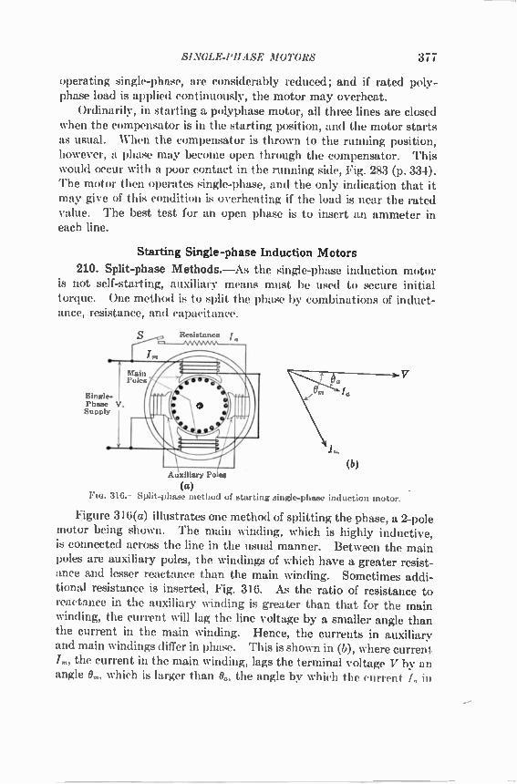
SINGLE-PHASE MOTORS 377
operating single-phase, are considerably reduced; and if rated poly-phase load is applied continuously, the motor may overheat. Ordinarily, in starting a polyphase motor, all three lines are closed
when the compensator is in the starting position, and the motor starts as usual. When the compensator is thrown to the running position, however, a phase may become open through the compensator. This would occur with a poor contact in the running side, Fig. 283 (p. 334). The motor then operates single-phase, and the only indication that it may give of this condition is overheating if the load is near the rated value. The best test for an open phase is to insert an ammeter in each line.
Starting Single-phase Induction Motors
210. Split-phase Methods.—As the single-phase induction motor is not self-starting, auxiliary means must be used to secure initial torque. One method is to split the phase by combinations of induct-ance, resistance, and capacitance.
Resistance Jo
Single-Phase V. Supply
Auxiliary Po es
a
(a) FIG. 316. —Split-phase method of starting single-phase induction motor.
Figure 316(a) illustrates one method of splitting the phase, a 2-pole motor being shown. The main winding, which is highly inductive, is connected across the line in the usual manner. Between the main poles are auxiliary poles, the windings of which have a greater resist-ance and lesser reactance than the main winding. Sometimes addi-tional resistance is inserted, Fig. 316. As the ratio of resistance to reactance in the auxiliary winding is greater than that for the main winding, the current will lag the line voltage by a smaller angle than the current in the main winding. Hence, the currents in auxiliary and main windings differ in phase. This is shown in (b), where current /,„, the current in the main winding, lags the terminal voltage V by an angle 0„„ which is larger than 06, the angle by which the current I „ in

378 ALTERNATING CURRENTS
the auxiliary winding lags V. For the best conditions the two cur-rents should differ in phase by 90°, but this condition is not readily obtainable and, in fact, is not necessary. These two sets of poles produce a sort of rotating field, which starts the motor. When the motor comes up to speed, a centrifugal device in the rotor opens the switch S and disconnects the auxiliary winding. It is also possible to split the phase with a 3-phase winding. Two
terminals are connected to the single-phase line, and a capacitor or an inductance is connected between the third terminal and either line wire. 211. Capacitor Motor.—The capacitor motor employs capacitance
to split the phase, rather than resistance. The use of capacitance has many advantages. The fluxes in the two phases can be made to have a phase difference of practically 90°, so that the motor becomes essen-tially a 2-phase motor. The starting torque is therefore considerably greater than with the usual split-phase motor of the same rating. The capacitance may remain in circuit continuously so that the power factor of the motor is very nearly unity, Fig. 317(d). Until recently, the cost of capacitors has prevented their use for motor-starting pur-poses. Their low cost at the present time makes it practicable to use them for phase-splitting purposes in fractional-horsepower motors. The circuit diagram of a simple capacitor motor is shown in Fig.
317(a), in which a capacitor C is connected in series with phase 2. If a large starting torque is desired, two capacitors may be used as shown in (b). On starting, a comparatively large capacitor CI is con-nected in circuit by switch Si. On running, the switch Si connects (usually automatically) a smaller capacitor C2 in circuit, disconnecting CI. The direction of rotation may be reversed by throwing switch 82
to the right. The volt-amperes to a capacitor vary as the square of the voltage.
Hence, it is sometimes economical to use a small autotransformer, Fig. 317(c), to step up the voltage, thus making it possible to reduce the capacitance. A capacitor can withstand a higher voltage for the short period of starting than it can safely withstand continuously. This makes it possible to obtain an increased starting torque by throw-ing switch S to the lower position, Fig. 317(c). The vector diagram for the simple capacitor motor, Fig. 317(a), is
shown in Fig. 317(d). The current II in phase 1 lags the impressed voltage V by the angle al. The current 12 in phase 2 leads the voltage by the angle a2. The voltage Ec across the capacitor lags /2 by
'l°; the voltage E2 across phase 2 leads /2 by the angle 13. The line voltage V is the vector sum of Ey and E. The voltage V and the

SINGLE-PHASE MOTORS 379
motor current / are nearly in phase. Note also that the currents II and /2 are nearly in quadrature, the optimum phase relation for a 2-phase motor. The capacitor is frequently a separate unit but is often incorpo-
rated as a part of the motor assembly.
Single-Phase Source
1
(a)
Single-Phase Source
Single-Phase Source
C1- Starting Capacitor C2 Running Capacitor
(b)
(c) (a) Simple capacitor motor (b) Reversible with variable capacitor (c) With variable autotransfortner (d) Vector diagram for simple capacitor motor
FIG. 317. —Capacitor motor.
212. Shaded-pole Method.—The principle of the shaded pole is discussed in connection with the metallic stamping that in the watt-hour meter produces the torque that compensates for friction (p. 107). The application of the shaded pole to the starting of a 4-pole motor is shown in Fig. 318. A short-circuited turn of low resistance is placed about a pole tip on each of the main poles. When the flux is increasing in the pole, a portion of the flux attempts to pass through this shaded tip. This flux induces a current in the coil, and by Lenz's law the current is in such a direction as to oppose the flux entering the coil. Hence, at first, the greater portion of the flux passes through the non-shaded side of each pole, Fig. 318. Ultimately, however, the main flux reaches its maximum value, where its rate of change is zero. The opposing emf in the shading coil then becomes zero. Considerable flux
(d)

380 ALTERNATING CURRENTS
then links the short-circuited coil. Later the opposing mmf of the short-circuited coil ceases, the current in this coil lagging its emf. After the main flux begins to decrease, the current induced in the shading coil tends to prevent the flux then existing in the shaded por-
tion of the pole tip from decreasing The flux first reaches its maximum value, therefore, at the nonshaded side of the pole and later reaches its maximum at the shaded side. The effect of the shad-ing coil is to retard in time phase a por-tion of the flux, so that there is a sweeping of the flux across the pole face in the direction of the shading coil. This flux cutting the rotor conductors induces currents, which, in turn, produce a torque sufficient to start the motor. The shaded
pole produces a weak starting torque and is used only with fractional-horsepower motors, such as fan motors, requiring little starting torque. 213. Repulsion-motor Start.—The methods just explained for
starting the single-phase induction motor produce weak starting tor-ques, which are insufficient to start the motor except under the lightest loads. A common method of obtaining large starting torque is to design the motor so that on starting it operates as a repulsion motor and, when it attains sufficient speed, to convert it into a single-phase induction motor by some mechanism operated by centrifugal force. Figure 319(a), (b), (c), illustrates the method used by the Century Electric Company. The armature is drum-wcund, and the brushes press on the end surface of the commutator during the starting period. The connections are the same as those of the repulsion motors shown in Figs. 307 and 308 (pp. 370 and 371). Figure 319(a) shows the entire motor cross section, and Fig. 319(b) shows the governing mechanism alone. At the pulley end of the armature, two governor weights move radially outward under centrifugal force. Their radial movement is converted into an axial one by means of the bell cranks. The governor-weight pins are connected to the bell crank at one end. and the other end presses on the end of the spring barrel. Within the spring barrel, the governor spring resists the axial thrust of the governor-weight pins and permits movement only after the desired speed has been reached and the governor weights develop the necessary centrifugal force. The short-circuiting segments, one of which is shown in Fig. 319(c).
are of copper and are held loosely together at one end by a circular wire
318.--Shaded-pole method of starting.

SINGLE-PHASE MOTORS
Governor Weights
Bell Crank "
(a) Cross section of motor and starting mechanism.
Sprt Short Governor Werghts ry 'Governor Sarre/Ring Circuiting C("FieleTs---),-Sprin 1Stee/!-- Segrnents-
\ C- --Spring Spring , Governor , Barre/ garre/-/ Weight P/;75V Collar or Not
(b) Governor mechanism.
381
Conmiutator /Segments
Short-Circuiting --" Segments
.-• Carbon Brush
Spring Barrel
Governor -"Weight Pins
Governor Spring
'Parallel-Motion Links
7:71
(e) Short-circuiting segment.
319. —Repulsion-start single-phase induction motor. (Century Electric Co.).
ring passing through the hole in the end of the segment. The entire segment assembly fits in a rectangular space around the outside of the spring barrel. Until the governor weights operate, the short-eireuiting segments are not in contact with the commutator segments. The brushes, which are sector-shaped, are pressed axially on the corn-

382 ALTERNATING CURRENTS
mutator surface by the action of the governor spring, until the governor weights act. The brush holders are connected mechanically to the spring-barrel mechanism. With the brushes pressing axially on the commutator, the motor
starts as a repulsion motor, developing considerable torque. When it has reached the necessary speed, the governor weights are able to overcome the action of the governor spring and to move radially out-ward. Acting through the bell crank and governor-weight pins they cause the spring barrel to move to the right, carrying the short-cir-cuiting segments and the brush holders with it. The loosely held short-circuiting segments are forced by centrifugal action against the inner surface of the commutator, short-circuiting the segments and hence the winding, while at the same time the brushes move away, clear of the commutator. The motor is thus converted during starting from a repulsion motor into a single-phase induction motor. The brushes are active for so short a time that there is but little wear.
290 V. To 9-Phase
220-Volt 220 V. Induction Motors Single-Phase Supply
210 V.
Stator of Phase Converter
F10. 320. — Method of obtaining 3-phase power from single-phase supply, by means of squirrel-cage induction motor operating as phase converter.
214. Induction Motor as Phase Converter.—If a 3-phase induction motor be operated single-phase, Fig. 320, 3-phase voltages exist across its three terminals. The reason for this is as follows: The counter emf in each phase of a polyphase induction motor is
induced by the rotating field cutting the stator conductors. If the stator is wound for 2-phase, the induced emfs at the stator terminals are 2-phase; if the stator is wound for 3-phase, the induced emfs at the stator terminals are 3-phase. The induced emf in each phase of a polyphase induction motor is slightly less than the terminal voltage (per phase) by the amount of the stator impedance drop. It is shown in Sec. 208 (p. 375) that in a single-phase induction
motor, a rotating field exists. At small values of slip, this field departs but slightly from a rotating field such as is produced by polyphase currents in polyphase windings. When a single-phase voltage is applied to one phase of a 2-phase or of a 3-phase motor, therefore, the rotating field is almost identical with that which exists when poly-

SINGLE-PHASE MOTORS 383
phase voltages are applied to the terminals. Consequently, if a single-phase voltage be applied to one phase of a 2-phase stator, a quadrature emf exists across the terminals of the other phase. If a single-phase voltage be applied to one phase of a 3-phase stator, the voltages across the three terminals will very nearly equal one another and will be approximately 120° apart. As the induced emfs are less than the applied terminal voltage by the amount of the stator impedance drops and as the rotating field is somewhat elliptical, the terminal voltages will not be balanced exactly. For example, in Fig. 320, 220 volts, single-phase, is applied to 1 phase of a 3-phase motor, and voltages of approximately 210 and 200 volts are found to exist across the other 2 phases. Polyphase induction motors are sometimes used in this manner
to produce polyphase voltages from single-phase supply. That is, single-phase voltage is supplied to one phase of the polyphase stator, and polyphase voltages are obtained from the stator terminals. When so used, the motor is called a phase converter. The phase converter is used in railway electrification. Although
the 3-phase induction motor is adapted to railway work, there is con-siderable disadvantage in using the two trolleys that are required if 3-phase power is to be supplied to the locomotive. By using a phase converter, the advantages of the 3-phase motor for driving may be secured, and at the same time all the advantages of a single trolley are retained. The phase converter receives single-phase power, which is pulsating, and delivers 3-phase power, which is substantially steady. This is made possible by the kinetic energy stored in the rotating arma-ture of the phase converter, this energy supplying the power during those times when the single-phase power is negative or is less than the average value of the polyphase power. The armature accelerates and so stores kinetic energy during the periods when the single-phase power exceeds the average power. The armature slows down and so gives up some of its kinetic energy during the periods when the single-phase power is less than the average power. In practice, the actual speed variations of the armature are slight. Typical connections for a railway phase converter are given in Fig. 321. A 2-phase converter is used, as only half the power need be converted under these conditions, the other half flowing conductively from the transformer secondary to the motors. The power is received single-phase from an 11,000-volt trolley and stepped down by a transformer on the locomotive. Special transformer taps are used to keep the phases balanced. The general diagram of connections is shown in Fig. 321(b), and the simplified diagram is shown in (a). It will be recognized that the converter and

384 ALTERNATING CURRENTS
transformer connection is equivalent to a T-connection. This is used in order that 3-phase power may be obtained by supplying single-phase power to the 2-phase stator of the converter. The phase ab to the driving motors is supplied directly from the transformer. The winding a'b"b' , tapped to winding ab, is the main winding of the phase converter (see Fig. 255, p. 296). The winding c'c"c is the teaser wind-ing tapped to the transformer at c', giving the third wire c of the 3-phase system. Ordinarily, the teaser winding would be tapped to
a
Transformer Secondary
11.000-Volt Trolley
a
Step-Down Transformer
Rail
a' Main Converter Winding 750 V. 750 V.
6'1 C To Driving Motors
Teaser 5 V. Converter 7 Winding
Simplified Diagram
321. —Connections of locomotive phase converter.
750 V. 3-Phase 750 V.
To Driving
Motors
point b", the center of the main converter winding. For convenience, however, the teaser winding is tapped instead to point c', the center of the transformer winding. But, under balanced conditions, c' and b" are at practically the same potential, so that, as far as voltages are concerned, connecting the teaser winding to c' is equivalent to connect-ing it to b". Phase converters are used on the Norfolk and Western Railway, on
the Virginian Railway, and on a portion of the Pennsylvania Railroad.

CHAPTER XI
THE SYNCHRONOUS MOTOR
215. Synchronous Motor.—It will be remembered that the direct-current generator operates satisfactorily as a motor. Moreover, there is practically no difference in the construction of the direct-current generator and the direct-current motor, and there is no substantial difference in the rating of a machine whether operated as motor or as generator.
Similarly, an alternator will operate as a motor without any changes being made in its construction. When so operated, the machine is called a synchronous motor. The design of a synchronous motor and of an alternator, each of
the same rating and speed, may differ somewhat in details, owing to the desirability of securing the best operating characteristics for each. Except in special high-speed 2-pole types, synchro s_motora are almost always salient-pole machines, whereas alternators may be of either the salient-pole or nonsalient-pole type. 216. Principles of Operation.—Figure 322 shows a conductor a
under an N-pole and carrying a current flowing toward the observer. By the well-known law of motor action a torque develops, tending to drive the conductor from left to right. If the current be alternating, it will reverse its direction for the next half-cycle and the torque then acts from right to left. Therefore, the net torque over any given number of complete cycles is zero, and no continuous motion can result. This is the condition existing in a synchronous motor when at stand-still. The current in the armature conductors is alternating, and the poles have fixed polarity, being excited with direct current. There-fore, the synchronous motor as such develops no starting torque. If, gowever, conductor a in some manner can be brought under the
next pole, which is an S-pole, for the half-cycle during which the cur-rent is in the reverse direction, the resulting torque will still be from left to right and a tendency toward continuous motion will result. _There Loilt,_ in asynchronous motor a given conductor mud move from 1 pole to the next in each half-cycic if the motor is to operate Wp_uously. This applies to the rotating-armature type of machine.
If the motor is of the rotating-field type, any given conductor must be passed by 1 pole every half-cycle.
385

386 ALTERNATING CURRENTS
Also consider Fig. 329(a) and (b) (p. 396), which shows a 4-pole rotating magnetic field produced by polyphase currents in the stator. This field rotates at synchronous speed. The S-poles of the rotor will lock in with the N-poles of the stator, and the N-poles of the rotor will lock in with the S-poles of the stator. Therefore the rotor must rotate
chronous_s_peed with the stator field. Hence, the synchronous motor must operate at constant speed, if the frequency is constant. There may be small momentary fluctuations of speed; but if The average speed differs by even a small amount from the sshronous value, the average torque will become zero almost immediately and the _ _ _ inzt-o— N.r come to a standstill. The relation of speed, number of _ poles, and frequency is the same as for the alternator and for the rotat-ing field of the induction motor. That is, the speed S = 120f/P rpm,
a
322.—Torque developed by synchronous motor.
where f is the fre cy and 1' the number of poles-(W' Seeg.-3 and 184, pp. ) and 313).
Exam ple . —A 500-kva 2,300-volt 10-pole synchronous motor operates on a 60-cycle 3-phase system. What is its speed?
120 • 60 = 10 = 720 rpm. Arm
Two-speed Synchronous Motors.—As with the induction motor, the stator windings of synchronous motors may be connected so that the number of poles is halved, doubling the speed. Usually the conse-quent-pole method, Fig. 290 (p. 349), is used. Simultaneously, the field poles must be reconnected so that an adjacent pair will be N-poles and the next adjacent pair S-poles. 217. Effect of Loading Synchronous Motor.—If a load be applied
to a direct-current shunt motor, the speed is decreased slightly. This reduces the magnitude of the counter emf —E. The line must stipply a voltageH-E, equal and opposite to the counter E and, in aa llifon 7nust supply the voltage to overcome the /Ra-drop in the armature. That is,
V = E + IR., (202)
where V is the fixed terminal voltage, I the armature current, and the armature resistance.

THE SYNCHRONOUS MOTOR 387
The current
= V + (—E) _ V — E (203) R. R.
where E is the component of terminal voltage that balances the counter emf. When E decreases, the armature_ current I increases. This
a
a q( MC )811)) ))) *
Rotation Load and 14- 1 Torque Motor
Torque (a)
(6)
V —Ea (No Load)
Ea' (With Load)
Fm. 323. —Effect of load on phase of induced emf in synchronous motor.
increased current supplies the extra torque and power required by the increased load. When load is applied to a synchronous motor, its average speed
cannot decrease, since the motor must operate at constant speed. Hence, it cannot cause the necessary increase in armature current in the same manner that the shunt motor does, that is, by operating at decreased speed. Figure 323(a) shows two poles N and S of a rotating-field type of synchronous motor. Neglecting any flux distortion, the emf induced in lonductor a is a maximum when conductor a is opposite

388 ALTERNATING CURRENTS
the center of a pole. It is zero when the pole reaches such a position that conductor a lies midway between the poles. The value of this emf e for any position of the pole axis YY is shown by curve e, YY being the pole axis for the pole shown in solid lines. Assume that a load now is applied to the motor shaft. This must
result in momentary slowing down of the rotor, since it requires time for a motor to adjust itself to a change in load conditions. The rotor, therefore, instead of being in the position shown by the solid lines in Fig. 323(a), will occupy a given position in space at a later time on account of the effect of the load torque. The relations under this condition are shown by the dotted lines. Because of the application of load, the pole center is now at Y'Y' instead of being at YY. There-fore, the induced emf will not reach its maximum value at the same instant that it would have reached it had no load been applied. This maximum value now occurs later in time, due to the slight backward angular displacement of the rotor. This is shown by a new curve of induced emf e', lagging e by an angle a, where e is the emf that would have been induced had no load been applied to the rotor shaft. This is further illustrated by the use of vectors. Assume that the
motor is running without load, and that the current is so small that the counter emf Fig. 323(b), is sensibly equal to the terminal voltage V and is 180° out of phase with V. (Ea is the component of the terminal voltage necessary to balance the counter emf —En.) The vector sum of V and —En is zero, practically. Now apply load. The terminal voltage V is assumed to be con-
stant and so is not affected by the load. The induced, or counter, emf —E. will be shifted backward by an angle a because of the backward angular displacement of the rotor caused by the load. Let this new value of counter emf be and let the component of terminal volt-age necessary to balance it be E. The vector sum of V and —E: is no longer zero. A vector difference exists, therefore, between V and E. In the direct-current motor, the armature current is given by
dividing the armature resistance into the sum of the terminal voltage and the counter emf —E., the counter emf being in opposition to the terminal voltage. Also, the armature current is given by the differ-ence between the terminal voltage and that component of the terminal voltage E that balances the counter emf —E. [see (203)]. In the synchronous motor, the armature current is given by divid-
ing the armature impedance Z.' into the vector sum of the terminal volt-
' In this discussion, Z is the actual impedance of the armature and is equal to the vector sum of the effective resistance and the leakage reactance. The use of synchronous reactance and impedance comes later.

THE SYNCHRONOUS MOTOR 389
age and the counter emf —E„', or the vector difference between the terminal voltage V and the emf E. That is,
= (204)
where E0 is either the vector sum of V and —E: or the vector dif-ference of V and E. Therefore,
eo = (205)
Equation (204) for the armature current in the synchronous motor is similar to the equation for the armature current in the direct-current motor (see Vol. I, Chap. XIII). [Also compare with Sec. 144 and Eq. (158), P. 2371 As a rule, the reactance of the armature of a synchronous machine
is high as compared with its resistance, and the current I lags the volt-age Eo that produces it by nearly 90°, Fig. 323(b). This brings the current I more or less in phase with Ea and not differing greatly from 180° from the counter emf —E,', . Therefore, I is largely energy current with respect to — EL, which means that it supplies considerable internal power to the motor. The rotor, by shifting its phase backward when load is applied, causes
the motor to take an energy current from the line that supplies the power demanded by the increased load. The total power suplied. to the motor per phase is
P = VI cos O. (206)
The total mechanical power developed is
P' = ELI cos (0 ± a). (207)
The net power at the pulley is less than I" by the amount of the frictional losses and the rotational core losses. The difference between P and/3' is the. armature copper loss.. rt-A-r--)uld be remembered that with constant frequency the average
motor speed remains constant. The rotor merely takes an angular position slightly back of its no-load position, without altering its average speed. This angular displacement of the rotor may be observed by means of a stroboscope (see p. 356).
Also, from Fig. 329(6), the rotor poles may be considered as being locked to the stator poles by the magnetic lines. These lines act as an elastic coupling and. when torque is applied to the rotor, stretch, permitting the rotor to shift its angular position by a small angle backward with respect to the stator poles.

390 ALTERNATING.. CURRENTS
218. Effect of Increasing Field Excitation.—When the field of a direct-current shunt motor is strengthened, there is a temporary increase in the armature induced era. This decreases the armature current, and the torque is lowered, since the change in armature cur-rent is much greater than the corresponding change in the field. As a result, the motor slows down and its induced, or counter, emf accord-ingly decreases. The armature current then increases until it is again of sufficient magnitude to enable the motor to carry the load. When the field of a synchronous motor is increased, the motor
cannot slow down, except momentarily, for it must run at constant average speed. Since its speed is constant, its counter emf must increase when the field is strengthened. It might seem then that the motor would stop, for its induced emf must become greater than its terminal voltage. In the direct-current motor, an induced emf exceed-
1 dl —Ea Ea Eo
IX
V IZ
(a) —1Z Ea
(b) FIG. 324. —Vector diagrams for overexcited synchronous motor, counter emf greater
than terminal voltage.
ing the terminal voltage would mean generator action, with the result that the machine would cease to operate as a motor. The synchronous motor, however, may operate as a motor when its
counter emf does exceed its terminal voltage in magnitude. Under these conditions, the motor is said to be overexcited. Two reactions occur that enable the motor to operate with an overexcited field. Consider the vector diagram, Fig. 324(a), in which V is the terminal
voltage and —.E0 is the counter emf. As in Fig. 323(b) the vector sum of V and —E. is Eo. In accordance with Eq. (204), Eo must be the resultant voltage that produces the armature current I. Since the armature is highly inductive, the current I will lag Eo by fr, where tan = X / R. However, as seen in Fig. 324(a), the current I leads the terminal voltage V by 0°. From Eq. (204),
(208)
which corresponds to the equation E = V — IoRo for the d-c motor. Equation (208) is illustrated in Fig. 324(b). The current I leads V by 0 as in (a). The IR drop is in phase with the current, and the IX drop leads the current by 90°. The impedance drop /Z is the vector sum

THE SYNCHRONOUS MOTOR 391
of IR and IX. The emf E., necessary to balance the counter emf, is found by subtracting /Z vectorially from V, just as in the shunt motor the component of terminal voltage necessary to balance the counter emf is found by subtracting the IR drop from the terminal voltage. To subtract /Z from V, —IZ is added to V. It will be noted that
the emf E. is numerically greater than the terminal voltage V. That is, by taking a leading current, the synchronous motor is able to operate with an induced emf greater than the terminal voltage. This is analogous to the alternator delivering leading current with its induced emf less than its terminal voltage. In each case, the flow of power is toward the higher voltage. Also, with a leading current, armature reaction weakens the
impressed field, which tends to counteract the increase in excitation. This is illustrated in Fig. 325, in which an armature coil is shown as moving with the armature from left to right. When the coil axis is in the position Y, shown dotted, the coil sides are under the centers of
Current I X i Terminallroltage
a Maximum
325. —Demagnetizing effect of leading current on field of synchronous motor
the poles and the induced emf is a maximum. As the terminal voltage is substantially 180° from the induced emf, it also will be a maximum practically at this instant, its direction being indicated in the dotted coil. If the current leads this terminal voltage by 90°, it will reach its maximum value one-fourth cycle ahead of the voltage, or at a, time when the axis of the coil is in position X. Note that for this position of the coil axis the ampere-turns of the coil act in direct opposition to those of the N-pole. Therefore, the effect of the leading current in the synchronous motor is to weaken the field. In other words, the armature reaction is such that on overexcitation it opposes the effect of the increased field current. Thus the synchronous motor adjusts itself to overexcitation by
taking a leading current, which causes the impedance drop to have such a direction that the induced emf can exceed in magnitude the terminal voltage, and also reacts on the field to oppose the increase in excitation. 219. Effect of Decreasing the Field Excitation.—When the field of
a direct-current shunt motor is weakened, the motor speeds up until
&Maximum

392 ALTERNATING CURRENTS
its counter emf reaches a value that gives the correct value of armature current for the particular load condition. When the field of a synchronous motor is weakened, it cannot speed
up permanently, for it must run at a constant average speed. How-ever, again it adjusts itself to operate with the weakened field. Con-sider the vector diagram, Fig. 326(a), in which the counter emf —E0 is substantially less than the terminal voltage V. As in Figs. 323(b) and 324(a), the resultant emf is Eo, which lags by a large angle the position that it has in Fig. 324. Eo produces the armature current I, and I lags Eo by the angle tl as before. The position of Eo now is such that I lags V by 8, a large angle. Also, the application of Eq. (208) is shown in (b). The current I
lags the terminal voltage V, as shown in Fig. 326(a). The IR and IX drops are laid off with reference to the current in the usual manner, and the /Z-drop is obtained. The emf E., which is opposite and equal to the counter emf, is found by adding vectorially — /Z to V as is done
Ea _ E.
—IZ
E.
(a) I (b) 326. —Vector diagram for underexcited synchronous motor, counter emf less than
terminal voltage.
in Fig. 324(b). The value of E. so obtained is considerably less than the terminal voltage V. This is made possible by the fact that the phase shift of the /Z drop is such that the machine runs as a motor with a very considerably reduced counter emf. Also, with lagging current, armature reaction strengthens the
impressed field, which again tends to counteract the decrease in excita-tion. This is illustrated in Fig. 327, in which an armature coil is shown moving with the armature from left to right. When the coil axis is in position Y, shown dotted, the coil sides are opposite the cen-ters of the pole faces and the counter emf is, therefore, a maximum. The terminal voltage, which is nearly 180° from the counter emf, also has its maximum value for this position of the coil, its direction being indicated in the dotted coil.. If the current is lagging the ter-minal voltage by 90°, it will not reach its maximum value until the coil axis reaches position X. The current under these conditions is in such a direction as to strengthen the S-pole. Therefore, in a syn-chronous motor, a lagging current strengthens the field through the effect of armature reaction. When the field of a synchronous motor

THE SYNCHRONOUS MOTOR 393
is weakened, the motor takes a lagging current, which strengthens the field by armature reaction and thus opposes the effect of the decreased field current. Thus, the motor adjusts itself to underexcitation by taking a
lagging current, which causes the impedance drop to have such a direction that the induced emf can be much less in magnitude than the terminal voltage, and also reacts on the field to oppose the decrease in excitation. In Figs. 325 and 327, the armature rotates, and the field structure is
stationary. As has been shown, the relative effects are the same when the armature is stationary and the field structure rotates. Also, in Figs. 325 and 327, the effects of single-phase armature reaction are shown, just as in Figs. 172 and 174 (pp. 190 and 191) for the alternator. The armature reaction under these conditions will be pulsating, but as in the alternator (p. 194) with balanced polyphase currents the
Terminal Voltage a Maximum X
Current a Maximum
Flo. 327. —Magnetizing effect of lagging current on field of synchronous motor.
armature reaction will be steady and will weaken and strengthen the field in the manner shown in Figs. 325 and 327 for single-phase. As a matter of fact, the armature reaction in a synchronous motor is the rotating field produced by the polyphase armature currents. It also follows that, when the current is in phase with the excitation voltage, armature reaction exists merely as a cross-magnetizing effect. 220. Motor and Alternator.—In Secs. 218 and 219 it is shown that
in a synchronous motor a leading current weakens the field and a lagging current strengthens the field, which is opposite to the effects occurring in an alternator. That is, in an alternator, a leading current strengthens the field, and a lagging current weakens the field (pp. 189-192). This seemingly contradictory effect of leading and lagging currents
in synchronous motors and alternators is explained by the fact that a leading current in a motor corresponds to a lagging current in a gen-erator and a lagging current in a motor corresponds to a leading cur-rent in a generator. Consider Fig. 328, in which V. is the generator terminal voltage. The emf —E0 induced in the armature is y, + JZ (also see Fig. 198, p. 222). (In the motor the induced emf has been

394 ALTERNATI NG C(' IIRE.VTS
designated as —Ea.) The current I lags the induced emf —E. by 90°. As in Fig. 323(b), the component of the impressed motor terminal volt-age, which balances the induced, or counter, emf —E. is +E.. The motor terminal voltage, y„, = ea+ J. Thus, the motor terminal voltage V„, and the generator terminal voltage V„ are practically in phase opposition. The current I now leads E. by 90'; and since V,„ and E. are substantially in phase, the current I leads V,„ by almost 90°. Thus it follows that a leading current in a motor corresponds to a
lagging current in a generator. It can be similarly shown that a lagging current in a motor corresponds to a leading current in a generator. Since in a generator a lagging current weakens the field, a leading cur-rent in a motor must weaken the field. In a generator a leading current strengthens the field, so that a lagging current in a motor strengthens the field.
I (Lags Induced Emf and Leads Motor Terminal Voltage)
—Ea (Induced Emn Iz Vm (Motor Terminal Voltage)
—IZ +E. Vo (Generator Terminal Voltage) no. 328. —Current lags for generator and leads for motor.
221. Excitation in Constant-potential System.--From the rela-tions odstita.: between the excitations and leading and lagging currents in synchronr us alternators and motors it is possible to show that, in a constant-pot ential system at constant load, the total excitation in the system, that, is, the sum of the d-c and the a-c excitation, tends to remain cowtant. Also, the total excitation supplied to the system tends to remain constant. Consider first the synchronous motor. When operating at any
given vol 'Age, it requires a certain excitation. If its field is weakened, its exciti.tion becomes inadequate. This deficit is, in part, made up by tnc motor's taking a lagging current from the line. A lagging cur-rer.t 113 ordinarily associated with inductance and, therefore, with the excitation of a magnetic field. When the motor takes a lagging cur-rent, some of its excitation, therefore, is obtained from the alternating-current line. In this respect, it is similar to an induction motor, except that the induction motor takes all its excitation from the alternating-current line. In fact, if the entire direct-current excitation be removed from a salient-pole synchronous motor, it will still continue to operate

THE SYNCHRONOUS MOTOR 395
if the load is not too great (Sec. 222). Its entire excitation then will be supplied by the lagging current that it takes from the line. Its power factor, however, will be very low. The lagging current required by the synchronous motor to help excite its field weakens the field of the alternators supplying it, and, as a result, their field excitation must be increased to maintain the line voltage constant. When, therefore, the field excitation of a synchronous motor is reduced, it is necessary to increase the field excitation of the alternators supplying the system, so that the total excitation to the system tends to remain constant. On the other hand, when a synchronous motor is overexcited, it
has a surplus of excitation. It takes a leading current. As a leading current will neutralize a portion of the lagging current of inductive apparatus (see Sec. 230, p. 409) connected to the system or else will strengthen the fields of the generators supplying the system, the syn-chronous motor under these conditions indirectly supplies excitation to other parts of the system. In any event, the terminal voltage of the alternators will rise and their field excitation must be reduced in order to maintain the voltage of the system constant. Thus, when a surplus of excitation is fed into a constant-potential
constant-load system, as by increasing the field current of a synchro-nous motor, this surplus is transferred to other parts of the system by means of the leading current taken by the synchronous motor. On the other hand, when a deficiency of excitation occurs at a point in a constant-potential system, as by decreasing the field current of a synchronous motor, excitation is transferred to this point from other parts of the system by means of lagging current. 222. Interlocking Action of Salient Poles.—The fact that a syn-
chronous motor with salient poles usually will operate, even if the field current is reduced to zero, is explained as follows: The alternating cur-rent in the stator winding will produce a rotating field, just as in the induction motor. Figure 329(a) shows such a rotating field for a 4-pole machine without a rotor. At. the particular instant shown, there are two N-poles vertically opposite and two S-poles horizontally opposite. Assume for the moment that the 4 poles are stationary in space. If a 4-pole salient-pole rotor without excitation be placed in this field, the magnetic flux from the stator will attempt to make the rotor take such a position that the magnetic reluctance is a mini-mum or the flux is a maximum. In order to accomplish this result, the pole pieces of the rotor become locked in with the poles pro-duced by the stator winding, as shown in Fig. 329(b). If now the stator poles are rotating at synchronous speed and the salient field poles are rotating at or near this speed, they ill lock in with the stator

396 ALTERNATING CURRENTS
poles as at standstill and the rotating stator poles pull the salient poles of the rotor around with them and in this manner enable the motor to carry a small load without direct-current excitation. Although the motor may carry a small load without any direct-current excitation, its power factor will be very low and the current will be lagging, which is undesirable. It is to be noted that, in the absence of direct-current excitation, the motor takes its entire excitation from the alternating-
(a) (b) 329. —Interlocking action of salient poles with rotating magnetic field.
current lines in the same manner as an induction motor, as already has been described. That is, if sufficient excitation is not supplied by the direct current in the field winding, the motor will take lagging exciting current from the alternating-current line to make up the deficit. The power factor of the simple induction motor for a given load
cannot be altered without changing the motor design, and the ordinary induction motor always takes a lagging current. The power factor of the synchronous motor can be altered at will, and the current can be changed from lagging to leading by simply changing the field excitation.
There are, however, frac-
b tional-horsepower motors, usu-ally\ single-phase, and timing
\ • motors such as clock motors (p. 0 • • • • 421), which operate without d-c
a \ • • • • v excitation. In such motors, the
a
330. —Synchronous-motor vector dia-grain, leading current.
low power factor has little effect on a power system and is far
a outweighed by the increased sim-IR plicity of operation.
223. Synchronous-motor Vector Diagram.—The solutions
of the vector diagrams given in Figs. 324(b) and 326(b) are accom-plished in much the same manner as the solutions of the alternator vector diagrams (pp. 199-211). The trigonometric solution is obtained

THE SYNCHRONOUS MOTOR 397
by projecting the component emf E., which balances the induced end' on the current vector, thus forming a right triangle with E. as
the hypotenuse.
Leading Current —Figure 330 corresponds to Fig. 324(b) in which the motor current is leading. To solve the diagram trigonometrically, the emf vector E., or Od, and IR are both projected on the current. vector, giving Ob and ba. This gives a right triangle Obd, of which E. is the hypotenuse. Then
E„ = i" cos 0 — /1?)2 (1. sin 0 /X)2. (209)
Also, E. may be determined by complex notation. Tina is,
= Y - = - (eos j sin 0)(R ± jX). (210)
Example. —A 100-hp 600-volt 1,200-rpm 3-phase 1-connected synchronous motor has an armature resistance of 0.052 ohm per phase and a leakage reactance of 0.42 ohm per phase. At rated load and U.S power factor, leading current, determine (a) induced armature emf per phase E. at rated load; (b) angle a between current and E.; (c) mechanical power developed within armature at rated load. Under the foregoing conditions, the motor has a rated-load efficiency, excluding field loss, of 0.92.
(a) Motor input = 100 • 746 = 81,100 watts. 0.92
Current / = _81100 = 97.6 amp. V3 • 600 • 0.80
Voltage per phase = 600 = 346 volts.
Using Eq. (209).
E. = N/1(346 • 0.80) — (97.6 • 0.052)12 -I- 1(346 • 0.60) + (97.6 • 0.42)12 = 368.3 volts. Aug.
(b) A study of Fig. 330 shows that
bd V sin 0 -I- IX 248.6 tan a = -= = 0.915.
Ob V cos 0 — IR 271.7 a = 42.5°. A ns.
Using Eq. (210),
= 346 — 97.6(0.80 +j0.60(0.052 j0.42) = 346 — ( —20.5 -I- j35.9) = 366.5 — j35.9.
1E.1 = V(366.5)2 + (35.9)2 = 368.3 volts. Ans. (check).
(c) The mechanical power developed is equal to the product of the induced amf, the current, and the cosine of the angle between them.
P.„ = 3 • 368.3 • 97.6 • cos 42.5° = 79,600 watts. Ans.

398 ALTERNATING CURRENTS
This power P., is also equal to the power input minus the armature resistance
loss.
= 81,100 — 3 • 97.62 • 0.052 = 79,600 watts (check).
V
331. —Synchronous-motor vec-tor diagram, lagging current.
The power developed at the pulley is less than P. by the rotational losses, namely, friction, windage, and rota-tional core losses. Lagging Current. —In Fig. 331,
which corresponds to Fig. 326(b), E,, and IR are projected on the current vector. Then
E. --= (V cos 0 — IR) 2 ± (V sin 0 — I X)2. (211)
The solution by complex notation is
= V - IZ = V — I (cos 0 — j sin 0)(R ± jX).
Example. —Repeat the foregoing example, but with lagging current.
(a) Using Eq. (211),
(212)
= •VR346 • 0.80) — (97.6 • 0.052)12 [(346 • 0.60) — (97.6 • 0.42)12
= 319 volts. Ans.
Using Eq. (212),
= 346 — 97.6(0.80 — j0.60)(0.052 j0.42) = 346 — (28.7 4- j29.8) = 317.3 — j29.8.
1E.1 = -V(317.3) 2 (29.8)2 = 319 volts (cheek). Ans.
bd V sin 8 — IX 166.6 (b) tan a, Fig. 331 = = = 0.613.
06 V cos — IR 271.7 a = 31.5°. Ans.
(c) l'„, = 3 • 319 • 97.6 • cos 31.5° = 79,600 watts. Ans.
(This is the same value as before, which it should be.)
These values of E. are the induced emfs in the armature and cor-respond to E., Figs. 182 and 188 (pp. 203 and 209). Since X is the armature leakage reactance, the values of E„ are the actual emfs induced in the armature under the given conditions of load. If the motor were disconnected from the line but driven mechanically, with the frequency and excitation unchanged, the emf at the terminals would be the no-load, or excitation, emf E (see p. 209). The excitation emf may be computed by using in the foregoing equations the synchronous reactance X,, rather than the leakage reactance X.

THE SYNCHRONOUS MOTOR 399
224. Synchronous-motor V-curves.—If the power P delivered to a 3-phase synchronous motor be kept constant and the field current If varied, the power factor of the motor will change. The power for a 3-phase motor is
P = -‘13 VI cos 0, (213)
where V is the terminal voltage, I the line current, and cos 0 the power factor of the motor. As both P and V are constant, any decrease in the power factor cos 0 must be accompanied by a corre-sponding increase in the current I. Likewise, any increase in the power factor must be accompanied by a decrease in the current I. Therefore, a change in the field current, at constant load, changes
the line, or armature, current I. In order to determine the relation
• 3-Phase
D C. Am.
D-C Supply •
Polyphase Wattmeter
Supply a
A
Field Rheostat
Field Terminals jLoad
C :Aer3rmmaintuarlse
332. —Connections for obtaining V-curves of synchronous motor.
between the field current and the armature current and also the characteristics of a synchronous motor as regards its ability to correct the power factor of a system, the so-called V-curves of the motor are obtained. The V-curves show the relation that exists between the armature current and the field current for different constant power inputs. Several curves are usually obtained, each curve representing a constant value of power input. The connections for making such a test are shown in Fig. 332. The field current is varied by means of the field rheostat. For
each value of field current, as read on the direct-current ammeter, the corresponding value of the alternating line current is noted. The electrical power delivered to the motor is kept constant by adjusting the load applied to the motor shaft. A polyphase wattmeter is desir-able for this experiment, as it eliminates the adding or subtracting of

400 ALTERNATING CURRENTS
individual instrument readings, which is necessary when two single wattmeters are used. Figure 333 shows a set of V-curves for a 150-hp 550-volt 60-cycle
synchronous motor. Curve AB is taken for one-fourth rated load, curve CD for one-half rated load, and curve EF for rated load. The value of power input P1 for curve AB is 30.5 kw, that for curve CD is P2 = 61 kw, and that for curve EF is P3 = 122 kw. With low values
180
160
140 e.
120
100
80
60
40
20
1 G E I Z Y/
•1 Pl n • /
a 1 1
I / 1 ..a 4 go. . ca•
rs./ C4. A. 160 ,Phase. -HP.
, 60 650 Cycle V.
I
P.
/
I ,
1
i
ii ,
I
Underexcitation or Region of Lag . L
I I / Ov
r Region rexcitation
of Lead
/ 1 i 12
il ii 1
1 i
10 X 20 30 Field Current - Amp.
FIG. 333. —V-curves of synchronous motor.
of field current for curve AB, for example, the armature current is large and is lagging. As the field current is increased, the power factor increases, and the armature current decreases until it reaches its minimum value I. If the field current be still further increased, the armature current begins to increase and becomes leading. In other words, the motor passes from underexcitation to overexcitation when the field current is increased from a low to a high value. The current /2 is the value of the current at unity power factor.
This is illustrated in Fig. 334. Let /2 be the value of line current at some power factor cos 02. The power (for one phase) is
P1 == V'I2 cos 0 2.
40

THE SYNCHRONOUS MOTOR 401
where V' is the phase voltage; but
/2 cos 02 = /I (214)
for all values of 02. In other words, for constant power Pi, /1 is always the energy
component of the current regardless of the power factor. Therefore, the current vector will always terminate on the line XXI perpendicular to V'. The current is a minimum at Ii, where the current is in phase with V'. The power factor is then unity. The excitation correspond-ing to the armature current Ii is called the normal excitation cf the motor for any given load. For an excita-tion less than the normal value, the motor takes a lagging current and is said to be underexcited; for values of the excitation _ _ greater than the normal value, the motor takes a leading current and is said to be \02
overexcited. 0 I Tr' By aid of the V-curves, the power
factor for any other value of line current and given input may be obtained. For example, assume that it is desired to ob-tain the power factor for some value of leading current /2, Fig. 333. _F ro m Fig 334, th_e ppwer_factor cos 025-7 iiiks• sh nu. 334. —Vector diagram
owing current variation in ), Therefore the power factor for any current synchronous motor with con-
/ may be found by dividing the current I stant power input.
into the minimum or normal value of the line, or armature, current /2 for the given input P I. The power represented by curve AB is
/32 =
for a 3-phase motor having a line voltage V. For example, the current Ii = 32 amp. Hence
P1 = V -3- • 550 • 32 = 30.5 kw.
A curve such as XZ drawn through the lowest points of the V-curves is a unity-power-factor curve. Curves XX and X Y, drawn through the V-curves at the proper points, are 0.8-power-factor curves, XX being for lagging current and X Y for leading current. Curves for other power factors may also be found in a similar manner. These curves are called compounding curves. It should be noted that the normal field current varies with the
value of power input to the motor.

402 ALTERNATING CURREN7'S
225. Synchronous-motor Excitation Diagram. —Consider Fig. 335(a). The motor is taking a lagging current I from the line, the line voltage being V or Since the current vector I is to remain fixed, its position is taken along the X-axis and the voltage V(1) is shown leading I by the angle 0. The resistance and syn-chronous reactance drops in the armature, IR and IX„ are equal to Oa and ad, and the resulting synchronous-impedance drop is given by Od. Since the syn-chronous-impedance drop is equal to the vector sum of V1 and Ei, the counter emf of the motor EI is equal to dh. Its true vector position is found by completing the parallelogram; this is readily done by swinging arcs dk and Ok. El makes an angle 02 with I reversed (cf. Fig. 335 with Fig. 323(b) (p. 387)). The power input to the motor is V(i)/ cos 0 and is given by area Obce divided
by X., since area Obce = Vu) cos 0 • I(X.). The area Oade then must be propor-tional to the PR-loss in the motor. The mechanical power developed in the motor is proportional to the difference of these areas, or to area abed. Also, the mechani-cal power developed is equal to E11 cos 02 and is proportional to area Ocfg = abed. In each case the power (per phase) is found by dividing the area to scale by X.
F2 Ft (b)
FIG. 335. —(a) Synchronous-motor excitation diagram; (b) corresponding V-curve.
There is, however, another condition of operation that will fulfill the foregoing conditions of power, V and El. The current I may lead rather than lag. How-ever, the current vector remains fixed in position so that the voltage vector V must take a new position, 0° in a clockwise direction from I. Its position is shown with a dashed line at V(2). The corresponding value of counter emf must be equal to dh', and its vector position is found by completing the parallelogram and is shown at E. In each case the impedance drop /Z. is equal to the vector sum of the terminal voltage V(1) or V(2) and the counter emf El or E2. Obviously, the power relations remain unchanged (cf. examples on pp. 397 and 398). With leading current the value of the counter emf is much greater than with lagging current (cf. Fig. 324, p. 390, and Fig. 326, p. 392). If the saturation curve for the machine is available, it becomes possible to plot
the V-curves by the use of the diagram, Fig. 335(a). For example, since EI and E2 correspond to the same value of power, they correspond to points on the same V-curve. Their corresponding values of field current, F1 and F2, can be obtained from the saturation curve, and in Fig. 335(b) they are plotted as abscissas to correspond with the value of I as given in Fig. 335(a). To obtain another set of points on the same V-curve, make the area Oe'c'b'
(shown dotted) equal to area Oecb. Hence, the power input remains unchanged. V(1) is then swung clockwise to position V', where it intersects line c'b'. The synchronous impedance drop Od is extended to intersect e'c' at d'. The new value of IX. is readily found by dropping a perpendicular from d' to line Ob. The new

THE SYNCHRONOUS MOTOR 403
value of current then is found by dividing this perpendicular by X.. The two new values of counter emf are found by completing the parallelogram of voltages as was done in finding E, and E2. For example, d'h" gives one of the new values of E,. The field currents corresponding to these new values of counter emf are found from the saturation curve as before.
(a) Pole with field and damper windings.
Simplex high-starting-torque synchronous-ip..... ,
336. —Synehronous-motor pole and rotor structures. (West i rwholiee Electric Corp.)
226. Amortisseur, or Damper, Windings.—In Fig. 336(a) is shown a synehronous-motor field pole. It is to be noted that, in addition to the usual spool winding, there is a short-circuited grid of copper inserted in slots in the pole face. In the end strips of the grid there are holes so that each may be bolted to corresponding strips on adjacent poles. Thus a continuous squirrel-cage winding is formed about the field structure. In Fig. 336(b) is shown the rotating-field structure of a high-torque Simplex synchronous motor of the Westinghouse Electric

404 ALTERNATING CURRENTS
Corporation. The salient field poles are wound with the usual spool winding, the terminals of which are brought out to two of the five slip rings. The pole faces are slotted, and in this particular rotor a 3-phase winding is placed in the pole-face slots. The terminals of this winding are connected to the other three slip rings, making it possible to insert external resistance and thus produce high starting torque, as with a wound-rotor induction motor (Sec. 191, p. 326). However, when the motor reaches synchronism, the external resistance is short-circuited, so that the winding is practically short-circuited. In each case, the short-circuited winding is called an amortisseur winding, a damper winding, or sometimes just a damper. The purpose of the damper winding is to stabilize the operation of
the motor. When the motor is running at uniform speed, this damper winding is linked by the steady flux due to the combined mmfs of the field poles and the armature. Therefore it has no effect on the operation of the motor. However, the synchronous motor is very sensitive to change in phase (Sec. 217, p. 386). A small angular shift of the rotor with respect to the rotating armature mmf produces large changes in the energy component of current. System disturbances may cause the rotor to oscillate about its average position, and the resulting phase shift of the rotor produces pulsations in the power current, which in turn may increase the oscillations. This oscillation of the rotor about its average position is called hunting (see Sec. 147, p. 242). When reciprocating engines were used as prime movers for alternating-current power systems, their variable torque produced pulsations in the phase of the system emf, and hunting among alterna-tors and synchronous motors was common and difficult to eliminate. The purpose of the damper winding is to oppose and damp these
tendencies of the rotor to oscillate while rotating. The action of the damper winding involves the principle of both
the induction motor and the induction generator. So long as the rotor is rotating at synchronous speed, the rotating field of the armature or stator does not cut the dampers and they have no effect. That is, the armature mmf rotates synchronously with the field, and there is no relative motion between the field flux and the dampers. Assume that the rotor slows down momentarily. For an instant, the rotating field due to the armature mmf is rotating more rapidly than the field structure. This is equivalent to the rotor's slipping temporarily, and currents are induced in the dampers. This is induction-motor action, and the currents in the dampers are in such a direction that they tend to pull the rotor back toward synchronism. Again, if the field poles, for some reason, swing ahead of their normal

THE SYNCHRONOUS MOTOR 405
position, the dampers cut the rotating field in the opposite direction, or the slip becomes temporarily negative. Induction-generator action follows, putting a load on the rotor and tending to slow it down. These dampers always tend to pull the motor into synchronism and thus prevent hunting. Such windings are often used on alternators, particularly of the engine-driven type. By proper design of the damper winding, utilizing the principles
employed in the induction motor (p. 328), the starting torques of synchronous motors may be made comparable with and even greater than the full-load torque (see Sec. 228, p. 407). 227. Starting the Synchronous Motor.—It has been shown that
the synchronous motor as such is not self-starting. It must first be brought nearly or actually to synchronous speed before it can operate. There are several methods of accomplishing this. The direct-current exciter for the motor is frequently connected
directly to the motor shaft. If a direct-current source of power is available, the exciter may be operated as a motor and thus bring the synchronous motor up to speed. The field of the synchronous motor is then excited and the motor synchronized, just as with an alternator. If an exciter or sufficient direct-current power is not available, a
small induction motor, geared or direct-connected to the synchronous-motor shaft, may be used for bringing it up to speed. If the induction motor is direct-connected, its synchronous speed must have a higher value than that of the synchronous motor, in order to compensate for the slip of the starting motor. Such starting motors are often dis-connected mechanically after the synchronous motor has been con-nected to the line. The disadvantage of using an induction motor is the additional motor, the gears where used, etc. This method of starting has practically disappeared. The synchronous motor often is used to drive a direct-current
generator. If sufficient direct-current power is available, the genera-tor may be used as a motor to bring the synchronous motor up to speed. After the motor is synchronized, the field of the direct-current machine is strengthened and it then acts as a generator, taking mechanical power from the synchronous motor. The most common method is to start the synchronous motor as an
induction motor. First, the field circuit is opened. A polyphase alternating voltage is then impressed on its stator, and a rotating field is set up about the rotor. As a rule, it is desirable to use a compen-sator or some other device for reducing the voltage applied to the stator. One method of reducing the starting current is to employ a double-eireuit parallel winding, Fig. 337, the two windings being

406 ALTERNATING CURRENTS
arranged preferably in alternate slots. The reactance of a single winding is considerably greater than that of the two in parallel. Hence, if on starting only a single winding is energized, the starting current is materially reduced. Thus, in Fig. 337, the neutral con-tactor is open on starting. As the rotor approaches synchronism this contactor is closed, connecting the two windings in parallel for normal operation. The rotating field produced by the polyphase stator currents
induces currents in the pole faces of the rotor and in the amortisseur winding as well. This is obviously induction-motor action. The paths of the pole-face currents have considerable inductance, as also
does the common type of damper (see Sec. 187, p. 319), and only a comparatively weak starting torque can be obtained. On starting, the
Cr itreaker rotor currents ma3 be large, and or Contactor the rotor frequency is that of the
stator. The rotor reactance, which is proportional to the rotor induct-
Paralleled Stator Windings
Circu2i.tP Bolree aker ance and to the frequency, is large. or Contactor This causes the rotor currents to
lag the induced emfs by a consider-able angle, and, hence, the rotor cur-
rents make considerable space angle with the flux (see Fig. 270, p. 317). Therefore, the motor develops little torque, even with consid-erable line current. The motor under these conditions is very similar to the squirrel-cage induction motor, which has a small starting torque. The starting torque, though small,' is usually sufficient to start
the machine, which then accelerates until it is at or near synchronism. Before the compensator is thrown into the running position, the field switch is usually closed so as to minimize disturbances to the system. If the rotor is slipping slightly, it will usually pull into synchronism when the field switch is closed, the field poles locking in with the poles produced by the armature mmf (Fig. 329, p. 396). The motor may pull into synchronism before the field circuit is
closed. Owing to hysteresis, the flux (see Fig. 329) sweeping by the salient poles shows less and less tendency to leave them as the rotor approaches synchronism. That is, the flux tends to persist in the poles after the magnetizing force is decreased. This action may be strong enough to pull the rotor into synchronism before the field circuit is closed.
High-torque synchronous motors are described in Sec. 228.
337. —Double-circuit parallel-wind-ing synchronous motor.

THE SYNCHRONOUS MOTOR 407
When the field circuit is closed, it may excite the motor poles so that their polarity is opposite to that produced by the revolving field, that is, by the armature reaction, Fig. 329. The rotor is then thrown back one pole; in other words, it slips a pole. This may cause considerable disturbance to the system, and for this reason the field is usually closed when the compensator is in the starting position. This difficulty may be avoided by applying a weak direct-current field to the motor as it approaches synchronism. This causes the armature reaction to act in conjunction with the direct-current field windings, and the poles then come into synchronism with the same polarity as will be produced by the direct-current excitation. After the motor has pulled into synchronism, it is necessary merely to strengthen the direct-current field to the desired value. The starting compensator then may be thrown quickly into the running position. When voltage is first applied to the synchronous motor, there
may be a very high voltage induced in the field winding. The stator acts as the primary of a transformer, the primary having comparatively few turns. The flux produced by the stator, or primary, cuts the field winding at synchronous speed, and as the field has a very large num-ber of turns a very high emf is induced in the field. This emf may be sufficiently high to puncture the field winding. Therefore the field winding should be insulated for voltages considerably in excess of that which normal operation requires. The field is sometimes short-circuited or is shunted by a resistance when starting, in order to decrease this high voltage. The induced emf in the field decreases as the rotor comes up to speed until at synchronism it becomes zero. In the Simplex rotor, Fig. 330, on starting, the field is sectionalized,
a switch dividing the field into a number of series sections, Fig. 369 (p. 448). As the rotor comes up to speed, centrifugal action closes the switch connecting all sections in series. It would seem that if the field winding were short-circuited it
would act as a rotor winding and add to the starting torque. However, the field circuit has a high ratio of reactance to resistance, and also it constitutes a single-phase winding. Both these effects prevent its being at all effective until a speed well above half synchronous speed is reached.
STARTING SYNCHRONOUS MOTOR UNDER LOAD
228. High-starting-torque Motors.—Like the squirrel-cage induc-tion motor, the conventional synchronous motor with the usual low-resistance type of dampers has a comparatively low starting torque, discussed in Sec. 227. However, since during the starting period the

408 ALTERNATING CURRENTS
operation of the synchronous motor is the same as that of the induc-tion motor, its starting torque may be increased in the same manner as for the induction motor, that is, by increasing the resistance of the rotor winding. Moreover, since with the synchronous motor the squirrel-cage windings are not effective during normal operation, the design of the starting windings is not subjected to the limitations that are necessary with the induction motor. (With the induction motor a high-resistance starting winding gives at running speed high slip and low efficiency, so that, to combine high starting torque and low slip at full speed, the design of the winding is necessarily a compromise.) With the synchronous motor, the resistance of the squirrel cage may be made sufficiently high to give high starting torque, and the motor may be started under considerable load. The high resistance of the squirrel cage may produce such a large value of slip that the rotor poles cannot lock in with the synchronously rotating poles of the stator. This difficulty is overcome by short-circuiting the field winding as the rotor approaches synchronism (Sec. 227). In many applications high starting torque applied in steps is
required. Also, in order to obtain the required starting torque with many types of load the starting kva are too great for the system. To meet such requirements, synchronous motors with phase-wound dampers are used. These motors have the usual salient poles, but the damper bars, instead of being connected to end rings, are phase-con-nected and brought out through slip rings to resistors. The Simplex rotor shown in Fig. 336(b) is such a rotor (Sec. 226). Two of the five slip rings conduct current to the direct-current field winding, and the other three are connected to the terminals of the 3-phase rotor winding. The resistors are in circuit on starting and are cut out as the rotor approaches synchronism, just as is done with the wound-rotor induc-tion motor (see Fig. 279, p. 330). When the three slip rings are short-circuited, the winding functions as a damper. This type of motor when starting with full line voltage and with the control properly adjusted will develop 150 per cent full-load starting torque with a current inrush of not over 250 per cent rated current, and under these conditions the motor develops 125 per cent pull-in torque. A con-ventional synchronous motor would require 600 to 700 per cent rated-current inrush to develop a corresponding starting torque. This type of motor is adapted to heavy-duty machinery such as
crushers; rod, tube, and ball mills; and conveyers. Thus the syn-chronous motor can be adapted to duty requiring considerable starting and overload torque. The synchronous-induction motor is fundamentally a wound-rotor

THE SYNCHRONOUS MOTOR 409
slip-ring induction motor. The air gap is larger than is normal with induction motors, and the rotor slots are fewer and larger. On start-ing, resistance is inserted in the winding, and thus the large starting torque of the wound-rotor induction motor is secured. When the rotor approaches synchronous speed, the rotor windings are connected to a direct-current source, and the motor operates synchronously. Although such motors have excellent starting characteristics, they are expensive and have less efficiency than standard types. Also, in order that the induced emf in the field at starting may not be too high, the field turns are few in number, and the excitation voltage is low. Another method of starting when the load requires a large starting
torque is to connect the load to the motor through a clutch that can be made to slip. The motor is first brought up to full speed and the load then accelerated by means of the clutch. The clutch may be mechanical, contact of slipping plates frequently being produced magnetically, or a rotating member with interior magnetic poles energized with direct current and keyed to the motor shaft may act on a rotor with a short-circuited winding keyed to the load shaft (see Fig. 264, p. 307). This latter clutch has a rotating magnetic field, and its operation is similar to that of the induction motor. 229. Synchronous Condenser.—The fact that the power factor of
the synchronous motor may be varied at will makes it useful in many installations, particularly in those which operate at low power factor. It will be recalled that a low power factor means larger generators, more transmission copper, poorer regulation, and reduced efficiency. Factories and mills using induction-motor drive often have an over-all power factor as low as 0.5, which is very undesirable. Since the synchronous motor when overexcited acts like a capacitor
to take leading kva, it can be connected in parallel with such systems to improve their power factor. Even if no mechanical load is avail-able, it is frequently economical to operate such motors running light, their sole function being to improve the power factor. It would be difficult if not actually impossible to operate long-
distance transmission lines satisfactorily, if it were not possible to control the power factor at the receiving end. This is done by means of large synchronous motors running light (pp. 414 and 476). When synchronous motors operate without mechanical load, their sole function being merely to take leading kva, they are called synchronous condensers. (On long transmission systems such condensers frequently operate to take lagging kva.) 230. Power-factor Correction with Synchronous Condenser.—In
Fig. 338(a) is shown a 3-phase load taking a current /I, at voltage V and

410 ALTERNATING CURRENTS
at power factor cos 01, the current lagging. It is desired to determine the rating of a synchronous condenser that will raise the system power factor to unity.
Assume the system to be Y-connected, the voltage to neutral being V.. The vector diagram is shown in Fig. 338(b), in which the load current IL lags V. by 01. Resolve the current IL into two components, an energy component
/1 = IL cos 01 and a quadrature component /2 = IL sin 01. The energy current of the synchronous condenser is small compared with its quadrature current, when the condenser is operating without load, and is added at right angles to the quadrature current. Therefore, in determining the total current taken by the synchronous condenser, this energy current may be neglected. For unity power factor, the
8-Phase Power
Load P.F.=cos 02
Synchronous
(a) Condenser (b)
338. —Raising power factor to unity by means of synchronous condenser.
condenser current I. will then be substantially equal to the quadrature current /2, but leading. Therefore, the kva rating of the synchronous condenser is V./. = V„I2 volt-amp per phase. The 3-phase rating is 3V././1,000 = V/./1,000 kva. The small energy current taken by the synchronous condenser to supply its losses must be added to slightly increasing the total energy current. If it be desired to raise the power factor to some value less than
unity, a synchronous condenser of lesser rating can be used. In practice, it usually does not pay to raise the power factor above 0.9 or 0.95, as little is gained by any increase above these values. More-over, these last few per cent of improvement in the power factor require a much greater proportionate increase in condenser capacity. In Fig. 339(a) and (b), the load power factor is cos 01. The load
on the synchronous condenser is assumed to be zero, and its losses are neglected. The load current IL = Obis resolved into two components
• • • •
• • S. • \

THE SYNCHRONOUS MOTOR 411
Ii = Oa and /2 = ab as before, Fig. 338(b). It is desired to determine the rating of a synchronous condenser necessary to raise the system power factor to cos 00. The resultant current /0 is laid off lagging V. by 00 but terminating
on line ab since the power and hence the energy current Ii are fixed. The synchronous-condenser current I, has the value
Ii = IL sin 01 — /0 sin 00 = /2 — /0 sin Bo. (215)
Note that the resultant current /0 is the vector sum of the load cur-rent IL and the condenser current I. Unless it is negligible, the small energy current necessary to supply the condenser losses should be added to
V. 3-Phase Power
V.
(a)
• • • • • • •
Load •
Synchronous Condenser
(b) Flo. 339. —Raising power factor to cos Bo by means of synchronous condenser.
In employing a synchronous condenser for power-factor correction solely, economic factors should be carefully considered. The conden-ser is justified only when its investment charges and cost of operation are considerably less than the increased charges occasioned by the low power factor. However, other considerations, such as voltage control, are important. When a user of electric power pays on either a kilo-watt-hour or a kilowatt basis only, a low power factor is not detri-mental to him, except, possibly, to increase slightly the cost of his mains. This low power factor is detrimental to the power company, which must install larger generators, conductors, transformers, etc. For this reason, many power contracts penalize low power factor. Since with synchronous condensers no mechanical drive is neces-
sary, it is possible to seal them hermetically and operate them in an atmosphere of hydrogen, thus reducing the windage loss and increasing the cooling effect (see p. 172).

412 ALTERNATING CURRENTS
Figure 340 shows a 60,000-kva hydrogen-cooled synchronous con-denser whose sole function is to regulate kilovars (reactive kva). Owing to the fact that the condenser must be enclosed and sealed, it is
.q.ren-cooled synchronous condenser. (Westinghouse Electric Corp.)
FIG. 340. -60,0
not affected by weather and can therefore operate out of doors. The explanation of hydrogen cooling is given in Chap. VI (p. 172). 231. Synchronous Motor as Corrector of Power Factor.—The
synchronous motor may correct the — power factor of a system and, at the _
• same time, deliver mechanical power. •
•• Assume, in Fig. 341, that a 3-phase ••• system takes IL amp at a voltage V.
▪ li • • and that the power factor of the system Tra
is cos 01. It is desired to raise the power factor of the system to unity by
12 means of a synchronous motor, while at the same time the motor is to supply mechanical power requiring Va VI;
FIG. 341. —Vector diagram for watts from the line. synchronous motor which raises Assume the system to be Y-con-system power factor to unity. nected and that the voltage to neutral is V. volts. The vector diagram is shown in Fig. 341. The load current IL, which lags V. by 07, is resolved into an energy current /1 and a quadrature component /2.

THE SYNCHRONOUS MOTOR 413
The synchronous motor must first take a quadrature leading current /; in order to counteract the lagging quadrature current /2 of the load,
= /2 = IL sin 01. (216)
In addition, the synchronous motor must take an energy current I; to supply its losses and also the power required by its load. The total synchronous-motor current
/, = V(/;)2 ± (4)2, (217)
and the synchronous-motor power factor
/' cos 0 = • (218)
' /,
Example. —A manufacturing plant takes 200 kw, at 0.6 power factor, from a 600-volt 60-cycle 3-phase system. It is desired to raise the power factor of the
I
1'8=1 \ 77.0 A. I =192.6 A. j:=269.6 A.
V,— 246 V.
,=130.3 A.
10=299.6 A.
Fm. 342.— Vector diagram for synchronous motor which raises system power factor to COS 90.
entire system to 0.9 by means of a synchronous motor, which at the same time is to drive a direct-current shunt generator, requiring that the synchronous motor take 80 kw from the line. What should be the rating of the synchronous motor in volts and amperes? The vector diagram is shown in Fig. 342. Assume that the system is Y-con-
nected. The problem will be worked for one phase only. 600
Voltage to neutral I = = 346 volts.
200,000 Current per phase I = — 321 amp.
-0 • 600 • 0.60 Energy current of load /I = I cos 8 = 321 • 0.6 = 192.6 amp. Quadrature current of load 12 = I sin 8 = 321 • 0.8 = 256.8 amp. At 0.9 power factor, the resultant power-factor angle 00 = 25.8°.

414 ALTERNATING CURRENTS
Energy current of the synchronous motor
= 80 ," — 77.0 amp. • 600
Total energy current ri = /1 + /1. -= 192.6 77.0 = 269.6 amp. Quadrature current of the system
= 269.6 tan 25.8° = 269.6 • 0.4834 = 130.3 amp.
Quadrature current of the synchronous motor
I. = /2 — = 256.8 — 130.3 = 126.5 amp.
Total synchronous-motor current
/, = V(/ 1„)2 ( /2.)2 = V(77.0)2 + (126.5) 2 = V21,930 = 148 amp.
The synchronous motor will then he rated at 600 volts, 148 amp, or will have a rating of 154 kva. Ans. The resultant current 10, the vector sum of I and 1„ is shown in Fig. 342.
232. Kilowatt and Kilovar Method.—Since the voltage is constant. the kilowatts and the kilovars (quadrature kva) are proportional to the energy and quadrature currents. By the use of kilowatts and kilo-vars the solution of the example of Sec. 231 is considerably simplified (see pp. 64 and 150). Thus, in Fig. 343, the 200 kw and 80 kw taken by the load and the
motor are laid off
.14
44'
427 ••••
along the horizontal voltage vector V.. The total kilowatts are equal to their sum, or 280 kw. Since the resultant power factor is 0.9, the resultant kva vector
a is Ob, lagging V„ by 25.8° (cos—' 0.9). The corresponding kilovars = ab = 280 tan 25.8° = 135.4. The load kilovars = 200 tan 01 = 200 • 0.8/0.6 = 266.7. The synchronous-motor kilovars = 266.7 — 135.4 = 131.3. The sy nchronous-motor kva = V(80) 2 (131.3)2 = 154 kva. The load kva = 200/cos 01 = 200/0.600 = 333.3 kva as shown by Oc. The
= 280/0.900 = 311 kva as shown by are shown in the vector diagram of
280 kw 200 kw
Fig. 343.— Kilowatt, kilovar, and kilovolt-ampere diagram for synehro-nous-motor and power load.
resultant kva = 280/cos 25.8° Ob. The foregoing quantities Fig. 343. 233. Synchronous Motor as Regulator of Voltage.—Figure 344
shows one phase of a transmission line, which may be either single-phase or polyphase. A constant voltage V, is supplied to the sending

—IZ
THE SYNCHRONOUS M OTOR 415
end of the line by a generator or by a power plant. At the receiving end of the line is a synchronous motor whose terminal voltage is V„,. Between V. and V. are both resistance and reactance in series. These may be the usual resistance and reactance of a transmission line, or they may exist in an impedance coil, having a resistance R and react-ance X, in series with the supply mains and the motor terminals.
Synchronous Motor
FIG. 344. —Synchronous motor taking power through resistance and reactance in series.
Assume, first, that the synchronous motor is underexcited and, therefore, taking a lagging current. Along the vector I, Fig. 345(a), the IR drop is laid off in phase with I; at right angles to I and leading, the IX drop is laid off. The vector sum of the IR and IX drops is equal to the /Z- drop in the line. The motor voltage must be equal to the sending-end voltage minus the /Z drop, vectorially. /Z is reversed and added to V., therefore, giving V., the motor voltage. It will be noted that V„, is considerably less in magnitude than V.
V.
(a) Lagging current: motor voltage (6) Leading current: motor voltage less than sending-end voltage greater than sending-end voltage
Fla. 345. —Effect of line impedance on synchronous-motor voltage.
Vm
If the motor now be overexcited, I will lead the voltage V„,. By subtracting /Z from V., Fig. 345(b), the motor voltage V,„ becomes greater in magnitude than V,. (The method of computing these diagrams is identical with that given in Sec. 223, p. 396. Also see Chap. XIII.) This gives a method of controlling the voltage at the end of a
transmission line. If the voltage at the receiving end of the line tends to change because of a change in the sending-end voltage or in the line drop, it may often be held substantially constant by varying the

416 ALTERNATING CURRENTS
excitation of a synchronous motor or of a synchronous condenser placed at the receiving end of the line. In practice, synchronous con-densers are often installed for purposes of regulation only. At the Los Angeles end of the 240-mile Big Creek line, a number of syn-chronous condensers having ratings of 15,000 and 30,000 kva are installed, their sole function being to hold the voltage in Los Angeles at the proper value (see Fig. 340, p. 412). If the load were removed and no such regulating devices were used, this voltage would rise to values considerably in excess of that at the generating station 240 miles away, owing to the line-charging current flowing through the line reactance. Even without the adjustment secured by altering the field current,
a synchronous motor tends to maintain constant voltage at the end of a transmission line having reactance. If the voltage at the motor ter-
Polyphase Wattmeter
— 00 0 0
Reactances I - Am. 000/)6b
— Constant. Am. Voltage 00060'00 Supply El Am.
M TN°
Am.
Vm.
Induction Motor or Other Load Field Terminals
Synchronous Motor
FIG. 346.—Synchronous motor for controlling voltage at its terminals.
minals drops, its induced emf tends to exceed the terminal voltage and the motor must then take a leading current in order to operate. This leading current, flowing through the line reactance, tends to maintain the motor voltage, as a leading current flowing through reactance tends to produce a rise of voltage from sending end to load. On the other hand, a rise of voltage at the motor terminals tends to cause the motor to operate underexcited. It takes a lagging current, therefore, which increases the drop from generator to load and tends to cause the volt-age at the load to decrease. The effect of the synchronous motor on voltage control may be
shown by a laboratory experiment, the connections for which are given in Fig. 346. A 3-phase synchronous motor, running either light or partly loaded, is supplied from a constant-voltage source through three series reactances, one in each conductor. A load consisting of resistors or an induction motor or a combination of the two is con-nected in parallel with the synchronous motor. Vary the load and

. THE SYNCHRONOUS MOTOR 417
maintain the synchronous-motor terminal voltage V„, constant by varying its field current. It will be found that the field current must be materially increased as the load is increased. Figure 347 shows the general trend of the curve giving the relation between the field current and the load. It is also instructive to keep the load constant and at the same time
to obtain a V-curve and find the relation of V. to the synchronous-motor field current. The results of such a test are shown in Fig. 348. V. is considerably lower than V, for low values of field current; but, shortly after unity power factor is reached, V. exceeds V,. (Fur-ther discussion of transmission-line regulation is given in Chap. XIII, p. 456.)
Kw Load
Ftu. 347. —Relation of field cur-rent to load at motor, motor voltage constant.
V-Curve
P.F.=1.0,4
Field Current
348. —Effect of field current on motor voltage at constant load.
Motor Volta
234. Industrial Applications of Synchronous Motor.—Single-phase synehronous motors are rarely used in practice. Like the single-phase induction motor, the direction in which they rotate is determined by the direction in which they are started. There are fractional-horse-power single-phase synchronous motors, which are used mostly for driving stroboscopic and timing devices at synchronous speed. The rotor has no d-c field but is provided with a squirrel-cage winding for starting. The motor starts by means of a split phase and locks into synchronism by means of hysteresis action (see Fig. 329, p. 396). How-ever, for industrial power applications, the polyphase synchronous motor is almost always used. The inherent disadvantages of the synchronous motor are that it requires a direct-current supply for its excitation; unless provided with a special starting winding, its starting torque is small; and the motor is sensitive to system disturbances and may fall out of step when these occur. On the other hand, the ease with which its power factor can be controlled is a distinct advantage, often out-weighing all the disadvantages. The fact that its speed is constant is of little moment, since induction motors, especially in the larger sizes, have only 1 or 2 per cent speed regulation. At the lower speeds and

418 ALTERNATING CURRENTS
the higher frequencies the synchronous motor is cheaper than the induction motor, since to design an induction motor with good power factor under these conditions is difficult. In spite of the advantages of synchronous motors, engineers at one
time were hesitant in using them because of their tendency to hunt and the fact that with system disturbances they readily fell out of synchronism and were sensitive to sudden changes of load. However, with the constant steady frequency that is now available and the improved design, particularly of dampers, hunting under normal conditions is now practically unknown. Because of system inter-connections and the greatly improved methods of relaying and remov-ing faults quickly, system disturbances and interruptions are now relatively few. With the improved motor and damper design, sudden applications of load now have no noticeable effect on the steady opera-tion of the motor. These improvements in synchronous-motor opera-tion, together with a better understanding of the harmful effects of lagging kilovars on economy of operation, have resulted in a very wide use of the synchronous motor. Among its numerous applications are direct-current generator drive, ammonia and air compressors, water pumps, rubber mills, textile mills, pulp grinders, cement mills, ball mills in the mining industry, and ship propulsion. 235. Electric Ship Propulsion.—Although the steam turbine is
much lighter and more efficient than the reciprocating engine, it inher-ently must operate at high speed, whereas a propeller, in order to be efficient, must operate at low speed. In a large ship the propeller speed should not exceed 120 rpm, whereas the turbine operates at a speed near 2,880 rpm, requiring a 24 to 1 speed reduction. Both mechanical gear and electric drive are used to effect the necessary speed reduction. In recent years double-reduction gears of light weight have been developed, so that the tendency is to use gears rather than electric drive. Electric drive does possess the advantage of flexibility and greater economy at reduced speed if the ship has more than one propeller and generating unit; no reversing turbine is neces-sary, and full power on reversal is obtainable, together with greater maneuvering ability and quiet operation. Also, on many cargo ships a large amount of auxiliary power, 1,000 kw and more, is necessary in loading and unloading. The driving turbine-generator unit can be used to supply this power economically. Thus, there are conditions where electric drive can be justified in spite of its greater weight and complication. Both the induction and the synchronous motor are used, but the
advantage lies largely with the synchronous motor. At or near nor-

THE SYNCHRONOUS MOTOR 419
mal load it is lighter and more efficient, and weight is important in marine work. The air gap of synchronous motors is considerably greater than that of induction motors, and the mechanical difficulties that a short air gap involves, such as very accurate alignment, for example, are not present when synchronous motors are used. Owing to the salient-pole feature of the synchronous motor, stator coiLs may be replaced without removing the rotor. Also, the field windings on the salient poles are less subject to injury than are the end connections of the embedded conductors of the rotor of an induction motor. The synchronous motor is provided with a heavy squirrel-cage
winding, which plays a large part in the motor operation on starting
Switch. I 2 3 4 5 G 7 8 9 19 11 Start Ahead • • • • • • Run About • • • • • • Start Astern • • • • • • Ran Astern • • • • • • •
Stator
Propulsion Motor
Turbine Shaft
Rotor Field
Propulsion Generator
Variable-Voltage Series Field Exciter
Constant-Voltage Exciter
349. —Connections for electric ship propu skin. (Westinohottse Electric Corp., "Turbine Electric Marine Propulsion.")
and maneuvering; the winding is designed to provide high torque. (When a squirrel-cage winding plays a greater part than in normal synchronous-motor operation, the motor is often called a synchronous-induction motor.) A simplified wiring diagram is shown in Fig. 349. In order to control effectively the field of the propulsion generator. particularly on starting and maneuvering, it is excited from a variable-voltage exciter the field of which is supplied by the constant-voltage exciter, which is a compound d-c generator. On starting, the generator is operated at 15 to 20 per cent normal speed and switches 1, 2, 3, 6. 9, 10 are closed. The motor field circuit is open so that the motor operates as an induction motor. During the starting period, switch 10 being closed, the resistance in series with the variable-voltage exciter is short-circuited so that the generator becomes overexcited.

420 ALTERNATING CURRENTS
This produces large starting and lock-in torques in the motor. As the motor approaches closely to synchronism, switches 7 and 8 in the motor field circuit are closed and the rotor locks in with the rotating field (p. 406). Switch 10 is then opened, reducing the exciter field and bringing the generator excitation to normal. The turbine and gen-erator then are brought up to operating speed. While starting, as the motor is approaching synchronism, the ammeter in its field circuit oscillates; and when the oscillations become of the order of two per second, the motor can be synchronized. Switch 6, which is closed on starting ahead or astern, cuts out part
of the resistance connected across the rotor terminals and thus increases the induction-motor torque. It is open during running conditions. On reversing, the procedure is practically the same as on starting.
Switches 2 and 3 are opened and 4 and 5 closed, thus reversing two phase wires. In reversing astern, switch 11 is closed, cutting out some of the resistance in the field of the variable-voltage exciter and thus strengthening the field of the generator. This increases the motor torque in running astern. The foregoing operations are all performed automatically in the
proper sequence, by means of a propulsion-control lever. Also, before the main switches 1, 2, 3, 4, 5 are opened, the generator field is opened, thus reducing their interrupting duty and making air-break switches possible. The dots in the diagram, Fig. 349, give the closed position of each of the switches for each operation. 236. Frequency Converters.—It is sometimes necessary to supply
electrical power from one electrical system to another electrical system of different frequency. A common method is to use synchro-nous-motor-alternator sets. The synchronous motor and the alterna-tor must have a different number of poles, the number of poles in each being proportional to the frequency of the system to which the particu-lar machine is connected. For example, if the frequency is being changed from 60 to 25 cycles, the number of poles of the synchronous motor must be to the number of poles of the alternator in the ratio of 60/25 or 12/5. The highest speed at which this ratio of frequencies can be obtained will require a set having a 24-pole synchronous motor and a 10-pole alternator. The set must operate at only 300 rpm. Except in very large units, electrical machines operating at this
low speed are costly. A 10-pole 4-pole combination gives either a frequency ratio of 60/24 cycles or a frequency ratio of 62.5/25 cycles and operates at 750 rpm. Because of its greater speed this com-bination is often used, even if it does not give an exact 60/25 cycle ratio.

THE SYNCHRONOUS MOTOR 421
It is often difficult to synchronize such a set, as it must be syn-chronized with both systems. If the alternator voltages are out of phase with their respective line voltages, the synchronous motor must be made to slip one pole at a time until the alternator voltages are in phase with their respective line voltages. The load is shifted either by advancing the phase of the system supplying power, as by opening the turbine throttles, or by retarding in some manner the phase of the voltage in the system receiving power. When two or more such con-verters operate in parallel, it is not possible to shift the power load by any ordinary adjustments. Hence, it is desirable that one or more of the alternators be so constructed that the angular position of the stator can be adjusted. 237. Synchronous Motors for Timing —Because of their constant-
speed characteristic, synchronous motors are very useful for driving such devices as must be held in absolute synchronism with the supply frequency. Examples of their use are electric clocks, timing mechan-isms for demand indicators, the measurement of slip in induction motors (see p. 356), the driving of oseillograph mirrors, stroboscopic devices, and mechanical rectifiers. As the power required for such small motors is extremely small
and the matter of low power factor of no moment, they are usually made to operate without direct-current excitation. In Fig. 350(a), (6), (c), three examples of such motors are shown. The motor shown at (a) was invented by H. E. Warren of the
Warren Telechron Company and is widely used in electric clocks, time switches, and other timing devices. It consists primarily of a laminated stator, or field, with an appropriate exciting coil. The two salient poles are divided, and a shading coil of one turn of heavy copper is placed over one of the halves of each pole. The rotor consists of two or more thin hardened-steel disks of the shape shown, which are pressed on the small shaft. The hysteresis loop of hardened steel is large, and the hysteresis loss is high. Therefore, when the hardened-steel disks are reacted on by the rotating field, owing to the joint effects of the field coil and the shading poles a relatively large hysteresis loss occurs in these disks. Just as with the induction motor with resistance in its rotor circuit, the relatively large power loss that occurs in the disks results in a relatively large torque to supply this loss. Hence, the rotor accelerates nearly to synchronous speed. The path of minimum reluctance for the field flux is through the two crossbars in the rotor. Hence, as with the salient-pole synchronous motor, the rotor locks into synchronism (see Fig. 329, p. 396). In fact, it has been found that simple hardened-steel circular disks will

422 ALTERNATING CURRENTS
lock into synchronism. This is due to the fact that, as they approach synchronism, the disks become permanently magnetized along some fixed diameter and develop permanent poles. The speed of the rotor in the Warren type of motor is high (3,600 rpm at 60 cycles), so that a gear train with a high reduction ratio is necessary. The gears and clock-mechanism assembly are enclosed within a thin metal case con-taining lubricating oil, thus forming a compact and rugged unit. The motor shown at (b) consists of a 2-pole stator and an iron
armature, or rotor, with a large number of salient poles, 16, as shown. The rotor must first be brought up to synchronous speed, usually by spinning it by hand. When it is operating at its synchronous speed, 2 diametrically opposite armature poles are attracted to the field poles as the flux in the field is increasing. Because of the inertia of the armature, it continues to rotate while the flux is diminishing and
Pole-Shading Hard-Steel Turn Rotor Disc
Field Coil
A-C Mains
Exciting Coil
(a) (b) (a) Warren Telechron clock motor (b) Sixteen-pole subsynchronous motor (c) Holtz induction-reaction subsynchronous motor 350.--- S1111111 synchronous motors for timing purposes.
passing through zero. The next pair of rotor poles is then attracted by the field flux as it increases in the opposite direction. If the frequency is constant, such a motor will run at constant speed. Although the stator has only 2 poles, the speed of this motor is the same as that of a motor having the same number of stator as rotor poles. For example, at 60 cycles the speed of this motor is 450 rpm, corresponding to the 16 rotor poles. Because the rotor speed is much less than that corresponding to the number of stator poles, the motor is said to operate at subsynchronous speed. Such motors will not always start when spun by hand, and they will operate readily at half synchronous speed if they happen to lock in at that speed. Hence it is desirable to have considerable flywheel effect for mechanical damping and also electrical dampers or induction-motor action in the rotor to assist in bringing it into synchronism and to prevent hunting. The motor shown at (c), invented by F. C. Holtz of the Sangamo
Electric Company, is an example of a self-starting induction-reaction
Shading Coil
Shaded Pole
Shading Coil
(c)

THE SYNCHRONOUS MOTOR 423
subsynchronous motor. The motor is in reality a 2-pole single-phase combination induction-and-synchronous motor with a shaded-pole field and a squirrel-cage rotor. In this particular motor there are six rotor slots, so proportioned that they produce six salient poles on the rotor, and these poles give the synchronous- (or reaction-) motor effect. In Fig. 350(c) the copper end plate of the squirrel cage is cut away, showing two rotor slots and the squirrel-cage bars. At starting, the induction-motor torque must be sufficient to
overcome the tendency of the salient poles of the rotor to lock in with the stator poles. The motor operates like any induction motor, the rotor tending to accelerate to nearly synchronous speed. For example, with a frequency of 60 cycles, the induction-motor torque tends to accelerate the rotor nearly to the 2-pole synchronous speed of 3,600 rpm. The motor is so proportioned that, at 1,200 rpm, the 6-pole synchronous speed, the reaction torque, due to the pulsating stator-pole flux reacting with the six rotor poles, predominates over the induction-motor torque developed at that speed. The rotor, therefore, locks in with the stator poles and runs synchronously at 1,200 rpm. At its operating subsynchronous speed, the motor develops simultaneously induction-motor and synchronous-motor torque. This type of motor is used with timing devices, particularly with demand-meter registers. 238. Selsyns.—The word "selsyn" is an abbreviation of the word
self-synchronizing and is applied to devices which are connected electrically and in which change in the angular displacement of the rotating member of one device produces an equal angular displacement in the rotating member of another device. The system may be d-e or a-c and either single-phase or polyphase. A common type of single-phase selsyn apparatus is shown in Fig.
351. Each device has a stator wound like that of a 3-phase induction motor and has a wound bobbin-type rotor having a single winding, such as is shown in (a). However, the operation of the apparatus is more readily analyzed if gramme-ring stator windings are used for illustration as in (b). Receiver and transmitter are identical. Three equidistant taps a, b, c and a', b', c' are brought out from the stator windings, just as for 3-phase, and corresponding taps in the two devices are connected together. The rotors, which are both energized from a single-phase source, are shown connected in parallel, the current being conducted to the rotors through slip rings. In (b) the rotor of the transmitter is shown in a perpendicular
position with its center line opposite tap a. At this instant the current in the rotor winding is assumed to be in such a direction that the

424 ALTERNATING CURRENTS
upper pole is N and the lower S, both increasing. The flux is indicated by the dashed lines. The rotor is the primary and the stator the secondary of a transformer. The emfs induced in windings ba and ca are both acting upward as shown by the arrows and the terminal a is positive at this instant. Since in winding bc one-half of the flux entering the S-pole of the rotor links the winding in one direction and the other half in the reversed direction, the resultant emf induced in the winding is zero, and terminals b and c are at the same potential.
Single Phase Supply
(b) Connections of Selsyn System
Slip-rings and brushes
(a) Rotor and Stator Punchings
FIG. 351. —Selsyns.
Hence, one-half of the current I leaving terminal a returns at each of the terminals b and c. Since terminals b' and c' of the receiver are also at the same potential, there is no current in winding b'c'. The arrows show the directions of the currents in the stator windings a'b' and a'c'. The mmfs act in such a direction as to produce an S-pole at the top of the stator and an N-pole at the bottom. The rotor is excited in the same manner as the rotor of the transmitter, so that at the top there is an N-pole and at the bottom an S-pole. The N-pole at the top of the rotor locks in with the S-pole on the stator and the S-pole of the rotor locks in with the N-pole on the stator, so that the rotor will assume the same angular position as that of the rotor of the trans-

7'HE SYNCHRONOUS MOTOR 425
mitten For other instants during the a-c cycle, the positions of the stator poles will not change, and corresponding stator and rotor poles will always be of opposite polarity, so that the same angular position of the rotor is maintained. Also, since the flux and positions of the rotors are the same in transmitter and receiver, the same emf is induced in each winding and there is no circulatory current. If the rotor of the receiver is turned by an angle a, there will he a
phase displacement between the emfs induced in the transmitter and receiver stator windings. This will produce a resultant emf, which in turn will cause a circulatory current between the two stator windings (see Figs. 206 and 323(b), pp. 237 and 387). This circulatory current acts like a synchronizing current and tends to pull the rotor of the receiver to such a position that the two induced emfs are again equal and the circulatory current becomes zero. Hence, the receiver rotor always tends to assume the same angular position as the transmitter rotor. If there is a torque load on the receiver, however, it must assume an
angular displacement so that the resultant emf produces a current sufficient to maintain the torque, just as the synchronous motor must likewise assume a position back of that which it would have at no load, in order to develop torque current (p. 388). Hence any load on the receiver causes an error in the angle of transmission. However, by means of an auxiliary selsyn a current proportional to the resultant emf may be amplified and fed back into the main selsyn system to correct the error. Two similar wound-rotor induction motors may also be used as
selsyns. The two stators are connected in parallel to a 3-phase voltage supply, and the rotors are connected in parallel. Any difference in angular displacement between rotors produces unbalanced emfs in their windings, and the resultant currents act to pull the rotors into the same angular positions. Such selsyns may be used to keep two rotating shafts in synchronism, the greater proportion of the power being supplied by d-c motors, the selsyn motors serving merely to develop the torque necessary to maintain synchronism. Selsyns have wide ranges of application, particularly in remote
signaling or angular-position indicating, remote angular-position con-trol, and the transmission of synchronous power. On board ship they are used for signaling from bridge to engine room, for the control of turrets, searchlights, and radar antennas, and for indicating the positions of valves. On land they are used for remote metering, measuring water levels at different points, to indicate the positions of valves, for water-control gates, and for a large number of related applications.

CHAPTER XII
THE SYNCHRONOUS CONVERTER
239. Methods of Obtaining Direct Current from Alternating Current.—At the present time, over 90 per cent of electrical energy is generated and transmitted as alternating current. A very large percentage of this energy is utilized as alternating current, for example, to operate alternating-current motors, electric furnaces, and many other types of electrical appliances, and for illumination purposes. There are many cases, however, where the electrical energy must be .in the form of direct current, even though the available supply of energy is alternating current. For example, direct current must be used for charging storage batteries, for electrolytic work, and for telephone exchanges. The direct-current series motor is practically the only type of motor that can be used for street-railway work, and it is also used in railroad electrification. Direct current is still used in many of the downtown city districts. Its principal advantages have been that storage batteries could be used to ensure continuity of service; direct-current motors are well adapted to elevators and print-ing presses, these two types of load constituting a considerable propor-tion of the power load. (Direct current for city service, however, is, being replaced by alternating-current networks. Modern protective apparatus has been so perfected that serious service interruptions have become very infrequent (Sec. 289, p. 496).) There are several methods of converting alternating current into
direct current. Among the most common are mechanical and elec-tronic rectifiers (see Chap. XV), induction-motor- and synchronous-motor-generator sets, and synchronous converters. Induction-motor- and Synchronous-motor-generator Sets.—With
the exception of mercury-arc rectifiers of large power rating, none of the rectifying devices is capable of converting alternating to direct current on the large scale required in modern power systems. To convert large amounts of power, induction-motor- or synchronous-motor-generator sets may be employed. The output of such units is limited only by the rating in which it is possible to construct the direct-current generator. The disadvantage of a motor-generator set is that it requires two machines, with corresponding cost and floor space, and
428

THE SYNCHRONOUS CONVERTER 427
the over-all efficiency is not extremely high, being the product of the efficiencies of the individual units of the set. The synchronous, or rotary, converter is a single machine that converts
alternating current to direct current, or vice versa, and may be built to convert large amounts of power efficiently and economically. Because it has only one armature and one field, the synchronous con-verter usually costs less than an equivalent motor-generator set. Because the armature current is small, being the difference between the alternating and the direct currents, this type of machine has a high efficiency when operating under favorable conditions. 240. Principle of Synchronous Converter.—It has been demon-
strated that alternating current is generated in the armature coils of the ordinary direct-current generator. If taps be brought out properly from the armature winding to slip rings, alternating current may be taken from this same winding, and the machine becomes an alternator. Such an alternator can operate as a synchronous motor. The synchronous converter is
constructed like the ordinary direct-current generator, although the relative dimensions may he differ-ent. It has fixed poles, a rotating armature, a commutator, a shunt field, and usually a series field. In addition to the commutator, leads are taken from the armature to slip rings, in the manner shown in Fig. 352 (also see Fig. 353). Figure 352 represents a 2-pole single-phase converter. In the synchronous converter, as commonly used, alternating cur-
rent is supplied to the slip rings, and direct current is taken from the commutator and brushes. If, however, the direct-current brushes be open-circuited or removed, the machine becomes, under these condi-tions, a synchronous motor of the rotating-armature type. On the other hand, if direct current be supplied to the brushes and commuta-tor and the slip-ring brushes be disconnected, the machine becomes a shunt or a compound motor. If the machine be driven mechanically and current be taken from
the slip rings only, it becomes an alternator. On the other hand, if current be taken from the commutator only, it becomes a direct-current generator. Both alternating and direct current may be taken from it simultaneously, and then it becomes a double-current generator.
Fut. 352.— -Two-po e single-phase syn-chronous converter.

428 ALTERNATING CURRENTS
In the synchronous converter as ordinarily used, alternating cur-rent is supplied to the slip rings so that the machine operates as a synchronous motor, so far as the alternating-current side is concerned. At the same time, direct current is taken from the commutator and brushes, and, therefore, this side of the machine has characteristics very similar to those of a shunt or a compound generator. When operated in this manner, the machine is said to be a direct synchronous converter. The machine, however, may take power from the direct-current
supply, operating as a direct-current motor, and deliver alternating current from the slip rings. When operated in this manner, the machine is said to be an inverted synchronous converter. This is not the usual method of operation. 241. Polyphase Converters.—The output of a converter increases
materially with the number of phases. For example, the rating of a 6-phase converter is more than twice its rating when operated single-phase (see p. 437). The connections of polyphase converters are comparatively simple.
For example, for a 3-phase 2-pole converter, three, rather than two, equidistant taps would be brought out from the winding of Fig. 352, and three slip rings would be used. If a converter has 4 poles, there must be two taps from the winding to each ring. This is illustrated in Fig. 353, in which a 3-phase 4-pole converter is shown. Two taps run from each ring to the winding; in this case, the taps are diametri-cally opposite. For example, if the tap from one ring connects to a point in the winding which at some particular instant is under the center of an N-pole, there must be similar taps running from this same ring to every point of the winding which lies at that instant under the center of an N-pole (see points a, a, Fig. 353). In a 4-phase 2-pole converter, four equidistant taps are brought
out from the winding to four slip rings. Thus, in Fig. 352, two taps in quadrature with the two shown would be added, together with two more slip rings. A 6-phase 6-pole synchronous converter will have 6 slip rings and
3 taps from each slip ring, making a total of 18 taps to the winding. A simple rule for obtaining the number of taps to the winding is to
remember that, if the converter has n phases, there must be n slip-ring taps for every 360 electrical space degrees, or for every pair of poles. (This does not hold for single-phase.) For example, in Fig. 353, there must be 3 taps for each pair of poles, or 6 taps in all. Figure 363 (p. 439) shows the method of making the tap connections from the armature to the slip rings in a 24-pole 6-phase converter.

THE SYNCHRONOUS CONVERTER 429
It is to be noted that the slip-ring taps must be brought out at equidistant points along the winding, in order that the alternating voltages may be balanced. Hence, the direct-current windings that can be used for a synchronous converter are more or less restricted, for the number of coils must be divisible by the number of slip-ring taps.
Leads to Commutator
FIG. 353. —Three-phase 4-pole synchronous converter.
242. Voltage Ratio in Single-phase Synchronous Converter.—In a synchronous converter, both the alternating-current and the direct-current emfs are induced by the same system of conductors, cutting the same field. There must be a fixed ratio, therefore, between the direct-current and the alternating-current induced emfs. In a single-phase converter, there are the same number of active
conductors between the d-c brushes as between the a-c slip rings, Fig. 352. The same number of conductors, cutting the same field, induces both the d-c emf and the single-phase emf. It will be remembered that the emf between the brushes of a d-c
generator is the sum of the emf waves induced in each of the individual conductors connected in series between the brushes. For simplicity, consider an armature with two coils displaced 90° from each other. The a-c emf waves will be displaced in phase by 90°. The d-c emf is equal to the sum of the rectified a-c waves, as shown in Fig. 354(a). The resulting emf is the peak value of the resulting wave, Fig. 354(a) (also, see Vol. I, Chap. XI). The resultant emf wave between slip-ring taps is found therefore, by adding together the two a-c waves, 90° spart, point by point, Fig. 354(b). On comparing Figs. 354(a) and

430 ALTERNATING (17RRENTS
354(b), it will be seen that the d-c emf is equal to the peak value of the emf. Therefore, in a single-phase converter, the direct-current induced emf
is equal to the .0 times the rms value of the single-phase alternating-current induced emf. This ratio may be modified by wave form as in the split-pole converter (p. 443).
D-C Volts Resultant D-C Emf Max. A-C Volta
Resultant A-C Emf
EMS -C Volts
(a) (b) Fin. 354. —Relation between direct and alternating induced emfs in synchronous-
converter armature.
Single-Ph. Slip-Ring Tans — ±
O 0
O 0
O 0
O 0
O 0 • 0
Single-Ph. Slip-Ring Taps
Single-Phase Emf
3-Phase Ern!
(a) (b) • 355. —Relation of induced ends to belt snail in a closed armature winding.
243. Voltage Ratios in Polyphase Synchronous Converter.—It will be remembered that the total single-phase emf induced in an alternator armature is the vector sum of the individual inductor emfs. For
D.C.= 141 Volts example, in Fig. 355(a) are shown the several inductors upon the surface of the armature. In Fig. 355(b) a vector
Single-Phase =100 Volta at each inductor shows the emf in-
3-Phase=86.6 Volta duced in that inductor. The total single-phase emf is the vector sum of
hase=70.7 Volts the emfs in the individual inductors
Phase =60 Volts taken about each half of the armature and is therefore the diameter of a circle drawn to the proper scale, Fig. 355(b). The 3-phase emf is the vector sum
of the individual emfs included within a 120° arc, Fig. 355(b). The 4-phase emf is the vector sum of the emfs included within a 90° arc, and the 6-phase emf is the vector sum included within a 60° arc.
• 356.— Relations among emf8 in synchronous-converter armature.

THE SYNCHRONOUS CONVERTER 431
This gives a simple method for obtaining the various emf relations in a converter armature. Draw a circle, Fig. 356, whose diameter is 100 units. Let this represent a single-phase emf of 100 volts, rms.
The d-c emf will then be V -2. • 100 = 141.4 volts, which is shown by extending the diameter. The 3-phase emf is the length of a chord sub-tending an arc of 120°, or 86.6 volts. The 4-phase emf is the length of a chord subtending 90°, or 70.7 volts. The 6-phase emf is the length of a chord subtending 60°, or 50 volts. Below, these results are tabulated.
ELEcruosioTivE FORCES
1Nrect-current Single-phase 3-phase 4-phase 6-phase
141.4 100 86.6 70.7 50
Ratio of alternating-current enif to direct-current end
0.707 0.612 0.50 0.354
244. Current Ratios in Synchronous Converter.—The relations between the direct and alternating currents in a synchronous con-verter may be determined as follows. Single-phase.—If the efficiency is assumed to be 100 per cent and
the power factor unity, neglecting voltage drops in the armature,
VI = VI Ii _ V _ 141.4 7 — — 1 oo '
V and / are the d-c voltage and current and VI and /1 the single-phase voltage and current. If the efficiency be n and the power factor P.F., the approximate
single-phase current 1.414/
I = (220) n • P.F.
In practice, the efficiency is 92 to 96 per cent, and the power factor is rarely allowed to drop below 0.9. Three-phase. —At 100 per cent efficiency and unity power factor,
(II = 1.41-11). (219)
171. = -‘ V313,
where V3 is the 3-phase line voltage and /3 the 3-phase line current.
13= 1 V V3 V a

432 ALTERNATING CURRENTS
Neglecting voltage drops in the armature,
V 141.4 86.6 — 1.63 (Sec. 243), V3 =
/3 = 0.9431. (221)
If the efficiency be n and the power factor P.F., the approximate 3-phase line current
0.9431 13 = n • P.F. (222)
(With unity power factor and with the usual efficiency, /3 = I, nearly.)
Four-phase. —If the efficiency be n and the power factor P.F.,
VI = 2( 0 V4)/4 • n • P.F.
where V and I are the d-c voltage and current and V, and /4 are the 4-phase voltage and current. (The 4-phase system is equivalent to
(a)
FIG. 357. -Currents and voltages in double-Y 6-phase system.
two single-phase systems in quadrature, each with voltage V2 V4, Fig. 356.)
1 VV4 = = -0 2
The approximate 4-phase line current is
0.7071 /4 —
n • P.F. (223)
Six-phase. —The 6-phase system may be considered as composed of two Y-systems or two delta systems, each having one-half the kva rating of the 6-phase system (see Sec. 252, p. 445). Figure 357 shows a 6-phase double-Y-connection in which the 6-phase voltages between adjacent lines and to neutral are V6. A current /6 flows in

THE SYNCHRONOUS CONVERTER 433
each line. As the 6 phases are all connected together at the neutral, this system may be split into two equal Y-systems, Fig. 340(b), each having V6 volts to neutral. The output of each Y-system at unity power factor is 3V6/6 watts. If the efficiency be n and the power factor P.F.,
V/ = 2(3V616) n • P.F. = 6V6/6 • n • P.F., V 141.4
= 2.828 (Fig. 356), V6 50
07/ /6 ,---- .41 (224)
n • P.F.
(With unity power factor and the usual efficiency, /6 = 0.51, nearly.) Summarizing for unity power factor and 100 per cent efficiency,
Number of slip rings
Number of phases
2 3 4 6
1 3 4 6
Ratio 'AC
'DC
1.414 0.943 0.707 0.471
Example. —A 500-kw converter, Fig. 358, has an efficiency of 93 per cent at full load and operates at a power factor of 0.94. The d-c voltage is 550 volts.
60.0 a 490 a
50.0 a 490 a Ser. Field 909 a
Flu. 358.—Currents and voltages in 6-phase 500-kw synchronous converter and transformers.
The converter is supplied from a 6,600-volt 60-cycle 3-phase system. The trans-former primaries are connected in delta and the secondaries in 6-phase star. Determine (a) direct current; (b) slip-ring current; (c) slip-ring voltage to neutral; (d) diametrical transformer secondary voltage; (e) transformer primary currents; (f) a-c line current; (g) kva rating of each transformer. Neglect transformer magnetizing current and losses. (a) V = 550,
500,000 I = = 909 amp.
550
(b) From Eq. (224),
0.471 • 909 /6 =0.93 • 0.94 = 490 amp per line. Ans.

434 ALTERNATING CURRENTS
(c) From Sec. 243, the voltage between slip rings that are electrically adjacent is (50/141.4)550 = 194.5 volts. Since the secondary connection is 6-phase star,
the voltage to neutral is also 194.5 volts. Ans. (d) The diametrical secondary voltage is
2 • 194.5 = 389 volts. Ans.
(e) The transformer voltage ratio is 6,600/389. Hence the primary current is
389 490 6,600 = 28.9 amp. Ans.
(f) The line current is
Nig 28.9 = 50.0 amp. Ana.
(g) The transformer kva rating is
6,600 • 28.9 1,000 — 191 kva. A ,,.
245. Conductor Currents in Armature of Converter.—It has been pointed out that the synchronous converter has a high efficiency because the net current in each armature conductor is the difference between the alternating current and the direct current which would exist separately in that conductor. The reason for this is obvious.
The alternating current entering through the slip rings is a motor
(2) current, driving the machine as a synchronous motor, and is, there-fore, in opposition to the induced emf. The armature current that is
(1 3) delivered by the commutator to the brushes is a generator current and is, therefore, in conjunction with the induced emf. Both the alter-nating and the direct currents uti-
(4) lize the same conductors, rotating in the same field. Under these conditions, the two currents must flow in opposite directions. The
net current in each conductor must be the difference, therefore, between the motor current and the generator current. The wave form for the resultant current in the various conduc-
tors is very irregular and differs for the different armature conduc-tors. The value of the resultant current also differs in the different conductors. Consider conductor a, Fig. 359, which lies midway between two
slip-ring taps. First consider the direct current in this conductor as the
Fin. 359.—Relative positions of con-ductors and slip-ring taps.

(b) Resultant Current
THE SYNCHRONOUS CONVERTER 435
conductor moves through successive positions (1), (2), (3), (4). If the load be assumed constant and the width of the brush be neglected, the direct current will be positive and will not vary as the conductor moves from (1) to (2) to (3). At (3), a brush position, the current reverses abruptly and then remains constant until the conductor reaches position (1). This is shown in Fig. 360(a). The conductor a is midway between slip-ring taps, so that it is at
the center of the a-c phase belt which is included between these slip-ring taps. The phase of the emf in a is the same as that of the resultant emf of the entire belt. This is evident from a study of Fig. 355 (p.
(1) (2) (3) (4) (1)
A-C C:urrer-t D-C Current
(a) D-C and A-C Currents in Conductor a,
lie. 360. —Current at unity power factor in a conductor midway between slip-ring taps.
430), although a conductor at the exact center of the winding is not shown in that figure. Assume that the current is in phase with the induced emf (power
factor nearly unity). When a is in position (1), Fig. 359, the alternating current in the entire phase belt is zero; when a reaches position (2), the current is a maximum; etc. This current is plotted in Fig. 360(a), a sine wave being assumed. The alternating current is opposed to the direct current, since one is a motor current and the other a genera-tor current for the same induced emf. The resultant current is found by adding the two currents, point by point, the result being shown in Fig. 360(b). This resultant current is irregular in form, and its rms value is small compared with that of either of the component
currents. This resultant current, though periodic, is not a sine wave and,
therefore, must be made up of a current wave of fundamental Ire-

436 ALTERNATING CURRENTS
quency and higher harmonics. As the fundamental component of the current is assumed to be in phase with the induced emf, the product of this current of fundamental frequency and the induced emf gives the power necessary to supply the rotational losses, which include friction, windage, and core losses. Next consider conductor b, Fig. 359, at one of the slip-ring taps but
in the same phase belt as a. As this conductor passes through the suc-cessive positions (1), (2), (3), (4), the direct current is the same for each position of b as it was for the corresponding position of a. This direct current is plotted in Fig. 361(a). The alternating current in b must be the same as in a, for the two are in the same phase belt and so are in series. When conductor b is in position (1), a is in position (4) and, therefore, the current in both a (1) (2) (3) (4) (1) and b is a positive maximum,
A-C Current from Fig. 360. When b reaches ,„,D-C Current (2), the current is zero, etc. This current is plotted in Fig. 361(a). The resultant current is shown in Fig. 361 (b). It will be noted that the re-
(a) D-C and A-C Currents in Conductcr b, P.F. =1.0 N sultant current in conductor b is
distinctly greater in magnitude than the current in conductor a, Fig. 360(b). At unity power
factor, the heating in the con-ductors nearer the slip-ring taps will be greater, therefore, than it is in the conductors midway
between taps. On the other (b) Resultant Current hand, it can be shown that the
361. —Current at unity power factor in heating in conductor c, in the conductor at slip-ring tap.
same phase belt as a and b but at the other tap, is the same as that in b at unity power factor. If the power factor is other than unity, it can be shown that the heating in c is different from the heating in either a or b. The converter rating is determined by the allowable temperature of
the hottest part of its armature. Although the conductors midway between slip-ring taps are operating at temperatures lower than the allowable safe values, the converter rating must be adjusted to con-form to the safe temperature limits of the conductor whose temperature is highest. The greater the number of phases, the greater will be the number

THE SYNCHRONOUS CONVERTER 437
of slip-ring taps. This- will produce a lesser temperature range owing to difference in position of the various armature conductors, because the resultant of the direct and the alternating current for conductors located near the slip-ring taps, being the conductors that operate at the highest temperature, is decreased in magnitude. The average heating for all the conductors will be reduced, which will permit an increase in rating for the converter. The rating of a given converter increases rapidly with increase in the number of phases, as shown in Sec. 246, which gives the rating of a converter for different numbers of phases, the output as a d-c generator being taken as unity. 246. Effect of Number of Phases and of Power Factor on Output
of Synchronous Converter.—The considerable gain in rating obtained by operating a converter 6-phase is the reason why 6-phase converters are used so commonly. The advantage obtained by operating 12-phase is usually offset by the added wiring complications.
CONVERTER RATINGS
Number of phases
P.F. -= 1.0
1 0.85 D.C. 1.00 3 1.33 4 1.65 6 1.93 12 2.18
P.F. = 0.9 Pv
0.74 1.00 1.09 1.28 1.45 1.58
247. Effect of Power Factor on Converter Rating.—The rating and efficiency of a converter decrease much more rapidly with decrease in power factor than is the case with other types of a-c machinery. This results from the rapid increase in the resultant current in the converter armature with phase displacement between the a-c and the d-c waves. Assume that, in Fig. 361, the alternating current lags the induced emf by 45°. This corresponds to a power factor of 0.71. For the same power and emf, the a-c wave must be increased to 1/0.71, or 1.41, times the value shown in Fig. 361. This current wave is shown in Fig. 362(a). It is to be noted that the resultant wave shown in Fig. 362(b) has been increased considerably in magnitude over the value shown in Fig. 361(b). Hence, for the same heating in the two cases, it would be necessary to lower by a considerable amount the output of the converter operating at a power factor of 0.71. The table in Sec. 246 shows the large reduction in rating caused by lowering the power factor from unity to 0.9.

438 ALTERNATING Cl R RE N S
At values of power factor other than those near unity, the syn-chronous converter loses most of its advantages over the motor-generator set. Therefore, a converter should be operated at a power factor that is very nearly unity.
(1) (2) (3) (4) ( )
i 1 1 1 A-C Current at I1 1 0.71% P4wer Factbr
i I I
D-C Curkent
:4-45%1
(a) D-C1 and A-C purrenta 'n Conductor b, P'F.=0.71
(6) Resultant Current
Flo. 362. —Effect of low power factor on current in conductor at slip-ring tap.
248. Armature Reaction in Converter.—At unity power factor, the resultant current in a converter armature is comparatively small, as shown in Fig. 360(b). The armature reaction is correspondingly small, therefore, and there is, practically no distortion of the field. As a result, the machine commutates very much better than when operating as a d-c generator carrying the same load. When the power factor decreases, the resultant armature current increases, as shown in Fig. 362(b). As the rotational losses do not change to any great extent with change of power factor, the power necessary to supply these losses changes only by a small amount with change of power factor. Hence, the energy component of the fundamental of the resultant current changes only by a small amount with change of power factor, since the power necessary to rotate the armature is equal to this energy corn-

THE SYNCHRONOUS CONVERTER 439
ponent multiplied by the induced emf. At power factors less than unity, therefore, practically the only current that is added to the energy current existing at unity power factor is a quadrature current, lagging or leading the induced emf by 90 time degrees. Only the energy component or the component of current in phase with the induced emf produces cross magnetization (see p. 189). When the con-verter is operating direct, any current in quadrature with the induced emf merely strengthens or weakens the field, depending on whether the current lags or leads. Consequently, there is magnetizing action
FIG. 363. —Armature of 24-pole 60-cycle 300-rpm 2,250-kw., 230-270-volt commutating-pole synchronous converter with synchronous booster. (General Elec-tric Co.)
on the fields when the current lags and demagnetizing action when the current leads (see Chap. XI, Secs. 218 and 219, pp. 390 and 391). As a result, the added quadrature current merely strengthens or weakens the field but does not distort it. Hence, there is little or no sparking in a converter armature due to field distortion. It will be remembered (see Vol. I, Chap. XII) that in a d-c machine
an emf of self-induction exists in the armature coils which are under-going commutation. It is desirable, therefore, that a counter emf, opposite and equal to this emf of self-induction, be induced in the coils. Otherwise, sparking will exist even if there be no field distortion. In a d-c generator, this counter emf is obtained either by moving the

440 ALTERNATING CURRENTS
brushes ahead of the neutral plane or by .the use of commutating poles. The counter emf assists the current in the coils undergoing commuta-tion to reverse, and better commutation results. The same emf of self-induction exists in the converter coils that are undergoing com-mutation. Commutating poles are used in converters, therefore, particularly in those of large rating, in order to improve commutation. The commutating poles need not be so strong as those which are required for a d-c machine of the same rating, for there is little or no cross magnetization to be neutralized. The resultant current in the armature conductors of a converter,
under ordinary conditions of operation, is considerably less than either the alternating or the direct current. Therefore, a much larger com-mutator, in proportion to the armature, is required than would be necessary for a d-c generator having an armature of the same size. Converter armatures have abnormally large commutators [see Fig. 363, which shows the armature of a 2,250-kw General Electric synchronous converter with synchronous booster (see p. 442)]. 249. Voltage Control. a. Field Control. —The ratio of the d-c
emf to the a-c emf in the usual converter armature is fixed, regardless of field excitation. The ratio of brush voltage to slip-ring voltage, however, may be changed a limited amount by varying the field excitation. The brush voltage and the diametrical slip-ring rms
voltage multiplied by -0 differ from each other by the a-c impedance drop and by the d-c resistance drop through the converter armature. The d-c resistance drop is small in comparison with the impedance drop. If the impedance drop changes in either phase or magnitude, the ratio of brush voltage to slip-ring voltage changes. The imped-ance drop may be varied in phase and in magnitude by changing the excitation. Weakening the field below the value that gives unity power factor makes the current lag, increases its value, and lowers the induced emf (see Fig. 331, p. 398). Strengthening the field above the value that gives unity power factor makes the current lead, increases its value, and raises the induced emf (see Fig. 330, p. 396). Therefore, the effect of changing the field excitation is to change the power factor, which in turn changes the magnitude and phase of the impedance drop in the armature, as has been explained in con-nection with the synchronous motor (see pp. 396 to 398). The ratio of brush voltage to slip-ring voltage can be changed, therefore, in this manner. This ratio can be varied by an amount not exceeding 5 per cent above and below normal, increase in voltage usually being limited by saturation of the magnetic circuit. Also, the voltage ratio and the power factor cannot be adjusted independently.

THE SYNCHRONOUS CONVERTER 441
b. Series Reactance.—It is shown in Sec. 233 (p. 414) that the voltage at the terminals of a synchronous motor can be raised by overexcitation and lowered by underexcitation, provided that there is sufficient reactance in the circuit between the motor and the source of constant voltage. As the converter is operating on its a-c side as a synchronous motor, it has excitation characteristics similar to those of the synchronous motor. That is, overexcitation causes it to take a leading current, and underexcitation causes it to take a lagging current. Therefore, with series reactance in the a-c line, the alternating voltage may be raised and lowered by changing the excitation (Sec. 233, p. 414). This may be accomplished by hand regulation of the shunt-field rheostat or, automatically, by means of a regulator or by compounding. Instead of using special series reactances, the transformers, which
are usually necessary with a converter, may be designed to have suffi-cient leakage reactance for this purpose. The disadvantage of this method of voltage control is that a change
of voltage is accompanied by a change of power factor. Lowering the power factor by any considerable amount is not desirable, because of the decreased efficiency and output that result. The voltage and power factor cannot be changed independently. This method is usually limited, therefore, to less than 10 per cent variation above and below the normal voltage. Converters are frequently provided with series windings for com-
pounding in the same manner as d-c generators (see Fig. 371, p. 453). With increase in load the series winding increases the excitation and thus causes greater lead of the alternating current. This increases the d-c voltage in the same manner as an increase in the shunt-field current: c. Induction Regulator.—The induction regulator has already been
described in connection with the induction motor (see p. 358). This type of regulator may be connected between the transformers and the converter, in which case it must have the same number of phases as the converter. It is more common, however, to connect it between the line and transformers in order to reduce the size of leads due to the lesser current. The voltage control is independent of power factor, and the voltage may be raised and lowered smoothly without inter-ruption of current. The range of control obtainable with this method is 5 to 10 per cent plus or minus. The objections to the regulator are the extra equipment and the difficulty of constructing regulators capable of withstanding mechanically the shocks to which they are subjected during sudden heavy overloads and short circuits on the

442 ALTERNATING CURRENTS
converter. This is particularly true of converters that supply electric railways with power. d. Transformer Taps.—The induction regulator may be replaced
by a regulating transformer (p. 298). Such transformers have less magnetizing current than the regulator and can be constructed for higher voltage. On the other hand, the voltage changes occur in steps (about 0.58 per cent), and there is the added maintenance of the equipment and contacts. e. Synchronous Booster.—A low-voltage alternator is often con-
nected to the shaft of the converter. This alternator has the same number of poles as the converter. The alternator may be of the rotating-field type or of the rotating-armature type. It is, however, almost always of the rotating-armature type since this eliminates one
• Incoming 3-Phase Lines
•
Booster Field
41 11" :t: t
Converter Armature
r-
Booster Converter Converter Field Field Field
Rheostat" Rheostat
F m. 364. —Synchronous converter with series booster.
set of slip rings. The armature of the alternator is connected in series with the alternating-current lines supplying the converter, Fig.. 364. (For simplicity, a 3-ring converter is shown, although 6-ring converters are more frequently used.) By raising the field of the alternator or booster, the alternating voltage of the converter is raised. The con-verter voltage may be lowered, not only by decreasing the booster field but by reversing it as well. When the booster voltage is assisting the converter voltage, the
booster acts as an alternator and takes mechanical power from the con-verter shaft. This increases the energy component of the resultant armature current in the converter and, hence, changes the cross-magnetizing effect of the armature. When the booster voltage bucks the converter voltage, the booster receives electrical energy and delivers mechanical energy to the converter shaft. That is, it operates as a synchronous motor and tends to drive the converter mechanically. The energy current in the converter armature is decreased, therefore, and may even be reversed. This causes a variation of the cross

THE SYNCHRONOI'S CONVERTER 443
magnetization, which, in turn, requires that the strength of the com-mutating poles be changed accordingly. This is accomplished by separate windings on the commutating poles, the current in these windings being controlled by the booster field rheostat. The variation in voltage is twice the booster voltage and is about + 12 per cent. The advantage of this method of control is that the voltage may be varied independently of power factor. The objection to this type of voltage
Fto. 365., --Twenty-four-pole 2,730/3,705-kw 3111)-r pt It 210 /2S5-vol t synchronous converter with rotating armature, synchronous booster. (General Electric Co.)
control is the additional machine. However, it has practically superseded the other methods of voltage control, particularly with large units. Figure 365 shows a converter having a booster generator. f. Split-pole Converter.—The split-pole converter is based on the
following principle: The total induced d-c emf depends on the totalflux between brushes,
irrespective of the manner in which this flux is distributed. The alternating emf depends on the form of the flux wave, as well as on the total flux. Therefore, if the distribution of the flux be altered without changing its total value, the alternating emf may be altered in value but the d-c emf will not be affected. In the split-pole converter, the form of the alternating emf wave is
varied by means of auxiliary poles adjacent to the main poles. The main poles are excited by the main field winding, and the auxiliary poles

444 ALTERNATING CURRENTS
by a separate winding. By changing the auxiliary excitation in con-junction with the excitation of the main winding, the wave form of the alternating emf may be changed, thus varying the ratio of the a-c to the d-c voltage. Split-pole converters have been superseded by other types, particu-
larly by the booster type. 250. Efficiency.—Since both the power input and the power output
of the synchronous converter are electrical, they are easily measured with electrical instruments, and therefore direct measurement of efficiency is made more readily than with most types of electrical machinery. However, it is frequently desirable to measure the efficiency by the method of losses. The efficiency of converters is high, and therefore the measurement of output and input does not give the highest precision. Particularly with the larger units, it is fre-quently difficult to provide and absorb the necessary power. With the exception of the armature PR-loss, the losses are deter-
mined in the same manner as for synchronous machines (Sec. 141, p. 229). The armature copper loss is equal to the product of the d-c armature current squared and the armature resistance measured at 75°C and corrected by the following factors,' which take account of the opposition of the d-c and a-c currents.
1. Converters with 3-phase windings (three rings) 0.59 2. Converters with 2- (or 4-) phase windings (four rings) 0.40 3. Converters with 6-phase windings (six rings) 0.28
In the following table are given the weights and conventional efficiencies as determined by the AIEE standards for some typical synchronous converters.
WEIGHTS AND CONVENTIONAL EFFICIENCIES OF SYNCHRONOUS CONVERTERS (General Electric Company)
Output, kw
Direct- current, volts
Fr e-
quency, cycles per sec
Poles Speed, rpm
Conventional efficiency, % load
Weight,
lb Half
Three-quarters
Full
300 600 60 6 1,200 91.2 93.1 94.1 8,500 500 600 60 6 1,200 92.8 94.3 95.0 10,500
1,000 600 60 8 900 93.2 94.4 95.0 20,500 2,000 600 60 12 600 93.3 94.7 95.2 35,000 3,000 600 60 18 400 93.3 94.7 95.2 65,000 4,000 600 25 14 214 95.6 96.1 96.3 99,000
American Standard, Rotating Electrical Machinery (Mar. 29, 1943); Defini-tion 4.113.

no. 366. —Connections for testing synchronous converter.
THE SYNCHRONOUS CONVERTER 445
251. Experimental Determination of Voltage and Current Rela-tions in Converter.—An instructive laboratory experiment is carried out with a converter connected in the manner shown, in Fig. 366. The series reactances may be omitted if the transformers themselves have sufficient leakage reactance. Connect instruments to measure the 3-phase input, a voltmeter 172 to measure the transformer primary voltage, a voltmeter V3 to measure the slip-ring voltage, ammeters to measure the currents between the transformer secondaries and the converter, d-c instruments to measure the converter output, and a d-c ammeter to measure the field current.
Series Reactances
Transformers Shunt Field
Keep the load on the converter constant at its rated value. Vary its field over the maximum range of operation, reading all instruments. With field current as abscissas, plot as ordinates: 1. Voltages VI, V2, Vs, V4. 2. Efficiency of the entire unit. 3. Power factor. Also, check the voltage relations by the equations of Sec. 243
(p. 431) and the current relations by the equations of Sec. 244 (p. 433). Note the effect of power factor on efficiency. Other experiments may be performed using the same connec-
tions, such as keeping the field current constant at its normal no-load value (P.F. = 1.0) and noting the changes in efficiency and power factor as the load is increased. Plot efficiency and power factor as ordinates with output as abscissas. 252. Synchronous-converter Connections.—Transformers are usu-
ally necessary with synchronous converters. The d-c voltage is always low, and the a-c voltage at the slip rings must be still less. Trans-formers are necessary, moreover, for obtaining a 6-phase from a 3-phase system. Usually, the transformer primaries may be connected in either Y
or delta. The most common 6-phase connections for the trans-former secondaries are the "diametrical," the star, and the double Y (see Fig. 357, p. 432, and Fig. 371, P. 453). The difference between

446 ALTERNA71NG CURREN7'S
the diametrical and the star is that the secondaries are connected together at the neutral point in the star, whereas, in the diametrical connection, three separate secondaries are connected across diametri-cally opposite points. There is no difference between the double Y and the star if the neutrals of the two Y-sy stems are connected together. Other than a slight effect on harmonics and the fact that a neutral is available in the double Y, there is little difference in the use of the three connections, except with the split-pole converter. If the induced emf of the converter armature contains harmonics,
there will be no circulatory current within the armature itself, for in the d-c type of armature, such as is used for the converter, any emf induced under a given pole in one part of the armature is opposed by an opposite and equal emf induced under an opposite pole. If, how-ever, the line voltage is practically sinusoidal and the induced emf of the converter contains harmonics, there will be unbalanced harmonic voltages. The current due to these unbalanced voltages will consist entirely of harmonics that contribute no energy to the system but do heat the armature and transformers. This effect is negligible in the ordinary converter, but in the split-
pole type the voltage control depends on the introduction of large harmonic voltages into the emf wave. When this type of converter is used, therefore, the transformer connections must be so chosen that as many as possible of the harmonic currents are eliminated. Most 3-phase transformer connections eliminate the third-harmonic current and its multiples, with the following two exceptions: The primaries cannot be connected in delta if the secondaries are connected either diametrical, 6-phase star, or double Y, with the neutrals of the two Y-systems connected together, for the third-harmonic currents in the secondaries, because of unbalanced harmonic voltages, will cause third-harmonic currents to circulate in the primary delta, producing extra heating in the converter armature and in the transformers. The harmonic currents other than the third and multiples thereof
are not eliminated by 3-phase connections, but they are reduced to small values by the use of series reactances or by using transformers having high leakage reactance. Figure 358 (p. 433) shows the connections for a 500-kw converter
and transformers taking power from 6,600-volt 3-phase 60-cycle supply and delivering 550 volts direct current. The transformer primaries are connected in delta, and the secondaries can be connected either diametrical, star, or double Y. (If this were a split-pole type of con-verter, the primaries could not be connected in delta, but they must be connected in Y without neutral return to main generator.) The

THE SYNCHRONOUS CONVERTER 447
advantage of the star and the interconnected double-Y connection is the fact that a neutral is accessible. The voltages and currents at each part of the system are shown. A power factor 0.94 and an efficiency of 0.93 for the converter are assumed. The double-delta connection of secondaries also may be used.
Such a connection for a converter is showrt in Fig. 367. The arrows point in the relative directions in which the voltages act. No neutral is available if this method of connecting the transformers is used. 253. Inverted Synchronous Converter.—When a converter oper-
ates from a d-c source and delivers alternating current, it is known as an inverted synchronous converter. The d-c side has characteristics similar to those of a shunt or a compound motor. The a-c side has characteristics similar to those of an alternator. A converter when operating inverted has the same rating as when operating direct.
FIG. 367. —Double-delta connection of transformers to 6-phase synchronous converter.
Since the losses are supplied by the direct current, the d-c power com-ponent of current in the armature will exceed slightly the power com-ponent of the alternating current. When operating from the'a-c supply, the speed of the converter
must be in synchronism with the supply and hence constant. When operating alone from the d-c supply, the speed is determined by the counter emf and the flux, just as in any d-c motor, and the speed may vary. In fact, at times there is a tendency for the inverted converter to race, so that inverted converters should have speed-limiting devices. An inductive load on the a-c side weakens the field through armature reaction, in the same manner that the field of an alternator is weakened under similar conditions. The weakening of the field increases the speed of the converter. This increased speed causes the current to lag still more (tan 0 = 27fL/R) because of the increased frequency. As the effect is cumulative and may cause the armature to reach dangerous speeds, the necessity for using a speed-limiting device is obvious.

448 ALTERNATING CURRENTS
A centrifugal device is often used to trip the circuit breaker when the speed exceeds the safe value. Another method, not often used, is to have an exciter on the converter shaft. As the speed increases, the exciter voltage increases and the converter field is strengthened. This tends to check the increase in speed of the converter. Inverted converters will operate satisfactorily in parallel on the
alternating-current side, the load on any converter being increased by weakening its field. 254. Starting Synchronous Converter from Alternating-current
Side.—There are several methods of starting direct synchronous con-
ltdoalle16 368. —Relative directions of
rotation of the armature and of the rotating field produced by the armature.
Field-Reversing Field-Sp Ming Switch Switch
Flo. 369. —Connections of shunt field and shunt-field-splitting switch.
verters, some of which are similar to the methods used with the syn-chronous motor. If polyphase currents are supplied to the armature, a rotating field
is produced about the armature, Fig. 368. This is similar to the rotat-ing field of the induction motor, except that it is produced by a rotat-ing armature about itself. If the armature speed is below synchronism, this field cuts the pole faces and the damper windings, Fig. 372, and induces currents. A reaction results between the rotating field and these induced currents, producing rotation. In starting the converter in this manner several precautions are
necessary. The armature is the primary, and the shunt-field coils are the secondary of a transformer, the secondary having a very large number of turns. The rotating-armature field, therefore, induces very high emfs in the field coils on starting and tends to puncture them. To reduce these emfs, the field is usually split into sections by a field-splitting, or sectionalizing, switch. Figure 369 shows the connections

THE SYNCHRONOUS CONVERTER 449
of a 3-pole switch used to sectionalize in 4 parts the field circuit of a 4-pole converter. This sectionalizing switch should be open in starting from the a-c side. If there be a switch short-circuiting the series field, this should be
opened, as otherwise the currents induced in the series field by the transformer action of the armature will cause undue heating. If there be a series-field shunt, or diverter, this should be opened for the same reason. The rotating field produced by the armature cuts the armature
conductors, Fig. 368, just as if the armature were rotating and cutting the flux of a stationary field, as in the d-c generator. This field induces emfs in the armature coils. Some of these coils are short-circuited by the brushes, so that sparking under the brushes results, even though there is no d-c load. This sparking may not be severe, as the rotating field is comparatively weak in the interpolar spaces where the brushes are, because of the high reluctance of the air path at these points. If interpoles are used, however, the reluctance of the interpolar space is reduced materially, so that sparking becomes severe. Consequently, brush-raising devices are usually installed on interpole machines, to lift the brushes on starting and so eliminate this sparking. One of the brushes in a positive brush holder and one of the brushes in a negative brush holder (pilot brushes) are usually left on the commuta-tor to supply the field excitation. In order to reduce the sparking caused by these two brushes short-circuiting armature coils in which emfs are induced by the rotating field, the brushes are often beveled so that the time of short-circuiting is reduced to a minimum. Con-verters are started at reduced voltage obtained from taps on the transformer secondaries, although starting compensators are used at times in the units of smaller size. With converters of large rating, the switches or circuit breakers necessary for making the connections to the transformer secondaries and taps are costly because of the very large currents. Therefore, reduced voltage is frequently obtained by Y-delta connections of the transformer primaries (p. 333). Since the change from Y to delta produces a phase shift of 30° in the voltages across the converter slip rings, the connections should be such that the Y-voltages lead the delta, or running, voltages. The time required to switch from Y to delta then can be adjusted to that required for the converter armature to slip back 30 electrical degrees. As a rule, converters excite their own shunt fields. The armature
rotates in a direction opposite to that of the rotating field which is set up about it, Fig. 368. Therefore, as the armature approaches syn-chronism, the rotation of this field becomes slower and slower with

450 ALTERNATING CURRENTS
respect to the field structure, as the rotating field rotates in one direc-tion and the armature in the opposite direction. The field poles them-selves, which are magnetized alternately north and south by this field, become more and more slowly magnetized as the armature approaches synchronism. Finally, owing to hysteresis action (see Chap. XI, Sec. 227, p. 406), the poles themselves become permanently magnetized through armature reaction, and the armature pulls into synchro-nism in a manner similar to that of the salient-pole synchronous motor when started in this way. When the shunt-field switch is closed, the field produced by the
shunt winding may oppose the field built up in the field poles by armature reaction. Consequently, there is a tendency for the arma-ture to slip a pole. Should the armature slip a pole, the d-c voltage at the brushes reverses. This reverses the shunt-field current, which again causes the converter to slip a pole. This action, unless checked, may continue. It may be stopped by reversing the shunt-field current by means of the field-reversing switch, Fig. 369. It often happens that the d-c field is not strong enough to cause the
armature to slip a pole, because the field voltage may be low, owing to the alternating voltage being reduced through the starting taps. The tendency exists, however, and, because of the resulting distortion of the pole flux the brushes are no longer in the commutating zone. The brush voltage is thereby reduced, which again reduces the tendency to slip a pole. The converter will continue to run under these conditions; but it will take a large current at low power factor and will spark at the brushes, and its operation will be unsatisfactory. Should this condition occur, it is usually preferable to open the field switch, throw the line switch again into the starting position, and allow the armature to come into synchronism again. 255. Methods of Obtaining Correct Polarity.—It is important that
the converter always build up to the same d-c polarity, as it may be operating in parallel with other apparatus. As has just been pointed out, the converter may build up with either polarity. If this polarity happens to be wrong, there are several methods of correcting it. Below are given some of these methods. The starting compensator
(or transformer taps) is assumed to be in the starting position. a. Open the shunt-field circuit, and then open the line switch long
enough for the converter to slip one pole. This can be determined very readily with a stroboscope. Close the field switch, and then throw the a-c switch quickly into the running position. With a little practice this operation can be performed easily. b. Reverse the shunt field by means of the field-reversing switch.

THE SY VCHRONOI'S CO.VVERTER 451
This causes the converter to slip a pole and so reverses the d-e voltage, making the polarity correct. If left this way, the converter will con-tinue slipping, one pole at a time, as has just been pointed out. There-fore, the shunt-field switch must be thrown back immediately to its original position. c. When the converter is first connected across the a-c line, the
rotating field produced by the armature cuts the armature conductors and induces alternating currents in these conductors, as has been pointed out. The brushes are stationary and the field rotating, so that there is no commutating action. Thus there is an alternating emf of line frequency across the brushes at the instant of starting. The armature rotates in a direction opposite to that of its rotating field because of the reaction with the pole-face currents. This is illustrated by Fig. 368. The rotating field about the armature is shown as rotat-ing clockwise. A conductor, such as a pole face, when placed in this field, would tend to rotate clockwise. That is, if the armature were held stationary, the field structure would tend to rotate in the direction of the rotating flux produced by the armature, or in a clockwise direc-tion. The torque produced by this rotating flux is therefore in such a direction that it tends to cause the field structure to rotate in a clock-wise direction. The field structure, however, is fixed in position, and the armature is free to rotate. The reaction between the two remains unchanged. Consequently, the armature will rotate in a counter-clockwise direction. The relative motion between armature and field structure is the same as if the armature were stationary and the field were free to rotate. As the speed of the armature increases, the field produced by it
must rotate more and more slowly in space, although it does not change its speed relative to the armature. The brushes tend to become more nearly stationary with respect to this rotating field, so that the frequency of the emf across the brushes becomes less and lees. When the armature finally pulls into synchronism, the frequency of the emf across the brushes becomes zero, giving a d-c voltage. If a d-c voltmeter be connected across the brushes, its pointer will
tend to oscillate at line frequency when the alternating current is first switched on. As the armature speeds up, this frequency becomes less and less, and the pointer is soon able to follow the slow oscillations. When the frequency of oscillation becomes very low and the pointer is just going through zero in the positive direction, the field switch should be closed. This ensures the converter's coming in with the correct polarity. A zero-center type of voltmeter is desirable when this method is employed.

452 ALTERNATING CURRENTS
d. If the converter operates in parallel with others, and equalizers are used, a weak field of the correct polarity may be produced in the field of the incoming converter by closing a line and an equalizer switch, Fig. 370. This tends to make the armature-reaction mmf
build up a field of the correct polarity and so ensures the con-
Series Closed Fields verter coming in properly.
256. Starting Synchronous incoming — Machine Converter by Means of an Aux-
Mary Motor.—As is pointed out in Chap. XI, one method of starting a synchronous motor is to bring it up to speed with an auxiliary motor and then syn-
chronize (see Sec. 227, p. 405). The same method may be used with the converter. The methods of synchronizing are identical with those used with the alternator (see Sec. 146, p. 240). 257. Starting Synchronous Converter from the Direct-current
Side.—If sufficient d-c power is available, the converter may be started from the d-c side, starting as a shunt motor. When started in this manner, the series field should be short-circuited, as it will oppose the shunt field when the converter operates as a motor and will reduce the starting torque. The transformer secondaries are short circuits on the d-c armature at starting; for the frequency is zero, and their resis-tance is very low. This is especially true if the brushes happen to be resting on commutator segments that are connected directly to the slip-ring taps. Therefore, the transformers should be disconnected. The proper speed is obtained by adjusting the shunt field. As there is practically no voltage control in the simple converter when operating in this manner, it is not always possible to adjust the alternating volt,-age to a value equal to that of the line. To prevent any disturbance that may result from synchronizing at a voltage other than bus-bar voltage, some of the starting resistance often is left in the armature circuit until after the machine has been synchronized. 258. Parallel Operation of Synchronous Converters.—Synchronous
converters may be operated in parallel on the d-c side, just as shunt and compound generators are operated. If one series-field winding be used on each machine, only one equalizer is necessary. If the machine is a 3-wire converter and is compounded, there will be two series fields, Fig. 371. In this case, two equalizer switches are necessary (see Vol. I, Chap. XIV). The loads are shifted by changing the voltages of the
—Bus
+Bus 370. —Method of obtaining cor-
rect polarity by closing equaliser and series-field switches.

THE SYNCHRONOUS CONVERTER 453
converters, either by field control or by any of the other methods already described. Better operation is obtained if each converter has its own trans-
former bank, rather than having a single bank that supplies all the converters. The individual transformer bank introduces more or less reactance between converters and stabilizes their operation. It may even be necessary to install series reactances in the transformer leads. The a-c side of a converter may be opened accidentally by a circuit
breaker or otherwise, while the d-c side still may be connected to a source of power, such as other converters or a storage battery across the bus bars. The converter will then tend to operate as a shunt motor, usually with a weakened field, owing to the differential action
Interpole + Field Series Field
i Shunt Field
Series Field
A Equalizer
Equalizer
Neutral Interpole Field
FIG. 371. —Three-wire 220-volt direct-current system obtained from 220-volt syn-chronous converter employing 6-phase star connection.
of the compound winding. Under these conditions the converter may tend to race (see p. 447). Converters, therefore, are usually equipped with reverse-energy relays on the d-c side, or else the d-c breakers are interlocked with the a-c ones, so that the d-c side will be opened simul-taneously with the a-c side. This system does not operate, however, under failure of the incoming a-c power. Hence, practically all con-verters are equipped with speed-limiting devices that trip out both the d-c and a-c sides when the speed reaches too high a value. 259. Converter Dampers.—The resultant current in the converter
armature conductors produces the torque that overcomes the stray power losses of the converter. This resultant current is the difference of two nearly equal currents, as has been demonstrated. A small percentage change in either the motor current alone or the generator current alone produces a large percentage change in this torque current.

454 ALTERNATING CURRENTS
Thus the converter is sensitive to line disturbances, such as fluctuations of voltage or of frequency. Accordingly, it has a much greater tend-ency to hunt than the synchronous motor even. For this reason,
converters always have amortisseur, or damper, windings or grids built around and into the poles, Fig. 372. The action of these windings is the same as in the synchronous motor described on p. 403 (Sec. 226), except that the windings are now stationary in space. The armature that produces the rotating field rotates at synchronous speed in one direction, and the rotating field itself rotates at synchronous speed
372. —Main pole in the opposite direction with respect to the with damper winding. armature. Under normal operation, therefore, the field is stationary in space with respect to the damper windings. 260. Three-wire Converter.—It is shown in Vol. I (Chap. XV) that
the neutral of a 3-wire system may be obtained by the use of two or more slip rings connected to the d-c armature. A reactor is con-nected across the slip rings, and alternating current flows through the reactor. The neutral is connected to the mid-point of the reactor, and the direct current of the neutral divides and passes back into the armature through the reactor. The reactor has a low resistance and has practically no effect on the direct current.
Current Returning in Neutral -4--
D-C Neutral
Primaries Secondaries
373. —Zigzag connection of 3-phase secondaries for eliminating d-c magnetizing of transformer cores.
It is to be noted that a synchronous converter with the proper transformer connections provides a neutral point for just such a d-c neutral. For example, if a 6-phase double Y with interconnected neutrals or a 6-phase star, Fig. 371, a 4-phase star, or a 3-phase Y-con-nection of transformer secondaries be used, an excellent neutral point is provided. In the first two of these connections, the direct current flows in
opposite directions through the halves of each transformer secondary, so that there is no d-c magnetizing action on the core. In the Y-con-nection, however, this is not the case, and the magnetizing action of

THE SY NCH EON0( • S CUVVRRTKU 455
the direct current„ acting in conjunction with that of the alternating current, produces a pronounced unsymmetrical cyclic magnetiza-tion of the iron. This is undesirable; for it results in an increased magnetizing current whose positive and negative waves will be unequal and dissimilar, and the transformer losses are increased. By splitting each transformer secondary into two sections, a,a', b,11, c,c' , Fig. 373, and connecting as indicated, it is seen that the direct current flows in opposite directions in the halves of each secondary winding and, consequently, has no appreciable magnetizing effect. Figure 371 shows the complete connection for a 6-phase 220-volt
3-wire converter, having two series fields and with the d-c neutral connected to the neutral of the 6-phase star-connected transformer secondaries.

CHAPTER XIII
TRANSMISSION OF POWER BY ALTERNATING CURRENT
261. Transmission Systems.—To transmit power economically over considerable distances, it is necessary that the voltage be high. High voltages are readily obtainable with alternating current. As high as 20,000 volts may be generated directly. For voltages in excess of this it is desirable to use transformers, as it is difficult to insulate the generators for these higher voltages. The transmission voltage is usually too high for commercial uses, but for purposes of distribution it may be stepped down to the desired value by the use of transformers. In the past it has been possible to raise and lower direct-current
voltages for commercial power only by machines having rotating commutators. The efficiency of such apparatus is not high, and operating difficulties are encountered in connection with the commuta-tors, even at comparatively low voltages. Thermionic tubes, the ignition of which is controlled by grids or other means, have been developed more or less experimentally to the point where it is possible to transmit power with direct current at high voltage (Chap. XV). However, up to the present time, alternating current is nearly always used for transmission purposes. (The one exception is the Thury ' system in Europe.) Where considerable power is involved, polyphase systems are used because of the many advantages of polyphase over single-phase systems. For example, polyphase motors are considerably cheaper and lighter than single-phase motors of equal rating and, as a rule, have better operating characteristics. The ratings of generators and converters when operating polyphase is much greater than when operating single-phase (see pp. 123 and 437). Of the polyphase systems, the 3-phase system is generally used for
transmission, although the employment of 2-phase for distribution purposes is not uncommon. The 3-phase system has the advantage that it requires the least number of conductors of the polyphase sys-tems; the voltage unbalancing even with unbalanced loads is not usually serious; and for a given voltage between conductors, with a given power transmitted a given distance with a given line loss, the 3-phase system requires only 75 per cent as much copper as either the single-phase or the 2-phase system. I See Vol. I (Chap. XII) and also "Standard Handbook," 7th ed., Sec. 13.
456

TRANSMISSION OF POWER BY ALTERNATING CURRENT 457
The single-phase system is used in railroad electrification, where single-phase power is supplied at the trolley. The most notable examples are the New York, New Haven Sr Hartford Railroad, the Norfolk and Western Railway, and the Pennsylvania Railroad. When the voltage is so high as to make transformers necessary,
the power is usually generated at 6,600 or 13,200 volts. These voltages are not so high as to make difficult the proper insulation of the genera-tors, while at the same time the armature conductors, the bus bars, and the leads running from the generator to the bus bars do not become too large. The transmission voltage is determined largely by economic con-
siderations. Although a high voltage reduces the conductor cross section, the saving in copper or aluminum may be offset by the increased cost of insulating the line, by the increased size of trans-mission-line structures, and by the increased size of generating stations and substations, due to the large clearances required by the high-voltage leads and bus bars. A rough basis for determining the trans-mission voltage is to use 1,000 volts per mile of line. Because of the danger involved, it is not usually permissible to carry
high-voltage transmission lines through thickly populated districts in order to reach the distributing substations. The voltage is usually stepped down to about 13,200 or 26,400 volts at substations located at the outskirts of the city and is then carried into the city underground, or occasionally overhead, at 13,200 or 26,400 volts.' Figure 374 shows a typical system. No attempt is made to show
switches, circuit breakers, etc. Power is generated at 13,200 volts and is delivered directly to the 13,200-volt bus bars. Then it is stepped up to 132,000 volts, the transmission voltage, by delta-Y transformer banks whose secondaries are connected to the 132,000-volt bus bars. The power then passes out over the duplicate transmission lines to a substation located in the outskirts of the district where the power is to be utilized. It is then stepped down to 26,400 volts by Y-delta transformer banks and delivered to the 26,400-volt bus bars at this substation. The power then leaves the 26,400-volt bus bars for the various distributing substations in the district. One dis-tributing substation is shown. Here the voltage is stepped down to a
In 1927, the Commonwealth Edison Company of Chicago installed 6 miles of special 132,000-volt hollow-conductor cable, and at the same time the New York Edison Company installed 12 miles of such cable. In both installations the operation of these cables appears to be satisfactory. See P. TORCHIO, "132,000-volt, Single-conductor, Lead-covered Cable," Trans. AIEE, November, 1927, p. 186.

458 ALTERNATING CURRENTS
3-phase 4-wire system. In this system there is 4,000 volts bet ween conductors, or 2,310 volts to neutral, for distribution to the consumers.
13.200-V. Generators 13.200-V. Bus Bars Delta-Y Transformer Bank 132.000-V. Bus Bars
132.000-V. Transmission Lines
132.000-V. Bus Bars
Y-A Trans. Bank 26,400-V. Bus Bars 26.400-V. Underground Cable 26.400-V. Bus Bars Delta-Y Trans. Bank 4000. 2300-V. 9-Ph. 4-Wire Bus Bars
Generating Station
Transmission Lines
} Sub-station
Consumers Service 230-115 -V. 3-Wire Lighting Mains
7 2300-230 V. Lighting Trans.
A., 1 station -I 7 4000 - 550-V. _ 208-120 V. 1 L-V Network r
Sub- . _ 660-V. 3-Ph. Line
I I A-A Connected Power Transformers
Distributing Lines (Overhead or Underground)
I'm. 374. - Typical connections of power system.
Usually, the lighting and the power loads are connected to separate feeders, in order to avoid the annoying flickering of the lamps when
motors are connected to or discon-nected from the line. The lighting loads are usually supplied by 10/1 transformers, located on poles, from whose secondaries 230-115-volt 3-wire systems are obtained, Fig. 375. The two wires coming from the top crossarm to the crossarm next beneath and going through the fuse cutouts to the transformer are the 2,300-volt lines. In a 4-wire 3-phase 4,000-volt system, the pri-mary of this transformer would be connected between one line conduc-tor and neutral. The 230-115-volt secondary wires leave the front side of the transformer and feed three vertically arranged conductors of the 3-wire secondary mains, which supply the local lighting loads.
The power consumers are usually connected to the secondaries of V-connected or delta-connected transformers or are connected to the secondaries of 3-phase transformers located at the consumer's
FIG. 376.— Typical 2,300-230/115-volt lighting transformer and secondary
three-wire mains.

TRANSMISSION OF POWER BY ALTERNATING CURRENT 459
premises. In order that the secondary mains may not be too large, 440 and 550 volts are generally used for the power loads. A line also runs from the substation to a delta-Y step-down transformer, which supplies a 208-120-volt network (p. 496). In the substation other power-transforming apparatus may be
installed, such as constant-current transformers, motor-generator sets, synchronous converters, or mercury-arc rectifiers for obtaining direct current (also see Vol. I, Chap. XV). 262. Transmission-line Reactance, Single-phase.—In making line
calculations for the transmission of direct-current power, the resist-ance alone needs to be considered. In making similar calculations for alternating-current lines, it is necessary to take into consideration not only the line resistance but the line reactance as well. In cables and in overhead lines operating at high voltage, it is also necessary to consider the capacitance between conductors. Figure 376 shows the cross section of a two-conductor single-phase
line. As the current at any instant flows in opposite directions in the two conductors, the direction of the magnetic field set up about one conductor must always be opposite to that for the other conductor. That is, when one magnetic field has a clockwise direction, the other must have a counterclockwise direction. This causes the two fields to act in conjunction in the area between the two conductors, Fig. 376. Thus, two parallel wires form a rectangular loop of one turn through which flux is produced by the current in the two wires. This
It flux links the loop, and the circuit, I I therefore, has inductance. It might appear that this inductance Fin. 376.—Magnetic field between the
two conductors of single-phase line. would be negligible; for the loop has only one turn, and the flux path is entirely in air. It must he remembered, however, that the cross-sectional area of the flux path is large, usually being from 1 to 20 ft wide and several miles long. Although the flux density is small, the total flux linking the loop is usually considerable. It can be shown that the inductance of such a loop is'
L = 21 (0.080 0.741 logio --) 10-3 henrys, (225)
The derivation of these various transmission-line equations is found in R. R. LAWRENCE, " Principles of Alternating Currents" (see front of this volume, p. ii).

460 ALTERNATING CURRENTS
where D is the distance between conductor centers and r the radius of each conductor, both expressed in the same units, 1 is the length of the line in miles. The reactance of the loop is
X = 27r-fL ohms, (226)
where f is the frequency in cycles per second. It is usually more convenient to consider the inductance of a single
conductor only. The inductance per single conductor is one-half the value given in (225), which applies to the two conductors of the circuit. The reactance per mile is
X = 2irf (80 + 741 logio 7) 10-6 ohms per mile. (227)
Appendix J (p. 614) gives values of the reactance at 60 cycles per sec for solid and stranded conductors, at various spacings. The reactance for stranded conductors is slightly less than the correspond-ing values given for solid conductors. The reactance at other fre-quencies may be found by direct proportion.'
Example. —A single-phase transmission line is 40 miles long and consists of two 0000 solid conductors spaced 4 ft on centers.
Determine (a) inductance of entire line and reactance per conductor at 25 cycles per sec; (b) at 60 cycles per see; (c) total reactance drop with 200 amp, 60 cycles, in line. The diameter of 0000 conductor is 0.460 in.; the radius r = 0.230 in.
D 48 = r 0.230 209.
logu, 209 = 2.32 (p. 610).
The inductance per mile
L' = 2(0.080 -I- 0.741 • 2.32) = 3.60 milhenrys [from (225)1.
(a) The total inductance
L = 3.60 • 40 = 144 mil-henrys, or 72 milhenrys per conductor. Ana.
The reactance per conductor at 25 cycles
2w25 • 72 • 10-3 = 11.3 ohms. Ans.
(b) The reactance per conductor at 60 cycles
X 2 = 2760 • 72 • 10-3 = 27.1 ohms. Ana.
(c) The total reactance drop with 200 amp, 60 cycles,
V = 27.1 • 200 • 2 = 10,840 volts. Ans.
' For more complete tables, see "Standard .Handbook," 7th ed., See. 13.

377(a). —Three symmetrically spaced conductors of 3-phase line.
TRA NS MISSION OF PO WER BY ALTERNATING CURRENT 461
263. Transmission-line Reactance, Three-phase.—In transmis-sion-line problems, it is more convenient to consider the reactance of the individual conductor, rather than the reactance of the looped line or of the entire circuit. The convenience becomes more apparent when 3-phase lines are considered. In Fig. 377(a) are shown the three conductors A, B, C of a 3-phase line, symmetrically spaced. That is, each conductor is at an apex of the same equilateral triangle. The current at the instant shown is flowing outward in conductor A and inward in conductors B and C. The field produced by each conductor is indicated. These fields are continually changing, owing to the cyclic variation of the currents in the three phases, and this causes a rotating field in the region between the conductors. This rotating field is similar to the rotating field of the polyphase induction motor; and as it cuts all three conductors, it induces emfs in them.
n o. 377(5).--Magnetic field pro-duced by conductor C does not link loop AB.
In treating this problem it is simpler to consider the reactance of each conductor separately. If the spacing is symmetrical, the flux produced by each conductor induces no emf in the circuit composed of the other two conductors. For example, Fig. 377(b) shows the circu-lar field produced by conductor C acting alone. As none of its mag-netic lines links the circuit AB, conductor C induces no emf in loop AB. Likewise, conductor A induces no emf in loop BC, and conductor B induces no emf in loop CA, provided that the conductors are sym-metrically spaced. In the 3-phase case for symmetrical spacing, therefore, the react-
ance per conductor is found by Eq. (227) or by consulting the tables on p. 614. The distance between the centers of conductors is used for D The value of D to be used with unsymmetrical spacing is given in
Sec. 266 (p. 465).

462 ALTERNATING CURRENTS
Example. —A 3-phase line consists of three 0000 solid conductors placed at the corners of an equilateral triangle, 4 ft on a side. Determine the reactance drop per conductor per mile with 120-amp 25-cycle alternating current,
48 X = 2 725 (80 + 741 1°" —) 10 -6
g 0.23 = 157(80 + 741 • 2.32)10-6 = 157 • 1,800 • 10-6 = 0.282 ohm.
The voltage drop
V = 120 • 0.282 -•• 33.8 volts. Ans.
Instead of calculating the reactance X, it may be found from the table in Appendix J (p. 614) for 60 cycles per sec, the value being 0.678 ohm. The 25-cycle reactance is 2% 0 of this value or 0.282 ohm. 264. Transmission-line Capacitance, Single-phase.--If a direct-
current voltage be applied to a transmission line under no-load condi-tions, no current flows after the first few moments, except the almost negligible leakage current. If an alternating voltage be applied to a transmission line, considerable current may flow, even if there be no
appreciable leakage and no connected load. This current is the charging cur-rent of the line and leads the voltage by almost 90°. The line acts as a capacitor, the conductors being the electrodes and the air the dielectric. Each conductor becomes charged, first positively and
, then negatively, which results in an , D alternating charging current.
FIG. 378.—Electrostatic flux be- This is illustrated by Fig. 378, which tween line conductors. shows conductors A and B of a single-
phase line. At the instant shown, conductor A is positive and conductor B is negative. The dielectric flux existing in the field between A and B is shown. The capacitance between conductors of such a line can be shown to be approximately
C = 0.0194 logio(D/r) Ad per mile,' (228)
where D is the distance between conductor centers and r the radius of each conductor, both expressed in the same units. The simplest method of treating transmission-line problems is to
work with voltages to neutral and with capacitances to neutral: In Fig. 379(a) an imaginary plane surface xy is shown midway
See footnote, p. 459.

TRANSMISSION OF POWER BY ALTERNATING CURRENT 463
between conductors A and B and perpendicular to the plane of the conductors. The electrostatic field between this surface and each conductor is the same. As the plane bisects every electrostatic flux line, the potential difference between conductor A and any point in the plane is equal to the potential difference between conductor B and this same point. That is, the potential of every point on the plane xy is midway between the potential of conductor A and that of conductor B. Hence, every point in this surface is at the same poten-tial, and xy is an eguipotential surface. The plane xy may be replaced by a thin conducting plate of infinite breadth without disturbing the
11 (a) Neutral plane between two line conductors
C.=2C C. =2 C
(b) Line capacitance replaced by (C) Line capacitance replaced by a single capacitor two series-connected capacitors
379. —Substitution of equivalent eaparit ors for transmission-line eaptieitallee.
electrostatic field. Each conductor has the same capacitance to this plate. This capacitance must be twice the capacitance between the conductors themselves. That is, the capacitance C between con-ductors, Fig. 379(b), may be replaced by two equal capacitances C., C., connected in series, Fig. 379(c), where C„ = 2C. The joint capacitance of the two capacitances C,„ C„ in series is just equal to the single capacitance C. The point 0 is the neutral of the system, its potential being the same as that of the plate xy. If the capacitance to neutral is used in calculating the charging
current, the voltage to neutral also must be used. With half the voltage and twice the capacitance, the charging current per conductor is the same as if the total voltage and the capacitance between conductors had been used.

(a)
464 ALTERNATING CURRENTS
The capacitance to neutral may be found by multiplying (228) by 2.
0.0388 _ pf per mile to neutral. (229) logio(D/r)
The line charging current is
I = 24rfC.E10-6 amp per mile of line, (230)
where f is the frequency in cycles per second, E the voltage to neutral, and C. the capacitance to neutral in microfarads per mile of line. Appendix K (p. 615) gives amperes per mile of line, per 100,000
volts to neutral, at 60 cycles per sec, for various sizes of conductor and various spacings.
Example. —A 40-mile 60-cycle single-phase line consists of two 000 conductors spaced 5 ft apart. Determine the charging current if the voltage between wires is 33,000 volts. The diameter of 000 wire is 410 mils. The radius r = 0.205 in.
D 60 - 293.
r 0.205 logo 293 = 2.47.
0.0388 = 40 • 2.47 - 0.628 Af.
The charging current
I, = 22-60 • 0.628 • 2000 10-6 = 3.91 amp. Ans.
265. Transmission-line Capacitance, Three-phase.—Figure 380 shows the three conductors A. B, C, of a 3-phase line, these conductors
A
tel
C.
it E (6)
FIG. 380.—Delta capacitance of 3-phase system replaced by equivalent Y-capacitance.
being symmetrically spaced. There is capacitance between each pair of conductors, which can be represented by three equal capacitances c, c, c, Fig. 380(a), connected in delta. In determining the capacitive relations in this type of system, it simplifies the problem to substitute an equivalent Y-system for the delta system. Ft is obvious that any

TRANSMISSION OF POWER BY ALTERNATING CURRENT 465
delta load may be replaced by an equivalent Y-load. This is the same as considering that each conductor has capacitance C. to a fictitious neutral 0, Fig. 380(b). In the actual line the neutral may be the ground. The voltage across each of these capacitors C. is E/N 4,
where E is the line voltage. (229) thpn may be applied to finding the capacitance to neutral C.,
D being taken as the distance between conductor centers. The volt-age to neutral E/ Vg is used for determining the charging current per
conductor.
Example.—Assume that a third wire is added to the system of Sec. 264 to form a symmetrical spacing and that the system is operated 3-phase, 33,000 volts between conductors. Find the charging current per conductor.
r = 0.205 in. D 60 r 0.205
logio 293 = 2.47. 0.0388
C. = 40 2.47 = 0.628 mf to neutral.
Volts to neutral = 33,000/Nig = 19,070 volts.
Charging current per conductor
2r60 • 0.628 • 19,070 • 10-6 = 4.52 amp. Ana.
This may be checked by Appendix K (p. 615).
266. Three-phase System; Conductors Spaced Unsymmetrically.— If the conductors in a 3-phase system are not symmetrically spaced,
(a) (b) 381.—Unsymmetrical spacing and equivalent symmetrical spacing.
being located at the corners of a triangle whose sides may be of any length, as A, B, C, Fig. 381(a), the side D of the equivalent equilateral triangle, Fig. 381(b), may be found as follows:
D = -7T2170. (231)
This value of D should be used as the distance between the conduc-tor centers of the equivalent system in transmission-line calculations. 267. Single-phase Line Calculations.—In determining the voltage
drop in an alternating-current line, both the rpsistAnce and the react-

466 ALT E RN A TING et RREN TS
ance must be taken into consideration. The voltage to supply the resistance drop is in phase with the current, and the voltage to supply the reactance drop is in quadrature with the current and leading. In making transmission-line calculations, it is convenient to work
to neutral in all cases. Figure 382 shows a single-phase line that has a resistance per wire of R ohms and a reactance per wire. of X ohms. The load takes a current I amp at a power factor cos 0, and the total voltage at the load or receiver is 2ER. The voltage to neutral at the
I? X
C . 2 Load D P.F.= cos 0
382. —Single-phase line having resistance and reactance.
receiver is, therefore, ER. The total voltage at the sending or generat-ing end is 2Es. If this system be split along the line CD, two systems result, one of
which is shown in Fig. 383. Each of these two systems transmits one-half the total power, and the sending-end and receiving-end voltage of each system is half the voltage between conductors. The voltage at each end is now the voltage to neutral. The ground is assumed to be the return conductor. The return conductor need be merely hypo-thetical, however, for, under balanced conditions, Fig. 382, no current flows back through the ground, as each half of the system acts as
X w vvvvvv--, m oo° ,
Es g P. F. = Coo
÷ Ground
FIG. 383.—Single-phase line and voltages to neutral.
ER t Load
a return for the other half. The voltage drop through the ground, therefore, is zero. That is, Fig. 382, for purposes of calculation, the ground may be considered as having zero resistance and zero reactance. Let it be required, Fig. 383, to determine the sending-end voltage
Es when the load voltage ER, the current I, and power factor cos 0 are given. The vector diagram is shown in Fig. 384(a). The compo-nent of voltage to supply the IR drop is laid off in phase with the current I; the component to supply the IX drop is laid off leading the current I by 90°. The resultant of these two components is the component to supply the /Z drop or to supply the actual voltage drop per conductor.

(es)
TRANSMISSION OF POWER BY ALTERNATING CURRENT 467
The voltage at the sending end Es is the vector sum of ER and /Z. In Fig. 384(b), the IN and IX components are added to ER vectorially. This figure is similar to Fig. 180 (Chap. VII, p. 201), and its geometrical solution is identical.
Es = / ER cos 0 ± IR) 2 ± (ER sin 0 IX)2. (232)
If the current leads ER,
Es = /(ER cos 0 ±111)2 ± (ER sin 0 — 1X)2. (233)
Computation is frequently facilitated, particularly with reference to the decimal point, if ER is factored and placed outside the radical.
Es = ER NI(C OS 0 + 1:12 + (sin 0 + ER—ix)2 (234) ER
Es
Fin. 384.-- Vector diagrams for single-phase transmission line.
These voltage relationships also may be determined by means of complex nota-tion. ER is taken along the axis of reals. With lagging current,
= ER ± 1 (COS 0 — j sin 0)(R jX). (235)
With leading current,
= ER + 1 (COS 0 j sin 0)(R ± jX). (236)
Example. —It is desired to deliver 4,000 kw, single-phase, at a distance of 25 miles, the load voltage being 33,000 volts, 60 cycles, and the power factor of the load being 0.85, lagging current. The conductors are spaced 4 ft on centers. The line loss shall not exceed 10 per cent of the power delivered. Determine (a) size of conductor; (6) resistance drop per conductor; (c) reactance drop per conductor; (d) voltage at sending end; (e) line regulation. Neglect capacitive
effects. (a) Line loss =- 4,000 • 0.10 = 400 kw = 400,000 watts.
Loss per conductor = 400,000 = 200,000 watts. 2
Current / 4,000,000 — 142.5 amp. 33,000 • 0.85
/2R' = (142.5)2R' = 200,000 watts. 200,000
R' = 9.85 ohms. (142.5) 2 9.85
Resistance (per mile) = = 0.394 ohm.

468 ALTERNATING CURRENTS
From Appendix H (p. 612), the wire having the next lowest resistance per mile is 000 A. W.G., the resistance of which is 0.333 ohm per mile. Ans.
(b) Total resistance per conductor
R = 25.0.333 = 8.33 ohms. IR = 142.5.8.33 = 1,188 volts. Ans.
(c) From Appendix J (p. 614), for 000 conductor and 48-in. spacing, the reactance per conductor is 0.692 ohm per mile.
Total reactance per conductor X = 25 • 0.692 = 17.3 ohms. Reactance drop /X = 142.5 • 17.3 = 2,470 volts. Ans. (d) Applying (232), using volts to neutral (ER =, 16,500 volts),
• cos 0 = 0.85, 0 = 31.8° sin 0 = 0.527.
ER = V(16,500 • 0.85 + 1,188)' + (16,500 • 0.527 + 2,470)2 = V(15,220) 2 + (11,170)2 = V356.4 • 106 = 18,870 volts. Ans.
Using (234),
Es = 16,500 V(0.85 + 0.072) 2 + (0.527 + 0.1496)2 = 16,500 V(0.922)2 + (0.6766) 2 = 16,500 • 1.144 = 18,870 volts.
Using (235),
Es = 16,500 + 142.5(0.85 — j0.527)(8.33 +j17.3) = 16,500 + 1,001 +12,095 — j626 + 1.299 = 18,800 + 11,470.
iEs! = V(18,800) 2 + (1,470) 2 = 18,870 volts (check).
Voltage at the sending end = 2 • 18,870 = 37,740 volts. Ans. (e) The line regulation is defined as the rise in voltage when full load is thrown off
the line, divided by the load voltage,
Regulation = 000 37 '740 — 33,000 , or 14.4%. Ans. 33,
268. Three-phase Line Calculations.—The advantage of working transmission-line problems to neutral is more apparent in 3-phase lines than in single-phase lines. Figure 385(a) shows a 3-phase system, each conductor of which has a resistance of R ohms and a reactance of X ohms. The voltage to neutral at the load is ER, and the voltage to neutral at the sending end is Es. In order to determine the line characteristics, one phase is removed, Fig. 385(b), and its character-istics determined. Under the condition of balanced load, which is assumed, the relations in all three phases are the same, so that the results obtained with one phase may be applied to the other two. As each pair of wires is the common return of the third wire, no current returns through the ground under the balanced conditions assumed. As the voltage drop between the load neutral and the generator neutral is zero, the ground may be considered as a return conductor of zero

TRANSMISSION OF POWER BY ALTERNATING CURRENT 469
resistance and of zero reactance, as was done in the single-phase case. The load need not be necessarily Y-connected, as indicated in Fig. 385(a). The same method is used even if the load be delta-connected and there be no neutral. The delta load is replaced by an equivalent Y-load, and the computations are made for one phase only.
tno000 X
La) Three- Phase Transmission Line having Resistance and Reactance
Cl g Es
Ground
X .vvvvvvv—, n 0 0 0
Load
.R loo6
Ground
(b) One Phase of 3-Phase Line
Flo. 385. —Three-phase line having resistance and reactance.
Example. —Solve the example of Sec. 267, assuming 3-phase transmission, other conditions remaining the same. Power to be delivered, 4,000 kw; load voltage, 33,000 volts between conductors; distance, 25 miles; frequency, 60 cycles; load power factor, 0.85, lagging current; spacing of conductors, 48 in.; allowable line loss, 10 per cent of power delivered. Determine (a), (b), (c), (d), (e), (Sec. 267). (f) Determine sending-end voltage when load power factor is 0.70, leading current.
4,000 (a) Power per phase = = 1,333 kw.
3 33,000
Load voltage to neutral ER as — 19,070 volts. Ni3
1,333,000 Current per conductor I = — 82.3 amp.
19,070 • 0.85 Allowable loss per conductor = 1,333 • 0.10 -= 133.3 kw as 133,300 watts. Resistance per conductor R' = 133,300/(82.3) 2 = 19.68 ohms.
19.68 Resistance per mile as 25 — 0.787 ohm.
From Appendix H (p. 612), the wire having the next lowest resistance per mile is No. 1 A.W.G., the resistance of which is 0.665 ohm per mile. Ana.
(b) Total resistance per conductor
R as 25 • 0.665 .= 16.6 ohms. IR as 82.3 • 16.6 = 1,365 volts. Ana.
(c) From Appendix J (p. 614), for No. 1 A. W. G. wire and 48-in, spacing, the reactance is 0.734 ohm per mile.

470 LTERN ATI NG CI: latENTS
'rota' reactance per conductor
X = 25 • 0.734 = 18.35 ohms. Reactance drop
IX = 82.3 • 18.35 = 1,510 volts. Ans.
(d) From (232), using volts to neutral (ER = 19,070 volts),
cos 0 = 0.85, 0 = 31.8°, sin 8 = 0.527.
Es = V(19,070 • 0.85 ± 1,365)2 ± (19,070 • 0.527 1,510)2
= •V(17,580)2 (11,560)2 = 1/443 • 106 = 21,000 volts.
Using (235),
Js = 19,070 + 82.3(0.85 — j0.527)(16.6 j18.35) = 21,000 -I- j564.
Esi = V(21,000) 2 (564)2 = 21,000 volts (cheek).
The voltage between conductors at the sending end
E's -0 • 21,000 = 36,400 volts. Ans.
(e) Regulation = 21 000 — 19,070 19,070 = 193019,070 — 0.101, or 10.1 per cent. .4ns.
/ 1333000 — 99.6 amp. 19,070 • 0.70
Using (236),
= 19,070 99.6(0.70 + /0.715)(16.6 +118.35) = 18,920 +12,460 volts.
iEs i = V(18,920)2 + (2,460) 2 = 19,070 volts. Ans.
With a leading current at 0.70 power factor, the sending-end and receiving-end voltages are equal. Wit more line reactance or with a lower power factor, it is possible for the receiving-end voltage to be greater even than the sending-end voltage (see p. 415).
269. Lines Having Considerable Capacitance.—Heretofore, the line capacitance has been considered negligible in its effect on the regu-
c/.2 Ch E.S
Ground
X OTO0000 c/2
4 CA .
T i_
Ground
Flo. 386.---Transmission line having resistance, reactance, and capacitance.
lation. In long lines of high voltage the charging current, due to the line capacitance, may have a considerable effect on the regulation. Its tendency is to cause the voltage to rise from the sending end to the receiving end. The capacitance of the usual line is distributed uniformly along the line. The calculations are considerably simplified, however, if the total capacitance C to neutral be divided, one-half

TRANSMISSION OF POWER 81' ALTERNATING CURRENT 471
being concentrated at the sending end and one-half at the receiving end in parallel with the load, Fig. 386. This assumption introduces little or no error, except in very long and very high voltage 60-cycle lines (Sec. 271). The capacitor at the sending end has no effect on the regulation, but its charging current /c/2 must be added vectorially to the line current / in order to obtain the total current supplied to the line at the sending end. The current /c/2 taken by the capacitor at the load must be added vectorially to the load current IR in order to obtain the total line current I. The problem is then treated by the methods already outlined.
Example. —It is required to deliver 40,000 kw, 3-phase, at 0.85 power factor, lagging current, at a distance of 140 miles, with a line loss not exceeding 10 per cent of the power delivered. The voltage at the load is 132,000 volts, 60 cycles, and the conductors are arranged at the apexes of an equilateral triangle, 12 ft on a side. Determine (a) voltage between conductors at sending end; (b) line regulation; (c) total power supplied to line; (d) efficiency of transmission. Power per phase
4 P = 0, " = 13,330 kw.
3
Volts to neutral at load
132 000 ER = - 76,200 volts.
-‘15
Current per conductor at load
13,330,000 = 76,200 • 0.85
Power loss per conductor = 13,330 • 0.10 1,333,000 _ 31 (206) 2
= 0.224 ohm.
Is =
Conductor resistance R'
31.4 Resistance per mile =
140
206 amp.
= 1,333 kw = 1,333,000 watts.
.4 ohms.
From Appendix H (p. 612), the wire having the nearest resistance per mile is 250,000 cir mils, with resistance per mile of 0.2278 ohm. Conductor resistance R = 140 • 0.2278 = 31.9 ohms. From Appendix J (p. 614), the reactance per conductor per mile for 250,000-
eir-mil wire and 12-ft spacing is 0.789 ohm. Total reactance = 140 • 0.789 = 110.5 ohms. The charging current at 60 cycles for 250,000-cir-mil wire with 12-ft spacing
and 100,000 volts to neutral is, from Appendix K (p. 615), 0.542 amp per mile. The total charging current for the line is
= 0.542 • 76 '200 100000 140 = 57.8 amp. ,
As only one-half the line capacitance is assumed at the receiving end, the charging current. flowing over the line, /,./2 = 57.8/2 = 28.9 amp.

472 ALTERNATING CURRENTS
In order to find the total line current, however, this 28.9 amp must be added vectorially to the 206 amp of load current. The
/c/2=28.9 load current, therefore, Fig. 387, is resolved
i1=175 into an energy component
IR cos 9 = = 206 • 0.85 = 175.0 amp
=108.6 and a quadrature component
/s sin 0 12 206 • 0.527 = 108.6 amp.
Fie. 387.—Effect of line-charging current on total line current.
As the quadrature component, 108.6 amp, lags the load voltage by 90°, and the charging current, 28.9 amp, leads the load voltage by 90°,
the resulting quadrature component is
Total line current
= 108.6 — 28.9 = 79.7 amp.
/ = V(175)2 -I- (79.7) 2 = 192.3 amp.
Let 0' be the angle between this current and the receiving-end voltage.
175 cos 0' = 192.3 = 0.910, 0' = 24.5°,
(a) Voltage to neutral at sending end
sin 0' -- 79 .7 2.3 = 0 414 19
Es = V(76,200 • 0.910 + 192.3 • 31.9)1 ± (76,200 • 0.414 ± 192.3 • 110.5)2
= V(69,340 ± 6,130) 2 ± (31,550 + 21,250)2
= V(5,700 + 2,790) • 102 = 92,140 volts. Ana.
Voltage between conductors
E =,= • 92,140 = 159,600 volts. Ans.
92,140 — 76,200 15,940 (b) Line regulation = 76200 = 70,200 y or 21.0 %. Ana.
, (c) Line loss
3 • (192.3)2 • 31.9 = 3,540,000 watts.
Total sending-end power
Ps 40,000 ± 3,540 = 43,540 kw. Ana.
(d) Efficiency 40,000
n 43,540 7 or 91.8%. Ans.
270. Solution by Complex Quantities for Lines Having Consider-able Capacitance.—Transmission lines may be solved with complex quantities [Eqs. (235) and (236), p. 467], if the line capacitance is negligible. If the line capacitance is not negligible, it is necessary to add one-half the total line-charging current -1-j1c/2 to the total load

TRANSMISSION OF POWER BY ALTERNATING CURRENT 473
current (see p. 470). Since this charging current is constant and nearly independent of the load, it is preferable, for purposes of analysis, to treat it as an independent current. The equation for the sending-end voltage then becomes
Js = ER + I (COS 0 ± j sin 0)(R jX) j(R jX). (237)
The minus sign is used for lagging current, and the plus sign for leading current. This equation, when expanded, becomes
es = ER ± IR cos 0 ± jIX cos 0 Ic2X — jIR sin 0 ± /X sin 0 , (238)
the negative sign being taken. The position of each of these vectors is shown in Fig. 388. Since
jle/2 is assumed constant, triangle abc is constant; each side of triangle
+IR cos 0
-FjIX cos 0
sin
Flo. 388.—Complete vector diagram for transmission line.
'IR sin 0
+Drain 0
2 44 IA
ER a 2
cde is proportional to the energy current of the load, I cos 0, and hence to the kilowatts taken by the load; each side of triangle efg is proportional to the quadrature current of the load, I sin 0, and hence to the reactive kva, or kilovars. For example, if the load power factor is unity, I sin 0 is zero and triangle efg disappears. The foregoing relations make the diagram, Fig. 388, very useful in analyzing the effects of varying load, power factor, etc., on such lines. Applying (237) to the example (Sec. 269),
76,200 + 206(0.85 — j0.527)(31.9 +1110.5) + /28.9(31.9 + 1110.5) =. 90,600 +116,800.
lEs1 = V(90,600)2 + (16,800)e =.= 92,140 volts. Ans.

474 ALTERNATING CURRENTS
Power at sending end is readily found. Load energy current is 206 • 0.85 = 175.0 amp. Load quadrature current is 206( —j0.527) = —j108.6 amp. Total quadrature current is —j108.6 j28.9 = —379.7 amp. Then, by Sec. 56 (p. 81).
Ps = 3(90,600 • 175 — 16,800 • 79.7) = I."),890 — 1,360) 103 watts 3 • 14,520 = 43,560 kw. .Ins.
271. Lines with Distributed Capacitance.—The method of splitting the total line capacitance and placing one-half at each end does not give the required accuracy with long high-voltage lines (220 kv and also the 287-kv Boulder Dam lines). In such lines it is found neces-sary to take into consideration the uniform distribution of capacitance along the entire line. The exact equations for such lines are readily derived' and are as
follows:
Js = ea cosh N/gy + \If sinh N/gy, (239)
= ,1N cosh -Vgy+ sinh Veji, (240) -VZ/Y
where Z = R jX is the series reactance per conductor of the line and y = G jB is the shunt admittance (capacitive) from conductor to neutral. In power lines, the leakage G is almost always negligible, so that y = jB, the shunt capacitive susceptance. To facilitate computation, the cosh and sinh functions may be
expanded into series, and (239) and (240) become
(, , zy g2y2 1 -r 1.7 2 m 1 • 2 • 3 • 4 m
Is = fR(i.
g2 17 2
IR7" 2g•)3- ± 2 • 3 . 14 • 5 ±
g r ?;2),2
1 • 2 1 • 2 • 3 • 4
+ eRr (1 + 74- + 2/72 + \ 2 • 3 2 • 3 4 • 5
(241)
(242)
The third terms within the parentheses are usually small and are sometimes neglected.
LAWRENCE, R. R., "Principles of Alternating Currents," McGraw-Hill Book Company, Inc., pp. 451-458, 463.

TRANSMISSION OF POWER BY ALTERNATING CURRENT 475
(241) and (242) may also be written
= 4eR ± Is = 4 1R + (T R,
where 4 = ( 1 ± XY g172 \ 1 • 2 1 • 2 • 3 • 4 +
7y 2v2 2 • 3 2 • 3 • 4 • 5
Y(1 + 3+ 23 4 5 +
(243) (244)
These values of 4, c apply only to straightaway lines. If series or shunt impedances are inserted in the line, as by transformers or reactors, these values must be modified.' The receiver voltages and currents may be determined from the
following equations:
= 4V. — IR = 41s — (Ts.
(245) (246)
Example. —Three-phase line; voltage 220,000; 60 cycles; length of line 230 miles; spacing 27 ft; conductors 636,000 cir-mil aluminum cable, steel-reinforced (ACSR); diameter = 0.977 in. (Appendix I). Load is 75,000 kw at 0.85 power factor, lag. Determine (a) resistance; (b) inductance; (c) impedance; (d) admit-tance, neglecting shunt conductance; (e) ; (1) /; (g) c; (h) receiving-end current; (0 sending-end voltage; (j) sending-end current; (k) sending-end power; (I)
efficiency. (a) From Appendix I (p. 613), resistance per mile at 25°C. 200 amp, 60 cycles.
is 0.149 ohm.
R = 230 • 0.149 = 34.3 ohms. Arts.
(b) From Eq. (225) (p. 459), the inductance per wire
= 230 (0.080 + 0.741 logio 207.448125) 10-3 =0.4995 or 0.500 henry.
(c) g = 34.3 + j(377 • 0.500) =. 34.3 + j188.5 ohms. Ans. (d) From Eq. (227) (p. 464).
0.0388 C = 230 27 • 12 , = 3.16 (Af,
'°g " if0885 y = +j3.16 • 10-6 • 377 -= +j1.191 • 10-3 mho. Ans.
(e) g y = (34.3 +/188.5)(+/1.191 • 10-3) = -0.225 + j0.0409. (I)
(fl')' = ( -0.225 + j0.0409)6 -= 0.0490 - j0.018. (II)
4 = (i ± -0.225 +10.04092 0.049024 - j0.018
= 0.889 +10.0197. Ans.
NESBIT, WILLIAM, " Electrical Characteristics of Transmission Circuits by NVestinghouse Engineers," 3d ed., Chap. IX.

476 ALTERNATING CURRENTS
(f) Using (c), (I), (II),
= (34.3 + 088.5) (1 + - 0225 + j0.0409 + 0.0490 - j0.018 6 120
= (34.3 + /188.5)(0.963 +10.0067) = 31.8 +j181.7 ohms.
(9) Using (d), (I), (II),
C +0.191 • 10-3 (1 + 6
-0.225 + j0.0409 0.0490 - j0.018 120
= +0.191 • 10-'3(0.963 + /0.0067) = ( -0.0080 ± 0.147)10-3 . Ans.
75 000 (I)) - - 231.5 amp.
v 3•220,000• 0.85 FR = 231.5(0.850 - j0.527) = 196.8 - j122.0 amp,
where 0.850 = cos 31.8° and 0.527 = sin 31.8°. Ans.
(i) Volts to neutral 220,000/N/3 = 127,000 volts. Using (243),
fs = (0.889 +10.0197)(127,000) + (31.8 +j181.7)(196.8 - j122.0) = 112,900 +12,500 -1- 6,260 + j35,800 - j3,880 + 22,200 = 141,400 +j34,400 volts Ans.
= V(141,400)3 + (34,400)3 /13.7° = 145,600 /13.7° volts. Ans.
Voltage (absolute) between conductors = 145,600 .0 = 252,000 volts. Ana. (j) Using (244),
is = (0.889 + 0.0197)(196.8 - /122.0) + ( -0.0080 + /1.147)10-3 (127,000) = 175.0 - 008.5 + j3.9 + 2.4 - 1.0 + 045 1 = 176.4 +141.1 amp Ans.
Is = V(176.4)2 + (41.1)3 /13.1° = 181.2 /13.1° amp. Ara.
Note that, although the receiving-end current lags its voltage, the sending-end current, due to the line capacitance, is practically in phase with the sending-end voltage. (k) From Par. 56 (p. 81).
Ps = (141,400 • 176.4) + (34,400 • 41.1) = 24,940,000 + 1,414,000 watts = 26,350 kw. Ans. 25,000
(1) - 26 350 = 0.949, or 94.9%. Ans. ,
Lines operating at 220 kv almost never operate under the conditions of the fore-going example, that is, with considerable voltage difference between receiving and sending ends. The lines almost always operate with receiving- and sending-end voltages substantially equal. This condition is realized by operating synchronous

TRANSMISSION OF POWER BY ALTERNATING CURRENT 477
condensers at the receiving end, overexciting them if the receiving-end voltage is low and underexciting them if the receiving-end voltage is high (see Sec. 233, p. 414). In this example, the receiving -end voltage is almost equal to the sending-end voltage if the load power factor is unity. Thus,
jR = 196.8 ± j0 amp,
fs = (0.889 + j0.0197)(127,000) ± (31.8 +j181.7)(196.8 + i0) = 112,900 + j2,500 ± 6,260 + j35,800 = 119,200 ± j38,300 volts Ans.
= V(119,200) 2 + (38,300)2 /17.8° = 125,200 /17.8° volts. Ans. = (0.889 +10.0197)(196.8) ( —0.0080 +j1.147)10 (127,000) = 175.0 +13.9 — 1.0 +1145.7 = 174.0 + j149.6 amp Ans.
= V(174.0)2 ± (149.6) 2 /40.7° = 229.4 /40.7° amp. Ans.
Ps = (119,200 • 174.0) ± (38,300 • 149.6) = 20,740 ± 5,730 = 26,470 kw. Ans.
25000 = — 26 470 0 • 944' or 94 4 ° 7' Ans , •
Owing to the line capacitance the sending-end current now leads its voltage by an angle of 22.9°. The current is now greater in magnitude so that the line loss is increased and the efficiency reduced.
The foregoing results may be checked by computing eR and t R from es and Is, using (245) and (246). In many computations the transformer shunt admittances and series iniped-
ances are included in the line constants 4, L. ; and 4 in (244) and (246) becomes p since it is no longer equal to 4. ,
272. Corona.2—Figure 389 shows a tapered conductor whose diameter at the large end is about in. This conductor tapers gradually to a point. It is suspended vertically in air, with its tip about 18 in. from a conducting sheet or plate, which is grounded. The secondary terminals of a high-voltage transformer are connected one to the tapered conductor and the other to the plate. A low voltage is first applied to the transformer, and the voltage is
then gradually increased. When the secondary voltage is in the neigh-borhood of 3,000 to 4,000 volts, a bluish discharge occurs from the pointed tip of the conductor. This may be plainly seen if the room be
For more complete discussion of transmission lines see "Electrical Transmis-sion and Distribution Reference Book," Westinghouse Electric Corporation, Chaps. 3 and 4; LOEW, E. A., "Electric Power Transmission," and DAHL, 0. G. C., "Electric Circuits—Theory and Applications," Vol. I, McGraw-Hill Book Company, Inc. *See Vol. I, Chap. X, Ionization of Air: Corona.

478 ALTERNATING CURRENTS
darkened. As the voltage is increased, the bluish discharge forms for a greater distance along the conductor and surrounds it in a ring. When the voltage reaches the neighborhood of 100,000 volts, this bluish discharge may have formed on the rod up to a point where the diameter of the rod is about in. Meanwhile, the discharge from near the pointed end, and the accompanying hissing sound, will have become quite vigorous. This bluish discharge is called corona. It occurs when the electro-
static stress in the air exceeds about 75,000 volts maximum per in. (30 kv per cm), or 53,000 volts rms per in. (21 kv per cm). At this voltage gradient, the number of electrostatic lines per unit area becomes too great for the air to withstand (see Vol I, Chap. X, Ioniza-
Step-up Transformer
rona
= =, 'Ground
Fin. 389. —Corona formation on tapered conductor.
tion). This is the reason why corona first appears at the sharp point at the bottom of the rod, Fig. 389, and then forms along the lower por-tions, where the radius of curvature is smaller, before forming along the upper portions. When air is so highly ionized that corona forms, its dielectric strength is practically nil, and the air may be considered as broken down or disrupted electrically and becomes a partial con-ductor. Corona is always accompanied by the production of ozone, the odor
of which is detected readily. In the presence of moisture, nitrous acid forms when corona occurs. The acid and ozone may attack metals and other substances, such as insulating materials. The power loss due to corona may be reduced by increasing the diameter of the conductors and thus increasing their radius of curvature. This fact favors aluminum for transmission-line conductors, other factors being equal. In order to obtain the requisite tensile strength, alu-

TRANSMISSION OF POWER 131" ALTERNATING CURRENT 479
minum conductors having a steel cable for the core are in common use (ACSR, aluminum cable, steel-reinforced). In order to obtain a greater diameter with copper, the Anaconda
hollow conductor cable is manufactured. The copper strands are twisted about a twisted I-beam copper core, thus giving a far larger diameter for the same copper cross section. The General Cable Company manufactures a tubular conductor made up of 10 copper-strip segments each with a tongue and groove. The tubular con-ductor is formed by drawing the 10 strips through a circular die, causing the tongues and grooves to interlock, and at the same time imparting a spiral lay to the strips. This type of conductor is used on the 287-kv Boulder Dam lines. Figure 390 shows the conductors of a high-voltage line illuminated
by the corona discharge. 273. Corona Power.'--Corona is accompanied by a dissipation of
energy. If a transmission line be operated at a sufficiently high volt-age, corona loss occurs. When a line is long, corona loss becomes serious and must be considered when the line is designed. Corona loss begins when the voltage stress at the surface of the
conductor exceeds 21.1 kv per cm at 25°C and at a barometric pressure of 76 cm of mercury. With polished wires the loss starts somewhat above the effective disruptive critical voltage to neutral, eo. The value of eo is derived from the equation
eo = 21.12110r62.303 logio —r kv, (247,
Fia. 390.—Illumination ot trana-mission line by corona.
where M o takes account of the condition of the conductor surface; .1f. is 1 for polished wires, 0.93 to 0.98 for weathered wires, and 0.83 to 0.87 for 7-strand cables; D is the distance between wire centers in centimeters; r is the radius of the conductor in centimeters; 6 is the air-density factor = 3.92b/(273 1), where b is the barometric pressure in centimeters of mercury and t is the temperature in degrees centigrade. When b = 76 and = 25, 6 = 1. Shortly alter the voltage eo is reached, the loss increases as the square of the
voltage above eo. The loss for e kv to neutral is given by
For a more complete discussion, see F. W. PEEK, JR., "The Law of Corona and the Dielectric Strength of Air," Trans. AIEE, Vol. 30, p. 1889, 1911. Also PEEK, F. W., JR., "Dielectric Phenomena in High-voltage Engineering," 3d ed., McGraw-Hill Book Company, Inc.. 1929.

480 ALTERNATING CURRENTS
241 P = — (f + 25) V7D— (e — co)210-' kw per km of conductor, (248)
where f is the frequency in cycles per second. Figure 391 shows the loss for a 000 A. W.G. seven-strand cable with 310-cm
spacing. Example. —Investigate the corona loss of a 3-phase line, 120 km long, with 00
A. W.G. solid-copper conductor whose diameter is 0.926 cm; the spacing is 275 cm; the voltage between lines is 190.5 kv; the frequency is 60 cycles per sec. Assume that the wire is polished. The barometer is 75.4 cm, and the temperature is — 1°C. The disruptive critical voltage must first be found. For polished wires M c, = 1;
r = 0.463 cm.
(3.92 • 75.4) 275 = = 1.086; loa, (273 — 1) —° 0.463 = 2 '774 '
From (247),
eo = 21.1 • 1 • 0.463 • 1.086 • 2.303 • 2.774 = 67.8 kv.
190.5 Kilovolts to neutral = = 110 kv.
-0
Power per km, using (248),
241 P 1.086 (60 + 25) V) .463275 (110 — 67.8)210'5 = 13.75 kw.
Total line loss = 13.75 • 120 • 3 = 4950 kw. Ans. This loss is much too large. As the conductors become weathered, it will
increase.
LIGHTNING AND TRANSIENTS'
274. Lightning.—A large proportion of the interruptions to power service, particularly on high-voltage lines, is due to lightning. The mechanism and quantitative effects of lightning strokes were little understood until by means of the cathode-ray oscillograph (Sec. 84, p. 118) it became possible to obtain oscillographic records of actual lightning strokes, Fig. 392. Lightning to earth is primarily due to the clouds becoming charged
to a high potential, the polarity of which is opposite to that of the earth. The charges in the clouds are due to an accumulation of charges that are carried upward from the earth by the electrified particles of moisture. The clouds are sometimes positive and some-times negative, but usually they are negative. The clouds and surface of the earth, therefore, form a huge two-plate capacitor. The trans-mission line and other objects project into the electric field of this capacitor.
See "Electric Transmission and Distribution Reference Book," Westinghouse Electric Corporation, Chaps. 5, 12 and 13.

TRANSMISSION OF POWER BY ALTERNATING CURRENT 481
It has been found that most line interruptions are due to a direct stroke to the line. The factors that cause the cloud discharge and the direct stroke are probably as follows: The charges are distributed over the surfaces of the moisture particles that go to make up the cloud. When two equal particles combine, the resulting volume is doubled but the resulting surface is increased 16 by less than the increase in volume. Hence, as numbers of particles corn- 14 bine, the resulting surface charge
tt 12
becomes more and more concen-trated (see Vol. I, Chap. X, Dielec-tric Field). Ultimately, the charge
8 on some one cloud becomes highly 3 V 6 concentrated, and the potential
gradient (Vol. I, Chap. X, Dielec- 5 4 trics) exceeds the dielectric strength of the intervening air. Hence, ni p- 2
ture occurs, the lightning stroke 0 60 70 80 90 100 110 120 130 constituting a streamer of ionized Kilovolts to Neutral
air. Fro. 391.—Corona loss per kilometer for 7-strand cable. The current is very large, its
magnitude being of the order of 10,000 to 150,000 amp. The stroke tends to terminate on those objects such as the transmission line, which project into the dielectric field. In Figure 392' is shown an oscillogram of actual lightning, which
is without doubt the first oscillogram ever taken of an actual lightning stroke. The ripples are due to a local flashover. Also is shown the oscillogram of artificial lightning produced by a lightning generator. Measurements show the surge due to natural lightning reached a maximum value of 1,500,000 volts (1,500 kv) in 5 Asec (microseconds), but, owing to reflections resulting from a local flashover at 10 µsec, the surge reached a maximum value of 2,500,000 volts. Such oscillo-grams show that lightning effects occur with extreme rapidity. The oscillogram of artificial lightning shows that it is possible to simulate natural lightning very closely. By means of lightning or surge generators it has become possible to study the effects of lightning on insulation and on actual power systems. Ordinarily, lightning potential rises to its maximum in 2 to 10 Asec and then decays, reach-
1 This oscillogram was obtained on Friday noon, July 27, 1928, by the late F. W. Peek, Jr., of the General Electric Company, and his associates on the 220-kv lines of the Pennsylvania Power and Light system, near Lake Wallenpaupack, Pa. See "Investigating Lightning on 220-kv. Lines," Elec. World, Aug. 11, 1928, p. 278.
I I I 000 A. W.G. 7-Strand Cable
Diem. = 1.18 cm. Spacing= 310 cm.
Temp. =13°C. Barometer= 76 cm.
6)=80.5 Ky.
e,,

482 ALTERNATING CURRENTS
jug partically zero in 40 to 160 Asec, Fig. 392. When lightning strikes a line, it tends to arc across insulation or to destroy apparatus in the immediate vicinity. Also, the wave divides, traveling in opposite directions along the line. The velocity of the waves is approximately that of light (3 • 101° cm per bee), and the waves in passing tend to cause arc-over or to destroy apparatus. However, the waves atten-uate very rapidly, and their destructive effects ordinarily are confined to the region where the stroke occurs. Although the voltage and the current in a lightning stroke are
extremely large, the actual energy is relatively small, being of the order of 4 kw-hr. Switching, sudden short circuits, and similar disturbances originat-
ing in the system produce surges which may assume the form of a
16/1 T"ir No GAIWArRATOR VV. ve-
NATURAL. 1.-1C•PYT NI NG W A
pa 30
• 7 - ro ac onci
Fia. M. —Comparison of natural lightning wave measured on transmission lines with cathode-ray oscillograph with an artificial lightning wave measured in the same way.
traveling wave similar to that produced by lightning, and at times these surges reach magnitudes which are sufficient to damage apparatus. 275. Lightning and Surge Protection.—Transmission lines are in
part protected from lightning stroke by overhead ground wires (see Fig. 402, p. 491, which shows two ground wires). Such ground wires are of steel, of copperweld, a copper-covered steel, or of high-tensile-strength alloys. Ground wires are well connected electrically to the steeltower tops or, in the case of wooden poles, to a copper wire running down the pole to ground. Although ground wires reduce the frequency of lightning strokes by 50 per cent possibly, they do not by any means afford complete protection. For the most part, lines and apparatus are protected by lightning
arresters. The function of an arrester is to limit the voltage rise across its terminals to a value that is somewhat above the operating voltage of the line. When the voltage across the arrester reaches the critical value, the function of the arrester is to prevent further rise.

TRANSMISSION OF POWER BY ALTERNATING CURRENT 483
This requires that the arrester pass a very large current with little further increase in its voltage. In Fig. 393 is shown the characteristic an' of an ideal arrester. When the line voltage reaches the critical value at a, the arrester discharges indefinitely large currents without further increase in the voltage at its terminals. (The practice is to set the critical voltage about 2.5
Actual. . times the peak operating voltage.) Charactensuc b Ideal
Characteristic —r In the actual arrester, however, the a a voltage rises slightly with increase
Cutstff in current, owing to resistance drop. ;6. voltage Normal Line
This characteristic is shown by the Voltage part ab of the actual characteristic abc.
Amperes
When the voltage returns to Flu. 393. —Lightning-arrester eliaraeter-normal, the arrester must cut off ist1es.
the current well above the peak operating voltage as at c, Fig. 393. Otherwise, the power voltage will sustain a dynamic discharge. In addition, under normal conditions the arrester must be an open circuit. On discharge it must absorb the energy of the discharge, as otherwise the energy will tend to oscillate as voltage and current waves.
Since the damage due to lightning occurs for the most part in the immediate vicinity of the stroke, the arrester should be connected near the apparatus that it is intended to protect (Sec. 282).
=- Ground
u. 394. —Horn-gap arrester.
276. Horn Gaps.—One of the earliest arresters used for high volt-ages was of the horn-gap type. This consists of two horns, each mounted on an insulator, the gap itself being located between the lower parts of the horns. One horn is connected directly to the line to be protected, and the other is connected to ground usually through resistance to limit the discharge current, Fig. 394. The gap is set so

484 ALTERNATING CURRENTS
that ordinary operating voltages cannot jump it. When a surge reaches 150 to 200 per cent of the normal line voltage, it discharges across the gap and goes to ground. The function of the horns is to break the arc. An arc tends to rise because of its heat and, also, because of the well-known fact that a current forms a loop as large as possible, in order to make the permeance of the magnetic circuit a maximum (see Vol. I, Chap. VI). Simple horn gaps as arresters are far from satisfactory, for they
often arc over unnecessarily, the protection that they afford is not adequate because of the comparatively low discharge rate of the resistance, and they do not Rh\ ,lys suppress the dynamic are that
(a) (b) FIG. 39h. —General Electric oxide-film lightning arrester.
follows the transient discharge. This results in either a permanent arcing ground or the destruction of the gap. For these reasons horn-gap arresters are now almost obsolete for lightning protection. 277. Oxide-film Arrester.—The oxide-film arrester was developed
by the General Electric Company. The individual unit, Fig. 395(a), consists of a porcelain annulus, about 734 in. (19 cm) in diameter and 5% in. (1.59 cm) thick, over which two metal disks are crimped. The inner surfaces of the disks are coated with a film of insulating varnish, which punctures at about 300 volts. The space between the disks is filled with lead peroxide. A number of these units, depending on the line voltage and other factors, such as lightning conditions, are stacked in series and connected between conductors and ground in series, with a hemispherical gap at the line end, Fig. 395(b). When the potential exceeds about 300 volts per unit, the varnish film punctures,

TRANSMISSION OF POWER BY ALTERNATING CURRENT 485
permitting the passage of the discharge through the lead peroxide, to ground. The heat developed at the point of discharge causes the lead peroxide to change to litharge and red lead, which are fairly good insulators. After the voltage has returned to normal, these lead com-pounds seal the puncture. In time, the original film is replaced by litharge and red lead, which may raise the discharge voltage. In service, however, the units need not be replaced for several years. Figure 395(b) shows an oxide-film arrester ready to be connected to a 25,000-volt line. 278. Pellet Type.—The pellet-type arrester is a modification of
the oxide-film arrester. The peroxide of lead is made up into small pellets, about the size of ordinary pills, which are coated with a thin insulating film. The pellets are enclosed in a porcelain tube and through suitable leads are connected between line and ground in series with a short gap. A high-voltage discharge breaks down the insu-lating film, permitting the discharge to ground. As with the oxide film, the heat developed by the passage of current reseals the films to stop the flow of dynamic current. This type of arrester is simple, easy to repair, and inexpensive. It is used extensively with distri-bution transformers. 279. SV Autovalve Lightning Arrester.—The S \
Autovalve lightning arrester, sometimes called thc New Autovalve lightning arrester, is manufactured by the Westinghouse Electric Corporation. It supersedes the original autovalve arrester, which consisted of carbon disks separated by thin mica 014 washers as spacers. Both types were invented by
64 Dr. Joseph Slepian. The SV arrester consists of 64 one or more circular porous blocks in series, the
number of blocks depending on the rating of the 1111 complete arrester. The blocks are made up of ceramic material and conducting particles fabricated into a uniform mixture. The blocks are formed by heavy hydraulic pressure and then are fired in the electric furnace. The physical characteristics of the materials are such that myriads of pores are formed within the finished blocks. For making electrical contact, two parallel surfaces are sprayed with copper by the Schoop spray process. The principle of operation is based on the fact that the voltage
necessary to start and maintain a discharge confined within narrow
311i, Ne‘‘
autovalve lightning arrester. (Westing-house Electric Corp.)

ALTERNATI NG CURRENTS
FIG. 397(a). —Standard thyrite disk, having "mullite" insulating collar, as used in thyrite lightning arrester. (General Electric Co.)
Double -grip clamp terminal for line connection
Metal rung top fitting
Thyrite dusts
Wet -proces.s porcelain container
Cement
Metal ring g r 7
bot tom fitting-
unit namapiate----
venting screen
Red venting plug
Foundat ion base castin
passages is much higher than when the discharge is not re-stricted. The passages can be so adjusted in size that the volt-age necessary to initiate and maintain a discharge is repre-sented by the part ab of the arrester discharge curve, Fig. 393. When the voltage drops below this value, the discharge diminishes until the cutoff volt-age is reached (see bc, Fig. 393). The cutoff voltage is well above the voltage at which the system operates, so that the dynamic power arc does not follow. Each block is 1 in. (2.54 cm)
thick, and the diameters are 2 in.
Cap
Compression spring
clap unit elements
sealed in wet-process porcelain)
Contact strap
Double-grip clamp terminal for ground connection
\— Taite-up plate .., Bottom cover
plate
397(b). —Thyrite lightning arrester unit, 11.5 kv, in vertical cutaway section to show construction. Parts named. (General Electric Co.)
(5.08 cm) and 41A in. (11.4 cm). Each block is rated at 3,000 volts rms. The blocks are assembled or stacked within porcelain tubes,

TRANSMISSION OF POWER BY ALTERNATING CURRENT 487
Fig. 396, to form elements. There are approximately 24 blocks in the element, Fig. 396, so that each element is rated at approximately 72 kv. 280. Thyrite.—Thyritel is a nonporous ceramic material developed
by the General Electric Company and is an excellent insulator until a critical voltage is reached; the resistance then suddenly decreases, and the material becomes capable of discharging large currents with small increases in voltage. The current increases 12.6 times for each time the voltage is doubled. When the voltage returns to normal, the arrester cuts off and prevents the flow of dynamic current. These properties of thyrite make it well adapted to lightning-arrester service. Thyrite is made in disks with the two opposite surfaces sprayed
with copper for electrical contact, Fig. 397(a). An 11.5-kv unit, consisting of four disks in series, with cutaway to show the interior, is given in Fig. 397(b). A number of gaps in series with the thyrite disks maintain the arrester in an open-circuit condition until a discharge occurs. The characteristics of thy-rite remain constant under many different conditions of operation, such as direct current, alternating current, or lightning, and it has no appreciable time lag. 281. Protector Tube.—Because of their
Arcing Horn
Upper cost, it is not practicable to use autovalve and Electrode thyrite lightning arresters to any great extent for protecting line insulators. However, pro-tector tubes that are compact and relatively inexpensive now find _ wide usage for this purpose. A typical tube is shown in Fig. 398. It is made up of fiber and micarta tubes with ferrules on top and bottom; there are II Lower
upper and lower electrodes within the tube. Electrode An arcing horn is mounted on the top ferrule, ItE Vent and the tubes are mounted so that a horn is just below each line conductor, these forming a Cross-arm series gap. The lower electrode is grounded. When a flashover occurs, the discharge jumps to the horn and goes down within the tube between the upper and lower electrodes. The temperature of the discharge, or arc, raises the pres-sure within the tube, which tends to suppress the arc. However, the predominant effect in suppressing the arc is the fact that its heat drives the gases from the organic material forming the micarta and fiber tube. This de-ionized gas intermingles freely with the ionized
Thyrite means gate or opening.
— Fiber Tube
Micarta Tubes
398. —Protoetor tube.

-188 ALTERNATING CURRENTS
gas of the arc, de-ionizing it and thus destroying its conductance, so that the power arc that tends to follow the transient discharge does not restrike during the next current cycle. 282. Lightning-arrester Connections.—Lightning arresters should
be connected as near as possible to the apparatus that they are designed to protect. For example, lightning arresters now are usually mounted directly on power transformers. Similarly, the pellet type is mounted at the terminals of distribution transformers. Where an arrester is to protect a station, it should be mounted at the termination of the incoming or outgoing line, as close as possible to the station apparatus, Fig. 404 (p. 493). Stations connected with underground cables generally are not provided with arresters, for the large capacitance of the cables reduces materially the voltage of the surge. However, lightning arresters are frequently connected at the junction of an overhead line and cables, to prevent high-voltage surges entering the cables.
TRANSMISSION-LINE CONSTRUCTION
283. Pin-type Insulators.—The operating performance of a trans-mission line depends to a large extent on the insulators. The insulator not only must have sufficient mechanical strength
to support the maximum loads of ice and the wind that reasonably may be expected but also must withstand severe mechanical abuse, lightning, and power arcs without dropping the line conductor. They also should be designed so that accumulated dirt and dust are readily washed away by rain. Insulators are made of glass, porcelain, and patented compounds. Little or no difficulty is encountered in insu-lating low-voltage lines. Glass is suitable for lines of light construction, such as telephone
lines, and for power lines of moderate voltage. Its advantages up to 10,000 or 15,000 volts are its cheapness and the fact that cracks and flaws are detected readily. On the other hand, it is hygroscopic and breaks readily. Only a high-quality heat-resistant glass such as Pyrex is suitable for high-voltage lines. Porcelain has excellent mechanical and electrical characteristics
but is more expensive than glass. Internal flaws are not detected readily, and cracks in the porcelain cause rapid deterioration of the insulator. Porcelain is the principal material used for insulators on high-voltage power lines. Patented compounds have good mechanical characteristics and
are readily molded to any desired form. However, they cannot withstand the severe mechanical stresses combined with the electrical

TRA NS MISSION OF PO WER BY ALTERNATING CURRENT 489
stresses and weathering encontered in power lines. Hence they are limited to low voltage and for indoor use. Pin-type insulators are used practically always for such lines, since they are inexpensive, are easy to install, and act as rigid supports for the conductors.
61/2 dia. - ---V
-1-
Top Shell-,
Washer
Second Shell
Center Shell
0i°
399. —High-voltage pin-type insulator. (Locke Insulator Corp.)
In the larger sizes of pin-type insulator, the insulator is made up in sections cemented together, Fig. 399. Pin-type insulators can be used safely for voltages up to about 66,000 volts, but for voltages near 66,000 volts and higher they are large, expensive, and produce exces-sive torsion in the crossarms. 284. Suspension-type Insulators.—If seemed at one time that the
insulator would limit transmission voltages, as the pin type had practically reached its limit in size, weight, and cost. The intro-duction of the suspension-type insulator. however, has raised the limit of trans-mission voltages to more than four times the value possible with the pin-type insula-tor. With the suspension type of insulator. the conductor is suspended instead of being rigidly supported. A string of suspension insulators is made up of several units in series, the number of units depending on the voltage. A single unit can operate safely at 16,000 to 25,000 volts, depending on local conditions.
Fla. 400. Section of link-ty; suspension insulator.

401. —High-voltage flashover from arcing ring to arcing rod of suspen-sion-insulator string. (General Electric Co.)
490 ALTERNATING CURRE'N TS
Under normal conditions, the insulator string act:, as a flexible support for the conductor and offers little or no resistance to horizontal forces. Hence, the stresses in adjacent spans should be nearly balanced, or
the string will be pulled out of the vertical. When a span breaks, the string is thrown temporarily into the adjacent unbroken span as a strain, or dead-end, insulator. Suspension-type insulators are used also as strain insulators at dead ends, railroad crossings, etc. Figure 400 shows a section of a link-type suspension insu-lator in which the suspension loops link each other. Figure 401 shows a string of cemented-cap-type insulators arcing over under high voltage (also see Figs. 402, 403). It is good practice to require
dry flashover of the assembled insulator unit at three to five times the operating voltage and wet flashover at twice the oper-ating voltage. The leakage path
should be approximately twice the shortest air-gap distance. 285. Transmission Structures.—There are three general types of
transmission structures employed in this country—wooden poles, steel poles, and steel towers. Concrete poles are used occasionally. Wooden poles are used on the lighter lines, especially where the
voltage is low. Wooden poles have the advantage of being cheap, and this economical advantage is enhanced, of course, in or near areas where suitable timber grows. They are light, easily fitted, and easily erected. On the other hand, their life is less than that of steel or con-crete structures. They are not strong enough for heavy lines oper-ating at high voltage. Owing to the limited height of wooden poles, the spans must be short. Steel poles are made ordinarily of four main members supported
and braced by latticework and usually are set in concrete. This type of pole is strong and, if painted occasionally, has a long life. It does not require a wide right of way and is particularly useful in mill yards and along railroad tracks, where space is limited. Except

TRANSMISSION OF POWER BY ALTERNATING CURRENT 491
for moderate heights, however, towers are cheaper than steel poles, especially in this country where labor costs are high. Steel towers are a development of the windmill tower common
in this country. They are composed ordinarily of four main members braced by light cross members. They are stronger and more rigid than either the wooden or the steel pole. As they are made of com-paratively few standard members, riveted or bolted together, the labor costs are comparatively low. Owing to the spread of the four main members, they are able to resist the high torsional stresses such
Flo. 402. —Standard tower and sharp-thorned Joshua trees on single-eireuit seetion of Boulder Dam-Los Angeles 257,000-volt transmission line. (General Electric Co.)
as would result from the breaking of the conductors on one side. Towers may be set in concrete bases. This is necessary if the ground is marshy. A less expensive method is to rivet plates, or feet, on the bottom and bury the lower supports directly in the ground. The towers are usually shipped "knocked down" and are assembled on the spot by the erecting crew. Steel towers are the most satisfactory type of transmission-line
support from the point of view of mechanical strength, reliability, maintenance, and life. They are used for practically all lines of 132 kv and higher. In Fig. 402 is shown a standard tower of the Boulder Dam—Los
Angeles 287,000-volt transmission line. The line is 225 miles long,

492 ALTERNATING CURRENTS
and the transmission voltage is the highest in the world (1946). Note the two overhead ground wires, the arcing rings at the lower end of the insulator strings, and the arcing rods at the upper end. There are 24 insulator units in each string, and the voltage to ground is
166,000 volts, giving an average voltage per unit of 6,900 volts. A less expensive form of transmission-
line structure is the flexible tower. This form of tower is based on the principle that, if the stresses in two adjacent spans are equal, the structure acts merely as a prop which supports the line but which need not resist longitudinal forces. Flexi-ble towers, Fig. 403, are merely A-frames designed to withstand the maximum transverse stress that may occur but are not intended to withstand stress in the direction of the line. When these towers are used, an anchor tower about every mile is necessary, in order to take care of any unbalanced longitudinal forces, which occur when conductors break. When suspension insulators are used, a steel ground wire is necessary at the top of the structure to give longitudinal support to the tower. The advantage of flexible tower construction lies in the fact that the towers are usually assembled complete in the factory and are easily erected.
FIG. 403. -132,000-volt sin-gle-circuit A-frame flexible tower of the Northern Ohio Traction and Light Company. (Archbold-Brady Cp.)
SUBSTATIONS AND DISTRIBUTION
286. Transformer Substations.—The function of the sub-station is to receive the electrical energy, usually at a voltage too high for commercial purposes, and to deliver this energy at other voltages and
sometimes at other frequencies such as may be required for the district served. The substation may be a transformer station only, receiving
energy at a voltage of 26,400 volts, for example, and transforming it to 2,300 volts for general distribution. Figure 404 shows the

TRANSMISSION OF POWER BY ALTERNATING CURRENT 493
wiring diagram of such a station. Two distribution lines leave the station at 2,300 volts, one for lighting and one for power. Power loads and lighting loads should be kept separate, if possible, in order to avoid the flickering of lamps when the motor loads are thrown on and off the line. Usually, 2,300- to 230-115-volt transformers are used to step down the voltage for lighting purposes, a 3-wire system
SPh. incoming Lines 26.400 V.
L. A
0 S.
Choke Coil
T. C T. C 0
0. Current Trans.
3-Ph. 30.400 Volt Bus
3-Ph. 2300-Volt Bus
C. T.
Y 26.400 A 2300.V. 2300 V./110 V. P. T.
C. g
11 T. C. = Trip Coil 0. S. Oil Switch P. T. = Potential Transformer C. T. = Current Transformer D. S. = Disconnecting Switch L A. = Lightning Arrester
3-Ph. Outgoing Lines 2300.V.
Flo. 404. —Typical connections for a transformer substation.
being employed for the secondary (see Figs. 374, 375, p. 458). Owing to the possibility of the low-voltage wires coming in contact with high-voltage wires and so exposing the consumer to danger, one wire of the secondary of lighting circuits, usually the neutral, should be grounded at each consumer's premises. As motor loads are usually 3-phase, two V-connected transformers, three single-phase transformers, or a single 3-phase transformer may be used for stepping down the voltage. In order to save secondary copper, motors are often operated at 440 or 550 volts. Some large consumers, employing a few large motors,

494 ALTERNATING CURRENTS
may operate them at 2,300 volts and thus eliminate the step-down transformers. 287. Distribution Circuits.—In calculating the voltage drop in
low-voltage circuits, the same principles are employed that are applicable to high-voltage circuits (Secs. 262 to 268). With such low-voltage circuits, capacitance effects are negligible. However, the percentage of reactive drop may be high, and frequently little is gained by increasing the cross section of conductor. A careful study of Eq. (227) (p. 460) will show that increasing the diameter of wire reduces the reactance drop by only a small amount. Reactance drop may be reduced by reducing the spacing between conductors, but with conductors on poles a certain minimum spacing is required. Hence, with alternating current, the problem of obtaining good volt-age regulation is more difficult than with direct current (Vol. I, Chap. II, Potential Drop in Feeders).
Example. —It is desired to deliver 50 kva, 0.80 power factor, lagging current, at 230 volts, single-phase, 60 cycles, from a transformer secondary over a distance of 600 ft, the loss not to exceed 12 per cent of the delivered power. The wires are spaced 18 in. between centers. Determine (a) size of conductor; (b) voltage differ-ence between sending and receiving ends; (c) efficiency of transmission.
(a) Current — 5"00 230 — 217 amp.
(217)2K' = 0.12 • 40,000 = 4,800 watts.
R' = 4' — 0.102 ohm. (217)2
Resistance per mile = 5,280 0.102 = 0.449 ohm. 1,200
From Appendix H (p. 612) stranded 00 wire gives the next lowest value of resistance. The resistance = 0.428 ohm. Ans.
600 (b) R = 0.428 5,280 = 0.0486 ohm per wire.
Resistance drop
IR = 217 • 0.0486 = 10.55 volts per wire.
From Appendix H, the diameter of 00 stranded wire is 0.418 in. Using Eq. (227) (p. 460),
10-6 (56°°,280 ) X = 21-60 (80 -I- 741 log10 0. 12809 )
= 0.572 (5,280 ) = 0.065 ohm.
(Appendix J, p. 614 may also he used.)
IX = 217 • 0.065 = 14.1 volts.
Volts to neutral = 115; cos 0 = 0.80, sin 0 .= 0.60.

TRANSMISSION OF POWER BY ALTERNATING CURRENT 495
Using Eq. (232) (p. 467),
Es .V(115 • 0.80 10.55)2 + (115 • 0.60 + 14.1)2 = 132 volts,
2(132 — 115) =- 34 volts. Ans. (s) I2R (217) 2 • 0.0972 = 4,580 watts,
000 Efficiency — 50, 50 ' 80 0±.804,580 / or 89.8 %. Ans.
It is interesting to compare the effect on the voltage difference of using 000, the next larger size of wire. Resistance of 600 ft = 0.0385 ohm.
If? = 217 • 0.0385 = 8.36 volts. Reactance of 600 ft = 0.0633 ohm.
IX = 217 • 0.0633 -= 13.75 volts.
Es = \/(115 • 0.80 -1- 8.36)2 -1- (115 • 0.60 + 13.75) 2 = 130.1 volts.
2(130.1 — 115) = 260.2 — 230 = 30.2 volts.
That is, an increase of 26 per cent in the cross section of the conductor has almost negligible effect on the value of Es and small effect on the voltage difference.
288. Three-wire Systems.—The alternating-current 3-wire system is identical in its basic principle with the direct-current 3-wire system.
405.—Unbulaneed 3-wire system.
That is, the neutral wire acts as a return for the current in the two outer wires. With balanced loads, the neutral current is zero (see Vol. I, Chap. XV). The neutral is obtained usually by connection to the center of the transformer secondary, Fig. 405 (also see Fig. 375, p. 458), although an autotransformer or balance coil also may be used (see Fig. 245, p. 288). In order to ensure protection against shock to persons, due to a possible breakdown of the transformer insulation or to contact of secondary mains with high-voltage wires, the neutral of the transformer is grounded, Fig. 405. With no current in the neutral, the reactance of the outer wires
may be calculated as in Sec. 287. The calculation of the system reactance An ith current in the neutral is a special problem. Also, the neutral current is determined not only by the magnitudes of the currents in the outer wires but also by their phase relation.

496 ALTERNATING CURRENTS
Example. —The equivalent load on one side of the 3-wire system taken from the secondary of the transformer, Fig. 405, is 50 amp at unity power factor, and the load on the other side of the 3-wire system is 55 amp at 0.8 power factor, lagging current. The voltages Ebb and E a may be assumed to be 115 volts each and in phase with each other. Determine the current in the neutral and its phase relation to the voltages E.. and Eoo.
+03 A:,
a +44 A. N N =50 A.
-j3.i A.
E..=E0b =115 V.
Fm. 406.—Vector diagram for unbalanced 3-wire system.
The vector diagram, Fig. 406, shows E.. = Ea, = 115 volts in phase with each other. The current I.. = 50 amp is in phase with E..; the current la, = 55 amp lags Ea, by 36.9° (cos-1 0.8). The neutral current, by subscript notation (p. 124),
I 00 , I ao ho.
Reversing Lb, Fig. 406, gives h.. Hence I.., is the vector sum of /.. and /1,0. The problem may be solved trigonometrically, but the solution by complex num-bers is simple.
= 50 +10. = (55 • 0.80) — j(55 • 0.60) (sin 36.9° = 0.60).
/o6 = 44 — j33 amp. /bb = —44 + j33 amp. = (50 +10) ( —44 +133) = 6 +133 amp.
1/0„,1 = N/(13)2 + (33)2 = 33.5 amp. Ans. tan a = = 5.5, a = 79.7°. Ans.
Hence the neutral current differs considerably from the arithmetical difference of the two currents in the outer wires.
289. Low-voltage Alternating-current Networks.—The method of distribution of a-c energy for lighting and industry is indicated in Fig. 374 (p. 458), in which the primary mains, or distribution lines, operate at 4,000 volts, 3-phase, 4-wire, 2,310 volts to neutral; trans-formers located at or near the consumers' premises step down the voltage to the value required. Frequently the primary mains are 2,300-volt (between wires), 3-phase, 3-wire. In the early days direct current was developed for distribution in thickly settled areas because it was much more reliable than any of the then existing a-c systems (Vol. I, Chap. XV). However, because of the higher efficiency and lower cost of an a-c system, it became desirable to develop one that

TRANSMISSION OF POWER BY ALTERNATING CURRENT 497
would compare in reliability with the d-c system, and the alternating-current network has resulted. The first cost and operation of this system is much less than with the d-c system, largely because the d-c substation is eliminated. Inherently the system is based on a 3-phase 4-wire 208-volt
secondary system with grounded neutral, Fig. 407. This gives 208 volts, 3-phase, for 220-volt induction motors, which are now designed so that their operating characteristics are not greatly affected by the 5.5 per cent reduction in voltage, and 120 (208/ 0) volts to neutral for lamps, Fig. 407. (Some systems operate at 199-115 volts.) The system is designed to supply areas where the load density is high; general distribution in a large city and in downtown districts of the smaller cities and towns affords an example. The system is adapted particularly well to areas where frequent changes in large single loads require a system having a high degree of flexibility, as in downtown
Primaries 0 Secondaries Neutral
Fna. 407. —Low-voltage a-c network principle.
districts where changes frequently occur in both lighting loads and miscellaneous industrial applications. Typical loads are stores, theaters, hospitals, elevators, and small industries. The secondary, or low-voltage, system consists of a 208- to 120-volt 3-phase 4-wire network fed at different points from high-voltage feeders through network transformers. A one-line diagram of the system is shown in Fig. 408. In the
secondary system the mains are connected together solidly to form a grid, or network, to which the customer loads are directly connected. The secondary system is designed with such size of wire that faults will burn themselves clear. To localize burnouts and thus prevent the destruction of an entire cable by overheating during a short circuit, current "limiters," consisting of a copper conductor of cross section slightly less than that of the cable, are inserted in series with the cable at the two ends. The limiters are surrounded with cement or some other fire-resisting material to prevent hot metal becoming a fire menace to neighboring cables. The network is supplied by specially designed network transformers
of about 300-- to 500-kva rating, the primaries being connected through

498 ALTERNATING CURRENTS
disconnecting switches to feeders operating usually at the voltage at which power is delivered to the substation, 13,800 volts or thereabouts, Figs. 407 and 408, being common. Thus the 2,300- and 4,000-volt intermediary system, Fig. 374, is eliminated. The transformers are located usually in manholes, vaults in buildings, and private enclosures. Transformers for subway and manhole installations are of the sub-mersible type and are waterproof. Since continuity of service is highly important in downtown
districts, particularly in the large cities, means are necessary to
'Substation A
tFeeder No. 1
CD 13.800-V.
Feeder No. 2fi
Low-voltage Network
Feeder No. 8 - 01 13.800-V:
Feeder No. 4"
1=3 Automatic Network Protector
High-voltage Oil Circuit Breaker .—.Disconnecting Switch
41-13.800-208-V. Network Transformer
408. —Low-voltage a-c network.
approximate the quality of service given by direct current with storage battery stand-by. The network is usually fed from more than one source, two substations being shown in Fig. 408. Also, in order that the failure of a single feeder may not cause interruption of service, there should be at least two feeders from each substation to the network. To improve further the continuity of service, the automatic
network protector has been developed. This consists of an air-break switch with closing and tripping mechanism controlled by suitable relays. When a feeder trips out or is removed from service, the net-work protector automatically disconnects the transformer secondaries from the network, for otherwise the transformer would feed energy from the network back into the feeder, which may have become faulty,
1 Substation B

TRANSMISSION OF POWER BY ALTERNATING CURRENT 499
The relays operate on reverse energy and are so sensitive that they operate to disconnect the transformer secondary when only exciting current flows to it from the network. When the operator connects the feeder to the substation bus bars,
the protector will automatically close if the secondary voltage of the transformer is slightly higher than that of the network and if the two voltages are substantially in phase opposition. If the conditions are not correct for closing, the protector merely remains ready to close and operates when the correct conditions do occur. 290. Motor-generator and Synchronous-converter Substations.—
It is often necessary to obtain direct current from alternating current, either for power supply to a thickly populated district or for electric railways. As has been pointed out (Sec. 239, p. 426), the mercury-arc rectifier, the synchronous-motor-generator set, the induction-motor-generator set, or the synchronous converter may be employed for changing the alternating-current supply into direct current. The rectifier has no rotating parts and in the higher voltages is very efficient, as has been pointed out. The advantage of the synchronous-motor-generator set is that its power factor may be controlled; its disadvantage is its tendency to fall out of step when line disturbances occur. The advantage of the induction-motor-generator set is that the induction motor tends to continue operating even when severe line disturbances occur; the induction motor does not require d-e excita-tion and is very rugged. Its principal disadvantages are that it takes lagging current, and at light loads its power factor is low. The advantages and disadvantages of the synchronous converter
as compared with motor-generator sets have already been discussed in See. 239 (p. 426). 291. Circuit Breakers.—With an ordinary air-break switch, it is
practically impossible to interrupt a high-voltage circuit supplying any considerable amount of power. Special air-break switches are in use for interrupting high-voltage circuits; but the knife blades of these switches are 4 to 6 ft long, and the switch is provided with horn gaps. Such switches are suited only to outside mounting, where there is ample space for the resulting arc. The power rating of such switches is very limited. Circuits may be opened in air by means of air-blast circuit breakers.
When the switch contacts begin to open, a powerful blast of air is directed transversely to the arc. The ionized gases of the arc are not only partly de-ionized by the admixture of the air in the blast, but the path of the arc is extended, thus increasing its tendency to rupture. Otherwise, in order to interrupt high-voltage circuits, especially where

500 ALTERNATING CURRENTS
the power is large, the switch contacts must be immersed in oil in order to suppress the resulting arc. The process of interrupting the arc by the oil 'circuit breaker is as
follows: After the contacts have begun to move apart, the current is interrupted while passing through one of its zero values, when the energy of the magnetic field (Li2) is zero. Since the contacts can have moved apart only a short distance during the time when the current is near its zero value, the current continues to flow as the contacts move apart, thus forming an arc that consists of highly ionized gases. The voltage across the contacts reaches its peak value usually within a very short time before or after the current is passing through its zero value, and this voltage tends to maintain the current across the arc. However, the heat of the arc decomposes the oil into gases, which for the most part are non-ionized. These gases by recom-bination act to de-ionize the gases in the arc and thus convert them to a dielectric of sufficient strength to withstand the voltage across the contacts, which is attempting to maintain the arc. The current may be reestablished for several cycles before the arc is finally de-ionized and the current interrupted. Ultimately, the noncarbonized oil in the switch tank enters the space between the contacts, establishing a dielectric strength, or dielectric recovery voltage, that is ample to extinguish the arc. It follows that a zero power-factor load is the most difficult to interrupt, since the circuit voltage is a maximum at the instant the current is going through its zero value. Thus, at the instant the current would be interrupted most readily, the maximum circuit voltage exists across the contacts, tending to maintain an arc. The usual type of modern oil circuit breaker opens the circuit in 3 to 8 cycles after the first instant of short circuit. Since a direct current does not go through zero values, it is very
difficult to interrupt high-voltage direct current even under oil. Manufacturers have developed several different designs for
extinguishing arcs. In Fig. 409 is shown a section of an Allis-Chalmers BZO-60, 115-kv breaker. The high-voltage terminals are connected to the stationary switch contacts within the oil-filled case by copper connecting rods, which are insulated from the case by high-voltage bushings. The contacts are surrounded by a "ruptor," the stationary "tulip contact," which is shown separately. The movable contacts, or contact bridge, are operated by the bakelized wooden lift rod, which extends up through the top of the case to the opening and closing mechanism. In closing the circuit, the bayonets, or plungers, move up through the throat of the tulip contact of the ruptor. Between the tulip contact and the stationary contacts there is a small oil

TRANSMISSION OF POWER BY ALTERNATING CURRENT 501
reservoir, or chamber. During the initial movement of the bayonet in the chamber, in proceeding to open the circuit, pressure is generated in the chamber by the heat of the arc, and oil is impelled into the throat, or passage, to intermingle with the arc and complete the dielectric recovery of the oil, and thus extinguish the arc.
High-Voltage Terminals
Ruptor—
Lift Rod
Manhole
Bayonet or Plunger
Movable Contact or Contact Bridge
Ground / Connection
Stationary Tulip Contact
Throat
Lower Edge of Tulip
Line of Contact Engagement
Plunger
Crosshead of Movable Member
FM. 409. —Allis-Chalmers-type oil circuit breaker, 115 kv, 800 amp, 1,500,000-kva interrupting capacity.
Mr-blast circuit breakers, in which the arc is extinguished by a high-velocity jet of air directed at the arc, are now in common use for circuits up to 15 kv and 1,500,000 kva. Although they do not have the advantages of oil insulation, they do have the important advantage that fire hazard due to burning oil is eliminated. 292. De-ion Grid Circuit Breaker.'—The de-ion grid circuit
breaker, invented by Dr. Joseph Slepian of the Westinghouse Electric
1 BAKER, B. P., and H. M. WILCOX, "The Use of Oil in Arc Rupture," Trans. AIEE, Vol. 49, p. 431, April. 1930

502 ALTERNATING CURRENTS
Corporation, is designed so that the arc, consisting of a stream of highly ionized gases, is quickly de-ionized by being forced into intimate con-tact with an adequate supply of non-ionized gas. The construction of the contacts and grids is shown in Fig. 410(a)
and (b). The moving contact, Fig. 410(a), moves up to the stationary main contacts through a narrow groove formed in a stack consisting of a series of plates of insulating material interspersed with plates of
magnetic material. The groove is Oil Pockets
partly open at the right-hand side. Return Flux Insulation Figure 410(b) shows the plates of in Iron j Iron Plate each material.
Moving When the contacts open, the Contact
arc is drawn down through the Insulated Main Flux Tie Rod lh in Air Gap groove as shown in (b). The cur-
rent in the arc produces a magnetic flux in the iron plates, Fig. 410(a),
" • and this flux crosses the groove. • The arc is, therefore, in a magnetic
field and by motor action is driven
RAermco Hvaobrlne il0 Stationary Main • Contacts toward the closed end of the groove.
It is thrown against a solid wall of Vent oil. In the very short time that
the arc exists the oil cannot escape. ,re LT Insulation The heat of the arc decomposes - - some of this oil into gases, which
Iron • 0=r.a are relatively cool and are therefore Plates
Arc Moving Contact in a non-ionized condition. These (6) gases cannot escape except by pass-
410. —Cross section of "de-ion ing through the arc toward the open grid."
end of the groove. In doing so, the non-ionized gases intermingle intimately with the ionized gases of the arc, causing their rapid de-ionization and hence the extinction of the arc. This type of breaker interrupts the circuit in about 3 cycles minimum. 293. Automatic Substations.—In order to eliminate the expense of
an attendant, automatic substations have been developed. These are particularly adapted to electric railway work. After the trolley voltage in the vicinity of the station has fallen below a predetermined value and remained there for a minute or so, a combination of relays and switches starts up one of the synchronous converters or motor-generator sets, synchronizes it with the alternating-current line, and then connects the direct-current side to the trolley line. If the load

TRANSMISSION OF POWER BY ALTERNATING CURRENT 503
on the station exceeds the safe load of the machines in service at that time, another machine starts up automatically; and after it is con-nected across the line, the field rheostat operates to make it take its share of the load. Also, the machines drop out of service automatically after the load has fallen below a predetermined value. By means of a telemetering system, the load despatcher in the central station is kept informed, by automatic means, of every operation in the substation. He is able to start and stop any machine, his control being effected through the medium of the telemetering system or of pilot wires.
FIG. 411. —Outdoor switching station at Marshall Ford Dam. (General Electric Co.)
294. Outdoor Stations.—When the voltage is high, the clearances required by the high-tension leads and bus bars within a station would require a large building and, hence, a considerable investment. There-fore, transformers, switches, lightning arresters, and rotating machin-ery even have been designed so that it is possible for them to operate out of doors. The building need house only the switchboard and the operator—if the latter is necessary. The oil switches, lightning arresters, transformers, bus bars, and even synchronous condensers can be placed out of doors (see Fig. 340, p. 412). The apparatus must be practically airtight to keep out moisture. Figure 411 shows an outdoor substation at Marshall Ford Dam associated with the Lower Colorado River Authority and located 20 or 30 miles from Austin, Tex., on the Colorado River.

CHAPTER XIV
ELECTRON TUBES
295. Electrons.—Electron tubes, vacuum tubes, or thermionic valves, as they arc variously called, depend for their operation on the fact that electricity is atomic. That is, electricity is composed of extremely small negative charges called electrons. The charge of each electron is 1.59 • 10—" coulomb, and its mass is 9.04 • 10-28 gram, or 1/1,845 of the mass of the hydrogen atom. A neutral atom of matter consists of a small positively charged nucleus, with which enough elec-trons are associated to give an equal negative charge, so that the resultant charge of the entire atom is zero. The nucleus itself is made up of as many hydrogen nuclei, or protons, as there are electrons and an equal or greater number of neutrons that have substantially the same mass as the proton but no electric charge. In nonconductors of elec-tricity, the electrons are very closely associated with the nucleus, and it is difficult to remove an electron from the atom. In the metals, which are conductors, a small proportion of the electrons appear to be free in the sense that they are able to pass easily from one atom to the next. Even so, the density of these free electrons in a metal is extremely high, being sufficient to give a charge of approximately 16,000 coulombs per cu cm. The free electrons in a metal are supposedly in constant motion and
are continually colliding with one another and with the atoms of the metal, which are also in motion. Their motion is similar to that of the atoms of a gas in a confined space. As with the atoms of a gas, the velocities of the individual electrons differ widely at any instant, but their velocity as a whole gives an average velocity that is deter-mined by the temperature of the metal. 296. Emission.—The surface of the metal is a boundary surface
for the free electrons and is impervious to most of them. A force of repulsion is exerted at this surface on the electrons in contact with it, which turns back all those whose velocities fall below a certain critical value, while allowing those having velocities greater than this critical value to pass through. If the space outside the metal is evacuated, it will gradually become filled with electrons. These electrons collide among themselves, however, causing some of them to return to the metal through the surface. This process is accelerated by the space-
504

ELECTRON TUBES 505
charge effect of the electrons. That is, the electrons in the space out-side the metal, all being negatively charged, mutually repel one another and drive some of the electrons back into the metal. A condition of equilibrium is reached when in any given time the number of electrons leaving the metal is equal to the number returning to it. 297. Critical Velocity.—The critical velocity that an electron must
have in order to escape from a metal is of the order of magnitude of 108 cm per sec. It varies somewhat for the different metals. It is usually expressed in terms of the difference of potential through which an electron must fall in order to acquire this velocity, for this difference of potential is the quantity actually measured. The energy of an electron carrying a charge e and having a mass m when it has fallen freely through a difference of potential V and acquired a final velocity v is
Ve = 34mv2. (249)
The difference of potential corresponding to a velocity of 108 cm per sec is about 4 volts. The emission of electrons from a metal is analogous to evaporation
from a liquid. The surface tension of the liquid corresponds to the apparent repulsive force at the surface of the metal. The latent heat of evaporation corresponds to the work done by the electrons against the repulsive force at the surface. At room temperature, the number of electrons emitted from a
metal over any ordinary interval of time is very small; for the average velocity of the electrons within the metal is low, and only occasionally does one attain sufficient velocity to escape from the surface. Raising the temperature of the metal increases the average velocity
of the electrons and increases the emission, for more electrons obtain sufficient velocity to escape. The emission increases rapidly with increase in temperature and reaches astonishingly large values at white heat. Emission of electrons may also be produced by the action of light (photoelectric effect), by X-rays, by the various rays from radio-active substances, and by the impinging on the surface of high-speed electrons (secondary emission). 298. Richardson's Law.—Richardson, in 1901, showed that the
emission per unit area is an exponential function of the temperature and is also a property of the material. The current in amperes per square centimeter emitted from a body
at temperature T in Kelvin degrees is given by the equation b
I = AT2e- Y, (250)
where e is the natural logarithmic base.

506 ALTERNATING CURRENTS
This relation is known as Richardson's law of emission. The value of A is the same for most pure metals. Values of A and b for several emission materials are given in the following table.
Substance
Tungsten Thorium Thorium on tungsten Barium and strontium oxides on platinum
A
so so 3.0 3.0
5.24 • 104 3.89 • 104 3.05 • 104 2.0 • 104
Of the two parameters, b is the more important at high temperatures, because it enters exponentially. The substances listed in the table are arranged in the order of their emissions at a high temperature, tungsten having the smallest emission. The maximum temperatures at which filaments may be operated
depend on their melting points and their physical dimensions. The temperature is usually chosen to give a life of approximately 1,000 hr. This corresponds roughly to current practice with incandescent lamps. The operating temperature for tungsten filaments 0.01 in. in diameter is approximately 2,500°C; for thoriated tungsten filaments, the tem-perature is about 1600°C; for platinum filaments coated with barium and strontium oxides, it is about 1300°C. At these temperatures, the emission is approximately the same for all these filaments. 299. Thermionic Efficiency.—In practice, the metal from which
emission takes place is in the form of a long filament of small diameter, which is heated by the passage of an electric current, or in the form of a cylinder of small diameter surrounding a heated filament. The latter type of emitter, or cathode, is called the separate-heater type. The energy necessary to maintain the filament at a given high tem-perature is determined mainly by the heat radiation from it. The energy radiated varies as the fourth power of the absolute temperature, which is the Stefan-Boltzmann law of thermal radiation. Emission currents for various kinds of filaments are shown plotted in Fig. 412 on logarithmic coordinates. The resultant curves are almost straight lines. Since this tube characteristic is of particular interest to the tube designer, special curvilinear coordinate paper is used ordinarily so that the plot becomes a straight line and data taken at low power may safely be extrapolated to a region difficult to measure. Thermionic efficiency is defined as the ratio of the current emitted
to the power input, both for the same surface area. For tungsten at 2500°C, this efficiency is approximately 5 ma per watt; for thoriated

ELECTRON TUBES 507
tungsten at 1600°C, it is about 50 ma per watt; for oxide-coated platinum at 1300°C, about 50 ma per watt. Both oxide-coated platinum and thoriated tungsten are less stable
in their emission characteristics than pure tungsten and are liable to be affected by traces of gas and by bombardment by positive ions. The surface layer of thorium on a thoriated tungsten filament is greatly affected by slight traces of gas. The chemical phosphorus or mag-
10,
3
100
300
loco
30
10
3.0
1.0
0.3
0.1 0 1 0 2 0.5 1.0 2 0 5 0 10 20 60 100
Watts per square centimeter Flo. 412.—Power-emission characteristics.
I, :..-.. A.
A:
4 C . E.
E i
*e Tunsr.)
I
?.z.i....p..n....a...Th.4._ent
V
a 0 V B i
=
nesium, used in completing the evacuation of the tube, is deposited on all inner surfaces and is available for absorbing traces of gas formed during operation. When these deposits are completely oxidized, further formation of gas attacks the thorium surface layer and ends the life of the filament. 300. Space Charge.—It is shown in Sec. 296 that when a hot fila-
ment which emits electrons is placed in an evacuated chamber the space becomes filled with electrons. This constitutes an electron gas, or space charge. The density of the charge is not uniform, being
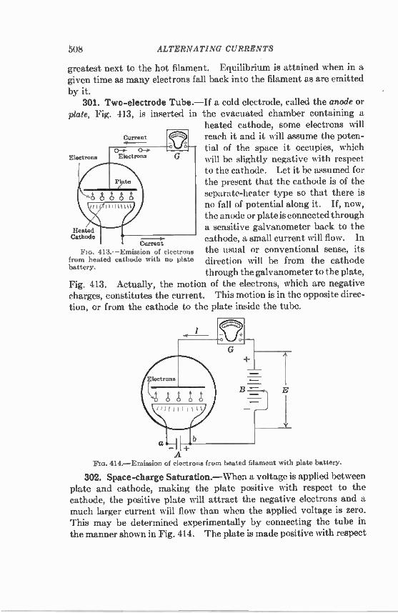
508 ALTERNATING CURRENTS
greatest next to the hot filament. Equilibrium is attained when in a given time as many electrons fall back into the filament as are emitted by it. 301. Two-electrode Tube.—If a cold electrode, called the anode or
plate. Fig. 413, is inserted in the evacuated chamber containing a heated cathode, some electrons will
Current reach it and it will assume the poten-4---
tial of the space it occupies, which El ctron ectrons I, will be slightly negative with respect
to the cathode. Let it be assumed for the present that the cathode is of the separate-heater type so that there is no fall of potential along it. If, now, the anode or plate is connected through
Heated a sensitive galvanometer back to the Cathode - --o- cathode, a small current will flow. In
Current FIG. 413. —Emission of electrons the usual or conventional sense, its
from heated cathode with no plate direction will be from the cathode battery.
through the galvanometer to the plate, Fig. 413. Actually, the motion of the electrons, which are negative charges, constitutes the current. This motion is in the opposite direc-tion, or from the cathode to the plate inside the tube.
414. —Emission of electrons from heated filament with plate battery.
302. Space-charge Saturation.—When a voltage is applied between plate and cathode, making the plate positive with respect to the cathode, the positive plate will attract the negative electrons and a much larger current will flow than when the applied voltage is zero. This may be determined experimentally by connecting the tube in the manner shown in Fig. 414. The plate is made positive with respect

ELECTRON TUBES 509
to the cathode by means of the battery B. The voltage E between the cathode and plate may be varied to E', E", etc., by the battery tap, as shown. A galvanometer or microammeter G is connected in circuit to measure the plate current. The manner in which the plate current varies with the temperature of the cathode for different applied plate voltages is shown in Fig. 415. For low temperatures and the cor-responding small emissions, the small plate voltage E' is sufficiently large so that all the emitted electrons are attracted to the plate, and the current increases rapidly with the temperature along the curve Oa. As the temperature and, hence, the emission increase, the density of the electron cloud between cathode and plate also increases, and, hence, the repulsive force on the electrons leaving the cathode, due to this negative space charge, increases. Ultimately, this repulsive force
E"
Flo. 415. —Plate current as function of Flu. 416. -Plate current as function of temperature for different voltages, voltage for different temperatures.
becomes equal to the attractive force due to the plate voltage E'. When this condition is reached, the rate at which the electrons return to the cathode is equal to the rate at which they are emitted by the cathode, and the plate current becomes constant, as at b, Fig. 415. This is called space-charge saturation. If the plate voltage is raised from E' to E", Fig. 415, the attractive effect on the electrons increases. It will require a greater space charge than before to drive the electrons back into the cathode at the same rate as the cathode is emitting them. Hence, space-charge saturation now occurs at c, Fig. 415, corresponding to a greater value of electron-emission current. The equation of the envelope OacdE is Richardson's law (250). 303. Child's Three-halves Power Law.—The plate current may
also be considered as a function of plate voltage for different cathode temperatures T', T", etc., Fig. 416. At low plate voltages, the electron emission or current is limited by space charge and increases as the volt-

510 ALTERNATING CURRENTS
age to the three-halves power. This is called Child's three-halves
power law. I = KET2. (251)
The constant K is a function of the dimensions and relative spacing of cathode and plate. At a given cathode temperature, such as T', the voltage ultimately reaches such a value that its attractive force at the cathode becomes larger than the mutual repulsive forces due to the space charge, and all the electrons emitted are drawn to the plate. The current becomes constant and is independent of the plate voltage. This condition for temperature T' is represented by the part ab of the curve. This is the true cathode saturation. As the cathode temperature is increased, the emission increases and cathode saturation occurs at higher values of plate current, as at c and d, Fig. 416. From the foregoing, it is obvious that the plate current is a func-
tion of two quantities, or parameters—plate voltage and cathode
temperature. 304. Edison Effect.—When the cathode is a filament and is heated
by passing a current through it, there is a fall of potential along the filament because of the resistance drop. The various parts of the filament, therefore, will have different potentials with respect to the plate. For example, in Fig. 414, the plate is at the
potential of the plate battery B above the right end of the filament but is at a higher potential, equal to the sum of the voltages of the B and A batteries, above the left end of the filament. If the B battery, Fig. 414, be removed, as in Fig. 413, and the plate
jilililulijilululi connected to the positive end of the filament, its potential above the negative end of the filament will be the voltage of the A battery. Its potential
above the various parts of the filament diminishes toward the positive
end of the filament. A current will flow in the plate circuit, larger than that discussed
in Sec. 301 but unequally distributed along the filament, being greatest at the negative end of the filament. If the plate be connected to the negative end of the filament, no current flows in the plate circuit, as the plate is negative to all other parts of the filament. Edison first noticed this effect in 1883, when he was developing the incandescent lamp. When he connected a plate P, sealed in the bulb near the filament F, through a sensitive galvanometer G to the negative ter-minal a of the filament F, Fig. 417, no current flowed through the
417.—Edison effect.

ELECTRON TUBES 511
circuit PGaF. If, however, he connected the plate to the positive terminal b of the filament F, a very appreciable current flowed through the circuit PGbF. At that time nothing was known of electrons, and this current was referred to merely as the Edison effect. A study of the phenomenon was made by Fleming in 1896, but its true significance was not understood until explained by J. J. Thomson and 0. W. Richardson in 1899 and 1901. 305. Fleming Valve.—The most valuable property of the two-
electrode tube, or diode, is its characteristic of unilateral conduction. When the plate is positive with respect to the filament, it draws electrons from the filament, a current flows from plate to filament, roughly proportional to the three-halves power of their voltage differ-ence, and the device has a finite although variable resistance. When the plate is negative with respect to the filament, the electrons are all driven back into the filament and no current flows. The resistance
Fm. 418. —Half-wave rectification with Fleming valve.
of the device becomes infinite. If an alternating voltage be applied to a two-electrode tube, Fig. 418(a), the resultant current is pulsating but unidirectional, Fig. 418(b). The negative loop is entirely sup-pressed. The positive loop is somewhat distorted because of the variation of resistance of the device with current. The foregoing is called half-wave rectification. This rectifying action is identical in principle with that of the mercury-arc rectifier and the tungar rectifier described in Chap. XV. Fleming, in 1905, was the first to recognize this rectifying property of a two-electrode tube. He obtained a patent on its use as a detector of high-frequency oscillations, which became one of the fundamental patents in electron-tube development. 306. Full-wave Rectification.—Both loops of voltage may be recti-
fied by using two rectifiers, Fig. 419. The fesulting current through the load is shown in Fig. 420. This is called full-wave rectification. If the load is of high resistance, the voltage impressed on it may be smoothed out, as shown by the full line in Fig. 421, by connecting a large capacitor across the output circuit.

512 ALTERNATING CURRENTS
The output voltage across the load is less than the peak voltage applied to the tube by the amount of the voltage drops in the choke coils and in the rectifier tubes themselves. This drop is nearly proportional to the load current in high-vacuum rectifiers and causes the efficiency of the rectification process to be low. Since the efficiency is the ratio of load resistance to the sum of load resistance and tube resistance, that is, the total circuit resistance, high-vacuum rectifiers
Secondary
A-C Supply
Primary
Filter
Fla. 419. —Connections which give full-wave rectification.
should be used only with high-resistance loads. Mercury-vapor rectifiers have been developed for use in low-resistance circuits and are described in Chap. XV. The cathodes of rectifier tubes are usually operated from a low-
voltage winding of the same alternating-current transformer that supplies the high voltage being rectified. In the tubes of small power, the two units necessary for full-wave rectification are sealed into the same evacuated bulb. These full-wave rectifier tubes are used largely
- E
V Flu. 420. —Full-wave rectification Flo. 421. —Full-wave voltage rectifi-
with two rectifiers, cation with capacitor across load.
to supply the plate voltage in alternating-current-operated receiving sets. They are provided with low-pass filters, Fig. 419, for smooth-ing out the voltage ripple. This filter consists usually of three large capacitors in shunt to the load, and between each pair of capacitors is connected a large choke coil in the high-voltage lead. The cutoff frequency of this filter is placed at about 40 cycles per sec. High-power rectifiers, both the high-vacuum and mercury-vapor
types, are used for the production of high-voltage direct current for high-voltage (2,000 to 15,000 volts) three-electrode oscillators, for X-ray tubes, and for obtaining high voltages for insulation-testing
purposes.

ELECTRON TUBES 513
307. Rectifier Tubes.—The three quantities that define the opera-tion of a rectifier tube are the maximum peak inverse voltage that the tube will withstand without breakdown, the maximum peak plate current as determined by filament emission, and the maximum direct current as determined by the heating of the anode due to the voltage drop. Representative ranges of these quantities for the smaller rectifier tubes are 700 to 1,550 volts, maximum peak inverse voltage; 120 to 675 ma, maximum peak plate current; 40 to 225 ma, maximum direct current. 308. X-ray Tubes.—The Coolidge hot-cathode X-ray tube, Fig.
422, is a special two-electrode tube, designed for the production of X-rays. The filament E, heated by the low-voltage battery B, is concentrated and is electrostatically x-rays shielded by the molybdenum tube / M, so that the electrons are emitted M I in a fine pencil. The plate, or anode, C is a massive block of tung-sten, which serves as a target for the electrons. X-rays are given off at the point where the electrons strike. The anodes frequently are water-cooled to allow the use of high voltages and relatively large currents, as, for example, 100 kv and 5 ma.
It is interesting to notice that, because of the high voltages used, X-ray tubes operate under the conditions for cathode saturation (Sec. 303). All other rectifier tubes operate under the conditions for space-charge saturation (Sec. 302). X-rays have the property of penetrating substances that are
impervious to ordinary light. They are used to a very large extent in medical work in the study of fractured bones, the roots of teeth, etc.; in industry, to locate flaws in castings; in chemistry, to determine the crystal structure of substances, etc. 309. Three-electrode Tube.—The addition of a third electrode to
control the plate current was made by De Forest in 1907, in a tube that he called the audion. His patent, issued in that year, became as fundamental as that of Fleming in vacuum-tube development. He placed a lattice, or grid, as it is now called, between the cathode and plate, Fig. 423. The electrons, in passing from cathode to plate, must pass through this grid. If the grid is positive with respect to the cathode, it will assist the plate in drawing electrons from the cathode
Electrons
Ft°. 422. —Coolidge X-ray tube.

514 ALTERNATING CURRENTS
and, hence, will increase the plate current. If the grid is negative with respect to the cathode, it will act in the same manner as the space charge (Sec. 300) and will repel the negative electrons toward the cathode and, hence, will decrease the plate current. Therefore, the
plate current is a function not only of
Grid the cathode temperature T and the plate voltage E, but also of the grid voltage E„.
Plate In the region in which the current is Cathode limited by space charge, the expression
for the plate current is Filamentary Heater E )" = K ± (252)
A
where µ is the amplification factor of the tIe tube as defined by (254). The form of
B this equation is similar to that of (251), C p. 510. The grid voltage E, is IA times
as effective in determining the plate cur-k—ED-44-4.1 rent as the plate voltage E9, for the grid
FIG. 423. —Tr'ode in cross section, is much nearer the cathode than it is to the plate. Hence, a very small amount
of energy applied to the grid will control a much larger amount of energy passing from cathode to plate. It is this characteristic of the tube which permits its use as an amplifier and as an oscillator.
grid positive.
Flo. 424. —Connections for determining static characteristics of 3-electrode tube.
310. Static Characteristics of Three-electrode Tube.--A plot indicating the interdependence of electrode currents and voltages is called a steady-state, or static, characteristic. The three most impor-

ELECTRON TUB! A 515
taut static characteristies involve the three variables—grid voltage, plate voltage, and plate current. Figure 424 shows the connections that may be used to obtain the
static characteristics of a three-electrode tube, or triode. The voltage' E, applied to the plate by the B, or plate, battery depends on the type of tube being tested. It is determined by the allowable heating of the plate produced by the direct-eurrent power input. The tern-
30
25
10
5
260 200
Static Characteristics
V El
Q AEg A/
). AEg A/
).
10 - _ —16 a' -11:1 a - +I(
Ep 150 (Volts)
100
60
E9—Volts 425.—Plate-current grid-voltage characteristics.
perature of the plate must not exceed that attained by it during the pumping process. No part of the tube should become hot enough to cause the evolution of gas from the heated areas. The voltage applied to the grid may be obtained readily from dry
cells C in series, a high-resistance drop wire Pc being used to vary the voltage and a reversing switch Sw to give the desired polarity. .The applied electrode voltages also may be obtained from power supplies similar to the supply shown in Fig. 419.
The symbol Eb is used to denote the steady direct-current voltage across the B battery; E, is used to denote the direct-current voltage between plate and cathode. These two are seldom equal, but frequently their difference is negligible. For example, in Fig. 424, Ep differs from Eb by the voltage drop in the plate milliammeter I„, and ordinarily this voltage drop is negligible. Sometimes, however, a load may be connected between plate and B battery, and the voltage drop across this load may not be negligible so that Ep then cannot be assumed equal to E. A similar distinction is made between the voltage of the C batter3 Er and the voltage between grid and cathode Ep.

516 ALTERNATING CURRENTS
Normal values for grid voltage, plate voltage, and plate current are as follows:
Grid voltage 0 to -60 volts Plate voltage 28 to 300 volts Plate current 0.14 to 80 ma
If the plate voltage is held constant at some value E1, Fig. 425, and the grid voltage is varied, a curve abc is obtained. This is a plate-current grid-voltage characteristic. When the grid voltage is zero, current Ob flows to the plate, since the plate itself attracts elec-
30
25
20
10
0
Static Characteristics V i
Jr .r LlEp
350 4C 3 60 100 150 200 250 300
+10 +5 0 -5 -10 -15 Eg (Volts) -20
-25
- 30
- 35
-40 -45
Ei-Volts 426. —Plate-current plate-voltage characteristics.
trona from the cathode. In order to stop the flow of plate current, the grid potential must be negative and of a sufficient value Oa to neut4ralize the effect of the plate voltage. An approximate value may be found by sPtting /„ equal to zero in (252), whence
Eg = — ---e • (253)
If the plate voltage is increased to E2, then, for a given grid voltage, more current will flow in the plate circuit and curve a'b'c' is obtained. Curves for still greater plate voltages also are shown. The data represented in Fig. 425 may be plotted with plate voltage
as abscissa. The resulting curves will be for constant grid voltage, Fig. 426. These curves form the plate-current plate-voltage characteris-

ELECTRON TUBES 517
tics. This type of plot is valuable for studying the operation of tubes as amplifiers, as discussed in Sec. 314. In Fig. 427 is shown the third way in which the static characteris-
tics of a tube may be plotted. The coordinates are plate voltage and grid voltage, and the resultant curves are referred to as plate-voltage grid-voltage characteristics. The curves are for constant plate cur-rent. This type of plot is used in studying the operation of tubes as oscillators, as discussed in Sec. 323. The lines of constant plate cur-rent may be thought of as the contour lines of a three-dimensional
6 10 16 20 25 30 wv
250
200
150
100
50
0 —30
0
- --
E
pEg Q
Static Characteris
1
ics
—25 —20 —15 —10 —5 0 +5 4-1C
r, (ma)
30
26
15
10 5
Er-Volts Flo. 427.—Plate-voltage grid-voltage characteristics.
model in which plate current extends out from the paper at right angles to the plane of the voltage coordinates. The other two types of plotting, Figs. 425 and 426, are cross sections of this space model, taken parallel to each of the two voltage coordinates in turn. Grid current may be plotted in a similar manner, Fig. 449 (p. 536).
Except for tubes used as oscillators and class C amplifiers, the variation of grid current with plate and grid voltage is of little importance. 311. Tube Coefficients.—The slope of a static characteristic at its
usual operating point or at a predetermined point on the characteristic is termed a tube coefficient. Assume, Fig. 427, that the operating point is at Q and that the grid
voltage is given a negative increment AEG of 5 volts. To keep the new operating point on the same plate-current line (10 ma in the figure) the plate voltage E, must be changed by an amount AE„. The

518 ALTERNATING CURRENTS
ratio, AE„/ 41E0 for constant plate current is a tube coefficient called amplification factor and is denoted by the symbol µ.
AEp = AEL, 1p constant.
(25 I)
For triodes, p ranges ia value from 3 to 100. In Fig. 426, an increment in plate voltage AE,, demands a corre-
sponding plate-current increment AI „ so that the tube will continue to operate on the same grid-voltage line ( —5 volts in the figure). Their ratio is a tube coefficient called plate resistance and is denoted by the symbol rp.
AE„ = (255)
Eg constant. r„ ,
The last of the three most important coefficients is obtained as the slope of the characteristic curve whose coordinates are I„ and 110. This characteristic is shown in Fig. 425. The ratio of the change in plate current A/„ to the change in grid voltage AE„ for constant plate voltage (150 volts in the figure) is called grid-plate tmnsconductance or mutual conductance and is denoted by the symbol g„,
= A/ (256) AE g Ep constant.
These three coefficients are really the partial derivatives of the expression for plate current (252). As such they are n )t, independ-ent but are related by the equation
= g„,7•7, (257)
gm= AL • (258) r„
The amplification factor µ is determined by the relative spacing of grid and plate with respect to the cathode and by the degree of com-pleteness with which the grid shields the cathode from the electrostatic field of the plate, as determined by the openness of its mesh. It is essentially constant over a wide range of grid and plate voltages and cathode temperature. It follows then that transconductance g,,, and plate resistance r„ vary reciprocally. • Transconductance g„, increases slowly with plate voltage and grid
voltage in the positive direction and with cathode temperature. It increases also with the physical dimensions of the tube elements, as to both length and radius. For a given size of tube structure it is roughly
or

ELECTRON TUBES 519
independent of the relative position of the grid with respect to the cathode and plate and of the introduction of other electrodes. For small triodes it varies from 275 to 2,000 micromhos, with 1,000 micromhos as a typical value for standard operating voltages. From (257) and (258) plate resistance varies in a manner opposite
to that in which transconductance varies but varies to a much greater extent than transconductatwe. For small triodes its limits are 1 to 400 kilohms, with 10 kilohms as a typical value.
312. Measurement of Tube Coefficients.—While the tube coeffi-cients may be determined graphically from the static characteristics,
(a) Voltage-ratio method (b) Resistance-ratio method 428. —Dynamic measurement of amplification factor.
these coefficients may be measured more accurately by balance, or null, methods, involving the use of a small low-frequency alternating voltage. Because of the use of an alternating voltage, these methods are called dynamic methods. The results will agree with the values obtained by measuring the slopes of the various static characteristics, provided that the alternating voltage is small.
Since the amplification factor it is the ratio [see (254)] of the plate-voltage increment to grid-volt-age increment that will maintain • Attenuator :1 e,
the plate current constant, it is logical in a dynamic method for
IfEt Attenuator 6.2 determining the amplification factor to insert a small alternat- -129. —Voltage sources for voltage-
ratio methods. ing voltage el in the grid circuit, Fig. 428(a), and to introduce enough voltage e2 in the plate circuit to produce silence in the telephones or null detector at the plate. The ratio of the two voltages is the amplification factor.
e2 A = (259) ei
In the voltage-ratio method, the voltage sources must be properly phased and adjustable. This is accomplished best by using two similar transformers connected to a common source e and by following each transformer with a low-resistance adjustable attenuator, Fig. 429. In the resistance-ratio method for determining the amplification
factor, the voltage sources el and e2 of Fig. 428(a) are replaced by

520 ALTERNATING CURRENTS
voltage-dropping resistors R1 and R2, Fig. 428(b), across which is con-nected the low-frequency voltage e. When the resistor R2 is adjusted to produce silence in the telephones, the a-c voltage drop iR2 across it is equal to that in the plate circuit of the tube due to the voltage iR applied to its grid. Hence, by the equivalent plate-circuit theorem, stated in Sec. 314,
iR2 = or
R2
" = 114 (260)
The resistors R1 and R2 should be as small as possible so that the d-c voltage drop across R2 will be small.
Note: For the sake of clearness, the direct voltage and current sources and the means for measuring and controlling them have been omitted in Fig. 428 and in those remaining figures where these circuit elements are not pertinent to the point under discussion.
Because of the use of alternating current, any high-resistance potential divider, used to vary the grid voltage, must be shunted by a
rp
(a) Resistance-bridge method (1)) Voltage-ratio method no. 430. —Dynamic measurement of plate resistance.
capacitor of at least 1 a capacitance. The telephones should be of low d-c resistance or be shunted by a low-resistance choke coil so that the d-c voltage across them, due to the steady plate current, is small. Plate resistance 2., may be measured in the manner shown in Fig.
430(a). This is merely an alternating-current Wheatstone-bridge circuit, in one arm of which the plate circuit of the tube is connected. As in Fig. 428(b), resistor R2 should be as small as possible, and the telephones should be shunted by a low-resistance choke coil, in order to keep the d-c voltage across them small. When the bridge is balanced by adjusting H2,
R2 R3
rP R1 (261)
In order to cover a wide range of values, resistor R3 should be adjust-able by factors of 10.

ELECTRON TUBES 521
The voltage-ratio method for measuring plate resistance is shown in Fig. 430(6), where the voltage sources ei and e2 are obtained as indicated in Fig. 429. The plate resistance is
e2 r, = — Rg.
ei (262)
Grid-plate transconductance g„, may be measured by any of the three methods shown in Fig. 431. The simple arrangement of Fig. 431(a) is due to C. B. Aiken and J. F. Bell. Since at the null condition the voltage drop across R must be equal to the voltage applied to the grid (i„R = es), the transconductance (g„, = iples) is measured by the reciprocal of R,
(263)
(a) (b) (c)
Flo. 431. —Dynamic measurement of grid-plate transconductance.
In the voltage-ratio method of Fig. 431(6), the grid-plate trans-conductance becomes
e2 1 ei (264)
if R. is large compared to the resistance of the voltage source e2. In the resistance-ratio method, Fig. 431(c), the grid-plate trans-
conductance is
RI R3 f
and this expression reduces to
R2
gm — RiR3
when the plate resistance of the tube is much larger than Rg.
In this discussion of the measurement of dynamic characteristics, no consideration has been given to the effect of grid current and of capacitance between the electrodes of the tube. Some methods for taking account of these effects have been described by Chaffee.'
(265)
(266)
1 CHAFFEE, E. L., "Theory of Thermionic Vacuum Tubes," Chap. IX, McGraw-Hill Book Company. Inc.. 1933.

522 ALTERNATING CURRENTS
In the voltage-ratio methods, the out-of-phase component due to electrode and wiring capacitance is usually balanced out simply by providing a third voltage source and connecting it (with a variable capacitor in series) directly across the null detector. In general, the advantage of the resistance-ratio methods is the
ready availability of components in the usual laboratory. The advantage of the voltage-ratio method is its greater flexibility; since the a-c voltage sources may be insulated from each other, the d-c power sources may all be grounded at the cathode and the phasing voltage always may be connected directly across the null detector. 313. Three-electrode Receiving Tubes.—A large number of types
of three-electrode tubes are now in use. They differ according to their use as amplifiers, detectors, and oscillators, at radio or audio fre-quencies, and in respect to their power output. In addition, as the art has developed, the type of the power supply has caused the type of cathode to change. The space requirements in present-day compact receivers have reduced the over-all dimensions of the tubes, decreased the spacing of the electrode structures, and caused the development of the multielectrode tubes described in Sec. 321. The envelope of the tube may be of either glass or metal.' All of the recent small tubes have oxide-coated cathodes, because
of the greater efficiency of this type of emitter, as explained in Sec. 299. Those intended for operation through a transformer from an alter-nating-current supply usually have a separate oxide-coated cathode heated by radiation from an internal insulated filament. This type of construction avoids almost all the 60-cycle voltage introduced into the plate circuit by filamentary cathodes and allows tubes requiring different grid-bias voltages to be operated from a common filament transformer and plate supply (see Sec. 314). The fact that the cathode is an equipotential surface somewhat improves the operating characteristics, while the large surface area of the cathode increases the transconductance. Tubes having large output and intended to be used in the last stage of an amplifier for operating a loud-speaker still have the older filamentary cathode. A greater output can be obtained from a directly heated filament than from the heater type for equal input power, and a moderate amount of alternating-current hum in the plate circuit is not objectionable. The shape and dimen-sions of the filament are chosen so as to minimize the alternating-current hum.
' A complete description of tubes with their electrical and constructional characteristics will be found in the tube handbooks of the various tube manufacturers.

ELECTRON TUBES 523
314. Amplification.—Since the amplification factor µ of a three-electrode tube is considerably greater than unity, the tube may be used to amplify small voltages. Figure 432(a) shows a tube having a steady potential Eb connected in the plate circuit and another steady potential E, in the grid circuit. E, gives the grid a negative potential with respect to the cathode. These voltages give a definite quiescent
Load
(a) (b) Fla. 432.—Electron tube as amplifier.
Load
point Q on the plate-current grid-voltage characteristic, Fig. 433. Now let a small alternating voltage eg be introduced in the grid cir-cuit. This variation of grid voltage produces a variation of plate cur-rent. The actual plate current may be determined by projecting the eu sinusoid vertically on the I-E, curve. Thus, an alternating current i„, superposed on the steady plate current, is produced in the plate circuit. This current may be considered as being produced by a voltage met, acting through the
E, constant plate resistance r„ and the impedance Z of the load. The equivalence of e, and Ase„ is now referred to as the equivalent plate-circuit theorem. Its rigor- Time —a-T ifr
ous proof and that of its counter- 0 +E, part, the equivalent grid-circuit theorem, have been given by Chaffee.' The steady voltages and cur-
rents in the plate and grid I Time
circuits have no effect in deter-mining the alternating voltages and currents, except insofar as they define the portions of the static characteristics over which the tube operates. For distortionless reproduction, the voltages E, and Eb should be chosen so that the alternating ernf is operating on the straight part of the characteristic, Fig. 433, and, where E, is negative, so that the grid current I, is zero.
433. —Amplification characteristics of vacuum tube.
C HA FFEE, E. L., "Theory of Thermionic Vacuum Tubes," Chap. VIII

524 ALTERNATING CURRENTS
The grid bias Eg may be obtained without the use of a grid battery by placing a resistor P in the cathode circuit, Fig. 432(b). The voltage drop produced in this resistor by the steady plate current ip provides the negative bias Eg for the grid. The effective plate voltage is decreased by the same amount. The capacitor C by-passes the alter-nating component of current. When the capacitor C is omitted, an alternating voltage drop also
appears across P and hence in the grid-cathode circuit, opposite in phase to the input voltage e„ when the load is resistive. This voltage reduces the over-all amplification of the amplifier, and the effect is called degeneration. The net gain is more nearly independent of variations in the characteristics of the tube. Degeneration is much used in high-gain multistage amplifiers. 315. Dynamic Characteristics.—The construction used in Fig. 433
for obtaining the a-c plate current i, is correct only for no-load in the
30
5
0
+10 +5 0 -5 -10 -16
/ e
q P
$p / ,4;4i tan-1 Rts ' ";'-• CL7n
, n 0 1
CI 60 100
-4- tan-1 Ti,
160 E., 200 E. 250 200 R50 4(1
Eg (Volts) - 20
25
-SO
-35
-40
45
Es-Volts FIG. 434. —Operation on plate-current platc-voltage characteristic.
plate circuit. For a resistance load R, the curve on which the sinu-soidal grid voltage eg must be projected lies below the static character-istic by an amount dependent on the ratio of this resistance R to the plate resistance r. This curve is one of a family of dynamic character-istics for the tube, which, however, vary with the load. For this reason it is simpler to use the I p-E , characteristic of Fig. 426, on which the load resistance may be easily represented.

ELECTRON TUBES 525
Let the load have a d-c resistance Rb and an a-c resistance Rb. Of the plate voltage Eb, a part Eb—E, is lost as a voltage drop across the load, leaving the voltage E„ to be applied to the plate of the tube. As shown in Fig. 434, a straight line through Eb, making an angle with the vertical whose tangent is Rb, is the direct-current I—E character-istic of the load. Its intersection with the „—E, curve for the grid-bias voltage E. determines the plate current 1 „ and the quiescent point Q. When a voltage eg is applied to the grid, a voltage ep = peg may be considered to appear in the plate circuit by virtue of the equivalent plate-circuit theorem. The alternating-current 1—E characteristic of the load is a straight line through Q making an angle with the vertical whose tangent is Rb. It is the path of the operating point, and its intersections with the various constant-Es curves determine the simul-taneous values of instantaneous plate current and plate voltage. For the chosen value of et, in Fig. 434, the path of operation is pQn. For a load of negligible d-c resistance, Ei, = Eb, and the quiescent
point is directly above Eb. For a reactive load, the path of operation is an ellipse passing around the quiescent point. 316. Power and Efficiency.—The power drawn from the battery
is Eb/p, which is equal to the area of the rectangle Ebm/„0, Fig. 434. Of this total power, the part (Eb — Ep)I p, or the rectangle EbmQE„, is lost in the d-c resistance of the load, leaving the power EpIp, or the rectangle EpQ/90, to be applied to the tube. The a-c power output is
or the triangle Qqp. These areas are shown shaded in Fig. 434. The ratio of output to input power is the efficiency of the tube in con-verting d-c power to a-c power. It never can exceed 50 per cent and is generally less than 25 per cent, because for freedom from distortion the grid must not be allowed to swing positive. The power output may be increased by allowing the grid to swing
positive, extending the operating path beyond the point p in Fig. 434. Also, the grid may swing more negative, so that the plate current is reduced to zero at one point in its cycle. In the extreme case, the quiescent point may be shifted down to the Ep axis and the instantane-ous plate current kept at zero for a half-cycle or even more. In all these cases, the plate current is distorted, and harmonics are intro-duced. The effect of this on the output voltage may be reduced by the use of a parallel tuned circuit as a load or by using two tubes in a push-pull arrangement, Fig. 435. Because of the symmetrical con-nections of the tubes with respect to the positive and negative values of the impressed voltage, all even harmonics are suppressed. Letters have been assigned to the various types of amplification
just described. Class A amplification refers to the distortionless

526 ALTERNATING CURRENTS
operation where the grid never swings positive and the plate current is never zero. In class B amplification, the quiescent point is placed on the E, axis, the tube is biased to cutoff, and the grid is allowed to swing somewhat positive. In class C amplification, the grid bias is placed beyond cutoff, and the operating path is as long as possible. The efficiency of class B operation may reach 50 per cent, with a maximum
Input
.
Output
o
435. —Push-pull amplifiei.
of 80 per cent for class C. Intermediate classes are indicated by the symbols A', AB, and BC. 317. Voltage Amplification.—The ratio Al of the voltage across the
load to that applied to the grid is always less than the amplification factor µ of the tube and approaches that quantity as the load resistance Rh is made large compared with the plate resistance r„.
RI, 1 A' = Rh r„ = 1 ± (rpilib) (267)
Making Rh = r, however, reduces the gain only to p. The voltage drop in the load due to the d-c plate current makes it necessary to pro-
Flo. 436. —Resistance-coupled amplifier.
vide a large plate-battery voltage, but the amplification is inde-pendent of frequency over a wide range. A greater voltage amplification than can be obtained with a single
tube is made possible by applying the output of the first tube to the grid of a second tube. For a resistance load in the plate circuit of the first tube, the connections shown in Fig. 436 may be used. The capacitors isolate the tube from the effects of d-c voltages. The

ELECTRON TUBES 527
frequency range is determined at the low-frequency end by the ratio of the reactances of these capacitors to the resistances in the grid circuits, and at the high-frequency end by the ratio of the capacitive reactance from each plate to cathode to the plate-load resistance. The voltage amplification of such an amplifier should be about 40 over the frequency range from 25 cycles to 50 kc. By using pentodes, the voltage amplification can be increased tenfold. Because of the high resistance of the grid circuit of a vacuum tube,
a step-up transformer may be used as the plate load to make con-nection to the next tube. The characteristics of audio-frequency
cC g(P,li 437. —Transformer-coupled amplifier
transformers having laminated iron cores are such that, to obtain a rea-sonably constant voltage step-up ratio over the audio-frequency range from 50 cycles to 10 kc, this ratio is not greater than 3. It may be increased to 6 or 10 with a corresponding reduction of frequency range. The transformer may be tuned to a single frequency, and a voltage gain of at least 50 obtained. The connections for a two-stage trans-former-coupled amplifier are shown in Fig. 437. Its voltage gain should be about 1,500 over the frequency range from 100 cycles to 7 kc. The voltage gain that may be obtained in a multistage amplifier
is determined by the coupling between output and input. This is usually due to the impedances in the plate supply, which are common to all tubes. The greatly amplified plate current of the last tube produces a voltage drop across these imped-ances which is thereby introduced into the plate circuits of the preceding tubes. This produces degeneration (Sec. 314), when there is an even number of stages, and regeneration and self-oscillation (Sec. 322) when there is an odd FIG. 438.— Capseittoteet, number of stages. It occurs most frequently in a-c-operated amplifiers and is reduced by shunting all common impedances with by-pass capacitors and filters. The voltage gain obtainable in a single stage is limited by the
magnitude of the capacitances between the electrodes of the tube. There are three capacitances, arranged as in Fig. 438. Of these, the grid-to-plate capacitance C„ is the only one that transfers energy between the grid and plate circuits and produces regeneration and
c„„
in t node.

528 ALTERNATING CURREN7'S
oscillation. In triodes its value is between 1.2 and 8 if. The other two enter mainly into the determination of the input and output impedances of the tube at high frequencies. Their values lie between 1 and 4 1.10. The existence of a grid-to-plate capacitance of the mag-nitude given limits the voltage gain per stage to perhaps 100 at audio
Cf 1.
Hazeltine's Method Rice'. Method 439.—Neutralization of grid-plate capacitance.
frequencies and to 5 to 10 at radio frequencies. In tetrodes and pentodes, the grid-to-plate capacitance C„ is reduced to less than 0.02 Aid, and the regenerative effect is negligible. The effect of the capacitance C„ in producing regeneration may be
neutralized by the introduction of a capacitor, so connected that it introduces an equal and opposite voltage in the grid circuit. Two methods are shown in Fig. 439. Hazeltine's method was used exten-cively prior to the introduction of the screen-grid tube (Sec. 319) in radio receivers having multistage radio amplifiers and called neutro-dynes. Other methods are dis-
1 Kc cussed by Chaffee.' None of the Fm. 440.—Measurement of voltage methods is entirely satisfactory
amplification, because the neutralization cannot be maintained over a wide frequency band without adjustment.
318. Measurement of Voltage Amplification. —The voltage amplification of a single stage consisting of a tube and transformer may be measured in the same manner as described in Sec. 312 for the determination of the amplification factor of a tube alone. Since the transformer will introduce a considerable phase shift in the output voltage, a suitable mutual inductance Al is introduced in the plate circuit, Fig. 440. The voltage amplification of the stage is
.\114 co2M 2 (268)
'CHAFFER, E. L., "Theory of Thermionic Vacuum Tubes," Chap. XVIII.

ELECTRON TUBES 529
To obtain the correct value of voltage gain for a positive grid bias, a second tube should be connected across the transformer secondary with its grid biased in the same manner as the first tube. This addition is also desirable in order that the transformer secondary may have connected across it the input capacitance of a tube. This method may be used also for measuring the voltage gain of a transformer
alone. For covering a wide frequency range or for measuring the large voltage gain
of a multistage amplifier, the use of calibrated attenuators, voltage dividers, or microvolters is preferable. However, these methods do not show the phase shift in the output voltage.
319. Four-electrode Tubes.—Four-electrode tubes, or tetrodes, generally have two grids in addition to a cathode and plate. Of the two grids, one surrounding the other, either may be the control grid
Input 0
E„
Outrut
- 111 0
E
(a) Space-charge-grid tetrode
Input Output
11 - 111111 III; L_E±E6 , 1
(b) Screen-grid tetrode FIG. 441. —Tetrodes.
while the other may be connected to either cathode or plate through a suitable battery and serve merely to modify the characteristics that the tube would have as a triode, if this grid were absent. The two types of connections that are of importance, space-charge grid and screen grid, are shown in Fig. 441. In the space-charge-grid tetrode, Fig. 441(a), the two grids are of
similar construction, and the outer one is the control grid. The inner grid is made positive with respect to the cathode and serves to decrease the space charge in the neighborhood of the control grid. This increases the grid-plate transconductance of the tube three to four times over the value that could be obtained without it, but with the same spacing of cathode, control grid, and plate. This increase is not a real gain, because much the same increase in grid-plate trans-conductance can be obtained with closer spacing of the outer electrodes when a large-diameter separate-heater cathode is used. For this reason this type of connection is used only in low-grid-current tubes,

530 ALTERNATING CURRENTS
such ai the FP-54 and RH-507, where it serves to prevent the positive ions emitted from the cathode from reaching the control grid. The screen-grid tetrode, Fig. 441(b), was developed to decrease
to a negligible amount the grid-to-plate capacitance. The first grid is the control grid, and the second grid is built so that it almost sur-rounds the plate. Because of the almost complete shielding thus obtained, the capacitance C,,„ can be made as small as 0.005 AiAf.
8
6
5
o.
3
9
Static Screen
Characteristics Voltage =90 V.
50 100 150 200 250 ,Inn RS11 &I
Ep-VOlt8
Fm. 442. —Plate-current plate-voltage charaeteristies.
Eg (Volts) 0
1
-2
-3
-4
5
6
Although the other interelectrode capacitances are increased two to three times, the operation of the screen-grid tetrode at radio frequencies allows voltage gains of 25 to 50 per stage to be realized. The plate-current plate-voltage characteristics of a screen-grid
tube are shown in Fig. 442. For plate voltages greater than the screen-grid voltage, the slope of these curves is small so that the plate resistance is very high, being in the hundreds of kilohms. The ampli-fication factor is in the hundreds, for the grid-plate transconductance is about 1,000 micromhos. Large values of plate resistance and amplification factor characterize all screen-grid tubes. When used with plate loads having a very high a-c resistance but a low d-c resist-

ELECTRON TUBES 531
ance, such as may be obtained from parallel tuned circuits, more than half the amplification factor of the tube may be realized at moderate frequencies. The power output is small, for the operating path must not be allowed to extend into the region where the plate voltage is less than the screen-grid voltage. In the region where the plate is negative with respect to the screen
grid, the emission of secondary electrons (see Sec. 297, p. 505) from the plate, produced by the primary electrons from the cathode, causes the plate current to decrease rapidly and to have a negative slope over a small range of plate voltage. In this region the plate resistance is negative, as in a carbon arc. When the tube is operated in this manner, it is called a dynatron, and the region of negative resistance is referred to as the dynatron region. With a parallel tuned circuit con-nected between plate and cathode, oscillations will be produced with no further means for regeneration (see Sec. 322), provided that the equivalent series resistance which represents the impedance of the tuned circuit at resonance is greater than the negative resistance of the tube. Secondary emission is greatly affected by the surface conditions of the plate. Hence the dynatron characteristics will vary greatly for different tubes and with age in the same tube. 320. Five-electrode Tubes.—The dynatron region of a screen-grid
tetrode may be eliminated by introducing a third grid between the screen grid and plate, connected directly to the cathode, as shown in Fig. 443. This is called a suppressor grid because, being always negative Input a Output
with respect to the plate, it causes all secondary electrons emitted by the plate to return to it. This tube is called a pentode. The screen grid can-
1110 not extend around the plate to shield I E s
it completely from the control grid, as 14- - 4 - 0 1
in a screen-grid tetrode, for this would 1.1G. 413.---Five-electrode tube or he likely to reduce the effectiveness of pentode. the suppressor grid. To keep the control-grid-to-plate capacitance small, extra shields are provided either within the glass envelope or external to it. In the latter case the bulb is so shaped as to allow the shield to come very near to the plate. The plate-current plate-voltage characteristics are shown in Fig.
444. In pentodes designed for use in the intermediate stages of amplifiers, the slope of these curves is small and similar to that in

532 ALTERNATING CURRENTS
screen-grid tetrodes. Plate resistances are about 1 megohm. Ampli-fication factors range from 600 to 6,000 for values of transconductance of 650 to 9,000 micromhos. Pentodes for use in the output stage of audio amplifiers have plate resistances of 10 to 300 kilohms with amplification factors ranging from 100 to 700. The operating path extends down to low plate voltages and thus
produces a large output. The amount of distortion existing in these tubes depends greatly on the resistance of the plate load and at best is much larger than that produced in a triode. For the best value of load, the distortion is due mainly to a third harmonic, which cannot be
60
50
40
Ps.
30
20
10
0 0 50 100 150 200 250
E9-(Volts)
444.—Plate-current plate-voltage characteristics.
eliminated by using the push-pull arrangement described in Sec. 316 (p. 525). Plate-current plate-voltage characteristics with a much sharper
knee are obtained in beam-power pentodes by shaping all the electrodes so that the electron stream from cathode to plate is confined to two beams pointed in opposite directions, each covering an angle of about 60°. Beam-forming plates connected to the cathode replace the suppressor grid. The individual wires of the control and screen grid are aligned to provide an unobstructed path for the electron stream from cathode to plate. 321. Multielectrode Tubes.—Many other combinations of elec-
trodes have been arranged for tubes intended for special uses. Vari-able-amplification tubes called supercontrol amplifiers are designed to
0 Eg (Volts) -5
-10
-15
-20
-25
-30
-35
Static Screen
Characteristics Grid Voltage -250 V.
II - -,
300 350
40 -45 -50
400

ELECTRON TUBES 533
reduce the effect of interfering signals, or cross talk. They depend on the use of a control grid whose mesh is not uniform over the length of the cathode. This increases the negative grid bias at which the plate current is reduced to zero, thus decreasing the curvature of the plate-current grid-voltage characteristic and reducing distortion. This device is used only in tubes having a screen grid. Many types of multielectrode tubes have been designed to save
space in radio receiving sets. Those which serve the functions of detector, or mixer, and oscillator are called converters. There are two types of dual amplifiers, one in which the units are connected to give a push-pull amplifier, the other in which the units are connected in cascade to give a two-stage amplifier. Some types include a pair of diodes in the same envelope with a triode or a pentode. 322. Regeneration.—It is shown in Sec. 309 that in the amplifier
any change of the voltage applied to the grid causes not only a change of current in the plate circuit but also a change of energy in the plate circuit. This change of energy is several times greater than the change of energy applied to the grid. If the proper phase relation between plate current and voltage in the grid circuit is obtained, it is possi-ble to feed a portion of this energy of the plate circuit back into the grid circuit and, hence, reinforce the effect of the grid. The grid, in turn, increases the plate cur-rent, which again reacts on the grid. This feedback of energy is Flo. 445.—Connections for regeneration
with tuned grid circuit. called regeneration. The connec-tions for one method of regeneration are shown in Fig. 445. An inductor Lg and a variable capacitor C. are connected in parallel between the grid and the cathode. A coil L„, having mutual induct-ance M with Lg and connected in the plate circuit, serves to couple inductively the plate and grid circuits. An alternating voltage e, introduced into the tuned grid circuit
produces a plate current i„ in such a phase that, if the polarity of L, is correct, the voltage which ip induces in the tuned grid circuit is in phase with the original voltage e„. The same effect may be produced by connecting in the plate circuit a similar tuned circuit consisting of inductance and capacitance in parallel. The interelectrode capaci-tance from grid to plate in the tube itself then is depended on for coupling between plate and grid circuits. If the grid circuit is not
so

534 ALTERNATING CURRENTS
tuned, as in an audio amplifier, the voltage induced back into the grid circuit is in quadrature with the impressed voltage e„, and there is no regeneration. The effect of regeneration is to introduce a negative resistance
into the tuned circuit. That is, this tuned circuit may now become a generator of energy, this energy being obtained from the plate or B battery. If the mutual inductance M between L, and L, be made sufficiently large, the total resistance of the tuned circuit may be reduced nearly to zero, where the limit of regeneration is reached. At this limit of regeneration, the a-c plate current is approximately constant and inaependent of the magnitude of the impressed voltage eg, as well as of that of the initial resistance of the tuned circuit; its value is determined only by the characteristics of the tube. In prac-tice, this maximum theoretical limit cannot be reached, since small disturbances, such as slight mechanical vibrations of the inductors, capacitors, and the tube itself, may cause the total resistance of the plate circuit to become negative momentarily and cause the tube to begin oscillating (see Sec. 323). The maximum attainable plate current thus is not constant but
varies directly with the magnitude of the impressed voltage, if the voltage is small, and inversely with the resistance of the tuned circuit, if the voltage is large.
OSCILLATORS
323. Oscillation.—When the mutual inductance between plate and grid circuits is increased to such a value that the resistance of the tuned circuit becomes zero or negative, sustained oscillations, inde-pendent of the voltage eg, Fig. 445, impressed on the grid, are set up in the system. In fact, the impressed voltage eg may be removed entirely without affecting the oscillations. These sustained oscillations will start even in the absence of any impressed voltage. Slight mechanical disturbances to parts of the system (see Sec. 322) or small electrical disturbances such as occur when the plate circuit is closed, are sufficient to start the tube oscillating. Under these conditions, the tube is said to be an oscillator. It behaves like an a-c generator, con-verting the energy of the plate battery into a-c energy in the tuned circuit. The frequency of the alternating current generated is prac-tically equal to the natural frequency of the tuned circuit
1 f- 27 • c'
where L (henrys) and C (farads) are the inductance and capacitance of the tuned circuit.
(269)

ELECTRON TUBES 535
The type of oscillating circuit in which the tuned circuit is con-nected to the grid, Fig. 445, is that used in most receivers in which oscillating tubes are used, such as continuous-wave, carrier-frequency, and superheterodyne receivers. As far as sustained oscillations are con-
cerned, the tuned circuit, frequently called the tank circuit, may be placed equally well in the plate circuit, Fig. 446, the tuned circuit being inductively coupled to the grid by the mutual inductance M. This type of circuit is used in most power oscillators where the tube acts as an a-c generator. The grid bias may be obtained from a grid leak and grid capacitor in parallel, as described in Sec. 329 (p. 546). The resistance R represents the total resistance in the tuned circuit, including the equivalent resist-ance of the load, such as the equivalent antenna resistance. The tuned circuit L,C, is at plate potential above ground. In
order to bring it to ground potentini ff)r direct connection to an
1i(.. 447. Parallel-feed oscillator.
Lb
FIG. 446. —Vacuuni-tube power oscillator.
H ar tley Circuit Colpitts Circuit
FIG. 448. - Oscillator circuits.
antenna and for safe operation generally, the parallel-feed connection of Fig. 447 is used. Cb is a large blocking capacitor, which prevents the tuned circuit from short-circuiting the plate battery Eb. Lb is a radio-frequency choke coil, which keeps radio-frequency current out of the plate battery. Other circuits frequently used are shown in Fig. 448. The Hartley
circuit is simple to construct because the inductance used in the tuned

536 ALTERNATING CURRENTS
circuit is a single coil with one intermediate tap. The Colpitts circuit is the most difficult to construct because the two capacitors Cp and C. should be geared together. Its advantage is that a low-impedance path to the cathode is provided for the harmonics of both plate and grid currents. Its output voltage has lzss distortion than any of the other circuits.
In all oscillators the ratio of grid voltage to plate voltage is determined by the coupling provided between grid and plate external to the tube. For the tuned-plate connection of Fig. 446,
et, M (270)
ep Lp L, Tp
where L, and L, are the self-inductances of grid and plate coils, M is their mutual inductance, and K is their coefficient of coupling. T, and T, are the turns in the grid and plate coils. Similarly for the tuned-grid connection of Fig. 445,
_ec, _1.\11- 1 T,. ep Tc L, K T p
The path of the operating point is best shown on the grid-voltage plate-voltage diagram, Fig. 427 for on this plot it is a straight line. In Fig. 449 the position
jp—Milliamps 0 600 50 100 150 200 250 300
500
200
100
0 —100 —50
Static Characteristics
350
ig (ma) 60
ep
•'' _160
P
100
• •
•
• • • ,.
,
,200 „.250 .400 MO
g 0
,
.../ ...,
, • , '
.e. "./
"....
+60 +100 +150 .E9—Volts
FIG. 449.—Operation on plate-voltage grid-voltage characteristic.
of the quiescent point Q is determined by the plate voltage Ep and the grid voltage —E,. The path of operation is a straight line Qp through Q, whose slope is the reciprocal of the swing ratio edep. The oscillations build up in the tube along this
(271)
+200 +250 +300

ELECTRON TUBES 537
operating path until the losses inside the tube at plate and grid, and outside the tube in the tuned circuit, equal the d-c power input. The relations between the operating path and the constant plate-current curves shown give an indication of the shape of the plate-current wave form. The curves bend sharply as they approach the E,-axis and then rise slightly. This rise is due to the increase in grid current in this region as shown by the grid-current contours. The total emission from the cathode is used to supply these two currents, and the tube no longer operates at space-charge saturation. The locus of the points of maximum curvature of the plate-current contours is
approximately a straight line OP through the origin, whose properties were first studied by Prince.' Placing the quiescent point Q on the zero plate-current curve and the lower end of the operating path on the Prince line OP, the plate current is succession of half sinusoids, whose average or d-c value I, and a-c fundamental component I, are
= ip = 0.317i,,
/, — —1 . ,= 0.3534. 2 V2
(272)
The peak-voltage swing ep and the a-c fundamental plate current I, together determine the resistance R, of the plate load, into which the tube must work.
c, = (273)
The d-c power input 117; and the a-c power output 11rp are
= (274)
Their ratio is the efficiency n
1;,R„ = ep = 0.785 7e„.
= pp 4 E,
Since the load resistance R, is related to the series resistance R of the tuned circuit by the expression
RP = Z Tvie
the magnitude of the oscillatory current is
I = I = 1 = Q2I„, R C p R2 P
(275)
(276)
(277)
since L,C,c02 = 1 for the tuned circuit (Sec. 25, p. 45). Storage factor Q is the ratio of the reactance of either branch of the tuned circuit to its total resistance. These equations hold for all operating paths ending above the Prince line OP.
When the path extends below this line, the plate-current wave form is at first flattened at its top and then becomes dimpled and the grid current increases slowly at first and then rapidly. These effects decrease the a-c current component, the output, and the efficiency, in spite of the increase in the plate swing ep. The
I PRINCE, D. C., "Vacuum Tubes as Power Oscillators," Proc. IRE, Vol. 11, pp. 275, 405, 527, 1923.

538 ALTERNATING CURRENTS
same quantities also decrease when the path ends above the Prince line and hence have their maxima somewhat below this line. Increasing the swing ratio increases the output at the expense of efficiency. A limit to this increase occurs when the loss in the tube raises the temperature of the plate to its safe limit (see Sec. 324). The efficiency then will be less than 50 per cent. On the other hand, the swing ratio must always be greater than the reciprocal of the amplification factor in order that there may be any a-c plate current. The minimum value of their ratio is about 2, at which point the efficiency may reach 70 per cent. For every point p defining the end of the path of operation there correspond
values of a-c fundamental plate current I, a-c power output 11„ efficiency n, and the other quantities defined by (272) to (277). They may be represented by contour lines on the plate-voltage grid-voltage plane. Chaffee' has determined the shape of these contours by both a dynamic method and direct measurements on an oscillating tube. The position of the quiescent point just discussed is for a class B amplifier (see
Sec. 316). Placing the quiescent point within the region where plate current exists decreases the output and efficiency and makes the operation of the tube approach that of a class A amplifier. When the grid bias is made still more negative, plate current flows for only a small part of a half-cycle, which is the condition specified for a class C amplifier. Under these conditions the maximum efficiency attainable is increased somewhat and is associated with outputs approaching the maximum allowed by the heating of the plate. The frequency stability of an oscillator, that is, its independence of the plate
resistance of the tube and the various battery voltages, is best for the class C operation just described, for energy is fed to the tuned circuit for only a short portion of the cycle. The swing ratio is very large, as is also the negative bias. This condition is most easily attained in a tuned-grid oscillator, as (271) indicates.
324. Power Tubes.—Most of the tubes designed for use in receiv-ing sets will function as oscillators having power outputs up to severs l watts. Tubes with greater outputs for use in broadcast transmitters and industrial applications differ from the receiving tubes by being larger in size and by being able to dissipate larger power losses from their plates. All metal parts are heated during the pumping process, either by electron bombardment or in a high-frequency furnace, to as high a temperature as practicable, to drive out the occluded gases. The tube then may be operated almost up to that temperature without any further evolution of gas. Since most of the power developed in the tube must be dissipated by radiation, unless the tube is cooled by auxiliary means, the rating of the tube may be increased by blackening the plate and by the addition of cooling fins. When the power loss is greater than 1 kw, the plate is made the outer part of the tube and is water-cooled. The largest tubes now constructed have outputs of 100 kw. The cathodes of most power tubes are thoriated-tungsten
1 CHAFFEE, E. L., and C. N. KIMBALL, "A Method of Determining the Operat-ing Characteristics of a Power Oscillator," Jour. Franklin Inst., Vol. 221, pp. 237-249, 1936.

ELECTRON TUBES 539
filaments, for oxide-coated cathodes cannot withstand the positive-ion bombardment produced by high plate voltage. For the same reason, pure tungsten is used in the largest tubes.
MODULATION
325. Modulation.—Electrical communication over wires in its simplest form employs alternating currents of audio frequencies only, either singly or in combination. These currents may be amplified
I I II II I II 11111H111 (a) Unmodulated carrier wave
Amplitude Envelope
(b) Amplitude-modulated carrier wave
A
(C) Erequency-modulated wave
FIG. 450. —Carrier current.
Amplitude Envelope
(see Sec. 314), but only a single communication can be conducted over a single effective circuit at one time. In order to open new channels of communication over any given effective wire circuit, carrier wire telephony and wire telegraphy are employed. Alternating currents having superaudio frequencies (3 to 10,000 kc per sec') are used as carriers or vehicles for the audio-frequency currents. In radio-telephony and radiotelegraphy, electromagnetic waves are used as carriers having frequencies of 10 to 500,000 kc per sec. Of themselves, these superaudio frequencies cannot transmit signals, being, for the most part, beyond the range of audibility, and they can transmit only small amounts of power. By the superposition of audio-frequency currents on these carrier currents, however, it is possible to transmit
The ear may be sensitive to frequencies as high as 15 kc per sec, but most conversational frequencies do not exceed 2.5 kc per sec.

540 ALTERNATING CURRENTS
several messages simultaneously over a given effective communication circuit. The superposition of an audio-frequency current on a carrier-frequency current is called modulation. The unmodulated carrier-frequency current is characterized by
the constancy of its amplitude, by the constancy of its frequency, and by its continuity with time—that is, it is not interrupted. If any one of these constant characteristics be interfered with in a manner propor-tional to an audio or signal frequency, the carrier will be modulated. There can be then three types of modulation, called amplitude modula-tion, frequency modulation, and pulse modulation. Figure 450(a) shows an unmodulated carrier current of constant
amplitude A and constant frequency a. If the amplitude is caused to vary by an amount B proportional to the amplitude of a low-frequency signal and at a rate proportional to the frequency b of the signal, the carrier will be amplitude-modulated and a plot of its amplitude with time will be as indicated in Fig. 450(b). The superposed low-frequency current is the envelope of both the positive and negative peaks of the modulated carrier current. If the carrier amplitude A is maintained at a constant level but the
carrier frequency a is caused to vary by an amount + Aa proportional to the amplitude of a low-frequency signal and at a rate proportional to the frequency b of the signal, the carrier will be frequency-modulated as depicted in Fig. 450(c). 326. Amplitude Mcdulation.—When the low-frequency, or audio-
frequency, signal is a sinusoid of frequency b, the mathematical expres-sion for the amplitude modulated current is
i = A(1 m sin 27bt) sin 2Tat, (278)
where m is the degree of modulation, being the ratio of amplitudes of audio and carrier currents
m = A• (279)
It may be shown that the modulated carrier current, Fig. 450(b), actually consists of three sinusoidal currents, one having the frequency a, the frequency of the original carrier current; another having a frequency a — b, the difference between the carrier frequency and the audio frequency; and a third having a frequency a -I- b, the sum of the carrier frequency and the audio frequency The frequencies a -I- b and a — b are called side frequencies. This is illustrated in Fig. 451, which shows a portion of the frequency spectrum, the abscissas being frequencies and the ordinates being the amplitudes of the currents.

ELECTRON TUBES 541
The amplitudes of these three currents are directly related to the amplitudes of the carrier- and audio-frequency currents of Fig. 450 as shown by the ordinates of Fig. 451. The degree of modulation is the ratio of the sum of the amplitudes of the two side frequencies to the amplitude of the carrier frequency. With the more complex nonsinusoidal audio-frequency currents, such as would be produced by the voice, the resultant modulated current is quite complex and the side frequencies widen out into side bands. The carrier frequency, however, is always sufficiently high so that the side-band frequencies
A
a—b a a+b ----"' ---* --v
Side Carrier Side Frequency Frequency Frequency
nu. 451. —Frequency spectrum.
Signal Voltage Signal
Voltage
Modulator Oscillator
a) Plate-circuit (b) Ileising Constant-current
FIG. 452. — Methods for amplitude modulating an oscillator.
are in a relatively narrow band in the frequency spectrum, and all are transmitted essentially as a single frequency.
Amplitude modulation may be accomplished in either the carrier oscillator circuit or some following amplifier circuit. When consider-able power is to be transmitted and hence efficiency is of economic importance, the carrier oscillator is unmodulated, its output is ampli-fied by high-efficiency class C amplifiers (whose sharp tuning would cause side-band clipping were the carrier modulated), and the modula-tion is introduced in the last amplifier stage. In low-power trans-mitters and in some signal generators, the oscillator is modulated. In one method for amplitude modulating an oscillator, a signal
frequency, whose peak amplitude is but slightly less than the steady

542 ALTERNATING CURRENTS
plate voltage, is introduced in the oscillator plate circuit in series with the steady plate-supply voltage, Fig. 452(a). The output current in the tuned circuit then has an amplitude envelope, Fig. 450(b), propor-tional to the signal frequency. Another method for amplitude modulating an oscillator is called the
Heising constant-current method. In this method, Fig. 452(b), the plate circuit of the modulator tube is in parallel with the oscillator tuned circuit and is supplied through a low-frequency choke coil Lb, which maintains the current from the plate supply E6 at practically a constant value. Hence the voltage across the two tubes is propor-tional to the plate resistance of the modulator tube, which in turn is proportional to the amplitude of the signal voltage. An amplifier may be amplitude-modulated by introducing a signal
voltage of appropriate amplitude in any of the electrodes of the ampli-
Amplifier Modulator
Carrier
(a) Plate modulation (b) Grid modulation. Fiti. 453.— Methods for amplitude modulating an amplifier.
fier tube. Thus, there are screen-grid modulation, cathode modula-tion, suppressor modulation; but the more usual methods are plate modulation and grid modulation where the signal voltage is introduced in series with the plate or grid, Fig. 453. A class C amplifier with plate modulation may be adjusted to
produce very little envelope distortion. The plate-supply voltage allowable for an unmodulated class C amplifier must be reduced by about one-half when the tube is to be modulated. Grid modulation introduces somewhat more distortion in class C
amplifiers but does not require as much exciter power. 327. Frequency Modulation.—If the change in frequency Act of a
frequency-modulated wave were plotted against time, the result would be as indicated in Fig. 454, where the carrier is unmodulated in (a) and is frequency-modulated by signals of different amplitudes in (6) and (c). The current of the unmodulated wave is
= .4 sin 2irat, (280)
and when the carrier frequency a is varied over a frequency excursion

ELECTRON TUBES 543
Aa proportional to a signal amplitude B at a rate b (signal frequency). the expression for the frequency-modulated current is
Act i = A sin (Tat + —19 sin 2arb), (281)
where the ratio Act/b is the modulation index. In frequency-modulation broadcasting, the Federal Communica-
tions Commission has ruled that the maximum permissible carrier-
+Aa
0
—4a (a) (b) (e)
Time
454. —Frequency of a frequen -modulated wave.
frequency deviation be 75 Ice. This is sometimes referred to as 100 per cent modulation. The frequency-modulation frequency spectrum consists of the
central carrier frequency and several side frequencies separated b cycles apart and extending Act cycles or more either side of the center frequency. As the amplitude B of the audio signal is increased, the carrier current and the side-frequency currents wax and wane in amplitude with ever-decreasing maxima and with definite minima or zeros.
Oscillator Modulator
FIG. 455. —Reactance-tube frequency modulator.
A carrier-frequency oscillator may be frequency-modulated by connecting across its tuned circuit a reactance whose value is a function of a signal frequency. In Fig. 455, let the resistance R be large at the carrier frequency
compared with the reactance of capacitor C. A current through RC due to the oscillator voltage then will be in phase with this voltage, and the voltage at C will be in quadrature, as will the plate current of the modulator. The plate current is a function of the signal voltage; consequently, the modulator supplies a quadrature current and

544 ALTERNATING CURRENTS
behaves as a reactance across the oscillator tuned circuit, and the value of this reactance and hence of the carrier frequency is dependent on the signal amplitude. In a second frequency-modulation method, modulation occurs in
the amplifying circuits rather than in the oscillator circuit. As indicated in the block diagram of Fig. 456, the oscillator output is divided into two branches. In either branch, a 90° phase shift is introduced. In one branch, a balanced amplitude modulator, fed from the audio, or signal, source, produces amplitude modulation with the central, or carrier, frequency suppressed. The remaining side frequencies when combined with the phase-shifted carrier frequency produce a current that is varying not only in amplitude but also in phase and hence in frequency. The amplitude modulation is removed in the subsequent stages. This method devised by Armstrong, has
Crystal. Controlled Oscillator
Amplifier I I 90° Phase
Shift
Signal Source
Balanced Amplitude Modulator
Amplifiers, Frequency Multipliers and Frequency Out
Changers
Flo. 456. —Armstrong method of frequency modulation.
the advantage that the center frequency may be obtained from a crystal-controlled oscillator.
DETECTION
A modulated high-frequency current, Fig. 450(b), can have no effect on any ordinary sound-producing device, since such a device is unable to respond to such high frequencies. Neither can this high-frequency current produce any effect on the human ear, for its fre-quency is far beyond audible frequencies. It is, therefore, necessary to demodulate such currents in order that the receiving devices may be actuated by audio-frequency currents similar to those used for modulating. This process of demodulation is called detection. Amplitude modulation and frequency modulation require radically
different demodulation methods. 328. Rectification with Two-electrode Tube.—Amplitude demodu-
lation can be accomplished by any rectifying tube, such, for example, as the two-electrode tube, Fig. 457. The tube will eliminate the nega-tive loops, Fig. 450(b), (p. 539), leaving a pulsating, unidirectional current, Fig. 458, made up of a unidirectional steady current, an audio-

ELECTRON TUBES 545
frequency current, and a radio-frequency current. The unidirectional current and the audio-frequency current will flow through the tele-phones T, Fig. 457, which will reproduce in sound the initial audio-frequency current. The high-frequency component will be by-passed through the capacitor C.
457. —Two-electrode tube used as detector.
F G. 458.— Rectified carrier wave.
Although the two-electrode tube is a satisfactory rectifier, it is quite insensitive as a detector of low voltages. This may be seen in Fig. 460, where the current I for small values of voltage E is extremely small. This difficulty is overcome, in part, by inserting a positive polarizing voltage in series with the tube, Fig. 459. Thus, in Fig. 460, the steady polarizing voltage E, produces a steady current I„ in the tube circuit. Hence, an alter-nating emf e impressed on the tube is no longer perfectly rectified but produces an alternating current ip. Owing to the curvature of the char-acteristic, this current ip is dissym-
f Ep
459. —Two-electrode tube with polarizing voltage used us detector.
no. 460. —Detection with polarized two-electrode tube.
metrical, the positive current being larger than the negative current. The negative current is shown shaded. Hence, the average current is increased from 1„ to I,, and thus the existence of the impressed emf is detected. The change in current, 4-4, is greater than the current that would flow for zero polarizing voltage and has its maximum value when the polarizing voltage corresponds to the point

546 ALTERNATING CURRENTS
of greatest curvature of the characteristic. When the impressed voltage is amplitude-modulated, this change in plate current will follow the variations of the modulating current. 329. Detection with Three-electrode Tube with Polarized Grid.—
The three-electrode tube will detect an amplitude-modulated carrier in a manner similar to the two-electrode tube with polarizing voltage, rectification depending on operating the tube at a point of curvature on its plate-current grid-volt-age characteristic. The connections for
FIG. 461.— Three-electrode operating a tube as detector are shown in tube with etector. polarized grid used Fig. 461. The grid is polarized negatively, as d
and the tube operates on a point of curva-ture of the characteristic, Fig. 462. As with the two-electrode tube, a sinusoidal emf e impressed on the grid produces an alternating current ip in the plate circuit, the reference axis of i,„ being I„. Owing to the curvature of the characteristic, the negative portions of i,„ shown shaded, are less in magnitude than the positive portions, and the average current increases from I„ to 4. When the impressed voltage e is amplitude-modulated, this change in plate current, 4-4, will follow the variations of the modulat-ing current. The radio-frequency plate current ip is by-passed around
— —1-1; the telephones through the capaci-tor C, Fig. 461. For maximum sensitivity, the polarizing voltage E. should be such that detection occurs at the point of maximum curvature of the characteristic. This type of detection is much
used in receivers having sufficient amplification ahead of the detector tube to supply a voltage large enough to swing the grid almost to zero bias. Under these conditions the distortion introduced in the rectified current is a minimum. 330. Detection with Three-electrode Tube with Grid Resistance.—
The three-electrode tube also may detect an amplitude-modulated carrier in a manner that is quite different from the foregoing. The connections are shown in Fig. 463. A high resistance fl, of 1 to 5 megohms is connected in series with and adjacent to the grid. This resistance is shunted by a small capacitor C. whose capacitance is
Fin. 462.-- Detection with polarized three-electrode tube.

ELECTRON TUBES 547
between 50 and 200 if. The grid is polarized positively by the volt-age E1, so that a current /, flows in the grid circuit, Fig. 464. This current through the high resistance R. produces a voltage drop I,R,, so that the effective polarization of the grid is E. — 1R1. The corresponding plate current is I„. An alternating voltage e in the grid circuit will produce an alternating current in the grid circuit, whose negative portions, shown shaded, are less in magnitude than its posi-tive portions. Hence, the average grid current is increased from /, t-E9 to I. This decreases the polari-zation of the grid from E. — I,R, to E, — 4R.. The alternating component 4, is by-passed through the capacitor C,. The average plate current is decreased from I, to I; with a superposed alternating current i. With reference to I. as an axis, the positive portions of 19 are less in magnitude than the nega-tive portions, shown shaded. When the impressed voltage e is modu-
463. —Three-electrode tube with grid resistance used as detector.
464. —Detecting actioi with grid resistance.
lated, this change in plate current I, — 4, will follow the variations of the modulating current. The radio-frequency plate current i is by-passed through'the capacitor C, Fig. 463. The large curvature of the grid-current characteristic I., the
large slope of the plate-current characteristic I„, and the fact that the high resistance R. may be made very large, all combine to make this type of detection the most sensitive of the methods so far discussed.

548 ALTERNATING CURRENTS
331. Detection and Regeneration.—The two foregoing types of amplitude-modulation detection may be operated with a tuned circuit combined with regeneration, (see Sec. 322, p. 533). A very efficient
circuit of this character, having a tuned grid circuit, grid resistor, and grid capacitor, is shown in Fig. 465. The incoming signal e is detected, and a portion of the resulting energy of the plate cir-cuit is fed back into the grid circuit through the coupling M.
Flo. 465. —Three-electrode tube with The capacitor C„ shunts the grid resistance and regeneration used as high-frequency currents around detector.
the telephone receivers T. 332. Heterodyne, or Beat, Reception.—A high-frequency alter-
nating current may have its frequency a lowered by superposing on it a second current of somewhat lower or higher frequency a'. The resulting current may be shown to be similar to an amplitude-modu-lated current having an apparent frequency equal to the average of the two frequencies. Further, the amplitude envelope of this frequency has itself a frequency a — a' or a' — a, that is, the difference of the two impressed frequencies. Figure 466(a) shows the resulting current curve and the resulting amplitude envelope for the general case, that is, when the amplitudes of the two currents are unequal. Figure 466(b) shows the resulting current curve and the resulting amplitude envelope when the amplitudes of the two currents (b) Equal Amplitudes are equal. In neither case is the Fio. 466. —Beat-frequency envelopes.
envelope sinusoidal, but the divergence is marked only when the two amplitudes are nearly equal. A tube operating on a nonlinear portion of its' characteristic will
separate the envelope frequency from the high frequency, thus giving 9, current having the envelope frequency of a — a' cycles per sec (see Sec. 326, p. 540). This frequency is called the beat frequency. The superposed frequency a' may be obtained from an oscillating
(a) Unequal Amplitudes

ELECTRON TUBES 549
tube, Fig. 467, whose grid circuit is inductively coupled to the grid circuit of the nonlinear mixer tube (whose function is described below) through the mutual inductance M'. This method of reception is called heterodyne reception or beat reception. In radiotelegraphy, where the high-frequency, or carrier, current is
modulated by the dots and dashes of the Morse code, the frequency of the beat note is made so low as to be audible, and the dots and dashes are heard at that frequency. In radiotelephony (or broadcasting), where the high-frequency current is modulated by speech or music, the frequency of the beat note (that is, the amplitude envelope of the frequency a — a') is about 465 kc.
FIG. 467. —Separate heterodyne reception.
For example, if the incoming modulated frequency is 1,000 kc and the superposed frequency is 1,465 kc, the beat frequency is 1,465 — 1,000, or 465 kc. By means of the mixer tube, Fig. 467, this amplitude envelope of
beat frequency is converted into a carrier-frequency current of this same beat frequency. This new carrier frequency is called the inter-mediate frequency, and its current again must be demodulated, amplified, etc., in the ordinary manner. This is the principle of the superheterodyne receiver (Sec. 335). In the heterodyne method of reception just described, the tube that
properly mixes two superposed frequencies to yield a new intermediate frequency, which is the sum or the difference of the two superposed frequencies, is termed a mixer. One of the two superposed frequencies may be modulated either in amplitude or in frequency, in which case the new sum or difference frequency is also modulated by the same percentage for amplitude modulation and by the same frequency deviation for frequency modulation. The term detector is used

550 ALTERNATING CURRENTS
more properly to describe a tube that breaks down an amplitude-modulated voltage into its components and yields a replica of the audio-frequency, or low-frequency, signal that was used to modulate the carrier. The functions of oscillator and mixer may be performed by the
same tube. This method is called self-heterodyne or autodyne reception. The connections are identical with those of Fig. 465, with the omission of the grid polarizing battery. In the autodyne, the tube is already oscillating, which tends to increase its sensitivity; but this effect is frequently more than offset by the fact that the grid circuit is tuned to the frequency of the oscillating current and not to that of the incom-ing signal. If these frequencies differ by large amounts, further amp-lification is necessary to make autodyne reception equal to separate heterodyne reception. It is possible to detect a speech-modulated high-frequency current
with either the separate-heterodyne or the autodyne method by mak-ing the beat note of zero frequency. This greatly increases the detect-ing action, but serious distortion is likely to be introduced because of the difficulty of maintaining a zero-beat frequency.
frequency a FIG. 468. —A form of frequency-modulation discrimination.
333. Frequency-modulation Discriminators.—A device that is nonlinear with respect to carrier frequency will change a frequency-modulated carrier into an amplitude-modulated carrier and is called a discriminator. Because of the steep slope of its amplitude-frequency characteristic, a tuned circuit is such a device. In Fig. 468, if a frequency-modulated source of center frequency a is connected across an antiresonant circuit tuned off resonance, there will be produced across the tuned circuit a carrier voltage whose variation in amplitude is a function of the frequency excursion Aa, hence of the original audio,

ELECTRON TUBES 551
or signal, voltage. The resultant. amplitude-modulated carrier may then be detected by any of the usual methods. While indicating the principle involved, the method of Fig. 468 is not used because it intro-duces appreciable distortion due to its curvature OS X The system shown in Fig. 469 can be quite free from distortion.
The primary and secondary windings are mutually coupled; the volt-ages el and e2 are 180° out of phase. At resonance, the voltages ei and e3 differ in phase by 90° as do e2 and e3. At off-resonance frequen-cies, el and e3 differ by less than 90° when e2 and e3 differ by more than 90°. The diodes then have impressed on them equal and opposite voltages at resonance but unequal voltages off resonance. The output voltage then is frequency-dependent, and so the circuit demodu-lates a frequency-modulated input voltage.
•e-Dn. 469. —A more usual frequency-modulation discriminator.
RECEIVERS
334. Receiving Circuits.—In modern broadcasting, the modulated high-frequency currents of Fig. 450 (p. 539) are converted into electro-magnetic waves, which may be received by an antenna or loop and converted into audio-frequency current by a detector and then into sound waves by telephones or a loud-speaker. Most receivers are designed to operate from an alternating-current
supply. A full-wave rectifier and filter, Fig. 419 (p. 512), supplies a plate voltage of about 300 volts. The electromagnet of the loud-speaker frequently is used as one of the choke coils of the filter. Lower voltages for the screen grids and for the plates of any lower voltage tubes are obtained by means of series resistors or a voltage divider. In either case these resistors must be by-passed by large capacitors to provide a low-impedance path for the a-c plate current. Grid-bias voltage is obtained from the voltage drop in a resistor placed in the plate return lead to the cathode (Sec. 314). This resistor often is by-passed by a suitable capacitor. The filaments of all tubes are heated from one or more separate low-voltage windings on the rectifier

552 ALTERNATING CURRENTS
transformer. All tubes except the output tubes usually have separate heater cathodes to reduce the alternating-current hum in the loud-speaker and to allow all the filaments to be operated in parallel. In addition, there are various accessory circuits as warranted by
the economics of receiver design. The manual volume control often is supplemented by an automatic volume control where some of the audio output is rectified and the resultant d-c voltage is fed back to control the grid bias of one or more earlier stages in the receivers. A tone control may be adjusted for accentuating base notes or high notes. Where the last audio-frequency stage consists of a push-pull arrangement as in Fig. 435 (p. 526), the grids of the push-pull amplifier may be fed from a phase inverter to eliminate the input transformer. The plate circuit of the phase-inversion stage is connected to one push-pull grid, and the unbypassed cathode circuit of the inverter supplies the other push-pull grid. In frequency-modulation reception, any amplitude-modulated signal may be avoided by incorporating one or more "limiter" stages, which are essentially overloaded triodes and hence behave very much like biased diodes and chop off the varying amplitude component of the amplitude-modulated wave. Any undesirable atmospheric disturbance (static) that is propagated as an amplitude-modulated wave can be greatly reduced in this manner before detection in the frequency-modulated receiver. 335. Superheterodyne Receiver.—The superheterodyne method of
reception is used widely for both amplitude- and frequency-modulated signals. As indicated in Sec. 332, a voltage from a local oscillator and a voltage from the signal are connected to electrodes of a mixer, which is operating at a nonlinear portion of its characteristic. The resulting intermediate frequency is the same for all settings of the receiver con-trol if the tuning condenser of the local oscillator is designed to track with the tuning condenser of the signal circuit. When the mixer is a tube containing within its envelope the electrodes for the local oscil-lator, it is called a converter. The amplifier for the intermediate frequency may yield considerable gain and may be designed with quite definite frequency characteristics because the intermediate frequency is fixed. Following the intermediate-frequency amplifier, a second detector operating at a high voltage level is used in ampli-tude-modulation receivers, and a pair of limiter stages and a dis-criminator (Sec. 333) are used for frequency-modulation reception. The wiring diagram of a typical amplitude-modulation superhetero-dyne receiver is given in Fig. 470, and the essential high-frequency circuits of a frequency-modulation superheterodyne receiver are shown in Fig. 471.

Push-Full Amplifier
117 V. 1 _1 11 A-C
B.F. Amplifier
Antenna
sz3 / 3-gang
condenser
171. II igh-frequeney circuite of a frequency-modulation superliet erodyne reeeiver.
1,..t IF. Amplifier T'hase
2nd IF. Amplifier Inverter Detector
/77: 7.17 1
470. —T pie al superheterodyne receiver for am plitude-modulat ion reception.
Mixer lot I.F. Amplifier 2nd I.F. Amplifier
Loeal v I3-Supply
0 cillato
Limiter Discriminator Demodulator
To Audio Amplifier
S:18.1.1 .VON.L.)37d
cri

CHAPTER XV
RECTIFIERS
The necessity for using direct current in certain types of industrial application is discussed on pp. 2 and 426. As a rule, it is far more economical to generate electrical energy as alternating current in large generating units and at locations where coal and cooling water can be obtained advantageously or where water power is available and then to transmit the energy, rather than to generate in smaller units near the centers at which the energy is utilized. Hence, when direct-current power is needed for industrial purposes, it must be obtained, as a rule, from an alternating-current system and he transformed in some manner to direct current. As is shown in Chaps. XI and XII, this transformation may be accomplished by rotating machinery, such as induction- or synchronous-motor-generator sets or by syn-chronous converters. It has long been recognized that in larger power units rectifiers are more economical than rotating machinery for the conversion of alternating-current to direct-current energy. This is due to the fact that in the rectifier there is no magnetic field and hence there is no copper loss in supplying the necessary mmf; in the rectifier there is no induced emf, and so there are no core losses such as occur in the armature iron of a dynamo; in the rectifier there are no moving parts, and so there are no mechanical losses. Rectifiers of the selenium type, and of the grid-controlled mercury type, and the ignitron have reached such a high state of development that they are being used in many installations in which formerly rotating machinery would have been used. A rectifier, in a broad sense, is a device whose resistance changes
when the direction of current changes. It is defined in the ASA' definitions as "a device which converts alternating current into uni-directional current by virtue of a characteristic permitting flow of current in only one direction." On the other hand, an inverter converts unidirectional current into
alternating current. Rectifiers may be divided into two general classes, those designed
for small amounts of power, such as the mechanical, electrolytic,
American Standard Definitions of Electrical Terms C42; Definition. 15.50.010. 554

(a) Bridge circuit
RECTIFIERS 555
copper-oxide, selenium, and well-known glass-tube-type mercury-are rectifier; and rectifiers designed to supply commercial power systems. (This does not include the vacuum-tube types used mostly for com-munication purposes and described in Chap. XIV.) Rectifiers for relatively small amounts of power will be considered first. 336. Half- and Full-wave Rectification.—If a rectifying device
permits the passage of current in but one direction, as indicated in
Current •
A-C Volts Rect er
(a) Simple rectifier
1\A (6) Half-wave rectification
FP:. 472.
Fig,. 472(a), no current flows during the negative half of the wave that is cut off. Unless there is inductance or a battery in the circuit, the current will be zero, therefore, for half the time, Fig. 472(b). This is called half-wave rectification. This type of wave is satisfactory for some purposes, such as battery charging, but it would not be satis-factory for general power supply (see Secs. 305 and 306, p. 511). If, however, current can be made to flow during each half-cycle
period, as in Fig. 473(b), full-wave rectification results (see p. 512).
1-2 3-4 1-2 3-4 1-2 3-4
(b) Full-wave rectification Flo. 473.
When a transformer is used with the rectifier, it is a simple matter to obtain full-wave rectification by a center-tap connection, Figs. 475 and 480(a) (pp. 557 and 564). When a center tap is not available, the bridge circuit of Fig. 473(a) may be used. Four half-wave rectifiers connected in the form of a Wheatstone-bridge circuit are used, the direction of positive current being shown by the arrows on the rectifier diagram. The alternating-current power source is connected across one pair of diametrically opposite junctions of the bridge arms, and the load is connected across the other pair. When the upper line is positive, current flows through (1) into the positive terminal of the

556 ALTERNATING CURRENTS
load and out through (2) to the lower alternating-current wire, giving waves 1-2 in (b). During this half-cycle, current cannot flow through (4) and (3) because of their rectifying characteristic. When the lower line is positive, current flows through (3) into the positive terminal of the load and out through (4) to the upper alternating-current wire, giving waves 3-4 in (b). Current during this half-cycle cannot flow through (2) and (1) because of their rectifying characteristic. Hence, during each half-cycle, current enters the positive terminal of the load and leaves the negative terminal. By the use of a smoothing induct-ance the pulsations in the rectified current wave, Fig. 473(b), can be considerably reduced. 337. Mechanical Rectifiers. Rectifying Commutator.—The recti-
fying commutator is a commutator driven by a synchronous motor. The segments are connected so that when the alternating current reverses, the connections to the direct-current circuit are reversed
A-C Supply
Rectified Current
FIG. 474.--- Cominutating-type rectifier.
simultaneously, Fig. 474. A unidirectional current is thus obtained. As the brushes cannot have zero width, it is difficult to commutate at the point of zero current and the current and voltage are rarely zero at the same time. Hence, such devices spark more or less and are limited to small currents and voltages and to special applications.' Commutators for very high voltages are used occasionally for smoke-precipitation apparatus. Vibrating Rectifier.—The vibrating rectifier operates on the same
principle as the commutator, but the connections to the alternating-current source are reversed each half-cycle by a polarized armature, which is caused to vibrate synchronously by means of an alternating-current magnet. This type of rectifier has been used for charging small storage batteries but for this purpose has been superseded by such rectifiers as the Tungar, Rectox, and selenium types. However, the vibrator has come into wide use for inverting direct into alternat-ing current, although the resulting wave is far from sinusoidal. Such
By introducing a third harmonic into the emf wave, the emf can be made nearly zero for a considerable portion of the cycle, thus permitting improved com-mutation. SEYFERT, S. S., "Synchronous-mechanical Rectifier-inverter," Trans. AIEE, 1933, p. 397.

RECTIFIERS 557
inverters are used for automobile radio sets where the 6 volts of the battery is inverted to an alternating voltage, is stepped up to 125 to 400 volts by a transformer, and is rectified by a tube to supply the plate- and grid-circuit voltages. In railroad cars the alternating current, usually inverted from 32 volts d-c, is used to operate fluo-rescent lights and supplies the a-c service for electric razors. When desired, the inverting and rectifying functions may be combined in one set of vibrating reeds by the use of two or more contacts on each reed. 338. Electrolytic Rectifiers.—Electrolytic rectifiers are based on
the following principle: If a lead plate and an aluminum plate be immersed in a sodium bicarbonate or ammonium phosphate solution, current can pass from the solution to the aluminum. As soon as the current attempts to reverse and pa.ss from the aluminum to the
S_ solution, a thin insulating film of Bb aetitnegry • —charged aluminum oxide is instantly Aluminum
Pie Aluminum formed over the aluminum plate Plate
Lead Plate and acts as an insulator up to
475. —Electrolytic rectifier. about 150 volts. This prevents the current flowing from aluminum to solution, and such a device may be used, therefore, as a rectifier. Figure 475 shows such a simple rectifier, giving a full-wave rectification like that in Fig. 473(b). Such rectifiers are of low efficiency, 60 per cent and lower, and of
small capacity. They are used primarily for charging low-voltage batteries from alternating-current supply. As rectifiers they have been superseded by such types as the Tungar, Rectox, and selenium. However, the principle of the insulating film of aluminum is utilized in the electrolytic capacitor so widely used, particularly in radio work. 339. Copper-oxide Rectifier.—The copper-oxide rectifierl operates
on the principle that a layer of cuprous oxide on a sheet of copper per-mits the passage of electrons from the copper to the oxide but prevents their passage in the opposite direction. The action is an atomic and not an electrolytic one, and no moisture is essential to the operation. The conventional direction of current is opposite to the direction of movement of the electrons and the current passes, therefore, from the oxide to the copper, Fig. 476(a). The units may consist of washers of 1% to 14 in. diameter, Fig. 476(a), mounted on an insulating rod. A soft-metal washer, usually of lead, is placed between the copper
1 GRONDAHL, L. 0., and P. H. GEIGER, "A New Electronic Rectifier," Trans. A.I.E.E., 1927, p. 357; also U.S. Patent 1,640,335.
A-C Supply
Transformer

558 ALTERNATING CURRENTS
washers so as to produce more uniform pressure on the oxide. The Rectox rectifier of the Westinghouse Electric Corporation operates on this principle. The bridge-circuit connection of Fig. 473(a) is used. Each stack
is a unit in itself, Fig. 476(b), and several such stacks operate in parallel to give the desired current rating. The arrows show the direction of rectification in each section of the stack.
Direction of Current Flow Soft Metal
Copper Oxide
Copper
(a) Top and sectional plan of Rectox disc
(b) Wiring diagram
Flu. 476. —Rectox rectifier.
Rectox chargers are adapted for rectifying small values of power and are used extensively for charging batteries, to provide direct current for control systems such as are used with elevators, as integral parts of rectifier-type instruments (p. 105), and for several other purposes requiring small amounts of rectified current. The efficiency of rheostat-regulated chargers is between 30 and 40 per cent and of Barrier step-regulated chargers between 40 and 50 per Layer \ cent. Under optimum conditions and at low
tallic temperature the efficiency may reach 70 to 75 Me Back Plate per cent. The power factor varies from 0.70
to nearly unity, depending on the load. 340. Selenium Rectifier.'—The selenium
rectifier is based on the unilateral conduction property of a thin layer of selenium when it
Selenium Counter Layer is placed between and in intimate contact with Electrode two metallic electrodes. The selenium is
deposited as a film about 0.05 mm thick on one side of a carrier plate of either iron or aluminum. The adhesion should be high
so as to prevent contact losses. The selenium is then subjected to a series of controlled heat-treatments, which produce a crystalline structure. Then a low-melting-point alloy is metal-sprayed on the
HARTY, E. A., "Characteristics and Applications of Selenium-rectifier Cells," Trans. AIEE, Vol. 82, P. 624, 1943.
FIG. 477. —Selenium-recti-fier unit.

RECTIFIERS 559
selenium surface, forming the "counterelectrode." By means of a subsequent chemical treatment a film "blocking," or "barrier" layer, is formed between the selenium and counterelectrode. Figure 477 shows a single unit the thickness of which is considerably exaggerated. The rectification is in the direction of back plate to selenium. The unit can sustain a reverse voltage of 18 volts and is usually
rated at 6 volts. The normal current density is about 35 to 40 ma per sq cm or about 0.225 to 0.26 amp per sq in. for full-wave rectifi-cation. Below are given typical unit ratings for half-wave and full-wave center-tap operation.
Diameter, in. 1 1 2 231 6 43 Volta
Amp: Half-wave Full-wave
0.075 0.150
0.2 0.5 0.4 1.0
2.15 4.3
6 6
With added cooling these ratings may be increased, and for short times the current may be as high as 2 to 2.5 times normal. The power efficiency is 50 to 75 per cent, depending on the current and type of circuit. The units can be combined in series and parallel and are assembled in stacks. This type of rectifier is widely used for battery charging, telephony
and telegraphy, control circuits, railroad signaling, electrical measuring instruments, electroplating, and welding. 341. Hot-cathode Rectification.—A considerable number of recti-
fiers, including the high-voltage-diode type (Sec. 305, p. 511) operate on the hot-cathode principle. If a cathode is heated to a high temper-ature, the average velocity of the electrons in the metal increases and more electrons therefore are able to leave the metal (Sec. 297, p. 505). This principle is used in the hot-cathode gaseous rectifiers such as the Tungar and Rectigon (Sec. 342), as well as in the mercury-arc rectifier, which is so important in the rectification of large amounts of power. Figure 478 shows a closed vessel within which is a gas or
mercury vapor at very low pressure. A hot cathode and a relatively cool anode, connected in series with an alternating-current supply, enter the vessel from opposite sides. Because of its high temperature, the electrons leave the cathode readily. The anode, being relatively cold, emits practically no electrons. At the instant shown in Fig. 478(a), the anode is positive and the cathode is negative. The differ-ence of potential between them creates an electrostatic field between cathode and anode, which is represented by lines. A potential

— No Current
gradient is created at the surface of the cathode that acts in the direction of the positive anode and draws electrons from the cathode, and under the influence of the field the electrons travel toward the anode. In doing so the electrons collide with molecules of the gas or vapor and thus produce both positive ions and free electrons by collision. The electrons travel to the anode and the positive ions to the cathode, thus establishing a current from anode to cathode. These ions create other ions by collision, so that there is a relatively large number of ions in the space between anode and cathode. When the potential reverses and the former cathode now becomes
positive as in Fig. 478(b), the electrons are drawn from the field to the cathode, ionization due to electron collision ceases, and cur--- —Cool Anode ------- - rent can no longer flow. The mobility of the positive ions that may be present is so low that at the existing low voltage gradient
- — Not Cathode- in the field these ions cannot cause appreciable ionization by collision. Hence, such a recti-fier, or valve, will permit the
flow of current from anode to cathode but not in the reverse direction. The difference between this type of rectifier and the hot-cathode
vacuum type is in the number of ions available and the resulting space-charge effect. In the gaseous and vapor types of rectifier, a larger number of ions, or current carriers, can be produced with the same potential difference between cathode and anode. Hence, the voltage drop with relatively large currents is low. Also, in the vacuum type, only electrons are in the regions between anode and cathode, and these produce a space charge that tends to prevent the electrons that leave the cathode from moving toward the anode (Sec. 302, p. 508). In the gaseous and vapor types, both positive ions and electrons occupy the region between cathode and anode, and the effect of both positive and negative charges in the same space is to neutralize space-charge effects. Space-charge effects make the vacuum type a high-resistance device. The absence of space-charge effect makes the gaseous or vapor type of ionic device a low-resistance one. Although in the gaseous rectifier both positive ions and electrons
carry the current, the larger proportion of the current is carried by the electrons because of their far greater mobility. This is particularly true in mercury-arc rectifiers. The most important effect of the
560 ALTERNATING CURRENTS
+ Current -
(b) FIG. 478.--Hot-cathode rectification.

RECTIFIERS 561
positive ions is to neutralize the space-charge effect of the electrons, thus reducing the opposition of the space charge to the flow of current. The volt-ampere characteristic of the rectifier depends on the gas
pressure. If there is a perfect vacuum, there is no gas to be ionized, and the entire current is due to the movement of the electrons, the resulting space charge causing a very high voltage drop. If the gas pressure is too high, the mean free path of an ion is very short, and a high voltage is necessary to cause ionization and current flow. There is an optimum pressure, which gives a sufficient number of positive ions to just neutralize space charge. With inert gases this pressure varies from 0.01 mm to several centimeters of mercury. In mercury-arc rectifiers the pressure is low, being 0.001 to 0.09 mm of mercury at a temperature range of 20 to 80°C. In the Tungar rectifier the pressure of the inert gas (argon) is approximately 5 cm of mercury, the higher pressure being advantageous in that it tends to prevent evapora-tion of thorium from the filament. 342. Hot-cathode Gaseous Rectifiers.—The Tungar rectifier of
the General Electric Company and the Rectigon rectifier of the Westinghouse Electric Corporation are typical examples of hot-cathode gaseous rectifiers. The anode is of graphite, and the cathode is a coiled tungsten filament heated by an electric current. These electrodes are enclosed in a bulb containing an inert gas, usually argon, at reduced pressure. The connections for the Tungar rectifier are shown in Fig. 479.
A transformer ab steps down the supply voltage, and the filament. is connected across its secondary. The filament becomes incandescent and emits electrons. One terminal c of the transformer secondary and one end of the
filament are connected to the transformer primary at b. The filament then is at practically the same potential as that of the power-supply line b'b. The voltage of the battery being charged is somewhat less than the voltage between line a'a and line bib. The potential of the graphite anode is different, therefore, from the potential of point c. Consequently, during one half-cycle the potential of the filament is negative with respect to the anode; during the next half-cycle its potential is positive with respect to the anode. When the filament is negative, the negative charges, or electrons,
are repelled by it, because like charges repel one another. These electrons attain a considerable velocity and ionize the gas by collision. The region between the filament and the anode becomes conducting; and, as a result, current flows from a into the positive terminal of the battery, through the battery to the anode, to c and then to b.

51;2 .ILTEHNA TING CURRENTS
When the filament is positive, the electrons, or negative charges, that it emits owing to its high temperature are attracted toward the filament, since positive and negative charges attract one another. Consequently, the electrons that initiate the ionizing action are with-drawn from the region between the filament and the anode. As a result, the gas is no longer ionized and ceases to be a conductor. Therefore, no current can flow during this half-cycle. The current can flow only in one direction, namely, from the graphite to the filament, and the device acts as a rectifier. Figure 479(b) shows the connections for one commercial type of
low-voltage Tungar, the switches and cutouts being omitted. Both the current to be rectified and the current for heating the filament
A.C. Maine
Primary
—•• Rect ed current
(a)
Rectified Current
(b)
479. —Tungar rectifier.
1 ranaformar
2.5-Volt Tap
are supplied by the transformer secondary, the filament being con-nected between a 2.5-volt tap and one end of the secondary. Current regulation may be obtained by adjusting the resistance and the reactance. Where electrical connection between load and primary mains is permissible, an autotransformer with taps may be used. The devices shown in Fig. 479 give only half-wave rectification,
but this is not a serious disadvantage when ordinary batteries are being charged. However, a two-bulb rectifier giving full-wave rectifi-cation is available. Figure 481 (p. 567) shows the types of voltage and current waves with full-wave rectification and a battery load. The efficiency of the Tungar rectifier is 35 per cent in the smaller
sizes to 75 per cent in the larger sizes. The arc drop is 6 to 47 volts, and the current ratings are 2 to 15 amp. This type of rectifier is used principally for charging batteries.

RECTIFIERS 563
MERCURY-ARC RECTIFIERS
343. Mercury Arc.—In the Tungar and Rectigon rectifiers, the tungsten constitutes the cathode, and the ionized atoms of an inert gas constitute the current carriers, producing the space charge as well. Since the cathode operates at high temperature, it slowly volatilizes and its life is limited. With mercury-arc rectifiers, the mercury performs the two functions; it is the hot cathode, and it supplies the mercury vapor from which the necessary positive and negative ions are produced. Mercury is very advantageous for these purposes. In mercury, the electrons are held rather loosely to the positive atomic nucleus, and accordingly the vapor ionizes readily. Since the mercury vapor condenses and returns to the cathode pool, there is no deteriora-tion of the cathode with use. When the rectifier is in operation, a mercury arc concentrates on
the surface of the mercury at the cathode and produces the cathode spot, a region of high temperature at which ionization can occur readily. The arc maintains the cathode spot at high temperature through the concentrated bombardment of the surface of the mercury by heavy positive ions of the mercury vapor. The cathode, being negative, attracts the positive ions, and these ions in striking the mercury give up their kinetic energy as heat, raising a relatively small region of the mercury pool to a high temperature. Marti and Winograd' state that careful measurements made in the Brown-Boveri laboratories show this temperature to be 2087°C. Moreover, this high temperature is only local, the mean temperature of the cathode pool being of the order of 100°C. The anodes may be of either iron or graphite and operate comparatively cool, their temperatures being well below that at which they can emit electrons freely. The voltage drop in the arc is dependent on operating conditions,
such as the length of the arc, whether or not the arc is restricted, and whether or not an auxiliary anode is used to maintain the arc. The ordinary arc drop is of the order of 12 to 18 volts in single-tank recti-fiers and may go as high as 30 volts in multianode tank rectifiers where the cross section of the arc is restricted by shields, Fig. 498 (p. 589). The are drop remains nearly constant over a considerable range of the instantaneous values of current. Also, in large, well-designed mercury-arc rectifiers, the arc drop is nearly independent of the load current. 344. Operation of Single-phase Rectifiers.—In Fig. 480(a) is
shown a simple single-phase rectifier with two anodes A and B supplied I "Mercury Arc Rectifiers—Theory and Practice," McGraw-Hill Book Com-
pany, Inc., 1930.

564 ALTERNATING CURRENTS
by transformer secondary ab with a center tap o. The lower terminal is the cathode and consists of a pool of mercury. The rectifier is usually started by an ignition rod or starting anode [Fig. 498 (p. 589)], omitted in Fig. 480(a), which strikes an arc, producing the cathode spot. First consider the conditions existing when a resistance load R is connected between cathode and center tap o. There are resistance and leakage inductance in the transformer primary and secondary, but their effect will be neglected. Because of the high temperature of the cathode spot, the cathode emits electrons freely. These are attracted to that anode terminal which is positive at the time and are repelled by the anode terminal which is negative at the time. Because of their high velocities, these electrons ionize the mercury vapor by collision, the negative ions and electrons going to the positive
CT =
I P • 1 •q' 1 1 1 1 1 1 \ \
-E,,„ -46
(a) (b) 1:1(:. 480.- -Single-phase rectifier with resistance load.
anode and the positive ions to the cathode spot, thus causing current from anode to cathode. The bombardment of the cathode spot by the heavy positive ions maintains the spot at the necessary high temperature. The anodes operate well below the temperature at which they
can emit electrons freely. Hence, at the time an anode terminal is negative, the electrons in its neighborhood are all drawn to the cathode, ionization by collision ceases, and no current can flow from cathode to that anode. Likewise, current cannot flow from anode to anode. Thus the rectifying action occurs at the anodes and not at the cathode. Current, therefore, can enter the tube from either anode A or B, Fig. 480(a), depending on which side of the transformer secondary ab is positive, and can then go to the cathode and so to the load. In Fig. 480(a), anode A is shown positive, and then current is from A to the cathode (see Fig. 478). If only one anode were used, the negative half of the alternating-
-wrent wave would be eliminated in each cycle, and half-wave

RECTIFIERS 565
rectification, Fig. 472(b), would result. This condition could not be maintained with the mercury arc, since the de-ionization time of the gas is only a few microseconds and the arc cannot restrike if the cur-rent becomes zero, even for a few microseconds. [By using auxiliary or excitation anodes from which arcs to the cathode are maintained at all times, it is possible to operate the tube even if the main current is zero during parts of the cycle (see Fig. 495, p. 589).] To obtain a continuous flow of current through the tube, two
anodes A and B are necessary, one anode being connected to each outer terminal of the transformer secondary. When one terminal of the transformer secondary is negative, the other is positive, so that either one anode or the other is always positive. Thus, in Fig. 480(b), when the potential of anode A is positive with respect to center tap o, as shown by the half-wave E., current flows from anode A to the cathode. At the instant at which E. reaches zero. Ea, is also zero and de-ionization begins. If Edo, Fig. 480(b), can attain a positive value exceeding the excitation voltage, that is, the voltage just necessary to form the arc, before the vapor de-ionizes, the arc will continue. Under these conditions the current from anode A ceases while that from anode B begins (the effect of inductance is neglected). Therefore, current is always entering the tube from either one anode or the other. The current goes to the cathode, out through the load, such as the resistance R, and thus to the transformer secondary through the center tap o. The center tap performs the same function as the bridge connection, Fig. 473(a) (p. 555), in that it permits full-wave rectification. 345. Voltages and Currents with Resistance Load.—Again, con-
sider the single-phase rectifier, Fig. 480(a), assume a resistance load, and neglect the resistance and leakage reactance of the transformer. Also, for simplicity, assume that the arc is maintained by auxiliary anodes. In Fig. 480(b) are shown the voltage half-waves E. and E. acting to send current from the anodes through the tube to the cathode, then through the resistance load R back to the center tap o. The center tap o is assumed to be at zero potential. Let V. be the arc drop, which is essentially constant and is shown by the horizontal dotted line. Current cannot flow until the emf of the anode is at least equal to the arc drop. Hence, current begins to flow at time p, which is slightly later than that at which the emf oa begins to increase positively from its zero value. In order to obtain the cathode voltage V. and V,6, the arc drop V. is subtracted from E. and E. The voltages V. and Vet, are acting across the load R. Since there is no inductance in circuit, the current at each instant is proportional to

566 ALTERNATING CURRENTS
the voltages V. and V ob, and the value of the current is shown by the current waves I.. and Lb. Since the arc drop is essentially constant, it may be considered as a constant counter eznf. Hence the current to the load
(282)
where V. = V ob and E. = E„b and R is the resistance of the load. As current flows only when the anode emfs exceed the cathode emf by the arc drop, there will be short intervals of time, such as during which no current flows. If these intervals are sufficiently long to permit de-ionization of the gas (Sec. 344) and there are no auxiliary electrodes, the load current cannot maintain the arc with resistance only in the circuit. When an anode is firing, the difference of potential between it
and the cathode is equal merely to the arc drop V.. Consider the time when anode A is firing and the emf E. is at its maximum value. The anode A is at E06 volts above the center tap o, neglecting the small impedance drop in the winding oa. The cathode potential differs from the anode potential by the arc drop V., so that its potential above the center tap is V. volts. At this same instant the potential of anode B is —Ea, volts, shown dotted. Hence, the maximum instantaneous difference of potential that occurs between each anode and the cathode is 2E„, — V. volts, where E. is the maximum instan-taneous emf between the center tap and an anode. The maximum potential difference between the two anodes is 2E. volts. This volt-age is attempting to send current between anodes causing backfire (Sec. 368, p. 596), and the rectifier must be designed so that the high voltage between anodes cannot normally cause breakdown of the gaseous dielectric between them. The emfs — E. and —E., are called inverse voltages. 346. Battery Load.—Next replace the resistance load by a battery
load, Fig. 480(a), between cathode and center tap o. Figure 481 shows the rectified emf waves E. and Eck; the line voltage El, represents the constant emf of the battery. The resistance of the battery is Rb ohms. Current can flow into a battery only during times when the impressed emf exceeds the emf of the battery. With the mercury-arc rectifier, the emf of the rectifier must exceed the emf of the battery by the arc drop before current can flow. In Fig. 481 the emf E. of the rectifier is equal to the emf of the battery at time pi, but current does not begin to flow to the battery until time p when the battery emf characteristic Fib intersects the rectifier half-wave voltage V., where

RECTIFIERS 567
V. is equal to E. minus the arc drop, Fig. 480(b). After current begins, the rectifier emf E., Ea, drops to voltage V., Vol, because of the arc drop. The difference between V., Vob and Eb must be equal to the internal resistance drop in the battery plus the voltage drop due to the resistance of the connections, the latter being negligible. The current at any instant is
. Eb — amp. (283)
Rb
Between time q and time p', the battery emf exceeds the rectifier voltage V., and no current can flow from rectifier to battery. Indeed, the battery tends to send current in the reverse direction through the rectifier. However, the valve action of the rectifier prevents this reversal of current, and the current becomes zero at time q and remains so until time p' is reached, where the battery emf line Eb intersects
Ea V Eow . " iftb Current
F r.. E. 1 * ,
o pi p 9 a P'
Flo. 481. —Single-phase rectifier waves with battery load.
Va. The current wave under these conditions is intermittently the upper portion of an approximate sine wave whose frequency is that of the alternating supply. When the current becomes zero, the cathode voltage becomes that of the battery emf Eb. Hence, the wave shape of the cathode voltage is given by the heavy line VV. A mercury-arc rectifier could not operate with this type of current
wave unless auxiliary anodes were used to maintain the cathode spot. A smoothing inductance (Secs. 348 and 351, pp. 569, and 573) would tend to maintain the current during the periods corresponding to qp', etc.
Example. —The total voltage between the center tap and the two end terminals of a transformer secondary supplying a two-anode mercury-rectifier tube is 110 volts rms, 60 cycles. The arc drop in the tube is 16 volts. The tube is used to charge a 60-cell storage battery in which the emf of each cell is 2.0 volts and the resistance is 0.005 ohm. An external resistance of 0.5 ohm is connected in series with the battery. Neglect smoothing-inductance effects and also impedance drop in the transformer. Determine (a) maximum instantaneous value of the current; (b) maximum voltage between anode and cathode; (c) between anodes. (a) The maximum voltage from the center tap to the anodes is
110 V2- = 156 volts.

568 ALTERNATING CURRENTS
The arc drop being 16 volts, there remains 140 volts available for the external circuit. The emf of the battery is 60 • 2.0 = 120 volts. The internal resistance of the battery is 60 • 0.005 = 0.3 ohm. Hence the instantaneous maximum current
140 — 120 — 0.3 + 0.5 = 25 amp. Ana.
(The average current will be much less than this.) (b) From Sec. 345 the maximum, or inverse, voltage is
(110 Vi — 16) + 110 Vi = 140 + 156 = 296 volts. Ans.
(c) The voltage between anodes is the same as b, except that the arc drop is not included. Hence the maximum voltage is 312 volts. Arm
347. Anode Inductance.—In Fig. 482(a) is shown an alternating-current source oa, a single-anode mercury-arc rectifier R', and a load
=v-L§
v=o"
(b) Fio. 482. - Effect of inductance with single anode.
consisting of an iron-core inductance L and a resistance R, all in series. In the magnetic circuit of the inductance there is an air gap so that the flux can follow more readily any unidirectional pulsation of current. The resistance of the inductance is low and may be neglected. Only half-wave rectification can be obtained from this rectifier, and an auxiliary anode would be necessary to maintain the arc. In Fig. 482(b), the wave V shows the voltage across the source
minus the constant arc drop. When the voltage V begins to increase from zero, the current i must start at zero because of the inductance. However, as the voltage increases, the current i also increases; but. owing to the effect of the inductance, it lags the voltage V. In other words, the change of current must produce an emf of self-induction, e = —L di/dt, within the circuit. This emf is shown dotted and causes the current i to lag V. The net voltage acting across the resistance, V. = iR, must be equal, therefore, to the sum of e and V' and is shown by the curve V ., which is equal to V — L di/dt. The
These quantities may be determined by solving differential equations.

Smoothing Inductance
RECTIFIERS 569
inductance prolongs the current beyond the point at which V becomes zero. Beyond this point the anode emf actually becomes negative with respect to point o, Fig. 482(a), and since the arc drop still exists, the cathode voltage V also becomes negative for a time. At point p the current becomes zero; and since it cannot reverse, the emf of self-induction e must drop to zero. Hence, inductance prolongs the current beyond the time at which the anode and cathode half waves of emf become zero. Also, when the cathode voltage V has become zero and for a short time after it has become negative, the emf of self-induction adds to the cathode voltage to give a positive voltage V R across the load R. Hence the time during which the circuit voltage is acting is increased over the time represented by the half wave of anode emf (see Fig. 487, p. 574). Therefore, inductance can be used in rectifiers to prolong the
duration of the flow of current from a single anode, giving some other anode opportunity to fire before the current becomes zero, (Fig. 483(b)). 348. Smoothing Inductance.—In Fig. 483(a) is shown a single-
phase full-wave mercury-arc rectifier, similar to that in Fig. 480(a).
Primary ob 1 i E0 E. 000000000000J Leh E Vat,
;
2-Ancele Rectifier ICI Primary Current
nu. 483. —Effect of smoothing inductance.
A load is connected consisting of a smoothing inductance L and a resistance R. Let E‘,. and E. be the half waves giving the potential of the two anodes A and B above that of the center tap. The corre-sponding cathode potentials are given by the half waves V.. and Va„ obtained by subtraction of the arc drop from E. and Eob. Neglect the leakage inductance and resistance of the transformer. Without the smoothing inductance the voltage across the resistance
load would be given by Vo„, V„b, except for the short intervals such as p'q', during which the current becomes zero, Fig. 483(b). V,,,, and V„b also would be zero during these intervals. However, the smoothing inductance tends to prevent change in the load current, and with a

570 ALTERNATING CURRENTS
sufficiently large value of inductance the current shown by i will be nearly steady, although there must be necessarily a small ripple. Since the current is nearly steady, the voltage VR = iR across the resistance R also must be nearly steady, as shown by the curve V. Since the cathode voltage is given by Voo, Vob and the load voltage by VR, the difference between the two must be the emf of self-induc-tion —L di/dt in the smoothing inductance L. This is shown for two instants of time p and q in Fig. 483(b). Also, during such intervals as p'q' the current cannot be zero,
as it was in Fig. 480(b), so that during such intervals the emf of self-induction must maintain the current through the resistance R. Since current flows during the interval p' q' , there must still be an arc drop that must be subtracted from Eo„, Lb. This makes the cathode voltages V oo, Vob actually negative during intervals such as p' q' . However, the load voltage VR = IR must still be positive as shown. The positive emf that is necessary to make this condition possible can be supplied only by the emf of self-induction L di/dt as is indicated at the right, Fig. 483(b), where it is added to the negative values of Voo, Vob, at q, to give VII. During the intervals A, anode A is firing; and if the small ripple
be neglected, the current to the anode appears as a rectangular wave dropping to zero almost instantly when anode B fires and takes the arc. Although the load current can change only gradually, owing to the smoothing inductance, the current can transfer from one anode to the next in a very short time. Under these conditions the current wave in the primary of the transformer, which is the reflection of the secondary current wave, will be rectangular in form, Fig. 483(c). The primary current due to anode B is the reverse of that due to anode A, for the anode currents flow in the secondary in opposite directions. Owing to the leakage flux between primary and secondary, there
must be inductance in the transformer. Therefore the current to the anodes cannot increase to a steady value or decrease to zero instantly as shown in (b) but will change gradually as shown in Fig. 482(b) and Fig. 487(b). Hence the wave form of the primary current will depart somewhat from an exact rectangle. 349. Single-phase Glass-tube Rectifier.—The glass-tube mercury-
arc rectifier has been in use for a number of years, its principal uses being the charging of storage batteries, particularly for electrical vehicles, and the rectifying of the current output of constant-current transformers for magnetite arcs, for example (see Sec. 177, p. 299). The rating of such rectifiers was limited to about 50 kw. In Fig. 484

RECTIFIERS 571
is shown a typical low-voltage glass-tube rectifier. The anodes AI and A2 are connected directly across the transformer secondary. A starting anode A3 is in series with resistance R to one line. When the tube is tilted, an arc forms to the cathode, thus establishing the cathode spot. Instead of using a center tap in the transformer secondary for the
return current from the load, an autotransformer, or balance coil, is sometimes used, not only as a smoothing ihductance, but, by means of the taps e, e', which operate together, to provide means whereby the load voltage may be controlled. The operation of the autotransformer is
as follows: Assume that, at some particular instant, terminal b of the transformer second-ary, Fig. 484, is positive and terminal a nega-tive. Current attempts to flow from b to a through some external circuit. One path is by way of the anode A2, the tube, the cathode, and through the battery to the neutral N of the autotransformer. As some of this cur-rent must return to terminal a of the trans-former secondary, it attempts to pass through the winding Nd of the autotransformer. A part of the current does pass through this winding and in doing so creates a flux in the core of the autotransformer, which induces an emf in the winding Nc. The direction of this emf is such as to cause the remainder of the current to flow from N to c. This current flows through the local circuit NcA2. This, it will be remembered, is the principle of the autotransformer (see Sec. 170, p. 285). Since this type of rectifier delivers two half waves each cycle, it is a full-wave rectifier. Because of the fragile nature of the glass and the attendant
problem of cooling, this type of rectifier is limited to a few hundred watts. Six- and twelve-anode rectifiers made of strong heat-resisting glass
are now built for large power ratings (Sec. 362, p. 589). 350. Three-phase Rectifier.—In Fig. 485(a) three Y-connected
transformer primaries o'a', o'b', o'c' are shown. The three secondaries oa, ob, oc are connected to the three symmetrically spaced anodes .4, B, C of a mercury-arc tank. A resistance load R is connected between the cathode and the neutral o of the secondaries.
"Primary Transformer
.00000 0 0000000o,
a Ora-og0000 0 b Secondary,'
Anode
Mercury-. Pool
Cathode Starting • Anode _•••
e N c d i0660‘00T00-0061113016T6.1
Nd N, Autotransformer
Smoothing Inductance
FIG. 484. —Glass-tube mer-cuty-are rectifier.

572 ALTERNATING CU RREN TS
The 3-phase emf waves acting from the neutral o to the anodes A, B, C are E., L b, E„c, Fig. 485(b). The heavy curve V., Voo, Voc, is the cathode potential above the potential of the neutral o and is found by subtracting the constant arc drop from E., L b, E„,. In the interval ab the potential of anode A, represented by E.„ is greater than that of either anode B or C, as well as being greater than the cathode potential V.. Hence, electrons from the cathode will be attracted to anode A and will be repelled by anodes B and C. There-
(a) Connections of 3-Phase Rectifier
Anode Potential
Cathode Potential I
oa
Emfs and Currents—No Inductance
Fm. 485. —Three-phase mercury-arc rectifier.
Anodes
fore, during this interval, there is current from anode A to the cathode. At point p the potential of anode B is equal to that of anode A, and momentarily the arc will be divided between these two anodes. An instant later the potential of anode B (Lb) exceeds that of A, and the arc accordingly transfers to anode B. In this manner the arc is trans-ferred consecutively from one anode to the next as their successive potentials rise above that of the anode which has just been firing. It is to be noted also that, even with a pure resistance load, each anode fires before the current from the previous one has become zero. Hence, although there is no inductance in circuit, the current does not become zero over the cycle, and the arc can be maintained without

RECTIFIERS 573
auxiliary anodes. This is not possible ordinarily with single-phase rectifiers. A smoothing inductance is used generally, since it reduces the magnitude of the current ripple, Fig. 485(b). Since a resistance load is assumed in Fig. 485, the current wave / is of the same shape as the cathode-potential wave V, V, Voc. The shaded portions show the intervals over which anode A is
firing. It fires one-third of the time. The other anodes fire the same proportion of the time. Hence the transformer windings supplying each phase such as oa and o'a', ob and o'bi, etc., are in operation one-third of the time. Therefore, their power rating based on the usual steady load will be diminished because of the intermittent current flow. As the number of phases is increased, the proportion of the time that a transformer secondary is in operation is corre-spondingly decreased, unless complicated transformer connections and circuits are used. Hence, for a rectifier of fixed rating, the trans-former kva rating must increase as the number of phases increases. This effect is opposite to that occurring with rotating machinery, for which the rated kva output increases with the number of phases (pp. 123 and 437). A study of Fig. 485(b) shows that the emf waves E,
vary between 0.5 and the peak value, of the waves. The voltage between cathode and center tap, and also the current, vary by approxi-mately the same amount. By increasing the number of phases, or by the use of smoothing inductance, these variations may be reduced considerably. 351. Six-phase Rectifier and Anode Inductance.—In Fig. 486(a)
is shown a typical wiring diagram for a 6-phase six-anode rectifier. Ordinarily, 3-phase transformers are used with rectifier units, the core type being preferred. The primaries are shown as connected in delta and the secondaries in 6-phase star. A more advantageous secondary connection is to arrange the secondaries in double Y with an interphase transformer between the neutrals of the two Y-systems (see Fig. 499, p. 590). The secondaries 01 and 04 and one primary phase are wound on the same transformer leg, etc. The anodes 1, 2, 3, 4, 5, 6 are connected symmetrically and in
sequence. The simplified diagram in Fig. 486(b) shows that the time sequence of the 6-phase emfs to the anodes is the same as the sequence of the anodes themselves. The half waves of the six anode emfs E1, Es, Es, etc., consecutively differing in phase by 63°, are shown in Fig. 487(a). The arc will, therefore, transfer from one anode to the next in sequence as the successive anode potentials exceed that of the anode that has just been firing.

574 ALTERNATING CURRENTS
The load, shown as a resistance in series with a smoothing induct-ance, is connected between the cathode and the neutral 0 of the secondary star. With a resistance load only, and neglecting the resistance and leakage reactance of the transformer, and also neglecting the arc drop, the d-c emf between cathode and center tap 0 is given
2
I
Load 3
lb) Simplified Diagram of Secondaries
Smoothing Inductance
(a) Six-Phase Rectifier with Delta•Star-Connected Transformer
Fla. 486. —Six-phase mercury-arc rectifier with delta-star connected transformer.
E2 a ri2 ES E1 E5
(a)
(b)
o p q r 8 487. —Effect of smoothing inductance with 6-phase rectifier.
by the envelope of the sine waves E1, E2, etc., Fig. 487(a), from which the constant arc drop must be subtracted. With the emf waves E2, etc., the maximum variation of emf is from 0.866 to unity. As the number of phases is increased, the ripple in the d-c emf becomes smaller. With a resistance load only, the current wave is similar to

RECT IF I ERS 575
the voltage wave. It is highly desirable that the ripple in both the emf and the current waves be small, since inductive disturbances in neighboring communication circuits are due to these ripples. A smoothing inductance reduces such ripples. The effect of reactance, such as the transformer leakage reactance,
in series with each anode is to introduce a saw-tooth effect into the emf wave, as shown by the heavy lines in Fig. 487(a). Consider Fig. 487(b). The load current I is shown as constant. A large smoothing inductance can make the ripples in the load current so small that they may be neglected without sensible error. Also, a small current ripple has little effect on the current transfer from anode to anode. At point o, anode 1 is carrying the total load current I. The potential E1 of anode 1 exceeds the potential E2 of anode 2 until time p is reached. At time p the potentials of anodes 1 and 2 are equal, but an instant later the potential of anode 2 exceeds that of anode 1. Were there no inductance in the anode circuit, the current would transfer immediately from anode 1 to anode 2, Fig. 485(b). However, because of the inductance in the anode circuit, the current in anode 1 cannot decrease to zero in zero time but requires time to reach its zero value, as shown by the right-hand side of the current wave i1, Fig. 482(b). The decrease of the current in anode 1 with time is shown by the heavy line p"q, Fig. 487(b), the current reaching zero at time q. As the load current is constant, the rate at which anode 2 picks up current must always be equal to the rate at which anode 1 drops current. Aside from the arc drop, the total emf acting in the circuit of
anode 1 will be not E1 but E1 L dii/dt. The emf L diddt tends to prolong the current flow in anode 1 and so is added to El. It is shown in Fig. 487(a) as the difference between the values represented by the heavy line p'q' and a portion p'p" of p'r' of the El-wave. The emf of self-induction in the circuit of anode 2 will be L di2/dt; and since it opposes the current's building up in anode 2, it is in opposition to E2 and so is subtracted from E2 as shown. Since the rate of change of both currents must always be equal but opposite in sign, the resultant emf p'q' , impressed on the circuit by anodes 1 and 2 while both are firing, lies midway between their respective emfs E1 and ER. Also, until the current i1 becomes zero, the two emfs of self-induction bring the resultant emfs of the two anodes to equality. Because of the valve action of the rectifier, the current i1 cannot
become negative. Hence at time q the emfs of self-induction in the circuits of anodes 1 and 2 become zero, and the emf jumps immediately from q' to q", the impressed emf of anode 2. Thus, although induct-

576 ALTERNATING CURRENTS
ance in series with an anode smooths the current wave, it may increase the irregularities in the emf wave between cathode and center tap by introducing a saw-tooth effect. It is interesting to note that the rising portion of the current
curve such as psi in Fig. 487(b) is identical with the corresponding portion of the current curve i, Fig. 482(b); and, were it not for the limiting effect of the load equivalent impedance, the current would continue to increase to a maximum as indicated by the dotted line. This maximum may be several times the value of the load current I. The angle in electrical degrees represented by the time intervals
pq and re, during which two anodes are firing simultaneously, is called the angle of overlap. The interval of time during which anode 1 carries current, indicated
by the shaded area, shows that anode 1 is in operation somewhat over one-sixth the total time. If, however, the current carried by the anode is averaged for one-sixth of a cycle (distance oq) it will be equal to the current /, since the shaded area to the left of the ordinate at o is equal to the area qp"e' . Hence the effect is as if the secondary 01 of the transformer is in operation essentially.at the average load for only one-sixth the time. However, anodes 4 and 1 and secondary coils 01 and 04 also obtain their power from the same primary winding, so that the primary winding is in operation practically one-third the total time. Therefore, with the connection of Fig. 486(a), the time of utilization of the primary winding is twice that of the secondary winding. It follows that, as the number of phases increases, the less the factor of utilization of the transformer winding and the greater its kva rating for a given rectifier rating. Also, with connections similar to those shown in Fig. 480(a), the rating of the secondaries must be greater than that of the primaries. 352. Voltage and Current Ripple.—Unless the smoothing induct-
ance is infinite, there must always be some cyclic variations in the current. Also, since power loads do not usually have the char-acteristics of pure resistance but involve counter emfs (as in motors) and inductance as well, and because of the leakage inductance in the transformer, a considerable ripple may appear in the voltage wave, causing the saw-tooth effect that was developed in Fig. 487(a). Figure 488(a)' shows a rectified emf wave in which there is the saw-tooth ripple shown in Fig. 487(a). This voltage may be separated into two components, a steady d-c voltage Ed.., Fig. 488(b), equal to the average voltage E,,,, in (a), and the voltage ripple. The ripple is
1 An oscillogram of such a wave obtained from a large power rectifier is shown in the Trans. AIEE, October, 1928, p. 1098, Fig. 1.

RECTIFIERS 577
rarely, if ever, sinusoidal. With a single-phase two-anode rectifier, the frequency of the fundamental component of the ripple is twice the power-system frequency. With a simple rectifier, the frequency increases proportionately with the number of anodes. For example, the fundamental frequency of the ripple, Fig. 487(a), is six times that of the power frequency.
.- Rectified Voltage
0 - 1 - - Time
Voltage Ripple
Time -
FIG. 488.- -Rectified voltage and voltage ripple.
The rectified current wave also may be separated into a steady component and a current ripple. By the use of sufficiently high inductance, the ripple in the current
wave can be reduced to a small value. Similarly, the ripples in the voltage wave across the load in series with the inductance can be reduced to small values, provided that the load itself does not have too much inductance. Usually, however, there is considerable inductance in the load itself, as in series railway motors. 353. Average Direct-current Electromotive Force.—Since the
d-c voltage is equal to the envelope pa'llq of the sinusoidal anode emfs, Fig. 489, from which the arc drop must be subtracted, it is not difficult to determine the aver-age d-c emf, provided that there is : p no inductance in the transformer. For example, the average value of the emf envelope, Fig. 489, is equal to the area aa'bib, taken over the firing interval ab of one anode, divided by the base. The base, or firing interval, ab of a single anode is equal to 2r/p radians, where p is the number of anodes. The area is readily integrated and is equal to 2E. sin (r/p), where E. is the crest value of the anode emfs. Hence, the average voltage
a FIG. 489. —Average rectified enif.
= • 2E„, sin I = E. E sin 7--r- volts. (284) 2T/P P 7 P

578 ALTERNATING CURRENTS
The average emf between cathode and center tap will be slightly different from this because of the arc drop.
Example. —(a) Determine average d-c anode emf for a four-anode rectifier when the rms emf of each secondary supplying the anodes is 460 volts. (Figure 489 shows the emf waves for a four-anode rectifier.) The arc drop is 18 volts and may be assumed constant. (6) Determine approximate average emf between cathode and center tap. Neglect impedance drop in the transfornier secondary.
(a) E,,, = 480 Vi = 679 volts, p = 4.
Using (284), 4 180' 4
= 679 - sin - = 679 • ; • 0.707 = 612 volts.
(b) The arc drop must he subtracted, giving
612 — 18 = 594 volts (approx.) Ans.
A study of Fig. 487(a) shows that the effect of the emf of self-induction in the transformer windings is to reduce the anode emf below that computed by (284).
GRID-CONTROLLED GASEOUS RECTIFIERS AND INVERTERS
354. Hot-cathode Thyratron.'—In Chap. XIV it is shown that by means of the potential applied to the grid of a vacuum tube it is possible to control the plate current. With gaseous tubes it is also possible to control the current in the tube by means of a grid, but the degree of control is more limited than with vacuum tubes, as will be shown later. There are two general types of gaseous tubes, hot-cathode tubes in which either the filament itself or a metallic envelope heated by the filament constitutes the cathode, and tubes or tanks in which a mercury pool constitutes the cathode, the device being actually an ordinary mercury-arc rectifier. With either type the current may be controlled by a grid either surrounding both anode and cathode or surrounding the anode alone. Also, there is the ignitron, in which the arc is initiated by an ignitor acting on the mercury pool. In each case, mercury vapor is ordinarily the gas used, and the pressure is from I to 50 microns (µ) of mercury (1 i = 10-6 m). 355. General Electric Thyratron.—In Fig. 490 are shown a cross
section of a General Electric type FG-67 Thyratron and the details of its construction. The cathode consists of a small nickel cylinder from which multiple
radial vanes project (four for this type of tube as shown in the top view in the figure). The small cylinder and vanes are coated with
The word thyratron is derived from the Greek and means a door. HULL, ALBERT W., " Hot-cathode Thyratrons," Gen. Eke. Rev., April, 1929, p. 213; July, 1929, p. 390; TOMPKINS, FREDERICK N., "The Parallel-type Inverter," Trans. AIEE, Vol. 51, p. 707, September, 1932.

RECTIFIERS 579
activating material from which the electron emission takes place. The vanes are surrounded by three concentric nickel cylinders, with spaces between, to heat-shield the vanes and thus minimize the watts per ampere emission. The cathode is heated by a single tungsten filament passing up
through the center of the cathode and insulated from it by a small porcelain tube. One end of the filament terminates on a cathode vane. This construction of the cathode is possible since it is not
An(xit.
Electron Paths
Porcelain Tube
Und
a
Heat•Shielding CyJuicier&
------
Claim&
Ramon
(Top View)
Filament
Cathode
. Cathode
_Filament - Lead
Grid Lead.
Flo. 490. -Construction of FG-67 Thyrutron. ((.eneral Electric Co.)
necessary that the electrons emitted by the cathode travel in straight lines to the anode as is necessary in vacuum tubes. The ions pass from the cathode to anode through the open top of the heat-insulating cylinders. With this type of cathode construction it is possible to obtain an efficiency of 1.25 amperes emission per watt.' This is about 24 times as great as is possible with oxide-coated filaments of the open type (see Fig. 412, p. 507). The grid consists of perforated metal completely surrounding
both cathode and anode. There is a perforated circular disk ab between cathode and anode and transverse to the cylinder. The
HULL, ALBERT W., "Gas-Filled Thermioule Tubes," Trans. AIEE, Vol. 47, p. 753, July. 1928.

580 ALTERNATING CURRENTS
electrons and ions go through the perforations in passing between cathode and anode, as indicated by the arrows. In this type of tube it is necessary that the grid entirely surround both cathode and anode, as otherwise glass effect will prevent the proper operation of the tube. Charges collecting on the glass introduce potentials, which act to control the ions in the same manner as potentials on the grid. How-ever, in some types of tubes the grid may surround or be adjacent to either cathode or anode (see Fig. 498, p. 589). Before putting a Thyratron into service, the cathode-heater
circuit should be operated at least 5 or 6 min at rated voltage and current. Otherwise, the tube drop will be excessive, and the cathode may be injured owing to bombardment by the positive ions. 356. Grid Control.—In gaseous rectifiers the grid can control the
are only to the extent of either initiating it or preventing it from starting. When the arc once has started, the grid loses control and cannot extin-guish the arc. The arc can be extin-
op.g.ep guished only by interruption of the anode 0-0 • .„9 P current either by an interruption in the
Oro. 0 ,10 external circuit, as with alternating cur-/ g).4.2..6dig * rent, or by making the anode voltage Grid
.G0,00 I negative. Since it requires from 100 to 1,000 Asec for the gas to de-ionize, the arc qclq' oil;
.0. must be extinguished for a period of at least this length. When once the arc is ..
o extinguished, the grid assumes control
7'
FIG. 491. —Sheath of positive ions on grid.
again and can either initiate or prevent further current from anode to cathode. This is an important characteristic of all grid-controlled gaseous rectifiers. The reason that the grid cannot extinguish the
arc is illustrated in Fig. 491, which shows the anode and cathode with two grid wires between them. In the space surrounding the grid are large quantities of positive ions and electrons, practically equal in num-ber. The grid, being negative, attracts the positive ions and repels the negative electrons. Hence, a sheath of positive ions is built up about the grid in the manner shown; when the tube is in operation, this can be observed by a dark space surrounding the grid. This sheath of posi-tive ions surrounding the grid neutralizes the negative potential of the grid making the grid ineffective in stopping the arc. In Fig. 492 are shown the grid-voltage plate-voltage character-
istics of the tube, the grid voltage being the breakdown, or starting,

RECTIFIERS 581
voltage of the tube, that is, the grid voltage at which the anode fires. The breakdown voltage is quite sensitive to temperature, the temper-ature being that of the bottom of the tube, where the mercury collects. The grid-voltage anode-voltage characteristics given in Fig. 492, although specifically for an FG-57 tube, are typical for Thyratron tubes in general. Since considerable deviation may be expected in individual tubes, not only an average characteristic is given but the range over which the tube operates is shown by the shaded area. Unlike the vacuum tube, the response of the Thyratron to given values of grid voltage is not definite, and the response is sensitive to changes
/" \ ' 141 4 AkIN
V&314 AVA1
2 —10 —8 —6 —4 —2 —C
1000
800 a
.F. 600 ci)
400 A'
200 a)
D-C Grid Voltage at Start of Discharge, in Volts 402. —Typical control characteristics of Thyratron FG-57, condensed mercury
temperature, 40°C. (General Electric Co.)
in temperature. Hence, to ensure that the tube fires or does not fire, as the case may be, it is desirable to employ grid voltages considerably more positive or negative than those given by the tube characteristics. As with the mercury-arc rectifier, the tube drop for a given temper-
ature is nearly independent of current and varies from 10 to 24 volts, the lower value being for a temperature of approximately 75° and the higher value being for a temperature of approximately 35°C. 357. Methods of Grid Control.—There are two common methods
of controlling the firing of the tube by means of the grid. Figure 492 shows that the firing of the tube can be controlled by the magnitude of the voltage applied to the grid. However, owing to variations of the breakdown voltage with temperature and among different tubes, a large factor of safety in the applied voltage is necessary. This

582 .il,TERN ATI NG C U RRE N 7'S
method is used with the grid-controlled power rectifier, Fig. 499 (p. 590). It is always necessary to connect considerable resistance in series with the grid to limit the grid current. The grid, being posi-tive, is in reality an anode; and, with a constant voltage and no series resistance, the current to the grid will be large when the grid voltage exceeds the arc drop. Another method, commonly used, is to vary the phase of the
voltage applied to the grid. This method of grid control is illustrated in Fig. 493 for a single-phase rectifier with resistance load and no smoothing inductance. In Fig. 493(a) and (b) are shown the anode voltage waves; 180° out of phase with them, the breakdown-voltage waves are shown dotted. These breakdown-voltage waves represent the minimum voltage that must be applied to the grid in order that the tube may fire (see Fig. 492). The supply voltage of the grid circuit is also shown, but its phase relation to the anode voltage is different in
- Anode—. Voltage
Breakdown Voltage
Grid; Supply Voltage
(a)
Breakdown Voltage --
q .;
Voltage
P;
•arid Supply Voltage
(b)
Flo. 493. —Effect of phase shift of grid potential on Thyratron output.
Fig. 493(a) and (b). Until the time corresponding to point p is reached in (a), the grid potential is more negative than the value at which the tube will fire, as is shown by the dotted wave. Hence, up to time p, no current can pass from the anode to cathode. However, at time p, the voltage applied to the grid becomes equal to the breakdown voltage, and current flows during the interval represented by the shaded area. During this interval the grid has no control over the current, since the anode current is not affected by any potential that may be applied to the grid. At point q, however, the anode voltage is zero, and, assuming no inductance or d-c emf in the circuit, the current becomes zero. The gas de-ionizes, and the grid again assumes control. The tube will then fire again at time pl, where the grid voltage wave again intersects the breakdown-voltage curve. In Fig. 493(b), the grid-supply-voltage wave has been advanced in
phase so that it intersects the breakdown-voltage curve at time p'. The tube accordingly fires at this instant and continues to deliver cur-rent until the anode voltage becomes zero at q'. During the next cycle it fires at time /X. Hence, the time over which the tube is active

RECTIF I E RS 583
has been inoreased, as a comparison of the shaded areas shows. There-fore, the average value of direct current can be controlled readily by varying the phase of the grid voltage. The same method of control is adaptable to mercury-arc rectifiers. 358. Thyratron as Rectifier.—In Fig. 494 are shown the connec-
tions that are used ordinarily when the Thyratron operates as a full-wave rectifier. Since the filament voltage is of the order of 5 volts, a special transformer for the filament supply is desirable. It is also desirable that the filament supply be independent of the power trans-
A-C Supply
R Autotranaformer
(a) Phase-shifting Circuit
Flu. 494. Thyratron 11S reetifier.
Transformer Secondary
Filament 7, Transformer
(6) Vector diagram Fiti. 495.
former, since the cathode emission is quite sensitive to changes in the filament voltage that might occur when the load on the power trans-former varies. The phase shifter consists of a small 3-phase wound-
rotor induction motor with a split-phase power supply (Sec. 210, p. 377). The grid emfs are taken from the rotor through slip rings, the phase shift being obtained by rotation of the rotor, the principle being that of the induction regulator (Sec. 202, p. 358). Another simple type of phase shifter is shown in Fig. 495. It consists of a capacitive or inductive reactor X in series with a resistor R, as shown in (a). This circuit is connected across a transformer secondary ab. As the resistor le is varied, the locus of E,,,, the emf between the center tap o and c, the junction of X and R, is the arc of a semicircle. Hence the phase of the

584 ALTERNATING CURRENTS
grid emf Ei,c can be shifted by nearly 180° as shown by the vector diagram in (b). The circuit of Fig. 494 may be extended readily to polyphase
rectification, and Thyratrons are used for this purpose. Thyratron rectifiers having low power ratings have many industrial
applications, such as regulators for alternator fields, for amplifying power derived from photoelectric cells, for lamp dimming in theaters, for precise timing of the current in welding operations, and for many applications requiring rectification, relaying, and control (see footnote, p. 578).
THYRATRON AS INVERTER
359. Simple Inverter Action.—The Thyratron may be used also for inverting, that is, converting direct into alternating current. The
A
Grid Res.
Load
Grid Transf.
600 V. D-C
A-C Emf
Flo. 496. Example of inverter operation.
control voltage on the grids is alternating, and its frequency is that desired for the alternating current. This voltage may be obtained from a small alternator or some other suitable source. When the tube operates as a rectifier, the grid has opportunity to
assume control twice during each cycle, since the anode current auto-matically goes through zero twice during each cycle. However, 1%ith steady direct current supplied to the anodes, the grid, once it has permitted current flow, cannot stop it, no matter how negative its potential becomes. Hence, means must be found to make the anode negative or to make the current flowing to it zero for an interval at least equal to the de-ionization time of the gas. In circuits in which only small amounts of power are involved, this may be accomplished by the use of a capacitor. In order to illustrate the method by which the direct current can be
inverted into alternating current, the circuit in Fig. 496 is shown. Two Thyratron tubes A and B are used. The positive d-c conductor connects to the center of the load resistor, and the negative d-c con-

RECTIFIERS 585
ductor connects to the cathodes of the two tubes. An alternating emf is applied to the grids through the grid transformer, and the grids are shown as having a slight negative bias, although this is not neces-sary. A capacitor C is connected between the anodes of the tubes. Assume that the voltage of the d-c system is 500 volts, that the
negative conductor is at zero potential, that tube A is firing, and that tube B is not firing as its grid at the instant is too negative. The cur-rent flows from the positive line through the left-hand side of the load resistor to a, the anode and cathode to the negative d-c conductor. Since the tube drop is 15 volts, the potential of anode A is +15 volts. Hence, the terminal a' of the capacitor C is +15 volts. Since no current flows through the right-hand portion of the load resistor after the capacitor has become fully charged, the potential of the anode of tube B becomes +500 volts and terminal b' of the capacitor is also at a potential of +500 volts. Thus there is 485 volts across the capacitor, and its charge is proportional to the voltage. Now assume that the potential of the grid of tube B reaches the
firing value. The potential of its anode and also of the right-hand plate b' of capacitor C drops suddenly from +485 to +15 volts. Therefore the capacitor discharges suddenly, the positive charge going through tube B to the negative conductor of the d-c system. The negative charge on the left-hand plate a' of the capacitor will be neutralized by a positive charge coming through the load resistor to a and to a', the left-hand capacitor plate. The time of discharge is so short that the current to the negative plate is large momentarily; and since the transient impedance of the capacitor is small compared with that of the resistor, the anode A is deprived momentarily of its current. The anode current thus is reduced to zero for an interval that exceeds the de-ionization time of the tube, and the grid again assumes control. This action of the capacitor also may be analyzed from the voltage
point of view. The anode a and the plate a' of the capacitor C are +15 volts above the potential of the cathode, but both are 485 volts nega-tive to plate b'. When tube B fires, the potential of plate b' suddenly drops to +15 volts. It requires time, although very brief, for the capacitor to discharge, and the capacitor will maintain its potential momentarily. This makes the potential of anode a
+15 — 485 = —470 volts
momentarily, but the potential decreases as the capacitor discharges. Hence, if the capacitance of the capacitor is sufficiently great, the duration of negative anode potential will exceed the de-ionization time of the tube, the anode current will become zero, and the grid

586 ALTERNATING CURRENTS
will assume control. When the anode of tube A permits the tube to fire again, the current to the anode of tube B is similarly interrupted by the capacitor discharge. The alternating-current wave will not be sinusoidal; but, in the
more practical circuit, Fig. 497, the leakage inductances of the trans-former reduce the harmonics, and a wave shape approaching the sinusoidal may be obtained. 360. Inverter Circuit.—The alternating-current circuit of Fig. 496
would not be useful ordinarily. A more practical circuit is shown in Fig. 497, in which the direct current feeds through an inductance L in the positive direct-current line, which acts as a choke to prevent
Flo. 497. —Inverter circuit for changing direct to alternating current.
the alternating current from flowing into the direct-current system. Instead of feeding to the center of the load resistance, the positive direct-current conductor feeds to the center tap o of the primary ab of a transformer. The secondary of this transformer supplies the alternating-current load. Otherwise, the circuit is essentially that of Fig. 496. When the inductance L is small and the leakage reactance and
resistance of the transformer are considerable, the circuit becomes somewhat difficult to analyze owing to the several emfs of self-induction. For example, assume that tube A is firing. The resistance of the winding oa must be very small. If the direct-current system be assumed to be a 500-volt one, the potential of the positive terminal of the direct-current system at the instant must be +500 volts, and that of terminal a or of the anode of tube A is +15 volts. Hence, 485 volts drop must occur in the inductance L and the winding oa. Since the resistance of both of these windings is negligible, this drop can be

RECTIFIERS 587
due only to the applied direct-current emf overcoming emfs of self-inductance in L and self- and mutual inductance in the winding oa. It can be shown that, with a sufficiently leading current in the
alternating-current system, the system is operative without capacitor C. In a power system, the inverter is operative if overexcited syn-chronous apparatus is connected to the alternating-current system. For example, the counter emf of an overexcited synchronous motor reacting with the self- and mutual inductances of the transformer momentarily induces in the winding ao a counter emf exceeding the emf from o to a produced by the d-c system. This reduces to zero the current to anode A and even tends to reverse the current that had a direction from o to a, but because of the rectifying action of the tube the current cannot reverse. However, since the current is reduced to zero momentarily, the tube A is given time to de-ionize, and the grid again assumes control. During the next half-cycle similar Iction takes place with anode B. Thus the winding ab is subjected to a series of d-c pulses of opposite polarity, a pulse going first in the direc-tion oa, then ob. This induces an alternating emf in the output wind-ing of the transformer. The output emf wave will be more or less flat-topped. However, it is possible to combine the currents of several tubes whose firing is displaced in time, thus obtaining more nearly sinusoidal waves (see Fig. 164, p. 180). It is possible to obtain a fairly well-rounded wave with two single tubes giving full-wave rectification. When a system passes from rectifier to inverter action, the direct-
current power must reverse. The current cannot reverse since its direction through the rectifier is fixed by the valve action. Hence, the direct-current voltage must reverse. This is opposite to the effect obtained with the synchronous-motor direct-current-generator sets and synchronous converters, for which the current in the direct-current system reverses when the power reverses. 361. Ratings of Thyratrons.—Following is given the rating of a
few typical Thyratrons. It will he noted that, with the exception of F(1-81, which is filled with gas, they are capable of rectifying relatively large values of power for their size. Thyratrons with a rating as high as 200 amp at 20,000 volts have
been developed, on an experimental basis at least, and by the use of such high-voltage tubes it is proposed to rectify alternating current to direct current for power transmission and to invert the direct current at the receiving end for alternating-current distribution. However, because of the limited life of activated cathodes, mercury cathodes will undoubtedly be used for any considerable amounts of power.

588 ALTERNATING CURRENTS
Type*
Maxi- mum length, in.
Diam- eter, in.
Cathode Maxi-
MU M
peak, volts
Maximum plate, amp Grid
amp,
average Volts Amp
Instan- taneous
Aver- age
FG-81 6% 2 % 6 2.5 5.0 180 2.0 0.5 0.05 FG-67 7 3 5.0 4.5 1,000 15.0 2.5 0.25 F0-53 26j 8n 5.0 65.0 1,500 600.0 100.0 1.0 FG-17 6% 27/1 6 2.5 5.0 2,500 2.0 0.5 0.05 FG-29 14% 5% 6 5.0 17.5 3,500 75.0 12.5 1.0 FG-41 lni 5X6 5.0 20.0 10,000 75.0 12.5 1.0
• General Elactrie Company.
362. Power Rectifiers with Grid Control.-The methods of grid control of the Thyratron output (Secs. 356 and 357) are also applicable to large power mercury-arc rectifiers. By means of energized grids it becomes possible to control and regulate the output voltage of the rectifier and even to obtain compounding. Also, after a backfire has occurred, the use of grids makes it possible to restore the rectifier to normal operating conditions before the circuit breakers can act, by the quick application of a negative potential to the grids. In Fig. 498 is shown a cross-sectional view of an Allis-Chalmers
multianode steel-tank rectifier with grid control. The mercury-cathode pool, located at the bottom of the arc chamber, is contained within a quartz cylinder, and the cathode is insulated from the tank by means of a mica "cathode gasket." The anodes, which may be 6, 12, 18, or 24 in number, are fabricated from ferrous or graphitic material of high purity and are arranged in a circle. They are screwed to the steel anode shafts, which are insulated from the cover of the tank by means of glass or ceramic material. The anodes are sur-rounded by sleeves, or housings fastened to the anode, insulated as shown at the right-hand side, or to the anode plate as shown at the left-hand side. The anodes in some types of rectifiers are equipped with water-cooled fin-type radiators or a self-contained cooling system, both of which are shown in Fig. 498. Some are also provided with heaters to prevent condensation of mercury at light loads. The control grids are of either metal or graphite and are sup-ported by the sleeves or anctie housing. The external electrical connection to the grids is made to the grid inlet, which is insulated from the tank by a busdng. The connection from the inlet to the grids is made with a flexible lead. At the top of the tank is a water-cooled condensing chamber. and

RECTIFIERS 589
below it is an internal cooling coil, both of which condense the mercury vapor, which in liquid form runs down into the cathode pool. In order to start the arc, a starting anode, or ignition rod, extends from the top of the condensing chamber down to the cathode. When the starting switch is closed, the starting anode is energized and a solenoid at its upper end causes it to make contact with the mercury. The solenoid is then caused to be de-energized, and a spring raises the anode
Vacuum valve
Water cooled assembly
Water jacket
Vacuum chamber
Internal cooling coil
Ignition starting device -
Cathode terminal 4 Cathode gasket
Mercury cathode pool
Self •contained cooling system
Main anode assembly
Anode-plate gasket
Anode shaft
Main anode
Upper and lower grid
Excitation anode
Supporting insulator
Flu. 498. —Cross section of single-tank multi-anode mercury-arc rectifier. (Allis Chalmers Mfg. Ca.)
and thus draws out the arc. If the anod3 happens to be of the wrong polarity, the anode restrikes until the polarity is correct and the arc is established. Two excitation anodes, one of which is shown in the arc chamber, maintain arcs continuously, irrespective of the power arcs. This ensures continuity of operation, particularly at light loads when the power arcs may not be sufficient to maintain the cathode spot. The entire case is water-jacketed for adequate cooling. A vacuum
pump, capable of maintaining the vacuum from 0.01 to 0.001 mm of mercury, is necessary for most steel-tank rectifiers. Large rectifiers of the glass-bulb type, made from strong heat-

590 ALTERNATING CURRENTS
resisting glass, with as many as 6 to 12 anodes and with rating up to 1,000 amp and 20,000 volts, now are being built. Such rectifiers are glass-sealed and retain their initial vacuum for the life of the rectifier. 363. Connections for Grid Control.—In Fig. 499 are shown the
connections used by the Allis-Chalmers Company in their 12-anode grid-controlled rectifier, which is supplied by a transformer, Y-con-nected on the primary and having a double 6-phase secondary connec-tion with interphase transformers, or balance coils. The individual coils of the power and the grid transformers are represented by straight
6
7 11 112
, Transformers
7 2 8 3 9 4 10 5 11 612
0 0 0 00 0 0 0 0 0 0 0 COED CD COCO CD CD COCO CD COCO
1 7 2 8 3 9 4 10 5 11 612
Alludes Grids
2,8
Protective It..
To Grid 1
°on
1.7 340 12
Load
Smoothing Inductance
499.— Grid-controlled 3-phase mercury-arc rectifier with interphase transformers.
lines, their directions denoting the phase of their respective voltages. The number at the end of each coil of the power-transformer secondary shows the anode to which it is connected. The arrows show the direc-tion of vector rotation. In each system the coil emfs have a phase relation of 60°. That is, in the upper system, were the balance coil not active, the 60° phase sequence of the emfs is 1-2-3-4-5-6. In the lower system, emf 7 is in phase with emf 1 of the upper system, etc., and the phase sequence is 7-8-9-10-11-12. Transformer secondaries 1, 3, 5 and 2, 4, 6 constitute two 3-phase
Y-connected systems. If their neutrals were connected together solidly, a 6-phase star system would result. If the rectifier anodes are fed from a 6-phase system, each transformer secondary operates during only one-sixth the time, whereas, with a 3-phase transformer, each

RECTIFIERS 591
transformer secondary operates during one-third the time. The regulation of the transformer is better under the 3-phase conditions than under the 6-phase conditions. Better economy and better regulation are obtained if 3-phase operation is possible. The objection to 3-phase operation is the large ripple in the rectifier emf and current waves [cf. Figs. 485(b) and 487(a), pp. 572 and 5741. By connecting the interiiha.se transformer, or balance coil,' between neutrals, it becomes possible to operate the two 3-phase systems in parallel, even though no voltage in one system is in phase with any voltage of the other system. That is, the balance coil equalizes the voltage between systems. For example, without the balance coil, anodes corresponding to coils 1 and 2, Fig. 499, cannot operate in parallel since the arc always transfers to the anode at the higher potential. However, if anode I starts to fire, its current flows through the left-hand side of the balance coil, thus reducing the potential of anode 1. Since the balance coil is a mutual inductance or an autotransformer, the change of current in the left-hand side causes an emf to be induced in the right-hand side, thus raising the emf of anode 2, bringing the two anodes to equality of potential. Hence, the balance coil always brings the anodes that are firing to an equality of potential and permits the parallel operation of two systems that are out of phase with each other. In a similar manner, anodes 7 and 8 of the second system can
operate in parallel. Also, since emfs 1 and 7, 2 and 8, etc., are in phase with each other, the upper and lower systems will operate in parallel through the neutrals of the balance coils. Owing to the effect of the balance coils and the overlapping, anodes 1, 7, 2, 8 all operate to carry equal currents simultaneously. An instant later, anodes 7, 2, 8, 3 all operate simultaneously, etc. Also, in this type of rectifier, another arrangement is to locate anode 7 diametrically opposite anode I, anode 8 opposite anode 2, etc., so that anodes 1 and 7, 2 and 8, etc., fire simultaneously. Owing to overlap, anodes 1 and 3 Is ill be firing together for a portion of the firing interval; the same is true of anodes 7 and 9, etc. Thus there are two diametrically opposite arcs rotating within the tank, not unlike the rotating field of a 2-pole induction motor.
The grid-transformer primary is connected in delta and must receive its power from the same alternating-current source as the power transformer. The secondaries are connected in 6-phase star with 460 volts diametrical or 230 volts to neutral. Since the emfs to anodes 1 and 7 are in phase with each other, their grids can be supplied
' For a more detailed analysis see 0. K. MARTI and H. WiNoouso, "Mercury Arc Rectifiers," pp. 127-130, McGraw-Hill Book Company, Inc., 1930.

592 ALTERNATING CURRENTS
by the same grid-transformer secondary coil, the secondary coil 1, 7 connecting to grids 1 and 7, etc. Protective resistances with a pilot lamp are connected in series with each grid, as is shown for grids 1 and 7. The phase relations between the grid-transformer emfs and the power-transformer emfs must be adjusted correctly. 364. Grid Control in Power Rectifier.—Grid control is accom-
plished by variation of the magnitude of the grid voltages iather than by shifting the phase, as in Fig. 493. The neutral of the grid-trans-former secondary, Fig. 499, is connected to a potentiometer wire ab, which is connected between the positive-power, or cathode, conductor and the negative-power conductor. The approximate values of resistance in the potentiometer circuit are indicated. By changing the positions of the contacts a and c, the potential of the grid sytem above the cathode can be controlled. In the actual rectifier the regulation is automatic. The contacts a
and c are actuated by a regulator, which acts in response to changes in line voltage. Also, the regulator may be compensated for line drop, thus giving the rectifier a rising characteristic. Hence, the mercury-arc rectifier, like the direct-current generator, is very flexible in the matter of regulation and voltage control. 365. Ignitron.—The disadvantages of the multianode single-tank
rectifier are as follows: A continuous arc must be maintained by means of an auxiliary anode, with resulting energy loss; diffuse ionization is always present in the tank, which is conducive to backfiring; the starting of the arc and its control are obtained by separate means, the control element usually being a grid. It is necessary to have extensive splash baffles extending for a considerable distance below the anodes in order to prevent the mercury blast striking the anode sur-faces directly and thus increasing the opportunities for backfire. Moreover, the path of the arc is constricted by the baffles, and the baffles also cause the arc to take a curved and thus not the most direct path between anode and cathode. All these factors produce a high arc drop, usually between 25 and 30 volts and frequently higher. Also, it is necessary to insulate the cathode pool from the tank; otherwise, the arcs would tend to strike the sides of the tank. The tight insulated seal that is necessary adds considerably to the cost. Moreover, it became desirable to develop a 220-volt rectifier, which had a high efficiency, not obtainable with a 25- to 30-volt arc drop.
All these factors led to the development of the ignitron, which is a single half-wave mercury-arc unit in which the ignition of the arc and its control are both accomplished by the same element. A cross section of a sealed-in unit is shown in Fig. 500.

RECTIFIERS 593
The main anode is of graphite, and the cathode is a mercury pool. The steel tank is water-jacketed. The firing is accomplished by an ignitor, invented by Slepian and Ludwig of the Westinghouse Electric Corporation. The starting ignitor is a pointed rod of high-resistance refractory material, the pointed end of which dips into the mercury pool. When a positive current impulse, usually of 20 to 40 amp, is delivered to the ignitor, a spark occurs at the junction of the ignitor and the mercury pool and this spark instantly develops into a small
FERNICO METAL ALLOY AND Pr REX TYPE
GLASS SEAL
FLOW-DIRECTING VANES
DEIONIZATION BAFFLE - --'
SPLASH-H000 BAFFLE
AUXILIARY ANODE
0 TUBE SUPPORT AND CATHODE CONNECTION
0
WATER CONNECTION
STAINLESS -STEEL WATER JACKET
MAIN GRAPHITE ANOOE
STARTING IGNITOR
MERCURY POOL CATHODE
VACUUM 'SEAL -OFF •
500. —Cross-sectional view of the sealed igrdtron for power-rectifier ser% ire (General Electric Co.)
cathode spot, which ionizes the mercury; if the anode is sufficiently positive, an arc strikes from anode to cathode. The entire process requires only a few microseconds so that very precise timing is obtained. The arc is extinguished during the following half-cycle, when the anode-cathode potential reverses, and the current for the half-cycle goes to zero. In some ignitrons, after the arc has been ignited, an auxiliary, or holding, anode functions to maintain the cathode spot for the remainder of the conduction period, while the main anode fires. This ensures sufficient ionization to enable the main pnode to operate stead-ily with very small load currents. The power output can be controlled by timing the firing by means of the ignitor, usually by shifting the phase of the pulse to the ignitor.

594 ALTERNATING CURRENTS
Thus the ignitron is nonconducting except when actually firing, and accordingly the danger of backfire is minimized. The arc need not be restricted closely by baffles, there is a direct arc path from anode to cathode, and owing to the fact that there is but one anode per tank it is possible geometrically that anode and cathode be relatively close together. All these factors reduce the arc drop to 12 to 18 volts, making the rectifier efficient for 220-volt circuits. Moreover, with a single anode per tank, it is not necessary to insulate the cathode pool,
-- 1
501. —Pumped ignitron mercury-arc rectifier. 4,250 kw, 850 volts (d-c). (General Electric ('a.)
which reduces the cost. The single units may be connected in 3-phase, 6-phase, or 12-phase combinations just as the anodes of a single tank are connected, the tanks being all connected together to act as a single cathode, Fig. 501. In the smaller ratings, sealed-in glass tubes are used; in the intermediate ratings, sealed-in water-cooled metal tanks, Fig. 500, are used. In the larger power units, pumped all-steel water-cooled tanks are used, a 6-phase unit of this type being shown in Fig. 501. 366. Ignitron Connections.—In Fig. 502 is shown a diagram of
connections for a typical ignitron system with delta-connected trans-

RECTIFIERS 595
former primaries and double-Y-connected secondaries, with an inter-phase transformer. For simplicity, in parts of the diagram the connections of only one phase are shown. The anodes of the ignitrons are connected consecutively to the terminals of the transformer secondaries in the same manner as corresponding multiple-tank anodes. The tanks and hence cathodes are all connected together to form the positive terminal of the system. The direct current is returned to the center of the interphase transformer. The interphase transformer
Main 3-phase power system
Interlock
A-C rectifier feeder breaker
_ 01
Transformer primary
Main rectifier transformer
an:dormer !secondary
Rectifier con-sisting of 6 sealed ignitrons
Current-limiting high-voltage fuses _
power transformer transformer
Auxiliary-power switch
Resistor
0 „.---Anode
m à anode
Ignitor point Capacitor—
Phase-shifting, firing, and holding-anode-excitation circuits only one circuit shown
P wx s
6 1 31 A
t
Overload x. trip
D-C bus
Capacitor
Saturable reactor
Linear reactor
Linearreactor r 1
D-C saturating current adjus d-c output vol age of rectifier Saturating 1D-C reactor (Adjustable
Autotrausformer
1
FIG. 502. —Wiring diagram of typical 250-volt double-Y-eonneeted sealed-ignitron rectifier. (General Electric Co.)
operates in the same manner as the interphase transformers between the Y's in Fig. 499. That is, it assists in commutating the current from anode to anode, as for example from the anode of ignitron 1 to that of 2, and it makes possible the simultaneous firing of two anodes, one in each 3-phase secondary group. One phase only of the control circuit is shown. The current-
limiting high-voltage fuses are interlocked with the main a-c rectifier feeder breaker, so that if one trips or blows the other will operate simultaneously. The control is effected by a phase-shifting circuit supplied by the secondary S of a small transformer having primary P. The reactance of the saturable reactor can be varied by changing the saturation of its core with an adjustable d-c current flowing in a wind-

596 ALTERNATING CURRENTS
jug on the reactor. The direct current is supplied through auxiliary circuits, not shown, which in turn control the magnitude of the d-c current by means of rheostats and regulators. Varying the reactance of the saturable reactor shifts the phase of the voltage E with respect to the supply voltage, and thus the firing time can be controlled, Fig. 493 (p. 582). The remainder of the network generates the impulses to the ignitors.
The capacitor C charges through the linear reactor on the rising voltage wave, the linear reactor having constant reactance throughout its range of operation. When the capacitor C becomes charged, the saturating reactor is designed to become saturated and the capacitor can discharge readily through its low reactance and one of the rectifiers R to the ignitor. The rectifiers R prevent reverse current flowing through the ignitors. The autotransformers, with a center-tap con-nection to the cathodes, provide a return path for the ignitor current besides permitting the simultaneous firing of two ignitors, which differ in phase by 180°. Thus, in Fig. 502, ignitors 3 and 6 fire simul-taneously. Six-phase secondaries KS' supply power in sequence to the holding anodes. Terminal 6' is shown connected to the holding anode in 6; 3' would be connected to the holding anode in 3. 367. Excitron.—The excitroni is a single-tank grid-controlled
rectifier developed by the Allis-Chalmers Company. Unlike the ignitron, a continuous arc is maintained by an excitation anode close to the cathode pool. A perforated basket-type grid completely sur-rounds the anode. The cathode pool is not insulated from the tank; and, with continuous excitation, arcing to the tank might occur. This is prevented by an insulated helical copper cooling coil within the tank and concentric with it. The turns of the coil are wound close together so that the arc cannot strike through them to the wall of the tank. As with the Thyratron and multianode tank, the firing is controlled by the potential applied to the grid. The arc drop is 17 to 20 volts. Grid-controlled rectifiers, ignitrons, and excitrons all may be
operated as inverters. 368. Backfiring.—The major factor affecting the reliability of
mercury-arc rectifiers is their tendency to backfire, or arc-back, that is, for an anode to develop a hot spot, emit electrons, and become a cathode. Current is immediately supplied to it from the other anodes; and as there is no load in series, a short circuit through the transformer secondaries results. The current is limited only by the resistance and
WINOGRAD, H., "Development of Excitron-type Rectifier," Trans. AIEE, Vol. 33, p. 969, 1944.

RECTIFIERS 597
the leakage reactance of the transformer. If the backfire continues, the breaker is tripped and service is interrupted. To minimize back-firing, the anodes are made of steel or graphite, since these materials dissipate heat readily, graphite having the property of very high heat radiation. Also, the anodes are well cooled, by either air or circulat-ing water, Fig. 498. The object of the anode shields is to make it more difficult for arcs to occur between anodes.
1 iu
98
96 4
5
94
92
90
3
IlT ill 88
86
1 4411110 84
s2 80 1. 1.500-kw, 600-V. Motor-Generator Set 78 2. 1 500-kw, 600-V. Synchoronous Converter
3. 1,000-kw. 250-V. Ignitron
76 4 3,000-kw. 600-V. Multianode Tank
5. 1,500 -kw. 600-V. Ignitron
74
72
70 0 10 20 30 40 60 60 70 80 90 100 110 120 lao:
Per Cent Load FIGI. 503.—Efficiencies of a-c to d-c converting apparatus.
In most rectifiers, when backfire occurs, further firing is immedi-ately stopped by applying negative potential to the grid or interrupt-ing the power to the ignitor. Usually the rectifier resumes service after a few cycles without having tripped the breaker. 369. Efficiencies of Rectifiers.—Since the arc drop of rectifiers is
nearly constant, their efficiencies increase with voltage rating. For example, the efficiency at an output voltage of 100 volts of an ignitron with 20 volts arc drop cannot exceed 83M per cent, whereas at 200 volts the corresponding efficiency would be 91 per cent and at 600 volts nearly 97 per cent. Thus, the efficiency increases rapidly with voltage. At 2,000 volts the efficiency approaches 99 per cent. In

598 ALTERNATING CURRENTS
Fig. 503 are shown typical efficiency curves of rectifier units (with transformers) together with those for a synchronous-motor-generator set and a synchronous converter (without transformers). The rectifier and ignitron efficiencies do not vary much from 20 per cent load to overloads and thus at light loads are superior to rotating machinery. Note that the efficiencies of the 250-volt ignitron are much less than those for the 600-volt ignitron; at 600 volts there is little difference in the efficiencies of the multianode and the ignitron rectifier. Although the cost of rectifiers is somewhat greater than for synchronous converters, rectifiers are now preferred to the converter and motor-generator set in a large proportion of installations, because of their higher efficiency, lesser weight, independence of frequency, and the fact that they can withstand heavy overloads without difficulty. They are widely used for d-c power supply for electrolytic work, rail-roads, steel mills, and motor control (Sec. 370). 370. Electronic Control of Motors.— Alternating-eurrent motors,
particularly the induction motor, are admirably adapted to constant-speed drive but are not well adapted to applications requiring variable and adjustable speeds. Hence, it is frequently necessary to convert alternating to direct current and employ d-c motors in order to obtain the desired speed characteristics. However, even with constant d-e voltages the speed range of shunt motors employing field control is at best only 5 to 1. With armature-resistance control a speed ratio of 20 to 1 is readily obtainable; but except at the higher speeds this method is extremely inefficient, and the speed regulation is poor (Vol. I, Chap. XIII).
By the use of electronic tubes, however, it becomes possible to operate d-c motors from a-c supply and at the same time, with arma-ture control, to obtain a speed range of 50 to 1 and, by means of field control, to obtain a speed range of 4 to 1, thus giving an over-all range of 200 to 1. In addition, the motor-generator set or synchronous converter for converting to direct current is not necessary. Thus, even with the arc drops, the electronic-tube method of control is usually the more efficient method and has a higher degree of flexibility. For
example, it becomes possible by means of electronic tubes to obtain a wide range of speed characteristics, such as a decrease of speed with load, constant speed for each speed setting, and rapid controlled acceleration and reversals without the current exceeding safe values. In Fig. 504 is shown a simplified diagram of the Mot-O-Trol system
of the Westinghouse Electric Corporation. For simplicity, three vacuum tubes and a rectifier tube, which for the most part actuate the control circuits, and most of the auxiliary circuits are omitted. A

RECT ERS 599
single-phase system is shown, although it is not difficult to employ the same principle for polyphase circuits. Power is supplied by transformer Ti, which is shown as having two
secondaries SI, with a center tap o, and 82. The secondary S1 is connected in the usual manner with Thyratrons (1) and (2) to provide full-wave rectification for current to the motor armature. By means of relays, switches 8, SI can be closed simultaneously to produce rotation in one direction and SL A% can be closed simultaneously to provide rotation in the reverse direction. The resistor R16 has low resistance and provides a voltage drop that acts in the grid circuit of a vacuum tube to control speed, such, for example, as maintaining the
FIG. Mot-O-Trol systein. ( est istoho use Elect ric ( 'or p.)
speed constant with change of torque load. For example, an increase in load on the motor increases the voltage drop in R1,, which acting in the grid circuit of a vacuum tube causes the plate current to increase the angle of firing of Thyratrons (1) and (2), thus supplying more current to the armature and tending to maintain the speed. The dephasing circuit connected to the secondary of transformer
T2, with the resistors r,r and the capacitor C, supplies a-c voltage, lagging by 90° the anode voltage of the two Thyratrons. This voltage is applied to the grids of the two Thyratrons (1) and (2) by means of the two secondaries of the transformer T5. A d-c emf applied in series with these quadrature emfs can be made to advance or retard the angle of firing of the Thyratrons. This d-c emf may be applied manually by means of a voltage divider P2 and thus controls the firing of the tubes and hence the speed. In the actual system the grids of vacuum

600 ALTERNATING CURRENTS
tubes are in shunt with the control circuits so that the voltage drops across the resistance in these circuits or across the resistance RI6 change the grid voltage and hence the plate emf. Changes in the plate emfs of the vacuum tube raise or lower the grid emfs of Thyra-trons (1) and (2) and control the power supplied to the motor armature. For example, the voltage drop across R9 is proportional to the voltage across the motor armature, and the firing of the Thyratrons can be made to respond thereto. In the actual apparatus, the speed can be set to any desired value, and the tube system can automatically maintain the speed constant at all loads. Reversing is automatically effected by pressing the "reverse" button. The field circuit is supplied by a combination of Thyratron (3) and
a phanotron, a gas-filled diode rectifier. When the upper line is positive, current flows from anode to cathode and through the field, which is shunted by a high resistance r'. When the current through the Thyratron attempts to reverse, it is cut off. The self-inductance of the field, which is high, tends to prevent change of current. The direction of the ernf of self-induction is such that the upper field terminal becomes negative to the lower line (which is now positive), and during this half-cycle the field draws current through the phano-tron. This is called a " free-wheeling" circuit. Like Thyratrons (1) and (2) the grid circuit of Thyratron (3) is
supplied by the dephasing circuit, and a hand-operated potentiometer P; supplying direct current can be used to control the firing of the tube. As with the armature circuit, vacuum tubes are connected to cooperate with the field circuit for automatic control. The two transformer secondaries Tr.F. are the secondaries of filament transformers, the primaries not being shown.

APPENDIX A
Circular Measure—The Radian
The radian is a circular angle subtended by an arc equal in kagth to the radius of its circle, as shown in the figure. The circle has a radius of r units, and the radian is subtended by an arc whose length is r units. As the circumference of a circle is 2irr units, there
must be 2r, or 6.283, radians in 360°. Therefore, 1 radian equals 360721- = 57.30°. It follows that 180° = Ir
radians. Angular velocity is often expressed in radians per second, and the accepted
symbol is w (omega). In every revolution, a rotating quantity completes 2r radians. If the rotating quantity makes n revolutior.3 per second, its angular velocity w 2rn radians per second.
APPENDIX B
Trigonometry -Simple Functions
1. The sine (sin) of an angle 2. The cosine (cos) of an angle 3. The tangent (tan) of an angle 4. The cotangent (cot) = 1/tan S. The secant (sec) = 1/cos 6. The cosecant cosec) = 1/sin
7. sin A = 8. cos A = 9. tan A
13.
= opposite side/hypotenuse = adjacent side/hypotenuse = opposite side/adjacent side = adjacent side/opposite side = hypotenuse/adjacent side — hypotenuse/opposite side a/c 10. cot A = b/a = 1/tan A b/c 11. sec A = c/b 1/cos A
= alb 12. cosec A = c/a = 1/sin A
Ratio of sides in a right isos-celes triangle
15. sin B b/c = cos A --- cos (90° H. cos B .. a/c = sin A = sin (90° —
sin A a/c a , /I. - = = - = Lan A
COS A 18. sin 30° 0.5
601
it
Ratio of sides in a 30-60° right triangle
— B), since A = 90° — B B)

602 ALTERNATING CURRENTS
19. COB 30° = V3/2 = 0.866 20. sin 60° = -0/2 = 0.866 21. cos 60° = 0.5 22. tan 30° = 1/ 0 = 0.577 23. tan 60° = = 1.732 24. sin 45° = cos 45° = 1/ 0 = 0.707 26. tan 45° = 1.0

APPENDIX 603
APPENDIX C
Functions of Angles Greater than 90°
(ob the radius vector is always positive)
FIRST QUADRANT
+ab sill A = - sin is (-i-)
+ob , +0a cos A = — ens is (±)
+ob
+ oaab Ian A = —+ tan is (+)
SECOND QUADRANT +ab
sin A = sin is (+) 4-ob - Oa
()S = ens is (-1 +ob
tan A = +ab tan is (—)
THIRD QUADRANT —oh
sin A = sin is (—) +ob —oa
Cos A = cos is (—) tan A =
—oa tan is (+
FOURTH QUADRANT —ab
sin .1 = +ob sin is (—) - -
= - 0a-Is .1 O W 15 ( ±)
tan = b tan is (—) +oa
+01) sin (+A) = +ob .'
—oh' sin (—A) — sin A
-Fob' (lb = ab'
' k180, SN ;raphic Representation of Trigonometric Functions. p. 604.)

604 ALTERNATING CURRENTS
1.0
0
1.0
1.0
26. sin (—A) = — sin A oa oa cos (+A) _13 -6; cos (—A) = +ow — cos A
27. cos (—A) = cos A 28. sin (90° -4- x) cos x 29. cos (90° + z) = — sin x 90. tan (90° + x) = — cot x 31. sin (180° — x) = sin x 32. cos (180° — x) = — cos x 33. tan (180° — x) = — tan z
Quad. I Quad. let I 2nd I 3rd ) 4th
Quad.
Sine
Quad.'
I I I I I I
-7 =r1=7.7 ±7Z_
'Cosinel I I
1
To—co
0° 03° I0 vo° No'

APPENDIX 605
APPENDIX D
Simple Trigonometric Formulas
HFb = (2
b2 (2
C2 C2
since sin x = —a
34• sint x cos2 x = 1 35. sec2 x = 1 tan2 x 36. sin (x y) sin x eos y 3os x sin y 37. sin (x — y) sin x cos y — cos x sin y 38. cos (x y) u. cos x cos y — sin x sin y 39. cos (x — y) = cos x cos y sin x sin y
tan x tan y 40. tan (x y) = 1 — tan x tan y tan x — tan y
41. tan (x — y) = 1 + tan x tan y
42. sin 2x = 2 sin x cos x 43. cos 2x = cos' x — sin' x
2 tan x 44. tan 2x — 1 — tan2r
46.
cos x =
Law of Sine*. In any triangle
a sin A sin B sin C
Law of Cosines. —In any triangle the square of any side is equal to the sum of the squares of the other two sides minus twice the product of these two sides into the cosine of their included angle. That is, 48. a' = + cl — 2be cos A
b2 c2 — a2 47. cos A — 2bc
+ — 52 48. cos B 2ca
a' + — c2 49. cos C 2ab

606 ALITILVA TING ‘CURRENTS
APPENDIX E
MATHE MATICAL TABLES Natural Sines and Cosines
No m-Foe mines use right-hand column of degrees and lower line of tenths
Deg. '0.0 '0.1 '0.2 "0.3 00.4 '0.5 "0.6 "0.7 '0.8 *0.9 '1.0
00 0.0000 0.0017 0.0035 0.0052 0.0070 0.0087 0.0105 0.0122 0.0140 0.0157 0.0175 89 1 0.0175 0.0192 0.0209 0.0227 0.0244 0.0262 0.0279 0.0297 0.0314 0.0332 0.0349 88 2 0.0349 0.0366 0.0384 0.0401 0.0419 0.0436 0.0454 0.0471 0.0488 0.0506 0.0523 87 3 0.0523 0.0541 0.0558 0.0576 0.0593 0.0610 0.0628 0.0645 0.0663 0.0680 0.0698 88 4 0.0698 0.0715 0.0732 0.0750 0.0767 0.0785 0.0802 0.0819 0.0837 0.0854 0.0872 85
5 0.0872 0.0889 0.0906 0.0924 0.0041 0.0958 0.0976 0.0993 0.1011 0.1028 0.1045 84 6 0.1045 0.1063 0.1030 0.1097 0.1115 0.1132 0.1149 0.1167 0.1184 0.1201 0.1219 83 7 0.1219 0.1236 0.1253 0.1271 0.1288 0.1305 0.1323 0.1340 0.1357 0.1374 0.1392 82 8 0.1392 0.1409 0.1426 0.1444 0.1461 0.1478 0.1495 0.1513 0.1530 0.1547 0.1564 81 9 0.1564 0.1582 0.1599 0.1616 0.1633 0.1650 0.1668 0.1685 0.1702 0.1719 0.1736 80*
10' 0.1736 0.1754 0.1771 0.1788 0.1805 0.1822 0.1840 0.1857 0.1874 0.1891 0.1908 79 11 0.1908 0.1925 0.1942 0.1959 0.1977 0.1994 0.2011 0.2028 0.2045 0.2062 0.2079 78 12 0.2079 0.2096 0.2113 0.2130 0.2147 0.2164 0.2181 0.2198 0.2215 0.2232 0.2250 77 13 0.2250 0.2267 0.2284 0.2300 0.2317 0.2334 0.2351 0.2368 0.2385 0.2402 0.2419 76 14 0.2419 0.2436 0.2456 0.2470 0.2487 0.2504 0.2521 0.2538 0.2554 0.2571 0.2588 75
15 0.2588 0.2605 0.2622 0.2639 0.2656 0.2672 0.2689 0.2706 0.2723 0.2740 0.2756 74 16 0.2756 0.2773 0.2790 0.2807 0.2823 0.2340 0.2857 0.2874 0.2890 0.2907 0.2924 73 17 0.2924 0.2940 0.2957 0.2974 0.2990 0.3007 0.3024 0.3040 0.3057 0.3074 0.3090 72 18 0.3090 0.3107 0.3123 0.3140 0.3156 0.3173 0.3190 0.3206 0.3223 0.3239 0.3256 71 19 0.3256 0.3272 0.3289 0.3305 0.3322 0.3338 0.3355 0.3371 0.3387 0.3404 0.3420 70°
20° 0.3420 0.3437 0.3453 0.3469 0.3486 0.3502 0.3518 0.3535 0.3551 0.3567 0.3584 69 21 0.3584 0.3600 0.3116 0.3633 0.3649 0.3665 0.3681 0.3697 0.3714 0.3730 0.3746 68 22 0.3746 0.3762 0.3778 0.3795 0.3811 0.3827 0.3843 0.3859 0.3875 0.3891 0.3907 67 23 0.3907 0.3923 0.3939 0.3955 0.3971 0.3987 0.4033 0.4019 0.4035 0.4051 0.4067 66 24 0.4067 0.4083 0.4099 0.4115 0.4131 0.4147 0.4163 0.4179 0.4195 0.4210 0.4226 65
25 0.4226 0.4242 0.4258 0.4274 0.4289 0.4305 0.4321 0.4337 0.4352 0.4368 0.43E4 64 26 0.4384 0.4399 0.4415 0.4431 0.4446 0.4462 0.4478 0.4493 0.4509 0.4524 0.4540 63 27 0.4540 0.4555 0.4571 0.4586 0.4602 0.4617 0.4633 0.4648 0.4664 0.4679 0.4695 62 28 0.4695 0.4710 0.4726 0.4741 0.4756 0.4772 0.4787 0.4802 0.4818 0.4833 0.4848 81 29 0.4848 0.4863 0.4879 0.4894 0.4909 0.4924 0.4939 0.4955 0.4970 0.4985 0.5000 60°
30° 0.5000 0.5015 0.5030 0.5045 0.5060 0.5075 0.5090 0.5105 0.5120 0.5135 0.5150 50 31 0.5150 0.5165 0.5180 0.5195 0.5210 0.5225 0.5240 0.5255 0.5270 0.5284 0.5299 58 32 0.5299 0.5314 0.5329 0.5344 0.5358 0.5373 0.5388 0.5402 0.5417 0.5432 0.5446 57 33 0.5446 0.5461 0.5476 0.5490 0.5505 0.5519 0.5534 0.5548 0.5563 0.5577 0 5592 56 34 0.5592 0.5606 0.5621 0.5635 0.5650 0.5664 0.5678 0.5693 0.5707 0.5721 0.5736 55
35 0.5736 0.5750 0.5764 0.5779 0.5793 0.5807 0.5821 0.5835 0.5850 0.5884 0.5878 54 36 0.5878 0.5892 0.5906 0.5920 0.5934 0.5948 0.5962 0.5976 0.5990 0.6004 0.6018 53 37 0.6018 0.6032 0.6046 0.6060 0.6074 0.6088 0.6101 0.6115 0.6129 0.6143 0.6157 52 38 0.6157 0.6170 0.6184 0.6198 0.6211 0.6225 0.6239 0.6252 0.6266 0.6280 0.6293 51 39 0.6293 0.6307 0.6320 0.6334 0.6347 0.6361 0.6374 0.6388 0.6401 0.6414 0.6428 50°
40° 0.6428 0.6441 0.6455 0.6468 0.6481 0.6494 0.6508 0.6521 0.6534 0.6547 0.6561 49 41 0.6561 0.6574 0.6587 0.6600 0.6613 0.6626 0.6639 0.6652 0.6665 0.6678 0.6691 48 42 0.6691 0.6704 0.6717 0.6730 0.6743 0.6756 0.6769 0.6782 0.6794 0.6807 0.6820 47 43 0.6820 0.6833 0.6845 0.6858 0.6871 0.6884 0.6896 0.6909 0.6921 0.6934 0.6947 46 44 0.6947 0.6959 0.6972 0.6984 0.6997 0.7009 0.7022 0.7034 0.7646 0.7059 0.7071 45
.1.0 "0.9 00.8 '0.7 '0.6 "0 5 "0.4 00.3 00.2 00 1 00.0 Deg.

A PHI; N DI X
Natural Sines and Cosines. -(Concluded)
607
Cles. '0.0 °OA '0.2 '0.3 '0.4 '0.5 0.6 0.7 .0.8 .0.9 '1.0
45 0.7071 0.7083 0.7096 0.7108 0.7120 0.7133 0.7145 0.7157 0.7169 0.7181 0.7193 44 48 0.7193 0.7206 0.7218 0.7231 0.7242 0.7254 0.7266 0.7278 0.7290 0.7302 0.7314 43 47 0.7314 0.7325 0.7337 0.7349 0.7361 0.7373 0.7385 0.7396 0.7408 0.7420 0.7431 42 48 0.7431 0.7443 0.7455 0.7466 0.7478 0.7490 0.7501 0.7513 0.7524 0.7536 0.7647 41 49 0.7547 0.7559 0.7570 0.7581 0.7593 0.7604 0.7615 0.7627 0.7638 0.7649 0.7660 40°
50" 0.7660 0.7672 0.7683 0.7694 0.7705 0.7716 0.7727 0.7738 0.7749 0.7760 0.7771 39 51 0.7771 0.7782 0.7793 0.7804 0.7815 0.7828 0.7837 0.7848 0.7859 0.7869 0.7880 38 52 0.7880 0.7891 0.7902 0.7912 0.7923 0.7934 0.7944 0.7955 0.7965 0.7976 0.7986 37 53 0.7986 0.7997 0.8007 0.8018 0.8028 0.8039 0.8049 0.8059 0.8070 0.8080 0.8090 38 54 0.8090 0.8100 0.8111 0.8121 0.8131 0.8141 0.8151 0.8161 0.8171 0.8181 0.8192 35
55 0.8192 0.8202 0.8211 0.8221 0.8231 0.8241 0.8251 0.8261 0.8271 0.8281 0.8290 34 56 0.8290 0.8300 0.8310 0.8320 0.8329 0.8339 0.8348 0.8358 0.8368 0.8377 0.8387 33 57 0.8387 0.8398 0.8406 0.8415 0.8425 0.8434 0.8443 0.8453 0.8462 0.8471 0.8480 32 58 0.8480 0.8490 0.8499 0.8508 0.8517 0.8526 0.8536 0.8545 0.8554 0.8563 0.8572 31 59 0.8572 0.8581 0.8590 0.8599 0.8607 0.8616 0.8625 0.8634 0.8643 0.8652 0.8660 3(Y'
60' 0.8660 0.8669 0.8678 0.8686 0.8695 0.8704 0.8712 0.8721 0.8729 0.8738 0.8746 29 61 0.8746 0.8755 0.8763 0.8771 0.8780 0.8788 0.8796 0.8805 0.8813 0.8821 0.8829 28 62 0.8829 0.8838 0.8846 0.8854 0.8862 0.8870 0.8878 0.8886 0.8894 0.8902 0.8910 27 63 0.8910 0.8918 0.8926 0.8934 0.8942 0.8949 0.8957 0.8965 0.8973 0.8980 0 8988 20 84 0.8988 0.8996 0.9003 0.9011 0.9018 0.9026 0.9033 0.9041 0.9048 0.9056 0.9063 25
65 0.9063 0.9070 0.9078 0.9085 0.9092 0.9100 0.9107 0.9114 0.9121 0.9128 0.9135 24 66 0.9135 0.9143 0.9150 0.9157 0.9164 0.9171 0.9178 0.9184 0.9191 0.9198 0.9205 23 67 0.9205 0.9212 0.9219 0.9225 0.9232 3.9239 0.9245 0.9252 0.9259 0.9265 0.9272 22 88 0.9272 0.9278 0.9285 0.9291 0.9298 0.9301 0.9311 0.9317 0.9323 0.9330 0.9336 21 69 0.9336 0.9342 3.9348 0.9354 0.9361 0.9367 0.9373 0.9379 0.9385 0.9391 0.9397 20°
713" 0.9397 0.9403 0.9109 0.9415 0.9421 0.9426 0.9432 0.9438 0.9444 0.9449 0.9455 19 71 0.9455 0.9461 0.9468 0.9472 0.9478 0.9483 0.9489 0.9494 0.9500 0.9505 0.9511 18 72 0.9511 0.9516 0.9521 0.9527 0.9532 0.9537 0.9542 0.9548 0.9553 0.9558 0.9563 17 73 0.9563 0.9568 0.9573 0.9578 0.9583 0.9588 0.9593 0.9598 0.9603 0.9608 0.9613 16 74 0.9613 0.9617 0.9622 0.9627 0.9632 0.9638 0.9641 0.9648 0.9650 0.9655 0.9659 15
75 0.9659 0.9664 0.9668 0.9673 0.9677 0.9681 0.9656 0.9690 0.9694' 0.9699 0.9703 14 76 0.9703 0.9707 0.9711 0.9715 0.9720 0.9724 0.9728 0.9732 0.9736 0.9740 0.9744 13 77 0.9744 0.9748 0.9751 0.9755 0.9759 0.9763 0.9757 0.9770 0.9774 0.9778 0.9781 12 78 0.9781 0.9785 0.9789 0.9792 0.9796 0.9799 0.9803 0.9806 0.9810 0.9813 0.9816 11 79 0.9816 0.9820 0.9823 0.9826 0.9829 0.9833 0.9636 0.9839 0.9842 0.9845 0.9848 10°
80° 0.9848 0.9851 0.9854 0.9857 0.9860 0.9863 0.9866 0.9569 0.9871 0.9874 0.9877 9 81 0.9877 0.9880 0.9882 0.9885 0.9888 0.9890 0.9893 0.9895 0.9898 0.9900 0.9903 8 82 0 9903 0.9905 0.9907 0.9910 0.9912 0.9914 0.9917 0.9919 0.9921 0.9923 0.9925 7 83 0.9925 0.9928 0.9930 0.9932 0.9934 0.9936 0.9938 0.9940 0.9942 0.9943 0.9945 6 84 0.9945 0.9947 0.9949 0.9951 0.9952 0.9954 0.9956 0.9957 0.9959 0.9960 0.9962 5
85 0.9962 0.9963 0.9965 0.9966 0.9968 0.9969 0.9971 0.9972 0.9973 0.9974 0.9976 4 86 0.9976 0.9977 0.9978 0.9979 0.9980 0.9981 0.9982 0.9983 0.9984 0.9985 0.9986 3 87 0.9986 0.9987 0.9988 0.9989 0.9990 0.9990 0.9991 0.9992 0.9993 0.9993 0.9994 2 88 0.9994 0.9995 0.910.15 0.9996 0.9996 0.9997 0.9997 0.9997 0.9998 0.9998 0.9998 1 89 0.9998 0.9999 0.9999 0.9999 0.9999 1.0000 1.0000 1.0000 1.0000 1.0000 1.0000 0° _
01.0 "0.9 "0.8 00.7 00.6 00.5 "0.4 "0.3 "0.2 00.1 "0.0
-
Ng.

608 ALTERNATING CURRENTS
APPENDIX F
Natural Tangents and Cotangents
Note. -For cotangents use right-hand column of degrees and lower line of tenths
Deg. '0.0 "3.1 "0.2 "0.3 "3.4 "0.5 "0.6 *0.7 '0.8 '0.9 "1.0
0' 0.0000 0.0017 0.0035 0.0052 0.0070 0.0087 0.0105 0.0122 0.0140 0.0157 0.0175 89 1 0 0175 0.0192 0.0209 0.0227 0.0244 0.0262 0.0279 0.0297 0.0314 0.0332 0.0349 88 2 0.0349 0.0367 0.0384 0.0402 0.0419 0.0437 0.0444 0.0472 0.0489 0.0507 0.0524 87 3 0.0524 0.0542 0.0559 0.0577 0.0594 0.0612 0.0629 0.0647 0.0664 0.0682 0.0699 88 4 0.0699 0 0717 0.0734 0.0752 0.0769 0.0787 0.0805 0.0822 0.0840 0.0857 0.0875 85
5 0.0875 0.0892 0.0910 0.0928 0.0945 0.0963 0.0981 0.0998 0.1016 0.10.03 0.1051 84 6 0.1051 0.1069 0.1086 0.1104 0.1122 0.1139 0.1157 0.1175 0.1192 0.1210 0.1228 83 7 0.1228 0.1246 0.1263 0.1281 0.1299 0.1317 0.1334 0.1352 0.1370 0.1388 0.1405 82 8 0.1405 0.1423 0.1441 0.1459 0.1477 0.1495 0.1512 0.1530 0.1548 0.1566 0.1584 81 9 0.1584 0.1602 0.1620 0.1638 0.1655 0.1673 0.1691 0.1709 0.1727 0.1745 0.1763 80'
10 0.1763 0.1781 0.1799 0.1817 0.1835 0.1853 0.1871 0.1890 0.1908 0.1926 0.1944 79 11 0.1944 0.1962 0.1980 0.1998 0.2016 0.2035 0.2053 0.2071 0.2089 0.2107 0.2126 78 12 0.2126 0.2144 0.2162 0.2180 0.2199 0.2217 0.2235 0.2254 0.2272 0.2290 0.2309 77 13 0.2309 0.2327 0.2345 0.2364 0.2382 0.2401 0.2419 0.2438 0.2456 0.2475 0.2493 76 14 0.2493 0.2512 0.2530 0.2549 0.2568 0.2586 0.2605 0.2623 0.2642 0.2661 0.2679 75
15 0.2679 0.2698 0.2717 0.2736 0.2754' 0.2773 0.2792 0.2811 0.2830 0.2849 0.2867 74 16 0.2867 0.2886 0.2905 0.2924 0.2943 0.2962 0.2981 0.3030 0.3019 0.3038 0.3057 73 17 0.3057 0.3076 0.3096 0.3115 0.3134 0.3153 0.3172 0.3191 0.3211 0.3230 0.3249 72 18 0.3249 0.3269 0.3288 0.3307 0.3327 0.3346 0.3365 0.3385 0.3404 0.3424 0.3443 71 19 0.3443 0.3463 0.3482 0.3502 0.3522 0.3541 0.3561 0.3581 0.3600 0.3620 0.3640 70*
20* 0.3640 0.3659 0.3679 0.3699 0.3719 0.3739 0.3759 0.3779 0.3799 0.3819 0.3839 69 21 0.3839 0.3859 0.3879 0.3899 0.3919 0.3939 0.3959 0.3979 0.4000 0.4020 0.4640 68 22 0.4040 0.4061 0.4081 0.4101 0.4122 0.4142 0.4163 0.4183 0.4204 0.4224 0.4245 67 23 0.4245 0.4265 0.4286 0.4307 0.4327 0.4348 0.4369 0.4390 0.4411 0.4431 0.4452 66 24 0.4452 0.4473 0.4494 0.4515 0.4536 0.4557 0.4578 0.4599 0.4621 0.4642 0.4663 65
25 0.4663 0.4684 0.4706 0.4727 0.4748 0.4770 0.4791 0.4813 0.4834 0.4856 0.4877 64 26 0.4877 0.4899 0.4921 0.4942 0.4964 0.4986 0.5008 7.5029 0.5051 0.5073 0.5095 63 27 0.5095 0.5117 0.5139 0.5161 0.5184 0.5206 0.5228 0.5250 0.5272 0.5295 0.5317 62 28 0.5317 0.5340 0.5362 0.5384 0.5407 0.5430 0.5452 0.5475 0.5498 0.5520 0.5543 61 29 0.5543 0.5566 0.5589 0.5612 0.5635 0.5658 0.5681 0.5704 0.5727 0.5750 0.5774 60*
30° 0.5774 0.5797 0.5820 0.5844 0.5867 0.5890 0.5914 0.5938 0.5961 0.5985 0.6009 59 31 0.6009 0.6032 0.6056 0.6030 0.6104 0.6123 0.6152 0.6176 0.6200 0.6224 0.6249 58 32 0.6249 0.6273 0.6297 0.6322 0.6346 0.6371 0.6395 0.6420 0.6445 0.6469 0.6494 57 33 0.6494 0.6519 0.6544 0.6569 0.6594 0.6619 0.6644 0.6669 0.6694 0.6720 0.6745 56 34 0.6745 0.6771 0.6796 0.6822 0.6847 0.6873 0.6899 0.6924 0.6950 0.6976 0.7002 55
35 0.7002 0.7028 0.7054 0.7080 0.7107 0.7133 0.7159 0.7186 0.7212 0.7239 0.7265 54 36 0.7265 0.7292 0.7319 0.7346 0.7373 0.7403 0.7427 0.7454 0.7481 0.7508 0.7536 53 37 0.7536 0.7563 0.7590 0.7618 0.7646 0.7673 0.7701 0.7729 0.7757 0.7785 0.7813 52 38 0.7813 0.7841 0.7869 0.7898 0.7926 0.7954 0.7983 0.8012 0.8040 0.8069 0.8098 51 39 0.8098 0.8127 0.8156 0.8185 0.8214 0.8243 0.8273 0.8302 0.8332 0.8361 0.8391 50'
40° 0.8391 0.8421 0.8451 0.8481 0.8511 0.8541 0.8571 0.8601 0.8632 0.8662 0.8693 49 41 0.8693 0.8724 0.8754 0.8783 0.8816 0.8847 0.8878 0.8910 0.8941 0.8972 0.9004 48 42 0.9004 0.9036 0.9067 0.9099 0.9131 0.9163 0.9195 0.9228 0.9260 0.9293 0.9325 47 43 0.9325 0.9358 0.9391 0.9424 0.9457 0.9490 0.9523 0.9556 0.9590 0.9623 0.9657 46 44 0.9657 0.9691 0.9725 0.9759 0.9793 0.9827 0.9861 0.9896 0.9930 0.9965 1.0000 45
'1.0 '0.9 "0.8 '0.7 *0.5 *0.5 "0.4 'D.8 '0.2 "0.1 '0.0 Deg.

APPEND] X
Natural Tangents and Cotangents. -(Conclutled)
609
Ng. "0.0 '0.1 *0.2 .0.3 °O.4 *0.5 .0.6 .0.7 '0.8 .0.9 .1.0
45 1.0000 1.0035 1.0070 1.0105 1.0141 1.0176 1.0212 1.0247 1.0283 1.0319 1.0355 44
46 1.0355 1.0392 1.0428 1.0464 1.0501 1.0538 1.0575 1.0612 1.0649 1.0646 1.0724 43
47 1.0724 1.0761 1 0799 1.0837 1.0875 1.0913 1.0951 1.0990; 1.1028 1.1067 1.1106 42
48 1.1106 1.1145 1.1184 1.1224 1.1263 1.1303 1.1343 1.1383 1.1423 1.1463 1.1504 41
49 1.1504 1.1544 1.1585 1.1626 1.1667 1.1708 1.1750 1.1792 1.1833 1.1875 1.1918 40°
50° 1.1918 1.1960 1.2002 1.2045 1.2088 1.2131 1.2174 1.2218 1.2261 1.2305 1.2349 39
51 1.2349 1.2393 1.2437 1.2482 1.2527 1.2572 1.2617 1.2662 1.2708 1.2753 1.2799 38
52 1.2799 1.2846 1.2852 1.2938 1.2985 1.3032 1.3079 1.3127 1.3175 1.3222 1.3270 37
63 1.3270 1.3319 1.3367 1.3416 1.3465 1.3514 1.3564 1.3613 1.3663 1.3713 1.3764 36
64 1.3764 1.3814 1.3865 1.3916 1.3968 1.4019 1.4071 1.4124 1.4176 1.4229 1.4281 35
55 1.4281 1.4335 1.4388 1.4442 1.4496 1.4550 1.4605 1.4659 1.4715 1.4770 1.4826 34
56 1.4826 1.4882 1.4938 1.4954 1.5051 1.5108 1.5166 1.5224 1.5282 1.5340 1.5399 33
57 1.5399 1.5458 1.5517 1.5577 1.5637 1.5697 1.5757 1.5818 1.5880 1.5941 1.6003 32
58 1.6003 1.6066 1.6128 1.6191 1.6255 1.6319 1.6383 1.6447 1.6512 1.6577 1.6643 31
69 1.6643 1.6709 1.6775 1.6842 1.8909 1.8977 1.7E45 1.7113 1.7182 1.7251 1.7321 30*
60" 1.7321 1.7391 1.7461 1.7532 1.7603 1.7675 1.7747 1.7820 1.7893 1.7066 1.8040 29
61 1.8040 1.8115 1.8190 1.8265 1.8341 1.8418 1.8495 1.8572 1.8650 1.8728 1.8807 28
62 1.8807 1.8887 1.8967 1.9047 1.9128 1.9210 1.9292 1.9375 1.9458 1.9542 1.9626 27
63 1.9626 1.9711 1.9797 1.9843 1.9570 2.0017 2.0145 2.0233 2.0323 2.0413 2.0503 26
64 2.0503 2.0594 2.0686 2.0778 2.0872 2.0965 2.1060 2.1155 2.1251 2.1348 2.1445 25
65 2.1445 2.1543 2.1642 2.1742 2.1842 2.1943 2.2045 2.2148 2.2251 2.2355 2.2480 24
66 2.2460 2.2566 2.2673 2.2781 2.2839 2.2558 2.3109 2.3220 2.3332 2.3445 2.3559 23
67 2.3559 2.3673 2.3789 2.3908 2.4023 2.4142 2.4232 2.4343 2.4504 2.4627 2.4751 22
68 2.4751 2.4876 2.5012 2.5129 2.5257 2.5386 2.5517 2.5649 2.5782 2.5916 2.6051 21
69 2.6051 2.6187 2.6325 2.6464 2.6605 2.6746 2.6889 2.7034 2.7179 2.7326 2.7475 20°
70° 2.7475 2.7625 2.7776 2.7929 2.8083 2.8239 2.8397 2.8556 2.8716 2.8878 2.9042 19
71 2.9042 2.9208 2.9375 2.9544 2.9714 2.9887 3.0061 3.0237 3.0415 3.0595 3.0777 18
72 3.0777 3.0961 3.1146 3.1334 3.1524 3.1716 3.1910 3.2106 3.2305 3.2506 3.2709 17 73 3.2709 3.2914 3.3122 3.3332 3.3544 3.3759 3.3977 3.4197 3.4420 3.4646 3.4874 18 74 3.4874 3.5105 3.5339 3.5576 3.5816 3.6059 3.6305 3.6554 3.8806 3.7062 3.7321 15
75 3.7321 3.7583 3.7848 3.8118 3.8391 3.8667 3.8947 3.9232 3.9520 3.9812 4.0108 14 76 4.0108 4.0408 4.0713 4.1022 4.1335 4.1653 4.1976 4.2303 4.2635 4.2972 4.3315 13 77 4.3215 4.3662 4.4015 4.4374 4.4737 4.5107 4.5443 4.5864 4.6252 4.6646 4.7046 12 78 4.7046 4.7453 4.7867 4.8248 4.8716 4.9152 4.9554 5.0045 5.0504 5.0970 5.1446 11 79 5.1446 5.1929 5.2422 5.2924 5.3435 5.3955 5.4486 5.5028 5.5578 5.6140 5.8713 10°
80. 5.6713 5.7297 5.7894 5.8502 5.9124 5.9758 8.0405 6.1066 8.1742 6.2432 6.3138 9 81 6.3138 6.3859 8.4596 6.5350 6.6122 6.6912 6.7720 8.8548 6.9395 7.0264 7.1154 8 82 7.1154 7.2066 7.3002 7.3962 7.4847 7.5958 7.6996 7.8062 7.9158 8.0285 8.1443 7 83 8.1443 8.2636 8.3863 8.5126 8.6427 8.7769 8.9152 9.0579 9.2052 9.3572 9.5144 6 84 9.5144 0.677 9.845 10.02 10.20 10.39 10.58 10.78 10.99 11.20 11.43 5
85 11.43 11.68 11.91 12.16 12.43 12.71 13.00 13.30 13.62 13.95 14.30 4 88 14.30 14.67 15.06 15.46 15.89 16.35 16.83 17.34 17.89 18.46 19.08 3 87 19.08 19.74 20.45 21.20 22.02 22.90 23.86 24.90 26.03 27.27 28.64 2 88 28.64 30.14 31.82 33.69 35.80 38.19 40.92 44.07 47.74 52.08 57.29 1 89 57.29 63.66 71.62 81.85 95.49 114.6 143.2 191.0 286.5 573.0 a OP
'1.0 '0.9 *0.8 *0.7 '0.6 .0.5 .0.4 .0.3 °O.2 15.1 '0.0 Dee.

610 ALTERNATING CURRENTS
APPENDIX G
Logarith ms of Nu mbers
N 0 1 2 ' 3 4 5 6 7 8 9
10 0000 0043 0086 0128 0170 0212 0253 0294 0334 0374 11 0414 0453 0492 0531 0569 0607 0845 0682 0719 0755 12 0792 0828 0884 0899 0934 0989 1004 1038 1072 1106 13 1139 1173 1206 1239 1271 1303 1335 1367 1399 1430 14 1461 1492 1523 1553 1584 1614 1644 1673 1703 1732
15 1761 1790 1818 1847 1875 1903 1931 1959 1987 2014 16 2041 2068 2095 2122 2148 2175 2201 2227 2253 2279 17 2304 2330 2355 2380 2405 2430 2455 2480 2504 2529 18 2553 2577 2501 2625 2848 2672 2695 2718 2742 2765 19 2788 2810 2833 2856 2878 2900 2923 2945 2967 2989
20 3010 3032 3054 3075 3098 3118 3139 3180 3181 3201 21 3222 3243 3263 3284 3304 3324 3345 3365 3385 3404 22 3424 3444 3464 3483 3502 3522 3541 3560 3579 3598 23 3617 3636 3655 3674 3692 3711 3729 3747 3766 3784 24 3802 3820 3838 3856 3874 3892 3909 3927 3945 3962
25 3979 3997 4014 4031 4048 4065 4082 4099 4116 4138 28 4150 4166 4183 4200 4216 4232 4249 4265 4281 4298 27 4314 4330 4346 4362 4378 4393 4409 4425 4440 4456 28 4472 4487 4502 4518 45 4548 4564 4579 4594 4609 29 4624 4639 4654 4869 4683 4698 4713 4728 4742 4757
80 4771 4788 4800 4814 4829 4843 4857 4871 4888 4900 81 4914 4928 4942 4955 4969 4983 4997 5011 5024 6038 82 5051 5065 5079 5092 51 5119 5132 5145 5159 5172 83 5185 5198 5211 5224 5237 5250 52 5276 5289 5302 34 5315 5328 5340 5353 5366 5378 5391 5403 5416 5428
85 5441 5453 5485 5478 5490 5502 5514 5527 5539 5551 88 5563 5575 5587 5599 5611 5623 5635 5647 5658 5670 87 5682 5694 5705 5717 5729 5740 5752 5763 5775 5786 28 5798 5809 5821 5832 5843 5855 5866 5877 5888 5899 39 5911 5922 5933 5944 5955 5986 5977 5988 5999 6010
40 8021 8031 8042 8053 8064 8075 8085 8098 6107 8117 41 6128 6138 6149 6160 6170 6180 6191 6201 6212 6222 42 6232 6243 6253 6263 6274 6284 6294 6304 6314 6325 43 6335 6345 6355 6365 6375 6385 6395 6405 8415 6425 44 8435 6444 6454 6464 6474 6484 6493 6503 6513 6522
, 43 6532 6542 6551 6581 6571 8580 8590 8599 6809 6818 46 6328 6637 6646 6656 6661 6675 6684 6693 6702 6712 47 6721 6730 6739 6749 6758 6767 6776 6785 6794 6803 48 6812 6821 6830 6839 6848 6857 6866 8875 6884 6893 49 6902 6911 6920 6928 6937 8948 8955 6964 6972 6981
ao 6990 6998 7007 7016 7024 7033 7042 7050 7059 7087 51 7076 7084 7093 7101 7110 7118 7126 7135 7143 7152 62 7160 7168 7177 7185 7193 7202 7210 7218 7226 7235 53 7243 7251 7256 7267 727 7284 7292 7300 7308 7318 54 7324 7332 7340 7348 7356 7364 7372 7380 7388 7398
••• •••••

APPENDIX 611
Logarithms of Nu mbers. —Concludeti
N !0 r 1 2 3 4 5 6 1 8 9
55 7404 7412 7419 7427 7435 7443 7451 7450 7466 7474 56 7482 7490 7497 7505 7513 7520 7528 7536 7543 7551 67 7559 7566 7574 7582 7589 7597 7604 7612 7619 7627 68 7634 7642 7649 7657 7664 7672 7679 7686 7694 7701 59 7709 7716 7723 7731 7738 7745 7752 7760 7767 7774
eo 7782 7789 7796 7803 7810 7818 7825 7832 7839 7846 61 7853 7860 7868 7875 7882 7889 7896 7903 7910 7917 62 7924 7931 7938 7945 7952 7959 7966 7973 7980 7987 63 7993 8000 8007 8014 8021 8028 8035 8041 804 8055 64 8062 8069 8075 8082 8089 8096 8102 8109 8116 8122
65 8129 8136 8142 8140 8156 8162 8169 8176 8182 8189 66 8195 8202 8209 8215 8222 8228 8235 8241 8248 8254 67 8261 8267 8274 8280 8287 8293 8299 8306 8312 8319 68 8325 8331 8338 8344 8351 8357 8363 8370 8376 8382 60 8388 8395 8401 8407 8414 8420 8426 8432 8439 8445
70 8451 8457 8483 8470 8476 8482 8488 8494 8500 8506 71 8513 8519 8525 8531 8537 8543 8.549 8555 8561 8567 72 8573 8579 8.585 8501 8597 8603 8609 8615 8621 8627 73 8633 8639 8645 8651 8657 8863 8669 8675 8681 8686 74 8692 8698 8704 8710 8716 8722 8727 8733 8739 8745
75 8751 8456 8762 8768 8774 8779 8785 8791 8797 8802 76 8808 8814 8820 8825 8831 8837 8842 8848 8854 8859 77 8865 8871 8876 8882 8887 8803 8899 8904 8910 8915 78 8921 8927 8932 8938 8943 8049 8954 8960 8965 8971 79 8976 8982 8987 8993 8998 9004 9009 9015 9020 9025
80 9031 9036 9042 9047 9053 9058 9063 0069 9074 9079 81 9085 9090 9096 9101 9106 9112 9117 9122 9128 9133 82 9138 9143 9149 9154 9159 9165 9170 9175 9180 9186 83 9191 9196 9201 9206 9212 9217 9222 9227 9232 9238 84 9243 9248 9253 9258 9263 9269 9274 9279 9284 9289
85 9294 9299 9304 9300 9315 9320 9325 9330 9335 9340 86 9345 9350 9355 9300 9365 9370 9375 9380 9385 9390 87 9395 9400 9405 9410 9415 9420 9425 9430 9435 9140 88 9445 9450 9455 9460 9465 9469 9474 9479 9484 9489 89 9494 9499 9504 .9509 9513 9518 9523 9528 9533 9538
90 9542 9547 9552 9357 9562 0566 9571 9576 -9581 9586 91 9590 9595 9600 9605 9609 9614 9619 9624 9628 9633 92 9638 9643 9647 9652 9657 9661 9666 9671 9675 9680 93 9685 9689 9694 9699 9703 9708 9713 9717 9722 9727 94 9731 9736 9741 9745 9750 9754 9759 9763 9768 9772
95 9777 9782 9786 9791 9795 9800 9805. 0809 9814 9818 96 9823 9827 9832 9836 9341 9845 9850 9854 9859 9863 97 9868 9872 9877 9881 9886 9890 9894 9899 9903 9908 98 9912 9917 9921 9926 9930 9934 9939 9943 9948 9952 99 9956 9961 9965 N W 0974 9978 9983 9987 9991 9998

612 ALTERNATING CI TRENTS
APPENDIX H Resistance of Copper Wire, Ohms per Mile, 25°C (77°F)
Size, cir mils or AWG
Number of wires Outside diameter,
mils Ohms per mile
STR 4.NDED
I , 000,000
750,000 500,000 450,000 400,000 350,000 300,000
250,000 0000 000 00 0
1 2 3 4
61 61 37 37 37 37 37
37 19 19 19 19
19 7 7 7
1.152 0.998 814 772 728 681 630
575 528 470 418 373
332 292 260 232
SOLID
0000 000 oo 0
2 3 4
460 410 365 325
289 258 229 204
0.0571 0.0760 0.1130 0.1267 0.1426 0.1626 0.1900
0.2278 0.2690 0.339 0.428 0.538
0.681 0.856 1.083 1.367
0.264 0.333 0.420 0.528
0.665 0.839 1.061 1.335
For more detailed tables, see Vol. I

APPENDIX 613
APPENDIX I Properties of Aluminum Cable Steel-reinforced
(ACSR) Aluminum Company of America
Cir mils or A WC
No. of wires
Alum. Copper equiv.
1,590,000 1.431.000 1,272.000 1.192,500 1,113.000
1.033,500 954,030 874.500 795 030 715,500
636,000 556,500 477,000 397,500 336,400
2663330 0000 000 00 0
2 3 4
1.000.000 900,000
800,000 750,000 700,000
650,000 600.000 5&%000 50%000
450,000
40%000 351%000 30%000 250,000 0000
000 00 0 1 2
3 4 5
Al.
54 54 54 54 54
54 54 54 26 54
54 26 26 26 26
26 8 8 6 6
6 6 6 6
St.
19 19 19 19 19
7 7 7 7 7
7 7 7 7 7
7 1 1 1 1
Out-aide die..
in.
1.545 1.465
1.382 1.338 1.293
Cross section, mg in.
Al. Total
1.249 1.124 0.9990 0.9366 0.8741
1.246 0.8117
1.196 0.7493 1.146 0.6868 1.108 0.6244 1.036 0.5620
0.977 0.927 0.858 0.783 0.721
0.833 0.563 0.502 0.447 0.398
0.355 0.318 0.281 0.250
0.4995 0.4371 0.3746 0.3122 0.2642
0.2095 0.1662 0.1318 0.1045 0.0829
0.0657 0.0521 0.0413 0.0328
1.4071 1.2664 1.1256 1.0553 0.9850
0.9170 0.8464 0.7759 0.7261 0.6348
0.5642 0.5083 0.4357 0.3630 0.3073
0.2367 0.1939 .1537 0.1219 0.0987
0.0787 0.0608 0.0482 3.0383
Total lb per mile
Ohms per mile of single conductor at 25°C
0 amp d.c.
10,735 0.0587 9,662 0.0652 8,588 0.0734 8.055 0.0783 7,517 0.0839
7,022 6,481 5,942 5,776 4,860
4.321 4.044 3,467 2,887 2,445
1,813 1,549 1,227 974 773
814 486 388 308
0.0903 0.0979 0.107 0.117 0.131
0.147 0.168 0.196 0.235 0.278
0.350 0.441 0.556 0.702 0.885
1.12 1.41 1.78 2.24
200 amp 600 amp
25 cyckm
0.0589 0.0654 0.0736 0.0785 0.0841
0.0906 0.0980 0.107 0.117 0.131
0.147 0.188 0.198 0.235 0.278
0.350 0.443 0.557 0.703 0.885
1.12 1.41 1.78 2.24
80 cycles
0.0594 0.0659 0.0742 0.0791 0.0848
0.0913 0.0985 0.108
0.117 0.133
0.149 0.168 0.196 0.235 0.278
0.350 0.446 0.561 0.707 0.889
1.12 1.41 1.78 2.24
25 cychm
80 cycles
0.0592 0.0607 0.0657 0.0671 0.0738 0.0752 0.0787 0.0801 0.0843 0.0857
0.0908 0.0983 0.107 0.117 0.131
0.147 0.168 0.196 0.235 0.278
0.350 0.447 0.582 0.708 0.887
1.12 1.41 1.78 2.24
0.0922 0.0997 0.109 0.117 0.133
0.149 0.168 0.196 0.235 0.278
0.350 0.464 0.579 0.718 0.893
1.12 1.41 1.78 2.24

fi I 1 ALTERNATING Cr' RR ENTS
APPENDIX .1 Inductive Reactance per Single Conductor, Ohms per Mile'
STRANDED
Size' Out-
60 cycles per sec
ir mile No.
side or
of tda.
dia. '
Spacing, ft
AWG . 1 n.
1 2 3 4 5 6 7 8 10 12 15 20
,000,000 61 1.152 0.400 0.484 0.533 0.568 0.595 0.617 0.636 0.652 1.679 0.702 0.729 0.76.1 750,000 61 0.998 0.417 0.501 0.550 0.585 0.612 0.634 ). 653 0.f369 0.696 0.719 ). 746 0.781 .500,000 37 0.814 0.443 0.527 0.576 0.611 0.638 0.660 0.679 0.695 0.772 0.745 0 .772 0.807 400,000 19 0.725 0.458 0.542 0.591 0.626 0.653 0.675 0.694 0.710 0.737 0.760 0.787 0.822 300,000 19 0.628 0.476 0.560 0.609 0.644 0.671 0.693 0.712 0.728 0.755 0.778 0.805 0 . 84(1
250,000 19 0..574 0.487 0.571 0.620 0.655 0.682 0.704 0.723 0.739 .766 0.789 .816 0.851 0000 19 0.528 0.497 .581 0.630 0.665 0.692 0.714 1.733 0.749 .776 0.799 .826 0.861 000 7 0.464 0.518 0.602 0.651 0.6811 0.713 0.735 0.754 0.770 0.797 0.820 0.847 0.882 00 7 0.414 0.532 0.616 0.665 0.700 0.727 0.749 0.768 0.784 0.811 0.834 0.861 0.896 0 7 0.368 0.546 .630 0.679 0.714 0.741 0.763 0.782 0.798 0.825 0.848 0.875 0.910
1 7 0.328 0.560 .644 0.693 0.728 0.755 0.777 0.796 0.812 0.839 0.862 0.889 0.924 2 7 0.292 0.574 .658 0.707 0.742 0.7691).791 0.810 0.826 .853 O. 87fi 0.903 0.938 3 7 0.260 0.588 .672 0.721 0.756 0.783 0.805 0.824 0.840 .867 0.890 0.917 0.952 4 7 0.232 0.602 .686 0.735 0.770 1.797 0.819 0.838 0.854 1.881 0.904 0.931 0.966
SOLID
0000 0.4600 0.510 0.594 0.643 0.678 0.705 0.727 0.746 0.762 0.789 0.812 0.839 0.87. 000 0.4096 0.524 0.608 0.657 0.692 0.719 0.741 0.760 .776 0.803 0.826 0.853 0.881 00 0.3648 0.538 0.622 0.671 0.706 0.733 0.755 0.774 0.790 0.817 0.840 0.867 0. 90: 0 0.3249 0.552 0.636 0.685 0.720 0.747 0.769 0.788 .804 0.831 0.854 0.881 0.911 1 0.2893 0.566 0.650 0.699 0.734 0.761 0.783 0.802 0.8180.845 0.868 0.895 0.03
2 0.2576 0.581 0.665 0.714 0.749 0.776 0.798 0.817 0.833 0.860 0.883 0.910 0.94: 3 0.2294 0.595 ). 679 0.728 0.763 0.790 0.812 0.831 0.847 0.874 0.897 0.924 0.951 4 0.2043 0.609 0.693 0.742 0.777 0.804 0.826 0.845 .861 0.888 0.911 0.938 0.97: 5 0.1819 0.623 0.707 0.756 0.791 0.818 0.840 0.859 .875 0.902 0.925 0.952 0.981 6 0.1620 0.637 0.721 0.770 0.805 0.832 0.854 0.873 .889 0.916 0.939 0.966 1.001
• From formula s 21r,/ (80 + 741.1 log 7.) 10-8

APPENDIX 615
APPENDIX K Charging Current per Single Wire, Amperes per Mile per 100,000 Volts
from Phase Wire to Neutral* STRANDED
60 cycles per fwe
Size, car or A WG
No. of tam.
Out-aide dia., in.
1 2
1.000,000 750,000 500,000 400,000 300,000
25%000 0000 000 00 0
1 2 3 4
61 61 37 19 19
19 19 7 7 7
7 7 7 7
1.152 0.998 0.814 0.725 0.628
0.574 0.528 0.464 0.414 0.368
0.328 0.292 0.260 0.232
1.110 0.903 0.81510.762 0.726 1.059 0.870 0.78710.738 0.704 0.996 0.826 0. 752 f:). 707 0.679 0.963 0.804 0.733 0.690 0.660 0.925 0.777 0.711 0.670 0.642
0.903 0.883 0.854 0.830 0.807
0.786 0.765 0.745 0.727
0.762 0.747
0.726 0.709 0.653 0.692 0.639
0.697 0.685 0.668
0.676 0.661 0.646 0.632
0.625 0.612 1.599 .588
0.658 0.631 0.648 0.621 0.632 0.607 0.619 0.595 0.606 0.582
0.594 0.582 0.570 0.559
0000 000 00 0 1
2 3 4 5 6
0.4600 0.4096 0.3648 0.3249 0.2893
0.2576 0.2294 0.2043 0.1819 0.1620
0.853 0.828 0.805 0.784 0.763
0.744 0.725 0.707 0.690 0.874
0.725 0.667 0.707 0.652 0.691 0.638 0.675 0.624 0.659 0.611
0.645 0.598 0.631 0.586 0.617 0.575 0.604 0.563 0.592 0.553
0.571 0.560 0.550 0.539
801.1D
Snaei lig, ft
6 7 8 10
0.698 0.678 0.651 0.637 0.620
0.610 0.601 0.588 0.576 0.565
0.554 0.544 0.534 0.524
0.677 0.658 0.633 0.619 0.603
0.594 0.585 0.572 0.561 0.550
0.540 0.531 0.521 .512
0.659 0.641 0.617 0.604 0.589
0.580 0.571 0.559 0.549 0.539
0.529 0.520 0.510 0.502
0.631 0.615 0.593 0.581 0.567
0.558 0.551 0.539 0.530 0.520
0.511 0.502 0.494 0.485
12 15
0.811 0.595 0.574 0.563 0.550
0.542 0.535
0.524 0.515 0.506
0.497 0.489 0.481 0.473
0.587 0.572 0.553 0.543 0.531
0.523 0.517
0.507 0.498 0.490
0.483 0.473 .466 0.459
20
0.559 0.546 0.528 0.519 0.508
0.501 0.495 0.485 0.478 0.470
0.463 0.455 0.448 0.442
631!0. 60610 . 587 0. 618 1. 593 0.575 0.605 0. 581 10.564 0.593 0.570 0.553 0. 5800. 5390. 543
0.57010.549 fr). 533 0.558 0.538E0.523
0.548 0.52910.514 0.538 0.519E0.505 0.528 0.510 0.496
0.571 0.580 0.550 0.540 0.530
0.520 0.511 0.502 0.495 0.485
0.559 0.548 0.538 0.528 0.519
0.510 0.501 0.492 0.484 0.476
.539 0.529 0.520 0.511 0.502
0.493 0.485 0.477 0.469 0.462
0.524 0.514 0.505 0.497 0.489
0.480 0.473 0.465 0.458 0.431
0.506 0.497 0.489 0.483 0.473
0.465 0.458 .451 .444 .437
0.485 0.477 0.469 0.482 0.455
0.447 0.441 0.435 0.428 0.422
• • From formula / 2rf• 38.83 10-*E. logo (D/t)

ALTERNATING CURRENTs
APPENDIX L Identifying Code Letters
Code letters marked on motor name plates to show rotor shall be in accordance with the following table:
Code Letter A
motor input with locked
Kva per Hp with Locked Rotor 0 to 3.14
3.15 to 3.54 3.55 to 3.99 4.0 to 4.49 4.5 to 4.99 5.0 to 5.59 5.6 to 6.29 6.3 to 7.09 7.1 to 7.99 8.0 to 8.99 9.0 to 9.99 M. 10.0 to 11.19 11.2 to 12.49 12.5 to 13.99 14.0 and up
The above table is an adopted standard of the NE MA.

QUESTIONS AND PROBLEMS
QUESTIONS ON CHAPTER I
Alternating Current and Voltage
1. State briefly some of the industrial applications in which it is necessary to use direct current.
2. In spite of the many applications of direct current, why is a large percentage of power at the present time generated as alternating current? Name sonic secondary reasons for generating power as alternating current.
3. How does the weight of transmission conductor vary with the transmission voltage? Give reasons why it may be more economical to generate power in large quantities and transmit it over expensive transmission systems rather than to generate it at the point of use.
4• what is meant by a sine wave? Discuss the wave form.of commercial alter-nators. Why are sine waves assumed in making alternating-current calculations?
5. Describe a graphical method of producing a sine wave. Show how such a wave may be plotted by the use of sine tables.
6. Through how many space degrees must a coil turn, rotating in a bipolar field, before one cycle is completed? Under these conditions, what is the relation of the actual space degree to the electrical space degree? What is meant by an alternation?
7. In a 4-pole alternator, through how many space degrees must a coil turn before a cycle is completed? Why? In this case, what is the relation between electrical space degrees and actual space degrees? How fast in rps must such a coil rotate in order to produce a frequency of 60 cycles per sec? in rpm?
8. What are two advantages of the higher frequencies for commercial genera-tion and utilization? Name two distinct disadvantages of the higher frequencies.
9. Why is either 50 or 60 cycles per sec usually chosen as the system frequency when a power company supplies both lighting and power loads? Under what conditions is 25 cycles used? What is the advantage of this frequency over 60 cycles? 10. State a simple trigonometric expression that gives the variation with time
of a sine-wave current. What is the significance of the quantity oh in terms of the angular velocity of the rotating vector that is associated with the sine wave, and also in terms of the frequency? 11. What is the average value of an alternating-current sine wave over one
complete cycle? Upon what basis is the value of an alternating-current ampere determined? Define an alternating-current ampere. 12. How does the heating effect of a current vary with the current? How does
the squared-current sine wave compare with the original-current sine wave as regards frequency, maximum value, and axis of symmetry? What is the ratio of the maximum to the rms value of a sine wave? 13. By means of integration, derive the ratio of maximum to average value for
a sine wave for a positive half-cycle. 14. What is the ratio of rms to average for a half-cycle, and what is this ratio
called? What is the ratio of average to rms value? 617

618 ALTERNATING CURRENTS
15. Derive the equation for the current-squared sine wave. By means of integration, derive the ratio of the maximum to the rms value of a sine wave. 16. Compare 1 ohm resistance for alternating current with 1 ohm resistance for
direct current. How is an alternating-current volt defined? 17. Define a scalar quantity; a vector quantity. How are vectors represented?
How are they added? What is meant by the parallelogram of forces? the vector polygon of forces? How are two vectors subtracted? 18. What is meant by a current and a voltage being in phase with each other?
In what terms is phase difference expressed? A certain wave crosses the time axis in a positive direction to the right of another wave. Is the first wave lagging or leading the other? Explain. 19. If two current waves are plotted, how can the sum of the currents be
determined graphically? If two currents are in phase, how is their sum found? 20. Show that the sum of two currents is not necessarily equal to their algebraic
sum. 21. Demonstrate the method of producing a sine wave by means of a rotating
vector. How is the value of the wave determined at any instant? What is the • relation of the speed of the rotating vector to the circuit frequency?
22. If two current waves differ in phase by a certain angle, what is the relation existing between the rotating vectors that produce these waves? Illustrate with sketches. 23. Describe a fundamental method of adding two currents, showing how the
resultant current is determined. 24. What relation exists between the resultant wave and the vector sum of
the rotating vectors? Show that this offers a ready method for adding alternating currents or voltages. Why may vectors representing rins values be used as well as vectors representing maximum values? 25. Show that the sum of a sine wave A sin x and a cosine wave B cos x is C
sin (x 0), deriving the value of C and 0 as functions of A and B. 26. From the equation of Question 25, show that sine waves differing in phase
by angles other than 90° may be similarly added.
PROBLEMS ON CHAPTER I
Alternating Current and Voltage
62 A 60-cycle alternating current has an rms value of 42.42 amp, making its maximum value 60 amp. Draw the current wave to scale by the method of Fig. 4 (p. 5); also, construct the wave from a table of sines (see p. 606). Indicate rms value and average value (for a half-cycle).
2. Determine instantaneous values of the current in Prob. 1 for angles of 15, 30, 60, 75, 270, 290°, using a table of sines. To what values of time do these angles correspond, assuming that zero time is when the wave crosses the axis in a
positive direction? 3. A sine-wave alternating voltage has a maximum value of 170 volts and a
frequency of 25 cycles per sec. Determine (a) value of voltage 0.001, 0.004, 0.01 sec after crossing zero axis in a positive direction; (b) angles corresponding to each valu of time; (c) rms and average (for a half-cycle) values.
A 50-cycle alternating current has a maximum instantaneous value of 42.4 amp. It crosses the zero axis in a positive direction when time is zero. Determine (a) time when current first reaches a value of 30.0 amp; (b) time when current, after having gone through its maximum positive value, reaches a value or

QUESTIONS AND PROBLEMS 619
36.7 amp; (c) value of current when the time is %20 sec; (d) value of time when current first reaches a negative value of 21.21 amp.
0,›The rated speed of the 108,000-kva 13,800-volt 3-phase 60-cycle water-wheel alternators at the Grand Coulee Dam in the state of Washington is 720 rpm. How many poles have the alternators? How many electrical space degrees correspond to one actual space degree?
6. At Niagara Falls there is in operation a 65,000-kva 12,000-volt 25-cycle 107.1-rpm 3-phase alternator. How many poles has the alternator? How many electrical space degrees correspond to one actual space degree?
7. The 35,000-kva 13,800-volt 3-phase 50-c dc water-wheel alternators at Big ('reek, Calif., have a speed of 375 rpm. How many poles have they? Deter-mine the number of poles for a 2,000-kva 60-cycle 3-phase gas-engine-driven alter-nato.Iisving a rated speed of 133.3 rpm.
8 ) A current is given by i -= 22.62 sin 3771. Determine (a) maximum value;
(b) s value; (c) frequency; (d) radians through which its vector has gone when 1 = 0.01 sec; (e) number of degrees in (d); (f) value of current at instant in (d).
9. An emf is given by 170 sin 314.21. Determine (a) maximum value; (h) rms value; (c) frequency; (d) radians through which its vector has rotated in 0.0015 see; (e) degrees in (d); (f) value of emf at instant in (d).
10. A 25-cycle era has an rms value of 250 volts, is zero and increasing posi-tively when time 1 = 0. Determine (a) maximum value; (b) equation; (c) radians at t = ii 5 see; (d) degrees in (c); (e) emf at time t in (c).
. The tins value of a sine wave current is 42.42 amp, and the frequency is 60 cycles per see. (a) Plot the sine wave squared, using a much smaller scale than that of the original current wave. Determine (b) frequency of squared wave; (c) distance in aniii2 of axis above 0-axis; (d) maximum value; (e) average of squared wave• (f) square root of (e); (g) ratio of (f) to maximum value of current wave.
2. In Prob. 11, determine (a) average value of current wave for a half-cycle; (b) atio of average to maximum value; (c) ratio of rms to average value. 13. Express a 60-cycle 10-amp (rms) current as a time function by an equation
of the form i = I. sin (..d. (a) Derive the squared value as a cosine function of the frequency doubled and time. (b) Sketch each wave. (c) At what value of time does current2 first reach a value of 29.3 a rz•ip2? (d) 50.0 7577.i2? (e) 125.88 aiiIp"2? (f) Determine four consecutive values of time at which the current squared reaches 200 a7i7p2. 14. The rms value of a 50-cycle emf is 200 volts. Determine (a) equation of
emf as a sine function of time 1; (b) equation of ma squared; (c) value of emf squared at 1 = lioo and %oo ace; (d) average of (b) by integration; (e) square root of (d). 15. The maximum value of a 25-cycle current wave is 25.45 amp. Determine
(a) equation of wave; (b) average value for half-cycle by integration; (c) equation of current-squared wave; (d) value of current squared when I = 3200 sec; (e) average of squared wave by integration; (f) square root of (e); (g) ratio of (f) to maximum value. 16. Fig. 16A shows a square- -*-
topped 500-cycle emf wave having a 1
maximum vvaalluuee of 20 volts. For 0.2 i 0.0008 Sec I 0.0008 See. 1 Time
of each cycle the value of the emf is 1..-o.00i Sec. 0.001 Sec.
zero. Determine (a) average value FIG. 16A. for a half-cycle; (b) rms value.

620 ALTERNATING CU RREN7'S
03) In Fig. 17A is shown a rectified sine wave of current (see Chap. XV) in which the negative half-cycles have been reversed in sign. The maximum value of
40 Amp the half waves is 40 amp. Determine (a) reading of a-c ammeter, which measures rms values; (b) reading of d-c ammeter,
Fie 17A. which measures average values; (c) average . power if current flows through a resistance of 5 ohms; (d) percentage error if d-c ammeter reading be taken in computing the power. (e) For what type of application would d-c ammeter give required value of
current? e) A direct current of 12.5 amp flows in a 25-ohm noninductive resistance. Determine (a) maximum value of an alternating current that will produce heat at the same rate in this resistance; (b) maximum rate in joules per second at which this alternating current dissipates energy; (c) average rate at which it dissipates en
Number 6 AWG underground cable, which supplies a series incandescent-lamp system with alternating current (see p. 299), is guaranteed to operate safely with 5,000 volts (rms) alternating. If the system were changed to direct current, what voltage would it be safe to operate the system? 20. A 60-cycle 200-volt (rms) wave is known to lead the current in the circuit
by an angle of 50°. The rms value of the current is 30 amp. Draw with some care, Fig. 4, p. 5, the corresponding waves of voltage and current. As an initial value of time assume that the voltage first passes through zero in a positive direc-tion at 12 o'clock. Determine (a) time after 12 that current first crosses axis in a positive direction; (b) value of voltage at this instant; (c) value of voltage at instant current first crosses axis in a negative direction. 21. Two 50-cycle currents having rms values of 22.6 and 33.9 amp differ in
phase by an angle of 60°, the latter current lagging. Plot with some care, Fig. 4,
p. 5, their waves, and by adding ordinates determine resultant current wave. Determine graphically (a) maximum value of resultant wave; (b) rms value;
(c) resultant obtained by adding two rms currents as vectors differing in phase by 60°, and compare with (b); (d) angle between resultant and 22.6-amp vector, and compare with the corresponding angle obtained from graph of instantaneous values; (e) value of 22.6-amp current when 33.9-amp current first crosses axis in positive
direction. \. 22. (a) With the two radius vectors that generate the waves in Prob. 21, find instantaneous value of each current when the algebraic sum of the two currents first is zero. (b) If the radius vector of the 22.6-amp current starts at 0°, through how many degrees must two vectors rotate in order to obtain values in (a)? Determine (c) first time at which positive instantaneous values of both currents are equal; (d) values of currents corresponding to this time. 23. Two currents i, = 12 sin 211-60t and i = 9 cos 2760f flow in a wire. (a)
By means of Eq. (11) p. 22, determine equation of resultant current is and angle between i1 and is. (b) Determine rms value of is. 24. Two emfs el = 35.35 sin 22-25t and e 2 = 40 cos 27251, are connected in
series. Determine (a) equation of their resultant emf es, using Eq. (11) p. 22; (b) \ angle 0 between el and es; (c) rms value of es.
25. Two 50-cycle currents i = 2.5 sin (cut — 15°) and is = 3.5 sin (wt — 75°) flow into a common wire. Determine (a) their resultant is, using method on p. 23; (b) angle between i and is; (c) angle between it and is; (d) rms value of is.

QUESTIONS AND PROBLEMS 621
\ 26. An owl el .= 100 sin (22r501 — 75°) is in series with an emf 52 = 120 sin (212501 — 105°). Determine (a) their resultant e3, using method on p. 23; (h) qngle between el and e3; (c) angle between e2 and e3; (d) rms value of es. 27. In Fig. 27A are shown a lamp load taking 6 amp (rms) and a single-phase
motor taking 4 amp from a 120-volt 60-cycle source. The current to the lamp load is in phase with the voltage, and the current to the motor lags 50°. Determine (a) value of total current I; (b) angle by which total current lags 6-amp current; (c) angle by which total current lags voltage.
Source Lamp 120 V. Load 60N. 6 Amp
FIG. 27A.
Motor 4 Amp
28. Two alternators A and B are connected to the same 2,300-volt bus bars, Fig. 28A. Alternator A delivers 150 amp (rms), and alternator B delivers 200 amp (rms). The current of alternator A leads that of B by 20°. Determine (a) total current 13 to load; (b) phase angle between 13 and current of alternator A. 29. When the total current on the system (Prob. 28) is 400 amp, alternator .4
supplies 346.4 amp and this current leads the 400-amp current by 30°. Determine the current supplied by B and the phase angle that it makes with the total current vid the current supplied by A. 30. Each of two alternator coils AO and OB, Fig. 30,4, generates 240 volts
(rms). The emf generated in coil AO leads that generated in coil OB by 120°. Draw vectors representing these emfs, and determine (a) emf across open ends AB of the two coils when they are connected in series; (b) angle that this emf makes with emf in AO.
FIG. 30A. Flo. 32A.
31. Coil OB (Prob. 30) is reversed (now BO) so that its emf now leads that of coil AO by 60°. Draw vectors representing the einfs and determine (a) emf across their open ends; (b) angle that this emf makes with emf of coil AO. 32. Two transformer secondary coils AO and OB, Fig. 32A, connected in
series generate emfs of 129.9 and 150 volts (rms), the emf in coil AO leading that

622 ALTERNATING CURRENTS
in coil 011 by 90. Draw the vectors representing these emfs, and determine (a) emf across open ends AB; (b) angle that this emf makes with emf in AO. 33. The turns of transformer AO (Prob. 32) are adjusted so that the emf of
coil AO becomes 150 volts, but the application of load causes the angle between the two emfs to become 85°. Determine (a) and (b), Prob. 32, under these conditions.
QUESTIONS ON CHAPTER II
Alternating-current Circuits
1. At any instant how may the power in an alternating-current circuit be determined? Sketch a voltage and a current wave in phase, and sketch also the resulting power wave. If the maximum values of the voltage and current waves are -V2 E and N/5 I, what is the maximum value of the power in watts? the average 'value in watts?
2. If the voltage and current waves in Question 1 are given by E. sin cot and /„, sin wt, show that the power wave is a sine (or cosine) wave of double frequency.
3. Sketch voltage, current, and power waves for a circuit in which the current lags the voltage by 90°. Compare this power wave with that in which the current is in phase with the voltage. What is the average power delivered to a circuit in which the current lags the voltage by 900?
4. If the voltage and current waves in Question 3 are given by E. sin cot and —/„, cos cut, show that the power wave is a sine wave of double frequency.
6. Sketch voltage, current, and power waves for a circuit in which voltage and current differ in phase by an angle 0 which is less than 90° but greater than zero. Compare this power wave with those of Questions I and 3. What is meant by power factor? To what ratio is power factor equal?
6. When an alternating voltage is impressed across a resistance, what phase relation exists between voltage and resulting current? Given the voltage and the resistance, del ive the equation for the power in the circuit. How is the power in such a circuit determined? . 7. What is the effect of inductance on the building up of a current in a circuit across which a steady direct-current voltage is impressed? What occurs when the current attempts to die out in an inductive circuit? State how the current is prevented from reaching its Ohm's-law value in such a circuit.
8. What effect does inductance have in an alternating-current circuit on (a) phase angle between current and voltage; (b) magnitude of the current? What is the effect of frequency upon the magnitude of the current? What is inductive reactance?
9. What, in general, is the effect of capacitance on the current in any electric circuit? How does capacitance affect (a) phase angle between current and voltage in an alternating-current circuit; (b) magnitude of the current? • 10. What is the effect of frequency on the magnitude of the current in a cir-cuit containing capacitance only? What is capacitive reactance? What is the value of the average power taken by a perfect capacitor? Show that the power wave is a sine wave of double frequency. 11. What is the phase relation between current and voltage across the resist-
ance in a circuit containing resistance and inductance in series? between current and voltage across the inductance? How is the line voltage obtained? 12. Define impedance? How may the angle between line voltage and current
be determined in a circuit having impedance? With constant voltage and current, what effect does this angle have on the power?

QUESTIONS AND PROBLEMS 623
13. What is the phase relation between current and voltage across the resist-ance in a circuit containing resistance and capacitance in series? between current and voltage across the capacitance? What is the phase relation between line voltage and current? Draw the vector diagram for the circuit. 14. Draw the vector diagram for a circuit having resistance, inductance, and
capacitance in series. To what are the tangent and cosine of the circuit phase
angle equal? 15. Define resonance in a series alternating-current circuit. What phase rela-
tion exists between line voltage and line current? What is the numerical relation existing between the inductive voltage and the capacitive voltage? With both inductance and capacitance in a series circuit, show that the voltage across each can be much greater than the line voltage. 16. Show with sketches the effect on the current of changing the frequency in a
series circuit having fixed values of resistance, inductance, and capacitance. Also, show the effect of changing the ratio of inductance to capacitance in the circuit when the resonant frequency is kept constant. 17. By means of a sketch show what is meant by the sharpness of tuning, or
the selectivity, of a series circuit. How is selectivity defined quantitatively? 18. In practice, why is parallel grouping of resistances, inductances, etc., more
common than series grouping? How may the resultant of several currents be found? In what way does parallel resonance differ from series resonance, espe-cially with regard to the value of the current? In what way are the two similar? 19. Draw a vector diagram for a circuit with (a) resistance and inductance
in parallel; (6) resistance and capacitance in parallel; (c) resistance, inductance,
and capacitance in parallel. 20. Show with a sketch the effect on the current of changing the frequency in a
parallel circuit having fixed values of resistance, inductance, and capacitance. Also, show the effect on the circuit impedance, and compare these curves with those in Question 16 for the series circuit. 21. Explain why the alternating-current resistance of an iron-cored impedance
coil differs from the direct-current resistance. Define effective resistance. How may the losses in the coil be taken into consideration when the impedance coil is connected in circuit with resistance, etc.? 22. How may the phase relations existing in a series circuit having two com-
ponent voltages be determined when these voltages and the line voltage are known? Draw a vector diagram for a circuit with resistance and inductive impedance in series; with capacitive impedance. How may the power and the power factor of
each part of the circuit be determined? 23. Explain why a circuit in which the line voltage and three component volt-
ages are known in magnitude only is indeterminate unless one more factor be known. What additional information makes the circuit relations determinable? Draw a vector diagram for a circuit with resistance, inductive impedance, and
capacitance in series. l< 24. In what way is the polygon of currents similar to the polygon of voltages? In what way do the two polygons differ? Draw a vector diagram for a circuit with
resistance, inductive impedance, and capacitance in parallel. t 25. What is meant by energy current, What relation does it bear to the power? What is quadrature current, and what relation does it bear to the pow r? Why is quadrature current in generating apparatus and in transmission and distribution lines usually undesirable? How may the lagging quadrature current in such lines
be reduced or eliminated?

624 ALTERNATING CURRENTS
26. Define reactive volt-amperes, and state the unit in which they are expressed. What is the relation among watts, vars, and volt-amperes? 27. Describe a method for finding the total current and power when a number
of impedances are connected in parallel.
28. In a series circuit at constant voltage, what is the relation of resistance to reactance in order that the power be a maximum? If a variable resistance is in series with a fixed impedance, what is the relation of the resistance to the impedance in order that the power be a maximum?
29. Why are commercial voltage and current waves frequently nonsinusoidal? Why is it possible to use sine functions in the analysis of circuits having such waves? Show that the usual voltage and current waves in power circuits cannot contain even harmonics. How is the rms value of two or more harmonic voltages or cur-rents found?
PROBLEMS ON CHAPTER II
Alternating-current Circuits
34. The emf and current waves of a circuit having resistance only are e = 170 sin 27r6Ot and i = 14.14 sin 2760t. Determine (a) equation of power wave; (b) frequency of power wave; (c) maximum value of power wave; (d) average power; (e) power when t = %so see, 344o see, 3o see. (f) Draw voltage, current, and power waves.
35. The emf and current waves of a circuit having inductance only are e 141.4 sin 22251 and i = —17.0 cos 2r251. Determine (a) equation of power wave; (b) frequency of power wave; (c) maximum value of power wave; (d) average power; (e) power when t = hoo see, hoo sec, ho see. (f) Draw voltage, current, and power waves.
36. A lamp load consists of thirty 100-watt lamps each taking rated power from a 120-volt supply. Determine (a) power when supply is d-c; (b) when supply is 60-cycle sinusoidal a-c; (c) equation of a-c voltage wave if voltage is zero and increasing when t = 0; (d) equation of current wave; (e) equation of power wave. .\ 37. An electric flatiron whose heating element is practically a pure resistance takes 480 watts when connected across 115-volt d-c mains. Determine (a) power that it takes from 120-volt 60-cycle mains; (b) its resistance; (c) equations of a-c voltage, current, and power waves (draw waves), zero time being when voltage is going through zero and increasing positively; (d) maximum value of power; (e) instantaneous power when t is %so sec. (f) Show graphically that average power over 1 cycle is product of rms volts and amperes.
38. A pure inductance takes 4 amp from 120-volt (rms) 60-cycle mains. Determine (a) equation of voltage and current waves, zero time being when current is going through zero and increasing positively; (b) equation of power wave; (c) maximum instantaneous power; (d) average power; (e) maximum energy stored in inductance; (f) rate at which emf of self-induction is changing when t = 31.10 sec. ,g) Plot all three waves .
;, 39. (a) At no-load, a 25-kva 60-cycle transformer takes 0.320 amp at 2,300 volts, and the power factor is 0.17. What power does it take at no-load? (b) At full load, the transformer takes 10.9 amp at 2,300 volts, and the power is 22.5 kw. What is its full-load power factor?
40. (a) At light load, a 10-hp 220-volt 60-cycle single-phase motor takes 29.5 amp at 220 volts, and the power factor is 0.44. Determine watts input. (b)

QUESTIONS AND PROBLEMS 625
Near rated load, the input is 45.2 amp at 220 volts, and power factor is 0.83. If the motor efficiency at this load is 0.86, determine its output in horsepower.
41. A 240-volt single-phase generator is rated at 60 kva at a power factor of 0.80. Determine (a) rated current; (b) power required to drive generator at rated load if efficiency is 0.90; (c) maximum power that generator can deliver and not exceed its kva rating, assuming that driving power is not limited.
42. The generator of Prob. 41 is delivering 40 kw at 235 volts and 52 kva. Determine (a) power factor; (b) current. \ 43. The inductance of a coil is 0.191 henry, and the resistance is negligible.
When the coil is connected across 120-volt 50-cycle mains, determine (a) current; (b) equation of emf and current waves, the emf being zero and increasing positively when t 0; (c) equation of power wave; (d) maximum power; (e) power when t = 0.00667 sec; (f) rate of change of emf of self-induction when t = 0.0075 sec. (g) Plot all three waves.
44. Repeat Prob. 43 when the frequency is 25 cycles per sec, all other factors reyaining unchanged.
45. A coil having an inductance of 0.179 henry and negligible resistance takes 4.0 amp from 220-volt a-c mains. Determine (a) frequency; (b) current when connected to 220-volt 60-cycle mains; (c) current when connected to 110-volt 50-cycle mains.
46. A reactance coil whose resistance is negligible takes 1.060 amp from 120-volt 60-cycle mains. Determine (a) its inductance; (6) current that it will take from 120-volt 25-cycle mains.
47. A reactor of 200 ohms is desired for a 1,000-cycle telephone circuit. Determine (a) its inductance; (b) current that it takes from 50-volt 796-cycle supply.
48. A capacitance of 40 pf is connected across a 230-volt (rms) 60-cycle supply. Determine (a) rms current; (h) maximum instantaneous current; (c) equations of emf and current waves, zero time being when emf is crossing zero axis in a positive direction.
49. A capacitance of 4 pf is connected across a 40-volt (rms) 1,000-cycle power supply. Determine (a) rms current; (b) maximum current; (c) equations of current and emf waves, zero time being when current wave is crossing zero axis in a positive direction; (d) maximum rate of change of current and of emf.
50. The emf and current waves in a circuit having capacitance only are e = 311 sin 21601 and i = 5.65 cos 2w50t. Determine (a) equation of power wave; (b) frequency of power wave; (c) maximum value of power wave; (d) average power; (e) power when t = kgoe see, %so sec, L300 sec. (1) Draw the waves.
51. A 4-pf capacitor is connected across an emf of 50 volts (ruts), 1,000 cycles. Determine (a) equation of emf and current, zero time being when emf is crossing axis in a positive direction; (b) equation of power wave; (c) maximum instan-taneous power; (d) average power; (e) maximum energy stored in capacitor; (f) ma_xjmum rate of change of current. (g) Plot all three waves. 752. A capacitor has a capacitance of 18 pf. Determine current that it takes
from (a) 115-volt 60-cycle mains; (b) 115-volt 133-cycle mains; (c) 220-volt 120-yycle mains.
53. The capacitance of a telephone capacitor is 0.4 of. Determine (a) its reactance at 1,000 cycles; (b) current that it takes when an emf of 20 volts at 1,000 cycles is impressed on it; (c) current at 25 volts, 796 cycles.
64. In a power circuit it is desired to obtain a 90° leading current of 60 amp by the use of capacitors, the voltage supply being 600 volts, 60 cycles. (Capacitors

626 ALTERNATING CURRENTS
are used on power systems to correct power factor.) Determine (a) required capacitance; (b) current that capacitors would take at 440 volts, 120 cycles. k 55. It is desired to obtain 43.5 amp at 2,300 volts, 60 cycles, by means of
capacitors. Determine (a) necessary capacitance in microfarads; (b) kva rating
of capacitors; (c) kva rating at 2,300 volts, 25 cycles. 58. (a) A capacitance of 2.0 IA takes 0.74 amp when connected to a 50-volt
source. Determine frequency. (b) A capacitance of 100 aaf takes 0.06 amp when connected to a 500-kc source. Determine voltage.
57. A capacitor when connected across 120 volts, 60 cycles, takes 8 amp. Determine (a) current when capacitance and frequency are both doubled. (b) Repeat (a) for inductance and compare. N53. A 6-ohm resistor and an 8-ohm inductive reactance when connected in
series across a 60-cycle supply take 12 amp. Determine (a) impedance of circuit; (b) voltage across resistor; (c) voltage across reactance; (d) circuit voltage; (e) power; (f) angle between current and voltage; (g) power factor; (h) inductance.
(1) Draw vector diagram. 89. A 0.0159-henry inductance coil and a 4-ohm resistor are connected in
series across 240-volt 60-cycle mains. Determine (a) reactance; (b) impedance; (c) current; (d) power; (e) phase angle; (f) power factor; (g) voltage across resistor; (h) Joltage across inductance coil. (i) Draw vector diagram.
60. Repeat Prob. 59 with the inductance halved. 0' 61. When a 12-ohm resistor and an unknown inductance coil of negligible resistance are connected in series across a 120-volt 50-cycle supply, the current is 8 amp. Determine (a) reactance; (b) inductance; (c) phase angle; (d) power; (e) power factor; (f) voltage across resistor and across inductance coil. (g) Draw
vector diagram. 62. The corrected readings of a voltmeter, ammeter, and wattmeter when con-
nected to measure the voltage, current, and power of a circuit known to consist only of resistance and inductance coil in series are as follows: volts, 118; amperes, 3.27; power, 320 watts. The frequency is 60 cycles. Determine (a) power factor; (b) circuit phase angle; (c) resistance; (d) reactance; (e) inductance; (f) voltage Kross resistance and inductance coil. (g) Draw vector diagram.
63. The primary of a telephone induction coil has an effective resistance of 68 ohms and an inductance of 0.154 henry. Determine (a) impedance at 1,000 cycles; (b) current that it takes when 50 volts at 1,000 cycles is impressed across it; (c) power to coil.
64. The current in a circuit known to consist only of resistance and inductance in series is 8.31 amp when the circuit is connected across 120-volt 25-cycle mains: when connected across 120-volt 60-cycle mains the current is 5.30 amp. Deter-mine the resistance and inductance.
65. The current in a series inductive circuit is 7.5 amp at 25 cycles. The cir-cuit takes 425 watts, and the power factor is 0.47. Determine (a) circuit voltage; (b) series inductance; (c) resistance. (d) Draw vector diagram. "'• 86. A 50-ohm resistor and an 80-0 capacitor are connected in series across 115-volt 60-cycle mains. Determine (a) current; (b) power; (c) power factor; (d) voltage across resistor; (e) voltage across capacitor. (f) Draw vector diagram (g) Repeat with the circuit connected across 115-volt 25-cycle mains. lk 67. A current of 2.0 amp at 60 cycles flows in a circuit with a resistor and a
capacitor in series. The voltage across the resistor is 60 volts, and that across the capacitor is 90.8 volts. Determine (a) circuit voltage; (b) power; (c) power factor; (d) capacitance. (e) Draw vector diagram.

QUESTIONS AND PROBLEMS 627
68. A circuit with a resistor and a capacitor in series takes 200 watts at a power factor of 0.40 from 200-volt 50-cycle mains. Determine (a) current; (b) power-factor angle; (c) resistance; (d) impedance; (e) capacitance.
69. A circuit with a resistor and a capacitor in series takes 3.0 amp, 216 watts, at 0.6 power factor from a 60-cycle supply. Determine (a) resistance; (b) circuit voltage; (c) capacitive reactance; (d) capacitance; (e) power-factor angle.
70. A 33-ohm resistor is in series with a 35.3-mf capacitor across a constant-potential source of 100 volts. Determine (a) frequency that will give current of 2.0 amp; (b) circuit power; (c) power factor. 2 741. A circuit with a 50-mf capacitor and an adjustable resistor in series is 'connected across 120-volt 60-cycle mains. To what value of ohms must the resis-tor be adjusted for the circuit to take 80 watts? (Two values of resistance will satisfy this condition.)
72. A 50-cycle current of 2.0 amp flows in a circuit consisting of an adjustable resistor and a 56.6-.if capacitor in series. Determine (a) value to which resistor should be adjusted for the voltage across the capacitor to be 0.75 the voltage across the circuit; (b) circuit voltage; (c) power; (d) power factor.
73. A series circuit with 12 ohms resistance, 32 ohms inductive reactance, and 20 ohms capacitive reactance is connected across 240-volt 60-cycle mains. Deter-mine (a) impedance; (b) current; (c) voltage across each circuit element; (d) power; (e) power factor and power-factor angle. (f) Draw vector diagram to scale.
74. A voltage of 220 volts at 60 cycles is impressed on a circuit having a 50-ohm resistor, 25-mf capacitor, and 0.2-henry inductor in series. Determine (a) impedance; (b) current; (c) voltage across resistor, inductor, capacitor; (d) total power; (e) power factor and power-factor angle. (f) Draw vector diagram. X715. A 15-ohm resistor, a 0.25-henry inductor, and a 100-pf capacitor are con-
nected in series across 200-volt 25-cycle mains. Determine (a) current; (b) power; (c) voltage across resistor, inductor, capacitor; (d) circuit power factor and power-factor angle. (e) Draw vector diagram. /76. A series circuit with a 12-ohm resistor and a 32-ohin inductive reactance is connected across 240-volt 60-cycle mains (Prob. 73). Determine (a) capacitive reactance that will make circuit resonant; (b) current; (c) circuit power; (d) values of capacitance and inductance.
77. In Prob. 74 determine f.r resonance (a) value of capacitance C with resistance R, inductance L, and frequency f as given; (b) value of inductance L with C and f as given; (c) value of f with L and C as given; (d) voltage across inductor and capacitor in (a), (b), (c); (e) current and power in (a), (b), (c).
78. In a series circuit the resistance is 1,000 ohms and the inductance 0.008 henry and the capacitance is adjustable. Determine (a) value of capacitance to give resonance at 1,000 cycles; (b) current if emf is 40 volts; (c) voltage across inductance and across capacitance; (d) power.
79. A series circuit with a 10-ohm resistor, a 0.2-henry inductor, and a capacitor are connected across a 120-volt, 60-cycle supply. Determine (a) capaci-tance for resonance; (b) voltage across inductance and across capacitance. The inductance is increased to 0.3 henry. Determine (a) capacitance for resonance; (d) value of Q. (e) Which value of inductance gives greater selectivity?
80. Coil A has an inductance of 250 ph and an effective resistance of 5.0 ohms. Coil B has an inductance of 190 mh and an effective resistance of 3.0 ohms. In the region of 700 kc per sec, which coil is the better from the standpoint of sharpness of tuning?

628 ALTERNATING CURRENTS
81. A coil has a Q of 200 at a frequency of 1,700 kc, and its inductance is 74.0
µh. Determine its power factor. 82. A series circuit consists of a 12-ohm resistor, a 24-ohm inductive reactor,
and an adjustable capacitor. To what two values can the capacitive reactance be adjusted in order that the circuit may take 620 watts from 120-volt 25-cycle mains?
83. A series circuit is connected across 120-volt 50-cycle mains. The capaci-tance is 60 ;if, and the inductance is 0.3 henry. To what two values may the resist-ance be adjusted in order that the circuit may take 160 watts?
84. (a) In Prob. 82, to what value should the capacitor be adjusted in order that the current be a maximum? Determine (b) voltage across resistance, inductance, capacitance; (c) power. (d) Draw vector diagram.
85. In Prob. 83, with a resistance of 25 ohms, determine (a) frequency that will make current a maximum; (b) voltage across resistance, inductance, capacitance; (c) power. (d) Draw vector diagram.
88. A telephone receiver has an effective resistance of 80 ohms and an imped-ance of 350 ohms at 1,000 cycles. Determine (a) capacitance in series that will make phase angle zero between the applied voltage and current at 1,000 cycles; (b) power to receiver when the applied voltage is 3.0 volts; (c) voltage across receiver
and capacitor under these conditions. 87. A series circuit consists of 20 ohms resistance and an adjustable capacitor
and inductor. With 240 volts, 60 cycles, impressed on circuit, determine for each of the following values of inductance the capacitance that will give resonance at 60 cycles: 0.04, 0.1, 0.5, 1.0 henry. Plot curves of current and frequency (see Fig. 43,
p. 47). 88. A 24-ohm resistor and a 0.0796-henry inductor are connected in parallel
across 115-volt 60-cycle mains. Determine (a) current in resistor; (b) current in inductor; (c) total current; (d) power factor; (e) power-factor angle. (f) Draw
vector diagram. 89. A 40-ohm resistor and an inductor are connected in parallel across 120-
volt 50-cycle mains, and the total current is 6.0 amp. Determine inductance. 90. An 80-ohm resistor and a 4.0-µf capacitor are connected in parallel across
a 240-volt 400-cycle supply. Determine (a) current in resistor; (b) current in capacitor; (c) total current; (d) power-factor angle; (e) power factor. (f) Draw
vector diagram. 91. A circuit consists of a resistor and a 53.0-µf capacitor in parallel across
120-volt 60-cycle mains. The total current is 4.0 amp. Determine ohms of
resistor. 92. A 25-ohm resistor, a 0.1-henry inductor, and a 160-µf capacitor are con-
nected in parallel across 200-volt 25-cycle mains. Determine (a) current to resistor, inductor, capacitor; (b) total current; (c) power-factor angle; (d) power factor. (e) Draw vector diagram.
93. A 50-ohm resistor, an 80-ohm inductive reactor, and a 60-ohm capacitive reactor are connected in parallel across 240-volt 60-cycle mains. Determine (a) current to resistor and inductive and capacitive reactors; (b) power-factor angle; (c) power factor; (d) power. (e) Draw vector diagram. (f) To what value of capacitance should the capacitive reactor be adjusted to give antiresonance?
94. With a secondary load, the primary of a telephone induction coil, having an effective resistance of 240 ohms and an inductance of 0.01583 henry, is in parallel with a 2-µf capacitor of negligible resistance. With 50 volts at a frequency of 1,000 cycles across the primary, determine (a) current to primary; (b) current to capaci-

QUESTIONS AND PROBLEMS 629
tor; (c) line, or total, current; (d) power to entire circuit; (e) phase angle between
line current and voltage. 95. A 30-ohm resistor and a 0.0637-henry inductor are connected in parallel
across a 120-volt a-c supply. Determine (a) frequency at which total current will be 7.22 amp; (b) power factor of circuit. (c) Draw vector diagram. X 96. A 25-ohm resistor and an unknown capacitor are connected in parallel across a 100-volt 50-cycle supply, and the total current is 4.75 amp. When the resistor and capacitor are connected across a 100-volt supply of unknown fre-quency, the current is 6.41 amp. Determine frequency.
97. A 12-ohm resistor, a 0.1-henry inductor, and a l06-if capacitor are con-nected in parallel across 120-volt 60-cycle supply. Determine (a) current to resistor, inductor, capacitor; (b) total current; (c) phase angle; (d) power factor;
(e) power. (f) Draw vector diagram. 98. A 25-ohm resistor, a 0.05-henry inductor, and an adjustable capacitor
are connected in parallel across a 100-volt 120-cycle supply. Determine (a) capac-itance to make circuit antiresonant; (b) current to inductor and to capacitor;
(c), power. X 99. A 0.02-henry inductor, a 200-ohm resistor, and an unknown capacitor are connected in parallel across a 100-volt circuit. When the circuit is adjusted to antiresonance, the current taken by the inductor is 0.796 amp. Determine (a)
frequency; (b) value of capacitance. (c) Draw vector diagram. 100. A circuit consists of a 0.1876-henry inductor having negligible resistance in
parallel with a 1.5-Ad capacitor. Determine the antiresonant frequency. For a constant applied voltage of 100 volts, plot a curve of current and frequency as the frequency is varied from zero to 500 cycles. What is the current when the fre-
quency is infinite? 101. Repeat Prob. 100 with the capacitance equal to 10 Ad and inductance corre-
spondingly adjusted to give the same antiresonant frequency. 102. A 2-Af capacitor, a 200-ohm resistor, and a 0.01269-henry inductor are
connected in parallel. Determine (a) value of frequency for minimum current; (b) value of current if einf is 40 volts; (c) impedance of circuit at 800 cycles; (d)
impedance at 1,200 cycles. 103. A 50-ohm resistor and a 0.15-henry inductor are connected in parallel
across 200-volt 60-cycle mains. Determine (a) power factor of circuit; (b) value of parallel capacitance to give unity power factor; (c) parallel capacitance to give 0.8 power factor, lagging and leading current. X 104. The resistance of an air-core inductance is measured with direct current and is found to be 3.50 ohms. When 220 volts, 60 cycles, is applied, the current is 4.24 amp and the power is 66.2 watts. With an iron core, the current is 0.52 amp, and the power is 1.33 watts. Determine (a) effective resistance with air core; (b) ratio of effective to ohmic resistance in (a); (c) effective resistance with iron core; (d) ratio of effective to ohmic resistance in (c). 105. The resistance of an alternator armature is measured with direct current,
With 14 volts, the current is 62 amp. With 48 amp alternating current the power is found to be 756 watts. Determine (a) effective resistance of armature; (b)
ratio of effective to ohmic resistance. X 106. A noninductive resistor and an impedance coil are connected in series across 120-volt 60-cycle mains. The circuit takes 3.85 amp. A voltmeter con-nected across the resistor reads 84 volts; connected across the impedance, it reads 62 volts. Determine (a) impedance of coil; (b) circuit power factor; (c) reactance

630 ALTERNATING CURRENTS
and inductance of coil; (d) power-factor angle of coil; (e) effective resistance of c01; (f) power to entire circuit. (9) Draw vector diagram. '4 107. In order to make measurements on a small relay coil, it is connected in series with a resistor across a 240-volt 150-cycle circuit. The voltages across the resistor and the coil are measured and found to be 180 and 120 volts. The current is 0.4 amp. Determine (a) impedance of relay; (b) circuit power factor; (c) reactance and inductance of relay; (d) power-factor angle of relay; (e) effective resistance of relay; (f) power to entire circuit; (g) power to resistor and to relay. (h) Draw vector diagram. 108. A series circuit consisting of a resistor unit and an impedance coil takes
3.0 amp at 0.742 power factor from a 440-volt 60-cycle supply. The voltage across the impedance coil is 336 volts. Determine (a) ohms of resistor unit; (b) imped-ance of coil; (c) inductance of coil; (d) effective resistance of coil; (e) power factor of coil. 109. A series circuit consisting of a resistor, an impedance coil, and a capacitor
of negligible loss is connected across 200-volt 60-cycle mains, and the current is 4.0 amp. The voltage across the resistor is measured and found to be 170 volts; that across the capacitor, 100 volts; that across the impedance coil, 150 volts. Determine (a) power-factor angle and power factor of entire circuit; (b) power factor of impedance coil; (c) effective resistance of impedance coil; (d) inductance of impedance coil. 110. In a series circuit similar to that of Prob. 109, the voltages across the
resistor, impedance coil, and capacitor are 96, 100, and 140 volts. The line voltage is 120 volts, 60 cycles, and the current is 2.5 amp. Determine (a) circuit power-factor angle and power factor; (b) circuit power; (c) power factor and power-factor angle of impedance coil; (d) resistance and inductance of impedance coil; (e) power to impedance coil. 111. A series alternating-current circuit, consisting of a resistor, an impedance
coil, and a capacitor of negligible loss, takes 530 watts at 120 volts, 60 cycles, and 5.0 amp lagging current. The voltage across the resistor is 86 volts, and that across the capacitor is 80 volts. Determine (a) power in resistor; (b) power in impedance coil; (c) voltage across impedance coil; (d) power-factor angle of impedance coil; (e) capacitance in microfarads of capacitor; (f) inductance of impedance coil.
112. A series circuit consisting of a 30-ohm resistor, an impedance coil, and an unknown capacitor (loss negligible) is connected across 220-volt 60-cycle mains. With 6.0 amp leading current, the voltage across the impedance coil is 120 volts, and its power factor is 0.180. Determine (a) resultant of voltages across resistor and impedance coil; (b) voltage across capacitor; (c) circuit power and power-factor angle. (A vector diagram assists in the solution.) 113. A series circuit consisting of a resistor, an impedance coil, and a capacitor
(loss not negligible), Fig. 113A, is connected across 200-volt 60-cycle mains. An ammeter A indicates 2.5 amp. A voltmeter across the resistor reads 140 volts; across the impedance coil reads 100 volts; across both the resistance and impedance coil reads 194 volts; across the capacitor reads 186 volts. Draw vector diagram to scale. Determine (a) power-factor angle and power factor of impedance coil; (b) power-factor angle and power factor of entire circuit; (c) power-factor angle and power factor of capacitor; (d) resistance of impedance coil; (e) inductance of impedance coil. 114. A noninductive resistor and an impedance coil are connected in parallel
across 208-volt 60-cycle mains. The resistor takes a current of 2.25 amp; the

FIG. 1 13.4.
QUESTIONS AND PROBLEMS 631
impedance coil takes a current of 1.5 amp; the total current is found to be 3.1 amp. Determine (a) power-factor angle and power factor of circuit; (b) power to circuit; (c) power-factor angle and power factor of impedance coil; (d) effective resistance of impedance coil; (e) inductance of impedance coil. 115. In order to measure the power taken by a small 120-volt 60-cycle single-
phase induction motor, it is connected in parallel with a noninductive resistor across 120-volt 60-cycle mains. The currents measured are as follows: resistor current, 3.0 amp; motor current, 4.2 amp; total current, 6.7 amp. Determine (a) power factor of circuit; (6) power factor of motor; (c) power to motor; (d) total power to circuit.
194 V.
115 V. 50N)
• Fiu. 1 16A.
R 2
TC
116. A noninductive resistor Bland a capacitor C having negligible loss in series with a resistor R2 are connected in parallel across 115-volt 50-cycle mains, Fig. 116A. The current to the resistor RI is 1.50 amp; that to the capacitor C and resistor R2 is 2.00 amp; the total current is 3.041 amp. Determine (a) power-factor angle and power factor of circuit; (b) power to entire circuit; (c) power to resistor Rs; (d) impedance of circuit containing the capacitor and R2; (e) capacitance of capacitor. 117. A parallel circuit consisting of a resistor, an impedance coil, and a capacitor
of negligible loss is connected across a 100-volt 25-cycle supply and takes a current of 3.1 amp. The current to the resistor is 2.5 amp, that to the capacitor 2.0 amp, and that to the impedance coil 2.8 amp. Determine (a) power-factor angle and power of entire circuit; (6) power factor and power-factor angle of impedance coil; (c) resistance of impedance coil; (d) reactance and inductance of impedance coil. 118. In a 240-volt 60-cycle circuit similar to that of Prob. 117, the current to
the resistor is 1.5 amp; that to the capacitor is 2.0 amp; that to the impedance is 1.1 amp; the total current is 2.3 amp. Determine (a) to (d), Prob. 117. 119. A parallel circuit consisting of a noninductive resistor, an impedance coil,
and a capacitor of negligible loss is connected across 120-volt 60-cycle mains and takes 6.0 amp lagging current at a power factor of 0.936. The resistor takes 4.0 amp, and the capacitor 3.0 amp. Determine (a) power to the impedance coil; (b) current to impedance coil; (c) power-factor angle and power factor of impedance coil. 120. A single-phase 60-cycle induction motor takes 12.3 amp at 220 volts at
a power factor of 0.79. Determine (a) energy current; (b) quadrature current; (c)

FIG. I26A.
632 ALTERNATING CURRENTS
power input; (d) vars; (e) capacitance of a capacitor in parallel to raise circuit power factor to unity. 121. A 200-kw single-phase inductive load is connected at the end of a feeder,
which has a resistance of 0.75 ohm per conductor. The voltage at the load is 2,300 volts, 60 cycles, and the power factor is 0.70. Determine (a) total current; (b) line loss; (c) efficiency of transmission; (d) energy current; (e) quadrature cur-rent; (f) line loss due to (d) and to (e); (g) kilovars. The power remains constant. 122. The power factor of the load (Prob. 121) is raised to unity by connecting
a capacitor in parallel. Determine (a) capacitance of capacitor; (b) kvar rating; (c) line loss and efficiency of transmission. % 123. Two impedance coils are connected in parallel across a 100-volt 60-cycle supply. The current and power to the first are 5 amp and 100 watts and to the second 10 amp and 867 watts. Determine (a) energy and quadrature currents to each coil; (b) total energy and quadrature currents; (c) total, or circuit, current; (d) circuit power; (e) circuit power factor. 124. An impedance coil having 15 ohms effective resistance and 0.5 henry
inductance is connected in parallel with a 7-pf capacitor across 110-volt 60-cycle mains. Determine (a) energy and quadrature currents to each circuit; (b) total energy and quadrature currents; (c) total current; (d) circuit power factor. 125. A single-phase induction motor takes 5,000 watts at 0.6 power factor lag-
ging current, from a 200-volt 60-cycle supply. Determine (a) kva; (b) kvars; (c) ratio of kvars to kva, or reactive factor. An incandescent lamp load, P.F. = 1.0, is connected in parallel with the motor.
Determine (d) total power in kilowatts; (e) total kva; (f) total kilovars; (g) circuit power factor. 128. In Fig. 126A are shown three impedances Z1, Z2. Z n connected in
parallel across a 230-volt 60-cycle supply. Determine (a) currents 11, /2, /3; (b)
40SZ
0.05 h.
power factor of each impedance; (c) energy current and quadrature current in each impedance; (d) total energy and quadrature currents; (e) total power; (f) total vats; (g) circuit power factor. 127. A variable resistance R in series with a fixed capacitor having a reactance
of 24 ohms is connected across a 120-volt, 50-cycle supply. (a) Determine value of resistance for maximum power. (b) Plot power as a function of ft from R = 0, to R = 600 ohms. (c) Determine energy and quadrature currents when It = 0. 13.85, 24, 41.6, co ohms. In each case, plot energy current as abscissa and quadrature current as ordinate. The locus should be a semicircle with its diameter on the positive axis of ordinates. 128. An adjustable resistance is in series with an inductance of 0.25 henry
across 120-volt 50-cycle mains. Determine (a) value of resistance for maximum

QUESTIONS AND PROBLEMN 633
power; (b) value of capacitance (except co) connected in series to give maximum power; (a) maximum power; (d) power factor. 129. A variable resistance is in series with an impedance coil having an induct-
ance of 0.08 henry and an effective resistance of 5 ohms. If this circuit is connected across 120-volt 50-cycle mains, to what value must the variable resistance be adjusted in order that it may absorb the maximum power? 130. An impedance coil with an effective resistance of 40 ohms and an induct-
ance of 0.06 henry is in series with a variable resistance It, and the circuit is
connected across a 50-volt 1,000-cycle supply. Determine (a) value of R for maximum power to R; (b) maximum power to R; (c) power to circuit; (d) power factor of circuit.
131. A resistance of 60 ohms and a capacitance of 25 µ f in series are connected in series with a variable resistance R across a 120-volt 60-cycle supply. Deter-mine (a) value of R for maximum power to R; (b) circuit power; (c) circuit power factor; (d) value of R for maximum circuit power; (e) circuit power factor in (d). 132. A nonsinusoidal emf wave is given by e = 170 sin 2760/ — 35.4 sin
(27180t — 20°) 28.28 sin (273001 + 10°). (a) Plot wave. Determine (b) max-imum emf from plot; (c) rms value of each frequency; (d) !Ins value of wave. 133. A nonsinusoidal current
i = 21.2 sin 27251 + 11.31 sin (271275t ± 30°) 7.07 sin (27125/ + 60°)
flows in a 12-ohm resistor. (a) Plot wave. Determine (b) rms value of each component current; (c) power in resistor; (d) rms voltage across resistor. 134. A 100-volt battery is in series with a 60-cycle emf having a fundamental
emf of 80 volts rms and a 30-volt rms third harmonic. Determine reading of rms voltmeter when connected across all three voltages in series.
QUESTIONS ON CHAPTER HI
Complex Quantities
1. What is the effect of operating on a vector with the quantity —1? Show that -1- or +j operating on a vector must rotate it through 90°. Define the axis of reala; the axis of imaginariez.
2. How are the vectors in the complex plane designated? What is a real component? an imaginary component?
3. How are complex vectors added? subtracted? 4. What is meant by rationalizing a complex fraction?
5. Show how to obtain the reciprocal of a rectangular vector; how to divide one rectangular vector by another.
6. How is an "exponential" vector derived, and how is it expressed? 7. Describe the polar notation of vectors. How are such vectors added and
subtracted?
8. Show how to multiply polar vectors, to take reciprocals, and to divide. X 9. How are polar vectors raised to powers? How are roots extracted? 10. What operator will rotate a polar vector through a positive angle a? a
negative angle a? Repeat for a rectangular vector. '1/4 11. With the current along the axis of reels, show how complex quantities can be applied to circuits with resistance and inductance in series; with resistance akd capacitance in series. 12. Given the voltage and current of a circuit, each expressed in real and
imaginary components, show how the power is determined; the phase angle between voltage and current.

634 ALTERNATING CURRENTS
13. Define the conjugate of a complex quantity and of a polar vector. Show how power and vars may be determined by the use of the conjugate of either
voltage or current. 14. In a circuit consisting of two impedances in parallel, show how the current
to each branch is determined, using complex quantities. Show how the total Nrrent, power, and power factor are determined. 15. With two or more impedances in parallel, show, by means of the direct-
current analogue, how the equivalent impedance is determined. Describe the
\Inethod of finding the impedance of a series-parallel circuit. 16. Define admittance, conductance, susceptance, stating the unit in which
each is expressed. Show the relation of admittance to impedance. 17. Express resistance and reactance as functions of conductance and sus-
ceptance. Compare the signs of reactance and susceptance when applied to
inductive and capacitive circuits. 18. Describe the method of solving the series-parallel circuit by the use of
admittance.
PROBLEMS ON CHAPTER III
Complex Quantities
N OTE. — The instructor may require many of the following problems to be
solved by rectangular vectors and also by polar vectors. 135. Show graphically in the complex plane the following rectangular vectors,
including their real and imaginary components as well as their absolute values: (a) 3 + j4; (b) 17 —j5; (c) 5 — j8; (d) —10 + j25; (e) —11 — j15. (Rec-tangular-coordinate paper should be used.) 136. Express each vector, Prob. 135, as (a) exponential vector; (b) polar
vector. 137. Change to rectangular form (a) 8f 1600; (b)12e ; (c) 18\1200; (d) 15/150°.
138. Change to rectangular form (a) 24/300; (b) 42\60°; (c) 32/135'; (d)
20\150°.
139. Add and show graphically the following; determine and show absolute values of resultants: (a) (11 +j15) and (12 — j4); (b) ( —30 + 16) and (20 — j24). - 140. Subtract (a) (-4 + j6) from (7 +j12); (b) (4 — j7) from (6 +112); (c) (-4 — j6) from (-8 —j10); (d) (4 +16) from (8 — PO). 141. Express as polar vectors (a) 12/60° + 10/40'; (b) 8\120° + 6\150°.
142. Express as polar vectors (a) 4 00° 60/120'; (b) 48\150° -I- 36190°.
143. Multiply, and show products graphically: (a) (3 -I- j6) and (8 j4); (6) (7 — j4) and (-2 — j3). 144. Determine products, and show graphically: (a) (8 + j12)( —3 — j4);
(b) ( —3 — j4)(6 — j6). 145. Determine value of each of the following, showing graphically each
vector and its reciprocal: (a) 1/(6 +j4); (b) 1/(4 — j6); (c) 1/( —2 —j5); (d)
1/( —3 +j4). 146. Determine (a) (10 + j20)/(10 — j20); (b) (12 +j18)/(4 — j6); (c)
(10 —j15)/(-3 j4); (d) ( —8 —j12)/(4 —j3). 147. Determine (a) (30 -I- j40)/R4 +13)(2 — i5)1;
(b) [(6 + j8) (10 - 02)1/R2 - j3)( — 3 — 74)1.

QUESTIONS AND PROBLEMS (i35
148. Determine (a) 1/2ci40*; (b) 1/ -5e-jur; (c) 40t,120./8f,300; (d) tot-,46°/.4c, tor ;
(e) Weil"' • 300120 . 149. Determine (a) 20/40° • 12\1-0°; (b) 9\710° • 18140°; (c) 5\135° • 6190°;
(d) 8\20° • 10\120° • 5\30°. 150. Determine, expressing results as polar vectors; (a) (4 + j5)(12/20)°;
(b) (8 - j12)(2/20°).
151. Determine (a) 11(80/135°); (b) 1/1(0.2\40°)(0.1 W)1; (c)1/(2.5\120°).
152. Transform to polar vectors, and find (a) 1/(4 + j4); (b) 1/(3 - j4);
(c) 1/( -5 - j2). 153. Determine (a) 12/6074/20'; (b) 20/3074 W-r; (c) 18 Vir / 3\ 6-0° ; (d)
10/4571(5190°)(4\30°)1; (e) 15 \12071(20\60°)(0.3 \15°)1. 154. Transform to polar vectors, and find (a) (12 -j12)/(3 +j3); (b)
(4 j2)/( -2 +13); (c) ( - 4 - j6)/( -2 - 3.2). 155. (a) Find the rectangular vector (5 + j5)2; (b) convert (5 + j5) to a polar
vector, square, and compare with (a). (c) Repeat (a) and (b) with (17.32 + j20)2. '(156. Determine (a) (3 + j4) 2; (b) (3 - j4) 3; (c) (3 - j4)4 by expanding as rectangular vectors; also, by first converting into polar vectors. Compare
results.. /57. Determine (a) 1/196I90°; (b) 1/512\120'; (c) 1/343/135'; (d)
1/256/160°. 158. Determine (a) .,/(-7 - j24); (b) -V44 - j240; (c) In Probs. 159 and 160, express answers in both polar and rectangular vectors.
In each case determine the magnitude of the vector result. 159. Rotate the vector 4 + j6.93 in a positive direction through an angle of
+30°, using the rectangular method (Eq. (82), p. 771; through an angle of -120°. 160. Rotate -24 - j43.9 in a negative direction through an angle of 31.3°. \161. A 25-cycle current 15 +10 amp flows in an impedance having resistance of 17.32 ohms and inductive reactance of 20.0 ohms. Determine voltage in com-
plex, its magnitude, and phase angle. y162. A 60-cycle current 2 +10 amp flows in a circuit having a resistance of 50 ohms and a capacitive reactance of -j60 ohms in series. Determine voltage in
complex, its magnitude, and phase angle. 163. A 60-cycle current 2.8 + j0 amp flows in a series circuit having a resistance
of 40 ohms, an inductance of 0.1 henry, and a capacitance of 50 0. Determine (a) impedance of circuit in complex; (b) voltage in complex and its magnitude;
(c) circuit phase angle; (d) power factor. 164. A voltage is given by 104 -1-j60 volts, and the current by 52.0 - j3.0
amp. Determine power by the method of components (Sec. 56, p. 81). 185. A voltage is given by -231.8 - j62.11 volts, and the current by
-7.727 + /2.070 amp. Determine power by the method of components (Sec.
56, p. 81). 166. A voltage is given by +1240 volts, and the current by -7.07 + 37.07 amp.
Determine power by the method of components (Sec. 56, p. 81). 167. Determine the watts and vars. Prob. 164, by the conjugate method
(Sec. 57, p. 83). State whether vars are inductive or capacitive. 168. Determine the watts and vars, Prob. 165, by the conjugate method
(Sec. 57), stating whether the vars are inductive or capacitive.
0

636 ALTERNATING CURRENTS
189. Determine the watts and vars, Prob. 166, by the conjugate method (Sec. 57), stating whether the vars are inductive or capacitive. 170. A 60-cycle emf is given by 91.92 + j77.14 volts and the current by
5.638 - j2.052 amp. Determine by the conjugate method (Sec. 57) the watts and vars, stating whether the vars are inductive or capacitive. Express the ietage and current as polar vectors, and verify the watts and vars.
171. A voltage of 120 volts, 60 cycles, is applied to a circuit with resistance of 10 ohms and inductive reactance of 8 ohms. Taking the voltage along the axis of
determine (a) current in complex; (6) power; (c) phase angle. 172. A 25-cycle current 4.33 + 32.5 amp flows in an impedance 12.5 - j21.65
ohms. Determine (a) voltage; (b) circuit phase angle; (c) power factor; (d) power
by conjugate method. 173. A 60-cycle current -10.61 +00.61 amp flows in an impedance
7.07 + j7.07 ohms. Determine (a) voltage in complex; (b) circuit phase angle; (c) power (Sec. 56 or 57). (d) Draw vector diagram.
174. A 60-cycle emf is given by 120/40° volts, and the current is 6.0 V-0°
amp. Determine (a) impedance in polar coordinates; (b) resistance; (c) reactance (dating whether inductive or capacitive); (d) power. i‘ 175. A voltage is given by 144.9 + j38.8 volts and the current by 10.39 - j6.0 amp. Determine (a) complex expression for impedance, stating whether inductive or capacitive; (b) power; (c) phase angle between voltage and current. (d) Draw xeetor diagram. A 176. An emf of 120 volts, 60 cycles, is impressed on a circuit in which a resist-ance of 15 ohms, a capacitance of 50 id, and an inductance of 0.1 henry are in series. If the voltage is given by 120 + j0 volts, determine (a) current in complex; (b) magnitude of current; (c) power; (d) phase angle. (e) Draw vector diagram. \ 177. An emf of 240/30° volts is impressed on a circuit consisting of 12 ohms
resistance, and impedances 40/30° and 60V7.0° ohms, all in series. Determine (a)
current in rectangular and polar vectors; (b) voltage across resistance and each impedance, in complex; (c) power in resistance and each impedance. (d) Draw
vector diagram. N( 178. An impedance coil having a resistance of 12 ohms and an inductance of 0.07 henry is connected in parallel with a 100-of capacitor across 100-volt 60-cycle mains, Fig. 178A. With voltage vector along axis of reels, determine in complex (a) current in impedance coil; (b) current in capacitor; (c) total current I; (d) equivalent impedance of circuit; (e) circuit power factor; (f) circuit power. k 179. A resistance of 15 ohms in series with an inductive reactance of +08 ohms is connected in parallel with a resistance of 20 ohms in series with a capacitive reactance of -j25 ohms, Fig. 179A. An emf of 120 volts, 60 cycles, whose vector
2 a
FIG. I 78A.
100 f
FIG. 179,4.
eon
- jun
•

QUESTIONS AND PROBLEMS 637
may be taken along the axis of reals, is applied to the circuit. Determine (a) current /1; (b) current /2; (C) total current I; (d) equivalent impedance of entire circuit; (e) power to each impedance; (j) total power; (g) power factor of entire circuit. (h) Draw vector diagram. \ 180. A telephone induction coil with an impedance of 40 -I- j96.0 ohms at a frequency of 1,000 cycles per sec is connected in parallel with a 2.00-0 capacitor. A current of 12.0 ma flows in the induction coil. With the current vector along axis of reals, determine (a) circuit voltage; (b) current in capacitor; (c) total current; (d) equivalent impedance; (e) total power; (f) power factor of entire circuit. 181. A resistance of 50 ohms, an impedance coil of 40 + j60 ohms, and a
resistance of 30 ohms in series with a reactance of —j70 ohms are connected in parallel across 240 volts, 50 cycles. Determine (a) current to each branch of parallel circuit; (6) total current; (c) equivalent impedance; (d) power factor; (e) total power. - 182. Impedances 8 +02 ohms and 10 — j16 ohms are in parallel across a 100-volt 60-cycle supply. With the direction of the voltage along the axis of reals, determine (a) equivalent impedance by the method of Sec. 59, p. 85; (b) total cur-rent in complex and its absolute value; (c) power; (d) power factor. 183. Solve Prob. 182 with the voltage vector making a positive angle of 30° with
the axis of reals. (E = 86.6 + j50 volts.) 184. Determine (a) impedance of circuit, Prob. 180, by method of Sec. 59,
p. 85; (b) total current if impressed emf is 50 volts, 1,000 cycles; (c) power; (d) phase angle. 185. In Fig. 185A is shown a parallel circuit, one branch of which consists of
a 200-ohm resistor and an inductor of 0.16 henry in series; the other branch con-sists of a 200-ohm resistor and a 4-pf capacitor in series. Compute impedance of entire circuit at frequencies of 0 (d-c), 60, 100, 1,000, 20,000 cycles per sec and at infinite frequency. NOTE. —In this type of parallel circuit, if R = R = N/Tje, the circuit behaves
like a pure resistance at all frequencies and also under transient conditions. 186. In a circuit similar to that of Fig. 185A, R =- 400 ohms and C = 2 if.
Determine value of L to make circuit behave as a pure resistance under transient conditions and at all frequencies. Compute circuit resistance R at 0, 100, 1,000. and eo cycles.
R=20012
L =0.16 h.
R=2oon A 51- j4
2 8
5 6.6+ 7.612
C =41.1f
C
Fia. 185A. Fig. 187A.
6.9-.19.811
187. A series-parallel circuit, Fig. 187A, consists of two impedances, B = 65 +37.6 ohms and 6.9 — j9.8 ohms in parallel witl! each other and in series

638 ALTERNATING CURRENTS
with the impedance A = 5 + j4 ohms. The entire circuit is connected across 120-volt 60-cycle mains. Determine (a) equivalent impedance of parallel circuit bc; (b) impedance of entire circuit; (c) total current I; (d) voltages between ab and bc; (e) current in branches B and C; (f) power in impedances A, B, C; (g) total power; (h) power factor of entire circuit. (i) Draw vector diagram. 188. Repeat Prob. 187 with impedances A = 8 — j12 ohms; B = 24 + j36
ohms; C = 40 — j60 ohms. 189. A telephone induction coil having an impedance 35 + j900 ohms at
1,000 cycles is connected in parallel with a 1-Af capacitor. Determine (a) imped-ance of circuit; (b) voltage across the circuit if total current is 5 ma; (c) power to circuit.
190. Figure 190A shows one station and its line of an intercommunicating telephone system. The line has a resistance of 20 ohms. At the subscriber's
fTransmitter [ Receiver„,-
1 1 tZ=501-i011
FIG. 190A.
t . 1 f
R = 150 .2 L = 0.030 h.
station, a transmitter having 50 ohms resistance and a receiver in series with a 1-4 capacitor are connected directly across the line. The resistance and inductance of the receiver at 1,000 cycles are 150 ohms and 0.030 henry. Determine at 1,000 cycles (a) impedance of circuit measured between terminals ab; (b) current in line when 20 volts at 1,000 cycles is impressed across terminals ab; (c) power to
transmitter; (d) power to receiver. 2002 L=0.1 h. 191. Determine (a) impedance Z at
no 796 cycles of network shown in Fig. 191A. tl Z loon (b) current entering network at ab with a
current of 15 ma in the 100-ohm resist-11.4( ance. 192. In Prob. 179, Fig. 179A, deter-FIG. 19IA.
mine (a) admittance of circuit (1); (b) admittance of circuit (2); (c) total circuit admittance; (d) currents II, /2, I; (e) circuit power factor; (f) total power.
193. A resistance of 100 ohms in series with a 20-pf capacitor is connected in parallel with a 0.3-henry inductor of negligible resistance. The applied voltage is 120 volts, 60 cycles. Determine (a) admittance of each branch; (b) total circuit admittance; (c) total current; (d) current to each branch; (e) circuit imped-ance in complex.; (f) power factor; (g) power. 194. In Prob. 187, Fig. 187(A), determine (a) admittance of circuit B; (6)
admittance of circuit C; (c) admittance between be; (d) impedance between be; (e) impedance of entire circuit; (f) total circuit admittance; (g) total current I; (h) voltages between ab and be; (i) current in B and in C; (j) power in A, B, C; (k) total power; (1) power factor of entire circuit. 195. In the series-parallel circuit, Fig. 195A, determine (a) admittance of
circuits (1), (2), (3), 4); (b) admittance between ab and bc; (c) impedance between ab and be; (d) total circuit impedance; (e) total circuit admittance; (f) current I;

QUESTIONS AND PROBLEMS 639
Zi=3+j512 Z3=6-j6it
E—loo+jov
Fio. 195A.
g) total power; (h) power factor; (i) voltages E. and E.; (j) currents /1, /2, 13, /4; k) power in circuits (1), (2), (3), (4).
QUESTIONS ON CHAPTER IV
Alternating-current Instruments and Measurements
1. Describe the electrodynamometer principle, giving the reason why the deflections are proportional to the currents in the fixed and movable coils as well as to the sine of the angle between the two coil axes.
2. Explain how the electrodynamometer principle is applied to a voltmeter.
What is the general character of the scale divisions? Compare the magnitude of its current with that taken by a d-c instrument of the same range. Discuss the use of such an instrument with direct current.
3. Describe the inclined-coil voltmeter, giving the principle on which it
operates. 4. What difficulty arises when attempt is made to apply the dynamometer
principle to the alternating-current ammeter? 6. Describe the construction of the wattmeter and the principle of its opera-
tion. Show how it is connected in a circuit. Give the best method of connect ing the potential circuit, especially when the instrument is used in connection with
considerable voltage. 8. Show two possible methods of connecting a wattmeter in circuit. Discuss
the corrections that should be made in each case, if the exact value of the power be desired. What is meant by a "compensated wattmeter"?
7. What precautions should be taken against overloading a wattmeter? How are wattmeters rated, and why?
8. State the advantages of a polyphase wattmeter over single-phase instru-ments. How is the polyphase wattmeter constructed?
9. How are wattmeters calibrated? Draw a diagram of connections. 10. Describe how the Weston iron-vane type of voltmeter utilizes the principle
of magnetized iron. Upon what fundamental electrical principle does this instru-
ment operate? How is the instrument damped? 11. Show how the iron-vane principle has been adapted to an inclined-coil
instrument. What two methods are used to damp this instrument? 12. What change should be made in the construction of the above two types
of iron-vane voltmeter in order that they may be used as ammeters? What are the limitations of iron-vane instruments for d-c measurements?
640 ALTERNATING CURRENTS
18. On what principle do thermocouple instruments operate? What means are adopted to eliminate any error that changes in "cold-end" temperature might produce? How is an essentially uniform scale obtained? Draw the connections. 14. On what principle does the rectifier-type instrument operate? Draw a
diagram of the "bridge" circuit, explaining its operation. Why may wave form introduce considerable error? Why do such instruments have wide application? 15. Discuss the use of d-c watt-hour meters with alternating-current circuits. 16. Describe the construction of the induction watt-hour meter. What should
be the phase relation between the potential coil flux and the circuit voltage? How is this phase relation obtained? 17. How is friction compensation effected? Discuss this principle very
carefully. Show by simple sketches how the driving torque is developed. Why does the
disk tend to rotate in the direction of the gliding field? 18. How is the induction watt-hour meter calibrated? What adjustments,
not used for the d-c type, are necessary? What are the advantages of this type of meter over the d-c type? 19. Describe one common type of frequency meter. On what principle does
it operate? Why are the vibrating reeds kept polarized? 20. Describe the Tuma phasemeter. How is this instrument adapted for
power-factor measurements? What control is exerted on the moving system? Why are the coils of the moving system not exactly 90° apart? What modifications of the instrument are necessary in order that it may be used on 3-phase circuits? 21. For what purposes are synchroscopes used? Describe the construction of
one type. In what way is it related to the phasemeter? 22. What are the commercial uses of the oscillograph? What is its principle
of operation? In what way does the moving element differ from that of the ordinary galvanometer? How are the time abscissas obtained? Why is it desirable to immerse the moving element in oil? 23. Sketch the general arrangements of the laboratory type, giving the relative
positions of the lamp, prismr, vibrators, lenses, rotating mirrors, film drum, etc. 24. Make a diagram of connections showing how the voltage vibrator and
the current vibrator are connected in circuit. 25. On what principle does the cathode-ray oscilloscope operate? State the
functions and describe the operations of the cathode, electron gun, intensity-control, accelerating and focusing electrodes, horizontal and vertical deflecting plates, fluorescent screen, voltage divider. 26. How may the cathode-ray oscillograph be made to measure current?
What is meant by a Lissajous figure? Compare the fields to which the cathode-ray oscilloscope is best adapted with the fields to which the magnetic oscillograph is adapted. 27. Describe the impedance bridge, giving the equations for determining the
unknown impedances. QUESTIONS ON CHAPTER V
Polyphase Systems
1. Give four reasons why polyphase power supply is superior to single-phase supply.
2. Why is it desirable at times to use double-subscript notation in the solution of problems? Why is this system particularly applicable to polyphase systems? State briefly the principles on which the system is based.

QUESTIONS AND PROBLEMS 641
3. State the subscript relations as applied to voltages between two points in a circuit. Repeat for currents meeting at a junction.
4. Describe an elementary 3-phase generator. What relations exist among the three voltages of such a generator? How may three independent single-phase systems be obtained from such a generator?
5. What is meant by 1"-connection? How many wires are necessary? When are 4 wires used? What is the numerical relation and what is the phase relation of the line voltage to the coil voltage in this system? the line current to the coil current? What relation exists among the three coil currents if there is no neutral wire?
\ 8. At unity power factor, what is the total power generated in a 'V-connected generator in terms of coil volts and coil current ? if the power factor is other than unity? What is the line power in terms of line current, line voltage, and power fetor?
' 7. Why is the line power factor the cosine of the coil power-factor angle? What significance has power factor in an unbalanced system?
8. Show that the delta connection is not a short circuit for the three coil voltages. What is the numerical relation and the phase relation which exists between the coil current and the line current?
9. To what is the total power produced by a delta connection equal in terms of coil voltage, coil current, and coil power factor? in terms of line voltage, line current, and coil power factor? 10. Sketch the connections of the three-wattmeter method of measuring
power in a 3-phase system (a) when the neutral of the system is accessible; (b) when the neutral is not accessible. To what is the total power equal in terms of the wattmeter readings?
11. Illustrate the principle of the 'V-box, and state the conditions under which it can be used. 12. Make a diagram of connections for the two-wattmeter method of measuring
power in a 3-phase system. Using instantaneous values, prove the method for both a Y- and a delta-connected load. 13. Under what conditions do the wattmeters read the same? different?
When does one wattmeter read zero? Under what conditions does one wattmeter reverse? Give two methods of obtaining power factor from the two wattmeter readings alone. Under what Ponditions can the two-wattmeter method not be used to measure power in a 3-phase system? \ 14. What phase relations exist among the voltages of a 2-phase system? Show the connections of four different types of 2-phase system. What relations exist .among all voltages in each of these systems?
15. Sketch the methods of connecting the coils of a 2-phase generator to give (a) a 2-phase isolated system; (b) a 4-phase star system with 4 and 5 wires; (c) a 2-phase 3-wire system; (d) a 4-phase mesh system. What re!aticn exists between the coil voltage and the line voltage in each of these systems? between coil current and line current? 18. Show the wattmeter connections that would be used to measure the power
in the foregoing systems under balanced load conditions and under general unbal-anced load conditions. 17. Show how a Y-connected system of impedances may be converted into an
equivalent delta system, and vice versa. Indicate the applications of these transformations to the solution of a-c networks.

642 ALTERNATING CURRENTS
PROBLEMS ON CHAPTER V
Polyphase Systems
196. (a) In the network shown in Fig. 196A the voltages
= 200 + j0 volts; Vbc = 25 ± j60 volts; V„ = 100 — j85 volts.
Determine Vng and V. Draw vector diagram. (b) Currents in the network, Fig. 196A, are I 4.5 + j1.0 amp; lb, = 3.0 ± j2.2 amp; f.,/ = 1.0 ± j1.0 amp. Determine currents IF, LI, J. Include currents in vector diagram.
a
200+ j0 V.
Zgh
Zf ze
FIG. 196A.
197. Determine in Prob. 196 impedances Z„-, Zd, Zf, Z„ Zg,„ stating whether they are inductive or capacitive. Compare with phase relations on vector diagram. 198. The equations for the three coil emfs of a 3-phase alternator (see p. 129)
are e.. = 170 sin 1571; e.b = 170 sin (1571 — 120°); e„. = 170 sin (1571 — 240°). Determine the instantaneous value of each of these three emfs for values of time t 3.600, X50, %00, %1;) sec. Show that their algebraic sum at each instant is
-)41/4ero. 199. A 3-phase Y-connected 60-cycle alternator is rated at 1,800 kva, 2,300 volts. Determine (a) current rating per terminal; (b) rated coil current and coil y9ltage; (c) current and voltage rating if the alternator is connected in delta. )( 200. A 100-hp 600-volt 60-cycle 3-phase Y-connected induction motor when operating at rated load takes 92.0 amp at 0.90 power factor. Determine (a) voltage rating per phase or coil; (b) power per phase; (c) voltage, current, power
reing of motor if connected in delta. A 201. In Prob. 200, determine the resistance and reactance of each of three equal impedances that, if connected in Y, will take the same current and power
as/the induction motor. 202. Three equal inductive impedances connected in Y across a 240-volt
3-phase 60-cycle system take 2,400 watts and 3,000 va. Determine (a) power factor; (b) current; (c) resistance and reactance of each impedance. • 203. Three capacitors, each 251.Lf, used to improve power factor, are connected in Y across a 3-phase 4,000-volt 60-cycle system. Determine (a) kilovars that they take; (b) kilovars when the capacitors are connected in delta in the same
system. 204. A 200-hp 60-cycle 3-phase synchronous motor is operating overexcited on
a 2,300-volt 60-cycle supply, so that it takes a leading current (see p. 390). The current is 35 amp, and the power is 100 kw. Determine (a) kva; (b) values of

QUESTIONS .i\ I) PRoBLEMS 643
resistance and capacitance in each of three impedances connected in Y that woald replace the motor; (c) values of resistance and capacitance in impedances if con-nected in delta.
205. Each unit of a load connected in Y across a 230-volt 60-cycle 3-phase system consists of a resistor of 25 ohms and a capacitor of 40 pf in parallel, Fig.
I'm. 205A.
205A. Determine (a) line current; (b) system kva; (c) system power; (d) system vars; (e) power factor.
206. Three impedances, each consisting of a resistor and a capacitor in series, are connected in delta across the 3-phase system of Prob. 205. Determine the values of resistance and capacitance that will produce the same current, kva, kilowatts, vars, power factor as those of Prob.
\205. 207. The three emfs induced is the three
coils of a 3-phase 150-kva 60-cycle alternator, Eca oc Fig. 207A, are Ebo
E.. = 240 + j0 volts; E„b = —120 — j207.8 volts; E., = —120 -I- j207.8 volts.
Determine (a) complex and absolute values of Eap„ E be, Ec. if the coils are connected in Y with the ends o of the three phases connected to-
gether; (b) emf E, across open ends ob when coils on and ob are connected so that terminal a of coil on connects to terminal o of coil ob; (c) emf E00 across open ends oo when three coils are connected oa-ob-co; (d) E„ with coils connected in delta, on-ob-oc. (e) Draw vector diagrams. 208. Repeat Prob. 207 with the coordinate axes so chosen that
E.. = 207.8 j120 volts; Ea, = —j240 volts; Ea = —207.8 + j120 volts.
')rough what angle have the vectors of Prob. 207 been rotated? " 209. Each of the three coils of Prob. 207 delivers its rated current at a power
factor of 0.80 lagging current. Determine (a) values of these three currents in complex, expressed as rectangular vectors; (b) kilowatt output per coil. (c) Show that, when the coils are connected in Y, the sum of the three currents is zero. (d) If the coils are connected in delta, as in (d), Prob. 207, determine the complex and absolute values of the three line currents. 210. Repeat Prob. 209 with the conditions as given in Prob. 208. 211. Three impedances each having a resistance of 8 ohms and an inductive
reactance of 6 ohms are connected in Y to a 3-phase 4-wire 115-volt (between line
Fin. 207A.

644 ALTERNATING CURRENTS
conductors and neutral) 60-cycle system. The three voltages to neutral and their phase sequence are ;Tao, Vb., V.,. With the direction of Vo. along the positive axis of reale, determine (a) three line currents in complex and in magnitude; (b) current in neutral conductor; (c) total power; (d) power factor. (e) Draw vector
diagram. 212. Three impedances Z1, Z2, Z: are connected from the phase wires a, b, c
to the neutral wire o of a 230-volt (between phase wires) 3-phase 60-cycle system the voltages of which are balanced between phase wires and between phase wires and neutral, Fig. 212A. The values of the impedances are Z,, 12 ohms resistance;
Fie. 212A.
Z2, 10 ohms resistance, 6 ohms inductive reactance; Z3, 8 ohms resistance, 12 ohms inductive reactance. Three wattmeters W I, 1V2, W : are connected with their current coils in the phase wires a, b, c and their potential circuits connected each between its respective phase wire and the neutral o. With
V.,,, = 132.8 + j0 volts,
determine (a) current in each phase wire Ie., It", I.,..,; (b) current in neutral /00t; (e) power to each impedance; (d) reading of each wattmeter; (e) total power. 213. The efficiency of a 2,300-volt, 500-hp 3-phase 60-cycle 8-pole induction
motor at rated load is 0.94, and the power actor is 0.90, the current lagging. The motor is delta-connected. At rated load, determine (a) kilowatt input; (6) kva input; (c) line current; (d) coil current. I A 300-hp 3-phase synchronous motor is connected in parallel with the induction motor and takes 270 kva at 0.8 power factor leading current. Determine (e) total kva; (f) total current; (g) power
/factor. 214. The two-wattmeter method is used to test a 20-hp 220-volt 1,750-rpm
60-cycle 3-phase induction motor. When the three line voltages are 220 volts, one wattmeter reads + 11,400 watts and the other +5,400 watts. Determine (a)
• power factor; (b) line current; (c) kva. Use Eq. (130) (p. 144), and check with
\ Fig. 127 (p. 145). A 215. When the load on the motor of Prob. 214 is light, the first wattmeter reads +3,000 watts and the second reads —300 watts. Determine (a) power factor; (b)
/line current; (c) kva. /\ 215. The input to a 600-volt 300-hp synchronous motor is measured by the two-wattmeter method. One wattmeter reads +125 kw and the other +15.0 kw, when the motor takes a leading current. Determine (a) power factor; (b) current; (c) kva; (d) output if efficiency at this load is 0.92 exclusive of d-c field loss. 217. In Prob. 216, determine (a) power factor, lead or lag; (b) current; (c)
kva when the two wattmeters read +83 and —15 kw; +86.0 and +34.0 kw; —52.0 and +98 kw.
AIM

QUESTIONS AND PROBLEMS 645
218. Figure 218A shows a 240-volt balanced 3-phase 60-cycle system supply-ing power at 0.8 power factor to a balanced 3-phase inductive load through con-ductors a'a, b'b, cic. The line voltages in their sequence are
Vph = V1,. = Vett = 240 volts (numerically).
Each of the three line currents /„,,„ /b,h, L.', is numerically equal to 25 amp. Two wattmeters 11', and 11's are connected each with its current coil in conductor
TV2 laia a
b..240 V. 240 V. I e' Vic
de 4 jc
240 v. 0061 1 ab 'c IA. at b
Flu. 218A.
Balanced
3-Phase
Inductive Load
p F = 0 8
a'a. The potential circuit of W s is connected between conductors ab, and the potential circuit of W 2 is connected between conductors be. (a) Draw a vector diagram that shows the volts and amperes to each watt-
meter. Determine (b) reading of each wattmeter; (c) power taken by load, and compare with (b). (d) Repeat (a), (b), (c), with unity-power-factor load, currents, and voltages remaining unchanged. (e) Show that with the balanced conditions the reading of W 2 is proportional to the vars of the system. - — 219. Each of the two coils of a 1,00C-kva 60-cycle 2-phase alternator generates
2,300 volts, and these emfs differ in phase by 90°. If the two coils are connected together at their center points and the connection brought out with those of the four coil terminals, indicate on a diagram all the emfs that can be obtained.
petermine rated current per terminal. \ 220. The two coils of Prob. 219 are connected together at one end, and the alternator is delivering rated current at rated voltage. Determine (a) voltage across free ends of the two coils; (b) current in each of three conductors from
machine. N 221. A 2-phase star-connected alternator rated at 2,500 kva, 2.300 volts, 60 cycles, has four coils, each pair of coils being connected in series and the emfs of each pair of coils being in phase with each other. This alternator supplies ma balanced 4-phase 5-wire star system. Determine (a) current rating per terminal; (b) all possible voltages obtainable. (c) Show how minimum number of watt-meters must be connected in order to measure output under all conditions of load. 222. The four coils of the alternator of Prob. 221 are connected to form a
4-phase mesh connection, Fig. 133 (p. 149). Determine (a) emf between adjacent, terminals; (b) emf between diametrically opposite terminals; (c) rated current per terminal. (d) Show connections of minimum number of wattmeters to measure power under all conditions of load. (e) Show connection that will make all watt-meters [not minimum number as in (d)I read equal with balanced load. 223. In a 4-phase 4-wire 50-cycle system, the voltage between adjacent con-
ductors is 120 volts, giving 169.7 volts between diametrically opposite conductors. Four resistors of 25 ohms each are connected between adjacent conductors, Fig. 223A. Also, four similar wattmeters IF, having potential circuits of equal resist-ance, are connected to measure the power, the potential circuits having a common

646 ALTERNATING CURRENTS
connection at 0 (see Fig. 122, p. 138). Determine (a) total power; (b) current in each conductor; (c) reading of each wattmeter; (d) kva of system.
FIG. 223A.
224. The following balanced loads are connected to a 230-volt 3-phase 60-cycle distributing system: (1) lamps (through two-to-one transformers; the power factor is essentially unity) taking 40 amp between each pair of conductors, that is, the loads are delta-connected; (2) induction motor taking 7,000 watts at 0.85 power factor (current lags); (3) induction motor taking 4,000 watts at 0.75 power factor (current lags); (4) commutator-type motor taking 6,500 watts at 0.95 power factor, leading current. Determine (a) system kilowatts; (b) system vars; (c) system kva; (d) current (see Sec. 99, p. 150). 225. The following loads are connected to a 2,300-volt 3-phase 3-wire system:
(1) lamp load (through transformers), power factor essentially unity, 12 kw; (2) induction motors (in large measure through transformers), 240 kw, power factor 0.65 lag; (3) synchronous motor, 80 kw, power factor 0.45, lead. Determine (a) system kw; (b) system kvars; (c) system kva; (d) current. 226. Three impedances Z1, Z 2, Z3 are connected across the three conductors
a'a, bib, cic of a 230-volt 60-cycle 3-phase system, Fig. 226A. The sequence of
Flu. 226A.
phase rotation is V„v, 17,,„ V. If 17„/, is taken along the axis of reals, determine (a) current in each impedance; (b) current in each of line conductors a'a, b'b,c'c; (c) readings of W1, and 1V, (d) Check (c) by finding power in each impedance. 227. Solve Prob. 226 with the phase sequence of voltages V„,„ V, V k.
>( 228. Three impedances Z1, Z2, Z3 are connected across the three conductors a'a, b'b, c'c of a 120-volt 60-cycle 3-phase system. Fig. 228A. The sequence of phase rotation is Vol., V be, V If V‘o is taken along the axis of reals, determine (a) current in each line conductor; (b) readings of 11.1 and W 2. (C) Check (b) by finding power in each impedance.

QUESTIONS AND PROBLEMS 647
229. Solve Prob. 228 with the phase sequence of voltages Vob, V., 230. Solve Prob. 228 with the impedance Za changed to Z3 = 20 -I- j30 ohms. 231. In Fig. 231A are shown three impedances
12 — j10 ohms, 10 + 320 ohms, 15 j0 ohms,
connected between conductors a, b, c, and the neutral o of a balanced 230-volt 60-cycle 3-phase 4-wire system. The phase sequence of voltages is Va., Vb., V.
ID,. 228A.
Fia. 231A.
If V.. is taken along the axis of reals, determine (a) current in each impedance; (b) neutral current (c) readings of wattmeters WI, W2, 11'3; (d) power to each impedance determined by method given in Sec. 56 (p. 81) and by /2R-loss. (e) Show that the sum of 11',, ll'2, 113 in (c) equals the sum in (d). (Compare this connection of wattmeters with that given in Fig. 122, p. 138, and in Fig. 212A, p. 644. This illustrates that the power is correctly measured irrespective of the 3 wires chosen for the wattmeter current coils.) 232. Repeat Prob. 231, substituting, for the impedances ao. ho, co, 8 — j10
ohms, 15 + j8 ohms, 20 — j30 ohms, and using 600 volts, 60 cycles, between outer conductors. 233. Convert the delta system, Fig. 226A, into an equivalent Y-system, com-
puting the impedances Z.., Zno, Z., where o is the neutral connection of the new Y-system (see Sec. 101, p. 154). Using the values of leo, 10,, lee determined in Prob. 226, compute the line voltages 17,0„ Vb.. V. \ 234. In Fig. 234A are shown the three impedances of Fig. 231(a) connected in Y without a neutral conductor. The sequence of phase rotation is V.s, Vb,, and V.b may be taken along the axis of reals. Determine (a) equivalent delta system; (b) current in each delta impedance; (c) three line currents; (d) voltages 1%,„, Vb„, V,o1 (e) line voltages V„,„ Vf,„ V,. from (d).

648 ALTERNATING CURRENTS
M G. 234A.
236. In Fig. 235A is shown a 200-volt 25-cycle 2-phase 3-wire system. An impedance 12 j8 ohms is connected across ao, and an impedance 10 JO ohms is connected across bo. If V,., is taken along the axis of reale and Vb. lagging 90°, determine (a) absolute values of currents /e., ILA; (b) readings of the two wattmeters W I, W2; (c) power to circuits ao and bo. With (c) check (b).
FIG. 235A.
\ 236. Repeat Prob. 235, using, for impedances between ao and be, 8 — j12 ohms; 8 36 ohms.
\.0 297. A 10-hp 240-volt (between diametrically opposite conductors) induction motor is taking 8.50 kw at 0.84 power factor and rated voltage. Determine, in complex, values of impedances that can replace motor when connected (a) 4-phase star; (b) 4-phase mesh.
QUESTIONS ON CHAPTER VI
The Alternator
1. Why can a rotating field and a stationary armature be used for alternators where they cannot be used conveniently for d-c machines? Give two reasons why it is advantageous for alternators to be of the rotating-field type.
2. What two conditions must a coil of an alternator armature winding fulfill? What minor considerations govern its design? N 3. Name the two general classes into which alternator windings may be
• 4. Compare the wave and the lap winding of alternators with the same types of winding in d-c machines. N 6. Illustrate by a simple sketch the difference between a half-coil and a
whole-coil winding. What is the difference between a single- and a two-layer winding? What are the objections to using one slot per pole?

QUESTIONS AND PROBLEMS 649
8. State the advantages of the two-layer lap winding. Show that a 2-phase full-pitch lap winding is an extended application of the single-phase full-pitch lap winding. What relation exists between the two coil sides lying in any one slot? \ 7. Show that a 3-phase full-pitch lap winding consists of three full-pitch
single-phase windings properly placed. What are the phase relations between consecutive coil-side belts? What relation exists between the two coil sides lying inkny one slot?
8. What is meant by a fractional-pitch winding? In what way do the top and bottom layers compare with those of a corresponding full-pitch winding? State three advantages of fractional-pitch windings. What is meant by pitch factor? Show that some slots contain coil sides of different phases. Why does a fractional-pitch winding improve wave form?
9. In what way does the spiral winding differ from the lap and wave windings (barrel type) as regards mechanical disposition of the coils? 10. Show how the conductors of a spiral winding may be reconnected to form
an equivalent barrel-type winding. Why is an inner coil frequently omitted? Show how a 3-phase spiral winding is evolved from single-phase windings. What is meant by range? 11. State the advantages of the chain winding and its present usage. 12. Into what three general classes, so far as design is concerned, are alter-
nators divided? \ 13. Describe the construction of the stator, or armature, of low-speed alter-nators and of high-speed turbine-driven alternators. \ 14. What two general types of slot are used for alternating-current machines? What are the advantages of each? NA. Into what two classes is coil insulation divided? Why are the armature conductors in large alternators stranded? "18. Why is it more difficult to ventilate high-speed turbine-driven alternators
than slow-speed alternators? Why are totally enclosed systems used? State the avantages of hydrogen cooling. 17. Describe the construction of salient poles and methods of holding them
to the field spider. Of what materials are spiders made? 18. Why are salient field poles not used for turbine-driven alternators?
Describe the construction of the cylindrical rotor. Why must end flanges be used, and why should they preferably be of nonmagnetic material? ---- 19. At what voltages is excitation ordinarily supplied? Name three sources of excitation power and state the precautionary measures that are taken in central stations to ensure continuity of excitation. 20. Derive from a fundamental relation the equation for the induced emf
in an alternator. Derive the equations for breadth factor and pitch factor. 21. What relation exists between the flux distribution and the shape of the
emf wave induced in the conductor? How may the shape of the actual emf wave of a generator be made nearly sinusoidal even though the emf wave induced in the individual conductors differs considerably from a sine wave? 22. Sketch a pole winding of a distributed field winding, and derive the
"stepped" mmf wave that it produces. Also sketch the flux-density curve, and compare it with the mmf wave. Explain why such machines usually have a better wave shape than machines of the salient-pole type. 23. Discuss the procedure of phasing the coils of a 3-phase alternator so that
they may be Y-connected; delta-connected.

650 ALTERNATING CURRENTS
24. Upon what factors does the rating of an alternator depend? Why Is a kva rating more rational than a kilowatt rating? Upon which rating does the rating of the prime mover depend?
PROBLEMS ON CHAPTER VI
The Alternator
N. 238. Draw a single-phase full-pitch 4-pole single-layer lap winding in which there are four slots per pole, the winding and poles being shown in a plane as in Fig. 143 (p. 160). The winding space, that is, the four slots, occupied only 60 per cent tif the armature surface (see Fig. 142, p. 159). 239. Repeat Prob. 238, employing a wave winding. Compare the induced emfs
in the two windings if both have the same number of series-connected conductors and other conditions such as frequency and flux per pole are the same. 240. Draw a 6-pole single-layer winding, using half coils. There are three slots
per pole, which differ in position by 30 electrical space degrees [see Fig. 143(a), p. 160]. 241. Using the same stator as in Prob. 240, design a two-layer whole-coil lap
winding (see Fig. 144, p. 161). In the following problems, show the windings of the different phases with differ-
ent colors. With polyphase windings it is necessary to show the connections of only one phase. 242. Draw a 2-phase full-pitch two-layer lap winding for an alternator having
six slots per pole per phase. Show at least 4 poles (see Fig. 145, p. 161). 243. Draw a 2-phase full-pitch two-layer lap winding for an alternator in which
there are 10 slots per pole. Show at least 4 poles. 244. Draw a 3-phase full-pitch two-layer lap winding for an alternator having
nine slots per pole. Show at least 4 poles. Indicate clearly the +A-, — A-, +B-, —B-, +C-, —C-phase belts (see Fig. 146, p. 162). 245. Draw a 3-phase full-pitch two-layer lap winding for an alternator in which
there are six slots per pole per phase. Show at least 4 poles. Indicate clearly the +A-, —A-, +B-, —B-, +C-, —C-phase belts. 246. Draw a 2-phase five-sixths-pitch two-layer lap winding for an alternator
in which there are six slots per pole per phase (see Prob. 242). Determine the pitch factor k, 247. In a 6-pole 60-cycle alternator there are 60 slots. Draw a 2-phase frac-
tional-pitch two-layer lap winding, the pitch being as large as possible without being full pitch (see Prob. 243). Determine the pitch factor k„ / 248. Draw a 3-phase seven-ninths-pitch two-layer lap winding for an alternator in which there are nine slots per pole. Indicate the +A-, —A-, +B-, —B-, +C-, —C-phase belts (see Prob. 244). Determine the pitch factor k„ 249. In a 6-pole 60-cycle alternator there are 90 slots. Draw a 3-phase four-
fifths-pitch two-layer lap winding, indicating the +A-, —A-, +B-, —B-, +C-, —C-phase belts. Determine the pitch factor k, 250. Draw a single-phase single-range spiral winding for a 6-pole alternator in
which there are eight slots per pole, the winding occupying but six of these slots. Draw the equivalent single-layer lap winding, and determine the breadth factor kb (see Fig. 150, p. 165). 251. Draw a single-phase single-range spiral winding for an 8-pole alternator
in which there are six slots per pole, the winding occupying but four of these slots. Draw the equivalent single-layer lap winding, and determine the breadth factor kb.

QUESTIONS AND PROBLEMS 651
252. Using all the slots in the alternator of Prob. 250 draw a 2-phase two-range
chain winding. Determine the breadth factor kb. 253. Draw a 3-phase two-range chain winding for a 6-pole alternator having
nine slots per pole. Determine the breadth factor kb. 254. Draw a 3-phase two-range chain winding for an 8-pole alternator having
15 slots per pole. Determine the breadth factor kb. 255. Determine the breadth factor (Prob. 238) for a single-phase full-pitch
single-layer lap winding in which there are four slots per pole, the slots and hence the winding occupying only 60 per cent of the armature surface. 256. Determine the breadth factor (Prob. 243) for a 2-phase full-pitch two-layer
Jap winding for an alternator in which there are 10 slots per pole. 257. Determine the breadth and pitch factors (Prob. 248) for a 3-phase seven-
ninths-pitch two-layer lap winding for an alternator in which there are nine slots
. per pole. 258. A 4-pole 60-cycle single-phase alternator has a concentrated single-phase
full-coil lap winding similar to that shown in Fig. 143 (p. 160). There are 16 con-ductors per slot and 3,000,000 maxwells (0.03 weber) per pole. Assuming that the flux distribution under the poles is practically sinusoidal, determine the induced
emf. 259. In a 6-pole 25-cycle single-phase alternator there is one slot per pole and
48 conductors per slot. The winding is half-coil, similar to that shown in Fig. 143(a) (p. 160). Assuming the flux distribution sinusoidal, determine the induced emf when the flux is 3,750,000 maxwells (0.0375 weber) per pole. 260. An 8-pole 50-cycle alternator with two slots per pole has a full-coil full-
pitch lap winding such as is shown in Fig. 144 (p. 161). The pole pitch is 45 cm, and the slot pitch is 7.5 cm, so that the phase angle bet weer' en' fs in adjacent slots is 30°. There are eight conductors in each coil side. When the flux per pole is 1.6 • 107 maxwells (0.16 weber), determine the induced emf. 261. A single-phase 4-pole 1,800-rpm alternator has six slots per pole. Only
half of these slots are occupied by the winding, so that the breadth factor 0.910 is the same as that of a 2-phase winding having three slots per pole per phase. There are eight conductors in each coil side, and the winding is full-pitch two-layer lap. There are 4,800,000 maxwells (0.048 weber) per pole, and the flux may be assumed to be distributed sinusoidally. Determine (a) induced emf. If the winding were five-sixths pitch, determine (6) pitch factor; (c) induced emf. 262. A 64-pole 50-cycle 3-phase 'V-connected alternator has nine slots per pole
and a full-pitch two-layer lap winding in which there are four conductors per slot. There are 4,800,000 maxwells (0.048 weber) per pole distributed sinusoidally along the air gap. Determine (a) conductors per phase; (b) belt factor; (c) induced ter-minal emf; (d) rpm. (e) Sketch winding. 263. The winding of each phase of a 2-pole 3-phase 60-cycle alternator consists
of three full-pitch eight-turn coils, which are in adjacent slots 20 electrical degrees apart. The air-gap flux is 4 • 10' maxwells (0.04 weber) per pole and is simisoidally distributed. Determine (a) emf induced in each coil; (b) induced emf per phase if three coils are connected in series; (c) emf per phase if all three coils had been in same pair of slots. 264. The data for a 400-kva 6,900-volt (diametrical) 25-cycle star-connected
4-phase alternator are as follows: poles, six; total slots, 54; conductors per slot, 12; winding, two-layer, lap, eight-ninths pitch: flux per pole, 4.0 • 107 maxwells (0.4 weber). Determine (a) belt factor; (6) pitch factor; (c) conductors per phase; (d) induced terminal emf (diametrical).

652 .4LTERNATI NG CURRENTS
)( 265. The data for a 5,000-kva 13,800-volt 4- pole 60-cycle 3-phase Y-connected turbine-driven alternator are as follows: rotor diameter, 42 in.; net length of armature iron, 36 in.; slots, 60; conductors per slot, 20; winding, two-layer lap. four-fifths pitch, connected with two parallel paths; maximum value of sinusoidally distributed flux density, 46,000 maxwells per sq in. (0.713 weber per sq m.). Deter-mine (a) belt factor; (b) pitch factor; (c) average flux density; (d) pole pitch; (e) maxwells per pole; (f) induced terminal emf. 266. In Prob. 265, with two-thirds pitch, determine (a) pitch factor; (b) induced
,terminal emf.
\ 267. The following data are given for a 12-kva 240-volt 3-phase 60-cycle alter-nator: six poles; 72 slots; two coil sides per slot; seven turns per coil; two-layer lap winding, \--connected, two parallel circuits per phase; coil lies in slots 1 and 11; inside diameter of armature, 10 in.; axial length of armature iron, 5 in. The flux density along the air gap is a sine curve. The field current is adjusted until the maximum flux density in the air gap is 40,000 maxwells per sq in. (0.620 weber per sq m). Determine (a) breadth factor of winding; (b) pitch factor; (c) average flux density under a pole; (d) total flux per pole; (e) maximum end induced in any single conductor; (f) induced end at terminals.
288. In Prob. 267, with the coil lying in slots 1 and 10, determine (a) pitch factor; (6) induced terminal emf. 269. One of the 3-phase water-wheel alternators at Grand Coulee Dam, state of
Washington. is rated at 108,000 kva, P.F. = 1.0, 13.8 kv, Y-connected, 60 cycles, 120 rpm. Determine (a) poles; (b) kilowatt rating; (c) current rating; (d) input at rated kilowatt load if efficiency is 0.97, excluding field loss; (e) torque in pound-feet applied to shaft. 270. A 3-phase water-wheel alternator at Niagara, N.Y., is rated at 65,000 kva,
P.F. = 0.8; 12.0 kv, Y-connected, 25 cycles, 107 rpm. Determine (a) poles; (b) kilowatt rating; (c) current rating; (d) input at rated kilowatt load at 0.8 power factor if efficiency is 0.96, excluding field loss; (e) torque in pound-feet applied to shaft.
s'•-, 271. A 3-phase turbine-driven alternator is rated at 160,000 kva, P.F. = 0.8, 11.4 kv, \--connected, 25 cycles, 1,500 rpm. Determine (a) poles; (b) kilowatt rat-ing; (c) current rating; (d) input at rated kilowatt load at 0.8 power factor if effi-ciency is 0.974, excluding field loss; (e) torque in pound-feet applied to shaft.
QUESTIONS ON CHAPTER VII
Alternator Regulation and Operation
1. Why is the knowledge of the regulation much more important with alter-nators than with direct-current generators? What factor other than the magni-tude of the current determines the regulation of alternators? Why is it usually not practicable to determine the regulation of alternators by actual loading?
2. Show by a simple sketch that the inductors of an alternator armature have
leakage inductance. Compare the relative leakage inductances, other conditions being equal, of deep, narrow slots, shallower, wider slots, and semiclosed slots.
3. What is the effect of the number of conductors per slot upon the armature leakage inductance? How does the leakage reactance of a 25-cycle armature com-pare with that of a 60-cycle armature, other conditions being equal?
4. Give two reasons why the resistance of an alternator armature to alternating current is greatet than its resistance to direct current. What is the order of magni-tude of this increased resistance? How may this effective resistance be determined ?

QUESTIONS AND PROBLEMS 653
5. What is the effect of the current in an alternator coil on the main field (a) when the current is in phase with the no-load induced emf? (h) when the armature current lags the no-load induced emf by 900? (c) when the current leads the no-load induced emf by 900? Draw vector diagram. -Compare these effects with corresponding ones in d-c generators. Under what conditions does the armature mmf for a given armature current have its greatest effect on the main field of salient-pole alternators?
6. Show that in synchronous machines the armature reaction pulsates at double frequency but that its average effects are those given in Question 5. What are the effects of the mmf pulsations on the field structure?
7. Using a portion of a 3-phase winding, sketch the armature mmfs for two or three values of time, showing that these mmfs are essentially constant and rotate synchronously with the field. Representing the mmf waves by vectors, show the relations among the impressed field, the armature mmf, and the resultant field.
8. Show by a vector diagram how the induced emf in an alternator armature may be calculated, if the terminal voltage, the armature resistance drop, and the armature leakage-reactance drop are known, (a) when the power factor of the load is unity; (b) when the current lags the terminal voltage by an angle 0; (c) when the current leads the terminal voltage by an angle 0. Give the trigonometric solution of the diagram in each case.
9. Show how the induced emf may be calculated by means of complex quanti-ties under the conditions of (a), (b), (c) in Question 8. 10. Define regulation. Why is the induced emf in an alternator armature, when
loaded, not equal to the no-load emf? Why is it usually desirable to calculate alternator regulation from open-circuit and short-circuit data rather than to obtain it directly by loading? 11. Show that when a coil has moved 90 electrical space degrees from the point
where the flux linking it is a maximum, the induced emf becomes a maximum. Distinguish between a space diagram and a time diagram. When can the two be
combined? 12. From the space and time relations among mint's, fluxes, and emfs in an
alternator armature, construct the vector diagram giving the relations among 01, 0, F1, F, E., E, I, and A (see Fig. 186, p. 207). 13. Develop each of the steps necessary to obtain regulation by the general
method. 14. How is the armature reaction taken into consideration in the synchronous-
impedance method of determining regulation? Show that a fictitious voltage of the proper value leading the current by 90'
and hence in phase with the voltage which balances the armature leakage-reactance drop can be substituted for the effect of armature reaction, and that the no-load emf, therefore, can be determined. 15. What armature constant may be increased to include this fictitious voltage,
and what assumption is made in doing this? What is meant by synchronous react-ance? Describe carefully the method usually employed to determine these quanti-ties. What error occurs in the value of the synchronous reactance when it is determined under short-circuit conditions? How does this affect the regulation determined by using this value of synchronous reactance? 16. Why does the synchronous-impedance method of determining regulation
give unsatisfactory results with single-phase machines? Why are results obtained with polyphase machines more in accord with the actual performance of the
machine?

654 ALTERNATING CURRENTS
17. Describe the open-circuit test, giving the connections used. Repeat for the short-circuit test, giving two methods of connecting the ammeters. Compare the ammeter readings in each case with the line current and the coil current of a delta-connected machine.
18. How is the regulation of a Y-connected alternator calculated? of a delta-connected alternator? How do the coil resistances and reactances compare in the two cases for the same machine? What care should be taken when either method is used?
19. In what fundamental way does the inmf method differ from the synchro-nous-impedance method? Show by a vector diagram the various voltages and the mmfs that are substituted for voltages in the ninif method. How is the resultant field obtained? the no-load emf?
20. How do results obtained by the synchronous-impedance method compare with those obtained by the mmf method? Why do the two methods give different results? Show that by a rational interpretation of the results obtained by each method a fairly accurate knowledge of the true regulation is obtained. 21. What is one objective of the Potier method? What two curves are neces-
sary to the method? From the diagram, show how, for any degree of saturation, the armature leakage reactance, the synchronous reactance, and armature reaction may be obtained.
22. In developing the ASA method for determining alternator regulation, draw on the saturation-curve diagram the vector diagram giving the emf E. obtained from the terninal voltage, armature resistance, and leakage reactance. Show the mmf, or field current, necessary to produce the terminal voltage V on the air-gap line. Draw the mmf vector diagram, showing how saturation is taken into consideration.
23. From a conventional alternator vector diagram show how the mmf vector diagram in Question 22 is derived.
24. Although the Potier and ASA methods attempt to make correction for saturation of the magnetic circuit, with salient-pole alternators what important source of error is not readily corrected?
26. Enumerate the eight losses occurring in alternators, and discuss each briefly. Which are not chargeable to the alternator? Discuss methods for deter-mining these losses.
26. Describe briefly the mode of operation of the Tirrill voltage regulator; the Silverstat type of voltage regulator.
27. Explain why the prime-mover characteristics alone determine the kilowatt division of load between alternators in parallel. Why is this true of alternators and not true of d-c generators? Why is it undesirable that the prime movers have flat speed-load characteristics?
28. If two alternators are operating in parallel, what is the effect on the phase of their induced emfs of increasing the driving torque of the prime mover driving one of them? Show that the resultant emf produces a circulatory current called the synchronizing current and that the action of this current is such that it makes the parallel operation of alternators a condition of stable equilibrium. 29. If the field of one of two alternators operating in parallel is strengthened,
in what two ways is its internal emf affected? its current? Why? How are the emf and the current of the other machine affected at this same time? Show that the reactions resulting from changing the field excitation change the power factor but cannot change the kilowatt division of load between the alternators. What is the objection to operating two alternators in parallel, one with a leading current and the other with a lagging current?

QUESTIONS AND PROBLEMS 655
30. Sketch the connections of a simple method that may be used to show the proper time for connecting alternators in parallel. Compare the voltage rating of the synchronizing lamps with the voltage of the system. How do such lamps indi-cate the phase relation of the incoming machine and the bus bars? When should
the line switch be closed? 31. State two disadvantages of the three-dark method of synchronizing. How
may these disadvantages be, in part, eliminated by ti different grouping of the lamps? Why is the use of a synchronism indicator, or synchroscope, superior to
the foregoing methods, especially with certain types of alternators? 32. What types of prime mover have pulsating torques? How may the effect
of these torque pulsations be magnified several times by direct-connected alter-nators? Why is it undesirable that pulsations of frequency be communicated to the system? State the general remedies that may be used to reduce hunting and the reason for the use of each.
PROBLEMS ON CHAPTER VU
Alternator Regulation and Operation
(Problems marked* may be solved trigonometrically and with complex quanti-
ties.) *272. In a 100-kva 600-volt 60-cycle single-phase alternator, the effective arma-
ture resistance and leakage reactance are 0.072 and 0.18 ohm. At rated terminal voltage and kva load, determine internal induced emf E. at (a)•unity power factor;
(b) 0.75 power factor, lagging current; (c) 0.75 power factor, leading current. *273. The synchronous reactance (Prob. 272) is five times the leakage react-
ance. Determine no-load emf and regulation at (a) unity power factor; (b) 0.75 power factor, lagging current; (c) 0.75 power factor, leading current.
*274. In a 50-kva 550-volt 25-cycle single-phase alternator, the effective arma-ture resistance is 0.25 ohm, the synchronous reactance is 3.2 ohms, and the leakage reactance is 0.5 ohm. Determine at rated load, unity power factor, (a) internal emf E.; (b) no-load errif E; (c) regulation; (d) value of synchronous reactance, which
replaces armature reaction. .275. In Prob. 274, repeat for power factor of 0.8, lagging current, (a), (b), (c). '1178. In Prob. 274, repeat for power factor of 0.8, leading current, (a), (b), (c). *277. A 1,000-kva 2,300-volt 60-cycle 720-rpm 3-phase d4ta-connected alter-
nator has the following constants for each phase (coil): effective armature resist-
ance, 0.42 ohm; armature leakage reactance, 1.32 ohms; synchronous reactance, 6.7 ohms. At rated load and terminal voltage, unity power factor, determine (a) induced armature emf; (b) no-load induced emf; (c) power generated in armature.
Field current is 66 amp at 125 volts, core and friction losses at rated load and unity power factor are 21.5 and 17.5 kw. (d) Determine efficiency, including field
rheostat loss. *278. Repeat (a), (b), (c), Prob. 277 (at rated kva), for 0.8 power factor, lagging
and leading current. \ *279. The effective armature resistance and the synchronous reactance of an 800-kva 4,400-volt 25-cycle 2-phase alternator are 1.2 and 16.5 ohms for each of the two phases. Determine (a) rated current; (b) regulation at unity power factor; (c) regulation at 0.85 power factor, lagging current; (d) regulation at 0.85 power factor, leading current; (e) armature loss and percentage of output in each case. *280. The following open-circuit and short-circuit tests are made on a 6,000-kva
6,600-volt Y-connected 2-pole 60-cycle turbine-driven alternator. Field current

656 ALTERNATING CURRENTS
125 amp and corresponding open-circuit terminal emf, 8,200 volts; with armatufe short-circuited, field current raised to 125 amp, three line currents each 800 amp. At rated load, unity power factor, armature loss 1.5 per cent of output, determine (a) rated current; (b) effective armature resistance per phase; (c) synchronous impedance; (d) unsaturated synchronous reactance; (e) regulation at unity power factor; (f) regulation at 0.8 power factor, lagging current. 281. In Prob. 280 the field excitation voltage is 240 volts, the field current at
unity power factor and 0.8 power factor 120 and 140 amp; resistance of field winding at 75°C, 1.5 ohms; friction and windage loss, 75 kw; core loss at unity and 0.8 power factor, 60 and 65 kw. Excluding field rheostat loss,' determine efficiency at (a) unity power factor; (b) 0.8 power factor. *282. The following open- and short-circuit data are given for a 20-kva 230-volt
60-cycle 6-pole 3-phase alternator. The field excitation voltage is 115 volts.
Field current, amp 1 2 3 4 5 6 7 Terminal emf, volts . 80 154 210 252 280 298 312 Line current, amp 17 34 50.2 66 81 Core loss, watts 50 110 190 300 445 600
The ohmic resistance between armature terminals is 0.14 ohm. When the short-circuit current is 50.2 amp, the input to the alternator shaft is 1,150 watts, of which 350 watts is friction and windage. The leakage reactance is 0.3 ohm to neutral if the alternator is assumed Y-connected. Plot the curves of open-circuit terminal emf, short-circuit line current, core loss, synchronous reactance, with field current as abscissas. Assume that the alternator is Y-connected. At unity power factor, rated kva load, and rated terminal voltage, determine (a) ratio of effective to ohmic resistance with 50.2-amp line current; (b) induced armature emf E.; (c) no-load emf E by synchronous-impedance method; (d) efficiency excluding rheostat loss in field circuit. The core loss should be that corresponding to the field, which gives V and /R.1 The resistance of the field winding at 75°C is 14.2 ohms. '283. In Prob. 282 for rated kva load at rated terminal voltage and 0.8 power
factor, lagging current, determine (a) induced armature emf E.; (b) no-load emf E by synchronous-impedance method; (e) regulation. '284. Repeat Prob. 283 for 0.8 power factor, leading current. *285. Repeat Prob. 282, assuming that the alternator is delta-connected. *286. Compute the regulation of the alternator of Prob. 282, (unity power fac-
tor) by the mmf method. Using, when necessary, the open- and short-circuit characteristics, determine (a) field current to produce rated current at short cir-cuit; (b) sum of the terminal volts and armature resistance drop; (c) field current to produce (b); (d) resultant field current; (e) no-load emf and regulation. Com-pare results with those of Prob. 282. *287. Repeat Prob. 286 for 0.8 power factor, lagging current. Compare results
with these of Prob. 283. "288. Repeat Prob. 286 for 0.8 power factor, leading current. Compare results
with those of Prob. 284. '289. In Prob. 290 are given the effective armature resistance, data for the
saturation curve or open-circuit characteristic, and other data for a 50-kva 220-volt 25-cycle 1,500-rpm Y-connected alternator. The field current necessary to produce the rated current of 131 amp at short circuit is 4.8 amp. Using the data and
1 According to ASA Standard 50 (1942); see p. 230.

QUESTIONS AND PROBLEMS 657
saturation curve, determine by the mmf method the regulation at unity power . , factor at 0.8 power factor, lagging and leading current.
*290. A 5G-kva 220-volt 25-cycle 1,500-rpm \--connected alternator has an effective armature resistance of 0.038 ohm to neutral. Data for the open-circuit (0.C.) and zero-power-factor characteristic are as follows:
If, amp 1.5 3.0 4.0 4.8 6.5 8.0 9.75 11.0 13.0 13.9 16.( O.C. emf, volts 48 94 122 141 174 198 220* 234 254 262 278 0 P.F., volts 0 53 100 138 161 191 202' 224
• These are corresponding points on the two characteristics. ff = field current, excitation at 120 volts; O.C. = no-load terminal emf; 0 P.F. zero-power-
factor characteristic at rated current.
Plot the two characteristics, and draw the Potier triangle corresponding to V = 220 volts, zero power factor. The regulation is to be found by the general method (p. 209). Determine (a) rated current; (b) from Potier diagram, armature leakage reactance and armature reaction in terms of field current; (c) induced end' E. with rated current and unity power factor; (d) resultant inmf F from no-load characteristic; (e) impressed mmf F1, drawing alternator vector diagram; (f) no-load
• emf from no-load characteristic; (g) regulation. *291. In Prob. 290, with rated current at 0.8 power factor and lagging, determine
(a) induced emf E.; (b) resultant mmf F; (c) impressed mmf F1, drawing alternator vector diagram; (d) no-load emf from no-load characteristic; (e) regulation. *292. Repeat Prob. 291 for 0.8 power factor, leading current. *293. The regulation of the alternator of Prob. 290 is to be found at unity and
at 0.8 power factor, lagging current, by the ASA method (p. 225, Fig. 201). Draw air-gap line; and, using this and no-load saturation curve, determine for unity power factor and for 0.8 power factor (a) I, field current that produces rated cur-rent at short circuit; (b) I„, field current that produces rated terminal voltage on air-gap line; (c) I, vector sum of (a) and (b); (d) induced armature emf E5 (see Prob. 290); (e) I., increase in field current to account for saturation at induced emf (f) total impressed field Fl; (g) no-load emf E; (h) regulation (P.F. = 1.0 and 0.8, lagging current). Compare with similar results, Probs. 290 and 291. *294. In a 2,500-kva 2,300-volt 60-cycle 120-rpm \--connected 3-phase alter-
nator the effective armature resistance of each phase to neutral is 0.032 ohm. Data for the open-circuit and zero-power-factor characteristics are as follows:
if, amp ... O.C. emf,
10 20 25 30 40 50 57 70 80 90
kilovolts. 0.55 1.1 1.375 1.575 1.925 2.20 2.35* 2.58 2.73 2.83 0 P.F., kilo-volts. 0 0 0.575 0.97 1.55 1.85 2.0E
If, amp... 93 100 O.C. emf, kilovolts. 2.87 2.92
0 P.F., kilo-volts.... 2.15' 2.28
• These are corresponding points on the two characteristics. ff = field current, excitation at 240 volts, resistance of field winding at 75°C. 2.2 ohms. O.C. =
no-load terminal emf; 0 P.F. zero-power-factor characteristic at rated current.

658 ALTERNATING CURRENTS
Plot the two characteristics and draw the Potier triangle corresponding to V = 2,300 volts, zero power factor. The regulation is to be determined by the general method (p. 209). Determine (a) rated current; (b) from diagram, arma-ture leakage reactance and armature reaction in terms of field current; (c) induced emf E. at unity power factor; (d) resultant mmf from no-load characteristic; (e) impressed mmf F1, drawing alternator vector diagram; (f) no-load eta from no-load characteristic; (g) regulation. The friction and windage loss is 23.1 kw, and core loss corresponding to field, which gives V + Ill, is 36.5 kw. (h) Determine efficiency, excluding rheostat loss in field circuit.
*295. In Prob. 294 with rated current at 0.8 power factor, lagging current, determine (a) induced emf E.; (b) resultant field from no-load characteristic; (c) resultant mmf, drawing alternator vector diagram; (d) no-load emf from no-load characteristic; (e) regulation. Core loss is now 40 kw. (f) Determine efficiency, excluding field rheostat loss.
*296. Repeat Prob. 295 for 0.8 power factor, leading current. Core loss is now 27 kw. *297. The regulation of the alternator of Prob. 294 is to be found at unity and
0.8 power factor, lagging current, by the ASA method (p. 225, Fig. 201). Draw air-gap line; and, using this and no-load saturation curve, determine for unity power factor and 0.8 power factor (a) I,, field current that produces rated current at short circuit; (b) 1,, field current that produces rated terminal voltage on air-gap line; (c) /,, vector sum of (a) and (b); (d) induced armature emf E.; (e) I., increase in field current to account for saturation at induced emf E.; (f) total impressed field Fi; (g) no-load emf E; (h) regulation (P.F. = 1.0 and 0.8, lagging current). Com-pare with similar results, Probs. 294 and 295.
JUIP 298. Two similar 2,500-kva alternators operate in parallel. The speed-load characteristic of the first alternator is such that its frequency drops uniformly from 60.5 to 58.5 cycles from no-load to 2,500-kw load. The frequency of the second alternator drops from 60.5 io 59 cycles under the same conditions. Determine the kilowatt load of each alternator when the combined load on the two alternators is (a) 3,000 kw; (b) 4,000 kw. (c) Determine maxi-mum total unity-power-factor load that two alternators can supply without over-loading either. 299. The tension of the governor spring of the first alternator of Prob. 298 is so
adjusted that both alternators have the same frequency when the load on each is 1,500 kw. This change raises the speed-load characteristic of the second alternator the same number of cycles at every point. Determine power delivered by each alternator when system load is (a) zero; (b) 3,600 kw; (c) 4,200 kw.
-78 300. Two alternators, 1 and 2, are operating in parallel, supplying single-phase power at 2,360 volts to a load of 1,200 kw whose power factor is unity. Alternator 1 supplies 200 amp at 0.9 power factor, lagging current. Determine, for alternator 2, (a) power; (b) current; (c) power factor. 301. Repeat Prob. 300 with a load of 2,200 kw, 0.8 power factor, lagging
current. 302. Two 3-phase alternators are operating in parallel to supply a 6,000-kw
unity-power-factor load at 6,900 vo!ts. The current of alternator 1 is 200 amp at 0.85 power factor, leading current. Determine, for alternator 2, (a) power; (b) current; (c) power factor. 303. Repeat Prob. 302 with a load of 6,000 kw, 0.9 power factor, lagging
current.

QUESTIONS AND PROBLEMS 659
QUESTIONS ON CHAPTER VIII
The Transformer
1. Define a transformer. What distinct advantages do transformers possess over most other types of electrical machinery?
2. By what means is energy transferred from one circuit to the other? Which
winding is called the primary? the secondary? 3. Derive the equation for the induced emf in a transformer winding. To
what three factors is the induced emf proport ional? 4. What current flows into a transformer primary when the secondary is open?
What is its order of magnitude? What is the relation of the direction of primary current to the direction of flux in the core? of the secondary current? Explain.
5. Analyze the sequence of reactions that cause the primary to take more power from the line when load is applied to the secondary.
6. \Thy is the mutual flux in a transformer nearly constant from no load to rated load? What is the magnitude of the variation of the magnetizing current
under these conditions? 7. What approximate relation exists between primary ampere-turns and
secondary ampere-turns? What relation exists between primary current and
secondary current? 8. Describe any differences among primary leakage flux, secondary leakage
flux, and mutual flux. Which of the foregoing are direct functions of voltage, and which are direct functions of current?
9. What effect have the two leakage fluxes on the operation of the transformer? 10. Derive the complete vector diagram of the transformer. Why are the
primary and the secondary induced emfs shown equal in magnitude and in phase with each other? Why is a voltage equal and opposite to the primary induced emf necessary in order to find the voltage at the terminals of the primary? 11. Show that the total primary current is not equal and opposite to the second-
ary current even when both windings have the same number of turns. Resolve the primary current into two components, explaining why one of these components varies with the load on the transformer secondary. 12. From the complete transformer vector diagram, derive the simplified one,
explaining the approximation in so doing. State the advantages of the simplified diagram. 13. Derive the equivalent resistances of a transformer, referred to primary and
secondary. If the primary and secondary losses in a transformer are equal, what is the relation between the primary and secondary resistances and the ratio of
transformation ? 14. Derive the equivalent leakage reactances of a transformer, referred to
primary and secondary. What is the approximate relation of primary and secondary leakage reactance to the rat io of transformation? 15. What is the ratio of the equivalent resistance and leakage reactance,
as referred to the primary, to the equivalent resistance and leakage reactance as referred to the secondary? 16. Show that, if one side of a transformer is open and the other side is con-
nected across a voltage, practically the entire input goes to supply the core loss. How does this core loss vary with the voltage? Why? 17. Why do both the magnetizing current and the core loss usually increase
very rapidly after the rated voltage of the transformer has been reached? Why is it

660 ALTERNATING CURRENTS
practically impossible to operate transformers at voltages very much in excess of those for which they are rated? How is the true magnetizing current found? 18. When one side of a transformer is short-circuited and the other side is
connected to an a-c supply, show that the input goes almost entirely to supply-ing the copper losses of the primary and secondary coils. How are the equivalent impedance and the equivalent leakage reactance, referred to either side, deter-mined from the short-circuit test? 19. Define the regulation of a constant-potential transformer. Derive the equa-
t ion by which the regulation may be computed, for unity power factor and for the conditions of lagging and leading current. 20. Derive the equation for determining regulation, employing unit values. 21. What losses exist in a transformer operating under load? How may these
losses be computed for different loads? Indicate the method of calculating the efficiency over the working range of the transformer. What are the advantages of this method over direct measurements of output and input? How is all-day efficiency determined? 22. In what way does the core type of transformer differ in construction from
the shell type? Compare the dimensions of the electrical and magnetic circuits in the two. What measures are taken to make the leakage flux as small as possible? Which type is better adapted to high voltage, and which is better adapted to resist electromechanical stresses? 23. Describe the distributed-core type of transformer. 24. What improvements in transformer steel have made the use of spiral-wound
cores desirable? Describe the method of winding and applying the core in the Spirakore transformer. Repeat for the type of construction that is used to apply a wound core to rectangular coils. 25. Describe the construction of the Westinghouse Hypersil transformer; the
Line Materials wound-core and the Kuhlman bent-iron core transformers. 26. Discuss the following methods of cooling transformers: (a) dry type, air-
cooled; (6) oil-immersed, self-cooled; (c) oil-immersed, forced-air-cooled; (d) oil-immersed, water-cooled; (e) oil-immersed, forced-oil-cooled; (f) air blast. 27. What is meant by the "breathing" of transformers, and why is it harmful?
Describe three methods of meeting the problem. 28. Explain the principle upon which 3-phase transformers operate. What are
the advantages and disadvantages of this type of transformer? From the oper-ating standpoint, in what ways do the shell type and core type of 3-phase trans-former differ? 29. Define an autotransformer, explaining the differences between it and the
conventional transformer. Indicate the windings that determine the ratio of trans-formation; that determine the power transformed. 30. Under what conditions is it advantageous to use an autotransformer, and
where should it not be used? How may an ordinary transformer be connected to operate as an autotransformer? What is a balance coil? 31. Describe methods for phasing the sections of a primary winding of a trans-
former; repeat for the secondaries. 32. Describe the delta-delta, delta-Y, and Y-delta transformer connections,
including the method of phasing; state the conditions for which each connection is best adapted. 33. Describe the Y-Y transformer connection. What is meant by a floating
neutral, and what connection can be used to eliminate it?

QUESTIONS AND PROBLEMS 661
34. Under what conditions is it not possible to operate 3-phase transformer hanks in parallel, even though the ratios between line voltages are alike for the
several banks? 35. State why, at no-load, the three voltages across the delta-delta-connected
transformer secondaries are not in any way disturbed by the removal of one of the
transformers, if the voltages are balanced. 36. What is the ratio of the kva rating of the delta-connected bank to the
V-connected bank? Under what conditions is the V-connection sometimes used? 37. Make a diagram of the T-connection when used for transforming 3-phase
to 3-phase. How does the total 3-phase kva rating of the T-bank compare with the
sum of the kva ratings of the individual transformers? 38. Show how the T-connection may be used for obtaining a 2-phase 3-wire
system. What connection is necessary if the 3-wire system is to have equal
voltages? 39. By a diagram show the method by which a 2-phase (or 4-phase) 4- or 5-wire
system may be obtained from the T-connection. Show the location of the electrical
neutral of the T-system. 40. Why is it desirable to change transformer taps under load conditions?
Make a diagram showing how the operation is accomplished and how intermediate taps are provided. Make a diagram showing how phase control is obtained. 41. How does the construction of a constant-current transformer differ from
that of a constant-potential transformer? Assuming a change of load, analyze the reactions that cause the transformer to maintain the current constant. Why is the power factor of this type of transformer usually low? 42. Why is it necessary to use instrument transformers for measuring voltage,
current, and power on high-voltage a-c circuits? 43. In what particulars does the potential transformer differ from the conven-
tional power transformer? What is the usual voltage rating of the secondaries?
Why should the secondaries always be well grounded at one point? 44. Describe the construction of a current transformer. What prevents it from
giving a ratio of transformation that is exactly proportional to the ratio of second-ary to primary turns? What effect does its phase angle have on electrical measure-ments? Why should the secondary always be kept closed? In what ways does the operation of a current transformer differ from that of the usual constant-
potential transformer?
PROBLEMS ON CHAPTER VIII
The Transformer
(Problems marked * may be solved trigonometrically and with complex
quantities.) 304. The high-side winding of a 100-kva 2,300/575-volt 60-cycle transformer
consists of 200 turns of rectangular (0.526- by 0.1-in.) copper conductor. Deter-mine (a) turns in low-side winding; (b) rated high- and low-side currents; (c) cir-cular mils per ampere at rated current of the high-side winding; (d) circular-mil cross section of copper in the low-side winding, if both windings operate at same
carrent density. / 305. There are 120 turns in the low side, or secondary, of a 10-kva 2,300/230-
volt 60-cycle distribution transformer. A tap connection to the high side, or primary winding, is made to compensate for a 2.5 per cent impedance drop.

662 ALTERNATING CURRENTS
Determine (a) total primary turns; (b) high-side turns between tap and other line --x< connection; (c) rated low-side current; (d) high-side current corresponding to (c).
308. The low-side secondary of a 2,400/240-volt 25-kva 60-cycle transformer consists of two 120-volt windings that can be connected in series to give a secondary 3-wire system. There are 600 turns in the high-side winding. The loads on the two sides of the 3-wire system are unbalanced, the load on one side being 75 amp and the load on the other side being 60 amp, both at unity power factor. Deter-mine (a) turns in each half of secondary; (b) total secondary ampere-turns; (c) primary current. 307. The iron in a 500-kva 25-cycle 66,000/2,400-volt power transformer oper-
ates at a maximum flux density of 80,000 maxwells per sq. in.. and the volts per turn in each winding is 25. Determine (a) turns in each winding; (b) maximum , instantaneous value of flux; (c) net cross section of iron; (d) gross cross section of iron ,, if the ratio of net to gross is 0.92.
308. A 200-kva 13.200/240-volt 60-cycle transformer operates at a flux density that gives an induced emf of 20 volts per turn; the gross cross section of the iron is 108 sq in., and the ratio of net to gross is 0.9. Determine (a) maximum flux in core;
\(b) maximum net flux density in iron laminations. s 309. A 60-cycle 200-kva 3-winding transformer is rated at 2,400 volts primary voltage, and there are two secondary windings, one rated at 600 volts and the other at 240 volts. There are 200 primary turns. The rating of each secondary winding is 100 kva, one-half that of the transformer. Determine (a) turns in each second-ary winding; (b) rated primary current at unity power factor; (c) rated primary current at 0.8 power factor, lagging current; (d) rated current of the 600-volt and 240-volt secondary windings; (e) primary current when 240-volt winding delivers 400 amp and 600-volt winding delivers 150 amp, both loads being at unity power
/ factor. 310. In (e), Prob. 309, determine primary current when the current in the 240-
volt winding is in phase with its induced cm( and the current in the 600-volt wind-ing lags its induced emf by 45°. - 311. At no load, a 100-kva 2,400/240-volt 60-cycle distribution transformer takes 700 watts and 0.64 amp when 2,400 volts is applied to its high-side winding. Determine (a) no-load power factor; (b) no-load energy current; (c) magnetizing current; (d) percentage magnetizing current in terms of rated current. A non-inductive load of 200 amp is applied to the transformer secondary, so that the corresponding primary component is essentially in phase with the primary terminal
\.4 voltage. (e) Determine primary power factor and phase angle. 312. The constants of a 37.5-kva 50-cycle 600/240-volt transformer are as
follows: high-side effective resistance, 0.052 ohm; high-side leakage reactance, 0.120 ohm; low-side effective resistance, 0.0080 ohm; low-side leakage reactance, 0.024 ohm. Determine (a) equivalent effective resistance referred to high side; (b) equivalent effective resistance referred to low side; (c) equivalent leakage /reactance referred to high side; (d) equivalent leakage reactance referred to low / side.
313. In Prob. 312, the core loss at rated voltage is 360 watts. Determine (a) copper loss at rated kva load, using resistances computed in both (a) and (b); (b) efficiency at rated unity-power-factor load; (c) efficiency at rated kva load and
N O.80 power factor, lagging current. *314. In Probs. 312 and 313, determine regulation at unity power factor and at
0.8 power factor, lagging current. Use equivalent effective resistance and leakage reactance, referred to both high and low sides.

QUESTIONS AND PROBLEMS 663
315. The effective primary and secondary resistances of a 500-kva 12,000/2,400-volt 60-cycle transformer are 1.52 and 0.049 ohms, and the corresponding leakage reactances are 6.4 and 0.26 ohms. The no-load core loss is 1,700 watts. Deter-mine (a) equivalent effective resistance, referred to high and to low side; (b) equiva-lent leakage reactance, referred to high and low side; (c) efficiency at rated kva load and unity power factor; (d) efficiency at rated kva load and 0.75 power factor, leading current. (e) Plot efficiency as a function of kilowatt load at unity power factor. *316. In Prob. 315, determine (a) regulation corresponding to (c); (b) regulation
corresponding to (d); (c) regulation at 0.75 power factor, lagging current. 317. Determine efficiency at X, Yi rated kva load of the transformer of
Prob. 315 at 0.75 power factor, lagging current. Plot these values of efficiency with kva load as abscissas. 318. In an open-circuit test of a 10-kva 2,400/240-volt 60-cycle distribution
transformer, the low-side volts, amperes, and watts are found to be 240 volts, 0.75 amp, and 72 watts. The low side, or secondary, is short-circuited. When 67 volts is applied to the high side, rated current of 4.17 amp flows and the power is 146 watts. Determine (a) equivalent impedance, referred to high and to low side; (b) equivalent resistances; (c) equivalent leakage reactances. At rated load and unity power factor and at 0.80 power factor, lagging current, determine (d) efficiency at rated kva load; (e) efficiency at 3, 32, 5%, 5% kva load. (f) Plot efficiency curve as a function of kva. *319. Determine the regulation of the transformer of Prob. 318 at (a) unity
power factor; (b) 0.8 power factor, lagging current; (c) 0.8 power factor, leading current. 1 320. In an open-circuit test of a 25-kva 2,400/240-volt distribution transformer, made on the low side, the corrected volts, amperes, and watts are 240 volts, 1.6 amp. and 114 watts. In the short-circuit test, the low side is short-circuited, and the volts, amperes, and watts to the high side are 59 volts, 11.2 amp, and 420 watts. The d-c resistances of the high-side and low-side windings were measured and found to be 1.40 and 0.0167 ohms. Determine (a) equivalent impedance, referred to high side; (b) equivalent resistance, referred to high and low sides from a-c measure-ments. (c) Determine (b) computed from d-c measurements. Determine (d) ratio of effective to ohmic resistance for transformer as a whole; (e) equivalent leakage reactance, referred to high and low sides; (f) efficiencies at X, X, %, ai, Yt, Yi load at unity power factor and 0.70 power factor, lagging current. *321. In Prob. 320, determine regulation at rated kva load and (a) unity power
factor; (6)0.707 powerfactor, lagging current; (c) 0.90 power factor, leading current. 322. Determine all-day efficiency of the transformer of Prob. 315, at 0.90 power-
factor loads, as follows: rated kva, 8 hr; 0.5 rated kva, 2 hr; 0.25 rated kva, 2 hi.; no-load, 3 hr; disconnected from service, 9 hr. 423. Determine all-day efficiency of the transformer of Prob. 320, at unity
power-factor loads as follows: rated kva, 6 hr; 0.75 rated kva, 3 hr; 0.50 rated kva,
4 hr; 0.25 rated kva, 6 hr; no-load, 5 hr. X( 324. In Fig. 324A is shown an autotransformer used to step down primary voltage Vi to 0.65V1. If V1 = 240 volts and 200 amp at unity power factor is supplied by the secondary be, determine (a) voltage Vbe; (b) current Ls; (c) current Id,; (d) power transformed in windings ab and bc; (e) power that flows conductively to the load; (f) ratio of kva rating of autotransformer to that of conventional trans-
. former with same source and load conditions. Neglect losses.

664 ALTERNATING CURRENTS
.7 ( 325. (a) If the effective resistances of the winding ab and bc, Fig. 324A, are 0.00325 and 0.0132 ohm and the core loss is 110 watts, determine efficiency of autotransformer under the given load conditions. (b) Repeat (a) with load power factor 0.8, lagging current.
Source
171.= 240 Volts 22.000 Volta
1 000 33,000 Volta '
kva
FIG. 324A. FIG. 326A.
326. An autotransformer, Fig. 326A, is used to transform 1,060 kva, 0.9 power factor, at 33,000 volts, from a 22,000-volt 60-cycle system. Neglecting losses, determine (a) current in windings ab and ac; (b) current in wires a'a and c'c; (c) power transformed; (d) power that flows conductively to the load. (e) If the effec-tive resistances of the windings ab and ac are 0.28 and 1.1 ohms and the core loss is
1,700 watts, determine efficiency of auto-• transformer.
327. A 25-kva 2,400/240-v o I t t ran S-2400 Volta 2640 Volts former is connected as shown in Fig. 327A
25-kva Load Trans. so that it acts as a booster to raise the line
Fio. 327A.
voltage from 2,400 to 2,640 volts. With the maximum kilowatt load that it is possible to supply without overloading either of
the transformer windings, determine (a) power received by system; (b) power delivered by system, (c) power transformed; (d) power that flows through without transformation. (e) If efficiency of transformer is 98 per cent, determine efficiency of entire system. Magnetizing current, impedance drops, and transformer losses
)(may be neglected in (a), (b), (c), (d).
328. Repeat Prob. 327 with the secondary reversed so that the ultimate voltage is 2,160 volts. Which coil is the primary and which is the secondary under these
?(conditions?
329. A 25,000-kva 13,800-volt 60-cycle 3-phase Y-connected alternator sup-plies its rated load at rated voltage to the bus bars at 0.90 power factor, lagging cur-rent. The voltage is then stepped up with a delta-Y transformer bank to 66,000 volts for transmission and at the receiving end of the line is stepped down to 13,800 volts for distribution, with a delta-delta transformer bank: Make a wiring diagram of the system. Determine (a) coil voltage and coil current of alternator; (b) volt-ages and currents of primaries and secondaries of step-up transformers; (c) voltages and currents of primaries and secondaries of step-down transformers; (d) kva rating of each transformer. Neglect losses. 330. Two 30,000-kva 50-cycle 13,800-volt Y-connected water-wheel-driven
alternators operate in parallel to supply power to a 220-kva 3-phase transmission line. The voltage is stepped up to 220 kv by a delta-Y-connected transformer bank. At the receiving end of the line the voltage is stepped down to 150 kv by a Y-con-nected autotransformer hank. Half this power is then stepped down to 66 kv by a

QUESTIONS AND PROBLEMS 665
Y-delta transformer bank. Make a wiring diagram of entire system, showing voltage and current at each point in system. Also, give rating of each transformer in volts, amp, and kva. Both alternators may be assumed to deliver their full rated loads at unity power factor, and the power factor of all the loads may be /assumed to be unity. System losses may be neglected. \, 331. A substation takes 693 kw, 3-phase power, at 26,600 volts, and this power is stepped down to 2,300 volts by two V-connected transformers. The load power factor is unity. Determine (a) minimum rating of each transformer; (b) current and voltage rating of each winding; (c) power factor at which each winding oper-ates. Neglect losses. A third transformer of the same rating as these two is added. Determine (d) rating in kilowatts at unity power factor of substation; (e) percentage increase, in kilowatt rating and percentage increase in transformer 'investment.
332. A community served by a 13,800-volt 60-cycle 4-phase 5-wire system takes 12,000 kw at unity power factor from a 132-kv 3-phase 60-cycle transmission line by means of two Scott-connected transformers. Make a diagram of connec-tions. Give primary and secondary voltages and currents and kva rating of each transformer. 333. A factory takes 300 kw at 0.8 power factor, 2,400 volts, 3-phase, which is
transformed by means of the Scott connection to a balanced 240-volt (diametrical) 4-phase 5-wire system. Make a wiring diagram. Determine (a) primary and secondary currents in main transformer; (b) primary and secondary currents in easer transformer. Show all voltages and currents on diagram. 334. Make a diagram showing the method of obtaining a balanced 230-volt
2-phase 3-wire system from a 230-volt 3-phase 3-wire system using the Scott con-nection. If the maximum power is 50 kw at unity power factor, give voltage, current, and kva rating of primaries and secondaries of both main and teaser ansformers. Show all voltages and currents in 3-wire system. 6. A single-phase line delivers a maximum load of 250 kw at 2,400 volts,
0.8 power factor. An ammeter, voltmeter, indicating wattmeter, and watt-hour meter are to be connected for making measurements. Make a wiring diagram showing connections of instrument transformers, instruments, and meter. Give ratios of transformers and factor by which each instrument reading must be multiplied in order to obtain corresponding value of the current, voltage, power, etc., in high-voltage circuit. The ammeter, wattmeter, and watt-hour meter should have 5-amp rating at rated load.
QUESTIONS ON CHAPTER IX
The Induction Motor
1. Describe a simple experiment with a disk illustrating the underlying principle of induction-motor action. Show that the tendency of the rotor to follow the inducing magnetic field is an illustration of Lenz's law. Why cannot the rotor attain the speed of the inducing magnetic field?
2. Make a sketch of a 2-phase 2-pole drum winding, and sketch the positions of the poles for three or four different instantaneous values of current. Repeat for a 2-phase 4-pole winding and for a 3-phase 4-pole winding.
3. In order to produce a rotating field, what must be the space relation among belts to the respective currents in these belts? What is the relation between the space advance of the magnetic field and the time change of the currents? How is the direction of the rotating field reversed with a 2-phase and a 3-phase winding?

666 ALTERNATING CURRENTS
4. What is the relation of the synchronous speed to the frequency and the number of poles? What is meant by revolutions slip7 percentage slip? Show the relation of the rotor frequency to the slip.
5. On what three factors does the torque developed by an alternating-current motor depend? Plot a sine wave of current and a sine wave of flux about 45° out of phase, and then plot the resulting torque curve.
6. Describe the construction of a squirrel-cage rotor, stating the various methods of making the end-ring connections. Describe the die-cast aluminum rotor, stating its advantages.
7. Why does the rotor slip increase with increased load? What is the order of magnitude of the slip in commercial motors?
8. What direct-current motor characteristics do the squirrel-cage motor characteristics resemble? Why do the power factor and the efficiency of the induction motor increase rapidly with load?
9. State one serious objection to the squirrel-cage motor for certain types of service. Analyze carefully the reasons why this type of motor develops low torque at starting, although it takes an unusually large current. Under what conditions is the torque a maximum when the current and flux are fixed in magnitude? 10. Sketch a typical slip-torque curve of an induction motor. What is meant
by the breakdown torque? On what three factors does it depend? Name several industrial applications to which the squirrel-cage motor is particularly well adapted. 11. What is the effect on the slip of an induction motor of introducing resistance
in the rotor circuit? Explain. What is the distinct disadvantage of controlling the speed of the motor by inserting resistance in the rotor circuit? 12. Why are wound-rotor induction motors often necessary? Compare their
starting characteristics, operating characteristics, and cost with those of squirrel-cage motors. State a few of the industrial applications of the wound-rotor motor. 13. Describe the construction and analyze the operation of the double-squirrel-
cage rotor.
14. Up to what rating can general-purpose motors ordinarily be connected directly across the line? Describe the following methods of reducing the voltage, and state their advantages and disadvantages: Y-delta; autostarter (Y- and V-con-nected) ; series resistors and reactors. State the relation of line current and starting torque to the autotransformer tap ratio.
15. Into what six classes are induction motors classified by the National Electric Code and the NEMA? In the motor applications, what practical uses are made of these classifications? Describe the slot design and starting characteristics of classes A, B, C, D, and the wound rotor. 16. What is the effect on the operation of the induction motor (a) of increasing
the length of the air gap; (b) of using open slots; (c) of using semiclosed stator slots; (d) of using semiclosed rotor slots? Discuss the mechanical construction of the motor with special reference to air-gap requirements. 17. Draw the equivalent electric circuit that gives the performance of the
induction motor. What value of resistance replaces the mechanical load of the induction motor? Draw the complete vector diagram of the induction motor. Draw the approximate equivalent electric circuit of the induction motor, stating the assumption made and the resulting error.
18. From what measurements may data for the equivalent-circuit diagram be obtained? From the approximate diagram, show how to compute secondary

QUESTIONS AND PROBLEMS 667
current; magnetizing current; exciting current /0; power factor; output; torque; efficiency.
19. What measurements are necessary in order to obtain data for the construc-tion of the circle diagram? Why is reduced voltage used in the blocked run? How is the diameter of the semicircle determined? What construction is necessary in order to separate the primary and secondary copper losses? 20. From the circle diagram, how are the following factors determined for any
given value of primary current: (a) secondary current; (b) power input; (c) core and friction losses; (d) primary copper loss; (e) secondary copper loss; (f) output; (g) efficiency; (h) torque; (i) slip; (j) power factor? 21. What three factors determine the speed of the induction motor? Describe
briefly two methods of changing the speed by change of slip, stating the advan-tages and disadvantages of each method. 22. Give an example whereby speed may be controlled by change of frequency,
stating the limits of the method. 23. Describe the method of changing the number of poles in an induction motor
in order to obtain different speeds. What is meant by "consequent poles"? What are the limitations of this method? 24. What is meant by concatenation of induction motors? Analyze this method
of speed control, making a diagram of connections when two similar motors are used. To what d-c method of speed control does this correspond? 25. Under what conditions will an induction machine generate electrical
energy? State (a) rotor reactions that cause reversal of electrical energy in the rotor; (b) effect of these reactions on the stator. (c) How is the load of the induc-tion generator controlled? (d) Whence does the machine obtain its exciting cur-rent? (e) What determines its frequency and voltage? 26. State advantages and disadvantages of induction generator as compared
with synchronous generator. Why is the machine power factor determined by the machine itself and not by the load? Illustrate with vector diagram. To what application is induction-generator action particularly well adapted? 27. Why is it inaccurate to determine slip by measuring rotor speed and syn-
chronous speed and then subtracting? Describe the stroboscopic method of measuring slip, using a neon glow lamp. How may slip be measured mechanically? 28. What type of common alternating-current machinery does the induction
regulator resemble? What windings has the regulator, and where are they placed? Why is a tertiary winding necessary in the single-phase regulator, and where is it placed? 29. Describe the method of operation of the induction regulator, and show its
connections to a feeder. Compare the 3-phase with single-phase regulator. Why is regulation by tap changing superior to the induction regulator?
PROBLEMS ON CHAPTER IX
The Induction Motor
336. It is desired to obtain a speed of approximately 700 rpm with a 3-phase induction motor. Determine poles for (a) 60-cycle motor; (b) 25-cycle motor. (c) If the rated-load slip of each motor is 5 per cent, determine rated speed for each 'motor.
337. A 3-phase 250-hp 60-cycle induction motor driving a circulating-water pump has a speed of 390 rpm at rated load. Determine (a) poles; (b) slip at rated

668 ALTERNATING CURRENTS
load; (c) space degrees advance of rotating field in one cycle; (d) cycles in one revolution of rotating field; (e) rotor frequency. 338. The rated speed of a 10-hp 25-cycle 3-phase induction motor is 715 rpm.
Determine (a) poles; (b) slip; (c) time required for rotating field to advance by one \ pole pitch; (d) time required for rotor to slip one revolution; (e) rotor frequency.
339. A 50-hp 6-pole 3-phase 60-cycle 600-volt squirrel-cage induction motor would develop 180 per cent of its rated-load torque, if connected directly across the 600-volt mains, and would take 700 per cent of its rated current. If a starting compensator were used giving 40 per cent line voltage across the motor, determine in percentage of rated-load values (a) line current; (b) motor current; (c) starting torque. Neglect compensator losses and exciting current. (d) (e) (f) Repeat (a),
\\(b), (c), using 60 per cent taps. If the motor slip at rated load is 0.02, determine 1.'y) actual starting torque in pound-feet.
340. Were a 103-hp 100-amp 4-pole 63-cycle 3-phase 550-volt 1,765-rpm nor-mal-torque normal-starting-current (class A) squirrel-cage induction motor con-nected directly across the line, at the instant of closing the circuit it would take 660 per cent its rated current at 0.385 power factor and develop 165 per cent its rated-load torque. If a compensator with 40 per cent taps were used for starting, determine at starting (a) motor power factor; (b) motor current; (c) line current; s‘ W power to motor; (e) starting torque in pound-feet. Neglect compensator losses and exciting current. 341. Repeat Prob. 340 with motor changed to the compensator 60 per cent
taps.
342. The breakdown torque of a 20-hp 4-pole 60-cycle 3-phase 220-volt squirrel-cage induction motor is 2.6 times rated-load torque. Other factors being equal, that is, air-gap flux, resistance of rotor, self-inductance of stator and rotor, etc., determine (a) ratio of breakdown to rated-load torque in a 40-cycle motor; (b) in a 25-cycle motor. Neglect stator resistance. (c) Determine breakdown torque in (a) and (b) when motor is started with autotransformer at 80 per cent taps. (See Fig. 277, p. 324.) \ 343. In a 50-hp 60-cycle 440-volt 860-rpm 3-phase wound-rotor induction motor the ratio of maximum torque to rated-load torque is 1.7. Resistance is inserted in rotor circuit to give maximum torque at starting with rated voltage applied. Determine (a) starting torque with 220 volts applied to stator; (b) voltage to give rated-load torque at starting. 344. The design data of a 20-hp 3-phase 220-volt 25-cycle 4-pole delta-con-
nected induction motor are as follows: slots, 72; wires per slot, 10; inner diameter of stator, 43.2 cm; length of armature iron, 20 cm. Neglecting the stator imped-ance drop, determine for a full-pitch winding (a) belt factor; (b) flux per pole in air gap; (c) maximum flux density in air gap in gausses and in maxwells per square inch, assuming sinusoidal flux distribution. 345. Repeat Prob. 344 with five-sixths-pitch winding. 346. The design data for a 150-hp 3-phase 600-volt 60-cycle 6-pole Y-connected
squirrel-cage induction motor are as follows: slots, 108; coil sides per slot, two; turns per coil, one; pitch, 15 slots; inner diameter of stator, 30 in.; axial length of armature 12 in. Determine (a) pitch factor; (b) flux per pole in air gap; (c) maxi-mum flux density in air gap in maxwells per square inch, assuming sinusoidal flux distribution.
347. A 10-hp 4-pole 25-cycle 3-phase wound-rotor induction motor is taking 9,100 watts from the line. Core loss is 290 watts; stator copper loss is 568 watts:

QUESTIONS AND PROBLEMS 669
rotor copper loss is 445 watts; friction and windage are 121 watts. Determine (a) power transferred across air gap; (b) mechanical power in watts developed by rotor; (e) mechanical power output in watts; (d) efficiency; (e) slip; (f) torque in pound-feet.
HINT.- The ratio of rotor PR-loss to power transferred across air gap to rotor is proportional to slip. Also, torque developed in rotor may he determined from power transferred across air gap (synchronous watts) and synchronous speed. The torque at pulley is less than this value by friction and windage torque. It will assist in the solution of this problem to trace the power in the circuit of 1
VIg. 286 (p. 339). - 't 348. When the load on the motor of Prob. 347 is reduced, the power distribu-tion is as follows: input, 5,200 watts; core loss, 290 watts; stator copper loss, 195 watts; rotor copper loss, 145 watts; friction and windage, 121 watts. Repeat a) to (f), Prob. 347. 349. In Prob. 347 the speed is reduced by inserting external resistance, con-
nected through the slip rings, in the rotor circuit. At 500 rpm and the same value of stator current, determine (a) total loss in rotor circuit; (b) horsepower output;
i o) ( motor efficiency. The friction and windage lloo ss may be assumed proportional speed. 350. In Prob. 349, the speed is reduced to 375 rpm by inserting external resist-
ance in the rotor circuit. With the same value of stator current and assuming -“riction and windage loss proportional to speed, determine (a), (b), (c), Prob. 349. ' 351. A 10-hp 220-volt 60-cycle 3-phase wound-rotor induction motor is deliver-ing rated load at 575 rpm. The rotor resistance per phase is 0.14 ohm. Deter-
N tnine speed if rotor resistance is three times as great, assuming constant torque. 352. A 15-hp 440-volt 4-pole 60-cycle 3-phase 1,750-rpm squirrel-cage induction
motor is tested by means of a Prony brake. The data are as follows:
Volts Amp per
terminal
Kw Balance, lb
Slip, rpm
Cycles per sec P, P2
440 29.4 12.95 6.54 35.4 91 60 440 24.0 10.54 5.54 29.6 75 60 440 18.9 8.32 4.36 23.6 51 60 440 14.2 6.23 3.15 17.7 36 60 440 11.8 5.18 2.52 14.6 29 60 440 9.87 4.32 1.94 11.8 22 60 440 7.92 3.45 1.37 8.9 18 60 440 6.31 2.64 0.58 5.8 11 60 440 5.95 2.36 0.22 4.6 9 60 440 5.25 1.78 -0.38 2.5 5 60 440 4.2 1.86 -0.96 * 1 60
• Brake removed.
The brake arm is 2 ft long, and its tare weight is 1.3 lb. The two-wattmeter method is used. From the data in the table, compute the following: (a) torque; (b) percentage slip; (c) speed; (d) horsepower output; (e) efficiency; (f) power factor. Plot the data with horsepower as abscissas. Why does efficiency increase
tJ CT('.

670 ALTERNATING CURRENTS
to a maximum and then decrease? Why does power factor increase to a maximum with load and then decrease? From the two wattmeter readings, determine the power factor, using either Eq. (130) (p. 144) or Fig. 127 (p. 145). Compare these values with those obtained from dividing the total power by the volt-amperes. 353. Using the approximate equivalent circuit, determine for the motor in the
example on p. 340, at a slip of 0.045, the following quantities: (a) resistance that replaces load; (b) combined impedance of stator and rotor circuits in series; (c) current in stator and rotor; (d) motor output; (e) speed; (f) torque developed by rotor and torque at pulley; (g) power transferred across air gap; (h) total motor current; (1) power factor; (j) motor power input; (k) efficiency. Friction and wind-age remain essentially unchanged. 354. The constants of a 25-hp 3-phase 8-pole 60-cycle 220-volt wound-rotor
induction motor with delta-connected stator and rotor are as follows (see Fig. 288, p. 344): The ratio of rotor to stator turns is unity. At no-load, 220 volts, the cur-rent is 15.9 amp and the power 1,340 watts, of which 429 watts is friction and windage. The effective resistance per phase of stator and rotor, RI = 0.172 ohm, Rs = 0.1535 ohm. The stator and rotor reactance per phase, Xi = X2 = 0.43 ohm. Determine (a) energy current for core loss; (6) Go; .(r)Bo; (d) I? (Fig. 288) for slip of 0.023; (e) 12; (f) stator current 11; (g) power across air gap; (h) power in resistance R; (i) output in watts and horsepower [F and IV loss to be subtracted 74rom (h)]; (j) torque; (k) input; (1) efficiency; (m) power factor.
355. Repeat Prob. 354 for slip of 0.015. 356. In order to obtain data for the circle diagram, open-circuit and short-
circuit tests are made on a 200-hp 3-phase 4-pole 1,775-rpm 60-cycle 2,200-volt squirrel-cage induction motor. The motor is delta-connected. When operating at 2,200 volts without load, the input is 6,790 watts, of which 4,740 is friction and windage, and the line current is 12.3 amp. The voltage is reduced to 517 volts, and with the rotor blocked the average instrument readings for three different positions of the rotor are as follows: line current, 54.8 amp; power, 16,250 kw. The hot d-c resistance of the stator between each pair of terminals is measured and found to be 1.835 ohm. The ratio of effective to ohmic resistance in stator is 1.4. Use values per phase. Refer to Fig. 289 (p. 344). Determine (a) no-load core loss; (b) value and phase angle of /0, excluding F
and W loss, Fig. 289 (p. 344); (c) value and phase position of ID; (d) center M of circle, and draw circle; (e) effective resistance of stator; (f) point G and line PG: line AE at rated (line) current of 47.0 amp; (h) motor input; (i) rotor current; (j) slip; (k) power across air gap; (1) internal torque; (m) torque (total) at pulley; u(n) power factor; (o) efficiency; (p) breakdown torque.
357. Repeat (g) to (o), Prob. 356, at three-fourths rated current, 35.3 amp. /\ 358. Using the data of Prob. 356, determine (per phase) as in Prob. 354, Fig. 288 (p. 344), Go, Bo, RI, XI, X2, assuming XI = X2. At slip = 0.0165, determine (a) R = R21(1 — 8)/81; (b) rotor current 12; (c) 1;1?; (d) V'Go; (e) V'Bo; (f) Io; (g) stator current I; (h) power input; (i) power across air gap; (j) internal torque; (k) torque (total) at pulley; (1) power factor: (in) output; (n) efficiency.
QUESTIONS ON CHAPTER X
Single-phase Motors
1. What factor suggests that both shunt and series direct-current motors might possibly be used with alternating current? Why is it not possible to use the shunt motor effectively with alternating current? What characteristic of the

QUESTIONS AND PROBLEMS 671
series motor makes it possible for this type of motor to operate effectively with alternating current?
2. In what way does the field structure of an alternating-current series motor differ from that of the direct-current series motor? How does the number of series turns of the alternating-current motor compare with the number ordinarily used with the direct-current motor of corresponding rating? Why are the poles short and of comparatively large cross section? Why is the air gap short? Why is low frequency necessary?
3. Why does the alternating-current series motor have a large number of armature turns? Give two reasons why armature reaction must be compensated. Show two methods of connecting the compensating winding.
4. What commutating difficulty exists in the alternating-current motor that is not present in the direct-current motor? What method has been used to reduce the short-circuit currents? Why do a-c series motors have a large number of poles as compared with a d-c motor of corresponding rating? Why is the number of commutator segments large?
5. Show that during commutation there are two emfs in quadrature, which should be neutralized. How are the commutating poles connected to improve com-mutation? Show that they cannot give exact compensation under all conditions.
6. Draw a vector diagram of the alternating-current series motor. How is speed controlled? Where is this type of motor used?
7. What is the nature of the induced emfs in a gramme-ring armature having a commutator, when the armature is placed in a single-phase field? What occurs when the brushes are in the plane of the geometrical neutral and are short-circuited? When the brushes are parallel to the pole axis and are short-circuited? Why is no torque developed in either case?
8. Why is torque developed when the brush axis makes some angle greater than zero and less than 90° with the pole axis? How is the direction of rotation controlled? How may the field structure be wound so that the brushes may be left in the geometrical neutral?
9. Why are repulsion motors made with uniform air gaps rather than with salient poles? What is the nature of the speed and torque curves of the repulsion motor? 10. Show that a single-phase sinusoidal field can be replaced by two fields
rotating around the air gap in opposite directions. Sketch the slip-torque curve due to each of these two fields. How may the fact that the single-phase induction motor has no starting torque be explained by these curves? How do they explain the fact of the motor accelerating in the direction in which it is started? 11. By means of a sketch, show the position of the rotor ampere-turns of a
single-phase induction motor when the transformer currents alone are considered. Show the direction of the magnetic field that these ampere-turns produce. 12. Show that a speed emf in time phase with the single-phase flux is produced
by the rotation of the armature conductors. What flux is due to the current pro-duced by this speed emf, and what is its space position? Why do the combined effects of the transformer field and of the speed field produce a rotating magnetic field? How does this explain in part the operation of the single-phase induction motor? 13. What is the approximate ratio of weight of single-phase to polyphase
induction motors of the same ratings? How may a 3-phase induction motor be operated single-phase? What is often the cause of a polyphase motor's overheat-ing when carrying its normal load?

7c
672 ALTERNATING CURRENTS
14. Describe the manner in which the starting torque of a single-phase motor may be obtained by splitting the phase. What is the order of magnitude of this starting torque? How may the phase of motors with 3-phase windings be split by the use of inductance; by the use of capacitance? 15. Describe the principle of the capacitor motor, stating its advantages.
Show two different connections by which the starting torque is increased. Show a connection for reversing. Draw the vector diagram for the motor. 16. Discuss the operation of the shaded pole as a method of starting single-
phase motors. How is the repulsion-motor principle utilized in starting the single-phase induction motor? What operation converts the motor from a repulsion motor to an induction motor? 17. Upon what principle does the phase converter operate? What advantage
is derived by its use on railroad locomotives? Make a diagram of connections showing how the single-phase power received at high voltage from the trolley is converted into low-voltage 3-phase power for use in the motor of a locomotive.
V ,
PROBLEMS ON CHAPTER X
Single-phase Motors
359. The data for a 500-hp 230-volt 25-cycle a-c series motor are as follows: volts, 230; frequency, 25 cycles.
•
Amp 11,,111188 1,222 1,430 1,596 1,800 2,024 2,428 Kw 248 270 312 345 389 426 498 Torque, lb-ft 1,040 1,220 1,590 1,890 2,320 2,730 3,490 Speed, rpm 1,449 1,346 1,195 1,107 1,006 935 837
.x Compute for each load the following, and plot as functions of horsepower out-put:, power factor; torque; speed; efficiency. 360. Near rated load the following are further data obtained for the a-c series
motor of Prob. 359: volts, 230; amperes, 2,024; volts across main field, 60.2; interpole volts, 15.1; interpole amperes, 1,656; interpole-shunt amperes, 562; main-field resistance, 0.00166 ohm; interpole resistance, 0.00219 ohm; compensating-field resistance, 0.00078 ohm; compensating-field voltage, 10.75 volts; armature resistance, 0.00182 ohm, excluding brushes; brush loss, 8.9 kw; armature reactance, 0.0043 ohm. Determine (a) total interpole-circuit loss, including shunt; (b) effective resistance of interpole circuit; (c) brush resistance; (d) total armature resistance, including brushes; (e) impedance of main field, interpole circuit, com-pensating field; (f) reactance of main field, interpole circuit, compensating field; (g) vector diagram, Fig. 303 (p. 365); (h) power factor; (i) counter emf. 381. A 5-hp 230-volt 4-pole 60-cycle single-phase 1,725-rpm induction motor
with repulsion-motor start is tested by means of a Prony brake. The brake arm is 2 ft, and the tare is +0.6 lb; volts, 230; frequency, 60 cycles. The data are as follows:
Amp 36.0 29.6 24.0 20.3 16.3 13.1 10.9 9.06 Watts 6,960 5,860 4,810 4,030 3,120 2,310 1,550 875 Balance, lb 11.05 9.8 8.0 6.6 5.1 3.6 2.1 ' Slip, rpm 81 65 49 36 26 16 9 4
• Brake removed.

QUESTIONS AND PROBLEMS 673
Determine (a) torque; (b) percentage slip; (c) rpm; (d) horsepower output ; (e) efficiency; (f) power factor. Plot (a), (b), (c), (e), (f) with horsepower as abscissas. (g) At rated load, determine capacitance of capacitor that, if con-nected in parallel, would make power factor of system unity. (h) Determine power X1 ttor of system with capacitor of (g) connected in parallel, 3 hp output; (i) zero horsepower output. 362. A 315-hp 1,700-rpm 115-volt 60-cycle 4-pole capacitor motor is tested by
means of a Prony brake, and the following data are obtained. The voltage and frequency are constant at 115 yolts and 60 cycles.
Amp 0.70 0.76 0.82 0.91 1.00 1.17 1.28 1.47 Watts input 63.0 71.5 81.0 93.0 102.0 117.0 127.0 145 Torque, oz-in 0 8.8 18.0 30.0 39.0 51.1 59.2 69.0 Slip, rpm 15 30 50 70 110 150 230 380
Compute horsepower output, efficiency, and poa er factor, and plot efficiency, power factor, torque, percentage slip and amperes, as functions of horsepower. Indicate rated horsepower.
QUESTIONS ON CHAPTER XI
The Synchronous Motor
1. Compare the design of the alternator with that of the synchronous motor. 2. Show that at standstill the average torque of the single-phase synchronous
motor is zero and that, in order to develop a continuous torque, either the moving conductor or the moving pole must cover a distance equal to one pole pitch every half-cycle. What is the relation among speed, frequency, and number of poles? How may a two-speed synchronous motor be obtained?
3. What reaction occurs in the d-c shunt motor that enables it to take more current when additional load is applied? Show that the reaction in the synchronous motor under similar conditions cannot be exactly the same as that of
shunt motor. 4. What is the first reaction that occurs when load is applied to any motor?
What resulting reaction follows in the case of the synchronous motor? Show that the current taken by a synchronous motor when the angular position of the rotor is slightly retarded is mostly energy current.
5. What are the reactions that follow an increase of the excitation of a d-c shunt motor? Why cannot these same reactions occur in a synchronous motor?
6. What two reactions permit the synchronous motor to operate when its field current is increased above the normal value? Show that the magnitude of the emf induced in the armature can be greater than the terminal voltage. When the synchronous motor is overexcited, what must be the phase relation between its current and its terminal voltage? Illustrate by a vector diagram.
7. What effect is noted when the field of a d-c shunt motor is weakened? Why cannot the same reactions occur when the field of the synchronous motor is weakened?
8. What is the effect of a lagging current on the field of a synchronous motor? on the relation of the induced to terminal voltage? Make a vector diagram for the motor when operating underexcited.
9. What magnetic reaction enables the synchronous motor to operate even without d-c excitation? Whence does it obtain its excitation under these con-ditions?

674 ALTERNATING CURRENTS
10. By means of a vector diagram show that so far as armature reaction is con-cerned, a leading current. in a synchronous motor has the same effect as a lagging current in a synchronous gmerator. Repeat for a lagging current in the motor and a leading current in the generator. 11. Analyze the reactions that occur in a constant-potential system when a
surplus of excitation is fed into it at some point, as by overexcitation of a syn-chronous motor. Analyze the reactions that occur when a deficiency of excitation exists at some point, as when a synchronous motor is underexcited. 12. Analyze the pulling into synchronism and the operation of the synchronous
motor without d-c excitation, by means of the interlocking action of the rotating field of the stator and the field poles of the rotor. 13. Draw the synchronous-motor vector diagram for both leading and lagging
current. Derive the trigonometric solution of these diagrams. Show. how the v-ector relations may also be determined by means of complex notation. 14. Sketch a synchronous-motor V-curve. Show the point of unity power
factor, the region of lagging current, and the region of leading current. Sketch another V-curve in which the power is twice that given by the original curve. How is the position of this curve determined? What is meant by normal excitation and how does this vary with the motor load? Show that the power factor for each condition of operation may be determined directly from the V-curves. 15. Draw the synchronous-motor excitation diagram for two different values
of excitation, but at constant power input. Show the method of obtaining four points on the V-curve, provided that the saturation curve is available. 16. Give two reasons for building squirrel-cage, or amortisocur, windings about
the poles of a synchronous motor. Analyze the reactions by which an amortisseur winding stabilizes the operation of the synchronous motor. 17. Describe the method of starting a synchronous motor by means of an
auxiliary motor. What types of motor are used for this purpose? What are the objections to their use? 18. What is the sequence of operations in starting a synchronous motor by
means of its d-c generator? What objection is there to starting a motor in this way? 19. By what process may the synchronous motor start itself? Why is a com-
pensator or some other voltage-reducing device used? Of what order of magnitude is the starting torque in the normal motor? When should the d-c field circuit be closed? 20. Analyze closely the method by which the synchronous motor, when starting
as an induction motor, is able to pull into synchronism even without d-c excitation. 21. What happens at the time of closing the field switch if the d-c excitation
opposes the field built up by armature reaction? What should be the position of the starting device when the field switch is closed, and why? 22. How may correct polarity of the field poles be ensured so that little or no
disturbance results when the field switch is closed? 23. Why is it necessary to insulate the field coils of a synchronous motor for a
voltage several times the normal operating voltage? How may the emf induced in the field circuit be reduced? 24. Discuss the following methods of developing high starting torque: (a)
high-resistance dampers; (6) synchronous-induction motor; (c) phase-connected dampers; (d) clutches. 25. What is the distinction between the synchronous condenser and the syn-
chronous motor? Why are synchronous condensers often installed at various

QUESTIONS AA D PROBLEMS 675
points of power systems? What is the distinct advantage of using a synchronous-motor drive under certain conditions? 28. What is meant by th kilowatt and the kilovar methods for determining
synchronous-motor ratings? 27. Show by a vector diagram how it is possible to control the voltage at
some point on a system by means of a synchronous motor or synchronous con-denser. What condition is necessary in order that the voltage at the motor may be raised to a value higher than that of the rest of the system?. What degree of excitation is necessary in order that the voltage may be raised? Sketch the con-nections of a motor together with the necessary instruments for making tests when the motor is used as a voltage-controlling device. 28. Discuss single-phase synchronous motors and their fields of application. 29. What are the advantages of the polyphase synchronous motor over the
polyphase induction motor? What are its disadvantages? Enumerate some of the industrial applications of the synchronous motor, stating the reasons for its uses. 30. Why are synchronous motors well adapted to ship propulsion? Make
a typical diagram of connections stating why a variable-voltage exciter is desirable. Give the sequence of operations in starting ahead; in running ahead; in starting and running astern. 31. Describe the frequency changer and its function in a power system. What
difficulty occurs when it is being synchronized to two systems? How may the load be controlled? 32. Describe the construction and operation of a subsynchronous motor.
On what principle does the Warren clock motor operate? Describe the construc-tion and operation of the Holtz self-starting subsynchronous motor. 33. What is a selsyn, and what are its functions. Describe the method of
operation of one type.
PROBLEMS ON CHAPTER XI
The Synchronous Motor
(Problems marked • may be solved trigonometrically and with complex sKtintities.) 11-' 363. Determine the speeds in rpm of the following synchronous motors: (a) 25-cycle, 4-pole; (b) 60-cycle, 14-pole; 60-cycle, 44-pole; (c) 50-cycle, 56-pole; (d) 16%-cycle, 12-pole. (e) Compute the rated-load torques in (b), if the 14-pole Anotor is rated at 300 hp and the 44-pole at 1,250 hp. - 364. When a 500-hp 16-pole 2,300-volt 60-cycle 3-phase Y-connected synchro-nous motor is running at no-load, its counter emf is practically equal in magnitude to and is in phase with its terminal voltage. If load is applied to the rotating-field structure, its angular position is retarded 1.1 mechanical space degrees. Deter-mine (a) resultant einf per coil; (b) current per phase if armature impedance is 4.0 ohms per phase. (c) Draw an approximate vector diagram. Neglect armature ,•-sistance and flux distortion caused by armature reaction. ^ 385. Through how many space degrees must the rotor of Prob. 364 be retarded in order that the motor may take 100 amp?
366. A 15-kva 230-volt 6-pole 60-cycle 3-phase Y-connected unity-power-factor synchronous motor has the following constants: effective armature resistance per coil, 0.15 ohm; armature leakage reactance per coil, 1.2 ohms. Determine counter emf of motor at rated current (unity-power-factor current) (a) when power

676 ALTERNATING CURRENTS
factor is unity; (b) when power factor is 0.80, lagging current; (c) when power factor is 0.80, leading current. (d) Draw vector diagram. 367. In Prob. 366, the friction and windage loss at rated speed is 250 watts;
the field current at rated load, unity power factor, is 5.8 amp at 120 volts; the core loss is 500 watts. Determine (a) efficiency at rated load and unity power factor; (b) torque at pulley. ----- 368. In Prob. 366, at 0.8 power factor, leading current, the field current is 7.2 amp at 120 volts, and the core loss is 640 watts. Determine (a) efficiency at iated kva; (b) torque at pulley.
'369. The constants of an 0.8-power-factor' 2,300-volt 60-cycle 16-pole 3-phase Y-connected 800-hp synchronous motor are as follows: leakage reactance per phase, 0.86 ohm; effective resistance per phase, 0.19 ohm. The efficiency at rated output and unity power factor is 0.944, exclusive of field loss. Determine (a) current at rated output and unity power factor; (b) counter emf under conditions of (a); (c) counter emf at 0.8 power factor and 200 amp, leading current. (d)
Draw vector diagram. -/- "370. In Prob. 369, determine the counter emf at 0.75 power factor, lagging current, and rated kva. Assume the same efficiency. 371. In Prob. 369, the field current at unity power factor is 7.28 amp at 125
volts and at 0.8 power factor, leading current, is 9.1 amp. The friction and wind-age loss is 8 kw. The core losses at unity power factor and at 0.8 power factor, 200 amp leading current, are 13.2 and 14.8 kw. Determine over-all efficiency at (a) rated load and unity power factor; (b) at 0.80 power factor and 200 amp, lead-...pg current. (c) Determine torque at pulley in (a) and (b). *372. The leakage reactance of a 2,500-hp 13,200-volt 3-phase Y-connected
60-cycle 0.8-power-factor synchronous motor is 9.1 ohms per phase (to neutral), and the effective resistance is 1.4 ohms per phase (to neutral). Determine (a)
current at rated output and unity power factor, if efficiency exclusive of field loss is 0.94; (b) rated current at full kva rating if efficiency exclusive of field loss is 0.927; (c) induced emf at rated load and unity power factor; (d) induced emf at rated kva rating (0.8 power factor), leading current; (e) leading kilovars in (d). '373. In Prob. 372, the synchronous reactance per phase is 27 ohms. Determine
excitation voltage under conditions of (a) rated current, unity power factor; (6) rated current at 0.8 power factor as in (d), Prob. 372.
---\--c on 374. Figure 374A gives four V-curves of a 400-hp 2,20 0-volt 60-cycle Y-nected 3-phase, 0.8-power-factor synchronous motor. Replot the four charac-
teristics and draw the locus of unity power factor and the loci for 0.8 power factor, lagging and leading current. The motor is operating at rated kw load and at the same time is neutralizing 150 lagging kilovars. At what value of field current is it
operating? ---\- '375. The motor of Prob. 374 is rated on the 0.8-power-factor basis and its efficiency, exclusive of field loss, is 0.93. Accordingly, its kva rating is
(400 • 746) 1(0.8 • 0.93) • 1,0001
How many lagging kilovars can the motor neutralize when carrying its rated kilo-watt load and yet not exceed its kva rating? At what value of field current is it
operating?
Motor designed to operate at 0.8 power factor and deliver rated power output.

QUESTIONS AND PROBLEMS 677
\ '378. The motor of Prob. 374 is operating at its rated kilowatt load and at 0.8 power factor, leading current, when connected in parallel with a load that is taking 480 kw at 0.8 power factor, lagging current. Determine (a) power factor of system. (b) With field current in (a) remaining fixed, the kilowatt load taken by the synchronous motor increases 50 per cent for a short time. Determine power factor of system under these conditions.
.5 a)
180
160 I
- 140
se. ‘is .6 NP- 4c-4°
06 .ckP 41
q
100 l i r
+0
80
60 11\
IIII V-Curves
40 400-kw, 2200-Volt 3-Phase, 8-Pole
20 60-Cycle
Synchronous Motor
1 0 0 2 4 6 8 16 12 14 16 16 211 22 24 21
• , / Field Amperes FIG. 374A.
377. The motor of Prob. 374 is operating at constant field current of 18 amp. An induction-motor load of 250 kw at 0.70 power factor is connected in parallel. Plot power factor of system as load on synchronous motor varies from no-load to ,1,1,4 rated load.
Nk '378. A 500-hp squirrel-cage induction motor operating at rated load is con-nected in parallel with the synchronous motor of Prob. 374. The efficiency of the squirrel-cage motor is 0.94, and its power factor is 0.88. Determine system power factor when synchronous motor is operating at rated kva, leading current, and carrying full power load.
'379. Repeat Prob. 378 with the synchronous motor operating at no-load but ati rated kva load. -44 '380. The motor of Prob. 374 is connected in parallel with a 400-kw load, the power factor of which is 0.6, lagging current. Determine system power factor and field excitation when motor operates at its rated kva, leading current, but at no load, one-half rated, and rated power load. NI '381. In the motor of Prob. 374, the synchronous reactance is 3.77 ohms per phase, and the effective resistance 0.22 ohm (to neutral). At rated load and 20 amp field excitation, determine the excitation voltage. (This is a point on the saturation curve.) "4'382. Repeat Prob. 381 for 6 amp field excitation. 383. The following data are given for the saturation curve of a 1,000-hp
2,300-volt 3-phase 60-cycle Y-connected synchronous motor.

678 ALTERNATING CURRE.VTS
Field amp Terminal emf, kv
0 . 6 0.06
20 1.09
35 1.82
50 165 2.3312.68
75 2.86
90 3.07
105 3.23
130 3.36
The rated load efficiency, exclusive of field loss, is 0.95. One-half load, etc., may be taken in terms of rated load input. The no-load loss, including core loss and friction and windage. is 20 kw. The effective resistance per phase to neutral is 0.11 ohm, and the synchronous reactance is 1.64 ohms per phase to neutral. Employing an emf diagram like that shown in Fig. 335 (p. 402). plot V-curves of the motor at 114 rated, rated, 14 rated, and no-load. The current should be carried up to 300 amp or as far as saturation permits. It simplifies plotting if the V-curves are drawn on the same sheet as the saturation curve. Scales of 400 volts and 40 „. amp (armature) and 20 amp (field) to the inch give good proportions. M 384. Determine the total efficiency of the motor of Prob. 383 at rated kilowatt. load, 0.8 power factor, leading current, assuming that the rotational loss remains unchanged. The motor field is excited at 125 volts.
—....._ *385. Determine the excitation emf under the conditions of Prob. 384, and compare with value obtained in computing V-curve. --- *386. A manufacturing plant takes 450 kw at 2.300 volts, 3-phase, 60 cycles, at a power factor of 0.6, lagging current. Determine kva rating of a synchronous condenser necessary to bring system power factor to (a) unity; (b) 0.9, lagging current. Neglect loss in synchronous condenser. *387. In Prob. 386, determine power factor at which the system operates if a
synchronous condenser of 250 kva rating, operating no-load at its rated kva with leading current, is connected in parallel with load. Neglect synchronous-condenser losses.
*388. In Prob. 386, an 0.80-power-factor synchronous motor, having a power rating of 300 kw, or 375 kva, is connected in parallel with load. Determine system power factor when this motor is operating at its rated kilowatt and kva load with leading current.
*389. In l'rob. 386, determine kva rating of a synchronous motor capable of taking 200 kw (in addition to the 450 kw of plant load ) and at the same time hav-ing sufficient kva rating to make system power factor unity. (Note large kva rating as compared with load kilowatts.) *390. Repeat Prob. 389 except that the motor is to raise system power factor
to 0.9 lagging current. *391. An industrial load consists of 1-50-hp induction motor; load, 30 hp; efficiency, 0.86; P.F., 0.70. 1-100-hp induction motor; load, 75 hp; efficiency, 0.89; P.F., 0.80. 2-15-hp induction motors; load, 15 hp (total); efficiency, 0.82; P.F., 0.70. I-300-hp induction motor; load, 310 hp; efficiency, 0.92; P.F., 0.85. Lighting load, 33 kw. Synchronous motor (to be added), 300 hp, 0.80 P.F., leading current; load,
300 hp; efficiency, 0.925, exclusive of field loss. Determine for load, over-all, (a) kilowatts; (6) kva; (c)kilovars; (d) power factor.
QUESTIONS ON CHAPTER XII
The Synchronous Converter
1. State some of the applications of electrical energy in which it is impossible to employ alternating current.

QUESTIONS AND PROBLEMS 679
2. Name the types of rotating machinery that may be used for converting alternating to direct current on a large scale. Name the disadvantages of each type of apparatus. What factors are favorable to the use of the converter?
3. Name the machines whose principles are embodied in the synchronous converter. Just how is the converter armature connected? How is power sup-plied to the ordinary converter armature? What power is taken from the arma-ture? Name the different types of familiar machines for which the converter inay be used.
4. Under what operating conditions is the synchronous converter called direct! inverted!
6. Indicate the points at which the slip-ring taps connect to the winding in a 3-phase 2-pole converter and a 3-phase 4-pole converter. How many taps will an 8-pole 6-phase converter have? What special restriction, not necessary with the ordinary d-c winding, is imposed on the converter winding? Why?
6. Compare the number of active conductors between brushes with the num-ber between slip-ring taps in the single-phase converter. How is the resulting emf between direct-current brushes obtained? between slip-ring taps? What is the relation between the two?
7. Show by a circle and an inscribed polygon the method of adding the individual inductor voltages of the converter. Indicate the method of obtaining (a) single-phase voltage; (b) 3-phase voltage; (c) 4-phase voltage; (d) 6-phase voltage.
8. Knowing the voltage relations in a converter armature, derive the ratio of the direct current to the alternating current per terminal in (a) single-phase con-verter; (6) 3-phase converter; (c) 4-phase converter; (d) 6-phase converter.
9. Sketch the variation of the direct current in a single conductor midway between slip-ring taps, as the conductor takes successive positions in its rotation. Sketch the alternating current in the same conductor for corresponding positions when the current is in phase with the no-load emf. Find the resultant current for each position of the conductor. 10. Repeat Question 9 for a conductor at one of the slip-ring taps. 11. Repeat Question 10 for a power factor considerably less than unity. What
is the effect on the resultant current curve of increasing the number of phases? 12. Why does increasing the number of phases materially increase the rating
of a converter? Why does the efficiency of a converter decrease more rapidly with a decrease in power factor than is the case in most other types of apparatus? 13. Compare commutation in a converter when operating as such and when
operating as a d-c generator carrying the same load. Why does the materially increased armature current resulting from the converter operating at low power factors have little distorting effect on the main field? What is its effect on commutation? 14. Why are commutating poles desirable in synchronous converters, even
though the main field is not distorted to any considerable extent by armature reaction? 15. Why are the voltage ratios in a converter nearly constant under operating
conditions? Why is it possible to modify the ratio of the direct to the alternating voltage by a small amount by changing the excitation? 16. Explain how a series reactance may be used to control the d-c voltage.
When may a separate reactance be omitted? State the disadvantages of this method of voltage control. Explain how a compound winding tends to maintain the d-c voltage.

680 ALTERNATING CURRENTS
17. Explain the use of the induction regulator as a means of controlling the d-c voltage. What is the objection to the use of the regulator? 18. What are the advantages and disadvantages over the regulator of using
transformer taps for regulating the voltage? 19. Explain the operation of the series booster. What are its advantages and
disadvantages? Why is an auxiliary winding on the interpole necessary when a
booster is used? 20. Explain the underlying principle of the split-pole method of control. 21. Describe the determination of efficiency of a synchronous converter by (a)
measurement of input and output; (b) measurement of losses. 22. Sketch a diagram of connections, including all instruments, that would be
used in determining the various characteristics of the converter. What character-istics is it instructive to determine? How should they be plotted? 23. Why are transformers almost always necessary with synchronous con-
verters? Sketch the connections of the 6-phase-star secondary connection, showing the primaries in either Y or delta. Indicate the voltage at each point in the system, assuming 230 volts between the 3-phase lines on the primary side and 230 volts across the d-c brushes. What is the advantage of this system?
24. Repeat Question 23 for the double-delta connection of secondaries. 25. How does the rating of a synchronous converter, when operating inverted,
compare with its rating when operating direct? Why? How do the speed rela-tions in the two cases compare? Show by careful analysis the sequences of reac-tions that may cause an inverted converter to race. What means are used to
prevent racing? 28. By what reactions does a synchronous-converter armature start rotating
when polyphase currents are supplied to its slip rings? What is a field-sectionaliz-ing switch, and what should be its position when starting the converter from the a-c side? Why is it necessary to open the series-field shunt and any series-field short-circuiting switches? In starting, why does sparking take place under the brushes even with no d-c load? Why are brush-lifting devices frequently neces-sary, particularly when interpoles are used? 27. How does the armature pull into synchronism? What effects occur if
the shunt-field current opposes the field built up by armature reaction? How may the continual "slipping" of a pole be stopped? 28. Describe two methods by which the d-c polarity may be reversed, if
necessary. 29. Show that the speed of rotation in space of the field produced by the
armature currents becomes less and less during starting, as the armature speed approaches synchronism. How does this affect commutation? Describe the behavior of a d-c voltmeter connected across the brushes during the starting period.
When should the field switch be closed? 30. How may the armature be induced to build up the field poles to the right
polarity and so ensure the correct d-c polarity at the brushes when the field switch
is first closed? 31. Describe briefly the procedure of starting a synchronous converter by
means of an auxiliary machine. 32. Give the connections of both the shunt-field and the series-field circuits of
a synchronous converter when it is started from the d-c side. Why should the switch between the transformer secondaries and the slip rings be opened during the starting period? What difficulty is encountered in synchronizing?

QUESTIONS AND PROBLEMS 681
33. Discuss the operation of synchronous converters in parallel. How many equalizers are required? How are the loads between machines adjusted? Why is it preferable that each converter have its own transformer bank? 34. Why may synchronous converters operating in parallel show a tendency to
run away under some circumstances? Describe methods that are used to prevent synchronous converters from thus running away. 35. What is the principle by which a neutral is obtained in the 3-wire converter?
Why is it undesirable to use three single secondaries connected in Y when obtain-ing a neutral? How may a Y-connection be used and at the same time d-c mag-netization of the core be prevented? 36. Sketch the complete connections of a 3-wire, 6-phase synchronous converter
having two series fields, where the transformer secondaries are connected 6-phase star.
PROBLEMS ON CHAPTER XII
The Synchronous Converter
392. A 500-kw 60-cycle 6-slip-ring synchronous converter delivers direct current at 440 volts. At unity power factor, determine (a) diametrical a-c voltage of armature; (b) voltage between adjacent slip-ring taps; (c) voltage between alter-nate slip-ring taps; (d) rated d-c current; (e) rated a-c current per slip ring. Neglect all losses. 393. A 200-kw 3-phase synchronous converter, rated at 0.9 power factor, is
to be operated through transformers from a 2,200-volt 60-cycle system and is to deliver d-c power at 230 volts. The three transformers are connected delta-Y. Determine (a) rated d-c current; (b) rated a-c current per slip ring; (c) rated slip-ring voltage; (d) rated secondary voltage and current of each transformer; (e) rated primary voltage and current of each transformer; (f) kva rating of each transformer. Neglect voltage drops and losses. (g) Draw diagram of connec-tions, showing all voltages and currents. 394. A 1,000-kw 600-volt synchronous converter is to take power through
transformers from a 13,000-volt 25-cycle 3-phase system. The transformers are connected delta-diametrical (p. 445). At unity power factor, the converter and transformer efficiencies are 0.958 and 0.986. At unity power factor and rated d-e output, determine (a) d-c rating of converter; (b) alternating current per slip ring; (c) rating in kva, amperes, and volts of transformer secondaries; (d) power input, current, and voltage of each transformer primary. (e) Draw a diagram of con-nections showing all voltages and currents. Neglect voltage drops. 395. In Prob. 394, repeat (a) to (f) with the converter operating at 0.9 power
factor, leading current. The converter and transformer efficiencies are now 0.944 and 0.982. Use table (p. 437) to determine rated output of converter operat-s g at 0.9 power factor.
396. A 300-kw 600-volt 60-cycle 6-ring 3-phase synchronous converter oper-ates 3-phase at unity power factor and takes power through delta-Y-connected transformers from a 2,300-volt 60-cycle 3-phase system. The efficiencies of the converter and transformers are 0.940 and 0.984. Determine (a) d-c rating of con-verter operating 3-phase (see p. 437); (b) alternating current per slip ring; (e) rating of each transformer secondary in kva, volts, and amperes; (d) rating of each transformer primary in kva, volts, and amperes. (e) Draw diagram of con-nections, showing all currents and voltages. Neglect voltage drops. 397. Assume the converter of Prob. 396 to be operating 6-phase, unity power
factor, and 300-kw rating. Its efficiency is now 0.945, and the transformer effi-

682 ALTERNATING CURRENTS
eiencies remain unchanged. The transformers are connected delta-6-phase-star.
Repeat (a) to (e), Prob. 396. 398. A 500-kw 750-rpm 4-phase synchronous converter is rated at 600 volts d-c
and operates through transformers from a 2,300-volt diametrical 25-cycle 4-phase circuit. The transformers are connected with their primaries in mesh and their two secondaries diametrical. At its rated load and unity power factor, the effi-ciency of the converter is 0.944, and that of each transformer is 0.979. At rated load and unity power factor, determine (a) diametrical slip-ring voltages; (b) volt-ages across adjacent 4-phase wires (or slip rings); (c) ratios of primary to secondary voltages in transformers; (d) current per slip ring; (e) current in each transformer primary; (f) line current. (g) Draw diagram of connections, showing all voltages
and currents. Neglect voltage drops. 399. Repeat Prob. 398 with transformers each of whose primaries is designed
to be connected diametrically across each of the two phases of the 2-phase system. 400. A 2,250-kw 25-cycle 500-rpm 230-volt synchronous converter is designed
to supply a 3-wire d-c system. The transformers are connected delta-6-phase-star and receive power at 27,600 volts, 3-phase. The converter has a full-load efficiency of 0.944, and the transformers have full-load efficiencies of 0.984. The power factor is unity. Determine (a) direct current; (b) diametrical slip-ring voltage; (c) slip-ring voltage to neutral; (d) 6-phase slip-ring voltage; (e) current per slip
ring; (f) primary current per transformer; (g) incoming line current. (h) Draw diagram of connections showing all voltages and currents and method of obtaining d-c neutral. Neglect voltage drops. 401. In a system with a converter similar to that of Prob. 400 the transformer
ratios are selected so that the no-load voltage of the converter is 250 volts, in order to allow for voltage drop through the transformers and converter armature. The transformers are connected Y-6-phase-star. With the same currents and effi-ciencies determine (a) to (h) Prob. 400.
QUESTIONS ON CHAPTER XIII
Transmission of Power by Alternating Current
1. Why is alternating current particularly well adapted for transmitting power over considerable distances? What difficulties are encountered when direct current is similarly used?
2. State the advantages of polyphase transmission. Which of the polyphase systems is most commonly used, and why? Under what conditions is single-phase occasionally used?
3. Why are 6,600- and I3,200-volt generators commonly used when the transmission voltage is high? What rough basis can be used for determining the transmission voltage? What economic considerations are involved in determining
this voltage? 4. Give the principal links in a power system that distributes power to large
and small consumers located at a considerable distance from the point of gener-ation of power. State the considerations that govern the selection of each of
these links. 6. Why are the voltages ordinarily selected for power and for lighting pur-
poses usually different? Why should the secondaries of lighting transformers be
grounded? 6. Name the various types of apparatus that may be installed in a substation,
giving the type of service that each supplies.

QUESTIONS AND PROBLEMS 683
7. Make a sketch of the magnetic field existing between the two parallel conductors of a single-phase transmission line. What effect does this field have
on the operation of the line? 8. On what two factors does the inductance of such a line depend? Dis-
tinguish between the inductance of the circuit loop and that of a single conductor. 9. Sketch the magnetic field that may exist at some particular instant in the
region between the three conductors of a 3-phase transmission line, the conductors being symmetricaly spaced. What is the general nature of the field existing in this region, and what is its effect on the operation of the transmission system? 10. On what three factors does the reactance per conductor of a 3-phase
system depend? 11. Sketch the electrostatic field that exists between the two conductors of a
single-phase transmission system. On what two factors does the capacitance
existing between two such conductors depend? 12. Show that a thin, fictitious plane may be inserted midway between two
parallel wires and perpendicular to their plane without disturbing the electrostatic field between these conductors. With this as a basis, replace the capacitance between conductors by two series-connected capacitors. What is the ratio of the capacitance of each of the capacitors to the capacitance between the line conductors? 18. Replace the actual capacitance that exists between symmetrically spaced
3-phase conductors by two different arrangements of capacitors. Which of these two arrangements is ordinarily used in making line calculations, and why? 14. What close approximation as to wire spacing may be used in a 3-phase
system when transmission conductors are not located at the apexes of an equi-lateral triangle? 15. State some of the advantages of splitting a single-phase transmission line
along a fictitious neutral and using the quantities to neutral when computing the line characteristics. 16. Why may the ground be considered as having no resistance and no induct-
ance, although actually such is not the case? 17. Given the line resistance and reactance and the receiver voltage, current,
and power factor, show by means of a vector diagram the method of obtaining the voltage at the sending end of the line. Derive the complex equation which gives the solution of such lines. 18. Show that a 3-phase line may be split into three single lines, any one of
which may be used for purposes of calculation. Why may the ground be con-sidered as having zero resistance and zero reactance under these conditions? 19. How is the capacitance of a line actually distributed? For purposes of
calculation, how may this total capacitance be considered as being distributed if the line is not too long? What effect does the current taken by each capacitor have on the line behavior? on the current input at the sending end? 20. Derive the equation that gives by complex quantities the solution of
transmission lines having considerable capacitance, and draw the corresponding
vector diagram. 21. Give the equations for very high-voltage transmission lines, taking into con-
sideration their distributed capacitance. Show that the hyperbolic functions may be expanded to give four generalized equations. 22. What is the general nature of corona Upon what factors does its appear-
ance depend? On what parts of a conductor does it first appear? What is meant by effective disruptive critical voltage to neutral? How does corona loss vary

684 ALTERNATING CURRENTS
with increase in voltage above the critical value? How may corona loss in trans-mission lines be minimized? 23. Describe the accumulation of charge by clouds and the factors that result
in lightning discharge. What is the order of magnitude of the time of a lightning discharge? Describe the effects of traveling waves initiated by lightning. 24. Discuss the protection of lines by ground wires. Enumerate the char-
acteristics that are necessary to successful lightning arresters. 25. Describe briefly the following types of arrester: (a) horn gap; (b) oxide
film; (e) pellet type; (d) autovalve; (e) thyrite; (f) protector tube. 26. What general rule should be followed in connecting lightning arresters to a
system? 27. State the advantages of pin-type insulators for low and moderate voltages.
What are their limitations at the higher voltages? What materials are used for these insulators, and what are their relative advantages and disadvantages? Why are the larger units made up in sections? 28. In what manner does the suspension type of insulator support the line
conductor? What are the advantages of this type of insulator over the pin type? 29. Under what conditions are wooden poles employed as line supports?
steel poles? steel towers? Compare steel towers and steel poles. 30. What is meant by flexible-tower construction? Under what conditions
are flexible towers used, and what are their advantages? 31. What is the function of the substation? Sketch roughly the connections
of a transformer substation. 32. Make a sketch showing how a 230/115-volt 3-wire secondary system is
obtained from a 2,300-volt primary supply. Why is the secondary neutral grounded? 33. For what types of load is the 208/120-volt 3-phase low-voltage network
well adapted? What are its economies over other d-c and a-c distribution systems? Make a sketch of a typical system, showing where the different types of load are connected. 34. By what types of apparatus is direct current obtained from alternating-
current supply? Compare the advantages and disadvantages of the different types. 35. Describe the method by which the oil circuit breaker interrupts an alter-
nating current at high voltage. 36. Why is it difficult to interrupt high-voltage direct currents with oil circuit
breakers? 37. Describe the construction and method of operation of (a) a typical oil cir-
cuit breaker; (b) the de-ion circuit breaker. 38. What are the economic necessities that have developed the outdoor sub-
station? In what way does the apparatus for such a station differ from that of an indoor station?
PROBLEMS ON CHAPTER XIII
Transmission of Power by Alternating Current
(Problems marked * may be solved both trigonometrically and with complex quantities.) 402. A single-phase distribution circuit 12,000 ft long consists of two No. 000
AWG solid copper wires, the diameters of which are 0.410 in. and the resistances of which are 0.0727 ohm per 1,000 ft at 65°C. Determine (a) loop inductance

QUESTIONS AND PROBLEMS 685
when the wires are spaced 10 in. between centers; (b) loop inductance when the spacing is 24 in.; (c) 60-cycle reactance in (a); (d) 25-cycle reactance in (b). 403. In Prob. 402, determine (a) 25- and 60-cycle impedances with 20-in.
spacing; (b) 25- and 60-cycle impedances with 24-in. spacing; (c) impedance drops in (a) when current is 150 amp.; (d) impedance drops in (b) when current is 150 amp. In (c) and (d), draw vector diagrams of impedance drops with current as axis of reference, showing two components of voltage drop. 404. A 66,000-volt single-phase line consists of two No. 000 AWG solid copper
wires, the diameters of which are 0.410 in. The wires are spaced 10 ft on centers. Determine (a) capacitance per mile; (b) capacitance to neutral; (c) charging cur-rent per 100 miles if the frequency is 50 cycles per sec.
*405. A single-phase load of 160 kw, unity power factor, is delivered at 2,200 volts, 60 cycles, over a 2-wire single-phase line, 5,000 ft long, consisting of No. 0 AWG solid copper conductors spaced 12 in. on centers. The resistance is 0.10 ohm per 1,000 ft. Determine (a) loop resistance of line; (b) loop reactance; (c) percentage resistance drop; (d) percentage reactance drop; (e) sending-end voltage; (f) line loss; (g) efficiency. *406. Repeat Prob. 405 with a 160-kw 0.8-power-factor load, current lagging. VW. A 15-mile single-phase 13,200-volt (at load) 60-cycle distribution line
consists of solid No. 000 AWG copper conductor spaced 24 in. between centers. The resistance per mile is 0.384 ohm. The load is 2,400 kw at unity power factor. Determine (a) loop reactance of line; (b) impedance of line; (c) current; (d) per-centage resistance drop; (e) percentage reactance drop; (f) sending-end voltage; (g) line loss; (h) efficiency. (i) Draw vector diagram. *408. If the load of Prob. 407 is 2,400 kw, 0.8 power factor, lagging current,
determine (a) percentage resistance drop; (b) percentage reactance drop; (c) sending-end voltage; (d) line loss; (e) efficiency. (f) Draw vector diagram. *409. A single-phase 20-mile line with 26,000 volts, 25 cycles, at the load
consists of No. 0 AWG stranded copper conductors spaced 3 ft on centers and delivers 4,000 kw, unity power factor. Determine (a) current; (b) resistance per conductor (Appendix H, p. 612); (c) reactance per conductor (Appendix J, p. 614); (d) percentage resistance drop; (e) percentage reactance drop; (f) sending-end voltage to neutral, using (b) and (c); (g) line loss; (h) efficiency.
*410. In Prob. 409, with the load 3,600 kw, 0.8 power factor, lagging current, determine (a) current; (b) percentage resistance drop; (c) percentage reactance drop; (d) sending-end voltage to neutral; (e) line loss; (f) efficiency.
*411. In Prob. 410, with the load 3,600 kw, 0.9 power factor, leading current, determine (a) to (f). (g) Draw vector diagram. *412. It is desired to transmit over a single-phase line, 10 miles long, a load
of 1,200 kw, 0.85 power factor, lagging current, the loss not exceeding 7.5 per cent of the power delivered. The conductors are spaced 18 in. on center. The voltage at the load is 11,000 volts, 50 cycles. Determine (a) smallest size AWG solid copper conductor (Appendix H, p. 612); (b) resistance per wire; (c) reactance per wire; (d) sending-end voltage; (e) line regulation; (f) efficiency; (g) regulation and efficiency with 1,200 kw, 0.9 power factor, leading current. (h) Draw vector diagrams.
*413. Given the following data for a 3-phase transmission line: distance,
25 miles; power, 6,000 kw; power factor, 0.80, lagging current; voltage at load, 33,000 volts, 3-phase, 60-cycle; size wire, No. 00 AWG solid copper (diameter, 365 mils, p = 11 ohms per cir mil-ft); spacing of wires, 48 in., triangular. Deter-mine (a) resistance per conductor; (b) reactance per conductor (Sec. 263, p. 461);

686 ALTERNATING CURRENTS
(c) current; (d) voltage at sending end; (e) regulation; (f) line loss; (g) efficiency of transmission. (h) Draw vector diagram. *414. In Prob. 413, for 6,000 kw, 0.9 power factor, leading current, determine
(a) current; (6) voltage at sending end; (c) regulation; (d) line loss; (e) efficiency, (f) Draw vector diagram. *415. A 3-phase load of 30,000 kw at 0.80 power factor, lagging current, is to be
transmitted a distance of 50 miles, over a 3-phase overhead line consisting of three 350,000-cir-mil stranded copper conductors with 6-ft flat spacing (12 ft between centers of outer conductors). The frequency is 25 cycles, and the voltage at the load is 66,000 volts between conductors. For the equivalent spacing use Eq. (231) (p. 465). Determine (a) resistance per conductor (Appendix H, p. 612); (6) reactance per conductor (Appendix J, p. 614); (c) current; (d) sending-end voltage; (e) regulation; (f) line loss; (g) efficiency. (h) Draw vector diagram. *416. In Prob. 415, determine for 35,000 kw, 0.9 power factor, lagging current,
(a) current; (6) sending-end voltage; (c) regulation; (d) line loss; (e) efficiency. *417. It is desired to transmit 50,000 kw a distance of 140 miles at 132,000
volts at the load, 3-phase, 60 cycles. The line loss shall not exceed 10 per cent of the transmitted power when the load power factor is 0.85, lagging current. ACSR conductors are to be used. The equivalent spacing is 15 ft between centers. Neglecting charging current, determine (a) load current at 0.85 power factor, lagging current; (6) smallest permissible size of ACSR conductor (Appendix I, p. 613); (c) resistance per conductor; (d) loss at 0.85 power factor; (e) reactance per conductor; (f) sending-end voltage; (g) regulation; (h) efficiency. (i) Draw vector diagram.
*418. With the system of Prob. 417, the kva and voltage at the load remaining unchanged, determine, at unity power factor, (a) current; (6) sending-end voltage; (c) regulation; (d) line loss; (e) efficiency. (f) Draw vector diagram. *419. In Prob. 417, determine (a) line capacitance; (6) line charging current
using voltage at load; (c) total current at receiving end, assuming one-half line capacitance at each end of line; (d) sending-end voltage; (e) line regulation; (f) line loss; (g) efficiency; (h) total current to line at sending end. (1) Draw vector diagram. *420. In Prob. 419, with 50,000 kva at unity power factor, determine (a)
total current at receiving end; (b) sending-end voltage; (c) line regulation; (d) line loss; (e) efficiency; (f) total current to line at sending end. (g) Draw vector diagram. *421. Repeat Prob. 420 with 50,000 kva at 0.90 power factor, leading current. *422. Following are the data for a long 3-phase high-voltage line: power to be
delivered, 75,000 kw at 0.85 power factor, lagging current, 60 cycles; length of line, 250 miles; normal line voltage, 220,000 volts; conductor, 605,000 cir mil ACSR; equivalent spacing, 21 ft; resistance per mile, 0.154 ohm; reactance per mile, 0.815 ohm; susceptance per mile from wire to neutral, 5.37 • 10-6 mhos. Use the method of Sec. 271 (p. 474). Determine (a) load current; (b) total resistance, reactance, and susceptance per wire; (c) constant 4 = al ja2; (d) constant = jb2; (e) constant C = —c, + jc,; (I) sending-end voltage; (g) sending-
end current; (h) input at sending end; (i) power factor of (h); (j) efficiency. *423. In practice, the line of Prob. 422 would not operate with as great a
difference between sending- and receiving-end voltage. Hence, synchronous con-densers, through step-down transformers, would be connected at the receiving end to raise the power factor to unity or thereabouts. Neglecting the effect of the transformers, determine (a) combined kva rating of synchronous condensers to

QUESTIONS AND PROBLEMS 687
bring power factor at receiving end to unity, neglecting losses; (b) current at receiver end; (c) sending-end voltage; (d) sending-end current; (e) input at sending end; (f) power factor of (e); (g) efficiency. The power factor is unity at receiver. *424. It is desired to transmit 60 kw, unity power factor, single-phase, a
distance of 800 ft by means of an overhead 0-conductor feeder. The voltage at the load is 440 volts, 60 cycles. The loss shall not exceed 10 per cent of the load power. The two wires are to be spaced 12 in. on centers. Determine (a) smallest size AWG solid copper conductor that can be used with resistivity 10.75 ohms per cir mil-ft; (b) resistance per conductor; (c) reactance per conductor; (d) sending-end voltage; (e) regulation; (f) line loss; (g) efficiency.
*425. With the conductors determined in Prob. 424, compute regulation and efficiency for same load voltage and power but with a power factor of 0.85, lagging current. *426. In Prob. 424, compute the regulation and the efficiency, using 00 AWG
solid copper. Compare the value of regulation with that of Prob. 424, noting effect on regulation and efficiency of using larger conductor.
*427. In Prob. 424, with 60 kw load at 440 volts, 0.60 power factor, lagging current, determine (a) current; (b) smallest size solid copper conductor with line loss not exceeding 10 per cent of load power with resistivity 10.75 ohms per eir mil-ft; (c) resistance per conductor; (d) reactance per conductor; (e) sending-end voltage; (f) regulation; (g) line loss due to energy and quadrature currents and total; (h) efficiency. *428. It is desired to transmit 15 kw at 0.80 power factor, lagging current,
60 cycles, to a single-phase load, a distance of 420 ft over a 3-wire system. The voltage at the load is 230/115 volts, and the allowable voltage drop must not exceed 8 volts between outer conductors. The wires run open, and the two outer ones are spaced 12 in. on centers. Determine (a) smallest size of solid copper wire that may be used; (b) sending-end voltage; (c) efficiency of transmission. The neutral wire may be one-half the cross section of the outer wires, and balanced loads may be assumed. *429. In Fig. 429A is shown a 230/115 volt single-phase 3-wire system in which
a load of 12 kw at 0.95 power factor, lagging current, is connected across the upper side and a load of 10 kw at 0.8 power factor, lagging current, is connected across the lower side. Determine (a) current in upper wire; (b) current in lower wire; (c) current in neutral. (d) If resistance of each outer wire is 0.05 ohm and that of neutral is 0.10 ohm, compute efficiency of transmission.
o.0.511
FIG. 429A.
12 Kw 7
P.F = 0.95
230 V. 10 Kw ' P.F.= 0.8
Fin. 430A.
20 A.
P.F.= 0.7
25 A. P.F.= 0.8
*430. In Fig. 430A is shown a 230/115-volt single-phase 3-wire system, across the upper side of which there is connected a 60-amp lamp load, in parallel with a 20-amp motor load, the power factor of which is 0.70, lagging current; across the lower side there is connected a 40-amp lamp load, in parallel with a 25-amp motor load the power factor of which is 0.8, lagging current. Determine (a) current in upper wire; (b) current in lower wire; (c) current in neutral. *481. Repeat Prob. 430, with the two motor loads interchanged

688 ALTERNATING CURRENTS
432. In Fig. 432A is shown a 208/120-volt 3-phase low-voltage network supplied by a delta-Y-connected transformer with 6,900-volt primaries. The equivalent balanced lamp load is 180 amp from each line conductor to neutral and the equivalent balanced induction-motor load is 50 kw, 0.70 power factor, lagging current, connected to the three line conductors. Determine (a) total secondary kilowatt load; (b) current in each secondary line conductor; (c) current in each primary; (d) each line current to primaries. Neglect transformer losses and all voltage drops.
Fla. 432A.
QUESTIONS ON CHAPTER XIV
Electron Tubes
1. Discuss the nature of electrons, the order of magnitude of their charge and mass, and their relation to the atom and their collisions.
2. What conditions are necessary for a free emission of electrons? What is the effect of the electrons in the space outside a body on the number of electrons that remain in the space? What is meant by critical velocity?
3. State and analyze Richardson's law. Define thermionic efficiency. Com-pare the thermionic efficiencies of tungsten, oxide-coated platinum, and thoriated tungsten. What is meant by space charge?
4. Analyze electron emission in the two-electrode tube. What is meant by space-charge saturation, and what is its effect on the emission characteristic of the tube?
5. State and analyze Child's three-halves-power law. At any one temper-ature, why does the current become essentially constant with increase in voltage, after the voltage reaches some definite value?
8. Describe the Edison effect. 7. Describe the operation of the Fleming valve and its use as a rectifier. Com-
pare half-wave and full-wave rectification. Draw the connections for a full-wave rectifier, and explain the function of the filter. Describe the construction and operation of an X-ray tube.
8. Describe the construction and analyze the operation of a three-electrode vacuum tube. How does the grid act to control the output of the tube?
9. State the equivalent-plate-circuit theorem. 10. Draw the connections used for determining the static characteristics of
the three-electrode tube. Define the three tube coefficients, amplification factor, plate resistance, and mutual conductance, or transconductance. State the relation connecting them. What is the effect of the geometry of the tube on these quantities?

QUESTIONS AND PROBLEMS 689
11. Sketch and analyze the three following static characteristics: I,-E9 for different values of Ep; I9-E9 for different values of EQ; Ep-E, for different values of /p. 12. Draw the connections and describe the dynamic measurement of amplifi-
cation factor a by the voltage-ratio method and the resistance-ratio method. 13. Draw the connections and describe the dynamic measurement of plate
resistance 7.9 by the resistance-bridge method and the voltage-ratio method. 14. Draw the connections and describe the dynamic measurement of grid-plate
transconductance g„, by the Aiken and Bell method, the voltage-ratio method, and the resistance-ratio method. 15. Describe the construction of three-electrode receiving tubes. What
special feature is used with a-c tubes, and why is a directly heated filament some-times used? 18. Draw the connections and analyze the operation of the three-electrode
tube as an amplifier. What are the effects of the steady voltages and currents in the plate and grid circuits on the operation of the tube as an amplifier? 17. How may grid bias be obtained without a battery? Define degeneration. 18. Why is it more desirable to use the 19-E, characteristic in determining the
dynamic operating characteristics of a tube? Show the path of operation about the quiescent point. Show the areas that give the power drawn from the battery. the loss in the d-c resistance of the load, the power applied to the tube and the a-c power output. 19. Define class A, class B, and class C amplification and intermediate classes. 20. With load on the tube, why is the actual voltage amplification always less
than the amplification factor? Draw the connections of a resistance-coupled amplifier. What is the order of magnitude of voltage amplification in a two-stage resistance-coupled amplifier without and with pentodes? 21. What limits amplification obtainable in a multistage amplifier? What
factor normally limits the voltage gain in a single stage, and how may the gain be increased? How may grid-plate capacitance be neutralized? 22. Compare resistance-coupled and transformer-coupled amplifiers as to
over-all gain and frequency characteristics. 23. Explain why the screen-grid tube eliminates regenerative effects. 24. Describe a method for measuring voltage amplification. 25. In what manner does the four-electrode tube, or tetrode, differ from
the three-electrode tube? Describe the operation of the space-charge and the screen-grid types of tubes, comparing their I p-Ep characteristics with those of the three-electrode tube. 26. What is the object of the pentode tube? Show the tube connections,
and sketch its Ip-E, characteristic. State the approximate values of plate resistance, amplification factor, and transconductance. 27. Explain why a pentode introduces considerable distortion in the plate
current. Explain the operation of beam-forming plates in pentodes and the effect of the plates on the tube characteristics. 28. For what purposes are multielectrode tubes sometimes used? 29. Make a diagram of connections for regeneration, and analyze the principle
of operation. What is meant by negative resistance? 30. On what principle do oscillators operate? Draw wiring diagrams of their
four circuits. 31. Discuss the relative merits of the various oscillator circuits: tuned-grid;
tuned-plate; Hartley; Colpitta.

690 ALTERNATING CURRENTS
32. Explain why the diagram is best for the description of oscillator characteristics. 33. Express the ratio of a-c grid voltage to a-c plate voltage for each of these
circuits. 34. In what manner do power tubes differ from receiving tubes? How is the
rating of power tubes increased? Describe the construction of tubes whose rating exceeds 1 kw. 35. What is meant by modulation? Name three common methods. What
three frequencies exist in an amplitude-modulated carrier current? Distinguish between side frequencies and side bands. 36. Expand Eq. (278) (p. 540), and indicate the audio-frequency and radio-
frequency components. 37. Make a diagram of connections, and describe plate-circuit modulation,
grid modulation, screen-grid modulation, and the Heising constant-current method. 38. In what manner does a signal modulate the carrier wave in frequency
modulation? Draw a diagram of the reactance-tube method, and explain its operation. Repeat for the Armstrong method. 39. What is meant by detection? Show how detection may be accomplished
with a two-electrode tube. How is the sensitivity increased? 40. Describe detection with the three-electrode tube with polarized grid.
Why is the grid polarized negatively? Where is this type of detection used? 41. Analyze detection with three-electrode tubes by the use of grid resistance.
What are the functions of the grid resistance and the grid capacitor? Show how detection and regeneration may be combined in a single tube. 42. Analyze heterodyne, or beat, reception. What is meant by beat frequency?
Make a diagram of connections of separate heterodyne reception. What is a mixer? In what capacity may the term detector be properly used? 43. Define a discriminator. To what type of circuit is the frequency-modu-
lated wave applied in order to convert it into a wave whose amplitude is a function of the original audio wave? 44. Describe the general principles on which most receivers operate. Why are
filters used with alternating-current sets? How is automatic volume control effected? What is tone control? What is a limiter? Describe its effect on static. 45. In the superheterodyne receiver, what is the advantage of the intermediate
frequency being fixed? 46. Develop an expression for the impedance presented by the reactance-tube
circuit of Fig. 455 (p. 543) to the oscillator circuit when the reactance of capacitor C is negligible compared with the resistance of resistor R. 47. With R and C of Fig. 455 transposed, develop an expression for the imped-
ance presented by the reactance-tube circuit to the oscillator circuit when the resistance of R is negligible compared with the reactance of capacitor C.
PROBLEMS ON CHAPTER XIV
Electron Tubes
433. (a) Determine the number of electrons that must leave a filament per second to give a current of 100 ma. (b) If these electrons are accelerated by a potential of 400 volts, find the energy, expressed in ergs. (c) From (a) determine the power in watts.

QUESTIONS AND PROBLEMS 691
484. Find the electron current emitted by (a) a tungsten filament 1 in. long and 1 mil in diameter at a temperature of 2200°C; (b) a thoriated tungsten filament at 1600°C; (c) an oxide-coated filament at 1300°C. The dimensions of the fila-
ments in (b) and (c) are the same as that in (a). 436. Calculate from the slopes of the curves shown in Figs. 425, 426, 427
(pp. 515, 516, 517) values of Iu, r„, and g„, for rated plate voltage and various grid
voltages, and plot against grid voltage. 436. Check Eq. (257) (p. 518) at rated grid voltage. 437. Draw the path of operation for various resistance loads as shown in
Fig. 434 (p. 524), using rated battery voltage. Limiting the a-c grid voltage so that the grid neither swings positive nor causes the plate current to become zero, calculate the negative grid bias, over-all amplification, and efficiency of the tube.
Plot these quantities against load resistance. 438. Repeat the calculations of Prob. 437 for rated voltage at the plate.
Determine the necessary battery voltage. 439. From the slopes of the curves of Fig. 442 (p. 530), calculate the plate
resistance at rated plate voltage for various grid biases, and plot against grid voltage. Calculate the amplification factor and mutual conductance at rated grid
voltages. 440. Calculate the maximum negative plate resistance in the dynatron region.
Fig. 442 (p. 530), for various grid voltages. 441. Calculate the ratio of inductance to capacitance for which oscillation
will just occur for a value of Q of 100 for the tuned circuit ( see p. 531). 442. Repeat Prob. 437, using the curves of Fig. 442 (p. 530), limiting the
plate a-c voltage so that the instantaneous plate voltage does not become less than
the screen-grid voltage. 443. Repeat Prob. 438, using the curves of Fig. 442 (p. 530). 444. Repeat Prob. 439, using the curves of Fig. 444 (p. 532). 445. Repeat Prob. 437, using the curves of Fig. 444 (p. 532). 446. Repeat Prob. 438, using the curves of Fig. 444 (p. 532). 447. For the tube used in Fig. 449 (p. 536), using rated plate voltage, calculate
d-c and a-c plate current, d-c and a-c power, and efficiency for various ratios of a-c grid voltage to a-c plate voltage, on the assumption that the quiescent point
is on the 1„ = 0 line and that the end of the path of operation is on the Prince
line OP. 448. Calculate the approximate change in inductance presented by the react-
ance tube circuit of Fig. 455 (p. 543) when the grid-plate transconductance of the tube varies by 1 per cent about its nominal value of 5,000 micromhos. Assume
that R = 300 ohms, C = 70 aaf, and the frequency is 100 megacycles. 449. With R and C of Fig. 455 (p. 543) transposed, calculate the approximate
change in capacitance presented by the reactance tube circuit when I? = 10 ohms and C = 5 if and the grid-plate transconductance of the tube varies by 1 per cent about its nominal value of 5,000 micromhos. The frequency is 100 megacycles.
QUESTIONS ON CHAPTER XV
Rectifiers
1. For what purposes are rectifiers used, and why have power rectifiers
assumed so much importance in recent years? 2. Differentiate between half- and full-wave rectification. State where
half-wave rectification may be used and the purposes for which it is not well

692 ALTERNATING CURRENTS
adapted. Sketch a bridge connection by which full-wave rectification may be obtained.
3. Describe the rectifying commutator and the vibrating rectifier and inverter, giving their uses and limitations. State the principle on which the electrolytic rectifier operates. Of what materials is it made, and what are its uses?
4. In the copper-oxide rectifier, where does rectification occur? Describe its construction and give its power limitations and its principal applications.
5. Describe the principle of operation and the construction of the selenium rectifier. What are the counterelectrode and the barrier layer and in what direction does rectification take place?
6. Analyze carefully the principle of hot-cathode rectification, stating the part contributed by electrons and positive ions. Differentiate between the gaseous and the vacuum type of hot-cathode rectifiers.
7. On what principle do the Tungar and Rectigon rectifiers operate? What gas is ordinarily used, and why is its pressure relatively high? Make a diagram of connections.
8. State the two important properties of mercury that make it a very desirable rectifier cathode. Analyze rectification in a mercury-arc rectifier, discussing the cathode hot spot. What is the usual range of arc drop, and how does it vary with the current?
9. What is meant by "de-ionization time"? Why is it necessary in mercury-arc rectifiers to maintain an arc continuously? Describe two methods that can be used with single-phase rectifiers to sustain the arc. 10. Let E be the peak value of voltage from center tap to anode. What is
the maximum instantaneous value of voltage that may occur between an anode and cathode? between two anodes? 11. Sketch the emf waves in a single-phase rectifier due to full-wave rectification
with resistance but no inductance in circuit. Determine the current wave. 12. Sketch the current wave when a battery is being charged by a full-wave
single-phase rectifier, there being no inductance in circuit. Discuss the possibility of feedback when a battery is being charged. 13. Show that anode inductance prolongs the flow of anode current and also
introduces an emf into the anode circuit which accounts for the prolonged current. 14. Sketch a rectified half-wave emf, and show the effect of a smoothing
inductance on the voltage and current. How does a smoothing inductance affect the shape of the rectified emf wave across the circuit and the ripple in the current wave? 15. Describe the construction and operation of the single-phase glass-tube
rectifier. How is the arc started and maintained? For what purposes are such rectifiers used, and what is the upper limit of their rating? What is the maximum rating of the heat-resisting-glass six-anode type of mercury-arc rectifier? 16. Describe the operation of a 3-phase rectifier. Why is smoothing inductance
not necessary for maintaining the arc? What factor determines the times at which an anode fires and ceases to fire? Compare the normal transformer rating with its rectifier rating, giving reasons for any difference. Why is a smoothing inductance generally used with 3-phase rectifiers? 17. Draw a wiring diagram for a 6-phase rectifier. State its advantages.
‘Vhat is one disadvantage? 18. How does a smoothing inductance affect the period over which an anode
fires? What is meant by the angle of overlap? Analyze the effect of the smoothing

QUESTIONS AND PROBLEMS 693
inductance on the emf wave between cathode and center tap and between external circuit terminals, excluding the smoothing inductance. 19. How is the average alternating-current emf determined when the half-
waves are sinusoidal? What factors cause the voltage across the load to deviate from this computed value? 20. Describe the construction of the hot-cathode Thyratron, analyzing the
principles on which it operates. What gas is used? What is the source of electrons? 21. Analyze grid control of gaseous hot-cathode rectifiers, comparing it with
vacuum-tube grid control. Under what conditions does the grid lose control, and how may control by the grid be restored? Why must a large factor of safety be employed in the grid-control voltage? 22. By what two methods is grid control made effective? Show by a sketch
how phase shift in the grid voltage can determine the firing period of a rectifier. Describe two methods by which phase control of the grid voltage is obtained. 23. Make a diagram of connections for a Thyratron full-wave rectifier.
Enumerate some industrial applications of Thyratrons. 24. What factor makes inverter action more difficult than rectifier action?
How is the frequency of the inverted power determined? Show a circuit con-nection that enables the grid to regain control. Analyze the reactions that permit the grid to regain control. 25. Sketch the connections for an inverter system. Why is an inductance
necessary in the direct-current line? 28. Show the arrangement of cathodes, anodes, and grids in a power mercury-
arc rectifier. Of what materials aro the anodes and control grids? Why are shields about the anodes desirable? Describe one method of starting a power rectifier. What is the function of the excitation anodes? 27. Make a diagram of connections, showing the method of obtaining grid
control. What is the function of the interphase transformer, or balance coil? Why is a 3-phase rectifier more economical than a 6-phase rectifier? 28. How many anodes may fire simultaneously when two double-Y-systems,
each with its interphase transformer, supply a 12-anode rectifier? 29. Describe the method of applying grid control, and show that automatic
voltage regulation is obtainable. 30. State some of the disadvantages of the multianode-tank rectifier. Describe
the construction and the method of firing of the ignitron. Why is the danger of backfiring minimized, and why can the arc drop be made considerably less than with the multianode-tank rectifier? 31. Describe the construction and operation of the excitran. 32. Make a simplified diagram of 6-phase ignitron connections, showing the
method of controlling the firing. 33. To what is backfiring due? What limits the anode currents? What
means are taken to minimize backfiring? Show that with grid control it is possible to stop a backfire before it causes interruption of the d-c power. 34. Why does the value of the operating voltage have an important effect on
rectifier efficiency? Compare the light- and full-load efficiencies of rectifiers, including ignitrons, with those of synchronous-motor-generator sets and syn-chronous converters of comparable ratings. 35. State the advantages of rectifiers over rotating machinery for converting
alternating to direct current.

694 ALTERNATING CURREN7'S
36. Describe and show the connections of a rectifier system by means of which a d-c motor may be made to have a wide range of speed-load characteristics when
operated from an a-c power supply.
PROBLEMS ON CHAPTER XV
Rectifiers
450. A simple half-wave rectifier rectifies a 60-cyele 40-volt (rms) sine-wave
supply (see Fig. 472, p. 555), and it supplies a pure resistance load of 4 ohms. Neglect any rectifier drop. Determine (a) maximum instantaneous or peak value of rectified voltage waves; (b) average voltage; (c) maximum instantaneous or peak value of rectified current waves; (d) average current; (e) coulombs per second; (f) joules per second dissipated in resistance. 451. The resistance of Prob. 450 is replaced by a battery whose counter emf is
45 volts and whose internal resistance is 0.3 ohm. (a) Plot voltage wave and current wave to battery for at least three complete cycles. Determine (b) maxi-mum instantaneous value of current; (c) time at which current begins to flow after voltage has begun to increase above its zero value; (d) average power delivered to
battery. 452. Repeat Prob. 450 for full-wave rectification (see Fig. 473, p. 555). 453. Repeat Prob. 451 for full-wave rectification (see Fig. 473, p. 555). 454. A single-phase full-wave mercury-arc rectifier is supplied by a 220-volt
(rms) transformer secondary with a center tap, and the transformer takes its power from a 60-cycle sine-wave source. The arc drop is 16 volts and may be considered constant. The rectifier supplies a resistance load of 8 ohms. The inductance in circuit may be considered as negligible, ionization of the mercury vapor being maintained by an auxiliary anode. With the center tap considered as being at zero potential, determine (a) peak anode emf; (b) peak cathode voltage; (c) maximum instantaneous current; (d) average cathode voltage; (e) average current; (f) aver-age power; (g) inverse voltage. (h) Draw emf and current waves. The cathode voltage wave and the current wave may be considered as being rectified sine waves. 455. A battery having an emf of 90 volts and an internal resistance of 0.2 ohm
is connected to the output side of the rectifier of Prob. 454. Determine (a) maxi-mum value of current; (b) average value. (c) Sketch waves showing anode emf, cathode voltage, and current. (d) At what values of anode and cathode voltages
does the current begin and stop? 456. A 3-phase mercury-arc rectifier is supplied at a frequency of 60 cycles
by Y-connected transformer secondaries, the emf of each to neutral being 220 volts (rms). The arc drop is 24 volts and is constant. With a pure resistance load of 6 ohms, neglecting any impedance drop in the transformer, determine (a) average anode emf during firing period; (b) average cathode voltage assuming the cathode waves to be portions of sine waves; (c) maximum value of current; (d) average value of current (see Fig. 485, p. 572). The neutral of the transformer secondaries may be considered as being at zero potential. 457. In Prob. 456 the resistance load is replaced by a battery whose emf is
236 volts and whose internal resistance is 0.4 ohm. Plot the anode emf wave, the cathode voltage waves, and the current wave. Determine (a) maximum value of current; (b) value of cathode voltage at which current becomes zero; (c) approxi-mate average current; (d) approximate average coulombs per second to battery; (e) time when each anode fires, assuming no overlap.

QUESTIONS A M) PROBLEMS 695
458. It is desired to obtain 600 volts direct current by means of six ignitron rectifiers connected 6-phase to star-connected transformer secondaries. The primaries of the transformer are connected in delta and derive their power from a 13,800-volt 3-phase 25-cycle system. The neutral of the 6-phase star may be considered as being at zero potential. The arc drop may be considered as being 16 volts, and 10 per cent may be added to the direct-current voltage to allow for impedance drop in the transformer windings. Determine (a) voltage rating of each secondary to neutral; (b) ratio of transformation from delta to each 6-phase coil of the secondary; (c) average anode emf during firing period; (d) time when each anode fires if there is no overlap, that is, with an ideal transformer that has no resistance or leakage reactance.

a

INDEX
A
A amplifier, 525 Across-the-line starter, 333 Addition, of currents, 17 of sine waves, 21 of vectors, 20, 72
Adjustment of watt-hour meter, 110 Admittance, 88 Air-blast circuit breakers, 499 Air gap of induction motor, 337 Algebra, complex, 70 All-day efficiency of transformer, 266 Alternating current, advantages, 1 ampere, 9 average value, 11 circuits, 24 power, 24, 26, 27 uses, 1
Alternating electromotive force, 3 Alternating quantities, vector repre-
sentation, 18 Alternation, 4 Alternator, 157 armature, 167 impedance drop, 199 reactance, 185 reaction, 182, 197 resistance, 186
belt factor, 177 breadth factor, 177 construction, 167 efficiency, 229 electromotive force, 176 excitation, 174 field structure, 173 hunting, 242 impedance drop, 199 induced electromotive force, 176 leakage reactance, 185 losses, 229 open-circuit characteristic, 215 operation, 184
Alternator, parallel operation, 234 reactive power, 238 synchronizing power, 237
phasing, 182 pitch factor, 164 table, 178
rating, 183 regulation, 184, 203 American Standards Associa cion method, 225
electromotive-force method, 210 general method, 218 magnetomotive-force method, 218 Potier-triangle method, 222 synchronous-impedance method, 210
rotating field, 157 structure, 173
short-circuit characteristic, 215 sizes, 2 slots, 170 speed-load characteristic, 235 synchronizing, 240 types, 167 vector diagram, 200, 201, 202, 203 ventilation, 172 voltage regulation, 232 wave shape, 179 winding, 158 phasing of, 182
Aluminum cable data, 613 Aluminum-oxide rectifier, 557 American Standards Association alter-
nator regulation, 225 Ammeter, dynamometer, 96 iron-vane, 104
Amortisseur winding, 403, 453 Ampere, 9 Amplification, 523 characteristic, 517 voltage, 526
Amplification factor, 514, 518 697

698 ALTERNATING CURRENTS
Amplifier, push-pull, 526 resistance-coupled, 526 transformer-coupled, 527
Amplitude modulation, 539 Angular velocity, 6 Anode, 508 Anode inductance, 568 Antiresonance, 51 Apparent power, 28 Argument, 74 Armature, alternator, 167 impedance drop, 199 reactance, 185 reaction, 182 polyphase, 194 single-phase, 187 synchronous converter, 438
resistance, 186 Arrester, 482 (See also Lightning arrester)
Asynchronous generator, 355 Audion, 513 Autodyne reception, 558 Automatic network protector, 498 Automatic substation, 502 Autostarter, 288, 334 Autotransformer, 285 Autovalve lightning arrester, 485 Average current, 9, 11 Average power, 24 Axis, of imaginaries, 71 of reals, 71
B amplifier, 526 Backfiring of rectifier, 596 Balance coil, 288 Barrel winding, 158 Beat frequency, 548 Beat reception, 548 Belt factor, 177 table, 178
Bent-iron cores, 276 Booster, synchronous, 442 Booster transformer, 288 Breadth factor, 177 table, 178
Breakdown torque, 324 Breathing of transformers, 281
Bridge, impedance, 121 Bridge circuit, 555 Burden of current transformer, 302
C
C amplifier, 525 Capacitance, 34, 41, 42 transmission line, 462, 464
Capacitive impedance, 58 Capacitive reactance, 37 Capacitive susceptance, 36 Capacitor motor, 378 starting, 378
Carrier current, 539 Cathode, 506 Cathode spot, 563 Cathode-ray oscilloscope, 118 Chain winding, 165 Charging current, transmission line, 615 Child's three-halves power law, 509 Circle diagram, induction motor, 343 Circuit, capacitance, 34 inductance, 30 parallel, 49, 84 resistance, 29 resistance-capacitance, 41 resistance-inductance, 38 resistance-inductance-capacitance, 42 resonance, 45, 51 series, 35, 38, 41, 42, 55, 59, 78
Circuit breakers, 499 de-ion grid, 501 oil, 501
Circular measure, 601 Class A amplifier, 525 Class B amplifier, 525 Class C amplifier, 525 Classification of motors, 336 Clock motors, 422 Code letters, table of, 616 Coefficients of vacuum tubes, 517 Cold-junction compensation, 104 Colpitts oscillator, 535 Commercial frequencies, 8 Commutator rectifier, 556 Compensated wattmeter, 99 Compensator, 288 Complex, 70 applied to polyphase system, 151

INDEX 699
Complex impedance, 79 Complex operator, 79 Complex quantities, 70 Compounding curves, 401 Concatenation, 350 Condensers (capacitors), 34 synchronous, 409
Conductance, 88 Conductor reactance, table of, 614 Conjugate method of power calculation,
83 Constant-current modulation, 542 Constant-current transformer, 299 Converter, frequency, 420 polyphase, 418 synchronous, 426 tube, 533
Coolidge X-ray tube, 513 Cooling of transformers, 278 Copper-oxide rectifier, 557 Copper wire table, 612 Core loss, alternator, 229 transformer, 258
Core-type transformer, 267 Corona, 477 Corona power, 479 Cosines, 606 Cotangents, 608 Critical velocity, 505 Current, addition, 17 energy, 62 equation, 8 polygon, 61 quadrature, 62 ratio for synchronous converter, 431 -squared wave, 11 transformer, 301 burden, 302 phase angle, 302 ratio correction factor, 302
Cycle, 6 Cylindrical rotor, 174
Damper winding, 403, 452 De Forest audion, 513 Degeneration, 524 De-ion circuit breaker, 501 Delta connection, 134
Delta currents, 136 Delta equivalent, 154 Delta power, 137 Delta voltages, 135 DeMoivre's theorem, 74 Detection, 544, 546 Difference of phase, 17 Diode, 508, 511 Discriminator, 550 Dissipation factor, 49 Dist ribut ed winding magnetomotive
force, 181 Distribution, 494 Distribution transformer, 267 Division of vectors, 74 Double-current generator, 423 Double-squirrel-cage induction motor,
331 Double-subscript notation, 124 Dynamic characteristic, 524 Dynamometer, ammeter, 96 voltmeter, 95
Dynatron, 531
Eddy-current loss, 259 Edison effect, 510 Effective resistance, 55 Effective value, 11 Efficiency, alternator, 229 induction motor, 327 rectifier, 597 transformer, 263 all-day, 266
vacuum tube, 525 Electric ship propulsion, 418 Electrical degree, 8 Electrodynamometer, 94 ammeter, 96 voltmeter, 95 wattmeter, 97
Electrolytic rectifier, 557 Electromotive force, alternator, 176 induction-motor rotor, 314 method for regulation determination,
210 self-induced, 31 single conductor, 3 transformer, 245 waves for commercial alternators, 4

700 ALTERNATING CURRENTS
Electron, 504 emission, 504
Electron gas, 507 Electron tubes, 504 five-electrode, 531 four-electrode, 529 three-electrode, 513 two-electrode, 508
Electronic motor control, 598 Emission, 504 critical velocity, 505 Richardson's law, 505
End rings, 321 Energy current, 62 Equation, of current, 8 of sine wave, 8
Equivalent circuit of induction motor, 338
Equivalent delta-Y systems, 154 Equivalent impedance, 85 Equivalent reactance of transformer,
255 Equivalent resistance, 56 of transformer, 255
Equivalent vector diagram of trans-former, 255
Excitation, alternator, 174 diagram for synchronous motor, 402
Excitron, 596 Exponential vector, 74 addition, 75
Factor, belt, 177 breadth, 177 dissipation, 49 form, 13 pitch, 164
Farads, 35 Field, rotating, 157, 308, 310 winding, magnetomotive force of,
Filament saturation, 510 Filter, 512 Five-electrode tube, 531 Five-wire star system, 148 Fleming valve, 511 Flux, leakage, 185, 250 Form factor, 13 Four-electrode tube, 529
Four-phase system, 146 Fractional-pitch winding, 162 Frahm frequency meter, Ill Frequency, 6 beat, 548 commercial, 8 converter, 420 indicator, Ill modulation, 539 natural, 45 resonant, 45
Full-pitch winding, 162, 163 Full-wave rectifier, 511, 555
Gaseous rectifier, 561 General method for alternator regula-
tion determination, 209 Generation of sine waves, 3 Generator, asynchronous, 355 double-current, 427 induction, 352 synchronous, 157 (See also Alternator)
Glass-tube rectifier, 570, 589 Gliding field, 108 Graphical construction of sine curves, 5 Grid, 513 -controlled rectifier, 578, 588
Half-coil winding, 160 Half-wave rectification, 555 Harmonics, 5, 67 Hartley oscillator, 535 Ikating value of current, 9 IIeising modulation, 542 Heterodyne reception, 548 High-starting-torque synchronous
181 tor, 407 Hipersil core, 275 Holtz motor, 522 Horn-gap lightning arrester, 483 Hot-cathode rectifier, 559 Hunting, alternator, 242 synchronous motor, 403
Hydrogen cooling, 172, 412 Hysteresis loss, 259
MO-

INDEX 701
Identifying code letters, 616 Ignitor, 593 Ignitron, 592
connection, 594 Imaginaries, axis of, 71 Impedance, 39 armature, 199 bridge, 121 capacitive, 58 complex, 79 parallel, 64 test of transformer:, 260 vector, 79
Inclined-coil instruments, 96 Induced electromotive force, 3, 31 alternator, 176 induction motor rotor, 314 transformer, 245
Inductance, 30 Induction, generator, 352 motor, 305 air gap, 337 breakdown torque, 324 circle diagram, 343 classification, 336 double-squirrel-cage, 331 efficiencies, 327 equivalent circuit, 338 induced electromotive force, 314 phase converter, 382 principle, 305 rotating field, 307, 308, 310 rotor frequency, 314 single-phase, 372 single-phase starting, 377 slip, 313 slots, 319 speed control, 348 squirrel-cage, 321, 333 st arters, 288 stator, 319 synchronous speed, 313 torque, 315 vector diagram, 341 wound-rotor, 326
regulator, 358 watt-hour meter, 106
Inductive reactance, 33 transmission line, 614
Inertaire, 282 Inerteen, 282 Instantaneous power, 24 Instrument, 94 electrodynamometer, 94 rectifier type, 105 thermocouple, 104 transformer, 300 polarity marking, 304
Insulators, pin-type, 488 suspension, 489
Interphase transformer, 590 Interpoles, series motor, 364 Inverted synchronous converter, 447 Inverter, 447, 554 thyratron used as, 584
Iron-vane instruments, 102
5, 71
Kilovar, 64 addition, 414
Kilovolt-ampere addition, 150 Kuhlman transformer, 277
Lag, 17 Lap winding, 159 Lead, 17 Leakage reactance, alternator, 185 transformer, 250
Lighting, 480 Lightning arresters, 482 autovalve, 485 construction, 488 horn-gap, 483 oxide-film, 484 pellet, 485 thyrite, 487
Lightning protection, 482 protector tlibe, 487
Load combination by kva method, 150, 414

702 ALTERNATING CURRENTS
Logarithms, 610 Low-voltage network, 496
Magnetizing current, 260 Magnetomotive force, distributed, method, 218 vector diagram, 197
Mechanical rectifier, 556 Mercury-arc rectifier, 563 glass-tube, 570, 589 with anode inductance, 568 with battery load, 566 with resistance load, 565
Mesh connection, 149 Meter, watt-hour, 106 Modulation, 539 Modulus, 74 Motor, capacitor, 378 classification, 336 control with electron tubes, 598 -generator substation, 499 induction, 305 repulsion, 367 series, 360 single-phase, 360 single-phase induction, 377 squirrel-cage, 321 synchronous, 385 wound-rotor, 326
Mot-O-Trol, 598 Multielectrode tubes, 532 Mutual conductance, 518
Natural frequency, 45 Network, 496 protector, 498
Neutral atom, 504 Neutrodyne, 528 Nonsalient poles, 174 Nonsinusoidal waves, 67 Normal excitation, 400 Notation, complex, 70 double-subscript, 124 polar, 75
Nucleus, 504
0
Ohm, 16 Oil circuit breaker, 501 Open-circuit test, alternator, 215 transformer, 258
181 Open-delta connection, 292 Operator, complex, 79 Oscillation, 531 Oscillator, 534 Oscillograph, 115 Oscilloscope, 115, 118 Outdoor substation, 503 Overexcitat ion, 400 Oxide-film arrester, 484
Parallel circuit, 49 by admittances, 91 by complex, 84
Parallel in peuances, 64 Parallel operation, alternators, 234 synchronous converters, 452
Parallel resonance, 51 Parallel-feed oscillator, 535 Parallelogram of vectors, 15 Pellet-type arrester, 485 Pentode, 531 Phase angle of current transformer, 302 Phase converter, 382 Phase difference, 17 Phase meter, 112 Phase relations, 10 Phase voltages, 130 Phasing, alternator windings, 182 transformer windings, 289
Photoelectric emission, 505 Pin-type insulator, 488 Pitch factor, 164 table, 178
Plate, 508 characteristic, 515 resistance, 518
Polarity marking of instrument trans-formers, 304
Polarity of synchronous converter, 450 Polar notation, 75 Polar vector, addition, 75 division, 76

INDEX 703
Polar vector, multiplication, 76 powers, 76 reciprocals, 76 roots, 76
Polygon, current, 61 voltage, 55, 59
Polyphase armature reaction, 194 Polyphase systems, 123 Polyphase wattmeter, 100 Positive vector rotation, 19 Potential transformer, 300 Potier diagram, 222 Power, 24, 26, 27 complex, 81 corona, 479 delta, 137 maximum, 66 measurement, 138, 139, 149 reactive, 64 rectifiers, 554 series circuit, 40 synchronizing, 237 system, 456 three-phase, 132, 134 transformer, 267 transmission, 456 tubes, 538 two-phase, 146 Y-system, 132
Power factor, 28 correction, 409 diagram, 145
Power-factor indicator, 112 Primary of transformer, 248 Propulsion, electric, 418 Protector tube, 487 Proton, 504 Push-pull amplifier, 526 Pyranol, 282
Q-factor, 47 Quadrature current, 62 Quarter-phase system, 146
Radian, 601 Rating, alternator, 183
Rating, synchronous converter, 437 Ratio correction factor, 302 Reactance, 33 armature, 185 capacitive, 37 equivalent, 255 inductive, 33 leakage, 174, 185, 250 synchronous, 210 transmission-line, 459, 461
Reactance factor, 266 Reactive power, alternator, 238 Reactive volt-amperes, 64 Reactor starting, 336 Reals, axis of, 71 Receivers, 551 Receiving tubes, 522 Reciprocals of vectors, 73 Rectangular notation, 70 Rectangular vectors, 71 Rectification, 511 full-wave, 511, 555 half-wave, 555 two-electrode tube, 544
Rectifier, 554 advantages, 597 average d-c electromotive force, 577 backfiring, 596 commutator, 556 copper-oxide, 557 efficiency, 597 electrolytic, 557 excitron, 596 gaseous, 561 glass-tube, 570, 589 grid-controlled, 578 half-wave, 555 hot-cathode, 559 mechanical, 556 mercury-arc, 563 Rectigon, 561 Rectox, 558 ripples, 577 selenium, 558 single-phase, 563 six-phase, 573 three-phase, 571 Thyratron, 578 tubes, 513 -type instruments, 105

704 ALTERNATING CURRENTS
Rectifier, vibrating, 556 Rectigon, 561 Rectox, F58 Regeneration, 533, 548 Regulation, alternator, 184, 203
ASA method, 225 delta-connected, 214 general-method, 209 Potier triangle, 222 synchronous-impedance method, 210
three-phase, 214 Y-connected, 214
transformer, 262 transmission line, 468
Regulator, induction, 358 Silverstat, 232 Tirrill, 232
Repulsion motor, 367 starting, 380
Resistance, 29 armature, 186 -capacitive circuit, 41 copper wire, 612 -coupled amplifier, 526 effective, 55 equivalent, 56 -inductive circuit, 38 -inductive-capacitive circuit, 42
Resistance factor, 266 Resonance, 45 anti-, 51 curves, 54 parallel, 51, 53 series, 45
Richardson's law, 505 Root-mean-square value, 10 Roots of vectors, 76 Rotary converter, 427 (See also Synchronous converter)
Rotating field, alternator, 157 induction motor, 307 structure, 173 three-phase, 310 two-phase, 308
Rotation of vectors, 77 Rotor, electromotive force, 314 frequency, 314
Ruptor, 500
El
Salient poles, 173 Saturation, cathode, 510 filament, 510 space-charge, 508
Scalars, 14 Scott connection, 294 Screen grid, 529 Secondary of transformer, 245 Secondary emission, 505 Selectivity, 47 Selenium rectifier, 558 Self-heterodyne reception, 550 Selsyns, 423 Series circuit, 78 resistance-capacitance, 41 resistance-inductance, 38 resistance-inductance-capacitance, 42
Series motor, 360 characteristics, 366 commutating poles, 364 commutation, 364 interpoles, 364 starting, 336 vector diagram, 365
Series-parallel circuit, 86 by admittances, 91 by complex, 86, 88
Series resonance, 45 Shaded pole, 107 starting, 379
Shell-type transformer, 267 Short-circuit, characteristic, 215 test, alternator, 215 transformer, 268
Side bands, 541 Silverstat voltage regulator, 232 Sine waves, 3 addition, 20 equation, 8 graphical construction, 5
Single-phase armature reaction, 187 Single-phase induction motor, 372 starting, 377
Single-phase motors, 360 capacitor, 378 induction, 372 repulsion, 367 series, 360

INDEX 705
Single-phase winding, 159 Single-range winding, 165 Six-phase rectifier, 573 Six-phase synchronous converter, 428 Slip, 306, 313 measurement, 356
Slots, armature, 170 induction motor, 319
Smoothing inductance, 569 Space charge, 505, 507 Space-charge grid, 529 Space-charge saturation, 508 Space-time vectors, 204 Speed control, induction motor, 348 Spirakore transformer, 272 Spiral winding, 158, 165 Split-phase starting, 377 Split-pole synchronous converter, 443 Squirrel-cage motor, 321 double, 331 operating characteristics, 322 starting, 333 torque characteristics, 324
Star connection, 147 Starting, compensators, 288, 335 induction motor, 383 single-phase motors, 377 synchronous converters, 448 synchronous motors, 405
Static characteristics of vacuum tubes, 514
Stator, alternator, 167 induction motor, 319
Stator punchings, 168 Stefan-Boltzman law, 506 Stroboscope, 356 Substations, 499 automatic, 502 outdoor, 503 synchronous-converter, 499 transformer, 492
Superheterodyne, 552 Suppressor grid, 531 Surge protection, 482 Susceptance, 88 capacitive, 36
Suspension-type insulators, 487 Synchronizing, 240 power, 233
Synchronous booster, 442
Synchronous condenser, 409 Synchronous converter, 426 armature, current, 434 reaction, 438
booster, 442 connections, 445 current ratios, 431 dampers. 453 efficiencies, 444 inverted, 447 parallel operation, 452 polarity, 450 polyphase, 428 power output, 437 rating, 437, 444 split-pole, 443 starting, 448 substations, 499 testing, 445 three-wire, 454 voltage control, 440 voltage ratios, 429
Synchronous generator, 157 (See also Alternator)
Synchronous impedance, 210 determination, 211 method, 210
Synchronous-induction motor, 408 Synchronous motor, 385 arnortisseur winding, 403 armature reaction, 393 damping, 403 excitation, 390 diagram, 402
field excitation, 390 high-starting-torque, 407 hunting, 403 industrial applications, 417 loading, 386 power factor correction with, 412 small size, 421 starting, 405 timing with, 421 torque, 386 two-speed, 386 V-curves, 399 vector diagram, 396 voltage regulation with, 414
Synchronous reactance, 211

706 ALTERNATING CURRENTS
Synchronous speed, 313 Synchroscope, 114
'1' connection, 294 Tangents, 608 Tank circuit, 535 Tap changing, 296 Teaser transformer, 294 Telechron clock motor, 421 Tetrode, 529 Thermionic efficiency, 506 Thermionic emission, 504 Thermocouple instruments, 104 Thermosiphon circulation, 279 Three-electrode tubes, 513 static characteristics, 514
Three-halves power law, 509 Three-phase, generation, 127 Three-phase line calculations, 468 Three-phase power, 132, 134, 137 Three-phase power-factor indicator, 112 Three-phase rectifier, 571 Three-phase transformer, 282 connections, 290
Three-phase vector diagrams, 130, 132 Three-phase windings, 158 Three-wattmeter power measurement,
138 Three-wire distribution, 495 Three-wire synchronous converter, 454 Three-wire system, 495 Thyratron, 578 grid control, 588 inverter, 584 rating, 587
Thyrite, 487 Time-space vectors, 204 Tirrill regulator, 232 Torque, breakdown, 324 induction motor, 315 synchronous motor, 386
Towers, transmission, 490 Transconductance, 518 Transfer characteristic, 515 Transformer, 244 all-day efficiency, 266 ampere-turns, 247 auto-, 285
Transformer, bent-iron core, 276 booster, 288 breathing, 281 commercial, 267 connection, 289 delta, 290 Scott, 294 T, 294 V, 292 Y, 290
constant-current, 299 cooling, 278 core loss, 258 core-type, 267 -coupled amplifier, 527 current, 301 delta-connected, 290 distribution, 267 efficiency, 263, 266 equivalent reactance, 255 equivalent resistance, 255 equivalent vector diagram, 255
exciting current, 260 hipersil core, 275 impedance test, 268 induced electromotive force, 245 instrument, 300 Kuhlman, 277 leakage reactance, 250 magnetizing current, 260 open-circuit test, 258 phasing, 289 potential, 300 power, 267 primary, 245 regulation, 262 Scott-connected, 294 secondary, 245 shell-type, 267 short-circuit test, 268 simplified vector diagram, 254 Spirakore, 272 substation, 492 tap changing, 296 'r-connected, 294 teaser, 294 three-phase, 282 unit values, 266 V-connected, 292 vector diagram, 252

INDEX 707
Transformer, wound-core, 270, 276 Y-connected, 290
Transmission line, 456 calculations, 465, 468, 470 capacitance, 462, 464 construction, 488 reactance, 459 regulation, 468 with distributed capacitance, 474
Transmission structures, 490 Transmission system, 456 Triangle of vectors, 15 Trigonometry, formulas, 605 functions, 601 tables, 606
Triode, 515 True watts, 28 Tubes, 504 coefficients, 517 measurement of, 517
efficiency, 525 multielectrode, 532 power, 525, 538
Tulip contact, 500 Tuma phase meter, 112 Tungar, 561 Two-electrode tube, 508 rectification, 544
Two-phase system, 146 Two-wattmeter method, 139 power factor diagram, 145
Underexcitation, 400 Unit values, 266 Uses of alternating current, 1
V
V-connection, 292 V-curves, 399 Vacuum tube, 504 coefficients, 517 measurement of, 517
efficiency, 525 five-electrode, 531 four-electrode, 529 multielectrode, 532 rectifier, 513
Vacuum tube, three-electrode, 513 two-electrode, 508 X-ray, 513
Valve, Fleming, 511 Vara, 64 Vectors, 14 addition, 20, 72, 75 combination, 15 complex, 70 diagram, alternator, 200 equivalent transformer, 252 induction motor, 341 series motor, 365 single-phase line, 467 . synchronous motor, 396 transformer, 252 transmission line, 473
division, 74 exponential, 74 impedance, 79 multiplication, 73 reciprocal, 73 rectangular, 71 representation, 18 rotation, 19 triangle, 15
Velocity, angular, 6 Ventilation, alternator, 172 Vibrating rectifier, 556 Vibrating-reed frequency meter, 111 Volt, 16 Voltage, amplification, 526
measurement of, 528 control of synchronous converter, 440 polygon, 55, 59 ratios of synchronous converter, 429 regulators, 232, 414
Volt-amperes, 28 reactive, 64
Voltmeter, electrodynamometer, 95 inclined-coil, 96 iron-vane, 102
Warren Telechron clock motor, 421 Watt, 24 Watt-hour meter, 106 calibration, 110
Wattless current, 62

708 ALTERNATING CURRENTS
Wattmeter, 97 calibration, 102 compensated, 97 connection, 97 polyphase, 100
Wave shape, alternator, 179 Wave winding, 159 Winding, alternator, 158 amortisseur, 403, 453 barrel, 158, 160, 161 chain, 165 closed, 158 damper, 403, 453 distributed field, 181 fractional-pitch, 162 full-pitch, 161 half-coil, 160 lap, 159 phasing, 182 pitch factor, 164, 178 single-phase, 159 single-range, 165 spiral, 165
Winding, three-phase, 162 two-phase, 161 two-range, 166 wave, 159 whole-coil, 160
Wound-core transformer, 270, 276 Wound-rotor induction motor, 326 characteristics, 328
Wye connection, 130
X
X-ray tube, 513
Y-box, 139 Y-connection, 130 \--currents, 131 Y-delta starters, 333 Y-equivalent, 154 Y-power, 132 Y-voltages, 130

,.........
I

-
9