
mechanical and electrical engineering - Usage
418
-
Upload
khangminh22 -
Category
Documents
-
view
1 -
download
0
Transcript of mechanical and electrical engineering - Usage


THE ELEMENTS
OF
MECHANICAL AND ELECTRICAL ENGINEERING
PREPARED FOR STUDENTS OF
THE INTERNATIONAL CORRESPONDENCE SCHOOLS SCRANTON, PA.
Volume IV
ELECTRIC TRANSMISSION ELECTRIC RAIL WAYS ELECTRIC LIGHTING
DYNAMO-ELECTRIC MACHINE DESIGN (CONTINUOUS-CURRENT)
MOTOR DESIGN (CONTINUOUS-CURRENT)
THEORY OF ALTERNATING-CURRENT APPARATUS DESIGN OF ALTERNATING-CURRENT APPARATUS
WITH PRACTICAL QUESTIONS AND EXAMPLES
First Edition
SCRANTON
THE COLLIERY ENGINEER CO.

Copyright, 1898,1899, by THE COLLIERY ENGINEER COMPANY.
Electric Transmission: Copyright, 1895, 1899, by THE COLLIERY ENGINEER COM· PANY.
Electric Railways: Copyright, 1897, by THE COLLIERY ENGINEER COMPANY.
Electric Lighting: Copyright, 1897, by THE COLLIERY ENGINEER COMPANY.
Dynamo·Electric Machine Design: Copyright, 1898, by THE COLLIERY ENGINEER COMPANY.
Motor Design: Copyright, 1899, by THE COLLIERY ENGINEER COMPANY.
Theory of Alternating-Current Apparatns: Copyright, 1899, by THE COLLIERY ENGiNEER COMPANY. .
Design of Alternating-Cnrrent Apparatus: Copyright, 1899, by THE COLLIERY ENGINEER COMPANY. ~
BURR PRINTING HOUSE,
FRANKFORT AND JACOB STREETS,
NEW YORK.

CONTENTS.
ELECTRIC TRANS:v!ISSION.
The Power Station, The Transmission Circuit. -Drop of Potential and Line Loss, Choice of Method in Electric Distribution, . Practical Wiring, -The Testing of Lines, -
ELECTRIC RAILWAYS.
PAGE
2103 2142 2163 2171 2175 2184
Motor·Cars and Fittings, 2199 Electric Traction Systems, - 2199 Rolling-Stock, 2211 Car Equipment, - 2227 Overhead Line Construr;tion, 2243 Track Construction, 2266 The Power Station, 2271 The Testing Station, 2278 Alternating Currents in Railway Work, 2285 Application of Batteries to Electric Traction, 2286 Power Estimates, 2290 Inspection, - 221l1l
f<::LECTRIC LIGHTING.
Methods of Lighting, • 2301 The Electric Arc Light, 2302 The Arc Lamp, 2308 Electric Lighting by Incandescence, - 231 H Determination of Candle-Power, - 2324 General Data for Arc and Incandescent Lamps, - 2333 Line-Wires, . 2336 Systems of Distribution, 2341

IV CONTENTS.
ELECTRIC LIGHTING-Colltinued. PAGE
Current Regulation, 2344 Incandescent Lighting by Alternating Currents, 2371 Central Stations for Electric Lighting Plants, 23'15 Cables, - 2:J7'7 Calculations for Incandescent Lighting Circuits, ta,n
DYNAMO-ELECTRIC MACHINE DESIGN.
Factors Limiting Output, 2391 Heating of Machine, 2391 Speed of Armature, 2a95 Heating of Field Spools, 2395 Armature Reaction: Smooth Core, 23f17 Current Density in Armature Conductor, - 2415 Armature Reaction: Slotted Core, 2415 Armature Reaction: Constant-Current Dyna-
mos, 2419 Magnetic Densities, 2421 Calculation of Field Ampere-Turns, - 2423 Design of 12-Horsepower Dynamo, 2426 Characteristic Curves, - 2449 Efficiency, 2457 Mechanical Construction, 2468 Connection Diagrams, - 2513 Assembled Machines, • 2515
MOTOR DESIGN.
Principles of Operation, Dynamos and Motors Compared, Action of Motor, -Classes of Motors, Shunt Motors, Series Motors, Differentially-Wound Motors, Starting Rheostats, Automatic Switches, Series-Motor Connections, -Regulating Rheostats,
2517 25]8 2519 2529 2530 2533 2539 2540 2544-25+5 2546

CONTENTS.
MOTOR DESIGN-Continued.
Methods of Reversing Motors, Design of ContinuouscCurrent Motors, Railway-¥otor Armatures, -
THEORY OF ALTERNATING-CURRENT ApPARATUS.
Theory of Alternating Currents, Cycle, Frequency, Alternation, Period, Sine Curves, Two and Three Phase Systems, -Compositiqn and Resolution of Currents
E. M. F.'s, Maximum, Average, and Effective Values
Sine Curves, Self-Induction, Components of Impressed E. M.F., -
and
of
Circuits Containing Resistance and Self-Induc-. tion, -Effects of Capacity, Circuits Containing Resistance and Capacity,
. Circuits Containing Resistance, Self-Induction, .. and Capacity, -Power Expended in Alternating-Current Circuits, Transmission Lines, Alternating-Current Measuring Instruments, Power Measurement, -Single-Phase Alternators, Revolving-Field and Inductor Alternators, Polyphase Alternators, Two-Phase Alternators, Three-Phase Alternators, Monocyclic System,
V
PAGE
2546 2549 2557
2559 2562 2564 2574
2557
2579 2584 2588
2590 2599 2607
2611 2619 2628 2632 2643 2646 2667 2670 2671' 2676 2687
Transformers, Alternating-Current Motors, Synchronous Motors, -Induction Motors,
. 2688 - - 2713
2713
Phase Splitting, -Rotary Transformers. -
2716 2725 2726

vi CONTENTS.
DESIGN OF ALTERNA'I'ING~CURRENT ApPARATUS. PAGE
Alternators, 2735 Limitation of Output,. ~ - 2736 Relation Between COR Loss and Output, - 2739 Core Losses, - 2740 Radiating Surface of Armature, - - 2744 Armature Reaction, - 2746 Armature Windings, - 2752 Construction of Armatures, 2762 Magnetic Densities, 2776 Design of 100 K. W. Single-Phase Alternator, - 2778 Armature Winding for Two-Phase Alternator, - 2791 Armature Winding for Three-Phase Alternator, 2793 Design of Field-Magnets, 2799 1)esign of Field, - 2806 Mechanical Construction, - 2821 Connect1o~s, - 2834 Transformers, - 2841 Design of 8 K.W. Transformer, - - 2850 Induction Motors, 2869 Limitation of Out.put, - - 2870 Induction-Motor Windings, - 2873 Design of 10 H. P. Motor, - - 2878 Field Winding and Connections, - 2892 Mechanical Construction, - 2894
QUESTIONS AND EXAMPLES.
Electric Transmission, 1430-1505, - 2899 Electric Railways, 1506-158], - 2905 Electric Lighting, 1582-1647, - 2913 Dynamo-Electric Machine Design, 1648-1711, - 2919 Motor Design, 1712-1747, - 2925 Theory of Alternating-Current Apparatus, 1748-
1840, - 2931 Design of Alternating-Current Apparatus, 1841-
1918, - 2945

ELECTRIC TRANSMISSION',
THE POWER STATION.
PLAN OF INSTALLATION.
3216. The power station is a building intended for the reception of all the apparat.us necessary to the economical and reliable generation of power and its transformation into electric energy for transmission through outside circuits to the points where it is to be used. It is usual, whep, ground is not expensive, to build a one-story ~tructure, providing room for offices, stores, machinery, and boilers; or a separate building may be erected for offices and stores. A fireproof construction is most desirable, and, in any event, there should be a fire wall with iron communicating doors between the boiler-room and engine-room. The complete separation of these departments will prevent accumulation of dust on the engines and dynamos, due to the handling of coal and ashes, and will also keep the gases and vapors which arise in the boiler-room
d
FIG,1198.
NOTE. -This section, formerly known as Power Transmission, covers the same subject-matter as heretofore presented under that head.
2104 ELECTRIC TRANSMISSION.
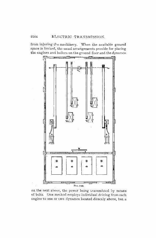
from injuring the machinery. When the available ground space is limited, the usual arrangements provide for placing the engines and boilers on the ground floor and the dynamos
FIG. 1199.
on the next above, the power being transmitted by means of belts. One method employs individual driving from each engine> t6 one or two dynamos located directly above, but a

ELECTRIC TRANSMISSION. 2105
better one is to make use of countershafts on the engine or dynamo floor, or both. These countershafts are divided into sections and fitted with friction pulleys in such a way as to permit of any desired combination of engines and dynamos, an arrangement best calculated to ensure uninterrupted service. A simple example of such an installation is shown in Fig. 1198, the lower view being an elevation. The engines are on the lower floor and the countershaft c on the upper floor, directly above the flywheels and connected by belting to the dynamos d. Two engines are indicated, their fly-wheels 70, 70 being dotted in the plan. This system aliows of considerable extension, and may, of course, be laid out on one floor. A further economy of space may be attained by installing a second row of dynamos between the first row and the countershaft, and providing another set of pulleys.
3217. A plan showing the general arrangement of machinery and boilers for a small station is given in Fig. 1199. The engines e are placed near the walls, allowing the whole center of the room for the dynamos d. At one end is the countershaft a c, which may be divided and fitted with a coupling at f for disconnecting one-half of the generating plant when the load is light. The switchboard s should be near the dynamos, but not so close as to be liable to injury from a broken belt. Beyond the fire wall are the boilers b, arranged so that the distance from them to the engine shall be as small as possible, to avoid condensation of steam in the pipes.
CHOICE OF LOCATION.
3218. The choice of location of the power-house is a most important matter. The principal considerations affect. ing this question are:
1st. Probable distribution of load over the system. 2d. Cost of ground for buildIng site. 3d. Coaling facilities and water-supply.
Concerning the first point, it is best, other things being

2106 ELECTRIC TRANSMISSION.
equal, to have the station situated as near as possible to that portion of the syst~m having the heaviest load. It is not necessary, or always right, that the station should be located at the point where the greatest amount of power is to be used, but it should be placed in what we may call the center of gravity of the system, when the largest feeders will also be the shortest. Suppose the plant is for furnishing light and power in a town, and it is expected that the current consumption in the different sections will have the
@
1 o
® relative values of 1, 3, 5, 9, and
P.S. • o
~ 11; also, that a map would I.!!J indicate the distributing cen
ters to be spaced about as shown in Fig. 1200. The center of gravity may be determined graphically, and
FIG. 1200. will, in this case, be at the point marked P. 5., which determines the location of the power station. There are still the other governing factors to be considered, namely, the cost of land, taxes, and the matter of coal and water-supply. If real estate in that particular neighborhood were cheap, it might be well to build there, but such an advantage may be more than offset by inconvenience and expense in coal transportation. On this account a water front is a desirable location; for coal may then be unloaded from barges, and brought on cars over a special track direct to the boiler-room; and water for the boilers and for condensing purposes may be obtained at a cost not exceeding that of the necessary pumping outfit.
STEAM PIPING.
3219. The stealll piping for the station should receive the most careful thought,as it is of the greatest importance, and upon its correct design will depend the prime requisite of successful operation, which is, that under no circumstances should there be failure of the current supply to the lines.' Some of the engines in many power
ELECTRIC TRANSMISSION. 2107
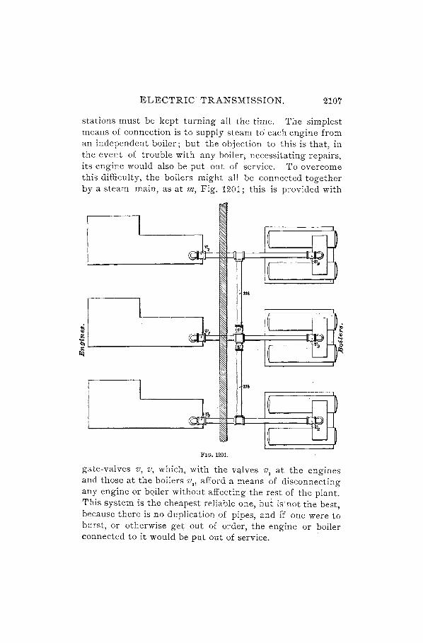
stations must be kept turning all the time. The simplest means of connection is to supply steam to" each engine from an independent boiler; but the objection to this is that, in the event of trouble with any boiler; necessitating repairs, its engine would also be put out of service. To overcome this difficulty, the boilers might all be connected together -by a steam main, as at tn, Fig. 1201; this is provided with
I I I~ IJ "'7
((III :ft
1 ~ c.1 m
I I~ IJ
_.~ "'1 I;; (e JI ))
'" -I ~ '~1
I 1m
I~ :~J ~
III ,)
I~ ~1 FIG. 1201.
gate-valves v, v, which, with the valves v, at the engines and those at the boilers v., afford a means of disconnecting any engine or bqiler without affecting the rest of the plant. This system is the cheapest reliable one, but iS'not the best, because there is no duplication of pipes, and i"f one were to burst, or otherwise get out of order, the engine or boiler connected to it would be put out of service.

2108 ELECTRIC TRANSMISSION.
3220. There,are two principal methods of installing a duplicate system, and they differ at first sight only in point of size of pipes. A diagram of the arrangement is shown in Fig. 1202. . Two m~ins 11Z, 1?Z, run the whole length of the boiler-room, being connected on one side with leaders to the boilers a, b, c, and on the other with leaders passing
l ....
~~ ~ A a !.al
~ ..llIVJIL ~ ~ ~ ='11\
I 'j ~ ~
~ ~ ] A b
F; ~~ ~ K"JlVIL ol:::I!Il{I
~ ~i-"!t
I ~ I :JIV ..
~ I ;A c !=
F ...11'1111 411 ~ ~~rl\1
~I<. D -FIG. 1202.
through the fire wall w to the engines. These connecting pipes, it, will be seen, are all in pairs, and start from the two mains; each one is provided with a gate-valve v at the end, and every pair terminates in a cast-iron Y, whether at the drum of the boiler or at' the. engine. This system, therefore, provides a double path for the steam between any engine and any boiler, and renders almost wholly improb-

ELECTRIC 'rRANSMISSION. 2109
able a suspension of operation due to accident to the steampower generating plant. The difference alluded to between the two methods of duplicating is, that in one pipes are provided of such size that one set alone will carry the steam for the engines, and the duplicate piping is held as a reserve, while in the other the pipes are of smaller size and are in use all the time, their combined area of cross-section being necessary for delivering the steam at th'e determined pressure. The first system is emplQyed quite frequently, but has, nevertheless, many disadvantages. It is impossible to keep the valves connecting with the reserve piping closed so tightly that no steam will leak past, and there is always a pressure indicated on the gauge. The exposure of all this surface to condensation, even though protected, by non. conducting covering, entails a continual waste of energy, and the drips always have to be left open to prevent the pipes filling up with water. Then, the first cost of such a system is considerably higher than if the smaller pipes were used, and repairs are more expensive. It may also happen that an engineer will habitually use one set of pipes alone for a long period, and when an accident compels him to close this set, he finds that the valves of the auxiliary piping have become seated through rust or deposits from the water and are immovable, and a shut-down is the result. With the second system, which presents another advantage, in that the exposed surface of pipes is less, both sides are in service continually, and if an accident should occur to one branch, the remaining one will furnish steam until a repair is accomplished. There would be, through the one pipe, a greater drop in pressure, but this could easily be remedied by closing the valves v" v" or 1/" V, communicating with the rest of the system and running one boiler at a higher pressure for a time. Other methods of piping are sometimes resorted to, but these two, as illustrated in Figs. 1201 and 1202, will be found to generally satisfy the conditions of simple connections on the one hand, or the more expensive but more reliable construction on the other.

2110 ELECTRIC TRANSMISSION.
BOILERS. 32~1 The boilers in most general use are those carry-
ing the water in tubes, and called water-tube boilers, the reason for the preference being that they steam rapidly, and will therefore respond quickly to extra demands made upon them. Many stations are, nevertheless, equipped with return-tubular boilers, which give entire satisfaction. For steady work this type is preferred by many station managers, as the steam pressure in a water-tube boiler will fall as easily as it rises, if the boiler is not properly fired; on the score of safety, water-tube boilers are, however, probably superior. When space is very limited, vertical boilers are sometimes put in.
Mechanical stokers are much used when it is desired to burn fine coal, and in such cases generally prove economical; also, economizers may be placed in the chimney, close to the boilers, their function being to warm the feed-water by means of the waste furnace gases. The boiler-room should be designed with a special view to the expeditious handling of coal and ashes with a minimum of labor. To accomplish this, it is well to deliver the coal from a railroadcar and unload directly into bunkers beneath the track, extending through into the boiler-room immediately opposite the fire-doors. These cellars should have storage capacity for at least fifteen days, unless there is another large supply easily accessible. A subway may be built beneath the ashpits, and these may be fitted with doors to open downwards, through which the ashes can be swept into a small car running on a track beneath. Tl).is is a refinement of practice. perhaps justifiable only in the case of very la-rge plants, .but may be used when it is necessary to clean out the ash-pits rapidly, if the owners of the plant are willing to incur the extra expense.
Provision must be made for an unlimited supply of water. It is not always well to trust entirely to city mains, although this source is usually reliable. When the station is not located near running water, it may be found advisable to sink a well, from which water may be pumped into a tank, and the water from the mains used only in cases of emergency.

ELECTRIC TRANSMISSION. 2111
ENGINES AND DYNAMOS.
3222. The type of engine which is most suitabl(t for a power station depends entirely upon the size of the system and on the general requirements of the service. The closest· speed regulation under widely varying loads is obtained with high-speed, automatic cut-off engines, and this class is, therefore, particularly suitable for small electric railways and lighting plants. A little consideration will show that such systems may furnish extremes of load at very short intervals; for if there were, on a small railroad, only one car in service, the station load would be zero (or, simply, the friction of the moving machinery) when the car was at rest, and a maximum when it was starting on a heavy grade. Again, in a small lighting plant, a large proportion of the lamps may be turned on or off at once, thus cal1;sing great fluctuations in the centra] station load. In general, it may be stated that the larger the system the nearer will the load approach a constant normal value. In very large systems the load will be a maximum at certain hours of the day or night, and will gradually fall to a minimum at other hours. For such an installation, it is best to use low-speed Corliss engines, and run them with condensers, if water for this purpose is readily available.
3223. Power is usually transmitted from engines to dynamos by means of a light double belting,countershafts being largely employed, as already explained; but a very general practice, especially in large stations, is to install direct-connected units, the dynamo frame being bolted to the engine base-plate. By this arrangement, the loss due to belt slipping is eliminated, and a great saving is made in the engine-room area. The question of the proper proportion of engine to dynamo power is, in this case, already determined, but for belt-connected plants it should be a matter of careful consideration. A dynamo may be run under a light load and still be efficient, whereas an engine, under the same circumstances, is decidedly inefficient·; there~ fore, the latter should, as a rule, be worked up'to nearly its full load-that is, the engine should not be too large, while

2112 ELECTRIC TRANSMISSION.
the dynamo may be of greater capacity. Such proportioning will give a good working economy, the normal rating of the dynamo being from 15 to 20% greater than that of the engine.
SIZE AND ARRANGEMENT OF UNITS.
3224. The size of units to be used in any given plant is a subject which has aroused much discussion, some favoring a number of small machines, others a few large ones. The best practice is, probably, to provide two small generators, adding as many others, of three times their capacity, as are necessary to obtain the required total horsepower. By this arrangement the running machinery can always be suited to the load and worked efficiently. When a very large plant is under consideration, the small units may themselves be quite large, comparatively, and be able to deliver 200 horsepower to the line. The largest generators, of say 1,500 kilowatts or 2,000 horsepower, are frequently connected directly to the shaft of large triple-expansion vertical marine engines, which afford a considerable saving in ground space, although their first cost is somewhat above that of the horizontal type. It is not well to have too many different sizes of dynamos in'one station, as this necessitates keeping so many extra armatures and other fittings in stock; this is one reason advanced by those who favor the use of a number of small units in preference to a few of large size, or an indiscriminate collection; but economy in operation will always be best attained with the arrangement of units already recommended.
Since the engines are called upon for sudden, and often extreme variations in output, heavy fly-wheels are of the greatest importance as speed regulators, and in the case of medium-speed engines of 200 or 300 horsepower and over, their weight is generally from one-quarter to one-third that of the engine itself, this weight being placed for the most part in the rim.
3225. Foundations.-All heavy moving machinery requires solid support, which is best obtained by securely
ELECTRIC TRANSMISSION. 2113
binding it by means of bolts to a mass of stone or brickwork sufficiently heavy to prevent excessive' vibration. The foundations for engines and dynamos should, when possible, be entirely independent of the walls of the building. This is especially desirable when the building is to be used for office purposes as well as for a power plant. In cases where a heavy concrete floor is used, it is well to cut a narrow, deep trench through the floor, close to the wall, and bridge this over with a wood floor. This prevents much, jf not all, of the vibration of the machinery from being communicated to the walls, and removes all danger of cracking or otherwise injuring them.
For a dynamo of 15 or 20 horsepower a thickness of brickwork of 3 feet will be sufficient for a foundation, the measurement being taken from the upper surface to the foundation plates below. A few inches of concrete, composed of broken stone, sand, and cement, first laid down will form a more satisfactory bed upon which to lay the brick than the ground itself. The bolts are put in place,wheads down, by templet, and the brick built loosely around, to allow them a little motion. A better plan is to slip an iron tube over each bolt, and set the brick up close to the tube. For very large dynamos the depth of foundation may be as much as 6 feet, but rarely more, as the area of base increases considerably with the larger machines.
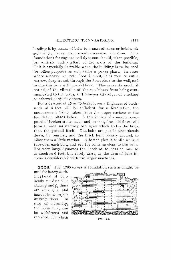
3226~ Fig. 1203 shows a foundation such as might be used for hea vy work. 111 s tea d of bolt'heads un d e r the plates p and P. there are keys e, e. and hand holes JIl, 7Jl. for dri ving them. In case of necessity, the bolts k, k. can be withdrawn and replaced, for which FIG. 1203.

2114 ELECTRIC TRANSMISSION.
purpose manholes would have to be built to afford access. When .the bolt-heads are against the plates, any extension of th~ brickwork below this line is useless. The beams n, 1t,
t'J~:pp.ort the wooden frame f upon which the dynamo rests. , A style of double wooden frame which is used for small
Ul'achines is shown in Fig. 1204. The upper frame slides llPon the lower, and is fitted with a screw s attached to the brace n by a thrust bearing, and working in a nut k on the lower frame B. This movement is required to effect the tightening of the belt by drawing the whole machine bodily away from the engine pulley. In order that the woodwork may insulate the machine from the ground, it should be
FIG. 1204.
oiled, or the pores should be filled with paraffin, to prevent the absorption of moisture.
3227. Belting.-Light double belting is much used for running dynamos, and should be provided 1 inch narrower than the width of the pulley. No lacing should be used, but the ends of the belt should be pared down to form two long wedges, which, when cemented together, will form a uniform joint no thicker than the belt itself. The speed of the dynamo is always predetermined, and when a countershaft is used, the driving pulley must be calculated from the size of the dynamo pulley and its revolutions, allowing 2%

ELECTRIC TRANSMISSION. 2115
for slip of the belt. The length of belt required can then be ascertained, but it must be found for that position when the pulleys are as near together as the belt tightener will allow. The pulley centers may be about 15 or 20 feet apart, as a rule, but this distance should be greater if the driving pulley is so large as to give an insufficient arc of contact on the smaller pulley. The two pulleys must be exactly in line, that the belt may run true and evenly. Some irregularity in the leather may cause a slight swerving to one side, which will move the armature a little lengthwise, but this will tend to give a more even wear to the commutator, and prevent the formation of grooves. The side of the belt which does the pulling should be below, as it has the least sag. The loose side will then be uppermost, and will sag so as to increase the arc of contact with both pulleys.
SWITCHBOARDS.
3228. The switchboard is a necessary part of every plant. It forms the controlling factor of the entire system. To it every dynamo feeds its output of current, which here is measured, recorded, subdivided, and distributed; and from it every circuit is either supplied with or deprived of current. It should therefore be so constructed that these various operations can be performed with ease and safety.
3229. The mechanical construction of the typical modern switchboard is about as follows: A number of angle-bars of wrought iron, of.a length agreeing with the total height of the board required, are set up vertically upon a channel-bar running at right angles to the upright bars. At their upper ends _ the angle-bars are again joined together by an angle-bar of perhaps the same cross-section, but rup.ning parallel to the lower channel-bar. The entire structure thus forms -a strong and rigid rectangular framework, into which marble or slate slabs, upon which the various instruments have been mounted, are fitted. The switchboard structure is then supported in its upright position,

2116 ELECTRIC TRANSMISSION.
either by embedding the lower channel in the concrete floor of the power-house, or by bracing 'it with extended iron aqns to the wall or some convenient girder, or by both methods.
The wiring of the switchboard, which is often very complex, is usually placed upon suitable brackets fastened to the rear of the board, and demands most careful design. It must be so laid out that all dangers of grounds, short circuits, mutual interference of circuits, etc., are eliminated. A clear space of about two feet between wall and rear of board should" be left free for inspection of the wiring.
3230. The switchboards must be placed near the dynamos, but not in line with the belts, lest one of these in breaking should damage the switches or instruments. Distinguishing letters or numbers should be given to each machine and plainly marked thereon, and the corresponding leads and switches on the board lettered or numbered accordingly. In the event of any of the generators giving trouble, they can then be cut out of circuit immediately. By this means any desired combination can be employed, all machines running at the point of greatest efficiency. If three small units are put in, equal to one large one, then one qr two can be used on light loads. When the demand becomes higher and the load increases, a large unit can be substituted, as it will be more economical than using three small machines. In this caSe one small unit is heid as a reserve in the event of a breakdown, but it could be dispensed with if it were so desired. The size of the larger units is dependent on the output of the station.
SWITCHBOARD APPARATUS.
3231. Switches.-Switches are usually of the jackknife type, illustrated in Fig.,1205. In this form of switch the circuit is made or broken by means of a copper contact blade k, which fits between the flexible copper tongues of two contacts, as c and d or a and b. These are shown in perspective at r. Each contact blade is fitted to a lever

ELECTRIC TRANSMISSION. 2117
l, l" pivoted at one end at p, p" and provided at the other end with a handle h, by which it may be operated. These switches are provided with one, two, or three blades and sets of contacts, each insulated from the others, and are accordingly called single, double, or triple pole. These names are usually abbreviated to S. P., D. P., and T. P. Sometimes the levers are provided with two contact blades, one on each side, and a second set of contact points is placed on the other side of the pivot, so that by throwing the switch completely over-that is, by moving the handle through 1800 -the contact points of this second set ar~ connected together. Such
FIG. 1205.
a switch is called a double-throw switch; the switch illustrated in Fig. 1205 is a do.uble-pole, single-throw switch.
The contact points are provided with terminals of varying forms, to which the ends of the wires are connected. For use on wooden switchboards, and for separate use, jack-knife switches are provided with a slate or marble base (m, Fig. 1205), on which all the parts are mounted. On slate or marble switchboards the various parts of the switch are mounted directly on the face of the board, connection with the contact pieces being usually made from the back of the board, so that no wires show in front. These switches should always be mounted on the board with the handle up,
~1l8 ELECTRIC TRANSMISSION.
so that when opened they will have no tendency to close by their own weight.
·3232. Bus-Bars.-"\Vhen several dynamos are to be run in parallel to supply a common set of circuits, it is customary to run a set of heavy wires or bars across the board, to which the dynamo terminals and the circuits may be attached at convenient points. These are called bus-bars. Bus-bars are usually made of bare copper rods to facilitate making connection at any desired point, and are mounted either on the front or on the back of the board. When on the front they are polished and add much to the appearance of the board. They are usually supported two or three inches from the face of the board by brass castings, whether on the front or back, and are made of large cross-section, so that the difference of potential between them is practically uniform at all points, even when large currents are flowing through them.
3233. InstrU1llents.-It is very desirable to know the output of each dynamo; consequently, an ammeter should be connected in circuit with each machine. The best forms of switchboard ammeters do not require that the whole current should enter the instrument, bufinstead only a small part, so that the ammeter maybe located at any convehient point on the board and the current carried to it by means of small wires. This is accomplished by making the ammeter of such resistance that when connected in parallel with a short length of the main conductor, or with a specially prepared low resistance inserted in the main circuit, enough current will flow through the instrument to cause it to indicate, on a properly divided scale, the amount of the current flowing in the circuit to which it is connected. This often saves a great deal of wiring on a switchboard.
A reliable and sensitive voltmeter should be used to indicate the voltage of the various circuits. More than one voltmeter for the various circuits and dynamos is not necessary, for by the use of a small plug switchboard, which need be only a few inches square, or by the use of a specially

ELECTRIC TRANSMISSION. 2119
devised switch, kilOwn 'as a voltU1eter switch, a single instrument may be connected at pleasure with the terminals of :my dynamo or any circuit, or may be used to indicate the presence ot a ground in the dynamos or circuits, in the manner to be described later.
Switchboard instruments are, as a rule, made with large open scales, so that they may be read at a distance. Voltmeters are often provided with a pointer, which may be moved by hand to the point where it is desired to keep the voltage consta~t; then, when the voltage is at the proper point, the voltmeter needle c?incides in position with this pointer, which may be seen at a greater distance than the scale can be read.
Incandescent lamps are ()ften so arranged on the switchboard as to illuminate the scales of the instn;tments; if this is the case, the lamps should be shaded to prevent the light from shining in any other direction than directly on the face of the instrument, as otherwise they are pni:cticaUy useless.
3234. Checking InstruU1ents.-The switchboard measuring instruments should be frequently examined to see whether any change has occurred in the accuracy of their readings. As reliable instruments as any for this purpose are the Weston portable standard voltmeters and ammeters. To check a voltmeter, the standard ,}oltmeter should be connected across its terminals, the two being thus in parallel, and the difference in reading, if any, noted. If they were connected in series, unless their resistances werc~ exactly equal, their indications would be different, although each instrument might be correct. In this case, a constant current would flow through each, and as the drop in, potential at any two points is directly proportional to the resistance between those two points, the readings of the two instrume'nts would not agree unless their resistances hap-pened to be the same. '
When joined, up in parallel, the E. M. F. will be the same between the ends of the two resistances, the only difference being in the amount of current taken by each branch, for it

2120 ELECTRIC TRANSMISSION.
is obvious that a voltmeter will indicate the drop of poten. tial through another voltmeter just the same as through any other resistance.
The station ammeters may be checked by putting the standard ammeter in series with them, one after another. Great care must be exercised in handling these standard instruments; they should be moved without unnecessary violence, and should not be subjected to jars or placed in a strong magnetic field.
3235. Safety Devices.-To prevent the possible damage to dynamos and circuits, due to an excessive flow of current from any cause, fuses are placed in each line circuit, also in each dynamo circuit. Those for the line circuits are usually placed at the top of the switchboard, and form convenient points to which to attach the circuits. The dynamo fuses are sometimes placed at the bottom of the board, but more often on the connection board of the dynamo. The fuses should be of sufficient size to carryall the current that the various parts of the circuit in which they are connected will safely transmit.
The larger sizes of fuses are usually made in the form of strips, of rectangular sectton, mounted on copper ,terminals of suitable shape and size to clamp under the binding-screws of the fuse block.
The fuse blocks should be located on the back of the board, if possible, for if on the front the board will be disfigured when the fuses" blow," unless they are completely enclosed.
3236. Ground Detector.-It is very important when a ground occurs on a circuit that it should be immediately detected. A device that will instantly indicate a ground and can always be left in connection with the circuit is shown in Fig. 1206, where I and I] are two lamps connected in series across the two conductors of a dynamo. The wire joining these lamps is connected, through a cut-out and the switch s, to the ground at g. As the lamps receive only one-half their proper E. M. F., they will'glow dimly with equal in.

ELECTRIC TRANSMISSION. 2121
tensity until a ground occurs. Then a shunt of low resistance is formed across the lamp that is connected to the dynamo conductor on which the ground is situated, and the result will be that the other lamp will glow with increased
,I 1 1 1 1 1 1 1 1
I 1 1 1 1 1 1 1
I 1 1 1 1 1 1 I 1 1
• gL FIG. 1206 .
intensity. Thus, in the figure, if g, represents a ground, a shunt a b g, g, taking part of the current, will be formed around the lamp I. Therefore, the lamp I, will receive a greater supply of current.
If there are grounds of approximately equal resistances on both sides of the circuit, both lamps will still glow with equal intensity. However, if one lamp, which should be provided with a key, be now switched out, the ground is present if the other lamp continues to glow.
The two coils of a differential galvanometer may be substituted for the lamps, so that, when no ground is present, the pointer remains on zero, but is immediately deflected when this condition no longer exists.
LIGHTNING-ARRESTERS.
3237. Some form of lightning-arrester should be connected in a circuit wherever there is danger that instruments, lamps, dynamos, or mctors will be burned out by' atmospheric electricity. Telephone and telegraph wires are

2122 ELECTRIC TRANSMISSION.
usually so protected where they enter buildings or stat~ons. Dynan10s having overhead external circuits usually have a lightning-arrester connected near where the external conductors leave the brushes. This arrangement is shown in Fig. 1207, where a is the lightning-arrester and g, g the ground wires. The best plates for this arrester are made of carbon, which does not fuse from the sparking. Sometimes there is a continual exchange of sparks between the plates, and metals, such as brass, are apt to fuse and form a connection with one another, thus short-circuiting the dynamo through the ground. However, in any case safety strips should be placed between the arrester and the dynamo, so
FIG. 1207.
that when a short circuit is produced the strip melts and breaks the circuit. Also an electromagnet .may be used either to break the circuit by attracting an armature when sufficient current is caused by a short circuit, or to attract and blow out any arc that ma.y be formed between the plates.
3238. A convenient form of arrester for dynamos consists of a pJate of lignum-vita; upon which is a pencil mark or narrow charred strip. There should be two such strips, one connectjng the minus conductor to the ground and the other connecting th~ plus conductor to the ground. Atmospheric electricity will then pass across these strips instead of entering the dynamo, and as the resistance of the strip

ELECTRIC TRANSMISSION. 2123
is about 50,000 ohms, which is higher than the insulation resistance of electric-light circuits, there is no chance of leakage.
3239. Long aerial lines not protected by tall trees or buildings are apt to be struck by lightning. Therefore, they should be protected at convenient places along their length by lightning-arresters. Special forms which may be screwed directly to the poles are constructed for this purpose.
3240. To secure good protection, a perfect ground connection is of the greatest importance. The wire leading to the earth should never be less than No.4 B. & S. gauge, and it should be soldered to a galvanized iron or copper plate t inch thick, with a surface of at least 10 square feet on each side. This plate should be stink to such a depth that even in the dryest weather it shall be in moist ground. A well or stream of water is a convenient place in which to lay an earth plate; and it is good practice also to connect the earth wire to any gas or water pipe that may b~ near. All underground connections must be soldered and painted with asphaltum to prevent corrosion.
3241. When plate arresters are used, the jaws are adjusted to a certain distance apart by a piece of cardboard. This cardboard should be run every day between the jaws to ensure that the proper separation remains unaltered, and the plates should be kept perfectly clean.. All a r res t e r s should be set upon an insulating incombustible base.
3242. Fig. 1208 shows a -rg;--~~=;I;~~_.!!.b-t form of lightning-arrester for use upon dynamos. It depends for its action upon the fact that an electric arc is repelled from between the poles of a magnet, and its construction is as follows:
m is a double electromagnet.
m
a
FIG. 1208.

2124 ELECTRIC TRANSMISSION.
between the poles of which are supported the two curved metallic pieces} and},. These pieces are carefully insulated from the magnet poles, and are separated a short distance from each other. The line current flows from the machine to a, through the electromagnet to }" and along the line at b. The piece} is connected to the earth.
The atmospheric electricity, proceeding along the line, forms an arc between} and }f' and the magnets repel this arc up along the curves, and finally blow it out altogether.
INST ALLING ELECTRIC MACHINERY.
3243. When a dynamo or motor is to be set in place, the foundation with sub-base must first be put in. The frame of the machine is often in two pieces, for convenience in shipment and to facilitate removal of the armature. All machined surfaces are painted over with white lead or cov·· ered with grease to protect them from the weather, and this should be cleaned off with turpentine in the one case, and with benzine or kerosene in the other. All surfaces which abut against others, and especially those between which friction occurs, as in bearings, must be carefully inspected and wiped clean before bringing together, that they may be entirely free from dust or grit.
FIG. 1200.
It is especially important that the unpacking and handling of the various parts of the machine be done with great care, as an apparently slight injury to the armature or field coils

ELECTRIC TRANSMISSION. 2125
may prove very serious, and lead to a breakdown subsequently. The armature should be lifted by the shaft, using a rope sling, as in Fig. 1209, at S, held away from the armature by a notched board B, unless the armature is small enough for two men to easily move it. The sling should never be put under the commutator, as this is liable to force it out of place and prevent its running true.
3244. In cases where a traveling or swinging crane is not available for putting the armature into position, two tackles may be used with advantage. One of these should be secured centrally above the frame of the machine, and the other close by but considerably to one side, so as to hang clear of the frame. The armature, in the sling, is first raised by this latter tackle, until above the level of the frame, when the other one is hooked on, and the weight transferred to it, so that the armature will hang directly over the machine, from which position it may be readily lowered into place. The armature, especially if it be a heavy one, should never be rested on the floor when removed from the machine. Supports should be provided for each end of the shaft, so that the armature may swing clear between them.
3245. The electrical connections must be made by some one who is thoroughly familiar with the machine, unless, as is generally the case, a diagram is provided; even then it is well to have them checked by another person. When the bearings are self-oiling, the oil-wells must be cleaned out to remove any dust, and filled with good quality light oil, and the rings should· be looked to, to make sure they are free to turn. When carbon brushes are used, they may be put into the holders at once and left resting on the commutator; but copper brushes, being set tangentially, should be raised from contact with the commutator when the machine is at rest, to prevent their catching on the commutator bars by a backward movement of the armature.
3246. When all is ready for a preliminary run, the armature should be turned over slowly by hand, to make

2126 ELECTRIC TRANSMISSION.
sure the shaft does not bind nor any revolving part strike the fields or pedestals. No loose wires must be allowed to hang from the terminals, where they might be drawn into the armature, and all tools used in setting up must be removed from the machine. Screws and nuts on the connections should be examined to see that they are tight and that the wires they hold enter sufficiently far to be firmly bound. The armature must be inspected carefully, and any pieces of sawdust or other foreign matter picked out. It is well, also, to look over the commutator, to ascerta:in that the insulation between bars is not injured at any point, or bridged over by a chip of copper.
3247. The distance between the armature core and the fields must be even all around, as measured at the center of each pole-piece, or else the different circuits in the winding will work against each other to some extent. Occasionally the armature is purposely set a little above the center line of the machine, to allow for wear in the bearings, but this amount must be very small. Any considerable want of symmetry should be corrected.
These points having been attended to, the dynamo may be run, starting very slowly and observing whether the belt keeps in the center of the pulleys, then gradually increasing up to full speed, but without any field excitation. This will determine any faults in the mechanical construction, and close watch should be kept so that, in the event of trouble manifesting itself, the engine or other source of power may be stopped or disconnected at a moment's notice.
INSTALLING ARC-LIGHTING DYNAMOS.
3248. Series-wound generators are used for arc-light circuits, either singly or connected in series, the positive pole of one machine being joined to the negative of the other, as, for instance, when two 40-light dynamos are put on a circuit of 80 lamps. Some trouble is experienced_by the instability of the regulators, which, working independently and not rapidly enough, cause alternately an excess and a

ELECTRIC TRANSMISSION. 2127
drop in current. This can be prevented by using only one regulator to keep the current normal, and locking the other, but the variation must not exceed the limit of one machine.
The dynamos must be protected by lightning-arresters placed just outside the building, one on each wire, connection being then made to the switchboard.
3249. Series DynaIllos in ParaIlel.-Series dynamos are seldom connected in parallel, although this can be done when special precautions are taken to guard against reversal. of field magnetism and rotation, which would otherwise occur. This combi- m,-7_-'--f
nation is in unstable equilibrium, because if one machine loses speed and generates too little current, that im-mediately weakens its field and still further cuts down the current, prob-ably also reversing it. One way of overcoming this objection is to connect the two positive brushes together, as well as the two negative. This extra wire a b, Fig. 1210, is called an equalizer, and serves to maintain the fields of the two machines at normal strength. Another n +
way of accomplishing this is to con- FIG. 1210.
nect the field of each machine in series with the armature of the other, causing each to excite the other's field.
INST ALLING DYNAMOS FOR INCANDESCENT LIGHTING.
3250. Direct-Current Generators.-For i'ncandescent-lighting circuits, when the station is ne~r the center of distribution, direct-current constan"t-potential dynamos are used. These lend themselves readily to connection in parallel, the arrangement being shown in Fig. 1211. Tne

2128 ELECTRIC TRANSMISSION.
positive brush of each is connected to the main m 12, and the negative to x y. There is no need of an equalizer, as each
m x machine is entirely independent. Should the voltage of one fall below that of the circuit, it will be run as a motor, but the direction of rotation will be the same, and no harm will result. There are two points of great importance to be regarded before a shunt dynamo is switched into a circuit already alive. The first is to be sure that the positive lead from the dynamo is to be connected, by the switch, to the line, or external circuit, on the positive side, and the negative lead to the negative side; the second is that the dynamo be caused to generate the full voltage, or (not more than) 1 or 2 per cent. over that of
+ - the circuit. The latter may be tested n y FIG. 1211. by means of a voltmeter, or a gal-
vanometer and incandescent lamp (for a nO-volt circuit) can be put in series with the armature, and connections made to the mains. When the galvanometer shows that no current is passing, the E. M. F. of the dynamo is equal to that of the line. The simplest manner of ascertaining the time for switching in is the use of a pilot lamp on the dynamo, which should be run a little brighter than a similar lamp on the mains; but this is not as reliable as the use of an accurate voltmeter. Inattention to these points may cause a serious short circuit, and burn out an armature.
INSTAI.LING GENERATORS FOR CONSTANT-POTENTIAL
MOTOR CIRCUITS.
3251. Since, in a circuit supplying power to motors, the output is continually varying, shunt-wound generators would not be entirely satisfactory, owing to the constant hand regulation which would be required. A regulation, therefore, which will follow up the demands mnst be substi-
ELECTRIC TRANSMISSION. 2129
tuted;and compound-wound dynamos are almost exclusively employed. These present a mean between the two types illustrated in Figs. 1210 and U11. In the first of these the whore current generated by one machine is passed through its field coils, of which the windings are large in cross-section and the turns comparatively few. In the second, the field winding is composed of many turns of finer wire, and is connected directly across the mains, so that the magnetization is constant. A combination of these two methods, by putting both a shunt and a series field winding on one machine, will result in increasing the electromotive force when the load becomes heavier, so that at the distant points of the system the full potential can always be supplied.
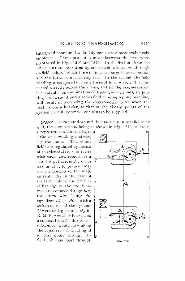
3252. Compound-wound dynamos run in parallel very well, the connections being as shown in Fig. 1212, where s, s, represent the shunt coils, c, 0 m c, the series winding, and m n, o p the rnains. The shunt fields are regulated by means of the rheostats r, r, in series with each, and sometimes a shunt is put across the series Y coil, as at t, to permanently carry a portion of the main current. As in the case of series machines, the brushes +
of like sign on the two dynamos are connected together, the extra wire being the equalizer a b, provided with a switch at l"2' If the dynamo D were to lag behind D" its E. M. F. would Be lower, and a current from D" due to this x
F-----:1i!f.=:::L,,'r...~ difference, would flow along the equalizer a b, dividing at a, part going through the field coil c and part through FIG. 1212.
'II,

2130 ELECTRIC TRANSMISSION.
the armature. The shunt field would still be traversed by a current in the same direction; therefore the rotation of D is also unchanged in direction, although it may be run as a motor. This will enable the speed to rise, and, consequently, the E. M. F., until it is again normal.
3253. Starting.-When it is desired to connect two compound-wound dynamos in parallel, one being already runnhg, special precautions must be taken, as in the case of shunt-wound machines, to guard against a short circuit. If we wish to connect the dynamo D to D" the latter running with load on, we proceed as follows: D must first be brought up to full speed, and the field regulator r turned on partially; then the equalizer switch k. is closed, so that the field-magnets are excited partly by the shunt and partly by the series windings, for some current from D, is shunted through the coil c. The E. M. F. at the terminals of D is now measured, and, if necessary, more resistance is cut out at the rheostat r, until the potential difference is about 1 per cent. higher than that of the external circuit. Last of all, the main switch k is closed, and as at first the machine will be generating but little current, the field regulator can be turned until the full share of the load is taken.
The above method of manipulating the switches should always be observed when they are separate. It is usual, however, to make the connections to the plus and minus leads and to the equalizer all at once with a triple contact switch but care must be taken that the dynamo has reached full speed, and that the field-magnets are excited. If the voltage is a trifle different from that of the mains, it can be immediately adjusted by means of the field rheostat. When it is desired to cut a machine out of circuit, the switches, if separate, must be opened in reverse order to that of closing; that is, the main switch should first be opened, then the equalizer switch, but the shunt field must never be reduced first.
a254. Mutual Adjustinent. - Two compound-wound dynamos funning in parallel exercise a mutual action upon

ELECTRIC TRANSMISSION. 2131
each other, tending to preserve a balance in their output; for if the E. M. F. of one falls somewhat, the proportion of load taken is reduced, so that the engine tends to increase in speed and again raise the E. M. F. This adjustment will take place when the dynamos are driven by separate engines, or when the slipping of the two belts is different, but it must not be depended upon to too great an extent. Machines differing in size or current capacity can be coupled in this manner, but their voltage must, of course, be equal; and another requirement is that the resistance of the series winding of each must be inversely proportional to the current capacity, so that if one machine produces double the current of another, the resistance of its series coil must be one-half that of the other. The drop in potential will then be the same in each case when the load is properly proportioned between the two dynamos, and the equalizer will carry no current. If the larger machine were to slow down somewhat, and deliver less than its share of the total output, sufficient current would flow along the equalizer from the smaller machine to maintain the correct proportion in the series coils, thereby strengthening the fidd of the larger machine and increasing the current to normal. The equalizer should have about half the cross-section of the dynamo cables.
When the dynamos are overcompounded, that is, designed to give a higher E. M. F. at full load than with light load, the equalizing connection can be made permanent. This is especially desirable in central station work, as when only one machine is running and its output is di.vided over several circuits, it is not necessary to have the high E. M. F. due to the overcompounding. The series current is therefore allowed to traverse the series windings of another or several machines, and the highest E. M. F. is reserved for the time when most needed, that is, at full station-load.
3255. Station Connections.-The switchboard arrangements for two compound-wound dynamos and six feeder circuits are shown in Fig. 1213. From each dynamo,

2132 ELECTRIC TRANSMISSION.
+
E + E
FIG. 1213.

ELECTRIC TRANSMISSION. 2133
(a) and (b), run three heavy leads E, -, and + to the triple pole main switches fl-f, 5, and M2 52' the + lead in each case being connected to the right-hand blade, the - lead to the left-hand blade, and lead E to the central blade. The lead E is connected at the junction of the armature and series field coil, as shown in Fig. 1212, arid these two leads E, with the cross connector E. E., constitute the equalizer a b of that figure, the central blades of the switches corresponding to switch k.. On the back of the board are secured the bus-bars +B and - B, connected through the switches Jrf, 5, and JI-f. S. to the dynamo leads of corresponding sign, and, also, above these, to sets of feeder switches C" C., etc., from which the different external circuits are run, safety-fuses j being inserted in all the outgoing wires, in addition to the main fuses./".I, on the terminal boards of the dynamos.
On the upper part of the switchboard are placed the voltmeter and the two ammeters A" A.. The voltmeter is connected by two flexible insulated wires to plugs which can be inserted in any of the holes p, p" P .. P.. These are connected by leads' (not .. shown) on the back of the board, as follows: p, p to the lower outside terminals of switch M, S" so that when the voltmeter is connected to these terminals it will indicate the E .. M. F. of dynamo (a), whether it is con· nected to the bus-bar or not; p, p, to the simila.r. contacts of switch M.S.; P. P2 to the bus-bars +B and -E, and P. to the ground for the purpose of testing the insulation of the circuits or of the machines. .
The ammeters are each connected by fine wires across a special low resistance shunt 5, 5., placed directly 'in the main circuit, an arrangement which obviates the necessity for running the heavy leads to the ammeter terminals. The instruments are calibrated to read the current passing through the main leads, the proportion flowing through the branch circuits of the ammeter· a,nd shunt always being the same.
3256. The rheostats for regulating the field current are placed in the lower corners of the switchboard, out

2134 ELECTRIC TRANSMISSION.
supported on brackets at the back, the shafts projecting through the face and being manipulated by means of handles H. All connections are behind the board, to avoid an unsightly appearance, and the fuses are also put there, but there must be plenty of clear space to enable the station attendant to replace melted fuses and inspect the wiring. Fuses can be placed on the face of the board, but they would require to be enclosed to prevent disfigurement of the surface of the panels when they blow.
3257. The foregoing figure and description show the general arrangement of switchboards for supJillying power from constant-potential dynamos. The exact arrangement for any particular case of cour&e depends upon the circumstances of that case and the taste and judgment of the designer of the board, the principal object being to get, first, an economical and convenient arrangement of the necessary apparatus, and second, a neat and symmetrical appearance. In large plants, employing a number of machines, it is more usual to use shunt-wound dynamos, the potential of which is kept constant by means of resistance-boxes in the field circuits operated by an attendant who has no other duty.
FAULTS IN DVNAMOS.
3258. Failure. to Generate.-The first run of a dyna!'lo should be made without field excitation, as already pointed out, and should last an hour or two for a small machine, up to a day or more for a large one. Everything being satisfactory, the field circuit may be closed and the resistance graaually cut out, a voltmeter being placed across the terminak This should register the full voltage, and if not, something is wrong. It may be that the residual magnetism is reversed, so that the machine can not build up its field. In order to test this, observe the deflection of the voltmeter when the fielQ circuit is open. If, on closing it, the needle moves back, then the E. M. F. generated in the armature tends to neutralize the residual magnetism. In

ELECTRIC TRANSMISSION. 2135
this case move the brushes round the commutator until each set occupies a position formerly covered by an adjacent set. If the machine builds up, and it is not convenient to have the brushes in that position, they can be moved back, and the shunt connections reversed. Another reason for the inability of the dynamo to generate may be want of sufficient residual magnetism, which can be remedied by using a current from a battery or another dynamo to start it. In the case of a broken circuit, each coil should be tested to, see if it is whole, and the connections examined all round. This' will localize the fault, and if the break is inside a field co-ii, a new,one should be substituted, When the field circuit is complete, the polarity should be tested with, a compass, to see that the Nand S poles alternate. If one of the coils is reversed, the machine will not build up to the proper voltage. A short-circuited coil may be detected by its remaining cool while the others heat up by the passage of the current. A ,short circuit in an armature coil may prevent the machine reaching the proper voltage, but this is easily found by that coil be<;:oming very hot. The heat will gradually be distributed if the fault is not remedied, so that several coils may be overheated. In this case the armature should be allowed to cool, and then run for a short time, when the defective coil will be easily distinguished. The full E. M. F. may not be reached on account of the speed being too low, but this may be easily checked with a speed indicator and the engine set to run faster or the ratio between the diameters of the pulleys changed.
3259. Faulty Insulation.-A connection to ground through the insulation may be detected with a voltmeter, by connecting one terminal to a brush and touching a wire from the other terminal to the frame. If a deflection is obtained, it will indicate a cross between some of the windings of the machine and the frame. Such a cross is usually termed a ground. If the movement o'f the needle is unsteady, the ground is probably in the armature or
2136 ELECTRIC TRANSMISSION.
commutator. If it is steady, however, the cross probably exists between the field and the frame. If in this case the deflection is very small,. it indicates that the cross is at some point. on the field near the brush to which the voltmeter was attached. The voltmeter should then be attached to the other brush and the test repeated. The deflection will then be larger and the sum of the two deflections will equal the total voltage of the machine. When the deflection at either brush does not exceed 5 per cent. of the E. M. F. across the brushes, it may be regarded as not serious. Insulation resistance may be measured as explained in Arts. 2546 and 2547.
3260. Sparking at brushes may be caused by an overload, due to a heavy demand for current or to a short circuit. If the overload is temporary, the machine will stand it, when properly designed; if it is to be permanent, another dynamo must be supplied or the load reduced. A short-circuited coil in the armature, or a broken circuit, will each cause sparking. In the latter case the flashing will be much more severe, and there will be no local heating of the armature as in the first case. An open armature coil may, however, be located, in most cases, by a careful inspection of the commutator bars, as the excessive sp.arking will pit the bars in which the broken coil terminates. The defective coil should be taken out and replaced as soon as possible, but in an emergency, when this can not be done, it may be cut out by connecting together the corresponding commutator bars. It must not be forgotten to open the circuit of the coil if it is short-circuited, since if left in, the heating and sparking will continue. The break in the armature coil is likely to be at the point of connection to the commutator; but if this is not the place, and there is no time to rewind the coil, the adjacent bars may be bridged over with a piece of copper wire, held by the screws or connected with solder, care being taken that none shall fall inside the windings. None of these makeshifts l;ihould be resorted to unless there is not opportunity to do otherwise.
ELECTRIC TRANSMISSION. 2137
An overload can be reduced by decreasing the strength of field,consequently the E. M. F., but this will not be satisfactory except for extraordinary occasions.
3261. Sparking may be caused by an unevencommutator, whether eccentric or having some bars displaced, or presenting a rough surface; so that the brushes do not remain in close contact. Eccentricity can be remedied only by re-turning, for which it is sometimes necessary to remove the entire armature and place it in a lathe, using the centers of the shaft for support. Often, however, a commutator may be re-turned while in the machine, by attaching a sliding tool rest and tool securely to the bed of the machine. The armature should then be driven at a slow speed, while the tool is manipulated as on a lathe. A high bar can be filed down, but this operation must be very carefully performed, to avoid producing a flat. When the surface is rough, due to excessive sparking or cutting, it can be smoothed down with some fine sandpaper, laid over a flat piece of wood. Never use emery paper or cloth. Before putting in the brushes, examine the commutator thoroughly to make sure that no metal chips are embedded in the mica insulation. It is well, also, to see that the bearing ends of the brushes are clean, in order that the full surface can be utilized for collecting current.
When all conditions are at their best, the commutator will take on a brown, polished appearance, and this can always be observed on sparkless dynamos when the commutator runs true and the brushes are not set so hard as to cuf.
3262. Distortion of the field, by shifting the neutral point, will cause sparking. Armature reaction under heavy load will produce this effect, unless the field is very strong, but the trouble can easily be remedied by shifting the position of the brushes according to the load. Carbon brushes are less apt to spark than copper, but can not be used for machines of low voltage on account of their high resistance. The quality of carbon must always be good. When the

2138 ELECTRIC TRANSMISSION.
grain is coarse and hard, and the bearing surface does not become smooth with use, the btu shes should be discarded. They may be improved by soaking in o'il ·or vaseline for a few houts, the vaseline being placed over a steam-pipe or near the boiler to keep it liquid.
3263. Heating.-A certain amount of heating is inseparable from the gerieration f)f current in a dynamo, 'but at continuous full load the temperature must not rise more than 800 F. above the surrounding atmosphere. If the usual temperature is comparatively low, the machine will stand overloading for a time, but as soon as the heat limit is approached, the overload must be taken off. There are occasions when the increase in load may reach 200 per cent. of the full load, but if only momentary, a well-designed dynamo will not suffer. Systematic overloading is ill advised. The hand is usually sufficiently sensitive to detect dangerous heating, and if it can be held on any part without discomfort, the heating will do no harm. We have already seen, Art. 3258, that if one field coil be short-circuited, the remaining coils will heat up. If an excessive rise of temperature is due to this cause, it will be readily discovered by touching each coil in succession. A heavy overload may cause the armature to heat dangerously. Warning will probably be given by abundant sparking and a decrease of speed, and a glance at the ammeter will determine the fact. If the load be not reduced, the armature may become so hot as to endanger it, and a strong, peculiar smell of burning shellac will be noticeable. Should the case become as serious as this, the load must at once be thrown off, but on no account .stop the machz'ne from turnz'ng. The superior ventilation due to the motion of the armature may prevent it being burnt out, while if allowed. to stand, the temperature will inevitably rise still higher than before.
3264. What may be called an inherent cause of heating is the production of eddy. currents in the armature core, due to the want of subdivision or lamination. There is no cure for this, it being a matter of design in the first instance.
ELECTRIC TRANSMISSION. 2139
3265. Should the bearings become hot, the caps may be removed, if the pull of the belt will not cause the shaft to jump and thus injure the armature by striking the polepieces. It will be possible in any case to slack up the bolts, and in an emergency, ice or cold water can be used to cool the meta 1. This is dangerous, however, on account of the liability of some water reaching the armature and of the possibility of cracking the shaft; hence, this method should be resorted to only in cases of absolute necessity. It will usually be found effective to relieve the pressure on the shaft, and see that plenty of oil is supplied. If the oiling is automatic, the well may require replenishing, as the rings may not dip in, or they may be caught against the side of the slot in the bearing, and refuse to turn. If the oil is thick and gritty, it should be drawn off at once, and a fresh supply substituted. During this op~ration, which can be done very quickly when everything is in readiness, lubrication must be keep up with an oil-can. On stopping the machine, a more thorough c1eani~g can be given, and the cause of the trouble should be definitely determined, that it ma y be removed.
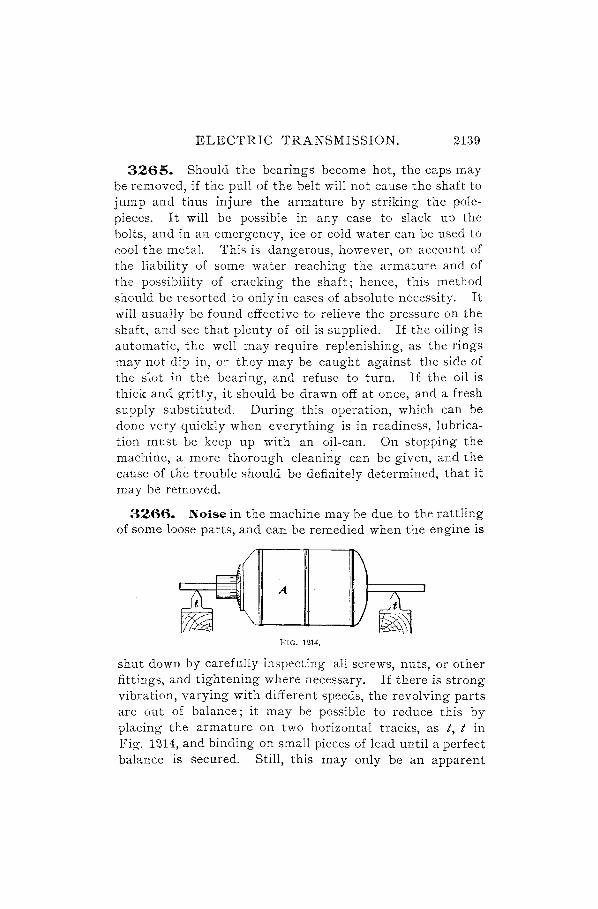
3266. Noise in the machine may be due to the rattling of some loose parts, and can be remedied when the engine is
A
FIG. 1214.
shut down by carefully inspecting all screws, nuts, or other fittings, and tightening where necessary. If there is strong vibration, varying with different speeds, the revolving parts are out of balance; it may be possible to reduce this by placing the armature on two horizontal tracks, as t, t in Fig. 1214, and binding on small pieces of lead until a perfect balance is secured. Still, this may only be an apparent

2140 ELECTRIC TRANSMISSION.
remedy, for a balance could be obtained with counteracting weights a.t different corners, which on revolving would produce a wobbling motion. It is reasonable to suppose that an armature supplied by a reputable maker will be carefully balanced, and the trouble may be due to the pulley. These are generally made in web form, and when turned all over, run very quietly.
3267. A striking sound can be easily located by the mark produced. A humming noise is probably due to the brushes on the commutator, and this can not be entirely eliminated, although it will be less with a good quality of carbon brush than if the brush is of poor quality.
The flapping of a belt joint is distinguishable above any other sound, and is chiefly objectionable when the dynamo is on a lighting circuit, as the effect on the lamps is noticeable. Dynamo belts should be endless, that is, furnished of the proper length for each machine, with a long cemented joint, so that no periodic change in speed can occur; the belt pressure is then more constant. Squeaking may be caused by slipping of the belt, because it is too narrow, or because the pulley is too small or the load too great. Resin should. not be used to give a tighter hold on the pulley, as the result is not a better permanent grip, and it is detrimental to the leather.
STATION MANAGEMENT.
3268. Increase in economy of operation without a decrease in the constancy and reliability with which power is supplied to consumers is always a proof of good management of a station. It will be a saving of expense to supply a sufficient number of accurate instruments, by means of which an account may be kept of the output in electrical power and the coal consumed in its production. This amount is usually expressed in pounds per electrical horsepower per hour, and may be the average weight of coal burned per hour during the day, or week, or month, divided by the average electrical horsepower during the same time.

ELECTRIC TRANSMISSION. 2141
This average horsepower may be determined by taking simultaneous readings during the day at regular intervals on the ammeters and voltmeters which measure the outgoing power, and averaging these results; then, the product
. C E ·11· h hI· h' h bemg watts, 746 WI gIve t e orsepower. n welg mg t e
coal for a test, notice whether it is damp to start with. Some dealers are unscrupulous enough to sprinkle plentifully to increase the weight, the water being easily taken up by some forms of bituminous coal. When coal is deli v~red is the time to ascertain the weight, andif leaks are carefully stopped, the average fuel consumption can be easily determined for any considerable period of time.
\Vhen condensing engines are used, the practice is sometimes follo'wed of throwing the condensers out of action when the load falls unusually low. The engine will necessarily work at much lower efficiency in this case, and if the reduction of load is gradual and likely to continue at that point, the better plan of meeting it is to lower the pressure in the boilers and use the condensers. A recording pressuregauge for indicating the boiler pressure continuously during the day and printing the record obtained, is a useful instrument, as showing with what degree of care the firing has been done.
3269. LeaI,;:age on the Line.-The amount of trouble to be expected on this score depends very largely upon the manner in which the installation is carried out. Good material in the hands of careful and experienced men is the prime requisite, and it will pay to do this work thoroughly. In lines running through the country, abrasion of the insulation is offen caused by the scraping of a branch of a tree, and the leakage is variable, there being sometimes, as on a still day, no contact, and on a wet and windy day the loss is a maximum. In any system using the ground as a return, such as electric railways, much trouble is apt to be caused by electrolysis, unless the rail bonds and connections to the supplementary wire are very reliable.

2142 ELECTRIC TRANSMISSION.
The current is carried along gas and water pipes, which serve as a return conductor, and it sometimes acts upon them electrolytically, making large holes in them, and necessitating considerable expense in repairs.
3270. Breaks.-When a wire has been put up without due allowance. being made for contraction in cold weather, it is liable to snap when a frost comes. A wire is sometimes nearly severed by a careless lineman in installing, or by some accident, and may be left with barely enough metal to hold the two ends together, so that the circuit, when tested for continuity, seems all right. The resistance will be higher than it should be, and the break must be located, even though it should necessitate a long examination. If the system is divided into separate circuits, the one at fault may be overhauled; if the wires are accessible, they may be shaken to locate the trouble, when the bending at that point may show it. If the wires are all laid in fireproof conduits, so that there is no danger of fire from overheating, a strong current may be sent through, and the slight contacts burnt through. Then the capacity test, described later, will indicate the location of the break.
THE TRANSMISSION CIRCUIT.
WIRES .
. 3271. The· wires most extensively used as conductors in the transmission of electrical energy are copper, iron, and various bronzes. It is probable that aluminum also will, in the future, be largely used for this purpose, but at present it is used in but few instances. German silver, lead, and tin wires are often used as conductors, but only at points where it is desirable to have a com parativel y high resistance in the circuit.
3272. The specific resistance of a conductor is the resistance between the opposite faces of a cube, 1 centimeter square, of the given substance, at a temperature of 0° C., or

ELECTRIC TRANSMISSION. 2143
32° F .. The resistance in microhms or millionths of an ohm of one cubic inch of each of the common metals is given in Table 76. The following table gives the resistances of the same metals in microhms per cubic centimeter at a temperature of 0° C.
TABLE 97.
Metal. Resist-
Metal. Resist-
ance. ance.
-
Silver, annealed .... 1.504 Iron, annealed ...... g.71G Copper, annealed ... 1.598 Nickel, annealed .... 12.470 Siiver, hard-drawn .. 1.634 Tin, pressed ........ 13.210 Copper, hard-drawn. 1. 634 Lead, pressed ....... 19.630 Gold, annealed ...... 2.058 German Silver ...... 20.930 Gold, hard-drawn ... 2.094 Antimony, pressed .. 35.500 Aluminum, annealed 2.912 Mercury ........... 94.320 Zinc, pressed ........ 5.626 Bismuth, pressed ... 131.200 Platinum, annealed .. 9.057
I I
3273. The specific conductivity of a conductor is the reciprocal of its specific resistance.
3274. The percentage conductivity of a conductor is the ratio that its specific conductivity bears to that of some standard conductor, usually pure copper, the conductivity of the latter being taken as 100.
The percentage conductivity of a wire is the ratio the conductivity of that wire bears to the conductivity of a pure copper wire at the same temperature and of the same length and weight, ·the conductivity of the latter being taken as 100.
3275. It is customary to express the diameter of a wire in mils and its cross sectional area in circular mils.
A ll1il is a linear measure, and is equal to one-thousandth of an inch, or, expressed as a decimal, .001 inch.
A circular Illil is the area of a circle the diameter of which is one mil.

2144 . ELECTRIC TRANSMISSION.
This method of expressing the area of cross-section of a wire is chosen in preference to expressing it in square inches, because a very simple relation exists between the circular millage and the diameter of a wire, so that either is more easily determined from the other than if the area were expressed in square inches.
Suppose a wire to have a diameter of 1 mil, or .001 inch, its area in square inches would then be .0012 X .7854 = .0000007854 sq. in. Such an area is termed a circular filiI, and is usually written C. M.
The num ber of such C. M.'s on the face of the cross-section of a wire is a measure of the area of this cross-section.
EXAMPLE.-What is the area of cross-section in circular mils of a copper rod 1 inch in diameter?
SOLUTION.-The area of a circle 1 inch in diameter expressed in: square inches is 12 X .7854 = .7854 sq. in.
1 c. M. = .0000007854 sq. in. (as above). Such a circle of 1 inch diameter has, therefore, a circular filill-
age of .()OO~~~~854 = 1,000,000 C. M.'s.
Hence, a wire of 1 inch diameter has a cross-sectional area of 1,000,000 circular mils.
But 1 inch = 1,000 mils, and, since 1,000 X 1,000 = 1,000,-000, the derivation of the following formula will be evident:
C. M. = dO, (489.)
where C. M. is the area in circular mils, and d is the diameter in mils. In other words, the area of cross-section of a wire in circular mils is computed by squaring the diameter of the wire in mils.
EXAMPLE.-What is the area in circular mils of a wire having 'a diameter of .46 in. ?
SOLUTION.- .46 in. = 460 mils. 460 X 460 = 211,600 C. M.'s. Ans.
Rule.-Tlze diameter in mils of it wire the area of whic/l tS given lS found by extracting the square root of tile n"rcular millage.
EXAMPLE.-What is the diameter of a wire having a cross-sectional area of 1,021.5 circular mils?
SOLUTION.- .y'1, 021. 5 = 31.961 mils = .031961 in. Ans.

ELECTRIC TRANSMISSION. 2145
COPPER WIRE.
3276. Copper is used for electric light and power lines, for most telephone and some telegraph lines, and for all cases where low resistance is required at moderate cost.
Pure annealed copper has a specific gravity of 8.89 at 60° F. One cubic inch weighs 0.32 pound, and its melting point is about 2,100° F. Good hard-drawn copper wire will support nearly three times its own weight in pounds per mile. Thus a No. 10 B. & S. gauge copper wire weighing 166 lb. per mile will have a breaking strength equal to 3 X ·166 = 498 lb. In making specifications for copper line-wire it is customary to specify that it shaH have a breaking strength equal to at least two and one-half times its weight per mile.
3277. The weight per mile of a copper wire is given by the formula
dO T¥= 6~.5' (490.)
where d is the diameter in mils and W the weight in pounds. The resistance per mile in ohms of any pure copper wire at
75° F. is given by the formula
R = 56~270, (491.)
where d IS the diameter in mils and R the resistance in ohms.
EXAMPLE.-About what is the weight per mile of a copper wire 80.808 mils in diameter?
S . W . h (80.808)2 1 4 48 lb· '1 A OLUTION.- elg t = ~ = o. . per m! e. ns.
EXAMPLE.-About what is the resistance per mile (at 75° F.) of a copper wire 102 mils in diameter?
SOL UTION. - Resistance per mile = ~~~2~~ = 5.476 ohms per mile. Ans.
3278. Matthiessen's Standard.-Tables giving the resistances of the various sizes of copper wire are usually based on the grade of wire used by Dr. Matthiessen in determining the resistance of copper. The conductivity of this

2146 ELECTRIC TRANSMISSION.
wire was at one time the highest known, but wire has been produced by electrode position having a somewhat higher conductivity. Matthiessen found that a piece of soft copper wire one foot long and having a uniform diameter of one one-thousandth of an inch, had a resistance of 9.612 legal ohms at a temperature of 0° C. Such a piece of wire is termed a mil-foot, meaning that its diameter is one mil and its length one foot.
3279. Brown & Sharpe Gauge.-This gauge is usualfy termed B. & S., and wire is generally designated according to it in the United States. The Birmingham wire gauge (B. W. G.), or Stubs gauge, is used sometimes, and differs considerably from the B. & S.
An advantage of the B. & S. gauge is that the resistance per unit length advances with the gauge number in a geometrical progression, and if the ratio between the successive sizes is known, the resistance of any size may be determined from the known resistance of any other size.
The ratio between the resistance of any wire in the B. & s. gauge and tltat of the next higher number is as 1 to 1.26.
As 1. 26 is the cube root of 2, it follows that:
A wire three siies smaller titan a given wire will lzave a resistance twice as great, and a wire three sizes larger will have a resistance one-half as great as that of the given wire.
EXAMPLE.-Find the resistance of 1,000 ft. of No. 16 B. & S. gauge copper wire, having given that the resistance of 1,000 ft. of No. 10 wire is 1 ohm. "
SOLuTION.-No. 16 is six sizes smaller than No. 10, and will therefore have four times the resistance. 4 X 1 = 4 ohms. Ans.
EXAMPLE.-The resistance of a No. 12 B. & S. gauge copper wire is 8.37 ohms per mile. What is the resistance (a) of a mile of No. 11 ? (b) of a mile of No. 13?
SOLUTION.-(a) 8.37 -+-1.26 = 6.64 ohms. Ans.
(b) 8.37 X 1.26 = 10.54 ohms. Ans.
EXAMPLE.-The resistance of a :No. 00 B. & S. gauge copper conductor is .411 ohm per mile. What is the resistance of a similar conductor of No.3 gauge?
ELECTRIC TRANSMISSION. 2147
SOLUTION.-The third size smaller than No. 00 is No.2. The resistance of No.2 per mile is, therefore, 2 X .411 = .822 ohm. The resistance of No.3 is 1.26 times that of No .. 2, or .822 X 1.26 = 1.036 ohms. Ans.
3280. It is a very convenient fact to remember that the diameter of a No. 10 wire in the B. & S. gauge is very close to one-tenth of an inch (.101890), and that its resistance per 1,000 feet is practically one ohm (1.04). For rough values, one can, by remembering these facts, compute the resist· ance and cross-sectional area of any other size in the B. & S. gauge without the use of a table. The area of course varies inversely as the resistance. For accurate calculations, however, it is better to consult a table giving the various properties of wire of different sizes.
3281. Table 98 gives the dimensions, weight, length, and resistance of pure copper wire according to the B. & S. gauge.
3282. Unfortunately various manufacturers of wire have adopted independent gauges by which to designate the sizes of their wires. Table 99 shows the diameters of the different gauge numbers according to the. more important of these standards.
3283. The temperature coefficient for pure copper is 0.0021 for a change of 1 ° F. This figure is exact enough for a correction to 75° or 60° F. for all ranges of temperature that occur in the testing room; but for ranges below 50° F. or above 100° F. it is better to consult a table.
Table 100 gives the constants by which the resistance of a copper conductor (at the observed temperature) must be multiplied to correct its resistance to 75° F.
EXAMPLE.-The observed resistance <if a copper wire is 12.746 ohms at 88° F. What is its resistance at 75° F.?
SOLUTION.- 12.746 X .9728 = 12.399 ohms. Ans.

2148 ELECTRIC TRANSMISSION.
TABLE 98.
AMERICAN, OR B. & S. GAUGE.
."3 .... '" Resistance of Pure Copper
~.S '" '" .,j
" "..; " at 75° F. "" ci " 0" " z D~ ",Ii< 0
.~ 0 p, .... ..; .... .... 0 " 0
.... " " 8 .... " " " . bIl . 5~ :; 8 .. " . p,,,, +" '" p,,,, AS " " H ,,"H p, ",Ii< ",Q
'" S .... '" bIl .... ..., Sg "ct).r:: SS (,!) ",0 '" .~ " '" ,,0 .... ~A " ,,"0 Ii< "'''' i5 ~ Ii< Oe:- ° ---
0000 460.000 2T 1,600.00 639·33 1. 56 .051 19, 605. 69 .0000708 000 409. 640 167, 805. 00 507. 01 1.97 .064 15,547. 87 .0001270 00 364. 800 133,079.40 402.09 2·49 .081 12,330.36 .Oci02020
0 324. 86 5 105.534· 50 319. 04 3. 1 3 .102 9,783. 63 .0003 200 I 289.300 83,694. 20 25 2.88 3·95 •129 7,754·66 .0005100 2 257. 630 66,373. 00 200·54 4·99 .1 63 6,149' 78 .000Srro 3 229.420 52,634. 00 159.03 6.29 .205 4,876.73 .0012890 4 204.310 41,742.00 126.12 7,93 .259 3, 867. 62 .0020500 5 181.940 33,102.00 100.01 10.00 .326 3, 06 7. 06 .003 2600 6 162.020 26,250.50 79.3 2 12.61 ·4II 2,43 2.22 .0051800 7 144. 280 20,816.00 62.90 15.90 .5 19 1,928.75 .0082400 8. 128.490 16,509. 00 49. 83 20.05 .652 1,529. 69 .0131100 9 lI4·430 13,094. 00 39· 56 25. 28 ;824 1,213. 22 .0208300
10 101. 890 10.381.00 31.37 31.88 I. 040 961.91 .0331400 II 90.742 8,234. 00 24. 88 40. 20 I. 3lI 762.93 .05 26900 12 80.808 6,529'90 19·73 50.69 I. 653 605. 03 .0837700 13 71.961 5,178.40 15065 63.91 2. 084 479. 80 .1332100 14 64. 084 4,106.80 12.41 80·59 2.628 380.51 .2118000 IS 57. 068 3,256.70 9. 84 101. 63 3.3 14 30r. 75 .3368000 16 50.820 2,5 82'9° 7081 128.14 4·179 239.32 .5355000 17 45. 257 0 2,048.20 6.19 16r. 59 5. 269 189.78 .85 15000 IS 40.303 1,624.30 4,91 203.76 6.645 150.50 1.3539000 19 35.390 1,252.40 3.78 264. 26 8.617 lI6.05 2.2772000 20 31.961 1,021. 50 3. 09 324. 00 10·566 94. 65 3.4230000 21 28·462 810.10 2·45 408.56 13· 323 75. 06 . 5·4430000 22 25347 642.70 1.94 SIS· IS 16·799 59·53 8.6540000 23 22: 571 509.45 1. 54 649. 66 21. 185 47. 20 13· 7630000 24 20.100 404. 01 1.22 819. 21 26.713 37·43 21. 8850000 25 17.900 320.40 ·97 1,032'96 33. 684 29. 69 34· 7950000 26 15.940 254·01 ·77 1,302.61 42.477 23·54 55.33 10000 27 14· 195 201. 50 .61 1,642.55 53· 563 18.68 87'9790000 28 I2.64! 159· 79 ·48 2,071. 22 67· 542 14. 81 139.8930000 29 11. 257 126.72 .38 2,611.82 85· 170 II. 74 222.4490000 30 10.025 100.50 .30 3,293'97 107.391 9.31 353· 7420000 31 8,928 79.71 .24 4,15 2.22 135.402 7·39 562.2210000 32 7.950 63·20 0. 19 5,236.66 170.765 5·86 894.2420000 33 7. 080 50.13 . I 5 6,602·71 21 5.3 12 4. 64 1,421.6460000 34 6.304 39·74 .12 8,328.30 271. 583 3. 68 2,26r. 8200000 35 5·614 31. 52 .10 10, 50r. 35 342.443 2.92 3,596.1040000 36 5. 000 25. 00 .08 13,238. 83 431. 712 2.32 5,715. 3600000 37 4-453 19. 83 .06 16.691.06 544. 28 7 1. 84 9, 084.7100000 38 3.965 15.72 .05 20,854. 65 686·5 IT 1.46 14,320.2600000 39 3· 53 1 12·47 .04 26,302. 23 865. 046 I. 10 22,752.6000000 40 3. 144 9. 89 ·°3 33,175,94 1,09r. 865 .92 36,223.5900000

ELECTRIC TRANSMISSION. 2149
TABLE 99. DIFFERENT STANDARDS FOR WIRE GAUGE IN USE IN
THE UNITED STATES. Dimensions of Wires in Decimal Parts of an Inch.
~ai « a ~ . ~ci' ," .c (/J • ~ai 0 ";./J,~ °0 "-'" oM <i~oi mui :::;:;.... H cd rJ)x;.J-) ocr; \.0..,
~f~ :.::: d.~ «" -".D H~ o~ ..... " «" ",ro m" Po M" ";;:Ii<:'" ;:::<Ll~ ~D;ii--: "" .'0 . ~ ~ ~ " ... .D ;.> • 0'" • . 0" .D0
S '" «Or '-[/). ~ ~ ~~ ~8Z ~~;;:I filf1'", Sa! ,,« s;iirJi S« cd 0°"'" " c "do-t: " ... Z·- «0 ~;;:I0~ «0 .en ot~ Z~ ~ <!1 P5 E-<0 Cb:E
--- --- --- ------ ---000000 ...... . .. .. .4600 , ... .... . ... 000000 00000 ...... . ... . .4300 .4500 '.0 • .... 00000 0000 . 460000 ·454 .3930 .4000 .. .. .... 0000 000 .409640 .425 . 3620 .3600 .3586 .... 000 00 . 364 800 .380 .33 10 .3300 .3282 ... , 00 0 .324 860 .340 .3070 .3050 .2994 .... 0 I . 289300 .300 . 283° .2850 .2777 .... I 2 .257630 .284 . 2630 .2650 .2591 .... 2 3 .229420 .259 .2440 . 2450 .2401 •• o • 3 4 . 204310 . 238 .2250 .2250 .2230 .... 4 5 . 181 940 .220 .2070 .2050 . 2047 .... 5 6 . 162020 .203 .1920 .1900 .1885 .0 •• 6 7 . 144280 · ISO .1770 .1750 .1758 .... 7 8 .128490 .165 . 1620 .1600 .1605 .... 8 9 .114430 . I4S .I4S0 .1450 .1471 .0 .. 9 10 . 101890 .134 .1350 .1300 .1351 .... TO II .090742 .120 .1200 . II75 .1205 .... II 12 . oS0808 .109 .1050 .1050 .1065 .... 12 13 . 071961 .095 .0920 .0925 .0928 .... 13 14 . 0640S4 .083 .0800 .0800 .0816 .08300 14 IS .057068 .072 .0720 .0700 .0726 .07200 IS 16 .050820 .065 .0630 .0610 .062 7 .06500 16 17 .045 257 .058 .0540 .0525 .0546 .05800 17 18 .040303 .049 .0470 .0450 .0478 .04900 18 19 .035890 .042 .0410 .0400 . 04 II .04 00 19 20 .031961 .035 .0350 .0350 .035 1 .03500 20 21 .028462 .032 .03 20 .0310 .03 21 .03 150 21 22 .02 5347 .028 .0280 .0280 .0290 .02950 22 23 .022571 .025 .0250 .0250 .0261 .02 700 23 24 .020100 .022 .0230 .0225 .023 1 .02 500 24 25 .017900 .020 .0200 .0200 .02I2 .02300 25 26 .0I 594° .01S .OISO .OISO .0194 .02050 26 27 .014195 .016 .0170 .0170 .0182 .018 75 27 28 .012641 .014 .0160 .0160 .0170 .or650 28 29 .OIl257 .01 3 .0I 5° .0150 .0163 .01 550 29 30 .010025 .012 .0140 .0140 .0156 .01 375 30 31 .008928 .010 .0135 .01 30 .0146 .0122 5 31 32 .007950 .009 .01 30 .0120 .01 36 .0112 5 '32 33 .007oS0 .008 .0IlO .01I0 .01 30 .0102 5 33 34 .006304 .007 .0100 .0100 .0IlS .00950 34 35 .005 614 .005 .0095 .0095 .0109 .00900 35 36 .005000 .004 .0090 .0090 .0100 .00750 36 37 .004453 ... ,
I
.0085 .0085 .0095 .00650 37 38 .003965 .... .00So .00So .009~ .00575 38 39 .003531 · ... .0075 .0075 .0083 .00500 39 40 .003144 · ,-. .0070 .0070 .0078 .00-'150 40

2150 ELECTRIC TRANSMISSION.
TABLE 100.
<1l~ ~ ~ ~ <1l r/l <1l rJl <1l r/l .... rJl ~ ~ .... <1l .... <1l ::l <1l ...: ...: ::l <1l ...: ::l <1l ...: ..... <1l 0 ..... .... 0 ..... .... 0 ..... .... 0 0:\ .... ..... ~ t-o ..... ~ t-o ..... 0:\ bIi ..... .... bIi '-' '-' '-' ~ <1l '-' <1l <1l 0:\ &p 0:\ &p 0:\ 0:\ o..p r:r.. r:r.. r:r.. o..p r:r.. S :::: S :::: S :::: S ::::
<1l .~ <1l .~ <1l .~ <1l .~
E-< E-< E-< E-<
100 .9484 82 .9853 '64 1.0236 46 1.0634 99 .9504 81 .9874 63 1.0258 45 f0657 98 .9524 80 .9895 62 1.0280 44 1.0679 97 .9544 79 .9916 61 1.0301 ' 43 1.0702 96 .9564 78 .9937 60 1.0323 42 1.0725
" 95 .9585 77 .. 9958 59 '1.0345 41 !.0748 94 .9605 76 ~9979 58 1.0367 40 1.07c71 , 93 :9626 75 1.0000 57 1.0389 39 , J.07~3 92 .9646 74 1.002] 56 1.0411 38 ' 1. 08I-fl 91 .9666 73 1.0042 55 1.0433 '37 : 1.083l:! 90 .9687 72 1.0064 54 1.0455 36 ' 1.Q862 89 .9708 71 1.0085 53 1.0478 35 1.0885' 88 .9728 70 1.0106 52 1.0500 34 1.0908 87 .9749 69 1.0128 51 1.0522 -33 1.0932 86 .9769 68' 1.0149 50 1.0544 32 1.0954 85 .9790 67 1.0160 49 1.0567 84 .9811 66 1.0193 ,48 1.0589' 83 .9832 65 1.0214 47 1.0612
3284. Table 101 is useful for 'calculating percentage conductivities. It gives the resistance (in British Asso~ ciation, or B. A., units), at various temperatures, of -a copper wire one foot long, weighing one grain.' The B. A. ohm equals 0.9889 legal ohm. Therefore, to reduce the resistances to leg:H ohms multiply by ,0. 9889.
3285. Table 102 gives the temperature correction of copper wire. It is based on Matthiessen's standard, described in Art. 3278.

ELECTRIC TRANSMISSION. 2151
TABLE 101.
RESISTANCE IN B. A. UNITS OF COPPER WIRE 1 FOOT LONG, WEIGHING 1 GRAIN.
Tempera- Tempera- Tempera-ture in Resist- ture in Resist- tu,re in Resist-Degrees ance. Degrees ance. .Degrees ance.
F. F. F.
32.0 .2064 66.2 .. 2220 84.2 .2305 41.0 .2102 68.0 ~228 86.0 .2313 50.0 .2144 69.8 .2237 87.8 .2322 51.8 .2153 71.6 .2242 89.6 .2328 53.6 .2161 73.4 .2253 91.4 .2340 55.4 .2170 75.2 .2262 93.2 .2348 57.2 .2178 77.0 .2271 95.0 .2357 59.0 .2186 78.8 .2279 96.8 .. 2365 60.8 .2194 80.6 .2287 98.6 2376 62.6 .2203 82.4 .2296 100.4 -.2383 64.4 .2211 e
TABLE 102.
Resistance Tempera- Resistance Tempera- Resistance Tempera-per Mil- ture in per Mil- turein per Mil- -ture in Foqtin Degrees Foot in Degrees Foot in Degrees Legal F. Legal F. Legal F. Ohms. Ohms. Ohms.
10.00 50.47 10.60 78.01 11.10 100.04 10.10 55.15 10.70 82.47 11.20 104.36 10 .. 20 59.79 10.80 86.90 11.30 108.64 10.30 64.40 10.90 91.31 11.40 112.90 10.40 68.97 11.00 95.69 11.50 117.14 10.50 73.51 .

2152 ELECTRIC TRANSMISSION.
In Table 102 the temperatures have been calculated between which the resistance increases 1 per cent. To calculate the resistance of any copper wire whose diameter is given in mils, whose length is given in feet, and whose temperature is given in degrees F., use the formula
(492.)
R t is the resistance to be found at temperature t, L is the length in feet, d is the diameter in mils, and K is the resistance per mil-foot found from Table 102 and corresponding to the temperature nearest to t.
EXAMPLE.-What is the resistance of a copper wire 40 mils in diameter and 27 feet long at a temperature of 72' F.?
SOLUTION.-From the table K equals 10.50; therefore,
27 Rt = (40)2 X 10.50 = 0.17718 ohm. Ans.
EXAMPLES FOR PRACT~CE.
1. (a) What is the resistance per mile (at 73' F.) of a copper wire 25 mils in dIameter? (b) What is the weight per mile?
A 5 (a) 88.7 'ohms per mile. ns. 1 (b) 10 lb. weight per mile.
2. W'hat is the resistance at 65' F. of a <:;opper wire 50 feet long and 28 mils in diameter? Ans .. 6569 ohm.
3, Find the approximat~ resistance per 1,000 feet of No.7 B. &. S. copper wire. . Ans .. 5 ohm.
4. What is the weight pel' thousand feet of No.7 B. & S. copper wire? Ans. 63.62 lb.
GERMAN.SILVER WIRE.
3286. German silver is used chiefly in electrical instruments, r'heostats~ and resistance coils. It is used for thes~ purposes on account of its high, resistance and its small temperature coefficient.
Its composition differs to such an extent with different ma'nufacturers, that no reliable figures can be given concerning its resistance, conductivity, and temperature coef-

ELECTRIC TRANSMISSION. 2153
ficient. But such figures should be found by experiment for the particular brand that one is using.
The figures given in this section will be for German silver having the following composition:
Copper. . . . . . . . . . . . . .. . . . . .. 4 parts. Nickel ..................... 2 parts. Zinc. . . . . . . . . . . . . . . . . . . . . .. 1 part.
The weight of such an alloy is 530 lb. per cubic foot, and its specific gravity is 8.3. The resistance of a prism one meter long weighing one gram is about 1. 75 ohms at 32° F. Its temperature coefficient is 0.000244 for 1 ° F.
German-silver wire is apt to become brittle with age, or from the effect of the passage of a strong current, and thus change its resistance . •
IRON WIRE.
3287', Iron wire is largely used for telegraph and telephone lines, although it is rapidly being replaced by copper in iong lines. It weighs 483 lb. per cubic foot and has a specific gravity of 7.73. A cubic inch weighs 0.28 lb.
3288. The approximate value of the resistance per mile of a good quality of iron wire may be determined from the formula
R = 360,000 . d"
(493.)
For stcel wire, which is often used in place of iron wire, this formula becomes approximately:
R _ 470,000. - d 2 (494.)
3289. It is customary to take as a standard in specifying quality of wire the weight of a wire one mile long and of such diameter as to have a resistance of one ohm. Such a wire is called a Il1i1e-olun. The weight of a mile-ohm of pure iron is 3,IJ96 lb. at 60° F., and the weight of a mileohm of pure copper is S711b. at the same temperature.
2154 ELECTRIC TRANSMISSION.
The weight per mile-ohm for any wire may be found by multiplying the resistance of a mile of the wire· by its weight per mile.
3290. The weight per mile-ohm of a given grade of wire is a very convenient quantity, as it gives a direct means of comparing the conductivity of that wire with that of pure metal or with any other standard. Thus, suppose it is desired to find the percentage of conductivity of a given iron wire whose weight per mile-ohm is 5,323 lb. as compared with that of a pure iron wire whos~ weight per mileohm is 3,996 lb. Since the conductivities of the two wires are to each other inversely as their weights per mile-ohm, we may write
Cs 3,996 C 3,996 7 7n1 100 = 5 323' or s = 5 323 X 100 = 5.0 70 , , ,
where Cs is the conductivity of the sample wire and 100 is the conductivity of the standard.
If we know the weight per mile-ohm for a given grade of wire and also the resistance per mile of a given size, the weight per mile of that size is readily determined by dividing the weight per mile-ohm by the resistance. Similarly, knowing the weight per mile-ohm and the weight per mile of a given size we may find the resistance per mile by dividing the former by the latter.
3291. Galvanizing.-Iron is very susceptible to corrosion, due to moisture and other elements in the atmosphere, and in order to protect iron wires used for outdoor work they are covered with a thin film of zinc. This process is called galvanizing. In order to render the surface of the iron wire perfectly clean, it is drawn through a vat of hydrochloric acid while hot, and immediately afterwards through a bath of molten zinc, the latter being kept at a uniform temperature of 7400 F. by a furnace underneath the containing vessel.
The zinc coating, upon being exposed to the atmosphere, becomes oxidized, and as oxide of zinc is not soluble in water, it forms a protection against moisture. However,

ELECTRIC TRANSMISSION; 2155
when the zinc is exposed to the action of sulphur or chlorine from salt spray or the acid gases in: smoke, it is converted into zinc chloride or sulphate, which readily dissolves in water. Under especially adverse conditions, it is impossible to make iron wire last more than a few years, and in some cases a few months, and it is therefore desirable to use copper wire in such cases, as this is practically indestructible.
3292. The various grades of iron wire on the market are termed "Extra Best Best," "Best Best," and "Best." A steel wire is also used which is cheaper and of higher resistance than iron. It has an advantage, however, of possessing greater tensile strength. It should not be used except on short lines, or in special cases where it is desirable to have great tensile strength.
The terms designating the grades are used almost indiscriminately, but among conscientious manufacturers they have approximately the following weights per mile-ohm:
Extra Best Best. . . . . . . . . ... . . . . . . .. 4,700 Best Best ..... , ................... 5,500 Best ............ , .......... , ..... 6,000 Steel. . . . . . . . . . . . . . . . . . . . . . . . . . . .. 6,500
3293. In view of the fact that the film of zinc is often so thin or so uneven as not to be effective in producing the desired results, it is always an important,matter to test the galvanizing before accepting any large quantity of wire. For this purpose several samples of the wire should be taken at random and immersed in a saturated 'olution of copper sulphate for one minute. They should then be wiped dry and clean and the operation repeated four times. If at the end of the fourth immersion there is 'no appearance of a copper deposit on the wire, the wire remaining black, as after the first immersion, the sample is well galvanized. If, however, a depOSIt of copper does appear on the wirc it is a sign that the zinc has been entirely removed, by combining with the sulphuric acid of the solution to form zinc sulphate. In this case the wire should be rejected, as it shows that the zinc coating is not thick enough~

2156 ELECTRIC TRANSMISSION.
3294. The following table gives the sizes and principal properties of three grades of galvanized iron wire. The sizes are according to the Birmingham Wire Gauge, which is most commonly used in connection with iron wire.
TABLE 103.
ci I H Breaking Ei
I oj
Weight in .5 " . Strengths in Resistance per Mile. H"1:i " ~ Pounds.
p:i H"'l Pounds. 2 II o II H " en " 13:::: .:~
,D .:'J ::::i .; :g One " Q <lJ
1,000 Iron. Steel. E. B. B. B. B. Steel:
" H Feet. Mile. Z <r: - ---------------
0 340 115,600 304.0 1,607 4,821 9,079 2.93 3.42 4.05 1 300 90,000 237.0 1,251 3,753 7,068 3.76 4.40 5.20 2 284 80,656 212.0 1,121 3,363 6,335 4.19 4.91 5.80 3 259 67,081 177.0 932 2,796 5,268 5.04 5.90 6.97 4 238 56,644 149.0 787 2,361 4,449 5.97 6.99 8.26 5 220 48,400 127.0 673 2,019 3,801 4.99 8.18 9.66 6 203 41,209 109.0 573 1,719 3,237 8.21 9.60 11.35 7 180 32,400 85.0 .450 1,350 2:545 10.44 12.21 14.43 8 165 27,225 72.0 378 1,134 2,138 12.42 14.53 17.18 9 148 21,904 58.0 305 915 1,720 15.44 18.06 21.35
10 134 17,956 47.0 250 750 1,410 18.83 22.04 26.04 11 120 14,400 38.0 200 600 1,131 23.48 27.48 32.47 12 109 11,881 31.0 165 495 933 28.46 33.30 39.36 13 95 9,025 24.0 125 375 709 37.47 43.85 51.82 14 83 6,889 18.0 96 288 541 29.08 57.44 67.88 15 72 5,184 13.7 72 216 407 65.23 76.33 90.21 16 65 4,225 11.1 59 177 332 80.03 93.66 110.70 17 58 3,364 8.9 47 141 I 264 100.50 120.40 1139.00 18 49 2,401 6.3 33 99 189 140.80 164.80 194.80
3295. Table 104 contains the results of tests of certain samples of wire of American manufacture.
The column headed" Percentage Conductivity" gives the percentages which the conductivities of the various samples bear to the conductivity of pure copper.
"Percentage of Elongation" means the percentage of the length a wire will elongate before breaking.
The column headed" Relative Breaking Stress" gives the

ELECTRIC TRANSMISSION. 2157
number of feet of its own length that each sample would be able to sustain.
TABLE 104.
Mechanieal. Electrical. •
'd <=I .s ",'ti ~ " oj ,; ... <=I bIlai bIl
" :;::~ .!<lOll ~
.... .~ ~ . <=I'd .s 'd :>l 0 ... " o . .~ <=I .!<l <=I oj oj Sl ai " § 8~ .!<l " oj 0 "0
~(:) 0Il'~ '" 0 e ~ () ,;, "", ,,'d OJ ... ~~ ~P-t "" ... -a.::: " <=I ... '" o~ ~ " ~ " " ... " '" """ " bIl " b
00':;: " "' E . ... 0 " " ~ . - .~ 's:P " E " 0 ,D " '" "' >rn
'"~ .s:::P-t ,,- :;:: " '".s::: .~ ~f;il 5 ~ " "' " ~ rn ... " '" " '" ... " " <1 " "' " <ill ... ~ Z ol ~ " ~ .~
-5 p.;
------------- --E. B. B. 12 190.83 11.50 15.00 417.50 '11,552.20 14.40 30.50 E. B. B. 8 381.66 17.70 26.50 937.50 12,930'.50 17.30 12.67 E. B. B. 11 222.64 17.20 21.50 577.50 13,639.40 15.60 24.20
,.,9t 282.80 10.00 26.50 770.00 14,375.90 21.90 16.10 E. B. B. 10 254.44 17.70 28.50 697.50 14,478.10 17.80 18.42
146 9t 287.50 16.00 29,00 832.50 15,288.86 21.90 16.10 E. B. B. 6 508.88 11.40 21.50 1,587.50 16,462.40 17.70 9.21 E. B. B. 9 318.05 19.30 17.50 1,007.50 16,725.10 16.90 15.54 Nashua 8 38166 15.10 26.50 1,535.00 21,183.00 14.70 15.00
M. S. plain 6 528.00 10.40 19.50 2,137.50 21,375.00 13.50 11.78
.. 3 8 378.10 10.00 31:00 1,635.00 22,301.40 16.50 16.10 A. H. 9t 293.00 16.00 27.50 1,257.50 22,635.00 15.10 22.70
3296. The wires for use on telegraph and telephone lines should be capable of elongating at least 15 per cent. before breaking, and the breaking stress should not be less than two and one-half times its weight per mile. It should also be able to bear not less than 15 complete twists in a length of 6 inches without breaking.
By referring to Tables 103 and 104, it will be seen that the wires which bear the greatest tensile strain have the poorest conductivity.
INSULATED CONDUCTORS.
3297. Insulated wire is used in all cases where. the conductor must lie in close proximity to the walls, ceilings, or floors of buildings, and in all places where there is a possibility of accidental contact with other conductors or with

2158 ELECTRIC TRANSMISSION.
the ground. It is also of great importance to protect all exposed conductors with a coating of some insulating material, so that the circuits of which they form a part may not prove dangerous to life.
Wire is usually insulated with some hard braid covering, composed of either cotton or hemp woven upon. the wire and saturated with some compound of India rubber, pitch, tar, or resin. The thickness of this covering is dependent upon the electrical pressure the wire will be subjected to, and is furnished according to such specifications by the manufacturers.
STRA.NDED CONDUCTORS.
3298. The maximum diameter of solid wire in common use in this country is.46 inch, equivalent to a No. 0000 B. & S. gauge wire. Such wires are very difficult to handle, and to obtain the necessary flexibility, conductors are often built up of a great number of smaller wires. Such conductors are usually termed st~anded cables.
3299. Stranded cables are from 10 to 15 per cent. more expensi ve than solid wires. Owing to the spiral arrangement of the strands, there is from 1 to 3 per cent. more metal per unit· of cross-section and length than in a solid conductor of equal resistance.
The use of flexible cables may be avoided by stringing the necessary number. of smaller separate wires and joining them in multiple, in order .to make up tlie required copper cross-section.
In Table 105 is.shown the equivalents for such use.
EXAMPLE.-A certain circuit requires a conductor having a crosssection of copper equivalent to a No. 00 B. & S. copper wire. A No. 00 wire is, however, found too difficult to handle. .What sizes can be substituted? .
SOLuTION.-Referring to Table 105, it is seen that anyone of the following combinations may be used: 2 No.2; 4 No.5; 8 No.8; 16 No. 11; 32 No. 14, or 64 No. 17.

ELECTRIC TRANSMISSION, . 2159
TABLE 105.
EQUIV ALENTS OF WIRES.
0000 2-0 4-3 8-6 16~9 32-12 6~15 000 2-1 4-4 8-7 16-10 32-13 64-16
00 2-2 4-5 8-8 16-11 32-14 64-1'1 0 2-3 4-6 8-9 16-12 32-15 1 2-4 4-7 8-10 16-13 32-16 2 2-5 ~8 8-11 16-14 32-17 3 2-6 ~9 8-12 16-15 32-18 4 2-7 4-10 8-13 16-16 5 2-8 4-11 8-14 16-]7 6 2-9 ~12 8-15 16-18 7 2-10 ~13 8-16 8 2-11 4-14 8-17 9 2-12 ~15 8-18
10 2-13 4-16
I 11 2-14 4-17 12 2-15 4-18 13 2-16 4-19 I 14 2-17 15 2-18
\ 16 2-19 I I
: -
PERCENTAGE ·CONDUCTIVITY . .
3~OO. To find the percentage conductivity of a conductor, we may proceed as follows:
Let R = the resistance per grain-foot of a pure metal wire at a temperature t, from the tables;
L = the length of the wire to be tested; w = weight of the wire to be tested; -y' = the calculated resistance in ohms of a pure mel:al
wire of the same weight, length, and temperature; 1:"/1 = the observed resistance in ohms of the wire to be
tested.

2160 ELECTRIC TRANSMISSION.
The resistance of a pure wire of length L and one grain weight per unit length is L R. and the resistance of a wire
. w of the same length but of a weight per unit length of L is
, LR DR r=-W=w' (495.)
L
x: 100 :: r' : rH where x is the percentage conductivity.
r' Therefore, x = 100.. (496.)
r
3301. To .Ind the weight per unit length of a wire, several pieces are cut off as nearly to one foot in length as possible. These are each carefully weighed in scales of sufficient accuracy to read in grains, and the average is taken as the weight per foot.
H but a short piece of the wire can be obtained, its resistance may be measured by a Weston ammeter and millivoltmeter (see Fig. 1032), while its temperature is ascertained by a thermometer. The resistance of this piece is divided by its length in feet to obtain the average resistance per foot.
a d
8
FIG. 1215.
3302. Another method for finding the resistance per foot of a low-resistance m~tal is shown in Fig. 1215. In this test a millivoltmeter is the only measuring instrument used.

ELECTRIC TRANSMISSION. 2161
This millivoltmeter, if the scale be proportional, need not be accurate, as only proportional deflections are required.
The low resistance to be measured is shown at a b, the voltmeter at v, and k is a four-way switch.
The switch k may make contact either with the points s and t, in which position the millivoltmeter is connected to the terminals of a b; or with x and y, in which case the millivoltmeter is connected to the terminals of c d.
A current strong enough to give a moderately large deflection on· the millivoltmeter is sent from any constant source through a band c d in series. The deflections are noted when the instrument is connected with a b and with c d. Let D be the deflection on a b, and D' be the deflection on c d. Let R' be the resistance of the standard "and R that of the metal to be measured. Then,
R D R'- D"
or (497.)
A standard resistance for this purpose may be constructed as follows:
The length of a long German-silver wire is so adjust"ed by means of a Wheatstone bridge that its resistance is equal to the desired resistance of the standard multiplied by the square o.f so.me who.le number. This wire is then cut into equal parts, equal in number to the whole number. These parts are then soldered in parallel between two copper bars c and d, as shown in the figure. The resistance between the bars will then be the standard desired.
We may demonstrate the correctness of this method of constructing the standard as follows:
Let r be the desired standard resistance in ohms, and n the whole number chosen. According to rule, the resistance R of the long German-silver wire is taken as
R = nO r,

2162 ELECTRIC TRANSMISSION.
When we cut the long w~re into 11 equal parts, each part
alone will have a resistance equal to R = 11 r. n
If, now, we place these 11 equal parts in multiple, the total resistance will again be divided by n, and will be
R -=r n2 ,
which is the desired resistance.
(498.)
EXAMPLE.-A copper wire was tested for percentage conductivity. It was found to weigh 220 grains per foot. The resistance of 1 foot was found by the method shown in Fig. 1215, with a standard resistance of 0.00021 ohm. The deflection at the standard resistance was 6 scale divisions, and that at the wire was 30 scale divisions, while the temperature of the wire was 77° F. What was the percentage conductivity?
SOLuTION.-Using formula 497,
30 R = '6 X .00021 = 0.00105 ohm.
From Table lO1 the resistance of 1 foot of pure copper wire weighing 1 grain at 77° F. is 0.2271 B. A. ohm. Multiplying by 0.9889, we obtain 0.22457 legal ohm.
Using formula 495,
, _ 0.22457 X (1)2 _ 0 00102 h r - 220 -. 0 m.
Using formula 496,
O 0.00102 9714 d .. x= 10 X 0.00105 = . percentage con UCtlVlty. Ans.
EXAMPLES FOR PRACTICE.
1. About what is the resistance per mile of a good quality of galvan-ized iron wire 189 mils in diameter? Ans. 10.0781 ohms.
2. A copper wire was tested for percentage conductivity. It was found to weigh 125 grains per foot. The resistance of 1 foot was found by the use of a standard resistance of 0.00021 ohm. The deflection at the standard resistance was 5 scale divisions and that at the wire was 42 divisions. The temper"ture was 59° F. What was the percentage conductivity? Ans. 98%,

ELECTRIC TRANSMISSION. 2163
DROP OF POTENTIAL AND. LINE LOSS.
DIRECT-CURRENT CIRCUITS.
3::103. When a quantity of water is forced through a hollow tube (as in the case of a pipe or other conductor) at a certain initial pressure, a fall of pressure can be observed all along the length of the tube. This fall, or drop, of pressure is mainly due to the friction the inner walls of the tube offer to the even flow of the water. The result of this drop is a perceptible difference between the pressure at the end of the pipe and that at the beginning.
Assuming the initial pressure in such a system to be 100 pounds per square inch, and the final pressure of the water, as it leaves the pipe, 95 pounds per square inch, the drop through the entire length of the piping is 100 - 95 = 5 lb.
This fall of pressure is a direct and unavoidable loss. It is, of course, clear that the loss may be reduced by shortening the length of the pipe or increasing its diameter; but wherever power is transmitted, a certain loss must occur in the transmission.
The various relations given above for the flow of water can at once be applied to what is termed the flow. of electricity, that is, the passage of an electric c'urrent through a conductor.
Whenever such a current of a certain pressure or voltage flows through a conductor, a certain percentage of this voltage is lost in transit. This los~ is generally spoken of as the drop of potential along the line. This drop is directly proportional to the resistance of the line and to the amount of current transmitted, in exactly the same way as the drop of water pressure is proportional to the amount of water transmitted and to the diameter of the pipe. This relation will be made clear by a consideration of Ohm's law. Assume the potential at two points on a conductor in which a current is flowing to be e and e' , respectively. Call the difference between the potential of these points E.
Then, E = ~ ~ c' ;;: drop.

2164 ELECTRIC TRANSMISSION.
We know that the current flowing between these points will be
where R is the resistance of the conductor between them. From this we obtain
and
E=RC,
E R= C.
(499.)
(500.)
Rule.-Drop £n potmtial = currmt transm£tted X res£stance.
From this formula it is seen that the loss of potential is greater the more current there is to transmit and the higher the resistance of the conductor. This makes it self-evident that to have a small loss in transmitting a certain current, a path of low resistance must be given the current, or, in other words, a conductor of ample cross-section and conductivity must be provided.
3304. A conductor which shall cause no loss whatever is, of course, an impossibility. It is possible, however, to make the loss almost as small as we please, by using conductors of sufficient diameter, but the gain in efficiency is soon overbalanced by the great cost of the conductor, and therefore, in practice, conductors are chosen which will cause a certain allowable loss. This loss is usually given as a certain percentage of the electrical pressure or voltage of the circuit.
Thus, if a dynamo is supplying incandescent lamps with a 125-volt current, and the wires or conductors leading to the lamps have a resistance which causes a loss of 5 per cent. during the transmission of the total energy, the generator pressure, it is clear, will have dropped 5 per cent. at the end of the line. Five per cent. of 125 = G.25 volts.
Hence, the lamps at the end of the line will receive only 125 - G.25 = 118.75 volts, although the pressure at the generator terminals is 125 volts.

ELECTRIC TRANSMISSION. 2165
Rule.-The fall of potential, or drop, in a circuit of uniform resistance through which a constant currmt is flowing is uniform.
Let Fig. 1216 represent a wire of one thickness from the + to the - terminals of the circuit and let a pressure of
100 volts be acting on 60 70 SO 90 lOJ~
the circuit. Then, if (: : I
the circuit be divided 50
into 10 equal parts of equal resistance, each --+---::+-::---="'----r,---...,"---=
. 40 30 20 1'0 0 one of these parts wIll FIG. 1216.
cause a drop of 10 volts, that is, one-tenth of the total drop, and the fall of potential will be gradual and uniform.
If, however, the resistance of the circuit is not uniform, that is, if it can not be divided up into equal parts of equal resistance, the drop will also be uneven, and it will be greatest in that part of the circuit which offers the greatest resistance. It follows directly from formula 499 that:
Rule.-The drop in any part of a circuit is directly proportional to the resistance of that part.
EXAMPLE.-Fig. 1217 represents a l h
+-----.
series circuit containing three lamps I of 50 ohms resistance each, one electric heater h .of 20 ohms, and one smaller electric heater h' of 10 ohms, besides the resistance of the conductors connecting them to each other and to the generator. This latter resistance
FIG. 1217. is assumed to be 1 ohm. The following determinations are to be made:
(a) The total resistance of the circuit. (b) The voltage required to force 2 amperes through this total
resistance. (e) The drop around each element of the circuit. SOLUTION.-(a) The total resistance of the circuit is equal to the
sum of its parts; hence, Resistance of conductors. . . . . . . . . . . . . . . . . . . 1 ohm Resistance of 3 lamps at 50 ohms each. . . . .. = 150 ohms Resistance of 1 heater. . . . . . . . . . . . . . . . . . . . .. = 20 ohms Resistance of 1 heater ...................... = 10 ohms
Total resistance. . . . . . . . . . . . . . . . . . . . . . .. = 181 ohms

2166 ELECTRIC TRANSMISSION.
(b) Voltage = current X resistance; hence, voltage = 2 X 181 = 362 volts: or, in other words, 362 volts will be required to force 2 amperes through the circuit of 181 ohms resistance.
(c) According to rule in Art. 3303,
Drop due to conductors .............. = 1 X 2 = 2 volts Drop due to each lamp .......... : ... = 50 X 2 = 100 volts Drop due to 20-ohm heater ......... , = 20 X 2 = 40 volts Drop due to 10-ohm heater. . . . . . . . .. = 10 X 2 = 20 volts
In the example we see that a drop of 2 volts has occurred in the conductors. This is, of course, not desired, and may be considered a wasteful drop in comparison with the other various drops, which result in the giving out of useful light and heat; or of power, where motors are used in the circuit.
In laying out a system of wiring a certain allowable percentage is decided upon in advance. The following figures should not be exceeded: For isolated plants, 5 per cent. ; for central stations, 10 per cent.; for long-distance transmission, the drop may range anywhere from 10 to 60 per cent., depending on the distance of transmission and on the cost of generating the power.
ENERGY LOSS IN CONDUCTORS.
3305. The t-Otal energy in the example above, Art. 3304, is given in watts by the product of volts and amperes, or
Total watts ............... = 362 X 2 = 724 watts ,Watts per lamp ............ = 100 X 2 = 200 watts Watts for large heater ..... = 40 X 2 = 80 watts Watts for small heater ~ .. , . = 20 X 2 = 40 watts Watts for conductors ...... = ·2 X 2 = 4 watts
The watts of electrical energy used in the conductors are considered a loss, and this loss is usually expressed as a certain percentage of the total energy. In this particular case the loss is very slight, being 4 -+- 724 = .0055, or about t of 1 per cent. of the total energy.
Had. the conductor been of smaller cross-section, the resistance would have been greater, and the energy loss

ELECTRIC TRANSMISSION. 2161
would have been greater proportionally. From this it will appear evident how the sizes of wire for certain percentages of loss may be determined.
3306. C' R Loss.-T~e energy loss in a conductor may also be expressed in terms of the current flowing and the resistance of the conductor, as follows:
Rule.-Tlte loss of energy in a conductor expressed in watts is equal to the square of tlte current ilZ amperes multiplied by the reststance of the conductor in olmzs.
This loss of energy is called the C' R loss, and since it is spent entirely in the conductor itself, without doing any mechanical work, it is dissipated in heat. The truth of the above rule may be easily demonstrated.
E We know that C = R' or E = C R, and also that TV = E C,
where T¥ represents the energy in watts and C, E, and R ha ve their usual significance.
Substituting the value of E in the last equation, we obtain directly
w = C R X C = CO R. (501.)
3307. Detenuination of Size of Conductor for Certain Percentage of Loss.-If we know the current to be carried in a given circuit, we may calculate the resistance the wires should have in order to produce a given
E percentage drop from formula 500, R = C.
EXAMPLE.-A motor requiring 10 amperes is located 600 feet from the generator which supplies current at 110 volts. What size of wire must be .used, allowing for a drop of 8 per cent. in the line?
SOLUTION.-8% of 110 = 8.8 = drop E.
R = 8i~ = .88 ohm.
Since the total length of the circuit is 2 X 600 feet = 1,200 feet, the
. h . f .88 '" Wire must ave a resIstance 0 1.2 = . 133 ohm per 1,000 feet.

2168 ELECTRIC TRANSMISSION.
Referring to <;olumn 6 of Table 98, we find that the nearest size.or wire to the one required is a No.8 B. & S. having a resistance of .625 ohm per 1,000 feet. A No.8 B. & S. should therefore be used. Ans.
EXAMPLE.-A direct-current transmission line 6 miles long supplies a total current of 200 amperes at an initial pressure of 5,000 volts, for lighting and power purposes. The line-wire is a No.2 B. & S. gauge copper. What is the drop percentage?
SOLuTION.-The resistance per 1,000 feet of No.2 B. & S. copper wire is, from Table 98, .163 ohm. The total resistance of the line will
therefore be 2 X 6 X1~:O~0 X.163 = 10.327 ohms.
E= C R = 200 X 10.327 = 2,065.4 volts.
2065.4 Percentage of total voltage = 5,000 X 100 = 41%. Ans.
3308. When the loss in a circuit is given as a percentage, it must be remembered that this is not to be taken as applying to the voltage at the receiving end of the line but at the dynamo or switchboard.
Let V = voltage at dynamo;
Then,
V'= voltage at the receiving end of line; p = percentage of loss; E = actual drop on line in volts.
E = 100 V~ _ V'. 100 -p (502.)
EXAMPLE.-What is the actual drop in volts on a lighting circuit for 110-volt lamps when the per cent. less is 3?
SOLuTION.-In this case V'= 110; P = 3. Then, by formula 502, the actual drop in volts
100 X 110 E = 97 - 110 = 3.4 volts. Ans.
SAFE CARRYING CAPACITY OF CONDUCTORS.
3309. The amount of current which a wire may carry in pr.actice is limited by the temperature which it will acquire by the passage of such current. The insurance corporations of this country have decided that the temperature of a wire carrying current should never exceed 10° C., or 18° F., above the surrounding air.

ELECTRIC TRANSMISSION. 2169
Though this limit is often exceeded in practice, it is the standard for goad work, and the following table, therefore, gives the amount of current in amperes that a wire under certain conditions may carry without having its temperature raised beyond the limit.
TABLE 106.
Number Number Amperes. in Circular Amperes. in Circular
B. & S. Mils. B. &8. Mils.
1,000.00 .... 2,160,900 61.00 3 52,6:34 900.00 .... 1,876,900 52.00 4 41,742 800.00 .... 1,612,900 43.00 5 33,102 700.00 .... 1,345,600 36.00 6 26,244 600.00 .... 1,100,401 30.00 7 20,822 550.00 .... 976,144 25.00 8 16,512 500.00 .... 861,184 22.00 9 1:3,110 475.00 .... 804,609 18.00 10 10, :381 450.00 .... 748,225 15.00 11 8,226 425.00 .... 692,224 12.00 12 6,528 400.00 .. , . 640,000 10.50 13 5,184 375.00 .... 586,756 9.00 14 4,110 350.00 .... 5:35,824 7.25 15 3,260 325.00 .. , . 485,809 6.00 16 2,581 300.00 .. , . 435,600 5.50 17 2,044 275.00 .... 388,129 4.00 18 1,624 250.00 .... 342,225 3.25 19 1,25:3 225.00 .... 297,025 2.75 20 1,024 200.00 .. , . 254,016 2.25 21 820 174.00 0000 211,600 2.00 22 626 147.00 000 167,805 1. 75 23 510 124.00 00 1:33,079 1. 50 24 404 103.00 0 105,592 1.25 25 320
87.00 1 83,694 1.00 26 254 73.00 2 66, :37i3
I

2170 ELECTRIC 'TRANSMISSION
3310. Detern1ination of Conductor Dependent Upon Two Factors.-In calculating conductors for a certain percentage ,of . energy loss, it very often· happens that the wire which will give the particular energy loss specified may yet be too small to carry the current of that circuit without being excessively heated. It is therefore necessary at all times, in determining such a conductor, to heed the following rule:
Rule.-Find the proper size of wire according to Art. 3307 for allowable loss " then determine by Table 106 whether the wire has the necessary carrying capacity. If it has not the requisite capacity, select a larger wire which will fulfil tltis condition.
EXAMPLE.-A dynamo supplies 200 amperes of current to a line at a pressure of 62i volts. The double length of the line is 800 feet, and a line loss of 20% is to be allowed. What should be the size of the conductor?
SOLuTION.-First Calculation:
Drop = 20% of 62.5 = 12.5 volts.
Line resistance = R = 12~~ = .0625 ohm.
The resistance per 1,000 feet of the wire to be used should be .0625 800 X 1,000 = .0781 ohm.
The nearest size to this, according to Table 98, is No. 00 B. & S. gauge. Referring to Table 106, it is seen that a No. 00 wire will carry only
124 amperes safely. The calculation must accordingly be made again and a smaller energy loss allowed, thus increasing the size of the wire.
Second Calculation ~. We might assume a lower loss, say 10 per cent., and repeat. the above calculation, but by referring to Table 106, we find that a conductor having a cross-section of 254,016 circular mils will safely carry the required current. As often occurs in practice, however, a few degrees more of heating is assumed safe, and in this case a No. 0000 B. & S. wire is selected instead of a proportionately much more expens-iye cable of 254,000 circular mils cross-section. According to Table 98, the resistance of No. 0000 B. & S. = .051 ohm per 1,000 feet. Hence, resistance per foot = .000051, and for 800 feet (specified as the total length of conductor) the resistance = 800 X .000051 = .0408 ohm.
Line drop = 200 X .0408 = 8.16 volts.
Percentage drop = ~2~~ X 100 = 13%.

ELECTRIC TRANSMISSION. 21 'i'l
Hence, the use of a No. 0000 B. & S. gauge wire will give a 13% line loss and allow the required carrying capacity. Ans:
CHOICE OF METHOD.
3311. In distributing electrical energy, the choice of method-lies between the use of direct and alternating currents. Direct currents are those which flow continually in one direction, while alternating currents are those which are constantly changing in the direction of their flow. A direct current maintains a constant value as long as the electromotive force and the resistance of the circuit are constant. An alternating current, however, starts, we will say, at a zero value, increases to a maximum in a positive direction, then diminishes, through zero, to a minimum in a negative direction, when it again increases to zero. This cycle of changes is repeated many times per second, and the time occupied in one complete cycle is called the period of the wave. The number of periods, or double reversals, taking place in one second is called the frequency.
3312. The great argument in favor of the alternating current is that it may readily be transformed from a lower to a higher voltage, or vice versa, by the methods described in Arts. 2452 to 2456, inclusive. The apparatus for accomplishing this transformation is called a transformer, and its action is precisely the same as that of the inductioncoil. Arts. 2455 and 2456.
3313. A transformer is a peculiar form of inductioncoil, consisting of two windings of wire, a primary and a secondary, closely associated with, but entirely insulated from, each other. These are laid side by side and surrounded by a mass of laminated iron, so as to increase to as great an extent as possible the number of lines of force set up by a given amount of current. The coils and iron are so located with respect to each other that all the lines of force due to a current in one of the coils will pass through the other coil. It is therefore obvious, from the laws of electromagnetic induction, Arts. 2452 and 2454, that any change in the

2172 ELECTRIC TRANSMISSION.
current flowing in the primary winding will induce similar currents in the secondary winding. If there is an equal number of turns in the primary and secondary, the induced voltage will be equal ,to that of the primary; but if the secondary has a greater or a less number of turns, then the induced voltage will be greater or less in the same ratio, Thus, if a transformer has 100 turns in its primary and 2,000 in its secondary, and an alternating current at a pressure of 50 volts be sent through the primary, the induced pressure in the secondary will be 1,000 volts; and, since the product of the volts and amperes in the secondary will be practically equal to that in the primary, the number of amperes in the secondary will be but one-twentieth of that in the primary. The coils in a transformer may be used as either primary or secondary. If the coil having 2,000 turns were used as the primary, the voltage in the secondary would then be but onetwentieth as great, while the current would be twenty times as large.
3314. A transformer used to raise the voltage from a low to a high value is called a step-up transformer, while one used to reduce the voltage is termed a step-down transformer. The ratio of transformation is the ratio between the secondary and the primary voltage, and is equal to the ratio between the number of turns in the primary and the number in the secondary.
LINE LOSS AT HIGH AND LOW VOLTAGES.
3315. By considering formula 501, Art. 3306, W = C' R, it is evident that the energy loss increases as the square of the current <:Lnd directly as the resistance of the line, and inasmuch as the voltage E does not enter into this equation, it is evident that a high voltage may be used without increasing the loss at all. We may, therefore, by using a very high voltage and a' comparatively small current, transmit elec'trical power with practically no more loss ,than if we used a small voltage and the same current. There is, ot course, a somewhat greater loss on high-voltage lines, due to leakage,

ELECTRIC TRANSMISSION. 2173
but this, as a rule, may be neglected if the insulation of the line is what it should be.
3316. As an illustration of the comparative loss between high and low voltages, let us assume a case where it is desired to transmit by direct current the energy from a 1,000 horsepower dynamo a distance of 10 miles, with a total line loss not to exceed 20 per cent.
We will calculate the size of the wire necessary for accomplishing this transmission for two cases, the first using a pressure of 500 volts and the second 10;000 volts. The cost of copper is taken as 15 cents per pound.
First case:
1,000 X 746 = 746,000 watts to be transmitted at a pressure of 500 volts.
746000 Total current = 500 = 1,492 amperes.
Drop = 20% of 500 = 100.
Resistance of line necessary to produce a drop of 100
E 100 volts = R = C = 1 492 = .067 ohm. ,
The double length of the -line is 20 miles, whence
.067 X 1,000 20 X 5,280 = .000635 ohm per 1,000 ft.
Referring to Table 98, we find that the resistance of a No. 0000 B. & S. copper wire is .051 ohm per 1,000 ft.,
h' h .051 . h d . d' W W lC IS. 000635 = 81 tImes t e eSlre resIstance. e
would therefore have to use 81 such wires in parallel in order to transmit this amount of power under these conditions.
This wire weighs 639.33 lb. per 1,000 feet, and the total
. ht fth r '11 th f b 639.33X81X20X5.280 welg 0 e me WI, ere ore, e 1,000 -
5,468,316 lb.
At 15 cents per lb. the total cost would be $.15X 5,468,316= $820,247.40, which price is of course entirely out of the question,

2174 ELECTRIC TRANSMISSION.
Second case: 746,000
Total current = 10000 = 74.6 amperes. , Drop = 20% of 10,000 = 2,000.
Resistance of line necessary to produce a drop of 2,000 E 2,000
volts = R = C = 74.6 = 26.8 ohms.
. 26.8 X 1 000 The resIstance per 1,000 feet = _ 8 ' 20 =.254 ohm.
D,2 0 X
From Table 98 we find thQt a No. 4°B. & S. wire has a resistance of .259 ohm per 1,000 ft., and a single wire of this size will transmit the current without giving a drop in excess of 20%.
Reference to Table 106, however, shows that this wire would produce too great a heating effect when carrying 74.6 amperes, and we therefore select a No.2 B. & S. wire which will carry the current without excessive heating.
The weight of 20 miles of this wire will be
200.54 X 20 X 5,280 = 21177lb 1,000 ,.
The cost of copper in this case will be
21,177 X $.15 = $3,176.55.
This figure is not at all excessive, and when it is considered that the stringing and supporting of 81 large wires would cost an immense amount more than the stringing of one small wire, the difference is seen to be still more in favor of the high voltage.
The foregoing problems show well the difference in initial cost between installations for the transmission of power using high and low voltages. Direct currents were specified in both cases, because the calculations of the size of conductors for alternating-current transmission is a matter which the student should not attempt to accomplish until he has mastered the principles of alternating currents, which subject will be treated of later. It may be said, however, that the C'R loss for alternating currents is the same as for direct, when C is taken as the effective value of the current,
ELECTRIC TRANSMISSION. 2175
3317. It will now be seen why the fact that alternating currents may be readily transformed gives them such a decided advantage over direct currents in long-distance transmission work. Direct currents may be transmitted over long distances and at high voltages with even less line loss than alternating currents at the same voltages, but the difficulty is in generating the extremely high-tension direct currents, and in utilizing them after transmission at the receiving end. With alternating currents, however, there is no difficulty in either respect, for the us'e of stepup transformers at the generating end will give sufficient line voltage for transmission, 'while step-down transformers at the receiving end will give a pressure suitable for direct utilization without danger to life or property.
-r,;{
3318. The most notable long-distance transmission plant using direct current is at Brescia, Italy, where 700 horsepower is transmitted over 12 miles at an initial pressure of 15,000 volts. In plants of this kind it is necessary to use enough generators in series at a pressure of about 3,000 volts each to give the desired initial voltage. At the receiving end, motors placed in series may use the power to run dynamos which will generate currents at the proper voltage for utility.
There are probably not more than six long-distance directcurrent installations in existence, but these are all reported to be entirely successful. The flexibility of the alternatingcurrent systems, however, has proved to be so great an advantage that long-distance plants using direct currents are no longer installed.
PRACTICAL WIRING.
INTERIOR WIRING.
3319. Cleat Wiring.-This is one of the cheapest methods of wiring where exposed wiring is allowable. This system is usually employed where the appearance of the wires is of no gr.eat consequence. It admits of ready access to conductors in case change of lamps is required.

2176 ELECTRIC TRANSMISSION.
Fig. 1218 shows a two-wire cleat and Fig. 1219 one for three wires. These cleats are of wood, and are fastened to
FIG. 1218. FIG. 1219.
the wall or ceiling by screws, as indicated. Various other forms of cleats and cleats of other materials are in use; the principle of all is, howeve~, the same, that is, to support the conductors.
The following Fire Underwriters' Rules will make the use of cleat work evident:
1. In general, cleat work is not desirable, and cleats must not be used unless in a very dry place.
2. Must not be used unless in a place perfectly open for inspection at any time.
3. Must not be used unless' they are of porcelain, or wellseasoned wood, filled to prevent absorption of moisture.
4 .. Must not be used unless they are so arranged that wires of opposite polarity, with a difference of potential of 150 volts or less, will be kept at least 2t inches apart, and that where a higher voltage is used this distance be increased proportionately.
3320. Molding Work.-This is so called because the
~~~~~~~~~
FIG. 1220.
wires are covered by wooden moldings. It is more expensi ve, both as regards labor and material, than cleat work. It is, however, much
neater in appearance, and can be used in all places which are free from too much moisture.
Fig. 1220 shows a ceiling molding, and Fig. 1221 a wall molding, both for two wires. FIG. 1221.
Numerous other forms are in use, all, however, similar in principle,

ELECTRIC TRANSMISSION. 2177
The standard rules for molding work are as follows: 1. Conductors must riot be of sizes smaller than No. 16
B. & S. wire gauge. 2. Must not be paraffin-covered. 3. Must not be laid in moldings of any kind in damp
places. ·4. Must not be carried with soft-rubber tube. 5. Must not be laid in moldings with open grooves against
the wall or ceiling. 6. Must not be· laid in moldings where less than t of an
inch of solid insulation is be~ween parallel wires and between wires and walls or ceilings . . 7. Must not be laid in plaster, cement, or similar finish
without an exterior metallic protection. S. Moldings, where admissible, must have at least two
coats of water-proof paint, or be impregnated with a moisture repellent.
3321. Concealed Work.-Wiring which is completely hidden from sight is termed concealed work. The wires in this case are usually strung through the space between the floor boards and the brick or concrete beneath, and are supported by ordinary cleats or molding.
A later method of concealed work is the interior conduit system. This system consists of a highly insulating and water-proof tube, in connection with junction-boxes and outlets designed to meet all requirements of interior wiring. These tubes are made in sizes from t of an inch to 1t inches in diameter, and in lengths of 10 feet.
They are concealed beneath the plaster, while junctionboxes arc located wherever most convenient, with the conduits leading directly into them. Nothing is exposed of this work but the covers of the junction-boxes. These are ornamental or perfectly smooth, and can be decorated to correspond with the walls and be almost unobservable.
To lay the conductor in such a system of interior conduits, a so-called fish wire is inserted into the conduit and readily pushed through to the next outlet. The electrical conductor is attached and drawn through.

2178 ELECTRIC TRANSMISSION.
Buildings should preferably be supplied with such a system of interior conduit while in the course of construction, because installing concealed work on a finished building is very expensive and difficult.
3322. .The following general rules have been recommended in connection with interior conduits:
1. Use as long pieces of tubing as possible. ,1' Fasten to walls or beams with staples, using a staple
driver to drive them home, so that while no damage is done to the tube it is perfectly secure.
3. Be sure the ends of the tube are so cut as to meet squarely at the joints, to prevent the wires from catching. They should pass freely, without friction.
4. Always blow soapstone into the tube after it is in position. This allows the conductor to be pulled through easily.
5. If rigid conductors are used, place a junction-box at each angle.
6. Always enter the tubing full into the junction-boxes, when they are used, and cover the joints with water-proof insulating compound.
If these directions are carefully followed, an absolutely water-proof conduit will be formed, and no trouble will be experienced in drawing the conductors by means of a fish wire through long distances and around corners.
UNDERGROUND WIRING.
3323. In large cities, the only practical method of running conductors for all varieties of electrical-power transmission is to place them underground. On account of the difficulty in approaching a burning building, the danger from crosses and falling wires, and the disfigurement of the stre.ets where a network of overhead wires is present, many city authorities have made the placing of them underground compulsory by law. There are many conduit systems in use, but only a few of the better known varieties will be gIven.

ELECTRIC TRANSMISSION. 2179
33.24. Wychoff Systell1.-The Wychoff system consists of creosoted wooden ducts, having a square cross-section with a three-inch circular hole in the center. The ducts are laid in a trench, in the bottom of which a flooring of two-inch creosoted planks has previously been placed. When the entire number of ducts are in place a similar layer of two-inch planks are placed above the whole, to protect the ducts from the pickaxes of laborers. The ends of the ducts fit into each other in the same manner as ordinary pump-logs. This system is cheap, but the creosote is apt to affect the covering of the cable by chemical action, and the ducts can not be bent around corners and obstructions. Also, such a system can not be placed near the pipes of a steam-heating company.
Earthenware pipes having a rectangular cross-section divided in the center by a shelf, are sometimes used, and each half receives three ducts. The joints are wrapped with burlap impregnated with asphalt, which renders them rigid and moisture proof.
3325. Dorset Systell1.-This consists of blocks of some substance like asphalt, bored with holes to receive the conductors. The blocks are joined at their ends by a paper sleeve which fits into the holes. The paper, however, is apt to become moist, and when a sag occurs the joints will open.
3326. Open-Box Conduit.-This consists of a wooden box of rough lumber about one to one and one-half inches thick. The boxes are all joined together by short wooden strips nailed on the outside, a.nd the cables are laid inside with a filling of pitch. After the conduit has been filled in with pitch, a wooden creosoted cover is nailed on, and in places where digging may be expected, a light cast-iron protective covering is laid over this.
3327. Wrought-Iron, CeIUent-Lined Pipe.-This conduit, although rather expensive, is very durable, and allows frequent changes in the size and number of conductors. It consists of a riveted wrought-iron shell, is inch thick and lined with i inch of cement concrete, the inside

2180 ELECTRIC TRANSMISSION.
surface of which is smoothly finished. This lining prevents the formation of scale by the corrosion of exposed iron, which may hinder the withdrawal of the cables. It also does not melt in warm weather and hold the cable. The pipe usually comes in seven or eight foot lengths, threaded at each end with a vanishing screw, i. e., a screw whose thread continually decreases in depth until it disappears altogether. The lengths are joined by a short piece of pipe having a right-hand thread on the inside of one end, and a left-hand thread on the inside of the other end. After the pieces have been screwed together, the joints are covered with a layer of cement.
The best way to lay wrought-iron conduits is to place them in a trench which is three to four feet deep, lined with suitable lumber and having its bottom carefully leveled to grade. 'Within this trench comes, first, a layer of concrete three inches thick, and over this a layer of conduits and a layer of concrete one inch thick. Similar layers of pipes and concrete are laid until the requisite number of conduits is in the trench, and the sides and top are filled in with concrete to a thickness of three inches. Over all is laid a covering of two-inch creosoted planks to protect the trench.
Multiple conduits, which are often laid directly in the ground without cement, may be obtained. They consist of a wrought-iron shell of large diameter, within which the cement concrete is filled around cores which, when withdrawn, leave a number of parallel ducts for the cable.
3328. Manholes.-At suitable distances along their lengths, underground conduits should run into underground compartments, called IllanhoIes. These are usually placed about 400 feet apart; but this distance varies under differcnt conditions.
Manholes are usually built of sewer brick, with walls about one foot thick, upon eight inches of concrete. This concrete is for the purpose of preventing the entrance of water or gas. They are entered through circular apertures at the top, about thirty inches in diameter, which are closed with cast-iron covers.

ELECTRIC TRANSMISSION. 2181
Where sewer or illuminating gas is present, all apertures where the conduits enter sho1'lJd be sealed up with plaster of Paris, pure clay, or some other substance which has no chemical effect upon the conduit or cables. Ventilating tubes should also run from the interior to the external atmosphere. However, where too much gas is still present, mechanical blowers should be employed.
Fig. 1222 shows two manholes connected by a conduit, and also illustrates the method of drawing in the con-
FIG. 1222.
ductors. In this figure w is the reel upon which the cable is wound, m and 11Z1 are .manholes, k is the conduit, p consists of two parallel pine boards provided with holes for carrying axles, upon which revolve the two pulley-wheels b and c, and d is a capstan for drawing the rope along.
3329. Drawing In.-The first operation in introdu· cing a conductor into a conduit is called "rodding." This consists in pushing a series of jointed rods into a duct from one manhole until the first rod reaches the other manhole. The rods are joined together one at a time as they are pushed in. When the chain of rods reaches between the two manholes, a rope is attached to one end and pulled through, the rods being disjointed as they reach the second manhole.
The cable is then taken from the top of the reel, so as to form an even curve-as shown in the figure-and drawn through the conduit. A man is stationed at a to guide the cable as it passes through. At e is shown a guide for the

2182 ELECTRIC TRANSMISSION.
cable. Two of these are placed together within the conduit, one at each end, and fit,· around the cable, so that it shall not be injured as it enters and leaves.
Great care must be taken in unroIling and handling the cable, lest the leaden outer cover be injured.
If an obstruction is met with, it may usually be removed by screwing on the end of the rod a piece specially const"ructed to clear the way. But when a clear passage can not be obtained by this method, measurements are taken from each manhole to locate the spot where the street must be opened for the conduit to be relaid.
3330. Cable Grips.-The rope is fastened to the cable by a chain, the end link of which fits into a
•
ring. This ring is connected to a screw which screws into one end of a short pipe,
~ ,~: the other end of which fits over the cable and is fastened with wooden screws. This, however, causes some waste, as a short
d
C
di. piece must be cut from each length of cable. A device for gripping a cable without injury or waste is shown in Fig. 1223, where
C b is the cable; m, m are two wedged-shaped blocks of wood, each of which forms half of a tube, and which, when placed together, fit around the cable; c is an iron ring fitted to the taper of the wedges and provided with perforations d and d" through which wires are strung to fasten on the chain.
FIG. 1223. It will at once be evident that the greater the force applied at the end of the cable, the tighter will be the pressure from the blocks.
3331. Cables.-All underground conductors must be insulated, and where desirable a number of conductors may be included in one sheath or covering. In telephone-cables as many as 240 separate wires are often bunched together in one cable, while for heavy currents a much smaller number becomes necessary. The thickness of the insulation will
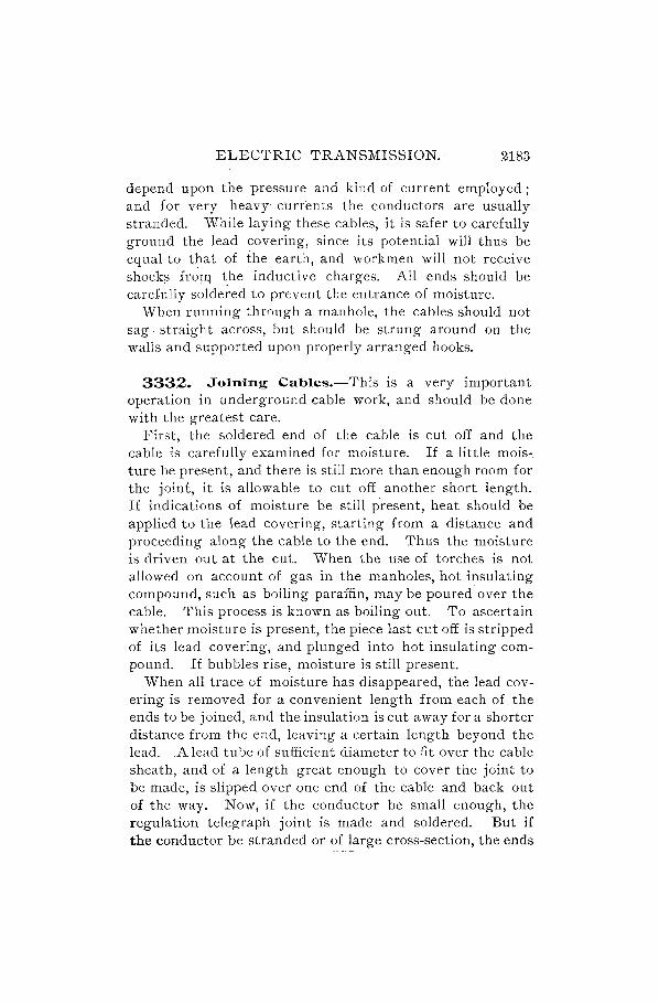
ELECTRIC TRANSMISSION. 2183
depend upon the pressure and kind of current employed; and for very heavyc'Urrents the conductors are usually stranded. "\Vhile laying these cables, it is safer to carefully ground the lead covering, since its potential will thus be equal to that of the earth, and workmen will not receive shock? froTQ the inductive charges. All ends should be carefully soldered to prevent the entrance of moisture.
When running through a manhole, the cables should not sag. straight across, but should be strung around on the walls and supported upon properly arranged hooks.
3332. Joining Cables.-This is a very important operation in underground cable work, and should be done with the greatest care.
First, the soldered end of the cable is cut off and the cable is carefully examined for moisture. If a little mois-. ture be present, and there is still more than enough room for the joint, it is allowable to cut off another short length. If indications of moisture be still present, heat should be applied to the lead covering, starting from a distance and proceeding along the cable to the end. Thus the moisture is driven out at the cut. When the use of torches is not allowed on account of gas in the manholes, hot insulating compound, such as boiling paraffin, may be poured over the cable. This process is known as boiling out. To ascertain whether moisture is present, the piece last cut off is stripped of its lead covering, and plunged into hot insulating compound. If bubbles rise, moisture is still present.
When all trace of moisture has disappeared, the lead covering is removed for a convenient length from each of the ends to be joined, and the insulation is cut away for a shorter distance from the end, leaving a certain length beyond the lead. A lead tube of sufficient diameter to fit over the cable sheath, and of a length great enough to cover the joint to be made, is slipped over one end of the cable and back out of the way. Now, if the conductor be small enough, the regulation telegraph joint is made and soldered. But if the conductor be stranded or of large cross-section, the ends
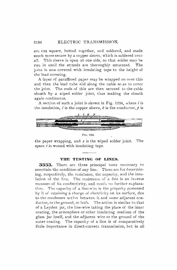
2184 ELECTRIC TRANSMISSION.
are cut square, butted together, and soldered, and made much more secure by a copper sleeve, which is soldered over all. This sleeve is open at one side, so that solder may be run in until the strands are thoroughly saturated. The joint is now covered with insulating tape to the height of the lead covering.
A layer of paraffined paper may be wrapped on over this and then the lead tube slid along the cable so as to cover the joint. The ends of this are then secured to the cable sheath by a wiped solder joint, thus making the sheath again continuous.
A section of such a joint is shown in Fig. 1224, where i is the insulation, I is the copper sleeve, k is the conductor, p is
FIG. 1224.
the paper wrapping, and s is the wiped solder joint. The space t is wound with insulating tape.
THE TESTING OF LINES.
3333. There are three principal tests necessary to ascertain the condition of any line. These are for determining, respectively, the resistance, the capacity, and the insulation of the line. The resistance of a line is an inverse measure of its conductivity, and needs no further explanation. The capacity of a line-wire is the property possessed by it of retaining a charge of electricity on its surface, due to the condenser action between it and some adjacent conductor, or the ground, or both. The action is similar to that of a Leyden jar, the line-wire taking the place of the inner coating, the atmosphere or other insulating medium of the glass jar itself, and the adjacent wire or the ground of the outer coating. The capacity of a line is of comparatively little importance in direct-current transmission, but in all

ELECTRIC TRANSMISSION. 2185
alternating or pulsating current work, and especially 'in telegraphy and telephony, it plays a very important part. The most important of the three tests, however, i'l that for insulation-that is, the determination of the resistance from the condu'ctor, through the insulating medium, to the ground or to other conductors. Evidently, the higher the insulation the smaller will be the loss due to 1eakage-a matter of the utmost importance in nearly every branch of work.
FAULTS.
3334. 'Faults on a line may be of two kinds: The line may be entirely broken or it may be unbroken, but in contact with some other conductor or with the ground. The former fault is termed a break; the latter, a cross or ground.
3335. A break may be of such a nature as to leave the ends of the conductor entirely insulated, or the wire may fall so as to form a cross. A cross may be of such low resistance as to form a short circuit, or it may possess high resistance, thus forming what is termed a leak.
3336. The instruments most used in testing lines are a galvanometer, standard battery, standard condenser, Wheatstone bridge, ammeter, voltmeter, and suitable keys for performing the necessary changes in the circuits. The galvanometer should be of the Thomson or D' Arsonval type, the former being more suitable for very delicate measurements, but the latter is more convenient, because it is not affected by external magnetism.
3337. Many of the tests described in the section on Electrical Measurements, are directly applicable to the determination of the various conditions of a line, but a few others will be described here.
MEASUREMENT OF LINE RESISTANCE.
3338. The resistance of a line may be measured on a '\Vheatstone bridge by connecting the ends of the line circuit in the unknown arm of the bridge. Sometimes it occurs in the case of a grounded circuit that earth-currents will in-

2186 ELECTRIC TRANSMISSION.
terfere to such an extent as to render accuracy impossible. In this case, if another parallel wire is available, the resistance of which is known, they may be connected together at the distant end, and the resistance of the two in series measured. The resistance of the first wire will then be the difference between the total measured resistance and that of the known wire.
MEASUREMENT OF LINE CAPACITY.
3339. The simplest and probably the most satisfactory method for measuring the capacity of a line or cable is to compare the capacity to be measured with that of a standard condenser. It is first necessary to obtain the deflection of the galvanometer needle when the standard condenser is discharged. For this purpose the apparatus is arranged as in Fig. 1225, in which G is a galvanometer, C the standard
G
B
'------lllllt--------<~===-r FIG. 1225.
condenser, B· a battery, and K a discharge-key, resting normaily against contact b, but capable of being depressed against a. When the key is depressed, the current from the battery charges the condenser. This charging should be allowed to continue for about thirty seconds, in order to give the charge a chance to "soak in. " The key should then be suddenly released, which will establish such connections as to allow the condenser to discharge through the galvanometer. The throw or kick of the galvanometer· needle

ELECTRIC TRANSMISSION. 21.87
should be noted, and several readings taken to avoid error and to obtain an average.
The cable or line is then substituted for the condenser, as in Fig. 1226, where the wire leading from the galvanometer
K
FIG. 1226.
and battery is connected to the core of the cable, while the wire leading from the key lever is connected with the sheath or armor. If the line were of bare wire, the wire from the key lever would be grounded. The reading is then taken on the galvanometer, as before. If no shunt is used on the galvanometer, or the same shunt is used in each c~se, the two capacities will vary in proportion to the respective readings of the galvanometer.
Thus, calling D the deflection obtained with the standard condenser, D' that with the cable,' C the standard capacity, and C' the capacity of the cabl~, we have
C/: C::D':D,
or C' = C .~ D' (503.)
The capacity per mile is found by dividing by the length of cable in miles; and the best results are obtained when the capacity of ~he standard condenser is v,ery nearly equal to that of the cable, and the deflections, therefore, nearly the same.

2188 ELECTRIC TRANSMISSION.
EXAMPLE.-A test was made to determine the capacity of a cable. The capacity of the standard condenser was 1 microfarad. The deflection or throw from the standard condenser was 37 divisions, and that from the cable was 42. What was the capacity of the cable?
SOLUTION.-Using formula 503.
C' = 42 3~ 1 = 1.135 microfarads. Ans.
3340. Tests for locating a break in a wire are usually made by capacity tests, as the capacity of the part of a wire bears the same relation to the capacity of the whole wire as the length of the part does to that of the whole.
When one good wire, having the same capacity per mile, is accessible, a condenser need not be used; but instead deflections may be taken on the broken wire and on the good wire. Let D be the throw on the broken wire, and D' the throw on the good wire. L is the distance to the break and L' the total length of the broken wire. Then,
D:D'::L:L',
or L= ~,L" (504.)
EXAMPLE.-A test was made to find a break in a cable conductor near to which ran another sound wire. The throw on the broken conductor was 35 divisions, and that on the good wire ,,'as 80 divisions. What was the distance to the break, the total length of broken cable being 3,100 feet?
SOLUTION.-Using formula 504. 35
L = 80 X 3,100 = 1,356 ft. Ans.
EXAMPLE.-A break occurs in a cable 3 miles long. It is known that the capacity of the entire conductor was .39 microfarad per mile, or 1.17 microfarads in all. Upon testing, it is found that with a standard condenser of t microfarad and a suitable battery and shunt to the galvanometer, the deflection is 98, while with the same shunt and bahery the deflection obtained from one end of the cable is 141. How far from the testing end is the break?
SOLuTION.-Using formula 503. C= h D = 98, D' = 141.
C'. = t ~i41 = .4796 microfarad.
n· f . d .4796 1 23 '1 lstance rom testmg en = -:39 =. ml es. Ans.

ELECTRIC TRANSMISSION. 2189
EXAMPLES FOR PRACTICE.
1. In a test for the capacity of a cable the capacity of the standard condenser was 2 microfarads. -The throw from the condenser was 53 divisions, and that from the cable was 32 divisions. What was the capacity of the cable? Ans. 1.207 microfarads.
2. A test was made to locate a break in a cable conductor. A sound wire was accessible. The throw on the broken wire was 29 divisions, and that on the good wire was 75 divisions. The length of the tested cable was 5,760 feet. What was the distance to the break?
Ans. 2,227 ft.
INSULATION TESTS.
3;341. The insulation resistance may be found, when the farther end of tlte lilte is disconnected from the ground and insulated, by the methods given in Arts. 252.2 and 2524. The insulation reststance per mile zs obtained by multiplyt1lg the reszstalzce of the line by its length in miles.
When th~ insulation resistance is very high, it is difficult to obtain an accurate rheostat of the very high resistance required. In this case, therefore, it is better to use a direct deflection method. A convenient form for connections in a test of high resistance insulation is shown in Fig. 1227.
Atg is a high resistance galvanometer,S'" is the galvanometer shunt, K. is a key which short-c i r cui t s the gal van 0 met e r when depressed, B is the battery, K is a reversing key, which (}" puts either pole of the battery to the line' while the other pole is to earth, N is a resist-ance coil equal to the resistance of
L
FIG. 1227.
the battery, and which

2190 ELECTRIC TRANSMISSION.
may be connected in the circuit, G and G) are earths, and r is an accurate resistance-box of rather high range.
Insert a plug in the apertur~ 1 of K to and in 3 of N. Adjust the shunt.S until a convenient deflection is obtained upon the galvanometer. Then, obtain deflections first with the + pole of the battery to line, and second with the --:- pole to the line. If these deflections do not agree, there is some trouble. with the galvanometer or the connections. It is probably with the position of the galvanometer scale.
After everything is working well, the first step is to find the galvanometer constant, which consists in obtaining the deflection through a known resistance r, using the galvanometer shunt 5, Fig. 1227. On inserting plugs in hole 1 of K, and in 3 and depressing the upper key of K, a current from the positive pole of the battery will flow through the galvanometer g and resistance r. Earth-currents should now be observed, if any exist, by cutting out the shunt 5, removing the plug in hole 3, and changing the plug in the commutator K) from 1 to 2. The sign (+ or -) of the deflection should also be noted and added to or subtrac:ted from the final deflection obtained later on, according as it is against or .. with the battery current. The cable is now to be charged from the battery by depressing the upper key of K, the galvanometer being short-circuited at K2 and the plug inserted in 3; after 30 seconds, K2 is released and the galvanometer readings noted every 15 seconds of the time required, which may be 3,4, or 5 minutes. The mean of the deflections at 45", 60", and 15" gives the true deflection for each minute. Immediately after the last reading taken in this manner, with the battery to the line, the galvanometer is again short-circuited, the battery key K released, and plug 3 removed. Thirty seconds after thus disconnecting the battery, return readings are taken from the cable at 15 seconds' intervals, the galvanometer key being opened. The mean return deflection for the first minute, added to the mean deflection for the last minute's charge, gives the true deflection for the first minute's electrification. The cable is then grounded for a time sufficient to thoroughly

ELECTRIC TRANSMISSION. 2191
discharge it, and the electrification tests are repeated with the negative pole to line, using 'the lower key of K.
3342. This whole process may be simplified by present-ing it in algebraic form. Let
B = resistance of battery in ohms; G = resistance of galvanometer in ohms; s = resistance of galvanometer shunt in ohms; r = high resistance in ohms; R = total resistance in megohms* of galvanometer with
shunt, battery, and high resistance; d, = deflection for gal vanom'eter con"stan t ; d. = deflection for cable, corrected for earth-currents; 1 = insulation resistance of cable in megohms.
According to the rule relative to derived circuits, the joint resistance in ohms of galvanometer and shunt =
GG s ,and the multiplying power of the shunt will be G + s . +s s
Then, R = (r + G c; s + B) -+- 10· = resistance in megohms of
circuit when obtaining deflection d,. The deflection without
a shunt through this resistance will be d, G + s, which mul-s
tiplied by R gives the galvanometer constant = R d, G + s. s
The insulation resistance of the cable in megohms is, then,
Rd G+s 1- constant _ 's (505.)
- d. - d.
Rule.-To find the insulation resistance of a cable by the direct deflection metfwd, obtain first the galvanometer constant as described. Thz's number divided by the deflection obtained from the cable will give the insulation resistance in megohms.
EXAMPLE.-It is required to find the insulation resistance of a cable, and the following apparatus is provided: A battery having a resistance
* A megohm is one million ohms.

2192 ELECTRIC TRANSMISSION.
of 450 ohms; a galvanometer of 8,100 ohms; a galvanometer sh~nt of 900 ohms; a ·high-resistance box of 1,000,000 ohms. The deflection through the resistance R is 240 divisions, and the deflection from the cable, corrected for earth-currents, is 193 divisions.
SOLUTION.-
Resistance of battery B = 450 ohms. Resistance of galvanometer
and shunt Gs G+s= 810 ohms.
Resistance of box r = 1,000,000 .ohms.
1,001,260 ohms = 1.0013 megohms.
The mUltiplying power of the shunt is G 7 s = 8,10~0~ 900 = 10.
G +s Then, the galvanometer constant R d, -s- = 1.0013 X 240 X 10 = 2,403. The deflection d. from the cable is 193 divisions, and the insulation resistance will be, by formula 505,
2,403 I = 193 = 12.45 megohms. Ans.
When r is very large, compared with the resistances of galvanometer and battery, and only approximate results are desired, sufficient accuracy is obtained by making R= rin calculating the insulation resistance.
3343. A simple and convenient method of measuring the insulation resistance of a line while in operation is illustrated in Fig. 1228, where D is a dynamo supplying current
FIG. 1228.
to the mains I and I'. V is a Weston voltmeter, having an internal resistance r, and G is the ground.
Tbe difference of potential across the mains is obtained in the ordinary manner, by bridging the voltmeter across the two leads. Suppose the potential thus measured is 7'. The

ELECTRIC TRANSMISSION. 2193
voltmeter is then connected between the line-wire I and ground, as shown, and the reading taken, which we will call v'.
Then the resistance K between the wire I and ground will be
R- (v-vl: - v' . (506.)
This is true, because the voltmeter when connected as in Fig. 1228 may be said to be connected across the mains through the resistance R + r. The deflections in the two cases will evidently be inversely proportional to the" resistances through which they are taken; hence,
v: r+R:: v': r,
v r = v' r + v'R,
Rv'=(v-v')r,
R = (v - :") r. v
TESTS FOR GROUNDS OR CROSSES.
3344. These faults occur much more frequently than breaks, and are often extremely difficult to locate.
Rule.-To locate a cross or ground, the resistance of tlte wire between,it and tlte station is first f(lund, and tlten tltis resistance is divided by the resistance of the wire per unit length, so that the distance from the station to the fault may be obtained.
Tests of this kind are often made by means of a differential galvanometer. A differential galvanometer is one in which, surrounding the needle at equal distances, are two coils of wire of equal resistances and wound in opposite directions. When two equal currents run in opposite directions around these coils, the pointer of such an instrument will remain upon zero. "
Connections for this test are shown in Fig. 1229, in which g is the galvanometer, R is a, rheostat, B is a battery,

2194 ELECTRIC TRANSMISSION.
G, G" and G. are earths, F is the fault, z is the resistance of the fault, % is the resistance from g to p~ and y is the resistance from F to the erid of the line M.
The line L at the distant station is disconnected from the ground and the end insulated at M.
The pointer of galvap.ometer g-of course taking the nec"essary precautions for earth-currents-is balanced upon zero. We then know that the resistance in the line is equal to that in the box R, because both are subject to the same E. M. F.; and since the deflection is zero the currents must be equal
--:.c --l'-L
Br J
FIG. 1229.
in each branch. The unplugged resistance of R, which we will call r, is equal to the resistance % that we seek, provided there is no resistance in the fault at F: The circuit measured will be B-2-F-G.-G and back to B.
However, if there be a resistance z between F and G., r = % + z. The test is now repeated from the other station and r' = y + z, where r' is the unplugged resistance from the other station.
L = % + y, where L is the known resistance of the line. Obtaining the values of the three unknown quantities from these three equations, we have

ELECTRIC TRANSMISSION. 2195
r+ r' - L z = ?, • (50'1.)
1" - r' +L %= 2 . (508.)
r'- r+ L Y= 2 . (509.)
EXAMPLE.-A test was made for a fault by means of a differential galvanometer. The unplugged resistance at the first station was 600 ohms, that at the second station was 630 ohms, and the resistance of the line was 1,150 ohms. What was the resistance to the fault from the first station? from the second station? What was the resistance of the fault ?
SOLUTION.- r = 600, r' = 630, L = 1,150,
600 + 630 - 1,150 z= 2 40. Ans.
_ 600 - 630 + 1,150 _ 560 An z_ 2 -. s.
_ 630 - 600 + 1,150 _ 590 A y- 2 -.-
EXAMPLES FOR PRACTICE.
1. A test for a fault was made upon an aerial line of 1,112 ohms resistance. The resistance of the line was 12.92 ohms per mile. The unplugged resistance in the rheostat at the first station was 630 ohms, and that at the second station .was 542 ohms. What was the resistance of the fault? How far was it from the first station, and how far from the second?
Ans.-The resistance of the fault was 30 ohms. The distance from the first station to the fault was 46 miles 774 yards. The distance from the second station was 39 miles 1,103 yards.
2. A wire touched the ground so that there was no resistance z in the fault. A test was mad,e at the station, and the unplugged resistance in the rheostat amounted to 326 ohms. What was the distance to the fault, the resistance of the wire being 16.1 ohms per mile?
. Ans. 20 miles 432 yards.
3345. Abetter way of testing for a ground or cross on a line is by Varley's loop test, circuits for which are shown in Fig. 1230, in which G is a reflecting galvanometer connected across th~ arms of a Wheatstone bridge in the ordinary

2196 ELECTRIC TRANSMISSION.
manner; a and b are the ratio arms of the bridge, and k is the variable arm. D E is the faulty line and F the location of the fault. B E is a good line, the resistance of waich is known. The two lines are connected together at E, and the ends of the loop so formed are connected across the term i- .
y
FIG. 1230.
nals of the bridge so as to form the unknown resistance. The battery is connected between A and the ground. Call y the resistance of the loop from B to F, % that from D to F, and R the total resistance of the loop = % + y.
Then when the bridge is balanced,
a y R-% lJ= k+% = k+%'
Hence,
a k + a % = b R - b %,
a % + b % = b R - a k.
bR-ak %= a+b . (510.)
It will be noticed that this is entirely independent of the resistance of the fault, or of any earth-currents which may exist. Having found % and knowing the resistance of the wire per foot the distance to the fault is readily calculated.
EXAMPLE.-A ground occurs on one conductor of a cable 10,000 teet long composed of three No. 10 insulated copper conductora. On

ELECTRIC TRANSMISSION. 2191
testing, the bridge was balanced with the following resistances: a = 10 ohms, b = 1,000 ohms, and k = 1,642 ohms. One good wire was used to complete the loop. Where is the ground, the resistance per 1,000 feet of the conductors being 1.002 ohms at the temperature of the test?
SOLUTlON.- R = 20 X 1.002 = 20.04 ohms.
_ 1,000 X 20.04 -10 X 1,64~ _ 3584 h x- 1,000+10 -. 0 ms.
. f . . 3.584 '"' f' DIstance rom testmg statIOn = 1.002 X 1,000 = 3,5,6 eet. Ans.

RAILWAYS.
MOTOR-CARS AND FITTINGS. 3346. The application of the electric motor to street
railway w'ork has pr-ovided a means of car propulsion which, from its peculiar ad~ptability to the conditions met with, is likely to supersede all other systems. The vari-ous methods of applying electricity to street-ear traction are the following: Those using storage-batteries on the cars; those employing electromagnetic switching devices in conne~tion with subsurface c'onductors, this being also called the closed-conduit system; those having an open conduit and a trolley connection beneath the car; those using an insulated third rail; and those with an overhead conductor and trolley connec;tion.
ELECTRIC TRACTION SYSTEMS.
STORAGE-BATTERY RAILWAYS.
3347. A storage-battery systeIll presents many advan'tages from a theoretical point of view, which can not, unfortunately" be entirely realized in practice. The first cost of the installation need not be' very great, and more battery sets could be added as the extension of the road or its traffic demanded. The station equipment could also be of minimum capacity, as it might be operated at full load continuously, and would then work at its highest efficiency, If sufficient provision be made fOJ; future enlargement; the addition of more pOwer units at a later date would involve comparatively small expense. Another fl.:dvantage poss.essed by this system is that no work on the rO,adbed is called for when it is desired to ~hange from the use o~ horses, provided
2200 ELECTRIC RAIL WAYS.
that the track is well laid in the first instance. There are also no overhead wires to keep in repair or present obstruction or danger, and, furthermore, every car is self-contained and independent of all others. Several disadvantages may be enumerated against this method which more than counteract these decidedly favorable points. The batteries, being composed of lead plates, are very heavy and require a large proportion of the available energy for their transportation. The weight necessary is about 100 pounds per horsepower per hour with ordinary speeds and grades; but provision must be made for cases of emergency and, usually, for some heavy grades, so that it has been found necessary in practice to provide for each car a battery weighing 3,000 or 4,000 pounds. This dead weight is a serious objection; but worse yet is the fact that deterioration is extremely rapid, the cells having a life of only one year or less. Sudden discharging has a detrimental effect, and, in consequence, smaller motors must be used than would be installed on an ordinary car having an external source of power. It follows, as a matter of course, that high speeds with storage-battery cars, or rapid acceleration at starting, are not commercially practicable, and their use is more or less restricted to those localities where such requirements are not made.
3348. A street-car operated by storage-batterie,s is very simiTar in outward appearance to an ordinary car. The motors are placed beneath the car floor, and the battery under the seats. A convenient method of accomplishing the removal of the batteries, when substituting charged cells for those run down, is to have a long, swinging panel on the side of the car, which will afford ready access to the cells, or they may be placed on a long board and passed in through a hinged panel at the end. A better construction is to provide space for the batteries on the truck, where they may conveniently be supported without interfering with the motors. This method of carrying the batteries relieves the car frame of the extra strain, so that it may be built lighter than when it has to accommodate such a heavy weight. It is usually nec-

ELECTRIC RAILWAYS. 2201
essary to provide two or three sets of accumulators for each car, in order that there may always be one set in readiness for use, and to make allowance for any cells which may be laid aside for repair or renewal. The E. M. F. of an accumulator cell may be taken as about 1.9 volts, from which may be calculated the number of cells required to operate a given motor. Those for a street-car may be about 108 in number, giving an E. M. F. of about 205 volts. Speed regulation is effected by changing the battery connections, this being accomplished automatically by means of a special switch or controller on the car platform.
ELECTROMAGNETIC SYSTEMS.
3349. The electroIllagnetic traction systell1 is oile which provides an insulated conductor for the supply of current, and in which a series of automatic switches operated by the moving car make contact between successive sections of an insulated rail and the conductor. By this means only a short length of exposed conductor is at any time active, and liability to accidents is thereby much decreased, the insulation of the line being also considerably improved. A diagram of this system is given in Fig. 1231,
t r r r
m s s
t~
+ 0
G FIG. 1231.
where G is the generator at the station, t t, the track, m the main conductor connected through the switches s, s, etc., with the insulated sections r, r, r, etc., of the third or middle rail. As the car passes over each section, it is connected to the positive terminal of the generator, and the current flows through the motors to the rails and so back to the station. The switch is enclosed in a rectangular box
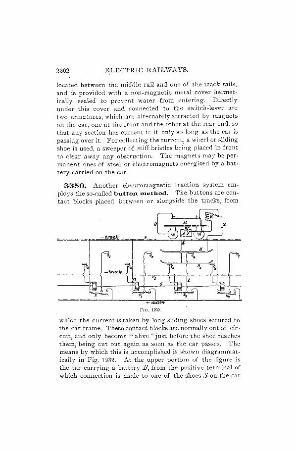
2202 ELECTRIC RAILWAYS.
located between the "middle rail and one of the track rails, and is provided with a non-magnetic metal cover hermetically sealed to prevent water from entering. Directly under this cover and connected to the switch-lever are two armatures, which are alternately attracted by magnets on the car, one at the front and the other at the rear end, so that any section has current in it only so long as the car is passing over it. For collecting the current, a wheel or sliding shoe is used, a sweeper of stiff bristles being placed in front to clear away any obstruction. The magnets may be permanent ones of steel or dectromagnets energized by a battery carried on the car.
3350. Another electromagnetic traction system employs the so-called button JTIethod. The buttons are contact blocks placed between or alongside the tracks, from
FIG. 1232.
which the current is taken by long sliding shoes secured to the car frame. These contact blocks are normally out of circuit, and only become" alive" just before the shoe reaches them, being cut out again as soon as the car passes. The means by which this is accomplished is shown diagrammatically in Fig. 1232. At the upper portion of the figure is the car carrying a battery B, from the positive terminal of which connection is made to one of the shoes 5 on the car

ELECTRIC RAILWAYS. 2203
frame, and from the negative terminal, to the wheels and track. The rails are marked rand r,; but for the sake of clearness the wheels are shown as running on one rail only. On starting up the car, sin<;:e all the switches, z, z" etc., ai"e open, an initial current must come from the battery E, which will at once close the switches nearest to the car by means of the electromagnets in circuit. This current may pass through the motor 111", as shown in the figure, in which case it may be used to propel the car over considerable distances should the line current fail or some of the contact switches refuse to work. On a down-grade track the contact blocks· may be entirely omitte~, as no power is required except for starting, and this the battery is able to supply. In this case an auxiliary switch is used to connect wires 3 and 4, and the circuit from the battery is simply through the motor and the rheostat R. Under the usual working conditions, current is tal{en from the main conductor, shown at the bottom of the figure, and the switches z, , Z2 being already closed, the contact blocks c, , c. will be connected to the main; There are, it lvill be seen, aiways two, and for a short space of time three, switches closed. In the position of' the car shown in the figure, the current passes through the switch Z2 and wire 1 to the contact block c,; thence through the shoe 5 and wire 2 to the rheostat R. The E. M. F. of the current from the mains is slightly higher than the battery E. M. F., so that the current divides at R, some being used to charge the battery, passing through it to the ground, but the greater amount going through the rheostat and motor to the second shoe 5,. From here it will go round the upper winding of the magnet of switch z., through wire 5 to the lower winding of Z " and from there by wire 6 to the ground or rails. If the car is moving towards the left, it will be seen that the contact c. is alive before the shoe reaches it, so that there is no interruption to the supply of power; also, on leaving any contact block, as c" there is no sparking, because there is already another path for the current through c,. When the car is moving in the other direction, to the right, the contact block c, is connected to

2204 ELECTRIC RAILWAYS.
the main as soon as tbe shoe S, touches C2 , so that the car will travel in either direction with equal facility. The contact blocks are placed in two rows at distances of eight feet, and the car body will therefore project over all those which are charged with current and prevent possible injury to persons or horses stepping upon them.
3351. One of the chief advantages of such a system as this is the high insulation which may be obtained, owing. to the fact that the whole of the active conductor is clisconnected from service except at those points where a car is passing. The switch magnets z, $" etc., are placed in pairs in water-tight boxes alongside one of the rails on the outside of the track. The cover is in the form of a diving-bell, so that no water can possibly reach the magnets, which are raised above the bottom of the box. The leakage from the contact blocks, which are held on insulated supports, amounts to little, even under the worst conditions of immersion in melting snow.
THE CONDUIT SYSTEM.
3352. The open-conduit system is coming into extensive use, notwithstanding the fact that the expense of construction is vc;ry high as compared with other systems. Two bare conductors are used, which are held on insulating supports in the upper part of a channel, or conduit, built in the roadway between the car rails. The general method of construction is show~ in Fig. 1233, the conductors a, a of circular cross-section being held at frequent intervals by the insulated clamps b. Two trolley-wheels supported on a frame c, attached to the car frame, make contact with the conductors, being themselves connected with the· wires leading to the motors, but insulated from each other, as the full working E. M. F. of 500 volts is maintained between the conductors. There are many ways of securing the wheels, but the principle of ·spring pressure is generally used. The conduit is about twenty inches deep by fourteen

ELECTRIC RAILWAYS. 2205
inches wide, and the width of the slot is five-eighths or tlfree-fourths of an inch. The yokes yare spaced about four feet apart, and usually extend under the rails on each
c
FIG. 1233.
side, as this tends to prevent slot closure or narrowing of the space in which the trolley frame moves. Since the conductors are intended to preserve a straight line and are of heavy section (i- in. or ~~ in. diameter), it is customary to provide expansion-joints about every 500 feet; these may
FIG. 1234.
consist simply of a loop, a break in surface continuity being avoided by a bridge riveted to one side. To afford protection to the conductors from water or pieces of metal falling

2206 ELECTRIC RAILWAYS.
into the conduit, the slot rails d, d have -projecting lips; the conduit is also provided with sewer connections for drainage.
[2J
o
-® ®
, ,
® ®: I-;~
I: :
m ~i~: rel :1 :: [§l
m 111t
FIG. 1235.
[2J
o
-® @
:: !i'il ~ it rEI
1: !i'il
3353. A successful conduit road has been established at Washington, D. C., in which the details of construction are somewhat different from the above, although the principles ihvolved are similar. The conductor a, Fig. 1234, is

ELECTRIC RAILWAYS. 2207
in section a T bar, supported by the projecting flange behind, which is bolted to an adjustable clip b, held on an insulating pin c. The shell d, into which the pin is cemented, is dropped into place from above and covered with the plate c. On the right-hand side of the figure is shown a section through a manhole. The framework carrying the moving contact pieces is shown in Fig. 1235. The insulated leads from the controller are brought down at I, I, and each of them secured to one of the shoes s, s,. These are pressed outwards against the conductor rails by leaf springs a, a. The contact shoes are renewable, being held in place by means of the bolts b, b.
3354. It is very necessary that the yokes should be well designed and strong, to resist the pressure of the earth (w hich is packed down by heavy traffic) and the tremendous pressure in cold climates, due to the freezing of the soil, with its accompanying expansion. 'Wrought iron, steel, and cast iron have been employed for this purpose, the last named perhaps being used the most. When yokes of light weight are put in, trouble is often occasioned by breakage. The conduit may be lined with steel plates, or it may be constructed of concrete alone on the sides; in some cases, the metal yokes have been replaced by concrete, but the best practice is to employ heavy castings, ranging in weight from 200 to 400 pounds or more, according to the depth of conduit and the amount of wagon traffic expected.
THE THIRD-RAIL SYSTEM.
3355. This system has a most promising future before it, and seems to bid fair to become the only method which will be used to supply electric power to locomotives for interurban or long-distance roads. In high-speed work it is advisable, if not absolutely necessary, to employ as an active conductor one which will not sag, but will present a smooth, straight surface, upon which the collectors on the car may slide. This conductor is usually in thE; form of an

2208 ELECTRIC RAILWAYS.
additional rail laid between or alongside the service rails upon which the car-wheels run. Some difficulty has been experienced or anticipated in regard to insulation, but it is found that there is no trouble on this score when the E. M. F. does not exceed about 500 volts, which is the usual working pressure on all electric-railways.
On the Nantasket Beach and East Weymouth Road, the third rail r, Fig. 1236, is made in 30-foot lengths. and
FIG. 1236_
weighs 93 pounds to the yard. In cross-section it is in the form of a flattened A, the downward-projecting flanges giving the requisite stiffness between supports. There are three of these supports to each rail, one at the middle and one close to each end; they are simply short, wooden posts a let into the cross-ties and creosoted to prevent absorption of moisture. Creosoting consists in expelling all air from the wood in vacuum chambers and filling the pores with a tar compound; the insulation obtained is very high. Electrical continuity through the rail circuit is assured by means of copper bond wires, which are riveted to the ends of abutting rails to supplement the otherwise poor contact

ELECTRIC RAILWAYS. 2209
which would be afforded by the fish-plates. Under the head of Track Construction this subjeot wiil be fully considered. There are two contact shoes and frames to each motor-car, placed 33 feet apart, so that at road crossings the third rail may be omitted and the inertia of the moving car be depended upon to carry it oyeL When the width of road is less than 33 feet, there will be no break 'at all. The shoes s are suspended by links I, I, allowing some vertical motion, so that there is always maintained a proper contact with the rail, and current is supplied by means of a flexible cable attached to the terminal t. The car is propelled by means of two motors, each of 125 horsepower, which will permit a speed of over 70 miles an hOUL
3356. The advantages of the third-rail system are that the construction of the active conductor can be of a more solid and permanent character than is the case with a suspended wire, and it is at all times easy of access for inspection or repaiL On long-distance roads the tracks would be fenced in to prevent accidents, so that danger to persons, due to contact with the live rail, would be minimized.
THE OVERHEAD TROLLEY SYSTEM.
3357. From its applicability to ordinary street traffic, the overhead trolley system has met with more general adoption than any other method of electric traction, due principally to the characteristic features of smaller first cost and ease of insulating the working conductors. Objection is made by some people to the use of overhead wires, on the ground that they interfere with the operations of the fire brigade when called out on service; but the feeder wires may be strung so as to be out of the way or even laid underground, and the live wires are near the middle of the street. By means of switches along the line, any section may be temporarily cut out of circuit, thus eliminating all danger of shock. The question of appearance is sometimes brought up as an' argument against the use of the overhead conductors, but with the employment of center poles or single

2210 ELECTRIC RAILWAYS.
side poles with brackets, this objection will hardly hold. In crowded city streets with a large passenger traffic, the conduit system may be substituted with advantage, but in outlying districts a more reliable service may generally b~ obtained with the overhead construction.
3358. The standard overhead trolley system employs for an active conductor a single copper wire m n, Fig. 1237, not smaller than No. 0 Brown & Sharpe gauge, and very frequently No. 00 or 000, or 0000. The current passes from
FIG. 1237.
the positive pole of the dynamo d in the power station, along the wire to the point t, where the trolley-wheel makes contact. From here it flows through the pole p on the roof of the car C, or through insulated wires within it, thence to the controlling mechanism on the car platform, by means of which the speed of travel may be regulated within the limits of the motors. Interposed in the circuit through the car are lightning-arresters, fusible cut-outs, and switches. The motors r are placed beneath the car floor, and the current passes from them through the car axles and wheels to the rails z y, which are connected to the minus terminal of the generator and also to ground. The car is shown more in detail in Fig. 1238 .. The controllers c, c, are placed in upright iron cases on the platforms, one at each end, and are operated by the bandIes on the top; th6 shorter handles n, n, are reversing-levers for changing the direction of travel of the car. Under the car are the motors ?n, m, in dust-proof cases; on the armature shafts are pinions a, a, which engage with the gear-wheels b, b, fixed. rigidly to the wheel axles. In a convenient position is the starting rheostat r, contain-

ELECTRIC RAILWAYS. 2211
ing resistance which is put in series with the armature when starting the motors, or in some cases used partly for this purpose and partly as a shunt across the field windings for regulation of speed. Beneath the seats in the car are the heaters It on an independent circuit. For interior illumination there are usually five lamps I, which are connected in
c
FIG. 1238,
series between the trolley t and the wheel axles (or ground), thus utilizing the full working potential of 500 or 550 volts. One lamp is placed at each end (1" 12 ) to illuminate a colored signal glass on the outside.
ROLLING-STOCK.
3359. The rolling-stock of an electric road may be arranged under two heads: IDotor-cars and trailers. We shall consider the former only, since the trailer is merely a somewhat lighter car, provided with a draw-bar for attachment to a motor-car, and is designed only as an

2212 ELECTRIC RAILWAYS.
auxiliary when traffic is unusually heavy. The frame of the motor-car must be specially strong and well built, as the time occupied in starting and stopping is much shorter than is the case with cars operated on other systems. The flooring should also be arranged for convenient removal of sections immediately over the motors, to allow of inspection and attention while the car is in motion, or at any time when it is not practicable to obtain access from beneath. When an overhead trolley is used, the roof should be strong enough to support the trolley stand, as well as the weight of workmen who may occasionally be required to repair it.
3360. Cars are constructed according to many different designs, depending upon the particular uses to which they are put. For small lines, a closed four-wheel car sixteen feet in length, similar to that shown in Fig. 1238, is most used, since it may be run all the year round. Some roads have the trucks so arranged that the body of the car may be removed and an open summer-car body substituted, thus making use of the- same motors. Long cars, measuring 26 feet or more along the body, are generally provided with double four-wheeled trucks, the distance between the axles of each truck being equal to about the gauge of track, or a trifle less. In countries where the winter is severe, it is customary to provide a closed platform at each end, the door being on the side; this is called a vestibule car. As a protection to the motorman in very cold weather, this style of car is to be recommended, but it is best to have the vestibule shut off from the interior of the car, and well ventilated, to prevent the condensation of moisture on the glass, which would obstruct the view. Another form of car is built with the vestibule in the side, but this is used only with long cars on double trucks. The vestibule construction is, in general, adopted only for cars stopping at rather long intervals. Double··deck cars, providing accommodation for passengers on the roof, are used in some localities. Some of the handsomest of this class have side vestibules and stairs and a covered upper deck, at one end of which is an

ELECTRIC RAILWAYS. 2213
enclosed compartment for the motorman, similar to the pilot-house on a river steamboat.
3361. The rollingstock equipment is not complete, in nor the r n countries, without a snowsweeper. In Fig. 1239 is shown one of these, the propelling motors being omitted for the sake of clearness. A long fourwheeled car truck a is provided at the ends with hinged brackets b, pivoted to the frame at c, and carrying at their lower ends heavy cylindrical brooms d, d, set at an angle of about 45° to the track. Each broom is independently adjustable by means of a handle h, and can be locked in any position. The brooms llre revolved independently of the motion of the car by a motor m in the car body, which transmits the power to them by means of a chain running on the sprocketwheels s, s. It will be seen that the brooms are so placed that they follow separate paths, clearing away the snow for a short

2214 ELECTRIC RAILWAYS.
distance on each side of the rails, and throwing it far enough to clear the car.
TRUCKS.
3362. The truck is an exceedingly important part of the road- equipment, for upon its excellence of design and building depends not only the comfort of the passengers but the question of cost of maintenance. The trucks must be entirely self-contained, that is, the one framework mtist support the wheels and axles, the wheel-guards, brakes, motors, and driving-gear. This, in reality, constitutes the car, combining all the essential parts; for the car body above is merely a framework arranged for the convenience of passengers, having none of the more vital parts necessary to operation, except the current-collecting apparatus in the case of the overhead trolley system, and even this is dispensed with in the conduit, or third-rail, system, now rapidly developing. We must not, however, overlook the fact that in all methods of electric traction the car body has a most severe duty imposed upon it, due to rapid acceleration at starting and an equally heavy strain when the brakes are suddenly applied in stopping; so that this portion of the car requires very good design and conscientious work, as any serious fault in construction will soon become apparent after the car is put into commission. The ordinary street-car truck is provided with four wheels, each pair being driven by an independent motor; this arrangement gives the highest traction efficiency, as all the wheels are drivers and take the whole weight of the car.
3363. It will be readily understood that the principle of spring suspension must be applied to the heavy motors required to propel the car, as without this provision the hammer blow on the track, when passing over inequalities or bad joints, would very quickly break it up. There is always the weight due to the wheels and axles, but this can not be avoided, and it is not a very serious matter if the weight of the motor is not added. The method of suspen-

ELECTRIC RAILWAYS. 2215
sion is shown in Fig. 1240; the motor M is held by the lugs /, I, which rest on springs s, s, these being in turn supported, one by a stringer.f on the car frame, and the other by the yoke y resting on the wheel axle. Rebounding is prevented by the upper springs s" s" bolts d, d passing through to the frame and yoke. The yoke is pivoted at one end on the wheel axle at a,' and at the other el}d passes over the armature'shaft carrying the pinion b. By this arrangement the
FIG. 1240.
distance between the pinion and the gear-wheel c is maintained constant, the motion of the motor relative to the axle being in a circular path.
3364. A complete four-wheel truck, showing the different parts in position, is illustrated in Fig. 1241, where the motors M, il1", are supported by the bolts b, b, btl b. with interposed rubber cushions to give flexibility. The gears g, g, are covered by cases c, c, to exclude dust, which is very destructive to the teeth, causing them to grind each other away at the points of contact. Since it is advisable to support the motor on springs, it is of course equally necessary to provide flexible suspension for the truck frame and car body. For short cars the springs s, s, s, s may be sufficient,
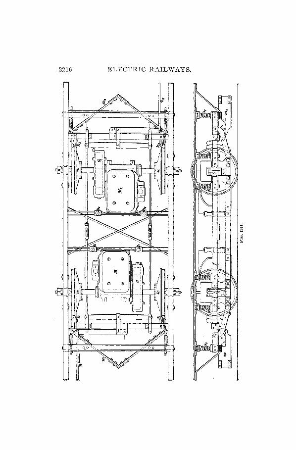
2216 ELECTRIC RAILWAYS.

ELECTRIC RAILWAYS. 2217
placed close in to the wheels, although such a construction would have little merit. The reason for providing a longer spring base is to prevent oscillation, which is unpleasant for passebgers and exerts a very destructive effect on the car body. The oscillation also takes the weight off one pair of wheels momentarily, and causes 'them to slip, thereb'y diminishing their tractive power. For this reason the spring base is extended by adding extra springs at s" s,. The wheels ware generally 33 inches in diameter, although some are made smaller; the bearings 'are outside the wheels, to give stability to the car body, the journ<J.l-boxes j being free to move vertically through a short distance. This arrangement is shown more c1e:l.rly.in Fig. 1242. In the car frame
~J ,
FIG. 1242.
f above the journal-box is a recess, into which fits a plug p, pressing up against a rubber cushion r. The plug, rounded on the bottom, rests in a hollow on the upper surface of the journal-box, which has also a recess underneath to receive a loose-fitting plug q. This is held in place by two bolts passing through the frame, rendering repair or replacement of the wheels and axles a very simple matter. The bearing a extends half-way round the shaft, as the pressure is in one direction only.
Referring again to Fig. 1241, the brakes are operated by the rods h, h" the illustration showing clearly how the various levers act when tension is applied; 'the direction of the resulting forces, when h is drawn up by the brake chain, is

2218 ELECTRIC RALL WAYS.
indicated by arrows, showing that all the brake-shoes k, k, k" k, are pressed on the wheels, whichever rod (It or lz,) is used. To guard the wheels against obstructions, the pilots In, In, are bolted s~curely to the frame at a sufficient height from the track to avoid touching the rails. . .
3365. The W"heel-base, that is, the distance between wheel-centers as measured along the rail, should not exceed seven feet in a rigid truck--more frequently it is only six feet six inches-since the power required to force the car around a curve increases greatly as the length of the wheelbase increases, and the wear on track and wheels becomes excessIve. The following curve diagram, Fig. 1243, shows
100
4, 674ft. 6ft. 7ft. base. " -\' --- --~
,\
\ , \ , ~
, , "
"-,,~,
i' , "'- a
r--.... --, ,::.---.. -......... - --::: -. -- .::- f-,., ------ F= -- -:.:: ::._-- - -
10 ~O 30 40 50 60 70 SO 90 100 110 12() 130 ;HQ'ritl:ontal ~ffo.rt,lbs. per ton.
FIG. 1243.
the force required in pounds per ton to drag cars having wheel-bases of 4 feet, 6 feet, and 7 feet around curves of different radii. The force required in the case of each car is shown by the corresponding curve. The diagram is used as the following example shows: Suppose we have a track curve of 50 feet radius, and wish to know what tractive effort will be required to propel a car around it, the car weighing 8 tons and having a wheel-base of 7 feet. To determine this, find the radius in the left-hand column; go along the horizontal'line towards the right until the curve marked 7 ft. is reached and from that point straight downwards, and read the answer 'n the lower line of numbers. In this case, the

ELECTRIC RAILWAYS. 2219
, ... ------------- -------... ",
'-,-------- ------,~ I \
J \ I \
I \ :1_-: ___ - -------------J1 I I I I I I I I : I
I I I I I :. I I I I I I I
, I I I
I I I I I I
I I
! -~~~
~~IT.rcL-----I L--,-.rr.tLt:l> I I I I : I
! I I ____ -1
'~:::::~~=:7'-- ---~-i ! I I I
I I
I
I I I I I
_____________ -,._1 I I I I I I I I
I I \ I r------------- -------,
• 1
""' ...... ~-------- ----~
line from 50 on the left followed along brings us to the point a, and on carrying ali n e down from that point, the value at the bot tom is found· to read 63. The re for e, the force or tractive effort required will be 63 pounds per ton, and since the car weighs 8 tons, the total f.orce will be 8 X 63 = 504 pounds.
~ It will be seen ci that the curves will ~ all meet at the 20
mark on the horizontal effort line, if carried far enough u p war d s, which shows that for this particular t r a c k there is required for the straight portion or tangent a force or tractive effort of about 2 0 P 0 u n d s per ton weight of car. On curves of large radius the lines on the diagram approach each other,

2220 ELECTRIC RAIL WAYS.
the length of wheel-base maL{ing very little difference; but as the radius decreases, the increased resistance, due to a long 'wheel-base, becomes more marked. With a forty-foot radius, there is a difference in tractive effort of twenty pounds between a four-foot and a seven-foot wheel-base, and a difference of nearly thirty pourtds on a thirty-foot radius. It is evident that in laying out a road, such small curves should be avoided where possible, or, if they are unavoidable and frequent, the trucks should be modeled to suit. For curves down to a forty-foot radius, a six-foot wheel-base will not require an excessive amount of power to be expended; but any arrangement calculated to diminish this loss by friction is a good investment. To accomplish this object, car trucks are built by one manufacturing concern which have three distinct sections, each supported on two wheels. This is known as the Robinson Radial Truck, Fig. 1244. The three sections are pivoted at a and b to each other, and the outer ones to the car body at c and d. These latter are provided with rollers r at the corners, bearing upon plates on the under surface of the car frame, so'that the trucks may easily, and with a minimum amount of friction, adjust themselves to any required position. The center truck is free to move transversely with respect to the car, guided by side rollers s pressing against cross-beams c. The wheel-base is made 14 feet, yet the car will run around a sharp curve, even of 25 feet radius, with apparently the same ease as on the straight track.' An ordinary rigid truck would be quite likely to leave the rails in such a case. This long wheel-base entirely prevents oscillation of the car, and gives longer life to the wheels. The :notors are carried on the end trucks, which take very nearly the whole weight of the car, as the center truck is of light construction with small wheels, and is only designed to direct the others and hold them at a tangent to the curve.
3366. Double trucks are used on long, heavy cars designed for interurban traffic, and even in large streetrailway systems· when there is sufficient traffic to warrant

ELECTRIC RAILWAYS. 2221
the expense. One of these trucks is illustrated in Fig. 1245. The motor is geared to the large wheels VV, on which is placed as much as possible of the weight supported by this truck (there being two for each car) to increase the adhesive power, while the small wheels w serve to guide the truck. ----r------
I i
FIG. 1245.
Double trucks having all the wheels of the same diameter are also made, but in all cases the main point is to put the weight of the motor on that pair of wheels which drives the car. Sometimes two motors are placed on each truck, by which method full adhesive power is obtained, but it is generally more convenient to have one motor, of ample capacity, on each truck.
3~~67 0 The springs used on car trucks are often made );raduatcd, that is, stiffer at one part than at another, so that the lighter portion may move under a light load and the stronger part sllstain a heavy load. There are two methods in use for accomplishing this result, one employing two rubber cones r, r, Fig. l~MG, inside a helical steel spring FIG. 1246.
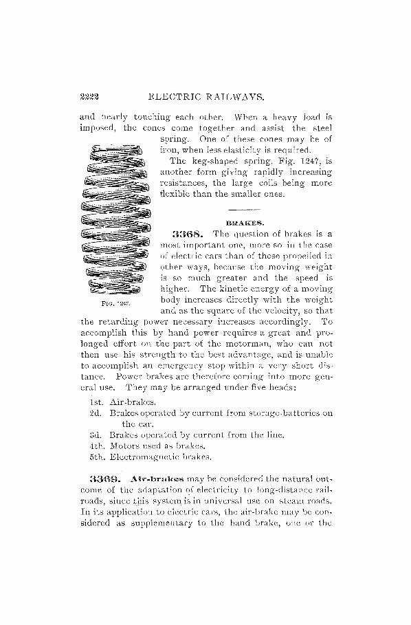
2222 ELECTRIC RAILWAYS.
and nearly touching each other. -When a heavy load is imposed, the cones come together and assist the steel
FIG. 1247.
spring. One of these cones may be of iron, when less elasticity is required.
The keg-shaped spring, Fig. 1247, is another form giving rapidly increasing resistances, the large coils being more flexible than the smaller ones.
BRAKES.
3368. The question of brakes is a most important one, more so in the case of electric cars than of those propelled in other ways, because the moving weight is so much greater and the speed is higher. The kinetic energy of a moving body increases directly with the weight and as the square of the velocity, so that
the retarding power necessary increases accordingly. To accomplish this by hand power requires a great and prolonged effort on the part of the motorman, who can not then use his strength to the best advantage, and is unable to accomplish an emergency stop within a very short distance. Power brakes are therefore coming into more general use. They may be arranged under five heads:
1st. Air-brakes. 2d. Brakes operated by current from storage-batteries on
the car. 3d. Brakes operated by current from the line. 4th. Motors used as brakes. 5th. Electromagnetic brakes.
3369. Air-brakes may be considered the natural outcome of the adaptation of electricity to long-distance railroads, since t\lissystcm is in universal use on steam roads. In its application to electric cars, the air-hrake may be con, sidered as supplementary to the hand brake, one or the

ELECTRIC RAILWAYS. 2223
other being used, as desired, and each acting on the same brake-shoes. Fig. 1248 shows a plan of a car thus equipped. The steam air-pump of a locomotive is replaced here by an e·lectric compressor c, driven by a small motor supplied with current from the line. This compressor is put in or out of action automatically by a regulator r, consisting of a rheostat and switch, the position of which is dependent on the pressure in the reservoir t. When this falls below a certain limit, the motor of the compressor starts up and
DODD
FIG. 1248.
pumps III more air, thus keeping the pressure very nearly constant. If, in descending a steep hill, the trolley-wheel were to leave the wire, there would still be sufficient air in the reservoir to stop the car, and that being accomplished, the hand brake could be set to hold it. Two main pipes are carried along the truc~ frame; the one marked a in the figure is the air-pipe, affording communication between the reservoir
. t and the controlling valves v, v,-one at each end of the car; the other pipe, marked b, is the brake-pipe, running from the

2224 ELECTRIC RAILWAYS.
controlling valves to the brake-cylinder s. Within reach on each platform are the whistles w, w connected with the airpipe, which always has the reservoir pressure. When it is necessary to stop the car, air is admitted into the brake-pipe b by means of the valve v, and the pressure on the piston in the brake-cylinder s drives forwards the connecting-rod d and the lever t. The brake mechanism is, from this point, very similar to that shown in Fig. 124]. . This system of braking is certainly a step in advance, and its practicability is of course well known through its universal application to steam roads; but a disadvantage is nevertheless to be found in the fact that extra power is required to stop the car, while the energy thus opposed is entirely lost, being transformed into heat at the brake-shoes. and not utilized.
3370. The secon'd system of those enumerated in Art. 3368, i. e., the use of storage-batteries, can hardly be ranked as much more than a possibility, owing to the expense of maintenance and of recharging, as well as the high first cost of the battery.
3371. The third system is not sufficiently reliable to need extended description, from the fact that the brake would become inoperative in case the line current were to fail, and should this occur when the car was on a grade, the consequences might be serious.
3372. The fourth method, that of using the motors themselves to stop the car by short-circuiting them through a resistance, is to be recommended from the fact that such a braking system is self-contained and}ndependent of the line. The resistance may be introduced in the armature circuit immediately on disconnecting from the supply wire, and may be cut out gradually, bringing the car to a stop within any required distance. A disadvantage is the fact that this brakin~method is severe on the gears, although it

ELECTRIC RAILWAYS. 2225
should be remembered that the reverse faces of the teeth are then used. A sudden short-circuiting is also liable to strip the pinion.
3373. A modification of this system is very useful in emergencies, as, for instance, when the current fails in descending a hill and the brakes are not sufficiently powerful to stop the car. The means for using it is always at hand on cars equipped with two motors and series-parallel control. This method consists in working one machine as a dynamo and employing the current so generated to turn the other machine in reverse direction as a motor. It is necessary, first of all, to open the canopy switch, in order that the motors may not be suddenly put into operation on restoration of power to the line. The motors then being no longer in connection with the trolley-wire, the reversing-lever is pushed back and the controller is moved to one of the parallel notches. This action places the two motors in series with each 9ther, as ) shown in Fig. 1249 (wheref,f'and a, a' represent, respect-ively, the field coils and the armatures of the two motors), f although they would be in parallel in respect to a current passing from the trolley to the rails. Since the car is supposed to be running by the "'" force of gravity, FIG. 1249.
both motors are being driven by the car-wheels, through the gears, and become dynamos. However, a series-wound machine running as a motor can not be operated as a dynamo

2226 ELECTRIC RAILWAYS.
without reversing either the armature or the direction of rotation, because the first feeble current generated flows in such a direction that it neutralizes the magnetism of the field instead of building it up. On the other hand, if the armature connections are reversed, which is accomplished by moving back the reversing-lever, as already mentioned, the small curren ts at first genera ted pass around -the fieldmagnets in such a direction as to strengthen them, and the machine operates at once if the external circuit is closed. In this case we have, therefore, two dynamos which, when connected as shown, tend to send a current through each other in the direction indicated by the arrows. The two machines can not, however, be of exactly equal power, so the weaker one is overcome by the stronger, and current is sent through it in the reverse direction to its usual path from the trolley, thereby tending to stop its rotation, which it in fact effectually accomplishes, and of cour.se slows down the car. As the speed decreases, the electrical effect diminishes until it practically disappears. The speed may then be low enough for the hand brake to hold the car. If the rails are slippery with ice or sleet, it may be necessary to allow ~he car to go ahead again and once more slowed down by the means here described, this series of operations being continued until the line current is available, which will be shown by the lamps lighting up, for the lamp circuit should be kept closed for this purpose.
It will be evident that the series stops of the controller can not be used in the above methQd of braking, but that the motors must at once be connected into a complete local circuit by moving the controller handle to a parallel notch.
3374. The fifth method is one which is more likely to find general adoption than any of the others; it involves the use of the motors as generators, as already explained, but instead of practically short-circuiting them, a smaller current is taken from them, which is used to energize an electromagnetic brake mounted on the car-axles, thus applying the retarding force in the most direct manner

ELECTRIC RAILWAYS. 2227
possible. The' brake consists essentially of two parts, one of U-shaped section, annular in form, carrying a magnetizing coil, and the other a fiat disk, arranged to revolve in close proximity to the face of the first. In Fig. 1250 a is the stationary iron annular magnet, and b the magnetizing coil; c is the disk, also of iron, made fast to the axle d. When a current is sent through b, strong eddy curnmts are induced in the disk c as it re- , volves, their tendency being to resist the rotation and bring the disk to rest. The air-gap at e is very small, and --'----""""""""'"the brake may be used to give retardation through the ill- ______ ..J-----.r--
duced .currel1ts thus devel- FIG. 1250.
oped, or the disk may be allowed to touch the polar surfaces, the friction thus obtained adding to the braking effect. The greater part of the retarding effect is exerted by the action of the eddy currents on the face of the disk.
CAR EQUIPMENT.
MOTORS.
3375. In the,early days of electric railways, the motors used were simply an adaptation of the ordinary bipolar stationary' motor to the new conditions. There was, in consequence, no protection to the armature and field winding, which were exposed to the air. The gears, forming a double reduction, were also uncovered, so that the dust from the road soon wore out the teeth by grinding on the faces. With the fbur-pole, low-speed motor, a single reduction in gear was ?btained, and this is stilI adhered to. The motor as now built is entirely enclosed.in a frame, which

2228 ELECTRIC RAILWAYS.
forms the magnetic yoke between the pole-pieces and supports the shaft of the armature. The General Electric Company build a motor, Fig. 1251, in which the wheel axle passes through the bearing at x, carrying at the other end the gear-wheel. Fig. 1252 is a view of the same motor from the other side, with the cover raised, the letters of reference being the same in both figures. The gears are enclosed in a compartment distinct from that containing the armature, and are run in oil. The pinion p is usually made of steel, and, in the best construction, the gear-wheel is also of this metal. A cover, half of which is shown, is fitted over the gears, a small opening with a hinged lid being provided in
FIG. 1251.
the upper portion for purposes of inspection. The magnetic frame is divided on the horizontal center line, the two parts being hinged at h, and securely bolted together at u. In the upper frame, when swung back as in Fig. 1252, may be seen the face of one of the pole-pieces /, and the spool head s of one of the magnetizing coils. The motor is of the consequent-salient type, the consequent poles being on the horizontal line and therefore divided; at f, and /, may be seen these pole faces. It will be noticed that this arrangement of magnetic circuits is such that no lines of force pass through the joint between the upper and lower frame castings, which would otherwise form a line of high resistance. The carbon brushes are carried in holders c, c, bolted to an

ELECTRIC RAILWAYS. 2229
insulating cross-bar d, which is s~cured to the frame, and the current is led to them by" meaJ;lR of two cables a, a, entering -through insulated bushings in the side of the frame. The current for the field coils is supplied through the wires e, e. In this motor the ratio of speed reduction by the gears is 4.78 to 1; the pmlon has 14 teeth, the gear-wheel 67. An output of about 25 horsepower is
FIG. 1252.
obtained, giving a" draw-bar pull of 800 pounds with 33-inch wheels; at 10 miles per hour. "
3376. The_Westinghouse single-reduction motor has a somewhat different disposition of pole-pieces, all four being salient. Of these, two are in the upper casting, two in the lower, and either casting may be removed to afford access to the armature. Each pole-piece p, Fig. 1253, is provided with a magnetizing coil c wound on a rectangular spool, which is bolted in place. In the illustration, the upper field is shown swung back on the hinges h, giving a view of the armature a and brushes b. The hinges for the lower field are on the right-hand side; it will b~ noticed that both field

2230 ELECTRIC RAILWAYS.
castings are attached to lugs on a horizontal trame f, carrying the armature, the gear shafts, and the box d which
FIG. 1253.
encloses the gears. The reduction generally used is 3.44 to 1, the gear-wheel having 62 teeth, and the pinion 18.
Direct-connected or gearless motors are seldom used, as they are more expensive to construct than those having the reducing gear. Owing to the armature being connected directly to the car-axle, a flexible suspension is absolutely necessary, to avoid the hammer blow on the track. This may be accomplished by mounting the armature on a hollow shaft, and connecting it, by means of springs, to the driven axle which passes through, a clearance of one inch being allowed on all of the sides.
THE TROLLEY.
3377. The device for making contact with the stationary conductor and transmitting the current to the mechanism on the car is called a trolley. The name is generally applied to such an apparatus placed on the roof of a car, and having, as essential parts, a pole carrying at its outer end a

ELECTRIC RAILWAYS. 22iH
small wheel, which is pressed up against the under side of an overhead conductor. In Fig. 1254 is shown a plan of the spring frame, and a side view of the upper end of the trolleypole. This latter is held in a clamp p, free to turn about an axis a parallel to the length of the car, thus giving lateral motion to the trolley. The springs s, s, press on each side
FIG. 1254.
in such a way as to tend to keep the pole in a central position. The frame j, which holds the clamp, is pivoted at its ends in two blocks e, e, ; from it project two arms g, g, at right angles to the direction taken by the pole when held in the clamp. When, therefore, the pole is drawn downwards by means of a cord secured to the upper erid, the springs m, 11Z,
are put in tension and tend to press the wheel against the overhead contact wire. The wheel and upper end of the trolley-pole are shown in the view at the right, and are lettered wand b, respectively. An elevation of the same is given in Fig. 125;'"i, a being the trolley-wheel, and b the head of the pole, or harp. The wheel is bored out to a (liameter greater than thatof the pinpupon which it revolves, and a bushing is forced in, made of bronze with graphite blocks inserted to give lubrication. Oil is likely to carbonize by the 'lction of the cu'rrent and cause the wheel to stick, which results in unequal wear in the groove and con- FIG. 12:;5,
tinuous arcing when this surface becomes uneven, due to the wheel leaving the wire.

2232 ELECTRIC RAILWAYS.
GrQund.
FIG. 1256.

ELECTRIC RAILWAYS. 2233
CONTROLLERS.
3378. On the car platforms, against the dashboards, are placed the switching devices, by means of which the speed of the car is regulated. These are the controllers; each consists, essentially, of a vertical revolving cylinder provided with insulated metallic contact bands of different lengths, which press against stationary contact pieces at the side, and effeCt various combinations of rheostat, armature, and field connections, according to the position of the cylinder, which is indicated by the operating handle attached to the cylinder shaft which projects through the outside cover. In Fig. 1256 is given a developed diagram of the Westing" house controller. The cylinder is at C, the contact buttons t, a, etc., are on the left, and two cut-outs are on the right, one to each motor. Above the cylinder is the reversingswitch R, al,ld below are the terminals to which are connected the cables leading to the motors, resistance-box, trolley, and ground. The reversing-switch is in the form of a disk of porcelain, upon which are mounted four brass contact pieces, indicated in the figure by double lines, as between the connection blocks f. + and a.-, etc. These contact pieces may be moved around so as to take the positions shown by the curved lines 8, breaking the circuit at the former places and connecting the other blocks together. When this is done, the circuit through the armatures of both motors is reversed, thereby reversing their direction of rotation. At an intermediate position the circuit remains broken, and the lever, which is inserted in an opening in the side of the case, may be withdrawn. The vertical dotted lines passing across the contact bands on the cylinder represent the different working points to which, relatively speaking, the contact buttons may be moved, for the cylinder is turned by the controller handle, the buttons remaining stationary. At the lower part of the figure are the motors M, , M.. There are six principal working points, 1,2,3, and 4,5,6; the intermediate ones, lettered a, b, c, d, are passed over rapidly, and are not denoted by any marks on the brass cover plate, being inserted to define more

2234 ELECTRIC RAIL WAYS.
clearly the two divisions of series and parallel working. The use of this method of speed regulation has given the name of series-parallel controller to the compound switch employed.
3379. We may trace the path of the current when the cylinder is turned to the first, second, and third points, thus: From the line to the terminal't at the base of the controller. then for the several points as follows:
(1) (2) (3) t button t button t button 2 button 2 terminal ..,...J ..,...J
::l oS ::l .s A t rheostat o in o rJj 0
'" 0 1 terminal .5] ..... <l)
8:;, ::l..<:1 1 button () ...
I ....
a button (,- button /,- button /,- button /,- cut-out /,- revers. sw. € /,- terminal 't:l ::: M, fields oS
/1+ terminal ....... e-
/1+ revers. sw. '" oS
a.+ revers. sw. <l)
B a,+ terminal oS
M. armature (/)
a, -, 3 terminal a,-, 3 terminal A, 1 rheostat ....... a,-, 3 button 4- terminal e-
I Cuts out
'" 4- button ell t rheostat. <l)
/.- bu!ton S /.- button /.- cut-out ell
(/)
/.- revers. sw. /.- terminal .......
Q'I
1II. fields '-" 't:l
/.+ terminal ::: ell
/.+ revers. sw. ,--.. e-
a.- revers. sw. '" ell a.- terminal <l)
M. armature S ell
a. terminal (/)
ground.

ELECTRIC RAILWAYS. ~235
At the first point the motors are in series, with the whole of the rheostat inserted; at the second point half the resistance is cut out, and at the third it is all cut out. This point is to be used when a low speed is desired, the motors still running efficiently, as all dead resistance is out of circuit. The point marked a is merely one of transition; it is a return to an arrangement almost identical with point 2, the only difference being that the half rheostat A is introduced instead of A l' The points b, c, d are all similar, serving as distance-pieces and preparing for the parallel" connection by putting 111, between line and ,ground, with the half rheostat A 1 in series. To this is added the second motor .11£. at the point 4, in series with A. The long space between a and 4 tends to lessen the sudden plunging forward of the car which occurs when two motors are put in parallel at once, because the full E. M. F. of the line is applied to one motor alone during an appreciable interval of time.
3380. The order of connections for parallel running on the points 4, 5, and 6 is this:
Short-cir-cui ted at Point 6.
/,-/'-/,-/'-M, /1+ /'+ a, + a, + M.
(4) t terminal t button b button
button a\ botton l cut-out 2 button Short-cir-
revers. sw. 2 terminal cuited.at terminal A t rheostat Points 5 fields 1 terminal and 6. terminal 1 button revers. sw. /. - button -revers. sw. /. - cut-out terminal /. - revers. sw. armature /2 - terminal
- a, -,3 terminal J)1"2 fields A, t rheostat /2 + terminal 4 terminal /' + revers. sw. 4 button a2 - revers. SY.'.
c button a2 - terminal L..a2 +, g button 111', armature
a2 + terminal Ground. .
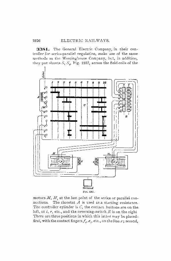
2236 ELECTRIC RAILWAYS.
3381. The General Electric Company, in their controller for series-parallel regulation, make use of the same methods as the Westinghouse Company, but, in addition, they put shunts 5, 5" Fig. 1257, across the field coils of the
s
e
g
128 !I 0 I I I I
I
I Jt
I
(hound
FIG. 1257.
motors M, 11£1 at the last point of the series or parallel connections. The rheostat A is used as a starting resistance. The controller cylinder is C, the contact buttons are on the left, at t, r, etc., and the reversing-switch R is on the right There-are three positions in which this latter may be placed: first, with the contact fingers f" a" etc., on the line %; second,

ELECTRIC RAILWAYS. 2237
on the line y, and third, in a central position between these two, when all connections are broken. It is in this position alone that the lever may be withdrawn, and, as' only one set of levers is provided for each car, the circuit through one controller is always broken when the other is in use. The various positions of the switch are numbered 1 to 10 in !.he diagram, and produce the following combinations:
1. Motors in series with each other and with all the resistance A.
2. Motors in series with each other and with half the resistance.
3. Motors in series, all resistance cut out. 4. Motors in series, all resistance cut out and fields
shunted. 5. Motors in series 'with each other and with half the re
sistance, fields full strength. 6. One motor in series with half the resistance, the other
motor cut out. 7. Same as 6. 8. Two motors in parallel, in senes with half the re
sistance. 9. Motors in parallel,all resistance cut out. 10. Motors in parallel, all resistance cut out and fields
shunted.
3382. A controller manufactured by the Walker Company is similar in many respects to those described, but differs in some important points. Three contact cylinders are provided. The principal one is the regular controller cylinder f0r regulating the speed of the car"; on the right-hand side is the reversing-switch, and on the left-hand a special circuit-breaker which comes into operation each time the current is cut off and distributes the arc through twentyeight .tir-gaps. The motor circuit has high self-induction, and when a quick break is made there is danger of the current piercing the insulation. In this case, the break is relatively slow, so that time is allowed for the back E. M. F. to gradually die away. Thi~ circuit-breaki~g switch is fitted with a pawl on the shaft, the pawl engaging- with a

2238 ELECTRIC RAILWAYS.
ratchet on the controller in such a way that a slight backward movement of the controller handle will open the circuit, and it can not be closed again until the handle is brought to the off point. An interlocking device is introduced between the controlling cylinder and the reversingswitch, so that the former can not be moved from the first position unless the latter is either on the forward or backward notch; also, the reversing-switch is only movable when the controlling cylinder handle is at the off position.
3383. Another method of control is that in which a starting resistance is inserted and gradually cut out as the car attains full speed. This system, called rheostatic
r-;:::========:=:;l3
rn
n n'
H H' FIG. 1258.
control, was the one used in the early days of electric railways, and to some extent it is still employed, although it is very wasteful when running at low speeds, as a great deal of energy is expended in heating the dead resistance.' The motors, as will be seen from the diagram, Fig. 1258, are
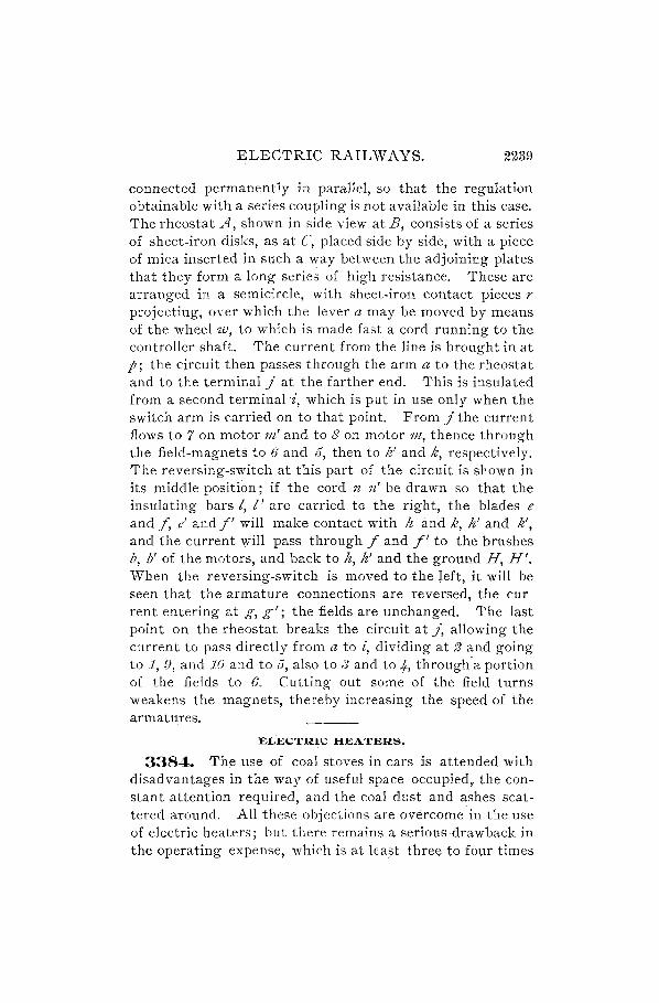
ELECTRIC RAILWAYS. 2239
connected permanently in parallel, so that the regulation obtainable with a series coupling is not available in this case. The rheostat A, shown in side view at B, consists of a series of sheet-iron disks, as at C, placed side by side, with a piece of mica inserted in such a way between the adjoining plates that they form a long series of high resistance. These are arranged in a semicircle, with sheet-iron contact pieces r projecting, over which the lever a may be moved by means of the wheel w, to which is made fast a cord running to the controller sha,ft. The current from the line is brought in at p; the circuit then passes through the arm a to the rheostat and to the terminal J at the farther end. This is insulated from a second terminali, which is put in use only when the switch arm is carried on to that point. From J the current flows to 7 on motor 111' and to 8 on motor 171, thence through the field-magnets to 6 and 5, then to k' and k, respectively. The reversing-switch at this part of the circuit is shown in its middle position; if the cord n n' be drawn so that the insulating bars I, I' are carried to the right, the blades e and f, e' and f' will make contact with It and k, h' and k', and the current will pass through f and f' to the brushes b, b' of the motors, and back to h, h' and the ground H, H'. When the reversing-switch is moved to the left, it will be seen that the armature connections are reversed, the cur rent entering at g, g'; the fields are unchanged. The last point on the rheostat breaks the circuit at J, allowing the current to pass directly from a to i, dividing at 2 and going to 1, 9, and 10 and to 5, also to ."] and to 4, through'a portion of the fields to 6. Cutting out some of the field turns weakens the magnets, thereby increasing the speed of the armatures.
ELECTRiC: HEATERS.
3384. Th~ use of coal stoves in cars is attended with disadvantages in the way of useful space occupied, the constant attention required, and the coal dl~st and ashes scattered around. All these objections are overcome in the use of electric heaters; but there remains a serious drawback in the operating expense, which is at least three to four times

2240 ELECTRIC RAILWAYS.
that of coal stoves. Many railway managers nevertheless· adopt the electric system on account of its popularity and the fact that no space is required for the installation which might be devoted to the accommodation of passengers. In Fig. 1259 is shown the plan of a car, with the wiring for the heaters It, which are placed under the seats near the wheelboxes w. Heat is generated by passing a current through a wire of high resistance embedded in enamel, or other substance of similar nature, which prevents oxidation of the wire by excluding all air from its surface. The outside of the metal case has proj ections e cast on it, in order to present a greater surface to the air. A switch is provided, by means of which the heaters are connected all in series, in series-parallel, or cut out entirely. The series-parallel ., " , I
II , I
I I I I I ; I I
\ t I J , I , I , I '. tJ
FIG. 1259.
coupling is obtained by moving the switch handle upwards so that the lever l will make contact with i, and n with j. The circuit then becomes: From the trolley to 1 to k, dividing at this point and passing through the upper heaters (that is, on the right when viewed from the switch) to 3-n-j-2 to ground; also from k through i-l, the lower heaters to 3-n-.f-2 and ground. When the switch handle is thrown over so that the lever l makes contact with j, the heaters are connected in series. At the position shown, they are cut out of circuit.
WIRING.
3385. The plan of wiring for a car using the seriesparallel controller is given in Fig. 1260. The motors M" M. are shown in dotted outline, and the wires are indicated by heavy lines. There are two principal circuits branching at a (a point on the roof wiring) close to the base of the trol-

ELECTRIC RAILWAYS. 2241
ley t which takes current from the line: From a one circuit is through the fusible cut-out b and lamps c to ,the wire
~===~~-':=~-::;~=-J \ \ ,I Ii I, , \ ~~~~~~~" J_"""
I
i I i , I , ; , , i I
.~rr~~~~n~l I ,i n: I llJ L~~ 111 {-toP
1111
~! 1 i III I J" I
I Ig I~ , c5
i~ i
~I n ~ I Ii! ! ,1'1
III!---.r, III---l-' III. III I
ll"' u,.J: ! i I ~ I
I ~
g, which is connected tot h e ground; the other circuit is through the canopy switches s, s to It, where a shunt is carried to one side of the lightning-arrester 1, the other side be-ing grounded. The main current passes through the choking coil k to the fuse box f, thence to the controllers e and motors, as already des c rib e d . in Arts. 3379 and 3380. All these wires are bunched and wound over so as to make a single cable d, an arrangement reducing their liability to injury. The connections to the armatures are indicated at
I'
\\ " 1/ + d t '\ / '" a" a,- an a \ \ ~! I + th c:.-~.---------'~ J~--J a. , a. -; e -------__ .~ --- connections t 0
the fields are shown atf,+,f,- and atf.+,f.-. The choking coil kconsists simply of q. few turns of wire wound over a
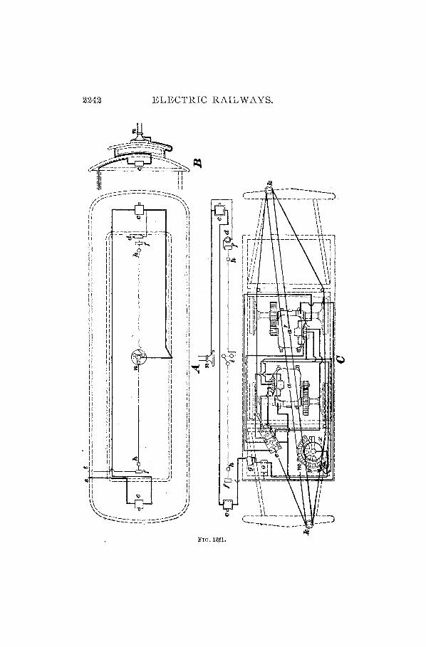
2242 ELECTRIC RAIL WAYS.
--:::::=======..=.:::::::: .. - .... /;;;.,- ~ .... ~'0 if \\ 11 11 11 11 II II II , II Ii , II II II 1 II II II I II II II I .ce II II 'I I II II 111 I If II I' ' Ii .11 I' 1 Ii 11 I' ' II II 11 I II II II I " II 11 I II II I: I, :1 Ii II i: :: II II II I' " I' I' Ii ,I d JI II I: 11 I: Ii II 'I II , II 'I I, II II I, II II "'I It II II~ II I, II 11 'i II II II II II II II II II II II II
" II II II II II 11" II II II II II II d II " II " 11 I, II Ii 'I II II 'I " II II ,I II' 'I II '" Ii I'" ot II
... 11 :1 :i I .... 'I 'I.
'D --::=!) 'I II II
n Q II ~\, -Y
"'..;':::-~---...,..~~-;::.-=-~~~'-':'"
FIG. l2lil.
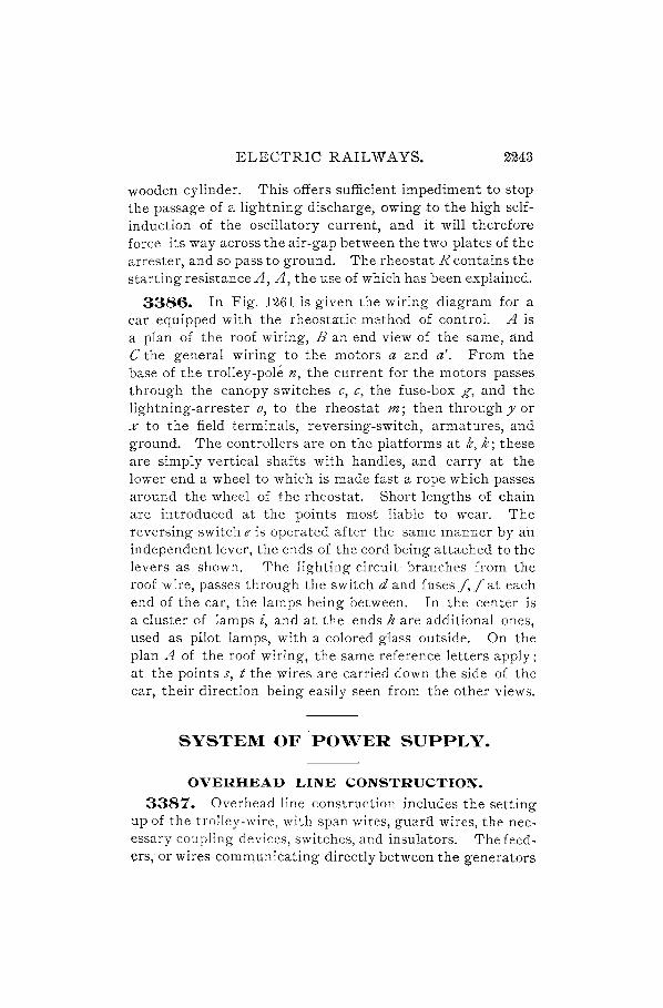
ELECTRIC RAILWAYS. 2"243
wooden cylinder. This offers sufficient impediment to stop the passage of a lightning discharge, owing to the high selfinduction of the oscillatory current, and it will therefore force its way across the air-gap between the two plates of the arrester, and so pass to ground. The rheostat R contains the starting resistance A, A, the use of which has been explained.
3386. In Fig. 1261 is given the wiring diagram for a car equipped with the rheosta:tic method of control. A is a plan of the roof wiring, B an end view of the same, and C the general wiring to the motors a and a'. From the base of the trolley-pole n, the current for the motors passes through the canopy switches c, c, the fuse-box g, and the lightning-arrester 0, to the rheostat m; then through y or % to the field terminals, reversing-switch, armatures, and ground. The controllers are on the platforms at k, k; these are simply vertical shafts with handles, and carry at the lower end a wheel to which is made fast a rope which passes around the wheel of the rheostat. Short lengths of chain are introduced at the points most liable to wear. The reversing-switch e is operated after the same manner by an independent lever, the ends of the cord being attached to the levers as shown. The lighting circuit· branches from the roof wire, passes through the switch d and fuses f,f at each end of the car, the lamps being between. In the center is a cluster of lamps £, and at the ends h are additional ones, used as pilot lamps, with a colored glass outside. On the plan A of the roof wiring, the same reference letters apply; at the points s, t the wires are carried down the side of the car, their direction being easily seen from the other views.
SYSTEM OF 'POWER SUPPLY.
OVERHEAD LINE CONSTRUCTION.
3387. Overhead line construction includes the setting up of the trolley-wire, with span wires, guard wires, the necessary coupling devices, switches, and insulators. The feeders, or wires communicating directly between the generators

2244 ELECTRIC RAILWAYS.
at the station and the various distributing points, may be carried overhead or laid underground, as most convenient. In the latter case they must be protected from abrasion, a lead sheath being frequently employed outside the insulation. Great care should be taken in handling, lest the covering be injured or broken, which would allow moisture to enter and gradually develop a fault.
There are three styles of support for trolley-wires: They may be suspended directly from brackets on poles at the
(a) (11) (c)
FIG. 1262.
side of the road; or a double track may be provided with center- poles carrying the wires on projecting arms on both sides; or the poles maybe placed at the sides of the street, and the trolley-wire supported by span wires stretched qcross. This last method is most common, because there is

ELECTRIC RAILWAYS. 2245
no obstruction in the roadway, as in the center-pole construction, and because only the side of a road can be used for the track in some localities, as on a country road.
3388. The poles may be of steel, iron, or wood. For cross-country roads wooden poles are generally selected, and their use is very frequently found in the city streets, although iron or steel poles are much more desirable. Fig. 1262 shows a sectional form of iron tubular pole adaptable to any type of construction, (a) being the side-pole, (b) the center-pole, and (c) the span-wire method. The poles are about 30 feet long, the lower section being 6 or 8 inches diameter, and the others 1 inch smaller successively, fitting inside each other with telescope joints at least 18 inches in length. The lower end of the pole is sunk into the ground to a depth of 6 or 7 feet, and filled around with cement. Allowance must be made, in setting, for the strain of the wires; and the top of the pole must slant away from the track about 5 inches when span wires are to be used. At (d) is an enlarged view of the top of U-.. __
pole (c), showing the insulated top k, supported on a wooden block sand carrying the tension bolt 11 to which the span wire is secured. The cross arm t carries feeders to supply current at distant points; the pole may also be utilized to carty an arc lamp, as at I, in Fig. 1262 (a). Instead of a tension bolt, a ratchet may be placed on the top of the pole, as at a, Fig. 1263, provided with a counterbal-anced pawl b engaging with the teeth. FIG. 1263.
The base c has flaring sides to shed rain, and fits into the insulating wooden block d. In a s1.ightly modified form the ratchet may be fastened to the side of the pole at any point. or bolted to a wooden pole.

2246 ELECTRIC RAILWAYS.
3389. In both bracket and center-pole construction, it is now the practice to use a flexible support for the troUey-
. wire. hanger, which pre-vents the destructive hammer blow of the passing
e~E=~!i'El=~!;;;:II-=~1ii4t trolley-wheel and reduces s;><:i!ll-;;;;---iil-:--~i' the sparking. Such an ar
rangement is shown in Fig; 1264, which represents 'the form used for the side-
FIG. 1264. bracket construction. A span wire w holding the hanger h is stretched tightly between two insulators z', z", the outer one being secured to a bracket b and the inner one held by a clamp on the framework. In the center-pole construction the brackets extend on both sides, and when the pole is of wood, a hole may be bored through it to receive the span wire.
3390. Wooden poles are generally set without concrete; but when they are placed at the side of the street to hold span wires stretched across, large stones should be used to take the pressure due to the pull of the wires, some being placed at the base of the pole away from the track, others near the surface of the ground at the side towards the track. A piece of timber may be substituted for the stones on the track side, and should be about 3 feet long and 4" X 8" in section. The slant of a wooden pole should be about double that of an iron pole, and when in position the ground must be solidly tamped around it to make a firm bed .• The diameter at the bottom should be not less than 10 inches, tapering to 6 or 7 inches at the top, which may be cut to a conical shape. The pole from the ground up may be round or octagonal. It will be found to effect a considerable saving in cost of renewal, and also to prevent leakage of current, to give the pole one or two coats of paint, applying some preservative compound to that part which is to be underground.
Steel poles are made of sheet metal, of channel section, ri"veted together at short intervals throughout their length,

ELECTRIC RAILWAYS. _ 2247
and may have a flat piece through the middle, the section then being like a double D. Latticework is also largely used, making a very neat and strong pole, which can be painted inside and out, and is easily climbed when necessary.
Guard wires may be required for city lines, to prevent contact between a falling telephone (or electric light) wire and the trolley-wire. These guard wires are suspended 10 or 15 inches above the trolley-wire, and are supported by span wires attached to the poles at the same distance above the trolley spans. Anchor wires must be provided at suitable intervals to secure the trolley-wire against falling, in the event of the connection at one end g1ving way. Before this precaution was adopted, there were instances of a whole system being incapacitated through the breaking of a trolley -wire.
3391. The general arrangement of wiring for a double track is shown in Fig. 1265. The pole~ /J are placed not
FIG. 1265.
more than 125 feet apart measured along the road, and between opposite poles are stretched the span wires s. At intervals of about 500 feet, and at the approach to all curves, anchor wires a are put up, being secured to the trolley-wire by hangers h.
3392. The method of setting up the trolley-wire" on curves is shown in Fig. 1266, where A represents the arrangement of guy wires g, attached to the trolley-wire t, when a single pole is used. Turnbuckles k are used to bring the wires to the proper tension, and anchor wires a to support the trolley-wire at the beginning of the tangent or straight portion. A flexible method of suspension is given at B, where a heavy span wire s holds up the guy wires; this form

2248 ELECTRIC RAILWAYS.
of construction tends to equalize the strains on the span WIres and is generally adopted in place of the other, which
B
a
a
FIG. 1266.
is the original method. A double curve is shown at C, the different wires being designated by the same letters as in the preceding layouts, and the poles byp.
3393. In rounding a curve, the trolley-wire does not follow the center line between the rails, but is carried over to the inside by an amount depending upon the radius of the curve." This variation is shown in Fig. 1267, where
lI'IG. 1267. the curve r is the center line of

ELECTRIC RAILWAYS. 2249
the rails, and t the line of the trolley-wire. The amount of offset, measured at the middle of a 90° curve, at the point indicated by the arrows in the figure, is as follows for curves of different radii:
Radius in Feet. 40 .................... . 50 .................... . 60 .................... . 80
100 120 150 200
Offset. 16 inches. 13 inches. 12 inches. 8 inches. 6 inches. 5 inches. 4 inches. 3 inches.
The object of this offset is to allow the trolley-wheel to lie more closely to the wire; this it would not do if the wire fol-· lowed the track center line, since the wheel would then lie across the wire diagonally, causing a large amount of wear in passing round the curve. In some old lines this effect is plainly visible, the wire showing splices at various points where breaks have occurred.
ERECTION OF. LINE.
3394. The size of the trolley-wire depends somewhat upon conditions of traffic, but it should never be less than No. 0 B. & S. hard-drawn copper, and is frequently as large as No. 000 or 0000. The guard wire, when used, may be of No.8 B. & S. steel galvanized wire, and all span wires should be not less than No.5 B. & S. steel wire, galvanized. The trolley-wire should hang about 19 feet above the track when in position.
The first proceeding in putting up a line is to stretch the span wires across, and, as the insulation must be as perfect as possible, il)sulators are employed in two places, first, at or near the pole, and second, in the hanger. Those in the span wire are called strain insulators, an illustration of one form being given in Fig. 1268, where i is a globe of some suitable

2250 ELECTRIC RAILWAYS.
insulating material, such as hard fiber or rubber, into which are secured the eye e and the bolt s ; the turnbuckle p, which connects the bolts sand s', is fitted with right and left hand threads for regulating the tension, and the wires are fastened to the ends at e, e'. When a ratchet is used, the turnbuckle is unnecessary, and the insulator is simply in
®()< ... . @Im,l/Ifilimill/I'''--'-:@ FIG. 1268.
the form of a globe with two eye-bolts, or an insulating cylinder with the two bolts.
When the span wires are in position, the next operation is to set the hangers for the trolley-wire. One form of hanger is shown in Fig. 1269, the span wires being passed under 1n
and n and over the center at e. A swivel-joint at a permits of proper adjustment, and below the cup insulator £ is a
m n 8
a
t
FIG. 1269.
pivot p, allowing a longitudinal swing. A clamp b holds the trolley-wire t either by having its edges pressed firmly over the wire, or by soldering. Another form of hanger is illustrated in Fig. 1270, in which the trolley-wire is held by a clamp a set up by means of screws. The span wire passes under the ears b, b and lies in the groove c, being held in

ELECTRIC RAILWAYS. 2251
place by its own tension. The central bolt d is insulated from the ears and span wire by a composition of mica and shellac, orsimilar substance, which is filled around the body, and' projects above it in the shape of a mushroom top. The bolt e
allows of motion, as in the preceding case.
In putting up the trolley-wire, the end is first anchored, and a length of perhaps 1,000 feet run off, FIG. 127'0.
supported by temporary wires from the clamps. This length is then drawn to the proper tension QY means of a block-andtackle, the hangers are permanently connected, and the anchor wires put up. In rounding a curve the wire is first stretched in temporary wire slings and anchored, after which the hangers, or pull-over clamps, are attached. For curves of small radius, a form such as is given in Fig. 1271 is used. The span wire is attached to the eye e, which is
FIG. 127'1.
fastened by the insulating piece i to the arm p carrying the trolley-wire clamp b pivoted at d. For such operations, a "tower wagon" is used, which consists of a platform supported on a wagon, at a convenient height for ready access to the wires. This platform is generally so arranged as to project beyond the wagon, so that the latter may stand clear of the tracks while repairs are in progress, and not interfere with regular traffic. '\iVhen not in use, the platform may be lowered to the wagon.

2252 ELECTRIC RAIL WAYS.
3395. Branch Lines and Curves.-At the point where one line branches from another, overhead switches, or "frogs," are used to guide the trolley-wheel from one wire to the other. Such a switch is shown in Fig. 1272,
(X)
c n
FIG. 1272.
where (x) is a view from the side, and (y) a view from the bottom; a is a plate with projecting edges p, p' at each side and spirally grooved ears at nand 111,111, m. The inner surface of the plate is at such a distance from the lower surface of the ears that the trolley-wheel will run straight through, bearing on its flanges while under the plate, and passing
a
a' b'
b
FIG. 1273.
from one wire to the other without any change in vertical pos1tlOn. The wires c, c' are secured by passing them over the ears, and bringing the ends through holes in the plate and bending them back, as at d or d'; the span wires are··

ELECTRIC RAILWAYS; 2253
connected at the rings e.. A switch for a single branch may be made by leaving out one. of the ears 'lIZ and narrowing the plate accordingly.
The position for the frog may be found by the method shown in Fig. 1273, where a b is the main line, c d the branch line, a' bi the main trolley-wire, and t c' the branch trolley-wire. The center of the triangle n oX m will be at a point t where the lines bisecting each angle meet, and this determines the position of the frog. It will be a little removed from the center lines of the tracks.
Upon curves of large radius, it is necessary to use a double clamp c, as shown in Fig. 1274, the span wires being secured
FIG. 1274.
at e, e' and the trolley-wire at b. At the point of intersection of two trolley-lines, a cross-over is used similar in principle to the overhead switch, Fig. 1272.
3396. Section insulators are used at the junction of two divisions when they are supplied by separate feed wires direct from the-station. One form is shown in Fig. 1275, in which the direct line of the trolley-wire is unbroken, allowing the trolley-wheel to run smoothly across the insulator. The span wire is in one piece between the poles, and is slipped under the hooks a, a and over the notch at b. A double strain insulator i i and bolts c, c hold the parts together against the pull of the trolley-wires from the two sections, which pass under the clamps d, d at each end,

2254 ELECTRIC RAILWAYS.
through the holes h, h, and are held by the set-screws s, s. The end castings are provided with lugs I, I and set-screws,
FIG. 12~5.
by which connection may be made to the feeders. Distancepieces of wood, well filled to prevent absorption of moisture, are inserted at w, w.
3392'. Wire Splicing.-The usual method of splicing overhead wires is the" telegraph," or Western Union, joint,
~4 _________ ~~ ______ ~
FIG. 1276.
Fig. 1276, in which the wires are wrapped one over the other and soldered. Resin should be used as a flux instead of acid, as acid will in time corrode the wire. An objection to this joint for trolley-wires is that it presents an obstruction ,
FIG. 1277.
to the trolley-wheel, and other devices have been adopted, one of which is a scarf-Joint, at least six inches long, Fig. 1277, carefully cleaned and wrapped with tinned binding wire. The whole length of the joint is then filled in with
a a [ ~ ______ - ____ -____ --~J ~
FIG. 1278.
solder, the ends of the trolley-wire being held firmly throughout the process by means of a screw clamp. Another method of joining, which is more readily accomplished, is by the use of a. bra-ss tubular connector, as shown in Fig.

ELECTRIC RAILWAYS. 2255
1278, the wires being introduced at each end and bent up through the openings a, a; the remaining space is then filled with melted solder and the ends of wire trimmed off. This connector has proved very satisfactory in service.
3398. Feeders.-It is very important that the E: M. F. on an electric road should be maintained as nearly constant as possible throughout the whole system, and the trolleywire being usually far too small to accomplish this, extra
f c
a t a'
p p'
FIG. 1279.
cables are run to various points along the line. These are called :feeders, and their size and distribution depend on the number of cars used and the length of the road.
The feeders may be supported on the side poles or on separate poles, but are frequently laid underground. Connection to the trolley-wire is made by using a hard-drawn copper span wire attached to a non-insulating hanger c, Fig. 1279, carrying the trolley-wire t· at the other end of the
span wire the feeder f is joined on, and a strain insulator a' is introduced between it and the pole p'. On the other side is a regular steel span wire between the pole p and the hanger, with an insulator at a.
The simplest method of line construction is to use a single wire, serving as working conductor and feeder; but, with a heavy load, the drop in potential at the end of the
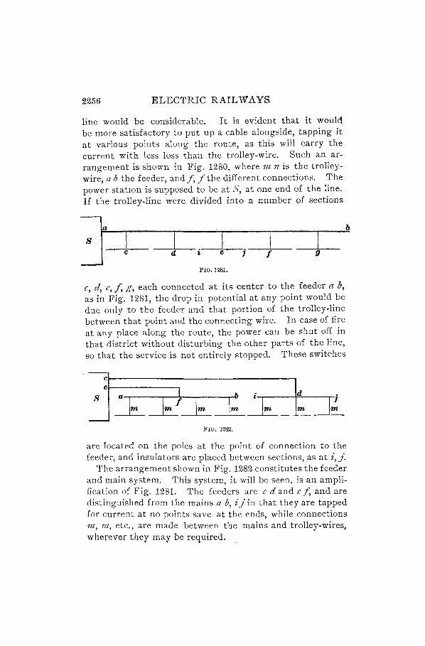
2256 ELECTRIC RAILWAYS.
line would be considerable. It is evident that it would be more satisfactory to put up a cable alongside, tapping it at various points along the route, as this will carry the current with less loss than the trolley-wire. Such an arrangement is shown in Fig. 1280, where m n is the trolley-wire, a b the feeder, and f, f the different connections. The power statIOn is supposed to be at S, at one end of the line. If the trolley-line were divided into a number of sections
Ja I I I I I c cl i e j f 9
FIG. 1281.
c, d, e, f, g, each connected at its center to the feeder a b, as in Fig. 1281, the drop in potential at any point would be due only to the feeder and that portion of the trolley-line between that point and the connecting wire. In case of fire at any place along the route, the powe!" can be shut off in that district without disturbing the other parts of the line, so that the service is not entirely stopped. These switches
J a~ ~ I I~
i
I~ 1m f 1m 1m FIG. 1282.
b
are located on the poles at the point of connection to the feeder, and insulators are placed between sections, as at i, j.
The arrangement shown in Fig. 1282 constitutes the feeder and main system. This system, it will be seen, is an amplification of Fig. 1281. The feeders are c d and e f, and are distinguished from the mains a b, ij in that they are tapped for current at no points save at the ends, while connections m, tn, etc., are made between the mains and trolley-wires. wherever they may be required.

ELECTRIC RAILWAYS. 2257
CALCULATION OF TROLLEY-WIRES AND FEEDERS.
3399. There is an important condition upon which the size of the supply wires is based, namely, that the difference in potential between the trolley-wire and the track shall have a certain minimum and a certain average value. To obtain this result, the drop in the line must not be allowed to exceed a certain amount, and will include the ground return as well as the overhead wiring.
For convenience, we will at first assume that there is no resistance in the return circuit through the rails and ground, hence, that the drop in the line to the farthest point is alone to be considered. We will then denote by R the resistance in ohms of the conductor; D, its length in feet; e, the drop in volts; C, the current; and dZ, the area of conductor in circular mils, or one-thousandths of an inch.
Th ' '1 f . 0 F . 56,970 e resIstance of 1 mi e 0 copper WIre at 75 . IS-y,-
ohms; therefore, the resistance of a wire 1 foot long and
1 ·1· d· . 56,970 7 h d· 1 mi In lameter IS 8 d' = 10. 9 0 ms, an , SInce t 1e 5,2 0 X
resistance varies directly as the length D <lnd inversely as the area d',
R=10.7~;D; (511.)
but e, e 10.79 X D
R = C by Ohm s law, therefore C = --;]2-;
whence,
and
d' = 10.79 CD, e
10.79 CD e=--d""--
(512.)
(513.)
Formula 512, while giving the required area of conductor for any given length, current, and loss in volts, does not, as we have seen, make provision for the resistance of the return path through the rails and earth, which is a matter not easily determined in advance, unless the line is to bean extension of a system already in operation, and the characteristics of ground and track are similar. In such a case the

TABLE 107.
CURRENT CAPACITY OF OVERHEAD WIRES CORRESPONDING TO A TEMPERATURE RISE OF 10.,20.,30., AND 40· C., RESPECTIVELY.
Diam- Area Amperes. Gauge Diameter Area Amperes.
eter in in Circular Num- in Mils, in Circular
Inches. Mils. 10° 20° 30° 40° ber. or rif-orr In. Mils. W 20° 30° 40°
--~ ---------
1.00 1,000,000 410 570 700 800 0000 460.000 211,600 145 200 240 275
.95 902,500 380 530 650 750 000 409.640 167,805 125 170 210 235
.90 810,000 350 490 600 700 00 364.800 133,079 110 145 180 205
.85 722,500 320 455 560 645 0 324.950 105,592 95 125 150 180
.80 640,000 290 420 520 595 1 28fJ.300 83,694 80 110 130 150
.75 562,500 265 385 470 545 2 257.630 66,373 70 95 1i5 130
.70 490,000 240 350 430 500 3 229.420 52,634 60 80 100 115
.65 422,500 220 310 390 450 4 204.310 41,742 55 70 85 100
.60 360,000 200 280 350 405 5 181. 940 33,102 50 63 75 87
.55 302,500 180 .250 310 360 6 162.020 26,~50 40 52 64 75
.50 250,000 160 220 270 310 '7 144.280 20,816 35 45 55 65
1:>, ~ en C1:J
t:rJ t" t:rJ () J-3 :;0 H ()
:;0 ~ H
t" ~ ~ ~ !1J

ELECTRIC RAILWAYS. 2259
resistance of the ground return, as computed, multiplied by the total current to pass through, will give the drop in volts, which can then be subtracted from the total allowable drop, and the value of the remainder applied in the formula.
There are, broadly, two classes of supply wires to be considered, n.amely, those in which the load is at one end, and those having a uniformly distributed load. To the first class belong all feeders having no connections to the trolleywire or mains except at one point; in the second class are included singh; trolley-lines without feeders, and mains co~nected to the line at various intervals throughout their length. For the first of these the formula given will hold good, but the second requires different calculation. The effect of a uniformly distributed load is that it requires only one-half the size of wire that would be necessary for an equal load at the end of the line, the same drop being allowed. \Ve may say, then, that for a uniformly distributed load
d 2 = 5.4 CD. e '
(514.)
also, (515.)
3400. There are two questions affecting the size of wire for overhead power supply-one being a given drop of potential, and the other a gi ven rise of temperature, and calculations made from the formulas given for overhead conductors should always be checked by rules based on practical experience, to ensure the ability of the wire to carry the current safely. Table 107 gives the current capacity for several different sizes of wire for a rise in temperature of 100, 200, 300 , and 40 0 C.
The table is applicable alike to uninsulated, bright wires, such as trolley-wires, and to those with an insulating covering; for, in the latter case, the surface, being black, radiates heat more rapidly, and also presents a larger area to the cooling effect of the atmosphere. As a rough, general

2260 ELECTRIC RAIL WAYS.
approximation, the following rule for capacity of feeders will be fou~d serviceable, but should not be used for final calculation:
Rule.-Tlte current whz'clt a gt'ven w£re w£ll carry safely, when exposed to the a£r, £s represented approx£mately by the follow£ng formula:
.Id" C= 'Y 1300' , (516.)
where C £s the current £n amperes and d £s the d£ameter of w£re £n mils.
3401. In our calculations for size of conductor, we have considered an area sufficient to give a certain drop <?f potential at a temperature of 75° F. When the current is first turned on the line, this drop will result, but a heating effect may occur after a short time which will raise the resistance and, consequently, reduce the current. Provided the rise of temperature is not much more than 30° C., it will be safe, but the E. M. F. of the generators must be increased to make up for the additional drop. It will be evident, then, that a correction in terminal drop is frequently necessary, and is obtained by using a new value for the specific resistance and transposing the formula. Constants for the different temperatures may be found by the following rule:
Rule.-Tlle resistance of a copper w£re £ncreases 0.1r per cent. for every degree Centigrade, or about 0.222 per cent. for every degree Fahrenht!it, that its temperature rises above tltat of the surrouftding air.
At 75° F., the resistance of a wire one mil in diameter and one foot long is, as we have found, 10.79 ohms, and at any temperature to Fahrenheit, the resistance
r = 10.79 + (.00222 X 10.79 X t) =
10.79+.0239538t. (517.)
A temperature rise of 10° C. is equivalent to 18° F., and taking the same figures as those in the table, we have the following values for the coefficients:

ELECTRIC RAILWAYS. 2261
Rise of 10° C. = 18° F., and resistance of 1 mil-foot-
r = 10.79 + (.0239538 X 18) = 11. 22. Rise of 20° C. = 36° F., r = 10.79 + (.0239538 X 36) = 11. 65. Rise of 30° C. = 54° F., r = 10.79 + (.0239538 X 54) = 12.08. Rise of 40° C. = 72° F., r = 10.79 + (.0239538 X 72) = 12.51.
The following examples will illustrate the method of determining the size of wire for any railway system, by the formulas given:
EXAMPLE.-A road is proposed to be built, having a length of lt miles, single track. There are to be five cars, each taking an average (estimated) current of 15 amperes, and the allowable drop, exclusive of ground return, is to be 50 volts, or less. Will a single No. 0 trolleywire suffice?
SOLuTION.-From formula 514,
d 2 _ 5.4 X 75 X 7,920 _ 64 152' '1 - 50 -, CIrc. ml s.
d = ,y 64,152 = 253 mils = .253 in.
The diameter of No. 0 wire is .325; therefore, it will amply suffice, carrying the current with hardly any increase of temperature. Ans.
EXAMPLE.-(a) If, in the above example, the conductors were to be provided to allow of 50 volts drop with the load concentrated at the end of the line, what would be the required size? (b) What would be the drop if a No. 0 trolley-wire alone were used?
SOLUTION.-(a) By formula 512,
d 2 _ 10.79 X 75 X 7,920 -128185' '1 - 50 -, CIrc. ml s.
This area is greater than a No. 0 trolley-wire, which is 105,592 eire. mils. Subtraeting,128,185 - 105,592 = 22,593 eirc. mils.
,y 22,593 = 150 mils = .150 in.
An additional feeder must therefore be added, to fulfil these conditions, its diameter being .150 in.; or, as an alternative, we might put up a No. 00 trolley-wire, which measures '.3648 in. in diameter, since ,y 128,185 = 358 mils = .358 in. Ans.
(b) From formula 513, we obtain
_ 10.79 X 75 X 7.920 _ 6,409,260 _ 60 7 It A e -105,592 - 105,592 - . vo s. ns.
EXAMPLE.-An electric railway is to be built having an arrangement as shown in Fig. 1283, with three feeders, 1,200, 2,100, and 3,300 feet in

22(J2 ELECTRIC RAIL WAYS.
length, respectively. The mains are each 4,200 feet long, with the feeder connection at the middle, and there are on each division seven sections of trolley-wire 700 feet long, No. 0 B. & S. gauge. Double tracks are to be laid, having an estimated resistance of .025 ohm per
FIG. 1283.
mile, and 30 cars will be used, to take an average current of 14 amperes each. With a total drop on any division of about 50 volts, what sizes, of feeders and mains will be required?
SOLUTION.-A glance at the plan of the road shows that return feeders will be required, as the station is removed from the line of the railway, and that these will run from that portion of the track on each division nearest to the power-house. For divisions 1 and 2, a single return cable will suffice, but for division 3 another had better be provided, following the direction of the outgoing feeder.
We will first calculate the drop in pressure through that portion of the circuit containing the known resistance. Each division has an average of 10 cars, since there are 30 in all, and the current will be 14 X 10 = 140 amperes. When the proper distance between cars is maintained, there can never be two on one length of trolley-wire between the sub-feeder from the main, at the center of the section, and the end of the section; therefore, the current is 14 amperes, and the length of wire, 350 feet; the size is No. 0, area, 105,592 circular mils, and the load being a moving one, we apply formula 515, giving the drop
_ 5.4 X 14 X 350 _ 26,460 _ ~ I e - 105,592 - 105,592 - .20 vo t. (a)
The connection from the track to the power station, P. 5., is indicated by the dotted line. For the track resistance of division 1, we wi!! consider that portion lying to the left, its length being, say, 3,800 feet. The resistance at .025 ohm per mile is
R - 3,800 02r- - 018 h - 5,280 X· 0 - . 0 m.

ELECTRIC RAILWAYS. 2263
The fall of potential with a distributed load will be one-half that with the load at the end, and by derivation from Ohm's law,
C 108 e ="2 X R = 2 X .018 = .97 volt, (b)
the current in divisions 1 and 2 being considered, in the case of the ground circuit, as divided in the ratio of the two lengths of track.
For division 2, we may take the length of track as being 9,800 - 3,800 = 6,000 feet. The resistance
R = ~:~~~ X .025 = "028 ohm.
The current will be 280 - 108 = 172 amperes, and the drop
_ C _172 ') ~ e - "2 X R - 2 X . 0~8 - 2.41 volts. (c)
In division 3, the connection to the track is made at the middle of the line; there is then to be considered only half the load, in order to determine the fall of potential. There is a distributed load of 5 X 14 = 70 amperes over a distance of 2,450 feet, and the resistance
2,450 ' R = 5,280 X .025 = .0116 ohm.
The current is 70 amperes, and the drop
e = ¥ X .0116 =.41 volt. (d)
Returning to division 1, we have, so far, the drop of potential in the trolley-wire and track. The calculations for the feeders and mains should be made with a view to an economical section of copper, provided an excessive fall in potential is not thereby occasioned. The main is in each division connected to the feeder at its center. A distributed load of 70 amperes is carried here, and allowing for a temperature rise of 15° C., the wire, as given in Table 107, is No.3. The drop of potential
_ 5.7 X 70 X 2,100 _ 837,900 -1~ 9 I (e) e - 52,634 - 52,634 - u. vo ts.
The current in the feeders will be 140 amperes, end load, and for an allowable rise of 150 C., the size will be No. 000. Then, for the outgoing feeder,
11.44 X 140 X 1,200 1,921,920 1145 I e = 167,805 = 167,805 = .' vo ts. (f)
For the return feeder, the proportional current may be taken as before, with reference to length of track, as being 108 amperes. For a temperature rise of 150 use No. 0 wire; then.
_ 11.44 X 108 X 500 _ 617,760 _ " 85 I e - 105,592 - 105,592 - ll. vo ts. (g)
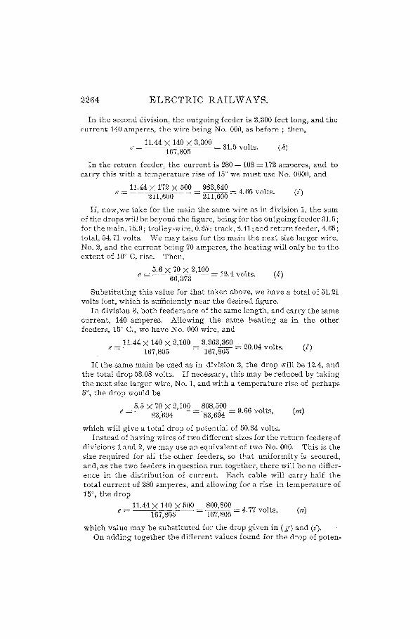
2~64 ELECTRlC RAIL W A VS.
In the second division, the outgoing feeder is 3,300 feet long, and the current 140 amperes, the wire being No. 000, as before; then,
_ 11.44 X 140 X 3,300 _ 31 5 It e - 167,805 -. vo s. (h)
In the return feeder, the current is 280 -108 = 172 amperes, and to carry this with a temperature rise of 15' we must use No. 0000, and
11.44 X 172 X 500 983,840 (z') e = 211,600 = 211,600 = 4.65 volts.
If, now, we take for the main the same wire as in division 1, the sum of the drops will be beyond the figure, being for the outgoing feeder 31.5; for the main, 15.9; trolley-wire, 0.25; track, 2.41; and return feeder, 4.65; total, 54.71 volts. We may take for the main the next size larger wire, No.2, and the current being 70 amperes, the heating will only be to the extent of 10' C. ri:;;e. Then,
5.6 X 70 X 2,100 e = 66,373 = 12.4 volts. (k)
Substituting this value for that taken above, we have a total of 51.21 volts lost, which is sufficiently near the desired figure.
In division 3, both feeders are of the same length, and carry the same current, 140 amperes. Allowing the same heating as in the other feeders, 15° C., we have No. 000 wire, and
_ 11.44 X 140 X 2,100 _ 3,363,360 = 20 04 It e - 167,805 - 167,805 . vo s. (/)
If the same main be used as in division 2, the drop will be 12.4, and the total drop 53.08 volts. If necessary, this may be reduced by taking the next size larger wire, No.1, and with a temperature rise of perhaps 5°, the drop would be
_ 5.5 X 70 X 2,100 _ 808,500 _ 9 66 It e - 83,694 - 83,694 -. vo s, (m)
which will give a total drop of potential of 50.34 volts. Instead of having wires of two different sizes for the return feeders of
divisions 1 and 2, we may use an equivalent of two No. 000. This is the size required for all the other feeders, so that uniformity is secured, and, as the two feeders in question run together, there will be no difference in. the distribution of current. Each cable will carry half the total current of 280 amperes, and allowing for a rise in temperature of 15°, the drop
_ 11.44 X 140 X 500 _ 800,800 _ 4 77 It (n) e - 167,805 - 167,805 -. vo s,
which value may be substituted for the drop given in (g) and (i). On adding together the different values found for the drop of poten-
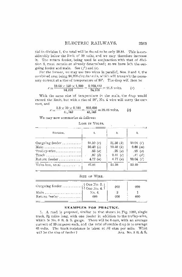
ELECTRIC RAILWAYS. 2265
tial in division 1, the total will be found to be only 33.34. This is considerably below the limit of 50 volts, and we may therefore increase it. The return feeder, being used in conjunction with that of division 2, must remain as already determIned; so we have left the outgoing feeder and main. See (f) and (e).
For the former, we may use two wires in parallel, Nos. 3 and 4, the combined area being 94,376 circular mils, which will transmit the necessary current at a rise of temperature of 30°. The drop will then be
_ 12.08 X 140 X 1,200 _ 2,029,440 _ 21 5 It e - 94,376 - 94,376 - . .vo s. (r)
With the same rise 'of temperature in the main, the drop would exceed the limit, but with a rise of 20°, No.4 wire will carry the cur-rent, and .
5.8 X 70 X 2,100 852,600 e = 41,742 = 41,742 =.20.42 volts. (s)
We may now summarize as follows:
Loss IN VOLTS.
Division. 1.
Outgoing feeder ........ , ... 21.50 (r) Main ....................... 20.42 (s) Trolley-wire ................ .25 (a) Track ...................... .97 (b) Return feeder ............. 4.77 (n)
Volts lost, totaL ........ _ 47.91
SIZE OF WIRE.
Outgoing feeder ........... .
Main ...................... . Return feeder ....... _ ...... .
j One No.3. I lOne No.4. f
No.4. 000
2.
31.50 (h) 12.40 (k)
.25 (a) 2.41 (c) 4.77 (n)
51.33
(l00
2 000
EXAMPLES FOR PRACTICE.
3.
20.04 (I) 9.66 (m) .25 (a) .41 (d)
20;04
50.40
000
1 000
(I)
1. A road is proposed, similar to that shown in Fig. 1280, single track, 2t miles long, with one feeder in addition to the trolley-wire, which is No. 0 B. & S. gauge. There will be 6 cars, with an average current of 20 amperes each, and the total allowable drop is to average 65 volts. The track resistance is taken at .07 ohm per mile. What will be the size of feeder? Ans. No. 3 B. & S.

2266 ELECTRIC RAILWAYS.
2. In the above example, if the trolley-wire were divided into ten insulated sections, what size wire should be used for the feeder? (Note that length of feeder is one half-section less than trolley-wire.)
Alis. No. 000 B. & S.
3. In Fig. 1282 is shown a road having feeders and mains, with 4 sections in division 1 and 3 sections in division 2. If the total length of railroad is 3 miles, double track, the resistance being .035 ohm per mile, and 16 cars are run, taking an average current of 20 amperes' each, what will be the size of feeders and mains, No. 00 trolley-wire being used and a drop of 75 volts being allowed on each division?
NOTE.-The current in each half of the main a b being taken off at two points only, provide one wire from f to a and from f to b, and another from! to the first sub-feeder m, one-third the distance from fto a and fromfto b. The track resistance on the first division is calculated in the usual way, the load being distributed, but for the second division the current may be taken as an end load at a distance S d.
Ans. f Div. 1.
l Div. 2.
Feeder, 4,526 ft.; No. 0000. Main 3,394 ( h'd No. O. Main 1,131 5 eac Sl e, No. O.
Feeder, 12,448 ft.; area, 356,608 circ. mils. Main 2,263 ft. each side, No. O.
TRACK CONSTRUCTION.
FORMS OF RAILS.
3402. Substantial track construction is of supreme importance in electric railway work. The roadbed can not be too carefully built, and it is well to follow, in general, the best steam railroad practice, when large lines are projected. The most satisfactory rail has been found to be the Trail, such as is used on steam roads, but this can not be used in paved streets, and the girder rail takes its place. Of this there are many different designs. In Fig. 1284, A is a center-bearing, B a side-bearing, C a grooved, and D a box girder rail; a T rail is shown at E. The side-bearing girder rail is most employed for city lines; the grooved form is a type which presents least obstruction, to the wheels of wagons in crossing the tracks, but it is objectionable from
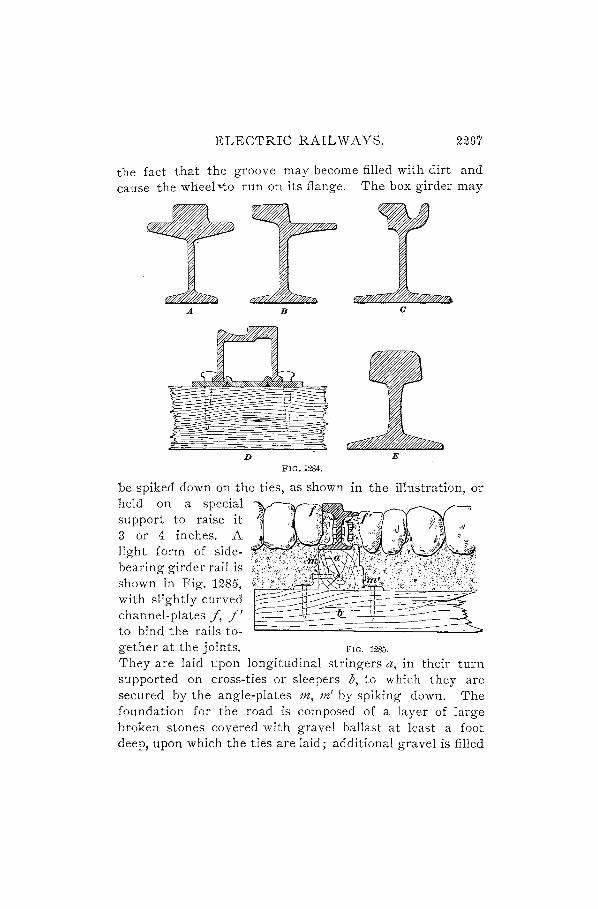
ELECTRIC RAILWAYS. 2267
the fact that the groove may become filled with dirt and cause the wheel ~to run on its flange. The box girder may
A B
D FIG. 1~84.
be spiked down on the ties, as shown in the illustration, or held on a special support to raise it 3 or 4 inches. A ligh t form of sidebearing girder rail is shown in Fig. 1285, with slightly curved channel-plates f, f' to bind the rails to-gether at the joints. FIG. 1285.
They are laid upon longitudinal stringers a, in their turn supported on cross-ties or sleepers b, to which they are secured by the angle-plates 112, 771' by spiking down. The foundation for the road is composed of a layer of large broken stones covered with gravel ballast at least a foot deep, upon which the ties are laid; additional gravel is filled

2268 ELECTRIC RAILWAYS.
in between and over the ties, and the paving-stones are set on this.
Rails are made of deeper section now than formerly, being, for heavy cars, about 10 inches in height, so that there is room for the paving-blocks without the use of extra supports. The base of the rail must be wide, so that it will not cut into the ties; the head should be so shaped that the wheel will be directly over the web, and the tram should not be too wide, unless made very strong, so that there may be no tilting of the rail when heavy wagons are run over it. The difference in height between tram and head is generally about It in., the head being 2 to 2t in. wide, the tram 2t to 3 in., and the base equal to these two.
CURVES.
3403. In the early days of electric railways, simple curves alone were used in rounding street corners, that is.
FIG. 1286. FIG. 1287.
they were laid out with a single radius, but more modern practice employs transition curves'- These are formed

ELECTRIC RAILWAYS. 2269
by combining curves of different radii, so that the ep.tran~e of the car into the curve shall be gradual, and a sudden shock avoided. The theoretically correct method of laying out a curve would be to make a true spiral connection between the end of the straight track (called the tangent) and the center of the curve, but this would be practically impossible. Some engineers advocate a near approach to such practice by starting with a radius of some 600 feet or more, and changing the radius every two feet, as measured along the track, when laying out the approach to a main curve of perhaps 35 feet radius. Such frequent change of radius would be very difficult for a trackman to accomplish, and would probably not be done; it is sufficient to change the radius at distances equal to the length of the wheel-base, an initial radius of 100 feet being large enough for street· railway work. It is. not easy to construct switches for a greater radius, and since they are used on probably fifty per cent. of the curves, this must be taken into consideration. In Fig. 1286 are shown the transition curves for a main radius of 35 feet. Each chord, or length of curve having the same radius, is about equal to the wheel-base of the cars, and there are three curves completin~ the transition, having radii, respectively, of 100, 75, and 55 feet. Fig. 1287 shows a transition with only two curves. In both cases the initial curve has a radius of 100 feet, and the remaining curves shoulc1 b::: divided equally between that radius and the radius of the main curve. Thus, for the curve forming the junction of the 100-ft. and 35-ft. curves, a radius of 65 feet, about midway between those' numbers, is taken. '
RAIL BONDS.
3404~ The electrical connection between two abutting rails must be as nearly perfect as possible. Electric welding is probably one of the most satisfactory methods of making 'the connection, but where this is not possible, rail bonds are used. These may be of No. 4: B. & S. copper wire,

2210 ELECTRIC RAIL WAYS.
provided with riveting terminals which are pressed into holes in the web, in the rails n, m as at w, i, Fig. 1288 (y), and headed over. To ensure a good connection, the holes should be reamed out just previous to inserting the plug, and, to allow for this, should be drilled a trifle smaller than the finished size. It will be found cheaper and more expeditious to drill the holes before the rails leave the mill. In addition to the
r r
·::z:·I:t~~: :::;::i::X:::: =:;:~:~:t kt:io oi:f't (00) (1/1
:sc~w!=t== X ~;:~ (Z)
FIG. 1288.
bond wires, one or more continuous wires c must be run the whole length of the track and connection made to each rail Y.
This is useful in supplementing the bonds, for, if they alone were to be depended upon, a broken wire would introduce a large resistance into the circuit. At (x) and (z) are shown different methods of making rail connections with the return wires.
FIG. 1289.
Solid bonds of the type shown in Fig. 1289 are much used. In applying this bond, the enlarged ends a, a are inserted into the holes in the rails, and taper plugs b, b a1-e driven in, which expand the copper heads so that they fit tightly in the hol~ in the rail, the edge being then hammered down.
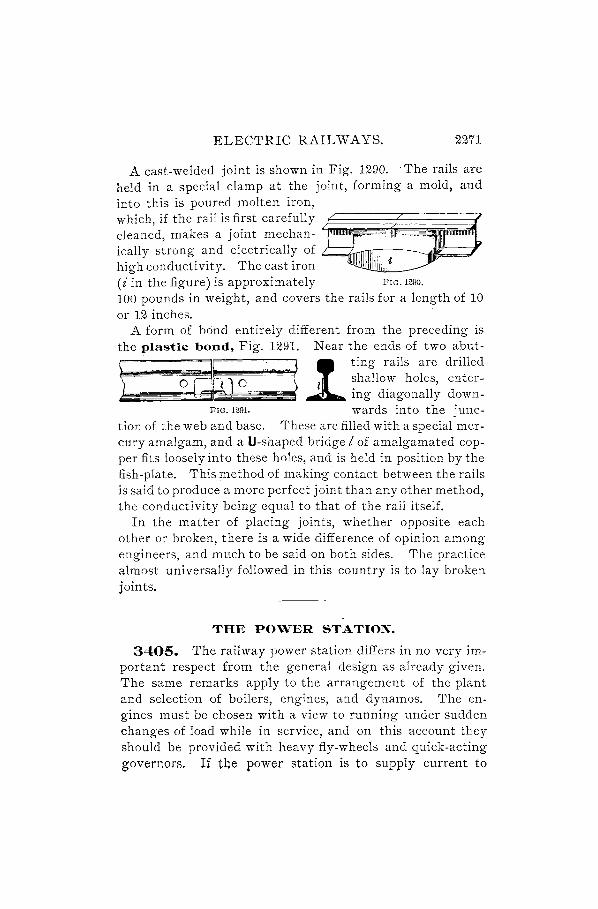
ELECTRIC RAILWAYS. 2271
A cast-welded joint is shown in Fig. 1290. The rails are held in a special clamp at the joint, forming a mold, and into this is poured molten iron,
which, if the rail is first carefully 4~~~~~~~~~~ cleaned, makes a joint mechan-ically strong and electrically of L.=Z"""TTTN----...
high conductivity. The cast iron (i in the figure) is approximately FIG. 1290.
100 pounds in weight, and covers the rails for a length of 10 or 12 inches.
A form of bond entirely different from the preceding is the plastic bond, Fig. 1291. Near the ends of two abut-
t ~~ .~ ~ ting rails are drilled -0;00.. l shallow holes, enter-=- ~= . ing diagonally down-FIG. 1291. wards into the junc-
tion of the web and base. These are filled with a special mercury amalgam, and a U-shaped bridge I of amalgamated copper fits loosely into these holes, and is held in position by the fish-plate. This method of making contact between the rails is said to produce a more perfect joint than any other method, the conductivity being equal to that of the rail itself.
In the matter of placing joints, whether opposite each other or broken, there is a wide difference of opinion among engineers, and much to be said on both sides. The practice almost universally followed in this country is to lay broken joints.
THE POWER STATION.
3405. The railway power station differs in no very important respect from the general design as already given. The same remarks apply to the arrangement of the plant and selection of boilers, engines, and dynamos. The engines must be chosen with a view to running under sudden changes of load while in service, and on this account they should be provided with heavy fly-wheels and quick-acting governors, If the power station is to supply current to

2272 ELECTRIC RAILWAYS.
only a few cars, simple high-speed engines with a wide range of cut-off should be installed; but when a large number of cars is to be used, compound high-speed or Corliss engines should be chosen. The method to be employed iIi determining the size of engines and dynamos for any given road will be explained under the head of Power Estimates.
CAR HOUSE AND REPAIR-SHOP.
3406. The car ho":"se is a building in which the cars are stored during those hours of the night when the line is out of operation, and should contain all facilities for inspection and repair. It is not necessary that it should be near the station,for it may be located wherever convenient,even at the other end of the line. Telephonic communication should, however, be provided with the power-house, so that current for the cars may be available when required. Space should be allowed for som.ewhat more than the number of cars in use, to provide for additional rolling-stock, as the extension of the system may warrant. The general plan of the building should be long, and it should be traversed by as many parallel tracks as the required accommodation calls for, all entering at one end, and each track closed by a large foldingdoor. The rails should be laid on brickwork piers or walls provided with substantial foundation, with a clear space between, forming a pit four or five feet deep, by means of which ready access may be had to the motors and' other fittings under the car body. The floor of the pit should be laid with concrete, as small trucks may then be easily moved along it, carrying armatures or other parts for the cars. With the increasing weights of motors, the old practice of raising them into place by main force is becoming more evidently inadequate. It is, at best, a very inefficient means, wasting both time and energy, and the most satisfactory method of handling is by the use of hydraulic jacks, which may be bought on the market, adapted to this particular purpose, -and mounted on trucks to run on rails laid in the pit.

ELECTRIC RAIL WAYS. 2273
3407. The wiring of the car house is a simple matter, one overhead wire being brought in over each track and connected at the door by a switch, so that it may be cut out of circuit for the sake of greater safety in handling the motors. These wires may be supported on insulators, as shown in Fig. 1292, and are intended to be fastened to overhead wooden beams by the lugs b, b. The clamp c holds the wire in the groove at the bottom, and is screwed to an insulated bolt passing through the frame a.
3408. It is well to make some FIG. 1292.
provision for running "cars out in case of fire. This is sometimes accomplished by making the track inclined, so that the cars will run down and out by gravity when the brakes are released; another suggestion is to set the controllers of all cars on the first notch when they are left for the night, but cut off t"he current from the overhead sections. In case of fire, the switches at the doors may be thrown over one by one, and all the cars would then slowly move out. Probably the best plan is to make the building of brick, with concrete floor and iron roof, so that the danger of fire will be reduced toa minimum.
3409. When the car house is situated near the street line, the several tracks
~~~~~~~~~~~~~~ running into it should not
1111 11:i I 1 II II I
I 1 II 'I ' i 1"1 ,i ii i
if 111~i I \1 11 )1 l!~11 I
II !II!~!III I1I1I Ii 111'1 f! ! ii Ii ,j
FIG. 129&;
start from the main line, but a siding s, Fig. 1293, should be laid out so that through cars need not go over so many switches. Those from the left pass over the switch a only, t40se from the ris-ht over &

2274 ELECTRIC RAILWAYS.
only, saving some amount of wear and tear on car-wheels and greatly prolonging the life of the switches.
, 3410. The repair-shop may be built directly at the end
of the car house, being in fact a continuation of it, but separated by the wall. Here a few tools, such as lathes, a small planer, shaper, milling-machines, boring-machines, .hydraulic press, grinding-machine, etc., should be available, as well as a blacksmith shop, so that repairs may be promptly attended to. Of especial importance is the grinding of wheels to remove any fiats which may and do occur, owing to ill usage on the part of careless motormen, or to soft spots on the wheel. The question as to whether it is well to regrind wheels depends upon the cost involved, and also upon the likelihood of continued service. If a wheel has run about 40,000 or 50,000 miles, it will perhaps not pay to regrind, because so much of the surface is worn away that there is no depth of chilled iron left, and the tread of the wheel is soft. Then, again, if the wheel has to be removed from the axle after running 35,000 miles, the expense incurred may not pay for the increased mileage ~btained. Special grinding attachments may, however, be had, which may be fitted to the axle while the car is blocked up from the rails, and the wheels trued up without removing them and 'with little delay. - The motors on the car are used to revolve the wheels, resistance being inserted at some suitable point until the speed is about 100 revolutions per minute. When the other pair of wheels is resting on the track, that motor must be cut out. If fiats on the wheels are allowed to develop, they will tend to destroy the track, since they cause heavy blows to be delivered at every revolution. Frequent inspection should be made of all cars, that no loose connections be allowed, and that commutators, brushes, gears, etc., are kept in good condition.
Another division of the repair department is the paint shop. Cracks develop in the car sides frequently, owing to the constant vibration due to running, and these should be tilled and painted itS soon as they appear, to prevent the

ELECTRIC RAILWAYS. 2275
access of water to the interior. All cars need revarnishing about once a year
SWITCHBOARDS.
3411. The switchboards are insulating supports for cable terminals, measuring instruments, and switches, as already described in the section on Electric Transmission. They are usually made of a number of vertical slabs of marble or: slate, frequently six or seven feet in height, arid each from eighteen inches to two feet or more in width. These divisions are called pan~ls, and each is provided with switches and other instruments necessary for the regulation of one generator or of one feeder circuit, the feeders being those wire$ which carry the current from the station to tbe
FIG. 1294.
centers of distribution. The switchboard must be set a little distance away from the wall and supported by brackets fastened into the brickwork, sufficient space being allowed fOJ;" ready access and convenient handling of the wires. There are many different styles of arrangement of switchboard appliances, but a representative method is. shown in Fig. 1294. There are generally two main divisions, one of which contains the panels for the generator instruments and the other those for the several feeders:' In the illustration we have shown a switchboard for two generators and four feeders, to which extra panels might be added as the business extended. The generator panels are ~n the" ieff, those

2276 ELECTRIC RAILWAYS.
for the feeders on the right. All connections are made behind the board, and the wires are shown dotted in the diagram. The bar running all the way across, marked + B, is the positive bus-bar; the negative bus-bar is - B, and is much smaller, both in cross-section and length, as it is only required to carry the current from one'generator, there being a connection to ground at G. On the generator panels at the bottom are the double-pole switches G. S., from which leads are run to the generator terminals, as indicated. The current passes from the positive side of the machine through the right-hand blade of the switch to the ammeter shunt s, then through the circuit-breaker C. B. to the positive busbar. The wattmeter W. M. is interposed in the circuit, being located, as shown, on the central panel; above it is the load ammeter A, connected across the shunt, which indicates the current output at any moment; the wattmeter sums up the total power which is delivered to the whole feeder system. At each of the feeder panels, connection is made to the bus-bar at a, and current is taken for the outside circuits, passing through the circuit-breakers at the top of the board, then down to the ammeter shunts s, and the single-pole feeder switches F. S. It may here be remarked that intersecting leads, as shown in the figure, do not touch each other unless they are marked with a dot at the point of junction; considerable clearance space should be given between any bare wires or bars crossing each other, and they must be firmly secured so that at no time will there. be any danger of their coming into contact.
At the back of the generator panels there are rheostats R, the handles of which project through to the front. These resistances are in series with the shunt field windings of the generators, to regulate the field strength. Circuit-breakers are used instead of fuses, as they are much quicker in action, and more easily adjusted to any current. They are simply automatic spring switches, which are released by an electromagnet when the current exceeds a certain strength, and are reset by pulling down the switch handle. Frequently, an electric bell is used as an automatic signal to show the a,t-

ELECTRIC RAIL WAYS. 2217
tendant that one of the feeder lines is broken, in case he did not hear the sound of the falling switch.
3412. The anuneter shunt is used to avoid the necessity of sending a very heavy current through the instrument. Its construction is shown in Fig. 1295. Two heavy copper terminals t, tl are soldered to the ends of the cables c, cI ' the recesses being shaped to fit. Connection between the terminals is made by strips of metal alloy a
1 1 : r
© © c t
I I : i - 'I I,
C-==-==~-l~~------------~~~'~====::j~
--------11~ , '
I , , ________ J
b
I L ______ _
FIG. 1295.
soldered in place, thus forming ,a path of higher resistance than the main line. The ammeter leads are brought to these terminals and firmly clamped in place by the bolts b, bl •
The instrument thus becomes virtually a voltmeter, indica. ting the drop of potential between those two points; but since this is proportional to the current flowing, the resulting readings are correct.
3413. Every panel should have a distinguishing number or letter, repeated, in the case of the generator panels, on the machines which they cOl'ltrol, S() that no mistake may be made in switch manipulation and any trouble set right without delay. .
An extra panel may be provided to carry one or more station voltmeters, or they may be mounted on the central panel. A ground detector, similar in principle to those already familiar to the student, may also be added. This
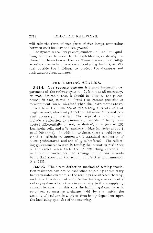
2278 ELECTRIC RAILWAYS.
will take the form of two series of five lamps, connecting between each bus-bar and the ground.
The dynamos are always compound-wound, and an equalizing bar may be added to the switchboard, as already explained in the section on Electric Transmission. Lightningarresters are to be placed on all outgoing feeders, usually just outside the building, to protect the dynamos and instruments from damage.
THE TESTING STATION.
34:14. The testing station is a most important department of the railway system. It is not at all necessary, or even desirable, that it should be close to the powerhouse; in fact, it will be found that greater precision of measurement can be obtained when the instruments are removed from the influence of the strong currents in that neighborhood, which may affect the galvanometers and prevent accuracy in testing. The apparatus required will include a reflecting galvanometer, capable of being connected differentially or not, as desired, a battery of 150 Leclanche cells, and a Wheatstone bridge (capacity about .1 to 10,000 ohms). In addition to these, there should be provided a ballistic galvanometer, a standard condenser of about t microfarad and one of fo microfarad. The reflecting galvanometer is used in testing the insulation resistance of the cables when there are no disturbing currents in neighboring conductors, the arrangement of instruments being that shown in the section on Electric Transmission, Fig. 1227.
3415. The direct deflection method of testing insulation resistance can not be used when adjoining cables carry heavy variable currents, as the readings are affected thereby, and it is therefore not suitable for testing one cable of a railway system when others in proximity to it are supplying current for cars. In this case the ballistic galvanometer is employed to measure a charge held by the cable, the amount of leakage in a given time being dependent upon the insulating qualities of the covering.
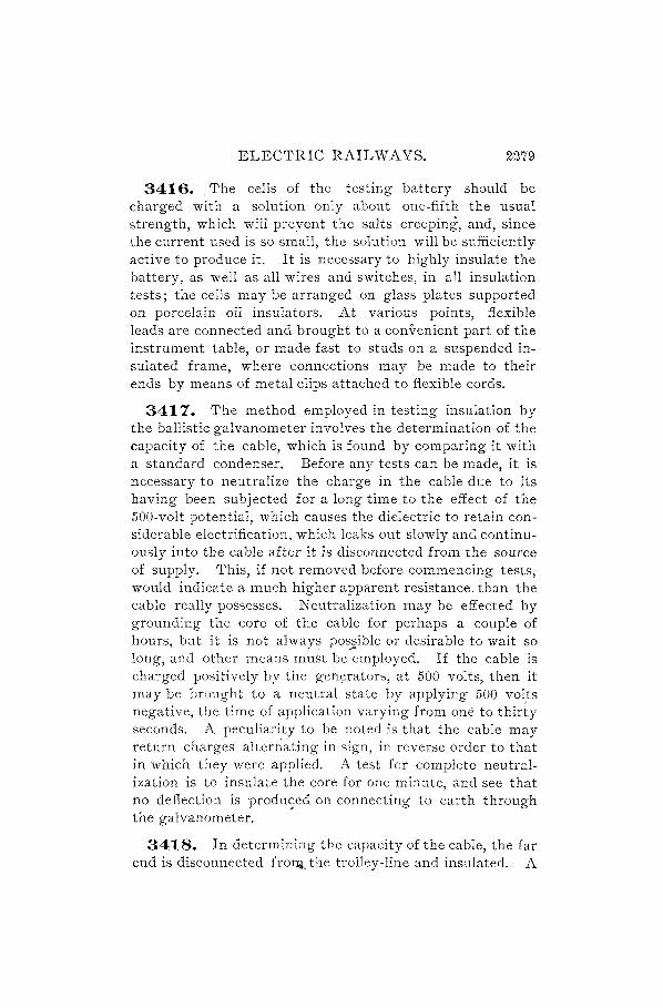
ELECTRIC RAILWAYS. 2279
3416. The cells of the testing battery should be charged with a solution only about one-fifth the usual strength, which will preyent the salts creeping, and, since the current used is so small, the solution will be sufficiently active to produce it. It is necessary to highly insulate the battery, as well as all wires and switches, in all insulation tests; the cells may be arranged on glass plates supported on porcelain oil insulators. At various points, flexible leads are connected and brought to a convenient part of the instrument table, or made fast to studs on a suspended insulated frame, where connections may be made to their ends by means of metal clips attached to flexible cords.
3417. The method employed in testing insulation by the ballistic galvanometer involves the determination of the capacity of the cable, which is found by comparing it with a standard condenser. Before any tests can be made, it is necessary to neutralize the charge in the cable due to its having been sUbjected for a long time to the effect of the 500-volt potential, which causes the dielectric to retain considerable electrification, which leaks out slowly and continuously into the cable after it is disconnected from the source of supply. This, if not removed before commencing tests, would indicate a much higher apparent resistance, than the cable really possesses. Neutralization may be effected by grounding the core of the cable for perhaps a couple of hours, but it is not always pos~ible or desirable to wait so long, and other means must be employed. If the cable is charged positively by the generators, at 500 volts, then it may be brought to a neutral state by applying 500 vol,ts negative, the time of application varying from one to thirty seconds. A peculiarity to be noted is that the cable may return charges aIteniating in sign, in reverse order to that in which they were applied. A test for complete neutralization 'is to insulate the core for one minute, and see that no deflection is produ<;ed on connecting to earth through the galvanometer.
3418. In determining the capacity of the cable, the far end is disconnected fro~ the trolley-line and insulated. A

2280 ELECTRIC RAILWAYS.
deflection d1 is then obtained on the galvanometer with a standard condenser of perhaps half a microfarad and (the same battery being used) a deflection d2 on the cable. Then, if K,= the capacity of the condenser and K 2 = the capacity of the cable,
d K, : K2 :: d, : do> or ]<"2 = K'd2. , (518.)
The capacity may also be given by the manufacturer who supplies the cable.
3419. A simple arrangement for testing the insulation resistance of a cable is shown in Fig. 1296. A small con
k
denser c of negligible capacity (say -10 micro-
\
___ ~L"__ ___ farad) is connected to
ground at G through the ballistic gal vanom
[ k2 eter g, also to the cable, or line L, by
B means of the key k, so that both may be charged at once by the battery B. The method of operation is as follows: All leading wires, ins t rum e n t s, and s wit c h e s being thor-
FIG. 1296. oughly insulated, and the cable freed at the far end, it is connected by the key k with the condenser c. Key k, is then depressed, and a charge given both condenser and cable, the condenser taking a proportionate part. At a moment when the current through the galvanometer is zero, indicating that the charge in the cable is steady, the key k is released, and the condenser discharges through the galvanometer, giving a deflection d, representing the full charge of the cable. The key k is then again depressed, and the battery again

ELECTRIC RAILWAYS. 2281
charges the cable and condenser for say 30 seconds, after which the battery is disconnected at k" and leakage' is allowed to take place for perhaps live :rI:\inu:tes. If the galvanometer shows a steady charge, the key k is then raised, discharging the condenser through the galvanometer and giving a deflection d., which is smaller than the first on account of the loss by leakage.
3420. The formula used in the determination of resistance is
26.06 t I=--fI'
Klog-j-, (519.)
where I = insulation resistance of cable in megohms, t = time in minutes during which the charge is allowed to leak, K = capacity of cable in microfarads, d, = initial discharge deflection, d.= final discharge deflection after t minutes.
Rule.-To find tlte insulation resistance of a cable by the ballzstic galvanometer method, multzply the tz"me in mz"nutes during wlzz"clz the charge zs allowed to leak by 26.06, and divide the product by a number obtained by multiplyz"ng togetlur the capacity of tlte cable z"n mz"crofarads and tlte logarithm of the quotient gz"ven by dZ"vZ"dz"ng the z"nz"tz"al d£scharge deflection (representing full charge) by the final dz"scltarge deflection.
EXAMPLE.-A railway feeder is 3-} miles long, and has a capacity of 2.5 microfarads. The galvanometer deflection for full charge was 234 divisions, and after five minutes' leakage a deflection of 104 divisions was observed. What was the insulation resistance? -
SOLuTION.-According to formula 519,
I- 26.06 X 5 - 2.5 X log Uf
ill = 2.25. By reference to a t~ble of logarithms it will be seen that the logarithm of 2.25 is 0.352.
Substituting this value for the ratio of the deflections, we have
I '. 1·· 130.3 148 h A = msu atlOn reslstance = 2.5 X 0.352 = megQ ms. ns.

2282 ELECTRIC RAILWAYS.
3421. The insulation of all cables should be periodically tested, in order to avoid breakdowns. A fault will usually develop quite slowly, and, being constantly watched, the cable may be put out of service before trouble is caused or a dangerous point reached. It will be found convenient to provide a section-lined chart, upon which the insulation of each cable may be graphically noted at every test, the line obtained by joining these readings showing at a glance the condition of the cable. Such a chart is shown in Fig. 1297, the vertical divisions representing weeks and months,
Jan. FIIr" Mar. APt'!. May June. , 1~ ~ ~ 4 U 18 U 4 n 18 U ~ 8 ~ • 6 i3 20 2'1 3 10 1'1 U
500~~-+~4-+-~-+~+-~-+~~+\~4-+-~-+~+-~
IOO,I--~~~+-+-+-+-+-+-+-+-4-4-4-4-4-~~~-k~~~~~~ __ -~ -.- --'-T'" --- "-", I:-.A- f--
800'~~~~~~+=~+=~~+-+-+-4-4-4-4-~\4-~~~-F~-b~
~'~~+-+-+-+-+-+-+-+-4-4-4-4-4-4-~~~~~~~~~~4
[\ 100'~~~~~~4~~-~-+-+-+-+-+-+-+-+4-'+-~~-4-+-+-+-+~
FIG. 1297.
each chart constituting a record for six mont~s. Several cables may be grouped together on one sheet by using different colored inks or lines of different formation. Three cables are shown in the figure; the heavy line represents the action of a cable in which a fault is developing. It will be seen that there is a decided droop in the curve in the tests made after March 18, and that one month later the insulation is still lower, its resistance steadily decreasing during another month, until it has a decided fall in May; the last test on the 27th of that month shows such a low value that the cable is put out of service, the fault located and repaired; and on June 10 the service is resumed, the insulation resistance being 350· megohms. These records

ELECTRIC RAILWAYS. 2283
are verYI valuable, showing the degrees of insulation of the various cables and affording a means of judging the comparative merits of different makes.
3422. Ordinary methods of testing for faults are not applicable to railway feeders', owing to their low resistance, which render~ accurate determinations almost out of the question. A means of locating a fault is shown in Fig. 1298. This requires that two well-insulated wires 'lV, 'lV' be run the length of the cable. At the testing station, located at one
w
}------------------"~"'-. '--------l
-1 I,
--.'
1 FIG. 1298.
end of the line, are two resistance-boxes R, R" connected on one side through the battery B to the ground at G, and on the other to A, A" respectively, these points being the terminals of the extra line-wires, which are connected together and to the cable at the far end, this end being insulated. A Thomson galvanometer g is inserted in 'lV'; the resistance of w is known, also the length of the cable, or its resistance. If a fault should develop at F, it will be seen that vve may arrange the different resistances in the form of a 'Vheatstone bridge. Taking the above letters as· indicating the several resistances, then a : b :: R, : R + 'lV. But a + b = C; therefore, a: C:: R, : R, + R + 'lV, and
R a = C R.+ R + 'lV' (520.)

2284 ELECTRIC RAILWAYS.
If C' = length of cable in feet, then the distance in feet from the testing point to the fault is
D- C' R, - R,+ R+ w· (521.)
This determination is independent of the copper resistance of the cable, if it is of uniform size. In the above arrangement, the resistance of the leading wires between R and A, and between R, and A" may be neglected, being very small.
Rule.-To find tlte distance in feet to a fault from tlte end of a cable, obtain a balance on tlze galvanometer witlt tiLe arrangement sltown in Fig. 1298, then multiply the lengtlt oj cable in feet by the resistance in box R" and divide the product by the sum of the resistances in the two boxes Rand R, and the resistance of the lille-wire w.
EXAMPLE.-On testing for a fault in a cable, a line-wire is used ,having a resistance of 12 ohms; the resistance-box in series with it has 230 ohms when the galvanometer shows a balance, and the box connected to the station end of the cable has 93 ohms. The length of the cable is 8,000 feet. 'What is the distance from the testing station to the fault?
SOLuTION.-The quantities given are: R = 230, R, = 93, W = 12, C' = 8,000. (Compare Fig. 1298.) From formula 521,
D - 8,000 X 93 _ (l (l(l1 f t - 93 + 230 + 12 - "',~'" ee. Ans.
EXAMPLES FOR PRACTICE.
1. The testing arrangements, when determining the insulation resistance of a certain cable, are as follows: A Thomson reflecting galvanometer of 10,000 ohms resistance; shunt, 1,480 ohms; resistaneebox, 1,000,560 ohms; battery, 500 ohms. The deflection for galvanometer constant was 306 divisions, and the corrected deflection from cable was 95 divisions. "\Vhat was the insulation resistance?
Ans. 23.24 megohms.
2. The capacity of a cable is 2.14 microfarads. On testing for insulation by the loss of charge method, the deflection for full charge was 287 divisions, and the deflection after four minutes' leakage was 194 divisions. Find the insulation resistance. Ans. 286.4 megohms.
3. In testing a cable for a fault, the ends were freed from ground and joined by a wire, a galvanometer being included in the circuit. Another wire from the far end of the cable was brought to the testing

ELECTRIC RAILWAYS. 2285
station at the near end, its resistance being 5.S ohms, and there connected to one terminal of a resistance-box A. The near end of the cable was connected to one terminal of a resistance-box "3, and the remaining terminals of the two boxes were joined together and to one pole of a battery, the other pole being grounded. On a balance being obtained with the galvanometer, there was in A a resistance of 340 ohms, and in'B 860 ohms. What was the distance to the fault from the station, the cable being 11,000 feet long? Ans. 7,845 feet.
ALTERNATING CURRENTS IN RAILWAY WOI1,K.
3423. The use of alternating currents is, in general, onl y ad visa ble when the source of power is a long distance from the point of utilization or distribution, and in such cases the three-phase system of transmission has proved well adapted to the purpose. It is then usual to install generators supplying a three-phase high-tension current directly to the line; but if the distance is so great as to make a very high tension (of 10,000 or 15,000 volts) necessary, step-up transformers are used in connection with low-voltage generators. At the sub-station this current is then lowered by means of a step-down transformer and brought to a rotary transformer, or motor-dynamo, which suppiies a direct current to the street-railway system at the regular pressure of 500 volts. Rotary field motors are sO,metimes used on the cars, in which case the high-tension current is simply transformed to a lower pressure, and so used; but such a system requires, two trolleys on each car and double overhead construction, two wires running side by si~e and insulated from each other. The switches and crossings become more complicated in consequence, and the wear and tear is greater. On the other hand, the total weight of wire put up need not be much greater than would be the case with the direct-current supply; the motors also are of very simple construction, and not liable to get out of order, having no commutators. Speed regulation is effected by cutting out the starting resistances; the ann:atnre is designed to give a large starting torque, and any of the extra resistance in series with it
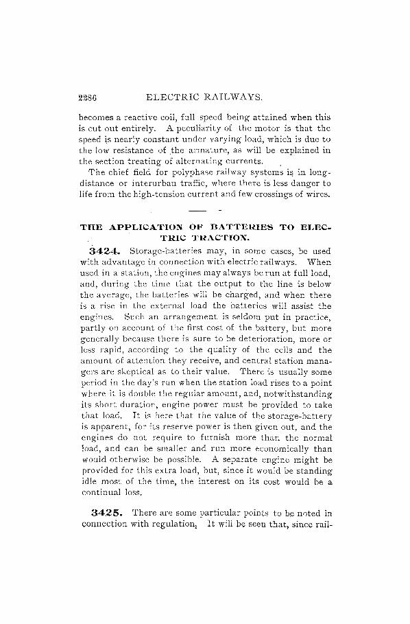
2286 ELECTRIC RAILWAYS.
becomes a reactive coil, full speed being attained when this is cut out entirely. A peculiarity of the motor is that the speed ~s nearly constant under varying load, which is due to the low resistance of .the armature, as will be explained in the section treating of alternating currents. .
The chief field for polyphase railway systems i'l in longdistance or interurban traffic, where there is less danger to life from the high-tension current and few crossings of wires.
THE APPLICATION OF BATTERIES TO ELECTRIC TRACTION.
3424. Storage-batteries may, in some cases, be used with advantage in connection with electric railways. When used in a station, the engines may always be run at full load, and, during the time that the output to the line is below the average, the batteries will be charged, and when there is a rise in the external load the batteries will assist the engines. Such an arrangement is seldom put in practice, partiy on account of the first cost of the battery, but more generally because there is sure to be deterioration, more or less rapid, according to the quality of the cells and the amount of attention they receive, and central station managers are skeptical as to their value. There is usually some period in the day's run when the station load rises to a point where it is double the regular amount, and, notwithstanding its short duration, engine power must be provided to take that load. It is here that the value of the storage-battery is apparent, for its reserve power is then given out, and the engines do not require to furnish more than the normal load, and can be smaller and run more economically than would otherwise be possible. A separate engine might be provided for this extra load, but, since it would be standing idle most of the time, the interest on its cost would be a continual loss.
3425. There are some particular points to be noted in connection with regulation: It will be seen that, since rail-

ELECTRIC RAILWAYS. 2287
way generators are usually over compounded, if a battel-y were simply connected in parallel with them on the circuit, it would be charged when the external load was heavy, because the voltage of the generators would then be the highest, and would discharge when the external load was light, thus aggravating the faults which it should remedy_ To overcome this action, it is necessary that the voltage of the battery should be raised as the load increases, so that at heavy loads it will feed into the line. This can be accomplished by switching in or out extra cells; but there is the disadvantage that these cells may be undercharged or reversed. Another method consists in using an electromechanical regulator, but this causes short-circuiting of the cells as the contact switch passes along, since it must cover two contacts at once on passing froin one to the other, if the circuit is not to be broken; with the heavy currents used, the contacts would soon burn out if the circuit were frequently opened.
3426. A very convenient way to regulate the action of the battery is by the method shown in Fig. 12!"H). The
FIG. 1299.
compound-wound dynamos are represented by d, dl> their series windings by c, c" and shunt by s, s,. An extra dynamo, or "booster," d2 is put in series with the battery E, having shunt and series coils as shown, wound in opposition to each other. vVhen the external load is light, the voltage of the dynamos d, dl is low, and very little current passes

2288 ELECTRIC RAILWAYS.
through the series coil; hence, the shunt winding s. of the booster acts to produce such polarity of its field-magnets as to develop an E. M. F. opposing that of the battery, which, therefore, helps the dynamos d, d, to charge it. 'When the external load is heavy, the series coil c. will take its share of the main current and overpower the shunt field s" reversing the polarity of the booster and allowing the battery current to feed into the line, thereby taking some of the load off the main dynamos d, d,. With a moderate load, the shunt and series windings of the booster balance each other, and the machine is idle, but at this time the engines are working at an economical point.
There is still another matter to consider. The charging and discharging must be so adjusted that they preserve a balance, that is, the charging in 24 hours must equal the discharge plus the battery loss. This may be accomplished by regulating the booster shunt by hand, the effect of which is to change the point of reversal of the booster with respect to the load. If the battery tends to discharge, the shunt field must be strengthened, and vice versa. When one dynamo alone is running and the battery is required to furnish extra power, the shunt is weakened.
When the booster is connected on at first, it will be necessary to increase the series field of the generators d, d, by cutting out some of the resistance forming the shunt across the series winding, in order to compensate for the extra coil c2 , but this is on-Iy substituting another path for the current instead of allowing the energy to be wasted in heating the resistance.
3427. In Fig. 1300 the heavy line is a graphic representation of the variation of load during a certain day in a central station. It will be seen that the lowest point, about 85 amperes, is reached between 3 and 4 o'clock in the morning; that the load rises abruptly at 6 o'clock, and continues to increase until 9, falling again towards noon, and attaining its maximum value at G in the evening, whence it falls rapidly and continuously. It is evident that, to operate such a

ELECTRIC RAILWAYS. 2289
road, a plant would have to be provided capable of turnish. ing 2,700 amperes to the line, and probably more on some occasions; but this amount is required only during a short period, and some of the plant must remain idle or work inefficiently for a greater part of the 24 hours. The average current is about 1,276 amperes, and a line drawn through this p'oint indicates the current output if the load were steady all day and the same in total amount. It would obviously, then, be an advantage if the high parts of the load could be brought down to equalize the effect of the low
d. M. P. M.
FIG. iaoo. parts, and the storage-battery accomplishes this. If it wer~ installed in such a station, the dynamos would be called upon to deliver only about half the current, 1,300 instead of 2,700 amperes, and would therefore be one-half the size; engines and boilers would also be correspondingly smaller. In the diagram, the shaded portion marked c represents the charge given to the accumulators, and that marked d repre· sents the discharge.

2290 ELECTRIC RAILWAYS.
POWER ESTIMATES.
3428. In considering the amount of power required for propelling a car, we shall assume that the force required to drag a car over a level track in average condition is 30 pounds for every ton that the car weighs. This, though a rather high figure, is a safe one. to use in calculations for horsepower, and the rule may be expressed as a formula thus,
f=30 TV, (522.)
where f is the force in pounds and W the weight of the car in tons.
In cases where the track resistance is known, we may use the formula
f=r W, (523.)
where r is the trackJesistance in pounds per ton weight of car.
EXAMPLE.-What force will be required to move a car forwards, its weight being 9 tons?
SOLuTION.-The weight of car W = 9 tons, and the force required wlll be, by formula 522,
f = 30 X 9 = 270 lb. Ans.
3429. When a grade has to be taken into account, the perpendicular distance in feet ascended in one minute multiplied by the weight of car, will give the power in footpounds expended in raising the car; the horizontal distance in feet traveled in one minute multiplied by the force in pounds necessary to move the car, will give the power in foot-pounds required for a level track. The sum of these values divided by 33,000 will be the total horsepower at the wheels. Loss of power in the transmitting mechanism will necessitate a larger figure for the power supplied to the motors, this depending upon the efficiency of the apparatus. We may express these several operations in a single for. mula, as follows:
hw+Df H = 33,000 E ' (524.)

ELECTRIC RAILWAYS. 2291
where H is the total horsepower required for the motors, h is the perpendicular distance in feet ascended in 1 minute, w is the weight of the car in pounds, D is the horizontal distance in feet traveled in' 1 minute, f is the force in pounds necessary to move the car, and E is the motor efficiency expressed as a decimal part of .1.
EXAMPLE.-If a car with passengers weighs 8 tons, and it is desired to take it up a 6 per cent. grade at a speed of 10 miles per hour, what horsepower must be delivered to the motors, their efficiency being 75 per cent.?
SOLuTION.-The car will cover in 1. minute 10 ~~,280 = 880 feet = D, and on a 6 per cent. grade this will correspond to a vertical distance of 880 X .06 = 52.8 feet = h. The weight of car expressed in pounds = 8 X 2,000 = 16,000 pounds = w. The force required for propulsion is, by formula 522,
f = 30 X 8 = 240 pounds,
and the efficiency being 75 per cent., E = .75. Then, by formula 524, we have .
H - h w + D f _ 844,800 + 211,200 _ 42 67 - 33,000E - 24,750 - ..
The power delivered to the motors must be 42.67 H. P. Ans.
3430. The power required in going around curves depends upon their radius and upon the construction of the truck. The power required f.or starting may be taken as the same as that for rounding curves.
3431. It has been found that a force of about 70 pounds per ton weight of car is required to start a car, or to keep it in motion when rounding curves. When starting on a grade, the effort must be greater in proportion to the percentage of rise, and for this condition add 20 pounds to the 70 for eyery ton weight and for each 1 per cent. of grade.
Expressed as a formula, the force required will be
f' = (70 + 20z) W, (525.)
where z is the per cent. grade and W the weight of the car in tons.

2292 ELECTRIC RAILWAYS.
On a 2 per cent. grade the force required in starting will therefore be f' = [70 + (20 X 2)] Xl = 110 pounds per ton.
EXAMPLE.-What force will be required to start an 8-ton car on a 5 per cent. grade?
SOLUTION.-According to formula 525, the force will be
f' = (70 + 20x) W = [70 + (20 X 5)] X 8 = 1,360 lb. Ans.
3432. The above formula for determining the power required in starting is based upon an acceleration from rest to a speed of nearly 9 miles an hour within 20 seconds. In case, therefore, of a different acceleration being employed, another method may be used, as follows:
Let W = weight of the car in tons; p = per cent. of grade; s = speed of car in miles per hour; t = time in seconds during which acceleration takes
place.
Then the power required will be that necessary to overcome the track friction as well as to produce the given acceleration. By formula 522, the force required to move the car against track resistance, f = 30 W. The force of acceleration will be
2,000 W 5,280s 91.1 Ws 32.2 X 3,600 t = t . (526.)
These two formulas may be combined into one. The force required to bring a car to a certain speed, in a given time, on a level track,
F=f+ 91.1t WS. (527.)
EXAMPLE.-A car weighing 10 tons is to be brought from rest to a speed of 8 miles an hour within 25 seconds. What force must be applied?
SOLUTION.-By formula 527, the force required
91.1 X 10 X 8 F= 30 X 10 + 25· = 591.5 pounds. Ans.

ELECTRIC RAILWAYS. 2293
3433. When a grade is to be taken into account, the force required to overcome it will be
2,000 Wx 1{0 = 20 Wp. (528.)
The force required to bring a car from rest to a certain speed within a given time, on a grade, will be
F' =/ + 91.1 Ws + 20 Wp. t
(529.)
EXAMPLE.-A car weiglling 8 tons is to be started 'on a 6 per cent. grade and a sufficient force applied to bring the car to a speed of 10 miles per hour within 30 seconds; let the track resistance be 20 pounds per ton weight of car. What will this force be?
SOLUTION.-By formula 529, the force required
91.1 X 8 X 10 F' = 20 X 8 + 30 + 20 X 8 X 6 = 1,363 pounds. Ans.
3434. In order to determine the power required in starting, we may proceed as follows: The speed of the car . 5280 X s ill feet per second = ' 3 . If the speed increases uni-
,600 formly from 0 to s miles per hour in t seconds, the distance
_ 5,280 X s ,1 _ 11 s . covered - 3 600 X t X '2 - 15 feet per second. 1 horse-
. , power = 33,000 foot-pounds per minute, or 550 foot-pounds per second. The average power will then be, starting on a grade,
F' X .!.1 s
550 15 = .00133F' s. (530.)
EXAMPLE.-What would be the average power required, in the preceding example, to bring the car to the speed mentioned?
SOLUTlON.-The force F' necessary to propel the car was found to be 1,363 pounds. The average horsepower would then be, by formula 530, .
. 00133 X 1,363 X 10 = 18.13 H. P. Aus.
It is to be remembered that, although the above figure represents the average horsepower required to propel the car under the conditions as stated, the question of motor

2294 ELECTRIC RAILWAYS.
efficiency enters very largely into consideration, and can not be taken as more than 50 per cent. An excess of current flows at the instant of turning on the controller, regulated only by the resistance of the armature, fields, and rheostat. After the armature has attained some speed of rotation, the counter E. M. F. will be effective; but at the start an excess of energy is used up in heating, which energy must be supplied from the line, although doing no useful work.
SLIPPING ON RAILS.
3435. The limit of adhesion may be i of the weight; therefore, on a level track the maximum force which could
2000 be applied without slipping would be -'-8- = 250 pounds
perton. If the rails were muddy or greasy, much less than ,this force could be used, while very clean, dry rails might increase this amount. In ordinary street-railway service the rails are usually rather slippery, and often, in consequence, the adhesive force may be low. \Ve may calculate the grade on which slipping will occur, when starting the car, and also when it is already in motion, in the following manner:
Let a = ratio of adhesive force to weight on drivers; . 'lV' = weight on drivers in pounds; W = weight of car in tons of 2,000 pounds; Gs = per cent. grade at which slipping occurs.
Then, slipping will occur, at starting, on a grade
G _aw'-70 W .- 20 W .
But w' = 2,000 W, when the whole weight of car is on the dnvers, in which case the limiting grade for starting
G _ 2,000 a Wt - 70 W _ 2,000 a - 70 t (531.) • - 20 W - 20 per cen .
When!' of the weight is on the drivers, %
2,000a _ 70 %
G. = ---2=-00:---- per cent. (532.)

ELECTRIC RAILWAYS. 2295
EXAMPLE.-If a car weighs 7 tons, and all its weight is on the drivers, adhesion being one~eighth of this weight, will it start un a 7 per cent. grade?
SOLUTION.-The per cent. grade at which slipping occurs at stal·ting is, by formula 532,
G - (2,000 X t) .,.- 70 _ 180 _ 9 t s- 20 -20- percen.
The car will therefore start on a 7 per cent. grade, as 9 per cent. is the limit. Ans.
3436. When the car is running, only 30 pounds per ton is necessary for propulsion; and the limit of grade which may be ascended is, letting Gr = maximum grade which a rimning car will ascend,
2,000a _ 30 z
Gr = ---,,2-0-- per cent. (533.)
EXAMPLE.-'fhe limit of adhesion being one-sixth the weight on the drivers, how steep a grade could be surmounted by a car with onequarter of its weight on the drivers, starting from the level?
SOLuTION.-According to formula 533,
2,O~oa _ 30 e'~oo X t) - 30
Gr = 20 = 20 = 2.67 per cent. Ans.
MAXIMUM LOAD.
3437. Before making the selection of the engines for a station, it is first necessary to decide, from the nature of the road and other circumstances, what the maximum load is likely to be, and to find the ratio between this and the average load throughout the day (of 24 hours). We h2..VC seen that in the case of a road having a single car, the maximum station load is reached every time that the car starts on a grade. If there were two cars, the chance of the maximum station load being double this amount would not be so great, because they would seldom both start at once on a heavy grade, and when the number is increased still further, the maximum load per car likely to come on the station is reduced in proportion. There are several factors to be taken
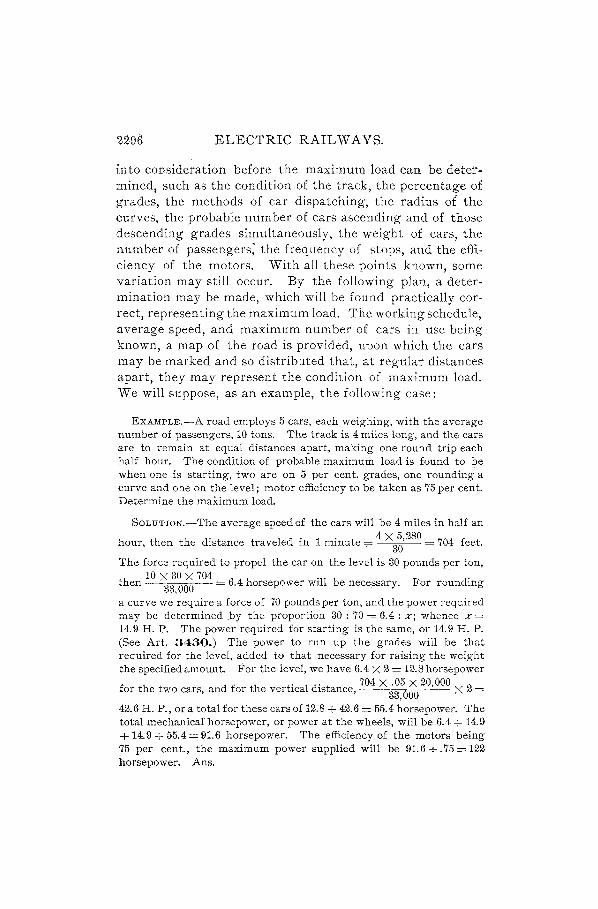
ELECTRIC RAILWAYS.
into consideration before the maximum load can be determined1 such as the condition of the track, the percentage of grades, the methods of car dispatching, the radius of the curves, the probable number of cars ascending and of those descending grades simultaneously, the weight of cars, the number of passengers; the frequency of stops, and the efficiency of the motors. With all these points known, some variation may still occur. By the following plan, a determination may be made, which will be found practically correct, representing the maximum load. The working schedule, average speed, and maximum number of cars in use being known, a map of the road is provided, upon which the cars may be marked and so distributed that, at regular distances apart, they may represent the condition of maximum load. We will suppose, as an example, the following case:
EXAMPLE.-A road employs 5 cars, each weighing, with the average number of passengers, 10 tons. The track is 4 miles long, and the cars are to remain at equal distances apart, making one round trip each half hour. The condition of probable maximum load is found to be when one is starting, two are on 5 per cent. grades, one rounding a curve and one on the level j motor efficiency to be taken as 75 per cent. Determine the maximum load.
SOLuTION.-The average speed of the cars will be 4 miles in half an
hour, then the distance traveled in 1 minute T= 4 X3~,280 = 704 feet.
The force required to propel the car on the level is 30 pounds per ton, 10 X 30 X 704 . .
then 33,000 = 6.4 horsepower wlll be necessary. For rounding
a curve we require a force of 70 pounds per ton, and the power required may be determined _by the proportion 30: 70 = 6.4 : Xj whence x = 14_9 H. P. The power required for starting is the same, or 14.9 H. P. (See Art. 3430.) The power to run up the grades will be that required for the level, added to that necessary for raising the weight the specified amount. For the level, we have 6.4 X 2 = 12_8 horsepower
f h d f h . I d' 704 X .05 X 20,000 2 or t e two cars, an or t e verbca lstance, 33,600 X =
42.6 H. P., or a totalfor these cars of 12_8 + 42.6 = 55.4 horsepower. The total inechanicafhorsepower, or power at the wheels, will be 6.4 + 14.9 + 14.9 + 55.4 = 91.6 horsepower. The efficiency of the motors being 75 per cent., the maximum power supplied will be 91.6+.75=122 horsepower. Ans.

ELECTRIC RAILWAYS. 229'1
The steam-engines and, electrical generators can easily take a temporary overload of 20 percent., and it would not be economical to employ machines rated crt the full capacity as given above for the maximum load. Allowing, then, 20 per cent., we have 122 -+- 1. 20 = 101 horsepower for the rated capacity.
POWEll EQUIPMENT.
3438. In stations with heavy normal load, it is advisable to install compound or triple-expansion Corliss engines, directly connected to large low-speed generators. For the 5-car road we have been considering, a simple high-speed engine would prove most satisfactory, and, as we have shown, it should be able to develop about 100 horsepower at t or i cut-off. The dynaqlOs may be 2, of 50 kilowatts each, one of which would furnish service for ~ time if the other should be disabled. Two boilers should be provided, each capable of supplying all the steam needed while the other is being cleaned.
For more extensive roads where a greater number of cars is in use, it is not necessary to go through the calculations respecting positions of various cars to determine the maximum load, for the mean load will approach this value more closely. For a 25-car road, the average station power to be allowed per car will be about 18 indicated horsepower, and the engines, if of the Corliss type, may be 2, each of 225 horsepower, and if the high-speed engine is used, with a greater range of cut-off, they may be each 200 horsepower. Three dynamos may be installed, each of 100 kilowatts, belted to a common countershaft to be driven by one or both engines.
For power stations to run 50 cars, the allowance is generally about 16 indicated horsepower per car, and two engines should be provided, each of about 400 horsepower, and four 150 K. W. dynamos. 'When a road has 100 cars, three engines should be used, in order to allow for the repair of one without interrupting the service; by reckoning 15 horsepower per car, we have a total of 1,500 horsepower.

2298 ELECTRIC RAILWAYS.
Two compound or triple-expansion engines of 600 horsepower and one compound engine of 300 horsepower can here be used, each large engine belted to two 250 kilowatt dynamos and the small engine to one 250 kilowatt dynamo. In still larger installations, direct-connected units are very desirable, but the power available per car should not, in the largest plant, be below 15 H. P.
The above estimates do not consider railroad systems running very heavy cars, but are based upon the use of cars of an average size. When a road has many steep grades, or a great number of stops are necessary, due allowance should be made. Also, snow-sweepers, when used, must be taken into account, as they often require as much power as four or five cars. In all cases, additional machinery must be provided in order to guard against stoppage of service owing to breakdowns.
3439. When several circuits are run from one machine, or from two or more connected in parallel, it frequently happens that one circuit will be temporarily loaded more than the others, causing a local fall of potential. The E. M. F. of the generator can not be raised, so the expedient is now generally adopted of increasing the potential of that branch by adding in the circuit anoth~r generator of considerable current capacity and low E. M. F. This machine is a compensator, more commonly called a booster, and has already been mentioned in connection with battery regulation. It should be so arranged as to be easily transferred from any circuit to another requiring its aid, plug and socket connections being provided for this purpose on the switchboard. The armature, being in the main circuit, is of low resistance; the field-magnets may be either serieswound or connected as a shunt across the station feeders. In the first case, the machine requires to be rather larger and therefore more expensive, although it will be entirely self-regulating; in the second case, the field is controlled in the usual manner by a rheostat placed in its circuit.

ELECTRIC RAIL WAYS. 2299
INSPECTION.
3440. It is very necessary that proper inspection should be made of all parts of the equipment which are subject to wear. This includes not only the motors, but the gears, wheels, carbodies, track, .andoverhead wiring. The general operation must also be closely watched, to eliminate all possible source of unprofitable expense and to provide a reliable and efficient service. The motors should be periodically tested for insulation, that faults may be corrected before they assume dangerous proportions; the gears should be examined to see that they are wearing well and are free from grit. Particular attention should be devoted to the prevention of flats on wheels, which are caused by the motorman applying the brakes so forcibly as to hold the wheels and make them skid. Immediately a flat is discovered, the car must be brought to the shed and the wheels ground true, for the hammer blow on the track at every revolution of a flatted wheel is very severe.
The track ne"Ods constant attention to keep it in good condition. One of the most serious difficulties is the prevention of low joints; with the long fish-plates now coming
FIG. 1301.
into use, the joint can be held up better than formerly. The bonds must be tested to see that they make good contact with the rails on each side. One method is to provide a flat, wooden straight-edge, Fig. 1301, about 6 feet long, with a millivoltmeter V mounted on a cross-board at the middle. At each end is a spring contact point on the lower edge, and a third about 12 inches from one end. These are connected to resistance-coils R, R" of about 10 ohms each, and to the voltmeter terminals, as shown, small switches 5, S' being placed in each circuit a V band b V c, so that separate readings may be taken. The voltmeter should'

2300 ELECTRIC RAIL WAYS.
have the zero-point at the center of the scale, so that the readings will be on opposite sides for currents through the two circuits. This device may be placed upon the rails when they are carrying current, the joint being between the contacts a and b on the left, and the voltmeter will then indicate the ratio of the current in the rail to that passing through the joint. A certain deflection may be taken as the limit beyond which rebonding is required. Imperfect joints ~re to be marked with chalk, in order to distinguish them, and they should be put in good condition without delay.

ELECTRIC LIGHTING. ELECTRIC ILLUMINATING APP ARA TUS.
METHODS OF LIGHTING.
3441. There are two principal systems of lighting by electrici t y in commercial use:,
a. Arc lighting. b. Incandescent lighting. Depending upon the nature of the current used, each of
these systems is subdivided into two methods, namely: a. Continuous-current lighting. b. Alternating-current lighting. There are therefore four distinct systems to be con·
sidered, namely: 1. Arc lighting by continuous current. 2. Arc lighting by alternating current. 3. Incandescent lighting by continuous current. 4. Incandescent lighting by alternating current.
GENERATORS.
3442. The dynamos used for generating the current which is converted into light at the lamps are usually specially designed for the particular system of lighting they are intended to supply, and may be classed as follows:
a. Continuous-current, constant-potential generators. b. Continuous-current, constant-current generators. c. Alternating-current, constant-potential generators. d. Alternating-current, constant-current generators. Various combination systems are often found in commer·
cial use, such as a system of arc and incandescent lamps supplied with current by the same generators, both in con· tinuous as well as in alternating current work. These are treated of fully in the following pages.

2302 ELECTRIC LIGHTING.
THE ELECTRIC ARC LIGHT. 3443. Arc lighting is the oldest form of electric illu
mination, its principle having first been made public in the year 1813 by Sir Humphry Davy, of England.
Davy found that when two carbon pencils formed part of a closed circuit through which a current of electricity
of the necessary strength was flowing, a series of intensely brilliant sparks passed
+ frbm one pencil to the next when they were separated. This series of sparks formed a flame having peculiar properties, chief among which were:
a. An extraordinarily high temperature. b. An exceeding brilliancy of light. The currents used in these early experi.
ments on the arc light were derived from large batteries of cells. In modern commercial lighting, specially constructed powerful dynamo-electric generators are employed.
FIG. 1302. Fig. 1302 shows the general appearance of the electric arc as formed between two carbon points A and B, across which a current is flowing. The two carbons are termed the electrodes, and according to the direction of the current flowing through them, the one is called the positive (+) electrode and the other the negative (-) electrode.
PRINCIPLE OF THE ELECTRIC ARC.
3444. To clearly understand what is actually taking place at the tips of these electrodes during the formation of
the electri~ arc., let Fig. 1303. rep- - 111111\11111111111 T __
resent a CIrCUIt through whIch a ~ . fl . f B current IS owmg rom a battery + E
of cells B . . In this battery circuit two car
bon rods or pencils have been placed, as shown in the figure.
When the carbons form a closed
-E~

ELECTRIC LIGHTING. 2303
circuit, or, as it is technically term~d, when they are in contact, the current from the battery flows through them without any visible effect. But if, while this current is flowing, the two electrodes E, El are slowly separated from each other at A, a series of brilliant, sputtering sparks is seen to pass across the space between the ends of· the carbons. These sparks, which occur at the kz"ndlz"ng of the arc, at once giye way to a flame of intense brilliancy, which continues to play between the two electrodes as long as the current from the battery retains the necessary strength and the carbons remain at a certain distance from each other .
. When this flame has continued for a time, an inspection of the electrodes will show that the tips have seemingly been eaten away or consumed, and it will be found that the tip of the positive electrode differs from that of the negative electrode. This is shown very clearly in Fig. 1302, which gives the appearance of the electrodes after the arc has been burning for some time. In the figure, the upper carbon A IS the positive electrode.
3445. The actual cause of the arc and how it is maintained are explained as follows: The current passing betweeh the two carbons which are in contact is suddenly given an air-gap which it must jump or " bridge," or the arc is "sprung" or " kindled." This air-gap is a path of high resistance. As already explained, a conductor of high resistance is easily heated to such a degree that it glows with light-that is, it becomes incandescent. This occurs in the gap between the two carbons. The result is that the positive carbon is heated intensely over a patch of its surface from which a column of carbon vapor arises. This vapor is projected across to the negative carbon and forms the conductor for the current, which continues across it. The vapor itself becomes incandescent and forms what has been termed the arc.
Careful study of the phenomenon of the arc has shown that the positive carbon is usually the seat of' a perfectly defined ebullition-that is, state of boiling or the carbon.

2304 ELECTRIC LIGHTING.
This ebullition, taking place on the face of the positive carbon, produces the luminous' patch above mentioned, an~ causes the carbon to gradually become slightly hollowed out, thus forming what is termed.the crater.
The light of the arc is emitted chiefly from this crater, very little being emitted from the flame itself and not much from the negative tip.
The crater, which is white hot all over its surface, may be regarded as a depression in the positive carbon, in which carbon is boiling and from which vapors are arising and traveling across the air-gap to the negative carbon, thus forming a conducting path for the current.
The fact of the ebullition or boiling of the carbon being established, the following highly important deductions can be made:
a. The arc can not be formed unless the temperature required to boil carbon is reached.
b. All arcs made with a pure carbon emit from the crater a light of equal whiteness, irrespective of the strength of the current, or the voltage, or the length of the arc.
c. Increase of current in an arc only il1;creases the size of the crater; unit area of crater surface always gives out a light of equal whiteness.
Based on this latter fact, it has been suggested to make the unit area of the crater of the arc light the standard unit of light.
3446. Since the boiling-point of any substance is a fixed temperature, it is clear that a constant temperature attends the arc, and therefore the deduction (a) above referred to is made. The boiling-point of the various substances which may have become mixed with the ordinary carbon during manufacture, which are termed impurities, is much lower than that of carbon, but they will not alter the brightness of the positive crater, because they disappear by volatilization at comparatively Jaw temperatures. It zs carbon exclusively tltat boils at the positive pole.
In considering the practical utilization of the arc light, it

ELECTRIC LIGHTING. 2305
will be shown that every arc lamp requires about 45 volts across its terminals. Of these 45 volts about 39 volts are required to m~intain the arc itself between the tips of the electrodes. Until quite recently this voltage was regarded as a counter E. M. F., and many text-books still mention it as such. This hypothesis is, however, now disregarded, and the (about) 39 volts of drop across the two carbon tips may be regarded as due solely to the work being done by the current in vaporizing the carbon.
AMOUNT OF LIGHT.
3447. The amount of light given off by the arc depends on:
a. The intensity of the current. b. The nature of the electrodes-that is, whether of car
bon or other substance. c. The medium which surrounds the arc-that is, whether
air or other gas. The color of the arc light depends upon the material
of which the electrodes are composed. With electrodes of sodium, it is yellow; with electrodes of zinc, it is white; with electrodes of silver, it is green; with electrodes of carbon, it is of a bluish white color.
In commercial work, carbon electrodes are almost exclusively used, for they are both cheap and of greater durability than others.
3448. The tem.perature of the arc is very difficult to determine accurately. One of the most recent determinations makes it about 3,500 degrees Centigrade. An approximate idea of this heat may be gained from -the fact that only 500 degrees Centigrade are required to make solid bodies glow with light. The electric arc thus gives us the highest temperature we can produce by known means.
In the arc the most refractory substances are fused ~nd vaporized; platinum, for instance, melts away like wax in an ordinary flame. .

2306 ELECTRIC LIGHTING.
ARC-LIGHT CARBONS.
3449. The carbons used in commercial work are usually in the form of rods, and are generally composed of coke, tar, or the graphite deposited in the inside of the retorts during the manufacture of illuminating gas.
Whichever of these materials is used, it is ground very fine, carefully cleared of impurities, and mixed with molasses or a special syrup to make the particles adhere firmly together. The mass is then molded to the proper form, baked, and finished.
The carbons may have the following composition:
Pure powdered coke .............. . Calcined lampblack ............... . Syrup ................ ; .......... . Water ........................... .
15 parts. 5 parts. 8 parts.
Graphite or retort carbons last longest, but are likely to flicker.
During recent years cored carbons have been introduced. These are made with an inner core of softer carbon, having a higher conductivity than the surrounding material, thereby tending to hold the current, and, hence, the arc, in the center of the rod.
The finished carbons are often given a thin electroplated coating of copper or nickel, which increases the conductivity of the rod and frees the current from the necessity of forcing its way through the high-resistance carbon only. Such coated carbons last longer than bare ones.
CONSUMPTION OF CARBONS.
3450. Due to the fact that the positive carbon" craters" or hollows out, and thus forms a natural reflector for the light of the arc, it is usually placed ·above the negative carbon, so that the light may thereby be thrown beneath the lamp. In general, the top, or +, carbon burns at the rate of about It inches per hour.
With continuous currents, the + carbon wastes twice as
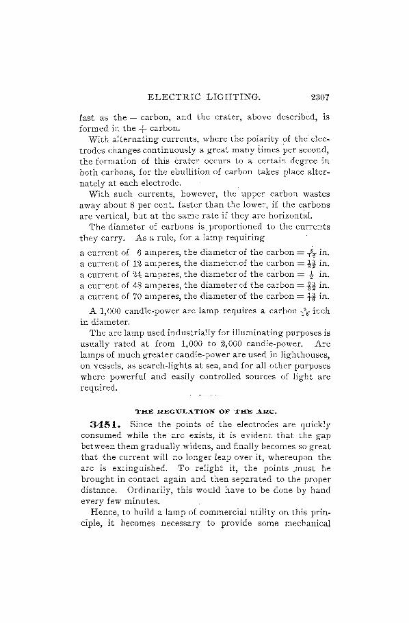
ELECTRIC LIGHTING. 2307
fast as the - carbon, and the crater, above described, is formed in the + carbon.
With alternating currents, where the polarity ~f the electrodes changes continuously a great many times per second, the formation of this crater occurs to a certain degree in both carbons, for the ebullition of carbon takes' place alter-nately at each electrode.' .
With such currents, however, the upper carbon wastes away about 8 per cent. faster than the lower, if the carbons are vertical, but at the same rate if they are horizontal.
The diameter of carbons is. proportioned to the currents they carry. As a rule, for a lamp requiring
a current of 6 amperes, the diameter of the carbon = -h in. a current of 12 amperes, the diameter. of the carbon = it in. a current of 24 amperes, the diameter of the carbon = tin. a current of 48 amperes, the diameter of the carbon = -it in. a current of 70 amperes, the diameter of the carbon = tt in.
A 1,000 candle-power arc lamp requires a carbon -h- inch in diameter.
The arc lamp used industrially for illuminating purposes is usually rated at from 1,000 to 2,000 candle-power. Arc lamps of much greater candle-power are used in lighthouses, on vessels, as search-lights at sea, and for all other purposes where powerful and easily controlled sources of light are required.
THE REGULATION OF THE ARC.
3451. Since the points of the electrodes are quickly consumed while the arc exists, it is evident that the gap between them gradually widens, and finally becomes so great that the current will no longer leap over it, whereupon the arc is extinguished. To relight it, the points .must be brought in contact again and then separated to the proper distance. Ordinarily, this would have to be done by hand every few minutes.
Hence, to build a lamp of commercial utility on this principle, it becomes necessary to provide some mechanical

2308 ELECTRIC LIGHTING.
contrivance whereby the carbons are automatically moved forwards as their points are consumed, so that the length of the gap is at all times the same, and the radiance of the lamp is, therefore, constant and continuous.
The demands which are made upon such a regulating device are the following:
a. The contrivance must cause the regular and gradual approach of the carbons to each other according to the rate at which they are consumed.
b. It must automatically produce the initial electric spark by bringing the carbons into contact as soon as the current is thrown on, and then separating them to the proper distance.
c. It must automatically hold the carbons at a predetermined distance from each other, which distance has been decided upon as the one best adapted for the particular current used and the intensity of light demanded.
In most lamps, the first-named duty is generally performed by gravity, which makes it necessary that the carbons be placed one vertically above the other.
The duties outlined by b are almost always performed by electromagnets, which are contained in a suitable case and placed above or below the arc.
The third duty is performed by adjustment screws usually attached to the carbon holders, which permit the raising or depressing of the carbons at will, even during the passage of the current.
THE ARC LAMP. 3452. An outline of the arc lamp is shown in Fig. 1304.
The positive carbons are a and a,; band b, are the negative carbons; c and c, are carbon rods for holding the active carbons; H contains the mechanism for keeping the carbon points at a constant distance; p and p, are binding-posts for the line-wire; In and In, are chimneys, wllich give added space for the travel of c and c,; and k is the ring for hanging the lamp. The active carbons are fastened in place by thumbscrews e, e" e., and e3 • The figure shows two sets of carbons. Only one set, however, is in operation at one time,

ELECTRIC LIGHTING. 2309
the second coming into operation as soon as the first is burned out. Lamps which burn for about eight hours are manufactured with one set of carbons, while with two sets they will burn about sixteen hours.
In setting the carbons, it is important that the longer carbon should be the positive one. If the carbons are reversed, the smaller one being above, the lamp will continue to operate even after the upper carbon is completely burned away, and the holder and part ~f the rod will be fused.
Although many inventions have been made upon the apparatus for regulating the distance of the carbons, they all follow two general methods of design; namely, a system using a rack and pinion, in which a long rack, carrying the positive carbon, engages with a pinion which imparts to it a vertical motion; and the clutch system, in which the carbon rod is held in a peculiar way by a device which is usually
m m.t
c
FIG. 1304.
operated by the attraction for its armature exerted by an electromagnet or a solenoid. The rack and pinion may be operated by clockwork until the carbons are at the right distance, and then stopped by the attraction for its armature of an electromagnet through which the main current passes, or they may be brought into action by the force of gravity and the heat produced by the main current. The clutch may be acted upon and released by the force of gravity and the attraction of a soft-iron core into a solenoid, or it may be operated by magnets, one on each side of an armature.
3453. Clutch Lalllp.-A simple form of clutch lamp is that of Brush, the regulating device of which is shown by the diagram, Fig. 1305.

2310 ELECTRIC LIGHTING.
At a is the positive carbon, and at b the negative; c is the car,bon rod; p is the negative and p, the positive bindingpost; s is the metallic supporting rod through which the main current passes. Starting from p" the main current goes to 2, where it divides and flows round the hollow electromagnets In and m" meeting again at 1; it then follows the circuit through cab s to p. There is also a second winding, which begins at 1 and passes back through the electromagnets In, In, in a direction opposite to that of the main wire,
2 r-----'+-<1o~P"'1'____,
c
"t f
• 3 /I a
b
r
FIG. 1305.
forming a high-resistance shunt. These shunt windings join at 3 and the circuit is continued through the electromagnet n to the negative terminalp.
A thick wire of low resistance connects between the terminal p, and the resistance r, the circuit being completed through the contact k and the electromagnet n to the terminal p. This winding is in the same direction as that in series with the shunt just mentioned. Under normal working conditions, the circuit is kept open at k by means of a small spring~attached to the armature I, which counterbalances the pull of the electromagnet due to the ordiriary strength of current passing through from the shunt coils m. m •.
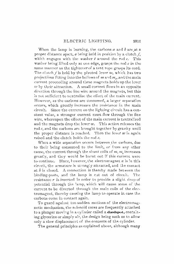
ELECTRIC LIGHTING. 2311
When the lamp is burning, the carbons a and b are.at a proper distance apart, a being held in position by a clutch f, which engages with the washer t around the rod c.· This washer being lifted only at one edge, grasps the rod c in the same manner as the tightener of a tent rope grasps its cord. The clutch f is held by the pivoted lever w, which has two projections fitting into the hollows of m and m" and the main current proceeding around these magnets holds up the lever W by th.eir attraction. A small current flows in an opposite direction through the fine wire around the magnets, but this is not sufficient to neutralize the effect of the main current. However, as the carbons are consumed, a larger separation occurs, which greatly increases the resistance in the main circuit. Since the current on the lighting circuit has a constant value, a stronger current must flow through the fine wire, whereupon the effect of the main current is neutralized and the magnets drop the lever w. This action releases the rod c, and the carbons are brought together by gravity until the proper distance is reached. Then the lever w is again raised and the clutch holds the rod c.
When a wide separation occurs between .the carbons, due to their being consumed to the limit, or from ·any other cause, the current through the shunt coils of m, 1lZ, increases greatly, and they would be burnt out if this current were to continue. Since, however, the electromagnet n is in this circuit, the armature is strongly attracted, and the contact at k is closed. A connection is thereby made between the binding-posts, and the lamp is cut out of circuit. The resistance r is inserted in order to provide a slight drop of potential through the lamp, which will cause some of the current to be diverted through the main coils of the electromagnet, thereby causing the lamp to operate in case the carbons come in contact again.
To guard against too sudden motions of the electromagnetic mechanism, the solenoid cores are frequently attached to a plunger moving in a cylinder called a dashpot, containing glycerine or simply air, the design being such as to allow only a slow displacement of the contents of the cylinder.
The general principles as explained above, although many

2312 ELECTRIC LIGHTING.
improvements have been made upon them, are those em. ployed in all lamps of this character. However, in some, instead of solenoids with movable cores, two sets of magnets are used, opposed to each other and attracting a common armature. One set of magnets is in the main circuit and one in the shunt, and the result of their differential action is the same as in the type of arc lamp just described.
3454. The clutch arrangement ~or a double set of carbons is shown in front and side view by Fig. 1306. The carbon rods, also called lamp rods, are cand c, ; F is the' frame, having a clutch (k and k,) at each side. The frame
FIG. 1306.
F is raised and lowered by the lever n which is pivoted at %.
The washers, such as t of Fig. 1305, strike against .the bottom of the mechanism box as they descend, and are caused to assume a horizontal position. The core of the electromagnet acts upon this combination of levers in the same manner as w is acted upon in Fig.·1305. The clutch on side k, is a little higher than that on k; so that although c is released, k, always grips the carbori rod c, and holds it at such a height that the washer does not come in contact with the bottom of the mechanism box, and no current passes through the carbons on that side. When, however, the car-

ELECTRIC LIGHTING. 2313
bons of c are consumed, the frame descends until the current passes through the carbons of c" and the .action goes on as before.
3455. Rack and Wheel LaIllp.-In these lamps the feeding is effected by gearing from a wheel, which is released by the shunt coils when the current in the main coils weakens. The carbon rod is provided with a rack '"ith which a pmlOn engages. The pinion with its gearing and the rack are raised by the attraction of the mai\J- coils, thereby striking the arc between the carbons. When the current weakens, the pinion and rack are lowered, and when they are at the lowest point a further lowering of the rack and carbon rod is obtained by the release of the gearing by the shunt coils, which allows the carbon rod to fall by gravity.
The rack and wheel lamps have the advantage, of a smoother feeding action than the clutch lamps, but they may become clogged with dust and require to be kept clean.
3456. Sometimes the reglJation is performed by the engaging of a chain instead of a rack with the wheel, but the principle of operation 'is the same. By either of these methods, lamps may be designed to operate both carbons at the same time, so that the arc may remain stationary. The method of Co operating with a chain is shown in Fig. 1307.
W is the wheel, C is the chain, A is the positive carbon, and B is the negative carbon. It may be seen that when TV turns and A is raised, B is lowered at the same time; or when A is low-ered, B is raised.
The apparatus shown in Fig. 1307, with an extra outside resistance, will serve for alternating and direct current constant-potential circ11its, as well as for constant-current series circuits.
B

2314 ELECTRIC LIGHTING.
THE ENCLOSED A.RC LAMP.
3457. The enclosed arc is a form of electric light which is rapidly coming into use. An ordinary arc in the open air burns carbon rapidly-so rapidly, indeed, that two sets of carbons are required for all-night lighting. If, however, the arc is enclosed, so that but little air can reach it, .the consumption of carbon is much slower, and the lamp may burn continuously for 150 hours or more.
Fig. 1308 sliows the arrangement of an enclosed arc. Gis a hollow glass bulb about 6 inches long and 3 inches in diam
eter and provided with a small opening at each end. To the lower end is screwed a small brass cap C. Between the cap and the end of the bulb is an asbestos washer W, making this end practically airtight when the cap is screwed up. At the center of the cap, and forming part of it, is a brass tube T, which holds the negative carbon.
The top of the bulb is ground smooth. Upon it rests a plate P with a hole in the center, through which the positive carbon passes. This plate is not fastened to the bulb, but is free to move about a little, and the hole in the center is just large enough to allow the positive carbon to move up and down freely. It is necessary to have the plate itself free to move, in order to get the carbons in line; for the negative carbon is put in
FIG. 1308. first, and the positive carbon has no room to move sideways in the plate. Since the top of the glass and the lower surface of the plate are ground plane, little or no air can get in between them, and the only

ELECTRIC LIGHTING. 2315
place where air can enter the bulb is at the hole in the center of the top plate, through the small space between the carbon and the plate itself. .
3458. In the plate shown in the figure, there are two . grooves a and c passing entirely around the carbon. This leaves less surface for the carbon to rub against, and affords a space in which eddies are formed by the hot air passing up, thus further tending to keep the cold air out.
The arrangement here described is intended for use on any ordinary arc lamp. The tube T at the bottom is put into the negative carbon hold'er of the lamp frame, and the positive carbon slips down from above through the plate.
3459. An open arc burns in an atmosphere of cold air in which there is plenty of oxygen. This oxygen combines with the carbon, and the carbon rods are quickly co·nsumed. If the carbons of an open arc are drawn wide apart, so as to raise the potential difference between the positive and negative carbons to 75 or 80 volts, the combustion becomes very rapid, and the arc burns with a flame which quickly uses up the carbons while giving but little light. In an
. enclosed arc the supply of oxygen is limited. After the first few minutes, the bulb is filled with a hot atmosphere of nitrogen, carbon monoxide, and carbon dioxide. If a lighted candle were placed in the bulb, it would quickly be
. extinguished, for want of oxygen. A little fresh air comes in continuously around the positive carbon. It would not be correct to have the enclosing bulb entirely air-tight, even if there were no danger of explosion from the expansion of the heated gases within. Some carbon is thrown off from the poles under any condition. If there is a little oxygen present, it will unite with this carbon to form a gas and -will not interfere with the light. If there is no oxygen, this carbon will quickly coat the inside of the bulb with a layer of lampblack. As it is, the bulb becomes coated on ·the inside with a light-colored deposit, which comes from impurities in the carbons, and is. mostly silicon. This layer helps to diffuse the light, and, in a measure, may take the

2316 ELECTRIC LIGHTING.
place of an opal globe. When it becomes too thick, it absorbs considerable light, and it is necessary to clean the bulbs.
3460. Enclosed arc lamps are run at a higher potential and with less current, than open arcs. The carbons may be drawn wide apart without causing the arc to flame.
At first, the bulbs were attached to lamps which were built for open arcs, as in the case of the bulb shown in the diagram, which was designed for this purpose. These lamps were run at about 8 amperes and 60 volts. To get this voltage, it is necessary to draw the carbons wide apart; that is, the lamp must have a long pick-up. Some styles of arc lamps could be adjusted to do this, but others could not.
It was soon found to be better to use a still higher voltage and a smaller current. For this purpose, special lamps are made, taking about 5 amperes at 85 volts. Such a lamp gives more light than one taking 8 amperes at 60 volts, so that, while the first lamp uses 425 watts, the latter takes 480, and we get more light per watt from the high-voltage, than from the low-voltage, arc.
3461. These enclosed arcs are generally used in parallel on a 110-volt circuit, a suitable resistance being put in to reduce the voltage from 110 to 80 or 85.
It is not necessary, then, to use two lamps in series, as is the case when open arcs are used on such a circuit. The enclosed arcs are hardly as efficient as the open arcs; but the former have many advantages which are rapidly bringing them into use, the most important of these being the small consumption of carbon. An ordinary carbon will last about 8 hours in an open arc lamp; but it is possible to obtain a life of 150 hours in a good enclosed arc lamp. This means that, when lamps are used in stores for 4 or 5 hours each evening, the open arc lamp must be trimmed every day and the enclosed arc only once a month·-a considerable saving of carbon and a greater saving of labor.
The carbons of an enclosed arc are burned away so slowly that the lamp feeds at long intervals, the light being, con-

ELECTRIC LIGHTING. 2317
sequently, st~adier and the arc quieter. These advantages, together with the fact that there is no possibility of sparks being thrown from the en_closed arc, make this form of lamp in many respects the ideal light for indoor illumination.
3462'. The mechanism of the special lamps for enclosed arcs is the same in principle as that of the open arcs. Quite a number of the lamps on the market use series coils only. The carbons are in contact when the lamp is not in use, and are caught and drawn apart by a series coil as soon as the current starts. Thc pick-up is long on all such lamps. At 85 volts the carbons are abo'ut t inch apart.
We easily see that there is an advantage in using only series coils when these lamps are placed on 110-volt circuits. If a shunt coil is used, the current through it does not go through the arc, and is wasted, so far as giving light is concerned. Of course there is a fall of potential in the series coil, but it is necessary to have some fall of potential to come down from 110 to 85 volts; so that the series coil is a part of the resistance which must be used any,vay.
3463. Where enclosed arcs are connected in series, it is best to use both shunt and series coils, or, if desired, shunt coils' alone may be used. In the latter case the carbons stand wide apart when the current is not on, and are held there by a strong spring pulling up. ·When the current is turned on, it all goes through the shunt coil at first. This exerts a strong pull downwards, drawing the positive carbon down till it touches the negative one, thus striking the arc. The instant the carbons come together, a current st"arts across, most of it going through the carbons and little through the shunt coil. The downward pull of the shunt coil is weaker now than the upward pull of the spring, and the carbons are thereby separated to the proper cListance.
3464. A representative form of enclosed arc lamp is shown in Fig. 1309. There is but one solenoid s, which is connected in series with the carbons and has a compact magnetic circuit through the cylindrical yoke y, the conical core k, and the armature a. The armature carries at its

2318 ELECTRIC LIGHTING.
lower end a pan p containing four clutch rings r, which fall by gravity and grip the carbon c by wedging between the carbon and the inclined side of the pan. As the car· bon falls by reason of the consumption at the are, or through the current being interrupted, the pan is lowered until the rings are caught by the tube t which is supported by the frame of the lamp. This action releases the carbon, which then falls towards the lower carbon c', but the consequent reduction of resistance causes a large current to flow through the coil s, which draws up the armature, and with it the carbon c, to the normal height. Regulation is, then, effected by the differential action of a series coil and gravity, for the moving system is designed to have considerable weight. The upper carbon is held in a sheath b, which allows of the use of shorter carbons than would otherwise be necessary. The sheath wiil readily pass between the clutch rings and through the tube t. Current is con· ducted to the carbon by means of sixteen contact rings d, enclosed within a box e, and making flexible contact with the carbon. The inner globe g sur· rounds the carbons, and is supported by the arm or yoke f The outer globe fits over the plate It at the bottom, and
==~==:::;;=~ is secured at the top by a circular nut
FIG. 1309.
at i, the joint being packed by means of asbestos gaskets. The space immediately above It and below the inner globe is intended for the rheostat-a necessary adjunct to all enclosed arc lamps.

ELECTRIC LIGHTING. 2319
The enclosed arc requires carbons of exceptional purity, in order to prevent the formation of deposits upon the inner globe. The especial feature of these lamps is, however, the use of a high potential, usually about 80 volts, between the carbons, the remainder of the E. M. F. of the circuit being taken up by the resistance of the series winding and the rheostat.
ELECTRIC LIGHTING BY INCANDESCENCE.
3465. In Art. 3445 atteption was called to the fact that a conductor of high resistance is easily heated to such a degree that it glows with light-that is, it becomes incandescent. It is evident that if a conductor can be obtained which will allow of continued incandescence when the current is passing, and which will last for a reasonable time, such a conductor would form an exceedingly simple lamp, as no complicated mechanism would be required to control its radiance, other than a proper regulation of the current and pressure for which it was designed.
Lamps of this kind were first patented in England in 1845. In these early lamps solid carbon or metal rods were used, which were heated white hot.
Owing to the tendency of carbon to oxidize when at a high temperature, it became necessary to enclose the incandescent carbon in a glass vessel from which the air had been exhausted.
Platinum, which was occasionally utilized as a conductor, did not prove lasting enough, while the carbon rods lacked the necessary chemical <lnd mechanical uniformity to make them commercially a success.
Edison, however, after experiments which lasted several years and during which a vast number of materials were tried, in the attempt to find a suitable conductor of lasting qualities, finally found that the carbonization of certain vegetable substances gave a conductor of the desired qualities. By means of this discovery he built the first practical incandescent lamp.

2320 ELECTRIC LIGHTING.
THE'INCANDESCENT LAMP.
3466. An incandescent lall1p is thus a light-pro. ducing device in which a current of electricity traverses a carbon strip, usually of horseshoe shape, supported in an almost complete vacuum, and heq.ts it to incandescence.
The Edison incandescent lamp is shown in Fig. 1310. G is a clear glass globe, which has been almost conipletely
exhausted of air and gas. Within this globe and supported by two platinum
o
A
FIG, 1310.
wires p and p, is the carbon strip, or filall1ent, F. This filament is very fine, having little more thickness than a horse hair, and is prepared by carbonizing an elastic vegetable substance made from wood pulp, linen, cotton, or paper, and called cellulose. The material is SUbjected to various treatments until it becomes gelatinous, or like jelly. It is then forced through an aperture in a die and drawn to the desired cross-section. Next, it is formed by winding on molds, and afterwards carbonized. This last is effected by raising the strips to a high temperature in an air-tight enclosure.
The platinum wires p and p" to which the filament is joined, are blown in the glass piece K.
One of these wires is connected to the brass screw piece s, ",-hile the other is connected to a brass plate 0, insulated from s by cement made of plaster of Paris, which also secures the glass bulb in place. The socket is shown at A. It contains a circular
aperture with a brass screw piece corresponding to s, so that when the lamp is screwed into the socket a good contact is made between the two screw connections. As the key It is

ELECTRIC LIGHTING. 2321
turned, the lamp being in the socket, it acts upon a lever which rises and makes connection with the plate at o. This connection is made with a scraping motion, which keeps the contact always bright. The two conductors from the lighting mains are twisted together into one cord, each being separately insulated, and enter at w. One conductor is connected to the screw piece of A, while the other is connected to the contact lever, and the current therefore passes directly through the carbon filament.
3467. Exhausting the Air frolD the Glass Globe.-The air is exhausted from the globe G, Fig. 1310, by a mercury air-pump. The principle of this apparatus is shown in Fig. 1311. Let R represent the lamp, one end of which has been sealed by the glass piece carrying the carbon filament. The other end is open and connected to the glass tube x. This, in t 'un, is connected to the tube c d, the lower end of which passes through the cork d and dips under the mercury in vessel B. The upper end is fastent 1 to the glass funnel A by a rubber tube c. A clamp tightly closes this rubber tube, and a valve closes the tube x.
When a long tube, closed FIG. 1311.

2322 ELECTRIC LIGHTING.
at one end, is filled with mercury and then placed in aver· tical position with the open end beneath the level of the mercury in a vessel, the mercury will stand at a certain height-about 30 inches-in the tube, as shown in Fig. 1311, which represents at R an exhausted glass sphere.
Mercury is poured in to the funnel A, and then a small quantity is allowed to escape down the tube by adjusting the clamp. This quantity carries part of the air down the tube and out through the aperture of B; and, as a constant quantityof mercury is allowed to escape, alternate layers of mercury and air proceed down the tube until an almost complete vacuum is formed in the lamp R, and no air bubbles are seen in the column of mercury passing down the tube.
3468. Before the lamp is connected to the pump, a short tube, with two capillary or extremely narrow contractions in its length, is blown in at the top.
Next, a tube is prepared with an enlarged end, as shown in Fig. 1312. Two short platinum wires respectively soldered
to the ends of the two cope -----------------~----- per wires are inserted in the
-t-4-=-------~-+}---l tube, and the enlarged end -------------------, is heated nearly to fusion
FIG. 1312. and compressed upon the wires, so that they are embedded in the glass, leaving two bent pieces outside. To these pieces wires are joined, and these are in turn connected to the ends of the carbon filament by a deposit of pure copper.
The enlarged end of the tube is then blown into the large opening in the bulb or globe, so that it forms part of the glass. N ext, the dra wn-down end is trimmed off square, and the lamp is ready to be exhausted.
However, while exhaustion is in progress, some further treatment is given to the carbon to confer upon it elasticity and ability to stand high degrees of incandescence. This consists in introducing into the bulb. a gas rich in carbon, and then passing a strong current through the filament. The effect of this treatment, which is called flashing, is to

ELECTRIC LIGHTING. 2323
deposit carbon upon the filament, this occurring principally upon those portions which glow the most brightly. Since these portions are originally the thin parts of the filament, they are at once built up, thus producing a carbon thread having a uniform resistance throughout its length.
A great variety of incandescent lamps are manufactured, but they differ only in details of construction. The general principle is the same, in that a filament through which a current passes is produced by carbonizing some vegetable substance, and this filament is held within a glass globe that has been almost completely exhausted of air.
3469. The COllllllon candle-powers for incandescent lamps are 8, 10, 16, 20, 32, 50, and 100. The 16 candle-power and 32 candle-power are most generally used.
The same incandescent lamp may be used on either alternating or direct current circuits.
Rule.-The power required for the average incandescent lamp may be calculated by allowing about 8.44 watts per candle, so that a 16 candle-power lamp requires about 16 X 8.44 = 55 watts.
Rule.-In figuring the number of lamps which a certain engine horsepower can supply, it is customary to allow 10 Edison 16 candle-power lamps per indicated lzorsepower.
The current required for 16 .candle-power lamps of different voltages is given below, figured on a basis. of 55 watts per lamp:
Electromotive Current Force in Volts. in Amperes.
110 .50 75 .7338 55 1.000
3470. The life of incandescent lamps is greatly diminished by running them higher than at their normal voltage. The average durability of the filament of incandescent

2324 ELECTRIC LIGHTING.
lamps is estimated at from 600 to 1,000 hours, or from two and one-half to four months, with an average use of from eight to nine hours a day. Many lamps burn very much longer than this; 800 hours is, however,_ a fair average
figure.
MEASUREMENTS AND CALCULATIONS.
DETERMINATION OF CANDLE-POWER.
3471. The candle-po'Wer of the electric lamp is the number of standard candles that would produce a light equal to its own in intensity.
The unit of light in gerzeral use is a spermaceti candle -} oj atZ inch in diameter, burning 120 grains per lzour. Six such candles weigh one pound. They vary sometimes as much as ten per cent. from the standard.
A legal standard of light was agreed upon by the International Congress of Electricians, at Paris, in April, 1884. This standard is as follows :
The unit of each sim.pJe light is the quantity of light of the same kind emi tted in the normal direction by a sq uare centimeter of surface of molten platinum at the temperature of solidification. The practical unit of white h;({ht is the quantity of ligh,t emitted normally by the same source.
A square foot of surface is equally illuminated by a standard candle at a distance of 12.7 inches. A 16 candlepower lamp gives the same illumination at a distance of 4 feet 2 inches.
3472. Photom.eter.-The candle-power of an electric light is measured by a photom.eter. The two photometers generally used are those of Bunsen and Rumford.
A diagram of Bunsen's 'photOIueter is shown in Fig. 1313. A is a darkened box containing the lamp l. From this box a tube projects, so that the rays from the lamp are carried directly through it into an opposite tube at a known distance from the first. This second tube carries a scale upon which slides the box s. In the center of this box is

ELECTRIC LIGHTING. 2325
stretched a piece of paper d with a grease-spot at its center. This spot is, of course, transparent, and allows the lIght to pass from either direction.
On each side of the paper is an inclined mirror, so placed that on looking directly upon the edge of the paper through a horizontal slit in the tube, both sides may be seen in the mirrors at the same time. In a compartment B at the other end of the second tube is a standard candle c. Both compartments are covered at the back by a non-reflecting
A
h n
)
I . U I
I.- 1------- x -------~-
FIG. 1313.
cloth, and all inside surfaces are blackened, so as to exclude all effects from reflected light.
To make the test, the room is darkened and box s is adj listed along the slide until the outline of the grease-spot. disappears and the entire paper shows exactly the same degree of brightness, which indicates that the movable paper has now been placed in a position at which the light from c has the same effect upon it as the light from l.
This means that a light C?f candle-power c must be placed at a distance y from the grease-spot to shed the same radiance upon the paper as a light of candle-power 1 at a distance x.
Let L -= light from standard candle; D = distance between candle and screen; d = distance between lamp tested and screen.
Then the light from the lamp tested,
d'L 1= D'.

2326 ELECTRIC LIGHTING.
Since L is taken as a standard candle, or unity, the candle· power of lamp tested,
d' 1= DO' (534.)
That is to say, the intensity of the light received by an object varies inversely as the square of its distance from the source.
Thus, if a light has a candle-power intensity of 1,000 at a distance of 2 feet, at 4 feet, or twice the distance, the intensity will not be one-half of this, but one-fourth, or 250 candle-power. The abbreviation for candle-power is c. p.
EXAMPLE.-Suppose a light of an intensity of one candle-power be placed at c in the photometer, and a lamp of unknown intensity at I, and let it be required to determine the candle-power at I. On moving the greased paper along the tube 4 inches from c and 16 inches from I, the grease-spot disappears.
SOLuTION.-In this case, D = 4 and d = 16; then, by formula 534, the candle-power of the lamp,
16 X 16 I = 4 X 4"" = 16 c. p. Ans.
34'13. In Rum.ford's photom.eter two shadows of an opaque rod are thrown on a white screen. One shadow is thrown by the lamp at a given angle, and the other is thrown by the candle at an angle equal to that of the lamp. The distances 'are adjusted until both shadows have the same degree of intensity, when the same formula is applied .
. 34'14. Distribution of Light.-The candle-power of a lamp differs according to the direction from which it is
measured. The maximum candlepower is that obtained from an angle of 45° below the horizontal
\ plane of the lamp. This makes it _-+ ___ *"_-.----!'~H~ necessary to take the mean spheri-
FIG. 1314.
cal candle-power instead of the horizontal.
In Fig. 1314 the direction of the ray of maximum intensity of an arc lamp is shown to be at an
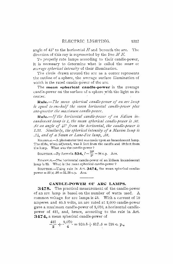
ELECTRtC LtGHTING. 2327
angle of 45° to the horizontal H and beneath the arc. The direction of this ray is represented by the line M N.
To properly rate lamps according to their candle-power, it is necessary to determine what is called the mean or a'lterage spherical intensity of their illumination.
The circle drawn around the arc as a center represents the outline of a sphere, the average surf;:tce illumination of which is the rated candle-power of the arc.
The Illean spherical candle-power is the average candle-power on the surface of a sphere .with the light as its center. '
R,ule.-The mean spherical candle-power of an arc lamp is equal to one-half the mean horizontal candle-power plus one-quarter tlte maximum candle-power.
Rule.-If tlte ltorizontal candle-power of alZ Edison incandescent lamp is 1, the mean spherical candle-power is .98. At an angle of 45° from the horizontal, the candle-power is 1.33. Similar(v, the spherical intensity of a Maxim lamp is .74, and of a Swan or Lane-Fox lamp, .58.
EXAMPLE.-A photometer test was made upon an incandescent lamp. The slide, when adjusted, was 3 feet from the candle and 18- feet from the lamp. What was the candle-power?
182 SOLU'l'ION.-By formula 534,,1 = 32 = 36 c.B. Ans.
EXAMPLE.-The horizontal candle-power of an Edison incandescent lamp is 32. What is the mean spherical candle-power?
SOLUTION.-Using rule in Art. 34'14, the mean spherical candlepower = 32 X .98 = 31.36 c.p. Ans.
CANDLE-POWER OF ARC LAMPS. 3475. The practical measurement of the candle-power
of an arc lamp is based on the number of watts used. A common voltage for arc lamps is 45. With a current of 10 amperes and 45.5 volts, an arc rated at 2,000 candle-power gave a maximum candle-power of 2,070, a horizontal candlepower of 421, and, hence, according to the rule in Art. 3474, a mean spherical candle-power of
421 2,070 2 +-4- = 210.5+ 517.5 = 728 c. p.,

2328 ELECTRIC LIGHTING.
of which about 640 candle-power was given out in the lower half of the light-sphere.
Hence, the mean candle-power of an arc lamp is but little more than one-third of the maximum ray, while the light utilized by street lamps is less than one-third, the remainder being radiated above the horizontal. With different carbons or different adjustment the intensity or direction of the maximum ray varies, but with the same watts the mean candle-power remains sensibly the same.
The practical measure of the candle-power, therefore, is the watts used. A 2,000 candle-power lamp requires 450 watts; a 1,200 candle-power lamp requires 300 watts; or, since arc lamps are almost universally adjusted for 45 volts, these figures correspond to 10 amperes and 6.8 amperes, respectively.
The rule to follow, then, to determine whether an arc lamp is giving as much light as is being paid for, is:
Measure by means of a standard voltmeter tlte voltage llt the terminals of the lamp and determine with an ammeter the current flowing. If the product is equal to or greater than 450 for a 2,000 candle-power lamp, or 300 for a 1,200 candle-power lamp, the quantity of It"ght paid for at these ratings is actually given off or exceeded.
EXAMPLE.-A series generator running at about 450 volts is supplying ten 2,000 candle-power arc lamps with current. One of thes~ lamps is of a new make, and the question has arisen as to its giving out 2,000 candle-power. How can this be determined?
SOLUTloN.-An ammeter is placed in series with the lamp and a voltmeter around the terminals of the lamp. Both readings of these instruments are taken at the same time, and it is found that the voltage = 45.5 and the current = 9.6.
The product = 9.6 X 45.5 = 436.8 watts. This figure is slightly below what a good lamp should take to be of
a nominal 2,000 candle-power rating, and, hence, this measurement would show the new lamp to be below the average. Ans.
3476. The efficiency of' an electric lam.p is the mean spherical candle-power divided by the electrical work done between the terminals.

ELECTRIC LIGHTING. 2329
The connections for finding the efficiency of a lamp are shown in Fig. 1315.
B represents a photometer, s is the slide, c is the standard candle, % is the + terminal of the source of electricity, and y is the - terminal.
Across the terminals of the lamp I is a voltmeter V in
y
A ~
I , , , , , , , -l', , m~ " , , " c~ FIG. 1315.
shunt circuit. A is an ammeter in direct circuit with the lamp.
To calculate the efficiency, the candle-power is found by the photometer, and at the same time readings are taken upon the voltmeter"and ammeter.
Let E = efficiency of a lamp; C = the current going through the lamp; E = the E. M. F. between the terminals.
Then, E _ mean spherical c. p. - EC (535.)
That is, the efficiency of a lamp is found by d~·viding the mean spherical candle-power by the watts taken.
The resistance of a lamp when cold may be found by measurement upon an ordinary Wheatstone bridge.
Let W = electrical power in watts; R" = resistance hot.
(536.)
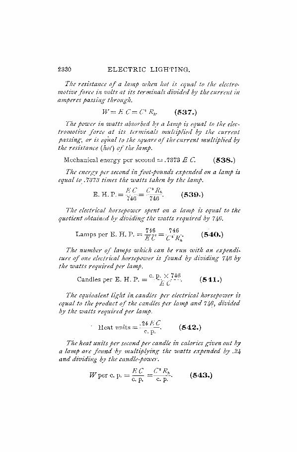
2330 ELECTRIC LIGHTING.
The resistance of a lamp wlten Itot is equal to the electro, motive force in volts at its termimiJs divided by the current itt amperes passing through.
W=E C= C' Rh • (537.)
The power in watts absorbed by a lamp is equal to the electromotive force at its terminals multiplied by the current passing, or is equal to the square of the current multipHed by tlte resistance (hot) of the lamp.
Mechanical energy per second = .7373 E C. (538.)
The energy per second in foot-pounds expended on a lamp is equal to . . '7373 times the watts taken by the lamp.
EC C'Rh E. H. P .. = 746 = 746· (539.)
The electrical horsepower spent on a lamp is equal to the quotient obtained by dividing tile watts required by 746.
746 746 Lamps per E. H. p, = E C - C'R
h• (540.)
The number of lamps which can be run with an expenditure of one electrical horsepower is found by dividing 746 by the watts required per lamp.
C dl E H P c. p. X 746 . an es per .. . . = E C . (541.)
The equivalent light in. candles per electdcal horsepower is equaUo the product of the candles per lamp and 746, divided by the watts required per lamp.
H . .24EC . eat umts = ---,
c. p. (542.)
The heat units per second per candle tOn calories given out by a lamp are found by multiplying the watts expended by .24 and dividing by the candle-power.
EC CO Rh W per c. p. = - =--. (543.)
c. p. c. p.

ELECTRIC LIGHTING. 2331
The watts required pcr candle-power are equal to the product of tile elcctromotive force and the current, divided by the candle-power.
EXAMPLE.-The mean horizontal candle-power of an arc lamp is 32. The maximum candle-power is :J6. The E. M. F. between the terminals is 30, and the current is 4 amperes. What is the efficiency?
SOLuTION.-Applying rule in Art. 3474,
mean spherical c. p. = '':f + ¥ = 25.
Applying formula 535, the efficiency
25 E = 30 X 4 = .20833. Ans.
EXAMPLE.-A test was made of a 16 candle-power incandescent lamp. The current was found to be.5 ampere and the E. M. F. 50 volts. What was the resistance when hot? the electrical power in watts? energy per second in foot-pounds? electrical H. P. spent on lamp? number of lamps per electrical H. P.? candles per electrical H. P.? heat units per second per candle in calories? watts per candle· power?
SOLuTION.-:-By formula 536, the resistance when hot
50 Rh = -:5 = 100 ohms. Ans.
By formula 537, the electrical power
W = 50 X .5 = 25 watts. Ans.
By formula 538,
energy per second = .7373 X 50 X .5 = 18.4:J25 ft.-lb. Ans.
By formula 539,
electrical H. P. spent on lamp = 507~6·5 = .03351 H. P. Ans.
By formula 540, 746
number of lamps per H. P. = 50 X -:5 = 29.84. Ans.
By formula 541,
dl H P 16 X 746 4"'- 44 can esper .. = 50X.5 = Ii .. Ans.
By formula 542, h . .24 X 50 X .5 375 I . eat UUlts = 16 =. ca one. Ans.
By formula 543, 50 X.5
watts per candle-power = -----:r6 = 1.5625. Ans.

2332 ELECTRIC LIGHTING.
3477. Incandescent lamps are commonly operated at .32 candle per watt, at which a 16 candle-power lamp absorbs about 50 watts; at .29 candle per watt, at which a 16 candle-power lamp absorbs about 55 watts; at .28 candle per w_att, at which a 16 candle-power lamp absorbs about 57.6 watts; or at. 25 candle per watt; at which a 16 candlepower lamp absorbs about 64 watts.
Wheria lamp is operated at a high rate of efficiency, the voltage, candle-power, and temperature are high; hence, although>the -running economy is greater, the life of the lamp is less thim if operated a_t a lower efficiency. By experience and observation, the proper efficiency of lamps to obtain the greatest economy may be determined, so that the cost of renewing shall not overbalance the gain in runningeconomy at high efficiencies.
At q,n efficiency of .25 candle per watt, incandescent filaments give a candle-power of 100 to 150 per square inch of surface. At .33 candle per watt, they give a candle-power of 160 to 270 per square inch. Very small lamps are operated at a low efficiency of about .13 candle per watt.
3478. In the manufacture oC incandescent lamps, a Bunsen photometer is used to determine the required voltage at the lamp terminals. For this purpose, a standard lamp of given candle-power is first constructed. This is set with the proper E. M. F. between terminals, at one end of the photometer,while the lamp to be measured is at the other in series circuit with a source of power and a rheostat. From the terminals of the latter, a voltmeter is connected in shunt circuit. The paper diaphragm of the photometer is placed exactly between the two lights. The rheostat is now turned until each lamp gives the same luminous intensity, or until both sides of the paper show equal degrees of brightness.
The E. M. F. is then read off upon the voltmeter, and this with the candle-power marked upen the measured lamp. The current passing through this lamp may also be determined by connecting a milliammeter in series circuit. Other lamps are substituted and sUbjected to the same measurements.

ELECTRIC LIGHTING. 2333
GENERAL DATA FOR ARC AND ISCANDESCENT LAMPS.
3479. The intensity of the light actually produced in commercial lamps is reduced somewhat by the use of glass globes. Thus,
The light cut off by incandescent-lamp bulbs is : For ordinary glass, 6.5%. For light ground or frosted glass, 12%~
The light cut off by arc-lamp globes is : For ordinary glass, 10%. For light ground glas's, 30%. For heavy ground glass, 45 to 50%. For strong opal glass, 50 to 60%.
COMMERCIAL LAMPS.
3480. The following table is taken from tests made on standard incandescent lamps of various makes at present in use:
TABLE 108.
Volts. C.P. Amperes. Watts Watts
per Lamp. per C. P.
52 16 1.04 54.1 3.38 52 32 2.08 108.2 3.38 52 100 6.50 338.0 3.38
100 16 .64 64.0 4.00 100 32 1.28 128.0 4.00 100 100 4.00 400.0 4.00
110 16 .58 64.0 4.00 110 32 1.16 128.0 4.00 110 100 3.64 400.0 4.00
Heating.-A 16 r candle-power (64-watt) incandescent lamp gives off about 220 British thermal units of heat per hour.

2334 ELECTRIC LIGHTING.
A British thermal unit is equivalent to the amount of heat required to raise 1 pound of water from 62° F. to 63° F.
Incandescent lamps give off between 10 and 20 per cent. less heat than gas-jets of the same candle-power.
3481. Illul1:dnation by Incandescent Lalllps.-In all methods of wiring, it is necessary to so locate the light that the best illumination may be obtained. In factory lighting the lights are so placed that they will be as near as possible to the workmen, whether at the machine or vise.
For the interior of stores, general illumination is required. Show-windows should be lighted by reflected light only, because exposed light striking the eye will cause the effect of the general arrangement to be lost to the observer. In picture galleries this same idea should be carried out. House illumination is more for effect than general illumination.
In theater lighting, where the scenic effects depend entirely upon a careful adjustment of light intensities, experience is the only guide.
Among other points to be observed in placing lights is the color of the surrounding walls. Dull walls will reflect only about 20 per cent. of the light thrown on them, while a clean, white surface will reflect 80 per cent. The height of the room als9. reduces the effectiveness of a given light intensity.
The following table gives the general effect produced by different numbers of 16 candle-power lamps placed at a given height above the floor.
Number of 16 C. P. Lamps per 100 Sq. Ft. Approximate Effect.
1.0 Dull 1.5 Medium 2.0 Good 3.0 Bright 4.0 Brilliant

ELECTRIC LIGHTING. 2335
One candle-foot is considered a good light to read by, which is the illumination given by a standard candle at the distance of 1 foot.
The candle-power value of different lights is as follows:
Ordinary moonlight . . . . . . . . . . . . . . . . . . . .. .025 candle-foot Street lighted .by gas .......... '" ......... 030 candle-foot Stage of a theater. . . . . . . . . . . . . . . . . .. 2.9 to 3.8 candle-feet Diffused daylight .................... 10 to 40 candle-feet
A clear idea of these various intensities is easily gained by comparison, remembering t~at 1 candle-foot furnishes a good light to read by, as stated above .
. The following table. gives the number of square feet illuminated by a 16 candle-power incandescent lamp at stated heights and under certain conditions; the table fulfils all practical reqtiirements:
TABLE 109.
Nature of Room. Height.
Offices with desks .•.... 10 feet
Reading-rooms with tables ............... 15 feet
Stores ................. 15 feet Dance halls ............ 20 feet Halls and lobbies ....•.. 18 feet Machine-shops ......... 15 feet
Large town halls ....... 25 feet Churches .............. 40 feet
Number of Square Feet per 16 C. P. Lamp.
50, also localized near desks.
50, also localize$1 near tables.
80. 80.
100. 150 and localized at
machines. 120. 200.
Thus, in a dance hall for instance, where the lights are hung 20 ieetabove the floor, one lamp is required for every 80 square feet of floor surface.

ELECTRIC LIGHTING.
EXAMPLES FOR PRACTICE.
1. It is required to light a hall 150 feet long and 50 feet wide with Edison 16 candle-pow~r incandescent lamps, at a height of 16 feet from the 11oor._ To accomplish this purpose, how many indicated horsepowers must be supplied by the engines at the station? The intensity of the light varies inversely as the square of the distance from the source. Ans. 59.7 1. H. P.
NOTE.-When the results are in lamps or other indivisible objects, any decimal part will be considered as one.
2. A test was made upon an Edison lamp by the apparatus shown in Fig. 1315. After the slide was adjusted, it stood 2 feet from the candle and 8 feet from the lamp. The voltmeter read 110 volts and the ammeter .7 ampere. What was (a) the candle-power? (b) the resistance of the lamp when hot? (c) the number of lamps that would consume one electrical H. P.? (d) the efficiency? (e) heat units per second per candle in calories? (f) watts per candle-power?
1 (a) 16 c. p. (b) 157.143 ohms.
Ans. (c) 10 lamps. (d) 20.77%. (e) 1.157 calories. U) 4.8125 watts per c. p.
LINE-WIRES.
3482. Aerial line-wires for incandescent lights are always well insulated by a covering of the best material, such as rubber, gutta-percha, or a fibrous covering saturated with an insulating compound. They are fixed upon glass insulators attached to poles or houses in a manner similar to telegraphlines. For outside use the rubber insulation is usually covered with braid or tape, and this, in turn, is painted with a protective compound, or three thicknesses of fiber saturated with insulating compound may be used. The tiewires for fastening the line to the insulators must also be of insulated wire whether in buildings or outside.
Prof. A. Jamieson gives the following formula to determine the proper insulation resistance for an electric-light installation:
R = total insulation resistance of the generator or of the lamp circuit in ohms;
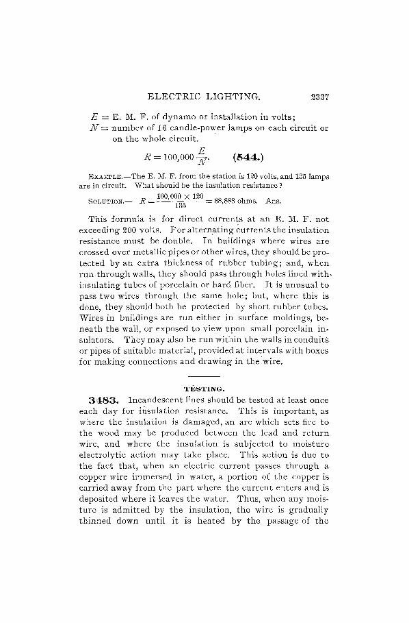
ELECTRIC LIGHTING. 2337
E = E. M. F. of dynamo or installation in volts; N = number of 16 candle-power lamps on each circuit or
on the whole circuit.
E R = 100,000 N' (544.)
EXAMPLE.-The E. M. F. from the station is 120 volts, and 135 lamps are in circuit. What should be the insulation resistance?
100,000 X 120 SOLUTION.- R = 135 = 88,888 ohms. Ans.
This formula is for direct currents at an E. M. F. not exceeding 200 volts. For altern,ating currents the insulation resistance must be double. In buildings where wires are crossed over metallic pipes or other wires, they should be protected by an extra thickness of rubber tubing; and, when run through walls, they should pass through holes lined with. insulating tubes of porcelain or hard fiber. It is unusual to pass two wires through the same hole; but, where this is done, they should both be protected by short rubber tubes. Wires in buildings are run either in surface moldings, beneath the wall, or exposed to view upon small porcelain insulators. They may also be run within the walls in conduits or pipes of suitable material, provided at intervals with boxes for making connections and drawing in the'wire.
TESTING.
3483. Incandescent lines should be tested at least once each day for insulation resistance. This is important, as where the insulation is damaged, an arc which sets fire to the wood may be produced between the lead and return wire, and where the insulation is subjected to moisture electrolytic action may take place. This action is due to the fact that, when an electric current passes through a copper wire immersed in water, a portion of the copper is carried away from the part where the current enters and is deposited where it leaves the water. Thus, when any moisture is admitted by the insulation, the wire is gradually thinned down until it is heated by the passage of the

2338 ELECTRIC LIGHTING.
current.' Also, it may be entirely eaten away so as to cause an arc.
The resistance of the line may be found by a Wheatstone bridge or by a differential galvanometer, and the most convenient method for finding the insulation resistance is by Weston's instruments, as described in Art. 3343.
Faults and crosses are located by the same methods as described in the section on Electric Transmission.
3484. The tests for the resistances of the line and insulation are the same as for other aerial lines, but a very
U. u FIG. 1316.
convenien~ method is given by Dr. Maschke for locating a fault. In ·Fig. 1316, d is the dynamo or installation, v is a Weston voltmeter, I, I, etc., are lamps in series, and k and k, are two-way switches, k connecting binding-post b of the voltmeter either with point a of the circuit or with the ground a.t c, and k, connecting binding-post n of the voltmeter either with point e of the circuit or with the ground at y.
The fault r connects with the ground at g, andg, is also a ground. The 'circuit contains 23 lamps, each taking an E. M. F. of 45 volts, and the voltmeter will have a, Scale

ELECTRIC LIGHTING. 2339
ranging from 0 to about 1,500 volts. Suppose the ground g to be between the x lamp and the x + 1., counting from a.
First take a reading upon the voltmeter when post b is connected to a and post n to y In this case the reading is taker;t between a and r, as n is connected to r through g,g" and y. Let R be the resistance of the voltmeter and R, be the resistance of the fault. Let the reading of the voltmeter be v. The E. M. F. between a and r is 45 X x volts.
v : 45 X x :: R : R + R"
as the readings of a voltmeter are inversely as the resistance between its points of connection.
R v = R + R, X 45x volts. (1)
N ext connect post b to c and post n to e, then the instrument is connected between e and r with R, in series. The E. M. F. between e and r is 45 (23 - x) volts. Let this reading of the voltmeter be v,.
R v, = R + R, (23 - x) 45 volts. (2)
Therefore, dividing (1) by (2), ~ = -23 x . v, -x
v x=23-+ ' v v,
or let N equal number of lamps in series circuit,
v X=lV-+ . v v,
(545.)
From equation (1) above we have,
R, = ~ (ex -11), (546.)
where e equals the voltage between the lamp terminals.
EXAMPLE.-A series circuit containing 23 lamps was tested to locate a ground. The reading on the voltmeter between the ground and the minus terminal of the dynamo was 260 volts. The reading between the plus termina.l and the ~round Wa.s ~5 volts. Lamps eash took 4q

2340· ELECTRIC LIGHTING.
volts. (a) Between what two lamps is the ground? (b) What was the resistance of the ground, the resistance of the voltmeter being 145,000 ohms?
SOLUTION.-(a) Using formula 545,
260 x= 23 260 + 85 = 17.
Therefore the ground is between the 17th and 18th lamp. Ans.
(b) Using formula 546,
Rl = 14~6~00 (45 X 17 - 260) = 281,634 ohms. Ans.
It is evident that, by this method, a ground may be located in any circuit of nearly uniform cross-section of wire, for any circuit may be imagined to consist of one-volt lamps in series equal in number to the E. M. F. of the circuit. Then N, in formula 545, corresponds to the E. M. F. at the terminals of the source of power, and x corresponds to the number of volts to the fault. The resistance to the fault is found by dividing the total resistance of the line by the total E. M. F., and multiplying by x. In the derivation of formula 546 the expression 45 x will simply be x, or the number of volts to the fault.
EXAMPLES FOR PRACTICE.
1. A series circuit containing 50 lamps was tested to locate a ground by Maschke's method. The resistance of the voltmeter was 150,000 ohms. The reading between the ground and the minus terminalof the dynamo was 1,250 volts. The lamps were designed for 55 volts between terminals. The reading between the ground and the plus terminal was 846 volts. Ca) Between what two lamps was the ground? (b) What was the resistance of the fault ?
A ) (a) Between the 29th and 30th lamp. ns. (b) Resistance of fault = 41,400 ohms.
2. A series circuit contained 39 lamps, each taking 40 volts. A test was made for a ground with a voltmeter of 155,000 ohms resistance. The reading on one side was 350 volts, and on the other it was 130 volts. (a) Between what lamps was the ground? (b) What was the resistance of the fault? A ) (a) Between the 28th and 29th.
ns. 1 (b) 341,000 ohms.

ELECTRIC LIGHTING. 2341
SYSTEMS OF DISTRIBUTION.
3485. The two principal factors in every system of distribution of electric energy are current and pressure, or, as they are technically termed, aITIperage and voltage.
The product of the actual volts and amperes of a circuit represents the power of that circuit expressed in watts, This product is often termed wattage.
A variation of either of these factors, voltage or amper· age, will cause a variation of the wattage; that is, of the power of the circuit.
Constant-Current Circuit~.-If the dynamo furnishing power to a line be so designed that for all change of load the current it sends into the line remains practically the same, such a circuit is termed a constant-current circuit. In such a circuit the voltage varies with the load.
3486. Constant-Potential Circuits.-If the dynamo furnishing power to the line be so designed that for all changes of load the voltage it impresses upon the line remains practically the same, such a circuit is termed a constant-potential circuit.
3487. Generators, or dynaITIos, are hence designed according to the needs of the circuit they' are to supply, as
(a) Constant-Current Generators. (b) Constant-Potential Generators. They are designed for either continuous-current or alter
nating-current generation, and form four distinct types, as tabulated in Art. 3442.
As a rule, constant-current generators are used for series arc or incandescent lighting only. Occasionally, specially designed motors are, however, run on such circuits.
Constant-potential generators are used to supply current to incandescent systems, to a,c systems, and to powercircuits, and to combinations of these, so that the load of a constant-potential generator may at times consist of incandescent lamps, arc lamps, motors, and perhaps heating devices.

2342 ELECTRIC LIGHTING.
SERIES DISTRIBUTION.
3488. This system is in use for both continuous and alternating currents, and represents the earliest method adopted in electric-lighting circuits. Fig. 1317 show~ a circuit of this kind wired for arc lighting. As indicated by the
/f~ arrows, the current from
~G + x, x/ ~ I the generator G flows suc-
1 1 • 1 . -- ceSSlve y through the lamps I, returning from the
_ ~ ---== _Xl last lamp to the negative f- terminal.' The lamps thus
FIG. 1317. form one continuous serz"es, hence the name series circuit. The current in a circuit of this kind is practically constant, whatever may be the number of lamps burning. The voltage, however, varies with the number of lamps. Arc lamps are usually adjusted for 45 volts, and the total voltage of a series-arc circuit is therefore approximately given by the product of the number of lamps and 45. An additional allowance must of course be made for drop in conductors.
EXAMPLE.-In Fig. 1317, a series-arc circuit is represented with six 2,000 candle-power continuous-current arc lamps, each adjusted for 45 volt,s. Allowing 75 volts for drop in the circuit, what is the ,!,oltage at the generator?
SOLuTION.-Six lamps at 45 volts = 270 volts. Drop of conductors = 75 volts.
Hence, generator E. M. F. = 345 volts. Ans.
The current through such a circuit being a constant one, this system is best adapted for use where the load remains practically constant. This being the case in street illumination, the series method of distribution is generally used by plants installed for city or town lighting. Incandescent as well as arc lamps can be economically operated on a series system of practically constant load.
3489. Incandescent lalDps for series circuits differ mainly from those used on constant-potential circuits

ELECTRIC LIGHTING. 2343
in the construction of the filament which must be made to carry the heavier current of the series circuit.
Cut-Outs.-Since the extinction of anyone lamp on a series circuit would extinguish all of them by breaking the circuit, a device called an autom.atic.cut-out is attached to each lamp. This consists of an electromagnetic arrangement for short-circuiting the lamp, and is explained in the description of Fig. 1331.
An ingenious method of shunting burnt-out series lamps is due to O. B. Shallenberger. In this system of street lighting each of a series of incandescent lamps is shunted by a reactive coil having its winding so proportioned to the mass of iron in its core that upon the interruption of the current through any lamp, a normal current is allowed to flow through the corresponding coil to the remaining lamps by reason of the consequent high magnetic saturation of its core.
3490. The general outline of a series circuit will form an irregular polygon of many sides (see Fig. 1317); therefore, in designing a circuit of this kind, care should be taken to make the distances from lamp to lamp in as straight, that is, as short, a line as possible, otherwise the cost of conductors may reach too high a figure.
The number of Iam.ps in one circuit fed by a single dynamo varies from 1 to 100, and the resistance, electromotive force, current, caridle-power, and methods of regulation differ widely in the various systems.
3491. The currents of arc circuits vary from 6 to 15 amperes for circuits in general use, as follows:
1,200 c. p. arc lamps, circuits average 6.8 amperes. 2,000 c. p. arc lamps, circuits average 10 amperes. 3,000 c. p. arc lamps, circuits average 15 amperes.
For exceptionally powerful lights, such as are required for lighthouses and search-lights on steamers, much heavier currents may be used.

2344 ELECTRIC LIGHTING.
CURRENT REGULATION.
3492. The throwing out of individual lamps on a seriesarc circuit, and the shunting of the main current around the lamp or lamps cut out, prod1fces a decrease in the resistance of the circuit. The immediate result of this decrease of resistance is to allow more current to flow through the circuit.
Since arc lamps on a series circuit are, however, designed for constant current, this increase of current must be prevented. This can be done in two ways-either by inserting resistance equivalent to that which has been cut out, or by cutting down the voltage.
The first method is a poor one, because the power required to overcome the inserted resistance is the same as is required for the lamp; hence, darkness is being paid for at the same rate as light.
The second method is generally used, and is based on the principle of self-regulation of current.
3493. The methods used to regulate the E. M. F. of closed-coil armatures are as follows: (1) Varying the speed, (2) varying the strength of the field, and (3) shifting the brushes.
The first method is seldom used, though in special cases it is very convenient. The principle of this method is, that with a simple series-wound dynamo, if the external resistance is increased, thus decreasing the current and E. M. F., the speed may be increased until the E. M. F. rises to a point where it will force the normal current through the external circuit; if this adjustment of the speed is made as rapidly as the external resistance changes, the current will be maintained at a constant value .
. 3494. The second method has been described 111 Art. 3206 in connection with series-wound dynamos. It is evident that this same principle may be applied to constantcurrent machines, so as to properly vary the E. M. F. The range of this method of regulation is quite limited, because

ELECTRIC LIGHTING .. 2345
the strength of the field can not be economically forced beyond the point where the iron begins to be saturated (Art. 3188), and if it is much reduced, the armature reaction (which is constant, since the current is constant) will cause the neutral point to considerab~ly alter its position.
3495. The third method is almost universally used in this type of machines. From what has been said in Art. 3103, it will be evident that the greatest difference of potential in a (bipolar) closed-coil armature exists between
:l)
Be. FIG. 1318.
the two opposite coils which are in the neutral spaces; so, to get this maximum difference of potential between the brushes, they are placed on the opposite commutator segments, which are connected to these two coils. Now, if the brushes are shifted from this position, although the E. M. F. generated in the armature is not altered, the difference of potential between tlte brus/zes is reduced/ for, although the circuit through the armature winding is still divided into two parts connected in parallel between the brushes, the separate E. M. F. 's of all the coils in each of the two parts

2346 ·ELECTRIC LIGHTING.
are not all in the same direction. This may be more plainly seen by examining Fig. 1318; the current divides at ii, one half passing through the turns i,}, k, t, etc., and the other through h, g, f; e, etc., to ai, where it again unites. The maximum E M. F. that is obtained from the coil is equal, therefore, to the E. M. F. generated in one-half of the coil.
3496. If there were no armature reaction, shifting the brushes to a point half-way around the commutator from the neutral space would reduce the difference of potential between them to zero, and in positions between these two the difference of potential would be proportional to the amount of shift. Since the -coils short-circuited by the brushes would be moving in strong magnetic fields, there would also be violent sparking.
There is, however, a very considerable armature reaction in dynamos of this type, which is so proportioned with respect to the strength of the field that it has two effects. One is to shift the neutral point so that the difference of potential between the brushes is not quite' proportional to the amount of shift; but this is of little importance compared. to the second effect, which is that the tendency of the current in the armature winding to form consequent poles at the points where the current enters or leaves the winding through the leads to the commutator actually forces tlte lz'nes of force of the field away from the armature at these points, leaving only a weak field to influence the short-circuited coil. By proper proportioning of the armature winding, this results in little or no sparking at the brushes, especially as the amount of current in a constant-current machine seldom exceeds 10 amperes, which allows of the use of such a narrow brush that the' time during which a coil is shortcircuited is so, short that the current in the coil does not have 'time to become large enough to cause serious spar-king. I
The brushes may be shifted by hand to get the desired regulation, but as this would require constant attention, it

ELECTRIC LIGHTING. 234'(
is usual to shift the brushes automatically, by d~vi.ces on or near the dynamos. These devices are usually controlled about as follows: Electromagnets are connected in the main circuit, and are so adjusted that when any change in the external resistance causes the current to increase or decrease from normal, the corresponding movement of the magnet keeper mechanically connects the rocker-arm of the dynamo to some sort of driving mechanism, so that the brushes are properly shifted. "\Vhen they reach such a point that the current is again at its normal value, the electromagnet (usually called the controlling magnet) disconnects the rocker-arm from the driv'ing mechanism, and the motion of the brushes ceases until some change in the external circuit calls for a new adjustment.
The mechanical parts of the various brush-shifting devices are quite different in the different makes of constantcurrent machines. In the following description of the principal features of some of the best known types of closed-coil, constant-current machines, the types of regulating devices used will be taken up more in detail.
WOOD REGULATOR.
3497. The Wood dynamos have bipolar, consequentpole, series-wound field-magnets of the type illustrated in Fig. 1187, but placed horizontally, and ring-wound armatures of quite large diameter.
The regulator on all except the largest size of this dynamo is such as is shown in Fig. 1319 (a) and (b). To reduce the sparking to a minimum, it has been found desirable to use two positive brushes a, a, located a little distance apart on the commutator, and two negative brushes b, b, located opposite the positive brushes. The brushes are mounted on opposite ends of the rocker-arms rand r" so that simply shifting these two effects,the shift~ of the four brushes. The angle between the rocker-arms rand r, of each pair of brushes is variable, preserving a distance between the

2348 ELECTRIC LIGHTING.
ELECTRIC LIGHTING. 2349
bearing ends of the brushes equal to about 3 commutator segments at light loads (low E. M. F.), and about double this at heavy loads (high E. M. F.). This variation in distance is accomplished by shifting the back brushes a l and bl of each pair a little faster than the front brushes a and bare shifted, so that the back brush gradually overtakes the front one, lessening the distance between them, in shifting from the heavy-load to the light-load position.
The electromagnet e is connected in series with the armature, field, and external circuit, and furnishes the power for regulating the current. The cores c, c of this electromagnet are free to move into or out of the coils, the attraction of the magnet being balanced by a tension-spring provided with an adjustment at d. The lever arm m is raised by the electromagnet when the current increases, and is lowered when the current weakens. A small gear g on the end of the shaft continuously drives two friction-rollers./" f. in opposite directions by means of the gears gl' go. The movement of the lever arm m presses the friction-wheelfby means of the intermediate links n, 0 against one or the other of the friction-rollers, thereby turning the friction-wheel in a forward or backward direction. This motion is then communicated by means of gearing to the rocker-arms, producing the relative movement already referred to .. The two positive and the two negative brushes are connected by short, flexible cables, so that the intervening coils on the armature are short-circuited, and as the distance between the brushes increases, a further number of coils will be rendered ineffective, thereby lowering the E. M. F. of the dynamo. In order to facilitate adjustment, the brushes are set to a certain length, the amount of their projection from the holders being determined by means of a gauge.' The regulator is fastened to one of the yokes y of the field. In the larger sizes of these machines the friction-rollers are driven by a light belt from a small pulley on the end of the armature shaft, but otherwise operate in the same manner as that described. These regulators are simple and reliable in action.

2350 ELECTRIC LIGHTING.
EXCELSIOR DYNAMO REGULATOR.
3498. On this machine, which is bipolar, an iron arm projects f10m each pole-piece, forming the pole-pieces for a small armature which is operated as a motor to shift the brushes of the machine. This small armature is geared to the rocker-arm, and the controlling magnet is so arranged that if the, current in the machine rises above the normal, a portion of the current is shunted through the armature of this small motor, which causes It to turn in such a direction that the brushes are moved away from the neutral point, thus reducing the current.
At the same time the motion of the rocker-arm operates a switch which cuts out some of the turns of the magnetizing coils, thus lowering the E. M. F. of the armature. It will be seen that this method of regulating the difference of potential between the brushes is a combination of the methods described in Arts. 3494 and 3495.
If the current is decreased below the normal strength, the controlling magnet reverses the current in the armature of the small motor, so that it runs in the opposite direction and shifts the brushes towards the neutral point, at the same time cutting in some of the turns of the magnetizing coils, all of which brings the current back to its normal strength.
BALL DYNAMO REGULATOR.
3499. The Ball dynamo is of very peculiar construction, and but little used. The regulator is, however, of a distinct type, and is therefore worth mentioning. In the larger machines the regulation is obtained by automatically shifting the brushes, the field-magnets of the machine itself acting as the controlling magnet, and also furnishing the necessary power. A circular opening is made in the magnetic yoke (on each end of the machine) of such size that the area of the magnetic circuit at that point is much reduced, which causes a leakage of the lines of force across the opening. Two iron segments are supported on a nonmagnetic hUb in this openin~; now, if th~se iron pieces wen~

ELECTRIC LIGHTING. . 2351
free to move, they would take up such a position in the opening as to make up as much as possible for the reduction in the area of the magnetic circuit, and allow the lines of force to pass directly through them. They are free to rotate about the hub to which they are attached, which revolves on ball bearings, but are prevented from taking up their natural position by a counterweight, which deflects them more or less, according to the strength of the field of the machine.
The brush-holder studs are connected directly to this movable part of the magnetic yoke, so that when the strength of the field increases, ' due to an increase in the current above the normal strength, this movable part is pulled around against the opposition of its counterweight until the brushes are shifted to the point where the current again becomes of normal strength.
BRUSH REGULATOR.
3500. The regulation of the Brush machines is nearly automatic; that is, a machine will give nearly a constant current without any regulation whatever. This is due to the fact that the armature reaction increases so much with any increase in the current that the line of maximum action is shifted farther ahead, which changes the relations of the various coils at the time when they are connected with, or disconnected from, each other or the external circuit.
This regulation is, however, not close enough for commercial working, so, in addition, a resistance is placed in shunt to the magnetizing coils, which is varied by a controlling magnet in the main circuit, thus making the regulation very exact. (See Art. 3207~ and Fig. 1195.)
This resistance consists of a series of blocks of carbon-a material which has the property of lessening its resistance if subjected to pressure. In. this case the pressure is obtained by the pull of the controlling magnet on its keeper, which forms the end of a lever that presses upon the carbon blocks. If the current in the external circuit increases, due
2352 ELECTRIC LIGHTING.
to a lessening of the external resistance, the controlling magnet pulls on its keeper with greater force, thus increasing the pressure on the carbons, decreasing their resistance, and weakening the strength of the field-magnets, which reduces the E. M. F. of the armature coils until the current is again at its normal strength.
The shifting of the point of maximum action, due to the weakening of the field at light loads, causes a certain amount of sparking, which is remedied by slightly shifting the brushes. In the multipolar machines this shifting is performed automatically by mechanism driven by a belt from a small pulley on the end of the armature shaft and controlled by the controlling magnet, as in the closed-coil dynamos described.
REGULATION OF WESTINGHOUSE DYNAMO.
3501. The regulation of this machine is entirely automatic. The field-magnets are separately excited, the current being furnished by a separate constant-potential dynamo, which gives a constant magnetizing force; but the strength and distribution of the resulting field are dependent on the armature reaction, which is so proportioned that any excess of current over the normal so reduces and distorts the field that the E. M. F. generated in a winding during the time that it is connected to the brushes is reduced until the current is again at its normal strength.
THOMSON-HOUSTON REGULATOR.
3502. The regulation of the Thomson-Houston arc machine, built by the General Electric Co., is effected by varying the distance between the two brushes of each set (Art. 3086), the primary brush being moved back, and the secondary ahead. This movement of the brushes decreases the distance between the primary brush of one set and the secondary of the other.
This shifting of the brushes is done automatically by the following apparatus: The primary and secondary brushes

ELECTRIC LIGHTING. 2353
are mounted on separate rocker~arms, which are connected together by a system of levers, so that when the primary brushes are shifted back, the secondary are moved ahead. The amount of movement of the secondary brushes is very little, being for the purpose of following the line of maximum action, which moves ahead slightly at light loads (low E. M. F.). A large magnet R, Fig. 1320, attached to the frame of the machine, ha:> attached to its keeper k a lever, which is connected to the rocker-arm that carries the primary brushes in such a manner that when the keeper of the magnet is pulled up, the primary brushes are shifted back and the secondary ahead, thus reducing the effective difference of potential between the brushes, as explained. The current for operating this regulating magnet is supplied by the main current, but it is not continually in circuit, being cut in or out, as occasion requires, by a controlling magnet, which is placed on the wall of the room at some can venien t place.
3503. Fig. 1320 is a diagram of the connections used in this apparatus. The coils of the controlling magnet, which are stationary, are represented at c, c; and d, d represent the cores of this magnet, which are movable. Their weight is partly counterbalanced by the· spring s, the tension of which is adjusted by means of the nuts at 11. Attached to these cores is a contact point, which touches a stationary contact piece at e. The c,onnections being as represented, + being the positive terminal of the dynamo, it is evident that when the two contact points at e are touching, the regulating magnet R is short-circuited, the current flowing from + to a, thence to b, thence through the contact points at e to f, thence through coils c, c to g, and out to the line and to the lamps I. Now, if this current exceeds a certain strength, the pull of the coils c, c on the cores d, d becomes sufficient to raise them, breaking the contact at e. This forces the current around from a through the regulating magnet R to f, thence to g, where it passes out to the line, as before; the regulating magnet then pulls up its keeper

2354 ELECTRIC LIGHTING.
k, which in moving shifts the brushes and reduces the current as described.
When the current is reduced to its normal value the cores of the controlling magnet descend, contact is made at e, which short-circuits the regulating magnet, and allows its keeper to drop; this shifts the brushes again so as to increase
r
f
a
FIG. 1320.
the current. This action is kept up, so that the cores of the controlling magnet and the brushes of the machine are continually in slight motion. In order to prevent the self-induction of the regulating magnet from causing a serious spark at e when the contact is broken, a shunt of high resistance is permanently connected around the break at e, as represented at r. This self-induction is produced in the regulating magnet R whenever the circuit is opened at e, for this suddenly diverts the main current through the regulating magnet, whose momentary sdf-indllction opposes the cur·

ELECTRIC LIGHTING. 2355
rent, forcing it along by way of a, b, and the resistance r to the line. If the resistance were not there the current would cross the air-gap at e, making a destructive spark.
The space between the ends of the commutator segments being small, some device is necessary to prevent the spark which occurs when a segment passes from under one of the secondary brushes from continuing to pass from segment to segment, for that would permanently short-circuit the machine. This device consists of a small rotary blower, which is situated between the commutator and the bearing. This blower is so arranged as to deliver a puff of air right at the end of the secondary brushes, at the moment that the spark occurs, so that it is immediately broken and does no damage.
The adjustment of the commutator, brushes; air-blast, etc., of this machine requires considerable attention, in order that the machine should run well. The manufacturers supply printed matter with ea~h machine, giving full particulars of these operations, hence they need not be taken up here.
ALTERNATING CURRENT SERIES DISTRIBUTION.
3504. Arc Lighting.-Systems of this kind are not in very extended use. Those installed, however, particularly in this country, are giving very good results. A typical system of this kind is the Westinghouse systefll. It consists in operating a constant-current alternator on a main circuit which passes through transformers suitable for the number of lamps to be operated at anyone point. Dynamos of this kind have been built for 250 lamps of 2,000 nominal candle-power each. The principle of transformation of current makes it possible to build dynamos of large capacity without introducing dangerously high potential in the wires to which the lamps are directly connected.
This is attained in the following way: In general, transformers for lighting circuits are so constructed that the ratio of transformation is uS1lally about 20 to 1; that is to

2356 ELECTRIC LIGHTING.
say, a primary voltage of perhaps 2,000, and a secondary of 100. But in this system the transformers have low ratios of transformation, such as 3 to 1, or even 1 to 1. The latter ratio means that both the primary and secondary windings are alike. This being the case, and the transformers being connected in series, it is clear that the secondary E. M. F. of such a transformer will be almost exactly equal to that of the primary. The voltage at the secondary, however, is a comparatively low one compared to the voltage of the entire line; and since only the low-tension wires are carried into the residences of consumers, the danger to life
l x x x x
T
T
I x x x x
FIG. 1321.
from the high-tension mains is almost eliminated. The only point which must be carefully guarded against, and which is well taken care of in the construction, is the insulation between primaries and secondaries of the transformers. A connection here, due to faulty insulation, would bring the E. M. F. of the high-tension line upon the premises. Fig. 1321 illustrates this system.
In the figure, the system as applied to house lighting is shown, where all lamps I are connected to the secondaries of transformers T. It is, of course, possible to connect the lamps directly in the main circuit without the use of trans-

ELECTRIC LIGHTING. 235'(
formers, and this is often done in street lighting, where the risk attached to the high-tension mains may be assumed.
3505. A combination house and street system is shown in Fig. 1322, as are also transformers T, of ratio 3 to 1, designed for three lamps on the secondaries.
G
X L Ii x l
The arc lamps for interior illumination are indicated by the letters I; those for street lighting by L.
The regulation of this system is performed automatically by the dynamo, which is so designed that for any overload the magnetization of its armature almost neutralizes the magnetization of its fields, thereby reducing the E. M. F. and, hence, the current, to a minimum.
The mechanism of the lamps employed in connection with this system is very simple, and consists of a rack movement which is regulated by a solenoid in the ma!n circuit and by another of high resistance in shunt to the arc. Both of these solenoids are provided with cores built up of bundles of fine wires, so as to avoid heating and to increase their sensltlveness. A small reflector is placed around the upper carbon to throw the rays from the lower carbon center in a useful direction.

2358 ELECTRIC LIGHTING.
SUSPENSION OF ARC LAMPS . .
3506. For street lighting, arc lamps are usually sus· pended at the end of a truss or support extending from the
qp
t
top of the pole out over the middle of the road. -For the purpose of cleaning or of changing the carbons they may be drawn back and forth between the pole and the end of the truss by means of pulleys or other apparatus.· It is not s:J.fe however, to suspend the lamp by cords unless some special device is used to relieve the stress, as, on account of the wear upon these cords, the lamp is liable to drop. A good form of cross
FIG. 1323. suspension to which the lamp may be firmly fixed is shown in Fig. 1323, where
I is the lamp, t is a truss, which is pivoted at p on the top of the pole, and w is a ball of such weight that the lamp is nearly balanced. Above the truss is shown a top view. When the rope r is untied, the lamp will de~cend slowly to the pole, so that it is within easy reach from a ladder.
Other forms are usually rigid trusses that are fastened to the top of the pole, and from the . extremity of which the lamp is brought within reach by means of a pulley and tackle. It is better to have the lamp suspended somewqat higher than the pole, since, when this is done, the shadow cast by the pole is much lessened.

ELECTRIC LIGHTING. 2359
PARALLEL DISTRIBUTION.
3507. The lllultiple-arc systelll, also called the llluitiple systetn, or parallel systelll, will be readily understood from Fig. 1324. ~+_
In thi, ,-"tern, which is ,A A X X JIll supplIed wIth a current of . r:r:r:r '( constant potential, any _-~---L_-L_..l-_L--1 __
number of lamps I may be FIG. 1324.
switched in or out without interfering with the rest of the circuit. This system is particularly adapted to the incandescent lamp (though special arc lamps.are also used, as explained. further on), and almost all residences, stores, offices, and buildings generally, are wired on the para)lel system. This statement holds good for the alternating as well as for the continuous-current system; for, when the alternating current is used, the wiring of the building itself, which follows after the transformation from a higher to a lower potential has taken place, is identic~l with that used for the continuous current.
In this system each lamp is entirely independent of all the others, and its burning out does not affect the brightness of the rest. The lamps used in this system must, however, all be built for the same voltage; i.e., if the system be a 110-volt system, all must be nO-volt lamps; if the system be a 55-volt system, all must be 55-volt lamps. The reason for this is that the generator supplying this circuit is so constructed that it automatically holds the voltage at a constant value, no matter how nany lamps are burning, and even when not one is burning; the current, however, changes for every change of load.
3508. Drop of Potential.-As explained in Art. 3303 and following, every electrical circuit suffers a drop of potential, which is greater in proportion to the curreat transmitted and to the resistance of the circuit. Due to this ·fact it is clear that in the circuit shown iri Fig. 1324, the lamp farthest from the generator will receive a less voltage than a lamp which is close to the generator terminals, and incandescent circuits bein~ at times very long, it is evident

2360 ELECTRIC I...IGHTING.
that this difference might become so great that the illumination at the far points of the line would be poor. When this occurs, the lamps at the end of the line will not burn at their rated candle-power. ·If by special meap.s the generator E. M. F. be raised so that the farthest end of the line receives the full required voltage, then the lamps nearest the generator will be receiving too high a voltage, and thus their life may be considerably impaired. Both of these cases would be considered poor service, and would be found unsatisfactory.
To overcome this difficulty, several methods have been devised, which are all based on the simple parallel system, but which make it possible to give the lamps at the farthest end of ' the line nearly the same voltage as lamps near the terminals; in short, to give to every lamp very nearly the same voltage. It is clear that this can only be accomplished by arranging the conductors so that the resistance of the circuit from the dynamo to any lamp shall have a constant value and shall be equal to the resistance through any other lamp.
In the so-called loop systelD, as shown in Fig. 1325, this is accomplished by running the conducting lead a a the
FIG. 1825.
entire length of the circuit and utilizing its returning side only for connection to lamps.
b A study of the diagram will s how t hat the
length of wire which the current must traverse to go through anyone lamp from the + pole to the - pole is the same for all lamps. Comparing any two lamps of the circuit in the figqre, say the first and the fifth lamp, the path of the current is as ~ollows:
First Lamp-,.---->-----, + pole to 1 to 2 to 6 to 3 to 4 to the - pole. '-r-'
FiftkLamp-r---"----, + pole to 1 to 5 to 6 to 3 to 4 to the - pole.
'--.---'

ELECTRIC LIGHTING. 2361
The paths are the same except within the bracketed portions. Of these two bracketed portions, 1 to 2 and 5 to 6
'---~ ~
are evidently also alike, so that they differ only in the two portions 2 to 6 and 1 to 5, and by examining the figure it will be seen that these are also alike; hence, both paths are of the same length. Consequently, the voltage of any lamp on the circuit is not affected by its nearness to or remoteness from the generating station.
3509. The spiral loop, a variation, is, however, substantially the same as the simple loop. It is shown in Fig. 1:326, from which it \ G
will be seen that bot h \ spirals, the + as well as the -, extend completely around the system, and that here again, as in Fig. 1325, the path which the FIG. 1326.
current must traverse to light up anyone lamp is the same for all lamps.
3510. Disadvantage of the Loop Systellls.-The object of the loop system is to obtain a constant pressure by making the length, that is, the resistance of the path of the current, the same for all lamps. If the pressure were dependent only on the resistance, constant pressure would be obtained by this system; but the drop of the circuit is also proportional to the amount of current flowing, and, since this is subject to great variation, the loop system will not at all times give a constant potential in the circuit.
3511. The Tree Systelll.-This system, illustrated in Fig. 1327, and in extended use in house wiring, is a less advantageous arrangement than the loop circuit, for the paths of the current are of different lengths for the various lamps; hence, they must suffer changes of pressure, and, consequently, variations of voltage occur from both causes -change of resistance and change of current.

2362 ELECTRIC LIGHTING.
The name tree systelll has been given this arrangement from its likeness to a tree, there being a main trunk line with
FIG. 1327.
subdivisions carried off from it, like branches from a tree trunk. From these branc-hes, smaller ones are again carried off, etc.
3512. The Closet Systelll.-This is another system
r------------.:.+~ very extensively used in house WIrIng, and attains very nearly the same results as the loop system; that is, it gives the currents required for the various lamps very nearly the same length (same resistance of path),
1
.5
=--____________ thereby making the pres-FIG" 1328. sure of the circuit sub-
ject only to variations of load, and causing all lamps to burn with equal brilliancy.
This system will be clearly understood by reference to Fig. 1328, which forms one group of lamps to which two main wires are connected.
Very nearly the same result is obtained here as in the ioop system, as far as the path of the current is concerned, for any lamp. Comparing any two lamps of the circuit in

ELECTRIC LIGHTING. 2363
Fig. 1328, say lamps a and d, the path of the current is as follows:
~~
For lamp a, + pole to 1 to 2 to 6 to 3 to 4 to - pole. '---y----'
~
For lamp d, + pole to 1 to 5 to 6 to 3 to 4 to - pole. '---y----'
With the same reasoning as in Art. 3508, we find the paths differ only in the portions 1 to 5 and 2 to 6.
These are, however, slightly different in the figure, because the circles have, for clearer ilIustration, been chosen with diameters of great difference. It is evident that these circles can be made practically of the same size, whereupon the portions 2 to 6 and 1 to 5 will be of practically the same
... -
FIG. 1329.
length. Consequently, as in Art. 3508, the voltage for any lamp is independent of its distance from the generator. If, then, the entire wiring plan of an installation is laid out in a collection of groups of the kind shown in Fig. 1328, and the various leads from these groups brought together into a "closet," as shown in Fig. 1329, the arrangement generally

2364 ELECTRIC LIGHTING.
used in wiring buildings, which is termed the closet system. is obtained.
From Fig. 1329 it will be seen that the main current is brought to the positive and negative closets C and C', and from there distributed to the various groups G, all of which are wired approximately the same distance from the closets. Thus, the same potential is obtained for the various groups as far as length, that is, resistance of path, is concerned. Of course, the fluctuations in pressure, due to changes of load, also occur here, as in the other systems described.
3513. Multiple-Series SysteIllo-As shown in Art. 3315. the economy of using high-pressure currents is very great, and, therefore, many attempts have been made to in-
-11
f
FIG. 1330.
crease the working pressure of incandescent-lighting circuits, but with indifferent success, because the manufacture of a high-pressure voltage incandescent lamp has not proved practicable. By increC'.sing the pressure more energy could be delivered, or a greater distance reached, without increasing the losses of the circuit.
A partial solution of this problem is reached in the multiple-series systeIll. which, as Fig. 1330 shows, is a simple parallel system, in which, however, two or more lamps are arranged in series groups in each case, and these groups are connected in parallel between the conductors a band c f. Mani-

ELECTRIC LIGHTING. 2365
festly, when one lamp is burned out, all the other lamps in that group will also cease to glow. To obviate this difficulty, automatic devices which close the circuit across the lamps have been used, but have not given complete satis-faction. A diagram of one of these devices is I"b'------,
shown in Fig. 1331. The lamp is at I; 1JZ is an electromagnet in series with the lamp, and a is a lever carrying an armature, which is at- ~~~ tracted by the electromagnet. When the .~~ current flows through the lamp, the electromagnet is magnetized, and the lever a is held up tightly against its stop e. When, however, the lamp is burned out or the filament is destroyed from any cause, the magnet releases its armature, which is pulled back by the spring s against contact f. The circuit is thus closed around b fad. FIG. 1331.
I s
The multiple-series system is usually fed by a dynamo generating agout a 220-volt current, so that two 110-volt or four 55-volt lamps must be placed in each series across the ~ains. The great objection to this system is, of course, the fact that when one lamp of a series burns out, all other lamps on that series are also extinguished, such devices as that shown in Fig. 1331 not proving, as above stated, very satisfactory. This system, however, on account of its adaptability to lamps of different voltages and candlepowers, is occasionally used to light stores and large buildings.
3514. The Three-Wire SysteDl.-A system which gives the most practical solution of wiring, and which makes it possible to economically light great areas, artd yet offers very good means of regulating for constant pressure, is the system first intro~uced by Edison, and hence called the Edison three-w-ire systeDl.
From Fig. 1332, which illustrates this system, it will be seen that two dynamos are employed, connected in series with each other and having a third wire e It carried out to the line where they are connected together. In connecting

2366 ELECTRIC LIGHTING.
the two dynamos in series, the resultant voltage will, of course, be twice that of one dynamo; and, consequently, the difference of potential between the mains a band c f is twice that of either one of the dynamos taken separately. If, therefore, the lead chis carried out from the junrtion of the two dynamos, it is evident that the voltage measured
m
It
e~ ____ +-______ +-______ ¥n~ ____ -. ________ -L ____ ~h
c o "--_---:1+ f
FIG. 1332.
between a b or c f and this lead c It is equal to that of one dynamo.
Therefore, if each dynamo generates an E. M. F. of 110 volts, standard lamps of this voltage can be connected across the mains a b to e It and c f to e h. But since the difference of potential between a band c f is 220 volts, all the ad vantages of the economy of higher potential distribution are obtained without the disadvantages of the multiple-series sys-

ELECTRIC LIG HTING. 2367
tern (Art. 3513), where all lamps of anyone series were extinguished when one of the series was burned out.
3515. The neutral wire is the term given the lead brought out from the junction of the two machines, because when the two branches are equally loaded, no current flows in this wire. A study of Fig. 1332 will show that the current in the neutral wire at any time will be exactly equal to the difference between the current used on the two sides of the circuit.
EXAMPLE.-Suppose a three-wire sY3tem, as shown in Fig. 1332, to be loaded with 100 lamps, each taking 1 ul11pere, 80 of these lamps being on one side of the circuit and 20 on the other. What is the current in the neutral wire, no losses being considered?
SOLUTION.-It is evident that one side of the system needs more current than the other, and that the neutral wire acts as an overflow main, allowing the current not required on the one side of the circuit to return to the generator, so that the neutral wire will hav,< a current flowing in it under these conditions of 80 - 20 = 60 amperes. Ans.
The principal advantage of the three-wire system is the saving of copper. The main leads, or outer conductors, carry a current equal to only one-half that required to supply the same number of lamps on the two-wire system, so that very much less copper is required.
The principal objections to the three-wire system are two: The increased first cost of the plant, two dynamos being required, where other syste,ms need but one; and the additional care required to insulate the increased potential of the entire circuit.
3516. Modification of the Three-Wire SysteIn; Single DynaIno.-In some cases, where the load remains reasonably constant, G + it becomes practica- ~~---r9----'§""-' -r§----'-r§-§.--ble to wire a circuit (i\ (i\ (i\ ;:r:: (i\
on the three-wire plan ___ -'-Y_YL-...LY_Y1--LY_ with one dynamo. As FIG, 13~3.
shown III Fig. 1333, the neutral wire is then not brought back to the station, but forms merely the link connecting

2368 ELECTRIC LIGHTING.
the two main leads, and the one dynamo generates a current of twice the voltage used on an equivalent two-wire system. This system may prodllce great variation in pressure where the two circuits do not remain balanced, and, hence, is utilized only by institutions generating and using their own power, and willing to suffer the variations of pressure,
3517. Five and seven wire SystCIllS have been projected and are in use, especially in Europe. They are
G 1 A designed on the same prin-ciples as the three-wire system described above. Fig. 1334 illustrates such a five-wire system. In this case the voltage across the extreme leads, that is, between A and B, is four times that of one lamp. Four dynamos are re-
'J>-____ L-____ -'-_--=B qui red, making the first FIG. 1334. cost of the plant very
great, which, together with the increased difficulties of insulating the higher potentials, has hindered it from being generally introduced. For the seven-wire system, which requires six dynamos, the same reasoning holds.
The various systems described thus far all attempt to give power distribution with as little variation in potential as possible, but a larger design carried out on this principle involves such a vast amount of copper that the cost of the conductors becomes too great to make the plant economical. If, however, a certain variation in drop of the circuit could be allowed to exist without seriously interfering with the average brilliancy of the user's lamps, such a system might be designed with not too great a cost of conductors. A system of this kind introduced by Edison is the feeder and main system.
3518. The Feeder and Main Systelll.-The principle of the system illustrated in Fig. 1335 is to connect the

ELECTRIC LIGHTING. 2369
various portions of the area to be lighted by means of separate conductors with th~ generating station and allow absolutely no power to be taken from these conductors between the point of distribution and the generator. Every district of distribution thus has its independent conductors F,
F . F
~ : ~1H : ~ f! FIG. 1335.
termed feeders, which connect to what are called the distributing Illains M. It therefore becomes possible to regulate the pressure for a consumer at any point of distribution from the station, and independently of the other consumers supplied.
A further and the greatest advantage of this system is the economy in copper which can be obtained in the feeders. There being no. connections except at the ends, the drop is of no importance so far as good service is concerned, and the cross-section of copper may, therefore, be greatly reduced.
In connection with the above description, it may be remarked that the entire city of New York is wired, through underground conduits, on this system, by the Edison Illuminating Company.
3519. Arc Lalllps on Constant-Potential Circuits.-The use of incandescent and arc lamps on the same circuit is very often found in practice. Since incandescent circuits are, however, usually run at about 110 volts, several arc lamps may be connected in series, instead of. using single enclosed arcs, and this series is then joined in parallel across the constant-potential mains. Fig. 1336 shows such an arrangement.
The generator G here shown is feeding a 110-volt current to the line to which both incandescent and arc lamps are connected, the incandescent lamps sing-Iy, the arc lamps in series of two.

2370 ELECTRIC LIGHTING.
An arc lamp requires from 35 to 50 volts, according to its make, a very general voltage being 45. It ,vill, therefore,
~+ H 1 iB X __ x
FIG. 1336.
be evident that two such lamps in series would, if adjusted foi, say, 45 volts, take up only 2 X 45 = 90 volts of the E.M. F. of the circuit, thus leaving 110 - 90 = 20 volts. This surplus of E. M. F., which, if not taken up, would allow too much current to flow through the lamps, is usually compensated for by means of inserted resistance, as shown at R, Fig. 1336.
EXAMPLE.-Two constant-potential direct-current arc lamps, adjusted for 50 volts, of 7~- amperes each, are to be wired in series across a 110-volt incandescent circuit. It is required to determine the extra resistance which must be placed in series with the pair.
SOLuTION.-Two lamps at 50 volts = 100 volts. 110 volts -lQO = 10 volts to be taken up by resistance. Through these 10 volts 7~ amperes
, 1 E. M. F. h . must flow. Ohm saw, current = resistance' transposed for use ere,
d R . E. M. F. h R 10 1 33 h . rea s: eSlstance = current ; ence, = 7.5 =. 0 ms, or a resIst·
ance-coil wound to give 1.33 ohms resistance, and to have a carrying capacity of 7.5 amperes, is required.
3520. The resistance, or choking, coil assists to a certain extent in the regulation of the lamp. Thus, in a 45-volt lamp, taking a current of 10 amperes, the resistance is 4.5 ohms. If the resistance of the lamp be increased 0.5 ohm, the current will decrease to 9 amperes. Suppose, now, that the constant E. M. F. of the circuit be 60 volts, and that a resistance equal to 1.5 ohms be added to the lamp. Then, if the resistance be increased 0.5 ohm, the current will decrease to 9.23 amperes.
Arc lamps are usually run two in series upon 110-volt incandescent circuits, or four in series upon 220-volt circuits.

ELECTRIC LIGHTING. 237]
In the secondary of a transformer, and upon alternatingcurrent incandescent circuits, they are provided with an inductive resistance, or choking, coil, to be connected in series. - This coil, by its induction (which is further increased by the presence of an iron core), chokes back a certain amount of the E. M. F. to obtain the proper pressure at the terminals of the lamp. It consists of a closely wound coil of copper wire with about -2\ of the resistance of that of·a direct-current coil to produce the same reduction. Also, it loses much less energy than an ordinary resistance, as most of the reduction is accomplished by the self-induction retarding or obstru'cting the E. M. F., instead of by the heating of a wire.
INCANDESCENT ELECTRIC LIGHTING BY ALTERNATING CURRENTS.
3521. In the alternating transformer system, which is used for transmitting power from great distances and distributing lights over a large area, the same methods of distributlon described in the preceding pages are' in use upon the actual distributing lines, that is, upon the secondary circuits of the transformers. In t 11 e s e transformers the high pressure of the mains is reduced to the low pressure required for lighting, and the wiring from FIG. 1337.
the transformers to the buildings is usually done on the multiple-arc system.
A typical circuit of this kind is shown diagrammatically in Fig. 1337. This is the method used almost exclusively for incandescent lighting where, as the figure shows, both the transforme"rs T and the lamps I are wired On the multiple-arc

2372 ELECTRIC LIGHTING.
system; the transformer primaries are in parallel across the high-tension mains and the lamps in parallel across the low-' tension secondaries of the transformers. G is the generator.
This system is almost entirely self-regulating, and allows of the greatest flexibility of distribution from the secondary circuits.
FIG. 1338.
Where a large number of lamps is to be supplied at a single location, the transformers may be banked, that is, joined together upon their secondaries-in series or in parallel-for greater voltage or greater current. Fig. 1338 shows such a connection for greater current. Here the .secondaries of their transformers are banked and joined in parallel to supply the great number of lamps on the lighting circuit.
FIG. 1339.
Lighting' Circuit.
Fig. 1339 shows a connection for higher E. M. F., which would he used where the lamp circuit was of high resistance, Qr the lamps of higher voltage than that given ·by the SeC-

ELECTRIC LIGHTING. 2313
ondary of one transformer. By connecting the secondaries of two transformers in series, double the E. M. F. of one is obtained.
Fig. 1340 shows a connection for a three-wire distribution, from which it will appear that the principle of wiring is
FIG. 1340.
similar to that outlined in Art. 3514 for direct currents.
3522. The figures 1338, 13R9, and 1340 may be regarded as forming three parts of one line, that is, a primary line of 1,000 volts.
In Fig. 1338 the transformers have a ratio of transformation of 20: 1, that is, from 1,000 volts to 50. At this point three are banked together in parallel to feed a 50-volt lamp circuit.
In Fig. 1339 a lamp circuit of 100 volts is to be supplied. The same transformers are used; but in this case their secondaries are connected in series to produce the required 100 volts.
In Fig. 1340 different transformers are used, wound for a ratio of transformation of 10: 1, that is, 1,000 volts to 100. The object here is to supply a three-wire system with a 200-volt current between extreme conductors. The secondaries, therefore, are connected in series, giving 200 volts; a wire brought out from their point of junction gives the intermediate E. M. F. of 100 volts to either side, and forms the so-called neutral wire.

2374 ELECTRIC LIGHTING.
These various arrangements indicate the great flexibility of the transformer system above alluded to, and make it evident why it is gradually supplanting the direct current.
INSTALLATION OF TRANSFORMERS.
3523. Transformers are usually set up in moistureproof and fireproof iron cases on poles, or attached to the outside of buildings. Sometimes, however, they are placed in sub-cellars or vaults within the building. The cases are sometimes filled with oil to ensure good insulation. Substations may be arranged so that all the transformers are at one place; and a low-pressure circuit may be run from this place to each consumer. In the secondary circuit, and often in the primary as well, a two-pole switch is placed just outside the transformer, and beyond these switches two double-pole safety cut-outs are connected respectively in both circuits. There are two ways of connecting transformers in the circuit of the generator: one in series, where a constant current is maintained in the primary circuits; and the other in parallel, where a cons tan t E. M. F. is maintained between the posi ti ve and nega ti ve conductor of the genera tor.
3524. Trall.s:forlDers ill. Series.-When they are in series, the regulation is usually performed by hand, as no efficient automatic device for alternating currents has yet been constructed. Also, lamps can not be run in multiple arc in the secondary circuits of this system, as the effect of altering the number of lamps would be to cause changes in the E. M. F. between the secondary conductors. The reason for this is as follows:
The E. M. F. of the secondary circuit depends directly upon the current in the primary and inversely upon its own resistance, and as the current is always constant in the primary, the E. M. F. of the secondary will' change with the number of lamps in parallel. Therefore, as this system is not self-regulating, the lamps should either be alternatingcurrent arc or low-resistance incandescent, so arranged in series that, when each is cut out, an equal resistance is, by

ELECTRIC LIGHTING. 2375
an automatic device, thrown in the circuit. 'When all lamps are turned off, the secondary should not be left on open circuit, but should be closed through a resistance equal to that of all the lamps combined.
If left upon open circuit, the secondary will no longer exert the necessary mutual induction to counteract the self-induction of the primary, so that the current in the generator circuit will be reduced.
3525. TransforIl1.ers in Parallel.-On account of the inconveniences above named, transformers are usually run in parallel circuit. By this method-with lamps in parallel in the secondary-they are nearly self-regulating, for the following reason:
When all the lamps are turned off, so that the secondary circuit is open, the self-induction of the primary is sufficient to choke back nearly all the E. M. F., and a very small current will flow. Now, if one lamp be turned on, a current can flow in the secondary. This current, by mutual induction, induces an E. M. F. in the primary which, to a certain extent, counteracts the back E. M. F. Thus, the primary current rapidly rises in strength until it is great enough to induce the requisite current in the secondary. If more lamps are switched in, the mutual induction still increases, the back E. M. F. is still further reduced, and sufficient current for all the lamps flows in the secondary. Cutting out the lamps will have a directly opposite effect.
It is now seen that transformers in parallel should be left on open circuit, as in this case the smallness ,of current flowing in the primary reduces the loss of power to a minimum. The circuit is usually opened by simply switching out the lights.
CENTRAL STATIONS FOR ELECTRIC-LIGHTING PLANTS.
3526. The design of the central station for an electric-lighting plant involves a great many considerations which depend upon the system of distribution adopted. The choice of the system itself, as to whether the direct or
2376 ELECTRIC LIGHTING.
alternating current should be used, is dependent upon the area of the territory to be lighted and upon the distance between the centers of generation and distribution. Thus, for small districts in which the lighting is dense, and -in which the central station can be placed approximately in the center of the area illuminated, the two-wire direct-current low-pressure system is the one most suitable. It has been found, however, that such a system is no longer economical when the mean length of the feeders becomes greater than 300 yards.
By the Edison three-wire system, the distribution of direct-current low-pressure supply may be economically conducted for a feeder length of from one-half to threequarters of a mile. The five-wire system allows of a mean feeder length of one mile. Beyond this distance directcurrent systems are too costly, and, therefore, the alterna-ting-current system is used. .
35.27. The Location of the Central Station.-In the case of series distribution, it is evident that the location of the central station is of slight importance, provided it is located somewhere on the outline of the polygon which forms the circuit, for all points on this polygon are equally advantageous. It may also be stated that if other considerations make it necessary to locate the station at a certain distance from the polygon, any point along the entire line, at this required distance from the outline, can be taken. But with parallel distribution the case is entirely different. Here the exact location of the station is of the highest importance, ~nd should never be decided upon until all conditions entering into the problem have been carefully weighed; for when this system is employed, the question of conducting heavy currents makes the cost of the conductor a figure that must be kept as low as possible, and this can only be attained by making all distances as short as possible. This would mean that the central station should be placed in the center of the system to be served, as described in the section on Electric Transmission.

ELECTRIC LIGHTING. 2377
CABLES.
3528. Arc-light cables, on account of the high pressure generally used, always have the best insulation. They are fastened to glass insulators when run on poles, and the size of conductor for series lighting is determined by the safe carrying capacity. When arc lights are used in buildings, the conductors are always exposed to view and tied to small porcdain insulators.
For running arc as well as incandescent lines upon poles, the same formulas for sags and stresses as those for telegraph and telephone lines may be used, of course using the proper coefficient of expansion.
3529. Cable Protectors.-When high pressures are used upon cables, especially upon those that are protected by a lead cover, it is found that unless cable protectors are employed, the insulation is frequently punctured. This action may be explained as follows:
In Fig. 1341, twenty-four arc lamps are connected to the dynamo in series circuit, and each latnp is connected to the next by a lead-covered cable. Now, suppose each lamp takes 50 volts, and that the drop of E. M. F. in the cable may be neglected. Suppose, also, that the E. M. F. at the dynamo is 1,200 volts. Then, the difference of potential between a and d will be 1,100 volts, that between band c will be 1,000 volts, etc.
Each length of cable will act as a condenser, and a discharge will tend to flow through the insulation from the conductor to some point on the covering and then across the section, as from a to d. Now, if while in a FIG. 134l.
charged state two breaks be made in the conductor, so that one conductor of a section is insulated from the other, a

2378 ELECTRIC LIGHTING.
discharge will take place which will pierce the insulationo
This can not, of course, occur if a path for the discharge exists through the conductor or dynamo.
In practice, two breaks at the same instant are not liable to occur. But when shunt coils are used around a~c lights, only one' break is necessary to produce the conditions for a discharge. It is found that the self-induction in the shunt coils of arc lamps is sufficient to almost entirely prevent the discharge from flowing through them. Thus the condition for two simultaneous breaks is practically always present when the circuit is opened. .
To prevent this destruction to the insulation, a cable protector may be used, as shown in Fig. 1342. This is called the Acheson cable protector. It is usually placed at joints
FIG. 1342.
where cables join with aerial conductors, and within poles where the consluctors run to arc lamps. In Fig. 1342, I is the lead covering of the cable and c is a metallic clamp which fastens the piece p upon the lead. This piece carries the needle x, so that the point projects about i inch beyond where the lead is cut away and the insulation £ is exposed. The needle is clamped by the set"screw c. A metallic clamp r is placed over the insulating material s, which should be slightly thicker than £. This clamp carries a piece 7Z, through which needle y is placed opposite to x, and held in position by set-screw c,. Around the exposed conductor is the metallic clamp t, which carrie"s one end of fuse wire f, the other end of which is connected to clampr.
The needles are adjusted to a distance of separation slightly less than the thickness of the cable insulation, and all exposed places, either of the insulation or conductor, are wound with insulating tape. The winding is made to project for a distance over the lead covering.
Any discharge that may occur will take place between the

ELECTRIC LIGHTING. 2379
points of the needles and along the fuse wire, and thus the insulation is protected by the needle points and the dynamo or lamp by the fuse wire.
CA.BLE TERMINA.LS.
3530. When an underground electric-light cable con: nects with an aerial line or with lamps, some form of protective terminal such as is shown in Fig. 1343 is used. This t e r min a I may be placed on the side of a wooden pole, or on the top of a hollow iron pole. It may be altogether enclosed in a weather-proof cast-iron box, or, as the double switch k iR itself in a weatherproof covering, it may be left on the outside. In the figure, k is a switch operated by handle h, c and c, are the entering cables,p and p, are needle cable protectors, f and J;. are fuse wires, r, r, r, r are porcelain insulators, d and d, are the conductors which FIG. 184.'3.
run either to the lamp or to the overhead circuit, and 1n and tn, are cups screwed to the cables and filled with insulating material.
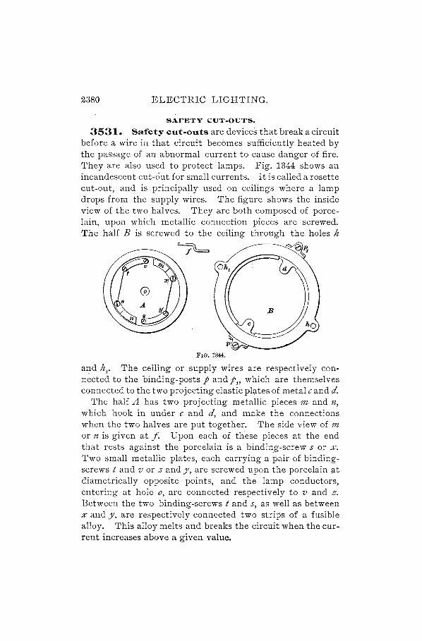
2380 ELECTRIC LIGHTING.
SAFETY CUT-OUTS.
3531. Safety cut-outs are devices that break a circuit before a wire in that circuit becomes sufficiently heated by the passage of an abriormal current to cause danger of fire. They are also used to protect lamps. Fig. 1344 shows an incandescent cut-out for small currents. It is called a rosette cut-out, and is principally used on ceilings where a lamp drops from the supply wires. The figure shows the inside view of the two halves. They are both composed of porcelain, upon which metallic connection pieces are screwed. The half B is screwed to the ceiling through the holes h
=;6
FIG. 1344.
and h,. The ceiling or supply wires are respectively conn~cted to the binding-posts p andp" which are themselves connected to the two projecting elastic pl~tes of metal c and d.
The half A has two projecting metallic pieces 1n and fl,
which hook in under c and d, and make the connections when the two halves are put together. The side view of 1n
or n is given at f. Upon each of these pieces at the end that rests against the porcelain is a binding-screw s or %.
Two small metallic plates, each carrying a pair of bindingscrews t and v or z and y, are screwed upon the porcelain llt diametrically opposite points, and the lamp conductors, entering Oat hole 0, are connected respectively to v and z. Between the two binding-screws t and s, as well as between % and y. are respectively connected two strips of a fusible alloy. This alloy melts and breaks the circuit when the current increases above a given value.

ELECTRIC LIGHTING. 2381
The current starts from one supply wire and flows-through d, m, and the alloy or fuse wire % y to z. Then it flows through the lamp to v, through the fuse wire t s to c, and out to the other supply wire. The two halves are connected by a screwing motion, which rubs the two contact pieces together.
3532. Cut-out for Large Currents.-Fig. 1345 represents a cut-out which may be used for from 100 to 400
0 0 II
a
~I a,
lo:z:o:z:,l b ' I~ b, I:z;.Oa:..OI P,
0 0
FIG. 1345.
amperes. The metallic tube~ a and a l fit over the ends of the line-wire, and the screws for clamping in these ends are %, %" %., and%.. The thumb-screw binding-posts P and Pt are used for connecting in circuit the strip of fusible alloy, and the metallic plates band bt are in connection with a and at'
The soapstone base s is pierced with the proper holes for fastening to some support.
CALCULATIONS FOR INCANDESCENTLIGHTING CIRCUITS.
3533. In making calculations for electric-light wiring, very simple formulas may be applied in most cases. The current taken by average lamps is as follows:
110-Volt.
.5 ampere 1 ampere 1.5 amperes 3 amperes
16 c. p. lamp 32 c. p. lamp 50 c. p. lamp
100 c. p. lamp
55-Volt.
1 ampere 2 amperes 3 amperes 6 amperes

2382 ELECTRIC LIGHTING.
The number of lamps on a circuit may, therefore, always be expressed in terms of 16 c. p. lamps, as
one 32 c. p. lamp = 2 of 16 c. p. one 50 c.p. lamp = 3 of 16 c. p. one 100 c. p. lamp = 6 of 16 c. p.
Then, forl10-volt circ~ts the ?llowing formula applies:
Rf ,= N F' (547.)
where Rf = resistance per foot of the conductor; E = drop in volts in the circuit; N = number of 16 c. p. lamps; F = distance in feet from dynamo or distributing
board to lamps.
That is: The resistance per foot of the conductor required for a 110-'1I0It electric-light installation is equal to tlte allowable drop in volts divided by the product of the number of 16 c. p. lamps and the single distance in feet betwem the dynamo or distributing board and the lamps. Tht"s product is called tlte lamp=ieet.
EXAMPLE.-A lamp circuit is to be installed in which there are 80 sixteen candle-power 110-volt lamps. A drop of 10 volts is allowed, and the. lamps are 500 feet distant from the dynamo. What size of wire should be used?
SOLUTION.-In this example E= 10 volts; N= 80; F= 500.· Then, by formula 547, the resistance per foot of the conductor,
10 Rf = 80 X 500 = .00025 ohm.
This is equal to .25 ohm per 1,000 feet, and in Table 98 this corresponds to No. 4 B. & S. near enough. Ans.
3534. When 55-volt lamps are used, double the curre~t is required for the same illumination, and for determining the size of conductor we have
(548.)
That is: The resistance per foot of a conductor for a 55-volt

ELECTRIC LIGHTING. 2383
Ughting circuit is obtained by dividing the drop in volts by twice the lamp-feet.
EXAMPLE.-A group of 25 lamps of 16 c. p. is installed on a 55-volt circuit, at a distance of 75 feet from the switchboard. If a drop of 2 volts is allowed, what size of wire should be used?
SOLUTION.- E = 2 volts; N = 25, and F = 75. Then, by formula 548,
Rf = 2 X 2: X 75 = .000533 ohm = .533 ohm per 1,000 feet.
This corresponds to No.7 B. & S. gauge. Ans.
3535. When the wire is very large, it is more convenient to express the area in circular mils, and the following formula.is used for nO-volt circuits: '
A _10.8NF ' - E ' '(549.)
where A = area in circular mils.
The area of a conductor, in circular mils, for a 110-volt cz'rcuit is equal to 10.8 times the lamp-feet, divided by the drop in volts.
For 55-volt circuits use
A _ 2 X 10.8NF - E . (550.)
The area of a conductor, in circular mils, for a 55-'llolt circuit is equal to the lamp-feet divided by the drop in volts and multiplied by:2 and by 10.8.
3536. The last two formulas, giving the area directly in circular mils, are based upon the fact that the resistance of a wire of commercial copper 1 foot long and 1 circular mil in cross-section at 75° F. is about 10.8 ohms. A nearer figure is 10.79, but this involves more trouble in the calculations, and for this class of work the constant 10.8 is sufficiently accurate.
Since resistance is directly proportional to length and inversely proportional to area of cross-section, it is evident that a wire 2 feet long would have twice this resistance, and

2384 ELECTRIC LIGHTING.
a. wire 1 foot long, but of 2 circular mils cross-section, onehalf this resistance.
Expressed in symbols, this would be
where
R _10.8 L - d 2 , (551.)
R = resistance in ohms; L = length in feet; d = diameter of wire in mils.
Here d' is given instead of the area in circular mils, because the diameter of the wire is the figure generally quoted.
Formula 551 may be expressed as follows: Tlte resz'stana of a copper wire z's equal to its lengtlt in feet multz'plz'ed by 10.8 and dz'vz'dcd by its cross-section in circular mils
This formula may be transposed and written:
d 2_10.8L - R . (552.)
That is: Tlte cross-scctio1Z of a copper wire in circular mils is found by multz'plying its lmgtlt in feet by 10.8 and dividing the result by its resistance in oltms.
EXAMPLE.-Required the cross-section in circular mils of a wire 1,000 feet long and of a resistance of 1 ohm.
SOLUTION.-By formula 552,
d2 10.8 X 1,000 10800' 1 "'1 A "= 1 =, Clrcu ar ml s. ns.
3537. It may be desired to know in some cases what the drop would be with a given conductor, and this may be determined by transposition of terms in the formulas already given.
For 110-volt circuits,
E=RfNF. (553.) Tlte drop in volts is equal to tlte resistance per foot of tlte
conductor multiplz'ed by tlte lamp-feet.
Or, E = lO'S;F. (554.)

ELECTRIC LIGHTING. 2385
The drop in volts is equal to 10.8 times the lampfeet, divided by the cross-sectiollal area of the conductor in circular mils:
For 55-volt circuits,
E=2Rf N F. (555.)
The drop in volts is equal to tlte resistance per foot of the conductor multiplied by t'Wice tlte lamp-feet.
Or, E - 2 X lO.SNF - A . (556.)
The drop in 1/01ts is equal to t'Wice tile lamp-feet multiplied by 10.8 and divided by the area qf the conductor in circular mils.
EXAMPLE.-A circuit of 200 sixteen candle-power, 55-volt incandescent lamps is to be wired for a 20 per cent. loss in conductors. The total length of the circuit is 800 feet. What should be the size of the conductor?
SOLUTION.-The actual drop on the line is, by formula 502,
E_l00X55 '55-1""~-1 - -8-0- - - u.1O vo ts.
In this example N=200; F=400; and E=13.75. Then, by formula 548, the resistance per foot of the conductor
Rf = 2 X ;;0 7~ 400 = .0000859 ohm = .0859 per 1,000 feet.
The nearest size of wire is No. 00 B. & s. This wire will carry only 124 amperes, so it can not be used. The
nearest size for the required 200 amperes is a heavy cable, but we may use two No. 0 wires in parallel. The resistance per foot will be onehalf of a single wire, or .000051 ohm, and by formula 555, the resulting drop in the circuit
E = 2 X .000051 X 200 X 400 = 8.16 volts. Ans.
3538. Size of Conductors :for Three-Wire §ystem..-The method followed in calculating the size of conductors for the three-wire system is based on the same laws as for the two-wire system. \iVhen the two sides of the three-wire system are balanced, with no current in the neutral wire, the E. M. F. of the circuit is double that of a twowire system, and since the current for one lam p also passes through another lamp in series, the total current required is
2386 ELECTRIC LIGHTING.
only one-half of that necessary for the same number of lamps on the two-wire system. For an equal percentage drop of potential, therefore, the size of wire need be only one-fourth 6f that necessary in the two-wire system. .If, however, the drop is to remain the same in each case, the size of wire in the three"wire system will be one-half that required for the two-wire system; for, although the resistance of the conductor for the three-wire system would thereby be doubled, the current is of only one-h:llf the value, so that in the one case E = C R, and in the other case E =- t eX :2 R, which values are identical.
For the. three-wire system, therefore,
(552'.)
The resistance per foot of the conductor in a 110-220 volt three-wire system is equal to twice the drop in volts divided by the lamp-feet.
For large conductors, the area in circular mils
A _lO.8NF _ 5.4NF - 2E - E .
Rule.-In determining the safe carrying capacity of conductors for the three-wire system, remember that, with the same number and kind of lamps, the conductor carries only one-half the current of a conductor installed on tIle l!tultiplcarc system.
3539. Amount of Copper in Three-Wire System. -When the three-wire system is adopted in place of the two-wire, the total E. M. F. is doubled, as we have seen, and the current is reduced by one-half. But the same amount of energy is delivered, and the drop will be the same if the conductor area is decreased in proportion to the decrease of current. Then, since the third, or neutral, wire is usually made equal to the outer wires, the total amount of copper is reduced by one-fourth. When the percentage loss is the same, however, the outer wires may be in cross-section only

ELECTRIC .LIGHTING. 2387
one-fourth that of the conductors necessary for the twowire system. But an additional conductor, the neutral wire, of the same cross-section, must be supplied, having, however, only one-half the length of the total circuit, or onceighth the metal of the multiple-arc system.
The total metal of the three-vvire system is, therefore, t + -§- = .y. of the metal required in a multi pIc-arc system for the same number and kind of lamps, and for an equal percentage drop of potential.
The neutral wire could be made considerably smaller than the outside conductors, because it normally carries .only a small fraction of the current. However, for practical reasons, it is usually made of the same size as the other conductors.
The three-wire system in a building is generally followed throughout the feeders and mains, but two-wire branch circuits are then run from the panel boxes, each circuit carrying not more than five or six amperes.
The following is an important rule for interior wiring:
Rule.-No 'Wire smaller tlzan a No. 16 B. & S. gauge sltould be used in any dynamo circuit, nor any 'Wire smaller than a No. 14 B. & S. in any inside 'Wiring.
8540. EXAMPLE.-A system of wiring illustrated in the diagram, Fig. 1346, is to be run on the multiple-arc plan, and with the closet system for houses. The length of feeder from the dynamo to the main is 480 feet; length of main from feeder to center of distribution for house circuits is 220 feet; length of sub-main is 30 feet; l~ngth of lamp circuit from closet to lamps for third floor is 58 feet; for second floor, 42 feet; and for first floor, 22 feet. There are 5 lamps on the third floor, 10 lamps on the second, and 16 lamps on the first, all of 16 candlepower and requiring 110 volts. The fceder is joined to the center of the main, and six houses on each side are each supplied with the same number of lamps; that is, with 31. Ailow for 6 volts drop in the feeders, and 1 volt drop in the mains, in the sub-mains, and in the house circuits, respectively. 'What should be the size (a) of the feeders? (b) of the mains? (c) of the sub-mains? (d) of the wires for the lamp circuits?
SOLUTION.-(a) Since there are 12 houses, each having 31 lamps, the total number of lamps is 372 = N. The length of the feeder is 480

2388 ELECTRIC LIGHTING.
feet = F. The drop is 6 volts = E. Then, by formula 549, the cross· section8.1 area of the feeder
A 10.8 N F 10.8 X 372 X 480 321408' 1 '1 = -y- = . 6 =, Clrcu ar ml s.
By reference to Table 106, it will be seen that this cable will carry between 225 and 250 amperes, and since the current in the feeders is only ll.t 'l. = 186 amperes, this size is safe. Ans.
(b) The mains will carryon each side one-half the total number
a
. ;;---IJS'--~
_---42'-
, .c---- 22 --_
--------- #If) ----------\~c~----------------~~f
FIG. 1346.
of lamps that is, for 6 houses; and this number is 188 = N; the distance = 220 feet = F; the drop = 1 volt = E. Then, by formula 549, the area of the cable
A 10.8 X 186 X 220 441 936' I '1 = 1 =, Clrcu ar ml s.
Since this cable is larger than thE) fE)edE)r, "nd c'lrriE)S only one-half the current, it is s'IfE). Ans.

ELEC'rRIC LIGHTING. 2389
(c) The sub-mains will supply current for each house individually. The number of lamps is 31 = N; the distance = 30 feet = F; the drop = 1 volt = E. By formula 547, the resistance per foot of the conductor
Rf = ;F = 31 ~ 30 = .001075 ohm = 1.075 ohms per 1,000 feet.
By Table 98, this will be found to correspond to No. 10 wire, nearly. This size will carry 18 amperes, and the current being only 2.J- = 15.5 amperes, it is safe. Ans.
Cd) In the circuit on the first floor there are 16 lamps = N; the dis~ tance = 22 feet = F; the drop = 1 volt = E. By formula 547, the resistance per foot of the conductor
1 Rf = 16 X 22 = .002841 ohm = 2.841 ohms per 1,000 feet.
The nearest size of wire is No. 14, and since it will carry 9 amperes, it is safe: Ans.
On the second floor there are 10 lamps = N; the distance is 42 feet = F; the drop = 1 volt = E. By formula 547, the resistance per foot of the conductor
1 Rf = 10 X 42 = .002381 ohm = 2.381 ohms per 1,000 feet.
The nearest size of wire is No. 14, and as it will safely carry the current of 5 amperes, it may be used in preference to No. 13, as the difference in drop will not be noticeable. Ans.
On the third floor there are 5 lamps = N; the distance = 58 feet = F; the drop is 1 volt = E. By formula 547, the resistance per foot of the conductor
1 Rf = 5 X 58 = .003448 ohm = 3.448 ohms per 1,000 feet.
The corresponding size of wire is about No. 15, but this may not be used, according to the underwriters' regulations, and No. 14 must be taken. Ans.
EXAMPLES FOR PRACTICE.
1. Lamps of 115 volts are to be installed with 10% drop. What must be the E. M. F. at the brushes of the dynamo? Ans. 128 volts.
2. Twenty 110-volt lamps are to be installed in a building at a distance of 65 feet from the closet where the circuits start. What should be the size of the conductor, the percentage of loss being 2{·%?
Ans. No. 13 B. & S. wire.
3. A group of 50 lamps, of 16 candle-power, 110 volts, is to be connected to the street mains; the distance is 192 feet, and the allowable drop is 1t volts. What size of wire is to be used?
Ans. No. 0 B. & S.


DYNAMO-ELECTRIC MACHINE DESIGN. (CONTINUOUS-CURRENT.)
FACTORS LIMITING OUTPUT. 3541. The output of a constant-potential dynamo is
limited by two factors: the carrying capacity of the armature conductors, and the distortion of the field by armature reaction. The evidence of a machine having reached the lim.it in the first of the above cases is the development of serious heat in the armature;' distortion of the field is indicated by excessive sparking at the commutator.
3542. The question of sparking must be considered fully in the design of a dynamo; for it is not merely a matter of shifting the brushes which should be relied upon to prevent sparking, nor yet an excessive strength of field, as this is wasteful of energy. In a well-designed dynamo, sparking should not occur within the limits of the working range, which may include an overload above the rated output of 15 or 20 per cent.
HEATING OF MACHINE.
3543. The heat that is being continually generated in the machine, owing to the resistance which the conductors present to the passage of current, is given off from the surface of the armature and of the whole machine to the surrounding air. This giving off of heat can occur only when the dynamo is hotter than the air, for if two bodies are equally hot, one can not give any heat to the other. Conversely, the greater the difference in temperature between two bodies, such as a dynamo armature and the

2392 DYNAMO-ELECTRIC MACHINE DESIGN.
surrounding air, the more heat will be given from the hot body to the cold.
When a dynamo is first started, it is at about the same temperature as the surrounding air, so that when the losses in the armature begin to generate heat, this heat can not pass off to the air; but, instead, it raises the temperature of the armature until it is enough hotter than the surrounding air to cause all the heat being generated to be given off.
With a constant load, the amount of heat generated will become constant, and it will be given off as fast as it is developed; but with an increase of load, the temperature will again rise until the armature is enough hotter than the air to give off all this increased amount of heat.
3544. The copper and iron parts of the machine can stand a rather high increase of temperature without serious effects; but the insulating materials, such as cotton, silk, shellac, paper, etc., will become carbonized, that is, charred, or otherwise rendered useless for their specific purpose. For a short time these materials will withstand a temperature considerably above the boiling-point of water (212° F.), but it has been found that if they are continually subjected to a temperature greater than about 180° F., they will gradually become carbonized. Hence, as armatures are expected to last for several years, they should never be subjected to a continual temperature greater than about 170° F. Consequently, the amount of current which will cause a dynamo armature to heat to about 1700 F. is the limiting amount which that armature can safely give.
3545. Since, for a given output, the temperature of the armature will rise a certain amount above that of the surrounding air, it is evident that, if the air is originally of a high temperature, the armature will actually have a higher temperature when giving off a certain amount of heat than if the air were cooler; that is, for a certain amount of heat generated, the temperature of the armature will rise to a certain number of degrees above the temperature of the air. The average temperature of the air in

DYNAMO-ELECTRIC MACHINE DESIGN. 2303
places where dynamos are installed is often as high as 00° F., so the allowable rise in temperature of the armature above that of the air is about 80° F., and dynamos are usually rated according to this rise in temperature.
HEATING IN ARMATURE.
3546. The chief source of heat in a dynamo is usually that due to the flow of current through the armature. This being proportional to the square of the current and to the resistance, is frequently termed the C'R loss. In order to reduce this loss, the armature 'resistance should be made very low. It is not possible to go beyond certain limits, however, in the size of c0nductor, as the winding space can not be indefinitely increased. The watts lost in heat generally vary according to the size of the machine, a smaller dynamo being less efficient in this respect than a larger one, owing to the lack of suitable ventilation and the high resistance of the winding. It is usual to provide a certain proportion of armature surface per watt expended in heating, in order to allow of the heat being radiated at a sufficiently high rate to prevent excessive rise in temperature. A safe figure to use, and one which is confirmed in practice, is 1.11 square inches of surface per watt lost, equivalent to .9 watt per square inch, for peripheral speeds ranging from 2,500 to 3,500 feet per minute. A rule given by Esson, applicable to rise of temperature for any particular case, is the following:
99w t-- s (1 + 0.00018 v)' (559.)
where t = temperature rise in degrees Fahrenheit; w = watts expended in heat; s = surface of armature in square inches; l' = peripheral velocity in feet per second.
The rise in temperature of an armature is equal to 99 times tlu watts lost, divided by the exposed surface in square ilZ!:hes 1IZultiplied by 1 plus 0.00018 times tile velocity in feet per sec07zd.

2394 DYNAMO-ELECTRIC MACHINE DESIGN.
3547. Loss Due to Heating.-After the armature winding has been designed, its resistance can be calculated, and the (', R loss determined approximately. In general, it will be found that the resistance is somewhat larger than the calculated value, owing to the effect of joints between the conductors. The (" R loss will, however, be found to nearly agree with the values as given in the curve A, Fig. 1347.
It will be seen that the losses due to this cause fall off quickly when passing from the small sizes to machines of
FIG. 1347.
larger capacity, a 100 K. VV. dynamo having a C'R loss of about 2 per cent. of the input.
3548. Heating of the armature is due, not alone to the CO R loss, but also to convection from the copper conductors, to eddy currents in them, and to hysteresii=l Ring armatures usually present a greater surface to the cooling effect of the air than do drum-wound armatures, for it is not only the outer cylindrical surface which is to be considered, but likewise the ends of the cores and all exposed portions of the winding. The inner turns of the ring armature are not, however, as efficient in dissipating heat as the outer turns.
DYNAMO-ELECTRIC MACHINE DESIGN. 2395
SPEED OF ARMATURE.
3549.. In Fig. 1347 are given the peripheral speeds of armatures in feet per minute. Curve B shows the speeds adopted by a well-known manufacturer for dynamos of t kilowatt to about 10 kilowatts, all of bipolar construction. The general range of larger machines is from 2,800 to 3, GOO feet per minute, as indicated on curve C. It need not be considered indispensable that a steady increase of speed should accompany increase in size. Some manufacturers adopt a fixed peripheral velocity which is adhered to through a wide range; for the smaller sizes, up to, say, 25 horsepower, the velocity may be 3,100 feet per minute, and for all larger machines a velocity of about 3,500 feet per minute. All these figures are for the usual high-speed type of dynamo; the moderate-speed type is run at about twothirds of the above velocity.
Large direct-connected multipolar dynamos of 100 kilowatts and upwards have usually a peripheral velocity of 2,200 to 2,500 feet per minute, as, for instance, those built by the General Electric Company. Railway generators for belt-driving are frequently designed for a surface speed of 5,000 feet per minute; the pulleys, however, should be of smaller diameter than the armatures, as the belt should not run at a higher speed than about 4,500 feet per minute. The adoption of a high peripheral speed for the armature is to be commended, on account of a reduction in weight for a given output; but due consideration must be given to mechanical strength. A very high speed also demands very careful balancing of the rotating parts, in order to avoid injury to the insulation through vibration.
HEATING OF FIELD SPOOLS.
3550. The field spools of the dynamo must be designed with a view to presenting sufficient surface to the air to dissipate the heat developed. The ends of the spool assist materially in radiating heat, as does also, to some extent, the inner surface which lies against the magnet core. A

239G DYNAMO-ELECTRIC MACHINE DESIGN.
useful formula, taking into account the cooling effect of a little space at least on one side between the spool and magnet, is the following:
SOw t= -, (560.)
s
where t = temperature rise of spool in degrees Fahrenheit; w = watts expended in coils; s = surface of spools (wire only) in square inches.
Expressed in words, this formula states that the rise in temperature of the field spools is equal to 80 times tile watts expmded in tile coils, divided by the exposed surface of the wire in square inches.
'With a permissible rise in temperature of 75° or SOo F., it will be found that about 1.1 square inches per watt will be required. Such a proportion is, in fact, frequently used, although it is perhaps a better plan to allow 1. 5 or 2 square inches per watt, because the lesser rise in temperature thereby occasioned will cause less variation in the exciting current during the time when the machine is slowly warming up. In any case, it must be remembered that the shape of the spools and their position with regard to neighboring portions of the magnetic circuit will have considerable influence in determining the allowable surface of winding. The formula given above refers to magnet spools as ordinarily constructed. It is also most important that the depth of winding should not be too great---'-not over 2t inches, as. a ruleas the temperature of the inner turns may otherwise become very high. For small machines the usual depth of winding is considerably less than this figure, being from 1 inch to It inches.
3551. The advantage attending the use of short spools with comparatively small winding volume is that a compact lP.agnetic circuit is secured and the weight of copper is reduced. On the other hand, since a given magnetizing force is required, the ampere-turns must remain the same; if, then, the number of turns is reduced, the current must be increased. The losses are, however, proportional to the

DYNAMO-ELECTRIC MACHINE DESIGN. 2397
square of the current, and only vary directly with the resistance; so that it is more economical to reduce the current and increase the resistance than the reverse. It will then be seen that here the number of square inches of winding surface per watt lost in the coils is a compromise between efficiency of the machine on the one hand, and first cost of copper on the other; for if we desire the loss in heating to be small, we must use a greater weight of wire. It will be shown in the following pages that compromises of this kind must be made continually through the entire subject of dynamo design.
3552. In shunt-wound dynamos, the loss of energy in the field winding is from about 10 per cent. for a 1 K. W. machine to about 1.5 per cent. for a 100 K. W. machine.
ARMATURE REACTION-SMOOTH CORE.
EFFECT OF ARMATURE AMPERE-TURNS_ .
3553. The subject of armature reaction has previously been referred to in a general way, and we will now consider
it more in detail with reference to actual design. We have seen that the magnetic effect of the armature ampere-turns is at right angles to the direction of the lines of force due to the field winding, so that a cross-magnetization is produced.

2398 DYNAMO-ELECTRIC MACHINE DESIGN.
For the purpose of, studying the field induced by the armature current, we will show the distribution of the lines of force as it would occur if the disturbing effect of the field ampere-turns were not present. In Fig. 1348 are represented the armature and pole-pieces of a bipolar dynamo; the conductors are indicated by the small circles on the periphery of the armature, and the direction of the flow of current in them is shown by their marking, the' cross representing a current flowing upwards thrpugh the paper, and the full black circle representing a current flo~ing away from the observer. The lines of force, it will be noticed, spread evenly over the pole-pieces and complete the circuit through ,the iron of the armature core. T~e reluctance of the path through the iron of the pole-pieces and core 'is almost negligible, compared with the reluctance offered by the air-gap, so that it is evident that the magnetomotive force (M. M. F.) of the armature ampere-turns is almost wholly expended in driving the lines of force through the air-gap. The greatest difference of magnetic potential due to the armature ampere-turns is at the pole-tips at nearly diametrically opposite points, and the least difference of potential'is at the horizontal center line, where it is reduced to zero. This maximum difference of magnetic potential is, then, proportional to the armature ampere-turns, or to the cross M. M. F., and may also be expre~sed in terms of any angle. For example,
Let C = current flowing through armature; c = number of conductors on periphery of armature.
Then, for any angle l, Fig. 1350,
, C 1 cross M. M. F. = 3.1\)2 X 2 X eX 360'
Since the greatest magnetic difference of potential exists between the upper and lower ends of the pole-pieces, that is. at opposite ends of the armature, the cross M. M. F. will be
C 180 Cc 3.192 X 2 X eX 360 = 3.19~ X T' (561.)

DYNAMO-ELECTRIC MACHINE DESIGN. 2399
This cross M. M. F. may be considered as expending nearly all its force on the air-gaps at the ends of the pole-pieces, at top and bottom, since the effect diminishes to zero at the horizontal center line, provided also that the area of the pole-pieces is sufficiently great to allow of practically unobstructed passage o~ the lines of force.
EFFECT OF CROSS AMPERE-TURNS.
3554. We may now proceed to an investigation of the effect of field distortion. -Fig. lS49 shows the resulting field wben armature ampere-turns and field ampere-turns are simultaneously acting upon the magnetic circuit.
The direction along which the M; M. F. of the armature ampere-turns acts is shown by the heavy dotted lines. It will be seen that this is directly opposed to the M. M. F. of the field ampere-turns at the leading pole tips a and e, with the result that a decided neutralization of induction occurs; but at the following pole tips c, f the induction is strengthe.ned, because the two M. M. F. 's act in conjunction and build up a stronger field. It should be pointed out that the total number of lines of force' in the air-gap is not changed, but their distribution is altered, so that the density varies accordingly.
3555e In the calculations to determine the ampere-turns necessary for the field-magnets, a certain number is taken for each portion of the magnetic circuit, as will be explained in due time. Let At" represent the field ampere-turns required to overcome the reluctance of the air-gaps (twice the radial distance from pole-piece to core). Then the M. M. F at one air-gap, due to th~ field ampere-turns, is equal to
3.192 X A2~' (562.)
We have found, however, by formula 561, that the cross M. M. F. of the armature over the two air-gaps a band cd is

2400 DYNAMO-ELECTRIC MACHINE DESIGN.
< Cc 3.192 X -:[; therefore ,the cross M. M. F. for one air-gap
will be , , Cc 1_ . Cc 3.192 X T X 2 - 3.192 X s· (563.)
The algebraic sum of these two equations will, then, give us the resultant M. M. F. at the pole tips. YNe must have regard to the sign of formula 563, as it is in one case positive and in one case negative. At the upper end of the lefthand pole-piece, the cross M. M. F. opposes the field M. M. F., so that for the air-gap a b at the leading pole tip the resultant M. M. F. is
3.192(A2~- ~c). (564.)
At the lower end of the same pole-piece, the M. M. F. 's are in the same sense, and the resultant M. M. F. for the airgap cd is
, (Ata CC) 3.192 2+8 . (565.)
3556. From the above equations we may directly obtain the values of the induction in the air-gap, since it ,is, in such a case, represented by the M. M. F. divided by the length of the circuit. Then,
If B'g = density of lines of force per square inch in leading pole tip;
fg = length of single air-gap in inches,
(566.)
The density 0.1 magnetic lines 0.1 force under the leading pole tip is equal to 3.192 times the differeJlce between tile field ampereturns required .lor one air-gap and one-Italf tlte cross ampereturns, divided by tlte length 0.1 tile single air-gap.

DYNAMO-ELECTRIC MACHINE DESIGN. 2401
3557. Also, if W g = density of the following pole tip,
n _3.192 (A;g + ~c) Bg-;;: t..
g
(567.)
The density of tlte magnetic lines of force under the following pole tip is equal to 3.192 times the sum of the field ampereturns required for one air-gap and one-half tlze cross ampereturns, divided by the length of the single air-gap.
3558. At the horizontal center line it has been shown that the cross M. M. F. is zero; therefore, the density in the air-gap at this point will be due only to the ampere-turns of the field. Let By represent the inductiol1 at the center line; then
3.192 ~tu 3.192 At B - - g . g - 19 - 2lg (568.)
That is, the density of magnetic lz"nes of force at the center of the pole-piece is equal to 3.192 times tlte field ampereturns required for the gap, divided by twice the length of the single air-gap.
3559. The airgap between the II'
III II '1 111I II 1, ',"
armature core and 1'1' II I:::: II II the right-hand pole- 1111, II rl
11111 II II
Piece (Fig. 1349) I ',l,' ','1 I: III d, I
may be considered 'I:: ':! II in exactly the same FIG. 1349.
manner, the magnetic density being least at the leading pole tip e and greatest at the following pole tip f.

2402 DYNAMO-ELECTRIC MACHINE DESIGN.
EFFECT OF BACK AMPERE-TURNS.
3560. We have thus far referred only to the effect produced by the cross ampere· turns of the armature. It is not
possible, however, to run the dynamo with the brushes set exactly midway between the pole tips, and a certain angle of lead must be given, as shown in the discussion, in a previ-ous section, of the theory of the dynamo. In Fig. 1350 the angle of lead = r, or one-half the angle represented
FIG. 1350. by 2 r, this being the angular distance through which the brushes must be moved in order to obtain sparkless commutation. The turns embraced within twice this angle r, multiplied by the current which each conductor carries, constitute the back a~pere·turns. The direction of the lines of force induced by these turns is indio cated by the small arrows on the armature core, and the direction of the field lines of force is shown by the small arrows on the pole-pieces. It is evident, then, that the back ampere-turns neutralize a certain 'equal number of ampereturns on the field-magnets, so that this must be borne in mind later, when the total field ampere-turns are calculated.
3561. For a bipolar dynamo, the value of the current flowing through anyone conductor is one-half the total armature current, there being only two circuits. Also, the number of conductors enclosed within the double angle of
lead 2 r is equal to ::0 of the total number, since r is ex
pressed in degrees, and there are 360 degrees to the circle. Then the value of the back ampere-turns of the armature
C 2r Crc Atb = 2' X 360 X c = 360' (569.)
DYNAMO-ELECTRIC MACHINE DESIGN. 2403
where C = total armature current; r = angle of lead of brush-es ; c = total number of conductors.
The back ampere-turns of tke armature of a bipolar dynamo are equal to the armature current in amperes mUltz"phed by the angle of lead and the total number of conductors, and divided by 360.
VALUE OF CROSS AMPERE·TURNS.
3562. The cross ampere-turns are included within the angle I, Fig. 1350, which is equal to 180° - 2 r, that is, to the whole number of armature ampere-turns less the back ampere-turns. We may then write the following expression for the value of the cross ampere-turns:
(570.)
where C = tota' 'rmature current; I = 180° less twice the angle of lead; c = total number of armature conductors.
The cross ampere-turns of tlte armature of a bipolar dynamo are equal to half the armature current multiphed by the number of conductors enclosed 'Witlzz"n an angle equal to 180° less twice the angle of lead.
3563. Although, as we have seen, the cross ampereturns do not change the total number of lines of force, but only deflect them, the tendency of this cross M. M. F. is to weaken the field at the leading pole tip by diverting the lines of force from that point. A certain strength of field is, however; necessary for commutation, so that there exists in all cases a critical value of cross M. M. F. beyond which it is impossible to go without causing destructive sparking. We have found, by formula 561, that if the angle embraced by the conductors producing the cross ampere-turns is 180°,
their magnetomotive force = 3.192 X ; X c X !~~. If we

2404 DYNAMO-ELECTRIC MACHINE DESIGN.
now substitute for 180 the angle I, the M. M. F. of the cross
ampere-turns = 3.192 X ; X c X 3~O' and this M. M. F. is
expended over two air-gaps, one at the upper pole tip and the other at the lower pole tip. The value, then, of the cross M. M. F. at one pole tip is
C c I 3.192 X 2" X"2 X 360· (571.)
If this value should equal the magnetomotive force of the field ampere-turns of the air-gap, the field at this pole tip would be entirely neutralized, in which case the machine would be unworkable owing to the excessive and violent sparking at the brushes. It follows, therefore, that, for the leading pole tip,
Atg " C c I (_) 3.192-2 > 0.192 X Z-X 2" X 360· ~72.
The mag7Zetomotive force of the field ampere-turns for the single air-gap must be greater than - ./'c magnetomotive force due to one-half the cross ampere-turns of the armature.
LIMITING VALUE OF AIR-GAP DENSITY.
3564. We may also specify the above requirement in terms of the density in the air-gap, since this density is equal to the M. M. F. divided by the length of air-gap. The following value, then, must be a positive quantity:
(573.)
where B' g = density of field under leading pole tip; Atg = field ampere-turns required for air-gap; C = total armature current; c = total number of conductors on periphery of
armature; I = 1800 less twice the angle of lead; ll{ = length of single air-gap, in inche:;;,
DYNAMO-ELECTRIC MACHINE DESIGN. 2405
It is not enough to make this equation a positive quantity only; the field at this point must be sufficiently strong to overcome the self-induction of the coil which is being shortcircuited and generate in it a current in the opposite direction. To ensure satisfactory working, the M. M. F. in the gap, due to the field, should be at least II to 2 times the cross M. M. F. applied to the gap, even when a large angle of lead is employed. It might appear that the demagnetizing action of the back ampere-turns would prevent a position of sparklessness being found, when a heavy current necessitated a large angle of lead;, but it must be remembered that, as the back ampere-turns are increased, the cross ampere-turns are decreased, so that, although the field is reduced in strength, its distribution is more uniform. A point is, therefore, usually found where the reversing field is sufficiently strong for commutation, and it is only when an excessive current is taken from the machine that the back ampere-turns weaken the field to such an extent as to preclude sparkless operation.
3565. A further disadvantage of a weak field at the leading pole tip is that a large angle of lead is required, thereby bringing the short-circuited coil very close to the edge of the pole-piece. At this point there is a more or less abrupt change in magnetic density, and any uneven spacing of the conductors will cause them to be shortcircuited at different points, relative to the pole-piece, thereby causing sparking. A variation in load will also be more likely to give rise to sparking when the point of commutation is under the pole tip.
3566. We will now find it convenient to introduce another method of denoting the value of the cross ampereturns. The back turns extend only to the point where commutation occurs, and this is at the entering fringe of the pole-piece. Then, we may say that the cross-turns are those conductors which lie under the pole-piece and under the magnetic fringe at the edges. For all practical purposes, we may designate this fringe as equal to about four-fifths

2406 DYNAMO-ELECTRIC MACHINE .DESIGN.
of the length of the air-gap. The value of the cross ampere-turns Ate still remains the same as in formula 570, only substituting this more correct definition of I, which takes into account the commutating fringe and dispenses with the reference to the value of the back ampere-turns.
3567. We have said that the M. M. F. in the gap, due to the field, should be at least It to 2 times the cross M. M. F. of the armature. We may compare the ampereturns in the two cases, since they are proportional to the magnetomotive force. The field ampere-turns expended in the gap (Atg) take into account both the air-gaps, and the cross ampere-turns (Ate) also act through two air-gaps, at the top and bottom of the pole-pieces, respectively (see Fig. 1349). , Then, we may say that the field ampere-turns for the air-gaps must be It to 2 times the cross ampere-turns. The smaller value is to be used in calculations for drum armatures, and the larger value for ring armatures. The difference in these coefficients is due to the fact that in the ring armature there is a greater amount of self-induction in the coils when short-circuited, and this requires a greater angle of lead, thereby reducing the total effective field and requiring at the same time a more powerful field for reversal, with the same .number of conductors and coils as a drum armature. In order to counteract this effect as much as possible, a high density is used in the core of the ring armature, so that the self-induced current can not reach a high value, as the collapse of the extra lines of force, due to its current before short-circuiting, develops only a low E. M. F. Nevertheless, the self-induction is higher than in the loop of a drum winding. When a ring armature is constructed with many turns to a section, it may become necessary even to exceed the figure given. Another reason calling for a higher coefficient in the case of ring armatures is that the extra amount of lead which must be given to the brushes would bring the short-circuited coils very near to the pole tip, where the change in magnetic density is abrupt. To avoid this, a stronger commutating fringe is required.

DYNAMO-ELECTRIC MACHINE DESIGN. 2407
Also there are some lines of force which leak across the inside of the core. With a drum winding, these lines are of no account; but they cut the inner turns of the ring coils, inducing an E. M. F. which opposes that of the outer turns.
LIMITING VALUES OF CROSS AND ARMATURE AMPERE· TURNS, DRUM WINDING.
3568. Returning to the consideration of the cross ampere-turns, we have found that they should be limited to a value equal to two-thirds of the field ampere-turns required for the air-gap in the case of a bipolar drum annature; for Atg equals It Ate) whence
A -2A _Atg te -"3 tg - L5"' (574.)
where Ate = cross ampere-turns, drum armature; Atg = ampere-turns of field required for two air-gaps.
For a drum-wound bipolar armature, the limiting value of tlze cross ampere-turns is the 7Jalue they have when they are equal to two-thirds the field ampere-turns required for the air-gaps.
3569. We may here introduce an expression for the total ampere-turns of the armature, which are equal to the sum of the cross ampere-turns and the back ampere-turns; or, the arD1ature aD1pere-turns
Ata = Ate+ Atb•
We have seen (formula 570) that the cross ampere-turns
C l Ate=2'X360Xc;
then formula 5'14 may be written:
C l _ Atg 2' X 360 X c - D' (575.)
But the total armature ampere-turns are obviously equal (for a bipolar machine) to one-half the total number of

2408 DYNAMO-ELECTRIC MACHINE DESIGN.
conductors on the surface of the armature multiplied by the current carried by each, that is, by one-half the total armature current. We may then write
(576.)
Each term of formula 575 may be divided by 2, so that
C I c _ Atg "2X 360 X 2- -3'
whence C c Atg 360 120 Atg "2X 2"=3- X -1-= I .
Since C c
Ata = 2 X "2 (see formula 576),
At _120 Atg a- I . (577.)
The maximum number of ampere-turns which a bipolardrum armature may carry is equal to 120 times the field ampere-turns required for the air-gaps, divided by the angle embraced by one pole-piece.
LIMITING VALUE OF CROSS AND ARMATURE AMPERETURNS, RING WINDING.
3570. In the case of a bipolar ring-wound armature, we have seen (Art. 3564) that the field ampere-turns required for the air-gap must be equal to twice the cross ampereturns. Then,
(578.)
where Ate = cross ampere-turns, ring armature; Atg = ampere-turns of field required for two air-gaps.
For a ring-wound bipolar armature, the limiting value of the cross ampere-turns is when they are equal to one-half the field ampere-turns required for the air-gaps.
3571. In the same manner as has already been proved,

DYNAMO-ELECTRIC MACHINE DESIGN. 2409
it may be shown that the cross ampere-turns C I "2 X 360 X c, and, therefore, that
At _ C c _ Atg 360 _ 90 Atg u-"2 X 2"-T X -1---1-·
are equal to
(579.)
That is, the ma.:n'mul1Z number of ampere-turns which a bzpolar ring armature may carry is equal to 90 times the field ampere-turns required for the air-gaps, divz·ded by the angle embraced by one pole-piece.
3572. For the same total number of conductors on the periphery of the armature, the ring-armature core carries twice as many ampere-turns as the drum-armature core. It must be remembered, however, that the density of the lines of force due to these turns would remain the same; so that, if the two cores were of the same cross-sectional area, as, for instance, in the annular construction of core disks, the in~ duction would be the same in both cases. As another example, suppose a magnet requires 500 ampere-turns to develop an induction of 50,000 lines of force per square inch, and it is then split in two longitudinally; each of the separate parts will require 500 ampere-turns to give the same density of lines of force as before.
LIMITING VOLUME OF CURRENT.
3573. For the purpose of determining the maximum possible output of a dynamo, we will adopt an expression for the total amount of current which the armature carries. Let c = number of conductors on periphery of armature, and C' =.current flowing in each conductor. We will call the whole sheet of current flowing across the armature the voluDl.e of current, and represent it by the letter V. Then,
v= C'c. (580.)
The volume of current is equal to the current )lowing in one conductor mUltipl£ed by the number of conductors on the periphery of the armature.

2410 pYNAMO-ELECTRIC MACHINE DESIGN;
3574. We may arrive at once at a figure for the value of V for bipolar armatures. We have seen, by formula 576, that .the ampere-turns of the armature are equal to one-half the total number of conductors multiplied by die
current carried by each, that is, equal to; X~. But in
this case, ~ = C'. so that the armature ampere-turns
Ata= C' x~. By formula 580. V = C' Cj
therefore, V = 2 Ata. (581.)
We have seen, by formula 57'1, that for a bipolar drum winding the armature ampere-turns may have a maximum
120At value of ,g j wherefore,
V = 2.40/tg• (582.)
The maximum volume of current which a drum armature may carry is equal to 240 times the field ampere-turns required for the air-gaps, divided by the angle embraced by one pole-piece.
3575. We have also found, by formula 579, that for a bipolar ring winding the armature ampere-turns may have
. 90At a maXlmum value of -,-gj wherefore,
V_ISO Atg - , . (583.)
The maximum volume of current whz"ch a rzng armature may carry is equal to 180 tz"mes the field ampere-turns required for the air-gaps, divided by the angle embraced by one pole-piece. .
3576. It will be noticed that in expressing in words the above formulas (582 and 583) for volume of current, we have omitted mention of the term "bipolar." I t will be shown presently that these formulas are true, not only for bipolar machines, but also for those of multipolar construction.
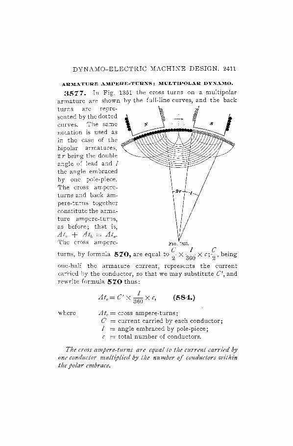
DYNAMO-ELECTRIC MACHINE DESIGN. 2411
3577.
-1---/
armature are shown turns are represented by the dotted curves. The same notation is used as in the case of the bipolar armatures, 2 r being the double angle of lead and I the angle embraced by . one pole-piece. The cross ampereturns and back am-
\ I I r+j pere-turns together constitute the arma-ture ampere-turns, as before, that is, Ate + Atb = Ata.
\ I / \ '/ ~ The cross ampere- FIG. 1351.
C I C. turns, by formula 570, are equal to 2 X 360 Xc; 2' bemg
one-half the armature current, represents the current carried by the conductor, so that we may substitute C', and rewrite formula 570 thus:
where
Ate= C' X 3:0 X c, (584.)
Ate = cross ampere· turns ; C' = current carried by each conductor; I = angle embraced by pole-piece; c = total number of conductors.
The cross ampere-turns are equal to the current carried by one conductor multiplied by the number of conductors within the polar embrace.

2412 DYNAMO-ELECTRIC MACHINE DESIGN.
3578. The back ampere-turns may in like manner be written
A C ' 21' tb = X 3tfO X c. (585.)
The back ampere-turns arc equal to tlte current carried by one conductor multiplied by the number of conductors enclosed within the double angle of lead.
3579. In the case of a bipolar dynamo, the sheet of current on one side of the armature, that is, opposite one pole-piece, constituted the armature ampere-turns, and compris,ed the cross ampere-turns and the back ampere-turns. In the case of a multipolar dynamo the same reasoning holds good, and the armature ampere-turns At" = Ate + Atb • The armature ampere-turns are also evidently equal to the current in one conductor multiplied by the number of conduct-
ors per pole-piece; that is, Ata = C~c, whereF= number of
poles. We have seen, by formula 580, that C' c is equal to the volume of current V, so that we may say
(586.)
The maXi1tZU17Z number of ampere-turns which an armature may carry is equal to tlte 7Jolume of current )lowing through the conductors divided by the number of field-magnet poles.
This formula is true of all machines, whether bipolar or multipolar, and whether the winding be in many parallel circuits or whether it form a two-circuit senes, or wave, winding.
3580. If a parallel or multiple-circuit winding is used, the current in each conductor is equal to the total current divided by the number of poles, for there is one circuit for
h 1 · h C' - C I h f .. eac, po e-plece; t us, - p' n t e case 0 a two-CIrcUIt
winding, the current C' in any conductor is one-half the
DYNAMO-ELECTRIC MACHINE DESIGN. 2413
C armature current; or C' = 2' Then, for a multiple-circuit
winding, the armature ampere-turns
C' c C c C c Ata = p = p X P = p" (587.)
The armature ampere-turns for a multiple-cz'rcztz't winding are equal to tlte armature current multz"plz'ed by the number of conductors, and divided by the square of the number of poles.
3581. For a two-circuit winding,
C' c C c' Cc Ata = p = 2 X P = iF P' (588.)
The armature ampere-turns for a two-cz'rcuit winding are equal to the armature current 11Zultt'pNed by the number of conductors, a7zd divided by twice the number of poles.
3582. Since the same number of magnetizing ampereturns are used on the field whether the winding be multiple or two-circuit, the above values of the armature ampereturns (formulas' 587 and 588) must be the same in each case. That it actually is so may be proved by a simple example. Let us take a 6-pole dynamo with 90 conductors on the armature, and let us suppose a current of 10 amperes to flow through anyone conductor. Then, for a multiplecircuit winding, there will. be 6 circuits; the armature Cllrrent C will be 60 amperes; the number of poles P will be 6; the number of conductors c will be 90, By formula 587, the armature ampere-turns
C c 60 X 90 Ata = P' = --;36- = 150.
For a two-circuit winding, the armature current will be 2 X 10 = 20 amperes, and by formula 588 the armature ampere-turns
At - f~- 20 X 90 - 150 a - 2P - 12 - ,

2414 DYNAMO-ELECTRIC MACHINE DESIGN"
We may also appiy formula 586 to this case, and we have
3583. The maximum value which the cross ampereturns may have is found by the same formula as wcs applied to bipolar dynamos. For a drum-wound armature, formula
At 574 shows that Ate = _-.!t.. By formula 584, W~ know 1.5
that Ate = C' X 3:0 X c; therefore,
C' I Atg X 360 X c = TI'
c' c _ Atg 360 _ 240 Atg p--r~Xp7- PI .
We have seen that
then,
By formula 586,
therefore,
At _ 240 Atg a- PI .
V Ata = P;
V - 240 At(f - I .
3584. In the same manner, the maximum value of (he volume of current for a ring-wound multipolar armature is
180 At found to be V = ----" I .
It must be remembered that these values for the volume of current are not to be exceeded, and a margin should be allowed, suited to the work required of the machine, for cases of temporary overload.
3585. By the above formulas, which are identical with formulas 582 and 583, it will be seen that the permissible volume of current varies directly as A tg, the field ampere-

DYNAMO-ELECTRIC MACHINE DESIGN. 2415
turns required for the air-gaps, that is to say, as the length and density of the air-gap-but inversely as the polar embrace.
This latter is generally of an average value in bipolar dynamos, so that the volume of current is affected only by the length and density of the air-gap. In this type of machine, therefore, increased capacity may be obtained by increasing the size of the armature; but a longer air-gap or a greater density must also be provided to overcome the effect of the increased volume of current. With a multipolar. field, however, the angle of polar embrace may be reduced, so that the same armature may be made to furnish a greater output, although both the length and the density of the air-gap remain the same.
CURRENT DENSITY IN ARMATURE CONDUCTORS.
3586. The current densities used in armature conductors vary within considerable limits, some makers preferring to keep to a low value and others using high densities. Much depends upon the mechanical construction of the winding and upon provision for \'entilating, also upon the conditions under which the machine will operate. In ordinary cases it is not usual to go below 600 circular mils per ampere, and 600 to 700 is a safe figure. For special purposes, a density of 500 circular mils per ampere may be used, and again, when conditions are such that a heavy overload is to be carried at times, or the temperature of the engine room is very high, a density of 1,000 circular mils per ampere may be employed.
ARMATURE REACTION-SLOTTED CORES.
3587. Many devices have from time to time been suggested for eliminating armature reaction; but an effective method of reducing it, and one which is universally used, is to construct the armature core of slotted disks. The different

2416 DYNAMO-ELECTRIC MACHINE DESIGN.
forms of teeth, due to this slotting, will be described in their proper place, but, for the present, we will consider a representative form, as shown in Fig. 1352.
The teeth t, t, etc., taper somewhat towards the root, as the slots between them must be parallel, to allow of symmetrical winding. ,\Vith this construction of core, it will be seen that the density of the lines of force in the teeth must be considerably greater than the density in the air-gap, and, in fact, a very appreciable reluctance is thus added to the magnetic circuit. The density is usually carried to 100,000
FIG. 1352.
lines per square inch, or more, so that, saturation being so nearly attained, the effect of the cross ampere-turns of the armature is far less noticeable. This saturation of the teeth, by introducing reluctance into the magnetic circuit, obviates the necessity for a large air-gap between the armature core and the pole face. The clearance is then determined, not only by the relation of the cross ampereturns acting on the air-gap to the field ampere-turns required for the air-gap, but also by the effect produced on the mas-net faces by the moving- teeth.

DYNAMO-ELECTRIC MACHINE DESIGN. 2417
In considering armature reaction with reference to slotted cores, we can allow a larger volume of current than could be permitted with a smooth core, on account of distortion of the field being so much less, and conditions favorable to satisfactory results will usually be secured by allowing suf· ficient cross-section in the armature conductors and a high density in the armature teeth, together with a well-proportioned air-gap. In general, we may allow a volume of current equal,to about It times that carried by a smooth-core armature of the same class.
LENGTH OF AIR-GAP.
3588. Fig. 1353 shows the distribution of lines of force along the pole face. It will be seen that the induction is not even, but is more dense opposite the teeth. VVhen the armature is revolved, the rapid changes of magnetization produced by the motion of the teeth result in the heating of the pole faces by generation FIG. 1353.
of eddy currents. The eddy-current loss may assume serious proportions when the changes in magnetic density are large. VVhen the air-gap is long, that is, when the distance from the surface of the teeth to the pole face is great as compared with the width of the slot, the lines of force spread out and the density at the pole face becomes more uniform. It will be e'Tident that the ratio of length of air-gap to width of slot must vary somewhat, according to the density in the airgap, a higher density requiring a longer air-gap for the same width of slot. In small dynamos the density in the air-gap is rarely over 32,000 lines of force per square inch, and in such cases the length of air-gap should be not less than

2418 DYNAMO-ELECTRIC MACHINE DESIGN.
one-third the width of the slot. For higher densities, this length of air-gap is' not suffiCient; in large m~chines the density may be carried even as high as 60,000 lines of force per square inch, and in that case the length of air-gap should be more than one-half the width of slot, while for an intermediate value, such as 50,000 lines per square inch, it will be safe to make the length of air-gap equal to one-half the width of slot.
3589. We will repeat the above determinations in the shape of a formula for more ready reference.
Let I = length of single air-gap (see Fig. 1353); w = width of armature slot (see Fig. 1353).
Then, for densities approximating 32,000 lines of force per square inch,
w 1>3' (589.)
The length of the single air-gap must be greater than onetltz'rd the width of slot, when the az'r-gap density is about 32,000 lz'nes of force per square inclt.
3590. For densities approximating 50,000 lines of force . per square inch,
w 1=2"' (590.)
The length of the single air-gap should be equal to one-half the width of slot, when the air-gap density is about 50,000 lz'nes of force per square inclz.
3591. Also, for high densities,
w 1>"2' (591.)
The length of the single air-gap must be greater than onehalf the width of slot, when the air-gap density t's about 60,000 lines of force per square inch.
DYNAMO-ELECTRIC MACHINE DESIGN. 2419
ARMATURE REACTION-CONSTANT-CURRENT DYNAMOS.
3592. We may compare some of the foregoing principles with reference to their application to constant-current dynamos. In these machines armature reaction is made use of as a regulating influence, s(l that it is not advisable to counteract it, as in the case of constant-potential dynamos. The armature ampere-turns have almost as high a value as the field ampere-turns, so that any increase of current will produce considerable distortion and even induce a partly negati ve field by reason of the lines of force crossing the intervening space between the magnet poles and entering the armature. When a constant-current dynamo is short-circuited, a rise of current takes place; but its value can not increase to a dangerous extent before the field is completely neutralized and the current dies out. A constant-current dynamo is, therefore, radically different from a constantpotential dynamo, and in some respects a good design for the former type of machine would prove an exceedingly poor design for the latter. The field-magnets of an arc dynamo are large in area at the air-gap, and present a weak field, which is very susceptible to effects of armature reaction; on the other hand, as we have seen, the field of a constantpotential dynamo is strong, being designed to resist distortion by the armature current.
SMOOTH AND SLOTTED ARMATURES.
3593. Both smooth-core and toothed-core armatures have special features which make it desirable or necessary to use one or the other form in any particular case. The distinguishing characteristic of the toothed armature is its small armature reaction; so that when carbon brushes are used to take off the current, it does not become necessary to change the angle of lead for variations in load, as the high resistance of carbon will effect sparkless commutation under these conditions, as already explained in Arts. 3110 to 3112. Further, since the smooth-core armature requires

2420 DYNAMO-ELECTRIC MACHINE DESIGN.
that the position of the brushes be changed for every change of load, it will be at once understood wherein lie the special applications of the two types of machines. For electriclighting dynamos, where the load comes on at a steady rate, without sensible fluctuations, and always at the same hour of day, the smooth-core armature is preferable; but in railway central-station work the load is constantly varying, sometimes within very wide limits, and as it is impossible to move the brushes to suit such a load, the toothed armature is adopted for these machines. It may further be said that for this class of work the toothed armature J1ZUst be used. It might be supposed that the advantages of a stiff field, that is, a field free from distortion, would be so evident that a toothed armature should be used under all circumstances. This form of armature has, however, its disadvantages. The coils being wound between projecting iron teeth, considerable self-induction occurs when the coils are short-circuited, which, of course, tends to produce sparking. This effect may be counteracted to a large extent by making the density in the teeth very high. There will then be less change in the number of lines of force when a coil is short-circuited at the leading pole tip, owing to the saturation of the tooth by lines of force from the field-magnet. In a smooth-core machine, comparatively little self-induction is present, and since in an electric-light station an attendant is always at hand, the brushes can easily be adjusted, at intervals, to the load as it rises or falls.
3594. For electroplating, where heavy currents are carried, it is important that the self-induction should be kept as low as possible, and smooth-core machines are therefore used for this work.
3595. In a toothed-core armature the lines of force snap suddenly across the intervening spaces between the teeth, so that eddy currents are almost entirely eliminated in the conductors. In smooth-core machines, on the other hand, the conductors come more gradually under the influence of the pole-piece, so that if they have much width, eddy currents are set up in them, and the loss due to this cause

DYNAMO-ELECTRIC MACHINE DESIGN. 2421
may even in some cases be as great as the armature C· R loss. When the conductors on a smooth-core armature must necessarily be of large area, in order to carry the current, they may be stranded and twisted into a cable, or they may be twisted once at a point midway across the armature face, so that the strand which is the first to enter under the pole tip at one portion of the active length shall be the last to enter at the second portion. This will prevent longitudinal currents being set up in the different strands, which, being connected together at the ends, would form closed loops in which a current would circulate when the conductor 'yas entering under or leaving the pole tips.
3596. A considerable advantage offered by the toothedcore construction is that the conductors are driven positively and directly by the projecting teeth, making a specially valuable construction for cases in which an essential requirement is that a powerful torque shall be exerted. In the smooth-core winding, the conductors may be prevented from slipping by the insertion of driving pins; but this method of building can not be used when heavy loads are frequently applied. Another advantage of the toothed armature is the ease of ventilating, for the armature core is exposed at the teeth, and ventilating spaces may be provided which conduct streams of air radially through the core. The smooth-core armature being entirely covered, this system of ventilation can not be followed.
3597. The toothed armature requires somewhat less ampere-turns for the air-gap and teeth than the smooth-core armature for the air-gap; but the greater advantage lies in the lesser distortion of the field.
MAGNETIC DENSITIES.
DENSITY IN TEETH.
3598. We have seen that there are two reasons which call for a high density of lines of force in the teeth of a slotted armature: the introduction of reluctance into the magnetic circuit of the cross ampere-turns, and the dampening
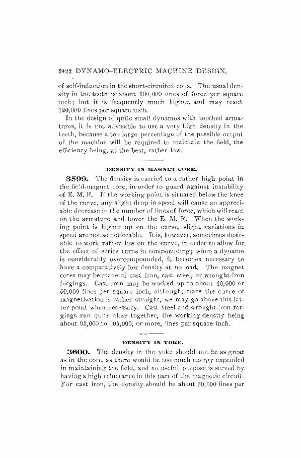
2422 DYNAMO-ELECTRIC MACHINE DESIGN.
of self-induction in the short-circuited coils. The usual den. sity in the teeth is about 100,000 lines of force per square inch; but it is frequently much higher, and may reach 120,000 lines per square inch.
In the design of quite small dynamos with toothed arma· tures, it is not advisable to use a very high density in the teeth, because a too large percentage of the possible output of the machine will be required to maintain the field, the efficiency being, at the best, rather low.
DENSITY IN MAGNET CORE.
3599. The density is carried to a rather high point in the field-magnet core, in order to guard against instability of E. M. F. If the working point is situated below the knee of the curve, any slight drop in speed will cause an appreciable decrease in the number of lines of force, which will react on the armature and lower the E. M. F. When the working point is higher up on the curve, slight variations in speed are not so noticeable. It is, however, sometimes desirable to work rather low on the curve, in order to allow for the effect of series turns in compounding; when a dynamo is considerably overcompounded, it becomes necessary to have a comparatively low density at no load. The magnet cores may be made of cast iron, cast steel, or wrought-iron forgings. Cast iron may be worked up to about 40,000 or 50,000 lines per square inch, although, since the curve of magnetization is rather straight, we may go above this lat· ter point when necessary. Cast steel and wrought-iron for· gings run quite close together, the working density being about 95,000 to 105,000, or more, lines per square inch.
DENSITY IN YOKE.
3600. The density in the yoke should not be as great as in the core, as there would be too much energy expended in maintaining the field, and no useful purpose is served by having a high reluctance in this part of the magnetic circult. For cast iron, the density should be about 30,000 lines per

DYNAMO-ELECTRIC MACHINE DESIGN. 2423
square inch; for cast steel, about 75,000 lines per square inch; and for wrought-iron forgings, about 85,000 lines per square inch.
DENSITY IN ARMATURE CORE.
3601. It is well to keep the density somewhat lower in the armature core than in the teeth, in order to avoid loss due to hysteresis; for the density is continually changing from zero to a maximum in anyone part of the armature .. The lines of force from the field-magnet divide where they enter the core and pass throug,h the upper and lower halves to the farther pole-piece, producing, therefore, a minimum density at the. point of division and a maximum density opposite the neutral space between the poles. The density in the armature core may be taken as about 85,000 or 90,000 lines of force per square inch, for drum armatures. For ring armatures it is usual to adopt a higher density, for the same reason that the teeth should be saturated, namely, to prevent the generation of large currents due to self-induction. The same values for density may then be taken, that is, from 100,000 to 110,000, or even as high as 120,000, lines of force per square inch.
CALCULATION OF FIELD AMPERE.TURNS.
3602. We will now consider the calculation of the ampere-turns on the field-magnets. Curves of magnetization and of permeability have already been given in the section on the Principles of Electricity and Magnetism. In the design of dynamos it is, however, much more convenient to replace the magnetizing force H in the magnetization curve by the ampere-turns per inch length of circuit. The curve, with this modification, is laid out in Fig. 1354, and the required value of the ampere-turns for any magnetic circuit can be read off at once, being simply dependent, for any given metal, upon the length of circuit and the density of the lines of force. Suppose, for example, a wrought-iron ring has a circumference of 6 inches, and a cross-section of

2424 DYNAMO-ELECTRIC MACHINE DESIGN.
1 square inch; then, to produce a density of 100,000 lines of force per square inch, it would be necessary to wind on
J60000
J40000
J80000
120000
110000
Ai ~ U)()OOO
10< ., '" ~ 9000 .;1 .,. "l
~ 8000 I!I.
8 ~ 'TOOO
'" ... .. .. 6000
~ ;,.
~ 0000
400()
8QOi)
SOOO
0
0
0 18
0
0
0
0
0
1000 0 '1/
o
I
If V
II
II IJ
'- -~ ~,.,."
):.,.0"
S1>00tm l,.1""t"",. I-
~1.~t~ 1/1/ 1 lt~1::-:tt J!'o .. gf, .. gB. ~ i>t..J):.,.o"
W.,.O ""g
I} IAV
L/~ vv ,I
!.--I-1.,.0" 1:--- .......
C"s!\.;-0-.,.0.11 ~
I.-'
1 .... 1/ V
,
50 ;J.()O J50 200 250 800 A.mpe .. e.-X ... • .. 8 pe .. Inch Length.
FIG. 1354.
137 X 6 = 822 ampere-turns. The figure 137 is found at the intersection of the ordinate 100,000 with the curve marked

DYNAMO-ELECTRIC MACHINE DESIGN. 2425
"Wrought-Iron Forgings," by following the vertical line downwards to the lower line of numbers.
3603. In discussing the theory of the dynamo, we found that the fundamental equation for E. M. F. is based on three variables: the number of conductors on the armature surface, the number of lines of force cut by those conductors, and the speed of rotation in revolutions per minute. In a smooth-core dynamo, the depth of armature winding should not ordinarily exceed -r\ inch or i inch, as the heat generated is not quickly given off with a deep winding, unless special ventilation is proyided; also, the area of conductor should not be less than 500 circular mils per ampere, and may require to be more in large machines. Therefore, the number of conductors for any particular armature may usually be closely approximated at first, and changed subsequently if it should be found necessary. In designing a dynamo of a similar type to some already built, it is usually possible to determine the number of conductors at once, with very little preliminary work.
3604. The diameter of the armature being known from the space occupied by the winding, the revolutions per minute at which the machine should run may be determined as soon as the peripheral speed is decided, which, as we have seen, may be from 2,000 to 3,000 feet per minute. In the formula for electromotive force above referred to, we find, therefore, that the number of lines of force may be more or less accurately predetermined. It then remains to find the number of field ampere-turns which will be required to force these lines through the several paths composing the magnetic circuit of the dynamo.
3605. These paths in the magnetic circuit may be divided under well-defined heads, namely, the magnet cores, the yoke, the pole-pieces, the armature core, the teeth, and the air-gap. An additional number of ampere-turns must also be added, to counteract the effect of the back ampereturns of the armature.
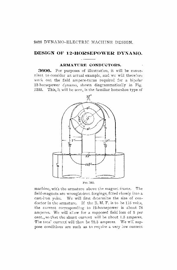
2426 DYNAMO-ELECTRIC MACHINE DESIGN.
DESIGN OF 12-HORSEPOWER DYNAMO.
ARMATURE CONDUCTORS.
3606. For purposes of illustration, it will be convenient to consider an actual example, and we will therefore work out the field ampere-turns required for a bipolar 12-horsepower dynamo, shown diagrammatically in Fig. 1355. This, it will be seen, is the familiar horseshoe type of
FiG. 1355.
machine, with the armature above the magnet frame. The field-magnets are wrought-iron forgings, fitted closely into a cast-iron yoke. We will first determine the size of conductor in the armature. If the E. M. F. is to be 115 volts, the current corresponding to 12-horsepower is about 78 amperes. We will allow for a supposed field loss of 2 per cent., so that the shunt current will be about 1.5 amperes. The total current will then be 79.5 amperes. Vle will suppose conditions are such as to require a very low current

DYNAMO-ELECTRIC MACHINE DESIGN. 2427
TABLE 110. COPPER WIRE TABLE.
Copper Conductor.
.0 .S~ 5@ ~g
'"
Single Cotton-Covered Wire.
Double Cotton-Covered Wire .
U -- ----1-----'-----1----1 ---------I --- ---1----
0000 460.000 211,600.000 0.04904 000 409.600 167,800.000 0.06182
00 364.800 133,IOO.000 0.07798 o 324,900 I05,500.000 0.09833 I 289.300.83,690.000 0.12400 2 257.600 66,370.000 0.15640 3 229.400 52,630.000 0.19720 4 204.300 41,740.000 0.24860 5 r81.900 33, roO. 000 0.31330 6 162.000 26,250.000 0.39530 7 144.300 20,820.000 0.49840 8 128,500 16,5ro.000 0.62850 9 114.400 13,090.000 0.79200
10 roI.900 ro,380.000 0.99950 II 90.740 8,234.000 I. 25900 12 80.8ro 6,530.000 I.59000 13 71.960 5,178.000 2.00400 14 64.080 4,I07·000 2.52700 15 57.070 3,257·000 3. 18600 16 50.820 2,583.000 4.01800 17 45.260 2,048.000 5. 06700 18 40.300 1,624.000 6.38900 19 35.890 1,288.000 8.29000 20 31.960 1,022.000 IO.16000 21 28.460 8ro.roo 12.81000 22 25.350 642.400 16.17000 ~3 22·570 509.500 20·37000 24 20.IOO 404.000 25.69000 25 17.900 320.400 32.39000 26 15.940 254.100 40.85000 27 14.200 201.500 51.50000 28 12.640 159.800 64.94000 29 11.260 126.700 81.89000 30 10. J30 roo.500 103.20000 31 8,928 79.700 130.20000 32 7,950 63.2IO 164.20000 33 7.080 50.130 207. IOOOO 34 6.305 39· 750 261.10000 35 5·1)15 31.520329.20000 36 5.000 25.000 415.20000 37 4·453 19. 830 523.40000 38 3.965 15.720 660.00000 39 3.531 12·470 832.40000 40 3.145 9.888 I05·00000
472.000 1.80 423.600 2.08 376.800 '2.38 336,900 2·72 30I. 300 3.07 269.600 3.48 24I.400 4.00 216.300 4·52 193.900 5·05 172.000 5.60 154.300 6.23 137.500 6·94 122.400 7·68 117.900 8·55 96.740 9. 60 86.810 IO.80 77.960 12.06 70.080 13·45 63. 0 70 14.90 56.820 16.60 5I. 260 18.20
-46.300 20.20 41.890 22.60 37.960 25.30 34.460 28.60 3I.350 3I.00 28.570 34.30 26.100 37.70 23.900 41.50 2I.940 45.30 20.200 49.40 18.640 54. 00 17.260 58.80 16.030 64.40 14.930 69. 00 13.950 75·00 13.080 81.00 12.310 87. 60 I I. 620 94.20 11.000 101.00 IO.450 I08.00 9'965 115·00 9.531 122.50 9· 145 130.00
3. 60 4·81 6.29 8 .. 22
IO·37 13·45 17·33 22.70 27·22 34·84 43·12 53· 51 65·53 8I.22
102.40 129. 60 16I.60 20I.00 246.60 306. ro 368. IO 448.00 567·10 763. 00 908.80
1,065.00 1,30 7.00
1,579.00 1,91 4. 00 2,280.00 2,711.00 3,240.00 3, 84I.00 4,608.00 5,290.00 6,250.00 7,290.00 8,5 27.00 9,860.00
II,330.00 12,960.00 13,580.00 16,670.00 18,780.00
478.00 I. 70 429.00 2.00 384.00 2.32 342.90 2.65 307.30 2·99 275. 60 3.36 247·40 3.80 226·40 4.28 207.90 4. 83 189. 00 5·44 173.30 6.08 157.50 6.80 142.50 7·64 127.90 8·51 II2·70 9.58' 94.80 10.62 80.96 11.88 73.08 13·ro 66.07 14.68 59.82 16·35 54.26 18.08 49.30 19.90 44· 89 2I. 83 40.96 23.91 37.40 26.20 29.12 28·58 30.60 31.12 28.10 33.60 25.90 36.20 23·94 39.90 22.20 42.60 20.64 45.50 19.36 48.00 18.03 5I. IO 16,93 56.80 15,95 60.20 15.08 64.30 14.31 68.60 13.61 73. 00 13.00 78.50 12.45 84.00 11.96, 89. 10 II. 53195.00 11.15 ro2·50
3. 2
4·44 5.98 7·80 9·93
12·54 16.04 20·35 25.92 32 .45 4I. 07 5I.38 64.96 80·47
101.97 125.30
156.80 190.70 239.40 300.00 363. 20 440.00 528·50 634. 80 762·70 90 7. 0 0
1,075·00 1,254. 00 1,456.00 1,770.00 2,016.00 2,300.00 2,560.00 2,90I.00 3,585·00 4,027·00 4,594. 00 5,230.00 5,92I.00 6,847.00 7,392.00 8,82I.00 8,805·00
11,650.00
2428 DYNAMO-ELECTRIC MACHINE DESIGN.
density, and we will allow 1,000 circular mils per ampere. We shall thus require a total area of 79,500 circular mils. The armature current, however, divides into two circuits,
so that the required area of the conductor is 79,;00 = 39;750
circular mils. By referring to T<J.ble 110, it will be found ~hat No.4 wire is the nearest to this size. It is rather above the area required, and would also be hard to wind and to connect to the commutator, so we will see if we can not use another size. Two No. 7's may be substituted, or three No. 9's, the latter size giving the closest appro~imation to the desired cross-section.
3607 . We will adopt as a preliminary estimate a total number of 252 conductors, and we will wind the armature according to the diagram in Fig. 1171, in the section on Applied Electricity. A difference of potential of about 15 volts between commutator bars will call for, say, J"11./- = about 8 segments clear between brushes, or a total of 18 segments for the whole commutator, so that the winding spaces on the armature are 18 X 2 = 36 =w. By formula 483 in the
. f d h h· h 36 ± 2 sectIOn re erre to, W = 2 Y ± 2, w ence t e PItc y = --2-
= 17 or 19. As pointed out in connection with this formula, the smaller number (17) should be used.
SIZE OF TEETH.
3608. Having decided on the number of winding spaces, that is, on the number of slots, for this style of winding, we wilJ see how we can get the wires in. On consulting the table of sizes of wire, we find that if we put three turns of No. 9 double cotto1?--covered wire side by side, they will occupy a space of about.43 inch. Allowing for a thickness of insulation of .035 inch each side between the wire and the teeth, we have .43 + .07 = .5 inch. We have taken 36 slots for the armature; therefore, the turns per slot will be »-1-1- = 7, which means that we must provide 7 layers of the three conductors. The wires will not bed down between each

DYNAMO-ELECTRIC MACHINE DESIGN. 2429
other, as there is only sufficient width in the slot to accommodate the three wires, so that the 7 layers will occupy a depth of about 1 inch. Then, allowing for insulation and for a piece of hard wood which is driven in above the wire, the depth of the slot will be 1. 25 inches.
3609. Knowing the dimensions of the slot, we may now calculate the width of the tooth. Since the slot is parallel-sided, the teeth must taper; let us then take as the average width of the tooth that at a point -§- inch from the edge. The circumference of a circle passing through this point, concentric with the· outer edge of the disk, will be 9-1 X 71: = 30.63 inches. Each slot being. 5 inch wide, the total figure will be 36 X .5 = 18 inches. Then, 30.63 - 18 = 12.63 inches, which is the space available for the teeth. There are 36 teeth; therefore the average width of each is
12.63 35' h 36=' mc.
3610. The tooth and slot are drawn to scale in Fig. 1356, which also shows a method of securing the strip of wood w. Notches are cut in the teeth, and the wood is shaped so as to drive in, making a dovetail joint. Binding wires must, however, not be omitted, as explained later on.
3611. The effective length of the armature is not 7t inches, as given in FIG. 1356.
the diagram, Fig. 1355; each disk is separated from its neighbor by some insulating substance, whether it be paper, or varnish, or simply the oxide which is upon the surface, so that the actual length of armature iron is reduced by about 12 per cent. In this case, therefore, the effective length is .88 X 7.25 = 6.38 inches. The average area of one tooth will be .35 X 6.38 = 2.233 square inches.

2430 DYNAMO-ELECTRIC MACHINE DESIGN.
3612. The average polar span, Fig. 1355, is 1250 ; then, the number of teeth under one pole will be tH X 36 = 12. The total area of the teeth under the magnet pole will be 12 X 2.233 equals, say, 26.8 square inches. The density of lines of force in the teeth must be, as we have seen, about 110,000 lines per square inch; therefore, the total number of lines of force in the teeth, and also in the air-gap, will be 110,000 X 26.8 equals, say, 2,950,000.
It is sometimes desirable, in order to avoid the necessity for a large number of slots of small size, to place two coils in one slot. One side of each coil will then occupy the lower half of one slot, and the other side of the coil will be laid in the upper -half of a slot under the succeeding pole. With this arrangement, the coils should first be wound on a form to the proper shape, then taped, shellaced, and dried, after which they may be put in place, with a layer of insulating material between coils in each slot, because there will be a large difference of potential between them.
SPEED OF ROTATION.
3613. The preliminary values are now determined, with the exception of the speed of rotation of the armature. This we can obtain by modification of formula 480 in
A 1· d EI .. d h S E X 60 X 108 h pp Ie ectncIty, an we ave = eN' were
E is the total E. M. F. of the dynamo, c is the total number of conductors, and iVis the lines of force from one pole-piece. We may calculate the probable amount of drop in E. M. F. through the armature, which it is necessary to determine before we can tell what E is. There are six No. 9 wires in multiple, which carry the total armature current of 79.5 amperes. The length of one wire on the armature surface is 7t inches; to this we add the length of one of the end connectors, say 14 inches, making a total length of 21t inches for each of the 252 conductors. As a means of simplifying the calculation, we will take one of the six wires, and find its resistance. Each of the six circuits passes through 18 slots

DYNAMO-ELECTRIC MACHINE DESIGN. 2431
before it reaches the opposite point on the commutator, and there are 7 turns per slot. Then the length of one circuit is 18 X 7 X 21t = 2,677 inches = 223 feet. The resistance of No.9 wire is .192 ohm per thousand feet; then, 223 feet = .223 X .792 = .1766 ohm, and for the whole armature it will
.1166 be -6-' - = .0294 ohm. Allowing for a temperature rise of
70° F., the resistance becomes .0338 ohm, and the drop in potential will be eX R = (78 + 1.5) X .0338 = 2.687 volts, allowing 1. 5 amperes for the shunt. There is some resistance in the commutator connections, also in the brushes at the contact point; if the brushes are of carbon, there will be additional resistance, due to their length. If we then take an armature drop of 4 volts, we shall have sufficient margin.
We may now write out the formula for the speed:
119 X 60 X 10· . s= 252 X 2,950,000 = 960 rev. per mm.
3614. The diameter of the armature is 11 inches, and the circumference is 34.55 inches = 2.88 feet. The peripheral velocity will then be 2,765 feet per minute.
3615. We might use either 40 or 32 slots in this armature, but it would be found that a higher speed would be required in each case, and the teeth would be rather thin at the root if there were 40 of them. Also, when the number of teeth is small, the current is not likely to be so steady.
DENSITIES IN MAGNETIC CIRCUIT.
DENSITV IN AiR-GAP.
3616. In determining the density in the air-gap, we may assume a length of t inch. The bore of the fields will then be lIt inches, and the circumference = 36.13 inches. The average polar span is 125°, therefore the width of face will be ~ ~ g X 36.13 = 12.5 inches. The length of face will be 'it inches, allowing t inch for fringe, and the area of the air-gap = 7.25 X 12.5 = 90.625 square inches. Then the

2432 DYNAMO-ELECTRIC MACHINE DESIGN.
d . ·11 b 2,950,000 2 1· f f -enslty WI e 90.625 = 3 ,550 mes 0 orce per square
inch. By formula 589 we see that, when the density is about 32,000 lines of force per square inch, the length of airgap should be greater than one-third the width of slot. The slot is .5 inch wide, so that the air-gap should be greater than t X i inch = t inch = .167. We may therefore safely adopt a length of -i6 inch = .1875.
DENSITY IN MA.GNET CORE.
361 '1. We are now in a position to find the number of lines of force in the magnet core. There will be a greater number of lines required than are used in the armature, on account of magnetic leakage, and the coefficient by which the armature induction is multiplied varies with different designs of magnetic circuit. For this form which we have under consideration we may use a coefficient of 1.25. The lines of force, then, in the field core will be 1. 25 X 2,950,000 = 3,687,500. The core is wrought iron, 7 inches in diameter, the area being 38.48 square inches, and the density . 3,687,500 r . h IS 38.48 = 96,000 mes per square mc .
DENSITY IN YOKE A.ND IN POLE-PIECES.
3618. The yoke is cast iron, 8 inches by 13 inches, the
b · 1 4 . h Th d . . 3,687,500 area emg 0 square mc es. e enslty IS 104
35,500 lines of force per square inch. The average length of path of the lines in the pole-pieces
is 5 inches in each, or a total of 10 inches. The density may be taken as about one-half that in the core, or, say, 50,000 lines per square inch.
AREA OF ARMATURE CORE.
3619. In the armature the value of the induction may be taken as 85,000 lines per square inch, net. The actual width of the core is 7.25 inches, but we have only 88 per cent. of iron, the effective width being 6.38 inches. The

DYNAMO-ELECTRIC MACHINE DESIGN. 2433
f h . 1,475,.0.0.0 17 35 . h ' area 0 t e armature core IS 8 .0 = . square me es, 5, DO
half the lines of force passing above the shaft and half
below. Then the radial depth of the core is 1t:: = 2.72
inches, or, say, 2-1 inches. Subtracting double this length and double the length of teeth from the diameter of the armature, 11 inches, we have a 3-inch circle in the center of the disks, which will serve for the shaft.
TOTAL AMPERE-TURNS.
3620. The densities in every portion of the magnetic circuit being known, we may calculate the total ampereturns. We find the ampere-turns required for the magnet cores, the yoke, the pole-pieces, the armature core, the teeth, and the air-gaps. To these we must add the back ampere-turns of the armature. When a slotted armature is used, the armature reaction, as we have pointed out, is comparatively slight. This requires only a moderate displacement of the brushes, and since, in the machine under consideration, the pole tips are pointed, we may find a sufficiently strong field for reversing without the necessity of providing a large angle of lead, especially when carbon brushes are used"as we have supposed to be the case. We will allow, then, for two slots within the double angle of lead; there are 7 turns per slot, and each set of three conductors carries one-half the armature current, or 39.75 amperes; calling this, in round numbers, 40, the back ampereturns will then be 2 X 7 X 4.0 = 56.0. The length of the two magnet cores is 11 inches, and the density is 96,000 lines of force per square inch. By reference to the magnetization curves of Fig. 1354, we find that wrought-iron forgings at this density require 1.0.0 ampere-turns per inch length, or a total of 100 X 11 = 1,100 ampere-turns. The cast-iron yoke requires 66 ampere-turns per inch at the density we have 'given, namely, 35,5.0.0 lines per square inch; the length of

2434 DYNAMO-ELECTRIC MACHINE DESIGN.
circuit being 11.5 inches, the required ampere-turns are 66 X 11.5 = 759. The pole-pieces, which are part of the magnet forgings, have a total average length of 10 inches, and, at a density of 50,000 lines per square inch, -require 10 ampere-turns per inch, or a total of 10 X 10 = 100. In the armature core we have a density of 85,000 lines per square inch, for which we must provide 34 ampere-turns per inch length, or 34 X 9 = 306 ampere-turns. The teeth have a higher density, namely, 110,000, and the ampereturns per inch must be 118. The total length of the teeth is 2 X 1. 25 = 2.5. inches, and the ampere-turns will be 119 X 2.5 = 297. For the determination of the ampere-turns of the air-gap we will refer to the section on Principles of Electricity and Magnetism, Art. 2400, where, by transposition of the formula for density B, we find that for air, which has a permeability of 1, the ampere-turns required for a given density are equal to the density multiplied by the
Bf length and divided by 3.192; or, ampere-turns = 3.192. In
this case the density is 32,550 lines of force per square inch = B ; the length of double air-gap is i = .375 inch = f; and
. 32550 X .375 the ampere-turns for the aIr-gap = '3 = 3,824-
.192
3621. \Ve will now sum up the total ampere-turns required for the magnetic circuit, as follows:
Ampere- Total Length. Area. Density. Turns Ampere-
per Inch. Turns.
Magnet Core 11 38.48 96,000 100 1,100 Cast-Iron Yoke lIt 104 35,500 66 759 Pole-Pieces 10 50,000 10 100 Armature Core 9 17.35 85,000 34 306 Teeth 2t 26.8 110,000 118 295 Air-Gap i 32,550 3,824 Back Ampere-Turns 560
Total Ampere-Turns for Field 6,944

DYNAMO-ELECTRIC MACHINE DESIGN. 2435
SIZE OF SHUNT WIRE. 3622. In determining the size of wire to be used for the
shunt winding, we know, approximately, the length of one turn, as we can allow a certain amount for depth of winding. In any case, variation in this dimension will not affect the size of wire necessary for the machine, which size is always the same for any given dynamo, whether the amount of wire used be great or small. The explanation is that, if double the number of turns be put on, this will approximately double the resistance, thereby reducing the current by onehalf, so that the total number of ampere-turns remains the same. There is, however, a disadvantage in using a small amount of wire, as this necessitates a larger current. The loss in the field coils is proportional to the square of the current and only directly proportional to the resistance; therefore, it is better to increase the length of wire, so that the watts lost in heating may be as few as possible. On the other hand, an excessive amount of wire is expensive, and the weight to be used must therefore constitute a mean between cost of energy for maintaining the field and cost of copper in the field coils.
3623. Another consideration may also influence the amount of wire used, namely, the available space for winding. In machines of special construction, space may be so limited that only a little wire can be wound on the cores. In that event it is necessary to point out that ample ventilation should be provided to carry off the heat produced. The particular disadvantage, from a working point of view, of a small amount of wire is that the regulation of E. M. F. is troublesome; for the difference in resistance when hot and when cold is considerable, which causes a continual falling of E. M. F. as the fields become warm, so that a constant difference of potential is obtained only after the machine has been running for some time.
3624. The size of the shunt wire may be found at once by the following formula:
A _12 X 1m X At (592.) - E b - e '
2436 DYNAMO-ELECTRIC MACHINE DESIGN.
in which A = area of cross-section in circular mils; 1m = mean length in feet of one turn of wire"; At = ampere-turns for the magnetic circuit; Eb= E. M. F. at the brushes;
e = drop of potential through field regulator.
The cross-sectional area of the wire for the shunt winding of a dynamo is found by multiplying 12 times the mean length of turn by the ampere-turns and dividing this product by the E. M. F. at the brushes, less the drop in volts through the field regulator.
In this formula the factor e may be omitted when it is not proposed to use a field regulator in ordinary working, after the field coils are heated up.
3625. The coefficient 12 is derived from the resistance of 1 mil-foot of copper, which, at 75° F., is 10.8 ohms. In this formula we have allowed for a rise in temperature of 55° F., which increases the value of the coefficient to 12. This will be found to be a good general figure to use, but it may of course be modified to suit any other rise in temperature.
3626. In applying the formula to the present case, we will determine the probable length of one turn, to give the value of 1m. The diameter of the field core is 7 inches. The inside diameter of the spool is perhaps 7i inches, and the diameter on the winding surface 7t inches. We have a total winding length on the core of about 5t inches, and if we allow t inch at top and bottom for spool flanges, there will be a net length available of 4! inches. With a flange It inches deep, we may wind to a thickness of about Ii inches, and the average length of turn will be 8~ X 3.1416 = 27.1 in. = 2.26 feet. Allowing for the use of a field regulator only until the field coils are warm, and dispensing with it after that, the size of shunt wire will be, by formula 592,
A 12 X 2.26 X 6,944 1 638· 1 ·1 = "115 =, Clrcu ar ml s.
From Table 110 it will be seen that this area corresponds almost exactly to No. 18 B. & S., which is, therefore, the cor·

DYNAMO-ELECTRIC MACHINE DESIGN. 2437
rect size to use. A slight variation from the exact size determined by the formula is immaterial; for if the wire is a trifle small, a very little increase in speed will suffice to bring up the E. M. F. to the required point.
3622'. When designing a dynamo which is to be built on original lines, it is well to allow some margin for regulating, about 15 per cent. drop through the regulator being desirable. For standard machines, however, the less external resistance is used the better.
V ALUE OF SHUNT CURRENT.
3628. We may now determine the current in the field. If we wind the spools to a depth of 1k inches, the cross-sectional area of the single spool will be It X 41 = 5.34 square inches, or for two spools the area = 10.68 square inches. By reference to the table of magnet wire, the wire being usually single cotton-covered, we find that we can put in 448 turns of No. 18 wire to the square inch. We would then have a total number of 10.68 X 448 = 4,784 turns = 2,392 turns per spool. The winding will have about 20 turns to the inch, or, for the full length of spool, about 95 to a layer. Then, since it is desirable to have only complete layers; we will choose 25, and the turns per spool will be 95 X 25 = 2,375, or, for both spools, 4,750 turns. The total number of ampere-turns is
. 6944 6,944; therefore, the current to be used IS 4' 750 = 1. 46 , amperes, this being controlled by the field regulator.
3629. We are now able to determine the actual temperature rise by the application of formula 560. The outside diameter of the spools, when overlaid with a layer of cord, will be about level with the edge of the flange, or 10 inches, and the Circumference is 31.4 inches. The width being 41 inches, the radiating surface of each coil is 31.4 X 4.75 = 149.3 square inches, and for the two spools there is a radiating surface of wire of 298.6, say 300 square inches. The watts

2438 DYNAMO-ELECTRIC MACHINE DESIGN.
expended in the winding are 1. 46 X 115 = 168. Then, l?y formula 560; the temperature rise
80 X 168 . t = 300 = 44.8 degrees FahrenheIt.
It will be seen by this result that we might use less wire on our fields without an excessive rise in temperature; but the amount we have chosen will probably be more satisfactory.
3630. No material modification is introduced if we substitute for the coefficient 12 in formula 592 another coefficient based on a rise of 45° F. This would be about 11.8, and would alter the size of wire only in corresponding ratio; the area would be about 1,605 circular mils.
3631. We might allow for the permanent use of a field regulator for this dynamo by taking the next larger wire, No. 17; but its resistance is such that it would be necessary to introduce too much external resistance in series with it to produce an efficient machine. It is therefore much better to use No. 18, and, if necessary, to slightly increase the speed; or, if the speed is fixed, a combination winding can be made of Nos. 17 and 18.
RESISTANCE OF SHUNT.
3632. It is a simple calculation to determine the r_esistance of the shunt winding. We have found the average length of turn to be 2.26 feet; the number of turns we use is 4,750; therefore the total length is 2.26 X 4,750 = 10,735 feet. The resistance per 1,000 feet of No. 18 wire, at ordinary temperature, is 6.39 ohms, and the total resistance is 10.7 X G.39 = 68.37 ohms. Applying formula 461 in Electrical Measurements for increase of resistance with temperature, r. = 68.37 (1 + .002156 X 45) = 75 ohms with 45° F. rise. The E. M. F. at the terminals being 115 volts, ·the maximum possible current after the temperature has risen will be 4-;- = 1.53 amperes. We require only a current of 1.46 amperes, so that this size of wire will allow of control of E. M. F. by means of a field regulator.

DYNAMO-ELECTRIC MACHINE DESIGN. 2439
RELATION OF SHUNT TO ARMATURE RESISTANCE.
3633. We have said that the question of electrical efficiency is affected by the amount of wire used in the shunt, a higher resistance giving better efficiency. The result of a high shunt resistance in parallel circuit with a low armature resistance, as in a shunt dynamo, is a smaller proportion of current subtracted from the total output; therefore, it is desirable that both these ends should be attained. The following formula is given by S. P. Thompson as showing the efficiency, with a favorable resistance in the external circuit:
where
(593.)
E = electrical efficiency; ra = resistance of armature; rs = resistance of shunt.
Tlze electrical efficienc), of a dynamo is equal to the reciprocal of tile sum of 1 and twice the square root of the quotient obtained by dividing the armature resistance by the shunt resistance.
3634. We may apply this formula to the machine we have been designing as a check on the efficiency. The formula is useful rather as a means of finding at once what the resistance of the shunt should be, in order to give a certain predetermined electrical efficiency. In our case we have supposed there is a . fall of potential of 4 volts through the
armature at full load, so that the resistance will be 7: 5 = .05
ohm. The shunt current is 1.42 amperes, and the terminal
E. M. F b · 11 1 h·' 115 h . e1l1g 5 vo ts, t e resIstance = 1. 42 = 81 0 ms.
Then, by formula 593, the electrical efficiency
1 E = . / = .95, or 95 per cent.
1 + 2 'Y .05 81

2440 DYNAMO-ELECTRIC MACHINE DESIGN.
3635. Taking formula 593 as a basis, and an electrical efficiency of 90 per cent. as a low figure, we find that; to obtain this efficiency, the resistance of the shunt must be at least 324 times that of the armature.
MAGNETIZATION CURVES. 3636. In order to demonstrate graphically the behavior
of a dynamo and to assist in determining the additional ampere-turns required for the series coils in compound winding, it is convenient to layout a cur,?"e of D1agnetization. This is obtained from the known values of the
3
/ V
/
V 0 ~
~ ~
/-
d ~ I 1" /;
l
3 ,4 6 6
ThOUBand A tnpe~·e-7"u,rnB.·
FIG. 1357.
'1
--.........
8
induction in the armature and the corresponding ampere. turns required, and is extremely useful, as showing what the performance of the dynamo is likely to be, and whether the E. M. F. will be stable.

DYNAMO-ELECTRIC MACHINE DESIGN. 2441
3637. A magnetization curve is given in Fig. 1357, which illustrates the action of the dynamo we have been considering. Of the curves shown, that marked I is the noload curve and II is the full-load curve (80 amperes). It is possible to layout these curves either by calculation or by experiment. Taking the full-load curve first, the value of the ampere-turns is marked on the scale of abscissas at the bottom-such, for instance, as the full number 6,944 previously calculated-and on the scale of ordinates the corresponding value of the induction in the armature. This would be 2,950,000 in the case supposed; the intersection of vertical and horizontal lines drawn from these points gives one point on the curve. The required ampere-turns are also calculated for other values of armature induction, and, the points being laid off, form the curve. A value may be taken, for example, of 2,500,000 lines of force in the armature; then, by the same methods of reasoning as those already explained, the total ampere-turns are to be calculated. The termination of the curve at the lower end indicates the probable point where the field would become too weak to prevent destructive sparking.
3638. The no-load curve is laid- off in the same manner as the full-load curve, except that the back ampere-turns are omitted, the curve lying, therefore, higher for a given magnetizing force. This curve does not in actual practice come down to the origin 0, as there is always some residual magnetism in the iron, and we have therefore shown the outward curvature at this portion, although theoretically we might consider the curve to end at o. liVe may also work out the magnetization curve for any other load, which will then lie between the limits of curves I and II in Fig. 1357.
MAGNETIZA TION CURVES FROM TESTS. 3639. Magnetization curves may be plotted from read
ings taken when testing a dynamo that is already built. The curves are developed from the fundamental formula
eNS . E X 60 X 10' for E. M. F., E = 60 X 10" from wluch N = cS .

2442 DYNAMO--ELECTRIC MACHINE DESIGR
When the no-load curve is required, the E. M. F. at the brushes may be considered to be the same as the total E. M. F., E, which takes into account the armature drop. The only current through the armature is that for -the sh{uit: and the resistance being so low, the drop is negligibj'e'." The armature is then run at diff.erent speeds, and readings are taken of the E. M. F. at the brushes, of the speed, a.nd of the shunt current. From the first two of the above the number of lines of force in the armature is calculated, and the number of turns on the shunt coils being known, the reading of the shunt current enables the corresponding ampere-turns to be determined. For example, suppose the speed of the machine is 850 revolutions per minute, and simultaneous readings show that the E. M. F. at the brushes is 90 volts <}nd the shunt current is. 96 ampere. Then the corresponding number of lines of force in the
6 • 90 X 60 X i 0' armature IS lV = 252 X 850 = 2,521,000. There are 4,750
turns in the shunt winding, therefore the ampere turns are .96 X 4,750 = 4,560. If these values for induction and ampere-turns are laid off to a suitable scale, as was shown in Fig. 1357, their intersection will give a point on the no-load curve.
3640. When the curve for full load or for any intermediate load is desired, the same readings are taken as for the no-load curve; but between the readings taken at the different speeds, the resistance of the external circuit must be changed, in order to keep the current at the constant value represented by the curve.
3641. We see that the curves of Fig. 1357 resemble the saturation curves of iron and steel in Fig. 1354, and in fact they constitute saturation curves for the magnetic circuit of the dynamo as a whole, and are frequently called by that name. It is necessary for the machine to be worked above the knee of the curve in order to give stability to the E. M. F .. When, however, it is necessary to allow for the

DYNAMO-ELECTRIC MACHINE DESIGN. 2443
series turns of compound winding, such a high point of saturation is not desirable with the shunt alone, but may be reached at full load.
CURVES APPLIED TO COMPOUND WINOING.
3642. The magnetization curve may be used in determining the series ampere-turns necessary for compound winding. The induction in the armature for any given E. M. F. and speed may readily be calculated, as we have shown, and the corresponding field ampere-turns may be found by reference to the curve. The values of the ampereturns are thus found for no load and for full load, the E. M. F. ar{d speed being usually specified for these two points. Then the difference between the values for the ampere-turns constitutes the ampere-turns required for the series winding.
3643. In order to facilitate the application of such calculations, we will consider a compound winding for the dynamo of Fig. 1355. Let us suppose the following specifications are laid down: The dynamo is to have an E. M. F. at no load of 110 volts, the speed being 1,040 revolutions per minute. At full load the E. M. F. must be 120 volts, the current output 75 amperes, and the speed 1,000 revolutions per minute. The number of conductors c in the armature is 252, as before; then the number of lines of force at no load
N = E X 60 X 108 = 110 X 60 X 108 = 2 518 "15 cS 252 X 1,040 ,,0.
By referring to the no-load curve in Fig. 1357, we see that this induction corresponds to 4,500 field ampere-turns. At full load the armature loss may be taken as 4 volts, and we will allow for the series winding a further drop in potential of 1 volt; so that the E. M. F. at full load = 120 + 4 + 1 = 125 volts. For the induction in the armature at full load we then have
N = 125 X 60 X 108 = 2 980 000. 252 X 1,000 "

2444 DYNAMO-ELECTRIC MACHINE DESIGN.
On the full-load curve of Fig. 1357 we find the corresponding ampere-turns to be 7,600.
3644. There is a choice of two ways in which the shunt coils may be connected; the two methods are the long shunt and the short shunt. For purposes of comparison, l the two styles of connection are
shown diagrammatically in Fig. 1358. The long shunt (a) shows that the shunt current passes through the series coil c, then through the shunt coil s; while in the short shunt (b) the shunt coil
(a) (b) FIG. 1358 is entirely independent of the
series coil, being connected directly across the brushes. In the present example we will suppose the short shunt (b) to be employed, as this is the more usual method.
3645. We have taken the armature drop as 4 volts, at full load ; then, the total E. M. F. generated being 125 volts, the E. M. F. at the shunt terminals is 125 - 4 = ]21 volts. We found that for 110 volts at the terminals the ampereturns were 4,500; then, for a!1 E. M. F. of 121 volts the shunt ampere-turns will be 1ft X 4,500 = 4,950. The fullload ampere-turns are 7,600; therefore the required number of series ampere-turns is 7,600 - 4,950 = 2,650. The full-load current is given as 75 amperes, and the series turns
2650 will therefore be ~ = 35.4, or, say, 36 turns, 18 turns on
each spool.
PROPORTION OF SHUNT AND SERIES WINDINGS.
3646. The simple number of ampere-turns for shunt and series windings is not sufficient as a guide to the actual number of turns of each which must be supplied. There must be a proper proportioning of the two windings, so that the total loss of energy is suitably divided; for if the series coil, for instance, were to be designed for an extremely low

DYNAMO-ELECTRIC MACHINE DESIGN. 2445
loss, the weight of wire would be excessive, and if the wire were made too small, the rise in temperature would be too great. The easiest manner of winding is to determine the size and weight of the shunt wire according to the directions and formulas already given, and then to wind over it the series coil and proportion it with this rule in view:
Rule.-Tlte energy loss, in watts, of tlte sltunt and series windings of a compound dynamo sltould be proportioned to tlte respective ampere-turns carried by eaclt coil.
Suppose, for example, that the shunt coils have 2,000 ampere-turns, and the loss in watts is 100; then, if the series coils have 500 ampere-turns, the loss in them should be, approximately, 25.
3647. It is not quite so easy to calculate the series winding if it is to occupy part of the spool at one end, but it is on some accounts a better way of arranging it. Suppose, then, for our dynamo we decide on this method of winding. Our spool is 41 inches long, and we may wind to a depth of about Ii inches. Then, the mean length of one turn is 8.625 X 3.14 = 27.1 inches, or 2.26 feet, and the ampere-turns to be supplied being 2,650, the area of crosssection of the wire is, by formula 592,
A 12 X 2.26 X 2,650 71 800' 1 '1 = 1 =, Clrcu ar ml s.
A wire of this size would have to be made to order, which is out of the question; but it would in any case be too large for convenient use, and it is better to choose two or three smaller wires of equivalent cross-section. We might choose two No. 5's, but their combined areas would' be rather too small; No. 6 has an area of 26,250 circular mils, and three of this size will be the best to use. In order, then, to have an even winding, we must have the width of coil such that the wires of one layer are a m ul ti pIe of 3; also the number of turns is to be 18, that is, the total number of wires will be 54. If we choose 9 wires for one layer, we shall have exactly 6 layers. By reference to Table 110, we

2446 DYNAMO-ELECTRIC MACHINE DESIGN.
see that we can wind nearly 6 turns to the inch, and 9 wires will lie in a space of Ii inches.
3648. Allowing for a piece of vulcanized fiber i in<:;h thick between the shunt and series coils, the available space for the shunt winding will be 4i - Ii = 3 inches. The shunt ampere-turns are 4,950, and the E. M. F. at the terminals is 121 vclts. Then, by formula 592,
A 12 X 2.26 X 4,950 1 108' 1 '1 = 121 =, Clrcu ar ml s.
This size of wire is between Nos. 19 and 20, but the difference is too great for us to take either one, and it is not good engineering to require special wire drawn. If we use No. 20 we can not obtain the necessary ampere-turns, and if we take No. 19 we must keep a field regulator or external resistance constantly in circuit. The most usual method of overcoming the difficulty is to use the smaller wire and increase the speed. If, however, it should be necessary to keep to the speed specified, we may effect such a combination of the two wires on each spool that the number of turns will be correct as well as the resistance, hence, also, the ampere-turns. The winding area is 3 X 1-g. = 3~, or 3.375, square inches, and we shall divide it between the two sizes of wire in inverse proportion to the resistance of each.
Let A = total winding area in cross-section' A) = required area for larger wire; A,= required area for smaller wire; R) = specific resistance of larger wire, R,= specific resistance of smaller wire; R = sum of the specific resistances of the two wires.
Th A 1 _ R, h A A X R, ( - 94 ) - en, A - R' w ence 1 = R' ~.
and A _A X R) .- R . (595.)
The resistance per 1,000 feet-which we may call here the specific resistance-of No. 19 wire is 8.29 ohms = R); the

DYNAMO-,ELECTRIC MACHINE DESIGN. 2447
resistance per 1,000 feet of No. 20 wire is 10.163 ohms = R 2 ;
the sum of these is 18.45 = R. The total winding area = 3.375 square inches = A. Then, by formula 594, the area to be wound with the larger wire .
A 3.375 X 10.163 186 . h 1= 18.45 =. square mc es.
By formula 595, the area required for the smaller wire
A 3.375 X 8.29 1 ~15 . h 2 = 18.45 =. D square mc es.
No. 19 wire winds about 567 turns to the square inch; therefore the turns required will be 567 X 1.8G = 1,054. No. 20 wire has about 763 turns per square inch, and the turns of this size will be 763 X 1. 515 = 1,157. The total turns per spool = 2,211.
3649. In order to check these figures, we will calculate the resistance of the coil. The average length of turn is 2.26 feet. The resistance of No. 19 wire is 8.29 ohms per 1,000 feet, and that of No. 20 is 10.16 ohms. Then, the resistance of each is :
No. 19, 1,054 X 2.26 X .00829 = 19.7 ohms, cold; or, ;32.16 ohms, hot. No. 20,1,157 X 2.26 X .01016 = 26.5 ohms, cold; or,29.8 ohms, hot.
Resistance, hot, per spool = 51. 96 ohms. Resistance, hot, two spools = 103.92 ohms.
The hot resistance is calculated for a rise in temperature of 58° F. The maximum possible current which will
flow through the heated shunt coils is 1~~~ 9 = 1.16 amperes.
The number of turns is 2,211 X 2 = 4,422, and the ampereturns would be 5,129, which allows a slight margin over the required number of 4,950. The working current in the
h '1 4,950 2 d h d s unt COl s = 4,422 = 1.1 ' amperes, an t e watts expen -
ed = 1.12 X 121 = 135.5.
3650. The diameter of the outside of the coil, when covered WIth a layer of cord for the sake of neatness ()f

2448 DYNAMO-ELECTRIC MACHINE DESIGN.
finish, will be 10 inches. Then the radiating surface of the coil = 31. 4 X 3 = 94.2, and for two spools = 188.4 square inches. By formula 560, the rise in temperature
t = 80 X 135.5 = 57 6° F 188.4 ..
3651. Returning to the series coils, we have a surface for radiation of 31. 4 X 1. 625 = 51.1 square inches per spool, or 102.2 square inches total. Then the watts lost in the series coil will be 75 X 1 = 75, and the rh;e in temperature
t = 80 X 75 = 58 7° F 102.2 . .
3652. If the increase in temperature involved with this winding is not considered desirable, a. lower final temperature may be obtained by using a larger size of wire for the series coil, leaving the width of coil the same, but having a depth of winding of perhaps 1.5 inches. The shunt coil may be increased to the same depth, the additional wire being added in the same proportion of the two sizes. The rise in temperature under these conditions will be only about 40° F.
3653. An exact predetermined drop in potential through the series coils can not be obtained with ordinary sizes of wire, and when it is important that this should be the case, a length of strip copper is used instead of wire. This is, indeed, a more usual proceeding, and we might use such stri p copper in the dynamo:we have under consideration, by which means we could obtain the exact drop of one volt, which we have specified. A difference, however, of a fraction of one volt is not sufficient to debar us from using the round copper, which is more easily obtainable, unless we were considering the design of a line of machines of various sizes, or unless we desired to construct a large number of one size.
3654. When designing the series winding for an overcompounded dynamo, it is frequently the practice to allow for much larger increase in potential than that which is to be used, and to provide a shunt across the terminals of the
DYNAMO-ELECTRIC MACHINE DESIGN. 2449
series coil, which may be varied as required. This shunt must be of large carrying capacity, as it may have to allow 30 per cent. of the full output to pass.
3655. Compound-wound dynamos which are worked on the upper portion of the curve of magnetization give a more uniform increase of potential than those worked on the lower portion, although, as has been pointed out, a larger number of ampere-turns is required than would be the case if a lower part of the curve were selected. When the lower part is used, the effect is to cause the E. M. F. to rise rapidly at the outset; but with heavier loads the increase in E. M. F. is more gradual.. In the design of generators for power circuits, a large amount of over-compounding is required, and it is then necessary to use the lower portion of the curve, as a large range is covered, and it would otherwise call for an excessive weigh"t of wire on the field.
CHARACTERISTIC CURVES.
THE METHOD OF DERIVING EXTERNAL CHARACTERISTICS.
3656. From the formula for electromotive force, E = eNS .. 'd h hEM F . . 1 60 X 108 ' It IS eVl ent t at t e . . . IS proportlOna to
the number of lines of force N, provided that the speed is kept constant. The shunt ampere-turns may be expressed
as At = "';; X t, where Eb = the E. M. F. at the brushes,
which is the same as that at the shunt terminals in the shortshunt connection, R = resistance of the shunt winding, and t = number of shunt turns. It follows, therefore, that the E. M. F. at the terminals of the shunt field winding is proportional to the ampere-turns, when the resistance, which is the only other variable, is kept constant. After the machine has been running for some time, a steady temperature is attained, and the resistance then remains unchanged. It

2450 DYNAMO-ELECTRIC MACHINE DESIGN.
will therefore be seen that it is possible to layout the values of lines of force and corresponding ampere-turns, expressed in the curves of Fig. 1357, in terms of E. M. F. generated and E. M. F. at field terminals. Such a transformation has been effected in Fig. 1359, which shows the three curves of Fig. 1357. Curve I is the no-load curve and curve II is the full-load curve. Intermediate between them is curve III,
p
0 /
1
~ ~ ~ 0 ~ :---~/ V / A // 00
I~ ~/ 1/ mj
d v~ V 80 1/ /; ~I V / 'to i/
/ I'll Ifo / 60
/1; ~f / 50 II '--I;
V !l0 ! 47 I;J ? 80
I /
20 1;, V
:10 / ~ /
o 10 :JO 30 110 50 60 70 80 90 1(1) 110 120 13.1) R.M .. P.ut F.ield Terminals.
FIG. 1359.
representing half load. It will be noticed that this line is slightly nearer to the no-load curve than to the full-load curve, which is accounted for by the fact that the number of back ampere-turns is less than at full load, so that a higher voltage is produced for the same field excitation. At first thought it may be supposed that the E. M. F. at the armature terminals and that at the field terminals must necessa-

DYNAMO-ELECTRIC MACHINE DESIGN. 2451
rily be of the same value, when laid off by the magnetization curve. Nevertheless this is not the case, for we should then have simply a straight line for the curve of Fig. 1359, running diagonally across from 0 to P.
3657. We will look into the method of construction of the curves. Let us take, for example, the foll,owing values from curve I of Fig. 1357: N= 2,000,000; At= 3,250. In the machine we are considering, the number of armature conductors is 252 = c, and the speed 5 = 960 revolutions
252 X 2,000,000 X 960 per minute. Then, E = 60 X 100,000,000 = 80.6 volts.
The field winding has 4,750 turns, with a resistance of 75 ohms, hot. Then, the E. M. F. at the shunt terminals will be
E - A t X R _ 3,250 X 75 _ 51 3 It b---t---~O- . vo s. ,
These two values for E. M. F. are laid off on the ruled sheet, and the point is marked where the lines drawn from the marginalnumbers meet. In this manner, by taking any corresponding values of lines of force and ampere-turns from the magnetization curves, those curves may be transferred to this sheet.
3658. In a shunt-wound dynamo, the E. M. F. at the armature terminals is of course the same as that at the field terminals; therefore it follows that there are only two possible values of E. M. F. with any particular current, and these are at the points where the curves cross the diagonal o P. Curves II and III give the value of the full armature E. M. F. for the corresponding loads; but when it is desired to know the external·B. M. F., that is, the E. M. F. available for the external circuit, it is necessary to subtract the loss of volts through the armature. For the full load of about 80 amperes (inclusive of shunt current) we have taken a drop of 4 volts; then the full-load curve, Fig. 1359, modified in this respect, becomes that which lies below curve II, namely, curve IV, and the half-load curve is that marked V.

2452 DYNAMO-ELECTRIC MACHINE DESIGN.
The intersection, then, of the full-line curves of Fig. 1359 with the diagonal 0 P shows the external E. M. F. which the machine in question will give under varying loads.
EXTERNAL CHARACTERISTICS OF SHUNT DYNAMOS.
3659. The performance of a dynamo under load may be more graphically shown by means of what is called a characteristic curve, or, simply, characteristic, which may be at once constructed from the data given in Fig. 1359. The external characteristic of the shunt dynamo described is drawn in Fig. 1360. The ordinates represent the external
'/10
1110
110
• ~.lOO
:tl! 90
.! ~o Ii;j l!!i 70
s:.; 60 -Ii! 60
~ ~o ... ~ 80
eo
n.
oIL"
II /
, .. ......-~ -('
~
c I;
1/ : :
II / .
II / ,
l~ V: ./ r ~,.
e../ v: I--~" ,
~ ,."
:h
-- -~ - , ,
'\ , '.
I ,,)
/ I I
/ ,-/ "
V " /
V ,/
~
o 10 2() 110 40 80 60 '10 80 90 100 110 1;1(1 J80 J40
Current in Amperes.
FIG. 1360.
E. M. F. in volts, and the abscissas the current in the external circuit in amperes, these values being ordinarily laid out to the same scale, as shown, as this ensures uniformity in the general appearance of the characteristics.
The points on the no-load curve are at a and O. In determining the points on the curve for any load, as, for example, half load, the intersection of the half-load curve in Fig. 1359
DYNAMO-ELECTRIC MACHINE DESIGN. 2453
with the diagonal is noted; from the half-load current of, say, 40 amperes is deducted the shunt current, and the values for E. M. F. and current are marked on the characteristic at b. In the same manner the full-load current less the shunt current is marked at c. The lower values of E. M. F. for these external currents are also laid off at d and e. If still larger currents were shown on the curves of magnetization, they might be transferred to the curve of the external characteristic, but a limit is reached after a time, when no further decrease in the external resistance will cause the current to increase. This is at the paint f, where the characteristic begins to bend around and fall very rapidly.
RESISTANCE IN THE CHARACTERISTIC.
3660. The current and E. M. F. being, as we have said, laid off to the same scale, the slope of a line drawn from the origin 0 to any point on the curve, such as c, gives the value of the external resistance with that load. The resistance is equal to the electromotive force divided by the current. Suppose that, at the point c, the E. M. F. is 115 volts, and the current is 78 amperes; then the resistance is l,V = 1.475 ohms. But in the triangle c 0 Iz the side c h represents 115
divisions, and the side 0 h 78 divisions; also, : ~ is the tan
gent of the angle r; therefore, the resistance of the external circuit corresponding to any point on the characteristic zs equal to the tangent of the angle of slope of a line drawn from the origin to that point.
3661. It is usually not possible to so overload a dynamo as to cause it to work on the rounded portion of the curve, because there would be great trouble from heating, and the armature would be in danger of destruction. It is certainly not advisable to so design the machine as to require working beyond the comparatively straight portion of the characteristic. When the machine is delivering the maximum current, its performance will be unsatisfactory, for any slight

2454 DYNAMO~ELECTRIC MACHINE DESIGN.
change in the external resistance will greatly affect the E. M. F., the field magnetism being unstable. H the resistance should fall so that the slope of the line coincides with the line 0 d, which is almost a straight line, the E. M. F-. and current will vary within wide limits, even though the resistance remains practically constant. This is called the critical resistance.
3662. The fall of the characteristic from the point of no load, when the E. M. F. is highest, is due to drop of potential through the armature and to the weakening and demagnetizing action of the armature current. In laying out this curve, we have taken the armature drop at full load as being 4 volts. This is allowing a good margin, since we found the actual resistance of the copper conductors to be only. 0338 ohm, corresponding to a loss of 2.7 volts. It is possible that, if the drop at full load were measured after the machine is constructed, the loss might be less. The effect on the shape of the characteristic would then be to lengthen out the curve, so that it might pass through the point g. It is, then, evident that by lowering the resistance of the armature we increase the range of the dynamo; not that it becomes advisable, necessarily, to carry more load; but the working range becomes more extended, so that a heavy overload may be taken with less fall in E. M. F. at the terminals of the external circuit. Also, the critical resistance is reduced, as is seen by the slope of the lower portion of the curve.
CHARACTERISTIC FROM TESTS.
3663. The characteristic may be constructed by test on the machine itself. The dynamo is run at a constant speed, and the external resistance is varied, thereby producing variation in the current output. Simultaneous readings are then taken of the E. M. F. and current by means of a voltmeter and an ammeter, and these readings furnish

DYNAMO-ELECTRIC MACHINE DESIGN. 2455
points on the required curve. There are two possible values of E. M. F. for each value of the external current, except the maximum, these values depending upon the resistance of the external circuit. At no load, for example, the E. M. F. may be 119 or 0, the resistance being in the first case infinitely large, and in the second case the armature terminals would be short-circuited, giving a resistance practically equal to zero. If the resistance is gradually increased from 0, the shunt current will begin to energize the field as soon as the critical resistance is passed, which, in the dynamo under consideration, would be in the neighborhood of .5 ohm.
3664. The characteristic of Fig. 1360 has been calculated for a speed of 960 revolutions per minute, and it is correct for that speed alone. With the same magnetizing ampere-turns and a higher speed, the induction in the airgap being the same, the E. M. F. would be higher; this in its turn would increase the field ampere-turns, again raising the external E. M. F. by a slight amount. For a higher speed, therefore, the characteristic will lie higher on the upper part than for a lower speed, will make a smaller angle with the horizontal line at the lower portion, and will extend correspondingly outwards towards the right-hand side of the sheet, as shown by the dotted line. An increase in speed will, then, increase the output of the machine; for if the current is limited, as before, by the heating of the conductors, the product-of electromotive force and current will be greater, that is, the watts output will be a higher figure.
3665. The value of the falling characteristic is that if the machine is short-circuited by accident, the E. M. F. will fall to zero and the output will cease. _ If the engine is well governed no harm will result, except it be through sudden discharge of the field, which may be a serious matter in the case of a high. voltage machine with many turns in the field winding.
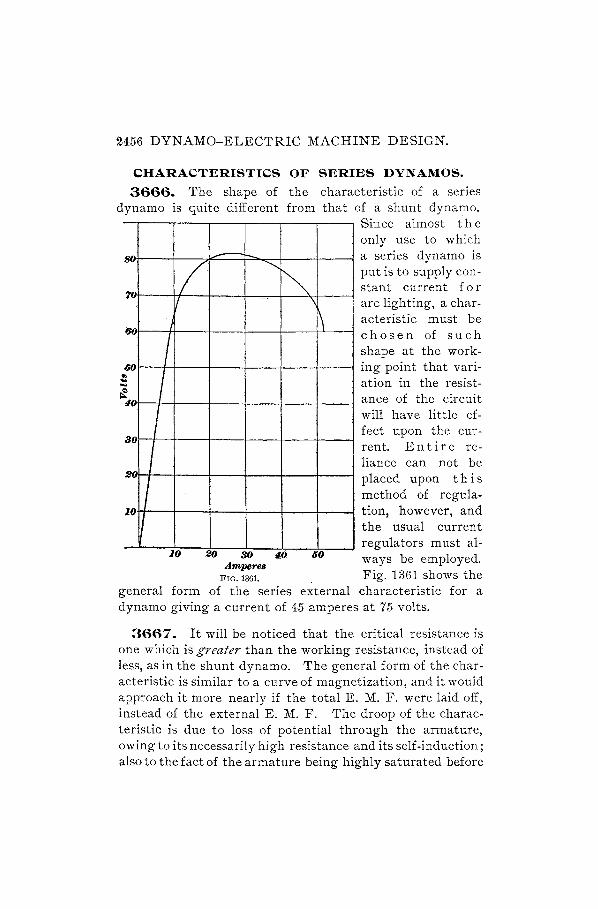
2456 DYNAMO:....ELECTRIC MACHINE DESIGN.
CHARACTERISTICS OF SERIES DYNAMOS.
3666. The shape of the characteristic of a series dynamo is quite different from that of a shunt dynaJ?o.
.....
(J()
IiO .. .. ... 0
80
1.0
-/ ""'" ~
Since almost the only use to which a series dynamo is put is to supply constant current for arc lighting, a characteristic must be c h 0 sen of s u c h shape at the working point that variation in the resistance of the circuit will have little effect upon the current. En tire reliance can not be placed upon t his method of regulation, however, and the usual current regulators must al-
II \
I 1\
I I 1 I
I I
20 .A.n::!'I'eB MJ 60 ways be employed. FIG. 1361. . Fig. 1361 shows the
10
general form of the series external characteristic for a dynamo giving a current of 45 amperes at 75 volts.
3667. It will be noticed that the critical resistance is one which is greater than the working resistance, instead of less, as in the shunt dynamo. The general form of the characteristic is similar to a curve of magnetization, and it would approach it more nearly if the total E. M. F. were laid off, instead of the external E. M. F. The droop of the characteristic is due to loss of potential through the armature, owing to its necessarily high resistance and its self-induction; also to the fact of the armature being highly saturated before

DYNAMO-ELECTRIC MACHINE DESIGN. 2457
the field-magnets reach that state, and to the demagnetizing action of the back ampere-turns, as in a shunt dynamo. These effects increase with the current, but the increase in E. M. F. being continually smaller, it reaches a point where the losses overpower it, producing thereby the droop in the curve.
EFFICIENCY.
ELECTRICAL EFFICIENCY.
3668. The electrical efficiency is the ratio of the useful output to the total output, and is therefore usually high. This ratio may be expressed in percentage as follows:
where
E - 100 e C (596.) - ECa '
e = E. M. F. at brushes; E = total E. M. F. generated; C = current available for outside circuit; Co, = total current in armature.
The electrical efficiency of a dynamo is equal to 100 times the product of the E. M. F. at the brushes and the current in the external circuit, dh'ided by the product of the totalE. M. F. of the dynamo and the total armature current.
3669. In applying this formula to our dynamo, we should get the same result. Then,
100 X 115 X 78 E = 119 X 79.42 = 05 per cent.
COMMERCIAL EFFICIENCY.
3670. The commercial or net efficiency is always lower than the electrical efficiency, because it expresses the relation between the useful output e C and the power required to drive the machine, which latter is required to overcome all inherent losses caused by friction, hysteresis, and eddy currents, as well as the C'R losses of. armature and field.

2458 DYNAMO-ELECTRIC MACHINE DESIGN.
It is usually understood, when the term efficiency is applied to a dynamo, that commercial efficiency is referred to, and it is to be so taken in connection witli the discussion following.
In a dynamo the mechanical energy delivered to the arma~ ture shaft is usually called the input; the electrical energy appearing in the external circuit from the brushes is called the output; and the energy converted into heat directly or indirectly in the dynamo itself is termed energy losses, or simply losses. This last term is not a strictly true one; for the energy converted into heat in the dynamo is lost only in relation to its utility-it can not be utilized to an advantage, and, if too intense, endangers the life of the mach.ine.
From what has been stated, it will be seen that the input to a dynamo is always equal to the output at the brushes plus the losses in the machine itself; or, in other words, the losses in the dynamo are equal to the difference betweJn the input and the output. It is assumed in the above statement that the input, output, and losses are reduced to the same units. For example, suppose that 20 horsepower is delivered to'the armature shaft of a dynamo where the output from the brushes to the external circuit is 13,428 watts. Reducing the·20 horsepower to watts gives 20 X 746 = 14,920 watts; hence, the losses in the dynamo are equal to the difference between the input of 14,920 watts and the output of 13,428 watts, or 14,920 - 13,428 = 1,492 watts.
3671. It is more convenient, however, to express the relation of the input, output, and losses of a dynamo in percentage; that is; the output as well as the losses may be expressed as a certain per cent. of the input.
Let I = the input of a dynamo, or the power applied at the pulley;
o = the output; E = the per cent. commercial efficiency.
Then, the per cent. efficiency of a dynamo may be found by the formula
E - 100 X 0 - I . (597.)

DYNAMO-ELECTRIC MACHINE DESIGN. 2459
That is, to find the per cmt. ejfidmcy of a djmamo, divide the output in watts 'by the input in watts and multz"ply by 100.
For instance, in the above example, the efficiency, by formula 597,
100 X 13,428 E = 14 920 = 90 per cent. ,
3672. The relation of the input to the heat losses in a dynamo, expressed in percentage, is termed the per cent. loss.
Thus, letting L = the per cent, loss, the per cent. loss in a dynamo may. be found by the following formula:
L _100(I - 0) - I . (598.)
To find the total per cent. loss in a djmamo, divide the dijJerence between the input and the output in 'watts by the input z"n 7.vatts and tnultiply by 100.
EXAMPLE.-(a) What is the per cent. efficiency of a dynamo, if 10 horsepower is delivered to the armature shaft and the output from the brushes is equivalent to 6,341 watts? (b) What is the total per cent. loss in the dynamo when running under these conditions?
·SOLUTION.-Reducing the input of 10 H. P. gives 10 X '746 = '7,460 watts input. (a) By formula 597, the efficiency
100 X 6,341 . E = '7,460 = 85 per cent. Ans.
(0) By formula 598, the total loss
L = 100 (7,460 - 6,341) 15 per cent. Ans. 7,460
3673. When the output of a dynamo and Its corresponding efficiency are given, the input necessary may be found by the following formula:
I _100 X 0 - E . (599.)
The z'nput necessary to drive a dynamo, when z"ts output and ejficiency at that output are gz"7.len, ts obtained by

2460 DYNAMO-ELECTRIC MACHINE DESIGN.
dividing the output by the per cent. efficiency and multiplying the quotient by 100.
EXAMPLE.-The efficiency of a constant-potential dynamo is found to be 85% when giving an output of 6,341 watts; find the input in horse. power necessary to drive its armature shaft under these conditions.
. 100 X 6,341 SOLuTION.-By formula 599.the necessary lllput I = 85
7,460 watts. The equivalent of 7,460 watts in horsepower is 77!~0 =
10 horsepower, which is the power required to drive the armature shaft of the dynamo under the stated conditions. Ans.
3674. When the input of a dynamo and its corresponding efficiency are given, the output may be found by the following formula:
IE 0= 100' (600.)
The output of a dynamo, of which the input and tile efficiency at that input are given, is obtained by multiplying the input by the per cent. efficiency and dividing by 100.
EXAMPLE.-An input of 35 horsepower is delivered to the shaft of a dynamo; if its efficiency at that input is 89.5%, find its output in watts.
SOLuTION.-The equivalent of 35 horsepower is 35 X 746 = 26,110 watts. By formula 600. the output of the dynamo under these con-
d't' 0 26,110 X 89.5 23°6845 A 1 IOns, = 100 =,e>. watts. ns.
3675. The efficiency of a dynamo depends upon its character, construction, condition when tested, its capacity (or output), losses, and various other conditions; in fact, two dynamos of the same construction and capacity seldom show exactly the same efficiencies. The foIIowing list, however, will give the student a general idea of the approximate per cent. efficiencies which should be obtained from constant-potential machines of different capacities, or outputs, under ordinary conditions to be met with in practice:
From 750 to 1,500 watts output, inclusive, about 75% efficiency.
From 3,000 to 5,000 watts output, inclusive, about 80% efficiency.

DYNAMO-ELECTRIC MACHINE DESIGN. 2461
From 7,500 to 10,000 watts output, inclusive, about 85% efficiency.
From 15,000 to 100,000 watts output, inclusive, about 90% efficiency.
From 150,000 watts output and upwards, from 91 to 93% efficiency.
LOSSES.
3676. The tota110ss of power in a dynamo can be separated into smaller losses, depending upon the manner in which the loss is produced and the part of the dynamo in which it occurs. In ordinary cases, all the losses will come :under one of the following heads:
1. Mechanical friction loss. 2. Core loss. 3. Field loss. 4. Armature loss.
FRICTION LOSSES.
3677. The larger part of the loss due to mechanical friction takes place usually between the bearings and journals. The brushes rubbing on the'commutator also produce friction, in some cases this being equal to bearing friction and air friction combined. The per cent. of power lost in mechanical friction necessarily depends upon the construction and condition of the bearings and journals, upon the size of the machine, and to s<?me extent on the method of driving the armature shaft. Under ordinary conditions, the loss in mechanical friction should not exceed 5% of the input of dynamos from 1,500 up to about 10,000 watts output, and 3% of the input of dynamos from 15,000 to 100,000 watts output. For example, suppose that a dynamo has an efficiency of 88% at its rated output of 22,000 watts, and a test shows that 2.5% of the input is lost in mechanical friction. The total loss in the machine is 100 - 88 = 12%, of which 2.5% is lost in friction; the remaining 9.5% loss is due to other causes. The total input to the machine, from
2462 DYNAMO-ELECTRIC MACHINE DESIGN.
. 22000 formula 600, IS 88- X 100 = 25,000 watts; hence, the
It' f" . 25,000 X 2.5 625 tt power os 111 nctlOn IS 100 = wa s.
CORE LOSSES.
3678. The core loss is the energy converted into heat in the iron disks of the armature core when they are rotated in the magnetic field. A small portion of this loss is due to eddy currents generated in the revolving core disks; the larger portion of the loss is due to a magnetic .friction which occurs whenever the direction of the lines of force is rapidly changed in a magnetic substance. When the magnetism of an electromagnet is rapidly reversed, that is, when the direction of the lines of force is suddenly changed several times in rapid succession by reversing the direction of the magnetizing current, the iron or steel in the core becomes heated, which necessitates a certain amount of energy being expended. This effect is called hysteresis (pronounced his-ter-ee'-sis ).
3679. The energy expended by hysteresis is furnished by the force which causes the change in the magnetism, and, in the case of an electromagnet where the magnetism is reversed by the magnetizing current being reversed, the energy is supplied by the magnetizing current.
The same effect is produced when the iron of the armature core is rapidly rotated in the constant magnetic field of the dynamo; this case differs from the electromagnet only in the fact that the magnetic lines of force remain at rest and the iron core is made to rotate. Since the core is rotated from the armature shaft, the energy lost in hysteresis is furnished by the force which drives the shaft.
The loss of energy due to hysteresis depends (1) upon the hardness and quality of the magnetic substance in which the magnetic change takes place, (2) upon the amount of metal in which the reversal takes place, (3) upon the num-

DYNAMO-ELECTRIC MACHINE DESIGN. 2463
ber of complete reversals of magnetism per second, and (4) upon the maximum density of the lines of force in the metal. Building the core of iron disks does not affect the hysteretic loss; it only reduces the eddy currents. Hysteretic loss is greatly reduced by using soft annealed iron, which exhibits only slight traces of residual magnetism; for where the residual magnetism is large, the loss due to hysteresis is large in proportion. The hysteretic loss increases in a certain ratio with the magnetic density and' the number of reversals per second; hence, these quantities are kept within reasonable limits. The magnetic density in the armature rarely exceeds 85,000 lines of force per square inch; and the maximum number of complete reversals of magnetism in the armature core is about 133 per second. In bipolar dynamos the number of complete reversals of magnetism in the armature is equal to the number of revolutions per second at which the armature shaft is driven; in mUltipolar machines the number of reversals is equal to the number of revolutions of the armature shaft multiplied by the number of pai7's 0.1 poles. For example, if the armature of a four-pole dynamo is driven at 600 revolutions per minute, or 10 revolutions per second, the number of complete reversals of magnetism in the armature core is 10 X 2 = 20 per second.
In a well-designed dynamo, the core loss, including eddy currents and hysteresis, should not exceed 2% of its input when delivering its rated output from the brushes.
FIELD LOSSES.
3680. In self-exciting dynamos, a portion of the electrical energy generated in the armature is required to excite the field-magnets. 1'his energy is considered as one of the losses of the dynamo, since it does not appear in the external circuit and is entirely dissipated in the form of heat.
In a series-connected dynamo, where the total current from the armature passes through the magnetizing coils, the power in watts is equal to the square of the current,

2464 DYNAMO-ELECTRIC MACHINE DESIGN.
multiplied by the resistance of the series turns. If, then, C is the total current from the armature, r is the total resistance of the series coils, and W is the watts lost in the series coils, then, W = C' r. For example, suppose that a series dynamo generates 200 volts between its terminals when a current of 100 amperes is flowing from its brushes through its series coils and through the external circui t. The total output of the dynamo is then 100 X 200 = 20,000 watts. If the total resistance of the series coils is .1 ohm, then the number of watts (IV) required to excite the field-magnets is C" r = 100' X .1 = 100 X 100 X .1 = 1,000 watts.
3681. In a shunt dynamo which generates a nearly constant potential for limited strengths of current in the armature, the field coils usually consist of a large number of turns of fine wire, offering a high resistance compared with the field coils of a series dynamo. The power in watts IV = C E; that is, it is equal to the current in amperes flowing through the shunt coils multiplied by the difference of potential in volts between the terminals of the shunt coils. "Ve will suppose, for example, that the current C = 2 amperes and the E. M. F. E = 110 volts; then W = 2 X 110 = 220 watts, which represents the power required by the fieldmagnets.
Since the power in watts can be expressed in terms of resistance and electromotive force, or resistance and strength of current, the number of watts dissipated in the shunt coil
E' may also be expressed as W = C' R, or W = R where R =
resistance of shunt.
3682. All other conditions being similar, the same number of watts will be dissipated in a shunt field coil as in a series coil, provided an equal amount of magnetizing force is produced in the two cases.
3683. In a compound-wound dynamo, the field loss consists of two losses, one in the series coil and the other in the shunt coil. The loss in the series coil depends upon the strength of current flowing from the dynamo, as in the case
DYNAMO-ELECTRIC MACHINE DESIGN. 2465
of a simple series dynamo; while the loss in the shunt coil is constant, irrespective of the load on the machine; provided, of course, the dynamo generates a constant electromotive force for all loads. This can readily be understood from the following example: A dynamo is compounded to generate 220 volts between its terminals for all loads up to its rated capacity; that is, when the current from the armature becomes strongel\ and the difference of potential between the terminals tends to fall, the current in passing through the series coil strengthens the field-magnets sufficiently to keep a difference of exactly 220 volts between the terminals of the dynamo. Assume the resistance o'f the shunt coil to be 275 ohms and that of the series coil to be .055 ohm. At a rated output of 4,400 watts, the current flowing through the series
T d' t th t l' .. 4,400 20 . ( COl an In 0 e ex erna clrcUlt IS 220 = amperes assu-
ming the connections are made for a short shunt). At all
loads, the current in the shunt coil is Cs = ~: = ~~~ = .8
ampere; and the loss of power in the shunt coil is vv" = Ee X Cs = 220 X .8 = 176 watts; even when the external circuit is open the loss in the shunt coil remains constant, or 176 watts in this particular case. The loss in the series coil, however, varies directly with the square of the current passing through it. In this example, the loss in the series coil is W = e X r = 20' X .055 = 22 watts; at half load, or 10 amperes, the loss is W = 10' X .055 = 5.5 watts, etc.; at no load there is no current in the series coil, and, consequently, no loss. The total field loss in a compound dynamo is the sum of the losses in the series and shunt coils. For instance, in this example, the total field loss at full load is 198 watts; at half load 181. 5 watts, and at no load 176 watts.
ARMATURE LOSSES.
3684. The principal armature loss is that produced by the current in flowing against the internal resistance of the armature, that is, the resistance of the armature conductors. The core losses previously described could also be classed as

2466 DYNAMO-ELECTRIC MACHINE DESIGN.
part of the armature losses; but it is usual to consider them apart: The armature loss proper is usually termed the cop~ per or wire loss, since it is due to the resistance of the afmature conductors, which are composed of copper wire or ban;, The internal resistance of an armature is an exceedingly variable quantity, depending upon the form, construction, size, number of conductors, size of conductors, etc. In constant-potential dynamos, generally speaking, the internal resistance of the armature must necessarily be comparatively small, since it determines the maximum strength of current that can be obtained from the dynamo, as will be seen subsequently.
3685. The armature loss depends upon the amount of internal resistance and upon the strength of current flowing through the armature conductors. In a given armature the internal resistance remains constant at equal temperatures, while the strength of cnrrent varies with the load upon the dynamo at that particular moment; in other words, this loss occurs only when there is a current flowing through the armature-the stronger the current, the greater is the loss, and vice versa. In an armature the number of watts lost in the armature conductors is equal to the square of the current in amperes flowing through the armature multiplied by the internal resistance in ohms of the armature, from the positive to the negative brush.
EDDV -CURRENT LOSSES.
3686. Aside from the four principal losses mentioned, other small losses occur in some machines when the armature is revolving. If large conductors are used in the winding of the armatures, a difference of potential is sometimes generated between the edges of the conductor in such a manner as to give rise to small eddy, or local, currents in the conductors themselves, but the currents do not appear in the external circuit and are useless. In some cases these local currents dissipate considerable energy and heat the arm a-

DYNAMO-ELECTRIC MACHINE DESIGN. 2467
ture badly when the machine is not loaded; but in a welldesigned dynamo they are too small to be considered.
3687. In a slotted armature the projecting teeth have a tendency to disturb the position of the lines of force where they enter and leave the polar faces, as we have already seen. As in the previous case, a well-designed dynamo will show but few traces of these eddy, or Foucault currents, as they are called in honor of the man who first recognized their existence. Other local currents may occur in various parts of some dynamos on account of bad design, but it is only necessary here to treat specifically upon such losses as are common to all dynamos and impossible to eliminate.
3688. From the previous articles, the following summary will be a help to establish the rules of efficiency and losses:
Input = the power driving the dynamo, which is derived from some outside agency.
Outl}ut = input minus the total losses.
Total losses = the sum of the friction, core, field, armature, and other losses.
ff' . input minus total losses 1 0 Per cent. e 1c1ency = . X 0,
1l1put
output 100 or -'--t- X . 1l1pU
'friction losses Per cent. loss in frictioll =. X 100.
1l1put
core losses Per cent. loss in core =. X 100.
1l1put
field losses Per cent. loss in field =. X 100.
1l1put
. armature losses Per cent. loss in annature =. X 100.
1l1put

2468 DYNAMO-ELECTRIC MACHINE DESIGN.
MECHANICAL CONSTRUCTION.
MAGNETIC CIRCUITS.
3689. In our calculations for finding the required ampere-turns for a dynamo, we have considered in detail the
different parts of the magnetic circuit. In a bipolar dynamo of the
~---l--~"""" type we have considered there is but one such circuit. Although this subject has been referred to in the section on Applied Electricity, it may be well to repeat a few of the important remarks there made respecting the number of circuits in different
FIG. 1362. styles of field frames.
3690. The single-circuit salient-pole type shown in Fig. 1362 has one magnetizing coil VV which drives the lines of force through the circuit M and the armature A. If, now, we divide the field frame into two portions, each of one-half the cross-section of the frame in Fig. 1362, we shall have two circuits, in each of which the density will be the same as in Fig. 1362. The appearance of the frame will be as drawn in Fig. 1363, where the two circuits M, M' take the place of the single circuit of Fig. 1362. Suppose Fig. 1362 requires a field winding of 10,000 ampere-turns; it is all in one coil, and the difference of potential across its termi-nals is that of the armature, FIG. 1363.
say 120 volts. Now, in Fig. 1363 each of the coils W, W' requires 10,000 ampere-turns (approximately), because the densities are the same, also the lengths, except the length of yoke, which is a trifle less. But two circles whose areas are as 2 to 1 have circumferences of a ratio 1 to .707, so that the total length of wire for the double circuit will be about 1.414 times that required for a single circuit. The size of wire

DYNAMO-ELECTRIC MACHINE DESIGN. 2469
may be found by applying formula 592. If only one magnetic circuit is considered, it will be necessary to take 60 volts as the E. M. F. across its terminals, because the two coils are to be connected in series.
3691. In the four-pole dynamo of Fig. 1364 (a), there are four paths along which the lines of force flow; but the
(b) FIG. 1364.
magnetic circuits to be considered in determining the ampereturns are only two. Another disposition of the field frame and yokes, as at (b), does not change the number of circuits through the armature, or the distribution of the lines of force; yet in this case there are evidently only two magnetic circuits for which the ampere-turns are to be calculated. If, therefore, we determine the densities in the different materials forming the path abc de, we may calculate the ampereturns required for the length of that composite path or circuit, and double this number of ampere-turns will be required for the whole machine, or one-half this number will be placed on each of the four coils. In like manner, a six-pole dynamo may be considered as having three magnetic circuits, or as requiring for the whole machine three times the number of ampere-turns calculated for a single complete magnetic circuit; an eight-pole dynamo will have four magnetic circuits, and so on.
3692. It is possible to construct a bipolar dynamo for any output, but this form is not advisable for machines of more than about 15 or 20 horsepower, as they become too

2470 DYNAMO-ELECTRIC MACHINE DESIGN.
heavy. There is a saving in iron by subdividing the circuits, and we have already pointed out how the volume of current may b<; increased by the multipolar construction. In small machines, the extra expense of multipolar fields is not warranted, as the labor bears a much greater proportion to the weight than is the case with large machines.
LEAKAGE.
3693. The leakage factor which determines the size of the magnet core is not always to be taken as 1. 25, as in
the foregoing calculations. In those machines having the yokes lying close to the pole-pieces, as, for example, that shown in Fig. 1365, there may be considerable leakage across from the pole tips, along the circuits
FIG. 1360. indicated by the dotted lines. A factor of 1.5 may then be necessary, or even a higher figure. Leakage is increased by proximity of iron or steel masses, such as bearings and their pedestals; hence, they should be placed as far away from the pole-pieces as is convenient, or if they are necessarily close, the castings should be of non-magnetic metals. 'With a high degree of saturation in the armature, leakage is increased. Some loss in magnetizing force due to leakage is unavoidable, but even a comparatively large leakage represents but a small per cent. of the output of the machine, so that the loss in this regard is not excessive.
ARMATURE CORES.
3694. The ratio of the diameter of an armature to its length is usually readily determined by the peripheral speed at which it is desired to run and by the density of lines of force in the armature core. For purposes of comparison, it
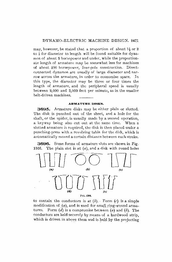
DYNAMO-ELECTRIC MACHINE DESIGN. 24'(1
may, however, be stated that a proportion of about ]t or 2 to 1 for diameter to length will be found suitable for dynamos of about 5 horsepower and under, while the proportion~ ate length of armature may be somewhat less for machines of about 100 horsepower, four-pole construction. Directconnected dynamos are usually of large diameter and narrow across the armature, in order to economize space. In this type, the diameter may be three or four times the length of armature, and the' peripheral speed is usually between 2,000 and 3,000 feet per minute, as in the smaller belt-driven machines.
ARMATURE DISKS.
3695. Armature disks may be either plain or slotted. The disk is punched out of the sheet, and a hole for the shaft, or the spider, is usually made by a second operation, a keyway being also cut out at the same time. When a slotted armature is required, the disk is then placed under a punching-press with a revolving table for the disk, which is automatically moved a certain distance between each stroke.
3696. Some forms of armature slots are shown in Fig. ]366. The plain slot is at (a), and a disk with round holes
(a) fII) (0)
UUCJru1f (d,) (6)
FIG. 1366.
to' contain the conductors is at (b) . . Form (c) is a simple modification of_(~), and is used for smaJLr.ing--vvqungarmatures. Form (d) is a compromise between (a) and (b). The conductors are held securely by means of a bard wood strip, which is driven in abqY'e them and i~ ~eld.py- the.pt~je.cting

2472 DYNAMO-ELECTRIC MACHINE DESIGN.
edges of the teeth. The cutting away of the connecting bridge has the effect of lessening the self-induction of the coil, which is rather large when the pierced disk (b) is used. The form shown at (e) is that which was mentioned in con~ nection with the dynamo for which calculations were made.
3697. Disks are made of one piece up to a diameter of 25 or 30 inches, or whatever width of sheet may be obtainable. When the diameter is so great, it is of course necessary to cut another circular piece from the center, forming the disk for another and smaller machine. The thickness of the disk is usually about .022 inch, and the material should be the best soft charcoal iron, specially manufactured for the purpose. The outer disks being usually unsupported at the outer edge, thicker sheets should be used, about T\- inch thick. Three of these at each end will be enough to hold up the teeth and prevent them from spreading.
ARMATURE SPIDERS.
3698. Fig. 1367 shows the method of mounting the disks for a ring armature of about 12 inches diameter. The inside diameter of the disks being perhaps 7 inches, they
FIG. 1367.
are threaded over two spiders s, s' having each four arms. Each spider has a ring r r' at the back, which is faced up in

DYNAMO-ELECTRIC MACHINE DESIGN. 2473
the lathe, and the edges of the arms are also turned true, so that the disks will slide over them and fit accurately. A small key k runs the full width of the armature, in a keyway cut in corresponding arms of both spiders, and a similar keyway in the disks enables them to be securely held in the proper position, so that they will not shift when the machine is working. The spider arm is only about -1'6 inch wide at the part where this key is fitted, in order to allow space for the winding; therefore the key is made about i inch wide, but the thickness is about double, measured radially. At the point where the arms join the hub, they should widen, in order to give strength to resist the twisting action communicated through the shaft. It will be noticed that the arms are continued outwards in the form of wings; these are intended to give strength to the rings r, r', that they may hold up the disks tightly without bending at the outer edge. The wings should not project beyond the line of the winding, in a horizontal direction. The arms are shown in the end elevation as being spaced equally, and for convenience in making shop drawings they may be so put in; but it is important to remember that the arms must be exactly opposite teeth. If, then, an armature has, for example, 57 teeth, the pattern must be so constructed that the arms are opposite 1, 15, 29, and 43.
3699. It is always necessary to carefully check the winding volume on the inside of the core, to see that there is room between the arms of the spider for the armature wires. It should be remembered that space is required for insulation between the winding and the core and between the winding and the arms. A sixteenth of an inch of mica and calico, or micanite and calico, will usually suffice. This must be very carefully put on and shellaced. '\Then computing the number of turns which will lie on the inside, sufficient clearance must be allowed for winding and manipulation, so that the actual net volume can not be counted on.
3700. In order that the disks may be readily slipped over the spiders, which is done before they are put together,

2474 DYNAMO-ELECTRIC MACHINE DESIGN.
each spider is provided with two lengths of arm. Opposite arms are of the same length, as seen in full lines in the crosssectional view of Fig. 1367; but two are shorter than the other two, as is indicated by the dotted lines at a. Eachspider may thus have a number of disks laid over it, up to the full extent of the longer arms, and the two spiders are then pressed together with clamps. It is better to leave a small clearance space between the ends of opposite arms, and allow the hubs to meet on the shaft. The small key k should be shorter than the width occupied by the disks by a little less than the thickness of one of the end disks. After the disks are all in place, the spiders containing them are pressed on the shaft, and the nut 7t is screwed up to hold them, instead of the clamps, these being then removed. A set-screw I should be used to prevent the nut from loosening.
3701. For the purpose of reducing magnetic leakage, the spider is nearly always made of bronze for small machines. A key k' is fitted in the shaft for driving; suitable sizes for keys will be given when we take up the design of shafts. For large armatures, bronze would be too expensive, and cast iron may be used. In such cases, however, the arms should connect between poles of the same sign, so that lines of force will not leak across, as would occur if the arms were opposite Nand S poles at one time.
3702 . . It is only in small machines that it is advisable to use a nut on the shaft for holding the spiders in place and clamping the disks. "When the diameter of the armature is large, this method of construction should give place to a more secure means of fastening. In Fig. 1368 is shown a design in which bolts are used to draw up the disks to a solid body. In other respects the manner of assembling is the same as in Fig. 1367. The spiders are cast with thickened arms at the part a where the bolts are intended to pass, and holes are drilled through, into which the bolts are fitted. It is cheaper to use through bolts, as shown in the figure, than to put in cap-screws, which would "requil'e that one of the holes be drilled smaller and tapped. The arms should

DYNAMO-ELECTRIC MACHINE DESIGN. 2475
be faced at those parts where the head of the bolt and the nut are to bear. The washer under the nut is a lock washer, split and bent in such away as to prevent the nut from loosening after it is once tightened up. The bolt itself must then also be held from turning, which may be
,~---------~ .
// ~ / \
/ \ ! \ / \ ! \ I I
\ I I I
\ ) \ ' \ / , I
~, // '.............. ------/
..... ------------~
FIG. 13G8.
accomplished by using a square-headed bolt and so shaping the spider arm at b as to almost touch the flat side of the bolt-head.
3703. In order to prevent, as far as possible, the generation of eddy currents in the spider rings, these )11ay be cut away on the inner side, as at c, without thereby sacrificing any necessary strength. A central rib d may be left, if the ring is so large as to be likely to bend between the supporting arms.
3704. A method of strengthening the spider "rings when used in connection with drum winding is shown in Fig. 1369, which represents a complete armature for a directconnected machine. This consists in the addition of a ~ange b, following the curve of the spider arm e, and continued around the full circle. On the other side is a separate ring c, held in place by tap-bolts d at each arm. The armature winding It is drawn in, to show the space occupied by it, and

2416 DYNAMO-ELECTRtC MACHtNE DESIGN.

DYNAMO-ELECTRIC MACHINE DESIGN. 2477
not the exact shape of one coil, for the coils are bent around through an angle of 60° to enter the fields of two pole-pieces simultaneously. Two iron flanges .f, f are used to press in the inner portions of the coils and hold them in position. At the end of one of the arms a, a groove is milled, into which fits a corresponding tongue on each disk, thereby dispensing with the use of a key. The resulting n:otch in the central stamping cut from this disk is cut out again when the slots are punched for a smaller armature, so that the disk is not spoiled.
ARMATURE CONDUCTORS.
3705. When armatures are of such a diameter that the disks can not be made in one piece, some method of building up the core must be devised. The iron sheets may form segments of a ring, with holes very close to the inside edge, as shown in Fig. 1370, through which insulated steel pins
FIG. 1370.
are passed. Each sheet has two such holes, a, b, Fig. 137.0, so spaced that adjoining layers of disks may overlap at the joints. Another plan is to make dovetailed notches in the lower edges and to use steel keys of the same shape, which fit into these notches and are held at the outer ends in the spider rings.
3706. The insulation of the armature conductors must be very thoroughly carried out. The slots should have a lining of mica and calico, with an aggregate thickness of about.035 inch each side. Micanite may be substituted, this material being usually reliable.

2478 DYNAMO-ELECTRIC MACHINE DESIGN.
For bar windings, the conductors should be of such a size as to fit closely in the slot, after the insulation is laid in.
Fig. 1371 shows a slot having two conductors. This is a section of a two-layer winding; there
. fore, as e~plained in Art. 3154, the two conductors have between them the full difference of potential of the dynamo and must be well insulated from each other. In the sectional view shown, the conductors are separated by a
FIG. 1371. strip of i-inch vulcanized fiber f. The hardwood strip w secures the conductors in place; usually this is in two pieces, each of one-half the length of the armature, and they are pressed in from each end, meeting in the middle.
3707. The use of end connectors has already been explained in Art. 3152. The end connectors need not have the same sectional area as the conductors, as they are exposed to the air. We may allo~ 600 or 700 circular mils per ampere, which would give us for the conductor shown in Fig. 1371 a width of i inch and a thickness of, say, A inch. With an armature of 19 or 20 inches diameter, these dimensions would be about correct, allowing for a four-pole magnet frame. As already stated, the end connectors should be laid out on the drawing:board, and the most suitable curve found for the spiral. This must be such that the space between succeeding spirals is as regular as possible; but it should not be necessary to construct the spiral of more than three or four curves. The copper strip, about 1176 inches wide, has a T3rinch cut carried down from one end to within, say, i inch of the other end, and the two ribbons. so formed are bent on a form to such curves that, on springing loose, they will have the shape intended and laid out on the drawing.
3708. There is a choice of two methods of securing the end connector to the bar. One side of the bar may be milled off, as at (a), Fig. 1372, or the bar may be cut through, as at (b), and the connector inserted. The connectors are held by rivets, and the joint should also be care
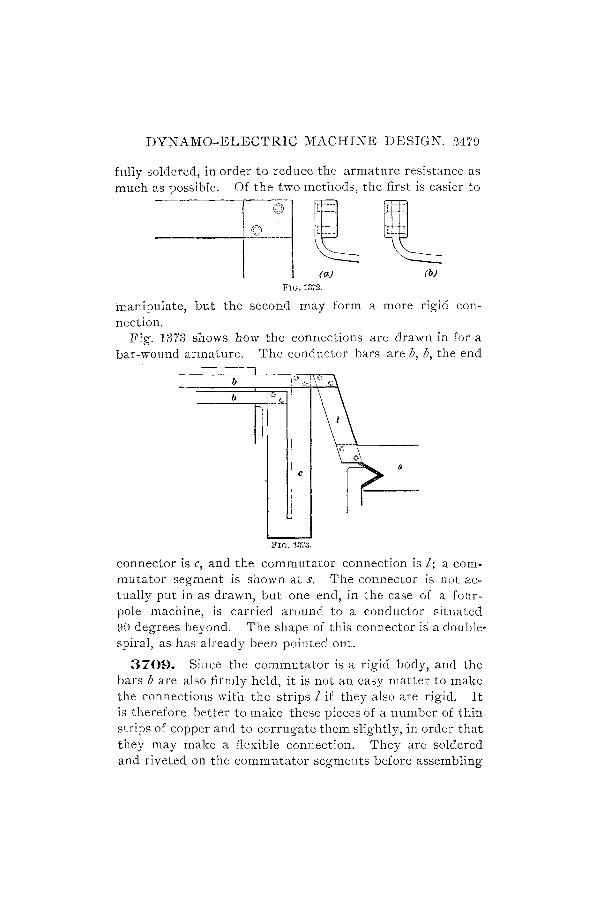
DYNAMO-ELECTRIC MACHINE DESIGN. 247D
fully soldered, in order to reduce the armature resistance as much as possible. Of the two methods, the first is easier to
I I " J- __ ....l.. )... _ --l.
)- -- • 'r- - -( . , , J-.- __ , .J- _ --1, v ------+--------- t"" ~,o
(a) FIG. 131'2.
(b)
manipulate, but the second may form a more rigid connection.
Fig. 1373 shows how the connections are drawn in for a bar-wound armature. The conductor bars are b, b, the end
b
b
8
FIG. 1373.
connector is c, and the commutator connection is I; a commutator segment is shown at s. The connector is not actually put in as drawn, but one end, in the case of a fourpole machine, is carried around to a conductor situated DO degrees beyond. The shape of this connector is a doublespiral, as has already been pointed out.
3709. Since the commutator is a rigid body, and the bars b are also firmly held, it is not an easy matter to make the connections with the strips 1 if they also are rigid. It is therefore better to make these pieces of a number of thin strips of copper and to corrugate them slightly, in order that they may make a flexible connection. They are soldered and riveted on the commutator segments before assembling
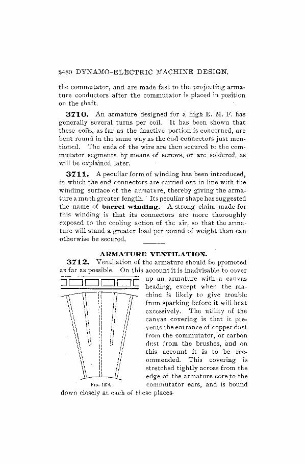
2480 DYNAMO-ELECTRIC MACHINE DESIGN.
the commutator, and are made fast to the projecting armature conductors after the commutator is placed in position on the shaft.
3710. An armature designed for a high E. M. F. lias generally several turns per coil. It has been shown that these coils, as far as the inactive portion is concerned, are bent round in the same way as the end connectors just mentioned. The ends of the wire are then secured to the commutator segments by means of screws, or are soldered, as will be explained later.
3711. A peculiar form of winding has been introduced, in which the end connectors are carried out in line with the winding surface of the armature, thereby giving the armature a much greater length .. Its peculiar shape has suggested the name of barrel winding_ A strong claim made for this winding is that its connectors are more thoroughly exposed to the cooling action of the air, so that the annature will stand a greater load per pound of weight than can otherwise be secured.
ARMATURE VENTILATION. 3712. Ventilation of the armature should be promoted
as far as possible. On this account it is inadvisable 'to cover
:::J II . II C up an armature with a canvas L-I 0 0 L-I heading, except when the ma~ chine is likely to give trouble
\ \ \ \ :: If /f from sparking before it will heat \\ \ \ :! I: / I excessively. The utility of the \ \ \ \ 11 J I 1/ \ \ \ \ I, 'I 1/ can vas covering is that it pre-,\ , 'I II '/
\\ \ \ : I ! II/vents the entrance of copper dust \\ II I, " /1 \\ \1 I: {I II from the commutator, or carbon " \1 11 d',' h . \ \ .J d u 1/ dust from the brus es, and on \\ II /1 \ \ 'I II this account it is to be ree-l' '1 /' \ \ :: 1/ ommended. This covering is \ \ 11 I I
\ \ : I / I stretched tightly across from the \ ' 'I II ~ edge of the armature core to the
FIG. 1374. commutator ears, and is bound down closely at each of these places.
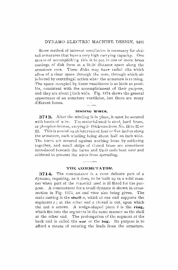
DYNAMO-ELECTRIC MACHINE DESIGN. 2481
Some method of internal ventilation is necessary for slotted armatures that have a very high carrying capacity. One means of accomplishing this is to put in one or more brass castings of disk form at a little distance apart along the armature core. These disks may have radial ribs which allow of a clear space through the core, through which air is forced by centrifugal action when the armature is turning. The space occupied by these ventilators is as little as possible, consistent with the accomplishment of their purpose, and they are abouttinch wide. Fig. 1374 shows the general appearance of an armature ventilator, but there are many different forms.
BINDING WIRES.
3713. After the winding is in place, it must be secured with bands of wire. The material used is steel, hard brass, or phosphor-bronze, varying in thickness from No. 18 to 21 or 22. This is wound on at intervals of four or five inches along the armature, each winding being about half an inch wide. The turns are secured against working loose by soldering together, and small strips of tinned brass are sometimes introduced beneath the turns and their ends bent over and soldered to prevent the wires from spreading.
THE COMMUTATOR.
3714. The commutator is a most delicate part of a dynamo, requiring, as it does, to be built up in a solid manner ",-hen part of the material used is ill fitted for the purpose. A commutator fora small dynamo is shown in crosssection in Fig. 1375, an end view also being given. The main casting is the shell a, which at one end supports the segments s ; at the other end a thread is cut, upon which the nut n screws. A wedge-shaped piece b is the ring, which fits into the segments in the same manner as the shell at the other end. The prolongation of the segment at the back end is called the ear or the lug. Its purpose is to afford a means of securing the leads from the armature.

2482 DYNAMO-ELECTRIC MACHINE DESIGN.
The segment at the level of the brush surface is not, as a rule, sufficiently wide to accommodate the screws which are used to tighten the leads, and the diameter must therefore be increased by means of the lugs. The lug at the point e is only of sufficient width to give the necessary rigidity to
FIG. 13i'5.
this part, but at the upper end it must be expanded in the direction of the shaft, in order to allow room for the two headless screws and for the recess r. This is used for binding on the calico which is used to protect the winding, as previously described.
COMMUTATOR SEGMENTS.
3715. The segment is of hard copper. Plenty of metal should be allowed for turning down the commutator on the surface covered by the brushes. The bars are made to order, generally, but some standard sizes are carried in stock by large dealers. If bars are required for a commutator which is to be 6 inches in diameter at the brush surface, and the insulation between bars is .035 inch, then it is best to allow in the estimate of size for a diameter of about 6.g. inches. Suppose there are to be 60 segments. The circumference of a circle 6.g. inches in diameter is 19.242 inches.
This allows for each segment 19.242 - .035 = .286 inch 60 '" . .

DYNAMO-ELECTRIC MACHINE DESIGN. 2483
of width. If we allow for a depth of let inches below the finished surface, the thickness of the segment at its lower
d '11 b 3. 5 X 3.14 . h If h . d e ge WI e 60 - .035 = .148 me . t e reqUlre
width of the lug for the armature leads is .35 inch, the
d · h" '11 b (.35 + .035) X 60 7R ' h lameter at t IS pomt WI e 3.14 = tr me es.
The segments are finished so carefully by a reliable man· ufacturer that they need no machining, except after they are set up with the insulation between, when the exposed portion is turned all over.
3716. The slots in the lugs for the armature leads should be made fust wide enough and deep enough to accommodate the wires; but there must be enough material left for the screws to be securely held, and they must not penetrate the side of the lug so as to reach the insulation. The shell, ring, and nut are made of bronze.
3717. In the design shown in Fig. 1375, the angle of the head and ring where they close in upon the segments is
FIG. 1376.
70°. This angle has been found 111 practice to give good results; but there are many other designs of cow mutator in which some different angle is used, as, for example, that shown in Fig. 1376. Here, only a single bevel is employed, which construction effects a possible saving in the machine· shop, although it is more or less a question of personal fqney whether the single Qr the QQ\Jble b\jYel is 1151':0 .•

2484 DYNAMO-ELECTRIC MACHINE DESIGN.
COMMUT A TOR SHELL.
3718. To return to Fig. 1375: The segments may he cut out at the corners at c, d, to prevent the head of the shell or the ring from coming in contact with the segments by reason of the insulation being pressed aside. On this account, also, it is well to allow the insulation to project into this corner, as drawn. It will be noticed that the insulation is made to extend beyond the segments atf, j, also at g, beyond where the head of the shell touches it. The reason is that this method of construction allows of higher insulation resistance being obtained, by providing a larger surface of insulating material between the segments and the body of the commutator. It will he seen that considerable clearance is allowed between the shell at a and the segments; this space should not be less than i inch, and may be t inch,. or more. Any unevenness in the setting of the segments will, then, not cause them to approach too nearly to the shell.
3719. It is most important that the shell at h be strong enough to withstand firmly the severe pressure which is brought to bear on it when the commutator is tightened up; for if the head should spring back, the segments are no longer held along the whole width of the bevel, and the insulation is liable to be crushed at those points where the pressure becomes concentrated. It is unnecessary that the shell should bear on the shaft throughout its whole length, and to save boring it should be cored out as shown, leaving about an inch at each end for support. It is not well to trust to the commutator holding in place on the shaft by making a close fit, for it is quite likely to work loose, and would drag at the armature connections. A small key k should therefore be set into the shaft, and may be held in place by means of a flat-headed machine-screw.
3720. The nut n may be hexagonal or may be round and provided with holes for a spanner. It may be advisable in some cases to add a second nut. The set-screw should

DYNAMO-ELECTRIC MACHINE DESIGN. 2485
not press directly on the thread, as this will injure it, but a brass plug should be interposed between them ..
3721. The insulation may be mica or micanite. The latter is very useful and well adapted for commutators. For use in the bevels, the thickness should be about T\ inch, and the shape of each ring, at top and bottom, should be carefully ascertained by laying out on the drawing-board. The insulation between the bars should be about. 035 inch to .04 inch and should completely fill the space between segments.
LARGE COMMUTATORS.
3722. Commutators for large machines, especially of the direct-connected type, require to be mounted on a spider, somewhat after the manner of an armature; A commutator of this type is drawn in Fig. 1377. A cast-iron spider a also forms the shell and extends round to one side of the segments. The ring b is turned to fit oyer the shell, and is drawn up into place by means of the tap-bolts shown. Lock washers are used, as previously described, in order to prevent the bolts from working loose. The bolts may be placed on the outside of the commutator or on the inside. The advantage of having them outside is that they are more accessible; but when they are placed on the inside they effect a saving of space, as will be seen by the figure, and this is a very desirable object in direct-connected machinery. The spider is intended to be fitted to the hub of the armature spider, which enters at e, and they are locked together by a suitable key. Other details on the drawing will be readily understood by reference to the preceding articles explaining the smaller commutator.
3223. Commutators for constant-potential dynamos sho·uld not have more than 15 or 16 volts difference of potential between bars, and it is better to make it less. If we provide 7 or 8 bars for each 100 volts that the machine gives, multiplied by the number of pole-pieces, this will give a safe working rule. Thus, a 500-volt four-pole dynamo will

2486 DYNAMO-E~ECTRIC MACHINE DESIGN.
have 7 X m X 4 =·140 bars, and, the maximum difference of potential being between adjacent poles, the number of bars spanning 500 volts is .1.! 0 = 35, giving a difference of
potential between each of 14.28 volts. For a ring-wound arc-light dynamo, the number of bars should be four or five for each lamp.

DYNAMO-ELECTRIC MACHINE DESIGN. 2487
3724. In deciding upon the clearance between armature and commutator, enough space must be left for fastening the armature leads, so that repairs may be easily accomplished and the wires be not too much crowded together.
3725. The question of the required surface of commutator may be considered under the head of brushes. A certain clearance beyond the edge of the brush is necessary, to allow for longitudinal motion of the armature; about one-quarter of an inch is usually sufficient. For direct-connected machines the brushes may run within an eighth of an inch of the edge, as there is no relative motion in the direction of the shaft.
3726. The ratio of diameter to length of commutators for belted machines may be taken as about 1.2 to 1; that is, the diameter is 1. 2 times the length. For a diameter, then,
of 6 inches the length would be l~ 2 = 5 inches. This rule
may be observed for machines up to about 75 horsepower; but beyond this it may be advisable to increase the ratio, in order to save in total length of machine.
BRUSHES.
3727. Commutator brushes may be made of brass, copper, or carbon. The brass and copper may be in. the form of leaf metal or gauze. Cop,per~gauze brushes are useful in the case of constant-potential dynamos for lighting, when the E. M. F. is low. These machines require constant attention, so that no advantage is secured by the use of carbon brushes, which add resistance to the circuit without it being possible to fully profit by the lesser sparking at commutation. The current density at the contact area should ordinarily not exceed 150 amperes per square inch for copper brushes, 100 amperes for brass brushes, and 30 amperes for carbon brushes.
Single brushes should never be used to collect the current,
2488 DYNAMO-ELECTRIC MACHINE DESIGN.
as it should be possible to take out a brush while the machine is running, in order to trim or replace it.
3728. Since 'carbon brushes may be relied upon to commutate a large part of the current, they are more used than copper brushes, being smoother in their action and less wearing to the commutator. Gauze brushes are made from sheet gauze folded on itself a number of times until the required thickness-about 11f inch-is obtained. The folding is diagonal, so that there is no trouble from wire threads slipping off at the ends. After being compressed and hammered into rectangular shape, four or five inches long and perhaps one and one,-half inches wide, the end which enters the brush holder is dipped into solder to cause it to hold its shape. The commutator end is then filed to a bevel, and the brush is ready for use.
3729. Carbon brushes are simply blocks, copper plated or plain, which are fitted into a clamp and press directly down on the commutator. It is the general practice to make the brushes radial; but some manufacturers adopt an inclined position, somewhat between that of the tangential copper brush and the radial brush.
SIZE OF BRUSHES.
3730. The thickness of carbon brushes varies with the size of machine. On small dynamos the brushes are generally larger in proportion than on large dynamos, as it is not necessary to economize space to the same extent. The thickness might be about 11f inch or i inch on the smallest sizes, with a width of about 1 inch and a length of 2 inches. On larger dynamos, 10 horsepower and upwards, the thickn~ss should increase to one-half or tnree-quarters of an inch. The rule already given, that the density per square inch should not exceed 30 amperes, will be a guide ,to the thickness required.
The thickness of a copper-leaf brush is generally' from i inch to t inch.

DYNAMO-ELECTRIC MACHINE DESIGN. 2489
BRUSH HOLDERS. 3731. The brush holder should be designed with the
following points in view:
1. The carbons must be held firmly, so that they will not rattle or afford poor contact with the metallic frame.
2. An adjustable spring pressure must be provided, in order to keep the carbons down to the commutator with just enough pressure to prevent cutting of the surface while maintaining good contact.
3. The brushes must be capable of being raised and held clear of the commutator.
4. ·Working joints must not be relied upon to carry the full current from the brush.
3732. The really perfect brush holder has doubtless yet to be designed, for there are some faults to be found
FIG. 1378.
with nearly all forms. The brush holder shown in Fig. 1378 is a fair specimen, but we will suggest, as useful exer· cise for the student, that he design one himself, and try to

2490 DYNAMO-ELECTRIC MACHINE DESIGN.
embody in it all the points mentioned above, and, in addition, perhaps a parallel mo~ion for the brush.
3733. With regard to the first condition, as exemplified in Fig. 1R78, the carbon c is held firmly in a clamp in which it is an easy fit when the screw s is loose. On tightening the screw, the carbon is pressed in at the two ends and also, by reaction, at the sides. The brass casting a, of which this is part, extends back to a stud which supports it, passing through the hole b, upon which stud it is free to move. The frame a is cut away in the middle sufficiently to allow a central casting d to enter, which may be clamped to the stud by means of the screw attached to the handle h. A pin e is passed through the screw and handle to prevent the screw from turning in the handle. The ends of the pin should be below the surface, in order to avoid giving a shock to the person adjusting the brushes. The clamp d is provided with an arm at its lower side, and a tension-spring j connects it to the frame a, thereby covering the second condition mentioned above, regarding adjustment. By loosening the handle and pr:essing it downwards, the spring is compressed and the brush may be raised from the commutator, as required by the third condition. Then, in order to provide adequate carrying capacity without having recourse to movable joints, a strip of copper braidg is screwed to the casting a at one end and to the central clamp d at the other end.
3734. A brush holder which has been put to considerable use is one in which a simple frame like that of Fig. 1378 is used for the carbon, but without any such clamping device. The frame is stationary, and the carbon is pressed downwards through it to the commutator by means of a spring above, operating a lever arm. This type of brush holder is liable to rattle, as the carbon is not properly held, and, furthermore, the contact between the brush holder and the carbon is not good, so that additional resistance is introduced into the circuit at this point.

DYNAMO-ELECTRIC MACHINE DESIGN. 2491
3735. A form of brush holder· coming into very wide use is what is called the reaction brush holder, illustrated in Fig. 1379. The principal feature of this holder is that the brush b is wedged in between it and the commutator, without any support on the outer side, as in the more general forms of holders. The brush is beveled on the top, and a curved lever I, pressing down wards, forces the brush against the fiat surface at the. end of the holder. The lever is actuated by a spring s, which may be set into anyone of the notches n on the lever, thus providing for different de- FIG. 1379.
grees of tension. The frame f is cast in one piece and carries-as many levers and springs as may be needed-one for ~ach brush. It is essential that the brushes be quite fiat on the side which is pressed against the holder, and on this account it is best to use carbons which are ground or sawn true and well plated. The angle a between the bevel of the brush and the surface of the holder should be about 45°, and the angle e between the surface of the holder and the tangent to the commutator at that point should be about 60°. These angles may be varied, as is done, for instance, by the C. & C. Co., who use a much larger angle between the commutator and the holder, and put straps around the brushes.
The direction of rotation is intended to be right-handed when put on as shown in Fig. 1379; that is, from the holder towards the brush. Some builders run the armature in the reverse direction, but the brush works well either way. When the brush is worn down, the lever is held by a projecting tooth which rests upon the edge of the frame and is prevented from touching the commutator. A very light pressure may be used with this type of brush holder, and carbons last a long time.

2492 DYNAMO-ELECTRIC MACHINE DESIGN.
Some of the advantages of the reaction brush holder are: it may be set very close to the commutator, thereby introducing a minimum of resistance into the circuit; the movement of the brush is in a straight line, so that there is always a bearing over the whole of the end surface; the brushes may be placed alongside and touching each other, thus utilizing the whole width of the commutator; and they may be very easily and quickly removed, for when the lever is raised the brush may be slipped out, even while the machine is running.
BRUSH-HOLDER STUD.
3736. The stud for the brush holders described in Art. 3732 is shown in Fig. 1380. This is a brass casting, and should be large enough to give rigidity to the brush holders
FIG. 1380.
and prevent undue vibration. The stud a is circular in crosssection, two brush holders being shown in dotted lines in pOSItIOn. It may here be remarked that the width of the holder at the part where the stud passes through should be about 1:\ inch greater than the width of the carbon holder at the other end, and in drawing the brush holder, additional allowance must be made for machine finish at the stud end.
3737. The stud has a square collar at b, as seen in the end view, and the part beyond is square as far as the two lines which indicate a return to -the circular cross-section. The insulating washers c, c are also square, with rounded

DYNAMO-ELECTRIC MACHINE DESIGN. 2493
corners, and the bushing d is square. The washers and bushing are of hard rubber, the former about -16 or t inch thick, and the latter t or -fTf inch, except in very large machines, where these dimensions may be suitably increased. At eis a circular washer of brass, andfis a cable tip, which is used to make connection with the main leads which carry the current to the point of distribution. A nut g is put on last to hold the stud firmly in place. It may be necessary to put an additional nut on, for the sake of greater security.
ROCKER-ARM.
3738. The brush-holder studs are held in position by means of a rocker-anD. h, which is shown again in Fig. 1381. This represents a rocker-arm for a bipolar dynamo. It is to be fitted over the end of the bearing next to the commutator, and is provided with a wing nut w, by means of
FIG. 1381.
which it may be clamped in any desired position. The square recesses r, r are seen, into which the studs are fitted. The reason for this shape is that the studs must be prevented from turning, as they would if simply clamped in a circular hole, owing to the reaction of the brushes when pressed against the commutator.
3739. At one end is a projecting boss a, tapped for a screw which holds the handle in place, by means of which

2494 ,DYNAMO-ELECTRIC MACHINE DESIGN.
the rocker-arm is moved when it is necessary to change the position of the brushes. In Fig. 1382 is given a view of the handle alone. It is made of maple or some such wood, and
FIG. 1382.
has a bolt b through the center, which screws into the rockerarm, the lower part of the handle itself entering also a little distance.
CABLE TIPS.
3740. In the description of Fig. 1380 the cable tip was briefly mentioned. Fig 1383 shows one of these more fully.
o b
It will be seen that there are two sizes of recesses; the smaller recess a is intended to receive the bare wire of the cable, which is soldered into place, and the recess b is made larger in order to accommodate the insulation. By this means a neat and strong connection maybe made to the main leads, and if
~'IG" 1383. for any purpose it may be necessary to remove the cables, the tips are easily disconnected from the studs. The cable tips are of cast brass; they should be made light, so that they do- not require extreme or long-applied heat to solder in the wires. The usual diameters for the stranded cable, bare, are from 3\ inch for, say, 8 or 10 ampents to ~ inch for about 300 amperes, and the thickness of insulation at one side will be from "-l6 for"the r;;llHI-Hv+ ~i~es.to i of all illcn tor the larger 5iZies. .

DYNAMO-ELECTRIC MACHINE DESIGN. 2495
SHAFT.
3741. The design of the armature shaft should be undertaken with a full recollection of the principles explained in the section on Mechanics. Beyond this, it is only necessary to point out some of the details of construction. To begin with, then, the diameter and length of the bearings should first be decided upon; for if we were to determine the diameter at the armature first, we might find that the bearings came out much too small. We must throughout have good proportions to give the prime requisite, stiffness; the shoulders at the bearings must be large enough to prevent any possibility of the shaft being driven in if the bolts of the bearings are slackened; there must be sufficient end play between bearings to avoid any liability of the shaft expanding sufficiently to hold fast and in order to produce a smooth wearing of the commutator, which is promoted by a slight oscillation of the armature while running.
3742. The journals of the shaft should be as small as possible, consistent with proper strength, as the friction is proportional to the diameter of shaft, other things being equal. In Fig. 1384 we have given the dimension of a shaft such as would be suitable for a lO-horsepower dynamo. We
FIG. 1384.
have taken a diameter at the journals of l.g- inches, and a length at the pulley end of three times this diameter, or 5 inches. At the commutator end the journal need not be so long, and we have made it 4 inches in length. The shaft shoulcl be turned down a little smaller than this diameter for the pulley, and we may make it It inches diameter, and about the same lengthl say 5t inches, '1'hvfe must be a

2496 DYNAMO-ELECTRIC MACHINE DESIGN.
good shoulder at the journal, and we will increase the diameter by half an inch at the part where the commutator is driven on, making it 2i inches. For the other journal we will provide the same amount of shoulder, making the shaft for a ,short distance 2i inches diameter. The· armature is driven on at this end up to a shoulder 5, and a thread is cut on the shaft to take a nut n, by which the armature is held in position. It is not well to cut the thread down by the shoulder for the journal, and an addition to the diameter must be made, such that the bottom of the thread will be a larger diameter than 2i inches. We may in the present example take a diameter for the shaft of 2t inches at this part. Since the armature is pressed up to a stop at 5, we will allow a further increase of diameter at this part of a quarter of an inch, making 2t inches. This largest diameter may be that of the rough forging, because nothing has to fit over it, and if it were turned, it would mean turning so much more metal from the whole length of the shaft.
3743. The shoulders at the journals must be carefully rounded, sharp corners being always avoided, as this introduces a serious weakness by concentrating the strain at one point instead of distributing it over a larger area.
3744. The ratio of length to diameter of journal at the pulley end should be, for machines of about 10 horsepower, 3 to 1; for machines of 100 horsepower, about 4 to 1; and for
sti111arger machines it is well to increase the ratio still further. A 100-horsepower
. dynamo would have the diameter of journals about 4 inches.
The shaft should be provided with oi1-throwing ridges, in order to prevent oil
I from reaching the commutator or anna-FIG. 1385. ture. The shape of these ridges is shown
in Fig. 1385. They should be covered by the cap to the bearing, as indicated in the sketch, so that the oil that is

DYNAMO-ELECTRIC MACHINE DESIGN. 2497
thrown off will fall within the casing and be returned to the oil-well, if self-oiling bearings are used, or to the waste pocket when sight-feed lubricators are employed.
3745. We must caution the student against making use in his designs of 'the very bad construction of shaft shown in Fig. 1386, in which the end of the shaft carrying
FIG. 1386.
the pulley is larger in diameter than it is in the bearing. The result of such design is that the continual pull of the belt produces in the shoulder s violent strains, constantly changing from one direction to the opposite, as the shaft revolves, and these reversals of load produce in time a crystallization of the metal which will cause it to break down at probably the most important time, that is, when the load is heaviest. If the shaft must be of such a small diameter in the bearing, let the size be the same under the pulley, but not greater. By far the better plan is, as we have drawn it in Fig. 1384, to make the journal sufficiently large that there shall be no necessity to have the shaft larger at the pulley end.
KEYS.
3746. The following table gives the sizes of steel keys for different dia,meters of sha,fts :

2498 DYNAMO-ELECTRIC MACHINE DESIGN.
TABLE 111. SIZES OF KEYS.
Diameter of Shaft. Width. Thickness.
Diameter of Shaft. Width. Thickness.
1 1 -tll 31 1 -is 4 TI
i 3 n- 3t 1 1\ 3"2"
t i 3 3i I t 1Il!"
i ';y :fy 3t I i 1 3
1"6 i 3~ I t I 3
TI i 31 ~ t 1 t 5 3~ 1 ~ 32
Ii ~ ";y 4 1 i 4 I
It 5 !6 4t 1 i 111
Ii 5 3 4t Ii ~ 111 IT
It i 1 4. 4i Ii i
l~ i t 5 It 1 Ii i l 5t It 1 II i t 5t It 1 2 1 5 6 It 15
"2 IT 16 2i ,t 5 6t Ii 1 16 2t t 5
IT '1 Ii In-2i i i '1t II Ii 2t i i 8 2 It 2~ i i 8t 2-k It 2i ~ ! 9 2t Ii 2I ! 7 9t 2i Ii IT 3 3 T\ 10 2t It 4"
PULLEYS.
3747. The pulleys used to drive high-speed armatures must of necessity also run at high speed; therefore it is important that they be as perfectly balanced as possible. To ensure this, it is best to employ webbed pulleys,which may be turned all over, and this design may be used on all sizes of dynamos up to 100 horsepower. The ratio of diame-

DYNAMO-ELECTRIC MACHINE DESIGN. 2499
ter to length may be taken as about 1.2 to 1 for very small machines, while for sizes above 5 horsepower a ratio of 1.3 : 1 to 1.45 : 1 will be found to conform to good practice.
Fig. 1387 s how s a webbed pulley such as would be suitable for a 10- ::, horsepower dynamo. The peripheral speed of w;ebbe(i pulleys may be taken as 2,200 to 3,000 feet per minute, the higher figure corresponding tot h e larger sizes of machine.
BEARINGS.
FIG. 1387.
3748. Bearings for dynamos are usually made selfoiling, instead of being fitted with sight-feed lubricators. A self-centering bearing with oil-rings· is shown in Fig. 1388, which gives two views, one being a longitudinal cross-section and the other a transverse section through the bearing at one of the oil-rings. The bearing proper, or box, is composed of two parts a and b, the upper and the lower, which are supported by the pedestal d and secured by the cap c, which is held in place by four bolts e. Two oil-rings f, fare introduced into openings cut for this purpose in the upper box, and rest upon the shaft, dipping into the oil contained in the reservoir below. When the shaft is revolved, the rings take up oil and carry it to the shaft. The boxes should have oilways cut in them, as shown by the dotted lines, and their arrangement should be such as to lubricate the whole of the bearing with one ring, in case one of the rings should become immovable. -It is possible that a ring may adhere so closely to the edge of the slot by the capillary action of the oil as to stop turning. On this account it may be

2500 DYNAMO-ELECTRIC MACHINE DESIGN.
advisable to make the ring of a winding form so that it can not lie close against the box. A small cover g is provided to span the top of the slot, to guard against the ring climbing up on the top of the box. The two halves of the bearing are fitted with a tongue joint, so that they can not slip sideways. It will be seen that the upper box is not cut through by the oil-ring slot, but that a small connecting bridge It IS
/'-------------------\ I • I •
I \ 1 \ I • I , • I
i \ I ,
I I
j ,
.j ~//: I r : I , " I .'
! "; i FIG. 1388.
left, which holds the three parts together. The oil-rings should not be so large in diameter as to be in danger of touching the sides of the oil chamber; it must be remembered that a theoretical static clearance-is not sufficien t, as the ring, when turning, is carried over slightly to one side. If the box were allowed any twisting motion, such as it might derive from the shaft, the bridges It would touch the

DYNAMO-ELECTRIC MACHINE DESIGN. 2501
oil-rings and prevent them from turning; therefore the lower box is fitted with two pins, i, i, which are so spaced as to touch against the walls of the central oil chamber. For purposes of inspection of the rings and for supply of oil, two openings k, k are made in the pedestal cap, which may be covered by small hinged lids to prevent the entrance of dust or other foreign matter. With the same end in view of keeping the oil clean, a plate I may be screwed on the end of the pedestal; it should not be made fast to the cap also, as it would have to be moved every time the cap was taken off. An oil-gauge lfl, to show at a glance the amount of oil in the reservoir, will be fourid to be a valuable addition, as there is then much less possibility of the level of the oil falling below the edge of the rings. A drain-cock 7Z should be provided for, in order that the oil may be· drained off and filtered, or fresh oil supplied.
3749. The pedestal and cap for the commutator end are turned at 0 to receive the rocker-arm. At the pulley end of the machine the bearing is symmetrical at both ends. It will be observed that a greater thickness of metal is allowed at jJ than at other parts of the pedestal. The reason for this is that the cores of the oil chamber and of the interior of the pedestal may vary a little in setting, and the extra clearance is allowed in order that the iron may .not be too thin at this part.
3750. In the drawing we have supposed the two boxes to be held together by the clamping of the outer bolts on the cap. In addition to this, we might wish to bolt the boxes together independently. This should, indeed, be done in the case of a long bearing, and is a simple matter of design. Care should be taken that the tap-bolts used do not come too close to the inner surface of the cap, and due allowance must be made for side play. It would probably be necessary to cast small bosses on the upper and lower boxes, the upper ones to bear against the heads of the bolts, and the lower ones to form a sufficiently solid mass to tap into.
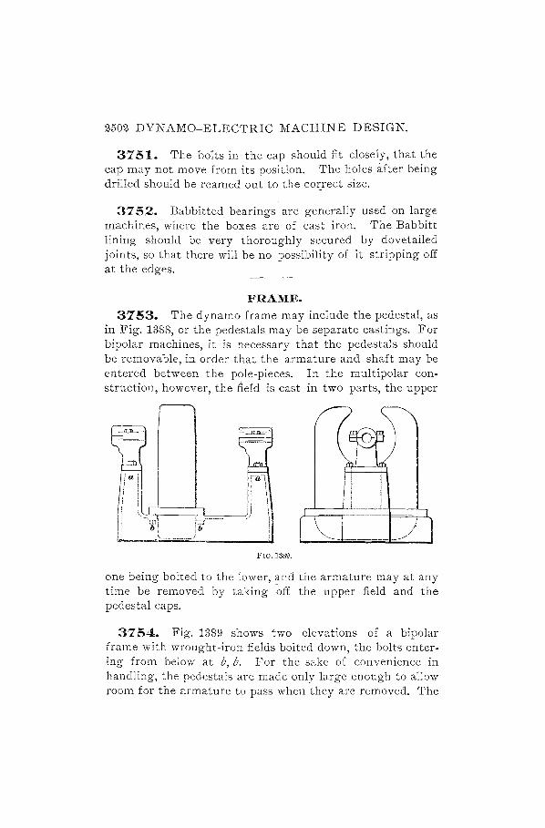
2502 DYNAMO-ELECTRIC MACHINE DESIGN.
3751. The bolts in the cap should fit closely, that the cap may not move from its position. The holes after being drilled should be reamed out to the cozrect size.
3752. Babbitted bearings are generally used on large machines, where the boxes are of cast iron. The Babbitt lining should be very thoroughly secured by dovetailed joints, so that there will be no possibility of it stripping off at the edges.
FRAME.
3753. The dynamo frame may include the pedestal, as in Fig. 1388, or the pedestals may be separate castings. For bipolar machines, it is necessary that the pedestals should be removable, in order that the armature and shaft may be entered between the pole-pieces. In the multipolar construction, however, the field is cast in two parts, the upper
,-L-,-===j-------------p=...---.....
\ ) "'-- ---- ------
FIG. 1389.
one being bolted to the lower, and the armature may at any time be removed by taking ~ff the upper field and the pedestal caps.
3754. Fig. 1389 shows two elevations of a bipolar frame with wrought-iron fields bolted down, the bolts entering from below at b, b. For the sake of convenience in handling, the pedestals are made only large enough to allow room for the armature to pass when they are removed. The

DYNAMO-ELECTRIC MACHINE DESIGN. 2503
centers of the bearings are not directly over the centers of the supporting pillars a, a, but are set to one side. On the commutator end this is done to allow clearance for the brush-holder studs and cable tips when the rocker-arm is moved round, and on the other end this construction allows the rim of the pulley to come closer to the center of the machine than would otherwise be the case.
3755. The frame of a circular field four-pole dynamo is shown in Fig. 1390. The bearings are of different
o
a aD b
FIG. 1390.
lengths, the commutator .bearing being shorter. It will also be noticed that the rocker-arm is supported in a rather different manner from that described in connection with smaller machines. The frame as a whole is fitted to a baseplate b, and slides along it in a direction perpendicular to the line of shaft, being guided by planed tongues a, a, which fit into corresponding recesses in the frame. This movement is intended to take up the slack in the belt, and should be provided for in all belt-driven machines. A screw passes through the hole c and engages in a nut fastened to the frame. A ratchet-and-pawl mechanism is used in connection with a lever to turn the screw and move the machine back and forth.
3756. The rocker-arm support is a separate casting, and is independent of the pedestal cap, so that the cap may

2504 DYNAMO-ELECTRIC MACHINE DESIGN.
be removed without disturbing the rocker-arm. A detail of the rocker-arm support is given in Fig. 1391. Being open at the top, it allows of the removal of the shaft without taking off this support, and being fastened only below- the
FIG. 1391.
,-- ---, >-- ---
.. - --, ~- ---
center line, the cap may be loosened or taken off without the necessity of dismantling the rocker-arm. Flat-headed screws are used in the holes a, a, and they pass through and enter into bosses cast on the pedestal. The groove for the rockerarm is V-shaped.
FIG. 1392.
3757. The following are dimensions for eye-bolts for screwing into the frame, such as is shown in Fig. 1390 and detailed in Fig. 1392~

DYNAMO-ELECTRIC MACHINE DESIGN. 2505
TABLE 112. SIZES OF STANDAI~D EVE-BOLTS.
A i- t -o{6 5 i l 1 It 1~ 2 8
B It It l-Ar It 1 196 Ii III 16 2i 2i 3i C Ii It Itt Ii 2t 2i 2 2t 3 4
32' 58. The lengths and diameters of standar"d tap-bolts, given in the accompanying table, " will be found useful in actual designing of the parts of dynamos.
TAB'LE 113. STANDARD HEXAGONAL HEAD TAP-BOLTS.
Diameter of Screw ;l- /6 i 7 16 t /6
Short Diameter of Head 7 16 t 9
·Ts .g. t lS To Long Diameter of Head .51 .58 .65 .72 .87 .94 Length Under Head tto3 t to 3t t to 3-~ t to 3i- tto4 t to 4t
Diameter of Screw .g. t t 1 It It Short Diameter of Head t 1 It 11- 1i l~
Long Diameter of Head 1.01 1.15 1.30 1.45 1.59 1.73 Length Under Head ItoH Itto4t It to 5 1t to 5 2 to.!) 2 to 5
POLE-PIECES.
32' 59. The shape of the pole-pieces is an important matter. In a two-pole field there must be plenty of metal at the ends of the pole-pieces, that is, they must not be tapering. The object is to diminish the reluctance as far as possible, so that the lines of force will distribute themselves evenly over the whole air-gap and not be concentrated near the end where they emerge from the magnet core. This effect may be produced by placing the armature a little out of the center, in the direction of the pole tips. When an inverted form of dynamo i.s used, such as the Edison bipolar, the pole-pieces must be separated from the baseplate by a footstep of zinc, usually four or five inches deep, in order to c:J.iminish the leakage.

2506" DYNAMO-ELECTRIC MACHINE DESIGN.
3760. The pole tips must not end abruptly, as we have already pointed out, but a commutating fringe must be pro. vided. The shape of the pole tip may be as shown in Fig. 1393, with pointed ends at the leading and following tips, or
, ' , ' , ' , , L:.J C
~==::"~aL:::==~ b 1i
FIG. 1393.
with rounded ends. The thickness at a should be comparatively small, as this dimension affects the diameter of the frame; but it should not be so small as to cause the pole tips b, b to be thin, as they extend farther from the core and are intended to carry a large number of lines of force. Also, if the pole tips are made thin, the casting is liable to be hard at those parts and to have a lower perme<:tbility. The upper part of the core c is to be fitted to a hole bored in the yoke, unless, as presently to be described, the yoke is cast around it. The surface of the cylinder c must be greater than the area of cross-section of the magnet core, in order that there may be no throttling of the lines of force as they pass into the yoke. When the yoke is of cast iron, the density will not usually be more than 35,000 or 40,000 lines per square inch, so that the area of contact between the

DYNAMO-ELECTRIC MACHINE DESIGN. 2507
core and yoke should be nearly double the cross-sectional area of the core.
The pole-piece is intended to be secured by means of two bolts at d, d. These should fit closely in the holes in the yoke, in order .that the pole-piece may not shift. In case one bolt is used instead of two, a dowel-pin should also be provided to guard against any twisting of the pole-piece.
3761. When the pole-piece is to be cast into the yoke, it is usually a wrought-iron forging, and the shape must be such as· to be firmly held in place. Any .design may be adopted that is likely to secure this end. The end of the pole-piece may be hollowed out, as in Fig. 1394 at a, as this will afford. a little more contact sur-face than if it were flat, and will also reduce the weight of the forging. Plenty of metal must be left around the top of the
a
pole piece and on the sides, in FIG. 1394.
order that the castings may be sound and strong. In such a design as this, pole tips can not be used unless they are bolted on after the spool is in place. The pole tip then forms a flange as shown in Fig. 1395, which supports the spool.
s
The surfaces at s must be well fitted, in order to eliminate all unnecessary reluctance. The two screws which hold the pole tip in position should be well fitted, in order that the
FIG. 1395. tip may not move, and the clearance holes around the head must be as small in diameter and as shallow as possible, while allowing the head of the screw ttl be beneath the surface. If the pole tip is so small that only one screw is considered necessary, a dowel-pin should be used to prevent the fJ()le tip from turning.

2508 DYNAMO-ELECTRIC MACHINE DESIGN.
LAMINA TED FIELDS.
3762. There may be considerable loss of power due to eddy currents in the fields as the teeth of a slotted armature move past the pole tips. This loss is made evident by a local heating, and may be almost entirely removed by laminating either the whole pole-piece or simply the pole tips. One method proposed is to use a mass of laminated sheet iron for a pole tip such as that described in connection with Fig. 1395. Some makers prefer to construct the whole pole-piece of laminated iron firmly bolted together and cast into the yoke. It is probably sufficient to provide lamination for the pole tip alone.
CROSS-SECTION OF CORES.
3763. Magnet cores should preferably be made circular in cross-section, as the circle encloses a larger area for a given periphery than any other geometrical shape. For purposes of comparison, therefore, the following table, given by S. P. Thompson, will prove useful, as it shows the relative lengths of wire required to wind around sections of various forms enclosing equal areas:
Circle. . . . . . . . . . . . . . . . . . . . . . . . . . . . . . . . . . . . . . . . .. 3.540 Square ....... ; ............................ ' ..... 4.000 Rectangle 2: 1 . . . . . . . . . . . . . . . . . . . . . . . . . . . . . . . . .. 4.240 Rectangle 3: 1 . . . . . . . . . . . . . . . . . . . . . . . . . . . . . . . . .. 4.620 Rectangle 10: 1 . . . . . . . .. . . . . . . . . . . . . . . . . . . . . . . .. 6.910 Oblong, made of one square between two semicircles. 3.760 Oblong, made of two squares between two semi-
circles. . . . . . . .. ............................ 4.280 Two circles, side by side. . . . . . . . . . . . . . . . . . . . . . . .. 4.997 Two circles, but wire wound around both together. 4.100 Three circles, wire wound around each separately .. 6.180 Four circles, wire wound around each separately ... 7.090
SPOOLS. 3764. Magnet spools should be substantially built, in
order to stand handling and perhaps rough usage without risk of falling apart. Fig. 1396 shows the details of con-

DYNAMO-ELECTRIC MACHINE DESIGN. 2509
struction of a spool such as would be suitable for a 10-horsepower dynamo. The actual frame of the spool consists of two sheet-iron cylinders a, b, one within the other, having
~--. ---10r---~'-------1
1 ! ····f· .. ......" ... fi.. I I J " ·tlr----'l:---·~
I ~ I . .ff 'r f II>-------:r,-.;F-c---------II I 1/1 _" /:l;
J I ,..II--------'J'r-------- id
l~~~~i,g·~·'----------------~c~~e FIG. 1396.
flanges c, d which are pressed close in to the end rings e, f and hold them securely in place. These rings are made of hard vulcanized fiber for small spools. The surface of the outer cylinder b is then covered with thinner fiber wound on to a thickness of about three - sixteenths of an inch, after which the wire is put in place. The inner end of the wire may be brought out through a hole in the end ring e or .f, on a level with the first layer. An even number of layers will result in bringing the ends out close together, and wi 11 r end e r connections easily made.
3765. For heavy spools, it is best to
... ~
FIG. 1397.

2510 DYNAMO-ELECTRIC MACHINE DESIGN.
have metal flanges, preferably of brass, in order to prevent leakage around the coil. Fig. 1397 shows the construction of a flange of this description, also the manner of bringing out the inner end of the wire. The flange f is cored out on the inside for the sake of lightness. A slight recess is turned at a, to receive the flange of the sheet-iron cylinder b. Insulating linings c, d are provided, as in Fig. 1396, to hold the wire. The end of the wire is at e; before winding, a narrow strip of thin copper g is soldered to it and wrapped throughout its length with tape. After the spool is filled, this end is bent over, and a brass connector h is soldered on, as shown. The strip is then held in place by the cord i, with which the whole spool is served.
TERMINAL CONNECTIONS. 3766. The connections between the dynamo and the
external circuit are made on a terIllinal board. This is a piece of wood shaped to receive the terminals, and may be of the form shown in Fig. 1398, although there is a large
e FIG. 1398.
variety of designs used. The terminals are cast brass blocks, of the same width as the terminal board in the groove, and are secured to the board by means of screws entering from beneath and countersunk sufficiently to be well clear of the metallic support. To further ensure the screws against accidental contac~ with the frame, a piece of thin fiber may be cut to the shape of the board, and placed under it, holes being made to pass the two holding-down screws.

DYNAMO-ELECTRIC 'MACHINE DESIGN. 2511
TERMINAL BLOCKS. 3'16'1. In Fig. 1399 is shown a terminal block which
would be suitable for the board in Fig, 1398. Two holes a, a are drilled through from side to side, and the cable tips to whi( h the leads are soldered are turned to fit these holes, the sel-screws being used to -
~:~~:c t~~e~~rmi!:: ~l~rc~w i~ 1§.·1 (r~ I§I I ! i\.) / i I
~~a~~ve,::e~x~:ais c:~:~:~~~ I C.J I \<~> I ("J I for the shunt, a small hole I I I
must be drilled, as shown' at s, in Fig. 1400, for the accommodation of the cable tip.
3'168. A different method is given for the clamping of the main lead cable tips. Slots are cut through at a, a, Fig. 1400, so that, when the screws b, b are tightened, the tips are held firmly. The terminal block can not now be fastened by one screw, as there is no room in FIG. 1399.
the center, so two screws are used, located near the outer edge at c, c. In laying out the holes for the cable tips, sufficient clearance must be allowed for the body of the tips, so that they will not touch each other when all are in place.
3'169. The cable tip used for the terminal blocks is shown in Fig. 1401. The end a is of such a size as to enter easily into the hole in the block, and is intended to be flush with the edge of the block when in position. The lead is soldered in, as already described. The edge e should not be left square, but must be rounded, as shown, in order that the insulation of the cable be not damaged. The cable tips are brass castings.
3'1'10. For shunt connections the terminal block shown in 1<ig. 1402 is suitable. It is designed on the same lines as