electrical dist.fh9
18
QO 1P 1 Space Required QOT 1P Tandem 1 Space Required QO 2P 2 Spaces Required 4 Spaces Required QO2200 2P 200 A QO 3P 3 Spaces Required 5 n t « t Œ c I £ Square D brand QO « miniature circuit breakers are plug-on products for use in QO load centers, NQOD panelboards, NQOD OEM interiors or Speed-D « switchboard distribution panels. Bolt-on QOB circuit breakers are for use in NQOD panelboards or interiors.5 The Square D exclusive Qwik-Open « mechanism, with a trip reaction within 1/60th of a second, is standard on all 1P 15A and 20 A circuit breakers. See Digest Section 1 for load centers, and Section 9 for panelboards and interiors. 10•30 A circuit breakers are suitable for use with 60oC or 75oC conductors. 35•125 A circuit breakers are suitable for use with 75oC conductors. UL Listed 5 k AIR on corner grounded Delta systems. UL Listed as HACR type for use with air conditioning, heating and refrigeration equipment having motor group combinations and marked for use with HACR type circuit breakers. UL Listed as SWD (switching duty) rated. Suitable for switching 120 Vac fluorescent lighting loads. Requires four spaces (1 AWG•300 kcmil Al/Cu.) Suitable for switching 120 Vac fluorescent lighting loads. UL Listed for use ahead of QO, QO-GFI, QO-EPD, QOT, and QO-PL 10 k AIR circuit breakers to permit their application at 22 kA fault level. 100 A maximum branch mounted opposite. Order only. Contact your local Field Office. Includes two circuit breakers (one QO2030 and one QO3020) and handle tie QOTHT. Not suitable for use in 3¯ panels. Use only in 1¯ panel rated 150 A or greater. Current limiting QOT tandem circuit breakers have a mounting cam as shown. Installation into a QO load center can only be made in those positions having a mounting pan rail slot. Meets Paragraph 408.15 of the NEC¨. UL Listed as Class CTL Pan Rail slot Rail Bead Mounting Cam www.afielektrik.com H 01 ELECTRICAL DISTRIBUTION Miniature Circuit Breakers Molded Case Switch 60 A max.-240 Vac Molded Case Switch 100 A max.-240 Vac 1P-120/240 Vac Cat.No. QO110 QO115«6 QO120«6 QO125« QO130« QO135« QO140« QO145« QO150« QO160« QO170« - - - - - - - - Table 1.1: Plug-On Circuit Breakers Amperes Rating n 10A 15A 20A 25A 30A 35A 40A 45A 50A 60A 70A 80A 90A 100A 110A 125A 150A 175A 200A 10 k AIR 2P-240 Vac t Common Trip Cat.No. - QO215H QO220H QO225H QO230H - QO240H QO260H QO270H QO280H QO290H QO2100H QO2110 - - - - - QO200 QO2000P 1P-120/240 Vac Common Trip Cat.No. QO210 QO220« QO225« QO230« QO235« QO240« QO245« QO250« QO260« QO270« QO280« QO290« QO2100« QO2110« QO2125« QO2150«˘£ QO2175«˘£ QO2200«˘£ - 3P-240 Vac Common Trip Cat.No. QO310 QO315« QO320« QO325« QO330« QO335« QO340« QO350« QO360« QO370« QO380« QO390« QO3100« - - - - - QO300 QO3000P 15A 20A 25A 30A 40A 50A 60A 70A 80A 90A 100A 110A 125A 150A 175A 200A 22 k AIRH 40A 45A 50A 60A 70A 80A 90A 100A 110A 125A 42 k AIR« 15A 20A 25A 30A 65 k AIR« QO115VHt QO120VH QO125VH QO130VH - - - - - - - - - - - - - - - - - - - - - - QO115t QO115t QO115K QO115 - - - - - - - - - - - - - - - - - - - - - - - - - - - - - - QO215VH¤ QO220VH¤ QO225VH¤ QO230VH¤ QO240VH¤ QO250VH¤ QO260VH¤ QO270VH¤ QO280VH¤ QO290VH¤ QO2100VH¤ QO2110VH¤ QO2125VH¤ QO2150VH¤Œ£ QO2175VH¤Œ£ QO2200VH¤Œ£ QOH240K QOH245K QOH250K QOH260K QOH270K QOH280K QOH290K QOH2100K QOH2110K QOH2125K QOH215 QOH220 QOH225K QOH230 QO315VH¤ QO320VH¤ QO325VH¤ QO330VH¤ QO340VH¤ QO350VH¤ QO360VH¤ QO370VH¤ QO380VH¤ QO390VH¤ QO3100VH¤ - - - - - - - - - - - - - - - QO315H QO320 QO325K QO330 Table 1.2: QO/QOB Ring Terminal Amperes Rating Poles Suffix 10-30 A 35-60 A 35-50 A 70-110 A 60-100 A 1,2,3 1,2 3 2 3 5237 5238 5273 Table 1.3: Wire Sizes Circuit Breaker Type Ampere Rating Wire Size (AWG/kcmil) QO 1P QO 2P QO 3P QOB-VH QOT QO-AFI,QO-GFI & QO-EPD QO-PL 10-30A 10-30A 35-70A 10-30A 10-30A 35-70A 80-125A 150-200A 10-30AI 35-70A 80-125A 110-150A 15-20A 15-30 A 40,50,60 A 10-60 A 14-8 Al/cu (2) 14-10 Cu 8-2 Al/Cu 14-8 Al/cu (2) 14-10 Cu 8-2 Al/Cu 4-2/0 Al/Cu 4-300 Al/Cu 14-8 Al/Cu, (2) 4-10 Cu 8-2 Al/Cu 4-2/0 Al/Cu 4-300 Al/Cu 12-8 Al 14-8 Cu 12-8 Al 14-8 Cu 12-4 Al 14-6 Cu 12-2 Al 14-2 Cu Table 1.4: QOT Tandem Circuit Breakers Amperes Rating n Cat.No. ¶ 1P-120/240 Vac 15 A & 15 A 15 A & 20 A 20 A & 20 A QOT1515 QOT1520 QOT2020 2P-120/240 Vac Common Trip Order two Q0T1515 or QOT2020 crcuit breakers and handle tie QOTHT for common switching of center two poles. Table 1.5: Replacement Tandem Circuit Breakers Amperes Rating Cat.No. 15 A & 15 A 15 A & 20 A 20 A & 20 A 20 A & 30 A 30 A & 20 A QOT1515 QOT1520 QOT2020 QOT2030 QOT3020 Two 1P Individual Trip -120/240 Vac - 2 Spaces Required Order two Q0T1515 or QOT2020 crcuit breakers and handle tie QOTHT For Use in Old Style Non-Class CTL QO Load Centers-10 k AIR 1P-120/240 Vac - 1 Space Required 15 A & 15 A 15 A & 20 A 20 A & 20 A 20 A & 30 A 30 A & 20 A - QO203003020 t - QOT Tandem
-
Upload
khangminh22 -
Category
Documents
-
view
6 -
download
0
Transcript of electrical dist.fh9

QO 1P
1 Space Required
QOT 1P Tandem
1 Space Required
QO 2P
2 Spaces Required
4 Spaces Required
QO2200 2P 200 A
QO 3P
3 Spaces Required
5
n
t«
t
êc
I
£
Square D brand QO«miniature circuit breakers are plug-on products for use in QO load centers, NQOD panelboards, NQOD OEM interiors orSpeed-D« switchboard distribution panels. Bolt-on QOB circuit breakers are for use in NQOD panelboards or interiors.5The Square D exclusive Qwik-Open« mechanism, with a trip reaction within 1/60th of a second, is standard on all 1P 15A and 20 A circuit breakers.
See Digest Section 1 for load centers, and Section 9 for panelboards and interiors.10•30 A circuit breakers are suitable for use with 60oC or 75oC conductors. 35•125 A circuit breakersare suitable for use with 75oC conductors.UL Listed 5 k AIR on corner grounded Delta systems.UL Listed as HACR type for use with air conditioning, heating and refrigeration equipment having motorgroup combinations and marked for use with HACR type circuit breakers.UL Listed as SWD (switching duty) rated. Suitable for switching 120 Vac fluorescent lighting loads.Requires four spaces (1 AWG•300 kcmil Al/Cu.) Suitable for switching 120 Vac fluorescent lighting loads.UL Listed for use ahead of QO, QO-GFI, QO-EPD, QOT, and QO-PL 10 k AIR circuit breakers to permittheir application at 22 kA fault level.100 A maximum branch mounted opposite.Order only. Contact your local Field Office.Includes two circuit breakers (one QO2030 and one QO3020) and handle tie QOTHT.Not suitable for use in 3¯ panels. Use only in 1¯ panel rated 150 A or greater.
Current limiting QOTtandem circuitbreakers have amounting cam asshown. Installationinto a QO loadcenter can only bemade in thosepositions having amounting pan railslot. MeetsParagraph 408.15 ofthe NEC¨. UL Listedas Class CTL
Pan Rail slot
Rail BeadMounting Cam
www.afielektrik.comH 01
ELECTRICAL DISTRIBUTIONMiniature Circuit Breakers
Molded Case Switch 60 A max.-240 VacMolded Case Switch 100 A max.-240 Vac
1P-120/240 Vac
Cat.No.
QO110QO115«6
QO120«6
QO125«QO130«QO135«QO140«QO145«QO150«QO160«QO170«
--------
Table 1.1: Plug-On Circuit Breakers
AmperesRating n
10A15A20A25A30A35A40A45A50A60A70A80A90A100A110A125A150A175A200A
10 k AIR
2P-240 Vac tCommon Trip
Cat.No.
-QO215HQO220HQO225HQO230H
-QO240HQO260HQO270HQO280HQO290HQO2100HQO2110
-----
QO200QO2000P
1P-120/240 VacCommon Trip
Cat.No.
QO210QO220«QO225«QO230«QO235«QO240«QO245«QO250«QO260«QO270«QO280«QO290«QO2100«QO2110«QO2125«QO2150«Æ£QO2175«Æ£QO2200«Æ£
-
3P-240 VacCommon Trip
Cat.No.
QO310QO315«QO320«QO325«QO330«QO335«QO340«QO350«QO360«QO370«QO380«QO390«QO3100«
-----
QO300QO3000P
15A20A25A30A40A50A60A70A80A90A100A110A125A150A175A200A
22 k AIRH
40A45A50A60A70A80A90A100A110A125A
42 k AIR«
15A20A25A30A
65 k AIR«
QO115VHt
QO120VHQO125VHQO130VH
------------
----------
QO115t
QO115t
QO115K
QO115
----------------
----------
----
QO215VH¨QO220VH¨QO225VH¨QO230VH¨QO240VH¨QO250VH¨QO260VH¨QO270VH¨QO280VH¨QO290VH¨QO2100VH¨QO2110VH¨QO2125VH¨QO2150VH¨ê£
QO2175VH¨ê£
QO2200VH¨ê£
QOH240KQOH245K
QOH250K
QOH260K
QOH270K
QOH280K
QOH290K
QOH2100K
QOH2110K
QOH2125K
QOH215QOH220QOH225K
QOH230
QO315VH¨QO320VH¨QO325VH¨QO330VH¨QO340VH¨QO350VH¨QO360VH¨QO370VH¨QO380VH¨QO390VH¨QO3100VH¨
-----
----------
QO315H
QO320QO325K
QO330
Table 1.2: QO/QOB Ring TerminalAmperes
Rating Poles Suffix
10-30 A35-60 A35-50 A
70-110 A60-100 A
1,2,31,2323
5237
5238
5273
Table 1.3: Wire SizesCircuit Breaker
TypeAmpereRating
Wire Size(AWG/kcmil)
QO1P
QO2P
QO3P
QOB-VHQOT
QO-AFI,QO-GFI& QO-EPD
QO-PL
10-30A10-30A35-70A10-30A10-30A35-70A
80-125A150-200A10-30AI35-70A
80-125A110-150A15-20A15-30 A
40,50,60 A10-60 A
14-8 Al/cu(2) 14-10 Cu
8-2 Al/Cu14-8 Al/cu
(2) 14-10 Cu8-2 Al/Cu
4-2/0 Al/Cu4-300 Al/Cu
14-8 Al/Cu, (2) 4-10 Cu8-2 Al/Cu
4-2/0 Al/Cu4-300 Al/Cu
12-8 Al 14-8 Cu12-8 Al 14-8 Cu12-4 Al 14-6 Cu12-2 Al 14-2 Cu
Table 1.4: QOT Tandem Circuit BreakersAmperesRating n Cat.No. 
1P-120/240 Vac15 A & 15 A15 A & 20 A20 A & 20 A
QOT1515QOT1520QOT2020
2P-120/240 Vac Common TripOrder two Q0T1515 or QOT2020 crcuit breakers and handletie QOTHT for common switching of center two poles.
Table 1.5: Replacement TandemCircuit Breakers
AmperesRating Cat.No.
15 A & 15 A15 A & 20 A20 A & 20 A20 A & 30 A30 A & 20 A
QOT1515QOT1520QOT2020QOT2030QOT3020
Two 1P Individual Trip -120/240 Vac -2 Spaces Required
Order two Q0T1515 or QOT2020 crcuitbreakers and handle tie QOTHT
For Use in Old Style Non-Class CTLQO Load Centers-10 k AIR
1P-120/240 Vac - 1 Space Required
15 A & 15 A15 A & 20 A20 A & 20 A20 A & 30 A30 A & 20 A
-QO203003020 t
-
QOT Tandem

www.afielektrik.comH 02
1PQO-AFI
1PQO-GFI
2PQO-GFI
QO-K KeyOperated
Three-wireQO-SWN
With Shunt TripQO 1P
Two-wireQO-SWN
ELECTRICAL DISTRIBUTIONMiniature Circuit Breakers
Table 1.6: QO Arc Fault Circuit Breakers α
QO® Arc-Fault Circuit BreakerQO arc-fault circuit breakers provide branch feeder protection(i.e. QO115AFI) or combination protection (i.e. QO115CAFI) asrequired by the NEC and local code adoption, and comply withUL1699.
QO-HIDHID circuit breakers are for use on circuits feeding fluorescent and highintensity discharge (HID) lighting systems such as mercury vapor, metalhalide, or high pressure sodium. These circuit breakers are physicallyinterchangeable with QO circuit breakers.
Branch FeederArc-fault Interrupter
Combination Arc-faultInterrupter
15201520
CircuitBreaker
Type
AmpereReating
QO-GFIQwik-Gard® circuit breakers provide overload and short circuitprotection, combined with Class A ground fault protection. ClassA denotes a ground fault circuit interrupter that will trip when afault current to ground is 6 mA or more, for people protection.Do not connect to morethan 250 feet of load conductor for thetotal one-way run toprevent nuisance tripping.
QO-KKey operated QO circuit breakers are available in single-pole construction and can be mounted in any single-polespace which will accept a standardQO. These circuit breakers can be turned ON or OFF or to RESET with aspecial key (catalog number QOK10) included with the circuit breaker.These circuit breakers are UL Listed and available as shown in the table.
152025304050
QO115HIDn
QO120HIDn
QO125HIDQO130HIDQO140HIDQO150HID
AmpereReating
1P 120 Vac10 k AIR
1 Space RequiredCat. No.
1P 120 Vac10 k AIR
1 Space RequiredCat. No.
QO315HIDQO320HIDQO325HIDQO330HID
--
1P 120 Vac10 k AIR
1 Space RequiredCat. No.
QO215HIDQO220HIDQO225HIDQO230HIDQO240HIDQO250HID
Table 1.10: HID Circuit Breakers
Table 1.7: QO-GFI Circuit Breakers
QO-HMHigh magnetic trip circuit breakers are recommended for applications wherehigh initial inrush may occur and for individual dimmer applications.
Table 1.11: QO-K Circuit Breakers
1015202530
AmpereReating t Cat. No.
QO110KQO115KQO120KQO125KQO130K
120 Vac - 10 k AIR (1 Space Required)
Non-automatic (Standard) Miniature SwitchesMiniature non-automatic switches have the same physical packagingas miniature circuit breakers, but open only when the handle is switchedto the OFF position. Non-automatic switches provide no overcurrentprotection or short circuit protection. They must not be used on systemsthat have an available fault current greater than the values listed in thetable. Non-automatic switches are UL Listed per UL 1087 and are CSAcertified.
Table 1.12: QO-HM Circuit Breakers
- 15 A20 A
AmpereReating t
Cat. No.
QO115HMsn
QO120HMsn
1P
120 Vac 10 k AIR
s UL Listed as HACR type for use with air conditioning, heating and refrigerationequipment having motor group combinations and marked for use with HACR typecircuit breakers.
n UL Listed as SWD (switching duty) rated. Suitable for switching 120 Vac fluorescent lighting loads.10-30 A circuit breakers are suitable for use with 60ºC or 75ºC conductors. 35-60 A
t circuit breakers are suitable for use with 75oC conductors.H Suitable only for feeding 240 Vac and 208 Vac loads. Does not contain load neutral
connection.
QO-EPDQO-EPD circuit breakers provide overload and short circuit protectioncombined with Class B ground fault protection.They are designed toprovide ground fault protection of equipment at a 30 milliampere level.They are not designed to protect people from electrical shock.
Table 1.13: QO Non-Automatic Miniature Switches,240 Vac 10 kA
60100
AmpereReating t Cat. No.
QO200QO2000
1P
Cat. No.
QO300QO3000
1P
Qwik-Gard Circuit BreakersWith Ground Fault Circuit Interrupter
1P 120 Vac
15202530405060
AmpereReatingt
Table 1.8: QO-EPD Circuit Breakers
2 Wire 120 Vac 2 Wire 120 Vac
10152025304050
AmpereReatingt
1P 120 Vac 2P Common Trip120/240 Vac
15202530405060
AmpereReatingt
QOSWNSwitch Neutral Common Trip 2002 NEC® 514.11.
Table 1.9: QO-SWN Circuit Breakers
QO115AFIQO120AFIQO115CAFIQO120CAFI
1P 120 Vac10 k AIR
1 Space RequiredCat. No.
1P 120 Vac10 k AIR
1 Space RequiredCat. No.
QO115AFIQO120AFIQO115CAFIQO120CAFI
2P Common Trip120/240 Vac
10 k AIR2 Space Required
Cat. No.
QO215GFIQO220GFIQO225GFIQO230GFIQO240GFIQO240GFI
QO260GFIH
22 k AIR1 Space Required
Cat. No.
QO115VHGIFQO120VHGIFQO125VHGIFQO130VHGIF
---
QO115GFIQO120GFIQO125GFIQO130GFI
---
10 k AIR1 Space Required
Cat. No.
QO115EPDQO120EPDQO125EPDIQO130EPD
---
10 k AIR1 Space Required
Cat. No.
10 k AIR2 Space Required
Cat. No.
QO215EPDQO220EPDQO225EPDQO230EPDQO240EPDQO240EPD
QO260EPDIH
QO210SWNQO215SWNQO220SWNQO225SWNQO230SWNQO240SWNQO250SWN
10 k AIR2 Space Required
Cat. No.
10 k AIR3 Space Required
Cat. No.
QO310SWNQO315SWNQO320SWNQO325SWNQO330SWNQO340SWNQO350SWN

125 A 100-125 A QOLl125 6-2/0
225A 150-225 A QOL225 6-300
Main LugRating ¨
Use OnCo vertible Load Center
With Mains Rating Cat. No.
Lug Wire SizeAWG/kcmil
Al or Cu
¨
Do not exceed the load center mains rating.Wire range listed for QOL lug kits is the wire range of that lug. To find outmaximum wire sizepermitted in a particular load center per UL, see pages 1-5 through 1-10 under main wire size.If main circuit breaker knockout has been removed from the load center’s trim, orderappropriate filler plate from page 1-12.
Main Lug KitsTable 1.19: Field-installable Main Lugs (Convertible Load Centers Only)
MainsRating Spaces
Max.SinglePole
Circuits
Max.TandemCircuit
Breakers
Load CenterBox and Interior
Cat. No.
MainWire Size
AWG/K cmilAl or Cu
EquipmentGround Bar Kit
(Order Separately)Cat. No.
Box. NoSee
Page1-16
Indoor Cover with Door(Order Separately)
FlushCat. No.
SurfaceCat. No.
Convertible Mains —Factory-installed Main Circuit Breaker, 22 kA Short Circuit Current Rating,Convertible to Main Lugs (see below) or Lower Amperage Main Circuit Breaker (See page 1-5), nQOM1 Main Circuit Breaker Frame Size—Copper Bus
Convertible Mains —Factory-installed Main Circuit Breaker, 22 kA Short Circuit Current Rating,Convertible to Main Lugs (see below) or Lower Amperage Main Circuit Breaker (See page 1-5), nQOM2 Main Circuit Breaker Frame Size—Copper Bus
12 12 0 QO112M100 QOC12UF QOC12UC 6-1 PK9GTA 516 16 0 QO116M100 QOC20U100F QOC20U100S PK12GTA 620 20 0 QO120M100 QOC20U100F QOC20U100S PK15GTA 624 24 0 QO124M100 QOC24UF QOC24US 6-2/0 PK15GTA 732 32 0 QO132M100 QOC32UF Use Rush PK18GTA 824 24 0 QO124M125 QOC24UF QOC24US 6-2/0 PK15GTA 732 32 0 QO132M125 QOC32UF Use Rush PK18GTA 8
100 A
100 A
20 30 10 QO12030M150 QOC30UF QOC30US PK18GTA 924 24 0 QO124M150 QOC30UF QOC30US PK15GTA 930 30 0 QO130M150 QOC30UF QOC30US PK18GTA 932 32 0 QO132M150 QOC40UF QOC40US PK18GTA 1020 40 20 QO12040M200 QOC30UF QOC30US PK23GTA 924 24 0 QO124M200 QOC30UF QOC30US PK15GTA 930 30 0 QO130M200 QOC30UF QOC30US PK18GTA 930 40 10 QO13040M200 QOC30UF QOC30US PK23GTA 940 40 0 QO140M200 QOC40UF QOC40US PK23GTA 1042 42 0 QO142M200 QOC42UF QOC42US PK23GTA 1140 40 0 QO140M225 QOC42UF QOC40US PK23GTA 1142 42 0 QO142M225 QOC42UF QOC40US PK23GTA 11
150 A
200 A
225 A
4-250
4-250
4-300
Fixed Mains—Factory-installed LAL Main Circuit Breaker, 42 kA Short Circuit Current Rating u
PK27GTA
or
PK15GTA6
(1) 4-500or (2) 4-3/0
(1) 4-600or (2) 4-250
I
N
D
O
O
R
42 42 0 QON42MS300 MHC68V F MHC68VS 16(int)
MH68 (box)42 42 0 QON42MS400 MPC68V FMPC68VS 16
(int)MH68 (box)
200 A
400 A
t
www.afielektrik.comH 03
Table 1.18: Indoor Main Circuit Breaker (Order QO, QOT, QO-EPD, QO-GFI, QO-AFI and QO-PLbranch circuit breakersfrom pages 1-2 and 1-3.)
1Ø3W—120/240 Vac—UL Listed
Maximum single pole branch circuits utilizing QO and/or QOT circuit breakers.22 k AIR main circuit breaker UL Listed for use ahead of QO, QOT and QO PL 10 k AIR branch circuitbreakers to permit their application on systems with up to 22 kA available fault current.UL short circuit current rating depends on lowest interrupting rating of circuit breakers installed. Also, ULListed 5000 A short circuit current for corner grounded Delta systems. Use QO-H circuit breakers only.Interior only, order box separately.PK27GTA includes a 6–2/0 Al/Cu lug.PE1A Discount Schedule
▲
n
t«
t
ê
ELECTRICAL DISTRIBUTIONLoad Centers
Above listings through 200 A mains rating meet Federal Specification W-P-115c as Type 1, Class 2.

www.afielektrik.comH 04
Amperage 25 k AIR 65 k AIR 100 k AIR m
70 A80 A90 A
100 A110 A125 A150 A175 A200 A225 A
QDL32070QDL32080QDL32090QDL32100QDL32110QDL32125QDL32150QDL32175QDL32200QDL32225
QGL32070QGL32080QGL32090QGL32100QGL32110QGL32125QGL32150QGL32175QGL32200QGL32225
QJL32070QJL32080QJL32090QJL32100QJL32110QJL32125QJL32150QJL32175QJL32200QJL32225
Fixed Mains—Factory-installed Main Lugs—Copper Bus—65 kA Short Circuit Current Rating ▲t
31220183042
QO403L60NRBQO312L125GRBQO320L125GRBQO318L200GRBQO330L200GRBQO342L225GRB
Cover included
60 A125 A
200 A
225 A
-6-2/0
6-250
6-300
10-66-2/0
6-250
6-300
PK4GTAFactory Incl.¨Factory Incl.¨Factory Incl.¨Factory Incl.êFactory Incl.ê
10R3R4R6R6R8R
Convertible Mains—Factory-installed QDL Main Circuit Breaker—CopperBus—25 kA Short Circu it Current Rating nt
273030304242
QO327M100RBQO330MQ125RBQO330MQ150RBQO330MQ200RBQO342MQ200RBQO342MQ225RB
Cover included
100 A125 A150 A200 A225 A
4-2/04-3004-3004-3004-300
4-2/04-3004-3004-3004-300
PK15GTAPK18GTAPK18GTAPK18GTAPK23GTAPK23GTA
6R14R14R14R14R14R
R
A
I
N
P
R
O
O
F
MainsRating
Max.Numberof 1P QO
circuitbreakers
Load CenterBox and Interior
Cat. No.
MainWire Size
AWG/K cmilAl Cu
EquipmentGround Bar Kit
(Order Separately)Cat. No.
Box. NoSee
Page1-16, 1-17
Indoor Cover with Door(Order Separately)
FlushCat. No.
SurfaceCat. No.
Fixed Mains—Factory-installed Main Lugs—Copper Bus—65 kA Short Circuit Current Rating ▲
Convertible Mains—Factory-installed QDL Main Circuit Breaker—CopperBus—25 kA Short Circuit Current Rating n
125 A
200 A
3 QO403L60NF/S - 10-6 PK4GTA 1312 QO312L125G QOC216UF QOC16US Factory-incl. 620 QO320L125G QOC24UF QOC24US 6-2/0 6-2/0 Factory-incl. 724 QO324L125G QOC24UF QOC24US Factory-incl. 718 QO318L200G QOC30UF QOC30US Factory-incl. 930 QO330L200G QOC30UF QOC30US 6-250 6-250 Factory-incl. 930 QO342L225G QOC42UF QOC42US 6-300 6-300 Factory-incl. 11
Cover Included WithLoad Center100 A
225 A
125 A
200 A
27 QO327M100 t QOC30UF QOC30US 4-2/0 4-2/0 PK15GTA 930 QO330MQ125« QOC342MQF QOC342MQS 4-300 4-300 PK18GTA 1230 QO330MQ150« QOC342MQF QOC342MQS 4-300 4-300 PK18GTA 1242 QO342MQ150« QOC342MQF QOC342MQS PK23GTA 1230 QO330MQ200« QOC342MQF QOC342MQS 4-300 4-300 PK18GTA 1242 QO342MQ200« QOC342MQF QOC342MQS PK23GTA 1242 QO342MQ225« QOC342MQF QOC342MQS 4-300 4-300 PK23GTA 12
100 A
225 A
150 A
¨
¨
¨
¨
¨
¨
¨
¨
¨
¨
¨
¨
I
N
D
O
O
R
Above listings through 200 A mains rating meet Federal Specification W-P-115C as Type 1, Class 2.
UL short circuit current rating depends on lowest interrupting rating of circuit breaker installed.25 kA short circuit current rating maximum with Square D Type QDL main circuit breaker, or 22 kA SCCR maximum with back-fed TypeQO-VH main circuit breaker, feeding QO 10 k AIR branch circuit breakers.Includes factory-installed back fed QO3100VH main circuit breaker.65 kA Short Circuit Current Rating maximum with field-installed Square D type QGL 65 k AIR minimum main circuit breaker feeding QOand Q1 10 k AIR minimum branch circuit breakers.Side hinge door device allow 1-1/4 in. on left side for door to open.PK23GTA and LK100AN.PK15GTA.Certified to IEC 60439-1 for use on 415Y/240 Vac 3Ø4W,3,000 SCCR when QODX... branch circuit breakers are usedand 10,000 SCCR when QO...VS branch circuit breakers are used.CE marked.DE3A Discount ScheduleDE2 Discount Schedule
▲n
t«
tê¨
P
¨
ê
Q0342MQ200 Q0312L125G
ELECTRICAL DISTRIBUTIONLoad Centers
3Ø4W-208Y120 VAC, 3Ø4W 240/120 VAC DELTA & 3Ø3W 240 VAC DELTA, UL Listed
Table 1.23: 3Ø Main Circuit BreakersField-installable alternate main circuit breakers for QO 3Ømain circuit breaker load centersrated 70—225 A. Do not exceed the load center main rating.
m When these 3P circuit breakers are used as the main circuit breaker of a 3 Ø load center,the maximum AIR rating is 65 kA at 240 Vac and 100 kA at 208 Vac.
Table 1.24: 3Ø Main Lug KitsField-installable main lugs for convertible 3Ø main circuit breaker load centers.
Amperage
125 A150 A
QOL3125QOL3225
6-2/0 Cu/Al6-300 Cu/Al
Cat. No.Lug Wire SizeAWG/kcmil

C223N
s
n
L221N
The UL Listed short-circuitcurrent rating for Square Dgeneral duty, not fusibleswitches is based on theswitch being used inconjunction with fuses.Evaluation of non-fusibleswitches in conjunctionwith molded case circuitbreakers has not beenperformed. Forapplications requiringgreater protection,consider using a heavyduty safety switch. Referto UL Listed MaximumShort Circuit CurrentRatingsÑAC onlyÑonpage 3-6. If a UL Listedshort-circuit current ratingis required, this non-fusibleswitch must be replacedwith a Square D generalduty fusible safety switchequipped with theappropriate class and sizefusing. The UL Listedshort-circuit current ratingof the fusible switch istypically as follows: whenused with Class H and KfusesÑ10,000 A, Class Rand J fusesÑ100,000 A.Consult the wiring diagramof the switch to verify theUL Listed short-circuitcurrent rating.50 kA for 60 A non-fusibleswitch.
Table 3.2: Non-Fusible
System A 1Ø 3Ø
HorsepowerRatings (Max.)
2 Wire (2 Blades)—240 Vac Maksimum
306060
100200400600
3101020---
-------
3 Wire (3 Blades)—240 Vac Maksimum3060
100200400600
3101515--
7-1/2153060
125150
NEMA 1Indoor
Cat.No.
--
QO260NATS cQO2000NS cUse 3P SwitchUse 3P SwitchUse 3P Switch
DU321DU322DU323DU324DU325DU326
NEMA 3RRainproofê
Cat.No.
DU21RBDU222RB
QO200TR cI
QO2000NRB c I
Use 3P SwitchUse 3P SwitchUse 3P Switch
DU321RBDU322RBDU323RBDU324RB
--
Table 3.1: Fusible
System A Fuse Cat.No.
Std.(Fast ActingOne-Time Fuses)
1Ø 3Ø
Std.(Fast ActingOne-Time Fuses)
1Ø 3Ø
3 Wire (2 Blade and Fuseholder, 1 Neutral)—120/240 Vac (Plug7, 240 Vac (Cart.) Maximum
303060
100200400600
PlugCart.Cart.Cart.Cart.Cart.Cart.
1-1/21-1/2
37-1/2
15--
-3
7-1/2t15t25t
--
331015---
-7-1/2t
15t25t60t
--
2 Wire (1 Blade and Fuseholder, 1 Neutral)—120 Vac
30
30
Plug
Cart.
Use Light Duty Device for this Application (see below)
Use three-wire device for this application
-
-
-
-
-
-
-
-
4 Wire (3 Blade and Fuseholder, 1 Neutral)—240 Vac Maximum
3060
100200400400600600800
Cart.Cart.Cart.Cart.Cart.
Class TCart.
Class TClass T
1-1/23
7-1/215-----
37-1/2H
15H
25H
50527575
100
31015------
7-1/215H
30H
60H
125-
150--
NEMA 1Indoor
Cat.No.
D211ND221ND222ND223N
D224Nt
D225ND226N
D321ND322ND323N
D324Nt
D325ND325NTD326N
D326NTT327N
NEMA 3Rs
Rainproof
Cat.No.
D211NRBD221NRBD222NRBD223NRB
D224NRBt
D225NRD226NR
D321NRBD322NRBD323NRB
D324NRBt
D325NRD325NTRD326NR
D326NTRT327NR
Class R Fuse KitsField-Installedn
-DRK30
RFK03HRFK10
HRK1020DRK40DRK600
DRK30RFK03HRFK10
HRK1020DRK40
-DRK600
--
Bolt-on hubs Refer to page 3-11.Enclosed molded case switch Refer to page 1-24.Includes factory-installed grounding kit.Not service entrance rated Refer to page 1-19 for more information.If a neutral assembly is required, order and field-install SN0610.If a neutral assembly is required, order and field install a SN20A Neutral Assembly Kit. For a 200% neutral application,order and field install (2) SN20ANeutral Assembly Kits and (1) SN20NI Neutral Jumper Kit.If a neutral assembly is required, order part number D600SN. Available for field-installation.Light Duty—Visible Blades 10 kA Short Circuit Current RatingThe Square D light duty enclosed switch is ideal for home applications in disconnecting power to workshops, hobby rooms, furnaces, and garages.
êc
×I
ê
Table 3.3: Fusible
UL Listed Short CircuitWithstand Rating
SwitchType
FuseClass
Sort CircuitRating
Fusible
NonFusibles
PlugHKJRTHKJT
10 kA10 kA10 kA
100 kA100 kA100 kA10 kA
100 kA100 kA
100 kAn
www.afielektrik.comH 05
ELECTRICAL DISTRIBUTIONGeneral Duty Safety Switches
General Duty—Up To 100 kA Short Circuit Current Rating With Proper Current Limiting FusingGeneral duty safety switches are designed for residential and commercial applications where durability and economy areprime considerations. Typical loads are lighting, air conditioning, and appliances. They are suitable for use as serviceequipment when equipped with a factory- or field-installed neutral assembly or a field-installed service grounding kit, asapplicable.General duty safety switches are UL Listed, File E2875, and meet or exceed the NEMA Standard KS1. 400 and 600 Ageneral duty switches (NEMA 1 only) will accept Class J fuses and are UL Listed for use on systems with up to 100 kAavailable fault current. 600 A requires Class J fuse kit-GDJK600 (page 3-3). 400 A requires moving load base.Class T 400-800 A gene ral duty safety switches use 300 Vac Class T fuses and are UL Listed for use on systems withup to 100 kA available fault current.
Bolt-on hubs-Refer to page 3-11.When installed, this kit rejects all but Class R fuses.For corner grounded delta systems only. Use switching poles for ungrounded conductors.If corner grounded delta, use outer switching poles for ungrounded conductors.For 200% neutral, order (1) additional neutral kit SN20A and (1) neutral jumper kit SN20NI.t
H
t
n
s
2 Wire (1 Blade and Fuseholder, 1 Neutral)—120 Vac
SystemRating
(A) Fuse
NEMA 1Indoor
Cat.No. System A Fuse
NEMA 1Indoor
Cat.No.
HorsepowerRatings
Std. Max.
HorsepowerRatings
Std. Max.
30 Plug L111N 1/2 23030
PlugCart.
L211NL221N
1-1/21-1/2
33
For single phase hp rating, use two switching poles.
3 Wire (2 Blade and Fuseholder, 1 Neutral)—120 Vac
DE1A Discount Schedule.

NEMA 12
snt
«t
êc
NEMA 3RNEMA 1 NEMA 4, 4X and 5
Stainless Steel
Visible blade heavy duty safety switches are designed for application where maximumperformance and continuity of service are required. All heavy duty safety switchesfeature quick-make, quick-break operating mechanism, a dual cover interlock and acolor coded indicator handle. They are suitable for use as service equipment whenequipped with a field- or factory-installed neutral assembly or equipment grounding kit,unless a 600Y/347 V or 480 Y/277 V, 1000 A or greater, solidly grounded WYE systemis used, per NEC 215-10. Heavy duty safety switches are UL Listed (except as noted),File E2875 and 154828 and meet or exceed the NEMA Standard KS1. For UL Listedshort circuit current ratings, see page 3-6.
Complete rating is NEMA 3, 3R, 4, 4X, 5 and 12. For NEMA 3R applications, remove drain screw from bottom endwall.Also suitable for NEMA 3R application by removing drain screw from bottom endwall.Refer to page 7-31 for additional motor application data. The starting current of motors of more than standard horsepowermay require the use of fuses with appropriate time delay characteristics.For switching dc, use two switching poles.For corner grounded delta systems only and with neutral assembly installed. Use switching poles for ungrounded conductors.60 ampere switch with 30 ampere fuse spacing and clips. Must use 60 A enclosure accessories including electrical interlocks.
System Amperes
Table 3.8: 240 Volt - Single Throw Fusible
Std.(Using Fast ActingOne Time Fuses)
1Ø 3Ø
Max.(Using Dual
Element TimeDelay Fuses)
1Ø 3Ø
250 VdcH
Cat.No.
NEMA 4,4X,5 s304 Stainless Steel (for
316 stainless, seepage 3-7) Dust tight,
Watertight, CorrosionResistant (Watertight
Hubs, page 3-11)
NEMA12kWith
Knockouts(Watertight Hubs,
page 3-11)
Cat.No.
NEMA12, 3Rn
WithoutKnockouts
(Watertight Hubs,page 3-11)
Cat.No.
1-1/21-1/2
37-1/2
15--
5050
3 t-
7-1/2 t15 t25 t
-75 t
--
33
1015---
5050
7-1/2 t-
15 t
25 t
60 t
-200 t
--
2 Wire (2 Blade and Fuseholder)—240 Vac, 250 Vdc303060
100200400600800
1200
55
10204050505050
H221DS-
H222DSH223DSH224DSH225DSH226DS
--
H221A--
H223AH224A
----
H221AWKH2212AWKê
H222AWKH223AWKH224AWKH225AWKH226AWKH227AWKH228AWK
Use three-wire devicesFor two-wire applications
H225RH226R
H227R cH228R c
NEMA 3RRainproof
(Bolt-on Hubs,page3-11)
Cat.No.
H225H226H227H228
NEMA 1Indoor
Cat.No.
1-1/23
7-1/215--
5050
37-1/2
15255075
100100
31015---
5050
7-1/2153060
125200250250
3 - Wire (3 Blade and Fuseholder)—240 Vac, 250 Vdc3060
100200400600800
1200
510204050505050
H321DSH322DSH323DSH324DSH325DSH326DS
--
H321AH322AH323AH324A
----
H321AWKH322AWKH323AWKH324AWKH325AWKH326AWKH327AWKH328AWK
Use four-wire devicesFor three-wire applications
H325RH326R
H327R cH328R c
H325H326H327H328
H221NRBH222NRBH223NRBH224NRBH225NRH226NR
H227NR cH228NR c
H221NH222NH223NH224NH225NH226NH227NH228N
1-1/23
7-1/215--
5050
3 t7-1/2 t
15 t25 t50 t75 t
--
31015---
5050
7-1/2 t15 t
30 t
60 t
125 t200 t
--
3 - Wire (2 Blade and Fuseholder)—240 Vac, 250 Vdc3060
100200400600800
1200
510204050505050
H225NDSH226NDS
--
----
H225NAWKH226NAWKH227NAWKH228NAWK
Use two-wire devicesField-installed solid neutral assemblies
Order seperately See page 3-12.
H321NRBH322NRBH323NRBH324NRBH325NRH326NR
H327NR cH328NR c
H321NH322NH323NH324NH325NH326NH327NH328N
1-1/23
7-1/215--
5050
37-1/2
15255075
100100
31015---
5050
7-1/2153060
125200250250
510204050505050
H325NDSH326NDS
--
----
H325NAWKH326NAWKH327NAWKH328NAWK
4 - Wire (3 Blade and Fuseholders, 1 Neutral)—240 Vac, 250 Vdc3060
100200400600800
1200
Use three-wire devicesField-installed solid neutral assemblies
Order seperately See page 3-12.
4 - Wire (4 Blade and Fuseholders)3060
100200400600
Use 600 Vac devices. See page 3-5.
240 Vac
Horsepower Ratings u
www.afielektrik.comH 06
ELECTRICAL DISTRIBUTIONHeavy Duty Safety Switches

s
n
t
«t
êc
×
Class H Fuse Provisions:Fusible Square D 30 through 600 A heavy duty safety switches accept Class H fuses as standard. With Class H fusesinstalled, the switch is UL Listed for use on systems with up to 10 kA available fault current.Class R Fuse Provisions:Fusible Square D 30•600 A heavy duty safety switches will accept Class R fuses as standard. A field-installed rejectionkit is available which, when installed, rejects all but Class R fuses. With the installation of the rejection kit and Class Rfuses, the switch is UL Listed for use on systems with up to 200 kA available fault current. See Class R fuse kits onpage 3-11.Class J Fuse Provisions:Provisions for installing Class J fuses are included in 30 through 400 A 600 Volt, and 100 th rough 400 A 240 Volt ,fusible heavy duty safety switches. Conversion to Class J fuse spacing requires relocating the load side fuse baseassembly from the standard Class H fuse location to an alternate position as marked in the enclosure. With Class Jfuses installed, the switch is UL Listed for use on systems with up to 200 kA available fault current. Switches rated600 A, 240 or 600 Volt, require the addition of an adapter kit, H600J at $456. One kit per 3P switch.Class L Fuse Provisions:Fusible 800 A and 1200 A safety switches use Class L bolt-in fuses and are rated for use on systems with up to 200 kAat 600 Vac maximum. 1200 A switches accept class L fuses from 601•1200 A, 800 A switches acce pt class L fusesfrom 601•800 A.
Complete rating is NEMA 3, 3R, 4, 4X, 5 and 12.Also suitable for NEMA 3R application by removing drain screw from bottom endwall.Refer to page 7-35 for additional motor application data. The starting current of motors of more than standard horsepower may requirethe use of fuses with appropriate time delay characteristics.For corner grounded delta systems only and with neutral assembly installed. Use switching poles for ungrounded conductors.On 3P devices, use two outside poles for switching dc.60 A switch with 30 A fuse spacing and clips. Must use 60 A enclosure accessories including electrical interlocks.Suitable for NEMA 5 applications with drain screw installed.Not suitable for use as service equipment.
Class R Fuse
---
4050505050
51020405050
------
H461H462H463H464H465H466
7-1/2152550
100150
204050-
250400
10203050
125200
255075-
350500
153030505050
H461DSH462DSH463DSH464DS
--
------
H461AWKH462AWKH463AWKH464AWKH465AWK
-
3060
100200400600
- -
www.afielektrik.comH 07
System Amperes
Table 3.9: 600 Volts - Single Throw Fusible
Std.(UsingFast
ActingOne Time
Fuses)
3Ø 3Ø
Std.(UsingDual
ElementTimeDelayFuses)
3Ø 3Ø
dct
Cat.No.
NEMA 4,4X,5 s304 Stainless Steel (for
316 stainless, seepage 3-7) Dust tight,
Watertight, CorrosionResistant (Watertight
Hubs, page 3-11)
NEMA12kWith
Knockouts(Watertight Hubs,
page 3-11)
Cat.No.
NEMA12, 3Rn
WithoutKnockouts
(Watertight Hubs,page 3-11)
Cat.No.
----
100 H150 H
--
----
25 H400 H
--
--------
--------
2 Wire (2 Blade and Fuseholder)—600 Vac, 600 Vdc3060
100200400600800
1200
----
50505050
H265DSH266DS
--
----
H265AWKH266AWKH267AWKH268AWK
Use three-wire devicesFor two-wire applications
H265RH266R
H267R cH268R c
NEMA 3RRainproof
(Bolt-on Hubs,page3-11)
Cat.No.
H265H266H267H268
NEMA 1Indoor
Cat.No.
5152550
100150200200
153060
125250400500500
7-1/2153060
125200250250
205075
150350500500500
4 - Wire (3 Blade and Fuseholders, 1 Neutral)—600 Vac, 600 Vdc t3060
100200400600800
1200
1530505050505050
H364NDSH365NDSH366NDS
--
H364NA----
H364NAWKH365NAWKH366NAWKH367NAWKH368NAWK
H361NRBH362NRBH363NRBH364NRBH365NRH366NR
H367NR¨H368NR¨
H361NH362NH363NH364NH365NH366NH367NH368N
H361 RBH3612RB ê
H 362RBH363RBH364RBH365RH366R
H367R cH368R c
H361H361-2 ê
H 362H363H364H365H366H367H368
55
152550
100150200200
15153060
125250400500500
7-1/27-1/2
153060
125200250250
20205075
150350500500500
3 - Wire (3 Blade and Fuseholder)—600 Vac, 600 Vdc t303060
100200400600800
1200
5---
4050505050
H361DS-
H362DSH363DSH364DSH365DSH366DS
--
H361AWKH3612AWK ê
H362AWKH363AWKH364AWKH365AWKH366AWKH367AWKH368AWK
4 - Wire (4 Blade and Fuseholders)—600 Vac, 600 Vdc ×
Std.(UsingFast
ActingOne Time
Fuses)
Std.(UsingDual
ElementTimeDelayFuses)
Horsepower Ratirgs u
250 600
----
50505050
6 - Wire (6 Blade and Fuseholder)—600 Vac ×
H361AH361-2A ê
H362AH363A
-----
151530505050505050
Use three-wire devicesField-installed solid neutral assemblies
Order seperately See page 3-12.
5---
4050505050
--
--
25 60 30 75H663DSH664DS
--
H663AWKH664AWK
100200 For application requiring motor disconnect capability,
use elektrical interlock. Refer to page 3-11
ELECTRICAL DISTRIBUTIONHeavy Duty Safety Switches

snt«t
êc
×I
µ
µ
www.afielektrik.comH 08
System Rating(A)
Table 3.10: 600 Volts - Single Throw Non-Fusible
dc«
Cat.No.
NEMA 4,4X,5304 Stainless Steel (for
316 stainless, seepage 3-7) Dust tight,
Watertight, CorrosionResistant (Watertight
Hubs, page 3-11)
NEMA12kWith
Knockouts(Watertight Hubs,
page 3-11)
Cat.No.
NEMA12, 3R nWithout
Knockouts(Watertight Hubs,
page 3-11)
Cat.No.
------
5050
--------
2 Wire (2 Blades)—600 Vac, 600 Vdc3060
100200400600800
1200
----
5050-
50
H265DSH266DS
--
----
H265AWKH266AWKH267AWKH268AWK
Use three-wire devicesFor two-wire applications
H265RH266R
H267R tH268R t
NEMA 3RRainproof
(Bolt-on Hubs,page3-11)
Cat.No.
H265H266H267H268
NEMA 1Indoor
Cat.No.
Horsepower Ratings
Max. u
----
50505050
Volts ac
240 400 600
------
5050
--------
------
50-
--------
1Ø 3Ø 250 6001Ø 3Ø 1Ø 3Ø
HU361êHU361EHU3612HU362
-HU363HU364HU365HU366HU367HU368
555
10102015--
5050
10101020204060
125200250250
7-1/27-1/27-1/2
25254050--
5050
202020505075
125250400500500
3030306060
100200400600800
1200
10101030304050
--
5050
3 - Wire (3 Blades)—600 Vac, 600 Vdc
HU361RBê
HU361RBEI¨HU3612RBHU362RB
-HU363RBHU364RBHU365RHU366RHU367RHU368R
t
t
HU361DSHU361DSEIê
-HU362DS
HU362DSEIêHU363DSHU364DSHU365DSHU366DS
--
HU361AHU361AEIêHU3612A¨
HU362A-
HU363AHU364A
----
HU361AWKHU361AWKEIêHU3612AWK¨
HU362AWK-
HU363AWKHU364AWKHU365AWKHU366AWKHU367AWKHU368AWK
3030306060
100150350500500500
555
1010204050505050
1515153030505050505050
HU461HU462HU463HU464HU465HU466
10203050--
10204060
125200
20405050--
205075
125250400
3060
100200400600
25505050--
4 - Wire (4 Blades)—600 Vac, 600 Vdc
------
------
HU461DSHU462DSHU463DSHU464DS
--
HU461AWKHU462AWKHU463AWKHU464AWKHU465AWK
-
306075
150350500
10ê1020405050
15ê3030505050
¨
¨
¨
¨
2Ø 3Ø 2Ø 3Ø 2Ø 3Ø
----
----
10204060
----
205075
125
3060
100200
----
6 - Wire (6 Blades)—600 Vac
----
HU661DSHU662DSHU663DSHU664DS
HU661AWKHU662AWKHU663AWKHU664AWK
30607550
----
----
3Ø 3Ø 3Ø----
Complete rating is NEMA 3, 3R, 4, 4X, 5 and 12.Also suitable for NEMA 3R application by removing drain screw from bottom endwall.Refer to page 7-32 for additional motor application data.For switching dc, use two switching poles.Suitable for NEMA 5 applications with drain screw installed.Switches with EI suffix are stocked with factory-installed electrical interlocks with one normally-open and one normally-closed contact.Use 60 A enclosure accessories, including electrical interlocks.No knockouts are provided.Check series number on switch for correct accessory. See page 3-15.HU461AWK (Series E1) is rated 5 hp@250 Vdc, 10 hp@600 Vdc.Not suitable for use as service equipment.One enclosure for NEMA 1, 3, 3R or 12 applications. UL Listed.
Non-Fusible Safety SwitchesAny brand of circuit breaker or fuse not exceeding the ampere rating of theswitch may be used in conjunction with an non-fusible safety switch whenthere is up to 10 kA short circuit current available (see table below).Above 10 kAÑWhen applied on systems with greater than 10 kA shortcircuit current available, the UL Listed short circuit current rating forSquare D non-fusible switches is based upon the switch being used inconjunction with fuses or Square D circuit breakers or Mag-Gard motorcircuit protectors.
Applies to NEMA 1, 3R, 4X stainless, 12 switches.Ampere rating of fuse or circuit breaker not to exceed switch ampere rating.All H and J circuit breakers are acceptable, but will only support the noted Short CircuitCurrent Ratings.
Table 3.12: Non-Fusible Safety Switches
Heaty DutySafety Switch Type
Switch Rating(A)
Fuse or CircuitBreaker Type
Any brand circuitbreaker Up to 10 kA
All H, KR, T, J, L 200 kA 200 kA 200 kA
30-100 H 65 kA 35 kA 25 kA30-100 FA 14 kA 14 kA 14 kA30-100 FH 18 kA 18 kA 18 kA
200 H, J 65 kA 35 kA 25 kA200 KA400 LA 22 kA 22 kA 22 kA600 MA200 KH400 LH 25 kA 25 kA 25 kA600 MH
3-Phase240 Vac 480 Vac 600 Vac
Non-FusibleSwitch
UL Listed Maximum Short Circuit Current Ratings—AC onlyNOTE: Consult the wiring diagram of the switch to verify theUL Listed short circuit current rating.
On 600 V, 200 A switches, 100,000 A max. on corner grounded deltawhen protected by Class J or R fuses.
Table 3.11: Fusible Safety SwitchesFor the short current rating, refer to the table below.
Heaty DutySafety Switch Type
UL ListedFuse Class
UL Listed Short CircuitCurrent Ratings
Fusible H, K 10kAR, J, L 200 KA
ELECTRICAL DISTRIBUTIONHeavy Duty Safety Switches

Non-Fusible3060100200
HU361DFHU362DFHU363DF
HU364DF«
----
----
205075125
----
3060100
-
15305050
9999TC109999TC109999TC10
9999R8
9999TC209999TC209999TC20
9999R9
Table 3.14: 3P 600 Vac, 600 Vdc
Fusible3060100200
H361DFH362DFH363DF
H364DF«
RFK06RFK06HRFK10
HRK1020
5152550
153060125
7-1/2153060
205075150
15305050
9999TC109999TC109999TC10
9999R8
9999TC209999TC209999TC20
9999R9
Amperes
Horsepower Ratings—3Ø ▲
Cat. NoClass RFuse Kits
600 VdcnMax.
Electrical Interlock KitsField-Installed Cat. No. t
1 NO/1 NC Contact 2 NO/2 NC Contact600 Vac
Std. Max.480 Vac
Std. Max.
www.afielektrik.comH 09
316 Grade Stainless Steel—NEMA 3, 3R, 4, 4X, 5, 12Type 316 stainless steel enclosure safety switches offer superior corrosion resistance to a wider range of chemicals thanType 304 stainless switches. Type 316 better resists chloride and is often used in marine, waste treatment and transportationapplications. Use watertight hubs from page 3-11. Equipment grounding lugs are supplied as standard.(For Type 304 stainless switches see pages 3-4•3-6.)
H361SS
H363DF
H361DX
H60XFA
Fiberglass Reinforced Polyester Enclosures—NEMA 4XFiberglass reinforced polyester enclosures are watertight, corrosion resistant, and impervious to windblown dust, rain,and splashing liquid. The molded fiberglass is extremely stable in a wide range of operating temperatures and can withstandheavy impact. Switches are furnished with hubs (page 3-15) and equipment grounding lugs. UL Listed.
Krydon® Enclosures—NEMA 4XKrydon enclosures are compression molded of fiberglass reinforced polyester, specially formulated to withstandattack from almost any corrosive atmosphere found in the toughest industrial application. Switches are furnishedwith hubs (page 3-15) and equipment grounding lugs. UL Listed.
NEMA 7 and 9An enclosed automatic molded case switch for use in Divisions 1 and 2 of the following: Class I, Groups C and D; Class II,Groups E, F and G; or Class III, Hazardous Locations as defined in NEC® Article 500. Furnished with threaded conduitopenings in both top and bottom endwall (page 3-15). Suitable for use as service equipment and listed as “Raintight” foroutdoor applications. UL Listed, and CSA Certified. Equipment grounding lugs supplied as standard.
Amperes
Horsepower Ratings—3Ø ▲
Cat. No ¨
Enclosed MoldedCase Switch ê
600 Vdc n
Solid NeutralAssembly
480 Vac240 Vac
6060100100225
H60XFAH60XFA1212
H100XFAH100XFA1212H225XKA ¨
1515303060
30306060
125
50507575
150
100SNA100SNA100SNA100SNA225SNA
Table 3.16: 3P, Non-Fusible, 600 Vac, 250 Vdc Maximum, Short Circuit Rating 10 kA AIR
Cat. No
Table 3.15: 3P 600 Vac, 600 Vdc
Amperes
Horsepower Ratings—3Ø ▲
Cat. NoClass RFuse Kits
600 VdcnMax.
Electrical Interlock KitsField-Installed Cat. No. t
1 NO/1 NC Contact 2 NO/2 NC Contact600 Vac
Std. Max.480 Vac
Std. Max.
Fusible3060100
H361DXH362DXH363DX
RFK06RFK06HRFK10
51525
153060
7-1/21530
205075
153050
9999TC109999TC109999TC10
9999TC209999TC209999TC20
Non-Fusible
3060100
HU361DXHU362DXHU363DX
---
---
205075
---
3060100
153050
9999TC109999TC109999TC10
9999TC209999TC209999TC20
ELECTRICAL DISTRIBUTIONHeavy Duty Safety Switches
Electrical interlock not available. For auxiliary switches, refer to page 7-4 for catalognumber suffix and price adder (e.g. H60XFA1212).Std.—Using fast acting one time fuses. Max.—Using dual element time delay fuses.For switching dc use two switching poles.For EI Kit information and pricing refer to page 3-11.Not suitable for use as service equipment.Includes PKDB1, breather and drain kit, required for rainproof application—NEMA 7 only.Not UL Listed or CSA Certified due to wire bending space requirements.
t
▲nt«ê¨
Non Fusible3060100200400600
HU361SSHU362SSHU363SSHU364SSHU365SSHU366SS
----
100150
205075125250400
----
125200
3060100150350500
153050505050
Amperes
Table 3.13: 3P 600 Vac, 600 Vdc
Cat. No
Horsepower Ratings—3Ø
480 Vac 600 Vac 600 VdcStd. Max. Std. Max. Max.
Fusible3060100200400600
H361SSH362SSH363SSH364SSH365SSH366SS
5152550100150
153060125250400
7-1/2153060125200
205075150350500
153050505050

30–100 A Types DT, DTU (Series F)Fusible (DT) and non-fusible (DTU) switches availableManually-operated switch suitable for use in accordance with article 702 of the NEC, ANSI/NFPA 70Standards: UL 98, NEMA KS1, CSA, and NOMModular designÑswitch handle, lock-plate, switch mechanism; line and load bases are field replaceableUL Listed short circuit current ratings up to 200 kA (using Class R, J, or T fusesÑsee table for rating)Load make/break ratedMeets NEMA hp ratingsDual cover interlockMay be padlocked ON (I) or OFF (O)Lock-off accepts up to three padlocksSide-opening doorQuick make / quick break mechanismMeets NEMA requirements as heavy duty switchField-installed electrical interlock kitsField-installed neutral assembly kits (2P and 3P switches)UL Listed as suitable for use as service equipmentSupplied as standard for switching one load between two power sources, and may be field-convertedto switch on powersource between two loads.
30 (Series T4), 200–600 A Types 82,000 and 200 A DTU (Series E, A)Non-fusibleDesigned for manual transfer of loads from one supply to anotherUL Listed switches are suitable for use in accordance with Article 702 of the National Electrical Code,ANSI / NFPA 70All 82,000 and DTU double throw switches are continuous duty rated for their nameplate ampere ratingThe 82,000 and DTU (Series E, A) switches are load make/break ratedUL Listed as suitable for use as service equipmentHorsepower rated only as footnoted.
Field-Installed Accessories:•Neutral•Electrical Interlock•Grounding Terminals
82,000 LÝneNEMA 1
30-1000 ADT, DTU (Series F)NEMA 1
www.afielektrik.comH 10
ELECTRICAL DISTRIBUTIONDouble Throw Safety Switches

Refer to page 7-31 for additional motor application data. The starting current of motors or more than standard horsepower may require the useof fuses with appropriate time delay characteristics.Std.—Using fast acting one time fuses. Max.—Using dual element time delay fuses.For switching dc, use two switching poles.If used on corner grounded delta systems, install neutral and use outer switching pole for ungrounded conductors.Use outer switching poles.Maximum rating.240 Vac only.Neutral included with device.Suitable for use as service equipment.Hp rating applies only to H82454.250 V dc rated.
s
n
t«t
êc
×I
www.afielektrik.comH 11
SystemRating
(A)NEMA
Cat. No.CurrentSeries
NEMA 3RCat. No.
NEMA 4,4X5304 Stainless Steel
Cat. No.
NEMA 12GasketedCat. No. 1Ø 3Ø 1Ø 3Ø
Horsepower Ratings ▲n240 Vac
Std. Max. 250 Vdc t
Table 3.35: Fusible—2P 240 Vac—250 Vdc
100 F DT223 DT223RB - - 7.5 15 « 15 30 « 20
Line
Line
Load
3P, 240 Vac—250 Vdc
30 F DT321 DT321RB - - 1.5 t 3 « 3t 7.5 « 5
30 F DT321 DT321RB - - 3 t 7.5 « 10t 15 « 10
Line
Line
Load
100 F DT323 DT323RB - - 7.5 t 15 « 15t 30 « 20
Table 3.36: Non-Fusible—2P 240 Vac—250 Vdc
60 F DTU222 - - - - - 10 - 10 ê100 F DTU223 DTU223RB - - - - 15 - 20 ê
Line
Line
Load30 T4 92251 - - - - - - - -200 E 82254 DTU224NRB - H82254 15 - - - -- - - - - - 15 - - - -400 A 82555 82255R - H82255 - - - - -
3P 240 Vac—250 Vdc
30 F DTU321 - - - - 3« 5t 10« 5 ê
60 F DTU322 - - - - - 10t 15« 10 ê
100 F DTU323 DTU323RB - - - - 15t 30« 20 ê
Line
Line
Load
30 T4 92251 ¨ - - - - - - - -
200 E 82354 ¨ DTU324NRB ¨ - H82354 ¨P - - 15 - -200 E DTU324N ¨ - - - - - 15 - -400 A 82355 ¨ 82355R ¨ - H82355 ¨ - - - - -600 A DTU326 DTU326R - - - - 125 - 50
4P 240 Vac
30 T4 92451 ¨ - - - - - - - -200 E 82454 82454R - H82454 - - 15 - -400 A 82455 82455R - H82455 - - - - -600 A DTU426 DTU426R - - - - 125 - 50
¨
¨
ELECTRICAL DISTRIBUTIONDouble Throw Safety Switches

Non-Fusible 6P, 600 Vac—600 Vdc
Non-Fusible 3P, 600 Vac—600 Vdc
Fusible 3P, 600 Vac—600 Vdc
Table 3.37: 600 V Double Throw Safety Switches
Maximum Hp is 60 for corner grounded delta systems.480 Vac maximum only, 250Vdc.Standard Hp rating.Not suitable for use as service equipment.600 Vac max.250 V dc rated.Std.—Using fast acting one time fuses. Max.—Using dual element time delayfuses.(Non-fusible switches have max rating unless noted.)Complete rating on switch is NEMA 3R or 12.For 3R applications, remove drain screw from bottom endwall.H82 ... and H92 ... devices are NEMA 12 only, intended for use indoors only.Not UL Listed.
Refer to page 7-31 for additional motor application data. The starting current of motors or more thanstandard horsepower may require the use of fuses with appropriate time delay characteristics.If used on corner grounded delta systems, install neutral and use outer switching pole for ungroundedconductors.For switching dc, use two switching poles.Use outer switching poles.Maximum Hp is 15 for corner grounded delta systems.Maximum Hp is 30 for corner grounded delta systems.Use 75oC #4 Cu or #2 Al conductors only.Use 75oC #1 Cu conductors only.
s
n
t«têc
×
Non-Fusible 4P, 600 Vac—600 Vdc
1Ø 3ØStd. Max.
480 Vac
1Ø 3ØStd. Max.
600 VacVdc t
250 6001Ø 3ØStd.
240 VacMax.
1Ø 3Ø 1Ø 3Ø 1Ø 3Ø
10« 30n 10« 30n 10« 30
ELECTRICAL DISTRIBUTIONDouble Throw Safety Switches
SystemRating
(A)NEMA
Cat. No.CurrentSeries
NEMA 3RCat. No.
NEMA 4,4X5304 Stainless Steel
Cat. No.
NEMA 12GasketedCat. No.
Horsepower Ratings ▲ n
30 F DT361 DT361RB - - - - 5 15 7.5 20 5 1560 F DT362 DT362RB - - - - 15 30 15 50 - 30100 F DT363 DT363RB - - - - 25 60 30 75 - 50
Line
Line
Load
30 F DTU361 DTU361RB - - 5 10 7.5 20 10 30 5 1560 F DTU362 DTU362RB DTU362RS DTU362AWK 10 20 25 50 30 60 10 30100 F DTU363 DTU363RB DTU363DS DTU363AWK 20 40 40 75 40 75 20 50
Line
Line
Load
200 E 82344 82344RB 82344DS H82344 - - - 15 - - - -400 A 82345 82345R 82345DS H82345 - - - - - - - -600 A DTU366 DTU366R - DTU366AWK - 125 - 250 - 350 50 -
60 F DTU462 DTU462DS DTU462AWK 20 20 40 50 50 60 10 30100 F DTU463 DTU463DS DTU463AWK 30 40 50 75 50 75 20 30
Line
Line
Load
200 E 82444 82444R 82444DS H82444 - - - - - - - -400 A 82445 82445R - H82445 - - - - - - - -600 A DTU466 DTU466R - - - 125 - 250 - 350 50 -
Use NEMA 12
60 F - - - DTU662AWK - 20 - 50 - 60 10 30100 F - - - DTU663AWK - 40 - 75 - 75 20 50
Line
Line
Load
www.afielektrik.comH 12

ELECTRICAL DISTRIBUTIONPanelboards
Series Rated/Fully Rated TablesNQ Panelboards
NF Panelboards
I-Line® Panelboards
Lighting and Appliance PanelboardsNF/NQ Pricing Procedures
NQ Merchandised Main Lug Panelboards
Merchandised Main Circuit Breaker Panelboards
Merchandised Main Lug & Main Circuit Breaker
Panelboards with TVSS
Merchandised Accessories
QOB Branch Circuit Breakers
Factory Assembled Panelboards and Circuit Breakers
Factory Assembled Common Features
NF Merchandised Main Lugs Panelboards
Merchandised Main Circuit Breaker Panelboards
Merchandised Main Lug & Main Circuit Breaker Panelboards
with TVSS
Merchandised Accessories
EDB, EGB, EJB Branch Circuit Breakers
Factory Assembled Panelboards
Factory Assembled Common Features
NF/NQ Merchandised Single Row (Column Width) Panelboards
Column Width
Power Distribution Panelboards—Circuit Breaker TypeI-Line® Pricing Procedure
Merchandised Panelboards (HCN, HCM, HCP-SU)
Merchandised Panelboards (HCP, HCR-U)
Merchandised Accessories
Circuit Breakers
H-frame and J-frame Circuit Breakers
K-frame and R-frame Circuit Breakers
L-frame Circuit Breakers
M-frame Circuit Breakers
P-frame Circuit Breakers
Factory Assembled Pricing
Factory Assembled Branch Circuit Breakers
Factory Assembled Common Features
Power Distribution Panelboards—Fusible TypeQMB Replacement Switches
Factory Assembled Pricing
Factory Assembled TVSS Units
Panelboard Special FeaturesFactory Assembled Modifications
Terminal Data
CTC Cabinets—Wall Mounted Metering Equipment
www.afielektrik.comH 13

s Obsolescent. Contact the Square D/Schneider Electric local Field Sales Officefor the replacement circuit breaker.
MaximumSystemVoltage
AC s
120
208Y/120
240
240
240
Max. ShortCircuitCurrentRatingRMS
Symm.)
Integral ofRemote2- or 3-
pole MainCircuit
Breaker
Square D BranchCircuit Breakers
Designation Poles
42k65k
100k
100k35k42k50k65k85k100k
MGOG, LH
FJ s, QJQJ, LC
QJQJ, PH, PJ, RJ
MGKA
LA, MAMGMG
HG, JGJGOG
LH, MH, PA. PG. RGFG s, FH, MH, MX, PJ
FC, KC, KH, LC, LHLHLHMGRL
FC, KC, LC, LXPH, PJ, RJ
QJFJ s
FC, KCLC, LX
KC, LC, LXKC, LC
LCLC
HJ, JJJJ
LC, LX, MJ, PJ, RJMJ
12, 3
11, 2, 3
2, 32, 3
12, 3
1, 2, 32, 32, 3
12, 3
22, 3
1,2,32,3
FYFA, FD s
FD sFA
FA, FD sQD, QG
FAFD s
HD, JD, QDFA
FA (25 A Max.)FA, HDJD, QD
FA, FD s, QDHD, JD, QD
FD sFD s, FG s
FALA
HD, JD, KAFH, KH
FD s, FG s, FJQD, QGFD sFD s
FA, FH, FD s, FG s, FJ sFH, FD s, FG s, FJ s
KAKH
LA, LH, MGFA
FA, FH, PD, HGJD, JG
HD, HG, JD, JGLA, LH
MaximumSystemVoltage
AC s
240
240
277
480
480
480
480Y/277
600
600
600Y/347
Max. ShortCircuitCurrentRatingRMS
Symm.)
Integral ofRemote2- or 3-
pole MainCircuit
Breaker
Square D BranchCircuit Breakers
Designation Poles
125k
200k
25k35k
65k
200k
22k
30k
35k
42k
50k
65k
100k
200k
25k35k
65k
200k
18k
25k
35k
50k
100k
18k25k50k
RLHL, JL
JLPC, PH, PL, RL
PC, PL, RLFI, KI, LI, LXI
KI, LI, LXIFI, KI, LI, LXI
FI, KILI, LXI
LIKI, LI, LXI
LIFH, KA
FG s , KH, LHFJ s
FC, KCLC, LX (400 A Max.)LC, LX (600 A Max.)
FI, KILI, LXI (400 A Max.)LI, LXI (600 A Max.)
MGKH, LA, MA, MX, PA, PC,PX, PJ
LA, MA, PA, PC, PXLA, MA, PA
MGMH, MX, PA
HG, JGJG
LH, MG, PG, RGLHMJRLMJ
FC, KCHJ, JJ
JJLC, LI, LX, LXI
LC, LX (400 A Max.)KC, LC, LX
LC, LXHL, JL
JLLI, LXI (600 A Max.)
PC, PH, PL, RLRL
FI, KIKILI
LXIFH, KA
FG s, KH, LHFJ s
FC, KCLC, LX (600 A Max.)
FI, KILI, LXI (600 A Max.)
HG, JGJG
MG, PG, RGMG
HJ, JJJJ
PJ, RJLC
HL, JLJLPK
FI, KIKI
KI, LILI
MGMJ
HL, JL
2, 3
2, 3
1
2, 3
11
1
1
2, 3
2, 3
2, 3
2, 3
2, 3
2, 3
2, 3
2, 3
2, 32, 3
2, 3
2, 3
2, 3
2, 3
2, 3
2, 3
2, 3
1
RGHD, HG, HJ, FA, FH
JD, JG, JJHD, HG, JD, JG
HH, JJHD, HG, HJJD, JG, JJ
FD s, FG s, FJFA, FH, FC, FD s, FG s, FJ sFH, FD s, FG s, FJ s
FCKA, QD, QG, QJ
KCFD sFD sFD s
FA, FH, FY, FD s, FG sFH
FY, FD s, FG sFA, FH, FY, FD s, FG s, FJ
FHFY, FD s, FG s, FJ
FAFHKA
HD, JDFA (5 A Max.)
HD, JDFA, HD
JDHD, JDHG, JG
FH (25 A Max.)RG
KA, KHFA, FH
FA, FH, HD, HGJD, JG
HD, HG, JD, JGFHKALA
FA, FH, HD, HG, HJJD, JG, JJ
KAHJ, JJ
RGFA, FH, FC, HD, HG, HJ
JD, JG, JJ, KAFC, KA, KC, LA, HJ, HL, JJ, JL
KA, HJ, HL, JJ, JLFD sFD sFD s
FD s, FG sFD s, FG s
FD s, FG s, FJ sFD s, FG s, FJ s
FA, HDJD
HD,JDFA
FA, HD, HGJDMG
FH, HD, HG, HJFA, HD, HG, HJ
JD,JG, JJHJ, JJ, MJHD, HG, HJJD, JG, JJ
FHLA
FA (25 A Max.)FA (30 A Max.)
FJ
Table 9.3: I-Line Series Connected Circuit Breaker Ratings(RMS Symmetrical)
Table 9.3: I-Line Series Connected Circuit Breaker Ratings(RMS Symmetrical) (continued)
NF and I-Line® PanelboardsClass 2110/Refer to Catalog 2110CT9701
ELECTRICAL DISTRIBUTIONI-Line Panelboards
www.afielektrik.comH 14
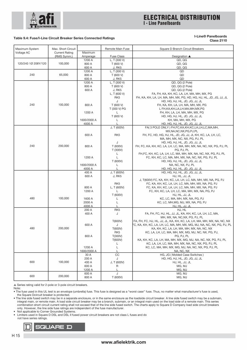
s Series rating valid for 2-pole or 3-pole circuit breakers.Note:• The fuse used in this UL test is an envelope (umbrella) fuse. This fuse is designed as a “worst case’’ fuse. Thus, no matter what manufacturer’s fuse is used,
the Square Dcircuit breaker is protected.• The line side fused switch may be in a separate enclosure, or in the same enclosure as the loadside circuit breaker. A line side fused switch may be a submain,
integral main, or remote main. A load side circuit breaker may be a branch, submain, or an integral main used on the load side of a remote main. This series combination short circuit current rating shall not exceed that of the line side fused switch. The charts apply to Square D Company load side circuit breakers only. However, the line side fuse ratings are independent of the fuse manufacturer.
• Not applicable to Corner Grounded Systems.• Limiters used in Square D DSL and DSL II fused power circuit breakers are not class L fuses and do not have series ratings.
Remote Main Fuse Square D Branch Circuit BreakersMaximumAmperage Fuse Class Designation s
1200 A L, T (300 V) QD, QG800 A T (600 V) QD, QG600 A J, RK5 QD, QG1200 A L, T (300 V) QD800 A T (600 V) QD600 A J, RK5 QD1200 A L, T (300 V) QD, QG (2 Pole)800 A T (600 V) QD, QG (2 Pole)600 A J, RK5 QD, QG (2 Pole)
L, T (600 V) FA, FH, KA, KH, KC, LA, LH, MA, MH, MX, PGRK5 FH, KA, KH, LA, LH, MA, MH, MX, PG, HD, HG, HJ, HL, JD, JG, JJ, JL
J HD, HG, HJ, HL, JD, JG, JJ, JL800 A T (600 V) FH, KA, KH, LA, LH, MA, MH, MX, PG
T (300 V) PG L FH,KA,KH,LA,LH,MA,MH,MX,PG1200 A L FH, KH, LA, LH, MA, MH, MX, PG
T (600 V) HD, HG, HJ, HL, JD, JG, JJ, JL1600/2000 A L KH, MA, MH, MX, PG
4000 A L HD, HG, HJ, HL, JD, JG, JJ, JLJ, T (600V) FA( 3 POLE ONLY ) FH,FC,KA,KH,KC,LA,LH,LC,MA,MH,
MX,NA,NC,NX,PG,PJ,PL600 A RK5 FH, FC, HD, HG, HJ, HL, JD, JG, JJ, JL KH, KC, LA, LH, LC,
MA, MH, MX, NC, NX, PG, PJ, PLJ HD, HG, HJ, HL, JD, JG, JJ, JL
800 A T (600V) FH, FC, KA, KH, KC, LA, LH, LC, MA, MH, MX, NA, NC, NX, PG, PJ, PLT (300V) PG, PJ, PL
L FH,FC, KH, KC, LA, LH, LC, MA, MH, MX, NA, NC, NX, PG, PJ, PL1200 A L FC, KH, KC, LC, MA, MH, MX, NA, NC, NX, PG, PJ, PL
T (600V) HD, HG, HJ, HL, JD, JG, JJ, JL1600/2000 A L NA, NC, NX, PJ, PL
4000 A L HD, HG, HJ, HL, JD, JG, JJ, JL400 A J, T (600V) HD, HG, HJ, HL, JD, JG, JJ, JL600 A J, RK5 HJ, HL, JJ, JL
J, T(600V) FC, KA, KH, KC, LA, LH, LC, MA, MH, MX, NA, PG, PJRK5 FC, KA, KH, KC, LA, LH, LC, MA, MH, MX, NA, PG, PJ
800 A L, T (600V) FC, KA, KH, KC, LA, LH, LC, MA, MH, MX, NA, PG, PJ1200 A L FC, KH, KC, LA, LH, LC, MA, MH, MX, NA, PG, PJ
T (600V) HJ, HL, JJ, JL1600 A L KC, LC, MA, MH, MX, NA, PG, PJ2000 A L KC, LC, MH,MG, MJ, MX, NA, PG, PJ4000 A L HJ, HL, JJ, JL200 A RK5 HJ, HL400 A J FA, FH, FC, HJ, HL, JJ, JL, KA, KH, KC, LA, LH, LC, MA,
MH, MX, NA, NC,NX, PG, PJ, PLT(600V) FA, FH, FC, HJ, HL, JJ, JL, KA, KH, KC, LA, LH, MA, MH, MX, NA, NC, NX
600 A J FC, KA, KH, KC, LA, LH, LC, MA, MH, MX, MG, MJ, NA, NC, NX, PG, PJ, PLT(600V) KA, KH, KC, LA, LH, MA, MH, MX, NA, NC, NX
RK5 KC, LA, LH, LC, MA, MH, MX, MG, MJ, NC, NX, PG, PJ,800 A T(300V) PG, PJ, PL
T(600V) KA, KH, KC, LA, LH, MA, MH, MX, MG, MJ, NA, NC, NX, PG, PJ, PLL KC, LA, LH, LC, MA, MH, MX, NA, NC, NX, PG, PJ, PL
1200 A L KC, LC, MA, MH, MX, MG, MJ, NA, NC, NX, PG, PJ, PL1600/2000 A L NA, NC, NX
30 A CC HG, JG ( Molded Case Switches )200 A J HD, HG, HJ, HL, JD, JG, JJ, JL400 A J, T (600V) HJ, HL, JJ, JL600 A R MG, MJ1200 A L MG, MJ600 A J MG, MJ800 A T (600V) MG, MJ
Maximum System Max. Short CircuitVoltage AC Current Rating
(RMS Symm.)
120/240 1Ø 208Y/120 100,000
240 65,000
240 100,000
240 200,000
480 100,000
480 200,000
600 100,000
600 200,000
ELECTRICAL DISTRIBUTIONI - Line Panelboards
Table 9.4: Fuse/I-Line Circuit Breaker Series Connected Ratings I-Line® PanelboardsClass 2110
www.afielektrik.comH 15

Tota
l Circ
uit B
reak
erM
ount
ing
Spac
e (I
n.)
Mai
ns A
mpe
re R
aitin
g
Box
Heig
ht (I
n.)Interior Assembly
(Less Branch)
Circuit Breakers)
Catalog Number
Front Box
4 Piece TrimWithout Door
TrimWith Door Type 1
NEMA3R/5/12
(Includes Front)
Catalog Number Catalog Number Catalog Number Catalog Number
27
45
63
99
225400600800225400600800225400600800225400600800
HCM14482NHCM14484HCM14486HCM14488
HCM23642NHCM23644HCM23646HCM23648
HCM32732NHCM32734HCM32736HCM32738
HCM50912NHCM50914HCM50916HCM50918
HCM48T D
HCM64T D
HCM73T D
HCM91T D
HC3248B
HC3264B
HC3273B
HC3291B
HC3248WP
HC3264WP
HC3273WP
HC3291WP
48
64
73
91
HCM48T
HCM64T
HCM73T
HCM91T
HCP-SU Universal Single Row Main Lugs or Main Circuit Breaker3-pole-Suitable for use as service equipment when provided with a main circuit breaker.
54 800 HCP54868SU HC2686T 4P HC2686T HR HC2686DB HC2886WP 86
HCN Main Lugs Only3-pole-Suitable for use as service equipment when provided with a main circuit breaker.
27
45
63
81
99
225400600225400600225400600225400600225400600
HCN14522NHCN14524HCN14526
HCN23652NHCN23654HCN23656
HCN32742NHCN32744HCN32746
HCN41832NHCN41834HCN41836
HCN50922NHCN50924HCN50926
HCN52T
HCN65T
HCN74T
HCN83T
HCN92T
HCN52T D
HCN65T D
HCN74T D
HCN83T D
HCN92T D
HC2652B
HC2665B
HC2674B
HC2683B
HC2692B
HC2652WP
HC2665WP
HC2674WP
HC2683WP
HC2692WP
52
65
74
83
92
HCN Main Circuit Breaker tIncludes 3-pole, vertically mounted main circuit breaker-Suitable for use service equipment
18
27
36
45
54
63
8190
100225400100225400100225225400400225
HCN095221MNHCN09522MNHCN14654M
HCN18651MNHCN18652MNHCN23744M
HCN27741MNHCN27742MNHCN32832MNHCN32834MHCN41924MHCN45922M
HCN52T
HCN65T
HCN74T
HCN83T
HCN92T
HCN52T D
HCN65T D
HCN74T D
HCN83T D
HCN92T D
HC2652B
HC2665B
HC2674B
HC2683B
HC2692B
HC2652WP
HC2665WP
HC2674WP
HC2683WP
HC2692WP
52
65
74
83
92
HCN Main Lugs Only3-pole-Suitable for use as service equipment when provided with a main circuit breaker.
HCM Main Circuit Breaker tIncludes 3-pole, vertically mounted main circuit breaker-Suitable for use service equipment27
36
4554
72
81
400225600800400225600800400
HCM14644MHCM18642MNHCM18736MPHCM18738MPHCM23734M
HCM27732MNHCM36916MPHCM36918MPHCM41914M
HCMT64T
HCM73T
HCM73T
HCM91T
HCM91T
HCMT64T D
HCM73T D
HCM73T D
HCM91T D
HCM91T D
HC3264B
HC3273DB9
HC3273B
HC3291DB9
HC3291B
HC3264WP
Use HCP
HC3273WP
Use HCP
HC3291WP
64
-
73
-
91
ê
s Add “F’’ for Flush or “S’’ for Surface.n Add-on door kit available from Peru. Example: For HCM48TS surface trim kit, order HCM48DS door kit.t For Type 1 applications, order interior, front, and box. For Type 3R/5/12 applications, order interior and box only. The front is included with the box.« Remove drain screws for Type 3R rating.t Bottom feed standard, for top feed main circuit breaker specify at time of order.ê Hinged trim with door.¨ For main lugs panel, order sub-feed lug kit and back-feed as main lugs.
For main circuit breaker panel, order plug-on I-LINE type PG, PJ, PL, MG or MJ circuit breakers from 9-28 through 9-30 and backfeed as the main breaker (order solid neutral from 9-22).
P Suitable for use as service equipment if equipped with an integral main circuit breaker or when not more than six main disconnecting means are provided and the panelboard is not used as a lighting and appliance branch circuit panelboard.PG, PJ, PL circuit breakers are available with both thermal-magnetic equivalent and Micrologic trip. The Micrologic circuit breakers are available 80% and 100% rated. “C” suffix denotes a 100% rating.Circuit breaker interrupt ratings, starting on page 7-2.
* I-Line Surgelogic TVSS not available.DB9 box is 9.5 inches deep.
ELECTRICAL DISTRIBUTIONI-Line Merchandised Panelboards
TYPE HCN225 A max. (240 V max.) branchcircuit breaker QB, QD, QG, QJ150 A max. branch circuitbreaker FA, FH, FY, HD, HG, HJ,HL *
TYPE HCM250 A max. branch circuitbreakerFA, FH, FY, FI, QB, QD, QG, QJ,HD, HG, HJ, HL, JD, JG, JJ, JL
Box Size:26 in. Wide, 6.5 in. Deep
Box Size:32 in. Wide, 8.25 in. Deep
TYPE HCP-SUh800 A max. main circuit breaker600 A max. branch circuitbreakerFY, FA, FH, FI, KI, LA, LH, LC,LX, LI, LXI, LE, MG, MJ, PG, PJ,PL, PGC, PJC, PLCj, QB, QD,QG, QJ, HD, HG, HJ, HL, JD,JG, JJ, JL
Box Size:26 in. Wide, 9.5 in. Deep
I-Line® MerchandisedPanelboards
Table 9.96: Interiors, Boxes and Fronts(100 A and 225 A interiors include solid neutral, all others without solid neutral. Order solid neutral from 9-23)
www.afielektrik.comH 16

Table 9.99: Main Circuit Breaker Interiors -Standard Frame Types s
PanelboardType
Factory SuppliedMain Circuit Breaker
Main CircuitBreaker Ampacity
100225
400
600or
800
HCNHCN, HCM
HCNHCM
HCM, HCP
FA36100KA36225
LAP36400MBLAP36400MB
MGP36600or
MGP36800
s Circuit breaker interrupt ratings, starting on page 7-2.
Table 9.100: Standard Copper Bus Interiors s
Type
HCNHCN, HCP-SUHCP, HCR-U
Main Ampacity
600800
800 & Above
s Merchandised copper interiors are not available in all ampacities.Example: Application calls for a HCN 225A copper bus interior,order a HCN 600A interior See table 9.100
FYFA, FHFA. FHFA, FH, FI, SL-100HD, HGHD, HG, HJ, HLQB, QD, QG, QJ
Table 9.98: Circuit Breaker/Sub-feed Lug Kit Mounting Inch Requirement
112
2, 32
2, 32
1,5 in.1,5 in.3 in.
4,5 in.3 in.
4,5 in.3 in.
QB, QD, QG, QJJD, JG, JJ, JL, KI, SL250LA, LH, Q4, SL400LC, LI, LX, LXI, LEMG, MJ, MA, MH, SL800PG, PJ, PL, PGC, PJC, PLC, S33931RGC, RJC, RLC, S33930
30A
100A
150A
225A
225 A250 A400 A600 A800 A
1200 A1200 A
3
2,3
2, 3
4,5 in.4,5 in.
6 in.7.5 in.
9 in.15 in.
Type of Circuit BreakerMaximumAmpacity
No. ofPoles
MountingRequirement Type of Circuit Breaker
MaximumAmpacity
No. ofPoles
MountingRequirement
Tota
l Circ
uit
Bre
aker
Mou
ntin
g S
pac
e (I
n.)
Mai
ns A
mp
ere
Rai
ting
HCN Main Lugs Only3-pole-Suitable for use as service equipment when provided with a main circuit breaker.
Interior Assembly
(Less Branch)
Circuit Breakers)
Catalog Number
Front s Box t
Box
Hei
ght
(In.)
4 Piece TrimWithout Door n
TrimWith Door
Catalog Number Catalog Number Catalog Number Catalog Number
Max.No of
LC,MJ, PL, RL
Circuit Breakers
27
45
63
99
400600800
1200400600800
1200400600800
1200400600800
1200
1PL
2PL
3PL
5PL
HCP14504HCP14506HCP14508
HCP145012NHCP23594HCP23596HCP23598
HCP235912NHCP32684HCP32686HCP32688
HCP326812NHCP50864HCP50866HCP50868
HCP508612N
HCW50T
HCW59T
HCW68T
HCW86T
HCW50T D
HCW59T D
HCW68T D
HCW86T D
HC4250DB
HC4259DB
HC4268DB
HC4286DB
50
59
68
86
HCP Main Circuit Breakere—Includes 3-poleVertically mounted main circuit breaker—Suitable for use as service equipment.
36
72
600800600800
2LC
4LC
HCP18686MHCP18688MHCP36866MHCP36868M
HCW68T
HCW86T
HCW68T D
HCW86T D
HC4268DB
HC4286DB
68
86
ELECTRICAL DISTRIBUTIONI - Line Panelboards
TYPE HCP800 A max. branchcircuit breakerFAa, FH, FI, FY, QB, QD,QG, QJ, HD, HG, HJ, HL, JD,JG, JJ, JL, KI, Q4, LA, LH,LC, LI, LX, LXI, LE, MG, MJ,PG, PJ, PL, PGC, PJC,PLCb
Box Size:2 in.Wide, 9.5 in. Deep
s FA and KA circuitbreakers with fieldinstallable ground faultkits may be mounted intype HCP, HCP-SU andHCR-U panelboards asshown, and require Lframe mounting space.n PG, PJ, PL circuitbreakers are availablewith both thermalmagneticequivalentand Micrologic trip. TheMicrologic circuitbreakers are available80% and 100% rated.“C” suffix denotes a100% rating.
TYPE HCR-UUniversal Mains1200 A max. branchcircuit breakerFAa, FH, FI, FY, QB, QD,QG, QJ, HD, HG, HJ, HL, JD,JG, JJ, JL, KI, Q4, LA, LH,LC, LI, LX, LXI, LE, MG, MJ,PG, PJ, PL, PGC, PJC, PCL,RGC, RJC, RLCbc
Box Size:44 in.Wide, 9.5 in. Deep
s FA and KA circuitbreakers with fieldinstallable ground faultkits may be mounted intype HCP, HCP-SU andHCR-U panelboards asshown, and require Lframe mounting space.n When RL main circuitbreakers withequipment ground faultare applied on a 3Ø4Wsystem, order solidneutral catalog numberHCR12SNCT. TheHCR12SNCT includesa neutral currenttransformer.t PG, PJ, PL circuitbreakers are availablewith both thermalmagneticequivalentand Micrologic trip. TheMicrologic circuitbreakers are available80% and 100% rated.“C” suffix denotes a100% rating.
I-Line® MerchandisedPanelboards
600 Vac, 250 Vdc10/Refer to Catalog 2110CT9701
Table 9.97: (1200 A Interiors Include solid neutral, all others without solid neutral.Order solid neutral from 9-23.)
Add “F’’ for Flush or “S’’ for Surface.Add-on door kit available. Example: For HCW50TS trim kit, order HCW50D door kit.See 9-23 for 42 in. wide weatherproof enclosures.Suitable for use as service equipment if equipped with an integral main circuit breaker or when not more than six main disconnecting means are provided and the panelboard is not used as a lighting and appliance branch circuit panelboard.Circuit breaker interrupt ratings, starting on page 7-2.When RL main circuit breakers with equipment ground fault are applied on a 3Ø4W system, order solid neutral catalog number HCR12SNCT.The HCR12SNCT includes a neutral current transformer.15 in. of mounting space is taken up by the back fed main lug kit or RG, RJ, RL main circuit breaker, leaving 93 in. of branch circuit breaker mounting space.Add-on door kit available. Example: For HCR86TS trim kit, order HCW86D door kit.
HCR-U Universal Main Lugs or Main Circuit Breakere—3-poleSuitable for use as service equipment when provided with a main circuit breaker.For MAIN LUGS panel, order sub-feed lug kit catalog number S33930 and back feed as main lugs.For MAIN CIRCUIT BREAKER panel, order plug-on I-LINE type PG, PJ, PL, RGC, RJC or RLCf circuit breakers from pages 9-27 through 9-29,and back feed as the main circuit breaker. (Order solid neutral separately)
108 1200 6PL or 3RLC HCR548612U HCW86T HCW86T D HC4486DB 86
▲nt«
tê
¨
¨
www.afielektrik.comH 17

Blank Fillers—1.5 in. (3 per pkg.) HNM1BLBlank Fillers—4.5 in. (5 per pkg.) HNM4BLSolid Neutral Assemblies
225 A HC2SN400 A HC4SNs, HCW4SN n600 A HC6SNs, HCW6SN n HC8SNs, HCW8SN n800 HCPSU8SN u
HCPSU8SNCTu1200 A HCW12SN n1200 A, for use with HCR-U universal panel only HCWM12SN H1200 A, Including neutral CT for 3Ø4W systems HCR12SNCTH
Equipment Ground Bar Kits—HCN PK27GTAHCM, HCP, HCR-U PK32DGTABlank Extensions—(For replacement purposes only in 1.5 in. (3 per pkg.) HLW1BLType HCP, HCR-U panelboards) 4.5 in. (5 per pkg.) HLW4BL
Description Catalog No.
400 A HCN400VCA HCM400VCA HCW400VCA600 A HCN600VCA HCM600VCA HCW600VCA800 A — HCM800VCA HCW800VCA1200 A — — HCW1200VCA
Crimp Lug Adapker Kits s
Table 9.102: Panelboard Adapter KitsI-Line Panelboard Type
HCN HCM HCP, HCR-U n
Catalog Number
Table 9.103: Type 3R/5/12 EnclosuresDimensions
Interior Type H W D
HC4250WP HCP 50 42 12.95HC4259WP HCP 59 42 12.95HC4268WP HCP 68 42 12.95HC4286WP HCP 86 42 12.95HC4486WP HCR-U 86 44 14.50
Catalog Number
Table 9.104: Box ExtensionsInterior Type Extension
HC2609DEX (F or S) HCP-SU 9 in.HC2609EX (F or S) HCN 9 in.HC3209EX (F or S) HCM 9 in.HC4212DEX (F or S) HCP 12 in.HC4406DEX (F or S) HCR-U 6 in.HC4412DEX (F or S) HCR-U 12 in.
100 4.5 114 SL100 65,000 25,000 18,000 FH 250 4.5 114 SL250 125,000 100,000 50,000 JL250 4.5 114 SL250 200,000 200,000 100,000 KI400 6 152 SL400 n 65,000 35,000 25,000 LH 800 9 229 SL800 65,000 65,000 25,000 MH
1200 9 229 S33931 100,000 65,000 25,000 MJ, PJ1200 15 381 S33930 125,000 100,000 50,000 RL
HCN, HCM, HCP, HCP-SU
HCM, HCP, HCP-SU
HCP, HCP-SUHCM, HCP, HCP-SU
HCP, HCP-SU, HCR-U
AmpereRating
Table 9.105: Sb-feed Lug Kits s
CatalogNumber
HeightIN (mm)
Protected byCircuit Breaker
For Use in I-LINEPanelboard Types
Max. Short Circuit System RatingsRMS Symmetrical Amperes
240 Vac 480 Vac 600 Vac
Catalog Number(Prefix)
Table 9.106: Sub-feed Lug kit terminal data
Std. Lug KitCatalog No. Standard Lug Wire Size s
SL100 3 100 AL100FA #14–1/0 AWG Cu or #12–1/0 AWG AlSL250 3 250 — #4 AWG–300 kcmilSL400 3 400 AL400LA one #1 AWG–600 kcmil or two #1 AWG–250 kcmilSL800 3 800 AL900MA (3) #3/0 AWG–500 kcmilS33931 3 1200 AL1200P24K (4) #3/0 AWG–500 kcmilS33930 3 1200 AL1200R53K (4) #3/0 AWG–600 kcmil
No.Poles
AmpereRating
Table 9.101: I-Line Merchandised Panelboard Accessories
s Used on Type HCN, HCM.n Used on 400 A, 600 A, 800 A, 1200 A HCP (main lugs), and 600 A, 800 A (main circuit breaker).u Used on Type HCP-SU.H Used on Type HCR-U.
s For use with MLO panel, order VCEL lugs seperately.n Not for use with P- or R-frame circuit breakers or sub-feed kits S33930 or S33931.
s Plug-on in same manner as a branch circuit breakern SL400 cannot be used in HCM panelboards due to inadequate wire bending space
s Unless otherwise specified, wire sizes apply to both aluminum and copper conductors.
For Surgelogic® I-Line plug-on TVSS unit pricing and information, refer to Section 6 pages 3-4.For Field Installable I-Line Door Kits see the Supplemental & Obsolescence Digest section 4.
ELECTRICAL DISTRIBUTIONI-Line Merchandised Accessories
I-Line® MerchandisedPanelboards
AccessoriesClass 690, 2110/Refer to Catalog 2110CT9701
www.afielektrik.comH 18