Copeland-Electrical-Handbook.pdf - InspectAPedia.com
543
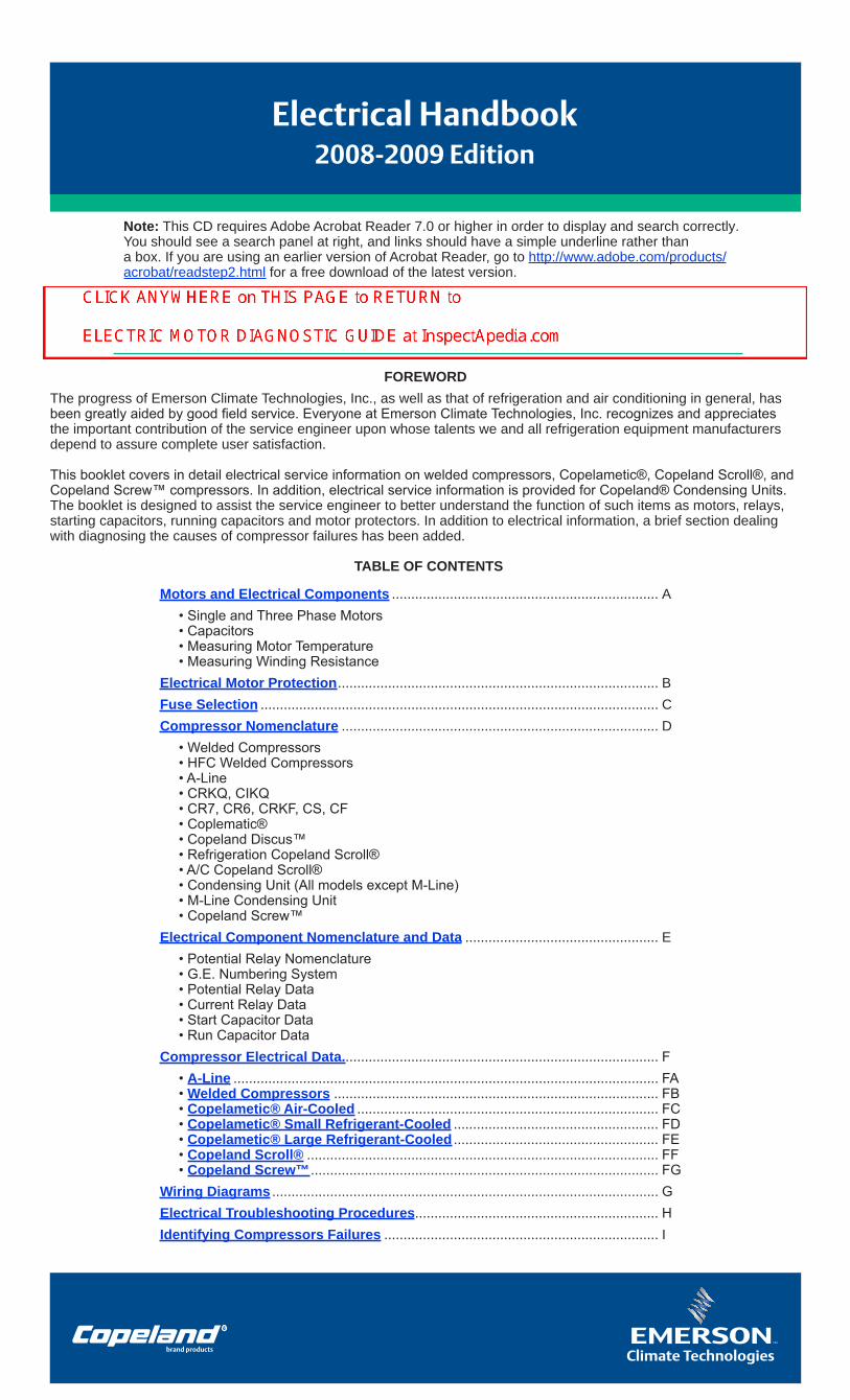
Electrical Handbook 2008-2009 Edition Note: This CD requires Adobe Acrobat Reader 7.0 or higher in order to display and search correctly. You should see a search panel at right, and links should have a simple underline rather than a box. If you are using an earlier version of Acrobat Reader, go to http://www.adobe.com/products/ acrobat/readstep2.html for a free download of the latest version. TABLE OF CONTENTS Motors and Electrical Components ..................................................................... A • Single and Three Phase Motors • Capacitors • Measuring Motor Temperature • Measuring Winding Resistance Electrical Motor Protection................................................................................... B Fuse Selection ....................................................................................................... C Compressor Nomenclature .................................................................................. D • Welded Compressors • HFC Welded Compressors • A-Line • CRKQ, CIKQ • CR7, CR6, CRKF, CS, CF • Coplematic® • Copeland Discus™ • Refrigeration Copeland Scroll® • A/C Copeland Scroll® • Condensing Unit (All models except M-Line) • M-Line Condensing Unit • Copeland Screw™ Electrical Component Nomenclature and Data .................................................. E • Potential Relay Nomenclature • G.E. Numbering System • Potential Relay Data • Current Relay Data • Start Capacitor Data • Run Capacitor Data Compressor Electrical Data.................................................................................. F • A-Line .............................................................................................................. FA • Welded Compressors .................................................................................... FB • Copelametic® Air-Cooled .............................................................................. FC • Copelametic® Small Refrigerant-Cooled ..................................................... FD • Copelametic® Large Refrigerant-Cooled ..................................................... FE • Copeland Scroll® ........................................................................................... FF • Copeland Screw™.......................................................................................... FG Wiring Diagrams .................................................................................................... G Electrical Troubleshooting Procedures............................................................... H Identifying Compressors Failures ....................................................................... I FOREWORD The progress of Emerson Climate Technologies, Inc., as well as that of refrigeration and air conditioning in general, has been greatly aided by good field service. Everyone at Emerson Climate Technologies, Inc. recognizes and appreciates the important contribution of the service engineer upon whose talents we and all refrigeration equipment manufacturers depend to assure complete user satisfaction. This booklet covers in detail electrical service information on welded compressors, Copelametic®, Copeland Scroll®, and Copeland Screw™ compressors. In addition, electrical service information is provided for Copeland® Condensing Units. The booklet is designed to assist the service engineer to better understand the function of such items as motors, relays, starting capacitors, running capacitors and motor protectors. In addition to electrical information, a brief section dealing with diagnosing the causes of compressor failures has been added.
-
Upload
khangminh22 -
Category
Documents
-
view
0 -
download
0
Transcript of Copeland-Electrical-Handbook.pdf - InspectAPedia.com
Electrical Handbook2008-2009 Edition
Note: This CD requires Adobe Acrobat Reader 7.0 or higher in order to display and search correctly.You should see a search panel at right, and links should have a simple underline rather than a box. If you are using an earlier version of Acrobat Reader, go to http://www.adobe.com/products/acrobat/readstep2.html for a free download of the latest version.
TABLE OF CONTENTS
Motors and Electrical Components ..................................................................... A• Single and Three Phase Motors• Capacitors• Measuring Motor Temperature• Measuring Winding Resistance
Electrical Motor Protection ................................................................................... BFuse Selection ....................................................................................................... CCompressor Nomenclature .................................................................................. D
• Welded Compressors• HFC Welded Compressors• A-Line• CRKQ, CIKQ• CR7, CR6, CRKF, CS, CF• Coplematic®• Copeland Discus™• Refrigeration Copeland Scroll®• A/C Copeland Scroll®• Condensing Unit (All models except M-Line)• M-Line Condensing Unit• Copeland Screw™
Electrical Component Nomenclature and Data .................................................. E• Potential Relay Nomenclature• G.E. Numbering System• Potential Relay Data• Current Relay Data• Start Capacitor Data• Run Capacitor Data
Compressor Electrical Data.................................................................................. F• A-Line .............................................................................................................. FA• Welded Compressors .................................................................................... FB• Copelametic® Air-Cooled .............................................................................. FC• Copelametic® Small Refrigerant-Cooled ..................................................... FD• Copelametic® Large Refrigerant-Cooled ..................................................... FE• Copeland Scroll® ........................................................................................... FF• Copeland Screw™ .......................................................................................... FG
Wiring Diagrams .................................................................................................... GElectrical Troubleshooting Procedures............................................................... HIdentifying Compressors Failures ....................................................................... I
FOREWORDThe progress of Emerson Climate Technologies, Inc., as well as that of refrigeration and air conditioning in general, has been greatly aided by good field service. Everyone at Emerson Climate Technologies, Inc. recognizes and appreciates the important contribution of the service engineer upon whose talents we and all refrigeration equipment manufacturers depend to assure complete user satisfaction.
This booklet covers in detail electrical service information on welded compressors, Copelametic®, Copeland Scroll®, and Copeland Screw™ compressors. In addition, electrical service information is provided for Copeland® Condensing Units. The booklet is designed to assist the service engineer to better understand the function of such items as motors, relays, starting capacitors, running capacitors and motor protectors. In addition to electrical information, a brief section dealing with diagnosing the causes of compressor failures has been added.
CLICK ANYWHERE on THIS PAGE to RETURN to ELECTRIC MOTOR DIAGNOSTIC GUIDE at InspectApedia.com
SECTION A
MOTORS AND ELECTRICAL COMPONENTS
TOPICS Single Phase Motors ...................................................A2Start Relays .................................................................A3Start Capacitors ...........................................................A5Run Capacitors ............................................................A7Parallel and Series Capacitors ....................................A9Measuring Motor Temperature ..................................A10Measuring Winding Resistance .................................A11Resistance Measurements for Single Voltage Motors................................................A13Resistance Measurements for Dual Voltage Motors .............................................A15
Section A.indd 1Section A.indd 1 2/6/2008 10:46:30 AM2/6/2008 10:46:30 AM
A2
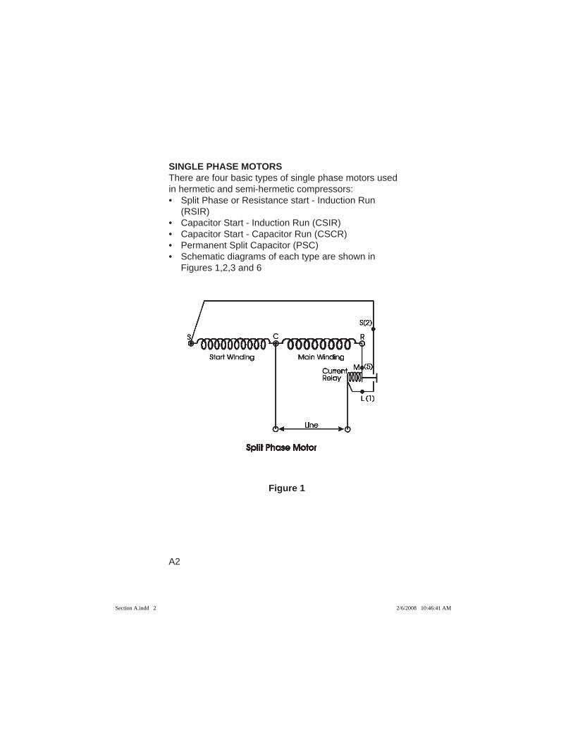
SINGLE PHASE MOTORSThere are four basic types of single phase motors used in hermetic and semi-hermetic compressors: • Split Phase or Resistance start - Induction Run
(RSIR) • Capacitor Start - Induction Run (CSIR) • Capacitor Start - Capacitor Run (CSCR) • Permanent Split Capacitor (PSC) • Schematic diagrams of each type are shown in
Figures 1,2,3 and 6
Figure 1
Section A.indd 2Section A.indd 2 2/6/2008 10:46:41 AM2/6/2008 10:46:41 AM
A3
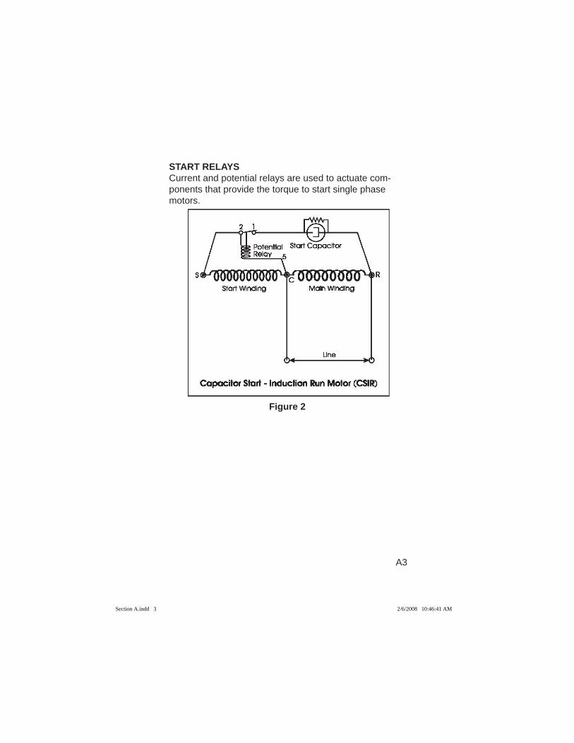
START RELAYSCurrent and potential relays are used to actuate com-ponents that provide the torque to start single phase motors.
Figure 2
Section A.indd 3Section A.indd 3 2/6/2008 10:46:41 AM2/6/2008 10:46:41 AM
A4
The Current RelayCurrent relays are used on small fractional horsepower compressor motors. The current relay contacts are normally open when de-energized. Its coil is wound with heavy wire and is placed in series with the incoming power line (Figure 1). The connections to the current relay are L, M, and S. Alternate connections are 1,5, and 2. When the compressor is energized inrush currents pass through the current relay coil, and its contacts close and connect the start winding to the motor circuit. The start winding is wound with a higher resistance than the run winding. This changes its phase current with respect to the run winding and produces the torque required for motor starting. The relay’s contacts open when current drops as the compressor comes up to speed, and the start winding is disconnected from the motor circuit.
The Potential RelayThe potential (voltage sensing) relay places the start capacitor in series with the start winding. It does so by sensing voltage across the start winding, rather than line current as does the current relay.
The contacts of the potential relay are normally closed (Figures 2, and 3), and the start capacitor is connected to the start winding as soon as power is applied to the compressor motor. The relay’s coil senses the voltage developed across the start winding. It is designed to pick up, open its contacts, and disconnect the start capacitor from the start winding, when suffi cient voltage is gener-ated. Since the voltage or back-EMF generated by the start winding is proportional to motor speed, the relay will open only when the motor has started and is approach-ing normal running speed.
Section A.indd 4Section A.indd 4 2/6/2008 10:46:41 AM2/6/2008 10:46:41 AM
A5
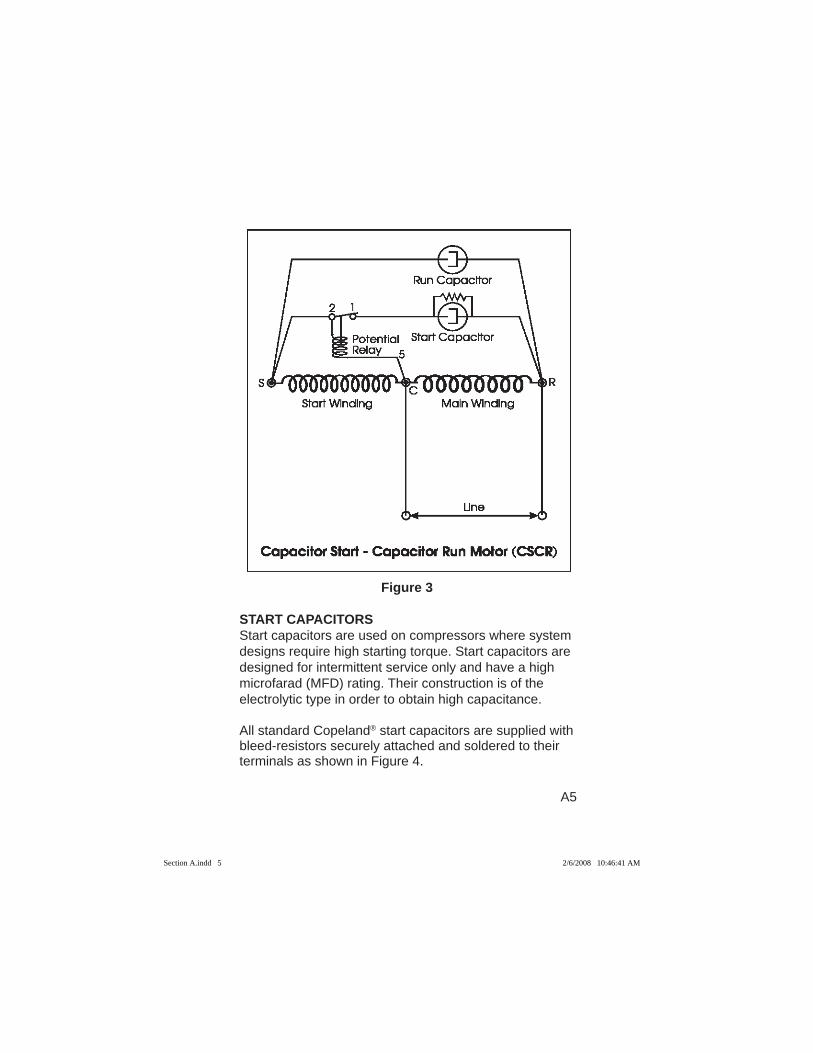
Figure 3
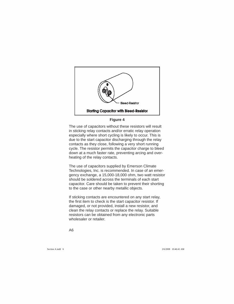
START CAPACITORSStart capacitors are used on compressors where system designs require high starting torque. Start capacitors are designed for intermittent service only and have a high microfarad (MFD) rating. Their construction is of the electrolytic type in order to obtain high capacitance. All standard Copeland® start capacitors are supplied with bleed-resistors securely attached and soldered to their terminals as shown in Figure 4.
Section A.indd 5Section A.indd 5 2/6/2008 10:46:41 AM2/6/2008 10:46:41 AM
A6
Figure 4
The use of capacitors without these resistors will result in sticking relay contacts and/or erratic relay operation especially where short cycling is likely to occur. This is due to the start capacitor discharging through the relay contacts as they close, following a very short running cycle. The resistor permits the capacitor charge to bleed down at a much faster rate, preventing arcing and over-heating of the relay contacts.
The use of capacitors supplied by Emerson Climate Technologies, Inc. is recommended. In case of an emer-gency exchange, a 15,000-18,000 ohm, two watt resistor should be soldered across the terminals of each start capacitor. Care should be taken to prevent their shorting to the case or other nearby metallic objects.
If sticking contacts are encountered on any start relay, the fi rst item to check is the start capacitor resistor. If damaged, or not provided, install a new resistor, and clean the relay contacts or replace the relay. Suitable resistors can be obtained from any electronic parts wholesaler or retailer.
Section A.indd 6Section A.indd 6 2/6/2008 10:46:41 AM2/6/2008 10:46:41 AM
A7
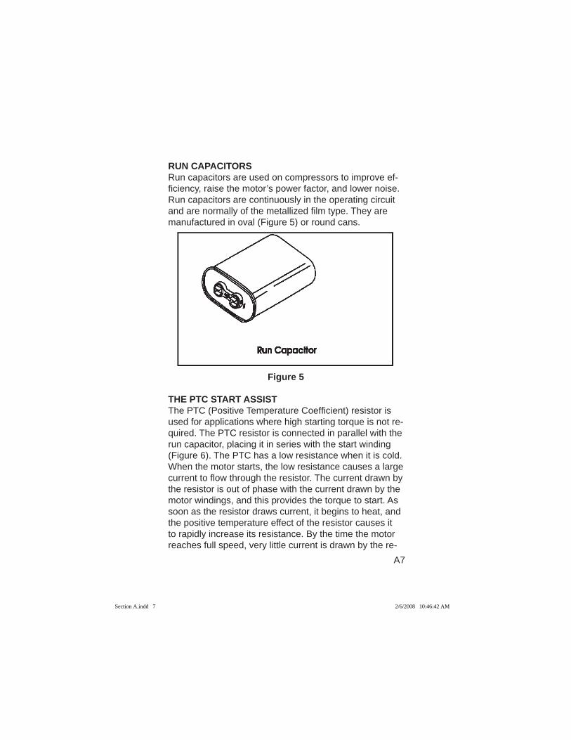
RUN CAPACITORSRun capacitors are used on compressors to improve ef-fi ciency, raise the motor’s power factor, and lower noise.Run capacitors are continuously in the operating circuit and are normally of the metallized fi lm type. They are manufactured in oval (Figure 5) or round cans.
Figure 5
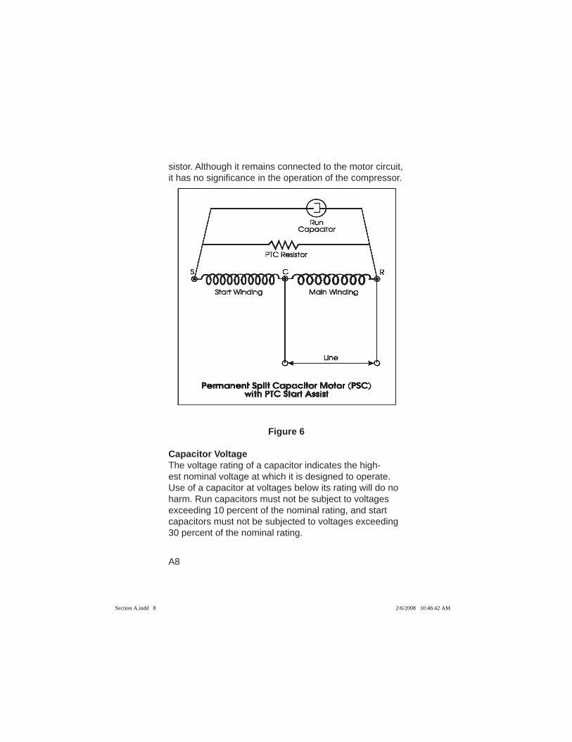
THE PTC START ASSISTThe PTC (Positive Temperature Coeffi cient) resistor is used for applications where high starting torque is not re-quired. The PTC resistor is connected in parallel with the run capacitor, placing it in series with the start winding (Figure 6). The PTC has a low resistance when it is cold. When the motor starts, the low resistance causes a large current to fl ow through the resistor. The current drawn by the resistor is out of phase with the current drawn by the motor windings, and this provides the torque to start. As soon as the resistor draws current, it begins to heat, and the positive temperature effect of the resistor causes it to rapidly increase its resistance. By the time the motor reaches full speed, very little current is drawn by the re-
Section A.indd 7Section A.indd 7 2/6/2008 10:46:42 AM2/6/2008 10:46:42 AM
A8
sistor. Although it remains connected to the motor circuit, it has no signifi cance in the operation of the compressor.
Figure 6
Capacitor VoltageThe voltage rating of a capacitor indicates the high-est nominal voltage at which it is designed to operate. Use of a capacitor at voltages below its rating will do no harm. Run capacitors must not be subject to voltages exceeding 10 percent of the nominal rating, and start capacitors must not be subjected to voltages exceeding 30 percent of the nominal rating.
Section A.indd 8Section A.indd 8 2/6/2008 10:46:42 AM2/6/2008 10:46:42 AM
A9
The voltage to which a capacitor is subjected is not line voltage, but is a much higher potential (often called back electromotive force or back EMF) which is generated in the start winding. On a typical 230 volt motor, the gener-ated voltage may be as high as 400 volts and is deter-mined by the start winding characteristics, the compres-sor speed, and the applied voltage.
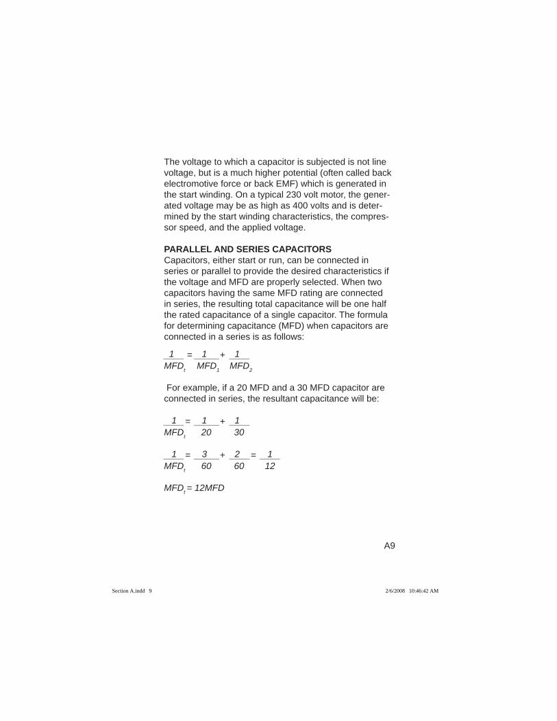
PARALLEL AND SERIES CAPACITORSCapacitors, either start or run, can be connected in series or parallel to provide the desired characteristics if the voltage and MFD are properly selected. When two capacitors having the same MFD rating are connected in series, the resulting total capacitance will be one half the rated capacitance of a single capacitor. The formula for determining capacitance (MFD) when capacitors are connected in a series is as follows:
1 1 1____ = _____+ ____MFDt MFD1 MFD2 For example, if a 20 MFD and a 30 MFD capacitor are connected in series, the resultant capacitance will be:
1 1 1____= _____+ ____MFDt 20 30 1 3 2 1____= _____+ ____= ____MFDt 60 60 12
MFDt = 12MFD
Section A.indd 9Section A.indd 9 2/6/2008 10:46:42 AM2/6/2008 10:46:42 AM
A10
The voltage rating of similar capacitors connected in series is equal to the sum of the voltage of the two capacitors. However, since the voltage across individual capacitors in series will vary with the rating of the capaci-tor, for emergency fi eld replacements, it is recommended that only capacitors of like voltage and capacitance be connected in series to avoid the possibility of damage due to voltage beyond the capacitor limits.
When capacitors are connected in parallel, their MFD rating is equal to the sum of the individual capacitances. The voltage rating is equal to the lowest voltage rating of the individual capacitors.
It is possible to use any combination of single, series, or parallel start capacitors, with single or parallel run capacitors (run capacitors are seldom used in series). MEASURING MOTOR TEMPERATUREDuring system engineering development or in attempting to evaluate the ability of a compressor motor to operate under severe conditions, it is often desirable to measure motor temperatures under extreme conditions. In the laboratory during compressor development, tempera-ture measurements of this type are made by means of thermocouples embedded in the motor windings with the leads brought out through gasketed surfaces. In evaluat-ing a production compressor in a system, thermocouple readings are not usually feasible, and the only means of checking motor temperatures is by checking resistance values.
The resistance through the motor windings varies in a ratio to the change in winding temperature. By establish-
Section A.indd 10Section A.indd 10 2/6/2008 10:46:42 AM2/6/2008 10:46:42 AM
A11
ing a base resistance value at a given base temperature (normally room temperature after storage for a prolonged period without operation) any change in the temperature of the motor windings can be calculated by determining the change in winding resistance. The resistance meth-od, since it reads the overall resistance of the winding, is an average reading and does not accurately refl ect the temperature that might exist at hot spots. In some cases, there may be hot spots that can reach temperatures of 40°F or more above the average reading so resistance readings must be evaluated very conservatively.
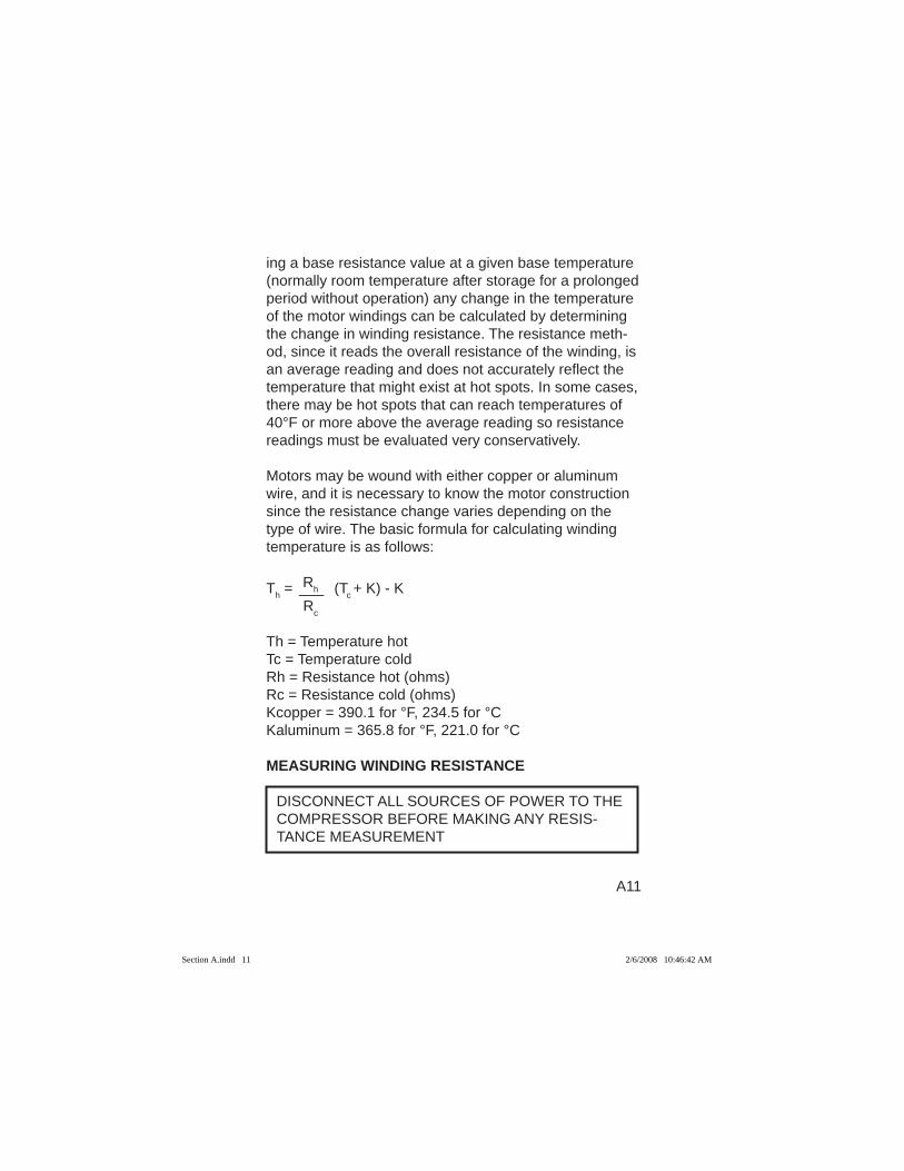
Motors may be wound with either copper or aluminum wire, and it is necessary to know the motor construction since the resistance change varies depending on the type of wire. The basic formula for calculating winding temperature is as follows:
RhTh = ___ (Tc + K) - K Rc
Th = Temperature hotTc = Temperature coldRh = Resistance hot (ohms)Rc = Resistance cold (ohms)Kcopper = 390.1 for °F, 234.5 for °CKaluminum = 365.8 for °F, 221.0 for °C
MEASURING WINDING RESISTANCE
DISCONNECT ALL SOURCES OF POWER TO THE COMPRESSOR BEFORE MAKING ANY RESIS-TANCE MEASUREMENT
Section A.indd 11Section A.indd 11 2/6/2008 10:46:42 AM2/6/2008 10:46:42 AM
A12
Compressor Wiring DiagramsCompressor wiring diagrams with motor winding connec-tions and numbering are often used as a reference for compressor motor winding resistance measurements. Electrical Handbook wiring diagrams show the compres-sor motor with its windings connected for its design volt-ages. The compressor motor windings are also shown unwired and labeled so that if it is necessary, individual winding resistances can be measured and compared to each other.
The pages of Section G of the Electrical Handbook that are headed Copelametic Wiring Diagrams and Welded Compressors Wiring Diagrams list applicable wiring diagrams. They are indexed by the portion of the Copeland® compressor model number that references: 1. Compressor Model2. The Compressor Electrical Characteristics: the type
of motor, type of overload protection, voltage and phase.
A typical compressor model number 4DH3R22ME-TSK indicates a 4D Compressor Model with TSK Compressor Electrical Characteristics (see Section D of the Electrical Handbook for further compressor model nomenclature).
Ohmmeter Resistance Measurements.Electrical Handbook (See Section F) pages designated Electrical Data-Copelametic Compressors, Electrical Data-Copeland Scroll Compressors, and Electrical Data-Welded Compressors have columns that are headed Winding Resistance (Ohms).
Section A.indd 12Section A.indd 12 2/6/2008 10:46:42 AM2/6/2008 10:46:42 AM
A13
The resistances shown are compressor motor resistanc-es measured when the motor is connected for the volt-age shown in the Electrical Data column headed Volts.Measurements must be taken with all external con-nections removed from the winding terminal blocks, but winding connection jumpers (if system voltage has been selected) inplace. Resistance measurements should be within plus or minus 10% of the listed resis-tance.
The most satisfactory instrument for all winding resis-tance measurements is a low range digital ohmmeter since many of the winding resistances listed are in frac-tions of an ohm. MEASURING RESISTANCES OF SINGLE VOLTAGE RANGE MOTORS (Single Phase and Three Phase)Measurements are straightforward for single phase and three phase compressors that can only be wired across the line for a single voltage.
Section A.indd 13Section A.indd 13 2/6/2008 10:46:42 AM2/6/2008 10:46:42 AM
A14
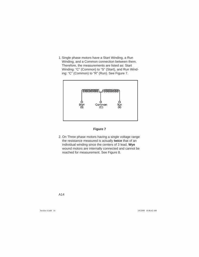
1. Single phase motors have a Start Winding, a Run Winding, and a Common connection between them. Therefore, the measurements are listed as: Start Winding: “C” (Common) to “S” (Start), and Run Wind-ing: “C” (Common) to “R” (Run). See Figure 7.
Figure 7
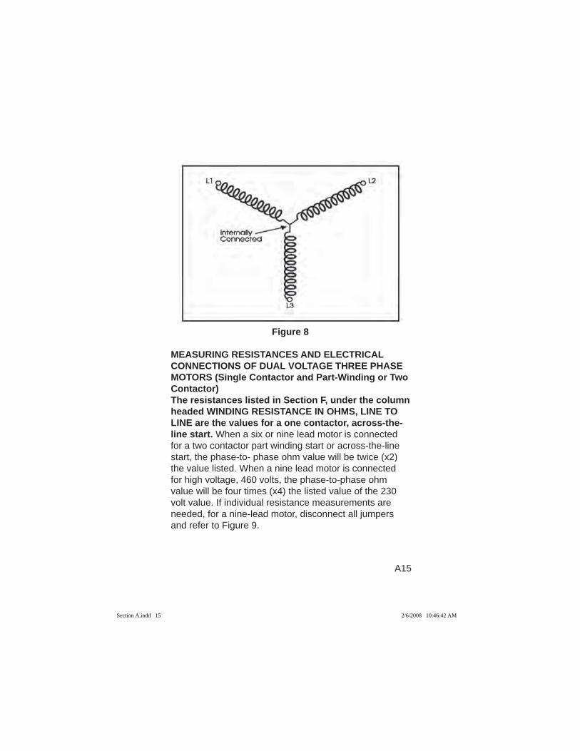
2. On Three phase motors having a single voltage range the resistance measured is actually twice that of an individual winding since the centers of 3 lead, Wye wound motors are internally connected and cannot be reached for measurement. See Figure 8.
Section A.indd 14Section A.indd 14 2/6/2008 10:46:42 AM2/6/2008 10:46:42 AM
A15
Figure 8
MEASURING RESISTANCES AND ELECTRICAL CONNECTIONS OF DUAL VOLTAGE THREE PHASE MOTORS (Single Contactor and Part-Winding or Two Contactor)The resistances listed in Section F, under the column headed WINDING RESISTANCE IN OHMS, LINE TO LINE are the values for a one contactor, across-the-line start. When a six or nine lead motor is connected for a two contactor part winding start or across-the-line start, the phase-to- phase ohm value will be twice (x2) the value listed. When a nine lead motor is connected for high voltage, 460 volts, the phase-to-phase ohm value will be four times (x4) the listed value of the 230 volt value. If individual resistance measurements are needed, for a nine-lead motor, disconnect all jumpers and refer to Figure 9.
Section A.indd 15Section A.indd 15 2/6/2008 10:46:42 AM2/6/2008 10:46:42 AM
A16
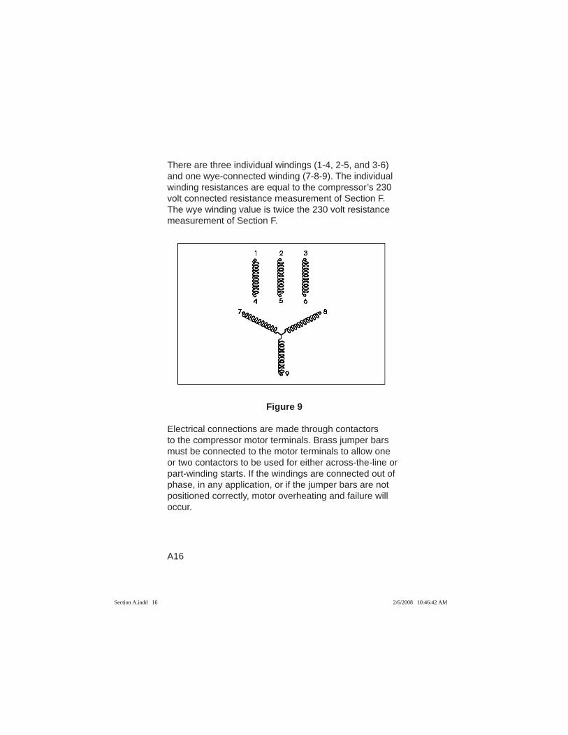
There are three individual windings (1-4, 2-5, and 3-6) and one wye-connected winding (7-8-9). The individual winding resistances are equal to the compressor’s 230 volt connected resistance measurement of Section F. The wye winding value is twice the 230 volt resistance measurement of Section F.
Figure 9
Electrical connections are made through contactors to the compressor motor terminals. Brass jumper bars must be connected to the motor terminals to allow one or two contactors to be used for either across-the-line or part-winding starts. If the windings are connected out of phase, in any application, or if the jumper bars are not positioned correctly, motor overheating and failure will occur.
Section A.indd 16Section A.indd 16 2/6/2008 10:46:42 AM2/6/2008 10:46:42 AM
A17
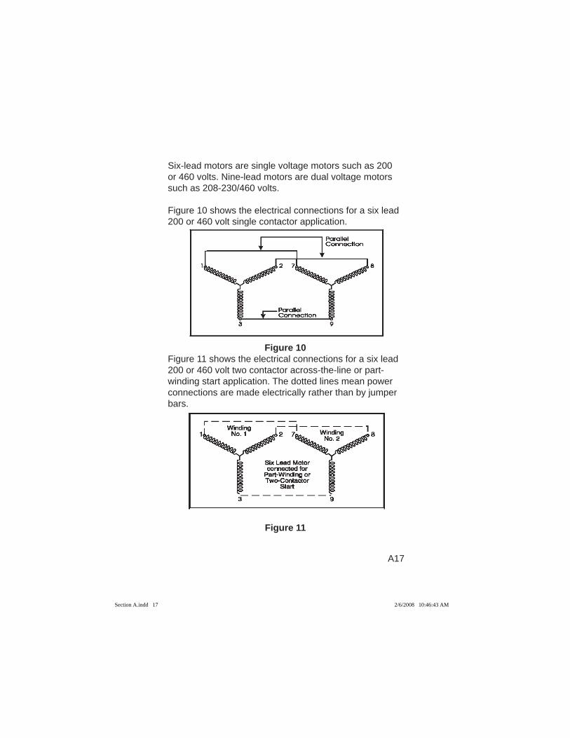
Six-lead motors are single voltage motors such as 200 or 460 volts. Nine-lead motors are dual voltage motors such as 208-230/460 volts. Figure 10 shows the electrical connections for a six lead 200 or 460 volt single contactor application.
Figure 10
Figure 11 shows the electrical connections for a six lead 200 or 460 volt two contactor across-the-line or part-winding start application. The dotted lines mean power connections are made electrically rather than by jumper bars.
Figure 11
Section A.indd 17Section A.indd 17 2/6/2008 10:46:43 AM2/6/2008 10:46:43 AM
A18
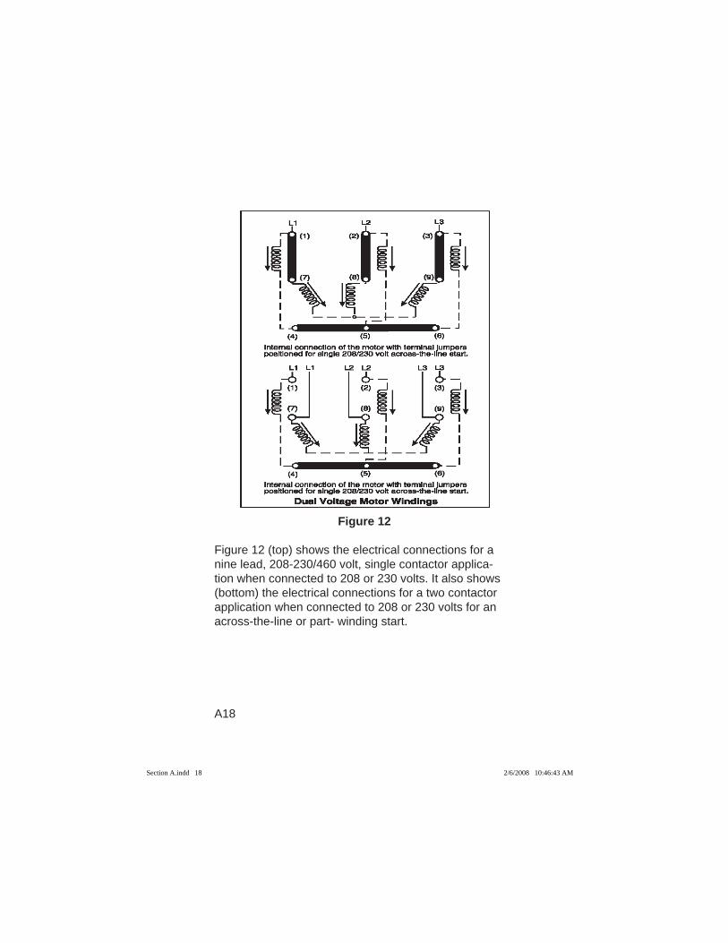
Figure 12
Figure 12 (top) shows the electrical connections for a nine lead, 208-230/460 volt, single contactor applica-tion when connected to 208 or 230 volts. It also shows (bottom) the electrical connections for a two contactor application when connected to 208 or 230 volts for an across-the-line or part- winding start.
Section A.indd 18Section A.indd 18 2/6/2008 10:46:43 AM2/6/2008 10:46:43 AM
A19
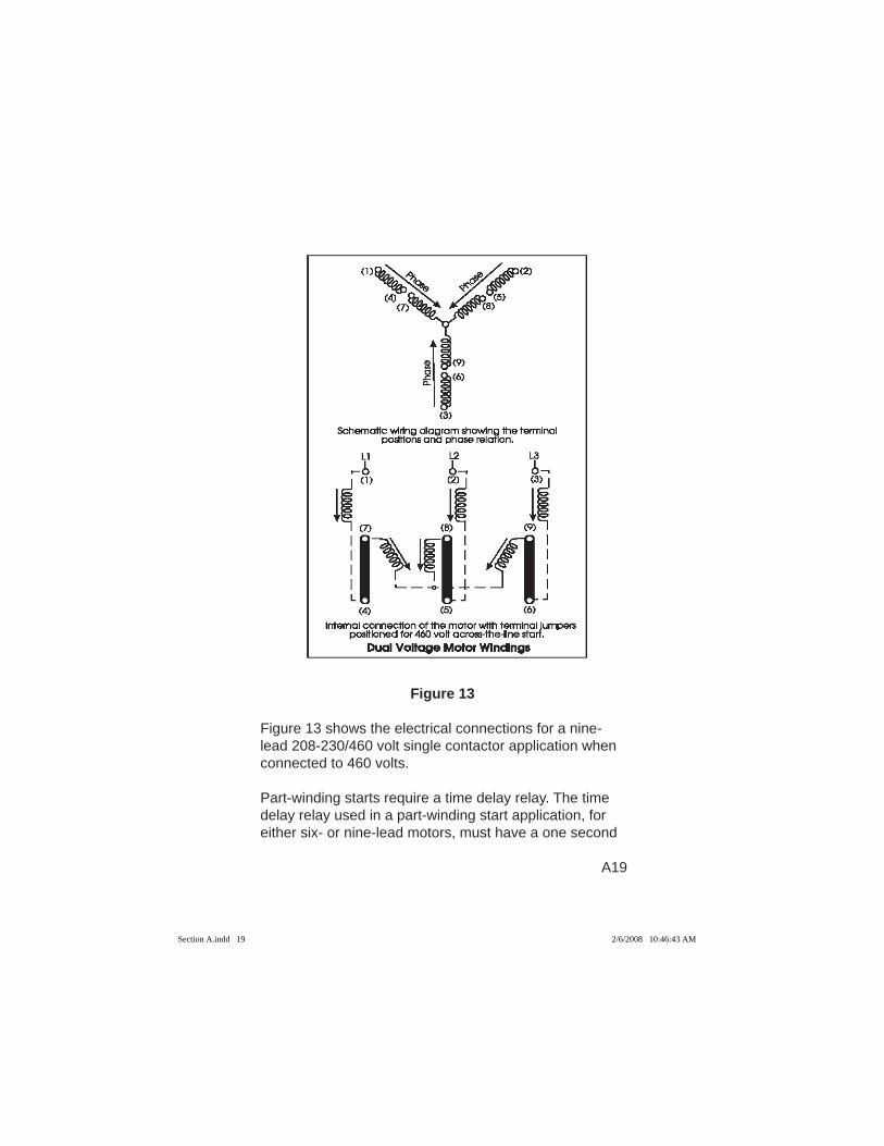
Figure 13
Figure 13 shows the electrical connections for a nine-lead 208-230/460 volt single contactor application when connected to 460 volts. Part-winding starts require a time delay relay. The time delay relay used in a part-winding start application, for either six- or nine-lead motors, must have a one second
Section A.indd 19Section A.indd 19 2/6/2008 10:46:43 AM2/6/2008 10:46:43 AM
A20
delay and must be used between the pull in of the fi rst and second contactors. Part-winding contactors must be sized based on the compressor motor Rated Load Amps (RLA) and the Part Winding Start, Locked Rotor Amp (LRA) rating. See Section F.
Measurements Using The Megohmeter or “MEGGER”When using a megohmeter to evaluate the motor insulation of compressors, it is important to understand that they are not intended to be used for a single read-ing. They were developed to establish a trend. In other words, “meggers” are best used as part of a regular maintenance program where periodic readings can be recorded and a long term insulation resistance trend established.
There are many factors that affect megohm readings including contaminated refrigerant, oil level, and cur-rent leakage through electrical fusites or terminal plates. Before making a measurement, all external wiring should be removed, and all electrical terminal bolts cleaned and torqued to specifi cations.
Measurements Using The High Potential Or “Hi-Pot” Tester Ohmmeter readings usually determine if a motor is shorted or open, but a motor that has passed ohmmeter resistance checks may still have repeated overload or short circuit protector trips.
The motor may have a weakened winding that shorts to ground when the compressor is called on to run. The winding breakdown can be caused because of the system voltage applied to it, heat build up, or mechani-
Section A.indd 20Section A.indd 20 2/6/2008 10:46:43 AM2/6/2008 10:46:43 AM
A21
cal stresses. It may also have a terminal board that has developed an insulation breakdown from a terminal to ground or from a terminal to another terminal.
A “Hi-Pot” tester can be used in conjunction with an ohmmeter to check for insulation failure on both welded compressors and Copelametic compressors. The ter-minal board check can only be made on Copelametic compressors.
A “Hi-Pot” tester develops a high voltage, low current power source and is used to check for an insulation breakdown that the ohmmeter with its low voltage power source may miss. It measures winding insulation resistance to ground and (where applicable) terminal board resistance from terminal to ground and from ter-minal to terminal. To measure winding insulation resis-tance, all wiring is removed from the motor winding terminals. To measure terminal board resistance, all wiring is removed from the terminal board.
The “Hi-Pot tester” should never be:
1. Operated alone or by an inexperienced service per-son.
2. Set at a voltage of more than twice the compressor operating voltage plus 1000 volts.
3. Be set for more than 5 milliamps without consulting Emerson Climate Technologies, Inc.
4. Applied for more than the time it takes to obtain a reading (no more than a few seconds).
5. Used as a phase-to-phase winding check.6. Used on any other part of the compressor.7. Used when the compressor (system) is in a vacuum.
Section A.indd 21Section A.indd 21 2/6/2008 10:46:43 AM2/6/2008 10:46:43 AM
B1
SECTION B
ELECTRONIC MOTOR PROTECTIONScroll Compressor Applications
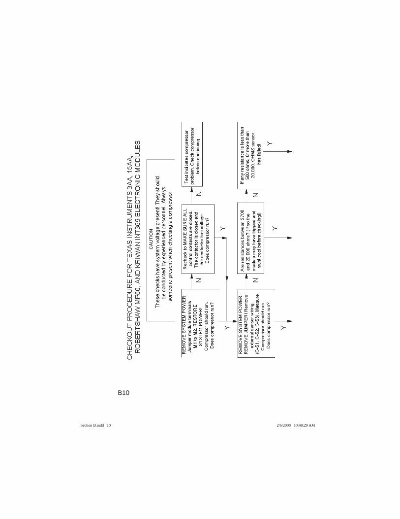
All Emerson Climate Technologies, Inc. Electronic Motor Protectors are manufactured by Kriwan Industries and Texas Instruments.
Scroll Compressor ApplicationsIn all applications using Copeland Scroll® compressors, each protector monitors motor temperature, supply power voltage.
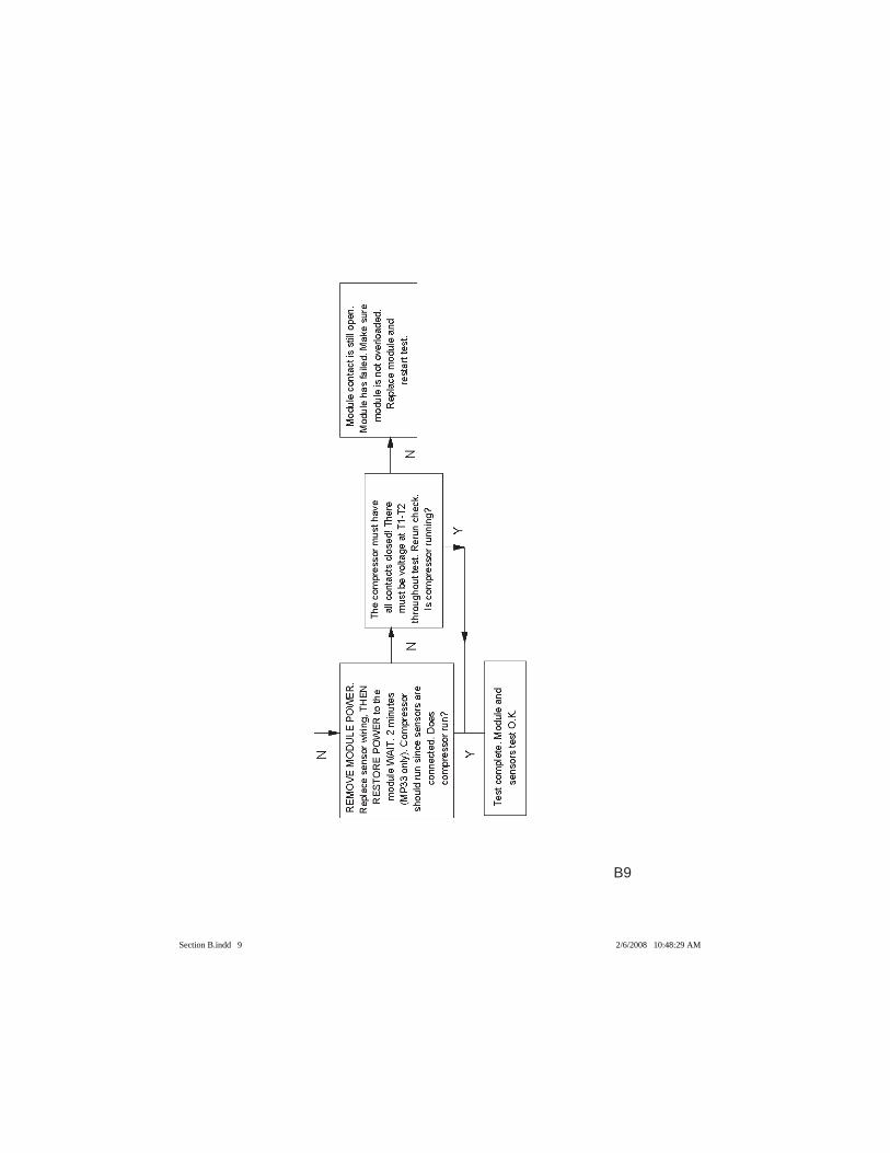
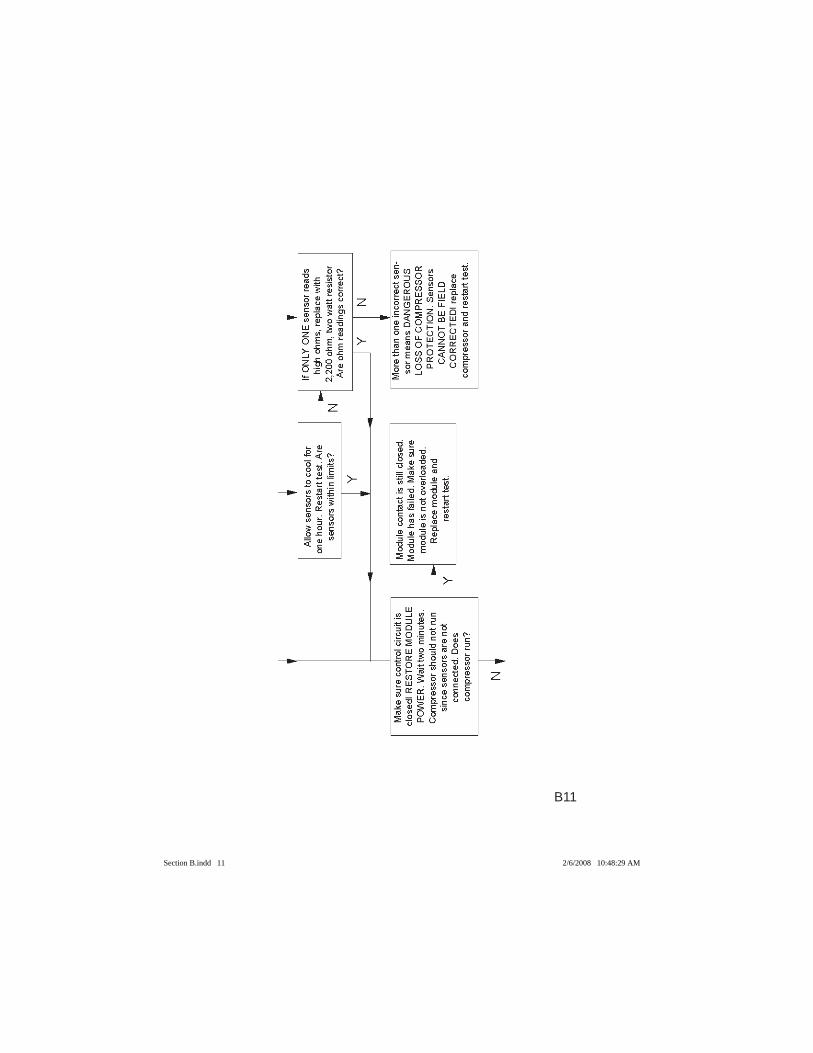
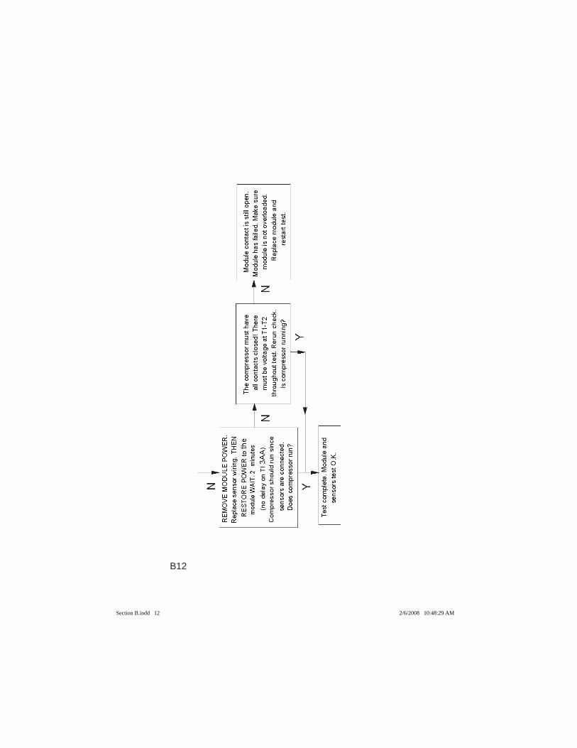
In all applications, utilizing the Kriwan Module, the motor temperature is monitored using 4 positive temperature coeffi cient sensors (PTC) wired in series. Four sensors are embedded in the motor and one is located inside the scroll set and is used to monitor the discharge gas temperature. The sensors have a positive temperature coeffi cient, and their resistance increases as the internal temperature of the compressor motor rises. The control module will compare the sensor resistance to a predeter-mined safe level; and if the total sensor resistance is too high, the module control contact opens and breaks the circuit for the contactor coil control voltage, which then opens the contactor and removes line voltage from the compressor. After a trip, when the motor has cooled to a level that allows for the sensor resistances to return to safe levels, the module will reset and close the control contacts, which will allow the motor to restart.
All motor protector modules monitor power supplied to the module and will trip if the power supplied to T1-T2 terminals are too low.
Section B.indd 1Section B.indd 1 2/6/2008 10:48:20 AM2/6/2008 10:48:20 AM
B2
In refrigeration applications using scroll compressors, each protector additionally monitors 3 phase incom-ing power phase rotation and phase loss. The module is continuously monitoring the phases by checking the phase sequencing. If the phase drops below a level that is detectable by the electronics, the module will detect a phase loss and will trip. The module monitors the phase angle differences between the phases.
The supply voltage can be 24VDC, 24VAC or 120/240VAC depending on the model of motor protector module. Refer to AE Bulletin AE 4-1302 and AE 4-1318 for specifi cations.
Semi-Hermetic Compressor ApplicationsIn all applications using Semi-Hermetic compressors, each protector monitors motor temperature, supply power voltage.
Each protector consists of three temperature sensors (embedded in the compressor motor windings) connect-ed to an electronic control module.
The sensors have a positive temperature coeffi cient, and their resistance increases as the internal tempera-ture of the compressor motor rises. The control module compares the sensor resistance to a predetermined safe level; and if any sensor resistance is too high, the module control contact opens and breaks the circuit for the contactor coil control voltage, which then opens the contactor and removes line voltage from the compressor. After a trip, when the motor has cooled to a level that allows for the sensor resistances to return to safe levels, the module will reset and close the control contacts, which will allow the motor to restart.
Section B.indd 2Section B.indd 2 2/6/2008 10:48:26 AM2/6/2008 10:48:26 AM
B3
All motor protector modules monitor power supplied to the module and will trip (open the contacts between M1 and M2) if the power supplied to L1-L2 terminals are too low. See AE Bulletin AE 10-1264 for specifi cations and wiring diagrams. Screw Compressor ApplicationsIn all applications using Screw compressors, each mod-ule monitors motor temperature, phase sequence control for direction of rotation, manual reset lock-out and oil temperature protection by PTC sensor.
In all applications, the motor temperature is monitored using nine sensors embedded into the motor windings which are in series and connected to the module. The sensors have a positive temperature coeffi cient and their resistance increases as the internal temperature of the compressor rises. The control module compares the sensor resistance to a predetermined safe level and if any sensor resistance is too high. The module control contact opens and breaks the circuit for the contactor coil control voltage, which then opens the contactor and removes line voltage from the compressor. After a trip, the module “must” be manually reset by interruption of the supply voltage to the module for a minimum of 2 seconds.
The other features of the module are: Direction of Rota-tion / Phase Sequence. When the module senses incor-rect rotation or a phase sequence fault the module will immediately shutdown the compressor and lockout. After the correction of the fault, the module must be manually reset.
Oil protection by the PTC sensor. An oil sensor is in-stalled in the oil sump of the compressor and pre-wired
Section B.indd 3Section B.indd 3 2/6/2008 10:48:26 AM2/6/2008 10:48:26 AM
B4
to the module in series with the motor windings PTC’s. If the temperature of the oil rises to an unsafe condition, the compressor will shutdown.
The supply voltage can be 24VDC, 24VAC, 120volt or 220volt.
Refer to AE Bulletin AE4-1322 and/or Operating Instruc-tion 2001-71 for specifi cations. Type Of Protection The Motor Protector Provides:Motor Over Temperature and Running Over Current• It protects the compressor by opening it’s control
contact when it senses dangerous motor over tem-peratures and/or over currents, which convert to over temperatures.
Primary Single Phasing• The protector sensors detect the sharp rise of tem-
perature in compressor motor windings caused by the high current resulting from a transformer primary single phase condition.
Voltage Unbalance• The protector protects against dangerous over-cur-
rents caused by system voltage unbalance. Low Voltage Protection• The electronic motor protector is designed so that it
will not allow the compressor to start with low voltage at the protector module. When running, if the module voltage drops below operating minimums, the module control contact will immediately open and a two-min-ute delay before a restart is attempted. If any of these occurrences result in a dangerous motor temperature rise, the protector will immediately open it’s control contact.
Section B.indd 4Section B.indd 4 2/6/2008 10:48:26 AM2/6/2008 10:48:26 AM
B5
Short Cycle Protection• Since the electronic protector has been designed
to provide a two-minute time delay before restart after a low voltage or no voltage condition, it can be used as protection against compressor short cycling. For short cycling protection, the compressor control circuit must be designed so the temperature or pres-sure controller turns the electronic protector power on and off, and the protector contact control the compressor contactor. Each time protector power is cycled, it provides a two-minute time delay before it’s contact closes and restarts the compressor.
Phase Loss Protection• The scroll refrigeration module and the screw module
will sense the correct phase sequence of L1, L2 and L3 incoming power. The three phase power must be wired in the correct 120 degree phase sequence that will ensure the compressor will start and operate in the correct clockwise rotation.
When the module trips on phase loss, a delay of 5 minutes is activated and then there is a new attempt to restart. If all three phases are present, then the compressor will continue to run. If not the module will lock out. There can be 10 attempts to restart before the module will lock out and then only can be reset by reestablishing incoming power to the module.
ELECTRONIC PROTECTOR SPECIFICATIONS:Low Voltage Protection24 VAC Module (Texas Instruments)Cut-Out Voltage is 16 volts plus or minus 1.5 volts at normal ambients.
Section B.indd 5Section B.indd 5 2/6/2008 10:48:26 AM2/6/2008 10:48:26 AM
B6
Cut-In Voltage is 2 volts higher than cut-out. 120 VAC ModuleCut-Out Voltage is 85 volts plus or minus 4.5 volts at normal ambients.Cut-In Voltage is 4 volts higher than cut-out. 240 VAC ModuleCut-Out Voltage is 170 volts plus or minus 8 volts at normal ambients. Cut-In Voltage is 4 volts higher than cut-out.For all Modules, the low Voltage Response Delay is .2 seconds plus or minus .15 seconds.Off Cycle Timer120 seconds plus or minus 15 percent at normal ambients.Contact RatingThe TI (15AA) and the Kriwan (INT369) have a contact rating of 275VA for either 120 VAC or 240 VAC. The 24VAC module has a rating of 72VA.Sensor ResistancesSee individual protector check-out procedures.
Section B.indd 6Section B.indd 6 2/6/2008 10:48:27 AM2/6/2008 10:48:27 AM
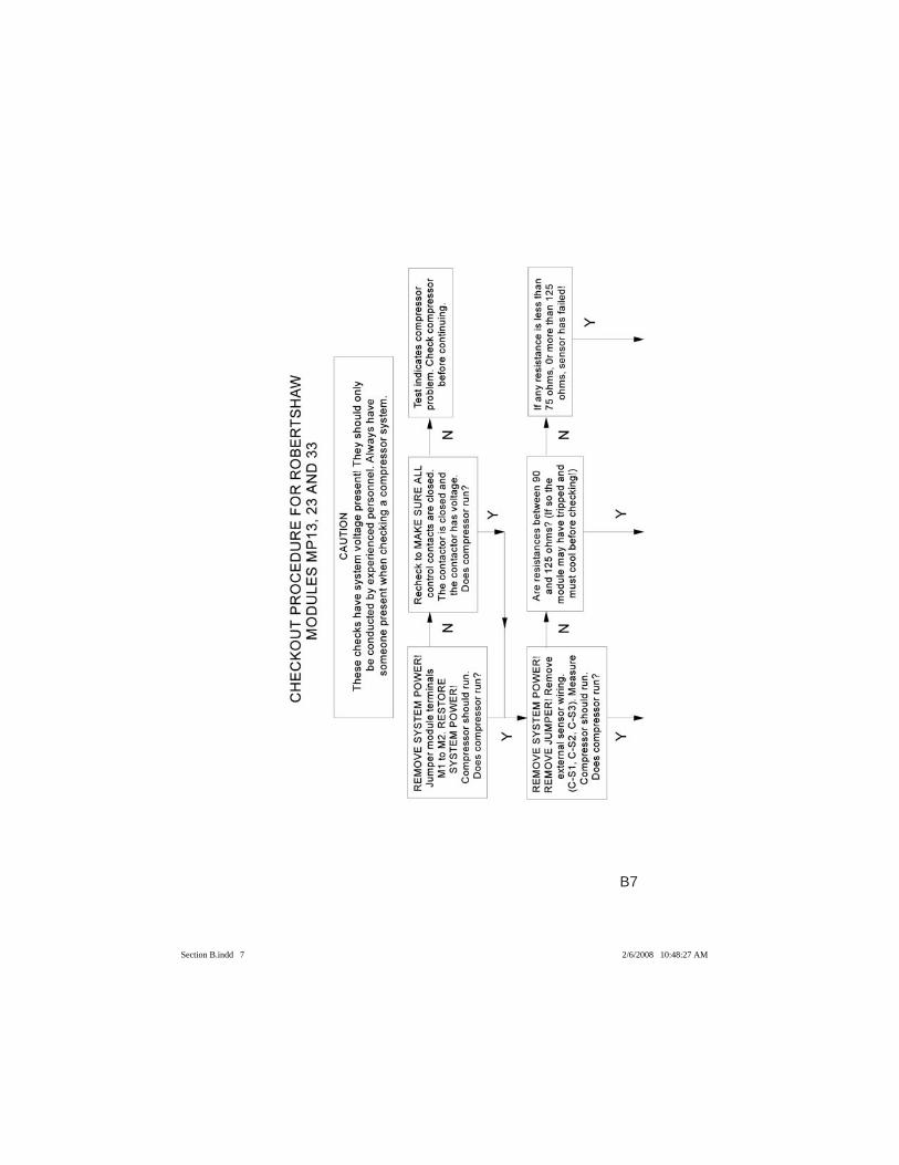
B7
Section B.indd 7Section B.indd 7 2/6/2008 10:48:27 AM2/6/2008 10:48:27 AM
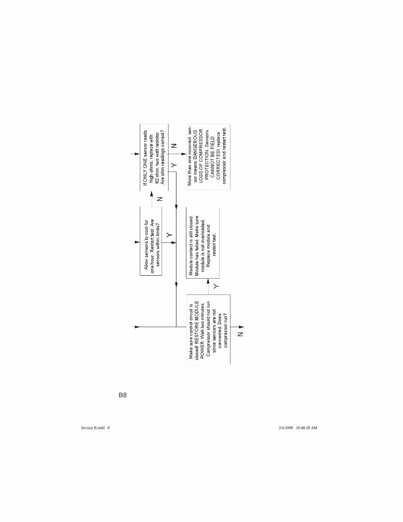
B8
Section B.indd 8Section B.indd 8 2/6/2008 10:48:28 AM2/6/2008 10:48:28 AM
B9
Section B.indd 9Section B.indd 9 2/6/2008 10:48:29 AM2/6/2008 10:48:29 AM
B10
Section B.indd 10Section B.indd 10 2/6/2008 10:48:29 AM2/6/2008 10:48:29 AM
B11
Section B.indd 11Section B.indd 11 2/6/2008 10:48:29 AM2/6/2008 10:48:29 AM
B12
Section B.indd 12Section B.indd 12 2/6/2008 10:48:29 AM2/6/2008 10:48:29 AM
C1
SECTION C
FUSE SELECTION FOR WELDED COMPRESSORS AND COPELAMETIC COMPRESSORS
Motor Running Overload Protection and Branch Circuit Short Circuit Protection are required for every compres-sor electrical branch circuit. These are detailed in Articles 430 and 440 of The National Electrical Code (NEC). All installations and fuse selections must conform to the NEC and any specifi c local code requirements. In case of questions, contact a qualifi ed electrician.
The fuse selection procedures of the Electrical Hand-book are based on time delay (dual element) sizes that will meet the requirements of most compressor installa-tions. The selections conform to the National Electrical Code short circuit requirements for single motor protec-tion.
The manufacturer of the compressor system should be consulted in cases of multiple motor or group fusing, extreme ambient temperatures, or unusual operating conditions where a larger fuse size than recommended may be required.
Each compressor nameplate lists compressor data that is needed to size short circuit protection: The Phase of the motor, Locked Rotor Amps (LRA), and Rated Load Amps (RLA). (RLA is not provided on welded compres-sor nameplates.) This data is also available in Section F.
Section C.indd 1Section C.indd 1 2/5/2008 8:00:59 AM2/5/2008 8:00:59 AM
C2
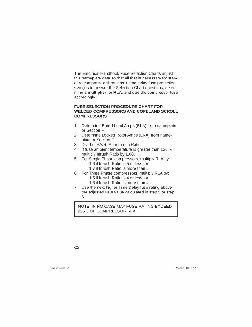
The Electrical Handbook Fuse Selection Charts adjust this nameplate data so that all that is necessary for stan-dard compressor short circuit time delay fuse protection sizing is to answer the Selection Chart questions, deter-mine a multiplier for RLA, and size the compressor fuse accordingly.
FUSE SELECTION PROCEDURE CHART FOR WELDED COMPRESSORS AND COPELAND SCROLL COMPRESSORS
1. Determine Rated Load Amps (RLA) from nameplate or Section F.
2. Determine Locked Rotor Amps (LRA) from name-plate or Section F.
3. Divide LRA/RLA for Inrush Ratio.4. If fuse ambient temperature is greater than 120°F,
multiply Inrush Ratio by 1.08.5. For Single Phase compressors, multiply RLA by: 1.6 if Inrush Ratio is 5 or less, or 1.7 if Inrush Ratio is more than 5.6. For Three Phase compressors, multiply RLA by: 1.5 if Inrush Ratio is 4 or less, or 1.6 if Inrush Ratio is more than 4.7. Use the next higher Time Delay fuse rating above
the adjusted RLA value calculated in step 5 or step 6.
NOTE: IN NO CASE MAY FUSE RATING EXCEED 225% OF COMPRESSOR RLA!
Section C.indd 2Section C.indd 2 2/5/2008 8:01:07 AM2/5/2008 8:01:07 AM
C3
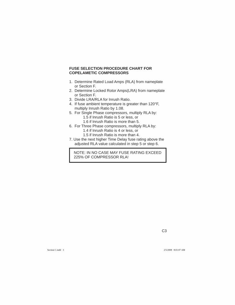
FUSE SELECTION PROCEDURE CHART FOR COPELAMETIC COMPRESSORS
1. Determine Rated Load Amps (RLA) from nameplate or Section F.
2. Determine Locked Rotor Amps(LRA) from nameplate or Section F.
3. Divide LRA/RLA for Inrush Ratio.4. If fuse ambient temperature is greater than 120°F,
multiply Inrush Ratio by 1.08.5. For Single Phase compressors, multiply RLA by: 1.5 if Inrush Ratio is 5 or less, or 1.6 if Inrush Ratio is more than 5.6. For Three Phase compressors, multiply RLA by: 1.4 if Inrush Ratio is 4 or less, or 1.5 if Inrush Ratio is more than 4.7. Use the next higher Time Delay fuse rating above the
adjusted RLA value calculated in step 5 or step 6.
NOTE: IN NO CASE MAY FUSE RATING EXCEED 225% OF COMPRESSOR RLA!
Section C.indd 3Section C.indd 3 2/5/2008 8:01:07 AM2/5/2008 8:01:07 AM
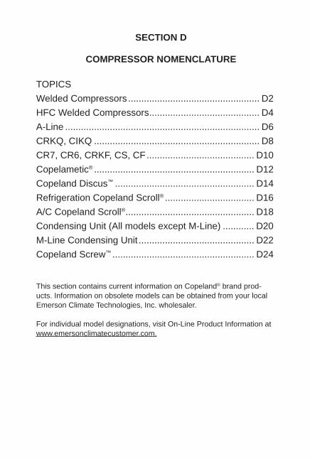
SECTION D
COMPRESSOR NOMENCLATURE
TOPICSWelded Compressors .................................................. D2HFC Welded Compressors .......................................... D4A-Line .......................................................................... D6CRKQ, CIKQ ............................................................... D8CR7, CR6, CRKF, CS, CF ......................................... D10Copelametic® ............................................................. D12Copeland Discus™ ..................................................... D14Refrigeration Copeland Scroll® .................................. D16A/C Copeland Scroll® ................................................. D18Condensing Unit (All models except M-Line) ............ D20M-Line Condensing Unit ............................................ D22Copeland Screw™ ...................................................... D24
This section contains current information on Copeland® brand prod-ucts. Information on obsolete models can be obtained from your local Emerson Climate Technologies, Inc. wholesaler.
For individual model designations, visit On-Line Product Information at www.emersonclimatecustomer.com.
D2
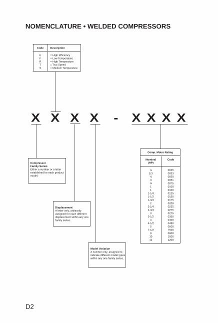
NOMENCLATURE • WELDED COMPRESSORS
Code Description
EFRTS
= High Effi ciency= Low Temperature= High Temperature= Two Speed= Medium Temperature
CompressorFamily SeriesEither a number or a letter established for each product model.
DisplacementA letter only, arbitrarily assigned for each different displacement within any one family series.
Comp. Motor Rating
Nominal (HP)
Code
¼1/3½½¾11
1-1/41-1/21-3/4
22-1/42-3/4
33-1/2
44-1/2
57-1/2
91012
0025003300500051007501000100012501500175020002250275027503500400045005007500090010001200
X X X X - X X X X
Model VariationA number only, assigned to indicate different model types within any one family series.
D3
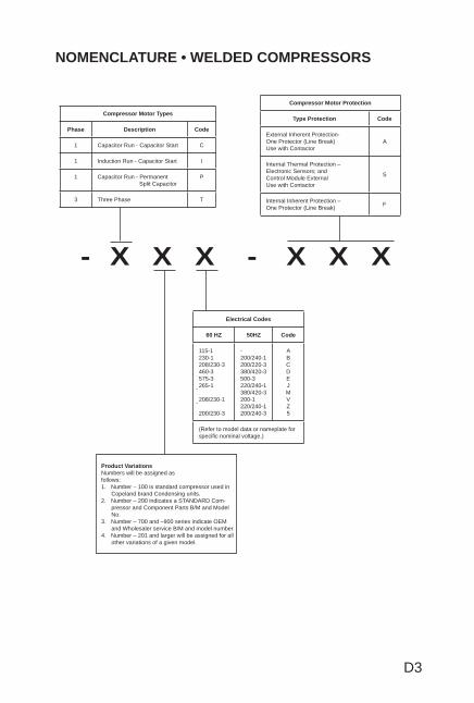
NOMENCLATURE • WELDED COMPRESSORS
Compressor Motor Types
Phase Description Code
1 Capacitor Run - Capacitor Start C
1 Induction Run - Capacitor Start I
1 Capacitor Run - Permanent Split Capacitor
P
3 Three Phase T
Compressor Motor Protection
Type Protection Code
External Inherent Protection-One Protector (Line Break)Use with Contactor
A
Internal Thermal Protection – Electronic Sensors; andControl Module ExternalUse with Contactor
S
Internal Inherent Protection – One Protector (Line Break) F
Electrical Codes
60 HZ 50HZ Code
115-1230-1208/230-3460-3575-3265-1208/230-1200/230-3
-200/240-1200/220-3380/420-3500-3220/240-1380/420-3200-1220/240-1200/240-3
ABCDEJMVZ5
(Refer to model data or nameplate for specifi c nominal voltage.)
Product VariationsNumbers will be assigned asfollows:1. Number – 100 is standard compressor used in
Copeland brand Condensing units.2. Number – 200 indicates a STANDARD Com-
pressor and Component Parts B/M and Model No.
3. Number – 700 and –900 series indicate OEM and Wholesaler service B/M and model number.
4. Number – 201 and larger will be assigned for all other variations of a given model.
- X X X - X X X
D4
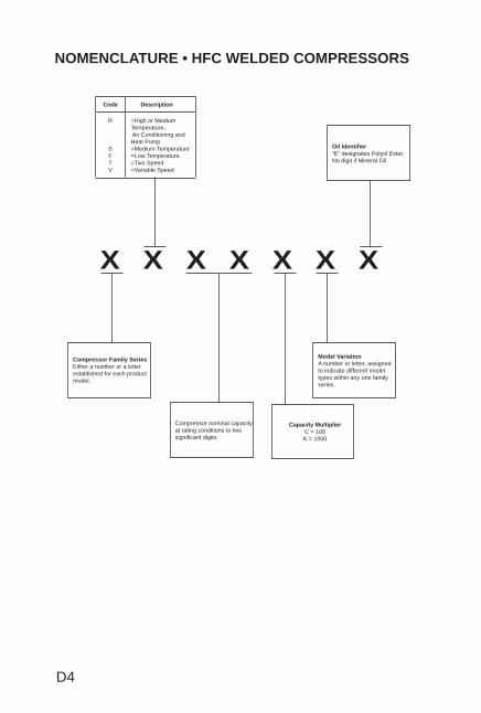
NOMENCLATURE • HFC WELDED COMPRESSORS
Oil Identifi er“E” designates Polyol Ester. No digit if Mineral Oil
X X X X X X X
Model VariationA number or letter, assigned to indicate different model types within any one family series.
Compressor nominal capacity at rating conditions to two signifi cant digits.
Capacity MultiplierC = 100K = 1000
Compressor Family SeriesEither a number or a letter established for each product model.
Code Description
R
SFTV
=High or Medium Temperature, Air Conditioning and Heat Pump=Medium Temperature=Low Temperature=Two Speed=Variable Speed
D5
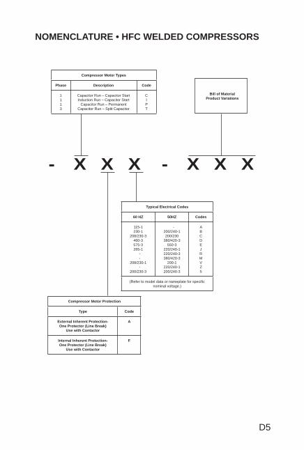
NOMENCLATURE • HFC WELDED COMPRESSORS
- X X X - X X X
Bill of Material Product Variations
Compressor Motor Types
Phase Description Code
1113
Capacitor Run – Capacitor Start Induction Run – Capacitor Start
Capacitor Run – PermanentCapacitor Run – Split Capacitor
CIPT
Typical Electrical Codes
60 HZ 50HZ Codes
115-1230-1
208/230-3460-3575-3265-1
- -
208/230-1 -
200/230-3
-200/240-1200/230
380/420-3550-3
220/240-1220/240-3380/420-3
200-1220/240-1200/240-3
ABCDEJRMVZ5
(Refer to model data or nameplate for specifi c nominal voltage.)
Compressor Motor Protection
Type Code
External Inherent Protection-One Protector (Line Break)
Use with Contactor
A
Internal Inherent Protection-One Protector (Line Break)
Use with Contactor
F
D6
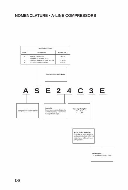
NOMENCLATURE • A-LINE COMPRESSORS
Compressor Shell Series
A S E 2 4 C 3 E
Oil Identifi er“E” designates Polyol Ester.
Model Series VariationA number or letter arbitrarily assigned to indicate different model types within any one family series.
Capacity MultiplierC: 100
K: 1,000
CapacityCompressor nominal capacity at 60 Hertz rating condition to two signifi cant digits.
Compressor Family Series
Application Range
Code Description Rating Point
S
FR
Medium & ExtendedTemperature R-404A, R-22Extended Medium R-134a, R-404AHigh Temperature R-134a
20/120
-10/12045/130
D7
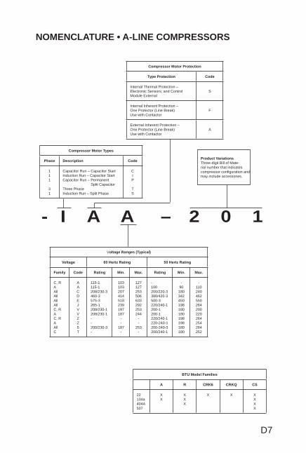
NOMENCLATURE • A-LINE COMPRESSORS
- I A A – 2 0 1
Product VariationsThree-digit Bill of Mate-rial number that indicates compressor confi guration and may include accessories.
Compressor Motor Protection
Type Protection Code
Internal Thermal Protection – Electronic Sensors; and ControlModule External
S
Internal Inherent Protection – One Protector (Line Break)Use with Contactor
F
External Inherent Protection – One Protector (Line Break)Use with Contactor
A
BTU Model Families
A R CRK6 CRKQ CS
22134a404A507
XX
XXX
X X XXXX
Voltage Ranges (Typical)
Voltage 60 Hertz Rating 50 Hertz Rating
Family Code Rating Min. Max. Rating Min. Max.
C, RAAllAllAllAllC, RAC, RAAllC
AACDEJVVZZ5T
115-1115-1208/230-3460-3575-3265-1208/230-1208/230-1--200/230-3-
103103207414518239197187
--
187-
127127253506633292253244
--
253-
-100200/220-3380/420-3500-3220/240-1200-1200-1220/240-1220-240-1200-240-3200/240-1
-90180342450198180180198198180180
-110240462550264200220264254264252
Compressor Motor Types
Phase Description Code
111
31
Capacitor Run – Capacitor StartInduction Run – Capacitor StartCapacitor Run – Permanent Split CapacitorThree PhaseInduction Run – Split Phase
CIP
TS
D8
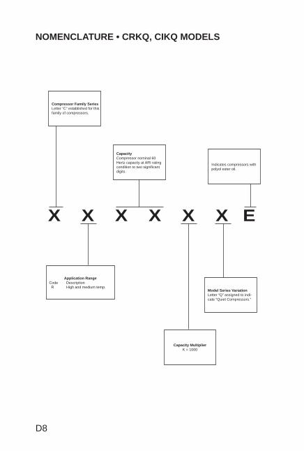
NOMENCLATURE • CRKQ, CIKQ MODELS
X X X X X X E
Indicates compressors with polyol ester oil.
CapacityCompressor nominal 60 Hertz capacity at ARI rating condition to two signifi cant digits.
Compressor Family SeriesLetter “C” established for this family of compressors.
Model Series VariationLetter “Q” assigned to indi-cate “Quiet Compressors.”
Application RangeCode Description R High and medium temp.
Capacity MultiplierK = 1000
D9
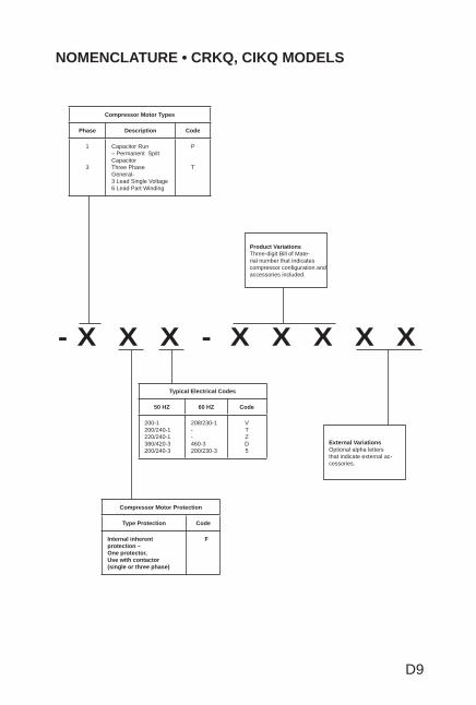
NOMENCLATURE • CRKQ, CIKQ MODELS
- X X X - X X X X X
Product VariationsThree-digit Bill of Mate-rial number that indicates compressor confi guration and accessories included.
Compressor Motor Types
Phase Description Code
1
3
Capacitor Run – Permanent Spilt CapacitorThree PhaseGeneral-3 Lead Single Voltage6 Lead Part Winding
P
T
External VariationsOptional alpha letters that indicate external ac-cessories.
Typical Electrical Codes
50 HZ 60 HZ Code
200-1200/240-1220/240-1380/420-3200/240-3
208/230-1--460-3200/230-3
VTZD5
Compressor Motor Protection
Type Protection Code
Internal inherent protection – One protector, Use with contactor(single or three phase)
F
D10
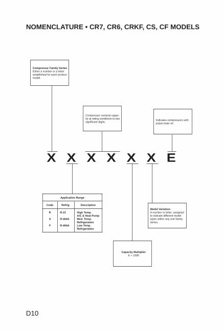
NOMENCLATURE • CR7, CR6, CRKF, CS, CF MODELS
X X X X X X E
Capacity MultiplierK = 1000
Model VariationA number or letter, assigned to indicate different model types within any one family series.
Indicates compressors with polyol ester oil.
Compressor nominal capac-ity at rating conditions to two signifi cant digits.
Compressor Family SeriesEither a number or a letter established for each product model.
Application Range
Code Refrig. Description
R
S
F
R-22
R-404A
R-404A
High Temp.A/C & Heat PumpMed. Temp.RefrigerationLow Temp.Refrigeration
D11
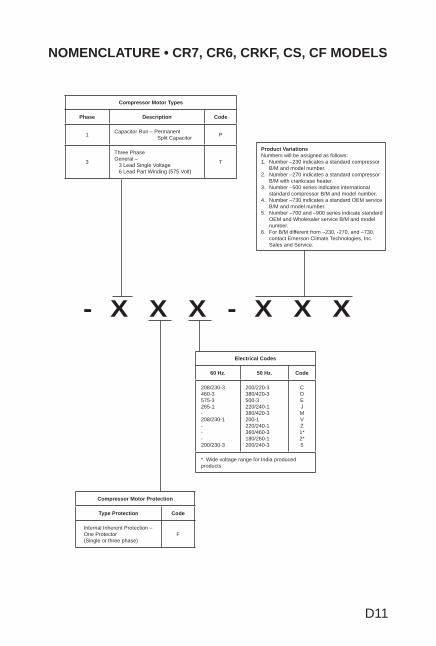
NOMENCLATURE • CR7, CR6, CRKF, CS, CF MODELS
- X X X - X X X
Product VariationsNumbers will be assigned as follows:1. Number –230 indicates a standard compressor
B/M and model number.2. Number –270 indicates a standard compressor
B/M with crankcase heater.3. Number –500 series indicates international
standard compressor B/M and model number.4. Number –730 indicates a standard OEM service
B/M and model number.5. Number –700 and –900 series indicate standard
OEM and Wholesaler service B/M and model number.
6. For B/M different from –230, -270, and –730, contact Emerson Climate Technologies, Inc. Sales and Service.
Compressor Motor Types
Phase Description Code
1 Capacitor Run – Permanent Split Capacitor P
3
Three PhaseGeneral – 3 Lead Single Voltage 6 Lead Part Winding (575 Volt)
T
Electrical Codes
60 Hz. 50 Hz. Code
208/230-3460-3575-3265-1-208/230-1---200/230-3
200/220-3380/420-3500-3220/240-1380/420-3200-1220/240-1360/460-3180/260-1200/240-3
CDEJMVZ1*2*5
* Wide voltage range for India produced products
Compressor Motor Protection
Type Protection Code
Internal Inherent Protection – One Protector (Single or three phase)
F
D12
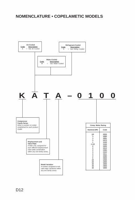
NOMENCLATURE • COPELAMETIC MODELS
K A T A – 0 1 0 0
Refrigerant-Cooled Code Description R = Std. Refrig. Cooled
Water-Cooled Code Description W = Std. Water Cooled
Air-Cooled Code Description A = Std. Air Cooled
Model VariationA number assigned to indi-cate major variations within any one family series.
Displacement and Valve PlateA letter only, assigned for each different displacement valve plate combination within any one family series.
Compressor Family SeriesEither a number or a letter established for each product model.
Comp. Motor Rating
Nominal (HP) Code
1/3½½¾1
1-1/222333452025303540
003300500051007501000150020002100300031003110400050020002500300035004000
D13
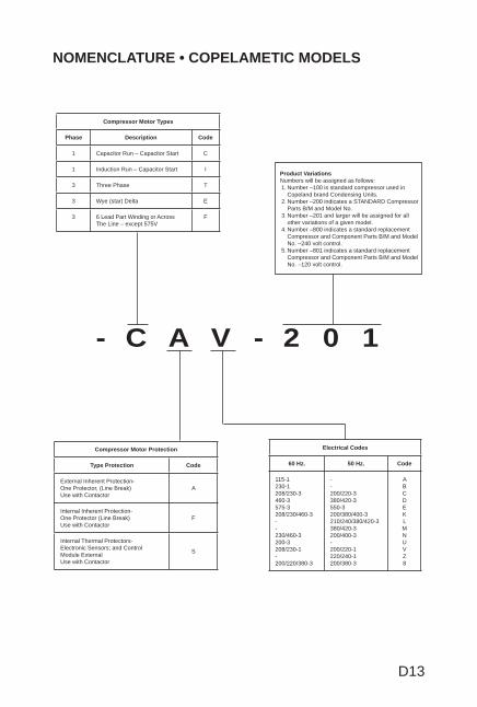
NOMENCLATURE • COPELAMETIC MODELS
- C A V - 2 0 1
Product VariationsNumbers will be assigned as follows:1. Number –100 is standard compressor used in
Copeland brand Condensing Units.2. Number –200 indicates a STANDARD Compressor
Parts B/M and Model No.3. Number –201 and larger will be assigned for all
other variations of a given model.4. Number –800 indicates a standard replacement
Compressor and Component Parts B/M and Model No. –240 volt control.
5. Number –801 indicates a standard replacement Compressor and Component Parts B/M and Model No. –120 volt control.
Compressor Motor Types
Phase Description Code
1 Capacitor Run – Capacitor Start C
1 Induction Run – Capacitor Start I
3 Three Phase T
3 Wye (star) Delta E
3 6 Lead Part Winding or Across The Line – except 575V
F
Compressor Motor Protection
Type Protection Code
External Inherent Protection-One Protector, (Line Break)Use with Contactor
A
Internal Inherent Protection-One Protector (Line Break)Use with Contactor
F
Internal Thermal Protectors-Electronic Sensors; and ControlModule ExternalUse with Contactor
S
Electrical Codes
60 Hz. 50 Hz. Code
115-1230-1208/230-3460-3575-3208/230/460-3--230/460-3200-3208/230-1-200/220/380-3
--200/220-3380/420-3550-3200/380/400-3210/240/380/420-3380/420-3200/400-3-200/220-1220/240-1200/380-3
ABCDEKLMNUVZ8

D14
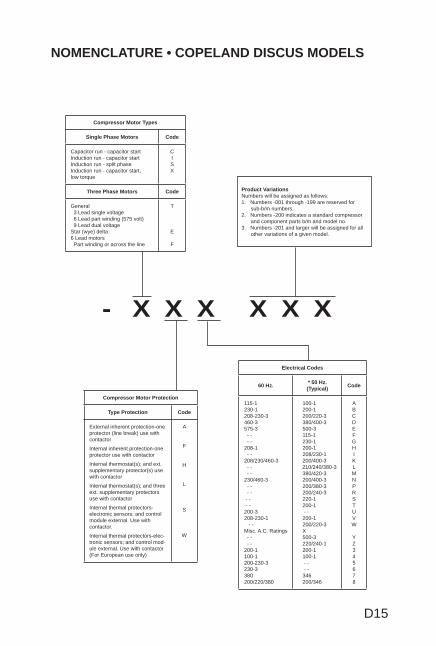
NOMENCLATURE • COPELAND DISCUS MODELS
X X X X X X X X X
Tandem Style ModelsIndicated by the digit representing the comp. model series connectedin tandem with a comp. of the model series indicated by the fi rst digit.
Compressor Cooling
Code Description
A D R T W
Air cooled DiscusRefrigerant cooledStd. two stageWater cooled
Model VariationEither a number or a letter assigned to indicate major variations within any one family series.
Displacement and Valve PlateA letter only, arbitrarily assigned for each different displacement valve plate combination within any one family series
Compressor Family SeriesEither a number of a letter extablished for each product family.
May also be “0” (Mineral Oil) “E” (POE Oil) “L” (Less Oil)
Capacity MultiplierK - 1,000
M - 10,000
Nominal Capacity at Rating Condition 2 numeric characters
Primary Application RangeR = ARI High Temp, Rated @ 45/130S = ARI Med Temp, Rated @ 20/120F = ARI Low Temp, Rated @ -25/105
D15
NOMENCLATURE • COPELAND DISCUS MODELS
- X X X X X X
Product VariationsNumbers will be assigned as follows:1. Numbers -001 through -199 are reserved for
sub-b/m numbers.2. Numbers -200 indicates a standard compressor
and component parts b/m and model no.3. Numbers -201 and larger will be assigned for all
other variations of a given model.
Compressor Motor Protection
Type Protection Code
External inherent protection-one protector (line break) use with contactor
Internal inherent protection-one protector use with contactor
Internal thermostat(s); and ext. supplementary protector(s) use with contactor
Internal thermostat(s); and three ext. supplementary protectors use with contactor
Internal thermal protectors-electronic sensors; and control module external. Use with contactor.
Internal thermal protectors-elec-tronic sensors; and control mod-ule external. Use with contactor (For European use only)
A
F
H
L
S
W
Electrical Codes
60 Hz. * 50 Hz. (Typical) Code
115-1230-1208-230-3 460-3575-3 - - - -208-1 - -208/230/460-3 - - - -230/460-3 - - - - - - - -200-3208-230-1 - -Misc. A.C. Ratings - - - -200-1100-1200-230-3230-3380200/220/380
100-1 200-1 200/220-3 380/400-3 500-3 115-1 230-1 200-1 208/230-1 200/400-3 210/240/380-3 380/420-3 200/400-3 200/380-3 200/240-3 220-1 200-1 - - 200-1 200/220-3 X 500-3 220/240-1 200-1 100-1 - - - - 346 200/346
ABC DEFGHIKLMNPRSTUVW YZ345678
Compressor Motor Types
Single Phase Motors Code
Capacitor run - capacitor startInduction run - capacitor startInduction run - split phaseInduction run - capacitor start, low torque
CISX
Three Phase Motors Code
General 3 Lead single voltage 6 Lead part winding (575 volt) 9 Lead dual voltageStar (wye) delta6 Lead motors Part winding or across the line
T
E
F
D16
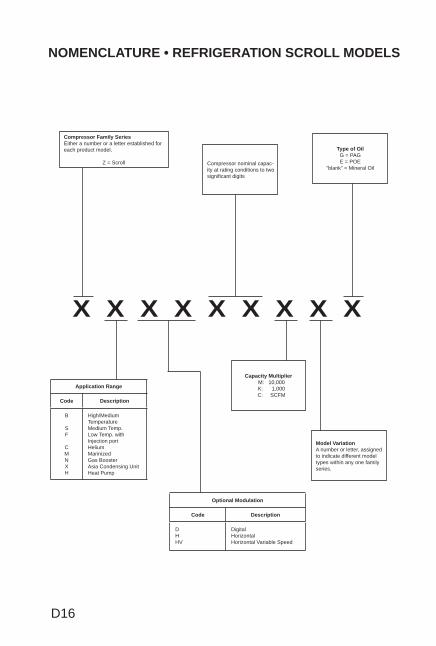
NOMENCLATURE • REFRIGERATION SCROLL MODELS
X X X X X X X X X
Compressor Family SeriesEither a number or a letter established for each product model.
Z = Scroll
Capacity Multiplier M: 10,000 K: 1,000 C: SCFM
Type of OilG = PAGE = POE
“blank” = Mineral OilCompressor nominal capac-ity at rating conditions to two signifi cant digits
Model VariationA number or letter, assigned to indicate different model types within any one family series.
Application Range
Code Description
B
SF
CMNXH
High/Medium TemperatureMedium Temp.Low Temp. with Injection portHeliumMarinizedGas BoosterAsia Condensing UnitHeat Pump
Optional Modulation
Code Description
DHHV
DigitalHorizontalHorizontal Variable Speed
D17
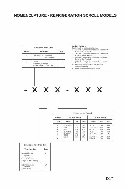
NOMENCLATURE • REFRIGERATION SCROLL MODELS
- X X X - X X X
Product VariationsNumbers will be assigned as follows:1. 230/231 - Standard Compressor & Component
Parts w/ Flag Terminal 2. 250/251 - Standard Compressor & Component
Parts w/ Screw Terminal 3. 240/241 - Rotalock Compressor & Component
Parts w/ Flag Terminal 4. 261/265 - Rotalock Compressor & Component
Parts w/ Screw Terminal 5. 900 series indicates standard OEM and
wholesaler service.6. Other numbers designate variations.
Compressor Motor Types
Phase Description Code
1 Capacitor Run – Permanent Split Capacitor
P
3 General3 Lead Single Voltage6 Lead Part Winding (575 Volt)
T
Voltage Ranges (Typical)
Voltage 60 Hertz Rating 50 Hertz Rating
Code Rating Min. Max. Rating Min. Max.
CDEV57JR
208/230-3460-3575-3208/230-1200/230-3380-3265-1-
187414518197180342239-
253506633253253418292-
200-3380/420-3500-3200-1200/220-3-220/240-1220/240-3
180342450180180-198180
220462550220242-264264
Compressor Motor Protection
Type Protection Code
Internal Inherent Protection-
One Protector Use with Contactor(Single or Three Phase)
F
External Electronic Protection
(Three Phase)
W
D18
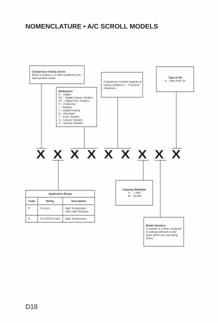
NOMENCLATURE • A/C SCROLL MODELS
X X X X X X X X X
Compressor Family SeriesEither a number or a letter established for each product model.
Capacity MultiplierK: 1,000
M: 10,000
Type of OilE – 3MA POE OilCompressor nominal capacity at
rating conditions 2 – 3 numeric characters.
ModulationD – DigitalDU – Digital Uneven TandemDT – Digital Even TandemH – HorizontalI – HeatingJ – Digital HeatingS – UltraTechT – Even TandemU – Uneven TandemV – Velocity Variable
Model VariationA number or a letter, assigned to indicate different model types within any one family series.
Application Range
Code Refrig. Description
P R-410A High TemperatureUltra High Pressure
R R-22/407C/134a High Temperature
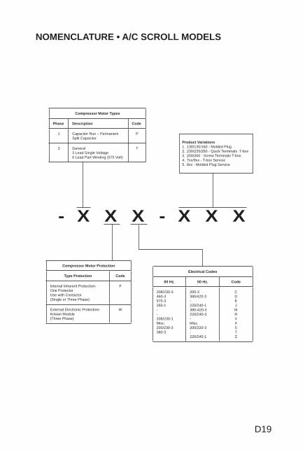
D19
NOMENCLATURE • A/C SCROLL MODELS
- X X X - X X X
Product Variations1. 130/135/160 - Molded Plug2. 230/235/260 - Quick Terminals T-box3. 250/265 - Screw Terminals T-box4. 7xx/9xx - T-box Service5. 8xx - Molded Plug Service
Compressor Motor Types
Phase Description Code
1 Capacitor Run – Permanent Split Capacitor
P
3 General3 Lead Single Voltage6 Lead Part Winding (575 Volt)
T
Electrical Codes
60 Hz. 50 Hz. Code
208/230-3460-3575-3265-1--208/230-1Misc.200/230-3380-3
200-3380/420-3-220/240-1380-420-3220/240-3-Misc.200/220-3-220/240-1
CDEJMRVX57Z
Compressor Motor Protection
Type Protection Code
Internal Inherent Protection-One Protector Use with Contactor(Single or Three Phase)
F
External Electronic Protection-Kriwan Module(Three Phase)
W
D20
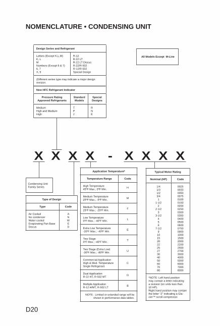
NOMENCLATURE • CONDENSING UNIT
X X X X - X X X X
Condensing Unit Family Series
Design Series and Refrigerant
Letters (Except K,L,M)K, LMNumbers (Except 6 & 7)6, 7X, 9
R-12R-22 LTR-22 LT DiscusR-22/R-502R-12/R-502Special Design
(Different series type may indicate a major design revision.
New HFC Refrigerant Indicator
Pressure Rating Approved Refrigerants
Standard Models
Special Designs
MediumHigh and MediumHigh
TPJ
RNE
Type of Design
Type Code
Air CooledNo condenserWater cooledEvaporating Pan BaseDiscus
ANWED
Typical Motor Rating
Nominal (HP) Code
1/41/31/23/41
1-1/22
2-1/23
3-1/2456
7-1/29101520222527304050607080
002500330050007501000150020002500300035004000500060007500900100015002000220025002700300040005000600070008000
*NOTE: Left hand position may contain a letter indicating a revision (on units less than 10 HP).Right hand position may contain the letter “Z” indicating a Gla-cier™ scroll compressor.
Application Temperature*
Temperature Range Code
High Temperature45ºF Max.; 0ºF Min. H
Medium Temperature25ºF Max.; -5ºF Min. M
Medium Temperature25ºF Max.; -25ºF Min. F
Low Temperature0ºF Max.; -40ºF Min. L
Extra Low Temperature-20ºF Max.; -40ºF Min. E
Two Stage0ºF Max.; -40ºF Min. T
Two Stage (Extra Low)-30ºF Max.; -80ºF Min. U
Commercial ApplicationHigh & Med. TemperatureSingle Refrigerant
C
Dual ApplicationR-22 HT, R-502 MT D
Multiple ApplicationR-12 H/MT, R-502 LT B
NOTE: Limited or extended range will be shown in performance data tables.
All Models Except M-Line
D21
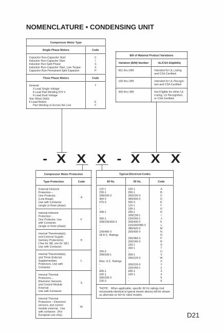
NOMENCLATURE • CONDENSING UNIT
- X X X - X X X
Compressor Motor Type
Single Phase Motors Code
Capacitor Run-Capacitor StartInduction Run-Capacitor StartInduction Run-Split PhaseInduction Run-Capacitor Start, Low TorqueCapacitor Run-Permanent Split Capacitor
CISXP
Three Phase Motors Code
General 3 Lead Single Voltage 6 Lead Part Winding 575 V 9 Lead Dual VoltageStar (Wye) Delta6 Lead Motors Part Winding or Across the Line
T
EF
Bill of Material Product Variations
Variation (B/M) Number UL/CSA Eligibility
001 thru 099 Intended for UL Listing and CSA Certifi ed.
100 thru 299 Intended for UL Recogni-tion and CSA Certifi ed.
300 thru 399 Not Eligible for either UL Listing, LU Recognition, or CSA Certifi ed.
Compressor Motor Protection
Type Protection Code
External InherentProtection – One Protector,(Line Break)Use with Contactor(single or three phase)
A
Internal InherentProtection – One Protector, Usewith Contactor.(single or three phase)
F
Internal Thermostat(s);and External Supple-mentary Protector(s).(Two for 3Ø, one for 1Ø.)Use with Contactor.
H
Internal Thermostat(s);and Three External Supplementary Protectors. Use with Contactor.
L
Internal Thermal Protectors – Electronic Sensors; and Control Module External.Use with Contactor.
S
Internal Thermal Protectors – Electronic sensors; and control module external. Use with contactor. (For European use only).
W
Typical Electrical Codes
60 Hz. 50 Hz. Code
115-1230-1208/230-3460-3575-3--208-1-265-1208/230/460-3--230/460-3All D.C. Ratings----200-3208/230-1-Misc. A.C. Ratings--200-1100-1200/230-3230-3
100-1200-1200/220-3380/400-3500-3115-1230-1200-1208/230-1220/240-1200/400-3210/240/380-3380/420-3200/400-3
200/380-3200/240-3220-1200-1-200-1200/220-3
200/220-3220/240-1200-1100-1--
ABCDEFGHIJKLMNOPRSTUVWXYZ3456
*NOTE: When applicable, specifi c 50 Hz ratings (not necessarily identical to typical shown above) will be shown as alternate on 60 Hz rated models.
D22
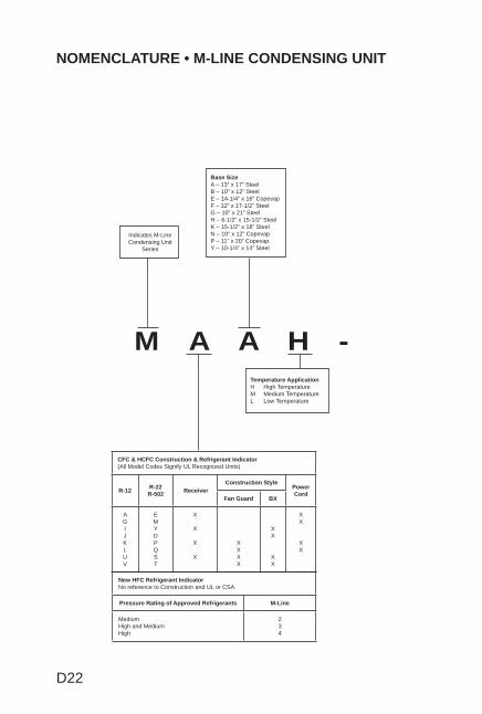
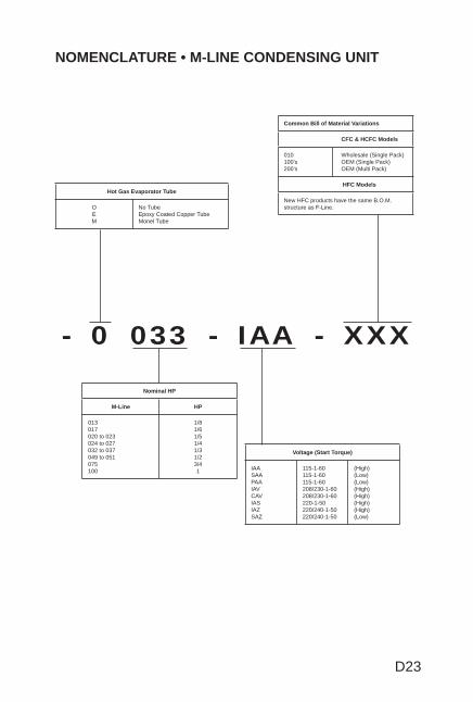
NOMENCLATURE • M-LINE CONDENSING UNIT
M A A H -
CFC & HCFC Construction & Refrigerant Indicator(All Model Codes Signify UL Recognized Units)
R-12 R-22R-502 Receiver
Construction StylePower Cord
Fan Guard BX
AGIJKLUV
EMYDPQST
X
X
X
X
XXXX
XX
XX
XX
XX
Indicates M-Line Condensing Unit
Series
Base SizeA – 13” x 17” SteelB – 10” x 12” SteelE – 14-1/4” x 16” CopevapF – 12” x 17-1/2” SteelG – 10” x 21” SteelH – 6-1/2” x 15-1/2” SteelK – 15-1/2” x 18” SteelN – 10” x 12” CopevapP – 11” x 20” CopevapY – 10-1/4” x 14” Steel
Temperature ApplicationH High TemperatureM Medium TemperatureL Low Temperature
New HFC Refrigerant Indicator No reference to Construction and UL or CSA
Pressure Rating of Approved Refrigerants M-Line
MediumHigh and MediumHigh
234
D23
NOMENCLATURE • M-LINE CONDENSING UNIT
- 0 033 - IAA - XXX
Common Bill of Material Variations
CFC & HCFC Models
010100’s200’s
Wholesale (Single Pack)OEM (Single Pack)OEM (Multi Pack)
HFC Models
New HFC products have the same B.O.M. structure as F-Line.
Hot Gas Evaporator Tube
OEM
No TubeEpoxy Coated Copper TubeMonel Tube
Voltage (Start Torque)
IAASAAPAAIAVCAVIASIAZSAZ
115-1-60115-1-60115-1-60208/230-1-60208/230-1-60220-1-50220/240-1-50220/240-1-50
(High)(Low)(Low)(High)(High)(High)(High)(Low)
Nominal HP
M-Line HP
013017020 to 023024 to 027032 to 037049 to 051075100
1/81/61/51/41/31/23/41
D24
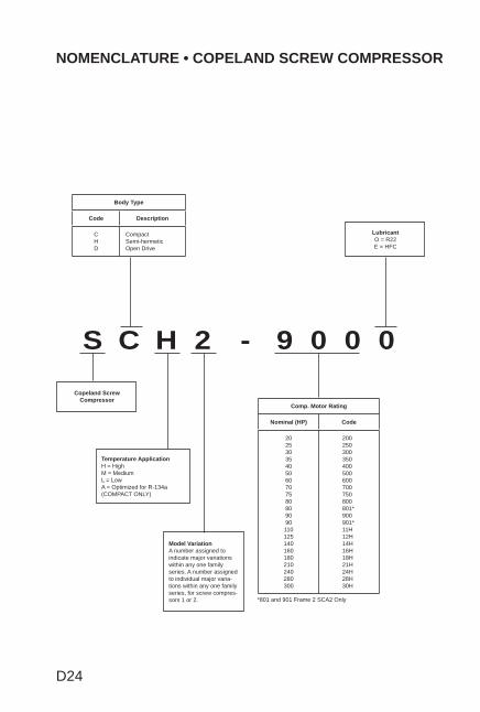
NOMENCLATURE • COPELAND SCREW COMPRESSOR
S C H 2 - 9 0 0 0
LubricantO = R22E = HFC
Copeland ScrewCompressor
Temperature ApplicationH = HighM = MediumL = LowA = Optimized for R-134a (COMPACT ONLY)
Model VariationA number assigned to indicate major variations within any one family series. A number assigned to individual major varia-tions within any one family series, for screw compres-sors 1 or 2.
Comp. Motor Rating
Nominal (HP) Code
20253035405060707580809090110125140160180210240280300
200250300350400500600700750800801*900901*11H12H14H16H18H21H24H28H30H
Body Type
Code Description
CHD
CompactSemi-hermeticOpen Drive
*801 and 901 Frame 2 SCA2 Only
D25
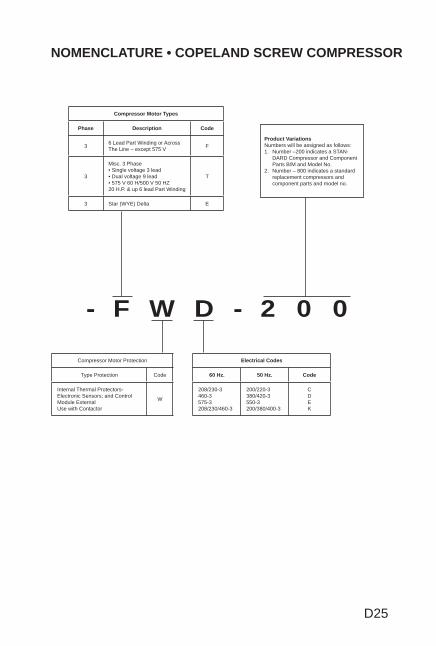
NOMENCLATURE • COPELAND SCREW COMPRESSOR
- F W D - 2 0 0
Product VariationsNumbers will be assigned as follows:1. Number –200 indicates a STAN-
DARD Compressor and Component Parts B/M and Model No.
2. Number – 800 indicates a standard replacement compressors and component parts and model no.
Compressor Motor Types
Phase Description Code
3 6 Lead Part Winding or AcrossThe Line – except 575 V F
3
Misc. 3 Phase• Single voltage 3 lead• Dual voltage 9 lead• 575 V 60 H/500 V 50 HZ20 H.P. & up 6 lead Part Winding
T
3 Star (WYE) Delta E
Compressor Motor Protection
Type Protection Code
Internal Thermal Protectors-Electronic Sensors; and Control Module ExternalUse with Contactor
W
Electrical Codes
60 Hz. 50 Hz. Code
208/230-3460-3575-3208/230/460-3
200/220-3380/420-3550-3200/380/400-3
CDEK
SECTION E
ELECTRICAL COMPONENT NOMENCLATUREAND DATA
TOPICS
Potential Relay Nomenclature .....................................E1
G.E. Numbering System .............................................E1
Potential Relay Data ...................................................E2
Current Relay Data .....................................................E7
Start Capacitor Data ..................................................E16
Run Capacitor Data ...................................................E22
This section contains current information on Copeland® products. Infor-mation on obsolete models can be obtained from your local wholesaler carrying Copeland brand products.
Section E TOC.indd 1Section E TOC.indd 1 2/21/2008 7:40:03 AM2/21/2008 7:40:03 AM
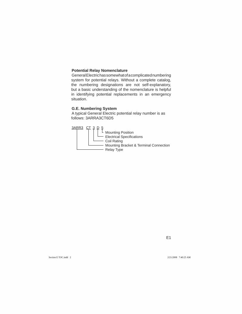
Potential Relay NomenclatureGeneral Electric has somewhat of a complicated numbering system for potential relays. Without a complete catalog, the numbering designations are not self-explanatory, but a basic understanding of the nomenclature is helpful in identifying potential replacements in an emergency situation.
G.E. Numbering SystemA typical General Electric potential relay number is as follows: 3ARRA3CT6D5
3ARR3 CT 3 D 5 Mounting Position Electrical Specifi cations Coil Rating Mounting Bracket & Terminal Connection Relay Type
E1
Section E TOC.indd 2Section E TOC.indd 2 2/21/2008 7:40:25 AM2/21/2008 7:40:25 AM
E2
Wholesaler Copeland® GE P/N Pick-up Drop Out Cont. Volt Freq. P/N Brand P/N Volts Volts Rating
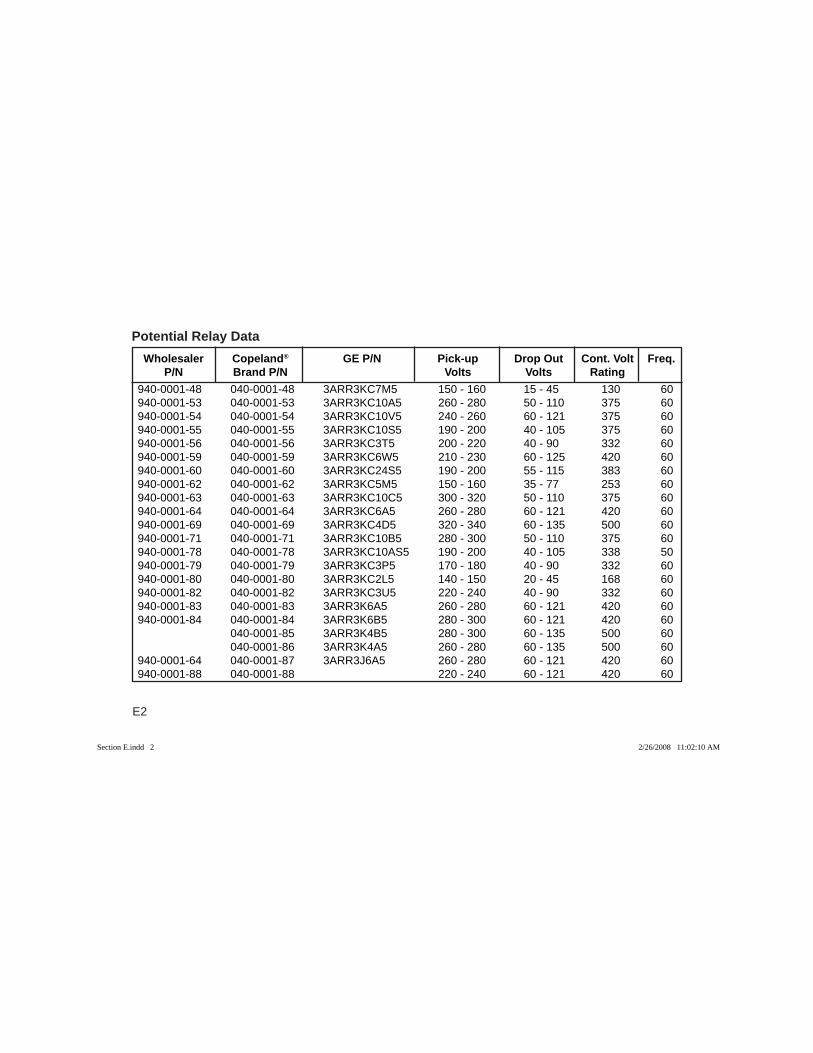
Potential Relay Data
940-0001-48 040-0001-48 3ARR3KC7M5 150 - 160 15 - 45 130 60940-0001-53 040-0001-53 3ARR3KC10A5 260 - 280 50 - 110 375 60940-0001-54 040-0001-54 3ARR3KC10V5 240 - 260 60 - 121 375 60940-0001-55 040-0001-55 3ARR3KC10S5 190 - 200 40 - 105 375 60940-0001-56 040-0001-56 3ARR3KC3T5 200 - 220 40 - 90 332 60940-0001-59 040-0001-59 3ARR3KC6W5 210 - 230 60 - 125 420 60940-0001-60 040-0001-60 3ARR3KC24S5 190 - 200 55 - 115 383 60940-0001-62 040-0001-62 3ARR3KC5M5 150 - 160 35 - 77 253 60940-0001-63 040-0001-63 3ARR3KC10C5 300 - 320 50 - 110 375 60940-0001-64 040-0001-64 3ARR3KC6A5 260 - 280 60 - 121 420 60940-0001-69 040-0001-69 3ARR3KC4D5 320 - 340 60 - 135 500 60940-0001-71 040-0001-71 3ARR3KC10B5 280 - 300 50 - 110 375 60940-0001-78 040-0001-78 3ARR3KC10AS5 190 - 200 40 - 105 338 50940-0001-79 040-0001-79 3ARR3KC3P5 170 - 180 40 - 90 332 60940-0001-80 040-0001-80 3ARR3KC2L5 140 - 150 20 - 45 168 60940-0001-82 040-0001-82 3ARR3KC3U5 220 - 240 40 - 90 332 60940-0001-83 040-0001-83 3ARR3K6A5 260 - 280 60 - 121 420 60940-0001-84 040-0001-84 3ARR3K6B5 280 - 300 60 - 121 420 60 040-0001-85 3ARR3K4B5 280 - 300 60 - 135 500 60 040-0001-86 3ARR3K4A5 260 - 280 60 - 135 500 60940-0001-64 040-0001-87 3ARR3J6A5 260 - 280 60 - 121 420 60940-0001-88 040-0001-88 220 - 240 60 - 121 420 60
Section E.indd 2Section E.indd 2 2/26/2008 11:02:10 AM2/26/2008 11:02:10 AM
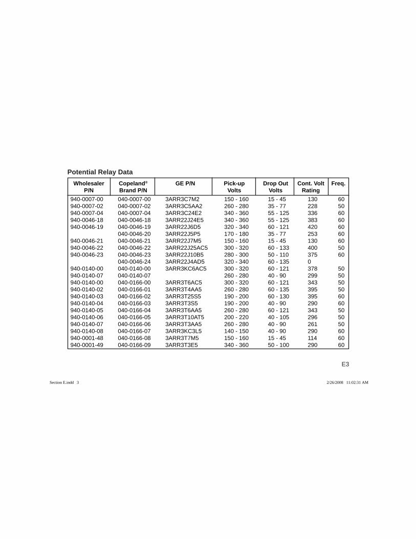
E3
940-0007-00 040-0007-00 3ARR3C7M2 150 - 160 15 - 45 130 60940-0007-02 040-0007-02 3ARR3C5AA2 260 - 280 35 - 77 228 50940-0007-04 040-0007-04 3ARR3C24E2 340 - 360 55 - 125 336 60940-0046-18 040-0046-18 3ARR22J24E5 340 - 360 55 - 125 383 60940-0046-19 040-0046-19 3ARR22J6D5 320 - 340 60 - 121 420 60 040-0046-20 3ARR22J5P5 170 - 180 35 - 77 253 60940-0046-21 040-0046-21 3ARR22J7M5 150 - 160 15 - 45 130 60940-0046-22 040-0046-22 3ARR22J25AC5 300 - 320 60 - 133 400 50940-0046-23 040-0046-23 3ARR22J10B5 280 - 300 50 - 110 375 60 040-0046-24 3ARR22J4AD5 320 - 340 60 - 135 0 940-0140-00 040-0140-00 3ARR3KC6AC5 300 - 320 60 - 121 378 50940-0140-07 040-0140-07 260 - 280 40 - 90 299 50940-0140-00 040-0166-00 3ARR3T6AC5 300 - 320 60 - 121 343 50940-0140-02 040-0166-01 3ARR3T4AA5 260 - 280 60 - 135 395 50940-0140-03 040-0166-02 3ARR3T25S5 190 - 200 60 - 130 395 60940-0140-04 040-0166-03 3ARR3T3S5 190 - 200 40 - 90 290 60940-0140-05 040-0166-04 3ARR3T6AA5 260 - 280 60 - 121 343 50940-0140-06 040-0166-05 3ARR3T10AT5 200 - 220 40 - 105 296 50940-0140-07 040-0166-06 3ARR3T3AA5 260 - 280 40 - 90 261 50940-0140-08 040-0166-07 3ARR3KC3L5 140 - 150 40 - 90 290 60940-0001-48 040-0166-08 3ARR3T7M5 150 - 160 15 - 45 114 60940-0001-49 040-0166-09 3ARR3T3E5 340 - 360 50 - 100 290 60
Wholesaler Copeland® GE P/N Pick-up Drop Out Cont. Volt Freq. P/N Brand P/N Volts Volts Rating
Potential Relay Data
Section E.indd 3Section E.indd 3 2/26/2008 11:02:31 AM2/26/2008 11:02:31 AM
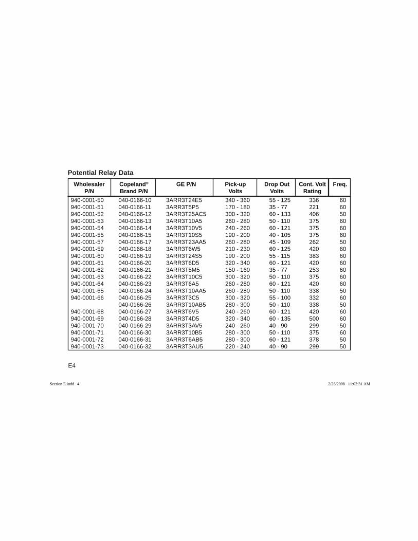
E4
940-0001-50 040-0166-10 3ARR3T24E5 340 - 360 55 - 125 336 60940-0001-51 040-0166-11 3ARR3T5P5 170 - 180 35 - 77 221 60940-0001-52 040-0166-12 3ARR3T25AC5 300 - 320 60 - 133 406 50940-0001-53 040-0166-13 3ARR3T10A5 260 - 280 50 - 110 375 60940-0001-54 040-0166-14 3ARR3T10V5 240 - 260 60 - 121 375 60940-0001-55 040-0166-15 3ARR3T10S5 190 - 200 40 - 105 375 60940-0001-57 040-0166-17 3ARR3T23AA5 260 - 280 45 - 109 262 50940-0001-59 040-0166-18 3ARR3T6W5 210 - 230 60 - 125 420 60940-0001-60 040-0166-19 3ARR3T24S5 190 - 200 55 - 115 383 60940-0001-61 040-0166-20 3ARR3T6D5 320 - 340 60 - 121 420 60940-0001-62 040-0166-21 3ARR3T5M5 150 - 160 35 - 77 253 60940-0001-63 040-0166-22 3ARR3T10C5 300 - 320 50 - 110 375 60940-0001-64 040-0166-23 3ARR3T6A5 260 - 280 60 - 121 420 60940-0001-65 040-0166-24 3ARR3T10AA5 260 - 280 50 - 110 338 50940-0001-66 040-0166-25 3ARR3T3C5 300 - 320 55 - 100 332 60 040-0166-26 3ARR3T10AB5 280 - 300 50 - 110 338 50940-0001-68 040-0166-27 3ARR3T6V5 240 - 260 60 - 121 420 60940-0001-69 040-0166-28 3ARR3T4D5 320 - 340 60 - 135 500 60940-0001-70 040-0166-29 3ARR3T3AV5 240 - 260 40 - 90 299 50940-0001-71 040-0166-30 3ARR3T10B5 280 - 300 50 - 110 375 60940-0001-72 040-0166-31 3ARR3T6AB5 280 - 300 60 - 121 378 50940-0001-73 040-0166-32 3ARR3T3AU5 220 - 240 40 - 90 299 50
Potential Relay Data Wholesaler Copeland® GE P/N Pick-up Drop Out Cont. Volt Freq. P/N Brand P/N Volts Volts Rating
Section E.indd 4Section E.indd 4 2/26/2008 11:02:31 AM2/26/2008 11:02:31 AM
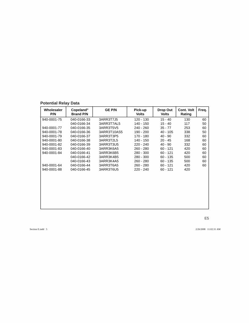
E5
Wholesaler Copeland® GE P/N Pick-up Drop Out Cont. Volt Freq. P/N Brand P/N Volts Volts Rating
Potential Relay Data
940-0001-75 040-0166-33 3ARR3T7J5 120 - 130 15 - 40 130 60 040-0166-34 3ARR3T7AL5 140 - 150 15 - 40 117 50940-0001-77 040-0166-35 3ARR3T5V5 240 - 260 35 - 77 253 60940-0001-78 040-0166-36 3ARR3T10AS5 190 - 200 40 - 105 338 50940-0001-79 040-0166-37 3ARR3T3P5 170 - 180 40 - 90 332 60940-0001-80 040-0166-38 3ARR3T2L5 140 - 150 20 - 45 168 60940-0001-82 040-0166-39 3ARR3T3U5 220 - 240 40 - 90 332 60940-0001-83 040-0166-40 3ARR3K6A5 260 - 280 60 - 121 420 60940-0001-84 040-0166-41 3ARR3K6B5 280 - 300 60 - 121 420 60 040-0166-42 3ARR3K4B5 280 - 300 60 - 135 500 60 040-0166-43 3ARR3K4A5 260 - 280 60 - 135 500 60940-0001-64 040-0166-44 3ARR3T6A5 260 - 280 60 - 121 420 60940-0001-88 040-0166-45 3ARR3T6U5 220 - 240 60 - 121 420
Section E.indd 5Section E.indd 5 2/26/2008 11:02:31 AM2/26/2008 11:02:31 AM
E6
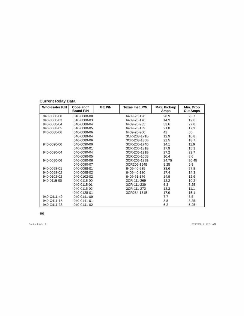
Wholesaler P/N Copeland® GE P/N Texas Inst. P/N Max. Pick-up Min. Drop Brand P/N Amps Out Amps
Current Relay Data
940-0088-00 040-0088-00 6409-26-196 28.9 23.7940-0088-03 040-0088-03 6409-26-176 14.9 12.6940-0088-04 040-0088-04 6409-26-935 33.6 27.8940-0088-05 040-0088-05 6409-26-189 21.8 17.9940-0088-06 040-0088-06 6409-26-900 42 36 040-0089-04 3CR-203-171B 12.9 10.8 040-0089-06 3CR-203-186B 22.5 18.7940-0090-00 040-0090-00 3CR-206-174B 14.1 11.9 040-0090-01 3CR-206-181B 17.9 15.1940-0090-04 040-0090-04 3CR-206-191B 27.2 22.7 040-0090-05 3CR-206-165B 10.4 8.6940-0090-06 040-0090-06 3CR-206-189B 24.75 20.45 040-0090-07 3CR206-154B 8.25 6.9940-0098-01 040-0098-01 6409-40-935 33.6 27.8940-0098-02 040-0098-02 6409-40-180 17.4 14.3940-0102-02 040-0102-02 6409-51-176 14.9 12.6940-0115-00 040-0115-00 3CR-111-269 12.2 10.2 040-0115-01 3CR-111-239 6.3 5.25 040-0115-02 3CR-111-272 13.3 11.1 040-0128-01 3CR234-181B 17.9 15.1940-C411-49 040-0141-00 7.7 6.5940-C411-18 040-0141-01 3.8 3.25940-C411-38 040-0141-02 6.2 5.25
Section E.indd 6Section E.indd 6 2/26/2008 11:02:31 AM2/26/2008 11:02:31 AM
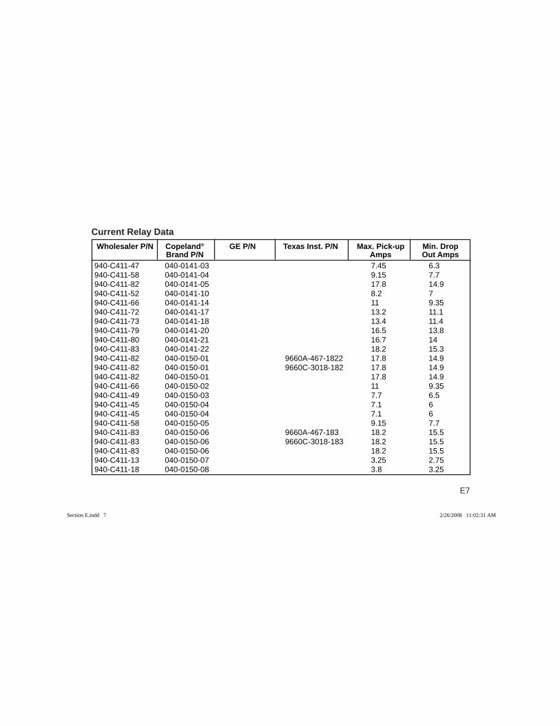
E7
Current Relay Data
940-C411-47 040-0141-03 7.45 6.3940-C411-58 040-0141-04 9.15 7.7940-C411-82 040-0141-05 17.8 14.9940-C411-52 040-0141-10 8.2 7940-C411-66 040-0141-14 11 9.35940-C411-72 040-0141-17 13.2 11.1940-C411-73 040-0141-18 13.4 11.4940-C411-79 040-0141-20 16.5 13.8940-C411-80 040-0141-21 16.7 14940-C411-83 040-0141-22 18.2 15.3940-C411-82 040-0150-01 9660A-467-1822 17.8 14.9940-C411-82 040-0150-01 9660C-3018-182 17.8 14.9940-C411-82 040-0150-01 17.8 14.9940-C411-66 040-0150-02 11 9.35940-C411-49 040-0150-03 7.7 6.5940-C411-45 040-0150-04 7.1 6940-C411-45 040-0150-04 7.1 6940-C411-58 040-0150-05 9.15 7.7940-C411-83 040-0150-06 9660A-467-183 18.2 15.5940-C411-83 040-0150-06 9660C-3018-183 18.2 15.5940-C411-83 040-0150-06 18.2 15.5940-C411-13 040-0150-07 3.25 2.75940-C411-18 040-0150-08 3.8 3.25
Wholesaler P/N Copeland® GE P/N Texas Inst. P/N Max. Pick-up Min. Drop Brand P/N Amps Out Amps
Section E.indd 7Section E.indd 7 2/26/2008 11:02:31 AM2/26/2008 11:02:31 AM
E8
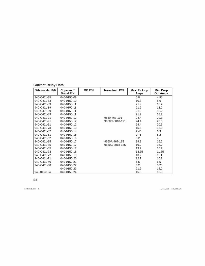
Current Relay Data
940-C411-35 040-0150-09 5.8 4.95940-C411-63 040-0150-10 10.3 8.6940-C411-89 040-0150-11 21.9 18.2940-C411-89 040-0150-11 21.9 18.2940-C411-89 040-0150-11 21.9 18.2940-C411-89 040-0150-11 21.9 18.2940-C411-91 040-0150-12 9660-467-191 24.4 20.3940-C411-91 040-0150-12 9660C-3018-191 24.4 20.3940-C411-91 040-0150-12 24.4 20.3940-C411-78 040-0150-13 15.8 13.3940-C411-47 040-0150-14 7.45 6.3940-C411-61 040-0150-15 9.75 8.2940-C411-52 040-0150-16 8.2 7940-C411-85 040-0150-17 9660A-467-185 19.2 16.2940-C411-85 040-0150-17 9660C-3018-185 19.2 16.2940-C411-85 040-0150-17 19.2 16.2940-C411-73 040-0150-18 13.35 11.35940-C411-72 040-0150-19 13.2 11.1940-C411-71 040-0150-20 12.7 10.8940-C411-40 040-0150-21 6.5 5.5940-C411-38 040-0150-22 6.2 5.25 040-0150-23 21.9 18.2940-0150-24 040-0150-24 15.8 13.3
Wholesaler P/N Copeland® GE P/N Texas Inst. P/N Max. Pick-up Min. Drop Brand P/N Amps Out Amps
Section E.indd 8Section E.indd 8 2/26/2008 11:02:31 AM2/26/2008 11:02:31 AM
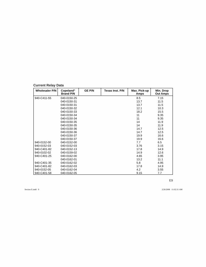
E9
Current Relay Data
940-C411-55 040-0150-25 8.5 7.15 040-0150-31 13.7 11.5 040-0150-31 13.7 11.5 040-0150-32 12.1 10.3 040-0150-33 18.2 15.5 040-0150-34 11 9.35 040-0150-34 11 9.35 040-0150-35 14 11.9 040-0150-35 14 11.9 040-0150-36 14.7 12.5 040-0150-36 14.7 12.5 040-0150-37 19.9 16.6 040-0150-37 19.9 16.6940-0152-00 040-0152-00 7.7 6.5940-0152-03 040-0152-03 3.76 3.15940-C401-82 040-0152-13 17.8 14.9940-0102-02 040-0159-02 14.9 12.6940-C401-25 040-0162-00 4.65 3.95 040-0162-01 13.2 11.1940-C401-35 040-0162-02 5.8 4.95940-C401-82 040-0162-03 17.8 14.9940-0152-05 040-0162-04 4.2 3.55940-C401-58 040-0162-05 9.15 7.7
Wholesaler P/N Copeland® GE P/N Texas Inst. P/N Max. Pick-up Min. Drop Brand P/N Amps Out Amps
Section E.indd 9Section E.indd 9 2/26/2008 11:02:31 AM2/26/2008 11:02:31 AM
E10
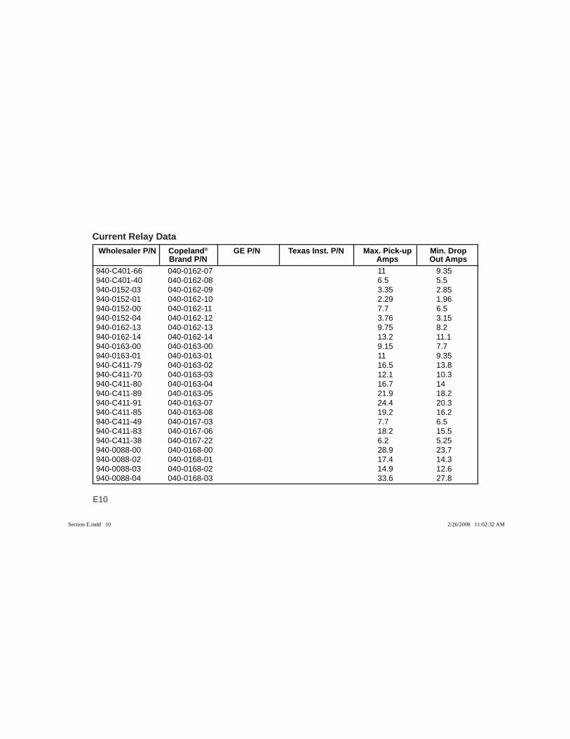
Current Relay Data
940-C401-66 040-0162-07 11 9.35940-C401-40 040-0162-08 6.5 5.5940-0152-03 040-0162-09 3.35 2.85940-0152-01 040-0162-10 2.29 1.96940-0152-00 040-0162-11 7.7 6.5940-0152-04 040-0162-12 3.76 3.15940-0162-13 040-0162-13 9.75 8.2940-0162-14 040-0162-14 13.2 11.1940-0163-00 040-0163-00 9.15 7.7940-0163-01 040-0163-01 11 9.35940-C411-79 040-0163-02 16.5 13.8940-C411-70 040-0163-03 12.1 10.3940-C411-80 040-0163-04 16.7 14940-C411-89 040-0163-05 21.9 18.2940-C411-91 040-0163-07 24.4 20.3940-C411-85 040-0163-08 19.2 16.2940-C411-49 040-0167-03 7.7 6.5940-C411-83 040-0167-06 18.2 15.5940-C411-38 040-0167-22 6.2 5.25940-0088-00 040-0168-00 28.9 23.7940-0088-02 040-0168-01 17.4 14.3940-0088-03 040-0168-02 14.9 12.6940-0088-04 040-0168-03 33.6 27.8
Wholesaler P/N Copeland® GE P/N Texas Inst. P/N Max. Pick-up Min. Drop Brand P/N Amps Out Amps
Section E.indd 10Section E.indd 10 2/26/2008 11:02:32 AM2/26/2008 11:02:32 AM
E11
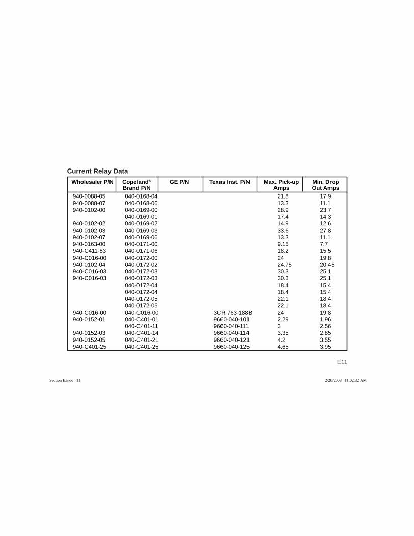
Current Relay Data Wholesaler P/N Copeland® GE P/N Texas Inst. P/N Max. Pick-up Min. Drop Brand P/N Amps Out Amps
940-0088-05 040-0168-04 21.8 17.9940-0088-07 040-0168-06 13.3 11.1940-0102-00 040-0169-00 28.9 23.7 040-0169-01 17.4 14.3940-0102-02 040-0169-02 14.9 12.6940-0102-03 040-0169-03 33.6 27.8940-0102-07 040-0169-06 13.3 11.1940-0163-00 040-0171-00 9.15 7.7940-C411-83 040-0171-06 18.2 15.5940-C016-00 040-0172-00 24 19.8940-0102-04 040-0172-02 24.75 20.45940-C016-03 040-0172-03 30.3 25.1940-C016-03 040-0172-03 30.3 25.1 040-0172-04 18.4 15.4 040-0172-04 18.4 15.4 040-0172-05 22.1 18.4 040-0172-05 22.1 18.4940-C016-00 040-C016-00 3CR-763-188B 24 19.8940-0152-01 040-C401-01 9660-040-101 2.29 1.96 040-C401-11 9660-040-111 3 2.56940-0152-03 040-C401-14 9660-040-114 3.35 2.85940-0152-05 040-C401-21 9660-040-121 4.2 3.55940-C401-25 040-C401-25 9660-040-125 4.65 3.95
Section E.indd 11Section E.indd 11 2/26/2008 11:02:32 AM2/26/2008 11:02:32 AM
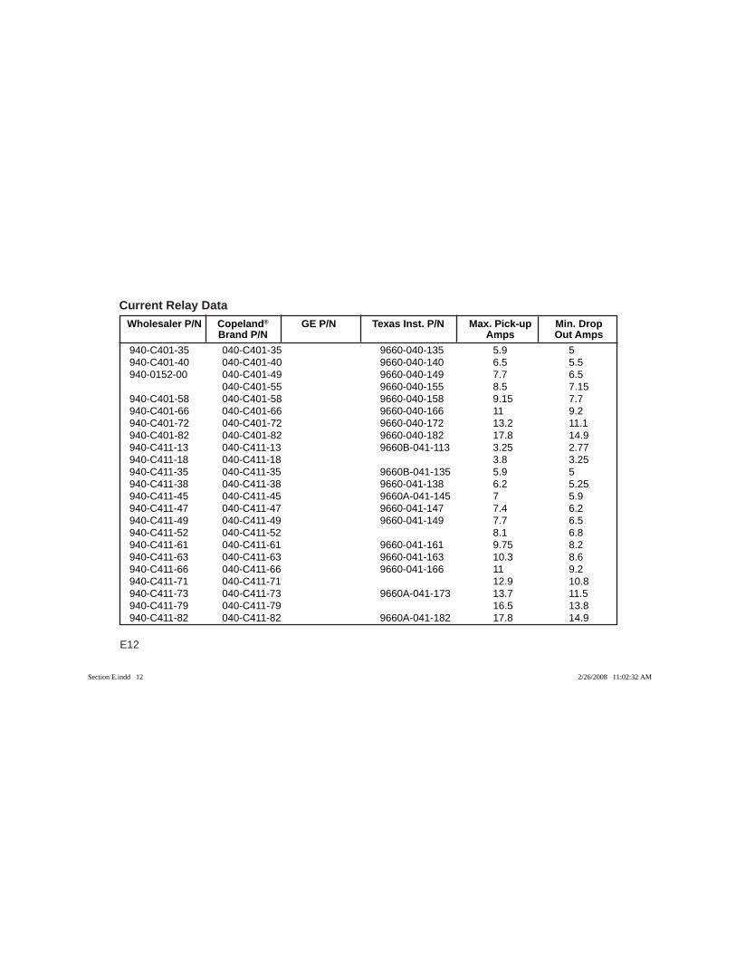
E12
Current Relay Data Wholesaler P/N Copeland® GE P/N Texas Inst. P/N Max. Pick-up Min. Drop Brand P/N Amps Out Amps
940-C401-35 040-C401-35 9660-040-135 5.9 5940-C401-40 040-C401-40 9660-040-140 6.5 5.5940-0152-00 040-C401-49 9660-040-149 7.7 6.5 040-C401-55 9660-040-155 8.5 7.15940-C401-58 040-C401-58 9660-040-158 9.15 7.7940-C401-66 040-C401-66 9660-040-166 11 9.2940-C401-72 040-C401-72 9660-040-172 13.2 11.1940-C401-82 040-C401-82 9660-040-182 17.8 14.9940-C411-13 040-C411-13 9660B-041-113 3.25 2.77940-C411-18 040-C411-18 3.8 3.25940-C411-35 040-C411-35 9660B-041-135 5.9 5940-C411-38 040-C411-38 9660-041-138 6.2 5.25940-C411-45 040-C411-45 9660A-041-145 7 5.9940-C411-47 040-C411-47 9660-041-147 7.4 6.2940-C411-49 040-C411-49 9660-041-149 7.7 6.5940-C411-52 040-C411-52 8.1 6.8940-C411-61 040-C411-61 9660-041-161 9.75 8.2940-C411-63 040-C411-63 9660-041-163 10.3 8.6940-C411-66 040-C411-66 9660-041-166 11 9.2940-C411-71 040-C411-71 12.9 10.8940-C411-73 040-C411-73 9660A-041-173 13.7 11.5940-C411-79 040-C411-79 16.5 13.8940-C411-82 040-C411-82 9660A-041-182 17.8 14.9
Section E.indd 12Section E.indd 12 2/26/2008 11:02:32 AM2/26/2008 11:02:32 AM
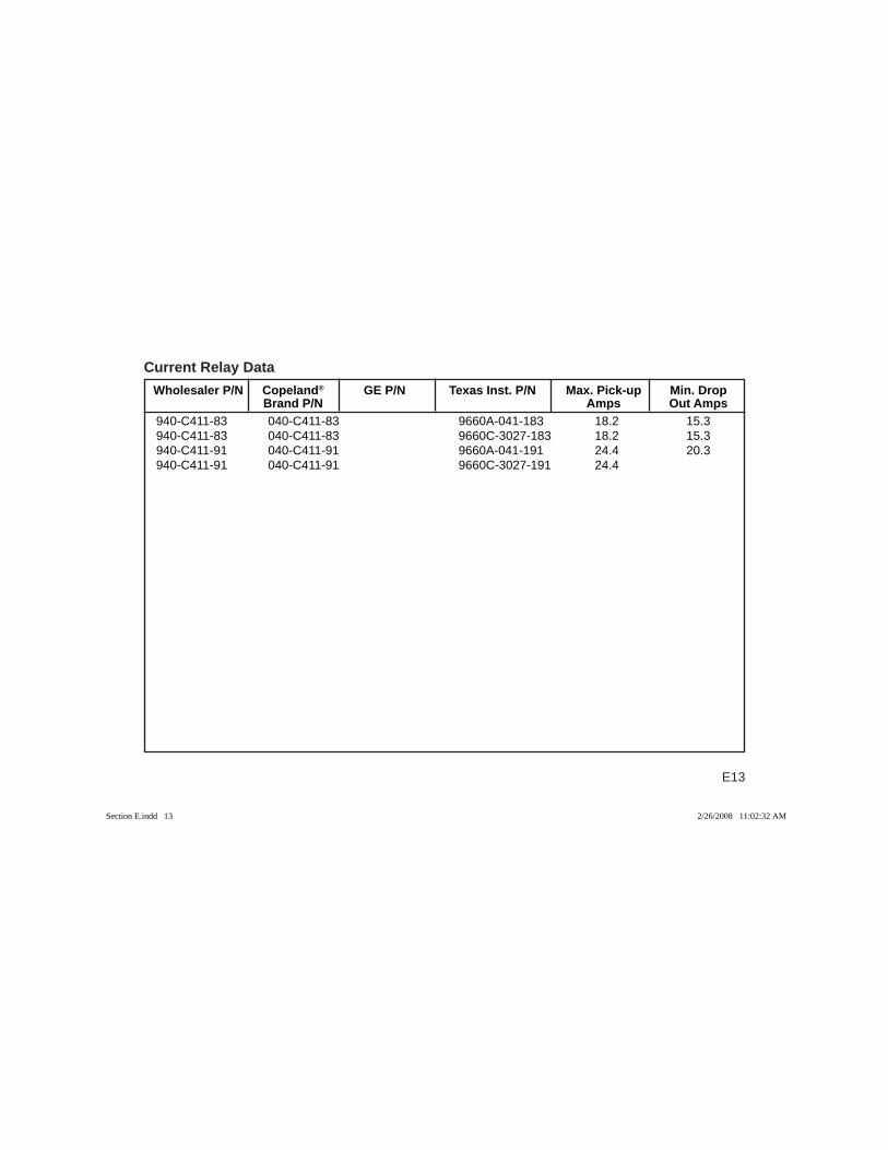
E13
Current Relay Data Wholesaler P/N Copeland® GE P/N Texas Inst. P/N Max. Pick-up Min. Drop Brand P/N Amps Out Amps
940-C411-83 040-C411-83 9660A-041-183 18.2 15.3940-C411-83 040-C411-83 9660C-3027-183 18.2 15.3940-C411-91 040-C411-91 9660A-041-191 24.4 20.3940-C411-91 040-C411-91 9660C-3027-191 24.4
Section E.indd 13Section E.indd 13 2/26/2008 11:02:32 AM2/26/2008 11:02:32 AM
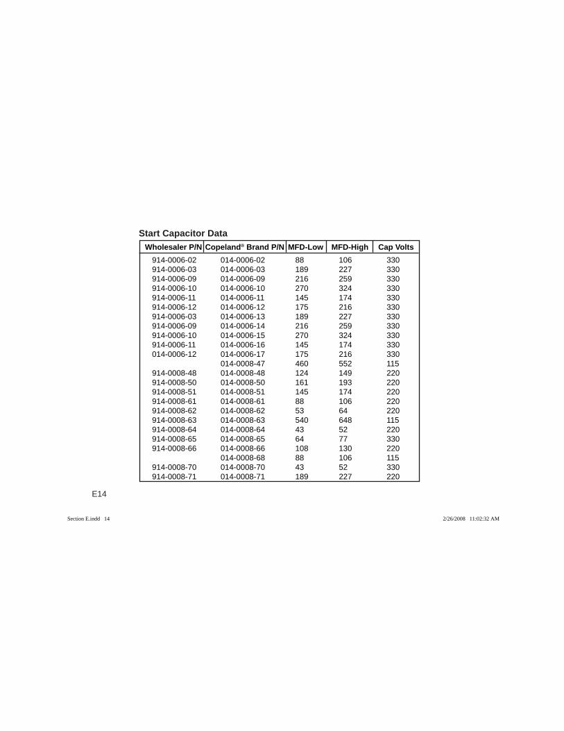
E14
Wholesaler P/N Copeland® Brand P/N MFD-Low MFD-High Cap VoltsStart Capacitor Data
914-0006-02 014-0006-02 88 106 330914-0006-03 014-0006-03 189 227 330914-0006-09 014-0006-09 216 259 330914-0006-10 014-0006-10 270 324 330914-0006-11 014-0006-11 145 174 330914-0006-12 014-0006-12 175 216 330914-0006-03 014-0006-13 189 227 330914-0006-09 014-0006-14 216 259 330914-0006-10 014-0006-15 270 324 330914-0006-11 014-0006-16 145 174 330014-0006-12 014-0006-17 175 216 330 014-0008-47 460 552 115914-0008-48 014-0008-48 124 149 220914-0008-50 014-0008-50 161 193 220914-0008-51 014-0008-51 145 174 220914-0008-61 014-0008-61 88 106 220914-0008-62 014-0008-62 53 64 220914-0008-63 014-0008-63 540 648 115914-0008-64 014-0008-64 43 52 220914-0008-65 014-0008-65 64 77 330914-0008-66 014-0008-66 108 130 220 014-0008-68 88 106 115914-0008-70 014-0008-70 43 52 330914-0008-71 014-0008-71 189 227 220
Section E.indd 14Section E.indd 14 2/26/2008 11:02:32 AM2/26/2008 11:02:32 AM
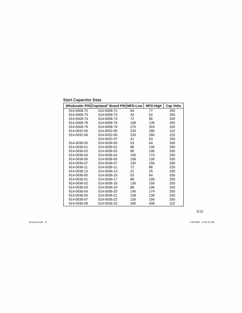
E15
914-0008-72 014-0008-72 64 77 250914-0008-73 014-0008-73 43 52 250914-0008-74 014-0008-74 72 86 330914-0008-78 014-0008-78 108 130 250914-0008-79 014-0008-79 270 324 165914-0032-00 014-0032-00 233 280 110914-0032-06 014-0032-06 233 280 125 014-0032-07 41 53 250914-0036-00 014-0036-00 53 64 330914-0036-01 014-0036-01 88 106 250914-0036-03 014-0036-03 88 106 330914-0036-04 014-0036-04 145 174 250914-0036-05 014-0036-05 108 130 330914-0036-07 014-0036-07 130 156 330914-0036-11 014-0036-11 72 88 220914-0036-13 014-0036-13 21 25 330914-0036-00 014-0036-16 53 64 330914-0036-01 014-0036-17 88 106 250914-0036-02 014-0036-18 130 156 250914-0036-03 014-0036-19 88 106 330914-0036-04 014-0036-20 145 174 250914-0036-05 014-0036-21 108 130 330914-0036-07 014-0036-22 130 156 330914-0036-08 014-0036-23 340 408 110
Wholesaler P/N Copeland® Brand P/N MFD-Low MFD-High Cap VoltsStart Capacitor Data
Section E.indd 15Section E.indd 15 2/26/2008 11:02:32 AM2/26/2008 11:02:32 AM
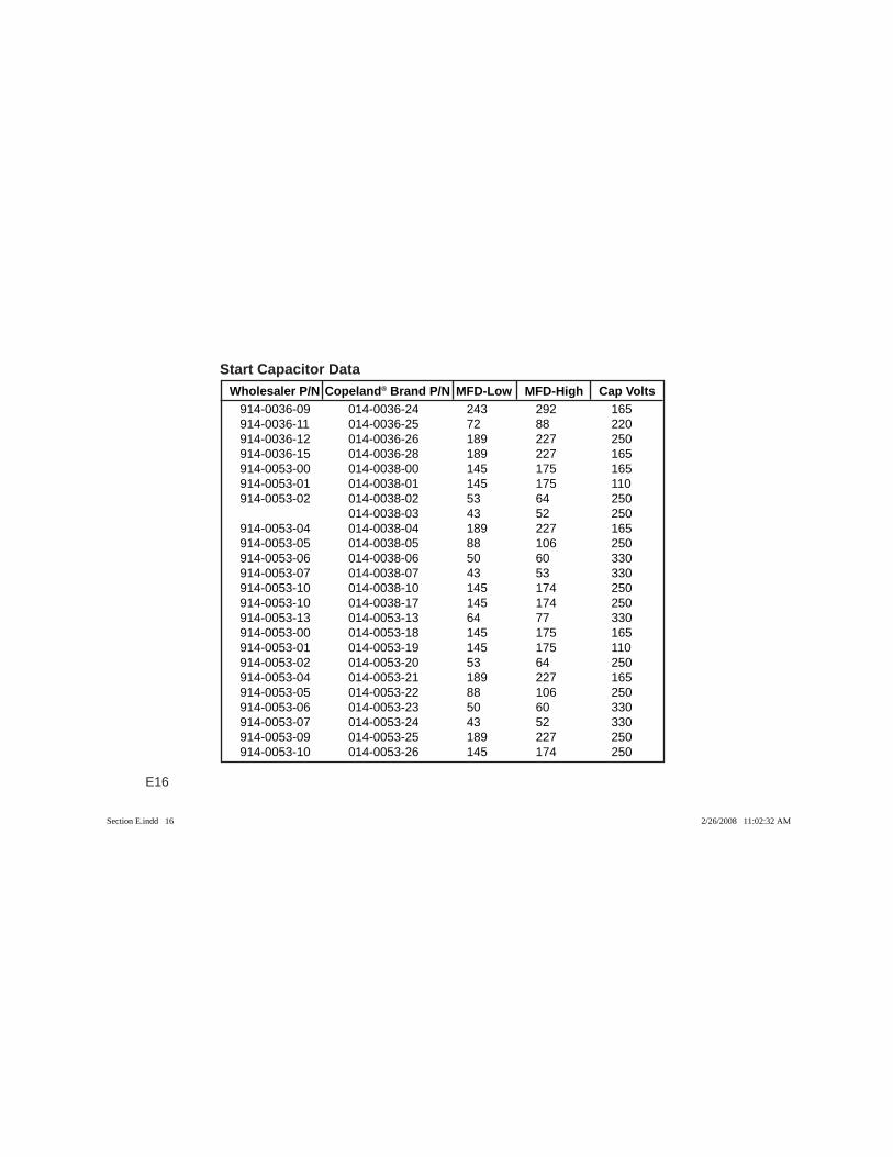
E16
914-0036-09 014-0036-24 243 292 165914-0036-11 014-0036-25 72 88 220914-0036-12 014-0036-26 189 227 250914-0036-15 014-0036-28 189 227 165914-0053-00 014-0038-00 145 175 165914-0053-01 014-0038-01 145 175 110914-0053-02 014-0038-02 53 64 250 014-0038-03 43 52 250914-0053-04 014-0038-04 189 227 165914-0053-05 014-0038-05 88 106 250914-0053-06 014-0038-06 50 60 330914-0053-07 014-0038-07 43 53 330914-0053-10 014-0038-10 145 174 250914-0053-10 014-0038-17 145 174 250914-0053-13 014-0053-13 64 77 330914-0053-00 014-0053-18 145 175 165914-0053-01 014-0053-19 145 175 110914-0053-02 014-0053-20 53 64 250914-0053-04 014-0053-21 189 227 165914-0053-05 014-0053-22 88 106 250914-0053-06 014-0053-23 50 60 330914-0053-07 014-0053-24 43 52 330914-0053-09 014-0053-25 189 227 250914-0053-10 014-0053-26 145 174 250
Wholesaler P/N Copeland® Brand P/N MFD-Low MFD-High Cap VoltsStart Capacitor Data
Section E.indd 16Section E.indd 16 2/26/2008 11:02:32 AM2/26/2008 11:02:32 AM
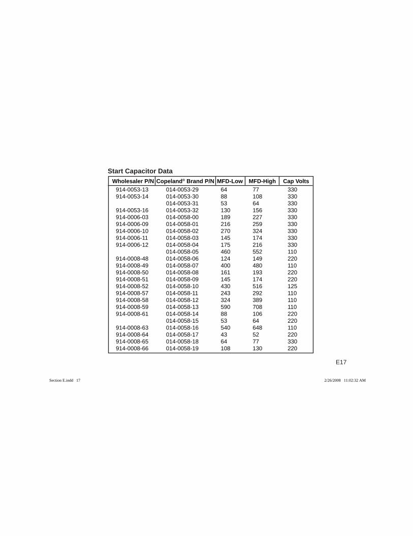
E17
914-0053-13 014-0053-29 64 77 330914-0053-14 014-0053-30 88 108 330 014-0053-31 53 64 330914-0053-16 014-0053-32 130 156 330914-0006-03 014-0058-00 189 227 330914-0006-09 014-0058-01 216 259 330914-0006-10 014-0058-02 270 324 330914-0006-11 014-0058-03 145 174 330914-0006-12 014-0058-04 175 216 330 014-0058-05 460 552 110914-0008-48 014-0058-06 124 149 220914-0008-49 014-0058-07 400 480 110914-0008-50 014-0058-08 161 193 220914-0008-51 014-0058-09 145 174 220914-0008-52 014-0058-10 430 516 125914-0008-57 014-0058-11 243 292 110914-0008-58 014-0058-12 324 389 110914-0008-59 014-0058-13 590 708 110914-0008-61 014-0058-14 88 106 220 014-0058-15 53 64 220914-0008-63 014-0058-16 540 648 110914-0008-64 014-0058-17 43 52 220914-0008-65 014-0058-18 64 77 330914-0008-66 014-0058-19 108 130 220
Wholesaler P/N Copeland® Brand P/N MFD-Low MFD-High Cap VoltsStart Capacitor Data
Section E.indd 17Section E.indd 17 2/26/2008 11:02:32 AM2/26/2008 11:02:32 AM
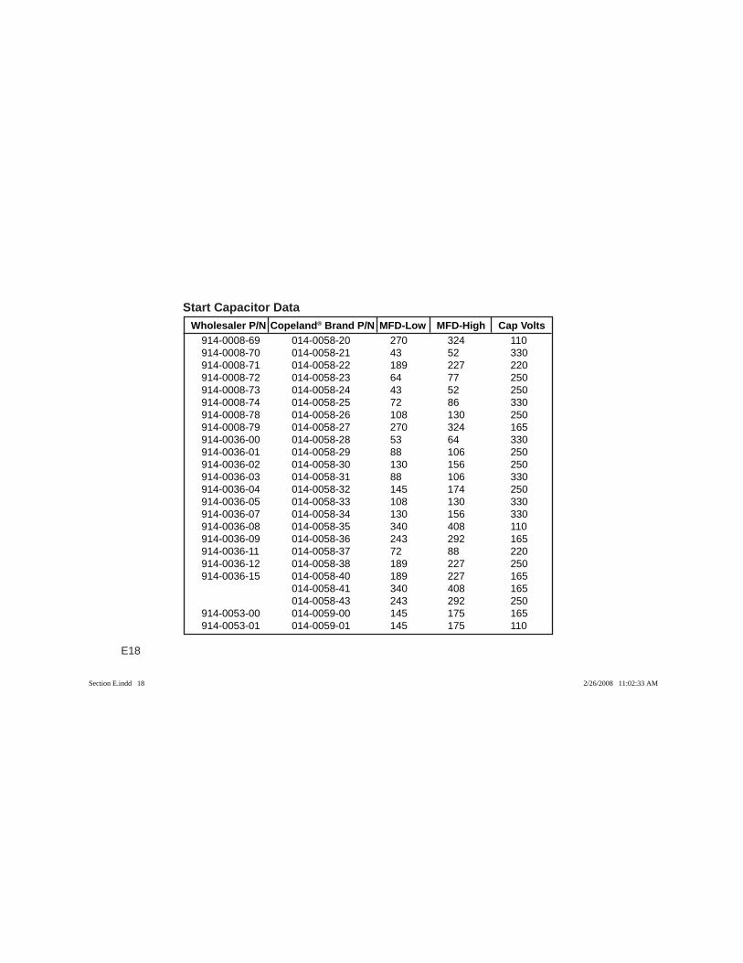
E18
Wholesaler P/N Copeland® Brand P/N MFD-Low MFD-High Cap VoltsStart Capacitor Data
914-0008-69 014-0058-20 270 324 110914-0008-70 014-0058-21 43 52 330914-0008-71 014-0058-22 189 227 220914-0008-72 014-0058-23 64 77 250914-0008-73 014-0058-24 43 52 250914-0008-74 014-0058-25 72 86 330914-0008-78 014-0058-26 108 130 250914-0008-79 014-0058-27 270 324 165914-0036-00 014-0058-28 53 64 330914-0036-01 014-0058-29 88 106 250914-0036-02 014-0058-30 130 156 250914-0036-03 014-0058-31 88 106 330914-0036-04 014-0058-32 145 174 250914-0036-05 014-0058-33 108 130 330914-0036-07 014-0058-34 130 156 330914-0036-08 014-0058-35 340 408 110914-0036-09 014-0058-36 243 292 165914-0036-11 014-0058-37 72 88 220914-0036-12 014-0058-38 189 227 250914-0036-15 014-0058-40 189 227 165 014-0058-41 340 408 165 014-0058-43 243 292 250914-0053-00 014-0059-00 145 175 165914-0053-01 014-0059-01 145 175 110
Section E.indd 18Section E.indd 18 2/26/2008 11:02:33 AM2/26/2008 11:02:33 AM
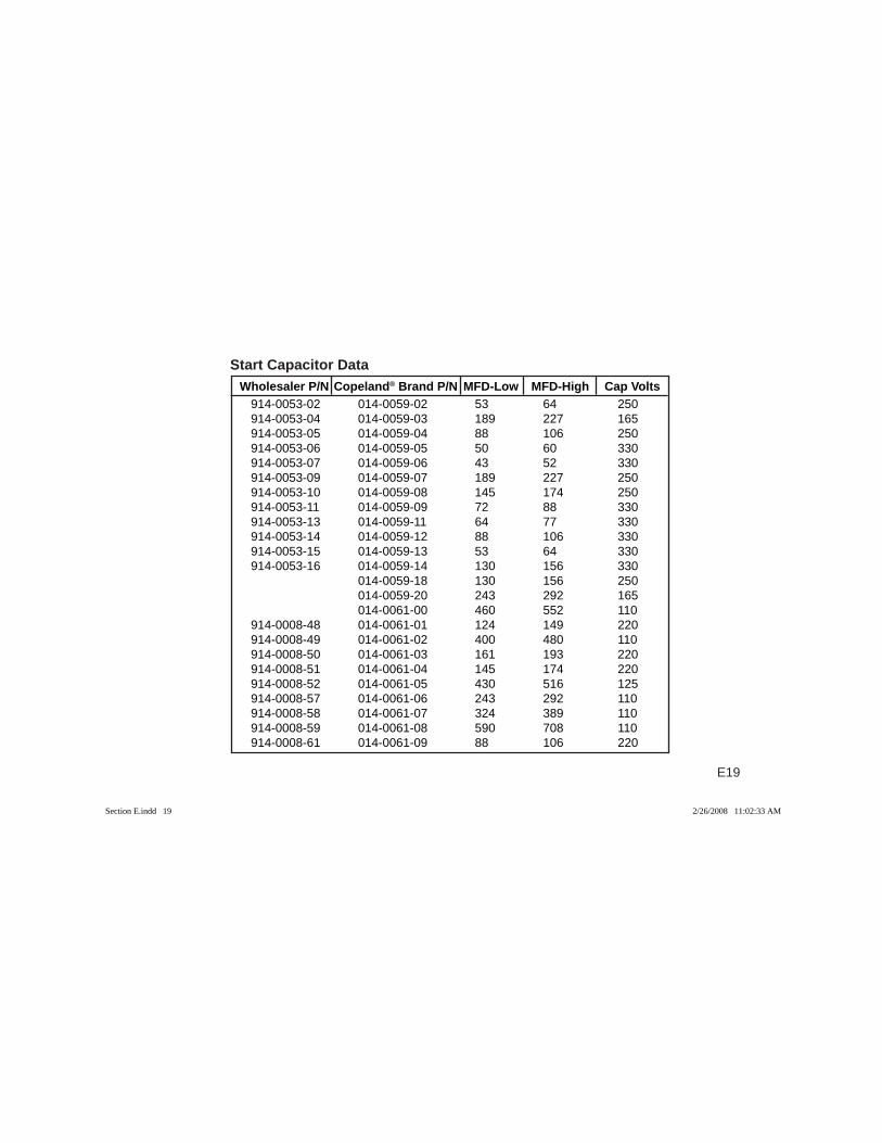
E19
Wholesaler P/N Copeland® Brand P/N MFD-Low MFD-High Cap VoltsStart Capacitor Data
914-0053-02 014-0059-02 53 64 250914-0053-04 014-0059-03 189 227 165914-0053-05 014-0059-04 88 106 250914-0053-06 014-0059-05 50 60 330914-0053-07 014-0059-06 43 52 330914-0053-09 014-0059-07 189 227 250914-0053-10 014-0059-08 145 174 250914-0053-11 014-0059-09 72 88 330914-0053-13 014-0059-11 64 77 330914-0053-14 014-0059-12 88 106 330914-0053-15 014-0059-13 53 64 330914-0053-16 014-0059-14 130 156 330 014-0059-18 130 156 250 014-0059-20 243 292 165 014-0061-00 460 552 110914-0008-48 014-0061-01 124 149 220914-0008-49 014-0061-02 400 480 110914-0008-50 014-0061-03 161 193 220914-0008-51 014-0061-04 145 174 220914-0008-52 014-0061-05 430 516 125914-0008-57 014-0061-06 243 292 110914-0008-58 014-0061-07 324 389 110914-0008-59 014-0061-08 590 708 110914-0008-61 014-0061-09 88 106 220
Section E.indd 19Section E.indd 19 2/26/2008 11:02:33 AM2/26/2008 11:02:33 AM
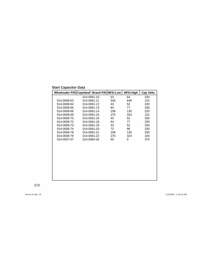
E20
Wholesaler P/N Copeland® Brand P/N MFD-Low MFD-High Cap VoltsStart Capacitor Data
014-0061-10 53 64 220914-0008-63 014-0061-11 540 648 110914-0008-64 014-0061-12 43 52 220914-0008-65 014-0061-13 64 77 330914-0008-66 014-0061-14 108 130 220914-0008-69 014-0061-15 270 324 110914-0008-70 014-0061-16 43 52 330914-0008-72 014-0061-18 64 77 250914-0008-73 014-0061-19 43 52 250914-0008-74 014-0061-20 72 86 330914-0008-78 014-0061-21 108 130 250914-0008-79 014-0061-22 270 324 165914-0037-07 014-0064-26 60 0 370
Section E.indd 20Section E.indd 20 2/26/2008 11:02:33 AM2/26/2008 11:02:33 AM
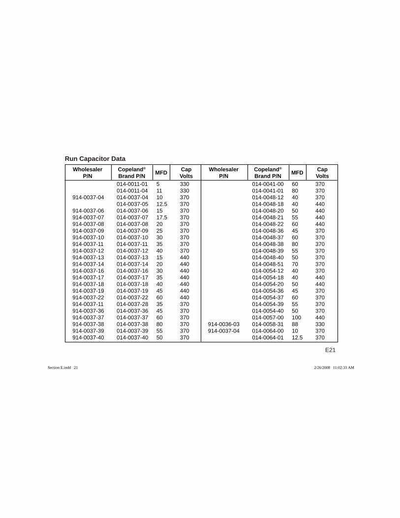
E21
Wholesaler Copeland® MFD Cap P/N Brand P/N Volts
Wholesaler Copeland® MFD Cap P/N Brand P/N Volts
Run Capacitor Data
014-0011-01 5 330 014-0011-04 11 330914-0037-04 014-0037-04 10 370 014-0037-05 12.5 370914-0037-06 014-0037-06 15 370914-0037-07 014-0037-07 17.5 370914-0037-08 014-0037-08 20 370914-0037-09 014-0037-09 25 370914-0037-10 014-0037-10 30 370914-0037-11 014-0037-11 35 370914-0037-12 014-0037-12 40 370914-0037-13 014-0037-13 15 440914-0037-14 014-0037-14 20 440914-0037-16 014-0037-16 30 440914-0037-17 014-0037-17 35 440914-0037-18 014-0037-18 40 440914-0037-19 014-0037-19 45 440914-0037-22 014-0037-22 60 440914-0037-11 014-0037-28 35 370914-0037-36 014-0037-36 45 370914-0037-37 014-0037-37 60 370914-0037-38 014-0037-38 80 370914-0037-39 014-0037-39 55 370914-0037-40 014-0037-40 50 370
014-0041-00 60 370 014-0041-01 80 370 014-0048-12 40 370 014-0048-18 40 440 014-0048-20 50 440 014-0048-21 55 440 014-0048-22 60 440 014-0048-36 45 370 014-0048-37 60 370 014-0048-38 80 370 014-0048-39 55 370 014-0048-40 50 370 014-0048-51 70 370 014-0054-12 40 370 014-0054-18 40 440 014-0054-20 50 440 014-0054-36 45 370 014-0054-37 60 370 014-0054-39 55 370 014-0054-40 50 370 014-0057-00 100 440914-0036-03 014-0058-31 88 330914-0037-04 014-0064-00 10 370 014-0064-01 12.5 370
Section E.indd 21Section E.indd 21 2/26/2008 11:02:33 AM2/26/2008 11:02:33 AM
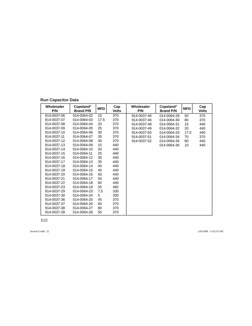
E22
914-0037-06 014-0064-02 15 370914-0037-07 014-0064-03 17.5 370914-0037-08 014-0064-04 20 370914-0037-09 014-0064-05 25 370914-0037-10 014-0064-06 30 370914-0037-11 014-0064-07 35 370914-0037-12 014-0064-08 40 370914-0037-13 014-0064-09 15 440914-0037-14 014-0064-10 20 440914-0037-15 014-0064-11 25 440914-0037-16 014-0064-12 30 440914-0037-17 014-0064-13 35 440914-0037-18 014-0064-14 40 440914-0037-19 014-0064-15 45 440914-0037-20 014-0064-16 50 440914-0037-21 014-0064-17 55 440914-0037-22 014-0064-18 60 440914-0037-23 014-0064-19 25 482914-0037-29 014-0064-23 7.5 330914-0037-30 014-0064-24 5 330914-0037-36 014-0064-25 45 370914-0037-37 014-0064-26 60 370914-0037-38 014-0064-27 80 370914-0037-39 014-0064-28 55 370
Wholesaler Copeland® MFD Cap P/N Brand P/N Volts
Wholesaler Copeland® MFD Cap P/N Brand P/N Volts
Run Capacitor Data
914-0037-40 014-0064-29 50 370914-0037-46 014-0064-30 80 370914-0037-48 014-0064-31 15 440914-0037-49 014-0064-32 20 440914-0037-50 014-0064-33 17.5 440914-0037-51 014-0064-34 70 370914-0037-52 014-0064-35 80 440 014-0064-36 10 440
Section E.indd 22Section E.indd 22 2/26/2008 11:02:33 AM2/26/2008 11:02:33 AM
SECTION F
COMPRESSOR ELECTRICAL DATA
TOPICS
Introduction .................................................................. F2
A-Line .......................................................................... FA
Welded Compressors ..................................................FB
Copelametic Air-Cooled ...............................................FC
Copelametic Small Refrigerant-Cooled .......................FD
Copelametic Large Refrigerant-Cooled .......................FE
Copeland Scroll ........................................................... FF
Copeland Screw ..........................................................FG
This section contains current information on Copeland® products. Information on obsolete models can be obtained from your local Emerson Climate Technologies, Inc. wholesaler.
Section F TOC.indd 1Section F TOC.indd 1 2/5/2008 10:00:51 AM2/5/2008 10:00:51 AM
F2
IntroductionThe electrical data is listed as an aid to the serviceman in determining compressor characteristics.
As required by U.L. requirements based on the National Electric Code, the terms nameplate amperage and full load amps have been replaced by the term “Rated Load Amps” (RLA). The value shown on the compressor nameplate is complicated by the fact that while normal operating amperage draw can be determined on a com-plete system by test, a compressor could really have an infi nite number of operating conditions depending on its application.
In order to provide a uniform basis of 71% of maximumcontinuous current allowed by the motor protection sys-tem. This will allow the compressor to draw 140% of therated load amp value prior to the protector tripping. Rated Load Amp values are not marked on new Co-pelametic, welded or scroll compressor nameplates un-less otherwise specifi ed by an equipment manufacturer.
Since one motor design may be used in a number of different compressor models, using different refrigerants, for different operating ranges, the Rated Load Amp valueshown in the handbook may vary from the value markedon individual compressor nameplates. The handbook value is usually selected as the highest nameplate value used for a given motor, so it is always a conserva-tive value which may be safely used in the event exact nameplate values are not known.
If refrigerant application specifi c RLA is required, this can be calculated from refrigerant application specifi c Maximum Continuous Current (MCC) listed in Emerson Climate Technologies, Inc. Online Product Information (OPI).
Section F TOC.indd 2Section F TOC.indd 2 2/5/2008 10:00:56 AM2/5/2008 10:00:56 AM
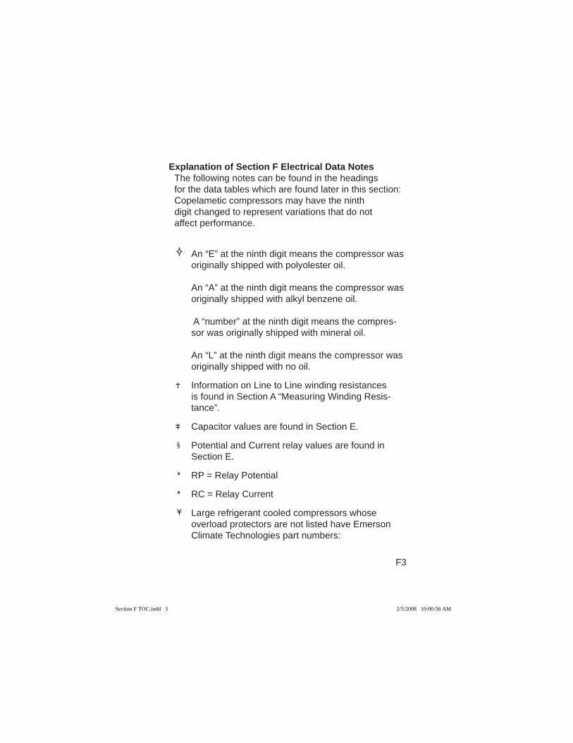
F3
Explanation of Section F Electrical Data NotesThe following notes can be found in the headingsfor the data tables which are found later in this section:Copelametic compressors may have the ninthdigit changed to represent variations that do notaffect performance.
An “E” at the ninth digit means the compressor was originally shipped with polyolester oil.
An “A” at the ninth digit means the compressor was
originally shipped with alkyl benzene oil.
A “number” at the ninth digit means the compres-sor was originally shipped with mineral oil.
An “L” at the ninth digit means the compressor was originally shipped with no oil.
Information on Line to Line winding resistances is found in Section A “Measuring Winding Resis-tance”.
Capacitor values are found in Section E.
Potential and Current relay values are found in Section E.
* RP = Relay Potential
* RC = Relay Current
Large refrigerant cooled compressors whose overload protectors are not listed have Emerson Climate Technologies part numbers:
Section F TOC.indd 3Section F TOC.indd 3 2/5/2008 10:00:56 AM2/5/2008 10:00:56 AM
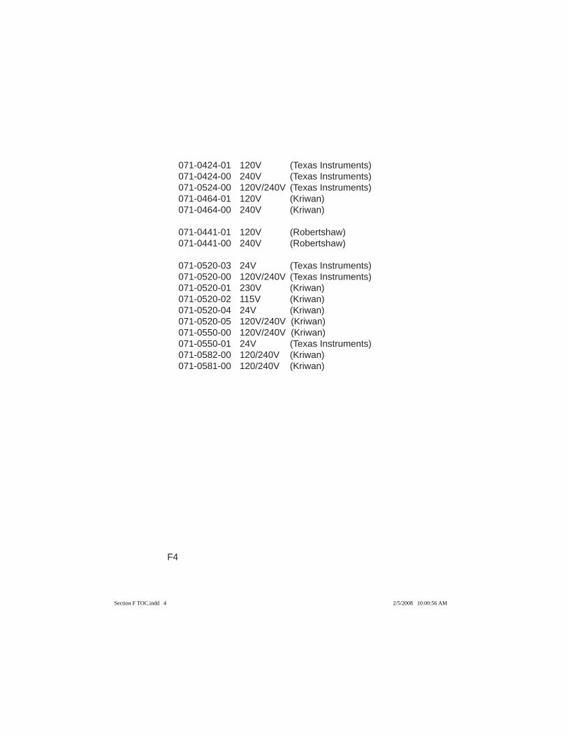
F4
071-0424-01 120V (Texas Instruments)071-0424-00 240V (Texas Instruments)071-0524-00 120V/240V (Texas Instruments)071-0464-01 120V (Kriwan)071-0464-00 240V (Kriwan)
071-0441-01 120V (Robertshaw)071-0441-00 240V (Robertshaw)
071-0520-03 24V (Texas Instruments)071-0520-00 120V/240V (Texas Instruments)071-0520-01 230V (Kriwan)071-0520-02 115V (Kriwan)071-0520-04 24V (Kriwan)071-0520-05 120V/240V (Kriwan)071-0550-00 120V/240V (Kriwan)071-0550-01 24V (Texas Instruments)071-0582-00 120/240V (Kriwan)071-0581-00 120/240V (Kriwan)
Section F TOC.indd 4Section F TOC.indd 4 2/5/2008 10:00:56 AM2/5/2008 10:00:56 AM
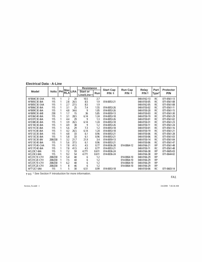
FA1 * See Section F Introduction for more information.
Electrical Data - A-Line
Max
Resistance
Model Volts PH RLA LRA Start or Run Start Cap Run Cap Relay Part Protector
Line/Line P/N P/N P/N Type* P/N
AFB04C3E-SAA 115 1 2 20 10.5 2.7 040-0162-13 RC 071-0561-13AFB05C3E-IAA 115 1 2.8 26.5 8.5 1.9 014-0053-21 040-0150-05 RC 071-0561-08AFB05C3E-SAA 115 1 2.7 27.5 8.5 1.9 040-0162-05 RC 071-0561-08AFB06C3E-IAA 115 1 3.1 25 7.4 1.55 014-0053-26 040-0150-02 RC 071-0561-11AFB09C3E-IAA 115 1 4.8 34.6 9 1.05 014-0053-26 040-0150-20 RC 071-0561-15AFB09C3E-IAB 230 1 1.7 15 36 5.85 014-0059-13 040-0150-03 RC 071-0561-30AFE06C4E-IAA 115 1 3.1 28.5 6.14 1.24 014-0053-18 040-0150-19 RC 071-0561-29AFE07C3E-IAA 115 1 4.4 29 9 1.3 014-0053-26 040-0150-01 RC 071-0561-02AFE08C4E-IAA 115 1 3.9 26.5 6.14 1.24 014-0053-18 040-0150-31 RC 071-0561-23AFE10C3E-IAA 115 1 4.9 38 9 1.2 014-0053-26 040-0150-11 RC 071-0561-24AFE11C3E-IAA 115 1 5.6 29 7.3 1.2 014-0053-18 040-0150-01 RC 071-0561-16AFE11C4E-IAA 115 1 4.2 26.5 6.14 1.24 014-0053-18 040-0150-19 RC 071-0561-21AFE12C3E-IAA 115 1 4.8 33 6.1 0.96 014-0053-21 040-0150-06 RC 071-0561-28AFE13C3E-IAA 115 1 5.8 33 6.1 0.96 014-0053-21 040-0150-06 RC 071-0561-03AFE13C3E-IAV 208/230 1 3.2 21.7 21.9 3.4 014-0059-13 040-0150-14 RC 071-0561-04AFE13C4E-IAA 115 1 5.6 37.5 6.1 0.96 014-0053-21 040-0150-06 RC 071-0561-47AFE17C4E-CAA 115 1 7.8 41.5 4.5 0.77 014-0036-28 014-0064-12 040-0166-21 RP 071-0561-48AFE17C4E-IAA 115 1 7.8 41.5 4.5 0.77 014-0053-21 040-0150-11 RC 071-0561-48AFJ23C1-IAA 115 1 7.2 59 4.771 0.611 014-0036-24 040-0166-38 RP 071-0605-03AFJ23C2-IAA 115 1 9.2 54 4.771 0.611 014-0036-24 040-0166-38 RP 071-0644-02AFJ31C1E-CFV 208/230 1 5.4 40 6 1.2 014-0064-10 040-0166-29 RP AFJ31C2E-CFV 208/230 1 7.5 44 6 1.2 014-0064-10 040-0166-29 RP AFJ37C1E-CFV 208/230 1 6.2 40 6 1.2 014-0064-10 040-0166-29 RP AFJ37C2E-CFV 208/230 1 8 46 6 1.2 014-0064-10 040-0166-29 RP AFT12C1-IAA 115 1 5 30 6.51 0.99 014-0053-18 040-0150-06 RC 071-0603-14
Section_Fa.indd 1Section_Fa.indd 1 3/4/2008 7:45:36 AM3/4/2008 7:45:36 AM
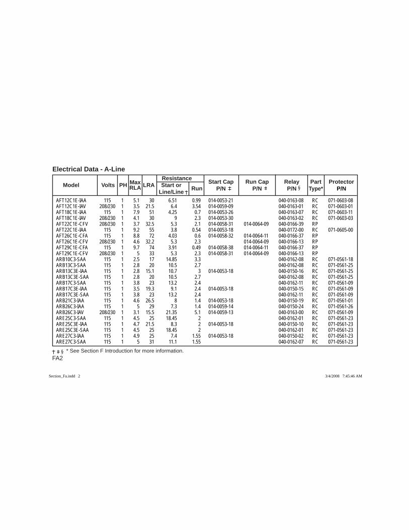
FA2 * See Section F Introduction for more information.
Electrical Data - A-Line
Max Resistance
Model Volts PH RLA LRA Start or Run Start Cap Run Cap Relay Part Protector
Line/Line P/N P/N P/N Type* P/N
AFT12C1E-IAA 115 1 5.1 30 6.51 0.99 014-0053-21 040-0163-08 RC 071-0603-08AFT12C1E-IAV 208/230 1 3.5 21.5 6.4 3.54 014-0059-09 040-0163-01 RC 071-0603-01AFT18C1E-IAA 115 1 7.9 51 4.25 0.7 014-0053-26 040-0163-07 RC 071-0603-11AFT18C1E-IAV 208/230 1 4.1 30 9 2.3 014-0053-30 040-0163-02 RC 071-0603-03AFT22C1E-CFV 208/230 1 3.7 32.5 5.3 2.1 014-0058-31 014-0064-09 040-0166-39 RP AFT22C1E-IAA 115 1 9.2 55 3.8 0.54 014-0053-18 040-0172-00 RC 071-0605-00AFT26C1E-CFA 115 1 8.8 72 4.03 0.6 014-0058-32 014-0064-11 040-0166-37 RP AFT26C1E-CFV 208/230 1 4.6 32.2 5.3 2.3 014-0064-09 040-0166-13 RP AFT29C1E-CFA 115 1 9.7 74 3.91 0.49 014-0058-38 014-0064-11 040-0166-37 RP AFT29C1E-CFV 208/230 1 5 33 5.3 2.3 014-0058-31 014-0064-09 040-0166-13 RP ARB10C3-SAA 115 1 2.5 17 14.85 3.3 040-0162-08 RC 071-0561-18ARB13C3-SAA 115 1 2.8 20 10.5 2.7 040-0162-08 RC 071-0561-25ARB13C3E-IAA 115 1 2.8 15.1 10.7 3 014-0053-18 040-0150-16 RC 071-0561-25ARB13C3E-SAA 115 1 2.8 20 10.5 2.7 040-0162-08 RC 071-0561-25ARB17C3-SAA 115 1 3.8 23 13.2 2.4 040-0162-11 RC 071-0561-09ARB17C3E-IAA 115 1 3.5 19.3 9.1 2.4 014-0053-18 040-0150-15 RC 071-0561-09ARB17C3E-SAA 115 1 3.8 23 13.2 2.4 040-0162-11 RC 071-0561-09ARB21C3-IAA 115 1 4.6 26.5 8 1.4 014-0053-18 040-0150-19 RC 071-0561-01ARB26C3-IAA 115 1 5 29 7.3 1.4 014-0059-14 040-0150-24 RC 071-0561-26ARB26C3-IAV 208/230 1 3.1 15.5 21.35 5.1 014-0059-13 040-0163-00 RC 071-0561-09ARE25C3-SAA 115 1 4.5 25 18.45 2 040-0162-01 RC 071-0561-23ARE25C3E-IAA 115 1 4.7 21.5 8.3 2 014-0053-18 040-0150-10 RC 071-0561-23ARE25C3E-SAA 115 1 4.5 25 18.45 2 040-0162-01 RC 071-0561-23ARE27C3-IAA 115 1 4.9 25 7.4 1.55 014-0053-18 040-0150-02 RC 071-0561-23ARE27C3-SAA 115 1 5 31 11.1 1.55 040-0162-07 RC 071-0561-23
Section_Fa.indd 2Section_Fa.indd 2 3/4/2008 7:45:46 AM3/4/2008 7:45:46 AM
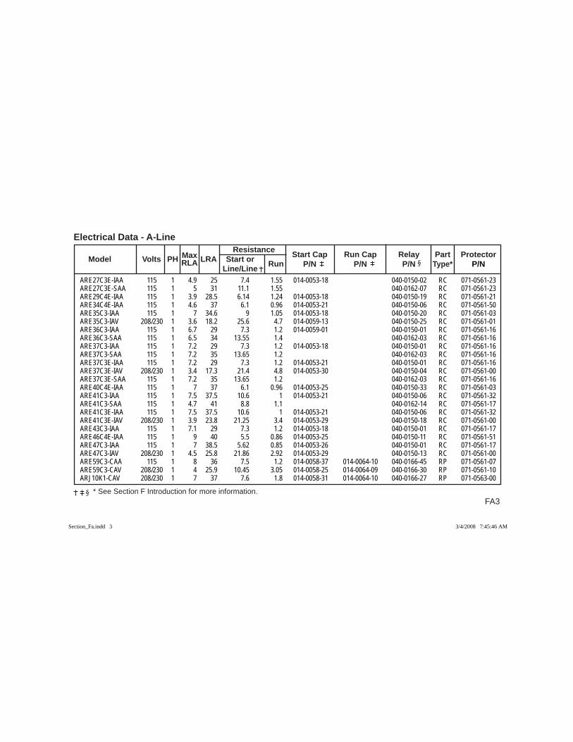
FA3 * See Section F Introduction for more information.
Electrical Data - A-Line
Max
Resistance
Model Volts PH RLA LRA Start or Run Start Cap Run Cap Relay Part Protector
Line/Line P/N P/N P/N Type* P/N
ARE27C3E-IAA 115 1 4.9 25 7.4 1.55 014-0053-18 040-0150-02 RC 071-0561-23ARE27C3E-SAA 115 1 5 31 11.1 1.55 040-0162-07 RC 071-0561-23ARE29C4E-IAA 115 1 3.9 28.5 6.14 1.24 014-0053-18 040-0150-19 RC 071-0561-21ARE34C4E-IAA 115 1 4.6 37 6.1 0.96 014-0053-21 040-0150-06 RC 071-0561-50ARE35C3-IAA 115 1 7 34.6 9 1.05 014-0053-18 040-0150-20 RC 071-0561-03ARE35C3-IAV 208/230 1 3.6 18.2 25.6 4.7 014-0059-13 040-0150-25 RC 071-0561-01ARE36C3-IAA 115 1 6.7 29 7.3 1.2 014-0059-01 040-0150-01 RC 071-0561-16ARE36C3-SAA 115 1 6.5 34 13.55 1.4 040-0162-03 RC 071-0561-16ARE37C3-IAA 115 1 7.2 29 7.3 1.2 014-0053-18 040-0150-01 RC 071-0561-16ARE37C3-SAA 115 1 7.2 35 13.65 1.2 040-0162-03 RC 071-0561-16ARE37C3E-IAA 115 1 7.2 29 7.3 1.2 014-0053-21 040-0150-01 RC 071-0561-16ARE37C3E-IAV 208/230 1 3.4 17.3 21.4 4.8 014-0053-30 040-0150-04 RC 071-0561-00ARE37C3E-SAA 115 1 7.2 35 13.65 1.2 040-0162-03 RC 071-0561-16ARE40C4E-IAA 115 1 7 37 6.1 0.96 014-0053-25 040-0150-33 RC 071-0561-03ARE41C3-IAA 115 1 7.5 37.5 10.6 1 014-0053-21 040-0150-06 RC 071-0561-32ARE41C3-SAA 115 1 4.7 41 8.8 1.1 040-0162-14 RC 071-0561-17ARE41C3E-IAA 115 1 7.5 37.5 10.6 1 014-0053-21 040-0150-06 RC 071-0561-32ARE41C3E-IAV 208/230 1 3.9 23.8 21.25 3.4 014-0053-29 040-0150-18 RC 071-0561-00ARE43C3-IAA 115 1 7.1 29 7.3 1.2 014-0053-18 040-0150-01 RC 071-0561-17ARE46C4E-IAA 115 1 9 40 5.5 0.86 014-0053-25 040-0150-11 RC 071-0561-51ARE47C3-IAA 115 1 7 38.5 5.62 0.85 014-0053-26 040-0150-01 RC 071-0561-17ARE47C3-IAV 208/230 1 4.5 25.8 21.86 2.92 014-0053-29 040-0150-13 RC 071-0561-00ARE59C3-CAA 115 1 8 36 7.5 1.2 014-0058-37 014-0064-10 040-0166-45 RP 071-0561-07ARE59C3-CAV 208/230 1 4 25.9 10.45 3.05 014-0058-25 014-0064-09 040-0166-30 RP 071-0561-10ARJ10K1-CAV 208/230 1 7 37 7.6 1.8 014-0058-31 014-0064-10 040-0166-27 RP 071-0563-00
Section_Fa.indd 3Section_Fa.indd 3 3/4/2008 7:45:46 AM3/4/2008 7:45:46 AM
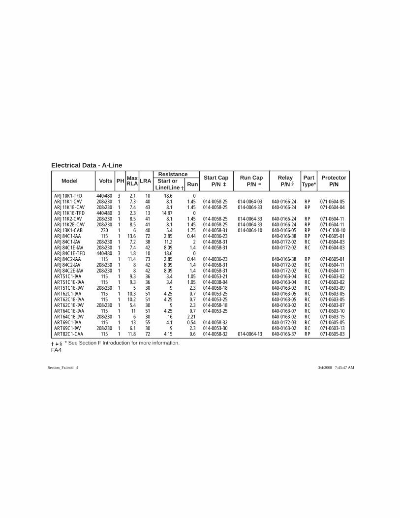
FA4 * See Section F Introduction for more information.
Electrical Data - A-Line
Max Resistance
Model Volts PH RLA LRA Start or Run Start Cap Run Cap Relay Part Protector
Line/Line P/N P/N P/N Type* P/N
ARJ10K1-TFD 440/480 3 2.1 10 18.6 0 ARJ11K1-CAV 208/230 1 7.3 40 8.1 1.45 014-0058-25 014-0064-03 040-0166-24 RP 071-0604-05ARJ11K1E-CAV 208/230 1 7.4 43 8.1 1.45 014-0058-25 014-0064-33 040-0166-24 RP 071-0604-04ARJ11K1E-TFD 440/480 3 2.3 13 14.87 0 ARJ11K2-CAV 208/230 1 8.5 41 8.1 1.45 014-0058-25 014-0064-33 040-0166-24 RP 071-0604-11ARJ11K2E-CAV 208/230 1 8.5 41 8.1 1.45 014-0058-25 014-0064-33 040-0166-24 RP 071-0604-11ARJ13K1-CAB 230 1 6 40 5.4 1.75 014-0058-31 014-0064-10 040-0166-05 RP 071-C100-10ARJ84C1-IAA 115 1 13.6 72 2.85 0.44 014-0036-23 040-0166-38 RP 071-0605-01ARJ84C1-IAV 208/230 1 7.2 38 11.2 2 014-0058-31 040-0172-02 RC 071-0604-03ARJ84C1E-IAV 208/230 1 7.4 42 8.09 1.4 014-0058-31 040-0172-02 RC 071-0604-03ARJ84C1E-TFD 440/480 3 1.8 10 18.6 0 ARJ84C2-IAA 115 1 11.4 73 2.85 0.44 014-0036-23 040-0166-38 RP 071-0605-01ARJ84C2-IAV 208/230 1 8 42 8.09 1.4 014-0058-31 040-0172-02 RC 071-0604-11ARJ84C2E-IAV 208/230 1 8 42 8.09 1.4 014-0058-31 040-0172-02 RC 071-0604-11ART51C1-IAA 115 1 9.3 36 3.4 1.05 014-0053-21 040-0163-04 RC 071-0603-02ART51C1E-IAA 115 1 9.3 36 3.4 1.05 014-0038-04 040-0163-04 RC 071-0603-02ART51C1E-IAV 208/230 1 5 30 9 2.3 014-0058-18 040-0163-02 RC 071-0603-09ART62C1-IAA 115 1 10.3 51 4.25 0.7 014-0053-25 040-0163-05 RC 071-0603-05ART62C1E-IAA 115 1 10.2 51 4.25 0.7 014-0053-25 040-0163-05 RC 071-0603-05ART62C1E-IAV 208/230 1 5.4 30 9 2.3 014-0058-18 040-0163-02 RC 071-0603-07ART64C1E-IAA 115 1 11 51 4.25 0.7 014-0053-25 040-0163-07 RC 071-0603-10ART64C1E-IAV 208/230 1 6 30 16 2.21 040-0163-02 RC 071-0603-15ART69C1-IAA 115 1 13 55 4.1 0.54 014-0058-32 040-0172-03 RC 071-0605-05ART69C1-IAV 208/230 1 6.1 30 9 2.3 014-0053-30 040-0163-02 RC 071-0603-13ART82C1-CAA 115 1 11.8 72 4.15 0.6 014-0058-32 014-0064-13 040-0166-37 RP 071-0605-03
Section_Fa.indd 4Section_Fa.indd 4 3/4/2008 7:45:47 AM3/4/2008 7:45:47 AM
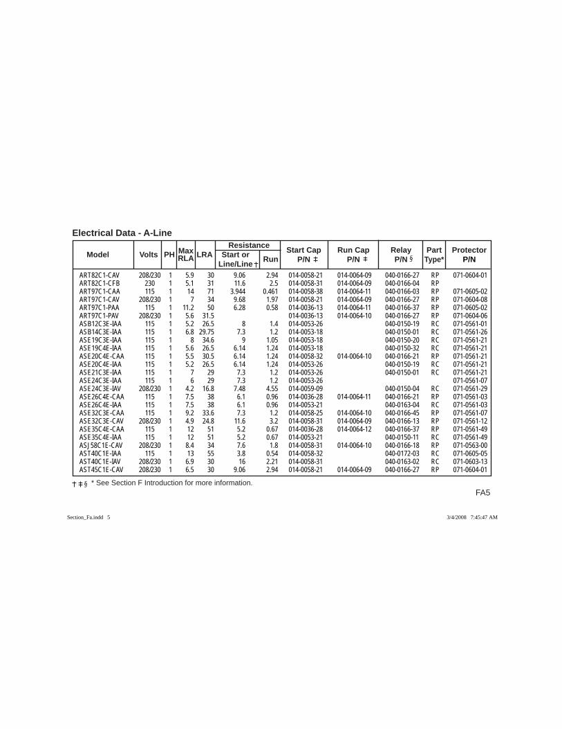
FA5 * See Section F Introduction for more information.
Electrical Data - A-Line
Max
Resistance
Model Volts PH RLA LRA Start or Run Start Cap Run Cap Relay Part Protector
Line/Line P/N P/N P/N Type* P/N
ART82C1-CAV 208/230 1 5.9 30 9.06 2.94 014-0058-21 014-0064-09 040-0166-27 RP 071-0604-01ART82C1-CFB 230 1 5.1 31 11.6 2.5 014-0058-31 014-0064-09 040-0166-04 RP ART97C1-CAA 115 1 14 71 3.944 0.461 014-0058-38 014-0064-11 040-0166-03 RP 071-0605-02ART97C1-CAV 208/230 1 7 34 9.68 1.97 014-0058-21 014-0064-09 040-0166-27 RP 071-0604-08ART97C1-PAA 115 1 11.2 50 6.28 0.58 014-0036-13 014-0064-11 040-0166-37 RP 071-0605-02ART97C1-PAV 208/230 1 5.6 31.5 014-0036-13 014-0064-10 040-0166-27 RP 071-0604-06ASB12C3E-IAA 115 1 5.2 26.5 8 1.4 014-0053-26 040-0150-19 RC 071-0561-01ASB14C3E-IAA 115 1 6.8 29.75 7.3 1.2 014-0053-18 040-0150-01 RC 071-0561-26ASE19C3E-IAA 115 1 8 34.6 9 1.05 014-0053-18 040-0150-20 RC 071-0561-21ASE19C4E-IAA 115 1 5.6 26.5 6.14 1.24 014-0053-18 040-0150-32 RC 071-0561-21ASE20C4E-CAA 115 1 5.5 30.5 6.14 1.24 014-0058-32 014-0064-10 040-0166-21 RP 071-0561-21ASE20C4E-IAA 115 1 5.2 26.5 6.14 1.24 014-0053-26 040-0150-19 RC 071-0561-21ASE21C3E-IAA 115 1 7 29 7.3 1.2 014-0053-26 040-0150-01 RC 071-0561-21ASE24C3E-IAA 115 1 6 29 7.3 1.2 014-0053-26 071-0561-07ASE24C3E-IAV 208/230 1 4.2 16.8 7.48 4.55 014-0059-09 040-0150-04 RC 071-0561-29ASE26C4E-CAA 115 1 7.5 38 6.1 0.96 014-0036-28 014-0064-11 040-0166-21 RP 071-0561-03ASE26C4E-IAA 115 1 7.5 38 6.1 0.96 014-0053-21 040-0163-04 RC 071-0561-03ASE32C3E-CAA 115 1 9.2 33.6 7.3 1.2 014-0058-25 014-0064-10 040-0166-45 RP 071-0561-07ASE32C3E-CAV 208/230 1 4.9 24.8 11.6 3.2 014-0058-31 014-0064-09 040-0166-13 RP 071-0561-12ASE35C4E-CAA 115 1 12 51 5.2 0.67 014-0036-28 014-0064-12 040-0166-37 RP 071-0561-49ASE35C4E-IAA 115 1 12 51 5.2 0.67 014-0053-21 040-0150-11 RC 071-0561-49ASJ58C1E-CAV 208/230 1 8.4 34 7.6 1.8 014-0058-31 014-0064-10 040-0166-18 RP 071-0563-00AST40C1E-IAA 115 1 13 55 3.8 0.54 014-0058-32 040-0172-03 RC 071-0605-05AST40C1E-IAV 208/230 1 6.9 30 16 2.21 014-0058-31 040-0163-02 RC 071-0603-13AST45C1E-CAV 208/230 1 6.5 30 9.06 2.94 014-0058-21 014-0064-09 040-0166-27 RP 071-0604-01
Section_Fa.indd 5Section_Fa.indd 5 3/4/2008 7:45:47 AM3/4/2008 7:45:47 AM
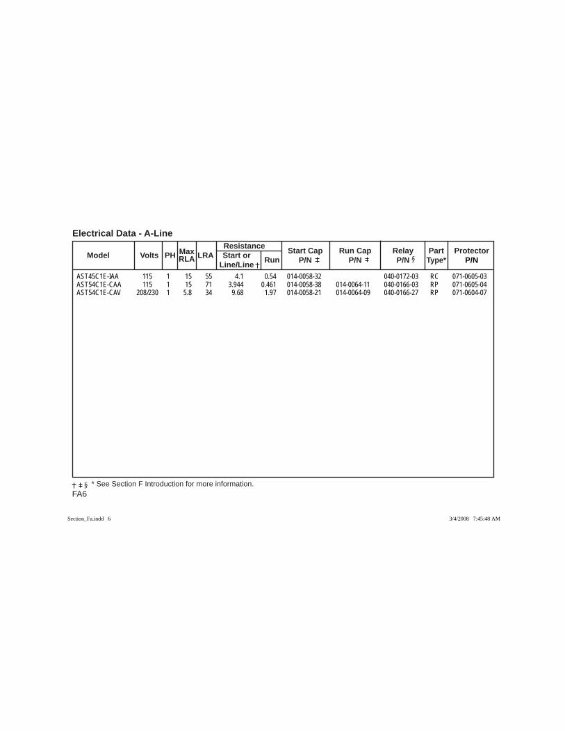
FA6 * See Section F Introduction for more information.
Electrical Data - A-Line
Max Resistance
Model Volts PH RLA LRA Start or Run Start Cap Run Cap Relay Part Protector
Line/Line P/N P/N P/N Type* P/N
AST45C1E-IAA 115 1 15 55 4.1 0.54 014-0058-32 040-0172-03 RC 071-0605-03AST54C1E-CAA 115 1 15 71 3.944 0.461 014-0058-38 014-0064-11 040-0166-03 RP 071-0605-04AST54C1E-CAV 208/230 1 5.8 34 9.68 1.97 014-0058-21 014-0064-09 040-0166-27 RP 071-0604-07
Section_Fa.indd 6Section_Fa.indd 6 3/4/2008 7:45:48 AM3/4/2008 7:45:48 AM
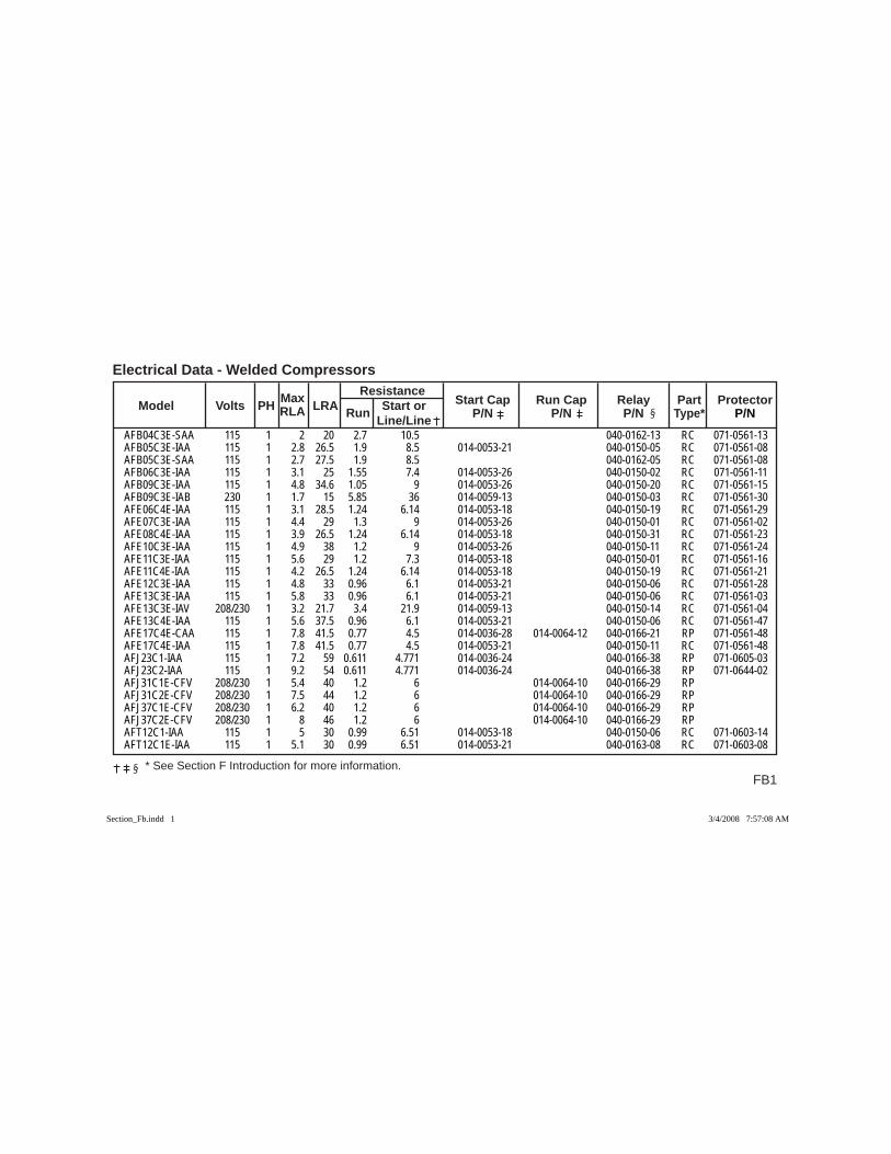
FB1
Electrical Data - Welded Compressors
* See Section F Introduction for more information.
Max Resistance Model Volts PH RLA LRA Run Start or Start Cap Run Cap Relay Part Protector Line/Line P/N P/N P/N Type* P/N
AFB04C3E-SAA 115 1 2 20 2.7 10.5 040-0162-13 RC 071-0561-13AFB05C3E-IAA 115 1 2.8 26.5 1.9 8.5 014-0053-21 040-0150-05 RC 071-0561-08AFB05C3E-SAA 115 1 2.7 27.5 1.9 8.5 040-0162-05 RC 071-0561-08AFB06C3E-IAA 115 1 3.1 25 1.55 7.4 014-0053-26 040-0150-02 RC 071-0561-11AFB09C3E-IAA 115 1 4.8 34.6 1.05 9 014-0053-26 040-0150-20 RC 071-0561-15AFB09C3E-IAB 230 1 1.7 15 5.85 36 014-0059-13 040-0150-03 RC 071-0561-30AFE06C4E-IAA 115 1 3.1 28.5 1.24 6.14 014-0053-18 040-0150-19 RC 071-0561-29AFE07C3E-IAA 115 1 4.4 29 1.3 9 014-0053-26 040-0150-01 RC 071-0561-02AFE08C4E-IAA 115 1 3.9 26.5 1.24 6.14 014-0053-18 040-0150-31 RC 071-0561-23AFE10C3E-IAA 115 1 4.9 38 1.2 9 014-0053-26 040-0150-11 RC 071-0561-24AFE11C3E-IAA 115 1 5.6 29 1.2 7.3 014-0053-18 040-0150-01 RC 071-0561-16AFE11C4E-IAA 115 1 4.2 26.5 1.24 6.14 014-0053-18 040-0150-19 RC 071-0561-21AFE12C3E-IAA 115 1 4.8 33 0.96 6.1 014-0053-21 040-0150-06 RC 071-0561-28AFE13C3E-IAA 115 1 5.8 33 0.96 6.1 014-0053-21 040-0150-06 RC 071-0561-03AFE13C3E-IAV 208/230 1 3.2 21.7 3.4 21.9 014-0059-13 040-0150-14 RC 071-0561-04AFE13C4E-IAA 115 1 5.6 37.5 0.96 6.1 014-0053-21 040-0150-06 RC 071-0561-47AFE17C4E-CAA 115 1 7.8 41.5 0.77 4.5 014-0036-28 014-0064-12 040-0166-21 RP 071-0561-48AFE17C4E-IAA 115 1 7.8 41.5 0.77 4.5 014-0053-21 040-0150-11 RC 071-0561-48AFJ23C1-IAA 115 1 7.2 59 0.611 4.771 014-0036-24 040-0166-38 RP 071-0605-03AFJ23C2-IAA 115 1 9.2 54 0.611 4.771 014-0036-24 040-0166-38 RP 071-0644-02AFJ31C1E-CFV 208/230 1 5.4 40 1.2 6 014-0064-10 040-0166-29 RP AFJ31C2E-CFV 208/230 1 7.5 44 1.2 6 014-0064-10 040-0166-29 RP AFJ37C1E-CFV 208/230 1 6.2 40 1.2 6 014-0064-10 040-0166-29 RP AFJ37C2E-CFV 208/230 1 8 46 1.2 6 014-0064-10 040-0166-29 RP AFT12C1-IAA 115 1 5 30 0.99 6.51 014-0053-18 040-0150-06 RC 071-0603-14AFT12C1E-IAA 115 1 5.1 30 0.99 6.51 014-0053-21 040-0163-08 RC 071-0603-08
Section_Fb.indd 1Section_Fb.indd 1 3/4/2008 7:57:08 AM3/4/2008 7:57:08 AM
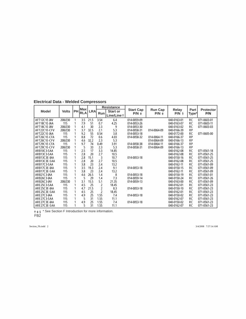
FB2
Electrical Data - Welded Compressors Max Resistance Model Volts PH RLA LRA Run Start or Start Cap Run Cap Relay Part Protector Line/Line P/N P/N P/N Type* P/N
* See Section F Introduction for more information.
AFT12C1E-IAV 208/230 1 3.5 21.5 3.54 6.4 014-0059-09 040-0163-01 RC 071-0603-01AFT18C1E-IAA 115 1 7.9 51 0.7 4.25 014-0053-26 040-0163-07 RC 071-0603-11AFT18C1E-IAV 208/230 1 4.1 30 2.3 9 014-0053-30 040-0163-02 RC 071-0603-03AFT22C1E-CFV 208/230 1 3.7 32.5 2.1 5.3 014-0058-31 014-0064-09 040-0166-39 RP AFT22C1E-IAA 115 1 9.2 55 0.54 3.8 014-0053-18 040-0172-00 RC 071-0605-00AFT26C1E-CFA 115 1 8.8 72 0.6 4.03 014-0058-32 014-0064-11 040-0166-37 RP AFT26C1E-CFV 208/230 1 4.6 32.2 2.3 5.3 014-0064-09 040-0166-13 RP AFT29C1E-CFA 115 1 9.7 74 0.49 3.91 014-0058-38 014-0064-11 040-0166-37 RP AFT29C1E-CFV 208/230 1 5 33 2.3 5.3 014-0058-31 014-0064-09 040-0166-13 RP ARB10C3-SAA 115 1 2.5 17 3.3 14.85 040-0162-08 RC 071-0561-18ARB13C3-SAA 115 1 2.8 20 2.7 10.5 040-0162-08 RC 071-0561-25ARB13C3E-IAA 115 1 2.8 15.1 3 10.7 014-0053-18 040-0150-16 RC 071-0561-25ARB13C3E-SAA 115 1 2.8 20 2.7 10.5 040-0162-08 RC 071-0561-25ARB17C3-SAA 115 1 3.8 23 2.4 13.2 040-0162-11 RC 071-0561-09ARB17C3E-IAA 115 1 3.5 19.3 2.4 9.1 014-0053-18 040-0150-15 RC 071-0561-09ARB17C3E-SAA 115 1 3.8 23 2.4 13.2 040-0162-11 RC 071-0561-09ARB21C3-IAA 115 1 4.6 26.5 1.4 8 014-0053-18 040-0150-19 RC 071-0561-01ARB26C3-IAA 115 1 5 29 1.4 7.3 014-0059-14 040-0150-24 RC 071-0561-26ARB26C3-IAV 208/230 1 3.1 15.5 5.1 21.35 014-0059-13 040-0163-00 RC 071-0561-09ARE25C3-SAA 115 1 4.5 25 2 18.45 040-0162-01 RC 071-0561-23ARE25C3E-IAA 115 1 4.7 21.5 2 8.3 014-0053-18 040-0150-10 RC 071-0561-23ARE25C3E-SAA 115 1 4.5 25 2 18.45 040-0162-01 RC 071-0561-23ARE27C3-IAA 115 1 4.9 25 1.55 7.4 014-0053-18 040-0150-02 RC 071-0561-23ARE27C3-SAA 115 1 5 31 1.55 11.1 040-0162-07 RC 071-0561-23ARE27C3E-IAA 115 1 4.9 25 1.55 7.4 014-0053-18 040-0150-02 RC 071-0561-23ARE27C3E-SAA 115 1 5 31 1.55 11.1 040-0162-07 RC 071-0561-23
Section_Fb.indd 2Section_Fb.indd 2 3/4/2008 7:57:14 AM3/4/2008 7:57:14 AM
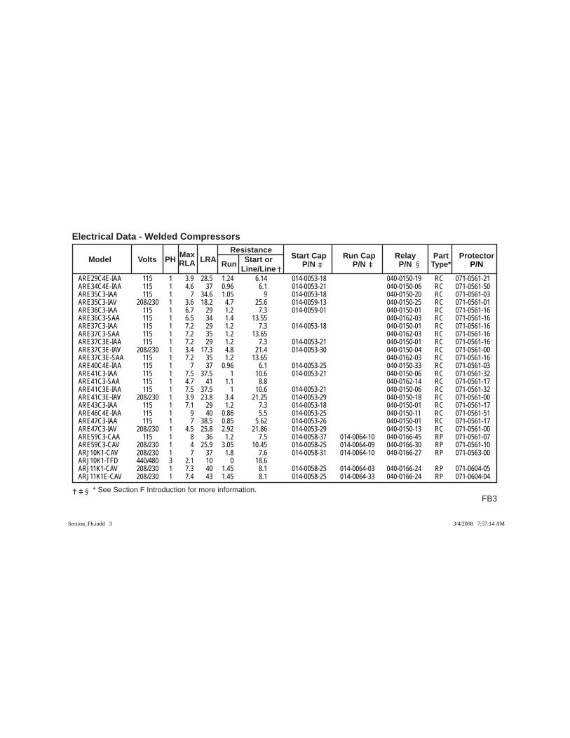
FB3
Electrical Data - Welded Compressors
* See Section F Introduction for more information.
Max Resistance Model Volts PH RLA LRA Run Start or Start Cap Run Cap Relay Part Protector Line/Line P/N P/N P/N Type* P/N
ARE29C4E-IAA 115 1 3.9 28.5 1.24 6.14 014-0053-18 040-0150-19 RC 071-0561-21ARE34C4E-IAA 115 1 4.6 37 0.96 6.1 014-0053-21 040-0150-06 RC 071-0561-50ARE35C3-IAA 115 1 7 34.6 1.05 9 014-0053-18 040-0150-20 RC 071-0561-03ARE35C3-IAV 208/230 1 3.6 18.2 4.7 25.6 014-0059-13 040-0150-25 RC 071-0561-01ARE36C3-IAA 115 1 6.7 29 1.2 7.3 014-0059-01 040-0150-01 RC 071-0561-16ARE36C3-SAA 115 1 6.5 34 1.4 13.55 040-0162-03 RC 071-0561-16ARE37C3-IAA 115 1 7.2 29 1.2 7.3 014-0053-18 040-0150-01 RC 071-0561-16ARE37C3-SAA 115 1 7.2 35 1.2 13.65 040-0162-03 RC 071-0561-16ARE37C3E-IAA 115 1 7.2 29 1.2 7.3 014-0053-21 040-0150-01 RC 071-0561-16ARE37C3E-IAV 208/230 1 3.4 17.3 4.8 21.4 014-0053-30 040-0150-04 RC 071-0561-00ARE37C3E-SAA 115 1 7.2 35 1.2 13.65 040-0162-03 RC 071-0561-16ARE40C4E-IAA 115 1 7 37 0.96 6.1 014-0053-25 040-0150-33 RC 071-0561-03ARE41C3-IAA 115 1 7.5 37.5 1 10.6 014-0053-21 040-0150-06 RC 071-0561-32ARE41C3-SAA 115 1 4.7 41 1.1 8.8 040-0162-14 RC 071-0561-17ARE41C3E-IAA 115 1 7.5 37.5 1 10.6 014-0053-21 040-0150-06 RC 071-0561-32ARE41C3E-IAV 208/230 1 3.9 23.8 3.4 21.25 014-0053-29 040-0150-18 RC 071-0561-00ARE43C3-IAA 115 1 7.1 29 1.2 7.3 014-0053-18 040-0150-01 RC 071-0561-17ARE46C4E-IAA 115 1 9 40 0.86 5.5 014-0053-25 040-0150-11 RC 071-0561-51ARE47C3-IAA 115 1 7 38.5 0.85 5.62 014-0053-26 040-0150-01 RC 071-0561-17ARE47C3-IAV 208/230 1 4.5 25.8 2.92 21.86 014-0053-29 040-0150-13 RC 071-0561-00ARE59C3-CAA 115 1 8 36 1.2 7.5 014-0058-37 014-0064-10 040-0166-45 RP 071-0561-07ARE59C3-CAV 208/230 1 4 25.9 3.05 10.45 014-0058-25 014-0064-09 040-0166-30 RP 071-0561-10ARJ10K1-CAV 208/230 1 7 37 1.8 7.6 014-0058-31 014-0064-10 040-0166-27 RP 071-0563-00ARJ10K1-TFD 440/480 3 2.1 10 0 18.6 ARJ11K1-CAV 208/230 1 7.3 40 1.45 8.1 014-0058-25 014-0064-03 040-0166-24 RP 071-0604-05ARJ11K1E-CAV 208/230 1 7.4 43 1.45 8.1 014-0058-25 014-0064-33 040-0166-24 RP 071-0604-04
Section_Fb.indd 3Section_Fb.indd 3 3/4/2008 7:57:14 AM3/4/2008 7:57:14 AM
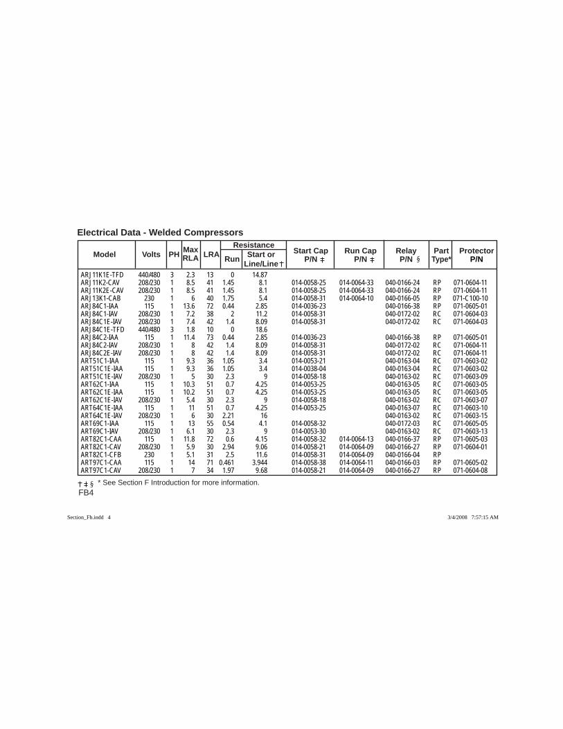
FB4
Electrical Data - Welded Compressors Max Resistance Model Volts PH RLA LRA Run Start or Start Cap Run Cap Relay Part Protector Line/Line P/N P/N P/N Type* P/N
* See Section F Introduction for more information.
ARJ11K1E-TFD 440/480 3 2.3 13 0 14.87 ARJ11K2-CAV 208/230 1 8.5 41 1.45 8.1 014-0058-25 014-0064-33 040-0166-24 RP 071-0604-11ARJ11K2E-CAV 208/230 1 8.5 41 1.45 8.1 014-0058-25 014-0064-33 040-0166-24 RP 071-0604-11ARJ13K1-CAB 230 1 6 40 1.75 5.4 014-0058-31 014-0064-10 040-0166-05 RP 071-C100-10ARJ84C1-IAA 115 1 13.6 72 0.44 2.85 014-0036-23 040-0166-38 RP 071-0605-01ARJ84C1-IAV 208/230 1 7.2 38 2 11.2 014-0058-31 040-0172-02 RC 071-0604-03ARJ84C1E-IAV 208/230 1 7.4 42 1.4 8.09 014-0058-31 040-0172-02 RC 071-0604-03ARJ84C1E-TFD 440/480 3 1.8 10 0 18.6 ARJ84C2-IAA 115 1 11.4 73 0.44 2.85 014-0036-23 040-0166-38 RP 071-0605-01ARJ84C2-IAV 208/230 1 8 42 1.4 8.09 014-0058-31 040-0172-02 RC 071-0604-11ARJ84C2E-IAV 208/230 1 8 42 1.4 8.09 014-0058-31 040-0172-02 RC 071-0604-11ART51C1-IAA 115 1 9.3 36 1.05 3.4 014-0053-21 040-0163-04 RC 071-0603-02ART51C1E-IAA 115 1 9.3 36 1.05 3.4 014-0038-04 040-0163-04 RC 071-0603-02ART51C1E-IAV 208/230 1 5 30 2.3 9 014-0058-18 040-0163-02 RC 071-0603-09ART62C1-IAA 115 1 10.3 51 0.7 4.25 014-0053-25 040-0163-05 RC 071-0603-05ART62C1E-IAA 115 1 10.2 51 0.7 4.25 014-0053-25 040-0163-05 RC 071-0603-05ART62C1E-IAV 208/230 1 5.4 30 2.3 9 014-0058-18 040-0163-02 RC 071-0603-07ART64C1E-IAA 115 1 11 51 0.7 4.25 014-0053-25 040-0163-07 RC 071-0603-10ART64C1E-IAV 208/230 1 6 30 2.21 16 040-0163-02 RC 071-0603-15ART69C1-IAA 115 1 13 55 0.54 4.1 014-0058-32 040-0172-03 RC 071-0605-05ART69C1-IAV 208/230 1 6.1 30 2.3 9 014-0053-30 040-0163-02 RC 071-0603-13ART82C1-CAA 115 1 11.8 72 0.6 4.15 014-0058-32 014-0064-13 040-0166-37 RP 071-0605-03ART82C1-CAV 208/230 1 5.9 30 2.94 9.06 014-0058-21 014-0064-09 040-0166-27 RP 071-0604-01ART82C1-CFB 230 1 5.1 31 2.5 11.6 014-0058-31 014-0064-09 040-0166-04 RP ART97C1-CAA 115 1 14 71 0.461 3.944 014-0058-38 014-0064-11 040-0166-03 RP 071-0605-02ART97C1-CAV 208/230 1 7 34 1.97 9.68 014-0058-21 014-0064-09 040-0166-27 RP 071-0604-08
Section_Fb.indd 4Section_Fb.indd 4 3/4/2008 7:57:15 AM3/4/2008 7:57:15 AM
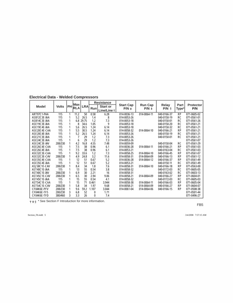
FB5
Electrical Data - Welded Compressors
* See Section F Introduction for more information.
Max Resistance Model Volts PH RLA LRA Run Start or Start Cap Run Cap Relay Part Protector Line/Line P/N P/N P/N Type* P/N
ART97C1-PAA 115 1 11.2 50 0.58 6.28 014-0036-13 014-0064-11 040-0166-37 RP 071-0605-02ASB12C3E-IAA 115 1 5.2 26.5 1.4 8 014-0053-26 040-0150-19 RC 071-0561-01ASB14C3E-IAA 115 1 6.8 29.75 1.2 7.3 014-0053-18 040-0150-01 RC 071-0561-26ASE19C3E-IAA 115 1 8 34.6 1.05 9 014-0053-18 040-0150-20 RC 071-0561-21ASE19C4E-IAA 115 1 5.6 26.5 1.24 6.14 014-0053-18 040-0150-32 RC 071-0561-21ASE20C4E-CAA 115 1 5.5 30.5 1.24 6.14 014-0058-32 014-0064-10 040-0166-21 RP 071-0561-21ASE20C4E-IAA 115 1 5.2 26.5 1.24 6.14 014-0053-26 040-0150-19 RC 071-0561-21ASE21C3E-IAA 115 1 7 29 1.2 7.3 014-0053-26 040-0150-01 RC 071-0561-21ASE24C3E-IAA 115 1 6 29 1.2 7.3 014-0053-26 071-0561-07ASE24C3E-IAV 208/230 1 4.2 16.8 4.55 7.48 014-0059-09 040-0150-04 RC 071-0561-29ASE26C4E-CAA 115 1 7.5 38 0.96 6.1 014-0036-28 014-0064-11 040-0166-21 RP 071-0561-03ASE26C4E-IAA 115 1 7.5 38 0.96 6.1 014-0053-21 040-0163-04 RC 071-0561-03ASE32C3E-CAA 115 1 9.2 33.6 1.2 7.3 014-0058-25 014-0064-10 040-0166-45 RP 071-0561-07ASE32C3E-CAV 208/230 1 4.9 24.8 3.2 11.6 014-0058-31 014-0064-09 040-0166-13 RP 071-0561-12ASE35C4E-CAA 115 1 12 51 0.67 5.2 014-0036-28 014-0064-12 040-0166-37 RP 071-0561-49ASE35C4E-IAA 115 1 12 51 0.67 5.2 014-0053-21 040-0150-11 RC 071-0561-49ASJ58C1E-CAV 208/230 1 8.4 34 1.8 7.6 014-0058-31 014-0064-10 040-0166-18 RP 071-0563-00AST40C1E-IAA 115 1 13 55 0.54 3.8 014-0058-32 040-0172-03 RC 071-0605-05AST40C1E-IAV 208/230 1 6.9 30 2.21 16 014-0058-31 040-0163-02 RC 071-0603-13AST45C1E-CAV 208/230 1 6.5 30 2.94 9.06 014-0058-21 014-0064-09 040-0166-27 RP 071-0604-01AST45C1E-IAA 115 1 15 55 0.54 4.1 014-0058-32 040-0172-03 RC 071-0605-03AST54C1E-CAA 115 1 15 71 0.461 3.944 014-0058-38 014-0064-11 040-0166-03 RP 071-0605-04AST54C1E-CAV 208/230 1 5.8 34 1.97 9.68 014-0058-21 014-0064-09 040-0166-27 RP 071-0604-07CF04K6E-PFV 208/230 1 9.6 59.2 1.107 3.044 014-0061-04 014-0064-06 040-0166-15 RP 071-0508-38CF04K6E-TF5 200/230 3 6.8 52 0 1.71 071-0501-44CF04K6E-TFD 380/460 3 3.3 26 0 7.4 071-0496-27
Section_Fb.indd 5Section_Fb.indd 5 3/4/2008 7:57:15 AM3/4/2008 7:57:15 AM
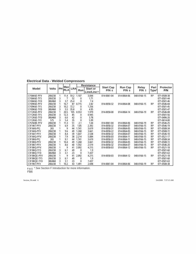
FB6
Electrical Data - Welded Compressors Max Resistance Model Volts PH RLA LRA Run Start or Start Cap Run Cap Relay Part Protector Line/Line P/N P/N P/N Type* P/N
* See Section F Introduction for more information.
CF06K6E-PFV 208/230 1 11.4 59.2 1.107 3.044 014-0061-04 014-0064-06 040-0166-15 RP 071-0508-38CF06K6E-TF5 200/230 3 7 52 0 1.71 071-0501-44CF06K6E-TFD 380/460 3 3.7 25.4 0 7.4 071-0501-46CF09K6E-PFV 208/230 1 16.7 87 0.715 2.82 014-0058-32 014-0064-08 040-0166-15 RP 071-0546-04CF09K6E-TF5 200/230 3 10.2 72.2 0 1.256 071-0501-45CF09K6E-TFD 380/460 3 5.5 35.8 0 4.95 071-0501-47CF12K6E-PFV 208/230 1 20.5 105 0.553 1.979 014-0058-00 014-0064-14 040-0166-19 RP 071-0546-08CF12K6E-TF5 200/230 3 12.3 85 0 0.945 071-0501-56CF12K6E-TFD 380/460 3 6.6 42 0 3.78 071-0496-20CF12K6E-TFE 575 3 5.4 35 0 5.99 071-0614-00CP25K8E-PFV 208/230 1 11.3 51 2.1 1.04 014-0061-04 014-0064-06 040-0166-19 RP 071-0546-25CR14K7-PFV 208/230 1 6.9 35 1.85 2.392 014-0058-32 014-0064-07 040-0166-15 RP 071-0546-19CR16K6-PFJ 265 1 9 44 1.741 3.619 014-0058-31 014-0064-05 040-0166-15 RP 071-0508-34CR16K6-PFV 208/230 1 9.6 49 1.268 3.661 014-0058-22 014-0064-05 040-0166-15 RP 071-0508-72CR16K7-PFV 208/230 1 8.4 39 1.647 2.538 014-0058-32 014-0064-07 040-0166-15 RP 071-0546-10CR16KQ-PFV 208/230 1 7.9 38 2.214 5.084 014-0058-03 014-0064-11 040-0166-15 RP 071-0521-17CR18K6-PFJ 265 1 9.1 44 1.741 3.619 014-0058-31 014-0064-11 040-0166-15 RP 071-0508-34CR18K6-PFV 208/230 1 10.4 49 1.268 3.661 014-0058-32 014-0064-05 040-0166-15 RP 071-0508-72CR18K7-PFV 208/230 1 8.6 40 1.592 2.519 014-0058-32 014-0064-07 040-0166-15 RP 071-0546-20CR18KQ-PFV 208/230 1 9 41 2.092 4.215 014-0058-03 014-0064-12 040-0166-15 RP 071-0521-18CR18KQ-TF5 200/230 3 6.1 49 0 1.9 071-0501-60CR18KQ-TFD 380/460 3 3.1 23 0 7.437 071-0501-63CR18KQE-PFV 208/230 1 9 41 2.092 4.215 014-0058-03 014-0064-12 040-0166-15 RP 071-0521-18CR18KQE-TF5 200/230 3 6.1 49 0 1.9 071-0501-60CR18KQE-TFD 380/460 3 3.1 23 0 7.437 071-0501-63CR19K7-PFV 208/230 1 10.2 43 1.491 2.698 014-0061-04 014-0064-06 040-0166-19 RP 071-0508-38
Section_Fb.indd 6Section_Fb.indd 6 3/4/2008 7:57:15 AM3/4/2008 7:57:15 AM
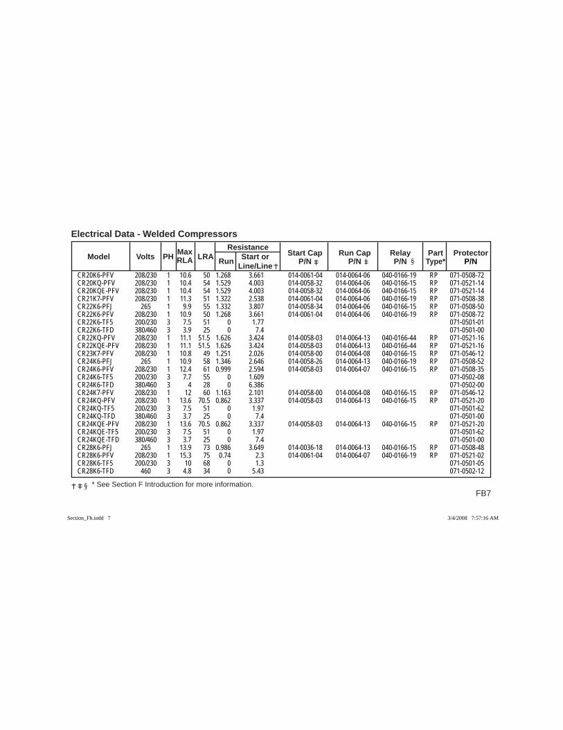
FB7
Electrical Data - Welded Compressors
* See Section F Introduction for more information.
Max Resistance Model Volts PH RLA LRA Run Start or Start Cap Run Cap Relay Part Protector Line/Line P/N P/N P/N Type* P/N
CR20K6-PFV 208/230 1 10.6 50 1.268 3.661 014-0061-04 014-0064-06 040-0166-19 RP 071-0508-72CR20KQ-PFV 208/230 1 10.4 54 1.529 4.003 014-0058-32 014-0064-06 040-0166-15 RP 071-0521-14CR20KQE-PFV 208/230 1 10.4 54 1.529 4.003 014-0058-32 014-0064-06 040-0166-15 RP 071-0521-14CR21K7-PFV 208/230 1 11.3 51 1.322 2.538 014-0061-04 014-0064-06 040-0166-19 RP 071-0508-38CR22K6-PFJ 265 1 9.9 55 1.332 3.807 014-0058-34 014-0064-06 040-0166-15 RP 071-0508-50CR22K6-PFV 208/230 1 10.9 50 1.268 3.661 014-0061-04 014-0064-06 040-0166-19 RP 071-0508-72CR22K6-TF5 200/230 3 7.5 51 0 1.77 071-0501-01CR22K6-TFD 380/460 3 3.9 25 0 7.4 071-0501-00CR22KQ-PFV 208/230 1 11.1 51.5 1.626 3.424 014-0058-03 014-0064-13 040-0166-44 RP 071-0521-16CR22KQE-PFV 208/230 1 11.1 51.5 1.626 3.424 014-0058-03 014-0064-13 040-0166-44 RP 071-0521-16CR23K7-PFV 208/230 1 10.8 49 1.251 2.026 014-0058-00 014-0064-08 040-0166-15 RP 071-0546-12CR24K6-PFJ 265 1 10.9 58 1.346 2.646 014-0058-26 014-0064-13 040-0166-19 RP 071-0508-52CR24K6-PFV 208/230 1 12.4 61 0.999 2.594 014-0058-03 014-0064-07 040-0166-15 RP 071-0508-35CR24K6-TF5 200/230 3 7.7 55 0 1.609 071-0502-08CR24K6-TFD 380/460 3 4 28 0 6.386 071-0502-00CR24K7-PFV 208/230 1 12 60 1.163 2.101 014-0058-00 014-0064-08 040-0166-15 RP 071-0546-12CR24KQ-PFV 208/230 1 13.6 70.5 0.862 3.337 014-0058-03 014-0064-13 040-0166-15 RP 071-0521-20CR24KQ-TF5 200/230 3 7.5 51 0 1.97 071-0501-62CR24KQ-TFD 380/460 3 3.7 25 0 7.4 071-0501-00CR24KQE-PFV 208/230 1 13.6 70.5 0.862 3.337 014-0058-03 014-0064-13 040-0166-15 RP 071-0521-20CR24KQE-TF5 200/230 3 7.5 51 0 1.97 071-0501-62CR24KQE-TFD 380/460 3 3.7 25 0 7.4 071-0501-00CR28K6-PFJ 265 1 13.9 73 0.986 3.649 014-0036-18 014-0064-13 040-0166-15 RP 071-0508-48CR28K6-PFV 208/230 1 15.3 75 0.74 2.3 014-0061-04 014-0064-07 040-0166-19 RP 071-0521-02CR28K6-TF5 200/230 3 10 68 0 1.3 071-0501-05CR28K6-TFD 460 3 4.8 34 0 5.43 071-0502-12
Section_Fb.indd 7Section_Fb.indd 7 3/4/2008 7:57:16 AM3/4/2008 7:57:16 AM
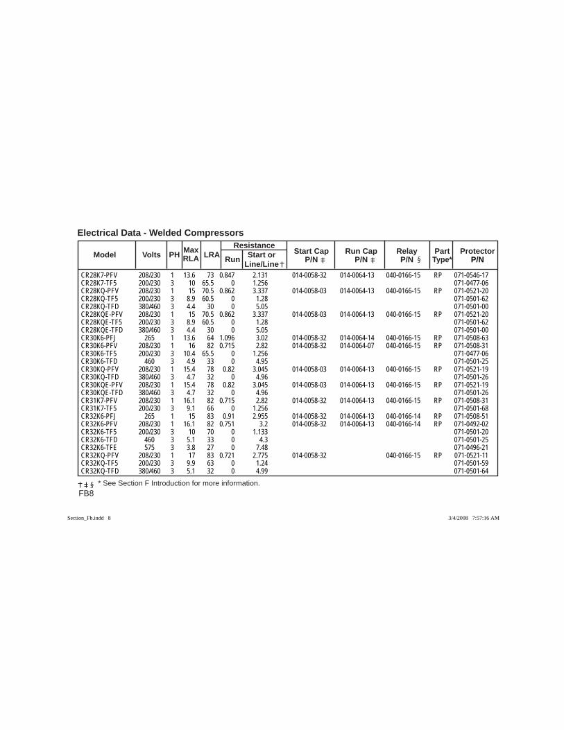
FB8
Electrical Data - Welded Compressors Max Resistance Model Volts PH RLA LRA Run Start or Start Cap Run Cap Relay Part Protector Line/Line P/N P/N P/N Type* P/N
* See Section F Introduction for more information.
CR28K7-PFV 208/230 1 13.6 73 0.847 2.131 014-0058-32 014-0064-13 040-0166-15 RP 071-0546-17CR28K7-TF5 200/230 3 10 65.5 0 1.256 071-0477-06CR28KQ-PFV 208/230 1 15 70.5 0.862 3.337 014-0058-03 014-0064-13 040-0166-15 RP 071-0521-20CR28KQ-TF5 200/230 3 8.9 60.5 0 1.28 071-0501-62CR28KQ-TFD 380/460 3 4.4 30 0 5.05 071-0501-00CR28KQE-PFV 208/230 1 15 70.5 0.862 3.337 014-0058-03 014-0064-13 040-0166-15 RP 071-0521-20CR28KQE-TF5 200/230 3 8.9 60.5 0 1.28 071-0501-62CR28KQE-TFD 380/460 3 4.4 30 0 5.05 071-0501-00CR30K6-PFJ 265 1 13.6 64 1.096 3.02 014-0058-32 014-0064-14 040-0166-15 RP 071-0508-63CR30K6-PFV 208/230 1 16 82 0.715 2.82 014-0058-32 014-0064-07 040-0166-15 RP 071-0508-31CR30K6-TF5 200/230 3 10.4 65.5 0 1.256 071-0477-06CR30K6-TFD 460 3 4.9 33 0 4.95 071-0501-25CR30KQ-PFV 208/230 1 15.4 78 0.82 3.045 014-0058-03 014-0064-13 040-0166-15 RP 071-0521-19CR30KQ-TFD 380/460 3 4.7 32 0 4.96 071-0501-26CR30KQE-PFV 208/230 1 15.4 78 0.82 3.045 014-0058-03 014-0064-13 040-0166-15 RP 071-0521-19CR30KQE-TFD 380/460 3 4.7 32 0 4.96 071-0501-26CR31K7-PFV 208/230 1 16.1 82 0.715 2.82 014-0058-32 014-0064-13 040-0166-15 RP 071-0508-31CR31K7-TF5 200/230 3 9.1 66 0 1.256 071-0501-68CR32K6-PFJ 265 1 15 83 0.91 2.955 014-0058-32 014-0064-13 040-0166-14 RP 071-0508-51CR32K6-PFV 208/230 1 16.1 82 0.751 3.2 014-0058-32 014-0064-13 040-0166-14 RP 071-0492-02CR32K6-TF5 200/230 3 10 70 0 1.133 071-0501-20CR32K6-TFD 460 3 5.1 33 0 4.3 071-0501-25CR32K6-TFE 575 3 3.8 27 0 7.48 071-0496-21CR32KQ-PFV 208/230 1 17 83 0.721 2.775 014-0058-32 040-0166-15 RP 071-0521-11CR32KQ-TF5 200/230 3 9.9 63 0 1.24 071-0501-59CR32KQ-TFD 380/460 3 5.1 32 0 4.99 071-0501-64
Section_Fb.indd 8Section_Fb.indd 8 3/4/2008 7:57:16 AM3/4/2008 7:57:16 AM
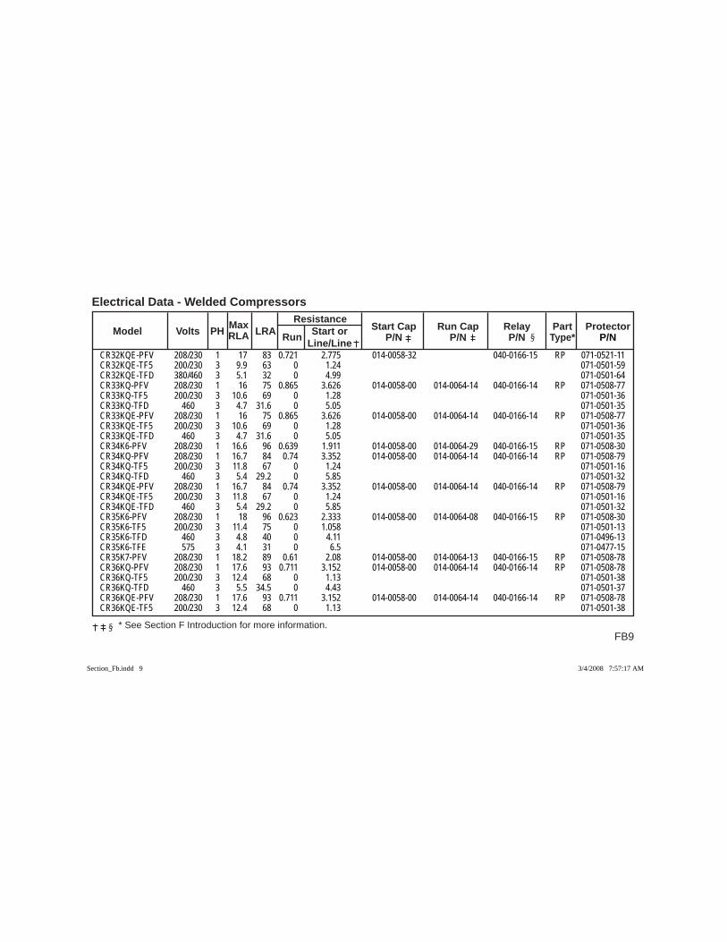
FB9
Electrical Data - Welded Compressors
* See Section F Introduction for more information.
Max Resistance Model Volts PH RLA LRA Run Start or Start Cap Run Cap Relay Part Protector Line/Line P/N P/N P/N Type* P/N
CR32KQE-PFV 208/230 1 17 83 0.721 2.775 014-0058-32 040-0166-15 RP 071-0521-11CR32KQE-TF5 200/230 3 9.9 63 0 1.24 071-0501-59CR32KQE-TFD 380/460 3 5.1 32 0 4.99 071-0501-64CR33KQ-PFV 208/230 1 16 75 0.865 3.626 014-0058-00 014-0064-14 040-0166-14 RP 071-0508-77CR33KQ-TF5 200/230 3 10.6 69 0 1.28 071-0501-36CR33KQ-TFD 460 3 4.7 31.6 0 5.05 071-0501-35CR33KQE-PFV 208/230 1 16 75 0.865 3.626 014-0058-00 014-0064-14 040-0166-14 RP 071-0508-77CR33KQE-TF5 200/230 3 10.6 69 0 1.28 071-0501-36CR33KQE-TFD 460 3 4.7 31.6 0 5.05 071-0501-35CR34K6-PFV 208/230 1 16.6 96 0.639 1.911 014-0058-00 014-0064-29 040-0166-15 RP 071-0508-30CR34KQ-PFV 208/230 1 16.7 84 0.74 3.352 014-0058-00 014-0064-14 040-0166-14 RP 071-0508-79CR34KQ-TF5 200/230 3 11.8 67 0 1.24 071-0501-16CR34KQ-TFD 460 3 5.4 29.2 0 5.85 071-0501-32CR34KQE-PFV 208/230 1 16.7 84 0.74 3.352 014-0058-00 014-0064-14 040-0166-14 RP 071-0508-79CR34KQE-TF5 200/230 3 11.8 67 0 1.24 071-0501-16CR34KQE-TFD 460 3 5.4 29.2 0 5.85 071-0501-32CR35K6-PFV 208/230 1 18 96 0.623 2.333 014-0058-00 014-0064-08 040-0166-15 RP 071-0508-30CR35K6-TF5 200/230 3 11.4 75 0 1.058 071-0501-13CR35K6-TFD 460 3 4.8 40 0 4.11 071-0496-13CR35K6-TFE 575 3 4.1 31 0 6.5 071-0477-15CR35K7-PFV 208/230 1 18.2 89 0.61 2.08 014-0058-00 014-0064-13 040-0166-15 RP 071-0508-78CR36KQ-PFV 208/230 1 17.6 93 0.711 3.152 014-0058-00 014-0064-14 040-0166-14 RP 071-0508-78CR36KQ-TF5 200/230 3 12.4 68 0 1.13 071-0501-38CR36KQ-TFD 460 3 5.5 34.5 0 4.43 071-0501-37CR36KQE-PFV 208/230 1 17.6 93 0.711 3.152 014-0058-00 014-0064-14 040-0166-14 RP 071-0508-78CR36KQE-TF5 200/230 3 12.4 68 0 1.13 071-0501-38
Section_Fb.indd 9Section_Fb.indd 9 3/4/2008 7:57:17 AM3/4/2008 7:57:17 AM
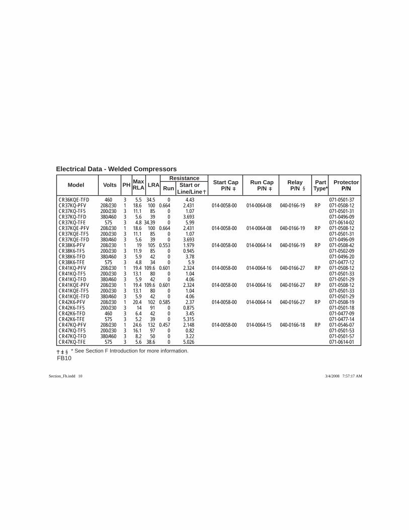
FB10
Electrical Data - Welded Compressors Max Resistance Model Volts PH RLA LRA Run Start or Start Cap Run Cap Relay Part Protector Line/Line P/N P/N P/N Type* P/N
* See Section F Introduction for more information.
CR36KQE-TFD 460 3 5.5 34.5 0 4.43 071-0501-37CR37KQ-PFV 208/230 1 18.6 100 0.664 2.431 014-0058-00 014-0064-08 040-0166-19 RP 071-0508-12CR37KQ-TF5 200/230 3 11.1 85 0 1.07 071-0501-31CR37KQ-TFD 380/460 3 5.6 39 0 3.693 071-0496-09CR37KQ-TFE 575 3 4.8 34.39 0 5.99 071-0614-02CR37KQE-PFV 208/230 1 18.6 100 0.664 2.431 014-0058-00 014-0064-08 040-0166-19 RP 071-0508-12CR37KQE-TF5 200/230 3 11.1 85 0 1.07 071-0501-31CR37KQE-TFD 380/460 3 5.6 39 0 3.693 071-0496-09CR38K6-PFV 208/230 1 19 105 0.553 1.979 014-0058-00 014-0064-14 040-0166-19 RP 071-0508-42CR38K6-TF5 200/230 3 11.9 85 0 0.945 071-0502-09CR38K6-TFD 380/460 3 5.9 42 0 3.78 071-0496-20CR38K6-TFE 575 3 4.8 34 0 5.9 071-0477-12CR41KQ-PFV 208/230 1 19.4 109.6 0.601 2.324 014-0058-00 014-0064-16 040-0166-27 RP 071-0508-12CR41KQ-TF5 200/230 3 13.1 80 0 1.04 071-0501-33CR41KQ-TFD 380/460 3 5.9 42 0 4.06 071-0501-29CR41KQE-PFV 208/230 1 19.4 109.6 0.601 2.324 014-0058-00 014-0064-16 040-0166-27 RP 071-0508-12CR41KQE-TF5 200/230 3 13.1 80 0 1.04 071-0501-33CR41KQE-TFD 380/460 3 5.9 42 0 4.06 071-0501-29CR42K6-PFV 208/230 1 20.4 102 0.585 2.37 014-0058-00 014-0064-14 040-0166-27 RP 071-0508-19CR42K6-TF5 200/230 3 14 91 0 0.875 071-0501-18CR42K6-TFD 460 3 6.4 42 0 3.45 071-0477-09CR42K6-TFE 575 3 5.2 39 0 5.315 071-0477-14CR47KQ-PFV 208/230 1 24.6 132 0.457 2.148 014-0058-00 014-0064-15 040-0166-18 RP 071-0546-07CR47KQ-TF5 200/230 3 16.1 97 0 0.82 071-0501-53CR47KQ-TFD 380/460 3 8.2 50 0 3.22 071-0501-57CR47KQ-TFE 575 3 5.6 38.6 0 5.026 071-0614-01
Section_Fb.indd 10Section_Fb.indd 10 3/4/2008 7:57:17 AM3/4/2008 7:57:17 AM
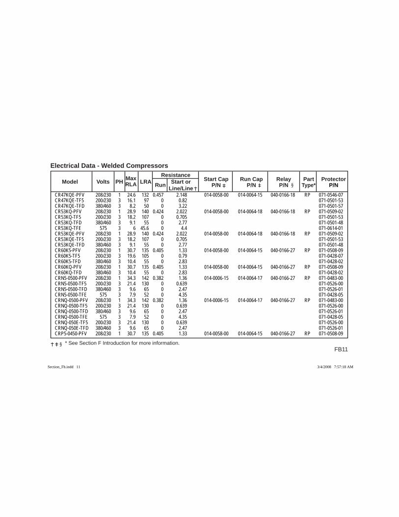
FB11
Electrical Data - Welded Compressors
* See Section F Introduction for more information.
Max Resistance Model Volts PH RLA LRA Run Start or Start Cap Run Cap Relay Part Protector Line/Line P/N P/N P/N Type* P/N
CR47KQE-PFV 208/230 1 24.6 132 0.457 2.148 014-0058-00 014-0064-15 040-0166-18 RP 071-0546-07CR47KQE-TF5 200/230 3 16.1 97 0 0.82 071-0501-53CR47KQE-TFD 380/460 3 8.2 50 0 3.22 071-0501-57CR53KQ-PFV 208/230 1 28.9 140 0.424 2.022 014-0058-00 014-0064-18 040-0166-18 RP 071-0509-02CR53KQ-TF5 200/230 3 18.2 107 0 0.705 071-0501-53CR53KQ-TFD 380/460 3 9.1 55 0 2.77 071-0501-48CR53KQ-TFE 575 3 6 45.6 0 4.4 071-0614-01CR53KQE-PFV 208/230 1 28.9 140 0.424 2.022 014-0058-00 014-0064-18 040-0166-18 RP 071-0509-02CR53KQE-TF5 200/230 3 18.2 107 0 0.705 071-0501-53CR53KQE-TFD 380/460 3 9.1 55 0 2.77 071-0501-48CR60K5-PFV 208/230 1 30.7 135 0.405 1.33 014-0058-00 014-0064-15 040-0166-27 RP 071-0508-09CR60K5-TF5 200/230 3 19.6 105 0 0.79 071-0428-07CR60K5-TFD 380/460 3 10.4 55 0 2.83 071-0428-02CR60KQ-PFV 208/230 1 30.7 135 0.405 1.33 014-0058-00 014-0064-15 040-0166-27 RP 071-0508-09CR60KQ-TFD 380/460 3 10.4 55 0 2.83 071-0428-02CRN5-0500-PFV 208/230 1 34.3 142 0.382 1.36 014-0006-15 014-0064-17 040-0166-27 RP 071-0483-00CRN5-0500-TF5 200/230 3 21.4 130 0 0.639 071-0526-00CRN5-0500-TFD 380/460 3 9.6 65 0 2.47 071-0526-01CRN5-0500-TFE 575 3 7.9 52 0 4.35 071-0428-05CRNQ-0500-PFV 208/230 1 34.3 142 0.382 1.36 014-0006-15 014-0064-17 040-0166-27 RP 071-0483-00CRNQ-0500-TF5 200/230 3 21.4 130 0 0.639 071-0526-00CRNQ-0500-TFD 380/460 3 9.6 65 0 2.47 071-0526-01CRNQ-0500-TFE 575 3 7.9 52 0 4.35 071-0428-05CRNQ-050E-TF5 200/230 3 21.4 130 0 0.639 071-0526-00CRNQ-050E-TFD 380/460 3 9.6 65 0 2.47 071-0526-01CRP5-0450-PFV 208/230 1 30.7 135 0.405 1.33 014-0058-00 014-0064-15 040-0166-27 RP 071-0508-09
Section_Fb.indd 11Section_Fb.indd 11 3/4/2008 7:57:18 AM3/4/2008 7:57:18 AM
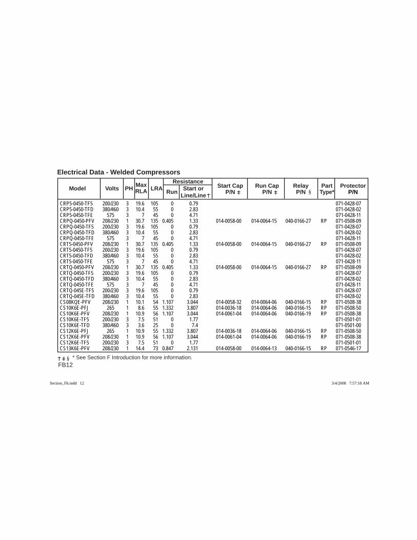
FB12
Electrical Data - Welded Compressors Max Resistance Model Volts PH RLA LRA Run Start or Start Cap Run Cap Relay Part Protector Line/Line P/N P/N P/N Type* P/N
* See Section F Introduction for more information.
CRP5-0450-TF5 200/230 3 19.6 105 0 0.79 071-0428-07CRP5-0450-TFD 380/460 3 10.4 55 0 2.83 071-0428-02CRP5-0450-TFE 575 3 7 45 0 4.71 071-0428-11CRPQ-0450-PFV 208/230 1 30.7 135 0.405 1.33 014-0058-00 014-0064-15 040-0166-27 RP 071-0508-09CRPQ-0450-TF5 200/230 3 19.6 105 0 0.79 071-0428-07CRPQ-0450-TFD 380/460 3 10.4 55 0 2.83 071-0428-02CRPQ-0450-TFE 575 3 7 45 0 4.71 071-0428-11CRT5-0450-PFV 208/230 1 30.7 135 0.405 1.33 014-0058-00 014-0064-15 040-0166-27 RP 071-0508-09CRT5-0450-TF5 200/230 3 19.6 105 0 0.79 071-0428-07CRT5-0450-TFD 380/460 3 10.4 55 0 2.83 071-0428-02CRT5-0450-TFE 575 3 7 45 0 4.71 071-0428-11CRTQ-0450-PFV 208/230 1 30.7 135 0.405 1.33 014-0058-00 014-0064-15 040-0166-27 RP 071-0508-09CRTQ-0450-TF5 200/230 3 19.6 105 0 0.79 071-0428-07CRTQ-0450-TFD 380/460 3 10.4 55 0 2.83 071-0428-02CRTQ-0450-TFE 575 3 7 45 0 4.71 071-0428-11CRTQ-045E-TF5 200/230 3 19.6 105 0 0.79 071-0428-07CRTQ-045E-TFD 380/460 3 10.4 55 0 2.83 071-0428-02CS08KQE-PFV 208/230 1 10.1 54 1.107 3.044 014-0058-32 014-0064-06 040-0166-15 RP 071-0508-38CS10K6E-PFJ 265 1 8.6 55 1.332 3.807 014-0036-18 014-0064-06 040-0166-15 RP 071-0508-50CS10K6E-PFV 208/230 1 10.9 56 1.107 3.044 014-0061-04 014-0064-06 040-0166-19 RP 071-0508-38CS10K6E-TF5 200/230 3 7.5 51 0 1.77 071-0501-01CS10K6E-TFD 380/460 3 3.6 25 0 7.4 071-0501-00CS12K6E-PFJ 265 1 10.9 55 1.332 3.807 014-0036-18 014-0064-06 040-0166-15 RP 071-0508-50CS12K6E-PFV 208/230 1 10.9 56 1.107 3.044 014-0061-04 014-0064-06 040-0166-19 RP 071-0508-38CS12K6E-TF5 200/230 3 7.5 51 0 1.77 071-0501-01CS13K6E-PFV 208/230 1 14.4 73 0.847 2.131 014-0058-00 014-0064-13 040-0166-15 RP 071-0546-17
Section_Fb.indd 12Section_Fb.indd 12 3/4/2008 7:57:18 AM3/4/2008 7:57:18 AM
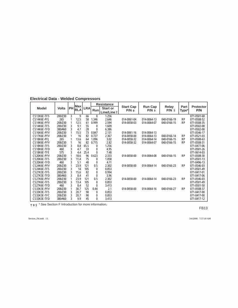
FB13
Electrical Data - Welded Compressors
* See Section F Introduction for more information.
Max Resistance Model Volts PH RLA LRA Run Start or Start Cap Run Cap Relay Part Protector Line/Line P/N P/N P/N Type* P/N
CS13K6E-TF5 200/230 3 9 66 0 1.256 071-0501-68CS14K6E-PFJ 265 1 12.5 58 1.346 2.646 014-0061-04 014-0064-13 040-0166-19 RP 071-0508-52CS14K6E-PFV 208/230 1 12.5 61 0.999 2.594 014-0058-03 014-0064-07 040-0166-15 RP 071-0508-35CS14K6E-TF5 200/230 3 9.1 55 0 1.609 071-0502-08CS14K6E-TFD 380/460 3 4.7 28 0 6.386 071-0502-00CS16K6E-PFV 208/230 1 15.5 73 0.847 2.131 014-0061-16 014-0064-13 071-0546-17CS17K6E-PFV 208/230 1 16 82 0.727 2.367 014-0058-00 014-0064-13 040-0166-14 RP 071-0521-03CS18K6E-PFJ 265 1 13.6 64 1.096 3.02 014-0058-32 014-0064-14 040-0166-15 RP 071-0508-63CS18K6E-PFV 208/230 1 16 82 0.715 2.82 014-0058-32 014-0064-07 040-0166-15 RP 071-0508-31CS18K6E-TF5 200/230 3 8.8 65.5 0 1.256 071-0477-06CS18K6E-TFD 460 3 4.7 33 0 4.95 071-0501-26CS18K6E-TFE 575 3 4.4 25.4 0 7.48 071-0614-03CS20K6E-PFV 208/230 1 18.6 96 0.623 2.333 014-0058-00 014-0064-08 040-0166-15 RP 071-0508-30CS20K6E-TF5 200/230 3 11.4 75 0 1.058 071-0501-13CS20K6E-TFD 460 3 5.1 40 0 4.11 071-0496-13CS24K6E-PFV 208/230 1 23.9 121 0.5 2.302 014-0058-00 014-0064-14 040-0166-23 RP 071-0546-03CS24K6E-TF5 200/230 3 14 105 0 0.853 071-0501-49CS27K3E-TF5 200/230 3 15.6 82 0 0.994 071-0417-01CS27K3E-TFD 380/460 3 8.4 41 0 3.96 071-0417-06CS27K6E-PFV 208/230 1 23.9 121 0.5 2.302 014-0058-00 014-0064-14 040-0166-23 RP 071-0546-03CS27K6E-TF5 200/230 3 13.4 105 0 0.853 071-0501-49CS27K6E-TFD 460 3 8.4 52 0 3.413 071-0501-50CS33K3E-PFV 208/230 1 30.7 125 0.44 2.1 014-0058-00 014-0064-16 040-0166-27 RP 071-0508-37CS33K3E-TF5 200/230 3 20.7 90 0 0.853 071-0417-00CS33K3E-TFC 208/230 3 20.7 90 0 0.853 071-0417-00CS33K3E-TFD 380/460 3 9.9 45 0 3.413 071-0417-12
Section_Fb.indd 13Section_Fb.indd 13 3/4/2008 7:57:18 AM3/4/2008 7:57:18 AM
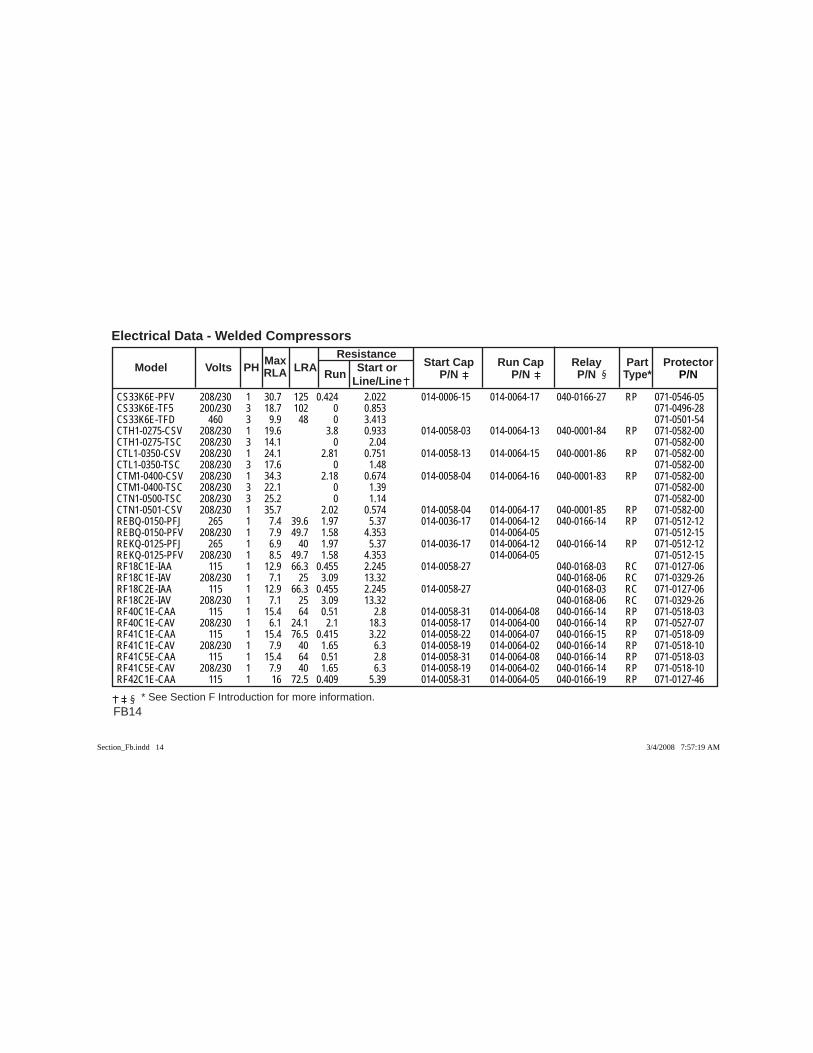
FB14
Electrical Data - Welded Compressors Max Resistance Model Volts PH RLA LRA Run Start or Start Cap Run Cap Relay Part Protector Line/Line P/N P/N P/N Type* P/N
* See Section F Introduction for more information.
CS33K6E-PFV 208/230 1 30.7 125 0.424 2.022 014-0006-15 014-0064-17 040-0166-27 RP 071-0546-05CS33K6E-TF5 200/230 3 18.7 102 0 0.853 071-0496-28CS33K6E-TFD 460 3 9.9 48 0 3.413 071-0501-54CTH1-0275-CSV 208/230 1 19.6 3.8 0.933 014-0058-03 014-0064-13 040-0001-84 RP 071-0582-00CTH1-0275-TSC 208/230 3 14.1 0 2.04 071-0582-00CTL1-0350-CSV 208/230 1 24.1 2.81 0.751 014-0058-13 014-0064-15 040-0001-86 RP 071-0582-00CTL1-0350-TSC 208/230 3 17.6 0 1.48 071-0582-00CTM1-0400-CSV 208/230 1 34.3 2.18 0.674 014-0058-04 014-0064-16 040-0001-83 RP 071-0582-00CTM1-0400-TSC 208/230 3 22.1 0 1.39 071-0582-00CTN1-0500-TSC 208/230 3 25.2 0 1.14 071-0582-00CTN1-0501-CSV 208/230 1 35.7 2.02 0.574 014-0058-04 014-0064-17 040-0001-85 RP 071-0582-00REBQ-0150-PFJ 265 1 7.4 39.6 1.97 5.37 014-0036-17 014-0064-12 040-0166-14 RP 071-0512-12REBQ-0150-PFV 208/230 1 7.9 49.7 1.58 4.353 014-0064-05 071-0512-15REKQ-0125-PFJ 265 1 6.9 40 1.97 5.37 014-0036-17 014-0064-12 040-0166-14 RP 071-0512-12REKQ-0125-PFV 208/230 1 8.5 49.7 1.58 4.353 014-0064-05 071-0512-15RF18C1E-IAA 115 1 12.9 66.3 0.455 2.245 014-0058-27 040-0168-03 RC 071-0127-06RF18C1E-IAV 208/230 1 7.1 25 3.09 13.32 040-0168-06 RC 071-0329-26RF18C2E-IAA 115 1 12.9 66.3 0.455 2.245 014-0058-27 040-0168-03 RC 071-0127-06RF18C2E-IAV 208/230 1 7.1 25 3.09 13.32 040-0168-06 RC 071-0329-26RF40C1E-CAA 115 1 15.4 64 0.51 2.8 014-0058-31 014-0064-08 040-0166-14 RP 071-0518-03RF40C1E-CAV 208/230 1 6.1 24.1 2.1 18.3 014-0058-17 014-0064-00 040-0166-14 RP 071-0527-07RF41C1E-CAA 115 1 15.4 76.5 0.415 3.22 014-0058-22 014-0064-07 040-0166-15 RP 071-0518-09RF41C1E-CAV 208/230 1 7.9 40 1.65 6.3 014-0058-19 014-0064-02 040-0166-14 RP 071-0518-10RF41C5E-CAA 115 1 15.4 64 0.51 2.8 014-0058-31 014-0064-08 040-0166-14 RP 071-0518-03RF41C5E-CAV 208/230 1 7.9 40 1.65 6.3 014-0058-19 014-0064-02 040-0166-14 RP 071-0518-10RF42C1E-CAA 115 1 16 72.5 0.409 5.39 014-0058-31 014-0064-05 040-0166-19 RP 071-0127-46
Section_Fb.indd 14Section_Fb.indd 14 3/4/2008 7:57:19 AM3/4/2008 7:57:19 AM
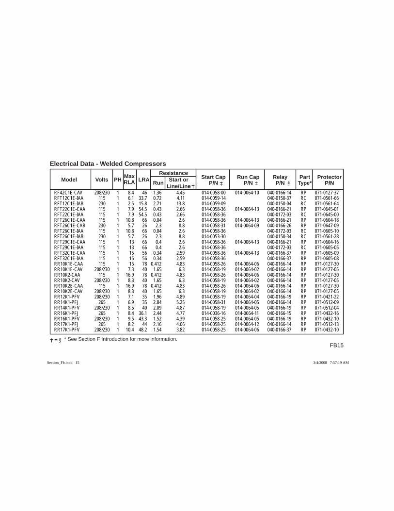
FB15
Electrical Data - Welded Compressors
* See Section F Introduction for more information.
Max Resistance Model Volts PH RLA LRA Run Start or Start Cap Run Cap Relay Part Protector Line/Line P/N P/N P/N Type* P/N
RF42C1E-CAV 208/230 1 8.4 46 1.36 4.45 014-0058-00 014-0064-10 040-0166-14 RP 071-0127-37RFT12C1E-IAA 115 1 6.1 33.7 0.72 4.11 014-0059-14 040-0150-37 RC 071-0561-66RFT12C1E-IAB 230 1 2.5 15.8 2.71 13.8 014-0059-09 040-0150-04 RC 071-0561-64RFT22C1E-CAA 115 1 7.9 54.5 0.43 2.66 014-0058-36 014-0064-13 040-0166-21 RP 071-0645-01RFT22C1E-IAA 115 1 7.9 54.5 0.43 2.66 014-0058-36 040-0172-03 RC 071-0645-00RFT26C1E-CAA 115 1 10.8 66 0.04 2.6 014-0058-36 014-0064-13 040-0166-21 RP 071-0604-18RFT26C1E-CAB 230 1 5.7 26 2.3 8.8 014-0058-31 014-0064-09 040-0166-26 RP 071-0647-09RFT26C1E-IAA 115 1 10.8 66 0.04 2.6 014-0058-36 040-0172-03 RC 071-0605-10RFT26C1E-IAB 230 1 5.7 26 2.3 8.8 014-0053-30 040-0150-34 RC 071-0561-28RFT29C1E-CAA 115 1 13 66 0.4 2.6 014-0058-36 014-0064-13 040-0166-21 RP 071-0604-16RFT29C1E-IAA 115 1 13 66 0.4 2.6 014-0058-36 040-0172-03 RC 071-0605-05RFT32C1E-CAA 115 1 15 56 0.34 2.59 014-0058-36 014-0064-13 040-0166-37 RP 071-0605-09RFT32C1E-IAA 115 1 15 56 0.34 2.59 014-0058-36 040-0166-37 RP 071-0605-08RR10K1E-CAA 115 1 15 78 0.412 4.83 014-0058-26 014-0064-06 040-0166-14 RP 071-0127-30RR10K1E-CAV 208/230 1 7.3 40 1.65 6.3 014-0058-19 014-0064-02 040-0166-14 RP 071-0127-05RR10K2-CAA 115 1 16.9 78 0.412 4.83 014-0058-26 014-0064-06 040-0166-14 RP 071-0127-30RR10K2-CAV 208/230 1 8.3 40 1.65 6.3 014-0058-19 014-0064-02 040-0166-14 RP 071-0127-05RR10K2E-CAA 115 1 16.9 78 0.412 4.83 014-0058-26 014-0064-06 040-0166-14 RP 071-0127-30RR10K2E-CAV 208/230 1 8.3 40 1.65 6.3 014-0058-19 014-0064-02 040-0166-14 RP 071-0127-05RR12K1-PFV 208/230 1 7.1 35 1.96 4.89 014-0058-19 014-0064-04 040-0166-19 RP 071-0421-22RR14K1-PFJ 265 1 6.9 35 2.84 5.25 014-0058-31 014-0064-05 040-0166-14 RP 071-0512-09RR14K1-PFV 208/230 1 8.5 40 2.09 4.87 014-0058-19 014-0064-05 040-0166-19 RP 071-0512-04RR16K1-PFJ 265 1 8.4 36.1 2.44 4.77 014-0036-16 014-0064-11 040-0166-15 RP 071-0432-16RR16K1-PFV 208/230 1 9.5 43.3 1.52 4.39 014-0058-25 014-0064-05 040-0166-19 RP 071-0432-10RR17K1-PFJ 265 1 8.2 44 2.16 4.06 014-0058-25 014-0064-12 040-0166-14 RP 071-0512-13RR17K1-PFV 208/230 1 10.4 48.2 1.54 3.82 014-0058-25 014-0064-06 040-0166-37 RP 071-0432-10
Section_Fb.indd 15Section_Fb.indd 15 3/4/2008 7:57:19 AM3/4/2008 7:57:19 AM
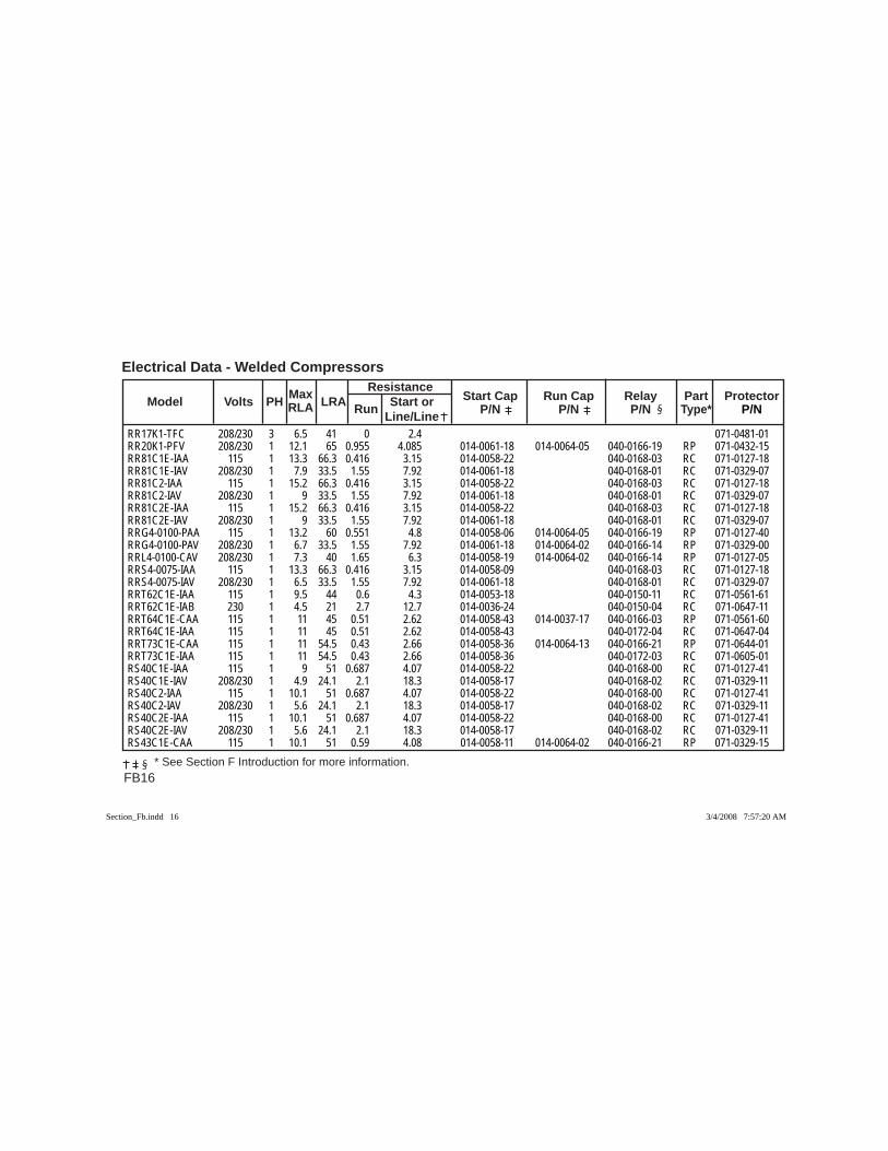
FB16
Electrical Data - Welded Compressors Max Resistance Model Volts PH RLA LRA Run Start or Start Cap Run Cap Relay Part Protector Line/Line P/N P/N P/N Type* P/N
* See Section F Introduction for more information.
RR17K1-TFC 208/230 3 6.5 41 0 2.4 071-0481-01RR20K1-PFV 208/230 1 12.1 65 0.955 4.085 014-0061-18 014-0064-05 040-0166-19 RP 071-0432-15RR81C1E-IAA 115 1 13.3 66.3 0.416 3.15 014-0058-22 040-0168-03 RC 071-0127-18RR81C1E-IAV 208/230 1 7.9 33.5 1.55 7.92 014-0061-18 040-0168-01 RC 071-0329-07RR81C2-IAA 115 1 15.2 66.3 0.416 3.15 014-0058-22 040-0168-03 RC 071-0127-18RR81C2-IAV 208/230 1 9 33.5 1.55 7.92 014-0061-18 040-0168-01 RC 071-0329-07RR81C2E-IAA 115 1 15.2 66.3 0.416 3.15 014-0058-22 040-0168-03 RC 071-0127-18RR81C2E-IAV 208/230 1 9 33.5 1.55 7.92 014-0061-18 040-0168-01 RC 071-0329-07RRG4-0100-PAA 115 1 13.2 60 0.551 4.8 014-0058-06 014-0064-05 040-0166-19 RP 071-0127-40RRG4-0100-PAV 208/230 1 6.7 33.5 1.55 7.92 014-0061-18 014-0064-02 040-0166-14 RP 071-0329-00RRL4-0100-CAV 208/230 1 7.3 40 1.65 6.3 014-0058-19 014-0064-02 040-0166-14 RP 071-0127-05RRS4-0075-IAA 115 1 13.3 66.3 0.416 3.15 014-0058-09 040-0168-03 RC 071-0127-18RRS4-0075-IAV 208/230 1 6.5 33.5 1.55 7.92 014-0061-18 040-0168-01 RC 071-0329-07RRT62C1E-IAA 115 1 9.5 44 0.6 4.3 014-0053-18 040-0150-11 RC 071-0561-61RRT62C1E-IAB 230 1 4.5 21 2.7 12.7 014-0036-24 040-0150-04 RC 071-0647-11RRT64C1E-CAA 115 1 11 45 0.51 2.62 014-0058-43 014-0037-17 040-0166-03 RP 071-0561-60RRT64C1E-IAA 115 1 11 45 0.51 2.62 014-0058-43 040-0172-04 RC 071-0647-04RRT73C1E-CAA 115 1 11 54.5 0.43 2.66 014-0058-36 014-0064-13 040-0166-21 RP 071-0644-01RRT73C1E-IAA 115 1 11 54.5 0.43 2.66 014-0058-36 040-0172-03 RC 071-0605-01RS40C1E-IAA 115 1 9 51 0.687 4.07 014-0058-22 040-0168-00 RC 071-0127-41RS40C1E-IAV 208/230 1 4.9 24.1 2.1 18.3 014-0058-17 040-0168-02 RC 071-0329-11RS40C2-IAA 115 1 10.1 51 0.687 4.07 014-0058-22 040-0168-00 RC 071-0127-41RS40C2-IAV 208/230 1 5.6 24.1 2.1 18.3 014-0058-17 040-0168-02 RC 071-0329-11RS40C2E-IAA 115 1 10.1 51 0.687 4.07 014-0058-22 040-0168-00 RC 071-0127-41RS40C2E-IAV 208/230 1 5.6 24.1 2.1 18.3 014-0058-17 040-0168-02 RC 071-0329-11RS43C1E-CAA 115 1 10.1 51 0.59 4.08 014-0058-11 014-0064-02 040-0166-21 RP 071-0329-15
Section_Fb.indd 16Section_Fb.indd 16 3/4/2008 7:57:20 AM3/4/2008 7:57:20 AM
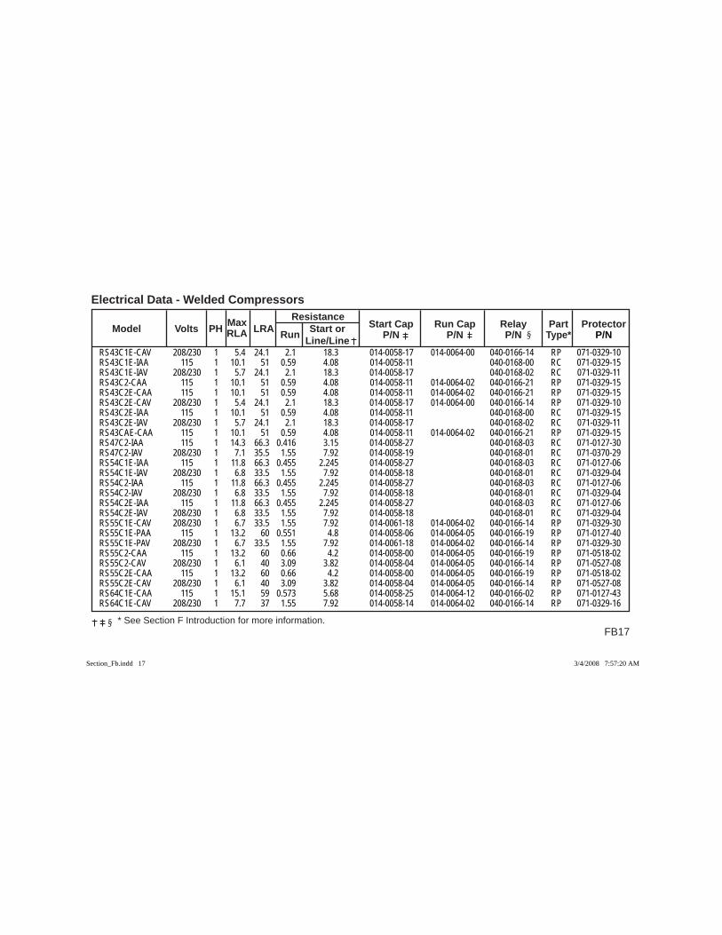
FB17
Electrical Data - Welded Compressors
* See Section F Introduction for more information.
Max Resistance Model Volts PH RLA LRA Run Start or Start Cap Run Cap Relay Part Protector Line/Line P/N P/N P/N Type* P/N
RS43C1E-CAV 208/230 1 5.4 24.1 2.1 18.3 014-0058-17 014-0064-00 040-0166-14 RP 071-0329-10RS43C1E-IAA 115 1 10.1 51 0.59 4.08 014-0058-11 040-0168-00 RC 071-0329-15RS43C1E-IAV 208/230 1 5.7 24.1 2.1 18.3 014-0058-17 040-0168-02 RC 071-0329-11RS43C2-CAA 115 1 10.1 51 0.59 4.08 014-0058-11 014-0064-02 040-0166-21 RP 071-0329-15RS43C2E-CAA 115 1 10.1 51 0.59 4.08 014-0058-11 014-0064-02 040-0166-21 RP 071-0329-15RS43C2E-CAV 208/230 1 5.4 24.1 2.1 18.3 014-0058-17 014-0064-00 040-0166-14 RP 071-0329-10RS43C2E-IAA 115 1 10.1 51 0.59 4.08 014-0058-11 040-0168-00 RC 071-0329-15RS43C2E-IAV 208/230 1 5.7 24.1 2.1 18.3 014-0058-17 040-0168-02 RC 071-0329-11RS43CAE-CAA 115 1 10.1 51 0.59 4.08 014-0058-11 014-0064-02 040-0166-21 RP 071-0329-15RS47C2-IAA 115 1 14.3 66.3 0.416 3.15 014-0058-27 040-0168-03 RC 071-0127-30RS47C2-IAV 208/230 1 7.1 35.5 1.55 7.92 014-0058-19 040-0168-01 RC 071-0370-29RS54C1E-IAA 115 1 11.8 66.3 0.455 2.245 014-0058-27 040-0168-03 RC 071-0127-06RS54C1E-IAV 208/230 1 6.8 33.5 1.55 7.92 014-0058-18 040-0168-01 RC 071-0329-04RS54C2-IAA 115 1 11.8 66.3 0.455 2.245 014-0058-27 040-0168-03 RC 071-0127-06RS54C2-IAV 208/230 1 6.8 33.5 1.55 7.92 014-0058-18 040-0168-01 RC 071-0329-04RS54C2E-IAA 115 1 11.8 66.3 0.455 2.245 014-0058-27 040-0168-03 RC 071-0127-06RS54C2E-IAV 208/230 1 6.8 33.5 1.55 7.92 014-0058-18 040-0168-01 RC 071-0329-04RS55C1E-CAV 208/230 1 6.7 33.5 1.55 7.92 014-0061-18 014-0064-02 040-0166-14 RP 071-0329-30RS55C1E-PAA 115 1 13.2 60 0.551 4.8 014-0058-06 014-0064-05 040-0166-19 RP 071-0127-40RS55C1E-PAV 208/230 1 6.7 33.5 1.55 7.92 014-0061-18 014-0064-02 040-0166-14 RP 071-0329-30RS55C2-CAA 115 1 13.2 60 0.66 4.2 014-0058-00 014-0064-05 040-0166-19 RP 071-0518-02RS55C2-CAV 208/230 1 6.1 40 3.09 3.82 014-0058-04 014-0064-05 040-0166-14 RP 071-0527-08RS55C2E-CAA 115 1 13.2 60 0.66 4.2 014-0058-00 014-0064-05 040-0166-19 RP 071-0518-02RS55C2E-CAV 208/230 1 6.1 40 3.09 3.82 014-0058-04 014-0064-05 040-0166-14 RP 071-0527-08RS64C1E-CAA 115 1 15.1 59 0.573 5.68 014-0058-25 014-0064-12 040-0166-02 RP 071-0127-43RS64C1E-CAV 208/230 1 7.7 37 1.55 7.92 014-0058-14 014-0064-02 040-0166-14 RP 071-0329-16
Section_Fb.indd 17Section_Fb.indd 17 3/4/2008 7:57:20 AM3/4/2008 7:57:20 AM
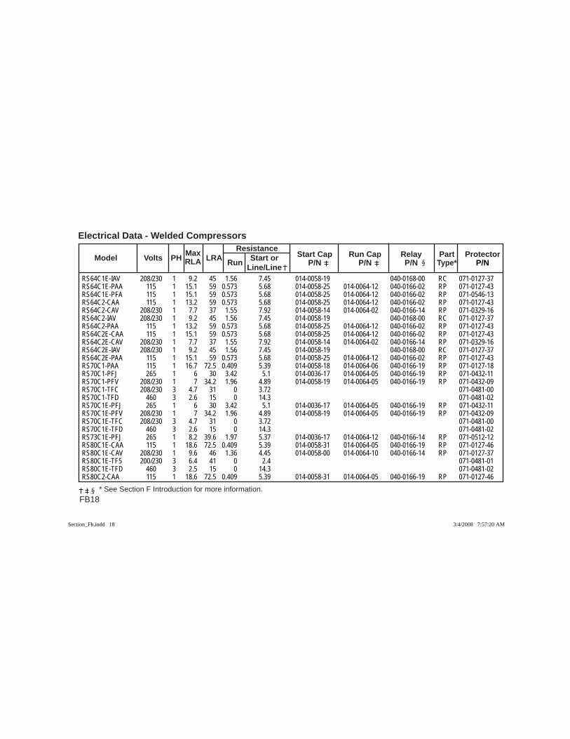
FB18
Electrical Data - Welded Compressors Max Resistance Model Volts PH RLA LRA Run Start or Start Cap Run Cap Relay Part Protector Line/Line P/N P/N P/N Type* P/N
* See Section F Introduction for more information.
RS64C1E-IAV 208/230 1 9.2 45 1.56 7.45 014-0058-19 040-0168-00 RC 071-0127-37RS64C1E-PAA 115 1 15.1 59 0.573 5.68 014-0058-25 014-0064-12 040-0166-02 RP 071-0127-43RS64C1E-PFA 115 1 15.1 59 0.573 5.68 014-0058-25 014-0064-12 040-0166-02 RP 071-0546-13RS64C2-CAA 115 1 13.2 59 0.573 5.68 014-0058-25 014-0064-12 040-0166-02 RP 071-0127-43RS64C2-CAV 208/230 1 7.7 37 1.55 7.92 014-0058-14 014-0064-02 040-0166-14 RP 071-0329-16RS64C2-IAV 208/230 1 9.2 45 1.56 7.45 014-0058-19 040-0168-00 RC 071-0127-37RS64C2-PAA 115 1 13.2 59 0.573 5.68 014-0058-25 014-0064-12 040-0166-02 RP 071-0127-43RS64C2E-CAA 115 1 15.1 59 0.573 5.68 014-0058-25 014-0064-12 040-0166-02 RP 071-0127-43RS64C2E-CAV 208/230 1 7.7 37 1.55 7.92 014-0058-14 014-0064-02 040-0166-14 RP 071-0329-16RS64C2E-IAV 208/230 1 9.2 45 1.56 7.45 014-0058-19 040-0168-00 RC 071-0127-37RS64C2E-PAA 115 1 15.1 59 0.573 5.68 014-0058-25 014-0064-12 040-0166-02 RP 071-0127-43RS70C1-PAA 115 1 16.7 72.5 0.409 5.39 014-0058-18 014-0064-06 040-0166-19 RP 071-0127-18RS70C1-PFJ 265 1 6 30 3.42 5.1 014-0036-17 014-0064-05 040-0166-19 RP 071-0432-11RS70C1-PFV 208/230 1 7 34.2 1.96 4.89 014-0058-19 014-0064-05 040-0166-19 RP 071-0432-09RS70C1-TFC 208/230 3 4.7 31 0 3.72 071-0481-00RS70C1-TFD 460 3 2.6 15 0 14.3 071-0481-02RS70C1E-PFJ 265 1 6 30 3.42 5.1 014-0036-17 014-0064-05 040-0166-19 RP 071-0432-11RS70C1E-PFV 208/230 1 7 34.2 1.96 4.89 014-0058-19 014-0064-05 040-0166-19 RP 071-0432-09RS70C1E-TFC 208/230 3 4.7 31 0 3.72 071-0481-00RS70C1E-TFD 460 3 2.6 15 0 14.3 071-0481-02RS73C1E-PFJ 265 1 8.2 39.6 1.97 5.37 014-0036-17 014-0064-12 040-0166-14 RP 071-0512-12RS80C1E-CAA 115 1 18.6 72.5 0.409 5.39 014-0058-31 014-0064-05 040-0166-19 RP 071-0127-46RS80C1E-CAV 208/230 1 9.6 46 1.36 4.45 014-0058-00 014-0064-10 040-0166-14 RP 071-0127-37RS80C1E-TF5 200/230 3 6.4 41 0 2.4 071-0481-01RS80C1E-TFD 460 3 2.5 15 0 14.3 071-0481-02RS80C2-CAA 115 1 18.6 72.5 0.409 5.39 014-0058-31 014-0064-05 040-0166-19 RP 071-0127-46
Section_Fb.indd 18Section_Fb.indd 18 3/4/2008 7:57:20 AM3/4/2008 7:57:20 AM
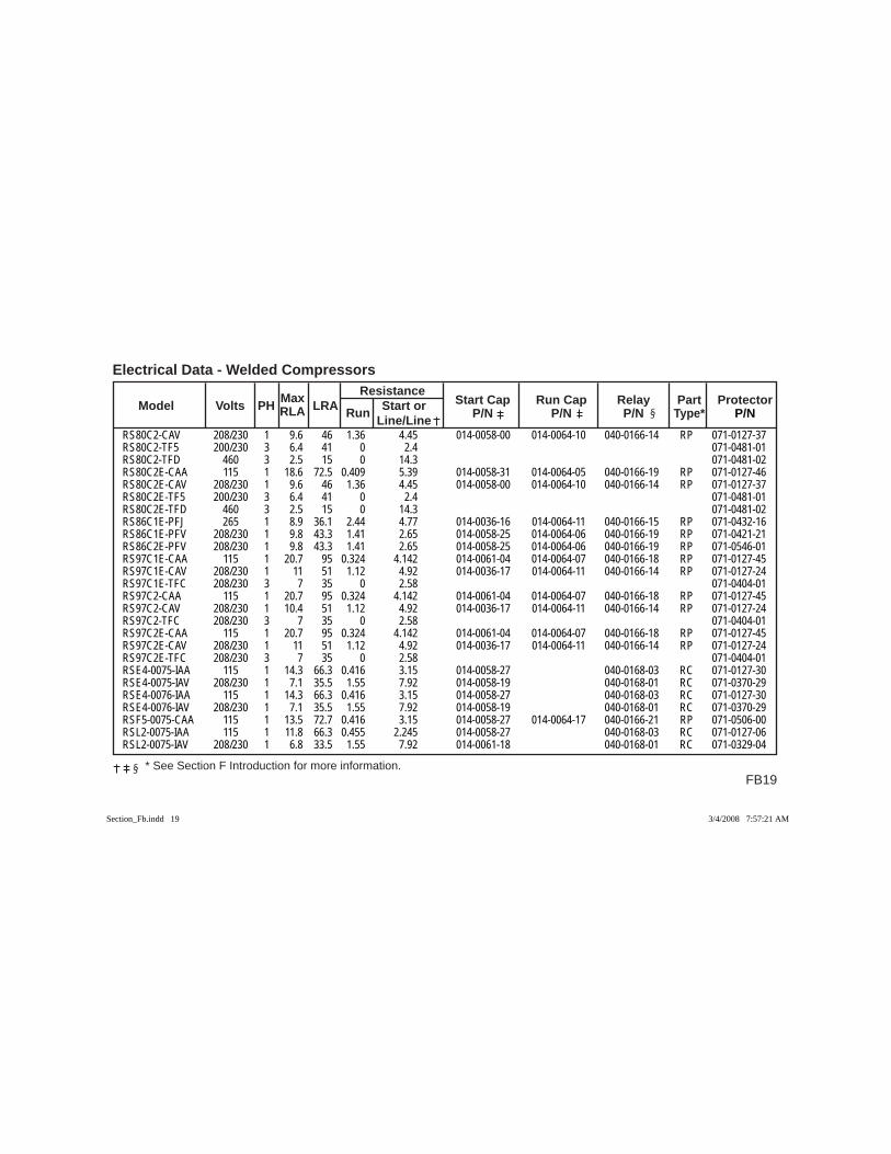
FB19
Electrical Data - Welded Compressors
* See Section F Introduction for more information.
Max Resistance Model Volts PH RLA LRA Run Start or Start Cap Run Cap Relay Part Protector Line/Line P/N P/N P/N Type* P/N
RS80C2-CAV 208/230 1 9.6 46 1.36 4.45 014-0058-00 014-0064-10 040-0166-14 RP 071-0127-37RS80C2-TF5 200/230 3 6.4 41 0 2.4 071-0481-01RS80C2-TFD 460 3 2.5 15 0 14.3 071-0481-02RS80C2E-CAA 115 1 18.6 72.5 0.409 5.39 014-0058-31 014-0064-05 040-0166-19 RP 071-0127-46RS80C2E-CAV 208/230 1 9.6 46 1.36 4.45 014-0058-00 014-0064-10 040-0166-14 RP 071-0127-37RS80C2E-TF5 200/230 3 6.4 41 0 2.4 071-0481-01RS80C2E-TFD 460 3 2.5 15 0 14.3 071-0481-02RS86C1E-PFJ 265 1 8.9 36.1 2.44 4.77 014-0036-16 014-0064-11 040-0166-15 RP 071-0432-16RS86C1E-PFV 208/230 1 9.8 43.3 1.41 2.65 014-0058-25 014-0064-06 040-0166-19 RP 071-0421-21RS86C2E-PFV 208/230 1 9.8 43.3 1.41 2.65 014-0058-25 014-0064-06 040-0166-19 RP 071-0546-01RS97C1E-CAA 115 1 20.7 95 0.324 4.142 014-0061-04 014-0064-07 040-0166-18 RP 071-0127-45RS97C1E-CAV 208/230 1 11 51 1.12 4.92 014-0036-17 014-0064-11 040-0166-14 RP 071-0127-24RS97C1E-TFC 208/230 3 7 35 0 2.58 071-0404-01RS97C2-CAA 115 1 20.7 95 0.324 4.142 014-0061-04 014-0064-07 040-0166-18 RP 071-0127-45RS97C2-CAV 208/230 1 10.4 51 1.12 4.92 014-0036-17 014-0064-11 040-0166-14 RP 071-0127-24RS97C2-TFC 208/230 3 7 35 0 2.58 071-0404-01RS97C2E-CAA 115 1 20.7 95 0.324 4.142 014-0061-04 014-0064-07 040-0166-18 RP 071-0127-45RS97C2E-CAV 208/230 1 11 51 1.12 4.92 014-0036-17 014-0064-11 040-0166-14 RP 071-0127-24RS97C2E-TFC 208/230 3 7 35 0 2.58 071-0404-01RSE4-0075-IAA 115 1 14.3 66.3 0.416 3.15 014-0058-27 040-0168-03 RC 071-0127-30RSE4-0075-IAV 208/230 1 7.1 35.5 1.55 7.92 014-0058-19 040-0168-01 RC 071-0370-29RSE4-0076-IAA 115 1 14.3 66.3 0.416 3.15 014-0058-27 040-0168-03 RC 071-0127-30RSE4-0076-IAV 208/230 1 7.1 35.5 1.55 7.92 014-0058-19 040-0168-01 RC 071-0370-29RSF5-0075-CAA 115 1 13.5 72.7 0.416 3.15 014-0058-27 014-0064-17 040-0166-21 RP 071-0506-00RSL2-0075-IAA 115 1 11.8 66.3 0.455 2.245 014-0058-27 040-0168-03 RC 071-0127-06RSL2-0075-IAV 208/230 1 6.8 33.5 1.55 7.92 014-0061-18 040-0168-01 RC 071-0329-04
Section_Fb.indd 19Section_Fb.indd 19 3/4/2008 7:57:21 AM3/4/2008 7:57:21 AM
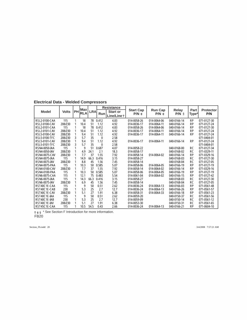
FB20
Electrical Data - Welded Compressors Max Resistance Model Volts PH RLA LRA Run Start or Start Cap Run Cap Relay Part Protector Line/Line P/N P/N P/N Type* P/N
* See Section F Introduction for more information.
RSL2-0100-CAA 115 1 18 78 0.412 4.83 014-0058-26 014-0064-06 040-0166-14 RP 071-0127-30RSL2-0100-CAV 208/230 1 10.4 51 1.12 4.92 014-0036-17 014-0064-11 040-0166-14 RP 071-0127-24RSL2-0101-CAA 115 1 18 78 0.412 4.83 014-0058-26 014-0064-06 040-0166-14 RP 071-0127-30RSL2-0101-CAV 208/230 1 10.4 51 1.12 4.92 014-0036-17 014-0064-11 040-0166-14 RP 071-0127-24RSL5-0100-CAV 208/230 1 9.4 51 1.12 4.92 014-0036-17 014-0064-11 040-0166-14 RP 071-0127-24RSL5-0100-TFC 208/230 3 5.7 35 0 2.58 071-0404-01RSL5-0101-CAV 208/230 1 9.4 51 1.12 4.92 014-0036-17 014-0064-11 040-0166-14 RP 071-0127-24RSL5-0101-TFC 208/230 3 5.7 35 0 2.58 071-0404-01RSN4-0050-IAA 115 1 9 51 0.687 4.07 014-0058-22 040-0168-00 RC 071-0127-34RSN4-0050-IAV 208/230 1 4.9 24.1 2.1 18.3 014-0058-17 040-0168-02 RC 071-0329-11RSN4-0075-CAV 208/230 1 7.7 37 1.55 7.92 014-0058-14 014-0064-02 040-0166-14 RP 071-0329-16RSN4-0075-IAA 115 1 14.9 66.3 0.416 3.15 014-0058-27 040-0168-03 RC 071-0127-30RSN4-0075-IAV 208/230 1 8.8 45 1.56 7.45 014-0058-14 040-0168-04 RC 071-0127-05RSN4-0075-PAA 115 1 10.3 50 0.585 5.07 014-0058-06 014-0064-05 040-0166-19 RP 071-0127-19RSN4-0100-CAV 208/230 1 7.7 37 1.55 7.92 014-0058-14 014-0064-02 040-0166-14 RP 071-0329-16RSN4-0100-PAA 115 1 10.3 50 0.585 5.07 014-0058-06 014-0064-05 040-0166-19 RP 071-0127-19RSN6-0075-CAA 115 1 12.1 75 0.483 5.54 014-0061-04 014-0064-02 040-0166-15 RP 071-0127-42RSN6-0075-IAA 115 1 14.3 66.3 0.416 3.15 014-0058-27 040-0168-03 RC 071-0127-30RSN6-0075-IAV 208/230 1 6.9 45 1.56 7.45 014-0058-14 040-0168-04 RC 071-0127-05RST40C1E-CAA 115 1 9 50 0.51 2.62 014-0036-24 014-0064-13 040-0166-03 RP 071-0561-48RST40C1E-CAB 230 1 5.3 25 2.7 12.7 014-0036-24 014-0064-13 040-0166-26 RP 071-0561-57RST40C1E-CAV 208/230 1 5.1 27 1.91 6.38 014-0058-31 014-0064-33 040-0166-18 RP 071-0561-23RST40C1E-IAA 115 1 9 50 0.51 2.62 014-0059-20 040-0150-37 RC 071-0561-56RST40C1E-IAB 230 1 5.3 25 2.7 12.7 014-0059-09 040-0150-14 RC 071-0561-12RST40C1E-IAV 208/230 1 5.1 27 1.91 6.38 014-0053-30 040-0150-31 RC 071-0561-65RST45C1E-CAA 115 1 10.5 54.5 0.43 2.66 014-0036-24 014-0064-13 040-0166-21 RP 071-0604-10
Section_Fb.indd 20Section_Fb.indd 20 3/4/2008 7:57:21 AM3/4/2008 7:57:21 AM
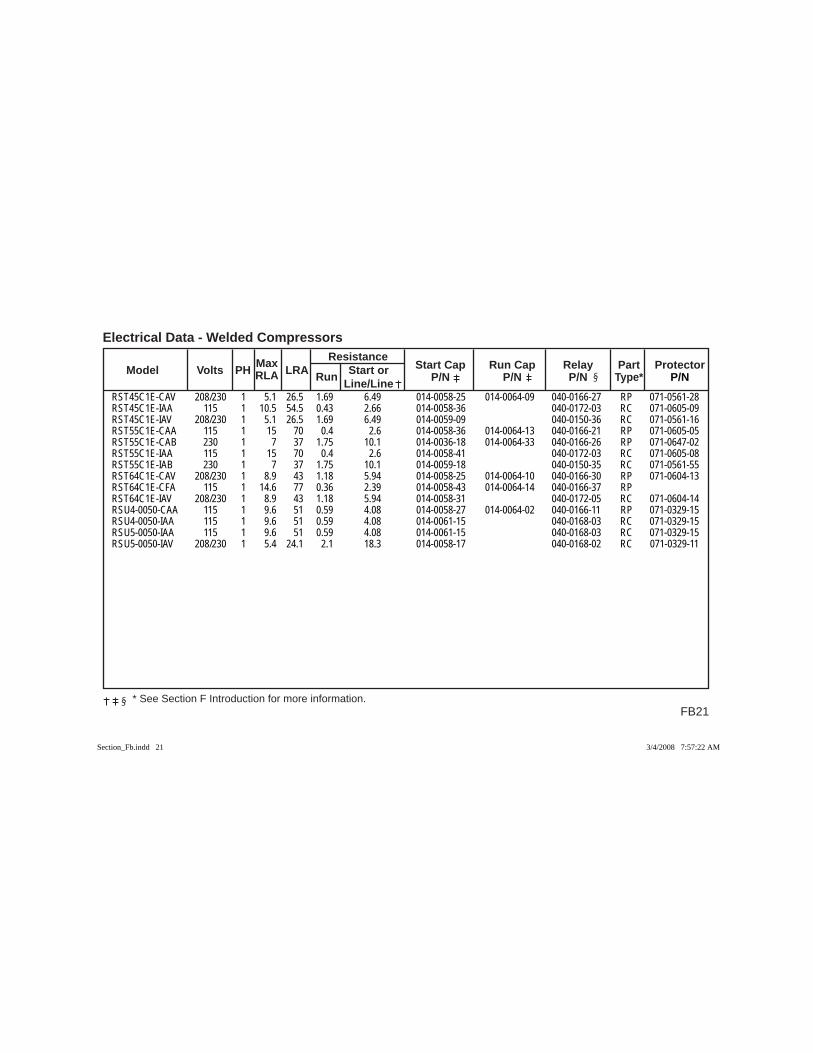
FB21
Electrical Data - Welded Compressors
* See Section F Introduction for more information.
Max Resistance Model Volts PH RLA LRA Run Start or Start Cap Run Cap Relay Part Protector Line/Line P/N P/N P/N Type* P/N
RST45C1E-CAV 208/230 1 5.1 26.5 1.69 6.49 014-0058-25 014-0064-09 040-0166-27 RP 071-0561-28RST45C1E-IAA 115 1 10.5 54.5 0.43 2.66 014-0058-36 040-0172-03 RC 071-0605-09RST45C1E-IAV 208/230 1 5.1 26.5 1.69 6.49 014-0059-09 040-0150-36 RC 071-0561-16RST55C1E-CAA 115 1 15 70 0.4 2.6 014-0058-36 014-0064-13 040-0166-21 RP 071-0605-05RST55C1E-CAB 230 1 7 37 1.75 10.1 014-0036-18 014-0064-33 040-0166-26 RP 071-0647-02RST55C1E-IAA 115 1 15 70 0.4 2.6 014-0058-41 040-0172-03 RC 071-0605-08RST55C1E-IAB 230 1 7 37 1.75 10.1 014-0059-18 040-0150-35 RC 071-0561-55RST64C1E-CAV 208/230 1 8.9 43 1.18 5.94 014-0058-25 014-0064-10 040-0166-30 RP 071-0604-13RST64C1E-CFA 115 1 14.6 77 0.36 2.39 014-0058-43 014-0064-14 040-0166-37 RP RST64C1E-IAV 208/230 1 8.9 43 1.18 5.94 014-0058-31 040-0172-05 RC 071-0604-14RSU4-0050-CAA 115 1 9.6 51 0.59 4.08 014-0058-27 014-0064-02 040-0166-11 RP 071-0329-15RSU4-0050-IAA 115 1 9.6 51 0.59 4.08 014-0061-15 040-0168-03 RC 071-0329-15RSU5-0050-IAA 115 1 9.6 51 0.59 4.08 014-0061-15 040-0168-03 RC 071-0329-15RSU5-0050-IAV 208/230 1 5.4 24.1 2.1 18.3 014-0058-17 040-0168-02 RC 071-0329-11
Section_Fb.indd 21Section_Fb.indd 21 3/4/2008 7:57:22 AM3/4/2008 7:57:22 AM
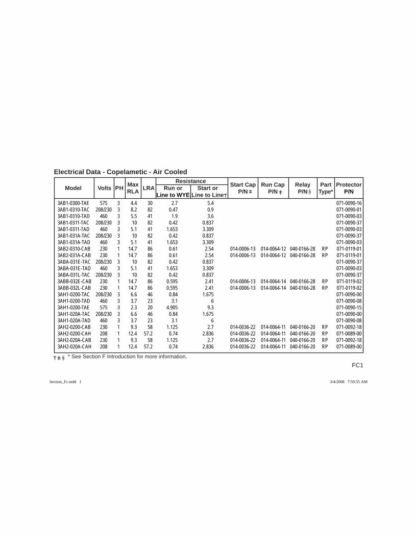
FC1
Electrical Data - Copelametic - Air Cooled
* See Section F Introduction for more information.
Max Resistance Model Volts PH RLA LRA Run or Start or Start Cap Run Cap Relay Part Protector
Line to WYE Line to Line P/N P/N P/N Type* P/N
3AB1-0300-TAE 575 3 4.4 30 2.7 5.4 071-0090-163AB1-0310-TAC 208/230 3 8.2 82 0.47 0.9 071-0090-013AB1-0310-TAD 460 3 5.5 41 1.9 3.6 071-0090-033AB1-0311-TAC 208/230 3 10 82 0.42 0.837 071-0090-373AB1-0311-TAD 460 3 5.1 41 1.653 3.309 071-0090-033AB1-031A-TAC 208/230 3 10 82 0.42 0.837 071-0090-373AB1-031A-TAD 460 3 5.1 41 1.653 3.309 071-0090-033AB2-0310-CAB 230 1 14.7 86 0.61 2.54 014-0006-13 014-0064-12 040-0166-28 RP 071-0119-013AB2-031A-CAB 230 1 14.7 86 0.61 2.54 014-0006-13 014-0064-12 040-0166-28 RP 071-0119-013ABA-031E-TAC 208/230 3 10 82 0.42 0.837 071-0090-373ABA-031E-TAD 460 3 5.1 41 1.653 3.309 071-0090-033ABA-031L-TAC 208/230 3 10 82 0.42 0.837 071-0090-373ABB-032E-CAB 230 1 14.7 86 0.595 2.41 014-0006-13 014-0064-14 040-0166-28 RP 071-0119-023ABB-032L-CAB 230 1 14.7 86 0.595 2.41 014-0006-13 014-0064-14 040-0166-28 RP 071-0119-023AH1-0200-TAC 208/230 3 6.6 46 0.84 1.675 071-0090-003AH1-0200-TAD 460 3 3.7 23 3.1 6 071-0090-083AH1-0200-TAE 575 3 2.3 20 4.905 9.3 071-0090-153AH1-020A-TAC 208/230 3 6.6 46 0.84 1.675 071-0090-003AH1-020A-TAD 460 3 3.7 23 3.1 6 071-0090-083AH2-0200-CAB 230 1 9.3 58 1.125 2.7 014-0036-22 014-0064-11 040-0166-20 RP 071-0092-183AH2-0200-CAH 208 1 12.4 57.2 0.74 2.836 014-0036-22 014-0064-11 040-0166-20 RP 071-0089-003AH2-020A-CAB 230 1 9.3 58 1.125 2.7 014-0036-22 014-0064-11 040-0166-20 RP 071-0092-183AH2-020A-CAH 208 1 12.4 57.2 0.74 2.836 014-0036-22 014-0064-11 040-0166-20 RP 071-0089-00
Section_Fc.indd 1Section_Fc.indd 1 3/4/2008 7:59:55 AM3/4/2008 7:59:55 AM
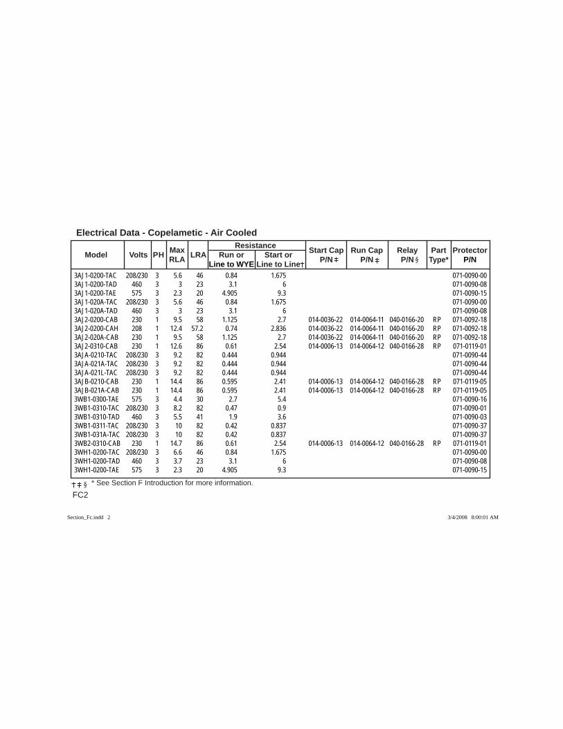
Electrical Data - Copelametic - Air Cooled
FC2 * See Section F Introduction for more information.
Max Resistance Model Volts PH RLA LRA Run or Start or Start Cap Run Cap Relay Part Protector
Line to WYE Line to Line P/N P/N P/N Type* P/N
3AJ1-0200-TAC 208/230 3 5.6 46 0.84 1.675 071-0090-003AJ1-0200-TAD 460 3 3 23 3.1 6 071-0090-083AJ1-0200-TAE 575 3 2.3 20 4.905 9.3 071-0090-153AJ1-020A-TAC 208/230 3 5.6 46 0.84 1.675 071-0090-003AJ1-020A-TAD 460 3 3 23 3.1 6 071-0090-083AJ2-0200-CAB 230 1 9.5 58 1.125 2.7 014-0036-22 014-0064-11 040-0166-20 RP 071-0092-183AJ2-0200-CAH 208 1 12.4 57.2 0.74 2.836 014-0036-22 014-0064-11 040-0166-20 RP 071-0092-183AJ2-020A-CAB 230 1 9.5 58 1.125 2.7 014-0036-22 014-0064-11 040-0166-20 RP 071-0092-183AJ2-0310-CAB 230 1 12.6 86 0.61 2.54 014-0006-13 014-0064-12 040-0166-28 RP 071-0119-013AJA-0210-TAC 208/230 3 9.2 82 0.444 0.944 071-0090-443AJA-021A-TAC 208/230 3 9.2 82 0.444 0.944 071-0090-443AJA-021L-TAC 208/230 3 9.2 82 0.444 0.944 071-0090-443AJB-0210-CAB 230 1 14.4 86 0.595 2.41 014-0006-13 014-0064-12 040-0166-28 RP 071-0119-053AJB-021A-CAB 230 1 14.4 86 0.595 2.41 014-0006-13 014-0064-12 040-0166-28 RP 071-0119-053WB1-0300-TAE 575 3 4.4 30 2.7 5.4 071-0090-163WB1-0310-TAC 208/230 3 8.2 82 0.47 0.9 071-0090-013WB1-0310-TAD 460 3 5.5 41 1.9 3.6 071-0090-033WB1-0311-TAC 208/230 3 10 82 0.42 0.837 071-0090-373WB1-031A-TAC 208/230 3 10 82 0.42 0.837 071-0090-373WB2-0310-CAB 230 1 14.7 86 0.61 2.54 014-0006-13 014-0064-12 040-0166-28 RP 071-0119-013WH1-0200-TAC 208/230 3 6.6 46 0.84 1.675 071-0090-003WH1-0200-TAD 460 3 3.7 23 3.1 6 071-0090-083WH1-0200-TAE 575 3 2.3 20 4.905 9.3 071-0090-15
Section_Fc.indd 2Section_Fc.indd 2 3/4/2008 8:00:01 AM3/4/2008 8:00:01 AM
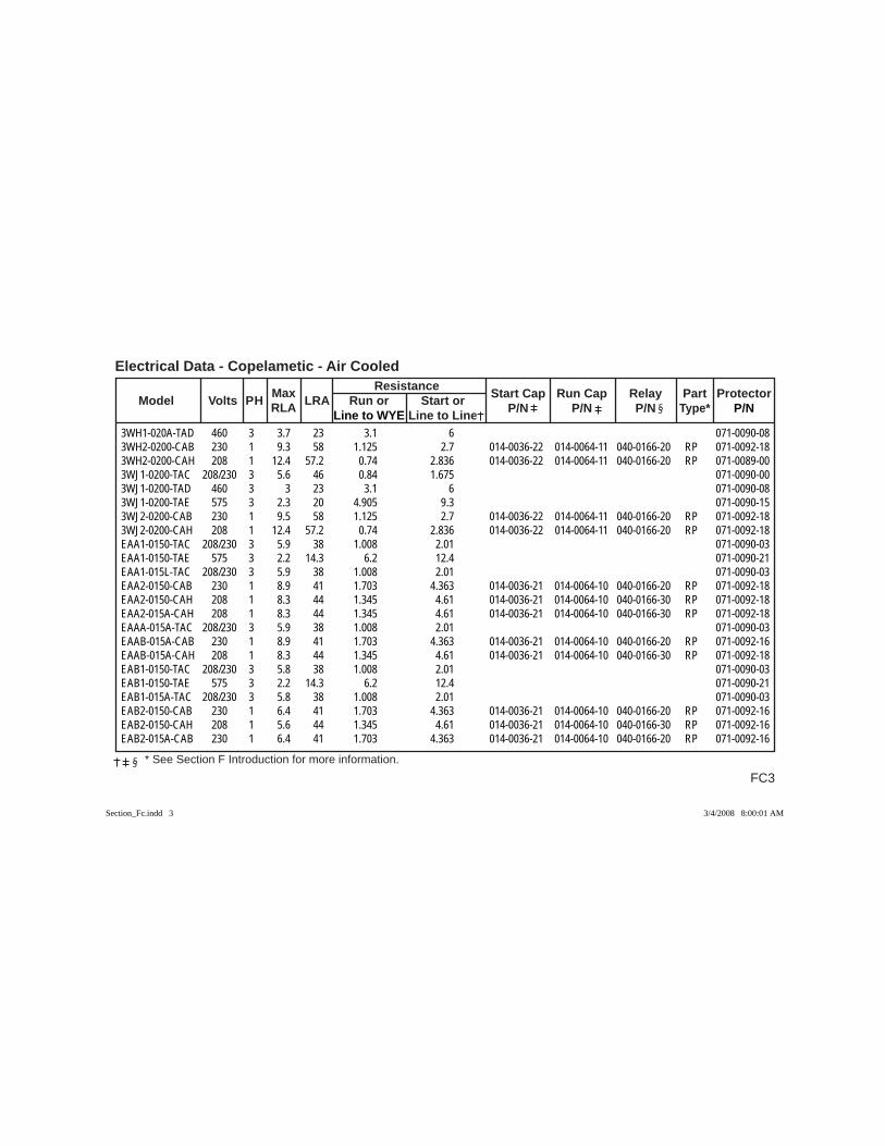
FC3
Electrical Data - Copelametic - Air Cooled
* See Section F Introduction for more information.
Max Resistance Model Volts PH RLA LRA Run or Start or Start Cap Run Cap Relay Part Protector
Line to WYE Line to Line P/N P/N P/N Type* P/N
3WH1-020A-TAD 460 3 3.7 23 3.1 6 071-0090-083WH2-0200-CAB 230 1 9.3 58 1.125 2.7 014-0036-22 014-0064-11 040-0166-20 RP 071-0092-183WH2-0200-CAH 208 1 12.4 57.2 0.74 2.836 014-0036-22 014-0064-11 040-0166-20 RP 071-0089-003WJ1-0200-TAC 208/230 3 5.6 46 0.84 1.675 071-0090-003WJ1-0200-TAD 460 3 3 23 3.1 6 071-0090-083WJ1-0200-TAE 575 3 2.3 20 4.905 9.3 071-0090-153WJ2-0200-CAB 230 1 9.5 58 1.125 2.7 014-0036-22 014-0064-11 040-0166-20 RP 071-0092-183WJ2-0200-CAH 208 1 12.4 57.2 0.74 2.836 014-0036-22 014-0064-11 040-0166-20 RP 071-0092-18EAA1-0150-TAC 208/230 3 5.9 38 1.008 2.01 071-0090-03EAA1-0150-TAE 575 3 2.2 14.3 6.2 12.4 071-0090-21EAA1-015L-TAC 208/230 3 5.9 38 1.008 2.01 071-0090-03EAA2-0150-CAB 230 1 8.9 41 1.703 4.363 014-0036-21 014-0064-10 040-0166-20 RP 071-0092-18EAA2-0150-CAH 208 1 8.3 44 1.345 4.61 014-0036-21 014-0064-10 040-0166-30 RP 071-0092-18EAA2-015A-CAH 208 1 8.3 44 1.345 4.61 014-0036-21 014-0064-10 040-0166-30 RP 071-0092-18EAAA-015A-TAC 208/230 3 5.9 38 1.008 2.01 071-0090-03EAAB-015A-CAB 230 1 8.9 41 1.703 4.363 014-0036-21 014-0064-10 040-0166-20 RP 071-0092-16EAAB-015A-CAH 208 1 8.3 44 1.345 4.61 014-0036-21 014-0064-10 040-0166-30 RP 071-0092-18EAB1-0150-TAC 208/230 3 5.8 38 1.008 2.01 071-0090-03EAB1-0150-TAE 575 3 2.2 14.3 6.2 12.4 071-0090-21EAB1-015A-TAC 208/230 3 5.8 38 1.008 2.01 071-0090-03EAB2-0150-CAB 230 1 6.4 41 1.703 4.363 014-0036-21 014-0064-10 040-0166-20 RP 071-0092-16EAB2-0150-CAH 208 1 5.6 44 1.345 4.61 014-0036-21 014-0064-10 040-0166-30 RP 071-0092-16EAB2-015A-CAB 230 1 6.4 41 1.703 4.363 014-0036-21 014-0064-10 040-0166-20 RP 071-0092-16
Section_Fc.indd 3Section_Fc.indd 3 3/4/2008 8:00:01 AM3/4/2008 8:00:01 AM

Electrical Data - Copelametic - Air Cooled
FC4 * See Section F Introduction for more information.
Max Resistance Model Volts PH RLA LRA Run or Start or Start Cap Run Cap Relay Part Protector
Line to WYE Line to Line P/N P/N P/N Type* P/N
EABA-0200-TAC 208/230 3 6.8 46 0.84 1.675 071-0090-00EABA-0200-TAD 460 3 3.6 23 3.346 6.692 071-0090-08EABA-0200-TAE 575 3 2.3 20 4.905 9.3 071-0090-15EABA-020A-TAC 208/230 3 6.8 46 0.84 1.675 071-0090-00EABB-0200-CAB 230 1 8.4 58 1.125 2.7 014-0036-22 014-0064-11 040-0166-20 RP 071-0092-18EABB-020A-CAB 230 1 8.4 58 1.125 2.7 014-0036-22 014-0064-11 040-0166-20 RP 071-0092-18EAC1-0150-TAC 208/230 3 6 38 1.008 2.01 071-0090-03EAC1-0150-TAE 575 3 2.2 14.3 6.2 12.4 071-0090-21EAC2-0150-CAB 230 1 7.1 41 1.703 4.363 014-0036-21 014-0064-10 040-0166-20 RP 071-0092-16EAC2-0150-CAH 208 1 6.4 44 1.345 4.61 014-0036-21 014-0064-10 040-0166-30 RP 071-0092-16EAC2-015A-CAB 230 1 7.1 41 1.703 4.363 014-0036-21 014-0064-10 040-0166-20 RP 071-0092-16EACA-0200-TAC 208/230 3 6.6 46 0.84 1.675 071-0090-00EACA-0200-TAD 460 3 3.5 23 3.346 6.692 071-0090-08EACA-0200-TAE 575 3 2.3 20 4.905 9.3 071-0090-15EACA-020A-TAC 208/230 3 6.6 46 0.84 1.675 071-0090-00EACA-020A-TAD 460 3 3.5 23 3.346 6.692 071-0090-08EACB-0200-CAB 230 1 8.4 58 1.125 2.7 014-0036-22 014-0064-11 040-0166-20 RP 071-0092-18EACB-0200-CAH 208 1 11.9 57.2 0.74 2.836 014-0036-22 014-0064-11 040-0166-20 RP 071-0092-18EAD1-0200-TAC 208/230 3 NA 46 0.84 1.675 071-0090-00EAD1-0200-TAD 460 3 NA 23 3.346 6.692 071-0090-08EAD1-0200-TAE 575 3 NA 20 4.905 9.3 071-0090-15EAD1-020L-TAC 208/230 3 6.8 46 0.84 1.675 071-0090-00EAD1-0320-TAC 208/230 3 12.4 85 0.419 0.838 071-0090-38
Section_Fc.indd 4Section_Fc.indd 4 3/4/2008 8:00:01 AM3/4/2008 8:00:01 AM
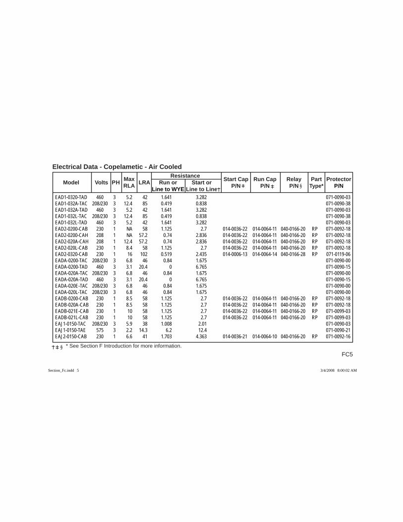
FC5
Electrical Data - Copelametic - Air Cooled
* See Section F Introduction for more information.
Max Resistance Model Volts PH RLA LRA Run or Start or Start Cap Run Cap Relay Part Protector
Line to WYE Line to Line P/N P/N P/N Type* P/N
EAD1-0320-TAD 460 3 5.2 42 1.641 3.282 071-0090-03EAD1-032A-TAC 208/230 3 12.4 85 0.419 0.838 071-0090-38EAD1-032A-TAD 460 3 5.2 42 1.641 3.282 071-0090-03EAD1-032L-TAC 208/230 3 12.4 85 0.419 0.838 071-0090-38EAD1-032L-TAD 460 3 5.2 42 1.641 3.282 071-0090-03EAD2-0200-CAB 230 1 NA 58 1.125 2.7 014-0036-22 014-0064-11 040-0166-20 RP 071-0092-18EAD2-0200-CAH 208 1 NA 57.2 0.74 2.836 014-0036-22 014-0064-11 040-0166-20 RP 071-0092-18EAD2-020A-CAH 208 1 12.4 57.2 0.74 2.836 014-0036-22 014-0064-11 040-0166-20 RP 071-0092-18EAD2-020L-CAB 230 1 8.4 58 1.125 2.7 014-0036-22 014-0064-11 040-0166-20 RP 071-0092-18EAD2-0320-CAB 230 1 16 102 0.519 2.435 014-0006-13 014-0064-14 040-0166-28 RP 071-0119-06EADA-0200-TAC 208/230 3 6.8 46 0.84 1.675 071-0090-00EADA-0200-TAD 460 3 3.1 20.4 0 6.765 071-0090-15EADA-020A-TAC 208/230 3 6.8 46 0.84 1.675 071-0090-00EADA-020A-TAD 460 3 3.1 20.4 0 6.765 071-0090-15EADA-020E-TAC 208/230 3 6.8 46 0.84 1.675 071-0090-00EADA-020L-TAC 208/230 3 6.8 46 0.84 1.675 071-0090-00EADB-0200-CAB 230 1 8.5 58 1.125 2.7 014-0036-22 014-0064-11 040-0166-20 RP 071-0092-18EADB-020A-CAB 230 1 8.5 58 1.125 2.7 014-0036-22 014-0064-11 040-0166-20 RP 071-0092-18EADB-021E-CAB 230 1 10 58 1.125 2.7 014-0036-22 014-0064-11 040-0166-20 RP 071-0099-03EADB-021L-CAB 230 1 10 58 1.125 2.7 014-0036-22 014-0064-11 040-0166-20 RP 071-0099-03EAJ1-0150-TAC 208/230 3 5.9 38 1.008 2.01 071-0090-03EAJ1-0150-TAE 575 3 2.2 14.3 6.2 12.4 071-0090-21EAJ2-0150-CAB 230 1 6.6 41 1.703 4.363 014-0036-21 014-0064-10 040-0166-20 RP 071-0092-16
Section_Fc.indd 5Section_Fc.indd 5 3/4/2008 8:00:02 AM3/4/2008 8:00:02 AM
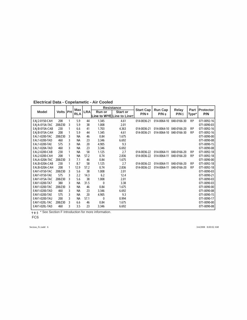
Electrical Data - Copelametic - Air Cooled
FC6 * See Section F Introduction for more information.
Max Resistance Model Volts PH RLA LRA Run or Start or Start Cap Run Cap Relay Part Protector
Line to WYE Line to Line P/N P/N P/N Type* P/N
EAJ2-0150-CAH 208 1 5.9 44 1.345 4.61 014-0036-21 014-0064-10 040-0166-30 RP 071-0092-16EAJA-015A-TAC 208/230 3 5.9 38 1.008 2.01 071-0090-03EAJB-015A-CAB 230 1 6.6 41 1.703 4.363 014-0036-21 014-0064-10 040-0166-20 RP 071-0092-16EAJB-015A-CAH 208 1 5.9 44 1.345 4.61 014-0036-21 014-0064-10 040-0166-30 RP 071-0092-16EAL1-0200-TAC 208/230 3 NA 46 0.84 1.675 071-0090-00EAL1-0200-TAD 460 3 NA 23 3.346 6.692 071-0090-08EAL1-0200-TAE 575 3 NA 20 4.905 9.3 071-0090-15EAL1-020A-TAD 460 3 NA 23 3.346 6.692 071-0090-08EAL2-0200-CAB 230 1 NA 58 1.125 2.7 014-0036-22 014-0064-11 040-0166-20 RP 071-0092-18EAL2-0200-CAH 208 1 NA 57.2 0.74 2.836 014-0036-22 014-0064-11 040-0166-20 RP 071-0092-18EALA-020A-TAC 208/230 3 7.1 46 0.84 1.675 071-0090-00EALB-020A-CAB 230 1 8.7 58 1.125 2.7 014-0036-22 014-0064-11 040-0166-20 RP 071-0092-18EALB-020A-CAH 208 1 12.9 57.2 0.74 2.836 014-0036-22 014-0064-11 040-0166-20 RP 071-0092-18EAV1-0150-TAC 208/230 3 5.6 38 1.008 2.01 071-0090-03EAV1-0150-TAE 575 3 2.2 14.3 6.2 12.4 071-0090-21EAV1-015A-TAC 208/230 3 5.6 38 1.008 2.01 071-0090-03EAV1-0200-TA7 380 3 NA 31.5 0 3.38 071-0090-03EAV1-0200-TAC 208/230 3 NA 46 0.84 1.675 071-0090-00EAV1-0200-TAD 460 3 NA 23 3.346 6.692 071-0090-08EAV1-0200-TAE 575 3 NA 20 4.905 9.3 071-0090-15EAV1-0200-TAU 200 3 NA 57.1 0 0.994 071-0090-17EAV1-020L-TAC 208/230 3 6.6 46 0.84 1.675 071-0090-00EAV1-020L-TAD 460 3 3.5 23 3.346 6.692 071-0090-08
Section_Fc.indd 6Section_Fc.indd 6 3/4/2008 8:00:02 AM3/4/2008 8:00:02 AM
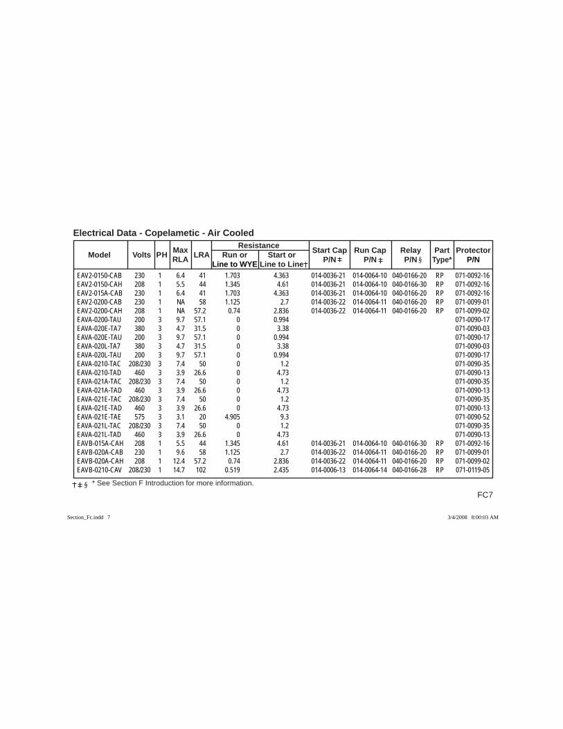
FC7
Electrical Data - Copelametic - Air Cooled
* See Section F Introduction for more information.
Max Resistance Model Volts PH RLA LRA Run or Start or Start Cap Run Cap Relay Part Protector
Line to WYE Line to Line P/N P/N P/N Type* P/N
EAV2-0150-CAB 230 1 6.4 41 1.703 4.363 014-0036-21 014-0064-10 040-0166-20 RP 071-0092-16EAV2-0150-CAH 208 1 5.5 44 1.345 4.61 014-0036-21 014-0064-10 040-0166-30 RP 071-0092-16EAV2-015A-CAB 230 1 6.4 41 1.703 4.363 014-0036-21 014-0064-10 040-0166-20 RP 071-0092-16EAV2-0200-CAB 230 1 NA 58 1.125 2.7 014-0036-22 014-0064-11 040-0166-20 RP 071-0099-01EAV2-0200-CAH 208 1 NA 57.2 0.74 2.836 014-0036-22 014-0064-11 040-0166-20 RP 071-0099-02EAVA-0200-TAU 200 3 9.7 57.1 0 0.994 071-0090-17EAVA-020E-TA7 380 3 4.7 31.5 0 3.38 071-0090-03EAVA-020E-TAU 200 3 9.7 57.1 0 0.994 071-0090-17EAVA-020L-TA7 380 3 4.7 31.5 0 3.38 071-0090-03EAVA-020L-TAU 200 3 9.7 57.1 0 0.994 071-0090-17EAVA-0210-TAC 208/230 3 7.4 50 0 1.2 071-0090-35EAVA-0210-TAD 460 3 3.9 26.6 0 4.73 071-0090-13EAVA-021A-TAC 208/230 3 7.4 50 0 1.2 071-0090-35EAVA-021A-TAD 460 3 3.9 26.6 0 4.73 071-0090-13EAVA-021E-TAC 208/230 3 7.4 50 0 1.2 071-0090-35EAVA-021E-TAD 460 3 3.9 26.6 0 4.73 071-0090-13EAVA-021E-TAE 575 3 3.1 20 4.905 9.3 071-0090-52EAVA-021L-TAC 208/230 3 7.4 50 0 1.2 071-0090-35EAVA-021L-TAD 460 3 3.9 26.6 0 4.73 071-0090-13EAVB-015A-CAH 208 1 5.5 44 1.345 4.61 014-0036-21 014-0064-10 040-0166-30 RP 071-0092-16EAVB-020A-CAB 230 1 9.6 58 1.125 2.7 014-0036-22 014-0064-11 040-0166-20 RP 071-0099-01EAVB-020A-CAH 208 1 12.4 57.2 0.74 2.836 014-0036-22 014-0064-11 040-0166-20 RP 071-0099-02EAVB-0210-CAV 208/230 1 14.7 102 0.519 2.435 014-0006-13 014-0064-14 040-0166-28 RP 071-0119-05
Section_Fc.indd 7Section_Fc.indd 7 3/4/2008 8:00:03 AM3/4/2008 8:00:03 AM
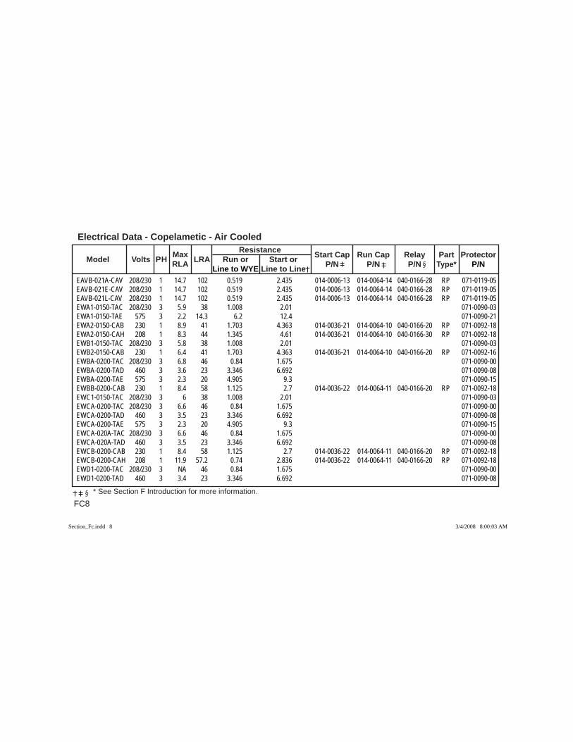
Electrical Data - Copelametic - Air Cooled
FC8 * See Section F Introduction for more information.
Max Resistance Model Volts PH RLA LRA Run or Start or Start Cap Run Cap Relay Part Protector
Line to WYE Line to Line P/N P/N P/N Type* P/N
EAVB-021A-CAV 208/230 1 14.7 102 0.519 2.435 014-0006-13 014-0064-14 040-0166-28 RP 071-0119-05EAVB-021E-CAV 208/230 1 14.7 102 0.519 2.435 014-0006-13 014-0064-14 040-0166-28 RP 071-0119-05EAVB-021L-CAV 208/230 1 14.7 102 0.519 2.435 014-0006-13 014-0064-14 040-0166-28 RP 071-0119-05EWA1-0150-TAC 208/230 3 5.9 38 1.008 2.01 071-0090-03EWA1-0150-TAE 575 3 2.2 14.3 6.2 12.4 071-0090-21EWA2-0150-CAB 230 1 8.9 41 1.703 4.363 014-0036-21 014-0064-10 040-0166-20 RP 071-0092-18EWA2-0150-CAH 208 1 8.3 44 1.345 4.61 014-0036-21 014-0064-10 040-0166-30 RP 071-0092-18EWB1-0150-TAC 208/230 3 5.8 38 1.008 2.01 071-0090-03EWB2-0150-CAB 230 1 6.4 41 1.703 4.363 014-0036-21 014-0064-10 040-0166-20 RP 071-0092-16EWBA-0200-TAC 208/230 3 6.8 46 0.84 1.675 071-0090-00EWBA-0200-TAD 460 3 3.6 23 3.346 6.692 071-0090-08EWBA-0200-TAE 575 3 2.3 20 4.905 9.3 071-0090-15EWBB-0200-CAB 230 1 8.4 58 1.125 2.7 014-0036-22 014-0064-11 040-0166-20 RP 071-0092-18EWC1-0150-TAC 208/230 3 6 38 1.008 2.01 071-0090-03EWCA-0200-TAC 208/230 3 6.6 46 0.84 1.675 071-0090-00EWCA-0200-TAD 460 3 3.5 23 3.346 6.692 071-0090-08EWCA-0200-TAE 575 3 2.3 20 4.905 9.3 071-0090-15EWCA-020A-TAC 208/230 3 6.6 46 0.84 1.675 071-0090-00EWCA-020A-TAD 460 3 3.5 23 3.346 6.692 071-0090-08EWCB-0200-CAB 230 1 8.4 58 1.125 2.7 014-0036-22 014-0064-11 040-0166-20 RP 071-0092-18EWCB-0200-CAH 208 1 11.9 57.2 0.74 2.836 014-0036-22 014-0064-11 040-0166-20 RP 071-0092-18EWD1-0200-TAC 208/230 3 NA 46 0.84 1.675 071-0090-00EWD1-0200-TAD 460 3 3.4 23 3.346 6.692 071-0090-08
Section_Fc.indd 8Section_Fc.indd 8 3/4/2008 8:00:03 AM3/4/2008 8:00:03 AM
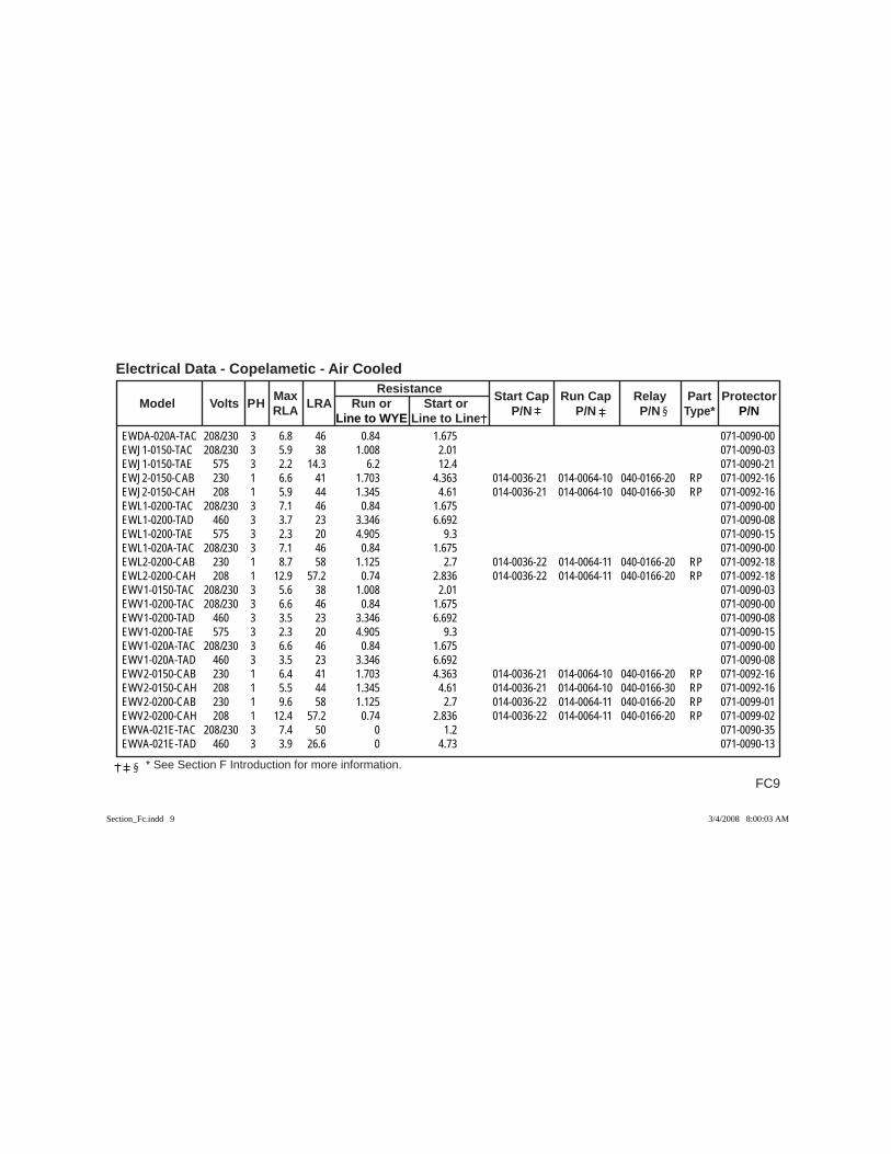
FC9
Electrical Data - Copelametic - Air Cooled
* See Section F Introduction for more information.
Max Resistance Model Volts PH RLA LRA Run or Start or Start Cap Run Cap Relay Part Protector
Line to WYE Line to Line P/N P/N P/N Type* P/N
EWDA-020A-TAC 208/230 3 6.8 46 0.84 1.675 071-0090-00EWJ1-0150-TAC 208/230 3 5.9 38 1.008 2.01 071-0090-03EWJ1-0150-TAE 575 3 2.2 14.3 6.2 12.4 071-0090-21EWJ2-0150-CAB 230 1 6.6 41 1.703 4.363 014-0036-21 014-0064-10 040-0166-20 RP 071-0092-16EWJ2-0150-CAH 208 1 5.9 44 1.345 4.61 014-0036-21 014-0064-10 040-0166-30 RP 071-0092-16EWL1-0200-TAC 208/230 3 7.1 46 0.84 1.675 071-0090-00EWL1-0200-TAD 460 3 3.7 23 3.346 6.692 071-0090-08EWL1-0200-TAE 575 3 2.3 20 4.905 9.3 071-0090-15EWL1-020A-TAC 208/230 3 7.1 46 0.84 1.675 071-0090-00EWL2-0200-CAB 230 1 8.7 58 1.125 2.7 014-0036-22 014-0064-11 040-0166-20 RP 071-0092-18EWL2-0200-CAH 208 1 12.9 57.2 0.74 2.836 014-0036-22 014-0064-11 040-0166-20 RP 071-0092-18EWV1-0150-TAC 208/230 3 5.6 38 1.008 2.01 071-0090-03EWV1-0200-TAC 208/230 3 6.6 46 0.84 1.675 071-0090-00EWV1-0200-TAD 460 3 3.5 23 3.346 6.692 071-0090-08EWV1-0200-TAE 575 3 2.3 20 4.905 9.3 071-0090-15EWV1-020A-TAC 208/230 3 6.6 46 0.84 1.675 071-0090-00EWV1-020A-TAD 460 3 3.5 23 3.346 6.692 071-0090-08EWV2-0150-CAB 230 1 6.4 41 1.703 4.363 014-0036-21 014-0064-10 040-0166-20 RP 071-0092-16EWV2-0150-CAH 208 1 5.5 44 1.345 4.61 014-0036-21 014-0064-10 040-0166-30 RP 071-0092-16EWV2-0200-CAB 230 1 9.6 58 1.125 2.7 014-0036-22 014-0064-11 040-0166-20 RP 071-0099-01EWV2-0200-CAH 208 1 12.4 57.2 0.74 2.836 014-0036-22 014-0064-11 040-0166-20 RP 071-0099-02EWVA-021E-TAC 208/230 3 7.4 50 0 1.2 071-0090-35EWVA-021E-TAD 460 3 3.9 26.6 0 4.73 071-0090-13
Section_Fc.indd 9Section_Fc.indd 9 3/4/2008 8:00:03 AM3/4/2008 8:00:03 AM

Electrical Data - Copelametic - Air Cooled
FC10 * See Section F Introduction for more information.
Max Resistance Model Volts PH RLA LRA Run or Start or Start Cap Run Cap Relay Part Protector
Line to WYE Line to Line P/N P/N P/N Type* P/N
EWVB-021E-CAV 208/230 1 14.7 102 0.519 2.435 014-0006-13 014-0064-14 040-0166-28 RP 071-0119-05HAF2-0025-IAA 115 1 3.9 23 1.76 4.48 014-0061-06 040-0115-00 RC 071-0092-37HAF2-0025-IAB 230 1 2.3 12.2 6.76 17.87 014-0061-13 040-0115-01 RC 071-0092-32HAF2-0025-SAA 115 1 3.9 22.5 1.82 17.24 040-0115-00 RC 071-0092-37HAF2-0033-IAA 115 1 5.4 31 1.23 3.1 014-0061-07 040-0166-08 RP 071-0092-04HAF2-0033-IAB 230 1 2.5 12 5.07 12.505 014-0061-12 040-0166-19 RP 071-0092-31HAFB-0033-IAA 115 1 5.4 31 1.23 3.1 014-0061-07 040-0166-08 RP 071-0092-04HAFB-0034-IAA 115 1 5.9 43.5 0.875 2.39 014-0061-07 040-0166-08 RP 071-0092-35HAFB-003E-IAA 115 1 5.4 31 1.23 3.1 014-0061-07 040-0166-08 RP 071-0092-04HAFB-003L-IAA 115 1 5.4 31 1.23 3.1 014-0061-07 040-0166-08 RP 071-0092-04HAG1-0050-TAC 208/230 3 2.4 13 3.62 7.24 071-0090-42HAG1-005L-TAC 208/230 3 2.4 13 3.62 7.24 071-0090-42HAG2-0050-CAA 115 1 8.6 44 0.755 2.36 014-0061-02 014-0064-00 040-0166-33 RP 071-0099-03HAG2-0050-CAV 208/230 1 4 22 3 9.455 014-0036-21 014-0064-00 040-0166-09 RP 071-0092-27HAG2-005L-CAV 208/230 1 4 22 3 9.455 014-0036-21 014-0064-00 040-0166-09 RP 071-0092-27HAGA-005E-TAC 208/230 3 2.4 13 3.62 7.24 071-0090-42HAGA-005L-TAC 208/230 3 2.4 13 3.62 7.24 071-0090-42HAGB-005E-CAV 208/230 1 4 22 3 9.455 014-0036-21 014-0064-00 040-0166-09 RP 071-0092-27HAGB-005L-CAV 208/230 1 4 22 3 9.455 014-0036-21 014-0064-00 040-0166-09 RP 071-0092-27HAJ1-0050-TAC 208/230 3 2.2 13 3.62 7.24 071-0090-42HAJ1-005L-TAC 208/230 3 2.2 13 3.62 7.24 071-0090-42HAJ2-0025-IAA 115 1 4.1 23 1.76 4.48 014-0061-06 040-0115-00 RC 071-0092-37HAJ2-0025-IAB 230 1 2.1 12.2 6.76 17.87 014-0061-13 040-0115-01 RC 071-0092-32
Section_Fc.indd 10Section_Fc.indd 10 3/4/2008 8:00:04 AM3/4/2008 8:00:04 AM
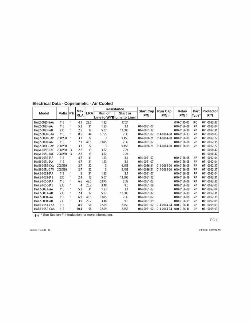
FC11
Electrical Data - Copelametic - Air Cooled
* See Section F Introduction for more information.
Max Resistance Model Volts PH RLA LRA Run or Start or Start Cap Run Cap Relay Part Protector
Line to WYE Line to Line P/N P/N P/N Type* P/N
HAJ2-0025-SAA 115 1 4.1 22.5 1.82 17.24 040-0115-00 RC 071-0092-37HAJ2-0033-IAA 115 1 5.2 31 1.23 3.1 014-0061-07 040-0166-08 RP 071-0092-04HAJ2-0033-IAB 230 1 2.5 12 5.07 12.505 014-0061-12 040-0166-19 RP 071-0092-31HAJ2-0050-CAA 115 1 8.5 44 0.755 2.36 014-0061-02 014-0064-00 040-0166-33 RP 071-0099-03HAJ2-0050-CAV 208/230 1 3.7 22 3 9.455 014-0036-21 014-0064-00 040-0166-09 RP 071-0092-27HAJ2-0050-IAA 115 1 7.1 43.5 0.875 2.39 014-0061-02 040-0166-08 RP 071-0092-35HAJ2-005L-CAV 208/230 1 3.7 22 3 9.455 014-0036-21 014-0064-00 040-0166-09 RP 071-0092-27HAJA-005E-TAC 208/230 3 2.2 13 3.62 7.24 071-0090-42HAJA-005L-TAC 208/230 3 2.2 13 3.62 7.24 071-0090-42HAJB-003E-IAA 115 1 4.7 31 1.23 3.1 014-0061-07 040-0166-08 RP 071-0092-04HAJB-003L-IAA 115 1 4.7 31 1.23 3.1 014-0061-07 040-0166-08 RP 071-0092-04HAJB-005E-CAV 208/230 1 3.7 22 3 9.455 014-0036-21 014-0064-00 040-0166-09 RP 071-0092-27HAJB-005L-CAV 208/230 1 3.7 22 3 9.455 014-0036-21 014-0064-00 040-0166-09 RP 071-0092-27HAK2-0033-IAA 115 1 5 31 1.23 3.1 014-0061-07 040-0166-08 RP 071-0092-04HAK2-0033-IAB 230 1 2.4 12 5.07 12.505 014-0061-12 040-0166-19 RP 071-0092-31HAK2-0050-IAA 115 1 6.6 43.5 0.875 2.39 014-0061-02 040-0166-08 RP 071-0092-35HAK2-0050-IAB 230 1 4 20.2 3.48 9.6 014-0061-09 040-0166-09 RP 071-0092-05HAT2-0033-IAA 115 1 5.2 31 1.23 3.1 014-0061-07 040-0166-08 RP 071-0092-04HAT2-0033-IAB 230 1 2.4 12 5.07 12.505 014-0061-12 040-0166-19 RP 071-0092-31HAT2-0050-IAA 115 1 6.9 43.5 0.875 2.39 014-0061-02 040-0166-08 RP 071-0092-35HAT2-0050-IAB 230 1 3.9 20.2 3.48 9.6 014-0061-09 040-0166-09 RP 071-0092-05HATB-0051-CAA 115 1 8.9 58 0.509 2.155 014-0061-02 014-0064-04 040-0166-11 RP 071-0099-03HATB-005E-CAA 115 1 10.4 58 0.509 2.155 014-0061-02 014-0064-04 040-0166-11 RP 071-0099-03
Section_Fc.indd 11Section_Fc.indd 11 3/4/2008 8:00:04 AM3/4/2008 8:00:04 AM
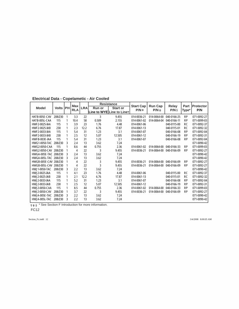
Electrical Data - Copelametic - Air Cooled
FC12 * See Section F Introduction for more information.
Max Resistance Model Volts PH RLA LRA Run or Start or Start Cap Run Cap Relay Part Protector
Line to WYE Line to Line P/N P/N P/N Type* P/N
HATB-005E-CAV 208/230 1 3.3 22 3 9.455 014-0036-21 014-0064-00 040-0166-25 RP 071-0092-27HATB-005L-CAA 115 1 10.4 58 0.509 2.155 014-0061-02 014-0064-04 040-0166-11 RP 071-0099-03HWF2-0025-IAA 115 1 3.9 23 1.76 4.48 014-0061-06 040-0115-00 RC 071-0092-37HWF2-0025-IAB 230 1 2.3 12.2 6.76 17.87 014-0061-13 040-0115-01 RC 071-0092-32HWF2-0033-IAA 115 1 5.4 31 1.23 3.1 014-0061-07 040-0166-08 RP 071-0092-04HWF2-0033-IAB 230 1 2.5 12 5.07 12.505 014-0061-12 040-0166-19 RP 071-0092-31HWFB-003E-IAA 115 1 5.4 31 1.23 3.1 014-0061-07 040-0166-08 RP 071-0092-04HWG1-0050-TAC 208/230 3 2.4 13 3.62 7.24 071-0090-42HWG2-0050-CAA 115 1 8.6 44 0.755 2.36 014-0061-02 014-0064-00 040-0166-33 RP 071-0099-03HWG2-0050-CAV 208/230 1 4 22 3 9.455 014-0036-21 014-0064-00 040-0166-09 RP 071-0092-27HWGA-005E-TAC 208/230 3 2.4 13 3.62 7.24 071-0090-42HWGA-005L-TAC 208/230 3 2.4 13 3.62 7.24 071-0090-42HWGB-005E-CAV 208/230 1 4 22 3 9.455 014-0036-21 014-0064-00 040-0166-09 RP 071-0092-27HWGB-005L-CAV 208/230 1 4 22 3 9.455 014-0036-21 014-0064-00 040-0166-09 RP 071-0092-27HWJ1-0050-TAC 208/230 3 2.2 13 3.62 7.24 071-0090-42HWJ2-0025-IAA 115 1 4.1 23 1.76 4.48 014-0061-06 040-0115-00 RC 071-0092-37HWJ2-0025-IAB 230 1 2.1 12.2 6.76 17.87 014-0061-13 040-0115-01 RC 071-0092-32HWJ2-0033-IAA 115 1 5.2 31 1.23 3.1 014-0061-07 040-0166-08 RP 071-0092-04HWJ2-0033-IAB 230 1 2.5 12 5.07 12.505 014-0061-12 040-0166-19 RP 071-0092-31HWJ2-0050-CAA 115 1 8.5 44 0.755 2.36 014-0061-02 014-0064-00 040-0166-33 RP 071-0099-03HWJ2-0050-CAV 208/230 1 3.7 22 3 9.455 014-0036-21 014-0064-00 040-0166-09 RP 071-0092-27HWJA-005E-TAC 208/230 3 2.2 13 3.62 7.24 071-0090-42HWJA-005L-TAC 208/230 3 2.2 13 3.62 7.24 071-0090-42
Section_Fc.indd 12Section_Fc.indd 12 3/4/2008 8:00:05 AM3/4/2008 8:00:05 AM
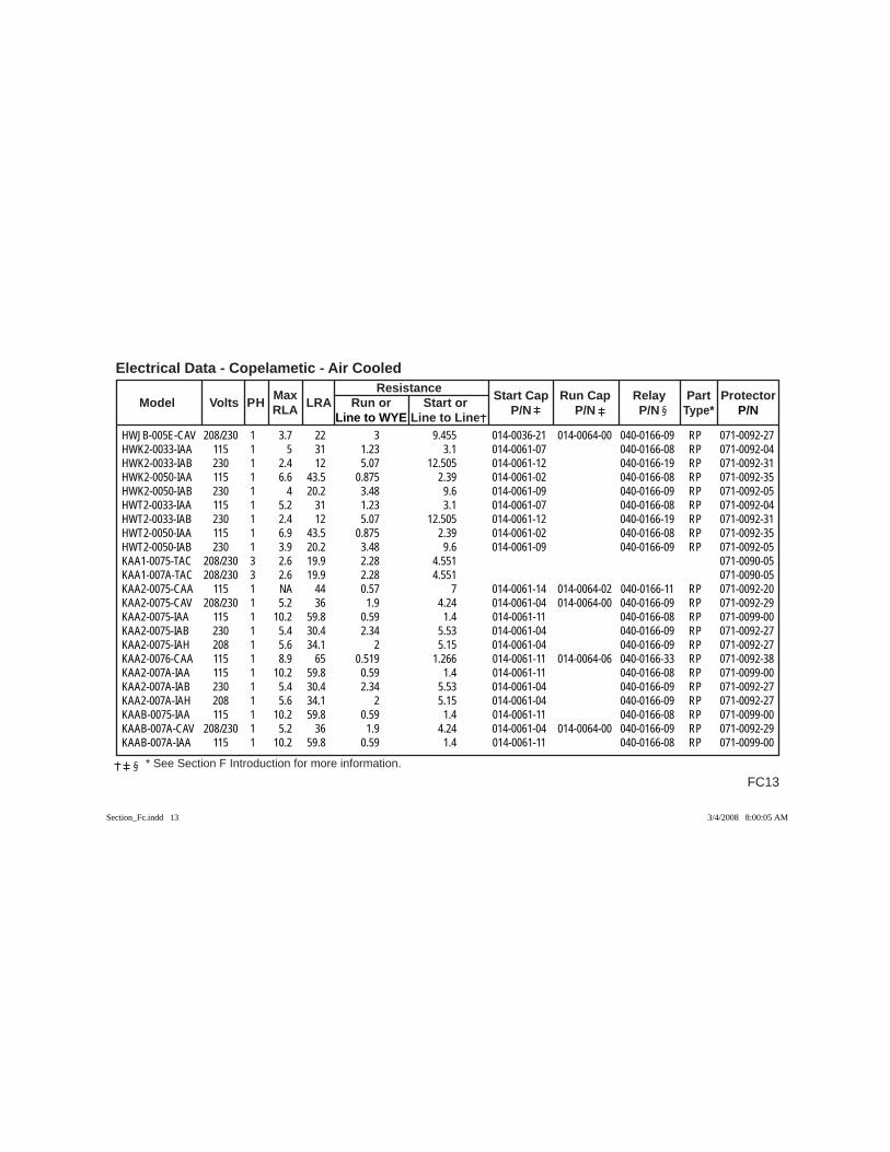
FC13
Electrical Data - Copelametic - Air Cooled
* See Section F Introduction for more information.
Max Resistance Model Volts PH RLA LRA Run or Start or Start Cap Run Cap Relay Part Protector
Line to WYE Line to Line P/N P/N P/N Type* P/N
HWJB-005E-CAV 208/230 1 3.7 22 3 9.455 014-0036-21 014-0064-00 040-0166-09 RP 071-0092-27HWK2-0033-IAA 115 1 5 31 1.23 3.1 014-0061-07 040-0166-08 RP 071-0092-04HWK2-0033-IAB 230 1 2.4 12 5.07 12.505 014-0061-12 040-0166-19 RP 071-0092-31HWK2-0050-IAA 115 1 6.6 43.5 0.875 2.39 014-0061-02 040-0166-08 RP 071-0092-35HWK2-0050-IAB 230 1 4 20.2 3.48 9.6 014-0061-09 040-0166-09 RP 071-0092-05HWT2-0033-IAA 115 1 5.2 31 1.23 3.1 014-0061-07 040-0166-08 RP 071-0092-04HWT2-0033-IAB 230 1 2.4 12 5.07 12.505 014-0061-12 040-0166-19 RP 071-0092-31HWT2-0050-IAA 115 1 6.9 43.5 0.875 2.39 014-0061-02 040-0166-08 RP 071-0092-35HWT2-0050-IAB 230 1 3.9 20.2 3.48 9.6 014-0061-09 040-0166-09 RP 071-0092-05KAA1-0075-TAC 208/230 3 2.6 19.9 2.28 4.551 071-0090-05KAA1-007A-TAC 208/230 3 2.6 19.9 2.28 4.551 071-0090-05KAA2-0075-CAA 115 1 NA 44 0.57 7 014-0061-14 014-0064-02 040-0166-11 RP 071-0092-20KAA2-0075-CAV 208/230 1 5.2 36 1.9 4.24 014-0061-04 014-0064-00 040-0166-09 RP 071-0092-29KAA2-0075-IAA 115 1 10.2 59.8 0.59 1.4 014-0061-11 040-0166-08 RP 071-0099-00KAA2-0075-IAB 230 1 5.4 30.4 2.34 5.53 014-0061-04 040-0166-09 RP 071-0092-27KAA2-0075-IAH 208 1 5.6 34.1 2 5.15 014-0061-04 040-0166-09 RP 071-0092-27KAA2-0076-CAA 115 1 8.9 65 0.519 1.266 014-0061-11 014-0064-06 040-0166-33 RP 071-0092-38KAA2-007A-IAA 115 1 10.2 59.8 0.59 1.4 014-0061-11 040-0166-08 RP 071-0099-00KAA2-007A-IAB 230 1 5.4 30.4 2.34 5.53 014-0061-04 040-0166-09 RP 071-0092-27KAA2-007A-IAH 208 1 5.6 34.1 2 5.15 014-0061-04 040-0166-09 RP 071-0092-27KAAB-0075-IAA 115 1 10.2 59.8 0.59 1.4 014-0061-11 040-0166-08 RP 071-0099-00KAAB-007A-CAV 208/230 1 5.2 36 1.9 4.24 014-0061-04 014-0064-00 040-0166-09 RP 071-0092-29KAAB-007A-IAA 115 1 10.2 59.8 0.59 1.4 014-0061-11 040-0166-08 RP 071-0099-00
Section_Fc.indd 13Section_Fc.indd 13 3/4/2008 8:00:05 AM3/4/2008 8:00:05 AM
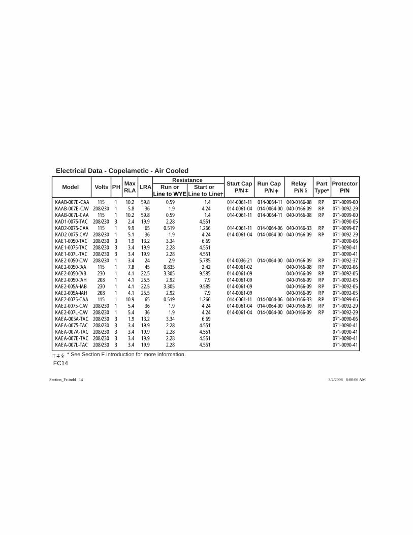
Electrical Data - Copelametic - Air Cooled
FC14 * See Section F Introduction for more information.
Max Resistance Model Volts PH RLA LRA Run or Start or Start Cap Run Cap Relay Part Protector
Line to WYE Line to Line P/N P/N P/N Type* P/N
KAAB-007E-CAA 115 1 10.2 59.8 0.59 1.4 014-0061-11 014-0064-11 040-0166-08 RP 071-0099-00KAAB-007E-CAV 208/230 1 5.8 36 1.9 4.24 014-0061-04 014-0064-00 040-0166-09 RP 071-0092-29KAAB-007L-CAA 115 1 10.2 59.8 0.59 1.4 014-0061-11 014-0064-11 040-0166-08 RP 071-0099-00KAD1-0075-TAC 208/230 3 2.4 19.9 2.28 4.551 071-0090-05KAD2-0075-CAA 115 1 9.9 65 0.519 1.266 014-0061-11 014-0064-06 040-0166-33 RP 071-0099-07KAD2-0075-CAV 208/230 1 5.1 36 1.9 4.24 014-0061-04 014-0064-00 040-0166-09 RP 071-0092-29KAE1-0050-TAC 208/230 3 1.9 13.2 3.34 6.69 071-0090-06KAE1-0075-TAC 208/230 3 3.4 19.9 2.28 4.551 071-0090-41KAE1-007L-TAC 208/230 3 3.4 19.9 2.28 4.551 071-0090-41KAE2-0050-CAV 208/230 1 3.4 24 2.9 5.785 014-0036-21 014-0064-00 040-0166-09 RP 071-0092-37KAE2-0050-IAA 115 1 7.8 45 0.835 2.42 014-0061-02 040-0166-08 RP 071-0092-06KAE2-0050-IAB 230 1 4.1 22.5 3.305 9.585 014-0061-09 040-0166-09 RP 071-0092-05KAE2-0050-IAH 208 1 4.1 25.5 2.92 7.9 014-0061-09 040-0166-09 RP 071-0092-05KAE2-005A-IAB 230 1 4.1 22.5 3.305 9.585 014-0061-09 040-0166-09 RP 071-0092-05KAE2-005A-IAH 208 1 4.1 25.5 2.92 7.9 014-0061-09 040-0166-09 RP 071-0092-05KAE2-0075-CAA 115 1 10.9 65 0.519 1.266 014-0061-11 014-0064-06 040-0166-33 RP 071-0099-06KAE2-0075-CAV 208/230 1 5.4 36 1.9 4.24 014-0061-04 014-0064-00 040-0166-09 RP 071-0092-29KAE2-007L-CAV 208/230 1 5.4 36 1.9 4.24 014-0061-04 014-0064-00 040-0166-09 RP 071-0092-29KAEA-005A-TAC 208/230 3 1.9 13.2 3.34 6.69 071-0090-06KAEA-0075-TAC 208/230 3 3.4 19.9 2.28 4.551 071-0090-41KAEA-007A-TAC 208/230 3 3.4 19.9 2.28 4.551 071-0090-41KAEA-007E-TAC 208/230 3 3.4 19.9 2.28 4.551 071-0090-41KAEA-007L-TAC 208/230 3 3.4 19.9 2.28 4.551 071-0090-41
Section_Fc.indd 14Section_Fc.indd 14 3/4/2008 8:00:06 AM3/4/2008 8:00:06 AM
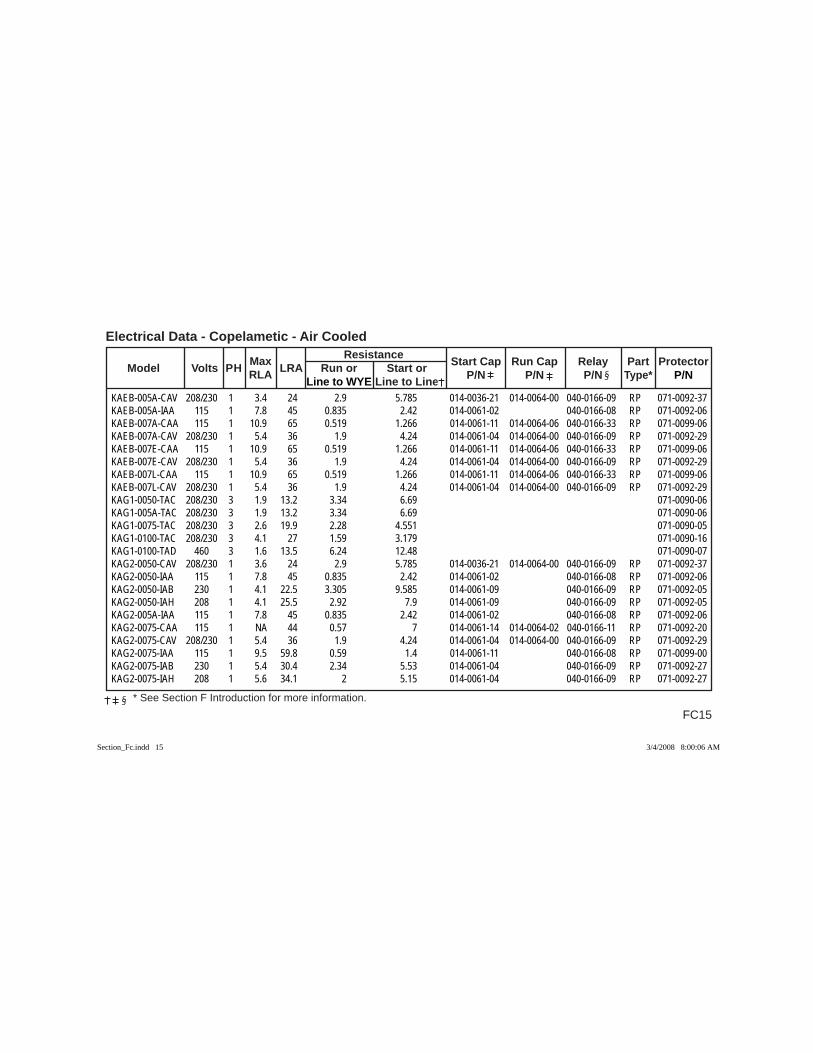
FC15
Electrical Data - Copelametic - Air Cooled
* See Section F Introduction for more information.
Max Resistance Model Volts PH RLA LRA Run or Start or Start Cap Run Cap Relay Part Protector
Line to WYE Line to Line P/N P/N P/N Type* P/N
KAEB-005A-CAV 208/230 1 3.4 24 2.9 5.785 014-0036-21 014-0064-00 040-0166-09 RP 071-0092-37KAEB-005A-IAA 115 1 7.8 45 0.835 2.42 014-0061-02 040-0166-08 RP 071-0092-06KAEB-007A-CAA 115 1 10.9 65 0.519 1.266 014-0061-11 014-0064-06 040-0166-33 RP 071-0099-06KAEB-007A-CAV 208/230 1 5.4 36 1.9 4.24 014-0061-04 014-0064-00 040-0166-09 RP 071-0092-29KAEB-007E-CAA 115 1 10.9 65 0.519 1.266 014-0061-11 014-0064-06 040-0166-33 RP 071-0099-06KAEB-007E-CAV 208/230 1 5.4 36 1.9 4.24 014-0061-04 014-0064-00 040-0166-09 RP 071-0092-29KAEB-007L-CAA 115 1 10.9 65 0.519 1.266 014-0061-11 014-0064-06 040-0166-33 RP 071-0099-06KAEB-007L-CAV 208/230 1 5.4 36 1.9 4.24 014-0061-04 014-0064-00 040-0166-09 RP 071-0092-29KAG1-0050-TAC 208/230 3 1.9 13.2 3.34 6.69 071-0090-06KAG1-005A-TAC 208/230 3 1.9 13.2 3.34 6.69 071-0090-06KAG1-0075-TAC 208/230 3 2.6 19.9 2.28 4.551 071-0090-05KAG1-0100-TAC 208/230 3 4.1 27 1.59 3.179 071-0090-16KAG1-0100-TAD 460 3 1.6 13.5 6.24 12.48 071-0090-07KAG2-0050-CAV 208/230 1 3.6 24 2.9 5.785 014-0036-21 014-0064-00 040-0166-09 RP 071-0092-37KAG2-0050-IAA 115 1 7.8 45 0.835 2.42 014-0061-02 040-0166-08 RP 071-0092-06KAG2-0050-IAB 230 1 4.1 22.5 3.305 9.585 014-0061-09 040-0166-09 RP 071-0092-05KAG2-0050-IAH 208 1 4.1 25.5 2.92 7.9 014-0061-09 040-0166-09 RP 071-0092-05KAG2-005A-IAA 115 1 7.8 45 0.835 2.42 014-0061-02 040-0166-08 RP 071-0092-06KAG2-0075-CAA 115 1 NA 44 0.57 7 014-0061-14 014-0064-02 040-0166-11 RP 071-0092-20KAG2-0075-CAV 208/230 1 5.4 36 1.9 4.24 014-0061-04 014-0064-00 040-0166-09 RP 071-0092-29KAG2-0075-IAA 115 1 9.5 59.8 0.59 1.4 014-0061-11 040-0166-08 RP 071-0099-00KAG2-0075-IAB 230 1 5.4 30.4 2.34 5.53 014-0061-04 040-0166-09 RP 071-0092-27KAG2-0075-IAH 208 1 5.6 34.1 2 5.15 014-0061-04 040-0166-09 RP 071-0092-27
Section_Fc.indd 15Section_Fc.indd 15 3/4/2008 8:00:06 AM3/4/2008 8:00:06 AM
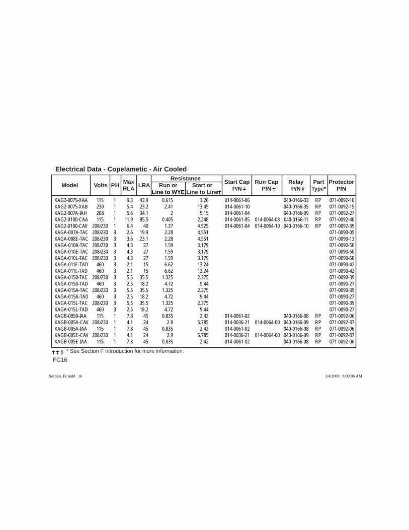
Electrical Data - Copelametic - Air Cooled
FC16 * See Section F Introduction for more information.
Max Resistance Model Volts PH RLA LRA Run or Start or Start Cap Run Cap Relay Part Protector
Line to WYE Line to Line P/N P/N P/N Type* P/N
KAG2-0075-XAA 115 1 9.3 43.9 0.615 3.26 014-0061-06 040-0166-33 RP 071-0092-10KAG2-0075-XAB 230 1 5.4 23.2 2.41 13.45 014-0061-10 040-0166-35 RP 071-0092-15KAG2-007A-IAH 208 1 5.6 34.1 2 5.15 014-0061-04 040-0166-09 RP 071-0092-27KAG2-0100-CAA 115 1 11.9 85.5 0.405 2.248 014-0061-05 014-0064-08 040-0166-11 RP 071-0092-40KAG2-0100-CAV 208/230 1 6.4 40 1.37 4.525 014-0061-04 014-0064-10 040-0166-10 RP 071-0092-39KAGA-007A-TAC 208/230 3 2.6 19.9 2.28 4.551 071-0090-05KAGA-008E-TAC 208/230 3 3.6 23.1 2.28 4.551 071-0090-13KAGA-010A-TAC 208/230 3 4.3 27 1.59 3.179 071-0090-50KAGA-010E-TAC 208/230 3 4.3 27 1.59 3.179 071-0090-50KAGA-010L-TAC 208/230 3 4.3 27 1.59 3.179 071-0090-50KAGA-011E-TAD 460 3 2.1 15 6.62 13.24 071-0090-42KAGA-011L-TAD 460 3 2.1 15 6.62 13.24 071-0090-42KAGA-0150-TAC 208/230 3 5.5 35.5 1.325 2.375 071-0090-39KAGA-0150-TAD 460 3 2.5 18.2 4.72 9.44 071-0090-27KAGA-015A-TAC 208/230 3 5.5 35.5 1.325 2.375 071-0090-39KAGA-015A-TAD 460 3 2.5 18.2 4.72 9.44 071-0090-27KAGA-015L-TAC 208/230 3 5.5 35.5 1.325 2.375 071-0090-39KAGA-015L-TAD 460 3 2.5 18.2 4.72 9.44 071-0090-27KAGB-0050-IAA 115 1 7.8 45 0.835 2.42 014-0061-02 040-0166-08 RP 071-0092-06KAGB-005A-CAV 208/230 1 4.1 24 2.9 5.785 014-0036-21 014-0064-00 040-0166-09 RP 071-0092-37KAGB-005A-IAA 115 1 7.8 45 0.835 2.42 014-0061-02 040-0166-08 RP 071-0092-06KAGB-005E-CAV 208/230 1 4.1 24 2.9 5.785 014-0036-21 014-0064-00 040-0166-09 RP 071-0092-37KAGB-005E-IAA 115 1 7.8 45 0.835 2.42 014-0061-02 040-0166-08 RP 071-0092-06
Section_Fc.indd 16Section_Fc.indd 16 3/4/2008 8:00:06 AM3/4/2008 8:00:06 AM
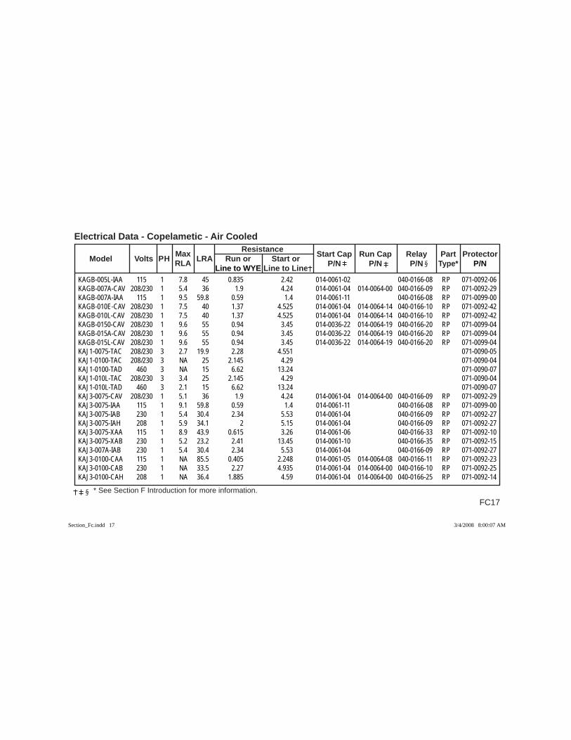
FC17
Electrical Data - Copelametic - Air Cooled
* See Section F Introduction for more information.
Max Resistance Model Volts PH RLA LRA Run or Start or Start Cap Run Cap Relay Part Protector
Line to WYE Line to Line P/N P/N P/N Type* P/N
KAGB-005L-IAA 115 1 7.8 45 0.835 2.42 014-0061-02 040-0166-08 RP 071-0092-06KAGB-007A-CAV 208/230 1 5.4 36 1.9 4.24 014-0061-04 014-0064-00 040-0166-09 RP 071-0092-29KAGB-007A-IAA 115 1 9.5 59.8 0.59 1.4 014-0061-11 040-0166-08 RP 071-0099-00KAGB-010E-CAV 208/230 1 7.5 40 1.37 4.525 014-0061-04 014-0064-14 040-0166-10 RP 071-0092-42KAGB-010L-CAV 208/230 1 7.5 40 1.37 4.525 014-0061-04 014-0064-14 040-0166-10 RP 071-0092-42KAGB-0150-CAV 208/230 1 9.6 55 0.94 3.45 014-0036-22 014-0064-19 040-0166-20 RP 071-0099-04KAGB-015A-CAV 208/230 1 9.6 55 0.94 3.45 014-0036-22 014-0064-19 040-0166-20 RP 071-0099-04KAGB-015L-CAV 208/230 1 9.6 55 0.94 3.45 014-0036-22 014-0064-19 040-0166-20 RP 071-0099-04KAJ1-0075-TAC 208/230 3 2.7 19.9 2.28 4.551 071-0090-05KAJ1-0100-TAC 208/230 3 NA 25 2.145 4.29 071-0090-04KAJ1-0100-TAD 460 3 NA 15 6.62 13.24 071-0090-07KAJ1-010L-TAC 208/230 3 3.4 25 2.145 4.29 071-0090-04KAJ1-010L-TAD 460 3 2.1 15 6.62 13.24 071-0090-07KAJ3-0075-CAV 208/230 1 5.1 36 1.9 4.24 014-0061-04 014-0064-00 040-0166-09 RP 071-0092-29KAJ3-0075-IAA 115 1 9.1 59.8 0.59 1.4 014-0061-11 040-0166-08 RP 071-0099-00KAJ3-0075-IAB 230 1 5.4 30.4 2.34 5.53 014-0061-04 040-0166-09 RP 071-0092-27KAJ3-0075-IAH 208 1 5.9 34.1 2 5.15 014-0061-04 040-0166-09 RP 071-0092-27KAJ3-0075-XAA 115 1 8.9 43.9 0.615 3.26 014-0061-06 040-0166-33 RP 071-0092-10KAJ3-0075-XAB 230 1 5.2 23.2 2.41 13.45 014-0061-10 040-0166-35 RP 071-0092-15KAJ3-007A-IAB 230 1 5.4 30.4 2.34 5.53 014-0061-04 040-0166-09 RP 071-0092-27KAJ3-0100-CAA 115 1 NA 85.5 0.405 2.248 014-0061-05 014-0064-08 040-0166-11 RP 071-0092-23KAJ3-0100-CAB 230 1 NA 33.5 2.27 4.935 014-0061-04 014-0064-00 040-0166-10 RP 071-0092-25KAJ3-0100-CAH 208 1 NA 36.4 1.885 4.59 014-0061-04 014-0064-00 040-0166-25 RP 071-0092-14
Section_Fc.indd 17Section_Fc.indd 17 3/4/2008 8:00:07 AM3/4/2008 8:00:07 AM
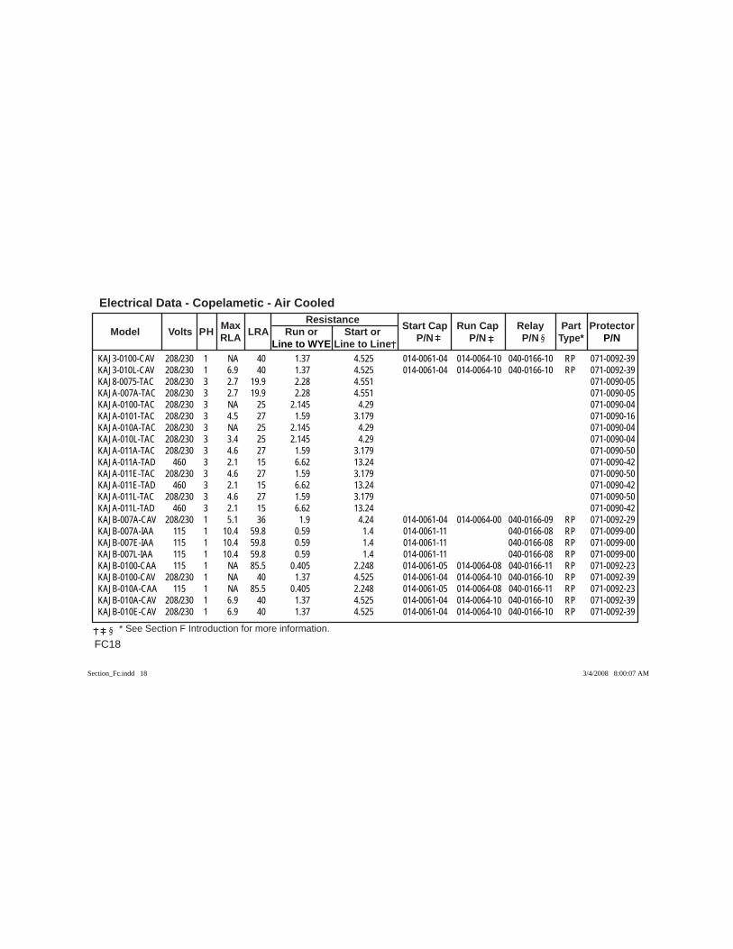
Electrical Data - Copelametic - Air Cooled
FC18 * See Section F Introduction for more information.
Max Resistance Model Volts PH RLA LRA Run or Start or Start Cap Run Cap Relay Part Protector
Line to WYE Line to Line P/N P/N P/N Type* P/N
KAJ3-0100-CAV 208/230 1 NA 40 1.37 4.525 014-0061-04 014-0064-10 040-0166-10 RP 071-0092-39KAJ3-010L-CAV 208/230 1 6.9 40 1.37 4.525 014-0061-04 014-0064-10 040-0166-10 RP 071-0092-39KAJ8-0075-TAC 208/230 3 2.7 19.9 2.28 4.551 071-0090-05KAJA-007A-TAC 208/230 3 2.7 19.9 2.28 4.551 071-0090-05KAJA-0100-TAC 208/230 3 NA 25 2.145 4.29 071-0090-04KAJA-0101-TAC 208/230 3 4.5 27 1.59 3.179 071-0090-16KAJA-010A-TAC 208/230 3 NA 25 2.145 4.29 071-0090-04KAJA-010L-TAC 208/230 3 3.4 25 2.145 4.29 071-0090-04KAJA-011A-TAC 208/230 3 4.6 27 1.59 3.179 071-0090-50KAJA-011A-TAD 460 3 2.1 15 6.62 13.24 071-0090-42KAJA-011E-TAC 208/230 3 4.6 27 1.59 3.179 071-0090-50KAJA-011E-TAD 460 3 2.1 15 6.62 13.24 071-0090-42KAJA-011L-TAC 208/230 3 4.6 27 1.59 3.179 071-0090-50KAJA-011L-TAD 460 3 2.1 15 6.62 13.24 071-0090-42KAJB-007A-CAV 208/230 1 5.1 36 1.9 4.24 014-0061-04 014-0064-00 040-0166-09 RP 071-0092-29KAJB-007A-IAA 115 1 10.4 59.8 0.59 1.4 014-0061-11 040-0166-08 RP 071-0099-00KAJB-007E-IAA 115 1 10.4 59.8 0.59 1.4 014-0061-11 040-0166-08 RP 071-0099-00KAJB-007L-IAA 115 1 10.4 59.8 0.59 1.4 014-0061-11 040-0166-08 RP 071-0099-00KAJB-0100-CAA 115 1 NA 85.5 0.405 2.248 014-0061-05 014-0064-08 040-0166-11 RP 071-0092-23KAJB-0100-CAV 208/230 1 NA 40 1.37 4.525 014-0061-04 014-0064-10 040-0166-10 RP 071-0092-39KAJB-010A-CAA 115 1 NA 85.5 0.405 2.248 014-0061-05 014-0064-08 040-0166-11 RP 071-0092-23KAJB-010A-CAV 208/230 1 6.9 40 1.37 4.525 014-0061-04 014-0064-10 040-0166-10 RP 071-0092-39KAJB-010E-CAV 208/230 1 6.9 40 1.37 4.525 014-0061-04 014-0064-10 040-0166-10 RP 071-0092-39
Section_Fc.indd 18Section_Fc.indd 18 3/4/2008 8:00:07 AM3/4/2008 8:00:07 AM
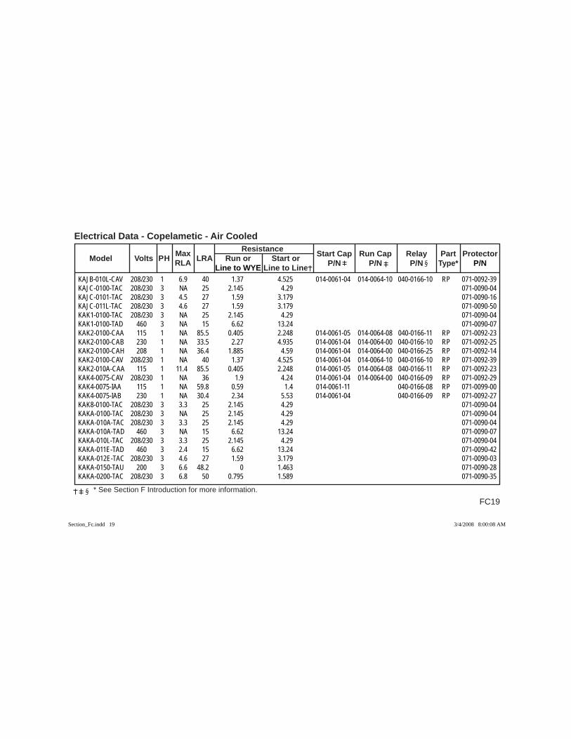
FC19
Electrical Data - Copelametic - Air Cooled
* See Section F Introduction for more information.
Max Resistance Model Volts PH RLA LRA Run or Start or Start Cap Run Cap Relay Part Protector
Line to WYE Line to Line P/N P/N P/N Type* P/N
KAJB-010L-CAV 208/230 1 6.9 40 1.37 4.525 014-0061-04 014-0064-10 040-0166-10 RP 071-0092-39KAJC-0100-TAC 208/230 3 NA 25 2.145 4.29 071-0090-04KAJC-0101-TAC 208/230 3 4.5 27 1.59 3.179 071-0090-16KAJC-011L-TAC 208/230 3 4.6 27 1.59 3.179 071-0090-50KAK1-0100-TAC 208/230 3 NA 25 2.145 4.29 071-0090-04KAK1-0100-TAD 460 3 NA 15 6.62 13.24 071-0090-07KAK2-0100-CAA 115 1 NA 85.5 0.405 2.248 014-0061-05 014-0064-08 040-0166-11 RP 071-0092-23KAK2-0100-CAB 230 1 NA 33.5 2.27 4.935 014-0061-04 014-0064-00 040-0166-10 RP 071-0092-25KAK2-0100-CAH 208 1 NA 36.4 1.885 4.59 014-0061-04 014-0064-00 040-0166-25 RP 071-0092-14KAK2-0100-CAV 208/230 1 NA 40 1.37 4.525 014-0061-04 014-0064-10 040-0166-10 RP 071-0092-39KAK2-010A-CAA 115 1 11.4 85.5 0.405 2.248 014-0061-05 014-0064-08 040-0166-11 RP 071-0092-23KAK4-0075-CAV 208/230 1 NA 36 1.9 4.24 014-0061-04 014-0064-00 040-0166-09 RP 071-0092-29KAK4-0075-IAA 115 1 NA 59.8 0.59 1.4 014-0061-11 040-0166-08 RP 071-0099-00KAK4-0075-IAB 230 1 NA 30.4 2.34 5.53 014-0061-04 040-0166-09 RP 071-0092-27KAK8-0100-TAC 208/230 3 3.3 25 2.145 4.29 071-0090-04KAKA-0100-TAC 208/230 3 NA 25 2.145 4.29 071-0090-04KAKA-010A-TAC 208/230 3 3.3 25 2.145 4.29 071-0090-04KAKA-010A-TAD 460 3 NA 15 6.62 13.24 071-0090-07KAKA-010L-TAC 208/230 3 3.3 25 2.145 4.29 071-0090-04KAKA-011E-TAD 460 3 2.4 15 6.62 13.24 071-0090-42KAKA-012E-TAC 208/230 3 4.6 27 1.59 3.179 071-0090-03KAKA-0150-TAU 200 3 6.6 48.2 0 1.463 071-0090-28KAKA-0200-TAC 208/230 3 6.8 50 0.795 1.589 071-0090-35
Section_Fc.indd 19Section_Fc.indd 19 3/4/2008 8:00:08 AM3/4/2008 8:00:08 AM
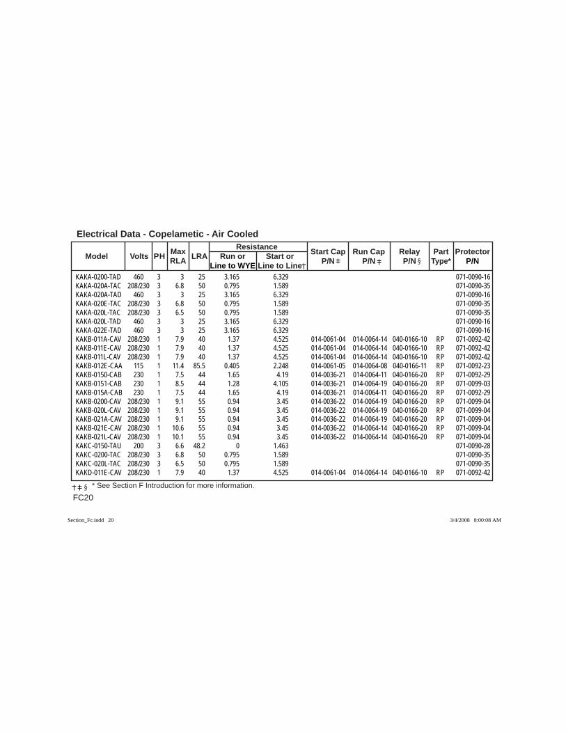
Electrical Data - Copelametic - Air Cooled
FC20 * See Section F Introduction for more information.
Max Resistance Model Volts PH RLA LRA Run or Start or Start Cap Run Cap Relay Part Protector
Line to WYE Line to Line P/N P/N P/N Type* P/N
KAKA-0200-TAD 460 3 3 25 3.165 6.329 071-0090-16KAKA-020A-TAC 208/230 3 6.8 50 0.795 1.589 071-0090-35KAKA-020A-TAD 460 3 3 25 3.165 6.329 071-0090-16KAKA-020E-TAC 208/230 3 6.8 50 0.795 1.589 071-0090-35KAKA-020L-TAC 208/230 3 6.5 50 0.795 1.589 071-0090-35KAKA-020L-TAD 460 3 3 25 3.165 6.329 071-0090-16KAKA-022E-TAD 460 3 3 25 3.165 6.329 071-0090-16KAKB-011A-CAV 208/230 1 7.9 40 1.37 4.525 014-0061-04 014-0064-14 040-0166-10 RP 071-0092-42KAKB-011E-CAV 208/230 1 7.9 40 1.37 4.525 014-0061-04 014-0064-14 040-0166-10 RP 071-0092-42KAKB-011L-CAV 208/230 1 7.9 40 1.37 4.525 014-0061-04 014-0064-14 040-0166-10 RP 071-0092-42KAKB-012E-CAA 115 1 11.4 85.5 0.405 2.248 014-0061-05 014-0064-08 040-0166-11 RP 071-0092-23KAKB-0150-CAB 230 1 7.5 44 1.65 4.19 014-0036-21 014-0064-11 040-0166-20 RP 071-0092-29KAKB-0151-CAB 230 1 8.5 44 1.28 4.105 014-0036-21 014-0064-19 040-0166-20 RP 071-0099-03KAKB-015A-CAB 230 1 7.5 44 1.65 4.19 014-0036-21 014-0064-11 040-0166-20 RP 071-0092-29KAKB-0200-CAV 208/230 1 9.1 55 0.94 3.45 014-0036-22 014-0064-19 040-0166-20 RP 071-0099-04KAKB-020L-CAV 208/230 1 9.1 55 0.94 3.45 014-0036-22 014-0064-19 040-0166-20 RP 071-0099-04KAKB-021A-CAV 208/230 1 9.1 55 0.94 3.45 014-0036-22 014-0064-19 040-0166-20 RP 071-0099-04KAKB-021E-CAV 208/230 1 10.6 55 0.94 3.45 014-0036-22 014-0064-14 040-0166-20 RP 071-0099-04KAKB-021L-CAV 208/230 1 10.1 55 0.94 3.45 014-0036-22 014-0064-14 040-0166-20 RP 071-0099-04KAKC-0150-TAU 200 3 6.6 48.2 0 1.463 071-0090-28KAKC-0200-TAC 208/230 3 6.8 50 0.795 1.589 071-0090-35KAKC-020L-TAC 208/230 3 6.5 50 0.795 1.589 071-0090-35KAKD-011E-CAV 208/230 1 7.9 40 1.37 4.525 014-0061-04 014-0064-14 040-0166-10 RP 071-0092-42
Section_Fc.indd 20Section_Fc.indd 20 3/4/2008 8:00:08 AM3/4/2008 8:00:08 AM
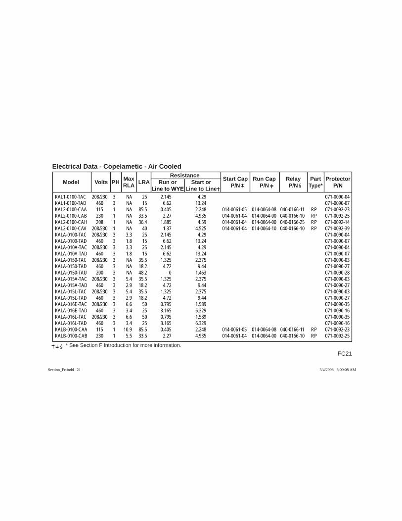
FC21
Electrical Data - Copelametic - Air Cooled
* See Section F Introduction for more information.
Max Resistance Model Volts PH RLA LRA Run or Start or Start Cap Run Cap Relay Part Protector
Line to WYE Line to Line P/N P/N P/N Type* P/N
KAL1-0100-TAC 208/230 3 NA 25 2.145 4.29 071-0090-04KAL1-0100-TAD 460 3 NA 15 6.62 13.24 071-0090-07KAL2-0100-CAA 115 1 NA 85.5 0.405 2.248 014-0061-05 014-0064-08 040-0166-11 RP 071-0092-23KAL2-0100-CAB 230 1 NA 33.5 2.27 4.935 014-0061-04 014-0064-00 040-0166-10 RP 071-0092-25KAL2-0100-CAH 208 1 NA 36.4 1.885 4.59 014-0061-04 014-0064-00 040-0166-25 RP 071-0092-14KAL2-0100-CAV 208/230 1 NA 40 1.37 4.525 014-0061-04 014-0064-10 040-0166-10 RP 071-0092-39KALA-0100-TAC 208/230 3 3.3 25 2.145 4.29 071-0090-04KALA-0100-TAD 460 3 1.8 15 6.62 13.24 071-0090-07KALA-010A-TAC 208/230 3 3.3 25 2.145 4.29 071-0090-04KALA-010A-TAD 460 3 1.8 15 6.62 13.24 071-0090-07KALA-0150-TAC 208/230 3 NA 35.5 1.325 2.375 071-0090-03KALA-0150-TAD 460 3 NA 18.2 4.72 9.44 071-0090-27KALA-0150-TAU 200 3 NA 48.2 0 1.463 071-0090-28KALA-015A-TAC 208/230 3 5.4 35.5 1.325 2.375 071-0090-03KALA-015A-TAD 460 3 2.9 18.2 4.72 9.44 071-0090-27KALA-015L-TAC 208/230 3 5.4 35.5 1.325 2.375 071-0090-03KALA-015L-TAD 460 3 2.9 18.2 4.72 9.44 071-0090-27KALA-016E-TAC 208/230 3 6.6 50 0.795 1.589 071-0090-35KALA-016E-TAD 460 3 3.4 25 3.165 6.329 071-0090-16KALA-016L-TAC 208/230 3 6.6 50 0.795 1.589 071-0090-35KALA-016L-TAD 460 3 3.4 25 3.165 6.329 071-0090-16KALB-0100-CAA 115 1 10.9 85.5 0.405 2.248 014-0061-05 014-0064-08 040-0166-11 RP 071-0092-23KALB-0100-CAB 230 1 5.5 33.5 2.27 4.935 014-0061-04 014-0064-00 040-0166-10 RP 071-0092-25
Section_Fc.indd 21Section_Fc.indd 21 3/4/2008 8:00:08 AM3/4/2008 8:00:08 AM
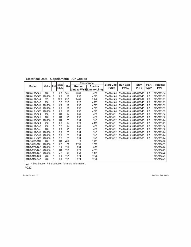
Electrical Data - Copelametic - Air Cooled
FC22 * See Section F Introduction for more information.
Max Resistance Model Volts PH RLA LRA Run or Start or Start Cap Run Cap Relay Part Protector
Line to WYE Line to Line P/N P/N P/N Type* P/N
KALB-0100-CAH 208 1 6.8 36.4 1.885 4.59 014-0061-04 014-0064-00 040-0166-25 RP 071-0092-14KALB-0100-CAV 208/230 1 6.9 40 1.37 4.525 014-0061-04 014-0064-10 040-0166-10 RP 071-0092-39KALB-010A-CAA 115 1 10.9 85.5 0.405 2.248 014-0061-05 014-0064-08 040-0166-11 RP 071-0092-23KALB-010A-CAB 230 1 5.5 33.5 2.27 4.935 014-0061-04 014-0064-00 040-0166-10 RP 071-0092-25KALB-010A-CAV 208/230 1 6.9 40 1.37 4.525 014-0061-04 014-0064-10 040-0166-10 RP 071-0092-39KALB-010E-CAV 208/230 1 6.9 40 1.37 4.525 014-0061-04 014-0064-10 040-0166-10 RP 071-0092-39KALB-010L-CAV 208/230 1 6.9 40 1.37 4.525 014-0061-04 014-0064-10 040-0166-10 RP 071-0092-39KALB-0150-CAB 230 1 NA 44 1.65 4.19 014-0036-21 014-0064-10 040-0166-20 RP 071-0092-16KALB-0150-CAH 208 1 NA 45 1.32 4.19 014-0036-21 014-0064-10 040-0166-30 RP 071-0092-18KALB-0150-CAV 208/230 1 NA 55 0.94 3.45 014-0036-22 014-0064-19 040-0166-20 RP 071-0099-04KALB-0151-CAB 230 1 8.9 44 1.28 4.105 014-0036-21 014-0064-19 040-0166-20 RP 071-0099-03KALB-015A-CAB 230 1 5.6 44 1.65 4.19 014-0036-21 014-0064-10 040-0166-20 RP 071-0092-16KALB-015A-CAH 208 1 8.1 45 1.32 4.19 014-0036-21 014-0064-10 040-0166-30 RP 071-0092-18KALB-015A-CAV 208/230 1 9.9 55 0.94 3.45 014-0036-22 014-0064-19 040-0166-20 RP 071-0099-04KALB-015E-CAV 208/230 1 9.9 55 0.94 3.45 014-0036-22 014-0064-19 040-0166-20 RP 071-0099-04KALB-015L-CAV 208/230 1 9.9 55 0.94 3.45 014-0036-22 014-0064-19 040-0166-20 RP 071-0099-04KALC-0150-TAU 200 3 NA 48.2 0 1.463 071-0090-28KALC-016L-TAC 208/230 3 6.6 50 0.795 1.589 071-0090-35KAM1-0050-TAC 208/230 3 1.7 13.2 3.34 6.69 071-0090-06KAM1-0075-TAC 208/230 3 NA 19.9 2.28 4.551 071-0090-05KAM1-0100-TAC 208/230 3 4.5 27 1.59 3.179 071-0090-40KAM1-0100-TAD 460 3 2.2 13.5 6.24 12.48 071-0090-43KAM1-010A-TAD 460 3 2.2 13.5 6.24 12.48 071-0090-43
Section_Fc.indd 22Section_Fc.indd 22 3/4/2008 8:00:09 AM3/4/2008 8:00:09 AM
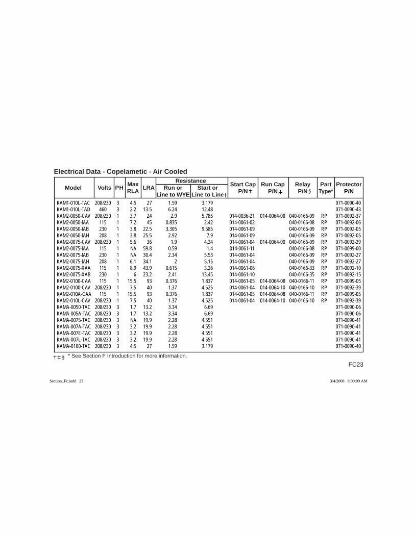
FC23
Electrical Data - Copelametic - Air Cooled
* See Section F Introduction for more information.
Max Resistance Model Volts PH RLA LRA Run or Start or Start Cap Run Cap Relay Part Protector
Line to WYE Line to Line P/N P/N P/N Type* P/N
KAM1-010L-TAC 208/230 3 4.5 27 1.59 3.179 071-0090-40KAM1-010L-TAD 460 3 2.2 13.5 6.24 12.48 071-0090-43KAM2-0050-CAV 208/230 1 3.7 24 2.9 5.785 014-0036-21 014-0064-00 040-0166-09 RP 071-0092-37KAM2-0050-IAA 115 1 7.2 45 0.835 2.42 014-0061-02 040-0166-08 RP 071-0092-06KAM2-0050-IAB 230 1 3.8 22.5 3.305 9.585 014-0061-09 040-0166-09 RP 071-0092-05KAM2-0050-IAH 208 1 3.8 25.5 2.92 7.9 014-0061-09 040-0166-09 RP 071-0092-05KAM2-0075-CAV 208/230 1 5.6 36 1.9 4.24 014-0061-04 014-0064-00 040-0166-09 RP 071-0092-29KAM2-0075-IAA 115 1 NA 59.8 0.59 1.4 014-0061-11 040-0166-08 RP 071-0099-00KAM2-0075-IAB 230 1 NA 30.4 2.34 5.53 014-0061-04 040-0166-09 RP 071-0092-27KAM2-0075-IAH 208 1 6.1 34.1 2 5.15 014-0061-04 040-0166-09 RP 071-0092-27KAM2-0075-XAA 115 1 8.9 43.9 0.615 3.26 014-0061-06 040-0166-33 RP 071-0092-10KAM2-0075-XAB 230 1 6 23.2 2.41 13.45 014-0061-10 040-0166-35 RP 071-0092-15KAM2-0100-CAA 115 1 15.5 93 0.376 1.837 014-0061-05 014-0064-08 040-0166-11 RP 071-0099-05KAM2-0100-CAV 208/230 1 7.5 40 1.37 4.525 014-0061-04 014-0064-10 040-0166-10 RP 071-0092-39KAM2-010A-CAA 115 1 15.5 93 0.376 1.837 014-0061-05 014-0064-08 040-0166-11 RP 071-0099-05KAM2-010L-CAV 208/230 1 7.5 40 1.37 4.525 014-0061-04 014-0064-10 040-0166-10 RP 071-0092-39KAMA-0050-TAC 208/230 3 1.7 13.2 3.34 6.69 071-0090-06KAMA-005A-TAC 208/230 3 1.7 13.2 3.34 6.69 071-0090-06KAMA-0075-TAC 208/230 3 NA 19.9 2.28 4.551 071-0090-41KAMA-007A-TAC 208/230 3 3.2 19.9 2.28 4.551 071-0090-41KAMA-007E-TAC 208/230 3 3.2 19.9 2.28 4.551 071-0090-41KAMA-007L-TAC 208/230 3 3.2 19.9 2.28 4.551 071-0090-41KAMA-0100-TAC 208/230 3 4.5 27 1.59 3.179 071-0090-40
Section_Fc.indd 23Section_Fc.indd 23 3/4/2008 8:00:09 AM3/4/2008 8:00:09 AM
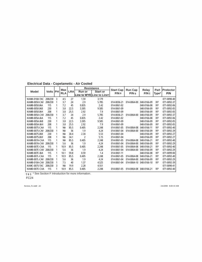
Electrical Data - Copelametic - Air Cooled
FC24 * See Section F Introduction for more information.
Max Resistance Model Volts PH RLA LRA Run or Start or Start Cap Run Cap Relay Part Protector
Line to WYE Line to Line P/N P/N P/N Type* P/N
KAMA-010A-TAC 208/230 3 4.5 27 1.59 3.179 071-0090-40KAMB-0050-CAV 208/230 1 3.7 24 2.9 5.785 014-0036-21 014-0064-00 040-0166-09 RP 071-0092-37KAMB-0050-IAA 115 1 7.2 45 0.835 2.42 014-0061-02 040-0166-08 RP 071-0092-06KAMB-0050-IAB 230 1 3.8 22.5 3.305 9.585 014-0061-09 040-0166-09 RP 071-0092-05KAMB-0050-IAH 208 1 3.8 25.5 2.92 7.9 014-0061-09 040-0166-09 RP 071-0092-05KAMB-005A-CAV 208/230 1 3.7 24 2.9 5.785 014-0036-21 014-0064-00 040-0166-09 RP 071-0092-37KAMB-005A-IAA 115 1 7.2 45 0.835 2.42 014-0061-02 040-0166-08 RP 071-0092-06KAMB-005A-IAB 230 1 3.8 22.5 3.305 9.585 014-0061-09 040-0166-09 RP 071-0092-05KAMB-005A-IAH 208 1 3.8 25.5 2.92 7.9 014-0061-09 040-0166-09 RP 071-0092-05KAMB-0075-CAA 115 1 NA 85.5 0.405 2.248 014-0061-05 014-0064-08 040-0166-11 RP 071-0092-40KAMB-0075-CAV 208/230 1 NA 36 1.9 4.24 014-0061-04 014-0064-00 040-0166-09 RP 071-0092-29KAMB-0075-IAB 230 1 NA 30.4 2.34 5.53 014-0061-04 040-0166-09 RP 071-0092-27KAMB-0075-IAH 208 1 NA 34.1 2 5.15 014-0061-04 040-0166-09 RP 071-0092-27KAMB-007A-CAA 115 1 NA 85.5 0.405 2.248 014-0061-05 014-0064-08 040-0166-21 RP 071-0092-40KAMB-007A-CAV 208/230 1 5.6 36 1.9 4.24 014-0061-04 014-0064-00 040-0166-09 RP 071-0092-29KAMB-007E-CAA 115 1 10.9 85.5 0.405 2.248 014-0061-05 014-0064-08 040-0166-21 RP 071-0092-40KAMB-007E-CAV 208/230 1 5.6 36 1.9 4.24 014-0061-04 014-0064-00 040-0166-09 RP 071-0092-29KAMB-007E-IAA 115 1 10.1 59.8 0.59 1.4 014-0061-11 040-0166-08 RP 071-0099-00KAMB-007L-CAA 115 1 10.9 85.5 0.405 2.248 014-0061-05 014-0064-08 040-0166-21 RP 071-0092-40KAMB-007L-CAV 208/230 1 5.6 36 1.9 4.24 014-0061-04 014-0064-00 040-0166-09 RP 071-0092-29KAMB-010A-CAV 208/230 1 7.5 40 1.37 4.525 014-0061-04 014-0064-10 040-0166-10 RP 071-0092-39KAMC-0075-TAC 208/230 3 NA 19.9 2.28 4.551 071-0090-41KAMD-007E-CAA 115 1 10.9 85.5 0.405 2.248 014-0061-05 014-0064-08 040-0166-21 RP 071-0092-40
Section_Fc.indd 24Section_Fc.indd 24 3/4/2008 8:00:10 AM3/4/2008 8:00:10 AM
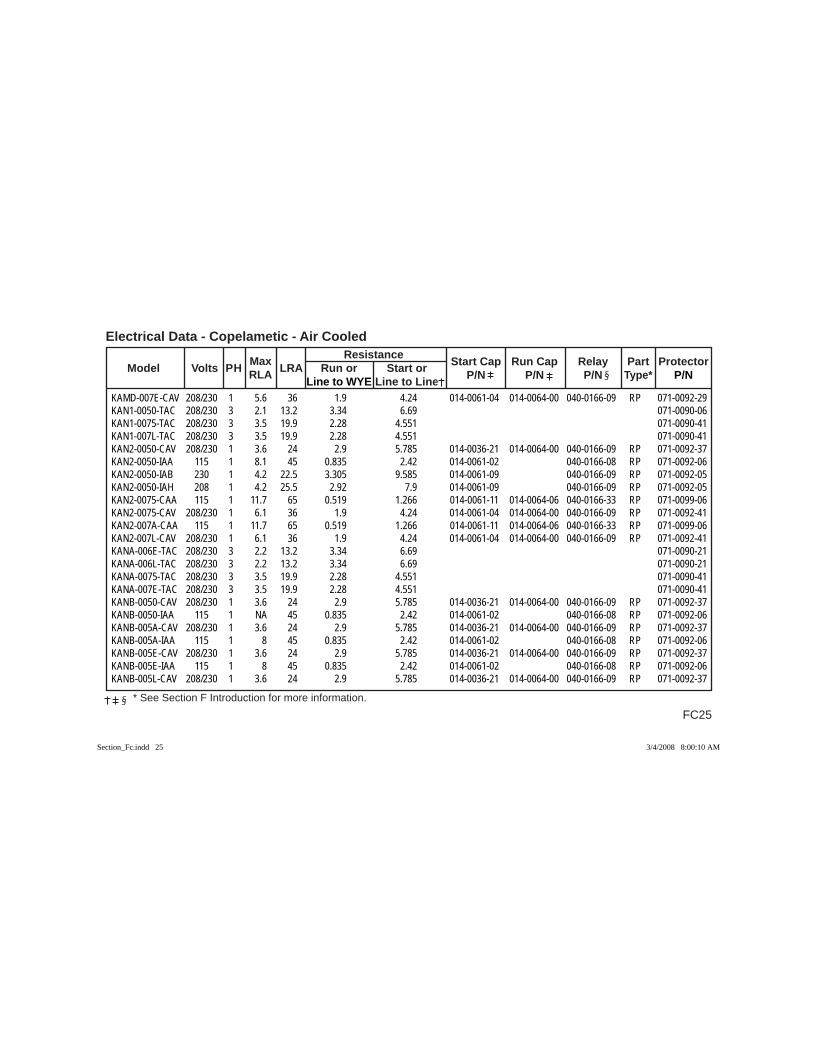
FC25
Electrical Data - Copelametic - Air Cooled
* See Section F Introduction for more information.
Max Resistance Model Volts PH RLA LRA Run or Start or Start Cap Run Cap Relay Part Protector
Line to WYE Line to Line P/N P/N P/N Type* P/N
KAMD-007E-CAV 208/230 1 5.6 36 1.9 4.24 014-0061-04 014-0064-00 040-0166-09 RP 071-0092-29KAN1-0050-TAC 208/230 3 2.1 13.2 3.34 6.69 071-0090-06KAN1-0075-TAC 208/230 3 3.5 19.9 2.28 4.551 071-0090-41KAN1-007L-TAC 208/230 3 3.5 19.9 2.28 4.551 071-0090-41KAN2-0050-CAV 208/230 1 3.6 24 2.9 5.785 014-0036-21 014-0064-00 040-0166-09 RP 071-0092-37KAN2-0050-IAA 115 1 8.1 45 0.835 2.42 014-0061-02 040-0166-08 RP 071-0092-06KAN2-0050-IAB 230 1 4.2 22.5 3.305 9.585 014-0061-09 040-0166-09 RP 071-0092-05KAN2-0050-IAH 208 1 4.2 25.5 2.92 7.9 014-0061-09 040-0166-09 RP 071-0092-05KAN2-0075-CAA 115 1 11.7 65 0.519 1.266 014-0061-11 014-0064-06 040-0166-33 RP 071-0099-06KAN2-0075-CAV 208/230 1 6.1 36 1.9 4.24 014-0061-04 014-0064-00 040-0166-09 RP 071-0092-41KAN2-007A-CAA 115 1 11.7 65 0.519 1.266 014-0061-11 014-0064-06 040-0166-33 RP 071-0099-06KAN2-007L-CAV 208/230 1 6.1 36 1.9 4.24 014-0061-04 014-0064-00 040-0166-09 RP 071-0092-41KANA-006E-TAC 208/230 3 2.2 13.2 3.34 6.69 071-0090-21KANA-006L-TAC 208/230 3 2.2 13.2 3.34 6.69 071-0090-21KANA-0075-TAC 208/230 3 3.5 19.9 2.28 4.551 071-0090-41KANA-007E-TAC 208/230 3 3.5 19.9 2.28 4.551 071-0090-41KANB-0050-CAV 208/230 1 3.6 24 2.9 5.785 014-0036-21 014-0064-00 040-0166-09 RP 071-0092-37KANB-0050-IAA 115 1 NA 45 0.835 2.42 014-0061-02 040-0166-08 RP 071-0092-06KANB-005A-CAV 208/230 1 3.6 24 2.9 5.785 014-0036-21 014-0064-00 040-0166-09 RP 071-0092-37KANB-005A-IAA 115 1 8 45 0.835 2.42 014-0061-02 040-0166-08 RP 071-0092-06KANB-005E-CAV 208/230 1 3.6 24 2.9 5.785 014-0036-21 014-0064-00 040-0166-09 RP 071-0092-37KANB-005E-IAA 115 1 8 45 0.835 2.42 014-0061-02 040-0166-08 RP 071-0092-06KANB-005L-CAV 208/230 1 3.6 24 2.9 5.785 014-0036-21 014-0064-00 040-0166-09 RP 071-0092-37
Section_Fc.indd 25Section_Fc.indd 25 3/4/2008 8:00:10 AM3/4/2008 8:00:10 AM
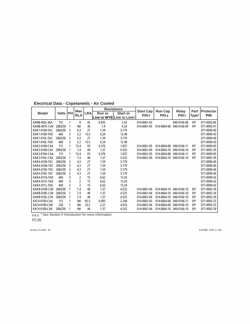
Electrical Data - Copelametic - Air Cooled
FC26 * See Section F Introduction for more information.
Max Resistance Model Volts PH RLA LRA Run or Start or Start Cap Run Cap Relay Part Protector
Line to WYE Line to Line P/N P/N P/N Type* P/N
KANB-005L-IAA 115 1 8 45 0.835 2.42 014-0061-02 040-0166-08 RP 071-0092-06KANB-007E-CAV 208/230 1 NA 36 1.9 4.24 014-0061-04 014-0064-00 040-0166-09 RP 071-0092-41KAR1-0100-TAC 208/230 3 4.3 27 1.59 3.179 071-0090-40KAR1-0100-TAD 460 3 2.2 13.5 6.24 12.48 071-0090-43KAR1-010L-TAC 208/230 3 4.3 27 1.59 3.179 071-0090-40KAR1-010L-TAD 460 3 2.2 13.5 6.24 12.48 071-0090-43KAR2-0100-CAA 115 1 15.4 93 0.376 1.837 014-0061-05 014-0064-08 040-0166-11 RP 071-0099-05KAR2-0100-CAV 208/230 1 7.4 40 1.37 4.525 014-0061-04 014-0064-10 040-0166-10 RP 071-0092-39KAR2-010A-CAA 115 1 15.4 93 0.376 1.837 014-0061-05 014-0064-08 040-0166-11 RP 071-0099-05KAR2-010L-CAV 208/230 1 7.4 40 1.37 4.525 014-0061-04 014-0064-10 040-0166-10 RP 071-0092-39KARA-0100-TAC 208/230 3 4.3 27 1.59 3.179 071-0090-40KARA-010A-TAC 208/230 3 4.3 27 1.59 3.179 071-0090-40KARA-010E-TAC 208/230 3 4.3 27 1.59 3.179 071-0090-40KARA-010L-TAC 208/230 3 4.3 27 1.59 3.179 071-0090-40KARA-011A-TAD 460 3 2 15 6.62 13.24 071-0090-42KARA-011E-TAD 460 3 2 15 6.62 13.24 071-0090-42KARA-011L-TAD 460 3 2 15 6.62 13.24 071-0090-42KARB-010A-CAV 208/230 1 7.4 40 1.37 4.525 014-0061-04 014-0064-10 040-0166-10 RP 071-0092-39KARB-010E-CAV 208/230 1 7.4 40 1.37 4.525 014-0061-04 014-0064-10 040-0166-10 RP 071-0092-39KARB-010L-CAV 208/230 1 7.4 40 1.37 4.525 014-0061-04 014-0064-10 040-0166-10 RP 071-0092-39KAT4-0100-CAA 115 1 NA 85.5 0.405 2.248 014-0061-05 014-0064-08 040-0166-11 RP 071-0092-23KAT4-0100-CAB 230 1 NA 33.5 2.27 4.935 014-0061-04 014-0064-00 040-0166-10 RP 071-0092-25KAT4-0100-CAV 208/230 1 NA 40 1.37 4.525 014-0061-04 014-0064-10 040-0166-10 RP 071-0092-39
Section_Fc.indd 26Section_Fc.indd 26 3/4/2008 8:00:11 AM3/4/2008 8:00:11 AM
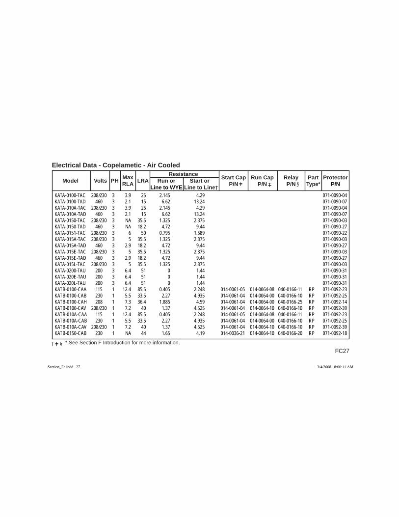
FC27
Electrical Data - Copelametic - Air Cooled
* See Section F Introduction for more information.
Max Resistance Model Volts PH RLA LRA Run or Start or Start Cap Run Cap Relay Part Protector
Line to WYE Line to Line P/N P/N P/N Type* P/N
KATA-0100-TAC 208/230 3 3.9 25 2.145 4.29 071-0090-04KATA-0100-TAD 460 3 2.1 15 6.62 13.24 071-0090-07KATA-010A-TAC 208/230 3 3.9 25 2.145 4.29 071-0090-04KATA-010A-TAD 460 3 2.1 15 6.62 13.24 071-0090-07KATA-0150-TAC 208/230 3 NA 35.5 1.325 2.375 071-0090-03KATA-0150-TAD 460 3 NA 18.2 4.72 9.44 071-0090-27KATA-0151-TAC 208/230 3 6 50 0.795 1.589 071-0090-22KATA-015A-TAC 208/230 3 5 35.5 1.325 2.375 071-0090-03KATA-015A-TAD 460 3 2.9 18.2 4.72 9.44 071-0090-27KATA-015E-TAC 208/230 3 5 35.5 1.325 2.375 071-0090-03KATA-015E-TAD 460 3 2.9 18.2 4.72 9.44 071-0090-27KATA-015L-TAC 208/230 3 5 35.5 1.325 2.375 071-0090-03KATA-0200-TAU 200 3 6.4 51 0 1.44 071-0090-31KATA-020E-TAU 200 3 6.4 51 0 1.44 071-0090-31KATA-020L-TAU 200 3 6.4 51 0 1.44 071-0090-31KATB-0100-CAA 115 1 12.4 85.5 0.405 2.248 014-0061-05 014-0064-08 040-0166-11 RP 071-0092-23KATB-0100-CAB 230 1 5.5 33.5 2.27 4.935 014-0061-04 014-0064-00 040-0166-10 RP 071-0092-25KATB-0100-CAH 208 1 7.3 36.4 1.885 4.59 014-0061-04 014-0064-00 040-0166-25 RP 071-0092-14KATB-0100-CAV 208/230 1 7.2 40 1.37 4.525 014-0061-04 014-0064-10 040-0166-10 RP 071-0092-39KATB-010A-CAA 115 1 12.4 85.5 0.405 2.248 014-0061-05 014-0064-08 040-0166-11 RP 071-0092-23KATB-010A-CAB 230 1 5.5 33.5 2.27 4.935 014-0061-04 014-0064-00 040-0166-10 RP 071-0092-25KATB-010A-CAV 208/230 1 7.2 40 1.37 4.525 014-0061-04 014-0064-10 040-0166-10 RP 071-0092-39KATB-0150-CAB 230 1 NA 44 1.65 4.19 014-0036-21 014-0064-10 040-0166-20 RP 071-0092-18
Section_Fc.indd 27Section_Fc.indd 27 3/4/2008 8:00:11 AM3/4/2008 8:00:11 AM
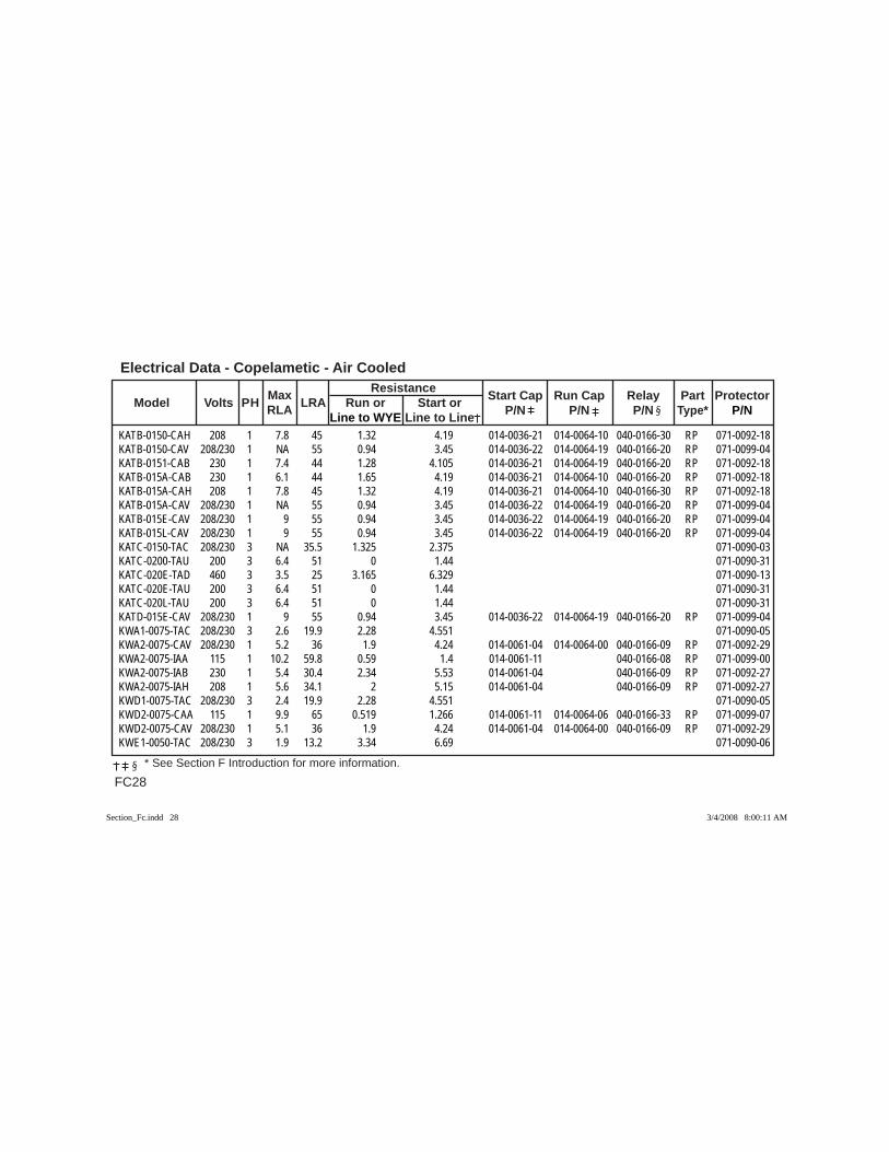
Electrical Data - Copelametic - Air Cooled
FC28 * See Section F Introduction for more information.
Max Resistance Model Volts PH RLA LRA Run or Start or Start Cap Run Cap Relay Part Protector
Line to WYE Line to Line P/N P/N P/N Type* P/N
KATB-0150-CAH 208 1 7.8 45 1.32 4.19 014-0036-21 014-0064-10 040-0166-30 RP 071-0092-18KATB-0150-CAV 208/230 1 NA 55 0.94 3.45 014-0036-22 014-0064-19 040-0166-20 RP 071-0099-04KATB-0151-CAB 230 1 7.4 44 1.28 4.105 014-0036-21 014-0064-19 040-0166-20 RP 071-0092-18KATB-015A-CAB 230 1 6.1 44 1.65 4.19 014-0036-21 014-0064-10 040-0166-20 RP 071-0092-18KATB-015A-CAH 208 1 7.8 45 1.32 4.19 014-0036-21 014-0064-10 040-0166-30 RP 071-0092-18KATB-015A-CAV 208/230 1 NA 55 0.94 3.45 014-0036-22 014-0064-19 040-0166-20 RP 071-0099-04KATB-015E-CAV 208/230 1 9 55 0.94 3.45 014-0036-22 014-0064-19 040-0166-20 RP 071-0099-04KATB-015L-CAV 208/230 1 9 55 0.94 3.45 014-0036-22 014-0064-19 040-0166-20 RP 071-0099-04KATC-0150-TAC 208/230 3 NA 35.5 1.325 2.375 071-0090-03KATC-0200-TAU 200 3 6.4 51 0 1.44 071-0090-31KATC-020E-TAD 460 3 3.5 25 3.165 6.329 071-0090-13KATC-020E-TAU 200 3 6.4 51 0 1.44 071-0090-31KATC-020L-TAU 200 3 6.4 51 0 1.44 071-0090-31KATD-015E-CAV 208/230 1 9 55 0.94 3.45 014-0036-22 014-0064-19 040-0166-20 RP 071-0099-04KWA1-0075-TAC 208/230 3 2.6 19.9 2.28 4.551 071-0090-05KWA2-0075-CAV 208/230 1 5.2 36 1.9 4.24 014-0061-04 014-0064-00 040-0166-09 RP 071-0092-29KWA2-0075-IAA 115 1 10.2 59.8 0.59 1.4 014-0061-11 040-0166-08 RP 071-0099-00KWA2-0075-IAB 230 1 5.4 30.4 2.34 5.53 014-0061-04 040-0166-09 RP 071-0092-27KWA2-0075-IAH 208 1 5.6 34.1 2 5.15 014-0061-04 040-0166-09 RP 071-0092-27KWD1-0075-TAC 208/230 3 2.4 19.9 2.28 4.551 071-0090-05KWD2-0075-CAA 115 1 9.9 65 0.519 1.266 014-0061-11 014-0064-06 040-0166-33 RP 071-0099-07KWD2-0075-CAV 208/230 1 5.1 36 1.9 4.24 014-0061-04 014-0064-00 040-0166-09 RP 071-0092-29KWE1-0050-TAC 208/230 3 1.9 13.2 3.34 6.69 071-0090-06
Section_Fc.indd 28Section_Fc.indd 28 3/4/2008 8:00:11 AM3/4/2008 8:00:11 AM
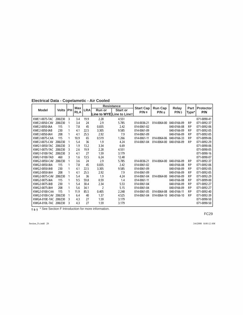
FC29
Electrical Data - Copelametic - Air Cooled
* See Section F Introduction for more information.
Max Resistance Model Volts PH RLA LRA Run or Start or Start Cap Run Cap Relay Part Protector
Line to WYE Line to Line P/N P/N P/N Type* P/N
KWE1-0075-TAC 208/230 3 3.4 19.9 2.28 4.551 071-0090-41KWE2-0050-CAV 208/230 1 3.4 24 2.9 5.785 014-0036-21 014-0064-00 040-0166-09 RP 071-0092-37KWE2-0050-IAA 115 1 7.8 45 0.835 2.42 014-0061-02 040-0166-08 RP 071-0092-06KWE2-0050-IAB 230 1 4.1 22.5 3.305 9.585 014-0061-09 040-0166-09 RP 071-0092-05KWE2-0050-IAH 208 1 4.1 25.5 2.92 7.9 014-0061-09 040-0166-09 RP 071-0092-05KWE2-0075-CAA 115 1 10.9 65 0.519 1.266 014-0061-11 014-0064-06 040-0166-33 RP 071-0099-06KWE2-0075-CAV 208/230 1 5.4 36 1.9 4.24 014-0061-04 014-0064-00 040-0166-09 RP 071-0092-29KWG1-0050-TAC 208/230 3 1.9 13.2 3.34 6.69 071-0090-06KWG1-0075-TAC 208/230 3 2.6 19.9 2.28 4.551 071-0090-05KWG1-0100-TAC 208/230 3 4.1 27 1.59 3.179 071-0090-16KWG1-0100-TAD 460 3 1.6 13.5 6.24 12.48 071-0090-07KWG2-0050-CAV 208/230 1 3.6 24 2.9 5.785 014-0036-21 014-0064-00 040-0166-09 RP 071-0092-37KWG2-0050-IAA 115 1 7.8 45 0.835 2.42 014-0061-02 040-0166-08 RP 071-0092-06KWG2-0050-IAB 230 1 4.1 22.5 3.305 9.585 014-0061-09 040-0166-09 RP 071-0092-05KWG2-0050-IAH 208 1 4.1 25.5 2.92 7.9 014-0061-09 040-0166-09 RP 071-0092-05KWG2-0075-CAV 208/230 1 5.4 36 1.9 4.24 014-0061-04 014-0064-00 040-0166-09 RP 071-0092-29KWG2-0075-IAA 115 1 9.5 59.8 0.59 1.4 014-0061-11 040-0166-08 RP 071-0099-00KWG2-0075-IAB 230 1 5.4 30.4 2.34 5.53 014-0061-04 040-0166-09 RP 071-0092-27KWG2-0075-IAH 208 1 5.6 34.1 2 5.15 014-0061-04 040-0166-09 RP 071-0092-27KWG2-0100-CAA 115 1 11.9 85.5 0.405 2.248 014-0061-05 014-0064-08 040-0166-11 RP 071-0092-40KWG2-0100-CAV 208/230 1 6.4 40 1.37 4.525 014-0061-04 014-0064-10 040-0166-10 RP 071-0092-39KWGA-010E-TAC 208/230 3 4.3 27 1.59 3.179 071-0090-50KWGA-010L-TAC 208/230 3 4.3 27 1.59 3.179 071-0090-50
Section_Fc.indd 29Section_Fc.indd 29 3/4/2008 8:00:12 AM3/4/2008 8:00:12 AM
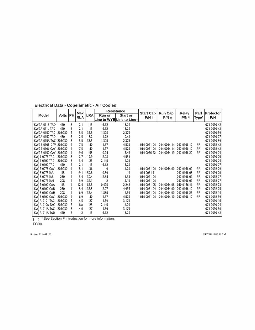
Electrical Data - Copelametic - Air Cooled
FC30 * See Section F Introduction for more information.
Max Resistance Model Volts PH RLA LRA Run or Start or Start Cap Run Cap Relay Part Protector
Line to WYE Line to Line P/N P/N P/N Type* P/N
KWGA-011E-TAD 460 3 2.1 15 6.62 13.24 071-0090-42KWGA-011L-TAD 460 3 2.1 15 6.62 13.24 071-0090-42KWGA-0150-TAC 208/230 3 5.5 35.5 1.325 2.375 071-0090-39KWGA-0150-TAD 460 3 2.5 18.2 4.72 9.44 071-0090-27KWGA-015A-TAC 208/230 3 5.5 35.5 1.325 2.375 071-0090-39KWGB-010E-CAV 208/230 1 7.5 40 1.37 4.525 014-0061-04 014-0064-14 040-0166-10 RP 071-0092-42KWGB-010L-CAV 208/230 1 7.5 40 1.37 4.525 014-0061-04 014-0064-14 040-0166-10 RP 071-0092-42KWGB-0150-CAV 208/230 1 9.6 55 0.94 3.45 014-0036-22 014-0064-19 040-0166-20 RP 071-0099-04KWJ1-0075-TAC 208/230 3 2.7 19.9 2.28 4.551 071-0090-05KWJ1-0100-TAC 208/230 3 3.4 25 2.145 4.29 071-0090-04KWJ1-0100-TAD 460 3 2.1 15 6.62 13.24 071-0090-07KWJ3-0075-CAV 208/230 1 5.1 36 1.9 4.24 014-0061-04 014-0064-00 040-0166-09 RP 071-0092-29KWJ3-0075-IAA 115 1 9.1 59.8 0.59 1.4 014-0061-11 040-0166-08 RP 071-0099-00KWJ3-0075-IAB 230 1 5.4 30.4 2.34 5.53 014-0061-04 040-0166-09 RP 071-0092-27KWJ3-0075-IAH 208 1 5.9 34.1 2 5.15 014-0061-04 040-0166-09 RP 071-0092-27KWJ3-0100-CAA 115 1 12.4 85.5 0.405 2.248 014-0061-05 014-0064-08 040-0166-11 RP 071-0092-23KWJ3-0100-CAB 230 1 5.4 33.5 2.27 4.935 014-0061-04 014-0064-00 040-0166-10 RP 071-0092-25KWJ3-0100-CAH 208 1 6.9 36.4 1.885 4.59 014-0061-04 014-0064-00 040-0166-25 RP 071-0092-14KWJ3-0100-CAV 208/230 1 6.9 40 1.37 4.525 014-0061-04 014-0064-10 040-0166-10 RP 071-0092-39KWJA-0101-TAC 208/230 3 4.5 27 1.59 3.179 071-0090-16KWJA-010A-TAC 208/230 3 NA 25 2.145 4.29 071-0090-04KWJA-011A-TAC 208/230 3 4.6 27 1.59 3.179 071-0090-50KWJA-011A-TAD 460 3 2 15 6.62 13.24 071-0090-42
Section_Fc.indd 30Section_Fc.indd 30 3/4/2008 8:00:12 AM3/4/2008 8:00:12 AM
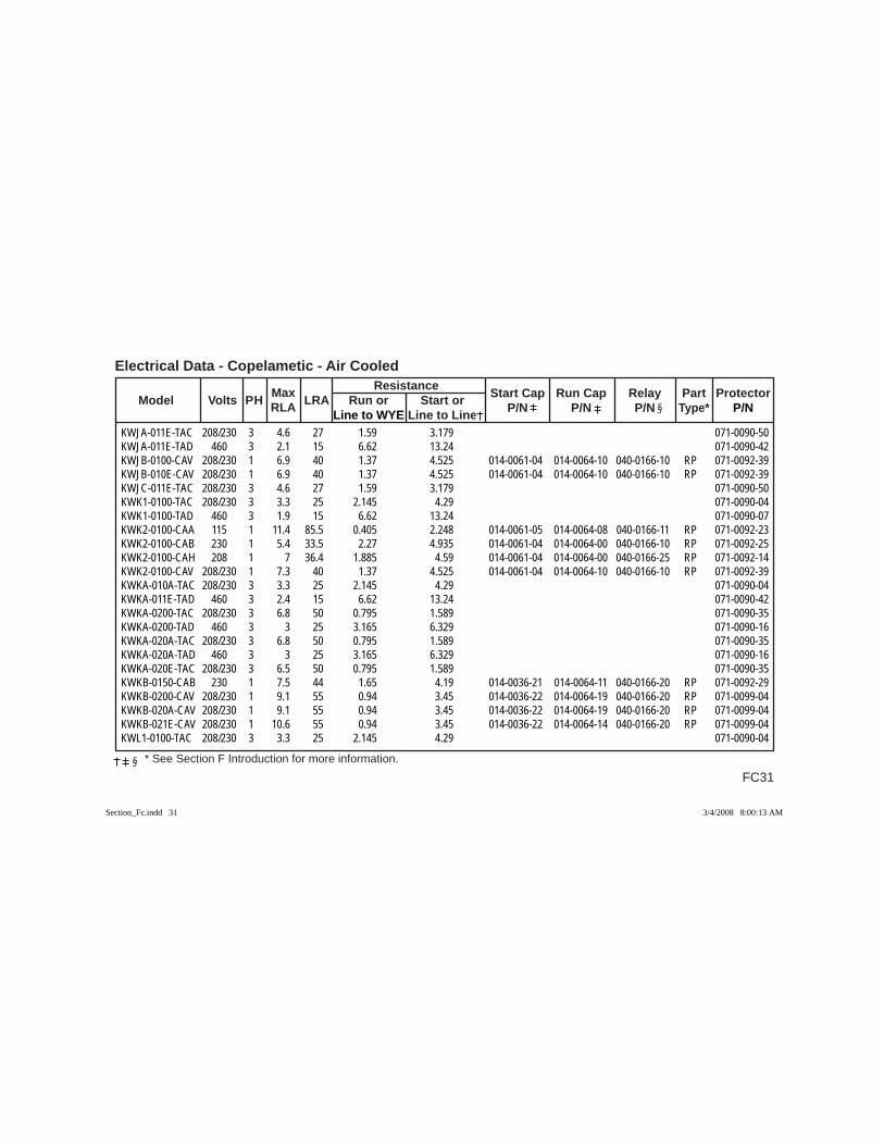
FC31
Electrical Data - Copelametic - Air Cooled
* See Section F Introduction for more information.
Max Resistance Model Volts PH RLA LRA Run or Start or Start Cap Run Cap Relay Part Protector
Line to WYE Line to Line P/N P/N P/N Type* P/N
KWJA-011E-TAC 208/230 3 4.6 27 1.59 3.179 071-0090-50KWJA-011E-TAD 460 3 2.1 15 6.62 13.24 071-0090-42KWJB-0100-CAV 208/230 1 6.9 40 1.37 4.525 014-0061-04 014-0064-10 040-0166-10 RP 071-0092-39KWJB-010E-CAV 208/230 1 6.9 40 1.37 4.525 014-0061-04 014-0064-10 040-0166-10 RP 071-0092-39KWJC-011E-TAC 208/230 3 4.6 27 1.59 3.179 071-0090-50KWK1-0100-TAC 208/230 3 3.3 25 2.145 4.29 071-0090-04KWK1-0100-TAD 460 3 1.9 15 6.62 13.24 071-0090-07KWK2-0100-CAA 115 1 11.4 85.5 0.405 2.248 014-0061-05 014-0064-08 040-0166-11 RP 071-0092-23KWK2-0100-CAB 230 1 5.4 33.5 2.27 4.935 014-0061-04 014-0064-00 040-0166-10 RP 071-0092-25KWK2-0100-CAH 208 1 7 36.4 1.885 4.59 014-0061-04 014-0064-00 040-0166-25 RP 071-0092-14KWK2-0100-CAV 208/230 1 7.3 40 1.37 4.525 014-0061-04 014-0064-10 040-0166-10 RP 071-0092-39KWKA-010A-TAC 208/230 3 3.3 25 2.145 4.29 071-0090-04KWKA-011E-TAD 460 3 2.4 15 6.62 13.24 071-0090-42KWKA-0200-TAC 208/230 3 6.8 50 0.795 1.589 071-0090-35KWKA-0200-TAD 460 3 3 25 3.165 6.329 071-0090-16KWKA-020A-TAC 208/230 3 6.8 50 0.795 1.589 071-0090-35KWKA-020A-TAD 460 3 3 25 3.165 6.329 071-0090-16KWKA-020E-TAC 208/230 3 6.5 50 0.795 1.589 071-0090-35KWKB-0150-CAB 230 1 7.5 44 1.65 4.19 014-0036-21 014-0064-11 040-0166-20 RP 071-0092-29KWKB-0200-CAV 208/230 1 9.1 55 0.94 3.45 014-0036-22 014-0064-19 040-0166-20 RP 071-0099-04KWKB-020A-CAV 208/230 1 9.1 55 0.94 3.45 014-0036-22 014-0064-19 040-0166-20 RP 071-0099-04KWKB-021E-CAV 208/230 1 10.6 55 0.94 3.45 014-0036-22 014-0064-14 040-0166-20 RP 071-0099-04KWL1-0100-TAC 208/230 3 3.3 25 2.145 4.29 071-0090-04
Section_Fc.indd 31Section_Fc.indd 31 3/4/2008 8:00:13 AM3/4/2008 8:00:13 AM
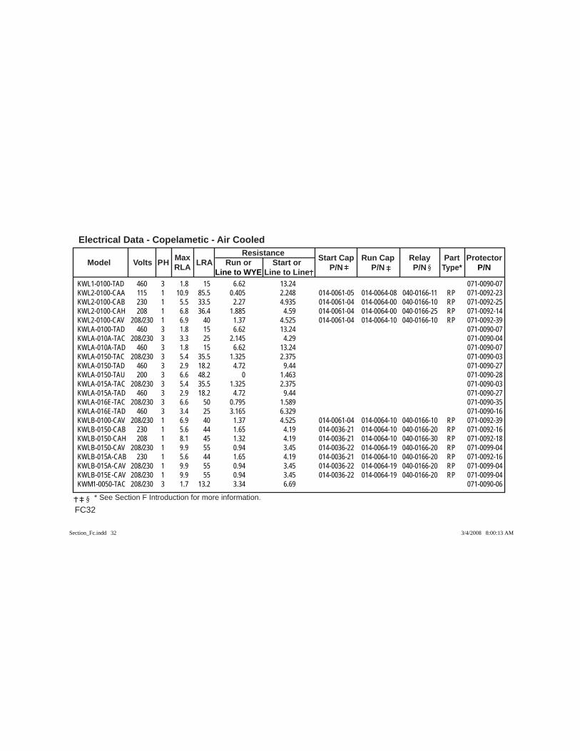
Electrical Data - Copelametic - Air Cooled
FC32 * See Section F Introduction for more information.
Max Resistance Model Volts PH RLA LRA Run or Start or Start Cap Run Cap Relay Part Protector
Line to WYE Line to Line P/N P/N P/N Type* P/N
KWL1-0100-TAD 460 3 1.8 15 6.62 13.24 071-0090-07KWL2-0100-CAA 115 1 10.9 85.5 0.405 2.248 014-0061-05 014-0064-08 040-0166-11 RP 071-0092-23KWL2-0100-CAB 230 1 5.5 33.5 2.27 4.935 014-0061-04 014-0064-00 040-0166-10 RP 071-0092-25KWL2-0100-CAH 208 1 6.8 36.4 1.885 4.59 014-0061-04 014-0064-00 040-0166-25 RP 071-0092-14KWL2-0100-CAV 208/230 1 6.9 40 1.37 4.525 014-0061-04 014-0064-10 040-0166-10 RP 071-0092-39KWLA-0100-TAD 460 3 1.8 15 6.62 13.24 071-0090-07KWLA-010A-TAC 208/230 3 3.3 25 2.145 4.29 071-0090-04KWLA-010A-TAD 460 3 1.8 15 6.62 13.24 071-0090-07KWLA-0150-TAC 208/230 3 5.4 35.5 1.325 2.375 071-0090-03KWLA-0150-TAD 460 3 2.9 18.2 4.72 9.44 071-0090-27KWLA-0150-TAU 200 3 6.6 48.2 0 1.463 071-0090-28KWLA-015A-TAC 208/230 3 5.4 35.5 1.325 2.375 071-0090-03KWLA-015A-TAD 460 3 2.9 18.2 4.72 9.44 071-0090-27KWLA-016E-TAC 208/230 3 6.6 50 0.795 1.589 071-0090-35KWLA-016E-TAD 460 3 3.4 25 3.165 6.329 071-0090-16KWLB-0100-CAV 208/230 1 6.9 40 1.37 4.525 014-0061-04 014-0064-10 040-0166-10 RP 071-0092-39KWLB-0150-CAB 230 1 5.6 44 1.65 4.19 014-0036-21 014-0064-10 040-0166-20 RP 071-0092-16KWLB-0150-CAH 208 1 8.1 45 1.32 4.19 014-0036-21 014-0064-10 040-0166-30 RP 071-0092-18KWLB-0150-CAV 208/230 1 9.9 55 0.94 3.45 014-0036-22 014-0064-19 040-0166-20 RP 071-0099-04KWLB-015A-CAB 230 1 5.6 44 1.65 4.19 014-0036-21 014-0064-10 040-0166-20 RP 071-0092-16KWLB-015A-CAV 208/230 1 9.9 55 0.94 3.45 014-0036-22 014-0064-19 040-0166-20 RP 071-0099-04KWLB-015E-CAV 208/230 1 9.9 55 0.94 3.45 014-0036-22 014-0064-19 040-0166-20 RP 071-0099-04KWM1-0050-TAC 208/230 3 1.7 13.2 3.34 6.69 071-0090-06
Section_Fc.indd 32Section_Fc.indd 32 3/4/2008 8:00:13 AM3/4/2008 8:00:13 AM
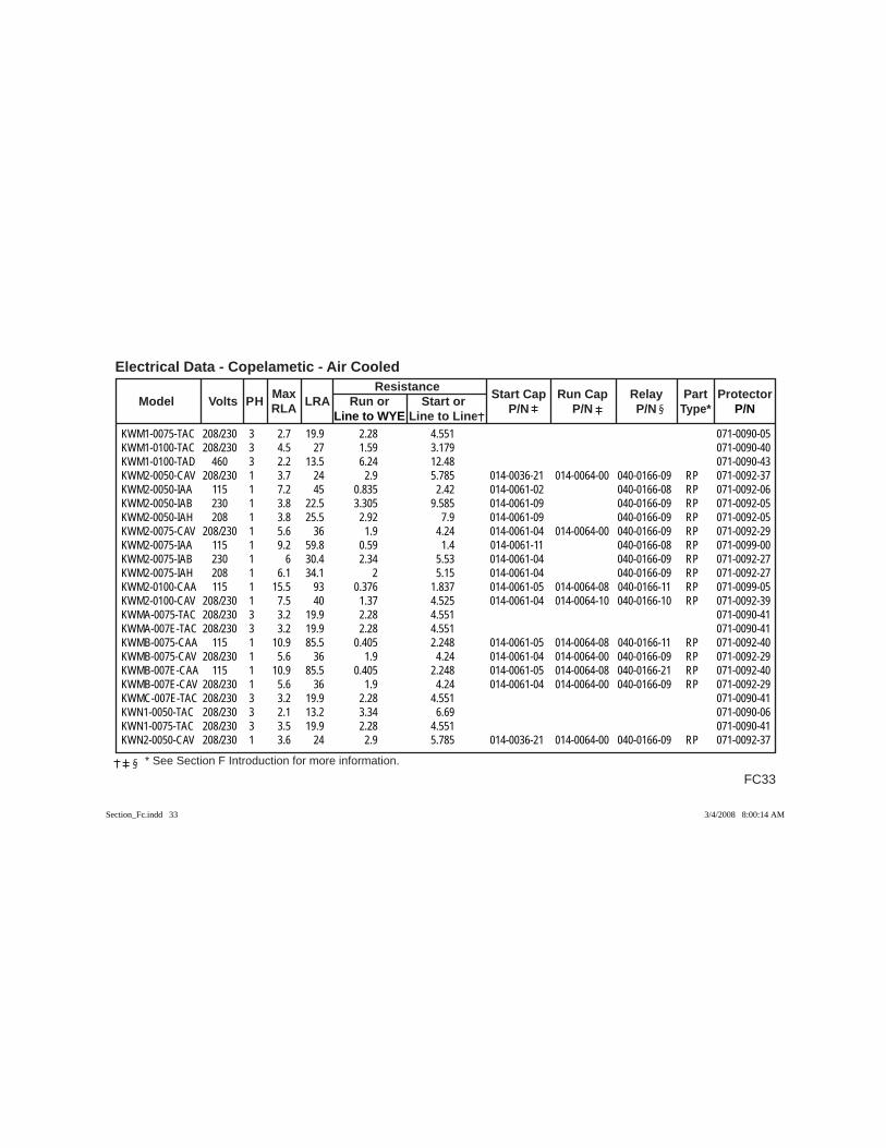
FC33
Electrical Data - Copelametic - Air Cooled
* See Section F Introduction for more information.
Max Resistance Model Volts PH RLA LRA Run or Start or Start Cap Run Cap Relay Part Protector
Line to WYE Line to Line P/N P/N P/N Type* P/N
KWM1-0075-TAC 208/230 3 2.7 19.9 2.28 4.551 071-0090-05KWM1-0100-TAC 208/230 3 4.5 27 1.59 3.179 071-0090-40KWM1-0100-TAD 460 3 2.2 13.5 6.24 12.48 071-0090-43KWM2-0050-CAV 208/230 1 3.7 24 2.9 5.785 014-0036-21 014-0064-00 040-0166-09 RP 071-0092-37KWM2-0050-IAA 115 1 7.2 45 0.835 2.42 014-0061-02 040-0166-08 RP 071-0092-06KWM2-0050-IAB 230 1 3.8 22.5 3.305 9.585 014-0061-09 040-0166-09 RP 071-0092-05KWM2-0050-IAH 208 1 3.8 25.5 2.92 7.9 014-0061-09 040-0166-09 RP 071-0092-05KWM2-0075-CAV 208/230 1 5.6 36 1.9 4.24 014-0061-04 014-0064-00 040-0166-09 RP 071-0092-29KWM2-0075-IAA 115 1 9.2 59.8 0.59 1.4 014-0061-11 040-0166-08 RP 071-0099-00KWM2-0075-IAB 230 1 6 30.4 2.34 5.53 014-0061-04 040-0166-09 RP 071-0092-27KWM2-0075-IAH 208 1 6.1 34.1 2 5.15 014-0061-04 040-0166-09 RP 071-0092-27KWM2-0100-CAA 115 1 15.5 93 0.376 1.837 014-0061-05 014-0064-08 040-0166-11 RP 071-0099-05KWM2-0100-CAV 208/230 1 7.5 40 1.37 4.525 014-0061-04 014-0064-10 040-0166-10 RP 071-0092-39KWMA-0075-TAC 208/230 3 3.2 19.9 2.28 4.551 071-0090-41KWMA-007E-TAC 208/230 3 3.2 19.9 2.28 4.551 071-0090-41KWMB-0075-CAA 115 1 10.9 85.5 0.405 2.248 014-0061-05 014-0064-08 040-0166-11 RP 071-0092-40KWMB-0075-CAV 208/230 1 5.6 36 1.9 4.24 014-0061-04 014-0064-00 040-0166-09 RP 071-0092-29KWMB-007E-CAA 115 1 10.9 85.5 0.405 2.248 014-0061-05 014-0064-08 040-0166-21 RP 071-0092-40KWMB-007E-CAV 208/230 1 5.6 36 1.9 4.24 014-0061-04 014-0064-00 040-0166-09 RP 071-0092-29KWMC-007E-TAC 208/230 3 3.2 19.9 2.28 4.551 071-0090-41KWN1-0050-TAC 208/230 3 2.1 13.2 3.34 6.69 071-0090-06KWN1-0075-TAC 208/230 3 3.5 19.9 2.28 4.551 071-0090-41KWN2-0050-CAV 208/230 1 3.6 24 2.9 5.785 014-0036-21 014-0064-00 040-0166-09 RP 071-0092-37
Section_Fc.indd 33Section_Fc.indd 33 3/4/2008 8:00:14 AM3/4/2008 8:00:14 AM
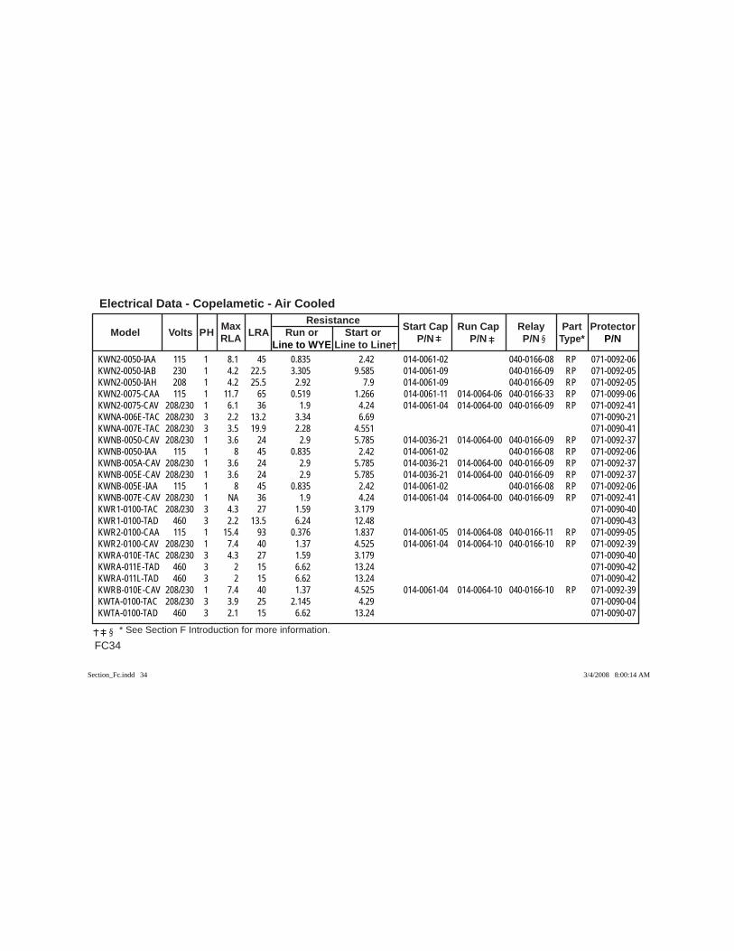
Electrical Data - Copelametic - Air Cooled
FC34 * See Section F Introduction for more information.
Max Resistance Model Volts PH RLA LRA Run or Start or Start Cap Run Cap Relay Part Protector
Line to WYE Line to Line P/N P/N P/N Type* P/N
KWN2-0050-IAA 115 1 8.1 45 0.835 2.42 014-0061-02 040-0166-08 RP 071-0092-06KWN2-0050-IAB 230 1 4.2 22.5 3.305 9.585 014-0061-09 040-0166-09 RP 071-0092-05KWN2-0050-IAH 208 1 4.2 25.5 2.92 7.9 014-0061-09 040-0166-09 RP 071-0092-05KWN2-0075-CAA 115 1 11.7 65 0.519 1.266 014-0061-11 014-0064-06 040-0166-33 RP 071-0099-06KWN2-0075-CAV 208/230 1 6.1 36 1.9 4.24 014-0061-04 014-0064-00 040-0166-09 RP 071-0092-41KWNA-006E-TAC 208/230 3 2.2 13.2 3.34 6.69 071-0090-21KWNA-007E-TAC 208/230 3 3.5 19.9 2.28 4.551 071-0090-41KWNB-0050-CAV 208/230 1 3.6 24 2.9 5.785 014-0036-21 014-0064-00 040-0166-09 RP 071-0092-37KWNB-0050-IAA 115 1 8 45 0.835 2.42 014-0061-02 040-0166-08 RP 071-0092-06KWNB-005A-CAV 208/230 1 3.6 24 2.9 5.785 014-0036-21 014-0064-00 040-0166-09 RP 071-0092-37KWNB-005E-CAV 208/230 1 3.6 24 2.9 5.785 014-0036-21 014-0064-00 040-0166-09 RP 071-0092-37KWNB-005E-IAA 115 1 8 45 0.835 2.42 014-0061-02 040-0166-08 RP 071-0092-06KWNB-007E-CAV 208/230 1 NA 36 1.9 4.24 014-0061-04 014-0064-00 040-0166-09 RP 071-0092-41KWR1-0100-TAC 208/230 3 4.3 27 1.59 3.179 071-0090-40KWR1-0100-TAD 460 3 2.2 13.5 6.24 12.48 071-0090-43KWR2-0100-CAA 115 1 15.4 93 0.376 1.837 014-0061-05 014-0064-08 040-0166-11 RP 071-0099-05KWR2-0100-CAV 208/230 1 7.4 40 1.37 4.525 014-0061-04 014-0064-10 040-0166-10 RP 071-0092-39KWRA-010E-TAC 208/230 3 4.3 27 1.59 3.179 071-0090-40KWRA-011E-TAD 460 3 2 15 6.62 13.24 071-0090-42KWRA-011L-TAD 460 3 2 15 6.62 13.24 071-0090-42KWRB-010E-CAV 208/230 1 7.4 40 1.37 4.525 014-0061-04 014-0064-10 040-0166-10 RP 071-0092-39KWTA-0100-TAC 208/230 3 3.9 25 2.145 4.29 071-0090-04KWTA-0100-TAD 460 3 2.1 15 6.62 13.24 071-0090-07
Section_Fc.indd 34Section_Fc.indd 34 3/4/2008 8:00:14 AM3/4/2008 8:00:14 AM
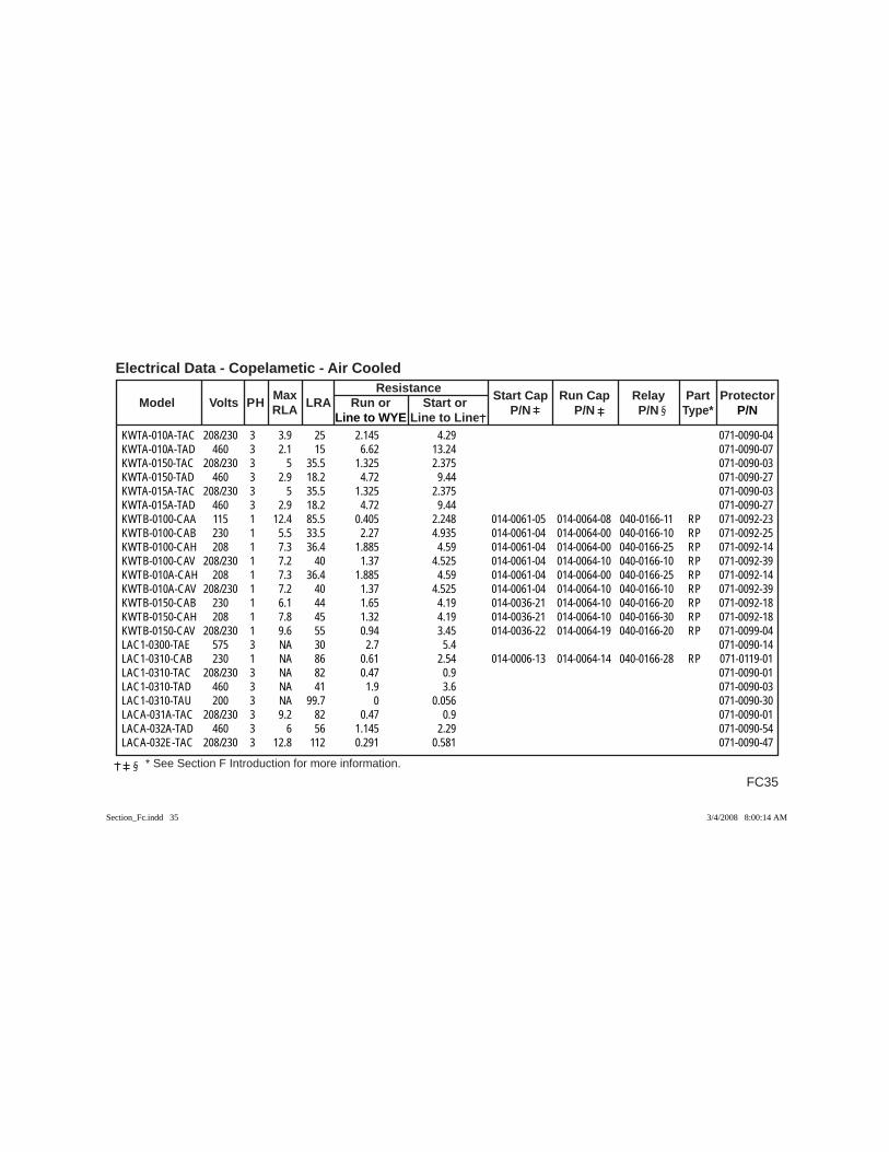
FC35
Electrical Data - Copelametic - Air Cooled
* See Section F Introduction for more information.
Max Resistance Model Volts PH RLA LRA Run or Start or Start Cap Run Cap Relay Part Protector
Line to WYE Line to Line P/N P/N P/N Type* P/N
KWTA-010A-TAC 208/230 3 3.9 25 2.145 4.29 071-0090-04KWTA-010A-TAD 460 3 2.1 15 6.62 13.24 071-0090-07KWTA-0150-TAC 208/230 3 5 35.5 1.325 2.375 071-0090-03KWTA-0150-TAD 460 3 2.9 18.2 4.72 9.44 071-0090-27KWTA-015A-TAC 208/230 3 5 35.5 1.325 2.375 071-0090-03KWTA-015A-TAD 460 3 2.9 18.2 4.72 9.44 071-0090-27KWTB-0100-CAA 115 1 12.4 85.5 0.405 2.248 014-0061-05 014-0064-08 040-0166-11 RP 071-0092-23KWTB-0100-CAB 230 1 5.5 33.5 2.27 4.935 014-0061-04 014-0064-00 040-0166-10 RP 071-0092-25KWTB-0100-CAH 208 1 7.3 36.4 1.885 4.59 014-0061-04 014-0064-00 040-0166-25 RP 071-0092-14KWTB-0100-CAV 208/230 1 7.2 40 1.37 4.525 014-0061-04 014-0064-10 040-0166-10 RP 071-0092-39KWTB-010A-CAH 208 1 7.3 36.4 1.885 4.59 014-0061-04 014-0064-00 040-0166-25 RP 071-0092-14KWTB-010A-CAV 208/230 1 7.2 40 1.37 4.525 014-0061-04 014-0064-10 040-0166-10 RP 071-0092-39KWTB-0150-CAB 230 1 6.1 44 1.65 4.19 014-0036-21 014-0064-10 040-0166-20 RP 071-0092-18KWTB-0150-CAH 208 1 7.8 45 1.32 4.19 014-0036-21 014-0064-10 040-0166-30 RP 071-0092-18KWTB-0150-CAV 208/230 1 9.6 55 0.94 3.45 014-0036-22 014-0064-19 040-0166-20 RP 071-0099-04LAC1-0300-TAE 575 3 NA 30 2.7 5.4 071-0090-14LAC1-0310-CAB 230 1 NA 86 0.61 2.54 014-0006-13 014-0064-14 040-0166-28 RP 071-0119-01LAC1-0310-TAC 208/230 3 NA 82 0.47 0.9 071-0090-01LAC1-0310-TAD 460 3 NA 41 1.9 3.6 071-0090-03LAC1-0310-TAU 200 3 NA 99.7 0 0.056 071-0090-30LACA-031A-TAC 208/230 3 9.2 82 0.47 0.9 071-0090-01LACA-032A-TAD 460 3 6 56 1.145 2.29 071-0090-54LACA-032E-TAC 208/230 3 12.8 112 0.291 0.581 071-0090-47
Section_Fc.indd 35Section_Fc.indd 35 3/4/2008 8:00:14 AM3/4/2008 8:00:14 AM
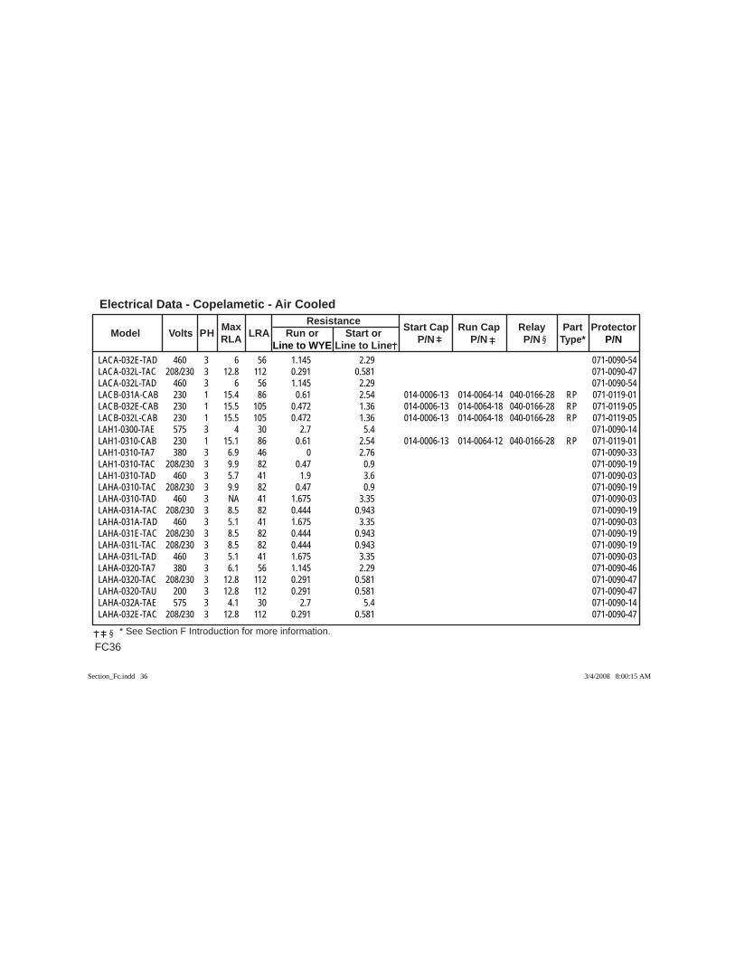
Electrical Data - Copelametic - Air Cooled
FC36 * See Section F Introduction for more information.
Max Resistance Model Volts PH RLA LRA Run or Start or Start Cap Run Cap Relay Part Protector
Line to WYE Line to Line P/N P/N P/N Type* P/N
LACA-032E-TAD 460 3 6 56 1.145 2.29 071-0090-54LACA-032L-TAC 208/230 3 12.8 112 0.291 0.581 071-0090-47LACA-032L-TAD 460 3 6 56 1.145 2.29 071-0090-54LACB-031A-CAB 230 1 15.4 86 0.61 2.54 014-0006-13 014-0064-14 040-0166-28 RP 071-0119-01LACB-032E-CAB 230 1 15.5 105 0.472 1.36 014-0006-13 014-0064-18 040-0166-28 RP 071-0119-05LACB-032L-CAB 230 1 15.5 105 0.472 1.36 014-0006-13 014-0064-18 040-0166-28 RP 071-0119-05LAH1-0300-TAE 575 3 4 30 2.7 5.4 071-0090-14LAH1-0310-CAB 230 1 15.1 86 0.61 2.54 014-0006-13 014-0064-12 040-0166-28 RP 071-0119-01LAH1-0310-TA7 380 3 6.9 46 0 2.76 071-0090-33LAH1-0310-TAC 208/230 3 9.9 82 0.47 0.9 071-0090-19LAH1-0310-TAD 460 3 5.7 41 1.9 3.6 071-0090-03LAHA-0310-TAC 208/230 3 9.9 82 0.47 0.9 071-0090-19LAHA-0310-TAD 460 3 NA 41 1.675 3.35 071-0090-03LAHA-031A-TAC 208/230 3 8.5 82 0.444 0.943 071-0090-19LAHA-031A-TAD 460 3 5.1 41 1.675 3.35 071-0090-03LAHA-031E-TAC 208/230 3 8.5 82 0.444 0.943 071-0090-19LAHA-031L-TAC 208/230 3 8.5 82 0.444 0.943 071-0090-19LAHA-031L-TAD 460 3 5.1 41 1.675 3.35 071-0090-03LAHA-0320-TA7 380 3 6.1 56 1.145 2.29 071-0090-46LAHA-0320-TAC 208/230 3 12.8 112 0.291 0.581 071-0090-47LAHA-0320-TAU 200 3 12.8 112 0.291 0.581 071-0090-47LAHA-032A-TAE 575 3 4.1 30 2.7 5.4 071-0090-14LAHA-032E-TAC 208/230 3 12.8 112 0.291 0.581 071-0090-47
Section_Fc.indd 36Section_Fc.indd 36 3/4/2008 8:00:15 AM3/4/2008 8:00:15 AM

FC37
Electrical Data - Copelametic - Air Cooled
* See Section F Introduction for more information.
Max Resistance Model Volts PH RLA LRA Run or Start or Start Cap Run Cap Relay Part Protector
Line to WYE Line to Line P/N P/N P/N Type* P/N
LAHA-032E-TAD 460 3 6 56 1.145 2.29 071-0090-54LAHA-032E-TAE 575 3 4.1 30 2.7 5.4 071-0090-14LAHA-032L-TAC 208/230 3 12.8 112 0.291 0.581 071-0090-47LAHA-032L-TAD 460 3 6 56 1.145 2.29 071-0090-54LAHA-032L-TAE 575 3 4.1 30 2.7 5.4 071-0090-14LAHB-0311-CAB 230 1 16.6 93 0.574 1.899 014-0006-13 014-0064-14 040-0166-28 RP 071-0119-05LAHB-031A-CAB 230 1 16.6 93 0.574 1.899 014-0006-13 014-0064-14 040-0166-28 RP 071-0119-05LAHB-031E-CAB 230 1 16.6 93 0.574 1.899 014-0006-13 014-0064-14 040-0166-28 RP 071-0119-05LAHB-031L-CAB 230 1 16.6 93 0.574 1.899 014-0006-13 014-0064-14 040-0166-28 RP 071-0119-05LAHB-032E-CAB 230 1 16.7 105 0.472 1.36 014-0006-13 014-0064-18 040-0166-28 RP 071-0119-05LAHB-032L-CAB 230 1 16.7 105 0.472 1.36 014-0006-13 014-0064-18 040-0166-28 RP 071-0119-05LAL1-0300-TAE 575 3 NA 30 2.7 5.4 071-0090-14LAL1-0310-CAB 230 1 NA 86 0.61 2.54 014-0006-13 014-0064-14 040-0166-28 RP 071-0119-01LAL1-0310-TAC 208/230 3 NA 82 0.47 0.9 071-0090-18LAL1-0310-TAD 460 3 NA 41 1.9 3.6 071-0090-03LAL1-031L-TAC 208/230 3 10.9 82 0.47 0.9 071-0090-18LAL1-031L-TAD 460 3 5 41 1.9 3.6 071-0090-03LALA-031A-TAC 208/230 3 10.9 82 0.47 0.9 071-0090-18LALA-032E-FXX 55 3 NA 320 0 0.12 LALA-032E-TAC 208/230 3 12.6 112 0.291 0.581 071-0090-47LALA-032E-TAD 460 3 6.2 56 1.145 2.29 071-0090-46LALA-032L-TAC 208/230 3 12.6 112 0.291 0.581 071-0090-47LALA-032L-TAD 460 3 6.2 56 1.145 2.29 071-0090-46
Section_Fc.indd 37Section_Fc.indd 37 3/4/2008 8:00:15 AM3/4/2008 8:00:15 AM
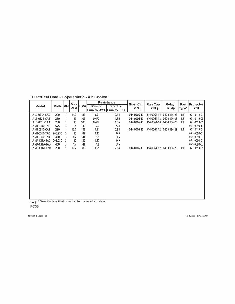
Electrical Data - Copelametic - Air Cooled
FC38 * See Section F Introduction for more information.
Max Resistance Model Volts PH RLA LRA Run or Start or Start Cap Run Cap Relay Part Protector
Line to WYE Line to Line P/N P/N P/N Type* P/N
LALB-031A-CAB 230 1 14.2 86 0.61 2.54 014-0006-13 014-0064-14 040-0166-28 RP 071-0119-01LALB-032E-CAB 230 1 15 105 0.472 1.36 014-0006-13 014-0064-18 040-0166-28 RP 071-0119-05LALB-032L-CAB 230 1 15 105 0.472 1.36 014-0006-13 014-0064-18 040-0166-28 RP 071-0119-05LAM1-0300-TAE 575 3 4 30 2.7 5.4 071-0090-13LAM1-0310-CAB 230 1 12.7 86 0.61 2.54 014-0006-13 014-0064-12 040-0166-28 RP 071-0119-01LAM1-0310-TAC 208/230 3 10 82 0.47 0.9 071-0090-01LAM1-0310-TAD 460 3 4.7 41 1.9 3.6 071-0090-03LAMA-031A-TAC 208/230 3 10 82 0.47 0.9 071-0090-01LAMA-031A-TAD 460 3 4.7 41 1.9 3.6 071-0090-03LAMB-031A-CAB 230 1 12.7 86 0.61 2.54 014-0006-13 014-0064-12 040-0166-28 RP 071-0119-01
Section_Fc.indd 38Section_Fc.indd 38 3/4/2008 8:00:16 AM3/4/2008 8:00:16 AM

FD1
Electrical Data - Copelametic Small Refrigerant-Cooled Compressors
* See Section F Introduction for more information.
Model Volts PH RLA LRA Resistance
Start Cap Run Cap Relay Part Protector Max Start or Run or P/N P/N P/N Type* P/N Line to Line Line to WYE
2DA3-060E-TFE 575 3 9.1 49 3.714 0 071-0429-182DA3F23K0-TFC 208/230 3 28.8 161 0.419 0 071-0429-082DA3F23K0-TFD 460 3 9.7 60 2.382 0 071-0429-102DA3F23K0-TFE 575 3 9.1 49 3.714 0 071-0429-182DA3F23KE-TFC 208/230 3 28.8 161 0.419 0 071-0429-082DA3F23KE-TFD 460 3 9.7 60 2.382 0 071-0429-102DA3F23KE-TFE 575 3 9.1 49 3.714 0 071-0429-182DA3F23KL-TFC 208/230 3 28.8 161 0.419 0 071-0429-082DA3F23KL-TFD 460 3 9.7 60 2.382 0 071-0429-102DA3F23KL-TFE 575 3 9.1 49 3.714 0 071-0429-182DA3R58K0-TFC 208/230 3 22.3 120 0.595 0 071-0429-022DA3R58K0-TFD 460 3 10.4 60 2.382 0 071-0429-102DA3R89K0-TFC 208/230 3 32 169 0.386 0 071-0429-082DA3R89K0-TFD 460 3 14.1 85 1.508 0 071-0429-052DA3R89K0-TFE 575 3 13.3 67 2.518 0 071-0429-252DA3R89KE-TFC 208/230 3 32 169 0.386 0 071-0429-082DA3R89KE-TFD 460 3 14.1 85 1.508 0 071-0429-052DA3R89KE-TFE 575 3 13.3 67 2.518 0 071-0429-252DA3R89KL-TFC 208/230 3 32 169 0.386 0 071-0429-082DA3R89KL-TFD 460 3 14.1 85 1.508 0 071-0429-052DA3R89KL-TFE 575 3 13.3 67 2.518 0 071-0429-252DA8F23KE-TFD 460 3 9.7 60 2.382 0 071-0429-102DB3F25K0-TFC 208/230 3 28.2 161 0.419 0 071-0429-08
Section_Fd.indd 1Section_Fd.indd 1 3/4/2008 8:02:47 AM3/4/2008 8:02:47 AM
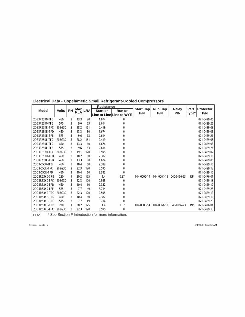
FD2 * See Section F Introduction for more information.
Electrical Data - Copelametic Small Refrigerant-Cooled Compressors
Model Volts PH RLA LRA Resistance
Start Cap Run Cap Relay Part Protector Max Start or Run or P/N P/N P/N Type* P/N Line to Line Line to WYE
2DB3F25K0-TFD 460 3 13.3 80 1.674 0 071-0429-052DB3F25K0-TFE 575 3 9.6 63 2.614 0 071-0429-262DB3F25KE-TFC 208/230 3 28.2 161 0.419 0 071-0429-082DB3F25KE-TFD 460 3 13.3 80 1.674 0 071-0429-052DB3F25KE-TFE 575 3 9.6 63 2.614 0 071-0429-262DB3F25KL-TFC 208/230 3 28.2 161 0.419 0 071-0429-082DB3F25KL-TFD 460 3 13.3 80 1.674 0 071-0429-052DB3F25KL-TFE 575 3 9.6 63 2.614 0 071-0429-262DB3R61K0-TFC 208/230 3 19.1 120 0.595 0 071-0429-022DB3R61K0-TFD 460 3 10.2 60 2.382 0 071-0429-102DB8F25KE-TFD 460 3 13.3 80 1.674 0 071-0429-052DC3-0500-TFD 460 3 10.4 60 2.382 0 071-0429-102DC3-050E-TFC 208/230 3 22.3 120 0.595 0 071-0429-132DC3-050E-TFD 460 3 10.4 60 2.382 0 071-0429-102DC3R53K0-CFB 230 1 30.2 125 1.4 0.37 014-0006-14 014-0064-18 040-0166-23 RP 071-0476-012DC3R53K0-TFC 208/230 3 22.3 120 0.595 0 071-0429-132DC3R53K0-TFD 460 3 10.4 60 2.382 0 071-0429-102DC3R53K0-TFE 575 3 7.7 49 3.714 0 071-0429-232DC3R53KE-TFC 208/230 3 22.3 120 0.595 0 071-0429-132DC3R53KE-TFD 460 3 10.4 60 2.382 0 071-0429-102DC3R53KE-TFE 575 3 7.7 49 3.714 0 071-0429-232DC3R53KL-CFB 230 1 30.2 125 1.4 0.37 014-0006-14 014-0064-18 040-0166-23 RP 071-0476-012DC3R53KL-TFC 208/230 3 22.3 120 0.595 0 071-0429-13
Section_Fd.indd 2Section_Fd.indd 2 3/4/2008 8:02:52 AM3/4/2008 8:02:52 AM
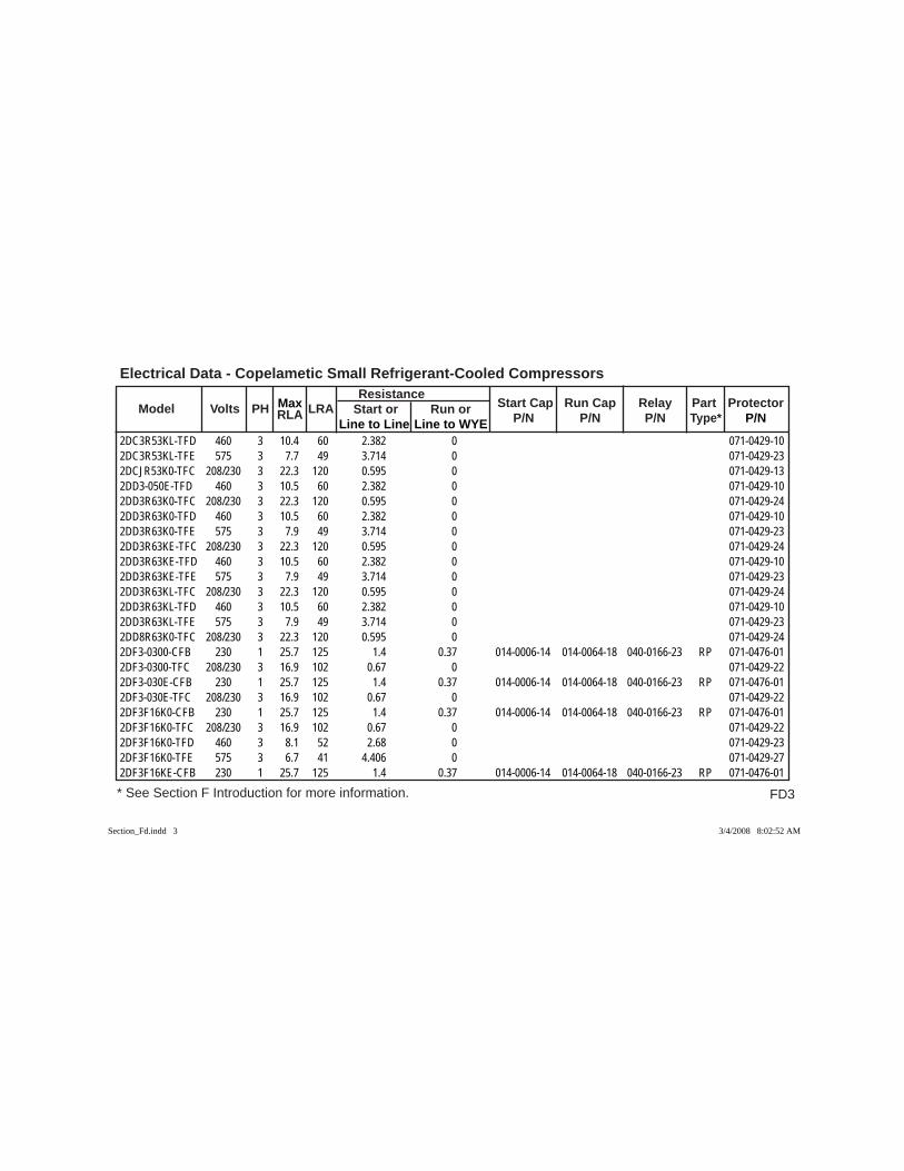
FD3
Electrical Data - Copelametic Small Refrigerant-Cooled Compressors
* See Section F Introduction for more information.
Model Volts PH RLA LRA Resistance
Start Cap Run Cap Relay Part Protector Max Start or Run or P/N P/N P/N Type* P/N Line to Line Line to WYE
2DC3R53KL-TFD 460 3 10.4 60 2.382 0 071-0429-102DC3R53KL-TFE 575 3 7.7 49 3.714 0 071-0429-232DCJR53K0-TFC 208/230 3 22.3 120 0.595 0 071-0429-132DD3-050E-TFD 460 3 10.5 60 2.382 0 071-0429-102DD3R63K0-TFC 208/230 3 22.3 120 0.595 0 071-0429-242DD3R63K0-TFD 460 3 10.5 60 2.382 0 071-0429-102DD3R63K0-TFE 575 3 7.9 49 3.714 0 071-0429-232DD3R63KE-TFC 208/230 3 22.3 120 0.595 0 071-0429-242DD3R63KE-TFD 460 3 10.5 60 2.382 0 071-0429-102DD3R63KE-TFE 575 3 7.9 49 3.714 0 071-0429-232DD3R63KL-TFC 208/230 3 22.3 120 0.595 0 071-0429-242DD3R63KL-TFD 460 3 10.5 60 2.382 0 071-0429-102DD3R63KL-TFE 575 3 7.9 49 3.714 0 071-0429-232DD8R63K0-TFC 208/230 3 22.3 120 0.595 0 071-0429-242DF3-0300-CFB 230 1 25.7 125 1.4 0.37 014-0006-14 014-0064-18 040-0166-23 RP 071-0476-012DF3-0300-TFC 208/230 3 16.9 102 0.67 0 071-0429-222DF3-030E-CFB 230 1 25.7 125 1.4 0.37 014-0006-14 014-0064-18 040-0166-23 RP 071-0476-012DF3-030E-TFC 208/230 3 16.9 102 0.67 0 071-0429-222DF3F16K0-CFB 230 1 25.7 125 1.4 0.37 014-0006-14 014-0064-18 040-0166-23 RP 071-0476-012DF3F16K0-TFC 208/230 3 16.9 102 0.67 0 071-0429-222DF3F16K0-TFD 460 3 8.1 52 2.68 0 071-0429-232DF3F16K0-TFE 575 3 6.7 41 4.406 0 071-0429-272DF3F16KE-CFB 230 1 25.7 125 1.4 0.37 014-0006-14 014-0064-18 040-0166-23 RP 071-0476-01
Section_Fd.indd 3Section_Fd.indd 3 3/4/2008 8:02:52 AM3/4/2008 8:02:52 AM

FD4 * See Section F Introduction for more information.
Electrical Data - Copelametic Small Refrigerant-Cooled Compressors
Model Volts PH RLA LRA Resistance
Start Cap Run Cap Relay Part Protector Max Start or Run or P/N P/N P/N Type* P/N Line to Line Line to WYE
2DF3F16KE-TFC 208/230 3 16.9 102 0.67 0 071-0429-222DF3F16KE-TFD 460 3 8.1 52 2.68 0 071-0429-232DF3F16KE-TFE 575 3 6.7 41 4.406 0 071-0429-272DF3F16KL-TFC 208/230 3 16.9 102 0.67 0 071-0429-222DF3F16KL-TFD 460 3 8.1 52 2.68 0 071-0429-232DF3F16KL-TFE 575 3 6.7 41 4.406 0 071-0429-272DL3-075E-TFC 208/230 3 31.6 169 0.386 0 071-0429-082DL3F20K0-TFC 208/230 3 26.3 161 0.419 0 071-0429-082DL3F20K0-TFD 460 3 8.7 60 2.382 0 071-0429-102DL3F20K0-TFE 575 3 7.7 49 3.714 0 071-0429-232DL3F20KE-TFC 208/230 3 26.3 161 0.419 0 071-0429-082DL3F20KE-TFD 460 3 8.7 60 2.382 0 071-0429-102DL3F20KE-TFE 575 3 7.7 49 3.714 0 071-0429-232DL3F20KL-TFC 208/230 3 26.3 161 0.419 0 071-0429-082DL3F20KL-TFD 460 3 8.7 60 2.382 0 071-0429-102DL3F20KL-TFE 575 3 7.7 49 3.714 0 071-0429-232DL3R78K0-TFC 208/230 3 31.6 169 0.386 0 071-0429-082DL3R78K0-TFD 460 3 13.9 85 1.508 0 071-0429-052DL3R78K0-TFE 575 3 13.2 67 2.518 0 071-0429-252DL3R78KE-TFC 208/230 3 31.6 169 0.386 0 071-0429-082DL3R78KE-TFD 460 3 13.9 85 1.508 0 071-0429-052DL3R78KE-TFE 575 3 13.2 67 2.518 0 071-0429-252DL3R78KL-TFC 208/230 3 31.6 169 0.386 0 071-0429-08
Section_Fd.indd 4Section_Fd.indd 4 3/4/2008 8:02:52 AM3/4/2008 8:02:52 AM
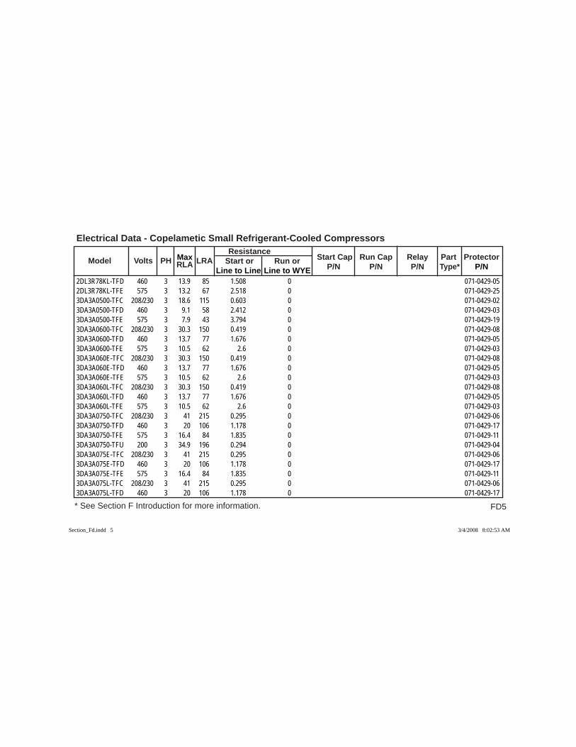
FD5
Electrical Data - Copelametic Small Refrigerant-Cooled Compressors
* See Section F Introduction for more information.
Model Volts PH RLA LRA Resistance
Start Cap Run Cap Relay Part Protector Max Start or Run or P/N P/N P/N Type* P/N Line to Line Line to WYE
2DL3R78KL-TFD 460 3 13.9 85 1.508 0 071-0429-052DL3R78KL-TFE 575 3 13.2 67 2.518 0 071-0429-253DA3A0500-TFC 208/230 3 18.6 115 0.603 0 071-0429-023DA3A0500-TFD 460 3 9.1 58 2.412 0 071-0429-033DA3A0500-TFE 575 3 7.9 43 3.794 0 071-0429-193DA3A0600-TFC 208/230 3 30.3 150 0.419 0 071-0429-083DA3A0600-TFD 460 3 13.7 77 1.676 0 071-0429-053DA3A0600-TFE 575 3 10.5 62 2.6 0 071-0429-033DA3A060E-TFC 208/230 3 30.3 150 0.419 0 071-0429-083DA3A060E-TFD 460 3 13.7 77 1.676 0 071-0429-053DA3A060E-TFE 575 3 10.5 62 2.6 0 071-0429-033DA3A060L-TFC 208/230 3 30.3 150 0.419 0 071-0429-083DA3A060L-TFD 460 3 13.7 77 1.676 0 071-0429-053DA3A060L-TFE 575 3 10.5 62 2.6 0 071-0429-033DA3A0750-TFC 208/230 3 41 215 0.295 0 071-0429-063DA3A0750-TFD 460 3 20 106 1.178 0 071-0429-173DA3A0750-TFE 575 3 16.4 84 1.835 0 071-0429-113DA3A0750-TFU 200 3 34.9 196 0.294 0 071-0429-043DA3A075E-TFC 208/230 3 41 215 0.295 0 071-0429-063DA3A075E-TFD 460 3 20 106 1.178 0 071-0429-173DA3A075E-TFE 575 3 16.4 84 1.835 0 071-0429-113DA3A075L-TFC 208/230 3 41 215 0.295 0 071-0429-063DA3A075L-TFD 460 3 20 106 1.178 0 071-0429-17
Section_Fd.indd 5Section_Fd.indd 5 3/4/2008 8:02:53 AM3/4/2008 8:02:53 AM
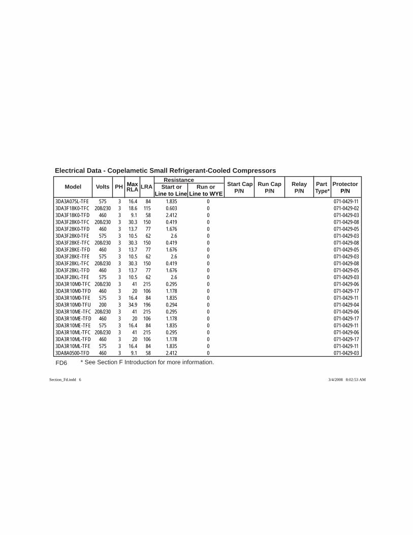
FD6 * See Section F Introduction for more information.
Electrical Data - Copelametic Small Refrigerant-Cooled Compressors
Model Volts PH RLA LRA Resistance
Start Cap Run Cap Relay Part Protector Max Start or Run or P/N P/N P/N Type* P/N Line to Line Line to WYE
3DA3A075L-TFE 575 3 16.4 84 1.835 0 071-0429-113DA3F18K0-TFC 208/230 3 18.6 115 0.603 0 071-0429-023DA3F18K0-TFD 460 3 9.1 58 2.412 0 071-0429-033DA3F28K0-TFC 208/230 3 30.3 150 0.419 0 071-0429-083DA3F28K0-TFD 460 3 13.7 77 1.676 0 071-0429-053DA3F28K0-TFE 575 3 10.5 62 2.6 0 071-0429-033DA3F28KE-TFC 208/230 3 30.3 150 0.419 0 071-0429-083DA3F28KE-TFD 460 3 13.7 77 1.676 0 071-0429-053DA3F28KE-TFE 575 3 10.5 62 2.6 0 071-0429-033DA3F28KL-TFC 208/230 3 30.3 150 0.419 0 071-0429-083DA3F28KL-TFD 460 3 13.7 77 1.676 0 071-0429-053DA3F28KL-TFE 575 3 10.5 62 2.6 0 071-0429-033DA3R10M0-TFC 208/230 3 41 215 0.295 0 071-0429-063DA3R10M0-TFD 460 3 20 106 1.178 0 071-0429-173DA3R10M0-TFE 575 3 16.4 84 1.835 0 071-0429-113DA3R10M0-TFU 200 3 34.9 196 0.294 0 071-0429-043DA3R10ME-TFC 208/230 3 41 215 0.295 0 071-0429-063DA3R10ME-TFD 460 3 20 106 1.178 0 071-0429-173DA3R10ME-TFE 575 3 16.4 84 1.835 0 071-0429-113DA3R10ML-TFC 208/230 3 41 215 0.295 0 071-0429-063DA3R10ML-TFD 460 3 20 106 1.178 0 071-0429-173DA3R10ML-TFE 575 3 16.4 84 1.835 0 071-0429-113DA8A0500-TFD 460 3 9.1 58 2.412 0 071-0429-03
Section_Fd.indd 6Section_Fd.indd 6 3/4/2008 8:02:53 AM3/4/2008 8:02:53 AM
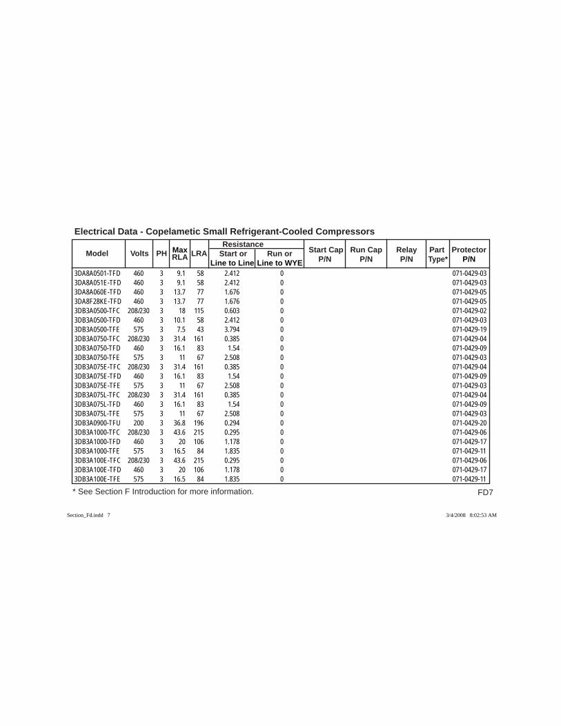
FD7
Electrical Data - Copelametic Small Refrigerant-Cooled Compressors
* See Section F Introduction for more information.
Model Volts PH RLA LRA Resistance
Start Cap Run Cap Relay Part Protector Max Start or Run or P/N P/N P/N Type* P/N Line to Line Line to WYE
3DA8A0501-TFD 460 3 9.1 58 2.412 0 071-0429-033DA8A051E-TFD 460 3 9.1 58 2.412 0 071-0429-033DA8A060E-TFD 460 3 13.7 77 1.676 0 071-0429-053DA8F28KE-TFD 460 3 13.7 77 1.676 0 071-0429-053DB3A0500-TFC 208/230 3 18 115 0.603 0 071-0429-023DB3A0500-TFD 460 3 10.1 58 2.412 0 071-0429-033DB3A0500-TFE 575 3 7.5 43 3.794 0 071-0429-193DB3A0750-TFC 208/230 3 31.4 161 0.385 0 071-0429-043DB3A0750-TFD 460 3 16.1 83 1.54 0 071-0429-093DB3A0750-TFE 575 3 11 67 2.508 0 071-0429-033DB3A075E-TFC 208/230 3 31.4 161 0.385 0 071-0429-043DB3A075E-TFD 460 3 16.1 83 1.54 0 071-0429-093DB3A075E-TFE 575 3 11 67 2.508 0 071-0429-033DB3A075L-TFC 208/230 3 31.4 161 0.385 0 071-0429-043DB3A075L-TFD 460 3 16.1 83 1.54 0 071-0429-093DB3A075L-TFE 575 3 11 67 2.508 0 071-0429-033DB3A0900-TFU 200 3 36.8 196 0.294 0 071-0429-203DB3A1000-TFC 208/230 3 43.6 215 0.295 0 071-0429-063DB3A1000-TFD 460 3 20 106 1.178 0 071-0429-173DB3A1000-TFE 575 3 16.5 84 1.835 0 071-0429-113DB3A100E-TFC 208/230 3 43.6 215 0.295 0 071-0429-063DB3A100E-TFD 460 3 20 106 1.178 0 071-0429-173DB3A100E-TFE 575 3 16.5 84 1.835 0 071-0429-11
Section_Fd.indd 7Section_Fd.indd 7 3/4/2008 8:02:53 AM3/4/2008 8:02:53 AM
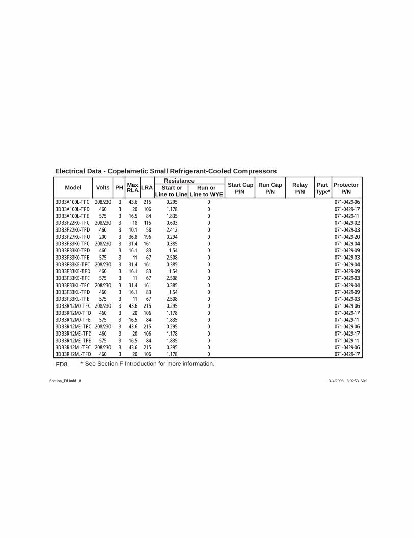
FD8 * See Section F Introduction for more information.
Electrical Data - Copelametic Small Refrigerant-Cooled Compressors
Model Volts PH RLA LRA Resistance
Start Cap Run Cap Relay Part Protector Max Start or Run or P/N P/N P/N Type* P/N Line to Line Line to WYE
3DB3A100L-TFC 208/230 3 43.6 215 0.295 0 071-0429-063DB3A100L-TFD 460 3 20 106 1.178 0 071-0429-173DB3A100L-TFE 575 3 16.5 84 1.835 0 071-0429-113DB3F22K0-TFC 208/230 3 18 115 0.603 0 071-0429-023DB3F22K0-TFD 460 3 10.1 58 2.412 0 071-0429-033DB3F27K0-TFU 200 3 36.8 196 0.294 0 071-0429-203DB3F33K0-TFC 208/230 3 31.4 161 0.385 0 071-0429-043DB3F33K0-TFD 460 3 16.1 83 1.54 0 071-0429-093DB3F33K0-TFE 575 3 11 67 2.508 0 071-0429-033DB3F33KE-TFC 208/230 3 31.4 161 0.385 0 071-0429-043DB3F33KE-TFD 460 3 16.1 83 1.54 0 071-0429-093DB3F33KE-TFE 575 3 11 67 2.508 0 071-0429-033DB3F33KL-TFC 208/230 3 31.4 161 0.385 0 071-0429-043DB3F33KL-TFD 460 3 16.1 83 1.54 0 071-0429-093DB3F33KL-TFE 575 3 11 67 2.508 0 071-0429-033DB3R12M0-TFC 208/230 3 43.6 215 0.295 0 071-0429-063DB3R12M0-TFD 460 3 20 106 1.178 0 071-0429-173DB3R12M0-TFE 575 3 16.5 84 1.835 0 071-0429-113DB3R12ME-TFC 208/230 3 43.6 215 0.295 0 071-0429-063DB3R12ME-TFD 460 3 20 106 1.178 0 071-0429-173DB3R12ME-TFE 575 3 16.5 84 1.835 0 071-0429-113DB3R12ML-TFC 208/230 3 43.6 215 0.295 0 071-0429-063DB3R12ML-TFD 460 3 20 106 1.178 0 071-0429-17
Section_Fd.indd 8Section_Fd.indd 8 3/4/2008 8:02:53 AM3/4/2008 8:02:53 AM
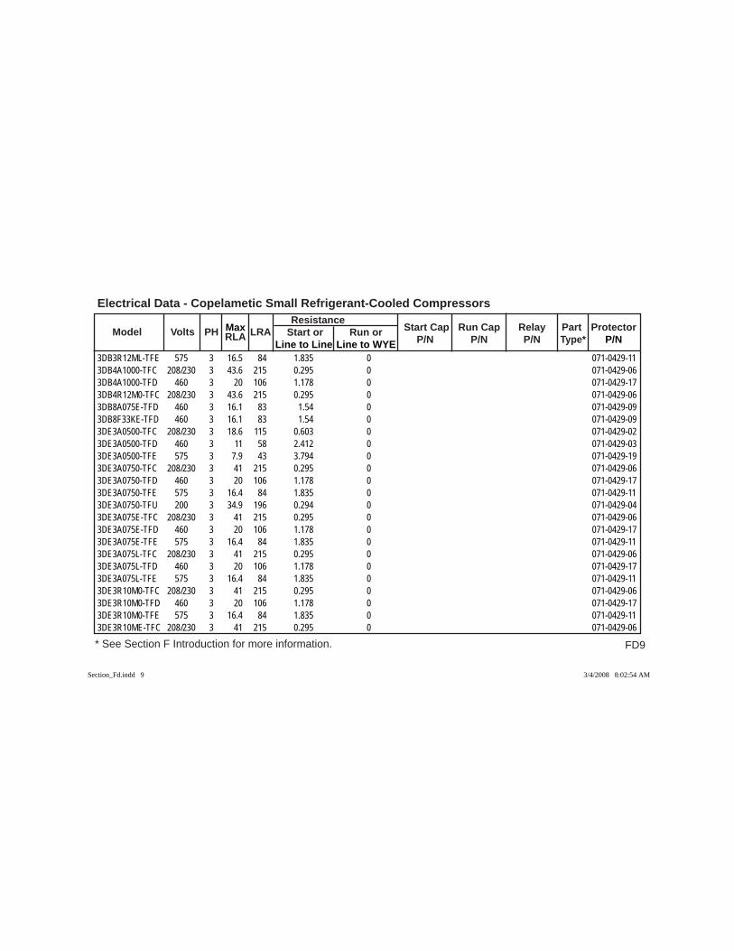
FD9
Electrical Data - Copelametic Small Refrigerant-Cooled Compressors
* See Section F Introduction for more information.
Model Volts PH RLA LRA Resistance
Start Cap Run Cap Relay Part Protector Max Start or Run or P/N P/N P/N Type* P/N Line to Line Line to WYE
3DB3R12ML-TFE 575 3 16.5 84 1.835 0 071-0429-113DB4A1000-TFC 208/230 3 43.6 215 0.295 0 071-0429-063DB4A1000-TFD 460 3 20 106 1.178 0 071-0429-173DB4R12M0-TFC 208/230 3 43.6 215 0.295 0 071-0429-063DB8A075E-TFD 460 3 16.1 83 1.54 0 071-0429-093DB8F33KE-TFD 460 3 16.1 83 1.54 0 071-0429-093DE3A0500-TFC 208/230 3 18.6 115 0.603 0 071-0429-023DE3A0500-TFD 460 3 11 58 2.412 0 071-0429-033DE3A0500-TFE 575 3 7.9 43 3.794 0 071-0429-193DE3A0750-TFC 208/230 3 41 215 0.295 0 071-0429-063DE3A0750-TFD 460 3 20 106 1.178 0 071-0429-173DE3A0750-TFE 575 3 16.4 84 1.835 0 071-0429-113DE3A0750-TFU 200 3 34.9 196 0.294 0 071-0429-043DE3A075E-TFC 208/230 3 41 215 0.295 0 071-0429-063DE3A075E-TFD 460 3 20 106 1.178 0 071-0429-173DE3A075E-TFE 575 3 16.4 84 1.835 0 071-0429-113DE3A075L-TFC 208/230 3 41 215 0.295 0 071-0429-063DE3A075L-TFD 460 3 20 106 1.178 0 071-0429-173DE3A075L-TFE 575 3 16.4 84 1.835 0 071-0429-113DE3R10M0-TFC 208/230 3 41 215 0.295 0 071-0429-063DE3R10M0-TFD 460 3 20 106 1.178 0 071-0429-173DE3R10M0-TFE 575 3 16.4 84 1.835 0 071-0429-113DE3R10ME-TFC 208/230 3 41 215 0.295 0 071-0429-06
Section_Fd.indd 9Section_Fd.indd 9 3/4/2008 8:02:54 AM3/4/2008 8:02:54 AM

FD10 * See Section F Introduction for more information.
Electrical Data - Copelametic Small Refrigerant-Cooled Compressors
Model Volts PH RLA LRA Resistance
Start Cap Run Cap Relay Part Protector Max Start or Run or P/N P/N P/N Type* P/N Line to Line Line to WYE
3DE3R10ME-TFD 460 3 20 106 1.178 0 071-0429-173DE3R10ME-TFE 575 3 16.4 84 1.835 0 071-0429-113DE3R10ML-TFC 208/230 3 41 215 0.295 0 071-0429-063DE3R10ML-TFD 460 3 20 106 1.178 0 071-0429-173DE3R10ML-TFE 575 3 16.4 84 1.835 0 071-0429-113DE8A0500-TFC 208/230 3 18.6 115 0.603 0 071-0429-023DE8A0500-TFD 460 3 11 58 2.412 0 071-0429-033DE8A060E-TFD 460 3 13.7 77 1.676 0 071-0429-053DE8A0750-TFD 460 3 20 106 1.178 0 071-0429-173DEHA075E-TFC 208/230 3 41 215 0.295 0 071-0429-063DEHA075E-TFD 460 3 20 106 1.178 0 071-0429-173DEHA075E-TFE 575 3 16.4 84 1.835 0 071-0429-113DEHA075L-TFC 208/230 3 41 215 0.295 0 071-0429-063DEHA075L-TFD 460 3 20 106 1.178 0 071-0429-173DEHA075L-TFE 575 3 16.4 84 1.835 0 071-0429-113DEHR10ME-TFC 208/230 3 41 215 0.295 0 071-0429-063DEHR10ME-TFD 460 3 20 106 1.178 0 071-0429-173DEHR10ME-TFE 575 3 16.4 84 1.835 0 071-0429-113DEHR10ML-TFC 208/230 3 41 215 0.295 0 071-0429-063DEHR10ML-TFD 460 3 20 106 1.178 0 071-0429-173DEHR10ML-TFE 575 3 16.4 84 1.835 0 071-0429-113DETA050E-TFD 460 3 11 58 2.412 0 071-0429-033DETR70KE-TFD 460 3 11 58 2.412 0 071-0429-03
Section_Fd.indd 10Section_Fd.indd 10 3/4/2008 8:02:54 AM3/4/2008 8:02:54 AM
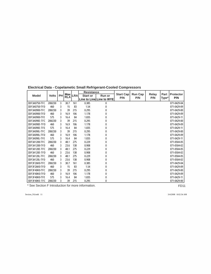
FD11
Electrical Data - Copelametic Small Refrigerant-Cooled Compressors
* See Section F Introduction for more information.
Model Volts PH RLA LRA Resistance
Start Cap Run Cap Relay Part Protector Max Start or Run or P/N P/N P/N Type* P/N Line to Line Line to WYE
3DF3A0750-TFC 208/230 3 30.7 161 0.385 0 071-0429-043DF3A0750-TFD 460 3 15 83 1.54 0 071-0429-093DF3A0900-TFC 208/230 3 39 215 0.295 0 071-0429-003DF3A0900-TFD 460 3 16.9 106 1.178 0 071-0429-093DF3A0900-TFE 575 3 16.4 84 1.835 0 071-0429-113DF3A090E-TFC 208/230 3 39 215 0.295 0 071-0429-003DF3A090E-TFD 460 3 16.9 106 1.178 0 071-0429-093DF3A090E-TFE 575 3 16.4 84 1.835 0 071-0429-113DF3A090L-TFC 208/230 3 39 215 0.295 0 071-0429-003DF3A090L-TFD 460 3 16.9 106 1.178 0 071-0429-093DF3A090L-TFE 575 3 16.4 84 1.835 0 071-0429-113DF3A1200-TFC 208/230 3 48.1 275 0.229 0 071-0504-053DF3A1200-TFD 460 3 23.6 138 0.908 0 071-0504-023DF3A120E-TFC 208/230 3 48.1 275 0.229 0 071-0504-053DF3A120E-TFD 460 3 23.6 138 0.908 0 071-0504-023DF3A120L-TFC 208/230 3 48.1 275 0.229 0 071-0504-053DF3A120L-TFD 460 3 23.6 138 0.908 0 071-0504-023DF3F26K0-TFC 208/230 3 30.7 161 0.385 0 071-0429-043DF3F26K0-TFD 460 3 15 83 1.54 0 071-0429-093DF3F40K0-TFC 208/230 3 39 215 0.295 0 071-0429-003DF3F40K0-TFD 460 3 16.9 106 1.178 0 071-0429-093DF3F40K0-TFE 575 3 16.4 84 1.835 0 071-0429-113DF3F40KE-TFC 208/230 3 39 215 0.295 0 071-0429-00
Section_Fd.indd 11Section_Fd.indd 11 3/4/2008 8:02:54 AM3/4/2008 8:02:54 AM

FD12 * See Section F Introduction for more information.
Electrical Data - Copelametic Small Refrigerant-Cooled Compressors
Model Volts PH RLA LRA Resistance
Start Cap Run Cap Relay Part Protector Max Start or Run or P/N P/N P/N Type* P/N Line to Line Line to WYE
3DF3F40KE-TFD 460 3 16.9 106 1.178 0 071-0429-093DF3F40KE-TFE 575 3 16.4 84 1.835 0 071-0429-113DF3F40KL-TFC 208/230 3 39 215 0.295 0 071-0429-003DF3F40KL-TFD 460 3 16.9 106 1.178 0 071-0429-093DF3F40KL-TFE 575 3 16.4 84 1.835 0 071-0429-113DF3R15M0-TFC 208/230 3 48.1 275 0.229 0 071-0504-053DF3R15M0-TFD 460 3 23.6 138 0.908 0 071-0504-023DF3R15ME-TFC 208/230 3 48.1 275 0.229 0 071-0504-053DF3R15ME-TFD 460 3 23.6 138 0.908 0 071-0504-023DF3R15ML-TFC 208/230 3 48.1 275 0.229 0 071-0504-053DF3R15ML-TFD 460 3 23.6 138 0.908 0 071-0504-023DF4A0900-TFC 208/230 3 39 215 0.295 0 071-0429-003DF4A0900-TFD 460 3 16.9 106 1.178 0 071-0429-093DF4A1200-TFC 208/230 3 48.1 275 0.229 0 071-0504-053DF4A1200-TFD 460 3 23.6 138 0.908 0 071-0504-023DF4A120E-TFC 208/230 3 48.1 275 0.229 0 071-0504-053DF4A120E-TFD 460 3 23.6 138 0.908 0 071-0504-023DF4A120L-TFC 208/230 3 48.1 275 0.229 0 071-0504-053DF4A120L-TFD 460 3 23.6 138 0.908 0 071-0504-023DF4R15M0-TFC 208/230 3 48.1 275 0.229 0 071-0504-053DF4R15ME-TFC 208/230 3 48.1 275 0.229 0 071-0504-053DF4R15ME-TFD 460 3 23.6 138 0.908 0 071-0504-023DF4R15ML-TFC 208/230 3 48.1 275 0.229 0 071-0504-05
Section_Fd.indd 12Section_Fd.indd 12 3/4/2008 8:02:54 AM3/4/2008 8:02:54 AM

FD13
Electrical Data - Copelametic Small Refrigerant-Cooled Compressors
* See Section F Introduction for more information.
Model Volts PH RLA LRA Resistance
Start Cap Run Cap Relay Part Protector Max Start or Run or P/N P/N P/N Type* P/N Line to Line Line to WYE
3DF4R15ML-TFD 460 3 23.6 138 0.908 0 071-0504-023DF4S11M0-TFC 208/230 3 38.6 240 0.255 0 071-0429-353DF4S11M0-TFD 460 3 18.6 115 1.02 0 071-0429-333DF4S11ME-TFC 208/230 3 42.6 240 0.255 0 071-0429-353DF4S11ME-TFD 460 3 20.4 115 1.02 0 071-0429-333DF4S11ML-TFC 208/230 3 42.6 240 0.255 0 071-0429-353DF4S11ML-TFD 460 3 20.4 115 1.02 0 071-0429-333DF8A0750-TFC 208/230 3 30.7 161 0.385 0 071-0429-043DF8A0750-TFD 460 3 15 83 1.54 0 071-0429-093DF8A0751-TFD 460 3 15 83 1.54 0 071-0429-093DF8A075E-TFC 208/230 3 30.7 161 0.385 0 071-0429-043DF8A076E-TFD 460 3 15 83 1.54 0 071-0429-093DF8R98KE-TFC 208/230 3 30.7 161 0.385 0 071-0429-043DFTA075E-TFD 460 3 15 83 1.54 0 071-0429-093DG3A0900-TFC 208/230 3 35.7 215 0.295 0 071-0429-003DG3A0900-TFD 460 3 15.6 106 1.178 0 071-0429-093DG3A0900-TFE 575 3 15.7 84 1.835 0 071-0429-113DG3A090E-TFC 208/230 3 35.7 215 0.295 0 071-0429-003DG3A090E-TFD 460 3 15.6 106 1.178 0 071-0429-093DG3A090E-TFE 575 3 15.7 84 1.835 0 071-0429-113DG3A090L-TFC 208/230 3 35.7 215 0.295 0 071-0429-003DG3A090L-TFD 460 3 15.6 106 1.178 0 071-0429-093DG3A090L-TFE 575 3 15.7 84 1.835 0 071-0429-11
Section_Fd.indd 13Section_Fd.indd 13 3/4/2008 8:02:55 AM3/4/2008 8:02:55 AM
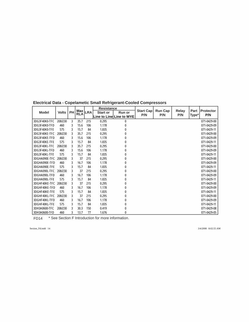
FD14 * See Section F Introduction for more information.
Electrical Data - Copelametic Small Refrigerant-Cooled Compressors
Model Volts PH RLA LRA Resistance
Start Cap Run Cap Relay Part Protector Max Start or Run or P/N P/N P/N Type* P/N Line to Line Line to WYE
3DG3F40K0-TFC 208/230 3 35.7 215 0.295 0 071-0429-003DG3F40K0-TFD 460 3 15.6 106 1.178 0 071-0429-093DG3F40K0-TFE 575 3 15.7 84 1.835 0 071-0429-113DG3F40KE-TFC 208/230 3 35.7 215 0.295 0 071-0429-003DG3F40KE-TFD 460 3 15.6 106 1.178 0 071-0429-093DG3F40KE-TFE 575 3 15.7 84 1.835 0 071-0429-113DG3F40KL-TFC 208/230 3 35.7 215 0.295 0 071-0429-003DG3F40KL-TFD 460 3 15.6 106 1.178 0 071-0429-093DG3F40KL-TFE 575 3 15.7 84 1.835 0 071-0429-113DGHA090E-TFC 208/230 3 37 215 0.295 0 071-0429-003DGHA090E-TFD 460 3 16.7 106 1.178 0 071-0429-093DGHA090E-TFE 575 3 15.7 84 1.835 0 071-0429-113DGHA090L-TFC 208/230 3 37 215 0.295 0 071-0429-003DGHA090L-TFD 460 3 16.7 106 1.178 0 071-0429-093DGHA090L-TFE 575 3 15.7 84 1.835 0 071-0429-113DGHF40KE-TFC 208/230 3 37 215 0.295 0 071-0429-003DGHF40KE-TFD 460 3 16.7 106 1.178 0 071-0429-093DGHF40KE-TFE 575 3 15.7 84 1.835 0 071-0429-113DGHF40KL-TFC 208/230 3 37 215 0.295 0 071-0429-003DGHF40KL-TFD 460 3 16.7 106 1.178 0 071-0429-093DGHF40KL-TFE 575 3 15.7 84 1.835 0 071-0429-113DH3A0600-TFC 208/230 3 30.3 150 0.419 0 071-0429-083DH3A0600-TFD 460 3 13.7 77 1.676 0 071-0429-05
Section_Fd.indd 14Section_Fd.indd 14 3/4/2008 8:02:55 AM3/4/2008 8:02:55 AM

FD15
Electrical Data - Copelametic Small Refrigerant-Cooled Compressors
* See Section F Introduction for more information.
Model Volts PH RLA LRA Resistance
Start Cap Run Cap Relay Part Protector Max Start or Run or P/N P/N P/N Type* P/N Line to Line Line to WYE
3DH3A0600-TFE 575 3 10.5 62 2.6 0 071-0429-033DH3A060E-TFC 208/230 3 30.3 150 0.419 0 071-0429-083DH3A060E-TFD 460 3 13.7 77 1.676 0 071-0429-053DH3A060E-TFE 575 3 10.5 62 2.6 0 071-0429-033DH3A060L-TFC 208/230 3 30.3 150 0.419 0 071-0429-083DH3A060L-TFD 460 3 13.7 77 1.676 0 071-0429-053DH3A060L-TFE 575 3 10.5 62 2.6 0 071-0429-033DH3F28K0-TFC 208/230 3 30.3 150 0.419 0 071-0429-083DH3F28K0-TFD 460 3 13.7 77 1.676 0 071-0429-053DH3F28K0-TFE 575 3 10.5 62 2.6 0 071-0429-033DH3F28KE-TFC 208/230 3 30.3 150 0.419 0 071-0429-083DH3F28KE-TFD 460 3 13.7 77 1.676 0 071-0429-053DH3F28KE-TFE 575 3 10.5 62 2.6 0 071-0429-033DH3F28KL-TFC 208/230 3 30.3 150 0.419 0 071-0429-083DH3F28KL-TFD 460 3 13.7 77 1.676 0 071-0429-053DH3F28KL-TFE 575 3 10.5 62 2.6 0 071-0429-033DHHA060E-TFC 208/230 3 26.8 150 0.419 0 071-0429-083DHHA060E-TFD 460 3 12 77 1.676 0 071-0429-053DHHA060E-TFE 575 3 10.5 62 2.6 0 071-0429-033DHHA060L-TFC 208/230 3 26.8 150 0.419 0 071-0429-083DHHA060L-TFD 460 3 12 77 1.676 0 071-0429-053DHHA060L-TFE 575 3 10.5 62 2.6 0 071-0429-033DHHF28KE-TFC 208/230 3 26.8 150 0.419 0 071-0429-08
Section_Fd.indd 15Section_Fd.indd 15 3/4/2008 8:02:55 AM3/4/2008 8:02:55 AM
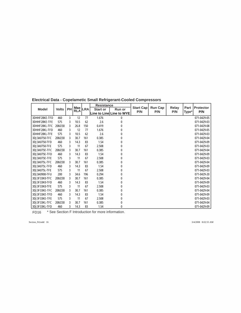
FD16 * See Section F Introduction for more information.
Electrical Data - Copelametic Small Refrigerant-Cooled Compressors
Model Volts PH RLA LRA Resistance
Start Cap Run Cap Relay Part Protector Max Start or Run or P/N P/N P/N Type* P/N Line to Line Line to WYE
3DHHF28KE-TFD 460 3 12 77 1.676 0 071-0429-053DHHF28KE-TFE 575 3 10.5 62 2.6 0 071-0429-033DHHF28KL-TFC 208/230 3 26.8 150 0.419 0 071-0429-083DHHF28KL-TFD 460 3 12 77 1.676 0 071-0429-053DHHF28KL-TFE 575 3 10.5 62 2.6 0 071-0429-033DJ3A0750-TFC 208/230 3 30.7 161 0.385 0 071-0429-043DJ3A0750-TFD 460 3 14.3 83 1.54 0 071-0429-093DJ3A0750-TFE 575 3 11 67 2.508 0 071-0429-033DJ3A075E-TFC 208/230 3 30.7 161 0.385 0 071-0429-043DJ3A075E-TFD 460 3 14.3 83 1.54 0 071-0429-093DJ3A075E-TFE 575 3 11 67 2.508 0 071-0429-033DJ3A075L-TFC 208/230 3 30.7 161 0.385 0 071-0429-043DJ3A075L-TFD 460 3 14.3 83 1.54 0 071-0429-093DJ3A075L-TFE 575 3 11 67 2.508 0 071-0429-033DJ3A0900-TFU 200 3 34.6 196 0.294 0 071-0429-203DJ3F33K0-TFC 208/230 3 30.7 161 0.385 0 071-0429-043DJ3F33K0-TFD 460 3 14.3 83 1.54 0 071-0429-093DJ3F33K0-TFE 575 3 11 67 2.508 0 071-0429-033DJ3F33KE-TFC 208/230 3 30.7 161 0.385 0 071-0429-043DJ3F33KE-TFD 460 3 14.3 83 1.54 0 071-0429-093DJ3F33KE-TFE 575 3 11 67 2.508 0 071-0429-033DJ3F33KL-TFC 208/230 3 30.7 161 0.385 0 071-0429-043DJ3F33KL-TFD 460 3 14.3 83 1.54 0 071-0429-09
Section_Fd.indd 16Section_Fd.indd 16 3/4/2008 8:02:55 AM3/4/2008 8:02:55 AM

FD17
Electrical Data - Copelametic Small Refrigerant-Cooled Compressors
* See Section F Introduction for more information.
Model Volts PH RLA LRA Resistance
Start Cap Run Cap Relay Part Protector Max Start or Run or P/N P/N P/N Type* P/N Line to Line Line to WYE
3DJ3F33KL-TFE 575 3 11 67 2.508 0 071-0429-033DJHA075E-TFC 208/230 3 30.7 161 0.385 0 071-0429-043DJHA075E-TFD 460 3 15.7 83 1.54 0 071-0429-093DJHA075E-TFE 575 3 11 67 2.508 0 071-0429-033DJHA075L-TFC 208/230 3 30.7 161 0.385 0 071-0429-043DJHA075L-TFD 460 3 15.7 83 1.54 0 071-0429-093DJHA075L-TFE 575 3 11 67 2.508 0 071-0429-033DJHF33KE-TFC 208/230 3 30.7 161 0.385 0 071-0429-043DJHF33KE-TFD 460 3 15.7 83 1.54 0 071-0429-093DJHF33KE-TFE 575 3 11 67 2.508 0 071-0429-033DJHF33KL-TFC 208/230 3 30.7 161 0.385 0 071-0429-043DJHF33KL-TFD 460 3 15.7 83 1.54 0 071-0429-093DJHF33KL-TFE 575 3 11 67 2.508 0 071-0429-033DK3A0750-TFC 208/230 3 30.7 161 0.385 0 071-0429-043DK3A0750-TFD 460 3 15 83 1.54 0 071-0429-093DK3A0900-TFC 208/230 3 39 215 0.295 0 071-0429-003DK3A0900-TFD 460 3 16.9 106 1.178 0 071-0429-093DK3A0900-TFE 575 3 16.4 84 1.835 0 071-0429-113DK3A1200-TFC 208/230 3 48.1 275 0.229 0 071-0504-053DK3A1200-TFD 460 3 23.6 138 0.908 0 071-0504-023DK3A120E-TFC 208/230 3 48.1 275 0.229 0 071-0504-053DK3A120E-TFD 460 3 23.6 138 0.908 0 071-0504-023DK3A120L-TFC 208/230 3 48.1 275 0.229 0 071-0504-05
Section_Fd.indd 17Section_Fd.indd 17 3/4/2008 8:02:56 AM3/4/2008 8:02:56 AM

FD18 * See Section F Introduction for more information.
Electrical Data - Copelametic Small Refrigerant-Cooled Compressors
Model Volts PH RLA LRA Resistance
Start Cap Run Cap Relay Part Protector Max Start or Run or P/N P/N P/N Type* P/N Line to Line Line to WYE
3DK3A120L-TFD 460 3 23.6 138 0.908 0 071-0504-023DK3R15M0-TFC 208/230 3 48.1 275 0.229 0 071-0504-053DK3R15M0-TFD 460 3 23.6 138 0.908 0 071-0504-023DK3R15ME-TFC 208/230 3 48.1 275 0.229 0 071-0504-053DK3R15ME-TFD 460 3 23.6 138 0.908 0 071-0504-023DK3R15ML-TFC 208/230 3 48.1 275 0.229 0 071-0504-053DK3R15ML-TFD 460 3 23.6 138 0.908 0 071-0504-023DK4A1200-TFD 460 3 23.6 138 0.908 0 071-0504-023DK4A120L-TFC 208/230 3 48.1 275 0.229 0 071-0504-053DK4A120L-TFD 460 3 23.6 138 0.908 0 071-0504-023DK4S11M0-TFC 208/230 3 38.6 240 0.255 0 071-0429-353DK4S11M0-TFD 460 3 18.6 115 1.02 0 071-0429-333DK4S11ML-TFC 208/230 3 38.6 240 0.255 0 071-0429-353DK4S11ML-TFD 460 3 18.6 115 1.02 0 071-0429-333DK8A0750-TFC 208/230 3 30.7 161 0.385 0 071-0429-043DK8A0750-TFD 460 3 15 83 1.54 0 071-0429-093DK8A075E-TFD 460 3 15 83 1.54 0 071-0429-093DKAA120L-TFC 208/230 3 48.1 275 0.229 0 071-0504-053DKAA120L-TFD 460 3 23.6 138 0.908 0 071-0504-023DKHA120E-TFC 208/230 3 48.1 275 0.229 0 071-0504-053DKHA120E-TFD 460 3 23.6 138 0.908 0 071-0504-023DKHA120L-TFC 208/230 3 48.1 275 0.229 0 071-0504-053DKHA120L-TFD 460 3 23.6 138 0.908 0 071-0504-02
Section_Fd.indd 18Section_Fd.indd 18 3/4/2008 8:02:56 AM3/4/2008 8:02:56 AM
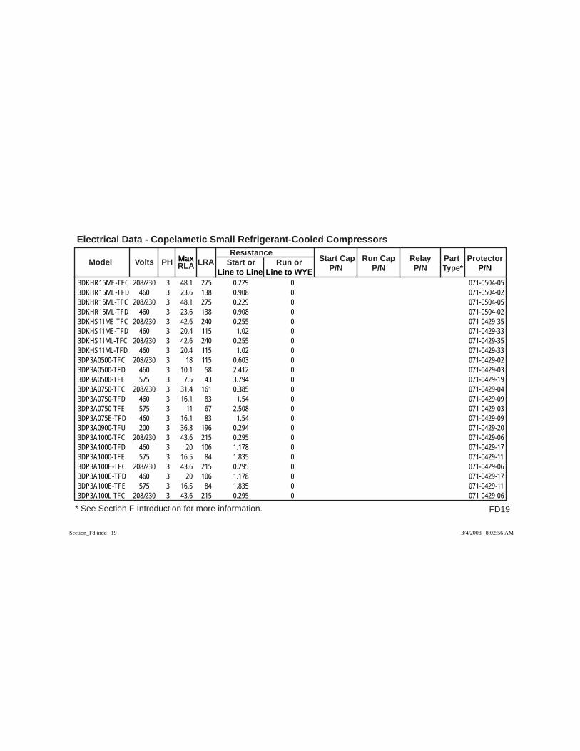
FD19
Electrical Data - Copelametic Small Refrigerant-Cooled Compressors
* See Section F Introduction for more information.
Model Volts PH RLA LRA Resistance
Start Cap Run Cap Relay Part Protector Max Start or Run or P/N P/N P/N Type* P/N Line to Line Line to WYE
3DKHR15ME-TFC 208/230 3 48.1 275 0.229 0 071-0504-053DKHR15ME-TFD 460 3 23.6 138 0.908 0 071-0504-023DKHR15ML-TFC 208/230 3 48.1 275 0.229 0 071-0504-053DKHR15ML-TFD 460 3 23.6 138 0.908 0 071-0504-023DKHS11ME-TFC 208/230 3 42.6 240 0.255 0 071-0429-353DKHS11ME-TFD 460 3 20.4 115 1.02 0 071-0429-333DKHS11ML-TFC 208/230 3 42.6 240 0.255 0 071-0429-353DKHS11ML-TFD 460 3 20.4 115 1.02 0 071-0429-333DP3A0500-TFC 208/230 3 18 115 0.603 0 071-0429-023DP3A0500-TFD 460 3 10.1 58 2.412 0 071-0429-033DP3A0500-TFE 575 3 7.5 43 3.794 0 071-0429-193DP3A0750-TFC 208/230 3 31.4 161 0.385 0 071-0429-043DP3A0750-TFD 460 3 16.1 83 1.54 0 071-0429-093DP3A0750-TFE 575 3 11 67 2.508 0 071-0429-033DP3A075E-TFD 460 3 16.1 83 1.54 0 071-0429-093DP3A0900-TFU 200 3 36.8 196 0.294 0 071-0429-203DP3A1000-TFC 208/230 3 43.6 215 0.295 0 071-0429-063DP3A1000-TFD 460 3 20 106 1.178 0 071-0429-173DP3A1000-TFE 575 3 16.5 84 1.835 0 071-0429-113DP3A100E-TFC 208/230 3 43.6 215 0.295 0 071-0429-063DP3A100E-TFD 460 3 20 106 1.178 0 071-0429-173DP3A100E-TFE 575 3 16.5 84 1.835 0 071-0429-113DP3A100L-TFC 208/230 3 43.6 215 0.295 0 071-0429-06
Section_Fd.indd 19Section_Fd.indd 19 3/4/2008 8:02:56 AM3/4/2008 8:02:56 AM

FD20 * See Section F Introduction for more information.
Electrical Data - Copelametic Small Refrigerant-Cooled Compressors
Model Volts PH RLA LRA Resistance
Start Cap Run Cap Relay Part Protector Max Start or Run or P/N P/N P/N Type* P/N Line to Line Line to WYE
3DP3A100L-TFD 460 3 20 106 1.178 0 071-0429-173DP3A100L-TFE 575 3 16.5 84 1.835 0 071-0429-113DP3R12M0-TFC 208/230 3 43.6 215 0.295 0 071-0429-063DP3R12M0-TFD 460 3 20 106 1.178 0 071-0429-173DP3R12M0-TFE 575 3 16.5 84 1.835 0 071-0429-113DP3R12ME-TFC 208/230 3 43.6 215 0.295 0 071-0429-063DP3R12ME-TFD 460 3 20 106 1.178 0 071-0429-173DP3R12ME-TFE 575 3 16.5 84 1.835 0 071-0429-113DP3R12ML-TFC 208/230 3 43.6 215 0.295 0 071-0429-063DP3R12ML-TFD 460 3 20 106 1.178 0 071-0429-173DP3R12ML-TFE 575 3 16.5 84 1.835 0 071-0429-113DPHA100E-TFC 208/230 3 43.6 215 0.295 0 071-0429-063DPHA100E-TFD 460 3 20 106 1.178 0 071-0429-173DPHA100E-TFE 575 3 16.5 84 1.835 0 071-0429-113DPHA100L-TFC 208/230 3 43.6 215 0.295 0 071-0429-063DPHA100L-TFD 460 3 20 106 1.178 0 071-0429-173DPHA100L-TFE 575 3 16.5 84 1.835 0 071-0429-113DPHR12ME-TFC 208/230 3 43.6 215 0.295 0 071-0429-063DPHR12ME-TFD 460 3 20 106 1.178 0 071-0429-173DPHR12ME-TFE 575 3 16.5 84 1.835 0 071-0429-113DPHR12ML-TFC 208/230 3 43.6 215 0.295 0 071-0429-063DPHR12ML-TFD 460 3 20 106 1.178 0 071-0429-173DPHR12ML-TFE 575 3 16.5 84 1.835 0 071-0429-11
Section_Fd.indd 20Section_Fd.indd 20 3/4/2008 8:02:56 AM3/4/2008 8:02:56 AM

FD21
Electrical Data - Copelametic Small Refrigerant-Cooled Compressors
* See Section F Introduction for more information.
Model Volts PH RLA LRA Resistance
Start Cap Run Cap Relay Part Protector Max Start or Run or P/N P/N P/N Type* P/N Line to Line Line to WYE
3DR3A1000-TFC 208/230 3 41.4 215 0.295 0 071-0429-003DR3A1000-TFD 460 3 18.6 106 1.178 0 071-0429-093DR3A1000-TFE 575 3 15.4 84 1.835 0 071-0429-113DR3A100E-TFC 208/230 3 41.4 215 0.295 0 071-0429-003DR3A100E-TFD 460 3 18.6 106 1.178 0 071-0429-093DR3A100E-TFE 575 3 15.4 84 1.835 0 071-0429-113DR3A100L-TFC 208/230 3 41.4 215 0.295 0 071-0429-003DR3A100L-TFD 460 3 18.6 106 1.178 0 071-0429-093DR3A100L-TFE 575 3 15.4 84 1.835 0 071-0429-113DR3F46K0-TFC 208/230 3 41.4 215 0.295 0 071-0429-003DR3F46K0-TFD 460 3 18.6 106 1.178 0 071-0429-093DR3F46K0-TFE 575 3 15.4 84 1.835 0 071-0429-113DR3F46KE-TFC 208/230 3 41.4 215 0.295 0 071-0429-003DR3F46KE-TFD 460 3 18.6 106 1.178 0 071-0429-093DR3F46KL-TFC 208/230 3 41.4 215 0.295 0 071-0429-003DR3F46KL-TFD 460 3 18.6 106 1.178 0 071-0429-093DR3F46KL-TFE 575 3 15.4 84 1.835 0 071-0429-113DRHA100E-TFC 208/230 3 41.4 215 0.295 0 071-0429-003DRHA100E-TFD 460 3 18.6 106 1.178 0 071-0429-093DRHA100E-TFE 575 3 16.2 84 1.835 0 071-0429-113DRHA100L-TFC 208/230 3 41.4 215 0.295 0 071-0429-003DRHA100L-TFD 460 3 18.6 106 1.178 0 071-0429-093DRHA100L-TFE 575 3 16.2 84 1.835 0 071-0429-11
Section_Fd.indd 21Section_Fd.indd 21 3/4/2008 8:02:57 AM3/4/2008 8:02:57 AM
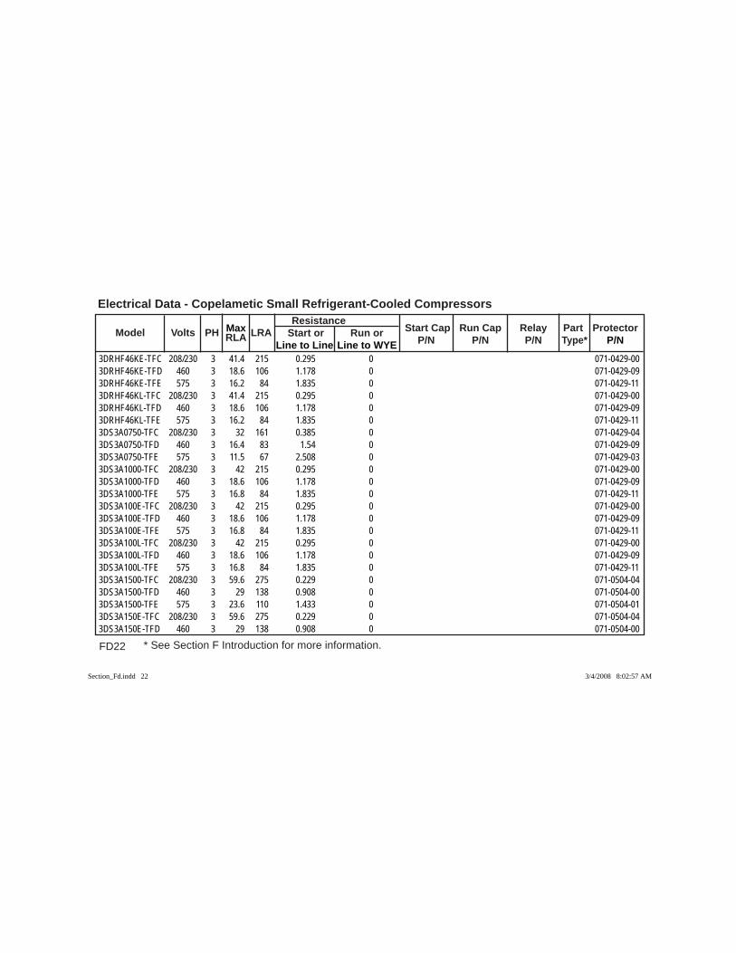
FD22 * See Section F Introduction for more information.
Electrical Data - Copelametic Small Refrigerant-Cooled Compressors
Model Volts PH RLA LRA Resistance
Start Cap Run Cap Relay Part Protector Max Start or Run or P/N P/N P/N Type* P/N Line to Line Line to WYE
3DRHF46KE-TFC 208/230 3 41.4 215 0.295 0 071-0429-003DRHF46KE-TFD 460 3 18.6 106 1.178 0 071-0429-093DRHF46KE-TFE 575 3 16.2 84 1.835 0 071-0429-113DRHF46KL-TFC 208/230 3 41.4 215 0.295 0 071-0429-003DRHF46KL-TFD 460 3 18.6 106 1.178 0 071-0429-093DRHF46KL-TFE 575 3 16.2 84 1.835 0 071-0429-113DS3A0750-TFC 208/230 3 32 161 0.385 0 071-0429-043DS3A0750-TFD 460 3 16.4 83 1.54 0 071-0429-093DS3A0750-TFE 575 3 11.5 67 2.508 0 071-0429-033DS3A1000-TFC 208/230 3 42 215 0.295 0 071-0429-003DS3A1000-TFD 460 3 18.6 106 1.178 0 071-0429-093DS3A1000-TFE 575 3 16.8 84 1.835 0 071-0429-113DS3A100E-TFC 208/230 3 42 215 0.295 0 071-0429-003DS3A100E-TFD 460 3 18.6 106 1.178 0 071-0429-093DS3A100E-TFE 575 3 16.8 84 1.835 0 071-0429-113DS3A100L-TFC 208/230 3 42 215 0.295 0 071-0429-003DS3A100L-TFD 460 3 18.6 106 1.178 0 071-0429-093DS3A100L-TFE 575 3 16.8 84 1.835 0 071-0429-113DS3A1500-TFC 208/230 3 59.6 275 0.229 0 071-0504-043DS3A1500-TFD 460 3 29 138 0.908 0 071-0504-003DS3A1500-TFE 575 3 23.6 110 1.433 0 071-0504-013DS3A150E-TFC 208/230 3 59.6 275 0.229 0 071-0504-043DS3A150E-TFD 460 3 29 138 0.908 0 071-0504-00
Section_Fd.indd 22Section_Fd.indd 22 3/4/2008 8:02:57 AM3/4/2008 8:02:57 AM

FD23
Electrical Data - Copelametic Small Refrigerant-Cooled Compressors
* See Section F Introduction for more information.
Model Volts PH RLA LRA Resistance
Start Cap Run Cap Relay Part Protector Max Start or Run or P/N P/N P/N Type* P/N Line to Line Line to WYE
3DS3A150E-TFE 575 3 23.6 110 1.433 0 071-0504-013DS3A150L-TFC 208/230 3 59.6 275 0.229 0 071-0504-043DS3A150L-TFD 460 3 29 138 0.908 0 071-0504-003DS3A150L-TFE 575 3 23.6 110 1.433 0 071-0504-013DS3F30K0-TFC 208/230 3 32 161 0.385 0 071-0429-043DS3F30K0-TFD 460 3 16.4 83 1.54 0 071-0429-093DS3F46K0-TFC 208/230 3 42 215 0.295 0 071-0429-003DS3F46K0-TFD 460 3 18.6 106 1.178 0 071-0429-093DS3F46K0-TFE 575 3 16.8 84 1.835 0 071-0429-113DS3F46KE-TFC 208/230 3 42 215 0.295 0 071-0429-003DS3F46KE-TFD 460 3 18.6 106 1.178 0 071-0429-093DS3F46KE-TFE 575 3 16.8 84 1.835 0 071-0429-113DS3F46KL-TFC 208/230 3 42 215 0.295 0 071-0429-003DS3F46KL-TFD 460 3 18.6 106 1.178 0 071-0429-093DS3F46KL-TFE 575 3 16.8 84 1.835 0 071-0429-113DS3R17M0-TFC 208/230 3 59.6 275 0.229 0 071-0504-043DS3R17M0-TFD 460 3 29 138 0.908 0 071-0504-003DS3R17M0-TFE 575 3 23.6 110 1.433 0 071-0504-013DS3R17ME-TFC 208/230 3 59.6 275 0.229 0 071-0504-043DS3R17ME-TFD 460 3 29 138 0.908 0 071-0504-003DS3R17ME-TFE 575 3 23.6 110 1.433 0 071-0504-013DS3R17ML-TFC 208/230 3 59.6 275 0.229 0 071-0504-043DS3R17ML-TFD 460 3 29 138 0.908 0 071-0504-00
Section_Fd.indd 23Section_Fd.indd 23 3/4/2008 8:02:57 AM3/4/2008 8:02:57 AM

FD24 * See Section F Introduction for more information.
Electrical Data - Copelametic Small Refrigerant-Cooled Compressors
Model Volts PH RLA LRA Resistance
Start Cap Run Cap Relay Part Protector Max Start or Run or P/N P/N P/N Type* P/N Line to Line Line to WYE
3DS3R17ML-TFE 575 3 23.6 110 1.433 0 071-0504-013DS4A0750-TFC 208/230 3 32 161 0.385 0 071-0429-043DS4A0750-TFD 460 3 16.4 83 1.54 0 071-0429-093DS4A1000-TFC 208/230 3 42 215 0.295 0 071-0429-003DS4A1000-TFD 460 3 18.6 106 1.178 0 071-0429-093DS4A1500-TFC 208/230 3 59.6 275 0.229 0 071-0504-043DS4A1500-TFD 460 3 29 138 0.908 0 071-0504-003DS4A1500-TFE 575 3 23.6 110 1.433 0 071-0504-013DS4S12M0-TFC 208/230 3 41.9 280 0.22 0 071-0504-083DS4S12M0-TFD 460 3 21.3 136 0.823 0 071-0429-343DS4S12ME-TFC 208/230 3 47.1 280 0.22 0 071-0504-083DS4S12ME-TFD 460 3 22.8 136 0.823 0 071-0429-343DS4S12ML-TFC 208/230 3 47.1 280 0.22 0 071-0504-083DS4S12ML-TFD 460 3 22.8 136 0.823 0 071-0429-343DS8A0750-TFD 460 3 16.4 83 1.54 0 071-0429-093DS8A0751-TFD 460 3 16.4 83 1.54 0 071-0429-093DS8A076E-TFD 460 3 16.4 83 1.54 0 071-0429-093DS8A1000-TFC 208/230 3 42 215 0.295 0 071-0429-003DS8A100E-TFC 208/230 3 42 215 0.295 0 071-0429-003DS8F30K1-TFD 460 3 16.4 83 1.54 0 071-0429-093DS8R11ME-TFD 460 3 16.4 83 1.54 0 071-0429-093DSTA075E-TFC 208/230 3 32 161 0.385 0 071-0429-043DSTA075E-TFD 460 3 16.4 83 1.54 0 071-0429-09
Section_Fd.indd 24Section_Fd.indd 24 3/4/2008 8:02:57 AM3/4/2008 8:02:57 AM

FD25
Electrical Data - Copelametic Small Refrigerant-Cooled Compressors
* See Section F Introduction for more information.
Model Volts PH RLA LRA Resistance
Start Cap Run Cap Relay Part Protector Max Start or Run or P/N P/N P/N Type* P/N Line to Line Line to WYE
3DSTR11ME-TFD 460 3 16.4 83 1.54 0 071-0429-093DT3A0750-TFC 208/230 3 32 161 0.385 0 071-0429-043DT3A0750-TFD 460 3 16.4 83 1.54 0 071-0429-093DT3A0750-TFE 575 3 11.5 67 2.508 0 071-0429-033DT3A1000-TFC 208/230 3 42 215 0.295 0 071-0429-003DT3A1000-TFD 460 3 18.6 106 1.178 0 071-0429-093DT3A1000-TFE 575 3 16.8 84 1.835 0 071-0429-113DT3A1500-TFC 208/230 3 59.6 275 0.229 0 071-0504-043DT3A1500-TFD 460 3 29 138 0.908 0 071-0504-003DT3A1500-TFE 575 3 23.6 110 1.433 0 071-0504-013DT3A150E-TFC 208/230 3 59.6 275 0.229 0 071-0504-043DT3A150E-TFD 460 3 29 138 0.908 0 071-0504-003DT3A150E-TFE 575 3 23.6 110 1.433 0 071-0504-013DT3A150L-TFC 208/230 3 59.6 275 0.229 0 071-0504-043DT3A150L-TFD 460 3 29 138 0.908 0 071-0504-003DT3A150L-TFE 575 3 23.6 110 1.433 0 071-0504-013DT3R11M0-TFC 208/230 3 42 215 0.295 0 071-0429-003DT3R11M0-TFD 460 3 18.6 106 1.178 0 071-0429-093DT3R11M0-TFE 575 3 16.8 84 1.835 0 071-0429-113DT3R17M0-TFC 208/230 3 59.6 275 0.229 0 071-0504-043DT3R17M0-TFD 460 3 29 138 0.908 0 071-0504-003DT3R17M0-TFE 575 3 23.6 110 1.433 0 071-0504-013DT3R17ME-TFC 208/230 3 59.6 275 0.229 0 071-0504-04
Section_Fd.indd 25Section_Fd.indd 25 3/4/2008 8:02:58 AM3/4/2008 8:02:58 AM

FD26 * See Section F Introduction for more information.
Electrical Data - Copelametic Small Refrigerant-Cooled Compressors
Model Volts PH RLA LRA Resistance
Start Cap Run Cap Relay Part Protector Max Start or Run or P/N P/N P/N Type* P/N Line to Line Line to WYE
3DT3R17ME-TFD 460 3 29 138 0.908 0 071-0504-003DT3R17ME-TFE 575 3 23.6 110 1.433 0 071-0504-013DT3R17ML-TFC 208/230 3 59.6 275 0.229 0 071-0504-043DT3R17ML-TFD 460 3 29 138 0.908 0 071-0504-003DT3R17ML-TFE 575 3 23.6 110 1.433 0 071-0504-013DT4S12M0-TFC 208/230 3 41.9 280 0.22 0 071-0504-083DT4S12M0-TFD 460 3 21.3 136 0.823 0 071-0429-343DT4S12ML-TFC 208/230 3 41.9 280 0.22 0 071-0504-083DT4S12ML-TFD 460 3 21.3 136 0.823 0 071-0429-343DT8A0750-TFD 460 3 16.4 83 1.54 0 071-0429-093DT8A075E-TFD 460 3 16.4 83 1.54 0 071-0429-093DT8R11ME-TFD 460 3 16.4 83 1.54 0 071-0429-093DTHA100E-TFD 460 3 18.6 106 1.178 0 071-0429-093DTHA150E-TFC 208/230 3 59.6 275 0.229 0 071-0504-043DTHA150E-TFD 460 3 29 138 0.908 0 071-0504-003DTHA150E-TFE 575 3 23.6 110 1.433 0 071-0504-013DTHA150L-TFC 208/230 3 59.6 275 0.229 0 071-0504-043DTHA150L-TFD 460 3 29 138 0.908 0 071-0504-003DTHA150L-TFE 575 3 23.6 110 1.433 0 071-0504-013DTHR11ME-TFD 460 3 18.6 106 1.178 0 071-0429-093DTHR17ME-TFC 208/230 3 59.6 275 0.229 0 071-0504-043DTHR17ME-TFD 460 3 29 138 0.908 0 071-0504-003DTHR17ME-TFE 575 3 23.6 110 1.433 0 071-0504-01
Section_Fd.indd 26Section_Fd.indd 26 3/4/2008 8:02:58 AM3/4/2008 8:02:58 AM
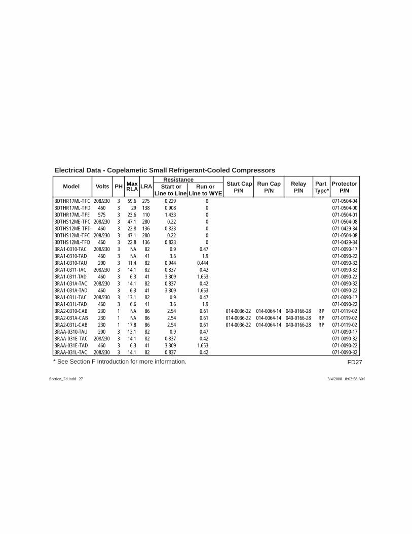
FD27
Electrical Data - Copelametic Small Refrigerant-Cooled Compressors
* See Section F Introduction for more information.
Model Volts PH RLA LRA Resistance
Start Cap Run Cap Relay Part Protector Max Start or Run or P/N P/N P/N Type* P/N Line to Line Line to WYE
3DTHR17ML-TFC 208/230 3 59.6 275 0.229 0 071-0504-043DTHR17ML-TFD 460 3 29 138 0.908 0 071-0504-003DTHR17ML-TFE 575 3 23.6 110 1.433 0 071-0504-013DTHS12ME-TFC 208/230 3 47.1 280 0.22 0 071-0504-083DTHS12ME-TFD 460 3 22.8 136 0.823 0 071-0429-343DTHS12ML-TFC 208/230 3 47.1 280 0.22 0 071-0504-083DTHS12ML-TFD 460 3 22.8 136 0.823 0 071-0429-343RA1-0310-TAC 208/230 3 NA 82 0.9 0.47 071-0090-173RA1-0310-TAD 460 3 NA 41 3.6 1.9 071-0090-223RA1-0310-TAU 200 3 11.4 82 0.944 0.444 071-0090-323RA1-0311-TAC 208/230 3 14.1 82 0.837 0.42 071-0090-323RA1-0311-TAD 460 3 6.3 41 3.309 1.653 071-0090-223RA1-031A-TAC 208/230 3 14.1 82 0.837 0.42 071-0090-323RA1-031A-TAD 460 3 6.3 41 3.309 1.653 071-0090-223RA1-031L-TAC 208/230 3 13.1 82 0.9 0.47 071-0090-173RA1-031L-TAD 460 3 6.6 41 3.6 1.9 071-0090-223RA2-0310-CAB 230 1 NA 86 2.54 0.61 014-0036-22 014-0064-14 040-0166-28 RP 071-0119-023RA2-031A-CAB 230 1 NA 86 2.54 0.61 014-0036-22 014-0064-14 040-0166-28 RP 071-0119-023RA2-031L-CAB 230 1 17.8 86 2.54 0.61 014-0036-22 014-0064-14 040-0166-28 RP 071-0119-023RAA-0310-TAU 200 3 13.1 82 0.9 0.47 071-0090-173RAA-031E-TAC 208/230 3 14.1 82 0.837 0.42 071-0090-323RAA-031E-TAD 460 3 6.3 41 3.309 1.653 071-0090-223RAA-031L-TAC 208/230 3 14.1 82 0.837 0.42 071-0090-32
Section_Fd.indd 27Section_Fd.indd 27 3/4/2008 8:02:58 AM3/4/2008 8:02:58 AM
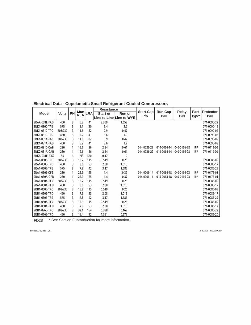
FD28 * See Section F Introduction for more information.
Electrical Data - Copelametic Small Refrigerant-Cooled Compressors
Model Volts PH RLA LRA Resistance
Start Cap Run Cap Relay Part Protector Max Start or Run or P/N P/N P/N Type* P/N Line to Line Line to WYE
3RAA-031L-TAD 460 3 6.3 41 3.309 1.653 071-0090-223RK1-0300-TAE 575 3 5.1 30 5.4 2.7 071-0090-163RK1-0310-TAC 208/230 3 11.8 82 0.9 0.47 071-0090-023RK1-0310-TAD 460 3 5.2 41 3.6 1.9 071-0090-033RK1-031A-TAC 208/230 3 11.8 82 0.9 0.47 071-0090-023RK1-031A-TAD 460 3 5.2 41 3.6 1.9 071-0090-033RK2-0310-CAB 230 1 19.6 86 2.54 0.61 014-0036-22 014-0064-14 040-0166-28 RP 071-0119-003RK2-031A-CAB 230 1 19.6 86 2.54 0.61 014-0036-22 014-0064-14 040-0166-28 RP 071-0119-003RKA-031E-FXX 55 3 NA 320 0.17 0 9RA1-0505-TFC 208/230 3 16.7 115 0.519 0.26 071-0086-099RA1-0505-TFD 460 3 8.6 53 2.08 1.015 071-0086-179RA1-0505-TFE 575 3 7.8 42 3.17 1.585 071-0086-299RA1-0506-CFB 230 1 26.9 125 1.4 0.37 014-0006-14 014-0064-18 040-0166-23 RP 071-0476-019RA1-050A-CFB 230 1 26.9 125 1.4 0.37 014-0006-14 014-0064-18 040-0166-23 RP 071-0476-019RA1-050A-TFC 208/230 3 16.7 115 0.519 0.26 071-0086-099RA1-050A-TFD 460 3 8.6 53 2.08 1.015 071-0086-179RB1-0505-TFC 208/230 3 15.9 115 0.519 0.26 071-0086-099RB1-0505-TFD 460 3 7.9 53 2.08 1.015 071-0086-179RB1-0505-TFE 575 3 7.8 42 3.17 1.585 071-0086-299RB1-050A-TFC 208/230 3 15.9 115 0.519 0.26 071-0086-099RB1-050A-TFD 460 3 7.9 53 2.08 1.015 071-0086-179RB1-0765-TFC 208/230 3 32.1 164 0.338 0.169 071-0086-229RB1-0765-TFD 460 3 15.4 82 1.351 0.675 071-0086-20
Section_Fd.indd 28Section_Fd.indd 28 3/4/2008 8:02:59 AM3/4/2008 8:02:59 AM
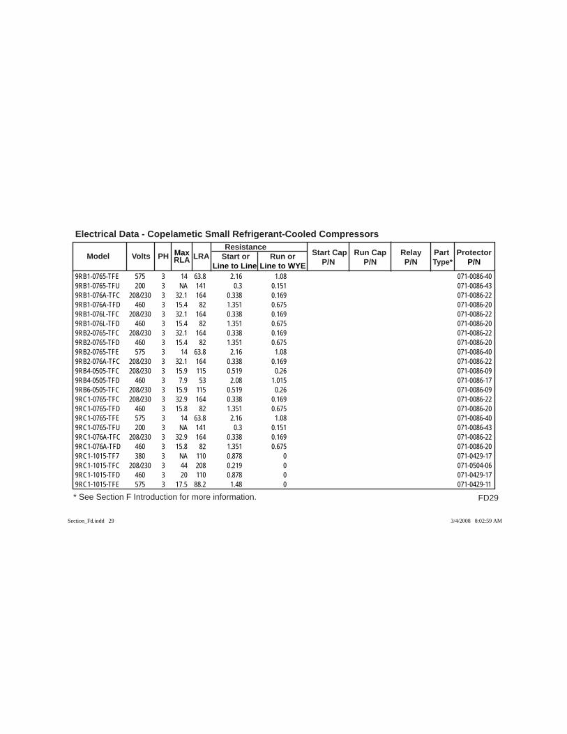
FD29
Electrical Data - Copelametic Small Refrigerant-Cooled Compressors
* See Section F Introduction for more information.
Model Volts PH RLA LRA Resistance
Start Cap Run Cap Relay Part Protector Max Start or Run or P/N P/N P/N Type* P/N Line to Line Line to WYE
9RB1-0765-TFE 575 3 14 63.8 2.16 1.08 071-0086-409RB1-0765-TFU 200 3 NA 141 0.3 0.151 071-0086-439RB1-076A-TFC 208/230 3 32.1 164 0.338 0.169 071-0086-229RB1-076A-TFD 460 3 15.4 82 1.351 0.675 071-0086-209RB1-076L-TFC 208/230 3 32.1 164 0.338 0.169 071-0086-229RB1-076L-TFD 460 3 15.4 82 1.351 0.675 071-0086-209RB2-0765-TFC 208/230 3 32.1 164 0.338 0.169 071-0086-229RB2-0765-TFD 460 3 15.4 82 1.351 0.675 071-0086-209RB2-0765-TFE 575 3 14 63.8 2.16 1.08 071-0086-409RB2-076A-TFC 208/230 3 32.1 164 0.338 0.169 071-0086-229RB4-0505-TFC 208/230 3 15.9 115 0.519 0.26 071-0086-099RB4-0505-TFD 460 3 7.9 53 2.08 1.015 071-0086-179RB6-0505-TFC 208/230 3 15.9 115 0.519 0.26 071-0086-099RC1-0765-TFC 208/230 3 32.9 164 0.338 0.169 071-0086-229RC1-0765-TFD 460 3 15.8 82 1.351 0.675 071-0086-209RC1-0765-TFE 575 3 14 63.8 2.16 1.08 071-0086-409RC1-0765-TFU 200 3 NA 141 0.3 0.151 071-0086-439RC1-076A-TFC 208/230 3 32.9 164 0.338 0.169 071-0086-229RC1-076A-TFD 460 3 15.8 82 1.351 0.675 071-0086-209RC1-1015-TF7 380 3 NA 110 0.878 0 071-0429-179RC1-1015-TFC 208/230 3 44 208 0.219 0 071-0504-069RC1-1015-TFD 460 3 20 110 0.878 0 071-0429-179RC1-1015-TFE 575 3 17.5 88.2 1.48 0 071-0429-11
Section_Fd.indd 29Section_Fd.indd 29 3/4/2008 8:02:59 AM3/4/2008 8:02:59 AM
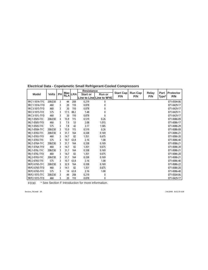
FD30 * See Section F Introduction for more information.
Electrical Data - Copelametic Small Refrigerant-Cooled Compressors
Model Volts PH RLA LRA Resistance
Start Cap Run Cap Relay Part Protector Max Start or Run or P/N P/N P/N Type* P/N Line to Line Line to WYE
9RC1-101A-TFC 208/230 3 44 208 0.219 0 071-0504-069RC1-101A-TFD 460 3 20 110 0.878 0 071-0429-179RC3-1015-TFD 460 3 20 110 0.878 0 071-0429-179RC3-1015-TFE 575 3 17.5 88.2 1.48 0 071-0429-119RC3-101L-TFD 460 3 20 110 0.878 0 071-0429-179RJ1-0505-TFC 208/230 3 15.9 115 0.519 0.26 071-0086-099RJ1-0505-TFD 460 3 7.9 53 2.08 1.015 071-0086-179RJ1-0505-TFE 575 3 7.8 42 3.17 1.585 071-0086-299RJ1-050A-TFC 208/230 3 15.9 115 0.519 0.26 071-0086-099RJ1-0765-TFC 208/230 3 31.7 164 0.338 0.169 071-0086-219RJ1-0765-TFD 460 3 14.7 82 1.351 0.675 071-0086-209RJ1-0765-TFE 575 3 10.7 63.8 2.16 1.08 071-0086-409RJ1-076A-TFC 208/230 3 31.7 164 0.338 0.169 071-0086-219RJ1-076A-TFD 460 3 14.7 82 1.351 0.675 071-0086-209RJ1-076L-TFC 208/230 3 31.7 164 0.338 0.169 071-0086-219RJ1-076L-TFD 460 3 14.7 82 1.351 0.675 071-0086-209RJ2-0765-TFC 208/230 3 31.7 164 0.338 0.169 071-0086-219RJ2-0765-TFE 575 3 10.7 63.8 2.16 1.08 071-0086-409RP2-0765-TFC 208/230 3 32.9 164 0.338 0.169 071-0086-229RP2-0765-TFD 460 3 14.1 82 1.351 0.675 071-0086-209RP2-0765-TFE 575 3 14 63.8 2.16 1.08 071-0086-409RP2-1015-TFC 208/230 3 44 208 0.219 0 071-0504-069RP2-1015-TFD 460 3 20 110 0.878 0 071-0429-17
Section_Fd.indd 30Section_Fd.indd 30 3/4/2008 8:02:59 AM3/4/2008 8:02:59 AM
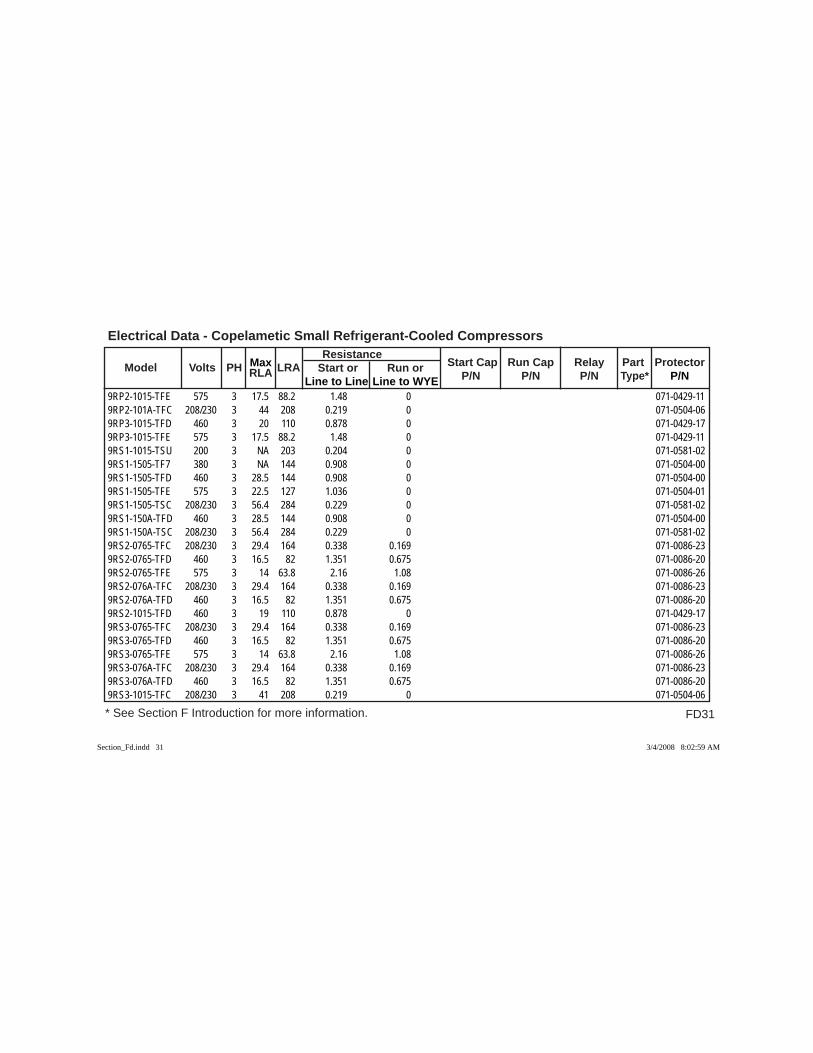
FD31
Electrical Data - Copelametic Small Refrigerant-Cooled Compressors
* See Section F Introduction for more information.
Model Volts PH RLA LRA Resistance
Start Cap Run Cap Relay Part Protector Max Start or Run or P/N P/N P/N Type* P/N Line to Line Line to WYE
9RP2-1015-TFE 575 3 17.5 88.2 1.48 0 071-0429-119RP2-101A-TFC 208/230 3 44 208 0.219 0 071-0504-069RP3-1015-TFD 460 3 20 110 0.878 0 071-0429-179RP3-1015-TFE 575 3 17.5 88.2 1.48 0 071-0429-119RS1-1015-TSU 200 3 NA 203 0.204 0 071-0581-029RS1-1505-TF7 380 3 NA 144 0.908 0 071-0504-009RS1-1505-TFD 460 3 28.5 144 0.908 0 071-0504-009RS1-1505-TFE 575 3 22.5 127 1.036 0 071-0504-019RS1-1505-TSC 208/230 3 56.4 284 0.229 0 071-0581-029RS1-150A-TFD 460 3 28.5 144 0.908 0 071-0504-009RS1-150A-TSC 208/230 3 56.4 284 0.229 0 071-0581-029RS2-0765-TFC 208/230 3 29.4 164 0.338 0.169 071-0086-239RS2-0765-TFD 460 3 16.5 82 1.351 0.675 071-0086-209RS2-0765-TFE 575 3 14 63.8 2.16 1.08 071-0086-269RS2-076A-TFC 208/230 3 29.4 164 0.338 0.169 071-0086-239RS2-076A-TFD 460 3 16.5 82 1.351 0.675 071-0086-209RS2-1015-TFD 460 3 19 110 0.878 0 071-0429-179RS3-0765-TFC 208/230 3 29.4 164 0.338 0.169 071-0086-239RS3-0765-TFD 460 3 16.5 82 1.351 0.675 071-0086-209RS3-0765-TFE 575 3 14 63.8 2.16 1.08 071-0086-269RS3-076A-TFC 208/230 3 29.4 164 0.338 0.169 071-0086-239RS3-076A-TFD 460 3 16.5 82 1.351 0.675 071-0086-209RS3-1015-TFC 208/230 3 41 208 0.219 0 071-0504-06
Section_Fd.indd 31Section_Fd.indd 31 3/4/2008 8:02:59 AM3/4/2008 8:02:59 AM
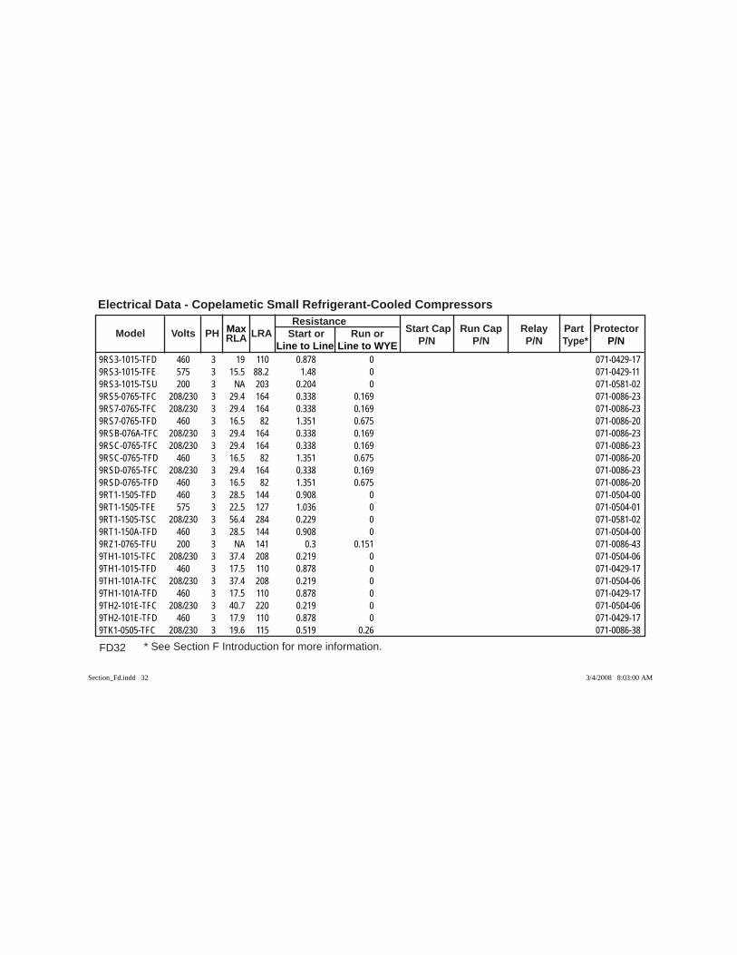
FD32 * See Section F Introduction for more information.
Electrical Data - Copelametic Small Refrigerant-Cooled Compressors
Model Volts PH RLA LRA Resistance
Start Cap Run Cap Relay Part Protector Max Start or Run or P/N P/N P/N Type* P/N Line to Line Line to WYE
9RS3-1015-TFD 460 3 19 110 0.878 0 071-0429-179RS3-1015-TFE 575 3 15.5 88.2 1.48 0 071-0429-119RS3-1015-TSU 200 3 NA 203 0.204 0 071-0581-029RS5-0765-TFC 208/230 3 29.4 164 0.338 0.169 071-0086-239RS7-0765-TFC 208/230 3 29.4 164 0.338 0.169 071-0086-239RS7-0765-TFD 460 3 16.5 82 1.351 0.675 071-0086-209RSB-076A-TFC 208/230 3 29.4 164 0.338 0.169 071-0086-239RSC-0765-TFC 208/230 3 29.4 164 0.338 0.169 071-0086-239RSC-0765-TFD 460 3 16.5 82 1.351 0.675 071-0086-209RSD-0765-TFC 208/230 3 29.4 164 0.338 0.169 071-0086-239RSD-0765-TFD 460 3 16.5 82 1.351 0.675 071-0086-209RT1-1505-TFD 460 3 28.5 144 0.908 0 071-0504-009RT1-1505-TFE 575 3 22.5 127 1.036 0 071-0504-019RT1-1505-TSC 208/230 3 56.4 284 0.229 0 071-0581-029RT1-150A-TFD 460 3 28.5 144 0.908 0 071-0504-009RZ1-0765-TFU 200 3 NA 141 0.3 0.151 071-0086-439TH1-1015-TFC 208/230 3 37.4 208 0.219 0 071-0504-069TH1-1015-TFD 460 3 17.5 110 0.878 0 071-0429-179TH1-101A-TFC 208/230 3 37.4 208 0.219 0 071-0504-069TH1-101A-TFD 460 3 17.5 110 0.878 0 071-0429-179TH2-101E-TFC 208/230 3 40.7 220 0.219 0 071-0504-069TH2-101E-TFD 460 3 17.9 110 0.878 0 071-0429-179TK1-0505-TFC 208/230 3 19.6 115 0.519 0.26 071-0086-38
Section_Fd.indd 32Section_Fd.indd 32 3/4/2008 8:03:00 AM3/4/2008 8:03:00 AM
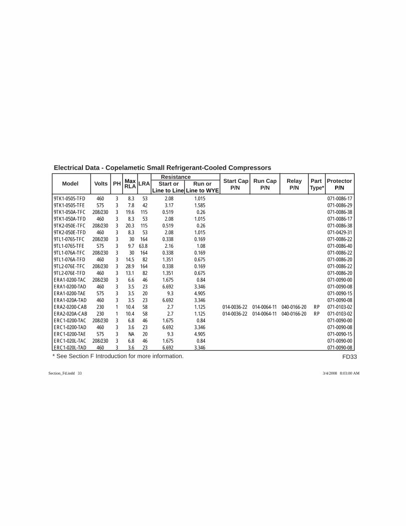
FD33
Electrical Data - Copelametic Small Refrigerant-Cooled Compressors
* See Section F Introduction for more information.
Model Volts PH RLA LRA Resistance
Start Cap Run Cap Relay Part Protector Max Start or Run or P/N P/N P/N Type* P/N Line to Line Line to WYE
9TK1-0505-TFD 460 3 8.3 53 2.08 1.015 071-0086-179TK1-0505-TFE 575 3 7.8 42 3.17 1.585 071-0086-299TK1-050A-TFC 208/230 3 19.6 115 0.519 0.26 071-0086-389TK1-050A-TFD 460 3 8.3 53 2.08 1.015 071-0086-179TK2-050E-TFC 208/230 3 20.3 115 0.519 0.26 071-0086-389TK2-050E-TFD 460 3 8.3 53 2.08 1.015 071-0429-319TL1-0765-TFC 208/230 3 30 164 0.338 0.169 071-0086-229TL1-0765-TFE 575 3 9.7 63.8 2.16 1.08 071-0086-409TL1-076A-TFC 208/230 3 30 164 0.338 0.169 071-0086-229TL1-076A-TFD 460 3 14.5 82 1.351 0.675 071-0086-209TL2-076E-TFC 208/230 3 28.9 164 0.338 0.169 071-0086-229TL2-076E-TFD 460 3 13.1 82 1.351 0.675 071-0086-20ERA1-0200-TAC 208/230 3 6.6 46 1.675 0.84 071-0090-00ERA1-0200-TAD 460 3 3.5 23 6.692 3.346 071-0090-08ERA1-0200-TAE 575 3 3.5 20 9.3 4.905 071-0090-15ERA1-020A-TAD 460 3 3.5 23 6.692 3.346 071-0090-08ERA2-0200-CAB 230 1 10.4 58 2.7 1.125 014-0036-22 014-0064-11 040-0166-20 RP 071-0103-02ERA2-020A-CAB 230 1 10.4 58 2.7 1.125 014-0036-22 014-0064-11 040-0166-20 RP 071-0103-02ERC1-0200-TAC 208/230 3 6.8 46 1.675 0.84 071-0090-00ERC1-0200-TAD 460 3 3.6 23 6.692 3.346 071-0090-08ERC1-0200-TAE 575 3 NA 20 9.3 4.905 071-0090-15ERC1-020L-TAC 208/230 3 6.8 46 1.675 0.84 071-0090-00ERC1-020L-TAD 460 3 3.6 23 6.692 3.346 071-0090-08
Section_Fd.indd 33Section_Fd.indd 33 3/4/2008 8:03:00 AM3/4/2008 8:03:00 AM
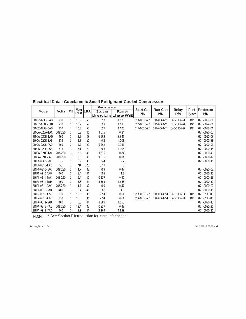
FD34 * See Section F Introduction for more information.
Electrical Data - Copelametic Small Refrigerant-Cooled Compressors
Model Volts PH RLA LRA Resistance
Start Cap Run Cap Relay Part Protector Max Start or Run or P/N P/N P/N Type* P/N Line to Line Line to WYE
ERC2-0200-CAB 230 1 10.9 58 2.7 1.125 014-0036-22 014-0064-11 040-0166-20 RP 071-0099-01ERC2-020A-CAB 230 1 10.9 58 2.7 1.125 014-0036-22 014-0064-11 040-0166-20 RP 071-0099-01ERC2-020L-CAB 230 1 10.9 58 2.7 1.125 014-0036-22 014-0064-11 040-0166-20 RP 071-0099-01ERCA-020A-TAC 208/230 3 6.8 46 1.675 0.84 071-0090-00ERCA-020E-TAD 460 3 3.5 23 6.692 3.346 071-0090-08ERCA-020E-TAE 575 3 3.1 20 9.3 4.905 071-0090-15ERCA-020L-TAD 460 3 3.5 23 6.692 3.346 071-0090-08ERCA-020L-TAE 575 3 3.1 20 9.3 4.905 071-0090-15ERCA-021E-TAC 208/230 3 8.8 46 1.675 0.84 071-0090-49ERCA-021L-TAC 208/230 3 8.8 46 1.675 0.84 071-0090-49ERF1-0300-TAE 575 3 5.2 30 5.4 2.7 071-0090-16ERF1-0310-FXX 55 3 NA 320 0.17 0 ERF1-0310-TAC 208/230 3 11.7 82 0.9 0.47 071-0090-02ERF1-0310-TAD 460 3 6.4 41 3.6 1.9 071-0090-10ERF1-0311-TAC 208/230 3 12.4 82 0.837 0.42 071-0090-36ERF1-0311-TAD 460 3 5.8 41 3.309 1.653 071-0090-10ERF1-031L-TAC 208/230 3 11.7 82 0.9 0.47 071-0090-02ERF1-031L-TAD 460 3 6.4 41 3.6 1.9 071-0090-10ERF2-0310-CAB 230 1 18.3 86 2.54 0.61 014-0036-22 014-0064-14 040-0166-28 RP 071-0119-00ERF2-031L-CAB 230 1 18.3 86 2.54 0.61 014-0036-22 014-0064-14 040-0166-28 RP 071-0119-00ERFA-0311-TAD 460 3 5.8 41 3.309 1.653 071-0090-10ERFA-031E-TAC 208/230 3 12.4 82 0.837 0.42 071-0090-36ERFA-031E-TAD 460 3 5.8 41 3.309 1.653 071-0090-10
Section_Fd.indd 34Section_Fd.indd 34 3/4/2008 8:03:00 AM3/4/2008 8:03:00 AM
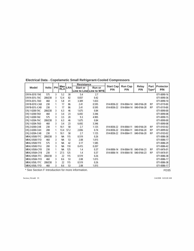
FD35
Electrical Data - Copelametic Small Refrigerant-Cooled Compressors
* See Section F Introduction for more information.
Model Volts PH RLA LRA Resistance
Start Cap Run Cap Relay Part Protector Max Start or Run or P/N P/N P/N Type* P/N Line to Line Line to WYE
ERFA-031E-TAE 575 3 5.2 30 5.4 2.7 071-0090-16ERFA-031L-TAC 208/230 3 12.4 82 0.837 0.42 071-0090-36ERFA-031L-TAD 460 3 5.8 41 3.309 1.653 071-0090-10ERFB-031E-CAB 230 1 17 86 2.41 0.595 014-0036-22 014-0064-14 040-0166-28 RP 071-0119-00ERFB-031L-CAB 230 1 17 86 2.41 0.595 014-0036-22 014-0064-14 040-0166-28 RP 071-0119-00ERJ1-0200-TAC 208/230 3 6.3 46 1.675 0.84 071-0090-00ERJ1-0200-TAD 460 3 3.4 23 6.692 3.346 071-0090-08ERJ1-0200-TAE 575 3 3.5 20 9.3 4.905 071-0090-15ERJ1-020A-TAC 208/230 3 6.3 46 1.675 0.84 071-0090-00ERJ1-020A-TAD 460 3 3.4 23 6.692 3.346 071-0090-08ERJ2-0200-CAB 230 1 10.1 58 2.7 1.125 014-0036-22 014-0064-11 040-0166-20 RP 071-0103-02ERJ2-0200-CAH 208 1 13.4 57.2 2.836 0.74 014-0036-22 014-0064-11 040-0166-20 RP 071-0099-02ERJ2-020A-CAB 230 1 10.1 58 2.7 1.125 014-0036-22 014-0064-11 040-0166-20 RP 071-0103-02MRA2-0500-TFC 208/230 3 NA 115 0.519 0.26 071-0086-38MRA2-0500-TFD 460 3 NA 53 2.08 1.015 071-0086-17MRA2-0500-TFE 575 3 NA 42 3.17 1.585 071-0086-29MRA2-0500-TFU 200 3 NA 110 0.415 0.207 071-0086-42MRA2-0506-CFB 230 1 NA 125 1.4 0.37 014-0006-14 014-0064-18 040-0166-23 RP 071-0476-01MRA2-050A-CFB 230 1 27.5 125 1.4 0.37 014-0006-14 014-0064-18 040-0166-23 RP 071-0476-01MRA2-050A-TFC 208/230 3 22 115 0.519 0.26 071-0086-38MRA2-050A-TFD 460 3 8.6 53 2.08 1.015 071-0086-17MRA2-050L-TFC 208/230 3 22 115 0.519 0.26 071-0086-38MRA2-050L-TFD 460 3 8.6 53 2.08 1.015 071-0086-17
Section_Fd.indd 35Section_Fd.indd 35 3/4/2008 8:03:00 AM3/4/2008 8:03:00 AM
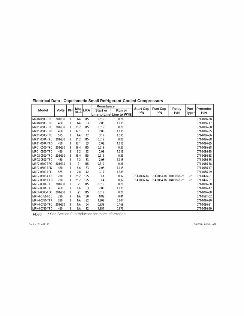
FD36 * See Section F Introduction for more information.
Electrical Data - Copelametic Small Refrigerant-Cooled Compressors
Model Volts PH RLA LRA Resistance
Start Cap Run Cap Relay Part Protector Max Start or Run or P/N P/N P/N Type* P/N Line to Line Line to WYE
MRA8-0500-TFC 208/230 3 NA 115 0.519 0.26 071-0086-38MRA8-0500-TFD 460 3 NA 53 2.08 1.015 071-0086-17MRB1-0500-TFC 208/230 3 21.2 115 0.519 0.26 071-0086-38MRB1-0500-TFD 460 3 12.1 53 2.08 1.015 071-0086-35MRB1-0500-TFE 575 3 NA 42 3.17 1.585 071-0086-36MRB1-050A-TFC 208/230 3 21.2 115 0.519 0.26 071-0086-38MRB1-050A-TFD 460 3 12.1 53 2.08 1.015 071-0086-35MRC1-0500-TFC 208/230 3 18.4 115 0.519 0.26 071-0086-38MRC1-0500-TFD 460 3 9.2 53 2.08 1.015 071-0086-35MRC8-0500-TFC 208/230 3 18.4 115 0.519 0.26 071-0086-38MRC8-0500-TFD 460 3 9.2 53 2.08 1.015 071-0086-35MRF2-0500-TFC 208/230 3 21 115 0.519 0.26 071-0086-38MRF2-0500-TFD 460 3 8.6 53 2.08 1.015 071-0086-17MRF2-0500-TFE 575 3 7.8 42 3.17 1.585 071-0086-29MRF2-0506-CFB 230 1 25.2 125 1.4 0.37 014-0006-14 014-0064-18 040-0166-23 RP 071-0476-01MRF2-050A-CFB 230 1 25.2 125 1.4 0.37 014-0006-14 014-0064-18 040-0166-23 RP 071-0476-01MRF2-050A-TFC 208/230 3 21 115 0.519 0.26 071-0086-38MRF2-050A-TFD 460 3 8.6 53 2.08 1.015 071-0086-17MRF8-0500-TFC 208/230 3 21 115 0.519 0.26 071-0086-38MRH4-0760-FSC 230 3 NA 130 0.82 0.41 071-0581-02MRH4-0760-TF7 380 3 NA 82 1.208 0.604 071-0086-20MRH4-0760-TFC 208/230 3 NA 164 0.338 0.169 071-0086-21MRH4-0760-TFD 460 3 NA 82 1.351 0.675 071-0086-20
Section_Fd.indd 36Section_Fd.indd 36 3/4/2008 8:03:01 AM3/4/2008 8:03:01 AM
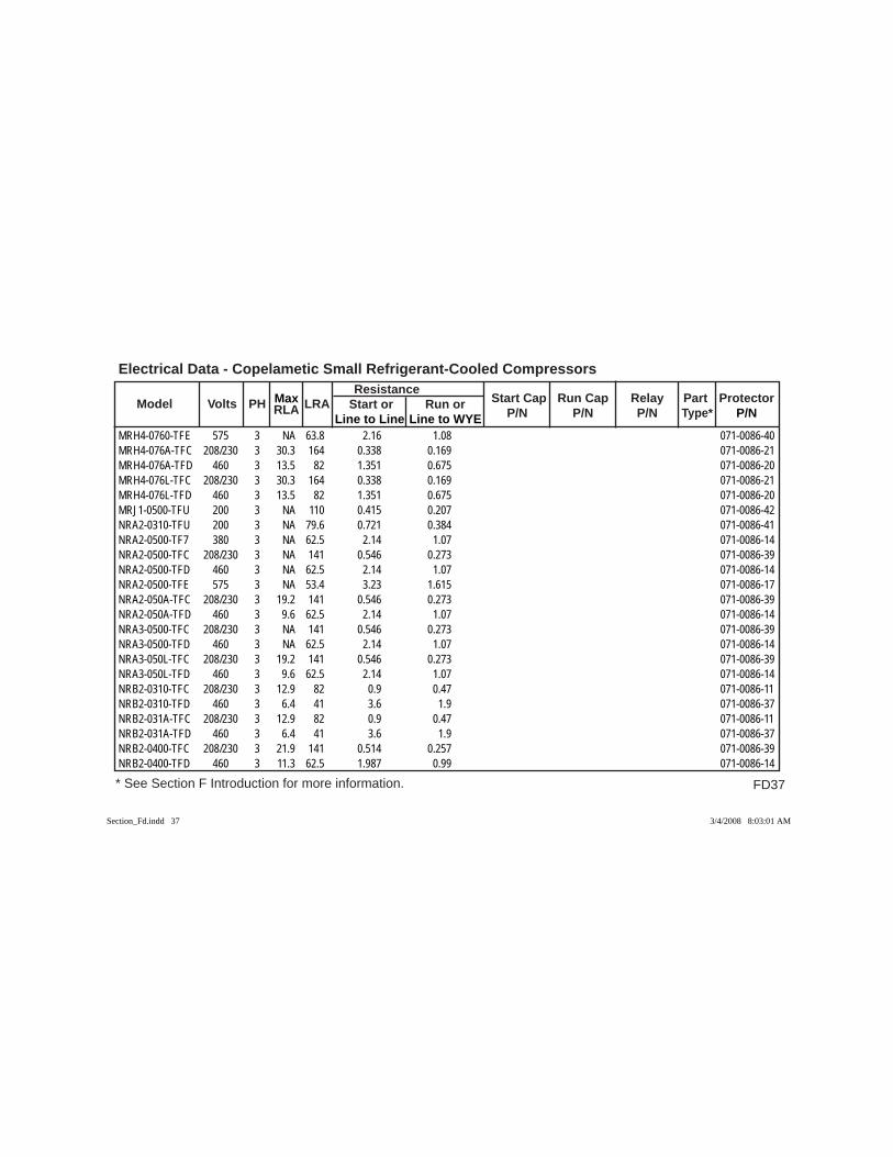
FD37
Electrical Data - Copelametic Small Refrigerant-Cooled Compressors
* See Section F Introduction for more information.
Model Volts PH RLA LRA Resistance
Start Cap Run Cap Relay Part Protector Max Start or Run or P/N P/N P/N Type* P/N Line to Line Line to WYE
MRH4-0760-TFE 575 3 NA 63.8 2.16 1.08 071-0086-40MRH4-076A-TFC 208/230 3 30.3 164 0.338 0.169 071-0086-21MRH4-076A-TFD 460 3 13.5 82 1.351 0.675 071-0086-20MRH4-076L-TFC 208/230 3 30.3 164 0.338 0.169 071-0086-21MRH4-076L-TFD 460 3 13.5 82 1.351 0.675 071-0086-20MRJ1-0500-TFU 200 3 NA 110 0.415 0.207 071-0086-42NRA2-0310-TFU 200 3 NA 79.6 0.721 0.384 071-0086-41NRA2-0500-TF7 380 3 NA 62.5 2.14 1.07 071-0086-14NRA2-0500-TFC 208/230 3 NA 141 0.546 0.273 071-0086-39NRA2-0500-TFD 460 3 NA 62.5 2.14 1.07 071-0086-14NRA2-0500-TFE 575 3 NA 53.4 3.23 1.615 071-0086-17NRA2-050A-TFC 208/230 3 19.2 141 0.546 0.273 071-0086-39NRA2-050A-TFD 460 3 9.6 62.5 2.14 1.07 071-0086-14NRA3-0500-TFC 208/230 3 NA 141 0.546 0.273 071-0086-39NRA3-0500-TFD 460 3 NA 62.5 2.14 1.07 071-0086-14NRA3-050L-TFC 208/230 3 19.2 141 0.546 0.273 071-0086-39NRA3-050L-TFD 460 3 9.6 62.5 2.14 1.07 071-0086-14NRB2-0310-TFC 208/230 3 12.9 82 0.9 0.47 071-0086-11NRB2-0310-TFD 460 3 6.4 41 3.6 1.9 071-0086-37NRB2-031A-TFC 208/230 3 12.9 82 0.9 0.47 071-0086-11NRB2-031A-TFD 460 3 6.4 41 3.6 1.9 071-0086-37NRB2-0400-TFC 208/230 3 21.9 141 0.514 0.257 071-0086-39NRB2-0400-TFD 460 3 11.3 62.5 1.987 0.99 071-0086-14
Section_Fd.indd 37Section_Fd.indd 37 3/4/2008 8:03:01 AM3/4/2008 8:03:01 AM
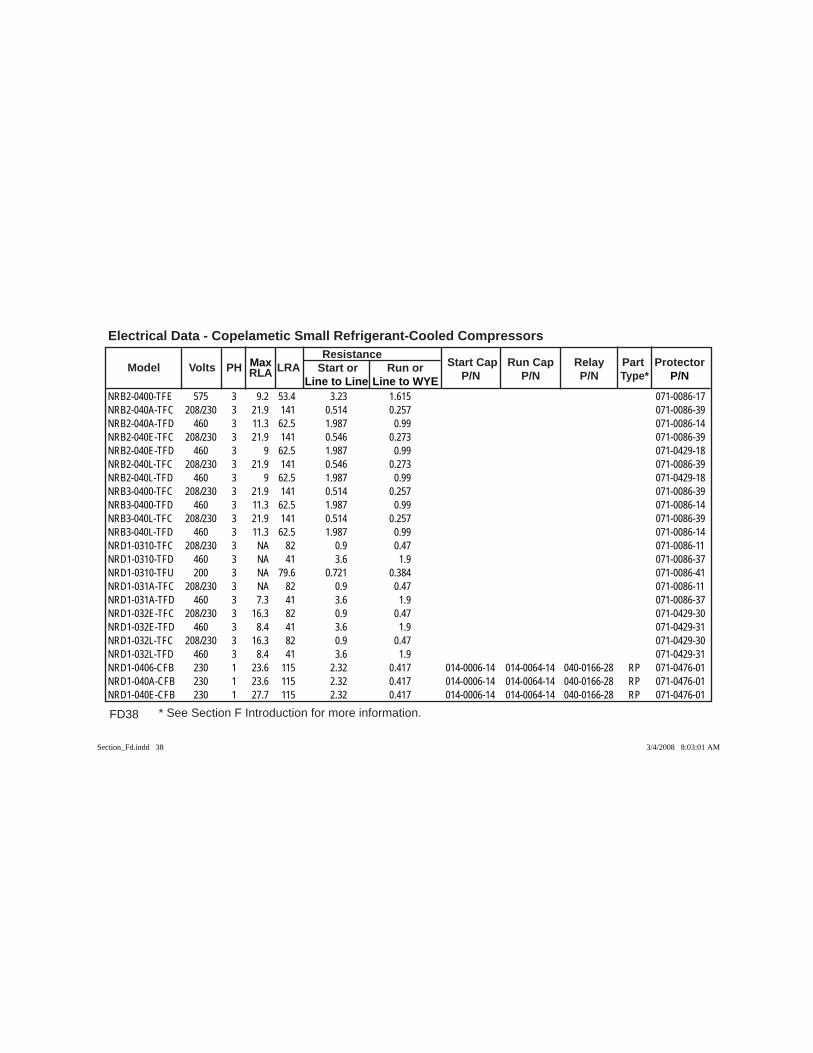
FD38 * See Section F Introduction for more information.
Electrical Data - Copelametic Small Refrigerant-Cooled Compressors
Model Volts PH RLA LRA Resistance
Start Cap Run Cap Relay Part Protector Max Start or Run or P/N P/N P/N Type* P/N Line to Line Line to WYE
NRB2-0400-TFE 575 3 9.2 53.4 3.23 1.615 071-0086-17NRB2-040A-TFC 208/230 3 21.9 141 0.514 0.257 071-0086-39NRB2-040A-TFD 460 3 11.3 62.5 1.987 0.99 071-0086-14NRB2-040E-TFC 208/230 3 21.9 141 0.546 0.273 071-0086-39NRB2-040E-TFD 460 3 9 62.5 1.987 0.99 071-0429-18NRB2-040L-TFC 208/230 3 21.9 141 0.546 0.273 071-0086-39NRB2-040L-TFD 460 3 9 62.5 1.987 0.99 071-0429-18NRB3-0400-TFC 208/230 3 21.9 141 0.514 0.257 071-0086-39NRB3-0400-TFD 460 3 11.3 62.5 1.987 0.99 071-0086-14NRB3-040L-TFC 208/230 3 21.9 141 0.514 0.257 071-0086-39NRB3-040L-TFD 460 3 11.3 62.5 1.987 0.99 071-0086-14NRD1-0310-TFC 208/230 3 NA 82 0.9 0.47 071-0086-11NRD1-0310-TFD 460 3 NA 41 3.6 1.9 071-0086-37NRD1-0310-TFU 200 3 NA 79.6 0.721 0.384 071-0086-41NRD1-031A-TFC 208/230 3 NA 82 0.9 0.47 071-0086-11NRD1-031A-TFD 460 3 7.3 41 3.6 1.9 071-0086-37NRD1-032E-TFC 208/230 3 16.3 82 0.9 0.47 071-0429-30NRD1-032E-TFD 460 3 8.4 41 3.6 1.9 071-0429-31NRD1-032L-TFC 208/230 3 16.3 82 0.9 0.47 071-0429-30NRD1-032L-TFD 460 3 8.4 41 3.6 1.9 071-0429-31NRD1-0406-CFB 230 1 23.6 115 2.32 0.417 014-0006-14 014-0064-14 040-0166-28 RP 071-0476-01NRD1-040A-CFB 230 1 23.6 115 2.32 0.417 014-0006-14 014-0064-14 040-0166-28 RP 071-0476-01NRD1-040E-CFB 230 1 27.7 115 2.32 0.417 014-0006-14 014-0064-14 040-0166-28 RP 071-0476-01
Section_Fd.indd 38Section_Fd.indd 38 3/4/2008 8:03:01 AM3/4/2008 8:03:01 AM
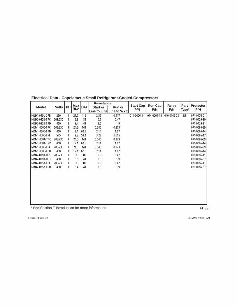
FD39
Electrical Data - Copelametic Small Refrigerant-Cooled Compressors
* See Section F Introduction for more information.
Model Volts PH RLA LRA Resistance
Start Cap Run Cap Relay Part Protector Max Start or Run or P/N P/N P/N Type* P/N Line to Line Line to WYE
NRD1-040L-CFB 230 1 27.7 115 2.32 0.417 014-0006-14 014-0064-14 040-0166-28 RP 071-0476-01NRD2-032E-TFC 208/230 3 16.3 82 0.9 0.47 071-0429-30NRD2-032E-TFD 460 3 8.4 41 3.6 1.9 071-0429-31NRM1-0500-TFC 208/230 3 24.3 141 0.546 0.273 071-0086-39NRM1-0500-TFD 460 3 12.1 62.5 2.14 1.07 071-0086-14NRM1-0500-TFE 575 3 9.2 53.4 3.23 1.615 071-0086-17NRM1-050A-TFC 208/230 3 24.3 141 0.546 0.273 071-0086-39NRM1-050A-TFD 460 3 12.1 62.5 2.14 1.07 071-0086-14NRM1-050L-TFC 208/230 3 24.3 141 0.546 0.273 071-0086-39NRM1-050L-TFD 460 3 12.1 62.5 2.14 1.07 071-0086-14NRN2-0310-TFC 208/230 3 13 82 0.9 0.47 071-0086-11NRN2-0310-TFD 460 3 6.5 41 3.6 1.9 071-0086-37NRN2-031A-TFC 208/230 3 13 82 0.9 0.47 071-0086-11NRN2-031A-TFD 460 3 6.4 41 3.6 1.9 071-0086-37
Section_Fd.indd 39Section_Fd.indd 39 3/4/2008 8:03:01 AM3/4/2008 8:03:01 AM
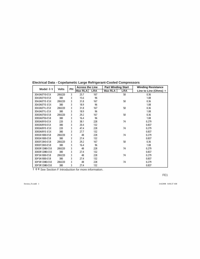
FE1
Across the Line Part Winding Start Winding Resistance Model Volts PH Max RLA LRA Max RLA LRA Line to Line (Ohms)
Electrical Data - Copelametic Large Refrigerant-Cooled Compressors
See Section F Introduction for more information.
3DA3A0710-ESX 200/220 3 25.7 167 58 0.363DA3A0710-ESX 380 3 15.6 96 1.083DA3A071E-ESX 200/220 3 31.8 167 58 0.363DA3A071E-ESX 380 3 18.9 96 1.083DA3A071L-ESX 200/220 3 31.8 167 58 0.363DA3A071L-ESX 380 3 18.9 96 1.083DB3A0750-ES8 200/220 3 29.2 167 58 0.363DB3A0750-ES8 380 3 16.4 96 1.083DB3A0910-ESX 220 3 38.1 228 74 0.2793DB3A0910-ESX 380 3 20.4 132 0.8373DB3A091E-ESX 220 3 47.4 228 74 0.2793DB3A091E-ESX 380 3 27.7 132 0.8373DB3A1000-ES8 200/220 3 48 228 74 0.2793DB3A1000-ES8 380 3 27.4 132 0.8373DB3F33K0-ES8 200/220 3 29.2 167 58 0.363DB3F33K0-ES8 380 3 16.4 96 1.083DB3R12M0-ES8 200/220 3 48 228 74 0.2793DB3R12M0-ES8 380 3 27.4 132 0.8373DP3A1000-ES8 200/220 3 48 228 74 0.2793DP3A1000-ES8 380 3 27.4 132 0.8373DP3R12M0-ES8 200/220 3 48 228 74 0.2793DP3R12M0-ES8 380 3 27.4 132 0.837
Section_Fe.indd 1Section_Fe.indd 1 3/4/2008 8:06:37 AM3/4/2008 8:06:37 AM
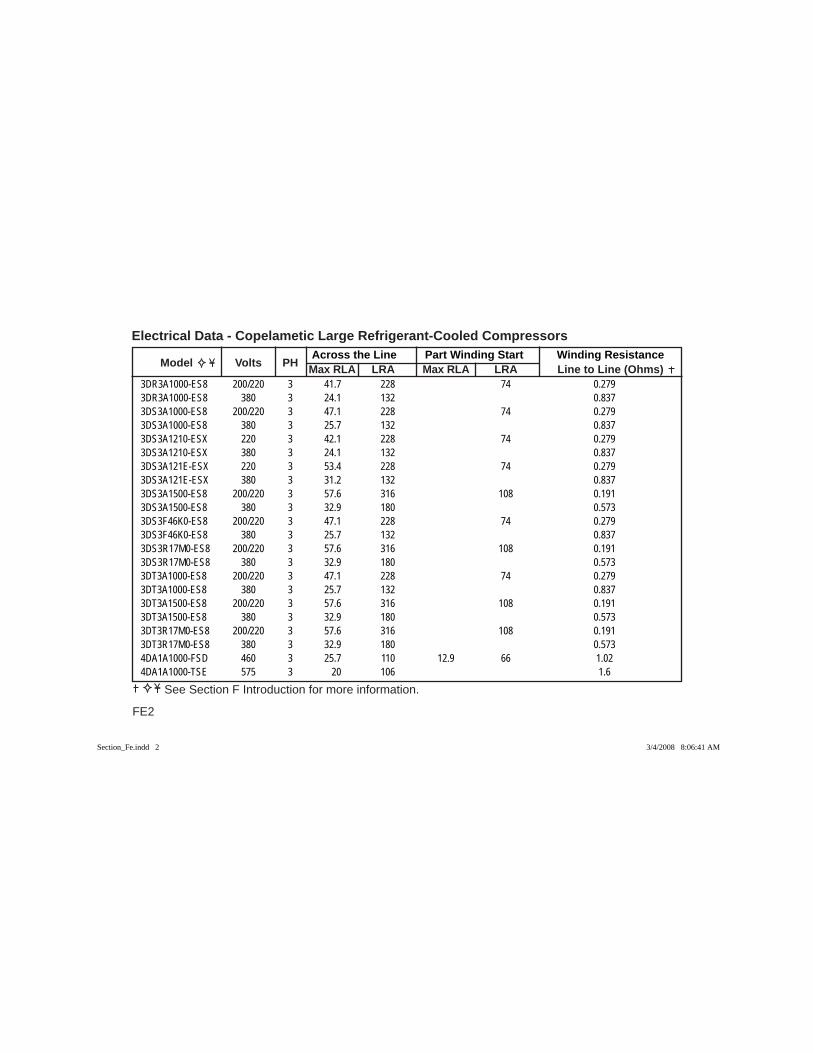
Across the Line Part Winding Start Winding Resistance Model Volts PH Max RLA LRA Max RLA LRA Line to Line (Ohms)
Electrical Data - Copelametic Large Refrigerant-Cooled Compressors
FE2
See Section F Introduction for more information.
3DR3A1000-ES8 200/220 3 41.7 228 74 0.2793DR3A1000-ES8 380 3 24.1 132 0.8373DS3A1000-ES8 200/220 3 47.1 228 74 0.2793DS3A1000-ES8 380 3 25.7 132 0.8373DS3A1210-ESX 220 3 42.1 228 74 0.2793DS3A1210-ESX 380 3 24.1 132 0.8373DS3A121E-ESX 220 3 53.4 228 74 0.2793DS3A121E-ESX 380 3 31.2 132 0.8373DS3A1500-ES8 200/220 3 57.6 316 108 0.1913DS3A1500-ES8 380 3 32.9 180 0.5733DS3F46K0-ES8 200/220 3 47.1 228 74 0.2793DS3F46K0-ES8 380 3 25.7 132 0.8373DS3R17M0-ES8 200/220 3 57.6 316 108 0.1913DS3R17M0-ES8 380 3 32.9 180 0.5733DT3A1000-ES8 200/220 3 47.1 228 74 0.2793DT3A1000-ES8 380 3 25.7 132 0.8373DT3A1500-ES8 200/220 3 57.6 316 108 0.1913DT3A1500-ES8 380 3 32.9 180 0.5733DT3R17M0-ES8 200/220 3 57.6 316 108 0.1913DT3R17M0-ES8 380 3 32.9 180 0.5734DA1A1000-FSD 460 3 25.7 110 12.9 66 1.024DA1A1000-TSE 575 3 20 106 1.6
Section_Fe.indd 2Section_Fe.indd 2 3/4/2008 8:06:41 AM3/4/2008 8:06:41 AM
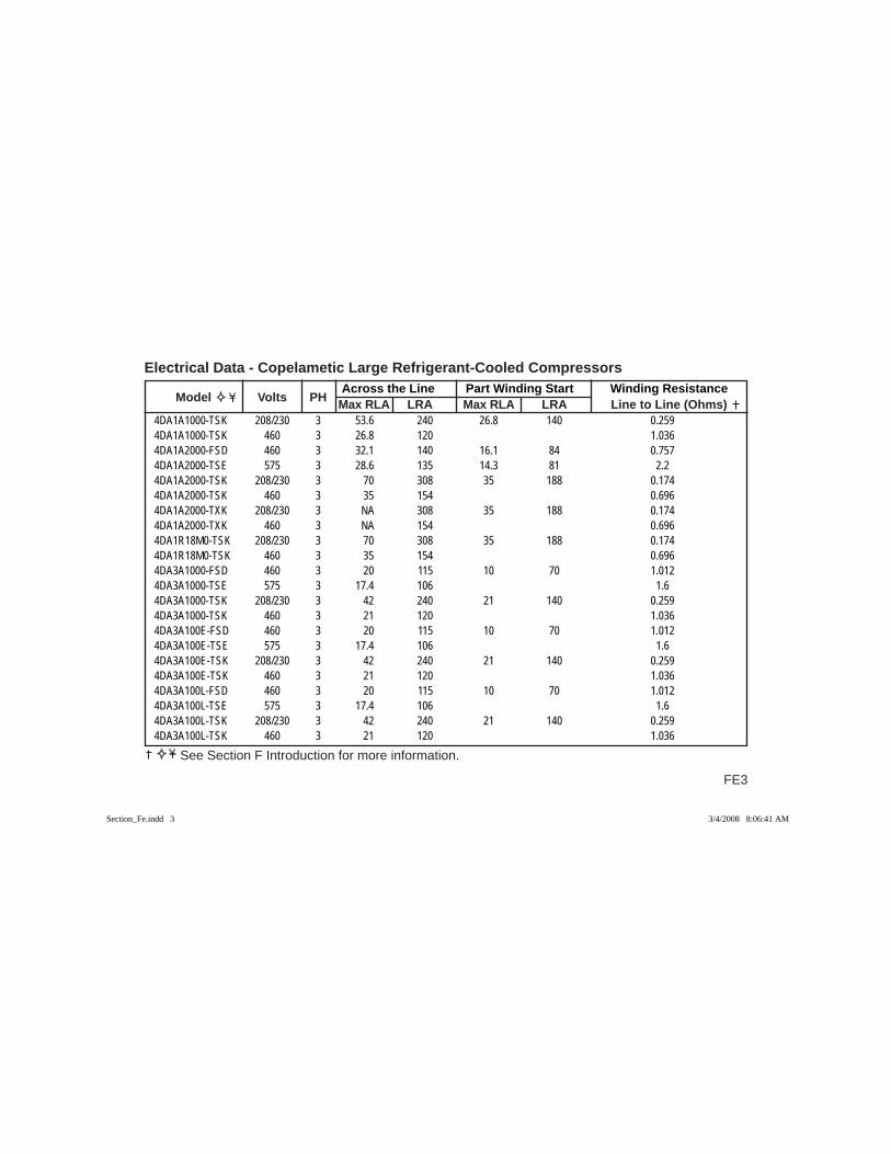
FE3
Across the Line Part Winding Start Winding Resistance Model Volts PH Max RLA LRA Max RLA LRA Line to Line (Ohms)
Electrical Data - Copelametic Large Refrigerant-Cooled Compressors
See Section F Introduction for more information.
4DA1A1000-TSK 208/230 3 53.6 240 26.8 140 0.2594DA1A1000-TSK 460 3 26.8 120 1.0364DA1A2000-FSD 460 3 32.1 140 16.1 84 0.7574DA1A2000-TSE 575 3 28.6 135 14.3 81 2.24DA1A2000-TSK 208/230 3 70 308 35 188 0.1744DA1A2000-TSK 460 3 35 154 0.6964DA1A2000-TXK 208/230 3 NA 308 35 188 0.1744DA1A2000-TXK 460 3 NA 154 0.6964DA1R18M0-TSK 208/230 3 70 308 35 188 0.1744DA1R18M0-TSK 460 3 35 154 0.6964DA3A1000-FSD 460 3 20 115 10 70 1.0124DA3A1000-TSE 575 3 17.4 106 1.64DA3A1000-TSK 208/230 3 42 240 21 140 0.2594DA3A1000-TSK 460 3 21 120 1.0364DA3A100E-FSD 460 3 20 115 10 70 1.0124DA3A100E-TSE 575 3 17.4 106 1.64DA3A100E-TSK 208/230 3 42 240 21 140 0.2594DA3A100E-TSK 460 3 21 120 1.0364DA3A100L-FSD 460 3 20 115 10 70 1.0124DA3A100L-TSE 575 3 17.4 106 1.64DA3A100L-TSK 208/230 3 42 240 21 140 0.2594DA3A100L-TSK 460 3 21 120 1.036
Section_Fe.indd 3Section_Fe.indd 3 3/4/2008 8:06:41 AM3/4/2008 8:06:41 AM
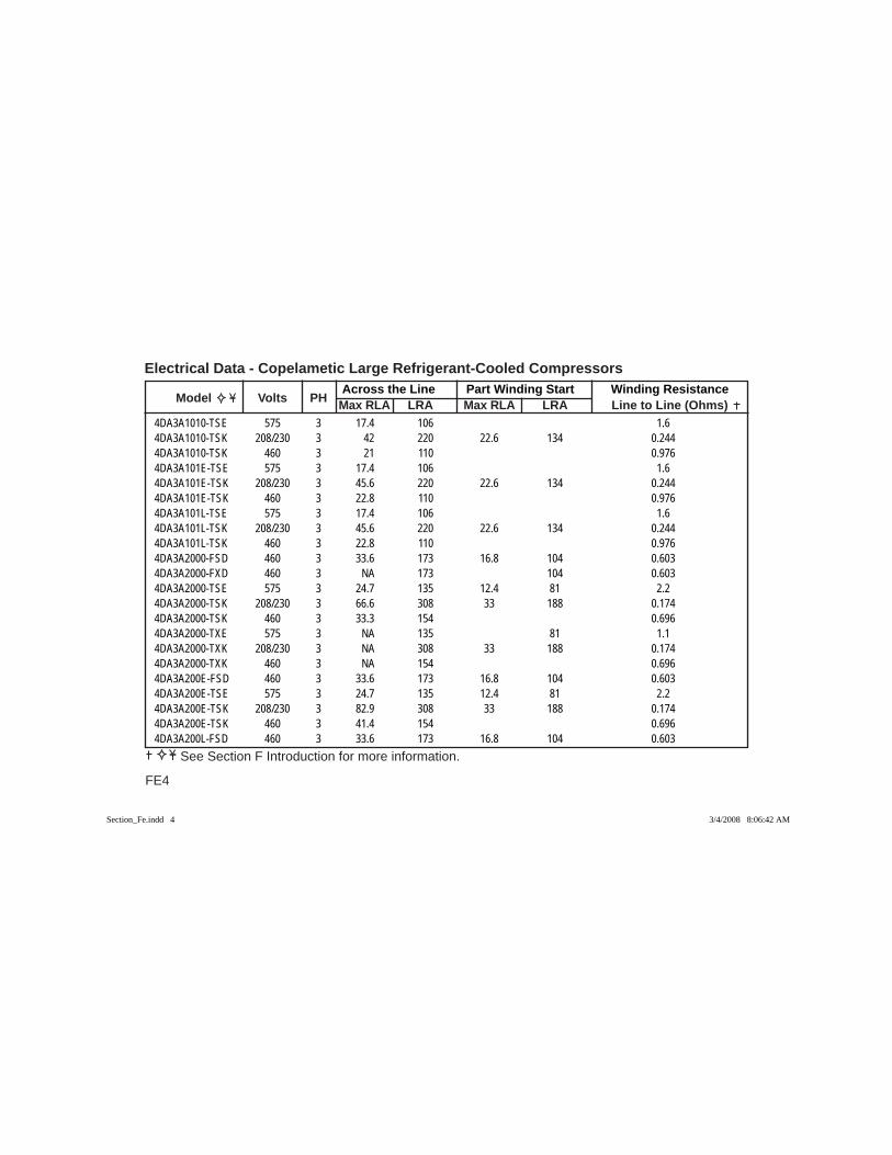
Across the Line Part Winding Start Winding Resistance Model Volts PH Max RLA LRA Max RLA LRA Line to Line (Ohms)
Electrical Data - Copelametic Large Refrigerant-Cooled Compressors
FE4
See Section F Introduction for more information.
4DA3A1010-TSE 575 3 17.4 106 1.64DA3A1010-TSK 208/230 3 42 220 22.6 134 0.2444DA3A1010-TSK 460 3 21 110 0.9764DA3A101E-TSE 575 3 17.4 106 1.64DA3A101E-TSK 208/230 3 45.6 220 22.6 134 0.2444DA3A101E-TSK 460 3 22.8 110 0.9764DA3A101L-TSE 575 3 17.4 106 1.64DA3A101L-TSK 208/230 3 45.6 220 22.6 134 0.2444DA3A101L-TSK 460 3 22.8 110 0.9764DA3A2000-FSD 460 3 33.6 173 16.8 104 0.6034DA3A2000-FXD 460 3 NA 173 104 0.6034DA3A2000-TSE 575 3 24.7 135 12.4 81 2.24DA3A2000-TSK 208/230 3 66.6 308 33 188 0.1744DA3A2000-TSK 460 3 33.3 154 0.6964DA3A2000-TXE 575 3 NA 135 81 1.14DA3A2000-TXK 208/230 3 NA 308 33 188 0.1744DA3A2000-TXK 460 3 NA 154 0.6964DA3A200E-FSD 460 3 33.6 173 16.8 104 0.6034DA3A200E-TSE 575 3 24.7 135 12.4 81 2.24DA3A200E-TSK 208/230 3 82.9 308 33 188 0.1744DA3A200E-TSK 460 3 41.4 154 0.6964DA3A200L-FSD 460 3 33.6 173 16.8 104 0.603
Section_Fe.indd 4Section_Fe.indd 4 3/4/2008 8:06:42 AM3/4/2008 8:06:42 AM
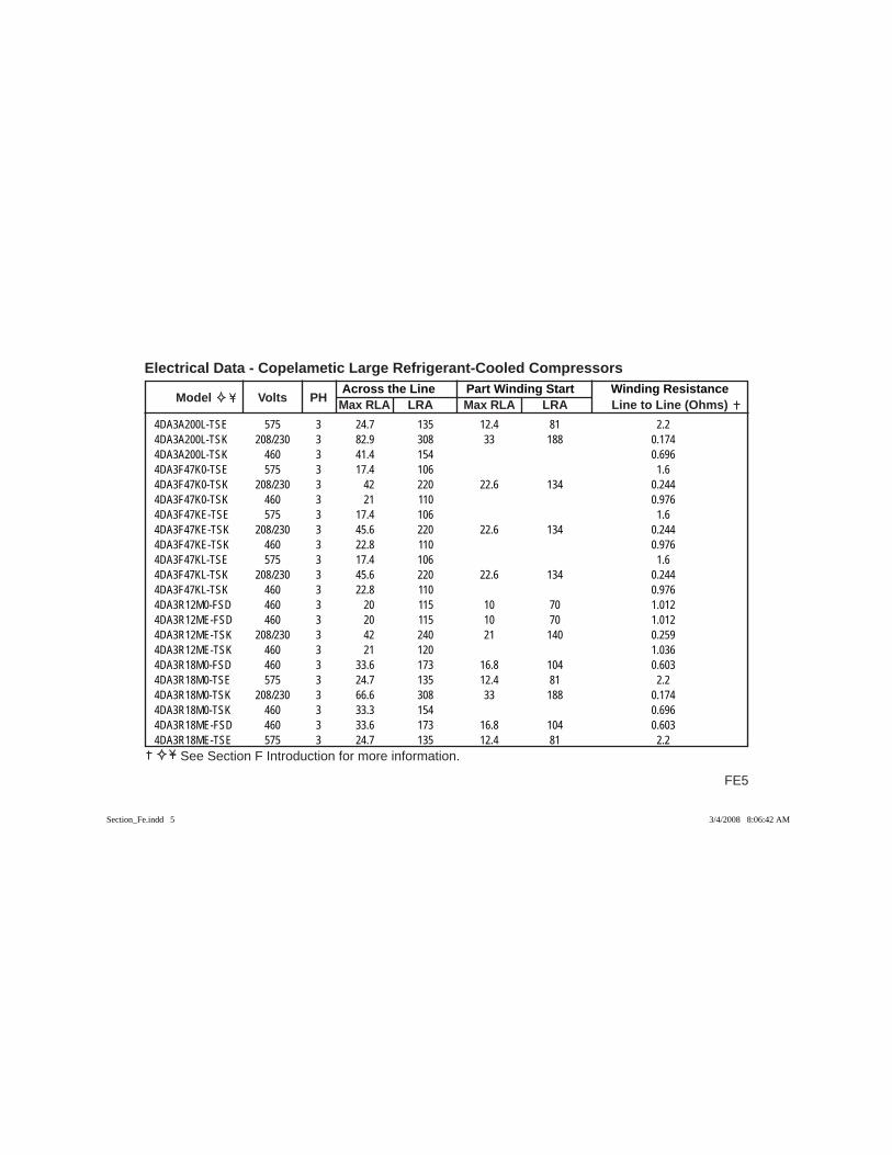
FE5
Across the Line Part Winding Start Winding Resistance Model Volts PH Max RLA LRA Max RLA LRA Line to Line (Ohms)
Electrical Data - Copelametic Large Refrigerant-Cooled Compressors
See Section F Introduction for more information.
4DA3A200L-TSE 575 3 24.7 135 12.4 81 2.24DA3A200L-TSK 208/230 3 82.9 308 33 188 0.1744DA3A200L-TSK 460 3 41.4 154 0.6964DA3F47K0-TSE 575 3 17.4 106 1.64DA3F47K0-TSK 208/230 3 42 220 22.6 134 0.2444DA3F47K0-TSK 460 3 21 110 0.9764DA3F47KE-TSE 575 3 17.4 106 1.64DA3F47KE-TSK 208/230 3 45.6 220 22.6 134 0.2444DA3F47KE-TSK 460 3 22.8 110 0.9764DA3F47KL-TSE 575 3 17.4 106 1.64DA3F47KL-TSK 208/230 3 45.6 220 22.6 134 0.2444DA3F47KL-TSK 460 3 22.8 110 0.9764DA3R12M0-FSD 460 3 20 115 10 70 1.0124DA3R12ME-FSD 460 3 20 115 10 70 1.0124DA3R12ME-TSK 208/230 3 42 240 21 140 0.2594DA3R12ME-TSK 460 3 21 120 1.0364DA3R18M0-FSD 460 3 33.6 173 16.8 104 0.6034DA3R18M0-TSE 575 3 24.7 135 12.4 81 2.24DA3R18M0-TSK 208/230 3 66.6 308 33 188 0.1744DA3R18M0-TSK 460 3 33.3 154 0.6964DA3R18ME-FSD 460 3 33.6 173 16.8 104 0.6034DA3R18ME-TSE 575 3 24.7 135 12.4 81 2.2
Section_Fe.indd 5Section_Fe.indd 5 3/4/2008 8:06:42 AM3/4/2008 8:06:42 AM
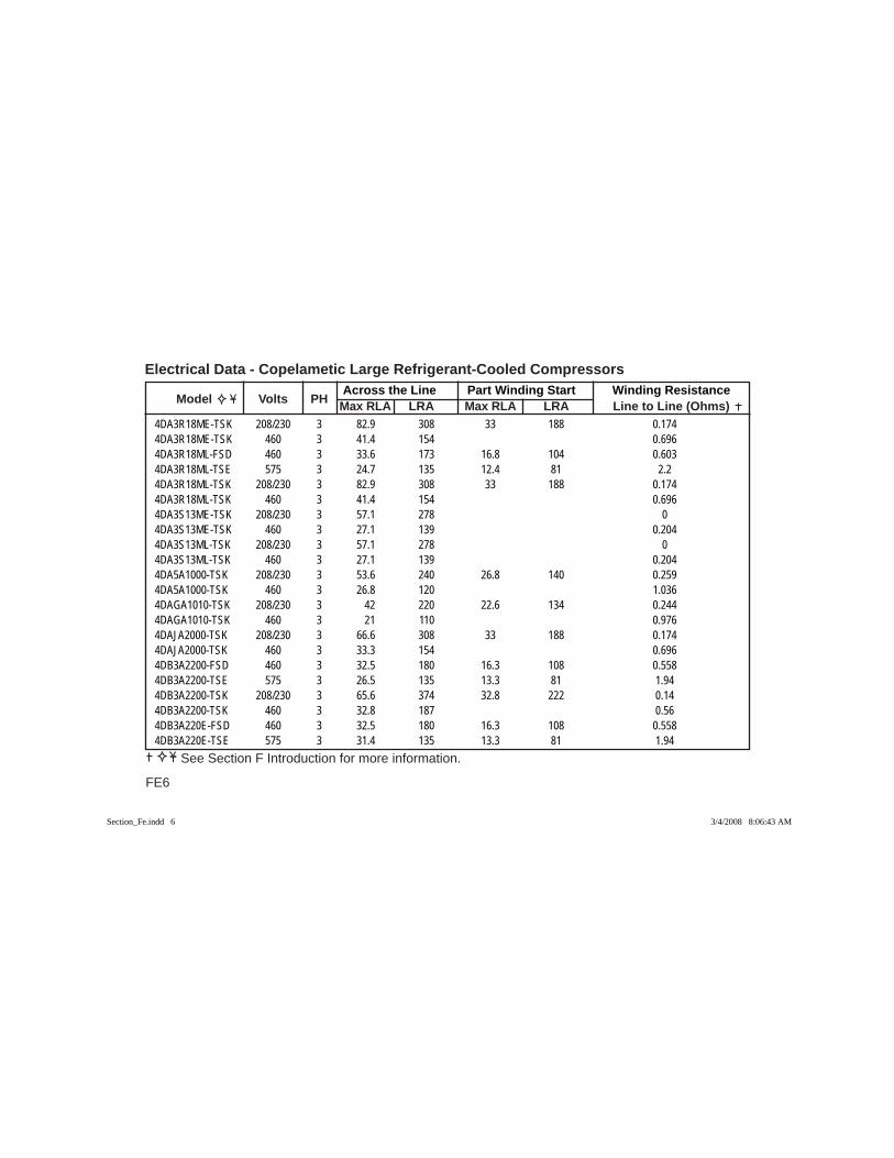
Across the Line Part Winding Start Winding Resistance Model Volts PH Max RLA LRA Max RLA LRA Line to Line (Ohms)
Electrical Data - Copelametic Large Refrigerant-Cooled Compressors
FE6
See Section F Introduction for more information.
4DA3R18ME-TSK 208/230 3 82.9 308 33 188 0.1744DA3R18ME-TSK 460 3 41.4 154 0.6964DA3R18ML-FSD 460 3 33.6 173 16.8 104 0.6034DA3R18ML-TSE 575 3 24.7 135 12.4 81 2.24DA3R18ML-TSK 208/230 3 82.9 308 33 188 0.1744DA3R18ML-TSK 460 3 41.4 154 0.6964DA3S13ME-TSK 208/230 3 57.1 278 04DA3S13ME-TSK 460 3 27.1 139 0.2044DA3S13ML-TSK 208/230 3 57.1 278 04DA3S13ML-TSK 460 3 27.1 139 0.2044DA5A1000-TSK 208/230 3 53.6 240 26.8 140 0.2594DA5A1000-TSK 460 3 26.8 120 1.0364DAGA1010-TSK 208/230 3 42 220 22.6 134 0.2444DAGA1010-TSK 460 3 21 110 0.9764DAJA2000-TSK 208/230 3 66.6 308 33 188 0.1744DAJA2000-TSK 460 3 33.3 154 0.6964DB3A2200-FSD 460 3 32.5 180 16.3 108 0.5584DB3A2200-TSE 575 3 26.5 135 13.3 81 1.944DB3A2200-TSK 208/230 3 65.6 374 32.8 222 0.144DB3A2200-TSK 460 3 32.8 187 0.564DB3A220E-FSD 460 3 32.5 180 16.3 108 0.5584DB3A220E-TSE 575 3 31.4 135 13.3 81 1.94
Section_Fe.indd 6Section_Fe.indd 6 3/4/2008 8:06:43 AM3/4/2008 8:06:43 AM
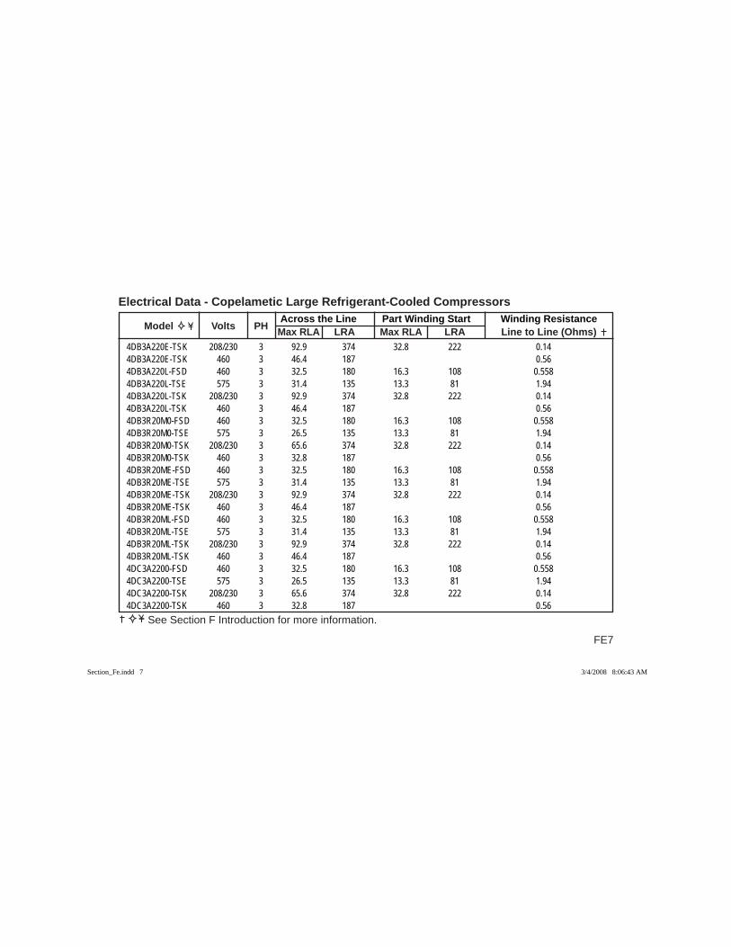
FE7
Across the Line Part Winding Start Winding Resistance Model Volts PH Max RLA LRA Max RLA LRA Line to Line (Ohms)
Electrical Data - Copelametic Large Refrigerant-Cooled Compressors
See Section F Introduction for more information.
4DB3A220E-TSK 208/230 3 92.9 374 32.8 222 0.144DB3A220E-TSK 460 3 46.4 187 0.564DB3A220L-FSD 460 3 32.5 180 16.3 108 0.5584DB3A220L-TSE 575 3 31.4 135 13.3 81 1.944DB3A220L-TSK 208/230 3 92.9 374 32.8 222 0.144DB3A220L-TSK 460 3 46.4 187 0.564DB3R20M0-FSD 460 3 32.5 180 16.3 108 0.5584DB3R20M0-TSE 575 3 26.5 135 13.3 81 1.944DB3R20M0-TSK 208/230 3 65.6 374 32.8 222 0.144DB3R20M0-TSK 460 3 32.8 187 0.564DB3R20ME-FSD 460 3 32.5 180 16.3 108 0.5584DB3R20ME-TSE 575 3 31.4 135 13.3 81 1.944DB3R20ME-TSK 208/230 3 92.9 374 32.8 222 0.144DB3R20ME-TSK 460 3 46.4 187 0.564DB3R20ML-FSD 460 3 32.5 180 16.3 108 0.5584DB3R20ML-TSE 575 3 31.4 135 13.3 81 1.944DB3R20ML-TSK 208/230 3 92.9 374 32.8 222 0.144DB3R20ML-TSK 460 3 46.4 187 0.564DC3A2200-FSD 460 3 32.5 180 16.3 108 0.5584DC3A2200-TSE 575 3 26.5 135 13.3 81 1.944DC3A2200-TSK 208/230 3 65.6 374 32.8 222 0.144DC3A2200-TSK 460 3 32.8 187 0.56
Section_Fe.indd 7Section_Fe.indd 7 3/4/2008 8:06:43 AM3/4/2008 8:06:43 AM
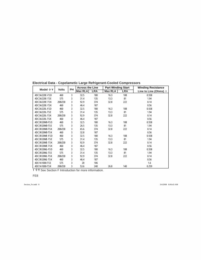
Across the Line Part Winding Start Winding Resistance Model Volts PH Max RLA LRA Max RLA LRA Line to Line (Ohms)
Electrical Data - Copelametic Large Refrigerant-Cooled Compressors
FE8
See Section F Introduction for more information.
4DC3A220E-FSD 460 3 32.5 180 16.3 108 0.5584DC3A220E-TSE 575 3 31.4 135 13.3 81 1.944DC3A220E-TSK 208/230 3 92.9 374 32.8 222 0.144DC3A220E-TSK 460 3 46.4 187 0.564DC3A220L-FSD 460 3 32.5 180 16.3 108 0.5584DC3A220L-TSE 575 3 31.4 135 13.3 81 1.944DC3A220L-TSK 208/230 3 92.9 374 32.8 222 0.144DC3A220L-TSK 460 3 46.4 187 0.564DC3R20M0-FSD 460 3 32.5 180 16.3 108 0.5584DC3R20M0-TSE 575 3 26.5 135 13.3 81 1.944DC3R20M0-TSK 208/230 3 65.6 374 32.8 222 0.144DC3R20M0-TSK 460 3 32.8 187 0.564DC3R20ME-FSD 460 3 32.5 180 16.3 108 0.5584DC3R20ME-TSE 575 3 31.4 135 13.3 81 1.944DC3R20ME-TSK 208/230 3 92.9 374 32.8 222 0.144DC3R20ME-TSK 460 3 46.4 187 0.564DC3R20ML-FSD 460 3 32.5 180 16.3 108 0.5584DC3R20ML-TSE 575 3 31.4 135 13.3 81 1.944DC3R20ML-TSK 208/230 3 92.9 374 32.8 222 0.144DC3R20ML-TSK 460 3 46.4 187 0.564DE1A1000-TSE 575 3 20 106 1.64DE1A1000-TSK 208/230 3 53.6 240 26.8 140 0.259
Section_Fe.indd 8Section_Fe.indd 8 3/4/2008 8:06:43 AM3/4/2008 8:06:43 AM
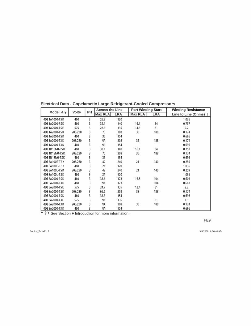
FE9
Across the Line Part Winding Start Winding Resistance Model Volts PH Max RLA LRA Max RLA LRA Line to Line (Ohms)
Electrical Data - Copelametic Large Refrigerant-Cooled Compressors
See Section F Introduction for more information.
4DE1A1000-TSK 460 3 26.8 120 1.0364DE1A2000-FSD 460 3 32.1 140 16.1 84 0.7574DE1A2000-TSE 575 3 28.6 135 14.3 81 2.24DE1A2000-TSK 208/230 3 70 308 35 188 0.1744DE1A2000-TSK 460 3 35 154 0.6964DE1A2000-TXK 208/230 3 NA 308 35 188 0.1744DE1A2000-TXK 460 3 NA 154 0.6964DE1R18M0-FSD 460 3 32.1 140 16.1 84 0.7574DE1R18M0-TSK 208/230 3 70 308 35 188 0.1744DE1R18M0-TSK 460 3 35 154 0.6964DE3A100E-TSK 208/230 3 42 240 21 140 0.2594DE3A100E-TSK 460 3 21 120 1.0364DE3A100L-TSK 208/230 3 42 240 21 140 0.2594DE3A100L-TSK 460 3 21 120 1.0364DE3A2000-FSD 460 3 33.6 173 16.8 104 0.6034DE3A2000-FXD 460 3 NA 173 104 0.6034DE3A2000-TSE 575 3 24.7 135 12.4 81 2.24DE3A2000-TSK 208/230 3 66.6 308 33 188 0.1744DE3A2000-TSK 460 3 33.3 154 0.6964DE3A2000-TXE 575 3 NA 135 81 1.14DE3A2000-TXK 208/230 3 NA 308 33 188 0.1744DE3A2000-TXK 460 3 NA 154 0.696
Section_Fe.indd 9Section_Fe.indd 9 3/4/2008 8:06:44 AM3/4/2008 8:06:44 AM
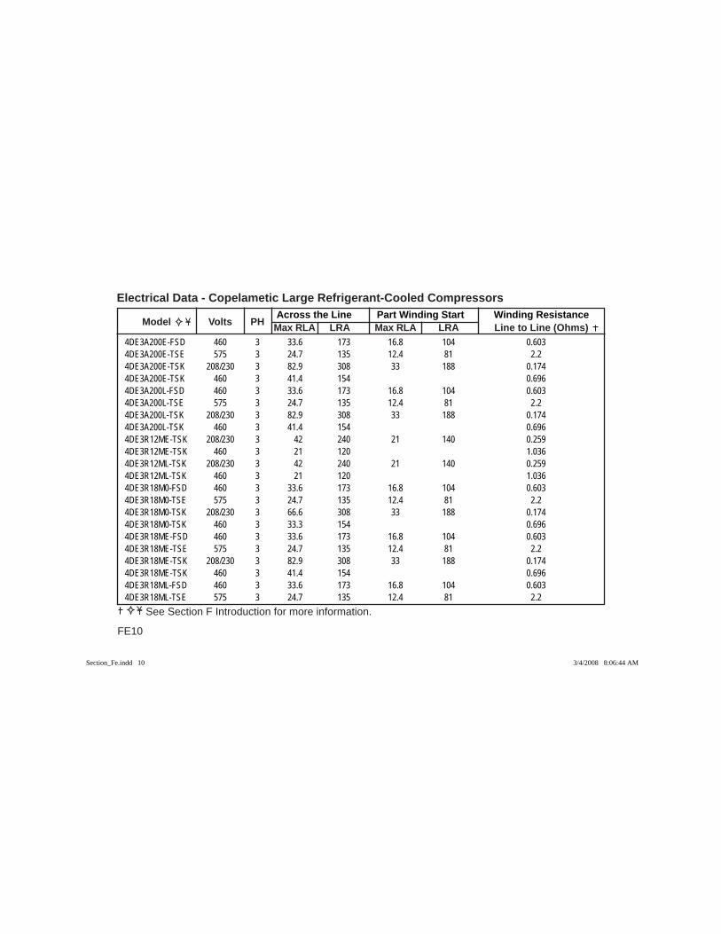
Across the Line Part Winding Start Winding Resistance Model Volts PH Max RLA LRA Max RLA LRA Line to Line (Ohms)
Electrical Data - Copelametic Large Refrigerant-Cooled Compressors
FE10
See Section F Introduction for more information.
4DE3A200E-FSD 460 3 33.6 173 16.8 104 0.6034DE3A200E-TSE 575 3 24.7 135 12.4 81 2.24DE3A200E-TSK 208/230 3 82.9 308 33 188 0.1744DE3A200E-TSK 460 3 41.4 154 0.6964DE3A200L-FSD 460 3 33.6 173 16.8 104 0.6034DE3A200L-TSE 575 3 24.7 135 12.4 81 2.24DE3A200L-TSK 208/230 3 82.9 308 33 188 0.1744DE3A200L-TSK 460 3 41.4 154 0.6964DE3R12ME-TSK 208/230 3 42 240 21 140 0.2594DE3R12ME-TSK 460 3 21 120 1.0364DE3R12ML-TSK 208/230 3 42 240 21 140 0.2594DE3R12ML-TSK 460 3 21 120 1.0364DE3R18M0-FSD 460 3 33.6 173 16.8 104 0.6034DE3R18M0-TSE 575 3 24.7 135 12.4 81 2.24DE3R18M0-TSK 208/230 3 66.6 308 33 188 0.1744DE3R18M0-TSK 460 3 33.3 154 0.6964DE3R18ME-FSD 460 3 33.6 173 16.8 104 0.6034DE3R18ME-TSE 575 3 24.7 135 12.4 81 2.24DE3R18ME-TSK 208/230 3 82.9 308 33 188 0.1744DE3R18ME-TSK 460 3 41.4 154 0.6964DE3R18ML-FSD 460 3 33.6 173 16.8 104 0.6034DE3R18ML-TSE 575 3 24.7 135 12.4 81 2.2
Section_Fe.indd 10Section_Fe.indd 10 3/4/2008 8:06:44 AM3/4/2008 8:06:44 AM
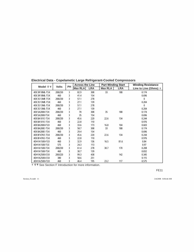
FE11
Across the Line Part Winding Start Winding Resistance Model Volts PH Max RLA LRA Max RLA LRA Line to Line (Ohms)
Electrical Data - Copelametic Large Refrigerant-Cooled Compressors
See Section F Introduction for more information.
4DE3R18ML-TSK 208/230 3 82.9 308 33 188 0.1744DE3R18ML-TSK 460 3 41.4 154 0.6964DE3S13ME-TSK 208/230 3 57.1 278 04DE3S13ME-TSK 460 3 27.1 139 0.2044DE3S13ML-TSK 208/230 3 57.1 278 04DE3S13ML-TSK 460 3 27.1 139 0.2044DE5A2000-TSK 208/230 3 70 308 35 188 0.1744DE5A2000-TSK 460 3 35 154 0.6964DE8A101E-TSK 208/230 3 45.6 220 22.6 134 0.2444DE8A101E-TSK 460 3 22.8 110 0.9764DE8A2000-FSD 460 3 33.6 173 16.8 104 0.6034DE8A200E-TSK 208/230 3 58.7 308 33 188 0.1744DE8A200E-TSK 460 3 29.4 154 0.6964DE8F47KE-TSK 208/230 3 45.6 220 22.6 134 0.2444DE8F47KE-TSK 460 3 22.8 110 0.9764DH1A1500-FSD 460 3 32.9 136 16.5 81.6 0.844DH1A1500-TSE 575 3 24.3 113 0.974DH1A1500-TSK 208/230 3 61.4 278 30.7 170 0.2084DH1A1500-TSK 460 3 30.7 139 0.8324DH1A2500-ES8 200/220 3 99.3 438 142 0.3454DH1A2500-ES8 380 3 58.6 251 0.1154DH1A2500-FSD 460 3 46.4 195 23.2 117 0.575
Section_Fe.indd 11Section_Fe.indd 11 3/4/2008 8:06:44 AM3/4/2008 8:06:44 AM
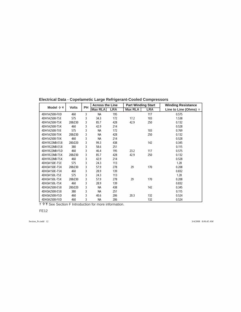
Across the Line Part Winding Start Winding Resistance Model Volts PH Max RLA LRA Max RLA LRA Line to Line (Ohms)
Electrical Data - Copelametic Large Refrigerant-Cooled Compressors
FE12
See Section F Introduction for more information.
4DH1A2500-FXD 460 3 NA 195 117 0.5754DH1A2500-TSE 575 3 34.3 172 17.2 103 1.5384DH1A2500-TSK 208/230 3 85.7 428 42.9 250 0.1324DH1A2500-TSK 460 3 42.9 214 0.5284DH1A2500-TXE 575 3 NA 172 103 0.7694DH1A2500-TXK 208/230 3 NA 428 250 0.1324DH1A2500-TXK 460 3 NA 214 0.5284DH1R22M0-ES8 200/220 3 99.3 438 142 0.3454DH1R22M0-ES8 380 3 58.6 251 0.1154DH1R22M0-FSD 460 3 46.4 195 23.2 117 0.5754DH1R22M0-TSK 208/230 3 85.7 428 42.9 250 0.1324DH1R22M0-TSK 460 3 42.9 214 0.5284DH3A150E-TSE 575 3 24.3 113 1.284DH3A150E-TSK 208/230 3 57.9 278 29 170 0.2084DH3A150E-TSK 460 3 28.9 139 0.8324DH3A150L-TSE 575 3 24.3 113 1.284DH3A150L-TSK 208/230 3 57.9 278 29 170 0.2084DH3A150L-TSK 460 3 28.9 139 0.8324DH3A2500-ES8 200/220 3 NA 438 142 0.3454DH3A2500-ES8 380 3 NA 251 0.1154DH3A2500-FSD 460 3 40.6 206 20.3 132 0.5244DH3A2500-FXD 460 3 NA 206 132 0.524
Section_Fe.indd 12Section_Fe.indd 12 3/4/2008 8:06:45 AM3/4/2008 8:06:45 AM

FE13
Across the Line Part Winding Start Winding Resistance Model Volts PH Max RLA LRA Max RLA LRA Line to Line (Ohms)
Electrical Data - Copelametic Large Refrigerant-Cooled Compressors
See Section F Introduction for more information.
4DH3A2500-TSE 575 3 34.4 172 17.2 103 1.5384DH3A2500-TSK 208/230 3 82.1 428 41.1 250 0.1324DH3A2500-TSK 460 3 41.1 214 0.5284DH3A2500-TXE 575 3 NA 172 103 0.7694DH3A2500-TXK 208/230 3 NA 428 250 0.1324DH3A2500-TXK 460 3 NA 214 0.5284DH3A250E-ES8 200/220 3 NA 438 142 0.3454DH3A250E-ES8 380 3 NA 251 0.1154DH3A250E-FSD 460 3 40.6 206 20.3 132 0.5244DH3A250E-TSE 575 3 34.4 172 17.2 103 1.5384DH3A250E-TSK 208/230 3 82.1 428 41.1 250 0.1324DH3A250E-TSK 460 3 52.9 214 0.5284DH3A250L-ES8 200/220 3 NA 438 142 0.3454DH3A250L-ES8 380 3 NA 251 0.1154DH3A250L-FSD 460 3 40.6 206 20.3 132 0.5244DH3A250L-TSE 575 3 34.4 172 17.2 103 1.5384DH3A250L-TSK 208/230 3 82.1 428 41.1 250 0.1324DH3A250L-TSK 460 3 52.9 214 0.5284DH3R16ME-TSK 208/230 3 57.9 278 29 170 0.2084DH3R16ME-TSK 460 3 28.9 139 0.8324DH3R16ML-TSK 208/230 3 57.9 278 29 170 0.2084DH3R16ML-TSK 460 3 28.9 139 0.832
Section_Fe.indd 13Section_Fe.indd 13 3/4/2008 8:06:45 AM3/4/2008 8:06:45 AM
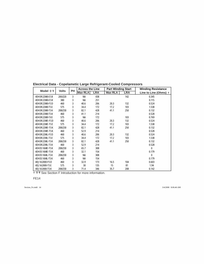
Across the Line Part Winding Start Winding Resistance Model Volts PH Max RLA LRA Max RLA LRA Line to Line (Ohms)
Electrical Data - Copelametic Large Refrigerant-Cooled Compressors
FE14
See Section F Introduction for more information.
4DH3R22M0-ES8 200/220 3 NA 438 142 0.3454DH3R22M0-ES8 380 3 NA 251 0.1154DH3R22M0-FSD 460 3 40.6 206 20.3 132 0.5244DH3R22M0-TSE 575 3 34.4 172 17.2 103 1.5384DH3R22M0-TSK 208/230 3 82.1 428 41.1 250 0.1324DH3R22M0-TSK 460 3 41.1 214 0.5284DH3R22M0-TXE 575 3 NA 172 103 0.7694DH3R22ME-FSD 460 3 40.6 206 20.3 132 0.5244DH3R22ME-TSE 575 3 34.4 172 17.2 103 1.5384DH3R22ME-TSK 208/230 3 82.1 428 41.1 250 0.1324DH3R22ME-TSK 460 3 52.9 214 0.5284DH3R22ML-FSD 460 3 40.6 206 20.3 132 0.5244DH3R22ML-TSE 575 3 34.4 172 17.2 103 1.5384DH3R22ML-TSK 208/230 3 82.1 428 41.1 250 0.1324DH3R22ML-TSK 460 3 52.9 214 0.5284DH3S16ME-TSK 208/230 3 65.7 308 04DH3S16ME-TSK 460 3 32.1 154 0.1794DH3S16ML-TSK 208/230 3 NA 308 04DH3S16ML-TSK 460 3 NA 154 0.1794DJ1A2000-FSD 460 3 32.9 173 16.5 104 0.6034DJ1A2000-TSE 575 3 30 135 15 81 1.944DJ1A2000-TSK 208/230 3 71.4 346 35.7 208 0.142
Section_Fe.indd 14Section_Fe.indd 14 3/4/2008 8:06:46 AM3/4/2008 8:06:46 AM
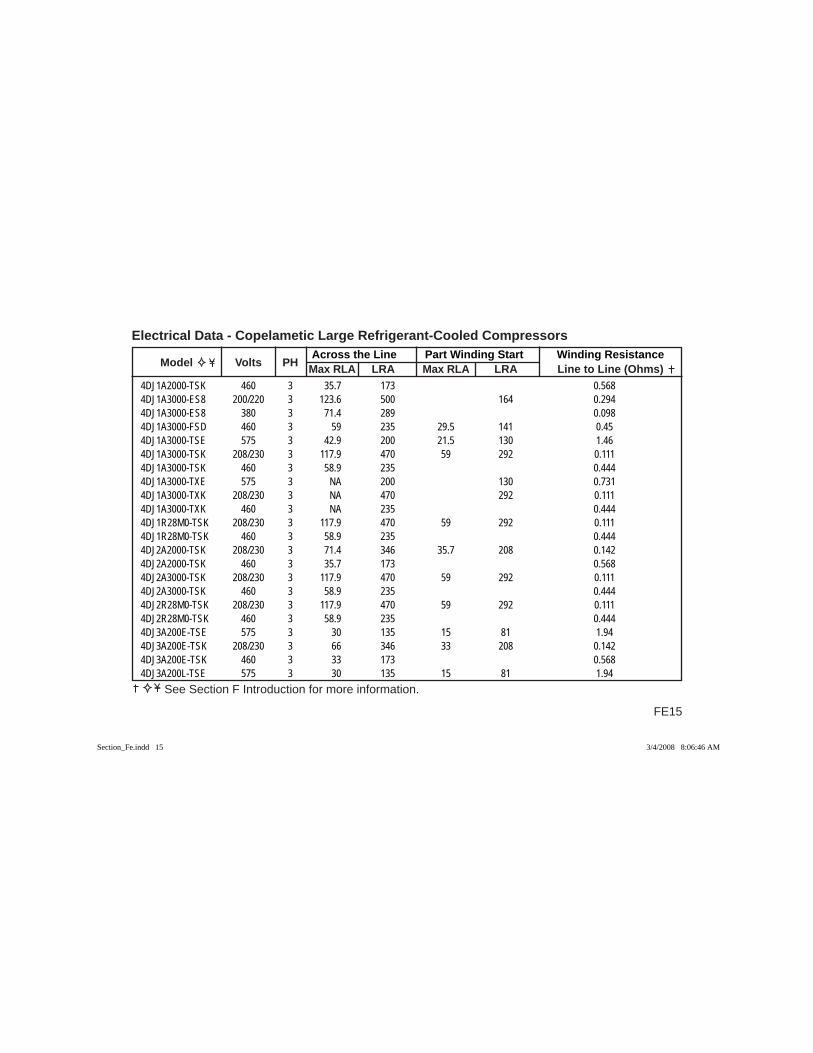
FE15
Across the Line Part Winding Start Winding Resistance Model Volts PH Max RLA LRA Max RLA LRA Line to Line (Ohms)
Electrical Data - Copelametic Large Refrigerant-Cooled Compressors
See Section F Introduction for more information.
4DJ1A2000-TSK 460 3 35.7 173 0.5684DJ1A3000-ES8 200/220 3 123.6 500 164 0.2944DJ1A3000-ES8 380 3 71.4 289 0.0984DJ1A3000-FSD 460 3 59 235 29.5 141 0.454DJ1A3000-TSE 575 3 42.9 200 21.5 130 1.464DJ1A3000-TSK 208/230 3 117.9 470 59 292 0.1114DJ1A3000-TSK 460 3 58.9 235 0.4444DJ1A3000-TXE 575 3 NA 200 130 0.7314DJ1A3000-TXK 208/230 3 NA 470 292 0.1114DJ1A3000-TXK 460 3 NA 235 0.4444DJ1R28M0-TSK 208/230 3 117.9 470 59 292 0.1114DJ1R28M0-TSK 460 3 58.9 235 0.4444DJ2A2000-TSK 208/230 3 71.4 346 35.7 208 0.1424DJ2A2000-TSK 460 3 35.7 173 0.5684DJ2A3000-TSK 208/230 3 117.9 470 59 292 0.1114DJ2A3000-TSK 460 3 58.9 235 0.4444DJ2R28M0-TSK 208/230 3 117.9 470 59 292 0.1114DJ2R28M0-TSK 460 3 58.9 235 0.4444DJ3A200E-TSE 575 3 30 135 15 81 1.944DJ3A200E-TSK 208/230 3 66 346 33 208 0.1424DJ3A200E-TSK 460 3 33 173 0.5684DJ3A200L-TSE 575 3 30 135 15 81 1.94
Section_Fe.indd 15Section_Fe.indd 15 3/4/2008 8:06:46 AM3/4/2008 8:06:46 AM
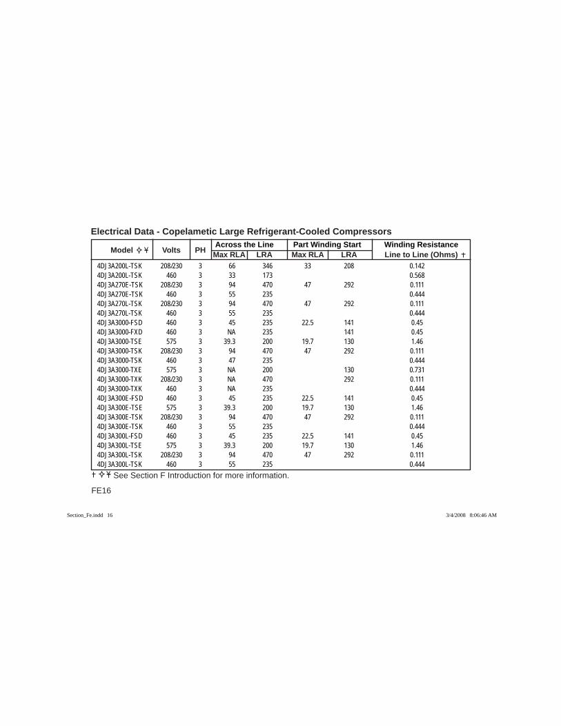
Across the Line Part Winding Start Winding Resistance Model Volts PH Max RLA LRA Max RLA LRA Line to Line (Ohms)
Electrical Data - Copelametic Large Refrigerant-Cooled Compressors
FE16
See Section F Introduction for more information.
4DJ3A200L-TSK 208/230 3 66 346 33 208 0.1424DJ3A200L-TSK 460 3 33 173 0.5684DJ3A270E-TSK 208/230 3 94 470 47 292 0.1114DJ3A270E-TSK 460 3 55 235 0.4444DJ3A270L-TSK 208/230 3 94 470 47 292 0.1114DJ3A270L-TSK 460 3 55 235 0.4444DJ3A3000-FSD 460 3 45 235 22.5 141 0.454DJ3A3000-FXD 460 3 NA 235 141 0.454DJ3A3000-TSE 575 3 39.3 200 19.7 130 1.464DJ3A3000-TSK 208/230 3 94 470 47 292 0.1114DJ3A3000-TSK 460 3 47 235 0.4444DJ3A3000-TXE 575 3 NA 200 130 0.7314DJ3A3000-TXK 208/230 3 NA 470 292 0.1114DJ3A3000-TXK 460 3 NA 235 0.4444DJ3A300E-FSD 460 3 45 235 22.5 141 0.454DJ3A300E-TSE 575 3 39.3 200 19.7 130 1.464DJ3A300E-TSK 208/230 3 94 470 47 292 0.1114DJ3A300E-TSK 460 3 55 235 0.4444DJ3A300L-FSD 460 3 45 235 22.5 141 0.454DJ3A300L-TSE 575 3 39.3 200 19.7 130 1.464DJ3A300L-TSK 208/230 3 94 470 47 292 0.1114DJ3A300L-TSK 460 3 55 235 0.444
Section_Fe.indd 16Section_Fe.indd 16 3/4/2008 8:06:46 AM3/4/2008 8:06:46 AM
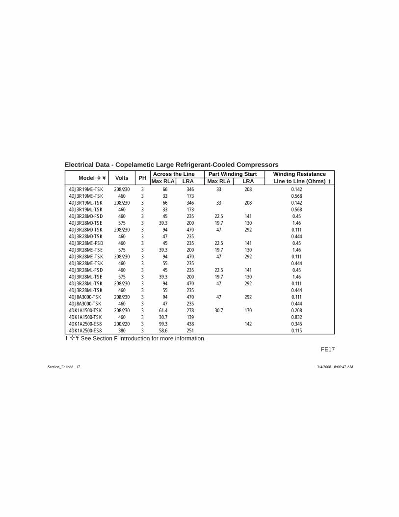
FE17
Across the Line Part Winding Start Winding Resistance Model Volts PH Max RLA LRA Max RLA LRA Line to Line (Ohms)
Electrical Data - Copelametic Large Refrigerant-Cooled Compressors
See Section F Introduction for more information.
4DJ3R19ME-TSK 208/230 3 66 346 33 208 0.1424DJ3R19ME-TSK 460 3 33 173 0.5684DJ3R19ML-TSK 208/230 3 66 346 33 208 0.1424DJ3R19ML-TSK 460 3 33 173 0.5684DJ3R28M0-FSD 460 3 45 235 22.5 141 0.454DJ3R28M0-TSE 575 3 39.3 200 19.7 130 1.464DJ3R28M0-TSK 208/230 3 94 470 47 292 0.1114DJ3R28M0-TSK 460 3 47 235 0.4444DJ3R28ME-FSD 460 3 45 235 22.5 141 0.454DJ3R28ME-TSE 575 3 39.3 200 19.7 130 1.464DJ3R28ME-TSK 208/230 3 94 470 47 292 0.1114DJ3R28ME-TSK 460 3 55 235 0.4444DJ3R28ML-FSD 460 3 45 235 22.5 141 0.454DJ3R28ML-TSE 575 3 39.3 200 19.7 130 1.464DJ3R28ML-TSK 208/230 3 94 470 47 292 0.1114DJ3R28ML-TSK 460 3 55 235 0.4444DJ8A3000-TSK 208/230 3 94 470 47 292 0.1114DJ8A3000-TSK 460 3 47 235 0.4444DK1A1500-TSK 208/230 3 61.4 278 30.7 170 0.2084DK1A1500-TSK 460 3 30.7 139 0.8324DK1A2500-ES8 200/220 3 99.3 438 142 0.3454DK1A2500-ES8 380 3 58.6 251 0.115
Section_Fe.indd 17Section_Fe.indd 17 3/4/2008 8:06:47 AM3/4/2008 8:06:47 AM
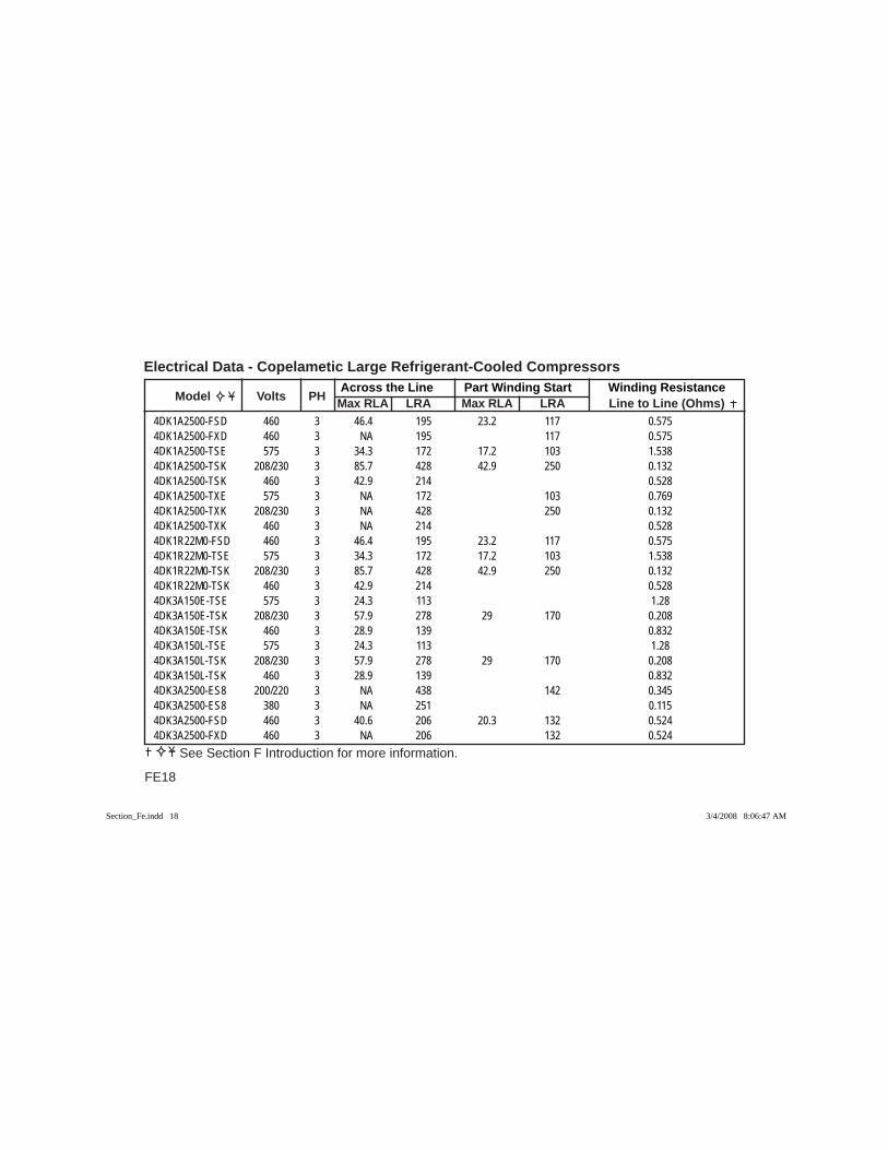
Across the Line Part Winding Start Winding Resistance Model Volts PH Max RLA LRA Max RLA LRA Line to Line (Ohms)
Electrical Data - Copelametic Large Refrigerant-Cooled Compressors
FE18
See Section F Introduction for more information.
4DK1A2500-FSD 460 3 46.4 195 23.2 117 0.5754DK1A2500-FXD 460 3 NA 195 117 0.5754DK1A2500-TSE 575 3 34.3 172 17.2 103 1.5384DK1A2500-TSK 208/230 3 85.7 428 42.9 250 0.1324DK1A2500-TSK 460 3 42.9 214 0.5284DK1A2500-TXE 575 3 NA 172 103 0.7694DK1A2500-TXK 208/230 3 NA 428 250 0.1324DK1A2500-TXK 460 3 NA 214 0.5284DK1R22M0-FSD 460 3 46.4 195 23.2 117 0.5754DK1R22M0-TSE 575 3 34.3 172 17.2 103 1.5384DK1R22M0-TSK 208/230 3 85.7 428 42.9 250 0.1324DK1R22M0-TSK 460 3 42.9 214 0.5284DK3A150E-TSE 575 3 24.3 113 1.284DK3A150E-TSK 208/230 3 57.9 278 29 170 0.2084DK3A150E-TSK 460 3 28.9 139 0.8324DK3A150L-TSE 575 3 24.3 113 1.284DK3A150L-TSK 208/230 3 57.9 278 29 170 0.2084DK3A150L-TSK 460 3 28.9 139 0.8324DK3A2500-ES8 200/220 3 NA 438 142 0.3454DK3A2500-ES8 380 3 NA 251 0.1154DK3A2500-FSD 460 3 40.6 206 20.3 132 0.5244DK3A2500-FXD 460 3 NA 206 132 0.524
Section_Fe.indd 18Section_Fe.indd 18 3/4/2008 8:06:47 AM3/4/2008 8:06:47 AM
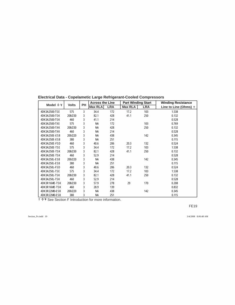
FE19
Across the Line Part Winding Start Winding Resistance Model Volts PH Max RLA LRA Max RLA LRA Line to Line (Ohms)
Electrical Data - Copelametic Large Refrigerant-Cooled Compressors
See Section F Introduction for more information.
4DK3A2500-TSE 575 3 34.4 172 17.2 103 1.5384DK3A2500-TSK 208/230 3 82.1 428 41.1 250 0.1324DK3A2500-TSK 460 3 41.1 214 0.5284DK3A2500-TXE 575 3 NA 172 103 0.7694DK3A2500-TXK 208/230 3 NA 428 250 0.1324DK3A2500-TXK 460 3 NA 214 0.5284DK3A250E-ES8 200/220 3 NA 438 142 0.3454DK3A250E-ES8 380 3 NA 251 0.1154DK3A250E-FSD 460 3 40.6 206 20.3 132 0.5244DK3A250E-TSE 575 3 34.4 172 17.2 103 1.5384DK3A250E-TSK 208/230 3 82.1 428 41.1 250 0.1324DK3A250E-TSK 460 3 52.9 214 0.5284DK3A250L-ES8 200/220 3 NA 438 142 0.3454DK3A250L-ES8 380 3 NA 251 0.1154DK3A250L-FSD 460 3 40.6 206 20.3 132 0.5244DK3A250L-TSE 575 3 34.4 172 17.2 103 1.5384DK3A250L-TSK 208/230 3 82.1 428 41.1 250 0.1324DK3A250L-TSK 460 3 52.9 214 0.5284DK3R16ME-TSK 208/230 3 57.9 278 29 170 0.2084DK3R16ME-TSK 460 3 28.9 139 0.8324DK3R22M0-ES8 200/220 3 NA 438 142 0.3454DK3R22M0-ES8 380 3 NA 251 0.115
Section_Fe.indd 19Section_Fe.indd 19 3/4/2008 8:06:48 AM3/4/2008 8:06:48 AM
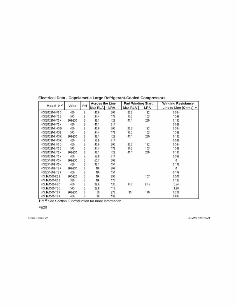
Across the Line Part Winding Start Winding Resistance Model Volts PH Max RLA LRA Max RLA LRA Line to Line (Ohms)
Electrical Data - Copelametic Large Refrigerant-Cooled Compressors
FE20
See Section F Introduction for more information.
4DK3R22M0-FSD 460 3 40.6 206 20.3 132 0.5244DK3R22M0-TSE 575 3 34.4 172 17.2 103 1.5384DK3R22M0-TSK 208/230 3 82.1 428 41.1 250 0.1324DK3R22M0-TSK 460 3 41.1 214 0.5284DK3R22ME-FSD 460 3 40.6 206 20.3 132 0.5244DK3R22ME-TSE 575 3 34.4 172 17.2 103 1.5384DK3R22ME-TSK 208/230 3 82.1 428 41.1 250 0.1324DK3R22ME-TSK 460 3 52.9 214 0.5284DK3R22ML-FSD 460 3 40.6 206 20.3 132 0.5244DK3R22ML-TSE 575 3 34.4 172 17.2 103 1.5384DK3R22ML-TSK 208/230 3 82.1 428 41.1 250 0.1324DK3R22ML-TSK 460 3 52.9 214 0.5284DK3S16ME-TSK 208/230 3 65.7 308 04DK3S16ME-TSK 460 3 32.1 154 0.1794DK3S16ML-TSK 208/230 3 NA 308 04DK3S16ML-TSK 460 3 NA 154 0.1794DL1A1500-ES8 200/220 3 NA 295 107 0.5464DL1A1500-ES8 380 3 NA 175 0.1824DL1A1500-FSD 460 3 28.6 136 14.3 81.6 0.844DL1A1500-TSE 575 3 22.8 113 1.284DL1A1500-TSK 208/230 3 60 278 30 170 0.2084DL1A1500-TSK 460 3 30 139 0.832
Section_Fe.indd 20Section_Fe.indd 20 3/4/2008 8:06:48 AM3/4/2008 8:06:48 AM
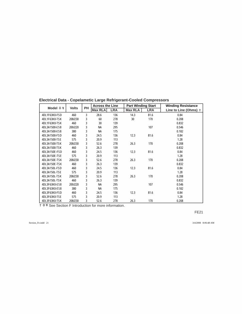
FE21
Across the Line Part Winding Start Winding Resistance Model Volts PH Max RLA LRA Max RLA LRA Line to Line (Ohms)
Electrical Data - Copelametic Large Refrigerant-Cooled Compressors
See Section F Introduction for more information.
4DL1F63K0-FSD 460 3 28.6 136 14.3 81.6 0.844DL1F63K0-TSK 208/230 3 60 278 30 170 0.2084DL1F63K0-TSK 460 3 30 139 0.8324DL3A1500-ES8 200/220 3 NA 295 107 0.5464DL3A1500-ES8 380 3 NA 175 0.1824DL3A1500-FSD 460 3 24.5 136 12.3 81.6 0.844DL3A1500-TSE 575 3 20.9 113 1.284DL3A1500-TSK 208/230 3 52.6 278 26.3 170 0.2084DL3A1500-TSK 460 3 26.3 139 0.8324DL3A150E-FSD 460 3 24.5 136 12.3 81.6 0.844DL3A150E-TSE 575 3 20.9 113 1.284DL3A150E-TSK 208/230 3 52.6 278 26.3 170 0.2084DL3A150E-TSK 460 3 26.3 139 0.8324DL3A150L-FSD 460 3 24.5 136 12.3 81.6 0.844DL3A150L-TSE 575 3 20.9 113 1.284DL3A150L-TSK 208/230 3 52.6 278 26.3 170 0.2084DL3A150L-TSK 460 3 26.3 139 0.8324DL3F63K0-ES8 200/220 3 NA 295 107 0.5464DL3F63K0-ES8 380 3 NA 175 0.1824DL3F63K0-FSD 460 3 24.5 136 12.3 81.6 0.844DL3F63K0-TSE 575 3 20.9 113 1.284DL3F63K0-TSK 208/230 3 52.6 278 26.3 170 0.208
Section_Fe.indd 21Section_Fe.indd 21 3/4/2008 8:06:48 AM3/4/2008 8:06:48 AM
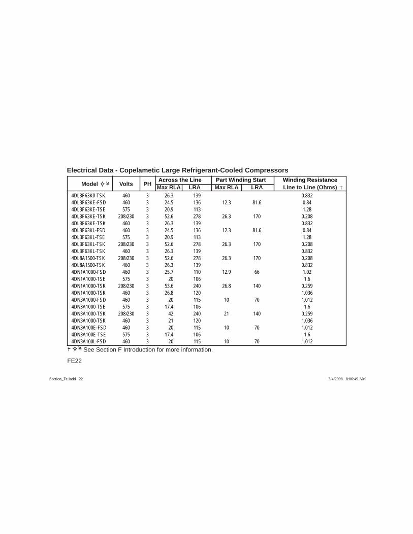
Across the Line Part Winding Start Winding Resistance Model Volts PH Max RLA LRA Max RLA LRA Line to Line (Ohms)
Electrical Data - Copelametic Large Refrigerant-Cooled Compressors
FE22
See Section F Introduction for more information.
4DL3F63K0-TSK 460 3 26.3 139 0.8324DL3F63KE-FSD 460 3 24.5 136 12.3 81.6 0.844DL3F63KE-TSE 575 3 20.9 113 1.284DL3F63KE-TSK 208/230 3 52.6 278 26.3 170 0.2084DL3F63KE-TSK 460 3 26.3 139 0.8324DL3F63KL-FSD 460 3 24.5 136 12.3 81.6 0.844DL3F63KL-TSE 575 3 20.9 113 1.284DL3F63KL-TSK 208/230 3 52.6 278 26.3 170 0.2084DL3F63KL-TSK 460 3 26.3 139 0.8324DL8A1500-TSK 208/230 3 52.6 278 26.3 170 0.2084DL8A1500-TSK 460 3 26.3 139 0.8324DN1A1000-FSD 460 3 25.7 110 12.9 66 1.024DN1A1000-TSE 575 3 20 106 1.64DN1A1000-TSK 208/230 3 53.6 240 26.8 140 0.2594DN1A1000-TSK 460 3 26.8 120 1.0364DN3A1000-FSD 460 3 20 115 10 70 1.0124DN3A1000-TSE 575 3 17.4 106 1.64DN3A1000-TSK 208/230 3 42 240 21 140 0.2594DN3A1000-TSK 460 3 21 120 1.0364DN3A100E-FSD 460 3 20 115 10 70 1.0124DN3A100E-TSE 575 3 17.4 106 1.64DN3A100L-FSD 460 3 20 115 10 70 1.012
Section_Fe.indd 22Section_Fe.indd 22 3/4/2008 8:06:49 AM3/4/2008 8:06:49 AM
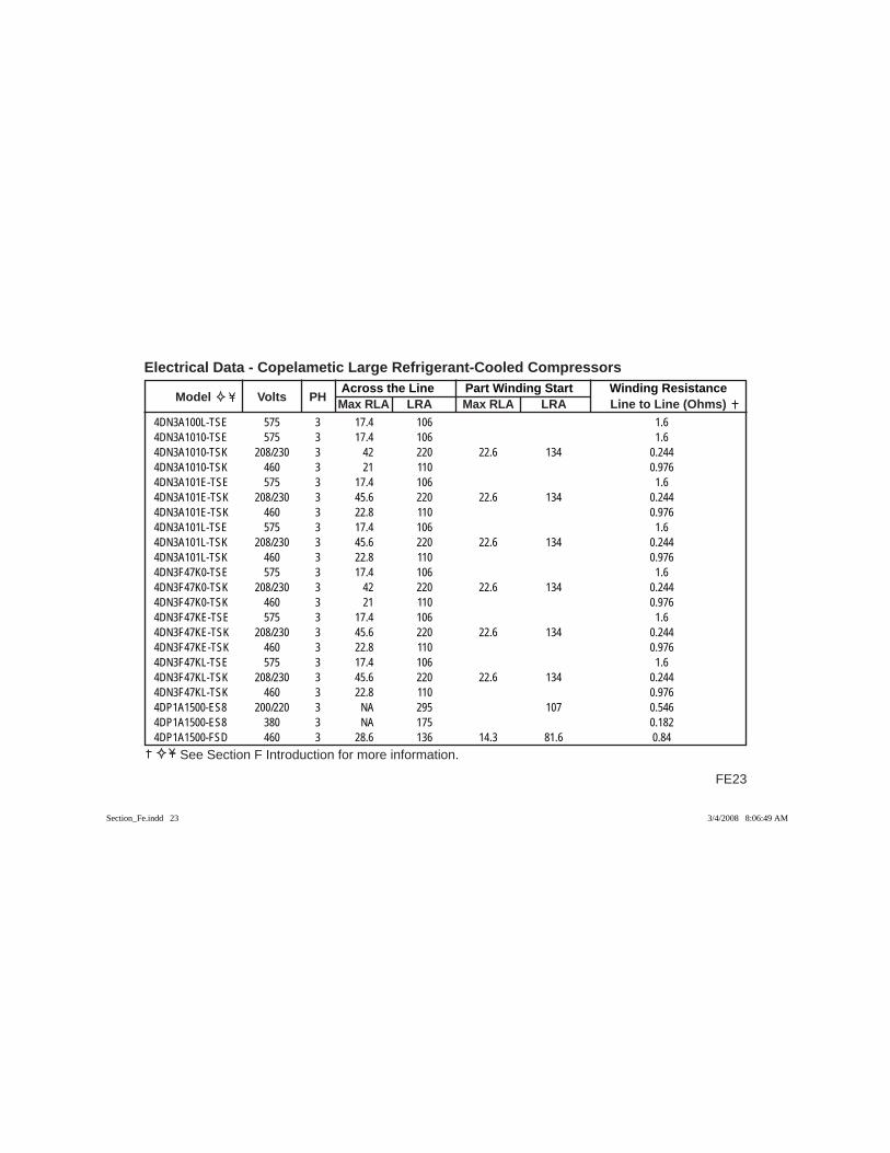
FE23
Across the Line Part Winding Start Winding Resistance Model Volts PH Max RLA LRA Max RLA LRA Line to Line (Ohms)
Electrical Data - Copelametic Large Refrigerant-Cooled Compressors
See Section F Introduction for more information.
4DN3A100L-TSE 575 3 17.4 106 1.64DN3A1010-TSE 575 3 17.4 106 1.64DN3A1010-TSK 208/230 3 42 220 22.6 134 0.2444DN3A1010-TSK 460 3 21 110 0.9764DN3A101E-TSE 575 3 17.4 106 1.64DN3A101E-TSK 208/230 3 45.6 220 22.6 134 0.2444DN3A101E-TSK 460 3 22.8 110 0.9764DN3A101L-TSE 575 3 17.4 106 1.64DN3A101L-TSK 208/230 3 45.6 220 22.6 134 0.2444DN3A101L-TSK 460 3 22.8 110 0.9764DN3F47K0-TSE 575 3 17.4 106 1.64DN3F47K0-TSK 208/230 3 42 220 22.6 134 0.2444DN3F47K0-TSK 460 3 21 110 0.9764DN3F47KE-TSE 575 3 17.4 106 1.64DN3F47KE-TSK 208/230 3 45.6 220 22.6 134 0.2444DN3F47KE-TSK 460 3 22.8 110 0.9764DN3F47KL-TSE 575 3 17.4 106 1.64DN3F47KL-TSK 208/230 3 45.6 220 22.6 134 0.2444DN3F47KL-TSK 460 3 22.8 110 0.9764DP1A1500-ES8 200/220 3 NA 295 107 0.5464DP1A1500-ES8 380 3 NA 175 0.1824DP1A1500-FSD 460 3 28.6 136 14.3 81.6 0.84
Section_Fe.indd 23Section_Fe.indd 23 3/4/2008 8:06:49 AM3/4/2008 8:06:49 AM
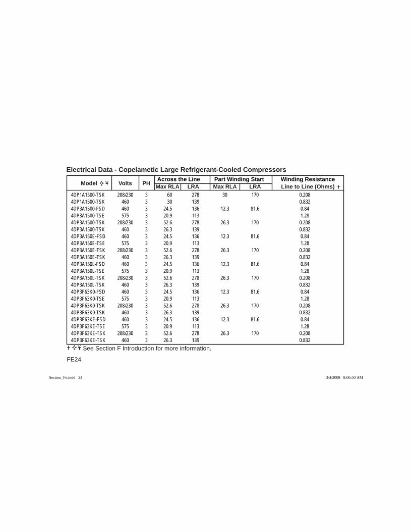
Across the Line Part Winding Start Winding Resistance Model Volts PH Max RLA LRA Max RLA LRA Line to Line (Ohms)
Electrical Data - Copelametic Large Refrigerant-Cooled Compressors
FE24
See Section F Introduction for more information.
4DP1A1500-TSK 208/230 3 60 278 30 170 0.2084DP1A1500-TSK 460 3 30 139 0.8324DP3A1500-FSD 460 3 24.5 136 12.3 81.6 0.844DP3A1500-TSE 575 3 20.9 113 1.284DP3A1500-TSK 208/230 3 52.6 278 26.3 170 0.2084DP3A1500-TSK 460 3 26.3 139 0.8324DP3A150E-FSD 460 3 24.5 136 12.3 81.6 0.844DP3A150E-TSE 575 3 20.9 113 1.284DP3A150E-TSK 208/230 3 52.6 278 26.3 170 0.2084DP3A150E-TSK 460 3 26.3 139 0.8324DP3A150L-FSD 460 3 24.5 136 12.3 81.6 0.844DP3A150L-TSE 575 3 20.9 113 1.284DP3A150L-TSK 208/230 3 52.6 278 26.3 170 0.2084DP3A150L-TSK 460 3 26.3 139 0.8324DP3F63K0-FSD 460 3 24.5 136 12.3 81.6 0.844DP3F63K0-TSE 575 3 20.9 113 1.284DP3F63K0-TSK 208/230 3 52.6 278 26.3 170 0.2084DP3F63K0-TSK 460 3 26.3 139 0.8324DP3F63KE-FSD 460 3 24.5 136 12.3 81.6 0.844DP3F63KE-TSE 575 3 20.9 113 1.284DP3F63KE-TSK 208/230 3 52.6 278 26.3 170 0.2084DP3F63KE-TSK 460 3 26.3 139 0.832
Section_Fe.indd 24Section_Fe.indd 24 3/4/2008 8:06:50 AM3/4/2008 8:06:50 AM
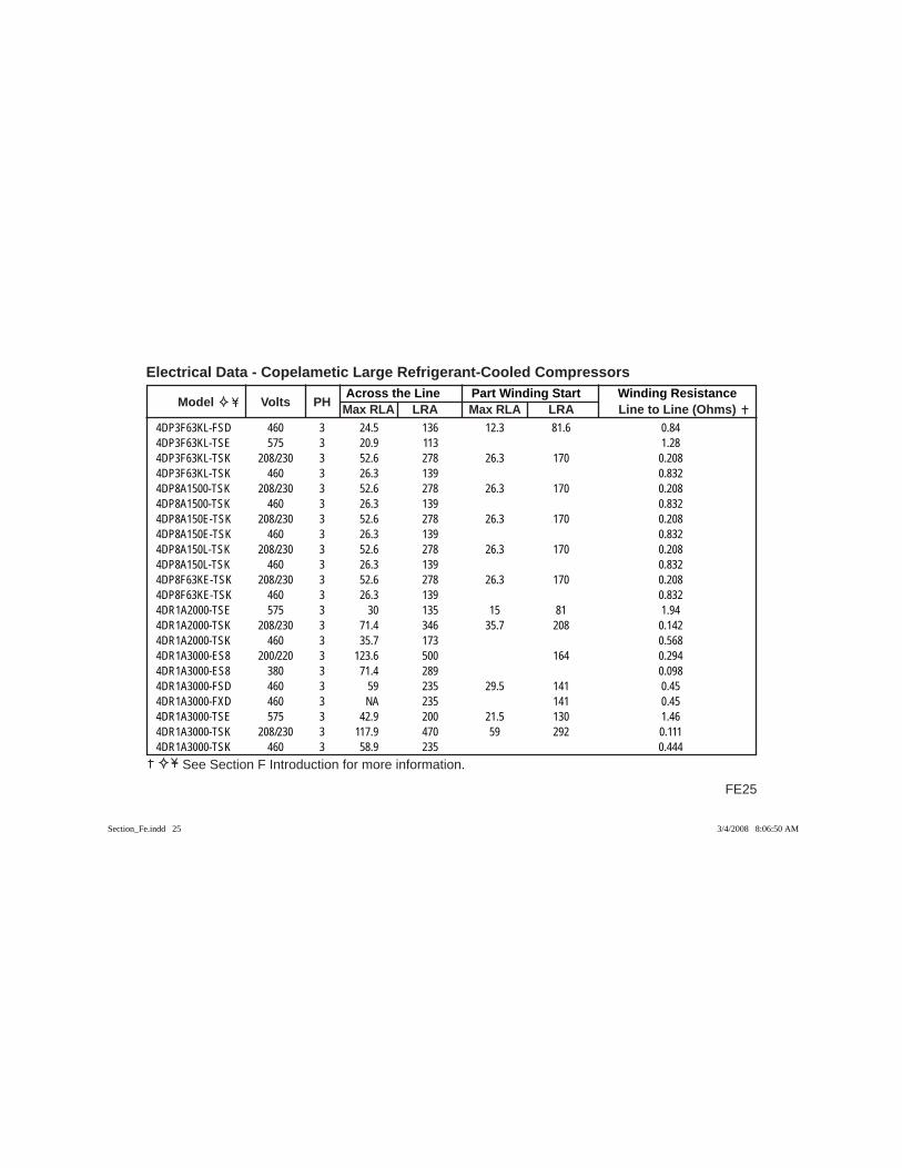
FE25
Across the Line Part Winding Start Winding Resistance Model Volts PH Max RLA LRA Max RLA LRA Line to Line (Ohms)
Electrical Data - Copelametic Large Refrigerant-Cooled Compressors
See Section F Introduction for more information.
4DP3F63KL-FSD 460 3 24.5 136 12.3 81.6 0.844DP3F63KL-TSE 575 3 20.9 113 1.284DP3F63KL-TSK 208/230 3 52.6 278 26.3 170 0.2084DP3F63KL-TSK 460 3 26.3 139 0.8324DP8A1500-TSK 208/230 3 52.6 278 26.3 170 0.2084DP8A1500-TSK 460 3 26.3 139 0.8324DP8A150E-TSK 208/230 3 52.6 278 26.3 170 0.2084DP8A150E-TSK 460 3 26.3 139 0.8324DP8A150L-TSK 208/230 3 52.6 278 26.3 170 0.2084DP8A150L-TSK 460 3 26.3 139 0.8324DP8F63KE-TSK 208/230 3 52.6 278 26.3 170 0.2084DP8F63KE-TSK 460 3 26.3 139 0.8324DR1A2000-TSE 575 3 30 135 15 81 1.944DR1A2000-TSK 208/230 3 71.4 346 35.7 208 0.1424DR1A2000-TSK 460 3 35.7 173 0.5684DR1A3000-ES8 200/220 3 123.6 500 164 0.2944DR1A3000-ES8 380 3 71.4 289 0.0984DR1A3000-FSD 460 3 59 235 29.5 141 0.454DR1A3000-FXD 460 3 NA 235 141 0.454DR1A3000-TSE 575 3 42.9 200 21.5 130 1.464DR1A3000-TSK 208/230 3 117.9 470 59 292 0.1114DR1A3000-TSK 460 3 58.9 235 0.444
Section_Fe.indd 25Section_Fe.indd 25 3/4/2008 8:06:50 AM3/4/2008 8:06:50 AM
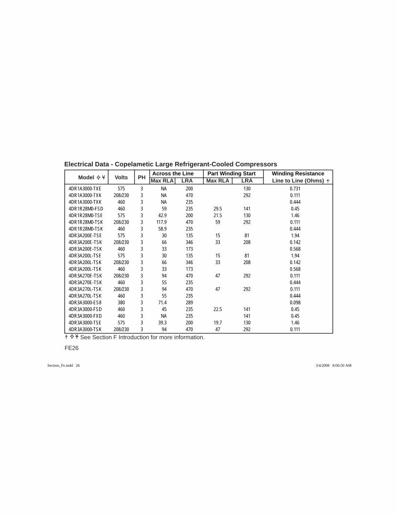
Across the Line Part Winding Start Winding Resistance Model Volts PH Max RLA LRA Max RLA LRA Line to Line (Ohms)
Electrical Data - Copelametic Large Refrigerant-Cooled Compressors
FE26
See Section F Introduction for more information.
4DR1A3000-TXE 575 3 NA 200 130 0.7314DR1A3000-TXK 208/230 3 NA 470 292 0.1114DR1A3000-TXK 460 3 NA 235 0.4444DR1R28M0-FSD 460 3 59 235 29.5 141 0.454DR1R28M0-TSE 575 3 42.9 200 21.5 130 1.464DR1R28M0-TSK 208/230 3 117.9 470 59 292 0.1114DR1R28M0-TSK 460 3 58.9 235 0.4444DR3A200E-TSE 575 3 30 135 15 81 1.944DR3A200E-TSK 208/230 3 66 346 33 208 0.1424DR3A200E-TSK 460 3 33 173 0.5684DR3A200L-TSE 575 3 30 135 15 81 1.944DR3A200L-TSK 208/230 3 66 346 33 208 0.1424DR3A200L-TSK 460 3 33 173 0.5684DR3A270E-TSK 208/230 3 94 470 47 292 0.1114DR3A270E-TSK 460 3 55 235 0.4444DR3A270L-TSK 208/230 3 94 470 47 292 0.1114DR3A270L-TSK 460 3 55 235 0.4444DR3A3000-ES8 380 3 71.4 289 0.0984DR3A3000-FSD 460 3 45 235 22.5 141 0.454DR3A3000-FXD 460 3 NA 235 141 0.454DR3A3000-TSE 575 3 39.3 200 19.7 130 1.464DR3A3000-TSK 208/230 3 94 470 47 292 0.111
Section_Fe.indd 26Section_Fe.indd 26 3/4/2008 8:06:50 AM3/4/2008 8:06:50 AM
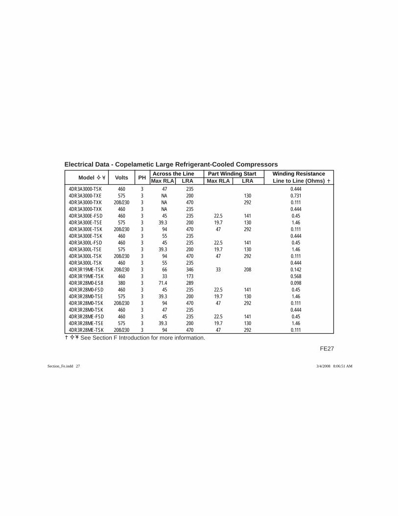
FE27
Across the Line Part Winding Start Winding Resistance Model Volts PH Max RLA LRA Max RLA LRA Line to Line (Ohms)
Electrical Data - Copelametic Large Refrigerant-Cooled Compressors
See Section F Introduction for more information.
4DR3A3000-TSK 460 3 47 235 0.4444DR3A3000-TXE 575 3 NA 200 130 0.7314DR3A3000-TXK 208/230 3 NA 470 292 0.1114DR3A3000-TXK 460 3 NA 235 0.4444DR3A300E-FSD 460 3 45 235 22.5 141 0.454DR3A300E-TSE 575 3 39.3 200 19.7 130 1.464DR3A300E-TSK 208/230 3 94 470 47 292 0.1114DR3A300E-TSK 460 3 55 235 0.4444DR3A300L-FSD 460 3 45 235 22.5 141 0.454DR3A300L-TSE 575 3 39.3 200 19.7 130 1.464DR3A300L-TSK 208/230 3 94 470 47 292 0.1114DR3A300L-TSK 460 3 55 235 0.4444DR3R19ME-TSK 208/230 3 66 346 33 208 0.1424DR3R19ME-TSK 460 3 33 173 0.5684DR3R28M0-ES8 380 3 71.4 289 0.0984DR3R28M0-FSD 460 3 45 235 22.5 141 0.454DR3R28M0-TSE 575 3 39.3 200 19.7 130 1.464DR3R28M0-TSK 208/230 3 94 470 47 292 0.1114DR3R28M0-TSK 460 3 47 235 0.4444DR3R28ME-FSD 460 3 45 235 22.5 141 0.454DR3R28ME-TSE 575 3 39.3 200 19.7 130 1.464DR3R28ME-TSK 208/230 3 94 470 47 292 0.111
Section_Fe.indd 27Section_Fe.indd 27 3/4/2008 8:06:51 AM3/4/2008 8:06:51 AM
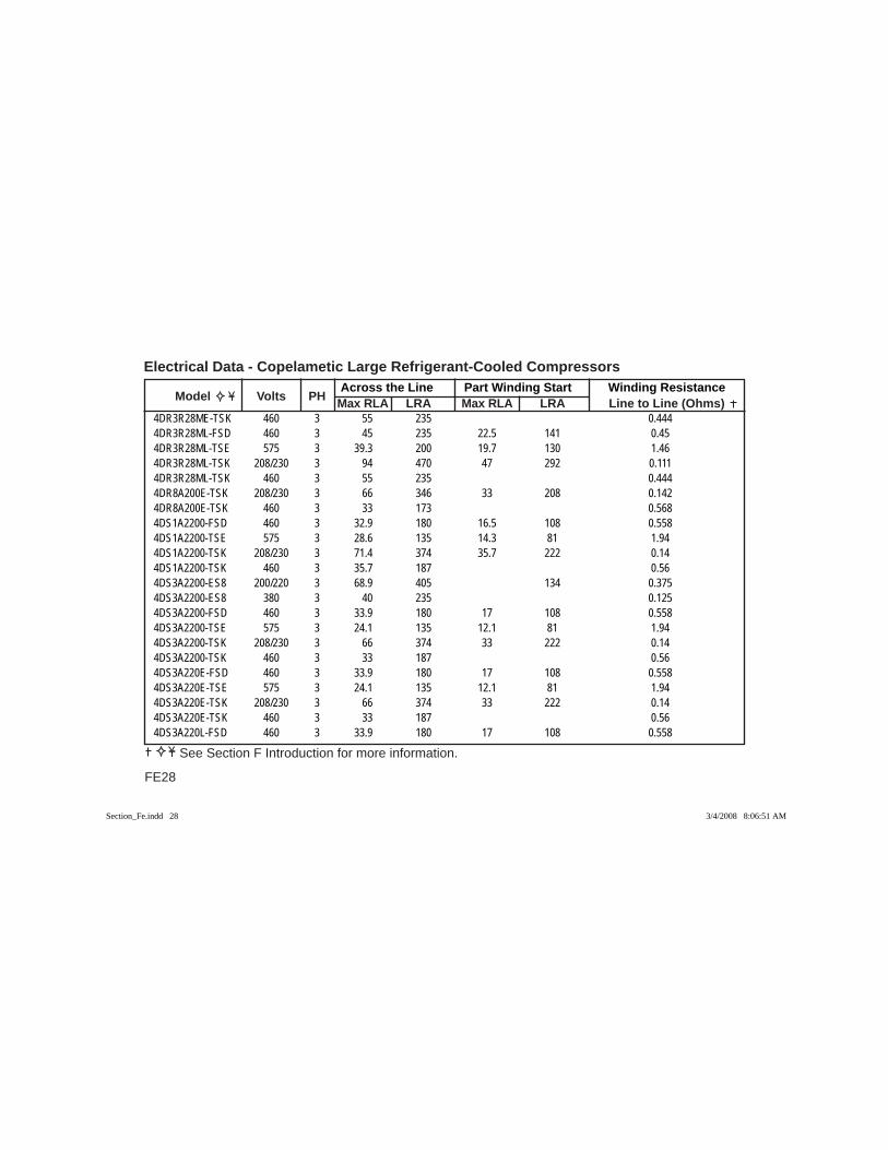
Across the Line Part Winding Start Winding Resistance Model Volts PH Max RLA LRA Max RLA LRA Line to Line (Ohms)
Electrical Data - Copelametic Large Refrigerant-Cooled Compressors
FE28
See Section F Introduction for more information.
4DR3R28ME-TSK 460 3 55 235 0.4444DR3R28ML-FSD 460 3 45 235 22.5 141 0.454DR3R28ML-TSE 575 3 39.3 200 19.7 130 1.464DR3R28ML-TSK 208/230 3 94 470 47 292 0.1114DR3R28ML-TSK 460 3 55 235 0.4444DR8A200E-TSK 208/230 3 66 346 33 208 0.1424DR8A200E-TSK 460 3 33 173 0.5684DS1A2200-FSD 460 3 32.9 180 16.5 108 0.5584DS1A2200-TSE 575 3 28.6 135 14.3 81 1.944DS1A2200-TSK 208/230 3 71.4 374 35.7 222 0.144DS1A2200-TSK 460 3 35.7 187 0.564DS3A2200-ES8 200/220 3 68.9 405 134 0.3754DS3A2200-ES8 380 3 40 235 0.1254DS3A2200-FSD 460 3 33.9 180 17 108 0.5584DS3A2200-TSE 575 3 24.1 135 12.1 81 1.944DS3A2200-TSK 208/230 3 66 374 33 222 0.144DS3A2200-TSK 460 3 33 187 0.564DS3A220E-FSD 460 3 33.9 180 17 108 0.5584DS3A220E-TSE 575 3 24.1 135 12.1 81 1.944DS3A220E-TSK 208/230 3 66 374 33 222 0.144DS3A220E-TSK 460 3 33 187 0.564DS3A220L-FSD 460 3 33.9 180 17 108 0.558
Section_Fe.indd 28Section_Fe.indd 28 3/4/2008 8:06:51 AM3/4/2008 8:06:51 AM
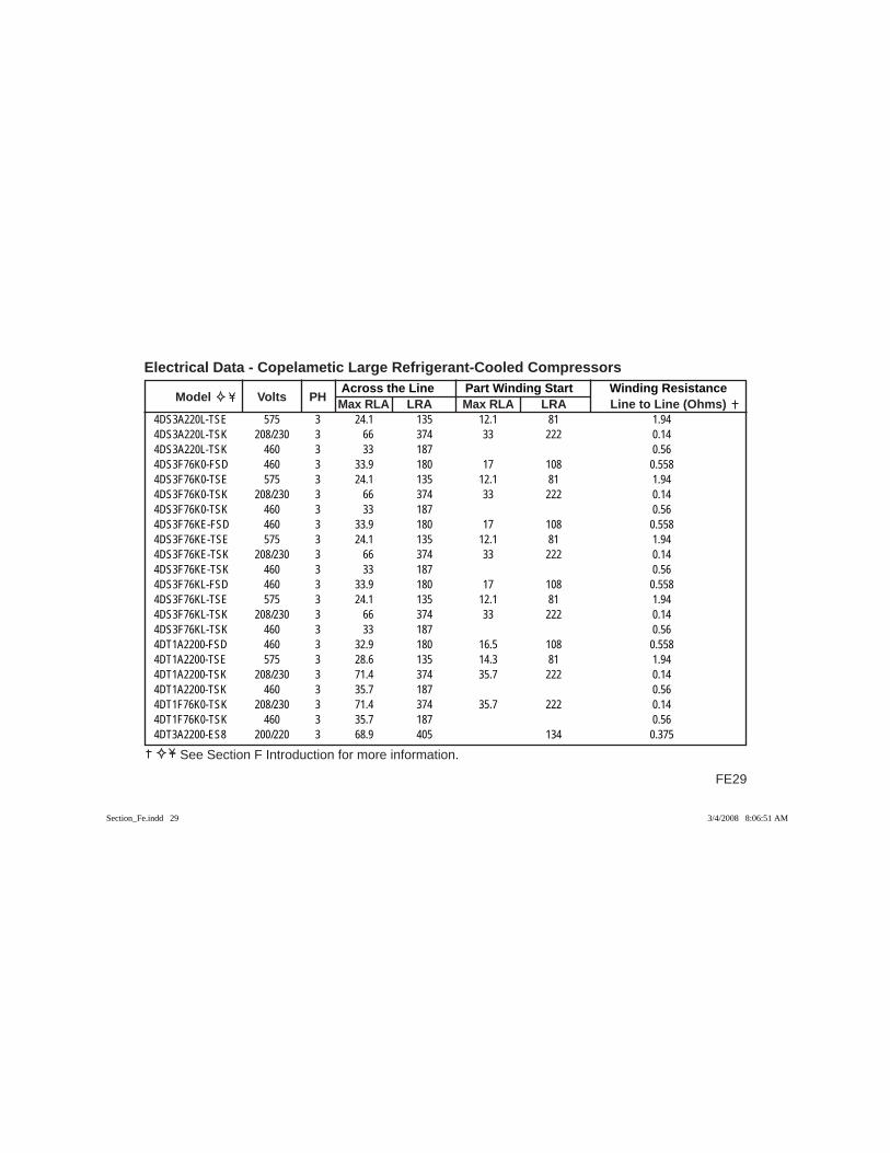
FE29
Across the Line Part Winding Start Winding Resistance Model Volts PH Max RLA LRA Max RLA LRA Line to Line (Ohms)
Electrical Data - Copelametic Large Refrigerant-Cooled Compressors
See Section F Introduction for more information.
4DS3A220L-TSE 575 3 24.1 135 12.1 81 1.944DS3A220L-TSK 208/230 3 66 374 33 222 0.144DS3A220L-TSK 460 3 33 187 0.564DS3F76K0-FSD 460 3 33.9 180 17 108 0.5584DS3F76K0-TSE 575 3 24.1 135 12.1 81 1.944DS3F76K0-TSK 208/230 3 66 374 33 222 0.144DS3F76K0-TSK 460 3 33 187 0.564DS3F76KE-FSD 460 3 33.9 180 17 108 0.5584DS3F76KE-TSE 575 3 24.1 135 12.1 81 1.944DS3F76KE-TSK 208/230 3 66 374 33 222 0.144DS3F76KE-TSK 460 3 33 187 0.564DS3F76KL-FSD 460 3 33.9 180 17 108 0.5584DS3F76KL-TSE 575 3 24.1 135 12.1 81 1.944DS3F76KL-TSK 208/230 3 66 374 33 222 0.144DS3F76KL-TSK 460 3 33 187 0.564DT1A2200-FSD 460 3 32.9 180 16.5 108 0.5584DT1A2200-TSE 575 3 28.6 135 14.3 81 1.944DT1A2200-TSK 208/230 3 71.4 374 35.7 222 0.144DT1A2200-TSK 460 3 35.7 187 0.564DT1F76K0-TSK 208/230 3 71.4 374 35.7 222 0.144DT1F76K0-TSK 460 3 35.7 187 0.564DT3A2200-ES8 200/220 3 68.9 405 134 0.375
Section_Fe.indd 29Section_Fe.indd 29 3/4/2008 8:06:51 AM3/4/2008 8:06:51 AM
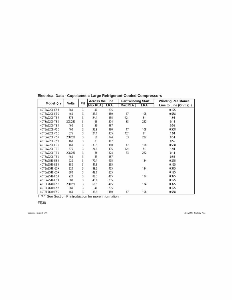
Across the Line Part Winding Start Winding Resistance Model Volts PH Max RLA LRA Max RLA LRA Line to Line (Ohms)
Electrical Data - Copelametic Large Refrigerant-Cooled Compressors
FE30
See Section F Introduction for more information.
4DT3A2200-ES8 380 3 40 235 0.1254DT3A2200-FSD 460 3 33.9 180 17 108 0.5584DT3A2200-TSE 575 3 24.1 135 12.1 81 1.944DT3A2200-TSK 208/230 3 66 374 33 222 0.144DT3A2200-TSK 460 3 33 187 0.564DT3A220E-FSD 460 3 33.9 180 17 108 0.5584DT3A220E-TSE 575 3 24.1 135 12.1 81 1.944DT3A220E-TSK 208/230 3 66 374 33 222 0.144DT3A220E-TSK 460 3 33 187 0.564DT3A220L-FSD 460 3 33.9 180 17 108 0.5584DT3A220L-TSE 575 3 24.1 135 12.1 81 1.944DT3A220L-TSK 208/230 3 66 374 33 222 0.144DT3A220L-TSK 460 3 33 187 0.564DT3A2510-ESX 220 3 72.1 405 134 0.3754DT3A2510-ESX 380 3 41.9 235 0.1254DT3A251E-ESX 220 3 89.3 405 134 0.3754DT3A251E-ESX 380 3 49.6 235 0.1254DT3A251L-ESX 220 3 89.3 405 134 0.3754DT3A251L-ESX 380 3 49.6 235 0.1254DT3F76K0-ES8 200/220 3 68.9 405 134 0.3754DT3F76K0-ES8 380 3 40 235 0.1254DT3F76K0-FSD 460 3 33.9 180 17 108 0.558
Section_Fe.indd 30Section_Fe.indd 30 3/4/2008 8:06:52 AM3/4/2008 8:06:52 AM
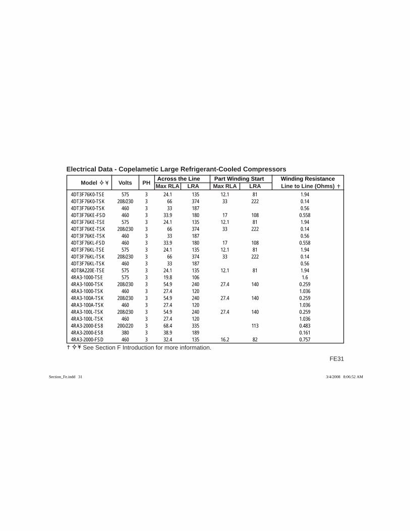
FE31
Across the Line Part Winding Start Winding Resistance Model Volts PH Max RLA LRA Max RLA LRA Line to Line (Ohms)
Electrical Data - Copelametic Large Refrigerant-Cooled Compressors
See Section F Introduction for more information.
4DT3F76K0-TSE 575 3 24.1 135 12.1 81 1.944DT3F76K0-TSK 208/230 3 66 374 33 222 0.144DT3F76K0-TSK 460 3 33 187 0.564DT3F76KE-FSD 460 3 33.9 180 17 108 0.5584DT3F76KE-TSE 575 3 24.1 135 12.1 81 1.944DT3F76KE-TSK 208/230 3 66 374 33 222 0.144DT3F76KE-TSK 460 3 33 187 0.564DT3F76KL-FSD 460 3 33.9 180 17 108 0.5584DT3F76KL-TSE 575 3 24.1 135 12.1 81 1.944DT3F76KL-TSK 208/230 3 66 374 33 222 0.144DT3F76KL-TSK 460 3 33 187 0.564DT8A220E-TSE 575 3 24.1 135 12.1 81 1.944RA3-1000-TSE 575 3 19.8 106 1.64RA3-1000-TSK 208/230 3 54.9 240 27.4 140 0.2594RA3-1000-TSK 460 3 27.4 120 1.0364RA3-100A-TSK 208/230 3 54.9 240 27.4 140 0.2594RA3-100A-TSK 460 3 27.4 120 1.0364RA3-100L-TSK 208/230 3 54.9 240 27.4 140 0.2594RA3-100L-TSK 460 3 27.4 120 1.0364RA3-2000-ES8 200/220 3 68.4 335 113 0.4834RA3-2000-ES8 380 3 38.9 189 0.1614RA3-2000-FSD 460 3 32.4 135 16.2 82 0.757
Section_Fe.indd 31Section_Fe.indd 31 3/4/2008 8:06:52 AM3/4/2008 8:06:52 AM
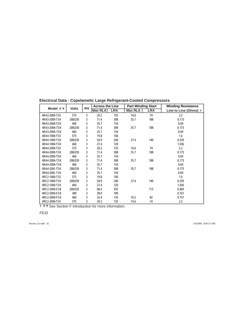
Across the Line Part Winding Start Winding Resistance Model Volts PH Max RLA LRA Max RLA LRA Line to Line (Ohms)
Electrical Data - Copelametic Large Refrigerant-Cooled Compressors
FE32
See Section F Introduction for more information.
4RA3-2000-TSE 575 3 29.2 135 14.6 74 2.24RA3-2000-TSK 208/230 3 71.4 308 35.7 188 0.1734RA3-2000-TSK 460 3 35.7 154 0.694RA3-200A-TSK 208/230 3 71.4 308 35.7 188 0.1734RA3-200A-TSK 460 3 35.7 154 0.694RA4-1000-TSE 575 3 19.8 106 1.64RA4-1000-TSK 208/230 3 54.9 240 27.4 140 0.2594RA4-1000-TSK 460 3 27.4 120 1.0364RA4-2000-TSE 575 3 29.2 135 14.6 74 2.24RA4-2000-TSK 208/230 3 71.4 308 35.7 188 0.1734RA4-2000-TSK 460 3 35.7 154 0.694RA4-200A-TSK 208/230 3 71.4 308 35.7 188 0.1734RA4-200A-TSK 460 3 35.7 154 0.694RA4-200L-TSK 208/230 3 71.4 308 35.7 188 0.1734RA4-200L-TSK 460 3 35.7 154 0.694RE2-1000-TSE 575 3 19.8 106 1.64RE2-1000-TSK 208/230 3 54.9 240 27.4 140 0.2594RE2-1000-TSK 460 3 27.4 120 1.0364RE2-2000-ES8 200/220 3 68.4 335 113 0.4834RE2-2000-ES8 380 3 38.9 189 0.1614RE2-2000-FSD 460 3 32.4 135 16.2 82 0.7574RE2-2000-TSE 575 3 29.2 135 14.6 74 2.2
Section_Fe.indd 32Section_Fe.indd 32 3/4/2008 8:06:53 AM3/4/2008 8:06:53 AM
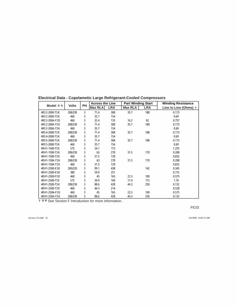
FE33
Across the Line Part Winding Start Winding Resistance Model Volts PH Max RLA LRA Max RLA LRA Line to Line (Ohms)
Electrical Data - Copelametic Large Refrigerant-Cooled Compressors
See Section F Introduction for more information.
4RE2-2000-TSK 208/230 3 71.4 308 35.7 188 0.1734RE2-2000-TSK 460 3 35.7 154 0.694RE2-200A-FSD 460 3 32.4 135 16.2 82 0.7574RE2-200A-TSK 208/230 3 71.4 308 35.7 188 0.1734RE2-200A-TSK 460 3 35.7 154 0.694RE4-2000-TSK 208/230 3 71.4 308 35.7 188 0.1734RE4-2000-TSK 460 3 35.7 154 0.694RE5-2000-TSK 208/230 3 71.4 308 35.7 188 0.1734RE5-2000-TSK 460 3 35.7 154 0.694RH1-1500-TSE 575 3 24.1 113 1.2554RH1-1500-TSK 208/230 3 63 278 31.5 170 0.2084RH1-1500-TSK 460 3 31.5 139 0.8324RH1-150A-TSK 208/230 3 63 278 31.5 170 0.2084RH1-150A-TSK 460 3 31.5 139 0.8324RH1-2500-ES8 200/220 3 99.1 438 142 0.3454RH1-2500-ES8 380 3 59.9 251 0.1154RH1-2500-FSD 460 3 45 165 22.5 100 0.5754RH1-2500-TSE 575 3 34.9 160 17.4 113 1.764RH1-2500-TSK 208/230 3 88.6 428 44.3 250 0.1324RH1-2500-TSK 460 3 44.3 214 0.5284RH1-250A-FSD 460 3 45 165 22.5 100 0.5754RH1-250A-TSK 208/230 3 88.6 428 44.3 250 0.132
Section_Fe.indd 33Section_Fe.indd 33 3/4/2008 8:06:53 AM3/4/2008 8:06:53 AM
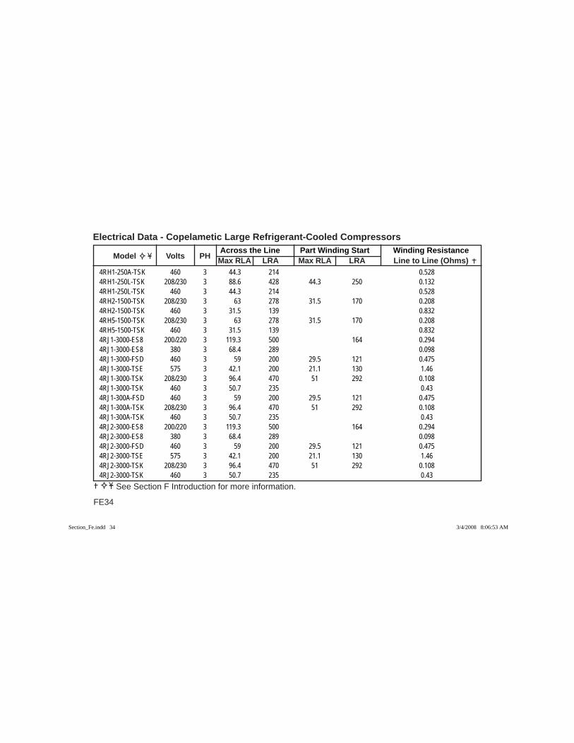
Across the Line Part Winding Start Winding Resistance Model Volts PH Max RLA LRA Max RLA LRA Line to Line (Ohms)
Electrical Data - Copelametic Large Refrigerant-Cooled Compressors
FE34
See Section F Introduction for more information.
4RH1-250A-TSK 460 3 44.3 214 0.5284RH1-250L-TSK 208/230 3 88.6 428 44.3 250 0.1324RH1-250L-TSK 460 3 44.3 214 0.5284RH2-1500-TSK 208/230 3 63 278 31.5 170 0.2084RH2-1500-TSK 460 3 31.5 139 0.8324RH5-1500-TSK 208/230 3 63 278 31.5 170 0.2084RH5-1500-TSK 460 3 31.5 139 0.8324RJ1-3000-ES8 200/220 3 119.3 500 164 0.2944RJ1-3000-ES8 380 3 68.4 289 0.0984RJ1-3000-FSD 460 3 59 200 29.5 121 0.4754RJ1-3000-TSE 575 3 42.1 200 21.1 130 1.464RJ1-3000-TSK 208/230 3 96.4 470 51 292 0.1084RJ1-3000-TSK 460 3 50.7 235 0.434RJ1-300A-FSD 460 3 59 200 29.5 121 0.4754RJ1-300A-TSK 208/230 3 96.4 470 51 292 0.1084RJ1-300A-TSK 460 3 50.7 235 0.434RJ2-3000-ES8 200/220 3 119.3 500 164 0.2944RJ2-3000-ES8 380 3 68.4 289 0.0984RJ2-3000-FSD 460 3 59 200 29.5 121 0.4754RJ2-3000-TSE 575 3 42.1 200 21.1 130 1.464RJ2-3000-TSK 208/230 3 96.4 470 51 292 0.1084RJ2-3000-TSK 460 3 50.7 235 0.43
Section_Fe.indd 34Section_Fe.indd 34 3/4/2008 8:06:53 AM3/4/2008 8:06:53 AM

FE35
Across the Line Part Winding Start Winding Resistance Model Volts PH Max RLA LRA Max RLA LRA Line to Line (Ohms)
Electrical Data - Copelametic Large Refrigerant-Cooled Compressors
See Section F Introduction for more information.
4RJ2-300A-TSK 208/230 3 96.4 470 51 292 0.1084RJ2-300A-TSK 460 3 50.7 235 0.434RK2-1500-TSE 575 3 24.1 113 1.2554RK2-1500-TSK 208/230 3 63 278 31.5 170 0.2084RK2-1500-TSK 460 3 31.5 139 0.8324RK2-2500-ES8 200/220 3 102.5 438 142 0.3454RK2-2500-ES8 380 3 59.9 251 0.1154RK2-2500-FSD 460 3 45 165 22.5 100 0.5754RK2-2500-TSE 575 3 34.9 160 17.4 113 1.764RK2-2500-TSK 208/230 3 88.6 428 44.3 250 0.1324RK2-2500-TSK 460 3 44.3 214 0.5284RK2-250A-FSD 460 3 45 165 22.5 100 0.5754RK2-250A-TSE 575 3 34.9 160 17.4 113 1.764RK2-250A-TSK 208/230 3 88.6 428 44.3 250 0.1324RK2-250A-TSK 460 3 44.3 214 0.5284RK5-2500-TSK 208/230 3 88.6 428 44.3 250 0.1324RK5-2500-TSK 460 3 44.3 214 0.5284RL1-1500-TSE 575 3 24.1 113 1.2554RL1-1500-TSK 208/230 3 62.6 278 31.3 170 0.2084RL1-1500-TSK 460 3 31.4 139 0.8324RL1-150A-TSK 208/230 3 62.6 278 31.3 170 0.2084RL1-150A-TSK 460 3 31.4 139 0.832
Section_Fe.indd 35Section_Fe.indd 35 3/4/2008 8:06:54 AM3/4/2008 8:06:54 AM

Across the Line Part Winding Start Winding Resistance Model Volts PH Max RLA LRA Max RLA LRA Line to Line (Ohms)
Electrical Data - Copelametic Large Refrigerant-Cooled Compressors
FE36
See Section F Introduction for more information.
4RL1-1900-TSU 200 3 NA 350 32.5 205 0.1334RL2-1500-TSE 575 3 24.1 113 1.2554RL2-1500-TSK 208/230 3 62.6 278 31.3 170 0.2084RL2-1500-TSK 460 3 31.4 139 0.8324RL2-150A-TSK 208/230 3 62.6 278 31.3 170 0.2084RL2-150A-TSK 460 3 31.4 139 0.8324RL5-1900-TSU 200 3 NA 350 32.5 205 0.1334RR1-3000-ES8 200/220 3 119.3 500 164 0.2944RR1-3000-ES8 380 3 68.4 289 0.0984RR1-3000-FSD 460 3 59 200 29.5 121 0.4754RR1-3000-TSE 575 3 42.1 200 21.1 130 1.464RR1-3000-TSK 208/230 3 101.4 470 51 292 0.1084RR1-3000-TSK 460 3 50.7 235 0.434RR1-300A-FSD 460 3 59 200 29.5 121 0.4754RR1-300A-TSK 208/230 3 101.4 470 51 292 0.1084RR1-300A-TSK 460 3 50.7 235 0.434RR2-3000-ES8 200/220 3 119.3 500 164 0.2944RR2-3000-ES8 380 3 68.4 289 0.0984RR2-3000-FSD 460 3 59 200 29.5 121 0.4754RR2-3000-TSE 575 3 42.1 200 21.1 130 1.464RR2-3000-TSK 208/230 3 101.4 470 51 292 0.1084RR2-3000-TSK 460 3 50.7 235 0.43
Section_Fe.indd 36Section_Fe.indd 36 3/4/2008 8:06:54 AM3/4/2008 8:06:54 AM
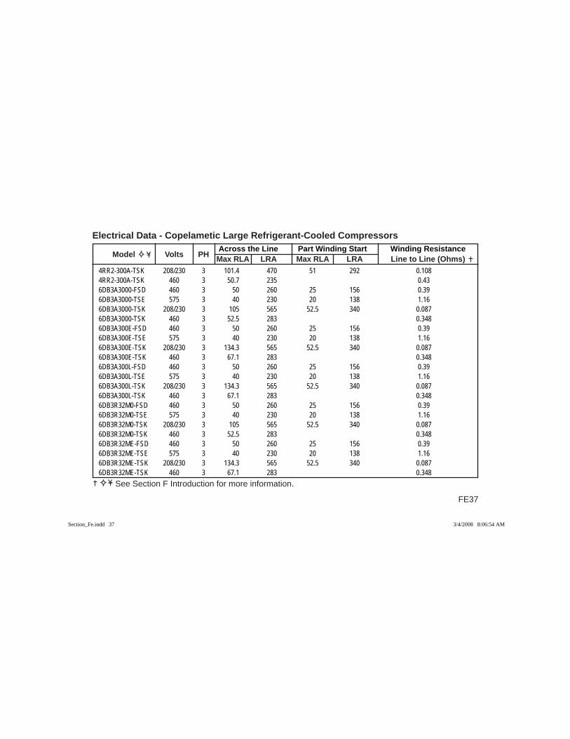
FE37
Across the Line Part Winding Start Winding Resistance Model Volts PH Max RLA LRA Max RLA LRA Line to Line (Ohms)
Electrical Data - Copelametic Large Refrigerant-Cooled Compressors
See Section F Introduction for more information.
4RR2-300A-TSK 208/230 3 101.4 470 51 292 0.1084RR2-300A-TSK 460 3 50.7 235 0.436DB3A3000-FSD 460 3 50 260 25 156 0.396DB3A3000-TSE 575 3 40 230 20 138 1.166DB3A3000-TSK 208/230 3 105 565 52.5 340 0.0876DB3A3000-TSK 460 3 52.5 283 0.3486DB3A300E-FSD 460 3 50 260 25 156 0.396DB3A300E-TSE 575 3 40 230 20 138 1.166DB3A300E-TSK 208/230 3 134.3 565 52.5 340 0.0876DB3A300E-TSK 460 3 67.1 283 0.3486DB3A300L-FSD 460 3 50 260 25 156 0.396DB3A300L-TSE 575 3 40 230 20 138 1.166DB3A300L-TSK 208/230 3 134.3 565 52.5 340 0.0876DB3A300L-TSK 460 3 67.1 283 0.3486DB3R32M0-FSD 460 3 50 260 25 156 0.396DB3R32M0-TSE 575 3 40 230 20 138 1.166DB3R32M0-TSK 208/230 3 105 565 52.5 340 0.0876DB3R32M0-TSK 460 3 52.5 283 0.3486DB3R32ME-FSD 460 3 50 260 25 156 0.396DB3R32ME-TSE 575 3 40 230 20 138 1.166DB3R32ME-TSK 208/230 3 134.3 565 52.5 340 0.0876DB3R32ME-TSK 460 3 67.1 283 0.348
Section_Fe.indd 37Section_Fe.indd 37 3/4/2008 8:06:54 AM3/4/2008 8:06:54 AM
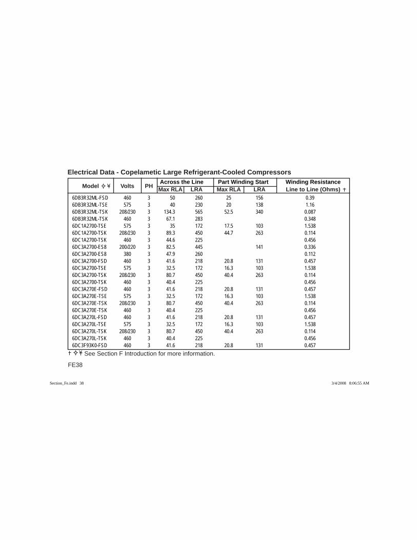
Across the Line Part Winding Start Winding Resistance Model Volts PH Max RLA LRA Max RLA LRA Line to Line (Ohms)
Electrical Data - Copelametic Large Refrigerant-Cooled Compressors
FE38
See Section F Introduction for more information.
6DB3R32ML-FSD 460 3 50 260 25 156 0.396DB3R32ML-TSE 575 3 40 230 20 138 1.166DB3R32ML-TSK 208/230 3 134.3 565 52.5 340 0.0876DB3R32ML-TSK 460 3 67.1 283 0.3486DC1A2700-TSE 575 3 35 172 17.5 103 1.5386DC1A2700-TSK 208/230 3 89.3 450 44.7 263 0.1146DC1A2700-TSK 460 3 44.6 225 0.4566DC3A2700-ES8 200/220 3 82.5 445 141 0.3366DC3A2700-ES8 380 3 47.9 260 0.1126DC3A2700-FSD 460 3 41.6 218 20.8 131 0.4576DC3A2700-TSE 575 3 32.5 172 16.3 103 1.5386DC3A2700-TSK 208/230 3 80.7 450 40.4 263 0.1146DC3A2700-TSK 460 3 40.4 225 0.4566DC3A270E-FSD 460 3 41.6 218 20.8 131 0.4576DC3A270E-TSE 575 3 32.5 172 16.3 103 1.5386DC3A270E-TSK 208/230 3 80.7 450 40.4 263 0.1146DC3A270E-TSK 460 3 40.4 225 0.4566DC3A270L-FSD 460 3 41.6 218 20.8 131 0.4576DC3A270L-TSE 575 3 32.5 172 16.3 103 1.5386DC3A270L-TSK 208/230 3 80.7 450 40.4 263 0.1146DC3A270L-TSK 460 3 40.4 225 0.4566DC3F93K0-FSD 460 3 41.6 218 20.8 131 0.457
Section_Fe.indd 38Section_Fe.indd 38 3/4/2008 8:06:55 AM3/4/2008 8:06:55 AM
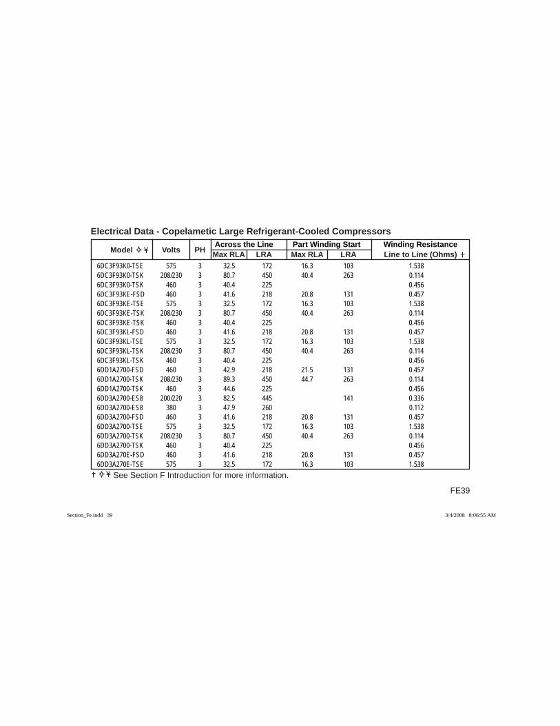
FE39
Across the Line Part Winding Start Winding Resistance Model Volts PH Max RLA LRA Max RLA LRA Line to Line (Ohms)
Electrical Data - Copelametic Large Refrigerant-Cooled Compressors
See Section F Introduction for more information.
6DC3F93K0-TSE 575 3 32.5 172 16.3 103 1.5386DC3F93K0-TSK 208/230 3 80.7 450 40.4 263 0.1146DC3F93K0-TSK 460 3 40.4 225 0.4566DC3F93KE-FSD 460 3 41.6 218 20.8 131 0.4576DC3F93KE-TSE 575 3 32.5 172 16.3 103 1.5386DC3F93KE-TSK 208/230 3 80.7 450 40.4 263 0.1146DC3F93KE-TSK 460 3 40.4 225 0.4566DC3F93KL-FSD 460 3 41.6 218 20.8 131 0.4576DC3F93KL-TSE 575 3 32.5 172 16.3 103 1.5386DC3F93KL-TSK 208/230 3 80.7 450 40.4 263 0.1146DC3F93KL-TSK 460 3 40.4 225 0.4566DD1A2700-FSD 460 3 42.9 218 21.5 131 0.4576DD1A2700-TSK 208/230 3 89.3 450 44.7 263 0.1146DD1A2700-TSK 460 3 44.6 225 0.4566DD3A2700-ES8 200/220 3 82.5 445 141 0.3366DD3A2700-ES8 380 3 47.9 260 0.1126DD3A2700-FSD 460 3 41.6 218 20.8 131 0.4576DD3A2700-TSE 575 3 32.5 172 16.3 103 1.5386DD3A2700-TSK 208/230 3 80.7 450 40.4 263 0.1146DD3A2700-TSK 460 3 40.4 225 0.4566DD3A270E-FSD 460 3 41.6 218 20.8 131 0.4576DD3A270E-TSE 575 3 32.5 172 16.3 103 1.538
Section_Fe.indd 39Section_Fe.indd 39 3/4/2008 8:06:55 AM3/4/2008 8:06:55 AM
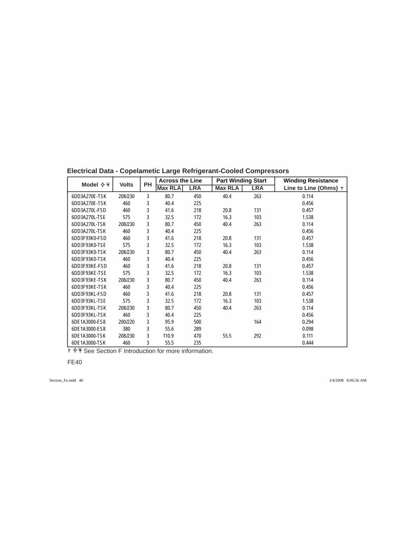
Across the Line Part Winding Start Winding Resistance Model Volts PH Max RLA LRA Max RLA LRA Line to Line (Ohms)
Electrical Data - Copelametic Large Refrigerant-Cooled Compressors
FE40
See Section F Introduction for more information.
6DD3A270E-TSK 208/230 3 80.7 450 40.4 263 0.1146DD3A270E-TSK 460 3 40.4 225 0.4566DD3A270L-FSD 460 3 41.6 218 20.8 131 0.4576DD3A270L-TSE 575 3 32.5 172 16.3 103 1.5386DD3A270L-TSK 208/230 3 80.7 450 40.4 263 0.1146DD3A270L-TSK 460 3 40.4 225 0.4566DD3F93K0-FSD 460 3 41.6 218 20.8 131 0.4576DD3F93K0-TSE 575 3 32.5 172 16.3 103 1.5386DD3F93K0-TSK 208/230 3 80.7 450 40.4 263 0.1146DD3F93K0-TSK 460 3 40.4 225 0.4566DD3F93KE-FSD 460 3 41.6 218 20.8 131 0.4576DD3F93KE-TSE 575 3 32.5 172 16.3 103 1.5386DD3F93KE-TSK 208/230 3 80.7 450 40.4 263 0.1146DD3F93KE-TSK 460 3 40.4 225 0.4566DD3F93KL-FSD 460 3 41.6 218 20.8 131 0.4576DD3F93KL-TSE 575 3 32.5 172 16.3 103 1.5386DD3F93KL-TSK 208/230 3 80.7 450 40.4 263 0.1146DD3F93KL-TSK 460 3 40.4 225 0.4566DE1A3000-ES8 200/220 3 95.9 500 164 0.2946DE1A3000-ES8 380 3 55.6 289 0.0986DE1A3000-TSK 208/230 3 110.9 470 55.5 292 0.1116DE1A3000-TSK 460 3 55.5 235 0.444
Section_Fe.indd 40Section_Fe.indd 40 3/4/2008 8:06:56 AM3/4/2008 8:06:56 AM
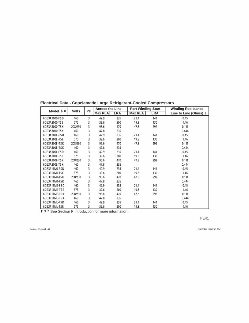
FE41
Across the Line Part Winding Start Winding Resistance Model Volts PH Max RLA LRA Max RLA LRA Line to Line (Ohms)
Electrical Data - Copelametic Large Refrigerant-Cooled Compressors
See Section F Introduction for more information.
6DE3A3000-FSD 460 3 42.9 235 21.4 141 0.456DE3A3000-TSE 575 3 39.6 200 19.8 130 1.466DE3A3000-TSK 208/230 3 95.6 470 47.8 292 0.1116DE3A3000-TSK 460 3 47.8 235 0.4446DE3A300E-FSD 460 3 42.9 235 21.4 141 0.456DE3A300E-TSE 575 3 39.6 200 19.8 130 1.466DE3A300E-TSK 208/230 3 95.6 470 47.8 292 0.1116DE3A300E-TSK 460 3 47.8 235 0.4446DE3A300L-FSD 460 3 42.9 235 21.4 141 0.456DE3A300L-TSE 575 3 39.6 200 19.8 130 1.466DE3A300L-TSK 208/230 3 95.6 470 47.8 292 0.1116DE3A300L-TSK 460 3 47.8 235 0.4446DE3F11M0-FSD 460 3 42.9 235 21.4 141 0.456DE3F11M0-TSE 575 3 39.6 200 19.8 130 1.466DE3F11M0-TSK 208/230 3 95.6 470 47.8 292 0.1116DE3F11M0-TSK 460 3 47.8 235 0.4446DE3F11ME-FSD 460 3 42.9 235 21.4 141 0.456DE3F11ME-TSE 575 3 39.6 200 19.8 130 1.466DE3F11ME-TSK 208/230 3 95.6 470 47.8 292 0.1116DE3F11ME-TSK 460 3 47.8 235 0.4446DE3F11ML-FSD 460 3 42.9 235 21.4 141 0.456DE3F11ML-TSE 575 3 39.6 200 19.8 130 1.46
Section_Fe.indd 41Section_Fe.indd 41 3/4/2008 8:06:56 AM3/4/2008 8:06:56 AM

Across the Line Part Winding Start Winding Resistance Model Volts PH Max RLA LRA Max RLA LRA Line to Line (Ohms)
Electrical Data - Copelametic Large Refrigerant-Cooled Compressors
FE42
See Section F Introduction for more information.
6DE3F11ML-TSK 208/230 3 95.6 470 47.8 292 0.1116DE3F11ML-TSK 460 3 47.8 235 0.4446DF1A3000-ES8 200/220 3 95.9 500 164 0.2946DF1A3000-ES8 380 3 55.6 289 0.0986DF1A3000-FSD 460 3 53.6 235 26.8 141 0.456DF1A3000-TSK 208/230 3 110.9 470 55.5 292 0.1116DF1A3000-TSK 460 3 55.5 235 0.4446DF3A3000-FSD 460 3 42.9 235 21.4 141 0.456DF3A3000-TSE 575 3 39.6 200 19.8 130 1.466DF3A3000-TSK 208/230 3 95.6 470 47.8 292 0.1116DF3A3000-TSK 460 3 47.8 235 0.4446DF3A300E-FSD 460 3 42.9 235 21.4 141 0.456DF3A300E-TSE 575 3 39.6 200 19.8 130 1.466DF3A300E-TSK 208/230 3 95.6 470 47.8 292 0.1116DF3A300E-TSK 460 3 47.8 235 0.4446DF3A300L-FSD 460 3 42.9 235 21.4 141 0.456DF3A300L-TSE 575 3 39.6 200 19.8 130 1.466DF3A300L-TSK 208/230 3 95.6 470 47.8 292 0.1116DF3A300L-TSK 460 3 47.8 235 0.4446DF3F11M0-FSD 460 3 42.9 235 21.4 141 0.456DF3F11M0-TSE 575 3 39.6 200 19.8 130 1.466DF3F11M0-TSK 208/230 3 95.6 470 47.8 292 0.111
Section_Fe.indd 42Section_Fe.indd 42 3/4/2008 8:06:56 AM3/4/2008 8:06:56 AM
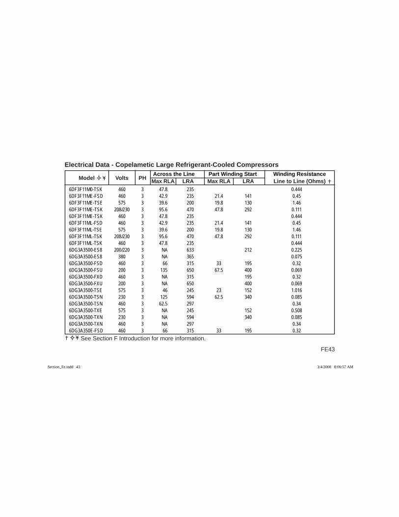
FE43
Across the Line Part Winding Start Winding Resistance Model Volts PH Max RLA LRA Max RLA LRA Line to Line (Ohms)
Electrical Data - Copelametic Large Refrigerant-Cooled Compressors
See Section F Introduction for more information.
6DF3F11M0-TSK 460 3 47.8 235 0.4446DF3F11ME-FSD 460 3 42.9 235 21.4 141 0.456DF3F11ME-TSE 575 3 39.6 200 19.8 130 1.466DF3F11ME-TSK 208/230 3 95.6 470 47.8 292 0.1116DF3F11ME-TSK 460 3 47.8 235 0.4446DF3F11ML-FSD 460 3 42.9 235 21.4 141 0.456DF3F11ML-TSE 575 3 39.6 200 19.8 130 1.466DF3F11ML-TSK 208/230 3 95.6 470 47.8 292 0.1116DF3F11ML-TSK 460 3 47.8 235 0.4446DG3A3500-ES8 200/220 3 NA 633 212 0.2256DG3A3500-ES8 380 3 NA 365 0.0756DG3A3500-FSD 460 3 66 315 33 195 0.326DG3A3500-FSU 200 3 135 650 67.5 400 0.0696DG3A3500-FXD 460 3 NA 315 195 0.326DG3A3500-FXU 200 3 NA 650 400 0.0696DG3A3500-TSE 575 3 46 245 23 152 1.0166DG3A3500-TSN 230 3 125 594 62.5 340 0.0856DG3A3500-TSN 460 3 62.5 297 0.346DG3A3500-TXE 575 3 NA 245 152 0.5086DG3A3500-TXN 230 3 NA 594 340 0.0856DG3A3500-TXN 460 3 NA 297 0.346DG3A350E-FSD 460 3 66 315 33 195 0.32
Section_Fe.indd 43Section_Fe.indd 43 3/4/2008 8:06:57 AM3/4/2008 8:06:57 AM
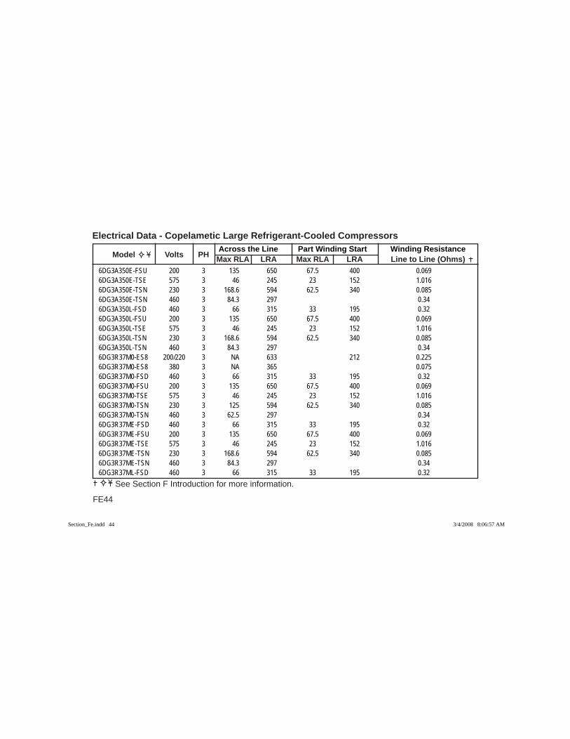
Across the Line Part Winding Start Winding Resistance Model Volts PH Max RLA LRA Max RLA LRA Line to Line (Ohms)
Electrical Data - Copelametic Large Refrigerant-Cooled Compressors
FE44
See Section F Introduction for more information.
6DG3A350E-FSU 200 3 135 650 67.5 400 0.0696DG3A350E-TSE 575 3 46 245 23 152 1.0166DG3A350E-TSN 230 3 168.6 594 62.5 340 0.0856DG3A350E-TSN 460 3 84.3 297 0.346DG3A350L-FSD 460 3 66 315 33 195 0.326DG3A350L-FSU 200 3 135 650 67.5 400 0.0696DG3A350L-TSE 575 3 46 245 23 152 1.0166DG3A350L-TSN 230 3 168.6 594 62.5 340 0.0856DG3A350L-TSN 460 3 84.3 297 0.346DG3R37M0-ES8 200/220 3 NA 633 212 0.2256DG3R37M0-ES8 380 3 NA 365 0.0756DG3R37M0-FSD 460 3 66 315 33 195 0.326DG3R37M0-FSU 200 3 135 650 67.5 400 0.0696DG3R37M0-TSE 575 3 46 245 23 152 1.0166DG3R37M0-TSN 230 3 125 594 62.5 340 0.0856DG3R37M0-TSN 460 3 62.5 297 0.346DG3R37ME-FSD 460 3 66 315 33 195 0.326DG3R37ME-FSU 200 3 135 650 67.5 400 0.0696DG3R37ME-TSE 575 3 46 245 23 152 1.0166DG3R37ME-TSN 230 3 168.6 594 62.5 340 0.0856DG3R37ME-TSN 460 3 84.3 297 0.346DG3R37ML-FSD 460 3 66 315 33 195 0.32
Section_Fe.indd 44Section_Fe.indd 44 3/4/2008 8:06:57 AM3/4/2008 8:06:57 AM
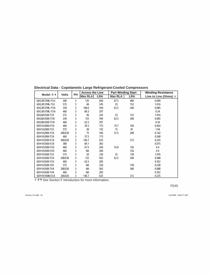
FE45
Across the Line Part Winding Start Winding Resistance Model Volts PH Max RLA LRA Max RLA LRA Line to Line (Ohms)
Electrical Data - Copelametic Large Refrigerant-Cooled Compressors
See Section F Introduction for more information.
6DG3R37ML-FSU 200 3 135 650 67.5 400 0.0696DG3R37ML-TSE 575 3 46 245 23 152 1.0166DG3R37ML-TSN 230 3 168.6 594 62.5 340 0.0856DG3R37ML-TSN 460 3 84.3 297 0.346DG8A3500-TSE 575 3 46 245 23 152 1.0166DG8A3500-TSN 230 3 125 594 62.5 340 0.0856DG8A3500-TSN 460 3 62.5 297 0.346DH1A2000-FSD 460 3 39.3 173 19.7 104 0.6036DH1A2000-TSE 575 3 30 135 15 81 1.946DH1A2000-TSK 208/230 3 75 346 37.5 208 0.1426DH1A2000-TSK 460 3 37.5 173 0.5686DH1A3500-ES8 200/220 3 146.7 633 212 0.2256DH1A3500-ES8 380 3 84.1 365 0.0756DH1A3500-FSD 460 3 67.5 260 33.8 156 0.46DH1A3500-FXD 460 3 NA 260 156 0.46DH1A3500-TSE 575 3 50 230 25 138 1.0766DH1A3500-TSK 208/230 3 125 565 62.5 340 0.0886DH1A3500-TSK 460 3 62.5 283 0.3526DH1A3500-TXE 575 3 NA 230 138 0.5386DH1A3500-TXK 208/230 3 NA 565 340 0.0886DH1A3500-TXK 460 3 NA 283 0.3526DH1R35M0-ES8 200/220 3 146.7 633 212 0.225
Section_Fe.indd 45Section_Fe.indd 45 3/4/2008 8:06:57 AM3/4/2008 8:06:57 AM
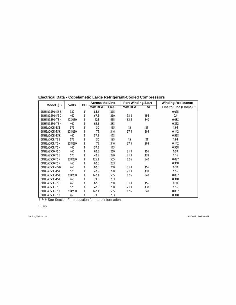
Across the Line Part Winding Start Winding Resistance Model Volts PH Max RLA LRA Max RLA LRA Line to Line (Ohms)
Electrical Data - Copelametic Large Refrigerant-Cooled Compressors
FE46
See Section F Introduction for more information.
6DH1R35M0-ES8 380 3 84.1 365 0.0756DH1R35M0-FSD 460 3 67.5 260 33.8 156 0.46DH1R35M0-TSK 208/230 3 125 565 62.5 340 0.0886DH1R35M0-TSK 460 3 62.5 283 0.3526DH3A200E-TSE 575 3 30 135 15 81 1.946DH3A200E-TSK 208/230 3 75 346 37.5 208 0.1426DH3A200E-TSK 460 3 37.5 173 0.5686DH3A200L-TSE 575 3 30 135 15 81 1.946DH3A200L-TSK 208/230 3 75 346 37.5 208 0.1426DH3A200L-TSK 460 3 37.5 173 0.5686DH3A3500-FSD 460 3 62.6 260 31.3 156 0.396DH3A3500-TSE 575 3 42.5 230 21.3 138 1.166DH3A3500-TSK 208/230 3 125.1 565 62.6 340 0.0876DH3A3500-TSK 460 3 62.6 283 0.3486DH3A350E-FSD 460 3 62.6 260 31.3 156 0.396DH3A350E-TSE 575 3 42.5 230 21.3 138 1.166DH3A350E-TSK 208/230 3 147.1 565 62.6 340 0.0876DH3A350E-TSK 460 3 73.6 283 0.3486DH3A350L-FSD 460 3 62.6 260 31.3 156 0.396DH3A350L-TSE 575 3 42.5 230 21.3 138 1.166DH3A350L-TSK 208/230 3 147.1 565 62.6 340 0.0876DH3A350L-TSK 460 3 73.6 283 0.348
Section_Fe.indd 46Section_Fe.indd 46 3/4/2008 8:06:58 AM3/4/2008 8:06:58 AM

FE47
Across the Line Part Winding Start Winding Resistance Model Volts PH Max RLA LRA Max RLA LRA Line to Line (Ohms)
Electrical Data - Copelametic Large Refrigerant-Cooled Compressors
See Section F Introduction for more information.
6DH3R23ME-TSK 208/230 3 75 346 37.5 208 0.1426DH3R23ME-TSK 460 3 37.5 173 0.5686DH3R23ML-TSK 208/230 3 75 346 37.5 208 0.1426DH3R23ML-TSK 460 3 37.5 173 0.5686DH3R35M0-FSD 460 3 62.6 260 31.3 156 0.396DH3R35M0-TSE 575 3 42.5 230 21.3 138 1.166DH3R35M0-TSK 208/230 3 125.1 565 62.6 340 0.0876DH3R35M0-TSK 460 3 62.6 283 0.3486DH3R35ME-FSD 460 3 62.6 260 31.3 156 0.396DH3R35ME-TSE 575 3 42.5 230 21.3 138 1.166DH3R35ME-TSK 208/230 3 147.1 565 62.6 340 0.0876DH3R35ME-TSK 460 3 73.6 283 0.3486DH3R35ML-FSD 460 3 62.6 260 31.3 156 0.396DH3R35ML-TSE 575 3 42.5 230 21.3 138 1.166DH3R35ML-TSK 208/230 3 147.1 565 62.6 340 0.0876DH3R35ML-TSK 460 3 73.6 283 0.3486DJ1A4000-ES8 200/220 3 164.1 633 212 0.2256DJ1A4000-ES8 380 3 96.9 365 0.0756DJ1A4000-FSD 460 3 69.3 300 34.7 170 0.3526DJ1A4000-FSU 200 3 170 660 85 400 0.0676DJ1A4000-FXU 200 3 NA 660 400 0.0676DJ1A4000-TSE 575 3 57.1 235 28.6 135 1.14
Section_Fe.indd 47Section_Fe.indd 47 3/4/2008 8:06:58 AM3/4/2008 8:06:58 AM
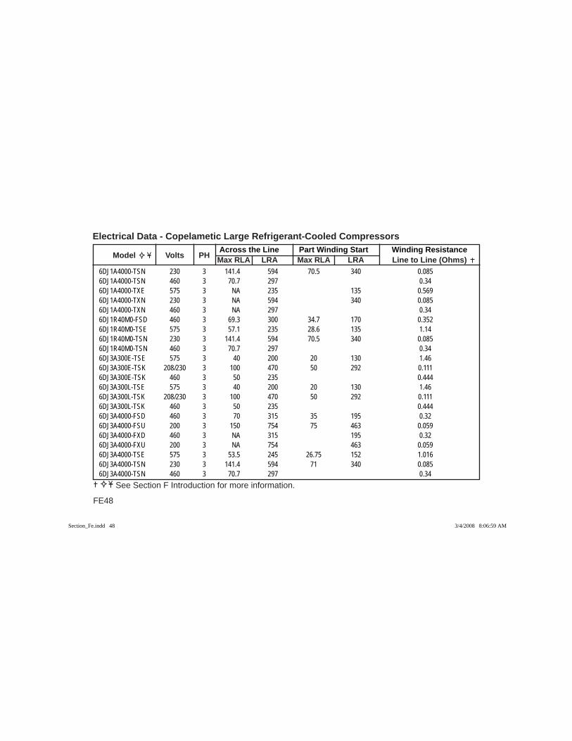
Across the Line Part Winding Start Winding Resistance Model Volts PH Max RLA LRA Max RLA LRA Line to Line (Ohms)
Electrical Data - Copelametic Large Refrigerant-Cooled Compressors
FE48
See Section F Introduction for more information.
6DJ1A4000-TSN 230 3 141.4 594 70.5 340 0.0856DJ1A4000-TSN 460 3 70.7 297 0.346DJ1A4000-TXE 575 3 NA 235 135 0.5696DJ1A4000-TXN 230 3 NA 594 340 0.0856DJ1A4000-TXN 460 3 NA 297 0.346DJ1R40M0-FSD 460 3 69.3 300 34.7 170 0.3526DJ1R40M0-TSE 575 3 57.1 235 28.6 135 1.146DJ1R40M0-TSN 230 3 141.4 594 70.5 340 0.0856DJ1R40M0-TSN 460 3 70.7 297 0.346DJ3A300E-TSE 575 3 40 200 20 130 1.466DJ3A300E-TSK 208/230 3 100 470 50 292 0.1116DJ3A300E-TSK 460 3 50 235 0.4446DJ3A300L-TSE 575 3 40 200 20 130 1.466DJ3A300L-TSK 208/230 3 100 470 50 292 0.1116DJ3A300L-TSK 460 3 50 235 0.4446DJ3A4000-FSD 460 3 70 315 35 195 0.326DJ3A4000-FSU 200 3 150 754 75 463 0.0596DJ3A4000-FXD 460 3 NA 315 195 0.326DJ3A4000-FXU 200 3 NA 754 463 0.0596DJ3A4000-TSE 575 3 53.5 245 26.75 152 1.0166DJ3A4000-TSN 230 3 141.4 594 71 340 0.0856DJ3A4000-TSN 460 3 70.7 297 0.34
Section_Fe.indd 48Section_Fe.indd 48 3/4/2008 8:06:59 AM3/4/2008 8:06:59 AM
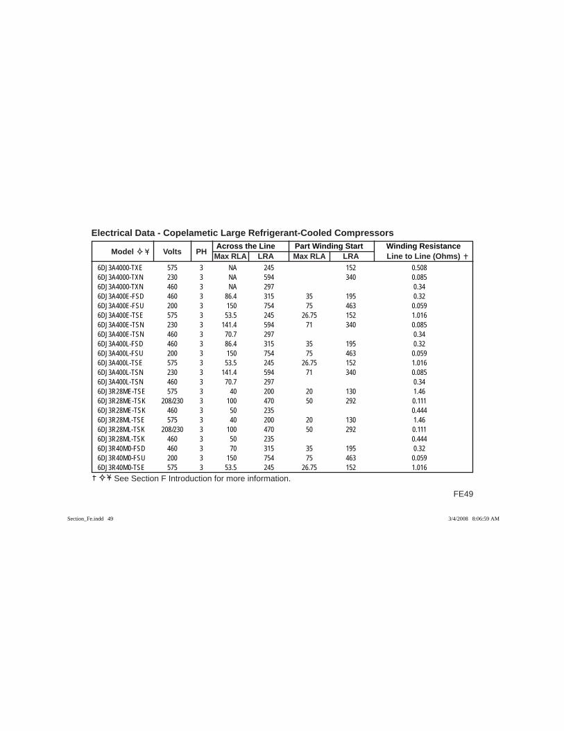
FE49
Across the Line Part Winding Start Winding Resistance Model Volts PH Max RLA LRA Max RLA LRA Line to Line (Ohms)
Electrical Data - Copelametic Large Refrigerant-Cooled Compressors
See Section F Introduction for more information.
6DJ3A4000-TXE 575 3 NA 245 152 0.5086DJ3A4000-TXN 230 3 NA 594 340 0.0856DJ3A4000-TXN 460 3 NA 297 0.346DJ3A400E-FSD 460 3 86.4 315 35 195 0.326DJ3A400E-FSU 200 3 150 754 75 463 0.0596DJ3A400E-TSE 575 3 53.5 245 26.75 152 1.0166DJ3A400E-TSN 230 3 141.4 594 71 340 0.0856DJ3A400E-TSN 460 3 70.7 297 0.346DJ3A400L-FSD 460 3 86.4 315 35 195 0.326DJ3A400L-FSU 200 3 150 754 75 463 0.0596DJ3A400L-TSE 575 3 53.5 245 26.75 152 1.0166DJ3A400L-TSN 230 3 141.4 594 71 340 0.0856DJ3A400L-TSN 460 3 70.7 297 0.346DJ3R28ME-TSE 575 3 40 200 20 130 1.466DJ3R28ME-TSK 208/230 3 100 470 50 292 0.1116DJ3R28ME-TSK 460 3 50 235 0.4446DJ3R28ML-TSE 575 3 40 200 20 130 1.466DJ3R28ML-TSK 208/230 3 100 470 50 292 0.1116DJ3R28ML-TSK 460 3 50 235 0.4446DJ3R40M0-FSD 460 3 70 315 35 195 0.326DJ3R40M0-FSU 200 3 150 754 75 463 0.0596DJ3R40M0-TSE 575 3 53.5 245 26.75 152 1.016
Section_Fe.indd 49Section_Fe.indd 49 3/4/2008 8:06:59 AM3/4/2008 8:06:59 AM
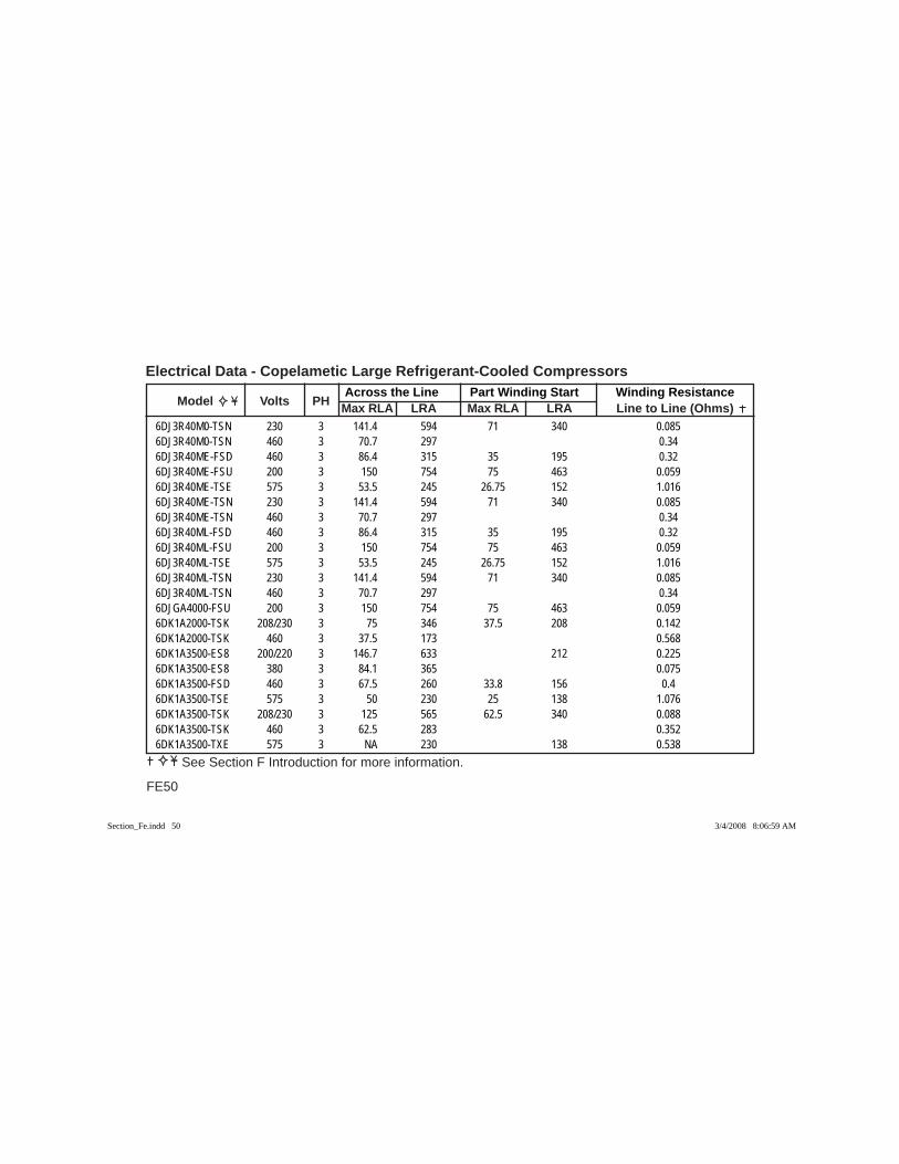
Across the Line Part Winding Start Winding Resistance Model Volts PH Max RLA LRA Max RLA LRA Line to Line (Ohms)
Electrical Data - Copelametic Large Refrigerant-Cooled Compressors
FE50
See Section F Introduction for more information.
6DJ3R40M0-TSN 230 3 141.4 594 71 340 0.0856DJ3R40M0-TSN 460 3 70.7 297 0.346DJ3R40ME-FSD 460 3 86.4 315 35 195 0.326DJ3R40ME-FSU 200 3 150 754 75 463 0.0596DJ3R40ME-TSE 575 3 53.5 245 26.75 152 1.0166DJ3R40ME-TSN 230 3 141.4 594 71 340 0.0856DJ3R40ME-TSN 460 3 70.7 297 0.346DJ3R40ML-FSD 460 3 86.4 315 35 195 0.326DJ3R40ML-FSU 200 3 150 754 75 463 0.0596DJ3R40ML-TSE 575 3 53.5 245 26.75 152 1.0166DJ3R40ML-TSN 230 3 141.4 594 71 340 0.0856DJ3R40ML-TSN 460 3 70.7 297 0.346DJGA4000-FSU 200 3 150 754 75 463 0.0596DK1A2000-TSK 208/230 3 75 346 37.5 208 0.1426DK1A2000-TSK 460 3 37.5 173 0.5686DK1A3500-ES8 200/220 3 146.7 633 212 0.2256DK1A3500-ES8 380 3 84.1 365 0.0756DK1A3500-FSD 460 3 67.5 260 33.8 156 0.46DK1A3500-TSE 575 3 50 230 25 138 1.0766DK1A3500-TSK 208/230 3 125 565 62.5 340 0.0886DK1A3500-TSK 460 3 62.5 283 0.3526DK1A3500-TXE 575 3 NA 230 138 0.538
Section_Fe.indd 50Section_Fe.indd 50 3/4/2008 8:06:59 AM3/4/2008 8:06:59 AM

FE51
Across the Line Part Winding Start Winding Resistance Model Volts PH Max RLA LRA Max RLA LRA Line to Line (Ohms)
Electrical Data - Copelametic Large Refrigerant-Cooled Compressors
See Section F Introduction for more information.
6DK1A3500-TXK 208/230 3 NA 565 340 0.0886DK1A3500-TXK 460 3 NA 283 0.3526DK1A350E-TSK 208/230 3 125 565 62.5 340 0.0886DK1A350E-TSK 460 3 62.5 283 0.3526DK1R35M0-ES8 200/220 3 146.7 633 212 0.2256DK1R35M0-ES8 380 3 84.1 365 0.0756DK1R35M0-FSD 460 3 67.5 260 33.8 156 0.46DK1R35M0-TSE 575 3 50 230 25 138 1.0766DK1R35M0-TSK 208/230 3 125 565 62.5 340 0.0886DK1R35M0-TSK 460 3 62.5 283 0.3526DK3A200E-TSE 575 3 30 135 15 81 1.946DK3A200E-TSK 208/230 3 75 346 37.5 208 0.1426DK3A200E-TSK 460 3 37.5 173 0.5686DK3A200L-TSE 575 3 30 135 15 81 1.946DK3A200L-TSK 208/230 3 75 346 37.5 208 0.1426DK3A200L-TSK 460 3 37.5 173 0.5686DK3A3500-FSD 460 3 62.6 260 31.3 156 0.396DK3A3500-TSE 575 3 42.5 230 21.3 138 1.166DK3A3500-TSK 208/230 3 125.1 565 62.6 340 0.0876DK3A3500-TSK 460 3 62.6 283 0.3486DK3A350E-FSD 460 3 62.6 260 31.3 156 0.396DK3A350E-TSE 575 3 42.5 230 21.3 138 1.16
Section_Fe.indd 51Section_Fe.indd 51 3/4/2008 8:07:00 AM3/4/2008 8:07:00 AM
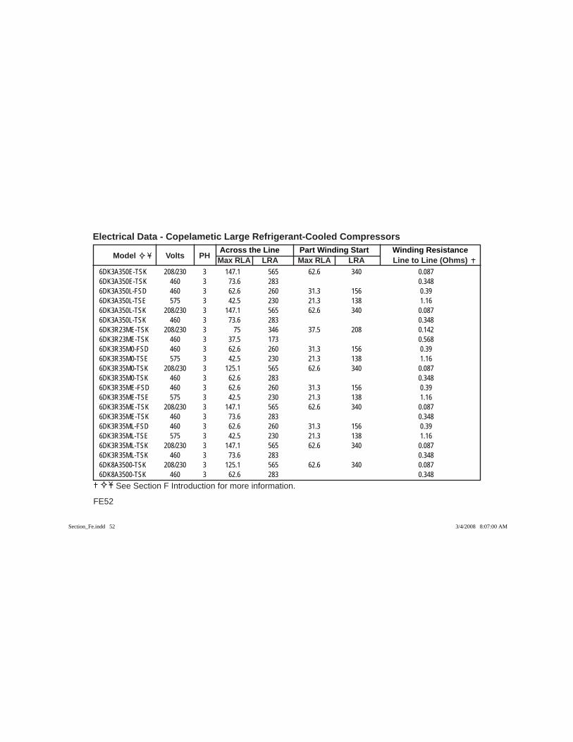
Across the Line Part Winding Start Winding Resistance Model Volts PH Max RLA LRA Max RLA LRA Line to Line (Ohms)
Electrical Data - Copelametic Large Refrigerant-Cooled Compressors
FE52
See Section F Introduction for more information.
6DK3A350E-TSK 208/230 3 147.1 565 62.6 340 0.0876DK3A350E-TSK 460 3 73.6 283 0.3486DK3A350L-FSD 460 3 62.6 260 31.3 156 0.396DK3A350L-TSE 575 3 42.5 230 21.3 138 1.166DK3A350L-TSK 208/230 3 147.1 565 62.6 340 0.0876DK3A350L-TSK 460 3 73.6 283 0.3486DK3R23ME-TSK 208/230 3 75 346 37.5 208 0.1426DK3R23ME-TSK 460 3 37.5 173 0.5686DK3R35M0-FSD 460 3 62.6 260 31.3 156 0.396DK3R35M0-TSE 575 3 42.5 230 21.3 138 1.166DK3R35M0-TSK 208/230 3 125.1 565 62.6 340 0.0876DK3R35M0-TSK 460 3 62.6 283 0.3486DK3R35ME-FSD 460 3 62.6 260 31.3 156 0.396DK3R35ME-TSE 575 3 42.5 230 21.3 138 1.166DK3R35ME-TSK 208/230 3 147.1 565 62.6 340 0.0876DK3R35ME-TSK 460 3 73.6 283 0.3486DK3R35ML-FSD 460 3 62.6 260 31.3 156 0.396DK3R35ML-TSE 575 3 42.5 230 21.3 138 1.166DK3R35ML-TSK 208/230 3 147.1 565 62.6 340 0.0876DK3R35ML-TSK 460 3 73.6 283 0.3486DK8A3500-TSK 208/230 3 125.1 565 62.6 340 0.0876DK8A3500-TSK 460 3 62.6 283 0.348
Section_Fe.indd 52Section_Fe.indd 52 3/4/2008 8:07:00 AM3/4/2008 8:07:00 AM

FE53
Across the Line Part Winding Start Winding Resistance Model Volts PH Max RLA LRA Max RLA LRA Line to Line (Ohms)
Electrical Data - Copelametic Large Refrigerant-Cooled Compressors
See Section F Introduction for more information.
6DL1A2700-FSD 460 3 42.9 218 21.5 131 0.4576DL1A2700-TSE 575 3 35 172 17.5 103 1.5386DL1A2700-TSK 208/230 3 89.3 450 44.7 263 0.1146DL1A2700-TSK 460 3 44.6 225 0.4566DL3A2700-ES8 200/220 3 82.5 445 141 0.3366DL3A2700-ES8 380 3 47.9 260 0.1126DL3A2700-FSD 460 3 41.6 218 20.8 131 0.4576DL3A2700-TSE 575 3 32.5 172 16.3 103 1.5386DL3A2700-TSK 208/230 3 80.7 450 40.4 263 0.1146DL3A2700-TSK 460 3 40.4 225 0.4566DL3A270E-FSD 460 3 41.6 218 20.8 131 0.4576DL3A270E-TSE 575 3 32.5 172 16.3 103 1.5386DL3A270E-TSK 208/230 3 80.7 450 40.4 263 0.1146DL3A270E-TSK 460 3 40.4 225 0.4566DL3A270L-FSD 460 3 41.6 218 20.8 131 0.4576DL3A270L-TSE 575 3 32.5 172 16.3 103 1.5386DL3A270L-TSK 208/230 3 80.7 450 40.4 263 0.1146DL3A270L-TSK 460 3 40.4 225 0.4566DL3F93K0-ES8 200/220 3 82.5 445 141 0.3366DL3F93K0-ES8 380 3 47.9 260 0.1126DL3F93K0-FSD 460 3 41.6 218 20.8 131 0.4576DL3F93K0-TSE 575 3 32.5 172 16.3 103 1.538
Section_Fe.indd 53Section_Fe.indd 53 3/4/2008 8:07:00 AM3/4/2008 8:07:00 AM
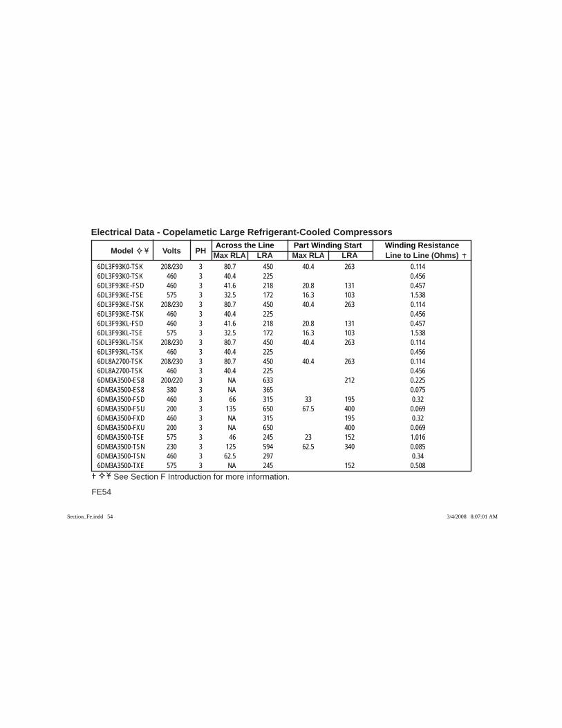
Across the Line Part Winding Start Winding Resistance Model Volts PH Max RLA LRA Max RLA LRA Line to Line (Ohms)
Electrical Data - Copelametic Large Refrigerant-Cooled Compressors
FE54
See Section F Introduction for more information.
6DL3F93K0-TSK 208/230 3 80.7 450 40.4 263 0.1146DL3F93K0-TSK 460 3 40.4 225 0.4566DL3F93KE-FSD 460 3 41.6 218 20.8 131 0.4576DL3F93KE-TSE 575 3 32.5 172 16.3 103 1.5386DL3F93KE-TSK 208/230 3 80.7 450 40.4 263 0.1146DL3F93KE-TSK 460 3 40.4 225 0.4566DL3F93KL-FSD 460 3 41.6 218 20.8 131 0.4576DL3F93KL-TSE 575 3 32.5 172 16.3 103 1.5386DL3F93KL-TSK 208/230 3 80.7 450 40.4 263 0.1146DL3F93KL-TSK 460 3 40.4 225 0.4566DL8A2700-TSK 208/230 3 80.7 450 40.4 263 0.1146DL8A2700-TSK 460 3 40.4 225 0.4566DM3A3500-ES8 200/220 3 NA 633 212 0.2256DM3A3500-ES8 380 3 NA 365 0.0756DM3A3500-FSD 460 3 66 315 33 195 0.326DM3A3500-FSU 200 3 135 650 67.5 400 0.0696DM3A3500-FXD 460 3 NA 315 195 0.326DM3A3500-FXU 200 3 NA 650 400 0.0696DM3A3500-TSE 575 3 46 245 23 152 1.0166DM3A3500-TSN 230 3 125 594 62.5 340 0.0856DM3A3500-TSN 460 3 62.5 297 0.346DM3A3500-TXE 575 3 NA 245 152 0.508
Section_Fe.indd 54Section_Fe.indd 54 3/4/2008 8:07:01 AM3/4/2008 8:07:01 AM
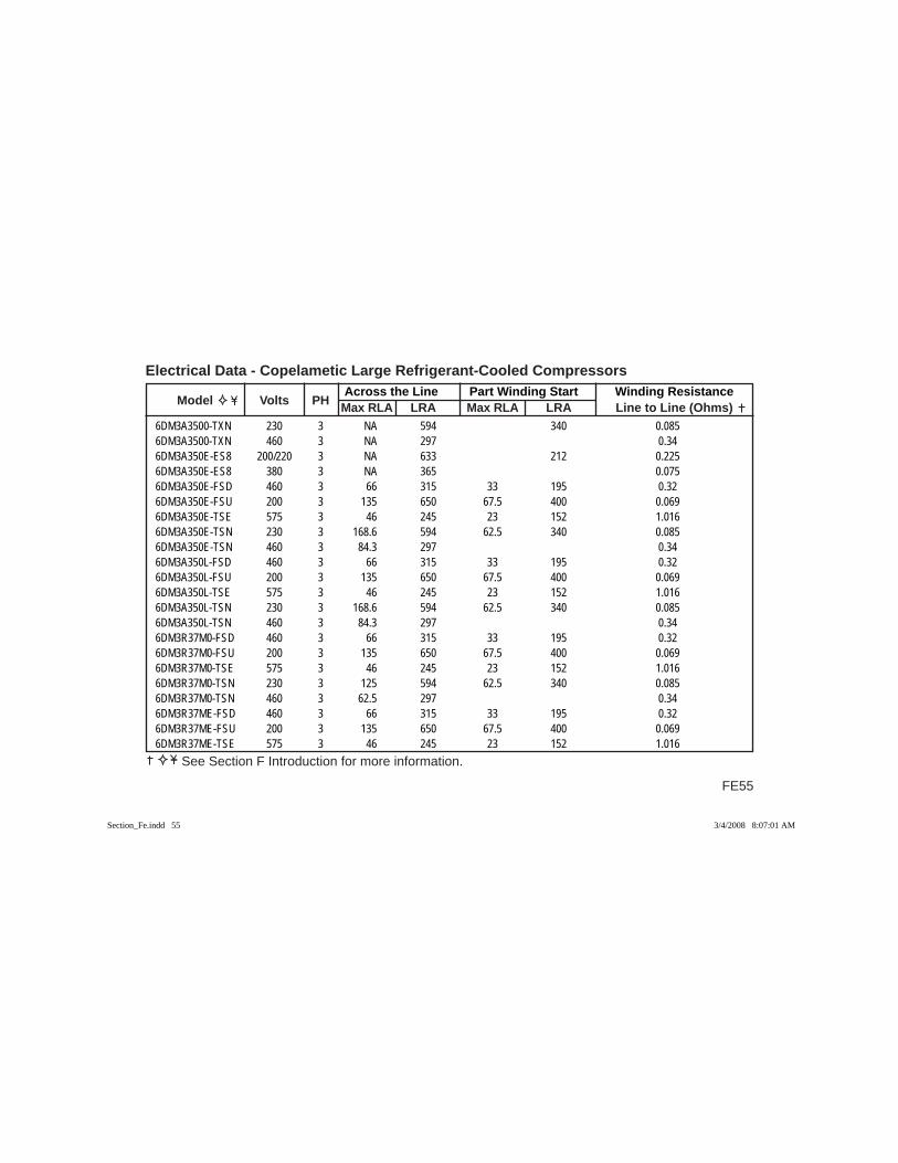
FE55
Across the Line Part Winding Start Winding Resistance Model Volts PH Max RLA LRA Max RLA LRA Line to Line (Ohms)
Electrical Data - Copelametic Large Refrigerant-Cooled Compressors
See Section F Introduction for more information.
6DM3A3500-TXN 230 3 NA 594 340 0.0856DM3A3500-TXN 460 3 NA 297 0.346DM3A350E-ES8 200/220 3 NA 633 212 0.2256DM3A350E-ES8 380 3 NA 365 0.0756DM3A350E-FSD 460 3 66 315 33 195 0.326DM3A350E-FSU 200 3 135 650 67.5 400 0.0696DM3A350E-TSE 575 3 46 245 23 152 1.0166DM3A350E-TSN 230 3 168.6 594 62.5 340 0.0856DM3A350E-TSN 460 3 84.3 297 0.346DM3A350L-FSD 460 3 66 315 33 195 0.326DM3A350L-FSU 200 3 135 650 67.5 400 0.0696DM3A350L-TSE 575 3 46 245 23 152 1.0166DM3A350L-TSN 230 3 168.6 594 62.5 340 0.0856DM3A350L-TSN 460 3 84.3 297 0.346DM3R37M0-FSD 460 3 66 315 33 195 0.326DM3R37M0-FSU 200 3 135 650 67.5 400 0.0696DM3R37M0-TSE 575 3 46 245 23 152 1.0166DM3R37M0-TSN 230 3 125 594 62.5 340 0.0856DM3R37M0-TSN 460 3 62.5 297 0.346DM3R37ME-FSD 460 3 66 315 33 195 0.326DM3R37ME-FSU 200 3 135 650 67.5 400 0.0696DM3R37ME-TSE 575 3 46 245 23 152 1.016
Section_Fe.indd 55Section_Fe.indd 55 3/4/2008 8:07:01 AM3/4/2008 8:07:01 AM
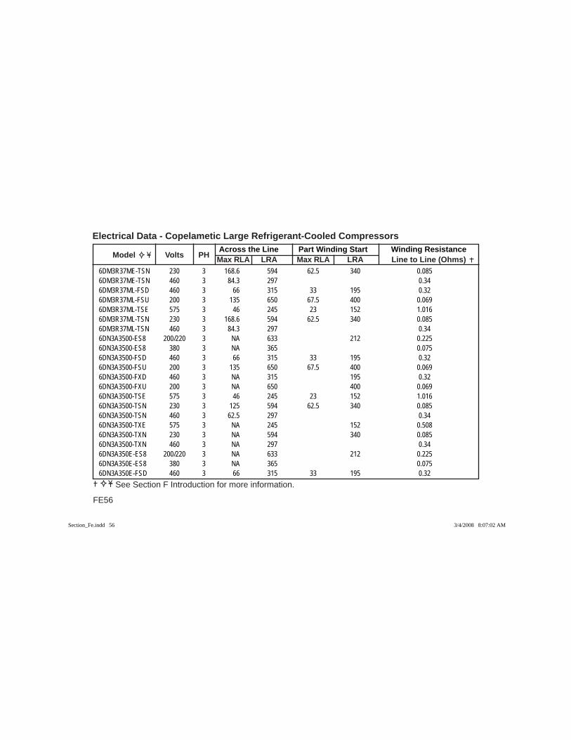
Across the Line Part Winding Start Winding Resistance Model Volts PH Max RLA LRA Max RLA LRA Line to Line (Ohms)
Electrical Data - Copelametic Large Refrigerant-Cooled Compressors
FE56
See Section F Introduction for more information.
6DM3R37ME-TSN 230 3 168.6 594 62.5 340 0.0856DM3R37ME-TSN 460 3 84.3 297 0.346DM3R37ML-FSD 460 3 66 315 33 195 0.326DM3R37ML-FSU 200 3 135 650 67.5 400 0.0696DM3R37ML-TSE 575 3 46 245 23 152 1.0166DM3R37ML-TSN 230 3 168.6 594 62.5 340 0.0856DM3R37ML-TSN 460 3 84.3 297 0.346DN3A3500-ES8 200/220 3 NA 633 212 0.2256DN3A3500-ES8 380 3 NA 365 0.0756DN3A3500-FSD 460 3 66 315 33 195 0.326DN3A3500-FSU 200 3 135 650 67.5 400 0.0696DN3A3500-FXD 460 3 NA 315 195 0.326DN3A3500-FXU 200 3 NA 650 400 0.0696DN3A3500-TSE 575 3 46 245 23 152 1.0166DN3A3500-TSN 230 3 125 594 62.5 340 0.0856DN3A3500-TSN 460 3 62.5 297 0.346DN3A3500-TXE 575 3 NA 245 152 0.5086DN3A3500-TXN 230 3 NA 594 340 0.0856DN3A3500-TXN 460 3 NA 297 0.346DN3A350E-ES8 200/220 3 NA 633 212 0.2256DN3A350E-ES8 380 3 NA 365 0.0756DN3A350E-FSD 460 3 66 315 33 195 0.32
Section_Fe.indd 56Section_Fe.indd 56 3/4/2008 8:07:02 AM3/4/2008 8:07:02 AM

FE57
Across the Line Part Winding Start Winding Resistance Model Volts PH Max RLA LRA Max RLA LRA Line to Line (Ohms)
Electrical Data - Copelametic Large Refrigerant-Cooled Compressors
See Section F Introduction for more information.
6DN3A350E-FSU 200 3 135 650 67.5 400 0.0696DN3A350E-TSE 575 3 46 245 23 152 1.0166DN3A350E-TSN 230 3 168.6 594 62.5 340 0.0856DN3A350E-TSN 460 3 84.3 297 0.346DN3A350L-FSD 460 3 66 315 33 195 0.326DN3A350L-FSU 200 3 135 650 67.5 400 0.0696DN3A350L-TSE 575 3 46 245 23 152 1.0166DN3A350L-TSN 230 3 168.6 594 62.5 340 0.0856DN3A350L-TSN 460 3 84.3 297 0.346DN3R37M0-FSD 460 3 66 315 33 195 0.326DN3R37M0-FSU 200 3 135 650 67.5 400 0.0696DN3R37M0-TSE 575 3 46 245 23 152 1.0166DN3R37M0-TSN 230 3 125 594 62.5 340 0.0856DN3R37M0-TSN 460 3 62.5 297 0.346DN3R37ME-FSD 460 3 66 315 33 195 0.326DN3R37ME-FSU 200 3 135 650 67.5 400 0.0696DN3R37ME-TSE 575 3 46 245 23 152 1.0166DN3R37ME-TSN 230 3 168.6 594 62.5 340 0.0856DN3R37ME-TSN 460 3 84.3 297 0.346DN3R37ML-FSD 460 3 66 315 33 195 0.326DN3R37ML-FSU 200 3 135 650 67.5 400 0.0696DN3R37ML-TSE 575 3 46 245 23 152 1.016
Section_Fe.indd 57Section_Fe.indd 57 3/4/2008 8:07:02 AM3/4/2008 8:07:02 AM
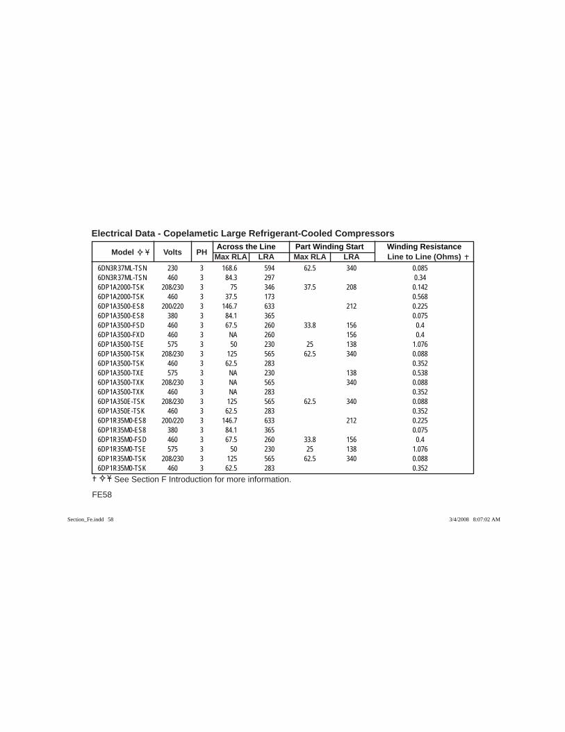
Across the Line Part Winding Start Winding Resistance Model Volts PH Max RLA LRA Max RLA LRA Line to Line (Ohms)
Electrical Data - Copelametic Large Refrigerant-Cooled Compressors
FE58
See Section F Introduction for more information.
6DN3R37ML-TSN 230 3 168.6 594 62.5 340 0.0856DN3R37ML-TSN 460 3 84.3 297 0.346DP1A2000-TSK 208/230 3 75 346 37.5 208 0.1426DP1A2000-TSK 460 3 37.5 173 0.5686DP1A3500-ES8 200/220 3 146.7 633 212 0.2256DP1A3500-ES8 380 3 84.1 365 0.0756DP1A3500-FSD 460 3 67.5 260 33.8 156 0.46DP1A3500-FXD 460 3 NA 260 156 0.46DP1A3500-TSE 575 3 50 230 25 138 1.0766DP1A3500-TSK 208/230 3 125 565 62.5 340 0.0886DP1A3500-TSK 460 3 62.5 283 0.3526DP1A3500-TXE 575 3 NA 230 138 0.5386DP1A3500-TXK 208/230 3 NA 565 340 0.0886DP1A3500-TXK 460 3 NA 283 0.3526DP1A350E-TSK 208/230 3 125 565 62.5 340 0.0886DP1A350E-TSK 460 3 62.5 283 0.3526DP1R35M0-ES8 200/220 3 146.7 633 212 0.2256DP1R35M0-ES8 380 3 84.1 365 0.0756DP1R35M0-FSD 460 3 67.5 260 33.8 156 0.46DP1R35M0-TSE 575 3 50 230 25 138 1.0766DP1R35M0-TSK 208/230 3 125 565 62.5 340 0.0886DP1R35M0-TSK 460 3 62.5 283 0.352
Section_Fe.indd 58Section_Fe.indd 58 3/4/2008 8:07:02 AM3/4/2008 8:07:02 AM
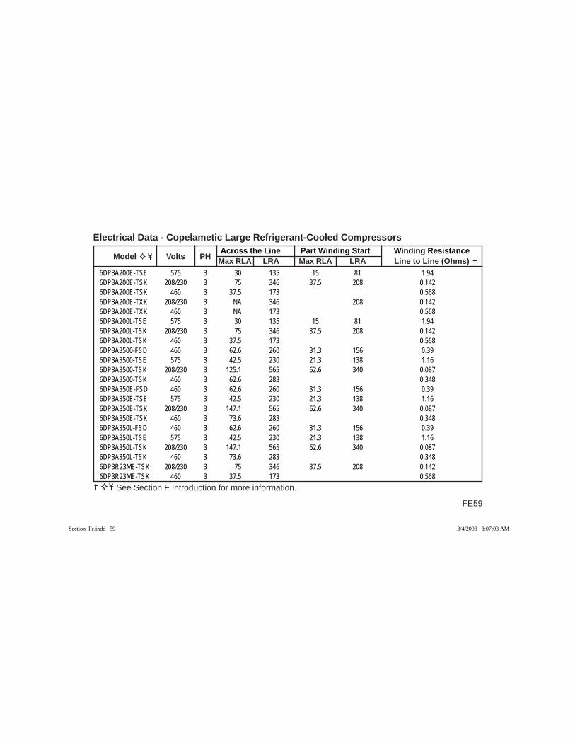
FE59
Across the Line Part Winding Start Winding Resistance Model Volts PH Max RLA LRA Max RLA LRA Line to Line (Ohms)
Electrical Data - Copelametic Large Refrigerant-Cooled Compressors
See Section F Introduction for more information.
6DP3A200E-TSE 575 3 30 135 15 81 1.946DP3A200E-TSK 208/230 3 75 346 37.5 208 0.1426DP3A200E-TSK 460 3 37.5 173 0.5686DP3A200E-TXK 208/230 3 NA 346 208 0.1426DP3A200E-TXK 460 3 NA 173 0.5686DP3A200L-TSE 575 3 30 135 15 81 1.946DP3A200L-TSK 208/230 3 75 346 37.5 208 0.1426DP3A200L-TSK 460 3 37.5 173 0.5686DP3A3500-FSD 460 3 62.6 260 31.3 156 0.396DP3A3500-TSE 575 3 42.5 230 21.3 138 1.166DP3A3500-TSK 208/230 3 125.1 565 62.6 340 0.0876DP3A3500-TSK 460 3 62.6 283 0.3486DP3A350E-FSD 460 3 62.6 260 31.3 156 0.396DP3A350E-TSE 575 3 42.5 230 21.3 138 1.166DP3A350E-TSK 208/230 3 147.1 565 62.6 340 0.0876DP3A350E-TSK 460 3 73.6 283 0.3486DP3A350L-FSD 460 3 62.6 260 31.3 156 0.396DP3A350L-TSE 575 3 42.5 230 21.3 138 1.166DP3A350L-TSK 208/230 3 147.1 565 62.6 340 0.0876DP3A350L-TSK 460 3 73.6 283 0.3486DP3R23ME-TSK 208/230 3 75 346 37.5 208 0.1426DP3R23ME-TSK 460 3 37.5 173 0.568
Section_Fe.indd 59Section_Fe.indd 59 3/4/2008 8:07:03 AM3/4/2008 8:07:03 AM
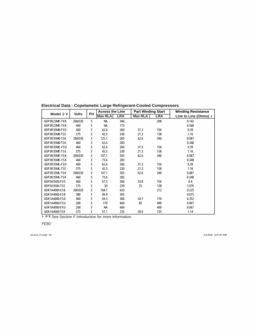
Across the Line Part Winding Start Winding Resistance Model Volts PH Max RLA LRA Max RLA LRA Line to Line (Ohms)
Electrical Data - Copelametic Large Refrigerant-Cooled Compressors
FE60
See Section F Introduction for more information.
6DP3R23ME-TXK 208/230 3 NA 346 208 0.1426DP3R23ME-TXK 460 3 NA 173 0.5686DP3R35M0-FSD 460 3 62.6 260 31.3 156 0.396DP3R35M0-TSE 575 3 42.5 230 21.3 138 1.166DP3R35M0-TSK 208/230 3 125.1 565 62.6 340 0.0876DP3R35M0-TSK 460 3 62.6 283 0.3486DP3R35ME-FSD 460 3 62.6 260 31.3 156 0.396DP3R35ME-TSE 575 3 42.5 230 21.3 138 1.166DP3R35ME-TSK 208/230 3 147.1 565 62.6 340 0.0876DP3R35ME-TSK 460 3 73.6 283 0.3486DP3R35ML-FSD 460 3 62.6 260 31.3 156 0.396DP3R35ML-TSE 575 3 42.5 230 21.3 138 1.166DP3R35ML-TSK 208/230 3 147.1 565 62.6 340 0.0876DP3R35ML-TSK 460 3 73.6 283 0.3486DP5A3500-FSD 460 3 67.5 260 33.8 156 0.46DP5A3500-TSE 575 3 50 230 25 138 1.0766DR1A4000-ES8 200/220 3 164.1 633 212 0.2256DR1A4000-ES8 380 3 96.9 365 0.0756DR1A4000-FSD 460 3 69.3 300 34.7 170 0.3526DR1A4000-FSU 200 3 170 660 85 400 0.0676DR1A4000-FXU 200 3 NA 660 400 0.0676DR1A4000-TSE 575 3 57.1 235 28.6 135 1.14
Section_Fe.indd 60Section_Fe.indd 60 3/4/2008 8:07:03 AM3/4/2008 8:07:03 AM

FE61
Across the Line Part Winding Start Winding Resistance Model Volts PH Max RLA LRA Max RLA LRA Line to Line (Ohms)
Electrical Data - Copelametic Large Refrigerant-Cooled Compressors
See Section F Introduction for more information.
6DR1A4000-TSN 230 3 141.4 594 70.5 340 0.0856DR1A4000-TSN 460 3 70.7 297 0.346DR1A4000-TXE 575 3 NA 235 135 0.5696DR1A4000-TXN 230 3 NA 594 340 0.0856DR1A4000-TXN 460 3 NA 297 0.346DR1A400E-ES8 200/220 3 164.1 633 212 0.2256DR1A400E-ES8 380 3 96.9 365 0.0756DR1R40M0-ES8 200/220 3 164.1 633 212 0.2256DR1R40M0-ES8 380 3 96.9 365 0.0756DR1R40M0-FSD 460 3 69.3 300 34.7 170 0.3526DR1R40M0-TSN 230 3 141.4 594 70.5 340 0.0856DR1R40M0-TSN 460 3 70.7 297 0.346DR3A300E-TSE 575 3 40 200 20 130 1.466DR3A300E-TSK 208/230 3 100 470 50 292 0.1116DR3A300E-TSK 460 3 50 235 0.4446DR3A300L-TSE 575 3 40 200 20 130 1.466DR3A300L-TSK 208/230 3 100 470 50 292 0.1116DR3A300L-TSK 460 3 50 235 0.4446DR3A4000-FSD 460 3 70 315 35 195 0.326DR3A4000-FSU 200 3 150 754 75 463 0.0596DR3A4000-FXD 460 3 NA 315 195 0.326DR3A4000-FXU 200 3 NA 754 463 0.059
Section_Fe.indd 61Section_Fe.indd 61 3/4/2008 8:07:03 AM3/4/2008 8:07:03 AM
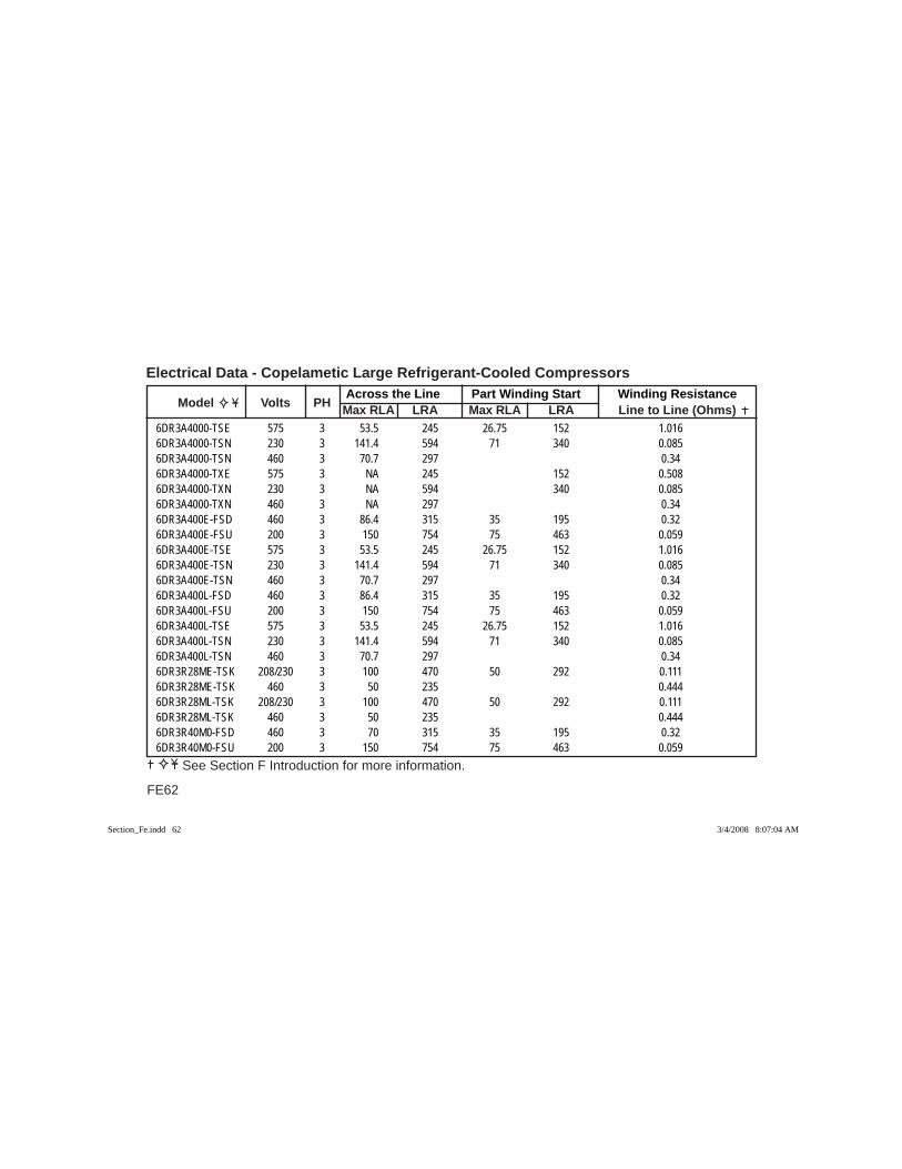
Across the Line Part Winding Start Winding Resistance Model Volts PH Max RLA LRA Max RLA LRA Line to Line (Ohms)
Electrical Data - Copelametic Large Refrigerant-Cooled Compressors
FE62
See Section F Introduction for more information.
6DR3A4000-TSE 575 3 53.5 245 26.75 152 1.0166DR3A4000-TSN 230 3 141.4 594 71 340 0.0856DR3A4000-TSN 460 3 70.7 297 0.346DR3A4000-TXE 575 3 NA 245 152 0.5086DR3A4000-TXN 230 3 NA 594 340 0.0856DR3A4000-TXN 460 3 NA 297 0.346DR3A400E-FSD 460 3 86.4 315 35 195 0.326DR3A400E-FSU 200 3 150 754 75 463 0.0596DR3A400E-TSE 575 3 53.5 245 26.75 152 1.0166DR3A400E-TSN 230 3 141.4 594 71 340 0.0856DR3A400E-TSN 460 3 70.7 297 0.346DR3A400L-FSD 460 3 86.4 315 35 195 0.326DR3A400L-FSU 200 3 150 754 75 463 0.0596DR3A400L-TSE 575 3 53.5 245 26.75 152 1.0166DR3A400L-TSN 230 3 141.4 594 71 340 0.0856DR3A400L-TSN 460 3 70.7 297 0.346DR3R28ME-TSK 208/230 3 100 470 50 292 0.1116DR3R28ME-TSK 460 3 50 235 0.4446DR3R28ML-TSK 208/230 3 100 470 50 292 0.1116DR3R28ML-TSK 460 3 50 235 0.4446DR3R40M0-FSD 460 3 70 315 35 195 0.326DR3R40M0-FSU 200 3 150 754 75 463 0.059
Section_Fe.indd 62Section_Fe.indd 62 3/4/2008 8:07:04 AM3/4/2008 8:07:04 AM
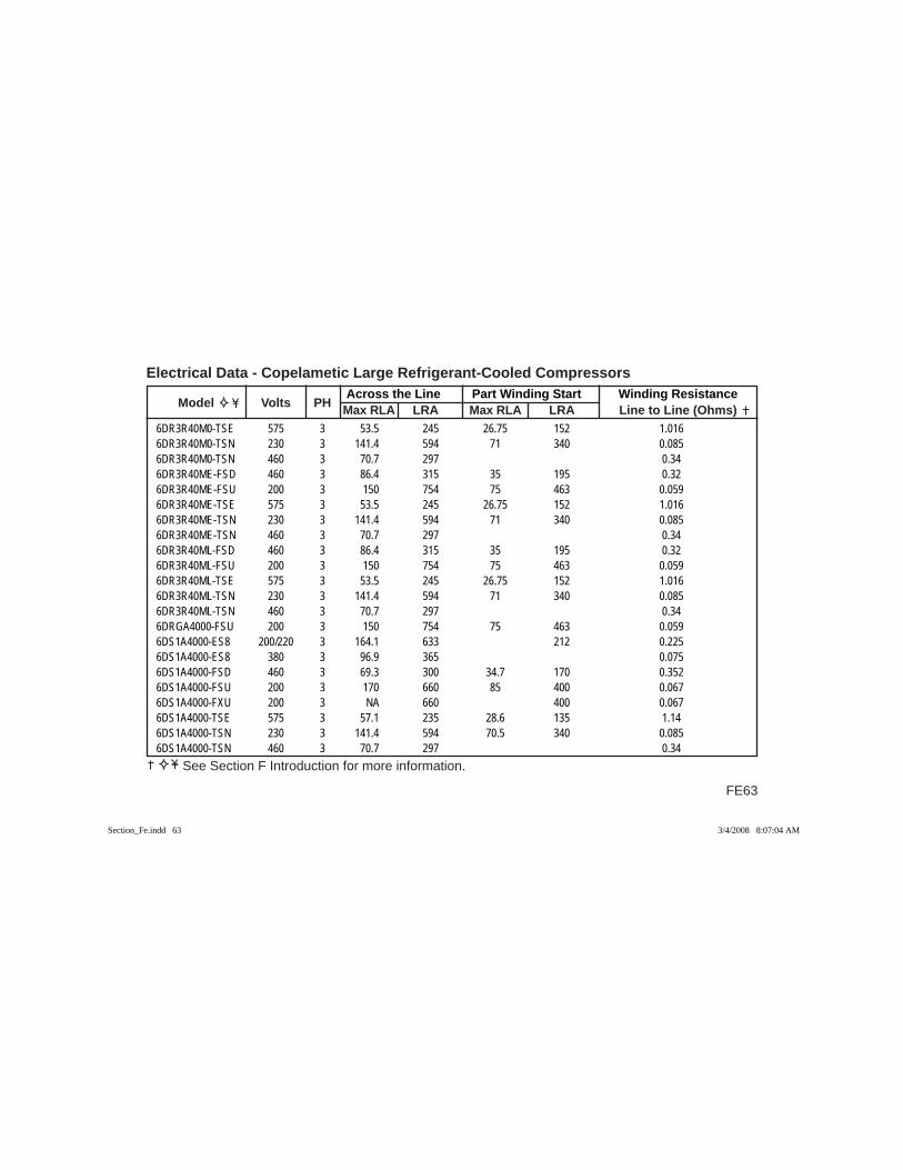
FE63
Across the Line Part Winding Start Winding Resistance Model Volts PH Max RLA LRA Max RLA LRA Line to Line (Ohms)
Electrical Data - Copelametic Large Refrigerant-Cooled Compressors
See Section F Introduction for more information.
6DR3R40M0-TSE 575 3 53.5 245 26.75 152 1.0166DR3R40M0-TSN 230 3 141.4 594 71 340 0.0856DR3R40M0-TSN 460 3 70.7 297 0.346DR3R40ME-FSD 460 3 86.4 315 35 195 0.326DR3R40ME-FSU 200 3 150 754 75 463 0.0596DR3R40ME-TSE 575 3 53.5 245 26.75 152 1.0166DR3R40ME-TSN 230 3 141.4 594 71 340 0.0856DR3R40ME-TSN 460 3 70.7 297 0.346DR3R40ML-FSD 460 3 86.4 315 35 195 0.326DR3R40ML-FSU 200 3 150 754 75 463 0.0596DR3R40ML-TSE 575 3 53.5 245 26.75 152 1.0166DR3R40ML-TSN 230 3 141.4 594 71 340 0.0856DR3R40ML-TSN 460 3 70.7 297 0.346DRGA4000-FSU 200 3 150 754 75 463 0.0596DS1A4000-ES8 200/220 3 164.1 633 212 0.2256DS1A4000-ES8 380 3 96.9 365 0.0756DS1A4000-FSD 460 3 69.3 300 34.7 170 0.3526DS1A4000-FSU 200 3 170 660 85 400 0.0676DS1A4000-FXU 200 3 NA 660 400 0.0676DS1A4000-TSE 575 3 57.1 235 28.6 135 1.146DS1A4000-TSN 230 3 141.4 594 70.5 340 0.0856DS1A4000-TSN 460 3 70.7 297 0.34
Section_Fe.indd 63Section_Fe.indd 63 3/4/2008 8:07:04 AM3/4/2008 8:07:04 AM
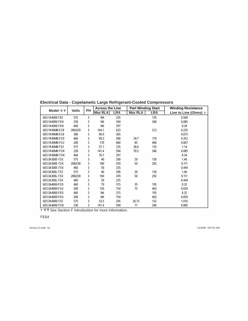
Across the Line Part Winding Start Winding Resistance Model Volts PH Max RLA LRA Max RLA LRA Line to Line (Ohms)
Electrical Data - Copelametic Large Refrigerant-Cooled Compressors
FE64
See Section F Introduction for more information.
6DS1A4000-TXE 575 3 NA 235 135 0.5696DS1A4000-TXN 230 3 NA 594 340 0.0856DS1A4000-TXN 460 3 NA 297 0.346DS1R40M0-ES8 200/220 3 164.1 633 212 0.2256DS1R40M0-ES8 380 3 96.9 365 0.0756DS1R40M0-FSD 460 3 69.3 300 34.7 170 0.3526DS1R40M0-FSU 200 3 170 660 85 400 0.0676DS1R40M0-TSE 575 3 57.1 235 28.6 135 1.146DS1R40M0-TSN 230 3 141.4 594 70.5 340 0.0856DS1R40M0-TSN 460 3 70.7 297 0.346DS3A300E-TSE 575 3 40 200 20 130 1.466DS3A300E-TSK 208/230 3 100 470 50 292 0.1116DS3A300E-TSK 460 3 50 235 0.4446DS3A300L-TSE 575 3 40 200 20 130 1.466DS3A300L-TSK 208/230 3 100 470 50 292 0.1116DS3A300L-TSK 460 3 50 235 0.4446DS3A4000-FSD 460 3 70 315 35 195 0.326DS3A4000-FSU 200 3 150 754 75 463 0.0596DS3A4000-FXD 460 3 NA 315 195 0.326DS3A4000-FXU 200 3 NA 754 463 0.0596DS3A4000-TSE 575 3 53.5 245 26.75 152 1.0166DS3A4000-TSN 230 3 141.4 594 71 340 0.085
Section_Fe.indd 64Section_Fe.indd 64 3/4/2008 8:07:05 AM3/4/2008 8:07:05 AM

FE65
Across the Line Part Winding Start Winding Resistance Model Volts PH Max RLA LRA Max RLA LRA Line to Line (Ohms)
Electrical Data - Copelametic Large Refrigerant-Cooled Compressors
See Section F Introduction for more information.
6DS3A4000-TSN 460 3 70.7 297 0.346DS3A4000-TXE 575 3 NA 245 152 0.5086DS3A4000-TXN 230 3 NA 594 340 0.0856DS3A4000-TXN 460 3 NA 297 0.346DS3A400E-FSD 460 3 86.4 315 35 195 0.326DS3A400E-FSU 200 3 150 754 75 463 0.0596DS3A400E-TSE 575 3 53.5 245 26.75 152 1.0166DS3A400E-TSN 230 3 141.4 594 71 340 0.0856DS3A400E-TSN 460 3 70.7 297 0.346DS3A400L-FSD 460 3 86.4 315 35 195 0.326DS3A400L-FSU 200 3 150 754 75 463 0.0596DS3A400L-TSE 575 3 53.5 245 26.75 152 1.0166DS3A400L-TSN 230 3 141.4 594 71 340 0.0856DS3A400L-TSN 460 3 70.7 297 0.346DS3R28ME-TSE 575 3 40 200 20 130 1.466DS3R28ME-TSK 208/230 3 100 470 50 292 0.1116DS3R28ME-TSK 460 3 50 235 0.4446DS3R28ML-TSE 575 3 40 200 20 130 1.466DS3R28ML-TSK 208/230 3 100 470 50 292 0.1116DS3R28ML-TSK 460 3 50 235 0.4446DS3R40M0-FSD 460 3 70 315 35 195 0.326DS3R40M0-FSU 200 3 150 754 75 463 0.059
Section_Fe.indd 65Section_Fe.indd 65 3/4/2008 8:07:05 AM3/4/2008 8:07:05 AM
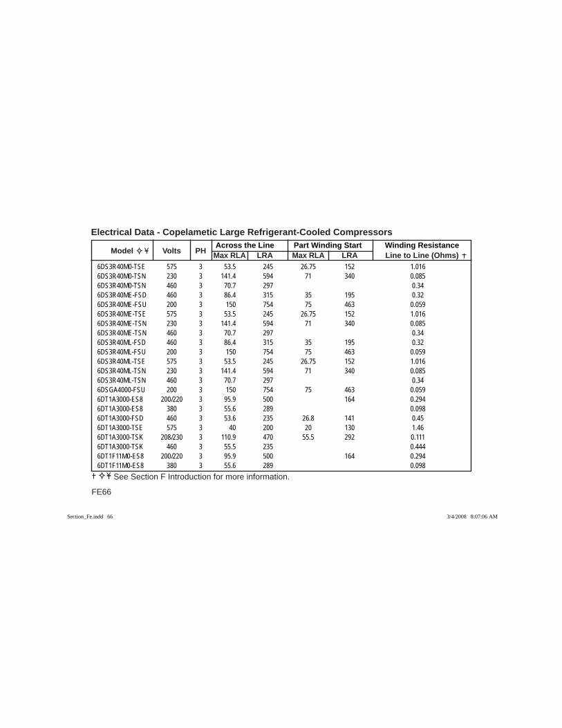
Across the Line Part Winding Start Winding Resistance Model Volts PH Max RLA LRA Max RLA LRA Line to Line (Ohms)
Electrical Data - Copelametic Large Refrigerant-Cooled Compressors
FE66
See Section F Introduction for more information.
6DS3R40M0-TSE 575 3 53.5 245 26.75 152 1.0166DS3R40M0-TSN 230 3 141.4 594 71 340 0.0856DS3R40M0-TSN 460 3 70.7 297 0.346DS3R40ME-FSD 460 3 86.4 315 35 195 0.326DS3R40ME-FSU 200 3 150 754 75 463 0.0596DS3R40ME-TSE 575 3 53.5 245 26.75 152 1.0166DS3R40ME-TSN 230 3 141.4 594 71 340 0.0856DS3R40ME-TSN 460 3 70.7 297 0.346DS3R40ML-FSD 460 3 86.4 315 35 195 0.326DS3R40ML-FSU 200 3 150 754 75 463 0.0596DS3R40ML-TSE 575 3 53.5 245 26.75 152 1.0166DS3R40ML-TSN 230 3 141.4 594 71 340 0.0856DS3R40ML-TSN 460 3 70.7 297 0.346DSGA4000-FSU 200 3 150 754 75 463 0.0596DT1A3000-ES8 200/220 3 95.9 500 164 0.2946DT1A3000-ES8 380 3 55.6 289 0.0986DT1A3000-FSD 460 3 53.6 235 26.8 141 0.456DT1A3000-TSE 575 3 40 200 20 130 1.466DT1A3000-TSK 208/230 3 110.9 470 55.5 292 0.1116DT1A3000-TSK 460 3 55.5 235 0.4446DT1F11M0-ES8 200/220 3 95.9 500 164 0.2946DT1F11M0-ES8 380 3 55.6 289 0.098
Section_Fe.indd 66Section_Fe.indd 66 3/4/2008 8:07:06 AM3/4/2008 8:07:06 AM

FE67
Across the Line Part Winding Start Winding Resistance Model Volts PH Max RLA LRA Max RLA LRA Line to Line (Ohms)
Electrical Data - Copelametic Large Refrigerant-Cooled Compressors
See Section F Introduction for more information.
6DT1F11M0-FSD 460 3 53.6 235 26.8 141 0.456DT3A3000-FSD 460 3 42.9 235 21.4 141 0.456DT3A3000-TSE 575 3 39.6 200 19.8 130 1.466DT3A3000-TSK 208/230 3 95.6 470 47.8 292 0.1116DT3A3000-TSK 460 3 47.8 235 0.4446DT3A300E-FSD 460 3 42.9 235 21.4 141 0.456DT3A300E-TSE 575 3 39.6 200 19.8 130 1.466DT3A300E-TSK 208/230 3 95.6 470 47.8 292 0.1116DT3A300E-TSK 460 3 47.8 235 0.4446DT3A300L-FSD 460 3 42.9 235 21.4 141 0.456DT3A300L-TSE 575 3 39.6 200 19.8 130 1.466DT3A300L-TSK 208/230 3 95.6 470 47.8 292 0.1116DT3A300L-TSK 460 3 47.8 235 0.4446DT3A3010-ESX 200/220 3 94.6 500 0.2946DT3A3010-ESX 380 3 68.8 289 0.0986DT3A301E-ESX 200/220 3 94.6 500 0.2946DT3A301E-ESX 380 3 81.7 289 0.0986DT3A301L-ESX 200/220 3 94.6 500 0.2946DT3A301L-ESX 380 3 81.7 289 0.0986DT3F11M0-FSD 460 3 42.9 235 21.4 141 0.456DT3F11M0-TSE 575 3 39.6 200 19.8 130 1.466DT3F11M0-TSK 208/230 3 95.6 470 47.8 292 0.111
Section_Fe.indd 67Section_Fe.indd 67 3/4/2008 8:07:06 AM3/4/2008 8:07:06 AM
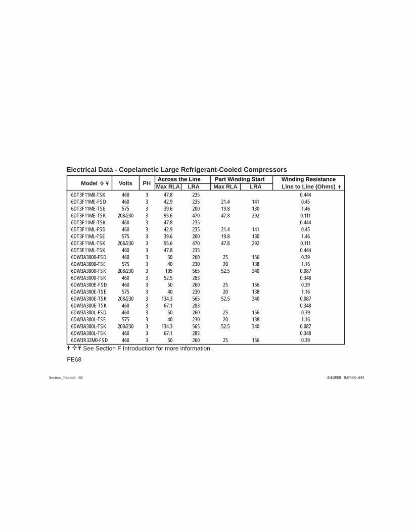
Across the Line Part Winding Start Winding Resistance Model Volts PH Max RLA LRA Max RLA LRA Line to Line (Ohms)
Electrical Data - Copelametic Large Refrigerant-Cooled Compressors
FE68
See Section F Introduction for more information.
6DT3F11M0-TSK 460 3 47.8 235 0.4446DT3F11ME-FSD 460 3 42.9 235 21.4 141 0.456DT3F11ME-TSE 575 3 39.6 200 19.8 130 1.466DT3F11ME-TSK 208/230 3 95.6 470 47.8 292 0.1116DT3F11ME-TSK 460 3 47.8 235 0.4446DT3F11ML-FSD 460 3 42.9 235 21.4 141 0.456DT3F11ML-TSE 575 3 39.6 200 19.8 130 1.466DT3F11ML-TSK 208/230 3 95.6 470 47.8 292 0.1116DT3F11ML-TSK 460 3 47.8 235 0.4446DW3A3000-FSD 460 3 50 260 25 156 0.396DW3A3000-TSE 575 3 40 230 20 138 1.166DW3A3000-TSK 208/230 3 105 565 52.5 340 0.0876DW3A3000-TSK 460 3 52.5 283 0.3486DW3A300E-FSD 460 3 50 260 25 156 0.396DW3A300E-TSE 575 3 40 230 20 138 1.166DW3A300E-TSK 208/230 3 134.3 565 52.5 340 0.0876DW3A300E-TSK 460 3 67.1 283 0.3486DW3A300L-FSD 460 3 50 260 25 156 0.396DW3A300L-TSE 575 3 40 230 20 138 1.166DW3A300L-TSK 208/230 3 134.3 565 52.5 340 0.0876DW3A300L-TSK 460 3 67.1 283 0.3486DW3R32M0-FSD 460 3 50 260 25 156 0.39
Section_Fe.indd 68Section_Fe.indd 68 3/4/2008 8:07:06 AM3/4/2008 8:07:06 AM

FE69
Across the Line Part Winding Start Winding Resistance Model Volts PH Max RLA LRA Max RLA LRA Line to Line (Ohms)
Electrical Data - Copelametic Large Refrigerant-Cooled Compressors
See Section F Introduction for more information.
6DW3R32M0-TSE 575 3 40 230 20 138 1.166DW3R32M0-TSK 208/230 3 105 565 52.5 340 0.0876DW3R32M0-TSK 460 3 52.5 283 0.3486DW3R32ME-FSD 460 3 50 260 25 156 0.396DW3R32ME-TSE 575 3 40 230 20 138 1.166DW3R32ME-TSK 208/230 3 134.3 565 52.5 340 0.0876DW3R32ME-TSK 460 3 67.1 283 0.3486DW3R32ML-FSD 460 3 50 260 25 156 0.396DW3R32ML-TSE 575 3 40 230 20 138 1.166DW3R32ML-TSK 208/230 3 134.3 565 52.5 340 0.0876DW3R32ML-TSK 460 3 67.1 283 0.3486DY3A3000-FSD 460 3 50 260 25 156 0.396DY3A3000-TSE 575 3 40 230 20 138 1.166DY3A3000-TSK 208/230 3 105 565 52.5 340 0.0876DY3A3000-TSK 460 3 52.5 283 0.3486DY3A300E-FSD 460 3 50 260 25 156 0.396DY3A300E-TSE 575 3 40 230 20 138 1.166DY3A300E-TSK 208/230 3 134.3 565 52.5 340 0.0876DY3A300E-TSK 460 3 67.1 283 0.3486DY3A300L-FSD 460 3 50 260 25 156 0.396DY3A300L-TSE 575 3 40 230 20 138 1.166DY3A300L-TSK 208/230 3 134.3 565 52.5 340 0.087
Section_Fe.indd 69Section_Fe.indd 69 3/4/2008 8:07:07 AM3/4/2008 8:07:07 AM
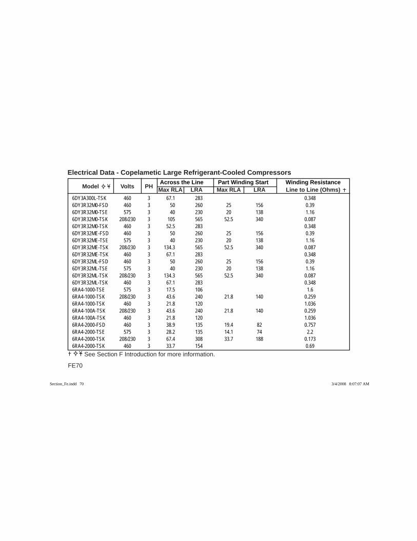
Across the Line Part Winding Start Winding Resistance Model Volts PH Max RLA LRA Max RLA LRA Line to Line (Ohms)
Electrical Data - Copelametic Large Refrigerant-Cooled Compressors
FE70
See Section F Introduction for more information.
6DY3A300L-TSK 460 3 67.1 283 0.3486DY3R32M0-FSD 460 3 50 260 25 156 0.396DY3R32M0-TSE 575 3 40 230 20 138 1.166DY3R32M0-TSK 208/230 3 105 565 52.5 340 0.0876DY3R32M0-TSK 460 3 52.5 283 0.3486DY3R32ME-FSD 460 3 50 260 25 156 0.396DY3R32ME-TSE 575 3 40 230 20 138 1.166DY3R32ME-TSK 208/230 3 134.3 565 52.5 340 0.0876DY3R32ME-TSK 460 3 67.1 283 0.3486DY3R32ML-FSD 460 3 50 260 25 156 0.396DY3R32ML-TSE 575 3 40 230 20 138 1.166DY3R32ML-TSK 208/230 3 134.3 565 52.5 340 0.0876DY3R32ML-TSK 460 3 67.1 283 0.3486RA4-1000-TSE 575 3 17.5 106 1.66RA4-1000-TSK 208/230 3 43.6 240 21.8 140 0.2596RA4-1000-TSK 460 3 21.8 120 1.0366RA4-100A-TSK 208/230 3 43.6 240 21.8 140 0.2596RA4-100A-TSK 460 3 21.8 120 1.0366RA4-2000-FSD 460 3 38.9 135 19.4 82 0.7576RA4-2000-TSE 575 3 28.2 135 14.1 74 2.26RA4-2000-TSK 208/230 3 67.4 308 33.7 188 0.1736RA4-2000-TSK 460 3 33.7 154 0.69
Section_Fe.indd 70Section_Fe.indd 70 3/4/2008 8:07:07 AM3/4/2008 8:07:07 AM
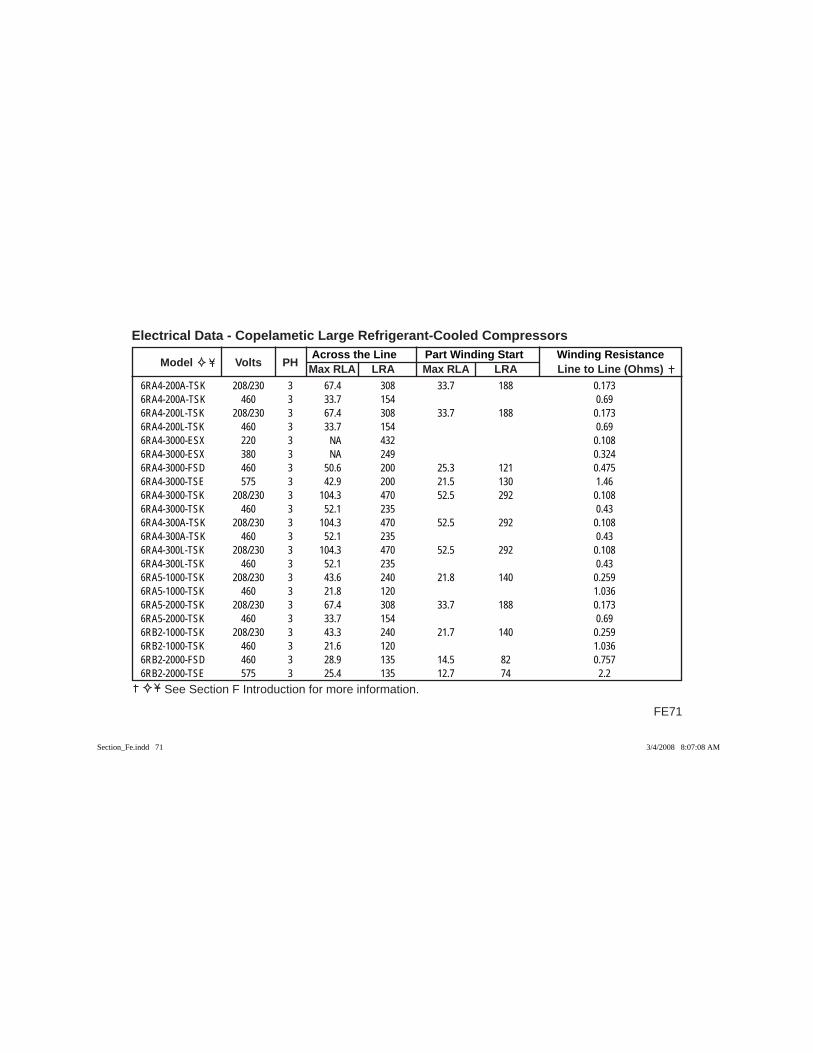
FE71
Across the Line Part Winding Start Winding Resistance Model Volts PH Max RLA LRA Max RLA LRA Line to Line (Ohms)
Electrical Data - Copelametic Large Refrigerant-Cooled Compressors
See Section F Introduction for more information.
6RA4-200A-TSK 208/230 3 67.4 308 33.7 188 0.1736RA4-200A-TSK 460 3 33.7 154 0.696RA4-200L-TSK 208/230 3 67.4 308 33.7 188 0.1736RA4-200L-TSK 460 3 33.7 154 0.696RA4-3000-ESX 220 3 NA 432 0.1086RA4-3000-ESX 380 3 NA 249 0.3246RA4-3000-FSD 460 3 50.6 200 25.3 121 0.4756RA4-3000-TSE 575 3 42.9 200 21.5 130 1.466RA4-3000-TSK 208/230 3 104.3 470 52.5 292 0.1086RA4-3000-TSK 460 3 52.1 235 0.436RA4-300A-TSK 208/230 3 104.3 470 52.5 292 0.1086RA4-300A-TSK 460 3 52.1 235 0.436RA4-300L-TSK 208/230 3 104.3 470 52.5 292 0.1086RA4-300L-TSK 460 3 52.1 235 0.436RA5-1000-TSK 208/230 3 43.6 240 21.8 140 0.2596RA5-1000-TSK 460 3 21.8 120 1.0366RA5-2000-TSK 208/230 3 67.4 308 33.7 188 0.1736RA5-2000-TSK 460 3 33.7 154 0.696RB2-1000-TSK 208/230 3 43.3 240 21.7 140 0.2596RB2-1000-TSK 460 3 21.6 120 1.0366RB2-2000-FSD 460 3 28.9 135 14.5 82 0.7576RB2-2000-TSE 575 3 25.4 135 12.7 74 2.2
Section_Fe.indd 71Section_Fe.indd 71 3/4/2008 8:07:08 AM3/4/2008 8:07:08 AM
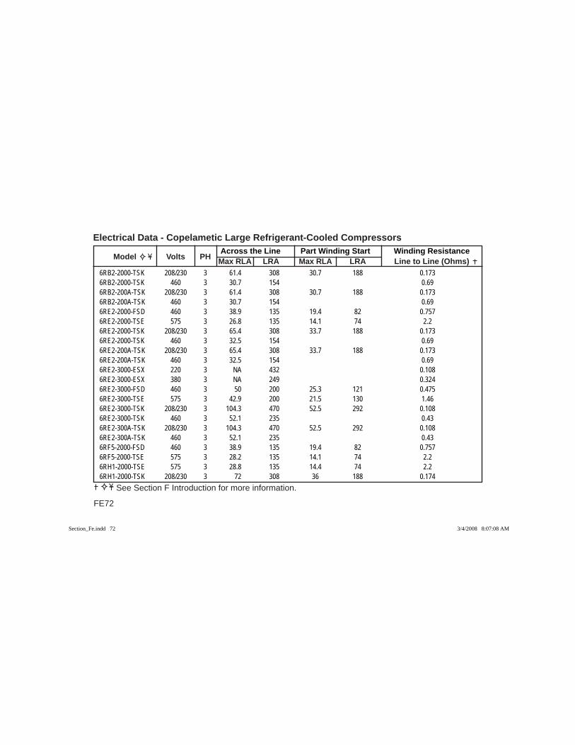
Across the Line Part Winding Start Winding Resistance Model Volts PH Max RLA LRA Max RLA LRA Line to Line (Ohms)
Electrical Data - Copelametic Large Refrigerant-Cooled Compressors
FE72
See Section F Introduction for more information.
6RB2-2000-TSK 208/230 3 61.4 308 30.7 188 0.1736RB2-2000-TSK 460 3 30.7 154 0.696RB2-200A-TSK 208/230 3 61.4 308 30.7 188 0.1736RB2-200A-TSK 460 3 30.7 154 0.696RE2-2000-FSD 460 3 38.9 135 19.4 82 0.7576RE2-2000-TSE 575 3 26.8 135 14.1 74 2.26RE2-2000-TSK 208/230 3 65.4 308 33.7 188 0.1736RE2-2000-TSK 460 3 32.5 154 0.696RE2-200A-TSK 208/230 3 65.4 308 33.7 188 0.1736RE2-200A-TSK 460 3 32.5 154 0.696RE2-3000-ESX 220 3 NA 432 0.1086RE2-3000-ESX 380 3 NA 249 0.3246RE2-3000-FSD 460 3 50 200 25.3 121 0.4756RE2-3000-TSE 575 3 42.9 200 21.5 130 1.466RE2-3000-TSK 208/230 3 104.3 470 52.5 292 0.1086RE2-3000-TSK 460 3 52.1 235 0.436RE2-300A-TSK 208/230 3 104.3 470 52.5 292 0.1086RE2-300A-TSK 460 3 52.1 235 0.436RF5-2000-FSD 460 3 38.9 135 19.4 82 0.7576RF5-2000-TSE 575 3 28.2 135 14.1 74 2.26RH1-2000-TSE 575 3 28.8 135 14.4 74 2.26RH1-2000-TSK 208/230 3 72 308 36 188 0.174
Section_Fe.indd 72Section_Fe.indd 72 3/4/2008 8:07:08 AM3/4/2008 8:07:08 AM
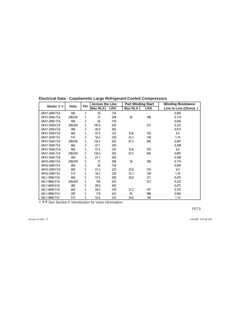
FE73
Across the Line Part Winding Start Winding Resistance Model Volts PH Max RLA LRA Max RLA LRA Line to Line (Ohms)
Electrical Data - Copelametic Large Refrigerant-Cooled Compressors
See Section F Introduction for more information.
6RH1-2000-TSK 460 3 36 154 0.6966RH1-200A-TSK 208/230 3 72 308 36 188 0.1746RH1-200A-TSK 460 3 36 154 0.6966RH1-3500-ES8 200/220 3 145.9 633 212 0.2256RH1-3500-ES8 380 3 85.9 365 0.0756RH1-3500-FSD 460 3 67.5 225 33.8 150 0.46RH1-3500-TSE 575 3 50.2 230 25.1 138 1.166RH1-3500-TSK 208/230 3 134.3 565 67.5 340 0.0876RH1-3500-TSK 460 3 67.1 283 0.3486RH1-350A-FSD 460 3 67.5 225 33.8 150 0.46RH1-350A-TSK 208/230 3 134.3 565 67.5 340 0.0876RH1-350A-TSK 460 3 67.1 283 0.3486RH5-2000-TSK 208/230 3 72 308 36 188 0.1746RH5-2000-TSK 460 3 36 154 0.6966RH5-3500-FSD 460 3 67.5 225 33.8 150 0.46RH5-3500-TSE 575 3 50.2 230 25.1 138 1.166RJ1-3000-FSD 460 3 57.5 200 28.8 121 0.4756RJ1-4000-ES8 200/220 3 160 633 212 0.2256RJ1-4000-ES8 380 3 89.6 365 0.0756RJ1-4000-FSD 460 3 64.3 239 32.2 147 0.3756RJ1-4000-FSU 200 3 170 625 85 388 0.0666RJ1-4000-TSE 575 3 53.6 225 26.8 140 1.14
Section_Fe.indd 73Section_Fe.indd 73 3/4/2008 8:07:08 AM3/4/2008 8:07:08 AM
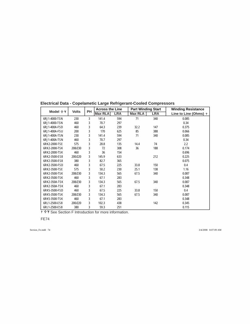
Across the Line Part Winding Start Winding Resistance Model Volts PH Max RLA LRA Max RLA LRA Line to Line (Ohms)
Electrical Data - Copelametic Large Refrigerant-Cooled Compressors
FE74
See Section F Introduction for more information.
6RJ1-4000-TSN 230 3 141.4 594 71 340 0.0856RJ1-4000-TSN 460 3 70.7 297 0.346RJ1-400A-FSD 460 3 64.3 239 32.2 147 0.3756RJ1-400A-FSU 200 3 170 625 85 388 0.0666RJ1-400A-TSN 230 3 141.4 594 71 340 0.0856RJ1-400A-TSN 460 3 70.7 297 0.346RK2-2000-TSE 575 3 28.8 135 14.4 74 2.26RK2-2000-TSK 208/230 3 72 308 36 188 0.1746RK2-2000-TSK 460 3 36 154 0.6966RK2-3500-ES8 200/220 3 145.9 633 212 0.2256RK2-3500-ES8 380 3 82.7 365 0.0756RK2-3500-FSD 460 3 67.5 225 33.8 150 0.46RK2-3500-TSE 575 3 50.2 230 25.1 138 1.166RK2-3500-TSK 208/230 3 134.3 565 67.5 340 0.0876RK2-3500-TSK 460 3 67.1 283 0.3486RK2-350A-TSK 208/230 3 134.3 565 67.5 340 0.0876RK2-350A-TSK 460 3 67.1 283 0.3486RK5-3500-FSD 460 3 67.5 225 33.8 150 0.46RK5-3500-TSK 208/230 3 134.3 565 67.5 340 0.0876RK5-3500-TSK 460 3 67.1 283 0.3486RL1-2500-ES8 200/220 3 102.3 438 142 0.3456RL1-2500-ES8 380 3 59.3 251 0.115
Section_Fe.indd 74Section_Fe.indd 74 3/4/2008 8:07:09 AM3/4/2008 8:07:09 AM
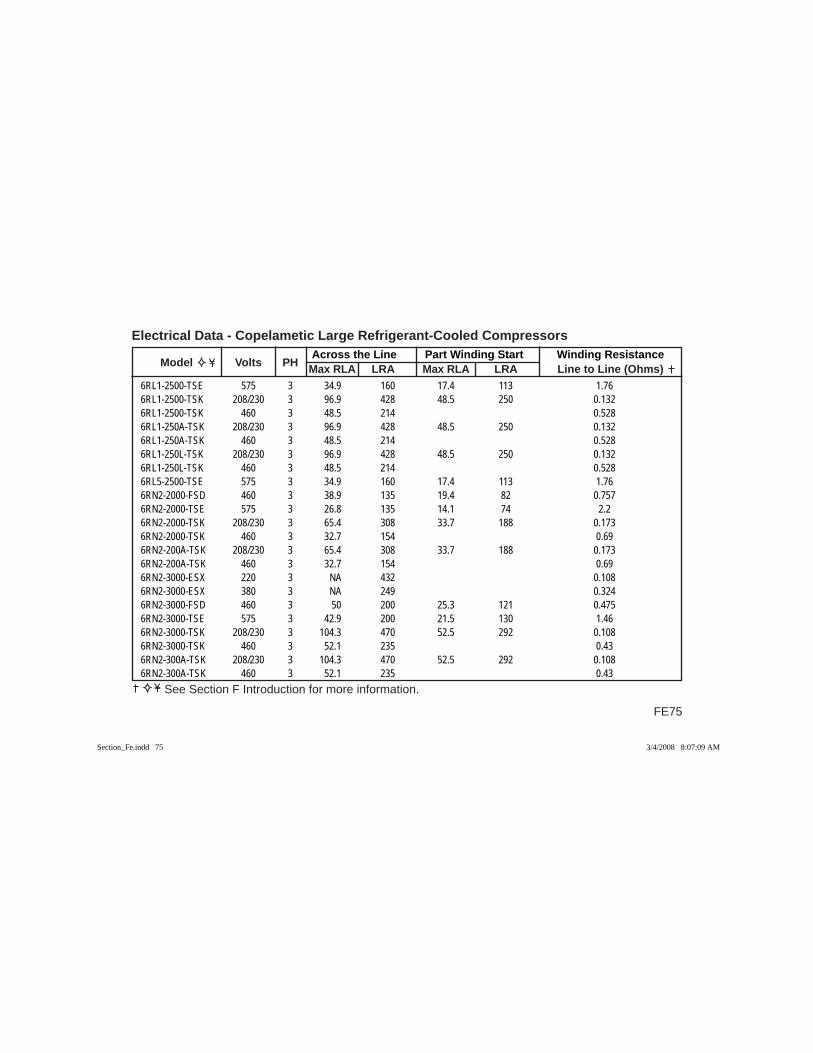
FE75
Across the Line Part Winding Start Winding Resistance Model Volts PH Max RLA LRA Max RLA LRA Line to Line (Ohms)
Electrical Data - Copelametic Large Refrigerant-Cooled Compressors
See Section F Introduction for more information.
6RL1-2500-TSE 575 3 34.9 160 17.4 113 1.766RL1-2500-TSK 208/230 3 96.9 428 48.5 250 0.1326RL1-2500-TSK 460 3 48.5 214 0.5286RL1-250A-TSK 208/230 3 96.9 428 48.5 250 0.1326RL1-250A-TSK 460 3 48.5 214 0.5286RL1-250L-TSK 208/230 3 96.9 428 48.5 250 0.1326RL1-250L-TSK 460 3 48.5 214 0.5286RL5-2500-TSE 575 3 34.9 160 17.4 113 1.766RN2-2000-FSD 460 3 38.9 135 19.4 82 0.7576RN2-2000-TSE 575 3 26.8 135 14.1 74 2.26RN2-2000-TSK 208/230 3 65.4 308 33.7 188 0.1736RN2-2000-TSK 460 3 32.7 154 0.696RN2-200A-TSK 208/230 3 65.4 308 33.7 188 0.1736RN2-200A-TSK 460 3 32.7 154 0.696RN2-3000-ESX 220 3 NA 432 0.1086RN2-3000-ESX 380 3 NA 249 0.3246RN2-3000-FSD 460 3 50 200 25.3 121 0.4756RN2-3000-TSE 575 3 42.9 200 21.5 130 1.466RN2-3000-TSK 208/230 3 104.3 470 52.5 292 0.1086RN2-3000-TSK 460 3 52.1 235 0.436RN2-300A-TSK 208/230 3 104.3 470 52.5 292 0.1086RN2-300A-TSK 460 3 52.1 235 0.43
Section_Fe.indd 75Section_Fe.indd 75 3/4/2008 8:07:09 AM3/4/2008 8:07:09 AM
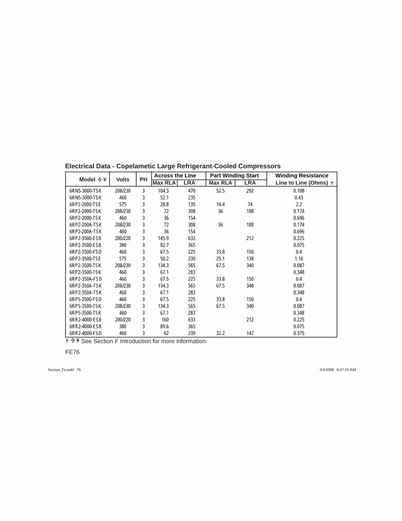
Across the Line Part Winding Start Winding Resistance Model Volts PH Max RLA LRA Max RLA LRA Line to Line (Ohms)
Electrical Data - Copelametic Large Refrigerant-Cooled Compressors
FE76
See Section F Introduction for more information.
6RN5-3000-TSK 208/230 3 104.3 470 52.5 292 0.1086RN5-3000-TSK 460 3 52.1 235 0.436RP2-2000-TSE 575 3 28.8 135 14.4 74 2.26RP2-2000-TSK 208/230 3 72 308 36 188 0.1746RP2-2000-TSK 460 3 36 154 0.6966RP2-200A-TSK 208/230 3 72 308 36 188 0.1746RP2-200A-TSK 460 3 36 154 0.6966RP2-3500-ES8 200/220 3 145.9 633 212 0.2256RP2-3500-ES8 380 3 82.7 365 0.0756RP2-3500-FSD 460 3 67.5 225 33.8 150 0.46RP2-3500-TSE 575 3 50.2 230 25.1 138 1.166RP2-3500-TSK 208/230 3 134.3 565 67.5 340 0.0876RP2-3500-TSK 460 3 67.1 283 0.3486RP2-350A-FSD 460 3 67.5 225 33.8 150 0.46RP2-350A-TSK 208/230 3 134.3 565 67.5 340 0.0876RP2-350A-TSK 460 3 67.1 283 0.3486RP5-3500-FSD 460 3 67.5 225 33.8 150 0.46RP5-3500-TSK 208/230 3 134.3 565 67.5 340 0.0876RP5-3500-TSK 460 3 67.1 283 0.3486RR2-4000-ES8 200/220 3 160 633 212 0.2256RR2-4000-ES8 380 3 89.6 365 0.0756RR2-4000-FSD 460 3 62 239 32.2 147 0.375
Section_Fe.indd 76Section_Fe.indd 76 3/4/2008 8:07:10 AM3/4/2008 8:07:10 AM
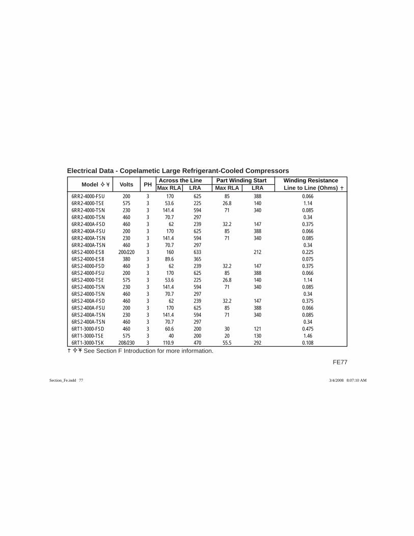
FE77
Across the Line Part Winding Start Winding Resistance Model Volts PH Max RLA LRA Max RLA LRA Line to Line (Ohms)
Electrical Data - Copelametic Large Refrigerant-Cooled Compressors
See Section F Introduction for more information.
6RR2-4000-FSU 200 3 170 625 85 388 0.0666RR2-4000-TSE 575 3 53.6 225 26.8 140 1.146RR2-4000-TSN 230 3 141.4 594 71 340 0.0856RR2-4000-TSN 460 3 70.7 297 0.346RR2-400A-FSD 460 3 62 239 32.2 147 0.3756RR2-400A-FSU 200 3 170 625 85 388 0.0666RR2-400A-TSN 230 3 141.4 594 71 340 0.0856RR2-400A-TSN 460 3 70.7 297 0.346RS2-4000-ES8 200/220 3 160 633 212 0.2256RS2-4000-ES8 380 3 89.6 365 0.0756RS2-4000-FSD 460 3 62 239 32.2 147 0.3756RS2-4000-FSU 200 3 170 625 85 388 0.0666RS2-4000-TSE 575 3 53.6 225 26.8 140 1.146RS2-4000-TSN 230 3 141.4 594 71 340 0.0856RS2-4000-TSN 460 3 70.7 297 0.346RS2-400A-FSD 460 3 62 239 32.2 147 0.3756RS2-400A-FSU 200 3 170 625 85 388 0.0666RS2-400A-TSN 230 3 141.4 594 71 340 0.0856RS2-400A-TSN 460 3 70.7 297 0.346RT1-3000-FSD 460 3 60.6 200 30 121 0.4756RT1-3000-TSE 575 3 40 200 20 130 1.466RT1-3000-TSK 208/230 3 110.9 470 55.5 292 0.108
Section_Fe.indd 77Section_Fe.indd 77 3/4/2008 8:07:10 AM3/4/2008 8:07:10 AM
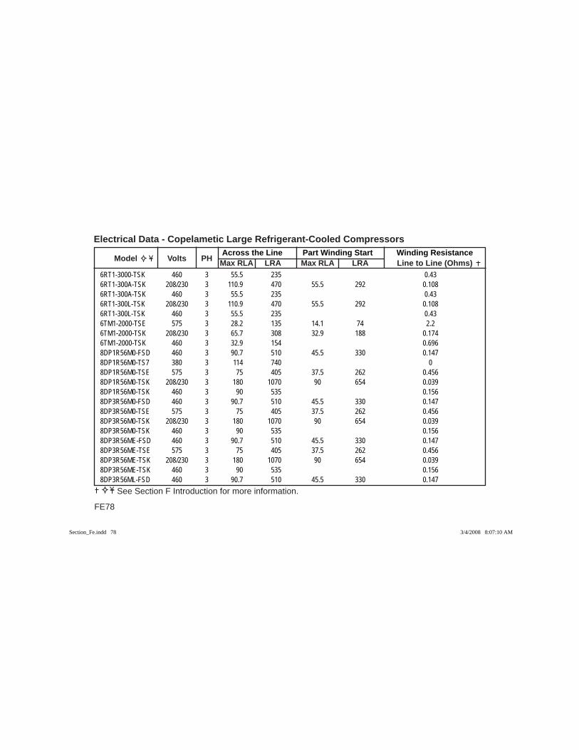
Across the Line Part Winding Start Winding Resistance Model Volts PH Max RLA LRA Max RLA LRA Line to Line (Ohms)
Electrical Data - Copelametic Large Refrigerant-Cooled Compressors
FE78
See Section F Introduction for more information.
6RT1-3000-TSK 460 3 55.5 235 0.436RT1-300A-TSK 208/230 3 110.9 470 55.5 292 0.1086RT1-300A-TSK 460 3 55.5 235 0.436RT1-300L-TSK 208/230 3 110.9 470 55.5 292 0.1086RT1-300L-TSK 460 3 55.5 235 0.436TM1-2000-TSE 575 3 28.2 135 14.1 74 2.26TM1-2000-TSK 208/230 3 65.7 308 32.9 188 0.1746TM1-2000-TSK 460 3 32.9 154 0.6968DP1R56M0-FSD 460 3 90.7 510 45.5 330 0.1478DP1R56M0-TS7 380 3 114 740 08DP1R56M0-TSE 575 3 75 405 37.5 262 0.4568DP1R56M0-TSK 208/230 3 180 1070 90 654 0.0398DP1R56M0-TSK 460 3 90 535 0.1568DP3R56M0-FSD 460 3 90.7 510 45.5 330 0.1478DP3R56M0-TSE 575 3 75 405 37.5 262 0.4568DP3R56M0-TSK 208/230 3 180 1070 90 654 0.0398DP3R56M0-TSK 460 3 90 535 0.1568DP3R56ME-FSD 460 3 90.7 510 45.5 330 0.1478DP3R56ME-TSE 575 3 75 405 37.5 262 0.4568DP3R56ME-TSK 208/230 3 180 1070 90 654 0.0398DP3R56ME-TSK 460 3 90 535 0.1568DP3R56ML-FSD 460 3 90.7 510 45.5 330 0.147
Section_Fe.indd 78Section_Fe.indd 78 3/4/2008 8:07:10 AM3/4/2008 8:07:10 AM
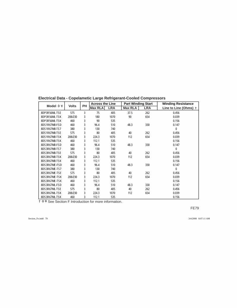
FE79
Across the Line Part Winding Start Winding Resistance Model Volts PH Max RLA LRA Max RLA LRA Line to Line (Ohms)
Electrical Data - Copelametic Large Refrigerant-Cooled Compressors
See Section F Introduction for more information.
8DP3R56ML-TSE 575 3 75 405 37.5 262 0.4568DP3R56ML-TSK 208/230 3 180 1070 90 654 0.0398DP3R56ML-TSK 460 3 90 535 0.1568DS1R67M0-FSD 460 3 96.4 510 48.3 330 0.1478DS1R67M0-TS7 380 3 130 740 08DS1R67M0-TSE 575 3 80 405 40 262 0.4568DS1R67M0-TSK 208/230 3 224.3 1070 112 654 0.0398DS1R67M0-TSK 460 3 112.1 535 0.1568DS3R67M0-FSD 460 3 96.4 510 48.3 330 0.1478DS3R67M0-TS7 380 3 130 740 08DS3R67M0-TSE 575 3 80 405 40 262 0.4568DS3R67M0-TSK 208/230 3 224.3 1070 112 654 0.0398DS3R67M0-TSK 460 3 112.1 535 0.1568DS3R67ME-FSD 460 3 96.4 510 48.3 330 0.1478DS3R67ME-TS7 380 3 130 740 08DS3R67ME-TSE 575 3 80 405 40 262 0.4568DS3R67ME-TSK 208/230 3 224.3 1070 112 654 0.0398DS3R67ME-TSK 460 3 112.1 535 0.1568DS3R67ML-FSD 460 3 96.4 510 48.3 330 0.1478DS3R67ML-TSE 575 3 80 405 40 262 0.4568DS3R67ML-TSK 208/230 3 224.3 1070 112 654 0.0398DS3R67ML-TSK 460 3 112.1 535 0.156
Section_Fe.indd 79Section_Fe.indd 79 3/4/2008 8:07:11 AM3/4/2008 8:07:11 AM
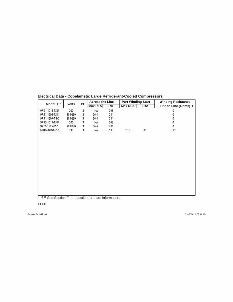
Across the Line Part Winding Start Winding Resistance Model Volts PH Max RLA LRA Max RLA LRA Line to Line (Ohms)
Electrical Data - Copelametic Large Refrigerant-Cooled Compressors
FE80
See Section F Introduction for more information.
9RS1-1015-TSU 200 3 NA 203 09RS1-1505-TSC 208/230 3 56.4 284 09RS1-150A-TSC 208/230 3 56.4 284 09RS3-1015-TSU 200 3 NA 203 09RT1-1505-TSC 208/230 3 56.4 284 0MRH4-0760-FSC 230 3 NA 130 16.3 85 0.41
Section_Fe.indd 80Section_Fe.indd 80 3/4/2008 8:07:11 AM3/4/2008 8:07:11 AM
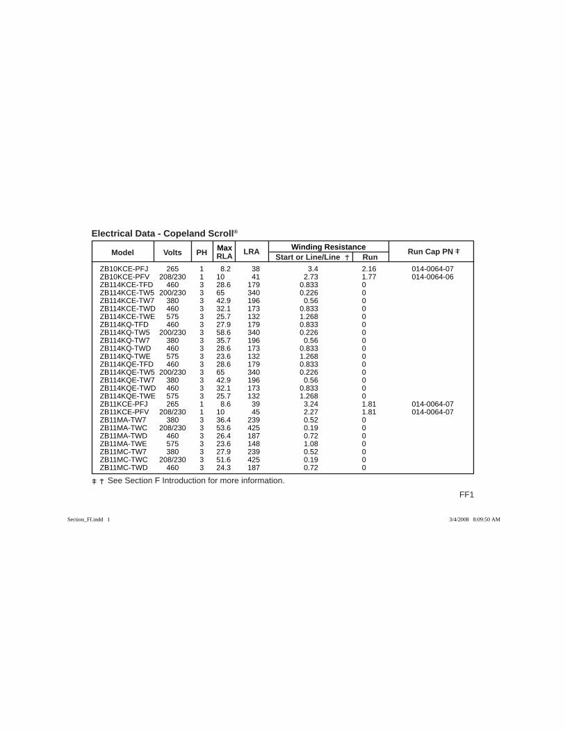
Max Winding Resistance Model Volts PH RLA
LRA Start or Line/Line Run
Run Cap PN
FF1
See Section F Introduction for more information.
Electrical Data - Copeland Scroll®
ZB10KCE-PFJ 265 1 8.2 38 3.4 2.16 014-0064-07 ZB10KCE-PFV 208/230 1 10 41 2.73 1.77 014-0064-06 ZB114KCE-TFD 460 3 28.6 179 0.833 0 ZB114KCE-TW5 200/230 3 65 340 0.226 0 ZB114KCE-TW7 380 3 42.9 196 0.56 0 ZB114KCE-TWD 460 3 32.1 173 0.833 0 ZB114KCE-TWE 575 3 25.7 132 1.268 0 ZB114KQ-TFD 460 3 27.9 179 0.833 0 ZB114KQ-TW5 200/230 3 58.6 340 0.226 0 ZB114KQ-TW7 380 3 35.7 196 0.56 0 ZB114KQ-TWD 460 3 28.6 173 0.833 0 ZB114KQ-TWE 575 3 23.6 132 1.268 0 ZB114KQE-TFD 460 3 28.6 179 0.833 0 ZB114KQE-TW5 200/230 3 65 340 0.226 0 ZB114KQE-TW7 380 3 42.9 196 0.56 0 ZB114KQE-TWD 460 3 32.1 173 0.833 0 ZB114KQE-TWE 575 3 25.7 132 1.268 0 ZB11KCE-PFJ 265 1 8.6 39 3.24 1.81 014-0064-07 ZB11KCE-PFV 208/230 1 10 45 2.27 1.81 014-0064-07 ZB11MA-TW7 380 3 36.4 239 0.52 0 ZB11MA-TWC 208/230 3 53.6 425 0.19 0 ZB11MA-TWD 460 3 26.4 187 0.72 0 ZB11MA-TWE 575 3 23.6 148 1.08 0 ZB11MC-TW7 380 3 27.9 239 0.52 0 ZB11MC-TWC 208/230 3 51.6 425 0.19 0 ZB11MC-TWD 460 3 24.3 187 0.72 0
Section_Ff.indd 1Section_Ff.indd 1 3/4/2008 8:09:50 AM3/4/2008 8:09:50 AM
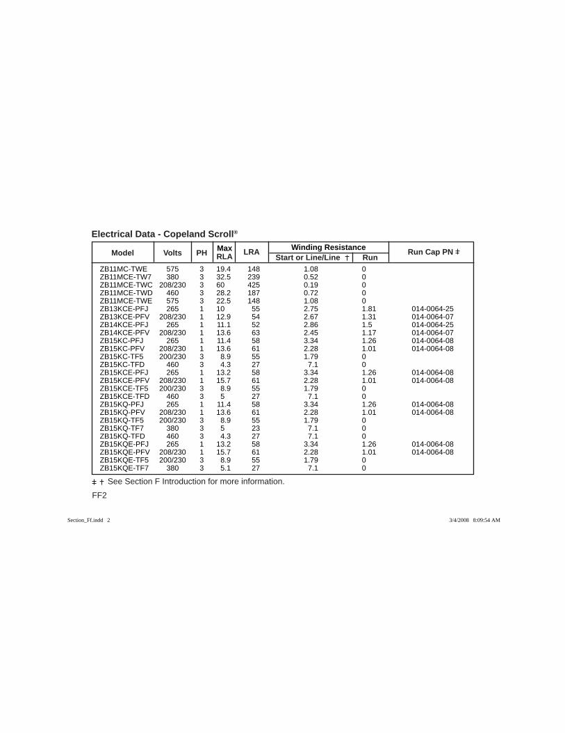
FF2
See Section F Introduction for more information.
Max Winding Resistance Model Volts PH RLA
LRA Start or Line/Line Run
Run Cap PN
Electrical Data - Copeland Scroll®
ZB11MC-TWE 575 3 19.4 148 1.08 0 ZB11MCE-TW7 380 3 32.5 239 0.52 0 ZB11MCE-TWC 208/230 3 60 425 0.19 0 ZB11MCE-TWD 460 3 28.2 187 0.72 0 ZB11MCE-TWE 575 3 22.5 148 1.08 0 ZB13KCE-PFJ 265 1 10 55 2.75 1.81 014-0064-25 ZB13KCE-PFV 208/230 1 12.9 54 2.67 1.31 014-0064-07 ZB14KCE-PFJ 265 1 11.1 52 2.86 1.5 014-0064-25 ZB14KCE-PFV 208/230 1 13.6 63 2.45 1.17 014-0064-07 ZB15KC-PFJ 265 1 11.4 58 3.34 1.26 014-0064-08 ZB15KC-PFV 208/230 1 13.6 61 2.28 1.01 014-0064-08 ZB15KC-TF5 200/230 3 8.9 55 1.79 0 ZB15KC-TFD 460 3 4.3 27 7.1 0 ZB15KCE-PFJ 265 1 13.2 58 3.34 1.26 014-0064-08 ZB15KCE-PFV 208/230 1 15.7 61 2.28 1.01 014-0064-08 ZB15KCE-TF5 200/230 3 8.9 55 1.79 0 ZB15KCE-TFD 460 3 5 27 7.1 0 ZB15KQ-PFJ 265 1 11.4 58 3.34 1.26 014-0064-08 ZB15KQ-PFV 208/230 1 13.6 61 2.28 1.01 014-0064-08 ZB15KQ-TF5 200/230 3 8.9 55 1.79 0 ZB15KQ-TF7 380 3 5 23 7.1 0 ZB15KQ-TFD 460 3 4.3 27 7.1 0 ZB15KQE-PFJ 265 1 13.2 58 3.34 1.26 014-0064-08 ZB15KQE-PFV 208/230 1 15.7 61 2.28 1.01 014-0064-08 ZB15KQE-TF5 200/230 3 8.9 55 1.79 0 ZB15KQE-TF7 380 3 5.1 27 7.1 0
Section_Ff.indd 2Section_Ff.indd 2 3/4/2008 8:09:54 AM3/4/2008 8:09:54 AM
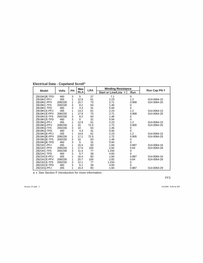
Max Winding Resistance Model Volts PH RLA
LRA Start or Line/Line Run
Run Cap PN
FF3
See Section F Introduction for more information.
Electrical Data - Copeland Scroll®
ZB15KQE-TFD 460 3 5 27 7.1 0 ZB19KC-PFJ 265 1 12.9 61 2.23 1.2 014-0064-15 ZB19KC-PFV 208/230 1 15.7 73 2.71 0.908 014-0064-25 ZB19KC-TF5 200/230 3 8.2 63 1.46 0 ZB19KC-TFD 460 3 4.3 31 5.94 0 ZB19KCE-PFJ 265 1 13.2 61 2.23 1.2 014-0064-15 ZB19KCE-PFV 208/230 1 17.9 73 2.71 0.908 014-0064-25 ZB19KCE-TF5 200/230 3 8.2 63 1.46 0 ZB19KCE-TFD 460 3 5 31 5.94 0 ZB19KQ-PFJ 265 1 12.9 61 2.23 1.2 014-0064-15 ZB19KQ-PFV 208/230 1 15 72.5 1.72 0.905 014-0064-25 ZB19KQ-TF5 200/230 3 10 63 1.46 0 ZB19KQ-TFD 460 3 4.3 31 5.94 0 ZB19KQE-PFJ 265 1 14.6 61 2.23 1.2 014-0064-15 ZB19KQE-PFV 208/230 1 17.1 72.5 1.72 0.905 014-0064-25 ZB19KQE-TF5 200/230 3 10 63 1.46 0 ZB19KQE-TFD 460 3 5 31 5.94 0 ZB21KC-PFJ 265 1 16.4 83 1.84 0.887 014-0064-16 ZB21KC-PFV 208/230 1 17.9 100 2.82 0.64 014-0064-29 ZB21KC-TF5 200/230 3 11.4 77 1.234 0 ZB21KC-TFD 460 3 5.7 39 4.83 0 ZB21KCE-PFJ 265 1 16.4 83 1.84 0.887 014-0064-16 ZB21KCE-PFV 208/230 1 20.7 100 2.82 0.64 014-0064-29 ZB21KCE-TF5 200/230 3 12.1 77 1.234 0 ZB21KCE-TFD 460 3 6.1 39 4.83 0 ZB21KQ-PFJ 265 1 16.4 83 1.84 0.887 014-0064-29
Section_Ff.indd 3Section_Ff.indd 3 3/4/2008 8:09:54 AM3/4/2008 8:09:54 AM
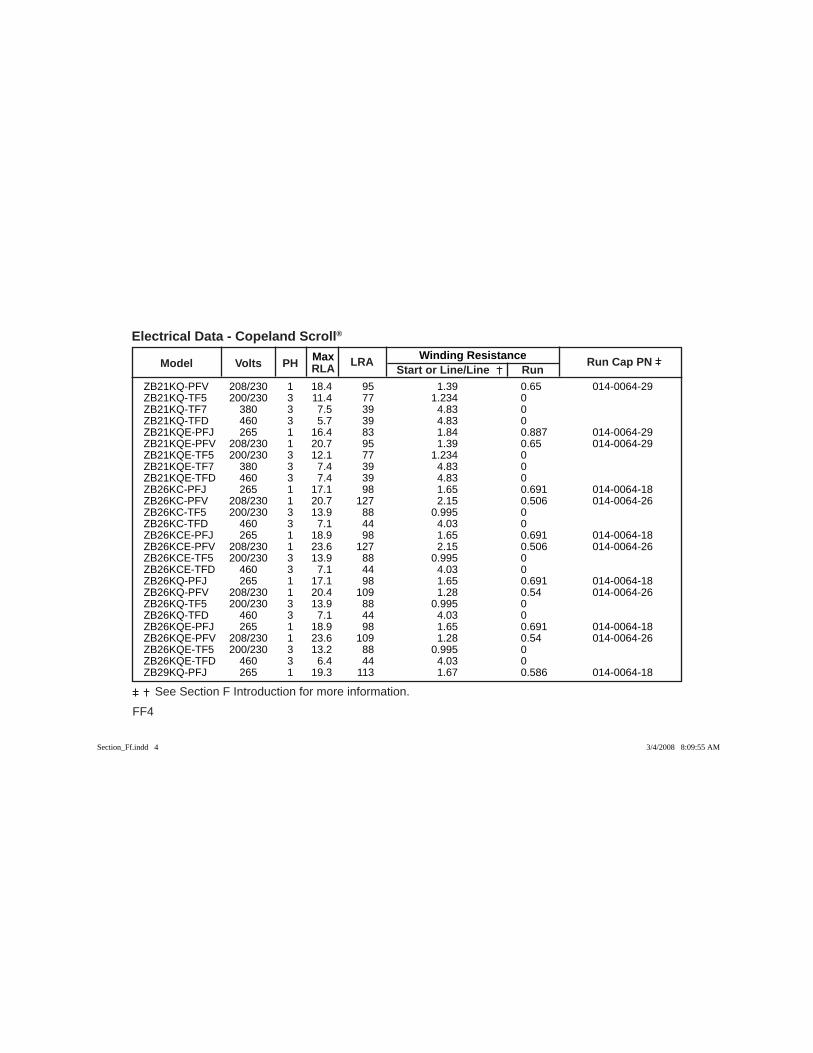
FF4
See Section F Introduction for more information.
Max Winding Resistance Model Volts PH RLA
LRA Start or Line/Line Run
Run Cap PN
Electrical Data - Copeland Scroll®
ZB21KQ-PFV 208/230 1 18.4 95 1.39 0.65 014-0064-29 ZB21KQ-TF5 200/230 3 11.4 77 1.234 0 ZB21KQ-TF7 380 3 7.5 39 4.83 0 ZB21KQ-TFD 460 3 5.7 39 4.83 0 ZB21KQE-PFJ 265 1 16.4 83 1.84 0.887 014-0064-29 ZB21KQE-PFV 208/230 1 20.7 95 1.39 0.65 014-0064-29 ZB21KQE-TF5 200/230 3 12.1 77 1.234 0 ZB21KQE-TF7 380 3 7.4 39 4.83 0 ZB21KQE-TFD 460 3 7.4 39 4.83 0 ZB26KC-PFJ 265 1 17.1 98 1.65 0.691 014-0064-18 ZB26KC-PFV 208/230 1 20.7 127 2.15 0.506 014-0064-26 ZB26KC-TF5 200/230 3 13.9 88 0.995 0 ZB26KC-TFD 460 3 7.1 44 4.03 0 ZB26KCE-PFJ 265 1 18.9 98 1.65 0.691 014-0064-18 ZB26KCE-PFV 208/230 1 23.6 127 2.15 0.506 014-0064-26 ZB26KCE-TF5 200/230 3 13.9 88 0.995 0 ZB26KCE-TFD 460 3 7.1 44 4.03 0 ZB26KQ-PFJ 265 1 17.1 98 1.65 0.691 014-0064-18 ZB26KQ-PFV 208/230 1 20.4 109 1.28 0.54 014-0064-26 ZB26KQ-TF5 200/230 3 13.9 88 0.995 0 ZB26KQ-TFD 460 3 7.1 44 4.03 0 ZB26KQE-PFJ 265 1 18.9 98 1.65 0.691 014-0064-18 ZB26KQE-PFV 208/230 1 23.6 109 1.28 0.54 014-0064-26 ZB26KQE-TF5 200/230 3 13.2 88 0.995 0 ZB26KQE-TFD 460 3 6.4 44 4.03 0 ZB29KQ-PFJ 265 1 19.3 113 1.67 0.586 014-0064-18
Section_Ff.indd 4Section_Ff.indd 4 3/4/2008 8:09:55 AM3/4/2008 8:09:55 AM

Max Winding Resistance Model Volts PH RLA
LRA Start or Line/Line Run
Run Cap PN
FF5
See Section F Introduction for more information.
Electrical Data - Copeland Scroll®
ZB29KQ-PFV 208/230 1 22.1 137 1.34 0.46 014-0064-18 ZB29KQ-TF5 200/230 3 16.4 91 0.994 0 ZB29KQ-TF7 380 3 9.3 54 2.76 0 ZB29KQ-TFD 460 3 7.9 50 3.88 0 ZB29KQE-PFJ 265 1 20 113 1.67 0.586 014-0064-18 ZB29KQE-PFV 208/230 1 25 137 1.34 0.46 014-0064-18 ZB29KQE-TF5 200/230 3 17.1 91 0.994 0 ZB29KQE-TF7 380 3 9.6 54 2.76 0 ZB29KQE-TFD 460 3 7.9 50 3.88 0 ZB30KC-PFV 208/230 1 25 132 2.089 0.454 014-0064-26 ZB30KC-TF5 200/230 3 15 115 0.808 0 ZB30KC-TF7 380 3 8.6 57 2.77 0 ZB30KC-TFD 460 3 7.4 47.5 3.58 0 ZB30KC-TFE 575 3 6.4 40 5.72 0 ZB30KCE-PFV 208/230 1 26.8 132 2.089 0.454 014-0064-26 ZB30KCE-TF5 200/230 3 15.7 115 0.808 0 ZB30KCE-TF7 380 3 8.8 57 2.77 0 ZB30KCE-TFD 460 3 7.5 47.5 3.58 0 ZB30KCE-TFE 575 3 6.4 40 5.72 0 ZB30KQ-PFV 208/230 1 25 132 2.089 0.454 014-0064-26 ZB30KQ-TF5 200/230 3 15 115 0.808 0 ZB30KQ-TFD 460 3 7.4 47.5 3.65 0 ZB30KQE-PFV 208/230 1 26.8 132 2.089 0.454 014-0064-26 ZB30KQE-TF5 200/230 3 15.7 115 0.808 0 ZB30KQE-TFD 460 3 8.6 47.5 3.65 0 ZB38KC-PFV 208/230 1 30.1 175 1.204 0.327 014-0064-27
Section_Ff.indd 5Section_Ff.indd 5 3/4/2008 8:09:55 AM3/4/2008 8:09:55 AM
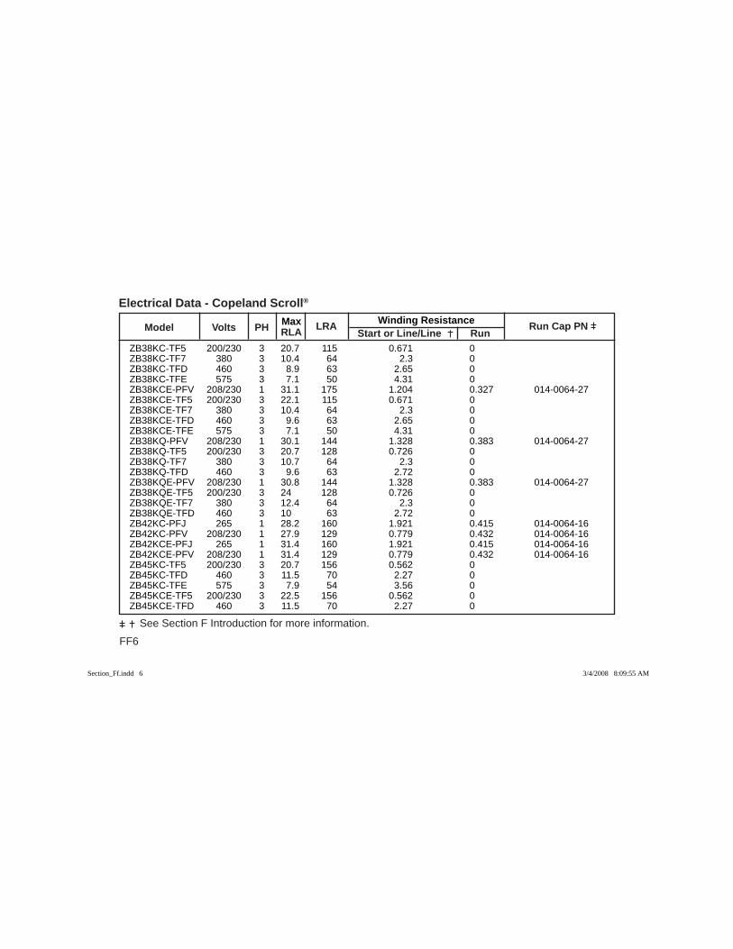
FF6
See Section F Introduction for more information.
Max Winding Resistance Model Volts PH RLA
LRA Start or Line/Line Run
Run Cap PN
Electrical Data - Copeland Scroll®
ZB38KC-TF5 200/230 3 20.7 115 0.671 0 ZB38KC-TF7 380 3 10.4 64 2.3 0 ZB38KC-TFD 460 3 8.9 63 2.65 0 ZB38KC-TFE 575 3 7.1 50 4.31 0 ZB38KCE-PFV 208/230 1 31.1 175 1.204 0.327 014-0064-27 ZB38KCE-TF5 200/230 3 22.1 115 0.671 0 ZB38KCE-TF7 380 3 10.4 64 2.3 0 ZB38KCE-TFD 460 3 9.6 63 2.65 0 ZB38KCE-TFE 575 3 7.1 50 4.31 0 ZB38KQ-PFV 208/230 1 30.1 144 1.328 0.383 014-0064-27 ZB38KQ-TF5 200/230 3 20.7 128 0.726 0 ZB38KQ-TF7 380 3 10.7 64 2.3 0 ZB38KQ-TFD 460 3 9.6 63 2.72 0 ZB38KQE-PFV 208/230 1 30.8 144 1.328 0.383 014-0064-27 ZB38KQE-TF5 200/230 3 24 128 0.726 0 ZB38KQE-TF7 380 3 12.4 64 2.3 0 ZB38KQE-TFD 460 3 10 63 2.72 0 ZB42KC-PFJ 265 1 28.2 160 1.921 0.415 014-0064-16 ZB42KC-PFV 208/230 1 27.9 129 0.779 0.432 014-0064-16 ZB42KCE-PFJ 265 1 31.4 160 1.921 0.415 014-0064-16 ZB42KCE-PFV 208/230 1 31.4 129 0.779 0.432 014-0064-16 ZB45KC-TF5 200/230 3 20.7 156 0.562 0 ZB45KC-TFD 460 3 11.5 70 2.27 0 ZB45KC-TFE 575 3 7.9 54 3.56 0 ZB45KCE-TF5 200/230 3 22.5 156 0.562 0 ZB45KCE-TFD 460 3 11.5 70 2.27 0
Section_Ff.indd 6Section_Ff.indd 6 3/4/2008 8:09:55 AM3/4/2008 8:09:55 AM

Max Winding Resistance Model Volts PH RLA
LRA Start or Line/Line Run
Run Cap PN
FF7
See Section F Introduction for more information.
Electrical Data - Copeland Scroll®
ZB45KCE-TFE 575 3 7.9 54 3.56 0 ZB45KQ-TF5 200/230 3 20.7 156 0.562 0 ZB45KQ-TF7 380 3 10.7 70 1.92 0 ZB45KQ-TFD 460 3 11.5 75 2.27 0 ZB45KQE-TF5 200/230 3 23.1 156 0.562 0 ZB45KQE-TF7 380 3 12.6 70 1.92 0 ZB45KQE-TFD 460 3 10.1 75 2.27 0 ZB48KQ-TF5 200/230 3 25 164 0.501 0 ZB48KQ-TF7 380 3 12.1 100 1.79 0 ZB48KQ-TFD 460 3 12.1 100 1.79 0 ZB48KQE-TF5 200/230 3 26 164 0.501 0 ZB48KQE-TFD 460 3 13.6 100 1.79 0 ZB50KC-TF5 200/230 3 28.6 196 0.44 0 ZB50KC-TF7 380 3 15.7 135 1.174 0 ZB50KC-TFD 460 3 14.3 100 1.764 0 ZB50KC-TFE 575 3 9.6 90 2.989 0 ZB50KCE-TF5 200/230 3 28.6 196 0.44 0 ZB50KCE-TF7 380 3 18.2 135 1.174 0 ZB50KCE-TFD 460 3 15 100 1.764 0 ZB50KCE-TFE 575 3 9.6 90 2.989 0 ZB50KQ-TF5 200/230 3 28.6 196 0.44 0 ZB50KQ-TF7 380 3 15.7 135 1.174 0 ZB50KQ-TFD 460 3 14.3 100 1.764 0 ZB50KQ-TFE 575 3 9.6 90 2.989 0 ZB50KQE-TF5 200/230 3 28.6 196 0.44 0 ZB50KQE-TF7 380 3 18.2 135 1.174 0
Section_Ff.indd 7Section_Ff.indd 7 3/4/2008 8:09:56 AM3/4/2008 8:09:56 AM

FF8
See Section F Introduction for more information.
Max Winding Resistance Model Volts PH RLA
LRA Start or Line/Line Run
Run Cap PN
Electrical Data - Copeland Scroll®
ZB50KQE-TFD 460 3 15 100 1.764 0 ZB50KQE-TFE 575 3 9.6 90 2.989 0 ZB56KA-TW7 380 3 16.6 112 1.03 0 ZB56KA-TWC 208/230 3 26.4 189 0.37 0 ZB56KA-TWD 460 3 13.9 99 1.41 0 ZB56KA-TWE 575 3 10.1 74 2.3 0 ZB56KC-TW7 380 3 16 112 1.03 0 ZB56KC-TWC 208/230 3 25.8 189 0.37 0 ZB56KC-TWD 460 3 13.5 99 1.41 0 ZB56KC-TWE 575 3 9.9 74 2.3 0 ZB56KCE-TW7 380 3 18.6 112 1.03 0 ZB56KCE-TWC 208/230 3 30 189 0.37 0 ZB56KCE-TWD 460 3 15.7 99 1.41 0 ZB56KCE-TWE 575 3 9.9 74 2.3 0 ZB58KC-TF5 200/230 3 32.1 195 0.4 0 ZB58KC-TF7 380 3 16.7 123 1.051 0 ZB58KC-TFD 460 3 16.4 95 1.799 0 ZB58KC-TFE 575 3 12 80 2.55 0 ZB58KCE-TF5 200/230 3 32.1 195 0.4 0 ZB58KCE-TF7 380 3 17.1 123 1.051 0 ZB58KCE-TFD 460 3 16.4 95 1.799 0 ZB58KCE-TFE 575 3 12.9 80 2.55 0 ZB58KQ-TF5 200/230 3 32.1 195 0.4 0 ZB58KQ-TF7 380 3 16.7 123 1.051 0 ZB58KQ-TFD 460 3 16.4 95 1.799 0 ZB58KQ-TFE 575 3 12 80 2.55 0
Section_Ff.indd 8Section_Ff.indd 8 3/4/2008 8:09:56 AM3/4/2008 8:09:56 AM

Max Winding Resistance Model Volts PH RLA
LRA Start or Line/Line Run
Run Cap PN
FF9
See Section F Introduction for more information.
Electrical Data - Copeland Scroll®
ZB58KQE-TF5 200/230 3 32.1 195 0.4 0 ZB58KQE-TF7 380 3 17.1 123 1.051 0 ZB58KQE-TFD 460 3 16.4 95 1.799 0 ZB58KQE-TFE 575 3 12.9 80 2.55 0 ZB66KC-TF5 200/230 3 33.6 225 0.347 0 ZB66KC-TF7 380 3 18.6 140 0.93 0 ZB66KC-TFD 460 3 17.3 114 1.36 0 ZB66KC-TFE 575 3 13.5 80 2.55 0 ZB66KCE-TF5 200/230 3 33.6 225 0.347 0 ZB66KCE-TF7 380 3 20.7 140 0.93 0 ZB66KCE-TFD 460 3 17.5 114 1.36 0 ZB66KCE-TFE 575 3 13.5 80 2.55 0 ZB66KQ-TF5 200/230 3 33.6 225 0.347 0 ZB66KQ-TF7 380 3 18.6 140 0.93 0 ZB66KQ-TFD 460 3 17.3 114 1.36 0 ZB66KQ-TFE 575 3 13.5 80 2.55 0 ZB66KQE-TF5 200/230 3 33.6 225 0.347 0 ZB66KQE-TF7 380 3 20.7 140 0.93 0 ZB66KQE-TFD 460 3 17.5 114 1.36 0 ZB66KQE-TFE 575 3 13.5 80 2.55 0 ZB68KA-TW7 380 3 20.7 144 0.78 0 ZB68KA-TWC 208/230 3 33.3 232 0.29 0 ZB68KA-TWD 460 3 17 125 1.11 0 ZB68KA-TWE 575 3 12.9 100 1.86 0 ZB75KA-TW7 380 3 25.4 151 0.72 0 ZB75KA-TWC 208/230 3 37.4 278 0.26 0
Section_Ff.indd 9Section_Ff.indd 9 3/4/2008 8:09:56 AM3/4/2008 8:09:56 AM

FF10
See Section F Introduction for more information.
Max Winding Resistance Model Volts PH RLA
LRA Start or Line/Line Run
Run Cap PN
Electrical Data - Copeland Scroll®
ZB75KA-TWD 460 3 18.4 127 1.02 0 ZB75KA-TWE 575 3 15.2 100 1.7 0 ZB75KC-TW7 380 3 20.6 151 0.72 0 ZB75KC-TWC 208/230 3 37.5 278 0.26 0 ZB75KC-TWD 460 3 18.1 127 1.02 0 ZB75KC-TWE 575 3 13.9 100 1.7 0 ZB75KCE-TW7 380 3 23.9 151 0.72 0 ZB75KCE-TWC 208/230 3 43.6 278 0.26 0 ZB75KCE-TWD 460 3 21.1 127 1.02 0 ZB75KCE-TWE 575 3 16.1 100 1.7 0 ZB76KC-TF5 200/230 3 41.4 239 0.306 0 ZB76KC-TF7 380 3 23.6 145 0.85 0 ZB76KC-TFD 460 3 19.2 125 1.227 0 ZB76KC-TFE 575 3 13.8 80 2.55 0 ZB76KCE-TF5 200/230 3 41.4 239 0.306 0 ZB76KCE-TF7 380 3 23.6 145 0.85 0 ZB76KCE-TFD 460 3 20 125 1.227 0 ZB76KCE-TFE 575 3 13.8 80 2.55 0 ZB76KQ-TF5 200/230 3 41.4 239 0.306 0 ZB76KQ-TF7 380 3 23.6 145 0.85 0 ZB76KQ-TFD 460 3 19.2 125 1.227 0 ZB76KQ-TFE 575 3 13.8 80 2.55 0 ZB76KQE-TF5 200/230 3 41.4 239 0.306 0 ZB76KQE-TF7 380 3 23.6 145 0.85 0 ZB76KQE-TFD 460 3 20 125 1.227 0 ZB76KQE-TFE 575 3 13.8 80 2.55 0
Section_Ff.indd 10Section_Ff.indd 10 3/4/2008 8:09:57 AM3/4/2008 8:09:57 AM

Max Winding Resistance Model Volts PH RLA
LRA Start or Line/Line Run
Run Cap PN
FF11
See Section F Introduction for more information.
Electrical Data - Copeland Scroll®
ZB88KC-TF5 200/230 3 47.1 245 0.282 0 ZB88KC-TF7 380 3 24.4 145 0.85 0 ZB88KC-TFD 460 3 19.6 125 1.227 0 ZB88KC-TFE 575 3 15.9 100 1.87 0 ZB88KCE-TF5 200/230 3 47.1 245 0.282 0 ZB88KCE-TF7 380 3 24.4 145 0.85 0 ZB88KCE-TFD 460 3 20.7 125 1.227 0 ZB88KCE-TFE 575 3 15.9 100 1.87 0 ZB88KQ-TF5 200/230 3 47.1 245 0.282 0 ZB88KQ-TF7 380 3 24.4 145 0.85 0 ZB88KQ-TFD 460 3 20.7 125 1.227 0 ZB88KQ-TFE 575 3 15.9 100 1.87 0 ZB88KQE-TF5 200/230 3 47.1 245 0.282 0 ZB88KQE-TF7 380 3 24.4 145 0.85 0 ZB88KQE-TFD 460 3 20.7 125 1.227 0 ZB88KQE-TFE 575 3 15.9 100 1.87 0 ZB92KA-TW7 380 3 27.9 195 0.57 0 ZB92KA-TWC 208/230 3 45.7 350 0.22 0 ZB92KA-TWD 460 3 24.3 158 0.83 0 ZB92KA-TWE 575 3 19.3 125 1.28 0 ZB92KC-TW7 380 3 24.3 195 0.57 0 ZB92KC-TWC 208/230 3 45.4 350 0.22 0 ZB92KC-TWD 460 3 21.5 158 0.83 0 ZB92KC-TWE 575 3 17.2 125 1.28 0 ZB92KCE-TW7 380 3 28.2 195 0.57 0 ZB92KCE-TWC 208/230 3 52.9 350 0.22 0
Section_Ff.indd 11Section_Ff.indd 11 3/4/2008 8:09:57 AM3/4/2008 8:09:57 AM
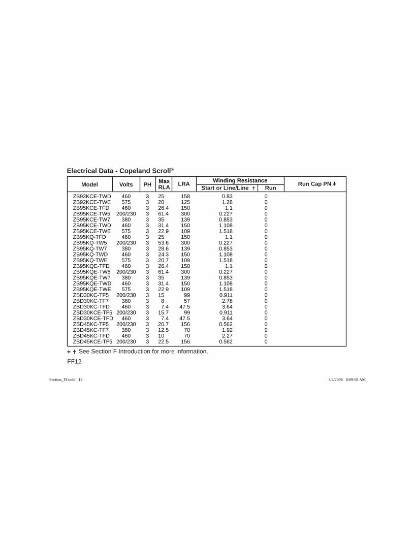
FF12
See Section F Introduction for more information.
Max Winding Resistance Model Volts PH RLA
LRA Start or Line/Line Run
Run Cap PN
Electrical Data - Copeland Scroll®
ZB92KCE-TWD 460 3 25 158 0.83 0 ZB92KCE-TWE 575 3 20 125 1.28 0 ZB95KCE-TFD 460 3 26.4 150 1.1 0 ZB95KCE-TW5 200/230 3 61.4 300 0.227 0 ZB95KCE-TW7 380 3 35 139 0.853 0 ZB95KCE-TWD 460 3 31.4 150 1.108 0 ZB95KCE-TWE 575 3 22.9 109 1.518 0 ZB95KQ-TFD 460 3 25 150 1.1 0 ZB95KQ-TW5 200/230 3 53.6 300 0.227 0 ZB95KQ-TW7 380 3 28.6 139 0.853 0 ZB95KQ-TWD 460 3 24.3 150 1.108 0 ZB95KQ-TWE 575 3 20.7 109 1.518 0 ZB95KQE-TFD 460 3 26.4 150 1.1 0 ZB95KQE-TW5 200/230 3 61.4 300 0.227 0 ZB95KQE-TW7 380 3 35 139 0.853 0 ZB95KQE-TWD 460 3 31.4 150 1.108 0 ZB95KQE-TWE 575 3 22.9 109 1.518 0 ZBD30KC-TF5 200/230 3 15 99 0.911 0 ZBD30KC-TF7 380 3 8 57 2.78 0 ZBD30KC-TFD 460 3 7.4 47.5 3.64 0 ZBD30KCE-TF5 200/230 3 15.7 99 0.911 0 ZBD30KCE-TFD 460 3 7.4 47.5 3.64 0 ZBD45KC-TF5 200/230 3 20.7 156 0.562 0 ZBD45KC-TF7 380 3 12.5 70 1.92 0 ZBD45KC-TFD 460 3 10 70 2.27 0 ZBD45KCE-TF5 200/230 3 22.5 156 0.562 0
Section_Ff.indd 12Section_Ff.indd 12 3/4/2008 8:09:58 AM3/4/2008 8:09:58 AM
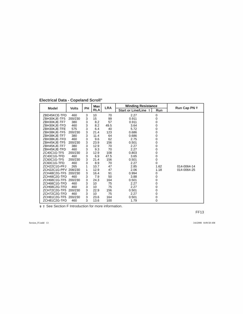
Max Winding Resistance Model Volts PH RLA
LRA Start or Line/Line Run
Run Cap PN
FF13
See Section F Introduction for more information.
Electrical Data - Copeland Scroll®
ZBD45KCE-TFD 460 3 10 70 2.27 0 ZBH30KJE-TF5 200/230 3 15 99 0.911 0 ZBH30KJE-TF7 380 3 8.2 57 0.911 0 ZBH30KJE-TFD 460 3 8.2 49.5 3.64 0 ZBH30KJE-TFE 575 3 6.4 40 5.72 0 ZBH38KJE-TF5 200/230 3 21.4 123 0.686 0 ZBH38KJE-TF7 380 3 11.4 64 0.686 0 ZBH38KJE-TFD 460 3 9.6 62 2.75 0 ZBH45KJE-TF5 200/230 3 23.9 156 0.501 0 ZBH45KJE-TF7 380 3 12.9 70 2.27 0 ZBH45KJE-TFD 460 3 9.3 70 2.27 0 ZC40C1G-TF5 200/230 3 12.9 108 0.803 0 ZC40C1G-TFD 460 3 6.9 47.5 3.65 0 ZC60C1G-TF5 200/230 3 21.4 156 0.501 0 ZC60C1G-TFD 460 3 8.9 70 2.27 0 ZCH22C1G-PFJ 265 1 10.7 47 2.85 1.62 014-0064-14 ZCH22C1G-PFV 208/230 1 12.9 47 2.06 1.18 014-0064-25 ZCH48C2G-TF5 200/230 3 16.4 91 0.994 0 ZCH48C2G-TFD 460 3 7.9 50 3.88 0 ZCH68C1G-TF5 200/230 3 24.3 164 0.501 0 ZCH68C1G-TFD 460 3 10 75 2.27 0 ZCH68C2G-TFD 460 3 10 75 2.27 0 ZCH72C2G-TF5 200/230 3 22.9 156 0.501 0 ZCH72C2G-TFD 460 3 10 75 2.27 0 ZCH81C2G-TF5 200/230 3 23.6 164 0.501 0 ZCH81C2G-TFD 460 3 13.6 100 1.79 0
Section_Ff.indd 13Section_Ff.indd 13 3/4/2008 8:09:58 AM3/4/2008 8:09:58 AM
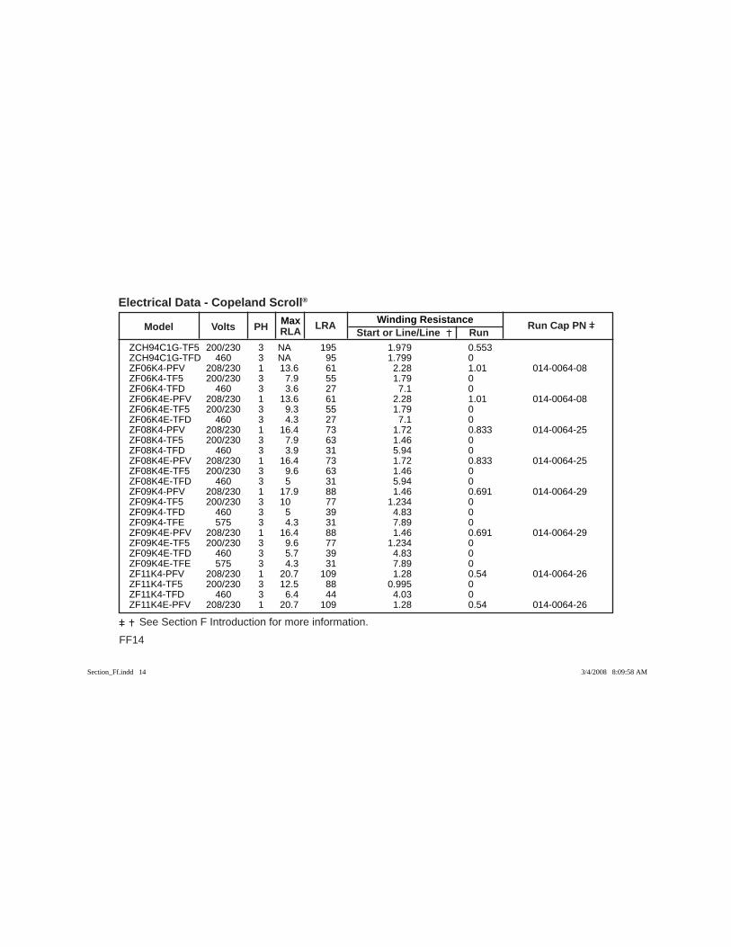
FF14
See Section F Introduction for more information.
Max Winding Resistance Model Volts PH RLA
LRA Start or Line/Line Run
Run Cap PN
Electrical Data - Copeland Scroll®
ZCH94C1G-TF5 200/230 3 NA 195 1.979 0.553 ZCH94C1G-TFD 460 3 NA 95 1.799 0 ZF06K4-PFV 208/230 1 13.6 61 2.28 1.01 014-0064-08 ZF06K4-TF5 200/230 3 7.9 55 1.79 0 ZF06K4-TFD 460 3 3.6 27 7.1 0 ZF06K4E-PFV 208/230 1 13.6 61 2.28 1.01 014-0064-08 ZF06K4E-TF5 200/230 3 9.3 55 1.79 0 ZF06K4E-TFD 460 3 4.3 27 7.1 0 ZF08K4-PFV 208/230 1 16.4 73 1.72 0.833 014-0064-25 ZF08K4-TF5 200/230 3 7.9 63 1.46 0 ZF08K4-TFD 460 3 3.9 31 5.94 0 ZF08K4E-PFV 208/230 1 16.4 73 1.72 0.833 014-0064-25 ZF08K4E-TF5 200/230 3 9.6 63 1.46 0 ZF08K4E-TFD 460 3 5 31 5.94 0 ZF09K4-PFV 208/230 1 17.9 88 1.46 0.691 014-0064-29 ZF09K4-TF5 200/230 3 10 77 1.234 0 ZF09K4-TFD 460 3 5 39 4.83 0 ZF09K4-TFE 575 3 4.3 31 7.89 0 ZF09K4E-PFV 208/230 1 16.4 88 1.46 0.691 014-0064-29 ZF09K4E-TF5 200/230 3 9.6 77 1.234 0 ZF09K4E-TFD 460 3 5.7 39 4.83 0 ZF09K4E-TFE 575 3 4.3 31 7.89 0 ZF11K4-PFV 208/230 1 20.7 109 1.28 0.54 014-0064-26 ZF11K4-TF5 200/230 3 12.5 88 0.995 0 ZF11K4-TFD 460 3 6.4 44 4.03 0 ZF11K4E-PFV 208/230 1 20.7 109 1.28 0.54 014-0064-26
Section_Ff.indd 14Section_Ff.indd 14 3/4/2008 8:09:58 AM3/4/2008 8:09:58 AM

Max Winding Resistance Model Volts PH RLA
LRA Start or Line/Line Run
Run Cap PN
FF15
See Section F Introduction for more information.
Electrical Data - Copeland Scroll®
ZF11K4E-TF5 200/230 3 8.9 88 0.995 0 ZF11K4E-TFD 460 3 7.1 44 4.03 0 ZF11K4E-TFE 575 3 5 34 6.28 0 ZF13K4-TF5 200/230 3 15 99 0.911 0 ZF13K4-TF7 380 3 7.1 57 2.78 0 ZF13K4-TFD 460 3 6.8 49.5 3.64 0 ZF13K4E-PFV 208/230 1 26.8 129 0.779 0.432 014-0064-26 ZF13K4E-TF5 200/230 3 15 99 0.911 0 ZF13K4E-TF7 380 3 8.2 57 2.78 0 ZF13K4E-TFD 460 3 8.2 49.5 3.64 0 ZF13K4E-TFE 575 3 8.2 40 5.72 0 ZF13KVE-TF5 200/230 3 19.3 123 0.686 0 ZF13KVE-TF7 380 3 10.7 64 2.28 0 ZF13KVE-TFD 460 3 9.3 62 2.75 0 ZF13KVE-TFE 575 3 7.9 50 4.31 0 ZF15K4-TF5 200/230 3 16.4 123 0.686 0 ZF15K4-TF7 380 3 9.5 64 2.28 0 ZF15K4-TFD 460 3 8.6 62 2.75 0 ZF15K4E-PFV 208/230 1 31.8 169 0.605 0.329 014-0064-27 ZF15K4E-TF5 200/230 3 21.4 123 0.686 0 ZF15K4E-TF7 380 3 9.5 64 2.28 0 ZF15K4E-TFD 460 3 9.6 62 2.75 0 ZF15K4E-TFE 575 3 7.9 50 4.31 0 ZF18K4-TF5 200/230 3 20 156 0.501 0 ZF18K4-TF7 380 3 11.3 70 1.92 0 ZF18K4-TFD 460 3 8.9 70 2.27 0
Section_Ff.indd 15Section_Ff.indd 15 3/4/2008 8:09:59 AM3/4/2008 8:09:59 AM
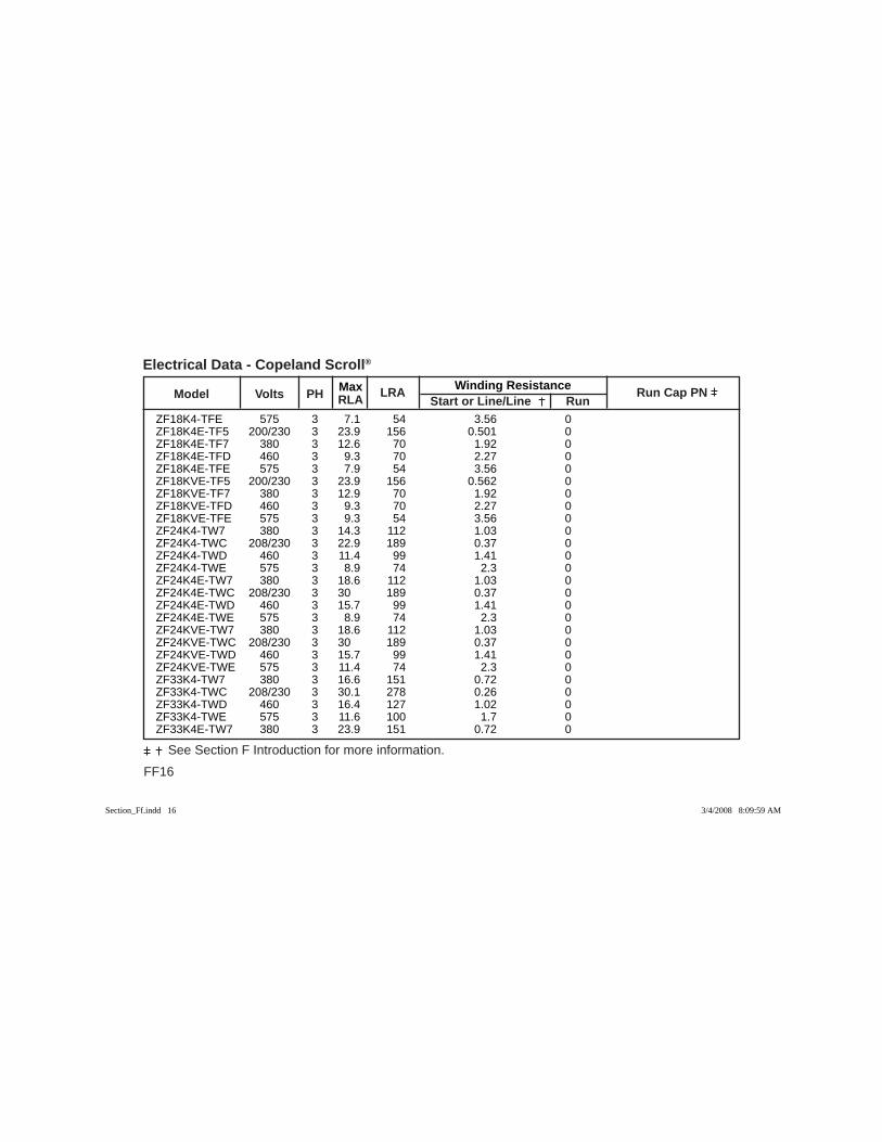
FF16
See Section F Introduction for more information.
Max Winding Resistance Model Volts PH RLA
LRA Start or Line/Line Run
Run Cap PN
Electrical Data - Copeland Scroll®
ZF18K4-TFE 575 3 7.1 54 3.56 0 ZF18K4E-TF5 200/230 3 23.9 156 0.501 0 ZF18K4E-TF7 380 3 12.6 70 1.92 0 ZF18K4E-TFD 460 3 9.3 70 2.27 0 ZF18K4E-TFE 575 3 7.9 54 3.56 0 ZF18KVE-TF5 200/230 3 23.9 156 0.562 0 ZF18KVE-TF7 380 3 12.9 70 1.92 0 ZF18KVE-TFD 460 3 9.3 70 2.27 0 ZF18KVE-TFE 575 3 9.3 54 3.56 0 ZF24K4-TW7 380 3 14.3 112 1.03 0 ZF24K4-TWC 208/230 3 22.9 189 0.37 0 ZF24K4-TWD 460 3 11.4 99 1.41 0 ZF24K4-TWE 575 3 8.9 74 2.3 0 ZF24K4E-TW7 380 3 18.6 112 1.03 0 ZF24K4E-TWC 208/230 3 30 189 0.37 0 ZF24K4E-TWD 460 3 15.7 99 1.41 0 ZF24K4E-TWE 575 3 8.9 74 2.3 0 ZF24KVE-TW7 380 3 18.6 112 1.03 0 ZF24KVE-TWC 208/230 3 30 189 0.37 0 ZF24KVE-TWD 460 3 15.7 99 1.41 0 ZF24KVE-TWE 575 3 11.4 74 2.3 0 ZF33K4-TW7 380 3 16.6 151 0.72 0 ZF33K4-TWC 208/230 3 30.1 278 0.26 0 ZF33K4-TWD 460 3 16.4 127 1.02 0 ZF33K4-TWE 575 3 11.6 100 1.7 0 ZF33K4E-TW7 380 3 23.9 151 0.72 0
Section_Ff.indd 16Section_Ff.indd 16 3/4/2008 8:09:59 AM3/4/2008 8:09:59 AM

Max Winding Resistance Model Volts PH RLA
LRA Start or Line/Line Run
Run Cap PN
FF17
See Section F Introduction for more information.
Electrical Data - Copeland Scroll®
ZF33K4E-TWC 208/230 3 43.6 278 0.26 0 ZF33K4E-TWD 460 3 21.1 127 1.02 0 ZF33K4E-TWE 575 3 16.1 100 1.7 0 ZF33KVE-TW7 380 3 23.9 151 0.72 0 ZF33KVE-TWC 208/230 3 43.6 278 0.26 0 ZF33KVE-TWD 460 3 21.1 127 1.02 0 ZF33KVE-TWE 575 3 16.1 100 1.7 0 ZF40K4-TW7 380 3 22.9 195 0.57 0 ZF40K4-TWC 208/230 3 40.7 350 0.22 0 ZF40K4-TWD 460 3 20 158 0.83 0 ZF40K4-TWE 575 3 15.4 125 1.28 0 ZF40K4E-TW7 380 3 28.2 195 0.57 0 ZF40K4E-TWC 208/230 3 52.9 350 0.22 0 ZF40K4E-TWD 460 3 25 158 0.83 0 ZF40K4E-TWE 575 3 20 125 1.28 0 ZF40KVE-TW7 380 3 28.2 195 0.57 0 ZF40KVE-TWC 208/230 3 52.9 350 0.22 0 ZF40KVE-TWD 460 3 25 158 0.83 0 ZF40KVE-TWE 575 3 20 125 1.28 0 ZF48K4-TW7 380 3 25 239 0.52 0 ZF48K4-TWC 208/230 3 48.2 425 0.19 0 ZF48K4-TWD 460 3 22.1 187 0.72 0 ZF48K4-TWE 575 3 17.9 148 1.1 0 ZF48K4E-TW7 380 3 32.5 239 0.52 0 ZF48K4E-TWC 208/230 3 60 425 0.19 0 ZF48K4E-TWD 460 3 28.2 187 0.72 0
Section_Ff.indd 17Section_Ff.indd 17 3/4/2008 8:10:00 AM3/4/2008 8:10:00 AM
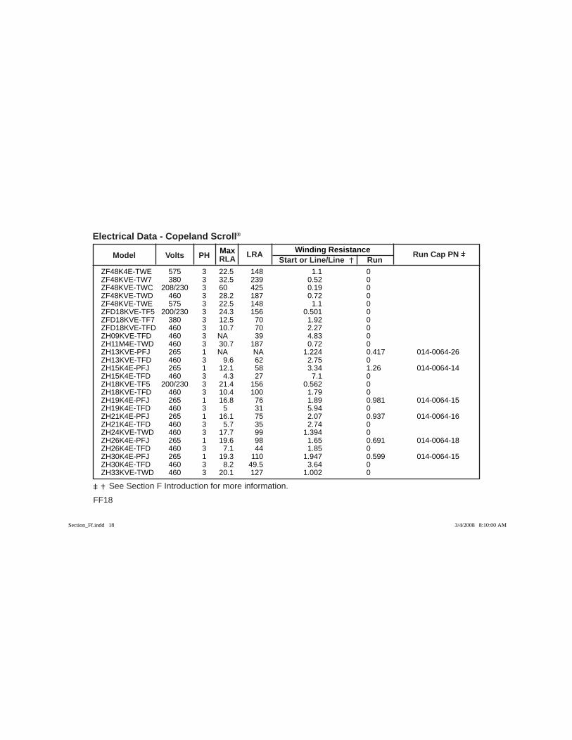
FF18
See Section F Introduction for more information.
Max Winding Resistance Model Volts PH RLA
LRA Start or Line/Line Run
Run Cap PN
Electrical Data - Copeland Scroll®
ZF48K4E-TWE 575 3 22.5 148 1.1 0 ZF48KVE-TW7 380 3 32.5 239 0.52 0 ZF48KVE-TWC 208/230 3 60 425 0.19 0 ZF48KVE-TWD 460 3 28.2 187 0.72 0 ZF48KVE-TWE 575 3 22.5 148 1.1 0 ZFD18KVE-TF5 200/230 3 24.3 156 0.501 0 ZFD18KVE-TF7 380 3 12.5 70 1.92 0 ZFD18KVE-TFD 460 3 10.7 70 2.27 0 ZH09KVE-TFD 460 3 NA 39 4.83 0 ZH11M4E-TWD 460 3 30.7 187 0.72 0 ZH13KVE-PFJ 265 1 NA NA 1.224 0.417 014-0064-26 ZH13KVE-TFD 460 3 9.6 62 2.75 0 ZH15K4E-PFJ 265 1 12.1 58 3.34 1.26 014-0064-14 ZH15K4E-TFD 460 3 4.3 27 7.1 0 ZH18KVE-TF5 200/230 3 21.4 156 0.562 0 ZH18KVE-TFD 460 3 10.4 100 1.79 0 ZH19K4E-PFJ 265 1 16.8 76 1.89 0.981 014-0064-15 ZH19K4E-TFD 460 3 5 31 5.94 0 ZH21K4E-PFJ 265 1 16.1 75 2.07 0.937 014-0064-16 ZH21K4E-TFD 460 3 5.7 35 2.74 0 ZH24KVE-TWD 460 3 17.7 99 1.394 0 ZH26K4E-PFJ 265 1 19.6 98 1.65 0.691 014-0064-18 ZH26K4E-TFD 460 3 7.1 44 1.85 0 ZH30K4E-PFJ 265 1 19.3 110 1.947 0.599 014-0064-15 ZH30K4E-TFD 460 3 8.2 49.5 3.64 0 ZH33KVE-TWD 460 3 20.1 127 1.002 0
Section_Ff.indd 18Section_Ff.indd 18 3/4/2008 8:10:00 AM3/4/2008 8:10:00 AM

Max Winding Resistance Model Volts PH RLA
LRA Start or Line/Line Run
Run Cap PN
FF19
See Section F Introduction for more information.
Electrical Data - Copeland Scroll®
ZH38K4E-TFD 460 3 9.6 62 2.75 0 ZH40KVE-TWD 460 3 23.1 158 0.83 0 ZH45K4E-TFD 460 3 9.6 70 2.27 0 ZH48KVE-TWD 460 3 27.1 198 0.72 0 ZH56K4E-TWD 460 3 16.4 94 1.394 0 ZH75K4E-TWD 460 3 22.9 127 1.002 0 ZH92K4E-TWD 460 3 27.1 158 0.83 0 ZM18K4E-TFD 460 3 9.3 70 2.27 0 ZMD18KVE-TFD 460 3 10.7 70 2.27 0 ZMD26KVE-TFD 460 3 10.4 75 2.26 0 ZNH13C2A-KXX 275 3 NA 125 0.458 0 ZNH16C2A-KXX 275 3 NA 125 0.458 0 ZNH22C2A-KXX 275 3 NA 125 0.458 0 ZNH22C3A-KXX 275 3 NA 110 0.571 0 ZNH28C2A-KXX 275 3 NA 125 0.458 0 ZO104KCE-TFD 460 3 NA NA 2.26 0 ZO34K3E-TFD 460 3 NA 27 7.15 0 ZO45K3E-TFD 460 3 NA 35 5.35 0 ZO58K3E-TFD 460 3 NA 46 3.88 0 ZP103KCE-TF5 200/230 3 33.6 225 0.347 0 ZP103KCE-TFD 460 3 18.6 114 1.36 0 ZP103KCE-TFE 575 3 13.6 80 2.55 0 ZP120KCE-TF5 200/230 3 37.1 239 0.306 0 ZP120KCE-TF7 380 3 26.4 145 0.85 0 ZP120KCE-TFD 460 3 20 125 1.227 0 ZP120KCE-TFE 575 3 14.3 80 2.55 0
Section_Ff.indd 19Section_Ff.indd 19 3/4/2008 8:10:00 AM3/4/2008 8:10:00 AM
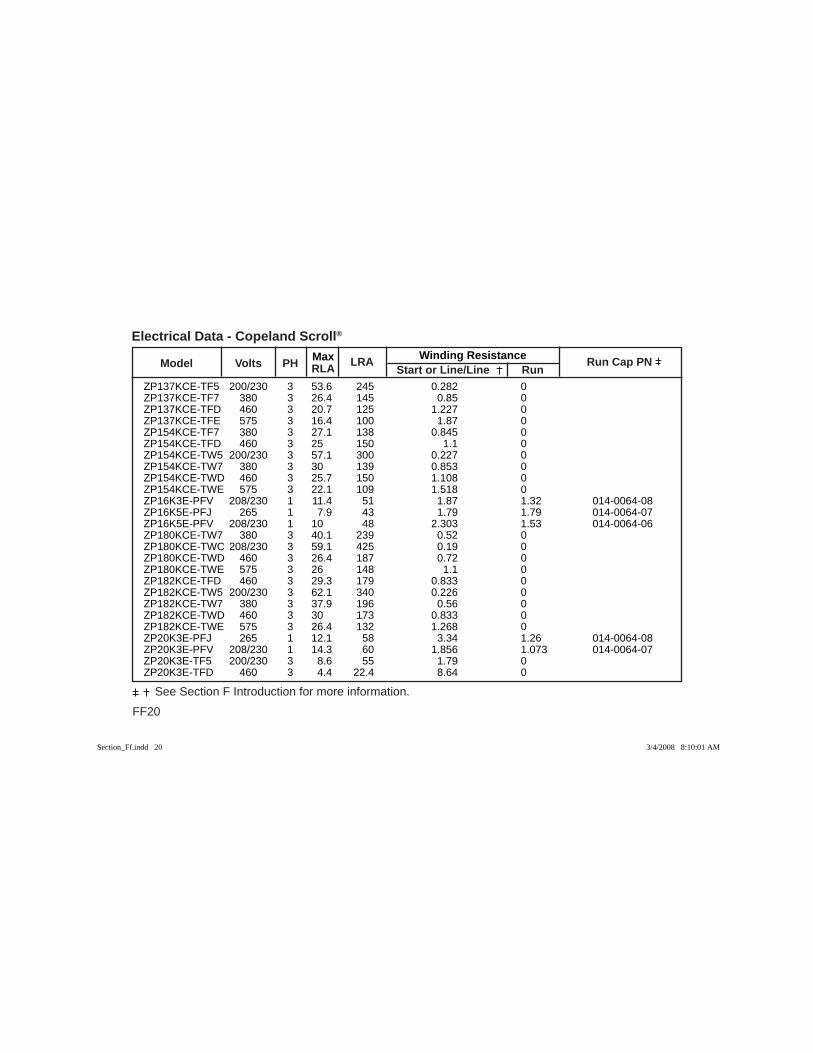
FF20
See Section F Introduction for more information.
Max Winding Resistance Model Volts PH RLA
LRA Start or Line/Line Run
Run Cap PN
Electrical Data - Copeland Scroll®
ZP137KCE-TF5 200/230 3 53.6 245 0.282 0 ZP137KCE-TF7 380 3 26.4 145 0.85 0 ZP137KCE-TFD 460 3 20.7 125 1.227 0 ZP137KCE-TFE 575 3 16.4 100 1.87 0 ZP154KCE-TF7 380 3 27.1 138 0.845 0 ZP154KCE-TFD 460 3 25 150 1.1 0 ZP154KCE-TW5 200/230 3 57.1 300 0.227 0 ZP154KCE-TW7 380 3 30 139 0.853 0 ZP154KCE-TWD 460 3 25.7 150 1.108 0 ZP154KCE-TWE 575 3 22.1 109 1.518 0 ZP16K3E-PFV 208/230 1 11.4 51 1.87 1.32 014-0064-08 ZP16K5E-PFJ 265 1 7.9 43 1.79 1.79 014-0064-07 ZP16K5E-PFV 208/230 1 10 48 2.303 1.53 014-0064-06 ZP180KCE-TW7 380 3 40.1 239 0.52 0 ZP180KCE-TWC 208/230 3 59.1 425 0.19 0 ZP180KCE-TWD 460 3 26.4 187 0.72 0 ZP180KCE-TWE 575 3 26 148 1.1 0 ZP182KCE-TFD 460 3 29.3 179 0.833 0 ZP182KCE-TW5 200/230 3 62.1 340 0.226 0 ZP182KCE-TW7 380 3 37.9 196 0.56 0 ZP182KCE-TWD 460 3 30 173 0.833 0 ZP182KCE-TWE 575 3 26.4 132 1.268 0 ZP20K3E-PFJ 265 1 12.1 58 3.34 1.26 014-0064-08 ZP20K3E-PFV 208/230 1 14.3 60 1.856 1.073 014-0064-07 ZP20K3E-TF5 200/230 3 8.6 55 1.79 0 ZP20K3E-TFD 460 3 4.4 22.4 8.64 0
Section_Ff.indd 20Section_Ff.indd 20 3/4/2008 8:10:01 AM3/4/2008 8:10:01 AM
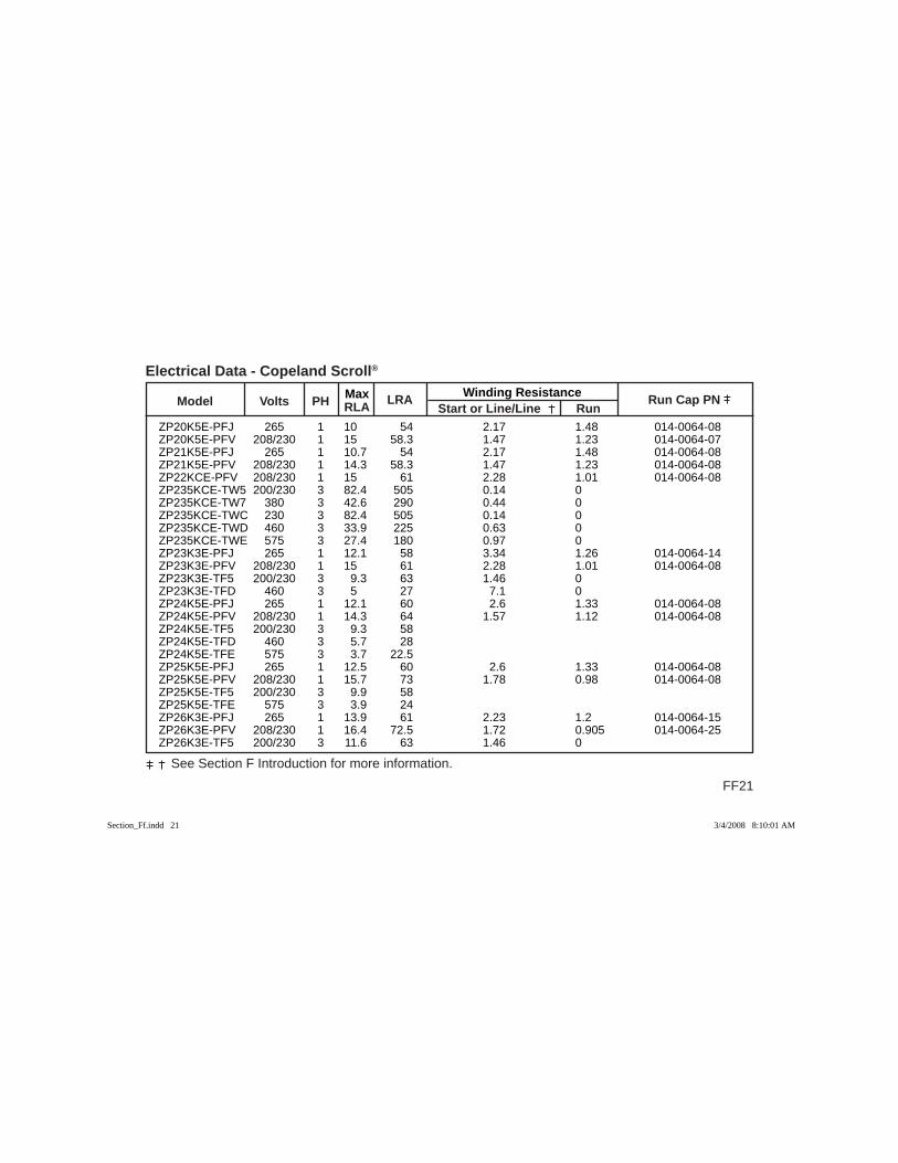
Max Winding Resistance Model Volts PH RLA
LRA Start or Line/Line Run
Run Cap PN
FF21
See Section F Introduction for more information.
Electrical Data - Copeland Scroll®
ZP20K5E-PFJ 265 1 10 54 2.17 1.48 014-0064-08 ZP20K5E-PFV 208/230 1 15 58.3 1.47 1.23 014-0064-07 ZP21K5E-PFJ 265 1 10.7 54 2.17 1.48 014-0064-08 ZP21K5E-PFV 208/230 1 14.3 58.3 1.47 1.23 014-0064-08 ZP22KCE-PFV 208/230 1 15 61 2.28 1.01 014-0064-08 ZP235KCE-TW5 200/230 3 82.4 505 0.14 0 ZP235KCE-TW7 380 3 42.6 290 0.44 0 ZP235KCE-TWC 230 3 82.4 505 0.14 0 ZP235KCE-TWD 460 3 33.9 225 0.63 0 ZP235KCE-TWE 575 3 27.4 180 0.97 0 ZP23K3E-PFJ 265 1 12.1 58 3.34 1.26 014-0064-14 ZP23K3E-PFV 208/230 1 15 61 2.28 1.01 014-0064-08 ZP23K3E-TF5 200/230 3 9.3 63 1.46 0 ZP23K3E-TFD 460 3 5 27 7.1 0 ZP24K5E-PFJ 265 1 12.1 60 2.6 1.33 014-0064-08 ZP24K5E-PFV 208/230 1 14.3 64 1.57 1.12 014-0064-08 ZP24K5E-TF5 200/230 3 9.3 58 ZP24K5E-TFD 460 3 5.7 28 ZP24K5E-TFE 575 3 3.7 22.5 ZP25K5E-PFJ 265 1 12.5 60 2.6 1.33 014-0064-08 ZP25K5E-PFV 208/230 1 15.7 73 1.78 0.98 014-0064-08 ZP25K5E-TF5 200/230 3 9.9 58 ZP25K5E-TFE 575 3 3.9 24 ZP26K3E-PFJ 265 1 13.9 61 2.23 1.2 014-0064-15 ZP26K3E-PFV 208/230 1 16.4 72.5 1.72 0.905 014-0064-25 ZP26K3E-TF5 200/230 3 11.6 63 1.46 0
Section_Ff.indd 21Section_Ff.indd 21 3/4/2008 8:10:01 AM3/4/2008 8:10:01 AM
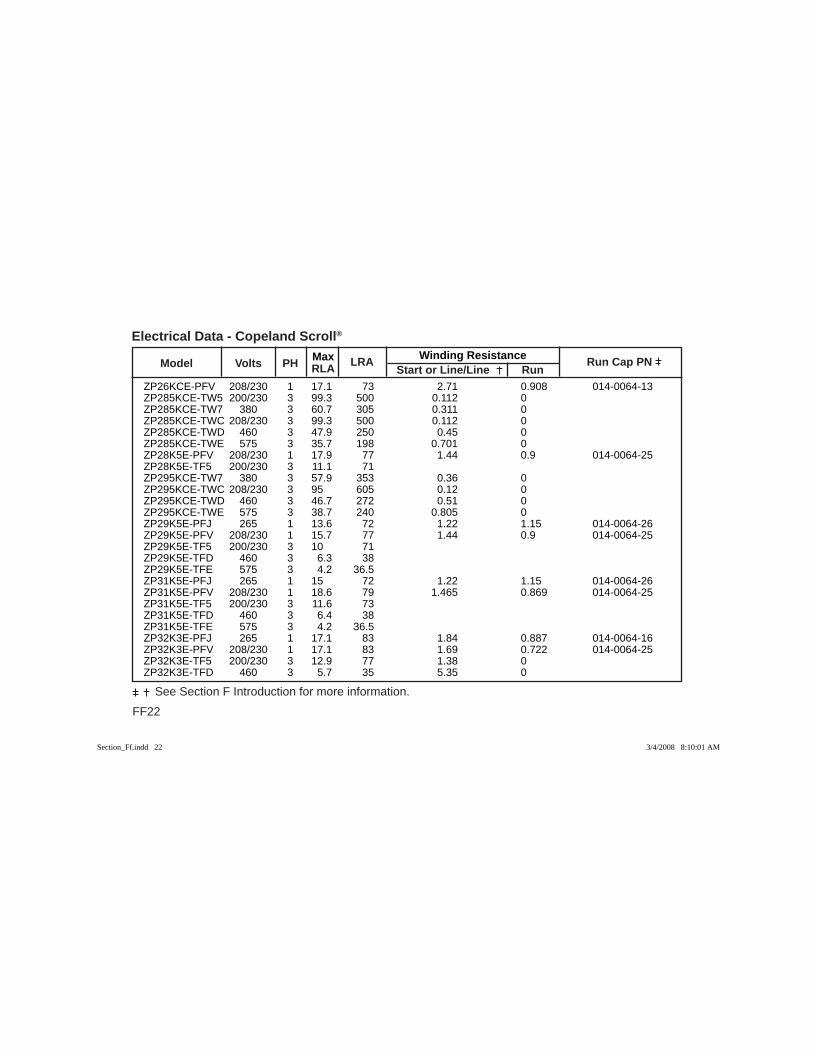
FF22
See Section F Introduction for more information.
Max Winding Resistance Model Volts PH RLA
LRA Start or Line/Line Run
Run Cap PN
Electrical Data - Copeland Scroll®
ZP26KCE-PFV 208/230 1 17.1 73 2.71 0.908 014-0064-13 ZP285KCE-TW5 200/230 3 99.3 500 0.112 0 ZP285KCE-TW7 380 3 60.7 305 0.311 0 ZP285KCE-TWC 208/230 3 99.3 500 0.112 0 ZP285KCE-TWD 460 3 47.9 250 0.45 0 ZP285KCE-TWE 575 3 35.7 198 0.701 0 ZP28K5E-PFV 208/230 1 17.9 77 1.44 0.9 014-0064-25 ZP28K5E-TF5 200/230 3 11.1 71 ZP295KCE-TW7 380 3 57.9 353 0.36 0 ZP295KCE-TWC 208/230 3 95 605 0.12 0 ZP295KCE-TWD 460 3 46.7 272 0.51 0 ZP295KCE-TWE 575 3 38.7 240 0.805 0 ZP29K5E-PFJ 265 1 13.6 72 1.22 1.15 014-0064-26 ZP29K5E-PFV 208/230 1 15.7 77 1.44 0.9 014-0064-25 ZP29K5E-TF5 200/230 3 10 71 ZP29K5E-TFD 460 3 6.3 38 ZP29K5E-TFE 575 3 4.2 36.5 ZP31K5E-PFJ 265 1 15 72 1.22 1.15 014-0064-26 ZP31K5E-PFV 208/230 1 18.6 79 1.465 0.869 014-0064-25 ZP31K5E-TF5 200/230 3 11.6 73 ZP31K5E-TFD 460 3 6.4 38 ZP31K5E-TFE 575 3 4.2 36.5 ZP32K3E-PFJ 265 1 17.1 83 1.84 0.887 014-0064-16 ZP32K3E-PFV 208/230 1 17.1 83 1.69 0.722 014-0064-25 ZP32K3E-TF5 200/230 3 12.9 77 1.38 0 ZP32K3E-TFD 460 3 5.7 35 5.35 0
Section_Ff.indd 22Section_Ff.indd 22 3/4/2008 8:10:01 AM3/4/2008 8:10:01 AM

Max Winding Resistance Model Volts PH RLA
LRA Start or Line/Line Run
Run Cap PN
FF23
See Section F Introduction for more information.
Electrical Data - Copeland Scroll®
ZP32K3E-TFE 575 3 4.8 31 7.89 0 ZP32KCE-PFV 208/230 1 20 100 2.82 0.64 014-0064-14 ZP34K5E-PFV 208/230 1 20 112 1.253 0.556 014-0064-25 ZP34K5E-TF5 200/230 3 14.7 88 0.995 0 ZP34K5E-TFD 460 3 6.6 44 4.03 0 ZP36K3E-PFJ 265 1 20 98 1.65 0.691 014-0064-18 ZP36K3E-PFV 208/230 1 20.7 105 1.36 0.605 014-0064-28 ZP36K3E-TF5 200/230 3 15 88 0.995 0 ZP36K3E-TFD 460 3 7.1 39 4.83 0 ZP36K3E-TFE 575 3 5.7 34 6.28 0 ZP36K5E-PFJ 265 1 17.9 87 1.167 0.719 014-0064-26 ZP36K5E-PFV 208/230 1 20 112 1.253 0.556 014-0064-25 ZP36K5E-TF5 200/230 3 15.1 88 0.995 0 ZP36K5E-TFD 460 3 6.6 44 4.03 0 ZP36K5E-TFE 575 3 5.5 34 6.28 0 ZP385KCE-TW5 200/230 3 122.1 599 0.096 0 ZP385KCE-TW7 380 3 77.1 358 0.244 0 ZP385KCE-TWC 208/230 3 122.1 599 0.096 0 ZP385KCE-TWD 460 3 60.7 310 0.349 0 ZP385KCE-TWE 575 3 55 239 0.555 0 ZP38K3E-PFV 208/230 1 21.4 104 1.38 0.57 014-0064-28 ZP38K3E-TF5 200/230 3 15 88 0.995 0 ZP38K3E-TFD 460 3 7.9 46 3.88 0 ZP38K3E-TFE 575 3 5.6 34 6.28 0 ZP38K5E-PFV 208/230 1 22.1 109 1.215 0.552 014-0064-25 ZP38K5E-TF5 200/230 3 15.1 83.1 1.034 0
Section_Ff.indd 23Section_Ff.indd 23 3/4/2008 8:10:02 AM3/4/2008 8:10:02 AM
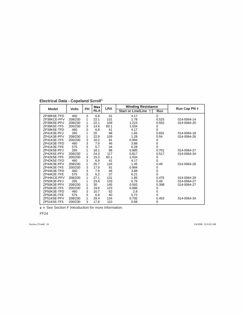
FF24
See Section F Introduction for more information.
Max Winding Resistance Model Volts PH RLA
LRA Start or Line/Line Run
Run Cap PN
Electrical Data - Copeland Scroll®
ZP38K5E-TFD 460 3 6.8 41 4.17 0 ZP38KCE-PFV 208/230 1 22.1 131 1.78 0.525 014-0064-14 ZP39K5E-PFV 208/230 1 22.1 109 1.215 0.552 014-0064-25 ZP39K5E-TF5 200/230 3 14.6 83.1 1.034 0 ZP39K5E-TFD 460 3 6.8 41 4.17 0 ZP41K3E-PFJ 265 1 20 98 1.65 0.691 014-0064-18 ZP41K3E-PFV 208/230 1 22.9 109 1.28 0.54 014-0064-26 ZP41K3E-TF5 200/230 3 16.2 91 0.994 0 ZP41K3E-TFD 460 3 7.9 46 3.88 0 ZP41K3E-TFE 575 3 5.7 34 6.28 0 ZP42K5E-PFJ 265 1 18.1 98 0.885 0.701 014-0064-27 ZP42K5E-PFV 208/230 1 24.3 117 0.817 0.517 014-0064-34 ZP42K5E-TF5 200/230 3 15.3 83.1 1.034 0 ZP42K5E-TFD 460 3 6.9 41 4.17 0 ZP44K3E-PFV 208/230 1 25.7 134 1.45 0.49 014-0064-26 ZP44K3E-TF5 200/230 3 17.9 91 0.994 0 ZP44K3E-TFD 460 3 7.9 46 3.88 0 ZP44K3E-TFE 575 3 6.2 37 6.21 0 ZP44KCE-PFV 208/230 1 27.1 131 1.85 0.475 014-0064-29 ZP50K3E-PFJ 265 1 23.6 133 0.76 0.49 014-0064-27 ZP50K3E-PFV 208/230 1 30 145 0.593 0.398 014-0064-27 ZP50K3E-TF5 200/230 3 19.6 123 0.686 0 ZP50K3E-TFD 460 3 10.7 62 2.8 0 ZP50K3E-TFE 575 3 6.8 40 5.72 0 ZP51K5E-PFV 208/230 1 29.4 134 0.792 0.453 014-0064-34 ZP51K5E-TF5 200/230 3 17.8 110 0.68 0
Section_Ff.indd 24Section_Ff.indd 24 3/4/2008 8:10:02 AM3/4/2008 8:10:02 AM
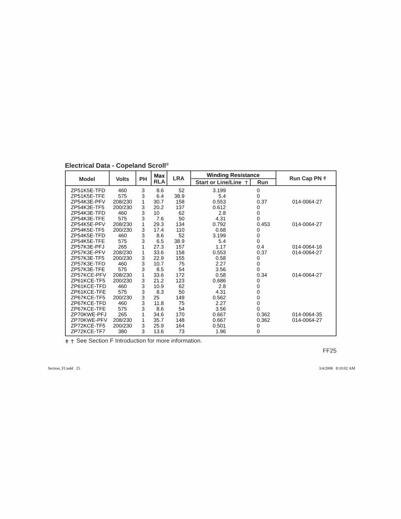
Max Winding Resistance Model Volts PH RLA
LRA Start or Line/Line Run
Run Cap PN
FF25
See Section F Introduction for more information.
Electrical Data - Copeland Scroll®
ZP51K5E-TFD 460 3 8.6 52 3.199 0 ZP51K5E-TFE 575 3 6.4 38.9 5.4 0 ZP54K3E-PFV 208/230 1 30.7 158 0.553 0.37 014-0064-27 ZP54K3E-TF5 200/230 3 20.2 137 0.612 0 ZP54K3E-TFD 460 3 10 62 2.8 0 ZP54K3E-TFE 575 3 7.6 50 4.31 0 ZP54K5E-PFV 208/230 1 29.3 134 0.792 0.453 014-0064-27 ZP54K5E-TF5 200/230 3 17.4 110 0.68 0 ZP54K5E-TFD 460 3 8.6 52 3.199 0 ZP54K5E-TFE 575 3 6.5 38.9 5.4 0 ZP57K3E-PFJ 265 1 27.3 157 1.17 0.4 014-0064-16 ZP57K3E-PFV 208/230 1 33.6 158 0.553 0.37 014-0064-27 ZP57K3E-TF5 200/230 3 22.9 155 0.58 0 ZP57K3E-TFD 460 3 10.7 75 2.27 0 ZP57K3E-TFE 575 3 8.5 54 3.56 0 ZP57KCE-PFV 208/230 1 33.6 172 0.58 0.34 014-0064-27 ZP61KCE-TF5 200/230 3 21.2 123 0.686 0 ZP61KCE-TFD 460 3 10.9 62 2.8 0 ZP61KCE-TFE 575 3 8.3 50 4.31 0 ZP67KCE-TF5 200/230 3 25 149 0.562 0 ZP67KCE-TFD 460 3 11.8 75 2.27 0 ZP67KCE-TFE 575 3 8.6 54 3.56 0 ZP70KWE-PFJ 265 1 34.6 170 0.667 0.362 014-0064-35 ZP70KWE-PFV 208/230 1 35.7 148 0.667 0.362 014-0064-27 ZP72KCE-TF5 200/230 3 25.9 164 0.501 0 ZP72KCE-TF7 380 3 13.6 73 1.96 0
Section_Ff.indd 25Section_Ff.indd 25 3/4/2008 8:10:02 AM3/4/2008 8:10:02 AM
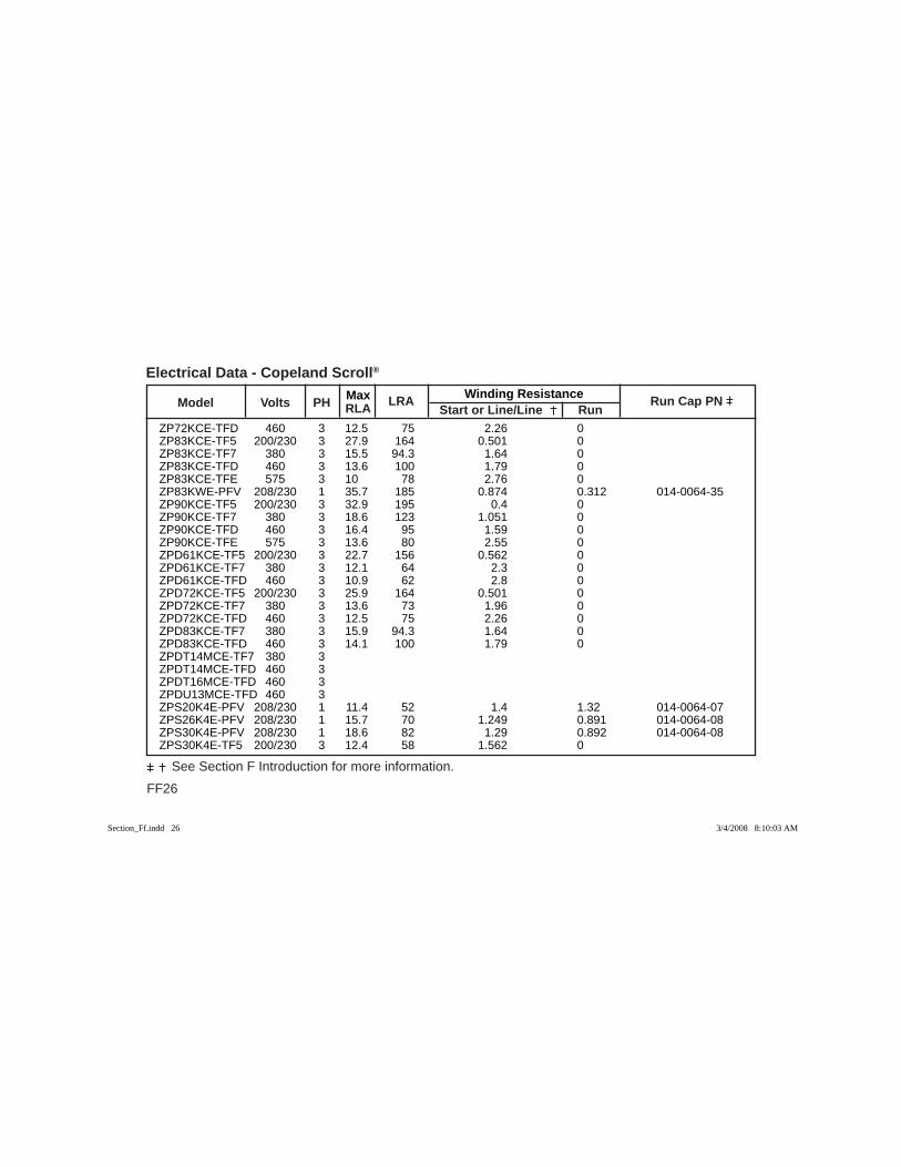
FF26
See Section F Introduction for more information.
Max Winding Resistance Model Volts PH RLA
LRA Start or Line/Line Run
Run Cap PN
Electrical Data - Copeland Scroll®
ZP72KCE-TFD 460 3 12.5 75 2.26 0 ZP83KCE-TF5 200/230 3 27.9 164 0.501 0 ZP83KCE-TF7 380 3 15.5 94.3 1.64 0 ZP83KCE-TFD 460 3 13.6 100 1.79 0 ZP83KCE-TFE 575 3 10 78 2.76 0 ZP83KWE-PFV 208/230 1 35.7 185 0.874 0.312 014-0064-35 ZP90KCE-TF5 200/230 3 32.9 195 0.4 0 ZP90KCE-TF7 380 3 18.6 123 1.051 0 ZP90KCE-TFD 460 3 16.4 95 1.59 0 ZP90KCE-TFE 575 3 13.6 80 2.55 0 ZPD61KCE-TF5 200/230 3 22.7 156 0.562 0 ZPD61KCE-TF7 380 3 12.1 64 2.3 0 ZPD61KCE-TFD 460 3 10.9 62 2.8 0 ZPD72KCE-TF5 200/230 3 25.9 164 0.501 0 ZPD72KCE-TF7 380 3 13.6 73 1.96 0 ZPD72KCE-TFD 460 3 12.5 75 2.26 0 ZPD83KCE-TF7 380 3 15.9 94.3 1.64 0 ZPD83KCE-TFD 460 3 14.1 100 1.79 0 ZPDT14MCE-TF7 380 3 ZPDT14MCE-TFD 460 3 ZPDT16MCE-TFD 460 3 ZPDU13MCE-TFD 460 3 ZPS20K4E-PFV 208/230 1 11.4 52 1.4 1.32 014-0064-07 ZPS26K4E-PFV 208/230 1 15.7 70 1.249 0.891 014-0064-08 ZPS30K4E-PFV 208/230 1 18.6 82 1.29 0.892 014-0064-08 ZPS30K4E-TF5 200/230 3 12.4 58 1.562 0
Section_Ff.indd 26Section_Ff.indd 26 3/4/2008 8:10:03 AM3/4/2008 8:10:03 AM
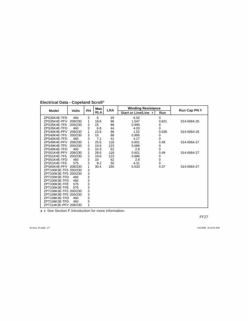
Max Winding Resistance Model Volts PH RLA
LRA Start or Line/Line Run
Run Cap PN
FF27
See Section F Introduction for more information.
Electrical Data - Copeland Scroll®
ZPS30K4E-TFD 460 3 5 29 6.02 0 ZPS35K4E-PFV 208/230 1 18.6 96 1.547 0.621 014-0064-25 ZPS35K4E-TF5 200/230 3 15 88 0.995 0 ZPS35K4E-TFD 460 3 6.8 44 4.03 0 ZPS40K4E-PFV 208/230 1 23.6 96 1.52 0.635 014-0064-25 ZPS40K4E-TF5 200/230 3 15 88 0.995 0 ZPS40K4E-TFD 460 3 7.1 41 4.17 0 ZPS49K4E-PFV 208/230 1 25.6 118 0.601 0.49 014-0064-27 ZPS49K4E-TF5 200/230 3 19.6 123 0.686 0 ZPS49K4E-TFD 460 3 10.3 62 2.8 0 ZPS51K4E-PFV 208/230 1 28.6 118 0.601 0.49 014-0064-27 ZPS51K4E-TF5 200/230 3 19.6 123 0.686 0 ZPS51K4E-TFD 460 3 10 62 2.8 0 ZPS51K4E-TFE 575 3 8.2 50 4.31 0 ZPS60K4E-PFV 208/230 1 30.4 150 0.533 0.37 014-0064-27 ZPT100K3E-TF5 200/230 3 ZPT100K3E-TF5 200/230 3 ZPT100K3E-TFD 460 3 ZPT100K3E-TFD 460 3 ZPT100K3E-TFE 575 3 ZPT100K3E-TFE 575 3 ZPT108K3E-TF5 200/230 3 ZPT108K3E-TF5 200/230 3 ZPT108K3E-TFD 460 3 ZPT108K3E-TFD 460 3 ZPT114K3E-PFV 208/230 1
Section_Ff.indd 27Section_Ff.indd 27 3/4/2008 8:10:03 AM3/4/2008 8:10:03 AM

FF28
See Section F Introduction for more information.
Max Winding Resistance Model Volts PH RLA
LRA Start or Line/Line Run
Run Cap PN
Electrical Data - Copeland Scroll®
ZPT114K3E-TF5 200/230 3 ZPT114K3E-TF5 200/230 3 ZPT114K3E-TFD 460 3 ZPT114K3E-TFD 460 3 ZPT122KCE-TF5 200/230 3 ZPT122KCE-TF5 200/230 3 ZPT122KCE-TFD 460 3 ZPT122KCE-TFD 460 3 ZPT134KCE-TF5 200/230 3 ZPT134KCE-TF5 200/230 3 ZPT134KCE-TFD 460 3 ZPT134KCE-TFD 460 3 ZPT144KCE-TF5 200/230 3 ZPT144KCE-TF5 200/230 3 ZPT144KCE-TF7 380 3 ZPT144KCE-TF7 380 3 ZPT144KCE-TFD 460 3 ZPT144KCE-TFD 460 3 ZPT166KCE-TF5 200/230 3 ZPT166KCE-TF5 200/230 3 ZPT166KCE-TF7 380 3 ZPT166KCE-TF7 380 3 ZPT166KCE-TFD 460 3 ZPT166KCE-TFD 460 3 ZPT166KCE-TFE 575 3 ZPT166KCE-TFE 575 3
Section_Ff.indd 28Section_Ff.indd 28 3/4/2008 8:10:03 AM3/4/2008 8:10:03 AM
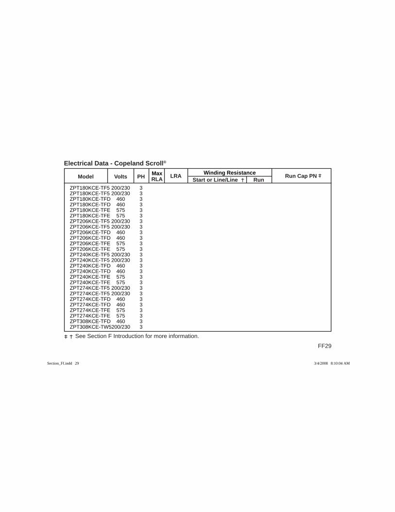
Max Winding Resistance Model Volts PH RLA
LRA Start or Line/Line Run
Run Cap PN
FF29
See Section F Introduction for more information.
Electrical Data - Copeland Scroll®
ZPT180KCE-TF5 200/230 3 ZPT180KCE-TF5 200/230 3 ZPT180KCE-TFD 460 3 ZPT180KCE-TFD 460 3 ZPT180KCE-TFE 575 3 ZPT180KCE-TFE 575 3 ZPT206KCE-TF5 200/230 3 ZPT206KCE-TF5 200/230 3 ZPT206KCE-TFD 460 3 ZPT206KCE-TFD 460 3 ZPT206KCE-TFE 575 3 ZPT206KCE-TFE 575 3 ZPT240KCE-TF5 200/230 3 ZPT240KCE-TF5 200/230 3 ZPT240KCE-TFD 460 3 ZPT240KCE-TFD 460 3 ZPT240KCE-TFE 575 3 ZPT240KCE-TFE 575 3 ZPT274KCE-TF5 200/230 3 ZPT274KCE-TF5 200/230 3 ZPT274KCE-TFD 460 3 ZPT274KCE-TFD 460 3 ZPT274KCE-TFE 575 3 ZPT274KCE-TFE 575 3 ZPT308KCE-TFD 460 3 ZPT308KCE-TW5 200/230 3
Section_Ff.indd 29Section_Ff.indd 29 3/4/2008 8:10:04 AM3/4/2008 8:10:04 AM
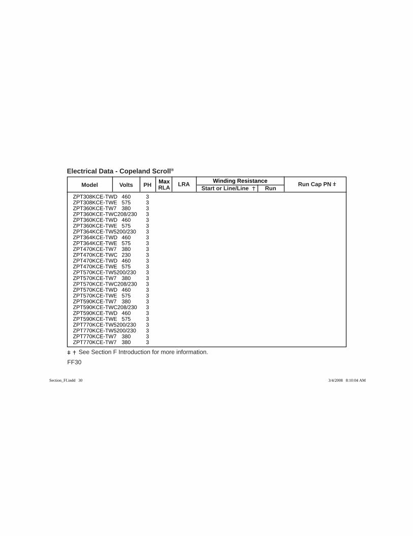
FF30
See Section F Introduction for more information.
Max Winding Resistance Model Volts PH RLA
LRA Start or Line/Line Run
Run Cap PN
Electrical Data - Copeland Scroll®
ZPT308KCE-TWD 460 3 ZPT308KCE-TWE 575 3 ZPT360KCE-TW7 380 3 ZPT360KCE-TWC 208/230 3 ZPT360KCE-TWD 460 3 ZPT360KCE-TWE 575 3 ZPT364KCE-TW5 200/230 3 ZPT364KCE-TWD 460 3 ZPT364KCE-TWE 575 3 ZPT470KCE-TW7 380 3 ZPT470KCE-TWC 230 3 ZPT470KCE-TWD 460 3 ZPT470KCE-TWE 575 3 ZPT570KCE-TW5 200/230 3 ZPT570KCE-TW7 380 3 ZPT570KCE-TWC 208/230 3 ZPT570KCE-TWD 460 3 ZPT570KCE-TWE 575 3 ZPT590KCE-TW7 380 3 ZPT590KCE-TWC 208/230 3 ZPT590KCE-TWD 460 3 ZPT590KCE-TWE 575 3 ZPT770KCE-TW5 200/230 3 ZPT770KCE-TW5 200/230 3 ZPT770KCE-TW7 380 3 ZPT770KCE-TW7 380 3
Section_Ff.indd 30Section_Ff.indd 30 3/4/2008 8:10:04 AM3/4/2008 8:10:04 AM

Max Winding Resistance Model Volts PH RLA
LRA Start or Line/Line Run
Run Cap PN
FF31
See Section F Introduction for more information.
Electrical Data - Copeland Scroll®
ZPT770KCE-TWC 208/230 3 ZPT770KCE-TWC 208/230 3 ZPT770KCE-TWD 460 3 ZPT770KCE-TWD 460 3 ZPT770KCE-TWE 575 3 ZPT770KCE-TWE 575 3 ZPU223KCE-TFD 460 3 ZPU240KCE-TFD 460 3 ZPU257KCE-TFD 460 3 ZPU272KCE-TFD 460 3 ZPU272KCE-TXD 460 3 ZPU272KCE-TXE 575 3 ZPU274KCE-TFD 460 3 ZPU274KCE-TX5 200/230 3 ZPU274KCE-TXD 460 3 ZPU274KCE-TXE 575 3 ZPU285KCE-TFD 460 3 ZPU285KCE-TX5 200/230 3 ZPU285KCE-TXD 460 3 ZPU285KCE-TXE 575 3 ZPU302KCE-TFD 460 3 ZPU302KCE-TX5 200/230 3 ZPU302KCE-TXD 460 3 ZPU302KCE-TXE 575 3 ZPU319KCE-TFD 460 3 ZPU319KCE-TX5 200/230 3
Section_Ff.indd 31Section_Ff.indd 31 3/4/2008 8:10:04 AM3/4/2008 8:10:04 AM

FF32
See Section F Introduction for more information.
Max Winding Resistance Model Volts PH RLA
LRA Start or Line/Line Run
Run Cap PN
Electrical Data - Copeland Scroll®
ZPU319KCE-TXD 460 3 ZPU319KCE-TXE 575 3 ZPU336KCE-TFD 460 3 ZPU336KCE-TW5 200/230 3 ZPU336KCE-TW7 380 3 ZPU336KCE-TWD 460 3 ZPU336KCE-TWE 575 3 ZPU417KCE-TWC 200/230 3 ZPU417KCE-TWC 230 3 ZPU417KCE-TWD 460 3 ZPU417KCE-TWE 575 3 ZPU520KCE-TWD 460 3 ZPU680KCE-TW7 380 3 ZPU680KCE-TWC 208/230 3 ZPU680KCE-TWD 460 3 ZPU680KCE-TWE 575 3 ZPY115MCE-TW5 200/230 3 ZPY115MCE-TW7 380 3 ZPY115MCE-TWC 208/230 3 ZPY115MCE-TWD 460 3 ZPY115MCE-TWE 575 3 ZPY309KCE-TF5 200/230 3 ZPY309KCE-TFD 460 3 ZPY309KCE-TFE 575 3 ZPY360KCE-TF5 200/230 3 ZPY360KCE-TFD 460 3
Section_Ff.indd 32Section_Ff.indd 32 3/4/2008 8:10:05 AM3/4/2008 8:10:05 AM

Max Winding Resistance Model Volts PH RLA
LRA Start or Line/Line Run
Run Cap PN
FF33
See Section F Introduction for more information.
Electrical Data - Copeland Scroll®
ZPY360KCE-TFE 575 3 ZPY411KCE-TF5 200/230 3 ZPY411KCE-TFD 460 3 ZPY411KCE-TFE 575 3 ZPY462KCE-TFD 460 3 ZPY462KCE-TW5 200/230 3 ZPY462KCE-TW7 380 3 ZPY462KCE-TWD 460 3 ZPY462KCE-TWE 575 3 ZPY546KCE-TFD 460 3 ZPY546KCE-TW5 200/230 3 ZPY546KCE-TW7 380 3 ZPY546KCE-TWD 460 3 ZPY546KCE-TWE 575 3 ZPY705KCE-TW7 380 3 ZPY705KCE-TWC 230 3 ZPY705KCE-TWD 460 3 ZPY705KCE-TWE 575 3 ZPY855KCE-TW5 200/230 3 ZPY855KCE-TW7 380 3 ZPY855KCE-TWC 208/230 3 ZPY855KCE-TWD 460 3 ZPY855KCE-TWE 575 3 ZR108KC-TF5 200/230 3 33.6 225 0.347 0 ZR108KC-TF7 380 3 18.6 140 0.93 0 ZR108KC-TFD 460 3 17.3 114 1.36 0
Section_Ff.indd 33Section_Ff.indd 33 3/4/2008 8:10:05 AM3/4/2008 8:10:05 AM
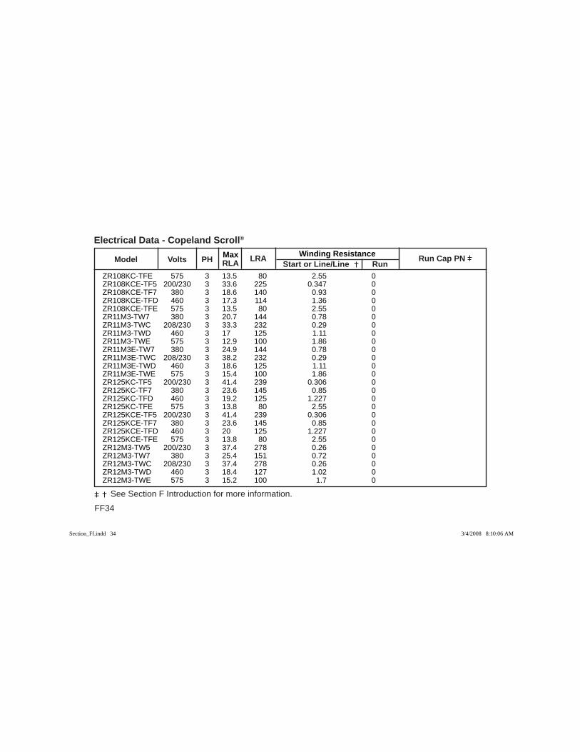
FF34
See Section F Introduction for more information.
Max Winding Resistance Model Volts PH RLA
LRA Start or Line/Line Run
Run Cap PN
Electrical Data - Copeland Scroll®
ZR108KC-TFE 575 3 13.5 80 2.55 0 ZR108KCE-TF5 200/230 3 33.6 225 0.347 0 ZR108KCE-TF7 380 3 18.6 140 0.93 0 ZR108KCE-TFD 460 3 17.3 114 1.36 0 ZR108KCE-TFE 575 3 13.5 80 2.55 0 ZR11M3-TW7 380 3 20.7 144 0.78 0 ZR11M3-TWC 208/230 3 33.3 232 0.29 0 ZR11M3-TWD 460 3 17 125 1.11 0 ZR11M3-TWE 575 3 12.9 100 1.86 0 ZR11M3E-TW7 380 3 24.9 144 0.78 0 ZR11M3E-TWC 208/230 3 38.2 232 0.29 0 ZR11M3E-TWD 460 3 18.6 125 1.11 0 ZR11M3E-TWE 575 3 15.4 100 1.86 0 ZR125KC-TF5 200/230 3 41.4 239 0.306 0 ZR125KC-TF7 380 3 23.6 145 0.85 0 ZR125KC-TFD 460 3 19.2 125 1.227 0 ZR125KC-TFE 575 3 13.8 80 2.55 0 ZR125KCE-TF5 200/230 3 41.4 239 0.306 0 ZR125KCE-TF7 380 3 23.6 145 0.85 0 ZR125KCE-TFD 460 3 20 125 1.227 0 ZR125KCE-TFE 575 3 13.8 80 2.55 0 ZR12M3-TW5 200/230 3 37.4 278 0.26 0 ZR12M3-TW7 380 3 25.4 151 0.72 0 ZR12M3-TWC 208/230 3 37.4 278 0.26 0 ZR12M3-TWD 460 3 18.4 127 1.02 0 ZR12M3-TWE 575 3 15.2 100 1.7 0
Section_Ff.indd 34Section_Ff.indd 34 3/4/2008 8:10:06 AM3/4/2008 8:10:06 AM
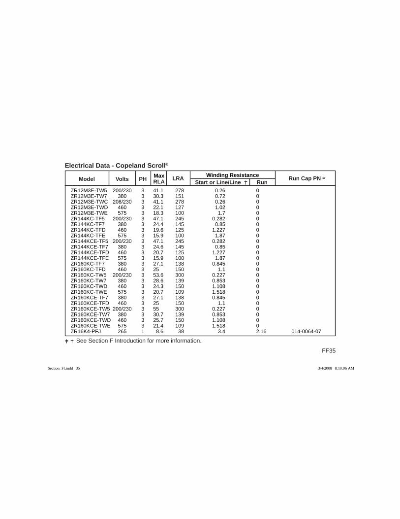
Max Winding Resistance Model Volts PH RLA
LRA Start or Line/Line Run
Run Cap PN
FF35
See Section F Introduction for more information.
Electrical Data - Copeland Scroll®
ZR12M3E-TW5 200/230 3 41.1 278 0.26 0 ZR12M3E-TW7 380 3 30.3 151 0.72 0 ZR12M3E-TWC 208/230 3 41.1 278 0.26 0 ZR12M3E-TWD 460 3 22.1 127 1.02 0 ZR12M3E-TWE 575 3 18.3 100 1.7 0 ZR144KC-TF5 200/230 3 47.1 245 0.282 0 ZR144KC-TF7 380 3 24.4 145 0.85 0 ZR144KC-TFD 460 3 19.6 125 1.227 0 ZR144KC-TFE 575 3 15.9 100 1.87 0 ZR144KCE-TF5 200/230 3 47.1 245 0.282 0 ZR144KCE-TF7 380 3 24.6 145 0.85 0 ZR144KCE-TFD 460 3 20.7 125 1.227 0 ZR144KCE-TFE 575 3 15.9 100 1.87 0 ZR160KC-TF7 380 3 27.1 138 0.845 0 ZR160KC-TFD 460 3 25 150 1.1 0 ZR160KC-TW5 200/230 3 53.6 300 0.227 0 ZR160KC-TW7 380 3 28.6 139 0.853 0 ZR160KC-TWD 460 3 24.3 150 1.108 0 ZR160KC-TWE 575 3 20.7 109 1.518 0 ZR160KCE-TF7 380 3 27.1 138 0.845 0 ZR160KCE-TFD 460 3 25 150 1.1 0 ZR160KCE-TW5 200/230 3 55 300 0.227 0 ZR160KCE-TW7 380 3 30.7 139 0.853 0 ZR160KCE-TWD 460 3 25.7 150 1.108 0 ZR160KCE-TWE 575 3 21.4 109 1.518 0 ZR16K4-PFJ 265 1 8.6 38 3.4 2.16 014-0064-07
Section_Ff.indd 35Section_Ff.indd 35 3/4/2008 8:10:06 AM3/4/2008 8:10:06 AM
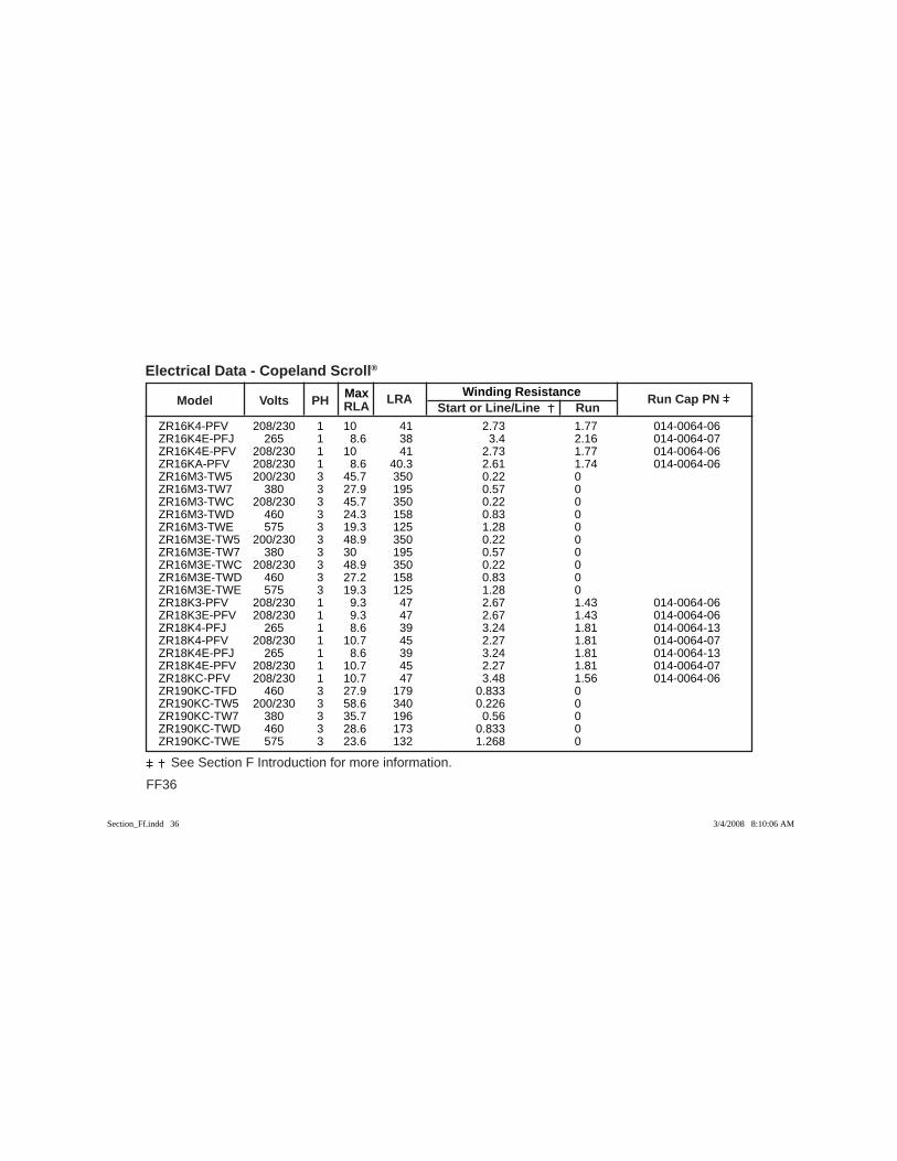
FF36
See Section F Introduction for more information.
Max Winding Resistance Model Volts PH RLA
LRA Start or Line/Line Run
Run Cap PN
Electrical Data - Copeland Scroll®
ZR16K4-PFV 208/230 1 10 41 2.73 1.77 014-0064-06 ZR16K4E-PFJ 265 1 8.6 38 3.4 2.16 014-0064-07 ZR16K4E-PFV 208/230 1 10 41 2.73 1.77 014-0064-06 ZR16KA-PFV 208/230 1 8.6 40.3 2.61 1.74 014-0064-06 ZR16M3-TW5 200/230 3 45.7 350 0.22 0 ZR16M3-TW7 380 3 27.9 195 0.57 0 ZR16M3-TWC 208/230 3 45.7 350 0.22 0 ZR16M3-TWD 460 3 24.3 158 0.83 0 ZR16M3-TWE 575 3 19.3 125 1.28 0 ZR16M3E-TW5 200/230 3 48.9 350 0.22 0 ZR16M3E-TW7 380 3 30 195 0.57 0 ZR16M3E-TWC 208/230 3 48.9 350 0.22 0 ZR16M3E-TWD 460 3 27.2 158 0.83 0 ZR16M3E-TWE 575 3 19.3 125 1.28 0 ZR18K3-PFV 208/230 1 9.3 47 2.67 1.43 014-0064-06 ZR18K3E-PFV 208/230 1 9.3 47 2.67 1.43 014-0064-06 ZR18K4-PFJ 265 1 8.6 39 3.24 1.81 014-0064-13 ZR18K4-PFV 208/230 1 10.7 45 2.27 1.81 014-0064-07 ZR18K4E-PFJ 265 1 8.6 39 3.24 1.81 014-0064-13 ZR18K4E-PFV 208/230 1 10.7 45 2.27 1.81 014-0064-07 ZR18KC-PFV 208/230 1 10.7 47 3.48 1.56 014-0064-06 ZR190KC-TFD 460 3 27.9 179 0.833 0 ZR190KC-TW5 200/230 3 58.6 340 0.226 0 ZR190KC-TW7 380 3 35.7 196 0.56 0 ZR190KC-TWD 460 3 28.6 173 0.833 0 ZR190KC-TWE 575 3 23.6 132 1.268 0
Section_Ff.indd 36Section_Ff.indd 36 3/4/2008 8:10:06 AM3/4/2008 8:10:06 AM
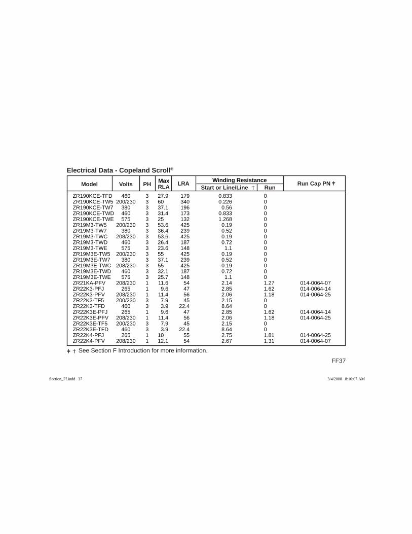
Max Winding Resistance Model Volts PH RLA
LRA Start or Line/Line Run
Run Cap PN
FF37
See Section F Introduction for more information.
Electrical Data - Copeland Scroll®
ZR190KCE-TFD 460 3 27.9 179 0.833 0 ZR190KCE-TW5 200/230 3 60 340 0.226 0 ZR190KCE-TW7 380 3 37.1 196 0.56 0 ZR190KCE-TWD 460 3 31.4 173 0.833 0 ZR190KCE-TWE 575 3 25 132 1.268 0 ZR19M3-TW5 200/230 3 53.6 425 0.19 0 ZR19M3-TW7 380 3 36.4 239 0.52 0 ZR19M3-TWC 208/230 3 53.6 425 0.19 0 ZR19M3-TWD 460 3 26.4 187 0.72 0 ZR19M3-TWE 575 3 23.6 148 1.1 0 ZR19M3E-TW5 200/230 3 55 425 0.19 0 ZR19M3E-TW7 380 3 37.1 239 0.52 0 ZR19M3E-TWC 208/230 3 55 425 0.19 0 ZR19M3E-TWD 460 3 32.1 187 0.72 0 ZR19M3E-TWE 575 3 25.7 148 1.1 0 ZR21KA-PFV 208/230 1 11.6 54 2.14 1.27 014-0064-07 ZR22K3-PFJ 265 1 9.6 47 2.85 1.62 014-0064-14 ZR22K3-PFV 208/230 1 11.4 56 2.06 1.18 014-0064-25 ZR22K3-TF5 200/230 3 7.9 45 2.15 0 ZR22K3-TFD 460 3 3.9 22.4 8.64 0 ZR22K3E-PFJ 265 1 9.6 47 2.85 1.62 014-0064-14 ZR22K3E-PFV 208/230 1 11.4 56 2.06 1.18 014-0064-25 ZR22K3E-TF5 200/230 3 7.9 45 2.15 0 ZR22K3E-TFD 460 3 3.9 22.4 8.64 0 ZR22K4-PFJ 265 1 10 55 2.75 1.81 014-0064-25 ZR22K4-PFV 208/230 1 12.1 54 2.67 1.31 014-0064-07
Section_Ff.indd 37Section_Ff.indd 37 3/4/2008 8:10:07 AM3/4/2008 8:10:07 AM
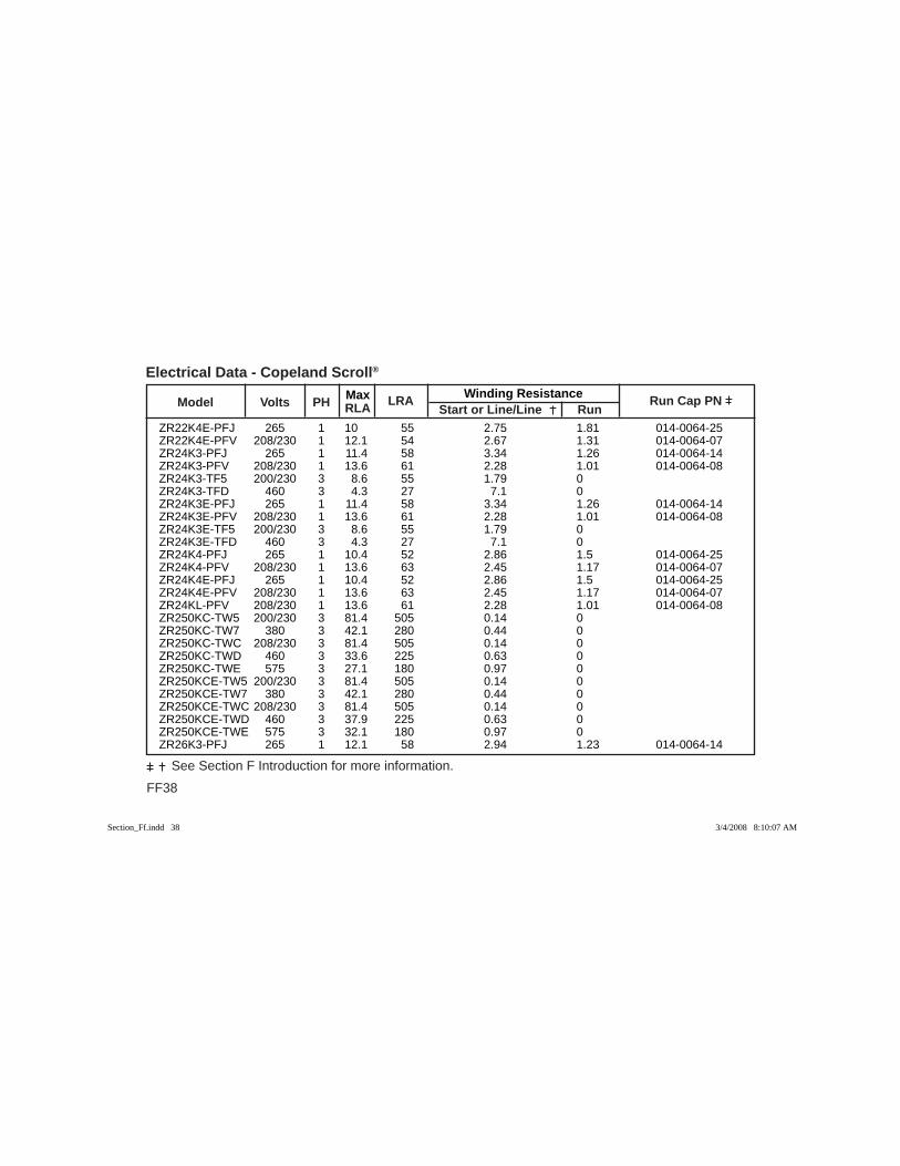
FF38
See Section F Introduction for more information.
Max Winding Resistance Model Volts PH RLA
LRA Start or Line/Line Run
Run Cap PN
Electrical Data - Copeland Scroll®
ZR22K4E-PFJ 265 1 10 55 2.75 1.81 014-0064-25 ZR22K4E-PFV 208/230 1 12.1 54 2.67 1.31 014-0064-07 ZR24K3-PFJ 265 1 11.4 58 3.34 1.26 014-0064-14 ZR24K3-PFV 208/230 1 13.6 61 2.28 1.01 014-0064-08 ZR24K3-TF5 200/230 3 8.6 55 1.79 0 ZR24K3-TFD 460 3 4.3 27 7.1 0 ZR24K3E-PFJ 265 1 11.4 58 3.34 1.26 014-0064-14 ZR24K3E-PFV 208/230 1 13.6 61 2.28 1.01 014-0064-08 ZR24K3E-TF5 200/230 3 8.6 55 1.79 0 ZR24K3E-TFD 460 3 4.3 27 7.1 0 ZR24K4-PFJ 265 1 10.4 52 2.86 1.5 014-0064-25 ZR24K4-PFV 208/230 1 13.6 63 2.45 1.17 014-0064-07 ZR24K4E-PFJ 265 1 10.4 52 2.86 1.5 014-0064-25 ZR24K4E-PFV 208/230 1 13.6 63 2.45 1.17 014-0064-07 ZR24KL-PFV 208/230 1 13.6 61 2.28 1.01 014-0064-08 ZR250KC-TW5 200/230 3 81.4 505 0.14 0 ZR250KC-TW7 380 3 42.1 280 0.44 0 ZR250KC-TWC 208/230 3 81.4 505 0.14 0 ZR250KC-TWD 460 3 33.6 225 0.63 0 ZR250KC-TWE 575 3 27.1 180 0.97 0 ZR250KCE-TW5 200/230 3 81.4 505 0.14 0 ZR250KCE-TW7 380 3 42.1 280 0.44 0 ZR250KCE-TWC 208/230 3 81.4 505 0.14 0 ZR250KCE-TWD 460 3 37.9 225 0.63 0 ZR250KCE-TWE 575 3 32.1 180 0.97 0 ZR26K3-PFJ 265 1 12.1 58 2.94 1.23 014-0064-14
Section_Ff.indd 38Section_Ff.indd 38 3/4/2008 8:10:07 AM3/4/2008 8:10:07 AM
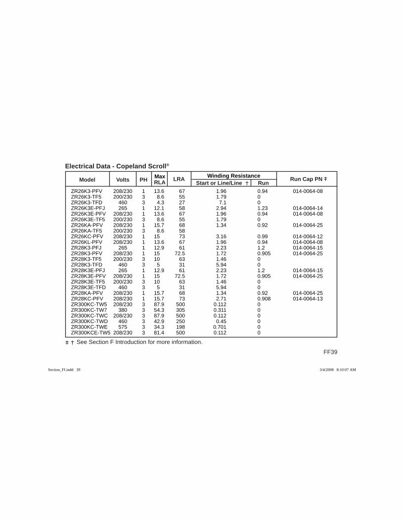
Max Winding Resistance Model Volts PH RLA
LRA Start or Line/Line Run
Run Cap PN
FF39
See Section F Introduction for more information.
Electrical Data - Copeland Scroll®
ZR26K3-PFV 208/230 1 13.6 67 1.96 0.94 014-0064-08 ZR26K3-TF5 200/230 3 8.6 55 1.79 0 ZR26K3-TFD 460 3 4.3 27 7.1 0 ZR26K3E-PFJ 265 1 12.1 58 2.94 1.23 014-0064-14 ZR26K3E-PFV 208/230 1 13.6 67 1.96 0.94 014-0064-08 ZR26K3E-TF5 200/230 3 8.6 55 1.79 0 ZR26KA-PFV 208/230 1 15.7 68 1.34 0.92 014-0064-25 ZR26KA-TF5 200/230 3 8.6 58 ZR26KC-PFV 208/230 1 15 73 3.16 0.99 014-0064-12 ZR26KL-PFV 208/230 1 13.6 67 1.96 0.94 014-0064-08 ZR28K3-PFJ 265 1 12.9 61 2.23 1.2 014-0064-15 ZR28K3-PFV 208/230 1 15 72.5 1.72 0.905 014-0064-25 ZR28K3-TF5 200/230 3 10 63 1.46 0 ZR28K3-TFD 460 3 5 31 5.94 0 ZR28K3E-PFJ 265 1 12.9 61 2.23 1.2 014-0064-15 ZR28K3E-PFV 208/230 1 15 72.5 1.72 0.905 014-0064-25 ZR28K3E-TF5 200/230 3 10 63 1.46 0 ZR28K3E-TFD 460 3 5 31 5.94 0 ZR28KA-PFV 208/230 1 15.7 68 1.34 0.92 014-0064-25 ZR28KC-PFV 208/230 1 15.7 73 2.71 0.908 014-0064-13 ZR300KC-TW5 208/230 3 87.9 500 0.112 0 ZR300KC-TW7 380 3 54.3 305 0.311 0 ZR300KC-TWC 208/230 3 87.9 500 0.112 0 ZR300KC-TWD 460 3 42.9 250 0.45 0 ZR300KC-TWE 575 3 34.3 198 0.701 0 ZR300KCE-TW5 208/230 3 81.4 500 0.112 0
Section_Ff.indd 39Section_Ff.indd 39 3/4/2008 8:10:07 AM3/4/2008 8:10:07 AM
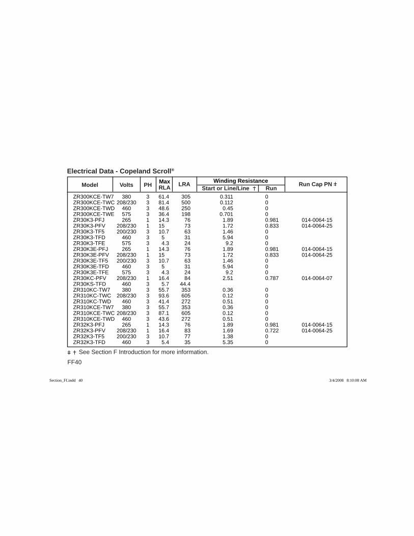
FF40
See Section F Introduction for more information.
Max Winding Resistance Model Volts PH RLA
LRA Start or Line/Line Run
Run Cap PN
Electrical Data - Copeland Scroll®
ZR300KCE-TW7 380 3 61.4 305 0.311 0 ZR300KCE-TWC 208/230 3 81.4 500 0.112 0 ZR300KCE-TWD 460 3 48.6 250 0.45 0 ZR300KCE-TWE 575 3 36.4 198 0.701 0 ZR30K3-PFJ 265 1 14.3 76 1.89 0.981 014-0064-15 ZR30K3-PFV 208/230 1 15 73 1.72 0.833 014-0064-25 ZR30K3-TF5 200/230 3 10.7 63 1.46 0 ZR30K3-TFD 460 3 5 31 5.94 0 ZR30K3-TFE 575 3 4.3 24 9.2 0 ZR30K3E-PFJ 265 1 14.3 76 1.89 0.981 014-0064-15 ZR30K3E-PFV 208/230 1 15 73 1.72 0.833 014-0064-25 ZR30K3E-TF5 200/230 3 10.7 63 1.46 0 ZR30K3E-TFD 460 3 5 31 5.94 0 ZR30K3E-TFE 575 3 4.3 24 9.2 0 ZR30KC-PFV 208/230 1 16.4 84 2.51 0.787 014-0064-07 ZR30KS-TFD 460 3 5.7 44.4 ZR310KC-TW7 380 3 55.7 353 0.36 0 ZR310KC-TWC 208/230 3 93.6 605 0.12 0 ZR310KC-TWD 460 3 41.4 272 0.51 0 ZR310KCE-TW7 380 3 55.7 353 0.36 0 ZR310KCE-TWC 208/230 3 87.1 605 0.12 0 ZR310KCE-TWD 460 3 43.6 272 0.51 0 ZR32K3-PFJ 265 1 14.3 76 1.89 0.981 014-0064-15 ZR32K3-PFV 208/230 1 16.4 83 1.69 0.722 014-0064-25 ZR32K3-TF5 200/230 3 10.7 77 1.38 0 ZR32K3-TFD 460 3 5.4 35 5.35 0
Section_Ff.indd 40Section_Ff.indd 40 3/4/2008 8:10:08 AM3/4/2008 8:10:08 AM
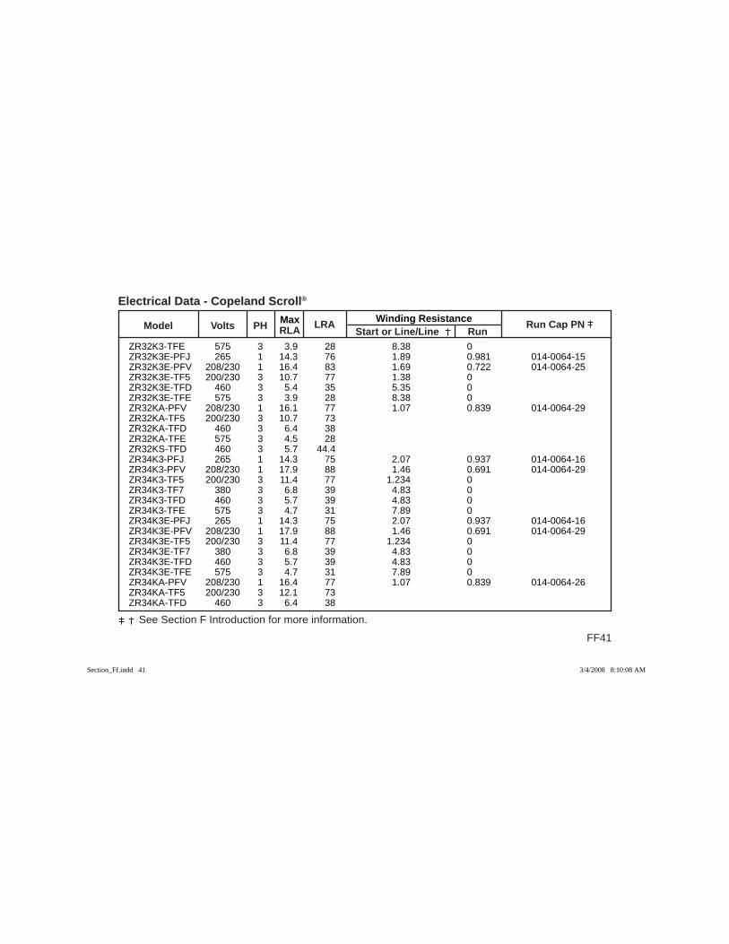
Max Winding Resistance Model Volts PH RLA
LRA Start or Line/Line Run
Run Cap PN
FF41
See Section F Introduction for more information.
Electrical Data - Copeland Scroll®
ZR32K3-TFE 575 3 3.9 28 8.38 0 ZR32K3E-PFJ 265 1 14.3 76 1.89 0.981 014-0064-15 ZR32K3E-PFV 208/230 1 16.4 83 1.69 0.722 014-0064-25 ZR32K3E-TF5 200/230 3 10.7 77 1.38 0 ZR32K3E-TFD 460 3 5.4 35 5.35 0 ZR32K3E-TFE 575 3 3.9 28 8.38 0 ZR32KA-PFV 208/230 1 16.1 77 1.07 0.839 014-0064-29 ZR32KA-TF5 200/230 3 10.7 73 ZR32KA-TFD 460 3 6.4 38 ZR32KA-TFE 575 3 4.5 28 ZR32KS-TFD 460 3 5.7 44.4 ZR34K3-PFJ 265 1 14.3 75 2.07 0.937 014-0064-16 ZR34K3-PFV 208/230 1 17.9 88 1.46 0.691 014-0064-29 ZR34K3-TF5 200/230 3 11.4 77 1.234 0 ZR34K3-TF7 380 3 6.8 39 4.83 0 ZR34K3-TFD 460 3 5.7 39 4.83 0 ZR34K3-TFE 575 3 4.7 31 7.89 0 ZR34K3E-PFJ 265 1 14.3 75 2.07 0.937 014-0064-16 ZR34K3E-PFV 208/230 1 17.9 88 1.46 0.691 014-0064-29 ZR34K3E-TF5 200/230 3 11.4 77 1.234 0 ZR34K3E-TF7 380 3 6.8 39 4.83 0 ZR34K3E-TFD 460 3 5.7 39 4.83 0 ZR34K3E-TFE 575 3 4.7 31 7.89 0 ZR34KA-PFV 208/230 1 16.4 77 1.07 0.839 014-0064-26 ZR34KA-TF5 200/230 3 12.1 73 ZR34KA-TFD 460 3 6.4 38
Section_Ff.indd 41Section_Ff.indd 41 3/4/2008 8:10:08 AM3/4/2008 8:10:08 AM
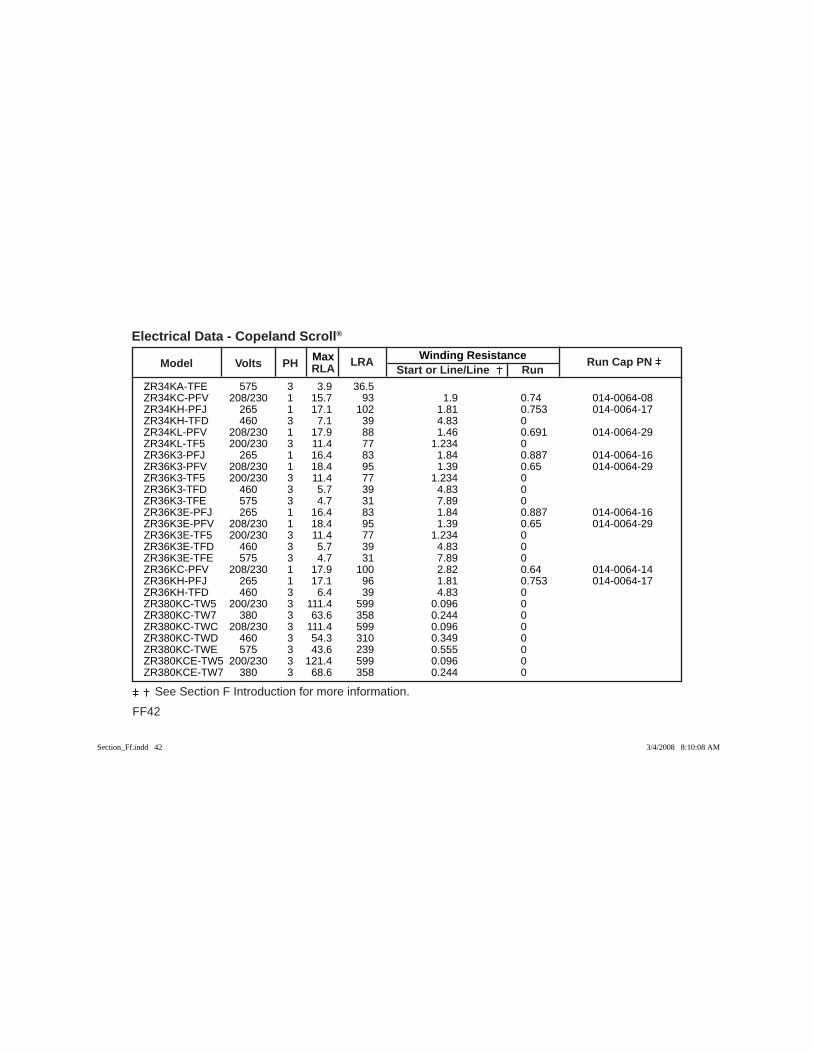
FF42
See Section F Introduction for more information.
Max Winding Resistance Model Volts PH RLA
LRA Start or Line/Line Run
Run Cap PN
Electrical Data - Copeland Scroll®
ZR34KA-TFE 575 3 3.9 36.5 ZR34KC-PFV 208/230 1 15.7 93 1.9 0.74 014-0064-08 ZR34KH-PFJ 265 1 17.1 102 1.81 0.753 014-0064-17 ZR34KH-TFD 460 3 7.1 39 4.83 0 ZR34KL-PFV 208/230 1 17.9 88 1.46 0.691 014-0064-29 ZR34KL-TF5 200/230 3 11.4 77 1.234 0 ZR36K3-PFJ 265 1 16.4 83 1.84 0.887 014-0064-16 ZR36K3-PFV 208/230 1 18.4 95 1.39 0.65 014-0064-29 ZR36K3-TF5 200/230 3 11.4 77 1.234 0 ZR36K3-TFD 460 3 5.7 39 4.83 0 ZR36K3-TFE 575 3 4.7 31 7.89 0 ZR36K3E-PFJ 265 1 16.4 83 1.84 0.887 014-0064-16 ZR36K3E-PFV 208/230 1 18.4 95 1.39 0.65 014-0064-29 ZR36K3E-TF5 200/230 3 11.4 77 1.234 0 ZR36K3E-TFD 460 3 5.7 39 4.83 0 ZR36K3E-TFE 575 3 4.7 31 7.89 0 ZR36KC-PFV 208/230 1 17.9 100 2.82 0.64 014-0064-14 ZR36KH-PFJ 265 1 17.1 96 1.81 0.753 014-0064-17 ZR36KH-TFD 460 3 6.4 39 4.83 0 ZR380KC-TW5 200/230 3 111.4 599 0.096 0 ZR380KC-TW7 380 3 63.6 358 0.244 0 ZR380KC-TWC 208/230 3 111.4 599 0.096 0 ZR380KC-TWD 460 3 54.3 310 0.349 0 ZR380KC-TWE 575 3 43.6 239 0.555 0 ZR380KCE-TW5 200/230 3 121.4 599 0.096 0 ZR380KCE-TW7 380 3 68.6 358 0.244 0
Section_Ff.indd 42Section_Ff.indd 42 3/4/2008 8:10:08 AM3/4/2008 8:10:08 AM
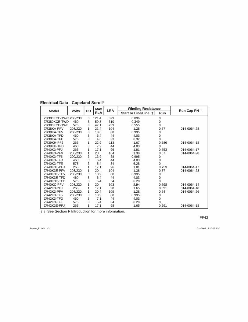
Max Winding Resistance Model Volts PH RLA
LRA Start or Line/Line Run
Run Cap PN
FF43
See Section F Introduction for more information.
Electrical Data - Copeland Scroll®
ZR380KCE-TWC 208/230 3 121.4 599 0.096 0 ZR380KCE-TWD 460 3 59.3 310 0.349 0 ZR380KCE-TWE 575 3 47.1 239 0.555 0 ZR38KA-PFV 208/230 1 21.4 104 1.38 0.57 014-0064-28 ZR38KA-TF5 200/230 3 13.6 88 0.995 0 ZR38KA-TFD 460 3 6.4 44 4.03 0 ZR38KA-TFE 575 3 4.6 33 6.32 0 ZR39KH-PFJ 265 1 22.9 113 1.67 0.586 014-0064-18 ZR39KH-TFD 460 3 7.9 44 4.03 0 ZR40K3-PFJ 265 1 17.1 96 1.81 0.753 014-0064-17 ZR40K3-PFV 208/230 1 20 104 1.38 0.57 014-0064-28 ZR40K3-TF5 200/230 3 13.9 88 0.995 0 ZR40K3-TFD 460 3 6.4 44 4.03 0 ZR40K3-TFE 575 3 5.4 34 6.28 0 ZR40K3E-PFJ 265 1 17.1 96 1.81 0.753 014-0064-17 ZR40K3E-PFV 208/230 1 20 104 1.38 0.57 014-0064-28 ZR40K3E-TF5 200/230 3 13.9 88 0.995 0 ZR40K3E-TFD 460 3 6.4 44 4.03 0 ZR40K3E-TFE 575 3 5.4 34 6.28 0 ZR40KC-PFV 208/230 1 20 103 2.94 0.598 014-0064-14 ZR42K3-PFJ 265 1 17.1 98 1.65 0.691 014-0064-18 ZR42K3-PFV 208/230 1 20.4 109 1.28 0.54 014-0064-26 ZR42K3-TF5 200/230 3 13.9 88 0.995 0 ZR42K3-TFD 460 3 7.1 44 4.03 0 ZR42K3-TFE 575 3 5.4 34 6.28 0 ZR42K3E-PFJ 265 1 17.1 98 1.65 0.691 014-0064-18
Section_Ff.indd 43Section_Ff.indd 43 3/4/2008 8:10:09 AM3/4/2008 8:10:09 AM
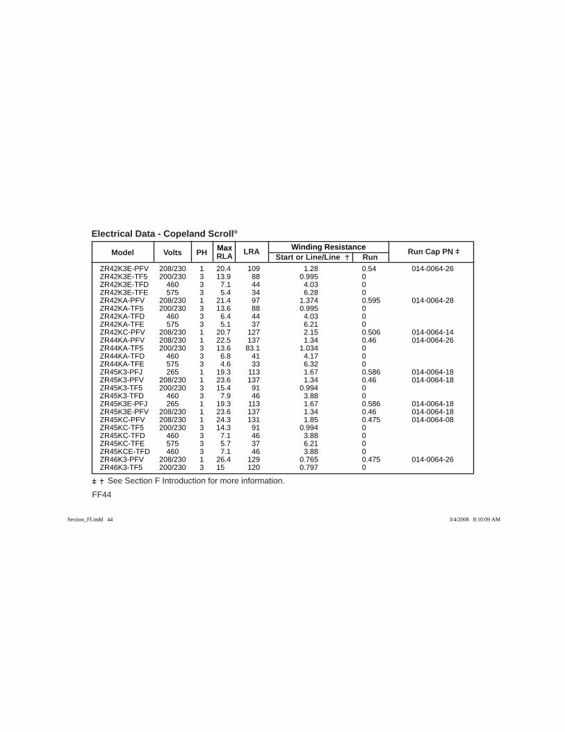
FF44
See Section F Introduction for more information.
Max Winding Resistance Model Volts PH RLA
LRA Start or Line/Line Run
Run Cap PN
Electrical Data - Copeland Scroll®
ZR42K3E-PFV 208/230 1 20.4 109 1.28 0.54 014-0064-26 ZR42K3E-TF5 200/230 3 13.9 88 0.995 0 ZR42K3E-TFD 460 3 7.1 44 4.03 0 ZR42K3E-TFE 575 3 5.4 34 6.28 0 ZR42KA-PFV 208/230 1 21.4 97 1.374 0.595 014-0064-28 ZR42KA-TF5 200/230 3 13.6 88 0.995 0 ZR42KA-TFD 460 3 6.4 44 4.03 0 ZR42KA-TFE 575 3 5.1 37 6.21 0 ZR42KC-PFV 208/230 1 20.7 127 2.15 0.506 014-0064-14 ZR44KA-PFV 208/230 1 22.5 137 1.34 0.46 014-0064-26 ZR44KA-TF5 200/230 3 13.6 83.1 1.034 0 ZR44KA-TFD 460 3 6.8 41 4.17 0 ZR44KA-TFE 575 3 4.6 33 6.32 0 ZR45K3-PFJ 265 1 19.3 113 1.67 0.586 014-0064-18 ZR45K3-PFV 208/230 1 23.6 137 1.34 0.46 014-0064-18 ZR45K3-TF5 200/230 3 15.4 91 0.994 0 ZR45K3-TFD 460 3 7.9 46 3.88 0 ZR45K3E-PFJ 265 1 19.3 113 1.67 0.586 014-0064-18 ZR45K3E-PFV 208/230 1 23.6 137 1.34 0.46 014-0064-18 ZR45KC-PFV 208/230 1 24.3 131 1.85 0.475 014-0064-08 ZR45KC-TF5 200/230 3 14.3 91 0.994 0 ZR45KC-TFD 460 3 7.1 46 3.88 0 ZR45KC-TFE 575 3 5.7 37 6.21 0 ZR45KCE-TFD 460 3 7.1 46 3.88 0 ZR46K3-PFV 208/230 1 26.4 129 0.765 0.475 014-0064-26 ZR46K3-TF5 200/230 3 15 120 0.797 0
Section_Ff.indd 44Section_Ff.indd 44 3/4/2008 8:10:09 AM3/4/2008 8:10:09 AM
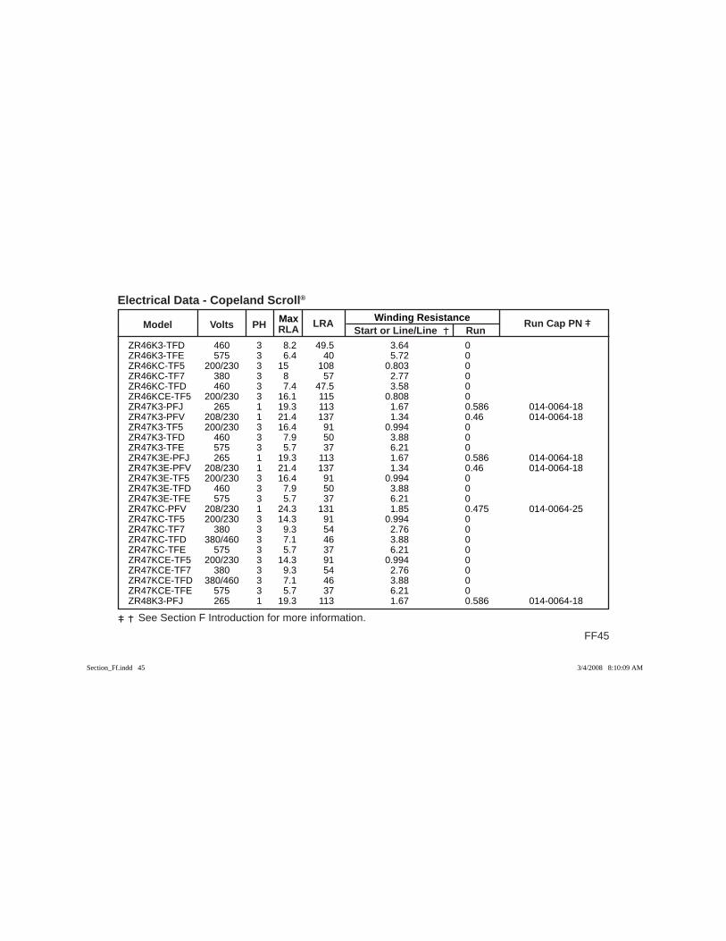
Max Winding Resistance Model Volts PH RLA
LRA Start or Line/Line Run
Run Cap PN
FF45
See Section F Introduction for more information.
Electrical Data - Copeland Scroll®
ZR46K3-TFD 460 3 8.2 49.5 3.64 0 ZR46K3-TFE 575 3 6.4 40 5.72 0 ZR46KC-TF5 200/230 3 15 108 0.803 0 ZR46KC-TF7 380 3 8 57 2.77 0 ZR46KC-TFD 460 3 7.4 47.5 3.58 0 ZR46KCE-TF5 200/230 3 16.1 115 0.808 0 ZR47K3-PFJ 265 1 19.3 113 1.67 0.586 014-0064-18 ZR47K3-PFV 208/230 1 21.4 137 1.34 0.46 014-0064-18 ZR47K3-TF5 200/230 3 16.4 91 0.994 0 ZR47K3-TFD 460 3 7.9 50 3.88 0 ZR47K3-TFE 575 3 5.7 37 6.21 0 ZR47K3E-PFJ 265 1 19.3 113 1.67 0.586 014-0064-18 ZR47K3E-PFV 208/230 1 21.4 137 1.34 0.46 014-0064-18 ZR47K3E-TF5 200/230 3 16.4 91 0.994 0 ZR47K3E-TFD 460 3 7.9 50 3.88 0 ZR47K3E-TFE 575 3 5.7 37 6.21 0 ZR47KC-PFV 208/230 1 24.3 131 1.85 0.475 014-0064-25 ZR47KC-TF5 200/230 3 14.3 91 0.994 0 ZR47KC-TF7 380 3 9.3 54 2.76 0 ZR47KC-TFD 380/460 3 7.1 46 3.88 0 ZR47KC-TFE 575 3 5.7 37 6.21 0 ZR47KCE-TF5 200/230 3 14.3 91 0.994 0 ZR47KCE-TF7 380 3 9.3 54 2.76 0 ZR47KCE-TFD 380/460 3 7.1 46 3.88 0 ZR47KCE-TFE 575 3 5.7 37 6.21 0 ZR48K3-PFJ 265 1 19.3 113 1.67 0.586 014-0064-18
Section_Ff.indd 45Section_Ff.indd 45 3/4/2008 8:10:09 AM3/4/2008 8:10:09 AM
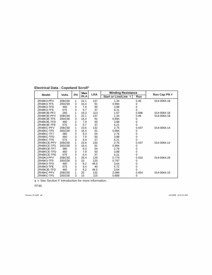
FF46
See Section F Introduction for more information.
Max Winding Resistance Model Volts PH RLA
LRA Start or Line/Line Run
Run Cap PN
Electrical Data - Copeland Scroll®
ZR48K3-PFV 208/230 1 22.1 137 1.34 0.46 014-0064-18 ZR48K3-TF5 200/230 3 16.4 91 0.994 0 ZR48K3-TFD 460 3 7.9 50 3.88 0 ZR48K3-TFE 575 3 5.7 37 6.21 0 ZR48K3E-PFJ 265 1 19.3 113 1.67 0.586 014-0064-18 ZR48K3E-PFV 208/230 1 22.1 137 1.34 0.46 014-0064-18 ZR48K3E-TF5 200/230 3 16.4 91 0.994 0 ZR48K3E-TFD 460 3 7.9 50 3.88 0 ZR48K3E-TFE 575 3 5.7 37 6.21 0 ZR48KC-PFV 208/230 1 23.6 132 2.75 0.437 014-0064-14 ZR48KC-TF5 200/230 3 16.4 91 0.994 0 ZR48KC-TF7 380 3 9.3 54 2.76 0 ZR48KC-TFD 460 3 7.9 50 3.88 0 ZR48KC-TFE 575 3 6.4 37 6.21 0 ZR48KCE-PFV 208/230 1 23.6 132 2.75 0.437 014-0064-14 ZR48KCE-TF5 200/230 3 16.4 91 0.994 0 ZR48KCE-TF7 380 3 9.3 54 2.76 0 ZR48KCE-TFD 460 3 7.9 50 3.88 0 ZR48KCE-TFE 575 3 6.4 37 6.21 0 ZR49K3-PFV 208/230 1 26.4 129 0.779 0.432 014-0064-26 ZR49K3-TF5 200/230 3 15 120 0.797 0 ZR49K3-TFD 460 3 8.2 49.5 3.64 0 ZR49K3-TFE 575 3 6.4 40 5.72 0 ZR49K3E-TFD 460 3 8.2 49.5 3.64 0 ZR49KC-PFV 208/230 1 25 132 2.089 0.454 014-0064-15 ZR49KC-TF5 200/230 3 15 115 0.808 0
Section_Ff.indd 46Section_Ff.indd 46 3/4/2008 8:10:10 AM3/4/2008 8:10:10 AM
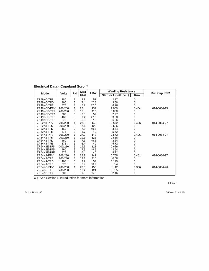
Max Winding Resistance Model Volts PH RLA
LRA Start or Line/Line Run
Run Cap PN
FF47
See Section F Introduction for more information.
Electrical Data - Copeland Scroll®
ZR49KC-TF7 380 3 8.8 57 2.77 0 ZR49KC-TFD 460 3 7.4 47.5 3.58 0 ZR49KC-TFE 575 3 5.9 37.5 6.26 0 ZR49KCE-PFV 208/230 1 25 132 2.089 0.454 014-0064-15 ZR49KCE-TF5 200/230 3 15 115 0.808 0 ZR49KCE-TF7 380 3 8.8 57 2.77 0 ZR49KCE-TFD 460 3 7.4 47.5 3.58 0 ZR49KCE-TFE 575 3 5.9 37.5 6.26 0 ZR52K3-PFV 208/230 1 27.9 148 0.572 0.406 014-0064-27 ZR52K3-TF5 200/230 3 17.1 128 0.686 0 ZR52K3-TFD 460 3 7.5 49.5 3.64 0 ZR52K3-TFE 575 3 5.7 40 5.72 0 ZR54K3-PFV 208/230 1 27.9 148 0.572 0.406 014-0064-27 ZR54K3-TF5 200/230 3 19.3 123 0.686 0 ZR54K3-TFD 460 3 7.5 49.5 3.64 0 ZR54K3-TFE 575 3 6.4 40 5.72 0 ZR54K3E-TF5 200/230 3 19.3 123 0.686 0 ZR54K3E-TFD 460 3 7.5 49.5 3.64 0 ZR54K3E-TFE 575 3 6.4 40 5.72 0 ZR54KA-PFV 208/230 1 28.2 141 0.768 0.461 014-0064-27 ZR54KA-TF5 200/230 3 17.1 110 0.68 0 ZR54KA-TFD 460 3 7.9 52 3.199 0 ZR54KA-TFE 575 3 5.9 38.9 5.4 0 ZR54KC-PFV 208/230 1 28.6 150 1.12 0.386 014-0064-26 ZR54KC-TF5 200/230 3 16.4 124 0.735 0 ZR54KC-TF7 380 3 9.3 65.8 2.46 0
Section_Ff.indd 47Section_Ff.indd 47 3/4/2008 8:10:10 AM3/4/2008 8:10:10 AM
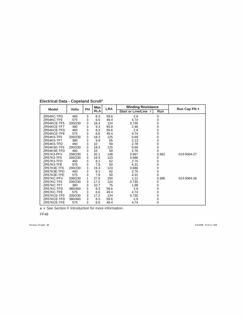
FF48
See Section F Introduction for more information.
Max Winding Resistance Model Volts PH RLA
LRA Start or Line/Line Run
Run Cap PN
Electrical Data - Copeland Scroll®
ZR54KC-TFD 460 3 8.3 59.6 2.9 0 ZR54KC-TFE 575 3 6.6 49.4 4.74 0 ZR54KCE-TF5 200/230 3 16.4 124 0.735 0 ZR54KCE-TF7 380 3 9.3 65.8 2.46 0 ZR54KCE-TFD 460 3 8.3 59.6 2.9 0 ZR54KCE-TFE 575 3 6.6 49.4 4.74 0 ZR54KS-TF5 200/230 3 18.3 125 0.69 0 ZR54KS-TF7 380 3 9.9 65 2.13 0 ZR54KS-TFD 460 3 10 59 2.78 0 ZR54KSE-TF5 200/230 3 18.3 125 0.69 0 ZR54KSE-TFD 460 3 10 59 2.78 0 ZR57K3-PFV 208/230 1 32.1 148 0.667 0.362 014-0064-27 ZR57K3-TF5 200/230 3 19.3 123 0.686 0 ZR57K3-TFD 460 3 9.1 62 2.75 0 ZR57K3-TFE 575 3 7.9 50 4.31 0 ZR57K3E-TF5 200/230 3 19.3 123 0.686 0 ZR57K3E-TFD 460 3 9.1 62 2.75 0 ZR57K3E-TFE 575 3 7.9 50 4.31 0 ZR57KC-PFV 208/230 1 27.9 150 1.12 0.386 014-0064-26 ZR57KC-TF5 200/230 3 17.2 124 0.735 0 ZR57KC-TF7 380 3 10.7 75 1.98 0 ZR57KC-TFD 380/460 3 8.3 59.6 2.9 0 ZR57KC-TFE 575 3 6.6 49.4 4.74 0 ZR57KCE-TF5 200/230 3 17.2 124 0.735 0 ZR57KCE-TFD 380/460 3 8.3 59.6 2.9 0 ZR57KCE-TFE 575 3 6.6 49.4 4.74 0
Section_Ff.indd 48Section_Ff.indd 48 3/4/2008 8:10:11 AM3/4/2008 8:10:11 AM
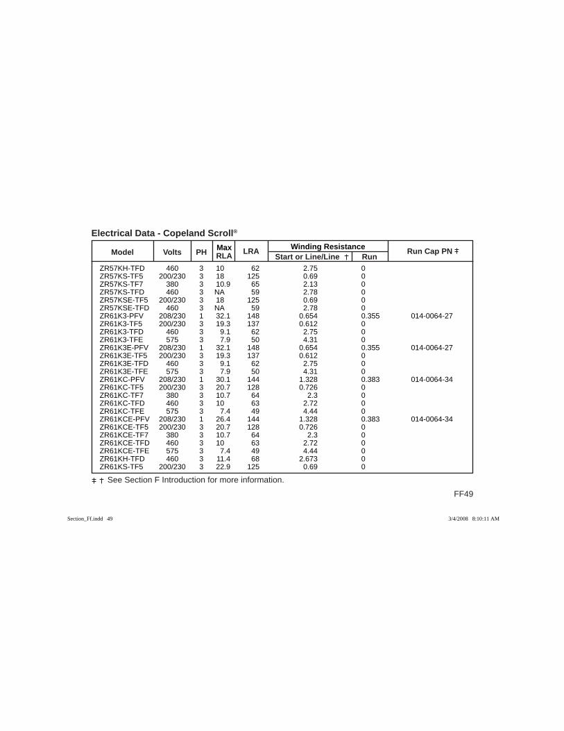
Max Winding Resistance Model Volts PH RLA
LRA Start or Line/Line Run
Run Cap PN
FF49
See Section F Introduction for more information.
Electrical Data - Copeland Scroll®
ZR57KH-TFD 460 3 10 62 2.75 0 ZR57KS-TF5 200/230 3 18 125 0.69 0 ZR57KS-TF7 380 3 10.9 65 2.13 0 ZR57KS-TFD 460 3 NA 59 2.78 0 ZR57KSE-TF5 200/230 3 18 125 0.69 0 ZR57KSE-TFD 460 3 NA 59 2.78 0 ZR61K3-PFV 208/230 1 32.1 148 0.654 0.355 014-0064-27 ZR61K3-TF5 200/230 3 19.3 137 0.612 0 ZR61K3-TFD 460 3 9.1 62 2.75 0 ZR61K3-TFE 575 3 7.9 50 4.31 0 ZR61K3E-PFV 208/230 1 32.1 148 0.654 0.355 014-0064-27 ZR61K3E-TF5 200/230 3 19.3 137 0.612 0 ZR61K3E-TFD 460 3 9.1 62 2.75 0 ZR61K3E-TFE 575 3 7.9 50 4.31 0 ZR61KC-PFV 208/230 1 30.1 144 1.328 0.383 014-0064-34 ZR61KC-TF5 200/230 3 20.7 128 0.726 0 ZR61KC-TF7 380 3 10.7 64 2.3 0 ZR61KC-TFD 460 3 10 63 2.72 0 ZR61KC-TFE 575 3 7.4 49 4.44 0 ZR61KCE-PFV 208/230 1 26.4 144 1.328 0.383 014-0064-34 ZR61KCE-TF5 200/230 3 20.7 128 0.726 0 ZR61KCE-TF7 380 3 10.7 64 2.3 0 ZR61KCE-TFD 460 3 10 63 2.72 0 ZR61KCE-TFE 575 3 7.4 49 4.44 0 ZR61KH-TFD 460 3 11.4 68 2.673 0 ZR61KS-TF5 200/230 3 22.9 125 0.69 0
Section_Ff.indd 49Section_Ff.indd 49 3/4/2008 8:10:11 AM3/4/2008 8:10:11 AM
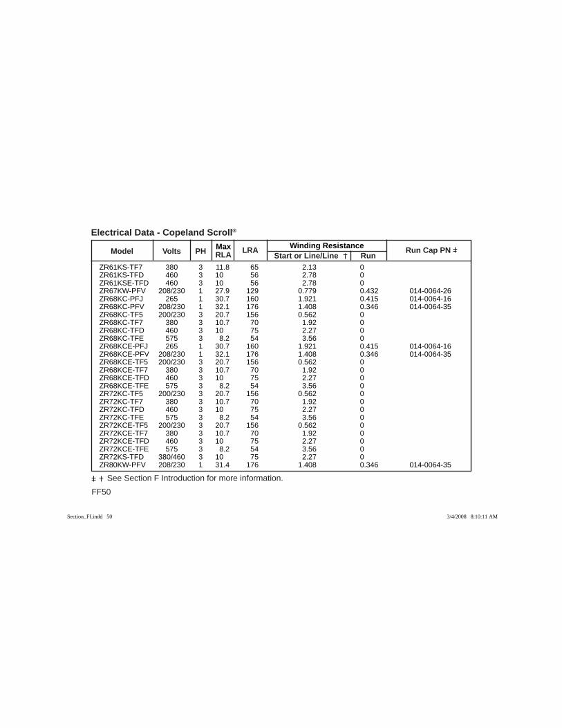
FF50
See Section F Introduction for more information.
Max Winding Resistance Model Volts PH RLA
LRA Start or Line/Line Run
Run Cap PN
Electrical Data - Copeland Scroll®
ZR61KS-TF7 380 3 11.8 65 2.13 0 ZR61KS-TFD 460 3 10 56 2.78 0 ZR61KSE-TFD 460 3 10 56 2.78 0 ZR67KW-PFV 208/230 1 27.9 129 0.779 0.432 014-0064-26 ZR68KC-PFJ 265 1 30.7 160 1.921 0.415 014-0064-16 ZR68KC-PFV 208/230 1 32.1 176 1.408 0.346 014-0064-35 ZR68KC-TF5 200/230 3 20.7 156 0.562 0 ZR68KC-TF7 380 3 10.7 70 1.92 0 ZR68KC-TFD 460 3 10 75 2.27 0 ZR68KC-TFE 575 3 8.2 54 3.56 0 ZR68KCE-PFJ 265 1 30.7 160 1.921 0.415 014-0064-16 ZR68KCE-PFV 208/230 1 32.1 176 1.408 0.346 014-0064-35 ZR68KCE-TF5 200/230 3 20.7 156 0.562 0 ZR68KCE-TF7 380 3 10.7 70 1.92 0 ZR68KCE-TFD 460 3 10 75 2.27 0 ZR68KCE-TFE 575 3 8.2 54 3.56 0 ZR72KC-TF5 200/230 3 20.7 156 0.562 0 ZR72KC-TF7 380 3 10.7 70 1.92 0 ZR72KC-TFD 460 3 10 75 2.27 0 ZR72KC-TFE 575 3 8.2 54 3.56 0 ZR72KCE-TF5 200/230 3 20.7 156 0.562 0 ZR72KCE-TF7 380 3 10.7 70 1.92 0 ZR72KCE-TFD 460 3 10 75 2.27 0 ZR72KCE-TFE 575 3 8.2 54 3.56 0 ZR72KS-TFD 380/460 3 10 75 2.27 0 ZR80KW-PFV 208/230 1 31.4 176 1.408 0.346 014-0064-35
Section_Ff.indd 50Section_Ff.indd 50 3/4/2008 8:10:11 AM3/4/2008 8:10:11 AM
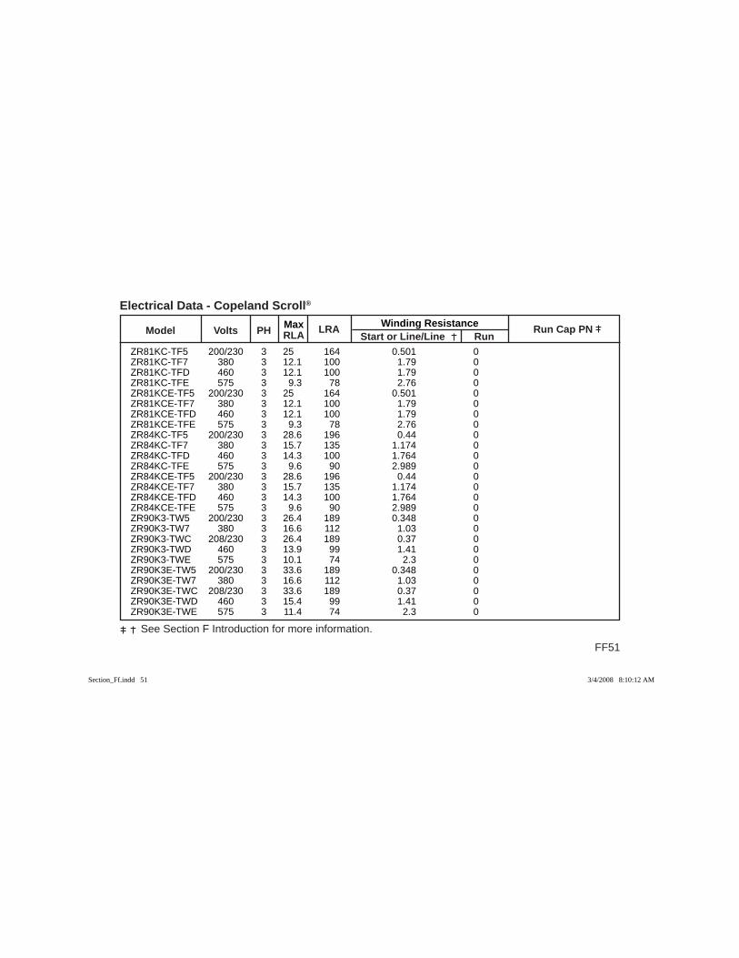
Max Winding Resistance Model Volts PH RLA
LRA Start or Line/Line Run
Run Cap PN
FF51
See Section F Introduction for more information.
Electrical Data - Copeland Scroll®
ZR81KC-TF5 200/230 3 25 164 0.501 0 ZR81KC-TF7 380 3 12.1 100 1.79 0 ZR81KC-TFD 460 3 12.1 100 1.79 0 ZR81KC-TFE 575 3 9.3 78 2.76 0 ZR81KCE-TF5 200/230 3 25 164 0.501 0 ZR81KCE-TF7 380 3 12.1 100 1.79 0 ZR81KCE-TFD 460 3 12.1 100 1.79 0 ZR81KCE-TFE 575 3 9.3 78 2.76 0 ZR84KC-TF5 200/230 3 28.6 196 0.44 0 ZR84KC-TF7 380 3 15.7 135 1.174 0 ZR84KC-TFD 460 3 14.3 100 1.764 0 ZR84KC-TFE 575 3 9.6 90 2.989 0 ZR84KCE-TF5 200/230 3 28.6 196 0.44 0 ZR84KCE-TF7 380 3 15.7 135 1.174 0 ZR84KCE-TFD 460 3 14.3 100 1.764 0 ZR84KCE-TFE 575 3 9.6 90 2.989 0 ZR90K3-TW5 200/230 3 26.4 189 0.348 0 ZR90K3-TW7 380 3 16.6 112 1.03 0 ZR90K3-TWC 208/230 3 26.4 189 0.37 0 ZR90K3-TWD 460 3 13.9 99 1.41 0 ZR90K3-TWE 575 3 10.1 74 2.3 0 ZR90K3E-TW5 200/230 3 33.6 189 0.348 0 ZR90K3E-TW7 380 3 16.6 112 1.03 0 ZR90K3E-TWC 208/230 3 33.6 189 0.37 0 ZR90K3E-TWD 460 3 15.4 99 1.41 0 ZR90K3E-TWE 575 3 11.4 74 2.3 0
Section_Ff.indd 51Section_Ff.indd 51 3/4/2008 8:10:12 AM3/4/2008 8:10:12 AM
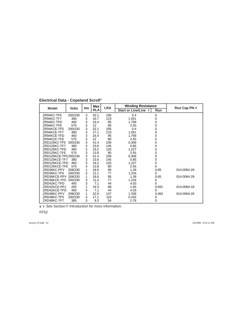
FF52
See Section F Introduction for more information.
Max Winding Resistance Model Volts PH RLA
LRA Start or Line/Line Run
Run Cap PN
Electrical Data - Copeland Scroll®
ZR94KC-TF5 200/230 3 32.1 195 0.4 0 ZR94KC-TF7 380 3 16.7 123 1.051 0 ZR94KC-TFD 460 3 16.4 95 1.799 0 ZR94KC-TFE 575 3 12 80 2.55 0 ZR94KCE-TF5 200/230 3 32.1 195 0.4 0 ZR94KCE-TF7 380 3 17.1 123 1.051 0 ZR94KCE-TFD 460 3 16.4 95 1.799 0 ZR94KCE-TFE 575 3 12 80 2.55 0 ZRD125KC-TF5 200/230 3 41.4 239 0.306 0 ZRD125KC-TF7 380 3 23.6 145 0.85 0 ZRD125KC-TFD 460 3 19.2 125 1.227 0 ZRD125KC-TFE 575 3 13.8 80 2.55 0 ZRD125KCE-TF5 200/230 3 41.4 239 0.306 0 ZRD125KCE-TF7 380 3 23.6 145 0.85 0 ZRD125KCE-TFD 460 3 19.2 125 1.227 0 ZRD125KCE-TFE 575 3 13.8 80 2.55 0 ZRD36KC-PFV 208/230 1 18.6 95 1.39 0.65 014-0064-29 ZRD36KC-TF5 200/230 3 12.1 77 1.234 0 ZRD36KCE-PFV 208/230 1 18.6 95 1.39 0.65 014-0064-29 ZRD36KCE-TF5 200/230 3 11.4 77 1.234 0 ZRD42KC-TFD 460 3 7.1 44 4.03 0 ZRD42KCE-PFJ 265 1 19.3 98 1.65 0.691 014-0064-18 ZRD42KCE-TFD 460 3 7.1 44 4.03 0 ZRD48KC-PFV 208/230 1 22.9 137 1.339 0.462 014-0064-26 ZRD48KC-TF5 200/230 3 17.1 110 0.432 0 ZRD48KC-TF7 380 3 9.3 54 2.76 0
Section_Ff.indd 52Section_Ff.indd 52 3/4/2008 8:10:12 AM3/4/2008 8:10:12 AM

Max Winding Resistance Model Volts PH RLA
LRA Start or Line/Line Run
Run Cap PN
FF53
See Section F Introduction for more information.
Electrical Data - Copeland Scroll®
ZRD48KC-TFD 460 3 7.9 46 3.88 0 ZRD48KCE-PFV 208/230 1 22.9 137 1.339 0.462 014-0064-26 ZRD48KCE-TF5 200/230 3 17.1 110 0.432 0 ZRD48KCE-TF7 380 3 9.3 54 2.76 0 ZRD48KCE-TFD 460 3 7.9 46 3.88 0 ZRD49KC-PFV 208/230 1 26.4 129 0.779 0.432 014-0064-26 ZRD49KC-TF5 200/230 3 15 115 0.911 0 ZRD49KC-TF7 380 3 8 57 2.78 0 ZRD49KC-TFD 460 3 7.4 47.5 3.64 0 ZRD49KCE-TF5 200/230 3 15.7 115 0.911 0 ZRD49KCE-TF7 380 3 8 57 2.78 0 ZRD49KCE-TFD 460 3 7.4 47.5 3.64 0 ZRD61KC-PFV 208/230 1 32.1 148 0.667 0.362 014-0064-27 ZRD61KC-TF5 200/230 3 20.7 137 0.612 0 ZRD61KC-TF7 380 3 10.7 64 2.3 0 ZRD61KC-TFD 460 3 10 62 2.8 0 ZRD61KC-TFE 575 3 7.1 53 4.333 0 ZRD61KCE-PFV 208/230 1 32.1 148 0.667 0.362 014-0064-27 ZRD61KCE-TF5 200/230 3 20.7 137 0.612 0 ZRD61KCE-TF7 380 3 10.7 64 2.3 0 ZRD61KCE-TFD 460 3 9.1 62 2.8 0 ZRD68KC-TFD 460 3 11.1 75 2.27 0 ZRD68KCE-TFD 460 3 11.1 75 2.27 0 ZRD72KC-TF5 200/230 3 20.7 156 0.562 0 ZRD72KC-TF7 380 3 12.5 70 1.92 0 ZRD72KC-TFD 460 3 10 70 2.27 0
Section_Ff.indd 53Section_Ff.indd 53 3/4/2008 8:10:12 AM3/4/2008 8:10:12 AM
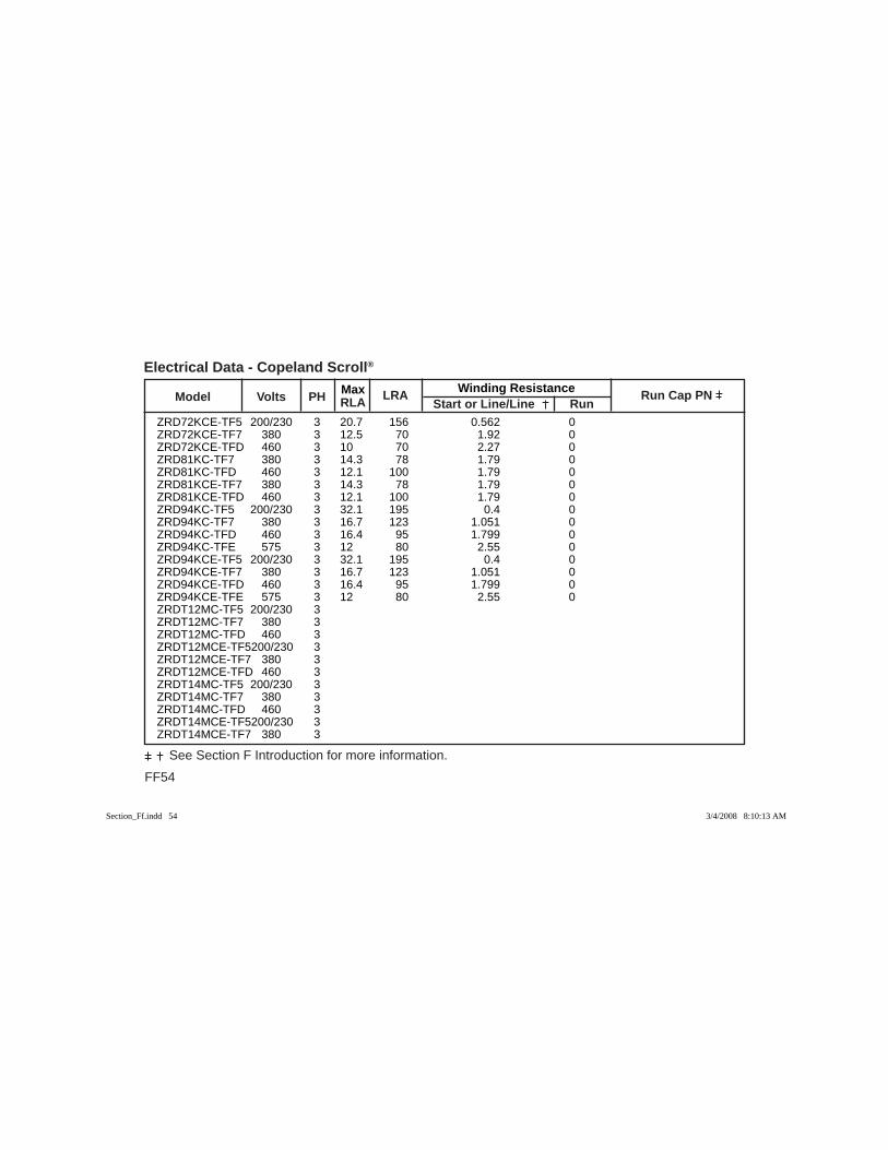
FF54
See Section F Introduction for more information.
Max Winding Resistance Model Volts PH RLA
LRA Start or Line/Line Run
Run Cap PN
Electrical Data - Copeland Scroll®
ZRD72KCE-TF5 200/230 3 20.7 156 0.562 0 ZRD72KCE-TF7 380 3 12.5 70 1.92 0 ZRD72KCE-TFD 460 3 10 70 2.27 0 ZRD81KC-TF7 380 3 14.3 78 1.79 0 ZRD81KC-TFD 460 3 12.1 100 1.79 0 ZRD81KCE-TF7 380 3 14.3 78 1.79 0 ZRD81KCE-TFD 460 3 12.1 100 1.79 0 ZRD94KC-TF5 200/230 3 32.1 195 0.4 0 ZRD94KC-TF7 380 3 16.7 123 1.051 0 ZRD94KC-TFD 460 3 16.4 95 1.799 0 ZRD94KC-TFE 575 3 12 80 2.55 0 ZRD94KCE-TF5 200/230 3 32.1 195 0.4 0 ZRD94KCE-TF7 380 3 16.7 123 1.051 0 ZRD94KCE-TFD 460 3 16.4 95 1.799 0 ZRD94KCE-TFE 575 3 12 80 2.55 0 ZRDT12MC-TF5 200/230 3 ZRDT12MC-TF7 380 3 ZRDT12MC-TFD 460 3 ZRDT12MCE-TF5 200/230 3 ZRDT12MCE-TF7 380 3 ZRDT12MCE-TFD 460 3 ZRDT14MC-TF5 200/230 3 ZRDT14MC-TF7 380 3 ZRDT14MC-TFD 460 3 ZRDT14MCE-TF5 200/230 3 ZRDT14MCE-TF7 380 3
Section_Ff.indd 54Section_Ff.indd 54 3/4/2008 8:10:13 AM3/4/2008 8:10:13 AM

Max Winding Resistance Model Volts PH RLA
LRA Start or Line/Line Run
Run Cap PN
FF55
See Section F Introduction for more information.
Electrical Data - Copeland Scroll®
ZRDT14MCE-TFD 460 3 ZRDT16MC-TF7 380 3 ZRDT16MC-TFD 460 3 ZRDT16MCE-TF7 380 3 ZRDT16MCE-TFD 460 3 ZRDT96KC-TF7 380 3 ZRDT96KC-TFD 460 3 ZRDT96KCE-TF7 380 3 ZRDT96KCE-TFD 460 3 ZRDU11MC-TF5 200/230 3 ZRDU11MC-TF5 200/230 3 ZRDU11MC-TF7 380 3 ZRDU11MC-TF7 380 3 ZRDU11MC-TFD 460 3 ZRDU11MC-TFD 460 3 ZRDU11MCE-TF5 200/230 3 ZRDU11MCE-TF7 380 3 ZRDU11MCE-TFD 460 3 ZRDU13MC-TF5 200/230 3 ZRDU13MC-TF5 200/230 3 ZRDU13MC-TF7 380 3 ZRDU13MC-TF7 380 3 ZRDU13MC-TFD 460 3 ZRDU13MC-TFD 460 3 ZRDU13MCE-TF5 200/230 3 ZRDU13MCE-TF5 200/230 3
Section_Ff.indd 55Section_Ff.indd 55 3/4/2008 8:10:13 AM3/4/2008 8:10:13 AM
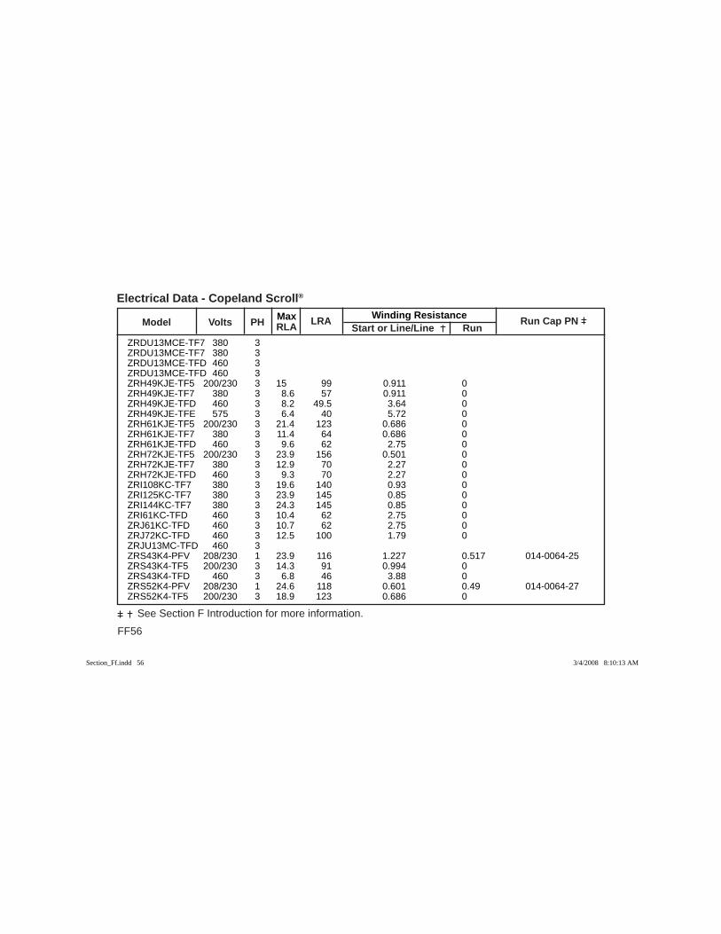
FF56
See Section F Introduction for more information.
Max Winding Resistance Model Volts PH RLA
LRA Start or Line/Line Run
Run Cap PN
Electrical Data - Copeland Scroll®
ZRDU13MCE-TF7 380 3 ZRDU13MCE-TF7 380 3 ZRDU13MCE-TFD 460 3 ZRDU13MCE-TFD 460 3 ZRH49KJE-TF5 200/230 3 15 99 0.911 0 ZRH49KJE-TF7 380 3 8.6 57 0.911 0 ZRH49KJE-TFD 460 3 8.2 49.5 3.64 0 ZRH49KJE-TFE 575 3 6.4 40 5.72 0 ZRH61KJE-TF5 200/230 3 21.4 123 0.686 0 ZRH61KJE-TF7 380 3 11.4 64 0.686 0 ZRH61KJE-TFD 460 3 9.6 62 2.75 0 ZRH72KJE-TF5 200/230 3 23.9 156 0.501 0 ZRH72KJE-TF7 380 3 12.9 70 2.27 0 ZRH72KJE-TFD 460 3 9.3 70 2.27 0 ZRI108KC-TF7 380 3 19.6 140 0.93 0 ZRI125KC-TF7 380 3 23.9 145 0.85 0 ZRI144KC-TF7 380 3 24.3 145 0.85 0 ZRI61KC-TFD 460 3 10.4 62 2.75 0 ZRJ61KC-TFD 460 3 10.7 62 2.75 0 ZRJ72KC-TFD 460 3 12.5 100 1.79 0 ZRJU13MC-TFD 460 3 ZRS43K4-PFV 208/230 1 23.9 116 1.227 0.517 014-0064-25 ZRS43K4-TF5 200/230 3 14.3 91 0.994 0 ZRS43K4-TFD 460 3 6.8 46 3.88 0 ZRS52K4-PFV 208/230 1 24.6 118 0.601 0.49 014-0064-27 ZRS52K4-TF5 200/230 3 18.9 123 0.686 0
Section_Ff.indd 56Section_Ff.indd 56 3/4/2008 8:10:13 AM3/4/2008 8:10:13 AM
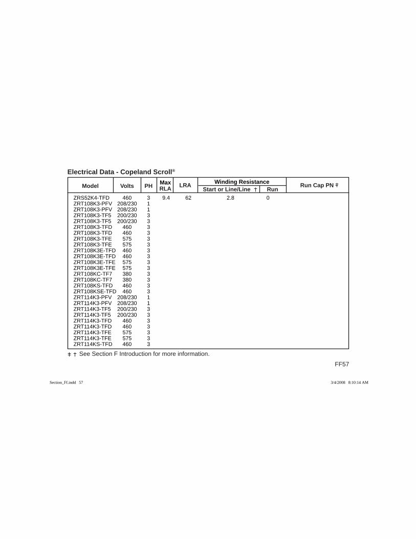
Max Winding Resistance Model Volts PH RLA
LRA Start or Line/Line Run
Run Cap PN
FF57
See Section F Introduction for more information.
Electrical Data - Copeland Scroll®
ZRS52K4-TFD 460 3 9.4 62 2.8 0 ZRT108K3-PFV 208/230 1 ZRT108K3-PFV 208/230 1 ZRT108K3-TF5 200/230 3 ZRT108K3-TF5 200/230 3 ZRT108K3-TFD 460 3 ZRT108K3-TFD 460 3 ZRT108K3-TFE 575 3 ZRT108K3-TFE 575 3 ZRT108K3E-TFD 460 3 ZRT108K3E-TFD 460 3 ZRT108K3E-TFE 575 3 ZRT108K3E-TFE 575 3 ZRT108KC-TF7 380 3 ZRT108KC-TF7 380 3 ZRT108KS-TFD 460 3 ZRT108KSE-TFD 460 3 ZRT114K3-PFV 208/230 1 ZRT114K3-PFV 208/230 1 ZRT114K3-TF5 200/230 3 ZRT114K3-TF5 200/230 3 ZRT114K3-TFD 460 3 ZRT114K3-TFD 460 3 ZRT114K3-TFE 575 3 ZRT114K3-TFE 575 3 ZRT114KS-TFD 460 3
Section_Ff.indd 57Section_Ff.indd 57 3/4/2008 8:10:14 AM3/4/2008 8:10:14 AM

FF58
See Section F Introduction for more information.
Max Winding Resistance Model Volts PH RLA
LRA Start or Line/Line Run
Run Cap PN
Electrical Data - Copeland Scroll®
ZRT114KSE-TFD 460 3 ZRT122K3-PFV 208/230 1 ZRT122K3-PFV 208/230 1 ZRT122K3-TF5 200/230 3 ZRT122K3-TF5 200/230 3 ZRT122K3-TFD 460 3 ZRT122K3-TFD 460 3 ZRT122K3-TFE 575 3 ZRT122K3-TFE 575 3 ZRT122K3E-PFV 208/230 1 ZRT122K3E-PFV 208/230 1 ZRT122K3E-TF5 200/230 3 ZRT122K3E-TF5 200/230 3 ZRT122K3E-TFD 460 3 ZRT122K3E-TFD 460 3 ZRT122KCE-TFD 460 3 ZRT122KCE-TFD 460 3 ZRT122KS-TF5 200/230 3 ZRT122KS-TFD 460 3 ZRT122KSE-TF5 200/230 3 ZRT122KSE-TFD 460 3 ZRT136KC-TF5 200/230 3 ZRT136KC-TF5 200/230 3 ZRT136KC-TF7 380 3 ZRT136KC-TF7 380 3 ZRT136KC-TFD 460 3
Section_Ff.indd 58Section_Ff.indd 58 3/4/2008 8:10:14 AM3/4/2008 8:10:14 AM

Max Winding Resistance Model Volts PH RLA
LRA Start or Line/Line Run
Run Cap PN
FF59
See Section F Introduction for more information.
Electrical Data - Copeland Scroll®
ZRT136KC-TFD 460 3 ZRT136KC-TFE 575 3 ZRT136KC-TFE 575 3 ZRT136KCE-TF5 200/230 3 ZRT136KCE-TFD 460 3 ZRT136KCE-TFD 460 3 ZRT136KCE-TFE 575 3 ZRT136KCE-TFE 575 3 ZRT144KC-TF5 200/230 3 ZRT144KC-TF5 200/230 3 ZRT144KC-TF7 380 3 ZRT144KC-TF7 380 3 ZRT144KC-TFD 460 3 ZRT144KC-TFD 460 3 ZRT144KC-TFE 575 3 ZRT144KC-TFE 575 3 ZRT144KCE-TF5 200/230 3 ZRT144KCE-TF5 200/230 3 ZRT144KCE-TFD 460 3 ZRT144KCE-TFD 460 3 ZRT144KCE-TFE 575 3 ZRT144KCE-TFE 575 3 ZRT162KC-TF5 200/230 3 ZRT162KC-TF5 200/230 3 ZRT162KC-TF7 380 3 ZRT162KC-TFD 460 3
Section_Ff.indd 59Section_Ff.indd 59 3/4/2008 8:10:14 AM3/4/2008 8:10:14 AM
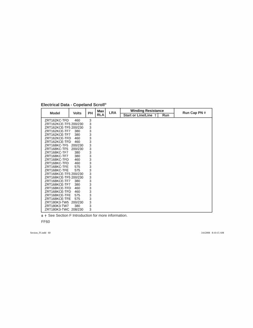
FF60
See Section F Introduction for more information.
Max Winding Resistance Model Volts PH RLA
LRA Start or Line/Line Run
Run Cap PN
Electrical Data - Copeland Scroll®
ZRT162KC-TFD 460 3 ZRT162KCE-TF5 200/230 3 ZRT162KCE-TF5 200/230 3 ZRT162KCE-TF7 380 3 ZRT162KCE-TF7 380 3 ZRT162KCE-TFD 460 3 ZRT162KCE-TFD 460 3 ZRT168KC-TF5 200/230 3 ZRT168KC-TF5 200/230 3 ZRT168KC-TF7 380 3 ZRT168KC-TF7 380 3 ZRT168KC-TFD 460 3 ZRT168KC-TFD 460 3 ZRT168KC-TFE 575 3 ZRT168KC-TFE 575 3 ZRT168KCE-TF5 200/230 3 ZRT168KCE-TF5 200/230 3 ZRT168KCE-TF7 380 3 ZRT168KCE-TF7 380 3 ZRT168KCE-TFD 460 3 ZRT168KCE-TFD 460 3 ZRT168KCE-TFE 575 3 ZRT168KCE-TFE 575 3 ZRT180K3-TW5 200/230 3 ZRT180K3-TW7 380 3 ZRT180K3-TWC 208/230 3
Section_Ff.indd 60Section_Ff.indd 60 3/4/2008 8:10:15 AM3/4/2008 8:10:15 AM

Max Winding Resistance Model Volts PH RLA
LRA Start or Line/Line Run
Run Cap PN
FF61
See Section F Introduction for more information.
Electrical Data - Copeland Scroll®
ZRT180K3-TWD 460 3 ZRT180K3-TWE 575 3 ZRT180K3E-TWC 208/230 3 ZRT180K3E-TWD 460 3 ZRT180K3E-TWE 575 3 ZRT188KC-TF5 200/230 3 ZRT188KC-TF5 200/230 3 ZRT188KC-TF7 380 3 ZRT188KC-TF7 380 3 ZRT188KC-TFD 460 3 ZRT188KC-TFD 460 3 ZRT188KC-TFE 575 3 ZRT188KC-TFE 575 3 ZRT188KCE-TF5 200/230 3 ZRT188KCE-TF5 200/230 3 ZRT188KCE-TF7 380 3 ZRT188KCE-TF7 380 3 ZRT188KCE-TFD 460 3 ZRT188KCE-TFD 460 3 ZRT188KCE-TFE 575 3 ZRT188KCE-TFE 575 3 ZRT216KC-TF5 200/230 3 ZRT216KC-TF5 200/230 3 ZRT216KC-TF7 380 3 ZRT216KC-TF7 380 3 ZRT216KC-TFD 460 3
Section_Ff.indd 61Section_Ff.indd 61 3/4/2008 8:10:15 AM3/4/2008 8:10:15 AM
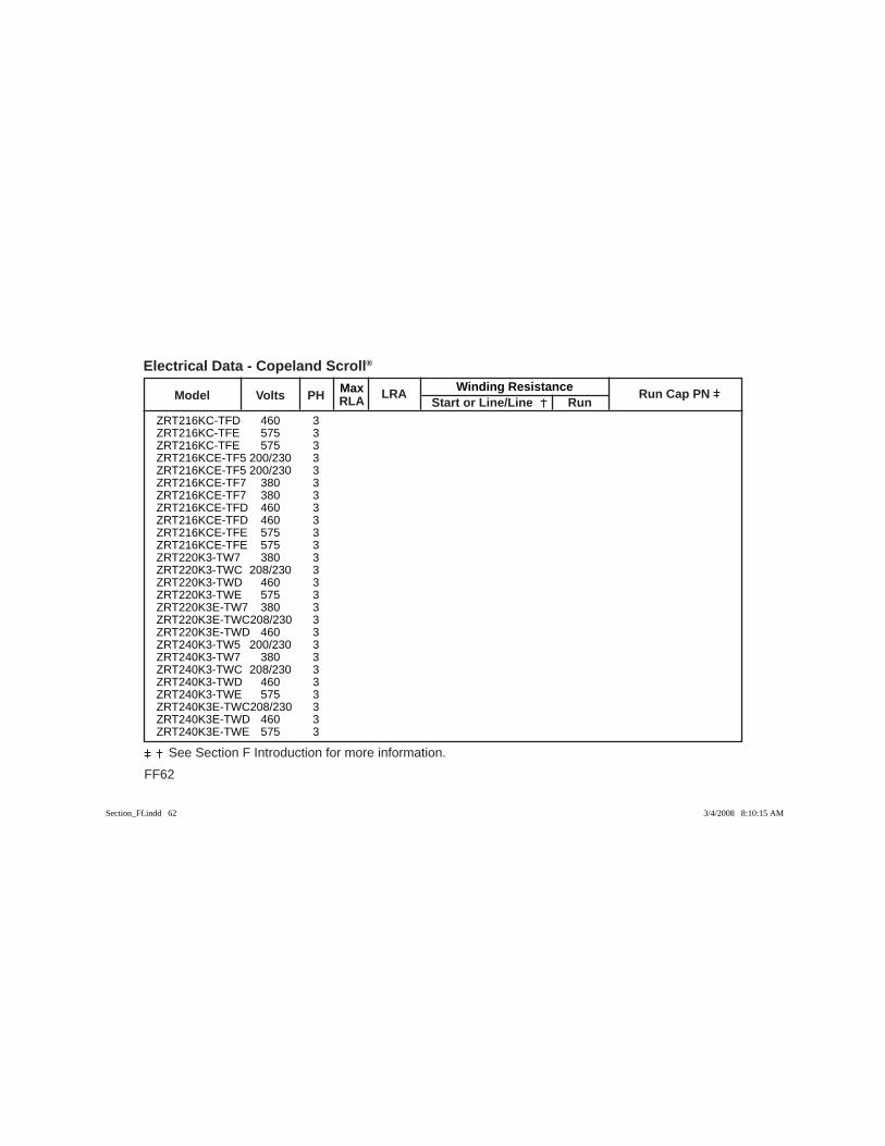
FF62
See Section F Introduction for more information.
Max Winding Resistance Model Volts PH RLA
LRA Start or Line/Line Run
Run Cap PN
Electrical Data - Copeland Scroll®
ZRT216KC-TFD 460 3 ZRT216KC-TFE 575 3 ZRT216KC-TFE 575 3 ZRT216KCE-TF5 200/230 3 ZRT216KCE-TF5 200/230 3 ZRT216KCE-TF7 380 3 ZRT216KCE-TF7 380 3 ZRT216KCE-TFD 460 3 ZRT216KCE-TFD 460 3 ZRT216KCE-TFE 575 3 ZRT216KCE-TFE 575 3 ZRT220K3-TW7 380 3 ZRT220K3-TWC 208/230 3 ZRT220K3-TWD 460 3 ZRT220K3-TWE 575 3 ZRT220K3E-TW7 380 3 ZRT220K3E-TWC 208/230 3 ZRT220K3E-TWD 460 3 ZRT240K3-TW5 200/230 3 ZRT240K3-TW7 380 3 ZRT240K3-TWC 208/230 3 ZRT240K3-TWD 460 3 ZRT240K3-TWE 575 3 ZRT240K3E-TWC 208/230 3 ZRT240K3E-TWD 460 3 ZRT240K3E-TWE 575 3
Section_Ff.indd 62Section_Ff.indd 62 3/4/2008 8:10:15 AM3/4/2008 8:10:15 AM
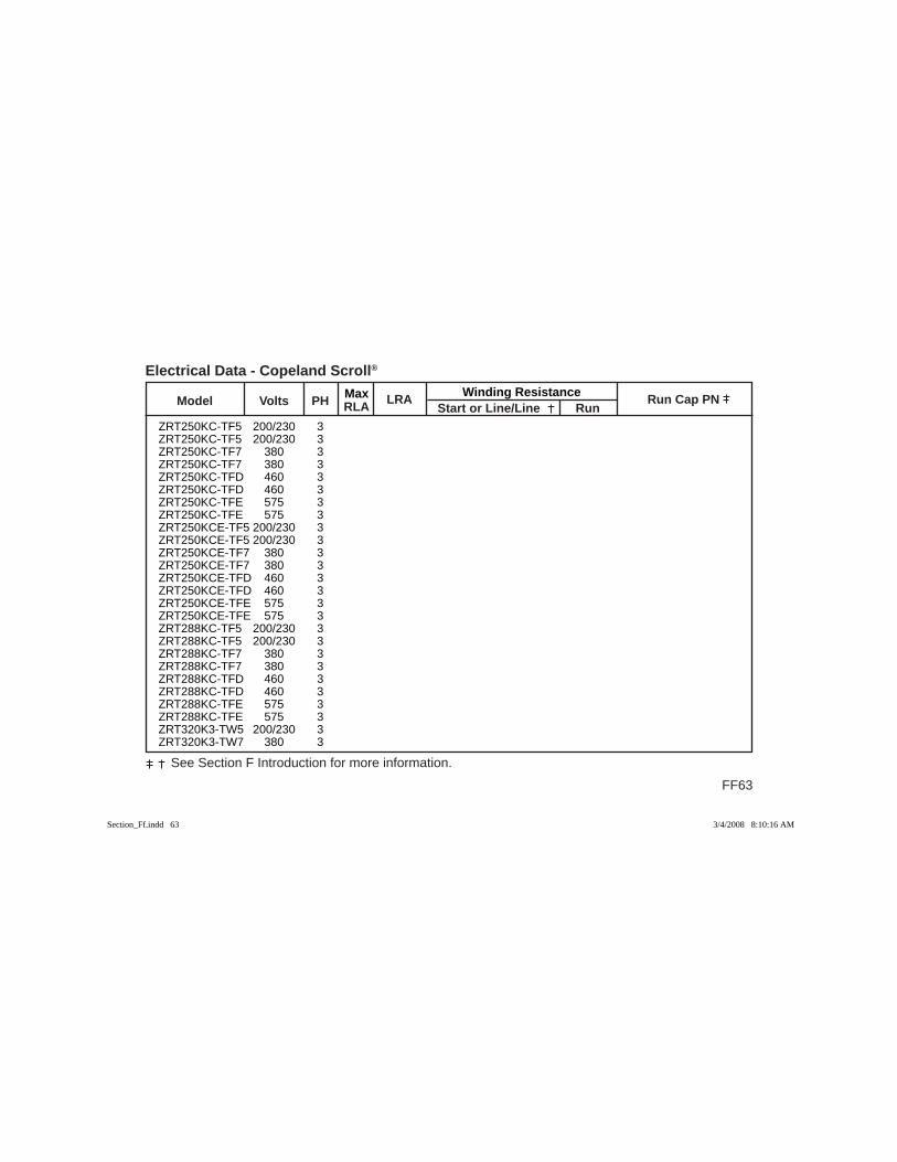
Max Winding Resistance Model Volts PH RLA
LRA Start or Line/Line Run
Run Cap PN
FF63
See Section F Introduction for more information.
Electrical Data - Copeland Scroll®
ZRT250KC-TF5 200/230 3 ZRT250KC-TF5 200/230 3 ZRT250KC-TF7 380 3 ZRT250KC-TF7 380 3 ZRT250KC-TFD 460 3 ZRT250KC-TFD 460 3 ZRT250KC-TFE 575 3 ZRT250KC-TFE 575 3 ZRT250KCE-TF5 200/230 3 ZRT250KCE-TF5 200/230 3 ZRT250KCE-TF7 380 3 ZRT250KCE-TF7 380 3 ZRT250KCE-TFD 460 3 ZRT250KCE-TFD 460 3 ZRT250KCE-TFE 575 3 ZRT250KCE-TFE 575 3 ZRT288KC-TF5 200/230 3 ZRT288KC-TF5 200/230 3 ZRT288KC-TF7 380 3 ZRT288KC-TF7 380 3 ZRT288KC-TFD 460 3 ZRT288KC-TFD 460 3 ZRT288KC-TFE 575 3 ZRT288KC-TFE 575 3 ZRT320K3-TW5 200/230 3 ZRT320K3-TW7 380 3
Section_Ff.indd 63Section_Ff.indd 63 3/4/2008 8:10:16 AM3/4/2008 8:10:16 AM

FF64
See Section F Introduction for more information.
Max Winding Resistance Model Volts PH RLA
LRA Start or Line/Line Run
Run Cap PN
Electrical Data - Copeland Scroll®
ZRT320K3-TWC 208/230 3 ZRT320K3-TWD 460 3 ZRT320K3-TWE 575 3 ZRT320K3E-TWC 208/230 3 ZRT320K3E-TWD 460 3 ZRT320K3E-TWE 575 3 ZRT320KC-TFD 460 3 ZRT320KC-TW5 200/230 3 ZRT320KC-TW7 380 3 ZRT320KC-TWD 460 3 ZRT320KC-TWE 575 3 ZRT320KCE-TFD 460 3 ZRT320KCE-TW5 200/230 3 ZRT320KCE-TW7 380 3 ZRT320KCE-TWD 460 3 ZRT320KCE-TWE 575 3 ZRT380K3-TW5 200/230 3 ZRT380K3-TW7 380 3 ZRT380K3-TWC 208/230 3 ZRT380K3-TWD 460 3 ZRT380K3-TWE 575 3 ZRT380K3E-TWC 208/230 3 ZRT380K3E-TWD 460 3 ZRT380K3E-TWE 575 3 ZRT380KC-TFD 460 3 ZRT380KC-TW5 200/230 3
Section_Ff.indd 64Section_Ff.indd 64 3/4/2008 8:10:16 AM3/4/2008 8:10:16 AM

Max Winding Resistance Model Volts PH RLA
LRA Start or Line/Line Run
Run Cap PN
FF65
See Section F Introduction for more information.
Electrical Data - Copeland Scroll®
ZRT380KC-TW7 380 3 ZRT380KC-TWD 460 3 ZRT380KC-TWE 575 3 ZRT380KCE-TFD 460 3 ZRT380KCE-TW5 200/230 3 ZRT380KCE-TW7 380 3 ZRT380KCE-TWD 460 3 ZRT380KCE-TWE 575 3 ZRT500KC-TW5 200/230 3 ZRT500KC-TW5 200/230 3 ZRT500KC-TW7 380 3 ZRT500KC-TW7 380 3 ZRT500KC-TWC 208/230 3 ZRT500KC-TWC 208/230 3 ZRT500KC-TWD 460 3 ZRT500KC-TWD 460 3 ZRT500KC-TWE 575 3 ZRT500KC-TWE 575 3 ZRT500KCE-TW5 200/230 3 ZRT500KCE-TW5 200/230 3 ZRT500KCE-TW7 380 3 ZRT500KCE-TW7 380 3 ZRT500KCE-TWC 208/230 3 ZRT500KCE-TWC 208/230 3 ZRT500KCE-TWD 460 3 ZRT500KCE-TWD 460 3
Section_Ff.indd 65Section_Ff.indd 65 3/4/2008 8:10:16 AM3/4/2008 8:10:16 AM
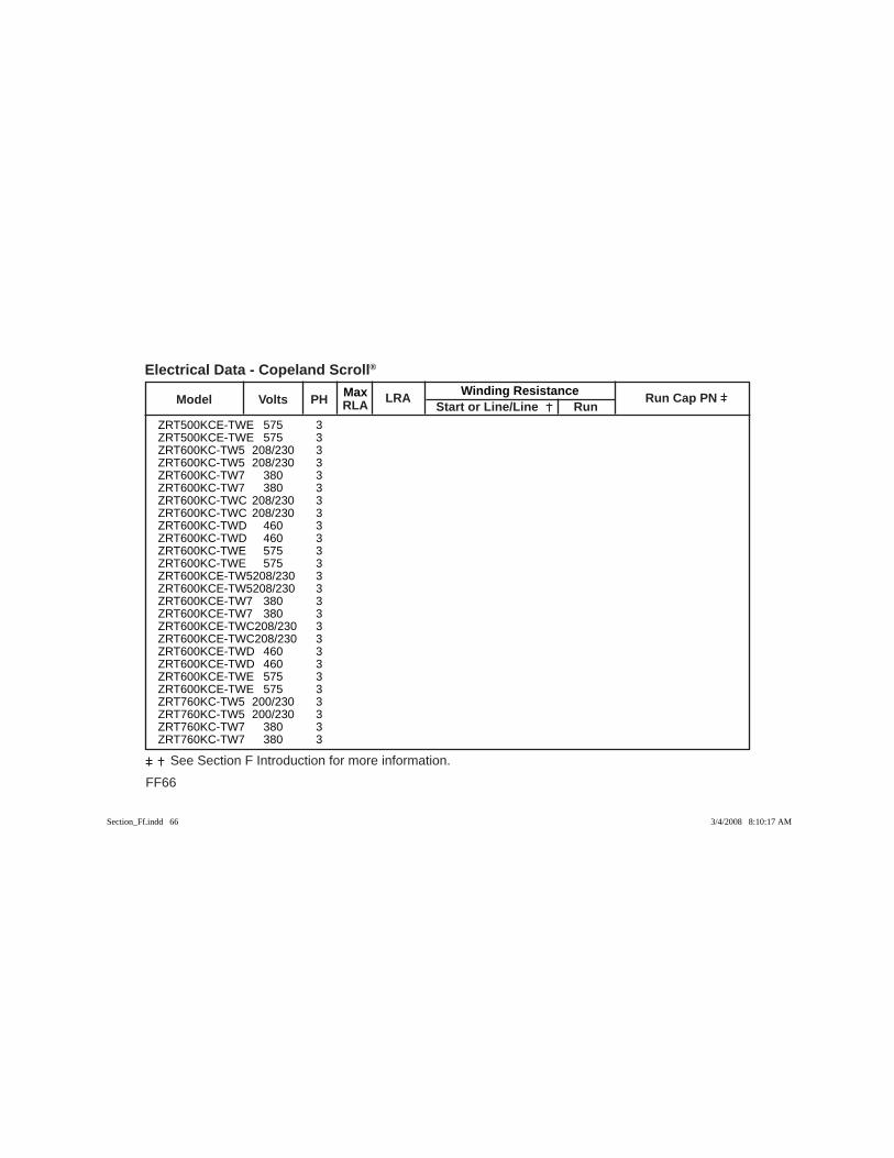
FF66
See Section F Introduction for more information.
Max Winding Resistance Model Volts PH RLA
LRA Start or Line/Line Run
Run Cap PN
Electrical Data - Copeland Scroll®
ZRT500KCE-TWE 575 3 ZRT500KCE-TWE 575 3 ZRT600KC-TW5 208/230 3 ZRT600KC-TW5 208/230 3 ZRT600KC-TW7 380 3 ZRT600KC-TW7 380 3 ZRT600KC-TWC 208/230 3 ZRT600KC-TWC 208/230 3 ZRT600KC-TWD 460 3 ZRT600KC-TWD 460 3 ZRT600KC-TWE 575 3 ZRT600KC-TWE 575 3 ZRT600KCE-TW5 208/230 3 ZRT600KCE-TW5 208/230 3 ZRT600KCE-TW7 380 3 ZRT600KCE-TW7 380 3 ZRT600KCE-TWC 208/230 3 ZRT600KCE-TWC 208/230 3 ZRT600KCE-TWD 460 3 ZRT600KCE-TWD 460 3 ZRT600KCE-TWE 575 3 ZRT600KCE-TWE 575 3 ZRT760KC-TW5 200/230 3 ZRT760KC-TW5 200/230 3 ZRT760KC-TW7 380 3 ZRT760KC-TW7 380 3
Section_Ff.indd 66Section_Ff.indd 66 3/4/2008 8:10:17 AM3/4/2008 8:10:17 AM

Max Winding Resistance Model Volts PH RLA
LRA Start or Line/Line Run
Run Cap PN
FF67
See Section F Introduction for more information.
Electrical Data - Copeland Scroll®
ZRT760KC-TWC 208/230 3 ZRT760KC-TWC 208/230 3 ZRT760KC-TWD 460 3 ZRT760KC-TWD 460 3 ZRT760KC-TWE 575 3 ZRT760KC-TWE 575 3 ZRT760KCE-TW5 200/230 3 ZRT760KCE-TW5 200/230 3 ZRT760KCE-TW7 380 3 ZRT760KCE-TW7 380 3 ZRT760KCE-TWC 208/230 3 ZRT760KCE-TWC 208/230 3 ZRT760KCE-TWD 460 3 ZRT760KCE-TWD 460 3 ZRT760KCE-TWE 575 3 ZRT760KCE-TWE 575 3 ZRT90K3-PFV 208/230 1 ZRT90K3-PFV 208/230 1 ZRT90K3-TF5 200/230 3 ZRT90K3-TF5 200/230 3 ZRT90K3-TFD 460 3 ZRT90K3-TFD 460 3 ZRT90K3E-PFV 208/230 1 ZRT90KC-PFV 208/230 1 ZRT90KC-PFV 208/230 1 ZRT90KC-TF5 200/230 3
Section_Ff.indd 67Section_Ff.indd 67 3/4/2008 8:10:17 AM3/4/2008 8:10:17 AM

FF68
See Section F Introduction for more information.
Max Winding Resistance Model Volts PH RLA
LRA Start or Line/Line Run
Run Cap PN
Electrical Data - Copeland Scroll®
ZRT90KC-TF5 200/230 3 ZRT90KC-TFD 460 3 ZRT90KC-TFD 460 3 ZRT90KC-TFE 575 3 ZRT90KC-TFE 575 3 ZRT92K3-PFV 208/230 1 ZRT92K3-PFV 208/230 1 ZRT92K3-TF5 200/230 3 ZRT92K3-TF5 200/230 3 ZRT92K3-TFD 460 3 ZRT92K3-TFD 460 3 ZRT92K3-TFE 575 3 ZRT92K3-TFE 575 3 ZRT96K3-PFV 208/230 1 ZRT96K3-PFV 208/230 1 ZRT96K3-TF5 200/230 3 ZRT96K3-TF5 200/230 3 ZRT96K3-TFD 460 3 ZRT96K3-TFD 460 3 ZRT96K3-TFE 575 3 ZRT96K3E-PFV 208/230 1 ZRT96K3E-PFV 208/230 1 ZRT96K3E-TF5 200/230 3 ZRT96K3E-TF5 200/230 3 ZRT96K3E-TFD 460 3
Section_Ff.indd 68Section_Ff.indd 68 3/4/2008 8:10:17 AM3/4/2008 8:10:17 AM
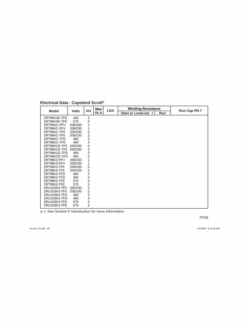
Max Winding Resistance Model Volts PH RLA
LRA Start or Line/Line Run
Run Cap PN
FF69
See Section F Introduction for more information.
Electrical Data - Copeland Scroll®
ZRT96K3E-TFD 460 3 ZRT96K3E-TFE 575 3 ZRT96KC-PFV 208/230 1 ZRT96KC-PFV 208/230 1 ZRT96KC-TF5 200/230 3 ZRT96KC-TF5 200/230 3 ZRT96KC-TFD 460 3 ZRT96KC-TFD 460 3 ZRT96KCE-TF5 200/230 3 ZRT96KCE-TF5 200/230 3 ZRT96KCE-TFD 460 3 ZRT96KCE-TFD 460 3 ZRT98K3-PFV 208/230 1 ZRT98K3-PFV 208/230 1 ZRT98K3-TF5 200/230 3 ZRT98K3-TF5 200/230 3 ZRT98K3-TFD 460 3 ZRT98K3-TFD 460 3 ZRT98K3-TFE 575 3 ZRT98K3-TFE 575 3 ZRU103K3-TF5 200/230 3 ZRU103K3-TF5 200/230 3 ZRU103K3-TFD 460 3 ZRU103K3-TFD 460 3 ZRU103K3-TFE 575 3 ZRU103K3-TFE 575 3
Section_Ff.indd 69Section_Ff.indd 69 3/4/2008 8:10:18 AM3/4/2008 8:10:18 AM

FF70
See Section F Introduction for more information.
Max Winding Resistance Model Volts PH RLA
LRA Start or Line/Line Run
Run Cap PN
Electrical Data - Copeland Scroll®
ZRU140KC-TF5 200/230 3 ZRU140KC-TF5 200/230 3 ZRU140KC-TF7 380 3 ZRU140KC-TF7 380 3 ZRU140KC-TFD 460 3 ZRU140KC-TFD 460 3 ZRU140KC-TFE 575 3 ZRU140KC-TFE 575 3 ZRU178KC-TF5 200/230 3 ZRU178KC-TF5 200/230 3 ZRU178KC-TF7 380 3 ZRU178KC-TF7 380 3 ZRU178KC-TFD 460 3 ZRU178KC-TFD 460 3 ZRU178KC-TFE 575 3 ZRU178KC-TFE 575 3 ZRU280K3-TW5 200/230 3 ZRU280K3-TW7 380 3 ZRU280K3-TWC 208/230 3 ZRU280K3-TWD 460 3 ZRU280K3-TWE 575 3 ZRU280K3E-TWC 208/230 3 ZRU280K3E-TWD 460 3 ZRU280K3E-TWE 575 3 ZRU285KC-TFD 460 3 ZRU285KC-TX5 200/230 3
Section_Ff.indd 70Section_Ff.indd 70 3/4/2008 8:10:18 AM3/4/2008 8:10:18 AM
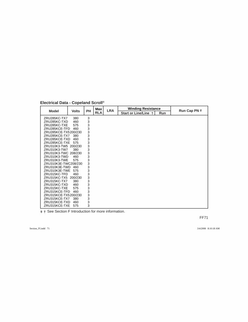
Max Winding Resistance Model Volts PH RLA
LRA Start or Line/Line Run
Run Cap PN
FF71
See Section F Introduction for more information.
Electrical Data - Copeland Scroll®
ZRU285KC-TX7 380 3 ZRU285KC-TXD 460 3 ZRU285KC-TXE 575 3 ZRU285KCE-TFD 460 3 ZRU285KCE-TX5 200/230 3 ZRU285KCE-TX7 380 3 ZRU285KCE-TXD 460 3 ZRU285KCE-TXE 575 3 ZRU310K3-TW5 200/230 3 ZRU310K3-TW7 380 3 ZRU310K3-TWC 208/230 3 ZRU310K3-TWD 460 3 ZRU310K3-TWE 575 3 ZRU310K3E-TWC 208/230 3 ZRU310K3E-TWD 460 3 ZRU310K3E-TWE 575 3 ZRU315KC-TFD 460 3 ZRU315KC-TX5 200/230 3 ZRU315KC-TX7 380 3 ZRU315KC-TXD 460 3 ZRU315KC-TXE 575 3 ZRU315KCE-TFD 460 3 ZRU315KCE-TX5 200/230 3 ZRU315KCE-TX7 380 3 ZRU315KCE-TXD 460 3 ZRU315KCE-TXE 575 3
Section_Ff.indd 71Section_Ff.indd 71 3/4/2008 8:10:18 AM3/4/2008 8:10:18 AM
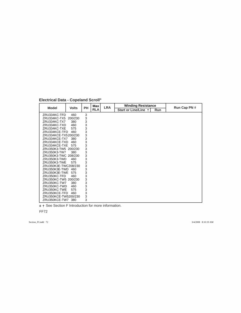
FF72
See Section F Introduction for more information.
Max Winding Resistance Model Volts PH RLA
LRA Start or Line/Line Run
Run Cap PN
Electrical Data - Copeland Scroll®
ZRU334KC-TFD 460 3 ZRU334KC-TX5 200/230 3 ZRU334KC-TX7 380 3 ZRU334KC-TXD 460 3 ZRU334KC-TXE 575 3 ZRU334KCE-TFD 460 3 ZRU334KCE-TX5 200/230 3 ZRU334KCE-TX7 380 3 ZRU334KCE-TXD 460 3 ZRU334KCE-TXE 575 3 ZRU350K3-TW5 200/230 3 ZRU350K3-TW7 380 3 ZRU350K3-TWC 208/230 3 ZRU350K3-TWD 460 3 ZRU350K3-TWE 575 3 ZRU350K3E-TWC 208/230 3 ZRU350K3E-TWD 460 3 ZRU350K3E-TWE 575 3 ZRU350KC-TFD 460 3 ZRU350KC-TW5 200/230 3 ZRU350KC-TW7 380 3 ZRU350KC-TWD 460 3 ZRU350KC-TWE 575 3 ZRU350KCE-TFD 460 3 ZRU350KCE-TW5 200/230 3 ZRU350KCE-TW7 380 3
Section_Ff.indd 72Section_Ff.indd 72 3/4/2008 8:10:19 AM3/4/2008 8:10:19 AM
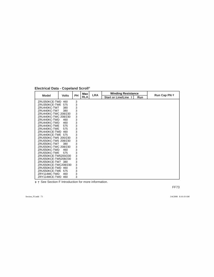
Max Winding Resistance Model Volts PH RLA
LRA Start or Line/Line Run
Run Cap PN
FF73
See Section F Introduction for more information.
Electrical Data - Copeland Scroll®
ZRU350KCE-TWD 460 3 ZRU350KCE-TWE 575 3 ZRU440KC-TW7 380 3 ZRU440KC-TW7 380 3 ZRU440KC-TWC 208/230 3 ZRU440KC-TWC 208/230 3 ZRU440KC-TWD 460 3 ZRU440KC-TWD 460 3 ZRU440KC-TWE 575 3 ZRU440KC-TWE 575 3 ZRU440KCE-TWD 460 3 ZRU440KCE-TWE 575 3 ZRU550KC-TW5 200/230 3 ZRU550KC-TW5 208/230 3 ZRU550KC-TW7 380 3 ZRU550KC-TWC 208/230 3 ZRU550KC-TWD 460 3 ZRU550KC-TWE 575 3 ZRU550KCE-TW5 200/230 3 ZRU550KCE-TW5 208/230 3 ZRU550KCE-TW7 380 3 ZRU550KCE-TWC 208/230 3 ZRU550KCE-TWD 460 3 ZRU550KCE-TWE 575 3 ZRY114MC-TWD 460 3 ZRY114MCE-TWD 460 3
Section_Ff.indd 73Section_Ff.indd 73 3/4/2008 8:10:19 AM3/4/2008 8:10:19 AM

FF74
See Section F Introduction for more information.
Max Winding Resistance Model Volts PH RLA
LRA Start or Line/Line Run
Run Cap PN
Electrical Data - Copeland Scroll®
ZRY324KC-TF5 200/230 3 ZRY324KC-TF7 380 3 ZRY324KC-TFD 460 3 ZRY324KC-TFE 575 3 ZRY324KCE-TF5 200/230 3 ZRY324KCE-TF7 380 3 ZRY324KCE-TFD 460 3 ZRY324KCE-TFE 575 3 ZRY375KC-TF5 200/230 3 ZRY375KC-TF7 380 3 ZRY375KC-TFD 460 3 ZRY375KC-TFE 575 3 ZRY375KCE-TF5 200/230 3 ZRY375KCE-TF7 380 3 ZRY375KCE-TFD 460 3 ZRY375KCE-TFE 575 3 ZRY432KC-TF5 200/230 3 ZRY432KC-TF7 380 3 ZRY432KC-TFD 460 3 ZRY432KC-TFE 575 3 ZRY432KCE-TF5 200/230 3 ZRY432KCE-TF7 380 3 ZRY432KCE-TFD 460 3 ZRY432KCE-TFE 575 3 ZRY480K3-TW5 200/230 3 ZRY480K3-TW7 380 3
Section_Ff.indd 74Section_Ff.indd 74 3/4/2008 8:10:19 AM3/4/2008 8:10:19 AM
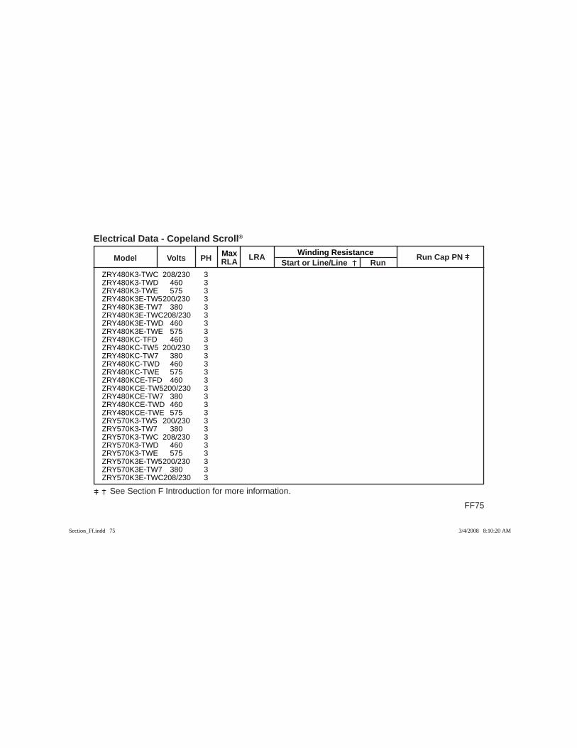
Max Winding Resistance Model Volts PH RLA
LRA Start or Line/Line Run
Run Cap PN
FF75
See Section F Introduction for more information.
Electrical Data - Copeland Scroll®
ZRY480K3-TWC 208/230 3 ZRY480K3-TWD 460 3 ZRY480K3-TWE 575 3 ZRY480K3E-TW5 200/230 3 ZRY480K3E-TW7 380 3 ZRY480K3E-TWC 208/230 3 ZRY480K3E-TWD 460 3 ZRY480K3E-TWE 575 3 ZRY480KC-TFD 460 3 ZRY480KC-TW5 200/230 3 ZRY480KC-TW7 380 3 ZRY480KC-TWD 460 3 ZRY480KC-TWE 575 3 ZRY480KCE-TFD 460 3 ZRY480KCE-TW5 200/230 3 ZRY480KCE-TW7 380 3 ZRY480KCE-TWD 460 3 ZRY480KCE-TWE 575 3 ZRY570K3-TW5 200/230 3 ZRY570K3-TW7 380 3 ZRY570K3-TWC 208/230 3 ZRY570K3-TWD 460 3 ZRY570K3-TWE 575 3 ZRY570K3E-TW5 200/230 3 ZRY570K3E-TW7 380 3 ZRY570K3E-TWC 208/230 3
Section_Ff.indd 75Section_Ff.indd 75 3/4/2008 8:10:20 AM3/4/2008 8:10:20 AM

FF76
See Section F Introduction for more information.
Max Winding Resistance Model Volts PH RLA
LRA Start or Line/Line Run
Run Cap PN
Electrical Data - Copeland Scroll®
ZRY570K3E-TWD 460 3 ZRY570KC-TFD 460 3 ZRY570KC-TW5 200/230 3 ZRY570KC-TW7 380 3 ZRY570KC-TWD 460 3 ZRY570KC-TWE 575 3 ZRY570KCE-TFD 460 3 ZRY570KCE-TW5 200/230 3 ZRY570KCE-TW7 380 3 ZRY570KCE-TWD 460 3 ZRY570KCE-TWE 575 3 ZRY750KC-TW5 200/230 3 ZRY750KC-TW7 380 3 ZRY750KC-TWC 208/230 3 ZRY750KC-TWD 460 3 ZRY750KC-TWE 575 3 ZRY750KCE-TW5 200/230 3 ZRY750KCE-TW7 380 3 ZRY750KCE-TWC 208/230 3 ZRY750KCE-TWD 460 3 ZRY750KCE-TWE 575 3 ZRY900KC-TW5 208/230 3 ZRY900KC-TW7 380 3 ZRY900KC-TWC 208/230 3 ZRY900KC-TWD 460 3 ZRY900KC-TWE 575 3
Section_Ff.indd 76Section_Ff.indd 76 3/4/2008 8:10:20 AM3/4/2008 8:10:20 AM
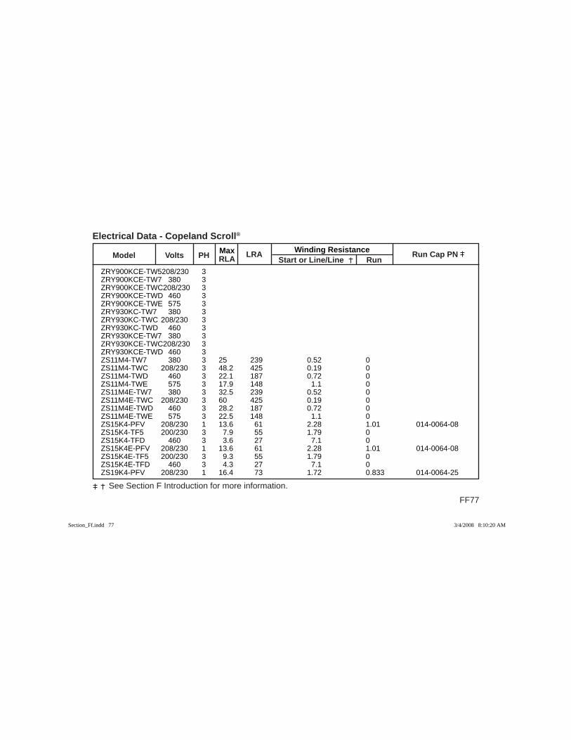
Max Winding Resistance Model Volts PH RLA
LRA Start or Line/Line Run
Run Cap PN
FF77
See Section F Introduction for more information.
Electrical Data - Copeland Scroll®
ZRY900KCE-TW5 208/230 3 ZRY900KCE-TW7 380 3 ZRY900KCE-TWC 208/230 3 ZRY900KCE-TWD 460 3 ZRY900KCE-TWE 575 3 ZRY930KC-TW7 380 3 ZRY930KC-TWC 208/230 3 ZRY930KC-TWD 460 3 ZRY930KCE-TW7 380 3 ZRY930KCE-TWC 208/230 3 ZRY930KCE-TWD 460 3 ZS11M4-TW7 380 3 25 239 0.52 0 ZS11M4-TWC 208/230 3 48.2 425 0.19 0 ZS11M4-TWD 460 3 22.1 187 0.72 0 ZS11M4-TWE 575 3 17.9 148 1.1 0 ZS11M4E-TW7 380 3 32.5 239 0.52 0 ZS11M4E-TWC 208/230 3 60 425 0.19 0 ZS11M4E-TWD 460 3 28.2 187 0.72 0 ZS11M4E-TWE 575 3 22.5 148 1.1 0 ZS15K4-PFV 208/230 1 13.6 61 2.28 1.01 014-0064-08 ZS15K4-TF5 200/230 3 7.9 55 1.79 0 ZS15K4-TFD 460 3 3.6 27 7.1 0 ZS15K4E-PFV 208/230 1 13.6 61 2.28 1.01 014-0064-08 ZS15K4E-TF5 200/230 3 9.3 55 1.79 0 ZS15K4E-TFD 460 3 4.3 27 7.1 0 ZS19K4-PFV 208/230 1 16.4 73 1.72 0.833 014-0064-25
Section_Ff.indd 77Section_Ff.indd 77 3/4/2008 8:10:20 AM3/4/2008 8:10:20 AM

FF78
See Section F Introduction for more information.
Max Winding Resistance Model Volts PH RLA
LRA Start or Line/Line Run
Run Cap PN
Electrical Data - Copeland Scroll®
ZS19K4-TF5 200/230 3 7.9 63 1.46 0 ZS19K4-TFD 460 3 3.9 31 5.94 0 ZS19K4E-PFV 208/230 1 16.4 73 1.72 0.833 014-0064-25 ZS19K4E-TF5 200/230 3 9.6 63 1.46 0 ZS19K4E-TFD 460 3 5 31 5.94 0 ZS21K4-PFV 208/230 1 17.9 88 1.46 0.691 014-0064-29 ZS21K4-TF5 200/230 3 10 77 1.234 0 ZS21K4-TFD 460 3 5 39 4.83 0 ZS21K4E-PFV 208/230 1 16.4 88 1.46 0.691 014-0064-29 ZS21K4E-TF5 200/230 3 11.1 77 1.234 0 ZS21K4E-TFD 460 3 5.7 39 4.83 0 ZS21K4E-TFE 575 3 4.3 31 7.89 0 ZS26K4-PFV 208/230 1 20.7 109 1.28 0.54 014-0064-26 ZS26K4-TF5 200/230 3 12.5 88 0.995 0 ZS26K4-TFD 460 3 6.4 44 1.85 0 ZS26K4E-PFV 208/230 1 20.7 109 1.28 0.54 014-0064-26 ZS26K4E-TF5 200/230 3 13.6 88 0.995 0 ZS26K4E-TFD 460 3 7.1 44 1.85 0 ZS26K4E-TFE 575 3 5 34 6.28 0 ZS30K4-PFV 208/230 1 26.4 129 0.779 0.432 014-0064-26 ZS30K4-TF5 200/230 3 15 99 0.911 0 ZS30K4-TFD 460 3 6.8 49.5 3.64 0 ZS30K4E-PFV 208/230 1 26.8 129 0.779 0.432 014-0064-26 ZS30K4E-TF5 200/230 3 15 99 0.911 0 ZS30K4E-TF7 380 3 8.2 57 2.78 0 ZS30K4E-TFD 460 3 8.2 49.5 3.64 0
Section_Ff.indd 78Section_Ff.indd 78 3/4/2008 8:10:21 AM3/4/2008 8:10:21 AM
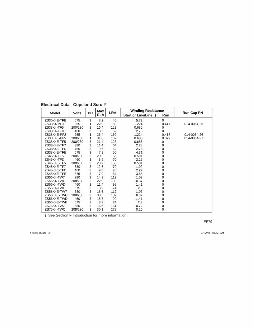
Max Winding Resistance Model Volts PH RLA
LRA Start or Line/Line Run
Run Cap PN
FF79
See Section F Introduction for more information.
Electrical Data - Copeland Scroll®
ZS30K4E-TFE 575 3 8.2 40 5.72 0 ZS38K4-PFJ 265 1 22.9 160 1.224 0.417 014-0064-26 ZS38K4-TF5 200/230 3 16.4 123 0.686 0 ZS38K4-TFD 460 3 8.6 62 2.75 0 ZS38K4E-PFJ 265 1 26.4 160 1.224 0.417 014-0064-26 ZS38K4E-PFV 208/230 1 31.8 169 0.605 0.329 014-0064-27 ZS38K4E-TF5 200/230 3 21.4 123 0.686 0 ZS38K4E-TF7 380 3 11.4 64 2.28 0 ZS38K4E-TFD 460 3 9.6 62 2.75 0 ZS38K4E-TFE 575 3 7.9 50 4.31 0 ZS45K4-TF5 200/230 3 20 156 0.501 0 ZS45K4-TFD 460 3 8.9 70 2.27 0 ZS45K4E-TF5 200/230 3 23.9 156 0.501 0 ZS45K4E-TF7 380 3 12.6 70 1.92 0 ZS45K4E-TFD 460 3 9.3 70 2.27 0 ZS45K4E-TFE 575 3 7.9 54 3.56 0 ZS56K4-TW7 380 3 14.3 112 1.03 0 ZS56K4-TWC 208/230 3 22.9 189 0.37 0 ZS56K4-TWD 460 3 11.4 99 1.41 0 ZS56K4-TWE 575 3 8.9 74 2.3 0 ZS56K4E-TW7 380 3 18.6 112 1.03 0 ZS56K4E-TWC 208/230 3 30 189 0.37 0 ZS56K4E-TWD 460 3 15.7 99 1.41 0 ZS56K4E-TWE 575 3 8.9 74 2.3 0 ZS75K4-TW7 380 3 16.6 151 0.72 0 ZS75K4-TWC 208/230 3 30.1 278 0.26 0
Section_Ff.indd 79Section_Ff.indd 79 3/4/2008 8:10:21 AM3/4/2008 8:10:21 AM
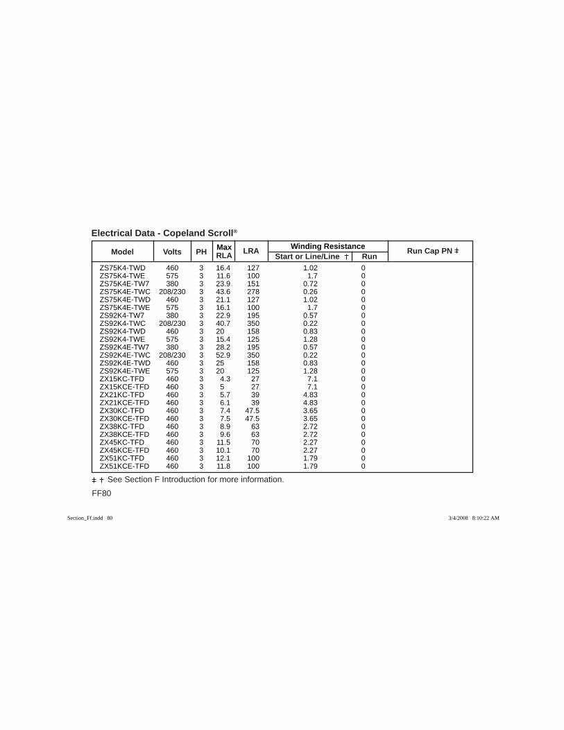
FF80
See Section F Introduction for more information.
Max Winding Resistance Model Volts PH RLA
LRA Start or Line/Line Run
Run Cap PN
Electrical Data - Copeland Scroll®
ZS75K4-TWD 460 3 16.4 127 1.02 0 ZS75K4-TWE 575 3 11.6 100 1.7 0 ZS75K4E-TW7 380 3 23.9 151 0.72 0 ZS75K4E-TWC 208/230 3 43.6 278 0.26 0 ZS75K4E-TWD 460 3 21.1 127 1.02 0 ZS75K4E-TWE 575 3 16.1 100 1.7 0 ZS92K4-TW7 380 3 22.9 195 0.57 0 ZS92K4-TWC 208/230 3 40.7 350 0.22 0 ZS92K4-TWD 460 3 20 158 0.83 0 ZS92K4-TWE 575 3 15.4 125 1.28 0 ZS92K4E-TW7 380 3 28.2 195 0.57 0 ZS92K4E-TWC 208/230 3 52.9 350 0.22 0 ZS92K4E-TWD 460 3 25 158 0.83 0 ZS92K4E-TWE 575 3 20 125 1.28 0 ZX15KC-TFD 460 3 4.3 27 7.1 0 ZX15KCE-TFD 460 3 5 27 7.1 0 ZX21KC-TFD 460 3 5.7 39 4.83 0 ZX21KCE-TFD 460 3 6.1 39 4.83 0 ZX30KC-TFD 460 3 7.4 47.5 3.65 0 ZX30KCE-TFD 460 3 7.5 47.5 3.65 0 ZX38KC-TFD 460 3 8.9 63 2.72 0 ZX38KCE-TFD 460 3 9.6 63 2.72 0 ZX45KC-TFD 460 3 11.5 70 2.27 0 ZX45KCE-TFD 460 3 10.1 70 2.27 0 ZX51KC-TFD 460 3 12.1 100 1.79 0 ZX51KCE-TFD 460 3 11.8 100 1.79 0
Section_Ff.indd 80Section_Ff.indd 80 3/4/2008 8:10:22 AM3/4/2008 8:10:22 AM
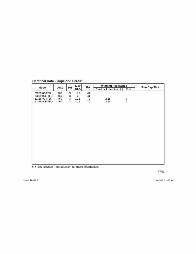
Max Winding Resistance Model Volts PH RLA
LRA Start or Line/Line Run
Run Cap PN
FF81
See Section F Introduction for more information.
Electrical Data - Copeland Scroll®
ZXI09KC-TFD 460 3 5.7 41 ZXI09KCE-TFD 460 3 6 41 ZXI18KC-TFD 460 3 11.1 70 2.26 0 ZXI18KCE-TFD 460 3 11.1 70 2.26 0
Section_Ff.indd 81Section_Ff.indd 81 3/4/2008 8:10:22 AM3/4/2008 8:10:22 AM
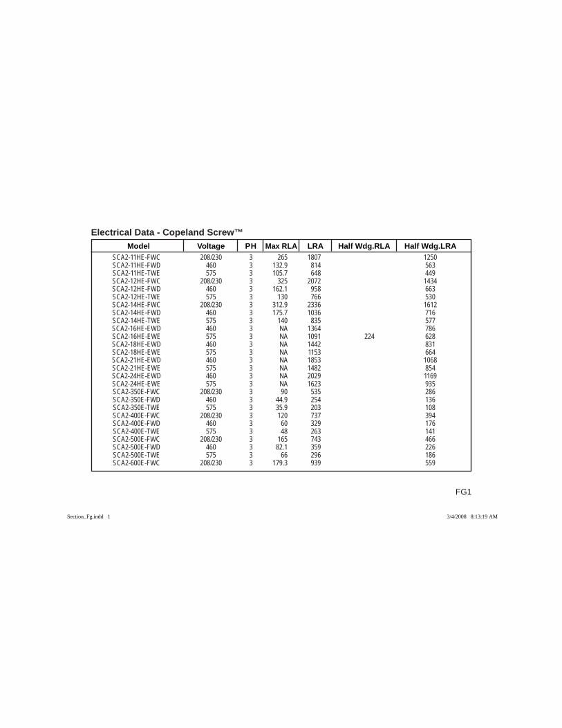
Electrical Data - Copeland Screw™
FG1
Model Voltage PH Max RLA LRA Half Wdg.RLA Half Wdg.LRA SCA2-11HE-FWC 208/230 3 265 1807 1250 SCA2-11HE-FWD 460 3 132.9 814 563 SCA2-11HE-TWE 575 3 105.7 648 449 SCA2-12HE-FWC 208/230 3 325 2072 1434 SCA2-12HE-FWD 460 3 162.1 958 663 SCA2-12HE-TWE 575 3 130 766 530 SCA2-14HE-FWC 208/230 3 312.9 2336 1612 SCA2-14HE-FWD 460 3 175.7 1036 716 SCA2-14HE-TWE 575 3 140 835 577 SCA2-16HE-EWD 460 3 NA 1364 786 SCA2-16HE-EWE 575 3 NA 1091 224 628 SCA2-18HE-EWD 460 3 NA 1442 831 SCA2-18HE-EWE 575 3 NA 1153 664 SCA2-21HE-EWD 460 3 NA 1853 1068 SCA2-21HE-EWE 575 3 NA 1482 854 SCA2-24HE-EWD 460 3 NA 2029 1169 SCA2-24HE-EWE 575 3 NA 1623 935 SCA2-350E-FWC 208/230 3 90 535 286 SCA2-350E-FWD 460 3 44.9 254 136 SCA2-350E-TWE 575 3 35.9 203 108 SCA2-400E-FWC 208/230 3 120 737 394 SCA2-400E-FWD 460 3 60 329 176 SCA2-400E-TWE 575 3 48 263 141 SCA2-500E-FWC 208/230 3 165 743 466 SCA2-500E-FWD 460 3 82.1 359 226 SCA2-500E-TWE 575 3 66 296 186 SCA2-600E-FWC 208/230 3 179.3 939 559
Section_Fg.indd 1Section_Fg.indd 1 3/4/2008 8:13:19 AM3/4/2008 8:13:19 AM
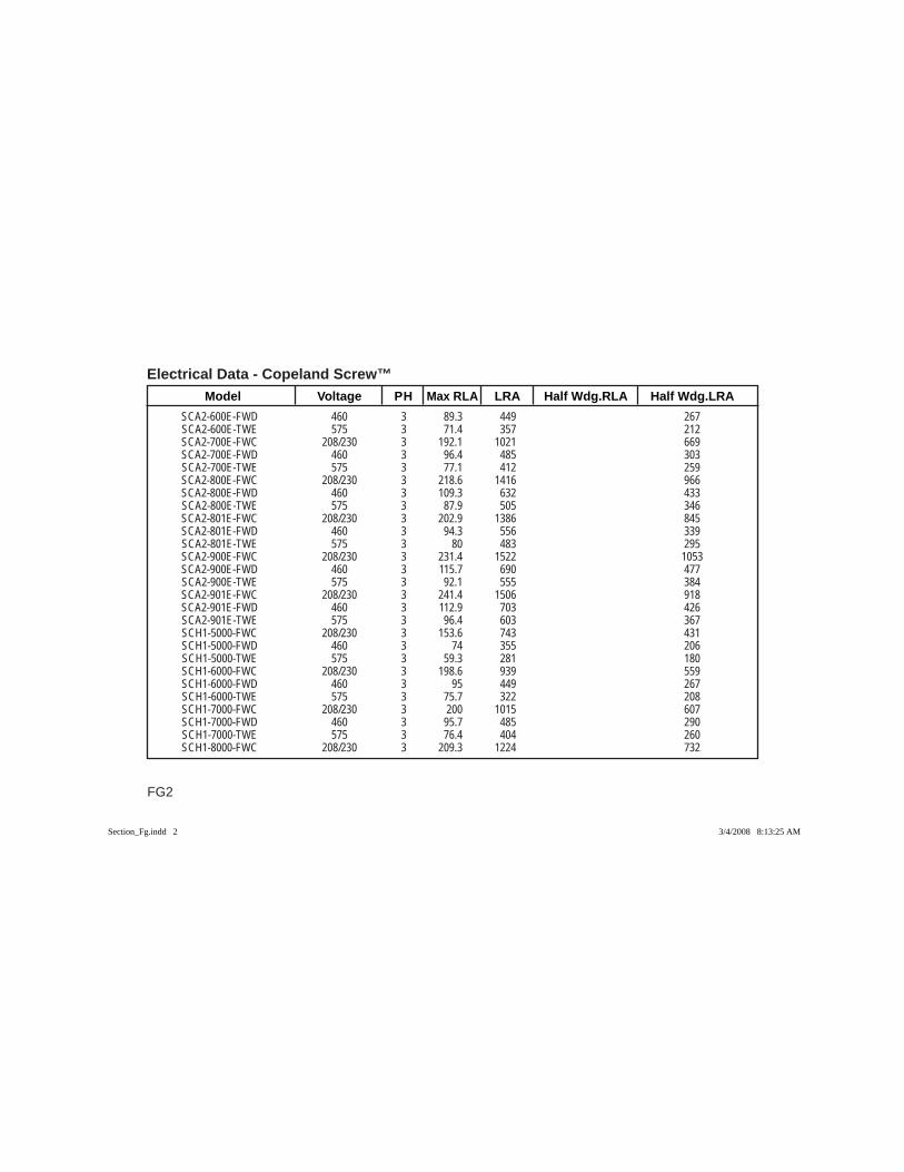
Electrical Data - Copeland Screw™ Model Voltage PH Max RLA LRA Half Wdg.RLA Half Wdg.LRA
FG2
SCA2-600E-FWD 460 3 89.3 449 267 SCA2-600E-TWE 575 3 71.4 357 212 SCA2-700E-FWC 208/230 3 192.1 1021 669 SCA2-700E-FWD 460 3 96.4 485 303 SCA2-700E-TWE 575 3 77.1 412 259 SCA2-800E-FWC 208/230 3 218.6 1416 966 SCA2-800E-FWD 460 3 109.3 632 433 SCA2-800E-TWE 575 3 87.9 505 346 SCA2-801E-FWC 208/230 3 202.9 1386 845 SCA2-801E-FWD 460 3 94.3 556 339 SCA2-801E-TWE 575 3 80 483 295 SCA2-900E-FWC 208/230 3 231.4 1522 1053 SCA2-900E-FWD 460 3 115.7 690 477 SCA2-900E-TWE 575 3 92.1 555 384 SCA2-901E-FWC 208/230 3 241.4 1506 918 SCA2-901E-FWD 460 3 112.9 703 426 SCA2-901E-TWE 575 3 96.4 603 367 SCH1-5000-FWC 208/230 3 153.6 743 431 SCH1-5000-FWD 460 3 74 355 206 SCH1-5000-TWE 575 3 59.3 281 180 SCH1-6000-FWC 208/230 3 198.6 939 559 SCH1-6000-FWD 460 3 95 449 267 SCH1-6000-TWE 575 3 75.7 322 208 SCH1-7000-FWC 208/230 3 200 1015 607 SCH1-7000-FWD 460 3 95.7 485 290 SCH1-7000-TWE 575 3 76.4 404 260 SCH1-8000-FWC 208/230 3 209.3 1224 732
Section_Fg.indd 2Section_Fg.indd 2 3/4/2008 8:13:25 AM3/4/2008 8:13:25 AM
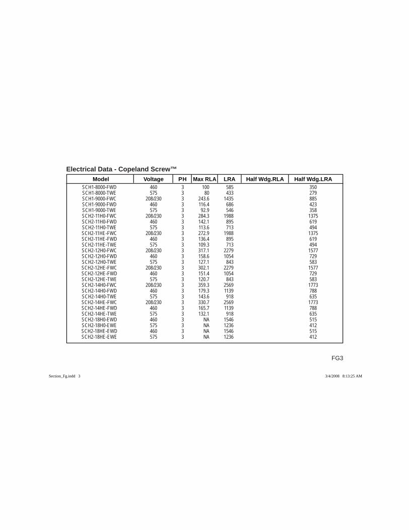
Electrical Data - Copeland Screw™
FG3
Model Voltage PH Max RLA LRA Half Wdg.RLA Half Wdg.LRA SCH1-8000-FWD 460 3 100 585 350 SCH1-8000-TWE 575 3 80 433 279 SCH1-9000-FWC 208/230 3 243.6 1435 885 SCH1-9000-FWD 460 3 116.4 686 423 SCH1-9000-TWE 575 3 92.9 546 358 SCH2-11H0-FWC 208/230 3 284.3 1988 1375 SCH2-11H0-FWD 460 3 142.1 895 619 SCH2-11H0-TWE 575 3 113.6 713 494 SCH2-11HE-FWC 208/230 3 272.9 1988 1375 SCH2-11HE-FWD 460 3 136.4 895 619 SCH2-11HE-TWE 575 3 109.3 713 494 SCH2-12H0-FWC 208/230 3 317.1 2279 1577 SCH2-12H0-FWD 460 3 158.6 1054 729 SCH2-12H0-TWE 575 3 127.1 843 583 SCH2-12HE-FWC 208/230 3 302.1 2279 1577 SCH2-12HE-FWD 460 3 151.4 1054 729 SCH2-12HE-TWE 575 3 120.7 843 583 SCH2-14H0-FWC 208/230 3 359.3 2569 1773 SCH2-14H0-FWD 460 3 179.3 1139 788 SCH2-14H0-TWE 575 3 143.6 918 635 SCH2-14HE-FWC 208/230 3 330.7 2569 1773 SCH2-14HE-FWD 460 3 165.7 1139 788 SCH2-14HE-TWE 575 3 132.1 918 635 SCH2-18H0-EWD 460 3 NA 1546 515 SCH2-18H0-EWE 575 3 NA 1236 412 SCH2-18HE-EWD 460 3 NA 1546 515 SCH2-18HE-EWE 575 3 NA 1236 412
Section_Fg.indd 3Section_Fg.indd 3 3/4/2008 8:13:25 AM3/4/2008 8:13:25 AM
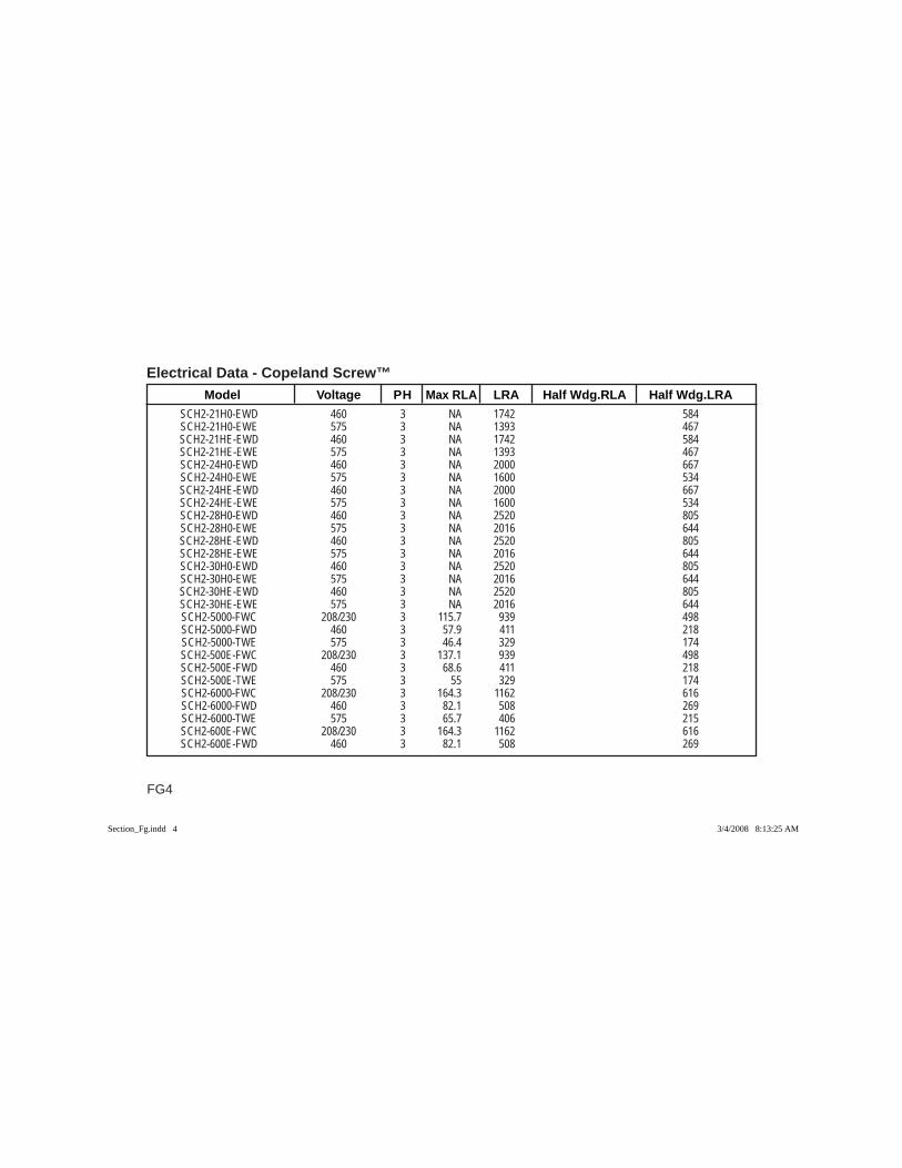
Electrical Data - Copeland Screw™ Model Voltage PH Max RLA LRA Half Wdg.RLA Half Wdg.LRA
FG4
SCH2-21H0-EWD 460 3 NA 1742 584 SCH2-21H0-EWE 575 3 NA 1393 467 SCH2-21HE-EWD 460 3 NA 1742 584 SCH2-21HE-EWE 575 3 NA 1393 467 SCH2-24H0-EWD 460 3 NA 2000 667 SCH2-24H0-EWE 575 3 NA 1600 534 SCH2-24HE-EWD 460 3 NA 2000 667 SCH2-24HE-EWE 575 3 NA 1600 534 SCH2-28H0-EWD 460 3 NA 2520 805 SCH2-28H0-EWE 575 3 NA 2016 644 SCH2-28HE-EWD 460 3 NA 2520 805 SCH2-28HE-EWE 575 3 NA 2016 644 SCH2-30H0-EWD 460 3 NA 2520 805 SCH2-30H0-EWE 575 3 NA 2016 644 SCH2-30HE-EWD 460 3 NA 2520 805 SCH2-30HE-EWE 575 3 NA 2016 644 SCH2-5000-FWC 208/230 3 115.7 939 498 SCH2-5000-FWD 460 3 57.9 411 218 SCH2-5000-TWE 575 3 46.4 329 174 SCH2-500E-FWC 208/230 3 137.1 939 498 SCH2-500E-FWD 460 3 68.6 411 218 SCH2-500E-TWE 575 3 55 329 174 SCH2-6000-FWC 208/230 3 164.3 1162 616 SCH2-6000-FWD 460 3 82.1 508 269 SCH2-6000-TWE 575 3 65.7 406 215 SCH2-600E-FWC 208/230 3 164.3 1162 616 SCH2-600E-FWD 460 3 82.1 508 269
Section_Fg.indd 4Section_Fg.indd 4 3/4/2008 8:13:25 AM3/4/2008 8:13:25 AM
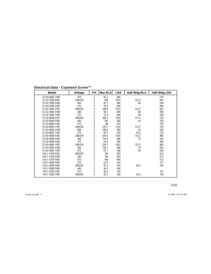
Electrical Data - Copeland Screw™
FG5
Model Voltage PH Max RLA LRA Half Wdg.RLA Half Wdg.LRA SCH2-600E-TWE 575 3 65.7 406 215 SCH2-7000-FWC 208/230 3 200 1015 125.5 607 SCH2-7000-FWD 460 3 95.7 485 60 290 SCH2-7000-TWE 575 3 76.4 404 260 SCH2-700E-FWC 208/230 3 188.6 1015 125.5 607 SCH2-700E-FWD 460 3 90.7 485 60 290 SCH2-700E-TWE 575 3 72.9 404 48 260 SCH2-8000-FWC 208/230 3 209.3 1224 131.5 732 SCH2-8000-FWD 460 3 100 585 63 350 SCH2-8000-TWE 575 3 80 433 279 SCH2-800E-FWC 208/230 3 225.7 1224 131.5 732 SCH2-800E-FWD 460 3 108.6 585 63 350 SCH2-800E-TWE 575 3 87.1 433 50.5 279 SCH2-9000-FWC 208/230 3 243.6 1435 152.5 885 SCH2-9000-FWD 460 3 116.4 686 73 423 SCH2-9000-TWE 575 3 92.9 546 358 SCH2-900E-FWC 208/230 3 250.7 1435 152.5 885 SCH2-900E-FWD 460 3 120.7 686 73 423 SCH2-900E-TWE 575 3 97.1 546 58 358 SHL1-12H0-FWC 208/230 3 NA 943 612 SHL1-12H0-FWD 460 3 NA 943 612 SHL1-12H0-TWE 575 3 NA 943 612 SHL1-2000-TWE 575 3 32.9 183 127 SHL1-2000-TWK 208/230 3 81.4 492 40.5 164 SHL1-2000-TWK 460 3 40.7 246 SHL1-2500-TWE 575 3 34.3 166 94 SHL1-2500-TWK 208/230 3 85.7 436 42.5 150
Section_Fg.indd 5Section_Fg.indd 5 3/4/2008 8:13:26 AM3/4/2008 8:13:26 AM
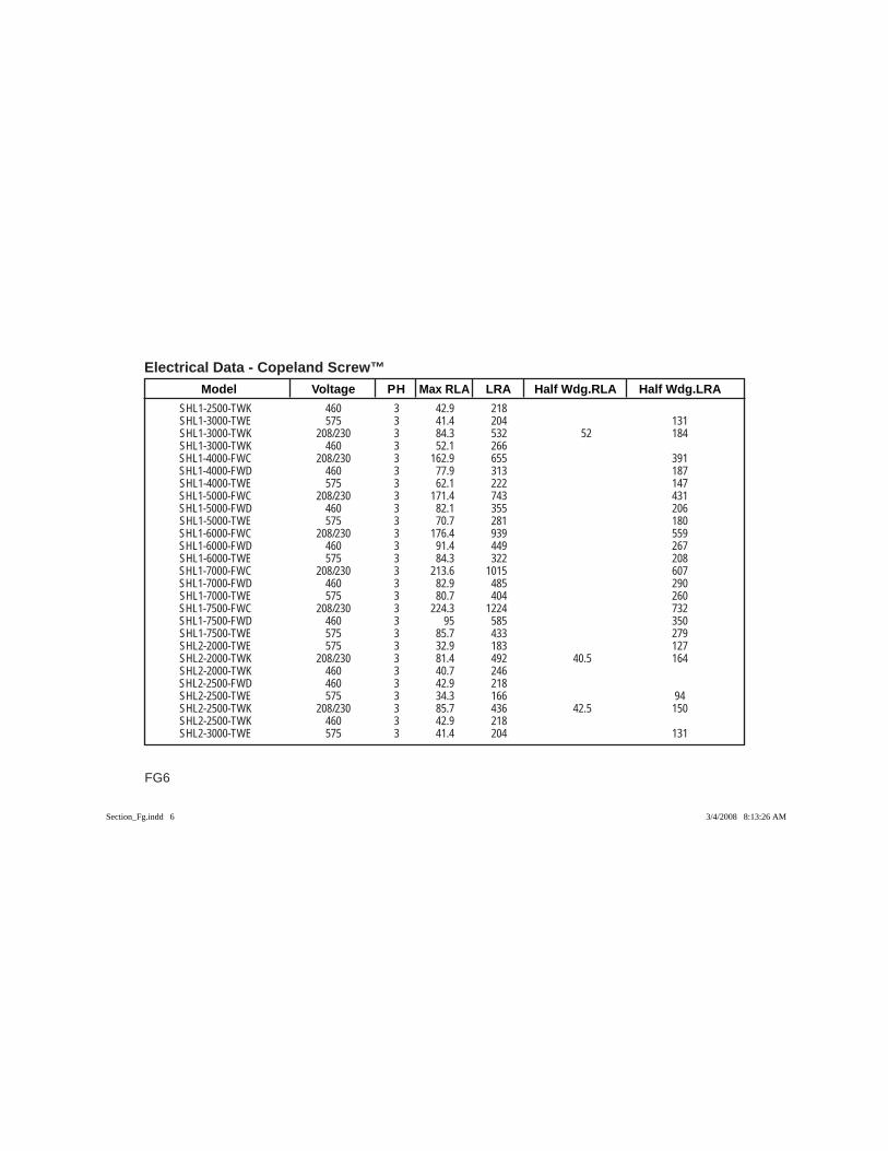
Electrical Data - Copeland Screw™ Model Voltage PH Max RLA LRA Half Wdg.RLA Half Wdg.LRA
FG6
SHL1-2500-TWK 460 3 42.9 218 SHL1-3000-TWE 575 3 41.4 204 131 SHL1-3000-TWK 208/230 3 84.3 532 52 184 SHL1-3000-TWK 460 3 52.1 266 SHL1-4000-FWC 208/230 3 162.9 655 391 SHL1-4000-FWD 460 3 77.9 313 187 SHL1-4000-TWE 575 3 62.1 222 147 SHL1-5000-FWC 208/230 3 171.4 743 431 SHL1-5000-FWD 460 3 82.1 355 206 SHL1-5000-TWE 575 3 70.7 281 180 SHL1-6000-FWC 208/230 3 176.4 939 559 SHL1-6000-FWD 460 3 91.4 449 267 SHL1-6000-TWE 575 3 84.3 322 208 SHL1-7000-FWC 208/230 3 213.6 1015 607 SHL1-7000-FWD 460 3 82.9 485 290 SHL1-7000-TWE 575 3 80.7 404 260 SHL1-7500-FWC 208/230 3 224.3 1224 732 SHL1-7500-FWD 460 3 95 585 350 SHL1-7500-TWE 575 3 85.7 433 279 SHL2-2000-TWE 575 3 32.9 183 127 SHL2-2000-TWK 208/230 3 81.4 492 40.5 164 SHL2-2000-TWK 460 3 40.7 246 SHL2-2500-FWD 460 3 42.9 218 SHL2-2500-TWE 575 3 34.3 166 94 SHL2-2500-TWK 208/230 3 85.7 436 42.5 150 SHL2-2500-TWK 460 3 42.9 218 SHL2-3000-TWE 575 3 41.4 204 131
Section_Fg.indd 6Section_Fg.indd 6 3/4/2008 8:13:26 AM3/4/2008 8:13:26 AM
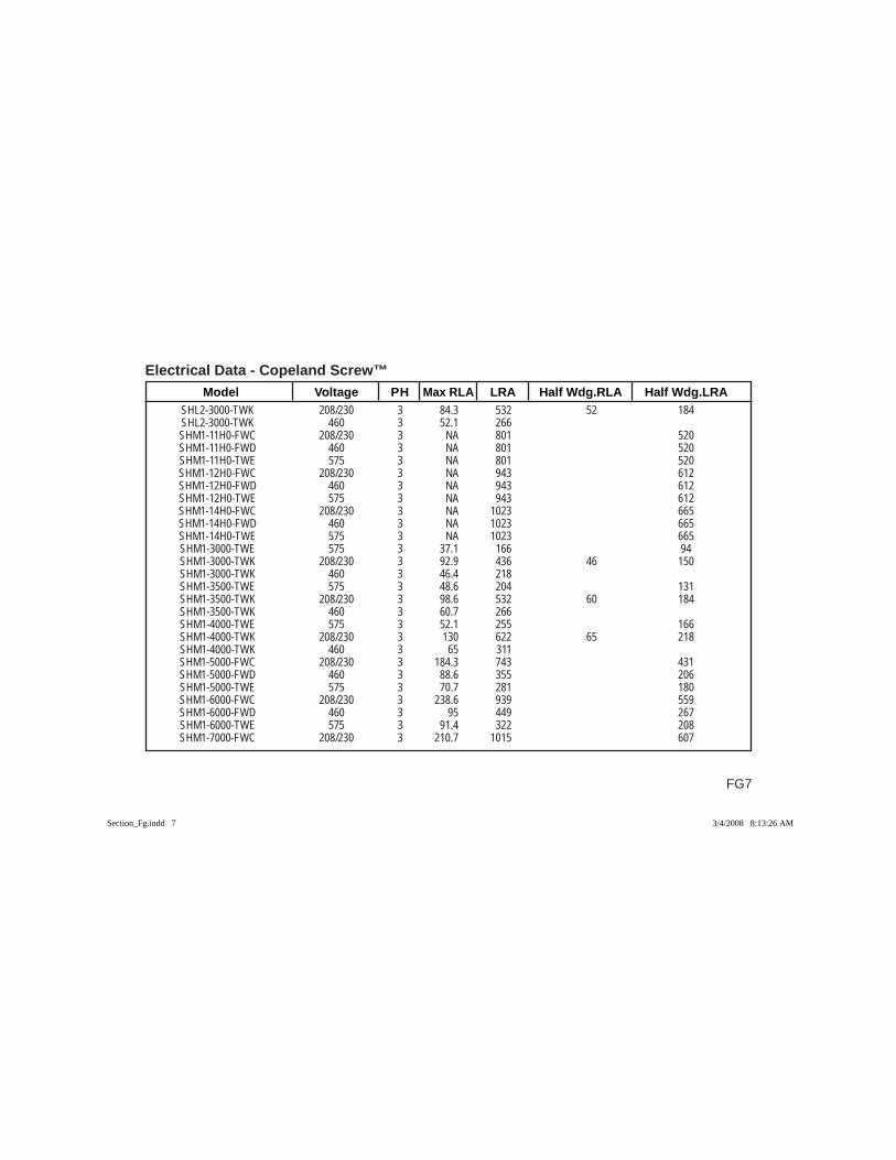
Electrical Data - Copeland Screw™
FG7
Model Voltage PH Max RLA LRA Half Wdg.RLA Half Wdg.LRA SHL2-3000-TWK 208/230 3 84.3 532 52 184 SHL2-3000-TWK 460 3 52.1 266 SHM1-11H0-FWC 208/230 3 NA 801 520 SHM1-11H0-FWD 460 3 NA 801 520 SHM1-11H0-TWE 575 3 NA 801 520 SHM1-12H0-FWC 208/230 3 NA 943 612 SHM1-12H0-FWD 460 3 NA 943 612 SHM1-12H0-TWE 575 3 NA 943 612 SHM1-14H0-FWC 208/230 3 NA 1023 665 SHM1-14H0-FWD 460 3 NA 1023 665 SHM1-14H0-TWE 575 3 NA 1023 665 SHM1-3000-TWE 575 3 37.1 166 94 SHM1-3000-TWK 208/230 3 92.9 436 46 150 SHM1-3000-TWK 460 3 46.4 218 SHM1-3500-TWE 575 3 48.6 204 131 SHM1-3500-TWK 208/230 3 98.6 532 60 184 SHM1-3500-TWK 460 3 60.7 266 SHM1-4000-TWE 575 3 52.1 255 166 SHM1-4000-TWK 208/230 3 130 622 65 218 SHM1-4000-TWK 460 3 65 311 SHM1-5000-FWC 208/230 3 184.3 743 431 SHM1-5000-FWD 460 3 88.6 355 206 SHM1-5000-TWE 575 3 70.7 281 180 SHM1-6000-FWC 208/230 3 238.6 939 559 SHM1-6000-FWD 460 3 95 449 267 SHM1-6000-TWE 575 3 91.4 322 208 SHM1-7000-FWC 208/230 3 210.7 1015 607
Section_Fg.indd 7Section_Fg.indd 7 3/4/2008 8:13:26 AM3/4/2008 8:13:26 AM
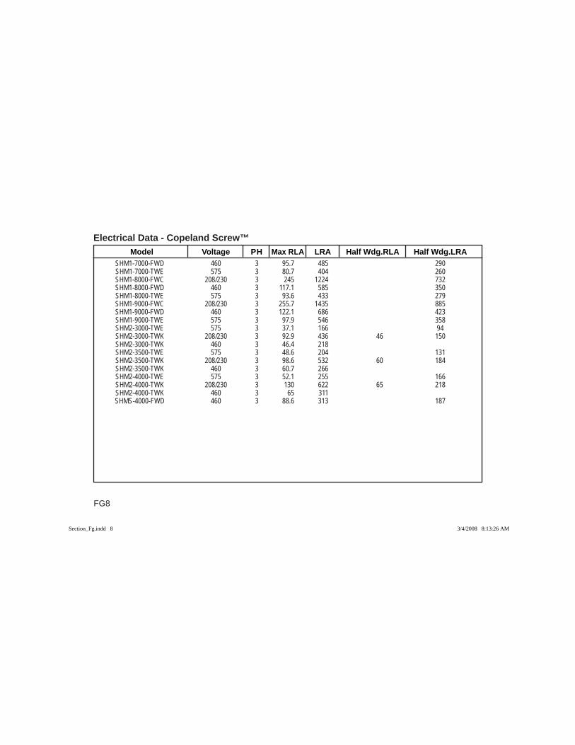
Electrical Data - Copeland Screw™ Model Voltage PH Max RLA LRA Half Wdg.RLA Half Wdg.LRA
FG8
SHM1-7000-FWD 460 3 95.7 485 290 SHM1-7000-TWE 575 3 80.7 404 260 SHM1-8000-FWC 208/230 3 245 1224 732 SHM1-8000-FWD 460 3 117.1 585 350 SHM1-8000-TWE 575 3 93.6 433 279 SHM1-9000-FWC 208/230 3 255.7 1435 885 SHM1-9000-FWD 460 3 122.1 686 423 SHM1-9000-TWE 575 3 97.9 546 358 SHM2-3000-TWE 575 3 37.1 166 94 SHM2-3000-TWK 208/230 3 92.9 436 46 150 SHM2-3000-TWK 460 3 46.4 218 SHM2-3500-TWE 575 3 48.6 204 131 SHM2-3500-TWK 208/230 3 98.6 532 60 184 SHM2-3500-TWK 460 3 60.7 266 SHM2-4000-TWE 575 3 52.1 255 166 SHM2-4000-TWK 208/230 3 130 622 65 218 SHM2-4000-TWK 460 3 65 311 SHMS-4000-FWD 460 3 88.6 313 187
Section_Fg.indd 8Section_Fg.indd 8 3/4/2008 8:13:26 AM3/4/2008 8:13:26 AM
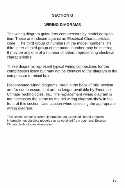
G1
SECTION G
WIRING DIAGRAMS
The wiring diagram guide lists compressors by model designa-tion. These are indexed against an Electrical Characteristics code. (The third group of numbers in the model number.) The third letter of third group of the model number may be missing. It may be any one of a number of letters representing electrical characteristics.
These diagrams represent typical wiring connections for the compressors listed but may not be identical to the diagram in the compressor terminal box.
Discontinued wiring diagrams listed in the back of this section are for compressors that are no longer available by Emerson Climate Technologies, Inc. The replacement wiring diagram is not necessary the same as the old wiring diagram show in the front of this section. Use caution when selecting the appropriate wiring diagram.
This section contains current information on Copeland® brand products. Information on obsolete models can be obtained from your local Emerson Climate Technologies wholesaler.
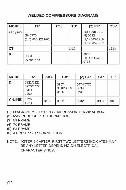
G2
WELDED COMPRESSORS DIAGRAMS
MODEL TF* ES8 TS* (2) PF* CSVCR , CS
(5) 0770 (1,5) 005-1211-01
(1,5) 005-1211 (5) 0782(1,3) 005-1210 (1,3) 005-1212
CT 1319 1318
R 0833 0778/0779
0865(1) 005-0670 0768
MODEL IA* SAA CA* (2) PA* CF* TF*R 0831/0832
0776/077707800769
07670818/0819 0820
0774/077508340781
A-LINE 09291223 0930 0932 0932 0931 0980
(1) DIAGRAM MOLDED IN COMPRESSOR TERMINAL BOX. (2) MAY REQUIRE PTC THERMISTOR (3) 59 FRAME(4) 70 FRAME(5) 63 FRAME(6) 4 PIN SENSOR CONNECTION
NOTE: ASTERISK AFTER FIRST TWO LETTERS INDICATES MAY BE ANY LETTER DEPENDING ON ELECTRICAL CHARACTERISTICS.
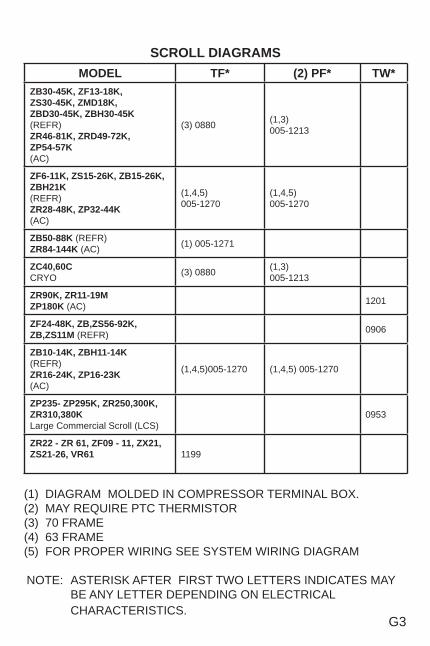
G3
SCROLL DIAGRAMSMODEL TF* (2) PF* TW*
ZB30-45K, ZF13-18K, ZS30-45K, ZMD18K, ZBD30-45K, ZBH30-45K(REFR)ZR46-81K, ZRD49-72K,ZP54-57K(AC)
(3) 0880 (1,3) 005-1213
ZF6-11K, ZS15-26K, ZB15-26K, ZBH21K(REFR)ZR28-48K, ZP32-44K(AC)
(1,4,5)005-1270
(1,4,5)005-1270
ZB50-88K (REFR)ZR84-144K (AC) (1) 005-1271
ZC40,60CCRYO (3) 0880 (1,3)
005-1213
ZR90K, ZR11-19MZP180K (AC) 1201
ZF24-48K, ZB,ZS56-92K,ZB,ZS11M (REFR) 0906
ZB10-14K, ZBH11-14K(REFR)ZR16-24K, ZP16-23K(AC)
(1,4,5)005-1270 (1,4,5) 005-1270
ZP235- ZP295K, ZR250,300K, ZR310,380KLarge Commercial Scroll (LCS)
0953
ZR22 - ZR 61, ZF09 - 11, ZX21, ZS21-26, VR61 1199
(1) DIAGRAM MOLDED IN COMPRESSOR TERMINAL BOX. (2) MAY REQUIRE PTC THERMISTOR (3) 70 FRAME(4) 63 FRAME(5) FOR PROPER WIRING SEE SYSTEM WIRING DIAGRAM
NOTE: ASTERISK AFTER FIRST TWO LETTERS INDICATES MAY BE ANY LETTER DEPENDING ON ELECTRICAL CHARACTERISTICS.
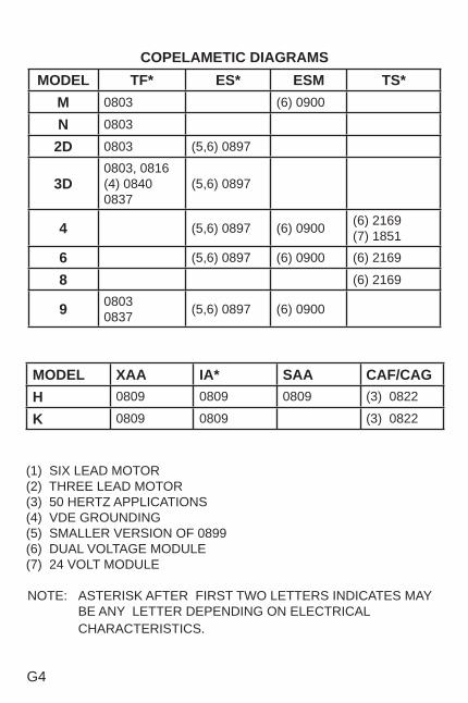
G4
COPELAMETIC DIAGRAMS MODEL TF* ES* ESM TS*
M 0803 (6) 0900
N 0803
2D 0803 (5,6) 0897
3D0803, 0816(4) 0840 0837
(5,6) 0897
4 (5,6) 0897 (6) 0900 (6) 2169(7) 1851
6 (5,6) 0897 (6) 0900 (6) 2169
8 (6) 2169
9 08030837 (5,6) 0897 (6) 0900
MODEL XAA IA* SAA CAF/CAGH 0809 0809 0809 (3) 0822
K 0809 0809 (3) 0822
(1) SIX LEAD MOTOR(2) THREE LEAD MOTOR (3) 50 HERTZ APPLICATIONS(4) VDE GROUNDING (5) SMALLER VERSION OF 0899(6) DUAL VOLTAGE MODULE(7) 24 VOLT MODULE NOTE: ASTERISK AFTER FIRST TWO LETTERS INDICATES MAY
BE ANY LETTER DEPENDING ON ELECTRICAL CHARACTERISTICS.
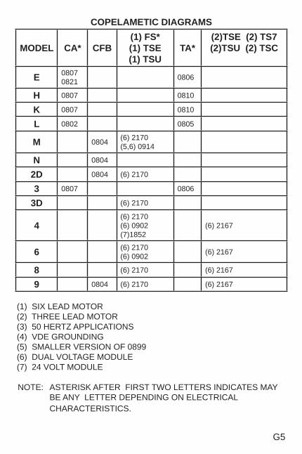
G5
COPELAMETIC DIAGRAMS
MODEL CA* CFB(1) FS* (1) TSE (1) TSU
TA*(2)TSE (2) TS7 (2)TSU (2) TSC
E 0807 0821 0806
H 0807 0810
K 0807 0810
L 0802 0805
M 0804 (6) 2170(5,6) 0914
N 0804
2D 0804 (6) 2170
3 0807 0806
3D (6) 2170
4(6) 2170 (6) 0902 (7)1852
(6) 2167
6 (6) 2170(6) 0902 (6) 2167
8 (6) 2170 (6) 2167
9 0804 (6) 2170 (6) 2167
(1) SIX LEAD MOTOR(2) THREE LEAD MOTOR (3) 50 HERTZ APPLICATIONS(4) VDE GROUNDING (5) SMALLER VERSION OF 0899 (6) DUAL VOLTAGE MODULE(7) 24 VOLT MODULE
NOTE: ASTERISK AFTER FIRST TWO LETTERS INDICATES MAY BE ANY LETTER DEPENDING ON ELECTRICAL CHARACTERISTICS.
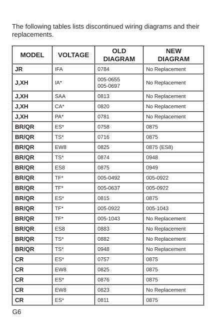
G6
The following tables lists discontinued wiring diagrams and their replacements.
MODEL VOLTAGE OLDDIAGRAM
NEWDIAGRAM
JR IFA 0784 No Replacement
J,XH IA* 005-0655005-0697 No Replacement
J,XH SAA 0813 No Replacement
J,XH CA* 0820 No Replacement
J,XH PA* 0781 No Replacement
BR/QR ES* 0758 0875
BR/QR TS* 0716 0875
BR/QR EW8 0825 0875 (ES8)
BR/QR TS* 0874 0948
BR/QR ES8 0875 0949
BR/QR TF* 005-0492 005-0922
BR/QR TF* 005-0637 005-0922
BR/QR ES* 0815 0875
BR/QR TF* 005-0922 005-1043
BR/QR TF* 005-1043 No Replacement
BR/QR ES8 0883 No Replacement
BR/QR TS* 0882 No Replacement
BR/QR TS* 0948 No Replacement
CR ES* 0757 0875
CR EW8 0825 0875
CR ES* 0876 0875
CR EW8 0823 No Replacement
CR ES* 0811 0875
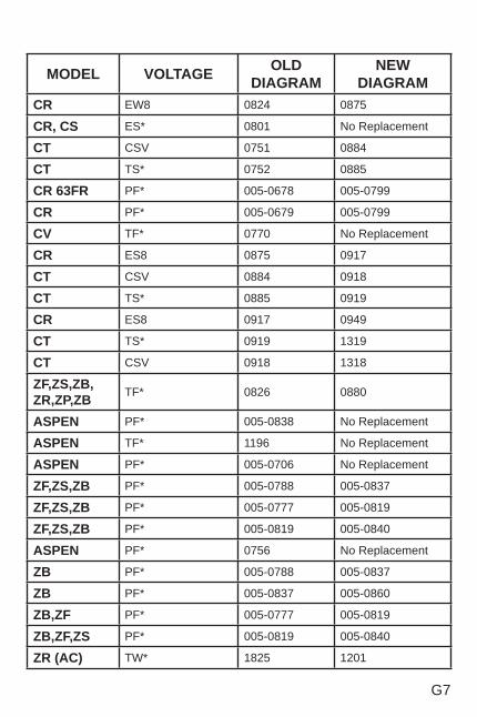
G7
MODEL VOLTAGE OLDDIAGRAM
NEWDIAGRAM
CR EW8 0824 0875
CR, CS ES* 0801 No Replacement
CT CSV 0751 0884
CT TS* 0752 0885
CR 63FR PF* 005-0678 005-0799
CR PF* 005-0679 005-0799
CV TF* 0770 No Replacement
CR ES8 0875 0917
CT CSV 0884 0918
CT TS* 0885 0919
CR ES8 0917 0949
CT TS* 0919 1319
CT CSV 0918 1318
ZF,ZS,ZB,ZR,ZP,ZB TF* 0826 0880
ASPEN PF* 005-0838 No Replacement
ASPEN TF* 1196 No Replacement
ASPEN PF* 005-0706 No Replacement
ZF,ZS,ZB PF* 005-0788 005-0837
ZF,ZS,ZB PF* 005-0777 005-0819
ZF,ZS,ZB PF* 005-0819 005-0840
ASPEN PF* 0756 No Replacement
ZB PF* 005-0788 005-0837
ZB PF* 005-0837 005-0860
ZB,ZF PF* 005-0777 005-0819
ZB,ZF,ZS PF* 005-0819 005-0840
ZR (AC) TW* 1825 1201
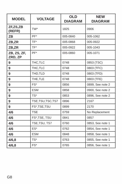
G8
MODEL VOLTAGE OLD DIAGRAM
NEWDIAGRAM
ZF,ZS,ZB(REFR) TW* 1825 0906
ZB PF* 005-0840 005-1062
ZB,ZR TF* 005-0868 005-0922
ZB,ZR TF* 005-0922 005-1043
ZB, ZS, ZF, ZRD, ZP
PF* 005-0860 005-1071
9 THC,TLC 0748 0853 (TSC)
9 THC,TLC 0748 0803 (TFC)
9 THD,TLD 0748 0803 (TFD)
9 THE,TLE 0748 0803 (TFE)
9 FS* 0856 0899, See note 2
9 ESM 0858 0900, See note 2
9 TS* 0853 0896, See note 2
9 TSE,TSU,TSC,TS7 0896 2167
9 FS*,TSE,TSU 0899 2170
4/6 TSE 0759 No Replacement
4/6 FS*,TSE, TSU 0841 0857
4/6 TSE,TSU, TS7 0760 0853, See note 1
4/6 ES* 0762 0854, See note 1
4/6 ESM 0848 0858, See note 1
4/6,8 TS* 0763 0855, See note 1
4/6,8 FS* 0765 0856, See note 1
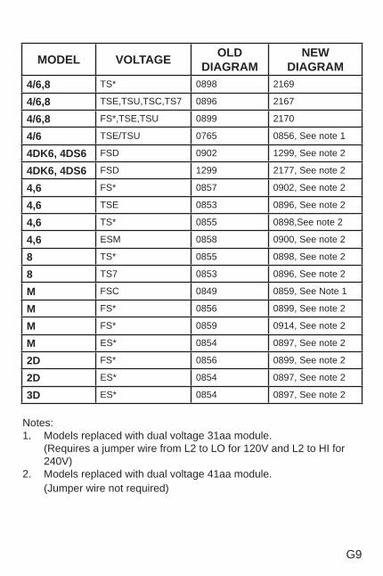
G9
MODEL VOLTAGE OLD DIAGRAM
NEWDIAGRAM
4/6,8 TS* 0898 2169
4/6,8 TSE,TSU,TSC,TS7 0896 2167
4/6,8 FS*,TSE,TSU 0899 2170
4/6 TSE/TSU 0765 0856, See note 1
4DK6, 4DS6 FSD 0902 1299, See note 2
4DK6, 4DS6 FSD 1299 2177, See note 2
4,6 FS* 0857 0902, See note 2
4,6 TSE 0853 0896, See note 2
4,6 TS* 0855 0898,See note 2
4,6 ESM 0858 0900, See note 2
8 TS* 0855 0898, See note 2
8 TS7 0853 0896, See note 2
M FSC 0849 0859, See Note 1
M FS* 0856 0899, See note 2
M FS* 0859 0914, See note 2
M ES* 0854 0897, See note 2
2D FS* 0856 0899, See note 2
2D ES* 0854 0897, See note 2
3D ES* 0854 0897, See note 2
Notes:1. Models replaced with dual voltage 31aa module. (Requires a jumper wire from L2 to LO for 120V and L2 to HI for
240V)2. Models replaced with dual voltage 41aa module. (Jumper wire not required)
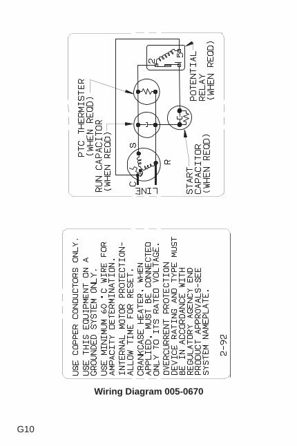
G10
Wiring Diagram 005-0670
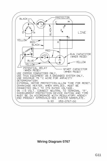
G11
Wiring Diagram 0767
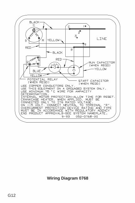
G12
Wiring Diagram 0768
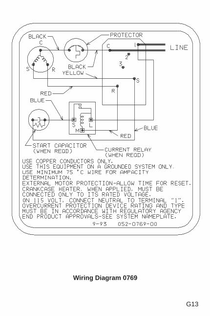
G13
Wiring Diagram 0769
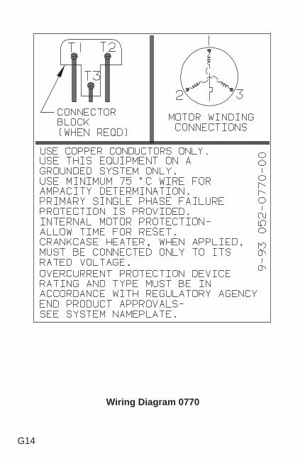
G14
Wiring Diagram 0770
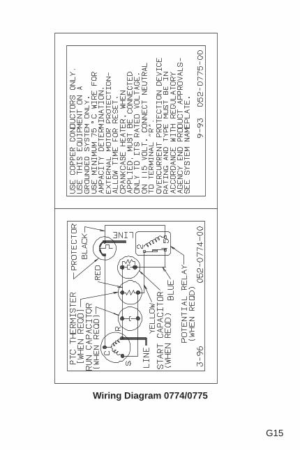
G15
Wiring Diagram 0774/0775
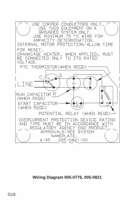
G16
Wiring Diagram 005-0776, 005-0821
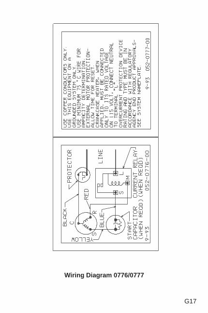
G17
Wiring Diagram 0776/0777
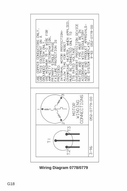
G18
Wiring Diagram 0778/0779
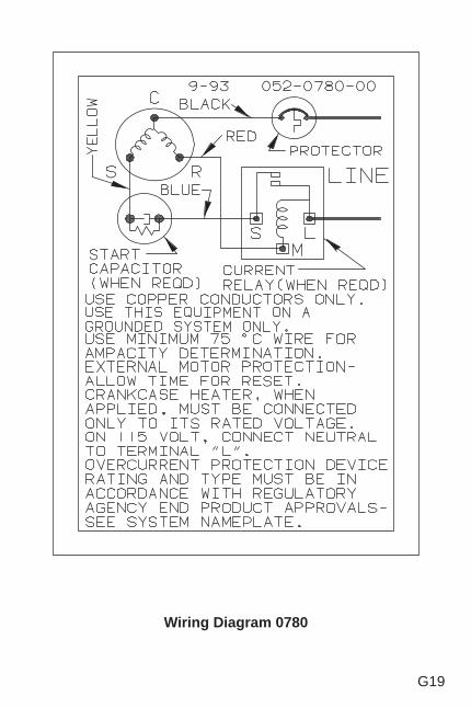
G19
Wiring Diagram 0780
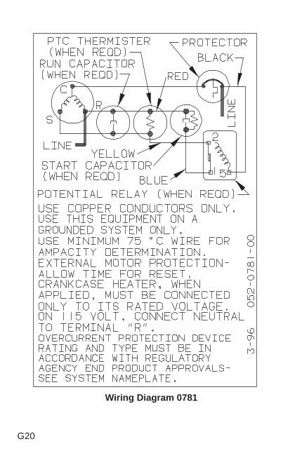
G20
Wiring Diagram 0781
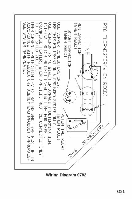
G21
Wiring Diagram 0782
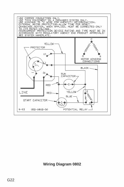
G22
Wiring Diagram 0802
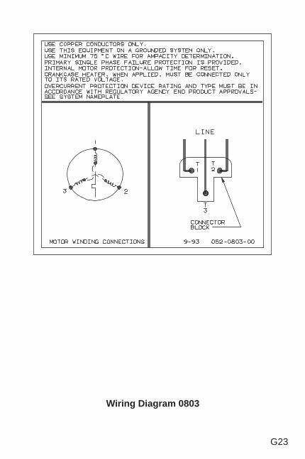
G23
Wiring Diagram 0803

G24
Wiring Diagram 0804
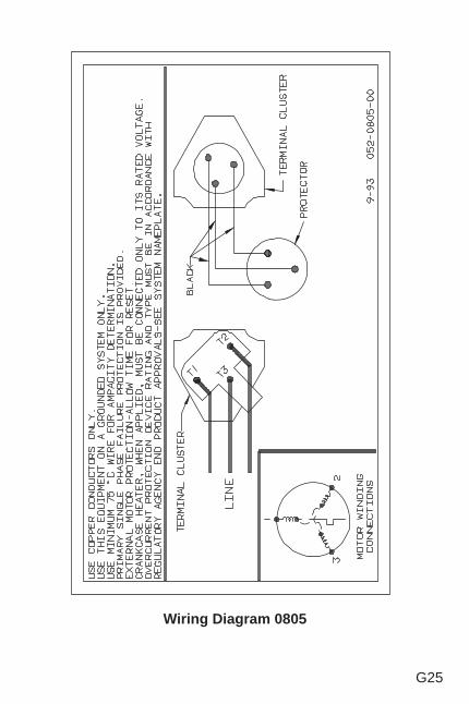
G25
Wiring Diagram 0805
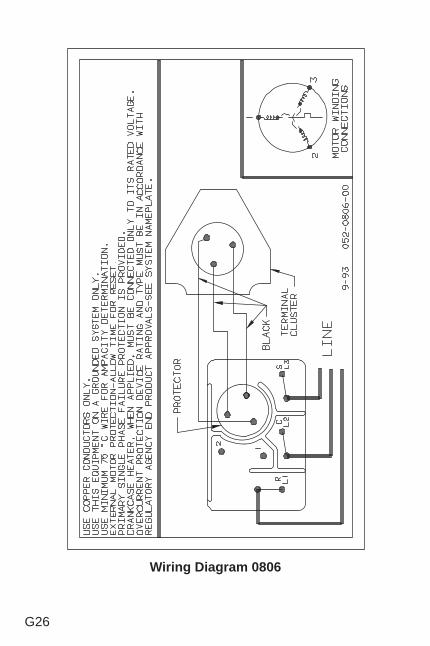
G26
Wiring Diagram 0806
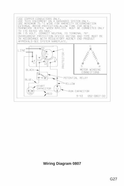
G27
Wiring Diagram 0807
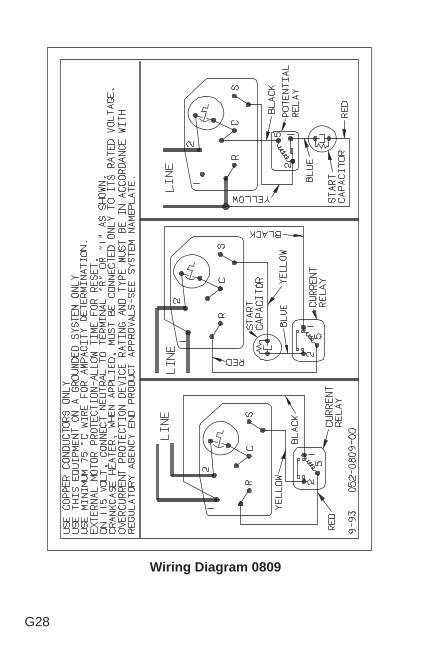
G28
Wiring Diagram 0809
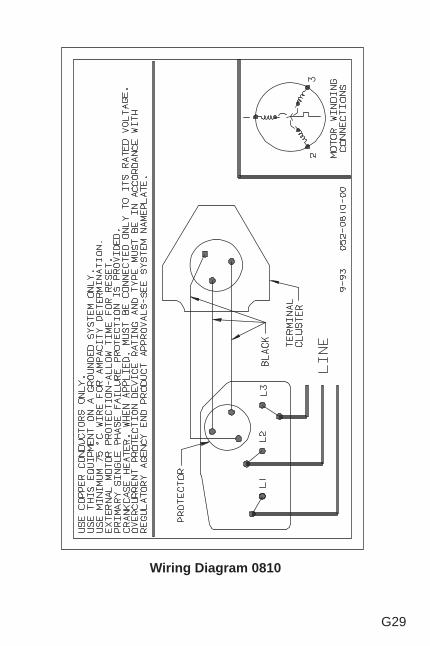
G29
Wiring Diagram 0810
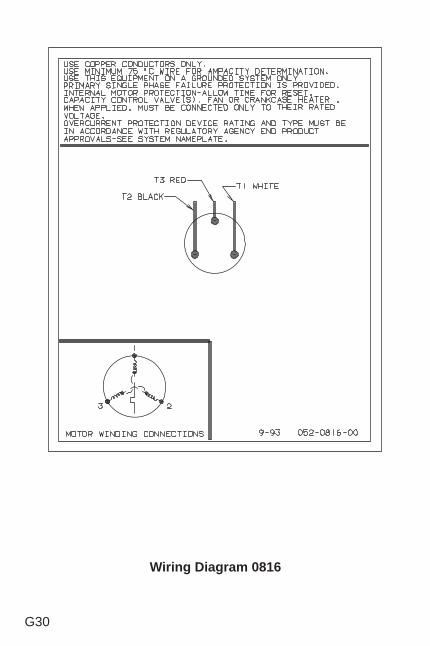
G30
Wiring Diagram 0816
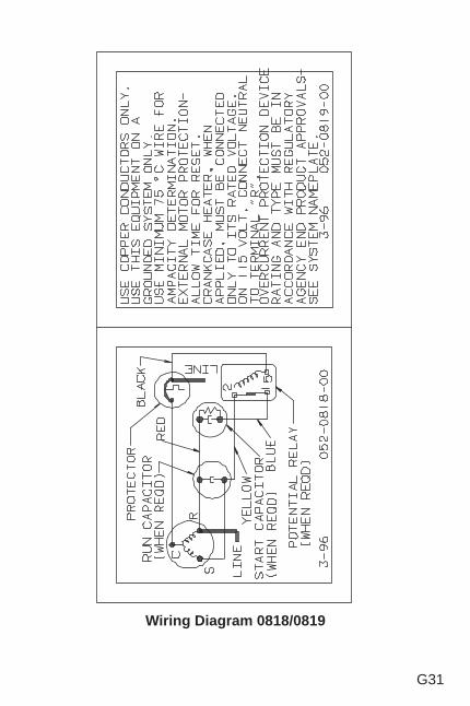
G31
Wiring Diagram 0818/0819
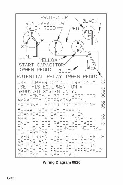
G32
Wiring Diagram 0820
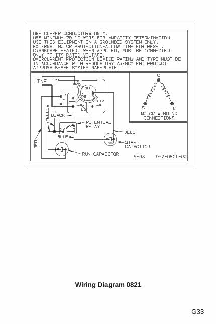
G33
Wiring Diagram 0821
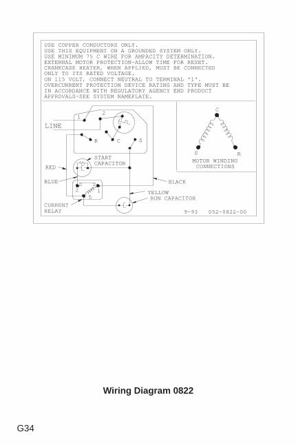
G34
Wiring Diagram 0822
CRANKCASE HEATER, WHEN APPLIED, MUST BE CONNECTEDONLY TO ITS RATED VOLTAGE.
USE COPPER CONDUCTORS ONLY.
USE MINIMUM 75 C WIRE FOR AMPACITY DETERMINATION.USE THIS EQUIPMENT ON A GROUNDED SYSTEM ONLY.
9-93 052-0822-00
EXTERNAL MOTOR PROTECTION-ALLOW TIME FOR RESET.
RS
C
MOTOR WINDINGCONNECTIONS
LINE
21
R C S
125
CURRENTRELAY
STARTCAPACITOR
BLACK
RUN CAPACITORYELLOW
RED
BLUE
ON 115 VOLT, CONNECT NEUTRAL TO TERMINAL "1".OVERCURRENT PROTECTION DEVICE RATING AND TYPE MUST BEIN ACCORDANCE WITH REGULATORY AGENCY END PRODUCTAPPROVALS-SEE SYSTEM NAMEPLATE.
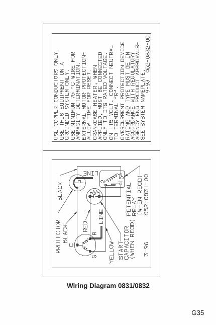
G35
Wiring Diagram 0831/0832
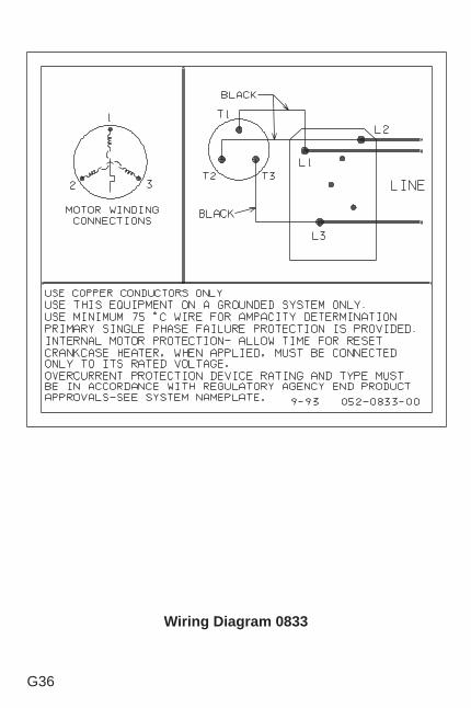
G36
Wiring Diagram 0833
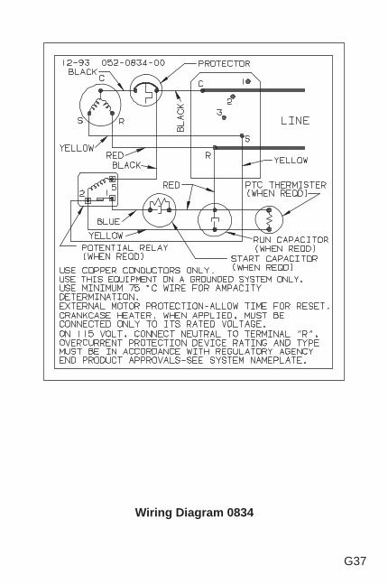
G37
Wiring Diagram 0834
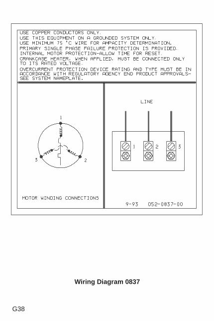
G38
Wiring Diagram 0837
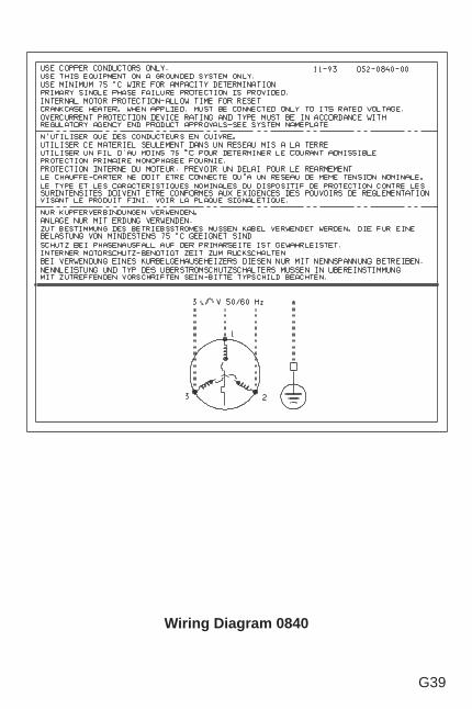
G39
Wiring Diagram 0840

G40
Wiring Diagram 0865
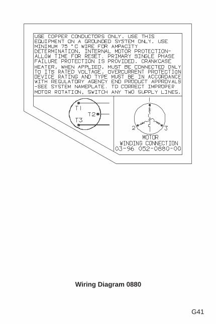
G41
Wiring Diagram 0880
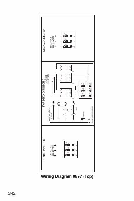
G42
Wiring Diagram 0897 (Top)
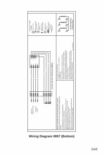
G43
Wiring Diagram 0897 (Bottom)
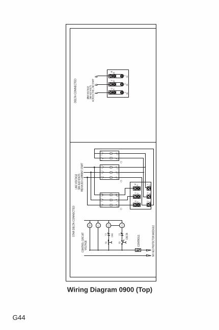
G44
Wiring Diagram 0900 (Top)
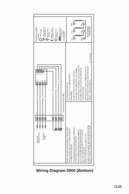
G45
Wiring Diagram 0900 (Bottom)
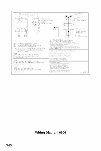
G46
Wiring Diagram 0906
TO MOTOR TERMINAL BLOCK/VERS BORNES DE BRANCHMENT DES BOUNES MOTEUR/ZUR BELEGUNGDER MOTOR KLEMMEN
NOTIZ:MOTORSCHUTZGERAET HAT EINEZEITVERZOEGERUNG VON 30 MINUTEN ZUMRUECKSCHALTEN
NOTE:EN CAS DE DECLENCHEMENT DU MODULEDE PROTECTION, LE REARMEMENT EST RETARDEA 30 MINUTES.
PROTECTOR MODULE AND OPTIONAL CRANKCASE HEATER MUSTBE CONNECTED ONLY TO THEIR RATED VOLTAGE.
USE COPPER CONDUCTORS ONLY.USE A TEMPERATURE OF 75C WHEN DETERMININGCROSS SECTION OF LEAD FOR MAX CURRENT.USE THIS EQUIPMENT ON A GROUNDED SYSTEM ONLY.PRIMARY SINGLE PHASE FAILURE PROTECTION IS PROVIDED.
LE MODULE DU DISPOSITIF DE PROTECTION ET LE CHAUFFE-CARTERFACULTATIF DOIVENT ETRE BRANCHES A LA TENSION NOMINALEAPPROPRIEE.
N'UTILISER QUE DES CONDUCTEURS EN CUIVRE.UTILIER UNE TEMPERATURE ED 75C POUR DETERMINERLA SECTION DES CABLES POUR LE COURANT MAXIMUM.EMPLOYER CET EQUIPEMENT SEULEMENT SUR SYSTEME MIS A LA TERRE.PROTECTION PRIMAIRE MONOPHASEE FOURNIE.
LE TYPE ET LES CARACTERISTIQUES NOMINALES DU DISPOSITIF DEPROTECTION CONTRE LES SURINTENSITES DOIVENT ETRE CONFORMES AUXEXIGENCES DES POUVOIRS DE REGLEMENTATION VISANT LE PRODUIT FINI-VOIR LA PLAQUE SIGNALETIQUE.
SCHUTZGERAET UND KURBELGEHAEUSEHEIZER (FALLS VORHANDEN)DUERFEN NUR MIT NENNSPANNUNG BETRIEBEN WERDEN.
NUR KUPFERLEITUNGEN VERWENDEN.
SCHUTZ BEI PHASENAUSFALL AUF DER PRIMAERSEITE IST GEWAEHRLEISTET.ANLAGE NUR MIT ERDUNG VERWENDEN.
ZUR BESTIMMUNG DES LEITERQUERSCHNITTS MUESSEN KABEL VERWENDET WERDEN,DIE FUER EINE BELASTUNG VON HUECHSTENS 75C ZUGELASSEN SIND.
NENNLEISTUNG UND TYP DES UEBERSTROMSCHUTZSCHALTERS MUESSENIN UEBEREINSTIMMUNG MIT ZUTREFFENDEN VORSCHRIFTEN SEIN-BITTE TYPENSCHILD BEACHTEN.
NOTE:SOLID STATE MODULE HAS 30 MINUTESTIME DELAY BEFORE RESET IN EVENTOF PROTECTOR TRIP.
INTERNAL THERMALSENSORS/CAPTEURS THERMIQUESINTERNES/INTERNETEMPERATURSENSOREN
TO CONTROL CIRCUIT/VERS LE CIRCUIT DECOMMANDE/ZUM STEUERSTROMKREIS
PROTECTOR MODULE VOLTAGE/TENSION DU MODULE DU DISPOSITIFDE PROTECTION/ANSCHLUSSPANNUNG DES SCHUTZGERAETES1
2 OVERCURRENT PROTECTION DEVICE RATING AND TYPE MUSTBE IN ACCORDANCE WITH REGULATION AND PRODUCT APPROVALS-SEE SYSTEM NAMEPLATE.
052-0906-00 (8525681)
F0R KRIWAN SCY (PHASE SENSING) MODULES ONLY3
3
L1
MOTOR WINDINGCONNECTIONS/BORNES DESENROULEMENTS DUMOTEUR/ANSCHLUSSDER MOTORWICKLUNGEN
L2
L3
L1 L2L3
FOR USE WITHKRIWAN SCY(PHASE SENSING)MODULE ONLY
6/99
21
S2 S1 M2 M1T2 T1
3
L3L1 L2
FOR USE WITH KRIWANSCY (PHASE SENSING)MODULE ONLY

G47
This page is left blank intentionally.
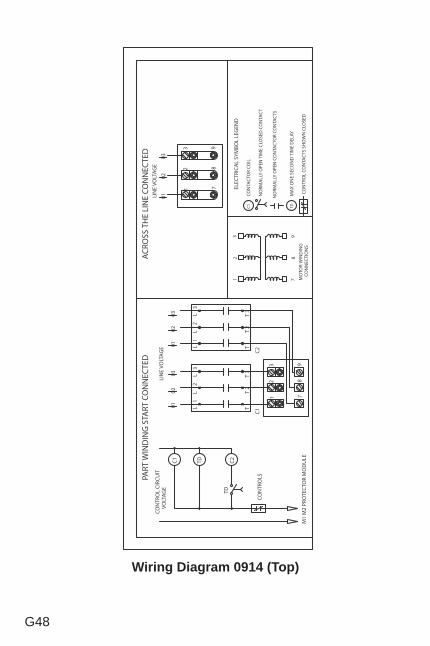
G48
Wiring Diagram 0914 (Top)
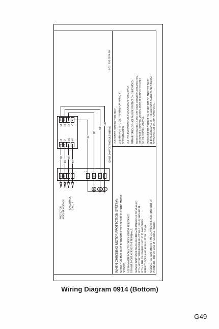
G49
Wiring Diagram 0914 (Bottom)
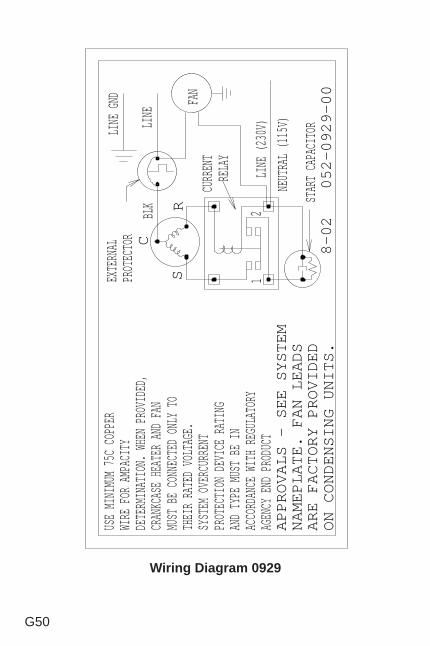
G50
Wiring Diagram 0929
USE MINIMUM 75C COPPER
WIRE FOR AMPACITY
DETERMINATION. WHEN PROVIDED,
CRANKCASE HEATER AND FAN
MUST BE CONNECTED ONLY TO
THEIR RATED VOLTAGE.
SYSTEM OVERCURRENT
PROTECTION DEVICE RATING
AND TYPE MUST BE IN
ACCORDANCE WITH REGULATORY
AGENCY END PRODUCT
BLK
CURRENT
RELAY
R
EXTERNAL
PROTECTOR C
1
LINE GND
APPROVALS - SEE SYSTEM
NAMEPLATE. FAN LEADS
ARE FACTORY PROVIDED
ON CONDENSING UNITS.
S
LINE (230V)
8-02 052-0929-00
2
START CAPACITORLINE
NEUTRAL (115V)
FAN
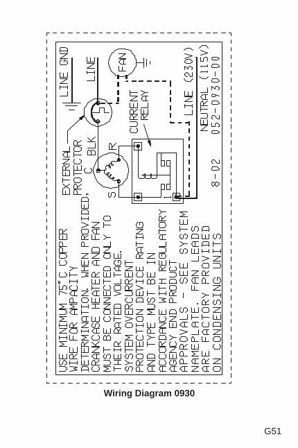
G51
Wiring Diagram 0930
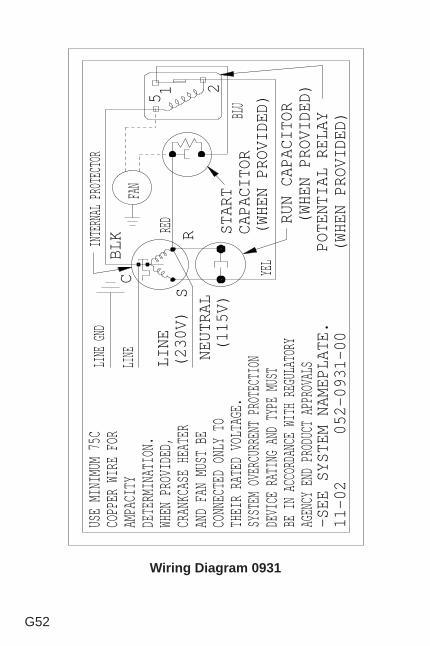
G52
Wiring Diagram 0931
RED
BLU
INTERNAL PROTECTOR
LINE GND
BLK
RUN CAPACITOR
(WHEN PROVIDED)
POTENTIAL RELAY
(WHEN PROVIDED)
C
SR
5
21
YEL
USE MINIMUM 75C
COPPER WIRE FOR
AMPACITY
DETERMINATION.
WHEN PROVIDED,
CRANKCASE HEATER
AND FAN MUST BE
CONNECTED ONLY TO
THEIR RATED VOLTAGE.
LINE
(230V)
-SEE SYSTEM NAMEPLATE.
11-02 052-0931-00
NEUTRAL
(115V)
START
CAPACITOR
(WHEN PROVIDED)
LINE
FAN
SYSTEM OVERCURRENT PROTECTION
DEVICE RATING AND TYPE MUST
BE IN ACCORDANCE WITH REGULATORY
AGENCY END PRODUCT APPROVALS
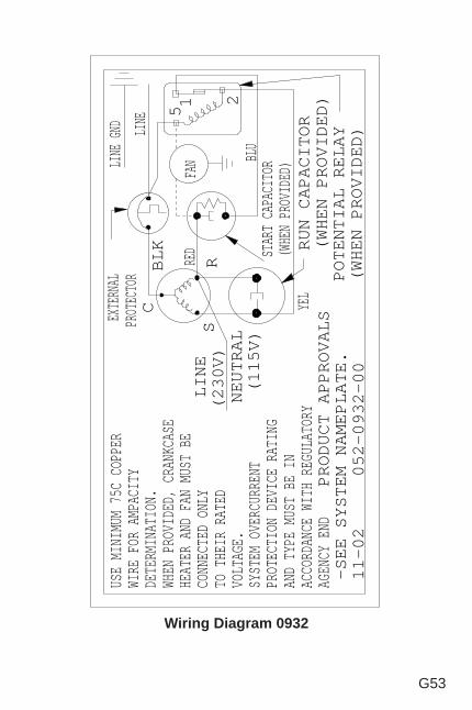
G53
Wiring Diagram 0932
RED
BLU
EXTERNAL
PROTECTOR
LINE GND
BLK RUN CAPACITOR
(WHEN PROVIDED)
POTENTIAL RELAY
(WHEN PROVIDED)
C
SR
5
21
YEL
USE MINIMUM 75C COPPER
WIRE FOR AMPACITY
DETERMINATION.
WHEN PROVIDED, CRANKCASE
HEATER AND FAN MUST BE
CONNECTED ONLY
TO THEIR RATED
VOLTAGE.
SYSTEM OVERCURRENT
PROTECTION DEVICE RATING
AND TYPE MUST BE IN
ACCORDANCE WITH REGULATORY
AGENCY END
LINE
(230V)
PRODUCT APPROVALS
-SEE SYSTEM NAMEPLATE.
11-02 052-0932-00
NEUTRAL
(115V)
LINE
FAN
START CAPACITOR
(WHEN PROVIDED)
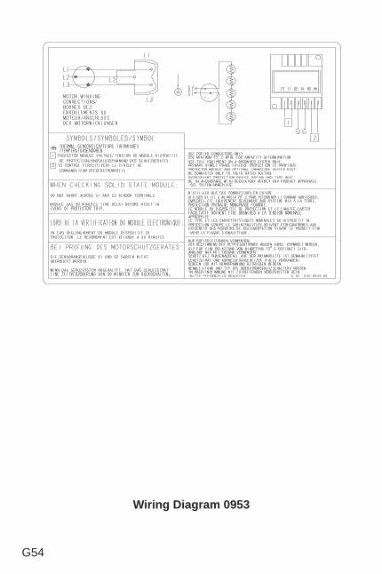
G54
Wiring Diagram 0953
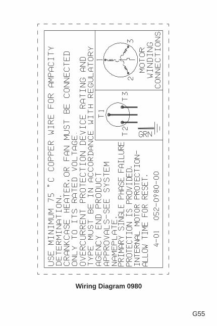
G55
Wiring Diagram 0980
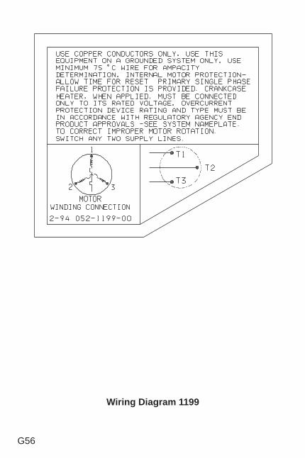
G56
Wiring Diagram 1199
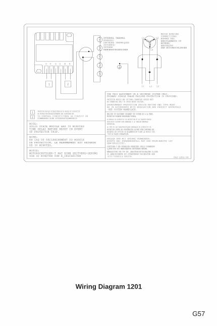
G57
Wiring Diagram 1201
NOTIZ:MOTORSCHUTZGER-T HAT EINE ZEITVERZ+GERUNGVON 30 MINUTEN ZUM R_CKSCHALTEN
NOTE:EN CAS DE DECLENCHEMENT DU MODULEDE PROTECTION, LE REARMEMENT EST RETARDEDE 30 MINUTES.
PROTECTOR MODULE AND OPTIONAL CRANKCASE HEATER MUSTBE CONNECTED ONLY TO THEIR RATED VOLTAGE.
USE THIS EQUIPMENT ON A GROUNDED SYSTEM ONLY.PRIMARY SINGLE PHASE FAILURE PROTECTION IS PROVIDED.
LE MODULE DU DISPOSITIF DE PROTECTION ET LE CHAUFFE-CARTERFACULTATIF DOIVENT ETRE BRANCHES A LA TENSION NOMINALEAPPROPRIEE.
EMPLOYER CET EQUIPEMENT SEULEMENT SUR SYSTEME MIS A LA TERRE.PROTECTION PRIMAIRE MONOPHASEE FOURNIE.
LE TYPE ET LES CARACTERISTIQUES NOMINALES DU DISPOSITIF DEPROTECTION CONTRE LES SURINTENSITES DOIVENT ETRE CONFORMES AUXEXIGENCES DES POUVOIRS DE REGLEMENTATION VISANT LE PRODUIT FINI-VOIR LA PLAQUE SIGNALETIQUE.
SCHUTZGER-T UND KURBELGEH-USEHEIZER (FALLS VORHANDEN)D_RFEN NUR MIT NENNSPANNUNG BETRIEBEN WERDEN.NENNLEISTUNG UND TYP DES _BERSTROMSCHUTZSCHALTERS M_SSENIN _BEREINSTIMMUNG MIT ZUTREFFENDEN VORSCHRIFTEN SEIN-BITTE TYPENSCHILD BEACHTEN.
NOTE:SOLID STATE MODULE HAS 30 MINUTESTIME DELAY BEFORE RESET IN EVENTOF PROTECTOR TRIP.
052-1201-00
INTERNAL THERMALSENSORS/CAPTEURS THERMIQUESINTERNES/INTERNETEMPERATURSENSOREN
TO CONTROL CIRCUIT/VERS LE CIRCUIT DECOMMANDE/ZUM STEUERSTROMKREIS
PROTECTOR MODULE VOLTAGE/TENSION DU MODULE DU DISPOSITIFDE PROTECTION/ANSCHLUSSPANNUNG DES SCHUTZGER-TES1
2
L1
MOTOR WINDINGCONNECTIONS/BORNES DESENROULEMENTS DUMOTEUR/ANSCHLUSSDER MOTORWICKLUNGEN
L2
L3
L1 L2L321
T2 S2 S1 M2 M1T1
OVERCURRENT PROTECTION DEVICE RATING AND TYPE MUSTBE IN ACCORDANCE WITH REGULATION AND PRODUCT APPROVALS-SEE SYSTEM NAMEPLATE.
ANLAGE NUR MIT ERDUNG VERWENDEN.SCHUTZ BEI PHASENAUSFALL AUF DER PRIM-RSEITE ISTGEW-HRLEISTET.
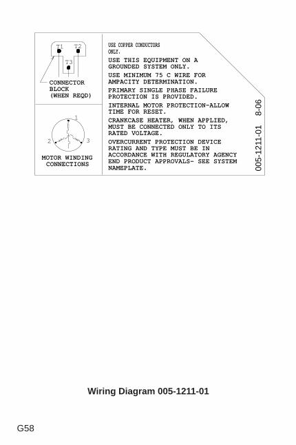
G58
Wiring Diagram 005-1211-01
CONNECTOCONNECTOR R BLOCBLOCK K (WHEN REQD(WHEN REQD) )
USEUSE COPPERCOPPER CONDUCTORCONDUCTORS S ONLYONLY. .
T1 T2
T3
USE MINIMUM 75 C WIRE FOUSE MINIMUM 75 C WIRE FOR R AMPACITY DETERMINATIONAMPACITY DETERMINATION. . PRIMARY SINGLE PHASE FAILURPRIMARY SINGLE PHASE FAILURE E PROTECTION IS PROVIDEDPROTECTION IS PROVIDED. . INTERNAL MOTOR PROTECTION-ALLOINTERNAL MOTOR PROTECTION-ALLOW W TIME FOR RESETTIME FOR RESET. . CRANKCASE HEATER, WHEN APPLIEDCRANKCASE HEATER, WHEN APPLIED, , MUST BE CONNECTED ONLY TO ITMUST BE CONNECTED ONLY TO ITS S RATED VOLTAGERATED VOLTAGE. .
USE THIS EQUIPMENT ON USE THIS EQUIPMENT ON A A GROUNDED SYSTEM ONLYGROUNDED SYSTEM ONLY. .
OVERCURRENT PROTECTION DEVICOVERCURRENT PROTECTION DEVICE E RATING AND TYPE MUST BE IRATING AND TYPE MUST BE IN N ACCORDANCE WITH REGULATORY AGENCACCORDANCE WITH REGULATORY AGENCY Y END PRODUCT APPROVALS- SEE SYSTEEND PRODUCT APPROVALS- SEE SYSTEM M NAMEPLATENAMEPLATE. .
MOTOR WINDINMOTOR WINDING G CONNECTIONCONNECTIONS S
1
2 3
005-
1211
-01
8-
06
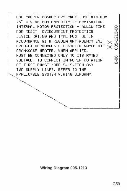
G59
Wiring Diagram 005-1213
8-06
00
5-12
13-0
0
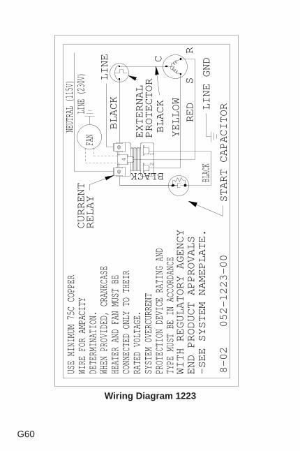
G60
Wiring Diagram 1223
USE MINIMUM 75C COPPER
WIRE FOR AMPACITY
DETERMINATION.
WHEN PROVIDED, CRANKCASE
HEATER AND FAN MUST BE
CONNECTED ONLY TO THEIR
RATED VOLTAGE.
SYSTEM OVERCURRENT
PROTECTION DEVICE RATING AND
TYPE MUST BE IN ACCORDANCE
WITH REGULATORY AGENCY
END PRODUCT APPROVALS
-SEE SYSTEM NAMEPLATE.
8-02 052-1223-00
RED
START CAPACITOR
CURRENT
RELAY
LINE
BLACK
YELLOW
BLAC
KKCALB
BLACK
4
21
EXTERNAL
PROTECTOR
R
C
S
LINE GND
LINE (230V)
NEUTRAL (115V)
FAN
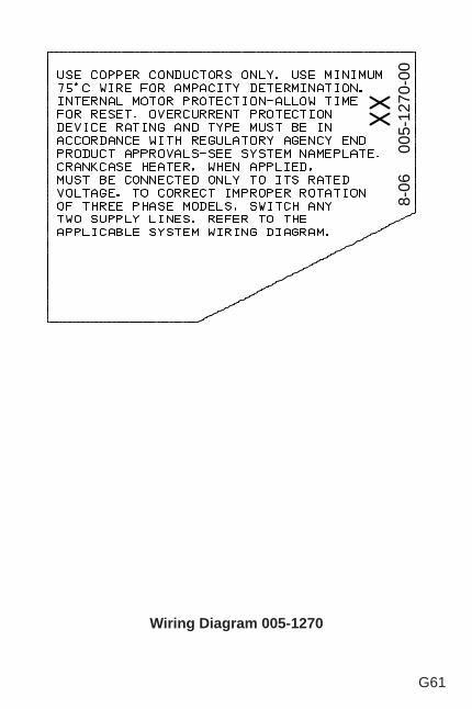
G61
Wiring Diagram 005-1270
8-06
00
5-12
70-0
0
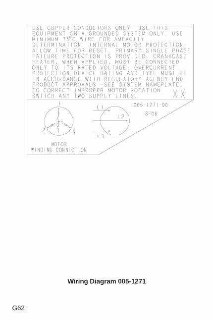
G62
Wiring Diagram 005-1271
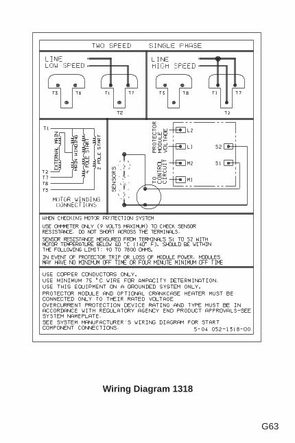
G63
Wiring Diagram 1318
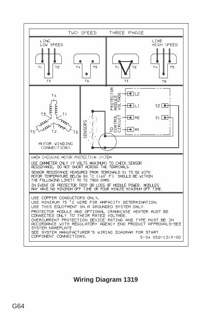
G64
Wiring Diagram 1319
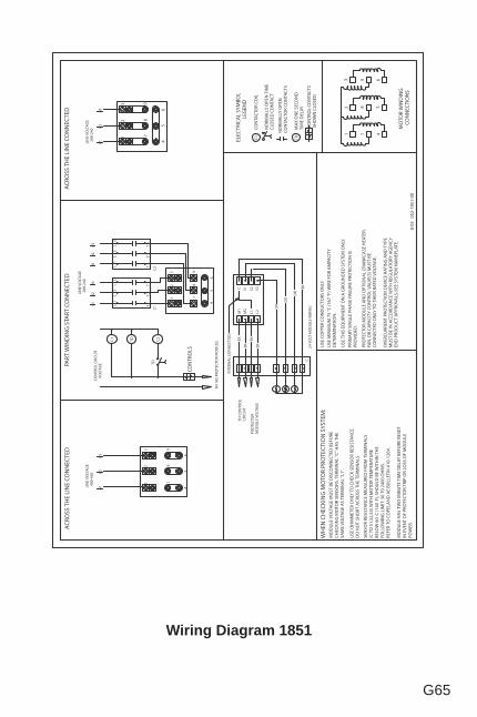
G65
Wiring Diagram 1851
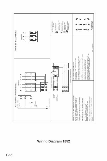
G66
Wiring Diagram 1852

G67
This page is left blank intentionally.
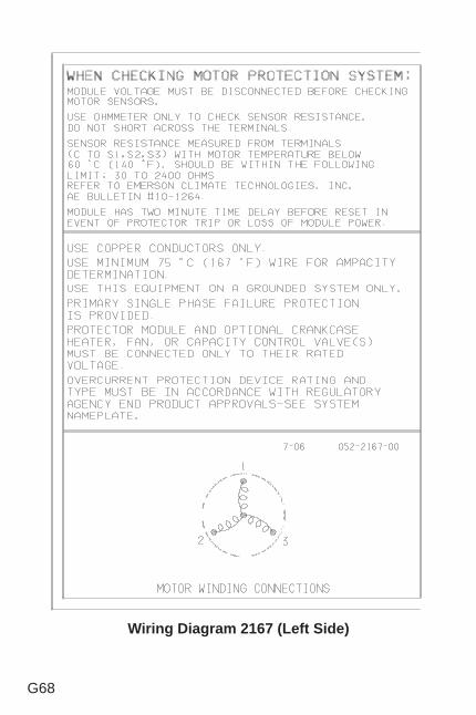
G68
Wiring Diagram 2167 (Left Side)
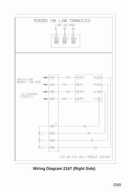
G69
Wiring Diagram 2167 (Right Side)
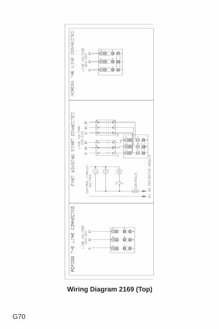
G70
Wiring Diagram 2169 (Top)
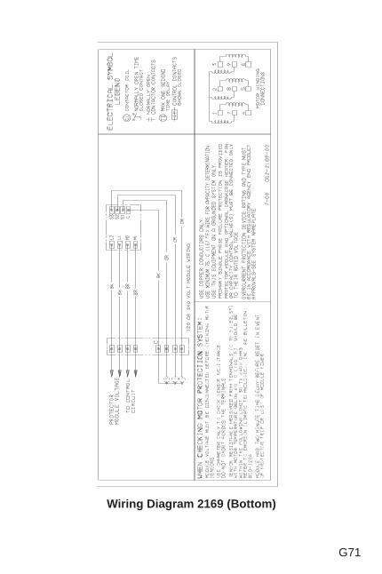
G71
Wiring Diagram 2169 (Bottom)
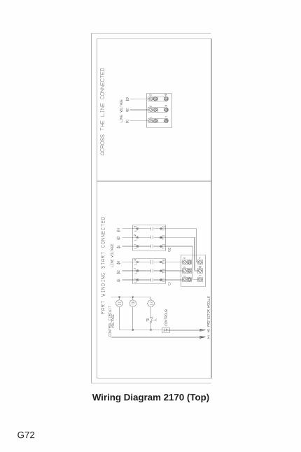
G72
Wiring Diagram 2170 (Top)
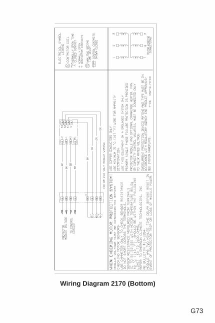
G73
Wiring Diagram 2170 (Bottom)
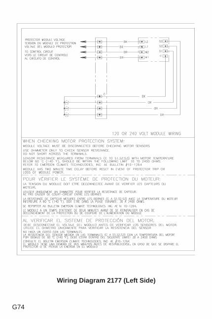
G74
Wiring Diagram 2177 (Left Side)
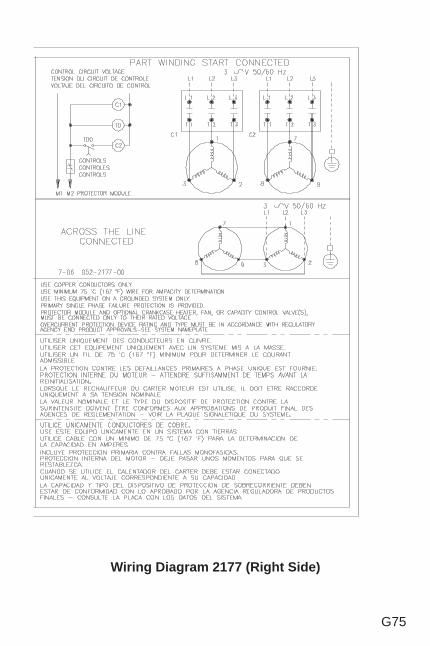
G75
Wiring Diagram 2177 (Right Side)
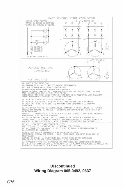
G76
DiscontinuedWiring Diagram 005-0492, 0637
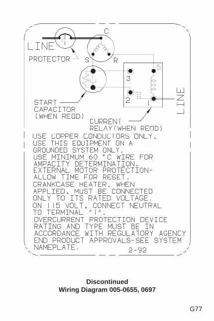
G77
DiscontinuedWiring Diagram 005-0655, 0697
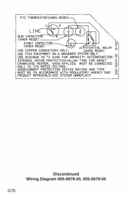
G78
DiscontinuedWiring Diagram 005-0678-00, 005-0679-00
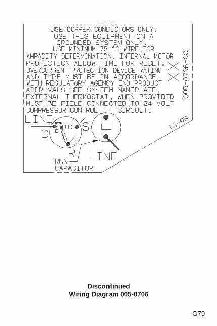
G79
DiscontinuedWiring Diagram 005-0706
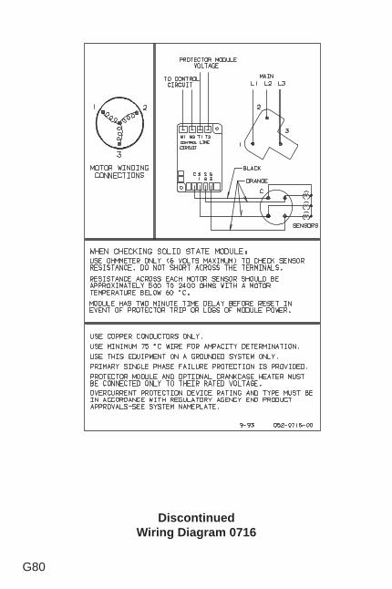
G80
DiscontinuedWiring Diagram 0716

G81
This page is left blank intentionally.
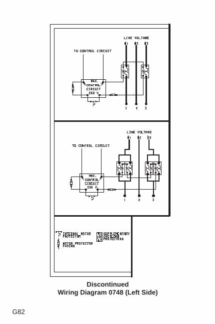
G82
DiscontinuedWiring Diagram 0748 (Left Side)
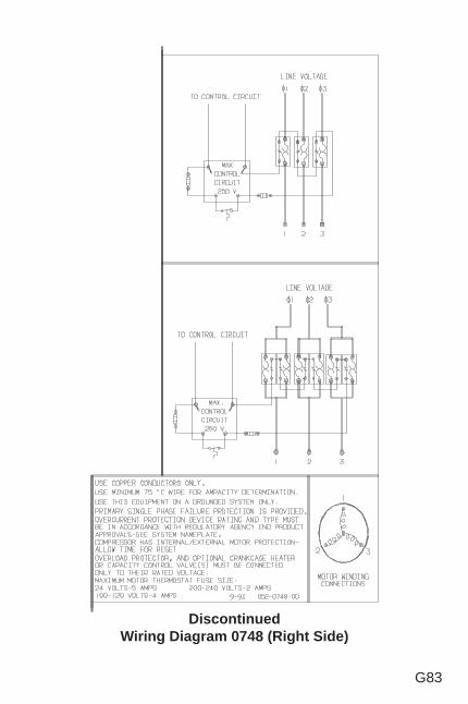
G83
DiscontinuedWiring Diagram 0748 (Right Side)
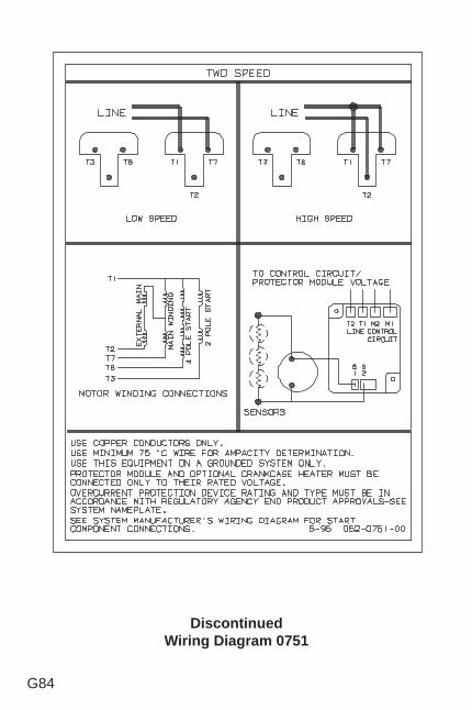
G84
DiscontinuedWiring Diagram 0751
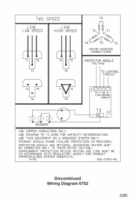
G85
DiscontinuedWiring Diagram 0752
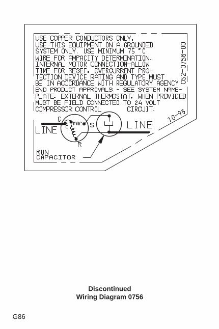
G86
DiscontinuedWiring Diagram 0756
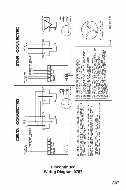
G87
DiscontinuedWiring Diagram 0757
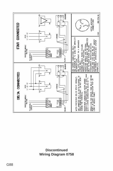
G88
DiscontinuedWiring Diagram 0758
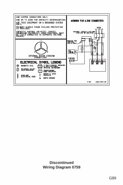
G89
DiscontinuedWiring Diagram 0759
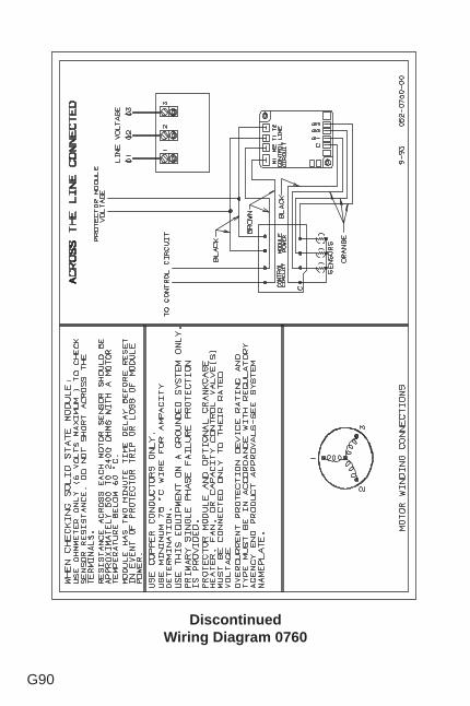
G90
DiscontinuedWiring Diagram 0760

G91
This page is left blank intentionally.
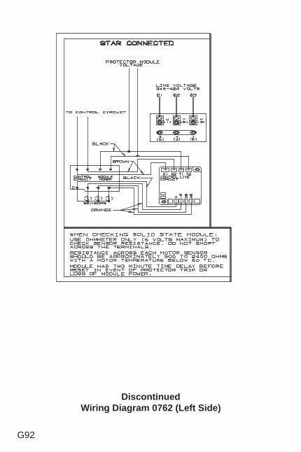
G92
DiscontinuedWiring Diagram 0762 (Left Side)
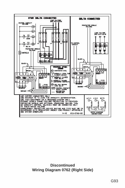
G93
DiscontinuedWiring Diagram 0762 (Right Side)
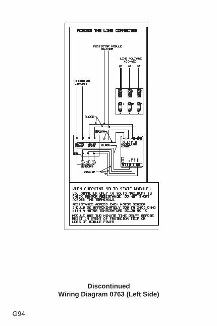
G94
DiscontinuedWiring Diagram 0763 (Left Side)
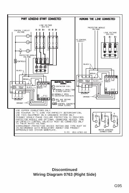
G95
DiscontinuedWiring Diagram 0763 (Right Side)
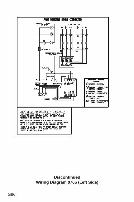
G96
DiscontinuedWiring Diagram 0765 (Left Side)
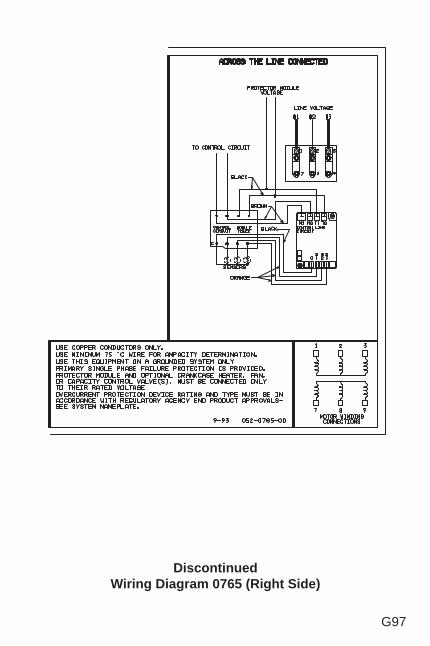
G97
DiscontinuedWiring Diagram 0765 (Right Side)
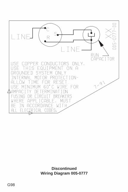
G98
DiscontinuedWiring Diagram 005-0777
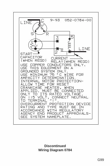
G99
DiscontinuedWiring Diagram 0784
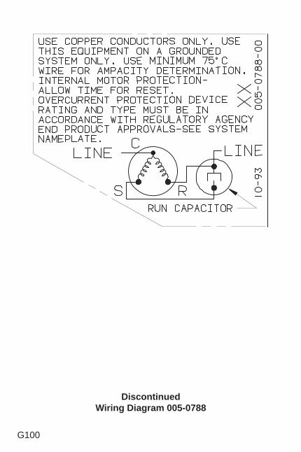
G100
DiscontinuedWiring Diagram 005-0788
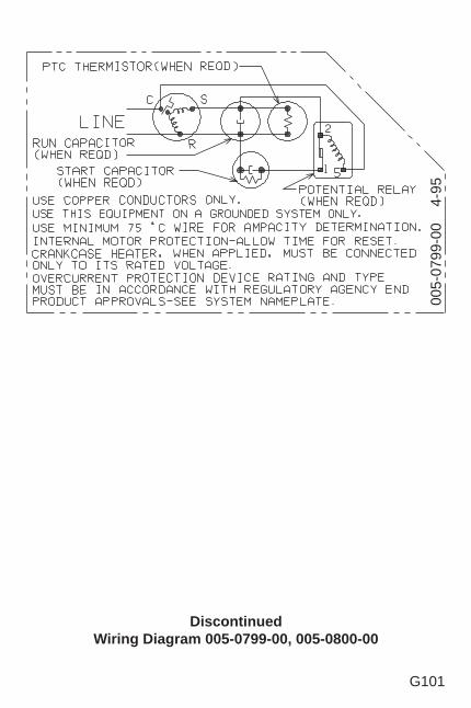
G101
DiscontinuedWiring Diagram 005-0799-00, 005-0800-00
005-
0799
-00
4-
95
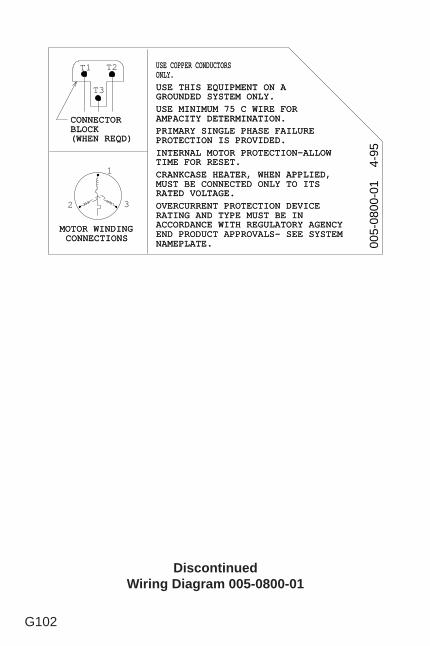
G102
DiscontinuedWiring Diagram 005-0800-01
CONNECTOCONNECTOR R BLOCBLOCK K (WHEN REQD(WHEN REQD) )
USEUSE COPPERCOPPER CONDUCTORCONDUCTORS S ONLYONLY. .
T1 T2
T3
USE MINIMUM 75 C WIRE FOUSE MINIMUM 75 C WIRE FOR R AMPACITY DETERMINATIONAMPACITY DETERMINATION. . PRIMARY SINGLE PHASE FAILURPRIMARY SINGLE PHASE FAILURE E PROTECTION IS PROVIDEDPROTECTION IS PROVIDED. . INTERNAL MOTOR PROTECTION-ALLOINTERNAL MOTOR PROTECTION-ALLOW W TIME FOR RESETTIME FOR RESET. . CRANKCASE HEATER, WHEN APPLIEDCRANKCASE HEATER, WHEN APPLIED, , MUST BE CONNECTED ONLY TO ITMUST BE CONNECTED ONLY TO ITS S RATED VOLTAGERATED VOLTAGE. .
USE THIS EQUIPMENT ON USE THIS EQUIPMENT ON A A GROUNDED SYSTEM ONLYGROUNDED SYSTEM ONLY. .
OVERCURRENT PROTECTION DEVICOVERCURRENT PROTECTION DEVICE E RATING AND TYPE MUST BE IRATING AND TYPE MUST BE IN N ACCORDANCE WITH REGULATORY AGENCACCORDANCE WITH REGULATORY AGENCY Y END PRODUCT APPROVALS- SEE SYSTEEND PRODUCT APPROVALS- SEE SYSTEM M NAMEPLATENAMEPLATE. .
MOTOR WINDINMOTOR WINDING G CONNECTIONCONNECTIONS S
1
2 3
005-
0800
-01
4-
95
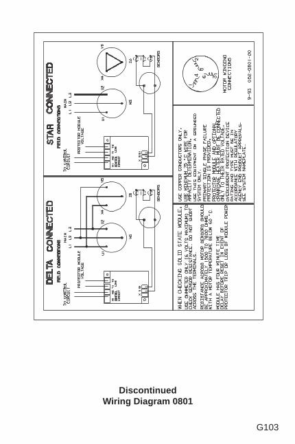
G103
DiscontinuedWiring Diagram 0801
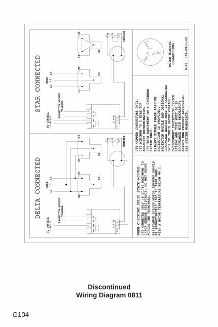
G104
DiscontinuedWiring Diagram 0811
W3
U1
V2
Y5
X4
Z6
SENSOR
SENSORS
M1
M2
T1
T2
LINE
L1
L2
L3
W3
U1
V2
Y5
X4
Z6
CONTROL
CIRCUIT
SENSOR
SENSORS
MAI
MAIN
SS1
PROTECTOR MODULE AND OPTIONA
PROTECTOR MODULE AND OPTIONAL
CRANKCASE HEATER MUST BE CONNECTE
CRANKCASE HEATER MUST BE CONNECTED
ONLY TO THEIR RATED VOLTAGE
ONLY TO THEIR RATED VOLTAGE.
USE COPPER CONDUCTORS ONLY
USE COPPER CONDUCTORS ONLY.
PRIMARY SINGLE PHASE FAILUR
PRIMARY SINGLE PHASE FAILURE
PROTECTION IS PROVIDED
PROTECTION IS PROVIDED.
USE THIS EQUIPMENT ON A GROUNDE
USE THIS EQUIPMENT ON A GROUNDED
SYSTEM ONLY
SYSTEM ONLY.
9-93 052-0811-0
9-93 052-0811-00
USE MINIMUM 75 C WIRE FO
USE MINIMUM 75 C WIRE FOR
AMPACITY DETERMINATION
AMPACITY DETERMINATION.
MOTOR WINDIN
MOTOR WINDING
CONNECTION
CONNECTIONS
14
25
6 3
M1
M2
T1
T2
LINE
CONTROL
CIRCUIT
XSS1
X
WHEN CHECKING SOLID STATE MODULE
WHEN CHECKING SOLID STATE MODULE:
USE OHMMETER ONLY (6 VOLTS MAXIMUM) T
USE OHMMETER ONLY (6 VOLTS MAXIMUM) TO
CHECK SENSOR RESISTANCE. DO NOT SHOR
CHECK SENSOR RESISTANCE. DO NOT SHORT
ACROSS THE TERMINALS
ACROSS THE TERMINALS.
RESISTANCE ACROSS MOTOR SENSORS SHOUL
RESISTANCE ACROSS MOTOR SENSORS SHOULD
BE APPROXIMATELY 1500 T0 7800 OHM
BE APPROXIMATELY 1500 T0 7800 OHMS
WITH A MOTOR TEMPERATURE BELOW 60 C
WITH A MOTOR TEMPERATURE BELOW 60 C.
L1
L2
L3
MAI
MAIN
STAR CONNECTE
STAR CONNECTED
DELTA CONNECTE
DELTA CONNECTED
OVERCURRENT PROTECTION DEVIC
OVERCURRENT PROTECTION DEVICE
RATING AND TYPE MUST BE I
RATING AND TYPE MUST BE IN
ACCORDANCE WITH REGULATOR
ACCORDANCE WITH REGULATORY
AGENCY END PRODUCT APPROVALS
AGENCY END PRODUCT APPROVALS-
SEE SYSTEM NAMEPLATE
SEE SYSTEM NAMEPLATE.
PROTECTOR MODUL
PROTECTOR MODULE
VOLTAG
VOLTAGE
TO CONTRO
TO CONTROL
CIRCUI
CIRCUIT
PROTECTOR MODUL
PROTECTOR MODULE
VOLTAG
VOLTAGE
TO CONTRO
TO CONTROL
CIRCUI
CIRCUIT
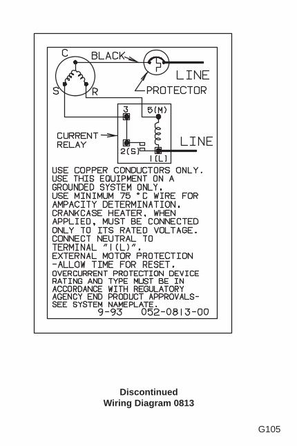
G105
DiscontinuedWiring Diagram 0813
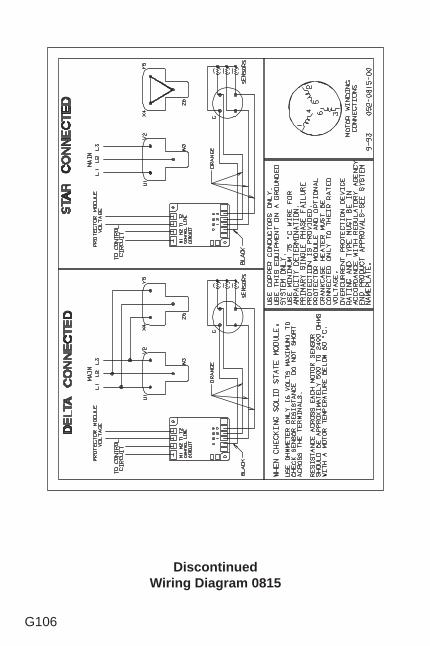
G106
DiscontinuedWiring Diagram 0815
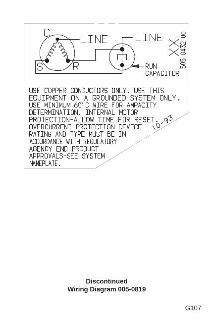
G107
DiscontinuedWiring Diagram 005-0819
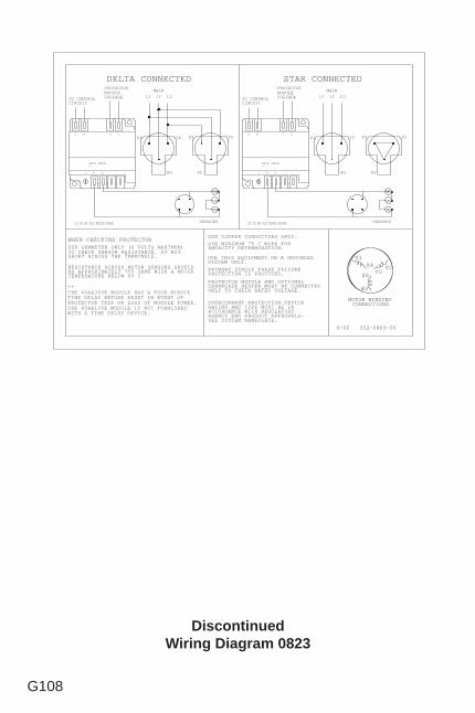
G108
DiscontinuedWiring Diagram 0823
PROTECTOR MODULE AND OPTIONALCRANKCASE HEATER MUST BE CONNECTEDONLY TO THEIR RATED VOLTAGE.
USE COPPER CONDUCTORS ONLY.
PRIMARY SINGLE PHASE FAILUREPROTECTION IS PROVIDED.
USE THIS EQUIPMENT ON A GROUNDEDSYSTEM ONLY.
6-00 052-0883-00
USE MINIMUM 75 C WIRE FORAMPACITY DETERMINATION.
MOTOR WINDINGCONNECTIONS
WHEN CHECKING PROTECTORUSE OHMMETER ONLY (6 VOLTS MAXIMUM)TO CHECK SENSOR RESISTANCE. DO NOTSHORT ACROSS THE TERMINALS.
RESISTANCE ACROSS MOTOR SENSORS SHOULDBE APPROXIMATELY 750 OHMS WITH A MOTORTEMPERATURE BELOW 60 C.
OVERCURRENT PROTECTION DEVICERATING AND TYPE MUST BE INACCORDANCE WITH REGULATORYAGENCY END PRODUCT APPROVALS-SEE SYSTEM NAMEPLATE.
U1
Y5X4 V2
Z6
W3
SENSORS 120 OR 240 VOLT MODULE WIRING120 OR 240 VOLT MODULE WIRING
**THE 40AA300E MODULE HAS A FOUR MINUTETIME DELAY BEFORE RESET IN EVENT OFPROTECTOR TRIP OR LOSS OF MODULE POWER.THE 40AA100E MODULE IS NOT FURNISHEDWITH A TIME DELAY DEVICE.
L1 L2 L3
W3
V2 Y5X4
Z6
MAINL1 L2 L3
U1 V2 Y5X4
MAIN
S1
M1 L1
S2
TO CONTROLCIRCUIT
L2U1
W3 Z6
PROTECTORMODULEVOLTAGE
PROTECTORMODULEVOLTAGE
L2
TO CONTROLCIRCUIT
L1M1
S1S2
M2
X
M2
X
SENSORS
DELTA CONNECTED STAR CONNECTED
PART No. 40AA300E**
PART No. 40AA300E**
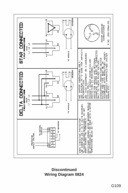
G109
DiscontinuedWiring Diagram 0824
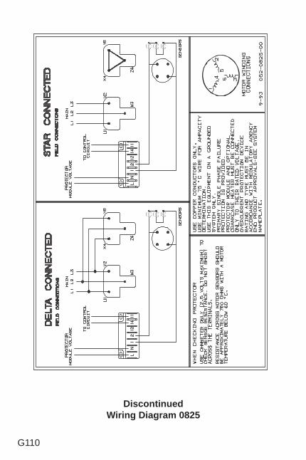
G110
DiscontinuedWiring Diagram 0825
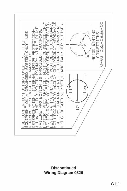
G111
DiscontinuedWiring Diagram 0826
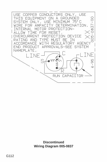
G112
DiscontinuedWiring Diagram 005-0837
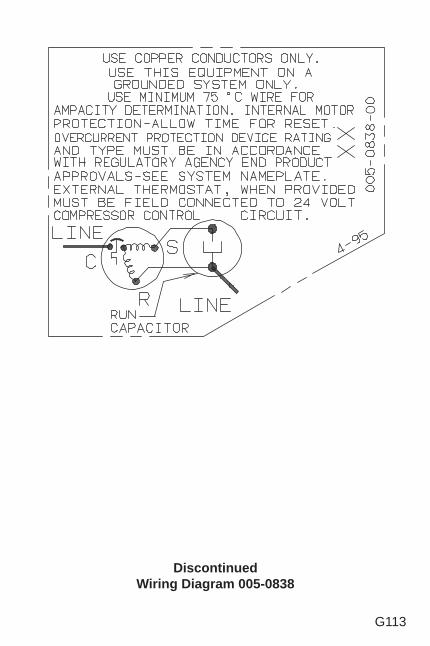
G113
DiscontinuedWiring Diagram 005-0838
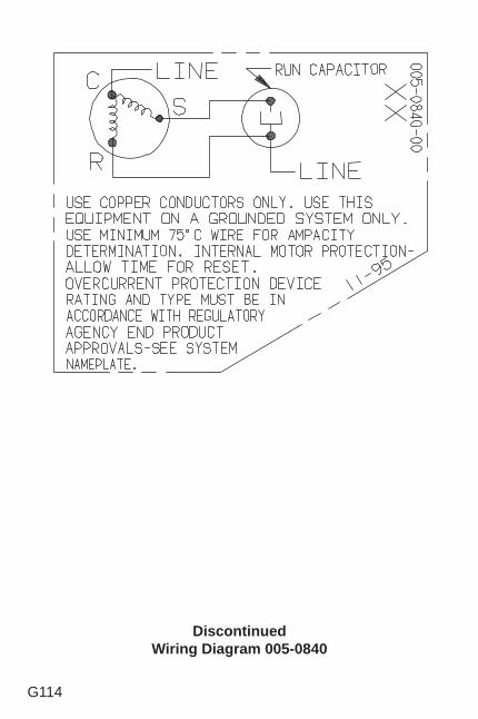
G114
DiscontinuedWiring Diagram 005-0840

G115
This page is left blank intentionally.
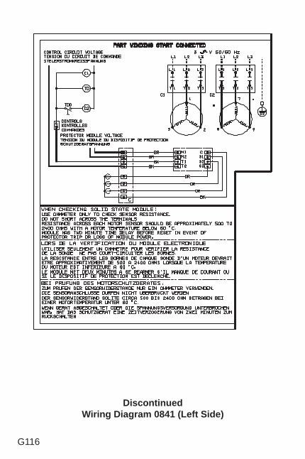
G116
DiscontinuedWiring Diagram 0841 (Left Side)
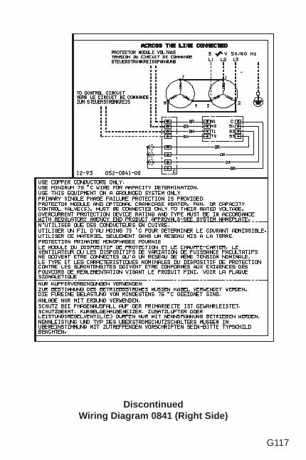
G117
DiscontinuedWiring Diagram 0841 (Right Side)
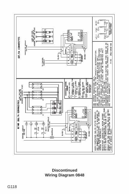
G118
DiscontinuedWiring Diagram 0848
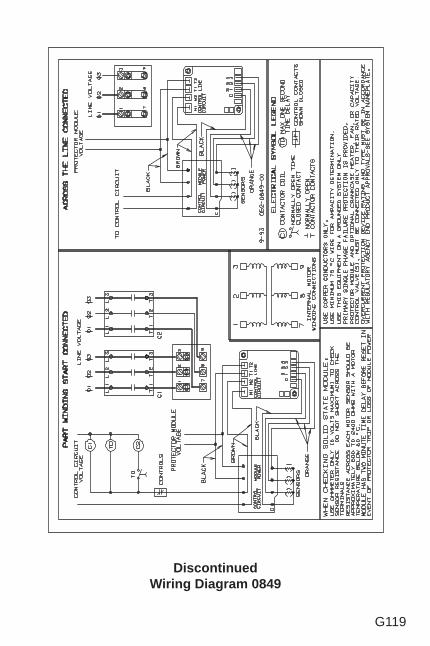
G119
DiscontinuedWiring Diagram 0849
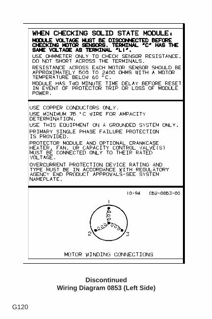
G120
DiscontinuedWiring Diagram 0853 (Left Side)
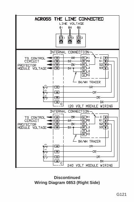
G121
DiscontinuedWiring Diagram 0853 (Right Side)
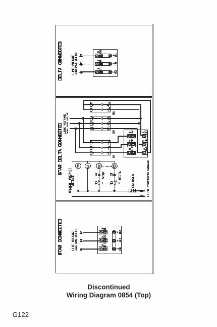
G122
DiscontinuedWiring Diagram 0854 (Top)
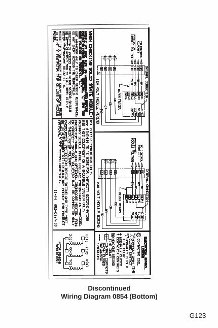
G123
DiscontinuedWiring Diagram 0854 (Bottom)
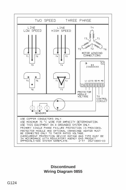
G124
DiscontinuedWiring Diagram 0855

G125
This page is left blank intentionally.
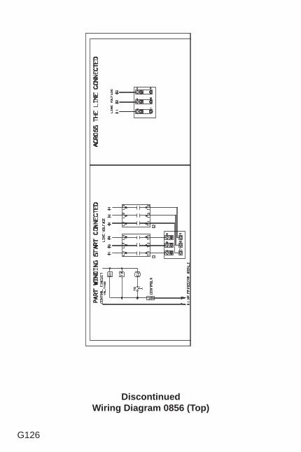
G126
DiscontinuedWiring Diagram 0856 (Top)
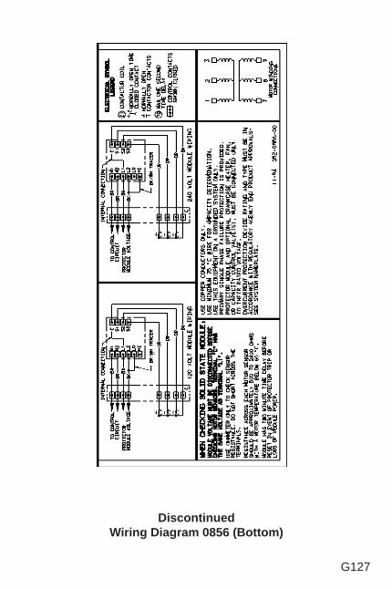
G127
DiscontinuedWiring Diagram 0856 (Bottom)
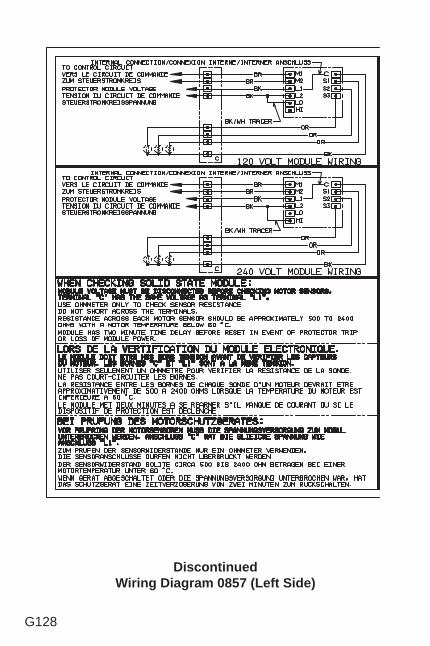
G128
DiscontinuedWiring Diagram 0857 (Left Side)
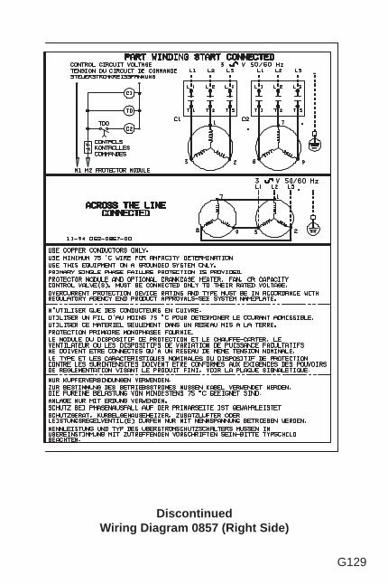
G129
DiscontinuedWiring Diagram 0857 (Right Side)
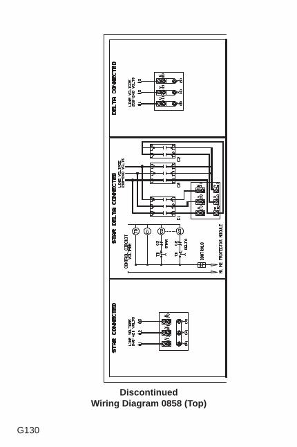
G130
DiscontinuedWiring Diagram 0858 (Top)
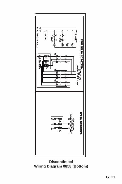
G131
DiscontinuedWiring Diagram 0858 (Bottom)
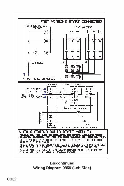
G132
DiscontinuedWiring Diagram 0859 (Left Side)
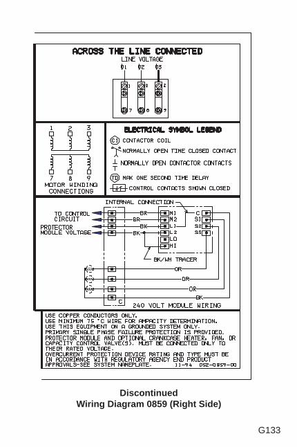
G133
DiscontinuedWiring Diagram 0859 (Right Side)
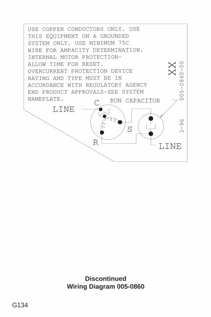
G134
DiscontinuedWiring Diagram 005-0860
XX
USE COPPER CONDUCTORS ONLY. USETHIS EQUIPMENT ON A GROUNDEDSYSTEM ONLY. USE MINIMUM 75CWIRE FOR AMPACITY DETERMINATION.INTERNAL MOTOR PROTECTION-ALLOW TIME FOR RESET.OVERCURRENT PROTECTION DEVICERATING AND TYPE MUST BE INACCORDANCE WITH REGULATORY AGENCYEND PRODUCT APPROVALS-SEE SYSTEMNAMEPLATE.
00-0680-500 69-3
RS
CLINE
LINE
RUN CAPACITOR
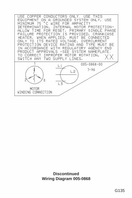
G135
DiscontinuedWiring Diagram 005-0868
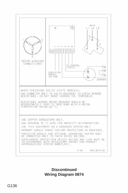
G136
DiscontinuedWiring Diagram 0874
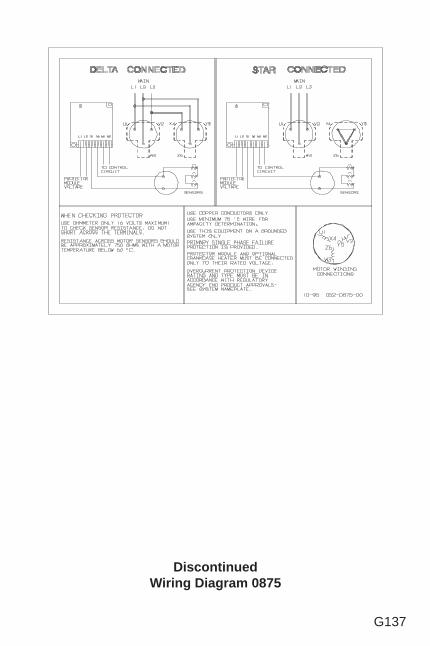
G137
DiscontinuedWiring Diagram 0875
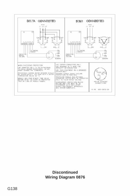
G138
DiscontinuedWiring Diagram 0876
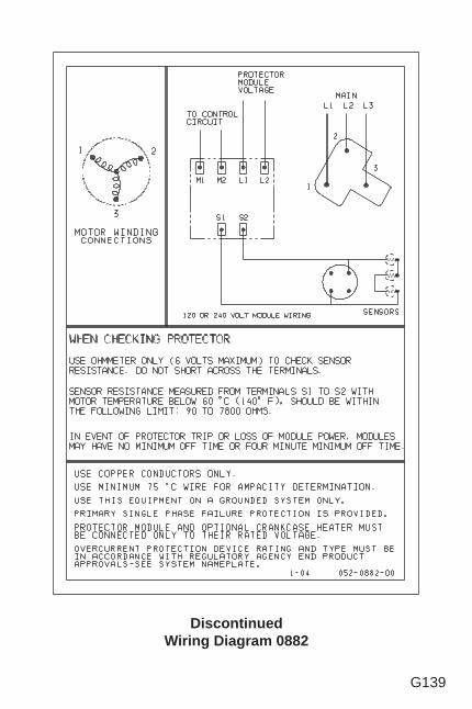
G139
DiscontinuedWiring Diagram 0882
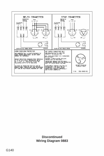
G140
DiscontinuedWiring Diagram 0883
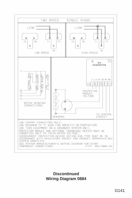
G141
DiscontinuedWiring Diagram 0884
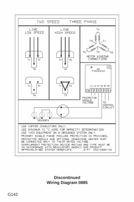
G142
DiscontinuedWiring Diagram 0885

G143
This page is left blank intentionally.
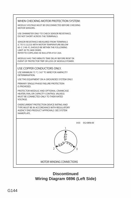
G144
DiscontinuedWiring Diagram 0896 (Left Side)
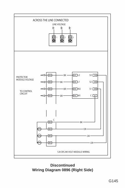
G145
DiscontinuedWiring Diagram 0896 (Right Side)
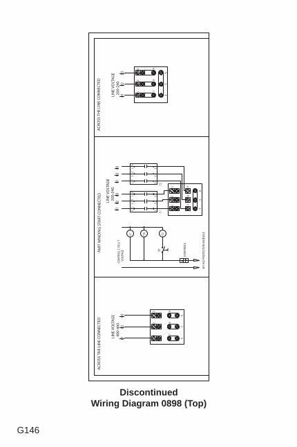
G146
DiscontinuedWiring Diagram 0898 (Top)
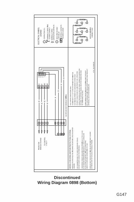
G147
DiscontinuedWiring Diagram 0898 (Bottom)
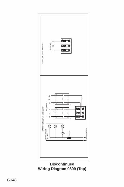
G148
DiscontinuedWiring Diagram 0899 (Top)
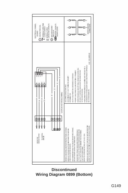
G149
DiscontinuedWiring Diagram 0899 (Bottom)
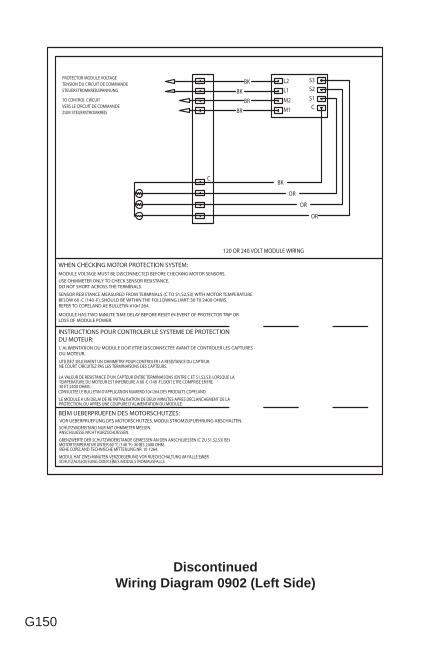
G150
DiscontinuedWiring Diagram 0902 (Left Side)
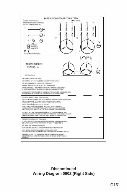
G151
DiscontinuedWiring Diagram 0902 (Right Side)
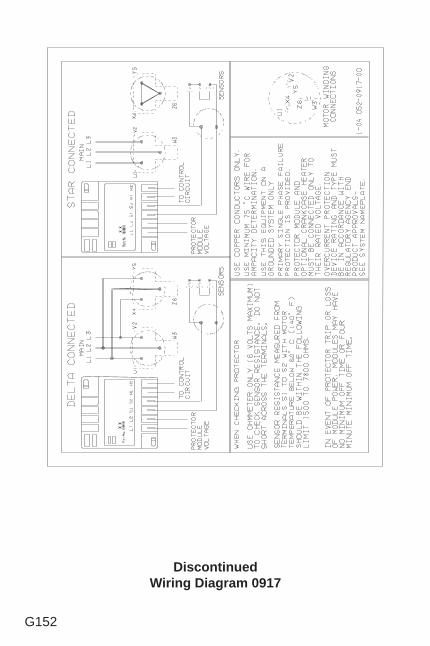
G152
DiscontinuedWiring Diagram 0917
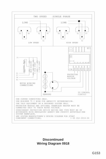
G153
DiscontinuedWiring Diagram 0918
1-00 052-0918-00
LINE
SENSORS
USE COPPER CONDUCTORS ONLY.USE MINIMUM 75 C WIRE FOR AMPACITY DETERMINATION.
T1 T7
T2
T8
USE THIS EQUIPMENT ON A GROUNDED SYSTEM ONLY.PROTECTOR MODULE AND OPTIONAL CRANKCASE HEATER MUST BECONNECTED ONLY TO THEIR RATED VOLTAGE.
MOTOR WINDINGCONNECTIONS
NIAM LANRETXE
GNIDNIW NIAM
TRATS ELOP 4
TRATS ELOP 2
T3
T8T7T2
T1
TWO SPEED SINGLE PHASE
LINE
T1 T7
T2
T3 T8
OVERCURRENT PROTECTION DEVICE RATING AND TYPE MUST BE INACCORDANCE WITH REGULATORY AGENCY END PRODUCT APPROVALS-SEESYSTEM NAMEPLATE.
LOW SPEED HIGH SPEED
SEE SYSTEM MANUFACTURER'S WIRING DIAGRAM FOR STARTCOMPONENT CONNECTIONS.
T3
PROTECTORMODULEVOLTAGE
TO CONTROLCIRCUIT
L1 L2 S1 S2 M1 M2Part-No. XXXXXX
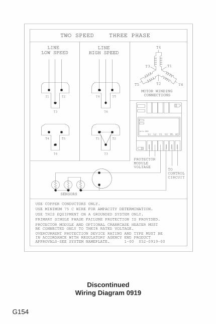
G154
DiscontinuedWiring Diagram 0919
LINEHIGH SPEED
SENSORS
T4 T5
T6
MOTOR WINDINGCONNECTIONS
T1 T2
T3
T4
T1
T6T2T5
T3
LINELOW SPEED
T1 T2
T3
T4 T5
T6
TWO SPEED THREE PHASE
PROTECTOR MODULE AND OPTIONAL CRANKCASE HEATER MUSTBE CONNECTED ONLY TO THEIR RATED VOLTAGE.
USE THIS EQUIPMENT ON A GROUNDED SYSTEM ONLY.USE MINIMUM 75 C WIRE FOR AMPACITY DETERMINATION.USE COPPER CONDUCTORS ONLY.
PRIMARY SINGLE PHASE FAILURE PROTECTION IS PROVIDED.
OVERCURRENT PROTECTION DEVICE RATING AND TYPE MUST BEIN ACCORDANCE WITH REGULATORY AGENCY END PRODUCTAPPROVALS-SEE SYSTEM NAMEPLATE. 1-00 052-0919-00
PROTECTORMODULEVOLTAGE
TOCONTROLCIRCUIT
L1 L2 S1 S2 M1 M2Part-No. XXXXXX
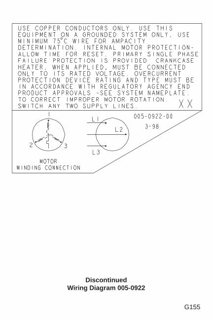
G155
DiscontinuedWiring Diagram 005-0922
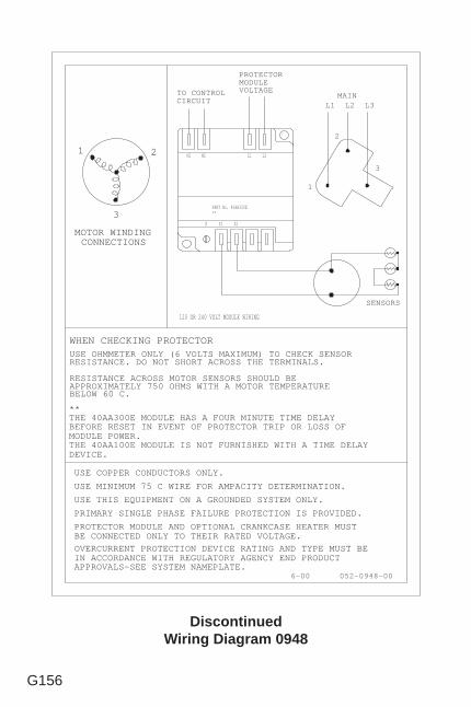
G156
DiscontinuedWiring Diagram 0948
052-0948-006-00
MOTOR WINDINGCONNECTIONS
MAIN
1 2
3
PROTECTOR MODULE AND OPTIONAL CRANKCASE HEATER MUSTBE CONNECTED ONLY TO THEIR RATED VOLTAGE.
USE COPPER CONDUCTORS ONLY.
PRIMARY SINGLE PHASE FAILURE PROTECTION IS PROVIDED.
USE THIS EQUIPMENT ON A GROUNDED SYSTEM ONLY.
USE MINIMUM 75 C WIRE FOR AMPACITY DETERMINATION.
1
2
3
L1 L2 L3
OVERCURRENT PROTECTION DEVICE RATING AND TYPE MUST BEIN ACCORDANCE WITH REGULATORY AGENCY END PRODUCTAPPROVALS-SEE SYSTEM NAMEPLATE.
SENSORS
TO CONTROLCIRCUIT
PROTECTORMODULEVOLTAGE
WHEN CHECKING PROTECTORUSE OHMMETER ONLY (6 VOLTS MAXIMUM) TO CHECK SENSORRESISTANCE. DO NOT SHORT ACROSS THE TERMINALS.
RESISTANCE ACROSS MOTOR SENSORS SHOULD BEAPPROXIMATELY 750 OHMS WITH A MOTOR TEMPERATUREBELOW 60 C.
**THE 40AA300E MODULE HAS A FOUR MINUTE TIME DELAYBEFORE RESET IN EVENT OF PROTECTOR TRIP OR LOSS OFMODULE POWER.THE 40AA100E MODULE IS NOT FURNISHED WITH A TIME DELAYDEVICE.
120 OR 240 VOLT MODULE WIRING
M1 M2 L1 L2
X S1 S2
PART No. 40AA300E**
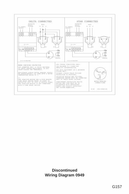
G157
DiscontinuedWiring Diagram 0949
L1 L2 L3
W3
V2 Y5X4
Z6
SENSORS
MAIN
PROTECTOR MODULE AND OPTIONALCRANKCASE HEATER MUST BE CONNECTEDONLY TO THEIR RATED VOLTAGE.
USE COPPER CONDUCTORS ONLY.
PRIMARY SINGLE PHASE FAILUREPROTECTION IS PROVIDED.
USE THIS EQUIPMENT ON A GROUNDEDSYSTEM ONLY.
6-00 052-0949-00
USE MINIMUM 75 C WIRE FORAMPACITY DETERMINATION.
MOTOR WINDINGCONNECTIONS
L1 L2 L3
U1 V2 Y5X4
SENSORS
MAIN
OVERCURRENT PROTECTION DEVICERATING AND TYPE MUST BE INACCORDANCE WITH REGULATORYAGENCY END PRODUCT APPROVALS-SEE SYSTEM NAMEPLATE.
U1
W3 Z6
U1
Y5X4 V2
Z6
W3
DELTA CONNECTED STAR CONNECTED
WHEN CHECKING PROTECTORUSE OHMMETER ONLY (6 VOLTS MAXIMUM)TO CHECK SENSOR RESISTANCE. DO NOTSHORT ACROSS THE TERMINALS.
RESISTANCE ACROSS MOTOR SENSORS SHOULDBE APPROXIMATELY 750 OHMS WITH A MOTORTEMPERATURE BELOW 60 C.
**THE 40AA300E MODULE HAS A FOUR MINUTETIME DELAY BEFORE RESET IN EVENT OFPROTECTOR TRIP OR LOSS OF MODULE POWER.THE 40AA100E MODULE IS NOT FURNISHEDWITH A TIME DELAY DEVICE.
120 OR 240 VOLT MODULE WIRING120 OR 240 VOLT MODULE WIRING
TO CONTROLCIRCUIT
PROTECTORMODULEVOLTAGE
M1 M2 L2L1
S2S1X S1
M1 L1
TO CONTROLCIRCUIT
L2
PROTECTORMODULEVOLTAGE
S2
M2
X
PART No. 40AA300E**
PART No. 40AA300E**
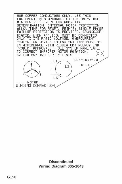
G158
DiscontinuedWiring Diagram 005-1043
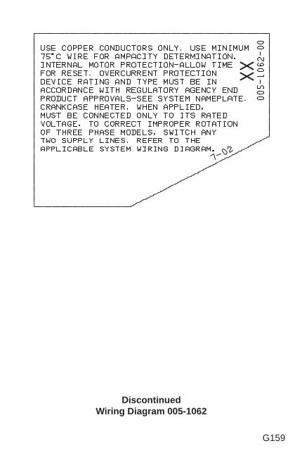
G159
DiscontinuedWiring Diagram 005-1062
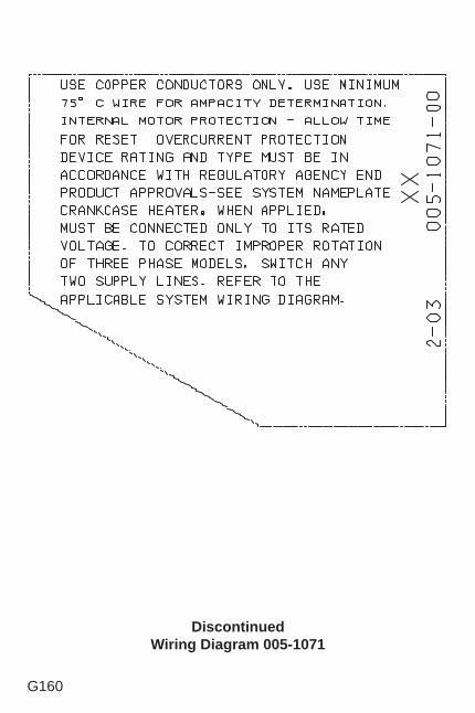
G160
DiscontinuedWiring Diagram 005-1071
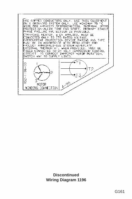
G161
DiscontinuedWiring Diagram 1196
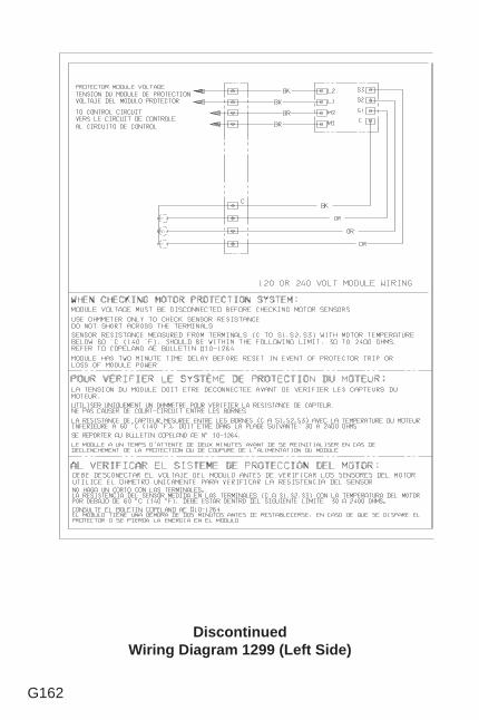
G162
DiscontinuedWiring Diagram 1299 (Left Side)
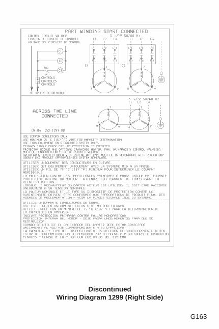
G163
DiscontinuedWiring Diagram 1299 (Right Side)
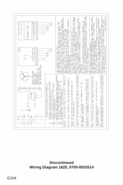
G164
DiscontinuedWiring Diagram 1825, 0700-8503514
SECTION H
ELECTRICAL TROUBLESHOOTING PROCEDURES
TOPICS
If The Compressor Will Not Run ............................... H2
If The Compressor Starts But Trips Repeatedly ....... H5
If The Compressor Runs But Will Not Refrigerate .... H8
CAUTIONBefore attempting any electrical trouble-shooting, makesure all grounds are connected and secure and there isground continuity throughout the compressor system. Also ensure the compressor system is correctly grounded to the power supply. If you are not a qualifed service person familiar with electrical troubleshooting techniques, DO NOT PROCEED until a qualifed service person is available.
H2
IF THE COMPRESSOR WILL NOT RUN
If a compressor fails to start and run properly, it is important that the compressor be tested to determine its condition. It is possible that external electrical components may be defective, the protector may be open, a safety device may be tripped, or other conditions may be preventing compressor operation. If the compressor is not the source of the malfunction, replacing the compressor will only result in the unnecessary expenditure of time and money while the basic problem remains.
1. If there is no voltage at the compressor terminals, follow the wiring diagram and check back from the compressor to the power supply to fi nd where the circuit is interrupted.
Check the controls (low pressure, high pressure, thermostat, oil pressure safety, etc.) to see if the contact points are closed. If a contactor is used, check to see if the contacts are closed. Check for a blown fuse, open disconnect switch, or loose connections.
2. If voltage is available at the compressor terminals and it is below 90 percent of the nameplate voltage, it is possible the motor may not develop suffi cient starting torque. Check to determine if wire sizes are adequate, electrical connections are loose, the circuit is overloaded, or if the power supply is adequate.
3. On units with single phase PSC motors, the suction and discharge pressures must be equalized before starting because of the low starting torque of the motor. Any change in the refrigerant metering device,
H3
the addition of a drier, or other changes in the system components may delay pressure equalization and create diffi culties. If PSC motor starting problems are being encountered, the addition of a hard start kit is recommended.
4. On single phase compressors, a defective start capacitor or relay may prevent the compressor from starting. If the compressor attempts to start, but is unable to do so or if there is a humming sound, check the relay to see if the relay contacts are damaged or its coil opened. The relay contacts should be closed during the initial starting cycle, but should open as the compressor comes up to speed.
Remove the wires from the start relay and check continuity through the relay coil. Replace the relay if there is no continuity. Use an ohmmeter to check across the relay contacts. Potential relay contacts are normally closed when the relay is not energized, while current relay contacts are normally open. If either gives an incorrect reading, replace the relay.
Do not attempt to run a compressor that has a capacitor that is bulging, leaking, or damaged. It must be replaced.
Make sure capacitors are electrically discharged before checking. Start capacitors should have bleed resistors. Check for continuity between the capacitor terminals and between the capacitor terminals and the case. Continuity indicates a short, and the capacitor should be replaced.
Substitute “a known to be good” start capacitor if available. If the compressor then starts and runs properly, replace the original start capacitor. On
H4
PSC motors, substitute a “a known to be good” run capacitor if available. If the compressor then starts and run properly, replace the original run capacitor.If a capacitor tester is not available, an ohmmeter may be used to check run and start capacitors for shorts or open circuits. Use an ohmmeter set to its highest resistance scale and connect probes to capacitor terminals.
a. With a good capacitor, the indicator should fi rst move towards zero and then increase towards infi nity.
b. If there is no movement of the ohmmeter indicator, an open circuit is indicated.
c. If the ohmmeter indicator moves to zero and remains there or on a low resistance reading, a short circuit is indicated. Defective capacitors should be replaced.
5. If the correct voltage is available at the compressor terminals and no current is drawn, remove power. Then remove all wires from the terminals and check for continuity through the motor winding. On single phase compressors, check for continuity from terminals C to R, and C to S and R to S. On three phase compressors, check for continuity between the terminals for connections to phases 1 and 2, 2 and 3, and 1 and 3. On compressors with line break inherent (internal) protectors, an open overload protector can cause a lack of continuity. If the compressor is warm, it may require consider-able time to cool down. If continuity cannot be established through all motor winding, the compressor should be replaced.
Check the motor for ground by means of a continuity check between the common terminal and the compressor shell. If there is a ground, replace the
H5
compressor.
6. If the compressor has an external protector, check for continuity through the protector or protectors. All external and internal inherent protectors on Copelametic compressor can be replaced in the fi eld. On larger compressors with thermostats, thermotectors, or solid state sensors in the motor windings; H,L,S protection (see Section D for compressor nomenclature), the internal protective devices cannot be replaced, and the compressor must be changed if the internal protectors are defective or damaged.
IF THE COMPRESSOR STARTS BUT TRIPS REPEATEDLY ON THE OVERLOAD PROTECTOR
1. Check the compressor suction and discharge pressures while the compressor is operating. Be sure the refrigerant is compatible with the compressor and the temperature range is within the limitations of the compressor. If pressures are excessive, it may be necessary to clean the condenser, remove non-condensables from the system, add a crankcase pressure regulating valve, modify the system control, or take such other action as may be necessary to avoid excessive pressures. If the fan motor is three phase, make sure it is running in the right direction.
An excessively low suction pressure may indicate a loss of charge, and a suction gas cooled compressor may not be getting enough refrigerant vapor across the motor for proper cooling.
On units with no service gauge ports where pressures can’t be checked, check the condenser to be sure it is
H6
clean and fan is running. Excessive temperatures on suction and discharge lines may also indicate abnormal operating conditions.
2. Check the line voltage at the motor terminals while the compressor is operating. The voltage should be within 10 percent of the nameplate voltage rating. If outside those limits, the voltage supply must be brought within the proper range, or a compressor with different electrical characteristics must be used.
3. Check the amperage drawn while the compressor is operating. The amperage drawn should be within ±10 percent of the published compressor curve data for the given pressures the compressor is operating under. High amperage can be caused by low voltage, high head pressure, high suction pressure, high oil level, mechanical compressor damage, defective run capacitors, or a defective starting relay.
On three phase compressors, check amperage in each line. One or two high amperage legs on a three phase motor indicates an unbalanced voltage supply, or a winding imbalance, which can cause motor overheating. If all three legs are not drawing approximately equal amperage, temporarily switch the leads to the motor to determine if the high leg stays with the line or stays with the terminal. If the high amperage reading stays with the line, the problem is in the line voltage supply. If the high amperage reading stays with the terminal, the problem is in the motor.
If the amperage is suffi ciently unbalanced to cause a protector trip (approximately 10%) and the voltage supply is unbalanced, check with the power company to see if the condition can be corrected. If the voltage supply is balanced, indicating a defective motor phase, the compressor should be replaced.
H7
4. Check for a defective run capacitor or starting relay in the same manner described in the previous section.
5. Check for wiring against the wiring diagram in the terminal box. On dual voltage motors, check the location of the terminal jumper bars to be sure phases are properly connected.
6. Overheating of the cylinders and head can be caused by a leaking valve plate or relief valve. To check, front seat the suction service valve and briefl y pump the compressor into a vacuum. Stop the compressor and open the suction valve to allow the pressure on the suction gauge to build up to 0 psig. Again, close the valve. If the pressure on the gauge continues to increase steadily, the valve plate or relief valve is leaking. Remove the head and check the valve plate. Replace if necessary.
7. If all operating conditions are normal, the voltage supply at the compressor terminals balanced and within limits, the compressor crank-case temperature within normal limits, the amperage drawn within the specifi ed range, the motor protector may be defective and should be replaced.
If the operating conditions are normal and the compressor is running excessively hot for no observable reason, or if the amperage drawn is above the normal range and suffi cient to repeatedly trip the protector, the compressor has internal damage and should be replaced.
H8
IF THE COMPRESSOR RUNS BUT WILL NOT REFRIGERATE
1. Check the refrigerant charge and the operating pressures. Any abnormal operating conditions must be corrected.
2. If the suction pressure is high and the evaporator and condenser are functioning normally, check the compressor amperage draw. An amperage draw within ±5 percent of published rating data, corrected for actual measured voltage, indicates normal compressor operation. An amperage draw considerably below the published rating data indicates a possible broken suction valve, discharge valve, broken connecting rod blown gasket, or worn rings in the compressor. Check the pistons and valve plate on an accessible compressor. If no other reason for lack of capacity and low amperage can be found, replace a welded compressor.
An amperage draw considerably above published rating data for the given operating pressures indicates possible bearing damage, and the compressor should be replaced.
Published compressor rating data for each model can be obtained by your Emerson Climate Technologies Wholesaler.
SECTION I
IDENTIFYING COMPRESSOR FAILURES
Most compressors fail due to system malfunctions which must be corrected to prevent repeat failures. After a compressor fails, field examination of the failed compressor often will reveal symptoms of system problems. Proper corrections will help eliminate future failures.Field examination does not affect warranty as long as all access plates and heads are rein-stalled with all internal components put back inside the compressor.
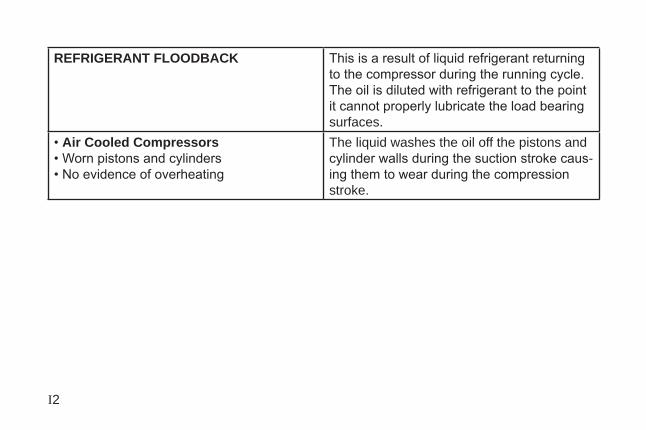
I2
REFRIGERANT FLOODBACK This is a result of liquid refrigerant returning to the compressor during the running cycle. The oil is diluted with refrigerant to the point it cannot properly lubricate the load bearing surfaces.
• Air Cooled Compressors• Worn pistons and cylinders• No evidence of overheating
The liquid washes the oil off the pistons and cylinder walls during the suction stroke caus-ing them to wear during the compression stroke.
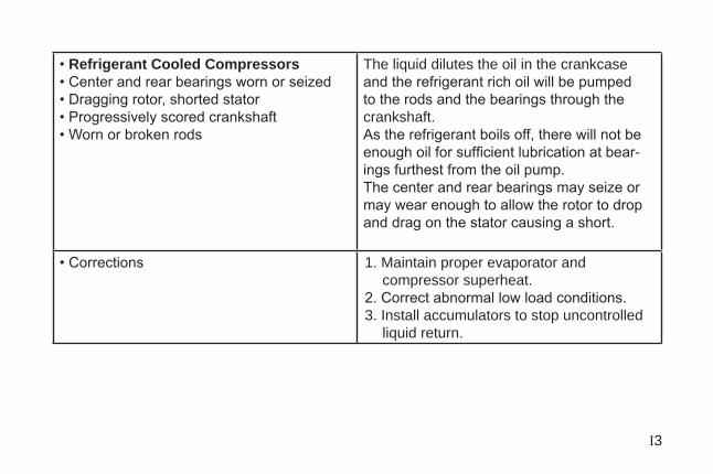
I3
• Refrigerant Cooled Compressors• Center and rear bearings worn or seized• Dragging rotor, shorted stator• Progressively scored crankshaft• Worn or broken rods
The liquid dilutes the oil in the crankcase and the refrigerant rich oil will be pumped to the rods and the bearings through the crankshaft.As the refrigerant boils off, there will not be enough oil for sufficient lubrication at bear-ings furthest from the oil pump.The center and rear bearings may seize or may wear enough to allow the rotor to drop and drag on the stator causing a short.
• Corrections 1. Maintain proper evaporator and compressor superheat.
2. Correct abnormal low load conditions.3. Install accumulators to stop uncontrolled
liquid return.
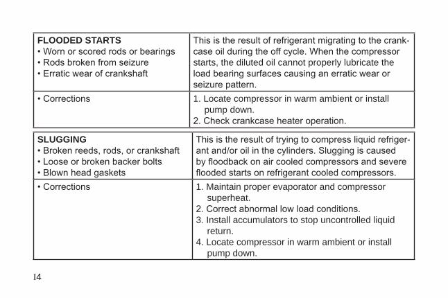
I4
FLOODED STARTS• Worn or scored rods or bearings• Rods broken from seizure• Erratic wear of crankshaft
This is the result of refrigerant migrating to the crank-case oil during the off cycle. When the compressor starts, the diluted oil cannot properly lubricate the load bearing surfaces causing an erratic wear or seizure pattern.
• Corrections 1. Locate compressor in warm ambient or install pump down.
2. Check crankcase heater operation.
SLUGGING• Broken reeds, rods, or crankshaft• Loose or broken backer bolts• Blown head gaskets
This is the result of trying to compress liquid refriger-ant and/or oil in the cylinders. Slugging is caused by floodback on air cooled compressors and severe flooded starts on refrigerant cooled compressors.
• Corrections 1. Maintain proper evaporator and compressor superheat.
2. Correct abnormal low load conditions.3. Install accumulators to stop uncontrolled liquid
return.4. Locate compressor in warm ambient or install
pump down.
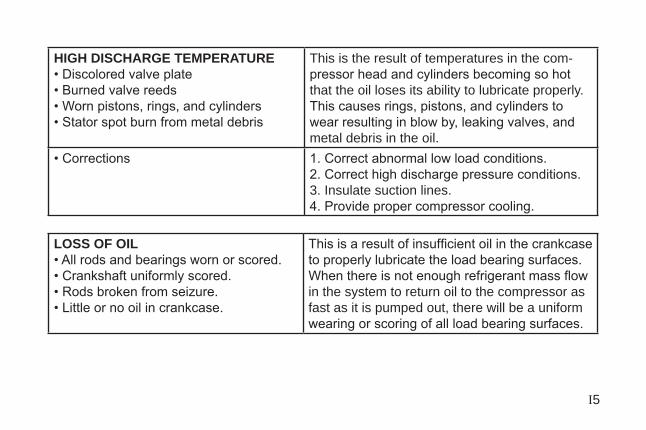
I5
HIGH DISCHARGE TEMPERATURE• Discolored valve plate• Burned valve reeds• Worn pistons, rings, and cylinders• Stator spot burn from metal debris
This is the result of temperatures in the com-pressor head and cylinders becoming so hot that the oil loses its ability to lubricate properly.This causes rings, pistons, and cylinders to wear resulting in blow by, leaking valves, and metal debris in the oil.
• Corrections 1. Correct abnormal low load conditions.2. Correct high discharge pressure conditions.3. Insulate suction lines.4. Provide proper compressor cooling.
LOSS OF OIL• All rods and bearings worn or scored.• Crankshaft uniformly scored.• Rods broken from seizure.• Little or no oil in crankcase.
This is a result of insufficient oil in the crankcase to properly lubricate the load bearing surfaces. When there is not enough refrigerant mass flow in the system to return oil to the compressor as fast as it is pumped out, there will be a uniform wearing or scoring of all load bearing surfaces.
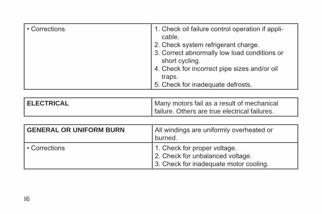
I6
• Corrections 1. Check oil failure control operation if appli-cable.
2. Check system refrigerant charge.3. Correct abnormally low load conditions or
short cycling.4. Check for incorrect pipe sizes and/or oil
traps.5. Check for inadequate defrosts.
ELECTRICAL Many motors fail as a result of mechanical failure. Others are true electrical failures.
GENERAL OR UNIFORM BURN All windings are uniformly overheated or burned.
• Corrections 1. Check for proper voltage.2. Check for unbalanced voltage.3. Check for inadequate motor cooling.
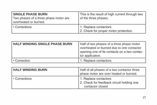
I7
SINGLE PHASE BURNTwo phases of a three phase motor are overheated or burned.
This is the result of high current through two of the three phases.
• Corrections 1. Replace contactors.2. Check for proper motor protection.
HALF WINDING SINGLE PHASE BURN Half of two phases of a three phase motor overheated or burned due to one contactor opening one of its contacts on a two contac-tor application.
• Correction 1. Replace contactors.
HALF WINDING BURN Half of all phases of a two contactor three phase motor are over heated or burned.
• Corrections 1. Replace contactors2. Check for feedback circuit holding one
contactor closed
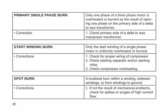
I8
PRIMARY SINGLE PHASE BURN Only one phase of a three phase motor is overheated or burned as the result of open-ing one phase on the primary side of a delta to wye transformer.
• Correction 1. Check primary side of a delta to wye mainpower transformer.
START WINDING BURN Only the start winding of a single phase motor is uniformly overheated or burned.
• Corrections 1. Check for proper wiring of compressor.2. Check starting capacitor and/or starting
relay.3. Check compressor overloading.
SPOT BURN A localized burn within a winding, between
windings, or from windings to ground. • Corrections 1. If not the result of mechanical problems,
check for spikes or surges of high current flow.
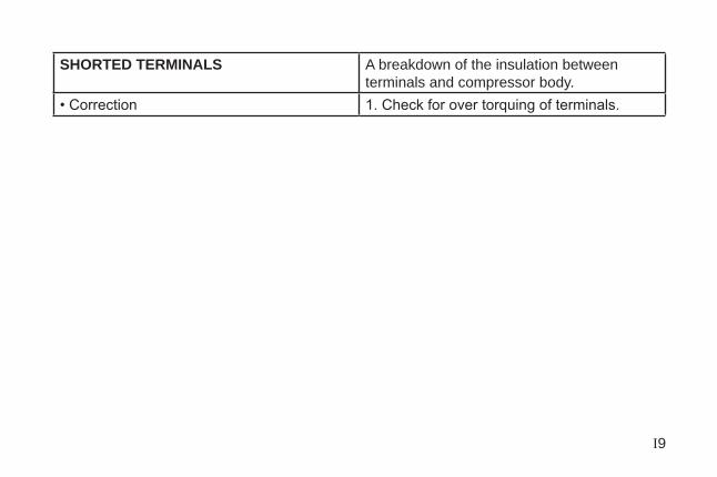
I9
SHORTED TERMINALS A breakdown of the insulation between terminals and compressor body.
• Correction 1. Check for over torquing of terminals.