induction-furnace-handbook.pdf - TCT Tesic
163
The following manual is no longer available in its printed version and will no longer be issued. With kind written permission of the author Mr. Dipl.-Ing. Herbert Netzel, we would like to hereby provide all foundry friends this manual freely available for download. This version is to facilitate free from any kind of advertising to ease the download. With Best Regards Zoran Tesic Managing Director of TCT Tesic GmbH
-
Upload
khangminh22 -
Category
Documents
-
view
0 -
download
0
Transcript of induction-furnace-handbook.pdf - TCT Tesic
The following manual is no longer available in its printed version and will no longer be issued.
With kind written permission of the author Mr. Dipl.-Ing. Herbert Netzel, we would like to hereby
provide all foundry friends this manual freely available for download.
This version is to facilitate free from any kind of advertising to ease the download.
With Best Regards
Zoran Tesic
Managing Director of TCT Tesic GmbH
Induction – Furnace - Handbook
byHerbert H. Netzel
This handbook is intended as a reference aid for foundry workers,process workers, master craftsmen, technicians and engineers employedin metal shops, foundries and maintenance.
The technical terms are arranged alphabetically, and are therefore easyto find.
3rd edition, extended by approximately 130 key terms and now contain-ing approximately 310 key terms,
March 2004
Copying prohibited, either in whole or in part.
Published by
I E SInduktion Experience ServiceHarkortring 6
D 58453 WITTEN
Tel.: 0049 (0) 23 02 69 60 39Fax: 0049 (0) 23 02 78 91 75E-mail: [email protected]
1
Induction-Furnance Handbook – H. H. Netzel
Foreword
The author Herbert H. Netzel has had 35 years of experience with cru-cible induction furnaces. Before joining BBC in 1970, he made his initialcontacts whilst studying electrical technology with an operator of a 1-tmains frequency furnace. After starting work for the major furnace man-ufacturer in Dortmund, he was involved in the customer service area inthe design, construction, installation and commissioning of mains fre-quency and medium frequency furnaces, including 20 years as the man-ager of the Customer Service Department. In addition to melting fur-naces, holding furnaces and casting equipment in general, he also pro-vided consultation on subsidiary equipment such as transformers,recooling systems and charging equipments. His area of responsibilityalso included auxiliary equipment such as crucible cleaning devices,slag-tapping equipment, crucible ejection machinery and extraction sys-tems. His particular area of interest always remained the specific operat-ing procedures used within the different foundries.
Due to the demand for information by many employees in the foundries,the author subsequently decided to compile this handbook.
The 1st edition of May 2003 was sold out within 2 months, and the 2nd
edition was published to meet the lively demand.
The supplier industry came up with the suggestion of printing theInduction Furnace Handbook in English, and including in it advertise-ments for the products of interested firms. This provided the impetus forthe 3rd edition and the increase in the number of technical terms byapproximately 90 %. Depending on the demand, the English edition willbe published at the beginning of 2004.
Chapter 1 – Manual for safe Induction Furnace Operation
Chapter 2 – Induction Furnace Handbook
Witten, March 2004

Chapter 1
Manual for safe induction furnace operation
Table of Contents
1. Foreword
2. System components
3. Functional description
4. Melting process
5. Safety instructions
6. Sanitary instructions
7. Conclusion
4

5
Induction-Furnance Handbook – H. H. Netzel
1. Foreword
With the aid of this Manual on the safe operation of induction furnaces, we
would like to provide all interested parties and operators of such systems with
helpful information for their employees.
A known or recognised danger can be prevented by taking suitable measures,
before accidents or damage are caused. Lack of awareness of dangers and their
consequences is the greatest omission in casting foundries. Avoiding accidents
costs a lot less than rectifying the consequences of accidents. Every works should
therefore carry out relevant training for their employees at least once per year.
New employees can thereby learn from experienced employees, and at the same
time be familiarised with them about the latest state of the technology.
2. System components
An induction furnace system consists of:
a) Energy supply with performance switch in front of the furnace transformer
b) NF switching system with control devices for the performance unit and an
operating cabinet with switching and display devices for the operation of the
furnace system
c) MF converter system with control devices for the performance unit and an
operating cabinet with switching and display devices and, if necessary to, a
processor for the operation of the furnace system
d) Cooling water supply system including return cooling system
e) Hydraulic system for the operation of the hydraulic components from a con-
trol panel
f) Ventilation system for the system areas
g) Charging system for charging the crucible furnaces
h) Scrap pre-heating system for drying out preheating charging materials
i) Induction crucible furnace for holding the melting crucible
j) Channel induction furnaces and casting equipment

6
3. Functional description of the system components
a) Energy supply
The energy supply with performance switch in front of the transformer
serves to connect the furnace transformer to the medium voltage power
supply network of the power supply company. The transformer converts
the medium voltage to the voltage required for the operation of the fur-
nace, e.g. from 20 kV three-phase current to 770 V for MF systems or
2000 V for NF systems. In the case of MF systems, a secondary fixed volt-
age is used, and no multiple contact switch is required. 10 or 12-stage mul-
tiple contact switches are used for NF systems. The transformers are
equipped with the following built-in monitoring devices: Thermometers,
oil filling level monitoring, Buchholz relays and air de-humidifiers.
b) Power supply line frequency switching system
A power supply frequency switching system consists of a main contactor
combination for operating the main power circuit, a switchable resistor for
reducing the surge current when switching on, which can be up to six times
the nominal current, the balancing system with the balancing reactor, capac-
itors and switching devices to control the system in line with operating
requirements, compensating capacitors with switching devices for controlled
compensation to cos phi = 1 and the connecting leads to the furnace connec-
tion. The system is controlled using the devices in the operating cabinet.
c) Medium frequency converter system
For an MF induction furnace, a converter is required to produce the neces-
sary to medium frequency from the 50 Hz power supply. In order to do this,
a direct voltage is produced in a rectifier, and fed to the inverter via a
smoothing choke, and a medium frequency voltage is produced in the
inverter with the aid of compensating capacitors and the inductivity of the
furnace coil. The regulation of the converter is carried out by the built-in con-
trol electronics. The control of the furnace is carried out using the devices in
the operating cabinet and if necessary with the aid of the processor.
7
Induction-Furnance Handbook – H. H. Netzel
d) Cooling water supply system
The operation of an induction furnace system requires a cooling water sys-
tem, including return cooling of the heated water. In the converter, includ-
ing the capacitors and the smoothing choke, the water circulating in the cir-
cuit is heated up from approx. 34 °C to 38 °C, and must be cooled down
again to 34 °C by a cooling system activator to. Approximately 215 l/h must
be pumped through the electrical equipment per kW of performance loss. In
the furnace coil, the water is heated up from approx. 35 °C to
62 °C, and must be cooled back down to 35 °C by a separate cooling system.
Approximately 32 l/h have to be pumped through the system per kW of
performance loss. In the event of a power failure or other interruption, an
emergency water supply must be installed for the furnace circuit. For oper-
ation in winter, when the furnace is switched off, heating must be provided.
e) Hydraulic system
A hydraulic station was high-pressure pumps is required for operation of
the tilting, cover and hood cylinders. The cylinders are actuated from the
control panel with the aid of lever-type switches for the electric valves.
Formerly, purely mechanical, hand-operated block control valves were
used. In the case of channel furnaces, emergency return valves are some-
times fitted, which are actuated by hand and can be installed at various
points in the system.
f) Ventilation system
Since a certain amount of dust and dirt is inevitable in smelting opera-
tions, the system components in the various areas have to be protected.
The heated air in these areas also has to be replaced with fresh air for cool-
ing purposes. In order to fulfil both these requirements, filtered air is fed
into the system rooms at a slight over-pressure. These rooms are therefore
almost completely dust-free to do this over-pressure. At an air heating per-
formance for the cooling air of 10 K, approx. 310 m3/h per kW of perform-
ance loss are needed.
g) Charging systems
Charging systems are required for the charging of the crucible furnaces.
Smaller furnaces up to approx. 500 kg are as a rule charged by hand.
Furnaces of up to approx. 3,000 kg are filled with the aid of hydraulically

8
operated delivery chutes without a vibration drive. In the case of furnaces
from approx. 5000 kg and crucible diameter is of greater than 800 mm,
vibration chutes are used. From approx. 1,200 mm diameter, charging
buckets with opening bottoms are also used for mains frequency induction
furnaces. The most commonly used system is the vibration chute with var-
ious additional devices such as: impact protection for the crucible, a con-
nection for an extraction hood, a complete housing for the purposes of
noise protection and lateral swivel equipment for the operation of two fur-
naces from one rail system in a Y-arrangement. The charging troughs must
be so designed that the available scrap can also be made up and conveyed
in sufficient quantities. In the case of a high proportion of small particles,
a separating device may have to be installed in the area 500 mm in front of
the edge of the crucible.
h) Pre-heating of scrap
In the operation of crucible furnaces, care must be taken to ensure that no
damp or wet materials and can be immersed in the liquid bath. Scrap-dry-
ing systems are used to avoid the water vapour explosions that can then
occur. Here the scrap or other material is heated up to over 100 °C before
being charged into the crucible furnace.
i) Induction crucible furnace
The most commonly used smelting system is the induction crucible fur-
nace. The induction crucible furnace has a crucible which heated by an
induction furnace coil surrounding the crucible. This arrangement makes
use of the transformer principle of induction, i.e. if an electrical conductor
is placed in a fluctuating magnetic field, a voltage will be induced in the
conductor. In crucible furnaces, this voltage causes strong eddy currents,
which due to the resistance of the material, cause it to be heated and ulti-
mately to melt. The water is fed by means of cooling water hoses, and duct-
ed away by the water-cooled cables used for the energy supply. The indi-
vidual cooling water lines are monitored with regard to volume and tem-
perature.
j) Channel furnaces and casting equipment
In the case of channel furnaces and casting equipment heated by induc-
tors, channel inductors are used as the heating equipment. A channel
inductor is designed in a similar way to a transformer, and consists of a

9
Induction-Furnance Handbook – H. H. Netzel
closed yoke, on which one or two coils are mounted. The channels of the
inductors run around these coils. The water is fed by means of cooling
water hoses, and ducted away by the water-cooled cables used for the
energy supply. The individual cooling water circuits are monitored with
regard to volume and temperature.
4. The melting process
The melting process is the procedure from the first charging to the tapping of the
finished melt batch.
When cold-starting mains frequency furnaces, starter blocks, starter rings or
compressed scrap are required, that have been made up into starter blocks.
Mains frequency furnaces are used as sump melting furnaces. At a liquid metal
filling level of approx. 60%, a suitable quantity of scrap is filled into the liquid
bath at a temperature of approx. 1,450 °C. The charged scrap is now melted by
super-heating the melt. After the first set has settled and started to melt, the sec-
ond set is added. This process is continued until the filling level for taking a sam-
ple is reached. In accordance with the analysis, the final analysis is now set and
the remaining materials with the alloy elements are added and melted. The melt
temperature should be 80 - 100 K below the tapping temperature. By agreement
with the foundry, the furnace is skimmed for tapping and brought up to the tar-
get temperature. In the case of NF furnaces, approx. 8 minutes are needed for
this purpose, depending on the specific performance, e.g. 12 t – 3,240 kW at
432 kWh per 100 K.
MF furnaces are operated without a sump as charge melting furnaces. The mate-
rial is charged into the empty furnace up to the upper edge of the furnace coil.
When the electrical power supply is switched on, a voltage is induced in the
scrap, which causes strong eddy currents. Due to the high electric current and
the resistance of the material, the material is heated up to the point of melting.
The melting material settles together, and the furnace can be recharged with
more material. In MF furnaces, the material is not charged into the liquid bath,
but onto the still solid material. When the liquid filling level has about reached
the upper edge of the coil, the sample is taken and the material for the final
analysis added to the furnace. This material is now melted, and the melt brought
up to a temperature of 80 - 100 K below the tapping temperature. By agreement
with the foundry, the furnace is now skimmed and brought up to the tapping
temperature. In the case of MF furnaces, 2 – 5 minutes are needed for this pur-
pose, depending on the specific performance. At 5 t and 3,600 kW performance,
3 minutes are required for 100 K, after which the 1st tapping is carried out.
10
5. Safety instructions
The smelting process is always associated with dangers due to molten material
which cannot always be accurately estimated in advance. It is said that known
dangers are no dangers, or at least dangers that can be anticipated and counter-
acted. Most foundry accidents are caused by the ejection of molten metal in the
form of splashes, small and large drops, heat radiation from the melting bath
and water vapour explosions. The causes of these occurrences are explained
below:
Metal splashes with a relatively low volume of melt are created when very small
metal parts come into contact with the melting bath and are ejected from the
melt. If these parts are also wet or damp, this leads to the ejection of small and
large drops.
In the case of hood extraction systems, which are tilted forward for skimming
and radiate heat back toward the operator, the operator is exposed to a great deal
of heat. If the operator is not wearing adequate protective clothing and face pro-
tection, this can lead to burns on the skin and damage to the eyes.
Water vapour explosions always occur when liquids get under the surface of the
bath. In extreme cases, 1 cc of water penetrating deep below the surface can
expand in a moment to 1,600 times its original volume.
Water can get into the melting bath not only during the melting process from the
materials charged: water vapour explosions can also be caused by damp or wet
tools.
When operating a crucible furnace, it can happen that the ramming mix has suf-
fered damage, and the melt has been moved forward up to the coil. If this con-
dition leads to a blockage of the windings and the release of water, water can
also penetrate under the melt, resulting in a sudden upward ejection of the melt.
These water vapour explosions have been known to be so powerful that the
cover supporting arm with the furnace cover has been pushed to the side, and
the melt thrown out onto the furnace platform. Operators who were in this area,
and not wearing adequate protective clothing, suffered severe burns.
In every foundry, personnel should receive regular training on such dangers and
the need to observe all applicable safety regulations. The most important safety
instructions are given below:
a) Neatness and tidiness at the workplace means that the furnace platform
should be tidy at all times, with the necessary tools ready to hand in their
proper places. Any other materials or objects lying around should be
removed immediately.
b) Adequate lighting at the workplace ensures that irregularities or problems
on the furnace platform can be recognised and rectified immediately.
11
Induction-Furnance Handbook – H. H. Netzel
c) Damage to equipment, operating switches, electrical and hydraulic lines
must be noted in a fault book and reported to maintenance, who should
carry out repairs immediately. Indicating lights are safety devices, and
should be tested once every week.
d) The condition of the crucible should be inspected visually after every
emptying or every tapping. Possible cracks in the crucible wall are indi-
cated by dark traces, which can then be inspected more closely.
e) The material to be charged should be inspected when being made up.
Pipes, tubes or hollow components should be sorted out by hand, and
checked to ensure that they do not hold any water. In winter, scrap should
be checked to ensure it does not contain any snow or ice, which can also
lead to water vapour explosions.
f) Visitors or personnel from other areas must always be made aware of the
dangers and told to remain in a safe place, e.g. the operating station.
g) The minimum level of safety is the equipment of persons on the furnace
platform with safety shoes, or at least closed shoes covering the whole
foot, long trousers extending over the tops of the shoes, overalls or fabric
jacket, protective goggles with side protection and safety helmet. The shift
foreman is responsible for ensuring that safety regulations are observed,
and should if necessary report to the works manager. A protective over-
coat and face protection should be worn during the tapping process.
h) The emergency outlet channel must be kept dry and clean at all times.
i) The furnace body should be inspected once every week, and cleaned
every month of dust, small particles of scrap and other impurities using a
vacuum cleaner.
j) Any oil that has leaked out must be picked up and the spot covered with
sand. The leak must be located and repaired.
k) There must always be two emergency escape routes from the furnace
platform in the event of accidents. These routes must be kept clear at all
times, and may not be blocked even for short periods.
l) Personnel must be notified of the need for safe working practices, and
must also be held responsible for observing these regulations.
m) When working with metal tools in the melting bath, and with the furnace
switched on, the tools must be earthed, or the operator must at least wear
dry leather gloves. Such work should only be carried out with the furnace
switched off. The tools should be warmed up over the bath before immer-
sion, in order to remove any damp or humidity.
n) The formation of bridges must be avoided in order to prevent the
unforeseen breakthrough of molten material to the outside. If a bridge
has formed, the furnace must be switched off and tilted, so that contact
with the melt can be made using a thin handspike. In some cases, the

bridge can be melted with the furnace at low power and in the tilted
position, and the furnace then recharged with more material through
this opening in the basic position, and then fully melted. After tapping,
the crucible must be inspected thoroughly, replaced if necessary and the
furnace relined.
o) In the event of a power failure when the furnace contains a full melt,
and it is not known how long it will take to correct the problem, the fur-
ther procedure must be established. There are two options - either to
allow the melt to solidify, or to empty the crucible. Depending on the
bath temperature, a crucible furnace loses 30 – 50 K/h with the cover
closed. For example, at a bath temperature of 1,500 °C, the furnace can
be left for up to 4 h without power, and with the cooling switched on,
and then slowly be brought back up to temperature. If the shut-down
time cannot be estimated after 2 h, the furnace can still be emptied. In
the case of a channel furnace, the channel has a somewhat higher tem-
perature loss due to the water-cooled jacket. At 70 K/h, the inductor can
be left for up to 2 h without power and with the cooling switched on,
and then be started up again at low power. In case of longer interrup-
tions, an inductor should be protected against solidifying with 15 % of
its nominal performance. The vessel iron loses a maximum of 30 K/h
due to its good insulation.
p) The electrical insulation of the live components against earth is measured
with the aid of an earthing relay. If the melt at earth potential approaches
the coil, the resistance will fall, and the system may have to be switched off.
q) The Saveway system continually measures the distance between the
Saveway electrodes and the melt by means of a special resistance meas-
urement. Depending on the filling level and the indicator sector, the point
of damage can be localised to within approx. 600 mm.
r) If work has to be carried out with the furnace in the tilted position, the
furnace must be secured against tipping. The furnace must also be
secured when pushing out the crucible.
s) Aluminium in pellet form must be available to stop cooking processes.
t) Electrical systems may only be opened and repaired by suitably trained
personnel.
u) Induction furnaces may only be operated by trained personnel who are
aware of the possible dangers.
The condition of the crucible must be inspected visually, and the remaining wall
thickness determined with the aid of measuring devices. An assessment of the
average remaining wall thickness can be made from the performance measure-
ment for NF furnaces, or from the frequency display in the case of MF furnaces.
12

6. Sanitary instructions
Sanitary instructions must conform to the applicable regulations.
In every foundry, the basic safety equipment must be accessible to all employees
at all times.
The basic safety equipment consists of:
a) Fire-extinguishing blankets
b) First aid box
c) Eye rinsing / washing equipment
d) Fire-extinguishing beater
e) Dry powder fire extinguishers
f) Wooden ladders, 3 m and 6 m or longer for channel furnaces and large cru-
cible furnaces.
g) Emergency telephone numbers
h) Instruction board for first aid at the workplace in foundries.
7. Conclusion
In conclusion, we would like to point out that it is impossible to list all the con-
ceivable features of safety training. There is a wide range of different situations,
which all require the appropriate action. The above information is provided to
the best of our knowledge and belief for the benefit of operating personnel in
foundries.
13
Induction-Furnance Handbook – H. H. Netzel
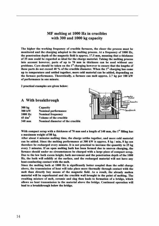
14
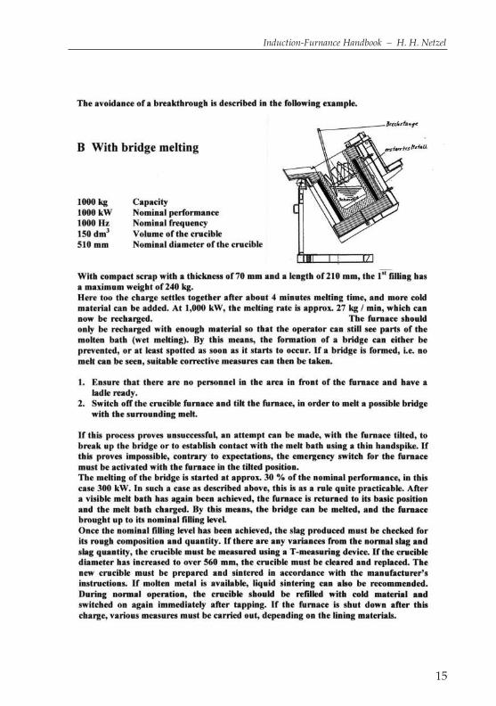
15
Induction-Furnance Handbook – H. H. Netzel
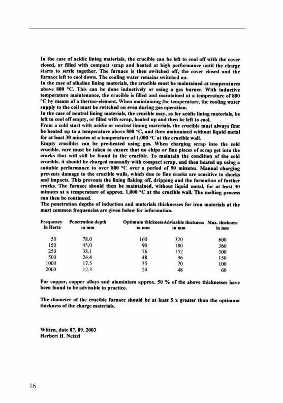
16
17
Induction-Furnance Handbook – H. H. Netzel
Chapter 2
Accident prevention grills
provide safety for operators against the furnace pit which is revealed when thefurnace is tipped. There are 3-sided accident prevention grills which raise them-selves automatically to a height of approx. 1 m behind the furnace and inclinedtoward the front at each side by means of counterbalance weights. A later con-struction works without counterbalance weights, and instead uses pre-loadedsprings, which allow a maximum movement of 1.2 m.
Accumulator
is any device for the storage of energy, such as an electric battery, a pressure ves-sel in the case of air or a pressure accumulator for hydraulic systems.
Additive
is the term for slag-forming, solid materials which are added when melting met-als or for the treatment of melts.
Alitisation
is a surface protection process for steel and certain types of iron for the improve-ment of the scaling resistance by means of the infusion of aluminium. The alu-minium is applied by means of spraying or immersion, and then diffuses intothe material by annealing. Material treated in this way becomes resistant to scal-ing up to approx. 950 °C.
Alloy
is a metallic material consisting of at least 2 elements, produced by alloying dur-ing the molten state.
Alloying
is the introduction of alloy components into a molten mass, in order to producean alloy or to correct or adjust an existing alloy.
Alpaca
is the trade name for the compound also known as German silver or argentan,consisting of 47-60% Cu, 12-25% Ni, up to 2% Pb, and the rest zinc.

24
Annealed cast iron
is a chill casting made from iron containing 2.4 to 3% carbon, which is annealed(tempered) for up to several days at temperatures above 900 °C. This comes inthe form of white and black annealed cast iron. White annealed cast iron isdecarburised annealed cast iron with the following composition:3 to 3.2% C0.75 to 0.55% Simax. 0.20% Smax. 0.10% PMn=1.7x% S
Black annealed cast iron is non-decarburised annealed cast iron with the follow-ing composition:2.40 to 2.60% C1.40 to 1.20% Simax. 0.15% Smax. 0.10% PMn= 1.7x% S
Arc furnace
are available with indirect arc heating, as in the graphite rod furnace, and directarc heating, as in the 3-phase and direct current arc furnace.
Automotive castings
is the designation used for castings for the automotive industry.
Balancing
is required when connecting a 1-phase crucible induction furnace to a 3-phasepower supply. Through the use of Steinmetz switching, the 1-phase load is con-verted into 3-phase of the same size. The power suppliers allow an imbalance of10% of the highest phase current, depending on the stability of the network. Incase of the failure of a balancing choke, a crucible induction furnace can also beoperated without balancing devices. It may be necessary to obtain the permis-sion of the power supply company for this imbalanced load at 60% of the nom-inal current with 2 phases.The important factor in this method of operation is that the nominal current ofthe transformer is not exceeded. an example is given below for a 12.5-t furnacewith 2,000 V and 2,600 kW nominal output.
1. the balanced phase must be disconnected from the network.2. the choke must be completely removed.3. the maximum phase current is determined from the rating plate of the trans-
former.
25
Induction-Furnance Handbook – H. H. Netzel
4. by slowly increasing the output at 70% of the crucible filling level, the maxi-mum voltage in practice can be determined. If for example at 1,700 V thephase current is over 1,000 A, the next lower step at 1,400 V must be definedas the maximum voltage step, in order not to overload the transformer. Theoutput will then be 1,275 kW and 49% of the nominal output.
4. This current is given for the lowest melting stage for constant output. As arule, the top 5 steps are designed for this purpose, which in this case means at1,700 V and Step 6 with 930 A.
5. at 1,700 V and 930 A, this gives an output of 1,580 kW, or 60% of the nominaloutput.
Back-filling
of moulds and crucibles is essential for stability. Crucibles made of SiO2 com-pounds or graphite clay are back-filled with quartz sand. Patching compound isapplied to the upper edge in order to prevent the back-fill trickling out.
Baled scrap
should be free of water, oils and greases, and without hollow components ororganic inclusions. Baled scrap is used in induction and cupola furnaces. Thedimensions must be suitable for the furnace dimensions, i.e. the maximumlength/diagonal should be no more than 60% of the furnace diameter.
Bath earthing
for safety reasons, the melting bath in a crucible induction furnace should be con-tinually earthed. This earthing is as a rule provided by bottom electrodes. In thecase of ceramically lined furnaces, this is no problem. When using crucibles ofgraphite clay or silicon carbide, a spiral of St 4828 in graphite is embedded beneaththe crucible and connected to earth potential outside the furnace housing. Anothermethod is earthing by means of the casting spout, in which is a shackle which iswelded on one side to the steel construction. With the 1st casting from a crucible,the molten metal flows over the shackle, and the bath is then earthed via the con-ducting crucible. Lost tamping forms have as a rule no connection with the bot-tom electrodes during the sintering charge, since the crucible bottom is tamped 5-10 mm higher than the bottom electrodes. In order to ensure earthing in this case,the earthing between the form and earth can be created with the aid of an earthcable with 2 contact magnets, in the same way as for arc welding.
Bath excess height
occurs in crucible induction furnaces as a result of the potential forces in themelt. According to the law of induction, a conductor with a current flowingthrough it is subject to a movement force, which in a crucible induction furnace
26
acts vertically to the wall, and thus pushes the melt away from the crucible wall.The melt can only compensate for this force in an upward direction, and this cre-ates the bath cone, which is higher or lower depending on the output and fre-quency.
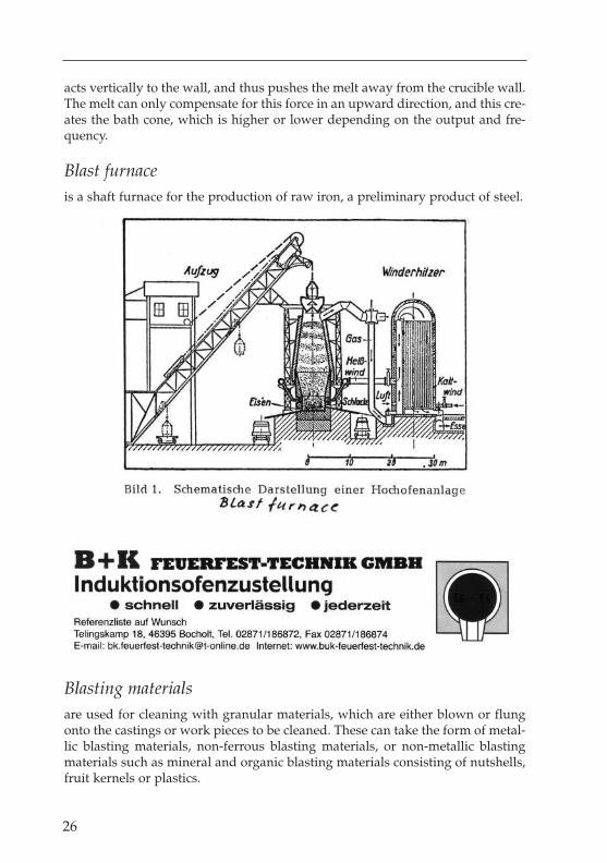
Blast furnace
is a shaft furnace for the production of raw iron, a preliminary product of steel.
Blasting materials
are used for cleaning with granular materials, which are either blown or flungonto the castings or work pieces to be cleaned. These can take the form of metal-lic blasting materials, non-ferrous blasting materials, or non-metallic blastingmaterials such as mineral and organic blasting materials consisting of nutshells,fruit kernels or plastics.

Boiling
or retardation of boiling occurs at a certain ratio of silicon to carbon and work-ing temperature. The VDG has carried out and published several investigationson this subject. According to the VDG manual, the start of the boiling process orretardation of boiling will be initiated at a ratio of Si to C of approx. 0.91 or 2%Si and 2.2% C and 1,510 °C. This condition should be avoided if possible, or gonethrough quickly, since boiling cannot be interrupted or stopped without negativeeffects on the melt. The addition of aluminium is the worst, yet most efficientsolution, if delay can be expected to lead to serious damage. A sudden tempera-ture reduction brought about by the addition of cooling scrap can also be suedsuccessfully without negative effects on the composition of the melt.
Boiling point
is the temperature at which a material is converted from the fluid state into thegaseous or vapour state.
30

31
Induction-Furnance Handbook – H. H. Netzel
32
Bottom Electrode Installation
Bottom electrode installationis carried out in different ways depending on thebottom construction. As a rule, heat-resistant wires from 2 up to a maximum of5 mm are used. Below the furnace body are 1 – 4 earthing clamps, depending onthe size of the furnace. To allow the crucible to be pushed out, individual wires are usually fed throughthe concreted furnace body and attached to a ringbelow the furnace bottom. 1 pipe 10 mm in diameter and 50 mm in length can bewelded to the furnace bottom. An M8 screw is fitted at the side to create an earthcontact with the wire. The wire can thus be fed further as it wears away. The bot-tom electrode wires, which are also referred to as bottom antennae, must beinstalled in such a way that when the bottom vibrates, there must be no contactbetween the vibration plate and the wire ends. In the case of 2-layer bottomvibration, the wire can be vibrated in via a guide with a 100 mm offset and aheight of approx. 50 mm. In the case of 2-layer bottom vibration, the wires canbe bent at the height of the 1st layer with a remaining length of at least the layerheight plus 250 mm for the bend parallel to the bottom. The mix for the 1st layeris filled in, ventilated and then compacted with the vibration plate. Before themix for the 2nd layer is filled in, the 1st layer must be properly keyed in order toensure good contact with the 1st layer. The antennae wires are now set at theright installation height by means of a bend, and the required mix for the 2nd
layer filled in and compacted. Since the wires should always end 5 - 10 mm with-in the crucible bottom, there is still no “earth contact” in the sinter charge. Inorder to ensure that an earth contact is created in the sinter charge, the mix mustbe scratched away at one electrode wire. The position can be established with amagnet or by markings on the coil wall.In clay-graphite and silicium carbide crucibles, a spiral of heat-resistant steel isplaced on the furnace bottom before insertion of the crucible. One end is feddownward through the furnace bottom and then attached to the bottom from theoutside. A layer of graphite shale or powder approx. 30 mm thick is now appliedto the bottom. The crucible can now be used with turnings. The back-fill mix isnow filled in as usual and compacted. By means of this bottom electrode instal-lation, the crucible has a relatively reliable earth connection.
Breakthrough
is the escape of molten metal through the crucible as far as the furnace coil orthrough the furnace coil into the outer furnace area.
Bridge formation
is a phenomenon that cannot entirely be avoided in induction furnaces. If thereis no proper heat-conducting contact between the liquid melt and the materialabove, the crucible is said to have a bridge. This phenomenon can occur for

example due to material becoming jammed above the melt or a ceramic coverover the melt due to superheating and break-up of the ramming mix. To avoidthis happening, the furnace should only be recharged with so much material sothat a smooth surface can still be seen in the crucible. If a bridge has neverthe-less formed, the furnace should be tilted, and the bridge broken up with extremecare. In MF furnaces, the bridge can sometimes be melted at low power. Seriousdamage and injury to personnel has in the past been caused by the uncontrolledmelting and breaking up of the bridge in the basic position.
Bunkers
are supply containers for the storage of bulk materials. In foundries, bunkers areused for holding mould materials, fuels and materials for making up the charge.
Buttons
is the designation for the remaining metal that solidifies in the ladle or the fur-nace. This is also referred to as ladle or furnace buttons.
Cables
are water-cooled in induction furnaces and used as cooling water return lines. Inthe case of low performances, cables can also be used as water feed lines. Thecopper conductors have 35 or 50 mm2 copper cross-sections. For medium fre-quency the individual conductors have a paint insulation, although this offers nobenefits for mains frequency. The electrical connections can take the form of flatconnections or clamp-ring connections.
Calorie
a formerly common unit of measure for heat, with the abbreviation ‘cal’. 1 cal isthe amount of heat required, at normal pressure, to increase the temperature of1 kg of water from 14.5 °C to 15.5 °C. 1,000 cal = 1 kcal. In the international sys-tem of weights and measures, the calorie has been replaced by the Joule. 1 cal =4.1868 J (old conversion ratio, 1kWh = 860 kcal/h for cooling system calcula-tions).
Carbonisation
is essential in the production of cast iron from steel scrap and carbon, since theexact carbon content is very rarely achieved with the metallurgical sample. As arule, the carbon content must be increased by up to 0.3%.The induction crucible furnace is very well suited for the carbonisation process.The bath movement, agitating effect and the simultaneous temperature increaseproduce the optimum results, provided that the following conditions are also
33
Induction-Furnance Handbook – H. H. Netzel
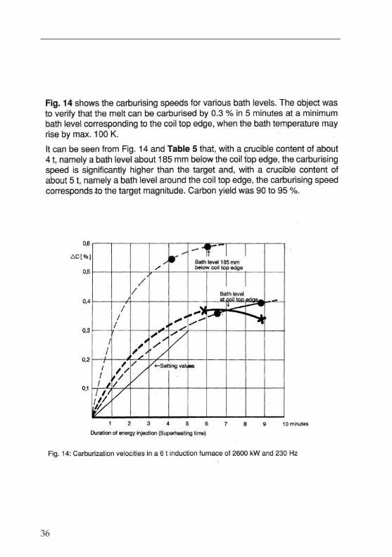
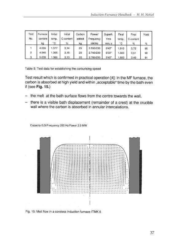
observed. For 0.3% carbonisation, these are 5 minutes agitation time, a tempera-ture increase of 100 K and a bath filling level above the active induction coil ofapprox. 25% of the coil height for mains frequency (50/60 Hz), and about 5% ofthe coil height for medium frequency (500 Hz) with the same specific perform-ance. The specific performance for equal bath movement is 300 kW/t for mainsfrequency, 545 kW/t at 250 Hz and 750 kW/t at 500 Hz.If in certain cases carbonisation by approx. 0.5% is required, an agitation time ofapprox. 7 minutes must be provided, in addition to increasing the temperature differential from 100 K to 130 K, in order to achieve reliable disso-lution of the carbon in the melt.
For the 3 frequencies specified above, the following furnace sizes and perform-ances can be regarded as ideal:
NF - 50 / 60 Hz 12.5 t - 3,000 kW 9 minutes for 100 K – 25% over-filling
MF - 250 Hz 5.5 t - 3,000 kW 4 minutes for 100 K – 25% over-fillingwith 2,400 kW 5 minutes for 100 K – 20% over-fillingwith 3,000 kW 5 minutes for 125 K – 25% over-filling
MF - 500 Hz 4.0 t - 3,000 kW 3 minutes for 100 K – 25% over-fillingwith 1,800 kW 5 minutes for 100 K – 15% over-fillingwith 3,000 kW 5 minutes for 166 K – 25% over-filling
34
I E SInduktion Experience Service
Harkortring 6
D-58453 W I T T E N
eMail: [email protected]

35
Induction-Furnance Handbook – H. H. Netzel
36
37
Induction-Furnance Handbook – H. H. Netzel
From these figures, it can be seen that a mains frequency furnace can be over-filled by approx. 300 mm, a 250 Hz furnace by approx. 220 mm and a 500 Hz fur-nace with suitable performance by approx. 150 mm.If a significantly higher specific performance is installed, due to the melting per-formance per hour required for operation, the metallurgical melting controlmust be properly set, and when reaching the upper edge of the coil, the requiredquantity of carbon for the final filling level must be added.For example, a 5.5 t furnace operating at 4,800 kW has a superheating capacityof 40 K/minute, and thus an agitating time of approx. 2.5 minutes for 100 K. Inorder to maintain the agitating time of 5 minutes, the temperature differencewould have to be 200 K. This value is not realistic in practice. This furnaceshould be operated at approx. 3,000 kW for about 5 minutes with a temperaturedifference of 125 K.movement force, which in an induction crucible furnace acts vertically to thewall, and thus pushes the melt away from the crucible wall. The melt can onlycompensate for this force in an upward direction, and this creates the bath cone,which is higher or lower depending on the performance and frequency.
Caster
is the general designation for the foundry specialist, and the professional termfor foundry workers who perform the casting into the moulds.
38
39
Induction-Furnance Handbook – H. H. Netzel
40

41
Induction-Furnance Handbook – H. H. Netzel

42
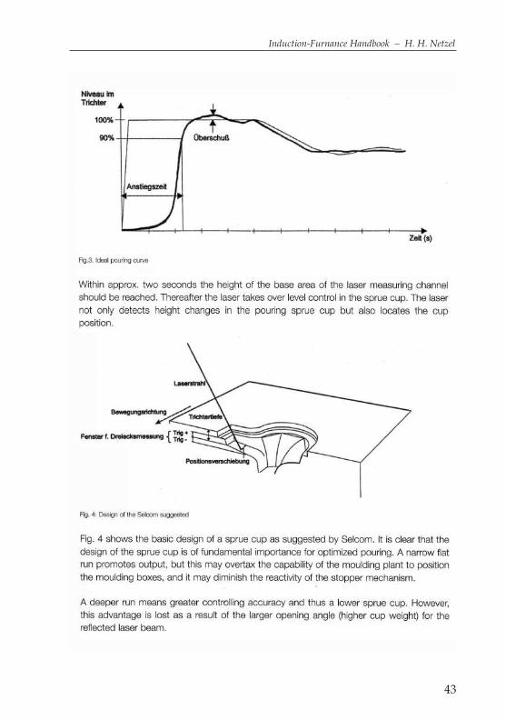
43
Induction-Furnance Handbook – H. H. Netzel
44
45
Induction-Furnance Handbook – H. H. Netzel
Casting
is the moulding of a material, which is filled into a mould corresponding to theshape of the finished product in the molten state under the force of gravity, cen-trifugal force or under pressure, where it then solidifies. In general, casting refersto the pouring of the molten casting material into the mould.
Casting compounds
are usually produced on the basis of Al2O3 or MgO. Depending on the applica-tion, approx. 5 – 11% water is also added. The compaction is carried out in vibra-tion vessels, which are available in the trade with diameters of approx. 15 to 60mm. The lower the water content during processing, the denser the compoundbecomes. The drying of the compounds must take place very carefully and veryslowly. The recommended temperature increase should be 30 °C/h, followed bya standing time of 30 minutes on reaching 500 °C, which is repeated at every fur-ther 100 K while increasing the temperature again by 50 °C/h. The compoundsmust be heated up to at least 1,000 °C, followed by a standing time of 2 hours.High-performance burners using oxygen reach temperatures of approx. 1,200 °C, in which case a standing time of 1 hour is sufficient.
Casting drum
is a drum ladle with a fireproof cladding, which also has lower temperature loss-es than with a normal casting ladle due to the lower heat radiation properties.
Casting finishing
refers to the separation of the rough castings from the ingates and feeders, theremoval of casting burrs and mould material residues and the cleaning of thecastings by treatment with blasting materials.
Cast iron
is an iron-carbon alloy containing at least 2% C and other alloy components,notable silicon. The main types include “grey cast iron” (cast iron with laminar

46
graphite) and cast iron with nodular graphite (nodular cast iron), as well as greycast iron with vermicular graphite, which all have a grey break surface.Tempered cast iron and hard cast iron solidify with a white appearance, and usu-ally have a white break surface.
Casting materials
that can be efficiently melted in crucible furnaces are listed below, although notin any order of priority:Grey cast iron, steel, copper, brass, aluminium, zinc, magnesium, gold, platinum,tin and bronze, nickel and silver.
Casting spout
is the term for the outlet of a crucible furnace. The quality of the casting from thecrucible furnace is largely influenced by the design, i.e. the shape, length andangle to the crucible.
Casting units
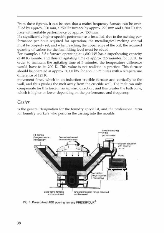
are usually heated, but can more rarely come in unheated versions. Today, casting isless frequently carried out via a stopper direct from the vessel. Instead, the process ofcasting via a siphon outlet with a stopper has become more popular. Casting equip-ment is available with capacities ranging from 0.8 t to approx. 20 t. The heating equip-ment consists of the conventional channel inductor and for special applications alsoa crucible inductor with a capacity of up to 300 kg. The vessel or boiler has an inletand outlet siphon, which can be fitted by means of a flange. By increasing the gaspressure above the bath level, the bath level within the vessel is lowered, and it risesin the outlet siphon to the specified casting height, which is also maintained through-out the casting process. The casting process is controlled and regulated with the aidof laser or camera equipment. The ‘teach-in’ principle stores up to 99 predefined andmanually initiated casting programmes, which can then be run off box by box.The total emptying of the vessel is carried out with the aid of hydraulic cylindersthrough the inlet. Casting units are coupled to the mould system, and in this wayare always brought into the correct casting position.
Cavitation
is created by fluids flowing through pipes at high speeds, and containing gas orvapour bubbles, causing wear or erosion to the surface.
Channel furnace
is the term for an induction furnace that is operated with 1 to 4 channel induc-tors. Channel furnaces are generally used as holding or storage furnaces.
47
Induction-Furnance Handbook – H. H. Netzel
Due to their high efficiency, channel furnaces are also used for the melting ofnon-ferrous metals and zinc. This principle and design have not however provenpopular for grey cast iron. In non-ferrous metal foundries, the double-chamberchannel furnace has come into common use. This consists essentially of a chan-nel inductor with 2 flanges, to which are flanged an inlet chamber and a castingchamber. These furnaces have only a low output, which is not suitable for themelting of solid charge materials. For aluminium, higher-performance furnacesare available, which can also melt solid pigs.
Charge
is the material placed in the furnace in order to be melted.
Charge material
is the general term for the material to be melted. An induction furnace is basical-ly suitable for the melting of all electrically conductive materials. The limits aredefined by the behaviour and properties of the molten material within the cru-cible material.
Charging
usually refers to the filling of a casting furnace with the materials to be melted.For small furnaces with a capacity of up to 1 t, charging can be carried out byhand. For larger furnaces, mechanical lifting equipment is used.
Checklist
is the new German expression for the checklist compiled for the performance ofspecified checking points. In the case of induction furnaces, a distinction is madebetween the electrical and mechanical components of the furnace. All leading fur-nace manufacturers have worked out the checklists for the system componentsseparately, or provide the relevant information in the operating instructions.Fundamentally, cleaning should be carried out every 4 weeks, together with avisual inspection. Special attention must be paid to ensure that there are no leaksin the water or hydraulic systems of the furnace. Repairs must be carried outimmediately, in order to avoid unforeseen breakdowns.
Chip melting a
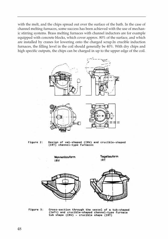
is associated with various difficulties due to the relatively low weight of the chips.Most customers have developed their own processes, which in combination withthe available equipment are used quite successfully.The use of “chip briquettes”has not proven popular. The specific density or filling weight is too low for them tobe immersed properly in the melt. The briquettes fall apart shortly after contact
48
with the melt, and the chips spread out over the surface of the bath. In the case ofchannel melting furnaces, some success has been achieved with the use of mechan-ic stirring systems. Brass melting furnaces with channel inductors are for exampleequipped with concrete blocks, which cover approx. 80% of the surface, and whichare installed by cranes for lowering onto the charged scrap.In crucible inductionfurnaces, the filling level in the coil should generally be 40%. With dry chips andhigh specific outputs, the chips can be charged in up to the upper edge of the coil.
49
Induction-Furnance Handbook – H. H. Netzel
50
51
Induction-Furnance Handbook – H. H. Netzel
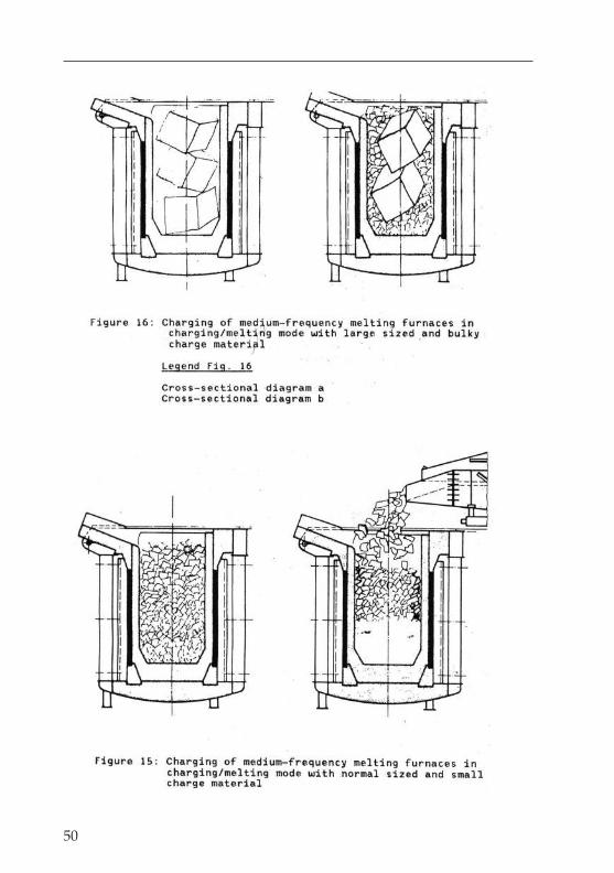
Chip melting b
In mains frequency furnaces, melting usually continues until a smooth bath sur-face appears before recharging. In foundries with medium-frequency furnaces,recharging usually takes place earlier. With this procedure, melting can be con-tinued up to the upper edge of the furnace coil, before bringing the furnace upto the maximum melt level using compact scrap or pigs. With modified outputsand frequencies (240 kW/t for low frequency, 540 kW at 250 Hz and 760 kW at500 Hz), continually charged chips charged in on top of the molten bath can bemelted from approx. 30 to 70% of the filling level. For brass or red cast, and usingthis process at approx. 330 kW/t and 960 kW furnace output with mains fre-quency in a 4-t furnace, approx. 1.6 t of chips can be melted in approx. 33 min.An important factor here is that the chips must be fed evenly over the centre ofthe bath at a rate of approx. 45 to 50 kg/min.Trials with an 18-t brass-furnace at 3,500 kW have shown that this method ofmelting works very well up to a rate of approx. 175 kg/min. From approx. 200kg/min of continuous charging, a ring formed around the crucible wall whichcould no longer be melted, but had to be brought into the melt manually.
Circuit
is a designation for cast recycling materials from the foundry’s own production.These may be sprues, risers or connectors. In some businesses, rejects are incor-rectly counted as part of the circuit, although this is not advisable from a com-mercial standpoint. In the case of rejects, a distinction must be made betweendirect casting rejects from the mould, casting faults following cleaning, faults fol-lowing mechanical processing and faults following annealing. With the aid ofsuitable measures, these individual faults can be minimised, and costs reducedsignificantly.
Clamping ring screw connection
is best known from the field of high-pressure hydraulics. Use has also been madeof this technology in high-tension electrical technology. For current and waterconnections, copper pipes are used, ranging in size from DN 18 to DN 60. At asize of DN 40, the current to be transmitted is in the order of size of up to 9,000A. The construction elements consist of Ms 58 and the sealing ring is made ofelectrolytic copper, which is soft-annealed according to the application. In thecase of frequently changed elements for replaceable furnace inserts, the ends ofthe pipes are made of brass, or sometimes even high-strength special alloys.
Cleaning
is the general term for all work carried out on the rough casting as this comesfrom the casting mould after cooling.

Cogemikanit
is a trade name for a plate coating material, which is used in induction furnaceconstruction as an electrical insulation and separating agent on the cruciblebetween the wear crucible and the coil plastering.Plate thicknesses of 0.5 to 2.5 mm can be treated. Above 2.5 mm, the plates areno longer mobile enough, and their application possibilities are therefore limit-ed. There are thicknesses of 0.4; 0.5; 0.6; 0.8; and 1.0 mm on rolls with a width of1,000 mm and lengths of 10 to 25 m, depending on the thickness.A special version is Cogemikanit with internal “fly screening” and an outer layerof 0.5 mm micanite for the connection of monitoring systems in crucible furnaces.Iron piles are insulated against the coil outer jacket with 2 mm of Isoplan anddepending on the operating voltage, with 2x 0.5 to 6x 0.5 mm of Cogemikanit at3,000 volts.
52
53
Induction-Furnance Handbook – H. H. Netzel
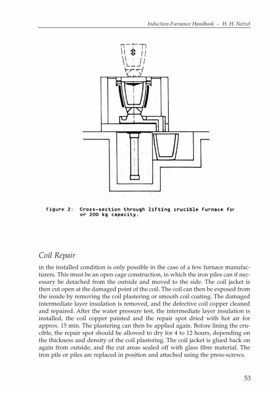
Coil Repair
in the installed condition is only possible in the case of a few furnace manufac-turers. This must be an open cage construction, in which the iron piles can if nec-essary be detached from the outside and moved to the side. The coil jacket isthen cut open at the damaged point of the coil. The coil can then be exposed fromthe inside by removing the coil plastering or smooth coil coating. The damagedintermediate layer insulation is removed, and the defective coil copper cleanedand repaired. After the water pressure test, the intermediate layer insulation isinstalled, the coil copper painted and the repair spot dried with hot air forapprox. 15 min. The plastering can then be applied again. Before lining the cru-cible, the repair spot should be allowed to dry for 4 to 12 hours, depending onthe thickness and density of the coil plastering. The coil jacket is glued back onagain from outside, and the cut areas sealed off with glass fibre material. Theiron pile or piles are replaced in position and attached using the press-screws.
56
Coil jacket
is the term for the outer protective cladding of induction furnace coils, consist-ing of flexible ceramic-organic panels of glass fibre materials. This serves to pro-tect the coil against metallic dusts and spray iron during operation. For safetyreasons, no materials or paint coatings may be used that are impermeable tomoisture. These would then act as a damp course, which can lead to windingshorts with leakage of water out of the coil. If this water penetrates into the areaof the smelt, this can easily cause water vapour explosions, which usually resultin the uncontrolled ejection of melt from the furnace and the breakthrough ofmolten mass through the coil. This can also lead to serious injury to personnel.
Coil short-circuit
is a short-circuit between 2 parallel windings, which can occur due to an insulationfault. If for example there is too much damp or moisture in the area of the interme-diate layers due to inadequate drying, the voltage must be reduced to a low level,so that no leak currents can flow. As a rule, such leak currents are only very low, andthis will not lead immediately to short-circuits. In the long term however, a danger-ous point will be created, which can be further damaged with every new lining. Ifnow in the course of the coil’s life, e.g. after 18 months operating time, and undermoist weather conditions and formation of condensation on the coil copper, the coilis activated at too high a voltage (> 1,000 V), this can lead to a short-circuit/wind-ing short. The copper of the coil is eroded as in the case of electrode welding, andwater can leak out. If the leaking water cannot escape through the intermediatespaces of the coil, the water will penetrate further and further toward the melt, andthis will inevitably lead to a water vapour explosion. In order to prevent this, mostfurnace manufacturers have chosen an open coil construction with water-permeableconstruction elements. The “packing of the furnace coil” with glass fibre materialsand waterproof coatings has in the past often been proven to be an error.Winding shorts can also occur due to localised over-heating at the inner edges ofthe intermediate insulation layers. The lightly carburised intermediate layers canretain the moisture very well, thus providing the ideal conditions for a windingshort. Accumulations of scrap always occur in the rear area of the furnace coil. Thismaterial cannot fall down when the furnace is tipped. Under the effects of the mag-netic field, scrap can also collect in the area of the induction coil in the coil jacket,subsequently leading to a winding or earth short. To avoid this, the lower area ofthe furnace should be cleaned every 4 weeks or vacuumed out with an industrialvacuum cleaner. Under no circumstances should compressed air be used, since thiscould blow metal parts behind the “core insulation”. This will result in an earthshort, which can only be located laboriously by checking every iron pile.If dark areas can be seen on the inner surface of the furnace coil after removingthe crucible, this area should be carefully cleaned of plaster and the condition ofthe intermediate layers checked. This check and any subsequent repair may wellavoid unexpected failure with devastating consequences.

57
Induction-Furnance Handbook – H. H. Netzel
Coil grout
is applied in crucible induction furnaces direct to the coil, which is insulatedwith intermediate layers. This ceramic “coil insulation” is also referred to as thesmooth coil plastering. This serves to even out any uneven areas of the coil at theinner coil wall, and as a sliding bearing for the crucible, which is graduallyincreasing in size. Between the coil plastering and the wear crucible, a separat-ing material of micanite, Isoplan or similar materials is applied as an “insulatinglayer”. The crucible can slide down the wall as the wall gets colder and upwardsas it heats up. If a crucible is operated continuously without any “extended inter-ruptions”, this sliding or separating layer can be dispensed with. In the case of a3-t furnace and 10 crucible changes per year, this can provide a saving of approx.1,500 €, or for 20-t furnaces of approx. 5,000 €.
Cold start
is the starting of a crucible following a shut-down. In an NF furnace, starterblocks are required reaching up to 2/3 of the coil height. These blocks are heat-ed inductively and then settle together. At this point, small quantities of scrapcan be recharged. After reaching the 2/3 filling level, larger quantities of scrapcan be added (5% of the total capacity) and melted. The furnace is brought up tothe maximum filling level at approx. 70% of nominal performance. The meltshould now be brought up to about 100 K below the normal tapping tempera-ture, and maintained at this temperature for 1 hour. The furnace is then broughtup to tapping temperature and the 1st tapping carried out.
Compound alloy
consists of at least three alloy elements.
Compressed air
is air compressed by a compressor, which is used for driving machinery andtools, as well as the energy transmitter for certain pneumatic conveyor systemsor for spraying and blowing equipment.
Compressors
are machines for the transport and compression of gases. In pipelines, compres-sors are used to absorb linear expansion.
Concrete rings
are ceramic construction elements which on installation of the induction coilserve as buttresses and “fixing elements” below and above the induction coil.
58
The lower concrete ring bears the thermal/mechanical forces of the cruciblebelow the furnace coil. The upper concrete ring serves to hold down the furnacecoil, which is “pushed” upward by the thrust forces of the ramming mix. Theseare made of fire-proof concretes which are resistant up to approx. 1,450 °C.
Condensation
is the transition from the vapour state into the liquid state.
Condensers
are used to compensate for the idling output which occurs with an inductiveconsumer such as an induction furnace. At 50 Hz, approx. 4.5x the level of theeffective output is needed as the condenser output, if the system is being oper-ated at 250 Hz, approx. 7.5x the level needs to be taken into account, and for sys-tems operating at 500 Hz, the figure is approx. 11x the effective output.500 Hz – 1,000 kW – 11,000 kVar250 Hz – 1,000 kW – 7,500 kVar
50 Hz – 1,000 kW – 4,500 kVar
Mains frequency condensers are as a rule air-cooled, while medium-frequencycondensers from approx. 100 Hz are produced as water-cooled units.
Continuous casting
is used for the production of symmetrical and non-symmetrical solid and hollowcastings by means of continuous die-casting. Depending on the direction ofwithdrawal, these are referred to either as vertical or horizontal die-castings.
Control
refers in general to the checking and monitoring of certain processes. Some of themain types of control include quantity, cost and quality control.
Conversion from low to medium frequency
can be advisable for commercial reasons and reasons of energy policy. Some ofthe advantages of medium-frequency systems are listed below:– starter blocks and laborious starting procedures are not required– no laborious scrap drying or dry storage required– increased electrical efficiency through charge operation– melting with higher output and shorter melting times– improvement of thermal efficiency due to the smaller furnace size– lowest possible energy consumption with optimum flexibility– saving of maintenance and repair costs

– increased operating safety– reduction of the fireproofing costs for the same throughput– increase in overall economy– old energy consumption with 13-t furnace with mains frequency, 750 kWh/t
(2,800 kW)– new energy consumption with the same furnace, 640 kWh/t (4,800 kW – 250 Hz)
Converters
are motor generators which produce the required operating frequency via thecombination of motor drive with mains frequency and generator. Up untilapprox. 1970, converters were supplied in horizontal or vertical versions ofapprox. 30 kW to 3,000 kW. Due to the relatively low efficiency level, the compli-cated regulation and the repair requirements, converters have been increasinglyreplaced by static frequency converters.
59
Induction-Furnance Handbook – H. H. Netzel
Cooling towers
60
Cooling
is the temperature loss of the crucible when the open is switched off, and whenthe crucible is usually empty. Acidic crucibles are left to cool off during interrup-tions in operations. Neutral and alkaline crucibles are as a rule maintained attemperatures above 800 °C.
Coolingdown speed
is specified in Kelvin/sec or Kelvin/min.
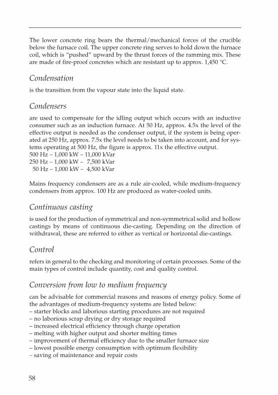
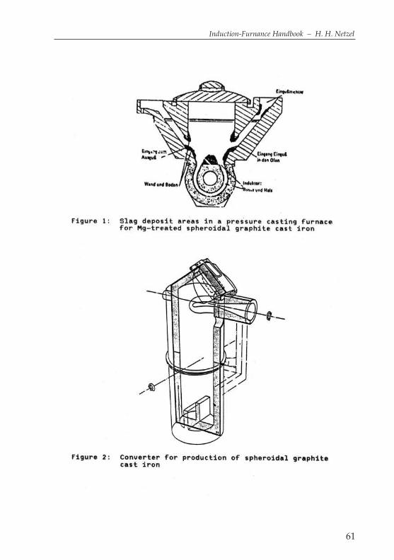
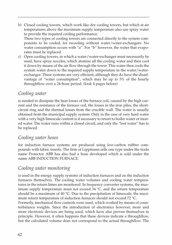
Converter for Mg-Iron
are manufactered from some companys. The most known is the G+F-Converter.
Cooling towers
are necessary for the recooling of cooling water heated up by frequency convert-ers and induction furnaces. There are 3 types of cooling towers used in directcombination with induction furnace systems (look pages before).
a) Dry cooling towers, which work like vehicle radiators with cooling vanesand high air volumes, can be used in central and northern Europe. Relevantheating equipment and ventilator covers must be provided for extremely lowtemperatures. In order to ensure the maximum supply temperature for fre-quency converters of 34 °C, supplementary coolers are used which operatefrom the municipal water supply.
61
Induction-Furnance Handbook – H. H. Netzel
62
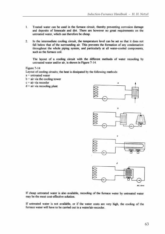
b) Closed cooling towers, which work like dry cooling towers, but which at airtemperatures above the maximum supply temperature also use spray waterto provide the required cooling performance.These two types of cooling towers are connected directly to the system com-ponents to be cooled, for recooling without water/water-exchangers. Nowater consumption occurs with “a”. For “b” however, the water that evapo-rates must be replaced.
c) Open cooling towers, in which a water/water-exchanger must necessarily beused, have spray nozzles, which atomise all the cooling water and then coolit down by means of the air flow through the tower. This water then cools thesystem water down to the required supply temperature in the water/water-exchanger. These systems are very efficient, although they do have the disad-vantage of “water consumption”, which may be up to 5% of the hourlythroughflow over a 24-hour period. (look 4 pages before)
Cooling water
is needed to dissipate the heat losses of the furnace coil, caused by the high cur-rent and the resistance of the furnace coil, the losses in the iron piles, the short-circuit ring and the thermal losses from the crucible wall. The water is usuallyobtained from the municipal supply system. Only in the case of very hard waterwith a very high limescale content is it necessary to resort to boiler water or treat-ed water. The water runs within a closed circuit, and only the “lost water” has tobe replaced.
Cooling water hoses
for induction furnace systems are produced using low-carbon rubber com-pounds with fabric inserts. The firm of Lippmann sells one type under the tradename Protector. ABB has also had a hose developed which is sold under thename ABB INDUCTION FURNACE.
Cooling water monitoring
is used in the energy supply systems of induction furnaces and on the inductionfurnaces themselves. The cooling water volumes and cooling water tempera-tures in the return limes are monitored. In frequency converter systems, the max-imum supply temperature must not exceed 34 °C, and the return temperatureshould be a maximum of 40 °C. Due to the precipitation of limescale, the maxi-mum return temperature of induction furnaces should not exceed 72 °C.Formerly, mechanical flow controls were used, which worked by means of coun-terbalance weights. Since the introduction of electronics however, more andmore electronic devices are being used, which have also proven themselves inprinciple. However, it often happens that these devices indicate a throughflow,but the calculated volume does not correspond to the actual throughflow. The
63
Induction-Furnance Handbook – H. H. Netzel

64
display may shut down after a short time, especially in cooling water circuitswith high electrical currents.
Cooling water volume
is determined mainly by the electrical output. One can say roughly that approx.27% of the furnace output and the heat losses from the crucible wall will have tobe dissipated. In rough terms, one can reckon on approx. 35% of the furnace out-put as the total loss performance that must be dissipated.In the case of a 5-t furnace with 250 Hz and 3,000kW, this gives 1,050 kW or903,000 kcal/h, that must be dissipated at a temperature difference of 27 K. Thisgives a cooling water volume of 33.5 m3/h (33.444 l/h). (kcal/h divided by thetemperature difference gives the volume in litres/h).
Cores
are as a rule used for the creation of cavities in casting moulds for the casting tobe produced.
Corundum
is obtained from bauxite, and has the chemical formula Al2O3; this is a crys-tallised aluminium oxide, which is used as an abrasive agent and fireproof lin-ing material.
Cover drives
for crucible induction furnaces are available in a wide range of versions. Flap coversor sliding covers are normally operated by means of differential cylinders and chains.If cover hoods are being used, the drive takes the form of 2 differential cylinders.Swivel covers are driven via a curved roller and guide cylinder by means of avertically acting plunger cylinder. The lowering takes place under the ownweight of the cover and the piston rod. In case of certain special requirements, asmall differential cylinder can also be used.
Cover extraction hood
is a combination of an internal cover, fitted with an extraction hood enclosing thecover. This type of extraction has proven itself well in practice, and is usedalmost exclusively for high-output furnaces. The hood can be adapted to meetthe corresponding requirements by means of set opening angles, and can forexample remove all the smoke during charging. Another option is the fitting ofthis extraction system with automatically opening slots in the frontal area forsmoke extraction directly in front of the crucible furnace during the productionof nodular graphite iron.

69
Induction-Furnance Handbook – H. H. Netzel
Crucible cleaning equipment
70
Cover extraction rings
are mostly used only for smaller furnaces. This type of extraction uses a conical ringwith extraction slots, which is ceramically cladded on the crucible side. The attach-ment to the furnace cover takes the form of wedges. Adequate extraction perform-ance is provided when the cover is closed or raised by approx. 200 mm. The emis-sion of smoke cannot however be avoided when the cover is opened for charging.
Crucibles
up to approx. 1.5-t capacity are made of graphite clay or silicon carbide, and inthe case of metal crucibles, of cast iron, cast steel, steel plate and plated steelplate. These crucibles are used in metal foundries for non-ferrous metals. Acidiccrucibles with capacities of up to 13 t are made from SiO2 material. The cruciblesare rapped in in special moulds with the addition of binding agents, and afterbeing allowed to cool in air are dried in drying furnaces, or even pre-sintered sothat they can be transported by road or rail. These crucibles are “fixed” withback-fill compound after being installed in the furnace, patched at the upperedge, and then sintered in the same way as a normally lined crucible. The work-ing life of such crucibles is comparable to that of conventionally lined crucibles.
Crucible cleaning equipment
is used for scraping off and cleaning of ceramic crucibles in aluminium cruciblemelting furnaces. This consists of a device with 3 or 4 shovels, which if necessarycan be operated individually under pneumatic power like a compressed airhammer. After the 1st downward stroke, the shovels are moved upward, rotatedthrough the specified angle and then lowered 2 – 5 times to clean the crucible.About 300 mm of aluminium are left in the crucible, so that the residue can thenbe removed from the furnace with the aid of a modified “slag excavator”. Thiswork must be carried out with the crucible still in the warm, operating condition,since if the crucible is too cold, not only will the dross be removed, but the cru-cible wall can also be severely damaged. Mechanical milling devices have notproven effective in this application.(look 1 page before)
Crucible induction furnace
is the term for a furnace containing a crucible, which is heated by an inductionfurnace coil surrounding the crucible. There are crucible induction melting fur-naces and crucible induction holding furnaces, which differ mainly in their nom-inal output. The same design of furnace can be operated at different voltages asa melting, storage and holding furnace. In the case of furnaces of the samedesign, the furnace connection voltage is the definitive factor in determining thenominal output.

71
Induction-Furnance Handbook – H. H. Netzel
Crucible inductor
is a relatively small crucible furnace, which has a flange above the upper concretering for attachment to the actual furnace. When used as holding equipment, thesecrucible inductors have a crucible diameter of approx. 500 mm and a crucibleheight of approx. 750 mm. The capacity is thus approx. 1,000 kg with an outputof 300 to 500 kW. The largest crucible inductor furnace constructed has a totalcapacity of approx. 100 tonnes including the crucible inductor with 6.6 tonnes forgrey cast iron, and approx. 38 tonnes of aluminium in total. The diameter of thecrucible is 950 mm and the height 1,400 mm. The installed output is 2,300 kW.
Crucible furnaces
have crucibles heated from the outside, and can be designed for heating byinduction, fuels or resistance. The best known type of crucible furnace is the cru-cible induction furnace.
Crucible edge extraction
is arranged in a similar way to cover ring extraction with a conical ring, althoughthis is set at a greater distance from the cover than the ring of the crucible edgeextraction system. This functions well when the cover is closed. However, whenthe cover is swung to the side, the extraction effect is largely cancelled out, andthe smoke is not extracted adequately.
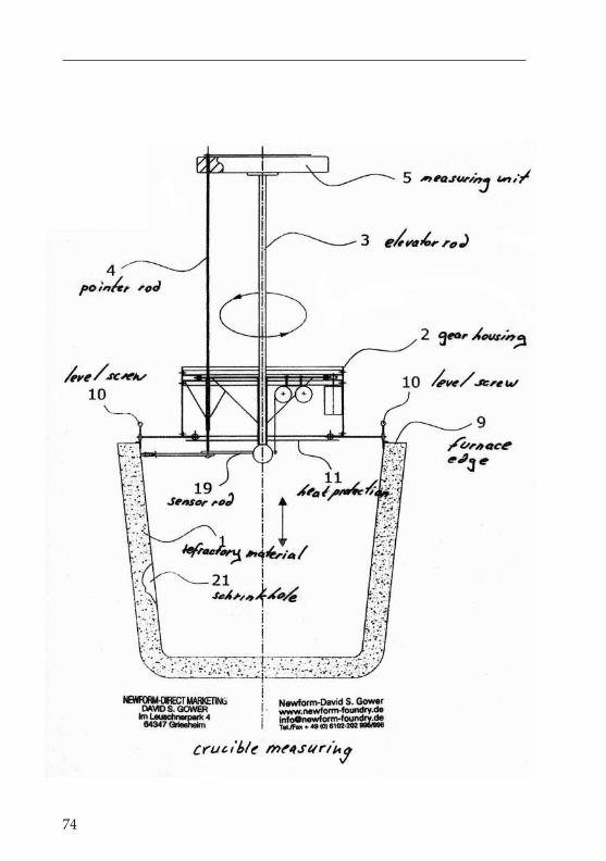
Crucible measurement
is a laborious procedure, which requires much preparation and preliminarywork, even when installing the coil. The centre of the crucible must be able to bedetermined accurately by means of 3 or 4 fixed points on the furnace platform.When installing the furnace coil, the coil must be installed exactly at this centralpoint. Markings must be applied to the vertical plumb fitted in the centre of thecoil at vertical spacing of 100 or 150 mm. The distance between the centre and thecoil wall is now determined and documented in four directions. When installingand aligning the lining template, the exact centre, i.e. the distance from the plumband the tamping template, must also be maintained and documented if necessary.After furnace operation, and the first cooling down of the tamping compound toapprox. 40 °C, the crucible can then be measured accurately. This method alsoallows the identification of any lateral, excentric erosion of the tamping com-pound .A simpler method, which however does not allow the identification ofexcentric erosion, is the use of an excentric T-beam. The shorter T-beam is weld-ed to a holding rod at a distance of 1/3 : 2/3. The short T-beam is the measuringbeam, which can be produced in 4 different lengths, or adjusted to differentlengths by means of screw bolts. This gives firstly the nominal dimension andthen the enlarged diameters in steps of 10-15 mm. With this measurementmethod, the crucible diameter can be checked immediately after total emptying.

Nominal dimensions for 12.5-t furnaceCoil diameter 1,470 mmCrucible diameter 1,190 mmTotal wall 140 mmmin. remaining wall 95 mmi.e. max. crucible diameter 1,280 mmMeasuring beam max. 1,260 mmHolding rod = furnace depth + 1 m
72
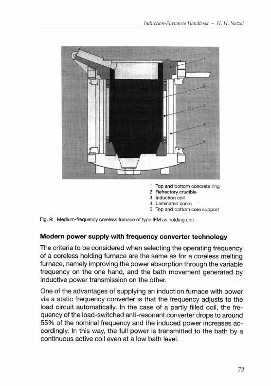
73
Induction-Furnance Handbook – H. H. Netzel
74

76

77
Induction-Furnance Handbook – H. H. Netzel
78
Crucible monitoring
is a crucial task of the insulation monitor. This device measures the insulationresistance between parts carrying voltage and other components connected tothe earth potential. The measurement is made possible by direct voltage. Thefirm of Saveway has developed a system for continual crucible monitoring with-out measuring the insulation of the system. Here, the “thermally” influencedresistance of the compounds is measured between measuring anodes on the“outer wall” of the wear crucible, see Saveway.
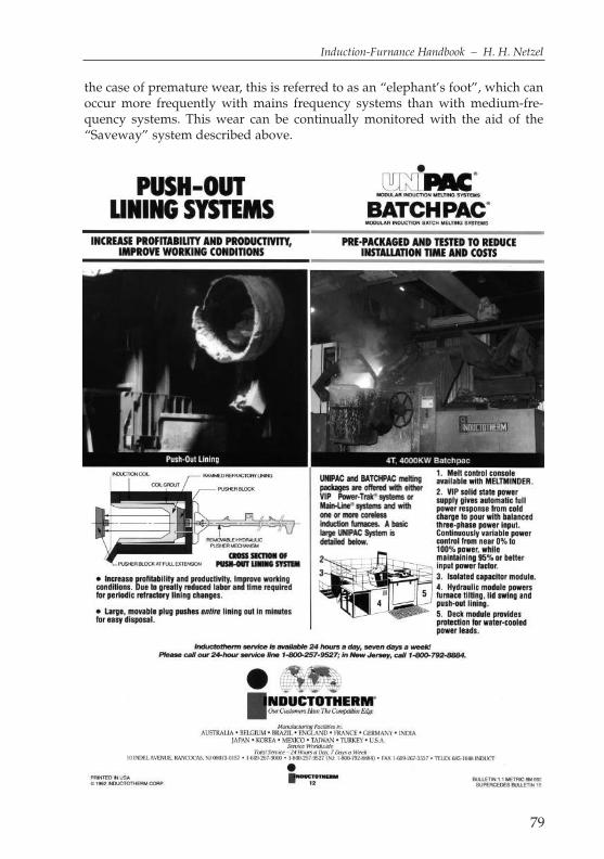
Crucible push – out – device
is a device for removing the wear crucible from the crucible furnace. Due to thecontraction of the crucible in the cold condition and the conicity of approx. 0.8%,this can be done with hydraulic cylinders with different pressure surfaces andstrokes. In order to prevent possible difficulties, the crucible should be “loosenedby hand” in the area of the casting spout. If the crucible cannot be removed dueto too little contraction, the crucible must be slit from bottom to top to a width ofabout 100 mm. Slitting from bottom to top has 2 advantages over working fromtop to bottom: 1. when starting in the lower cone area, the work is not carried outdirectly against the coil, and 2. during further caulking toward the top the workis carried out against the existing hole and later against the slit. This minimisesthe risk of damage to the coil. The position is opposite to the casting spout. Thecrucible is started out at a force of up to 200 kp/cm2 and the further removal at30 – 60 kp/cm2, depending on the crucible size, without damage to the coil.
Crucible storage furnaces
are in principle designed in the same way as crucible melting furnaces.Depending on their particular application however, they are equipped with sig-nificantly better heat insulation and sometimes also an induction coil, split intosections. In the case of a 50% division, both coils will for example have an out-put of 3,000 kW. When both coils are switched in series, the total output is only1,500 kW. Crucible storage furnaces have the advantage that in the event of prob-lems, stoppages or other interruptions, they can be completely emptied. Due tothe low specific output, it is advisable to sinter crucible storage furnaces withmolten iron.
Crucible wear
occurs due to the enormous temperature stress on the fireproof lining and themechanical abrasion during charging. As a rule, crucible furnaces are designedso that they can stand wear to the wall of approx. 30% of the total nominal wallthickness. However, since this wear does not usually occur evenly over the wallsurface, measurements of the crucible must be carried out from time to time. In
the case of premature wear, this is referred to as an “elephant’s foot”, which canoccur more frequently with mains frequency systems than with medium-fre-quency systems. This wear can be continually monitored with the aid of the“Saveway” system described above.
79
Induction-Furnance Handbook – H. H. Netzel

82

84
Crucible withdrawal device
were developed in order to circumvent the patent for the crucible removal device.In this case an approx 20 mm thick steel plate with a 30 – 50 mm hole is insertedcentrally below the crucible. To withdraw the crucible, a hole is then drilled in thecrucible bottom, a rod fed through the hole from inside the crucible, and the rodfixed in place below the withdrawal plate by means of a nut or wedge. The crucibleis then withdrawn with the aid of a crane, although the crab must not be in the cen-tre of the jib when lifting, since this method of working is not without risk. Whenapplying a lifting force of approx. 10 t, the crucible is released suddenly, and theweight of the crucible now hanging from the crane hook is in this example only 3 t. This procedure with the sudden change of load can cause the crane to “buck”.
Crucible working life
is usually specified in terms of throughput, number of charges or working days. De-pending on the working methods used, e.g. 1-, 2- or 3-shift operation, the crucible work-ing life will vary greatly. Very high casting temperatures above 1,600 °C reduce theworking life by approx. 30% in comparison to the same furnace operated at 1,540 °C.
Cupola furnace
is a foundry shaft furnace for the melting of cast iron. The metal charge (rawiron, scrap and recycled materials) is melted with the addition of slag-formingadditives, limestone and coke as energy transmitters. The combustion air(known as wind) is compressed by a blower, and blown into the furnace shaftthrough nozzles. These are categorised into cold wind or hot wind cupola fur-naces, depending on whether the combustion air is cold or heated.
Cokeless cupola furnace
The Flaven furnace can be regarded as a forerunner of the cokeless cupola fur-nace, and consisted of a combination of shaft and hearth furnace. Figure 39shows the design of the system. It can be seen that the charging column, whichis normally supported by the coke bed, rests on a water-cooled grill. The bars ofthe grill are fitted above the burner level, so that the molten iron dripping downfalls through the grill into the collector basin. The combustion takes place in aburner sleeve outside the furnace, so that the hot gases give off their heat to thecharge on their way through the furnace shaft. Since there is no glowing cokebed to take care of the over-heating zone, an over-heating bed of nodular fire-proof material must be built up on the water-cooled grill.According to W. Sachs, the consumption of fireproof nodules comes to 30 to 50 kg/t of charge materials, which must continually be added with the charge tomaintain a height of about 500 to 700 mm as the over-heating zone. No adhesionmust occur in the fireproof bed or on the grill.

85
Induction-Furnance Handbook – H. H. Netzel

86

87
Induction-Furnance Handbook – H. H. Netzel
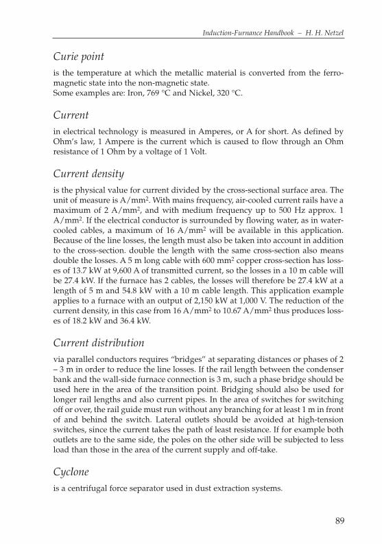
89
Induction-Furnance Handbook – H. H. Netzel
Curie point
is the temperature at which the metallic material is converted from the ferro-magnetic state into the non-magnetic state.Some examples are: Iron, 769 °C and Nickel, 320 °C.
Current
in electrical technology is measured in Amperes, or A for short. As defined byOhm’s law, 1 Ampere is the current which is caused to flow through an Ohmresistance of 1 Ohm by a voltage of 1 Volt.
Current density
is the physical value for current divided by the cross-sectional surface area. Theunit of measure is A/mm2. With mains frequency, air-cooled current rails have amaximum of 2 A/mm2, and with medium frequency up to 500 Hz approx. 1A/mm2. If the electrical conductor is surrounded by flowing water, as in water-cooled cables, a maximum of 16 A/mm2 will be available in this application.Because of the line losses, the length must also be taken into account in additionto the cross-section. double the length with the same cross-section also meansdouble the losses. A 5 m long cable with 600 mm2 copper cross-section has loss-es of 13.7 kW at 9,600 A of transmitted current, so the losses in a 10 m cable willbe 27.4 kW. If the furnace has 2 cables, the losses will therefore be 27.4 kW at alength of 5 m and 54.8 kW with a 10 m cable length. This application exampleapplies to a furnace with an output of 2,150 kW at 1,000 V. The reduction of thecurrent density, in this case from 16 A/mm2 to 10.67 A/mm2 thus produces loss-es of 18.2 kW and 36.4 kW.
Current distribution
via parallel conductors requires “bridges” at separating distances or phases of 2– 3 m in order to reduce the line losses. If the rail length between the condenserbank and the wall-side furnace connection is 3 m, such a phase bridge should beused here in the area of the transition point. Bridging should also be used forlonger rail lengths and also current pipes. In the area of switches for switchingoff or over, the rail guide must run without any branching for at least 1 m in frontof and behind the switch. Lateral outlets should be avoided at high-tensionswitches, since the current takes the path of least resistance. If for example bothoutlets are to the same side, the poles on the other side will be subjected to lessload than those in the area of the current supply and off-take.
Cyclone
is a centrifugal force separator used in dust extraction systems.
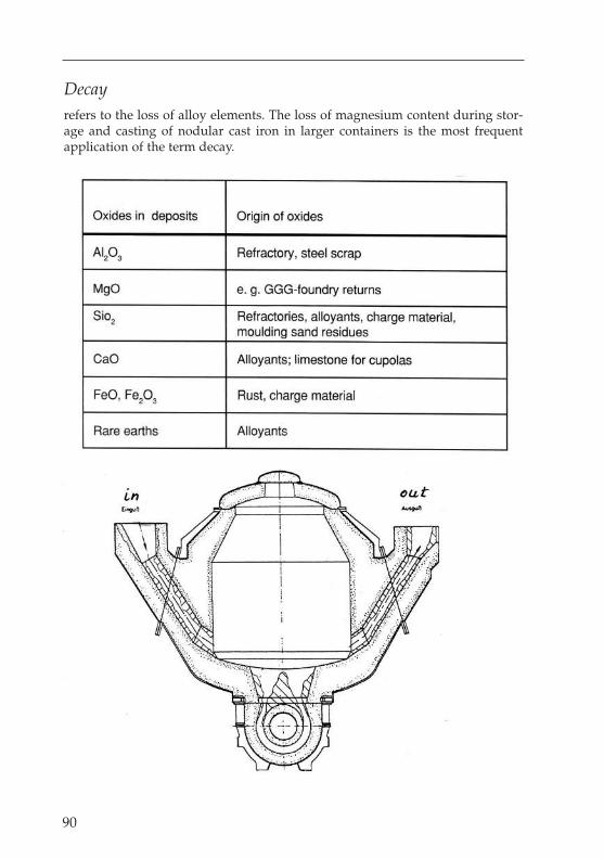
Decay
refers to the loss of alloy elements. The loss of magnesium content during stor-age and casting of nodular cast iron in larger containers is the most frequentapplication of the term decay.
90
91
Induction-Furnance Handbook – H. H. Netzel
Deoxidisation
is the removal of oxygen from the melt, i.e. the reduction of the oxides present inthe melt.
Desulphurisation
partial or more thorough removal of sulphur from metal melts, e.g. with the aidof calcium carbide, lime or soda for cast iron. Good desulphurisation is a pri-mary requirement in the production of cast iron from nodular graphite.
Differential cylinders
are “dual-acting” cylinders, i.e. both ends can be subjected to pressure in order tocarry out movements. These cylinders can also be installed in the horizontal position.
Diluting
is the reduction of the carbon content of an iron melt from a cupola furnace, a rawiron melt or a melt removed from a holding furnace by approx. 30% of the origi-nal carbon content by means of the addition of low-carbon content steel scrap.
Diodes
are non-controllable semi-conductor components, which are used in frequencyconverters in the area of the rectifiers with low and high outputs, i.e. flowingcurrents.
Drill conductors
See Roebel (transposed) conductor.
Dualtrak
is the designation for 2-furnace operation from an electrical energy supply of thefirm of Inductotherm, Simmerath.
Duomelt
is the designation of the firm of Junker, Lammersdorf, for a 2-furnace operationfrom an electrical energy supply with electronic switches (look next page).
Duplex operation
refers to melting in a furnace with the additional of already molten material, e.g.from a cupola furnace, or the mixing of cupola furnace or blast furnace iron.
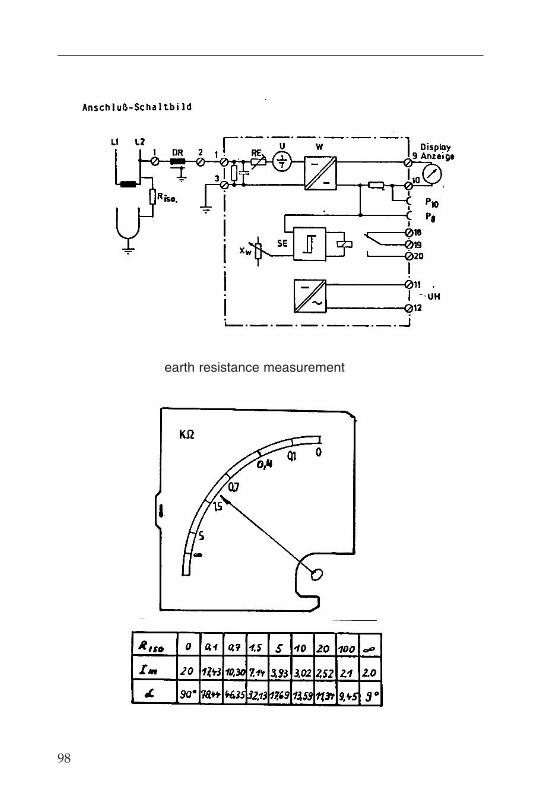
98
earth resistance measurement
99
Induction-Furnance Handbook – H. H. Netzel
Dust extraction
is the cleaning of the exhaust air, the dust-laden extraction filters and the hotgases in industrial operations and foundries.
Earth shorting
is an insulation fault between construction elements carrying voltage and thoseconnected to earth or the melting bath earthed by means of the bottom electrodes.
Earth shorting insulation test
is restricted as a rule to the area of the furnace and there mainly to the immedi-ate area of the furnace coil. The first thing to do is check the function of the earthshorting indicator with a 500 Ohm resistance, which is installed in the measure-ment line. In order to establish whether the earth short lies between the melt andthe coil, a significantly higher resistance value must be displayed after discon-necting the bottom electrodes. If the earth short is still present with the samevalue, the short must lie outside the furnace coil. In a dark furnace area, the shortmay even be visible to the naked eye. If the short lies in the area of the supplylines or the power supply, this might also be visible in dark working areas. Inmains frequency systems, earth shorts often occur in the area of the starter resis-tors. One “rough method” is a check using a bridged insulation detector, theearthed neutral point of the transformer using a 25 or 35 A fuse. This method caneven be used over a longer period to arrive at an audible diagnosis, e.g. in thebalancing choke or between an iron pile and the coil.
Efficiency
describes the relationship between the net and gross output. For 1 t of grey castiron, approx. 370 kWh of energy are required. In a crucible furnace, between 470and 540 kWh/t are required, depending on the construction features and capaci-ty of the furnace. This corresponds to an efficiency level of between 0.79 and 0.69.Due to the optimum design of a furnace with regard to its heat losses and eco-nomical dimensions, this gives a ratio of 1.13:1 between active induction coillength and coil diameter. The purely electrical efficiency level depends on thecoil length or height. With the same crucible capacity and same electrical output,this can be explained by means of 3 versions of a 13-t crucible furnace. The cru-cible wall thickness is in this case 140 mm. If one considers the magnetic fieldand the lines of flux in a completely molten furnace, there is a transverse field atthe upper and lower end of the coil, and a longitudinal field in the centre of thecoil. At the same electrical output, the sectors of the transverse fields are of equallength, i.e. with a coil length of approx. 1,300 mm there are transverse fields eachof approx. 300 mm at top and bottom, and a 700 mm longitudinal field in thecentre. These assumptions give an efficiency level of approx. 75%. If the coillength, for the same crucible capacity within the coil of 10 t, is changed, thisgives, in the case of a reduction to approx. 1100 mm coil length, a transverse field

at top and bottom of 300 mm each and a longitudinal field of 500 mm, resultingin a theoretical electrical efficiency level of approx. 69%. In case of the extensionof the coil to a height of 1,700 mm, this would give a longitudinal field of approx.1,100 mm and an electrical efficiency level of approx. 81%.
Effective output
is the product of the coil voltage multiplied by the effective current flowingthrough the furnace coil, given in kW.At 1,000 kW effective output and 250 Hz operating frequency, this gives a con-denser output of approx. 7,500 kVar as the idle output. The rail output in thiscase comes to approx. 7,570 kVA.
Emission
refers to the expulsion of jets, gases or materials, e.g. dust emission from a cupola furnace.
Energy / Energy consumption
is the designation for the product of performance (output) x time, and is speci-fied in kWh. In melting, the concept of “energy consumption” per tonne of melt-ed material is usually of interest. Here however, a distinction must be madebetween theory and practice. In the case of high-output casting furnaces, the the-oretical consumption is between 510 to 540 kWh per tonne of molten iron.Practical experience however shows that a more accurate figure is 585 to 640 kWh/tonne. If a crucible furnace is operated as a “melting machine” withoptimum charging, extraction and process control, energy consumptions of 560 kWh/tonne and tapping temperatures of 1,550 °C can be achieved.
100
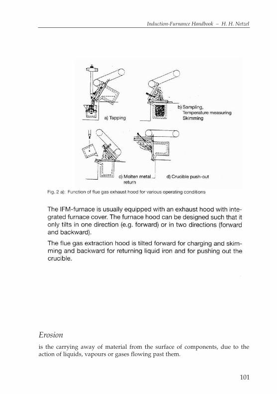
101
Induction-Furnance Handbook – H. H. Netzel
Erosion
is the carrying away of material from the surface of components, due to theaction of liquids, vapours or gases flowing past them.
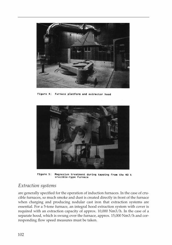
102
Extraction systems
are generally specified for the operation of induction furnaces. In the case of cru-cible furnaces, so much smoke and dust is created directly in front of the furnacewhen charging and producing nodular cast iron that extraction systems areessential. For a 5-tone furnace, an integral hood extraction system with cover isrequired with an extraction capacity of approx. 10,000 Nm3/h. In the case of aseparate hood, which is swung over the furnace, approx. 15,000 Nm3/h and cor-responding flow speed measures must be taken.

103
Induction-Furnance Handbook – H. H. Netzel
Filter
contained in foundries most out of clothes for holding back solid sustances (lookpages later).
Fireproof
is dealt with under the term “Lining”.
Flaking
refers to surface faults in cast products, which are caused by gas or air inclusionsbelow the casting surface. These usually flake off during the heat treatment ofthe castings. Flaking can also occur to fireproof brickwork and to crucible liningsdue to incorrect heating, sudden temperature changes or chemical effects.
Flushing
of cooling water circuits depends on the level of contamination of the pipes andthe operating temperatures of the cooling water.
EKW GmbH
Postfach 12 20
D-67299 Eisenberg
Tel: 0049/6351/409-0
Fax: 0049/6351/409-170
Hausanschrift:
EKW GmbH
Bahnhofstr. 16
D-67304 Eisenberg
Internet: www.ekw-feuerfest.de
email: [email protected]
Zeitgemäße
Feuerfest-Technologie
für die gesamte
Gießerei-Industrie
The hardness of the water in the system also pays a role. Some firms have spe-cialised in the flushing of water-cooled power circuits. These firms work in co-operation with furnace manufacturers, and know the special features of the indi-vidual system components. The systems are usually flushed out with descalingagents in order to remove deposits, and then flushed through again to neutralisethem with water from the municipal supply. These agents are environmentallyfriendly, and are also used in the foodstuffs industry.
Flushing block
is the normal term for a porous bottom block, through which gas can be intro-duced into the melt in furnaces or a ladle. The melt is usually flushed with argon.The gas is fed into the melt at low pressure, and removed from the melt by thepartial pressure reduction of other gases. The blowing in of flushing gas (includ-ing nitrogen) can also be used to stir or mix the melt with added reaction mate-rials, e.g. carburisation and desulphurisation agents.When melting chrome-nickel alloys in the crucible induction furnace, flushingwith argon can significantly reduce the melting and alloying times.In the case of light metals and zinc, a higher melting performance can beachieved with the aid of a nitrogen flushing lance due to the intensive movementof the bath.
Flow speed
in lines carrying water, as in cables, pipes and hoses, should not exceed 2.5 m/sec. In the crucible induction furnace coils the flow speed should beapprox. 2 m/sec. In connection areas and necessary restrictions in pipes causedby the design, flow speeds of up to 4 m/sec. can sometimes occur. The lengthsof line where this occurs should be kept within a maximum range of 100 mm.In extraction systems, speeds of up to approx. 40 m/sec. can be achieved in thepipelines. In a hood extraction system of a 13-t furnace, the flow speed at theextraction slot in the crucible cover should be approx. 6 m/sec., in order to cre-ate an adequate under-pressure.
Forklift trucks
are wheeled vehicles used for the lifting, transport and stacking of transportgoods. See also ‘Industrial trucks’.
Foundries
are industrial operations engaged in the moulding of materials by casting, inorder to produce cast metal products.
104
115
Induction-Furnance Handbook – H. H. Netzel
Foundry coke
is produced specially for use in the cupola furnace, the size of the pieces beinggreater than 80 mm. In the case of special foundry coke, the pieces are over 100 mm in size.
Foundrymen
are employed in foundries for the operation of the foundry systems.
Frequency
is the number of vibrations occurring in the time unit of one second. The formu-la symbol is ‘f’ and the unit of measure Hertz (Hz). The mains frequency inEurope is 50 Hz, while some power supply networks overseas operate at a fre-quency of 60 Hz. Frequencies above 60 Hz are referred to as medium frequencies.Normal operating frequencies for induction furnaces are:70 Hz, 95 Hz, 150 Hz, 250 Hz, 500 Hz, 750 Hz, 1,000 Hz, 2,000 Hz and more rarelyhigher frequencies such as 3 kHz, 4 kHz, 5 kHz and 10 kHz for very small fur-naces and inductive heating for forging or hardening.
Frequency converters
are frequency converters which create an oscillating circuit without rotatingparts via a combination of a condenser and a choke. In the case of so-calledtriductors, 3-fold mains frequency, and quinductors, 5-fold mains frequency, the3-fold or 5-fold mains frequency is generated as the operating frequency directfrom the mains frequency with a converter efficiency level of approx. 0.94.Modern converters have an efficiency level of 96%, and generate the requiredoperating frequency of approx. 70 – 10,000 Hz via a rectifier.These converters are equipped with a rectifier, which generates a 1-phase directcurrent from the 3-phase rotary current by means of thyristors or diodes. A directcurrent smoothing is incorporated between the rectifier and the inverter as anintermediate circuit. After the choke comes the adjustable inverter, which auto-matically generates the corresponding operating frequency in relation to theinductivity of the furnace, the capacity of the condenser bank and the powerconsumption. These are referred to as load-controlled converters, which areknown as “A” parallel or “B” series oscillating circuit converters, depending onthe condenser switching.
A: high current between furnace and condensers only
B: high current in the complete furnace circuit
(look 4 pages later)
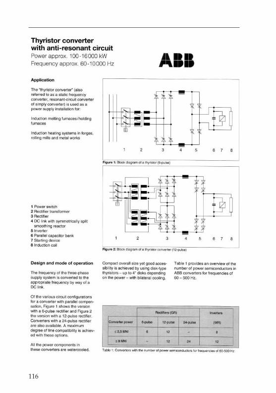
116
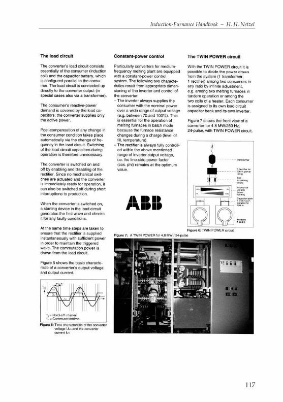
117
Induction-Furnance Handbook – H. H. Netzel
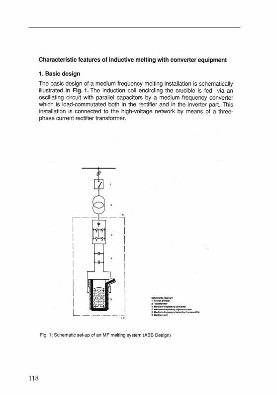
118
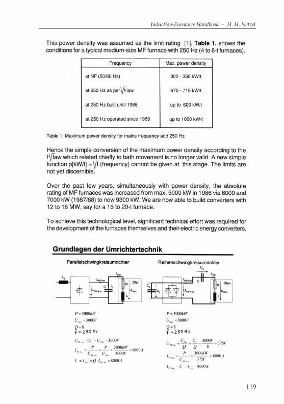
119
Induction-Furnance Handbook – H. H. Netzel
120
Furan resin binders
are cold- or warm-hardening mould material binders, which are usually used forthe production of the core.
Fuel – heated crucible furnaces
are heated with gas or oil, and are used as metal smelting furnaces for brightmetal such as copper alloys, aluminium, magnesium, lead etc.
Furnace bottom construction
varies in design according to the furnace size and the application in question.Although the heat losses can be reduced by the installation of heat insulationblocks, this also reduces the strength and rigidity. Cast concrete elementshave greater strengths and somewhat higher heat conduction properties. Thistrend has lead to longer working life, thanks to the use of high-quality con-cretes. In most cases, the masonry underpinning of induction coils has beenreplaced by concreting for cost reasons. With furnace sizes of up to approx. 5 t, the crucible removal device can be installed in a central position. Above 5 t capacity, the installation is displaced excentrically in the direction of thecasting spout.
Furnace control
is the operation of a furnace, particularly a melting furnace, in order to fulfil cer-tain metallurgical conditions. This is also referred to as process control.
Furnace covers
serve essentially to avoid heat losses, and as safety devices for the operating per-sonnel, to screen them against the heat radiation and prevent the danger offalling. Furnace covers are made of steel plate with a ceramic cladding, which isas a rule cast. An imaginary furnace cover is et in place under processor opera-tion of a crucible furnace at he end of the melting process, and all stored valuesof the melt are processed, and displayed on the screen or printed out for theinformation of the operator (ready for further measures).Larger furnaces with cover diameters of over approx. 1,200 mm have an addi-tional small cover that can be swung open by hand. Through this opening, addi-tives can be added to the melt or the temperature measured.
Furnace lining
fireproof cladding of a furnace for the melting of metals.
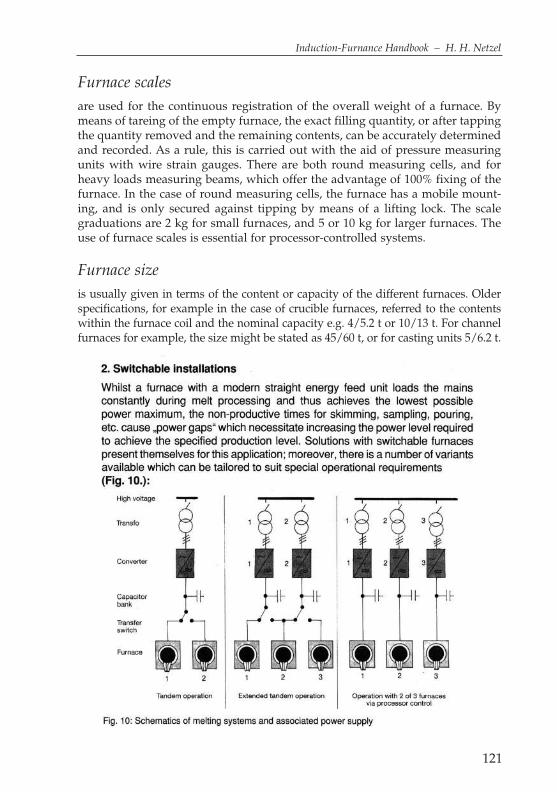
Furnace scales
are used for the continuous registration of the overall weight of a furnace. Bymeans of tareing of the empty furnace, the exact filling quantity, or after tappingthe quantity removed and the remaining contents, can be accurately determinedand recorded. As a rule, this is carried out with the aid of pressure measuringunits with wire strain gauges. There are both round measuring cells, and forheavy loads measuring beams, which offer the advantage of 100% fixing of thefurnace. In the case of round measuring cells, the furnace has a mobile mount-ing, and is only secured against tipping by means of a lifting lock. The scalegraduations are 2 kg for small furnaces, and 5 or 10 kg for larger furnaces. Theuse of furnace scales is essential for processor-controlled systems.
Furnace size
is usually given in terms of the content or capacity of the different furnaces. Olderspecifications, for example in the case of crucible furnaces, referred to the contentswithin the furnace coil and the nominal capacity e.g. 4/5.2 t or 10/13 t. For channelfurnaces for example, the size might be stated as 45/60 t, or for casting units 5/6.2 t.
121
Induction-Furnance Handbook – H. H. Netzel
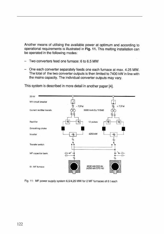
122

123
Induction-Furnance Handbook – H. H. Netzel
124
Furnace switching systems
are always required when several furnaces are to be supplied from one or moreenergy supply systems. The simplest form of switching is furnace currentswitching from one switching system to 2 following furnaces. An alternativehere would be effective current switching, with a condenser bank for each fur-nace. The furnace switching system with the optimum “reserve” for the furnacesand the energy supply is the so-called busbar distributor. With this system, everyfurnace can be switched to every power supply. This requires the same numberof furnaces as energy supply systems, together with the corresponding numberof effective current switches for each furnace. In the case of more than 3 furnaces,these systems require too large and complex a busbar system, so that from 4 fur-naces, a 2 x 2 furnace system is used.In mains frequency systems, the current to the furnace is approx. 4.5x higherthan the effective current. 250 Hz systems have a current to the furnace approx.7.5x higher than the effective current, while for 500 Hz systems, the current isapprox. 11x higher than the effective current.As an alternative to these switching systems, other systems have been developedwith unstepped distribution of the output to 2 or more furnaces. These systemsalso have the advantage that 2 furnaces can be supplied with energy simultane-ously.Electronic switching has not come into such common use, since in this case only1 furnace can be supplied with energy at any one time. The switching off and ontime is approx. 1 second.
Furnace transformers
except in the case of medium-frequency systems, are designed as step transform-ers. As a rule, 10- or 12-step secondary windings are used for mains frequencysystems. The switching takes place in the no-load condition on the secondaryside. The top 5 or 6 steps are designed for nominal output, while at the lowersteps, the output falls by the square of the reducing voltage. The lowest step isset so that the relevant furnace can still be kept hot at 60% of its capacity, with-out the temperature rising significantly. In the case of a 12.5-t furnace, the outputused by the furnace should be about 140 kW. If the maximum voltage is 2,000 Vfor 2,600 kW, the lowest voltage step must operate at 465 Volt.
Gas burners
are operated as normal burners with air, or as high-performance burners usingoxygen. Depending on the size of the crucible, holding, storage or channel fur-nace, outputs of from 100 to 500 kW are used, and more rarely 750 kW. The appli-cation temperatures to the ceramics range from 800 °C to 1,200 °C. The flametemperatures are considerably higher, and can reach levels of up to approx. 2,400 °C.

Gas flow agitation
is the treatment of the melt in a ladle with a gas flushing block in the bottom ofthe ladle. Depending on the pressure and the volume of gas, an agitation effectcan be achieved in the ladle. Metallurgic work can be carried out by the specificuse of deslagging and carbonising agents.
Graphit
is a black substance (a form of carbon) used in lubrication, as a moderator inatomic piles, and in making lead pencils. In different types of iron, You will findthe folowing types.The four basic types of iron are: Gray Iron, Ductile Iron, Mallable Iron and WhiteIron.
125
Induction-Furnance Handbook – H. H. Netzel
Graphite clay crucibles
must be prepared for optimum earthing at the crucible bottom. Earthing in thecasting spout is only effective after the 1st casting. In order to earth the crucible,a spiral with at least 5 windings of 3 mm wire is installed in the furnace bottom.This spiral is then covered with fine-grain graphite powder to a level such thatthe graphite clay crucible reaches its installation height after a few rotations. Theback-fill compound is then filled in and compacted. Finally, the upper edge ofthe back-fill compound is sealed off with a patch, so that the back-fill compoundcannot trickle out when the crucible is tipped. Prior to the 1st charging with scrapor molten material, the crucible should be heated up inductively at an output ofapprox. 40 kW/250 kg of crucible weight. The crucible should have a light redcolour approx.100mm below the crucible edge. Fine material (preferably chips)should now be placed in the bottom and normal scrap filled in on top. The 1st
charge can now be melted.
High-alumina cement
is a cement which sets very quickly and becomes very hard with water bind-ing. As a 25% additive with normal cement, this leads to setting within 30 min-utes.
Hardening
is the heat treatment of metallic materials in order to increase their hardness.
Hard casting
is the term for an iron-carbon alloy with a low graphitising factor, so that thematerial solidifies white.
Heat recovery
can only be practiced successfully with crucible furnaces to a limited extent, andonly with great effort, depending on the system configuration.As a rule, the temperature range of the cooling water lies between 30 and 65 °C,with a temperature difference of 27 K. Heating pumps work efficiently atapprox. 80 °C. Above 72 °C, the limescale precipitates out of the cooling water,the water lines become clogged, and the water has to be treated accordingly.Practical applications include:Treatment of washing water and heating of rooms in winter. With a 5-t furnacewith 3,000 kW, a maximum of 900 kW of heat energy will be absorbed by thecooling water, which can only be used economically to a very small extent. Thereis a large number of engineering companies involved in the field of heat recov-ery.
126
127
Induction-Furnance Handbook – H. H. Netzel
Heat losses
occur in all vessels containing melts at high temperatures. In the case of channelholding furnaces, the losses are determined by the melt contact surface, the bathsurface and the inductor idle losses. For a 120 kW inductor the inductor lossesamount to approx. 25 kW and for a 2,000 kW inductor approx. 100 kW. With opti-mum vessel design, the melt diameter also corresponds to the height of the melt-ing bath, thus achieving the lowest possible contact/bath surface with thelargest possible capacity. Holding furnaces can act like a “thermos flask”depending on the heat insulation and the lining. With a 13-t crucible furnace, thefollowing losses must be expected: 120 kW thermal wall loss, 20 kW bottom loss,35 kW surface loss with closed cover, totalling 175 kW idling losses.
Holding
is the expression for the temperature control to casting temperature. Depending onthe furnace construction and the heat insulation, the heat losses in kW/t of capac-ity can amount to between approx. 6 for channel holding furnaces with 130 t capac-ity and 28 for crucible furnaces with approx. 3 t capacity. Holding costs money, andshould be kept to a minimum as far as the process controls allow.
Hood extraction systems
were installed above furnaces in the same way as forge hearth extraction sys-tems. Very high air transport capacities are required due to the large separatingdistance from the furnace platform. In order to increase the air speed at the endof the hood, flow nozzles were installed in the funnel. Since these hoods have tobe swung to the side for charging and casting, a complicated swivelling systemis also necessary. In order to reduce the high separating distance during melting,raising and lowering systems can also be fitted. One could say that this systemcan be optimised, but for the same result, the costs are significantly higher thanwith other extraction systems.
Hydraulic systems
are complete systems for the hydraulic operation of machinery, consisting of apump assembly, hydraulic working cylinders or hydraulic motors, pipe systemsand control devices. The energy is transmitted by a hydraulic fluid, such as oilor emulsion, which is supplied by the pump assembly at pressures of up to 200 kp/cm2.
Idle output
is the product of the coil voltage multiplied by the idle current flowing betweenthe furnace coil and the condenser battery, given in kVar.

128
Immission
is the generation of jets, gases or solid materials of outside origin, e.g. dustimmission from cupola furnace operation on a neighbouring property.
Induction
is based on magnetism in conjunction with electrical voltages and currents. Thefollowing rules apply, as used in the design and construction of motors and fortransformers: when an electrical conductor is placed in an alternating magneticfield, an electrical voltage is induced in the conductor. When a current flowsthrough the conductor, a thrust is imparted to the conductor, which acts at anangle of 90° to the direction of the current. This property is used in the construc-tion of motors.In the generator, a voltage is generated in the rotor or stator winding of a con-ductor.In the transformer, a core holds 2 separate coils, each with a different number ofwindings. The voltage is transformed to a higher or lower level, depending onthe number of windings, i.e. the transmission ratio. Because the actual outputremains the same, the current changes in the inverse proportion.e.g.Primary: 10 kV 200 windings 50 A 500 kVASecondary: 1 kV 20 windings 500 A 500 kVA
The crucible induction furnace is based on the induction principle of transform-ers, which is explained below by means of an example.
A medium-frequency furnace with a 5 t capacity has an output of 3,000kW at3,000 Volt, 11 windings and a crucible wall thickness of 140 mm. An effective cur-rent of 1,000 A flows in the coil.If the melt or scrap charge is now applied as a secondary winding, this gives atheoretical voltage in the crucible of 273 Volt and a total current as a product inthe melt of approx. 11,000 A. This high current acts as an eddy current, whichheats and melts the charge.A connection between the coil and bath (lining leak) can also be identified withan earth short or imbalance monitoring device. In this way, a warning signal canbe generated if the melt penetrates into the vicinity of the coil.There is also the danger that a winding short caused by this metal will damagethe conductor to such an extent that cooling water escapes.It is essential at all times to avoid water getting into the melt. The voltage musttherefore be switched off automatically if the bath gets dangerously close to the coil.This danger can also be significantly reduced by the appropriate design of the coil.The furnace itself also includes the additional electrical devices shown in Figure114 for a medium-frequency furnace; the only difference in a mains frequencyfurnace is the absence of the frequency converters.

Inductor
this is the heating assembly for channel furnaces and casting units. A channelinductor is constructed in a very similar way to a transformer, and comprises aclosed iron core/yoke on which are mounted 1 or 2 coils. The channel isarranged as a secondary winding at 90° through the yoke opening. An inductorhas a relatively high area output in the channel, in relation to the cross-sectionand the inner jacket surface of the channel. An 800 kW inductor has a couplingsurface of approx. 2.1 m2. The inductor coil for example – at 660 V/50 Hz – has34 windings with an effective current of approx. 1212 A and this 41,208 amperewindings. The channel consequently has a current level of 41,208 A, since thenumber of windings is 1. This corresponds to a current density of 1.84 A/mm2.The area outputs are: approx. 890 kW/m2 for the inductor and approx. 380 kW/m2 for a comparable crucible furnace with 3 t capacity and 800 kW out-put.
129
Induction-Furnance Handbook – H. H. Netzel

131
Induction-Furnance Handbook – H. H. Netzel

134

135
Induction-Furnance Handbook – H. H. Netzel

136

137
Induction-Furnance Handbook – H. H. Netzel

138
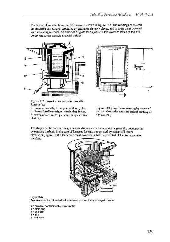
139
Induction-Furnance Handbook – H. H. Netzel

140
Industrial robots
are computer-controlled, freely programmable automatic machines that can beequipped with various grippers, tools etc. On production lines, they can alsocarry out complicated working procedures without human intervention. Theyare programmed by one-time manual performance of the task in question by theoperator. Robots are available that can handle useful weights of up to approx.300 kg, and can therefore also be used in foundries (look 7 pages before).
Industrial trucks
is a common term for forklift trucks used in production areas and warehouses.
Ingot moulds
are permanent moulds for the production of die-cast products. Ingot moulds areusually water-cooled, and are made of graphite or metallic materials.
Injection (Inoculation)
is the introduction of easily soluble alloy elements in order to achieve the optimummaterial properties. The injection materials are usually introduced into the castingstream in powder form during casting. If a very large quantity of injection materialsis needed because of special requirements, the use of wire injection devices is recom-mended. Injection prior to the filling of the iron into a heated casting unit can leadto increased formation of deposits in the channel inductor or the inductor neck.
Inlet funnel
is the upper, conical section of the inlet for sand and ingot casting.
Inmould process
is a process developed by the International Meehanite Metal Co. Ltd., Reigate(England). The magnesium treatment of cast iron melts forming the nodular graphiteis carried out not before the casting in a ladle, but directly in the casting mould. Theprocess uses a granular powder, which in addition to magnesium also contains calci-um and silicon, and therefore acts as an injection agent in the sense of mould injection.
Insulation
in induction furnace construction refers either to electrical or heat insulation. Theinsulation materials are 100% asbestos-free. For electrical applications, epoxyglass hard fibres (Diverrit E), micanite and ceramic-organic pressed materials areused, while thermal applications make use of ceramic fibre materials andpressed materials such as Isoplan, Nevalit and similar materials. Silica-glassmaterials are used for both applications.

142
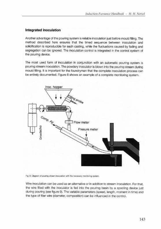
143
Induction-Furnance Handbook – H. H. Netzel

144
145
Induction-Furnance Handbook – H. H. Netzel
Insulation blocks
placed in moulds, delay the solidification of the casting at certain points in themould. The heat conductivity of these blocks is substantially lower than theremainder of the mould material.
Insulation monitoring
by means of a melting bath earthed by bottom electrodes offers great safety foroperating personnel, and can sometimes also give an indication of the conditionof the crucible. In this system, the insulation value between the voltage-carryingfurnace coil and the earth potential is determined by means of direct currentmeasurement. In the case of proper electrical insulation between the coil and theiron piles, and the high-current system, the power supply and the earth potential,a low insulation value can be attributed to the resistance between the coil and theearthed melting bath, and thus also the condition of the crucible (page 98).In the case of a newly concreted coil installation with coil plastering, the poor resist-ance value is usually due to the high moisture content. At resistance values below400 Ohms, a crucible induction furnace should therefore not be operated at above1,000 Volt operating voltage. From 400 – 700 Ohms, a level of 1,500 Volt should notbe exceeded, since in addition to the measured “earth short” due to moisturebetween the coil and earth, the winding voltage can also lead to winding shorts. Atapprox. 60 Volt winding voltage and mains frequency, there is a winding insulationof 3 mm. In the moist condition, the winding voltage should be no more than 10 V/mm, or in other words 30 Volt. In the case of medium-frequency furnaces, onehas winding voltages of up to 270 Volt and 15 mm of intermediate layer insulation,so that consequently a winding voltage of 150 V should not be exceeded.
Iron piles / yokes
are used for the return and direction of the magnetic flux outside the furnace coil. Theiron piles are physically hold the furnace coil. The construction of large crucibleinduction furnaces would be impossible without these iron piles. Iron piles are usedwith operating frequencies of up to approx. 2,000 Hz. The loss performance isbetween 0.35 W/kg and 1.5 W/kg of iron. The iron piles are used with a minimumprojection over the coil length/height of 100 mm or the distance between the meltand the coil diameter. The iron piles are very important in the design, and the dimen-sions depend on the magnetic load and the mechanical requirements with regard tostability. In the case of high electrical outputs and medium frequency, the iron pilesare water-cooled. Iron piles of crucible furnaces are made of ungrained plate.
Iron pile projection
is required for constructional and electro-magnetic reasons. The iron piles serveto guide and direct the magnetic flux outside the induction furnace coil. A trans-
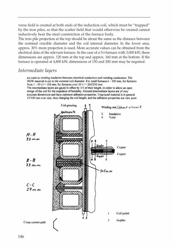
verse field is created at both ends of the induction coil, which must be “trapped”by the iron piles, so that the scatter field that would otherwise be created cannotinductively heat the steel constriction of the furnace body.The iron pile projection at the top should be about the same as the distance betweenthe nominal crucible diameter and the coil internal diameter. In the lower area,approx. 30% more projection is used. More accurate values can be obtained from theelectrical data of the relevant furnace. In the case of a 5-t furnace with 3,000 kW, thesedimensions are approx. 120 mm at the top and approx. 160 mm at the bottom. If thefurnace is operated at 4,800 kW, dimensions of 150 and 200 mm may be required.
Intermediate layers
146

162
Ladle
is a vessel equipped with fireproof cladding used for holding the melt from afurnace for the purposes of transport or casting. These come in the differentforms of transport and casting ladles.
Laser
is a focus light, generated from a device for amplifrying and concentrating lightwaves into an intense highly directional beam. In foundries laser operated formeasuring of distances and pouring levels in the mould.
Lining
is the term for the fireproof cladding of furnaces and ladles.
Lining
is also the designation for the melting crucible or wear crucible without the con-crete rings or fixed ceramic components. Nowadays dry tamping compoundsare generally used. Damp compounds are sometimes still used in aluminiumand zinc furnaces. There are 3 different types of material: acidic, basic and neu-tral compounds. Mixtures of the 3 above types of material are also used for cer-tain applications.Acidic compounds contain approx. 98.5% SiO2
Neutral compounds contain approx. 84.5% Al2O3 and up to 13% MgOBasic magnetic compounds contain approx. 88.0% MgO, up to 10% Al2O3 andapprox. 2% SiO2. The application temperatures of acidic compounds are normal-ly in the area of 1,600 °C and can reach up to a maximum of 1,700 °C for shortperiods.For neutral compounds, the normal application temperatures are in the area of1,650 °C and can reach up to a maximum of 1,750 °C for short periods.Basic magnetic compounds have a normal application temperature of 1,650 °Cand a maximum of 1,800 °C for short periods.In a 1-t crucible furnace with 1,000 kW for example, the maximum temperaturecan be reached within 2 minutes, after which the furnace must be emptied imme-diately and re-charged with scrap. The furnace is now brought up to tempera-ture for approx. 3 minutes at high output, so that the crucible is not cooled downtoo much from the extremely high temperature required. With this procedure,charge numbers of from 40 to 70 can be achieved, depending on the method ofoperation, compound and charge materials.Dry compounds are usually supplied in 25 kg sacks or disposable containersweighing up to 1,600 kg. The compounds are supplied ready for use with sinter-ing agents, and do not need to be mixed. Acidic compounds containing boricanhydride contain no crystalline water, so that these can be used with tempera-

163
Induction-Furnance Handbook – H. H. Netzel
ture increases of up to 150 K/h. High-alumina and magnesitic compounds arespecially mixed and supplied by manufacturers for individual applications.
Lining work and sintering
The inner surface of the induction furnace coil and the ceramic upper construc-tion (upper concrete ring) must form a smooth surface, without any deposits,which tapers gradually to form a cone at the top. If a crucible removal device isused, the conicity should be 0.8%. When working with an outer lining withapprox. 40 mm overlap at the bottom, the coil plastering should not be appliedconically. In this case, the conicity of the outer lining is sufficient. The coil plas-tering and the outer lining are applied with a water content of 5 – 8%. This mois-ture leads to a long drying time, and thus also to extended starting times. Inorder to remove this moisture from the coil plastering and the outer lining quick-ly, these can be dried out with a gas burner and the tamping form. The coil plas-tering can be dried out at a maximum of 150 °C and the outer lining at a maxi-mum of 350 °C in the lower area.The drying time in both cases should be at least 24 hours, if the outer lining hasbeen cast immediately after application of the coil plastering, the drying timeshould be at least 36 hours. The temperature increase should be between 30 to 50 K/h.If no burner is available, the drying can also be carried out inductively for medi-um-frequency furnaces.If neither gas nor inductive heating are to be used, the coil plastering and theouter lining should be allowed to dry out normally in air for approx. 12 hours,and then dried out for a further 24 hours with a 3 kW or 6 kW fan heater placedon the bottom of the furnace, depending on the furnace size. Some customers useresistance-heated “baskets”, which are supplied with a line through the furnacebottom. In the case of electrical heating, the heating should be carried out withthe furnace cover closed.Before applying the tamping compound, the inner surface of the coil is“papered” with 0.5 mm of Cogemikanit or similar material up to the edge of thefurnace. Micanites with added flow materials are expensive, and provide hard-ly any heating benefits.The furnace bottom with the bottom electrodes is now prepared for the applica-tion of the bottom compound. The tamping compound is filled in to such a levelthat the bottom electrodes can be tamped over to a depth of approx. 10 mm. Thisis usually carried out after manual ventilation using a bottom agitator, which ispowered electrically or pneumatically. Agitation continues for 5 – 10 minutesdepending on the furnace size. For bottom thicknesses of over 350 mm the workshould be carried out in 2 layers, paying special attention to the bottom elec-trodes. After the bottom agitator has been removed, the bottom height from thefurnace edge must be checked and recorded. Now an outer ring is well keyedaround the furnace bottom up to the cone of the tamping form (at least 15 mm),
164
in order to provide a good connection to the crucible wall. The tamping form isinstalled, centred and fixed in place at the crucible edge using wooden wedges.The crucible wall is filled up to the edge of the furnace in layers of 300 to 400 mm.After every layer, “Neptune zinc” ventilation is carried out to ensure better finalcompaction. Compaction must now be carried out very carefully in the area of thebottom cone. For the crucible wall, the self-rotating wall agitator is used. Thismust be installed in the lowest possible position using a crane, and agitationapplied in this area for approx. 5 minutes. Agitation then continues for 2, 3 or 4minutes for furnaces with up to 800 mm diameter and 100 mm height difference,up to 1,200 mm diameter and 125 mm height difference and over 1,200 mm diam-eter and 150 mm height difference respectively. Since the crucible wall will besubjected to high mechanical stresses in the upper area, the greatest care must beexercised here. The upper 200 mm are compacted by hand after removal of thewooden wedges. Die tamping compound should finish approx. 50 – 70 mmbelow the furnace edge. Tamping compound should be added continually duringagitation to avoid the formation of layers between the compacted compound andthe added compound. A thin patch layer is then applied to the ring of the cruciblewall to prevent the tamping compound trickling out at the 1st tapping. The com-pound is not scraped out of the casting spout. In the case of disposable and per-manent templates, the casting spout should also be filled with compound inorder to achieve a higher filling level during sintering. In the case of a disposabletemplate, the compound is removed from the casting spout following completionof the sintering process, and the area dried with a welding burner. After approx.10 minutes, this part of the tamping form becomes so soft that a “breakthrough”can be made to the casting spout using a crowbar. The iron now flows into thecasting spout and the furnace can be tipped for the 1st time.When using a permanent template, this must be provided with a supporting filmof micanite or with a separating agent prior to installation. There are conicalcomplete templates available, as well as folding templates.In the case of the conical complete template, this is heated up to approx. 450 °Cafter agitation at a rate of approx. 150 K/h, and then cooled down after 1 hourto 200 °C with compressed air or cooling fans. To remove it, the template mustbe pulled directly upward in a single movement. The folding permanent tem-plate is not heated, and is removed by folding in one of the 120° segments.Following removal of the templates, an “impact protection” layer of recycledmaterial is applied to the furnace bottom. The height of this layer should be 200– 300 mm, depending on the furnace size. The crucible must now be filled up tothe casting spout as quickly as possible. No power should be switched to thefurnace during this time. Once the maximum filling level has been reached,power is switched to the furnace, providing a temperature increase of approx.100 K/h, i.e. about 40 kW/t, or 200 kW for a 5-t furnace. At this output, the meltis brought up to sintering temperature and maintained at this level for approx.2 hours. The 1st tapping is then carried out, and a total of 3 charges should beprocessed.

165
Induction-Furnance Handbook – H. H. Netzel
Liquid Sintering
is a good practice to save sinteringtime in the meltshop (look the pages later ).
Loam
is a type of clay containing sand, and usually interspersed with iron oxides.
Long-term trials
refer to series of tests or trials lasting at least 1,000 operating hours.
Loss performance
is the overall term for the difference in performance between the performanceprovided via the cable from the transformer to the furnace and the performanceactually induced in the melt. The main types of loss performance are listed below:Switch system losses, condenser losses, performance and cable losses, coil loss-es, thermal furnace losses and cover losses.These overall losses can total up to 40% of the nominal system output. Depending on themethod of operation of a furnace system, these losses can be reduced to approx. 32%.
Machine casting
refers to the production of castings for the engineering industry.
lining power

177
Induction-Furnance Handbook – H. H. Netzel
Magnesium meltis produced in steel crucibles. The main application is found in pressure die-cast-ing foundries. The furnaces can be heated by induction resistance or by fuels. Inrecycling operations with annual throughputs of > approx. 3,000 t/p.a. and scrapdimensions of approx. 500x200x50, the inductively-heated steel crucible furnacemanufactured by ABB is used successfully. These furnaces are available with capac-ities of approx.800 kg with 400 kW and 1,500 kg with 560 kW. Ceramically-linedmagnesium furnaces have not proven popular for recycling purposes due to thehigh level of dross. Ceramically-lined magnesium furnaces of 7 and 10 t capacityare operated in the USA, although these are operated with 1/3 sump and chargedpigs. The pigs come from Russian and Chinese production, and contain impuritieswhich are then cleaned out in these furnaces. The furnaces have to remain in oper-ation continuously, since the tamping compound must not be allowed to cool off.
Magnetic craneis an aid for the transport of magnetic melting materials from one point to anoth-er, and for the sorting and making up of the charge. Great care must be exercisedwhen operating such equipment, so that other magnetic aids such as spoons orrods are not picked up, creating the risk of accidents. The maximum “attractionweights” must be strictly observed, so as not to create dangers during operation.Figure 5 shows the making up of the charge in the conveyor channel using ahigh-performance magnet and a suspended crane, which is also equipped withscales for weighing the materials accurately.
Magnetic separatorsare used for sorting and separating magnetic materials out from other materials.These devices are sometimes also constructed as belt separators.
182
Maintenance / Preventive maintenance
of production plant leads to the improved availability of such systems. On the onehand there is pure repair maintenance, i.e. which is only carried out when the systemhas broken down or when minor faults provide indications of possible failure. Forsome components, this can still be the best solution. On the other hand, it is becomingincreasingly necessary to undertake repair measures before damage actually occurs. Inthe case of cars, inspections are carried out and certain parts replaced on the basis ofmileage or the time interval between servicing. The same procedure should also beconsidered for induction furnace systems and the relevant system components, inorder to avoid unpleasant surprises. For this reason, some companies have introducedpreventive maintenance. Depending on the level of utilisation of systems, maintenancework and checks are carried out with a view toward maintaining availability of the sys-tem. Certain parts are replaced as a preventive measure, irrespective of their actualcondition, so that unforeseeable or unavoidable breakdowns cannot occur. This caninclude for example the replacement of an induction furnace coil after 5, or even after3 years of operation. Depending on the condition of cooling water hose surfaces, it mayprove necessary to replace such hoses prematurely even after very short operatingtimes. The firm of ABB introduced a system of preventive maintenance by means ofchecklists as early as the mid-1970’s. In this process, as for a car undergoing a road test,the whole system and all its components are inspected, from the furnace transformerto the casting spout, and the further procedure or necessary repairs established. Somefoundries have these checks carriedout every year in the period up to April, so that thenecessary measures can be taken during or even before the company holidays.
Making up the charge
is the filling of the charging device with the material to be melted. This work isusually carried out with the aid of a magnetic crane.
Material condition
specifies the condition of a material – solid, liquid or gaseous.
Mechanisation
is the use of mechanical aids and systems instead of manual working methods.
Meehanite cast iron
is a proprietary trademark of the Meehanite Metal Corporation for a cast ironmaterial that has been extensively developed with regard to melting, casting,moulding and heat treatment. This is based on a patent originally awarded to A.F. Meehan in the USA in 1922, which essentially covered a special injectionprocess on a CaSi basis to create very fine graphite in the structure.
183
Induction-Furnance Handbook – H. H. Netzel
Melt
is the fluid state of a material. Metals are generally converted to the fluid state ina furnace. Mercury is the only metal to exist in a fluid state at room temperature.
Melting time
and specific throughput/h are determined essentially by the specific output inkW/t, the melting process and the operation of the system. The heat losses areproportional to the melting time and are correspondingly lower at high furnaceoutput than at low outputs. With a 5-t furnace and a furnace output of 3,100 kW,one can reckon on a tap-to-tap time of approx. 60 min for GG at 1,450 °C tappingtemperature. At a tapping temperature of 1,550 °C, this gives an increased tap-to-tap time of approx. 64 min. These times also include the additional time forthe required handling. The pure melting times for the above examples areapprox. 52 min. and 55 min. respectively.
Melting loss
refers to metal losses which occur during melting mainly as a result of oxidation orvaporisation. The oxides form part of the slag, and are then removed with them fromthe melting bath. The melting loss is therefore defined as the weight difference betweenthe cold metal charge and the finished melt available in the furnace. In case of chargesmade up of small pieces, such as chippings and fine stamping waste, the melting lossis higher than for compact scrap. For the same overall weight of the charge, the surfacearea of the charge material (chippings) is many times that of compact scrap.
Metal spraying
is the spraying of a molten metal onto a work piece.
Micanite
is the trade name for plate and formed parts for the electrical insulation of induc-tion furnaces and heating equipment operating by induction resistance, e.g.toasters in the household or core insulation in induction furnaces.
MIG welding
is the abbreviation for Metal-Inert gas Welding. This is a method of arc weldingusing an additional wire in an atmosphere of inert gas such as argon or helium.
Model
is the moulding equipment for the direct forming of the cavity of the castingmould for the production of an accurately dimensioned casting.

184
Model plates
hold the model halves for the production of the casting mould. The model platesare fixed to the mould machine table.
Monorail
is a suspended conveyor device for handling and transport of materials bymeans of a crane or shackle/cable system.
Moulding
refers to the manufacture of casting moulds, and especially sand moulds. Theseare roughly divided into machine moulds and manual moulds.
Mould boxes
are rigid frames very resistant to warping and bending, used to position andhold the mould materials that are compressed inside them.
Mould gases
are released when casting the molten metal into the mould, and due to the oxygenin the air within the mould, are usually combustible and are seen as a gas flame.
Mould injection
is a very effective and efficient process, since the time interval between injectionand solidification is very short.
Mould machines
are devices for the production of sand moulds. They are divided into the follow-ing groups, according to the type of sand compression: (look next page)
a) Manual mould machinesb) Vibrating mould machinesc) Press mould machinesd) Stamp mould machinese) Blast mould machinesf) Injection mould machinesg) Slinger mould machines
Mould weights
are weights of cast iron, which are placed on top of sand moulds ready for cast-ing, in order to counteract the upward pressure of the casting mould.
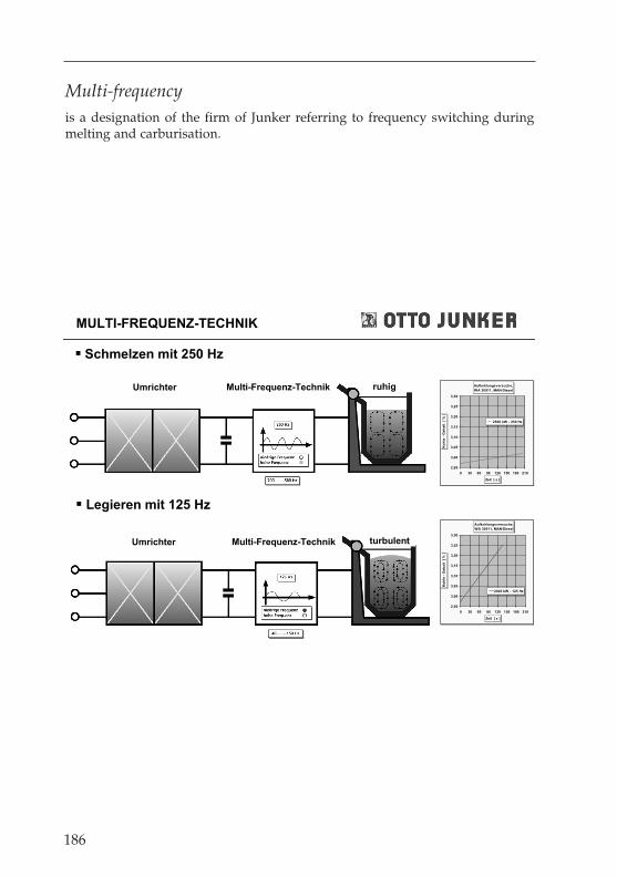
Multi-frequency
is a designation of the firm of Junker referring to frequency switching duringmelting and carburisation.
186
MULTI-FREQUENZ-TECHNIK
Schmelzen mit 250 Hz
Legieren mit 125 Hz
Umrichter Multi-Frequenz-Technik ruhig Aufkohlungsversuche,
WA 30911, MAN-Diesel
2,95
3,00
3,05
3,10
3,15
3,20
3,25
3,30
0 30 60 90 120 150 180 210
Zeit [ s ]
Ko
hle
- G
eh
alt
[
% ]
2500 kW - 250 Hz
turbulentUmrichter Multi-Frequenz-Technik
Aufkohlungsversuche,
WA 30911, MAN-Diesel
2,95
3,00
3,05
3,10
3,15
3,20
3,25
3,30
0 30 60 90 120 150 180 210
Zeit [ s ]
Ko
hle
- G
eh
alt
[
% ]
2000 kW - 125 Hz

193
Induction-Furnance Handbook – H. H. Netzel
Ni hard cast iron
is a martensitic, white cast iron alloyed with nickel and chromium for heavy-duty pump housings, pump pulleys, grinding components, rollers etc.
Nodular graphite iron
is the registered trade name of the International Nickel Ltd. London for cast ironcontaining nodular graphite.
Oil burner
a burner fuelled by heating oil for the heating of furnaces and firing systems.
Optipour system
is the optical casting system of the firm ABB, which measures the surface of acasting sump in the inlet funnel of a mould to be cast with an electronic camera,and then regulates the casting process in relation to the molten metal surface asdetermined by the camera. The casting process is stopped on reaching the speci-fied filling level. (look over next page)
Oscillating conveyors
are continuous conveyors in channel form for the transport of bulk materials,and are used in foundries for the charging of crucible furnaces. They can also beused for the separation of old sand. Depending on their cladding, they can alsobe used for the transport of pre-warned scrap or still hot castings.
Outer linings
are fitted in crucible furnaces with wall thicknesses of over approx. 150 mm. Asa rule, these consist of casting compounds with a high clay content, which arecast with the aid of a form which is conical toward the top. The conicity isapprox. 0.8%, as for crucible removal devices. For technical casting reasons, thethickness at the upper edge should not exceed 25 mm.For a 30-t furnace, the thickness at the top is 30 mm, and therefore 46 mm atthe bottom. These compounds are prepared with approx. 6% water. Althoughlarger quantities of water produce better casting characteristics, this has thedisadvantage of greater porosity, and consequently significantly lowerstrength. The water also has to be removed by means of various, laboriousheating methods. Drying can be carried out with gas- or oil-fired burners, orinductively. The maximum temperature at the lower edge of the outer liningshould not exceed 400 °C, in order to prevent any damage to the water-cooledinduction furnace coil. Otherwise the drying process should be carried out inthe same way as for casting compounds. An outer lining that has been dried
194
slowly will not tend to form cracks as quickly as an outer lining that has beendried too rapidly.
Outlet block
is the term used for the block holding or supporting the outlet.
Output
is the term used in electrical technology for the product of voltage in V multi-plied by the current in A, and is measured in units of Watts or Kilowatts, in shortkW. P = U x I.
Output increase
of existing systems using medium frequency or mains frequency are possible inthe range up to 10%, although a basic requirement is a water recooling system ofadequate size. Changing the voltage at the coil by 5% while maintaining thesame frequency produces an output increase of approx. 10%. Most transformershave +/- taps. Condensers are voltage-stable to approx. + 5%. A reduction of thefrequency by approx. 8% at the same voltage will give an output increase ofapprox. 10%. At the same frequencies and coil voltages, output increases can alsobe obtained by altering the number of windings.In the case of a mains frequency for example, the induction coil has 25 windingsand a length/height of approx. 1000 mm. If the number of windings is nowreduced by 1 winding to 24 windings while maintaining the same coillength/height, the electrical output will be increased by approx. 8%. If the lengthof the coil is also reduced, the output will be increased by approx. 4%.The total wall thickness from the new lining to the coil diameter at the copperwinding determines the coupling. If the wall thickness of an induction furnaceis reduced by 1 mm, this will give an output increase of approx. 0.8%, for thesame frequency and voltage. An increase in diameter of 10 mm will thereforegive an output increase of approx. 4%.In mains frequency systems, an output increase of up to 10% may also be possi-ble by means of over-compensation by the condenser bank and the associatedcapacitive voltage transformation.
Overcasting process
is the alloying of a molten metal with another solid metal by means of placing theadded metal on the bottom of the alloying ladle, and then pouring the molten metalover it. This procedure is also used for the production of nodular graphite castings.
Oxidation
the addition of oxygen for the purpose of oxidation.
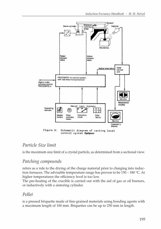
195
Induction-Furnance Handbook – H. H. Netzel
Particle Size limit
is the maximum size limit of a crystal particle, as determined from a sectional view.
Patching compounds
refers as a rule to the drying of the charge material prior to charging into induc-tion furnaces. The advisable temperature range has proven to be 150 – 180 °C. Athigher temperatures the efficiency level is too low.The pre-heating of the crucible is carried out with the aid of gas or oil burners,or inductively with a sintering cylinder.
Pellet
is a pressed briquette made of fine-grained materials using bonding agents witha maximum length of 100 mm. Briquettes can be up to 250 mm in length.
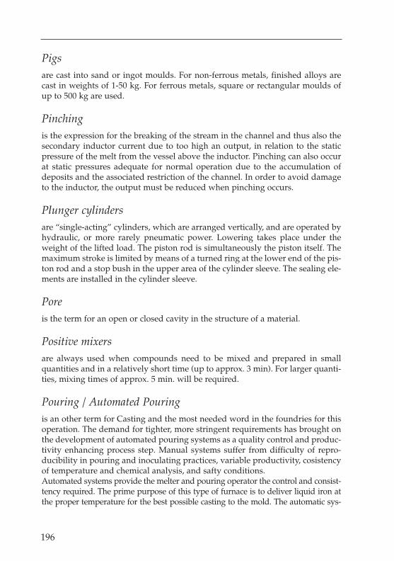
196
Pigs
are cast into sand or ingot moulds. For non-ferrous metals, finished alloys arecast in weights of 1-50 kg. For ferrous metals, square or rectangular moulds ofup to 500 kg are used.
Pinching
is the expression for the breaking of the stream in the channel and thus also thesecondary inductor current due to too high an output, in relation to the staticpressure of the melt from the vessel above the inductor. Pinching can also occurat static pressures adequate for normal operation due to the accumulation ofdeposits and the associated restriction of the channel. In order to avoid damageto the inductor, the output must be reduced when pinching occurs.
Plunger cylinders
are “single-acting” cylinders, which are arranged vertically, and are operated byhydraulic, or more rarely pneumatic power. Lowering takes place under theweight of the lifted load. The piston rod is simultaneously the piston itself. Themaximum stroke is limited by means of a turned ring at the lower end of the pis-ton rod and a stop bush in the upper area of the cylinder sleeve. The sealing ele-ments are installed in the cylinder sleeve.
Pore
is the term for an open or closed cavity in the structure of a material.
Positive mixers
are always used when compounds need to be mixed and prepared in smallquantities and in a relatively short time (up to approx. 3 min). For larger quanti-ties, mixing times of approx. 5 min. will be required.
Pouring / Automated Pouring
is an other term for Casting and the most needed word in the foundries for thisoperation. The demand for tighter, more stringent requirements has brought onthe development of automated pouring systems as a quality control and produc-tivity enhancing process step. Manual systems suffer from difficulty of repro-ducibility in pouring and inoculating practices, variable productivity, cosistencyof temperature and chemical analysis, and safty conditions. Automated systems provide the melter and pouring operator the control and consist-tency required. The prime purpose of this type of furnace is to deliver liquid iron atthe proper temperature for the best possible casting to the mold. The automatic sys-
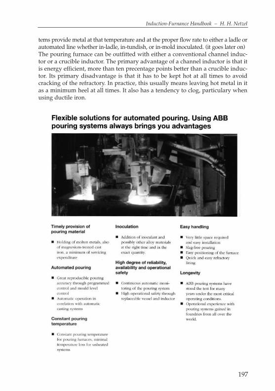
tems provide metal at that temperature and at the proper flow rate to either a ladle orautomated line whether in-ladle, in-tundish, or in-mold inoculated. (it goes later on)The pouring furnace can be outfitted with either a conventional channel induc-tor or a crucible inductor. The primary advantage of a channel inductor is that itis energy efficient, more than ten precentage points better than a crucible induc-tor. Its primary disadvantage is that it has to be kept hot at all times to avoidcracking of the refractory. In practice, this usually means leaving hot metal in itas a minimum heel at all times. It also has a tendency to clog, particulary whenusing ductile iron.
197
Induction-Furnance Handbook – H. H. Netzel
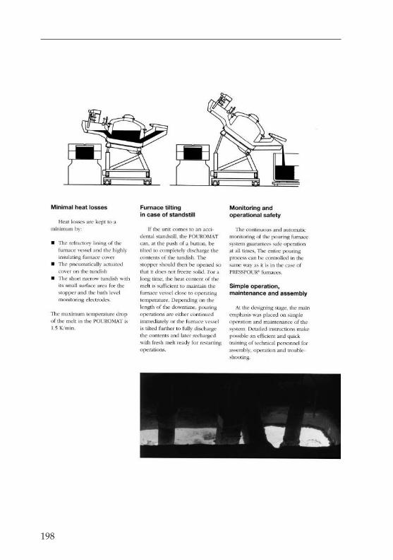
198

199
Induction-Furnance Handbook – H. H. Netzel

203
Induction-Furnance Handbook – H. H. Netzel
The primary advantage of a crucible inductor is that it can be emptied andallowed to cool down without too much penalty on refractory life. It also has lesstendency to clog in the first place and can be more easily cleaned with mechan-ical means. The nature of the foundry operation will determine if the flexibilityand high up-time of the crucible inductor will outweigh the disadvantage of itslower electrical efficiency.
Pouromat
is the registered trademark of the firm of ABB for all casting units with and with-out heating manufactured by ABB.
Power-Focus
is the name used by the firm of Junker or the displacement of the output concen-tration over the height of the furnace coil.
Precision casting
should only be used as a general term for waste-wax casting.
POWER FOCUS TECHNOLOGY
by operator to suit process requirements
Shifting of the power concentration across the furnace coilprocessor controlled,depending on furnace filling level
Converter Power Focus Technology
turbulent
moving
calm
PO
WE
RP
OW
ER
PO
WE
R
topstandardbottom
topstandardbottom
topstandardbottom
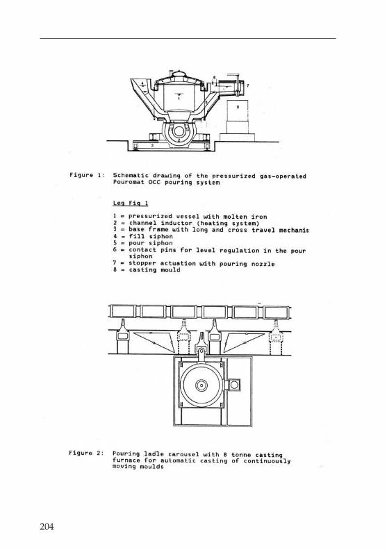
204
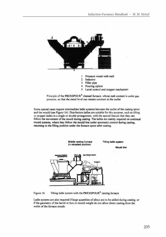
205
Induction-Furnance Handbook – H. H. Netzel
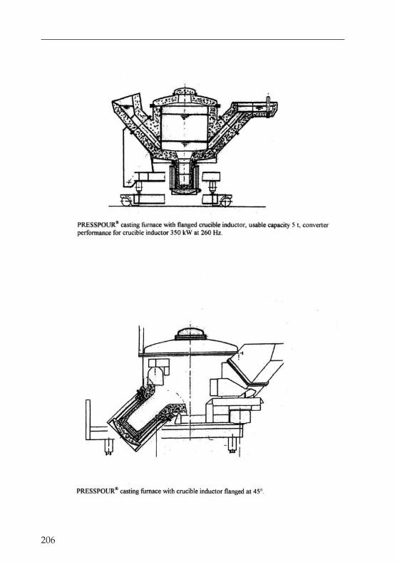
206
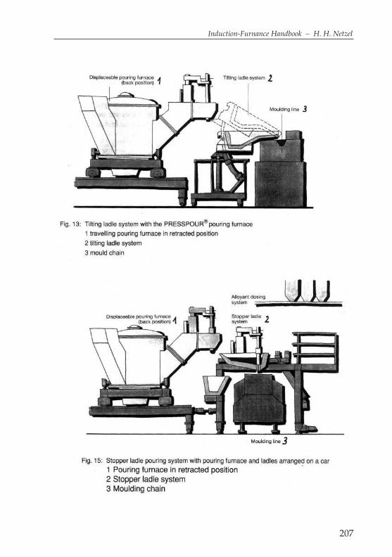
207
Induction-Furnance Handbook – H. H. Netzel
208

209
Induction-Furnance Handbook – H. H. Netzel
Pre-heating of Scrap
are usually used only at the edge of the crucible and in the spout area. One alsorefers to patch compounds, which are applied in accordance with the usageinstructions. Since these compounds contain at least 5% water, they can also besprayed on with the aid of suitable equipment. After an air-drying period, theymust also be dried with a gas flame, in order to prevent such compounds flak-ing off on contact with the molten mass.
Preliminary alloy
is the designation for alloys used exclusively as alloy materials.
Pyrometers
are used for the measurement of high temperatures, and come in the form of ther-mo-electric and radiation pyrometers. Pyrometers are used for measurementsbetween 1,000 °C up to a maximum of 1,600 °C (or for brief periods 1,800 °C).
Processors
are available for crucible, channel and holding furnaces and for casting units. Themelting processor fulfils the widest possible range of tasks. In the case of cruciblemelting furnaces, the processor consists of a computer with colour monitor forthe information of the operating personnel, a function keyboard for the operationof the system and a printer for recording and printing out the operating data.
The following devices are connected via the relevant interfaces:– the weighing system of the crucible furnace, which is mounted on pressure
measurement units/weighing beams – the immersion temperature measurement system– the memory-programmable controls required for locking the system– the analysis spectrometer a modem for remote diagnosis or service purposes
a higher-level process control system– The processor regulates and controls the furnace output and energy supply in
relation to the signals it receives from the connected devices. The melt proces-sor calculates the average temperature of the charge on the basis of the furnacecontents and the amount of energy already supplied. The following informa-tion is displayed on the monitor during the running of the melting programme:
– the weight of the melt – calculated average temperature of the melt– total energy consumption in relation to the charge– specific energy consumption in relation to the charge– remaining energy available(look pages later)

210
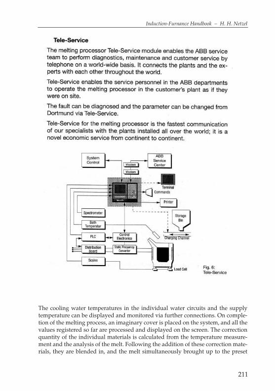
211
Induction-Furnance Handbook – H. H. Netzel
The cooling water temperatures in the individual water circuits and the supplytemperature can be displayed and monitored via further connections. On comple-tion of the melting process, an imaginary cover is placed on the system, and all thevalues registered so far are processed and displayed on the screen. The correctionquantity of the individual materials is calculated from the temperature measure-ment and the analysis of the melt. Following the addition of these correction mate-rials, they are blended in, and the melt simultaneously brought up to the preset
212
casting temperature and target composition. The melt processor then switches thefurnace to the holding mode, and instructs the operator to start the casting. Aftercasting of the maximum quantity available, taking into account the sump quanti-ty remaining, the next melting process can be started. Besides the control of theactual melting process, the melt processor also has several other programmes thatcan be called up. The processor has a programme for the starting of a cold crucibleafter extended shut-down, e.g. following the weekend or longer shut-down peri-ods. The programme enables the safe inductive heating of the charged crucible, sothat normal melting operations can be resumed at the start of the shift.A further programme is available for the sintering of a newly relined crucible. Afterrelining, the processor controls the sintering process by means of time-related tem-perature profiles. The wear to the crucible is also monitored by means of the chang-ing parameters for effective and idle output, frequency and crucible capacitycaused by the gradual reduction of the wall thickness. It calculates the washing-outof the furnace crucible from the electrical data of the furnace. The time progressionof the wall thickness during the life of the crucible, and the current condition of thecrucible during operation are then displayed on the screen. All similar events sig-nalled by the relevant interfaces, including any faults or problems occurring, areregistered, recorded and printed out at the appropriate time. All relevant operatingdata are provided regularly via the charge report, and automatically printed out forthe last charge whenever required, or when starting the next charge. In the case ofinductively heated channel furnaces or casting furnaces, the processor stores thefollowing data:inductor voltage and current effective and idle output insulationresistance between the inductor cooling jacket and the metal in the inductor chan-nel, other parts carrying voltage and earthcooling water temperatures of the sup-ply and individual circuits temperatures at 5 points in the boiler the processor forthis application stores all the values measured. It can display one or more of thevalues on the monitor, in relation to time, and print them out on the printer asrequired. The operator can select between several periods between the start of theinductor and the last 4 hours.In order to guarantee reliability against faults, theinputs and outputs of the computer must be connected to the furnace by memory-programmable controls. All registered and stored data can be transmitted andprocessed for remote maintenance by means of a modem. With the aid of therecorded values, the inductor diagram can be calculated and displayed. If criticalsituations occur during operation, the processor generates the relevant alarm.The integral statement regarding the relationship of effective and idle output canbe assisted by the display of the losses in the water-cooled components of thehousing. This also tells the operator whether the inductor is being washed out, e.g.in the area of the lower section and accumulating deposits in the upper section.
Process Solution for Sand
is an importand point for the modern foundry. On the next 2 pages You will findsome interesting information from a competent company GUT
215
Induction-Furnance Handbook – H. H. Netzel
Quartz
is a fireproof material, which consists largely of silicon dioxide (SiO2). At 870 °Ca conversion takes place, which on cooling leads to contraction cracks. Thesecracks close up again on heating up to over approx. 1,000 °C.
Quality symbols
are used to designate certain products. The best-known quality symbol forfoundries using nodular graphite is the “4G”.
Quenching
is the general term for a temperature reduction at a high cooling speed. Mouldmaterials with high heat conductivity lead to the quenching effect, which is allthe greater, the thinner the wall of the casting is.
Raw iron
is the first smelt produced in the blast furnace, and consists of the untreated ironobtained from iron ore. Raw iron is used as the charge material for the productionof cast iron and for steel production. Hematite raw iron is used exclusively forfoundry production. The standard material has the following chemical analysis:2.50 to 3.00% Si, 0.70 to 1.00% Mn, max. 0.12% P, max. 0.04% S, 3.70 to 4.1% C.Foundry raw iron is also used in foundries, and differs from hematite manlywith regard to the phosphorous content, which at 0.50 to 0.70% is 4 to 6 timeshigher. Specular pig-iron is a special raw iron with a significantly higher man-ganese content of from 6 to 30%. The normal analysis is: 4.00 to 5.00% C, 6.00 to30.00% Mn, 0.10 to 0.15% P, up to 1.00% Si, up to 0.04% S.Further types of raw iron include:Low-carbon or high-carbon raw iron, Siegerland special raw irons, special rawiron for the production of cast iron with nodular graphite and charcoal raw iron.Raw iron is generally used in the form of pigs or ingots of approx. 20 kg inweight, or more rarely as 60 kg joined ingots consisting of 3 20 kg pigs.
Racking off
is the removal of slag from the surface of the bath. Racking off is also used torefer to the removal of auxiliary casting materials from bunkers with the aid ofmechanical devices.
Reactive power
is the product of the coil voltage multiplied by the reactive current flowingbetween the furnace coil and the capacitor battery, given in k Var.

216
Resistance
in electrical technology is the product of the voltage present at the two ends ofan electrical conductor and the current flowing through it (current strength).R=U: I. This resistance is also referred to as the Ohm resistance. In addition to theOhm resistance, electrical technology also uses the terms “inductive resistance incoils” and “capacitive resistance of condensers”. The unit of measure is the Ohm.This relationship was discovered by the physicist Ohm, and the formula isreferred to as “Ohm’s law”.U=RxI (voltage=resistance x current strength / Volt=Ohm x Ampere).
Robot
is a designation for a human-like mechanical device or machine, which comesfrom the Czech language. Modern industrial robots are highly mechanised, andare now indispensable in the foundry industry. In die-casting foundries in par-ticular, and in view of the low piece weights involved, robots started to be usedas soon as they had been developed. Today, robots with handling weights of upto 500 kg are used successfully.
Roebel (transposed) conductor or drill conductor
was a special conductor guide used in generator technology. The BBC engineerLudwig Roebel was awarded a patent for these interwoven or drilled copperstrips on 19th March 1912. The special feature of this conductor is the fact thatevery individual conductor within a specified length range is present in everylayer of all the individual conductors. The individual conductors are insulatedfrom one another, and therefore reduce the considerable eddy currents thatcause losses. In induction furnace technology, advantage has been taken of thisknowledge in the design and construction of air-cooled inductors of up toapprox. 500 kW per inductor coil. This form of conductor cannot be used for cru-cible induction furnaces. Due to the dimensions of the channel, the iron core, thediameter of the coil, the number of windings, the length and the cooling air ductsnecessary for the construction of inductors, the use of air-cooled inductors is nec-essarily restricted. From the physical and energy-technology point of view, theiruse can be highly recommended, since the losses are lower than with normalconductors formed in parallel and water-cooled hollow copper conductors. Forcomparison, the copper loss figures for the 3 most common conductor types at500 kW nominal output are:water-cooled hollow copper conductors approx. 90 kW12-way flat individual conductors, undrilled approx. 75 kW12-way flat individual conductors, drilled approx. 64 kWHowever, since it is comparatively expensive to provide the relatively clean cool-ing air required, the water-cooled inductor has become the type more common-ly used in practice. Air-cooled inductors are constructed with an output of up to
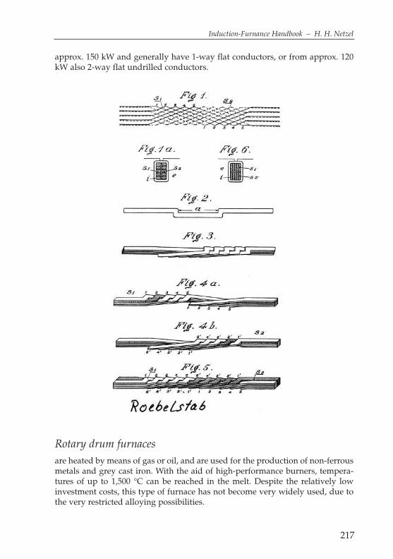
217
Induction-Furnance Handbook – H. H. Netzel
approx. 150 kW and generally have 1-way flat conductors, or from approx. 120kW also 2-way flat undrilled conductors.
Rotary drum furnaces
are heated by means of gas or oil, and are used for the production of non-ferrousmetals and grey cast iron. With the aid of high-performance burners, tempera-tures of up to 1,500 °C can be reached in the melt. Despite the relatively lowinvestment costs, this type of furnace has not become very widely used, due tothe very restricted alloying possibilities.
218
Sample ladles
are casting ladles used for taking a sample of the melt and for the casting of test pieces.
Sand preparation
is he general term for the production of finished moulding sand used for sandmoulding, shell moulding and for core production. Sand preparation is dividedinto new and old sands.
Saveway
is a system that works as follows: it is based on the highly non-linear change inthe electrical resistance of the fireproof material. As the crucible wall thickness isreduced, the melt penetrates further forward in the direction of the installed elec-trode plates. This causes the temperature of the fireproof material in front to rise,while its electrical resistance falls. For the measurement current, this means thatit flows from one electrode to the melt, and from there back to the other electrode.A certain proportion of the measurement current flows directly from electrode toelectrode. This proportion tends toward zero with reducing wall thickness, whilethe measurement current through the melt increases sharply. This alteration inthe condition of the fireproof lining is assessed by the complex measurement sys-tem, and the wear to each electrode plate is calculated and displayed (page 222).
Scrap drying
is essential for induction furnaces if the charge material is stored in the openinstead of indoors. When operating induction furnaces, care must be taken toensure that no fluids get into the melt. 1 cm3 of fluid getting into the bath willexpand suddenly in volume to 500-600 cm3. This is referred to as a water vapourexplosion. With medium-frequency furnaces, scrap drying can be dispensedwith provided that the scrap is handled accordingly. The operator must at alltimes ensure that material is not charged into the sump, but that there is alwaysenough solid material on top of the melt so that it will be dried before cominginto contact with the melt.The former practice of heating scrap up to temperatures of approx. 200 °C is nolonger viable nowadays because of increased energy costs. The material made up60% and the container the remaining 40%. The achievable melting performanceincrease is significantly lower than that indicated by the theoretical calculations.
Scrap pre-drying
For all materials used in induction furnaces, care must be taken to ensure that nodamp material is immersed in the molten bath, since this can cause explosiveeruptions. Usually only a small proportion of the materials are damp to any

extent. If this part of the charge is charged in last, the damp can dry off beforethe material is immersed in the bath.In critical cases, and for reasons of operating safety, the charge materials must bedried out in advance. The heating needed for this purpose is usually providedby oil, natural gas or electrical energy.Earlier systems were usually designed for pre-heating temperatures of up to 600 °C, so that in addition to drying, pre-heating was also carried out, whichequated to a heat content of the iron of around 100 kWh/t. This meant that about25% of the required heat was provided by means of the pre-heating. The electri-cal output could consequently be reduced, or the throughput increased accord-ingly. High oil and gas costs have meant that this process is now restricted todrying of the charge material. This also allows some technical simplifications,since the process can be carried out at lower furnace temperatures.The stationary system works with single-bucket heating. The filled bucket isbrought into the heating station, the burner device is fitted, and the gas forced orsucked through the charge. For better utilisation, it can also be redirected andducted away via the dust extraction system.
219
Induction-Furnance Handbook – H. H. Netzel
I E SInduktion Experience Service
Harkortring 6
D-58453 W I T T E N
eMail: [email protected]

226
227
Induction-Furnance Handbook – H. H. Netzel
Semi-finished products
are metallic products in the form of pressed or drawn rods, wires, tubes and pro-files, or rolled plates and strips.
Setting
is the hardening of mortar and concrete.
Shaking ladle
are used as treatment ladle for molten metals. The shaking movement is pro-duced y means of an excentric drive. Shaking pans are often used for the desul-phurisation of blast furnace and cupola furnace iron. The weights range from 0.8 t to a maximum of approx. 10 t.
Shell moulds
consists of least 2 mould halves or shells, which are stabilised with filling sandand used in mould boxes. The shell moulds are machine-manufactered, and areused for casting materials that tend to penetration.
Short-circuit rings
are used in magnetic applications in order to keep the scatter fields away from cer-tain components. In crucible induction furnace design, short-circuit rings arerequired for furnaces with a high specific output, so that the components mainly inthe upper furnace area are not heated excessively by the scatter field. In the bottomarea, the electrically conductive parts are further away from the coil than those inthe upper area. The short-circuit ring is made of coil copper in a water-cooleddesign. The ring is usually fitted above and behind the iron piles, in order to gen-erate an opposing field to the scatter field. By reason of the induction law, the mag-netic field generated is arranged in opposition to the generating magnetic field.In furnaces with high specific outputs, the loss performance in the short-circuitring can amount to approx.10 kW. The amount of water required to dissipate thisenergy is approx. 35 l/h and kW, and therefore approx. 350 l/h at 10 kW. Theshort-circuit ring must be installed electrically insulated from the supportingconstruction. Casting into the upper concrete ring without any possibility ofescape for loss water is not recommended.
Shrinkage dimension
is expressed as a percentage shrinkage between the model and the casting. Thisis the linear contraction of a casting when cooling down from the solidificationtemperature to room temperature.

228
Shrinkage cavities
are created when a melt solidifies due to volume contraction. With suitablemould design, the shrinkage should occur in the ingate or riser, and not in thecasting itself. Exothermal supply heating can be provided with the aid of shrink-age powder.
Shellac
is used in the foundry in an alcohol solution with methylated spirits as a coatingfor plaster models. Shellac is a natural resin.
Short-coil furnaces
come in 2 quite different versions. In version A, a “lower furnace with an integrat-ed low induction coil” is flange-fitted below a “cylindrical upper furnace” with-out cooling equipment. The iron piles are fitted only in the area of the furnacecoil. Version B consists of a crucible furnace with a low induction coil and a cool-ing coil made of V2A material installed directly in the coil extension. The ironpiles are fitted with electro-plate in the area of the coil, and in the area of the cool-ing coil, only the extended side plates with their welded bridges serve to support

229
Induction-Furnance Handbook – H. H. Netzel
the cooling coil against the furnace body. Die losses with Type B are approx. 15%lower than with Type A, due to the higher induction coil (look page before ).
Silicosis
is a lung disease caused by breathing in dust with a high proportion of verysmall particles. A respirator mask with nose filter should be worn wheneverworking with SiO2 materials.
Simplex operation
refers to the melting of solid materials in a furnace without the addition of anymolten charge.
Sintering
is the compaction of crystalline, granular or powdered materials by means ofaccretion of the crystallite under corresponding heating, without any of the com-ponents being melted. With the use of sintering agents, the reaction temperaturecan sometimes be reduced by up to 200 °C. For example, boracic acid or boricanhydride are used in the case of acidic tamping compounds. With the additionof 0.8%, the sintering point of pure quartzite is lowered from 1,700 °C to 1,550 °C.
Siphon outlet
a siphon outlet enables slag-free casting from foundry ladles. In channel fur-naces, the inlet and outlet are arranged according to the siphon principle. Inthis way, the molten metal is always fed in and removed below the bath sur-face. When emptying below the minimum sump level, the function of thesiphon must not be interrupted for filling, i.e. the furnace may only be tippedback slowly, in relation to the filling level. If the furnace is tipped back into thebasic position while still under-filled, the ingress of air, and thus also oxygen,is unavoidable. The furnace atmosphere is therefore enriched with oxygen,leading to increased slag formation on the melt sump. The ceramics in thetransitional area between the siphon and the furnace vessel can also be dam-aged.
Skimming
is generally carried out after reaching the tapping filling level. In most cases, aslag forming agent is applied to the bath, and then removed with manual equip-ment or pneumatic slag removers.The tools used must be treated in advance with blackening to facilitate subse-quent removal of the slag. Tools must be heated and dried over the bath beforeimmersion in the liquid melt.
230
Slag
consists of oxidic materials which are largely insoluble in molten metals, andinstead separate from them to form a separate layer on top of the molten metal.A distinction is made between basic and acidic slag.
Slag control agents
are added to the melting furnace as slag additives in order to alter their compo-sition, or to bind the slag being formed, so that this can then be removed withsuitable tools, i.e. tapping the slag. Such agents are also used to remove heavyslag deposits from the furnace walls. Normal soda is also often used for this pur-pose. When using soda however, care must be taken to ensure that the cruciblewall itself is not damaged.
Soldering
is the term for the joining of 2 metallic materials by means of a soldering mate-rial with a lower melting temperature. The metal components to be joined mustbe metallically clean. This cleaning is carried out with the aid of soldering fluidor soldering grease. The heat source can be provided by soldering irons, solder-ing lamps or burner flames. In industrial applications, induction heat and elec-trically heated through-type furnaces are used.
Solidification
is the transition from the molten to the solid state. Contraction occurs duringsolidification, and the resulting volume reduction on the mould has to be com-pensated for by the addition of more molten metal.
Solidification temperature
is the temperature at which a material changes from the liquid into the solidstate, or at which solidification starts. Solidification is completed when the solidtemperature is reached.
Soot
is produced in special furnaces by means of the incomplete combustion of gases,liquids or solids containing carbon. Soot is a carbon product with a particularlysmall particle size.
Spectral analysis devices
are used for the rapid chemical analysis of a material by means of the spectrumof its components. The sample is exposed to an electric arc. The light emitted by

231
Induction-Furnance Handbook – H. H. Netzel
the arc is refracted into its different spectrums, showing the spectral lines of allthe elements contained in the material. The qualitative analysis of the individualelements contained in the sample is carried out by identifying these lines. As arule 8-10 elements are identified.
Spin casting
is a casting process in rotating moulds using the effects of centrifugal force. Thisprocess is used for the production of tubes and cylinder sleeves.
Spinel
is an aluminous mineral with the chemical formula MgO Al2O3 for genuine spinel.Consist of at least 2 mould halves or shells, which are stabilised with filling sandand used in mould boxes. The shell moulds are machine-manufactured, and areused for casting materials that tend to penetration.
Starter blocks
are needed for starting up induction crucible furnaces of up to approx. 150 Hzoperating frequency,so that the furnace can start with an acceptable power con-sumption and electrical efficiency. The diameter should be approx. 100 mm lessthan the crucible diameter on relining.Conicality is required for rapid emptying from the mould. Some customers havemade themselves separable moulds, and can therefore work with a very lowconicality of below 1%. When casting the starting blocks, the lifting eyes of con-struction steel are cast directly into the block. In order to prevent damage to thelifting eyes during stacking in the crucible or during storage, it is advisable tocreate corresponding recesses in the lower area of the starting blocks. With thecorresponding design of the mould with 2 lateral grooves, the prefabricated lift-ing eyes are inserted into these grooves and thus adequately held in place.Operators of medium-frequency systems should also keep a number of starterblocks in stock, since these are very helpful for pushing in light scrap or lower-ing the melt temperature for sump smelting.
Starter rings
can be used as a substitute for starter blocks. The outer diameter is approx. 100 mm less than the crucible diameter, and the inner diameter of the rings isapprox. 200 mm less than the outer diameter. The use of such rings was recom-mended in the 1970’s for mains frequency furnaces with crucible diameters >1,000 mm for sinter charging. The first ring was placed on the crucible cone; dis-tance pieces 50 mm thick and about 100 mm long and wide were then placed atthree places around the circumference of the ring. The next ring was then placedon top of these parts. This procedure was repeated up to the upper edge of the

232
induction coil. Compact scrap can also be filled in inside the rings right up to thetop. Due to the good coupling, this ensures very even heating of the rings, andthus also of the ramming template and ramming mix. Dry mixes were heated atapprox. 100 °K/h. When semi-plastic mixes with up to 4% moisture were used,the temperature increase was reduced to 50 °K/h. This allowed even drying bymeans of the ramming template on the crucible wall. This process was howeverdiscontinued at the end of the 1970’s for cost reasons. The starter rings weremade from approx. 80/100 mm thick steel plates. One customer in Finland castthe rings from scrap iron.
Starting
of induction crucible furnaces varies greatly, depending on the working frequen-cy. There is the starting of a new crucible, and a crucible that has already been inoperation, also known as cold starting.Starting of a new crucible is also referred to as sintering; this may be liquid sin-tering following removal of a permanent template, or with a lost template, whichremains in the furnace and is also melted. After reaching the maximum fillinglevel, the melt is brought up to approx. 50 – 100 K above the normal tapping tem-perature, and maintained at this temperature for up to 2 hours for acidic cru-cibles and for up to 4 hours for neutral and alkaline crucibles. The 1st tapping isthen carried out.When starting damp lined crucibles, the manufacturer’s instructions must bestrictly observed, in order to ensure that the damp is driven out. These cruciblescannot be charged with molten metal.Mains frequency furnaces without liquid filling must be started using starterblocks. The diameter should be approx. 100 mm less than the crucible diameter.The filling height should be about 2/3 of the coil height.Medium-frequency furnaces without liquid filling can be started using normalsteel scrap, although this should not contain any chips, any dimensions greaterthat 50% of the crucible diameter or any magnetic yokes.
Steel
is an alloy of iron which can be forged without any further treatment. The limitof forgeability or malleability lies at approximately 2% C (as a rule at 1.7% C). Inthe binary iron-carbon system, all alloys with contents of up to about 2% C areconsidered as steels, whereas cast iron, tempered cast iron, hard cast iron andraw iron are not. There are a large number of trade and manufacturing designa-tions for steel, some of the better-known types of which are given below:Austenitic steel, machine steel, strip steel, construction steel, stainless steel, case-hardened steel, cast steel, spring steel, profile steel, cold-rolled steel, LD steel,alloyed steel, magnetic steel, non-rust steel, tempered steel, heat-resistant steeland tooling steel.

233
Induction-Furnance Handbook – H. H. Netzel
Steel crucible furnaces
are crucible furnaces that work with a crucible made of welded or cast steel. Steelcrucibles are used for non-ferrous metals and as a rule for special applications.The most common application is the melting of recycled magnesium.
Steinmetz switching
is the balance switching for the operation of 1-phase induction furnaces from 3-phase rotary current networks. In the case of Steinmetz switching, it is assumedthat the compensation of the 1-phase furnace is set to 1. By means of balance con-trol, the capacitive part of the balancing is switched in sequence with the induc-tive part, i.e. the capacity of the balancing condensers equals the output of thechoke. By means of corresponding condenser stage switching, condensers areswitched in parallel to the choke or the balancing condensers. The level of thebalancing performance depends on the output being absorbed by the inductionfurnace. The ideal figure is the furnace output divided by 1.73. Since a crucibleinduction furnace is designed so that it can still be operated at nominal load evenwith approx. 25% washing-out, the transformer steps must be designed in the
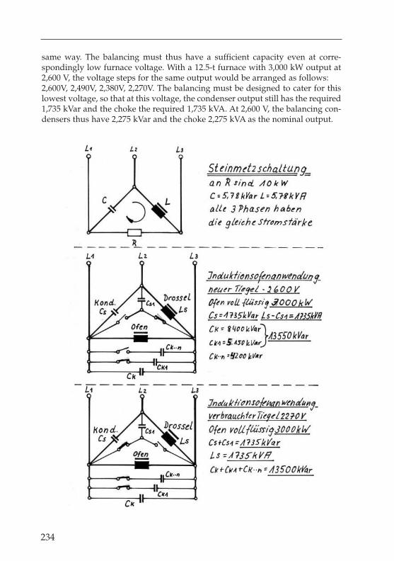
same way. The balancing must thus have a sufficient capacity even at corre-spondingly low furnace voltage. With a 12.5-t furnace with 3,000 kW output at2,600 V, the voltage steps for the same output would be arranged as follows:2,600V, 2,490V, 2,380V, 2,270V. The balancing must be designed to cater for thislowest voltage, so that at this voltage, the condenser output still has the required1,735 kVar and the choke the required 1,735 kVA. At 2,600 V, the balancing con-densers thus have 2,275 kVar and the choke 2,275 kVA as the nominal output.
234

235
Induction-Furnance Handbook – H. H. Netzel

236
Stripping
is rarely carried out nowadays in view of the relatively low costs of acidic tamp-ing compounds. In stripping, the crucible wall, which is infiltrated with iron, isremoved with the aid of compressed air hammers. The thickness of this layerranges from 30 to 50 mm. After the removal of the waste, the “crucible wall” iscleaned of loose particles. A lost tamping form is now put in place and the drycompound filled in. After vibration and compacting, the crucible furnace is start-ed up again as for a normal relining. This process saves the costs of the insula-tion behind the wear lining and the proportion of the compound remaining inthe furnace of approx. 30%.If the crucible is pressed out with the aid of a crucible removal device, the costsof stripping are only worthwhile in rare cases. For mains frequency furnaces<over approx. 12 t, more economical repair can often be effected by means ofpartial stripping of the lower section. Stripping is carried out over about thelower third of the crucible height, and an approx. 60 mm smaller repair tem-plate then positioned. A nominal diameter of 1,190 mm thus gives approx. 1,130mm. This is pre-heated with a gas burner and then liquid-sintered (look pagebefore).
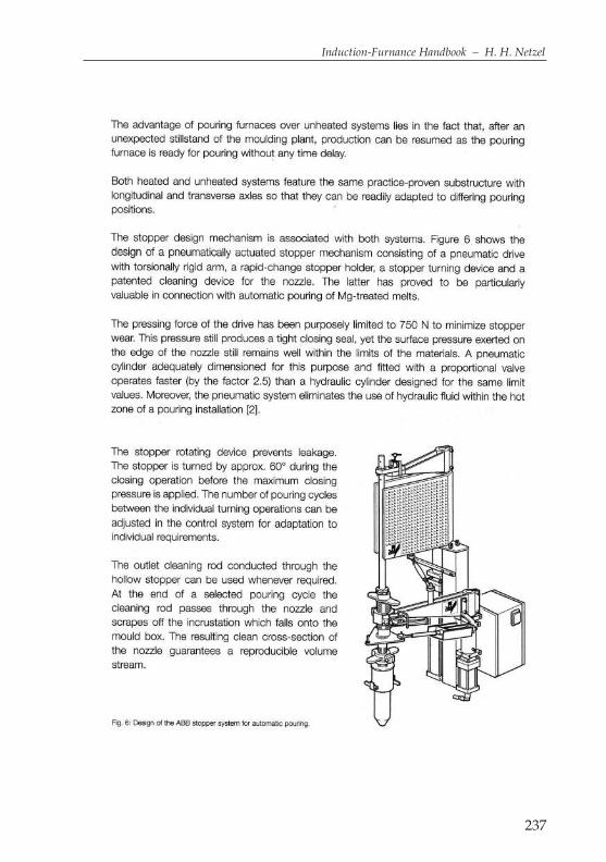
237
Induction-Furnance Handbook – H. H. Netzel

Stoppers
are used for sealing off the tapping hole of cupola furnaces. The material used isgraphite clay. For sealing off a stopper ladle, a stopper is screwed to the stopperrod that seals off the outlet hole.
Stopper actuators
come in hydraulic and pneumatic versions. Through the use of optimised com-ponents, both types are fast enough, and also very reliable. The casting of nodu-lar graphite iron is usually carried out with the aid of hollow stoppers, throughwhich the outlet block can be cleaned at regular intervals or after every castingby means of a suitable cleaning stopper.
Stopper ladle
is a casting ladle with bottom emptying, which can be emptied by raising thestopper rod. Alternatively, a swivelling stopper can also be used.
Storage
is the term for the “storage” of a melt in a storage or holding furnace, which cantake the form of a channel or crucible storage furnace. When storing GGG, spe-cial attention must be paid to the magnesium melting loss, so that the cooling ofthe magnesium content does not get out of control.
Stored heat
is the heat content of the crucible and the mass in the cover. If a furnace coolsdown completely over the weekend, this energy has to be re-supplied to the cru-cible again at the beginning of the next week. A 5-t furnace has approx. 900 kWhas stored heat in the crucible and the cover.
Sump
is the technical term for molten metal in a melting furnace or a ladle which is notemptied, but is reused.
Sump melting
is as a rule practiced in mains frequency induction furnaces, The optimum sumpheight corresponds to approx. 2/3 of the filling level, since in this case the whole coilis filled with molten metal, and the maximum electrical / inductive coupling isavailable. Medium-frequency furnaces are operated with a sump of approx. 15% ofthe total capacity. After tapping a medium-frequency furnace, the sump is still at a
238

239
Induction-Furnance Handbook – H. H. Netzel
relatively high temperature. When switching on the output again after charging, theremaining sump would be very well coupled, and would be over-heated for a shorttime. This produces an “elephant’s foot” as is normal in mains frequency furnaceoperation. To avoid this, approx. 30% of the sump weight charged into the sumpshould consist of compact cooling scrap (risers, sprues and approx. 100 mm largepieces). In larger furnaces (from approx. 5 t), a “starter block” with a weight ofapprox. 30% of the sump weight can also be charged in. This simultaneously lowersthe temperature, raises the bath level and reduces the wear to the crucible wall.
Switching on
of crucible induction furnaces is carried out as a rule by hand, or automaticallywith the use of processor controls. Mains frequency systems are usually connect-ed in 3-phase to the 3-phase power supply system. By means of Steinmetz switch-ing, the 3-phase system is also loaded equally over all 3 phases in the event of 1-phase connection of the induction furnace. Depending on the load on the system,the out-of-balance load of the 3 phases amongst each other may also be up to 10%of the maximum phase current. At phase currents above approx. 500 A, the bal-anced phase is switched on in advance of the field, and a furnace current isswitched via a switch-on resistance with reduced switch-on current. A short timeafter this switch-on process, the bypass contactor is switched in to short-circuitthis switch-on resistance. By this means, the high switch-on current of approx.1,500 A can be reduced to about one third of this level. The starting of a mains fre-quency furnace via the individual transformer steps offers no benefits, sinceevery individual step is ultimately switched on at full load. The main disadvan-tage is the multiplication of the hysteresis at the main and bypass contactors.In the case of medium-frequency systems, the current is brought up, in accor-dance with the specifications, from 0 to the maximal value of the required cur-rent by means of a so-called start-up ramp. For example, some customers havethis process set so that in the 1st switch-on phase, the output is brought up to1,000 kW and then after approx. 10 seconds to the maximum output of 3,200 kW.As soon as the electrical power is switched on, the energy is available in the formof heat, in the same way as a flow heater. For this reason, and before switchingon an induction furnace, the water supply to the furnace coil with sufficient vol-ume of water at the right temperature must be ensured.
Synthetic iron
is a term for cast iron produced from steel scrap with the addition of carbon and silicon.
Tapping
is the removal of the molten metal from the furnace. Tapping refers in particularto the opening of the tapping hole of a blast furnace or cupola furnace, so thatthe metal can flow out into the channel.
240
Tapping temperature
is the temperature at which the molten metal is removed from the furnace.
Temperature
is the heat level of a material, measured in Kelvin (K) or degrees Celsius (°C). Kis the SI unit of measure. The Kelvin scale begins at absolute zero, which corre-sponds to –273.15 °C. Conversion between k and °C:
K = °C + 273.15°C = K – 273.15
Temperature differences are expressed in Kelvin, although they can also be spec-ified in degrees Celsius.In some countries, Fahrenheit is still commonly used as a unit. In this case, theconversion is as follows:
°C = (°F-32) x 5/9°F = °C x 9/5 + 32
Temperature increase
is as a rule the temperature difference in °C or K per hour. Observation of thespecified temperature increases is important when heating ceramic compounds.When over-heating melts, the values are given in K/min.
Temperature gradient
Temperature difference in relation to the distance between 2 points. The unit ofmeasure of the temperature gradient is K/m or K/cm.
Temperature loss
is given in K/h for a completely filled crucible and with the electrical outputswitched off. Smaller furnaces have higher temperature losses than large fur-naces. In a 1-t furnace at 1,450 °C, this will produce a figure of approx. 50 K/hand for 12 t approx. 30 K/h. These figures apply for a fully heated crucibleand completely closed furnace cover, with the exhaust gas extractionswitched off.
Temperature change
or temperature change resistance refer as a rule in induction furnaces to theproperties of the ceramic materials at different temperatures. An acidic lining isless temperature-sensitive, and thus more resistant to temperature change thanbasic or neutral compounds.
Sebastian Apprecht
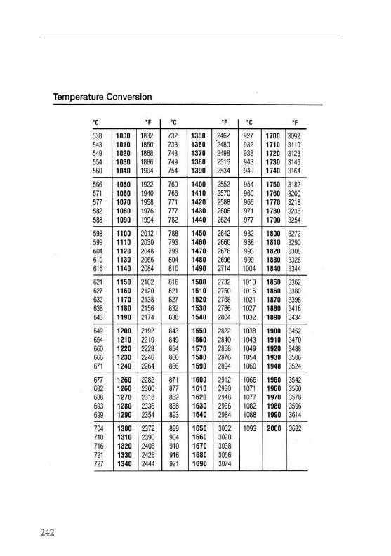
242

243
Induction-Furnance Handbook – H. H. Netzel

244

245
Induction-Furnance Handbook – H. H. Netzel
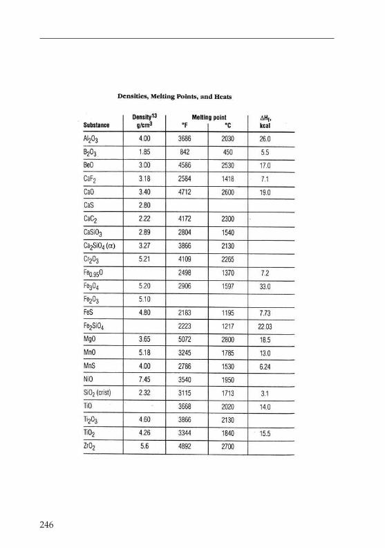
246
247
Induction-Furnance Handbook – H. H. Netzel
Templating
refers to the production of sand moulds of larger sizes for the production of rota-tionally symmetrical castings, using rotating templates in place of models, forexample for the casting of bells.
Thermal storage heating furnaces
are used as holding and storage vessels in continuous and non-continuousfoundry operations. Unforeseeable problems can also occur in continuous cast-ing operations, which can then be rectified with the aid of storage furnaces.Storage furnaces are designed as channel furnaces or crucible furnaces withgood heat insulation. A crucible storage furnace has the advantage of total emp-tying over a channel furnace, which must always be operated with a sump. Theheat losses are as follows for 40-t furnaces:
a) normal crucible melting furnace approx. 400 kWb) crucible storage furnace approx. 300 kWc) channel furnace 40 t usable capacity/12 t sump approx. 250 kW
Thermoelement
is an electrical element which generates a voltage when heated. It consists of 2different wires, which due to the voltage, cause a current to flow. These are usedup to a maximum of 1,600 °C. The voltage generated is in the mV-range.
Throat
is the term for the upper section of a shaft furnace, such as a cupola furnace. Thefurnace is charged through the throat, and the furnace exhaust gases are alsodrawn off through the throat.
Throat platform
is the platform or working stage for charging the furnace with the material orcharge to be melted.
Thyristor
in electrical technology is a controllable semi-conductor element, as opposed toa diode, which cannot be controlled. Thyristors are used in frequency convertertechnology for rectifiers and current inverters for the operation of induction fur-naces. High-performance thyristors are water-cooled, and can therefore be verysmall in size. Thyristors have also been developed in air-cooled versions,although these require relatively clean cooling air at a maximum of 33 °C.
248
Tipping cylinders
are as a rule designed in the form of “plunger cylinders”, i.e. the piston rod,without its own sealing elements, acts simultaneously as the “piston”. Loweringtakes place due to the counter-pressure of the furnace being raised. In mostcases, the 2 tipping cylinders are arranged laterally in the front area of the fur-naces. The lever arm has a length of 250 mm for small furnaces and a length ofup to approx. 1,000 mm for a 70-t furnace. Wherever possible, the arrangementshould be such that in the basic position, the tipping cylinders are standingeither vertically, or inclined up to 3° to the rear. In the end position, the tippingcylinders should be either vertical, or inclined a maximum of 3° toward the frontor rear. For furnaces from approx. 10 t, the tipping cylinders are equipped with“end-position damping”, which is achieved due to the piston rod design at thebottom. This is done to avoid sudden, jerky lowering into the basic position andany associated shocks when positioning the crucible.. In order to prevent anyunforeseen “tipping errors”, the cylinders should be bled every 6 months.
Tipping point
of a crucible furnace refers to the pivot point of the crucible furnace, aroundwhich the furnace is tipped. The casting spout length and the relevant tippingpoint must be optimised, depending on the use of the furnace and the deviceemployed to accept the melt. An optimum pivot point for all applications is the“lower lip” of the casting spout with a relatively long casting spout, in order toprovide clearance for ladles in front of the furnace. This arrangement means thatthe casting stream can be directed accurately, and produces the lowest possibleheight differences between casting and total emptying.
Tipping points
Tipping point at the end of the casting spout, no fluctuating casting stream, opti-mum design
Tipping point 100 mm below the end of the casting spout, casting stream fluctu-ates normally, normal design
Tipping point 200 mm below the end of the casting spout, casting stream fluctu-ates severely, uncommon design
Tipping angles
are important for total emptying. In the case of duplex furnaces, a tipping angleof 100° often has to be used because of the shoulders of the crucible. Most cru-cible furnaces work with a tipping angle of 95°. For casting units, an angle ofbetween 60° and 95° has to be catered for in order to take into account the induc-tor installation angle and the vessel dimensions.
253
Induction-Furnance Handbook – H. H. Netzel
Transformer
in electrical technology is a device for increasing or reducing an alternating volt-age without significant energy losses. A 1-phase transformer has the primaryand secondary coils arranged at either end of a closed, O-shaped core. The alter-nating current flowing in the primary coil generates, by means of induction, avoltage in the secondary coil, which is proportional to the number of windings.In order to achieve the strongest possible common magnetic field of the twowindings, these also sit on one arm of the O-shaped core.In rotary current transformers, the primary and secondary windings of eachphase are arranged on the three vertical arms of pillars. The primary coils con-sist of relatively thin wires or flat profiles. For the secondary coils, at high cur-rents, conductor strips are used with widths of up to 1 m.
Twin Power
is the registered trademark of the firm of ABB for the operation of 2 inductionfurnaces from a single electrical power supply with optional power distributionof approx. 5% to 95% in order to make 100% use of the total output.
Ultrasonic testing
is used for the detection of material faults by ultrasound, i.e. with sound vibra-tions of over 20,000 Hz. The frequencies used lie between 0.05 MHz and 25 MHz.In practice, the average level is around 12 MHz.
Ventilation
is required primarily to dissipate the heat loss to the system components. In induc-tion furnace systems for smelting operations, the system is designed in such a waythat the air outlets produce an over-pressure in the power supply room, meaningthat hardly any dust can enter from outside. In the case of air-cooled convertercabinets, the fresh air must be kept clean with the aid of corresponding filters.
Vermicular graphite
is a vermicular graphite, a form of graphite between laminar graphite and nodu-lar graphite. This is not desirable in the production of nodular graphite. Thisoccurs as a result of inadequate magnesium treatment, or due to excessive dead-melting of the treated iron.
Visualisation
is the pictorial or graphic representation of switch conditions or processes onmonitor screens.

254
Voltis the unit of measure of electrical voltage. The definition is that 1 Volt is the volt-age that causes an electrical current of 1 Ampere to flow through a resistance of1 Ohm. Ohm’s law: U=R x I.
Voltageis the term for the electrical voltage. This is the measure of the potential between2 electrical phases at 3-phase or 2 poles under direct current. The voltage is meas-ured in Volts. 1 Volt is the voltage that causes an electrical current of 1 Ampereto flow through an electrical resistance of 1 Ohm.

255
Induction-Furnance Handbook – H. H. Netzel
Water distribution
via collector pipes on the supply and return side requires the observation of“Tichelmann’s principle”, if the collector pipes are connected relatively close toeach other with short cooling water paths. In older induction furnaces, the supplyand return lines on both sides were installed directly next to the coil connections.In this case, the flow direction had to be the same in both pipes, i.e. on the right sidethe water flows in total from the top and in order to the coil sections. On the leftside, the water flows in order from the top down and in total away at the bottom.Tichelmann’s principle refers to the optimum distribution of collective flowsbetween individual flows and the return of individual flows to collective flows.Expressed more simply, the flow direction must be the same in both systems.With water, this can be solved for volumes of over 10 l/min. as shown inDiagram A. With volume regulation by means of narrow pipes (DN 5 – 8 mm)and lengths of 3 -6 m, this principle can be dispensed with, see Diagram B.
Water / Water exchangers
are used for higher outputs and an available operating water system. In regionswith high air temperatures these are used in conjunction with evaporation cool-ers to maintain the minimum cooling water supply temperature of 34 °C for fre-quency converters and 45 °C for induction furnaces.Exchangers function like an electrical transformer. If for example 34.5 m3/h flowthrough the furnace circuit, which must be cooled down from 65 °C to 38 °C,103.5 m3/h must flow on the cooling tower side or operating water side, whichin turn will be heated up from 21 °C to 30 °C.The product of volume x temperature difference must be the same on both sides.103.5 m3/h x 9 K=34.5 m3/h x 27 K ➜ 931.5 mm3 K/h=931.5 m3 K/h
256
Water vapour explosions
occur when water or damp gets under the bath surface of molten melts. In theoperation of medium-frequency furnaces with total emptying, the danger is some-what less, since the charging process can be controlled so that any wet or dampcharge material can dry out above the melting bath. If water penetrates below themelt, it will expand suddenly and quickly to about 600x its original volume.
Wear lining
Is the part of the fireproof cladding that is subject to wear, and which must there-fore be replaced from time to time. The outer lining is not exposed to wear, andhas a longer workinglife.
Welding
is the term for the joining of 2 metallic materials with a welding material thatmelts at approximately the same temperature. Welding rods are used for flamewelding, and electrodes for arc welding. In the process of inert gas welding, aspecial wire is fed in continuously from a roll. These processes include MIG(metal/inert gas) and TIG (tungsten/inert gas) welding.
Wood’s metal
melts at 70 to 72 °C. This alloy of bismuth has the following composition: 25% Pb, 12.5% Cd, 12.5% Sn, and the rest Wi.
Yoke
is an alternative term for iron piles. As a rule, one uses the term yoke when refer-ring to a channel furnace, since these use closed iron cores in a U- or E-shape. Forcrucible furnaces, the terms iron piles, and more rarely iron beams, are used.Yokes are produced from grained electro-plate.
Zinc vapour
is an accompanying phenomenon of melting which is unavoidable when melt-ing plate materials containing zinc. The zinc vapour emitted from the melt mustbe extracted and filtered out by suitable extraction devices. The negative effectson the durability of acidic crucibles can be reduced to a reasonable level by suit-able measures. Using the following procedure, the working life of a crucibleshould not be significantly lower than when working with zinc-free plate: Thesintering charge and the complete 2nd and 3rd charges are melted with zinc-freescrap. From the 4th charge, scrap contaminated with zinc can be used. Afterinterruptions in operations, the 1st charge is again melted with zinc-free scrap.