Electrical Safety - SHE
12
Issue Number: 1.4 Issue Date: 20/08/2020 Author: Various Page 19 of 99 APPENDIX A - EXPERIMENTAL EQUIPMENT - DESIGN AND OPERATION A1 INTRODUCTION A1.1 This appendix is concerned with what constitutes safe practice in the design, construction, and operation of experimental high and low voltage equipment having a steady short circuit current greater than 5mA and a maximum stored energy of greater than 5 Joules. A1.2 It is essential that the safe operating conditions are established in the design stage. Due to the vast array of high and low voltage equipment only a guide to safe practice in design and operation can be given, based in the main on past experience of similar work. It is advisable in the design stage to consult Electrical Authorising Engineers, Electrical Authorised Persons and SHE Group for consideration of the following precautions: • Additional Load on the Distribution Network; • Fire Detection; • Emergency Exits; • Emergency Shut-Down Facilities; • Lighting and Emergency Lighting; • Audible Alarms; • Environmental conditions A1.3 On experimental high or low voltage equipment working on or near live equipment is to be avoided whenever possible. Exceptionally live working is permitted, providing that it is undertaken in accordance with section B11. A2 ISOLATION AND EARTHING A2.1 A means of positively isolating low and high voltage equipment shall be provided and shall be clearly marked. A2.2 Contactors used for operational purposes must not be regarded as points of isolation. A2.3 Wherever practicable, locate the isolating switches adjacent to the equipment. A2.4 If the equipment is low voltage and has a single point of isolation, then a suitable risk assessment and / or the procedures set out in Table LV3 shall be followed. A2.5 Where a Permit to Work or Sanction to Test is required the isolation procedures are set out in Tables EXPHV1, EXPHV2, LV1 and LV2 and shall be followed. A3 EMERGENCY SHUTDOWN FACILITIES A3.1 Where there is an increased likelihood that an electrical incident or fire may occur, such as in experimental areas, HV enclosures and laboratories, the inclusion of emergency shutdown buttons or break-glass units to interrupt all electrical supplies should be considered. A3.2 Emergency shutdown control points shall be situated in prominent positions and shall be clearly labelled to indicate what they control. Circuit reference numbers shall also be included. A3.3 All personnel working in these areas shall be shown where these control points are located and instructed in their operation. A3.4 The design and positioning of such control points shall include consideration to avoid accidental tripping of the equipment or system. A3.5 Consideration should also be given in the design to the way tripped circuits are reset. Whilst for most applications an automatic reset occurs when the button is Note - This document may have been superseded by a more recent version. Please check on the SHE website for the most up-to-date version of this document.
-
Upload
khangminh22 -
Category
Documents
-
view
1 -
download
0
Transcript of Electrical Safety - SHE

Issue Number: 1.4 Issue Date: 20/08/2020 Author: Various Page 19 of 99
APPENDIX A - EXPERIMENTAL EQUIPMENT - DESIGN AND OPERATION A1 INTRODUCTION
A1.1 This appendix is concerned with what constitutes safe practice in the design,
construction, and operation of experimental high and low voltage equipment having a steady short circuit current greater than 5mA and a maximum stored energy of greater than 5 Joules.
A1.2 It is essential that the safe operating conditions are established in the design stage. Due to the vast array of high and low voltage equipment only a guide to safe practice in design and operation can be given, based in the main on past experience of similar work. It is advisable in the design stage to consult Electrical Authorising Engineers, Electrical Authorised Persons and SHE Group for consideration of the following precautions: • Additional Load on the Distribution Network; • Fire Detection; • Emergency Exits; • Emergency Shut-Down Facilities; • Lighting and Emergency Lighting; • Audible Alarms; • Environmental conditions
A1.3 On experimental high or low voltage equipment working on or near live equipment
is to be avoided whenever possible. Exceptionally live working is permitted, providing that it is undertaken in accordance with section B11.
A2 ISOLATION AND EARTHING A2.1 A means of positively isolating low and high voltage equipment shall be provided
and shall be clearly marked. A2.2 Contactors used for operational purposes must not be regarded as points of
isolation. A2.3 Wherever practicable, locate the isolating switches adjacent to the equipment. A2.4 If the equipment is low voltage and has a single point of isolation, then a suitable
risk assessment and / or the procedures set out in Table LV3 shall be followed. A2.5 Where a Permit to Work or Sanction to Test is required the isolation procedures
are set out in Tables EXPHV1, EXPHV2, LV1 and LV2 and shall be followed. A3 EMERGENCY SHUTDOWN FACILITIES A3.1 Where there is an increased likelihood that an electrical incident or fire may occur,
such as in experimental areas, HV enclosures and laboratories, the inclusion of emergency shutdown buttons or break-glass units to interrupt all electrical supplies should be considered.
A3.2 Emergency shutdown control points shall be situated in prominent positions and shall be clearly labelled to indicate what they control. Circuit reference numbers shall also be included.
A3.3 All personnel working in these areas shall be shown where these control points are located and instructed in their operation.
A3.4 The design and positioning of such control points shall include consideration to avoid accidental tripping of the equipment or system.
A3.5 Consideration should also be given in the design to the way tripped circuits are reset. Whilst for most applications an automatic reset occurs when the button is
Note - This document may have been superseded by a more recent version. Please check on the SHE website for the most up-to-date version of this document.

Issue Number: 1.4 Issue Date: 20/08/2020 Author: Various Page 20 of 99
released or the glass replaced, other applications may require a more controlled method of reset.
A3.6 Shutdown circuits shall be fully tested every 5 years, unless an Electrical Authorising Engineer has performed a risk assessment and specified an alternative period. However for main high voltage and low voltage distribution panels, local procedures, agreed with the Electrical Authorising Engineer, may be used to prevent a full trip of the breakers. As reliable operation of a shunt trips is dependent on a functional power supply, monitoring of the supply should be considered.
A4 APPARATUS LEFT WORKING UNATTENDED - Emergency Procedures A4.1 If it is necessary for apparatus to be left working unattended, emergency contact
details, of those responsible for the equipment in and out of normal working hours, must be recorded on hazard warning posters, located outside the area where the equipment operates.
A4.2 If there is any doubt about the advisability of leaving apparatus working un-attended the Electrical Authorising Engineer or SHE Group should be consulted.
A4.3 Where emergency instructions for the safe shut down of unattended equipment are necessary these should be located in a prominent position adjacent to equipment left working. Such instructions should be readily operated by personnel unfamiliar with it: a sketch of the layout and position of means of isolation and any specific explosion, toxic, or other hazards which may arise.
A4.4 Means shall be provided as necessary to prevent injury, or damage to the apparatus (such as manual resets) in the event of an electrical power or other service failure, or upon restarting following restoration of supply.
A5 INTERLOCKS A5.1 Safety interlocks shall be fitted to all enclosures to prevent access to any exposed
live or charged conductors above ELV. They are required on all panels or doors that can easily be removed without the use of a tool. Mechanical and electro-mechanical interlocks should be used for permanent enclosures.
A5.2 Permanent interlock systems shall be positively operated, should fail safe, and have their wiring segregated from other wiring (where applicable). Standard micro-switches shall not be used as a sole point of isolation for interlock systems.
A5.3 For non-permanent experiments simple electrical interlocks may be adequate. A5.4 Interlock circuits using positively operated switches are vital for the protection of
equipment and personnel against faults and mal operation. It is essential that they are thoroughly tested during commissioning and thereafter are checked periodically throughout the life of the Equipment.
A5.5 Ensure that all codes for trapped key interlocks employed on STFC sites are unique, for example Castell and Fortress locks, a master list of key interlock codes will be maintained by SHE Group.
A6 ELECTRONIC EQUIPMENT A6.1 No clear distinction is drawn between electronic and electrical equipment as far as
it concerns safety precautions and safe working. A6.2 Consideration must be given to the following recommendations:
• where voltages exceed ELV warning labels must be applied; • all designs shall eliminate inadvertent contact with high or low voltage
conductors, during servicing or other works, by the inclusion of shrouding or interlocks;
Note - This document may have been superseded by a more recent version. Please check on the SHE website for the most up-to-date version of this document.

Issue Number: 1.4 Issue Date: 20/08/2020 Author: Various Page 21 of 99
• wherever possible high and low voltage test equipment should be designed so that its maximum steady output current cannot exceed 5mA;
• the fire and/or explosion hazard should be scrutinised, particularly where high currents are involved;
• whenever high power, high frequency equipment is designed or used, the electro-magnetic field and ionising radiation hazards must be considered, see SHE Code 23, Working with time varying electro-magnetic fields and SHE code 28 radioactive open sources.
A7 BATTERIES A7.1 Batteries require additional provisions on the grounds that they store energy which
is not feasible to make safe by isolation and discharging. A7.2 Batteries shall be sub-divided into sections of no more than 120V for charging
purposes, with such sections paralleled. A7.3 Batteries shall be installed within suitable enclosures to protect against the
shorting of terminals, or within designated rooms with restricted access. Suitable and sufficient ventilation shall be provided, especially where Batteries are being charged.
A7.4 Appendix E contains further recommendations for the safe use, handling, storage, and maintenance of primary and secondary cells, and batteries.
A8 MARKING AND IDENTIFICATION A8.1 All switches, control buttons, and indicator lamps must be clearly marked to
indicate their function. A8.2 Emergency controls and isolators shall be installed in prominent positions and
must be marked to identify the equipment they control. A8.3 The following information should be displayed near the entrance to all
experimental High Voltage Enclosures and low voltage equipment: • Clear operating instructions; and • Clear shut-down instructions; and • Location of isolator; and • Emergency First Aid instructions; and • A hazard warning poster indicating the major hazards; and • Contact details for those responsible for the area in and out of normal working
hours. A9 EXPERIMENTAL LOW VOLTAGE EQUIPMENT A9.1 Enclosures and Barriers A9.1.1 All low voltage equipment shall be housed within suitable enclosures to prevent
access when the equipment is live or charged. An enclosure shall comprise of a container manufactured from insulated material or earthed metalwork.
A9.1.2 All covers, fascias, or doors shall only be removable with the use of a tool. A9.1.3 Larger enclosures shall be positioned in such a way so as not create additional
hazards. Sufficient space and lighting shall be provided around such enclosures to allow work within the enclosure to be carried out safely.
A9.1.4 All panels and ventilating spaces shall be designed so as to prevent physical contact with live or charged conductors, with a minimum of IP2X rating.
A9.1.5 Good housekeeping, tidiness, and neatness of layout are important factors in maintaining safety with all types of equipment.
Note - This document may have been superseded by a more recent version. Please check on the SHE website for the most up-to-date version of this document.

Issue Number: 1.4 Issue Date: 20/08/2020 Author: Various Page 22 of 99
A9.2 Earth Bonding A9.2.1 Metal enclosures, cases of all equipment, doors, cable armouring, conduits, and
metal trunking shall be suitably bonded and earthed. All bonding and earth connections shall be capable of carrying the maximum possible fault current.
A9.2.2 Equi-potential bonding will be required where other services (e.g. gas, water, etc.) form part of the experimental Equipment.
A9.3 Temporary Supplies A9.3.1 Where experimental low voltage equipment is to be installed for a temporary
period, less than one year, the use of Temporary Supplies may be considered. (See section B21)
A9.3.2 The use of general purpose extension leads shall only be used for very limited periods, less than 3 months. Their lay-out shall be such as to eliminate any trip hazards.
A9.3.3 “Hard wired temporary supplies” using protected or armoured cable should be considered for most temporary installations. Their installation shall be designed so as to eliminate any trip hazards, and follow manufactures guidelines. Temporary Supplies shall be registered, installed, and subjected to monthly inspection and testing. (see section B21)
A9.4 Voltage Warning Labels A9.4.1 Every item of equipment or enclosure where a voltage exceeding ELV exists, and
where the presence of such a voltage would not normally be expected, shall be so arranged that before access is gained to live parts, a warning of the maximum voltage present is clearly visible. Specific consideration should be given to instances where multiple phases are present.
A9.5 Earthing of Portable Electronic Test Equipment A9.5.1 All class I insulated portable electronic test equipment connected to the main
electrical distribution system must be properly earthed. (See SHE Code 17 Portable Electrical Equipment)
A9.5.2 Before using portable electrical test equipment (such as oscilloscopes and multi-meters) on electrical equipment operating at voltages above ELV, ensure that a risk assessment and method statement for the tests planned has been established; see STFC SHE Code 6 Risk Management. Staff performing tests must be competent and familiar with the equipment to be tested; particular attention shall be given to floating signal references and isolated earths. If equipment under test has been designed with test points then a RA is not required. If Live Working is required then it must conform to section B11.
A10 EXPERIMENTAL HIGH VOLTAGE EQUIPMENT A10.1 Enclosures and Barriers A10.1.1 All high voltage equipment shall be housed within suitable rated IP enclosures and
means provided to prevent access when the equipment is live or charged. An enclosure may be a room, a barricaded area, or / and equipment rack.
A10.1.2 For large equipment where it is possible to enter the enclosure, there should be a safe means of access and a clear and unobstructed passage around the
Note - This document may have been superseded by a more recent version. Please check on the SHE website for the most up-to-date version of this document.

Issue Number: 1.4 Issue Date: 20/08/2020 Author: Various Page 23 of 99
equipment. Overhead clearance should be considered, particularly where cranes are installed.
A10.1.3 On small equipment where entry is not possible, the panels and ventilating spaces shall be designed so as to prevent physical contact with exposed live or charged conductors with a minimum rating of IP2X, taking into consideration HV minimum clearance distances.
A10.1.4 An enclosure may be: • Permanent; • Temporary (lifetime less than 3 months); • Very Short Term (lifetime less than 1 week);
A10.1.5 Permanent enclosures should be soundly constructed and for large equipment shall be at least 2m high. Use may be made of close mesh perforated metal, and safety glass or plastic for windows. Adequate interlocks and labels must be fitted to doors and on panels which are easily removable, without the use of tools. Removable panels shall be marked with labels stating that live or charged parts will be exposed if those panels are removed.
A10.1.6 Temporary enclosures shall be designed to suit the scale of the experiment, but should be of a rigid construction and suitably interlocked.
A10.1.7 Very short term experiments shall be enclosed to bar access. Where reliance is placed on rope or tape barriers and prominent Danger Notices, the equipment should not be unattended when energised.
A10.1.8 All Low Voltage conductors which may remain live or charged even when the high voltage is de-energised should be completely enclosed and conform to IP2X.
A10.1.9 Good housekeeping, tidiness, and neatness of layout are important factors in maintaining safety with all types of enclosure.
A10.2 Isolation and Earthing A10.2.1 A means of positively isolating and earthing high voltage equipment shall be
provided. A10.2.2 For large permanent installations it is advisable to mechanically interlock the door
of the enclosure with the isolation and earthing switches, thus ensuring the system is earthed before the enclosure door can be opened.
A10.2.3 Where interlocks are not practicable, the isolator shall be a manually operated switch or fuse-switch located near the door and conspicuously marked. This type of switch must have the facility for safety locks to be fitted.
A10.2.4 Contactors used for operational purposes must not be regarded as points of isolation.
A10.2.5 Where the isolator does not interrupt the low voltage circuits, in order to facilitate rescue or firefighting operations, an emergency isolator is to interrupt all supplies and render the enclosure completely dead.
A10.2.6 Temporary installations may employ an isolator interlocked with the door and with a gravity operated earthing switch.
A10.2.7 Wherever practicable, locate the isolating and earthing switches so that they are visible from the entrance to the enclosure.
A10.2.8 The use of approved Earthing Sticks should be considered wherever practicable, but should only be applied after the usual methods of making safe have been performed.
A10.2.9 The person responsible for the area, in consultation with the Electrical Authorising Engineer or Electrical Authorised Person, must ensure that equipment used within the area is suitably rated (e.g. Earth sticks and test equipment). The user must inspect the equipment before use and ensure that the rating is not exceeded, see A10.8.8 for further details on earth sticks.
Note - This document may have been superseded by a more recent version. Please check on the SHE website for the most up-to-date version of this document.

Issue Number: 1.4 Issue Date: 20/08/2020 Author: Various Page 24 of 99
A10.3 Earth Bonding A10.3.1 Each large enclosure shall be provided with a suitable earth point within the
enclosure. Metal enclosures, cases of all Equipment, doors, cable armouring, conduits, and metal trunking shall be suitably bonded and earthed. All bonding and earth connections shall be capable of carrying the maximum possible fault current.
A10.4 Interlock Bypass A10.4.1 Occasionally with high voltage equipment it may be necessary to obtain access to
enclosures with the interlocks bypassed. Bypasses provided for this purpose should be carefully assessed with a risk assessment and method statement and approved by an Electrical Authorising Engineer. Refer to table EXPHV3.
A10.4.2 Where, in the judgement of the Electrical Authorising Engineer, or an Electrical Authorised Person approved in the Local Rules, after examining all possible alternatives, it is essential to gain access with conductors live or charged, then the following conditions must also be adhered to: • There must be adequate working space, adequate means of access and
adequate lighting; • An Electrical Nominated Person or Electrical Authorised Person responsible for
the work or acting as an accompanying safety person must have intimate knowledge of the equipment.
• Personnel must not work alone, at least two people must be present and must be in sight of each other.
• Entry must be limited to: o Electrical Authorised Person(s) and Electrical Nominated Person(s),
with one of them acting as the Accompanying Safety Person; or o as detailed in local operating instructions or rules.
• A Sanction for Work on or near Live Electrical Equipment (Section B11) must be issued to the Electrical Authorised Person or an Electrical Nominated Person before access is permitted. This Sanction must specify in detail the limits of the safe area, the conductors which are live or charged, any special precautions taken, and exactly what work is to be done.
• The area within which the work is to be done must be clearly defined by the use of ropes, barriers, or by height, and with notices. These must be arranged to maintain certain minimum clearances.
• As a guide the shortest distances in air between a live or charged conductor and the feet of someone working in the enclosure shall not be less than:
Rated Voltage Minimum Clearance 1kV to 50kV peak 3m or 10ft
50kV to 150kV peak 4m or 13ft 150kV to 300kV peak 5m or 16ft 300kV to 600kV peak 7m or 23ft 600kV to 900kV peak 11m or 36ft
Where these distances cannot be achieved, or are inadequate to avoid injury, then the Electrical Authorised Person can amend these distances if suitable risk assessments and method statements are followed.
Note - This document may have been superseded by a more recent version. Please check on the SHE website for the most up-to-date version of this document.

Issue Number: 1.4 Issue Date: 20/08/2020 Author: Various Page 25 of 99
• Where Interlocks are bypassed, the Electrical Authorised Person must ensure that all changes made to the system are formally recorded. Once work or tests are completed they must formally record that the bypassed interlocks have been reinstated and tested.
• When the work involves the use of portable ladders, then it must be supervised and directed by the Electrical Authorised Person. The Electrical Authorised Person must satisfy themselves that the ladders are of a suitable type, are no longer in use than is necessary for the job, and are not erected, moved, or used in a manner inconsistent with other requirements.
• When working or testing in a HV Enclosure ensure that tools, equipment, protective clothing, barriers, and/or screens are safe and fit for purpose.
A10.5 Warning Devices A10.5.1 Suitably positioned illuminated lamps shall be used to indicate that high voltage
circuits are live or charged, to indicate whether it is safe to enter. A10.5.2 Each indicator shall contain two sources of illumination. A10.5.3 On large installations lamps should be placed prominently within the high voltage
enclosure; the use of an audible evacuation signal are also advisable. A10.5.4 Warning notices of a type conforming to the requirements of the Health and Safety
(Safety Signs and Signals) Regulations (1996) shall be installed in such a way as to be visible on all approachable sides of the enclosure.
A10.6 Discharging of Capacitor Banks A10.6.1 The safety of persons working on capacitor banks must be ensured by
discharging, shorting, and earthing the capacitors so that no hazardous voltages remain, or will arise due to dielectric recovery.
A10.6.2 Two electrically independent systems shall be incorporated for these purposes, without the need to enter the high voltage enclosure. In large installations they will take the form of “Slow Dump” and Shorting Switches, and separate Earthing Switches.
A10.7 Slow Dumping of Capacitor Banks A10.7.1 All capacitor banks shall be provided with a means for relatively slow dissipation of
their stored energy into a resistive load. The resistance value and rating shall have an adequate margin of safety and be arranged to restrict currents and discharge times to reasonable values.
A10.7.2 An assessment of the means for slow dissipation of capacitor banks shall be approved by the Electrical Authorising Engineer.
A10.7.3 For small installations a bleeder chain across the capacitor(s) may be sufficient, on large installations a “slow dump switch” and “dump resistor” must be fitted.
A10.7.4 The “slow dump switch” circuit shall be an independent means of dissipating the energy stored in capacitors.
A10.7.5 Any “fast dump or crowbar” circuits provided as a plant protection measure shall be regarded as an additional facility.
A10.8 Shorting Switches for Capacitor Banks and Connections to Earth A10.8.1 All capacitor banks shall be provided with sufficient permanently installed shorting
switches to remove all hazardous voltages. The connections to the individual capacitors shall be direct, visible, and of robust construction.
Note - This document may have been superseded by a more recent version. Please check on the SHE website for the most up-to-date version of this document.

Issue Number: 1.4 Issue Date: 20/08/2020 Author: Various Page 26 of 99
A10.8.2 In cases where capacitor banks are connected in series-parallel, or are sub-divided by fuses or protective resistors, each parallel-connected group shall be independently discharged and short-circuited before access to the bank can be considered safe.
A10.8.3 Facilities for local operation of shorting switches shall be provided. A10.8.4 In some cases it may be permissible to combine dumping and earthing in a switch
that first connects a resistor in circuit for sufficient time to reduce any capacitor charge to a value at which the application of a short circuit can be shown to be a safe operation.
A10.8.5 Before short-circuits are applied across capacitors, checks must be made to ensure that there is no hazard to personnel.
A10.8.6 It is recommended that shorting switches should incorporate a solid connection to the installation earth independent of the load circuit.
A10.8.7 Except for very simple low energy experiments, Earthing Sticks shall be used only after the standard procedures of making safe as described in Table CAP1.
A10.8.8 Care shall be taken to ensure Earthing Sticks are: • suitably rated for the operating voltage of the system; and • capable of dissipating safely all the stored energy to which they may be
subjected; • the earth connection is sound and substantial; and • they have been suitably tested on a 5 yearly basis and records maintained.
A10.9 Capacitor Fault Conditions A10.9.1 Fault conditions on capacitor banks require special precautions which may be
peculiar to each installation. Consideration should be given to the means of making safe under such conditions. This may include emergency equipment such as voltage indication, and the discharge and earthing of damaged or faulty Capacitor Banks.
A10.9.2 The design must be such that in the event of a capacitor failure within one bank, the energy flowing into the fault can be absorbed safely.
A10.9.3 Considerable forces can be generated under fault conditions; the mechanical support systems of conductors must be sized to withstand these forces.
A10.10 Spare Capacitors A10.10.1 All spare or disconnected storage capacitors in working areas or storage facilities
must be kept short-circuited to prevent the build-up of dangerous voltages through dielectric recovery.
A10.10.2 Procedures and monitoring must be in place to ensure capacitors are not left open-circuit for longer than the minimum practicable period during the building or modification of Capacitor Banks.
Note - This document may have been superseded by a more recent version. Please check on the SHE website for the most up-to-date version of this document.

Issue Number: 1.4 Issue Date: 20/08/2020 Author: Various Page 27 of 99
Table EXPHV1 For Working on High Voltage Experimental Equipment in an Enclosure All High Voltage Equipment in experimental areas having a steady short circuit current greater than 5mA and a maximum stored energy of greater than 5 joules. The Electrical Authorised Person is responsible for ALL steps except step 6, which is undertaken by the Person in Charge.
Step Action 1: PREPARATION
COMPLY WITH ANY PARTICULAR SAFETY PROCEDURES APPLICABLE TO THE LOCATION. Risk Assessments must be in place for the work to be carried out before proceeding to Step 2.
2: ISOLATE AND FIX SIGNS
ISOLATE FROM ALL SOURCES OF SUPPLY. Where practicable, prevent unauthorised connection or unauthorised operation by fixing Safety Locks and/or Caution Notices at all the points of isolation. Fix Electrical Equipment Warning Signs on adjacent live Equipment at the places of work.
3: PROVE DEAD AND EARTH
ENSURE THAT THE EQUIPMENT TO BE WORKED ON IS THE EQUIPMENT THAT HAS BEEN ISOLATED. Where fitted, earth Equipment using the earthing switch and fix Safety Locks. Ensure that all Red lights (where fitted) have been extinguished, and replaced by illuminated Green (earthed) lights. Where practicable prove dead, with a High Voltage potential indicator, at all accessible points of isolation and at the places of work. Where possible, earth down exposed electrical conductors using Earthing Sticks.
4: ISSUE PERMIT TO WORK
The prospective Person in Charge is to be aware of the Risk Assessment, Safety Programme, and the safety arrangements at all the points of isolation and at the places of the work. The Person in Charge is to fit their Safety Locks to all points of isolation. The Permit to Work, issued by the Electrical Authorised Person, must be displayed at the point of work.
5: CONFIRM DEAD
Where it is not practicable in Step 3 to prove the Equipment dead until conductors have been made accessible to a High Voltage Test Indicator, the Electrical Authorised Person is to remain with and supervise the prospective Person in Charge to ensure covers or shrouds are removed safely. The Electrical Authorised Person shall then prove dead using an appropriate High Voltage Test Indicator.
6: UNDERTAKE WORK
The Person in Charge undertakes or directly supervises the work and, on completion or when the work is stopped and made safe, checks that all persons under their charge are made aware of the completion/suspension of work, returns the Permit to Work to the Electrical Authorised Person, and completes and signs Part 3.
7: CHECK WORK
If the work has been completed, check that the work is satisfactory, that the Equipment has been restored to working order and that it may be safely energised. If the work was stopped in Step 6, check that the Equipment has been made safe.
8: CANCEL PERMIT TO WORK
Cancel the Permit to Work completing and signing Part 4. The Person in Charge shall remove their Safety Lock applied in Step 4. Where a test is required before the Equipment is energised, Steps 9 and 10 are omitted, and the procedures of Table EXPHV2 are to be followed. Where other Permits relate to the Equipment and have not been cancelled, Steps 9 and 10 are omitted.
9: REMOVE EARTHS
Remove the Safety Locks and Earths applied in Step 3.
10: MAKE EQUIPMENT OPERATIONAL
Remove the Safety Locks and signs fitted in Step 2 and restore the Equipment to an operational state.
11: RECORDS The completed Permit to Work shall be placed in the operational file and held for 2 years.
Note - This document may have been superseded by a more recent version. Please check on the SHE website for the most up-to-date version of this document.

Issue Number: 1.4 Issue Date: 20/08/2020 Author: Various Page 28 of 99
Table EXPHV2 For Testing High Voltage Experimental Equipment in an Enclosure All High Voltage Equipment in experimental areas having a steady short circuit current greater than 5mA and a maximum stored energy of greater than 5 joules. The Electrical Authorised Person is responsible for ALL steps except step 6 undertaken by the Person in Charge.
Step Action
1: PREPARATION
COMPLY WITH ANY PARTICULAR SAFETY PROCEDURES APPLICABLE TO THE LOCATION. Risk Assessments must be in place for the test to be carried out before proceeding to Step 2.
2: ISOLATE AND FIX SIGNS
ISOLATE FROM ALL SOURCES OF SUPPLY. Where practicable, prevent unauthorised connection or unauthorised operation by fixing Safety Locks and/or Caution Notices at all the points of isolation. Fix Electrical Equipment Warning Signs on adjacent live Equipment at the places of work.
3: PROVE DEAD AND EARTH
ENSURE THAT THE EQUIPMENT TO BE TESTED IS THE EQUIPMENT THAT HAS BEEN ISOLATED. Where fitted, earth Equipment using the earthing switch and fix Safety Locks. Ensure that all Red lights (where fitted) have been extinguished, and replaced by illuminated Green (earthed) lights. Where practicable prove dead, with a High Voltage potential indicator, at all accessible points of isolation and at the places of test. Where possible, earth down exposed electrical conductors using Earthing Sticks.
4: ISSUE SANCTION TO TEST
The prospective Person in Charge is to be aware of the Risk Assessment, Safety Programme, and the safety arrangements at all the points of isolation and at the places of the test. The Person in Charge is to fit their Safety Locks to all points of isolation. Where the test may extend the boundaries of the HV enclosure, barriers are to be set up at safe distances and High Voltage Enclosure Signs fitted.
5: CONFIRM DEAD
Where it is not practicable in Step 3 to prove the Equipment dead until conductors have been made accessible to a High Voltage Test Indicator, the Electrical Authorised Person is to remain with and supervise the prospective Person in Charge to ensure covers or shrouds are removed safely. The Electrical Authorised Person shall then prove the Equipment dead using an appropriate High Voltage Test Indicator. The Electrical Authorised Person shall then prove the Equipment dead at the places of work before allowing the Person in Charge to assume control of the test.
6: UNDERTAKE WORK
The Person in Charge undertakes or directly supervises the test including the disconnection of any Removable Earths. On completion of the test, or when the test is stopped and made safe, the conductors are to be discharged and any Removable Earths restored. After ensuring that all persons under their charge are made aware of the completion/suspension of work, the Person in Charge returns the Sanction to Test to the Electrical Authorised Person, and completes and signs Part 3.
7: CHECK WORK If the test has been completed, check that the work is satisfactory, that the Equipment has been restored to working order and that it may be safely energised. If the work was stopped in Step 6, check that the Equipment has been made safe.
8: CANCEL SANCTION TO TEST
Cancel the Sanction to Test completing and signing Part 4. The Person in Charge shall remove their Safety Lock applied in Step 4. Where the test has been stopped in Step 6 and work is required before the Equipment is re-tested, Steps 9 and 10 are omitted, and the procedures of Table EXPHV1 are to be followed.
9: REMOVE EARTHS
Remove the Safety Locks and Earths applied in Step 3.
10: MAKE EQUIPMENT OPERATIONAL
Remove the Safety Locks and signs fitted in Step 2 and restore the Equipment to an operational state.
11: RECORDS The completed Permit to Work shall be placed in the operational file and held for 2 years.
Note - This document may have been superseded by a more recent version. Please check on the SHE website for the most up-to-date version of this document.
Issue Number: 1.4 Issue Date: 20/08/2020 Author: Various Page 29 of 99
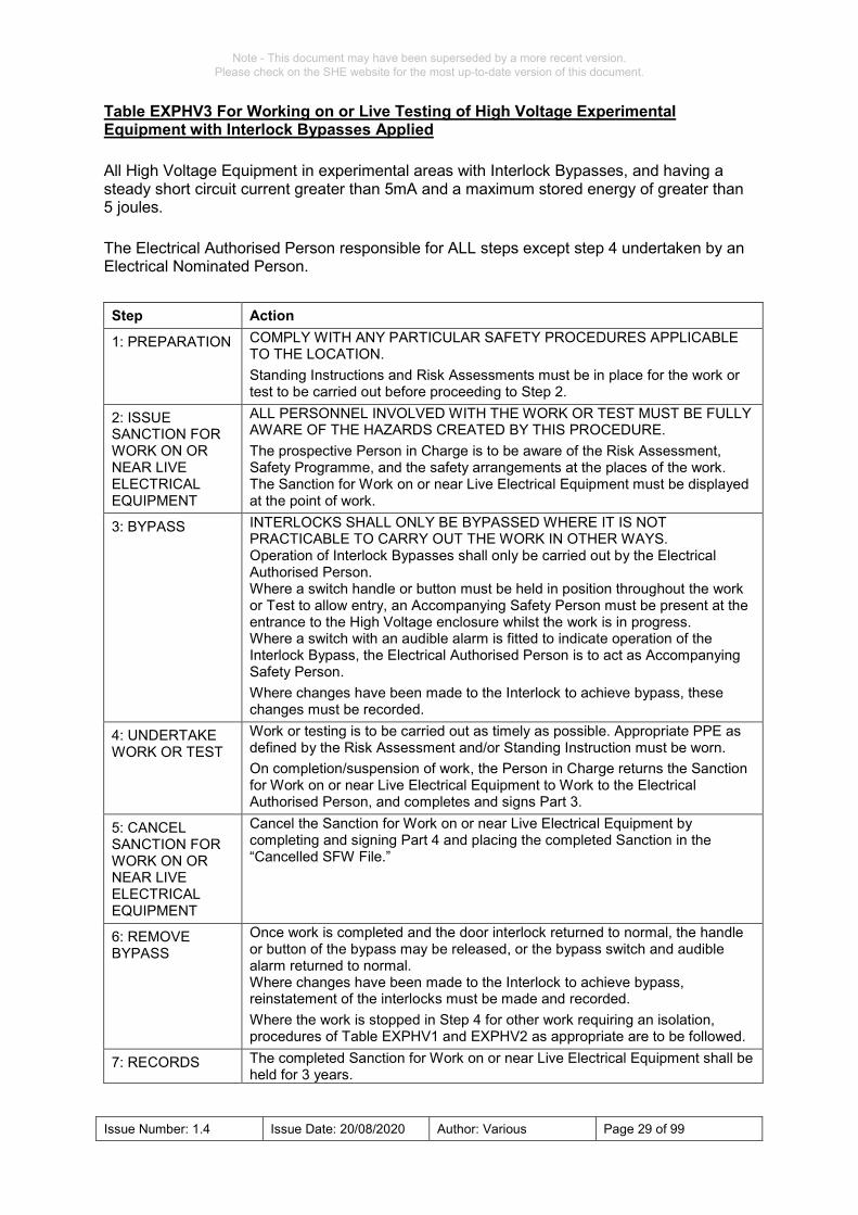
Table EXPHV3 For Working on or Live Testing of High Voltage Experimental Equipment with Interlock Bypasses Applied All High Voltage Equipment in experimental areas with Interlock Bypasses, and having a steady short circuit current greater than 5mA and a maximum stored energy of greater than 5 joules. The Electrical Authorised Person responsible for ALL steps except step 4 undertaken by an Electrical Nominated Person. Step Action
1: PREPARATION COMPLY WITH ANY PARTICULAR SAFETY PROCEDURES APPLICABLE TO THE LOCATION. Standing Instructions and Risk Assessments must be in place for the work or test to be carried out before proceeding to Step 2.
2: ISSUE SANCTION FOR WORK ON OR NEAR LIVE ELECTRICAL EQUIPMENT
ALL PERSONNEL INVOLVED WITH THE WORK OR TEST MUST BE FULLY AWARE OF THE HAZARDS CREATED BY THIS PROCEDURE. The prospective Person in Charge is to be aware of the Risk Assessment, Safety Programme, and the safety arrangements at the places of the work. The Sanction for Work on or near Live Electrical Equipment must be displayed at the point of work.
3: BYPASS INTERLOCKS SHALL ONLY BE BYPASSED WHERE IT IS NOT PRACTICABLE TO CARRY OUT THE WORK IN OTHER WAYS. Operation of Interlock Bypasses shall only be carried out by the Electrical Authorised Person. Where a switch handle or button must be held in position throughout the work or Test to allow entry, an Accompanying Safety Person must be present at the entrance to the High Voltage enclosure whilst the work is in progress. Where a switch with an audible alarm is fitted to indicate operation of the Interlock Bypass, the Electrical Authorised Person is to act as Accompanying Safety Person. Where changes have been made to the Interlock to achieve bypass, these changes must be recorded.
4: UNDERTAKE WORK OR TEST
Work or testing is to be carried out as timely as possible. Appropriate PPE as defined by the Risk Assessment and/or Standing Instruction must be worn. On completion/suspension of work, the Person in Charge returns the Sanction for Work on or near Live Electrical Equipment to Work to the Electrical Authorised Person, and completes and signs Part 3.
5: CANCEL SANCTION FOR WORK ON OR NEAR LIVE ELECTRICAL EQUIPMENT
Cancel the Sanction for Work on or near Live Electrical Equipment by completing and signing Part 4 and placing the completed Sanction in the “Cancelled SFW File.”
6: REMOVE BYPASS
Once work is completed and the door interlock returned to normal, the handle or button of the bypass may be released, or the bypass switch and audible alarm returned to normal. Where changes have been made to the Interlock to achieve bypass, reinstatement of the interlocks must be made and recorded. Where the work is stopped in Step 4 for other work requiring an isolation, procedures of Table EXPHV1 and EXPHV2 as appropriate are to be followed.
7: RECORDS The completed Sanction for Work on or near Live Electrical Equipment shall be held for 3 years.
Note - This document may have been superseded by a more recent version. Please check on the SHE website for the most up-to-date version of this document.

Issue Number: 1.4 Issue Date: 20/08/2020 Author: Various Page 30 of 99
Table CAP1 Procedure for working or testing on large high voltage capacitors banks Capacitor banks having a steady short circuit current greater than 5mA and a maximum stored energy of greater than 5 joules. The Electrical Authorised Person is responsible for ALL steps except step 8 undertaken by the Person in Charge. Step Action
1: PREPARATION COMPLY WITH ANY PARTICULAR SAFETY PROCEDURES APPLICABLE TO THE LOCATION. Standing Instructions and Risk Assessments must be in place for the work or test to be carried out before proceeding to Step 2.
2: ISOLATE AND FIX SIGNS
ISOLATE FROM ALL SOURCES OF SUPPLY. Where practicable, prevent unauthorised connection or unauthorised operation by fixing Safety Locks and/or Caution Signs at all the points of isolation.
3: DISCHARGE DISCHARGE ALL CAPACITORS IN A SAFE AND CONTROLLED MANNER. Controlled discharges shall be made using Slow Dump Switches and Dump Resistors to restrict currents.
4: SHORT ENSURE CAPACITORS ARE DISCHARGED BEFORE SHORTING. Operate Shorting Switches to remove all hazardous voltages. Ensure no hazard to personnel is involved with the operation of Shorting Switches
5: EARTH Where applicable, operate Earthing Switches.
6: PROVE DEAD Prove dead using a suitable voltage Test Indicator at all places of work. Additional Earthing Sticks may be used around the places of work.
7: ISSUE PERMIT TO WORK
The prospective Person in Charge is to be aware of the Risk Assessment, Safety Programme, and the safety arrangements at all the points of isolation and at the places of the work. The Person in Charge is to fit their Safety Locks to all shorting points or earthing points. The Permit to Work, issued by the Electrical Authorised Person, must be displayed at the point of work.
8: UNDERTAKE WORK
The Person in Charge undertakes or directly supervises the work and, on completion or when the work is stopped and made safe, checks that all persons under their charge are made aware of the completion/suspension of work, returns the Permit to Work to the Electrical Authorised Person, and completes and signs Part 3.
9: CHECK WORK If the work has been completed, check that the work is satisfactory, that the Equipment has been restored to working order and that it may be safely energised. If the work was stopped in Step 8, check that the Equipment has been made safe.
10: CANCEL PERMIT TO WORK
Cancel the Permit to Work completing and signing Part 4. The Person in Charge shall remove their Safety Lock(s) applied in Step 4.
11: REMOVE EARTHS
Remove Earths applied in Step 5.
12: REMOVE SHORTS
Remove shorts applied in Step 4. and return Capacitor Bank to an operational state.
13: MAKE EQUIPMENT OPERATIONAL
Remove all Safety Locks applied in Step 2 and return Capacitor Bank to an operational state. The completed Permit to Work shall be placed in the operational file and held for 2 years.
Note - This document may have been superseded by a more recent version. Please check on the SHE website for the most up-to-date version of this document.