The world of electrical safety - NuvoSource
176
SICAME GROUP 2014/2015 The world of electrical safety
-
Upload
khangminh22 -
Category
Documents
-
view
3 -
download
0
Transcript of The world of electrical safety - NuvoSource

SICAME GROUP
2014/2015
The world ofelectrical safety

Electrical safety, our business.
Now more than ever, working safely is essential for all professionals in the electricalindustry.In Europe and in the rest of the world, new clearances allow a larger population ofpeople to perform electrical and non-electrical work on or around installations andstructures, in compliance with prevention rules.
This major change, supports better risk analysis and strictadherence to the supervision chain, in order to furtherimprove operator safety.From this standpoint, CATU is fully committed to supportingyou in these changes.Firstly, with many new products designed and produced byour teams for you.Next, with a completely redesigned catalogue that focuses on ourproducts, their functions, and their use.Finally, with new educational tools, including our convenient guides thatprovide simple and helpful information.It's time to work with lasting safety, and we are here to help you, the Pros!
IEC TESTINGACCREDITATION N°1 - 0897
SCOPE AVAILABLE ONwww.cofrac.fr
Ele c t r i c a l s a f e t y,
f o r pro s l ike yo u !

Personal and collective 15protective equipment
Locking 51
Signaling 65
LV test and measurement 71
LV earthing systems 83
LV Live working tools 89
MV Substation equipment 123
Medium voltage equipment 141
HV lines and switchgear equipment 155
Earthing connections 165
CONTENTS

Personal and collectiveprotective equipment...............15
PPE, CPE : key advantages in risk prevention ....17Eyes protection .................................................18Head protection ................................................19Insulating rubber gloves....................................22Insulating boots ................................................27Insulating mats and accessories .......................29Safety shoes .....................................................27Accessories and insulating platforms ................30Arc Flash Protection ..........................................31Arc Flash equipment .........................................33Workwear and other protections........................36Other protection ................................................37Work at height ..................................................38Equipement for working on pole: harness..........39Equipement for working on pole: harness and anti-fall ....................................................................40Equipement for working on pole: anti-fall and tether................................................................41Equipement for working on pole: tether and safety line .........................................................42Equipement for working on pole: ropes and snap hooks .......................................................43Equipement for working on pole: snap hooks and anchoring accessories................................44Equipement for working on pole: climbers and accessories ................................................45Equipement for working on pole: insulating ladders .............................................................46Equipement for working on pole: insulating ladders and stepladders ................................................47Equipement for working on pole: ladders and accessories ................................................49
Locking .......................................51
Locking padlocks ..............................................52Multiple lockers ................................................56Padlock stations................................................58Circuit breaker lockers ......................................59Circuit breaker lockers, Panels and insert..........60Fluid locking .....................................................61Lockers.............................................................63Cabinets ...........................................................64
Signaling.....................................65
Warning signs ...................................................66Signaling and delineators..................................69
LV test and measurement .......71
Voltage Detector ...............................................72Phase rotation indicator ....................................77Installation Controller ........................................80
LV earthing systems ................83
Overhead bare ..................................................84Overhead insulating ..........................................86LV Cabinets .......................................................87
LV Live working tools ...............89
Insulated tools ..................................................91Jumper clamps, cables and accessories .........115Cover-up equipment .......................................118Cable identifier................................................122
4

GENERAL PRODUCTS INDEX
MV Substation equipment ....123
Substation equipment .....................................125Voltage detectors and short-circuiting systems for substations with bare conductors...............126Voltage detectors ............................................127Phase comparators .........................................129Two-pole phase comparator and permanent indicator .........................................................130IEC short-circuiting and earthing systems for MV substations ..........................................131Clamps for MV installations and substations....133Short-circuiting and earthing systems.............134VPIS and VDS systems for M.V. cubicles ..........136Extra safety equipment ...................................138Life saving kits................................................140
Medium voltage equipment ..141
IEC voltage detectors ......................................142Voltage detectors ............................................143Single phase comparators...............................144IEC equipment ................................................145Insulating sticks ..............................................146Clamp dispenser heads and accessories .........148Overhead line systems....................................149Cables ............................................................150Underground systems .....................................152Sticks accessories ..........................................153
HV lines and switchgear equipment ................................155
Voltage detectors ............................................156Insulating sticks ..............................................158Clamps ...........................................................159Earthing system APE .......................................160Insulating sticks and earth clamps ..................161Copper and aluminium cables .........................162Accessories ....................................................163
Earthing connections.............165
Earth rods .......................................................166Connectors and earth tester ............................167Earth resistance tester ....................................167
Golden safety rules..................................169Specification for short-circuiting and earthing system......171Choose your gloves size .........................170Choose your harness size .......................172
5

6
ABS helmet ................................................19
AC voltage detector for outdoor/indoor use....156
Accessories (measurement kit) .................167
Adhesive tape...........................................121
Adjustable access points ..........................163
Rachet spanners.......................................109
Aluminium cables..............................151/162
Anti-fall device with automatic
release strap ..............................................41
Aperture Housing......................................138
"Arc flash" face shield kit ..........................33
"Arc flash" jacket and protective
coverall kits ...............................................34
"Arc flash" protective kits
(25, 40, 55, 65 or 100 cal/cm2) ..............34/35
Bag for insulator cover..............................118
Bags for insulating mats .............................29
Bent snipe nose plier .............................93/98
Blanket clamp...........................................121
Cable cutter..................................92/100/102
Cable Identifier .........................................122
Cable spike equipment .............................152
Cable testing stick ....................................152
Carrying bag .............................26/75/77/162
Chain delineators........................................70
Clamp dispender heads ............................148
Clamps for installation on bare conductors ....133
Cleaning brushes......................................154
Cold Protection Kit and Cap ........................37
Come-along..............................................149
Compact carrying KIT ...............................139
Complete intervention kit.....................94/110
Connection adaptors for insulating sticks .....153
Connector.................................................167
Constraint tie ..............................................44
Contact probes for L.V. tester ......................79
Copper cables ...................................150/161
Copper/steel earth rods ............................166
Cranked ring spanner ...............................104
Delineators .................................................69
Double lanyard ...........................................42
Double safety descent device .....................43
Double tether rope with energy absorber ....42
Earth clamp ..............................................131
Earth rod ..................................................148
Earthing equipment ....................................86
Earthing equipment for overhead lines
systems......................................................84
Electrician coverall .....................................36
End cutting pliers........................................99
Equipotential Lines ...................................162
Face shield ............................................18/19
Fall arrester retractable type .......................41
Fixed length sticks....................................146
Fixing tools for warning signs .....................70
Flat nose plier........................................93/99
Flexible - type conductor cover .................118
Folding stepladder with railing ....................48
Forged steel climbers for round
wooden poles .............................................45
Frontal ratchet cable cutter.......................102
Full body fall arrest harness........................39
Fuse puller ...............................................154
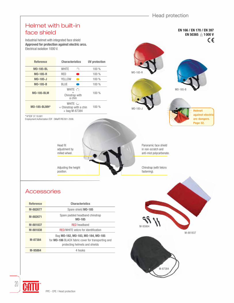
Grounding and continuity measurement
device ........................................................80
Grounding flags ..........................................69
Hacksaw ..................................................102
Hand stick ..................................................79
Helmet with built-in face shield ..................20
HV and EHV clamps manœuverable
by insulating stick.....................................159
IEC electronic Voltage Detectors, “Compact
serie” for indoor and outdoor use..............126
IEC Insulating stick for Voltage Detector ....126
IEC short-circuiting and earthing systems
(three-phase crossarm networks) .............132
IEC Voltage detector..................................142
Installation on bare conductors .................132
Installation on permanent fixed points.......131
Insulating blanket .....................................152
Insulating boots ..........................................27
Insulating flexible cover ............................120
Insulating flexible cover
with Velcro™ tape....................................120
Insulating gloves.........................................22
Insulating ladders .......................................46
Insulating mats...........................................28
Insulating platform (outdoor model) ............30
Insulating platforms (indoor models) ...........30
Insulating stepladders.................................48
Insulating sticks for manœuvring detectors
& short-circuiting and earthing systems....158
Insulating sticks for short circuiting and
earthing systems ......................................147
Insulating sticks for substation use ...........135
Insulating tool kits ....................................110
Insulating torque wrench 3/8” ..................109
Insulation controller ....................................81
Insulator cover..........................................118
Integrated voltage detecting system
(V.D.S) ......................................................136
Integrated voltage presence indicating
system (V.P.I.S) .........................................136
Interface for integrated voltage detecting
system (V.D.S) ..........................................137
Intervention kit ....................................94/110
Intervention kit for electricians..................114
Intervention kits Substation equipment .....125
Jumper cable with insulating jumper
clamps .....................................................116
Jumper cables realisation specially
manufactured items .................................151
Jumper connecting box with fuse .............117

7
GENERAL PRODUCTS INDEX
Lanyard ......................................................43
Lead set for checks on L.V distribution
board..........................................................79
LED’s headlamp..........................................21
LED’s headlamp (4 LED’s) ...........................21
Life saving kits for M.V. substations ..........140
Long nose pliers with side cutter ................98
Lockers..................................56/57/59/60/63
Low voltage complete set. Complete
equipment for live line (LV) interventions...113
Lowlock system..........................................86
Manœuvering and rescue stick .................138
Manœuvering hook...................................154
Mechanical climbers for rectangular shaped
concrete poles............................................45
Mechanical climbers for round and hexagonal
concrete poles............................................45
Mini jumper clamps fully insulating
for switchboard use ..................................115
Mittens .......................................................26
Mobile safety line .......................................42
Multi-pockets electrician bag......................30
Multiple Locker...........................................56
Open jaw spanner.....................................104
Operating Testers......................................129
Overglasses................................................18
Overgloves .................................................26
Padlocks.....................................................53
Permanent luminous indicator
for indoor use ...........................................130
Phase rotation indicator ..............................77
Pliers ..........................................................94
Pliers kit ...................................................100
Plug plier for preinsulating pin terminals.....98
Pneumatic glove tester ...............................25
Polycarbonate helmet .................................19
Pro electric full body fall arrest harness ......39
Ratchet cable cutter .................................102
Rescue hook.............................................139
Rope operated clamp................................163
Round nose plier ...................................93/98
Rubber gloves box ......................................25
Safety adhesive tape ..................................70
Safety boots ...............................................37
Safety boundary post..................................69
Safety glasses ............................................18
Safety lamps ............................................138
Safety rope with wear tell tales...................43
Safety Shoes ..............................................27
Scissors....................................................109
Screwdrivers PHILLIPS ....................91/96/97
Screwdrivers POZIDRIV .........................91/97
Screwdrivers kit .............................94/95/110
Self adhesive warning signs .......................68
Separable voltage detecting
system (V.D.S) ..........................................137
Set of sticks..............................................158
Short length stick .....................................135
Short-circuiting and earthing systems...134/135
Short-circuiting and earthing systems
carrying bags ...........................................162
Short-circuiting systems HV......................159
Short-circuiting systems LV ........................84
Short-circuiting system MV.......................145
Short-circuiting system MV substation......131
Shunt Telescopic probe.............................117
Side cutters ...........................................93/98
Single pole phase comparator for indoor
and outdoor use .......................................144
Snap hook with double safety latch ............43
Snap hook with stick adaptor......................44
Snap hooks (aluminium alloy) .....................44
Snap hooks (stainless steel)........................44
Socket 3/8” - 6 sided male hex Key .........107
Sockets 3/8” Long series..........................107
Sockets 3/8” U.S Standard .......................106
Sockets wrenches sets .............................108
Sound phase comparator..........................136
Spool with earthing connection.................148
Stainless steel earth rods..........................166
Standard electronic voltage detector
for indoor and outdoor use........................143
Standard extension ladders ........................47
Standard sticks.........................................135
Sticks with rain skirts ...............................147
Storage bag ...............................................79
Stripping plier for LV cables ......................101
Substation signs .........................................67
Tap off box ...............................................117
Telescopic stick for voltage detector .........135
Tether rope with a tension device. ..............41
Threaded adapter .....................................117
Tool bag ............................................111/112
Tool bag for safety harness.........................40
Trimmer and prunning saw.......................154
Two-pole phase comparator for indoor
and outdoor use .......................................130
Undergloves ...............................................26
Undergloves Nomex III ®............................32
Universal pliers ...........................................98
Voltage Detectors and Testers................72/74
Voltage detector with leds for indoor use
(Compact serie) without batteries .............128
Voltage detector with leds for indoor use
without batteries.......................................128
Voltage detectors and indicators ...............137
Voltage take-off punch................................78
Voltage tester for M.V. separable
connectors ...............................................137
Wall mounted supports .............................139
Warning flags .............................................69
Warning signs.............................................68
Water pump plier ........................................93
Wire Gun Tester ........................................163
Wire stripping plier ..............................92/101
Work Gloves ...............................................36
Working on pole kits ...................................40

References PagesReferences PagesReferences PagesReferences PagesA2C-10-ZA2C-15-ZA3MC-10-ZA3MC-15-ZAC-10-YAC-15-YAC-20-YAC-21AC-44AD-01AL-127AL-129AL-138AL-200AL-201-C/1AL-201/1AL-202AL-203AL-204AL-205AL-205/5AL-207/30AL-208-CAL-208-DAL-209-LAL-212AL-230-(**)-EXAL-230-111AL-230-S-(**)-EXAL-230-S-Z-EXAL-230-Z-EXAL-236-00-EXAL-236-111-EXAL-236-222-EXAL-236-S-00-EXAL-236-S-111-EXAL-236-S-222-EXAL-240-(**)-EXAL-240-B-00-EXAL-240-B-111-EXAL-240-B-222-EXAL-240-B-Z-EXAL-240-BL-00-EXAL-240-BL-111-EXAL-240-BL-222-EXAL-240-BL-Z-EXAL-240-J-00-EXAL-240-J-Z-EXAL-240-S-(**)-EXAL-240-S-B-111-EXAL-240-S-B-222-EX
1661661661661661661667070707070705759595757605959585959605853
1145353535858585858585353535353535353535353535353
AL-240-S-BL-111-EXAL-240-S-BL-222-EXAL-240-S-J-00-EXAL-240-S-J-111-EXAL-240-S-J-222-EXAL-240-S-V-00-EXAL-240-S-V-111-EXAL-240-S-V-222-EXAL-240-S-Z-EXAL-240-V-00-EXAL-240-V-111-EXAL-240-V-222-EXAL-240-V-Z-EXAL-240-Z-EXAL-260-(**)-EXAL-260-00-EXAL-260-S-(**)-EXAL-260-S-00-EXAL-260-S-Z-EXAL-260-Z-EXAL-31AL-31/05AL-31/25AL-316AL-318AL-32/05AL-32/25AL-321AL-322AL-323AL-324AL-53AL-58AL-60AL-62-AAL-63-AAL-65-AALM-20/45ALM-6/25ALM-6/38ALM-6/8ALP-03ALP-06ALP-12/2MALP-4/3ALP-4/6AM-20-GBAM-20-RMAM-282/2-RMAM-32/3AM-33/3
535353535353535353535353535353535353535370707069697070696969696969697070705757575756565656566667676767
AM-34/2AM-344 AM-344-GBAM-344/05AM-345-GBAM-41/1AM-41/2AM-467-EAM-467-GBAM-49/1AM-49/2AM-61-GBAM-61-RMAM-7002AMI-10AMI-15AP-499/1AP-510-BT-GBAP-510-GBAP-951/2AT-41/025AT-41/05AT-41/1AT-49/025AT-49/05AT-49/1AT-50/025AT-50/053AT-50/1AT-5005AT-51/025AT-51/05AT-51/1AT-52/05AT-52/1AT-53/1AT-54/05AT-54/1AT-55/05AT-55/1AT-56/05AT-56/1AT-58/05AT-58/1AT-59/05AT-59/1AT-60/05AT-60/1AT-61/05AT-61/1AT-62/05
6766666666666660666666676767
166166
60/6666676768686868686868686870686868686868686868686868686868686868686868
AT-62/1AT-63/05AT-63/1AT-66/1BCYC-92-20C-92-492C2C-10-ZC2C-15-ZC2C95ZCC-10-YCC-127-ERDF-CCC-15-YCC-151-KCC-20-YCC-245-150-(*)CC-245-150/420-CCC-245-150/420-KCC-245-225/420-(*)CC-245-225/550-CCC-245-225/550-KCC-245-315/765-1-CCC-245-315/765-1-KCC-245-60/150-CCC-245-60/150-KCC-245-63/150-(*)CC-245-63/90-(*)CC-245-90/225-(*)CC-365-10/30-(*)CC-365-101CC-365-3/10…-(*)CC-45-KCC-765-10/30CC-765-10/30-(*)CC-765-10/36CC-765-10/36-(*)CC-765-3/10CC-765-3/10-(*)CC-765-44/132CC-765-55/20CC-765-55/20-(*)CC-965-10/30CC-965-5/15CD-122CD-124CE-3-24-CCE-4-21-CE-4-21-(*)CE-4-30-CCE-5-90-CCE-5-90-K
68686868
16712914316616616716685
166137166157157157157157157157157157157157157157143143143137142126142126142126156142126127127138138135126
135/1461464444
8

References PagesReferences PagesReferences PagesReferences PagesCE-75-(*)CF-3-72…-(*)CF-3-90…-(*)CF-5-110-(*)CF-5-170-(*)CF-5-40-(*)CF-5-40-(*)CF-5-90-(*)CF-5-90-(*)CG-05-(*)CG-05-CCG-1-(**)-NRCG-10-(*)CG-117CG-2-(**)-NRCG-2-(**)-NRCG-3-(**)-NRCG-35/2CG-36CG-37CG-4-(**)-NRCG-80-(*)CG-81CG-951-(*)CG-952-(*)CG-96-(*)CG-97-CCG-981-(*)CG-991-(*)CG-991-(**)CGA-0-(*)-BCGA-00-(*)-BCGA-1-(*)-NBCGA-2-(**)-NBCGA-3-(**)-NBCGA-4-(***)-NBCGM-0-(*)CGM-00-(*)CGM-1-(*)CGM-2-(*)CGM-3-(*)CGM-4-(**)CI-06-DCI-08CI-10-DCI-12-DCI-70CL-1-06CL-2-10/30-2CL-2-5/36-2CL-4-10/30-2
135/14613513514614613514613514624
11424242524242425263224262636363636
24/262624242424242424252525252525
132/139/146139/146
131/139/146139/146
138129128128128
CL-4-10/30-MCL-40010CL-495-3CL-497-00CL-498-00CL-499/101CL-5-03CL-5-36CL-7-06/18-(*)CL-7-10/30-(*)CL-7-10/30-1-(*)CL-7-12/36-(*)CL-8-05CL-8-36/1CM-02-(*)CM-03-KCM-04-KCM-1-10CM-1-15CM-1-20CM-225CM-3-03CM-3-04CM-3-05CM-3-06CM-3900-JCM-4115-(*)CM-4120-(*)CM-4125-(*)CM-4130-(*)CM-4220-(*)CM-4230-(*)CM-4240-(*)CM-4345-(*)CM-4360-(*)CM-4400-JCM-4410CM-4410-(*)CM-4410-ICM-4415CM-4415-(*)CM-4415-ICM-4420CM-4420-(*)CM-4420-ICM-4425CM-4425-(*)CM-4425-ICM-45CM-4610CM-4610-(*)
128130136136137137130130144144144144129129154154154147147147138147147147147158158158158158158158158158158147147147147147147147147147147147147147138158158
CM-4610-ICM-4615CM-4615-(*)CM-4615-ICM-4620CM-4620-(*)CM-4620-ICM-4625CM-4625-(*)CM-4625-ICM-6-15CM-6-20CM-6-25CM-6-30CM-7-10-ACM-90CS-01-CCS-225CS-45CS-90CT-7-25/1CT-7-40/1CT-7-63CT-9-25CT-9-45CT-9-63CX-34211CX-35811CX-45211CX-45411CX-45511CZ-53-MRCZ-53-RCZ-53-R/2CZ-53MR/2CZ-54-RCZ-54-RMCZ-55-RCZ-55-RMCZ-60DT-300DT-500GL-100GL-101HL-100HL-101HL-102HL-103HL-104HL-105HL-200
158158158158158158158158158158161161161161
135/1461381391381381383030303030307878787878
1391391391391401401401401408081626261616161616161
HL-201HL-202HL-203KIT-01KIT-02KIT-03KIT-04KIT-05KIT-07KIT-10KIT-23CKIT-23CHKIT-23PKIT-23PHKIT-23SKIT-23SC2KIT-23SCPKIT-23SHKIT-23SP2KIT-ARC-100-B-(*)KIT-ARC-12-C-(*)KIT-ARC-12-J-(*)KIT-ARC-12-JP-(*)KIT-ARC-25-B-(*)KIT-ARC-40-B-(*)KIT-ARC-65-B-(*)KIT-HAUT-01-(*)KIT-HAUT-02-(*)KIT-HAUT-03-(*)KIT-HAUT-04-(*)KIT-HAUT-05-(*)KIT-HAUT-06-(*)M-187M-24-10M-24-120M-24-120-SM-24-150M-24-150-SM-24-16M-24-16-SM-24-25M-24-25-SM-24-35M-24-35-SM-24-35-VM-24-40M-24-40-SM-24-50M-24-50-SM-24-70M-24-70-S
616162
1251251101101101101259495959594949594953534343435353540404040404034
150150150150150150150150150150150162150150150150150150
GENERAL REFERENCES INDEX
9

References PagesReferences PagesReferences PagesReferences PagesM-24-95M-24-95-SM-28-120M-28-150M-28-50M-28-70M-76768M-78665M-87-153M-87-295M-87-53M-87290M-87290M-87292M-87295M-87303M-87369M-87369M-87370M-87384M-87386M-87387M-87413M-881601M-881602M-881635M-881837M-881838M-881961M-881968M-881976M-881979M-882462M-882671M-882677M-88896M-91209M-92-28M-921647M-95-236M-951143M-951981M-952206M-952271M-952325M-952439M-952650M-952656M-95626/4M-95627/4M-9573
M-95864M611386M952567M952568M952570MC-116MC-120/100MC-120/15MC-120/50MC-121MC-122MC-123MC-124MC-126MC-126/1MC-141MC-142MC-1421MC-143MC-144MC-145MC-146MC-147MC-147/1MC-148MC-148/1MC-149MC-150MC-153/05MC-153/10MC-153/30MC-153/60MC-155/05MC-155/10MC-155/20MC-155/30MC-155/60MC-155/80MC-156MC-156/1MC-181MC-182MC-182-8MMC-183MC-184-6FMC-184-6MMC-185-10FMC-185-10MMC-296-00/08MC-296-115/08MC-296-160/08
MC-296-440MC-296-560MC-296-AMC-296-BMC-296-CMC-296-MMC-296-NFCMC-296-PMD-10-CMD-12-CMD-14-CMD-40-BMD-42-BMF-60MF-61MF-62MF-63MF-66MO-02MO-052MO-11000MO-11001MO-11003MO-11010MO-11011MO-134MO-157MO-158MO-16AMO-17-01MO-17-02MO-17-03MO-17-04MO-17-AMO-180-ARCMO-182/1-BMO-182/1-JMO-182/1-RMO-183-BLMO-183-RLMO-184MO-185-B MO-185-BLMO-185-BLMMO-185-BLMHMO-185-JMO-185-RMO-186MO-187MO-187/1-BMO-23
MO-237-DMO-24MO-25MO-26MO-29MO-32/3MO-34MO-35MO-36 MO-36310MO-37MO-38MO-38510MO-39MO-510-03MO-52-LMO-52-PMO-52020MO-52021MO-52031MO-52033MO-52034MO-53MO-53002MO-53010MO-54MO-54002MO-54004MO-54005-CMO-54005-KMO-54010MO-55/1MO-56010MO-563-(*)MO-565-(*)MO-591000MO-591002MO-592002MO-61MO-61001MO-61002MO-64501MO-64502MO-650-DMO-652-DMO-65200DMO-65202MO-65202DMO-65203MO-65203DMO-65204
1174545454540
112/11345
112106111111114111113414142424444444342424443444444424441393941414141
1011011021029696969696969696
150150
151/162151/162
151151/162
881311621621627779
79/8134/35
11273
75/79111
20/11330/113
30348181182020353535358720208187
154804979811879
73/757988878787
131
2085858585
117116116116116116116116117117115115122115115115115115115115115115117116116116116116116116116116116117117
87/88/11788/117
8888/117
88888888878787
87878787878788
87/881541541541541541631631631631634343
18/34/3518/114
18181834373745454545454533
19/34/35191919191920202020202018333345
10

References PagesReferences PagesReferences Pages References PagesMO-65204MO-65204MO-65204DMO-65205MO-652055DMO-65205DMO-65206MO-65206DMO-65207MO-652082DMO-65208DMO-65209MO-652102DMO-65210DMO-65211MO-65212DMO-65230MO-65232MO-652321DMO-65232DMO-65233DMO-65234MO-65234DMO-65236MO-65236DMO-65238MO-65238DMO-65240MO-652405DMO-652406DMO-652410DMO-65242MO-65244MO-652441DMO-65244DMO-65245DMO-65246MO-65246DMO-65248MO-65248DMO-653-DMO-65405MO-65406MO-65505MO-65506MO-66000CMO-66001MO-66002MO-66002MO-66003MO-66005
11011496969696
96/110/11496969696
96/110/11496969696969696969696969696969697979797
97/110/11497/110/114
979797979797979697979797999898
110/1149898
MO-66102MO-66105MO-66202MO-66300MO-66301MO-66302MO-66303CMO-66402MO-66404MO-66404CCMO-66500MO-66502MO-66505MO-67101MO-67102MO-67103MO-67302MO-67302CMO-67304MO-67305MO-67306MO-67401MO-67402MO-67404MO-67500MO-67501MO-67502MO-67599MO-67600MO-67601MO-67611MO-67700MO-67701MO-68/10MO-68/15MO-68006MO-68007MO-68008MO-68008/19MO-68009MO-68010MO-68011MO-68012MO-68013MO-68014MO-68015MO-68016MO-68017MO-68018MO-68019MO-68020
9898989898
98/11499
98/110/1149899
99/11099/110/114
99100100100
101/11010110110110199
99/11099
100/110/1141001001021021021021001004040
104104104104104104104104104104104104104104104104
MO-68021MO-68022MO-68023MO-68024MO-68025MO-68026MO-68027MO-68028MO-68029MO-68030MO-68032MO-68106MO-68107MO-68108MO-68109MO-68110MO-68111MO-68112MO-68113MO-68114MO-68115MO-68116MO-68117MO-68118MO-68119MO-68120MO-68121MO-68122MO-68123MO-68124MO-68125MO-68126MO-68127MO-68128MO-68129MO-68130MO-68132MO-68205MO-68206MO-68207MO-68209MO-68210MO-682101MO-682111MO-682121MO-682131MO-682141MO-682151MO-682161MO-682171MO-682181
104104104104104104104104104104104104104104104104104104104104104104104104104104104104104104104104104104104104104105105105105105105105105105105105105105105
MO-682191MO-682211MO-68310MO-68311MO-68312MO-68313MO-68314MO-68316MO-68317MO-68319MO-68321MO-68322MO-68402MO-68403MO-68404MO-68405MO-68406MO-68408MO-68610MO-68613MO-68614MO-68620MO-68621MO-687-DMO-68701MO-68702MO-68703MO-68704MO-68705MO-68713MO-68714MO-68717MO-69002MO-69003MO-69004MO-69005MO-69050MO-69051MO-69054MO-69210MO-69213MO-69216MO-69217MO-69218MO-69219MO-69306MO-69307MO-69308MO-69308/23MO-69309MO-69310
105105105105105105105105105105105105929292929292
10410410410410487
103103103103103105105105103103103103109109109103103103103103103106106
106/108108106108
11
GENERAL REFERENCES INDEX

References PagesReferences PagesReferences PagesReferences PagesMO-693100MO-69311MO-69312MO-69313MO-69314MO-69315MO-69316MO-69317MO-69318MO-69319MO-69321MO-69322MO-69323MO-69324MO-69393MO-69394MO-69395MO-69396MO-69397MO-69398MO-69408MO-69408/23MO-69410MO-69412MO-69413MO-69414MO-69415MO-69416MO-69417MO-69418MO-69419MO-69420MO-69421MO-69422MO-69423MO-69424MO-69429MO-69430MO-69503MO-69512MO-69513MO-69514MO-69515MO-69523MO-69524MO-69533MO-69544MO-69608MO-69609MO-69610MO-69611
MO-69612MO-69613MO-69614MO-69616MO-69617MO-69618MO-69619MO-69621MO-69622MO-69624MO-697-1/4SAEMO-697-15/16MO-697-1SAEMO-697-5/16MO-697-7/8MO-69735MO-69736MO-69737MO-69738MO-69739MO-69740MO-69741MO-69742MO-69903MO-69904MO-69905MO-69906MO-69908MO-69910MO-69912MO-69T15MO-69T20MO-69T30MO-69T40MO-69T50MO-71MO-72002MO-72003MO-72004MO-72004MO-72005MO-72006MO-72006MO-72008MO-72008MO-72010MO-72030MO-72032MO-72034MO-72036MO-72038
MO-72040MO-72042MO-72042MO-72044MO-72044MO-72046MO-72048MO-720510MO-720515MO-720520MO-720525MO-720527MO-720530MO-720540MO-720545MO-720550MO-72056MO-72057MO-72058MO-72059MO-72100EMO-72102MO-72102MO-72122MO-72132MO-72142MO-72155MO-72162MO-72172MO-72200MO-72200MO-831MO-832MO-87370MO-87413MO-98208MO54000MO56009MP-01MP-01MP-02MP-100/02-10MP-100/03-10MP-100/03-5MP-100/05-10MP-100/05-5MP-100/10-10MP-100/10-5MP-11/11MP-11/16MP-123
MP-123/1MP-123/2MP-19-LOTMP-19/1MP-211MP-212MP-213MP-213/EXTMP-213/LAMMP-22MP-220MP-220/1MP-23MP-26-AMP-26-BMP-26-CMP-26-DMP-26-EMP-31MP-32/10MP-32/15MP-33MP-35MP-35/12MP-37MP-40MP-400MP-400-2MP-402-MBMP-402-MIMP-403-MBMP-403-MIMP-4110MP-41530MP-42/11MP-42/16MP-42/66MP-46501MP-467MP-50MP-501-DMP-502-DMP-503-DMP-506/2MP-508/2MP-509/2MP-510/2MP-514/2MP-515/2RMP-59MP-60/03-10
120120121121152152152152152118120120118118118118118118118118118118120120120121494949494949
1211212929294749
118494949464646464646
11829
107106
106/108106
106/108
106106108106
106/108106/108106/108
108106107107107107107
107/108106
106/108106/108106/108106/108
108106106108106108106
106/108106/108
108106106106108
108/109108/109
109105/107/109
108105/108
107105107107107
107107107107107107107107107107107106106106106106106106106106106106106106103103103103103103103107107107107107399191919491919491949191919191
919191949194919191919191919191919191919191
10992949393
93/9494
92/9392/94
944949
11433
105444129
11329292929292929292929
120
12

References PagesReferences PagesReferences Pages References PagesMP-60/03-5MP-60/05-1MP-60/05-10MP-60/05-5MP-602-DMP-603-DMP-604-DMP-605-DMP-607/2-IMP-607/3-IMP-608/2-IMP-608/3-IMP-609/2-IMP-624/2-DMP-634/2-DMP-700-1MP-700-100MP-700-2MP-700-200MP-700-3MP-700-4MP-700-5MP-700-6MS-124MS-125MS-152+MS-62MS-63MS-8013-2MS-8014-2MS-917-EXMS-917-VEMS-917/2-EXMS-920MT-1910MT-1911 MT-1911-EMT-1920MT-1921 MT-1921-EMT-1951/10MT-1951/12MT-205MT-206MT-207MT-222MT-223MT-242MT-244MT-245MT-249
29292929464646464747474747464648474847484848482121777878797973767375
131131131131131131134134868686868684848484
MT-2950/35MT-2951MT-2951/1MT-2951/2MT-3950/35MT-3951MT-3951/1MT-3952MT-3952/1MT-40MT-404MT-405MT-406MT-407MT-508/36MT-508/46MT-509/3MT-509/3EPMT-509/3VATMT-546MT-5805MT-615/1-7,5MT-615/2-7,5MT-630-CMT-630-KMT-630-SMT-633-CMT-633-KMT-633-SMT-634-C/KMT-634/1-C/KMT-635/1-C/K/SMT-640-SMT-641-SMT-650MT-6613MT-6613/1MT-70/1MT-701/1MT-731-(*)MT-732-(*)MT-734-(**)MT-735-(*)MT-735-P4MT-737-HMT-790MT-792MT-797MT-811-CMT-812-CMT-813-C
13413413413413413413413413415184848484
14914985858585
1328686
148148148148148148148148148148148
86/148145145151163159159159159162159163163163133133133
MT-814/2MT-814/3MT-815-CMT-815-EMT-815-SMT-817-CMT-818-CMT-834-EMT-834-HMT-834-TMT-835-EMT-835-HMT-835-TMT-837-EMT-837-HMT-837-TMT-840 MT-840/1MT-8408MT-841MT-843MT-843-PMT-847MT-852MT-853MT-890MT-891MT-893MT-895MT-920-EMT-925-EMT-934MT-935MT-951/1MT-951/2MT-951/3MT-952/1MT-952/2MT-952/3MT-953/08MT-953/12MT-955/08MT-955/12MT-956MT-9801MV-104/ (*)MV-105(*)MV-123-(*)MV-124-(*)MV-131-(*)MV-136-
133133133133133133133160160160160160160160160160133
133/148132133
148/161161161161161
131/132131/132131/132131/132
134134160160134134134134134134134134134134134132363337373727
MV-136B-MV-137MV-138/MV-222-MV-223-MV-226-MV-227-MV-228-MX-400MX-400/1MX-400/6MX-400/7MX-404MX-433-TPL-100PL-101PL-102RL-100SL-101SL-102SUP-124TO-2-16TO-2-19TO-3-16/19
2727262727272727
12212212212213616763636358646421
167167167
13
GENERAL REFERENCES INDEX

International Electrotechnical Commission is a worldwideorganization for standardization comprising nationalelectro technical committees (NC). The object of the IEC isto promote international cooperation on all questionsconcerning standardization in the electrical fields. Thesestandards have been approved by more than 50 differentcountries including Australia, Canada, China, France,Germany, Japan, Russia, Malaysia, Singapore, Mexico,India, Indonesia, South Africa, New Zealand, USA…
A rapid need to perform electrical operations evolved with the time.
This resulted in regional or national working on specific standards withoutcoordination.
IEC standards were developed according to a consensus procedure and approvedby recognized body. They provide an adequate answer at worldwide level.
The IEC standard presents benefits to all parties involved:
- for the end-users: it is the guarantee of a suitable and internationally recognizedquality equipment,
- for the Testing Laboratories: it determines better standards of testing and controlprocedures for materials,
- for the manufacturers: it helps them to make a better technico-commercial offer.
CATU Designs, tests and manufactures under the IEC requirements.
CATU Is the first manufacturer to provide a full range of products complying withthe IEC standards.
CATU Shows its innovation ability for the welfare of the electrical world.

Eyes protection 18
Head Protection 19
Insulating rubber gloves 22
Insulating boots 27
Insulating mats 28
"Arc Flash" protection 00
Workwear and other protections 00
Work at height 00
Personal and collectiveprotective equipment
18
19
22
27
28
31
36
38

Services
After sales
services
Training
Flexible workshop
After Sales Services
[email protected] : +33 01 42 31 46 85 - fax : +33 01 42 31 46 45
[email protected] : +33 01 42 31 46 86 - fax : +33 01 42 31 46 45
Technical Assistance
[email protected] : +33 01 42 31 46 24 - fax : +33 01 42 31 46 34
[email protected] : +33 01 42 31 46 52 - fax : +33 01 42 31 46 34
Technical
assistance
Testing laboratory
Testing Accreditationn°1-0897
Scope available onwww.co f rac . f r

17PPE - CPE / Key advantages in risk prevention
PPE - CPE
PPE within the framework of electrical safety recommendations."Personal Protective Equipment is used to protect individuals whowork on or near an installation that presents an electrical hazard."
Equipment complying with the standards in force and appropriate for the type of operation and voltage level of the installation must be used.
PPE check- Every PPE must be verified at least
visually before and after everyuse.
- Regular tests must bemade by qualified personsand at least annually.
- If the slightest doubt ex-ists the equipment mustbe reformed and replacedat once.
REGULATIONSThe personal protective equipment have to be in compliance withthe requirements of the European Directive :
89/391/CEE, on the introduction of measures to encourageimprovements in the safety and health of workers at work.
89/655/CEE and 89/656/CEE, on the minimum health and safetyrequirements for the use by workers of personal protectiveequipment at the workplace.
89/686/CEE, on the approximation of the laws of theMember States relating to personal protective equipment(CE marking).
In practice, they define: • The protections adapted to the kind of risk,• The highest level of protection possible,• The comfort, the ergonomics and the quality of the equipment,• The annual verification of PPE by a competent individual.
The obligations for using PPEs in companies are defined by the European Directive 89/656.
THE RESPONSIBILITY OF THE EMPLOYER• To give free of charge and in a personal way equipment necessary and
adapted to the risks, • To watch over their actual use, • To ensure the necessary replacement as well as the maintenance and
the compliance, • To inform the users of the risks against whom they are protected.
PPE : Personal Protective Equipment.PPE are defined as any device or means intended to be worn or held by one person to protect itself against one or severalrisks liable to threaten its safety or its security.
CPE: Collective protectiveequipment.Collective protective equipment for preventing electrical hazards contains all the products that close off the hazard by:- Distance (marking, signs),- Obstacles (covers, screen, barrier),- Insulation (insulating blankets, insulating caps, etc.).
CPE must comply with the standards in force.
PPE, CPE:key advantages in risk prevention.

18PPE - CPE / Eyes protection
Eyes protection
Safety glassesProtection against UV radiation and ejections of solidparticles.
OverglassesPolycarbonate overglasses. Protection against UV radiation and ejections of solid particles.
EN 166 / EN 170
MO-11000
MO-11003MO-11001
Tips “Softflex”.
Grilamid frame
Polycarbonate lense with a large field of vision. Anti-scratch, anti-impactand anti-chemical producttreatments.
Caution: Do not use forwelding operations.
Reference Characteristics UV protection Resistance
MO-11000
MO-11001
MO-11003*
Clearlenses
Tintedlenses
Tintedlenses
99.5 %< 370 nm
99.5 %< 370 nm
99.5 %< 370 nm
Level FImpact: 6 mm
steel ball launched at
45 m/s
Delivered in storage bag.* EN 169 - 80 °C - FT HTA N°127.
Characteristics
Reference Characteristics UV protection Resistance
MO-11010
MO-11011
Clearlenses
Green tintedlenses
100 %180 < 400 nm
100 %180 < 400 nm
Level FImpact:
6 mm steel balllaunched at 45 m/s
Delivered in storage bag.
Caution: Do not use forwelding operations.
MO-11011
MO-11010
EN 166 / EN 170
Polycarbonate lens and framewith a panoramic field of vision.
One piece wraparoundprotection that can beworn over eyeglasses.
Face shieldProtective screen that can be used without a helmet.Protection against electric arcs of short-circuits.Marking: 2-1.2 CATU 1 B 8 1000 V.
Caution: Do not use forwelding operations.
EN 166 / EN 170
Reference
MO-186
M-881635
M-952206 Spare strap for MO-186
Clear face
shield
Spare face
shield
240 L x 325 H
ForMO-186
350
350
Head fit adjustment bymilled wheel.
Polycarbonate faceshield. Anti-misttreatment.
gmm

19
PPE - CPE
Head protection
Face shieldProtection against electric short-circuit arcs. Face shield adjustable on MO-182 helmet.3-1,2 GW 1 SN DIN EN 166 8 1000 V.
EN 166 / EN 170
Fa ce shield on helmet MO-182/1-B.
Caution: Do not use forwelding operations.
UV protectionReference
MO-184 100 % 470 x 200 170
Acetatefaceshield
Adjustable by rubber band.
MO-182/1-R MO-182/1-J
MO-183-RL
EN 12492EN 397 440 V
EN 50365 1 000 VANSI Z89.1 20 000 V
ABS helmetSafety industrial helmet. Standard sizes 53 to 63.Leather trim 21 cm along the inside for added comfort.Multiple adjustments for a perfect fit headband.
MO-182/1-B
MO-182/1-R
MO-182/1-J
Reference
WHITE
RED
YELLOW
300
300
300
Characteristics
Polycarbonate helmetProtects against vertical and side impacts, very wellventilated. Improved comfort.Adjustable size from 53 to 63 cm.
MO-183-BL
MO-183-RL
Reference
WHITE
RED
455
455
Characteristics
EN 397 440 VEN 50365 1 000 V
ANSI Z89.1 20 000 VDeformable shock-resistant helmet with a "gutter" brim. Size from 53 to 62 cm. Lightweight with a comfort lining.
Side slots for mounting hearing protection.
Multiple adjustments for a perfect fit headband: adjustable in 3 mm increments.
Safety chinstrap
Built-in cushion for optimum ventilation.
Deformable shock-resistant helmet.
Head fit adjustment by milled wheel.
6-point cloth lining.Chinstrap with an easy adjustment buckle. Designed to tear if hooked.(< 25 daN).
gmm
g
g
mmDimensions g Weight
PPE - CPE / Head protection
20
Head protection
Helmet with built-in face shieldIndustrial helmet with integrated face shieldApproved for protection against electric arcs.Electrical isolation 1000 V.
Accessories
MO-185-R
MO-185-B
MO-185-J
M-881837
M-95864
M-87384
MO-185-BL
MO-185-R
MO-185-J
MO-185-B
MO-185-BLM
MO-185-BLMH*
Reference
WHITE
RED
YELLOW
BLUE
WHITE +
Chinstrap with a chin
WHITE + Chinstrap with a chin
+ bag M-87384
100 %
100 %
100 %
100 %
100 %
100 %
Characteristics UV protection
Panoramic face shield in non-scratch and anti-mist polycarbonate.
Chinstrap (with Velcro fastening).
Adjusting the height position.
Head fit adjustment bymilled wheel.
Reference Characteristics
M-882677
M-882671
M-881837
M-881838
M-87384
M-95864
Spare shield MO-185
Spare padded headband chinstrapMO-185
RED headband
RED/WHITE velcro for identification
Bag MO-182, MO-183, MO-184, MO-185 for MO-186 BLACK fabric cover for transporting and
protecting helmets and shields
4 hooks
Helmet against electric arc dangers. Page 32.
EN 166 / EN 170 / EN 397EN 50365 1 000 V
PPE - CPE / Head protection
* N°EDF 37.18.681Employment Authorization EDF : SMaRT/RE/001-2006.

21
PPE - CPE
Head protection
LED’s headlamp (4 LED’s)Can be carried either on the head or any kind of helmet.
Adhesive clip supplied to attach to helmet or shield.
Light wiring for a wide, short-distancebeam or a long-range directional beam,or a combination of the two for optimallighting. 1 flash mode. Range 32 m.
Powered by 1 battery AALR6: 20 hours.
Reference Characteristics Sealing
MS-124
SUP-124
5 led’s headlamp
Adhesive clip
IP x 7
-
75
15
Reference Characteristics Sealing
MS-125 Headlamp IP x 6 80
Lumens max.: 34 Lumens.
Battery.
LED’s headlamp Can be carried either on the head or any kind of helmet.Extra large stray .The external battery 4-pack can be carried in a pocket or around the waist.
Lighting current for a wide, short distance bean, or a long-range directional, or the combination of the two for 1 flash mode. Range: 75 m.
Lumens max.: 145 Lumens.
Power by 1 battery: 30 h.
Adhesive clip supplied to attach to a helmet.
g
g
PPE - CPE / Head protection
g Weight

ComplianceInsulating gloves offer personal protection againstelectrical shocks when working on or near live wires.They must comply with the IEC 60903 and EN 60903 standards. As a result, they undergovarious voltage, ageing, and mechanical testing.
The gloves are individually tested and sold in a sealed plastic bag.
CHARACTERISTICS OF SYMBOLS• Label with a double triangle symbolIEC 60 417-5216, suitable for work onlive wires.
• Label with a mechanical hammersymbol, indicating additional mechanicalproperties gloves.
Insulating rubber glovesAn essential choice for safety!
All our gloves provide greater comfort and hygiene when used.
Ergonomic shapeWith an ergonomic shape our gloves are suitable for any type ofhand and are soft and supple which allows good dexterity.
A choice of full sizeSizes from 7 to 12 can cover all requirements (Male / Female).
Bi-colorBi-color gloves on class 1/2/3/4 allows contrast to rapidly detectany excessive abrasion, cut, tearand other mechanical surfacedamage that could alter the dielectric properties of the glove.
Clear-marking
Rolled cuffRolled cuff for comfort & ease of handling.
Glove Types, Classes, and CategoriesThere are 2 main types of insulating gloves:- Rubber gloves provide high dielectric performance. They must be used with leather glove covers for mechanical protection.- Gloves with mechanical properties offer superior mechanical protection against punctures and tears. They eliminate the need for overgloves.
PPE - CPE / Insulating rubber gloves22

23
PPE - CPE
PPE - CPE / Insulating rubber gloves
Insulating rubber gloves
• Insulating rubber gloves should be chosen according to their class, which corresponds the voltage level used.
• Insulating rubber gloves can have other environmental resistance properties, and they are classified into categories.
Category
A
H
Z
R
C
Acid
Oil
Ozone
Acid, Oil, and Ozone
Very low temperature
Resisting in
Note 1: Category R combines the characteristics of Categories A, H, and Z.Note 2: Any category combination may be used.
Product code. Class/category.
Glove size. Iec live workingsymbol.
mark andnotifiedbody number.
Area for marking firstdate of use andsubsequent testdates.
IEC standardreference.
Manufacturer/distributer.
Manufacturerslot number.
Voltage level used
Product reference on typeexaminationcertificate.
Symbol appearsonly on mechanicalgloves.
CG-2 CGM-3
All insulating gloves must be visible inspected after inflation andbefore each use.
For Classes 0 and 00: The tests consist of an air inflation test and a visual inspection when the glove is inflated. The dielectric test is not required, but it may be performed at the owner's request.For Classes 1, 2, 3, and 4: Even when in storage, a glove should
be used without having been tested within the last six months.Normal testing periods are between 30 and 90 days.
An inspection of the inside of the gloves is also recommended.Gloves should be stored in their packaging, without beingcompressed or folded. They should not be stored near a heatsource with a temperature of 10 to 21°C.
Inspection and Storage of Insulating Gloves
Class00
0
1
2
3
4
750 V
1 500 V
11 250 V
25 500 V
39 750 V
54 000 V
500 Veffective
1 000 Veffective
7 500 Veffective
17 000 Veffective
26 500 Veffective
36 000 Veffective
DC DC
Month andyear ofmanufacture.
01
- 14

24PPE - CPE / Insulating rubber gloves
Insulating rubber gloves
Insulating rubber GlovesGloves without mechanical protection for use with silicon leather glove covers.
Conversion table for insulating rubber gloves and overgloves
Reference Class CategoryVoltage
CG-05-(*)
CG-10-(*)
00
0
≤ 500 V
≤ 1 000 V
AZC
AZC
360
360
GLOVES Reference GLOVES Size
CG-05-(*)
CG-10-(*)
CG-1-(**)-NR
CG-2-(**)-NR
CG-3-(**)-NR
CG-4-(**)-NR
A = 8
B = 9
C = 10
D = 11789101112
OVERGLOVES Reference OVERGLOVES Size OVERGLOVES
CG-981-(*)
CG-991-(**)
8
9
10
11
8
9101112
GLOVES
EN 60903 / IEC 60903
(*) References to be completed by size A, B, C or D.(**) References to be completed by size 07, 08, 09, 10, 11, 12 (07 and 12 on request).
(*) Complete by size codes A=8, B=9, C=10, D=11. (**) Complete by size codes 07 to 12 (sizes 07 and 12on request). (***) Complete by size codes 08 to 12. (****) Complete by size codes 09 to 12.
Check your gloves size page 170.
mm
ASTM Insulating Rubber GlovesInsulating rubber gloves offer personal protection against electrical shocks when working on or near live wires. Our gloves complies with the ASTM standard (ASTM D120). The acceptance levels for mechanical tests are stricter. Our gloves are made of rubber especially treated to obtainhigh dielectric characteristics and they are individually tested and sold in an individual packaging.
Reference Class TypeVoltage
CGA-00-(*)-B
CGA-0-(*)-B
CGA-1-(*)-NB
CGA-2-(**)-NB
CGA-3-(**)-NB
CGA-4-(***)-NB
00
0
1
2
3
4
≤ 500 V
≤ 1 000 V
≤ 7 500 V
≤ 17 000 V
≤ 26 500 V
≤ 36 000 V
I
I
I
I
I
I
Inch
14
14
14
14
14
16
Color
Black
Bi-colour:Black
outside.Natural inside.
CG-1-(**)-NR
CG-2-(**)-NR
CG-3-(***)-NR
CG-4-(****)-NR
1
2
3
4
≤ 7 500 V
≤ 17 000 V
≤ 26 500 V
≤ 36 000 V
RC
RC
RC
RC
360
360
360
410
Beige
Bi-colour:Red outside.
Natural inside
Color
CG-10
CG-2
Black outside, natural inside .
Class 00 Class 0 Class 1 Class 2 Class 3 Class 4
(*) Complete by size codes 07 to 12 (sizes 7 and 12 on request). (**) Complete by size codes 08 to 12. (***) Complete by size codes 09 to 12.

25PPE - CPE / Insulating gloves
PPE - CPE
Insulating rubber gloves
Mechanical glovesInsulating gloves with higher mechanical properties for working in full safety with-out leather overgloves.
Pneumatic glove testerFor compulsory control of gloves before use.Checking is done by inflating and immersing in water.
Reference Characteristics
CG-117 * Pneumatic glove tester 600
Gloves box Specially designed for protecting insulating gloves.Can be fixed on wall.
Reference
CG-35/2 * 101 x 224 x 476 900mm
* Delivered in cardboard 140 x 150 x 160.
* Includes a bottle of talcum powder and precautions for use on tape positioned according to the language (English, French, Spanish,
German, Italian, Portuguese, Arabic dutch, Chinese, Russian).
Recommended maintenance reminders.
The transparent cover enables to check gloves presence. UV resistant.
g
g
Cat.
RC
RC
RC
RC
RC
RC
360
360
360
360
360
410
Reference Class Voltage
CGM-00-(*)
CGM-0-(*)
CGM-1-(*)
CGM-2-(*)
CGM-3-(*)
CGM-4-(**)
00
0
1
2
3
4
≤ 500 V
≤ 1 000 V
≤ 7 500 V
≤ 17 000 V
≤ 26 500 V
≤ 36 000 V
(*) References to be completed by size 07, 08, 09, 10, 11, 12 (07 and 12 on request). (**) References to be completed by size 09, 10, 11, 12
mmDimensionsTotal length g Weight
mm
EN 60903 / IEC 60903
Color
Bi-colour:Orange outside.Natural inside.
Symbol appearsonly on mechanicalgloves.
Orange outside, natural inside.
Arc flash tested: IEC 61482-1-2. Class 2.ASTM F2675/F2675M

26PPE - CPE / Insulating gloves
Insulating gloves
Carrying bagRear loop for belt and snaps.
EN 388 EN 420
OverglovesMechanical and electric arc protection.
UnderglovesThese washable cotton undergloves improve theuse of the insulating gloves. They bring the bestheld, hygiene and a greater comfort.
Reference Characteristics
CG-36 90 X 175 X 585 Renforced waterproof fabricmm
Reference
160
200
Made from reinforced waterproof fabric for transport of rubbergloves in vehicles and tool boxes.
(*) References to be completed by size A, B, C or D.See the conversion table page 24 for the correct size based
on the insulated glove.
A = 8
B = 9
C = 10
D = 11
A = 8
B = 9
C = 10
D = 11
E = 12
CG-981-(*)
CG-991-(*)
Size
Reference
28
(*) References to be completed by size H ou F.
H = MenF = WomenCG-80-(*)
Size
3122
2121
Silicon grainleather, veryflexible.
CG-981-(*)
Largeprotective cuff.
CG-991-(*)
MittensFingerless gloves shape allowing to keep the maximum of dexterity.
Washable cottonundergloves.
Cotton mittens, limit the effects of perspirationand its fingerless glovesshape allowing to keep the maximum of dexterity.
Reference Size
CG-81 One size 20
Silicon goat grain leather.
g
g
g
Classe 0: 1 kV AC - 1.5 kV DC.
Can be used on footwear.
Insulating over shoesOvershoes which provide electrical insulation to protect operators against the risk of a current flow from the feet tothe ground or a step voltage. Adapted to a temporary and frequent use.
MV-138
Reference
MV-138/*
Size
M (39 to 42), L (43 to 45), XL (46 to 48)
* Indicate the size.
EN 20347 / EN 50321
Large protective cuff in chrome tanned hide.

27PPE - CPE / Insulating boots and mats
Insulating bootS
PPE - CPE
Insulating bootsProvide electrical insulation protecting "step voltages."No métallic element.
Design to prevent clogging.
MV-136 / MV-137
MV-136B
Provides protectionagainst step voltage.
For agribusiness application.
Shoe with leather and breathable liner microphone. Anti-perforation textile sole. Protection cap 200J. Adhesion: SRC.Torsion resistant sole.
Safety shoes with insulating solefor indoor and dry environment
Non-slip vulcanized rubber .
Reference
MV-136-*
MV-136B-*
MV-137
Size Class
39 to 49
0
0
-
Voltage
1 000V AC
1 000V AC
Tested 20 kV* Add size to the reference. Ex: MV-137-43.
Reference
MV-222-*
MV-223-*
Size Class
39 to 47
39 to 47
Type
Low
High
0: 1 000V
0: 1 000V
Norme
EN ISO 20345
EN ISO 20345
Use
Industry,construction,
bold and smooth floors
* Add size to the reference. Ex: MV-222-43.
Low shoes with anti-bacterial and calendered nonwoven liningwaterproof leather upper. Anti-perforation textile sole. Protection cap 200J. Adhesion: SRC. Torsion resistant sole.
Safety shoes with insulating solefor indoor controlled environment
Reference
MV-228-*
Size Class
39 to 47 0: 1 000V
Norme
EN ISO 20345
Use
Condition of strict hygiene, agribusiness. Controlled environment.
* Add size to the reference. Ex: MV-222-43.
Shoes with polyurethane rod and antibacterial lining, ventilated 3D mesh neighborhoods. Anti-perforation textile sole. Protection cap 200J. Adhesion: SRC.
MV-227 and MV-228 : on request only.
Reference
MV-226-*
MV-227-*
Size Class
39 to 47
39 to 47
Type
Low
High
0: 1 000V
0: 1 000V
Norme
EN ISO 20345
EN ISO 20345
Use
Industry, logistics
and transport,services andcommunities.
* Add size to the reference. Ex: MV-226-43.
EN 20345 / EN 50321
g Weight
MV-228
Ankle protection.
MV-222
MV-223
MV-227
MV-226
Ankle protection.
EN 20345
100 % TESTED 5KV

28PPE - CPE / Insulating mats, make the right choice
In compliance with IEC 61 111.
Class.
Traceability.Marking area showingthe date of first use andperiodic testing date.
Marking IEC or EN.
Class and maximum voltage
Class
0
1
2
3
4
1 500V
11 250V
25 500V
39 750V
54 000V
1 000Veffective
7 500Veffective
17 000Veffective
26 500Veffective
36 000Veffective
Recommendations for useStorage/TransportInsulated blanket should be properly stored to avoid the risk of damage to the insulating material.Do not bend insulating mats.Do not store or use close to excessive heat. Do not expose to direct sunlight for long period.Storage temperature : 10°C to 21°C.Before useVisually inspected by the user. If the insulating mats is durty, wash itwith soap and water. Dry it with respect of using temperatures.In useOperating temperatures : -40°C to 55°C.Avoid contact with chemical productsPlace the mat on a clean, smooth floor, devoid of aggressive elements for insulation. Position the feets in the center of the insulating mat.Periodic inspectionInsulating mats should not be used without having been electricallytested within twelve month preceding with the exception of class 0.Only visual inspection is required for class 0.
Insulating mats, make the right choice
Voltage Voltage
In accordance with standarsThe insulating mats provide individual and collective protection.Elastomer, they are used to cover the ground for the electricalprotection of operators during work or interventions on electricalinstallations.
CHARACTERISTICS OF SYMBOLSLabel with a double triangle symbol IEC 60 417-5216, suitable for liveworking.
Insulating matsLV class 0
MP-42/16
Insulating matsMV class 3/4
MP-42/11
In accordance with IEC 61111 (Live working tools – insulating maps category C:
Resistant to very low temperature -40°C)

29PPE - CPE / Insulating mats and accessories
PPE - CPE
Insulating mats and accessories
Insulating matsIndividual models
Thickness mm
MP-11/11
MP-11/16
MP-42/11
MP-42/16
MP-42/66
MP-60/05-1
MP-100/02-10
0
0
3
3
3
4
0
1 x 1
0.6 X 1
1 x 1
0.6 x 1
0.6 x 0.6
0.6 X 1
1 x 10
2.9
1.4
4.5
2.9
1.8
4.4
29
m
m
2
2
3
3
3
5
2
For placing in front of panels
Thickness mm
MP-60/03-5
MP-60/03-10
MP-100/03-5
MP-100/03-10
MP-60/05-5
MP-60/05-10
MP-100/05-5
MP-100/05-10
3
3
3
3
4
4
4
4
0.6 x 5
0.6 x 10
1 x 5
1 x 10
0.6 x 5
0.6 x 10
1 x 5
1 x 10
14
28
25
53.5
28
44
45
89
3
3
3
3
5
5
5
5
Insulating matsAdapted to the B High Voltage.
Bags for insulating matsSpecially designed for carrying and protecting insulating mats.Equipped with a shoulder strap.
Reference
MP-100/10-5
MP-100/10-10
1 x 5
1 x 10
87
154
10
10
High quality dielectrical rubber.
Non-skid surface.
Regulatory mark clearly indicating the mat features.
Contact us for any particular application.
Thickness mm
90
90
U max.kV
Reference Class
Reference Class
plastic window for instructionsand storage identification.
Reference
MP-01
MP-02
0.7 m
1.1 m
For MP-11/16, P-42/16 and MP-42/66
For MP-11/11 and MP-42/11
Characteristics
Non-skid surface.
High quality dielectrical rubber.
kg
kg
Voltage
≤ 1 000 V
≤ 1 000 V
≤ 26 500 V
≤ 26 500 V
≤ 26 500 V
≤ 36 000 V
≤ 1 000 V
Voltage
≤ 1 500 V
≤ 1 500 V
≤ 39 750 V
≤ 39 750 V
≤ 39 750 V
≤ 54 000 V
≤ 1 500 V
Voltage
≤ 26 500 V
≤ 26 500 V
≤ 26 500 V
≤ 26 500 V
≤ 36 000 V
≤ 36 000 V
≤ 36 000 V
≤ 36 000 V
Voltage
≤ 39 750 V
≤ 39 750 V
≤ 39 750 V
≤ 39 750 V
≤ 54 000 V
≤ 54 000 V
≤ 54 000 V
≤ 54 000 V
kgm
IEC 61111EN 61111
mmDimensions kg Weight Total length

30PPE - CPE / Accessories and insulating platforms
Accessories and insulating platforms
Multi-pockets electrician bagSpecially designed for carrying and protecting insulating mats, face shield and controllers.
Equipped withseveral pockets.
Reference
M-87386
M-87387
650 x 150 x 250
690 x 300 x 140
850
470
800 denier dust resistantnylon with PVC coating.
Lockable.
Insulating platforms (indoor models)
CT-7-25/1
CT-7-40/1
220
260
UNE 204 001 ≤ 36 kV
UNE 204 001 ≤ 45 kV
3.7
3.8
Insulating platform (outdoor model)
Reference Rated insulation
Number ofskirts/foot
CT-9-25
CT-9-45
CT-9-63
2
3
4
≤ 24 kV
≤ 45 kV
≤ 63 kV
6
6.5
7
Insulating platforms (indoor models)Adapted to the B High Voltage.
Reference Rated insulation
Heightmm
CT-7-63 515≤ 63 kV 3.35
Removable feet with rubber tips.
Heightmm
350
435
515
Feet with rubber tips.
Insulating skirts.
Solid plate with moulded insulating material 52 x 52 cm, thickness 40 cm.
Rated insulation
≤ 36 kV
≤ 45 kV
4
5
ClassReference Standards Heightmm
Moulded insulatingmaterial, one-piece.
Top 50 x 50 cm.
M-87386
mmg
kg
kg
kg

31PPE - CPE / Arc Flash Protection
PPE - CPE
Fire-retardant clothing in case of exposure to an electric arc, confirming
to IEC 61482-2 and the regulation NFPA 70E.
PROTECTION AGAINST ARC FLASH
The following are used to determine the proper equipment for protecting against anelectric arc:• The maximum fault current value.• The phase/ground rated voltage at the site of the risk.• The distance between the source of the arc and the reception surface.• The AC cycle number and the mono or three-phase circuit type.• The location where the arc is produced (confined space).
After recording these parameters, we can estimate the level of risk and determinethe proper protective clothing and PPE to use: 12 to 100 cal/cm2 or class 1 or 2.
For more information, please contact our technical department.
The "Arc Flash" phenomenon.An electric arc follows a short circuit. It produces nearly instant effects with seriousconsequences without proper protection.
Arc Flash Protectionthe solution for complete electric arc protection
- The arc's main manifestation is its thermal effect. The heat energy released, which is proportional to the voltage, intensity, and fault length, can be considerable(19.000°C), melting the metal and charring the insulation.
- Blast effect, caused by the very rapid release of energy in a limited volume of air (similar to an explosion).
- Light effect with high ultraviolet and infrared radiation.- Ionisation effect that can trigger an arc on nearby active sections.
When electric arc danger exists, heat-resistant clothing must be worn.The arc's characteristics are given by:• The resistance value of the free arc, expressed in cal/cm2 according to NFPA 70 E,
ASTM standards, and IEC 61482-1-1.or• The protection class (1 or 2) with a constrained arc according to IEC 61482-1-2.
mmDimensions kg Weight

32PPE - CPE / Arc Flash protection
Arc Flash protection
Nomex III ® Undergloves100% Nomex III® fire-resistant and heat-resistant undergloves. Protects the hands against heat of up to 100°C. Ideal protection for "arc flash" equipment.
High performance synthetic Nomex III ® fibre.
Reference
CG-37
Characteristics
One size 32Includes 5 pairs
EN 407EN 420
Fire protection.
g

33PPE - CPE / Arc Flash equipment
PPE - CPE
Arc Flash equipment
"Arc flash" face shield kit(12 cal/cm2)
1.5
MO-187
MO-182/1-B
M-87413
Reference KIT-ARC-01
1 Face shield with chin cup 12 cal/cm2, absorbs> 99.9% of harmful UV radiation,
70% light transmission, tested to ASTM F 2178specifications
1 ABS helmet electrically insulated EN397, EN 50365, ANSI Z89.1 20kV.
1 carrying bag for face shield and helmet
NFPA 70E
ATPV 20 Cal/cm2
IEC 61482-1-1IEC 61482-1-2 Classe 2
ElectricianABS helmet.
Large fieldof view.
Chin protection
Anti UV and polycarbonate1.5 mm thickness.
"Arc flash" Helmet (20 cal/cm2)The only one all integrated helmet with "arc flash"faceshield on the market.
NFPA 70E
CharacteristicsReference
MO-180-ARC Integrated helmet with "arc flash" Faceshield 1.2
"Arc flash" coverall double zipperProtects against the thermal hazards of an electric arc. Easy to put on.
CharacteristicsReference
MV-105(*) Ultra soft 1.4
Composition
RetractableFaceshield highvisibility& UV Protection.According toNFPA 70EASTM F 2178IEC 61482-2IEC 61482-1-1IEC 61482-1-2class 2GS-ET 29
Mechanical & Electrical Protection helmetEN 397EN 50365
Double zipper along the entire length.
Light, compact and flexible protection in Arc rated fabricASTM F1959ASTM F1506
IEC 61482-2
NFPA 70E
(*) to complete by size M, L ou XL. Other sizes on request.
kg
kg
kg
Total length g WeightPackaging

34PPE - CPE / Arc Flash equipment
Arc Flash equipment
(*) Reference to be completed by the size M, L or XL.Size S to 3 XL on request.
*1 For reference KIT-ARC-12-C-(*).*2 For reference KIT-ARC-12-C-(*).*3 For reference KIT-ARC-12-J-(*).
Blue jacket 3/4with 12 cal/cm2.
Protectivehood12 cal/cm2.
Safety glasses.
Coverall 12 cal/cm2.
Reference Characteristics
KIT-ARC-12-C-(*) *1
KIT-ARC-12-J-(*) *2
KIT-ARC-12-JP-(*) *3
Coverall
Long hooded jacket
Short jacket withouthood + pants
Capacity cal/cm2
12 cal/cm2
12 cal/cm2
12 cal/cm2
4.2
3
4.4
IEC 61482-2 NFPA 70E
Made of ultra soft ®
confortable and light.
"Arc flash" jacket and protective coverall kits (12 cal/cm2)
Made of Indura ultra soft ®
confortable and light.
Carrying bagfor the kit.
kg
Face shield on electrician helmet
MO-187
MO-182/1-B
MO-11000
MO-134
—
M-87413
M-87295
1 Face shield with chin cup 12 cal/cm2, absorbs> 99.9% of harmful UV radiation, tested to
ASTM F2178 specifications
1ABS helmet electrically insulated EN397, EN 50365, ANSI Z89.1, 20kV.
1 safety glasses EN 166/EN 170
1 arc flash protective hood (12 cal/cm2), only with coverall and blue short jacket.
1 protective coverall 12 cal/cm2 *1 , ASTM F1506 and NFPA 70E Standards or1 arc flash protective jacket 12 cal/cm2, ASTM F1506 and NFPA 70E Standards.
1 carrying bag for face shield and helmet.
1 all kit carrying bag.
Composition of KITS

35PPE - CPE / Arc Flash equipment
Arc Flash equipment
PPE - CPE
MO-182/1-B
MO-11000
M-87295
KIT-ARC-25-B-(*) *1
KIT-ARC-40-B-(*) *2
KIT-ARC-65-B-(*) *3
KIT-ARC-100-B-(*) *4
—
Carrying bagfor the kit.
Arc Flash protectivehood with face shield, 40 cal/cm2. Electrician helmet.
Arc Flash Dungarees, 40 cal/cm2.
Safety glasses.
Arc Flash Jacket, 40 cal/cm2.
IEC 61482-2 NFPA 70E
"Arc flash" protective kits (25, 40, 65 or 100 cal/cm2)
Reference Capacity cal/cm2
25
40
65
100
6
6.9
8
8
KAKI
GREY
CAMEL
CAMEL
Color
Composition of KITS
M-881968 *1
M-881961 *2
M-881976 *3
M-881979 *4
1 arc flash protective hood with an integrated
face shield 25 *1, 40 *2, 65 *3 or 100 *4 cal/cm2,
ASTM F2178 and NFPA 70E Standards
1 ABS helmet electrically insulated EN397, EN 50365, ANSI Z89.1 20kV.
—
1 safety glasses EN 166/EN 170
1 arc flash protective bib overall 25 *1,
40 *2, 65 *3 or 100 *4 cal/cm2, ASTM F1506
and NFPA 70E Standards
1 arc flash protective coat 25 *1, 40 *2,
65 *3 or 100 *4 cal/cm2, ASTM F1506 and
NFPA 70E Standards
1 all kit carrying bag
KIT-ARC-40-B-(*)KIT-ARC-25-B-(*) KIT-ARC-65/100-B-(*)
kg
(*) Reference to be completed by the size M, L or XL.Size S to 3 XL on request.
*1 For reference KIT-ARC-25-B-(*).
*2 For reference KIT-ARC-40-B-(*).
*3 For reference KIT-ARC-65-B-(*).
*4 For reference KIT-ARC-100-B-(*).
kg Weight

Knitted glove, 15 gauge, made oftexturized polyamide, blackcolour, black nitrilfoam coating onpalm and fingertips.
CG-951
36PPE - CPE / Workwear and other protections
2 flattened breastspockets closed by injected zips every plastic part hidden.
Workwear and other protections
Electrician coverallCoverall without metallic part, avoiding any flash hazards. 100% cotton.
CG-951 ManutentionActivities: Assembly, fitting, construction, maintenance and all building construction work.CG-952 Mechanical protection (cutting) Activities: Packaging, cutting, handling sharp and/or oily objects, stamping, automotive, aerospace, railway work, sharpening, all building and outdoor work.
Tape measure pocket on right back leg.
Neck jumper
Gusset back.
Front closed by injected zipevery plasticpart hidden.
2 flattened thighspockets.
Tape measurepocket onright back leg.
Reference
(*) Reference to be completed by the size,ex : MV-104/02.
36/38
40/42
44/46
48/50
52/54
56/59
60/62
64/66
MV-104/ (*)
Size
76/84
85/92
92/100
101/108
109/116
117/124
125/132
133/140
Chest size
00
01
02
03
04
05
06
07
Size forRef. (*)
Other Protection
Work Gloves
Reference
115
115
(*) Reference to be completed by the size of A, B, C or D.
A = 8
B = 9
C = 10
D = 11
One size
C = 10
CG-96-(*)
CG-97-C
Size
EN 388EN 420
CG-96-C
CG-97-C
American style gloves with very soft and flexible full bloom leather allowing full finger movement.
"Docker" style gloveswith very soft full bloomleather allowing full finger movement.
Semirigid red fabric top with elastic on the back.
3122
4544
4121
3122
g
Reference
Feeding fat and / or humid environment: installation,
adjustment, drawing, constructionand maintenance, wiring
and building work.
(*) Reference to be completed by the size of 07, 08, 09 or 10.
7 to 10
CG-951-(*)
CG-952-(*)
Size Use
Tightening elastic on theback of the hand.
Knitted glove, 13 gauge, made of cut resistant fibers, elasticated knitwrist,grey, with a black nonslip nitrilfoam coating on palm and fingertips.
CG-952

37PPE - CPE / Other Protection
Other Protection
PPE - CPE
Safety ShoesMV-123Low, derby style shoe without metal parts.
MV-124Heavy duty boots without metal parts.
Reference
1.2
1.26
(*) Reference to be completed by the size: 39, 40, 41, 42, 43, 44,45, 46, 47, 48. Example: MV-123-40.
from 39 to 48
from 39 to 48
MV-123-(*)
MV-124-(*)
Size
S3
S3
Marking
Safety BootsExposure to oils, hydrocarbons.Work involving oil.Thick soles avoiding, risk of slips and strains.Heavy duty, manufacturing, and construction.
Reference
1.4
(*) Reference to be completed by size:39, 40, 41, 42, 43, 44, 45, 46, 47.
Example: MV-131-40.
from 39 to 47MV-131-(*)
Size
Reference
MO-157
MO-158
Characteristics
safety cap
universal cap
neck warmer
Cold Protection Kit and CapMO-157Industrial safety cap with a fabric covered protective shell.
MO-158Kit to protect against harsh weather conditions, including:- 1 acrylic helmet cap. Protects against cold inside
the helmet.- 1 yellow high-visibility neck warmer.
Built-in shock absorption in the
MV-124
MV-123
Puncture resistant soled shoes. Very high performance SRC adhesion.
Composite toe 200 J.
Sole Black cleanlinessanti-sweat and anti-fungal.
EN 812
S3-SRC hydrocarbures
EN 471
Bodkin strap closure.
Indestructible lightweight TPU endpieces, extra wide 200 joules. inLight-System ®
composite.
Form-fitting, antistatic HI-CIand anti-bacterial.
Extrem 4 multidensity PU/TPUfoam sole and puncture-resistantcomposite Flex System ®.
155
55
86
MO-157
MO-158
Universalhood.
Water-resistantneck warmer.
Water and oil repellent.
Full bloom leather.
kg
kg
g
ISO EN 20345SRC (SRA+SRB)PPE category 2.
g Weight
ABS helmet materialsand brushedcotton/Lycra jacket.

38PPE - CPE / Work at height
Work at height,a regulation in line with the European Directive.
Regulatory perspective.
The safety equipment for working at height and their methods of use are defined by the decrees:No. 92-766 dated 29 July 1992: which applies the 1989 European Directive, No. 2004-924 dated 1st September 2004: "decree relating to the use of work equipmentmade available for temporary work at height".The following are defined in these decrees:The priority is the installation of collective protective equipment. When this is notpossible, the use of a device to an item of personal protective equipment against fallsfrom a height is required, whether this is for the purposes of retaining, support, saving, or protecting against falls from a height.
Removal of the minimum height of 3 m: After a risk evaluation, protectiveequipment is required as soon as there is a risk of a falling.
- The use of access and positioning techniques by means of ropes must comply with the following: a working rope, a safety rope fitted with a fall arrestor system, with two separate anchoring points. Workers must be provided with suitable fallarrestor harnesses connected to both ropes. Safe descent/mounting systems with a self-locking system and a mobile fall prevention system must be provided.
- The work must be programmed and supervised so that assistance can be givenimmediately to the worker in the event of an emergency.
The workers must reiecve suitable and specific training in the operationsconsidered and in the rescue procedures.
KEY PRODUCT STANDARDSEN 353-1.... Fall arrest grab for rigid support.EN 353-2.... Fall arrest grab for flexible support.EN 354 ....... Restraint lanyard.EN 355 ....... Shock absorber lanyard.EN 358 ....... Work positioning systems.EN 360 ....... Retractable type fall arrestors.EN 361 ....... Fall arrest harness.EN 362 ....... Connectors.EN 363 ....... Fall arrest systems.EN 813 ....... Sit harnesses.
To determine your harness size, see the table on 172.

39PPE - CPE / Equipment for working on pole: harness
PPE - CPE
Sternal point.
Dorsalpoint.
Adjustable, work positioning belt.
Strapsadjustable.
EN 358EN 361EN 813
Ventral snap-hook.
Rotary and adjustable,work positioning belt.
Padded legloops
Dorsalpoint.
Rotary and adjustable,work positioning belt.
Headboard.
Padded legloops.
Headboard.
Loops "clip" automatic onshorts.
2 fall arrest attachment points.
Tools holders.
Tools holders.
2 fall arrest attachment points.
Adjustable shoulderstraps elastic stray.
Headboard.
Sternal point.
Equipment for working on pole: harness
2 fall arrest attachment points.
Adjustable shoulderstraps elastic stray.
EN 358EN 361
EN 358EN 361
Pro electric full body fallarrest harness
Reference
2.7
(*) Reference to be completed by the size (example: MO-563-XL).Delivered in cloth bag.
S
M
XL
MO-563-(*)
Size
Elastic straps.
Pro electric full bodyfall arrest harness
Reference
3
(*) Reference to be completed by the size (example: MO-565-M).Delivered in cloth bag.
S
M
XL
MO-565-(*)
Size
Full body fall arrest harness
Reference
1.9
Delivered in cloth bag.
One sizeMO-71
Size
kg
kg
kg
kg Weight

40PPE - CPE / Equipment for working on pole: harness and anti-fall
MO-71
MO-565
MO-563
Anti-fall grip“ROP CHUCK” FALL ARREST.Uses special Ø 15 mm rope exclusively with a spliced upper end.To be used with a harness.
Lifeline.
Snap hook.
Locking.
Rope.
Fall ArrestFalls are instantly blocked with the lifeline. It remains locked until it is unlocked.
M-87295
MO-68/15
Equipment for working on pole: harness and anti-fall
Working on pole kitsReference
(*) Add size : M or XL (order example: KIT-HAUT-02-XL).
To go up a pole with insulating ladders
To go up a pole with spliced ladders
To go up a catenary
To go up on a pylon
To go up on a roof
To go up using a nacelle
KIT-HAUT-01-(*)
KIT-HAUT-02-(*)
KIT-HAUT-03-(*)
KIT-HAUT-04-(*)
KIT-HAUT-05-(*)
KIT-HAUT-06-(*)
Use
CompositionKIT-HAUT-…
01 02 03 04 05 06
MO-563 : Harness
MO-565 : Harness
MO-71 : Harness
MO-52020 : Tether rope
MO-54010 : Double tether rope
MO-52034 : Constraint tie
MO-52031 : Constraint tie
MO-56009 : Tether rope with Tension device
MO-68/15 : Anti-fall grip
MO-54 : Snap hook
M-87295 : Carrying bag
x 2
MO-54
MO-56009MO-52031
Reference
MO-68/10
MO-68/15
Characteristics
With 10 m of rope
With 15 m of rope
1.6
2.7
Delivered complete only.
Tool bag for safety harness
Reference
MO-32/3 250 x 230 x 100 835
2 pocket leatherpouch.
EN 353-2
MO-52020
MO-54010
g
kg
mm

41PPE - CPE / Equipment for working on pole: anti-fall and tether
PPE - CPE
Equipment for working on pole: anti-fall and tether
Fall arresterretractable type EN 360
Equipped rope straps with lever stretcher
Reference
MO-591002
MO-592002
Characteristics
Max. length: 10 m.
Max. length: 20 m.
5
7
Reference Characteristics
MO-52-L*
MO-61
Length: 4 m
Stretcher only
1 000
450
Tether rope equippedwith a tension device.
Ideal for all horizontal works.
* Equipped with adjuster.
Reference
MO-591000
Characteristics
Anti-fall: 2 m max. 1.16
Anti-fall device with automatic release strap
Reference
MO-56009
MO-56010
2 m
5 m
12
12
750
1 000
Reference Characteristics
MO-52-P Chrome leather sleeve 95 cm
Protecteur de longe
EN 360
Rope.
EN 358
EN 358
Hooks to belt withrapid link.
Tensioning device: A double-locking system instantly stops the rope.
Anti-fallWinder with self-locking strap.Equipped with shock absorber.
Snap hook.
Polyamid roye.
Snap hook.
Integrated braking mechanism and dissipating element. Self lockingmechanism and automatictensioning and return facility.
kg
kg
g
gmm
mmDimensions g Weight Total length
mmDiameter

42PPE - CPE / Equipment for working on pole: tether and safety line
Equipment for working on pole: tether and safety line
EN 355Double tether ropewith energy absorber
Reference
MO-52020
MO-52021
Length: 1.5 m
Length: 2 m
1.1
1.2
3 m
3.5 m
1 steel snap hook withscrewing locking.
Strap adjuster.Equipped with 2 steel snaphooks with automatic locking.
EN 355
EN 354
EN 795B
Double tether rope with energy absorber
Reference
MO-54010 Length: 1.20 m 1.43 m
Double lanyard
Reference
MO-53010 1 m 12 1.4
Equipped with 2 steel snaphooks with automatic locking.
1 steel snap hook withscrewing locking.
Can be connected to the harness by lockingsteel screw karabiners.
Mobile safety line
Reference
MO-53002 5 to 20 m 1 tonne at eachanchor point
2.8
Easy and quick to set up, this line can be used by 2 people. It is equipped with a tension device.This safety line is designed for short operations. The users can then hook themselves to thesafety line using a fall arrest device or a shockabsorbing lanyard.When using a shock absorbing lanyard, allow forat least 7 meters clearance.
Tether rope with energy absorber.
Double tether ropewith energy absorber.
Two-strandnylon lanyard
Double-latch karabiner, 50mm opening.
Adjustable strap.
Incorporated stretcher.
It has 2 harness rings withscrew gate karabiners.
Resistance
after rupture
after rupture
kg
kg
kg
kg
mm

43PPE - CPE / Equipment for working on pole: ropes and snap hooks
PPE - CPE
Delivered without snap hook.
Equipment for working on pole: ropes and snap hooks
Double safety descent deviceDouble safety manual descent device.Works on a static 11mm lanyard.Its ergonomic shape improves the self-adjusting descent.
High-resistance handle.Anti-panic and anti-faint (auto-locking).
Stainless steelpiece.
Reference
MD-02
Lanyard
11 380
Snap hook with double safety latch
EN 341-A
EN 362
EN 354
Safety rope with wear tell talesTwo-colour safety rope, 100% polyester madeof 3 white strands with black central thread.
Reference
MO-052 4 m 15 760
EN 354
Lanyard
Reference
MO-53 1.5 m 10 125
Synthetic fibreropes - 10 mm.
Loops splicedat both ends.
Buckle: Polyamide central lugattaches to snap-hook of belt.
Reference
MO-54002 50 20 kN 390
FNm
Body in steel.Fingers in stainless steel.
g
g
g
g
mm
mm
mm
mm
Corde multi-brins.
Total length g Weightmm
Diameter
Maximal openingmm FNm Clamping torque

44PPE - CPE / Equipment for working on pole: snap hooks and anchoring accessories
Equipment for working on pole: snap hooks and anchoring accessories
Snap hooks (stainless steel) EN 362
EN 362
EN 362
EN 795
Reference
MO-54
MO-55/1
18
28
100 x 58
155 x 75
154
140
Locks with threaded ring.
Additional catch is provided toprevent the rope from slippingin the carabiner.
Snap hooks (aluminium alloy) zicral
Reference
MO-54000
MO-54004
19
23
110 x 58
120 x 72
78
87
Snap hook with stick adaptor
Reference Type
MO-54005-C
MO-54005-K
50
50
C End fitting
K End fitting
470
470
Reference
CE-5-90-C
CE-5-90-K
9 m max.
9 m max.
C End fitting
K End fitting
4
4
MO-54 MO-55/1
MO-54000 MO-54004
D-shaped snap hook with automatic locking.
Telescopic stick
Connector with stick adaptor
Type
MO-54005-C
CE-5-90
depending on the height and the presence of the anchoring point.
Connector for stick.CE-5-90-C.
Tie in polyamidewidth 20 mm.
10 m rope.
To fix a life line from the ground. Snap hook to beoperated with a stick and unlocking using a cord.
Constraint tie
Reference
MO-52031
MO-52033
MO-52034
0.8 m
1.20 m
1.50 m
100
135
150
g
g
g
g
mm
kg
mm
mm
mm
mm

45PPE - CPE / Equipment for working on pole: climbers and accessories
PPE - CPE
Equipment for working on pole: climbers and accessories
Mechanical climbers for round and hexagonalconcrete poles
Reference Pole
MO-16-A 140 > 300 6.5
Delivered by pair.
Forged steel climbers for round wooden poles
Reference
MO-24
MO-25
MO-26
MO-35
200
250
300
350
2.6
2.8
3
3.2
Mechanical climbers for rectangular shaped concrete poles
Climbers for steel beamsShayed IPN, H ou L.
Reference Pole width
MO-17-A 14 to 42 cm 9
Delivered by pair.
Delivered by pair.
Adaptable to thepole diameter.For poles Ø 140to 300 mm.
Hard forged steel.
Leather belts withcast buckles.
Leather belts withcast buckles.
NFS-071-012
For rectangular shaped concrete poles.
Automatic locking of jaws by elastic cord.
Wear plate placed on sole arm.
Mobile drum on axis can be removed;processed steel rollers.
High resistance aluminium alloy rack, used for clamping ontopoles 14 to 42 cm wide.Spare parts
Reference
MO-17-01
MO-17-02
MO-17-03
MO-17-04
Pair of elastic cords
Pair of wear plates
Blade roller
Pair of runners
Characteristics
Sole in aluminium alloy, high resistance, with leather belts and steel buckle.
Reference
MO-23 5.15 to 20
MO-23
Forged Steel.
kg
kg
kg
mm
Polemm
mm
kg
mmDimensions g Weight
mmDiameterMaximal openingmm

SECURITY INSULATING LADDERSWork on or near electrical works and electrical installations maximum voltage of 1000V ac or 1500V dc. Minutes N° NF 930-03/01/01-29 L.N.E / AFNOR showing compliance with EN-131 and the mark "NF" (Quality Label). A complete range to high specifications: - Nominal insulation between 2 bars after immersion in water: 10 000V (EN 50528). - High mechanical resistance to bending and torsion. - Good strength / mass. - Marking of information for use. - High resistance to weather and corrosive elements and fire. - The maximum working load 150 daN.
PPE - CPE / Equipment for working on pole: insulating ladders
Optional accessories: Cradle support post and front Wheel MP-46503.
Equipment for working on pole: insulating ladders
Insulating laddersComes with right horizontal stabilizer.
Reference
MP-602-D
MP-603-D
MP-604-D
MP-605-D
2.41 m
2.97 m
4.09 m
4.93 m
Simple ladders
Insulating slide ladders
Reference Folded DeployedNumbersof rungs
MP-514/2
MP-515/2R
2.41 m
2.97 m
4.09 m
5.21 m
2 x 8
2 x 10
13.9
17
2 sections extension ladders, hand operated
2 sections extention ladders
Ladders come with cradle, strap and front wheels.
Numbersof rungs
8
10
14
17
6
9
10
12
Reference Folded DeployedNumbersof rungs
MP-506/2
MP-508/2
MP-509/2
MP-510/2
3.53 m
4.66 m
5.22 m
5.78 m
6.05 m
8.30 m
9.14 m
10.26 m
2 x 12
2 x 16
2 x 18
2 x 20
22.9
35.4
39.3
43
2 sections extension ladders, rope and pulley operated
Lateral risers in polyester/glass fiber rectangular section 70 x 25 mm. Aluminium alloy rungs with square.
29 x 29 mm section and anti-slip coating.
EN 131EN 50528
EN 131EN 50528
MP-634/2-D MP-60…
MP-514/2 MP-506/2
Wheels.
Wheels+ cradle.
Lateral risers in polyester/ glass fiberrectangular section70 x 25 mm. Aluminium alloyrungs with square
29 x 29 mm sectionand anti-slip coating.
MP-46503
kg
kg
Reference Folded DeployedNumbersof rungs
MP-624/2-D
MP-634/2-D
2.41
2.70
4.09 m
4.65 m
2 x 8
2 x 9
14.9
17
kg
kg
46

47
Equipment for working on pole: insulating ladders and stepladders
PPE - CPE
PPE - CPE / Travaux électriques en hauteur : Equipment for working on pole: insulating ladders and stepladders
Standard extension laddersLadders for electrical work at height. Maximum load: 150 daN. Echellons anti-slip aluminum.
MP-607/2-I
MP-608/2-I
MP-609/2-I
2 sections extension ladders, rope and pulley operated
Reference Folded DeployedNumbersof rungs
4.66 m
5.22 m
5.78 m
8.02 m
9.14 m
9.98 m
2 x 16
2 x 18
2 x 20
30.2
34.4
37.8
MP-607/3-I
MP-608/3-I
3 sections extension ladders, rope and pulley operated
Reference Folded DeployedNumbersof rungs
2.98 m
3.82 m
6.89 m
8.86 m
3 x 10
3 x 13
24.6
34.6
Superior element lateral risers in polyester/ glass fiber.
Lower element in aluminium alloy.
Insulation polyamide hooves.MP-607/2-I MP-608/3-I
MP-700-200
MP-700-100
Stabilizing compensator ladder Stabilizer set to low level. Compensates for differences in height between the two amounts.
Optional accessories: Supports post-straps.
Setting leverlock / unlock.
Reference
MP-46501 470 x 450 x 140 4.4
Hooves and door insulationkits tools for insulating stool See page 48.
Reference
MP-700-100
MP-700-200
150 x 150 x 60
280 x 150 x 100
100 *
200 **
EN 131
kg
kg
kgmm
gmm
* Blister.** Maximum load: 10 kg.
g WeightTotal lengthmm
Dimensions

PPE - CPE / Equipment for working on pole: insulating ladders and stepladders
Equipment for working on pole: insulating ladders and stepladders
MP-700-4
MP-700-1
MP-700-2
MP-700-3
MP-700-5
Reference Nbr steps
HeightAccess
(m)
Heightfolded
(m)
Heightbased
feet (m)2.58 m
2.81 m
3.04 m
3.27 m
3.50 m
1.39 m
1.64 m
1.89 m
2.14 m
2.39 m
0.68 m
0.91 m
1.14 m
1.37 m
1.60 m
3
4
5
6
7
5.9
6.9
8
9.4
11
Slimline8.8 cm.
Railing equipped with a toolholder.
EN 131
MP-700-2
Folding stepladder with railingSecure non-insulating platform.Maximum working load 150 daN. Rung footrest tested 260 daN.
MP-700-6
Reference Nbr steps
HeightAccess
Heightfolded
Heightbasedfeet
2.93 m 1.48 m 0.93 m4 19.5
Skirting onthree sides.
Large amounts.
Casters.
Optional accessories: Replacement kit clogs slip MP 700-100. Replacement Kit toolholders MP 700-200.
Insulating stepladdersCompact stepladders with insulating amounts reinforced polyester fiberglass with light alloy steps to work at height.Insulation between two steps: 30 000VMaximum load: 150 daN. Anti-pinch finger joints.
Seat belt.
kg
kg
48
MP-700-200
MP-700-100

49
PPE - CPE
PPE - CPE / Work at height : ladders and accessories
Work at height : ladders and accessories
Non-slip top ladders
Reference
MP-467 105 650
Hinged metal disc coatedwith special non-slip rubberfor protection bearingsurfaces.
Fixing hinge withscrews and wingnut.
EN 131
Stackable ladders elements
Metallic elements: NF C 18-430.Upright duralinox. Insulation elements: IEC-61478 Class I.Glass-epoxy – non-slip bars, Orange color T.S.T. - B.t / H.T.A.
* Telescopic Foots.
Cradles with strapsfor attachment toeach element.
Metallic or insulating elementsassembly with ferrules providing truncated pyramidaccurate editing, secure andsafe blocking.
Reference Nbr steps
MP-402-MB
MP-403-MB
MP-402-MI
MP-403-MI
MP-501-D
MP-502-D
MP-503-D
Metallic
basic *
Metallic
intermedia.
Insulating
BT / HTA
2.10 m
3 m
2.10 m
3 m
1.20 m
2.10 m
3 m
7
10
7
10
4
7
10
5.4
7.6
4.8
7
3.3
5.8
8.3
Elementstype
Accessories or spare parts
Reference
MP-400
MP-400-2
Set of 2 straps without screws
Cradle replacement
Characteristics
Reference
MO-831
MO-832
M-95-236 Measuring gauge diameters (3-20 mm)
Characteristics
Model BT-HTA - EDF SPS Approval 18-132 A Max. 11 m - Length folded 1.5 m Usable on a 50 kV max. - 3.3 kg
Transportation model HTB - Max. 12 m Used on BT, MV and HV systems up to 220 kV Identical to other MO-831 features 2 reeds TST
Telescopic measuring sticksMeasuring sticks for the height of conductors networks. Measurements can be made under tension (under the prescription UTE 18-510). 8 telescopic sections of insulated
polyester glass, graduated and operated by a push-button mechanism.
Upper portion made of IEC 60855 orange reinforced synthetic material.
Direct Reading at the top of the 1st section of the stick, from 2.65 to 11 or 12 m.Graduation in m, dm and cm.
mmg
kg
mmDiameter Total lengthg Weight

A range of safety footweardesigned for electricians.
MMV-228-(*)
MV-222-(*)MV-223-(*)
MV-227-(*)
MV-226-(*)
See page 27
ISOLATION 1kV =ELECTRICAL
SAFETY
ISOLATION 1kV =ELECTRICAL
SAFETY

Locking
Locking padlocks 52
Multiple lockers 56
Padlock stations 58
Circuit breaker lockers 59
Circuit breaker lockers, panels and insert 60
Fluid locking 61
Lockers 63
Cabinets 64

52Locking
LOCKING, an essential stage for lockout.
Irrespective of whether servicing or work involves an item of electrical installation or work equipment, a lockoutmust be done to ensure the safety of the teams working on the job.
Depending on the environments, default lockout accidents are causedby the:
The corresponding recommendations must be applied for each risk,but in all cases specific locking with regard to the risk consideredmust be set up.
Sometimes the overall analysis of risks reveals a combination of thedifferent risks which makes a more extensive locking operationmandatory. This is especially the case with electricity productionequipment.
What does locking mean?
The purpose of locking is to separate cut off or neutralisation partswith a suitable, and sufficiently protected system to prevent anyoperation by unauthorised persons (switching on power for anelectrical installation). Locking is generally accompanied by signs.
For the electrical domain, setting up and removing the lockout aredescribed in national and European standards (EN50110-1).
For electricity production equipment.
More generally, the safety recommendations are included inDirective CE7: 2009/104/EC on the minimum health and safetyrecommendations for using work equipment.

53
Locking padlocks
Locking
Special models with pictograms
Models with insulatedshackle Shackle covered with insulating red PVC.
Colour models
g Weightmm
Diametermm Total heightLocking / Locking padlocks
Reference
AL-230-(**)-EXAL-230-S-(**)-EX
AL-230-Z-EXAL-230-S-Z-EXAL-240-(**)-EX
AL-240-S-(**)-EXAL-240-Z-EX
AL-240-S-Z-EX
5070507050705070
66664444
204214204214192198192198
mmmm
(**) Add the key numbers 111 or 222 only.
Shackle
AL-230-…-EX AL-240-…-EX
Reference
AL-240-B-111-EXAL-240-B-222-EXAL-240-B-Z-EXAL-240-B-00-EX
AL-240-S-B-111-EXAL-240-S-B-222-EXAL-240-S-B-00-EXAL-240-J-111-EXAL-240-J-222-EXAL-240-J-Z-EXAL-240-J-00-EX
AL-240-S-J-111-EXAL-240-S-J-222-EXAL-240-S-J-00-EXAL-240-BL-111-EXAL-240-BL-222-EXAL-240-BL-Z-EXAL-240-BL-00-EX
AL-240-S-BL-111-EXAL-240-S-BL-222-EXAL-240-S-BL-00-EXAL-240-V-111-EXAL-240-V-222-EXAL-240-V-Z-EXAL-240-V-00-EX
AL-240-S-V-111-EXAL-240-S-V-222-EXAL-240-S-V-00-EX
ShackleColour
50505050707070505050507070705050505070707050505050707070
4444444444444444444444444444
192192192192198198198192192192192198198198192192192192198198198192192192192198198198
mmmm
mm
Reference
AL-260-(**)-EXAL-260-00-EXAL-260-Z-EX
AL-260-S-(**)-EXAL-260-S-00-EXAL-260-S-Z-EX
ShackleColour
505050707070
6;26.26.26.26.26.2
200200200210210 210
mm
(**) Add the key numbers 111 or 222 only.
AL-260-S-...- EXAL-260-...-EX
g
g
g

54Locking / Locking padlocks
A complete line of AL padlocks to meet all of your needs
AL - XXX - X - X - XXXX - XX
To order your padlocks
(**) : Key number 111 or 222.Z : Number of random key (at random).
00 : Key number on request.
Codes or key numbers
Shackle Ø:240 (Ø 4 mm) or 230 (Ø 6 mm)
or 260 (Ø 6.2 mm)
Shackle length:nothing or S (50 or 70 mm)
Colour:nothing or B
or J or BL or V
Stickers:EX
Key:number
111 or 222Z or 00
Choose your locks!
Shackle diameter Shackle length Body colours
Ø 4 mm
240
Ø 6 mm
230
50 mm
–
70 mm
S
Red
–
White
B
Yellow
J
Blue
BL
Green
V
Ø 6.2 mm
260
Stickers
Picto
EX
Keys
Random
Z
Standard
(*)
Upon request
00Isolated ring
1St example : Insulated shackle Ø 6.2 mm ...............AL-260Shackle Lg 50 mm ..................................–Standard colour (red) ...............................–Key n°222 .............................................222Sticker with picto....................................EXYour reference: AL-260-222-EX
2nd example : Shackle Ø 4 mm .................................AL-240Shackle Lg 70 mm ..................................SColour blue .............................................BLKey upon request....................................00Sticker with picto....................................EXYour reference: AL-240-S-BL-00-EX

55
Locking
Tables of possible combinations
Locking padlocks
Locking / Locking padlocks
Existing padlocks.
Key Sticker
(**)
Z
00
AL-230 (Ø 6 mm)
-(Shackle 50 mm) -S(Shackle 70 mm)
- B J BL V - B J BL V
AL-240 (Ø 4 mm)
-(Shackle 50 mm) -S(Shackle 70 mm)
- B J BL V - B J BL V
Existing padlocks.
Key Sticker
(**)
Z
00
AL-260 (Ø 6.2 mm - insulated shackle)
-(Shackle 50 mm) -S(Shackle 70 mm)
- B J BL V - B J BL V
Ø 6 mm
Ø 4 mm
Download our LOCKOUT/TAGOUT
SOLUTIONS on www.catuelec.com

56Locking / Multiple lockers
Multiple lockers
Flexible modelsNylon (non-conductive).
Reference
ALP-03
ALP-06
Shackle Holes
50
80
3
6
105
183
mm
9
9
mm
20
30
mm
mm
All-plastic modelsLabel with 'DANGER' warning and identification of theperson carrying out the work.
Reference
ALP-4/3
ALP-4/6
Shackle Holes
46
46
3
6
108
108
35
35
4
4
mm mm
8
8
mm
Universal modelMaximum weight supported: 100kg. 'DANGER' warning label.
Reference
ALP-12/2M
Holes
Ø4 Lg 2m 12 130mm
9
ALP-03
ALP-06
ALP-4/6
ALP-4/3
Nylon (non-conductive).
Steel cable coated innon-conductive PVC.
Holds up to 6 padlocks.
Nylon (non-conductive).
Holds up to 4 padlocks.
Holds up to 9 padlocks.Nylon body.
g
g
g

57Locking / Multiple lockers
Multiple lockers
Locking
mm
Steel shackle modelLabel with 'DANGER' warning and identification of theperson carrying out the work.
Reference
ALM-6/8
Shackle Holes
25 5 115 80mm mm
8
mm
mm
HASP models
Reference
ALM-6/25
ALM-6/38
ALM-20/45
Clamping Holes
25
38
20 & 31
6
6
6
112
125
138
95
110
120
mm
9
9
9
mm
Metal models
Reference Description
AL-200
AL-202
100 x 60 x 10
165 x 50 x 12
EDF type A
EDF type B
150
200
Reference Shackle
AL-203 * 6 50 180mm mm
Safety padlock
* Key n°111.
AL-200
AL-202
ALM-6/25
ALM-6/38
ALM-20/45
Number of locks
Cable
mm Total length
Holds up to 4 padlocks ofØ 6 mm max (AL-203,AL-230 or AL-240).
High-strength steelshackle and body.
Holds up to 6 padlocks.
Double sided.Holds up to 6 padlocks.
Holds up to 6 padlocks.
g Weightmm
Diameter
mm Total height
mmDimensions
g
g
g
g
mm

58Locking / Padlock stations
Padlock stations
Yellow PVC handle modelFitted to the belt so as to free up the hands. Key ring incorporated into the handle. Label system ensures that the user knows that all thepower sources have been locked out.
Reference
AL-212
Holes
12 190 x 130mm
9 120
Ivory handle model
Reference
AL-207/30
Holes
30 130mm
9
'Lockout manager'model
* 00: key number on demand.
AL-236-111-EX
AL-236-222-EX
AL-236-S-111-EX
AL-236-S-222-EX
AL-236-00-EX
AL-236-S-00-EX
6 (AL-230-111-EX)
6 (AL-230-222-EX)
6 (AL-230-S-111-EX)
6 (AL-230-S-222-EX)
6 (AL-230-00-EX *)
6 (AL-230-S-00-EX *)
1.15
1.15
1.21
1.21
1.15
1.21
Wall support for padlocksRed-painted metal wall support.
Reference
RL-100 12 175 x 71 x 31 65
Yellow PVC.
Ivory white PVC. High resistanceto impacts.
Plastic handle with 6 padlocks that areall opened with thesame key.
Fixation hole.
Compactment withtransparent coverfor key storage.
Holds up to 12 padlocks.g
g
g
mm
kg
mm
Reference

59Locking / Circuit breaker lockers
Locking
Circuit breaker lockers
Clipblock™ small model Quick fitting with a no. 3 flat screwdriver. Highly compact and can be padlocked.Prohibition sign. Delivered in blister pack.
Description and
AL-201/1
AL-201-C/1
5 units, no padlock
Delivered with 1 padlock *
158
60
Multiple model Suitable for all types of low voltage protection unitlocker. Particularly suited to the CLIPBLOCK™ circuit breaker locker.
110
160
AL-205
AL-205/5
2 parts delivered with 2m cord. Delivered
without padlock or locker AL-201/1.
2 parts - delivered with 5m cord.
Delivered without padlock
or locker AL-201/1.
Medium-size modelsRed plastic. No tool needed for installation (tightened manually).Delivered without padlock.
AL-208-C *
AL-208-D **
4
4
Stainless steel
Stainless steel
Screw
20
20
Holes
mm
AL-208-C*
AL-208-D**
* Bent snipe nose.
** Straight.
High resistance plastic cord.Length 2 m and Ø 4 mm.
Trip worm to allowspace for the padlock shackle.
g Weight Packaging
mmDiameterNumber of locks
mmDimensions
* Key on demand.
g
g
g
ABS body for usewith Ø 4 to 6 mmpadlocks.
Reference
Description and Reference
Reference

60Locking / Circuit breaker lockers, panels and inserts
Large modelNo tool needed for installation. Turn the screw in the circuit breaker handle and addone or more padlocks and a warning label.
Reference
AL-209-L
Holes
12 76 x 23mm
8 66
Model for moulded unitsSuitable for Schneider circuit breakers with the following references: NS80, NSE75/NSE100,NS100/NS160/NS250, NSF150/NSF250,NS400/NS630, NSJ400/NSJ600.
* Close.
Epoxy painted steel.
Holds up to 12 padlocks.
mm
Circuit breaker lockers, panels and inserts
g
Reference
AL-204
Holes
3 37 x 49 x 4 *mm
mm
8 32
Reference Type
AM-467-GB
AP-499/1
Aluminium
Plastic
80
100
mmg
Badge modelsØ 10mm hole for attachment on the upper part.
AM-467-GB AP-499/1

61Locking / Fluid locking
Locking
Fluid locking
g Weight
mmDiameterNumber of locks
mmDimensions
Models for gate valves Polyurethane. Easy to install with the two articulatedparts*. Padlock locking. Prevents any handling of the gate valve.
* Except HL-105, 2 parts.** 4 position settings.
Reference
HL-100
HL-101
HL-102
HL-103
HL-104
HL-105
Holes Gate*
6
8
9
9
9
9
1
2
3
3
3
1**
70
140
172
260
370
-
mm
Ext.
mm
45
170
250
505
1055
225
25 to 63,5
63,5 to 127
127 to 165
165 to 254
254 to 355
25 to 165
mm
HL-100
HL-101
HL-102
HL-105
Models for 1/4 turn valvesPolyurethane. Easy to adjust with the two clip-in parts.Padlock locking that prevents any quarter turn handling.
Reference Locking
HL-200
HL-201
HL-202
Holes
7
7
9
18 positions
113 positions
112 positions
195
254
430
mm
155
230
580
9.5 to 31.75
38.1 to 63.5
50.8 to 203.2
mm
HL-202
HL-201HL-200
Padlocklocking.
8 adjustmentpositions.
13 adjustmentpositions.
12 adjustmentpositions.
mm Total lenght
g
g
POLYPROPYLENE ADJUSTABLE MODEL

Fluid locking
62Locking / Fluid locking
Universal model Polypropylene. For locking all types of valves: 1/4 turn, butterfly, etc.
Reference Locking
HL-203
Holes
9 19 positions 300
mm
28595 to 255mm
Gas bottle modelsPolystyrene. Gas bottle locker device (propane, butane, etc.). Easy to install with the two articulated parts.
Reference Locking
GL-100
GL-101
Holes
7
7
1
1
Ø 70
Ø 85 - L 150
60
135
29
35
mm
GL-101
GL-100
9 adjustmentpositions.
Padlock locking.
Padlock locking.
g
mmg
ADJUSTABLE MODEL

63Locking / Lockers
Locking
Lockers
Electrical or pneumaticsocket lockers Polystyrene. Electrical or pneumatic socket locker device. Easy to install with the two articulated parts. Padlock locking.
Reference
PL-100
PL-101
Holes For cable
7
7
4
4
87 x 50 x 50
171 x 80 x 80
mm
13
23
75
170
mm
Machine control locker Red fabric and black leather. Locking device for the control units of numerical machines, cranes, winches, overhead cranes. Padlock locking.
Reference
PL-102
Holes
11 6 460 x 210 65mm
PL-101
PL-100
Holds up to 4 padlocks.
Holds up to 6 padlocks.
mmg
mmg
g Weight
mmDiameterNumber of locks
mmDimensions
mm Total lenght

Cabinets
64Locking / Cabinets
Lockout cabinetTwo adjustable shelves (12 positions). Locked by key.Delivered empty with attachment pegs and screws Optional accessories.
Reference
Reference
SL-101 405 x 355 x 156 5.6
Number of locks
Storage cabinetLocked by key. Delivered with 4-level padlock support, attachmentpegs and screws. Optional padlocks.
SL-102 42 465 x 395 x 55 4.5
Plexiglas window.Yellow-paintedmetal.
4 level padlocksupport.
Red-paintedmetal.
Plexiglaswindow.
Weightmm
Dimensions
mmkg
kg
kg
mm

Signaling
Warning signs 66
Signaling and delineators 69

66Signaling / Warning signs
Warning signs
Warning signsSpecial tool steel, oil-hardened.
mm
4
Check the absence of voltage
2
Lock the circuit breaker in the open position
3
Network identification
1
Separate the work area from all Sources of power supply
5
Apply appropriate short-circuiting and earthing systems
6
Show, warn others and isolate the work area from the
close live parts
DEAD WORKING LOW VOLTAGEGOLDEN RULES
Faceshield
Insulating gloves
Voltagedetector
Padlock
Insulating mat or plateform
In conformity with EN 50110 - NF C 18-510 - Decree n°2010-1118 du 22/09/2010 12 AP-510-BT-GB
Select theright equipment
Shortcircuiting system
Signaling
Reference Type Colour
AM-344-GB
AM-345-GB
AM-344
AM-344/05
AM-49/1
AM-49/2
AM-41/1
AM-41/2
AM-467-GB
AP-499/1
AM-20-GB
AP-510-BT-GB
aluminium
aluminium
aluminium
aluminium
aluminium
aluminium
aluminium
aluminium
aluminium
plastic
aluminium
plastic
100 mm side
100 mm side
100 mm side
50 mm side
100 mm side
200 mm side
100 mm side
200 mm side
Ø 80 mm
Ø 100 mm
350 x 250 mm
297 x 210 mm
black letters
on yellow
black letters
on yellow
black & yellow
black & yellow
black & yellow
black & yellow
black & yellow
black & yellow
white letters
on red
white & red
blue letters
plain aluminium
golden rules
AM-344-GB AM-345-GB
AM-344 - AM-344/05
AM-49/… AM-41/…
AM-467-GB AP-499/1
AM-20-GB AP-510-BT-GB

67
Signaling
Warning signs
Substation signsSpecialist signs.
AM-20-RM
AM-7002
AM-34/2
AM-282/2-RM
AM-61-GB AM-61-RM
AP - 951/2 96
mmReference Type Colour
AM-61-GB
AM-61-RM
AM-282/2-RM
AM-7002
AM-32/3
AM-33/3
AM-34/2
AP-951/2
AP-510-GB
AM-20-RM
aluminium
aluminium
aluminium
aluminium
aluminium
aluminium
aluminium
plastic
plastic
aluminium
200 x 150 mm
200 x 150 mm
200 x 60 mm
200 x 300 mm
Ø 300 mm
Ø 300 mm
Ø 200 mm
200 x 200 mm
420 x 297 mm
500 x 350 mm
black & yellow
white & red
red/black on alu
red/black on alu
white & red
golden rules
blue letters on
plain aluminium
AP-951/2
AM-33/
3
Signaling / Warning signs
AP-510-GB
AM-34/
2
AM-32/3 AM-33/3
mmDimensions

68Signaling / Warning signs
Reference
Warning signs
Self adhesive warning signsComplete range of self adhesive, warning signs packed in box of 20, 30 or 50 units.
AT-41/025AT-41/05AT-41/1 *AT-49/025AT-49/05 *AT-49/1 *AT-50/025AT-50/053AT-50/1
AT-51/025AT-51/05AT-51/1AT-52/05AT-52/1AT-53/05AT-53/1AT-54/05AT-54/1AT-55/05AT-55/1AT-56/05AT-56/1AT-58/05AT-58/1AT-59/05AT-59/1AT-60/05AT-60/1AT-61/05AT-61/1AT-62/05AT-62/1AT-63/05AT-63/1AT-66/1
25 mm side50 mm side100 mm side25 mm side50 mm side100 mm side25 mm side50 mm side100 mm side25 mm side50 mm side100 mm side
50 x 25 mm side100 x 50 mm side50 x 25 mm side100 x 50 mm side
Ø 50 mm Ø 100 mm Ø 50 mm Ø 100 mm Ø 50 mm Ø 100 mm Ø 50 mm Ø 100 mm Ø 50 mm Ø 100 mm Ø 50 mm Ø 100 mm Ø 50 mm Ø 100 mm Ø 50 mm Ø 100 mm Ø 50 mm
100 mm side100 mm side
5030205030205030205030203020302030203020302030203020302030203020302010
mm
AT-54/
1
AT-5
4/05 AT-5
5/1
AT-5
5/05
AT-59/
1
AT-5
9/05
AT-56/
1
AT-5
6/05
AT-51/025AT-51/05AT-51/1
AT-41/025AT-41/05AT-41/1
AT-49/025AT-49/05AT-49/1
AT-52/1
AT-52/05
AT-53/1
AT-53/05
AT-54/1 AT-54/05 AT-55/1 AT-55/05
AT-56/1 AT-56/05 AT-58/1 AT-58/05
AT-59/05AT-60/1 AT-60/05
AT-50/025AT-50/053AT-50/1
AT-66/1
* Avaible in pack of 500, References : AT-41/1-500, AT-49/1-500 and AT-49/05-500.
NFX 08-003
AT-59/1
AT-61/
1
AT-6
1/05
AT-61/05AT-61/1
AT-62/
1
AT-6
2/05
AT-62/05AT-62/1
AT-63/
1
AT-6
3/05
AT-63/05AT-63/1

AL-58
Reference Fixing
69
Signaling
AL-316 AL-318* Use with chain delineators AL 31/05 and 31/25.
** Use with chain delineators AL 32/05 and 32/25.
Marker post on a flexible base.
Weighted base.Concretebase.
Signaling and delineators
AL-58
AL-60
Fixing on handle;for work site 0.75 m
Fixing on earthing cable; for immediate identification in
open-type switchgears possibleinscription: 0 to 99 (by using
ALU-SCRIPT markers)
338 Base x 365 Height
338 Base x 365 Height AL-60
Grounding flagsVinyl coated fabric.
Safety boundary postFor temporary installation used with tough link chain delineators.
mm
Description
Reference Fixing
AL-53 Fixing on handle.350 Width x 650 Height
mm
Warning flagsBrightly colored ribbon.
AL-53
Reference
AL-316 *
AL-318 **
Length: 90 cm
Length: 90 cm
Red & white
Black & yellow
4.2
4.2
kg
* Use with chain delineators AL 31/05 and 31/25.
** Use with chain delineators AL 32/05 and 32/25.
DescriptionReference
AL-321 *
AL-322 **
AL-323 *
AL-324 **
Length: 90 cm
Length: 90 cm
Length: 90 cm
Length: 90 cm
Red & white
Black & yellow
Red & white
Black & yellow
0.65
0.65
4.5
4.5
kg
AL-321 AL-322 AL-323 AL-324
Signaling / Signaling and delineatorsg Weight
mmDimensions Packaging

70Signaling / Signaling and delineators
Signaling and delineators
Fixing tools for warning signs
Reference Characteristics
AC-21
AD-01
AC-44
Small nickelled chain sold in bags of 10 units.
Roundheaded screw anti-vandalism M3x15 sold in bags of 100 units.
Self-adhesive plastic plates Ø 40 mm for magnetic fixing (10 units).
Safety adhesive tape
AT-5005Reference Description
AT-5005 Adhesive tape black and yellow.
100 m Lenght x 50 mm Width
Reference Description
AD-01AC-21
AC-44
AL-32/05
AL-31/25
Chain delineators
Descriptionmm
Polyamide chains, High resistance to UV.
Chain link
mmgReference
AL-31/05
AL-31/25
AL-32/05
AL-32/25
AL-31
Red & white
Red & white
Black & yellow
Black & yellow
5 m length
25 m length
5 m length
25 m length
–
8
8
8
8
6.5
70 x 27
70 x 27
70 x 27
70 x 27
52 x 30
550
3750
550
3750
55Set of 10 opening links red & white.
Textile tape delineators
AL-138
AL-129
AL-127
AL-127
AL-129
AL-138
Red & yellow
Red & yellow
Red & white
50 m Lenght x 50 mm Width50 m Lenght
x 50 mm Width50 m Lenght
x 80 mm Width
Reference Description
Textile tape delineators
AL-62-A
AL-63-A
AL-65-A
Red
Yellow
Replacement ribbon*
AL-62-A
AL-63-A20 m Lenghtx
50 mm Width
Snap hook on one ribbon endand another on spool, adaptsribbon at desired length.
* For AL-62-A.
g Weightmm Diametermm
Dimensions

LV test and measurement
Voltage Detector 72
Phase rotation indicator 77
Safety test probes and accessories 78
Installation Controller 80

72LV Test and measurement / Voltage Detector
DETEX™ NG 917-EX and 917/2-EX Voltage Detectors and Testers
SPECIAL FEATURES917-EX and 917/2-EX• Fully modularized and adaptable to changing situations.• Total safety with a light indicating the presence of
dangerous voltage (> 50 V).• A test button to discern the verification of proper
functioning from continuity.• High degree of IP65 and IK06 protection.
917/2-EX• Equipped with custom lighting.• Rotary Field check (two-wire method).
Test-lead points according to IEC 61010-031Point Ø 2 mm and 19 mmlengths for well contact
DC test button.
Double-insulationflexible cords.
Hazardous voltage indicator light (> 50 V).
The configuration with both fixed points allows for a 19 mm gap between points, which immediately normalizes the double contact (2P+T, 10/16 A).
The DetexTM New Generation MS-917-EX and 917/2-EXare designed based on the IEC 61243-3 standards, in response to the requirements of the EN 50110-1European standard.
Sound and lighting equipment, suitable for indoor/ outdooruse. It enables to detect absence of voltage and:- Checks voltage levels from 12 to 690V AC, 750V DC,- Sound and light continuity for a non-live circuit (threshold
of 200 Ω for 917-EX and 100 Ω for 917/2-EX),- Unipolar identification of the phase,- Search for the polarities of a DC circuit,- Rotary Field by the two-wire method only for 917/2-EX.
Phase identification light (unipolar).
IEC 61243-3 EN 61243-3
-EX

73LV Test and measurement / Voltage Detector
Voltage Detector
LV Test and measurement
Hazardous voltagelight (> 50 V).
Phase identificationlight (unipolar).
Phase rotation detection check(two-wire method)
Multifunctional light12 V / + range12 V / - range
Voltage light.for 24 to 690 V AC(750 DC)
M-87369 Carrying bag.
M-952325 Board hangerprovided on the back of the device.
Accessories
Reference
M-87369
M-952325
Carrying bag *
Board hanger *
Characteristics
Front panel MS-917-2-EX
* Ordered separately.
* Supplied without accessories.
MS-917/2-EXstorage configuration.
Reference
MS-917-EX *
MS-917/2-EX *
200
100
– –
Cat=
g
Voltage12-690 V AC12-750 V DC
50/60 Hz+/- 10 % Continuity
IP65 Protection
IK06Category IV
600 VOperations
-15 to +45 °C (class N)
2 AAA batteries
1.5 VRotaryField
Lighting unit. 210
Suitable forstandard 2P+T.
19 mmClass II
Selections and Characteristics:
g Weight
Lighting unit.
-EX

74LV Test and measurement / Voltage Detector
DETEXTM NG 920-EX Voltage Detector and TesterThe DetexTM New Generation MS-920-EX is designed based on IEC 61243-3 rates, in response to the requirements of the EN 50110-1 European standard.
Sound and lighting equipment, suitable for indoor/ outdooruse. It enables to detect absence of voltage and:- Check of voltage levels > 50 V DC and AC,- Up to 690 V AC and 500 DC,- Continuity sound control for a non-live (< 100 Ω),- Unipolar identification of the phase,- Search for the polarities of a DC circuit,- Check (two-wire method).
Test button.
Double-insulationflexible cords.
SPECIAL FEATURES• Three-digit digital display RED and BLUE).• Measure of AC and DC voltage.• Fully modularized and adaptable to changing situations.• Total safety with a light indicating the presence
of dangerous voltage (> 50 V).• A test button to discern the verification of proper
functioning and continuity (threshold of 100 Ω).• High degree of IP65 and IK06 protection.• Check (two-wire method).• Equipped with custom lighting.
Test-lead points according to IEC 61010-031Point Ø 2 mm and 19 mm lengths for well contact.
Three digit colour LCD screen display.
Indicator light when voltage > 50 V.
The configuration with both fixed points allows for a 19 mmgap between points, which immediately normalizes the doublecontact (2P+T, 10/16 A).
IEC 61243-3 EN 61243-3
Voltage Detector
-EX

75LV Test and measurement / Voltage Detector
LV Test and measurement
g
Voltage12-690 AC12-800 DC
50/60 Hz Continuity< 100 Ω
ProtectionIP65IK06
Category IV600 V
-15 to+55°C (class N)
2 AAA batteries
1.5 VRotaryField
Lighting unit. 210
Suitable for standard
2P+T. 19 mmClass II
Accessories
Reference
M-87369
M-952325
Carrying bag *
Board hanger **
Characteristics
Cat=
* Ordered separately.
** Included with MS-920-EX.
* Unit comes with a hook table.
M-87369 Carrying bag.
Polarity.
MS-920-EX Front Panel Details
Hazardous voltage indicator light (> 50 V).
Rotary Fieldindicator.
Unipolar identification of the phase.
Example of continued 24V detection,display is BLUE because < 50 V.
Example of detecting 230 VAC, displayed in RED.
Display3 digits
888
MS-920 storage configuration.
M-952325 Board hanger provided onthe back of the device.
Selections and characteristics:
Reference
MS-920 *
Voltage Detector
Lighting unit.
g Weight

76LV Test and measurement / Voltage Detector
Voltage Detector
No Voltage Tester for electric vehicles
The MS-917-VE NVT voltage tester was specially designedto check for no voltage and direct current voltages onelectric or hybrid vehicles.
Used for No Voltage Checks and also:- checking voltage levels from 12 to 700 V DC,- checking a circuit's sound and light continuity (power off),- searching for polarity in a DC circuit.
IP2X test-lead pointsretractable sleeves.New: the "Touch"function: hold in theretracted position incomplete safety.
Voltage detection onelectrical power circuit.
Test button and continuity control.
Do not leave on for more than 30 s.
EN 61243-3 (2010) / IEC 61243-3 (2009)
EN 50110-1
Selections and characteristics:
Reference
MS-917-VE 12-750 V DC – –
Cat=
g
Voltage 50/60 Hz+/- 3 % Continuity
ProtectionIP65IK06
Category IV600 V
-15 to+45°C (class N)
2 AAA batteries
1.5 V
Phase rotation direction
Lighting unit. 210
Suitable for standard 2P+T.
19 mmClasse
II

77LV Test and measurement / Phase rotation indicator
LV Test and measurement
Isolated crocodile clamp IP2X :YELLOW - CX-01422.BROWN - CX-01222.
Probes with retractable protector with 1.20 flexible cable.GREEN - CX-35811.YELLOW - CX-45411.BROWN - CX-34211.
Phase rotation indicator
Signaling via the successive lighting of diodes symbolising rotation."FAULT" diode lits: phase cut off or incorrectly connected.
g
Voltage90-400 V 45/60 Hz
ProtectionIP54IK06
Class IIIIEC 61010-1
Phase rotation direction
IP2X test-leadpoints.
IEC 61010-31100
mm
225x130x65= storage
Accessories
Reference
M-87290
Characteristics
Carrying bag with stray.(included)
Rotate right
Rotate left
Default
IEC 61557-7
SPECIAL FEATURES• Compact.• Visualization by rotation LED’s cercle.• Works on generating units.
Cat
* Delivered in storage bag with 3 probes (GREEN, YELLOW, BROWN) 2 crocodile clamps (YELLOW, BROWN).
Carrying bag with stray.
M-87290
Selections and characteristics:
Reference
MS-152+ *
Phase rotation indicator
mmDimensions g Weight

Safety test probes and accessories
78LV Test and measurement / Safety test and accessories
Voltage take-off punchThe voltage take-off punch is able to make an insulating piercing on a low voltage wire to plug ameasurement device.
Isolated body.
Steel pin.
Female socket for safety testprobe Ø 4 mm.
Reference
MS-62
MS-63
Ø 5.6 - 14.4
Ø 12 - 31
15
5
mm g

M-87292
79LV Test and measurement / Safety test and accessories
Safety test probes and accessories
LV Test and measurement
mmDimensionsg Weight
mmClamping capacity
Contact probes for L.V. testerLights and rigids contact antennas for DetexTM NG : MS-917-EX, MS-917/2-EX et MS-920-EX.
For installations and sidewalk boxes
For overhead lines
Reference
MS-8014-2 125 cm 755
Reference
MS-8013-2 50 cm 400
Delivered in storage bag 50 x 130 x 1 300 mm.
Delivered in storage bag 50 x 150 x 470 mm.
Reference
M-951143
M-952439
80 cm
extension 40 cm
240
120Delivered in storage bag.
Contact antennas usedas suspension hooks.
Round tip contact.
Hand stickFor distance working2 removables elements
Ergonomichandle. Field of use:1 000 V max.
Storage bag
Reference Characteristics
M-87369
M-87290
180 x 70 x 45
225 x 130 x 65
mmStorage bag
with seatbelt for MS-917, MS-920.
Storage bag with stray for
MS-152+ et MS-703.
Lead set for checks on L.V distribution board
Reference
M-952271 Lead set for checks on L.V distribution board * 80 cm
Characteristics
* For DT-300 and DT-170 only.
Female socketStandard2P+T.
Heartbring safety crocodileclamp.
Safety test probes withretractables sheath.
Storage bag
Reference Characteristics
M-87292 250 x 200 x 70
mm
Flexible storage bagwith handle.
Connecting test probe by standard socket.
M-87369 M-87290
M-952271
Total length
g
g
g
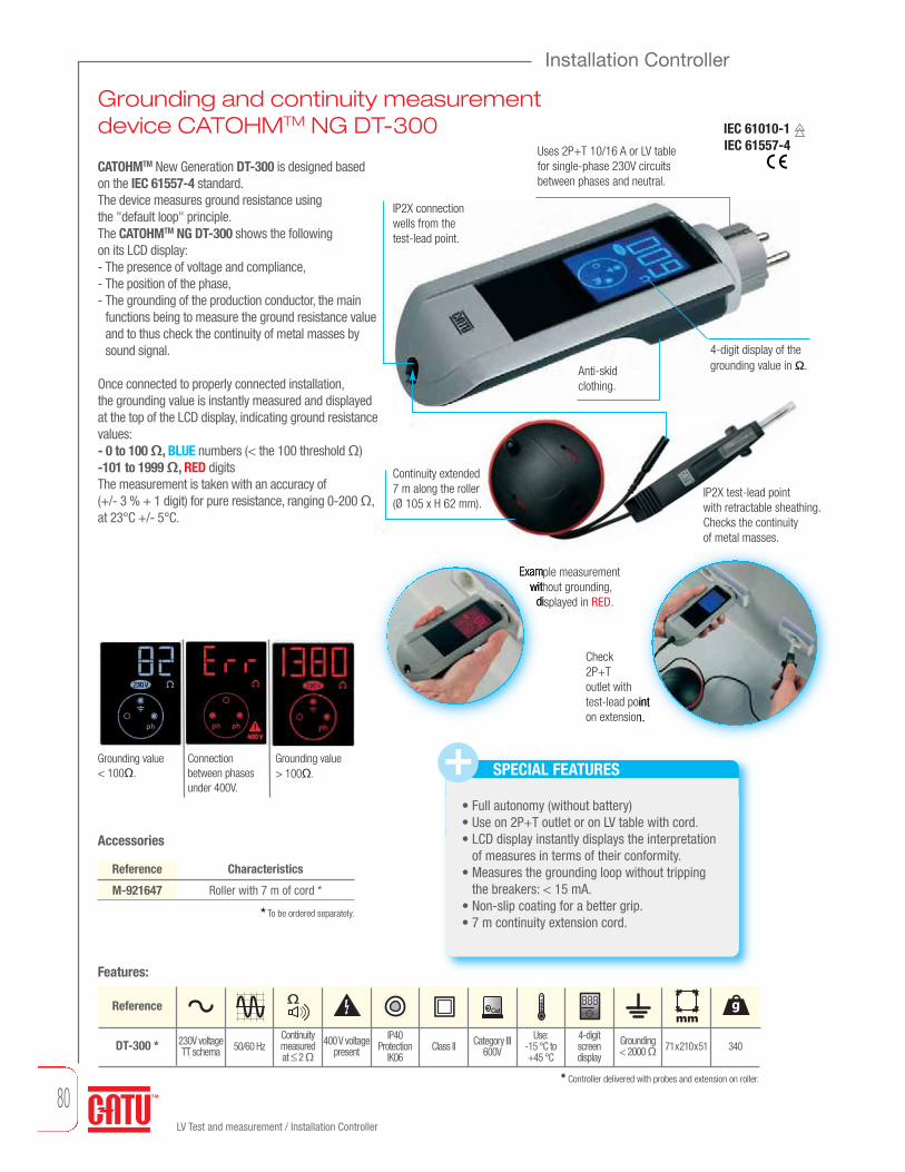
80LV Test and measurement / Installation Controller
Grounding and continuity measurementdevice CATOHMTM NG DT-300
Installation Controller
CATOHMTM New Generation DT-300 is designed based on the IEC 61557-4 standard.The device measures ground resistance using the "default loop" principle.The CATOHMTM NG DT-300 shows the following on its LCD display:- The presence of voltage and compliance,- The position of the phase,- The grounding of the production conductor, the main
functions being to measure the ground resistance valueand to thus check the continuity of metal masses bysound signal.
Once connected to properly connected installation, the grounding value is instantly measured and displayed at the top of the LCD display, indicating ground resistancevalues:- 0 to 100 Ω, BLUE numbers (< the 100 threshold Ω)-101 to 1999 Ω, RED digitsThe measurement is taken with an accuracy of (+/- 3 % + 1 digit) for pure resistance, ranging 0-200 Ω, at 23°C +/- 5°C.
Uses 2P+T 10/16 A or LV tablefor single-phase 230V circuitsbetween phases and neutral.
Anti-skid clothing.
4-digit display of thegrounding value in Ω.
Continuitymeasured at ≤ 2 Ω
Grounding value < 100Ω.
Connection between phasesunder 400V.
Grounding value > 100Ω.
Check2P+T outlet withtest-lead pointon extension.
Example measurementwithout grounding,
displayed in RED.
IP2X connectionwells from thetest-lead point.
DT-300 *
Cat g
230V voltageTT schema 50/60 Hz 400 V voltage
presentUse:
-15 °C to +45 °C
IP40Protection
IK06Category III
600VGrounding < 2000 Ω 340
4-digit screen display
Class II
888mm
71x210x51
SPECIAL FEATURES
• Full autonomy (without battery)• Use on 2P+T outlet or on LV table with cord.• LCD display instantly displays the interpretation
of measures in terms of their conformity.• Measures the grounding loop without tripping
the breakers: < 15 mA.• Non-slip coating for a better grip.• 7 m continuity extension cord.
Continuity extended7 m along the roller(Ø 105 x H 62 mm).
* Controller delivered with probes and extension on roller.
Reference
M-921647 Roller with 7 m of cord *
Characteristics
* To be ordered separately.
Accessories
Features:
Reference
IP2X test-lead point with retractable sheathing.Checks the continuity of metal masses.
IEC 61010-1IEC 61557-4

81LV Test and measurement / Installation Controller
LV Test and measurement
Installation Controller
IEC 60364 recommends periodically checkinginsulation resistance. Insulation resistance ismeasured between each active conductor and theground (when not live). Its value should be 500 kΩfor a DC testing voltage of 500 V.The DT-500 is a specially designed device forquickly, easily, and safely measuring insulation resistance.It provides a safety system that prevents ameasurement when connected to a live installation.Measures insulation resistance below 500 V.
The insulation resistance value is indicated byilluminating a light:- RED for values including 0, 300, 400 kΩ.- GREEN for values including 500, 600, 700, 800,
900, 1 000 k and ∞.
IP2X test-lead pointBLUE (neutral) independent andconnected by asafety terminal.
IP2X test-lead point RED.
IP2X test-lead point YELLOW/GREEN(ground).
3 large opening alligator clips:RED, YELLOW/ GREEN,BLUE.
The DT-500comes with a beltclip and areaswhere test-leadpoints can be stored.
Test button for measuringand self-testing.
Battery status indicator light.
Insulated resistancediodes.
500 V test indicator light.
Default blinking light.
DT-500 *
Cat g
Output voltage
< 500 V DC
from 0 to ∞
Use: 15 °C to +45 °C
IP54 Protection
IK06Category III
600V600 with
batteries andaccessories
Class II
500 V
+-
mmmesuresΩ
213x75x46
Accessories
Reference
M-951981
M-87292
M-88896
M-881602
M-881601
Characteristics
* To be ordered separately.
1 m insulationcable.
Insulation controller
BLUE probe for replacement *
Carrying bag *
RED alligator clip for replacement
BLUE alligator clip for replacement
YELLOW/GREEN alligator clip for replacement
* Controller delivered with 3 probes, 3 alligators clips and batteries.
The DT-500 can bypass the phase and neutral in order toprotect sensitive equipment (electronics, computers, etc.).
Picture of installation withoutpresence voltage.
Features:
Reference
IEC 61010-1IEC 61557-2
mmDimensions g Weight
4 LR6 batteries
IP2Xtest-endpoints
M-881601
M-88887
M-881602

www.catuelec.com
New generation of voltagecheck (VAT) operations andvoltage detectors .... see page 72.
EN 61243-3 (2010) / IEC 61243-3 (2009)
EN 50110-1

LV earthing systems
Overhead bare 84
Overhead insulating 86
LV Cabinets 87

84LV earthing systems / Overhead bare
Overhead bare
Short-circuiting systems Reference
MT-404
MT-405
MT-406
MT-407
3 MT-411 + 1 MT-411-C
4 MT-411 + 1 MT-411-C
5 MT-411 + 1 MT-411-C
6 MT-411 + 1 MT-411-C
3.4
3.8
4.2
4.6
Set of 4, 5, 6 ou 7 clamps MT-411.
Waterproof bagMT-400-01.
Telescopic stik 2 mCE-2-21-C.
An extra-flexible 16 mm2
copper cable assembly.
An insulatedsocket that can be locked with a bayonet, for connecting agrounded system.
Composition
Cable.
Insulated pin connecting to a short circuit socket.
Grounding device connecting with the earth rod MT-840 MT-650.
Reference
MT-242
MT-244
MT-245
MT-249
2 x 16
10 x 10
10 x 16
15 x 16
MT-840/1
MT-840
MT-840/1
MT-840/1
1
2.5
3
3.8
m x mm2 Earth clamp Cable
Packaging: polypropylene case. 310 x 280 x 105 mm.
MT-411-C
kg
kg
Earthing equipment for overhead lines systemsEarth rod to be ordered separately.See below.
Icc: 3 kA/1sMade of 4 references:
IEC 61230

85LV earthing systems / Overhead bare
Overhead bare
LV earthing systems
m x mm2 Cable m x mm2kg Weight
Short-circuiting and earthing systems NEVERS ERDF type
Insulating sticksraise up MT-546.
Insulating stickssupport M952570.
Multi strand of 5 copper cablesM952567.
Earth cableM952568.
Insulating sticks.
Voltage detectorCC-127-ERDF-C.
Reference
MT-509/3
MT-509/3EP
MT-509/3VAT
19(3 bags)
2.3
2.5
Composition
3 Telescopic metallic sticks 3 elements L = 2.37/6.15 m +
1 Telescopic metallic stick 3 elements (latest insulating yellow) L = 2.37/6.15 m +
1 insulating stick 2 elements L = 1.65/3.3 m + 1 multi-strand of 5 cables L = 6 x 16 mm2 with
2 female sockets + 1 stick raise-up + 1 sticks support
1 Telescopic metallic sticks 3 elements L = 2.37/6.15 m +
1 cable L = 6 x 16 mm2 with male socket
1 Telescopic metallic sticks 3 elements (latest insulating yellow)
L = 2.37/6.15 m
Short-circuit ERDF networks for the work of pruning trees. Implementation from the ground up to 10.5 m (sticks + operator) without climbing the support.Insultating stick contains made of resin polyester/ glass fibertube diameter 36.
Equipments packed in carry bags.
Insulating sticks Nevers type.
Insulating sticks bag.
Reference
CC-127-ERDF-CSpecific voltage detector
Range : 127-400 V450
Description
Reference
M952567
M952570
MT-546
M611386
M952568
Multi strand of 5 copper cables
Insulating sticks suppot
Insulating sticks raise up
Raise up sticks
Earth cable
Description
kg
g
IEC 61230

86LV earthing systems / Overhead insulating
Overhead insulating
Short-circuiting systemsEquipment includes either 5 or 6 copper-aluminiumalloy stubs
MT-222
Reference
MT-205
MT-206
MT-207
5
6
7
1.1
1.5
1.9
Socket
Reference
MT-222
MT-223
16 x 25
35 x 70
285390285
118
800
800
Packaging: polypropylene case. 234 x 215 x 75 mm.
Set of 4, 5, 6 ou 7 clamps.
Connector for conductor MT-222 or MT-223, see below, to be ordered separatly.
An extra-flexible 16 mm2
copper cable assembly.
m x mm2
Connectors for conductors
Earth rodEarthing equipment with bayonet splicing for overhead lines systems. Galvanized steel.
Hexagonal 18 mm per side.
Earthing equipment
kg
Icc: 4 kA/1s
Upon request, ability to connect with a male socket.
Reference
MT-650 1 m 2.2
To be ordered in addition to short circuit and grounding equipment.
kg
Lowlock system
Reference CompositionRating kg5 MT-616/1-03 contact clamps on handles
(I = 0.35 m each) 4 braids of M-24-35 copper cable (1.00 m) 1 M-87-153 carrying bag
250 x 85 x 750 mm
For conductors 3 to 21 mm Ø.With clamps type “snap-on/screw-on”.Connecting cables: 35 mm2 copper.Short-circuiting and earthing systems
7.5MT-615/1-7.5 3
5 MT-616/1-03 contact clamps on handles4 braids of M-24-35 copper cable (1.00 m)1 braid of M-24-35 copper cable (7.00 m)
1 MT-840/1 earth clamp
7.5MT-615/2-7.5 6. 5
IEC 61230

87LV earthing systems / LV Cabinets
LV Cabinets
LV earthing systems
IEC 61230
Short circuiting device for LV cabinetThe ground works BT is a mandatory operation in the NFC 18510 (chp 7.1 - Processes log) standard. Tinned copper insulated cable silicone core 16 mm2. Authorized employment ERDF equipment.Composition A: for connection.Composition B: for network.Composition C: for connection and network.Maximum Icc : 4kA/1s.
Case CIBE/REMBT/C400 P200/CODI/TUR/TIPI/False grid cutoff and riser.
1 2 3
M-95627/4
MC-296-00/08
MC-296-115/08
MC-296-160/08
* Sold in packs of 4. Other composition on request.
Composition set Reference MC-296-A MC-296-B MC-296-C
4 multi-strand copper cables 16mm²
4 multi-strand copper cables 16mm²
5 multi-strand copper cables 16mm²
Micro clamps
Connecting blade
Round cartridge
Cartridge size 00
Cartridge size 115
Cartridge size 160
Threated adapters
Pipe wrench 10x17mm
Open end spanners 13/14/16/17
Handle
Case with foam and notice
MC-296-440
MC-296-560
M-952656
MC-296-P*
M-95627/4*
M-95626/4*
MC-296-00/08*
MC-296-115/08*
MC-296-160/08*
MC-181*
M-882462
MO-687-D
MC-296-M
M-91209
1
1
1
1
1
1
1
1
1
1
1
1
1
1
1
1
1
1
1
1
1 + 1 clamp
1
1
1
1
1
1
1
1
1
1
MC-296-P
m x mm2 Cable m x mm2 kg WeightTotal length
MC-296-M
M-95626/4

88LV earthing systems / LV Cabinets
LV Cabinets
Short circuiting device for LV industries cabinet
The earthing BT works is a mandatory operation in the NFC 18510 (- Processes log chp 7.1) standard.Multi strand isolated copper silicon cable 16mm2.
Threaded adapterSmooth threaded terminals for positioning shunts (live working tools)or earthing equipment and short circuit cabinets terminals LV.
Reference Description
MC-184-6F
MC-182
MC-185-10F
MC-183
Smooth threaded terminal M6
Smooth threaded terminal M8
Smooth threaded terminal M10
Smooth threaded terminal M12
CompositionSet of 4 adapters by reference,
delivered in a vinyl bag
Set of 4 adapters by reference,delivered in a vinyl bag
Set of 4 adapters by reference,delivered in a vinyl bag
Set of 4 adapters by reference,delivered in a vinyl bag
120
150
200
250
Reference Description
MC-184-6M
MC-182-8M
MC-185-10M
MC-181
Smooth bolt terminal M6
Smooth bolt terminal M8
Smooth bolt terminal M10
Smooth bolt terminal M12
CompositionSet of 4 adapters by reference,
delivered in a vinyl bag
Set of 4 adapters by reference,delivered in a vinyl bag
Set of 4 adapters by reference,delivered in a vinyl bag
Set of 4 adapters by reference,delivered in a vinyl bag
120
150
200
250
MC-181
* Sold in packs of 4.
Composition set Reference MC-296-NFC
5 Multi-strand copper cables 16mm²
Micro clamps
Case and notice
M-952650
MC-296-P*
M-76768
1
1 + 1 clamp
1
MC-180
g
g
IEC 61230

LV Live working tools
Insulated tools 90
Jumper clamps, cables and accessories 115
Cover-up equipment 118
Cable identifier 122

90LV Live working tools / Insulated Tools
Insulated tools must comply with the NF EN 60900 and IEC 60900 standards. To meet these standards, insulated tools undergo 10 000 volts through electrical testing and many mechanical tests, including impact tests, tearing tests, and puncture tests. For working live at nominal voltage up to 1000 V a.c and 1500 V d.c.
Dual Layer Insulated Tools
Dual Material Insulated Tools
SPECIAL FEATURESChrome steel body, mat finish.Label.
Label.Uniform guard with insulating layer.
MaterialSOFTGRIP ®
White insulatinginner layer.
Orange insulatingouter layer.
• Products suitable for work on live cables, particularly lowvoltage (30 cm area of a live bare wire).• Ergonomic.• Dual material with non-skid "SOFTGRIP"® injected material for operator comfort.
• Extensive product line for work on live cables; mainlyused by LV Live Line Working teams.
• Ergonomic.• Dual-layer with a white insulating layer.• High mechanical strength in the layers due to dipping
technique.• Steel with high mechanical properties.
20 N5000 V
10 000 V
Dielectric TestIndentation
Flame retardancy
Test
for a
dhesion of the insulating materiel
Impact Test
SPECIAL FEATURES
High performing burnished steel.
IEC 60900 2012
50 daN
Insulated ToolsFind the tools to meet your needs!
Routine test: each tool is tested at 10kV for ten seconds.

91
Insulated tools
LV Live working tools
IEC 60900
LV Live working tools / Insulated toolsmm Diameter g Weightmm Blade lengthTool numberN°
Flat blade screwdriver, dual materialReference
MO-72002
MO-72003
MO-72004
MO-72005
MO-72006
MO-72008
MO-72010
2.5
3
4
5
6
8
10
60
100
125
150
150
175
200
30
40
50
70
90
150
220
mm
Dual material handleAnti slip material.
POZIDRIV screwdriver, dual materialReference
MO-72040
MO-72042
MO-72044
MO-72046
MO-72048
PZ 0
PZ 1
PZ 2
PZ 3
PZ 4
60
100
125
150
200
25
60
90
150
220
PZ N°
Chrome - molybdenumvanadium steel blade.
Chrome - molybdenumvanadium steel blade.
Injection moldedinsulation.
Dual material handleAnti slip material.
PHILLIPS screwdriver, dual materialReference
MO-72030
MO-72032
MO-72034
MO-72036
MO-72038
PH 0
PH 1
PH 2
PH 3
PH 4
60
100
125
150
200
25
60
90
150
220
PH N°
Dual material handleAnti slip material.
TORX screwdriver, dual materialReference
MO-72056
MO-72057
MO-72058
MO-72059
MO-720510
MO-720515
MO-720520
MO-720525
MO-720527
MO-720530
MO-720540
MO-720545
MO-720550
T 6
T 7
T 8
T 9
T 10
T 15
T 20
T 25
T 27
T 30
T 40
T 45
T 50
50
50
50
75
75
75
100
100
115
125
125
150
175
25
25
25
35
35
50
70
80
90
100
120
160
200
N°
Dual material handleAnti slip material.
mmg
mmg
mmg
mmg
Chrome - molybdenumvanadium steel blade.
Chrome - molybdenumvanadium steel blade.

Insulated tools
92
IEC 60900
Hexagonal screwdriver ALLEN, dual materialReference
On flats(mm)
MO-68402
MO-68403
MO-68404
MO-68405
MO-68406
MO-68408
2.5
3
4
5
6
8
75
75
100
100
125
150
40
50
70
80
100
150
Dual material handleAnti slip material.
Cable cutter plier, dual materialReference
MO-72200 Ø 5 max160 238
Cu / Almm
Dual material handleAnti slip material.
Chrome-vanadium steel.
Reference
Universal plier, dual material
MO-72102 Ø 3.5 Ø 2.2 Ø 1.5180 280
Dual material handleAnti slip material.
Dual material handleAnti slip material.
mm
Chrome-vanadium steel.
Wire stripping plier, dual materialReference
MO-72172 160 170
Cu / AlmmChrome-vanadium steel. 0.5 to 10 mm2
mmg
g
g
mm
mm
gmm
LV Live working tools / Insulated tools
Chrome - molybdenumvanadium steel blade.

Dual material handleAnti slip material.
Chrome-vanadium steel.
Insulated tools
93
LV Live working tools
IEC 60900
g Weightmm Blade length
Steel: 75 daN / mm2 Steel: 180 daN / mm2 Steel: 220 daN / mm2
Reference
Flat nose plier, dual material
MO-72132 160 170
Chrome-vanadium steel.
Reference
Round nose plier, dual material
MO-72122 160 160
Water pump plier, dual materialReference
MO-72155 32 350
Chrome-vanadium steel.
Reference
Bent snipe nose plier, dual material
MO-72142 Ø 2.5 Ø 1.6 Ø 1160 170
mm gmm
Reference
Side cutter plier, dual material
MO-72162 Ø 3 Ø 2.2 Ø 1.5160 210
mm gmm
Dual material handleAnti slip material.
Chrome-vanadium steel.
Dual material handleAnti slip material.
Chrome-vanadium steel.
Dual material handleAnti slip material.
Dual material handleAnti slip material.
250
mm
Double rack slipt joint.
gmm
gmm
gmm
Maximal openingmmCutting capacitymmTotal lengthmmmm
Stripping capacity
LV Live working tools / Insulated tools

Insulated tools
LV Live working tools / Insulated tools
94
Composition
MO-72004
MO-72006
MO-72008
MO-72042
MO-72044
Flat blade screwdriver de 4 x 125 mm
Flat blade screwdriver 6 x 150 mm
Flat blade screwdriver 8 x 175 mm
POZIDRIV screwdriver N°1
POZIDRIV screwdriver N°2
Reference KIT-23
Composition
MO-72102
MO-72155
MO-72172
MO-72142
MO-72200
Universal plier 180 mm
Water pump plier 250 mm
Wire stripping plier 160 mm
Bent snipe nose plier 160 mm
Cable cutter 160 mm
Reference KIT-27
Composition
MO-72004
MO-72006
MO-72008
MO-72042
MO-72044
MO-72172
MO-72142
MO-72200
Flat blade screwdriver 4 x 125 mm
Flat blade screwdriver 6 x 150 mm
Flat blade screwdriver 8 x 175 mm
POZIDRIV screwdriver N°1
POZIDRIV screwdriver N°2
Wire stripping plier 160 mm
Bent snipe nose plier 160 mm
Cable cutter 160 mm
Reference KIT-24
Composition
MO-72004
MO-72006
MO-72008
MO-72042
MO-72044
MO-72102
MO-72155
MO-72172
MO-72142
MO-72200
Flat blade screwdriver 4 x 125 mm
Flat blade screwdriver 6 x 150 mm
Flat blade screwdriver 8 x 175 mm
POZIDRIV screwdriver N°1
POZIDRIV screwdriver N°2
Universal plier 180 mm
Water pump plier 250 mm
Wire stripping plier 160 mm
Bent snipe nose plier 160 mm
Cable cutter 160 mm
Reference KIT-25
Complete intervention kit, dual material
Intervention kit, dual material
Pliers kit, dual material
Screwdrivers kit, dual materialIEC 60900

MO-72003 flat blade screwdriver 3 x 100
MO-72004 flat blade screwdriver 4 x 125
MO-72005 flat blade screwdriver 5 x 150
MO-72006 flat blade screwdriver 6 x 150
MO-72008 flat blade screwdriver 8 x 175
MO-72030 screwdriver PH 0 x 60
MO-72032 screwdriver PH 1 x 100
MO-72034 screwdriver PH 2 x 125
MO-72036 screwdriver PH 3 x 150
MO-72040 screwdriver PZ 0 x 60
MO-72042 screwdriver PZ 1 x 100
MO-72044 screwdriver PZ 2 x 125
MO-72046 screwdriver PZ 3 x 150
MO-68403 hexagonal screwdriver 3 x 75
MO-68404 hexagonal screwdriver 4 x 100
MO-68404 hexagonal screwdriver 5 x 100
•
•
•
•
•
•
•
•
•
•
•
•
•
•
•
•
•
•
•
•
•
•
•
•
•
•
•
•
•
•
•
•
•
•
•
•
•
•
•
•
•
•
•
•
•
•
•
•
•
KIT-23C KIT-23S KIT-23SC2 KIT-23SH KIT-23P KIT-23SP2 KIT-23SCP KIT-23CH KIT-23PH
Insulated tools
LV Live working tools / Insulated tools
95
LV Live working tools
Screwdrivers kit dual materialIEC 60900
Photos of KIT-23SCP
Delivered under blister.

Insulated tools
96
Flat blade screwdriverReference
6.5
3
3.5
4
5.5
6.5
8
10
40
100
100
100
125
150
175
200
38
33
37
46
75
94
165
195
Chrome - molybdenum vanadium steel blade.
MO-65202
MO-65203
MO-65204
MO-65205
MO-65206
MO-65207
MO-65209
MO-65211
MO-650-D
MO-652-D
Set of 3 screwdriverssMO-65205 / MO-65207 / MO-65209
Set of 4 screwdrivers MO-65203 / MO-65205 / MO-65207 / MO-65209
Flat blade screwdriver with recessed bladeReference
MO-65200D
MO-65202D
MO-65203D
MO-65204D
MO-65205D
MO-652055D
MO-65206D
MO-65208D
MO-652082D
MO-65210D
MO-652102D
MO-65212D
6.5
2
3
4
5.5
5.5
6.5
8
8
10
10
12
40
70
100
120
100
150
150
150
200
150
250
250
36
16
30
52
50
72
36
92
142
166
282
318
PHILLIPS screwdriverReference
MO-65230
MO-65232
MO-65234
MO-65236
MO-65238
MO-653-D
PH 0
PH 1
PH 2
PH 3
PH 4
60
80
100
150
200
25
50
75
150
230
PH N°
Set of 3 screwdrivers N°0. N°2 et N°3
PHILLIPS screwdriver with recessed bladeReference
MO-65232D
MO-652321D
MO-65233D
MO-65234D
MO-65236D
MO-65238D
PH 0 (4)
PH 0 (4)
PH 1 (5)
PH 2 (6)
PH 3 (8)
PH 4 (10)
75
150
100
125
150
200
50
55
60
82
146
256
gmm mm
gmm mm
gmm
gmm mm
IEC 60900
LV Live working tools / Insulated tools
Chrome - molybdenum vanadium steel blade.
Chrome - molybdenum vanadium steel blade.
Chrome - molybdenum vanadium steel blade.

Insulated tools
97
LV Live working tools
g Weightmm Blade length
POZIDRIV screwdriverReference
MO-65240
MO-65242
MO-65244
MO-65246
MO-65248
PZ 0
PZ 1
PZ 2
PZ 3
PZ 4
60
80
100
150
200
25
50
75
150
230
PZ N°
POZIDRIV screwdriver with recessed bladeReference
MO-652405D
MO-652406D
MO-65244D
MO-652441D
MO-65245D
MO-65246D
MO-65248D
MO-652410D
5
6
PZ 0 (4)
PZ 0 (4)
PZ 1 (5)
PZ 2 (6)
PZ 3 (8)
PZ 4 (10)
40
40
75
150
100
125
150
200
34
34
50
55
60
82
146
256
Screwdriver block terminal flat/PHILLIPSReference
MO-65405
MO-65406
5
6
80
100
Screwdriver block terminal flat/POZIDRIVReference
MO-65505
MO-65506
5
6
80
100
gmm
gmm mm
mm mm
mm mm
IEC 60900
LV Live working tools / Insulated tools
Chrome - molybdenum vanadium steel blade.
Chrome - molybdenum vanadium steel blade.
Chrome - molybdenum vanadium steel blade.
Chrome - molybdenum vanadium steel blade.
mm Diameter
For fuse boxes, connecting boxes, circuit breaker terminal blocks.

Insulated tools
98
MO-66005
MO-66002Reference
Universal plier
MO-66001
MO-66002
MO-66003
MO-66005
160
180
200
250
Special steel, oil-hardened. Burnished head.
210
260
300
510
Chrome-vanadium steel.
Reference
Flat nose plier
MO-66300
MO-66301
MO-66302
145
160
170
115
160
180
Reference
Bent snipe nose plier
MO-66402
MO-66404
160
200
160
185
Chrome-vanadium steel.
Reference
Round nose plier
MO-66202 160 150
Reference
Long nose plier with side cutter
MO-66102 160 145
Reference
Plug plier for preinsulating pin terminals
MO-66105 200 200
Chrome-vanadium steel.
Chrome-vanadium steel.
Chrome-vanadium steel for pin terminals 2.8/5/6.35 mm.
gmm
gmm
gmm
gmm
gmm
gmm
LV Live working tools / Insulated tools
IEC 60900

Insulated tools
99
LV Live working tools
gMaximal openingmm Cutting capacitymm WeightTotal lengthmm
Insulating universal plier
MO-66000C 16 mm2 copper200 170
mmReference
Insulating flat nose plier
Insulating bent half round nose plier
Composite insulation.
Composite insulation.
Composite insulation.
Reference
Waterpump plier
MO-66502
MO-66505
MO-66500
250
250
410
33
33
45
250
405
1 000
Chrome-vanadium steel.
Double rack slip joint (MO-66505 only).
End cutting pliers
Reference
MO-67401
MO-67402
MO-67404
Ø 2 max
Ø 3 max
Ø 4 max
140
160
200
Ø 1 max
Ø 2 max
Ø 3 max
165
210
450
MO-67402
MO-67404
Chrome-vanadium steel.
mm
mm g
MO-66303C 16 mm2 copper190 110
mmReference mm g
MO-66404CC 16 mm2 copper210 110
mmReference mm g
mm mm g
mm g
LV Live working tools / Insulated tools
IEC 60900
Steel: 75 daN / mm2 Steel: 180 daN / mm2 Steel: 220 daN / mm2

Insulated tools
100
Reference
MO-67500 Ø 5 Cu / Al180 420
Cable cutter
Cable cutter
Reference
MO-67501
MO-67502
Ø 15 max
Ø 20 max
170
230
285
520
Cable cutter
Reference
MO-67700
MO-67701
590
765
30
20
185 mm2
Copper/Aluminium
Ø 12 Aluminium
2.5
2.8
émm
MO-67501
MO-67502
Chrome-vanadium steel.
Chrome-vanadium steel.
Diagonal cutting plier
Chrome-vanadium steel.
Reference
MO-67101
MO-67102
MO-67103
Ø 2
Ø 3
Ø 3.2
Ø 1
Ø 2.2
Ø 2.5
Ø 0.5
Ø 1.5
Ø 2
140
160
190
150
180
210
mm
mm
gmm
gmm
mm
mm
gmm
mm mmMO-67700
MO-67701
Chrome-vanadium steel.
LV Live working tools / Insulated tools
IEC 60900

101
LV Live working tools
Cutting capacitymm WeightThicknessTotal lengthmm g
Insulated tools
émm
Delivered with pouch.
Reference
MO-67305
MO-67306
Ø 21 to 35 mm
Ø 26 to 52 mm
265
270
650
670
Reference
MO-67304 Ø 8 to 21 mm220 470
Stripping capacity
Wire stripping plier
Reference
MO-67302 0.5 to 10160 170
Stripping capacitymm2
Insulated knifeReference
180
180
62
50
110
110
MO-61001
MO-61002
mm
Reference
MO-67302C 0.5 to 10260 175
Stripping capacitymm2
Chrome-vanadium steel.
Curved blade.
MO-61001
MO-61002
mm g
mmmm g
mm
Stripping capacitymm
mm g
mm g
mm gmm
mmStripping capacity Maximal openingmm
LV Live working tools / Insulated tools
IEC 60900
Stripping tool for LV cables
Stripping tool for LV cables
Aluminium casting plier.
Aluminium casting plier.
Steel: 75 daN / mm2 Steel: 180 daN / mm2 Steel: 220 daN / mm2
Wire stripping plier fully insulated

102
Insulated tools
Reference Coppersection mm2
Aluminiumsection mm2
Ratchet cable cutter
MO-67599
MO-67600
MO-67601
900
950
975
Ø 32 max
Ø 38 max
Ø 55 max
180
240
300
250
300
450
Reference Coppersection mm2
Aluminiumsection mm2
Frontal ratchet cable cutter
MO-67611 900Ø 32 max 180 250
Treated forged steel blade.
Treated forgedsteel blade.
MO-67599
MO-67600
mm
mm
HacksawReference
MO-64501
MO-64502*
130
300
263
450
150
780
Protected hard forged steel.
Two blade positions. Flush and 90° cutting supplied.
Tension blade by screw.
* Delivered with 2 blades.
MO-64502
MO-64501
g
g
gmmmm
mm
mm
LV Live working tools / Insulated tools
IEC 60900

Reference
MO-69210
MO-69213
MO-69216
MO-69217
MO-69218
MO-69219
10
13
16
17
18
19
160
190
350
370
380
390
g
103
LV Live working tools
Weightmm Total lengthg
Insulated tools
Cutting capacitymm
Adjustable spannerReference
210
250
310
385
24 max
28 max
34 max
43 max
295
450
550
1 350
MO-69002
MO-69003
MO-69004
MO-69005
Reference
Combination wrench
MO-68701
MO-68702
MO-68703
MO-68704
MO-68705
150 x 150
150 x 150
150 x 150
150 x 150
150 x 150
225
260
250
250
400
6-8-10-12
8-10-12-14
7-9-11-13
8-10-13-17
14-17-18-21
Special steel insulated inserts using one-piece injection.
Special steel insulated inserts using one-piece injection.
Special steel, oil-hardened.
Reference
Right angle male hexagonal key
MO-69903
MO-69904
MO-69905
MO-69906
MO-69908
MO-69910
MO-69912
30
40
50
70
110
150
240
3
4
5
6
8
10
12
83 x 123
84 x 124
84 x 126
85 x 126
87 x 128
87 x 130
90 x 132
mmmm g
gmm
gmm
mm Blade length
Maximal openingmm
mm
mm
mm
LV Live working tools / Insulated tools
IEC 60900
Reversible ratchet ring spanner
mm Diameter

104
Insulated tools
Open jaw spanner
Reference
6
7
8
9
10
11
12
13
14
15
16
17
18
20
20
40
40
45
50
60
80
100
110
120
140
160
MO-68006
MO-68007
MO-68008
MO-68009
MO-68010
MO-68011
MO-68012
MO-68013
MO-68014
MO-68015
MO-68016
MO-68017
MO-68018
MO-68008/19 8 open end spanners set: 8 / 10 / 11 / 12 / 13 / 14 / 17 / 19 mm
Reference
19
20
21
22
23
24
25
26
27
28
29
30
32
170
185
200
220
250
260
280
300
340
360
400
500
570
685
MO-68019
MO-68020
MO-68021
MO-68022
MO-68023
MO-68024
MO-68025
MO-68026
MO-68027
MO-68028
MO-68029
MO-68030
MO-68032
Cranked ring spanner
Reference
6
7
8
9
10
11
12
13
14
15
16
17
18
30
35
40
45
50
65
80
100
120
150
180
190
195
MO-68106
MO-68107
MO-68108
MO-68109
MO-68110
MO-68111
MO-68112
MO-68113
MO-68114
MO-68115
MO-68116
MO-68117
MO-68118
Reference
19
20
21
22
23
24
25
26
27
28
29
30
32
200
240
260
260
270
280
300
360
400
440
480
500
540
MO-68119
MO-68120
MO-68121
MO-68122
MO-68123
MO-68124
MO-68125
MO-68126
MO-68127
MO-68128
MO-68129
MO-68130
MO-68132
Hexagonal spanner with T handle
Reference
145
145
145
135
135
10
13
14
20
21
145
185
220
350
370
MO-68610
MO-68613
MO-68614
MO-68620
MO-68621
g g
g g
mm
gmm
mm mm
mm mm
LV Live working tools / Insulated tools
IEC 60900

105
LV Live working tools
Weightg
Insulated tools
Maximal openingmm
ReferenceSockethead
6 sided
6 sided
6 sided
6 sided
6 sided
6 sided
6 sided
6 sided
6 sided
6 sided
6 sided
6 sided
6 sided
6 sided
6 sided
6 sided
6 sided
6 sided
5
6
7
8
9
10
11
12
13
14
15
16
17
18
19
20
21
22
20
30
35
50
60
60
90
95
130
160
170
220
230
280
320
340
470
500
MO-68205
MO-68206
MO-68207
MO-68208
MO-68209
MO-68210
MO-68211
MO-68212
MO-68213
MO-68214
MO-68215
MO-68216
MO-68217
MO-68218
MO-68219
MO-68220
MO-68221
MO-68222
Reference
305
305
305
305
305
305
305
305
305
305
405
405
405
10
11
12
13
14
16
17
19
21
22
13
14
17
350
360
370
400
450
560
650
750
800
850
650
800
900
MO-68310
MO-68311
MO-68312
MO-68313
MO-68314
MO-68316
MO-68317
MO-68319
MO-68321
MO-68322
MO-68713
MO-68714
MO-68717
Pipe wrench
Hexagonal spanner with T handle
mm
g
ReferenceSockethead
6 sided
6 sided
6 sided
6 sided
6 sided
6 sided
6 sided
6 sided
6 sided
23
24
25
26
27
28
29
30
32
600
650
700
750
800
850
900
950
1000
MO-68223
MO-68224
MO-68225
MO-68226
MO-68227
MO-68228
MO-68229
MO-68230
MO-68232
mm
g
mm
gmm
mm
gmm
mm
On flats
mm Total length
T wrench 3/8” (9.35 mm) and 1/2’’ (12.7 mm) square drive
Reference
130
210
350
3.8”
3.8”
1.2”
350
450
600
MO-69523
MO-69533
MO-69544
LV Live working tools / Insulated tools
IEC 60900
mm Diameter
MO-69544

106
Insulated tools
6 sided female socket 3/8” (9.53 mm) square drive - Metric and U.S Standard
Reference
6
7
8
9
10
11
12
13
14
15
16
17
18
19
21
22
25
30
30
30
35
35
35
45
45
50
55
60
65
70
85
90
MO-69306
MO-69307
MO-69308
MO-69309
MO-69310
MO-69311
MO-69312
MO-69313
MO-69314
MO-69315
MO-69316
MO-69317
MO-69318
MO-69319
MO-69321
MO-69322
Reference
23
24
1/4
5/16
3/8
7/16
1/2
9/16
5/8
11/16
3/4
13/16
7/8
15/16
1
100
120
25
30
30
35
40
45
55
60
70
85
90
105
110
MO-69323
MO-69324
MO-697-1/4SAE
MO-697-5/16
MO-69735
MO-69736
MO-69737
MO-69738
MO-69739
MO-69740
MO-69741
MO-69742
MO-697-7/8
MO-697-15/16
MO-697-1SAE
g g
Others references, consult us.
mm mm
12 sided female socket 1/2” (12.7 mm) square drive
Reference
8
10
11
12
13
14
15
16
17
60
60
65
70
70
70
75
75
80
MO-69408
MO-69410
MO-69411
MO-69412
MO-69413
MO-69414
MO-69415
MO-69416
MO-69417
Reference
18
19
20
21
22
23
24
29
30
80
85
90
100
100
115
125
135
140
MO-69418
MO-69419
MO-69420
MO-69421
MO-69422
MO-69423
MO-69424
MO-69429
MO-69430
g gmm mm
LV Live working tools / Insulated tools
Chrome steel.
IEC 60900

Torx.
107
LV Live working tools
Weightg
Insulated tools
Reference
MO-69393
MO-69394
MO-69395
MO-69396
MO-69397
MO-69398
MO-693100
3
4
5
6
7
8
10
45
55
60
65
70
70
80
6 sided male hex Key / Socket 3/8” square drive
Male TORX 3/8” square drive
Reference
TX15
TX20
TR30
TR40
TR50
60
60
105
105
105
50
55
60
80
100
MO-69T15
MO-69T20
MO-69T30
MO-69T40
MO-69T50
g
mmgmm
Extension pieces 3/8” square drive
Reference
21.5
21.5
140
264
124
270
MO-69523
MO-69533
mmgmm
mmDimensions
mm
LV Live working tools / Insulated tools
Steel.
6 sided female socket 3/8” (9.53 mm) square drive long series
Chrome steel. L: 65 mm.Reference
8
9
10
11
12
13
14
55
65
75
85
95
100
115
MO-69608
MO-69609
MO-69610
MO-69611
MO-69612
MO-69613
MO-69614
Reference
16
17
18
19
21
22
24
130
145
160
180
200
220
240
MO-69616
MO-69617
MO-69618
MO-69619
MO-69621
MO-69622
MO-69624
g g
Others references, consult us.
mm mm
IEC 60900
mm Diameter
MO-69523

108
Insulated tools
Sockets 3/8” "" ""!
Sockets 1/2” "" ""!
!!Plastic case without tools.
MO-69308
MO-69310
MO-69312
MO-69313
MO-69314
MO-69317
MO-69319
MO-69321
MO-69322
MO-69323
MO-69513
MO-69523
8
10
12
13
14
17
19
21
22
23
Reversible ratchet
Extension 130
30
35
35
45
45
60
70
85
90
100
600
124
MO-69308/23 1 250
MO-69408
MO-69410
MO-69412
MO-69413
MO-69414
MO-69417
MO-69419
MO-69421
MO-69422
MO-69423
MO-69514
MO-69524
8
10
12
13
14
17
19
21
22
23
Reversible ratchet
Extension 125
60
60
70
70
70
80
85
100
100
115
600
250
Complete sockets 410 x 120 x 75
MO-69524 MO-69308/23
Composition
g
MO-69408/23 1 500Complete sockets 410 x 120 x 75
Composition
g
Reference
MO-69503 410 x 120 x 75 250mm
g
Sockets wrenches sets
Other references, consult us.
Others references 1/2 », consult us.
mm mm
LV Live working tools / Insulated tools
IEC 60900

109
LV Live working tools
LV Live working tools / Insulated tools
Insulated tools
Rachet spanners
Reference
MO-69050
MO-69051
MO-69054
8 to 50 Nm
4 to 20 Nm
8 to 50 Nm
790
500
850
Torque wrench 3/8” square drive
330
235
290
Reference
Fully insulated scissors
MO-72100E 132 80
Reference
1/4”
3/8”
1/2”
3/8”
125
190
255
215
150
250
600
360
MO-69512
MO-69513
MO-69514
MO-69515
With mechanicallocking.
MO-69513
MO-69514
MO-69515
MO-69050 no reversible
MO-69051 - MO-69054 reversible
Linear graduation, English and Frenchscales (ibF Ft and Nm).
mm mm g
mm g
mm g
FNm
Weightgmm
Dimensions FNm Clamping torquemm Total length
IEC 60900

110
Insulated tools
Composition
MO-65242
MO-65244
MO-65204
MO-65206
MO-65209
POZIDRIV screwdriver N°1
POZIDRIV screwdriver N°2
Flat blade screwdriver 3.5 x 100 mm
Flat blade screwdrivere 5.5 x 125 mm
Flat blade screwdriver 8 x 175 mm
Reference KIT-03
Composition
MO-66002
MO-66502
MO-67302
MO-66402
MO-67500
Universal pliers overall length 180 mm
Water pump pliers overall length 250 mm
End stripping pliers 160 mm
Bent snipe nose pliers overall 160 mm
Cable cutter 170 mm
Reference KIT-07
Composition
MO-65242
MO-65244
MO-65204
MO-65206
MO-65209
MO-67302
MO-66402
MO-67500
POZIDRIV screwdriver N°1
POZIDRIV screwdriver N°2
Flat blade screwdriver 3.5 x 100 mm
Flat blade screwdriver 5.5 x 125 mm
Flat blade screwdriver 8 x 175 mm
End stripping pliers overall 160 mm
Bent snipe nose pliers overall 160 mm
Cable cutter 170 mm
Reference KIT-04
Composition
MO-65242
MO-65244
MO-65204
MO-65206
MO-65209
MO-66002
MO-66502
MO-67302
MO-66402
MO-67500
POZIDRIV screwdriver N°1
POZIDRIV screwdriver N°2
Flat blade screwdriver 3.5 x 100 mm
Flat blade screwdriver 5.5 x 125 mm
Flat blade screwdriver 8 x 175 mm
Universal pliers overall 180 mm
Water pump pliers overall 250 mm
End stripping pliers overall 160 mm
Bent snipe nose pliers overall 160 mm
Cable cutter 170 mm
Reference KIT-05
Screwdrivers kit
Pliers kit
Intervention kit
Complete intervention kit
LV Live working tools / Insulated tools
IEC 60900

111
LV Live working tools
Weightkgmm
Dimensions
LV Live working tools / Insulated tools
Insulated tools
Reinforced back.
Reference
Electrician tool bag
M-87370* Ajustable shouldesshap.* Delivered without tools.
440 x 330 x 160 1.1
Reference
Tool bag
M0-37
* Delivered without tools.
400 x 310 x 250 0.6
Ajustableshouldes shap.
High resistancecanvas.
Reference
Back pack for tools
M0-38
* Delivered without tools.
400 x 300 x 180 0.6
Wide adjustable strap.
Reinforced zip.
High resistancecanvas.
Reference
Tool box
M0-39
* Delivered without tools.
480 x 320 x 230 0.9
Ajustable shouldesshap.
High resistancecanvas.
Retractable handle.
mm kg
mm kg
mm kg
mm kg
Reinforced bottom.
Multipocketsinside.
Multipocketsinside.

112
Insulated tools
Reference
Tool bag
MO-34 410 x 280 x 150 3.2
Reference
Tool bag
MO-36 200 x 250 x 450 4.8
Black grainedleather withhandle.
Silicon grain leathertotally sewn. Strongleather handle andshoulder strap.
The interior includes: a pocket,a separation which forms atool tray and a fold-down tool tray.
Reinforced bottom.
Separation which formsa tool tray.
Reference
Flat tool case
M-87303 400 x 380 x 60 1
Strong waterproofcanvas.
mm kg
mm kg
mm kg
LV Live working tools / Insulated tools
Multi-pockets inside.

113
LV Live working tools
Weightmm Dimensions kg
LV Live working tools / Insulated tools
Insulated tools
Tool bag to order separately
1 right angle hexagonal key wrench 3 mm
1 right angle hexagonal key wrench 4 mm
1 right angle hexagonal key wrench 6 mm
1 insulating folding rule
1 adjustable spanner 250 mm
1 universal pliers 180 mm
1 round nose pliers 160 mm
1 water pump pliers 250 mm
1 side cutter 160 mm
1 flat blade screwdriver 4 x 100
1 flat blade screwdriver 6.5 x 150
1 flat blade screwdriver 8 x 175
1 Phillips screwdriver n° 1
1 Phillips screwdriver n° 2
1 Phillips screwdriver n° 3
MO-69903
MO-69904
MO-69906
MO-751
MO-69003
MO-66002
MO-66202
MO-66502
MO-67102
MO-69308/23
MO-65205
MO-65207
MO-65209
MO-65232
MO-65234
MO-65236
Insulated tools
following… MO-510-03 *
1 sockets 3/8" wrench set with 10 sockets: 8, 10, 12, 13, 14, 17, 19, 21, 22, 23
Personal equipment
MO-186
CG-98-C
CG-05-B
CG-36
MP-42/16
MS-917
MP-26-A
MP-35/12
MP-4110
MP-32/15
MP-19
MO-61001
MO-67502
MO-68008/19
1 face shield
1 working gloves size C
1 rubber gloves size B
1 carrying bag for rubber gloves
1 insulating mat 3 mm
1 voltage detector
10 insulating caps
1 insulating blanket
10 wood clamps for insulating blanket
6 line protectors 1.50 m
5 insulating adhesive tapes
1 stripping knife
1 cable cutter 230 mm
Reference MO-510-03 *
1 open end spanners set with8 / 10 / 11 / 12 / 13 / 14 / 17 / 19 mm
Voltage detector
Insulating tools
Insulating
Reference Characteristics
MO-34
MP-01
Leather tool bag , see page 112
Bag for insulating mats, see page 29
Reference Characteristics
M-87384
M-87386
Bag for face shield and helmet, see page 20
Multi-pocket electrician bag, see page 30
* Delivered without tool bag. * Delivered without tool bag.
Low voltage complete set.Complete equipment for live line (LV) interventions.

114
Insulated tools
Intervention kit for electricians
Composition
M-87370
CG-05-C
MO-11001
AL-230-111
MO-65204
MO-65206
MO-65209
MO-65242
MO-65244
MO-66002
MO-66402
MO-67302
MO-67500
MO-66502
1 tool bag
1 pair of insulating gloves size C
1 safety glasses
1 safety padlock
Flat blade screwdriver - 3.5 x 100 mm
Flat blade screwdriver - 5.5 x 125 mm
Flat blade screwdriver - 8 x 175 mm
POZIDRIV screwdriver - N°1 4.5 x 80 mm
POZIDRIV screwdriver - N°2 6 x 100 mm
Universal plier - length 180 mm
Bent snipe nose plier - length 160 mm
End stripping plier - length 160 mm
Cable cutter - length 180 mm
Water pump plier - length 250 mm
Reference MO-38510
LV Live working tools / Insulated tools
IEC 60900
" ! ! !" !" !!" " !" " !!
www.catuelec.com
Our LV Live working guide is available.

115
LV Live working tools
LV Live working tools / Jumper clamps, cables and accessories
These clamps are specially designed for use onenergized parts in LV installations (switchboards, etc.)to make temporary connections. Isolated bronze jawsdesigned to axially grip conductors can be used on threaded bolts or shanks and nuts. All other modelsin this series tighten with T-handle screw, and receivecable terminals
Reference
Mini jumper clamps fully insulated for switchboard use
MC-141
MC-142
MC-143
MC-144
MC-145
MC-146
MC-147
MC-147/1
MC-148
MC-148/1
MC-149
150 x 75 x 25
33 x 38 x 58
115 x 70 x 25
23 x 75 x 150
23 x 70 x 110
23 x 70 x 110
100 x 70 x 25
100 x 70 x 25
80 x 70 x 25
80 x 65 x 25
160 x 60 x 55
200
130
150
280
220
230
100
100
150
100
300
Six-sided 17-19 mm.
Adjustable clamp round Ø 6-10 mmflat 5 mm.
Threated rod M8MC-147.Threated rod M10MC-147/1.
Flat bar, thickness 2-25 mm.
Round 8-12 square 9-10 mm.
Wire clamp forstripped cables Ø 3 to 10 mm. Wire clamp
for stripped cables Ø 10 to 24 mm.
MC-141
MC-142
MC-143
MC-144
MC-145MC-146
MC-149
Axial (at cable end)
+ transversal
TransversalTransversal
Axial
Clamp with tapped revolving rodend M8, 200 A shunt. To be usedwith an insulating six-sided malehex key 5 mm.
MC-147
MC-148
MC-148/1
Clamp with tapped revolving rod end M8.
For 10 to 50 mm2 cable.
Flat bar, thickness 20-30.
For shunt 200 A.
gmm
Jumper clamps, cables and accessories
Weightmm Dimensions g

116
Jumper clamps, cables and accessories
Jumper cable with insulated jumper clamps
Reference
MC-121
MC-122
MC-123
MC-124
60 x 25
125 x 35
125 x 35
125 x 35
50
100
100
100
Jumper cable with insulatedjumper clamps
Reference
MC-120/15
MC-120/50
MC-120/100
1.5 m
5 m
10 m
850
1 950
4 000
Jumper cables LV live working tools.
Delivered with socketscrewing ISO M8
Insulatedcover.
Junction.
Fuse holder for Shunt.piece female-female.
piece male-female.
MC-121
MC-122
MC-123
Fuse holder for 30 A for Clamps + banana plug.
piece male-female.MC-124
Connector for cable 8 mm.Rated insulation:1 500 V.Icc = 5 kA/1 s.
2 clamps MC-120.150 x 100 x 60 mm and 190 g each.Tightening capacity. 12 mm (- flat).Spring tightening.
Cable H 07 RN-F of 25 mm2
Continuous rating: 75 A.
Insulated coppercable H 07 RN-F.Nominal intensity200 A.
g
g
mm
LV Live working tools / Jumper clamps, cables and accessories
Reference
MC-153/05
MC-153/10
MC-153/30
MC-153/60
MC-155/05
MC-155/10
MC-155/20
MC-155/30
MC-155/60
MC-155/80
0.5 m
1 m
3 m
6 m
0.5 m
1 m
2 m
3 m
6 m
8 m
270
570
1 720
3 460
380
760
1 520
2 280
4 560
6 080
35
35
35
35
50
50
50
50
50
50
Sectionsmm2g

117
LV Live working tools
Weightmm
Dimensions gTotal length
LV Live working tools / Jumper clamps, cables and accessories
Cylindrical body diameter10 mm to fits on panelnetwork threadof switchboard etc... Total length 50 mm.
Reference
MC-126
MC-126/1
1.5 to 16
10 to 70
60 A
100 A
Reference
MC-150 173 x Ø 32 185
Reference
Threaded adapter
MC-181
MC-182
MC-183
50
27
48
M10
M8
M12
50 x 13
50 x 10
50 x 17
Reference
Bypass housing
MC-156
MC-156/1
MO-237-D
Box 40 x 80 x 158 mm
Spare part
Triangular spanner witch T hande
Reference
Jumper connecting box with fuse
MC-116 30 to 200 A
MC-183
MC-182
MC-181
Set of 4 adapters by reference.
The housing allows on each side to connect 3 by pass jumpers.
The shunt for collective channeling is a box used to make sure, before proceeding to the replacementof a molten fuse situated on a channeling, that thedefect which brought about the molten iseliminated. This box is used with a fuse when the(nominal) assigned intensity of the channeling is < 100 A and with 2 fuses when this intensity is included between 100 A and 200 A. It can also be used to open a circuit in load, for example to change a damaged accessory such as a pin.
Shunt Telescopic probeSections mm2 Current
Intensidad
Characteristics
Connector with insulated probe.
Retractable cover.
The six removablefittings can be separated by thetriangular spanner.
Shunt for collective pipes.
MC-150
MC-126
Jumper clamps, cables and accessories
g
g
mm mm
mm
mm Diameter

118
Cover-up equipment
LV Live working tools / Cover-up equipment
For LV insulator.
Reference
Insulator cover
MP-22
MP-23
475
1 145
110
180
150Height
210 Height
Synthetic orangecolour rubber.
Lineinsulator
Dead end insulator
Characteristics
Bag for insulator cover
Reinforced bottonand rope handle.
Reference
MP-50 Ø 300 x H 400 mm 650
Flexible - type conductor cover
Reference
MP-32/10
MP-32/15
MP-33
1 m
1.5 m
3 m
410
620
1 230
End cap for conductor cable
Reference Section mm2
MP-26-A
MP-26-B
MP-26-C
MP-26-D
MP-26-E
6 cm
10 cm
12 cm
12 cm
12 cm
4 to 10 mm2
10 to 35 mm2
16 to 70 mm2
25 to 120 mm2
to 300 mm2
10
15
20
25
35
Strong waterproof.
Steel suspension hook.
6.5
11
15
20
30
InOut
Cylindrical cap made offlexible insulating material.
With cross-shaped opening.
For LV conductors.
Flexible - type conductor cover
Reference
MP-31
MP-59
Sipral shape type 5 m
Indent tool for MP-31
600
180
For overhead network (< 1000 V).
Characteristics
For conductor Ø 20-22 mm.
mmmm
g
g
g
g
mm
mm
mm
Shape type Ω, thickness 3.3 mm.For conductor Ø 16 mm max.
ST TST BT N°430
ST TST BT N°440
ST TST BT N°445
ST TST BT N°435

119
LV Live working tools
LV Live working tools / Insulating flexible blanket
Insulating flexible blanket
Electrical Insulating blanketThe electrical insulating blanket is used for the protection of workers from accidental contact with live or earthed electrical conductors, apparatus or circuits and avoidance of short circuitson electrical installations.
Recommendations for useStorage/TransportInsulated blanket should be properly stored to avoid the risk of damage to the insulating material.Do not store or use close to excessive heat. Do not expose to direct sunlight for long period.Storage temperature: 10°C to 21°C.
Before useInsulating blanket cut from a roll should keep visible markings.Each side of the blanket should be. Visually inspected by the user.The unsulating blanket must not have tears or holes. If the blanketis durty, wash it with soap and water. Dry it with respect of usingtemperatures.
In useOperating temperatures: -40°C to +55°C.Avoid contact with chemical products. Do not walk on the insulating blanket.
Periodic inspectionInsulating blanket should not be used without having been electrically tested within twelve month preceding with the excep-tion of class 00 and 0.Only visual inspection is required for class 00 and 0.
Electrical Insulating blanketIn accordance with IEC 61112 standard and according class 0specifications. Operating voltage: 1000 V AC and 1500 V DC.
In accordance with specific properties:Category A: acid resistant.Category C: resistant to very low temperature (-40°C).Category H: oil resistant.
ACCESSORIES SEE PAGE 121
Clamp and adhesive tape.
MP-19-LOT
MP-41530
Weightmm
Dimensions gmm Diameter

Cover-up equipment
Insulating flexible blanketPolyvinyl in roll.
120
Insulating flexible blanketreinforced polyvinylIndividual model.
Reference ClassOperating voltage
MP-123
MP-123/1
MP-123/2
360 x 660
500 x 900
800 x 1 200
0.5
0.5
0.5
150
290
600
émm
0
0
0
≤ 1 000 V≤ 1 000 V≤ 1 000 V
≤ 1 500 V≤ 1 500 V≤ 1 500 V
Reference ClassOperating voltage
MP-35
MP-35/12
MP-37
1.3 x 25
1.3 x 12.5
0.09 x 25
0.3
0.3
0.3
12
6
0.8
Flexible translucent polyvinyl.
Translucid polyvinyl.Reinforced by a grid of synthetic fibre. The «VelcroTM» type allows
the flexible blanket to beclosed by pressing theedges together. Severalflexible blanket can also beconnected in this manner.
kg
0
0
0
≤ 1 000 V≤ 1 000 V≤ 1 000 V
≤ 1 500 V≤ 1 500 V
-
Insulating flexible blanket orange rubber
Reference ClassOperating voltage
MP-220
MP-220/1
1 x 1
1 x 10
1
1
1.5
15
0
0
≤ 1 000 V≤ 1 000 V
≤ 1 500 V≤ 1 500 V
gmm
émm
émm
MP-37
MP-35
kg
m
m
LV Live working tools / Cover-up equipment
IEC 61112Class 01 000 V1 500 V

121
LV Live working tools
LV Live working tools / Cover-up equipment
Cover-up equipment
Reference
MP-4110
MP-41530
160
65
60
10
1
12
Electrical adhesive tape
Reference
MP-19-LOT 0.015 x 10 Set of ten rolls
Obstacle or distance protection, see chapter locking and signaling.
Insulating plastic clampwith spring.
MP-4110
Bimaterial insulating clamp.
MP-41530
Large electrical adhesive tapeRubber and PE compoundDielectric resistance : 2.5 kV.
Reference
MP-19/1 0.05 x 50 Red
Insulating flexible blanketLV/MV
In accordance with ST HTA 50D EDF-SERECT specification.
Reference Characteristics
MP-40 1.3 x 25 0.8 24
Flexible translucentvinyl materiel.
In roll
ST TST BT N°415
IEC EN 60454
IEC EN 60454
kgémmm
Blanket clamp
mm g
m
* Brown, yellow, red, orange, blue, white, black, green, green/yellow, grey.
m
émm ThicknessDimensions g Weight
Total length Packaging

Cable identifier
122 Dimensions kg Weight
Cable Identifier
Accessories
The MX-400 includes a modulator A and a receiver B.The MX-400 is a cable identifier that is particularlywell suited for quickly identifying undergroundcables and insulating overhead lines. It is alsodesigned for identifying phases. This identifier is used on any type of power distribution networkwith rated voltages of 230 to 400 Volts.
Operating voltage: 230/400 V +/– 10%.Frequency: 50 Hz +/– 10%.Operating temperature: – 10° to + 55°C.Storage temperature: – 20° to + 70 .Class II modulator.
Reference
MX-400 510 x 465 x 216 10.6
Reference
MX-400/1
MX-400/6
MX-400/7
MC-1421
Modulator + receiver
Receiver
Amperemetric clamp
Connection clamp
Comes complete with an ABS case, 2 cables, and 1amperemetric clamp.
The modulator is an electronic power system that draws current pulses in 10-millisecond intervals at a frequency of 1 Hertz.Current limited by fuse, HPC 100 kA aM 10 A.
The receiver is equipped with two sensors that detect thepassage of pulses drawn by the modulator. Once these pulsesare received, the device emits a light signal, confirmed with a beep after three seconds.Receiver powered by 9 V lithium type 6LR61 battery.Sensor sensitivity adjustable to 15 levels.Detection can easily be adjusted,which accordingly affectsidentification accuracy.
H07RNF power cables. (6 mm2 and 3 m length).The connection is made betweenphases for identifying the cable or between phase and neutral for identifying a phase. Afterconnection, the device isimmediately live, as indicated by two 230 and 400 Volts lights.
The phase is identified with an amperemetric clampconnected to the receiver andpositioned around the phase to be identified.When the clamp detects pulses drawn by the modulator,the receiver emits a light signal,confirmed by a beep after three seconds.
Characteristics
mm kg
LV Live working tools / Cable identifier

MV Substation equipment
Safety equipment 124Substation equipment 125Voltage detectors and short-circuiting systems for substations with bare conductors 126Voltage detectors 127Phase comparators 129Two-pole phase comparator and permanent indicator 130IEC short-circuiting and earthing systems for MV substations 131Clamps for MV installations and substations 133Short-circuiting and earthing systems 134VPIS and VDS systems for M.V. cubicles 136Extra safety equipment 138Life saving kits 140

124MV Substation equipment / Safety Equipment
Safety EquipmentKeep your substations in compliance
Special regulatory signaling
Safety Equipment
The standard recommends the following serviceequipment:- An insulating platform or an insulated mat,- A rescue pole,- A pair of insulating gloves adjusted to the
sub-station's rated voltage,- A voltage detector (see below for information)- A grounding and short circuit
device (see below for information)- A glove box,- A fuse holder.CATU has assembled all of theservice equipment into kits tosimplify your selection and to bringyour facilities into compliance rightaway. This equipment must include a suitable voltage detector.
The standard recommends the following signaling insubstations:- A substation poster,- Two posters about what to do in the event
of an indoor or outdoor electrical emergency,- A poster displays the service rules.
All of these posters comes in kitsthat were specially designed byCATU to get your substations incompliance.

125MV Substation equipment / Substation equipment
Substation equipment
MV Substation equipment
Reference Characteristics
Intervention kits
KIT-01
KIT-02
KIT-10
Intervention kit with insulating platform
Intervention kit with insulating platform
Intervention kit with insulating matdelivered with a protective P.V.C. container
* Delivered with fixations.**Delivered with wall mounted supports CI-06-D.
The KIT-01 is complemented by an appropriate detector:see pages 127, 128, 142 and 143.
MP-42/16
MP-20
CG-35/2
CI-23
CS-45
CG-3-10-NRCG-4-10-NR
CT-7-25/1CT-7-40/1
CI-06-D
KIT-02KIT-01
•
–
•
•
•
•
•
–
–
–
–
•
•
•
•
•
•
•
–
–
KIT-10
•
–
•
•
•
•
–
–
•
•
ReferenceCharacteristics
CG-3-10-NR
CG-4-10-NR
CG-35/2 *
CI-23 *
CS-45 **
CI-06-D
CT-7-25/1
CT-7-40/1
MP-42/16
MP-20
Composition of kits
Insulating rubber gloves Classe 3
Insulating rubber gloves Classe 4
Rubber gloves box
Fuse holder
Rescue stick
Wall mounted supports
Insulating platform
Insulating platform
Insulating MATIEC-61111Mat storage
box
26 500 V max
36 000 V max
–
Ø maxi 85 mm
45 000 V max
Delivered with CS-45
24 000 V max
40 000 V max
Class 3 - 26.5 kV
–
mm
Size 10
Size 10
60 x 210 x 460
90 x 240 x 260
Long. 1.65 m
–
500 x 500 x 220
500 x 500 x 220
0.6 m x 1 m
Ø 10 cm x 1 m
mmDimensions

Voltage detectors and short-circuiting systems for substations with bare conductors
126MV Substation equipment / Voltage detectors and short-circuiting systems for substations with bare conductors
CE-4-21-C
IEC Insulating stick for Voltage Detector Stick in compliance with IEC 61235.
CE-4-21-* 90 kV 2 m
Reference
IEC electronic Voltage Detectors, “Compact serie” for indoor and outdoor useUltimate technology of voltage detector "Head Capacitive Technology"Compact and light, it offers a wide band (10/36 kV).Operating check:By pressing the TEST button:- A RED LED flashes on.- Powerful rated audible signal > 60 dB(A)/2 m.- When loosening the button, the timed GREEN LED lights up.
While remaining on, it indicates the good working order of the detector.Characteristics:- Precise and stable operating threshold.- High environmental resistance (impacts, vibrations, moisture).- Temperature conditions: class N (IEC -61243-1 standard).- Use from 50 to 60 Hz.
Voltage presence isindicated by:RED flashing LED (verybright -visible at more than 20 m in direct lighting).
Contact electrodes fitted to the housingby screwing and easily interchangeable.
CC-765-10/36 - C
IEC Voltage detectorIn compliance with IEC-61243-1.CC-765 high environmental resistance: impacts, vibrations, moisture.Recommanded stick CE-4-21-C.
Telescopic stick. Hand guard.
(*) Specify type of mounting when ordering: C or K .
For other voltage range: contact us.
* C, E or K.
Reference gCharacteristic
350CC-765-55/20-(*) Ø 59 x 270Voltage detectorin storage box
mm
5.5/20 kV
CC-765-3/10-(*) 350Ø 59 x 270Voltage detectorin storage box
3/10 kV
CC-765-10/36-(*) 350Ø 59 x 270Voltage detectorin storage box
10/36 kV
CC-765-10/30-(*) 350Ø 59 x 270Voltage detectorin storage box
10/30 kV
IEC 61243-1

IEC electronic Voltage Detector, with antenna for indoor and outdoor usesDESCRIPTION- Ultimate “head capacitive technology” of voltage detector.- Universal application 50 / 60 Hz and wide band of voltage from 5 to 30 kV.- Type S (Substation) with electrode extension.
The electrode extension is designed to ensure no inside failure.- Equipped with its insulating stick : Assembly by screwing.
CHARACTERISTICS- Temperature conditions: class N (-25 to 55°C).- Type S (with electrode extension).- Electrode extension diameter : 14 mm.- Power supply: 1 standard 9 V battery 6LR61.- Network frequencies : 50 and 60 Hz.- Contact electrodes fitted by screwing and easily interchangeable.- Packaging: supplied in a carrying bag with zip (930 mm x 200 mm)
and transparent side pocket.- In compliance with the standard IEC 61243-1 Ed 2 (2003).- CE marking complies with EMC immunity regulations.
127MV Substation equipment / Voltage detectors
MV Substation equipment
Total lengthg Weightmm
Dimensions
Assemblyby screwing.
Voltage detectors
IEC 61243-1
CC-965-10/30
CC-965-5/15
Length: 1.55 mDiameter: 59 mm
Length: 1.45 mDiameter: 59 mm
Reference
850
820
g
10 to 30 kV
5 to 15 kV
AccessoryPlastic carrying case: REF. M78723.
Robust thermoplastichousing.
Hand guard.
Assemblyby screwing.
Voltage presence is indicated by:RED flashing LED (very bright, visible at more than 20 m in direct lighting).Powerful rated audible signal > 67 dB (A) / 1.5 m.
Robust thermoplastichousing.

128MV Substation equipment / Voltage detectors
C 18-311
CL-4-10/30-2
Built-in device for checking operation of the led’s indicator via a piezo-electric generator.High-brightness led’s indicator.
Voltage detector with leds for indoor use without batteries
CL-4-10/30-M
For indoor use. This compact serie voltage detector is designed to becarried easily by operators. Voltage presence is indicated by ahigh-brightness LED’s indicator. Built-in device for checking of theLED’s indicator by a piezotest generator.
Voltage detector with leds for indoor use (Compact serie) without batteries
Sturdy thermo-plastic moulded case providing.
Pivoting contact electrodeenabling wire contact at any angle.
Fixed stick.
10-30 kV
10-30 kV
1 000
950
Reference g
* Delivered in vinyl sheath with wall brackets CI-06-D.** Delivered in canvas, waterproofed with ramp.
CL-4-10/30-M *
CL-4-10/30-2 **
–
0.85 m
1.35 m
1.26 m
Folded up
5-36 kV
10-30 kV
400
400
Reference g
Other models fixed or telescopic, please contact us.Delivered in holster.
CL-2-5/36-2
CL-2-10/30-2
0.33 m
0.33 m
0.9 m
0.9 m
Equipped with a telescopic handle.
Contact electrode.
Ø 58.5 mm compatible withaperture housing.
Telescopic insulating stick.
Folded up
Voltage detectors

129MV Substation equipment / Phase comparators
MV Substation equipment
Phase comparators
Total length
CL-8-36
Two-pole phase comparators for indoor useThe DETEX CL-8-36 detects differences in voltage between any two points of an installation indicated by LED’s. It alsoenables assessment of the order of magnitude of the residualvoltage induced by nearby live lines or circuits, and thusdifferentiates it from the one provided directly from a highvoltage source.
CL-1-06
Checking aH.V. fuse.
Checking for phase matching.
Two 1.25 m elements withremovable probes, connectedvia a high-insulation lead.
High dielectric qualityinsulating material.
Operating TestersTo perform mandatory testing on the controllers before and after each use.
Reference gCharacteristic
320CL-1-06 190 x 32 x 65Delivered in casewith lead
Adjustable 10, 20, 30 kV
* As CL-8-36 tester with 2 probes exenders 0.550 m.Câble 1.5 m for CL-8-36 and 3 m for CL-8-36/1. Delivered in plastic case.
Reference
1.1
1.3
CL-8-36
CL-8-36/1 *1.25 m
1.25 m
0.62 m
0.62 m
2 à 36 kV
2 à 36 kV
assembled dismantled
aerial
C-92-20
CL-8-05
Reference Description
Spare probe 0.550 m
Probe extenders 0.550 m
Accessories
mm
mmDimensions
kg
g Weight
Unlike single-core voltage testers, dual coretesters can recognize potential differencesbetween any two points in an MV installation.Primarily reserved for conductors of the samephase (matching), they can also be used fordual core detection and for testing MV fuses.

130MV Substation equipment / Two-pole phase comparator and permanent indicator
Two-pole phase comparator and permanent indicator
Two-pole phase comparatorfor indoor and outdoor useComplete function testing: built-in, with TEST push-button (battery supplied).Consists of two elements connected by a high-insulation lead.Removable handles.Device delivered in metal case.140 x 250 x 850 mm - 7.5 kg.
CL-5-36 / CL-5-03
Indications provided bythe galvanometerneedle; dials arecalibrated according to voltage.
High isolated materialscharacteristics.
Contact electrodeReference Graduation cadran (kV)
CL-5-36
CL-5-03
5 - 36 kV
0.75 - 3 kV
5 - 10 - 15 - 20 - 25 - 30 - 33 - 36
0.750 - 1 - 1.25 - 1.5 - 37.5
CL-40010
Permanent luminous indicatorfor indoor useSingle-pole 5 to 75 kV indicator.
On bus bars.Signaling the presence of voltage by 7 electroluminiscent diodes.
9 V
9 V
type 6 LR-61
Reference
CL-40010 Sold in box of 3 units
kg

131MV Substation equipment / IEC short-circuiting and earthing systems for MV substations
MV Substation equipment
IEC short-circuiting and earthing systems for MV substations
Installation on permanent fixed points IEC 61230
MT-1910MT-1920
CF-5-40-E
M-78665MT-2951 MT-3951
Fixed points (characteristic page 134).
Earth clampsClaw for “T” or round fixed points for round conductors.
MT-1911MT-1921
MT-1911-EMT-1921-E
3 contact clamps.
3 copper cables MCC,IEC extra flexiblesilicone sheath, L = 1.5 m.
1 trifurcation connectorearthed by an extra-flexiblecopper cable with siliconesheath, L = 2.5 m.
Plastic case.
Earth clamp.
MT-1911-E
MT-1921-E
MT-1911
MT-1921
M-9573
Reference Characteristic
Claw for “T” fixed pointsMT-1951…
Ø 20 mm MT-2951…round fixed points
Ø 8 à 18 mmClaw for “T” fixed points
MT-1951… round fixed points Ø 25 mm MT-3951…
round conductors Ø 10 à 25 mm
Same characteristics with hande MT-1911-E
Same characteristics with hande MT-1921-E
Handle alone C and fitling
Rating(kA/1 s)
20
30
20
30
–
580
690
–
–
–
g
Insulating stick.
MT-890
MT-891
MT-893
MT-895
CI-10-D
M-78665
Reference Description
Clamps 3 claws
Earth clamp fixation
Cable tensioner
Cable kit support
Wall mounted support
Plastic case MT-1910 or MT-1920
Installation on permanent fixed points
MT-1910
MT-1920
Reference Rating(kA/1 s)
20
30
Installation onfixed points
Ø 20 mm MT-2951 range
Ø 25 mm MT-3951 range
3 clamps MT-1911-E1 MT-1911
3 clamps MT-1921-E1 MT-1921
3 cables 95 mm2
1 earth cable 35 mm2
3 cables 150 mm2
1 earth cable 50 mm2
Composition Connection set
3 fixed points.
Delivered with screws M 12.
g Weight Packaging
Delivered in case

132MV Substation equipment / IEC short-circuiting and earthing systems for MV substations
IEC short-circuiting and earthing systems for MV substations
Installation on bare conductors
MT-5805
CE-4-21-C
M-78665
IEC 61230
MT-890
MT-891
MT-893
MT-895
CI-06-D
Reference Description
Clamps 3 claws
Earth clamp fixation
Cable tensioner
Cable kit support
Wall mounted support
Installation on permanent fixed points
Insulating stick to beordered separately.
Contact clamps.
1 trifurcationconnector earthedby an extra-flexiblecopper cable with silicone sheath, L = 2.5 m.
Plastic caseincluded.
Extra-flexible cablesilicone sheath. L: 2.5 m.
Earth clamp.
Ø 5-3516-405-40
Ø 18-33––
Ø 5-160-16
Ø 5-28
MT-5805
MT-8408
MT-9801
Reference Rating(kA/1 s)
20
12,5
10
Installation onfixed points
3 clamps MT-815-C1 MT-840/1
3 clamps MT-814/31 MT-840/1
3 clamps MT-817-C3 clamps MT-814/2
1 MT-840/1
3 cables 95 mm2
1 earth cable 35 mm2
3 cables 70 mm2
1 earth cable 35 mm2
3 cables 50 mm2
1 earth cable 25 mm2
Composition Connection set
Delivered in case.Clamp characteristics : see page 133.
3 copper cable extra-flexiblesilicone sheath. L: 1.5 m.
Bare conductors.

133MV Substation equipment / Clamps for MV installations and substations
MV Substation equipment
Clamps for MV installations and substations
Clamps for installation on bare conductors
EC S
Bayonet add end-fitting.
Clamp stickmounting type.
Recommended stick:CE-4-21-C / CF-5-90-E / MG-115-S.
MT-818-CMT-814/2MT-814/3
MT-815-C MT-817-CMT-813-CMT-812-CMT-811-C
MT-840/1
MT-840
MT-841
Earth clampsCopper aluminium bronze earth clamps.Earth cable connection by connector, lug, TO- system...
MT-840
MT-840/1
MT-841
Reference Rating(kA/1 s)
20
20
30
TO-08 connector
35 mm2
Thread:
Ø 12.5 mm
Connect. Fontenay
≤ 50 mm2
Ø 6 -25
0 - 25
Ø 6 -25
0 - 25
Ø 6 -25
0 - 30
Connection
480
480
480
g
40 x 73 x 135
40 x 73 x 135
40 x 73 x 135
mm mm
Hexagonal add end-fitting.
MT-811-C
MT-812-C
MT-813-C
MT-814/2
MT-817-C
MT-814/3
MT-818-C
MT-815-C
MT-815-E
MT-815-S
Reference Rating(kA/1 s)
21
21
21
14,5
21
14.5
14.5
30
30
30
Ø 5-16
Ø 5-16
0-16
40 x 16
Ø 5-28
Ø 5-16
40 x 16
Ø 18-33
Ø 10-32
Ø 5-35
16-40
5-40
330
320
330
660
330
620
440
650
650
650
g
35 x 77 x 157
35 x 79 x 143
35 x 79 x 169
85 x 56 x 192
30 x 90 x 140
85 x 56 x 195
37 x 85 x 155
44 x 100 x 180
44 x 100 x 180
44 x 100 x 180
mm
conductor
Attachment (C-Type)Hexagonal end-fitting. A circumferential braking system prevents the clamp from turning under the weight of the cable. Separate by simple pulling.Earth cable connection.With a crimped lug (12 mm Ø hole).MaterialAluminium alloy except MT-814/2 and MT-814/3:copper-aluminium bronze.
Clamp capacity g Weightmm
Dimensionsmm
Diametermm
mm

134MV Substation equipment / Short-circuiting and earthing systems (installations)
Short-circuiting and earthing systems (installations)
NORMAFIXTM access points and clampsfor placement on permanently installedfixed points
MT-955…MT-953…
MT-956
MT-2951/1MT-2951/2MT-3951/1MT-3952/1
MT-2951MT-3951MT-3952
MT-1951/10MT-1951/12
MT-920-E
MT-2950/35MT-3950/35
18 mm
20 mm
25 mm
MT-951/1
MT-951/2
MT-951/3
MT-952/1
MT-952/2
MT-952/3
MT-953/08
MT-953/12
MT-955/08
MT-955/12
MT-956
MT-2951
MT-2951/1
MT-2951/2
MT-2950/35
MT-3951
MT-3952
MT-3951/1
MT-3952/1
MT-3950/35
Reference Rating(kA/1 s)
10
20
30
Sphere dimension Ø
Bolt: M 10 - L = 25 mm
Bolt: M 10 - L = 35 mm
Bolt: M 10 - L = 45 mm
Bolt: M 10 - L = 25 mm
Bolt: M 10 - L = 35 mm
Bolt: M 10 - L = 45 mm
Ø 6-8
Ø 10-12
Ø 6-8
Ø 10-12
Thread: Ø 12.5 mm
Bolt: M 12
Bolt: M 12 - L = 35 mm
Bolt: M 12 - L = 45 mm
Bolt: M 12 - L = 35 mm
Bolt: M 12
Bolt: M 16
Bolt: M 12 - L = 45 mm
Bolt: M 16 - L = 45 mm
Bolt: M 12 - L = 35 mm
Flat conductors
Round conductors
Terminal fitting
–
–
Fixing Conductors(mm)
90
100
107
110
120
130
130
185
150
200
75
130
180
200
247
240
240
300
350
300
g
IEC-61230
The advantages of grounding and short circuiting using permanently installed fixedpoints on existing conductors include:- Using the same grounding and short circuiting equipment regardless of the conduc-
tor shape, section, or configuration- Accessibility from variable angles- Eliminating the risk of errors because grounding locations appear at first glance. MT-951 MT-952
Access pointsTo be used with clamps type MT-1911, MT-1921.
MT-1951/10
MT-1951/12
Reference Rating(kA/1 s)
20
20
Bolt: M 10 - L = 35 mm
Bolt: 12 - L = 35 mm
Fixing
125
125
g
Clamps
MT-920-E
MT-925-E
Reference Rating(kA/1 s)
20
20
For fixed points Ø 20 mm
For fixed points Ø 25 mm
Fixing
350
400
g

135MV Substation equipment / Short-circuiting and earthing systems (installations)
MV Substation equipment
Short-circuiting and earthing systems (installations)
CF-3
CE-4-21-C
CE-75-C
CF-5
CM-7-10-A
Lower element made of resinpolyester/glass fiber. Ø 41 mm.
Lockableby button.
Telescopic stick contains 2 elements made of resinpolyester/ glassfiber tube.
An upper orangeelement made of glassfiber/resin epoxy foamfilled of 32 mmdiameter (**).
Isolating skirts polycarbonate Ø 100 mm,height 90 mm ,shock resistant.
Element made of glassfiber/resinepoxy foamfilled of 36 mmdiameter.
Insulating sticks for substation useShort circuiting and earthing systems for substation.Telescopic sticks for voltage detectors and earthing systems for use in dry and wet conditions.
CE-4-21-(*)
CM-7-10-A
CE-75-(*)
90 kV
Rallonge*
75 kV
41/32
36
41/32
1.15 m
–
1.15 m
2 m
1 m
2 m
1.5
1
1.2
(*) Specify type of mounting when ordering: C or K.Delivered with wall mounted support CI-10-D.
* For CE-4-21.
Referencemm Folded
Standard sticksFor short circuiting and earthing system.For use in dry conditions.
(*) Specify type of mounting when ordering: C or K.Delivered with wall mounted support CI-10-D.
CF-3-72…-(*)
CF-3-90…-(*)
72.5 kV
90 kV
36
36
880
1 060
Referencemm
g
Sticks with skirtsFor short circuiting and earthing system.For use in dry conditions.
Short length stickFor MV telescopic sticks.
(*) Specify type of mounting when ordering: C, K or E.
CF-5-40-(*)
CF-5-90-(*)
40 kV
90 kV
36
36
1.50 m
2 m
1.55
1.55
Referencemm
CE-3-24-CInsulating Length = 0.52Overall Length = 0.80Folded Length = 0.56
Reference
370
g
CE-3-24-C
Terminal element in resine ofpolyester/glass fiberfoam filled.
20 kV
kg
kg
IEC-61235**IEC-60855
1.50 m
2 m
g Weightmm
Dimensionsmm
Diameter Total length

136MV Substation equipment / VPIS and VDS systems for M.V. cubicles
VPIS and VDS systems for M.V. cubicles
We can deliver complete set with foot capacitance, head capacitanceand wirings to your own specifications. Please consult us.
* IEC 61958** IEC-61243-5
Sound phase comparator. MX-404.
Diode.
Sound phase comparator.
Led RED.
Discrepancyindication ledGREEN.
Integrated voltage presence indicating system (V.P.I.S)Indicates the voltage presence on M.V. cubicles by being installed on the capacitive dividers. Voltage of use behind capacitive dividers: 1 000 V (beetween phase and neutral). Light threshold: 90 V. Signaling: 3 neons. Attachment: male/female plugs.
Reference Characteristics
CL-495-3 *Delivered complete with
connector assembly 85
g
130 x 30
Integrated voltage detecting system (V.D.S)Indicates the voltage presence on M.V cubicles by being installed on the capacitive dividers. Voltage of use behind capacitive dividers: 1 000 V (beetwen phase and earth). Light threshold: 70/90 V. Input impedance: 36 MΩ. Signalling by 3 red diodes.
Sound phase comparatorThe MX-404 sound phase comparator checks the concordance between 2 phases. The comparator’s operation is indicated by:Emission of an audible signal when there is discrepancy between the twophases. Absence of an audible signal when there is no discrepancy betweenthe two phases. Power supply: 9 V type 6LR battery.
Reference Characteristics
MX-404 ** Delivered with case 145 x 80 9 V
type 6 LR-61
Reference Characteristics
CL-497-00 **Delivered complete with
connector assembly 90
g
146 x 30
mm
mm
mm

137MV Substation equipment / VPIS and VDS systems for M.V. cubicles
MV Substation equipment
VPIS and VDS systems for M.V. cubicles
Total lengthmm
Dimensions
Interface for integrated voltagedetecting system (V.D.S)Indicates the voltage presence on M.V cubicles by being installed on the capacitive dividers. For High impedance detecting systemsInput impedance: 36/43 MV. Voltage indication by 4 mm standard sockets on the front of the indicator.
Voltage indicator by 4 mm standard socket.
Separable voltage detecting system (V.D.S)This device enables to check the absence or presence of voltage on three phases (L1, L2, L3). HR high impedance.Voltage max: 1 080 V rms. 50/60 Hz. Voltage presence: RED flashing LED > 1 Hz. Fits in CL-498 devices.
Reference Characteristics
CL-499/101Delivered in plastic bag 145 x 80
Reference Characteristics
CL-498-00Delivered with connection set 90
g
146 x 30
EIC-61243-5
Voltage detector.
mm
mm
Voltage tester for M.V. separable connectors
Voltage detectors and indicators
Voltage tester for M.V. separable connectors 10-36 KVChecks the absence of voltage on the capacitive terminals of plug-in M.V. bushings.Sensor in the form of a bent finger enabling removal and reinstallation of the terminal insulating cover.Signal via beeping and bright red flashing of electro-luminescent diodes.Built-in function test via the "TEST" button which covers the entire device.Permanent stand-by state.Power supply: four 1.5 V, R-6 batteries.Mounting on insulating stick via a universal end.
Reference Characteristics
CC-151-K
CC-45-K
Tester in rigid case with batteries 70 x 100 x 165 mm
Stick to use with the CC-151K. L = 1.25 m
700
600
g
CL-499/101
CL-498-00
Weightg
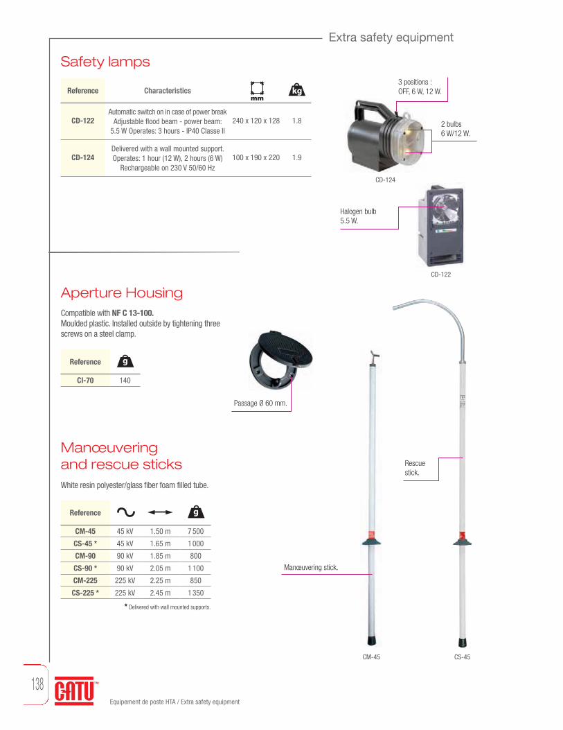
138Equipement de poste HTA / Extra safety equipment
Extra safety equipment
Safety lamps
Manœuvering and rescue sticksWhite resin polyester/glass fiber foam filled tube.
Aperture HousingCompatible with NF C 13-100.Moulded plastic. Installed outside by tightening threescrews on a steel clamp.
CD-122
CD-124
CS-45CM-45
Passage Ø 60 mm.
Halogen bulb5.5 W.
2 bulbs6 W/12 W.
3 positions :OFF, 6 W, 12 W.Reference Characteristics
CD-122
CD-124
Automatic switch on in case of power breakAdjustable flood beam - power beam:
5.5 W Operates: 3 hours - IP40 Classe II
Delivered with a wall mounted support. Operates: 1 hour (12 W), 2 hours (6 W)
Rechargeable on 230 V 50/60 Hz
240 x 120 x 128
100 x 190 x 220
1.8
1.9
* Delivered with wall mounted supports.
CM-45
CS-45 *
CM-90
CS-90 *
CM-225
CS-225 *
45 kV
45 kV
90 kV
90 kV
225 kV
225 kV
1.50 m
1.65 m
1.85 m
2.05 m
2.25 m
2.45 m
7 500
1 000
800
1 100
850
1 350
Reference g
CI-70 140
Reference g
Manœuvering stick.
Rescuestick.
mmkg

MV Substation equipment / Extra safety equipment and life saving kits
MV Substation equipment
139mm
Dimensions Total lengthWeightgmm
Diameter
Extra safety equipment and life saving kits
For sticks and voltage detectors. Plastic.
Wall mounted supports
CI-06-D
CI-08
CI-10-D
CI-12-D
28-30
16-20
32-36
28-30
Reference
36 max.
36 max.
58 max.
58 max.
Delivered with wood screws.
Top Bottom
Rescue hook
Reference Characteristics
CS-01-C Adaptor C 350
g
345 x 335
mm
On stick equipped with a "C" end-fitting.
Top
mm
Bottom
mm
Compact carrying KITThis compact kit is designed especially to be carried in a vehicle for safety electrical intervention.Made of two parts (of moulded material: PEHD), the red case cover is also an insulating platform.
Reference Characteristics with instructions in English
CZ-53-R
CZ-53-MR
CZ-53-R/2
CZ-53-MR/2
With instructions in English
With instructions in English/Arabic
With instructions in English
With instructions in English/Arabic
21
21
21
21
710 x 570 x 240
710 x 570 x 240
710 x 570 x 240
710 x 570 x 240
mm
25 kV
25 kV
36 kV
36 kV
Insulating platform.
Telescopic insulating stick.
Voltage detector with autotest. Rescue hook.
Insulated cutter cable.
Pair of insulating gloves.
Talcum powder can.
Adhesive tape (black and yellow).
Safety instructions and safety first aid posters.
Pair of insulating boots.
kg

Close
Wall mounted kit.
In case of an electrical accident, quick action is essential: by saving seconds, you get morechance to save life.Our life saving equipment is designed to make all necessary equipment immediately available to rescue people.
Life saving kits for M.V. substations
Open
Insulated cable cutter Maxi cable : 30 mm.Section ≈ 150 mm2.
CZ-60 0.630 m 2.2
Reference kg
Reference Characteristics
CZ-54-R
CZ-54-RM
CZ-55-R
CZ-55-RM
English instructions
English/Arabic instructions
English instructions
English/Arabic instructions
21
21
21
21
kg
840 x 754 x 270
840 x 754 x 270
840 x 754 x 270
840 x 754 x 270
mm
24 kV
24 kV
36 kV
36 kV
Insulated handles25 kV.
Safety instructions on the plastic board.
Voltage detector with flexible antennacontact (with autotest).
Rescue telescopic stick.
Insulatingplatform 24 or 36 kV.
Insulated cable cutter. Forged steel blades.Maximum opening 30 mm.
Wallmountedcabinet.
Insulating boots.
High voltage insulating gloves,insulating boots and talcumpowder can.
mmDimensions Total lengthWeightg
mmDiameter
Life saving kits
140MV Substation equipment / Life saving kits

Medium voltageequipment
IEC voltage detectors 142Voltage detectors 143Single phase comparators 144IEC equipment 145Insulating sticks 146Clamp dispenser heads and accessories 148Overhead line systems 149Cables 150Underground systems 152Sticks accessories 153

142
IEC voltage detectors
Robust housing.Weight of the detector: 350 gr.Size of the detector: Ø 59 x 270 mm.
CC-765-55/20*
CC-765-3/10*
CC-765-10/36*
CC-765-10/30*
50/60 Hz
50/60 Hz
50/60 Hz
50/60 Hz
IEC 61243-1
IEC electronic Voltage Detectors, "Compact serie"for indoor and outdoor use
Ultimate technology of voltage detector “Head Capacitive Technology"Compact and light, it offers a wide band (10/36 kV).Operating check:By pressing the TEST button:- A RED LED flashes on.- Powerful rated audible signal > 60 dB(A)/2 m.- When loosening the button. The timed GREEN LED lights up.
While remaining on, it indicates the good working order of the detector.
Characteristics:- Precise and stable operating threshold.- High environmental resistance (impacts, vibrations, moisture).- Temperature conditions: class N (IEC 61243-1 standard).- Use from 50 to 60 Hz.
ReferenceOperating voltage (KV)
5.5 - 20 kV
3 - 10 kV
10 - 36 kV
10 - 30 kV
(*) Specify type of mounting when ordering: C or K.Packaging: unit supplied complete in a case with batteries and contact electrodes (straight and V-shaped).
Total weight: 1100 g. Total size: 340 x 275 x 83 mm.For other voltages, please consult us.
Voltage presence is indicated by:- RED flashing LED (very bright -visible at more than
20 m in direct lighting),- powerful rated audible signal > 60 dB(A)/2 m.
Contact electrodesfitted to the housing by screwing and are easily interchangeable.
9 V
9 V
9 V
9 V
350
350
350
350
gtype 6 LR 61
C K
End fittings:C: hexagonal 12 mm, for hexagonal end-fitting sticks, K: universal, for universal end-fitting sticks.Recommended stick: CE-4-21, CE-75.
End fitting C.
End fitting K.
CC-765…C
CC-765…K
Medium Voltage Equipment / IEC voltage detectors
NEW Dual voltage range detector : CC-775This voltage detector is also available with two voltage ranges without a manual selector switch, in compliance with the standard IEC 61243-1.Example: from 2 to 7kV & from 12 to 25kV. Please contact us in order to determine together your appropriate need in the respect of the standard.

143
Voltage detectors
Medium Voltage Equipment
C 18-311
Standard electronic voltage detector for indoor and outdoor use
CheckingBy pressing the test button:- extremely bright RED flashing LED’s (visible at more than 50 meters
even in unfavourable light),- powerful rated audible signal > 60 dB/2 mThe test button is released:- a timed GREEN LED lights. Indicating both the detector is operational and the self testing of the unit continues.Characteristics:- Precise and stable operating threshold.- High environmental resistance (impacts, vibrations, moisture).
CC-365-K
CC-365-C
Double signaling:Voltage presence is indicated by both:- extremely bright RED flashing LED’s (visible at more
than 50 meters even in unfavourable light),- powerful rated audible signal > 60 dB/2 m.
Housing Polycarbonate.Size of detectorØ 59 x 390 mm.CC-365-101
C-92-492
Reference Characteristics
Flag/Vee contact electrode
Contact electrode for installationsL = 310 mm, insulating on 300 mm
Diode GREEN.
CC-365-3/10…-(*)
CC-365-10/30-(*)
50 Hz
50 Hz
Reference
3-10 kV
10-30 kV
(*) Specify type of mounting when ordering: C or K.Packaging: unit supplied complete in a case with batteries and contact electrodes (straight and V-shaped).
Total weight: 1100 g. Total size: 340 x 275 x 83 mm.
For other voltages, please consult us.
1.5 V
1.5 V
500
500
Accessories
C K
End fittings:C: hexagonal 12 mm, for hexagonal end-fitting sticks, K: universal, for universal end-fitting sticks.Recommended stick: CE-4-21, CE-75.
(operating voltage)g
type 6 LR 61
g Weight
Medium Voltage Equipment / Voltage detectors

144
Single phase comparators
IEC 61481
Unipolar device used to check phase concordance in 2 steps.- Step 1: storage of the reference phase.- Step 2: search for the phase in concordance with the one memorised in step 1.The operator has 15 seconds to complete step 2. After this time, step 1 must be started again.Users on 50 and 60 Hz networks.
Single pole phase comparatorfor indoor and outdoor use
Press the button to test the device and to reset its memory.
CL-7-06/18-(*)
CL-7-10/30-(*)
CL-7-10/30-1-(*)
CL-7-12/36-(*)
6-18 kV
10-30 kV
10-30 kV
12-36 kV
0.55 m
0.90 m
1.15 m
0.90 m
9 V
9 V
9 V
9 V
(*) Please specify type C or K when ordering.Delivered in carrying case.
Referencetype LF 22
GREEN LED = phasingindication.
Fixation C or K.
RED LED = non-phasing indication.
ORANGE LED = memorized phase status voltage are in memory.
850
900
950
900
gaerial
Medium Voltage Equipment / Single phase comparators

145
Medium Voltage Equipment
IEC short-circuiting and earthing systems (three-phase crossarm networks)MT-613 clamps are automatic contact clamps. They are put into position fromabove the conductor, using the clamp dispenser head MT-635/1-C.
IEC 61230
MT-6613
MT-6613/1
Reference Equipment composition
3 automatic contact clamps MT-613
Connection cables 35 mm2, max.
gap between clamps: 2.75 m
1 clamp dispenser head MT-635/1-C
1 spool with earthing cable connection MT-640-S
1 carrying bag M-87295
3 automatic contact clamps MT-613
Connection cables 95 mm2, max.
gap between clamps: 3 m
1 clamp dispenser head MT-635/1-C
1 earthing cable connection 15 m x 35 mm2
1 earthing clamp MT-840/1
1 carrying bag M-87295
Operation eyelet.
Removal
Fitting up.
Speed clamping.
C lamp dispenser head
Extra flexiblecable with silicone sheathing.
Double crimping lugs.
Installing
* Recommended sticks: CE-4-21-C.** Recommended sticks: CM-4, CF-5, CM-7 et CM-4000.
MT-6613 *
MT-6613/1 **
Reference Rating(kA/1 s)
8
17.5
Connection coppercable betweenclamps (mm2)
35 mm2
95 mm2
16 mm2
35 mm2
5 to 30
5 to 30
Earth connectioncopper cable (mm2)
Characteristicsconductor
mm
SPECIAL FEATURES• Remarkable rapidity and ease of handling.• Removal is carried out by pulling down
the clamp, which revolves around the conductorby means of the pig tail fixed in the centre of the clamp dispenser head.
IEC equipment
Medium Voltage Equipment / IEC equipment
g Weightmm
DiameterTotal length

146
Insulating sticks
IEC 61235
Telescopic sticks for voltage detectorSuitable for wet conditions.
CE-4-21-CCE-4-30-C CE-75-C
CF-5
CM-7-10-A
Yellow lower elementmade of resin polyester/glass fiber41 mm diameter base tube.
For sticks and voltage detectors. Plastic.
Wall mounted supports
CE-4-21-(*)
CE-4-30-C
CM-7-10-A
CE-75-(*)
90 kV
150 kV
Extension*
75 kV
41/32
41/32
36
41/32
1.15 m
1.75 m
–
1.15 m
2 m
3 m
1 m
2 m
1.5
2
1
2
(*) Please specify type C or K when ordering.Delivered with wall mounted supports CI-10-D.
* For CE-4-21.
Telescopic stick contains 2 elements made of resin polyester.
Lockable button.
Elementmade ofresin polyester/glass fiber.
Reference
Isolated skirts polycarbonate Ø 100 mm,height 90 mm ,resistant shocks.
Fixed length sticksSuitable for wet conditions.
CF-5-40-(*)
CF-5-90-(*)
CF-5-110-(*)
CF-5-170-(*)
40 kV
90 kV
110 kV
170 kV
1.50 m
2 m
2.50 m
3 m
1.15
1.55
2
2.4
1
1
2
3
(*) Please specify type C or K when ordering.
Reference Skirtnbr
CI-06-D
CI-10-D
CI-12-D
CI-08
28-30
32-36
28-30
16-20
Reference
36 max
58 max
56 max
36 max
Delivered with wood screws.
Element made of glassfiber/resin epoxy foam filled of 36 mmdiameter (**).
An upper orange element madeof glass fiber/resin epoxy foam filled of 32 mm diameter (**).
Top Bottom
Folded upkg
mm
Top
mm
Bottom
mm
kg
Medium Voltage Equipment / Insulating sticks

147
Insulating sticks
IEC 61235
CM-4400-J
Insulating sticks for short-circuiting and earthing systemsThis range allows a stick-length limitation in case of space requirementsand carrying capabilities.For common applications a serie of complete sets including2 or 3 elements are made to give simple solutions for workingdistance from 2 to 6 meters.
New safetybayonetsystem. Hand guard.
Manœuveringand lifting eyelet.
Yellow Composite stick fiber glass/epoxyresin foam filled Ø 39 mm. Fitting for clamp
of detector.
Fast assembly.
Intermediate elements with rain skirts.
Intermediateelement.
Basic element.
Terminalelement.
1.25
1.7
2.7
3.2
1.2
1.6
2.5
3
0.9
1.3
2.1
2.6
CM-4410
CM-4415
CM-4420
CM-4425
CM-4410-I
CM-4415-I
CM-4420-I
CM-4425-I
CM-4410-(*)
CM-4415-(*)
CM-4420-(*)
CM-4425-(*)
1.13 m
1.63 m
2.13 m
2.63 m
1.165 m
1.665 m
2.165 m
2.665 m
1.115 m
1.615 m
2.115 m
2.615 m
smallest end fitting
–
–
–
–
–
–
–
–
1.21 m
1.71 m
2.21 m
2.71 m
biggest end fitting
0.7 m
1 m
1.2 m
1.5 m
0.9 m
1.4 m
1.9 m
2.4 m
0.9-1 m
1.4-1.5 m
1.9-2 m
2.4-2.5 m
isolation
Basic
Inte
rmed
iate
Term
inal
(*) Add end-fitting: B-C-E-H-K-T-D.
950
Reference g
CM-4400-J 0.362 m
smallest end fitting
Hand guard.
Handle grip.
Reference kg
Insulating Stick bagsStrong waterproof canvas cases with a heavy duty zipper closure.
Reference
CM-1-10
CM-1-15
CM-1-20
CM-3-03
CM-3-04
CM-3-05
CM-3-06
1.30 m de Lg
1.80 m de Lg
2.40 m de Lg
0.575 x 1.950 (elmt 1.75 m de Lg)
0.575 x 2.450 (elmt 2 m de Lg)
0.575 x 2.850 (elmt 2,50 m de Lg)
0.575 x 3.400 (elmt 3 m de Lg)
Shoulder strap.
The flared shapeallows easy accessories positionning. No need to take them out.
Transparent plastic window for inspection.
MC-1-…For 1 to 3poles.
CM-3-…For elements series CM-6. For 5 simple elements or 4 double elements.
mm
Transparent plastic window for inspection.
Shoulder strap.
Medium Voltage Equipment
g Weightmm
Diameter Total length
Medium Voltage Equipment / Insulating sticksmm
Dimensions

148
MT-633/..
Clamp dispenser heads and accessories
Reference Headfor 3 clamps
Headfor 4 clamps
Withpigtail hook
MT-633-C
MT-633-K
MT-633-S
MT-634/1-C/K
MT-840/1 MT-843
MT-630-C
MT-633-C
MT-630-S
Clamp dispender heads
Earth clampCopper aluminium bronze earth clamps.
Earth rod
For MT-613/1 and 613/2 clamps
MT-650
Spool with earthing connectionSpool with cable and earth clamp.
Reference Headfor 3 clamps
Headfor 4 clamps
Withpigtail hook
MT-630-C
MT-630-K
MT-630-S
MT-635/1-C/K/S
MT-634-C/K
For MT-613/1 and 613/2 clamps
MT-630-K
MT-630/..
Copper aluminium alloy.
IEC 61230
MT-633-S
Medium Voltage Equipment / Clamp dispenser heads and accessories
Reference Silicone cable (mm2)
MT-640-S 16 16 m
MT-641-S 16 25 m
Reference ICC(kA/1 s)
Conductors(mm)
MT-840/1 20 Ø 6-25 0-25 480
MT-843 40 Ø 6-35 0-35 950
Reference Characteristics
MT-650 Hexagonal 1 msection rod
g

149
Overhead line systems
Short-circuiting and earthing systemsInstalled from the ground on conductors up to 10.50 m.
MT-546
MT-650
On-the-spot voltage testingwith a CC-765 detector attached to a metal pole with a combination Ve/flag antenna.
MT-508/36
MT-508/46
Reference Rating(kA/1 s)
8
8
3-22
3-22
Composition
3 telescopic metallic sticks 3 elementsL = 6.00/2.37 m - 2.4 kg - MT-512/36
1 insulating stick 2 elements 1.65 m - MT-531
Reel for 3 cables 10 m x 35 mm2 withearth connect. for attachment to stick - MT-543/35
1 earth rod 1 m - MT-650
1 bag. 2.50 x 0.30 x 0.15 - 10.5 kg - M-87-127
3 telescopic metallic sticks 4 elementsL = 5.10/1.62 m - 2.1 kg - MT-512/46
1 insulating stick2 elements 1.65 m - MT-531
1 insulating intermediatestick element 1.65 m - CM-4-165-B
1 stick lifter - MT-546
Reel for 3 cables 10 m x 35 mm2 withearth connect. for attachment to stick - MT-543/35
1 earth rod 1 m - MT-650
1 bag M-87-208
Reference
MT-508/36
MT-508/46
MT-512/36
MT-531
CM-4-165-B
MT-543/35
MT-650
Easier installationfeatures.
Self locking contact clamp: powerful conductor clampingand very good performance atshort-circuiting, does not slide.
Re-inforced insulatingstick (36 mm dia.).
More rigid metallic stick.Lower tube 30.6 mm dia.Upper tube 16 mm dia.
On all models: Reinforced insulating pole: Epoxy/fibreglassresin over Ø 36 mm PV foamwith a non-skid area. This equipment can be used for rigid deployed poles for easy installation.
Self-locking clampNo spring for easier maintenance, removal, and greater reliability.
conductor
mm
End fitting C ou K.
Medium Voltage Equipment / Overhead line systems
Medium Voltage Equipment
Medium Voltage Equipment / Overhead line systems
mmDiameterg WeightTotal length

150
Cables
* IEC 61230
Copper cables
Copper cables only: Heating curves (Gut & Grundberg method).
Copper cables only: Heating curves - 300 °C.
FUSIÓN
500100015002000
10
16
25
30
35
40
50
70
95
3000
4000
5000
6000
7000
8000
9000
10.000
15.000
20.000
25.000
30.000
35.000
40.000
0 0,5 1 2 3 4 5sA
120 mm2
300°C
500100015002000 10
16
2530
40
50
70
95
3000
4000
5000
6000
7000
8000
9000
10.000
15.000
20.000
25.000
30.000
35.000
40.000
0 0,5 1 2 3 4 5s
0 0,5 1 2 3 4 5s
A
120 mm2
35
Fusion 300 °C
M-24-10
M-24-16
M-24-25
M-24-35
M-24-40
M-24-50
M-24-70
M-24-95
M-24-120
M-24-150
–
M-24-16-S
M-24-25-S
M-24-35-S
M-24-40-S
M-24-50-S
M-24-70-S
M-24-95-S
M-24-120-S
M-24-150-S
Reference
A B*Rating
(kA/1 s)Cable
Weight (kg/m) Ø (mm)
2
3.5
6
8
10
12
16
20
30
40
0.105
0.156
0.275
0.386
0.440
0.545
0.768
1.000
1.280
1.630
4.5
5.6
7.5
9
9.5
10
12
14
17
19
Section(mm2)
10
16
25
35
40
50
70
95
120
150
Copper cables.
Medium Voltage Equipment / Cables
Extra flexible braided multi-strand copper cables.Delivered to the meter with a minimum of 5 meters.Available in vinyl (A) or silicone sheath (B).

151
Cables
Aluminium cablesExtra flexible braided multi-strand cables.Transparent PVC sheath, with cable section identification.
Jumper cables realizationspecially manufactured itemsAssembly consisting of three copper cables or braids for short circuiting,connected to a copper ground wire through a trifurcating box.Transparent PVC sheath.
M-28-50
M-28-70
M-28-120
M-28-150
Reference Rating(kA/1 s)
Cable Weight (kg/m) Ø (mm)
7
10
17.5
20
0.170
0.240
0.430
0.510
11.5
13.4
19
21
Section(mm2)
50
70
120
150
MT-40
MT-70/1
Reference Characteristics
3 cables 40 mm2 - L = 0.75 m1 earth cable 40 mm2 - L = 2 m
3 cables 70 mm2 with equipped lugs - L = 1.20 m
1 earth cable 35 mm2 - L = 2 m
Rating(kA/1 s)
10
14.5
2.3
4.4
Aluminium cable.
Phone: (33) 01 42 31 46 24 • Fax: (33) 01 42 31 46 34 • www.catuelec.com
kg
MT-70/1
MT-40
Medium Voltage Equipment / Cables
kg Weight
Medium Voltage Equipment

152
Multistrand copper earth wire 70 mm2 x 2.50 m with earth clamp.
Underground systems
Cable testing stickEnables piercing of cable insulation and shielding, earthing up to 50 kV.Capacity: 70 mm dia.
Carrying Case available separately (MP-02).
Ratchet type operatinghandle.MP-211 1.60 m 8.75Ø 60 maxi
Reference Double cuttingangle blade.
Cable-guide with protectingguide. 0.60 m insulating sleevewith 0.80 m extender.
Must be placed over the piercing point
Insulating blanket
960
Reference g
MP-212
Hole for handle.
900 X 900 Ø 50
mm
Cable spike equipmentDevice to test the voltage on underground cables (1st and 2nd
categories) and their earthing, using a system with 9** mm bullet and throwing in the cable a steel treated blade.
Cable spike
Spare blade for spade-cable MP-213
Blade extractor for spade-cable MP-213
Reference Characteristics
20 000
20
200
g
MP-213 *
MP-213/LAM
MP-213/EXT
* Delivered complete in suitcase.** 9 mm bullet not included and not supplied by CATU.
kg
mm
mm
Medium Voltage Equipment / Underground systems

153
E
Connection adaptors for insulating sticksAc
cess
orie
s Co
nnec
tion
adap
tors
Stic
ks
C K S A ou B
C EK
CI-7-C CI-3-C CI-6-C CI-5-C CI-3-K CI-4-K CI-6-K CI-7-K CI-5-K CI-3-E CI-7-E CI-4-E
E A B K S A B C K E S A B K C
21
hexagonal universal bayonet clamp-stick"MAJOR" Serie CM-4 / CM-6.
Sticks accessories
With this range any accessory can be attached to any stick by using connection adaptors. Other models, please consult us.
Clamp capacity g Weight
mmDimensions
mmTotal length
mm Maximal opening Medium Voltage Equipment / Sticks accessories
Medium Voltage Equipment

154
Sticks accessories
Cleaning brushes
Trimmer and prunning saw
Fuse pullerAll parts in metal protected against corrosion.
MD-12-C MD-14-C
MD-10-C
500
500
500
Reference g
MD-10-C
MD-12-C
MD-14-C
100 x 125 x 170
175 x 228
175 x 328
Concave brush with two rows of perpendicular bristle
Round head brushAdjustable hinged round
head brush
Characteristics
1.2
1.1
–
Reference
MD-40-B
MD-42-B
M-92-28
375 x 240 x 60
125 x 610 x 60
–
Trimmer, maximum capacityØ 45 mm (for branches up to
28 mm depending on tree species)Prunning saw on rigid frame,
34 cm blade
Replacement blade MD-42-B
Characteristics
MD-40-BMD-40-B
CM-04-K
MD-42-B
CM-04-K
Reference
up to 70
mm
230 x 80
kg
mm
mm
mm
Manœuvering hook
Bronze-copper nickel aluminium
Bronze-copper nickel aluminium
Reference Characteristics
120
120
g
CM-02-(*)
CM-03-K
(*) Add end-fitting: C, E or K.
CM-02-C CM-03-KCM-02-K
g Weightmm
Dimensionsmm
Diameter
Medium Voltage Equipment / Sticks accessories

HV lines and switchgear equipment
Voltage detectors 156
Insulating sticks 158
Clamps 159
Earthing system APE 160
Insulating sticks and earth clamps 161
Copper and aluminium cables 162
Accessories 163

156
AC voltage detector for outdoor useIEC electronic voltage detector “Ultra Compact Series” foroutdoor use.Ultimate “head capacitive technology” of voltage detector.Universal application 50/60Hz and wide band of voltage from 44 to 132kV.
Voltage presence is indicated by :- RED flashind led (very bright, visible up to 20 m in direct lighting.- powerful rated audible signal 67dB(A)/1.5 m.Operating check :- by pressing the Test Button, correct operation is indicated by red LED
flashing on and a sound signal.- After realeasing the Test Button, a timed green LED lights on.- It indicates the good working order of the detector.
Contact electrodes (hook shaped) fitted to the body by screwing and easily interchangeables.
Delivered in a caring bag.For other voltage, please consult us.
HV lines and switchgear equipment / Voltage detectors
Voltage detectors
IEC 61243-1 edition 2*
Visible light is also indicated on the circumference of the disk forbetter visibility.
Robust housing thermoplastic
Contact electodes fitted to the housing by screwing and are easily interchangeable.
K end fitting.
CC-765-44/132
CC-765-44/132-CEnd fitting “C”: hexagonal male 12 mm on flats, for hexagonal end fitting sticks.
End fittings
CC-765-44/132-KEnd fitting “K”: for Universal endfitting sticks.
*CC-765-44/132
Refe rence IEC 61243-1e dition 2
44 - 132 kV
Contact electrode
Ø 120 mm
Case colour
9 V -25/+55 C° 350
gtype 6 LR 61(Operating voltage)

157HV lines and switchgear equipment / Voltage detectors
Voltage detectors
Equipement pour ligne et poste HTB
******-
-
*
Ac voltage detector for outdoor usePrecise and stable operating threshold. Insensitivity to inducedvoltages by limiting the operating voltage range. Remarkablyresistant to impacts, vibrations, extreme temperatures, humidity.Double signaling. Voltage presence indicated at the same time by:- 4 bright RED flashing electro-luminescent diodes
(visible at more than 50 meters even in direct lighting),- a powerful rated acoustic signal (60 dB/2 m).
The CC-245 detectors are available according to the modelswith end fittings:W: Hexagonal 20 mm,C: Hexagonal 12 mm,K: Universal.Put on “silent block”.
IEC 61243-1 edition 2*
CC-245-63/90-C
C
Robust housing made from polycarbonate with high mechanicalproperties and dielectric strength.
Check that the device is working by pressing the TEST button. This tests all of the detector's active components once the TEST button is released.
CC-245-150/420-K
K
Surrounded by a rubber impact-resistant padding.
Two GREEN illuminated lights, indicating that the device is on.These lights turn off, and four lights illuminate when a voltage is detected.
Delivered in synthetic case with handle, battery and electrodes 370 x 165 x 145 mm.(*) Please specify type of mounting when ordering: C or K.
For other voltages, please consult us.
CC-245-63/90-(*)
CC-245-150-(*)
CC-245-225/420-(*)
CC-245-60/150-K or -C
CC-245-63/150-(*)
CC-245-90/225-(*)
CC-245-150/420-K or -C
CC-245-225/550-K or -C
CC-245-315/765-1-K or -C
Refe rence IEC 61243-1e dition 2
63 - 90 kV
150 kV
225 - 420 kV
60 - 150 kV
63 - 150 kV
90 - 225 kV
150 - 420 kV
225 - 550 kV
315 - 765 kV
Contact electrode
Ø 120 mm
Ø 120 mm
Ø 200 mm
Ø 120 mm
Ø 120 mm
Ø 120 mm
Ø 200 mm
Ø 200 mm
Ø 200 mm
Case colour
9 V
9 V
9 V
9 V
9 V
9 V
9 V
9 V
9 V
-25/+55 C°
-25/+55 C°
-25/+55 C°
-25/+55 C°
-25/+55 C°
-25/+55 C°
-25/+55 C°
-25/+55 C°
-25/+55 C°
650
650
650
650
650
650
650
650
650
gtype 6 LR 61(Operating voltage)
g Weight

Insulating sticks for manœuveringdetectors & short-circuiting and earthing systems
158
This range thus allows a stick-length limitation in case of space requirements and carrying capabilities.For common applications a serie of complete sets including 2 or 3 elements are providing simple solutions for working distance from 2 to6 meters.
1.35
1.8
2.8
3.3
1.3
1.7
2.6
3.1
1
1.4
2.2
2,7
1.35
1.8
2.8
3.3
Reference
CM-4610
CM-4615
CM-4620
CM-4625
CM-4610-I
CM-4615-I
CM-4620-I
CM-4625-I
CM-4610-(*)
CM-4615-(*)
CM-4620-(*)
CM-4625-(*)
CM-4115-(*)
CM-4120-(*)
CM-4125-(*)
CM-4130-(*)
1.13 m
1.63 m
2.13 m
2.63 m
1.165 m
1.665 m
2.165 m
2.665 m
1.115 m
1.615 m
2.115 m
2,615 m
1.575 m
2.075 m
2.575 m
3.075 m
smallest end fitting
–
–
–
–
–
–
–
–
1.21 m
1.71 m
2.21 m
2.71 m
1.675 m
2.175 m
2.675 m
3.175 m
0.08 m
0.33 m
0.33 m
0.83 m
0.8 m
1.3 m
1.8 m
2.3 m
0.78 m
1.28 m
1.78 m
2.28 m
0.82 m
1.07 m
1.32 m
1.82 m
Basic
Inte
rmed
iate
Term
inal
Fixed
stick
s
(*) Reference to be completed by fitting: C-E-H-K-T-D.
CM-3900-J
Intermediate element with rain skirts.
950
Reference g
CM-3900-J 0.36 m
Set of sticksComplete sets of sticks for common applications.
CM-4220-(*)
CM-4230-(*)
CM-4240-(*)
CM-4345-(*)
CM-4360-(*)
Reference Composition
2 elements : CM-4610+CM-4610-(*)
2 elements : CM-4615+CM-4615-(*)
2 elements : CM-4620+CM-4620-(*)
3 elements : CM-4615+CM-4615-I+CM-4615-(*)
3 elements : CM-4620+CM-4620-I+CM-4620-(*)
2 m
3 m
4 m
4.5 m
6 m
(*) Reference to be completed by fitting: C-E-H-K-T-D.
biggest end fitting Insulatingkg
smallest end fitting
Composite stickfiber glass/epoxyresin Ø 39 mm RED.
Handguard.
Fitting for clamp of detector.
Intermediateelement.
Basic element.
Terminalelement.
IEC 60855EN 50508
New safety bayonet system. Hand guard.
Manœuveringand lifting eyelet.
Fast assembly.
Handle grip.
Insulating sticks
HV lines and switchgear equipment / Insulating sticks

159
HV lines and switchgear equipment
Total length g Weight
MT-731-E MT-732-E MT-734 MT-735-H MT-737-H
Man
oeuv
erab
le c
lam
ps
MT-732-AMT-731-A
MT-732-BMT-731-B
MT-732-EMT-731-E
MT-732-HMT-731-H
MT-734MT-735
MT-734-AMT-735-A
MT-734-BMT-735-B
MT-734-EMT-735-E
MT-734-HMT-735-H
(*) Add type of connection A - B - E - H.(**) Add type of connection B - E - H.
** Other cable sections: see page 161 or 162.
MT-731-(*)
MT-732-(*)
MT-734-(**)
MT-735-(*)
MT-737-H
Refe rence Rating(kA/1 s)
40
40
40
40
40
150 mm2 max.
150 mm2 max.
150 mm2 max.
150 mm2 max.
150 mm2 max.
45 mm
45 mm
40 mm
40 mm
40 mm
M 12
M 12
M 12
M 12
M 12
Ø 5-60
Ø 40-120
Ø 5-40
Ø 15-60
Ø 20-120
Copper connection
Copper cables ** Contact range width Stud
1 450
1 450
800
900
1 350
g
200 x 200 x 50
200 x 200 x 50
145 x 125 x 52
178 x 175 x 60
240 x 200 x 55
mm
HV and EHV clamps manœuverableby insulating stickBody in aluminium alloy with trapezoidal threaded screw. Interposed elastic washersin the clamping system improve efficiency and ensure a higher withstand in case of electrodynamic shock. Manœuvering by CM-6 insulated stick of appropriate length and characteristics.
mm
Attachment of MT-735 or MT-734clamps with MT-717-3-B hook. Direct connection. Connection adaptor.
CM-6 CM-6
CI-3-E CI-3-H
IEC 61230
HV lines and switchgear equipment / Clamps
Clamps

Earthing system with clamps interlockingThe APE is a grounding system with an interlocking system between earthing and line clamps. It is used for safe and accurate installation (earthing clamp and then line clamp) and removal (line clamp and then earthing clamp).
160HV lines and switchgear equipment / Earthing system APE
Earthing system APE
MT-834-H
MT-834-E
MT-834-T
MT-835-H
MT-835-E
MT-835-T
MT-837-H
MT-837-E
MT-837-T
MT-934
MT-935
Reference Rating Use
31.5 kA/1 s
31.5 kA/1 s
31.5 kA/1 s
31.5 kA/1 s
31.5 kA/1 s
31.5 kA/1 s
31.5 kA/1 s
31.5 kA/1 s
31.5 kA/1 s
31.5 kA/1 s
31.5 kA/1 s
Substation
Substation
Substation
Substation
Substation
Substation
Substation
Substation
Substation
Line
Line
Fitting
H hexagonal
E bayonet
T bayonet
H hexagonal
E bayonet
T bayonet
H hexagonal
E bayonet
T bayonet
ring
ring
5 - 40
5 - 40
5 - 40
15 - 60
15 - 60
15 - 60
20 - 120
20 - 120
20 - 120
5 - 40
15 - 60
3.2
3.2
3.2
3.48
3.48
3.48
3.88
3.88
3.88
3.2
3.48
360 x 200 x 85
360 x 200 x 85
360 x 200 x 85
390 x 200 x 85
390 x 200 x 85
390 x 200 x 85
470 x 220 x 85
470 x 220 x 85
470 x 220 x 85
360 x 200 x 85
390 x 200 x 85
mm mm
width 38 mm
width 38 mm
width 38 mm
width 38 mm
width 38 mm
width 38 mm
width 38 mm
width 38 mm
width 38 mm
width 38 mm
width 38 mm
M 12
M 12
M 12
M 12
M 12
M 12
M 12
M 12
M 12
M 12
M 12
Connection
Range Stud
Captive protection cap.
Earth clamp.
Clamping handle.
Line clamp.SPECIAL FEATURES- Locking system using a patented system with
more than 30,000 possible combinations.- Easy installation and removal without
additional accessories.- Automatic trip at the recommended torque
on support withstand the short circuit current.- System security (unable to be unlocked without
the associated clamp).
kg
Substation clamp
Line clamp
One reference including 3 phases, so 3 clamps equipped.

161HV lines and switchgear equipment / Insulating sticks and earth clamps
Insulating sticks and earth clamps
HV lines and switchgear equipment
Clamp capacityg Weightmmmm
Dimensionsmm
Diamètre
Copper cables
Insulating sticks for short circuiting and earthing systemsCM-6 series is recommended for cables ≥ 95 mm2 .Yellow colour elements, with superior characteristics, they are connected between them without any prior order of assembly.These elements allow "long length" assemblies which cansupport short-circuit systems with large cross-section cablesShockproof guard and pole end cap.Yellow colour elements.
47
47
47
47
Reference
2.4
3.2
4
4.8
CM-6-15
CM-6-20
CM-6-25
CM-6-30
1.5 m
2 m
2.5 m
3 m
Earth clamps for over head live networks and substationsCopper aluminium bronze earth clamps.
MT-843 MT-847MT-843-P MT-852 MT-853
MT-843
MT-843-P
MT-847
MT-852
MT-853
Reference Rating Use
40 kA/1 s
40 kA/1 s
25 kA/0.5 s
63 kA/0.5 s
40 kA/0.5 s
Substation/Overhead line
Substation
Overhead line
Substation
Substation
Hole:
Ø 12.5
3 holes:
Ø 12.5
Hole: Ø 13
Hole: Ø 13
Hole: Ø 13
Ø 6 -25
0 - 35
Ø 6 -35
0 - 35
0 - 30
Fixed points
Fixed points
ConnectionØ (mm)
950
950
1 000
1 400
1 000
g
45 x 106 x 165
45 x 106 x 165
45 x 106 x 170
70 x 125 x 155
65 x 130 x 135
kgmm
mmmm
** IEC-61230Extra-flexible braided multi-strand copper. Delivered to the meter with a minimum of 5 meters. Available in vinyl or silicone sheath.
CM-6-15 CM-6-20 CM-6-25
Composite tube fiberglass and epoxy resin, yellow colour.
IEC-61235
See page 150.
CI-3-H
Total length

162HV lines and switchgear equipment / Copper and aluminium cables
Copper and aluminium cables
IEC-61230
Equipotential LinesUSEConductive line connecting two pieces of metallic pieces in order to givethem the same potential.
- Cable composition and features:35 mm2 copper cable insulated in a green silicone sheathing.Double crimped lugs at the cable ends.
- Clamp and stick composition and features:Insulating stick equiped with a clamp MT-735 in aluminium alloy with Ø 15 to 60 mm clamp capacity.
Reference Characteristics
M-24-35-V Cable 35 mm
Reference Characteristics
MT-735-P4 Clamps MT-735 on stick 400 mm
- Earth Clamp composition and features:All the earth clamps of page 161 are available to complete the equipotential lines.
Aluminium cablesExtra flexible braided multi-strand cables.Transparent PVC sheath, with cable section identification.
Aluminium cable.
M-28-70
M-28-120
M-28-150
Reference Rating(kA/1 s)
CableWeight (kg/m) Ø (mm)
10.0
17.5
20.0
0.240
0.430
0.510
13.4
19.00
21.00
Section(mm2)
70
120
150
M-87-295
Short-circuiting and earthing system carrying bagsCan receive earthing system equipment (clamps and cables).
M-87-53
Reference
M-87-53
M-87-153
M-87-295
2
2.5
1.5
380 x 250 x 400
380 x 250 x 600
550 x 300 x 300
mmkg

163HV lines and switchgear equipment / Accessories
Accessories
HV lines and switchgear equipment
g Weightmm
Dimensions Clamp capacitymmmm
Diameter
Reference Characteristics
MT-790
MT-792
MT-797
Copper/Alu alloy Ø 18 mm
Light alloy Ø 20 mm
Light alloy Ø 20 mm
1 400
855
1 200
Rating(kA/1 s)
30
30
30
Ø 12 - 60
Ø 12 - 60
Ø 60 - 120
255 x 105 x 50
270 x 105 x 60
240 x 170 x 60
Conductor
Copper
Aluminium
Aluminium
Type
Adjustable access points For large vertical or oblique heavy duty conductors.
Rope operated clampAttachment and removal is carried out from the ground orfrom the cross-arm, using a rope passed previously overthe conductor to be earthed. Up to 10 m: by using MT-709-B reel launcher placed on a CM-6 SERIE Stick (see page 160) that passes the rope overthe conductor;- up to 20 m: by using a MF-60 wire projector. This
projector fires an arrow carrying a braided nylon wirewhich sets the rope. The clamp is then fixed to the ropeand attached onto the conductor.
Wire Gun TesterAn extremely simple way to test the voltage in an overhead line without leaving theground. Just shoot a weighted arrow over the line - up to 18 m high - forming contactbetween the conductors through a very lightweight braided steel cable.If they are both live, this produces a sparkover and alerts the user.The MF-60 gun can also be used to shoot an insulating cord for handling MT-701/1contact clamps.
Reference Characteristics
MF-60
MF-61
MF-62
MF-63
MF-66
Complete cable-launcher projector delivered in a waterproof bag with 2 spare arrow and
2 spool of 30 m fuse wire.3.500 kg.
Spare arrow.
Spool of 30 m of fuse wire.
Spool of 100 m of fuse wire.
Spool of 30 m of nylon leadisolated hoisting cord.
MF-60MF-61
mmmmg
Attachment: the clamp is pulled up bythe rope. Pulling on the rope triggersthe spring and closes the jaw
Earthing cable:
cable 120 mm2 with crimped lugs on M12 screw (x3)
Reference
MT-701/1
2 000
gIcc(kA/1 s)
30
I assym.(A)
72 195 x 120 x 175mm
Ø 12 - 48
mm
V-shaped aluminium body.
Spring operatedswinging jawwith pre-set.
Rope reel.
Reel launcher.
Removal: pulling on the rope attachedto the hinged saddles causes theclamp to pivot and free the jaw.
MT-709-B MT-708-40
MT-701/1

OIL & GASOffshore installations, shipbuilding,heavy industry

Earth rods 166
Connectors and earth tester 167
Earth resistance tester 167
Earthing connections

166Earthing connections / Earth rods
Earth rodsGeneral
Stainless steel earth rods
Reference Type
AMI-10
AMI-15
1 m
1.50 m16 1.45
2.2B.CHROM
Strength steel ≥ 90 daN/mm2.
B.CHROM AMI
Connection
Connectable
kgmm
Self connectable rods: The lower end of each rod is equipped with a point used both for driving into the earth and forconnection; the upper pierced end receives (without the sleeve) the point of the previous rod. Use a rivetting head soas not to damage the upper end when driving in.
Connectable rods: Conical slide-in provides perfect assembly stability. For deep earth connections.
Copper/Steel earth rods
Reference Type
CC-10-Y
CC-15-Y
CC-20-Y
C2C-10-Z (1)
C2C-15-Z (1)
1 m
1.50 m
2 m
1 m
1.50 m
1.2
1.8
2.4
2
2.8
BCY
C2C-95Z
Steel with copper coating by electrolytic process: Minimum Thickness 250 µ (* = 350 µ).
(1) For connectable models, sleeves and tips are ordered separately.
Reference Type
A3MC-10-Z*
A3MC-15-Z*
AC-10-Y
AC-15-Y
AC-20-Y
A2C-10-Z*
A2C-15-Z*
1 m
1.50 m
1 m
1.50 m
2 m
1 m
1.50 m
1.8
2.75
1.25
1.9
2.5
1.95
1.85
standardwith
connector
Connectable(1)
14.2unit 16
17.3unit 19
14.2unit 16
17.3unit 19
Self connectable
TO-3-16/19TO-2-16
BMCY
PITO-3-16/19
TO-2-19C2C-95-ZC2C-95-ZC2C-95-Z
Standard copper/steel earth rods
Self connectable Copper/Steel earth rods
Connection
Connection
17.3unit 19
TO-3-16/19TO-2-19C2C-95-Z
kgmm
kgmm
CC-10-Ystandard
PCYP2-CZ
MCYM2-CZ
A3MC…Self
connectable
AC…A2C…
AC…A2C…
The rod is, in most cases, the most practical, effective and reliable earth connection means.
Highly effective: for a given contact surface area, the linear type electrode provides, both theoretically and practically, the least earth resistance. Furthermore, it enables the most moist and conductive layers to be reached.
Easy and quick to install, it requires no earth work. Even inside industrial buildings, it is often possible to install an earth rod exactly where required by breaking through a small area of the floor.
Accessible and testable connection: the use of an inspection box makes it possible to leave the head ofthe rod and its connection unburied and to periodically test it and measure its resistance.

Connection wire to supplythe charger with a 12 Vbattery.Battery charger
220-240 V.
Storage bag.
167Earthing connections / Connectors and earth tester
Earthing connections
40
40
6 to 95
95
95
Copper
Copper
Copper aluminium alloy
Copper aluminium alloy
Copper aluminium alloy
TS-1901 TO-2-19
TO-3-16/19Earthing connector
Reference Rod
TO-2-16
TO-2-19
TO-3-16/19
BCY
C2C95Z
16
19
19
14.2
17.3
ConnectorConductors section max. (mm2) Type section max. (mm2)
Interconnects to earth every metallic part of installations.
Earth resistance testerThe MX-430-M allows the measurement of earth resistance andearth specific resistivity and also the parasite voltages caused bygrounding parasitic voltage presence.This equipment is suitable for fast and easy measurement of thegrounding resistance in home, industrial buildings, substations,...Technical features- Application: measurement of grounding resistances
(with 3 earth rods), earth resistivity (with 4 earth rods) and parasite voltage presence
- Range of measurement: 0 - 20 Ω ; 0-200 Ω ; 0-2000 Ω and 20 KΩ.
- Voltmeter: voltmeter function in AC range as a conventional voltmeter 0-200 V AC.
- Operation frequency: 1470 Hz.- Current in and out put power: less than 0,5 W and the out put
current is limited to less than 15 mA (peak to peak).- Operation temperature: -10°C / +50°C.- Storage temperature: -25°C / +65°C.- Humidity: 95% RH (without condemnation).
Accessories (measurement kit)MX-433-T1 storage bag, 4 earth rod copper platted steel, 1 x 5 meter blackcable,1 x 40 meter red cable, 2 x 20 meter cable (1 blue and 1 green), 1 x 5 meter green cable to connect to the grounding system, 1 hammer, 1 reel tape measure 50 m.
Reference
COL-8/32
COL-32/100
1 x 2.5 to 2 x 6
1 x 2.5 to 2 x 16
Ø 8-32
Ø 32-100
Conductors section (mm2)
High visibility 3 1/2 digit display with directreadings, even under sunlight.
A smart charger is microprocessor-controlled and can be powered from the mains by a power plug provided source or from a 12 V car battery.
Connexion wire including a 12 V car battery.
Reference
MX-433-T 570 x 220 x 160 7. 7
Conductors section (mm2)
Reference
MX-430-M 221 x 189 x 99 2
Reference
CF-1 180 mm 110
g
kg
kg
Accessories included:
mm
Connectors and earth tester
Total length g Weightmm
Diamètre Clamp capacitymm
mm

*862:;90:;4:276.;)731.;)53"-(;054;)73:.;86;2174:;277+:359876
)890;/;56.;$(/;97;3:4:5320;56.;.::17+
45&:9;:'8+%:69;56.;+352982:4;&73;'4:76;17);56.;08#0;7195#:;6:9)734;
86898511;86;3562:;56.;67);)731.)8.:981898:4;)7'1.;:;:99:3;7&&;:&&828:62;7&
90:83;6:9)734;;578.86#7'95#:4)059::3;90:;27494;890;90:8623:5486#;3:27#689876;7&;/*:3:29)731.)8.:;"-(;84;&549;:27%86#;5%573;4'++18:3;86;18:186:;)7386#;:'8+%:69;-11;90:;97714;%::9;90:4+:28&82598764;7&;90:;!69:365987651;/1:29379:2068251;"7%%899::;!/" "-(;97714;05:;5;18:186:;18&:
7&;537'6.;;:534
!/;,$! ;(,,*
"59517#':;558151:;'+76;3:':49

169
,";(/;! ;;! ;(/;,/ ;,*!(!, )890;5;45&:9;172;449:%;45&:9;+5.172
"/";(/;-*/ "/;,;,(-/59;47'32:;56.;76;489:;76;:520;276.'2973;56.
5++5359'4;8671:.
-;-$,$!-(/;*,$("!$"!(;- /-$(! ;**(/*86;4'&&828:69;6'%:34;76;90:;276.'29734;7&;7'3;6:9)73)0:3:;7+:359876;84;9586#;+152:
*, ;-$ ;,(/$*;- ;!!(;(/;,$;-$/-::6;.'386#;90:;%749;48%+1:;9:%+7353;
%5869:6562:;7+:359876
2
3
4
5
*/-$-(/;(/;,$;-$/-;$,;-;,**!/*,$"/*;,;,/$*
;7+:686#;2832'893:5:34;4)8920:4; 1
Golden safety rulesfor short-circuiting and earthing system

Chooseyour gloves size!1
1 inch = 2.54 cm2
34
56
78
910
IMPORTANTIn the window of the printer's settings,check that the "scaling" drop-down
menu is set to: "none".
Stretch out your hand.
Wind the tap measurearound your hand at the levelof your knuckles.You can position the tapeeasier by taping it on the topof your hand.
Print this page and cut out the ruler.Ensure that the tape measures ten inchesor 27.90 cm once printed(scale of your printer = 100%).
Slightly fold your hand withoutclenching your fist and take the measurement.If you are between two sizes,take the biggest one.
Inch
cm
Sport size
71/2
19
XS
8
20.3
S
81/2
21.6
M
9
22.9
L
91/2
24.1
XL
10
25.4
XL
Inch
cm
Sport size
6
15.2
XS
61/2
16.5
S
7
17.8
M
71/2
19
L
8
20.3
XL
7%:6;#17:4;48:
56;#17:4;48:
1
2
3

Specificationfor short-circuiting and earthing system
- Earth rods: dia. or thickness on side face (mm): Flat bar, angle-bar, thickness (mm):
- Round conductor dia. (mm):
- Insulating stick: total length Fixed Connectable stick Telescopic
- Selected sketch (out of the three standard types shown below)
- Distance between live conductors (m): , between live conductors and grounding point (m)
- To place the clamps in position, the operator will stand: above the conductors under the conductors
at the conductors level
- For cable sections, please indicate max. Δ T or min. dia. of the conductor
Network voltage: kV Max. short-circuiting current (1s): kA
Nature of the conductive materials: Basis Al Basis Cu
Overhead lines Switchboard or substation
- Dia. or section of the conductors: min. - Round bars dia. (mm): mini. max.
max.
- Selected connection type: Sketch n°
- Contact clamps (type MT- )
- Short-circuiting cable
• Length (m)
• Dia. or section (mm, mm2)
- Grounding cable
• Length (m)
• Dia. or section (mm, mm2)
- Connection of cables on clamps, earth clamps, trifurcation
• Direct connection by screw and nut
• Connection by means of crimped lugs
- Earth clamp, type
- Presence of a reel
- Insulating stick, type
• Carrying bag for sticks
• Canvas bag for equipment
• Carrying case for equipment
• Cable reel
"053529:3849824
;;,+:35986#;4982
";;/539086#;2766:29876;+7869
;;"053529:3849824;7&;90:;:539086#;449:%
-22:44738:4
*:920; *:920; *:920;
Length =
H type Thickness =
- Flat bars
V type Length =
Thickness =
- Fitting on edge face Fitting on side face
-;; :9)73;:1:2938251;864951159876;2053529:3849824
171

172
536:44;48:;753.;86;%%
Chooseyour harness size!
A
B
C
D
Chest (A) Size (B)
S
M
XL
700 - 1 000
800 - 1 200
1 000 - 1 500
750 - 1 000
900 - 1 200
1 000 - 1 350
500 - 700
550 - 750
550 - 900
600 - 750
750 - 850
700 - 950
Height (D)Thigh (C)Reference

Note...........................................................................................
...........................................................................................
...........................................................................................
...........................................................................................
...........................................................................................
...........................................................................................
...........................................................................................
...........................................................................................
...........................................................................................
...........................................................................................
...........................................................................................
...........................................................................................
...........................................................................................
...........................................................................................
...........................................................................................
...........................................................................................

%35-%1/1-43/0,40-,51.&543-%.0-1+50.'2/(1402.,5,4143&50.52*/5+043/14*/351/352.+#5'2/5#2*/5*0&1.-351.&54%3/3'2/35-1..24535-2.,0&3/3&51,5-2.4/1-4*1+5
*/5-2($1.#50,53.404+3&5425(2&0'#51451.#540(354%35-%1/1-43/0,40-,52'504,53*0$(3.45.5-1,352'5(2&0'0-1402.52'54%3,35-%1/1-43/0,40-,)52*/5-2($1.#52*+&5.245352+03&5425,*$$+#5(143/01+,5-2.'2/(54254%2,35$/302*,+#50.5'2/-3
+*341+)5 +*-/0$4)5"143!)5"142%()5"14*)5"14*(4/3)5"+0$+2-)5343!)5343!*(0'0!)&3.43!)5,2(0+)5,2,42$)52/(1'0!)520.43,4)50323,4)53+0-1.5)5/0$+0! 51/354/1&35(1/,52'5"14*5
PRINTED IN FRANCE BY FOI GENERAL CATALOGUE RG-12
© 2014 CATU S.A. BAGNEUXAll reproduction, adaptation and translation rights reserved for all countries.
Design / direction / layout: COMST - www.comst.fr
Ele c t r i c a l s a f e t y,
f o r pro s l ike yo u !

Distributed by:
10/20 Avenue JEAN-JAURÈS - B.P.2 - 92222 BAGNEUX CEDEX (FRANCE)Phone: (33) 01 42 31 46 00 - Fax: (33) 01 42 31 46 32Phone business: (33) 01 42 31 46 46
www.catuelec.comSICAME GROUP