BASIC ELECTRICAL ENGINEERING
132
DEPARTMENT OF ELECTRICAL AND ELECTRONICS ENGINEERING BASIC ELECTRICAL ENGINEERING MRCET EAMCET CODE:MLRD www.mrcet.ac.in 1 BASIC ELECTRICAL ENGINEERING DIGITAL NOTES Prepared by N.Ramesh P.Raji Reddy O.Saidulu Reddy MALLA REDDY COLLEGE OF ENGINEERING & TECHNOLOGY (Autonomous Institution – UGC, Govt. of India) Recognized under 2(f) and 12 (B) of UGC ACT 1956 (Affiliated to JNTUH, Hyderabad, Approved by AICTE-Accredited by NBA & NACC-‘A’ Grade – ISO 9001:2015 Certified) Maisammaguda, Dhulapally (Post Via. Hakimpet), Secunderabad -500100, Telangana State, India.
-
Upload
khangminh22 -
Category
Documents
-
view
0 -
download
0
Transcript of BASIC ELECTRICAL ENGINEERING
DEPARTMENT OF ELECTRICAL AND
ELECTRONICS ENGINEERING BASIC ELECTRICAL ENGINEERING
MRCET EAMCET CODE:MLRD www.mrcet.ac.in 1
BASIC ELECTRICAL ENGINEERING
DIGITAL NOTES
Prepared by
N.Ramesh P.Raji Reddy
O.Saidulu Reddy
MALLA REDDY COLLEGE OF ENGINEERING & TECHNOLOGY
(Autonomous Institution – UGC, Govt. of India) Recognized under 2(f) and 12 (B) of UGC ACT 1956
(Affiliated to JNTUH, Hyderabad, Approved by AICTE-Accredited by NBA & NACC-‘A’ Grade – ISO 9001:2015 Certified)
Maisammaguda, Dhulapally (Post Via. Hakimpet), Secunderabad -500100, Telangana State, India.
DEPARTMENT OF ELECTRICAL AND
ELECTRONICS ENGINEERING BASIC ELECTRICAL ENGINEERING
MRCET EAMCET CODE:MLRD www.mrcet.ac.in 2
MALLA REDDY COLLEGE OF ENGINEERING AND TECHNOLOGY
I Year B.Tech II Sem – EEE/ECE/CSE/IT L T P C
3 0 0 3
(R18A0201) BASIC ELECTRICAL ENGINEERING
Objectives:
This course introduces the basic concepts of electrical circuits & networks and their analysis which is the foundation for all the subjects in the electrical engineering discipline.
The emphasis is laid on the basic elements in electrical circuits.
Analysis of Circuits which includes Network Analysis & Network Theorems.
Analysis of Single Phase AC Circuits and Basic Treatment of Single Phase Transformers and DC Machines is introduced.
UNIT –I: Introduction to Electrical Circuits: Concept of Circuit and Network, Types of elements, R-L-C
Parameters, Independent and Dependent sources, Source transformation and Kirchhoff’s Laws UNIT –II: Network Analysis: Network Reduction Techniques- Series and parallel connections of resistive networks, Star–to-Delta and Delta-to-Star Transformations for Resistive Networks, Mesh Analysis, and Nodal
Analysis, Network Theorems: Thevenin’s theorem, Norton’s theorem, Maximum Power Transfer theorem and Superposition theorem, Illustrative Problems.
UNIT-III: Single Phase A.C. Circuits: Average value, R.M.S. value, form factor and peak factor for sinusoidal wave
form, Complex and Polar forms of representation. Steady State Analysis of series R-L-C circuits. Concept of Reactance, Impedance, Susceptance, Admittance, Phase and Phase difference, Concept of Power Factor, Real, Reactive and Complex power, Illustrative Problems. UNIT –IV: Electrical Machines (elementary treatment only): Single phase transformers: principle of operation, constructional features and emf equation.
DC.Generator: principle of operation, constructional features, emf equation. DC Motor: principle of operation, Back emf, torque equation.
UNIT –V:
Electrical Installations: Components of LT Switchgear: Switch Fuse Unit (SFU), MCB, ELCB, MCCB, Types of Wires and Cables, Earthing. Types of Batteries, Important Characteristics for Batteries. Elementary calculations for energy
consumption and battery backup.
TEXT BOOKS: 1. Engineering Circuit Analysis - William Hayt, Jack E. Kemmerly, S M Durbin, Mc Graw Hill Companies. 2. Electric Circuits - A. Chakrabarhty, Dhanipat Rai & Sons.
3. Electrical Machines – P.S.Bimbra, Khanna Publishers.
DEPARTMENT OF ELECTRICAL AND
ELECTRONICS ENGINEERING BASIC ELECTRICAL ENGINEERING
MRCET EAMCET CODE:MLRD www.mrcet.ac.in 3
REFERENCE BOOKS:
1. Network analysis by M.E Van Valkenburg, PHI learning publications.
2. Network analysis - N.C Jagan and C. Lakhminarayana, BS publications. 3. Electrical Circuits by A. Sudhakar, Shyammohan and S Palli, Mc Graw Hill Companies. 4. Electrical Machines by I.J. Nagrath & D. P. Kothari, Tata Mc Graw-Hill Publishers. Outcomes: At the end of this course the student would get
A thorough knowledge of the basic RLC circuit elements.
Understanding of the basic concepts of networks and circuits with RLC.
Concepts of single phase AC circuits.
Network theorems and their application to solve problems in Network analysis.
Fundamentals Of Constructional Details And Principle Of Operation Of DC Machines And
Transformers.
DEPARTMENT OF ELECTRICAL AND
ELECTRONICS ENGINEERING BASIC ELECTRICAL ENGINEERING
MRCET EAMCET CODE:MLRD www.mrcet.ac.in 4
UNIT-I
INTRODUCTION TO ELECTRICAL CIRCUITS
Concept of Circuit and Network
Types of elements
R-L-C Parameters
Independent and Dependent sources
Source transformation Technique
Kirchhoff’s Laws
Simple Problems
DEPARTMENT OF ELECTRICAL AND
ELECTRONICS ENGINEERING BASIC ELECTRICAL ENGINEERING
MRCET EAMCET CODE:MLRD www.mrcet.ac.in 5
INTRODUCTION TO ELECTRICAL CIRCUITS
Network theory is the study of solving the problems of electric circuits or electric
networks. In this introductory chapter, let us first discuss the basic terminology of electric circuits and the
types of network elements.
Basic Terminology
In Network Theory, we will frequently come across the following terms −
Electric Circuit
Electric Network
Current
Voltage
Power
So, it is imperative that we gather some basic knowledge on these terms before proceeding further. Let’s
start with Electric Circuit.
Electric Circuit
An electric circuit contains a closed path for providing a flow of electrons from a voltage
source or current source. The elements present in an electric circuit will be in series connection, parallel
connection, or in any combination of series and parallel connections.
Electric Network
An electric network need not contain a closed path for providing a flow of electrons from a
voltage source or current source. Hence, we can conclude that "all electric circuits are electric networks"
but the converse need not be true.
Current
The current "I" flowing through a conductor is nothing but the time rate of flow of charge.
Mathematically, it can be written as
Where,
Q is the charge and its unit is Coloumb.
t is the time and its unit is second.
As an analogy, electric current can be thought of as the flow of water through a pipe. Current is measured
in terms of Ampere. In general, Electron current flows from negative terminal of source to positive
terminal, whereas, Conventional current flows from positive terminal of source to negative terminal.
DEPARTMENT OF ELECTRICAL AND
ELECTRONICS ENGINEERING BASIC ELECTRICAL ENGINEERING
MRCET EAMCET CODE:MLRD www.mrcet.ac.in 6
Electron current is obtained due to the movement of free electrons, whereas, Conventional current is
obtained due to the movement of free positive charges. Both of these are called as electric current.
Voltage
The voltage "V" is nothing but an electromotive force that causes the charge (electrons) to
flow. Mathematically, it can be written as
Where,
W is the potential energy and its unit is Joule.
Q is the charge and its unit is Coloumb.
As an analogy, Voltage can be thought of as the pressure of water that causes the water to flow through a
pipe. It is measured in terms of Volt.
Power
The power "P" is nothing but the time rate of flow of electrical energy. Mathematically, it
can be written as
Where,
W is the electrical energy and it is measured in terms of Joule.
t is the time and it is measured in seconds.
We can re-write the above equation a
Therefore, power is nothing but the product of voltage V and current I. Its unit is Watt.
Types of Network Elements
We can classify the Network elements into various types based on some parameters.
Following are the types of Network elements −
Active Elements and Passive Elements
Linear Elements and Non-linear Elements
Bilateral Elements and Unilateral Elements
Lumped Elements and Distributed Elements
DEPARTMENT OF ELECTRICAL AND
ELECTRONICS ENGINEERING BASIC ELECTRICAL ENGINEERING
MRCET EAMCET CODE:MLRD www.mrcet.ac.in 7
Active Elements and Passive Elements
We can classify the Network elements into either active or passive based on the ability of
delivering power.
Active Elements deliver power to other elements, which are present in an electric circuit.
Sometimes, they may absorb the power like passive elements. That means active elements have the
capability of both delivering and absorbing power.
Examples: Voltage sources and current sources.
Passive Elements can’t deliver power (energy) to other elements, however they can absorb power.
That means these elements either dissipate power in the form of heat or store energy in the form of
either magnetic field or electric field.
Examples: Resistors, Inductors, and capacitors.
Linear Elements and Non-Linear Elements
We can classify the network elements as linear or non-linear based on their characteristic to
obey the property of linearity.
Linear Elements are the elements that show a linear relationship between voltage and
current. Examples: Resistors, Inductors, and capacitors.
Non-Linear Elements are those that do not show a linear relation between voltage and
current. Examples: Voltage sources and current sources.
Bilateral Elements and Unilateral Elements
Network elements can also be classified as either bilateral or unilateral based on the direction
of current flows through the network elements.
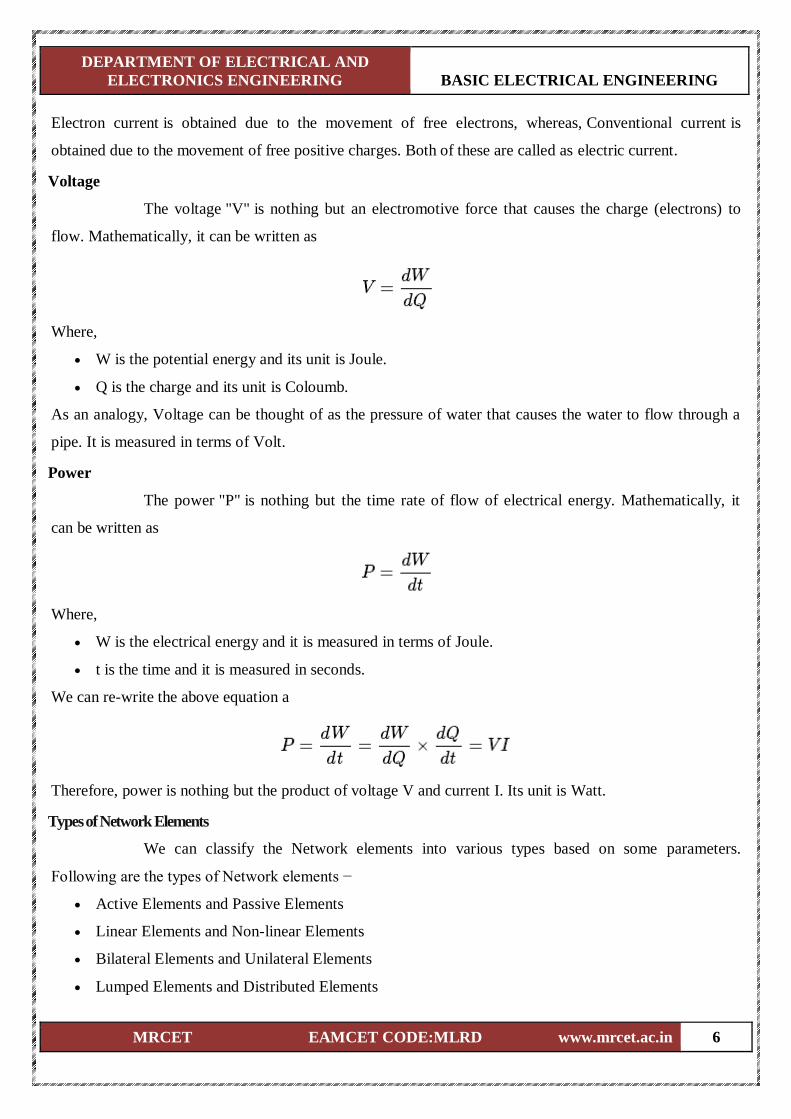
Bilateral Elements are the elements that allow the current in both directions and offer the same impedance
in either direction of current flow. Examples: Resistors, Inductors and capacitors.
The concept of Bilateral elements is illustrated in the following figures.
In the above figure, the current (I) is flowing from terminals A to B through a passive element having
impedance of Z Ω. It is the ratio of voltage (V) across that element between terminals A & B and current (I).
DEPARTMENT OF ELECTRICAL AND
ELECTRONICS ENGINEERING BASIC ELECTRICAL ENGINEERING
MRCET EAMCET CODE:MLRD www.mrcet.ac.in 8
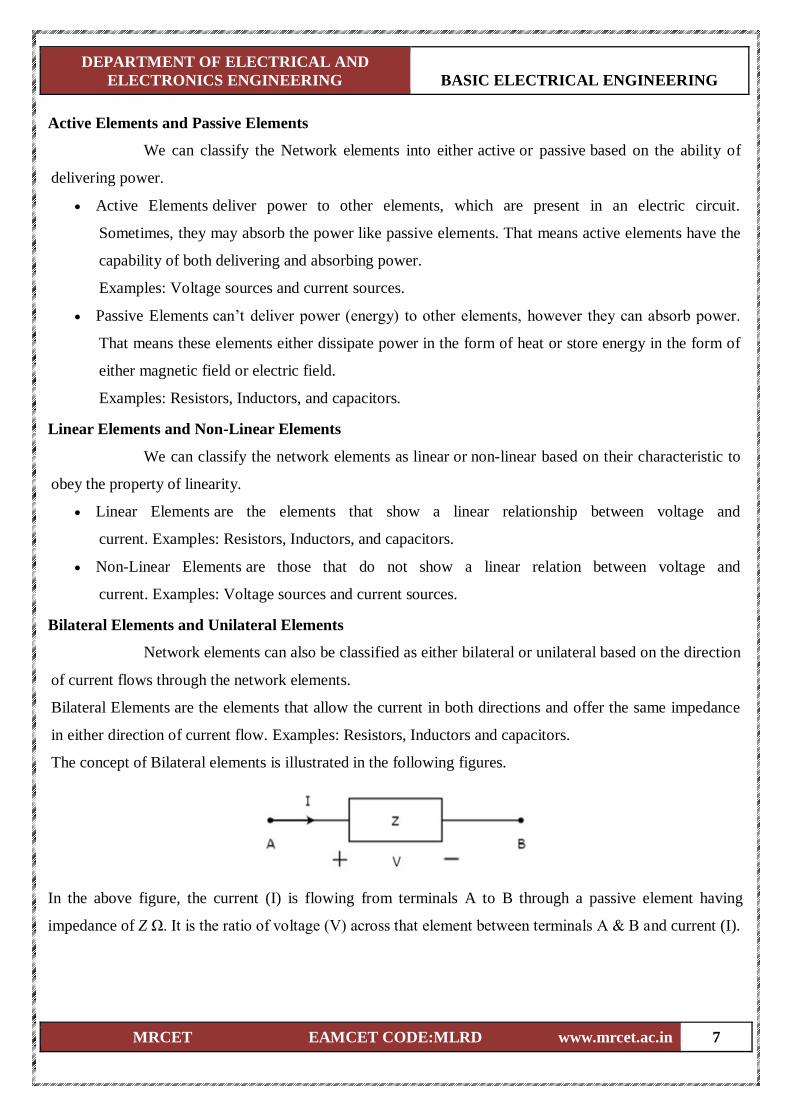
In the above figure, the current (I) is flowing from terminals B to A through a passive element having
impedance of Z Ω. That means the current (–I) is flowing from terminals A to B. In this case too, we will
get the same impedance value, since both the current and voltage having negative signs with respect to
terminals A & B.
Unilateral Elements are those that allow the current in only one direction. Hence, they offer different
impedances in both directions.
We discussed the types of network elements in the previous chapter. Now, let us identify the nature of
network elements from the V-I characteristics given in the following examples.
Example 1
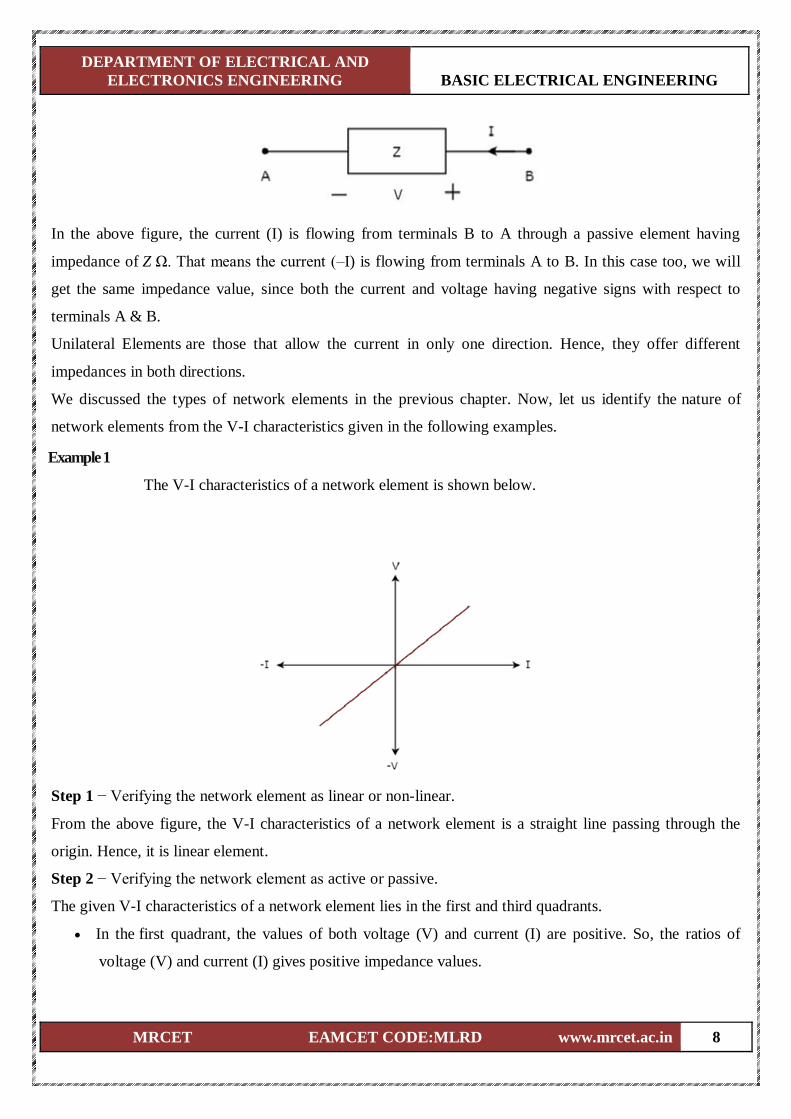
The V-I characteristics of a network element is shown below.
Step 1 − Verifying the network element as linear or non-linear.
From the above figure, the V-I characteristics of a network element is a straight line passing through the
origin. Hence, it is linear element.
Step 2 − Verifying the network element as active or passive.
The given V-I characteristics of a network element lies in the first and third quadrants.
In the first quadrant, the values of both voltage (V) and current (I) are positive. So, the ratios of
voltage (V) and current (I) gives positive impedance values.
DEPARTMENT OF ELECTRICAL AND
ELECTRONICS ENGINEERING BASIC ELECTRICAL ENGINEERING
MRCET EAMCET CODE:MLRD www.mrcet.ac.in 9
Similarly, in the third quadrant, the values of both voltage (V) and current (I) have negative values.
So, the ratios of voltage (V) and current (I) produce positive impedance values.
Since, the given V-I characteristics offer positive impedance values, the network element is a Passive
element.
Step 3 − Verifying the network element as bilateral or unilateral.
For every point (I, V) on the characteristics, there exists a corresponding point (-I, -V) on the given
characteristics. Hence, the network element is a Bilateral element.
Therefore, the given V-I characteristics show that the network element is a Linear, Passive, and Bilateral
element.
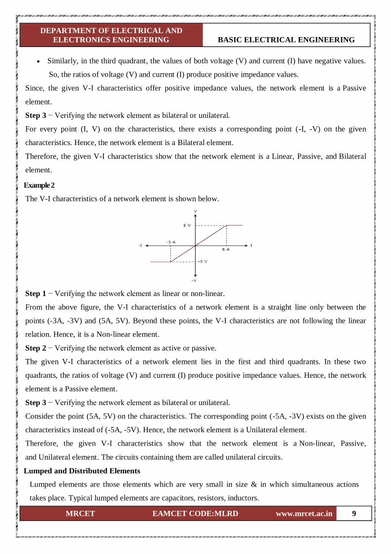
Example 2
The V-I characteristics of a network element is shown below.
Step 1 − Verifying the network element as linear or non-linear.
From the above figure, the V-I characteristics of a network element is a straight line only between the
points (-3A, -3V) and (5A, 5V). Beyond these points, the V-I characteristics are not following the linear
relation. Hence, it is a Non-linear element.
Step 2 − Verifying the network element as active or passive.
The given V-I characteristics of a network element lies in the first and third quadrants. In these two
quadrants, the ratios of voltage (V) and current (I) produce positive impedance values. Hence, the network
element is a Passive element.
Step 3 − Verifying the network element as bilateral or unilateral.
Consider the point (5A, 5V) on the characteristics. The corresponding point (-5A, -3V) exists on the given
characteristics instead of (-5A, -5V). Hence, the network element is a Unilateral element.
Therefore, the given V-I characteristics show that the network element is a Non-linear, Passive,
and Unilateral element. The circuits containing them are called unilateral circuits.
Lumped and Distributed Elements
Lumped elements are those elements which are very small in size & in which simultaneous actions
takes place. Typical lumped elements are capacitors, resistors, inductors.
DEPARTMENT OF ELECTRICAL AND
ELECTRONICS ENGINEERING BASIC ELECTRICAL ENGINEERING
MRCET EAMCET CODE:MLRD www.mrcet.ac.in 10
Distributed elements are those which are not electrically separable for analytical purposes.
For example a transmission line has distributed parameters along its length and may extend for hundreds
of miles.
R-L-C Parameters
Resistor
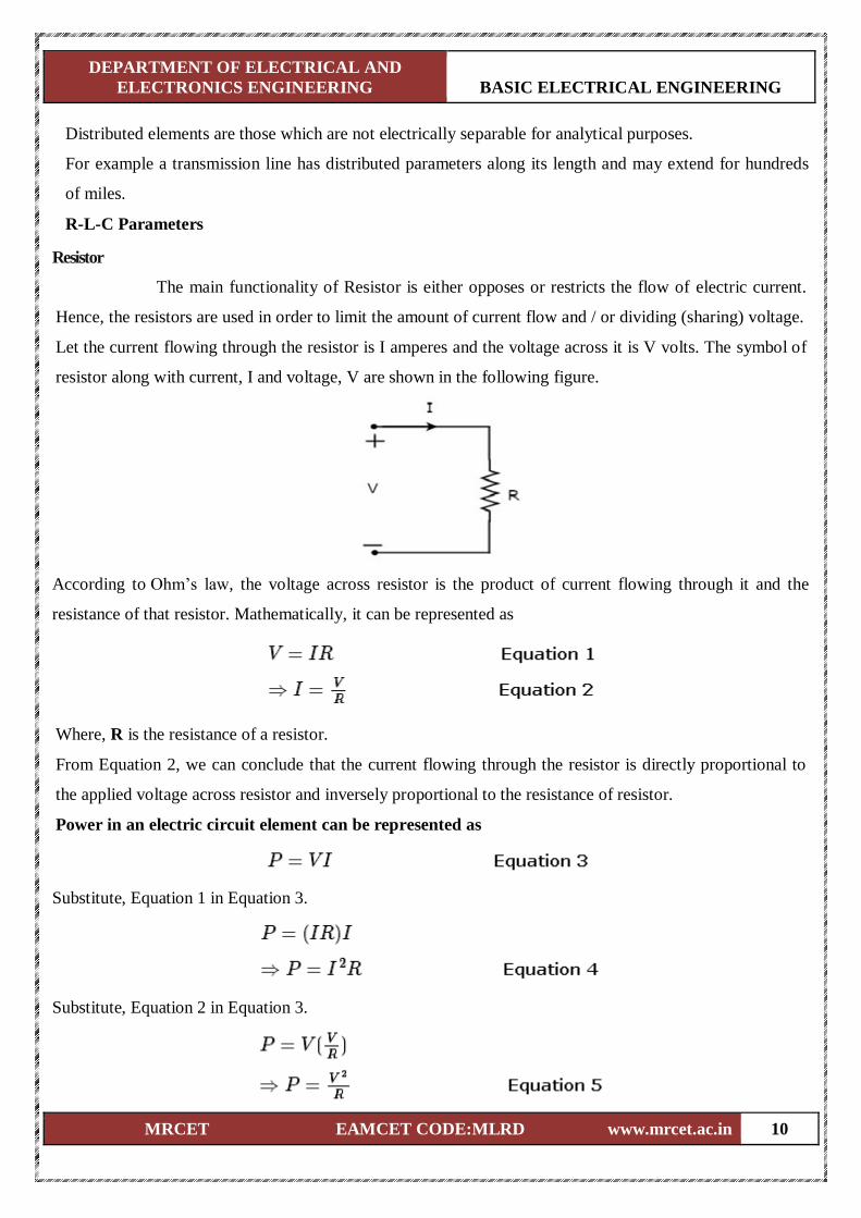
The main functionality of Resistor is either opposes or restricts the flow of electric current.
Hence, the resistors are used in order to limit the amount of current flow and / or dividing (sharing) voltage.
Let the current flowing through the resistor is I amperes and the voltage across it is V volts. The symbol of
resistor along with current, I and voltage, V are shown in the following figure.
According to Ohm’s law, the voltage across resistor is the product of current flowing through it and the
resistance of that resistor. Mathematically, it can be represented as
Where, R is the resistance of a resistor.
From Equation 2, we can conclude that the current flowing through the resistor is directly proportional to
the applied voltage across resistor and inversely proportional to the resistance of resistor.
Power in an electric circuit element can be represented as
Substitute, Equation 1 in Equation 3.
Substitute, Equation 2 in Equation 3.
DEPARTMENT OF ELECTRICAL AND
ELECTRONICS ENGINEERING BASIC ELECTRICAL ENGINEERING
MRCET EAMCET CODE:MLRD www.mrcet.ac.in 11
So, we can calculate the amount of power dissipated in the resistor by using one of the formulae mentioned
in Equations 3 to 5.
Inductor
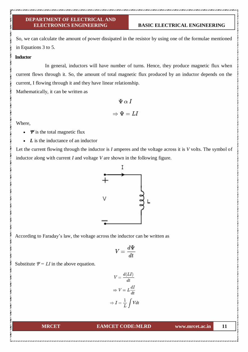
In general, inductors will have number of turns. Hence, they produce magnetic flux when
current flows through it. So, the amount of total magnetic flux produced by an inductor depends on the
current, I flowing through it and they have linear relationship.
Mathematically, it can be written as
Where,
Ψ is the total magnetic flux
L is the inductance of an inductor
Let the current flowing through the inductor is I amperes and the voltage across it is V volts. The symbol of
inductor along with current I and voltage V are shown in the following figure.
According to Faraday’s law, the voltage across the inductor can be written as
Substitute Ψ = LI in the above equation.
DEPARTMENT OF ELECTRICAL AND
ELECTRONICS ENGINEERING BASIC ELECTRICAL ENGINEERING
MRCET EAMCET CODE:MLRD www.mrcet.ac.in 12
From the above equations, we can conclude that there exists a linear relationship between voltage across
inductor and current flowing through it.
We know that power in an electric circuit element can be represented as
By integrating the above equation, we will get the energy stored in an inductor as
So, the inductor stores the energy in the form of magnetic field.
Capacitor
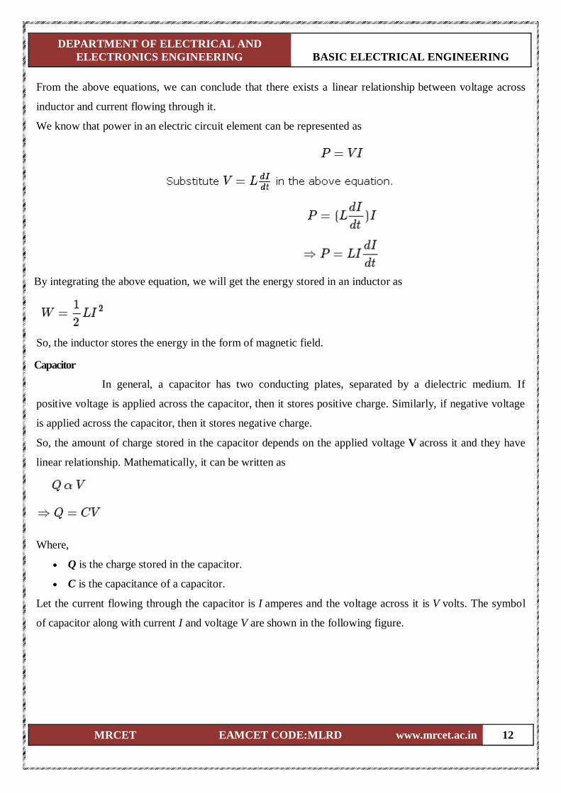
In general, a capacitor has two conducting plates, separated by a dielectric medium. If
positive voltage is applied across the capacitor, then it stores positive charge. Similarly, if negative voltage
is applied across the capacitor, then it stores negative charge.
So, the amount of charge stored in the capacitor depends on the applied voltage V across it and they have
linear relationship. Mathematically, it can be written as
Where,
Q is the charge stored in the capacitor.
C is the capacitance of a capacitor.
Let the current flowing through the capacitor is I amperes and the voltage across it is V volts. The symbol
of capacitor along with current I and voltage V are shown in the following figure.
DEPARTMENT OF ELECTRICAL AND
ELECTRONICS ENGINEERING BASIC ELECTRICAL ENGINEERING
MRCET EAMCET CODE:MLRD www.mrcet.ac.in 13
We know that the current is nothing but the time rate of flow of charge. Mathematically, it can be
represented as
From the above equations, we can conclude that there exists a linear relationship between voltage across
capacitor and current flowing through it.
We know that power in an electric circuit element can be represented as
By integrating the above equation, we will get the energy stored in the capacitor as
DEPARTMENT OF ELECTRICAL AND
ELECTRONICS ENGINEERING BASIC ELECTRICAL ENGINEERING
MRCET EAMCET CODE:MLRD www.mrcet.ac.in 14
So, the capacitor stores the energy in the form of electric field.
Types of Sources
Active Elements are the network elements that deliver power to other elements present in an
electric circuit. So, active elements are also called as sources of voltage or current type. We can classify
these sources into the following two categories −
Independent Sources
Dependent Sources
Independent Sources
As the name suggests, independent sources produce fixed values of voltage or current and
these are not dependent on any other parameter. Independent sources can be further divided into the
following two categories −
Independent Voltage Sources
Independent Current Sources
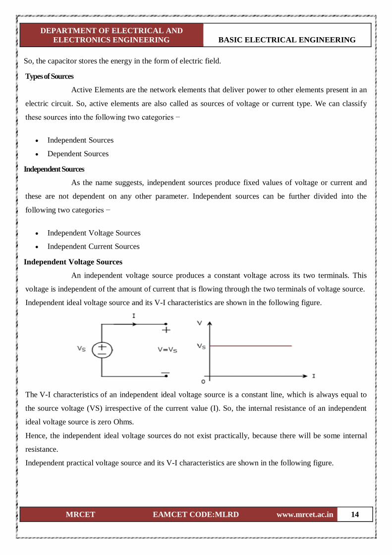
Independent Voltage Sources
An independent voltage source produces a constant voltage across its two terminals. This
voltage is independent of the amount of current that is flowing through the two terminals of voltage source.
Independent ideal voltage source and its V-I characteristics are shown in the following figure.
The V-I characteristics of an independent ideal voltage source is a constant line, which is always equal to
the source voltage (VS) irrespective of the current value (I). So, the internal resistance of an independent
ideal voltage source is zero Ohms.
Hence, the independent ideal voltage sources do not exist practically, because there will be some internal
resistance.
Independent practical voltage source and its V-I characteristics are shown in the following figure.
DEPARTMENT OF ELECTRICAL AND
ELECTRONICS ENGINEERING BASIC ELECTRICAL ENGINEERING
MRCET EAMCET CODE:MLRD www.mrcet.ac.in 15
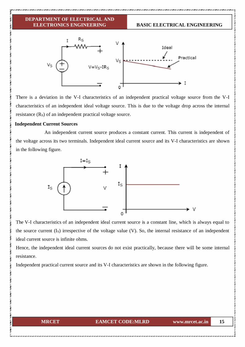
There is a deviation in the V-I characteristics of an independent practical voltage source from the V-I
characteristics of an independent ideal voltage source. This is due to the voltage drop across the internal
resistance (RS) of an independent practical voltage source.
Independent Current Sources
An independent current source produces a constant current. This current is independent of
the voltage across its two terminals. Independent ideal current source and its V-I characteristics are shown
in the following figure.
The V-I characteristics of an independent ideal current source is a constant line, which is always equal to
the source current (IS) irrespective of the voltage value (V). So, the internal resistance of an independent
ideal current source is infinite ohms.
Hence, the independent ideal current sources do not exist practically, because there will be some internal
resistance.
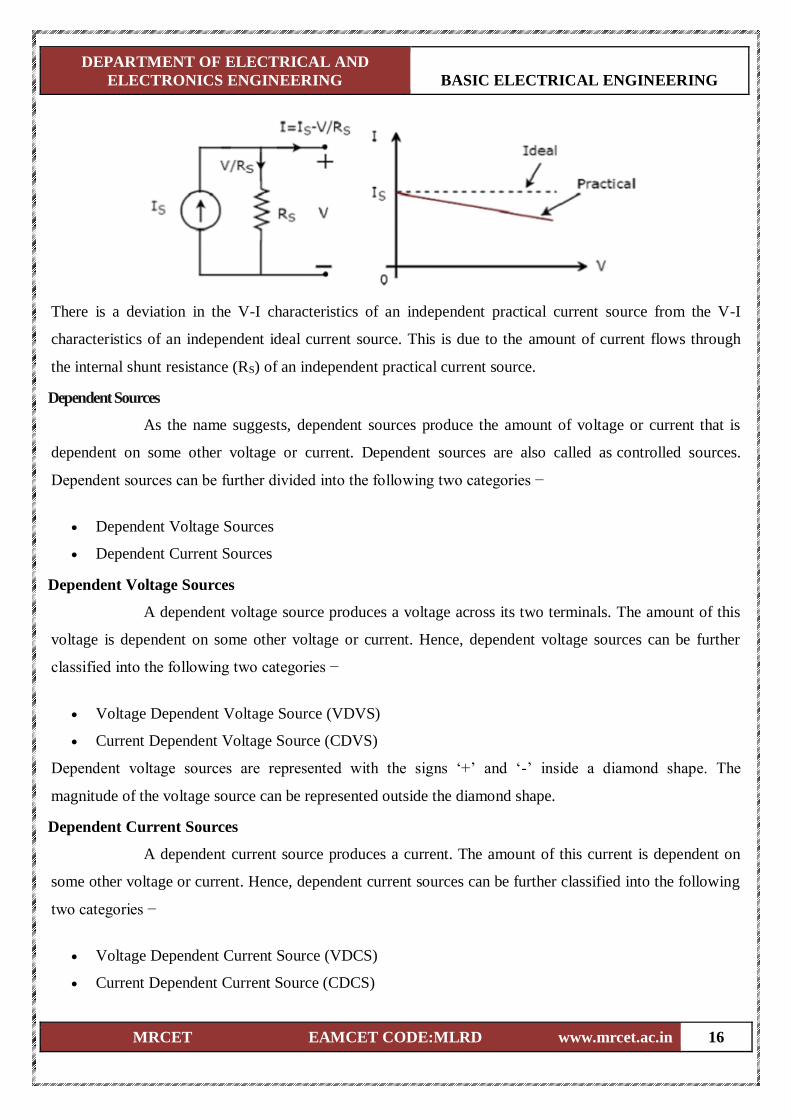
Independent practical current source and its V-I characteristics are shown in the following figure.
DEPARTMENT OF ELECTRICAL AND
ELECTRONICS ENGINEERING BASIC ELECTRICAL ENGINEERING
MRCET EAMCET CODE:MLRD www.mrcet.ac.in 16
There is a deviation in the V-I characteristics of an independent practical current source from the V-I
characteristics of an independent ideal current source. This is due to the amount of current flows through
the internal shunt resistance (RS) of an independent practical current source.
Dependent Sources
As the name suggests, dependent sources produce the amount of voltage or current that is
dependent on some other voltage or current. Dependent sources are also called as controlled sources.
Dependent sources can be further divided into the following two categories −
Dependent Voltage Sources
Dependent Current Sources
Dependent Voltage Sources
A dependent voltage source produces a voltage across its two terminals. The amount of this
voltage is dependent on some other voltage or current. Hence, dependent voltage sources can be further
classified into the following two categories −
Voltage Dependent Voltage Source (VDVS)
Current Dependent Voltage Source (CDVS)
Dependent voltage sources are represented with the signs ‘+’ and ‘-’ inside a diamond shape. The
magnitude of the voltage source can be represented outside the diamond shape.
Dependent Current Sources
A dependent current source produces a current. The amount of this current is dependent on
some other voltage or current. Hence, dependent current sources can be further classified into the following
two categories −
Voltage Dependent Current Source (VDCS)
Current Dependent Current Source (CDCS)
DEPARTMENT OF ELECTRICAL AND
ELECTRONICS ENGINEERING BASIC ELECTRICAL ENGINEERING
MRCET EAMCET CODE:MLRD www.mrcet.ac.in 17
Dependent current sources are represented with an arrow inside a diamond shape. The magnitude of the
current source can be represented outside the diamond shape. We can observe these dependent or controlled
sources in equivalent models of transistors.
Source Transformation Technique
We know that there are two practical sources, namely, voltage source and current source. We
can transform (convert) one source into the other based on the requirement, while solving network
problems.
The technique of transforming one source into the other is called as source transformation technique.
Following are the two possible source transformations −
Practical voltage source into a practical current source
Practical current source into a practical voltage source
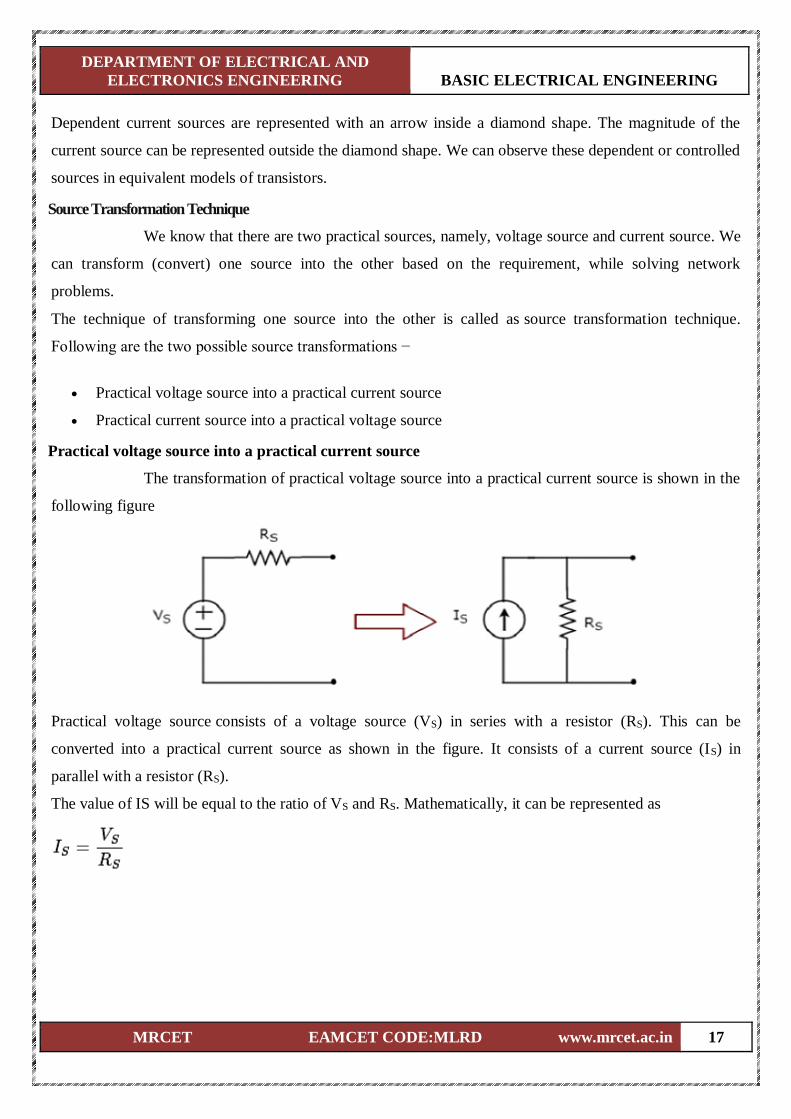
Practical voltage source into a practical current source
The transformation of practical voltage source into a practical current source is shown in the
following figure
Practical voltage source consists of a voltage source (VS) in series with a resistor (RS). This can be
converted into a practical current source as shown in the figure. It consists of a current source (IS) in
parallel with a resistor (RS).
The value of IS will be equal to the ratio of VS and RS. Mathematically, it can be represented as
DEPARTMENT OF ELECTRICAL AND
ELECTRONICS ENGINEERING BASIC ELECTRICAL ENGINEERING
MRCET EAMCET CODE:MLRD www.mrcet.ac.in 18
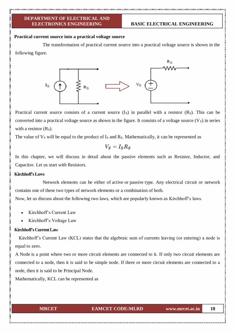
Practical current source into a practical voltage source
The transformation of practical current source into a practical voltage source is shown in the
following figure.
Practical current source consists of a current source (IS) in parallel with a resistor (RS). This can be
converted into a practical voltage source as shown in the figure. It consists of a voltage source (VS) in series
with a resistor (RS).
The value of VS will be equal to the product of IS and RS. Mathematically, it can be represented as
In this chapter, we will discuss in detail about the passive elements such as Resistor, Inductor, and
Capacitor. Let us start with Resistors.
Kirchhoff’s Laws
Network elements can be either of active or passive type. Any electrical circuit or network
contains one of these two types of network elements or a combination of both.
Now, let us discuss about the following two laws, which are popularly known as Kirchhoff’s laws.
Kirchhoff’s Current Law
Kirchhoff’s Voltage Law
Kirchhoff’s Current Law
Kirchhoff’s Current Law (KCL) states that the algebraic sum of currents leaving (or entering) a node is
equal to zero.
A Node is a point where two or more circuit elements are connected to it. If only two circuit elements are
connected to a node, then it is said to be simple node. If three or more circuit elements are connected to a
node, then it is said to be Principal Node.
Mathematically, KCL can be represented as
DEPARTMENT OF ELECTRICAL AND
ELECTRONICS ENGINEERING BASIC ELECTRICAL ENGINEERING
MRCET EAMCET CODE:MLRD www.mrcet.ac.in 19
Where,
Im is the mth branch current leaving the node.
M is the number of branches that are connected to a node.
The above statement of KCL can also be expressed as "the algebraic sum of currents entering a node is
equal to the algebraic sum of currents leaving a node". Let us verify this statement through the following
example.
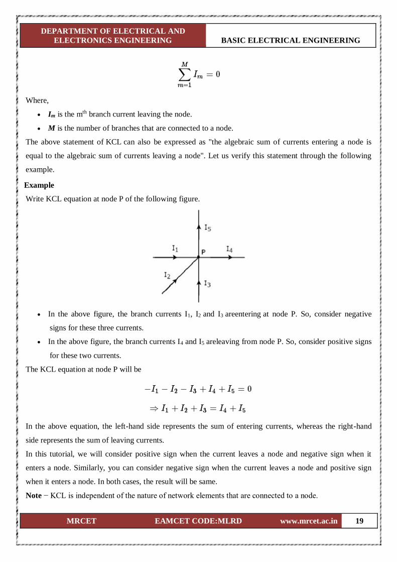
Example
Write KCL equation at node P of the following figure.
In the above figure, the branch currents I1, I2 and I3 areentering at node P. So, consider negative
signs for these three currents.
In the above figure, the branch currents I4 and I5 areleaving from node P. So, consider positive signs
for these two currents.
The KCL equation at node P will be
In the above equation, the left-hand side represents the sum of entering currents, whereas the right-hand
side represents the sum of leaving currents.
In this tutorial, we will consider positive sign when the current leaves a node and negative sign when it
enters a node. Similarly, you can consider negative sign when the current leaves a node and positive sign
when it enters a node. In both cases, the result will be same.
Note − KCL is independent of the nature of network elements that are connected to a node.
DEPARTMENT OF ELECTRICAL AND
ELECTRONICS ENGINEERING BASIC ELECTRICAL ENGINEERING
MRCET EAMCET CODE:MLRD www.mrcet.ac.in 20
Kirchhoff’s Voltage Law
Kirchhoff’s Voltage Law (KVL) states that the algebraic sum of voltages around a loop or
mesh is equal to zero.
A Loop is a path that terminates at the same node where it started from. In contrast, a Mesh is a loop that
doesn’t contain any other loops inside it.
Mathematically, KVL can be represented as
Where,
Vn is the nth element’s voltage in a loop (mesh).
N is the number of network elements in the loop (mesh).
The above statement of KVL can also be expressed as "the algebraic sum of voltage sources is equal to the
algebraic sum of voltage drops that are present in a loop." Let us verify this statement with the help of the
following example.
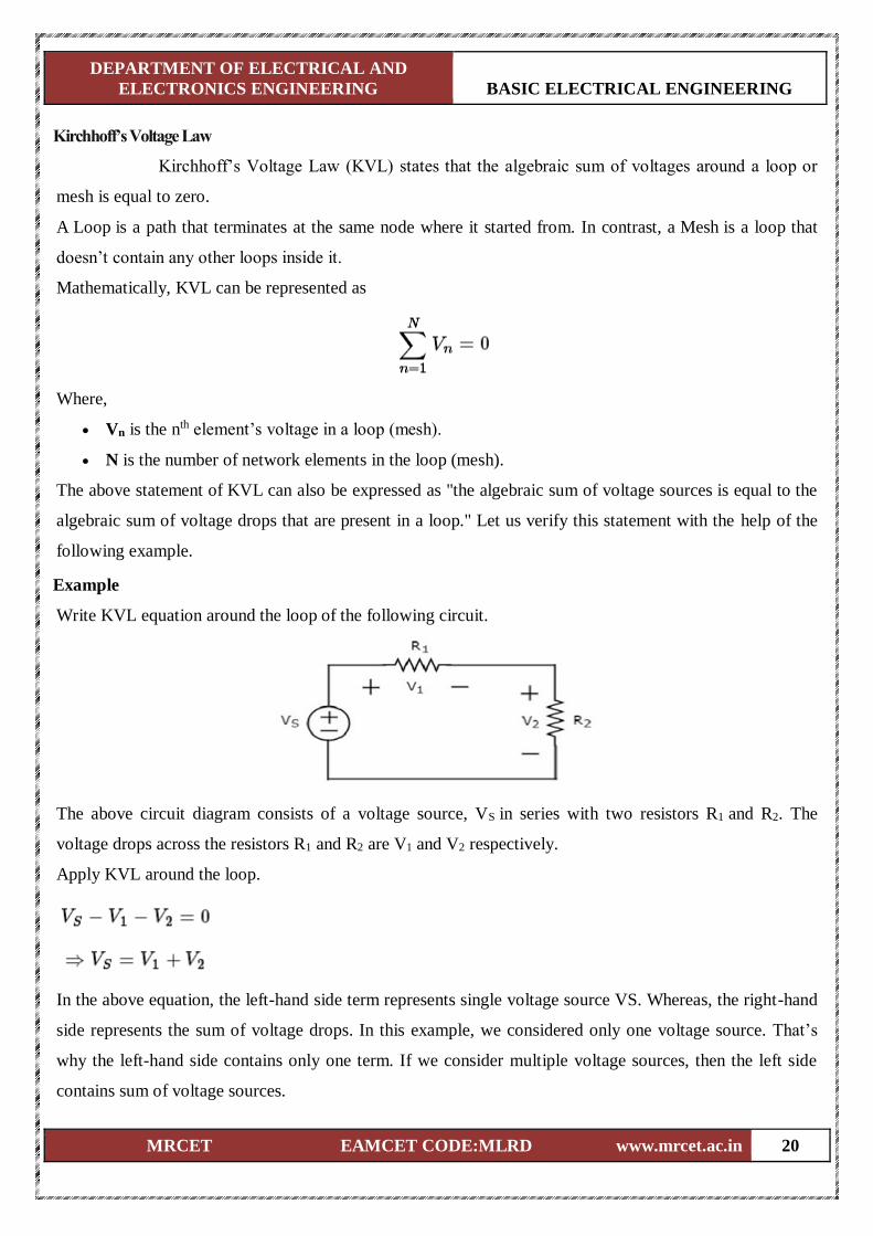
Example
Write KVL equation around the loop of the following circuit.
The above circuit diagram consists of a voltage source, VS in series with two resistors R1 and R2. The
voltage drops across the resistors R1 and R2 are V1 and V2 respectively.
Apply KVL around the loop.
In the above equation, the left-hand side term represents single voltage source VS. Whereas, the right-hand
side represents the sum of voltage drops. In this example, we considered only one voltage source. That’s
why the left-hand side contains only one term. If we consider multiple voltage sources, then the left side
contains sum of voltage sources.
DEPARTMENT OF ELECTRICAL AND
ELECTRONICS ENGINEERING BASIC ELECTRICAL ENGINEERING
MRCET EAMCET CODE:MLRD www.mrcet.ac.in 21
In this tutorial, we consider the sign of each element’s voltage as the polarity of the second terminal that is
present while travelling around the loop. Similarly, you can consider the sign of each voltage as the polarity
of the first terminal that is present while travelling around the loop. In both cases, the result will be same.
Note − KVL is independent of the nature of network elements that are present in a loop.
In this chapter, let us discuss about the following two division principles of electrical quantities.
Current Division Principle
Voltage Division Principle
Current Division Principle
When two or more passive elements are connected in parallel, the amount of current that
flows through each element gets divided(shared) among themselves from the current that is entering the
node.
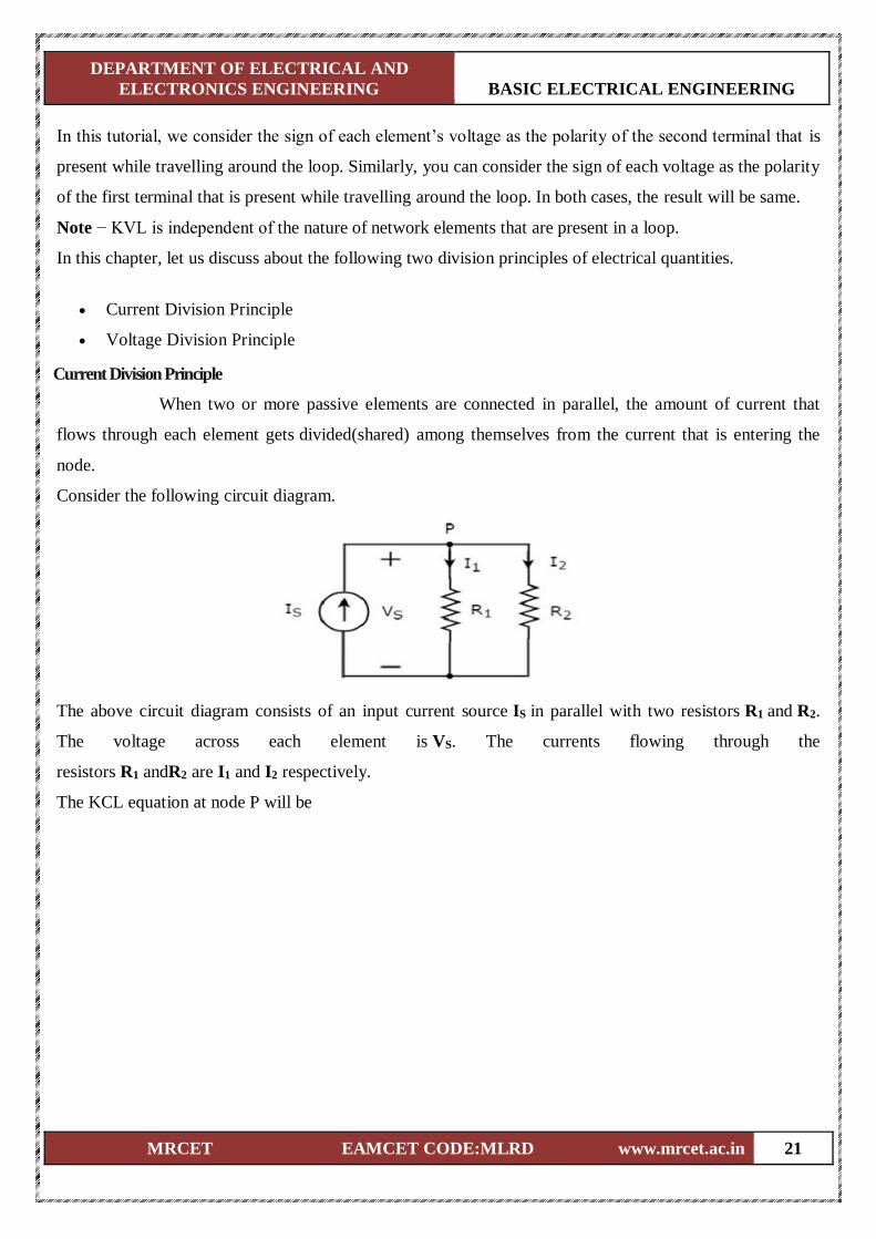
Consider the following circuit diagram.
The above circuit diagram consists of an input current source IS in parallel with two resistors R1 and R2.
The voltage across each element is VS. The currents flowing through the
resistors R1 andR2 are I1 and I2 respectively.
The KCL equation at node P will be
DEPARTMENT OF ELECTRICAL AND
ELECTRONICS ENGINEERING BASIC ELECTRICAL ENGINEERING
MRCET EAMCET CODE:MLRD www.mrcet.ac.in 22
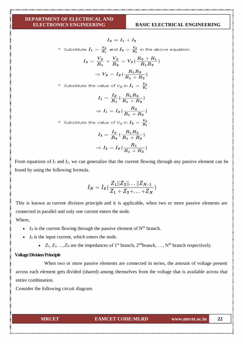
From equations of I1 and I2, we can generalize that the current flowing through any passive element can be
found by using the following formula.
This is known as current division principle and it is applicable, when two or more passive elements are
connected in parallel and only one current enters the node.
Where,
IN is the current flowing through the passive element of Nth branch.
IS is the input current, which enters the node.
Z1, Z2, …,ZN are the impedances of 1st branch, 2ndbranch, …, Nth branch respectively.
Voltage Division Principle
When two or more passive elements are connected in series, the amount of voltage present
across each element gets divided (shared) among themselves from the voltage that is available across that
entire combination.
Consider the following circuit diagram.
DEPARTMENT OF ELECTRICAL AND
ELECTRONICS ENGINEERING BASIC ELECTRICAL ENGINEERING
MRCET EAMCET CODE:MLRD www.mrcet.ac.in 23
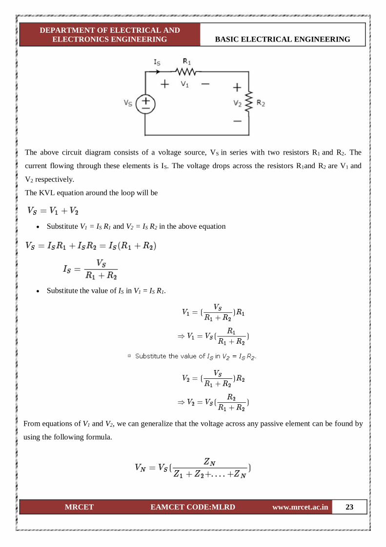
The above circuit diagram consists of a voltage source, VS in series with two resistors R1 and R2. The
current flowing through these elements is IS. The voltage drops across the resistors R1and R2 are V1 and
V2 respectively.
The KVL equation around the loop will be
Substitute V1 = IS R1 and V2 = IS R2 in the above equation
Substitute the value of IS in V1 = IS R1.
From equations of V1 and V2, we can generalize that the voltage across any passive element can be found by
using the following formula.
DEPARTMENT OF ELECTRICAL AND
ELECTRONICS ENGINEERING BASIC ELECTRICAL ENGINEERING
MRCET EAMCET CODE:MLRD www.mrcet.ac.in 24
This is known as voltage division principle and it is applicable, when two or more passive elements are
connected in series and only one voltage available across the entire combination.
Where,
VN is the voltage across Nth passive element.
VS is the input voltage, which is present across the entire combination of series passive elements.
Z1,Z2, …,Z3 are the impedances of 1st passive element, 2nd passive element, …, Nth passive element
respectively.
DEPARTMENT OF ELECTRICAL AND
ELECTRONICS ENGINEERING BASIC ELECTRICAL ENGINEERING
MRCET EAMCET CODE:MLRD www.mrcet.ac.in 25
UNIT-II
NETWORK ANALYSIS
Network Reduction Techniques
Series and Parallel connection of Resistive Networks
Star–to-Delta and Delta-to-Star Transformations for Resistive Networks
Mesh Analysis
Nodal Analysis
Network Theorems: Thevenin’s Theorem
Norton’s Theorem
Maximum Power Transfer Theorem
Superposition Theorem
Problems
DEPARTMENT OF ELECTRICAL AND
ELECTRONICS ENGINEERING BASIC ELECTRICAL ENGINEERING
MRCET EAMCET CODE:MLRD www.mrcet.ac.in 26
Network Reduction Techniques:
There are two basic methods that are used for solving any electrical network: Nodal analysis and Mesh
analysis. In this chapter, let us discuss about the Mesh analysis method.
Series and parallel connections of resistive networks:
If a circuit consists of two or more similar passive elements and are connected in exclusively of series type
or parallel type, then we can replace them with a single equivalent passive element. Hence, this circuit is
called as an equivalent circuit.
In this chapter, let us discuss about the following two equivalent circuits.
Series Equivalent Circuit
Parallel Equivalent Circuit
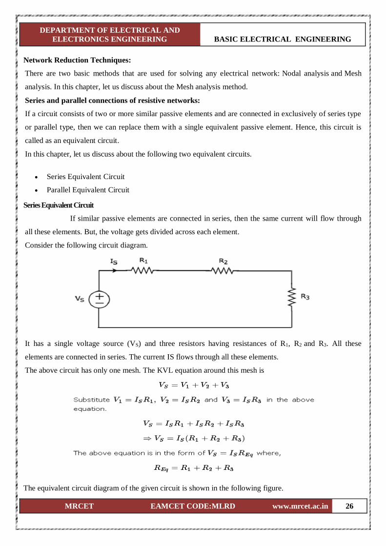
Series Equivalent Circuit
If similar passive elements are connected in series, then the same current will flow through
all these elements. But, the voltage gets divided across each element.
Consider the following circuit diagram.
It has a single voltage source (VS) and three resistors having resistances of R1, R2 and R3. All these
elements are connected in series. The current IS flows through all these elements.
The above circuit has only one mesh. The KVL equation around this mesh is
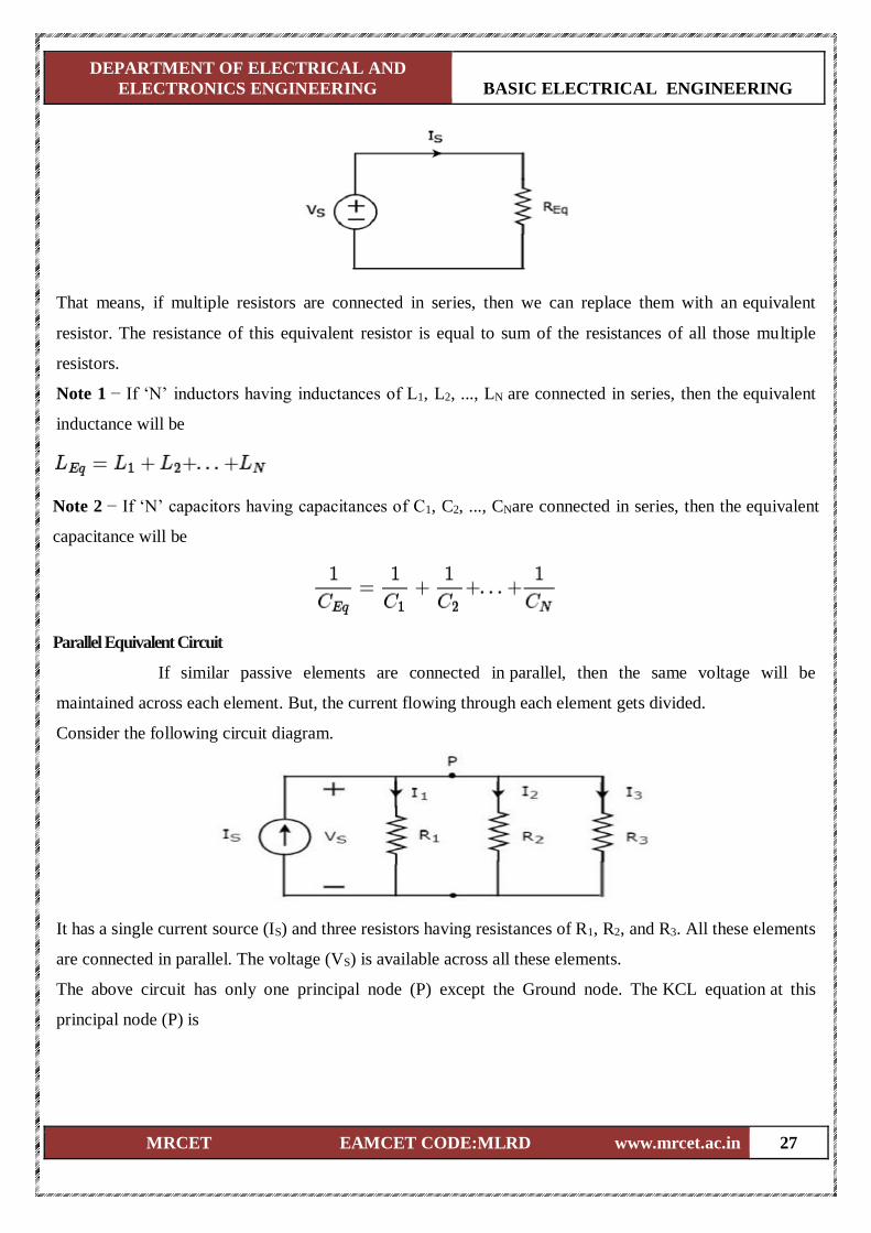
The equivalent circuit diagram of the given circuit is shown in the following figure.
DEPARTMENT OF ELECTRICAL AND
ELECTRONICS ENGINEERING BASIC ELECTRICAL ENGINEERING
MRCET EAMCET CODE:MLRD www.mrcet.ac.in 27
That means, if multiple resistors are connected in series, then we can replace them with an equivalent
resistor. The resistance of this equivalent resistor is equal to sum of the resistances of all those multiple
resistors.
Note 1 − If ‘N’ inductors having inductances of L1, L2, ..., LN are connected in series, then the equivalent
inductance will be
Note 2 − If ‘N’ capacitors having capacitances of C1, C2, ..., CNare connected in series, then the equivalent
capacitance will be
Parallel Equivalent Circuit
If similar passive elements are connected in parallel, then the same voltage will be
maintained across each element. But, the current flowing through each element gets divided.
Consider the following circuit diagram.
It has a single current source (IS) and three resistors having resistances of R1, R2, and R3. All these elements
are connected in parallel. The voltage (VS) is available across all these elements.
The above circuit has only one principal node (P) except the Ground node. The KCL equation at this
principal node (P) is
DEPARTMENT OF ELECTRICAL AND
ELECTRONICS ENGINEERING BASIC ELECTRICAL ENGINEERING
MRCET EAMCET CODE:MLRD www.mrcet.ac.in 28
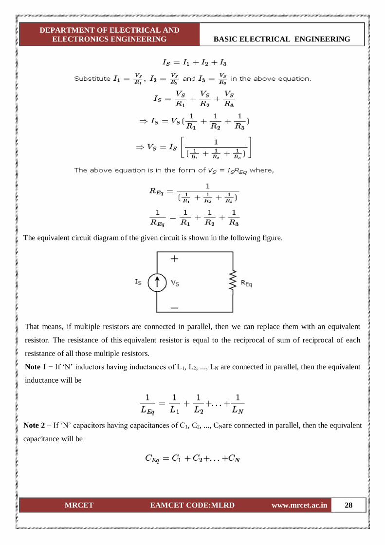
The equivalent circuit diagram of the given circuit is shown in the following figure.
That means, if multiple resistors are connected in parallel, then we can replace them with an equivalent
resistor. The resistance of this equivalent resistor is equal to the reciprocal of sum of reciprocal of each
resistance of all those multiple resistors.
Note 1 − If ‘N’ inductors having inductances of L1, L2, ..., LN are connected in parallel, then the equivalent
inductance will be
Note 2 − If ‘N’ capacitors having capacitances of C1, C2, ..., CNare connected in parallel, then the equivalent
capacitance will be
DEPARTMENT OF ELECTRICAL AND
ELECTRONICS ENGINEERING BASIC ELECTRICAL ENGINEERING
MRCET EAMCET CODE:MLRD www.mrcet.ac.in 29
Example Problems:
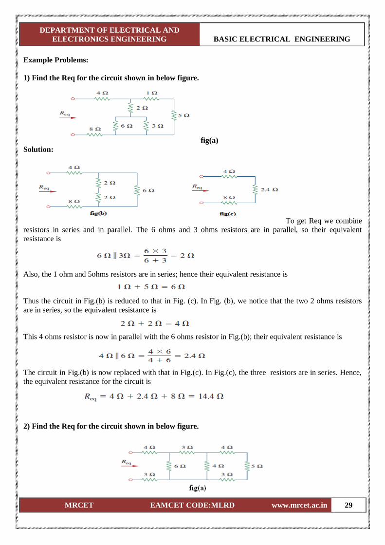
1) Find the Req for the circuit shown in below figure.
fig(a)
Solution:
To get Req we combine
resistors in series and in parallel. The 6 ohms and 3 ohms resistors are in parallel, so their equivalent
resistance is
Also, the 1 ohm and 5ohms resistors are in series; hence their equivalent resistance is
Thus the circuit in Fig.(b) is reduced to that in Fig. (c). In Fig. (b), we notice that the two 2 ohms resistors
are in series, so the equivalent resistance is
This 4 ohms resistor is now in parallel with the 6 ohms resistor in Fig.(b); their equivalent resistance is
The circuit in Fig.(b) is now replaced with that in Fig.(c). In Fig.(c), the three resistors are in series. Hence,
the equivalent resistance for the circuit is
2) Find the Req for the circuit shown in below figure.
DEPARTMENT OF ELECTRICAL AND
ELECTRONICS ENGINEERING BASIC ELECTRICAL ENGINEERING
MRCET EAMCET CODE:MLRD www.mrcet.ac.in 30
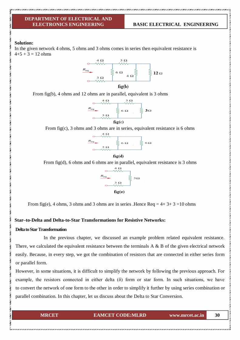
Solution:
In the given network 4 ohms, 5 ohms and 3 ohms comes in series then equivalent resistance is
4+5 + 3 = 12 ohms
From fig(b), 4 ohms and 12 ohms are in parallel, equivalent is 3 ohms
From fig(c), 3 ohms and 3 ohms are in series, equivalent resistance is 6 ohms
From fig(d), 6 ohms and 6 ohms are in parallel, equivalent resistance is 3 ohms
From fig(e), 4 ohms, 3 ohms and 3 ohms are in series .Hence Req = 4+ 3+ 3 =10 ohms
Star–to-Delta and Delta-to-Star Transformations for Resistive Networks:
Delta to Star Transformation
In the previous chapter, we discussed an example problem related equivalent resistance.
There, we calculated the equivalent resistance between the terminals A & B of the given electrical network
easily. Because, in every step, we got the combination of resistors that are connected in either series form
or parallel form.
However, in some situations, it is difficult to simplify the network by following the previous approach. For
example, the resistors connected in either delta (δ) form or star form. In such situations, we have
to convert the network of one form to the other in order to simplify it further by using series combination or
parallel combination. In this chapter, let us discuss about the Delta to Star Conversion.

DEPARTMENT OF ELECTRICAL AND
ELECTRONICS ENGINEERING BASIC ELECTRICAL ENGINEERING
MRCET EAMCET CODE:MLRD www.mrcet.ac.in 31
Delta Network
Consider the following delta network as shown in the following figure.
The following equations represent the equivalent resistance between two terminals of delta network, when
the third terminal is kept open.
Star Network
The following figure shows the equivalent star network corresponding to the above delta
network.
DEPARTMENT OF ELECTRICAL AND
ELECTRONICS ENGINEERING BASIC ELECTRICAL ENGINEERING
MRCET EAMCET CODE:MLRD www.mrcet.ac.in 32
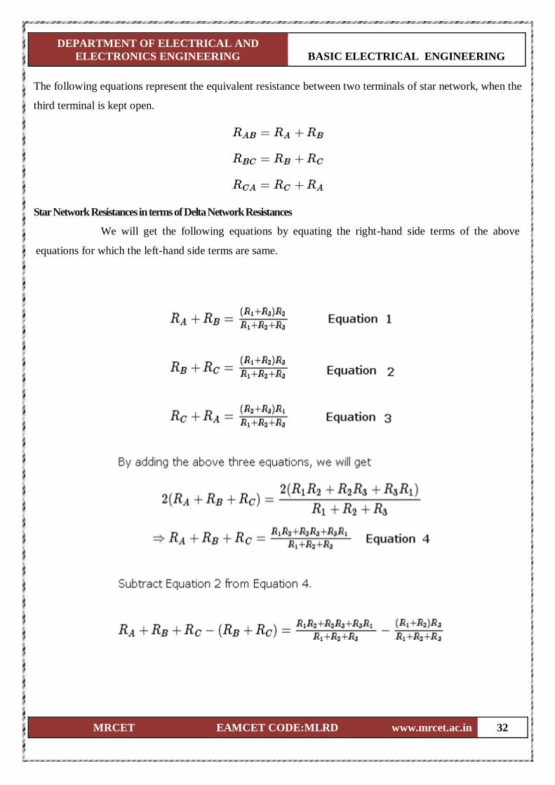
The following equations represent the equivalent resistance between two terminals of star network, when the
third terminal is kept open.
Star Network Resistances in terms of Delta Network Resistances
We will get the following equations by equating the right-hand side terms of the above
equations for which the left-hand side terms are same.
DEPARTMENT OF ELECTRICAL AND
ELECTRONICS ENGINEERING BASIC ELECTRICAL ENGINEERING
MRCET EAMCET CODE:MLRD www.mrcet.ac.in 33
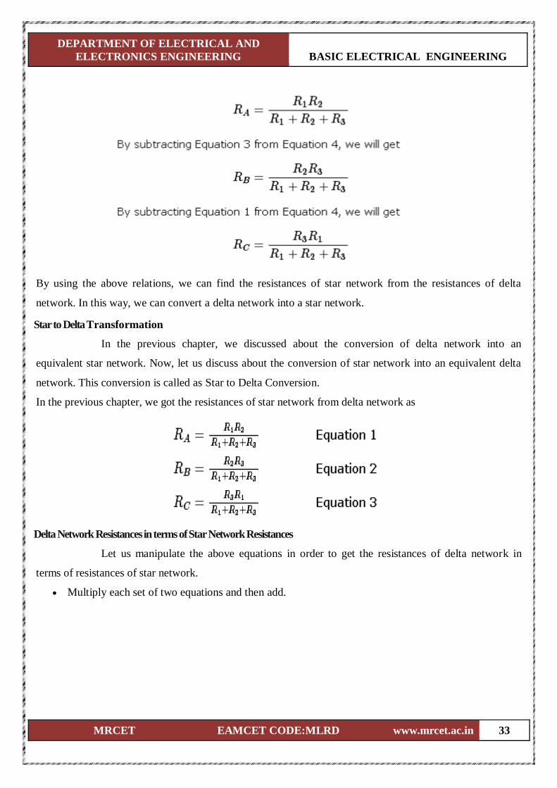
By using the above relations, we can find the resistances of star network from the resistances of delta
network. In this way, we can convert a delta network into a star network.
Star to Delta Transformation
In the previous chapter, we discussed about the conversion of delta network into an
equivalent star network. Now, let us discuss about the conversion of star network into an equivalent delta
network. This conversion is called as Star to Delta Conversion.
In the previous chapter, we got the resistances of star network from delta network as
Delta Network Resistances in terms of Star Network Resistances
Let us manipulate the above equations in order to get the resistances of delta network in
terms of resistances of star network.
Multiply each set of two equations and then add.
DEPARTMENT OF ELECTRICAL AND
ELECTRONICS ENGINEERING BASIC ELECTRICAL ENGINEERING
MRCET EAMCET CODE:MLRD www.mrcet.ac.in 34
By using the above relations, we can find the resistances of delta network from the resistances of star
network. In this way, we can convert star network into delta network.
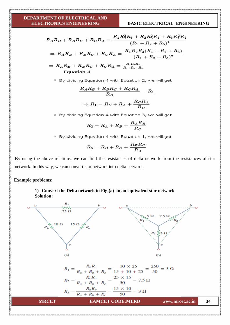
Example problems:
1) Convert the Delta network in Fig.(a) to an equivalent star network
Solution:
DEPARTMENT OF ELECTRICAL AND
ELECTRONICS ENGINEERING BASIC ELECTRICAL ENGINEERING
MRCET EAMCET CODE:MLRD www.mrcet.ac.in 35
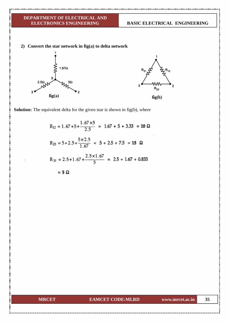
2) Convert the star network in fig(a) to delta network
Solution: The equivalent delta for the given star is shown in fig(b), where

DEPARTMENT OF ELECTRICAL AND
ELECTRONICS ENGINEERING BASIC ELECTRICAL ENGINEERING
MRCET EAMCET CODE:MLRD www.mrcet.ac.in 36
3) Determine the total current I in the given circuit.
Solution: Delta connected resistors 25 ohms, 10 ohms and 15 ohms are converted in to star as shown in
given figure.
R1 = R12 R31 / R12 + R23 + R31 = 10 x 25 / 10 + 15 + 25 = 5 ohms
R2 = R23 R12 / R12 + R23 + R31 = 15 x 10 / 10 + 15 + 25 = 3 ohms
R3 = R31 R23 / R12 + R23 + R31 = 25 x 15 / 10 + 15 + 25 = 7.5 ohms
The given circuit thus reduces to the circuit shown in below fig.
The equivalent resistance of
(20 + 5) ohms || (10 + 7.5) ohms = 25 x 17.5 / 25 + 17.5 = 10.29 ohms
Total resistance = 10.29 + 3 + 2.5 = 15.79 ohms
Hence the total current through the battery,
I = 15 / 15.79 = 0.95 A
DEPARTMENT OF ELECTRICAL AND
ELECTRONICS ENGINEERING BASIC ELECTRICAL ENGINEERING
MRCET EAMCET CODE:MLRD www.mrcet.ac.in 37
Mesh Analysis:
Mesh analysis provides general procedure for analyzing circuits using mesh currents as the circuit
variables. Mesh Analysis is applicable only for planar networks. It is preferably useful for the circuits that
have many loops .This analysis is done by using KVL and Ohm's law.
In Mesh analysis, we will consider the currents flowing through each mesh. Hence, Mesh analysis is also
called as Mesh-current method.
A branch is a path that joins two nodes and it contains a circuit element. If a branch belongs to only one
mesh, then the branch current will be equal to mesh current.
If a branch is common to two meshes, then the branch current will be equal to the sum (or difference) of
two mesh currents, when they are in same (or opposite) direction.
Procedure of Mesh Analysis
Follow these steps while solving any electrical network or circuit using Mesh analysis.
Step 1 − Identify the meshes and label the mesh currents in either clockwise or anti-clockwise
direction.
Step 2 − Observe the amount of current that flows through each element in terms of mesh currents.
Step 3 − Write mesh equations to all meshes. Mesh equation is obtained by applying KVL first and
then Ohm’s law.
Step 4 − Solve the mesh equations obtained in Step 3 in order to get the mesh currents.
Now, we can find the current flowing through any element and the voltage across any element that is
present in the given network by using mesh currents.
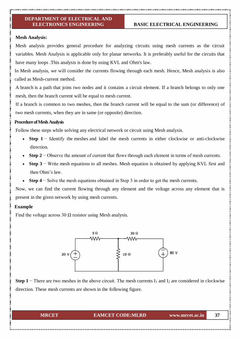
Example
Find the voltage across 30 Ω resistor using Mesh analysis.
Step 1 − There are two meshes in the above circuit. The mesh currents I1 and I2 are considered in clockwise
direction. These mesh currents are shown in the following figure.
DEPARTMENT OF ELECTRICAL AND
ELECTRONICS ENGINEERING BASIC ELECTRICAL ENGINEERING
MRCET EAMCET CODE:MLRD www.mrcet.ac.in 38
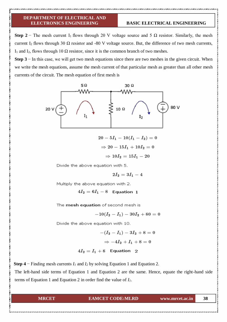
Step 2 − The mesh current I1 flows through 20 V voltage source and 5 Ω resistor. Similarly, the mesh
current I2 flows through 30 Ω resistor and -80 V voltage source. But, the difference of two mesh currents,
I1 and I2, flows through 10 Ω resistor, since it is the common branch of two meshes.
Step 3 − In this case, we will get two mesh equations since there are two meshes in the given circuit. When
we write the mesh equations, assume the mesh current of that particular mesh as greater than all other mesh
currents of the circuit. The mesh equation of first mesh is
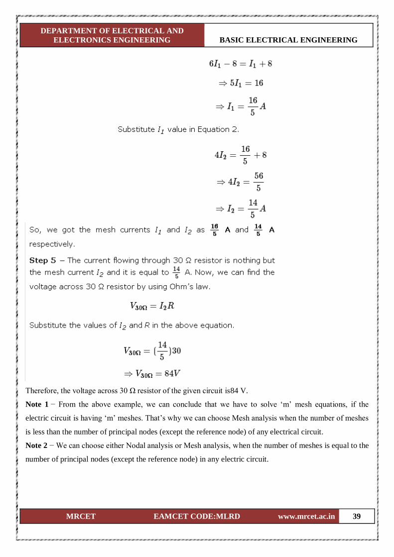
Step 4 − Finding mesh currents I1 and I2 by solving Equation 1 and Equation 2.
The left-hand side terms of Equation 1 and Equation 2 are the same. Hence, equate the right-hand side
terms of Equation 1 and Equation 2 in order find the value of I1.
DEPARTMENT OF ELECTRICAL AND
ELECTRONICS ENGINEERING BASIC ELECTRICAL ENGINEERING
MRCET EAMCET CODE:MLRD www.mrcet.ac.in 39
Therefore, the voltage across 30 Ω resistor of the given circuit is84 V.
Note 1 − From the above example, we can conclude that we have to solve ‘m’ mesh equations, if the
electric circuit is having ‘m’ meshes. That’s why we can choose Mesh analysis when the number of meshes
is less than the number of principal nodes (except the reference node) of any electrical circuit.
Note 2 − We can choose either Nodal analysis or Mesh analysis, when the number of meshes is equal to the
number of principal nodes (except the reference node) in any electric circuit.
DEPARTMENT OF ELECTRICAL AND
ELECTRONICS ENGINEERING BASIC ELECTRICAL ENGINEERING
MRCET EAMCET CODE:MLRD www.mrcet.ac.in 40
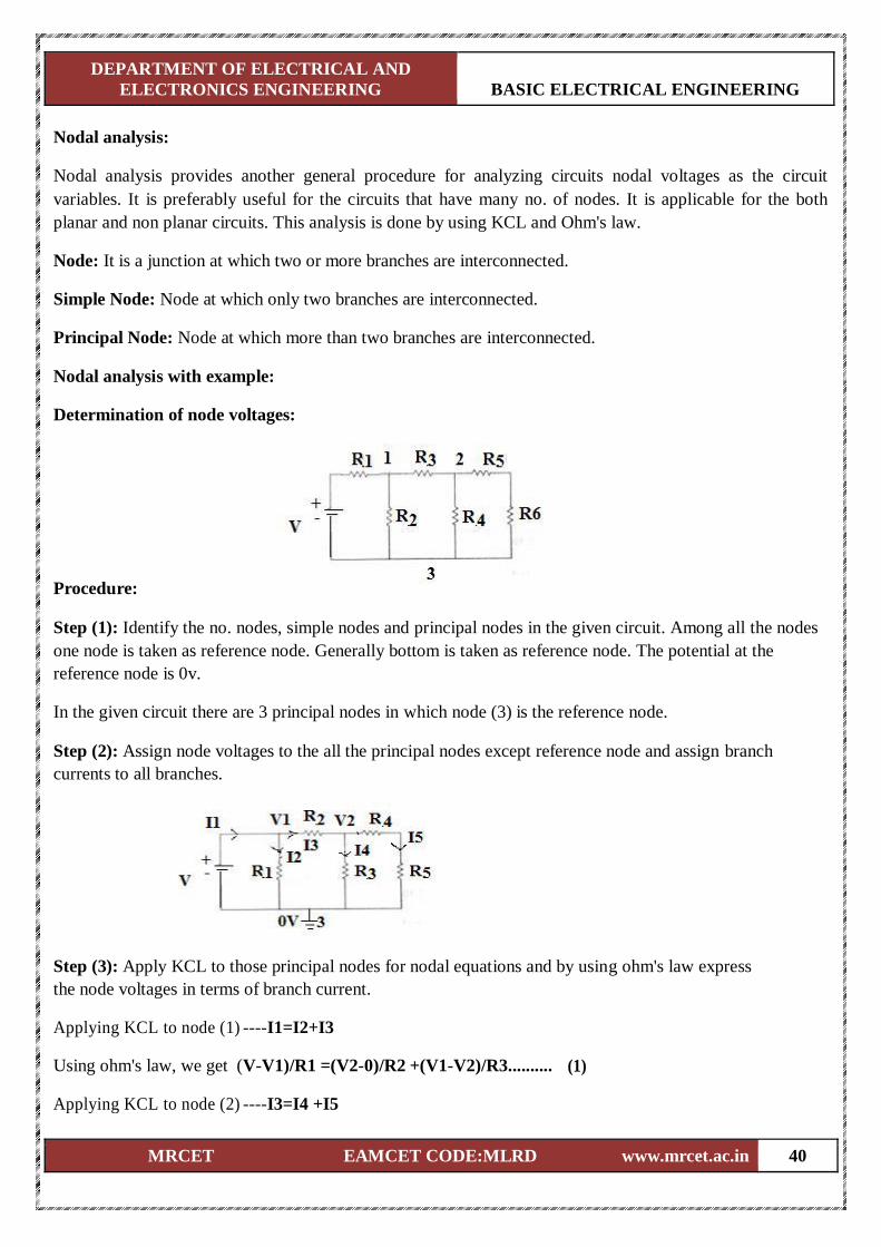
Nodal analysis: Nodal analysis provides another general procedure for analyzing circuits nodal voltages as the circuit
variables. It is preferably useful for the circuits that have many no. of nodes. It is applicable for the both
planar and non planar circuits. This analysis is done by using KCL and Ohm's law. Node: It is a junction at which two or more branches are interconnected. Simple Node: Node at which only two branches are interconnected. Principal Node: Node at which more than two branches are interconnected.
Nodal analysis with example:
Determination of node voltages:
Procedure: Step (1): Identify the no. nodes, simple nodes and principal nodes in the given circuit. Among all the nodes
one node is taken as reference node. Generally bottom is taken as reference node. The potential at the
reference node is 0v. In the given circuit there are 3 principal nodes in which node (3) is the reference node. Step (2): Assign node voltages to the all the principal nodes except reference node and assign branch
currents to all branches. Step (3): Apply KCL to those principal nodes for nodal equations and by using ohm's law express
the node voltages in terms of branch current. Applying KCL to node (1) ----I1=I2+I3
Using ohm's law, we get (V-V1)/R1 =(V2-0)/R2 +(V1-V2)/R3.......... (1)
Applying KCL to node (2) ----I3=I4 +I5
DEPARTMENT OF ELECTRICAL AND
ELECTRONICS ENGINEERING BASIC ELECTRICAL ENGINEERING
MRCET EAMCET CODE:MLRD www.mrcet.ac.in 41
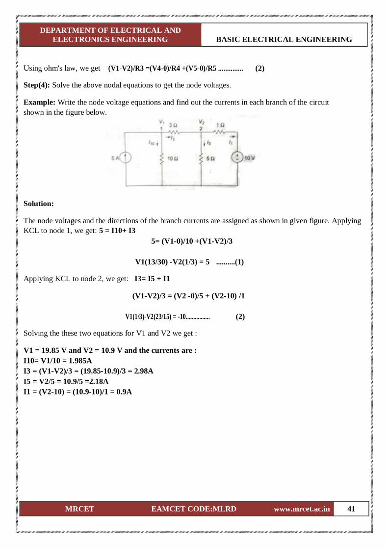
Using ohm's law, we get (V1-V2)/R3 =(V4-0)/R4 +(V5-0)/R5 .............. (2) Step(4): Solve the above nodal equations to get the node voltages. Example: Write the node voltage equations and find out the currents in each branch of the circuit
shown in the figure below.
Solution: The node voltages and the directions of the branch currents are assigned as shown in given figure. Applying
KCL to node 1, we get: 5 = I10+ I3 5= (V1-0)/10 +(V1-V2)/3
V1(13/30) -V2(1/3) = 5 ..........(1)
Applying KCL to node 2, we get: I3= I5 + I1
(V1-V2)/3 = (V2 -0)/5 + (V2-10) /1
V1(1/3)-V2(23/15) = -10................ (2)
Solving the these two equations for V1 and V2 we get :
V1 = 19.85 V and V2 = 10.9 V and the currents are :
I10= V1/10 = 1.985A
I3 = (V1-V2)/3 = (19.85-10.9)/3 = 2.98A
I5 = V2/5 = 10.9/5 =2.18A
I1 = (V2-10) = (10.9-10)/1 = 0.9A
DEPARTMENT OF ELECTRICAL AND
ELECTRONICS ENGINEERING BASIC ELECTRICAL ENGINEERING
MRCET EAMCET CODE:MLRD www.mrcet.ac.in 42
Network Theorems:
Introduction:
Any complicated network i.e. several sources, multiple resistors are present if the single element response is
desired then use the network theorems. Network theorems are also can be termed as network reduction
techniques. Each and every theorem got its importance of solving network. Let us see some important
theorems with DC and AC excitation with detailed procedures.
Thevenin’s Theorem and Norton’s theorem (Introduction) :
Thevenin’s Theorem and Norton’s theorem are two important theorems in solving Network problems having
many active and passive elements. Using these theorems the networks can be reduced to simple equivalent
circuits with one active source and one element. In circuit analysis many a times the current through a
branch is required to be found when it’s value is changed with all other element values remaining same. In
such cases finding out every time the branch current using the conventional mesh and node analysis methods
is quite awkward and time consuming. But with the simple equivalent circuits (with one active source and
one element) obtained using these two theorems the calculations become very simple. Thevenin’s and
Norton’s theorems are dual theorems.
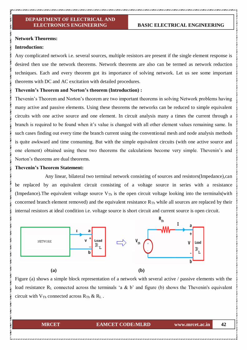
Thevenin’s Theorem Statement:
Any linear, bilateral two terminal network consisting of sources and resistors(Impedance),can
be replaced by an equivalent circuit consisting of a voltage source in series with a resistance
(Impedance).The equivalent voltage source VTh is the open circuit voltage looking into the terminals(with
concerned branch element removed) and the equivalent resistance RTh while all sources are replaced by their
internal resistors at ideal condition i.e. voltage source is short circuit and current source is open circuit.
(a) (b)
Figure (a) shows a simple block representation of a network with several active / passive elements with the
load resistance RL connected across the terminals ‘a & b’ and figure (b) shows the Thevenin's equivalent
circuit with VTh connected across RTh & RL .
DEPARTMENT OF ELECTRICAL AND
ELECTRONICS ENGINEERING BASIC ELECTRICAL ENGINEERING
MRCET EAMCET CODE:MLRD www.mrcet.ac.in 43
Main steps to find out VTh and RTh :
1. The terminals of the branch/element through which the current is to be found out are marked as say a & b
after removing the concerned branch/element
2. Open circuit voltage VOC across these two terminals is found out using the conventional network
mesh/node analysis methods and this would be VTh .
3. Thevenin's resistance RTh is found out by the method depending upon whether the network contains
dependent sources or not.
a. With dependent sources: RTh = Voc / Isc
b. Without dependent sources : RTh = Equivalent resistance looking into the concerned terminals with all
voltage & current sources replaced by their internal impedances (i.e. ideal voltage sources short
circuited and ideal current sources open circuited)
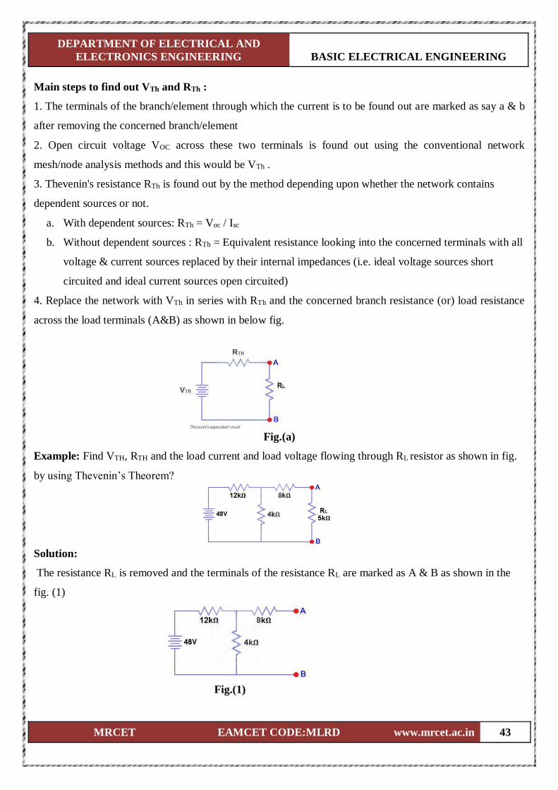
4. Replace the network with VTh in series with RTh and the concerned branch resistance (or) load resistance
across the load terminals (A&B) as shown in below fig.
Fig.(a)
Example: Find VTH, RTH and the load current and load voltage flowing through RL resistor as shown in fig.
by using Thevenin’s Theorem?
Solution:
The resistance RL is removed and the terminals of the resistance RL are marked as A & B as shown in the
fig. (1)
Fig.(1)
DEPARTMENT OF ELECTRICAL AND
ELECTRONICS ENGINEERING BASIC ELECTRICAL ENGINEERING
MRCET EAMCET CODE:MLRD www.mrcet.ac.in 44
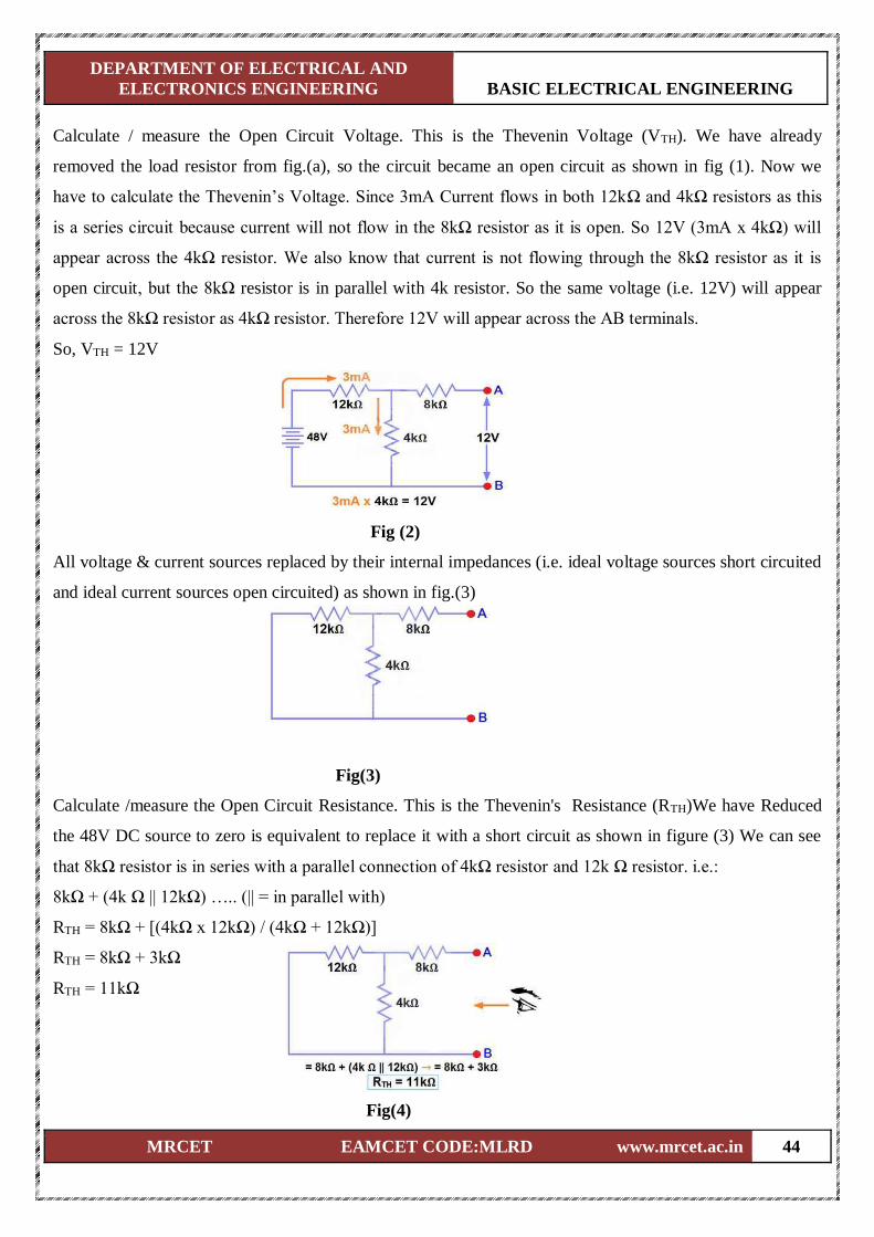
Calculate / measure the Open Circuit Voltage. This is the Thevenin Voltage (VTH). We have already
removed the load resistor from fig.(a), so the circuit became an open circuit as shown in fig (1). Now we
have to calculate the Thevenin’s Voltage. Since 3mA Current flows in both 12kΩ and 4kΩ resistors as this
is a series circuit because current will not flow in the 8kΩ resistor as it is open. So 12V (3mA x 4kΩ) will
appear across the 4kΩ resistor. We also know that current is not flowing through the 8kΩ resistor as it is
open circuit, but the 8kΩ resistor is in parallel with 4k resistor. So the same voltage (i.e. 12V) will appear
across the 8kΩ resistor as 4kΩ resistor. Therefore 12V will appear across the AB terminals.
So, VTH = 12V
Fig (2)
All voltage & current sources replaced by their internal impedances (i.e. ideal voltage sources short circuited
and ideal current sources open circuited) as shown in fig.(3)
Fig(3)
Calculate /measure the Open Circuit Resistance. This is the Thevenin's Resistance (RTH)We have Reduced
the 48V DC source to zero is equivalent to replace it with a short circuit as shown in figure (3) We can see
that 8kΩ resistor is in series with a parallel connection of 4kΩ resistor and 12k Ω resistor. i.e.:
8kΩ + (4k Ω || 12kΩ) ….. (|| = in parallel with)
RTH = 8kΩ + [(4kΩ x 12kΩ) / (4kΩ + 12kΩ)]
RTH = 8kΩ + 3kΩ
RTH = 11kΩ
Fig(4)
DEPARTMENT OF ELECTRICAL AND
ELECTRONICS ENGINEERING BASIC ELECTRICAL ENGINEERING
MRCET EAMCET CODE:MLRD www.mrcet.ac.in 45
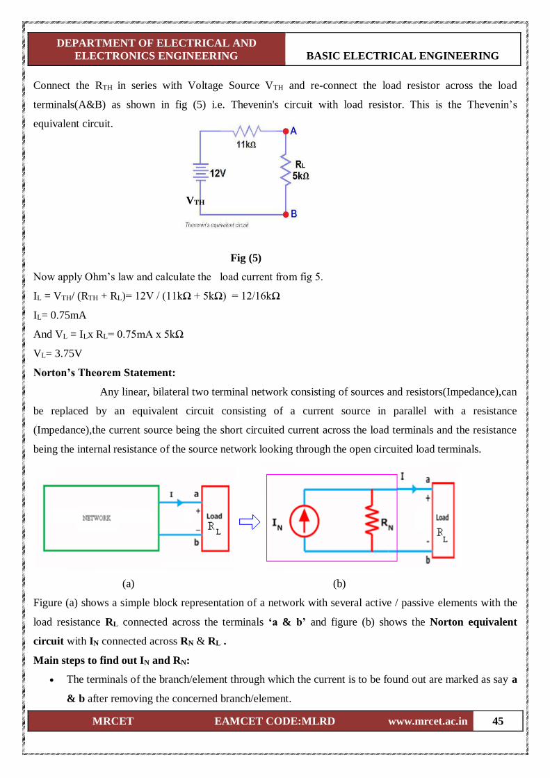
Connect the RTH in series with Voltage Source VTH and re-connect the load resistor across the load
terminals(A&B) as shown in fig (5) i.e. Thevenin's circuit with load resistor. This is the Thevenin’s
equivalent circuit.
VTH
Fig (5)
Now apply Ohm’s law and calculate the load current from fig 5.
IL = VTH/ (RTH + RL)= 12V / (11kΩ + 5kΩ) = 12/16kΩ
IL= 0.75mA
And VL = ILx RL= 0.75mA x 5kΩ
VL= 3.75V
Norton’s Theorem Statement:
Any linear, bilateral two terminal network consisting of sources and resistors(Impedance),can
be replaced by an equivalent circuit consisting of a current source in parallel with a resistance
(Impedance),the current source being the short circuited current across the load terminals and the resistance
being the internal resistance of the source network looking through the open circuited load terminals.
(a) (b)
Figure (a) shows a simple block representation of a network with several active / passive elements with the
load resistance RL connected across the terminals ‘a & b’ and figure (b) shows the Norton equivalent
circuit with IN connected across RN & RL .
Main steps to find out IN and RN:
The terminals of the branch/element through which the current is to be found out are marked as say a
& b after removing the concerned branch/element.
DEPARTMENT OF ELECTRICAL AND
ELECTRONICS ENGINEERING BASIC ELECTRICAL ENGINEERING
MRCET EAMCET CODE:MLRD www.mrcet.ac.in 46
Open circuit voltage VOC across these two terminals and ISC through these two terminals are found
out using the conventional network mesh/node analysis methods and they are same as what we
obtained in Thevenin’s equivalent circuit.
Next Norton resistance RN is found out depending upon whether the network contains dependent
sources or not.
a) With dependent sources: RN = Voc / Isc
b) Without dependent sources : RN = Equivalent resistance looking into the concerned terminals
with all voltage & current sources replaced by their internal impedances (i.e. ideal voltage
sources short circuited and ideal current sources open circuited)
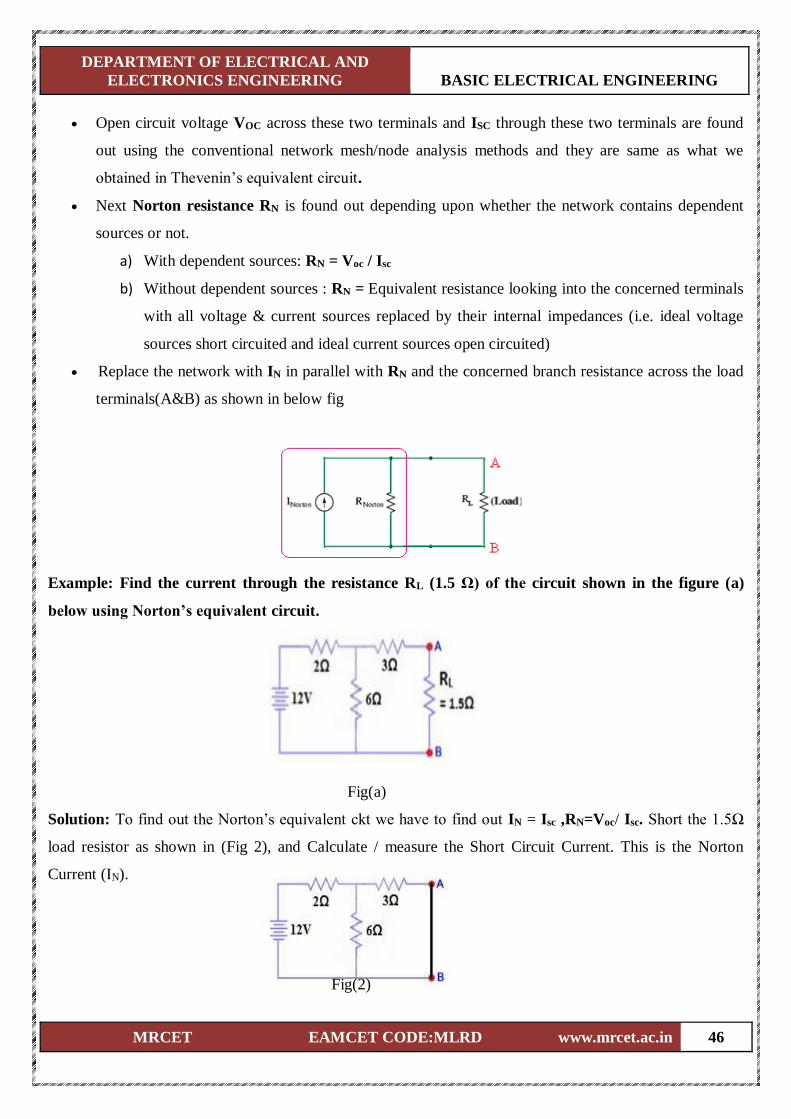
Replace the network with IN in parallel with RN and the concerned branch resistance across the load
terminals(A&B) as shown in below fig
Example: Find the current through the resistance RL (1.5 Ω) of the circuit shown in the figure (a)
below using Norton’s equivalent circuit.
Fig(a)
Solution: To find out the Norton’s equivalent ckt we have to find out IN = Isc ,RN=Voc/ Isc. Short the 1.5Ω
load resistor as shown in (Fig 2), and Calculate / measure the Short Circuit Current. This is the Norton
Current (IN).
Fig(2)
DEPARTMENT OF ELECTRICAL AND
ELECTRONICS ENGINEERING BASIC ELECTRICAL ENGINEERING
MRCET EAMCET CODE:MLRD www.mrcet.ac.in 47
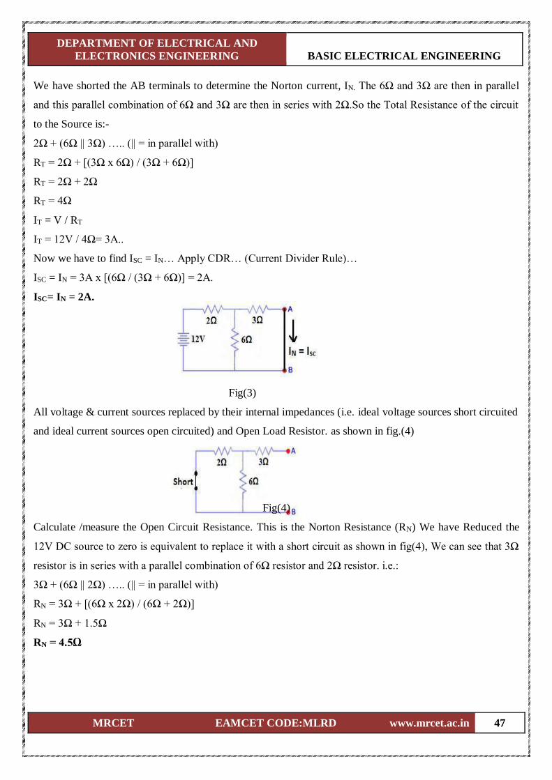
We have shorted the AB terminals to determine the Norton current, IN. The 6Ω and 3Ω are then in parallel
and this parallel combination of 6Ω and 3Ω are then in series with 2Ω.So the Total Resistance of the circuit
to the Source is:-
2Ω + (6Ω || 3Ω) ….. (|| = in parallel with)
RT = 2Ω + [(3Ω x 6Ω) / (3Ω + 6Ω)]
RT = 2Ω + 2Ω
RT = 4Ω
IT = V / RT
IT = 12V / 4Ω= 3A..
Now we have to find ISC = IN… Apply CDR… (Current Divider Rule)…
ISC = IN = 3A x [(6Ω / (3Ω + 6Ω)] = 2A.
ISC= IN = 2A.
Fig(3)
All voltage & current sources replaced by their internal impedances (i.e. ideal voltage sources short circuited
and ideal current sources open circuited) and Open Load Resistor. as shown in fig.(4)
Fig(4)
Calculate /measure the Open Circuit Resistance. This is the Norton Resistance (RN) We have Reduced the
12V DC source to zero is equivalent to replace it with a short circuit as shown in fig(4), We can see that 3Ω
resistor is in series with a parallel combination of 6Ω resistor and 2Ω resistor. i.e.:
3Ω + (6Ω || 2Ω) ….. (|| = in parallel with)
RN = 3Ω + [(6Ω x 2Ω) / (6Ω + 2Ω)]
RN = 3Ω + 1.5Ω
RN = 4.5Ω
DEPARTMENT OF ELECTRICAL AND
ELECTRONICS ENGINEERING BASIC ELECTRICAL ENGINEERING
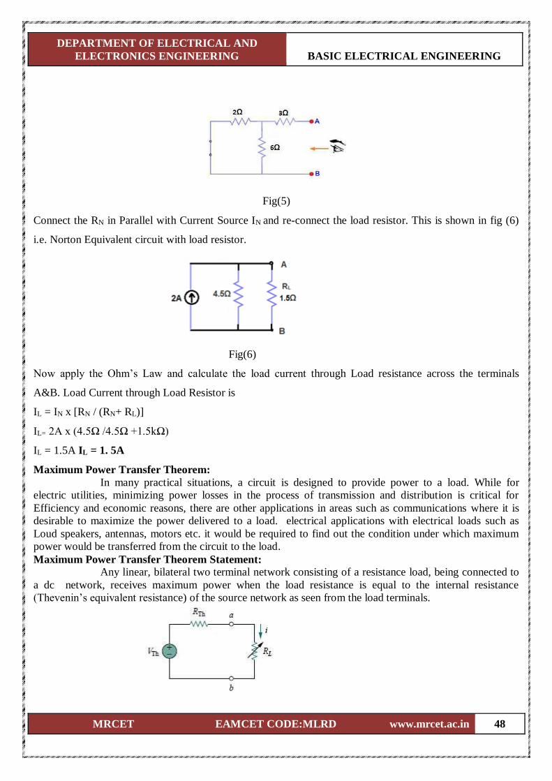
MRCET EAMCET CODE:MLRD www.mrcet.ac.in 48
Fig(5)
Connect the RN in Parallel with Current Source IN and re-connect the load resistor. This is shown in fig (6)
i.e. Norton Equivalent circuit with load resistor.
Fig(6)
Now apply the Ohm’s Law and calculate the load current through Load resistance across the terminals
A&B. Load Current through Load Resistor is
IL = IN x [RN / (RN+ RL)]
IL= 2A x (4.5Ω /4.5Ω +1.5kΩ)
IL = 1.5A IL = 1. 5A
Maximum Power Transfer Theorem:
In many practical situations, a circuit is designed to provide power to a load. While for
electric utilities, minimizing power losses in the process of transmission and distribution is critical for
Efficiency and economic reasons, there are other applications in areas such as communications where it is
desirable to maximize the power delivered to a load. electrical applications with electrical loads such as
Loud speakers, antennas, motors etc. it would be required to find out the condition under which maximum
power would be transferred from the circuit to the load.
Maximum Power Transfer Theorem Statement:
Any linear, bilateral two terminal network consisting of a resistance load, being connected to
a dc network, receives maximum power when the load resistance is equal to the internal resistance
(Thevenin’s equivalent resistance) of the source network as seen from the load terminals.
DEPARTMENT OF ELECTRICAL AND
ELECTRONICS ENGINEERING BASIC ELECTRICAL ENGINEERING
MRCET EAMCET CODE:MLRD www.mrcet.ac.in 49
According to Maximum Power Transfer Theorem, for maximum power transfer from the network to the
load resistance , RL must be equal to the source resistance i.e. Network’s Thevenin equivalent resistance RTh
. i.e. RL = RTh
The load current I in the circuit shown above is given by,
𝐼 =𝑉𝑇𝐻
𝑅𝑇𝐻+𝑅𝐿
The power delivered by the circuit to the load:
𝑃 = 𝐼2𝑅 =𝑉𝑇𝐻
2
(𝑅𝑇𝐻+𝑅𝐿)2𝑅𝐿
The condition for maximum power transfer can be obtained by differentiating the above expression for
power delivered with respect to the load resistance (Since we want to find out the value of RL for maximum
power transfer) and equating it to zero as :
𝜕𝑃
𝜕𝑅𝐿= 0 =
𝑉𝑇𝐻2
(𝑅𝑇𝐻+𝑅𝐿)2 −
2𝑉𝑇𝐻2
(𝑅𝑇𝐻+𝑅𝐿)3 𝑅𝐿 = 0
Simplifying the above equation, we get:
(𝑅𝑇𝐻 + 𝑅𝐿) − 2𝑅𝐿 = 0 ⟹ 𝑅𝐿 = 𝑅𝑇𝐻 Under the condition of maximum power transfer, the power delivered to the load is given by :
𝑃𝑀𝐴𝑋 =𝑉𝑇𝐻
2
(𝑅𝐿+𝑅𝐿)2× 𝑅𝐿=
𝑉𝑇𝐻2
4𝑅𝐿
Under the condition of maximum power transfer, the efficiency 𝜼 of the network is then given by:
𝑃𝐿𝑂𝑆𝑆 =𝑉𝑇𝐻
2
(𝑅𝐿+𝑅𝐿)2× 𝑅𝑇𝐻=
𝑉𝑇𝐻2
4𝑅𝐿
𝜼 =output
input=
𝑉𝑇𝐻2
4𝑅𝐿
(𝑉𝑇𝐻
2
4𝑅𝐿+ 𝑉𝑇𝐻
2
4𝑅𝐿)
= 0.50
For maximum power transfer the load resistance should be equal to the Thevenin’s equivalent resistance ( or
Norton equivalent resistance) of the network to which it is connected . Under the condition of maximum
power transfer the efficiency of the system is 50 %.
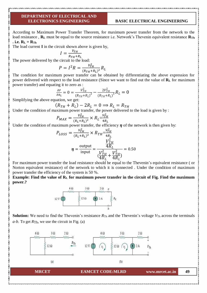
Example: Find the value of RL for maximum power transfer in the circuit of Fig. Find the maximum
power.?
Solution: We need to find the Thevenin’s resistance RTh and the Thevenin’s voltage VTh across the terminals
a-b. To get RTh, we use the circuit in Fig. (a)

DEPARTMENT OF ELECTRICAL AND
ELECTRONICS ENGINEERING BASIC ELECTRICAL ENGINEERING
MRCET EAMCET CODE:MLRD www.mrcet.ac.in 50
RTh= 2 + 3 + (6 // 12 )=5+(6×12
6+12)=5+4=9Ω
To get VTh, we consider the circuit in Fig.(b).Applying mesh analysis,
−12 + 18i1− 12i2 = 0,
i2 = −2 A, Solving for i1, we get i1= −2/3. Applying KVL around the outer loop to get VTh across terminals a-b, we obtain,
−12 + 6i1+ 3i2+ 2(0) + VTh= 0
VTh= 22 V For maximum power transfer, RL= RTh= 9Ω and the maximum power is,
𝑃𝑀𝐴𝑋 =𝑉𝑇𝐻
2
4𝑅𝐿=
22×22
4×9=13.44W
Superposition Theorem:
The principle of superposition helps us to analyze a linear circuit with more than one current
or voltage sources sometimes it is easier to find out the voltage across or current in a branch of the circuit by
considering the effect of one source at a time by replacing the other sources with their ideal internal
resistances.
Superposition Theorem Statement:
Any linear, bilateral two terminal network consisting of more than one sources, The total
current or voltage in any part of a network is equal to the algebraic sum of the currents or voltages in the
required branch with each source acting individually while other sources are replaced by their ideal internal
resistances. (i.e. Voltage sources by a short circuit and current sources by open circuit)
Steps to Apply Super position Principle:
1. Replace all independent sources with their internal resistances except one source. Find the output
(voltage or current) due to that active source using nodal or mesh analysis.
2. Repeat step 1 for each of the other independent sources.
3. Find the total contribution by adding algebraically all the contributions due to the independent
sources.
Example: By Using the superposition theorem find I in the circuit shown in figure?
Fig.(a)
DEPARTMENT OF ELECTRICAL AND
ELECTRONICS ENGINEERING BASIC ELECTRICAL ENGINEERING
MRCET EAMCET CODE:MLRD www.mrcet.ac.in 51
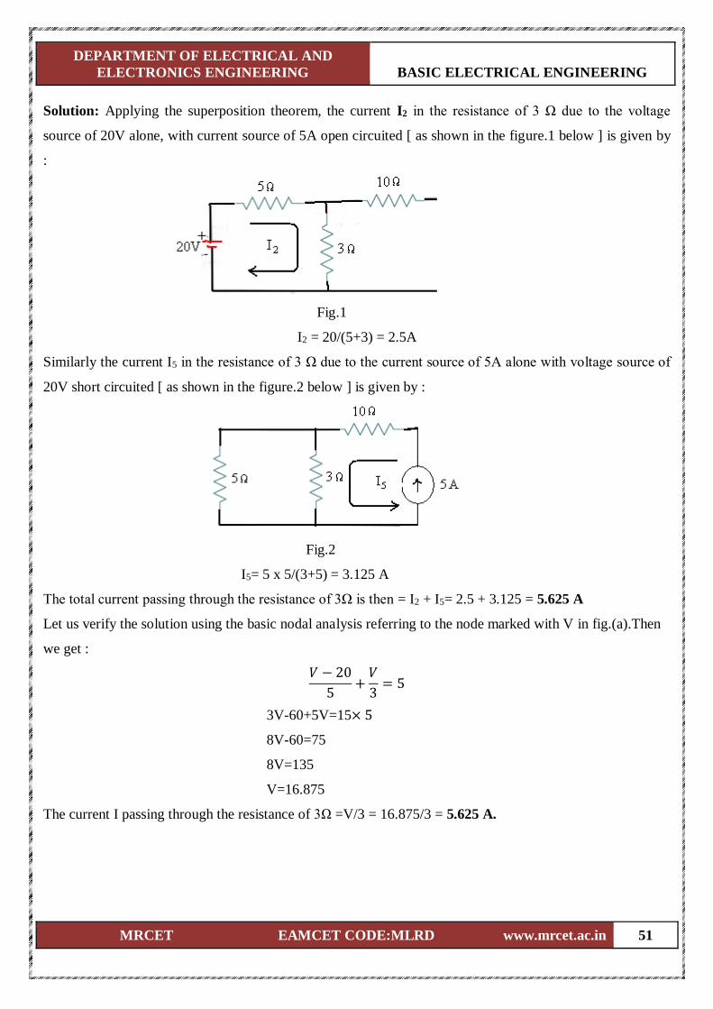
Solution: Applying the superposition theorem, the current I2 in the resistance of 3 Ω due to the voltage
source of 20V alone, with current source of 5A open circuited [ as shown in the figure.1 below ] is given by
:
Fig.1
I2 = 20/(5+3) = 2.5A
Similarly the current I5 in the resistance of 3 Ω due to the current source of 5A alone with voltage source of
20V short circuited [ as shown in the figure.2 below ] is given by :
Fig.2
I5= 5 x 5/(3+5) = 3.125 A
The total current passing through the resistance of 3Ω is then = I2 + I5= 2.5 + 3.125 = 5.625 A
Let us verify the solution using the basic nodal analysis referring to the node marked with V in fig.(a).Then
we get :
𝑉 − 20
5+
𝑉
3= 5
3V-60+5V=15× 5
8V-60=75
8V=135
V=16.875
The current I passing through the resistance of 3Ω =V/3 = 16.875/3 = 5.625 A.
DEPARTMENT OF ELECTRICAL AND
ELECTRONICS ENGINEERING BASIC ELECTRICAL ENGINEERING
MRCET EAMCET CODE:MLRD www.mrcet.ac.in 52
UNIT-III
SINGLE PHASE A.C. CIRCUITS
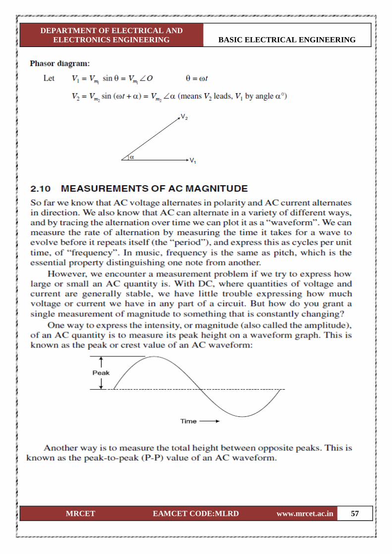
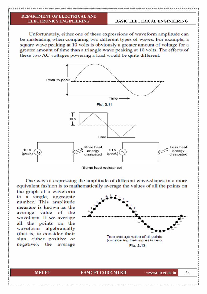
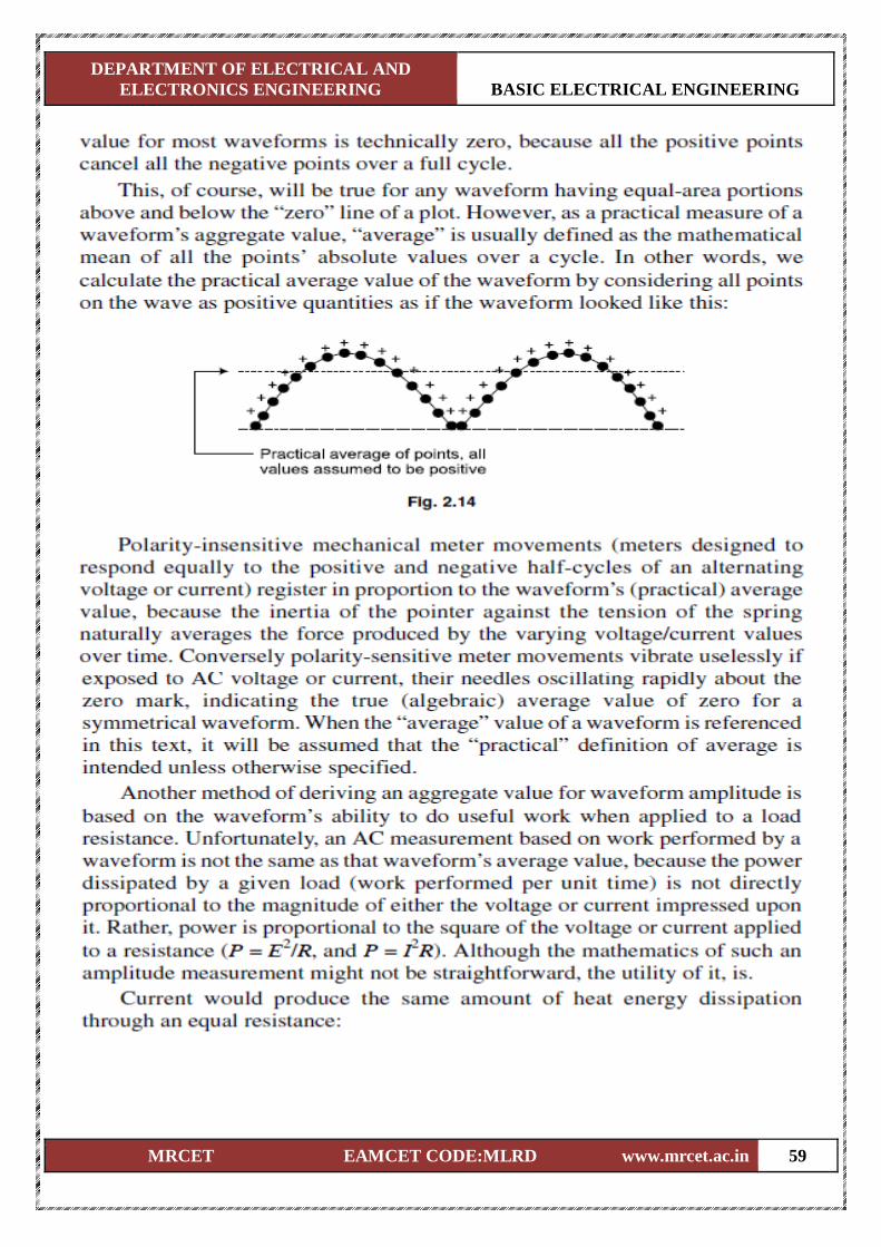
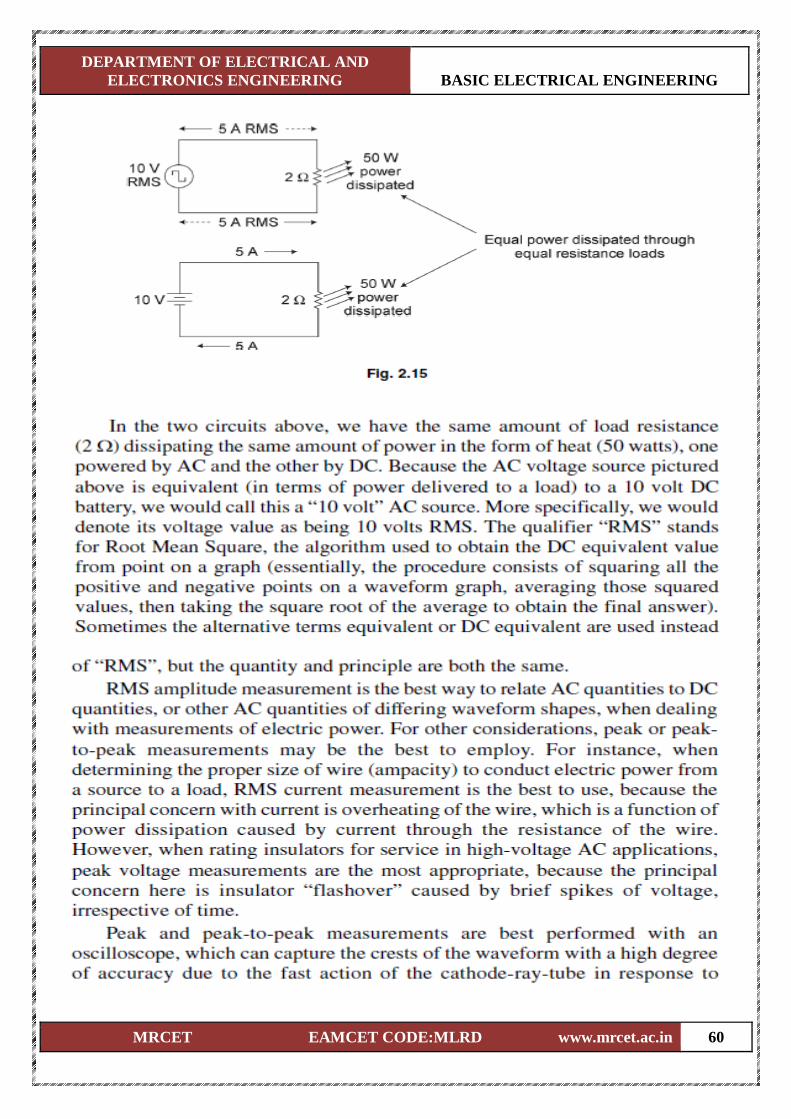
Average value, R.M.S. value, form factor and peak factor for sinusoidal wave form.
Complex and Polar forms of representation.
Steady State Analysis of series R-L-C circuits.
Concept of Reactance, Impedance, Susceptance, Admittance, Phase and Phase difference.
Concept of Power Factor, Real, Reactive and Complex power.
Illustrative Problems.
DEPARTMENT OF ELECTRICAL AND
ELECTRONICS ENGINEERING BASIC ELECTRICAL ENGINEERING
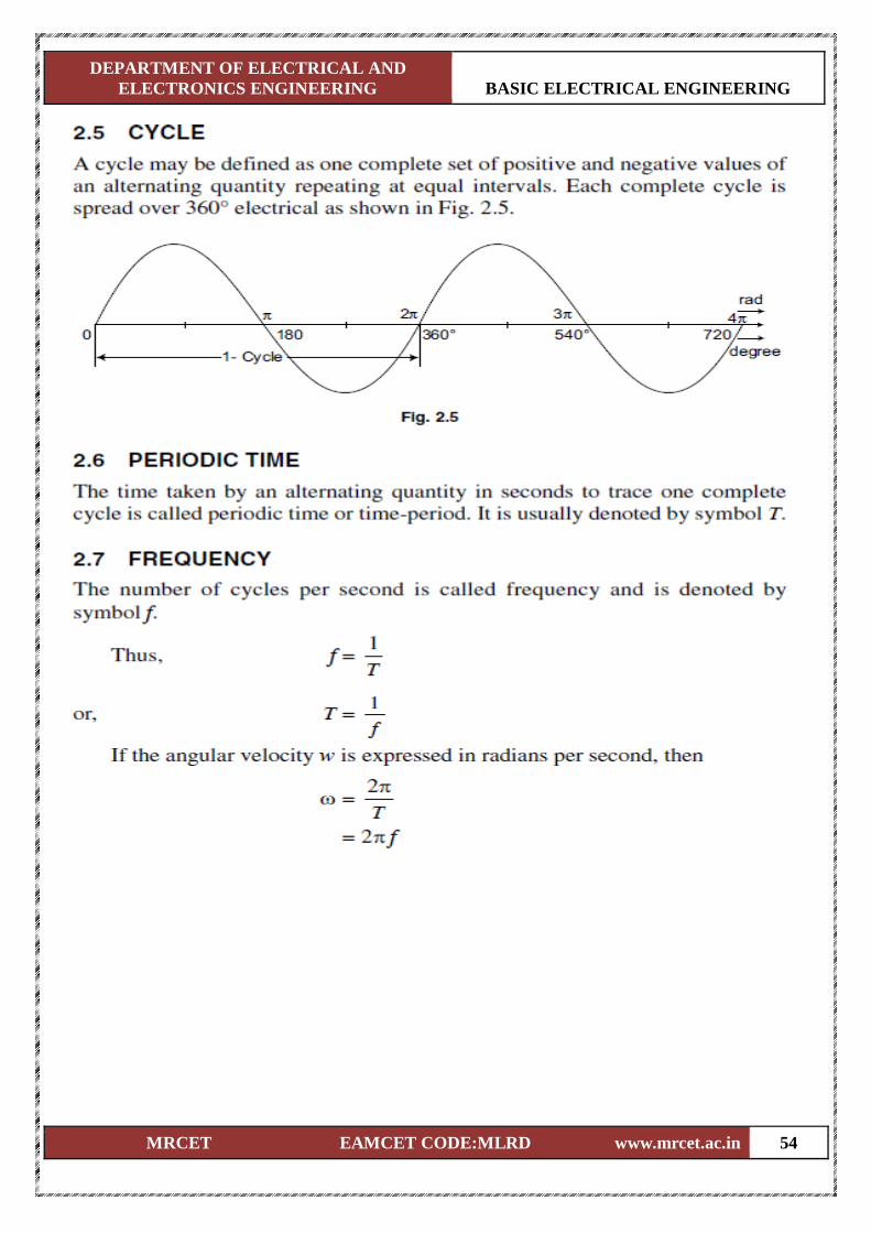
MRCET EAMCET CODE:MLRD www.mrcet.ac.in 53
DEPARTMENT OF ELECTRICAL AND
ELECTRONICS ENGINEERING BASIC ELECTRICAL ENGINEERING
MRCET EAMCET CODE:MLRD www.mrcet.ac.in 54
DEPARTMENT OF ELECTRICAL AND
ELECTRONICS ENGINEERING BASIC ELECTRICAL ENGINEERING
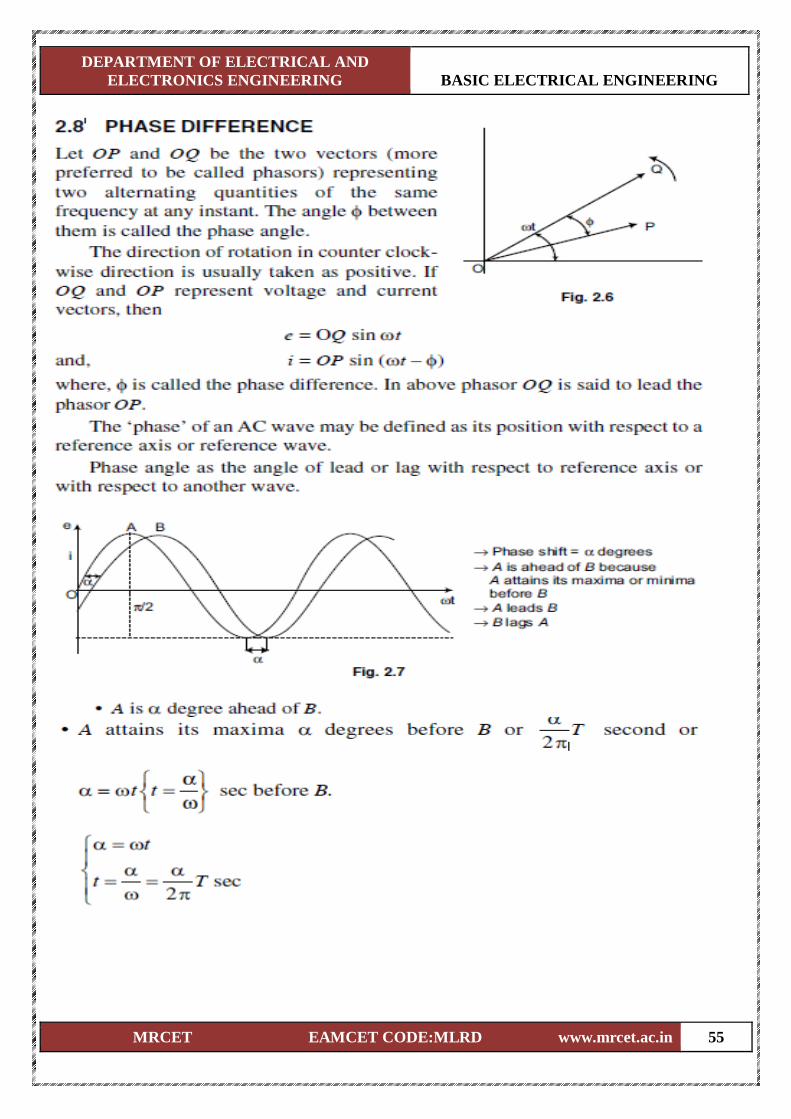
MRCET EAMCET CODE:MLRD www.mrcet.ac.in 55
DEPARTMENT OF ELECTRICAL AND
ELECTRONICS ENGINEERING BASIC ELECTRICAL ENGINEERING
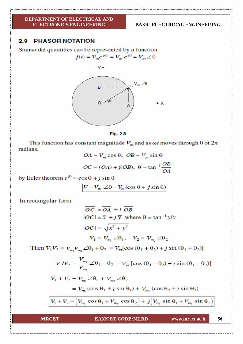
MRCET EAMCET CODE:MLRD www.mrcet.ac.in 56
DEPARTMENT OF ELECTRICAL AND
ELECTRONICS ENGINEERING BASIC ELECTRICAL ENGINEERING
MRCET EAMCET CODE:MLRD www.mrcet.ac.in 57
DEPARTMENT OF ELECTRICAL AND
ELECTRONICS ENGINEERING BASIC ELECTRICAL ENGINEERING
MRCET EAMCET CODE:MLRD www.mrcet.ac.in 58
DEPARTMENT OF ELECTRICAL AND
ELECTRONICS ENGINEERING BASIC ELECTRICAL ENGINEERING
MRCET EAMCET CODE:MLRD www.mrcet.ac.in 59
DEPARTMENT OF ELECTRICAL AND
ELECTRONICS ENGINEERING BASIC ELECTRICAL ENGINEERING
MRCET EAMCET CODE:MLRD www.mrcet.ac.in 60
DEPARTMENT OF ELECTRICAL AND
ELECTRONICS ENGINEERING BASIC ELECTRICAL ENGINEERING
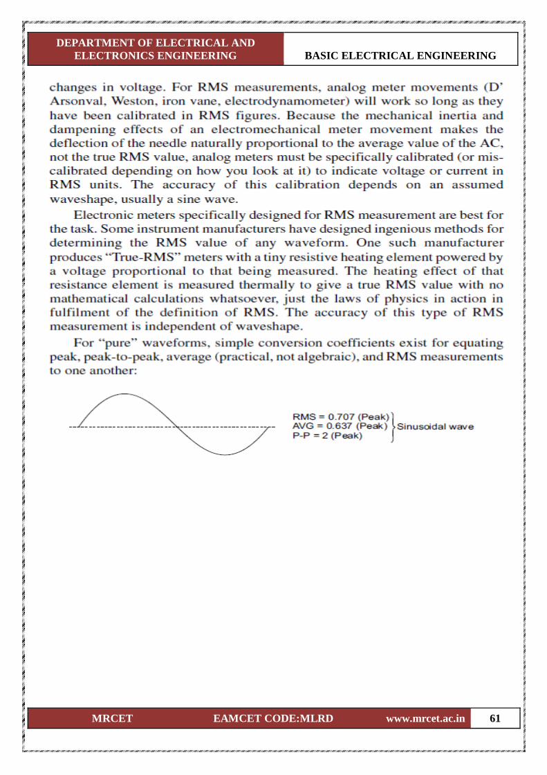
MRCET EAMCET CODE:MLRD www.mrcet.ac.in 61
DEPARTMENT OF ELECTRICAL AND
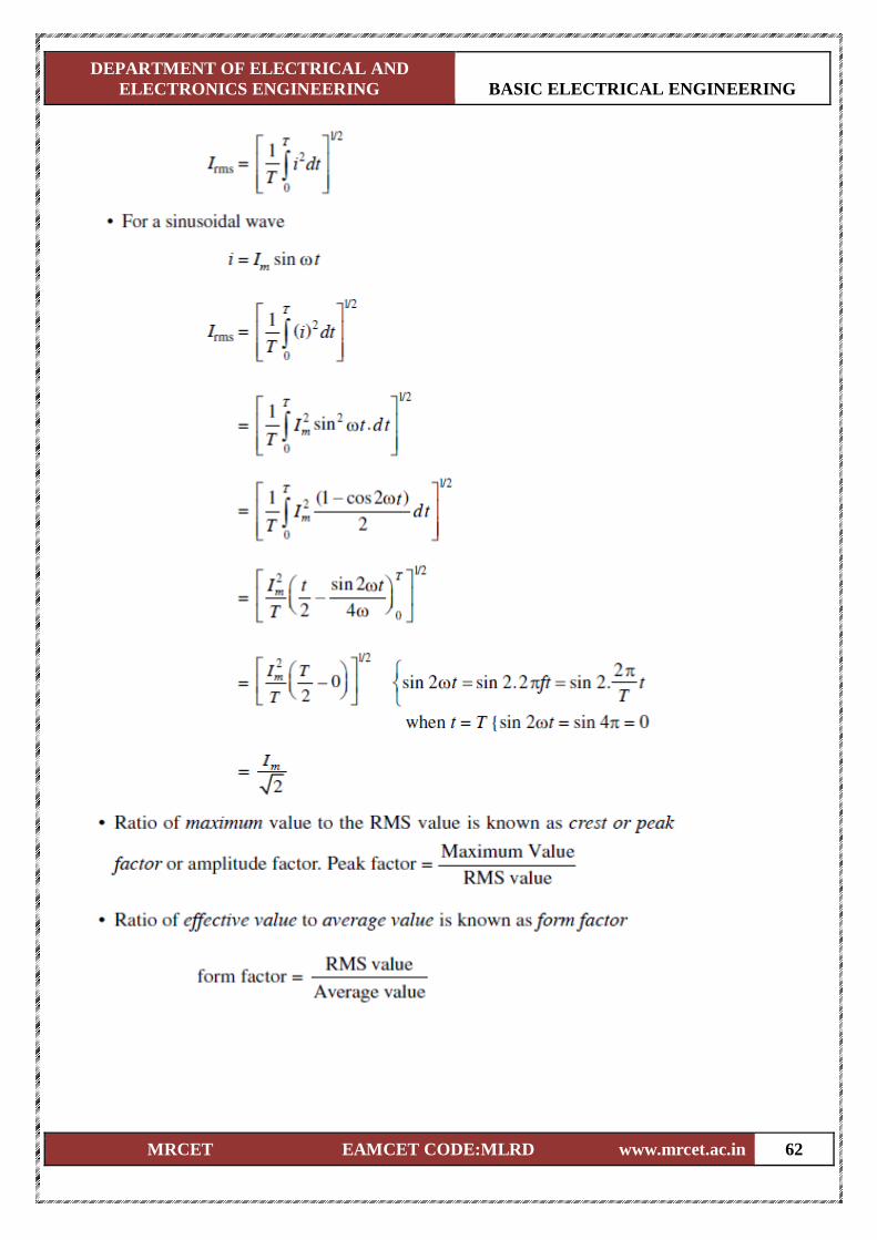
ELECTRONICS ENGINEERING BASIC ELECTRICAL ENGINEERING
MRCET EAMCET CODE:MLRD www.mrcet.ac.in 62
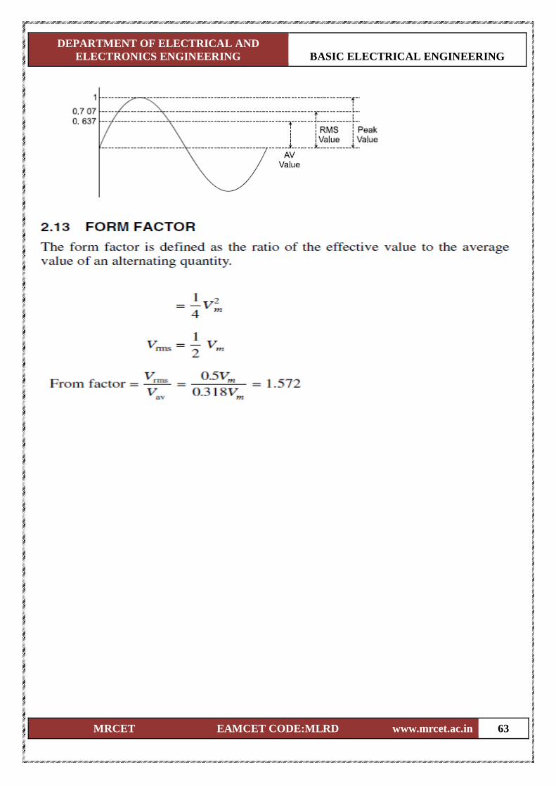
DEPARTMENT OF ELECTRICAL AND
ELECTRONICS ENGINEERING BASIC ELECTRICAL ENGINEERING
MRCET EAMCET CODE:MLRD www.mrcet.ac.in 63
DEPARTMENT OF ELECTRICAL AND
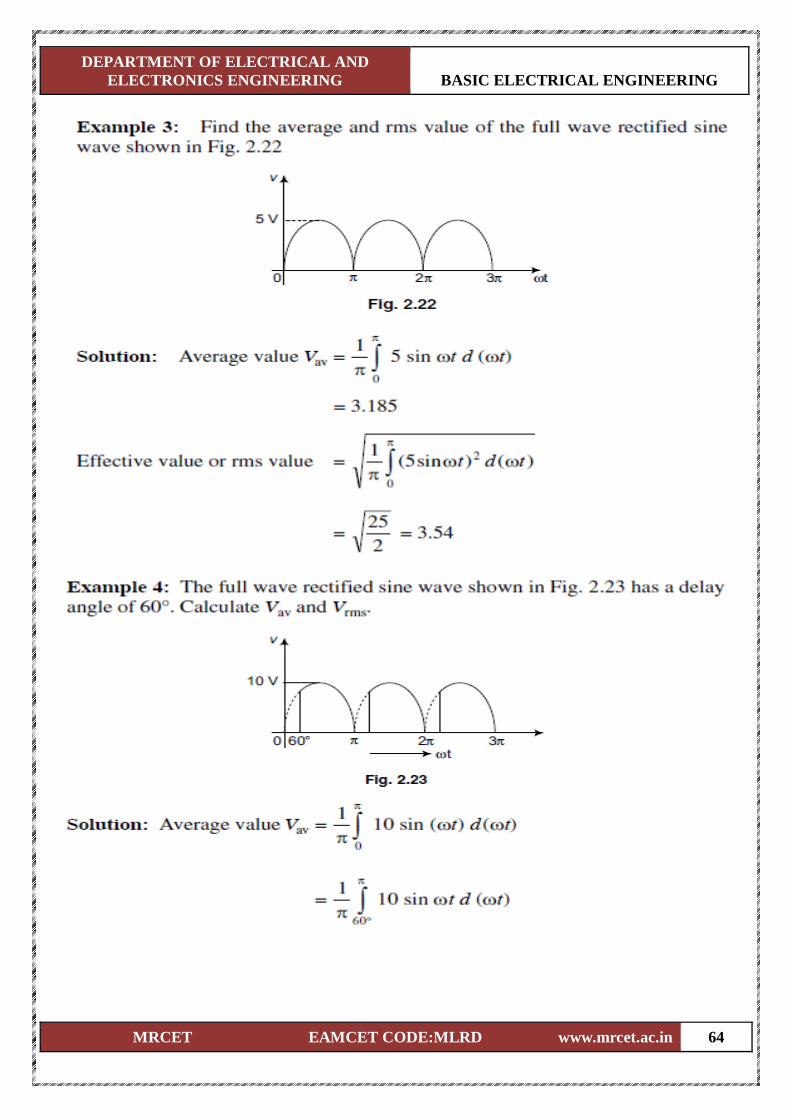
ELECTRONICS ENGINEERING BASIC ELECTRICAL ENGINEERING
MRCET EAMCET CODE:MLRD www.mrcet.ac.in 64
DEPARTMENT OF ELECTRICAL AND
ELECTRONICS ENGINEERING BASIC ELECTRICAL ENGINEERING
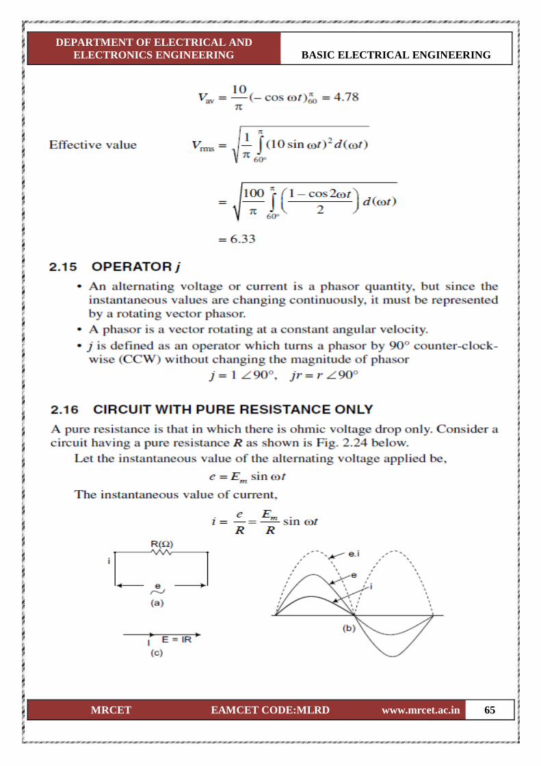
MRCET EAMCET CODE:MLRD www.mrcet.ac.in 65
DEPARTMENT OF ELECTRICAL AND
ELECTRONICS ENGINEERING BASIC ELECTRICAL ENGINEERING
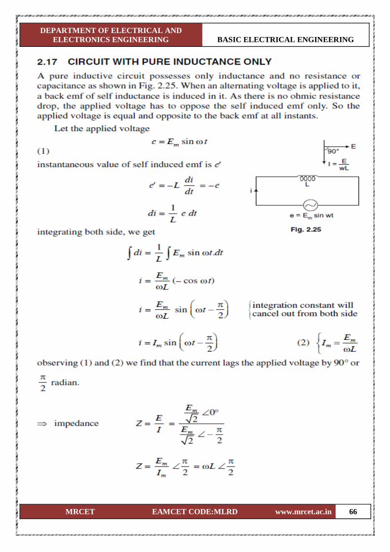
MRCET EAMCET CODE:MLRD www.mrcet.ac.in 66
DEPARTMENT OF ELECTRICAL AND
ELECTRONICS ENGINEERING BASIC ELECTRICAL ENGINEERING
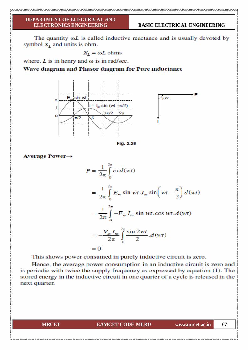
MRCET EAMCET CODE:MLRD www.mrcet.ac.in 67
DEPARTMENT OF ELECTRICAL AND
ELECTRONICS ENGINEERING BASIC ELECTRICAL ENGINEERING
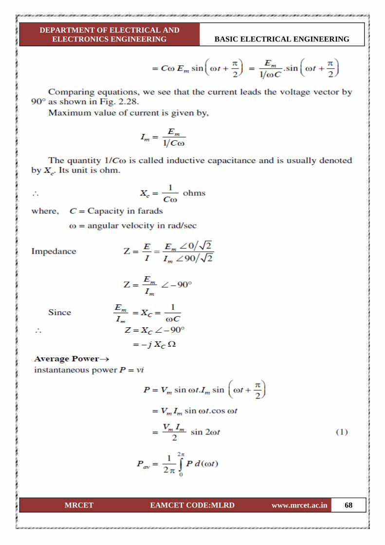
MRCET EAMCET CODE:MLRD www.mrcet.ac.in 68
DEPARTMENT OF ELECTRICAL AND
ELECTRONICS ENGINEERING BASIC ELECTRICAL ENGINEERING
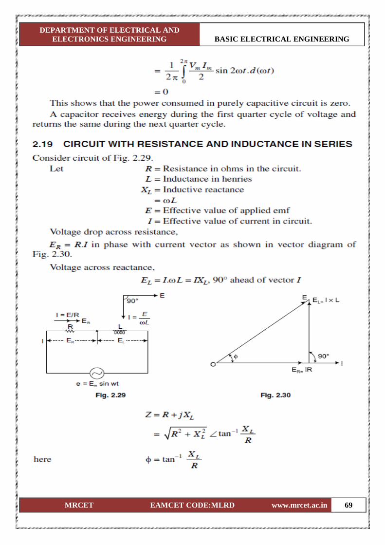
MRCET EAMCET CODE:MLRD www.mrcet.ac.in 69
DEPARTMENT OF ELECTRICAL AND
ELECTRONICS ENGINEERING BASIC ELECTRICAL ENGINEERING
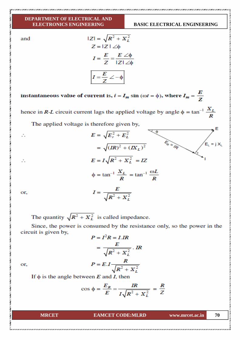
MRCET EAMCET CODE:MLRD www.mrcet.ac.in 70
DEPARTMENT OF ELECTRICAL AND
ELECTRONICS ENGINEERING BASIC ELECTRICAL ENGINEERING
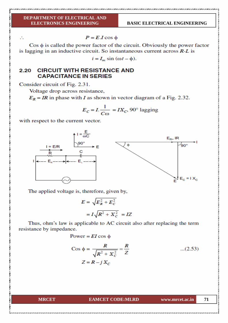
MRCET EAMCET CODE:MLRD www.mrcet.ac.in 71
DEPARTMENT OF ELECTRICAL AND
ELECTRONICS ENGINEERING BASIC ELECTRICAL ENGINEERING
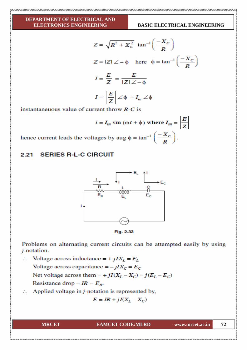
MRCET EAMCET CODE:MLRD www.mrcet.ac.in 72
DEPARTMENT OF ELECTRICAL AND
ELECTRONICS ENGINEERING BASIC ELECTRICAL ENGINEERING
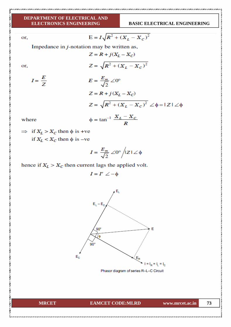
MRCET EAMCET CODE:MLRD www.mrcet.ac.in 73
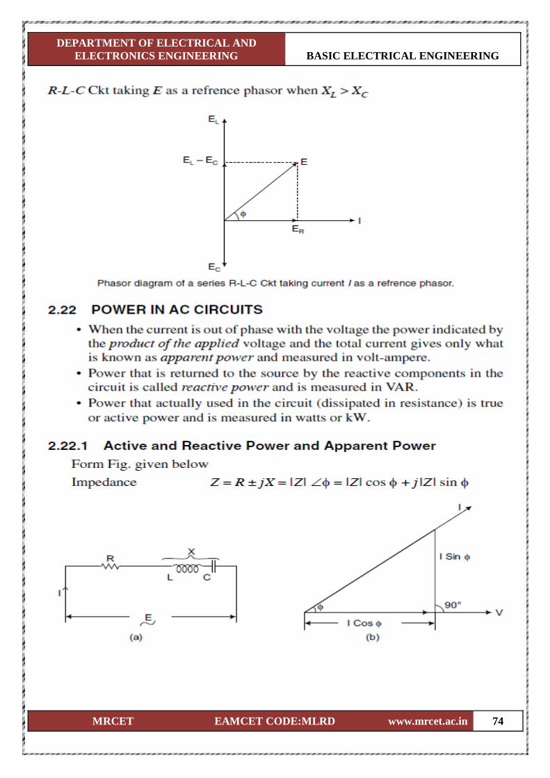
DEPARTMENT OF ELECTRICAL AND
ELECTRONICS ENGINEERING BASIC ELECTRICAL ENGINEERING
MRCET EAMCET CODE:MLRD www.mrcet.ac.in 74
DEPARTMENT OF ELECTRICAL AND
ELECTRONICS ENGINEERING BASIC ELECTRICAL ENGINEERING
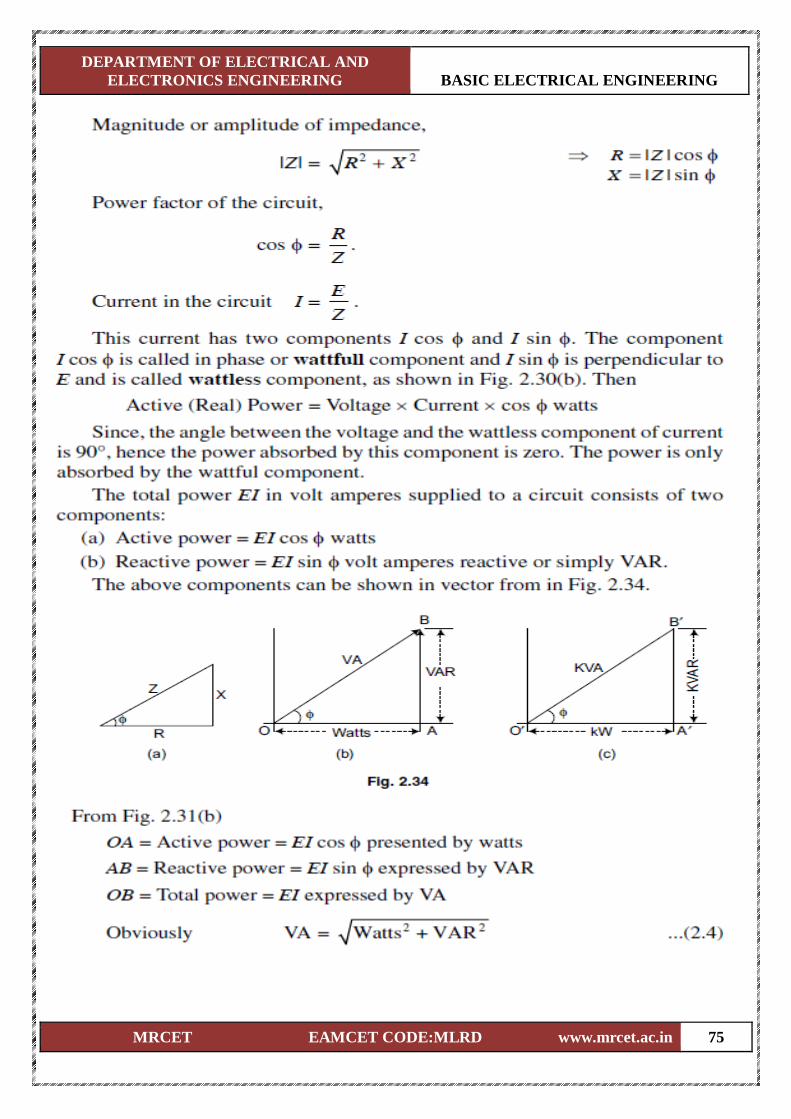
MRCET EAMCET CODE:MLRD www.mrcet.ac.in 75
DEPARTMENT OF ELECTRICAL AND
ELECTRONICS ENGINEERING BASIC ELECTRICAL ENGINEERING
MRCET EAMCET CODE:MLRD www.mrcet.ac.in 76
DEPARTMENT OF ELECTRICAL AND
ELECTRONICS ENGINEERING BASIC ELECTRICAL ENGINEERING
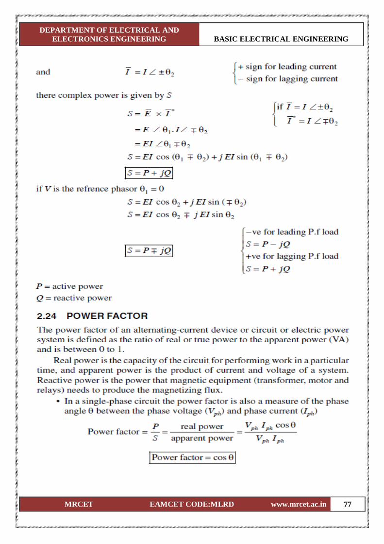
MRCET EAMCET CODE:MLRD www.mrcet.ac.in 77
DEPARTMENT OF ELECTRICAL AND
ELECTRONICS ENGINEERING BASIC ELECTRICAL ENGINEERING
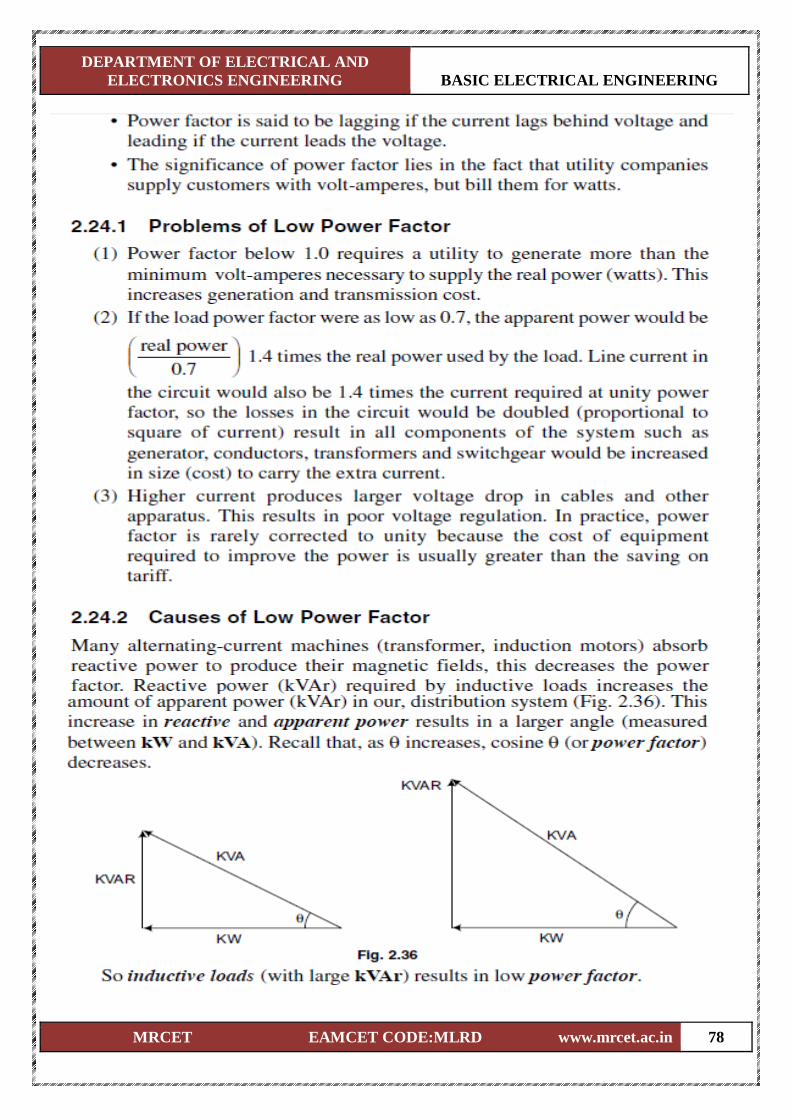
MRCET EAMCET CODE:MLRD www.mrcet.ac.in 78
DEPARTMENT OF ELECTRICAL AND
ELECTRONICS ENGINEERING BASIC ELECTRICAL ENGINEERING
MRCET EAMCET CODE:MLRD www.mrcet.ac.in 79
DEPARTMENT OF ELECTRICAL AND
ELECTRONICS ENGINEERING BASIC ELECTRICAL ENGINEERING
MRCET EAMCET CODE:MLRD www.mrcet.ac.in 80
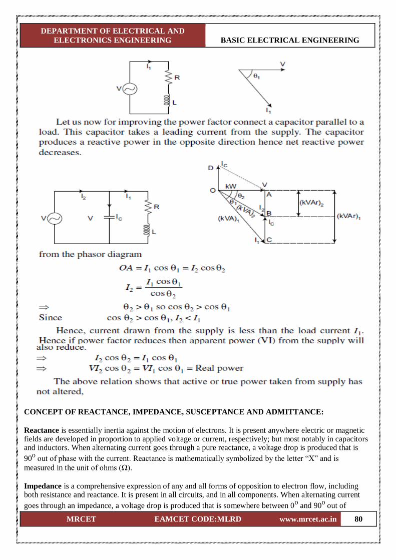
CONCEPT OF REACTANCE, IMPEDANCE, SUSCEPTANCE AND ADMITTANCE:
Reactance is essentially inertia against the motion of electrons. It is present anywhere electric or magnetic fields are developed in proportion to applied voltage or current, respectively; but most notably in capacitors and inductors. When alternating current goes through a pure reactance, a voltage drop is produced that is
90o out of phase with the current. Reactance is mathematically symbolized by the letter “X” and is
measured in the unit of ohms (Ω).
Impedance is a comprehensive expression of any and all forms of opposition to electron flow, including both resistance and reactance. It is present in all circuits, and in all components. When alternating current
goes through an impedance, a voltage drop is produced that is somewhere between 0o and 90
o out of
DEPARTMENT OF ELECTRICAL AND
ELECTRONICS ENGINEERING BASIC ELECTRICAL ENGINEERING
MRCET EAMCET CODE:MLRD www.mrcet.ac.in 81
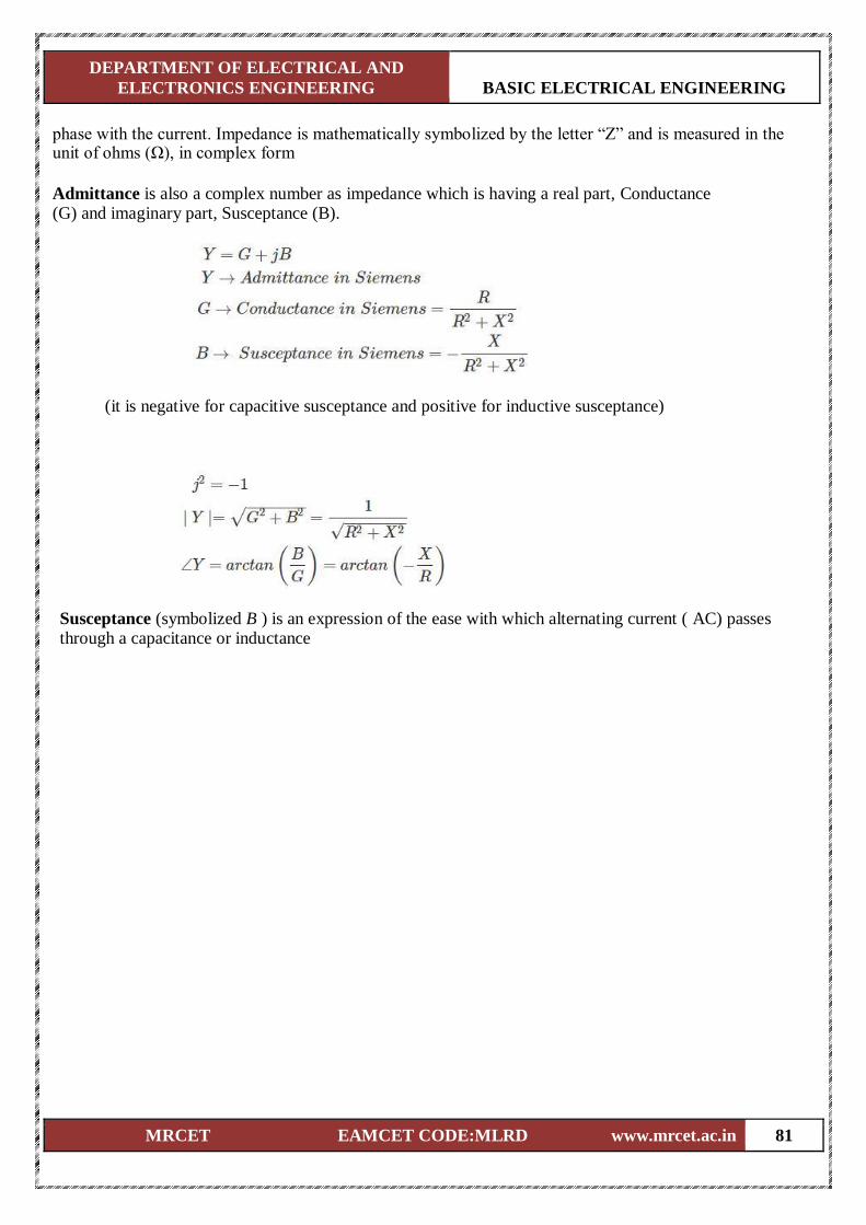
phase with the current. Impedance is mathematically symbolized by the letter “Z” and is measured in the unit of ohms (Ω), in complex form
Admittance is also a complex number as impedance which is having a real part, Conductance (G) and imaginary part, Susceptance (B).
(it is negative for capacitive susceptance and positive for inductive susceptance) Susceptance (symbolized B ) is an expression of the ease with which alternating current ( AC) passes through a capacitance or inductance
DEPARTMENT OF ELECTRICAL AND
ELECTRONICS ENGINEERING BASIC ELECTRICAL ENGINEERING
MRCET EAMCET CODE:MLRD www.mrcet.ac.in 82
UNIT-IV ELECTRICAL MACHINES
Dc Generator
Principle Of Operation
Constructional Features
EMF Equation
Dc Motor
Principle Of Operation
Back EMF
Torque Equation
Single Phase Transformer
Principle Of Operation
Constructional Features
EMF Equation
Simple Problems

DEPARTMENT OF ELECTRICAL AND
ELECTRONICS ENGINEERING BASIC ELECTRICAL ENGINEERING
MRCET EAMCET CODE:MLRD www.mrcet.ac.in 83
DC GENERATOR
Principle of DC Generator
There are two types of generators, one is ac generator and other is DC generator. Whatever
may be the types of generators, it always converts mechanical power to electrical power. An AC generator
produces alternating power. A DC generator produces direct power. Both of these generators produce
electrical power, based on same fundamental principle of Faraday's law of electromagnetic induction.
According to this law, when a conductor moves in a magnetic field it cuts magnetic lines of force, due to
which an emf is induced in the conductor. The magnitude of this induced emf depends upon the rate of
change of flux (magnetic line force) linkage with the conductor. This emf will cause a current to flow if the
conductor circuit is closed.
Hence the most basic tow essential parts of a generator are
1. a magnetic field
2. conductors which move inside that magnetic field.
Now we will go through working principle of DC generator. As, the working principle of ac generator is not
in scope of our discussion in this section.
Single Loop DC Generator
In the figure above, a single loop of conductor of rectangular shape is placed between two
opposite poles of magnet.
Let's us consider, the rectangular loop of conductor is ABCD which rotates inside the
magnetic field about its own axis ab. When the loop rotates from its vertical position to its horizontal
position, it cuts the flux lines of the field. As during this movement two sides, i.e. AB and CD of the loop
cut the flux lines there will be an emf induced in these both of the sides (AB and BC) of the loop.
DEPARTMENT OF ELECTRICAL AND
ELECTRONICS ENGINEERING BASIC ELECTRICAL ENGINEERING
MRCET EAMCET CODE:MLRD www.mrcet.ac.in 84
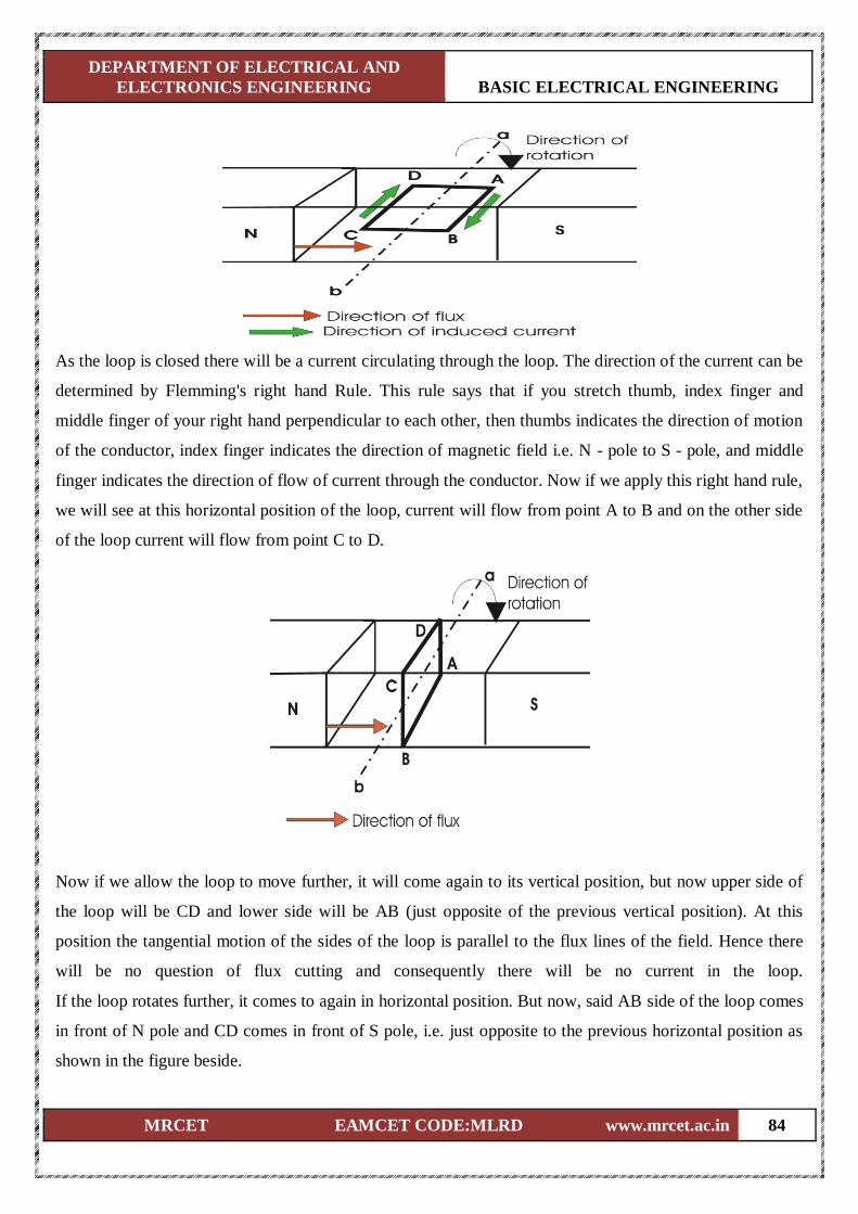
As the loop is closed there will be a current circulating through the loop. The direction of the current can be
determined by Flemming's right hand Rule. This rule says that if you stretch thumb, index finger and
middle finger of your right hand perpendicular to each other, then thumbs indicates the direction of motion
of the conductor, index finger indicates the direction of magnetic field i.e. N - pole to S - pole, and middle
finger indicates the direction of flow of current through the conductor. Now if we apply this right hand rule,
we will see at this horizontal position of the loop, current will flow from point A to B and on the other side
of the loop current will flow from point C to D.
Now if we allow the loop to move further, it will come again to its vertical position, but now upper side of
the loop will be CD and lower side will be AB (just opposite of the previous vertical position). At this
position the tangential motion of the sides of the loop is parallel to the flux lines of the field. Hence there
will be no question of flux cutting and consequently there will be no current in the loop.
If the loop rotates further, it comes to again in horizontal position. But now, said AB side of the loop comes
in front of N pole and CD comes in front of S pole, i.e. just opposite to the previous horizontal position as
shown in the figure beside.
DEPARTMENT OF ELECTRICAL AND
ELECTRONICS ENGINEERING BASIC ELECTRICAL ENGINEERING
MRCET EAMCET CODE:MLRD www.mrcet.ac.in 85
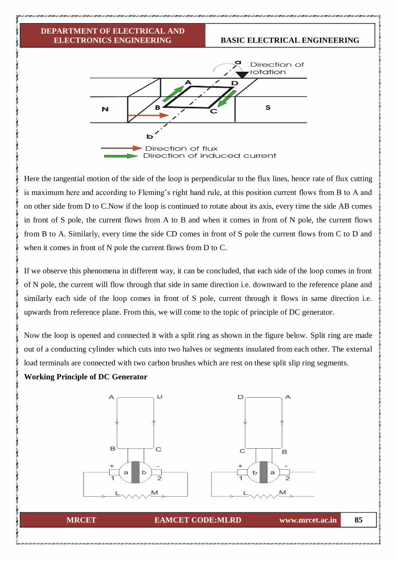
Here the tangential motion of the side of the loop is perpendicular to the flux lines, hence rate of flux cutting
is maximum here and according to Fleming’s right hand rule, at this position current flows from B to A and
on other side from D to C.Now if the loop is continued to rotate about its axis, every time the side AB comes
in front of S pole, the current flows from A to B and when it comes in front of N pole, the current flows
from B to A. Similarly, every time the side CD comes in front of S pole the current flows from C to D and
when it comes in front of N pole the current flows from D to C.
If we observe this phenomena in different way, it can be concluded, that each side of the loop comes in front
of N pole, the current will flow through that side in same direction i.e. downward to the reference plane and
similarly each side of the loop comes in front of S pole, current through it flows in same direction i.e.
upwards from reference plane. From this, we will come to the topic of principle of DC generator.
Now the loop is opened and connected it with a split ring as shown in the figure below. Split ring are made
out of a conducting cylinder which cuts into two halves or segments insulated from each other. The external
load terminals are connected with two carbon brushes which are rest on these split slip ring segments.
Working Principle of DC Generator
DEPARTMENT OF ELECTRICAL AND
ELECTRONICS ENGINEERING BASIC ELECTRICAL ENGINEERING
MRCET EAMCET CODE:MLRD www.mrcet.ac.in 86
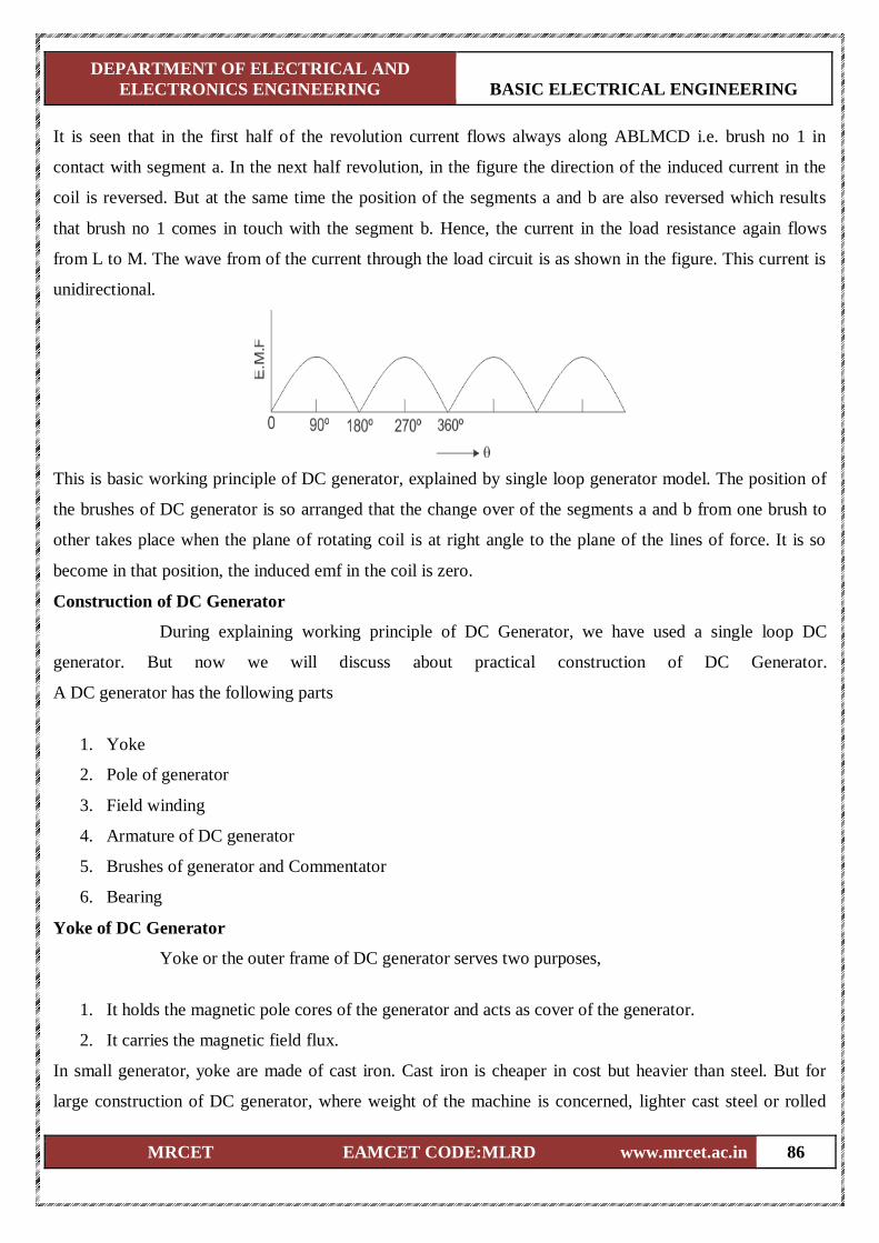
It is seen that in the first half of the revolution current flows always along ABLMCD i.e. brush no 1 in
contact with segment a. In the next half revolution, in the figure the direction of the induced current in the
coil is reversed. But at the same time the position of the segments a and b are also reversed which results
that brush no 1 comes in touch with the segment b. Hence, the current in the load resistance again flows
from L to M. The wave from of the current through the load circuit is as shown in the figure. This current is
unidirectional.
This is basic working principle of DC generator, explained by single loop generator model. The position of
the brushes of DC generator is so arranged that the change over of the segments a and b from one brush to
other takes place when the plane of rotating coil is at right angle to the plane of the lines of force. It is so
become in that position, the induced emf in the coil is zero.
Construction of DC Generator
During explaining working principle of DC Generator, we have used a single loop DC
generator. But now we will discuss about practical construction of DC Generator.
A DC generator has the following parts
1. Yoke
2. Pole of generator
3. Field winding
4. Armature of DC generator
5. Brushes of generator and Commentator
6. Bearing
Yoke of DC Generator
Yoke or the outer frame of DC generator serves two purposes,
1. It holds the magnetic pole cores of the generator and acts as cover of the generator.
2. It carries the magnetic field flux.
In small generator, yoke are made of cast iron. Cast iron is cheaper in cost but heavier than steel. But for
large construction of DC generator, where weight of the machine is concerned, lighter cast steel or rolled
DEPARTMENT OF ELECTRICAL AND
ELECTRONICS ENGINEERING BASIC ELECTRICAL ENGINEERING
MRCET EAMCET CODE:MLRD www.mrcet.ac.in 87
steel is preferable for constructing yoke of DC generator. Normally larger yokes are formed by rounding a
rectangular steel slab and the edges are welded together at the bottom. Then feet, terminal box and hangers
are welded to the outer periphery of the yoke frame.
Pole Cores and Pole Shoes
Let's first discuss about pole core of DC generator. There are mainly two types of construction available.
One: Solid pole core, where it is made of a solid single piece of cast iron or cast steel.
Two: Laminated pole core, where it made of numbers of thin, limitations of annealed steel which are riveted
together. The thickness of the lamination is in the range of 0.04" to 0.01". The pole core is fixed to the inner
periphery of the yoke by means of bolts through the yoke and into the pole body. Since the poles project
inwards they are called salient poles. The pole shoes are so typically shaped, that, they spread out the
magnetic flux in the air gap and reduce the reluctance of the magnetic path. Due to their larger cross-section
they hold the pole coil at its position.
Pole Coils: The field coils or pole coils are wound around the pole core. These are a simple coil of insulated
copper wire or strip, which placed on the pole which placed between yoke and pole shoes as shown.
Armature Core
The purpose of armature core is to hold the armature winding and provide low reluctance
path for the flux through the armature from N pole to S pole. Although a DC generator provides direct
current but induced current in the armature is alternating in nature. That is why, cylindrical or drum shaped
armature core is build up of circular laminated sheet. In every circular lamination, slots are either die - cut or
punched on the outer periphery and the key way is located on the inner periphery as shown. Air ducts are
also punched of cut on each lamination for circulation of air through the core for providing better cooling.
Up to diameter of 40", the circular stampings are cut out in one piece of lamination sheet. But above 40",
diameter, number of suitable sections of a circle is cut. A complete circle of lamination is formed by four or
six or even eight such segment.
Armature Winding
Armature winding are generally formed wound. These are first wound in the form of flat
rectangular coils and are then pulled into their proper shape in a coil puller. Various conductors of the coils
are insulated from each other. The conductors are placed in the armature slots, which are lined with tough
insulating material. This slot insulation is folded over above the armature conductors placed in it and
secured in place by special hard wooden or fiber wedges. Two types of armature windings are used – Lap
winding and Wave winding.
DEPARTMENT OF ELECTRICAL AND
ELECTRONICS ENGINEERING BASIC ELECTRICAL ENGINEERING
MRCET EAMCET CODE:MLRD www.mrcet.ac.in 88
Commutator
The commentator plays a vital role in DC generator. It collects current from armature and
sends it to the load as direct current. It actually takes alternating current from armature and converts it to
direct current and then send it to external load. It is cylindrical structured and is build up of wedge-shaped
segments of high conductivity, hard drawn or drop forged copper. Each segment is insulated from the shaft
by means of insulated commutator segment shown below. Each commentator segment is connected with
corresponding armature conductor through segment riser or lug.
Brushes
The brushes are made of carbon. These are rectangular block shaped. The only function of
these carbon brushes of DC generator is to collect current from commutator segments. The brushes are
housed in the rectangular box shaped brush holder or brush box. As shown in figure, the brush face is placed
on the commutator segment which is attached to the brush holder.
Bearing
For small machine, ball bearing is used and for heavy duty DC generator, roller bearing is used. The bearing
must always be lubricated properly for smooth operation and long life of generator.
Armature winding
Basically armature winding of a DC machine is wound by one of the two methods, lap
winding or wave winding. The difference between these two is merely due to the end connections and
commutator connections of the conductor. To know how armature winding is done, it is essential to know
the following terminologies -
1. Pole pitch: It is defined as number of armature slots per pole. For example, if there are 36 conductors
and 4 poles, then the pole pitch is 36/4=9.
2. Coil span or coil pitch (Ys): It is the distance between the two sides of a coil measured in terms of
armature slots.
3. Front pitch (Yf): It is the distance, in terms of armature conductors, between the second conductor
of one coil and the first conductor of the next coil. OR it is the distance between two coil sides that
are connected to the same commutator segment.
4. Back pitch (Yb): The distance by which a coil advances on the back of the armature is called as back
pitch of the coil. It is measured in terms of armature conductors.
5. Resultant pitch (Yr): The distance, in terms of armature conductor, between the beginning of one coil
and the beginning of the next coil is called as resultant pitch of the coil.
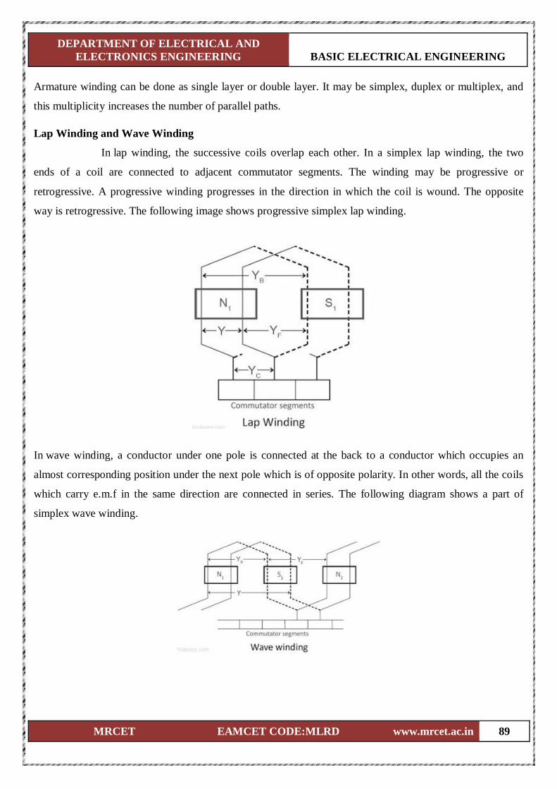
DEPARTMENT OF ELECTRICAL AND
ELECTRONICS ENGINEERING BASIC ELECTRICAL ENGINEERING
MRCET EAMCET CODE:MLRD www.mrcet.ac.in 89
Armature winding can be done as single layer or double layer. It may be simplex, duplex or multiplex, and
this multiplicity increases the number of parallel paths.
Lap Winding and Wave Winding
In lap winding, the successive coils overlap each other. In a simplex lap winding, the two
ends of a coil are connected to adjacent commutator segments. The winding may be progressive or
retrogressive. A progressive winding progresses in the direction in which the coil is wound. The opposite
way is retrogressive. The following image shows progressive simplex lap winding.
In wave winding, a conductor under one pole is connected at the back to a conductor which occupies an
almost corresponding position under the next pole which is of opposite polarity. In other words, all the coils
which carry e.m.f in the same direction are connected in series. The following diagram shows a part of
simplex wave winding.
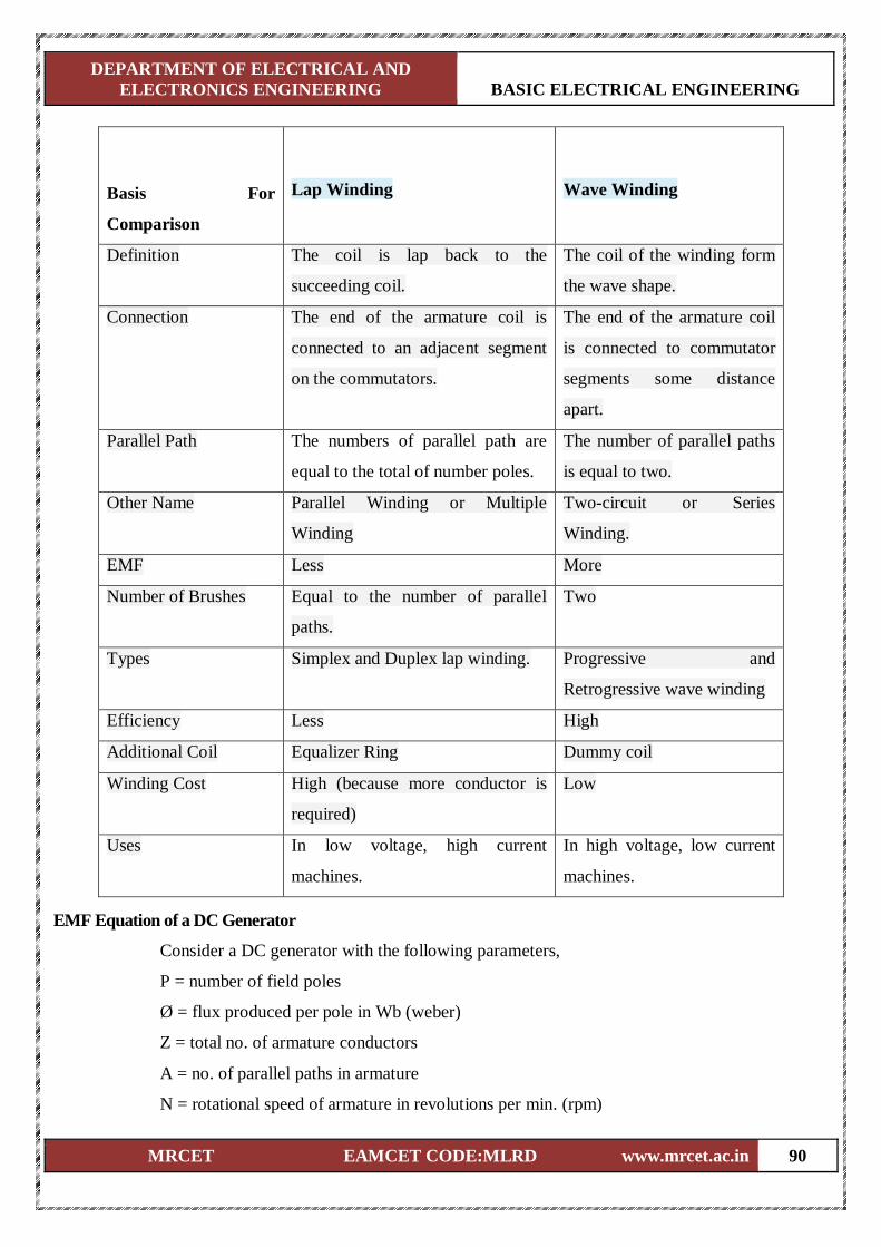
DEPARTMENT OF ELECTRICAL AND
ELECTRONICS ENGINEERING BASIC ELECTRICAL ENGINEERING
MRCET EAMCET CODE:MLRD www.mrcet.ac.in 90
Basis For
Comparison
Lap Winding
Wave Winding
Definition The coil is lap back to the
succeeding coil.
The coil of the winding form
the wave shape.
Connection The end of the armature coil is
connected to an adjacent segment
on the commutators.
The end of the armature coil
is connected to commutator
segments some distance
apart.
Parallel Path The numbers of parallel path are
equal to the total of number poles.
The number of parallel paths
is equal to two.
Other Name Parallel Winding or Multiple
Winding
Two-circuit or Series
Winding.
EMF Less More
Number of Brushes Equal to the number of parallel
paths.
Two
Types Simplex and Duplex lap winding. Progressive and
Retrogressive wave winding
Efficiency Less High
Additional Coil Equalizer Ring Dummy coil
Winding Cost High (because more conductor is
required)
Low
Uses In low voltage, high current
machines.
In high voltage, low current
machines.
EMF Equation of a DC Generator
Consider a DC generator with the following parameters,
P = number of field poles
Ø = flux produced per pole in Wb (weber)
Z = total no. of armature conductors
A = no. of parallel paths in armature
N = rotational speed of armature in revolutions per min. (rpm)
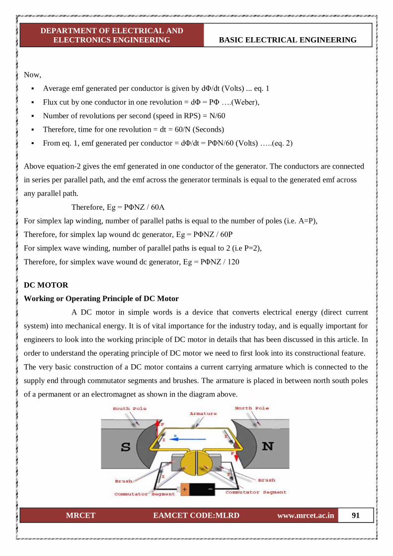
DEPARTMENT OF ELECTRICAL AND
ELECTRONICS ENGINEERING BASIC ELECTRICAL ENGINEERING
MRCET EAMCET CODE:MLRD www.mrcet.ac.in 91
Now,
Average emf generated per conductor is given by dΦ/dt (Volts) ... eq. 1
Flux cut by one conductor in one revolution = dΦ = PΦ ….(Weber),
Number of revolutions per second (speed in RPS) = N/60
Therefore, time for one revolution = dt = 60/N (Seconds)
From eq. 1, emf generated per conductor = dΦ/dt = PΦN/60 (Volts) …..(eq. 2)
Above equation-2 gives the emf generated in one conductor of the generator. The conductors are connected
in series per parallel path, and the emf across the generator terminals is equal to the generated emf across
any parallel path.
Therefore, Eg = PΦNZ / 60A
For simplex lap winding, number of parallel paths is equal to the number of poles (i.e. A=P),
Therefore, for simplex lap wound dc generator, Eg = PΦNZ / 60P
For simplex wave winding, number of parallel paths is equal to 2 (i.e P=2),
Therefore, for simplex wave wound dc generator, Eg = PΦNZ / 120
DC MOTOR
Working or Operating Principle of DC Motor
A DC motor in simple words is a device that converts electrical energy (direct current
system) into mechanical energy. It is of vital importance for the industry today, and is equally important for
engineers to look into the working principle of DC motor in details that has been discussed in this article. In
order to understand the operating principle of DC motor we need to first look into its constructional feature.
The very basic construction of a DC motor contains a current carrying armature which is connected to the
supply end through commutator segments and brushes. The armature is placed in between north south poles
of a permanent or an electromagnet as shown in the diagram above.
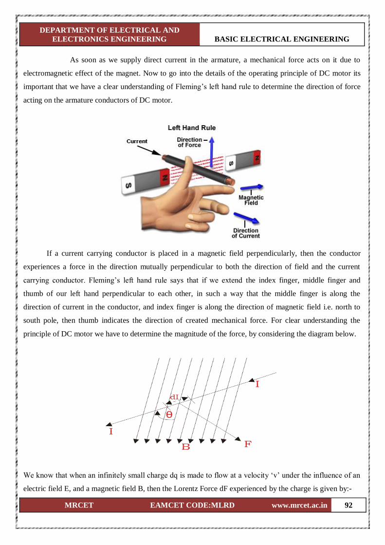
DEPARTMENT OF ELECTRICAL AND
ELECTRONICS ENGINEERING BASIC ELECTRICAL ENGINEERING
MRCET EAMCET CODE:MLRD www.mrcet.ac.in 92
As soon as we supply direct current in the armature, a mechanical force acts on it due to
electromagnetic effect of the magnet. Now to go into the details of the operating principle of DC motor its
important that we have a clear understanding of Fleming’s left hand rule to determine the direction of force
acting on the armature conductors of DC motor.
If a current carrying conductor is placed in a magnetic field perpendicularly, then the conductor
experiences a force in the direction mutually perpendicular to both the direction of field and the current
carrying conductor. Fleming’s left hand rule says that if we extend the index finger, middle finger and
thumb of our left hand perpendicular to each other, in such a way that the middle finger is along the
direction of current in the conductor, and index finger is along the direction of magnetic field i.e. north to
south pole, then thumb indicates the direction of created mechanical force. For clear understanding the
principle of DC motor we have to determine the magnitude of the force, by considering the diagram below.
We know that when an infinitely small charge dq is made to flow at a velocity ‘v’ under the influence of an
electric field E, and a magnetic field B, then the Lorentz Force dF experienced by the charge is given by:-
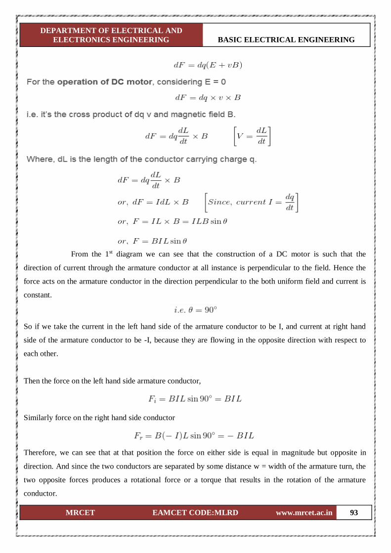
DEPARTMENT OF ELECTRICAL AND
ELECTRONICS ENGINEERING BASIC ELECTRICAL ENGINEERING
MRCET EAMCET CODE:MLRD www.mrcet.ac.in 93
From the 1st diagram we can see that the construction of a DC motor is such that the
direction of current through the armature conductor at all instance is perpendicular to the field. Hence the
force acts on the armature conductor in the direction perpendicular to the both uniform field and current is
constant.
So if we take the current in the left hand side of the armature conductor to be I, and current at right hand
side of the armature conductor to be -I, because they are flowing in the opposite direction with respect to
each other.
Then the force on the left hand side armature conductor,
Similarly force on the right hand side conductor
Therefore, we can see that at that position the force on either side is equal in magnitude but opposite in
direction. And since the two conductors are separated by some distance w = width of the armature turn, the
two opposite forces produces a rotational force or a torque that results in the rotation of the armature
conductor.
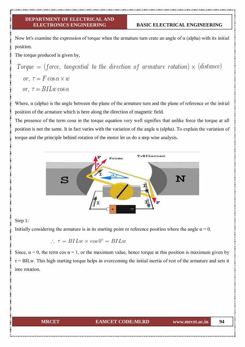
DEPARTMENT OF ELECTRICAL AND
ELECTRONICS ENGINEERING BASIC ELECTRICAL ENGINEERING
MRCET EAMCET CODE:MLRD www.mrcet.ac.in 94
Now let's examine the expression of torque when the armature turn crate an angle of α (alpha) with its initial
position.
The torque produced is given by,
Where, α (alpha) is the angle between the plane of the armature turn and the plane of reference or the init ial
position of the armature which is here along the direction of magnetic field.
The presence of the term cosα in the torque equation very well signifies that unlike force the torque at all
position is not the same. It in fact varies with the variation of the angle α (alpha). To explain the variation of
torque and the principle behind rotation of the motor let us do a step wise analysis.
Step 1:
Initially considering the armature is in its starting point or reference position where the angle α = 0.
Since, α = 0, the term cos α = 1, or the maximum value, hence torque at this position is maximum given by
τ = BILw. This high starting torque helps in overcoming the initial inertia of rest of the armature and sets it
into rotation.
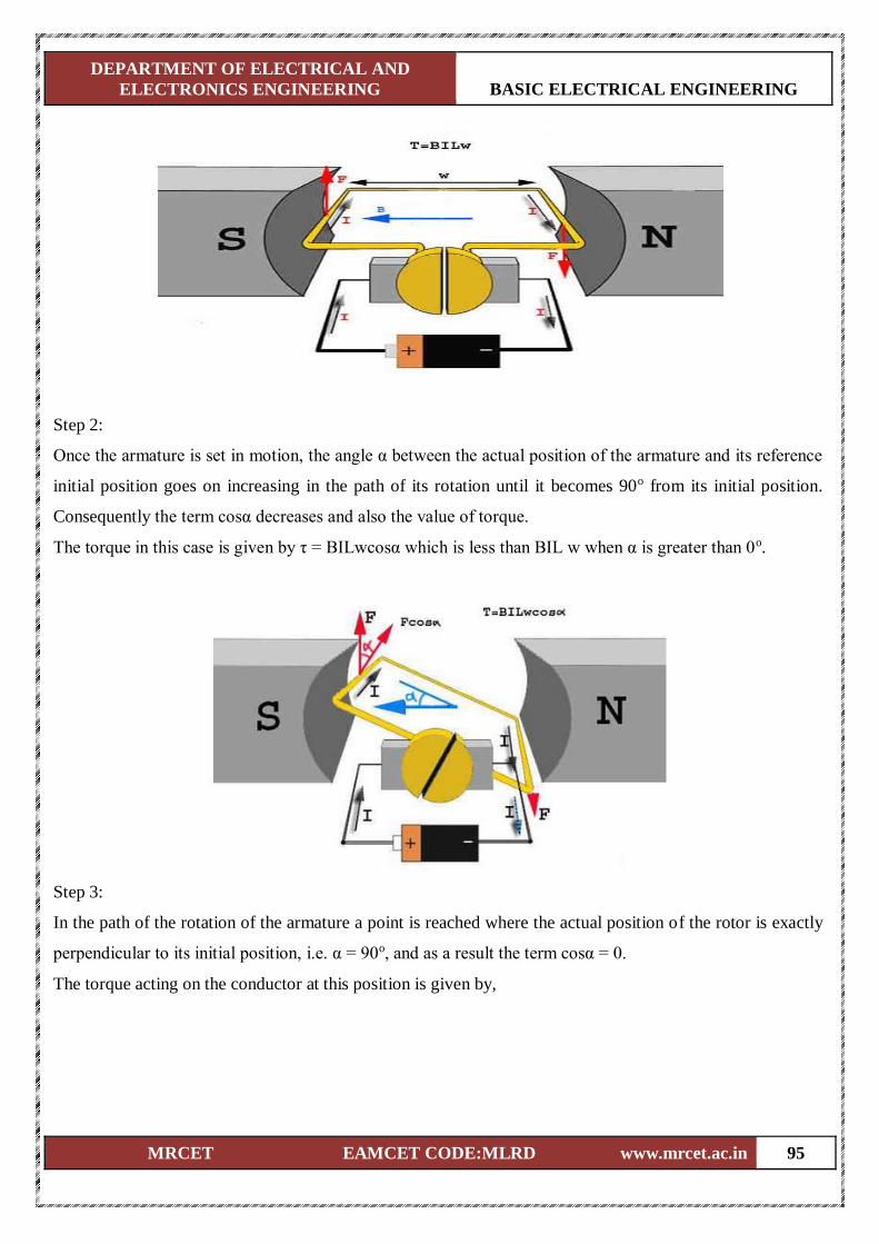
DEPARTMENT OF ELECTRICAL AND
ELECTRONICS ENGINEERING BASIC ELECTRICAL ENGINEERING
MRCET EAMCET CODE:MLRD www.mrcet.ac.in 95
Step 2:
Once the armature is set in motion, the angle α between the actual position of the armature and its reference
initial position goes on increasing in the path of its rotation until it becomes 90o from its initial position.
Consequently the term cosα decreases and also the value of torque.
The torque in this case is given by τ = BILwcosα which is less than BIL w when α is greater than 0o.
Step 3:
In the path of the rotation of the armature a point is reached where the actual position of the rotor is exactly
perpendicular to its initial position, i.e. α = 90o, and as a result the term cosα = 0.
The torque acting on the conductor at this position is given by,
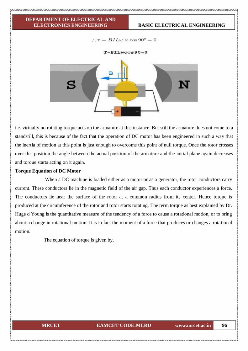
DEPARTMENT OF ELECTRICAL AND
ELECTRONICS ENGINEERING BASIC ELECTRICAL ENGINEERING
MRCET EAMCET CODE:MLRD www.mrcet.ac.in 96
i.e. virtually no rotating torque acts on the armature at this instance. But still the armature does not come to a
standstill, this is because of the fact that the operation of DC motor has been engineered in such a way that
the inertia of motion at this point is just enough to overcome this point of null torque. Once the rotor crosses
over this position the angle between the actual position of the armature and the initial plane again decreases
and torque starts acting on it again.
Torque Equation of DC Motor
When a DC machine is loaded either as a motor or as a generator, the rotor conductors carry
current. These conductors lie in the magnetic field of the air gap. Thus each conductor experiences a force.
The conductors lie near the surface of the rotor at a common radius from its center. Hence torque is
produced at the circumference of the rotor and rotor starts rotating. The term torque as best explained by Dr.
Huge d Young is the quantitative measure of the tendency of a force to cause a rotational motion, or to bring
about a change in rotational motion. It is in fact the moment of a force that produces or changes a rotational
motion.
The equation of torque is given by,
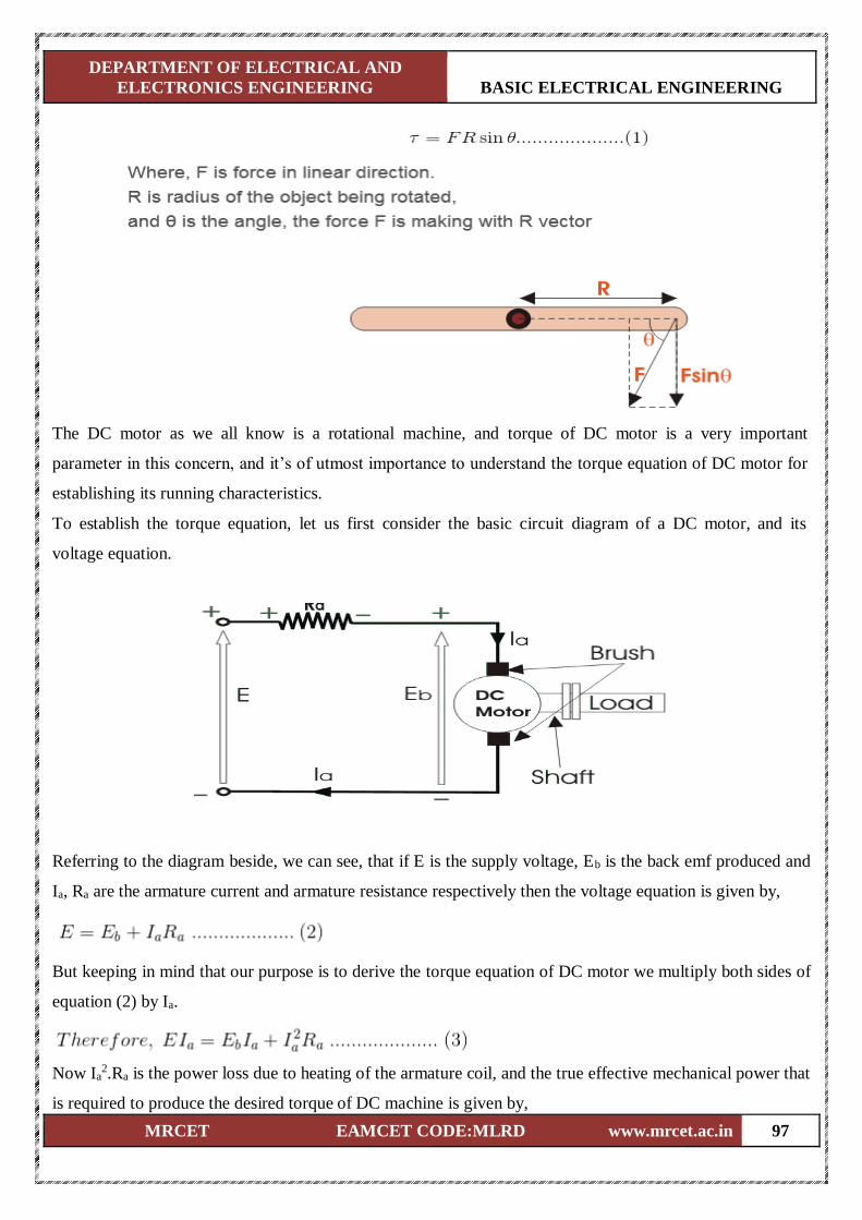
DEPARTMENT OF ELECTRICAL AND
ELECTRONICS ENGINEERING BASIC ELECTRICAL ENGINEERING
MRCET EAMCET CODE:MLRD www.mrcet.ac.in 97
The DC motor as we all know is a rotational machine, and torque of DC motor is a very important
parameter in this concern, and it’s of utmost importance to understand the torque equation of DC motor for
establishing its running characteristics.
To establish the torque equation, let us first consider the basic circuit diagram of a DC motor, and its
voltage equation.
Referring to the diagram beside, we can see, that if E is the supply voltage, Eb is the back emf produced and
Ia, Ra are the armature current and armature resistance respectively then the voltage equation is given by,
But keeping in mind that our purpose is to derive the torque equation of DC motor we multiply both sides of
equation (2) by Ia.
Now Ia2.Ra is the power loss due to heating of the armature coil, and the true effective mechanical power that
is required to produce the desired torque of DC machine is given by,
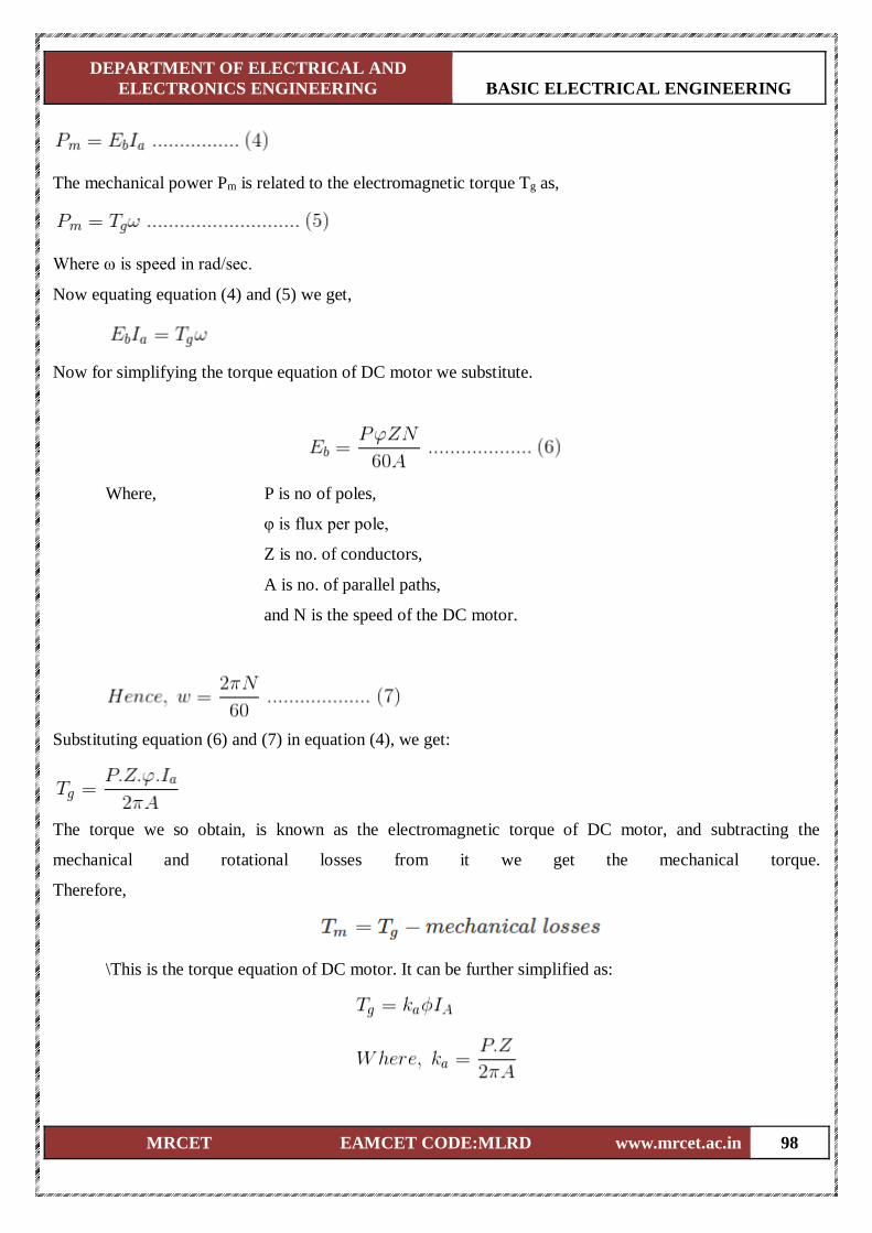
DEPARTMENT OF ELECTRICAL AND
ELECTRONICS ENGINEERING BASIC ELECTRICAL ENGINEERING
MRCET EAMCET CODE:MLRD www.mrcet.ac.in 98
The mechanical power Pm is related to the electromagnetic torque Tg as,
Where ω is speed in rad/sec.
Now equating equation (4) and (5) we get,
Now for simplifying the torque equation of DC motor we substitute.
Where, P is no of poles,
φ is flux per pole,
Z is no. of conductors,
A is no. of parallel paths,
and N is the speed of the DC motor.
Substituting equation (6) and (7) in equation (4), we get:
The torque we so obtain, is known as the electromagnetic torque of DC motor, and subtracting the
mechanical and rotational losses from it we get the mechanical torque.
Therefore,
\This is the torque equation of DC motor. It can be further simplified as:
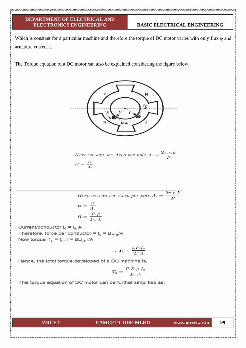
DEPARTMENT OF ELECTRICAL AND
ELECTRONICS ENGINEERING BASIC ELECTRICAL ENGINEERING
MRCET EAMCET CODE:MLRD www.mrcet.ac.in 99
Which is constant for a particular machine and therefore the torque of DC motor varies with only flux φ and
armature current Ia.
The Torque equation of a DC motor can also be explained considering the figure below.
DEPARTMENT OF ELECTRICAL AND
ELECTRONICS ENGINEERING BASIC ELECTRICAL ENGINEERING
MRCET EAMCET CODE:MLRD www.mrcet.ac.in 100
Which is constant for a particular machine and therefore the torque of DC motor varies with only flux φ and
armature current Ia.
TRANSFORMER
Introduction
The transformer is a device that transfers electrical energy from one electrical circuit to
another electrical circuit. The two circuits may be operating at different voltage levels but always work at
the same frequency. Basically transformer is an electro-magnetic energy conversion device. It is commonly
used in electrical power system and distribution systems. It can change the magnitude of alternating voltage
or current from one value to another. This useful property of transformer is mainly responsible for the
widespread use of alternating currents rather than direct currents i.e., electric power is generated,
transmitted and distributed in the form of alternating current. Transformers have no moving parts, rugged
and durable in construction, thus requiring very little attention. They also have a very high efficiency as
high as 99%.
Single Phase Transformer
A transformer is a static device of equipment used either for raising or lowering the voltage
of an a.c. supply with a corresponding decrease or increase in current. It essentially consists of two
windings, the primary and secondary, wound on a common laminated magnetic core as shown in Fig 1. The
winding connected to the a.c. source is called primary winding (or primary) and the one connected to load is
called secondary winding (or secondary). The alternating voltage V1 whose magnitude is to be changed is
applied to the primary.
Depending upon the number of turns of the primary (N1) and secondary (N2), an alternating e.m.f. E2 is
induced in the secondary. This induced e.m.f. E2 in the secondary causes a secondary current I2.
Consequently, terminal voltage V2 will appear across the load.
If V2 > V1, it is called a step up-transformer.
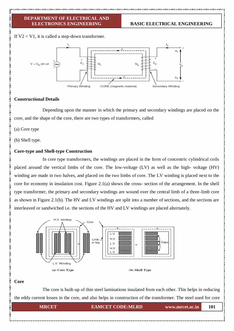
DEPARTMENT OF ELECTRICAL AND
ELECTRONICS ENGINEERING BASIC ELECTRICAL ENGINEERING
MRCET EAMCET CODE:MLRD www.mrcet.ac.in 101
If V2 < V1, it is called a step-down transformer.
Constructional Details
Depending upon the manner in which the primary and secondary windings are placed on the
core, and the shape of the core, there are two types of transformers, called
(a) Core type
(b) Shell type.
Core-type and Shell-type Construction
In core type transformers, the windings are placed in the form of concentric cylindrical coils
placed around the vertical limbs of the core. The low-voltage (LV) as well as the high- voltage (HV)
winding are made in two halves, and placed on the two limbs of core. The LV winding is placed next to the
core for economy in insulation cost. Figure 2.1(a) shows the cross- section of the arrangement. In the shell
type transformer, the primary and secondary windings are wound over the central limb of a three-limb core
as shown in Figure 2.1(b). The HV and LV windings are split into a number of sections, and the sections are
interleaved or sandwiched i.e. the sections of the HV and LV windings are placed alternately.
Core
The core is built-up of thin steel laminations insulated from each other. This helps in reducing
the eddy current losses in the core, and also helps in construction of the transformer. The steel used for core
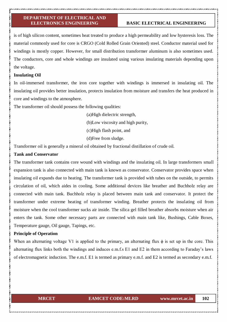
DEPARTMENT OF ELECTRICAL AND
ELECTRONICS ENGINEERING BASIC ELECTRICAL ENGINEERING
MRCET EAMCET CODE:MLRD www.mrcet.ac.in 102
is of high silicon content, sometimes heat treated to produce a high permeability and low hysteresis loss. The
material commonly used for core is CRGO (Cold Rolled Grain Oriented) steel. Conductor material used for
windings is mostly copper. However, for small distribution transformer aluminum is also sometimes used.
The conductors, core and whole windings are insulated using various insulating materials depending upon
the voltage.
Insulating Oil
In oil-immersed transformer, the iron core together with windings is immersed in insulating oil. The
insulating oil provides better insulation, protects insulation from moisture and transfers the heat produced in
core and windings to the atmosphere.
The transformer oil should possess the following qualities:
(a)High dielectric strength,
(b)Low viscosity and high purity,
(c)High flash point, and
(d)Free from sludge.
Transformer oil is generally a mineral oil obtained by fractional distillation of crude oil.
Tank and Conservator
The transformer tank contains core wound with windings and the insulating oil. In large transformers small
expansion tank is also connected with main tank is known as conservator. Conservator provides space when
insulating oil expands due to heating. The transformer tank is provided with tubes on the outside, to permits
circulation of oil, which aides in cooling. Some additional devices like breather and Buchholz relay are
connected with main tank. Buchholz relay is placed between main tank and conservator. It protect the
transformer under extreme heating of transformer winding. Breather protects the insulating oil from
moisture when the cool transformer sucks air inside. The silica gel filled breather absorbs moisture when air
enters the tank. Some other necessary parts are connected with main tank like, Bushings, Cable Boxes,
Temperature gauge, Oil gauge, Tapings, etc.
Principle of Operation
When an alternating voltage V1 is applied to the primary, an alternating flux ϕ is set up in the core. This
alternating flux links both the windings and induces e.m.f.s E1 and E2 in them according to Faraday’s laws
of electromagnetic induction. The e.m.f. E1 is termed as primary e.m.f. and E2 is termed as secondary e.m.f.
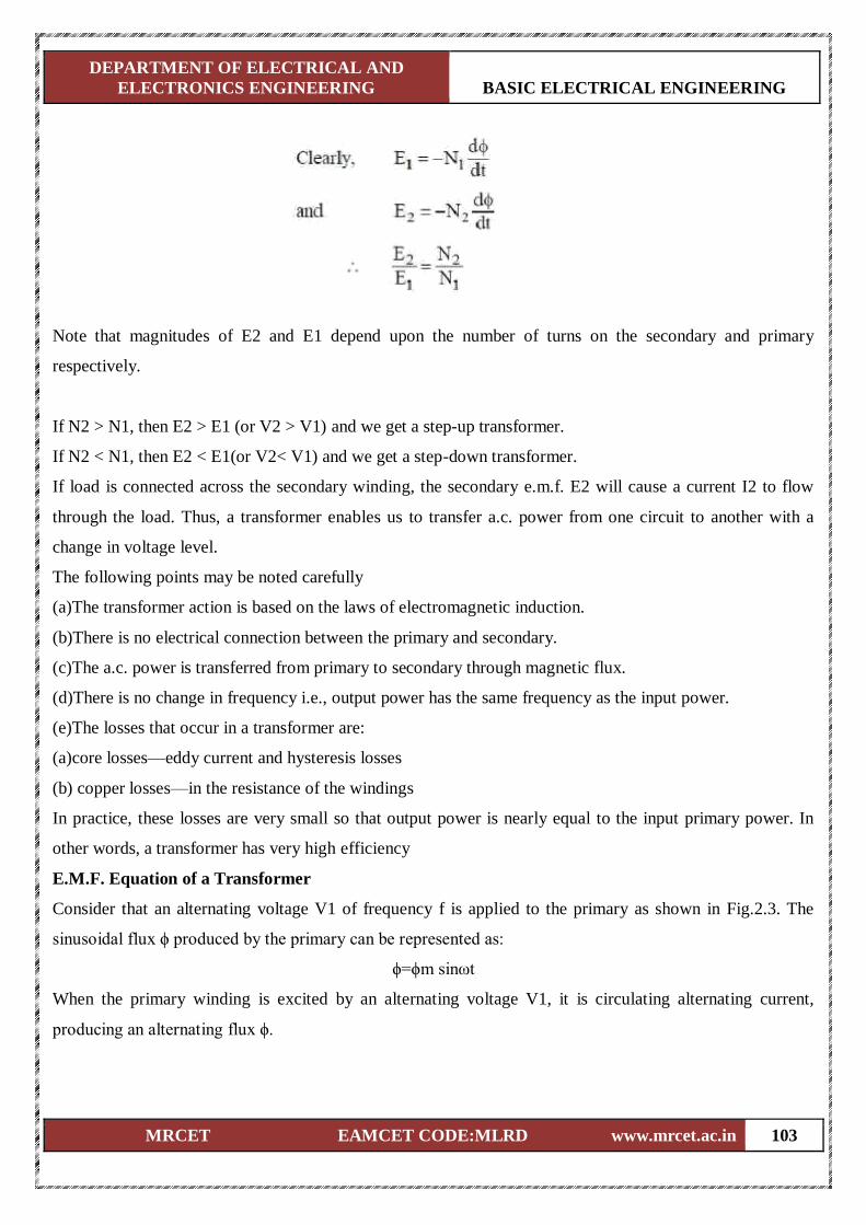
DEPARTMENT OF ELECTRICAL AND
ELECTRONICS ENGINEERING BASIC ELECTRICAL ENGINEERING
MRCET EAMCET CODE:MLRD www.mrcet.ac.in 103
Note that magnitudes of E2 and E1 depend upon the number of turns on the secondary and primary
respectively.
If N2 > N1, then E2 > E1 (or V2 > V1) and we get a step-up transformer.
If N2 < N1, then E2 < E1(or V2< V1) and we get a step-down transformer.
If load is connected across the secondary winding, the secondary e.m.f. E2 will cause a current I2 to flow
through the load. Thus, a transformer enables us to transfer a.c. power from one circuit to another with a
change in voltage level.
The following points may be noted carefully
(a)The transformer action is based on the laws of electromagnetic induction.
(b)There is no electrical connection between the primary and secondary.
(c)The a.c. power is transferred from primary to secondary through magnetic flux.
(d)There is no change in frequency i.e., output power has the same frequency as the input power.
(e)The losses that occur in a transformer are:
(a)core losses—eddy current and hysteresis losses
(b) copper losses—in the resistance of the windings
In practice, these losses are very small so that output power is nearly equal to the input primary power. In
other words, a transformer has very high efficiency
E.M.F. Equation of a Transformer
Consider that an alternating voltage V1 of frequency f is applied to the primary as shown in Fig.2.3. The
sinusoidal flux ϕ produced by the primary can be represented as:
ϕ=ϕm sinωt
When the primary winding is excited by an alternating voltage V1, it is circulating alternating current,
producing an alternating flux ϕ.
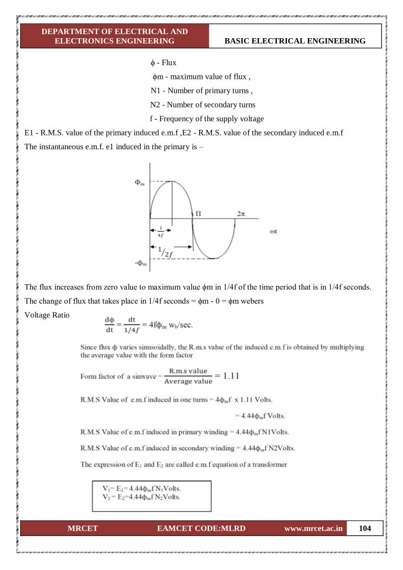
DEPARTMENT OF ELECTRICAL AND
ELECTRONICS ENGINEERING BASIC ELECTRICAL ENGINEERING
MRCET EAMCET CODE:MLRD www.mrcet.ac.in 104
ϕ - Flux
ϕm - maximum value of flux ,
N1 - Number of primary turns ,
N2 - Number of secondary turns
f - Frequency of the supply voltage
E1 - R.M.S. value of the primary induced e.m.f ,E2 - R.M.S. value of the secondary induced e.m.f
The instantaneous e.m.f. e1 induced in the primary is –
The flux increases from zero value to maximum value ϕm in 1/4f of the time period that is in 1/4f seconds.
The change of flux that takes place in 1/4f seconds = ϕm - 0 = ϕm webers
Voltage Ratio
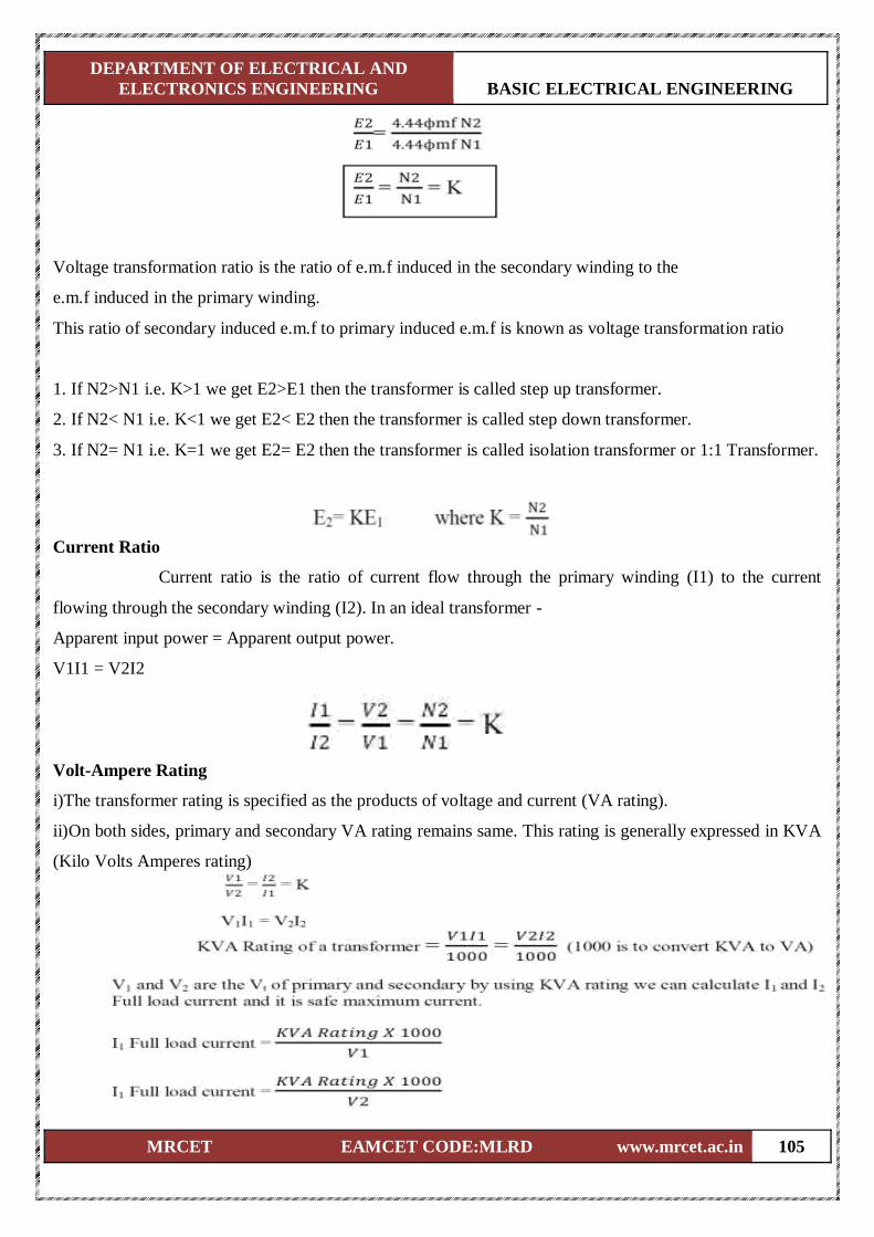
DEPARTMENT OF ELECTRICAL AND
ELECTRONICS ENGINEERING BASIC ELECTRICAL ENGINEERING
MRCET EAMCET CODE:MLRD www.mrcet.ac.in 105
Voltage transformation ratio is the ratio of e.m.f induced in the secondary winding to the
e.m.f induced in the primary winding.
This ratio of secondary induced e.m.f to primary induced e.m.f is known as voltage transformation ratio
1. If N2>N1 i.e. K>1 we get E2>E1 then the transformer is called step up transformer.
2. If N2< N1 i.e. K<1 we get E2< E2 then the transformer is called step down transformer.
3. If N2= N1 i.e. K=1 we get E2= E2 then the transformer is called isolation transformer or 1:1 Transformer.
Current Ratio
Current ratio is the ratio of current flow through the primary winding (I1) to the current
flowing through the secondary winding (I2). In an ideal transformer -
Apparent input power = Apparent output power.
V1I1 = V2I2
Volt-Ampere Rating
i)The transformer rating is specified as the products of voltage and current (VA rating).
ii)On both sides, primary and secondary VA rating remains same. This rating is generally expressed in KVA
(Kilo Volts Amperes rating)
DEPARTMENT OF ELECTRICAL AND
ELECTRONICS ENGINEERING BASIC ELECTRICAL ENGINEERING
MRCET EAMCET CODE:MLRD www.mrcet.ac.in 106
UNIT –V
ELECTRICAL INSTALLATIONS
Components of LT Switchgear: Switch Fuse Unit (SFU), MCB, ELCB, MCCB.
Types of Wires and Cables.
Earthing.
Types of Batteries.
Important Characteristics for Batteries.
Elementary calculations for energy consumption and battery backup.

DEPARTMENT OF ELECTRICAL AND
ELECTRONICS ENGINEERING BASIC ELECTRICAL ENGINEERING
MRCET EAMCET CODE:MLRD www.mrcet.ac.in 107
Wire and cable:
The use of Conductors and their insulation is regulated by Indian Electricity (IE) regulation
and Indian Standard (IS) Code Of Practice. Wires and cables are the most common forms of conductors.
They carry electric current through all types of circuits and systems. A conductor is a wire or cable or any
other form of mental, suitable for carrying current from generating station the point where it is used.
Difference Between Wire and Cable:
According to Bureau of Indian Standards (BIS), wire and cable can be defined as follows :
Bare Conductors :They have no covering. The best example is overhead transmission and distribution
lines.
Wire: If bare conductors are provided with Insulation, then it is known as a wire. The insulation separates
the conductor electrically from other conductors.
Cable: It consists of two or more conductors covered with suitable insulation and surrounded by a
protecting cover. The necessary requirements of a cable are that it should conduct electricity efficiently,
cheaply, and safely. This should neither be so small that it has a large internal voltage drop nor be too large
so that it costs too much. Its insulation should be such that it prevents leakage of current in unwanted
direction to minimize risk of fire and shock.
The cable essentially consists of three parts :
(i) Conductor or core- the metal wire, or strand of wires, carrying the current
(II) insulation of dielectric- a covering of insulating material to avoid leakage of current from
the conductor and
(iii) protective covering for protection of insulation from mechanical damage
Basically, there is no difference between a cable and a wire. It is a relative term. The term cable is used for
all heavy section insulated conductors, whereas a wire means a thin (i.e., smaller) section insulated
conductor used for carrying current from one point to another point.
Classifications of Wire / Cables:
The wires/ cables used for domestic or industrial wiring are classified into different groups as follows :
(i) According to the conductor material used
(a) Copper conductor cables
(b) Aluminium conductor cable
(ii) According to number of cores
(a) Singles core cable (SCC)
(b) Double core or twin core cables (DCC)
(c) Three core cables
DEPARTMENT OF ELECTRICAL AND
ELECTRONICS ENGINEERING BASIC ELECTRICAL ENGINEERING
MRCET EAMCET CODE:MLRD www.mrcet.ac.in 108
(d) four core cables
(e) Two core with earth continuity conductor cables
(iii) According to type of insulation
(a) Vulcanized Indian rubber (VIR) insulated wires/cables
(b) Tough rubber sheathed (TRS) or cable tyre sheathed (CTS) cables
(c) Polyvinyl chloride (PVC) cables
(b) Lead sheathed cables
(e) Weather proof cables
(f) Flexible cords and cables
(g) XLPE cables
(IV) According to the voltage at which they are manufactured
(a) Low tension (LT) cables – up to 1000V
(b) High tension (HT) cables – up to 11kV
(c) Super tension (ST) cables – from 22-33kV
(d) Extra high tension (EHT) cables – from 33-66kV
(e) Extra super voltage cables – beyond 132 kV
Specifications of Cables:
Cables are specified by providing
(i) Size of the cable in metric system (e.g., 19/2.24, 7/1.70, 7/2.24, 7/2.50 etc) giving the
Number of strands used and diameter of each strand, or giving the area of cross- section
of conductor used.
(ii) Type of conductor used in cables (copper or aluminium)
(iii) Number of cores that cable consists of e.g. single core, twin core, three core, four core
etc.
(iv) Voltage grade (240/415V or 650/1100V grade)
(v) Type of cable with clear description regarding insulation, shielding, armouring, bedding
etc.
A few specifications of a cable are given below:
(i) 7/20, VIR, aluminium conductor, twin core,650/1100 grade.
in this case, the numerator 7 indicates the number of stands in cable and denominator 20
represents the gauge number of each strand. The cable has two cores made with
Aluminium, With VIR insulation and is used for 650/1100 voltage
(ii) 19/1.12, aluminium conductor,3 ½ core, 1100V, PVC cable, PVC sheathed.
DEPARTMENT OF ELECTRICAL AND
ELECTRONICS ENGINEERING BASIC ELECTRICAL ENGINEERING
MRCET EAMCET CODE:MLRD www.mrcet.ac.in 109
in this case, the cable consists of 19 strands, each strand has a diameter of 1.12mm. The
conductor is made with aluminium, insulation is made with PVC, is covered with PVC
sheathing, and is used for 1100Vsupply system.
Earthing of Grounding:
The process of connecting the metallic frame (i.e., non- current carrying part) of electrical equipment or
some electrical part of the system (e.g., neutral point in a star-connected system, one conductor of the
secondary of a transformer, etc.) to the earth (i.e., soil) is called grounding or Earthing. The potential of the
earth is to be considered zero for all practical purposes. Earthing is to connect any electrical equipment to
earth with a very low resistance wire, making it to attain earth’s potential, This ensures safe discharge of
electrical energy due to failure of the insulation line coming in contact with the casing, etc. Earthing brings
the potential of the body of the equipment to zero i.e., to the earth’s potential, thus ptotecting the operating
personnel against electrical shock.
The earth resistance is affected by the following factors :
(a) Material properties of the earth, wire and the electrode
(b) Temperature and moisture content of the soil
(c) Depth of the pit
(d) Quantity of the charcoal used
Necessity of Earthing:
The requirement for provision of earthing can be listed as follows :
(1) To protect the operating personnel from the danger of shock.
(2) To maintain the line voltage constant, under unbalanced load condition.
(3) To avoid risk of fire due to earth leakage current through unwanted path.
(4) Protection of the equipments.
(5) Protection of large buildings and all machines fed from overhead lines
against lighting.
Methods of Earthing:
The various methods of earthing in common use are
(i) Plate earthing
(ii) Pipe earthing
(iii) Rod earthing
(iv) Strip or wire earthing
(i) Plate earthing:
In this method either a copper plate of 60cm × 60cm ×3.18 or GI plate of 60cm × 60cm × 6.35 is used for
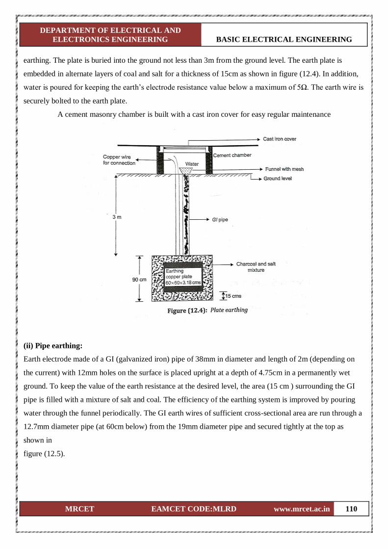
DEPARTMENT OF ELECTRICAL AND
ELECTRONICS ENGINEERING BASIC ELECTRICAL ENGINEERING
MRCET EAMCET CODE:MLRD www.mrcet.ac.in 110
earthing. The plate is buried into the ground not less than 3m from the ground level. The earth plate is
embedded in alternate layers of coal and salt for a thickness of 15cm as shown in figure (12.4). In addition,
water is poured for keeping the earth’s electrode resistance value below a maximum of 5Ω. The earth wire is
securely bolted to the earth plate.
A cement masonry chamber is built with a cast iron cover for easy regular maintenance
(ii) Pipe earthing:
Earth electrode made of a GI (galvanized iron) pipe of 38mm in diameter and length of 2m (depending on
the current) with 12mm holes on the surface is placed upright at a depth of 4.75cm in a permanently wet
ground. To keep the value of the earth resistance at the desired level, the area (15 cm ) surrounding the GI
pipe is filled with a mixture of salt and coal. The efficiency of the earthing system is improved by pouring
water through the funnel periodically. The GI earth wires of sufficient cross-sectional area are run through a
12.7mm diameter pipe (at 60cm below) from the 19mm diameter pipe and secured tightly at the top as
shown in
figure (12.5).
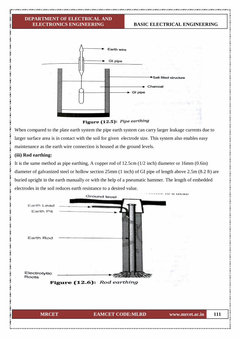
DEPARTMENT OF ELECTRICAL AND
ELECTRONICS ENGINEERING BASIC ELECTRICAL ENGINEERING
MRCET EAMCET CODE:MLRD www.mrcet.ac.in 111
When compared to the plate earth system the pipe earth system can carry larger leakage currents due to
larger surface area is in contact with the soil for given electrode size. This system also enables easy
maintenance as the earth wire connection is housed at the ground levels.
(iii) Rod earthing:
It is the same method as pipe earthing, A copper rod of 12.5cm (1/2 inch) diameter or 16mm (0.6in)
diameter of galvanized steel or hollow section 25mm (1 inch) of GI pipe of length above 2.5m (8.2 ft) are
buried upright in the earth manually or with the help of a pneumatic hammer. The length of embedded
electrodes in the soil reduces earth resistance to a desired value.
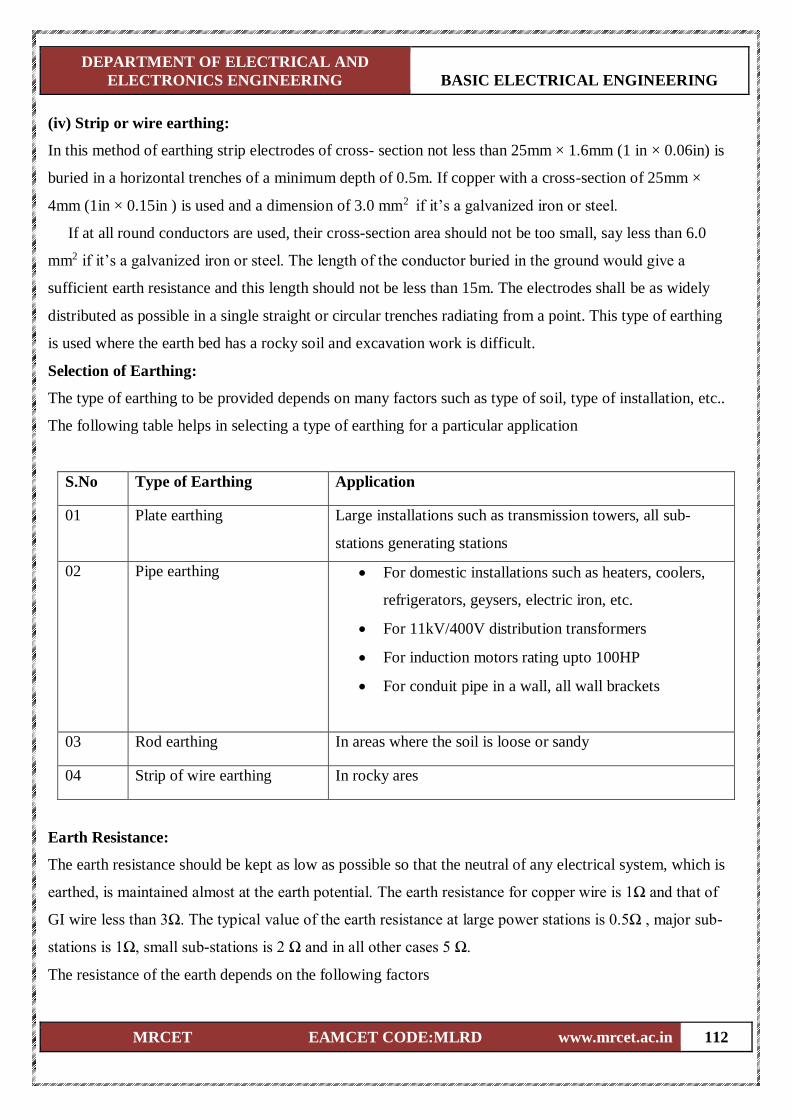
DEPARTMENT OF ELECTRICAL AND
ELECTRONICS ENGINEERING BASIC ELECTRICAL ENGINEERING
MRCET EAMCET CODE:MLRD www.mrcet.ac.in 112
(iv) Strip or wire earthing:
In this method of earthing strip electrodes of cross- section not less than 25mm × 1.6mm (1 in × 0.06in) is
buried in a horizontal trenches of a minimum depth of 0.5m. If copper with a cross-section of 25mm ×
4mm (1in × 0.15in ) is used and a dimension of 3.0 mm2 if it’s a galvanized iron or steel.
If at all round conductors are used, their cross-section area should not be too small, say less than 6.0
mm2 if it’s a galvanized iron or steel. The length of the conductor buried in the ground would give a
sufficient earth resistance and this length should not be less than 15m. The electrodes shall be as widely
distributed as possible in a single straight or circular trenches radiating from a point. This type of earthing
is used where the earth bed has a rocky soil and excavation work is difficult.
Selection of Earthing:
The type of earthing to be provided depends on many factors such as type of soil, type of installation, etc..
The following table helps in selecting a type of earthing for a particular application
S.No Type of Earthing Application
01 Plate earthing Large installations such as transmission towers, all sub-
stations generating stations
02 Pipe earthing For domestic installations such as heaters, coolers,
refrigerators, geysers, electric iron, etc.
For 11kV/400V distribution transformers
For induction motors rating upto 100HP
For conduit pipe in a wall, all wall brackets
03 Rod earthing In areas where the soil is loose or sandy
04 Strip of wire earthing In rocky ares
Earth Resistance:
The earth resistance should be kept as low as possible so that the neutral of any electrical system, which is
earthed, is maintained almost at the earth potential. The earth resistance for copper wire is 1Ω and that of
GI wire less than 3Ω. The typical value of the earth resistance at large power stations is 0.5Ω , major sub-
stations is 1Ω, small sub-stations is 2 Ω and in all other cases 5 Ω.
The resistance of the earth depends on the following factors
DEPARTMENT OF ELECTRICAL AND
ELECTRONICS ENGINEERING BASIC ELECTRICAL ENGINEERING
MRCET EAMCET CODE:MLRD www.mrcet.ac.in 113
Condition of soil.
ii. Moisture content of soil.
iii. Temperature of soil.
iv. Depth of electrode at which it is embedded.
v. Size, material and spacing of earth electrode.
vi. Quality and quantity of coal and salt in the earth pit.
Difference Between Earth Wire and Neutral Wire:
Neutral Wire :
(i) In a 3-phase 4-wire system, the fourth wire is a neutral wire.
(ii) IT acts a return path for 3-phase currents when the load is not balanced.
(iii) IN domestic single phase AC circuit, the neutral wire acts as return path for the line
current.
Earth Wire :
(i) Earth wire is actually connected to the general mass of the earth and metallic body of the
equipment
(ii) It is provided to transfer any leakage current from the metallic body to the earth.
Fuse:
The electrical equipment are designed to carry a particular rated value of current under normal conditions.
Under abnormal conditions such as short circuits, overload, or any fault; the current rises above this value,
damaging the equipment and sometimes resulting in fire hazard. Fuses come into operation under fault
conditions.
A fuse is short piece of metal, inserted in the circuit, which melts when excessive current flows through
it and thus breaks the circuits. Under normal operating conditions it designed to carry the full load current.
If the current increases beyond this designed value due to any of the reasons mentioned above, the fuse
melts, isolating the power supply from the load.
(a) Desirable characteristics of a Fuse Element:
The material used foe fuse wires must have the following characteristics:
i. Low melting point e.g., tin, lead.
ii. High conductivity e.g., copper.
iii. Free from deterioration due oxidation e.g., silver.
iv. Low cost e.g., tin, copper.
(b) Materials:
Material used are tin lead or silver having low melting points. Use of copper or iron is dangerous, though
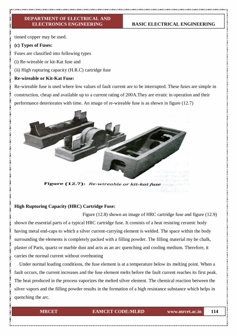
DEPARTMENT OF ELECTRICAL AND
ELECTRONICS ENGINEERING BASIC ELECTRICAL ENGINEERING
MRCET EAMCET CODE:MLRD www.mrcet.ac.in 114
tinned copper may be used.
(c) Types of Fuses:
Fuses are classified into following types
(i) Re-wireable or kit-Kat fuse and
(ii) High rupturing capacity (H.R.C) cartridge fuse
Re-wireable or Kit-Kat Fuse:
Re-wireable fuse is used where low values of fault current are to be interrupted. These fuses are simple in
construction, cheap and available up to a current rating of 200A.They are erratic in operation and their
performance deteriorates with time. An image of re-wireable fuse is as shown in figure (12.7)
High Rupturing Capacity (HRC) Cartridge Fuse:
Figure (12.8) shown an image of HRC cartridge fuse and figure (12.9)
shown the essential parts of a typical HRC cartridge fuse. It consists of a heat resisting ceramic body
having metal end-caps to which a silver current-carrying element is welded. The space within the body
surrounding the elements is completely packed with a filling powder. The filling material my be chalk,
plaster of Paris, quartz or marble dust and acts as an arc quenching and cooling medium. Therefore, it
carries the normal current without overheating
Under normal loading conditions, the fuse element is at a temperature below its melting point. When a
fault occurs, the current increases and the fuse element melts before the fault current reaches its first peak.
The heat produced in the process vaporizes the melted silver element. The chemical reaction between the
silver vapors and the filling powder results in the formation of a high resistance substance which helps in
quenching the arc.
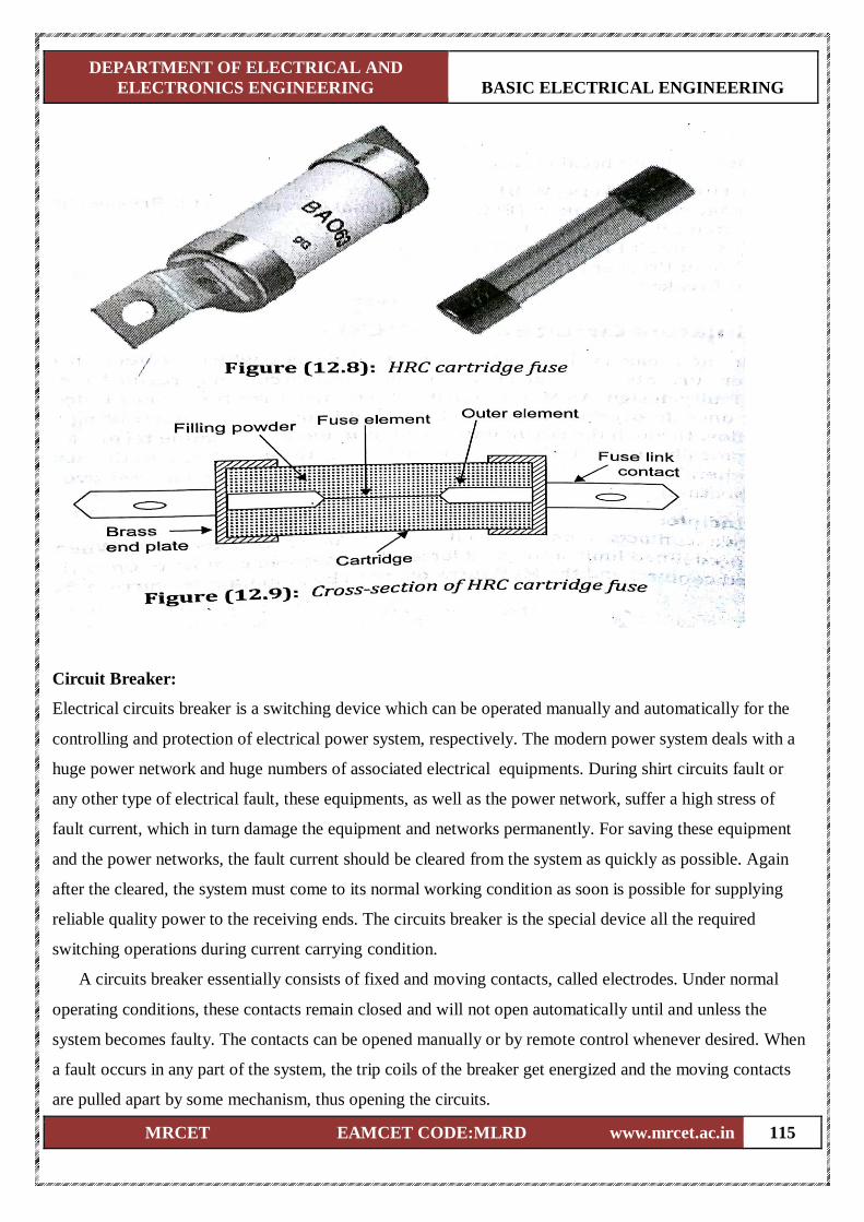
DEPARTMENT OF ELECTRICAL AND
ELECTRONICS ENGINEERING BASIC ELECTRICAL ENGINEERING
MRCET EAMCET CODE:MLRD www.mrcet.ac.in 115
Circuit Breaker:
Electrical circuits breaker is a switching device which can be operated manually and automatically for the
controlling and protection of electrical power system, respectively. The modern power system deals with a
huge power network and huge numbers of associated electrical equipments. During shirt circuits fault or
any other type of electrical fault, these equipments, as well as the power network, suffer a high stress of
fault current, which in turn damage the equipment and networks permanently. For saving these equipment
and the power networks, the fault current should be cleared from the system as quickly as possible. Again
after the cleared, the system must come to its normal working condition as soon is possible for supplying
reliable quality power to the receiving ends. The circuits breaker is the special device all the required
switching operations during current carrying condition.
A circuits breaker essentially consists of fixed and moving contacts, called electrodes. Under normal
operating conditions, these contacts remain closed and will not open automatically until and unless the
system becomes faulty. The contacts can be opened manually or by remote control whenever desired. When
a fault occurs in any part of the system, the trip coils of the breaker get energized and the moving contacts
are pulled apart by some mechanism, thus opening the circuits.
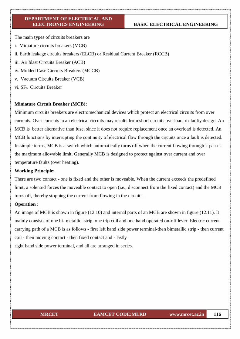
DEPARTMENT OF ELECTRICAL AND
ELECTRONICS ENGINEERING BASIC ELECTRICAL ENGINEERING
MRCET EAMCET CODE:MLRD www.mrcet.ac.in 116
The main types of circuits breakers are
i. Miniature circuits breakers (MCB)
ii. Earth leakage circuits breakers (ELCB) or Residual Current Breaker (RCCB)
iii. Air blast Circuits Breaker (ACB)
iv. Molded Case Circuits Breakers (MCCB)
v. Vacuum Circuits Breaker (VCB)
vi. SF6 Circuits Breaker
Miniature Circuit Breaker (MCB):
Minimum circuits breakers are electromechanical devices which protect an electrical circuits from over
currents. Over currents in an electrical circuits may results from short circuits overload, or faulty design. An
MCB is better alternative than fuse, since it does not require replacement once an overload is detected. An
MCB functions by interrupting the continuity of electrical flow through the circuits once a fault is detected.
In simple terms, MCB is a switch which automatically turns off when the current flowing through it passes
the maximum allowable limit. Generally MCB is designed to protect against over current and over
temperature faults (over heating).
Working Principle:
There are two contact - one is fixed and the other is moveable. When the current exceeds the predefined
limit, a solenoid forces the moveable contact to open (i.e., disconnect from the fixed contact) and the MCB
turns off, thereby stopping the current from flowing in the circuits.
Operation :
An image of MCB is shown in figure (12.10) and internal parts of an MCB are shown in figure (12.11). It
mainly consists of one bi- metallic strip, one trip coil and one hand operated on-off lever. Electric current
carrying path of a MCB is as follows - first left hand side power terminal-then bimetallic strip - then current
coil - then moving contact - then fixed contact and - lastly
right hand side power terminal, and all are arranged in series.
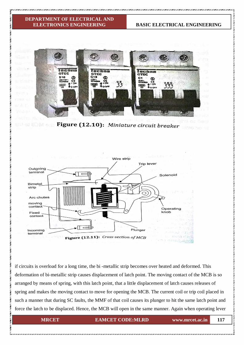
DEPARTMENT OF ELECTRICAL AND
ELECTRONICS ENGINEERING BASIC ELECTRICAL ENGINEERING
MRCET EAMCET CODE:MLRD www.mrcet.ac.in 117
if circuits is overload for a long time, the bi -metallic strip becomes over heated and deformed. This
deformation of bi-metallic strip causes displacement of latch point. The moving contact of the MCB is so
arranged by means of spring, with this latch point, that a little displacement of latch causes releases of
spring and makes the moving contact to move for opening the MCB. The current coil or trip coil placed in
such a manner that during SC faults, the MMF of that coil causes its plunger to hit the same latch point and
force the latch to be displaced. Hence, the MCB will open in the same manner. Again when operating lever
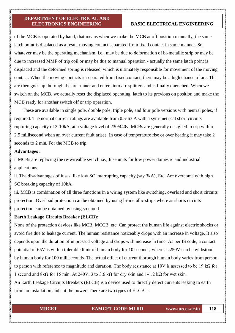
DEPARTMENT OF ELECTRICAL AND
ELECTRONICS ENGINEERING BASIC ELECTRICAL ENGINEERING
MRCET EAMCET CODE:MLRD www.mrcet.ac.in 118
of the MCB is operated by hand, that means when we make the MCB at off position manually, the same
latch point is displaced as a result moving contact separated from fixed contact in same manner. So,
whatever may be the operating mechanism, i.e., may be due to deformation of bi-metallic strip or may be
due to increased MMF of trip coil or may be due to manual operation - actually the same latch point is
displaced and the deformed spring is released, which is ultimately responsible for movement of the moving
contact. When the moving contacts is separated from fixed contact, there may be a high chance of arc. This
are then goes up thorough the arc runner and enters into arc splitters and is finally quenched. When we
switch on the MCB, we actually reset the displaced operating latch to its previous on position and make the
MCB ready for another switch off or trip operation.
These are available in single pole, double pole, triple pole, and four pole versions with neutral poles, if
required. The normal current ratings are available from 0.5-63 A with a sym-metrical short circuits
rupturing capacity of 3-10kA, at a voltage level of 230/440v. MCBs are generally designed to trip within
2.5 millisecond when an over current fault arises. In case of temperature rise or over heating it may take 2
seconds to 2 min. For the MCB to trip.
Advantages :
i. MCBs are replacing the re-wireable switch i.e., fuse units for low power domestic and industrial
applications.
ii. The disadvantages of fuses, like low SC interrupting capacity (say 3kA), Etc. Are overcome with high
SC breaking capacity of 10kA.
iii. MCB is combination of all three functions in a wiring system like switching, overload and short circuits
protection. Overload protection can be obtained by using bi-metallic strips where as shorts circuits
protection can be obtained by using solenoid
Earth Leakage Circuits Breaker (ELCB):
None of the protection devices like MCB, MCCB, etc. Can protect the human life against electric shocks or
avoid fire due to leakage current. The human resistance noticeably drops with an increase in voltage. It also
depends upon the duration of impressed voltage and drops with increase in time. As per IS code, a contact
potential of 65V is within tolerable limit of human body for 10 seconds, where as 250V can be withstood
by human body for 100 milliseconds. The actual effect of current thorough human body varies from person
to person with reference to magnitude and duration. The body resistance at 10V is assessed to be 19 kΩ for
1 second and 8kΩ for 15 min. At 240V, 3 to 3.6 kΩ for dry skin and 1-1.2 kΩ for wet skin.
An Earth Leakage Circuits Breakers (ELCB) is a device used to directly detect currents leaking to earth
from an installation and cut the power. There are two types of ELCBs :
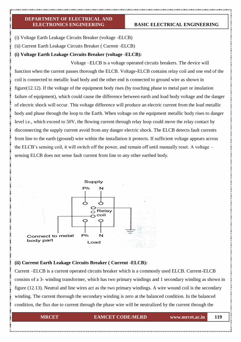
DEPARTMENT OF ELECTRICAL AND
ELECTRONICS ENGINEERING BASIC ELECTRICAL ENGINEERING
MRCET EAMCET CODE:MLRD www.mrcet.ac.in 119
(i) Voltage Earth Leakage Circuits Breaker (voltage -ELCB)
(ii) Current Earth Leakage Circuits Breaker ( Current -ELCB)
(i) Voltage Earth Leakage Circuits Breaker (voltage -ELCB):
Voltage –ELCB is a voltage operated circuits breakers. The device will
function when the current passes thorough the ELCB. Voltage-ELCB contains relay coil and one end of the
coil is connected to metallic load body and the other end is connected to ground wire as shown in
figure(12.12). If the voltage of the equipment body rises (by touching phase to metal part or insulation
failure of equipment), which could cause the difference between earth and load body voltage and the danger
of electric shock will occur. This voltage difference will produce an electric current from the load metallic
body and phase through the loop to the Earth. When voltage on the equipment metallic body rises to danger
level i.e., which exceed to 50V, the flowing current through relay loop could move the relay contact by
disconnecting the supply current avoid from any danger electric shock. The ELCB detects fault currents
from line to the earth (ground) wire within the installation it protects. If sufficient voltage appears across
the ELCB’s sensing coil, it will switch off the power, and remain off until manually reset. A voltage –
sensing ELCB does not sense fault current from line to any other earthed body.
(ii) Current Earth Leakage Circuits Breaker ( Current -ELCB):
Current –ELCB is a current operated circuits breaker which is a commonly used ELCB. Current-ELCB
consists of a 3- winding transformer, which has two primary windings and 1 secondary winding as shown in
figure (12.13). Neutral and line wires act as the two primary windings. A wire wound coil is the secondary
winding. The current thorough the secondary winding is zero at the balanced condition. In the balanced
condition, the flux due to current through the phase wire will be neutralized by the current through the
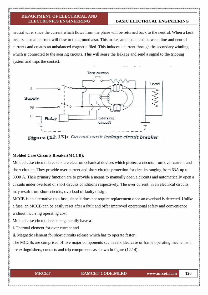
DEPARTMENT OF ELECTRICAL AND
ELECTRONICS ENGINEERING BASIC ELECTRICAL ENGINEERING
MRCET EAMCET CODE:MLRD www.mrcet.ac.in 120
neutral wire, since the current which flows from the phase will be returned back to the neutral. When a fault
occurs, a small current will flow to the ground also. This makes an unbalanced between line and neutral
currents and creates an unbalanced magnetic filed. This induces a current through the secondary winding,
which is connected to the sensing circuits. This will sense the leakage and send a signal to the tripping
system and trips the contact.
Molded Case Circuits Breaker(MCCB):
Molded case circuits breakers are electromechanical devices which protect a circuits from over current and
short circuits. They provide over current and short circuits protection for circuits ranging from 63A up to
3000 A. Their primary function are to provide a means to manually open a circuits and automatically open a
circuits under overload or short circuits conditions respectively. The over current, in an electrical circuits,
may result from short circuits, overload of faulty design.
MCCB is an alternative to a fuse, since it does not require replacement once an overload is detected. Unlike
a fuse, an MCCB can be easily reset after a fault and offer improved operational safety and convenience
without incurring operating cost.
Molded case circuits breakers generally have a
i. Thermal element for over current and
ii. Magnetic element for short circuits release which has to operate faster.
The MCCBs are comprised of five major components such as molded case or frame operating mechanism,
arc extinguishers, contacts and trip components as shown in figure (12.14)
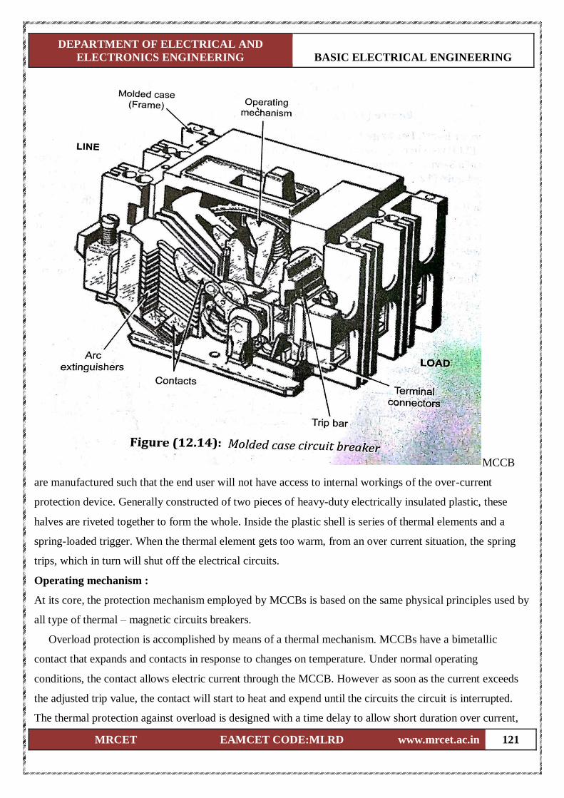
DEPARTMENT OF ELECTRICAL AND
ELECTRONICS ENGINEERING BASIC ELECTRICAL ENGINEERING
MRCET EAMCET CODE:MLRD www.mrcet.ac.in 121
MCCB
are manufactured such that the end user will not have access to internal workings of the over-current
protection device. Generally constructed of two pieces of heavy-duty electrically insulated plastic, these
halves are riveted together to form the whole. Inside the plastic shell is series of thermal elements and a
spring-loaded trigger. When the thermal element gets too warm, from an over current situation, the spring
trips, which in turn will shut off the electrical circuits.
Operating mechanism :
At its core, the protection mechanism employed by MCCBs is based on the same physical principles used by
all type of thermal – magnetic circuits breakers.
Overload protection is accomplished by means of a thermal mechanism. MCCBs have a bimetallic
contact that expands and contacts in response to changes on temperature. Under normal operating
conditions, the contact allows electric current through the MCCB. However as soon as the current exceeds
the adjusted trip value, the contact will start to heat and expend until the circuits the circuit is interrupted.
The thermal protection against overload is designed with a time delay to allow short duration over current,
DEPARTMENT OF ELECTRICAL AND
ELECTRONICS ENGINEERING BASIC ELECTRICAL ENGINEERING
MRCET EAMCET CODE:MLRD www.mrcet.ac.in 122
which is a normal part of operation for many devices. However, any over current conditions that last more
than what is normally expected represent an overload, and the MCCB is tripped to protect the equipment and
personnel.
On the other hand, fault protection is accomplished with electromagnetic induction, and the response is
instant. Fault currents should be interrupted immediately, no matter if their duration is short or long.
Whenever a fault occurs, the extremely high current induces a magnetic field in a solenoid coil located
inside the breaker – this magnetic induction trips a contact and current it interrupted. As a complement to the
magnetic protection mechanism, MCCBs have internal arc dissipation measure to facilitate interruption.
As with all types of circuits breakers, the MCCB includes a disconnection switch which is used to trip the
breaker manually. It is used whenever the electric supply must be disconnected to carry out field work such
as maintenance or equipment upgrades.
Applications :
Molded case circuits breakers can have very high current ratings, which allows them to be used in heavy
duty applications such as main electric feeder protection, capacitor bank protection, generator protection,
welding applications, low current application that require adjustable trip setting and motor protection.
Safety precautions in Handling Electrical Appliance:
It is essentially important to take precautions when we are working with electricity and using electrical
appliances. Here, some of the basic precautions are mentioned for safe usage of electrical appliance :
(i) Follow the manufacture’s instructions :
Always read the manufacture’s instructions carefully before using a new appliance.
(ii) Replace or repair damaged power cords :
Exposed wiring is a danger that cannot be ignored. If you see the protective coating on a wire is stripped
away, be sure to replace it or cover it with electrical tape as soon as possible.
(iii) Keep electrical equipment or outlets away from water :
Avoid water at all times when working with electricity. Never touch or repairing any electrical equipment or
circuits with wet hands. It increases the conductivity of electrical current. Keep all electrical appliance away
from water such as sinks, bathtubs, pools or overhead vents that may drip.
(iv) use insulated tools while working :
Always use appropriate insulated rubber gloves, goggles, protective clothes and shoes with insulated soles
while working on any branch circuits or any other electrical circuits. Use only tools and equipment with
non-conducting handles when working on electrical devices. Never use metallic pencils or rulers or wear
rings or metal watchbands when working with electrical equipment as they cause a strong electric shock.|

DEPARTMENT OF ELECTRICAL AND
ELECTRONICS ENGINEERING BASIC ELECTRICAL ENGINEERING
MRCET EAMCET CODE:MLRD www.mrcet.ac.in 123
(v) Don’t overload your outlets :
Every outlet in your home is designed to deliver a certain amount of electricity; by plugging too many
devices into it at once, you could cause a small explosion or a fire. If you have a lot of things to plug in, use
a power strip that can safely accommodate your needs.
(vi) Shut-off the power supply :
Always make sure that the power source should be shut-off before performing any work related to
electricity. For example; inspecting, installing, maintaining or repairing.
(vii) Avoid extension cords as much as possible :
Running extension cords through the house can trip up residence; this can cause injury and damage to the
wire or outlet if it cause the cord to be ripped out of the wall. If you find yourself using extension cords very
often, consider having an electrician install new outlets throughout your home.
(viii) When to repair :
Everyone want to have the safe electrical environment. Equipment producing “tingle” sound should be
disconnected and reported promptly for repair.
(ix) Avoid the usage of flammable liquids :
Never use highly flammable liquids near electrical equipment. Never touch another person’s equipment or
electrical control devices unless instructed to do so.
(x) Use electric tester :
Never try repairing energized equipment. Always check that it is de-energized first by using a tester. When
an electric tester touches a live or hot wire, the bulb inside the tester lights up showing that an electrical
current is flowing through the respective wire. Check all the wires, the outer metallic covering of the service
panel any other hanging wires with an electrical tester before proceeding with your work.
(xi) In case of electric shock :
If an individual comes in contact with a live electrical conductor, do not touch the equipment, cord person.
Disconnect the power source from the circuits breaker or pull out the plug using a leather belt. By enclosing
all electric conductors and contacts can save people from getting the electric shock. Use three-pin plugs,
which have earth wire connection which prevents electrical shock.
(xii) Display danger board :
Danger board should be displayed at the work place. We should not allow any unauthorized person to enter
in the working place and we should not put any new equipment into the service without necessary testing by
the concern authority.
(xiii) Usage of proper ladder :
Never use an aluminium or steel ladder if you are working on any receptacle at height in your home. An
DEPARTMENT OF ELECTRICAL AND
ELECTRONICS ENGINEERING BASIC ELECTRICAL ENGINEERING
MRCET EAMCET CODE:MLRD www.mrcet.ac.in 124
electrical surge will ground you and the whole electric current will pass through your body. Use a bamboo,
wooden or a fibreglass ladder instead.
(xiv) Usage of circuits breaker or fuse :
Always use a circuits breaker or fuse with the appropriate current rating. Circuits breakers and fuses are
protection devices that automatically disconnect the live wire a condition of short circuits or over current
occurs. The selection of the appropriate fuse or circuit breaker is essential. Normally for protection against
short circuits a fuse rated of 150% of the normal circuit current is selected. In the case of a circuit with 10
amperes of current, a 15 ampere fuse will against direct short circuits a 9.5 amperes fuse will blow out.
(xv) Use ceiling on live wire :
Always put a cap on the hot/live wire while working on an electric board or service panel as you could end
up short circuiting the bare ends of the live wire with the neutral. The cap insulates the copper ends of the
cable thus preventing any kind of shock even if touched mistakenly.
(xvi) Precaution during soldering :
Always take care while soldering your circuits boards. Wear goggles and keep yourself away from the
fumes. Keep the solder iron in its stand when not in use; it can get extremely hot and can easily cause burns.
(xvii) Things to remember :
The circuits is bad, electricity appliances are not working well, and lights are fluctuating. It means you need
an electrical inspection or repair. In this case, either you’ll call an electrician or do it yourself. So if you are
trying to repair, always remember that your hands are well dry, you have essential tools, rubber gloves &
shoe are good, As all these acts as an insulator. Do not wear loose clothing or tied near electrical equipment.
(xviii)Keep heaters away from bedclothes, clothing and curtains to avoid risk fire. Be extra careful when
using electrical appliances attached to power outlets near kitchen or bathroom sinks, tubs, swimming pools,
and other wet areas. Don’t cover an electric heater with clothing or other items.
Batteries:
A battery is a devices which converts chemical energy into electrical energy and is made up of a number of
cells. Batteries consists of two or more voltaic cell that are connected in series to provide a steady DC
voltage at the battery’s output terminals. The voltage is produced by a chemical reaction inside the cell.
Electrodes are immersed in an electrolyte, which forces the electric charge to separate in the from of ions
and free electrons. A battery’s voltage output and current rating are determined by the elements used for the
electrodes, the size of the electrodes, and the type of electrolyte used. Whether a battery may be recharged or
not depends on the cells used to make up the battery.
Batteries are classified into two types such as primary batteries and secondary batteries.
DEPARTMENT OF ELECTRICAL AND
ELECTRONICS ENGINEERING BASIC ELECTRICAL ENGINEERING
MRCET EAMCET CODE:MLRD www.mrcet.ac.in 125
(i) Primary Batteries
As the name indicates, these batteries are meats for single usage. Once these batteries are used they cannot
be recharged as the devices are not easily reversible and active material may not return to their original
forms. Other name for these batteries is disposable batteries. Some of the example for the disposable
batteries are the normal AA, AAA batteries which we use in wall clocks, television remote, etc.
(ii) Secondary Batteries
Secondary batteries are also known as rechargeable batteries. These batteries can be used and charged
simultaneously. A secondary battery or storage battery can be recharged because its chemical reaction is
reversible. Rechargeable batteries are (re) charged by applying electric current, which reverses the chemical
reactions that occur during discharge/use. Some of the examples for rechargeable batteries are the batteries
used in mobile phones MP3 players, etc.
Types of primary Cells/Batteries:
There are several types of primary cells in use today, such as
(i) Carbon- zinc dry cell
(ii) Alkaline cell
(iii) Zinc chloride cell
(iv) Mercury cell
(v) Silver oxide cell
(vi) Lithium cell
(i) Carbon- zinc dry cell
(a) This is one the most popular primary cells (often used for type AAA, AA, D)
(b) The negative electrode is made of zinc
(c) The positive electrode is made of carbon.
(d) The output voltage of a single cell is about 1.5 V.
(e) Performance of the cell is better with intermittent operation.
(ii) Alkaline cell
(i) The alkaline cell is another popular type also used for type AA, C, D, etc.
(ii) It has the same 1.5V output as carbon- zinc cells, but they are longer -lasting.
(iii) It consists of a zinc anode and manganese dioxide cathode in an alkaline electrolyte (potassium
hydroxide )
(iv) It works with high efficiency even with continuous use, due to low internal resistance.
(iii) Zinc chloride cell
(i) This cell is also referred to as a “heavy-duty” type battery.
DEPARTMENT OF ELECTRICAL AND
ELECTRONICS ENGINEERING BASIC ELECTRICAL ENGINEERING
MRCET EAMCET CODE:MLRD www.mrcet.ac.in 126
(ii) It is modified zinc-carbon cell.
(iii) It has little chance of liquid leakage because the cell consumes water along with the chemically active
materials. The cell is usually dry at the end of its useful life.
(iv) Mercury cell
(i) This cell consists of a zinc anode, mercury compound cathode, and potassium or sodium hydroxide
electrolyte.
(ii) It is becoming obsolete due to the hazards associated with proper disposal of mercury.
(v) Silver oxide cell
(i) This cell consists of a zinc anode, silver oxide cathode, and potassium of sodium hydroxide electrolyte.
(ii)It is typically available as 1.5V, miniature button form.
(iii) Applications include hearing aids, cameras, and watches
(vi) Lithium cell
(i) This cell offers high output voltage, long shelf life, low weight, and small volume.
(ii) It comes in two forms of 3V output in widespread use:
(a) Lithium-sulfur dioxide(LiSO2 ).
(b) Lithium- thionyl chloride.
(iii) LiSO2 type batteries contain methyl cyanide liquid solvent; if its container is punctured
(iv) Safe disposal of these cells is critical.
Types of Secondary Cells/Batteries:
There are several types of secondary cells in use today, such as
(i) Lead-acid cell
(ii) Nickel cadmium (NiCd) cell
(iii) Lithium-ion battery
(iv) Nickel-metal- hydride (NiMH) cell
(v) Nickel-iron (Edison) cell
(vi) Fuel cell
(vii) Solar cell
(i) Lead-acid cell:
(a) This cell is a widely applied type of secondary cell, used extensively in automobiles inverters, backup
power system, etc. Requiring high values of load current.
(b) Anode: Porous lead
(c) Cathode: Lead-dioxide
(d) Electrolyte: Sulfuric acid, 6 molar H2SO4
DEPARTMENT OF ELECTRICAL AND
ELECTRONICS ENGINEERING BASIC ELECTRICAL ENGINEERING
MRCET EAMCET CODE:MLRD www.mrcet.ac.in 127
(e) The output is about 2.1 V per cell.
(f) Cells are typically used in series combinations of 3 (6V battery) or 6 (12V battery)
(ii) Nickel cadmium (NiCd) cell:
(a) This type of cell delivers high current.
(b) It can be recharged many times.
(c) Anode: Nickel hydroxide Ni(OH)2
(d) Cathode: Cadmium hydroxide, Cd(OH)2
(e) Electrolyte : Cadmium hydroxide, KOH
(f) Maintain a steady voltage of 1.2V per cell until completely depleted
(g) It can be stored for long periods of times.
(h) Its specific gravity does not charge with the state of charge.
(I) Applications include portable power tools, alarm systems, portable radio and TV equipment.
(iii) Lithium-ion battery:
(i) Li-based cells are most compact ways of storing electrical energy.
(ii) Lower in energy density than lithium metal, lithium-ion is safe.
(iii) Anode: Graphite
(iv) Cathode: Lithium manganese dioxide
(v) Electrolyte : mixture of lithium salts
(vi) Energy density is twice of the standard nickel-cadmium.
(vii) No memory and no scheduled cycling is required to prolong battery life.
(iv) Nickel-metal- hydride (NiMH) cell:
(i) These cells are used in applications demanding long-running battery performance (e.g., high-end portable
electrical or electronic products like power tools).
(ii) They offer 40% more capacity over a comparably-sized NiCb cell.
(iii) They contain the same components as a NiCd cell, expect for the negative electrode.
(iv) They are more expensive than NiCd cells, self-discharge more rapidly, and cannot be cycled as
frequently as NiCd cells.
(v) Nickel-iron (Edison) cell:
(i) Anode: Nickel hydroxide, Ni(OH)2
(ii) Cathode: iron
(iii) Electrolyte: potassium hydroxide
(iv) The specific gravity of electrolyte remains unaffected during the charging and discharging process.
(v) They are now almost obsolete due to lead-acid batteries.
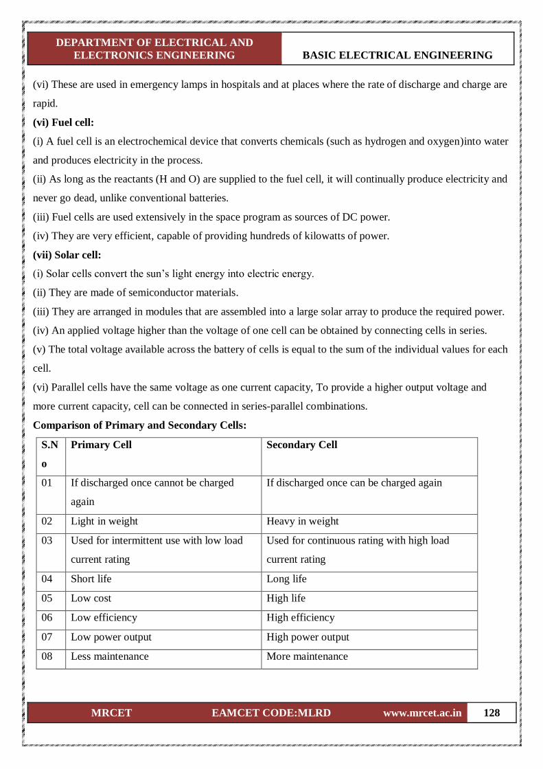
DEPARTMENT OF ELECTRICAL AND
ELECTRONICS ENGINEERING BASIC ELECTRICAL ENGINEERING
MRCET EAMCET CODE:MLRD www.mrcet.ac.in 128
(vi) These are used in emergency lamps in hospitals and at places where the rate of discharge and charge are
rapid.
(vi) Fuel cell:
(i) A fuel cell is an electrochemical device that converts chemicals (such as hydrogen and oxygen)into water
and produces electricity in the process.
(ii) As long as the reactants (H and O) are supplied to the fuel cell, it will continually produce electricity and
never go dead, unlike conventional batteries.
(iii) Fuel cells are used extensively in the space program as sources of DC power.
(iv) They are very efficient, capable of providing hundreds of kilowatts of power.
(vii) Solar cell:
(i) Solar cells convert the sun’s light energy into electric energy.
(ii) They are made of semiconductor materials.
(iii) They are arranged in modules that are assembled into a large solar array to produce the required power.
(iv) An applied voltage higher than the voltage of one cell can be obtained by connecting cells in series.
(v) The total voltage available across the battery of cells is equal to the sum of the individual values for each
cell.
(vi) Parallel cells have the same voltage as one current capacity, To provide a higher output voltage and
more current capacity, cell can be connected in series-parallel combinations.
Comparison of Primary and Secondary Cells:
S.N
o
Primary Cell Secondary Cell
01 If discharged once cannot be charged
again
If discharged once can be charged again
02 Light in weight Heavy in weight
03 Used for intermittent use with low load
current rating
Used for continuous rating with high load
current rating
04 Short life Long life
05 Low cost High life
06 Low efficiency High efficiency
07 Low power output High power output
08 Less maintenance More maintenance
DEPARTMENT OF ELECTRICAL AND
ELECTRONICS ENGINEERING BASIC ELECTRICAL ENGINEERING
MRCET EAMCET CODE:MLRD www.mrcet.ac.in 129
Battery Characteristics:
There are many characteristics that can help to identify a battery that can help to identify a battery and we
can distinguish the three main ones as; chemistry, battery capacity and voltage. However, if the battery is
only a starter, it also delivers cold cranking amps (CCA), which permits to offer high current at cold
temperatures.
(i) Chemistry
The main battery chemistries are lead, nickel and lithium. They all need a specific designated charger, this is
why charging these batteries on a different charger from their own might cause an incorrect charge, despite
it seeming to work at first. This happens because of the different regulatory requirement of each chemistry.
(ii) Battery Capacity
Battery capacity is a measure (typically in Amp-hr) of the charge stored by the battery, and is determined by
the mass of active material contained in the battery. The battery capacity represent the maximum amount of
energy that can be extracted from the battery under certain specified conditions. However, the actual energy
storage capabilities of the battery can vary significantly from the “nominal” rated capacity, as the battery
capacity depends strongly on the age and past history of the battery, the charging or discharging regimes of
the battery and the temperature.
The energy stored in a battery, called the battery capacity, is measured in either watt-hours (Wh), kilowatt-
hours (kWh), or ampere-hours (Ahr). The most common measure of battery capacity is Ah, defined as the
number of hours for which a battery can provide a current equal to the discharge rate at the nominal voltage
of the battery. The unit of Ah is commonly used when working with battery systems as the battery voltage
will vary throughout the charging or discharging cycle.
(ii) Voltage
A battery feature a nominal voltage. Along with the amount of cells connected in series, chemistry provides
the open circuits voltage (OCV), which is about 5-7% higher on a fully charged battery. It is important to
check the correct nominal voltage of a battery before connecting it.
(iv) Cold Cranking Amps (CCA)
Every starter battery is marked with cold cranking amps, also abbreviated CCA. The number denotes the
amount of amps that the battery is able to provide at -180C.
Energy Consumption Calculation:
Energy and power are closely related. Electrical energy can be measured only when electrical power is
known. So first we understand the electrical power. Electrical power it the amount of electrical current that
results from a certain amount of voltage or we can say that power is the rate which energy is delivered. It is
measured in watts. Mathematically it is written as
DEPARTMENT OF ELECTRICAL AND
ELECTRONICS ENGINEERING BASIC ELECTRICAL ENGINEERING
MRCET EAMCET CODE:MLRD www.mrcet.ac.in 130
Power = Voltage × Current
The measurement of electrical energy is completely dependent on power which is measured in watt,
kilowatts, megawatts, gigawatts, and time which is measured in an hour. Joule is the smallest unit of energy.
But for some bigger calculation, some better unit it required. So, the unit used for electrical energy is watt-
hour.
Electrical energy is the product of electrical power and time, and it measured in joules. It is defined as “1
joule of energy is equal to 1 watt of power is consumed for 1 second”. I.e.,
Energy = Power × Time
1 Joule = 1 watt × 1 second
Watts are the basic unit of power in which electrical power is measured or we can say that rate at which
electrical current is being used at a particular moment.
Watt-hour is the standard unit used for measurement of energy, describing the amount of watts used over a
time. It shows how fast the power is consumed in the period of time.
Energy in watt hours = Power in watts × Time in hours
Kilowatt-hour is simply a bigger unit of energy when large appliance drawn power in kilowatts. It can be
described as one kilowatt hour is the amount of energy drawn by the 1000 watts appliance when used for an
hour.
Where, One kilowatt = 1000 watts
Energy in kilowatt hours = Power in kilowatts × Time in hours
The electrical supply companies take electric energy charges from their consumer per kilowatt hour unit
basis.
This kilowatt hour is board of trade (BOT) unit.
Illustration for Energy Consumption:
A consumer uses a 10 kW geezer, a 6 kW electric furnace and five 100 W bulbs for 15 hours. How many
units (kWh) of electrical energy have been used?
Explanation : Given that
Load – 1 = 10 kW geezer
Load – 2 = 6 kW electric furnace
Load – 3 = 500 watt (five 100 watt bulbs)
Total load = 10kW + 6kW + 0.5kW = 16.5kW
Time taken = 155 hours
Energy consumed = Power in kW × Time in hours
= 16.5 × 15 = 247.5 kWh
DEPARTMENT OF ELECTRICAL AND
ELECTRONICS ENGINEERING BASIC ELECTRICAL ENGINEERING
MRCET EAMCET CODE:MLRD www.mrcet.ac.in 131
For above electrical energy consumption, the tariff can be calculated as follows :
1 unit = 1kWh
So, the total energy consumption = 247.5 units
If the cost per unit is 2.5, then the total cost of energy consumption
=247.5 × 2.5 = 618.75/-
MRCET EAMCET CODE:MLRD www.mrcet.ac.in 132