
Upcoming Batches in Electrical Engineering - wifistudy
63
-
Upload
khangminh22 -
Category
Documents
-
view
1 -
download
0
Transcript of Upcoming Batches in Electrical Engineering - wifistudy


Upcoming Batches in Electrical Engineering
SSC JE - 2019 (Timings 5 pm to 6 pm)
1. Power System complete Syllabus batch (30 to 40 days)
2. Mock Tests for SSC JE 2019 with Video solution (30 days to 40 days)
From 8th of June
From 13th of June
SSC JE - 2020 (Timings 7 pm to 8 pm)
1. Electrical Machine complete syllabus batch Now with MCQs also
2. Basic Electronics Complete syllabus batch

Special Free Session – 3 PMSubject – All subject mix MCQs
SSC JE – 5 PM (Under SSC Subscription)Subject – BEE (Basic Electrical Engineering)
UPPSC AE – 7 PM (Under UPPSC subscription)Subject – Control System
SSC JE – 10 PM Crash course of SSC JE with MCQs


@ashishsoniwifistudy

CRO (Cathode Ray Oscilloscope): -Advantage: -1. Linear device2. X-Y Plotter3. Wave form display.4. High Resolution5. Higher Sensitivity6. Low Power Consumption7. Higher Accuracy8. Higher speed9. Stores wave form10. Free from external fields11. Easily Adjustable scale12. Multiple wave forms can be observed.

CRT (cathode ray tube): -
Acc - Accelerating
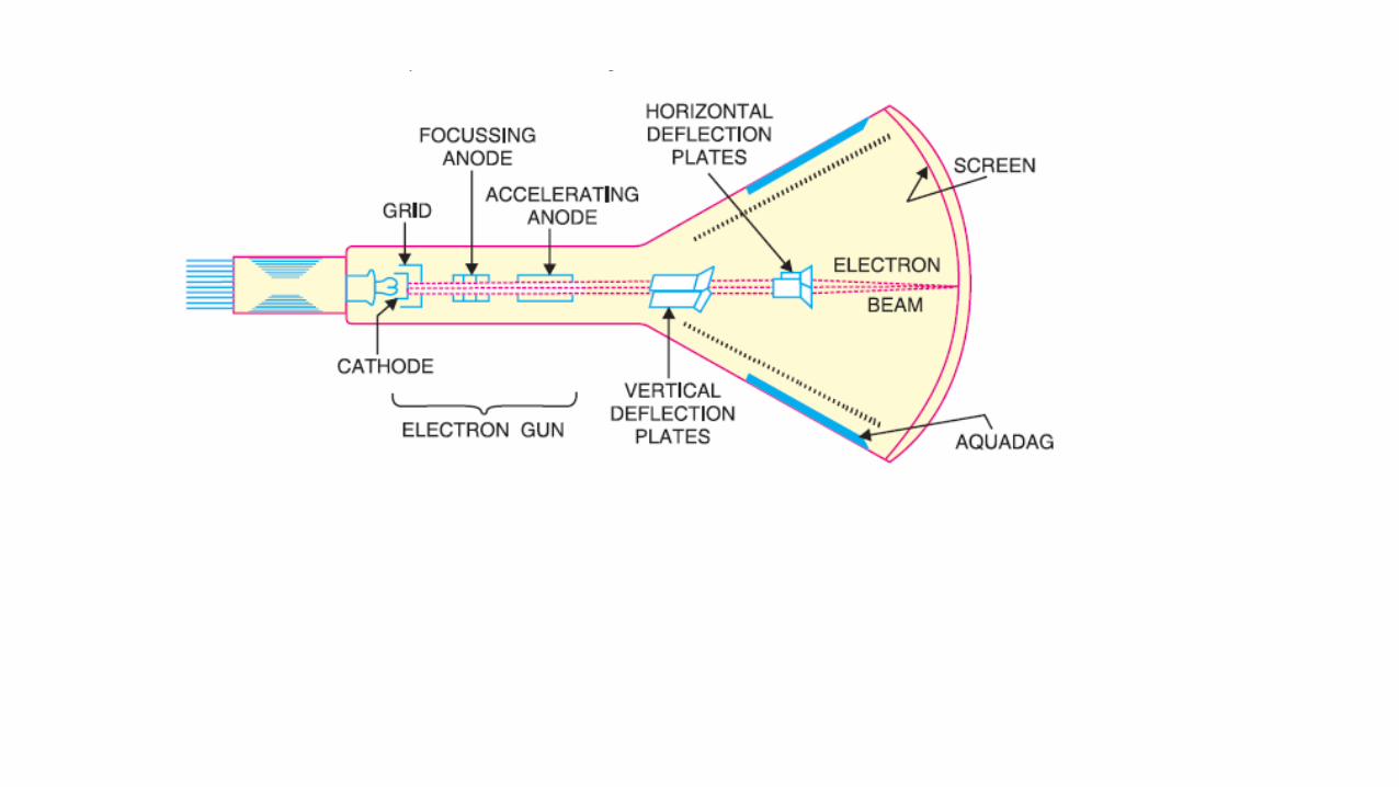


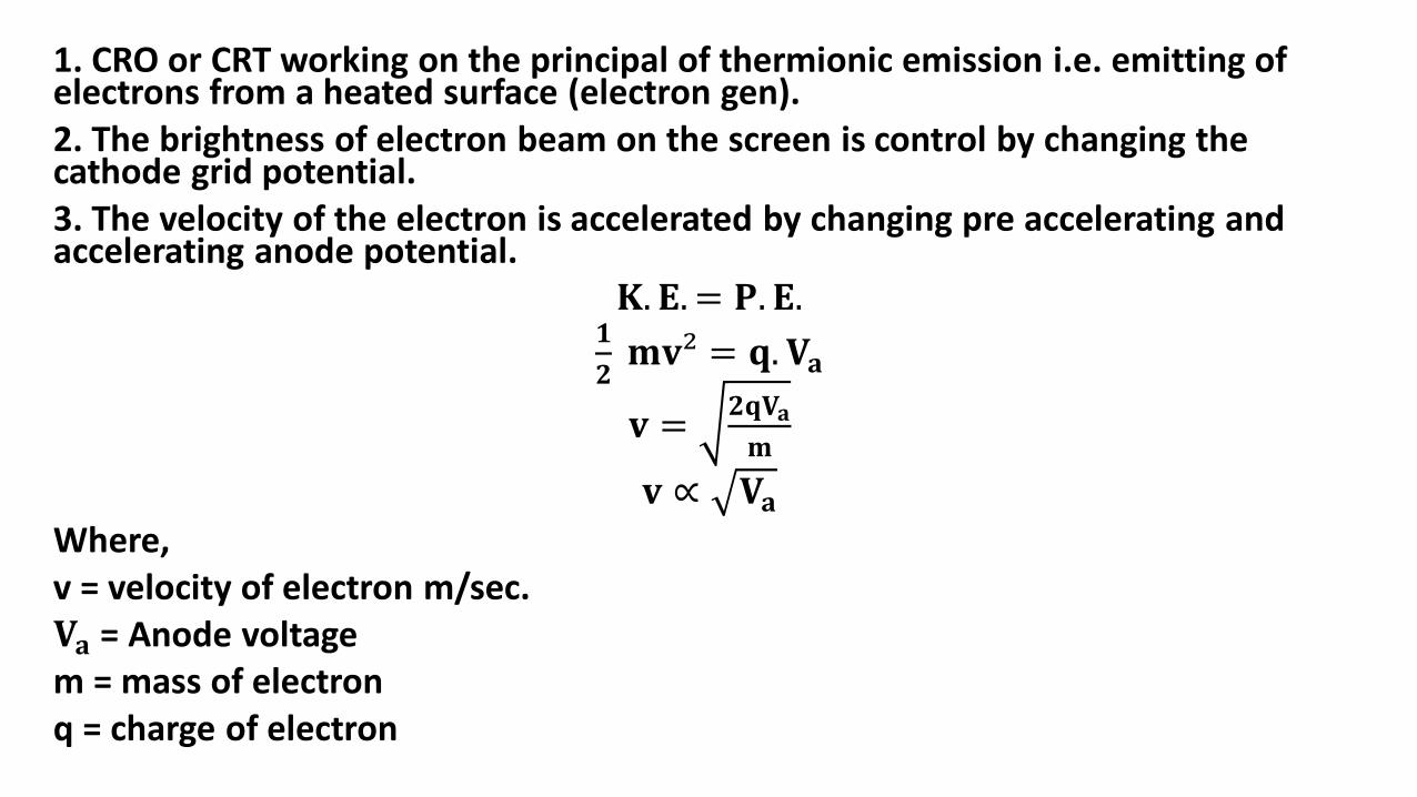
1. CRO or CRT working on the principal of thermionic emission i.e. emitting of electrons from a heated surface (electron gen).2. The brightness of electron beam on the screen is control by changing the cathode grid potential.3. The velocity of the electron is accelerated by changing pre accelerating and accelerating anode potential.
𝐊. 𝐄. = 𝐏. 𝐄.𝟏
𝟐𝐦𝐯² = 𝐪. 𝐕𝐚
𝐯 =𝟐𝐪𝐕𝐚
𝐦
𝐯 ∝ 𝐕𝐚Where, v = velocity of electron m/sec.𝐕𝐚 = Anode voltagem = mass of electronq = charge of electron

*Double concave electron lenses*

• Laboratory CRO uses electrostatic focus control.
• This is working on the principal of double concave electron lenses.
• By adjusting focus anode potential, the focal point can be change.
• For fine focus control small dc potential is applied to the horizontal and vertical deflecting plates, this is called ‘Astigmatism’.
• Television picture tube works on the electromagnetic focus control.
• Computer CRO works on both electrostatic and electromagnetic focus control.
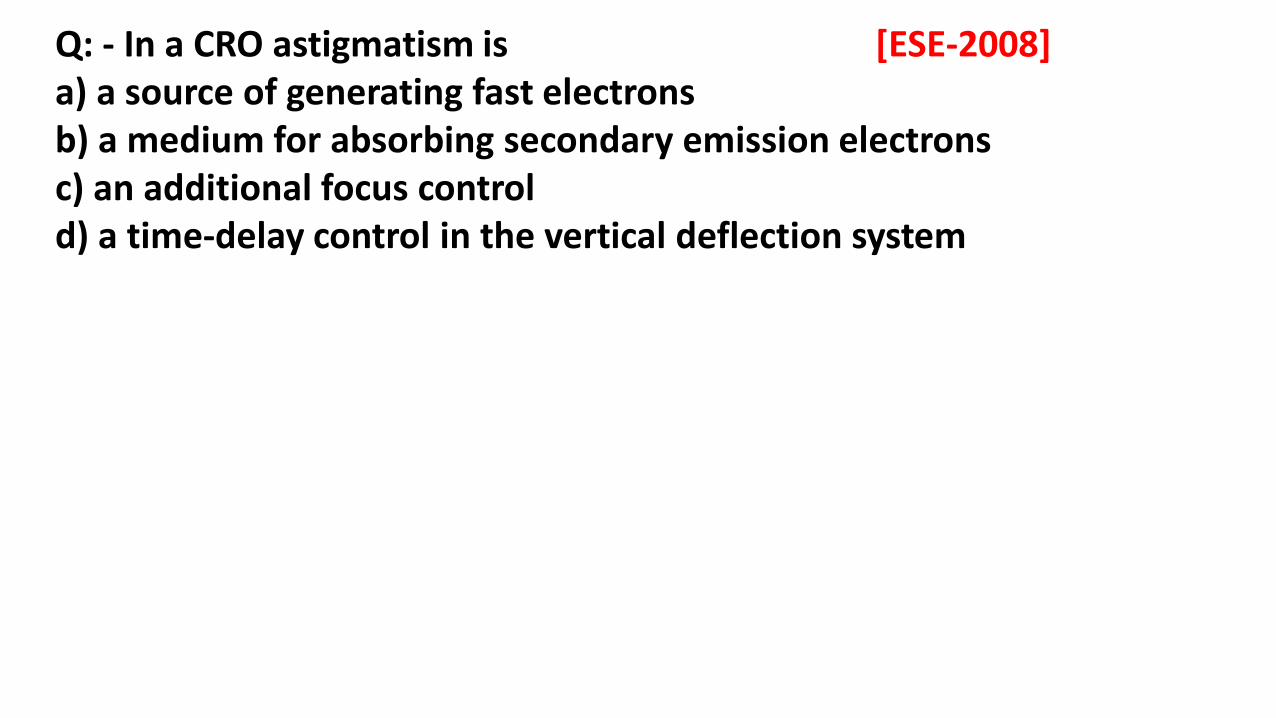
Q: - In a CRO astigmatism is [ESE-2008]a) a source of generating fast electronsb) a medium for absorbing secondary emission electronsc) an additional focus controld) a time-delay control in the vertical deflection system
0 0
O
O
O
O
O
O
O O O O O O
5
4
3
2
1
0
VDD
HDP
0 0.5 1 1.52 2.5 3 3.5 4
0 1 2 3 4 5
1
234
VX
VyVm
t
tr tf

For square signal: -
⇒
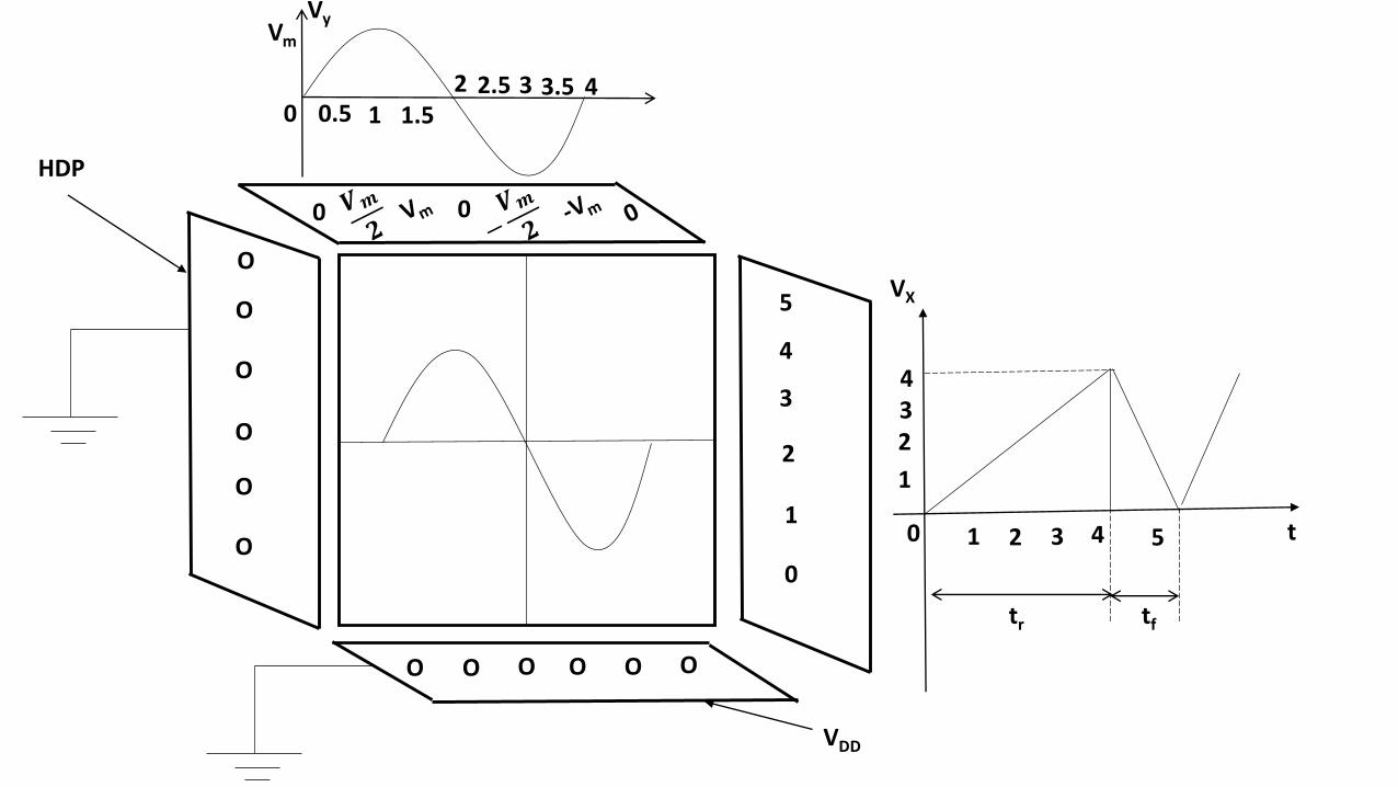
• Horizontal deflecting plates (HDP) are kept in vertical position.
• These are applied with saw tooth waveform which is produced by UJT relaxation oscillator or operational amplifier.
• The time period of the saw tooth waveform can be adjusted by using synchronizing input.
• The saw tooth is maintain equal to test signal time period.
This is not visible in CRO

• The saw tooth time period is maintained equal to test signal time period.
• HDP is used for shifting the electron beam Horizontally i.e. Horizontal time scale is adjusted by changing HDP potential.
• VDP is applied with test signal, whose waveform has to be observed on the screen VDP is kept in Horizontal position.
• For collection of Secondary electrons aquadag coated with graphite is used for maintaining electrical neutrality with in the CRT.
• During retrace or fly back time of the saw tooth signal blanking ckt is initiated which activates the cathode grid so that high negative potential is applied and hence the electrons are completely stopped entering into the CRT so that blurred image shown on the screen can be avoided.
• Different types of phosphorous coating is used on the screen depending on the application this phosphor converts heat into light energy.
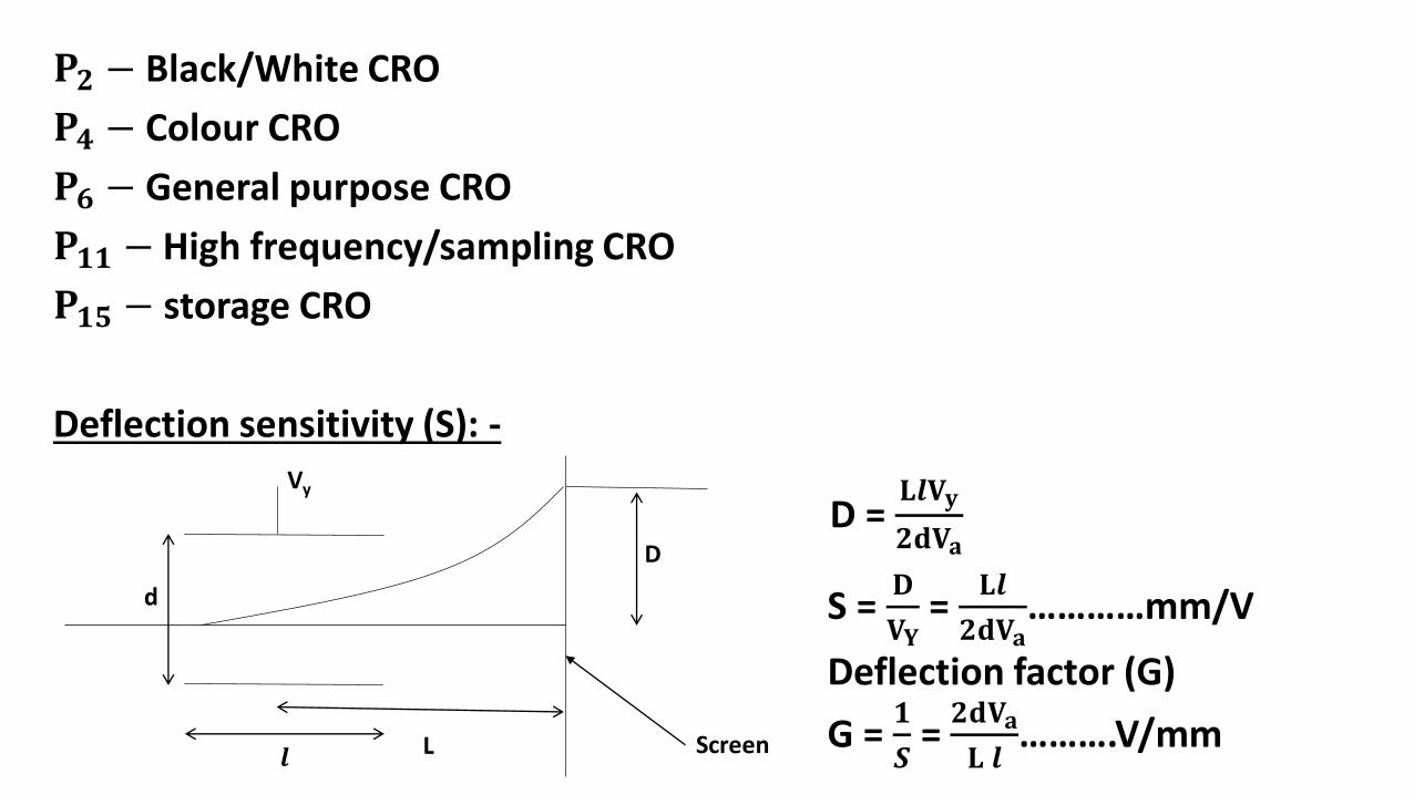
𝐏𝟐 − Black/White CRO
𝐏𝟒 − Colour CRO
𝐏𝟔 − General purpose CRO
𝐏𝟏𝟏 − High frequency/sampling CRO
𝐏𝟏𝟓 − storage CRO
Deflection sensitivity (S): -
d
Vy
𝒍 L
D
Screen
D = 𝐋𝒍𝐕𝐲
𝟐𝐝𝐕𝐚
S = 𝐃
𝐕𝐘=
𝐋𝒍
𝟐𝐝𝐕𝐚…………mm/V
Deflection factor (G)
G = 𝟏
𝑺= 𝟐𝐝𝐕𝐚
𝐋 𝒍……….V/mm

Va = Anode voltage
Vy = VDP voltage = test signal
𝒍 = length of VDP
d = distance between VDP plates
L = Distance between center of VDP to screen
D = height at which beam is hitting on the screen (Deflection height)
Special CRO’S: -
(1) Dual Trace CRO: -
This CRO consisting of due electron beam and two vertical deflecting plates with a selection switch. By changing the selection switch one of the vertical plate waveform can be observed on the screen.
i.e. waveforms can be alternatively observed. Simultaneous visibility is not possible.
• By using multiplexer the two waveforms can be observed one after the other. This is called alternate mode.
• The control signal of the multiplexer frequency can be maintained = twice the frequency of saw tooth or sweep oscillator.
Dual beam CRO: -
It consisting of two Horizontal, two vertical deflecting plates with two electron guns, So that two different waveforms can be observed simultaneously on the screen.
• Cost is higher, It is normally used in research laboratories.
High frequency or Sampling CRO: -
• This consisting of an extra post accelerating anode which is used for controlling the brightness of beam on the screen. Short persisting phosphorous coating is used in the High frequency CRO’s.
Storage CRO: -
Memory storing elements are used with in the CRO for storage of waveform pattern in the CRO’s.

Q: - A dual-beam CRO [ESE-2015]a) has one set of vertical deflection platesb) has two sets of horizontal deflection platesc) has two separate electron beamsd) None of the above
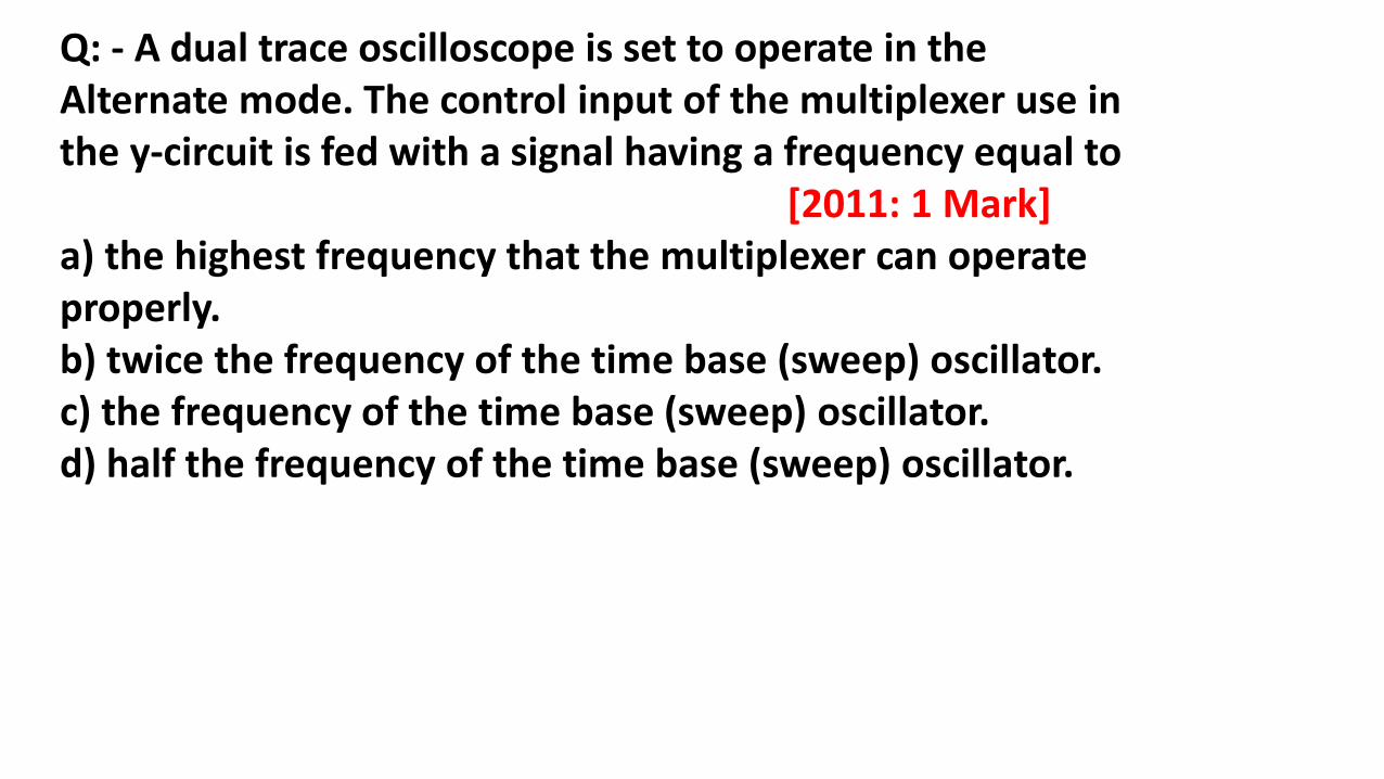
Q: - A dual trace oscilloscope is set to operate in the Alternate mode. The control input of the multiplexer use in the y-circuit is fed with a signal having a frequency equal to
[2011: 1 Mark]a) the highest frequency that the multiplexer can operate properly.b) twice the frequency of the time base (sweep) oscillator.c) the frequency of the time base (sweep) oscillator.d) half the frequency of the time base (sweep) oscillator.
Application of CRO: -
Lissajous pattern: -
If both horizontal and vertical deflecting plates are applied with sinusoidal signals then waveform pattern appearing on the screen is called lissajous pattern.
By using this pattern,
• Phase angle difference between two signals can be measured.
• The unknown frequency of the signal from the known frequency of signal and from the known lissajous pattern can be measured.
Note: -
At any point of time the electron beam hitting on the screen is the vector sum of voltages applied to the both horizontal and vertical deflecting plates. The vector sum consisting of both magnitude and phase angle.
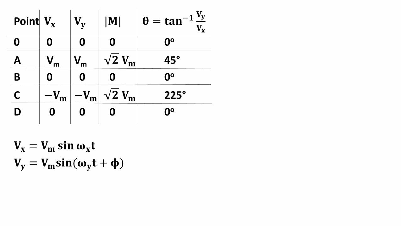
Point 𝐕𝐱 𝐕𝐲 |𝐌| 𝛉 = 𝐭𝐚𝐧−𝟏𝐕𝐲
𝐕𝐱
0 0 0 0 0o
A Vm Vm 𝟐 𝐕𝐦 45°
B 0 0 0 0o
C −𝐕𝐦 −𝐕𝐦 𝟐 𝐕𝐦 225°
D 0 0 0 0o
𝐕𝐱 = 𝐕𝐦 𝐬𝐢𝐧𝛚𝐱𝐭
𝐕𝐲 = 𝐕𝐦𝐬𝐢𝐧(𝛚𝐲𝐭 + 𝛟)

Case1: -𝐕𝐱 = 𝐕𝐲 = 𝐕𝐦
𝛚𝐱 = 𝛚𝐲 = 𝛚 ;𝛟 → charging
𝐕𝐱 = 𝐕𝐦𝐬𝐢𝐧𝛚𝐭
𝐕𝐲 = 𝐕𝐦 𝐬𝐢𝐧(𝛚𝐭 + 𝛟)
(1) 0 to 45o (2) 0o < 𝛟 < 90o
or
270o < 𝛟 < 360oStraight line

(3) 𝛟 = 90o or 270o (4) 90o < 𝛟 < 180o
or
180o < 𝛟 < 270o

Calculation of 𝛟 from the given Lissajous pattern: -
𝛟 = 180o
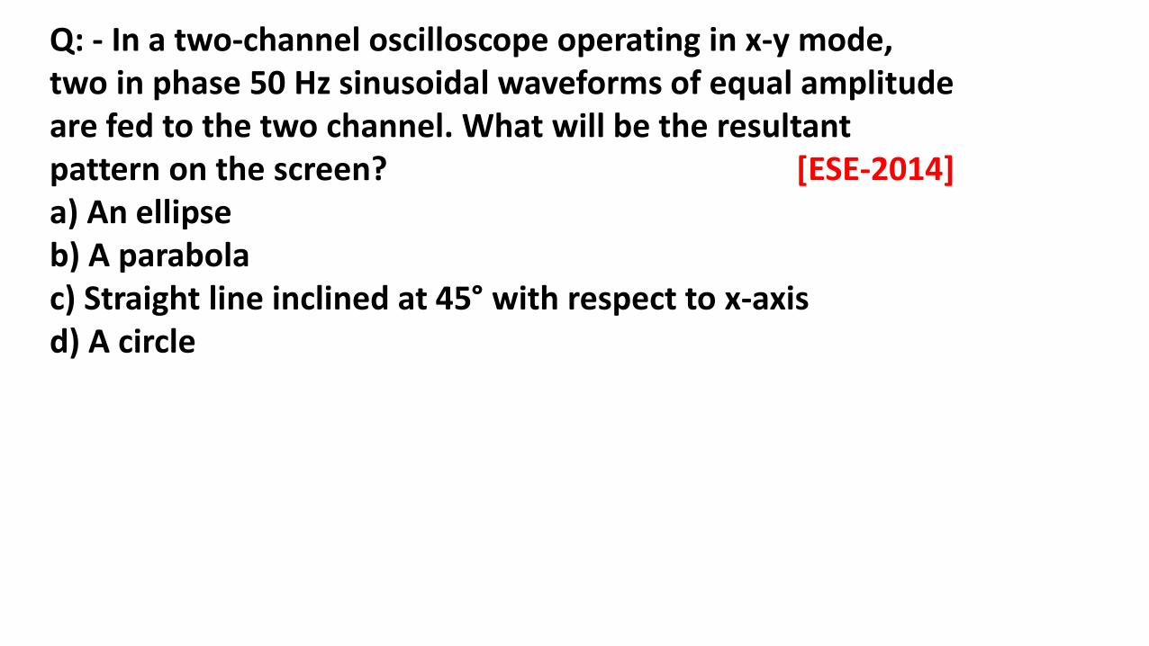
Q: - In a two-channel oscilloscope operating in x-y mode, two in phase 50 Hz sinusoidal waveforms of equal amplitude are fed to the two channel. What will be the resultant pattern on the screen? [ESE-2014]a) An ellipseb) A parabolac) Straight line inclined at 45° with respect to x-axisd) A circle
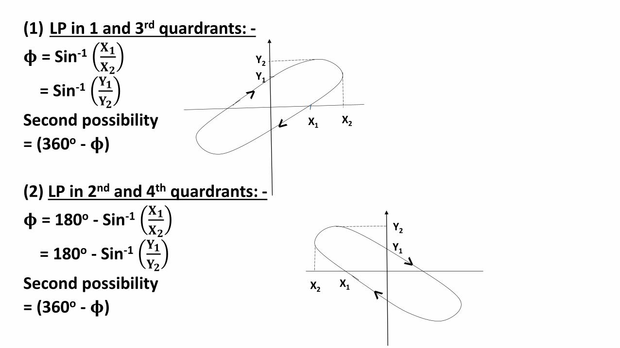
(1) LP in 1 and 3rd quardrants: -
𝛟 = Sin-1 𝐗𝟏
𝐗𝟐
= Sin-1 𝐘𝟏
𝐘𝟐
Second possibility
= (360o - 𝛟)
(2) LP in 2nd and 4th quardrants: -
𝛟 = 180o - Sin-1 𝐗𝟏
𝐗𝟐
= 180o - Sin-1 𝐘𝟏
𝐘𝟐
Second possibility
= (360o - 𝛟)
X1X2
Y2
Y1
Y1
Y2
X1X2

Q. The two signals S1 and S2, shown in figure, are applied toY and X deflection plates of an oscilloscope.
The waveform displayed on the screen is [2014: 1 Mark, Set-3]
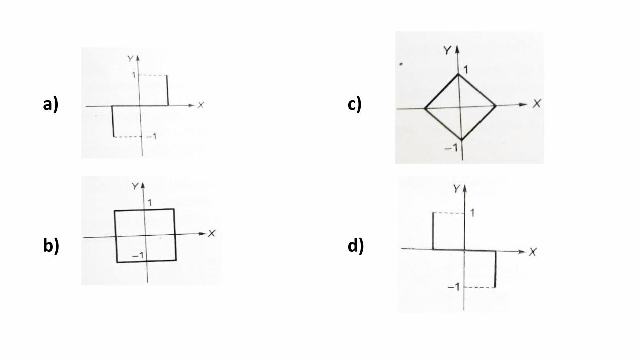
a)
b)
c)
d)
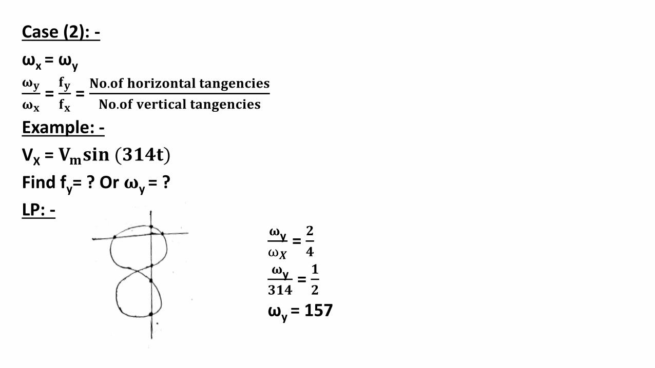
Case (2): -
ωx = ωy
𝛚𝐲
𝛚𝐱= 𝐟𝐲
𝐟𝐱= 𝐍𝐨.𝐨𝐟 𝐡𝐨𝐫𝐢𝐳𝐨𝐧𝐭𝐚𝐥 𝐭𝐚𝐧𝐠𝐞𝐧𝐜𝐢𝐞𝐬
𝐍𝐨.𝐨𝐟 𝐯𝐞𝐫𝐭𝐢𝐜𝐚𝐥 𝐭𝐚𝐧𝐠𝐞𝐧𝐜𝐢𝐞𝐬
Example: -
VX = 𝐕𝐦𝐬𝐢𝐧 (𝟑𝟏𝟒𝐭)
Find fy= ? Or 𝛚y = ?
LP: -𝛚y
ω𝑿= 𝟐
𝟒𝛚y
𝟑𝟏𝟒= 𝟏
𝟐
ωy = 157

Q: - List-I represents the figures obtained on a CRO screen when the voltage signals Vx = Vxm sinωt and Vy =
Vym sin(ωt + ϕ) are given to its X and Y plates respectively
and ϕ is changed. Choose the correct value of ϕ from List-I to match with the corresponding figure of List-II. [2003: 2 Marks]
List-IA. ϕ = 0B. ϕ = π/2C. π < ϕ < 3π/2D. ϕ = 3π/2List-II
Bandwidth of CRO: -
The maximum undistorted frequency observed on the CRO screen is called Bandwidth of the CRO, it is related with the rise time of the signal.
𝐁𝐖× 𝐭𝐫 = 𝟎. 𝟑𝟓
𝐁𝐖 = Bandwidth in Hz
𝐭𝐫 = rise time in sec.
BW = Bandwidth in Hz.
Calibration of CRO: -
CRO is calibrated by applying square or pulse signal of known frequency and magnitude, by using these parameters the horizontal and vertical scales of the CRO are calculate.
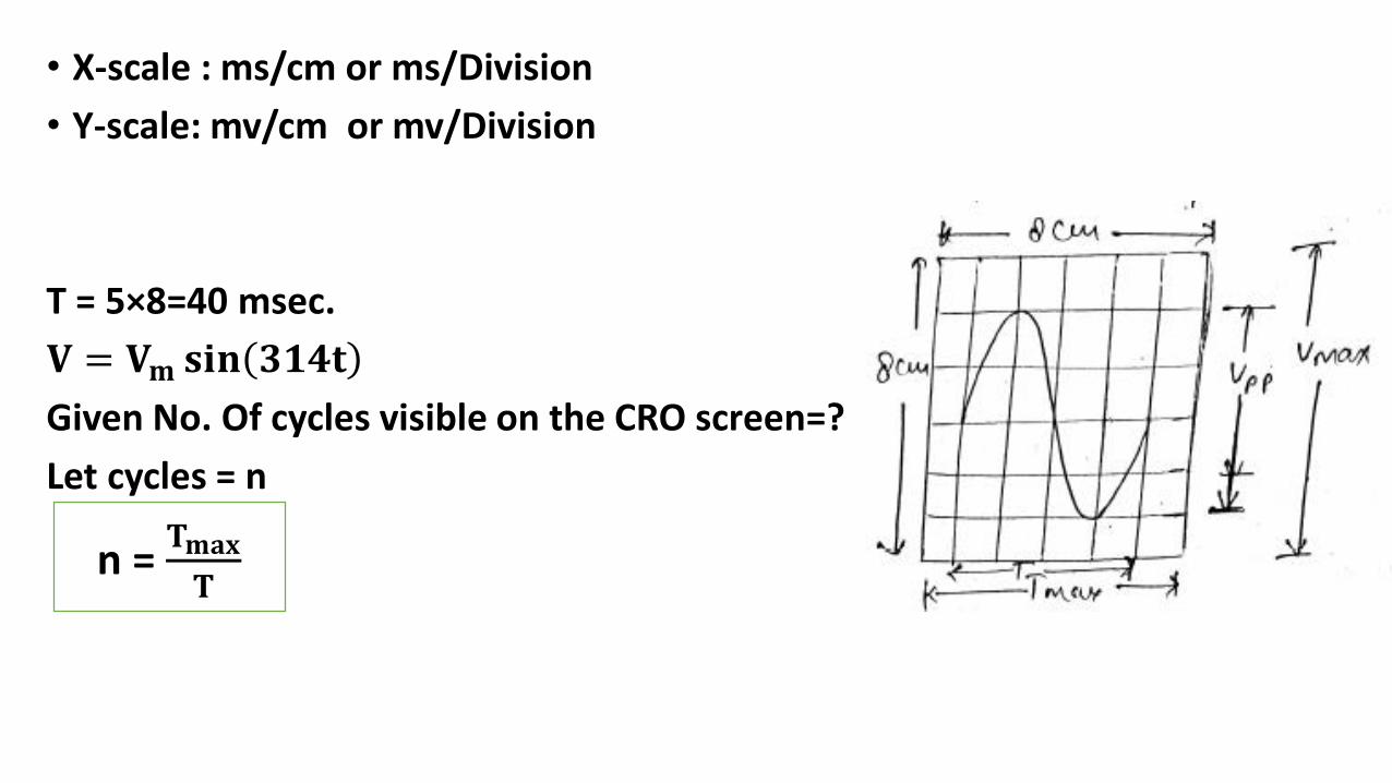
• X-scale : ms/cm or ms/Division
• Y-scale: mv/cm or mv/Division
T = 5×8=40 msec.
𝐕 = 𝐕𝐦 𝐬𝐢𝐧 𝟑𝟏𝟒𝐭
Given No. Of cycles visible on the CRO screen=?
Let cycles = n
n = 𝐓𝐦𝐚𝐱
𝐓

If 𝐕𝐩𝐩 > 𝐕𝐦𝐚𝐱 then Signal is clipped.
Example: -
X-scale : 5 ms/cm
T= 5×4=20ms
𝐟 =𝟏
𝐓=
𝟏
𝟐𝟎𝐦𝐬= 𝟓𝟎 𝐇𝐳
Frequency can be calculated by observing this CRO.

Q: - One cycle of a square wave signal observed on an oscilloscope is found to occupy 6 cm at a scale setting of 30 μs/cm. What is the signal frequency? [ESE-2006]a) 1.8 kHzb) 5.55 kHzc) 18 kHzd) 55.5 kHz

Q. A C.R.O. is operated with X and Y settings of 0.5 ms/cm and 100 mV/cm. The screen of the C.R.O. is 10 cm × 8 cm (X and Y). A sine wave of frequency 200 Hz and r.m.s. amplitude of 300 mV is applied to the Y-input. The screen will show [ESE-2003]a) one cycle of the undistorted sine wave.b) two cycles of the undistorted sine wave.c) one cycle of the sine wave with clipped amplitude.d) two cycles of the sine wave with clipped amplitude.

Q. A CRO screen has 10 divisions on the horizontal scale. If a voltage signal 5 sin (314t + 45°) is examined with a lien base setting of 5 ms/div, the number of signals displayed on the screen will be [ESE-2016]a) 1.25 cyclesb) 2.5 cyclesc) 5 cyclesd) 10 cycles

Probes in CRO: -
• Probe is a interconnecting channel between function generator and CRO.
• Probe must have high input resistance and low resistance, so that the signal taken from the function generator should not be attenuated.
• The probe must be independent of frequency and hence the time constant of probe and CRO is maintained equal.
• Laboratory CRO’s uses 10X or high impedance probe.
• In the computers active probes are used between internal drives to the CPU.
• These active probes consisting of BJT emitter followers, MOSFETs and op-amp’s which has Ri = ∞ and Ro is very low.

An LPF wattmeter of power factor 0.2 is having three voltage setting
300 V, 150V and 75V and two current settings 5 A and 10 A. The full
scale reading is 150. If the watt meter is used with 150 V voltage
setting and 10 A current setting, the multiplying factor of the watt
meter is ______
A3- phase balanced load which has a power factor of 0.707 is
connected to a balanced supply. The power consumed by the load is
5kW. The power is measured by the two-watt meter method. The
readings of the two watt meters are
a)3.94 kW and 1.06 kW
b)2.50 kW and 2.50 kW
c)5.00 kW and 0.00 kW
d)2.96 kW and 2.04 kW


SSC JE-2019


Benefits
Electrical Engineering by ASHISH SIR

Personalized Learning: -
Electrical Engineering by ASHISH SIR

Regular PDF update
Electrical Engineering by ASHISH SIR

Electrical Engineering by ASHISH SIR

Electrical Engineering by ASHISH SIR

Electrical Engineering by ASHISH SIR

Electrical Engineering by ASHISH SIR

Electrical Engineering by ASHISH SIR


Electrical Engineering by ASHISH SIR

(28) In a steam power plant…………heats the feed water on its way to the boiler by delivering heat from the flue gases: -
(A) Superheater (B) Economizer
(B) Preheater (D) Turbine
(29) Power generation of thermal power plants is based on: -
(A) Rankine cycle
(B) Otto cycle
(C) Diesel cycle
(D) Carnot cycle