low‐pressure electrolytic ammonia production - ND Gov
32
-
Upload
khangminh22 -
Category
Documents
-
view
0 -
download
0
Transcript of low‐pressure electrolytic ammonia production - ND Gov


LOW‐PRESSURE ELECTROLYTIC AMMONIA PRODUCTION Research Performance Progress Report (Quarterly) (for the period of July 1, 2018, through September 30, 2018) Prepared for: Karlene Fine North Dakota Industrial Commission State Capitol, 14th Floor 600 East Boulevard Avenue, Department 405 Bismarck, ND 58505-0840
Prepared by:
Ted R. Aulich
Energy & Environmental Research Center University of North Dakota
15 North 23rd Street, Stop 9018 Grand Forks, ND 58202-9018
October 2018

i
TABLE OF CONTENTS LIST OF FIGURES ........................................................................................................................ ii LIST OF TABLES .......................................................................................................................... ii PROJECT GOALS/OBJECTIVES ................................................................................................. 1 BACKGROUND ............................................................................................................................ 2 ACCOMPLISHMENTS ................................................................................................................. 3 PROGRESS AND STATUS........................................................................................................... 3
Task 1 – Project Management ............................................................................................... 3 Task 2 – IPC Synthesis Method and Performance Improvement ......................................... 4 Task 3 – PIC Membrane Synthesis Method Development and Performance/ Durability Optimization ........................................................................................................ 4 Task 4 – Cathode Catalyst Screening .................................................................................... 5 Task 5 – PIC-Based MEA Fabrication Method Development and LPEA Unit Cell Performance/Durability Optimization ................................................................................... 7 Task 6 – Design, Fabrication, and Operation of 100-g/d LPEA System .............................. 7 Task 7 – Techno-Economic Analysis .................................................................................... 7
PLANS FOR NEXT QUARTER.................................................................................................... 7
Task 1 – Project Management ............................................................................................... 7 Task 2 – IPC Synthesis Method and Performance Improvement ......................................... 7 Task 3 – PIC Membrane Synthesis Method Development and Performance/ Durability Optimization ........................................................................................................ 8 Task 4 – Cathode Catalyst Screening .................................................................................... 8 Task 5 – PIC-Based MEA Fabrication Method Development and LPEA Unit Cell Performance/Durability Optimization ................................................................................... 8 Task 6 – Design, Fabrication, and Operation of 100-g/d LPEA System .............................. 8 Task 7 – Techno-Economic Analysis .................................................................................... 9
PRODUCTS .................................................................................................................................... 9 IMPACTS ....................................................................................................................................... 9
Impact on technology transfer and commercialization status ............................................... 9 Dollar amount of award budget being spent in foreign country(ies) .................................... 9
CHANGES/PROBLEMS ............................................................................................................... 9
Scope issues, risks and mitigation strategies ......................................................................... 9 Actual or anticipated problems or delays and corrective actions or plans to resolve them .. 9 Changes that have a significant impact on expenditures ....................................................... 9
RECIPIENT AND PRINCIPAL INVESTIGATOR DISCLOSURES .......................................... 9 CONFLICTS OF INTEREST WITHIN PROJECT TEAM ........................................................... 9 PARTNERS AND FINANCIAL INFORMATION ..................................................................... 10 DRAFT PBI LITERATURE SEARCH ......................................................................... Appendix A

ii
LIST OF FIGURES 1 Haber–Bosch versus LPEA-based NH3 production .............................................................. 1 2 LPEA process ........................................................................................................................ 2 3 250-nm-diameter PBI nanofibers made from 15 wt% PBI solution ..................................... 5 4 250-nm-diameter PBI nanofibers made from 15 wt% PBI/DMAc solution, then coated with IPC via electrospraying 11 wt% IPC aqueous solution ..................................... 6 5 200-nm core–shell IPC–PBI nanofibers coelectrospun from 11 wt% IPC aqueous solution and 15 wt% PBI/DMAc solution ............................................................................. 6
LIST OF TABLES 1 Task Schedule ....................................................................................................................... 4 2 Budget and Expenses Through the Reporting Period ......................................................... 10

1
LOW‐PRESSURE ELECTROLYTIC AMMONIA PRODUCTION PROJECT GOALS/OBJECTIVES The project goal is to demonstrate an ammonia production energy reduction of 16% by replacing high-pressure Haber–Bosch-based ammonia synthesis with the Energy & Environmental Research Center (EERC)-developed low-pressure electrolytic ammonia (LPEA) process, as shown in Figure 1. To achieve the 16% production energy reduction target will require improving the LPEA process, which will require improving the polymer–inorganic composite (PIC) proton exchange membrane (PEM) on which the LPEA electrochemical cell is based. As a result, the proposed project is focused on improving the performance and durability of the PIC membrane, with the objective of producing a membrane that exhibits the following properties:
• Proton conductivity of ≥10-2 Siemens/centimeter (S/cm) and gas permeability of <2% at a minimum temperature of 300°C.
• Ability to sustain 10-2 S/cm proton conductivity for at least 1000 hours (h).
• Mechanical strength (at 300°C) comparable to that of a commercial proton exchange-based electrolyzer membrane.
• As measured in a membrane–electrode assembly (MEA) at a minimum temperature of
300°C, current efficiency of ≥65% for NH3 formation at a current density of ≥0.25 amps/cm2 (A/cm2), NH3 production energy efficiency of ≥65%, and ≤0.3% performance degradation per 1000 h of operation.
Figure 1. Haber–Bosch versus LPEA-based NH3 production.

2
BACKGROUND In support of U.S. Department of Energy (DOE) Energy Efficiency and Renewable Energy (EERE) Advanced Manufacturing Office (AMO) goals to reduce life cycle energy consumption of manufactured goods and more cost-effectively use hydrogen in manufacturing processes, this project is focused on optimizing and demonstrating the improved efficiency (versus Haber–Bosch ammonia production) of the EERC-developed LPEA production process. Because it does not require the high pressure and high recycle rate (because of low single-pass ammonia yield) of the Haber–Bosch process, LPEA offers the potential for significant reduction in both energy consumption and cost. Partners on the proposed project are North Dakota State University (NDSU), Proton OnSite (Proton), the UND Chemistry Department (UND Chemistry), and the North Dakota Industrial Commission (NDIC). The LPEA process is based on an innovative EERC-developed PIC high-temperature PEM. The process operates at ambient pressure and a temperature of 300°C and uses inputs of hydrogen, nitrogen, and electricity to make ammonia. The EERC demonstrated LPEA process viability in ammonia formation tests conducted using a 0.2-watt electrochemical cell built around an early-stage PIC membrane. To meet the above-listed membrane performance and durability specifications, the project will target development of a specifically configured PIC membrane that comprises “core–shell” inorganic proton conductor–polybenzimidazole (IPC–PBI) proton-conducting nanofibers contained within and aligned perpendicularly to the plane of a PBI matrix/membrane, as shown in Figure 2. Because each fiber core will comprise a chain of IPC particles in contiguous contact with one another throughout the chain length, each fiber will essentially function as a high-efficiency proton-conducting wire running straight through the membrane. Membrane production will utilize state-of-the-art nanofiber production/alignment and thermal pressing compositing techniques developed and deployed at project partner, NDSU.
Figure 2. LPEA process.

3
Following fabrication of a PIC membrane that meets the above specifications, the membrane—along with selected anode and cathode catalysts—will be used to construct experimental MEAs. MEAs will be incorporated into LPEA unit cells that will be evaluated based on NH3 formation efficiency and durability, with the objective of identifying an optimal MEA configuration. The optimal MEA configuration will be used as the basis for building a stack of several LPEA unit cells that will comprise an LPEA system capable of producing at least 100 grams/day (g/d) of NH3. The 100-g/d LPEA system will undergo optimization and then be used to demonstrate NH3 synthesis (from H2) at the LPEA target production energy input requirement of 1318 kilowatt hours (kWh)/ton, which would translate to a total (H2 production plus NH3 synthesis) LPEA-based NH3 production energy input requirement of 8376 kWh/ton, the project-targeted goal. LPEA system operation and performance data will be used to perform a techno-economic evaluation of the LPEA-based NH3 production process. ACCOMPLISHMENTS • Completed and initiated work under research contract agreements with project partners,
NDSU and UND Chemistry. • Completed first milestone, a draft literature search describing commercially available and
experimental high-temperature-compatible PBI formulations and their performance and durability attributes and limitations. The literature search is provided as Appendix A.
• Designed and built a state-of-the-art lab-scale polymer–inorganic compositing system for producing core–shell IPC–PBI nanofibers.
PROGRESS AND STATUS Table 1 lists task completion status. Task progress summaries are provided below.
Task 1 – Project Management (EERC) • Set up and initiated work under subrecipient contracts with NDSU and UND Chemistry. • Prepared and officially submitted revised statement of project objectives (SOPO). • Submitted purchase order for tunable diode laser (TDL)-based analyzer system for online
quantitation of ammonia and water vapor in LPEA system product stream. The TDL analyzer offers improved project-relevant performance features versus the FTIR (Fourier transform infrared)-based system referenced in the proposal at a significantly reduced price ($47,000 versus $94,000). The EERC learned about the TDL system through an extensive research effort conducted following project initiation. Prior to deciding to purchase the system, the EERC spoke with technical staff at a North Dakota coal-based power plant with long-term experience in utilizing the TDL system for monitoring ammonia and water vapor levels in a combustion emission stream. The power plant staff recommended the system based on its accuracy, reliability, and ease of use.
• Allocated $47,000 savings (associated with the above-described TDL-based ammonia analyzer) to support of a UND Chemistry graduate student dedicated to Task 4 – Cathode Catalyst Screening. This graduate student position is critical to Task 4 (Cathode Catalyst Screening) performance but was inadvertently left out of the project budget.
• Set up schedules for biweekly project status meetings of the PIC membrane development team (EERC and NDSU) and cathode catalyst-screening team (EERC and UND Chemistry).

4
Table 1. Task Schedule
Task No. Task Title or Brief Description
Task Completion Date*
Task Progress Notes Original Planned
Revised Planned
Actual Complete
% Complete
1 Project Management 14 June 2021
<10
2 IPC Synthesis Method and Performance Improvement
14 Dec 2019
<15
3 PIC Membrane Synthesis Method
Development and Performance/Durability Optimization
14 Dec 2020
<10
4 Cathode Catalyst Screening 14 Dec 2019
<15
5 PIC-Based MEA Fabrication Method
Development and LPEA Unit Cell Performance/Durability Optimization
14 Dec 2020
15 June 2019 start
6 Design, Fabrication, and Operation of 100-g/d LPEA System
14 March 2021
15 Dec 2019 start
7 Techno-Economic Analysis 14 June 2021
15 June 2020 start
* Unless otherwise noted, tasks start on 15 June 2018 project start date.
Task 2 – IPC Synthesis Method and Performance Improvement (EERC) • Ordered and received chemicals and minor equipment for IPC solution preparation. • Created an initial IPC formulation, and provided 11 and 27 weight percent (wt%) aqueous
IPC solutions to NDSU for initial PIC membrane fabrication method development work. • Improved the IPC synthesis method, which reduced the time necessary to make a batch of IPC
solution to 1 day from 3 days previously. • Tested methods for IPC molding and drying for producing pure IPC membrane samples for
alternating current impedance (ACI) testing. • Developed a draft standard operating procedure (SOP) for IPC solution synthesis. • Procured parts for fabrication (at EERC) of an x-ray diffraction system heated stage for IPC
material analysis, and initiated fabrication of the heated stage.
Task 3 – PIC Membrane Synthesis Method Development and Performance/ Durability Optimization (NDSU and EERC)
• To enable precisely controllable fabrication of uniform PBI and core–shell IPC–PBI
nanofibers, a state-of-the-art polymer–inorganic compositing system was designed and built. Innovative features include a compact, motor-hidden rotary nanofiber collector and adjustable nanofiber collection speed and height.
• Using PBI solution procured from PBI Performance Products Inc. and IPC solution provided by the EERC, the following nanofibers were produced: - Monolithic PBI nanofibers with diameter of about 250 nanometers (nm), as shown in
Figure 3.
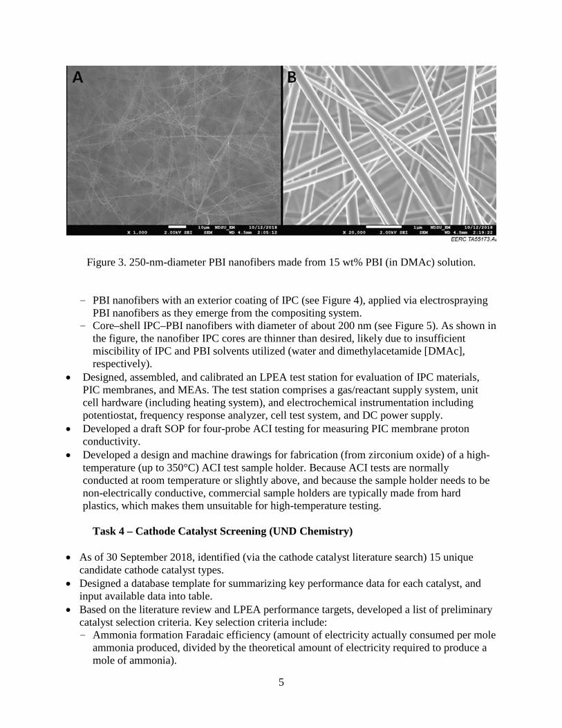
5
Figure 3. 250-nm-diameter PBI nanofibers made from 15 wt% PBI (in DMAc) solution.
- PBI nanofibers with an exterior coating of IPC (see Figure 4), applied via electrospraying PBI nanofibers as they emerge from the compositing system.
- Core–shell IPC–PBI nanofibers with diameter of about 200 nm (see Figure 5). As shown in the figure, the nanofiber IPC cores are thinner than desired, likely due to insufficient miscibility of IPC and PBI solvents utilized (water and dimethylacetamide [DMAc], respectively).
• Designed, assembled, and calibrated an LPEA test station for evaluation of IPC materials, PIC membranes, and MEAs. The test station comprises a gas/reactant supply system, unit cell hardware (including heating system), and electrochemical instrumentation including potentiostat, frequency response analyzer, cell test system, and DC power supply.
• Developed a draft SOP for four-probe ACI testing for measuring PIC membrane proton conductivity.
• Developed a design and machine drawings for fabrication (from zirconium oxide) of a high-temperature (up to 350°C) ACI test sample holder. Because ACI tests are normally conducted at room temperature or slightly above, and because the sample holder needs to be non-electrically conductive, commercial sample holders are typically made from hard plastics, which makes them unsuitable for high-temperature testing.
Task 4 – Cathode Catalyst Screening (UND Chemistry)
• As of 30 September 2018, identified (via the cathode catalyst literature search) 15 unique
candidate cathode catalyst types. • Designed a database template for summarizing key performance data for each catalyst, and
input available data into table. • Based on the literature review and LPEA performance targets, developed a list of preliminary
catalyst selection criteria. Key selection criteria include: - Ammonia formation Faradaic efficiency (amount of electricity actually consumed per mole
ammonia produced, divided by the theoretical amount of electricity required to produce a mole of ammonia).

6
Figure 4. 250-nm-diameter PBI nanofibers made from 15 wt% PBI/DMAc solution, then coated with IPC via electrospraying 11 wt% IPC aqueous solution (NPs = nanoparticles).
Figure 5. 200-nm core–shell IPC–PBI nanofibers coelectrospun from 11 wt% IPC aqueous solution and 15 wt% PBI/DMAc solution.

7
- Ammonia formation rate in moles ammonia/centimeter2•second (mol•cm-2•s-1). - Specific or mass catalyst activity for ammonia formation in milliamps•cm-2 (mA•cm-2)
catalyst surface area or mA•gram-1 (mA•g-1) catalyst. • Based on the literature review, developed draft generic SOPs for synthesizing experimental
quantities of various catalyst types. • Established a draft SOP for rotating disk electrode-based catalyst performance assessment.
Task 5 – PIC-Based MEA Fabrication Method Development and LPEA Unit Cell Performance/Durability Optimization (Proton OnSite and EERC)
• No progress; task initiation scheduled for 15 June 2019.
Task 6 – Design, Fabrication, and Operation of 100-g/d LPEA System (All) • No progress; task initiation scheduled for 15 December 2019.
Task 7 – Techno-Economic Analysis (All) • Although Task 7 was not scheduled to start until 15 June 2020, the EERC initiated an effort to
develop a “stretch goal” for LPEA energy consumption that is ideally achievable and would be more impactful than the ultraconservative energy consumption target cited in the proposal. This effort was undertaken based on technical reviewer comments received at the July 2018 project review meeting in Washington, D.C., and at the September DOE site visit to the EERC. In addition to the stretch goal, the EERC will attempt to determine an accurate energy consumption value for state-of-the-art high-pressure Haber Bosch-based ammonia production, with the objective of enabling direct comparison (based on overall energy consumption) of LPEA to Haber–Bosch-based ammonia production.
PLANS FOR NEXT QUARTER
Task 1 – Project Management • Set up and implement ongoing DOE project team communications strategy/approach that
ensures optimal utilization of team member expertise in executing the project and achieving project objectives.
Task 2 – IPC Synthesis Method and Performance Improvement
• Improve the LPEA test station by 1) installing a steam generator upstream of the LPEA
system for LPEA reactant gases humidification and 2) installing the online ammonia/water vapor analyzer downstream of the LPEA system.
• Complete fabrication of the high-temperature sample holder for the ACI testing. • Order supplies for performing ACI tests. • Conduct initial ACI tests on Nafion membrane samples to calibrate the ACI testing setup and
procedures.

8
• Conduct ACI tests on IPC samples, and provide feedback for improving IPC performance if needed.
Task 3 – PIC Membrane Synthesis Method Development and Performance/Durability Optimization
• Identify optimal PBI formulation(s), and evaluate formulation mechanical strength and
electrochemical and thermo-oxidative stability at 300°C (Milestone 3.2). • Tailor PBI and IPC solutions (via adjustment of solvents and/or cosolvents) to enable better
miscibility and improved core–shell nanofiber production. • Fabricate at least two samples of nanofiber-based PIC membranes (8 × 8 cm or larger) with
targeted IPC loading of about 50 wt%. • Characterize nanofiber and membrane morphology, molecular structure and microstructure,
and thermal durability via scanning electron microscopy (SEM)/transmission electron microscopy (TEM), energy-dispersive spectrometry (EDS), and thermogravimetric analysis (TGA) methods.
• Conduct ACI tests on PIC membrane samples, and provide feedback for improved PIC performance.
• Update SOP for the four-probe ACI testing based on actual PIC membrane-testing outcomes. • Develop initial correlations between PIC membrane fabrication material/process parameters
and nanofiber/membrane structure and thermal durability. • Continue optimization of PIC membrane fabrication material/process parameters. • Based on draft literature review, prepare manuscript of paper on high-performance, high-
temperature polymers for peer review publication submittal.
Task 4 – Cathode Catalyst Screening • Identify additional candidate cathode catalyst types. • Develop improved understanding of the types of promoters utilized for ammonia synthesis
catalysts, how the promoters work, promoter performance benefits, and typical levels at which promoters are added to achieve performance benefits.
• Adjust and optimize catalyst selection criteria. • Identify one catalyst with Faradaic efficiency ≥50%, and preliminarily evaluate its
performance.
Task 5 – PIC-Based MEA Fabrication Method Development and LPEA Unit Cell Performance/Durability Optimization
• No plans; task initiation scheduled for 15 June 2019.
Task 6 – Design, Fabrication, and Operation of 100-g/d LPEA System • No plans; task initiation scheduled for 15 December 2019.

9
Task 7 – Techno-Economic Analysis • Develop stretch goal for LPEA energy consumption. PRODUCTS None. IMPACTS
Impact on technology transfer and commercialization status No commercialization impacts, progress, issues, or concerns to report during this quarter.
Dollar amount of award budget being spent in foreign country(ies) No spending of any project funds in any foreign countries has occurred or is planned. CHANGES/PROBLEMS
Scope issues, risks and mitigation strategies None during this reporting period.
Actual or anticipated problems or delays and corrective actions or plans to resolve them
None during this reporting period.
Changes that have a significant impact on expenditures None.
RECIPIENT AND PRINCIPAL INVESTIGATOR DISCLOSURES None. CONFLICTS OF INTEREST WITHIN PROJECT TEAM None.

10
PARTNERS AND FINANCIAL INFORMATION This project is sponsored by NDIC, DOE, UND Chemistry, North Dakota State University, and Proton. Table 2 shows the initial 18-month budget of $1,663,107 for this project and expenses through the reporting period.
Table 2. Initial 18-Month Budget and Expenses Through the Reporting Period
Sponsor Budget Expenses Remaining DOE $1,324,993 $59,587 $1,265,406 UND Chemistry – In Kind $34,514 $1,235 $33,279 NDIC $230,000 $94,148 $135,852 NDSU – In Kind $60,000 $0 $60,000 Proton – In Kind $13,600 $0 $13,600 Total $1,663,107 $154,970 $1,508,137

APPENDIX A
DRAFT PBI LITERATURE SEARCH

1
Polybenzimidazoles (PBI) for high-temperature polymer electrolyte membranes (PEMs): An Overview
Xiang-Fa Wu1, Zhengping Zhou1, Jivan Thakare2, John Hurley2, and Ted Aulich2
1Department of Mechanical Engineering, North Dakota State University, Fargo, North Dakota 58108 2Energy and Environmental Research Center, University of North Dakota, Grand Forks, North Dakota 58202
Abstract
This paper reviews the brief history of polybenzimidazole (PBI), its synthesis and thermal properties
and the development of PBI-based polymer electrolyte membranes (PEMs) as high-temperature proton conductive membranes for use in fuel cells and other electrochemical energy conversion devices. The proton conductivities of a variety of PBI-based polymers are compared at various testing temperatures and doping states. Several PBI-based polymers are identified as potential high-temperature polymers to be processed as high-temperature PEMs to work at 300-350oC. In addition, the solvability of PBIs in organic and inorganic solvents and manufacturability of PBI solutions into membranes and continuous nanofibers are further discussed. 1. Introduction
Common themes critical to high-performance polymer electrolyte membranes (PEMs) for use in fuel
cells and low-pressure electrolytic ammonia (LPEA) production include: (1) high protonic conductivity, (2) low electronic conductivity, (3) low permeability to fuel and oxidant, (4) low water transport through diffusion and electro-osmosis, (5) high oxidative and hydrolytic stability, (6) sound mechanical strength and durability in both the dry and hydrated states, and (7) low material and fabrication cost.
Beyond, LPEA production requires high-performance electrolyte polymer membranes capable of carrying high proton conductivity (≥10-2 S/cm) and “near-zero” permeability for H2 and O2 at 260oC, and high thermomechanical durability (300oC for 1,000 hours with < 3% degradation) to reach the DOE targets. The UND/EERC-led research team proposed to develop innovative polymer-inorganic composite (PIC) membranes based on coelectrospun core-shell polymer nanofibers with the shell materials as high-performance polymers (e.g., polybenzimidazole-PBI) and the core as inorganic proton conductor (e.g., alkali thi-hydroxogenmanate-ATHG). The PIC membranes will be able to work at a temperature (300oC) that is much higher than those high-temperature proton exchange membranes (HT-PEMs) for fuel cells operating in the temperature range from 120 to 200 oC.
Most existing polymeric materials for intermediate and high-temperature PEM fuel cells and other electrochemical applications highly rely on absorbed water and their interactions with acid groups to produce protonic conductivity. PBIs are considered as the excellent candidate polymers for PEMs as PBIs are hydrophilic and have very high moisture regain with water absorption up to 15-18% by weight. In addition, PBIs can be easily acid-doped by stable mineral acids such as phosphoric and sulfuric acids or composited with pyrophosphates to reach the high protonic conductivity. The high thermal, thermal durability and chemical stability of PBIs provide the high potential of PBIs for use as HT-PEMs. 2. Brief history of polybenzimidazole –PBI
Polybenzimidazoles (PBIs) are referred to a large family of linear aromatic heterocyclic polymers
containing benzimidazole moieties at a part of the repeating molecular unit. PBIs of varying chemical structures and properties can be synthesized from hundreds of combinations of tetraamines and diacides. In particular, PBI is commonly referred the commercial product with the trademark Celazole® (Scheme 1).

2
The invention of the first aliphatic PBIs can be traced to the work by Brinker and Robison in 1959 [2], and aromatic PBIs with excellent thermal properties were synthesized by Voglel and Marvel [2,3] via heating an equimolar mixture of bis(o-diamine)s and phenyl esters of varying dicarboxylic acids.
Scheme 1. Chemical formula of poly 2,2’-m-(phenylene)-5,5’-bibenzimidazole Two synthesis schemes have been formulated for successful synthesis of PBIs, i.e., the one-stage and
two-stage methods. The two-stage synthesis of PBI with tetraaminobiphenly (TAB) and diphenyl isophthalate (DPIP) as monomers is shown in Figure 2 [4]. A single-stage synthesis was developed by Choe [5,6] by replacing DPIP with isophthalic acid (IPA) under the catalysis of organo-phosphrous and silicon compounds (Scheme 2)
Scheme 1. PBI synthesis based on a two-stage process [4]
Scheme 2. PBI synthesis based on a single-stage process [5,6]
PBIs received significant attentions for various high-performance applications, especially in fire protection clothing, HT-PEMs for fuel cells, etc. because of their unique thermal stability with the melting temperature higher than 400oC, balanced processing properties for membranes and fibers, and excellent water absorption and acid-doping properties [7-12]. Hereafter, the review is made on a comparative study

3
on the proton conductivity, dopant and doping level, mechanical strength of PBIs of varying molecular structures. 3. Comparative study of PBI-based PEMs
In the last two decades, significant research has been made to explore PBI membranes of various
chemical structures as HT-PEMs for use in high-temperature fuel cells. Such study provides the experimental evidence on the effects of molecular structures of PBIs, processing and acid doping on the mechanical strength, proton conductivity, and power density of the PBI membranes, from which suitable PBIs can be screened for producing PIC PEMs. Table 1 shows the details of the comparative study.
Table 1. Summary of the physical, chemical and electrochemical properties of high-temperature proton exchange PBI membranes for fuel cells
Ref.#
Polymer Acid/alkaline agent
Mechanical Strength
(MPa)
Doping level
(wt.%) or
(mol)
Proton conductivity
(σ, S/cm)
Power densit
y W/cm2
Ref.
(13) Sulfonated poly[2,2’-( p-oxydiphenylene)-
5,5’-bibenzimidazole]
(SOPBI)
H2SO4 81 154 wt.%
1.5 × 10⁻¹ (120 °C)
NA Polymer 48, 5556-5564
(2007)
(14) Poly(arylene ether sulfone)-b-
polybenzimidazole copolymers
H3PO4
31 12 mol 4.7 × 10⁻² (200 °C)
NA Polymer 49, 5387-5396
(2008)
(15) PBz-modified PBI electrospun nanofiber
composite
H3PO4
115 13.2 mol
1.7 × 10⁻¹ (160 °C)
0.67
J. Mater. Chem. A 1, 1171-1178
(2013) (16) Sulfonated PBI H2SO4 1.6 ~50 mol 3.26 × 10⁻¹
(160 °C) 0.152 Macromolecule
s 43, 6706-6715 (2010)
(17) Poly(vinylphosphonic acid)-doped PBI
(PVPA-PBI)
PVPA 91.1 6.1 wt.%
1.72 × 10⁻² (120 °C)
0.252 Sci. Rep. 3, 1764-1777
(2013) (18) Alkaline-doped PBI KOH NA NA 9.5 × 10⁻²
(25 °C) 0.372 Electrochem.
Commun. 2, 697-702 (2000)
(19) Phosphoric acid-doped PBI
H3PO4
NA 630 wt.%
5.0 × 10⁻² (140 °C)
NA J. Electrochem. Soc. 151, A8-A16 (2004)
(20) PBI/sulfonated polysulfone (SPSF)
polymer blends
Polysulfone/ chlorosulfonic
acid
NA 5.2 mol NA 0.54 Electrochem. Solid-State Lett. 5, A125-A128
(2002) (21) Phosphoric acid-
doped PBI Polyphosphoric
acid (PPA) 3.5 32 mol 1.0 × 10⁻²
(RT), 0.26 (200 °C)
0.9 Chem. Mater. 17, 5328-5333
(2005) (22) PA-doped PBI
composite ZrP/H3PO4
NA 5.6 mol 9.0 × 10⁻²
(200 °C) NA J. Membr. Sci.
226, 169-184

4
membranes with ZrP (2003)
(23) PWA/SiO2-doped PBI
Phosphotungstic acid
(PWA)/SiO2
NA 60 wt.% 3.0 × 10⁻³ (100 °C)
NA J. Power Sources 90,
231-235 (2000) (24) SiWA-SiO2-PBI SiWA-SiO2 NA 60 wt.% 2.23 × 10⁻³
(160 °C) NA J. Power
Sources 94, 9-13 (2001)
(25) Fluorine-containing PBI/HMI-TF
composite membranes
1-hexyl-3-methylimidazoli
um trifluoromethan
esulfonate (HMI-TF)
60.3 NA 1.6 × 10⁻²
(250 °C) NA Electrochim.
Acta 56, 2842-2846 (2011)
(26) SrCeO3-PBI composite membrane
Strontium cerate
( SrCeO3)
NA 190 wt.%
1.05 × 10⁻¹
(180 °C) 0.44 Electrochim.
Acta 154, 370-378 (2015)
(27) PBI/DAIm TIPN membrane
poly(1, 2-dimethy-3-
allylimidazolium)
(PDAIm)/KOH
48.2 2.89 wt.%
9.67 × 10⁻²
(80 °C) NA Electrochim.
Acta 257, 9-19 (2017)
(28) Sulfonated PES/PBI blend membrane
Sulfonated poly(ether sulfone)
(PES)/PPA
NA 98 wt.% 1.21 × 10⁻¹
(70 °C) 0.11 Eur. Polym. J.
46, 1633-1641 (2010)
(29) PBI/KOH membrane KOH 7.7 NA 1.84 × 10⁻²
(RT) 0.031 Int. J. Hydrogen
Energy 33, 7172-7176
(2008) (30) PA/PBI membrane H3PO4
NA 45 wt.% NA 0.12 Int. J. Hydrogen
Energy 34, 9479-9485
(2009) (31) CeSPP-doped PBI
composite membrane Cerium
sulfophenyl phosphate (CeSPP)
18 NA 1.1 × 10⁻¹ (100% RH),
2.4 × 10⁻³ (0% RH), (180 °C)
NA Int. J. Hydrogen Energy 42,
486-495 (2017)
(32) PA-doped PBI/Graphene oxide composite membrane
H3PO4
NA 13 wt.% 1.704 × 10⁻¹
(165 °C) 0.38 Int. J. Hydrogen
Energy 42, 2636-2647
(2017) (33) PA-doped PBI/ZrP
composite membrane H3PO4
119 15.4
wt.% 2.0 × 10⁻¹
(180 °C) NA Int. J. Hydrogen
Energy 42, 2648-2657
(2017) (34) PA-doped PBI
membrane H3PO4
NA 75 wt.% 6.2 × 10⁻²
(150 °C, 30% RH)
0.185 J. Electrochem. Soc. 151, A304-
A310 (2004) (35) Cross-linked PBI-
TEBP membrane H3PO4
77.11 7.9 mol 5.1 × 10⁻²
(150 °C) NA J. Mater. Chem.
21, 2187-2193 (2011)

5
(36) PBI-TGIC/SPANi composite membrane
Triglycidylisocyanurate
(TGIC)/sulfonated polyaniline
(SPANi)/ H2SO4
21 NA 1.3 × 10⁻¹
(180 °C, 100% RH); 1.8 × 10⁻²
(180 °C, 0% RH)
NA J. Membr. Sci. 549, 660-669
(2018)
(37) Cross-linked metal oxide containing PBI composite membrane
Sulfonated TiO2 particles/H3PO4
8 392 wt.%
9.8 × 10⁻²
(160 °C) 0.356 J. Membr. Sci.
560, 11-20 (2018)
(38) Side-chain PBI membrane
PPA 34.3 12.15 wt.%
1.1 × 10⁻¹
(80 °C) NA J. Membr. Sci.
546, 15-21 (2018)
(39) PA-doped cross-linked PBI-OO
membranes
H3PO4
11 266 wt.%
2.6 × 10⁻¹
(160 °C) 0.452
J. Membr. Sci. 544, 416-424
(2017) (40) Pyridine-containing
PBI membrane H3PO4
12.3 250
wt.% 8.3 × 10⁻²
(160 °C), 1.1 × 10⁻² (25 °C)
0.460
J. Membr. Sci. 502, 29-36
(2016) (41) PBI containing bulky
substituents teteraamines
and 4,4′-oxybis (benzoicacid)
8.7 245 wt.%
8.8 × 10⁻²
(160 °C) 0.636
J. Membr. Sci. 513, 270-279
(2016) (42) PA-doped PBI/PBI-
EPA blend membrane
H3PO4
59.4 260 wt.%
6.8 × 10⁻²
(160 °C) 0.527
J. Membr. Sci.
491, 10-21 (2015)
(43) Hydroxyl pyridine containing PBI
membrane
H3PO4
4.6 72 wt.% 1.02 × 10⁻¹
(180C) 0.57 J. Membr. Sci.
446, 318-325 (2013)
(44) PBI-functionalized SiO2 composite
membrane
H3PO4
98 385 wt.%
5.0 × 10⁻²
(160 °C) 0.65 J. Membr. Sci.
403-404, 1-7 (2012)
(45) PBI/1H-imidazole-4-sulfonic acid hybrid
membrane
1H-imidazole-4-sulfonic acid
33.8 8 mol 7.0 × 10⁻²
(160 °C) NA J. Membr. Sci.
399-400, 11-15 (2012)
(46) PBI-Clay composite membrane
H3PO4
105 12 mol 1.2 × 10⁻¹
(150 °C) 0.23 J. Membr. Sci.
383, 78-87 (2011)
(47) PA-doped PBI membrane
PPA
176 17.2 mol
5.3 × 10⁻²
(180 °C) NA J. Membr. Sci.
347, 69-74 (2010)
(48) Crosslinked PBI containing branching
structure
H3PO4
78.4 (undoped),
16.9 (doped)
197.1 wt.%
3.8 × 10⁻²
(180 °C) 0.404 J. Power
Sources 389, 222-229 (2018)
(49) Dimensionally-stable PA-doped PBI
membrane
PPMA 111.5 (undoped); 10 (doped)
24.6 mol
2.17 × 10⁻¹
(200 °C) 0.32 J. Power
Sources 336, 391-400 (2016)
(50) Poly (2, 5-benzimidazole) (AB-
PBI) membrane
H3PO4
NA 6 mol NA 0.305 J. Power Sources 270,
627-633 (2014) (51) Phenylindane-
containing PBI membrane
PPA 76 (undoped), 10 (doped)
10 mol 6.1 × 10⁻²
(180 °C) 0.36 J. Power
Sources 243, 796-804 (2013)
(52) Ionic liquid doped PBI membrane
1-H-3-methylimidazoli
um bis (trifluorometha
NA NA 1.86 × 10⁻³
(190 °C) 0.039 J. Power
Sources 222, 202-209 (2013)

6
nesulfonyl) imide
(53) PVA-PBI polymer blend membrane
KOH 40 35 wt.% 1.03 × 10⁻¹
(90 °C) 0.076 Renewable
Energy 127, 883-895 (2018)
(54) Polybenzimidazolium halides
isophthalic acid/a,a'-
dibromo-p-xylene
NA NA 5.8 × 10⁻² (60 °C)
2.9 × 10⁻²
(26 °C)
0.015 Macromol. Mater. Eng.
296, 899-908 (2011)
(55) Phosphoric acid-doped PBI
H3PO4
NA 5 mol 2.0 × 10⁻²
(150°C) 0.25 J. Electrochem.
Soc. 142, 121-123 (1995)
Based on Table 1, several PBIs are identified as the candidate polymers to be used as the shell materials for producing PIC HT-PEM. Polymer #1: Poly[2,2’-( p-oxydiphenylene)-5,5’-bibenzimidazole] (SOPBI) (1) Synthesis scheme:
Scheme 1. Direct polymerization methods of SOPBI in PPMA at 140 °C (procedure 1) and in PPA at 190 °C (procedure 2). Advantages: The sulfonated poly[2,2’-( p-oxydiphenylene)-5,5’-bibenzimidazole] (SOPBI) was prepared through the post-sulfonating reaction with a synthesized OPBI polymer (Scheme ). The processes were conducted in sulfuric acid as a sulfonating reagent at 80 oC. After post-sulfonation, the SOPBI did not show significant degradation. The SOPBI exhibited a good solubility in DMSO, high thermal stability, and maintained excellent mechanical properties. The SOPBI also possessed highly proton conductivity of 0.15 S/cm2 at 120 °C in water, as well as good water stability and radical oxidative stability. Polymer #2: Poly(arylene ether sulfone)-b-polybenzimidazole copolymers (BPS-PBI)(2) Synthesis Schemes:

7
Scheme 2. Synthesis of a benzoic acid-terminated poly(arylene ether sulfone) oligomer.
Scheme 3. Synthesis of o-diamino-terminated PBI oligomer.
Scheme 4. Synthesis of a poly(arylene ether sulfone)-b-polybenzimidazole (BPS-PBI) copolymer. Advantages: The poly(arylene ether sulfone)-b-polybenzimidazole copolymers (BPS-PBI) were synthesized and then doped with phosphoric acid as shown in the Schemes 2-4 above. Transparent and ductile membranes can be directly produced by casting BPS-PBI/DMAc solution. The acid-doping level of BPS-PBI can be

8
improved up to a maximum value of 12 when 14.6 M phosphoric acid solution was used. After acid doped, the BPS-PBI copolymer membranes significantly decreased the swelling rate which superior than the conventional acid-doped PBI homopolymers. Without external humidification, the BPS-PBI copolymer membranes exhibited a high proton conductivity up to 0.047 S/cm.
Polymer #3: Polybenzoxazine (PBz)-modified polybenzimidazole (PBI) nanofibers (PBI-PBz-NF-X)(3) Synthesis scheme:
Scheme 5. (a) Chemical structures of the polymers (PBI and PBz) and the scheme for preparation of crosslinked PBI-based nanofibers (PBI-PBz-NF-X) and the nanofiber-reinforced PBI composite membranes (PBI-CM-NF-X), (b) the chemical reactions involved in the crosslinking reactions of the PBI-PBz-NF-X nanofibers [15]. Advantages: The polymer blends consisting of Polybenzoxazine (PBz) and polybenzimidazole (PBI) was electrospun to nanofibers. In this study, the PBz has been utilized as the crosslinking agent for the PBI polymer as shown in the Scheme 5. The crosslinked PBz-PBI nanofiber membranes possessed a high mechanical strength of 115 MPa and an excellent proton conductivity of 0.17 S/cm, as well as a superior acid doping level of 13.2. More importantly, the proton conductivity of the resulting polymer is two times higher than that of neat PBI membrane. Taking advantages of the PBz-modified PBI membrane, the single fuel cell possessed a maximum power density of 0.67 W/cm2, which is a 34% increase compared to that of neat PBI membrane. More specific, a high current density of 1.45 A/cm2 was obtained at 0.4 V.

9
Polymer #4: Sulfonated PBI(4) Synthesis scheme: polycondensation of a sulfonated aromatic diacid with an aromatic tetraamine.
Scheme 6. (a) Direct polymerization of s-PBI from a sulfonated diacid and tetraamine and (b) post-sulfonation of p-PBI to produces s-PBI. Advantages: The authors prepared high molecular weight, highly PA-doped sulfonated PBI membranes using the polycodensation of a sulfonated aromatic diacid with an aromatic tetraamine (Scheme 6). This reported approach provides advantages such as limitation of side reactions and control over the degree of sulfonation. The sulfonated PBI membranes exhibited excellent proton conductivities up to 0.326 S/cm when the temperature increased to 180 °C. The proton conductivity increased with the acid doping level. These membranes possessed high PA loadings of >30 mol PA/PBI. More important, the fuel cells with the sulfonated PBI membranes had excellent performance with the maximum voltage of 0.76 V at 0.2 A/cm2 and 160 °C. Polymer #5: Poly(vinylphosphonic acid)-doped Polybenzimidazole (PVPA-PBI)(5) Synthesis Scheme:
Scheme 7. Schematic illustration of the preparation technique for MWNT/PyPBI/Pt. Chemical structure of PyPBI is presented in the dotted frame.

10
Scheme 8. Schematic illustration of the preparation technique of the MWNT/PyPBI-PVPA/Pt. Advantages: Long durability The synthesized poly(vinylphosphonic acid)-doped Polybenzimidazole (PVPA-PBI) membranes exhibited robust mechanical strength and remarkable high durability over than 400,000 cycles in a single cell. Under a non-humidified condition, the PVPA-PBI membranes achieved the maximum power density of 0.252 W/cm2 at 120 °C. In addition, the PVPA-PBI membrane maintained a high percentage of the maximum power density of 75% when tested at a high current density of 1.6 A/cm2. Polymer #6: Alkaline doped PBI (6)
Figure 1. Variation of the alkaline doped PBI conductivity with the doping electrolyte concentration for various alkali electrolytes. The conductivity was measured in the doping electrolyte. Advantages: The alkaline-doped PBI membranes were prepared by immersing the samples in potassium hydroxide solution (8 M) at 90 °C for 10 days. The highest proton conductivity of the KOH-doped PBI achieved up

11
to 0.095 S/cm at 25 °C, which exhibited the PBI has a remarkable capacity to concentrate KOH. In addition, the KOH-doped PBI demonstrated higher proton conductivity than H2SO4-doped PBI (0.05 S/cm) and H3PO4-doped PBI (0.002 S/cm) when all the doped PBI membranes were tested at 25 °C. The KOH-doped PBI membrane exhibited a similar fuel cell performance of 0.62 A/cm2 at 0.6 V to that from Nafion 117 membranes. 4. PBI nanofibers by electrospinning 4.1. Electrospinning
Electrospinning is a low-cost top-down nanofabrication technique based on the principle of
electrohydrodynamic jetting from a polymer solution or melt [56-58]. This technique has been widely used for producing continuous nanofibers of natural and synthetic polymers and polymer-derived carbon, ceramics, metals, metal oxides, etc. with the fiber diameter ranging from a few nanometers to micrometers [59-68]. Schematic electrospinning setup is illustrated in Fig. 1. In a typical electrospinning process based on a polymer solution, under the action of electrostatic force (onto the induced charges) on the polymer solution, a droplet forms from the capillary tube and deforms into a Taylor cone [56-58]. When the electrostatic force overcomes the surface tension, a charged thin jet is ejected, elongated and accelerated in the electrostatic field. After a variety of jet destabilizations and solvent evaporation (drying), the ultra-thinned jet is deposited on the collector to form a nonwoven nanofiber mat. A few types of nanofiber are shown in Figure 2.
To date, over two hundred nanofibers of synthetic and natural polymers and polymer-derived carbon, silicon, metals, metal oxides, ceramics, etc. have been produced by electrospinning [66]. These continuous nanofibers with various controllable morphologies (e.g., porous, hollow, core-shell structured, etc.) can be collected in the form of nonwoven highly porous nanofiber mats or aligned nanofibrous films with the aid of a specially designed collector or an auxiliary electrostatic field. Due to their unique continuity, high surface area to volume ratio, tailorable morphology and material properties, and low cost and easy scalability in fabrication (e.g., nozzle-less electrospinning), electrospun nanofibers represent a new class of nanomaterials, raising broad interests in recent years. Rapidly expanding applications of electrospun nanofibers include protective clothing, fine filtration, templates for synthesis of metallic and polymer nanotubes, precursors for carbon nanofibers (CNFs), tissue scaffolds and drug delivery , nanofiber composites, energy harvesting, conversion and storage, and so on [59, 65, 66, 68].
Figure 1. Schematic diagram of electrospinning

12
(a) (b) (c) (d)
Figure 2. Examples of continuous nanofibers produced by electrospinning, followed by carbonization and surface functionalization: (a) polyacrylonitrile (PAN)-based CNFs, (b) continuous CNT yarns, (c) CNT-grafted CNFs, and (d) polyaniline (PANI)-coated porous CNFs (from Dr. Wu’s research group at NDSU) 4.2. PBI membranes and nanofibers 4.2.1 PBI solubility in organic solvents
PBI solubility in organic solvents is crucial to processing PBI membranes (e.g., solution casting) and
fibers (e.g., solution spinning, electrospinning, etc.) for use as proton conducting electrolyte and reactant separator in PEMs used in fuel cells and LPEA production units. Due to the rigid macromolecular backbone structure and strong hydrogen bonds between PBI molecular chains, only a limited number of solvents are capable of breaking the intermolecular hydrogen bonds and dissolve the PBI. Typical solvents include high-boiling polar aprotic solvents such as N-methylpyrrolidone (NMP), N,N-dimethylacetamide (DMAc), N,N-dimethylformamide (DMF), dimethylsulfoxide (DMSO), mineral acids such as sulphuric acid (H2SO4), polyphosphoric acid (H3PO4), and strong organic acids such as trifluoroacetic acid (TFA). Among these, DMAc is used commonly for preparing PBI solutions that are used for casting PBI membranes and spinning fibers [64, 69, 70].
4.2.2 PBI nanofibers by electrospinning
Nonwoven PBI nanofiber mats were first produced by electrospinning in 1999 [71], in which the
continuous PBI nanofibers with the diameter around 300 nm were electrospun at ambient temperature based on PBI [poly(2-2’-(m-phenylene)-5,5’-bibenzimidazole] and DMAc solution with the PBI weight fraction 20%. The PBI/DMAc solution was prepared via dissolving PBI polymers into DMAc containing a little lithium chloride (LiCl, ~4% by weight) for enhanced shelf life to several months. The same procedure and PBI/DMAc solution (20% by weight) were also used for producing PBI-based CNFs for use as nanostructured electrodes of supercapacitors, in which electrospun PBI nanofibers with the diameter of 250 nm were produced as the CNF precursor for controlled pyrosis [72].
Electrospinning technique was also used for processing PBI/silica composite membranes [73]. PBI synthesized by melt polycondensation was mixed with silica nanoparticles (Ludox HS-40) up to 25% (by weight). The obtained nanofiber mats made of nonwoven electrospun PBI/silica nanofibers with the diameter ranging from 150 to 300 nm were further processed into dense membranes via hot pressing at ~300 oC. This process can be combined with a crosslinking process by using p-xylylene dichloride as a crosslinker [74].
To prepare polyelectrolyte composite nanofiber membranes for use as PEMs in fuel cells, PBI nanofiber membranes with the specific weight of 1.6 ± 0.2 mg.cm-2 were produced via electrospinning PBI-PBz/DMAc solution (25% by weight) with benzoxazine-containing polymer (PBz) (0 to 20% by weight) as a crosslinking agent (Li and Liu, 2013). The diameter of the PBI-PBz nanofibers was around 400 nm. The study showed that the non-uniform nanofiber diameter and beading occurred gradually with increasing PBz fraction up to 20 wt% PBz. The thermal crosslinking of the electrospun nanofiber mats was triggered through the ring-opening addition reaction of the benzoxazine groups of PBz at the 140 oC

13
for 1 hour, 170 oC for 1 hour, and 200 oC for 0.5 hour. H3PO4 (85% by weight) was used for acid doping of the PBI-PBz nanofiber membranes with the doping level up to 18.0-13.2. At 160 oC, the proton conductivity was in the range of 0.1 to 0.17 S.cm-1.
In addition, membranes of nonwoven continuous PBI nanofibers were produced via electrospinning diluted commercial PBI/DMAc solution (i.e., S26 with 26.2 wt% of PBI powder with repeating unit MW of 308 g/mol, 18,000 chain weight average molecular weight and inherent viscosity of 0.46 dL/g, 72.3 wt% DMAc and 1.5 wt% LiCl) to 10, 12.5, and 15 wt% PBI [75]. Before acid doping, the diameters of the as-electrospun PBI nanofibers were in the range of 120 to 180 nm. After phosphoric acid doping for 24, 48, 72 and 96 hours, respectively, scanning electron microscopy (SEM) showed the diameters of acid-doped electrospun PBI nanofibers were in the range of around 300 to 900 nm depending on the doping hours, around 2-fold increase in mean fiber diameter. The tensile strength of the PBI nanofiber membranes increased with increasing doping level, whereas the strain at break decreased 15% due to the brittle nature of H-bond network. PBI nanofiber membranes with acid doped for 72 hours demonstrated the highest proton conductivity (0.123 S.cm-1) at room temperature.
In the above, it can be found that limited experimental studies have been made on electrospinning PBI nanofibers and membranes for use as PEM. The proton conductivity of PBI membrane relies on the acid doping such that PBI membranes are not proton-conducting materials and a phosphoric acid molecule can be immobilized via protonating a benzimidazole ring, when it is accumulated in PBI membranes. Phosphoric acid doping also enables proton conductivity at temperatures as high as up to 200 oC without the need of any diffusion media such as water. In addition, electrospun PBI nanofiber membranes provide the excellent mesoporous structures for loading phosphoric acid to yield high proton conductivity. It has been shown that the loading of phosphoric in PBI membrane must be high enough to account for both the filling of the pores and the pore walls, as PBI reacts chemically with phosphoric to form benzimidazolium cations and hydrogen phosphate anion [76].
In addition, as the boiling temperature of phosphoric acid is 158 oC and it also decomposes at this temperature, thus phosphoric acid cannot be used as acid dopant for PBI membranes as PEM used for LPEA production at 300 oC. So far, no research has been conducted on producing PIC PEMs based on coelectrospun core-shell polymer nanofibers with PBI as the shell material and the core as inorganic proton conductor salts. 5. Conclusions
This review on the literature of PBI synthesis and applications for PEMs indicates that PBIs carry
excellent thermal stability at the work temperature as high as 300 oC, and PBIs used as HT-PEMs in intermediate- and high-temperature (120-200oC) fuel cells are attributed mainly to the high proton conductivity of PBIs after acid-doping, where strong hydrogen-bond network forms and functions as the proton transport channels. Yet, at the work temperature ≥ 300 oC, typical mineral acids (e.g., phosphoric acid and sulphuric acid) start to decompose. Thus, thermally stable inorganic proton conductors are requested to process thermally stable polymer-inorganic composite (PIC) PEMs, in which PBIs are used as the polymer matrix.
Appendix: Supporting information 1. Calculation of proton conductivity of polymer membranes Proton conductivity of polymer membranes can be determined using a four-point-probe electrochemical impedance spectroscopy under the frequency range from 100 Hz to 100 kHz. The polymer membranes and Pt plate electrodes are placed in a Teflon cell which is then moved into a thermos-controlled humid chamber. Proton conductivity (σ) is determined using the following equation(1):

14
σ = 𝑑𝑑/(𝑡𝑡𝑠𝑠𝑤𝑤𝑠𝑠𝑅𝑅) where d is the distance between the two Pt plate electrodes, ts and ws are the thickness and width of the polymer membrane, respectively. The resistance (R) value can be measured from the high-frequency intercept. 2. Calculation of doping level
Doping level=(W𝑎𝑎𝑎𝑎𝑎𝑎𝑎𝑎−W𝑎𝑎𝑑𝑑𝑑𝑑)/𝑀𝑀𝑀𝑀𝑎𝑎𝑎𝑎𝑎𝑎𝑎𝑎
𝑀𝑀𝑎𝑎𝑑𝑑𝑑𝑑/𝑀𝑀𝑀𝑀𝑃𝑃𝑃𝑃𝑃𝑃
where MWacid and MWPBI are the molecular weights of acid and repeat unit of PBI, respectively. Wdry and Wacid are the weights of polymer membranes before and after post-acid, respectively (2). 3. Swelling ratio of polymer membranes (2)
Swelling ratio (%)=(𝐿𝐿𝑤𝑤𝑤𝑤𝑤𝑤−𝐿𝐿𝑎𝑎𝑑𝑑𝑑𝑑)𝐿𝐿𝑎𝑎𝑑𝑑𝑑𝑑
× 100
where Lwet and Ldry are the length or thickness of wet and dry membranes, respectively. 4. Calculation of water uptake for polymer membranes Water uptake measurements can be performed by immersing the polymer membranes (certain weight) into deionized water at a certain temperature for 24 hours(1). Then the membranes are taken out, wiped and quickly weighed. Water uptake (S) can be calculated as follows:
s =(𝑊𝑊𝑠𝑠 −𝑊𝑊𝑑𝑑)
𝑊𝑊𝑑𝑑× 100%
where Wd and Ws are the mass of dry and wet membranes, respectively. References
1. K. C. Brinker, I. M. Robinson, Polybenzimidazoles. U.S. Patent 2,895,948 (1959). 2. H. Vogel, C. S. Marvel, Polybenzimidazoles, new thermally stable polymers. Journal of Polymer Science
50, 511-539 (1961). 3. H. Vogel, C. S. Marvel, Polybenzimidazoles II. Journal of Polymer Science Part A: General Papers 1,
1531-1541 (1963). 4. E. W. Neuse, Aromatic polybenzimidazoles: syntheses, properties and applications. Advances in Polymer
Science 47, 1–42 (1982). 5. E. W. Choe, Catalysts for the preparation of polybenzimidazoles. Journal of Applied Polymer Science 53,
497–506 (1994). 6. E. W. Choe, Single-stage melt polymerization process for the production of high molecular weight
polybenzimidazole (Celanese Corporation). US patent 4,312,976 (1982). 7. T. S. Chung, A critical review of polybenzimidazoles: Historical development and future R & D. Journal of
Macromolecular Science Part C: Polymer Reviews 37, 277-301 (1997). 8. J. I. Kroschwitz. (Ed.) High Performances and Composites. New York: John Wiley & Sons (1991). 9. F. N. Büchi, M. Inaba, T. J. Schmidt (Ed.). Polymer Electrolyte Fuel Cell Durability. New York, USA:
Springer (2009). 10. Q. Li, D. Aili, H. A. Hjuler, J. O. Jensen. (Ed.) High Temperature Polymer Electrolyte Membrane Fuel
Cells: Approaches, Status, and Perspectives. Heidelberg, Germany: Springer (2016).
15
11. P. M. Hergenrother. The use, design, synthesis, and properties of high performance/high temperature polymers: an overview. High Performance Polymers 15, 3-45 (2003).
12. Q. Li, J. O. Jensen, R. F. Savinell, N. J. Bjerrum, High temperature proton exchange membranes based on polybenzimidazoles for fuel cells. Progress in Polymer Science 34, 449-477 (2009).
13. H. Xu, K. Chen, X. Guo, J. Fang, J. Yin, Synthesis of novel sulfonated polybenzimidazole and preparation of cross-linked membranes for fuel cell application. Polymer 48, 5556-5564 (2007).
14. H.-S. Lee, A. Roy, O. Lane, J. E. McGrath, Synthesis and characterization of poly(arylene ether sulfone)-b-polybenzimidazole copolymers for high temperature low humidity proton exchange membrane fuel cells. Polymer 49, 5387-5396 (2008).
15. H.-Y. Li, Y.-L. Liu, Polyelectrolyte composite membranes of polybenzimidazole and crosslinked polybenzimidazole-polybenzoxazine electrospun nanofibers for proton exchange membrane fuel cells. Journal of Materials Chemistry A 1, 1171-1178 (2013).
16. J. A. Mader, B. C. Benicewicz, Sulfonated Polybenzimidazoles for High Temperature PEM Fuel Cells. Macromolecules 43, 6706-6715 (2010).
17. M. R. Berber, T. Fujigaya, K. Sasaki, N. Nakashima, Remarkably Durable High Temperature Polymer Electrolyte Fuel Cell Based on Poly(vinylphosphonic acid)-doped Polybenzimidazole. Scientific Reports 3, 1764 (2013).
18. B. Xing, O. Savadogo, Hydrogen/oxygen polymer electrolyte membrane fuel cells (PEMFCs) based on alkaline-doped polybenzimidazole (PBI). Electrochemistry Communications 2, 697-702 (2000).
19. Y.-L. Ma, J. S. Wainright, M. H. Litt, R. F. Savinell, Conductivity of PBI membranes for high-temperature polymer electrolyte fuel cells. Journal of the Electrochemical Society 151, A8-A16 (2004).
20. L. Qingfeng, H. A. Hjuler, C. Hasiotis, J. K. Kallitsis, C. G. Kontoyannis, N. J.Bjerrum, A quasi-direct methanol fuel cell system based on blend polymer membrane electrolytes. Electrochemical and Solid-State Letters 5, A125-A128 (2002).
21. L. Xiao, H. Zhang, E. Scanlon, L. S. Ramanathan, E. W. Choe, D. Rogers, T. Apple, B. C. Benicewicz, High-temperature polybenzimidazole fuel cell membranes via a sol−gel Process. Chemistry of Materials 17, 5328-5333 (2005).
22. R. He, Q. Li, G. Xiao, N. J. Bjerrum, Proton conductivity of phosphoric acid doped polybenzimidazole and its composites with inorganic proton conductors. Journal of Membrane Science 226, 169-184 (2003).
23. P. Staiti, M. Minutoli, S. Hocevar, Membranes based on phosphotungstic acid and polybenzimidazole for fuel cell application. Journal of Power Sources 90, 231-235 (2000).
24. P. Staiti, M. Minutoli, Influence of composition and acid treatment on proton conduction of composite polybenzimidazole membranes. Journal of Power Sources 94, 9-13 (2001).
25. J. T.-W. Wang, S. L.-C. Hsu, Enhanced high-temperature polymer electrolyte membrane for fuel cells based on polybenzimidazole and ionic liquids. Electrochimica Acta 56, 2842-2846 (2011).
26. A. Shabanikia, M. Javanbakht, H. S. Amoli, K. Hooshyari, M. Enhessari, Polybenzimidazole/strontium cerate nanocomposites with enhanced proton conductivity for proton exchange membrane fuel cells operating at high temperature. Electrochimica Acta 154, 370-378 (2015).
27. J. Lin, X, Yan, G. He, W. Chen, D. Zhen, T. Li, L. Ma, X. Wu, Thermoplastic interpenetrating polymer networks based on polybenzimidazole and poly (1, 2-dimethy-3-allylimidazolium) for anion exchange membranes. Electrochimica Acta 257, 9-19 (2017).
28. N. N. Krishnan, H.-J. Lee, H.-J. Kim, J.-Y. Kim, I. Hwang, J. H. Jang, E. A. Cho, S.-K. Kim, D. Henkensmeier, S.-A. Hong, T.-H. Lim, Sulfonated poly(ether sulfone)/sulfonated polybenzimidazole blend membrane for fuel cell applications. European Polymer Journal 46, 1633-1641 (2010).
29. H. Hou, G. Sun, R. He, B. Sun, W. Jin, H. Liu, Q. Xin, Alkali doped polybenzimidazole membrane for alkaline direct methanol fuel cell. International Journal of Hydrogen Energy 33, 7172-7176 (2008).
30. C. Wannek, I. Konradi, J. Mergel, W. Lehnert, Redistribution of phosphoric acid in membrane electrode assemblies for high-temperature polymer electrolyte fuel cells. International Journal of Hydrogen Energy 34, 9479-9485 (2009).
31. P. Sun, Z. Li, F. Dong, S. Wang, X. Yin, Y. Wang, High temperature proton exchange membranes based on cerium sulfophenyl phosphate doped polybenzimidazole by end-group protection and hot-pressing method. International Journal of Hydrogen Energy 42, 486-495 (2017).
32. N. Üregen, K. Pehlivanoğlu, Y. Özdemir, Y. Devrim, Development of polybenzimidazole/graphene oxide composite membranes for high temperature PEM fuel cells. International Journal of Hydrogen Energy 42, 2636-2647 (2017).

16
33. Y. Özdemir, N. Üregen, Y. Devrim, Polybenzimidazole based nanocomposite membranes with enhanced proton conductivity for high temperature PEM fuel cells. International Journal of Hydrogen Energy 42, 2648-2657 (2017).
34. J. A. Asensio, S. Borrós, P. Gómez-Romero, Polymer electrolyte fuel cells based on phosphoric acid-impregnated poly(2,5-benzimidazole) membranes. Journal of the Electrochemical Society 151, A304-A310 (2004).
35. M. Han, G. Zhang, Z. Liu, S. Wang, M. Li, J. Zhu, H. Li, Y. Zhang, C. M. Lew, H. Na, Cross-linked polybenzimidazole with enhanced stability for high temperature proton exchange membrane fuel cells. Journal of Materials Chemistry 21, 2187-2193 (2011).
36. P. Sun, Z. Li, S. Wang, X. Yin, Performance enhancement of polybenzimidazole based high temperature proton exchange membranes with multifunctional crosslinker and highly sulfonated polyaniline. Journal of Membrane Science 549, 660-669 (2018).
37. N. N. Krishnan et al., Polybenzimidazole (PBI-OO) based composite membranes using sulfophenylated TiO2 as both filler and crosslinker, and their use in the HT-PEM fuel cell. Journal of Membrane Science 560, 11-20 (2018).
38. S. Li, X. Zhu, D. Liu, F. Sun, A highly durable long side-chain polybenzimidazole anion exchange membrane for AEMFC. Journal of Membrane Science 546, 15-21 (2018).
39. N. N. Krishnan et al., Phosphoric acid doped crosslinked polybenzimidazole (PBI-OO) blend membranes for high temperature polymer electrolyte fuel cells. Journal of Membrane Science 544, 416-424 (2017).
40. J. Fang, X. Lin, D. Cai, N. He, J. Zhao, Preparation and characterization of novel pyridine-containing polybenzimidazole membrane for high temperature proton exchange membrane fuel cells. Journal of Membrane Science 502, 29-36 (2016).
41. J.-C. Chen, P.-Y. Chen, Y.-C. Liu, K.-H. Chen, Polybenzimidazoles containing bulky substituents and ether linkages for high-temperature proton exchange membrane fuel cell applications. Journal of Membrane Science 513, 270-279 (2016).
42. P. Ngamsantivongsa, H.-L. Lin, T. Leon Yu, Properties and fuel cell applications of polybenzimidazole and ethyl phosphoric acid grafted polybenzimidazole blend membranes. Journal of Membrane Science 491, 10-21 (2015).
43. J. Yang, Y. Xu, L. Zhou, Q. Che, R. He, Q. Li, Hydroxyl pyridine containing polybenzimidazole membranes for proton exchange membrane fuel cells. Journal of Membrane Science 446, 318-325 (2013).
44. Suryani, Y.-N. Chang, J.-Y. Lai, Y.-L. Liu, Polybenzimidazole (PBI)-functionalized silica nanoparticles modified PBI nanocomposite membranes for proton exchange membranes fuel cells. Journal of Membrane Science 403-404, 1-7 (2012).
45. C.-H. Shen, S. L.-C. Hsu, E. Bulycheva, N. Belomoina, Polybenzimidazole/1H-imidazole-4-sulfonic acid hybrid membranes for high-temperature proton exchange membranes fuel cells. Journal of Membrane Science 399-400, 11-15 (2012).
46. D. Plackett, A. Siu, Q. Li, C. Pan, J. O. Jensen, S. F. Nielsen A. A. Permyakova, N. J. Bjerrum, High-temperature proton exchange membranes based on polybenzimidazole and clay composites for fuel cells. Journal of Membrane Science 383, 78-87 (2011).
47. A. Y. Leykin, A. A. Askadskii, V. G. Vasilev, A. L. Rusanov, Dependence of some properties of phosphoric acid doped PBIs on their chemical structure. Journal of Membrane Science 347, 69-74 (2010).
48. M. Hu, J. Ni, B. Zhang, S. Neelakandan, L. Wang, Crosslinked polybenzimidazoles containing branching structure as membrane materials with excellent cell performance and durability for fuel cell applications. Journal of Power Sources 389, 222-229 (2018).
49. X. Li, H. Ma, Y. Shen, W. Hu, Z. Jiang, B. Liu, M. D. Guiver, Dimensionally-stable phosphoric acid–doped polybenzimidazoles for high-temperature proton exchange membrane fuel cells. Journal of Power Sources 336, 391-400 (2016).
50. F. Mack, S. Heissler, R. Laukenmann, R. Zeis, Phosphoric acid distribution and its impact on the performance of polybenzimidazole membranes. Journal of Power Sources 270, 627-633 (2014).
51. X. Li, X. Chen, B. C. Benicewicz, Synthesis and properties of phenylindane-containing polybenzimidazole (PBI) for high-temperature polymer electrolyte membrane fuel cells (PEMFCs). Journal of Power Sources 243, 796-804 (2013).
52. E. van de Ven, A. Chairuna, G. Merle, S. P. Benito, Z. Borneman, K. Nijmeijer, Ionic liquid doped polybenzimidazole membranes for high temperature Proton Exchange Membrane fuel cell applications. Journal of Power Sources 222, 202-209 (2013).

17
53. D. Herranz, R. Escudero-Cid, M. Montiel, C. Palacio, E. Fatás, P. Ocón, Poly (vinyl alcohol) and poly (benzimidazole) blend membranes for high performance alkaline direct ethanol fuel cells. Renewable Energy 127, 883-895 (2018).
54. D. Henkensmeier et al., Polybenzimidazolium-Based Solid Electrolytes. Macromolecular Materials and Engineering 296, 899-908 (2011).
55. J. S. Wainright, J. T. Wang, D. Weng, R. F. Savinell, M. Litt, Acid‐Doped Polybenzimidazoles: A New Polymer Electrolyte. Journal of The Electrochemical Society 142, L121-L123 (1995).
56. D. H. Reneker, I. Chun, Nanometre diameter fibres of polymer, produced by electrospinning. Nanotechnology 77, 216-223 (1996).
57. D. H. Reneker, A. L. Yarin, E. Zussman, H. Xu, Electrospinning of nanofibers from polymer solutions and melts. Advances in Applied Mechanics 41, 43-195 (2007).
58. D. H. Reneker, A. L. Yarin, Electrospinning jets and polymer nanofibers. Polymer 49, 2387-2425 (2008). 59. Z. M. Huang, Y. Z. Zhang, M. Kotaki, S. Ramakrishna, A review on polymer nanofibers by electrospinning
and their applications in nanocomposites. Composites Science and Technology 63, 2223-2253 (2003). 60. D. Li, Y. N. Xia, Electrospinning of nanofibers: reinventing the wheel? Advanced Materials 16, 1151-1170
(2004). 61. S. Guceri, Y. G. Gogotsi, V. Kuznetsov (ed.), Nanoengineered Nanofibrous Materials, Boston, PA: Kluwer
Academic Publishers (2003). 62. I. S. Chronakis, Novel nanocomposites and nanoceramics based on polymer nanofibers using
electrospinning process-A review. Journal of Materials Processing and Technology 167, 283-293 (2005). 63. R. Ramaseshan, S. Sundarrajan, R. Jose, S. Ramakrishna, Nanostructured ceramics by electrospinning.
Journal of Applied Physics 102, 111101 (2007). 64. A. Greiner, J. H. Wendorff, Electrospinning: A fascinating method for the preparation of ultrathin fibers.
Angewandte Chemine-International Edition 46, 5670-5703 (2007). 65. S. Ramakrishna, K. Fujihara, W. E. Teo, T. C. Lim, Z. Ma, An Introduction to Electrospinning and
Nanofibers, Singapore : World Scientific (2005). 66. A. L. Andrady, Science and Technology of Polymer Nanofibers, New York, NY: Jon Wiley & Son, (2008). 67. A. Baji, Y. W. Mai, S. C. Wong, M. Abtahi, P. Chen, Electrospinning of polymer nanofibers: Effect on
oriented morphology, structures and tensile properties. Composites Science and Technology 70, 703-718 (2010).
68. Kenry, C. T. Kim, Nanofiber technology: current status and emerging developments. Progress in Polymer Science 70, 1-17 (2017).
69. T. R. Hanley, T. E. Helminiak, C. L. Benner, Expansion of aromatic heterocyclic polymers in salt solution. Journal of Applied Polymer Science 22, 2965-2978 (1978).
70. H. L. Lin, Y. C. Chen, C. C. Li, C. P. Cheng, T. L. Ye, Preparation of PBI/PTFE composite membranes from PBI in N,N’-dimethylacetamide solutions with various concentrations of LiCl. Journal of Power Sources 181, 228-236 (2008).
71. J. S. Kim, D. H. Reneker, Polybenzimidazole nanofiber produced by electrospinning. Polymer Engineering and Science 39, 849-854 (1999).
72. C. Kim, S. H. Park, W. J. Lee, K. S. Yang, Characteristics of supercapacitor electrodes of PBI-based carbon nanofiber web prepared by electrospinning. Electrochimica Acta 50, 877-881 (2004).
73. T. von Graberg, A. Thomas, A. Greiner, M. Antonietti, J. Weber, Electrospun silica-polybenzimidazole nanocomposite fibers. Macromolecular Materials Engineering 293, 815-819 (2008).
74. K. Y. Wang, Y. Xiao, T. S. Chung, Chemically modified polybenzimidazole for the separation of electrolyte for the separation of electrolytes and cephalexin. Chemical Engineering Science 61, 5807-5817 (2006).
75. S. Jahangir, I. Aravi, L. I. Sanli, Y. Z. Menceloğlu, E. Özden-Yenigün, Fabrication and optimization of proton conductive polybzenimidazole electrospun nanofiber membranes. Polymers Advanced Technology 29, 594-602 (2018).
76. H. Weber, Nanostructured poly(benzimidazole): From mesoporous networks to nanofibers. ChemSusChem 3, 181-187 (2010).