A feasibility study of scaling-up the electrolytic production of carbon nanotubes in molten salts
Upload
khangminh22Category
view
1download
0
A STUDY OF ELECTROLYTIC METHODS FOR THE SEPARATION OF PLATINUM, PALLADIUM,
RHODIUM, AND IRIDIUM
DISSERTATION
Presented in Partial Fulfillment of the Requirements for the Degree Doctor of Philosophy in the Graduate School of
The Ohio State University
By
JOSEPH BUBERNAK, B.S., M.S.
The Ohio State University 1954
Approved by:
Adviser Department of Chemistry
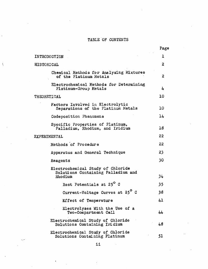
TABLE OF CONTENTSPage
INTRODUCTION 1V HISTORICAL 2
Chemical Methods for Analyzing Mixturesof the Platinum Metals 2
Electrochemical Methods for DeterminingPlatinura-Group Metals 4
THEORETICAL 10Factors Involved in Electrolytic
Separations of the Platinum Metals 10Codeposition Phenomena 14Specific Properties of Platinum,
Palladium, Rhodium, and Iridium IBEXPERIMENTAL 22
Methods of Procedure 22Apparatus and General Technique 23Reagents 30Electrochemical Study of Chloride
Solutions Containing Palladium and Rhodium 34
Rest Potentials at 25° C 35Current-Voltage Curves at 25° C 3#Effect of Temperature 41Electrolyses With the Use of a
Two-Compartment Cell 44Electrochemical Study of Chloride
Solutions Containing Iridium 4#Electrochemical Study of Chloride
Solutions Containing Platinum 51ii

PageSummary of the Electrochemical Behavior
of Iridium, Platinum, Palladium, and Rhodium in Concentrated Chloride Solution 56
The Use of Perchlorate and Sulfate asSupporting Electrolytes 59
The Use of Supporting ElectrolytesContaining Ethylene Diamine Tetraacetic Acid 65
Electrolysis in a Single-Compartment Cell.The Use of Anodic Depolarizers 69
Determination of Iridium 86
Determination of Palladium, Rhodiumand Iridium 89
A Scheme of Analysis for the PlatinumMetals 91
Procedure for Determining Platinum,Palladium, Rhodium and Iridium 96
SUMMARY 103BIBLIOGRAPHY 106ACKNOWLEDGMENT 109AUTOBIOGRAPHY 110
iii

A STUDY OF ELECTROLYTIC METHODS FOR THE SEPARATION OF PLATINUM, PALLADIUM, RHODIUM AND IRIDIUM
INTRODUCTIONThe purpose of this research was to utilize electro
lytic methods for simplifying the task of separating a mixture of the platinum metals— platinum, palladium, rhodium and iridium. Current-potential studies with a stationary platinum microelectrode were used mainly to study the electrochemical characteristics of the individual elements. In many electrolytes there was observed codeposition of one metal with another, and an attempt is made to explain this codeposition.
Originally it was desired to find some electrolyte in which by gradually making the cathode potential more negative the metals could be plated out one after another and thus separated. This ideal was not completely realized. The main difficulty was due to platinum, and it was found necessary to separate platinum first from the other elements by the method of hydrolytic precipitation described by Gilchrist and Wichers.
1

HISTORICALA literature survey was made of Chemisches Zentrallblatt
for the period, 1360 to 1907 and Chemical Abstracts for the period, 1907 to 1954. Since the platinum-group metals include osmium and ruthenium besides the four elements investigated in this research, some study was made on all six elements.
Chemical Methods For Analyzing A Mixture of the Platinum MetalsThere have been described at least two general schemes
for analyzing a mixture of the platinum metals. They are the Deville-Debray procedure and its modifications (4, 43) and the Gilchrist-Wichers procedure (6). In the modified Deville- Debray procedure platinum (IV) and iridium (IV) are precipitated as the insoluble ammonium salts, (NH^JgPtCl^ and (NH^^IrCl^, leaving palladium and rhodium in solution as their chlorides.The precipitate of ammonium chloroplatinate and ammonium chloro- iridate is ignited to the metals and platinum is leached out with aqua regia, leaving iridium behind as the metal. Palladium may be separated by precipitation with dimethylglyoxirae, leaving rhodium.in solution. Rhodium can then be determined as the metal after precipitation as its sulfide.
The objections to this analytical scheme are many. Ammonium chloroplatinate and chloroiridate are slightly soluble, so that some platinum and iridium pass into the filtrate with palladium and rhodium. Also, palladium and particularly rhodium co-precipitate with these two salts (11).

Similarly any osmium or ruthenium which may be present are precipitated along with platinum and iridium.
A more suitable scheme of analysis was developed by Gilchrist and Wichers. In this procedure osmium and ruthenium are first separately distilled from acid solution as their volatile tetroxides and collected in a suitable solution.These elements are then determined by precipitation as their sulfides and reduction to the metals. The solution remaining from these distillations is subjected to controlled hydrolytic precipitation to form the hydrated dioxides of rhodium, iridium and palladium. Platinum alone remains in the filtrate and is determined by precipitation of its sulfide and ignition to the metal. The precipitate containing the hydrated dioxides of iridium, rhodium, and palladium is dissolved in hydrochloric acid. Palladium is separated and determined by means of dimethylglyoxime. After destruction of the excess of dimethylglyoxime in the filtrate by evaporation with nitric and sulfuric acids, rhodium is precipitated as the metal by means of titanous chloride, leaving iridium in solution. After removal of titanium from the solution, the iridium is determined by precipitation as the sulfide and ignition to metallic iridium.
This scheme of analysis is outlined in Figure 1. For best results in using the method, reprecipitations must be made at various stages thus increasing the time of analysis.It will be shown later how electrochemical operations can be

adapted to this scheme.A third scheme of separation which might be mentioned
is that involving fusion with lead. This method has been shown by Schoeller to be useful for separating the platinum metals into two groups (32). Treatment of a mixture of the platinum metals with lead yields an acid-insoluble residue containing ruthenium, osmium and iridium* and an acid-soluble material containing rhodium, palladium and platinum. Further separations can then be made more easily using various procedures.
Electrochemical Methods for Determining Platinum-Group MetalsThe use of electrolytic deposition as a possible ana
lytical tool for the platinum group metals has been recognized for a long time. Many different electrolytes and conditions of electrolysis have been described for the electroanalytical deposition of platinum, palladium, and rhodium, and at least one reference has been made to the electrodeposition of iridium. These literature data are shown in Table I. This list of references is by no means complete, but was selected so as to show the various types of electrolytes and conditions of electrolysis that have been used for depositing these metals. These electrolyte baths were developed by trial and error and few authors have indicated whether any separation could be possible when two or more platinum-group metals are present in the same solution. The few successful separations

FIGURE I GILCHRIST-WICHERS SCHEME 5
OsCl4, RuCl^, PtCl4, PdClo, RhClo. IrCl.TAdd HNO3, distil into HC1 + SO2
RuC14, PtCl4, PdCl2, RI1CI3, IrCl^ Add H2SO4, NaBr03> distil into
HC1 + S02
I
OsOi
Evap. with HC1 3 times, add NaHCO^, filterOSO2, ignite to Os
PtCl4, PdCl2, RhCl3, IrCl4Decompose NaBrO^ with HC1, add NaBr03» NaHCO^, filter
dissolve ppt., reppt.
5So4Evap. with HC1 3 times, add
NaHC03, filterRUO2, ignite to Ru
Pd02, Rh02, Ir02 dissolve in HC1, add D.M.G.,
"Ptfclj
Destroy NaBrOo with HC1, pass in H,S
*PtS2) ignite to PtRhClo,'IrCl.
I 4destroy D.M.G. with HNO3 + H2SO4, fume with H2SO4, add TiCl3
Ir(S04)2
Pd-dimethylglyoxime weigh as salt
:---- »Rh (Ir)boil with H2SO4, reppt. with
(Ti) 1
TiCl-
Add cupferron, filter I.dissolve in boiling H2SO4, dilute, add HoS
1RI12S3; ignite to Rh "V
Ir
Ti (Ir)reppt. Ti with cupferron after dissolving in HNOo and fuming
with HoSOr >
destroy cupferron with HNOo + H2SO4, ppt. Ir02 with NaHCu3, ignite to Ir

6that have thus far been effected are as follows:
Pd-Ir — E. F. Smith (36) successfully separated palladium and iridium in a bath containing disodium phosphate and phosphoric acid. The electrolysis was carried out without stirring and the iridium was left in solution.
Pt-Ir — This pair of metals was also separated by Smith from a phosphate bath, the platinum being deposited and the iridium being left in solution. E. G. Weischede (7) separated platinum and iridium in weak sulfuric acid solution at low current density. The time of electrolysis was quite long.
Pt-Rh — The separation of platinum and rhodium in weak sulfuric acid using low current density was made by E. Kratz (IS). About 20 hours were required to deposit 15 mg. of Pt, the Rh remaining in solution,
Rh-Ir — An attempt by Smith to separate rhodium and iridium in phosphate solution failed. S. Tuthill (40) separated these two elements in strong chloride solution at controlled cathode potential, the rhodium being deposited while the iridium remained in solution. The fact that rhodium and iridium could be separated under these conditions, while the methods used by other investigators failed, prompted the writer to study other possible separations using the same technique.
During the period about 1925-1929, a detailed investigation was made by W. Moldenhauer and his students to determine whether mixtures of the platinum metals could be

7TABLE I LITERATURE DATA ON ELECTRODEPOSITION OF PLATINUM,
PALLADIUM, RHODIUM AND IRIDIUM
Reference Electrolyte. Conditions ResultsRhodium
35 Na3RhCl6, H3PO2P Na2HP04; slow 7 hours; darkdeposit; 6 fo
deposition on Cu cathode current efficiency
14 NaoRhCl^, H2S0i; slow deposition 5 hours, dark deposit
20
10
NaoRhCl^, H/jSO, ; stirring, on 10 min., dark * deposit
Ag; £-15 amps, 7 v.
Rh salt, H„S0.; on Cu; 7 amps, 10 min., white 4 v. ^ deposit
9 Rh salt, HoSOa , HC1 or HC10,;1.5-2 amps * *
"Good results"
7 Na3RhCl6, H2S0i; upon Ag; 2 v.; Deposition slow;silvery deposit
low current density
Iridium7 Na^IrCl^, H2S0^; 1.6-2 v.; "Good results"
— Il / Pcurrent density 5 x 10 amps/car
Palladium42 PdCl2, HgSO^; slow deposition Black deposit
33 Pd(N03)2, HN03 Dark deposit
35 (NH4)2PdCl4, Na2HP04, ^PO^; Bright depositslow deposition

aTABLE I (continued)
Reference Electrolyte, ConditionsPalladium
1 Pd(NH3)2Cl2, H2S0^; 0.3 amps; 60-65° C.Pd(NH3)2Cl2, my, 5-17 v, 2-10 ampsPdCl2, NaN02, NH^NO^, NH^; 90-95°C, 4.5 v.Pd(NH3)4(N03)2, Na2S04, H3P04, NH3; 65-ao°C; 0,3-2.5 amps/dm2;1.5 v.
20
15
30
Results
"Good results”
5 min., gray,adherentdepositBright deposit
Good plate; no hydrogen evolution
Platinum3 PtCl4, (NH4)2C204; or (NH4)2-
PtCl^; small current density
31 PtCl4, H2S04; slow deposition
37 PtCl4, Na2HP04, H3P04; upon Agor Cu; rotating Pt electrode
30 (NH4)2PtCl6, NH4C1; a0-90°C;5- 6 v., organic substances added
5 hours; bright deposit
Overnight deposition;"good results"7 min., good
plate
"Good results"

electrolytically separated in a weak solution of sulfuric acid (7> Id, 29). Their methods of investigation have been partially applied to the present work, and they will be discussed in the next section.

THEORETICAL
Factors Involved in Electrolytic Separations of the PlatinumMetals
In considering the possibilities of separating the four platinum metals - platinum, palladium, rhodium, and iridium, - by electrolytic reduction, three factors seem fundamental. They are: (1) single electrode potentials ofthese elements; (2) complex ion formation; and (3) overvoltages of the reduction processes at the electrodes. With regard to the first of these we find from Latimer (22) the following normal electrode potentials:
Pt2+ + 2e = Pt E°- + 1.2 v (1)Ir3+ + 3e - Ir E°= + 1.15 v (2)Pd2* + 2e « Pd E°= + 0.99 v (3)Rh3+ + 3e - Rh E°= + 0.3 v (4)
These potentials are all significantly different from each other (except possibly those of platinum and iridium) so that theoretically these processes can be carried out individually by means of the method of constant cathode potential.
Since the platinum metals readily enter into complex ion formation their electrode potentials are changed in most supporting electrolytes. For example, if one is working with a chloride solution of these elements the following equilibrium potentials are important, along with those (equations 1 to 4) listed above:
PtClS + 2e - PtClJ + 2C1 E°= + 0.63 v (5)10

11PtciJ + 2e - Pt + 4C1“ E§ + 0.73 v (6)IrOlg + e » IrClf E§ + 1.017 v (7)IrCl5 + 4e ■ Ir + 6C1~ E2 + 0.335 v (3)PdClJ + 2e = Pd + 4C1" e2 + 0.62 v (9)RhClf + 3e = Rh + 6d “ e2 + 0.44 v (10)
Clearly the problems of electrolytic separations in chloride solution are more difficult than is at first predicted from equations 1 to 4. Thus, suppose a mixture of the four plati- num-group metal chlorides were dissolved in water. Each of the metals will exhibit an equilibrium between the free (i.e., hydrated) and complex ions of that metal, such as:
[M(H20)x]n+ + xCl“ = [MClx]m“ + H20 (11)e.g. [Rh(H20)6]3+ + 6C1“ » [RhCl6]3” + 6H20
Depending upon the total chloride concentration, any of the intermediate species, such as [Rh(H20)<jCl]^+, [Rh(H20)i!fCl2]+, etc., may also be present. With such a system the following problem might be encountered if an attempt were made to effect a separation by means of electrolysis:
The potential at which metal deposition takes place will depend upon the amount of ion species most easily reduced, rather than upon the total amount of metal present (hydrated plus complex ion). Usually the ion species being reduced most readily is the hydrated ion. If, as the hydrated ion is being reduced at the electrode the reaction
(MClx )m“____52£^ [M(H20)x]n+ + xCl~ (12)is slow as compared to the electrode reaction, then the
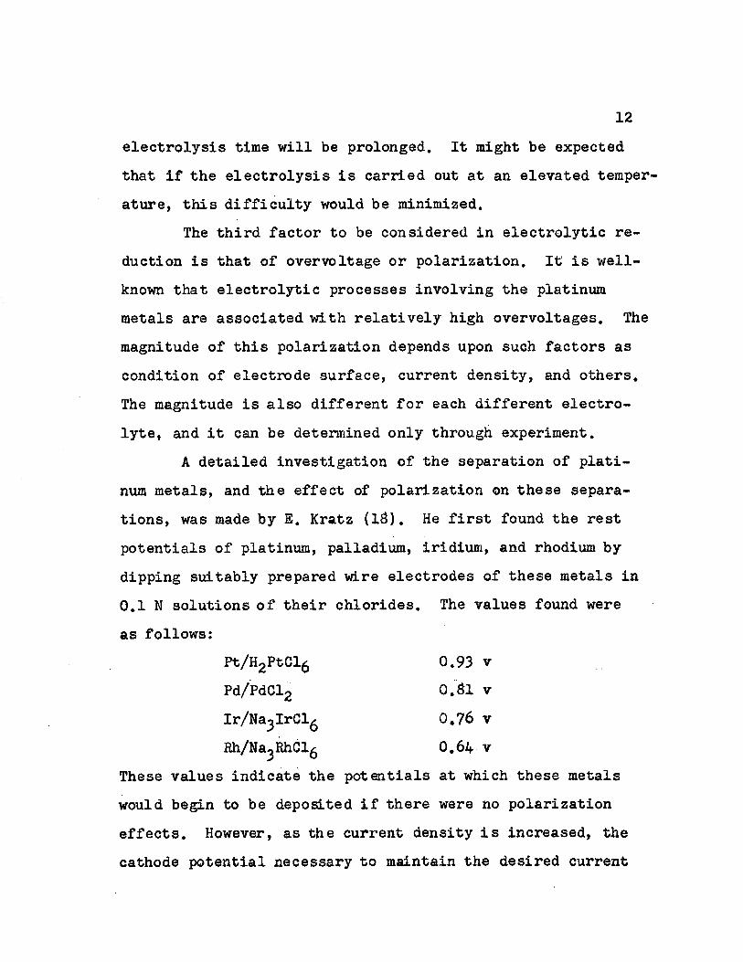
12electrolysis time will be prolonged. It might be expected that if the electrolysis is carried out at an elevated temperature, this difficulty would be minimized.
The third factor to be considered in electrolytic reduction is that of overvoltage or polarization. It is well- known that electrolytic processes involving the platinum metals are associated with relatively high overvoltages. The magnitude of this polarization depends upon such factors as condition of electrode surface, current density, and others. The magnitude is also different for each different electrolyte, and it can be determined only through experiment.
A detailed investigation of the separation of platinum metals, and the effect of polarization on these separations, was made by E. Kratz (13). He first found the rest potentials of platinum, palladium, iridium, and rhodium by dipping suitably prepared wire electrodes of these metals in 0.1 N solutions of their chlorides. The values found were as follows:
These values indicate the potentials at which these metals would begin to be deposited if there were no polarization effects. However, as the current density is increased, the cathode potential necessary to maintain the desired current
Pt/H2PtCl6Pd/PdCl2
0.93 v 0.31 v 0.76 v 0.64 v
Ir/Na3IrCl6Rh/Na3RhCl6

13density is also increased, due to polarization. This was Shown by current density-potential measurements carried out by Kratz. The data obtained by him are re-plotted in Figure 2.
In Figure 2 it is seen that polarization effects aresmallest for platinum and greatest for
figure 2 iridium. In the caseCurrent-Voltage Curves by Kratz of platinum, the polar
ization indicatedprobably represents
20 the over-all effectx due to the consecu-C '
tive processes,Pt2+ and
Pt2+«— *Pt, as well as to the disproportion- ation process,2Pt2+---*Pt4+ + PtThis will be discussedin the experimental
Cathode Potential, Volts vs. the Normal Hydrogen tlectrode
-o.U section* Suppose onethe wishes to attempt a
separation of platinum and palladium. If the electrolysis is carried

14out at an extremely low current density, then platinum would deposit free of palladium. However, Kratz states that in practical electrolysis cne wishes to deposit the metal in a reasonable length of time and so it would be necessary to increase the current density. As can be seen in Figure 2, even at a current density as low as 1 x 10"^ amp/cm^, the deposited platinum would be contaminated with palladium. Theoretically, in this electrolyte the only separations which can be made are for the pairs Pt-Ir and Pt-Rh. The first pair was separated by E. G. Weischede (7) and the second by Kratz.
In the work of Kratz, a study of the effect of complex formation on separations of the platinum-group metals was not made. This effect has been found to be quite important.Thus, Kratz has shown that the separation of rhodium and iridium is impossible from a dilute solution of sulfuric acid. Tuthill (40) used a strong solution of ammonium chloride as supporting electrolyte and effected a separation. The present research was designed to apply the method of Kratz to the study of platinum-group metal separations, but using various other supporting electrolytes.
Co-deposition PhenomenaJust as with ordinary chemical processes involving
the platinum-group metals so is it true with electrochemical processes that often the action of one metal is influenced by the presence of another. To illustrate this, there are

15shown in Figure 3 current-potential curves for 10"3 M rhodium chloride, 10- M palladium chloride, and mixtures of these metal chlorides (10_3 M each) in 0.1 M sodium chloride at pH * 1.5. As can be seen in this figure, when the metals are present alone, palladium shows a reduction wave whose halfwave potential is about + 0.10 volts vs. the saturated calomel electrode, and rhodium shows a reduction wave at -0.30 volts vs. S.C.E. When a current-potential curve is run for a mixture of palladium and rhodium chlorides in 0.1 sodium chloride, a reduction wave is obtained having a halfwave potential of +0.05 volts vs. S.C.E. Thus, the potential at which rhodium deposits is made to approach the deposition potential of palladium when palladium is present. If palladium were plated from this solution, it would be contaminated with rhodium, even if the cathode potential were carefully controlled.
The question arises as to the mechanism of such codeposition. The following theories are suggested as possible explanations for this codeposition: (1) Variation of overvoltage for the deposition of one platinum metal on other platinum-metal electrodes; (2) Formation of alloys which are chemical compounds or mixed crystals; (3) Catalytic effects. These theories will now be discussed individually.
Some study of this problem was made by Tuthill (loc. cit.). He found that rhodium will deposit from a solution of sodium chlororhodite at a cathode potential of -0.30 volts

Cu
rren
t,
mic
roa
mp
ere
s
I|I 16
Current - V o l t a g e Curves for Pallad ium and Rhodium in
O.l M Chloride
Pd + Rh
Pd
Rh
+0.3 +0.2 -0.30.1 -0.200Potential , volts saturated calomel electrode
FIGURE 3

!7vs. S.C.E., and that no iridium will deposit from a solution of sodium chloroiridate at this potential. When a similar solution containing both sodium chlororhodite and chloroiridate was electrolyzed at a cathode potential of-0.30 volts vs. S.C.E., the deposit contained both rhodium and iridium.Thus the iridium had in some way co-deposited with the rhodium. Tuthill found that practically no iridium deposited either on an ignited or a fresh rhodium surface, so that this co-deposition must not be due to differences in overvoltage of iridium on platinum and on rhodium.
Co-deposition of one metal with another can arise when both metals in question form an alloy in the form of a chemical compound or a mixed crystal. In this case the activity of each metal in the compound or mixed crystal is different from its activity in the free metal, and so its deposition potential is also changed. This subject is discussed by Kortum-Bockris (17). They show by current-voltage curves that the deposition of zinc from cyanide solution at certain current densities can be made to take place at a much more positive potential when it is deposited with copper than when it is deposited alone, due to the formation of the mixed crystal, brass.
Cooling-time curves (12) and electromotive data (5) for copper-zinc alloys show that definite mixed crystals of these metals are fonned. Similar data for palladium-rhodium mixtures and of other mixtures of two platinum metals (27) show that only a continuous series of solid solutions form.

idThe activity of a metal in the free state is not much different from its activity in a solid solution. Therefore, it seems that while the formation of mixed crystals may be the cause of co-deposition in some cases, this same explanation cannot apply to co-deposition of platinum metals with each other.
A more plausible explanation for co-deposition of the platinum metals with each other may be that one reduction process is in some way catalyzed by another reduction already taking place. Suppose a solution containing both palladium chloride and rhodium chloride in 0.1 M sodium chloride is electrolyzed. If the palladium ions, on diffusing toward the cathode, drag along with them some rhodium ions (possibly as RhCl^ ), then these rhodium ions may be reduced at the cathode at a more positive potential than when rhodium ions are present alone, since in the former case more rhodium ions would be found near the cathode, and so its deposition potential would be shifted to a more negative value. This dragging effect of rhodium ions by palladium ions might be caused by electrostatic attraction, resulting in diffusion of ion-pairs to the electrode. No experimental data can be offered to verify this theory.
Specific Properties of Platinum, Palladium, Rhodium, andIridium
Platinum: Platinum is found in its compounds commonlyin the divalent or tetravalent forms. Latimer (22) states

19that if platinum is in the form of the chloride complex, then the divalent state is slightly unstable with respect to dis- proportionati on:
2PtClj* x PtClJ + Pt + 2C1"0. Stelling (33) has carried out current density-potential measurements for solutions of 0.1 M chloroplatinic acid in2,5 M hydrochloric acid. He obtained as many as four reduction steps under certain conditions, to which he ascribed the following reactions:
Pt4+ + 2e = Pt2+ (1)Pt2+ + 2e = Pt (2)Pt/f+ + 4e * Pt (3)2H+ + 2e * H2 (4)
Under other conditions fewer steps were observed, depending upon the condition of the electrode, and other factors. From these current density-potential measurements and from rest- potential data, he found that the first reduction step proceeds with significant polarization (about 0.3 to 0.4 volts).
As will be described in the experimental section, cur rent-potential data and electrolytic data indicate that disproportionation of Pt2+ also takes place in solutions containing large amounts of chloride ion.
Palladium: The most important oxidation state ofpalladium in its compounds is +2, although the +4 state is slightly stable in some solutions. The normal potential for
_y. _p.the process, Pd + 2e = Pd, is such (+0.99 v.) that it can

20be made to take place at a relatively positive potential. No data for deposition Potentials of Palladium has been reported in the literature.
Rhodium: The main oxidation state of rhodium is the+3. Grube and his co-workers have carried out extensive investigations concerning the chemical and electrochemical behavior of rhodium in various electrolytes. Grube and Kest-. ing (10) made current density-potential measurements for rhodium chloride in various concentrations of hydrochloric acid and at various temperatures. They found that only at an HC1- concentration of 0.01 M and 20°C could rhodium be deposited at a potential more positive than that at which hydrogen was liberated. At higher concentrations of chloride the reduction step for rhodium deposition occurs at more negative potentials. Using a 2-compartment cell, they were able to deposit rhodium at high current efficiencies from solutions containing chloride, perchlorate, and sulfate.
Iridium: The main oxidation states of iridium in itscompounds are the +3 and the +4. The normal potential of the process representing reduction of Ir+^ to Ir+3 in chloride solution is -1.017 volts (22), so that this reduction can be carried out at a very low applied potential, and is effected by pany common reducing agents. However, further electrolytic reduction to the metallic state is difficult and has been accomplished only by E. G. Weischede (7) by electrolyz- ing the chloride in sulfuric acid solution for a long period

21of time. The reason for this difficulty of reduction may be due to a high overvoltage associated with the process.

EXPERIMENTAL
Methods of ProcedureThe experimental work consisted first in studying the
polarographic behavior of platinum, palladium, rhodium, and iridium in various supporting electrolytes to determine the nature of the reduction steps. These data also served as a guide to indicate approximately the potential at which the cathode should be set in order to carry out electrolyses at controlled cathode potential.
A second part of the research consisted in taking rest potential measurements. If a platinum wire electrode dips in a solution of one of the platinum-metal salts and the potential of that electrode measured against a saturated calomel electrode, one obtains the potential at which that metal would deposit if there were no overvoltage effects. Of course it is well known that there are large overvoltages associated with the deposition of these metals, and these rest potentials combined with electrolysis data give some indication of their magnitudes. Another value of rest potential data is for determining what strength of complexing ion is necessary to form completely the complex of the metal in question. This will be shown in the case of the chloride.
Finally, actual electrolyses were carried out. These electrolyses were at first done using a two-compartment cell without addition of a depolarizing agent. Later a one-com-partment cell was used with addition of an anodic depolarizer.
22

23Apparatus and General Technique
Polarographic, or current-potential measurements were taken with a Fisher Elecdropode using a stationary platinum wire as the polarized electrode. The dimensions of the electrode and method of procedure were as recommended by Kolthoff and Lingane (16). The platinum wire was sealed into a soft glass tube and the exposed part of the wire was four millimeters long and five-tenths millimeter in diameter. Measurements were taken versus a saturated calomel electrode having a potential of +0.2436 volts at 26°, as determined by reference to other saturated calomel electrodes in the laboratory.
About twenty milliliters of solution were taken for each polarographic run. It was found necessary to outgas the solution with nitrogen for fifteen minutes before each run in order to remove dissolved oxygen. No maximum suppressor was needed. The platinum micro electrode was then placed in the solution. Connection was made from the saturated calomel electrode to the cell by means of a salt bridge made from six-millimeter glass tubing bent in U-shape and filled with saturated potassium chloride in four per cent agar. The tip of this salt bridge was always placed about one-half inch from the microelectrode in the solution. The temperature of the solution being studied was kept constant to within 0.1°C. Each time the potential was adjusted at least two minutes were allowed before a reading of the current was

24taken.
Fresh solutions of the platinum-metal chlorides, particularly rhodium, usually behave differently from aged solutions, due to a reaction of the type (3):
[Rh(H20)3Cl3] + 3 H20 [Rh(H20)6]3+ + 3C1”Therefore, in order to get reproducible data all chloride solutions were heated on a steam bath for fifteen minutes prior to making a polarographic run.
Various methods were tried for cleaning the microelectrode of material deposited during a run, in order that it may be used for a subsequent run. The method finally adopted was to scrape the electrode lightly with fine emery cloth, rinse it with water, and finally to ignite the wire in a flame. This final ignition was found to be necessary when working with sulfate solutions since if this operation was omitted reproducible results were not obtained.
The same type of microelectrode and saturated calomel electrode as were used for polarographic runs were also used for taking rest-potential measurements. These measurements were made by dipping the mi croelectrode and salt bridge into the solution and reading the potential.developed after equilibrium was reached. A student-type potentiometer was used to measure the potential. Outgassing was carried out with nitrogen for fifteen minutes before the run and also during the run.
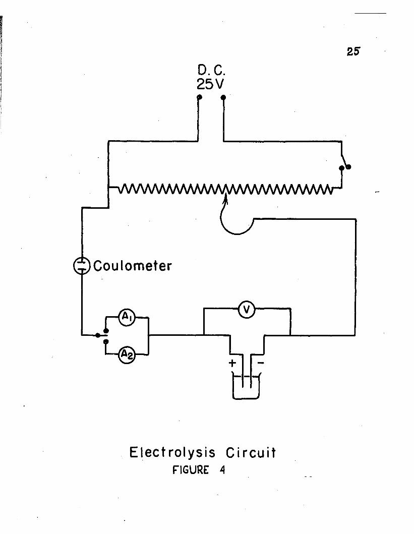
Figure 4 represents the circuit used for electrolysis
25D.C. 25 V
-VWWWWWi/WWWWVWWWWWI
© C o ulom eter
J“ © ”<v>
a
Electrolysis CircuitFIGURE A

with manual control of the cathode potential. This circuit was similar to that usually described in the literature except that it contained two milliammeters, a, of different ranges, either of which could be switched into the circuit.The milliammeter having the lower range (0 to 100 ma.) was used for observing residual currents in coulometric work, while the higher range (0 to 3000 ma.) was necessary when rhodium was being deposited, since a large current was obtained due to simultaneous evolution of hydrogen at the cathode. The cathode potential was measured against a saturated calomel electrode, the electrolytic cell making contact with it by means of a salt bridge containing saturated potassium chloride in four per cent agar. A student-type potentiometer was used to measure the cathode potential. The direct current used for electrolysis was obtained from storage batteries and the voltage was controlled by means of a 120-ohm slide wire rheostat connected in a potentiometer-type arrangement as shown in the figure.
A simple electrolytic cell having a pair of electrodes immersed in a beaker containing the solution to be electro- lyzed, has been used by many of the earlier workers for electrodeposition of the platinum-metals. This kind of cell has the disadvantage in that electrolytic reductions of the platinum metals proceed at low current efficiencies since some oxidation of the ions takes place at the anode simultaneously with reduction at the cathode. One can eliminate

27this difficulty by adding to the solution an anodic depolarizing agent such as hydrazine dihydrochloride or hydroxyla- xnine hydrochloride. These reagents are oxidized at the anode in preference to any other possible anodic reaction. This one-compartment cell with depolarizer was used throughout the last part of this work.
A complication presents itself when an anodic depolarizer is used. In chloride solution tetravalent platinum is reduced to the divalent state and tetravalent iridium is reduced to the trivalent state by these depolarizers. Also, in some solutions, such as sulfate or perchlorate, divalent palladium is reduced to the metallic state. In experiments where it was desired to study these reduction processes electrolytically the depolarizer was omitted and the cathode and anode were separated by using a two-compartment cell.Such a cell is shown in Figure 5. The porous clay cup (Coors, size 1) served to isolate the anode and cathode. The top inside of the cup was ground so that a male standard taper 24/40 joint fitted snugly into it, and the two parts were held together by means of Kronig cement. The anolyte always consisted of a dilute (1:4) solution of sulfuric acid.
The method of using this two-compartment cell was as follows: The Sargent Slomin cathode was placed in a suitableholder above the solution to be electrolyzed. The porous cup was next clamped in place inside the cathode, and the anode, a micro size electrode, placed in the porous cup. When it

28
o -
1: 4 H 2S 0 4
Porous clay cup
P t - m etal solution
Stirr ing bar
Two - Co m part ment Electrolytic CellFIGURE 5

29was desired to start the electrolysis enough dilute (1:4) sulfuric acid was poured into the porous cup so that when the electrolyte was raised from below to immerse the cathode the levels of the liquids in both compartments were at approximately the same height. The current was then immediately turne d on.
During the electrolysis any platinum metal ions carry-Sing a negative charge, such as IrCl^ , tend to migrate to the
anode compartment. However, when this type of ion reaches the catholyte-anolyte interface the high concentration of sulfate ion there dissociates the complex so that the uncomplexed (i.e., hydrated) platinum-metal ion, which carries a positive charge, returns to the cathode chamber.
If a strong chloride solution serves as catholyte then another complication sets in. In this case large numbers of chloride ions migrate to the anode and are oxidized to chlorine. The chlorine partially dissolves and in time diffuses through the porous cup to the catholyte where it interferes with the cathodic reaction. It is then necessary to separate the anode and cathode still further by means of an inverted glass U-tube filled with 1:4 sulfuric acid connecting the anolyte with a flask containing more 1:4 sulfuric acid and the anode. Admittedly the U-tube offers high electrical resistance but sufficiently high currents are obtained.
Some electrolyses were carried out at 60° c. In order to keep the solution at this temperature a simple water bath

30was used. The heater was a coil consisting of about five turns of nichrome wire encased in 4-mm.-Pyrex tubing bent in a spiral form slightly greater in diameter than the electrolysis beaker. The water bath itself was a Petri dish which was six inches in diameter and three inches high. With this arrangement the temperature of the electrolytic solution could be held constant to within 1° C.
Tuthill (loc.cit.) had shown that deposits of rhodium obtained from chloride solution contained some rhodium oxides. He decomposed these oxides by reducing the electrode in a current of hydrogen. In some parts of the present work the procedure described by him was followed. This procedure consisted in suspending the electrode in a glass chamber through which hydrogen gas flowed at a sLow rate, and heating the chamber to 4$0°C. by means of a nichrome heater wound around the outside. Nitrogen gas was used to sweep out the chamber before and after the reduction by hydrogen.
Some of the electrolytic reduction processes were followed coulometrically. For this study there was used a hydrogen-oxygen coulometer containing 0,5 M sodium sulfate as electrolyte. The use of this type of coulometer has been described by Lingane (24).
ReagentsThe platinum metal salts used in this investigation
were all obtained in the form of the chlorides. Rhodium (III)

31and iridium (IV) chlorides were obtained from the American Platinum Works of Newark, New Jersey; Palladium (II) and platinum (IV) chlorides from Coleman and Bell Company of Norwood, Ohio; and platinum (II) chloride from the Fisher Scientific Company of Pittsburgh, Pennsylvania. A qualitative spectrographic study of their purity showed that iridium chloride contained only a trace of rhodium, rhodium chloride contained a trace of iridium, and palladium chloride contained a trace of platinum. These salts were taken to be sufficiently pure for use in the work.
The commercial samples of rhodium chloride and palladium chloride were found to be relatively non-hygroscopic so that in the first series of experiments using these compounds the metal content of each sample was known simply from the wei^it of solid chloride used. The rhodium content of solid commercial rhodium chloride was determined by reducing a sample in a Rose crucible to be 37.06 percent (theor. for RhCl^OHgO, 39.06 percent). This value of 37.06 percent was used for calculating the rhodium content of a weighed sample. The palladium content of commercial palladium chloride was determined by electrolytic deposition to be 59.11 percent (theor. for PdCl2 60.06 percent). In each case the variation of metal content from theoretical may have been due to moisture or excess chloride in the sample.
Admittedly, results obtained by standardizing the procedure in this way were not of the highest accuracy, but

the method was used only in preliminary experiments. When great accuracy was desired in making up solutions of rhodium and palladium, as well as of platinum and iridium, aliquot portions of a stock solution of the respective chlorides were taken. Each stock solution was 0.01 M in hydrochloric acid in order to prevent hydrolysis of the metals to their hydroxides. The stock solutions were standardized by evaporating a twenty-five milliliter portion to dryness in a weighed Rose crucible followed by reduction of the resulting solid chloride to the metal by heating in a current of hydrogen and cooling in nitrogen. Results obtained in this way are known to be reliable (2d). Once standardized, only the platinum (IV) solution changed in concentration with time, due to the settling out of an insoluble material. Therefore the solution of platinic chloride was standardized immediately before use in each series of runs.
Qualitative Test ReagentsIn one phase of the analytical scheme which was de
vised palladium is electrodeposited and thus separated from rhodium and iridium, and then rhodium is deposited, leaving iridium alone in solution. The deposition of palladium takes place at nearly one hundred percent current efficiency so that the completeness of deposition is indicated when the current falls nearly to zero. In the deposition of rhodium, however, hydrogen evolution occurs simultaneously so that it

is necessary to test for completeness of deposition of rhodium by adding a suitable reagent to a portion of the solution being electrolyzed. A sensitive test reagent was discovered by Ivanov (13) to be stannous chloride solution. It is prepared by dissolving twenty grams of stannous chloride in one hundred milliliters of 1:1 hydrochloric acid, some metallic tin being added to keep the stannous salt from being oxidized by air.The test consists in the formation of a pink color when equal volumes of the test solution and the solution suspected of containing rhodium are heated to near boiling for a few minutes. A faint pink color is obtained even when the concentration of rhodium is as low as cne milligram per liter. Tuthill (loc.cit.) observed that iridium gives a light yellow color under the same conditions, but no difficulty was experienced in observing the pink color due to rhodium when both metals were pre sent.
The electrolytic determination of platinum was found to be possible only after it was first separated from the other metals by hydrolytic precipitation of the latter hydroxides. When the platinum solution thus obtained was electrolyzed, completeness of deposition was tested with ; sodium sulfide reagent. In this test two milliliters of the electrolyzing solution were placed in a small test tube. The solution was strongly acidified with two drops of concentrated hydrochloric acid and then one drop of a five percent solution of sodium sulfide was added. All of the sodium sulfide is

34thus decomposed to form hydrogen sulfide which forms a brown precipitate on warming for a few minutes if platinum is present.
Electrochemical Study of Chloride Solutions ContainingPalladium and Rhodium
The success achieved by Tuthill in separating rhodium and iridium by electrodepositing the rhodium from a concentrated solution of ammonium chloride prompted a similar study for other separations which would include platinum and palladium. It was decided to study first the electrochemical behavior of all four of these metals in chloride solution. Although Tuthill found ammonium chloride solution to be suitable for separating rhodium and iridium the first series of experiments were tried using sodium chloride as supporting electrolyte. This was done because it was desired to study the electrochemical processes involving tetravalent platinum and iridium, both of which form insoluble salts, (NH^PtCl^ and (NH^^IrCl^, in ammonium chloride solution.
It was thought that a study of the electrochemical characteristics of the platinum-metals should involve rest- potential measurements, current-potential measurements and actual electrolyses. Rest potential measurements allow a study of complexing effects to the exclusion of overvoltage and co-deposition effects. The latter effects could then be studied by means of current-potential measurements. Finally, various supporting electrolytes and electrolysis conditions
35were tested by actual electrolyses. The first pair of metals to be thus studied was palladium and rhodium.
Rest Potentials at 25° C.Rest potentials were obtained by dipping a small
electrode of one of the platinum metals in a solution containing the chloride of that metal. The electrical circuit was completed through a potentiometer and reference calomel electrode. It was desired to find how the rest potential of each metal varied with concentration of chloride ion. This was done using a tall-form electrolytic beaker fitted with a rubber stopper which had holes bored for insertion of an out- gassing tube, salt bridge, buret tip, and gas outlet. Fifty milliliters of 0.01 M platinum-metal chloride solution, adjusted to pH 2.0 with hydrochloric acid, were placed in the beaker and heated on the steam bath for fifteen minutes to age it (cf., p. 24). After cooling the solution, it was out- gassed for fifteen minutes. Passage of nitrogen was also continued throughout the run. The microelectrode and salt bridge were next placed in the solution, and timed with a stopwatch. Readings of the potential were taken until it became constant over a period of five minutes. This constant value was taken as the rest potential of the original solution. Increments of five milliliters of 5.2 M sodium chloride (adjusted to pH 2.0 with hydrochloric acid) were then added.Five minutes after each addition of chloride solution a new rest potential was read.

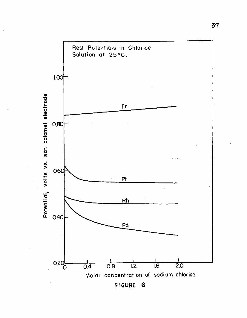
Plots of rest potentials thus obtained for iridium (IV), platinum (IV), rhodium (III), and palladium (II) chlorides at various concentrations of sodium chloride and a temperature of 25° C. are given in Figure 6. The data for platinum and iridium are brought together on this graph for comparison purposes and will be discussed later. Considerthe curves for palladium and rhodium. The values of the potentials represent those at which the processes
Rh3+ + 3e - RhPd2+ + 2e = Pd
would take place upon electrolysis provided that overvoltages were negligible. Thus, the theoretical deposition potential for rhodium from its pure chloride solution is +0.512 volts and for palladium +0.477 volts (vs. S.C.E.). If overvoltage and other effects were neglected then it would be predicted that an electrolytic separation of these two elements is not possible from such a solution since the difference between these two potentials (0.035 v.) is too small. As sodium chloride is added to the solution of rhodium chloride the rest potential changes very little. On the other hand addition of sodium chloride lowers the rest potential of palladium significantly. Thus at a concentration of 2.0 M sodium chloride the rest potential for rhodium is +0.459 volts while that for palladium is +0.316 volts. The difference of 0.143 volts indicates that a separation of palladium and rhodium is more nearly possible in solutions containing high concentra-
Po
ten
tia
l,
volt
s vs
. sa
t.
calo
mel
e
lec
tro
de
Rest P o t e n t i a l s in C h lo r id e S o l u t i o n a t 2 5 ° C .
1.00
0 .8 0
O.61
Rh
0 .4 0
0.20 2.00.80 .4
M o l a r c o n c e n t r a t i o n of s o d iu m chloride
FIGURE 6

3*tions of chloride than when no excess chloride is present.
Current-Voltage Curves at 25°C.Current-voItage measurements were taken using a
stationary platinum microelectrode as described previously. Figure 7 shows these data for solutions containing 10"^ m palladium in various concentrations of sodium chloride at 25°C. Figure 8 shows similar data for 10"^ M rhodium. As can be seen from these figures a reduction wave is obtained for palladium at more positive potentials than for rhodium at each concentration of chloride. This is not what would be expected from the rest-potential measurements mentioned above. The reason may be that deposition of rhodium takes place with a much higher overvoltage than does deposition of palladium.
The greatest difference in half-wave potentials for the reduction steps of palladium and rhodium occurs at the lower chloride concentration of 0.1 M. On the basis of this observation alone, an electrolytic separation of these two metals would seem to be most easily achieved at this low concentration of chloride. However, as was shown in Figure 3> current-potential data for mixtures of palladium and rhodium in 0.1 M chloride indicate that co-deposition of rhodium with palladium occurs even at very positive potentials. Similar current-potential data for mixtures of palladium and rhodium in solutions of several higher concentrations of chloride show such co-deposition characteristics. Generally it was

Cu
rren
t,
mic
roa
mp
ere
s
39
C u r r e n t - V o l t a g e Curves for Palladium in 0.1, 1.0, and 4 .0 M Sodium C h lo r ide
15
10
0.1 M
51.0 M
4.0
0
+0.3 +0.2 +0.1 0 .0 -0.1 -0 .2 -0 .3
Potent ial , volts vs. s a t u r a t e d calomel e le c t ro d e
FIGURE 7

Cu
rre
nt,
m
icro
am
pe
res
AO
C u r r e n t - V o l t a g e Curves for Rhodium in O.l , 1.0, a n d 4 . 0 M S o d iu m Chloride
15
10
.OM
4 . 0 M5
0
+0.1 0.0 - 0.1 - 0.2 -0 .3
P o te n t ia l , volts vs. s a t u r a t e d calomel electrode
f ig u r e : s

41observed that less co-deposition takes place at higher concentrations of chloride than at lower concentrations.
Effect of TemperatureRest-potentials were taken for palladium and rhodium
in various concentrations of sodium chloride at 60° C, and these data are plotted in Figure 9. Comparing these curves with those of Figure 6, it is seen that the curve for palladium now lies above that for rhodium. Thus, while the potentials for palladium increase with temperature, those for rhodium remain essentially the same for low concentrations of chloride and decrease with increase in chloride concentration, leveling off only at a chloride concentration of about 2,5 M. From these results it would seem that an increase in temperature favors deposition of palladium, but hinders deposition of rhodium (again neglecting overvoltage).
Figure 10 and 11 show current-voltage curves for palladium, rhodium, and for mixtures of these two elements (10“3 M each) in a solution containing 1,0 M hydrochloric acid and 3.0 M sodium chloride at 25° and 60° C, respectively. The potentials at which a reduction wave is obtained for rhodium is nearly the same at both temperatures, while in the case of palladium a slight shift is observed to more positive potentials at 60° G. Also the height of the wave is greater at 60° C than at 25°. This latter point is important in that electrolysis time for a given solution is smaller if

Pot
entia
l, Vo
lts
vs.
Sat
urat
ed
Cal
omel
El
ectr
ode
Rest Potentials in Chloride Solution at 60°C .1.00
0.80
0.60
0.40Rh
0.202.0 3.01.00.0
Molar Concentration of Sodium Chloride
FIGURE 9

Cu
rre
nt,
M
icro
am
pe
res
43
C u r r e n t - V o l t a g e Curves for P a l l a d i u m a n d R h o d i u m in
H C I - N a C I S o l u t i o n a t 2 5 °C .15
Pd + R
10
5
R h
0
+ 0 .3 + 0 .2 +0.1 0 .0 "0.1 - 0 .2 ~ 0 .3
P o t e n t i a l , v o l t s vs. s a t u r a t e d calom el e le c t ro d e
FIGURE 10

44it is carried out at a cathode potential corresponding to a high current on a current-potential curve.
Figure 11 also shows that the palladium-rhodium curve at 60° has two definite reduction steps. The first step represents reduction of palladium alone, while the second represents co-deposition of palladium and rhodium. From a series of current-potential studies of palladium-rhodium mixtures in solutions containing sodium chloride up to concentrations of 4.0 M, and in solutions containing both sodium chloride and hydrochloric acid, this is the only double wave that was obtained. It thus seemed that this electrolyte containing 3.0 M sodium chloride and 1.0 M hydrochloric acid was the best electrolyte to use for carrying out the separation of palladium and rhodium.
Electrolyses With the Use of a Two-Compartment CellElectrolyses were carried out for solutions containing
palladium and rhodium in 1.0 M hydrochloric acid and 3.0 M sodium chloride as well as in solutions containing other amounts of chloride. For each electrolyte studied, palladium was first electrolyzed. The cathode potential was gradually made more negative until a current of at least 50 milliamperes was obtained. The cathode potential was then kept at this value until the current dropped to nearly zero. A portion of the solution was tested for palladium with sodium sulfide as described in the section on reagents. If palladium was still

Cu
rren
t,
Mic
roa
mp
ere
s
44
C u r r e n t - V o l t a g e C u rv e s f o r
P a l la d iu m an d R h o d i u m in
HCI - N a C I S o l u t i o n a t 6 0 °C .
7 5
5 0Pd + Rh
Pd
2 5
Rh
0.0■*■0.2 + 0. -0. - 0.2 -0 .3+0.3
P o t e n t i a l , v o l ts vs. s a tu r a te d calomel electrode
FIGURE 11

45found to be present, the cathode potential was made slightly more negative, until after the current became small, no test was obtained for palladium in the solution. A similar electrolysis was carried out for a rhodium solution in the same supporting electrolyte. Finally a solution containing both metals was electrolyzed at a cathode potential corresponding to that at which palladium was completely deposited from its solution. When the current dropped to zero, a portion of the solution was tested for palladium with a 1 percent solution of dimethylglyoxime in alcohol. Often it was found that when the cathode potential was kept at the value for which palladium was completely deposited from its solution which was free of rhodium, it was incompletely deposited when rhodium was present. In such cases the cathode potential was made slightly more negative until no test was obtained for palladium.
In the electrolyses the two-compartment cell described previously was used. The anolyte was 1:4 sulfuric acid and the catholyte was the solution to be electrolyzed. Results obtained for several runs are given in Table II. When the supporting electrolyte was 1.0 M sodium chloride, all of the palladium could be deposited at +0.20 volts when no rhodium was present, but a potential of +0.10 volts (vs. S.C.E.) was required when rhodium was added. Moreover, in this electrolyte there was considerable co-deposition of rhodium with palladium. In 3.0 M sodium chloride, co-deposition was also

46TABLE II
Electrolysis Data for Pd and Rh in NaCl-HCl Solutions at 60°C.
RunNo."
CathodePotential
Gravimetric Taken, mg.
Results Found, mg.
Coulometric Results Found, mg. Current-....... efr;yi
a) Electrolyte, 1.0 M NaCl2*85 0.200 57.35 Pd 57.35 60.7 94.62.37 -0.100 33.30 Rh 33.83 36.5 92.82*33 0.100 .
b)
57.35 Pd 33.30 Rh
Electrolyte,
65.39
3.0 M NaCl2*56 0.00 52.60 Pd 51.80 53.3 97.32*59 -0.30 35.51 Rh 35.54 43.6 81.52-61 0.00 52.60 Pd
37.75 Rh59.24
c) Electrolyte, 1.0 M HC1 + 3.0 M NaCl2-95 0.050 56.20 Pd 56.04 59.8 93.72*104 -0.130 34.40 Rh 32.552.96 0.050 56.20 Pd
35.15 Rh55.96 ~ 61.6 91.0
2.121 0.00 56.43 Pd 36.72 Rh 43.30 Ir
54.1834.48

great. With 1,0 M hydrochloric acid plus 3.0 M sodium chloride as supporting electrolyte the separation of palladium and rhodium was not quantitative due to incompleteness of deposition of the palladium. The rhodium was also incompletely deposited from the solution. If the cathode potential were made more negative than -0.130 volts in order to effect a more complete deposition of rhodium, then hydrogen was evolved at such a rapid rate as to cause rhodium to precipitate onto the walls of the porous clay cup. Sometimes the entire surface of the porous cup became coated with a gray- black precipitate of rhodium metal. This phenomenon had been observed by Grube to occur in experiments on transference measurements of rhodium (3).
The electrolyte used in (C) of Table II is of similar chloride concentration as that used by Tuthill for the separation of rhodium and iridium, except that he used ammonium chloride instead of sodium chloride-hydrochloric acid. The result of an experiment is given in Table II in which there were present palladium, rhodium, and iridium. No apparent interference was offered by iridium, although, as in the previous experiment the separation of palladium and rhodium was incomplete. A more detailed study of the electrochemical behavior of iridium in chloride solution was next in order, and is dicussed in the next section.

Electrochemical Study of Chloride Solutions Containing IridiumReferring to rest-potential studies in Figures 6 and 9»
it is seen that the potentials of iridium (IV) in chloride solutions are relatively much higher than those of the other platinum metals. The fact that this potential changes little with concentration of chloride ion seems to indicate that the chloroiridate ion, IrCl^, is stable even in solutions of low chloride content. The potentials also increase slightly with temperature, as seen by comparing Figures 6 and 9.
The relatively high rest-potentials of iridium (IV) solutions indicate that this ion can be reduced at a more positive potential than is required for reduction of the other platinum metal ions. Iridium can assume a stable valence state of +3, and so electrolytic reduction of iridium (IV) solutions would be expected to proceed in two steps; i.e.;
IrCl^ + e =
IrCl^ + 3e - Ir + 6C1“In Figure 12 are given current-voltage curves for several solutions taken at 60°C. All concentrations of platinum metal ions were 10” M. The supporting electrolyte was 1.0 M hydrochloric acid plus 3.0 M sodium chloride. (The curve representing platinum will be discussed in the next section). Iridium shows a small reduction wave having a half-wave potential at about +0.30 volts. When the electrode is made more negative nothing further happens until -0.20 volts, at which potential hydrogen is evolved. The wave at +0.30 volts

Cu
rren
t,
Mic
roa
mp
ere
s
A 9
C u rre n t - V o l ta g e C u rv e s for I r , Pd, P t , a n d Rh in HCI - N aC I S o lu t ion
7 5
5 0
I r + Pd + RhPd + R
2 5
0
+0.2 +0.1 0.0+0.3 - 0.1 - 0 .2 -0 .3
P o te n t ia l , vo l ts vs. s a tu r a te d calomel e lec tro de
FIGURE 12

50represents reduction of chloroiridate to chloroiridite as indicated by the first equation above. This was shown by electrolysis experiments with the two-compartment cell. The solution changed in color frcm dark brown to yellow, while the cathode did not increase in weight by more than 0.05 milligrams. When the cathode potential was set at -0.60 volts considerable hydrogen evolution took place and the cathode lost 1.44 milligrams.
The only reference made in the literature concerning the electroanalytical deposition of iridium was made by E. G. Weischede (loc.cit.). He used dilute sulfuric acid as supporting electrolyte and a low current-density of about
i p5 x 10”* amps /cm , with stationary electrodes. Under these conditions the time of electrolysis was very long. Kratz (loc.cit.) showed that very few separations of the platinum metals are possible using this supporting electrolyte.
All attempts to deposit iridium from solutions of high chloride content ended in failure. There remained the alternative of determining iridium coulometrically by its reduction from the +4 to +3 state. The results obtained using the electrolyte containing 1.0 M hydrochloric acid plus 3.0 M sodium chloride, are indicated in Table III. The coulometric results for iridium are found to be widely variable, Possibly a large part of the error can be attributed to inability to prepare a solution having all the iridium in the +4 state before electrolysis. Passage of chlorine gas through the solution at about 50° G was used to oxidize the

51iridium. In some cases high results may have been due to traces of chlorine left in the solution. In other cases low results may have been due to unoxidized iridium. It was desired to study this point further, but since this chloride electrolyte was found to be unsuitable for separations of palladium and rhodium, it was decided to continue the search for a new supporting electrolyte. This chloride electrolyte was, however, also studied with regards to separations including platinum, and the information obtained is discussed in the next section.
Electrochemical Studies of Chloride Solutions ContainingPlatinum
Rest-potentials for platinum (IV) were found to be above those of rhodium and palladium but below those of iridium in chloride solution at 25° C and 60° C. This can be seen in Figures 6 and 9. Since platinum can exhibit the +4 or +2 valence states in its compounds, reduction of the+4 state would be expected to proceed in two steps: i.e.;
PtCl^ + 2e «= PtOl£ + 2C1“
PtCl^ + 2e * Pt + 4C1As seen in Figure 9 the rest-potentials for platinum at 60°C decrease steadily with increase of chloride concentration. Moreover, it was observed that the potential decreased with time even when no chloride was added, so that the points obtained for the curve do not represent true equilibrium potentials. Instead, the potentials were recorded after

52TABLE III
Electrolysis of Ir in 1,0 M HC1 + 3.0 M NaCI at 60° C
Run No. Cathode Gravimetric Results Coulometric ResultsPotential taken, mg. found, mg. found,, mg. current
erf., T "2*103 0.300 43.30 Ir 43.3 39.72*105 0.300
-0.23043.30 Ir 35.50 Rh 35.75
44.3 97.3
2*107 0.300 43.30 Ir 36.0 33.00.050 60.70 Pd 5#. 93 64.3 91.7-0.130 35.90 Rh 36.79 55.2 66.3
intervals of five minutes, just as was done in making up theother rest-potential curves. A possible explanation for this
opeculiar behavior of platinum may be that at 60 C platinum (IV) reacts slightly with the platinum raicroelectrode. Latimer (22) shows that normal potentials of the Pt*V - Pt** system favor disproportionation of Pt**.
2PtCl^ = PtClg + Pt + 2C1"This reaction is reversible and solutions containing chloro- platinate, PtCl^, are known to dissolve platinum at high concentrations of chloride. Thus Stelling (33) has shown that a solution which contains chloroplatinic acid and excess hydrochloric acid acts in such a way that the concentration of Pt*'1' increases with time.
This phenomenon of disproportionation also reflects itself in current-voltage data and in electrolysis. Figure

5312 shows that at 60° C platinum gives a single, rather indistinct wave starting at a potential of about +0.30 volts.In order to determine which process this wave represents a solution containing platinic chloride in 1.0 M hydrochloric acid plus 3.0 M sodium chloride was electrolyzed at 0.00 volts in the two-compartment cell. The result obtained is given in Table IV. The cathode potential was raised gradually from +0.30 volts to 0.0 volts, and the current also rose gradually. When it was held at 0.00 volts, the current dropped slowly to nearly zero. The coulometric results were calculated for the process P t ^ — *Pt^. From the results obtained it seems that the process represented actually is that of reduction of P t ^ to Pt^, with some evidence of disproportionation of the Pt^* formed.
TABLE IVElectrolysis of PtCl^ in 1.0 M HC1 + 3.0 M NaCI at 60° C
Run No. Cathode Gravimetric Results Coulometric Results Potential taken, mg. found, mg. found, mg. current — —— ~ ” eff , %
2.237 0.00 44.07 4.15 56.6
The disproportionation of P t^ might be expected to be less at room temperature than at 60° C. This is indicated by Figure 6, the equilibrium potentials being reached in a relatively short time. Further proof is evident by inspection of the current-potential curves of Figure 13. The supporting electrolyte was 1.0 M hydrochloric acid plus

Cu
rre
nt,
m
icro
am
pe
res
C u r r e n t - V o l t a g e C urves for
NaCI Solut ion at 2 8 ° C .
15
4+10
2+ Hank
5
0
-0.2 -0.3- 0.1+0.2 +0.1 0.0
Potent ia l , vol ts vs. s a t u r a t e d ca lom el e le c t r o d e
FIGURE 13

553.0 M sodium chloride and the temperature, 23° C. Under these conditions Pt*^ shows a well-defined wave having a half-wave potential at about +0.25 volts. The second step representing reduction of Pt** to Pt occurs at potentials more negative than -0.10 volts. This is shown by the second wave for Pt*v as well as for Pt*1 in Figure 13.
XTThat the disproportionation of Pt is very small atroom temperature was also shown by electrolyzing a solution
IVof Pt in 1.0 M hydrochloric acid plus 3.0 M sodium chloride.The run was carried out at 28° C, using the two-compartment
IVcell. The result is shown in Table V. While Pt was completely reduced to Pt**, only a very small amount of platinum
TTmetal deposited, thus showing that very little Pt dispro-IVportionated to Pt and Pt.
No reference has been found in the literature concerning the successful electrolytic separation of platinum and palladium. The electrolysis result in Table V suggests thatsuch a separation might be possible if the coulometric de-
IV TTtermination of platinum by the process Pt to Pt could be carried out without interference from palladium at a potential of about +0.25 volts. Then by making the cathode potential
TABLE VElectrolysis of PtCl^ in 1.0 M Hcl + 3.0 M NaCI at 28° C
Run No. Cathode Gravimetric Results Coulometric Results Potential taken, mg. found, mg. found, mg. current©f f , %
2.249 0.000 v 44.03 0.25 44.95 98*0

about 0.0 volts the palladium could be deposited and determined. That this is not possible is shown by referring again to Figure 13. Thus the height of the first wave representing reduction of P t ^ to P t ^ is increased when palladium is present, indicating simultaneous deposition of palladium alongwith reduction of platinum (Iv). Moreover, the curve for Pt^^
IIplus Pd shows that a strong co-deposition of platinum withpalladium precludes any possibility of separating these metals
IV TTby depositing palladium after first reducing the Pt to Pt .This latter point will be shown later by experiments in which
IV TTthe reduction of Pt to Pt was carried out with hydrazine.
Summary of the Electrochemical Behavior of Iridium, Platinum, Palladium, and Rhodium in Concentrated Chloride Solution
It is well to review the various possibilities for electrolytic separations of these four platinum metals in chloride solution. For this study Figure 14 was drawn up from the data obtained in this work. It shows the approximate ranges of potentials at which the various reduction processes occur in 1.0 M hydrochloric acid plus 3.0 M sodium chloride. They were obtained from current-potential data for solutions containing a single metal. Only the optimum conditions are recorded and co-deposition is neglected.
Suppose a solution of 1.0 M hydrochloric acid plus3.0 M sodium chloride and containing iridium (IV), platinum (IV), palladium (II), and rhodium (III) is electrolyzed starting at a cathode potential of about +0.40 volts and then

Cathode
Potential, Volts
vs. Saturated
Calomel
Elec
trod
eFigure 14 57
Approximate Ranges of Reduction For Pt, Pd, Rh, Ir in 1.0 M HC1 h
o.U
0.3
0.2
0.1
0.0
- 0.1
- 0.2
- 0.3
-jr4+— >jr3*
- Pt^ -*Pt2+
Ppd2+_»pd
Pt2+ — *Pt-Hh3+— *Rh
> - 0.3-Ir3+- ►Ir
Potentials 3.0 M NaCI
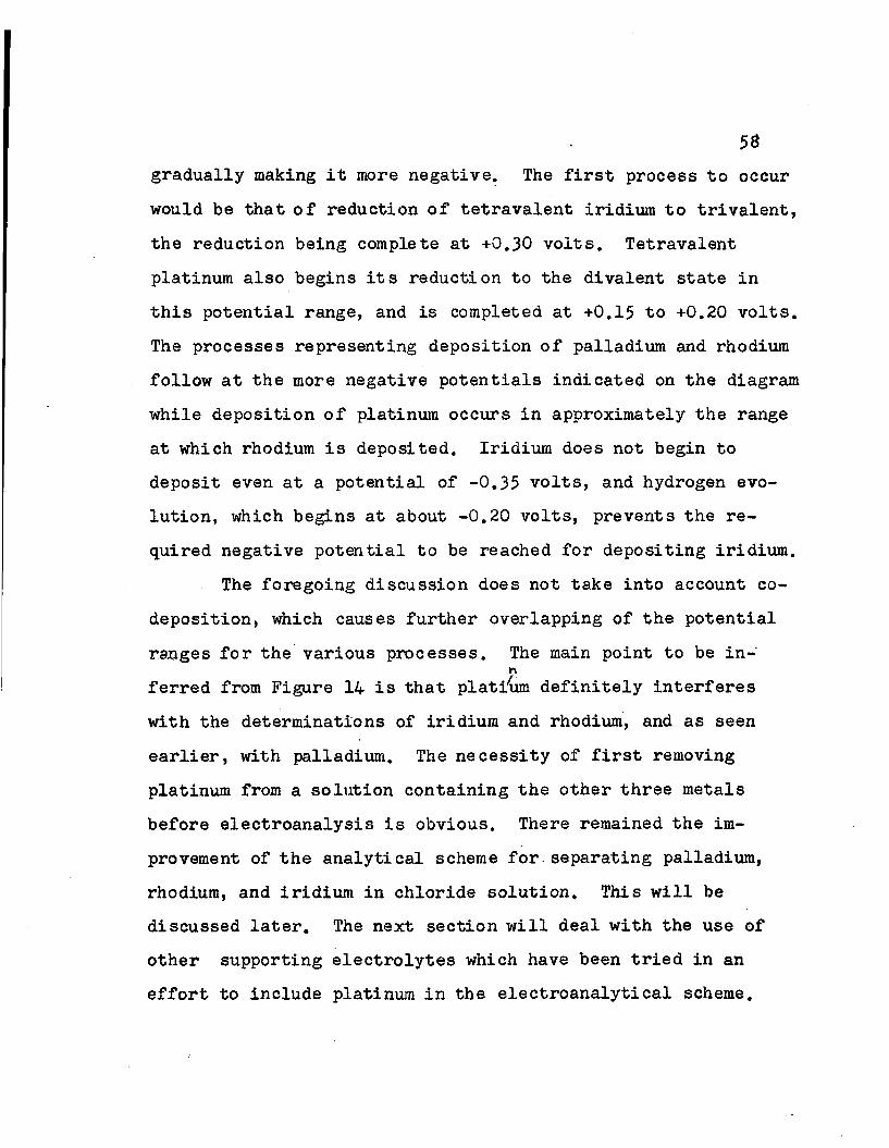
5*gradually making it more negative. The first process to occur would be that of reduction of tetravalent iridium to trivalent, the reduction being complete at +0.30 volts. Tetravalent platinum also begins its reduction to the divalent state in this potential range, and is completed at +0.15 to +0.20 volts. The processes representing deposition of palladium and rhodium follow at the more negative potentials indicated on the diagram while deposition of platinum occurs in approximately the range at which rhodium is deposited. Iridium does not begin to deposit even at a potential of -0.35 volts, and hydrogen evolution, which begins at about -0.20 volts, prevents the required negative potential to be reached for depositing iridium.
The foregoing discussion does not take into account codeposition, which causes further overlapping of the potential ranges for the various processes. The main point to be in-
r \
ferred from Figure 14 is that platiW definitely interferes with the determinations of iridium and rhodium, and as seen earlier, with palladium. The necessity of first removing platinum from a solution containing the other three metals before electroanalysis is obvious. There remained the improvement of the analytical scheme for separating palladium, rhodium, and iridium in chloride solution. This will be discussed later. The next section will deal with the use of other supporting electrolytes which have been tried in an effort to include platinum in the electroanalytical scheme.

59The Use of Perchlorate and Sulfate as Supporting Electrolytes
Chloride ion is a relatively strong complexing anion for the platinum metals. It was shown above that rhodium will deposit from solutions containing excess chloride at approximately the same potential that hydrogen is evolved. If electrolytes containing stronger complexing ions such as nitrite, oxalate, or cyanide are used, deposition of rhodium would be made very difficult. Thus, Willis (41) showed that no wave for deposition of rhodium could be obtained in 1.0 M solutions of these electrolytes, using a dropping-mercury cathode. An electroanalytical scheme for the four platinum metals employing one of these electrolytes would be complicated by the fact that after removal of platinum and palladium the supporting electrolyte would have to be destroyed before an electrolytic determination could be made. This additional operation represents one disadvantage of using complexing agents stronger than chloride ions as a supporting electrolyte. Several current-potential curves were run for mixtures of palladium and platinum chlorides in 1.0 M solutions of oxalic acid, sodium nitrite, and sodium cyanide. These showed strong codeposition of palladium with platinum just as was observed with chloride as suppprting electrolyte. The use of these electrolytes was, therefore, abandoned.
When disodium phosphate, sodium sulfate or sodium perchlorate, or the respective acids, are added to solutions of platinum-metal chlorides, the reduction waves for these

60elements on the current-potential diagrams are shifted to more positive potentials. This indicates that these anions are weaker complexing agents than is chloride. Tuthill (loc.cit) showed that rhodium and iridium cannot be separated in a solution containing about 0,2 M phosphate. Current- potential curves for palladium and platinum chlorides in 1.0 M phosphoric acid also shows strong co-deposition of these two metals.
Similarly, when solutions of the platinum-metal chlorides in various concentrations of sulfuric acid or perchloric acid were investigated, it was found that the reduction wave for platinum over-lapped those of palladium and rhodium. It was thought that entirely different results jaight be obtained if all traces of chloride were removed from the perchlorate or sulfate solution. The perchlorates were obtained by evaporating a solution of the platinum-metal chlorides with a few milliliters of nitric and perchloric acids to fumes of perchloric acid. This was followed by about three additional evaporations to fumes with perchloric acid, after which the residue was free of chloride. Some difficulty was encountered with platinum, for if more than a few milligrams of platinic chloride were used a brown precipitate formed, which did not redissolve. Current-potential curves for these solutions in 1.0 M perchloric acid gave very indistinct waves and the wave for platinum again over-lapped those of palladium and rhodium.

Sulfate solutions free of chloride are quite easily prepared when proper precautions are taken. A cold solution of the platium-metal chlorides is slowly poured, with stirring, into a cold solution of twenty milliliters of sulfuric acid and ten milliliters of water. This is done, instead of pouring the acid into the chloride solution, in order to prevent the formation of a precipitate, probably a basic sulfate, by having a large excess of sulfuric acid present at all times. The mixture is heated on the steam plate until most of the water has evaporated, then carefully heated over a flame. The heating is continued with strong evolution of sulfur trioxide fumes until the volume is reduced to about ten milliliters. This single fuming is sufficient to remove all traces of chloride. The solution is then diluted to 175 milliliters with water, making it 1.0 M in sulfuric acid.Other reagents were added in order to vary the nature of the supporting electrolyte.
When the chlorides were converted into sulfates, the colors of their solutions usually changed. The solution containing rhodium changed from rose to bright yellow, palladium from brown to yellow, platinum remained brown, and iridium changed from dark brown to green. The color change of iridium is significant in that it probably represents a change in valence of the iridium. This is supported by evidence fromcurrent-potential data which will be discussed below.
-3Current-potential curves were obtained for 10 M

62solutions of the platinum-metal sulfates in 1.0 M HgSO^,2.0 M H2S04, 1.0 M H2S04 with 2.0 M Na2S04, 1.0 M H2S04 with 2.0 M HC104, and 4.0 M HgSO4 at 60° C. Some difficulty was encountered in getting reproducible data with these solutions, until it was found that proper treatment of the platinum microelectrode between runs included ignition of the electrode in a flame. This ignition was unnecessary when solutions containing chloride were studied.
Of the various sulfate electrolytes studied, the one giving best results contained 1.0 M sulfuric acid plus 2.0 M sodium sulfate. The current-potential curves obtained with this electrolyte are shown in Figure 15. As can be seen in the figure, the curve representing iridium is the same as that of the blank (supporting electrolyte). The fact that no reduction wave is obtained for iridium at potentials more positive than that at which hydrogen is liberated seems to indicate that iridium was in the trivalent state. A search of the literature disclosed that sulfate compounds containing trivalent iridium are usually green in color. Thus, L. Marino (26) reported a green cesium iridium alum, Ir^SO^^* Cs2S04* 24H20. Regardless of the valence state which iridium might have in this sulfate solution, it is seen that a coulometric determination of iridium is not possible. An attempt to deposit iridium from 1.0 M sulfuric acid plus 2.0 M sodium sulfate at 60° C and a cathode potential of -0.30 volts resulted in a gain in weight of the cathode of only 0.07

Cur
rent
, m
icro
ampe
res
63
Current - Voltage Curves for Pt, Pd, Rh, and I r - Sulfates in H2S04 - Na2S04 Solution
30
20
Rh
Blank
+0.5 +0.4 +0.3 0.0 - 0.1 -0.2Potential, volts vs. saturated calomel electrode
FIGURE 15

64milligrams, while hydrogen was evolved at a rapid rate.
In the same supporting electrolyte rhodium was deposited at a potential slightly more positive than that at which hydrogen is evolved. Palladium and platinum show rather indistinct waves, both starting at about +0.55 volts. Current-potential curves for mixtures of the various metals were even more indistinct, and it was decided to carry out actual electrolyses to determine whether separations were possible. The two-compartment cell was used with 1.0 M sulfuric acid and 2.0 M sodium sulfate as anolyte. The results are shown in Table VI. It was first desired to electro- lyze platinum at a relatively positive potential in order to determine whether it can be reduced from the tetravalent to divalent state at 100 percent current efficiency. However,
TABLE VI
Electrolysis of Pt-metal Sulfates in H2S0^ + Na2S0^ at 60°C
Run No. Cathode Gravimetric Results Coulometric Results Potential taken, mg. found, mg. found, mg.current
eff., %2*161 0.100 93.7 Pt 73.412*162 -0.200 34.0 Rh 2S.95 31.6 91.62.1S5 0.100
-0.250 53.34 Pd 34.20 Rh 43.30 Ir
53.1733.7055.6 36.3
95.2SB.O
2»1#7 0.100-0.290 56.04 Pd
33.45 Rh 43.30 Ir56.3432.10 59.5 94.7

very little current was obtained until a cathode potential of +0.10 volts was reached. At this potential forty milli- . amperes of current passed at first, then dropped to nearly zero. The cathode was found to increase in weight considerably as indicated by run 2*l8l. At this potential of +0.10 volts palladium also deposited (run 2»1&5) so that an electrolytic separation of these two elements is seen to be impossible in the supporting electrolyte under consideration.Run 2«1$2 shows that rhodium is incompletely deposited at -0.20 volts, but it is more nearly complete at -0.25 to -0.29 volts as indicated by runs 2*185 and 2.187. At these more negative potentials, however, hydrogen is evolved causing precipitation of some rhodium on the porous cup, just as was observed earlier with chloride solutions. It is concluded that the sulfate electrolyte is not useful for electrolytic separations of the platinum metals.
The Use of Supporting Electrolytes Containing EthylenediamineTetraacetic Acid
As an application of chelating agent for improving separations of the platinum metals, disodium versenate (disodium salt of ethylenediamine tetraacetic acid) was used. 0. Krieg (19) found from spectrophotometric studies that palladium (II) and iridium (IV) form versenate complexes when disodium versenate is added to solutions containing the chlorides of these metals. Under the same conditions rhodium (III) and platinum (IV) showed no evidence of complex forma-

66tion. To test the use of this chelating agent the behaviorsof palladium and platinum were first studied.
Current-potential curves were obtained for 10"^ molar solutions of palladium and platinum in 0.3 M sodium chloride with and without addition of disodium versenate. These are shown in Figure 16. Comparing the curves for palladium in sodium chloride alone and in sodium chloride with addition of 0.05 M disodium versenate it is seen that the reduction wave for palladium was shifted by about 0.6 volts in the negative direction when versenate was present. On the other hand, the reduction wave for platinum is shifted by only about 0.1 to0.2 volts to the negative side on addition of versenate. Thecurve representing palladium plus platinum is very different from that representing platinum alone, showing that little or no co-deposition took place.
Electrolyses were carried out to test whether a separation of platinum and palladium is possible using versenate. The two-compartment cell was used with 1.0 M sodium sulfate as anolyte. The results obtained are shown in Table VII. In run number 2*224 a solution containing only platinum was electrolyzed. The cathode potential was set at 0.00 volts where upon a current of about forty milliamperes was obtained at first, then gradually it decreased to eight milliamperes. When the cathode potential was made -0.20 volts there was no increase in current. Since the cathode gained very little weight the reduction process undoubtedly represented a change

Cu
rren
t,
mic
roa
mp
ere
s
e 7
75
5 0
25
+0.2 0.0 -0.1 - 0.2 -0.3Potential, volts vs. saturated calomel e lectrode
Current - Voltage Curves in Versenate Solut ion1. P la t in ic chloride in NaCI2. Palladium chloride + platinic chloride in NaCI +
Na versenate3. P l a t i n i c chloride in NaCI +- Na versenate4. Palladium chloride in NaCI5. Palladium chloride in NaCI + Na versenate
FIGURE 16

TABLE VII
Electrolysis of Pd and Pt in 0.05 M Sodium Versenate plus 0.3 M Sodium Chloride at 60° C
Run No. Cathode Gravimetric Results Coulometric Results^ Potential takenj. nig. found, mg. found, mg. current
SjtsJLjk
2*224 -0.200 44.04 Pt 0.73 55.1 60.02*227 0.00 44.04 Pt 0.91 56.2 7$.5
44.47 Pd
of tetravalent platinum to divalent. Based upon this two- electron reduction the amount of platinum in solution was calculated to be.55.1 milligrams. This represents a current efficiency of only 60.0 per cent, so that some reduction of versenate may have also taken place. Run 2.227 was made with a solution containing both palladium and platinum. The cathode potential was set at 0.0 volts. In this run the results for platinum are seen to be nearly the same as when platinum was used alone.
A coulometric determination of platinum in the presence of palladium might prove feasible in this electrolyte if corrections were made for residual current. However, if a solution containing all four platinum metals under consideration were electrolyzed, the reduction of platinum to the divalent state would still leave all the metals in solution. The problem would then remain of making further separations.
, ^Coulometric results based on two electron process,Pt4+ + 2e - Pt2+.

69Current-potential data showed a rather indistinct and irre- producible wave for rhodium at approximately the same potential shown by palladium in sodium chloride-sodium versenate solution. It was desired to test whether a separation of palladium and rhodium was possible in this electrolyte. Using the two- compartment cell with 1.0 M sodium sulfate as anolyte 44.47 milligrams of palladium and 39.44 milligrams of rhodium (as chlorides) were electrolyzed at -0.200 volts. About thirty milliamperes of current were passed and a black deposit started to form on the cathode. After thirty minutes the electrolysis was stopped. The deposit was then examined and found to contain both palladium and rhodium.
The few experiments described above indicate that an electrolyte containing ethylenediamine tetraacetic acid does not improve the analytical scheme for the four platinum metals being studied.
Electrolyses in a Single-Compartment Cell. The Use of AnodicDepolarizers.
All electrolyses carried out up to this point were made in a two-compartment cell in order to separate the cathodic and anodic reactions. These anodic reactions may be evolution of chlorine and dissolution of the platinum anode when chloride solutions are used, or oxidation of platinum-metal ions to higher valence states when other solutions are used. All of these anodic reaction products interfere with the cathodic reductions. Instead of separa-
70ting the anode from cathode by using a two-compartment cell, one can carry out the electrolyses in a single-compartment cell by using an anodic depolarizer which prevents the above- mentioned anodic reactions from taking place. Thus, Tuthill (loc.cit.) used hydroxylamine hydrochloride as a depolarizer in separating rhodium and iridium in chloride solution.
A critical discussion on the use of depolarizers was given by Lingane (25). Of the two anodic depolarizers commonly used, hydrazine dihydrochloride and hydroxylamine hydrochloride, Lingane states that the former gives better results. Whereas hydroxylamine oxidizes at the anode to give nitric oxide, nitrous acid, and other products which might be harmful toward cathodic reactions, hydrazine gives only nitrogen as an oxidation product. Tuthill (loc.cit.) showed that in using hydroxylamine hydrochloride for deposition of rhodium some rhodium oxides were formed in the deposit. It was thought that the oxidation products of this depolarizer may have contributed to the formation of this oxide and that it might, therefore, be profitable to study the use of both these depolarizers.
Since anodic depolarizers must be relatively active reducing agents their chemical action on the platinum metals must be borne in mind. For example, the color of a solution containing iridium (IV) in 1.0 M hydrochloric acid plus 3.0 M sodium chloride is changed from dark brown to yellow on addition of hydrazine dihydrochloride or hydroxylamine hydro-

chloride. This indicates a reduction of tetravalent to trivalent iridium. Under the same conditions tetravalent platinum changes partially to divalent. These reductions are more rapid with hydrazine than with hydroxylamine and more rapid on warming the solution than at room temperature.No change is observed when these depolarizers are added to strong chloride solutions of palladium or rhodium, even when heated. But in solutions containing less chloride palladium gives first a yellow-brown precipitate which later turns gray. This probably represents reduction of palladium to the metallic state. In neutral 0.1 M sodium chloride solution the precipitation of palladium is complete. Solutions containing the platinum metals with excess of an ion which is a weaker complexing agent than chloride are even more reactive. Thus, addition of hydrazine sulfate to warm solutions (/^40o C) of palladium sulfate in 1.0 M sulfuric acid causes immediate precipitation of palladium. With the same kind of solution platinum is slowly precipitated at the boiling temperature, while rhodium (III) and iridium (III) solutions show no change. That platinum can be precipitated quantitatively with hydrazine sulfate was shown by Christensen (2).
Current-potential curves were carried out at 60° C for 10“ M solutions of platinum (IV), palladium (II), rhodium (III), and iridium (IV) in 1.0 M hydrochloric acid plus 3.0 M sodium chloride. In one series of runs 2.5 percent hydroxylamine hydrochloride was added, and the curves obtained are
72shown in Figure 17. A second series of runs employed 2.5 percent hydrazine dihydrochloride and the curves obtained are shown in Figure IS. The results with the former depolarizer will be discussed first.
The effect of addition of hydroxylamine hydrochloride can be seen by comparing the curves of Figure 17 with those of Figures 11 and 12. The reduction wave for.the process irIV Seen in Figure 12 is missing in Figure 17. Thishappens because tetravalent iridium is reduced to trivalent upon addition of hydroxylamine hydrochloride. The reduction waves for rhodium and palladium are shifted to more positive potentials by 0.05 to 0.10 volts upon addition of depolarizer. A separate reduction wave for palladium is obtained when rhodium and iridium are present with palladium as seen by the curves for Pd + Rh and Pd + Rh + Ir. This shows that separations of palladium from rhodium and iridium are possible. Similarly, the curves for Rh and Rh + Ir show that little or no co-deposition of iridium occurs with rhodium. Comparing Figures 11 and 17 again, it is seen that the height of the wave representing reduction of platinum is decreased slightly on addition of hydroxylamine. This indicates some reduction of tetravalent platinum to divalent by the depolarizer.Strong co-deposition of platinum with palladium is again shown here.
These current-potential curves in chloride solution with addition of hydroxylamine hydrochloride show that separ-

Cu
rre
nt,
m
icro
am
pe
res
73
C u r r e n t - V o l ta g e C u r v e s fo r Pt, I r ,
P d , Rh in HCI - N aC I S o l u t i o n +
H y d r o x y l a m i n e
'+Rh
7 5 Rh
Ir+Pd+Rh,
Pt+Pd;
Blank
+ Q 3 ♦0.2 +0.1 0.0 - 0.1 -0.2Potential, volts vs. s a tu ra te d calomel e le c t r o d e
FIGURE 17

Cu
rre
nt,
m
icro
am
pe
res
74
C u r r e n t - V o l t a g e C u r v e s f o r P t , I r
P d , R h in H C I - N a C I S o l u t i o n •+
H y d r a z i n e
75
I r + R h + Pd
R h + Pd —
50
BlankPd
25
Rhj
0
+0.3 +0.2 . +0.1 0.0 -0.1 -0.2P o t e n t i a l , volts vs. s a t u r a t e d calomel e lectrode
FIGURE 18

ations involving palladium, rhodium, and iridium are possible. The presence of platinum would interfere with a determination of palladium. Before these observations were confirmed by electrolysis experiments, it was decided to study similar current-potential data obtained by adding 2.5 percent hydrazine dihydrochloride to the electrolyte in place of hydroxylamine hydrochloride. The curves representing these data are shown in Figure IB, It is seen that the curve for the blank electrolyte (i.e., containing no platinum-metal ions) has an anodic wave starting at +0.10 volts and going to more positive potentials. The significance of this wave may be that ionic species which show reduction potentials more positive than +0.10 volts do not exist in the solution containing hydrazine. Thus, tetravalent iridium and tetravalent platinum are reduced to the trivalent and divalent states, respectively, when hydrazine is added to the solution. This is shown in the case of iridium by the absence of a reduction wave for the processIr^-+Ir^^. The curve for platinum shows only a small wave
IV IIfor the process Pt — >Pt , which indicates that little, if any, tetravalent platinum exists in the solution. Palladium is reduced at about the same potential at which the anodic wave for oxidation of hydrazine occurs, so that no change is seen for the palladium wave. Also, the wave for reduction of rhodium is the same when either hydroxylamine or hydrazine are used as depolarizers.
The curves for Eh + Pd and Rh + Pd + Ir show that there

is less interference by rhodium and iridium in deposition of palladium when hydrazine is present than when hydroxylamine is present. Therefore, it seems that a better separation of these three elements could be accomplished when the former depolarizer is used.
The curve for platinum represented in Figure 18 actually changes with time. When a fresh solution is heated to60° C, out-gassed with nitrogen for fifteen minutes and the
ocurrent-potential data taken at 60 C, a curve is obtainedhaving a slightly higher wave starting at +0.20 volts thanis presented in the figure. After heating the solution onthe steam plate (60° - 80° C) for thirty minutes or boilingit for five minutes the curve shown in the figure is obtained.The reason for this behavior is that reduction of tetravalentplatinum by hydrazine is relatively slow. In all cases thecurves for palladium plus platinum showed strong co-depositionof these two elements.
The first series of electrolytic runs made use ofhydrazine dihydrochloride as a depolarizer. Palladium wasdeposited on a platinum gauze cathode, washed with water and
odried at 110 C before weighing. Rhodium was also plated on a platinum gauze electrode but there remained a question of treating the rhodium deposit before weighing. Tuthill (loc. cit.) recommended heating it in hydrogen at 450° C in order to reduce any rhodium oxide that may have formed. Grube and Resting (loc. cit.) showed that dark electrodeposits of

77rhodium can be made white by igniting them in a flame. It is known (22) that the most stable oxide of rhodium, RhgO^, is unstable above 1150° C. Since this temperature can be attained with the flame of a Meker burner, it was decided to ignite some rhodium deposits in this way in order to save time in the determination of rhodium. A preliminary study showed that a rhodium-plated platinum cathode lost almost no weight (0.01 mg.) when heated at the full flame of a Meker burner for one minute. Deposits containing platinum were dried by heating in a low flame before weighing.
Table VIII shows some data obtained for palladium and platinum, using a one-compartment cell with hydrazine dihydrochloride as depolarizer. Fairly good results were found for
TABLE VIII
Deposition of Platinum and Palladium from 1.0 M HC1 + 3.0 M NaCl + 2.5# N2H4* 2HC1 at 60° C
Run No. Cathode Gravimetric Results Coulometric Results Potential taken, mg. found, mg. found, mg. current
ett.,2*193 0.050 44.51 Pd 44.13 45.9 96.32*206 -0.175 44.07 Pt 44.03 147.5 29.92*207 0.050 44.51
44.07PdPt
54.2333.91
2*214 0.050-0.190 44.51
44.07PdPt
49.3233.29
both metals when they were electrolyzed alone. However, when

mixtures were electrolyzed there was obtained strong codeposition of platinum with the palladium. In run number 2*207 the solution was merely heated to 60° C and electrolyzed, while in run number 2*214 it was boiled for ten minutes prior to electrolysis in order that the hydrazine reduce all tetravalent platinum to the divalent state. The amount of codeposition of platinum in the latter case, while less than in the former, was still quite great. Further attempts to separate platinum electrolytically from palladium or platinum from the other metals was abandoned.
It was next decided to attempt a separation of palladium, rhodium, and iridium. Data for several runs using hydrazine as depolarizer are shown in Table IX. It is seen that results for palladium tend to run high while those for rhodium were always low. It was thought that the palladium deposit might have contained some oxide, which would account for the high results. The rhodium deposits were brown and were ignited in the full flame of a Meker burner. This operation resulted in giving a white plate of rhodium, but some white smoke was given off and the results were found to be low. The nature of this volatile brown material was not known, but it was decided to reduce deposits in hydrogen at 450° C to see whether better results might be obtained.
A run was made using 19.5^ milligrams of rhodium (as RhCl^), 1.0 M hydrochloric acid, 3.0 M sodium chloride, 1 percent sodium sulfate (to aid in depositing the rhodium) and

79TABLE IX
Electrolysis of Pd, Rh and Ir in 1.0 M HC1 + 3.0 M NaCl + 5 g. N2H4- 2 HC1/175 ml. at 60° C
Run No. Cathode ■ Gravimetric Results Coulometric Results Potential taken, mgT found, mg. found, mg. current
2*199 -0.225 v. 39.44 Rh 37.362.201 0.050
-0.22544.5139.44
PdRh 43.3439.52 47.4 92.5
2*233 0.050-0.225 44.47
39.4453.34
PdRhIr
45.1737.23
46.7 96.3
2*240 0.050-0.225
44.4739.4453.34
PdRhIr
44.5239.22 45.7 97.5
2*241 0.050-0.225
44.4739.4453.34
PdRhIr
44.6333.60 47.7 92.3
2*242 0.050-0.225
33.9439.4453.34
PdRhIr
39.6433.50 91.5 93.0
2*244 0.050-0.225
44.4773.3353.34
PdRhIr
44.1976.9346.2 95.7
5.0 grams of hydrazine dihydrochloride. The electrolysis was conducted at 60° C. After the electrode, which became brown in color was heated at 450° C, in hydrogen for thirty minutes the deposit was found to weigh 21.00 milligrams, and it was still brown in color. This is considerably too high a weight. The electrode was then treated in hydrogen at a higher temperature (£00° C) for ten minutes, without any resulting decrease in weight. On igniting the electrode in a Meker flame the deposit became white and weighed 13.54

domilligrams. Therefore the deposit contained a material which is volatile above d00° C and on volatilization it causes loss of rhodium.
A run was made under the same conditions as above, including time of electrolysis and composition of electrolyte, except that no rhodium was added to the solution. A rhodium- plated cathode was used. It was heated in hydrogen at 450° C before and after electrolysis. Although the electrode remained white after electrolysis it was found to contain 4.45 milligrams of deposit, while the anode lost 0.54 milligrams in weight. When the cathode was ignited in a Meker flame some smoke was given off and the cathode lost 3.50 milligrams.
It was next desired to find whether this 4.45 milligrams of deposit was due to metallic impurities in commercial hydrazine dihydrochloride. An experiment was carried out in which five grams of hydrazine dihydrochloride were volatilized from a weighed porcelain curcible over a low flame. A brown stain was left which weighed only 0.13 milligrams. It was concluded that the electrolytic deposit was not due to impurities in the depolarizer.
It was later found that these peculiar electrolytic results were due to impurities in the sodium sulfate added to the electrolyte. This will be discussed later. In the meantime several eleclFolyses were carried out using ammonium chloride as supporting electrolyte instead of sodium chloride. Also both hydrazine and hydroxylamine were tried as depolar
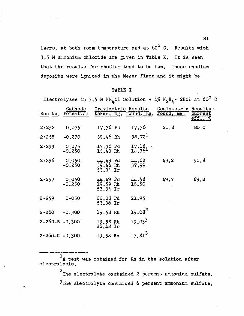
izers, at both room temperature and at 60° C. Results with 3.5 M ammonium chloride are given in Table X. It is seen that the results for rhodium tend to be low. These rhodium deposits were ignited in the Meker flame and it might be
TABLE XElectrolyses in 3.5 M NH^Cl Solution + 2HC1 at 60°
Cathode Gravimetric Results Coulometric ResultsRun No. Potential taken, mg. found, mg. found, mg. current
e'ff. V'%2.252 0.075 17.36 Pd 17.36 21.a ao.o2«25S -0.270 39.46 Rh 36.7212-253 0.075-0.250
17.36 Pd 15.40 Rh
17.16- 14.761
2*256 0.050-0.250 44.49 Pd 39.46 Rh
53.34 Ir44.6237.99
49.2 90.a
2-257 0.050-0.250 44.49 Pd
19.59 Rh 53.34 Ir
44.5616.50 49.7 a9.a
2-259 0-050 22.03 Pd 53.36 Ir 21.95
2*260 -0.300 19.5^ Rh 19.oa22.260-B -0.300 19.56 Rh
26.46 Ir19.033
2*260-0 -0.300 19.56 Rh 17.613
^A test was obtained for Rh in the solution after electrolysis,
2The electrolyte contained 2 percent ammonium sulfate. ^The electrolyte contained 6 percent ammonium sulfate.
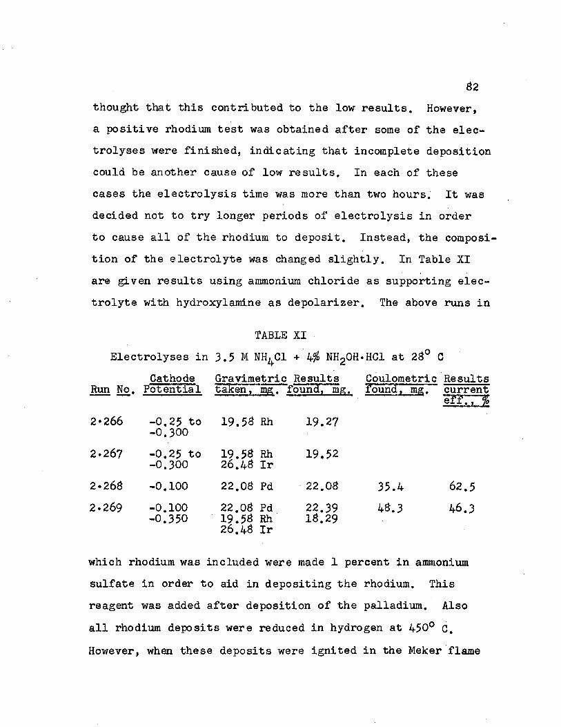
thought that this contributed to the low results. However, a positive rhodium test was obtained after some of the electrolyses were finished, indicating that incomplete deposition could be another cause of low results. In each of these cases the electrolysis time was more than two hours. It was decided not to try longer periods of electrolysis in order to cause all of the rhodium to deposit. Instead, the composition of the electrolyte was changed slightly. In Table XI are given results using ammonium chloride as supporting electrolyte with hydroxylamine as depolarizer. The above runs in
TABLE XIElectrolyses in 3.5 M NH^Cl + b$ nh2oh •HC1 at 26° C
Cathode Gravimetric Results Coulometric ResultsRun No. Potential taken, mg. found, mg. found, mg. current
sfr:r%2*266 -0.25 to
-0.30019.56 Rh 19.27
2*267 -0.25 to -0.30019.56 Rh 26.46 Ir
19.52
2*266 -0.100 22.06 Pd 22.06 35.4 62.52*269 -0.100
-0.35022.06 Pd 19.56 Rh 26.46 Ir
22.3916.29 46.3 46.3
which rhodium was included were made 1 percent in ammonium sulfate in order to aid in depositing the rhodium. This reagent was added after deposition of the palladium. Also all rhodium deposits were reduced in hydrogen at 450° c. However, when these deposits were ignited in the Meker flame

after reduction in hydrogen no decrease in weight was noted.It is seen in Table XI that results obtained for palladium and rhodium are fairly good. The one mixture containing these metals with iridium shows a slightly high result for palladium and low for rhodium. The results in Tables X and XI show that ammonium chloride is a good supporting electrolyte for the separation of palladium and rhodium. This electrolyte was used by Tuthill (loc. cit.) for the separation of rhodium and iridium. The results for rhodium in the presence of iridium were found to be good. The objection to using this electrolyte still remained, namely, that iridium was left in ammonium chloride solution. Attempts to determine the iridium coulometrieally in such a solution would lead to difficulties since ammonium chloroiridate is relatively insoluble.
A new study was made of the use of sodium chloride- hydrochloric acid as supporting electrolyte. In this study two changes were made in the composition of the supporting electrolyte. First, it was thought that a relatively large amount of hydrochloric acid is introduced when hydrazine dihydrochloride is added. Therefore, the amount of pure hydrochloric acid added at the start was reduced to such an amount as to make the solution 0.5 M in hydrochloric acid before adding the hydrazine dihydrochloride. Second, it was thought that the sodium sulfate used to aid in deposition of the rhodium previously (cf. Table IX) may have contained

84impurities which was responsible for the formation of a volatile deposit on the electrode. Therefore in subsequent runs ammonium sulfate was substituted for the sodium sulfate. Results obtained for rhodium and palladium are shown in Table XII. The content of hydrazine dihydrochloride in runs
TABLE XIIElectrolyses in 0.5 M HC1 + 3.
(n h4 )2so40 M NaCl + / 175 ml.
N2H4 * 2HC1 + 2g.
Run No. 2*285
CathodePotential-0.25 to -0.275
Gravimetric Results taken, mg. found, mg.19.62 Rh 19.50
19.37
Coul©metric found, mg.
Resultscurrentwrivr
2*286 -0.25 to -0.275
19.62 Rh 19.6919.662*286-B -0.25 to
-0.27519.62 Rh 20.01
19.812*287 -0.25 to
-0.27519.60 Rh 19.72
19.572«287-B -0.25 to
-0.27539.47 Rh 39.29.
2*288 -0.25 to -0.275
39.62 Rh 53.35 Ir
40.14
2*289 -0.25 to -0.275
19.60 Rh 53.35 Ir
19.57
2*290 0.050 22.10 Pd 22.07 24.65 89.62*291 0.050
-0.25 to -0.275
22.08 Pd 19.58 Rh
22.1819.46 24. SI 89.3
2*285 to 2*289 was 3 percent by weight, and for runs 2*290 and 2*291 was 5 percent by weight. There were no significant

differences in results for rhodium when these quantities were thus changed. Two gravimetric results are listed for rhodium in runs 2*2$5 to 2*2#7. The first result for each of these runs was obtained by weighing the deposit after reducing it in hydrogen at 450° C. The second result was obtained after igniting the electrode in the flame of a Meker burner. It is seen that the results are nearer the true value when the electrode is ignited than when it is reduced in hydrogen. Therefore all rhodium deposits obtained in subsequent runs were ignited. This was done by grasping the handle of the electrode with a pair of tongs and rotating the electrode in the hottest flame obtainable with the Meker burner for about one-half a minute. The electrode was allowed to cool for a few seconds, then passed through the flame momentarily once or twice. In this way the deposit becomes bright, and the gravimetric results are found to be near the correct value.
Tuthill (loc.cit.) found that rhodium is best separated from iridium by depositing the rhodium with stepwise increase in the cathode potential. In the present work the cathode potential was increased from -0.250 volts at the start of the electrolysis to about -0.260 volts after twenty minutes, and then to -0.275 volts after an additional twenty minutes.This was done for the experiments in Table XII as well as in all subsequent runs. The large amount of gas liberated when rhodium is deposited necessitates the use of a split watch glass to prevent loss of solution by spray. This gas which

S6is evolved includes nitrogen at the anode and hydrogen at the cathode.
The palladium deposits were dried at 110° C and were white in color. As seen in Table XII the results obtained are satisfactory. Comparing these results with those of Table IX in which 1.0 M hydrochloric acid was used instead of 0.5 M, it is observed that high acidity contributes to high results for palladium.
Determination of IridiumAfter palladium and rhodium have been deposited from
a solution containing palladium, rhodium, and iridium by the method described above, the remaining solution contains iridium in the trivalent state. It was desired to determine the iridium by a coulometric procedure. In order to carry out this coulometric determination it was necessary to destroy the excess hydrazine which was present in solution. Several methods were available for this purpose; hydrazine may be oxidized by adding sodium bromate or hydrogen peroxide to the boiling, acidic solution, by passing chlorine into the solution at about 50° C, or by electrolyzing the solution. In the latter case if the solution is electrolyzed using two platinum electrodes then as long as hydrazine is present it is oxidized to nitrogen at the amode and hydrogen is liberated at the cathode. When all the hydrazine has been oxidized the next process which occurs at the anode is that of oxidation of trivalent iridium to tetravalent, and at the cathode

37the tetravalent iridium is reduced back to trivalent. Thus a cyclic oxidation-reduction reaction is set up. The solution then assumes a brown color due to the tetravalent iridium ion, indicating that all of the hydrazine has been destroyed. Destruction. of hydrazine by sodium bromate, chlorine, or hydrogen peroxide probably also proceeds by oxidation of the hydrazine to free nitrogen.
The solution resulting after removal of hydrazine by any of the methods described above contains iridium in the tetravalent state. Also some free halogen, either bromine or chlorine, remains in excess. This excess halogen must be removed before iridium can be determined, and this is most easily done by evaporating the solution to dryness. After evaporation the residue may be dissolved in water and diluted to 175 milliliters. It is then ready for electrolysis.
Several runs were carried out in which the hydrazine was decomposed by passing chlorine through the warm (50° C) solution. The reaction was shown to be complete when the solution became dark brown in color, which was due to tetravalent iridium. The solution was evaporated to dryness. After dissolving the residue the solution obtained was electrolyzed using the two-compartment cell with the solution as catholyte and 1:4 sulfuric acid as anolyte. It was shown earlier that reduction of tetravalent iridium to the tri valent state is complete at a cathode potential of +0.30 volts vs. the saturated calomel electrode. When the electrolysis was performed

at this potential the coulometric results were always found to be low by as much as ten to fifteen percent. It was thought that this was due to the fact that some trivalent iridium was formed during evaporation of the solution. Therefore, it was attempted to first reduce all tetravalent iridium to trivalent at +0.30 volts, and then to determine iridium coulometrically by oxidation to the tetravalent state. This oxidation was easily done by reversing the polarity of the electrodes and making the anode potential +1.10 volts vs. the saturated calomel electrode. The coulometric results obtained by this method were also found to be low, but somewhat near the correct value for iridium. In three runs using 26.46 milligrams of iridium the following values were found: 24.30,2$.52, and 19.15 milligrams. When the other reagents mentioned above were used in place of chlorine for oxidation of hydrazine the results were found to be even less accurate.
The reason that low results were obtained for iridium using this procedure may have been due to interference by ions containing chlorine in various oxidation states. Latimer (21) states that chlorine is stable in acid solution with respect to disproportionation, but that the reaction does go to a measurable equilibrium. This is shown by the following equation:
+ -4Cl2 + H2Q = H + Cl + HC10 K- 4.66 x 10Hypochlorous acid is highly unstable with respect to dis- pro portionation:

3CIO" - C103 + 2Cl‘ AF° o -36 kcalChlorous acid may be formed in solution as an oxidation product of hypochlorous acid, and it is also unstable with respect to disproportionation:
HC10 + H20 - HC102+ 2H++ 2e E° = -1.64 v.3C102“ = 2C103” + Cl“
It is easily seen that when chlorine is used to oxidize hydrazine in the determination of iridium some hypochlorite, chlorite and chlorate are formed as by-products. These substances probably do not reduce readily at the cathode but may interfere with the determination of iridium by slowly reducing tetravalent iridium or by oxidizing trivalent iridium. This would tend to cause low results as was shown above.
Since iridium could not be determined satisfactorily using the coulometric procedure it was decided to carry out the determination by precipitation of the hydrated dioxide and reduction to the metal in an atmosphere of hydrogen.This method was described by Gilchrist and Wichers (loc.cit). Results for determinations using this method will be described in the following section.
Determination of Palladium, Rhodium and IridiumThe method described previously for the electrolytic
separation of palladium, rhodium and iridium was tested using various ratios of these elements. The electrolyte was0.5 M hydrochloric acid and 3.0 M sodium chloride with B.O

90grams hydrazine dihydrochloride being added per 175 milliliters of solution. Palladium was first deposited at a cathode potential of 0.050 volts and then rhodium at -0.250 to -0.275 volts vs. the saturated calomel electrode. The temperature of the electrolyte was kept at 60° C. The results are shown in Table XIII. In the determination of rhodium for runs 3*9 to 3*12, two grams of ammonium sulfate were added after
TABLE XIIIElectrolytic Separations with Various Amounts of Palladium,
Rhodium and IridiumPalladium Rhodium Iridium
Run No. Taken,mg.
found,mg.
taken,mg*.
found,mg-t.
taken,mg*
foundmg.
3*9 B.69 B.B9 39.45 3S.B6 0.00 mm
3.9-B 44.47 44.35 7.70 7.B9 0.00 -3*10 22.0B 22.15 0.00 0.14 26.4S -3*11 22.0B 21. B6 19.5B 19.59 26.4B -3*12 B.70 B.79 19.5S 19.51 26.4B -3*15 44.47 44.21 7.70 S.15 53.34 53.603*16 B.6B B.61 39.44 39.16 26.4B 26.913•16-B B9.04 BB.97 7.71 7.91 10.41 10.513*17 B.69 B.69 7B.93 7S.75 106.B4 (lost)
deposition of palladium in order to aid in the deposition of rhodium. Iridium hydroxide is known to be incompletely precipitated from solutions containing ammonium salts since in alkaline solution iridium ammines are formed. Therefore,

91in runs no. 3*15 to 3*17 no ammonium sulfate was added to the solution. As can be seen in the table the results for rhodium were not affected greatly, although a slightly longer time was required for the complete deposition of rhodium than when ammonium sulfate was added. In these, latter cases iridium was determined by the usual precipitation of the hydrated dioxide and reduction of the metal as described by Gilchrist and Wichers (loc.citj.
The time required for deposition of palladium was approximately one hour, and this time was independent of the amount of palladium used. With rhodium, however, the time varied from about one hour for run no. 3»9-B (7.70 mg. Rh) to over four hours for run no. 3*17 (78.93 mg. Rh). This method for determining rhodium, therefore, is best applicable to samples containing less than about seventy milligrams of rhodium. The results for palladium and rhodium are seen to agree satisfactorily with the actual values. When rhodium is present in small amounts the results tend to be slightly high. The gravimetric results for iridium are also found to be high, and this may be due to occlusion of sodium salts by the precipitated iridium hydroxide.
A Scheme of Analysis for the Platinum MetalsIt has thus far been shown that palladium, rhodium
and iridium can be separated by electrolysis in solutions of high chloride content. Platinum interferes with these

92separations so that when it is present it must be separated from these elements by some other means. It was decided to carry out this separation by the Gilchrist-Wichers method of hydrolytically precipitating the hydrated dioxides of palladium, rhodium and iridium. The platinum would then be left in solution alone and could be easily determined.
The determinations of these four elements can be further fitted into the Gilchrist-Wichers scheme of analysis for all six platinum metals. For this discussion reference is made to Figure 1 of this paper. After separation of osmium and ruthenium by distillation of their respective te- troxides the solution remaining contains sodium bromate, sulfuric acid, and sodium sulfate, besides the chlorides of platinum, palladium, rhodium, and iridium. Platinum can be separated from the other three elements by destroying the bromate by evaporation of the solution with hydrochloric acid and then precipitating the hydrated dioxides of palladium, rhodium, and iridium. Filtration of this mixture would yield a filtrate containing sodium chloride, sodium sulfate, sodium bromate and sodium chloroplatinate.
Here a-deviation from the Gilchrist-Wichers scheme can be made to advantage by employing an electrochemical method for the determination of platinum. The solution can be acidified with hydrochloric acid, evaporated to about 150 milliliters, and a concentrated solution of hydrazine dihydrochloride added slowly. The first amount of hydrazine added would

93reduce the bromate present while the remainder added in excess acts as an anodic depolarizer for electrolysis.
In order to test this method for determining platinum, a solution was made up, containing 1.0 M sodium chloride with four grams sodium bromate and ten milliliters sulfuric acid and made up to 175 milliliters. The solution was treated with about ten milliliters of hydrochloric acid and heated on the steam bath. A concentrated solution of hydrazine dihydrochloride was added dropwise until there was no more effervescence, and then two grams excess of the reagent were added. The solution was electrolyzed at 60° C and a cathode potential of -0.250 volts using the one-compartment cell.The result was as follows:
taken: 21.90 mg. Pt found; 21.87 mg.The advantage of this electrolytic method for determining platinum over that of precipitation as the sulfide which was adopted by Gilchrist and Wichers is that it is more rapid. Destruction of the bromate by hydrazine eliminates the need for evaporating the solution to dryness, thus saving time in the analysis. Also the time required for actually depositing the platinum is only about one hour. The electrode can be dried over a low flame and weighed after cooling for five minutes. One disadvantage in using the electrolytic method is that a precipitate, possibly of metallic platinum, sometimes forms when the filtrate obtained from precipitation of the hydrated dioxides of palladium, rhodium and iridium is

94heated with hydrochloric acid. This precipitate does not interfere when platinum is subsequently determined by precipitation as the sulfide and ignition to the metal. However, when it is determined by electrodeposition the precipitate must first be filtered off, dissolved in aqua regia, and then added to the main solution to be electrolyzed.
Analysis of the precipitate containing palladium, rhodium and iridium can also be carried out using electrochemical methods as described previously. The precipitate can be dissolved in hydrochloric acid and the solution made up to contain 0.5 M hydrochloric acid, 3.0 M sodium chloride, with addition of eight grams hydrazine dihydrochloride. Palladium is first deposited at a cathode potential of +0.050 volts vs. the saturated calomel electrode and a temperature of 60° C. Rhodium is next deposited at 60° C and a cathode potential of -0.250 to -0.275 volts vs. the saturated calomel electrode. The solution is next treated with chlorine to destroy the excess hydrazine and evaporated to dryness. The residue is then dissolved and the iridium determined by precipitation of the hydrated dioxide and ignition to the metal. An outline of this analytical scheme is shown in Figure 19.One such analysis was carried out to show the applicability of this procedure and the following results were obtained:
taken, mg: 21.33 Pt found, mg: 21.35 Pt22.03 Pd 21.37 Pd19.60 Rh 19.63 Rh26.43 Ir 26,33 Ir
A detailed discussion of the procedure is given in the next

Figure 19 95An Analytical Scheme for Platinum, Palladium,
Rhodium and Iridium
Liquor from Os and Ru determinations (PtCl^, IrCl^, RhCl3, PdCl2, NaBrO^, HgSO^)
Add HC1, evaporate,Add NaBrOo, NaHC03, filter,
Dissolve precipitate, reprecipitate,filter
PtCl^, NaBrO^, NaCl Pd02, RhO, IrO,
Destroy BrOo with HC1 plus excess N0H1/. 2HC1, Electrolyze at 60°C, and -0.250 v. vs.
S.C.E.
PtDry in flame, weigh
Dissolve precipitate in HC1, evaporate with NaCl to dryness. Add HC1,N2H, • 2HC1; Heat to 60° C, Electrolyze at +0.050 v.
vs. S.C.E.
Pd o Dry at 110 C,weigh
RhCl IrCl. 3 3
Electrolyze at 60 C, and -0.250 to -0.275 v. vs.s.c
*RhIgnite, weigh IrC
Destroy excess hydrazine with Cl2, evaporate, Add NaHCO^, NaBrO^, filter
IrO2Ignite in.air, reduce inH2 ’Ir.H2> cool in H^, weigh as

96section.
Procedure for Determining Platinum, Palladium, Rhodium andIridium
A solution is made up containing platinum chloride, palladium chloride, rhodium chloride, iridium chloride, 12.5 grams sodium bromate and ten milliliters concentrated sulfuric acid in about 100 milliliters of solution. This is approximately the composition of a solution that is obtained from the distillation of osmium and ruthenium by the Gilchrist- Wichers method of analysis. The solution is contained in a liter-beaker which is covered with a watch glass. Heat the solution on the steam-bath and add hydrochloric acid dropwise until effervescence stops, then add about ten milliliters excess. Evaporate the solution to a small volume, then make certain that all bromate is decomposed by evaporating again with hydrochloric acid. Dilute the mixture to about 200 milliliters with water.
Platinum is first separated by the method of Gilchrist and Wichers as follows: Heat the solution to boiling, andadd to it twenty milliliters of sodium bromate. Add dropwise a 10 percent solution of sodium bicarbonate until a drop of bromcresol purple (Q.01 percent), when allowed to run down a stirring rod moistened with the solution, changes from yellow to blue. At this stage, add ten milliliters more of bromate and boil the solution for five minutes. Increase the pH of the solution until a faint pink color is produced in the test drop of cresol red indicator (0.01 percent). Again add

97ten milliliters of the bromate reagent and boil for fifteen minutes.
Filter the solution through a porcelain filtering crucible and wash the precipitate with a hot one percent solution of sodium chloride of pH 6 to 7. Transfer the filtering crucible with precipitate to the beaker used for the precipitation and add some hydrochloric acid to dissolve the precipitate. It is usually necessary to add several portions of fresh acid to complete the dissolution. Wash the filtering crucible with water, drawing the wash liquid into a small filter flask. Add these washings to the hydrochloric acid solution in the beaker and evaporate to nearly dryness after adding two grams of sodium chloride. Add two milliliters of hydrochloric acid, dilute the solution to 300 milliliters with water, and repeat the precipitation as above.
Combine the filtrates from both precipitations, acidify with about fifteen milliliters of hydrochloric acid, and. evaporate the solution on the steam-bath to about 150 milliliters. If a dark precipitate has settled out at this stage it must be filtered through a porcelain filtering crucible, dissolved with aqua regia, and the resulting solution added to the main filtrate. Add a concentrated solution of hydrazine dihydrochlori.de dropwise through the opening between the lip of the beaker and a watch glass which is used as a cover, while the beaker is kept on the steam-plate. After effervescence has stopped an amount of hydrazine solution

9Sequivalent to about three grams of the reagent is added in excess. Heat the solution to 60° C and electrolyze using a Fisher cathode and rotating anode. Hold the cathode potential at -0.250 volts vs. the saturated calomel electrode. A current of about 1.0 amperes will flow. A slotted watch glass is used to prevent loss of solution through spraying. The electrolyzing solution remains colorless throughout the electrolysis run, so that completeness of deposition of the platinum must be determined by testing a milliliter of the solution with sulfide reagent as described previously. After electrolysis is completed wash the cathode with distilled water, dry it over a low flame, and weigh. The increase in weight of the cathode represents the amount of platinum in the sample.
Place the filtering crucible containing the hydrated dioxides of palladium, rhodium and iridium in a 250-ml. beaker, add some hydrochloric acid, and warm it on the steam- plate. Repeat the addition of hydrochloric acid until the brown precipitate has completely dissolved. Remove any material that may be in the porous bottom of the filtering crucible by washing with water while applying suction, and catch the washings in a small filter-flask. Combine these washings, with 32.0 grams of solid sodium chloride, to the main solution and evaporate on the steam-plate to dryness. Then add 10.0 milliliters of concentrated hydrochloric acid, I65 milliliters of water and 3.0 grams of hydrazine dihydro

99chloride. Heat the resulting solution on the steam-plate for thirty minutes. It is now ready for electrolysis.
Deposit the palladium on a platinum gauze electrode at 60° C and cathode potential of +0.050 volts vs. the saturated calomel electrode. After about thirty minutes the current will have dropped to a small value of 2 to 3 milliamperes. Continue the electrolysis for an additional ten minutes. Lower the electrolyte so that the electrodes may be rinsed with distilled water, and allow the washings to fall into the solu* tion. Dry the cathode at 110° C for ten minutes and weigh it after cooling for five minutes. The gain in weight of the cathode represents the amount of palladium in the sample.
Several determinations of palladium may be carried out successively before it becomes necessary to clean the electrode. The electrode may be cleaned by immersing it in warm concentrated hydrochloric acid to which has been added several drops of nitric acid. The action of this mixture on the palladium deposit is rapid, requiring only about ten minutes, while practically none of the platinum electrode is dissolved. After igniting the electrode in a small flame it is ready for re-use.
Keep the solution remaining from the palladium determination at a temperature of 60° C. Place a platinum cathode and rotating anode in the solution and electrolyze, starting at a cathode potential of -0.250 volts vs. the saturated calomel electrode. After twenty minutes increase the poten-

100tial to -0.265 volts, then after twenty minutes longer increase it to -0.275 volts. Toward completion of the electrolysis the current usually reaches about 2.0 amperes and there is considerable gas evolution, so that use of a slotted cover glass is necessary. Test 3-^1. portions of the electrolyte for completeness of deposition of rhodium by boiling with three milliliters of stannous chloride reagent. A negative test for rhodium is shown by the absence of a pink color with this reagent. Rinse down the sides of the beaker and slotted watch glass and continue the electrolysis for an additional fifteen minutes. After this time lower the electrolyzing solution and rinse the electrodes while allowing the washings to fall into the solution. Ignite the cathode in the hottest flame obtainable with a Meker burner until it is completely white. Cool the electrode and weigh. The increase in weight of the cathode represents the amount of rhodium in the sample.
If it is desired to clean the electrode after a series of runs this may be done by keeping it in molten potassium pyrosulfate for several hours. After removing the electrode from this melt place it in warm concentrated sulfuric acid to remove most of the solid pyrosulfate which has adhered. Then rinse it with distilled water. After igniting the electrode in a flame it is ready for re-use.
Determine iridium in the solution remaining after electrodeposition of palladium and rhodium by the method of Gilchrist and Wichers as follows: Heat the solution to 50° C

101and pass chlorine through at the rate of about two bubbles per second. All of the hydrazine is decomposed in about two hours and the iridium is oxidized to the tetravalent state, giving the solution a brown color. Evaporate the solution to dryness on the steam-bath. During this evaporation sodium chloride crystallizes out and tends to creep over the sides of the beaker. These crystals must be washed back into the solution from time to time to prevent loss of iridium.
Dissolve the residue in water and dilute the solution to 200 milliliters with water. Heat the solution to boiling and neutralize with sodium bicarbonate to the end-point of bromcresol purple, as described in the procedure for the separation of platinum. Add 20 milliliters of a filtered 10 percent solution of sodium bromate, and boil the solution, for 20-25 minutes. Be sure that sufficient bromate is present to oxidize all of the iridium to the tetravalent state.Filter the solution and wash the precipitate thoroughly with a one percent solution of ammonium chloride.
Place the filter and precipitate in a porcelain crucible. Dry them somewhat and then moisten them with a few drops of a saturated solution of ammonium chloride. Ignite the filter and precipitate carefully in air and then in hydrogen. Leach the metallic residue with diluted hydrochloric acid, then transfer it to a filter, and wash it with hot water. Ignite the filter and metallic residue in air. Finally,

102ignite the resulting oxidized metal in hydrogen, cool it in hydrogen and weigh as metallic iridium.

SUMMARYThe results of this research may be stated briefly
as follows:1. Rest-potential data and current-potential data
have been collected for solutions of platinum, palladium, rhodium, and iridium in supporting electrolytes containing chloride. In addition, current-potential data were obtained for solutions containing sulfate, ethylenediaminetetraacetic acid and others. The results obtained showed that a solution which is approximately 1.0 M in hydrochloric acid and 3.0 M in sodium chloride is best for carrying out separations of these platinum-metals.
2. Using the hydrochloric acid-sodium chloride e- lectrolyte, the following reduction processes and approximate potential ranges at which they occur, were established by current-potential and electrolytic data:
a) T 4+Ir + e - l r 3+ E = +0.40 to •>ocr\•o+ (60°C)b) Pt4+ + 2e - F t 2* E s +0.40 to +0.20 (2S°C)c) Pt2+ ~r 2e = Pt E = +o.od to -o.od (2B°C)
d) Pt4+ + 4e = Pt E = +0.30 to 0.00 (60°C)e) Pd2+ + 2e = Pd E = +0.15 to +0.05 (60°C)f) Rh3+ + 3e = Rh E = -o.og to -0.20 (60°C)g) 2H+ + 2e " H2 E = -o.id (60°C)
These values werei found for solutions which were approximate0.01 M in platinum-metal concentration. The first potential listed represents that at which the process first begins,

104while the second represents the most positive potential at which the process is completed.
3. The reduction processes which have been found useful for electrolytic separations are those indicated by equations (e) and (f). The processes involving reduction of platinum interfere with those involving the other metals, either because the potential ranges overlap, or because of co-deposition.
4. Several theories are discussed to explain the co-deposition phenomena encountered in separations involving the "platinum-metals.
5. A successful electrolytic method has been developed for separating palladium from rhodium and iridium, using hydrochloric acid-sodium chloride as supporting electrolyte. Palladium is deposited at a cathode potential of +0.050 volts vs. the saturated calomel electrode and a temperature of 60°C, while rhodium and iridium remain in solution.
6. The electrolytic separation of rhodium and iridium as first carried out by Tuthill has been simplified. By using hydrochloric acid-sodium chloride solution with hydrazine dihydrochloride as depolarizer it was found that the chlorine- oxidation step, as described by Tuthill for the electrolysis of rhodium, is unnecessary. Also, the rhodium deposit may be ignited briefly in a flame before weighing, instead of requiring reduction in hydrogen.
7. Attempts to determine iridium coulometrically by

105$(reduction from the tetravalent to trivalent state were un
successful. However, iridium can be determined in the solution remaining after deposition of palladium and rhodium by precipitating it as the hydrated dioxide and ignition to the metal, following the procedure recommended by Gilchrist and Wichers.
£. An analytical scheme is described in which electrochemical methods are used for the determination of platinum, palladium and rhodium, and for the separation of palladium, rhodium and iridium. This scheme is shown to be adaptable to the Gilchrist-Wichers procedure for the analysis of a mixture containing all six of the platinum-metals. After separation of osmium and ruthenium by distillation of their tetroxides, platinum is separated from palladium, rhodium and iridium by . precipitation of the latter as their hydrated dioxides. Platinum is then determined by electrodeposition from the filtrate. The precipitate containing palladium, rhodium and iridium is dissolved and the solution made to contain 0.5 M hydrochloric acid, 3.0 M sodium chloride and 5 percent hydrazine dihydrochloride. Palladium is first deposited at a cathode potential of +Q.050 volts vs. the saturated calomel electrode, leaving rhodium and iridium in solution. Rhodium is next deposited at a more negative potential (-0.250 to -0.275 volts), leaving iridium and excess hydrazine in solution. The excess hydrazine is destroyed with chlorine and iridium is determined by precipitation of its hydrated dioxide and ignition to the metal.
106BIBLIOGRAPHY
1. Amberg, R., Z. Elektrochem., 10 336 (1904); Lieb. Ann.,1 ^ 235 (1905).
2. Christensen, A. C., Archiv. Pharm. Chem., 22 105 (1915);C. A., 10 369 (1916). ”
3. Classen, A., Ber., 12 2467, 2477 (1334).4. Deville, S. C., and Debray, Ann. chim. et phys. (3) 56
439 (1359).5. Ferguson, A, L., and E. G. Sturdevant. Trans. Am.
Electrochem. Soc., 1,3 167 (1920).6. Gilchrist, R., and E. Wichers, J. Am. Chem. Soc., 57
2565 (1935).7. Grosse-Weischede, E., Dissertation, Darmstadt T. H.
(1927); Gmelin’s Handbuch, Syst. No. 63, Teil A, p. 479.3. Grube, G., and H. Autenrieth, Z. Elektrochem., 43 330
(1937).9. Grube, G., and B. T. Gu, Z. Elektrochem., 393 (1937).
10. Grube, G., and E. Resting, Z. Elektrochem., 39 949(1933).
11. Hillebrand, W. F., et. al., Applied Inorganic Analysis,P. 356 (1953).
12. International Critical Tables, Vol. 11, p. 435.13. Ivanov, V, N., J. Russ. Phys. Chem. Soc., J>0 I, 460
(1913); C. A., 12 3306 (1923).14. Joly, A., Compt. rend., 112 793, 795 (1391).15. Keitel, ¥., and H. E. Zchiegner, Trans. Electrochem.
Soc., £2 273 (1931).16. Kolthoff, I. M., and J. J. Lingane, Polarography, Vol. I,
p. 400 (1952).17. Kortum-Bockris, Electrochemistry, Vol. II, p. 433 (1951).13. Kratz, E., Dissertation, Darmstadt T. H., (1929).19. Kriege, 0., Ph. D. Dissertation, Ohio State University,
(1954).
10720. Langness, J. W., J. Am. Chem. Soc., 2£ 466 (1907).21. Latimer, W. M., Oxidation Potentials, p. 55 (1952).22. Latimer, W. M., Oxidation Potentials, p. 206, (1952).23. Latimer, W. M., and J. H. Hildebrand, Reference Book
of Inorganic Chemistry, p. 421 (19477724. Lingane, J„ J., J. Am. Chem. Soc., 62 1916 (1945).25. Lingane, J. J., Electroanalytical Chemistry p. 272 (1953).26. Marino, L., Z. Anorg. Allgem, Chem., ^2 213 (1904).27. Mellor, J. ¥., A Comprehensive Treatise of Inorganic
and Theoretical Chemistry, Vol. IV. p. 552.2£. Meyer, J., and K. Hoehne, Mikrochemie, 19 64 (1935).29. Moldenhauer, W., and E. G.-Weischede and E. Kratz, Z.
Anorg. Chem., 42 S2S (1929).30. Pfanhauser, W., Galvanotechnik, Vol I, p. S72-S (1941).31. Rudorff, P., Z. Angew. Chem., 23 695 (1S92); J. Chem.
Soc., 64 305 (1S93).32. Schoeller, W. R., and A. R. Powell, The Analysis of
Minerals and Ores of the Rarer Elements^ pp. 267-8mwr.-------------------------------------------------- — --------------
33. Smith, E. F., Am. Chem. J., 12 202 (1S90).34. Smith E. F., Ibid., 13_ 206 (1S91).35. Smith E. F., J. Anal. Appl. Chem., £ 201 (1S9D.36. Smith E. F., Am. Chem. J., 435 (1^92).37. Smith E. F., Electroanalysis p. 162 (191S).33. Stelling, 0., Z. Elektrochem., 2Z 321 (1931).39. Treadwell, W. D., Helv. chim. acta, 364 (1921).40. Tuthill, S. M., Ph. D. Dissertation, The Ohio State
University (194S).41. Willis, J. B., J. Am. Chem. Soc., 66 1067 (1944).

10342. Wohler, F., Lieb. Ann., 146 375 (1363).43. Wunder, M., and V. Thuringer, Z. Anal. Chem., 52 740
(1913).

109
ACKNOWLEDGMENT
I wish to express my sincere appreciation to Dr. William MacNevin for his suggestion of the problem and for his direction and assistance in this investigation.
I would also like to express my gratitude to the Graduate School of The Ohio State University for the award of a fellowship for the year, 1954, and to the Department of Chemistry for the several teaching assistant ships given me while I was a Graduate Student.

110
AUTOBIOGRAPHY
I, Joseph Bubemak, was born in Old Forge, Pennsylvania, June 9> 192#. I received my secondary school education in the public schools of Old Forge, Pennsylvania. My undergraduate training was obtained at The University of Scranton and The Pennsylvania State University. I received the degree Bachelor of Science in 1950 from the Pennsylvania State University. From Marshall College, I received the degree Master of Science in 1951. While in residence at Marshall College,I acted in the capacity of research fellow under a grant offered by the Damon Runyan Cancer Research Fund during the year 1950-51. In 1951 I received an appointment as teaching assistant in the Department of Chemistry at The Ohio State University. I held this position for two years. In- 1953 I received an appointment as research fellow by The Ohio State University Research Foundation. I held this position for one year while completing the requirements for the degree Doctor- of Philosophy.
Copyright © 2022 FDOKUMEN