'Electrical Discharge Machining of Tungsten Carbides'
9
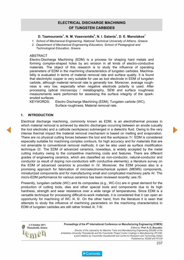
ELECTRICAL DISCHARGE MACHINING OF TUNGSTEN CARBIDES D. Tzamouranis 1 , N. M. Vaxevanidis 2 , N. I. Galanis 1 , D. E. Manolakos 1 1. School of Mechanical Engineering, National Technical University of Athens, Greece 2. Department of Mechanical Engineering Educators, School of Pedagogical and Technological Education, Greece ABSTRACT Electro-Discharge Machining (EDM) is a process for shaping hard metals and forming complex-shaped holes by arc erosion in all kinds of electro-conductive materials. The object of this research is to study the influence of operating parameters of EDM in the machining characteristics of tungsten carbides. Machina- bility is evaluated in terms of material removal rate and surface quality. It is found that electrolytic copper is very suitable for use as tool electrode in EDM of tungsten carbide, although material removal rate is generally low. Moreover, average rough- ness is very low, especially when negative electrode polarity is used. After processing optical microscopy / metallography, SEM and surface roughness measurements were performed for assessing the surface integrity of the spark- eroded surfaces. KEYWORDS: Electro Discharge Machining (EDM), Tungsten carbide (WC), Surface roughness, Material removal rate. 1. INTRODUCTION Electrical discharge machining, commonly known as EDM, is an electrothermal process in which material removal is achieved by electric discharges occurring between an anode (usually the tool electrode) and a cathode (workpiece) submerged in a dielectric fluid. Owing to the very intense thermal impact the material removal mechanism is based on melting and evaporation. There are no physical cutting forces between the tool and the workpiece /1/. EDM is considered especially suitable for machining complex contours, for high accuracy and for materials that are not amenable to conventional removal methods; it can be also used as surface modification technique /2/. The EDM of advanced ceramics, nowadays, is widely accepted by the metal cutting industry owing to the competitive machining costs and features. There are different grades of engineering ceramics, which are classified as non-conductor, natural-conductor and conductor (a result of doping non-conductors with conductive elements); a literature survey on the EDM of advanced ceramics is provided in /3/. Moreover, the EDM process also is a promising approach for fabrication of microelectromechanical system (MEMS) components, miniaturized components and for manufacturing small and complicated machinery parts /4/. The micro-EDM performance for various ceramics has been reviewed recently; see /5/. Presently, tungsten carbide (WC) and its composites (e.g., WC-Co) are in great demand for the production of cutting tools, dies and other special tools and components due to its high hardness, strength and wear resistance over a wide range of temperatures. Since EDM is a versatile technique for processing difficult-to-work materials, it is considered that it can open an opportunity for machining of WC /4, 6/. On the other hand, from the literature it is seen that attempts to study the influence of machining parameters on the machining characteristics in EDM of tungsten carbides are still rather limited /4, 7-9/. 237 Proceedings of the 4 th International Conference on Manufacturing Engineering (ICMEN) Edited by: Prof. K.-D. Bouzakis, Director of the Laboratory for Machine Tools and Manufacturing Engineering (EEΔΜ) of the Aristoteles University Thessaloniki and the Fraunhofer Project Center Coatings in Manufacturing (PCCM), a joint initiative by Fraunhofer-Gesellschaft and Centre for Research and Technology Hellas Published by: EEΔΜ and PCCM 3 - 5 October 2011, Thessaloniki, Greece
Transcript of 'Electrical Discharge Machining of Tungsten Carbides'
ELECTRICAL DISCHARGE MACHINING OF TUNGSTEN CARBIDES
D. Tzamouranis1, N. M. Vaxevanidis2, N. I. Galanis1, D. E. Manolakos1
1. School of Mechanical Engineering, National Technical University of Athens, Greece 2. Department of Mechanical Engineering Educators, School of Pedagogical and
Technological Education, Greece
ABSTRACT Electro-Discharge Machining (EDM) is a process for shaping hard metals and forming complex-shaped holes by arc erosion in all kinds of electro-conductive materials. The object of this research is to study the influence of operating parameters of EDM in the machining characteristics of tungsten carbides. Machina-bility is evaluated in terms of material removal rate and surface quality. It is found that electrolytic copper is very suitable for use as tool electrode in EDM of tungsten carbide, although material removal rate is generally low. Moreover, average rough-ness is very low, especially when negative electrode polarity is used. After processing optical microscopy / metallography, SEM and surface roughness measurements were performed for assessing the surface integrity of the spark-eroded surfaces. KEYWORDS: Electro Discharge Machining (EDM), Tungsten carbide (WC),
Surface roughness, Material removal rate. 1. INTRODUCTION Electrical discharge machining, commonly known as EDM, is an electrothermal process in which material removal is achieved by electric discharges occurring between an anode (usually the tool electrode) and a cathode (workpiece) submerged in a dielectric fluid. Owing to the very intense thermal impact the material removal mechanism is based on melting and evaporation. There are no physical cutting forces between the tool and the workpiece /1/. EDM is considered especially suitable for machining complex contours, for high accuracy and for materials that are not amenable to conventional removal methods; it can be also used as surface modification technique /2/. The EDM of advanced ceramics, nowadays, is widely accepted by the metal cutting industry owing to the competitive machining costs and features. There are different grades of engineering ceramics, which are classified as non-conductor, natural-conductor and conductor (a result of doping non-conductors with conductive elements); a literature survey on the EDM of advanced ceramics is provided in /3/. Moreover, the EDM process also is a promising approach for fabrication of microelectromechanical system (MEMS) components, miniaturized components and for manufacturing small and complicated machinery parts /4/. The micro-EDM performance for various ceramics has been reviewed recently; see /5/.
Presently, tungsten carbide (WC) and its composites (e.g., WC-Co) are in great demand for the production of cutting tools, dies and other special tools and components due to its high hardness, strength and wear resistance over a wide range of temperatures. Since EDM is a versatile technique for processing difficult-to-work materials, it is considered that it can open an opportunity for machining of WC /4, 6/. On the other hand, from the literature it is seen that attempts to study the influence of machining parameters on the machining characteristics in EDM of tungsten carbides are still rather limited /4, 7-9/.
9. Zwick/Roell Manual 10. ISO 4588: Adhesives - Guidelines for the surface preparation of metals. 11. ISO 13895: Adhesives - Guidelines for the surface preparation of plastics. 12. ANSYS 10 Tutorial, on line help Manual. 13. G. Dean, L. Crocker, The Use of Finite Element Methods for Design with Adhesives, 2001. 14. E. Madenci, I. Guven, The Finite Element Method and Applications in Engineering Using
ANSYS, 2006.
237
Proceedings of the 4th International Conference on Manufacturing Engineering (ICMEN)Edited by: Prof. K.-D. Bouzakis,
Director of the Laboratory for Machine Tools and Manufacturing Engineering (EEΔΜ) of theAristoteles University Thessaloniki and the Fraunhofer Project Center Coatings in Manufacturing (PCCM),
a joint initiative by Fraunhofer-Gesellschaft and Centre for Research and Technology HellasPublished by: EEΔΜ and PCCM
3 - 5 October 2011,Thessaloniki, Greece
237

Table 1: Composition of workpiece materials.
Composition wt%
Material
C N O Ti Co W
AC805 coating 16.03 13.69 12.81 57.48 ------ ------- TT25 14.48 ------- 4.79 6.34 8.31 66.09
Table 2: Properties of copper electrode.
Properties Density (g/cm³) 8.93 Melting point (ºC) 1083 Resistivity ( ·cm) 0.0009-0.007 x 10-³
Experimental procedure Die-sinking EDM to a depth of 500 m was conducted using 2 mm diameter electrode on the surface of WC specimens under different machining conditions shown in Table 3. The polarity of the tool and the values of the electric current (Ie) and pulse-on time (tp) were considered as the independent operational parameters of the study. There were two series of experiments, where the effectiveness of the process was evaluated in terms of the material removal rate (Vw) for AC805 and of the roughness of the machined surface (Ra and Rq) for TT25 insert. Pulse energy which is usually referred in the literature as an important machining parameter, is given by:
dttituW et
ee
e
*)(*)( (1)
which is simplified to:
eeee tiuW ** (2)
eu is the working voltage and was kept constant at 60 V.
Table 3: Experimental conditions.
Machining conditions Workpiece material WC +Co (AC805, TT25) Electrode material Cu Dielectric fluid Honilo 401 Pulse current, Ie (A) 1.5, 6, 7.5, 9 Pulse duration, tp ( s) 10 to 1000 Polarity Positive, negative
After processing optical microscopy / metallography, SEM and surface roughness measure-ments as well as XRD analysis were performed for assessing the surface integrity of the spark-eroded surfaces. Details of these measuring techniques are given elsewhere; see /2, 6, 12/ and
In the present paper, following research on EDMachining of tool steels /10-11/ and on EDDrilling of carbon fibre reinforced composite /12/ the feasibility of using die-sinking EDM for machining WC carbides is studied. EDM was performed with copper electrodes, at various pulse currents, pulse durations (pulse-on times) and polarities. The machinability of tungsten carbides was evaluated in terms of material removal rate, surface roughness and microscopic damage which were considered to be the most crucial outputs of the process /10, 12/.
2. EXPERIMENTAL Machine tool EDMachining was performed on an industrial AGIE EMT 110 machine tool of 100 V open voltage with rectangular pulse generator of 30 A maximum current (le) and adjustable pulse durations (tp) 1-1000 sec ( s) and duty factor. Castrol Honilo 401 was used as the dielectric fluid. Workpiece and electrode materials The workpiece materials were cutting inserts (triangles) with dimensions 10 mm×10 mm ×10 mm coded Sumitomo®, AC805 the first and TT25 the second. In order to determine their composition, XRD-analysis performed; see Figure 1 for x-ray plot for the matrix of AC805. According to plot, the main body of insert consists of tungsten carbide (WC) with a small quantity of vanadium (V). Cobalt (Co) is the binding material between carbide’s grains. The chemical compositions of the surfaces of both test materials obtained through XPS (ESCA) are summarized in Table 1. Note that for AC805 it is known (from the manufacturer’s handbook) that this insert is also coated with a superficial TiN+TiC layer. For the second test material (TT25) the analysis shown that there is no superficial coating and its composition is WC-TiC-8 wt % Co; see also Table 1. The tool electrode material used was electrolytic Cu in rod form of 2 mm diameter; its properties are tabulated in Table 2.
Figure 1: XRD-analysis of AC805 Sumitomo® insert.
238 4th ICMEN - 2011
238

Table 1: Composition of workpiece materials.
Composition wt%
Material
C N O Ti Co W
AC805 coating 16.03 13.69 12.81 57.48 ------ ------- TT25 14.48 ------- 4.79 6.34 8.31 66.09
Table 2: Properties of copper electrode.
Properties Density (g/cm³) 8.93 Melting point (ºC) 1083 Resistivity ( ·cm) 0.0009-0.007 x 10-³
Experimental procedure Die-sinking EDM to a depth of 500 m was conducted using 2 mm diameter electrode on the surface of WC specimens under different machining conditions shown in Table 3. The polarity of the tool and the values of the electric current (Ie) and pulse-on time (tp) were considered as the independent operational parameters of the study. There were two series of experiments, where the effectiveness of the process was evaluated in terms of the material removal rate (Vw) for AC805 and of the roughness of the machined surface (Ra and Rq) for TT25 insert. Pulse energy which is usually referred in the literature as an important machining parameter, is given by:
dttituW et
ee
e
*)(*)( (1)
which is simplified to:
eeee tiuW ** (2)
eu is the working voltage and was kept constant at 60 V.
Table 3: Experimental conditions.
Machining conditions Workpiece material WC +Co (AC805, TT25) Electrode material Cu Dielectric fluid Honilo 401 Pulse current, Ie (A) 1.5, 6, 7.5, 9 Pulse duration, tp ( s) 10 to 1000 Polarity Positive, negative
After processing optical microscopy / metallography, SEM and surface roughness measure-ments as well as XRD analysis were performed for assessing the surface integrity of the spark-eroded surfaces. Details of these measuring techniques are given elsewhere; see /2, 6, 12/ and
In the present paper, following research on EDMachining of tool steels /10-11/ and on EDDrilling of carbon fibre reinforced composite /12/ the feasibility of using die-sinking EDM for machining WC carbides is studied. EDM was performed with copper electrodes, at various pulse currents, pulse durations (pulse-on times) and polarities. The machinability of tungsten carbides was evaluated in terms of material removal rate, surface roughness and microscopic damage which were considered to be the most crucial outputs of the process /10, 12/.
2. EXPERIMENTAL Machine tool EDMachining was performed on an industrial AGIE EMT 110 machine tool of 100 V open voltage with rectangular pulse generator of 30 A maximum current (le) and adjustable pulse durations (tp) 1-1000 sec ( s) and duty factor. Castrol Honilo 401 was used as the dielectric fluid. Workpiece and electrode materials The workpiece materials were cutting inserts (triangles) with dimensions 10 mm×10 mm ×10 mm coded Sumitomo®, AC805 the first and TT25 the second. In order to determine their composition, XRD-analysis performed; see Figure 1 for x-ray plot for the matrix of AC805. According to plot, the main body of insert consists of tungsten carbide (WC) with a small quantity of vanadium (V). Cobalt (Co) is the binding material between carbide’s grains. The chemical compositions of the surfaces of both test materials obtained through XPS (ESCA) are summarized in Table 1. Note that for AC805 it is known (from the manufacturer’s handbook) that this insert is also coated with a superficial TiN+TiC layer. For the second test material (TT25) the analysis shown that there is no superficial coating and its composition is WC-TiC-8 wt % Co; see also Table 1. The tool electrode material used was electrolytic Cu in rod form of 2 mm diameter; its properties are tabulated in Table 2.
Figure 1: XRD-analysis of AC805 Sumitomo® insert.
239Further Manufacturing Processes
239

Table 5: Material removal rate.
t (min) z ( m) Vw (mm3/min) 0 0 0 3 104 0.311047988 6 214 0.426694035 9 336 0.502462135
12 404 0.48332072 Mean value 0.430881219
Figure 2: Graph showing the depth of machining in relation of time. Surface roughness of the machined parts Centre-line average roughness (Ra) and root mean square surface roughness (Rq) measure-ments of EDMed surfaces, for the second series of experiments (TT25 inserts), were made in order to provide quantitative evaluation of the influence of EDM parameters on surface finish. Note that Ra and Rq are by far the most commonly used parameter in surface finish measure-ment and for general quality control. Despite theirs inherent limitations, they are easy to mea-sure and offer a good overall description of the height characteristics of a surface profile /10/.
In order to have a better resolution of the results, the experiments were sub-divided into three groups. In the first one, pulse current was 6 A, the electrodes polarity positive and four pulses were used, namely 5 s, 10 s, 20 s and 50 s. In the second group the pulse current and time was kept at the same values, but there was a change in the polarity of electrodes (negative). In the third group, the polarity was negative, the pulse duration constant at 50 s and the pulse current changed to values of 1.5 A, 6 A and 9 A. Results obtained are graphically illustrated in Figures 3(a) and 3(b).
From the graphs it is evident that a reduction of pulse duration causes reduction of surface’s roughness; due to the short duration of the pulse, plasma channel has short diameter and carbide’s surface is lightly affected resulting in craters with short diameter and depth. This is due to, among other factors, its high melting and boiling point. In all cases, the negative electrode’s polarity causes better surface’s quality for the same pulse duration time. Moreover, from the Figure 3(b) it can be concluded that lower pulse current (intensity) causes better surface’s quality, given that pulse duration (tp) is constant. (Ra is less than 1 m for pulse
therefore they are not further discussed here. The operational parameters and experimental results obtained from EDMaching of both carbides are summarized in Table 4. Table 4: Operational parameters and experimental results of EDM for both materials.
Carbide’s code
Pulse current ( )
Pulse duration ( s)
Polarity We (mJ)
Vw (mm3/min) Ra ( m)
AC805 6 100 negative 36 0.607 -------- AC805 6 300 negative 108 0.376 -------- AC805 6 500 negative 180 0.228 -------- AC805 6 1000 negative 360 0.174 -------- AC805 7.5 10 negative 4.5 0.483 -------- AC805 7.5 50 negative 22.5 0.537 -------- AC805 7.5 100 negative 45 0.865 -------- AC805 7.5 300 negative 135 0.83 -------- AC805 9 10 negative 5.4 0.375 -------- AC805 9 50 negative 27 1.572 -------- AC805 9 100 negative 54 1.167 -------- AC805 9 300 negative 162 0.716 -------- TT25 6 10 negative 3.6 -------- 1.5 TT25 1.5 50 negative 4.5 -------- 0.96 TT25 6 20 negative 7.2 -------- 1.8 TT25 6 50 negative 18 -------- 2.4 TT25 9 50 negative 27 -------- 2.8 TT25 6 5 positive 1.8 -------- 1.2 TT25 6 10 positive 3.6 -------- 2.266 TT25 6 20 positive 7.2 -------- 2.6 TT25 6 50 positive 18 -------- 4.8
3. RESULTS AND DISCUSSION Material removal rate The material removal rate (Vw), was calculated for the first series of experiments (material AC805) see Table 4. The rate was evaluated by calculating the volume of the carbide that has been removed and by monitoring the time that was spent for that. Because of the circular shape of the electrode, a cylindrical imprint in carbide’s surface was produced. The height of the cylinder was obtained by an electronic instrument that counts the transposition (displacement) of the electrode with fault 2 m. The area of base of the cylinder was measured after the end of the machining, by using DMR optical microscope and the Tesavisio-300 optical system. In Table 5, measurements of the electrode’s transposition and the corresponding time, together with calculated values of the material removal rate for AC805 specimen machined with tp= 10 s and pulse current Ie=7.5 A are presented.
From the graph shown in Figure 2, an almost linear relation between depth and time of machining is revealed. According to this, the time that has to be spent for a specific machining can be precisely estimated. The maximum material removal rate was 1.6 mm3/min apx. and was achieved for Ie=9A and tp=50 s; see Table 4.
240 4th ICMEN - 2011
240

Table 5: Material removal rate.
t (min) z ( m) Vw (mm3/min) 0 0 0 3 104 0.311047988 6 214 0.426694035 9 336 0.502462135 12 404 0.48332072 Mean value 0.430881219
Figure 2: Graph showing the depth of machining in relation of time. Surface roughness of the machined parts Centre-line average roughness (Ra) and root mean square surface roughness (Rq) measure-ments of EDMed surfaces, for the second series of experiments (TT25 inserts), were made in order to provide quantitative evaluation of the influence of EDM parameters on surface finish. Note that Ra and Rq are by far the most commonly used parameter in surface finish measure-ment and for general quality control. Despite theirs inherent limitations, they are easy to mea-sure and offer a good overall description of the height characteristics of a surface profile /10/.
In order to have a better resolution of the results, the experiments were sub-divided into three groups. In the first one, pulse current was 6 A, the electrodes polarity positive and four pulses were used, namely 5 s, 10 s, 20 s and 50 s. In the second group the pulse current and time was kept at the same values, but there was a change in the polarity of electrodes (negative). In the third group, the polarity was negative, the pulse duration constant at 50 s and the pulse current changed to values of 1.5 A, 6 A and 9 A. Results obtained are graphically illustrated in Figures 3(a) and 3(b).
From the graphs it is evident that a reduction of pulse duration causes reduction of surface’s roughness; due to the short duration of the pulse, plasma channel has short diameter and carbide’s surface is lightly affected resulting in craters with short diameter and depth. This is due to, among other factors, its high melting and boiling point. In all cases, the negative electrode’s polarity causes better surface’s quality for the same pulse duration time. Moreover, from the Figure 3(b) it can be concluded that lower pulse current (intensity) causes better surface’s quality, given that pulse duration (tp) is constant. (Ra is less than 1 m for pulse
therefore they are not further discussed here. The operational parameters and experimental results obtained from EDMaching of both carbides are summarized in Table 4. Table 4: Operational parameters and experimental results of EDM for both materials.
Carbide’s code
Pulse current ( )
Pulse duration ( s)
Polarity We (mJ)
Vw (mm3/min) Ra ( m)
AC805 6 100 negative 36 0.607 -------- AC805 6 300 negative 108 0.376 -------- AC805 6 500 negative 180 0.228 -------- AC805 6 1000 negative 360 0.174 -------- AC805 7.5 10 negative 4.5 0.483 -------- AC805 7.5 50 negative 22.5 0.537 -------- AC805 7.5 100 negative 45 0.865 -------- AC805 7.5 300 negative 135 0.83 -------- AC805 9 10 negative 5.4 0.375 -------- AC805 9 50 negative 27 1.572 -------- AC805 9 100 negative 54 1.167 -------- AC805 9 300 negative 162 0.716 -------- TT25 6 10 negative 3.6 -------- 1.5 TT25 1.5 50 negative 4.5 -------- 0.96 TT25 6 20 negative 7.2 -------- 1.8 TT25 6 50 negative 18 -------- 2.4 TT25 9 50 negative 27 -------- 2.8 TT25 6 5 positive 1.8 -------- 1.2 TT25 6 10 positive 3.6 -------- 2.266 TT25 6 20 positive 7.2 -------- 2.6 TT25 6 50 positive 18 -------- 4.8
3. RESULTS AND DISCUSSION Material removal rate The material removal rate (Vw), was calculated for the first series of experiments (material AC805) see Table 4. The rate was evaluated by calculating the volume of the carbide that has been removed and by monitoring the time that was spent for that. Because of the circular shape of the electrode, a cylindrical imprint in carbide’s surface was produced. The height of the cylinder was obtained by an electronic instrument that counts the transposition (displacement) of the electrode with fault 2 m. The area of base of the cylinder was measured after the end of the machining, by using DMR optical microscope and the Tesavisio-300 optical system. In Table 5, measurements of the electrode’s transposition and the corresponding time, together with calculated values of the material removal rate for AC805 specimen machined with tp= 10 s and pulse current Ie=7.5 A are presented.
From the graph shown in Figure 2, an almost linear relation between depth and time of machining is revealed. According to this, the time that has to be spent for a specific machining can be precisely estimated. The maximum material removal rate was 1.6 mm3/min apx. and was achieved for Ie=9A and tp=50 s; see Table 4.
241Further Manufacturing Processes
241

of resolidifled material is enhanced by differences in thermal expansion characteristics between carbide grains and the binder and the brittleness of the test materials
Figure 4: Micrographs showing the EDMed surface of AC805 carbide (a) at 100x and (b) 500x (Ie= 6 A, tp= 100 s, polarity: negative).
Figure 5: Graph showing the machined surface of TT25 insert (a) for Ie=1.5A and (b) for Ie=9A; in both cases tp= 50 s, polarity: negative.
The compositions of the EDMed surfaces were examined through XPS (ESCA); see Table 6 in comparison with Table 2.
Table 6: Composition of workpiece materials after machining.
Composition wt%
Material
C Cu O Ti Co W
AC805 (Ie= 6A) 27.72 2.91 4.93 -------- 3.96 60.47
TT25 (Ie=1.5 A) 46.70 1.47 2.16 3.18 4.15 42.35
TT25 (Ie=9 A) 38.89 3.86 6.19 2.88 5.37 42.81
current of 1.5 A). These observations are consistent with the findings of previous researches; see /4, 8, 13/
Figure 3: Variation of surface roughness (Ra and Rq) of the EDMed TT25 surfaces (a) in
relation with the pulse time and (b) in relation with pulse current (intensity).
It should be noted that the choice of the electrode polarity plays an important role in deciding the final surface structure. Positive electrodes are known to produce crater floors of irregular structure causing diffused reflection of incident light. Conversely, machining with a negative electrode polarity results in flat craters with a smooth surface and a crater rim raised only slightly above the adjoining areas on the workpiece surface. Therefore it may be concluded that when EDMachining WC carbide and many exotic materials, the polarity of the electrode should be negative and not, as is usual for EDM of metals, positive see also /2, 3, 6, 13/. Surface morphology and composition The morphology of an EDMd surface is determined by various factors associated with a complex erosion mechanism. Randomly overlapping craters of dimensions varying with pulse energy cover the machined surface, their sizes and positions reflecting the stochastic nature of the process /2, 4/. From the examination of the EDMed surfaces, it was observed that these surfaces generally have a matt appearance covered by shallow craters, globules of debris, and pockmarks formed by entrapped gases escaping from the re-deposited material. It was found that local melting and evaporation of the workpiece material occurred during and after an electrical discharge and its expulsion took place with gas evolution /4, 13/. It was observed that at low peak current and low pulse duration, the craters were shallow and the density of global appendages and pockmarks was low, whereas at higher peak current and pulse duration, the craters were deeper and global appendages were most evident. These global appendages were molten metals, which were expelled randomly during the discharge and later solidified on the workpiece surfaces. Typical micrographs of the EDMed surface are presented in Figures 4 and 5 for AC805 and TT25 carbides respectively.
In Figures 4(a) and 5(a) a black net is evident; it is the cobalt matrix surrounding the carbide’s grains. There are also various craters; their diameters are varying from 5 m to 50 m. This variation probably is due to the differences of the sparks indicating the stochastic nature of EDM. Long spark’s duration causes long diameters of the plasma channel resulting in big craters. In addition to the above mentioned patterns, in case of AC805 carbides EDMed at higher pulse energy levels than the TT25 ones cleavages and surface cracking were observed by both optical and scanning electron microscope for all pulse energies applied greater than 36 mJ; see Figure 4(b). Cracks are probably caused either by local arcing or due to high thermal stresses exceeding the strength of the material. Thermal cracking generated mainly in the area
242 4th ICMEN - 2011
242

of resolidifled material is enhanced by differences in thermal expansion characteristics between carbide grains and the binder and the brittleness of the test materials
Figure 4: Micrographs showing the EDMed surface of AC805 carbide (a) at 100x and (b) 500x (Ie= 6 A, tp= 100 s, polarity: negative).
Figure 5: Graph showing the machined surface of TT25 insert (a) for Ie=1.5A and (b) for Ie=9A; in both cases tp= 50 s, polarity: negative.
The compositions of the EDMed surfaces were examined through XPS (ESCA); see Table 6 in comparison with Table 2.
Table 6: Composition of workpiece materials after machining.
Composition wt%
Material
C Cu O Ti Co W
AC805 (Ie= 6A) 27.72 2.91 4.93 -------- 3.96 60.47
TT25 (Ie=1.5 A) 46.70 1.47 2.16 3.18 4.15 42.35
TT25 (Ie=9 A) 38.89 3.86 6.19 2.88 5.37 42.81
current of 1.5 A). These observations are consistent with the findings of previous researches; see /4, 8, 13/
Figure 3: Variation of surface roughness (Ra and Rq) of the EDMed TT25 surfaces (a) in
relation with the pulse time and (b) in relation with pulse current (intensity).
It should be noted that the choice of the electrode polarity plays an important role in deciding the final surface structure. Positive electrodes are known to produce crater floors of irregular structure causing diffused reflection of incident light. Conversely, machining with a negative electrode polarity results in flat craters with a smooth surface and a crater rim raised only slightly above the adjoining areas on the workpiece surface. Therefore it may be concluded that when EDMachining WC carbide and many exotic materials, the polarity of the electrode should be negative and not, as is usual for EDM of metals, positive see also /2, 3, 6, 13/. Surface morphology and composition The morphology of an EDMd surface is determined by various factors associated with a complex erosion mechanism. Randomly overlapping craters of dimensions varying with pulse energy cover the machined surface, their sizes and positions reflecting the stochastic nature of the process /2, 4/. From the examination of the EDMed surfaces, it was observed that these surfaces generally have a matt appearance covered by shallow craters, globules of debris, and pockmarks formed by entrapped gases escaping from the re-deposited material. It was found that local melting and evaporation of the workpiece material occurred during and after an electrical discharge and its expulsion took place with gas evolution /4, 13/. It was observed that at low peak current and low pulse duration, the craters were shallow and the density of global appendages and pockmarks was low, whereas at higher peak current and pulse duration, the craters were deeper and global appendages were most evident. These global appendages were molten metals, which were expelled randomly during the discharge and later solidified on the workpiece surfaces. Typical micrographs of the EDMed surface are presented in Figures 4 and 5 for AC805 and TT25 carbides respectively.
In Figures 4(a) and 5(a) a black net is evident; it is the cobalt matrix surrounding the carbide’s grains. There are also various craters; their diameters are varying from 5 m to 50 m. This variation probably is due to the differences of the sparks indicating the stochastic nature of EDM. Long spark’s duration causes long diameters of the plasma channel resulting in big craters. In addition to the above mentioned patterns, in case of AC805 carbides EDMed at higher pulse energy levels than the TT25 ones cleavages and surface cracking were observed by both optical and scanning electron microscope for all pulse energies applied greater than 36 mJ; see Figure 4(b). Cracks are probably caused either by local arcing or due to high thermal stresses exceeding the strength of the material. Thermal cracking generated mainly in the area
243Further Manufacturing Processes
243

8. Kanagarajan D., Karthikeyan R., Palanikumar K., Sivaraj P., Influence of process parameters on electric discharge machining of WC / 30% Co composites, Proceedings of IMechE Part B: Journal of Engineering Manufacture, 222 (2008) 807-815.
9. Jahan M.P., Wong Y.S., Rahman M., A study on the fine-finish die-sinking micro-EDM of tungsten carbide using different electrode materials, Journal of Materials Processing Technology, 209 (2009) 3956-3967.
10. Petropoulos, G.P., Vaxevanidis N.M., Pantazaras C.N., Modeling of surface finish in electro-discharge machining based upon statistical multi-parameter analysis, Journal of Materials Processing Technology, 155-156 (2004) 1247-1251.
11. Hassiotis N., Liaropoulos I., Petropoulos G., Vaxevanidis N.M., Corrosion behaviour of EDMed surfaces of a tool steel, Proceedings of the 3rd International Conference on Manufacturing Engineering – ICMEN, 1-3 October 2008 Kassandra - Chalkidiki, Greece, 2008, pp.175-184.
12. Gourgouletis K., Vaxevanidis N.M., Galanis N.I., Manolakos D.E., Electrical Discharge Drilling of Carbon Fibre Reinforced Composite Materials, International Journal of Machining and Machinability of Materials, 2011 (accepted for publication/in press).
13. Lee S.H., Li X., Study of the surface integrity of the machined workpiece in the EDM of tungsten carbide, Journal of Materials Processing Technology, 139 (2003) 315-321.
In the EDMed surface of AC805, copper (Cu) in mass ratio nearly 3% was detected, which initially did not exist. The carbon probably comes from the dielectric pyrolysis. The same phenomenon occurs during EDMachining of TT25 inserts with 1.45% copper for 1.5 A and 3.86% copper for 9 A; i.e, carbon content increases with the increase of thermal impact. In this material Co content after EDM was reduced, indicating that during EDM of WC carbide the binder phase could be removed first by vaporization and/or melting and then the carbides would be detatched indirectly; see similar remarks in /6/.
4. CONCLUSIONS 1) EDM was successfully applied in cutting inserts consisted mainly of tungsten carbide (WC).
It was found that with certain machining parameters very good surface finish can be achieved (Ra less than 1 m).
2) For the range of machining conditions examined the material removal rate was optimized with negative tool polarity, 9 A pulses current and pulse duration in the range of 50 s, reaching to a maximum of 1.6 mm³/min. EDMaching of WC carbides appears to be time-consumptive process for industrial mass production.
3) The morphology of EDMed WC surfaces is characterized by randomly overlapping craters of dimensions varying with pulse energy cover the machined surface, their sizes and positions reflecting the stochastic nature of the process. Cleavages and surface cracking were observed by both optical and scanning electron microscope for all pulse energies above a certain level (We= 36 mJ).
4) Negative tools perform better than positive tools in terms of material removal rate, dimensional accuracy and surface finish of the workpiece produced.
5) Machined surfaces are rich in carbon indicating diffusion from the dielectric pyrolysis. Co content on the surface, after EDM was found reduced, indicating that during EDM of WC carbide the binder phase is removed first by vaporization and/or melting and then the carbide grains are detached indirectly.
5. REFERENCES 1. Ho K.H., Newman S.T., State of the art electrical discharge machining (EDM), International
Journal of Machine Tools and Manufacture, 43 (2003) 1287-1300. 2. Pantelis D.I., Vaxevanidis N.M., Houndri A.E., P. Dumas P., Jeandin M., Investigation into
the application of electrodischarge machining as steel surface modification technique, Surface Engineering, 14 (1998) 55-61.
3. Sanchez J.A., Cabanes I., Lopez de Lacalle L.N., Iamikiz, A., Development of optimum electrodischarge machining technology for advanced ceramics, International Journal of Advanced Manufacturing Technology, 18 (2001) 897-905.
4. Lee S.H., Li X. P., Study of the effect of machining parameters on the machining characteristics in electrical discharge machining of tungsten carbide, Journal of Materials Processing Technology, 115 (2001) 344-358.
5. Ferraris E., Liu K., Peirs J., Lauwers B., Reynaerts D., Free Form Microprocessing of Ceramic Materials by Electrical Discharge Machining, Ceramic Processing in Microtechno-logy, Whittles Publishing, 2009, pp.254-274.
6. Mamalis A.G., Vaxenanidis N.M., Pantelis D.I., On the Electrodischarge Machining of Ce-ramic Plasma-Sprayed Steel Plates, Annals of the CIRP, 41 (1992) 235-238.
7. Luis C.J., Puertas I., Methodology for developing technological tables used in EDM pro-cesses of conductive ceramics, Journal of Materials Processing Technology, 189 (2007) 301-309.
244 4th ICMEN - 2011
244

8. Kanagarajan D., Karthikeyan R., Palanikumar K., Sivaraj P., Influence of process parameters on electric discharge machining of WC / 30% Co composites, Proceedings of IMechE Part B: Journal of Engineering Manufacture, 222 (2008) 807-815.
9. Jahan M.P., Wong Y.S., Rahman M., A study on the fine-finish die-sinking micro-EDM of tungsten carbide using different electrode materials, Journal of Materials Processing Technology, 209 (2009) 3956-3967.
10. Petropoulos, G.P., Vaxevanidis N.M., Pantazaras C.N., Modeling of surface finish in electro-discharge machining based upon statistical multi-parameter analysis, Journal of Materials Processing Technology, 155-156 (2004) 1247-1251.
11. Hassiotis N., Liaropoulos I., Petropoulos G., Vaxevanidis N.M., Corrosion behaviour of EDMed surfaces of a tool steel, Proceedings of the 3rd International Conference on Manufacturing Engineering – ICMEN, 1-3 October 2008 Kassandra - Chalkidiki, Greece, 2008, pp.175-184.
12. Gourgouletis K., Vaxevanidis N.M., Galanis N.I., Manolakos D.E., Electrical Discharge Drilling of Carbon Fibre Reinforced Composite Materials, International Journal of Machining and Machinability of Materials, 2011 (accepted for publication/in press).
13. Lee S.H., Li X., Study of the surface integrity of the machined workpiece in the EDM of tungsten carbide, Journal of Materials Processing Technology, 139 (2003) 315-321.
In the EDMed surface of AC805, copper (Cu) in mass ratio nearly 3% was detected, which initially did not exist. The carbon probably comes from the dielectric pyrolysis. The same phenomenon occurs during EDMachining of TT25 inserts with 1.45% copper for 1.5 A and 3.86% copper for 9 A; i.e, carbon content increases with the increase of thermal impact. In this material Co content after EDM was reduced, indicating that during EDM of WC carbide the binder phase could be removed first by vaporization and/or melting and then the carbides would be detatched indirectly; see similar remarks in /6/.
4. CONCLUSIONS 1) EDM was successfully applied in cutting inserts consisted mainly of tungsten carbide (WC).
It was found that with certain machining parameters very good surface finish can be achieved (Ra less than 1 m).
2) For the range of machining conditions examined the material removal rate was optimized with negative tool polarity, 9 A pulses current and pulse duration in the range of 50 s, reaching to a maximum of 1.6 mm³/min. EDMaching of WC carbides appears to be time-consumptive process for industrial mass production.
3) The morphology of EDMed WC surfaces is characterized by randomly overlapping craters of dimensions varying with pulse energy cover the machined surface, their sizes and positions reflecting the stochastic nature of the process. Cleavages and surface cracking were observed by both optical and scanning electron microscope for all pulse energies above a certain level (We= 36 mJ).
4) Negative tools perform better than positive tools in terms of material removal rate, dimensional accuracy and surface finish of the workpiece produced.
5) Machined surfaces are rich in carbon indicating diffusion from the dielectric pyrolysis. Co content on the surface, after EDM was found reduced, indicating that during EDM of WC carbide the binder phase is removed first by vaporization and/or melting and then the carbide grains are detached indirectly.
5. REFERENCES 1. Ho K.H., Newman S.T., State of the art electrical discharge machining (EDM), International
Journal of Machine Tools and Manufacture, 43 (2003) 1287-1300. 2. Pantelis D.I., Vaxevanidis N.M., Houndri A.E., P. Dumas P., Jeandin M., Investigation into
the application of electrodischarge machining as steel surface modification technique, Surface Engineering, 14 (1998) 55-61.
3. Sanchez J.A., Cabanes I., Lopez de Lacalle L.N., Iamikiz, A., Development of optimum electrodischarge machining technology for advanced ceramics, International Journal of Advanced Manufacturing Technology, 18 (2001) 897-905.
4. Lee S.H., Li X. P., Study of the effect of machining parameters on the machining characteristics in electrical discharge machining of tungsten carbide, Journal of Materials Processing Technology, 115 (2001) 344-358.
5. Ferraris E., Liu K., Peirs J., Lauwers B., Reynaerts D., Free Form Microprocessing of Ceramic Materials by Electrical Discharge Machining, Ceramic Processing in Microtechno-logy, Whittles Publishing, 2009, pp.254-274.
6. Mamalis A.G., Vaxenanidis N.M., Pantelis D.I., On the Electrodischarge Machining of Ce-ramic Plasma-Sprayed Steel Plates, Annals of the CIRP, 41 (1992) 235-238.
7. Luis C.J., Puertas I., Methodology for developing technological tables used in EDM pro-cesses of conductive ceramics, Journal of Materials Processing Technology, 189 (2007) 301-309.
245Further Manufacturing Processes
245