Structural tale of two novel (Cr,Mn)C carbides in steel
35
Elsevier Editorial System(tm) for Acta Materialia Manuscript Draft Manuscript Number: A-14-1167R1 Title: Structural tale of two novel (Cr,Mn)C carbides in steel Article Type: Full Length Article Keywords: (Cr,Mn)C carbides, steel, transmission electron microscopy, electron diffraction, first principles calculations. Corresponding Author: Dr. Ganesh Kumar Tirumalasetty, Ph.D Corresponding Author's Institution: The University of Manchester First Author: Ganesh Kumar Tirumalasetty, Ph.D Order of Authors: Ganesh Kumar Tirumalasetty, Ph.D; Changming Fang, Ph.D; Jacob Jansen, Ph.D; Tadahiro Yokosawa, Ph.D; Maurits Boeije, M.Sc; Jilt Sietsma, Professor, Ph.D; Marijn van Huis, Ph.D; Henny Zandbergen, Professor, Ph.D Abstract: Chromium (Cr), Manganese (Mn), and Carbon (C) are well known alloying elements used in technologically important alloy steels and advanced high strength steels. It is known that binary CrCx and MnCx carbides can be formed in steels, but in this study we reveal for the first time that Cr and Mn were found combined in novel ternary cementite type (Cr,Mn)C carbides. Electron diffraction experiments showed that Cr, Mn, and C have formed two distinct carbide phases possessing orthorhombic and monoclinic crystal structures. Density functional theory (DFT) calculations were performed on these phases and excellent agreement was found between calculations and experiments on the lattice parameters and relative atomic positions. The calculations showed that the combination of Mn and Cr has resulted in a very high thermodynamic stability of the (Cr,Mn)C carbides, and that local structural relaxations are associated with carbon additions. Possible implications of these ternary carbides for novel applications in steel design and manufacturing are discussed.
Transcript of Structural tale of two novel (Cr,Mn)C carbides in steel

Elsevier Editorial System(tm) for Acta Materialia Manuscript Draft Manuscript Number: A-14-1167R1 Title: Structural tale of two novel (Cr,Mn)C carbides in steel Article Type: Full Length Article Keywords: (Cr,Mn)C carbides, steel, transmission electron microscopy, electron diffraction, first principles calculations. Corresponding Author: Dr. Ganesh Kumar Tirumalasetty, Ph.D Corresponding Author's Institution: The University of Manchester First Author: Ganesh Kumar Tirumalasetty, Ph.D Order of Authors: Ganesh Kumar Tirumalasetty, Ph.D; Changming Fang, Ph.D; Jacob Jansen, Ph.D; Tadahiro Yokosawa, Ph.D; Maurits Boeije, M.Sc; Jilt Sietsma, Professor, Ph.D; Marijn van Huis, Ph.D; Henny Zandbergen, Professor, Ph.D Abstract: Chromium (Cr), Manganese (Mn), and Carbon (C) are well known alloying elements used in technologically important alloy steels and advanced high strength steels. It is known that binary CrCx and MnCx carbides can be formed in steels, but in this study we reveal for the first time that Cr and Mn were found combined in novel ternary cementite type (Cr,Mn)C carbides. Electron diffraction experiments showed that Cr, Mn, and C have formed two distinct carbide phases possessing orthorhombic and monoclinic crystal structures. Density functional theory (DFT) calculations were performed on these phases and excellent agreement was found between calculations and experiments on the lattice parameters and relative atomic positions. The calculations showed that the combination of Mn and Cr has resulted in a very high thermodynamic stability of the (Cr,Mn)C carbides, and that local structural relaxations are associated with carbon additions. Possible implications of these ternary carbides for novel applications in steel design and manufacturing are discussed.

Acta Materialia
Editorial Office
Ref.: Ms. No. A-14-1167
Subject: submission of revised manuscript
Manchester, June 13, 2014.
Dear Editor,
Dear Prof. Wagner,
Please find the uploaded revision of our manuscript, with title “Structural tale of two
novel (Cr,Mn)C carbides in steel”, by G.K. Tirumalasetty, C.M. Fang, J. Jansen, T.
Yokosawa, M.F.J. Boeije, J. Sietsma, M.A. van Huis, and H.W. Zandbergen,
We would like to thank the referee for the kind words on the improvements in our work. The
remarks and comments in the referee report have helped us to further revise the manuscript.
Changes are highlighted in yellow. Please find also the response to the referee report below.
We hope that the improvements made will make the manuscript suitable for publication in its
present form.
We thank you for your consideration and are very looking forward to your reply.
Yours sincerely,
Ganesh Kumar Tirumalasetty
Materials Science Center,
The University of Manchester,
Grosvenor Street,
Manchester M17 HS
United Kingdom
E-mail: [email protected]
tel.: ++44 161 3063588
*Cover Letter

Response to the referee report
We would first like to thank the referee for the kind words about the improvements in our work.
We agree with the referee remarks and we have revised the manuscript accordingly.
There is just one detail the authors may wish to clarify further, i.e. regarding models A, B
and C in their MSLS refinement. These models are introduced by saying on p. 11
"Therefore, we performed refinements by assuming random distribution over three
possible atomic arrangements…" However, the authors fail to provide sufficient detail
what these three atomic arrangements are that appear to provide the basis for the three
models (A, B, C).
We thank the referee for this remark. The three atomic arrangements which are the basis for
Models A, B,C for both orthorhombic and monoclinic carbides are described in page 11 of the
revised manuscript.
*Response to Reviewer

From: Richard Wagner <[email protected]>
Date: Wed, June 11, 2014 at 08:57 PM
Subject: Your Submission
To: [email protected], [email protected]
Cc: [email protected], [email protected], [email protected], [email protected], J.Siets
[email protected],[email protected], [email protected]
Ref.: Ms. No. A-14-1167
Structural tale of two novel (Cr,Mn)C carbides in steel
Acta Materialia
Dear Dr. Tirumalasetty,
I have now received an independent review of your manuscript. The referee has made
suggestions for you to revise the paper. See below review.
If you will address these comments in your revised paper, I shall be pleased to consider
your manuscript for publication in Acta Materialia.
In the 'Response to Reviewer', please include a detailed explanation of changes made.
Please also highlight the amendments and corrections made to the original submission.
In some cases, the revision will need to be reviewed by the referee; please allow time for
this process.
To submit a revision, go to http://ees.elsevier.com/am/ and log in as an Author. You will
find your submission in 'Submissions needing revision'.
Your username is: [email protected]
If you need to retrieve password details, please go to:
http://ees.elsevier.com/am/automail_query.asp
Please note that we allow 30 days for minor revision and 60 days for major revision.
Thank you.
Yours sincerely,
Prof. Richard Wagner
Acta Materialia
Reviewer's comments:
In response to the original review comments the authors have significantly modified
their manuscript in part by re-writing entire sections. These modifications provide the
requested clarification on experimental procedures and calculation details. The paper is

now very well written. There is just one detail the authors may wish to clarify further, i.e.
regarding models A, B and C in their MSLS refinement. These models are introduced by
saying on p. 11 "Therefore, we performed refinements by assuming random distribution
over three possible atomic arrangements…" However, the authors fail to provide
sufficient detail what these three atomic arrangements are that appear to provide the basis
for the three models (A, B, C).
The reviewer(s) may also have uploaded detailed comments on your manuscript as an
attachment. To access these comments, please go to: http://ees.elsevier.com/am/
Your username is: [email protected]
Click on 'Author Login'.
You will find your submission in the folder entitled "Submission Needing Revision".
Click on 'View Reviewer Attachments' (if present).
Please note that this journal offers a new, free service called AudioSlides: brief, webcast-
style presentations that are shown next to published articles on ScienceDirect (see
also http://www.elsevier.com/audioslides). If your paper is accepted for publication, you
will automatically receive an invitation to create an AudioSlides presentation.
For further assistance, please visit our customer support site
at http://help.elsevier.com/app/answers/list/p/7923. Here you can search for solutions on
a range of topics, find answers to frequently asked questions and learn more about EES
via interactive tutorials. You will also find our 24/7 support contact details should you
need any further assistance from one of our customer support representatives.
Structural tale of two novel (Cr,Mn)C carbides in steel
G. K. Tirumalasetty1,2*
, C.M. Fang3, J. Jansen
1, T. Yokosawa
1,4, M.F.J. Boeije
5,
J. Sietsma6, M.A. van Huis
1,3, H.W. Zandbergen
1
1 Kavli Institute of Nanoscience, Delft University of Technology,
Lorentzweg 1, 2628 CJ Delft, The Netherlands
2 Materials Science Center, The University of Manchester,
Grosvenor Street, Manchester M17 HS, United Kingdom
3 Soft Condensed Matter, Debye Institute for Nanomaterials Science,
Utrecht University, Princetonplein 5, 3584 CC Utrecht, The Netherlands
4 Institute for Nuclear Waste Disposal, Karlsruhe Institute of Technology,
Hermann-von-Helmholtz-Platz 1,D-76344 Eggenstein-Leopoldshafen, Germany
5 Fundamental Aspects of Materials and Energy, Faculty of Applied Sciences,
Delft University of Technology, Mekelweg 15, 2629 JB Delft, The Netherlands
6 Department of Materials Science and Engineering, Delft University of Technology,
Mekelweg 2, 2628 CD Delft, The Netherlands
*Corresponding author:
Address: Materials Science Center, The University of Manchester,
Grosvenor Street, Manchester M17 HS
United Kingdom
Email: [email protected]
Tel.: +44 161 3063588
*Text onlyClick here to download Text only: Manuscript_CrMnC_12062014.doc Click here to view linked References
2
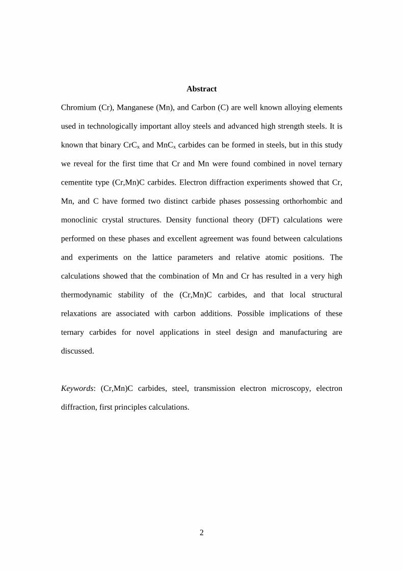
Abstract
Chromium (Cr), Manganese (Mn), and Carbon (C) are well known alloying elements
used in technologically important alloy steels and advanced high strength steels. It is
known that binary CrCx and MnCx carbides can be formed in steels, but in this study
we reveal for the first time that Cr and Mn were found combined in novel ternary
cementite type (Cr,Mn)C carbides. Electron diffraction experiments showed that Cr,
Mn, and C have formed two distinct carbide phases possessing orthorhombic and
monoclinic crystal structures. Density functional theory (DFT) calculations were
performed on these phases and excellent agreement was found between calculations
and experiments on the lattice parameters and relative atomic positions. The
calculations showed that the combination of Mn and Cr has resulted in a very high
thermodynamic stability of the (Cr,Mn)C carbides, and that local structural
relaxations are associated with carbon additions. Possible implications of these
ternary carbides for novel applications in steel design and manufacturing are
discussed.
Keywords: (Cr,Mn)C carbides, steel, transmission electron microscopy, electron
diffraction, first principles calculations.
3
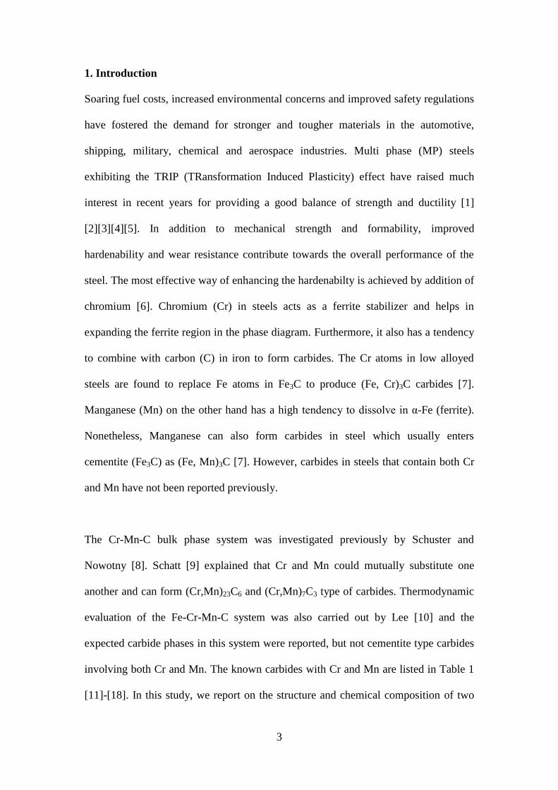
1. Introduction
Soaring fuel costs, increased environmental concerns and improved safety regulations
have fostered the demand for stronger and tougher materials in the automotive,
shipping, military, chemical and aerospace industries. Multi phase (MP) steels
exhibiting the TRIP (TRansformation Induced Plasticity) effect have raised much
interest in recent years for providing a good balance of strength and ductility [1]
[2][3][4][5]. In addition to mechanical strength and formability, improved
hardenability and wear resistance contribute towards the overall performance of the
steel. The most effective way of enhancing the hardenabilty is achieved by addition of
chromium [6]. Chromium (Cr) in steels acts as a ferrite stabilizer and helps in
expanding the ferrite region in the phase diagram. Furthermore, it also has a tendency
to combine with carbon (C) in iron to form carbides. The Cr atoms in low alloyed
steels are found to replace Fe atoms in Fe3C to produce (Fe, Cr)3C carbides [7].
Manganese (Mn) on the other hand has a high tendency to dissolve in α-Fe (ferrite).
Nonetheless, Manganese can also form carbides in steel which usually enters
cementite (Fe3C) as (Fe, Mn)3C [7]. However, carbides in steels that contain both Cr
and Mn have not been reported previously.
The Cr-Mn-C bulk phase system was investigated previously by Schuster and
Nowotny [8]. Schatt [9] explained that Cr and Mn could mutually substitute one
another and can form (Cr,Mn)23C6 and (Cr,Mn)7C3 type of carbides. Thermodynamic
evaluation of the Fe-Cr-Mn-C system was also carried out by Lee [10] and the
expected carbide phases in this system were reported, but not cementite type carbides
involving both Cr and Mn. The known carbides with Cr and Mn are listed in Table 1
[11]-[18]. In this study, we report on the structure and chemical composition of two
4
new ternary cementite type (Cr,Mn)C carbides found in multi-phase steel using
transmission electron microscopy (TEM) and using quantum mechanical density
functional theory (DFT) calculations.
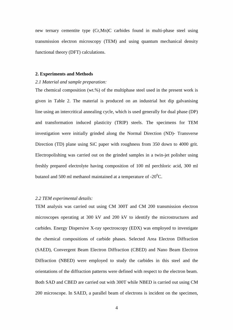
2. Experiments and Methods
2.1 Material and sample preparation:
The chemical composition (wt.%) of the multiphase steel used in the present work is
given in Table 2. The material is produced on an industrial hot dip galvanising
line using an intercritical annealing cycle, which is used generally for dual phase (DP)
and transformation induced plasticity (TRIP) steels. The specimens for TEM
investigation were initially grinded along the Normal Direction (ND)- Transverse
Direction (TD) plane using SiC paper with roughness from 350 down to 4000 grit.
Electropolishing was carried out on the grinded samples in a twin-jet polisher using
freshly prepared electrolyte having composition of 100 ml perchloric acid, 300 ml
butanol and 500 ml methanol maintained at a temperature of -200C.
2.2 TEM experimental details:
TEM analysis was carried out using CM 300T and CM 200 transmission electron
microscopes operating at 300 kV and 200 kV to identify the microstructures and
carbides. Energy Dispersive X-ray spectroscopy (EDX) was employed to investigate
the chemical compositions of carbide phases. Selected Area Electron Diffraction
(SAED), Convergent Beam Electron Diffraction (CBED) and Nano Beam Electron
Diffraction (NBED) were employed to study the carbides in this steel and the
orientations of the diffraction patterns were defined with respect to the electron beam.
Both SAD and CBED are carried out with 300T while NBED is carried out using CM
200 microscope. In SAED, a parallel beam of electrons is incident on the specimen,
5
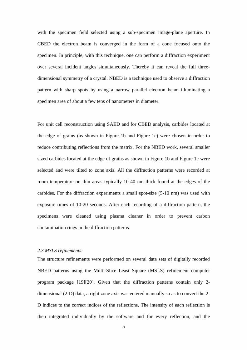
with the specimen field selected using a sub-specimen image-plane aperture. In
CBED the electron beam is converged in the form of a cone focused onto the
specimen. In principle, with this technique, one can perform a diffraction experiment
over several incident angles simultaneously. Thereby it can reveal the full three-
dimensional symmetry of a crystal. NBED is a technique used to observe a diffraction
pattern with sharp spots by using a narrow parallel electron beam illuminating a
specimen area of about a few tens of nanometers in diameter.
For unit cell reconstruction using SAED and for CBED analysis, carbides located at
the edge of grains (as shown in Figure 1b and Figure 1c) were chosen in order to
reduce contributing reflections from the matrix. For the NBED work, several smaller
sized carbides located at the edge of grains as shown in Figure 1b and Figure 1c were
selected and were tilted to zone axis. All the diffraction patterns were recorded at
room temperature on thin areas typically 10-40 nm thick found at the edges of the
carbides. For the diffraction experiments a small spot-size (5-10 nm) was used with
exposure times of 10-20 seconds. After each recording of a diffraction pattern, the
specimens were cleaned using plasma cleaner in order to prevent carbon
contamination rings in the diffraction patterns.
2.3 MSLS refinements:
The structure refinements were performed on several data sets of digitally recorded
NBED patterns using the Multi-Slice Least Square (MSLS) refinement computer
program package [19][20]. Given that the diffraction patterns contain only 2-
dimensional (2-D) data, a right zone axis was entered manually so as to convert the 2-
D indices to the correct indices of the reflections. The intensity of each reflection is
then integrated individually by the software and for every reflection, and the
6
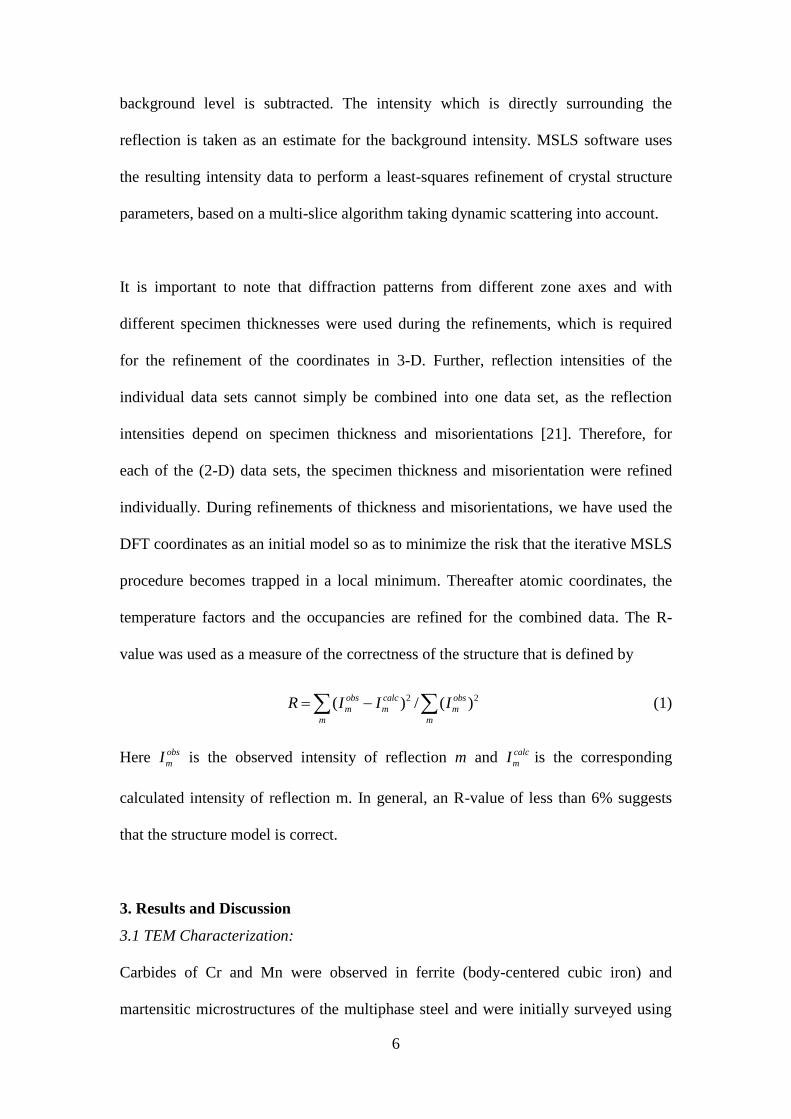
background level is subtracted. The intensity which is directly surrounding the
reflection is taken as an estimate for the background intensity. MSLS software uses
the resulting intensity data to perform a least-squares refinement of crystal structure
parameters, based on a multi-slice algorithm taking dynamic scattering into account.
It is important to note that diffraction patterns from different zone axes and with
different specimen thicknesses were used during the refinements, which is required
for the refinement of the coordinates in 3-D. Further, reflection intensities of the
individual data sets cannot simply be combined into one data set, as the reflection
intensities depend on specimen thickness and misorientations [21]. Therefore, for
each of the (2-D) data sets, the specimen thickness and misorientation were refined
individually. During refinements of thickness and misorientations, we have used the
DFT coordinates as an initial model so as to minimize the risk that the iterative MSLS
procedure becomes trapped in a local minimum. Thereafter atomic coordinates, the
temperature factors and the occupancies are refined for the combined data. The R-
value was used as a measure of the correctness of the structure that is defined by
2 2( ) / ( )obs calc obs
m m m
m m
R I I I (1)
Here obs
mI is the observed intensity of reflection m and calc
mI is the corresponding
calculated intensity of reflection m. In general, an R-value of less than 6% suggests
that the structure model is correct.
3. Results and Discussion
3.1 TEM Characterization:
Carbides of Cr and Mn were observed in ferrite (body-centered cubic iron) and
martensitic microstructures of the multiphase steel and were initially surveyed using
7
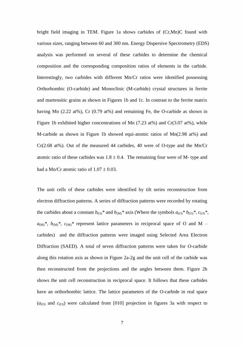
bright field imaging in TEM. Figure 1a shows carbides of (Cr,Mn)C found with
various sizes, ranging between 60 and 300 nm. Energy Dispersive Spectrometry (EDS)
analysis was performed on several of these carbides to determine the chemical
composition and the corresponding composition ratios of elements in the carbide.
Interestingly, two carbides with different Mn/Cr ratios were identified possessing
Orthorhombic (O-carbide) and Monoclinic (M-carbide) crystal structures in ferrite
and martensitic grains as shown in Figures 1b and 1c. In contrast to the ferrite matrix
having Mn (2.22 at%), Cr (0.79 at%) and remaining Fe, the O-carbide as shown in
Figure 1b exhibited higher concentrations of Mn (7.23 at%) and Cr(3.07 at%), while
M-carbide as shown in Figure 1b showed equi-atomic ratios of Mn(2.98 at%) and
Cr(2.68 at%). Out of the measured 44 carbides, 40 were of O-type and the Mn/Cr
atomic ratio of these carbides was 1.8 0.4. The remaining four were of M- type and
had a Mn/Cr atomic ratio of 1.07 0.03.
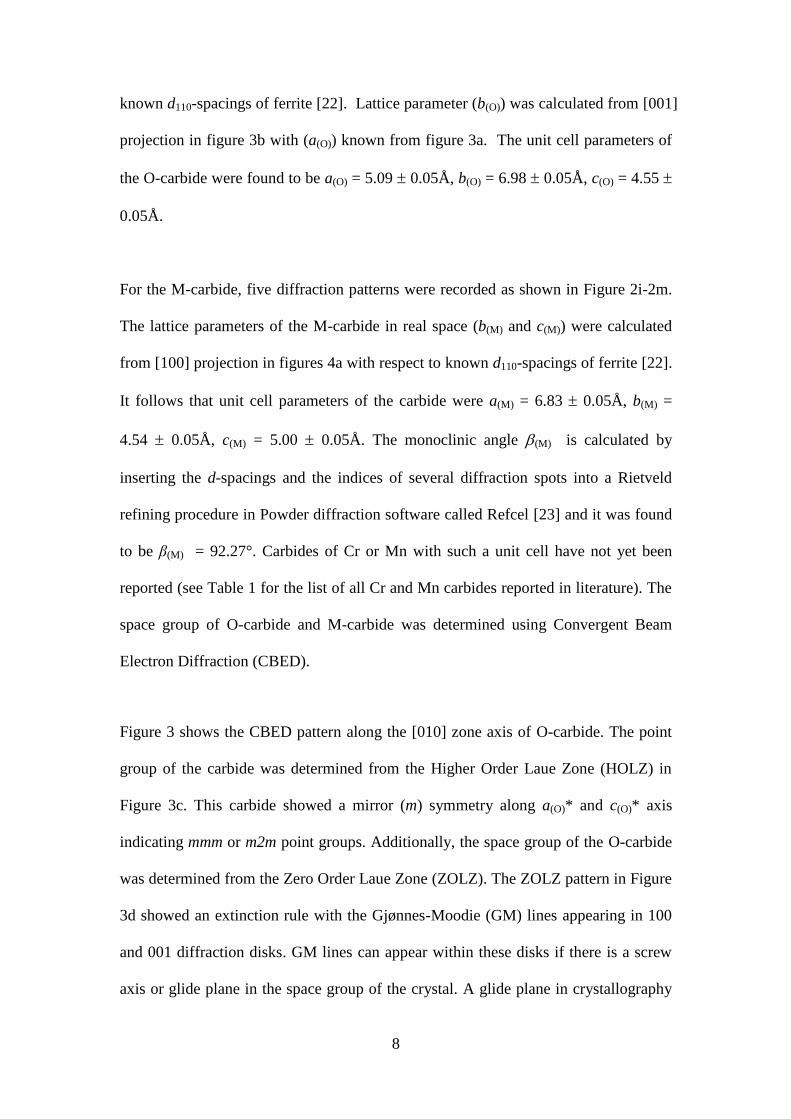
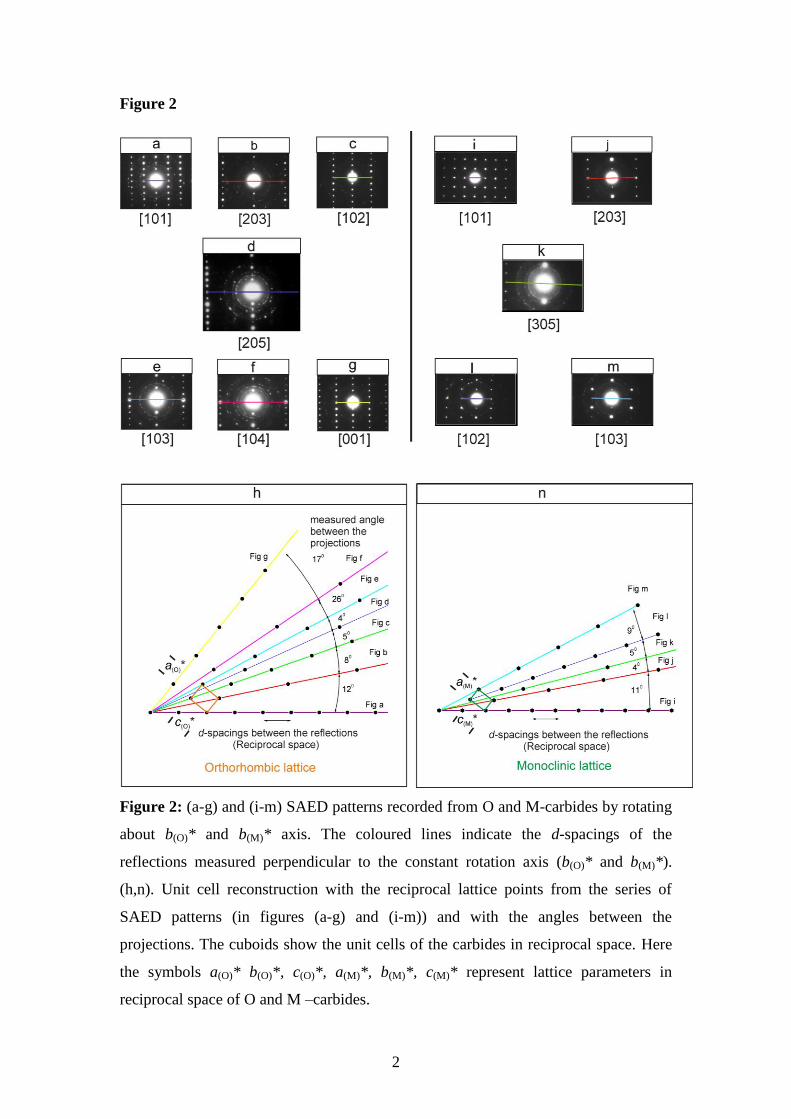
The unit cells of these carbides were identified by tilt series reconstruction from
electron diffraction patterns. A series of diffraction patterns were recorded by rotating
the carbides about a constant b(O)* and b(M)* axis (Where the symbols a(O)* b(O)*, c(O)*,
a(M)*, b(M)*, c(M)* represent lattice parameters in reciprocal space of O and M –
carbides) and the diffraction patterns were imaged using Selected Area Electron
Diffraction (SAED). A total of seven diffraction patterns were taken for O-carbide
along this rotation axis as shown in Figure 2a-2g and the unit cell of the carbide was
then reconstructed from the projections and the angles between them. Figure 2h
shows the unit cell reconstruction in reciprocal space. It follows that these carbides
have an orthorhombic lattice. The lattice parameters of the O-carbide in real space
(a(O) and c(O)) were calculated from [010] projection in figures 3a with respect to
8
known d110-spacings of ferrite [22]. Lattice parameter (b(O)) was calculated from [001]
projection in figure 3b with (a(O)) known from figure 3a. The unit cell parameters of
the O-carbide were found to be a(O) = 5.09 0.05Å, b(O) = 6.98 0.05Å, c(O) = 4.55
0.05Å.
For the M-carbide, five diffraction patterns were recorded as shown in Figure 2i-2m.
The lattice parameters of the M-carbide in real space (b(M) and c(M)) were calculated
from [100] projection in figures 4a with respect to known d110-spacings of ferrite [22].
It follows that unit cell parameters of the carbide were a(M) = 6.83 0.05Å, b(M) =
4.54 0.05Å, c(M) = 5.00 0.05Å. The monoclinic angle (M) is calculated by
inserting the d-spacings and the indices of several diffraction spots into a Rietveld
refining procedure in Powder diffraction software called Refcel [23] and it was found
to be β(M) = 92.27°. Carbides of Cr or Mn with such a unit cell have not yet been
reported (see Table 1 for the list of all Cr and Mn carbides reported in literature). The
space group of O-carbide and M-carbide was determined using Convergent Beam
Electron Diffraction (CBED).
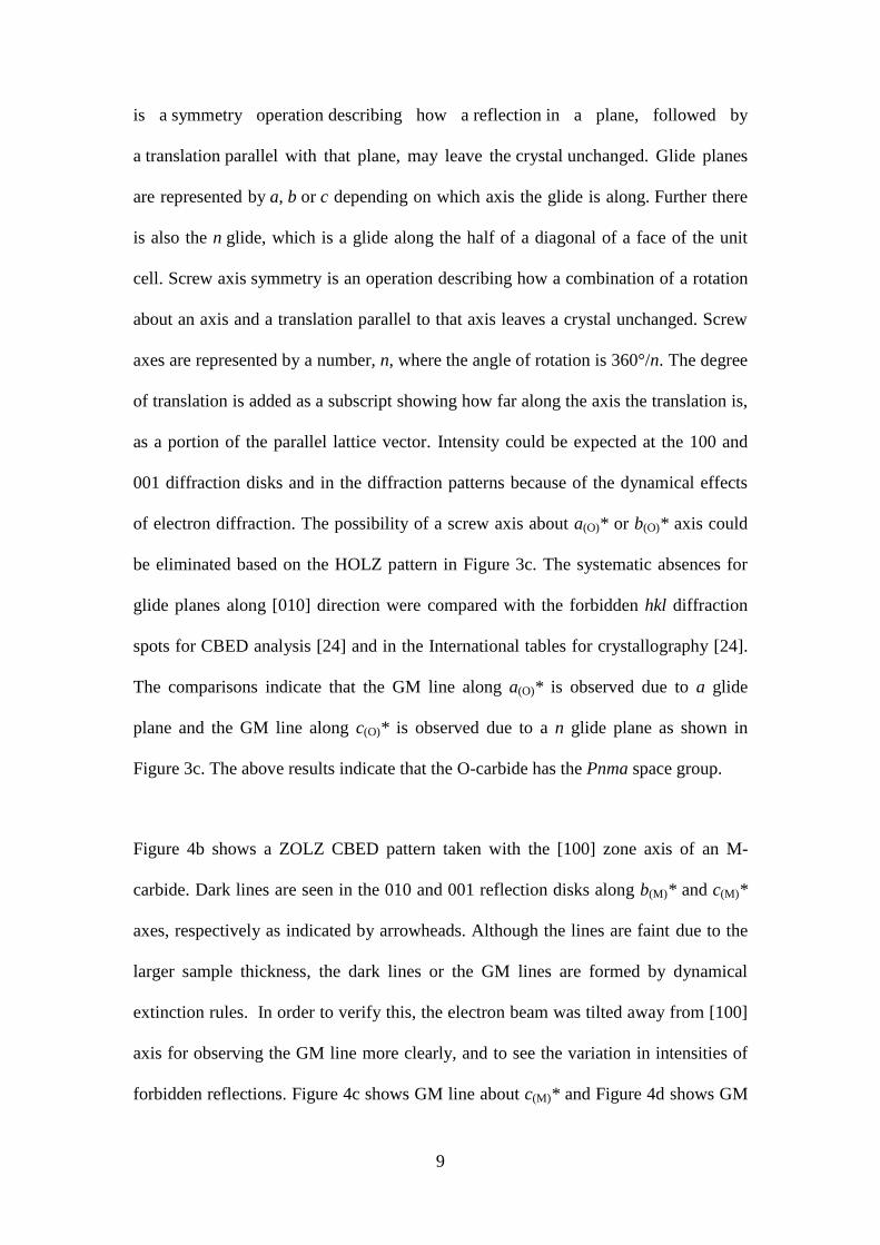
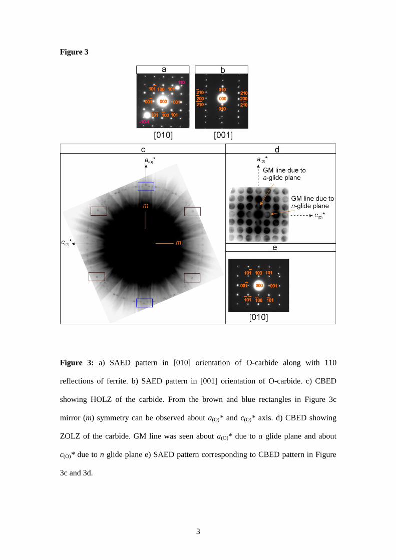
Figure 3 shows the CBED pattern along the [010] zone axis of O-carbide. The point
group of the carbide was determined from the Higher Order Laue Zone (HOLZ) in
Figure 3c. This carbide showed a mirror (m) symmetry along a(O)* and c(O)* axis
indicating mmm or m2m point groups. Additionally, the space group of the O-carbide
was determined from the Zero Order Laue Zone (ZOLZ). The ZOLZ pattern in Figure
3d showed an extinction rule with the Gjønnes-Moodie (GM) lines appearing in 100
and 001 diffraction disks. GM lines can appear within these disks if there is a screw
axis or glide plane in the space group of the crystal. A glide plane in crystallography
9
is a symmetry operation describing how a reflection in a plane, followed by
a translation parallel with that plane, may leave the crystal unchanged. Glide planes
are represented by a, b or c depending on which axis the glide is along. Further there
is also the n glide, which is a glide along the half of a diagonal of a face of the unit
cell. Screw axis symmetry is an operation describing how a combination of a rotation
about an axis and a translation parallel to that axis leaves a crystal unchanged. Screw
axes are represented by a number, n, where the angle of rotation is 360°/n. The degree
of translation is added as a subscript showing how far along the axis the translation is,
as a portion of the parallel lattice vector. Intensity could be expected at the 100 and
001 diffraction disks and in the diffraction patterns because of the dynamical effects
of electron diffraction. The possibility of a screw axis about a(O)* or b(O)* axis could
be eliminated based on the HOLZ pattern in Figure 3c. The systematic absences for
glide planes along [010] direction were compared with the forbidden hkl diffraction
spots for CBED analysis [24] and in the International tables for crystallography [24].
The comparisons indicate that the GM line along a(O)* is observed due to a glide
plane and the GM line along c(O)* is observed due to a n glide plane as shown in
Figure 3c. The above results indicate that the O-carbide has the Pnma space group.
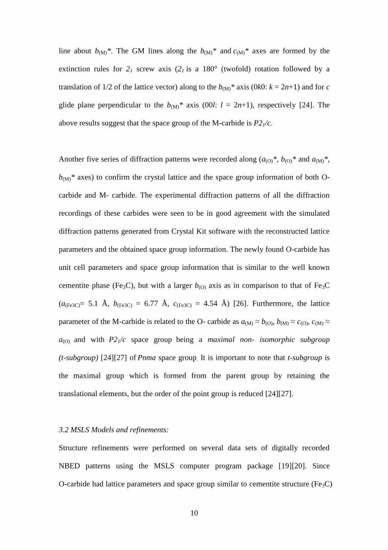
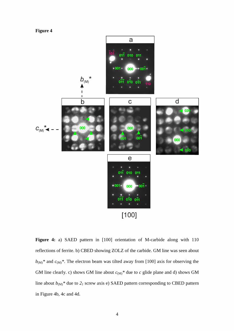
Figure 4b shows a ZOLZ CBED pattern taken with the [100] zone axis of an M-
carbide. Dark lines are seen in the 010 and 001 reflection disks along b(M)* and c(M)*
axes, respectively as indicated by arrowheads. Although the lines are faint due to the
larger sample thickness, the dark lines or the GM lines are formed by dynamical
extinction rules. In order to verify this, the electron beam was tilted away from [100]
axis for observing the GM line more clearly, and to see the variation in intensities of
forbidden reflections. Figure 4c shows GM line about c(M)* and Figure 4d shows GM
10
line about b(M)*. The GM lines along the b(M)* and c(M)* axes are formed by the
extinction rules for 21 screw axis (21 is a 180° (twofold) rotation followed by a
translation of 1/2 of the lattice vector) along to the b(M)* axis (0k0: k = 2n+1) and for c
glide plane perpendicular to the b(M)* axis (00l: l = 2n+1), respectively [24]. The
above results suggest that the space group of the M-carbide is P21/c.
Another five series of diffraction patterns were recorded along (a(O)*, b(O)* and a(M)*,
b(M)* axes) to confirm the crystal lattice and the space group information of both O-
carbide and M- carbide. The experimental diffraction patterns of all the diffraction
recordings of these carbides were seen to be in good agreement with the simulated
diffraction patterns generated from Crystal Kit software with the reconstructed lattice
parameters and the obtained space group information. The newly found O-carbide has
unit cell parameters and space group information that is similar to the well known
cementite phase (Fe3C), but with a larger b(O) axis as in comparison to that of Fe3C
(a(Fe3C)= 5.1 Å, b(Fe3C) = 6.77 Å, c(Fe3C) = 4.54 Å) [26]. Furthermore, the lattice
parameter of the M-carbide is related to the O- carbide as a(M) ≈ b(O), b(M) ≈ c(O), c(M) ≈
a(O) and with P21/c space group being a maximal non- isomorphic subgroup
(t-subgroup) [24][27] of Pnma space group. It is important to note that t-subgroup is
the maximal group which is formed from the parent group by retaining the
translational elements, but the order of the point group is reduced [24][27].
3.2 MSLS Models and refinements:
Structure refinements were performed on several data sets of digitally recorded
NBED patterns using the MSLS computer program package [19][20]. Since
O-carbide had lattice parameters and space group similar to cementite structure (Fe3C)
11
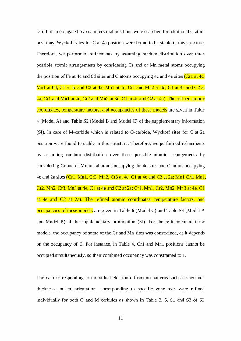
[26] but an elongated b axis, interstitial positions were searched for additional C atom
positions. Wyckoff sites for C at 4a position were found to be stable in this structure.
Therefore, we performed refinements by assuming random distribution over three
possible atomic arrangements by considering Cr and or Mn metal atoms occupying
the position of Fe at 4c and 8d sites and C atoms occupying 4c and 4a sites (Cr1 at 4c,
Mn1 at 8d, C1 at 4c and C2 at 4a; Mn1 at 4c, Cr1 and Mn2 at 8d, C1 at 4c and C2 at
4a; Cr1 and Mn1 at 4c, Cr2 and Mn2 at 8d, C1 at 4c and C2 at 4a). The refined atomic
coordinates, temperature factors, and occupancies of these models are given in Table
4 (Model A) and Table S2 (Model B and Model C) of the supplementary information
(SI). In case of M-carbide which is related to O-carbide, Wyckoff sites for C at 2a
position were found to stable in this structure. Therefore, we performed refinements
by assuming random distribution over three possible atomic arrangements by
considering Cr and or Mn metal atoms occupying the 4e sites and C atoms occupying
4e and 2a sites (Cr1, Mn1, Cr2, Mn2, Cr3 at 4e, C1 at 4e and C2 at 2a; Mn1 Cr1, Mn1,
Cr2, Mn2, Cr3, Mn3 at 4e, C1 at 4e and C2 at 2a; Cr1, Mn1, Cr2, Mn2, Mn3 at 4e, C1
at 4e and C2 at 2a). The refined atomic coordinates, temperature factors, and
occupancies of these models are given in Table 6 (Model C) and Table S4 (Model A
and Model B) of the supplementary information (SI). For the refinement of these
models, the occupancy of some of the Cr and Mn sites was constrained, as it depends
on the occupancy of C. For instance, in Table 4, Cr1 and Mn1 positions cannot be
occupied simultaneously, so their combined occupancy was constrained to 1.
The data corresponding to individual electron diffraction patterns such as specimen
thickness and misorientations corresponding to specific zone axis were refined
individually for both O and M carbides as shown in Table 3, 5, S1 and S3 of SI.

12
Thereafter atomic coordinates, the temperature factors and the occupancies were
refined for the combined data and the results of the refinements were displayed in
Table 4, 6, S2 and S4 of SI.
The average R value of all the data sets which gives correctness of the structure was
calculated for O-carbide and was found to be 5.06% for Model A and 5.28% for
Model B and 5.07% for Model C. While the average R-value for M-carbide was
found to be 5.03% for Model A and 4.96% for Model B and 4.98% for Model C. An
average R-value of less than 6% suggests that all the refined models strongly agree
with the experimental observations.
3.3 DFT calculations:
In order to obtain more insight into the stability and crystal chemistry of O-carbide
and M-carbide, density functional theory (DFT) calculations were performed. This
approach has been successfully applied to study the crystal structures and relative
stability of iron carbides [28]-[31]. The code Vienna Ab-initio Simulation Package
(VASP) [28] was employed with the DFT within the Projector-Augmented Wave
(PAW) method [33][34]. The generalized gradient approximation (GGA) [35] was
employed for the exchange and correlation energy terms [29]. The cut-off energy of
the wave functions was 500 eV for the carbides. Reciprocal space integrations were
carried out using a k-mesh of a 12×10×16 grid (378 k-points) in the irreducible
Brillouin zone (BZ) of θ-L3X using the Monkhorst and Pack method [36]. That k-
mesh is also used for the θ’-L3X1+x phases. Both the relative atomic positions, and the
shape and size of the simulation cell (the lattice parameters) were allowed to relax in
order to find the lowest-energy state of each structure considered. All carbide phases
were calculated as if they are bulk (periodic boundary conditions apply to all
13
simulation cells), and therefore interface energies or other interactions with the Fe
matrix are not taken into account in the calculated energies.
3.3.1 DFT-Structure Models
Based on the abovementioned experimental results, we built structural models for the
ternary MnCrC phases starting from the cementite phase, L3C. The structure of L3C as
shown in Figure 5a (where L is a metal (Fe) atom) consisting of a distorted hcp-type L
sub-lattice was initially considered with C being inserted in the octahedral sites of
ordered arrangements [29][30][31]. In the orthorhombic structure of L3C, with space
group Pnma, there are three types of atoms at different Wyckoff sites: L1 at 8d, L2 at
4c and C1 at 4c, with two large unoccupied sites (4a and 4b). DFT calculations
showed that carbon atoms (C2) prefer occupying one of the 4a sites where the energy
difference is greater than 1 eV which is in agreement with the structural optimizations
as well as the work by Jiang for Fe3C1+x [37]. Therefore, we used this configuration
for the O carbide and corresponding structure model is given in Figure 5b.
Regarding the M-carbide, there are three independent ways to add carbon atoms into
the 4a sites: a) two C atoms at positions (0,0,0) and (½,0,0); b) the two C atoms at
positions (0,0,0) and (0,½,½); and c) the two C atoms occupy positions (0,0,0) and
(½,½,½). The calculations showed that the configuration with two C atoms occupying
(0,0,0) and (0,½,½) is much more stable than the other two with an energy difference
of 0.9 eV/cell or 50 meV/atom. Therefore, we used this configuration for the m-
carbide and the resultant structure model is given in Figure 5c. The current
configuration has a monoclinic lattice with a point symmetry of 2/m for L3C1.5 (L = Cr,
Mn). Symmetry analysis showed that this C arrangement lowers the symmetry of the
O-carbide with the space group from Pnma to P21/c with the lattice relationships:
14
a(M) ≈ b(O), b(M) ≈ c(O), c(M) ≈ a(O) and β(M) is the unique monoclinic angle between a(M)
and c(M) axis. The M-carbide has β(M) angles that deviate about 2° from 90° due to the
occupation of the extra carbon atoms (C2). Nevertheless, at the atomic level,
substitution of Mn, Cr and C atoms into L3C structure results in a broken symmetry.
However, our calculations show that the deviations of lattice parameters and
coordinates of atoms from the monoclinic ones are not significant, since the averaged
structure, obtained by TEM measurements, will be observed as orthorhombic and
monoclinic. Therefore, we use Pnma and P21/c space groups in our discussion.
DFT calculations were performed for a binary chemical composition of L3C1+x (L =
Cr and Mn; x = 0, 0.25) and ternary composition (Mn2Cr)C1+x (x = 0, 0.25) for
comparison. The calculations showed that both Mn3C and Cr3C are stable relative to
the elemental solids. The calculated lattice parameters showed a slight deviation from
the experimental values of about 3%. This might be due to difficulties in obtaining
samples of high quality since Mn3C is formed only at a very narrow temperature
range of 1223-1323K and Cr3C is stable until 1023K. Table S5 of the SI further shows
that the Mn/Cr alloying carbides have lower formation energies than the sum of the
binary and that the energy differences of different Mn/Cr ordering for the Mn2CrC
phase are not significant. Nonetheless, it should be noted that Cr atoms occupying
part of the 8d sites and addition of one C atom at site 4a results in a broken symmetry
of the orthorhombic lattices. However, the calculations showed that the basic Mn/Cr
sub-lattices remains orthorhombic.
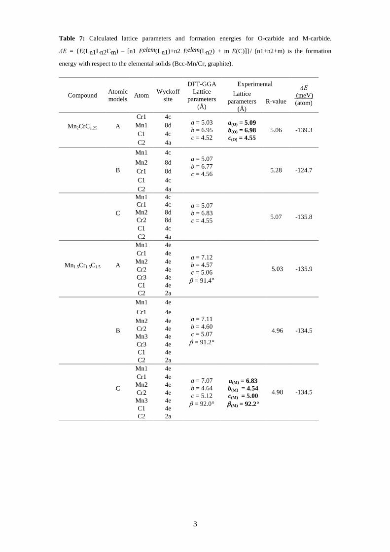
As shown in Table 7, addition of one C2 at the 4a site decreases the formation
energies in most cases, except for the model B of θ'-Mn2CrC1+x, which displays much
lower formation energies. This indicates that the addition of C2 at one of the 4a sites
15
causes Mn/Cr ordering with Cr atoms preferably occupying 8d sites. Certainly Cr/Mn
alloying is possible as shown in the case C in Table 3, considering the contribution of
configuration entropy at their high formation temperature. The calculations also show
the impact of C2 addition and Mn/Cr ordering on the lattice parameters (models B and
C in Table 3). Addition of one C2 at a 4a site increases the lattice parameters of the
corresponding system. The largest deviation of the calculated lattice parameters is for
the b-axis (~ -2.9 %) for case B, while that deviation is only –0.3% for case A.
While comparing the DFT results with the experimental results as shown in Table 7,
Tables S8-S9 of SI, we clearly see that all the three models for O carbide show similar
R-values irrespective of the arrangement of atoms. However, Model A agrees best in
terms of C occupation and lattice parameters. In case of the M carbide, all the three
models show same C occupation but Model C shows the best agreement in terms of
lattice parameters and monoclinic angle (β(M)).
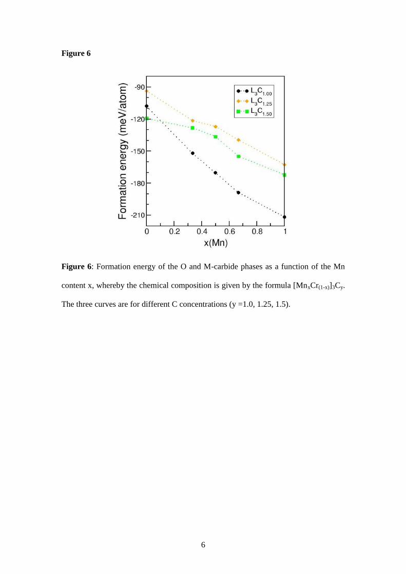
3.3.2 Formation and stability of the M- and O-phases in steels
In order to understand the formation mechanism of the O- and M-phases, we assess
their stability by the definition of formation energy (ΔE) as following:
ΔE = E(Ln1Ln2Cm) – [n1 Eelem(Ln1)+n2 Eelem(Ln2) + m E(C)]/ (n1+n2+m) (2)
ΔE is the formation energy with respect to the elemental solids (Bcc Mn, Bcc Cr, and
graphite) at zero K and zero Pa. It is also true that ΔE = ΔH at zero K and zero Pa
when the zero-vibration contribution is ignored.
16
Figure 6 shows the stability of both O and M carbide phases as function of formation
energy with the formation energy of the cementite phase as a comparison. Clearly the
both O and M carbides have similar stability at 0 K.
With the EDS analysis, minor contributions from Fe also appear in the experimental
data for these carbides since the EDS signal in TEM comes not only from the
precipitate but also from the matrix phase surrounding the precipitate, as a large part
of the sample is hit by stray electrons. In addition, in general there is a contribution of
the matrix material above and beneath the carbide [38] below. Therefore, additional
DFT calculations were carried out to check the possibilities of Fe in these carbide
structures. We therefore performed DFT calculations on a series of systems which
include Fe3C1+x, (Fe,L)3C1+x (L = Cr, Mn) and (Fe, Mn, Cr)3C1+x ( x = 1/4 to 1.0).
The experimental Energy Dispersive Spectrometry (EDS) analysis of the O-type
carbide showed ratios of Fe/Mn/Cr to be approximately 22/2/1. Therefore, we tested a
composition of (Fe2.25/3Mn0.50/3Cr0.25/3)3C1+x (x = 0 to 1.0). Fe atoms occupy the 4c and
8d sites with Mn and Cr at 8d sites. The calculations for (Fe2.25/3Mn0.50/3Cr0.25/3)3C1.25
showed that the formation energy of about 0.28 eV/unit cell or 0.070 eV/f.u. (f.u.,
formula unit) which is higher than the corresponding sum of the binary phases
Fe3C1.15, Mn3C1.25 and Cr3C1.25 or the sum of the binary Fe3C1.25 and the ternary
(Mn2/3Cr1/3)3C1.25 as shown in Table S6 of SI. This clearly indicates that at thermal
equilibrium conditions, the quaternary (Fe2.25/3Mn0.50/3Cr0.25/3)3C1.25 phase is
energetically very unfavorable. For the monoclinic phase, two chemical compositions
were tested. The calculations showed that high concentrations of Fe in the monoclinic
phase have an additional energy cost of 0.82 to 0.95 eV per unit cell for the two
17
chemical compositions as shown in Table S7 of SI. This indicates instability of the
Fe-replacements in the M type carbide structure at 0 K.
As shown above, the first-principles calculations provided lattice parameters and
coordination of atoms in excellent agreement with the experimental observations.
However, from the calculated formation energies, we cannot directly draw
conclusions on the formation of the O- and M- phases. The DFT calculations are for
the ground state at zero K, and entropy effects are neglected. Furthermore, the
calculations also showed interesting effect of extra C addition in the L3C-structure,
such as magnetism for the (MnCr)C1+x phases while their corresponding L3C-phase is
non-magnetic. This is of importance because at elevated temperature magnetism has
strong impact on the free energy as exemplified by the formation of austenite when
heating ferrite [28][39]. Other factors, such as local chemical composition, thermal
history, grain boundaries and interfaces and interface energies will also play a role in
the formation of the carbide phases in steels at temperatures of typically 1300 K.
Much more extensive experimental and computational studies are required to
understand the formation of phases in the very rich, quaternary Fe-Mn-Cr-C system.
The novel ternary phases found in this work are interesting and of high importance for
both science and industry. Elemental Cr as metal has a Mohrs hardness of 8 which is
just next to diamond in terms of hardness [40]. Furthermore, carbides of Cr are often
very hard and are known to produce wear resistant and corrosion free surfaces. A
uniform distribution of these newly formed carbides is more likely to enhance the
hardness and wear resistance of these steels. We also performed calculations of the
energy-volume relationship for the M-carbide and the data was processed with the
Birch-Murnagh relationship. Our results show a bulk modulus of about 225 GPa. The
18
fitting also provided a large B0' value (9.8) as compared with normal materials (4 to
5). Therefore, these newly identified carbides offer many opportunities for
developing novel applications.
Conclusions
Two novel ternary carbide phases including both Cr and Mn were identified in multi
phase TRIP assisted steel. The carbides were characterized using transmission
electron microscopy (TEM), electron diffraction and density functional theory (DFT)
calculations. Electron diffraction analysis revealed that the Orthorhombic carbide
possessed lattice parameters a(O)= 5.09 Å, b(O) = 6.98 Å, c(O) = 4.55 Å, consistent with
the Pnma space group while the Monoclinic carbide possessed lattice parameters
a(M) = 6.83 Å, b(M) = 4.54 Å, c(M) = 5.00 Å, β(M) = 92.2° consistent with the P21/c
space group. Atomic refinements with MSLS showed an average R-value of less than
6% for both these structures with the DFT models strongly supporting the
experimental observations. Remarkable Mn-Cr alloying leads to high thermodynamic
stabilities of these ternary phases. Now that the presence of the novel carbides is
disclosed, new steels may be designed whereby the size and concentration of the
carbides is investigated to further improve steel performance.
Acknowledgements
The authors would like to thank Dr. D.N. Hanlon (Tata Steel RDT) for providing the
samples and for useful discussions.
References
[1] Militzer, M. Science 2002; 298: 975–976.
[2] Tirumalasetty GK, van Huis MA, Fang CM, Xu Q, Tichelaar FD, Hanlon
DN, Sietsma J, Zandbergen HW. Acta Mater 2011; 59: 7406–7415.
19
[3] Tirumalasetty GK, van Huis MA, Kwakernaak C, Sietsma J, Sloof WG,
Zandbergen HW. Acta Mater 2012; 60: 1311–1321.
[4] Tirumalasetty GK, van Huis MA, Kwakernaak C, Sietsma J, Sloof WG,
Zandbergen HW. Scripta Mater 2014; 71: 29–32.
[5] Tirumalasetty GK, Mechanics in steels through Microscopy. PhD thesis,
ISBN: 9789077172902, 2013.
[6] Suh DW, Park SJ, Han HN, Kim SJ. Metallurgical and Materials Trans A
2010; 41; 13: 3276-3281.
[7] Smith WF. Structure and Properties of Engineering Alloys, second ed. New
York: McGraw-Hill; 1993.
[8] Schuster JC, Nowotny H. Monatshefte fu r Chemie. 1980; 111; 1: 113-117.
[9] Schatt W. Intermetallische Phasen; Leipzig: VEB; 1977.
[10] Lee BJ. Metallurgical Transactions A 1993; 24; 5: 1017-1025.
[11] Westgren A. Jernkontorets Annaler 1933; 117: 501-512.
[12] Westgren A. Jernkontorets Annaler 1935; 1935: 231-240.
[13] Inoue A, Masumoto T. Scripta Metall 1979; 13: 711-715.
[14] Bouzy E, Bauer Grosse E, le Caer G. Philosophical Magazine 1993, 68, 619-
638
[15] Hellbom K, Westgren A. Svensk Kemisk Tidskrift 1933; 45: 141-150.
[16] Bouchaud JP. Nature 1966; 212: 248-250.
[17] Bouchaud JP. Annales de Chimie 1967; 2: 353-366.
[18] Benz R, Elliott JF, Chipman J. Metallurgical Transactions 1973; 4: 1449-
1452
[19] Zandbergen HW, Andersen SJ, Jansen J. Science 1997; 277 (5330); 1221-
1225.
[20] Jansen J, Tang D, Zandbergen HW, Schenk H. Acta Cryst A 1998; 54: 91.
[21] Vissers R, Van Huis MA, Jansen J, Zandbergen HW, Marioara CD,
Andersen SJ. Acta Mater 2007; 55 (11): 3815-3823.
[22] Hull AW. Physical Review 1917; 10: 661-696.
[23] Powder Diffraction Program Library, Daresbury Laboratory, Warrington,
UK.
[24] Tanaka M, Sekii H, Nagasawa T. Acta Cryst 1983; A39: 825-837.

20
[25] International Tables for Crystallography 2006; Volume A; Space-group
symmetry. doi:10.1107/97809553602060000100.
[26] Shimura S. Proceedings of the Japan Academy 1930; 6: 269-271.
[27] Glazer M, Burns G, Space Groups for Solid State Scientists, Academic
Press, Jan 2013.
[28] Fang CM, van Huis MA, Sluiter MHF, Zandbergen HW. Phys Rev Lett
2010; 105: 055503.
[29] Fang CM, van Huis MA, Sluiter MHF, Zandbergen HW. Acta Mater 2010;
58: 2968.
[30] Fang CM, van Huis MA, Zandbergen HW. Scripta Mater 2011; 64: 296-299.
[31] Fang CM, van Huis MA, Zandbergen HW. Scripta Mater 2011; 63: 418-421.
[32] Kresse G, Hafner J. Phys. Rev B 1994; 49: 14251.
[33] Blöchl PE, Phys Rev B 1994; 50: 17953.
[34] Kresse G, Furthmüller J. Phys Rev B 1999; 54: 1758.
[35] Perdew JP, Burke K, Ernzerhof M. Phys. Rev. Lett. 1996; 77: 3865-3868.
[36] Monkhorst HJ, Pack JD. Phys. Rev. B 1976; 13: 5188.
[37] Jiang C, Uberuaga BP, Srinivasan SG. Acta Mater 2008, 56; 13: 3236-44.
[38] Tirumalasetty GK, Fang CM, Xu Q, Jansen J, Sietsma J, van Huis MA,
Zandbergen HW. Acta Mater 2012; 60: 7160–7168.
[39] Zener C. J. Appl. Phys. 1951; 22: 372.
[40] Tabor D, The Hardness of Metals, Oxford University Press, 2000.

1
Figures
Figure 1
Figure 1: (Cr,Mn)C carbides observed in multiphase steel a) spherical and elongated
shaped carbides of various sizes in ferrite; b) O (Orthorhombic) and M (Monoclinic)
carbides in ferrite; c) O and M carbides in martensite.
Figure(s)
2
Figure 2
Figure 2: (a-g) and (i-m) SAED patterns recorded from O and M-carbides by rotating
about b(O)* and b(M)* axis. The coloured lines indicate the d-spacings of the
reflections measured perpendicular to the constant rotation axis (b(O)* and b(M)*).
(h,n). Unit cell reconstruction with the reciprocal lattice points from the series of
SAED patterns (in figures (a-g) and (i-m)) and with the angles between the
projections. The cuboids show the unit cells of the carbides in reciprocal space. Here
the symbols a(O)* b(O)*, c(O)*, a(M)*, b(M)*, c(M)* represent lattice parameters in
reciprocal space of O and M –carbides.
3
Figure 3
Figure 3: a) SAED pattern in [010] orientation of O-carbide along with 110
reflections of ferrite. b) SAED pattern in [001] orientation of O-carbide. c) CBED
showing HOLZ of the carbide. From the brown and blue rectangles in Figure 3c
mirror (m) symmetry can be observed about a(O)* and c(O)* axis. d) CBED showing
ZOLZ of the carbide. GM line was seen about a(O)* due to a glide plane and about
c(O)* due to n glide plane e) SAED pattern corresponding to CBED pattern in Figure
3c and 3d.
4
Figure 4
Figure 4: a) SAED pattern in [100] orientation of M-carbide along with 110
reflections of ferrite. b) CBED showing ZOLZ of the carbide. GM line was seen about
b(M)* and c(M)*. The electron beam was tilted away from [100] axis for observing the
GM line clearly. c) shows GM line about c(M)* due to c glide plane and d) shows GM
line about b(M)* due to 21 screw axis e) SAED pattern corresponding to CBED pattern
in Figure 4b, 4c and 4d.
5
Figure 5
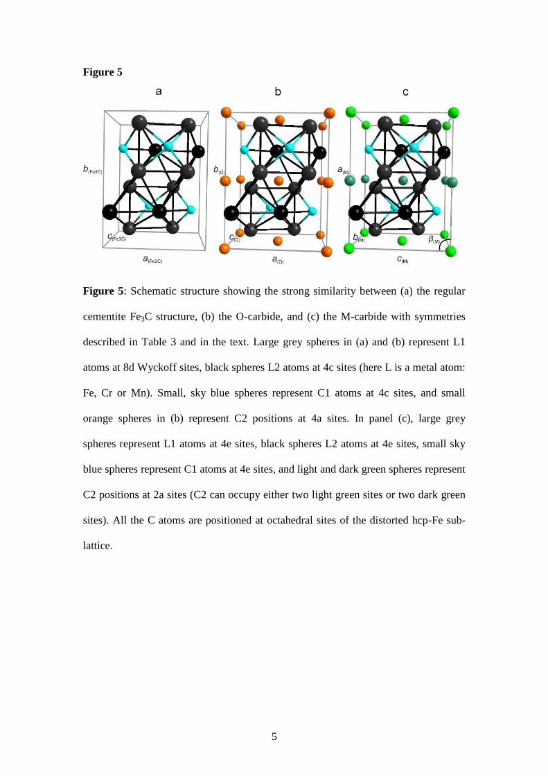
Figure 5: Schematic structure showing the strong similarity between (a) the regular
cementite Fe3C structure, (b) the O-carbide, and (c) the M-carbide with symmetries
described in Table 3 and in the text. Large grey spheres in (a) and (b) represent L1
atoms at 8d Wyckoff sites, black spheres L2 atoms at 4c sites (here L is a metal atom:
Fe, Cr or Mn). Small, sky blue spheres represent C1 atoms at 4c sites, and small
orange spheres in (b) represent C2 positions at 4a sites. In panel (c), large grey
spheres represent L1 atoms at 4e sites, black spheres L2 atoms at 4e sites, small sky
blue spheres represent C1 atoms at 4e sites, and light and dark green spheres represent
C2 positions at 2a sites (C2 can occupy either two light green sites or two dark green
sites). All the C atoms are positioned at octahedral sites of the distorted hcp-Fe sub-
lattice.
6
Figure 6
Figure 6: Formation energy of the O and M-carbide phases as a function of the Mn
content x, whereby the chemical composition is given by the formula [MnxCr(1-x)]3Cy.
The three curves are for different C concentrations (y =1.0, 1.25, 1.5).
1
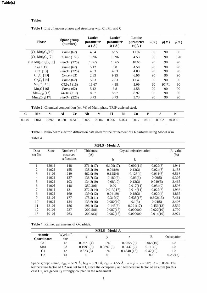
Tables
Table 1: List of known phases and structures with Cr, Mn and C
Table 2: Chemical composition (wt. %) of Multi phase TRIP-assisted steel.
C Mn Si Al Cr Nb V Ti Ni Cu P S N
0.149 2.061 0.392 0.620 0.515 0.022 0.004 0.006 0.024 0.017 0.011 0.002 <0.0001
Table 3: Nano beam electron diffraction data used for the refinement of O- carbides using Model A in
Table 4.
MSLS - Model A
Data
set No
Zone Number of
observed
reflections
Thickness
(Å)
Crystal misorientation R- value
(%)
h k l
1 [201] 148 371.1(17) 0.109(17) 0.002(11) -0.022(3) 1.941
2 [102] 155 138.2(19) 0.048(9) 0.13(3) -0.024(5) 4.138
3 [110] 249 462.9(19) 0.125(4) -0.125(4) -0.011(5) 6.518
4 [102] 127 138.7(13) -0.180(9) -0.03(3) 0.09(5) 9.305
5 [102] 103 134.3(19) -0.08(10) 0.12(3) 0.040(5) 3.465
6 [100] 148 359.3(6) 0.00 -0.017(11) -0.034(9) 4.596
7 [201] 131 372.2(14) 0.013( 17) -0.014(11) -0.027(3) 1.936
8 [102] 160 139.0(12) 0.041(9) 0.18(3) -0.020(4) 4.865
9 [210] 177 173.2(11) 0.317(9) -0.635(17) 0.602(13) 7.461
10 [102] 124 133.6(16) -0.080(10) -0.1(3) 0.04(5) 3.406
11 [210] 186 196.4(13) -0.145(8) 0.291(17) -0.456(13) 8.539
12 [010] 227 209.5(8) -0.087(17) 0.000000 -0.027(10) 4.799
13 [010] 263 209.9(3) -0.082(17) 0.000000 -0.014(10) 3.974
Table 4: Refined parameters of O-carbide.
MSLS - Model A
Atomic
Coordinates
Wyckoff
site x y z B Occupation
Cr1 4c 0.0671 (4) 1/4 0.8255 (3) 0.065(10) 1.0
Mn1 8d 0.1991 (5) 0.0897 (3) 0.3447 (2) 0.116(5) 1.0
C1 4c 0.823 (3) 1/4 0.4648 (13) 0.42(10) 1.0
C2 4a 0 0 0 0.1 0.238(7)
Space group: Pnma, a(O) = 5.09 Å, b(O) = 6.98 Å, c(O) = 4.55 Å, α = β = γ = 90°, R = 5.06%. The
temperature factor of C2 was set to 0.1, since the occupancy and temperature factor of an atom (in this
case C2) are generally strongly coupled in the refinement.
Phase Space group
(number)
Lattice
parameter
a ( Å )
Lattice
parameter
b ( Å )
Lattice
parameter
c ( Å ) α( o ) β( o ) γ( o )
(Cr, Mn)7C
3[10] Pnma (62) 4.54 6.95 11.97 90 90 90
(Cr, Mn)7C
3 [7] P63mc (186) 13.96 13.96 4.53 90 90 120
(Cr, Mn)
23C
6 [7,11] Fm-3m (225) 10.65 10.65 10.65 90 90 90
Cr3C [12] Pnma (62) 5.12 6.8 4.58 90 90 90
CrC [13] Fm-3m (225) 4.03 4.03 4.03 90 90 90
Cr3C
2 [13] Cmcm (63) 2.85 9.25 6.96 90 90 90
Cr3C
2 [14] Pnma (62) 5.53 2.83 11.49 90 90 90
Mn5C
2 [15] C12/c1 (15) 11.67 4.58 5.09 90 97.71 90
Mn3C [16] Pnma (62) 5.12 6.8 4.58 90 90 90
MnC0.07
[17] I4-3m (217) 8.97 8.97 8.97 90 90 90
Mn3.6C0.4 [17] Fm-3m (225) 3.73 3.73 3.73 90 90 90
Table(s)
2
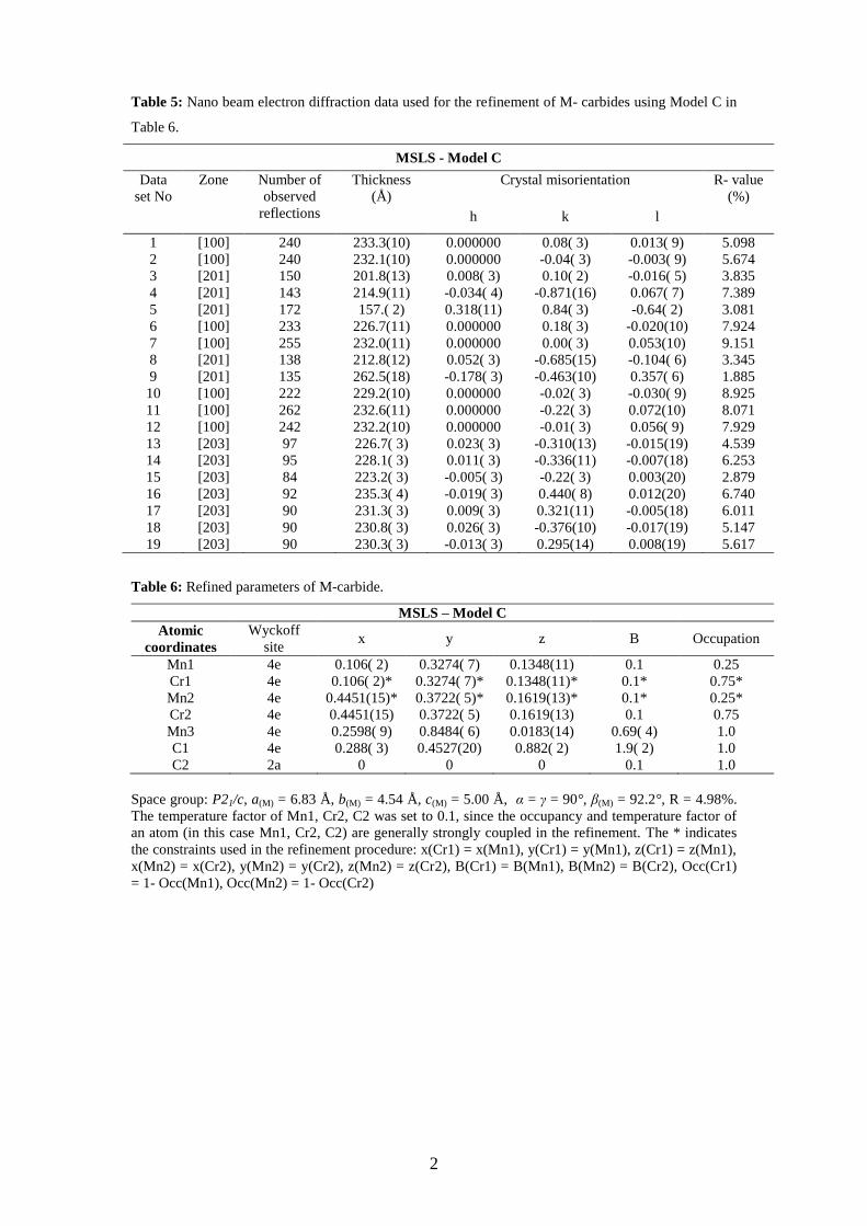
Table 5: Nano beam electron diffraction data used for the refinement of M- carbides using Model C in
Table 6.
MSLS - Model C
Data
set No
Zone Number of
observed
reflections
Thickness
(Å)
Crystal misorientation R- value
(%)
h k l
1 [100] 240 233.3(10) 0.000000 0.08( 3) 0.013( 9) 5.098
2 [100] 240 232.1(10) 0.000000 -0.04( 3) -0.003( 9) 5.674
3 [201] 150 201.8(13) 0.008( 3) 0.10( 2) -0.016( 5) 3.835
4 [201] 143 214.9(11) -0.034( 4) -0.871(16) 0.067( 7) 7.389
5 [201] 172 157.( 2) 0.318(11) 0.84( 3) -0.64( 2) 3.081
6 [100] 233 226.7(11) 0.000000 0.18( 3) -0.020(10) 7.924
7 [100] 255 232.0(11) 0.000000 0.00( 3) 0.053(10) 9.151
8 [201] 138 212.8(12) 0.052( 3) -0.685(15) -0.104( 6) 3.345
9 [201] 135 262.5(18) -0.178( 3) -0.463(10) 0.357( 6) 1.885
10 [100] 222 229.2(10) 0.000000 -0.02( 3) -0.030( 9) 8.925
11 [100] 262 232.6(11) 0.000000 -0.22( 3) 0.072(10) 8.071
12 [100] 242 232.2(10) 0.000000 -0.01( 3) 0.056( 9) 7.929
13 [203] 97 226.7( 3) 0.023( 3) -0.310(13) -0.015(19) 4.539
14 [203] 95 228.1( 3) 0.011( 3) -0.336(11) -0.007(18) 6.253
15 [203] 84 223.2( 3) -0.005( 3) -0.22( 3) 0.003(20) 2.879
16 [203] 92 235.3( 4) -0.019( 3) 0.440( 8) 0.012(20) 6.740
17 [203] 90 231.3( 3) 0.009( 3) 0.321(11) -0.005(18) 6.011
18 [203] 90 230.8( 3) 0.026( 3) -0.376(10) -0.017(19) 5.147
19 [203] 90 230.3( 3) -0.013( 3) 0.295(14) 0.008(19) 5.617
Table 6: Refined parameters of M-carbide.
MSLS – Model C
Atomic
coordinates
Wyckoff
site x y z B Occupation
Mn1 4e 0.106( 2) 0.3274( 7) 0.1348(11) 0.1 0.25
Cr1 4e 0.106( 2)* 0.3274( 7)* 0.1348(11)* 0.1* 0.75*
Mn2 4e 0.4451(15)* 0.3722( 5)* 0.1619(13)* 0.1* 0.25*
Cr2 4e 0.4451(15) 0.3722( 5) 0.1619(13) 0.1 0.75
Mn3 4e 0.2598( 9) 0.8484( 6) 0.0183(14) 0.69( 4) 1.0
C1 4e 0.288( 3) 0.4527(20) 0.882( 2) 1.9( 2) 1.0
C2 2a 0 0 0 0.1 1.0
Space group: P21/c, a(M) = 6.83 Å, b(M) = 4.54 Å, c(M) = 5.00 Å, α = γ = 90°, β(M) = 92.2°, R = 4.98%.
The temperature factor of Mn1, Cr2, C2 was set to 0.1, since the occupancy and temperature factor of
an atom (in this case Mn1, Cr2, C2) are generally strongly coupled in the refinement. The * indicates
the constraints used in the refinement procedure: x(Cr1) = x(Mn1), y(Cr1) = y(Mn1), z(Cr1) = z(Mn1),
x(Mn2) = x(Cr2), y(Mn2) = y(Cr2), z(Mn2) = z(Cr2), B(Cr1) = B(Mn1), B(Mn2) = B(Cr2), Occ(Cr1)
= 1- Occ(Mn1), Occ(Mn2) = 1- Occ(Cr2)
3
Table 7: Calculated lattice parameters and formation energies for O-carbide and M-carbide.
ΔE = E(Ln1Ln2Cm) – [n1 Eelem(Ln1)+n2 Eelem(Ln2) + m E(C)]/ (n1+n2+m) is the formation
energy with respect to the elemental solids (Bcc-Mn/Cr, graphite).
Mn1.5Cr1.5C1.5
A
Mn1 4e
a = 7.12
b = 4.57
c = 5.06
= 91.4°
5.03 -135.9
Cr1 4e
Mn2 4e
Cr2 4e
Cr3 4e
C1 4e
C2 2a
B
Mn1 4e
a = 7.11
b = 4.60
c = 5.07
= 91.2°
4.96 -134.5
Cr1 4e
Mn2 4e
Cr2 4e
Mn3 4e
Cr3 4e
C1 4e
C2 2a
C
Mn1 4e
a = 7.07
b = 4.64
c = 5.12
= 92.0°
a(M) = 6.83
b(M) = 4.54
c(M) = 5.00
(M) = 92.2°
4.98 -134.5
Cr1 4e
Mn2 4e
Cr2 4e
Mn3 4e
C1 4e
C2 2a
Compound Atomic
models Atom
Wyckoff
site
DFT-GGA
Lattice
parameters
(Å)
Experimental ΔE
(meV)
(atom)
Lattice
parameters
(Å)
R-value
Mn2CrC1.25
A
Cr1 4c a = 5.03
b = 6.95
c = 4.52
a(O) = 5.09
b(O) = 6.98
c(O) = 4.55
5.06 -139.3 Mn1 8d
C1 4c
C2 4a
B
Mn1 4c a = 5.07
b = 6.77
c = 4.56
5.28 -124.7
Mn2 8d
Cr1 8d
C1 4c
C2 4a
C
Mn1 4c
a = 5.07
b = 6.83
c = 4.55
5.07 -135.8
Cr1 4c
Mn2 8d
Cr2 8d
C1 4c
C2 4a

Supplementary MaterialClick here to download Supplementary Material: Supplementary information_CrMnC_12062014.doc