EIN: A Signal Processing Scratchpad
13
EIN: A Signal Processing Scratchpad Paul Lansky Kenneth Steiglitz Dept. of Music Dept. of Computer Science Princeton University Princeton University Princeton, NJ 08544 Princeton, NJ 08544 [email protected] [email protected] Computer systems designed for music synthesis usually encapsulate signal-processing algo- rithms as macros or functions, and thus provide a modular interface which facilitates the develop- ment of complex structures. This is the thinking behind Mathews’ original concept of the ‘‘unit generator’’ (Mathews 1969) and most subsequent software synthesis languages use this approach. While it has proven to be an effective method it has not generally provided a means by which the users of these systems, often more musically prepared than wise in the ways of digital signal pro- cessing, can gain an intuitive understanding of the mechanisms used to modify and create digital signals. Indeed, there is little conceptual difference between patching a signal through a bank of two-pole resonating filters/unit generators and tweaking the sliders on a graphic equalizer. EIN is an attempt to provide an interface in which the user has direct control over every add, multiply and store applied to each sample, and can gain a more direct understanding of the machinery of digital signal processing. While its main use has been instructional, it also provides a way to experiment with digital filters and design more complex instruments and algorithms. It is, in effect, a kind of low-level circuit design kit for signal processing. EIN Syntax EIN provides the routine machinery for calling the user’s code, executing it, writing the resulting output sound samples to a file, playing the file, and displaying and analyzing it in the time and frequency domains. The user provides a script in a language that is a superset of C. The EIN system then compiles it and provides a wrapper that calls the script for each time sample from t=0 up to the specified number of samples, nsamps; computes the next output sample y (for the mono case), or the variables left and right (for the stereo case); and writes the output samples to an output sound file, formated for the sampling rate of sr samples/sec. The int variables t and nsamps, and the float variables y, left, right, and sr, are reserved by EIN, and should not be used for other purposes. The mono/stereo option, and the values of sr and nsamps are selected with radio buttons on the interface. The remaining reserved names are described in Appendix 3. As an example, here is a one-line EIN script that produces a sine wave at 440 Hz: y = sin(t*two_PI*440./sr); The constant two_PI (2 ) is provided as a convenience because it is used so often in the argu- ments of trigonometric functions. Of course, since this code is in a loop and called once per Version September 26, 1994.
Transcript of EIN: A Signal Processing Scratchpad

EIN: A Signal Processing Scratchpad
Paul Lansky Kenneth SteiglitzDept. of Music Dept. of Computer SciencePrinceton University Princeton UniversityPrinceton, NJ 08544 Princeton, NJ [email protected] [email protected]
Computer systems designed for music synthesis usually encapsulate signal-processing algo-rithms as macros or functions, and thus provide a modular interface which facilitates the develop-ment of complex structures. This is the thinking behind Mathews’ original concept of the ‘‘unitgenerator’’ (Mathews 1969) and most subsequent software synthesis languages use this approach.While it has proven to be an effective method it has not generally provided a means by which theusers of these systems, often more musically prepared than wise in the ways of digital signal pro-cessing, can gain an intuitive understanding of the mechanisms used to modify and create digitalsignals. Indeed, there is little conceptual difference between patching a signal through a bank oftwo-pole resonating filters/unit generators and tweaking the sliders on a graphic equalizer. EIN isan attempt to provide an interface in which the user has direct control over every add, multiplyand store applied to each sample, and can gain a more direct understanding of the machinery ofdigital signal processing. While its main use has been instructional, it also provides a way toexperiment with digital filters and design more complex instruments and algorithms. It is, ineffect, a kind of low-level circuit design kit for signal processing.
EIN SyntaxEIN provides the routine machinery for calling the user’s code, executing it, writing the
resulting output sound samples to a file, playing the file, and displaying and analyzing it in thetime and frequency domains. The user provides a script in a language that is a superset of C. TheEIN system then compiles it and provides a wrapper that calls the script for each time samplefrom t = 0 up to the specified number of samples, nsamps; computes the next output sampley (for the mono case), or the variables left and right (for the stereo case); and writes theoutput samples to an output sound file, formated for the sampling rate of sr samples/sec.
The int variables t and nsamps, and the float variables y, left, right, andsr, are reserved by EIN, and should not be used for other purposes. The mono/stereo option, andthe values of sr and nsamps are selected with radio buttons on the interface. The remainingreserved names are described in Appendix 3.
As an example, here is a one-line EIN script that produces a sine wave at 440 Hz:
y = sin(t*two_PI*440./sr);
The constant two_PI (2 ) is provided as a convenience because it is used so often in the argu-ments of trigonometric functions. Of course, since this code is in a loop and called once per
Version September 26, 1994.

- 2 -
sample, it is more efficient and clearer to predefine the radian frequency in the argument of thesine as follows:
#define F 440. // frequency in Hz.float omega; // freq. in radians per sampleif(!t) omega = two_PI*F/sr; // one-time only initializationy = sin(omega*t);
Notice that the initialization of omega takes place only when t is zero; that is, only at the firsttime sample.
EIN also provides one new command, called tap, which allows the user to store signals indelay lines for later use. This feature makes it easy to implement filters without having to fusswith the details of managing buffers. The signal value that is stored is always the value of y atthe point that tap is employed. The tap command is invoked by a line of the form
tap i k
where i and k are two constants of type int. (Notice that there is no semicolon terminatingthe line.) This line has two effects. First, it causes the buffer Bi to be created, which stores thevalue of the signal at that point. Second, the variable Si is recognized anywhere else in the codeas the current contents of that buffer, which is the signal at that point delayed by k samplingintervals. Except for the translation of Si variables, lines not beginning with the keyword tapare transparent to the EIN pre-processor, and are passed on untouched to the C compiler.
If a tap appears before the first use of its signal, the signal is called feedforward; other-wise, feedback.
z
tap 1 100
0.99
S1-100
Fig. 1 Signal flowgraph of a simple feedforward filter.
To illustrate how tap is used, consider the simple inverse-comb filter defined by the fol-lowing equation:
w t = x t + 0.99*x t 100
where x t and w t are the input and output signals, respectively. Figure 1 shows the correspondingsignal flowgraph. What’s important about visualizing the operation of the filter with a signalflowgraph is that it defines an order in which the calculations for each time sample are done. Wecan read these from left to right in Fig. 1: first we save the value of the input signal in a bufferwith a delay of 100 samples, then we form the sum of the input signal and 0.99 times the delayed

- 3 -
input. Thus, the EIN script is
tap 1 100y = y + 0.99*S1;
The line y = y + 0.99*S1; does the arithmetic, while the tap 1 100 line signals EINto create a buffer to store the value of the signal at that point. Since the tap line defining S1appears before its first use, S1 is a feedforward signal. When it is used in the next line, it pro-vides a version of the input delayed by 100 samples.
z
tap 1 100
0.99
S1 -100
Fig. 2 Signal flowgraph of a simple feedback filter.
Figure 2 shows the signal flowgraph of a comb filter, an example of a feedback filter. Herethe order of operations from left to right is reversed: first we form the sum of input and weighteddelayed output, then we store the output for later use. The EIN script is therefore
y = y + 0.99*S1;tap 1 100
which uses precisely the same two lines as the inverse comb script, but in reverse order.
EIN’s tap command thus makes it possible to express traditional filter flowgraphs quitesuccinctly.
The InterfaceThe EIN interface is a NeXTStep application which incorporates a spectrum analysis and
spectrogram of the generated signal as well as sound input and output facilities. Figure 3 shows asnapshot of a typical screen while using EIN.
The main window, in the lower left-hand corner of the screen, and shown enlarged in Fig. 4,contains a scrollview with the programming window, and buttons to compile, run, set the sam-pling rate, mono or stereo output, control input signals, and optionally include additional C pro-grams or binaries in the compile step. As EIN compiles a script as a function, linking it with itsdriving program, additional C functions or libraries can be included by listing them in the form atthe bottom of the window, labelled ‘‘include (.c/.o)’’.
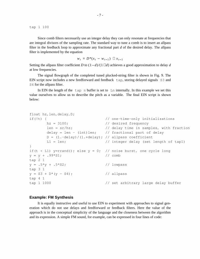
The views include a zoomable amplitude/time plot (Fig. 5), an adjustable FFT (Fig 6), cuedto the point of the cursor in the amplitude plot (the FFT changes as the cursor moves in the ampli-tude plot), and a spectrogram plot (Fig. 7): time is the horizontal axis, frequency the vertical axis,and grey-scale shows amplitude.

- 4 -
Fig. 3 Snapshot of a typical screen when using EIN.
Example: Tunable Plucked StringAs a demonstration we will build a tunable plucked string filter (Jaffe and Smith 1983;
Karplus and Strong 1983) in several stages. We begin with the comb filter illustrated in Fig. 2,with a resonant frequency of sr/100 and a feedback gain coefficient of 0.99. Its definingequation is
w t = x t + 0.99*w t 100
The corresponding EIN script, using a built-in white noise generator, is therefore
y = rrand(); // white noise generator built-in to EINy = y + 0.99*S1;tap 1 100
Next, we create the classical plucked-string filter by limiting the length of the input signalto one pitch period and putting a feedforward lowpass filter within the feedback loop. Thedefining equation of the lowpass filter is
w t = 0.5*x t + 0.5*x t 1

- 5 -
Fig. 4 Enlargement of the main window, containing script scrollview and main con-trols.
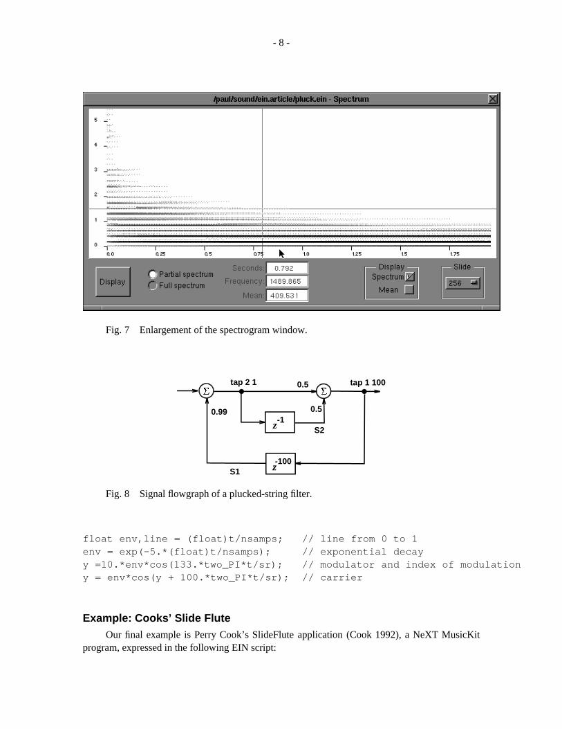
where x and w are its input and output respectively. Figure 8 shows the signal flowgraph of theentire plucked-string filter. The corresponding EIN script now includes a test which ensures thatthe input is turned off after 100 samples, and a new tap and assignment statement for the lowpassfilter:

- 6 -
Fig. 5 Enlargement of the time waveform window.
Fig. 6 Enlargement of the FFT window.
if(t < 100) y=rrand(); else y = 0;y = y + .99*S1;tap 2 1y = .5*y + .5*S2;
- 7 -
tap 1 100
Since comb filters necessarily use an integer delay they can only resonate at frequencies thatare integral divisors of the sampling rate. The standard way to tune a comb is to insert an allpassfilter in the feedback loop to approximate any fractional part d of the desired delay. The allpassfilter is implemented by the equation
w t = D*(x t w t 1 ) + x t 1
Setting the allpass filter coefficient D to (1 d)/(1 + d) achieves a good approximation to delay dat low frequencies.
The signal flowgraph of the completed tuned plucked-string filter is shown in Fig. 9. TheEIN script now includes a new feedforward and feedback tap, storing delayed signals S3 andS4 for the allpass filter.
In EIN the length of the tap n buffer is set to Ln internally. In this example we set thisvalue ourselves to allow us to describe the pitch as a variable. The final EIN script is shownbelow:
float hz,len,delay,D;if(!t) { // one-time-only initializations
hz = 3100; // desired frequencylen = sr/hz; // delay time in samples, with fractiondelay = len - (int)len; // fractional part of delayD = (1.-delay)/(1.+delay); // allpass coefficientL1 = len; // integer delay (set length of tap1)
}if(t < L1) y=rrand(); else y = 0; // noise burst, one cycle longy = y + .99*S1; // combtap 2 1y = .5*y + .5*S2; // lowpasstap 3 1y = S3 + D*(y - S4); // allpasstap 4 1tap 1 1000 // set arbitrary large delay buffer
Example: FM SynthesisIt is equally instructive and useful to use EIN to experiment with approaches to signal gen-
eration which do not use delays and feedforward or feedback filters. Here the value of theapproach is in the conceptual simplicity of the language and the closeness between the algorithmand its expression. A simple FM sound, for example, can be expressed in four lines of code:
- 8 -
Fig. 7 Enlargement of the spectrogram window.
z0.99
tap 2 1 0.5
0.5
tap 1 100
S2-1
-100S1 z
Fig. 8 Signal flowgraph of a plucked-string filter.
float env,line = (float)t/nsamps; // line from 0 to 1env = exp(-5.*(float)t/nsamps); // exponential decayy =10.*env*cos(133.*two_PI*t/sr); // modulator and index of modulationy = env*cos(y + 100.*two_PI*t/sr); // carrier
Example: Cooks’ Slide FluteOur final example is Perry Cook’s SlideFlute application (Cook 1992), a NeXT MusicKit
program, expressed in the following EIN script:

- 9 -
float ysave,amp,randamp;float line = (float)t/nsamps;if(!t) {
amp = 1;randamp = .04;
}y=( rrand()/32767.)*randamp* amp;y += amp; // breath pressure with rand devy = y + (S1 * -.35); // mix with pressure of returning wavetap 2 10 // embouchure, time to cross mouth holey = S2;y = (y * y * y) - y; // transfer differential across mouth holey = (.2*y) + (.95 * S1); // jet stream plus full waveysave = y; // listen to output herey = (.7 * y) + (.3 * S3);// low pass at end of tubetap 3 1tap 1 30 // fundamentaly = ysave;
S3
tap 1 1000tap 4 1
tap 3 1
tap 2 1
0.99
S1
0.5
0.5
S4
D
-1
S2-1-1
-1000
z
z
z
z-1
Fig. 9 Signal flowgraph of the plucked-string filter with an allpass filter added fortuning.
This is a model of a jet wind instrument. After initialization, the first two lines model a constantbreath pressure with a slight random perturbation. This is then added to 35% of the phase-inverted previous returning wave, stored in tap 1. (The flute is considered a tube open at bothends. The length of tap 1 models the length of the flute — this example is really a model of aslide flute, which is constantly changing size, rather than a flute with finger holes.) The next line,y = y 3 y, is a rough approximation to the action of the air blowing across the mouth hole,and 20% of this is added to 95% of the mixture of the left and right-going waves. Tap 2 modelsthe time it takes the breath to flow across the mouth hole. Finally, a model is created of the low-

- 10 -
pass effect created by the open end of the tube (tap 3). Cook’s signal flow graph is shown in Fig.10.
***
1 PoleFilter
n
p g
rdl
dl2
r2
Ampl.Env.
NoiseGen.
+-
Fig. 10 Signal flow graph of Cook’s slide flute model. This picture is courtesy ofPerry Cook.
ConclusionWe’ve found EIN to be useful both as a workbench for experimentation with filters and sig-
nals, and as a classroom tool while teaching introductory courses in computer music and digitalsignal processing. Its conceptual simplicity and freedom from elaborate syntactical rules allow itto be introduced at the earliest stages of a course. The use of multiple views of a sound, as well asauditory output, provide the student with feedback and reinforcement on several levels.
EIN is available by anonymous ftp in /pub/music on princeton.edu.
We conclude with an amusement. More than one beginning student has been tripped up bythe following puzzle, whose solution we leave as an exercise for the reader. The assignment is towrite an EIN script to generate a sine wave which will glissando from 2000 to 3000 Hz. The fol-lowing script would seem to do the trick:
float line = 2000 + 1000.*(float)t/nsamps; // line from 2000 to 3000y = sin( line*two_PI*t/sr ); // compute sine
but the spectrogram from EIN shown in Fig. 10 reveals that life is not always that simple...

- 11 -
Fig. 11 Spectrogram of the signal generated by the concluding puzzle.
AcknowledgmentThis work was supported by NSF Grants CDA91-15189 and MIP-9201484. The FFT and
spectral displays were taken from Edsnd, by James Pritchett, with work by Steven M. Boker.Thanks to Perry Cook, who provided help with the slide flute example and permission to use Fig10.
References
P. R. Cook. 1992. ‘‘A Meta-Wind-Instrument Physical Model and a Meta-Controller for RealTime Performance Control.’’ Proceedings of the International Computer Music Associa-tion, San Jose, California, Oct. 14-18, 1992, 273-276.
D. A. Jaffe and J. O. Smith. 1983. ‘‘Extensions of the Karplus-Strong Plucked-String Algo-rithm.’’ Computer Music J., 7: 56-69.
K. Karplus and A. Strong. 1983. ‘‘Digital Synthesis of Plucked-String and Drum Timbres.’’Computer Music J., 7: 43-55.
M.V. Mathews. 1969. The Technology of Computer Music. Cambridge, Massachusetts: M.I.T.Press.
K. Steiglitz. 1990. ‘‘Ein Kleiner Filter Compiler.’’ Tech. Report CS-TR-279-90. Computer Sci-ence Department, Princeton University.
Appendix 1: Some Details about Buffers in EINThe kernel of EIN, without the interface, is a very simple C pre-processor, originally only
about 50 lines long (Steiglitz 1990). In a single pass of the user’s EIN script, each non-tap lineis simply passed to the output, using the appropriate values from buffers for the Si. The onlyslightly delicate issue is the way the circular buffers for storing delayed signals are handled.

- 12 -
When a tap i k line is encountered, a new buffer Bi of length N is declared to be anarray, together with the int index into that array, IDi. Then code is generated that stores thesignal at that point in the buffer. For example, the script line tap 1 100 used to save thefeedback signal in a comb filter generates the code
B1[ID1++] = y;ID1 = ID1%L1;
where the integer variable L1 is equal to 100. The index ID1 is incremented after it is used,and then taken modulo the length of the buffer.
The only tricky point concerns the definition of the length N of the buffer. Suppose L isthe desired loop delay, the parameter in the EIN script. When the loop is a feedback loop, N =L; when the loop is a feedforward loop, N = L + 1. It is then not hard to verify that the buffervalue Bi[IDi] provides a signal with the desired delay. The extra buffer storage location in thecase of a feedforward loop is necessary because in that case the tap command is encounteredduring the same ‘‘clock’’ cycle that the signal is used.
It also follows from this arrangement that the case L = 0 is allowed for a feedforwardloop, corresponding to a buffer of length 1; the present signal value is simply saved for use duringthe same clock cycle of the filter. This is critical for the generality of the specification language,discussed in Appendix 4. A signal may be used both before and after its corresponding tap, butthe user must remember that because the signal is used before its tap, the length of its buffer isthat of a feedback signal, and uses after its tap are delayed one fewer sampling interval than thedesignated delay. As an example, if signal S1 is used both before and after tap 1 1, usesbefore the tap are delayed 1 interval, but uses after are delayed 0 intervals.
Appendix 2: WarningThe example of the tuned plucked-string filter illustrated how the internally generated vari-
able L1 can be changed by the knowledgeable user. The other side of the coin is that the inter-nally generated variable names of the form Li, Bi, and IDi are reserved by EIN and unwit-ting use of them will cause havoc. Besides that, the parsing for the signal variables Si in theuser’s script is primitive in the current version of EIN, and no other names are allowed to beginwith ‘‘S’’.
Appendix 3: Random Access to Input in EINBesides the signal and buffer variables just mentioned the following are all the reserved
words in EIN:
float y, left, right, sr, two_PI;int t, nsamps, inputskip;short *inputsig;
All the others besides inputskip and *inputsig were described at the beginning of thispaper. These latter two variables provide random access to an input signal if one is being used.
The pointer *inputsig is the address of an array of short integers containing all thesamples of an input soundfile. If the soundfile is mono, the sample numbers are equal to array

- 13 -
locations. If the soundfile is stereo, the even indices represent the left channel and the odd indicesthe right channel. The sample number is then equal to t/2 (+1 for the right channel). If an inputfile has been opened the values of y are the current samples of the input signal, but the input-sig[] array can also be used to arbitrarily address parts of the input soundfile.
The integer inputskip is the sample number at which the input signal is taken to start.This will be a number other than 0 if it is specified in the ‘‘input skip:’’ form for an input file (seethe screen snapshot in Fig. 3). Therefore, if a sound is accessed via the *inputsig array, itssamples should be referred to by saying inputsig[t + inputskip].
Appendix 4: A Remark about GeneralityAny signal flowgraph G that represents a realizable digital filter can be represented in an
EIN script using ordinary C code, plus tap statements.
The following informal argument should be convincing: Start with any signal flowgraphand remove the delay elements. What remains must be free of loops, because it represents thecomputation done during one sampling interval, and a loop would mean there would be no step-by-step procedure for finding the next output value.
The next claim is that the nodes in the flowgraph with the delays removed can be orderedfrom left-to-right, with no branches in the right-to-left direction. To do this, notice that there mustbe a node with no incoming branches. If there were not, there would be a loop, because we couldstart at a node and follow it backwards forever. Remove that node, putting it on the left end. Nowrepeating this process results in a left-to-right ordering that satisfies the claim.
In technical jargon, the flowgraph with the delay elements removed is a directed acyclicgraph (dag), and a dag can always be topologically sorted.
The left-to-right order of the nodes now determines an order in which an EIN script canevaluate the corresponding variables. The left-to-right arcs in the flowgraph without the delaysare implemented with feedforward (left-to-right) arcs with delay zero, and the remaining arcswith feedforward arcs with delays L 1 and feedback arcs with delays L 1.