Effectiveness of Negative Pulsed-Pressure Myofascial ... - MDPI
Upload
3rabonlineCategory
view
2download
0
Effect of intense pulsed ion beams irradiation on theoxidation behavior of c0-based superalloy
Hongtao Zhang a, Tianmin Wang a,*, Cong Wang a, Baoxi Han b, Sha Yan b,Weijiang Zhao b, Yafang Han c
a Center of Material Physics and Chemistry, School of Science, Beijing University of Aeronautics and Astronautics, Beijing 100083, Chinab Institute of Heavy Ion Physics, Peking University, Beijing 100871, China
c Beijing Institute of Aeronautical Materials, Beijing 100095, China
Received 16 October 2001; received in revised form 26 June 2002
Abstract
Intense pulsed ion beams (IPIB) with three different power densities (25, 37.5 and 50 MW/cm2) are employed for the
surface treatment of c0-based superalloy IC6. The influence of IPIB irradiation on the oxidation behavior of IC6 at 1100
�C for up to 100 h is investigated. It is found that the phase states of IC6 are dramatically changed after IPIB irradiationand the oxidation behavior of the irradiated coupons depends greatly on the power density of IPIB. IPIB irradiation
with a power density of 25 or 37.5 MW/cm2 significantly reduces the oxidation rate with respect to the unirradiated
coupon. The improvement of the oxidation resistance can be attributed to a change in the oxidation products from a
three-layered scale of Ni-rich oxides for the unirradiated coupon to a two-layered scale of Mo- and Al-rich oxides. In
contrast, IPIB irradiation with a power density of 50 MW/cm2 proves to be detrimental, causing a higher oxidation rate.
The oxidation mechanism for IPIB irradiated coupons is discussed.
� 2002 Elsevier Science B.V. All rights reserved.
Keywords: Intense pulsed ion beams; Irradiation; Alloy IC6; Short-circuit diffusion paths
1. Introduction
Intense pulsed ion beams (IPIB) have been de-
veloped over the last two decades as a prospective
technique for surface modification of materials [1–
3]. When irradiated by IPIB, the near-surface layer
of targets undergoes a rapid melt and solidification
with heating and cooling rates of 108–1010 K/s.
Such rates are high enough to result in phase and
microstructure changes, such as the formation ofamorphous phase and nonequilibrium micro-
structures [4,5]. These changes are responsible for
the property modification of target materials. For
example, both wear resistance and surface hard-
ness of AISI-4620 steel and O-1 tool steel have
been considerably improved after exposure to
IPIB [3,6]. Since oxidation resistance is one of the
most important surface-related properties forhigh-temperature alloys, it should be expected that
IPIB irradiation can affect this property of the
alloys. However, investigations dealing with the
Nuclear Instruments and Methods in Physics Research B 197 (2002) 83–93
www.elsevier.com/locate/nimb
*Corresponding author. Tel.: +86-10-8231-7931; fax: +86-
10-8231-5933.
E-mail addresses: [email protected] (H. Zhang),
[email protected] (T. Wang).
0168-583X/02/$ - see front matter � 2002 Elsevier Science B.V. All rights reserved.
PII: S0168-583X(02 )01335-6

effects of IPIB irradiation on oxidation behavior
have not yet been fully undertaken.
In the present work the possibility of improving
the oxidation resistance of Ni3Al based superalloyby IPIB irradiation was studied. The directionally
solidified (DS) c0-based superalloy IC6 is selected
as the object of investigation because of its ex-
ceptional properties, such as high incipient melting
temperature (1315 �C), good ductility from room
temperature to 1100 �C, excellent high tempera-
ture rupture strength, etc. [7]. The isothermal ox-
idation tests of IC6 unirradiated and irradiated byIPIB were performed at 1100 �C, which is the
operating temperature for IC6 [8].
2. Experimental
The master alloy with the chemical composition
of Ni–(7.5–8.5)Al–(13–15)Mo–(0.02–0.1)B (inwt%) was first prepared in a vacuum induction
furnace. Then the columnar grain rods were pro-
duced by rapid solidification technique in a com-
mercial DS vacuum induction furnace. The as-cast
rods were homogenized at 1260 �C for 10 h fol-
lowed by oil quenching in order to minimize the
segregation in the as-cast condition and to obtain
optimum mechanical properties. To obtain targetcoupons, the heat-treated rods were cut trans-
versely into 15� 10� 2 mm3 plates along the di-
rection of solidification growth. Then the coupons
were mechanically polished to Ra � 0:1 lm. Irra-diations were performed on the TEMP techno-
logical accelerator from the Nuclear Physics
Institute, Tomsk Polytechnic University in Russia
[9,10]. The beam consisted of carbon ions (70%)and protons (30%). The coupons were irradiated
respectively with three kinds of maximum ion
current density (J) and pulse number (n) at the
same maximum accelerating voltage (V ¼ 250 kV)
and pulse duration (s ¼ 60 ns, full width at half-
maximum), i.e. J1 ¼ 100 A/cm2, n1 ¼ 24, P1 ¼VJ1 ¼ 25 MW/cm2; J2 ¼ 150 A/cm2, n2 ¼ 16,
P2 ¼ VJ2 ¼ 37:5 MW/cm2; J3 ¼ 200 A/cm2, n3 ¼12, P3 ¼ VJ3 ¼ 50 MW/cm2. The distance from
beam generation to irradiated coupons is about 20
cm. The reproducibility of pulse power from shot
to shot is better than 20%. Only the two large faces
of the coupons were irradiated, accounting for
about 75–80% of the total surface area. In order to
study the effect of the IPIB power density solely,
the ion doses for three kinds of the irradiatedcoupons were controlled at approximately same
level (1� 1014 ions/cm2).
Prior to oxidation tests, the phase states of the
unirradiated and irradiated coupons were in-
spected by X-ray diffraction (XRD) with Cu-Karadiation at 40 kV and 40 mA. Then all coupons
were cleaned ultrasonically in ethanol. Isothermal
oxidation tests were performed at 1100 �C in staticair for up to 100 h. The coupons were quickly
inserted into the heat zone of the furnace at the
beginning of tests. The mass changes of coupons
were monitored continuously by a balance with a
resolution of 0.1 mg.
Following oxidation, the oxidation products
were characterized by XRD, scanning electron
microscopy (SEM) and energy dispersive X-rayanalysis (EDXA).
3. Results
3.1. XRD analysis of as-irradiated coupons
Fig. 1 shows the XRD patterns of unirradiatedand irradiated coupons. As might be expected, the
Fig. 1. XRD spectra of the unirradiated and irradiated cou-
pons.
84 H. Zhang et al. / Nucl. Instr. and Meth. in Phys. Res. B 197 (2002) 83–93
unirradiated coupon consisted mainly of c0-Ni3(Al, Mo). There were only two peaks of (2 0 0) and
(1 0 0) from c0 phase for the coupon irradiated by
IPIB with a low power density P1 (hereafter re-ferred as ‘‘P1 coupon’’). The relative peak heightratio of (2 0 0) to (1 0 0) was great. It is obvious
that the preferred orientation was present in the
surface layer of P1 coupon. For the coupon irra-diated by IPIB with a moderate power density P2(hereafter referred as ‘‘P2 coupon’’), only the (2 0 0)peak from c0 phase remained. So the preferred
orientation still existed. Moreover, a slight rise andbroadening of the background over a 2h range 45–55� suggests the formation of minor amorphous c0
phase on the surface of P2 coupon. A new phase,
besides c0, appeared on the surface region of the
coupon irradiated by IPIB with a high power
density P3 (hereafter referred as ‘‘P3 coupon’’).
However, the number of diffraction peaks was too
limited to ascertain what the new phase was. Per-haps it was Ni2Al3.
3.2. Kinetic study
The isothermal oxidation kinetics for the unir-
radiated and irradiated coupons at 1100 �C for
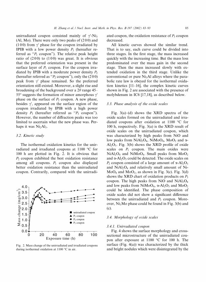
100 h are plotted in Fig. 2. It is obvious that
P2 coupon exhibited the best oxidation resistanceamong all coupons. P1 coupon also displayed
better oxidation resistance than the unirradiated
coupon. Contrarily, compared with the unirradi-
ated coupon, the oxidation resistance of P3 coupondecreased.
All kinetic curves showed the similar trend.
That is to say, each curve could be divided intothree stages. In the first stage, the mass increased
quickly with the increasing time. But the mass loss
predominated over the mass gain in the second
stage. Then the mass increased slowly with ex-
tended oxidation in the third stage. Unlike the
conventional or pure Ni3Al alloys where the para-
bolic rate law is obeyed for the isothermal oxida-
tion kinetics [11–16], the complex kinetic curvesshown in Fig. 2 are associated with the presence of
molybdenum in IC6 [17,18], as described below.
3.3. Phase analysis of the oxide scales
Fig. 3(a)–(d) shows the XRD spectra of the
oxide scales formed on the unirradiated and irra-
diated coupons after oxidation at 1100 �C for100 h, respectively. Fig. 3(a) is the XRD result of
oxide scales on the unirradiated coupon, which
was characterized by high peaks from NiO and
low peaks from NiAl2O4, NiMoO4, MoO2 and a-Al2O3. Fig. 3(b) shows the XRD profile of oxide
scales on P1 coupon. The main oxides were
NiAl2O4 and NiMoO4. Small peaks from MoO2
and a-Al2O3 could be detected. The oxide scales onP2 coupon consisted of a large amount of a-Al2O3
and NiAl2O4 and relatively small amount of Ni-
MoO4 and MoO2, as shown in Fig. 3(c). Fig. 3(d)
shows the XRD chart of oxidation products on P3coupon. The high peaks from NiO and NiAl2O4
and low peaks from NiMoO4, a-Al2O3 and MoO2
could be identified. The phase composition of
oxide scales did not show a significant differencebetween the unirradiated and P3 coupon. More-over, Ni3Mo phase could be found in Fig. 3(b) and
(c).
3.4. Morphology of oxide scales
3.4.1. Unirradiated coupon
Fig. 4 shows the surface morphology and cross-sectional microstructure of the unirradiated cou-
pon after exposure at 1100 �C for 100 h. The
surface (Fig. 4(a)) was characterized by the thick
and bright nodules which were disintegrated by theFig. 2. Mass change of the unirradiated and irradiated coupons
during isothermal oxidation at 1100 �C in air.
H. Zhang et al. / Nucl. Instr. and Meth. in Phys. Res. B 197 (2002) 83–93 85

dark islands in some regions. EDXA results indi-
cated that the bright nodules were NiO and the
dark islands were a mixture of nickel and alumi-
num oxides. A magnified examination of bright
nodules revealed that the average size of NiO
grains was about 5 lm (Fig. 4(b)). Cross-sectional
investigations (Fig. 4(c)) revealed that the oxida-tion products consisted of three layers. From
EDXA and XRD results it was found that the
outer layer contained NiO and the intermediate
layer contained a large amount of the spinel phase
(NiAl2O4) and a small amount of NiMoO4 and
MoO2. An Al-rich continuous layer formed in the
inner layer consisted of a-Al2O3. A diffusion layer
enriched in Mo and depleted in Al was devel-
oped beneath the oxide scales, irrespective of IPIB
irradiation.
3.4.2. P1 and P2 coupon
Both surface and cross-sectional examinations
revealed that the microstructure of oxide scales
formed on P1 coupon was similar to that formed
Fig. 3. XRD spectra of oxide scales formed at 1100 �C for
100 h: (a) unirradiated coupon; (b) P1 coupon; (c) P2 coupon;(d) P3 coupon.
Fig. 4. Scale pattern of the unirradiated coupon after oxidation
at 1100 �C for 100 h: (a) overview of surface morphology; (b) a
high magnification of bright area in (a); (c) cross-sectional mi-
crostructure.
86 H. Zhang et al. / Nucl. Instr. and Meth. in Phys. Res. B 197 (2002) 83–93
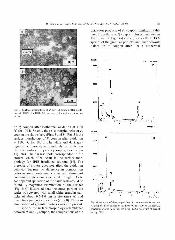
on P2 coupon after isothermal oxidation at 1100�C for 100 h. So only the scale morphologies of P2coupon are shown here (Figs. 5 and 8). Fig. 5 is the
surface morphology of P2 coupon after oxidationat 1100 �C for 100 h. The white and dark grey
regions continuously and randomly distributed on
the outer surface of P1 and P2 coupon, as shown inFig. 5(a). The darkest spots corresponded to the
craters, which often occur in the surface mor-phology for IPIB irradiated coupons [19]. The
presence of craters does not affect the oxidation
behavior because no difference in composition
between zone containing craters and those not
containing craters can be detected through EDXA.
No apparent spallation of the oxide scales could be
found. A magnified examination of the surface
(Fig. 5(b)) illustrated that the outer part of thescales was covered with small white granular par-
ticles of about 0.5–1.0 lm in size (area A) and
much finer grey network oxides (area B). The con-
glomeration of granular particles was also present.
In spite of the surface morphology resemblance
between P1 and P2 coupon, the compositions of the
oxidation products of P1 coupon significantly dif-fered from those of P2 coupon. This is illustrated inFigs. 6 and 7. Fig. 6(a) and (b) shows the EDXA
spectra of the granular particles and finer networkoxides on P1 coupon after 100 h isothermal
Fig. 5. Surface morphology of P2 (or P1) coupon after oxida-tion at 1100 �C for 100 h: (a) overview; (b) a high magnificationin (a).
Fig. 6. Analysis of the composition of surface scale formed on
P1 coupon after oxidation at 1100 �C for 100 h: (a) EDAX
spectrum of area A in Fig. 5(b); (b) EDAX spectrum of area B
in Fig. 5(b).
H. Zhang et al. / Nucl. Instr. and Meth. in Phys. Res. B 197 (2002) 83–93 87
oxidation at 1100 �C, respectively. The carbon
peak came from carbon deposited on the coupon.
It is evident that for P1 coupon, molybdenum was
richer in the granular particles than in the network
oxides, while the opposite concentration distribu-
tion for aluminum was formed on the surface of
oxide scales. Accordingly, the granular particles
contained mainly NiMoO4 and MoO2, and the
network oxides contained a mixed oxide enriched
in aluminum, i.e. NiAl2O4 and a-Al2O3, which wasconsistent with the XRD results. In comparison
with the unirradiated coupon, appreciable amount
of molybdenum appeared on the outer surface of
P1 coupon after exposure at 1100 �C for 100 h. It
was evident that the outward diffusion of molyb-
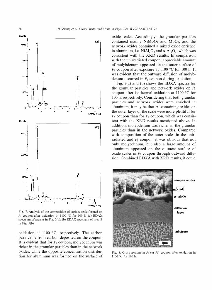
denum occurred in P1 coupon during oxidation.Fig. 7(a) and (b) shows the EDXA spectra for
the granular particles and network oxides on P2coupon after isothermal oxidation at 1100 �C for
100 h, respectively. Considering that both granular
particles and network oxides were enriched in
aluminum, it may be that Al-containing oxides on
the outer layer of the scale were more plentiful for
P2 coupon than for P1 coupon, which was consis-tent with the XRD results mentioned above. In
addition, molybdenum was richer in the granularparticles than in the network oxides. Compared
with composition of the outer scales in the unir-
radiated and P1 coupon, it was obvious that notonly molybdenum, but also a large amount of
aluminum appeared on the outmost surface of
oxide scales in P2 coupon through outward diffu-sion. Combined EDXA with XRD results, it could
Fig. 7. Analysis of the composition of surface scale formed on
P2 coupon after oxidation at 1100 �C for 100 h: (a) EDAX
spectrum of area A in Fig. 5(b); (b) EDAX spectrum of area B
in Fig. 5(b).
Fig. 8. Cross-sections in P2 (or P1) coupon after oxidation in1100 �C for 100 h.
88 H. Zhang et al. / Nucl. Instr. and Meth. in Phys. Res. B 197 (2002) 83–93
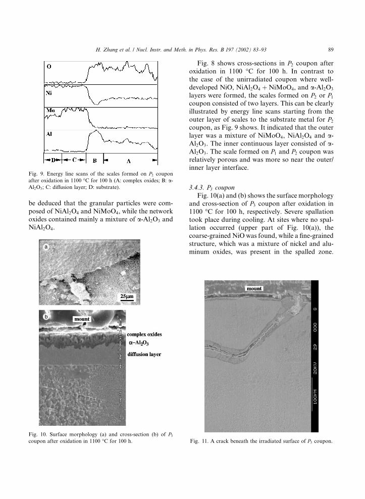
be deduced that the granular particles were com-
posed of NiAl2O4 and NiMoO4, while the network
oxides contained mainly a mixture of a-Al2O3 and
NiAl2O4.
Fig. 8 shows cross-sections in P2 coupon afteroxidation in 1100 �C for 100 h. In contrast to
the case of the unirradiated coupon where well-
developed NiO, NiAl2O4 þNiMoO4, and a-Al2O3
layers were formed, the scales formed on P2 or P1coupon consisted of two layers. This can be clearly
illustrated by energy line scans starting from the
outer layer of scales to the substrate metal for P2coupon, as Fig. 9 shows. It indicated that the outer
layer was a mixture of NiMoO4, NiAl2O4 and a-Al2O3. The inner continuous layer consisted of a-Al2O3. The scale formed on P1 and P2 coupon wasrelatively porous and was more so near the outer/
inner layer interface.
3.4.3. P3 coupon
Fig. 10(a) and (b) shows the surface morphology
and cross-section of P3 coupon after oxidation in1100 �C for 100 h, respectively. Severe spallation
took place during cooling. At sites where no spal-lation occurred (upper part of Fig. 10(a)), the
coarse-grained NiO was found, while a fine-grained
structure, which was a mixture of nickel and alu-
minum oxides, was present in the spalled zone.
Fig. 9. Energy line scans of the scales formed on P2 couponafter oxidation in 1100 �C for 100 h (A: complex oxides; B: a-Al2O3; C: diffusion layer; D: substrate).
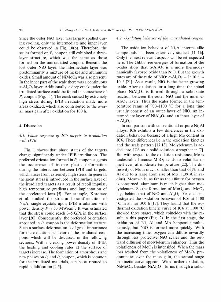
Fig. 10. Surface morphology (a) and cross-section (b) of P3coupon after oxidation in 1100 �C for 100 h. Fig. 11. A crack beneath the irradiated surface of P3 coupon.
H. Zhang et al. / Nucl. Instr. and Meth. in Phys. Res. B 197 (2002) 83–93 89
Since the outer NiO layer was largely spalled dur-
ing cooling, only the intermediate and inner layer
could be observed in Fig. 10(b). Therefore, the
scales formed on P3 coupon still exhibited a three-layer structure, which was the same as those
formed on the unirradiated coupon. Beneath the
lost outer NiO layer, the intermediate layer was
predominantly a mixture of nickel and aluminum
oxides. Small amount of NiMoO4 was also present.
In the inner part of the scale there was a continuous
a-Al2O3 layer. Additionally, a deep crack under the
irradiated surface could be found in somewhere ofP3 coupon (Fig. 11). The crack caused by extremelyhigh stress during IPIB irradiation made more
areas oxidized, which also contributed to the over-
all mass gain after oxidation for 100 h.
4. Discussion
4.1. Phase response of IC6 targets to irradiation
with IPIB
Fig. 1 shows that phase states of the targets
change significantly under IPIB irradiation. The
preferred orientation formed in P1 coupon suggeststhe occurrence of intense plastic deformation
during the interaction between IPIB and targets,which arises from extremely high stress. In general,
the great stress is introduced in the surface layer of
the irradiated targets as a result of recoil impulse,
high temperature gradients and implantation of
the accelerated ions [5]. For example, Korotaev
et al. studied the structural transformation of
Ni3Al single crystals upon IPIB irradiation with
power density P � 50 MW/cm2. It was estimatedthat the stress could reach 3–5 GPa in the surface
layer [20]. Consequently, the preferred orientation
appeared in P1 coupon is the deformation texture.Such a surface deformation is of great importance
for the oxidation behavior of the irradiated cou-
pons, which will be discussed in the following
sections. With increasing power density of IPIB,
the heating and cooling rates at the surface oftargets increase. The formation of amorphous and
new phases on P2 and P3 coupon, which is commonfor the irradiated materials, can be attributed to
rapid solidification [4,5].
4.2. Oxidation behavior of the unirradiated coupon
The oxidation behavior of Ni3Al intermetalliccompounds has been extensively studied [11–16].
Only the most relevant aspects will be retrospected
here. The Gibbs free energies of formation of the
oxides show that a-Al2O3 is a more thermody-
namically favored oxide than NiO. But the growth
rates are of the ratio of NiO: a-Al2O3 ¼ 1: 10�3 �10�4 [21]. As a result, NiO is the faster growing
oxide. After oxidation for a long time, the spinelphase NiAl2O4 is formed through a solid-state
reaction between the outer NiO and the inner a-Al2O3 layers. Thus the scales formed in the tem-
perature range of 900–1100 �C for a long time
usually consist of an outer layer of NiO, an in-
termediate layer of NiAl2O4 and an inner layer of
a-Al2O3.
In comparison with conventional or pure Ni3Alalloys, IC6 exhibits a few differences in the oxi-
dation behaviors because of a high Mo content in
IC6. These differences lie in the oxidation kinetics
and the scale pattern [17,18]. Molybdenum is ad-
ded into IC6 as a solid-solution strengthener [7].
But with respect to the oxidation resistance, Mo is
undesirable because MoO3 tends to volatilize or
melt even at moderate temperature [22]. The dif-fusivity of Mo is much smaller than that of Ni and
Al due to a large atom size of Mo (1.39 �AA in ra-
dius). Meanwhile, as far as the affinity for oxygen
is concerned, aluminum is much higher than mo-
lybdenum. So the formation of MoO2 and MoO3
lags behind that of NiO and Al2O3. Ye et al. in-
vestigated the oxidation behavior of IC6 at 1100
�C in air for 300 h [17]. They found that the iso-thermal oxidation kinetic curve of IC6 at 1100 �Cshowed three stages, which coincides with the re-
sult in this paper (Fig. 2). In the first stage, the
oxidation of Ni, Al and Mo happens simulta-
neously, but NiO is formed more quickly. With
the increasing time, oxygen can diffuse inwardly
through less protective NiO scales and the out-
ward diffusion of molybdenum enhances. Thus thevolatileness of MoO3 is intensified. When the mass
loss resulted from the volatileness of MoO3 pre-
dominates over the mass gain, the second stage
in kinetic curve appears. With further oxidation,
NiMoO4, besides NiAl2O4, forms through a solid-
90 H. Zhang et al. / Nucl. Instr. and Meth. in Phys. Res. B 197 (2002) 83–93
state reaction between Mo and NiO [23]. The
continuous layer of a-Al2O3 is developed as well.
On the one hand, the healing layer of a-Al2O3 can
hinder the migration of molybdenum. On theother hand, the supply of Mo via the outward
diffusion can not keep pace with the volatileness of
MoO3 because of a low diffusivity of Mo. Hence
the volatileness of MoO3 is gradually retarded and
the oxidation rate increases slowly, as the case
in the third stage of the kinetic curve. Beneath the
healing layer of a-Al2O3 there is a diffusion layer
(i.e. Al-depleted zone). With progressive oxida-tion, the outward diffusion of nickel and alumi-
num makes molybdenum so supersaturated in the
diffusion layer that the new phase Ni3Mo is
formed by phase transformation [24], as found in
Fig. 3.
4.3. Oxidation behavior of the irradiated coupons
Both the mass change measurements and anal-
ysis about the composition and microstructure of
oxide scales reveal that IPIB irradiation not only
alters the oxidation rate, but also induces a sig-
nificant change in the oxidation mechanism. Since
the chemical compositions of the IC6 alloy are
fixed even after exposure to IPIB, the change of
phase state and microstructure induced by IPIBirradiation should be taken into consideration to
account for the oxidation behavior of the irradi-
ated coupons. Compared with the unirradiated
coupon, the crystalline defects (point defects and
dislocations) remarkably increase in the surface
layer of the irradiated coupons owing to rapid
solidification during irradiation [5,25]. When the
coupon is irradiated by IPIB with a low powerdensity P1, the formation of deformation texture inP1 coupon indicates that intense plastic deforma-tion has taken place and a large strain energy has
been stored in alloy IC6. Such a high stored energy
can give rise to recrystallization when P1 coupon isheated to the test temperature [26]. Subsequently,
numerous grain boundaries can be produced on
the deformed surface of the alloy during oxidation.Investigations by Giggins and Pettit on Ni–Cr
alloys found that the fine-grained structures ap-
peared on the cold-worked alloy surface via re-
crystallization when the specimens were tested at
900/1100 �C [27]. All kinds of defects in the form
of grain boundaries, point defects and dislocations
can serve as preferential sites for nucleation of
oxides or as short-circuit diffusion paths by locallyfavoring diffusion of the metal [28]. The selec-
tive oxidation of chromium could be promoted.
Accordingly, the oxidation resistance of Ni–Cr
alloys was improved after cold working. The
beneficial effect caused by the fine-grain structure
is also demonstrated by many investigations. For
example, Wang et al. studied the oxidation be-
havior of the sputtered microcrystalline coatings[29,30]. They found that the oxidation products for
microcrystalline Ni3Al at 1000–1100 �C consisted
of a-Al2O3 and NiAl2O4, in contrast to the case of
the coarse-grain Ni3Al alloy where Ni-rich oxides
were formed. The improvement of oxidation re-
sistance of microcrystalline Ni3Al was corre-
spondingly attributed to the change of the oxide
scale pattern. Their results are therefore in goodaccordance with the results observed here. There is
no doubt that IPIB irradiation can induce a deeper
deformed zone and a higher energy deposition in
the surface of coupons than general cold work.
This can be given evidences by the appearance of
deformation texture in P1 coupon, amorphous c0
phase in P2 coupon and new phase in P3 coupon.Thus short-circuit diffusion, which results from thenumerous defects induced by IPIB irradiation as
well as abundant grain boundaries induced by re-
crystallization on the deformed surface, plays an
important role in the oxidation behavior of the
irradiated coupons. In spite of low diffusivity of
molybdenum, the outward diffusion of molybde-
num is dramatically enhanced, let alone the case of
nickel and aluminum. The formation of NiAl2O4
and NiMoO4 by the solid-state reaction and the
establishment of a healing layer of a-Al2O3 are
facilitated by the enhanced diffusion of cations. It
is well known that NiMoO4 has a good stability up
to 1150 �C [23], and the spinel (NiAl2O4) structure
is comparatively free of defects when compared to
the simple structure of NiO [14]. The better oxida-
tion resistance of P1 coupon arises from the changeof scale pattern from Ni-rich oxides in unirradi-
ated coupon to Mo- and Al-rich oxides.
With the increasing power density of IPIB from
P1 to P2, minor amorphous c0 phase is formed on
H. Zhang et al. / Nucl. Instr. and Meth. in Phys. Res. B 197 (2002) 83–93 91

the surface of P2 coupon. The best oxidation re-sistance of P2 coupon results from the increasing
amount of Al-rich oxides in the scales. The for-
mation of Al-rich oxides, i.e. the selective oxidationof aluminum, should be correlated not only with
the deformed surface, but also with the formation
of the amorphous c0 phase. Hampikian et al.
studied the effects of yttrium ion implantation on
the oxidation behavior of Ni–Cr and Co–Cr alloys
[31–33]. They found that both alloys contained
an amorphous surface phase as a result of suffi-
cient dose implantation of yttrium. Microstruc-ture analysis via transmission electron microscopy
showed that recrystallization of the amorphous
phase took place quickly in the first few minutes of
oxidation, which resulted in the fine-grain recrys-
tallized NiCr phase in Ni–Cr alloys and inter-
metallic phase for Co–Cr alloys. The improved
oxidation resistance of yttrium implanted Ni–20Cr
was ascribed to the fact that fine-grain NiCr viarecrystallization provides fast-diffusion paths for
chromium. Thus the selective oxidation of chro-
mium occurred. It is reasonable to assume that in
present experiment recrystallization of the amor-
phous phase occurs immediately after P2 coupon isinserted into the heat zone of the furnace. As a
result, the effect of short-circuit diffusion on the
oxidation behavior of P2 coupon becomes morepronounced because fine-grain structure via re-
crystallization can be synergeticly induced not only
by the deformed surface, as the case in P1 coupon,but also by the formation of the amorphous phase.
It is worth noting that the grain size of the scale
formed on P1 and P2 coupon is much smaller thanthat of the scale on the unirradiated coupon (cf.
Figs. 4(b) and 5(b)). This is also associated withthe increasing nucleation sites for the oxides by
means of short-circuit diffusion. A similar phe-
nomenon has been observed for a lot of alloy
systems in the previous work no matter the nu-
cleation sites for the oxides originate from the
dispersed rare-earth oxide phase [34] or from the
fine-grained structure of alloys [35,36].
The voids within the oxide scales for all irradi-ated coupons were more conspicuous than those in
the unirradiated coupon. In view of the fact that
the mobility of molybdenum in the irradiated
coupons is significantly enhanced during oxidation
by means of short-circuit diffusion paths, these
voids may be associated with the violent vola-
tileness of MoO3, which is in conformity with
the mass loss in oxidation kinetic (Fig. 2). Oncethe healing layer of a-Al2O3 is fully developed, the
volatileness of MoO3 is inhibited.
When the coupon is irradiated by IPIB with a
high power density P3, a new phase as well as the
crack appears in P3 coupon. The worst oxidationresistance of P3 coupon is attributed to the for-
mation of Ni-rich oxides as well as the extra mass
gain around the crack zone. The oxidation be-havior of P3 coupon is affected not only by the
effect of short-circuit diffusion, but also by the
appearance of this new phase. Unfortunately,
the effect of new phase on the oxidation behav-
ior of P3 coupon is still unclear because of uncer-tainty of new phase. But it can be concluded that
the IPIB irradiation with an extremely high power
density is harmful to the oxidation resistance ofalloy IC6.
5. Conclusion
The major conclusions from this study can be
summarized as follows:
(1) The change of the phase states for the irradi-
ated coupons depends on the power density
of IPIB. With the increasing power density
from 25 to 50 MW/cm2, the deformation tex-
tures from c0 phase, minor amorphous c0 phase
and new phase appear in turn.
(2) Compared with the unirradiated coupon, the
intense effects of short-circuit diffusion inducedby the change of the microstructures and phase
states after IPIB irradiation occur in the irradi-
ated coupons during oxidation at 1100 �C. Thescale pattern in the coupons irradiated by IPIB
with a power density of 25 and 37.5 MW/cm2
is characterized by two layers, consisting of
an outer layer of Mo- and Al-rich oxides and
an inner layer of a-Al2O3. The change in theoxidation products from a three-layered scale
of Ni-rich oxides for the unirradiated coupon
to such a two-layered scale of Mo- and Al-rich
oxides is responsible for the improved oxida-
92 H. Zhang et al. / Nucl. Instr. and Meth. in Phys. Res. B 197 (2002) 83–93

tion resistance. However, the IPIB irradiation
with an extremely high power density (50
MW/cm2) is harmful to the oxidation resis-tance of alloy IC6.
Acknowledgements
This work was sponsored by the Open Labo-
ratory of Solid Lubrication in Lanzhou Institute of
Chemical Physics under contract no. 9903, and byBeijing University of Aeronautics and Astronau-
tics for the basic research.
References
[1] D.J. Rej, H.A. Davis, J.C. Olson, G.E. Remnev, A.N.
Zakoutaev, V.A. Ryzhkov, V.K. Struts, I.F. Isakov, V.A.
Shulov, N.A. Nochevnaya, R.W. Stinnett, E.L. Neau, K.
Yatsui, W. Jiang, J. Vac. Sci. Technol. A 15 (3) (1997) 1089.
[2] D.C. Mcintyre, E.L. Neau, R.W. Stinnett, Adv. Mater.
Process. 5 (1999) 31.
[3] H.A. Davis, G.E. Remnev, R.W. Stinnett, K. Yatsui, MRS
Bull. 21 (1996) 58.
[4] M. Yastuzuka, Y. Hashimoto, T. Yamasaki, H. Uchida,
Jpn. J. Appl. Phys. 35 (1996) 1857.
[5] A.D. Pogrebnyak, Phys. Stat. Sol. (a) 117 (1990) 17.
[6] D.J. Rej, H.A. Davis, M. Nastasi, J.C. Olson, E.J.
Peterson, R.D. Reiswig, K.C. Walter, R.W. Stinnett,
V.K. Struts, Nucl. Instr. and Meth. B 127–128 (1997) 987.
[7] C.T. Liu, D.P. Pope, in: J.H. Westbrook, R.L. Fleischer
(Eds.), Intermetallics Compounds, Principles and Practices,
Vol. 2, John Wiley and Sons Ltd., England, 1995, p. 17
(Chapter 2).
[8] Y.F. Han, S.H. Li, M.C. Chaturvedi, Mater. Sci. Eng. A
160 (1993) 271.
[9] G.E. Remnev, I.F. Isakov, M.S. Opekounov, V.M. Mat-
vienko, V.A. Ryzhkov, V.K. Struts, I.I. Grushin, A.N.
Zakoutayev, A.V. Potyomkin, V.A. Tarbokov, A.N.
Pushkaryov, V.L. Kutuzov, M.Yu. Ovsyannikov, Surf.
Coat. Technol. 114 (1999) 206.
[10] I.F. Isakov, V.N. Kolodii, M.S. Opekounov, V.M. Mat-
vienko, S.A. Pechenkin, G.E. Remnev, Yu.P. Usov,
Vacuum 42 (1991) 159.
[11] J.D. Kuenzly, D.L. Douglass, Oxid. Met. 8 (1974) 139.
[12] S. Taniguchi, T. Shibata, H. Tsuruoka, Oxid. Met. 26
(1986) 1.
[13] S. Taniguchi, T. Shibata, Oxid. Met. 28 (1987) 155.
[14] S.C. Choi, H.J. Cho, Y.J. Kim, D.B. Lee, Oxid. Met. 46
(1996) 51.
[15] S.C. Choi, H.J. Cho, D.B. Lee, Oxid. Met. 46 (1996) 109.
[16] P. P�eerez, J.L. Gonz�aalez-Carrasco, P. Adeva, Oxid. Met. 48
(1997) 143.
[17] Y. Changjiang, L. Tiefan, S. Jianian, M. Xiaoyu, Acta
Metall. Sin. A 30 (1994) 44 (In Chinese).
[18] Y. Fuhe, L. Tiefan, C. Jiang, J. Chin. Soc. Corros. Protect.
18 (1998) 276 (in Chinese).
[19] B.P. Wood, A.J. Perry, L.J. Bitteker, W.J. Waganaar, Surf.
Coat. Technol. 108–109 (1998) 171.
[20] A.D. Korotaev, A.N. Tyumentsev, M.V. Tret�yak, Yu.P.Pinzhin, G.E. Remnev, D.A. Shchipakin, Phys. Met.
Metallogr. 89 (2000) 49.
[21] F.H. Stott, Mater. Sci. Technol. 5 (1989) 734.
[22] M. Simnad, A. Spilners, J. Met. 7 (1955) 1011.
[23] S.S. Brenner, J. Electrochem. Soc. 102 (1955) 7.
[24] Xiao Chengbo, Ph.D. Dissertation, Beijing Institute of
Aeronautical Materials, China, 1999.
[25] A.D. Pogrebnyak, G.E. Remnev, I.B. Kurakin, A.E.
Ligachev, Nucl. Instr. and Meth. B 36 (1989) 286.
[26] J.D. Verhoeven, in: Fundamentals of Physical Metallurgy,
John Wiley & Sons Inc., 1975, Chapter 10, p. 327.
[27] C.S. Giggins, F.S. Pettit, Trans. TMS-AIME 245 (1969)
2509.
[28] P. Kofstad, in: High Temperature Corrosion, Elsevier
Applied Science, England, 1988, Chapter 5, p. 141.
[29] W. Fuhui, L. Hanyi, Z. Shenglong, W. Weitao, Mater. Sci.
Progr. 7 (1993) 507 (in Chinese).
[30] W. Fuhui, Chin. J. Mater. Res. 12 (1998) 83 (in Chinese).
[31] J.M. Hampikian, Oxid. Met. 50 (1998) 123.
[32] J.M. Hampikian, D.I. Potter, Oxid. Met. 38 (1992) 125.
[33] J.M. Hampikian, D.I. Potter, Oxid. Met. 38 (1992) 139.
[34] J. Stringer, B.A. Wilcox, R.I. Jaffee, Oxid. Met. 5 (1972)
11.
[35] F. Wang, H. Lou, S. Zhu, W. Wu, Oxid. Met. 45 (1996)
39.
[36] F. Wang, Oxid. Met. 47 (1997) 247.
H. Zhang et al. / Nucl. Instr. and Meth. in Phys. Res. B 197 (2002) 83–93 93
Copyright © 2022 FDOKUMEN