Rotating Machine Technologies for Integration of Pulsed and ...
8
Rotating Machine Technologies for Integration of Pulsed and High Power Loads in Naval Electric Power Systems John Herbst, Hamid Ouroua, Angelo Gattozzi, Sid Pratap Center for Electromechanics University of Texas at Austin Austin, Texas USA [email protected] Abstract— Advanced electric sensors and weapons are placing increasing demands on the electric power distribution systems of future naval vessels and energy storage is viewed as a critical technology for effective integration of IPS architectures in these platforms. This paper shows that kinetic energy storage, i.e. stored in the angular momentum of a rotating mass, can be applied in differing topologies to address a range of ship power system applications. Rotating machine technologies are presented for UPS and load leveling applications as well as for high cycle rate pulsed power applications. Keywords—Flywheel; energy storage; pulsed power; uninterruptible power supply; hybrid energy storage module I. INTRODUCTION The U.S. Navy is developing integrated electric power systems (IPS) for future naval vessels. IPS architectures offer the potential for more effective use of installed power generation to service both propulsion and other high power electric loads. In IPS systems, the loads are typically of comparable scale to the power sources and in some cases the total load can exceed the available power generation on the ship. Pulsed or transient high power loads present significant challenges to the ship’s power system and the development of advanced power generation and energy storage technologies for effective management of these pulsed loads is critical to the successful integration of IPS architectures. Energy storage on ships is generally through fuel, batteries, capacitors, or kinetic energy storage. Modern kinetic energy storage systems include advanced technologies and materials that enable them to be the storage system of choice for some applications [1]. There are two primary applications for kinetic energy on naval electric power systems: uninterruptible power supply (UPS) to assure continuity of service to vital loads and load leveling for large transient loads. The UPS function includes operation during black-out starts and operation with a single electric power generation unit for optimum efficiency.The attributes of kinetic energy storage that makes it attractive for naval applications include: • Independent selection of power and energy capabilities • Very high power density and high energy density • Rapid charge/discharge • Essentially infinite cycle life The paper presents a brief description of advanced kinetic energy system topologies that provide increased energy and power density relative to earlier designs, along with examples of kinetic energy storage solutions for a range of applications Kinetic energy storage was the US Navy’s choice for EM launch of aircraft (EMALS). The EMALS pulsed power system will replace the steam catapult on the next generation aircraft carrier and will provide enhanced control of the launch forces to minimize stresses on the airframe. The system includes an array of several rotating machines used to store the energy for the launch and provide power to the linear induction motor that drives the catapult shuttle [2]. In addition, considerable efforts have been made for the inclusion of EM railguns on naval platforms. They offer increased velocity and extended range over traditional shipboard weapons and will allow the Navy to conduct precise, long-range naval surface fire support for land strikes; ship self- defense against cruise and ballistic missiles; and surface warfare to deter enemy vessels. EM railguns require short duration pulses at extremely high current and power levels – millions of amperes and tens of gigawatts of peak power. The application requires transient storage of energy at relatively high power levels followed by the discharge of this energy into the EM launcher at extremely high power levels [3]. There have been significant demonstrations that the energy can be stored kinetically and that residual energy in the system can be reclaimed to improve efficiency. Furthermore, the Navy is currently exploring the use of a hybrid energy storage module (HESM) to provide a device that supplements a high energy density storage medium with a high power density component to mitigate the impact of the pulsed loads on the ship’s power system. Although the HESM concept can be applied to any cyclic load, the initial evaluation focused on kinetic energy storage as the high power energy storage element and is being conducted in the context of repetitive cycling of a capacitor-based Pulse Forming Network (PFN) [4]. This study also recognizes that there is a kinetic energy storage approach to provide the extremely high power pulses required by the EM railgun that does not require capacitor- based PFNs. In fact, a higher peak power variant of the EMALS concept provides both the inertial energy storage and the transient output pulse needed for direct drive of an EM railgun. By minimizing the internal impedance of an electric machine, high current pulses can be extracted and an array of machines can potentially be used to meet the Navy’s requirements for the EM gun program [5]. The authors would like to gratefully acknowledge the Office of Naval Research and the Naval Surface Warfare Center Carderock Division for their support of these research programs.
-
Upload
khangminh22 -
Category
Documents
-
view
3 -
download
0
Transcript of Rotating Machine Technologies for Integration of Pulsed and ...

Rotating Machine Technologies for Integration of Pulsed and High Power Loads in Naval Electric Power Systems
John Herbst, Hamid Ouroua, Angelo Gattozzi, Sid Pratap Center for Electromechanics University of Texas at Austin
Austin, Texas USA [email protected]
Abstract— Advanced electric sensors and weapons are
placing increasing demands on the electric power distribution systems of future naval vessels and energy storage is viewed as a critical technology for effective integration of IPS architectures in these platforms. This paper shows that kinetic energy storage, i.e. stored in the angular momentum of a rotating mass, can be applied in differing topologies to address a range of ship power system applications. Rotating machine technologies are presented for UPS and load leveling applications as well as for high cycle rate pulsed power applications.
Keywords—Flywheel; energy storage; pulsed power; uninterruptible power supply; hybrid energy storage module
I. INTRODUCTION The U.S. Navy is developing integrated electric power
systems (IPS) for future naval vessels. IPS architectures offer the potential for more effective use of installed power generation to service both propulsion and other high power electric loads. In IPS systems, the loads are typically of comparable scale to the power sources and in some cases the total load can exceed the available power generation on the ship. Pulsed or transient high power loads present significant challenges to the ship’s power system and the development of advanced power generation and energy storage technologies for effective management of these pulsed loads is critical to the successful integration of IPS architectures.
Energy storage on ships is generally through fuel, batteries, capacitors, or kinetic energy storage. Modern kinetic energy storage systems include advanced technologies and materials that enable them to be the storage system of choice for some applications [1]. There are two primary applications for kinetic energy on naval electric power systems: uninterruptible power supply (UPS) to assure continuity of service to vital loads and load leveling for large transient loads. The UPS function includes operation during black-out starts and operation with a single electric power generation unit for optimum efficiency.The attributes of kinetic energy storage that makes it attractive for naval applications include:
• Independent selection of power and energy capabilities • Very high power density and high energy density • Rapid charge/discharge • Essentially infinite cycle life
The paper presents a brief description of advanced kinetic energy system topologies that provide increased energy and
power density relative to earlier designs, along with examples of kinetic energy storage solutions for a range of applications
Kinetic energy storage was the US Navy’s choice for EM launch of aircraft (EMALS). The EMALS pulsed power system will replace the steam catapult on the next generation aircraft carrier and will provide enhanced control of the launch forces to minimize stresses on the airframe. The system includes an array of several rotating machines used to store the energy for the launch and provide power to the linear induction motor that drives the catapult shuttle [2].
In addition, considerable efforts have been made for the inclusion of EM railguns on naval platforms. They offer increased velocity and extended range over traditional shipboard weapons and will allow the Navy to conduct precise, long-range naval surface fire support for land strikes; ship self-defense against cruise and ballistic missiles; and surface warfare to deter enemy vessels. EM railguns require short duration pulses at extremely high current and power levels – millions of amperes and tens of gigawatts of peak power. The application requires transient storage of energy at relatively high power levels followed by the discharge of this energy into the EM launcher at extremely high power levels [3]. There have been significant demonstrations that the energy can be stored kinetically and that residual energy in the system can be reclaimed to improve efficiency.
Furthermore, the Navy is currently exploring the use of a hybrid energy storage module (HESM) to provide a device that supplements a high energy density storage medium with a high power density component to mitigate the impact of the pulsed loads on the ship’s power system. Although the HESM concept can be applied to any cyclic load, the initial evaluation focused on kinetic energy storage as the high power energy storage element and is being conducted in the context of repetitive cycling of a capacitor-based Pulse Forming Network (PFN) [4].
This study also recognizes that there is a kinetic energy storage approach to provide the extremely high power pulses required by the EM railgun that does not require capacitor-based PFNs. In fact, a higher peak power variant of the EMALS concept provides both the inertial energy storage and the transient output pulse needed for direct drive of an EM railgun. By minimizing the internal impedance of an electric machine, high current pulses can be extracted and an array of machines can potentially be used to meet the Navy’s requirements for the EM gun program [5].
The authors would like to gratefully acknowledge the Office of Naval Research and the Naval Surface Warfare Center Carderock Division for their support of these research programs.

II. FLYWHEEL TECHNOLOGIES FOR NAVAL APPLICATIONS The use of magnetic bearings to reduce friction losses and
the use of advanced composite materials to mitigate rotational stresses in high speed rotors, enable the development of power-dense kinetic energy storage systems. These systems are compact and efficient and are suitable for use on naval platforms where space and efficiency are at a premium.
A. Magnetic Bearing Systems Support of the rotors of high speed rotating machines in the
dynamic and shock loading environment of naval applications is challenging but can be successfully accomplished through careful design – even with high moment of inertia rotors. The bearing system must be designed to manage loads due to lateral and axial accelerations as well as the gyroscopic loads caused by the dynamic motion of the ship.
High speed rotating machines are typically supported on 5-axis active magnetic bearings (AMB’s) to minimize the friction losses associated with conventional rolling element or fluid-film bearings. AMB’s have low losses but their load capacity and stiffness are lower than comparable rolling element or fluid-film bearings and they require touchdown or backup bearings to support the rotor when the magnetic bearings are not active or in the event of a fault in the system. The inherently low stiffness of AMB’s means that the machine shock and vibration isolation mounting and touchdown bearings must be designed to manage shock load events. However, the dynamic load capacity of the bearings must be sufficient to manage the dynamic loads associated with normal ship motions without contacting the touchdown bearings.
For land-based vehicular and stationary applications, a vertical spin axis orientation is preferred. This orientation isolates the magnetic bearings from gyroscopic loads associated with turns or curves and allows the weight of the rotor to be supported by the thrust bearing which typically has the lowest losses. One embodiment of a kinetic energy storage device, an advanced composite flywheel, designed for a locomotive application, is shown in Fig. 1.[6] This design includes a passive two-axis gimbal to mitigate gyroscopic loads associated with roll and pitch motions.
Fig. 1. A composite flywheel with magnetic bearings for a land-base vehicular application.
To minimize dynamic loading in shipboard applications the preferred orientation is horizontal with the spin axis aligned with the length of the ship. While ship motion loads are dynamically produced loads, they act in a quasi-static sense because they vary with time at relatively slow rates. Navy standard DOD-STD-1399-301A presents expressions to use for calculating these dynamic load components, along with appropriate ship parameters for a typical destroyer. Two aspects of ship motion that significantly affect the radial bearing forces are the Sea State (SS) and the maximum turning rate of the ship. These values translate into the dynamic motions of pitch, roll, yaw, heave, and surge. Because the flywheels are designed to be mounted with their rotational axes aligned with the ship longitudinal axis, the roll mode is effectively isolated from creating gyroscopic forces, causing only lateral dynamic forces on the bearings.
Under the ONR Megawatt Power Module program (MPM), an array of kinetic energy storage modules was designed to enable single generator set operations for the DDG 51 [7]. Each flywheel was designed to store 210 MJ at a maximum speed of 19,200 rpm. Table I summarizes the dynamic bearing loading on these machines at rest and during high rate turning events in SS4 and SS7. Turning rate was assumed to be 360 degrees in 90 s; this unrealistic value was selected to challenge the bearing and demonstrate the available load capacity margins.
TABLE I. DYNAMIC BEARING LOADING AS A FUNCTION OF TURN RATE AND SEA STATE.
Mount Moment
% of nominal lb fraction ofrotor W lb ft-lb
Calm seasw/o turning 100% 1800 0 0 9600
SS 4w/o turning 117% 2106 0.07 252 11232
SS 4w/turning
128% 2304 0.07 252 12288
SS 7w/o turning 176% 3168 0.282 1015 16896
SS 7w/turning 190% 3420 0.282 1015 18240
Radial Axial
These figures show that even under extreme conditions, the dynamic loading on the magnetic bearings is manageable and the loads transmitted to the hull are negligible.
Emerging magnetic bearing technologies using superconducting trapped field magnets offer the promise of even lower losses and higher specific load capacities than today’s AMB’s [8]. Support of high inertia rotors on AMB systems is not an impediment to implementation of high speed energy storage flywheels for naval applications.
B. Advanced composite materials High strength, high modulus graphite epoxy composites are
an enabling technology for kinetic energy storage systems as well as for retention bandings for the permanent magnets or windings of high performance electric machines. Unlike
typical metallic materials, the performance of composite structures is strongly dependent on the processes and procedures used during manufacturing and assembly. Precise control of the manufacturing processes and detailed characterization of the delivered structural properties for each resin/fiber combination is required to ensure accurate design margins in these critical applications. Strain-to-failure data collected on multiple composite laminate samples is used to calculate design allowable strains using statistical procedures documented in Composite Materials Handbook-17 (formerly Mil-Hdbk-17). Additional factors of safety are then applied depending on the requirements of the specific application (e.g. manned or unmanned spacecraft). Many of the manufacturing and quality assurance practices and procedures developed for composite flywheels have been documented in ANSI/AIAA Standard S-096-2004 Space Systems – Flywheel Rotor Assemblies. Using this approach, hoop wound cylindrical rings with off-axis reinforcement plies can achieve laminate hoop moduli over 186 Gpa (27 msi) and allowable working strains over 1%; this translates to design allowable stresses in excess of 1,862 Mpa (270 ksi). It is important to note that these figures include factors of safety above the A-basis design allowable calculated using CMH-17 procedures and that these structures are capable of extended fatigue cycles.
In addition to conventional design codes, a suite of software tools - called CEMWIND – has been developed to support the design and analysis of more complex composite structures. CEMWIND allows simulation of the filament winding process on a surface of revolution to assess critical manufacturing issues such as bridging or tow slippage. The code tracks the geometry of the winding throughout the filament winding process and then generates a finite element mesh with a unique material property definition for each element based on the fiber orientations of each ply at that location. Structural analysis of the composite structure can then be conducted using an external solver such as ABAQUS. Once a satisfactory design is achieved, the code exports the winding instructions for the McClean-Anderson filament winding machine. CEMWIND was specifically developed to enable the design of strain matching composite arbors (Fig. 2) to connect a composite rim to a shaft to improve the specific energy density of flywheel rotors. The codes have been used to design flywheels that have achieved tip speeds in excess of 1,350 m/s while maintaining significant structural margin and fatigue lifetimes suitable for space-based applications.
Fig. 2. Strain matching composite arbor and rim/arbor flywheel developed for space-based applications.
The following sections present examples of kinetic energy storage system designs for a range of naval applications. Examples presented include systems designed primarily for UPS applications (e.g. to enable single generator set operations) as well as systems designed to provide more active load leveling or to support pulsed loads.
C. DDG 51 Energy Storage Module In response to BAA07-029, a set of flywheels were
designed to enable single generator set operations on the DDG51 class of ships as part of the ONR Megawatt Power Module program [7]. The energy storage system provided UPS operation at 2.5 MWe for 10 minutes to enable multiple start attempts on a second gas turbine generator set. Subsequently, a Navy review of turbine start profiles on Navy gas turbine engines resulted in a decrease in the required UPS duration , significantly reducing the overall energy storage requirement.
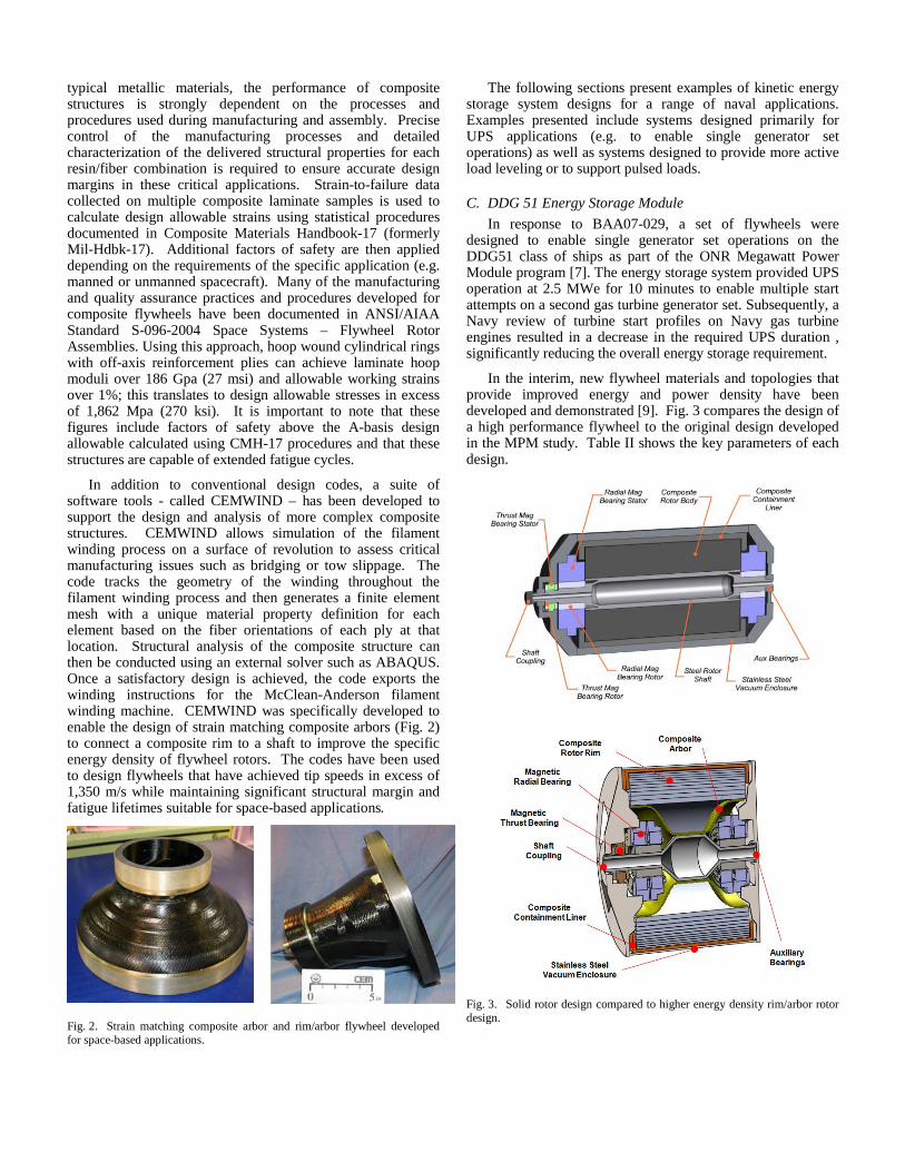
In the interim, new flywheel materials and topologies that provide improved energy and power density have been developed and demonstrated [9]. Fig. 3 compares the design of a high performance flywheel to the original design developed in the MPM study. Table II shows the key parameters of each design.
Fig. 3. Solid rotor design compared to higher energy density rim/arbor rotor design.
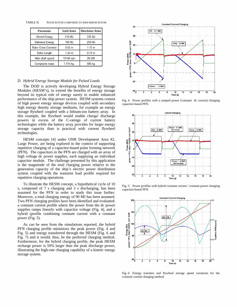
TABLE II. SOLID ROTOR COMPARED TO RIM/ARBOR ROTOR.
D. Hybrid Energy Storage Module for Pulsed Loads The DOD is actively developing Hybrid Energy Storage
Modules (HESM’s), to extend the benefits of energy storage beyond its typical role of energy surety to enable enhanced performance of the ship power system. HESM systems consist of high power energy storage devices coupled with secondary high energy density storage mediums, for example an energy storage flywheel coupled with a lithium-ion battery array. In this example, the flywheel would enable charge/ discharge powers in excess of the C-ratings of current battery technologies while the battery array provides for larger energy storage capacity than is practical with current flywheel technologies.
HESM concepts [4] under ONR Development Area #2, Large Power, are being explored in the context of supporting repetitive charging of a capacitor-based pulse forming network (PFN). The capacitors in the PFN are charged with an array of high voltage dc power supplies, each supplying an individual capacitor module. The challenge presented by this application is the magnitude of the total charging power relative to the generation capacity of the ship’s electric power distribution system coupled with the transient load profile required for repetitive charging operations.
To illustrate the HESM concept, a hypothetical cycle of 10 s, composed of 7 s charging and 3 s discharging, has been assumed for the PFN in order to study this issue further. Moreover, a total charging energy of 90 MJ has been assumed. Two PFN charging profiles have been identified and evaluated: a constant current profile where the power from the dc power supplies ramps linearly with capacitor voltage (Fig. 4), and a hybrid (profile combining constant current with a constant power (Fig. 5).
As can be seen from the simulations reported, the hybrid PFN charging profile minimizes the peak power (Fig. 4 and Fig. 5) and energy transferred through the HESM (Fig. 6 and Fig. 7) and it would, thus, be the preferred charging method. Furthermore, for the hybrid charging profile, the peak HESM recharge power is 50% larger than the peak discharge power, illustrating the high-rate charging capability of a kinetic energy storage system.
Fig. 4. Power profiles with a ramped power (constant dc current) charging capacitor-based PFN.
Fig. 5. Power profiles with hybrid constant current / constant power charging capacitor-based PFN.
Fig. 6. Energy transfers and flywheel storage speed variations for the constant current charging method.

Fig. 7. Energy transfers and flywheel storage speed variations for the hybrid charging method.
It is interesting to note that the PFN charging application
requires a flywheel battery with a high power-to-stored-energy ratio; this ratio is a strong driver of the machine topology. For example, the HESM design for the hypothetical PFN charging application described above will be significantly different if its stored energy is increased to provide long duration UPS functionality. More complex HESM design trade studies will ultimately be required to maximize the use of the stored energy in order to distribute the expense of energy storage across many functions.
This notional example illustrates the potential of the HESM to effectively isolate the ship’s electric power distribution system from the large transient loads associated with repetitive charging of capacitor-based PFN’s.
E. Electromagnetic Aircraft Launch System (EMALS) In conjunction with industrial partners, UT-CEM
developed and demonstrated the prototype pulsed power generator for the Electromagnetic Aircraft Launch System (EMALS). This system uses kinetic energy storage integrated into a generator to drive a linear induction motor to replace the steam catapults on the Gerald R. Ford class aircraft carriers.
Compared to steam catapults, the EMALS can control the applied acceleration force with greater precision, allowing it to launch more kinds of aircraft, from heavy fighter jets to light unmanned aircraft.[10] EMALS can also deliver 29 percent more energy than steam's approximately 95 MJ, increasing the output to 122 MJ.[11] The EMALS will also be more efficient than the 5-percent efficiency of steam catapults.[12]
The EMALS generator combines inertial energy storage with the motor and generator on a single rotor. The inertial energy store is recharged from the ship’s electric power distribution system between launches.
F. Compensated Pulsed Alternators (Compulsators) The compensated pulsed alternator (CPA or compulsator)
is a logical extension of the inertial energy storage approach embodied in the EMALS pulse power generator that can be used to provide the energy storage and pulsed power to directly drive electromagnetic railguns. The compulsator was originally developed at The University of Texas in the late 1970's as a power supply for high energy flash lamps to excite the laser for the Lawrence Livermore National Laboratory (LLNL) inertial confinement fusion program.[13] The technology was subsequently adapted to directly provide the extremely high power current pulses required by electromagnetic accelerators.
In its simplest form, a compulsator is a conventional wound-field synchronous generator designed with compensating windings or conductive eddy current shields to minimize the internal impedance of the machine [14]. Low internal impedance combined with high airgap flux densities enables the extraction of very large currents – literally millions of amperes - from the machine. More complex designs employ windings designed to vary the internal impedance of the machine with rotor position, an approach called selective passive compensation [15,16]. Multiple generations of the compulsator have been designed and demonstrated, including the Small Caliber Electromagnetic Launcher (SCEML), the Cannon-Caliber Electromagnetic Launcher (CCEML), the 9 MJ Range Gun System Compulsator (Task C) and the Subscale Focused Technology Program (SSFTP) Compulsator [17-22]. Fig. 8 shows the evolution of compulsator performance over the years and Fig. 9 shows pictures of the various machines.
Naval EM gun concepts are significantly larger than the tactical launchers developed under the Army EM gun program and would require multiple parallel compulsators (similar to the EMALS system) to provide the required energy storage and current capacity. Several studies were conducted in order to determine the required parameters for compulsators for naval application [3,22,23]. In related proof-of-concept experiments conducted under the contract for the study of Integration of the Electro-Kinetic Weapon Systems into the Next Generation of Navy Ships, controlled pulse discharge of parallel synchronous machines has been successfully demonstrated in the laboratory.
Fig. 8. Evolution of compulsator development at UT-CEM.
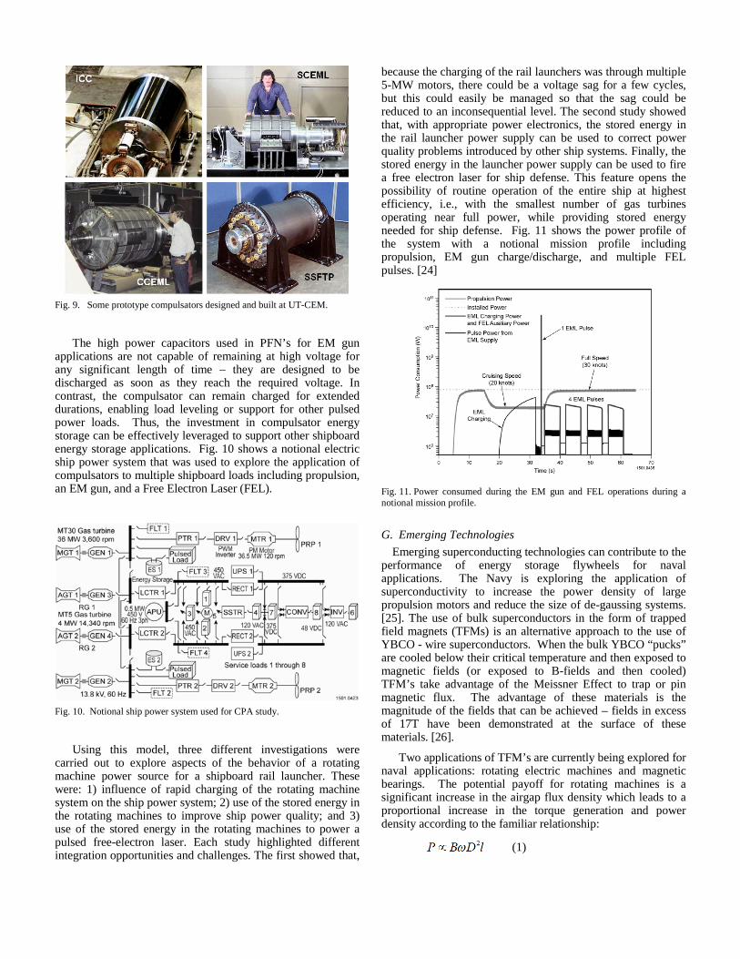
Fig. 9. Some prototype compulsators designed and built at UT-CEM.
The high power capacitors used in PFN’s for EM gun
applications are not capable of remaining at high voltage for any significant length of time – they are designed to be discharged as soon as they reach the required voltage. In contrast, the compulsator can remain charged for extended durations, enabling load leveling or support for other pulsed power loads. Thus, the investment in compulsator energy storage can be effectively leveraged to support other shipboard energy storage applications. Fig. 10 shows a notional electric ship power system that was used to explore the application of compulsators to multiple shipboard loads including propulsion, an EM gun, and a Free Electron Laser (FEL).
Fig. 10. Notional ship power system used for CPA study.
Using this model, three different investigations were
carried out to explore aspects of the behavior of a rotating machine power source for a shipboard rail launcher. These were: 1) influence of rapid charging of the rotating machine system on the ship power system; 2) use of the stored energy in the rotating machines to improve ship power quality; and 3) use of the stored energy in the rotating machines to power a pulsed free-electron laser. Each study highlighted different integration opportunities and challenges. The first showed that,
because the charging of the rail launchers was through multiple 5-MW motors, there could be a voltage sag for a few cycles, but this could easily be managed so that the sag could be reduced to an inconsequential level. The second study showed that, with appropriate power electronics, the stored energy in the rail launcher power supply can be used to correct power quality problems introduced by other ship systems. Finally, the stored energy in the launcher power supply can be used to fire a free electron laser for ship defense. This feature opens the possibility of routine operation of the entire ship at highest efficiency, i.e., with the smallest number of gas turbines operating near full power, while providing stored energy needed for ship defense. Fig. 11 shows the power profile of the system with a notional mission profile including propulsion, EM gun charge/discharge, and multiple FEL pulses. [24]
Fig. 11. Power consumed during the EM gun and FEL operations during a notional mission profile.
G. Emerging Technologies Emerging superconducting technologies can contribute to the
performance of energy storage flywheels for naval applications. The Navy is exploring the application of superconductivity to increase the power density of large propulsion motors and reduce the size of de-gaussing systems. [25]. The use of bulk superconductors in the form of trapped field magnets (TFMs) is an alternative approach to the use of YBCO - wire superconductors. When the bulk YBCO “pucks” are cooled below their critical temperature and then exposed to magnetic fields (or exposed to B-fields and then cooled) TFM’s take advantage of the Meissner Effect to trap or pin magnetic flux. The advantage of these materials is the magnitude of the fields that can be achieved – fields in excess of 17T have been demonstrated at the surface of these materials. [26].
Two applications of TFM’s are currently being explored for naval applications: rotating electric machines and magnetic bearings. The potential payoff for rotating machines is a significant increase in the airgap flux density which leads to a proportional increase in the torque generation and power density according to the familiar relationship:
(1)

where
B = air gap flux density ω = angular velocity D = diameter air gap l = length
Even a modest increase in the airgap flux density can significantly reduce the size of an electric machine for a given power level.
For magnetic bearings, the potential payoff is a significant reduction in the losses in the bearings coupled with a concurrent increase in the stiffness of the bearing.
III. SUMMARY AND CONCLUSIONS Kinetic energy storage systems are making their way on to
ships because they can be more efficient, more effective, and smaller than other approaches in many applications. At the same time, emerging technologies, particularly in composite materials, magnetic bearings, and superconductivity, are promising to make future systems even smaller and more efficient.
Energy storage is critical as ship power systems and mission packages become more electric. The ship is the ultimate isolated power system: except when docked, it must rely on its own power system. Thus the energy storage system must provide the capability for the ship to operate while another turbine is started in the event an operating one fails. The storage system also permits high pulsed loads to be serviced, particularly when the pulsed power drawn exceeds the steady-state power generation.
Kinetic energy storage is based on the core technology of motors and generators that have long been at the core of ship power technology. New materials, new control approaches, lifetime, and high turnaround efficiency make this approach appealing where size, weight , and cost are critical factors. Consequently kinetic energy storage is likely to become more common on ships.
IV. REFERENCES [1] R. Hebner, J. Beno, and A. Walls, “Flywheel batteries come around
again,” IEEE Spectrum, vol. 39,April 2002, pp. 46-51. [2] [E. Lewis and J. Beno, "Managing Multiple and Varying Energy
Demands by Means of Energy Storage in Combatants with Integrated Electric Propulsion," IMAREST Engine as a Weapon Symposium, Bristol, UK, June 9-10, 2004.
[3] W.A. Walls, W.F. Weldon, S.B. Pratap, M. Palmer, and D. Adams, "Application of Electromagnetic Guns to Future Naval Platforms", IEEE Transactions on Magnetics, Vol. 35, No. 1, January 1999, pp. 262-267.
[4] D. Hoffman, I. Gur, “ARPA-E/ASD(R&E) Hybrid Energy Storage Module (HESM)”, Amendment 1 to Department of the Navy Solicitation Number: 13-SN-0007 Program Industry Day
[5] M.L. Spann, S.B. Pratap, and M.D. Driga, "Compulsator research at the University of Texas at Austin - an overview," IEEE Transactions on Magnetics, vol. 39, no. 1, Jan 1989, pp. 529-537.
[6] Brian T. Murphy, Hamid Ouroua, Matthew T. Caprio, and John D. Herbst, " Permanent magnet bias, homopolar magnetic bearings for a 130 kW-hr composite flywheel," 9th International Symposium on Magnetic Bearings, Lexington, Kentucky, August 3-6 2004.
[7] R.E. Hebner, J.D. Herbst, and A. Gattozzi, "Pulsed power loads support and efficiency improvement on navy ships", Naval Engineer Journal, vol. 122, no. 4, p. 261, December 2010.
[8] K. Davey, R. Weinstein, and R. Sawh, “Development and analysis of YBCO trapped field magnets in electromechanical devices,” 16th International Conference on the Computation of Electromagnetic Fields (COMPUMAG 2007), Aachen, Germany, June 24-28, 2007, IEEE Transactions on Magnetics, Vol. 44, No. 6, June 2008, pp. 930-933.
[9] RF 240 R.C. Thompson, "Final Report for the Three Phases of the NASA NRA Arbor Flywheel Program: Integrated Composite Arbor and Flywheel Rim Technology Development, submitted to NASA Glenn Research Center, 2005.
[10] Christian Lowe, "Defense Tech: EMALS: Next Gen Catapult". http://defensetech.org/2007/04/05/emals-next-gen-catapult/. Retrieved 2008-02-27.
[11] Douglas Samuel, Thomas Conway, and Robert Klimowski, “Electromagnetic Aircraft Launch System-EMALS,” 1994, http://www.lakehurst.navy.mil/nlweb/ieeerevc.pdf.
[12] Bill Schweber (2002-04-11). "How It Works" (PDF). EDN Magazine. http://www.edn.com/contents/images/207108.pdf. Retrieved 2008-02-18]
[13] W.F. Weldon, M.D. Driga, W.L. Bird, K.M. Tolk, H.H. Woodson, and H.G. Rylander, "Compulsator: A High Power Compensated Pulsed Alternator", Second International Conference on Energy Storage, Compression, and Switching, Venice, Italy, December 5-8, 1978.
[14] W.F. Weldon and C.W. Drummond, "Compulsators: principles and applications," Fifth International Conference on Electric Machines and Drives, 11-13 September 1991, publ. no. 341, pp. 326-330.
[15] M.D. Driga, S.B. Pratap, and W.F. Weldon, "Advanced compulsator design," IEEE Transactions on Magnetics, vol. 25, no. 1, Jan 1989, pp. 142-146.
[16] S.B. Pratap, M.L. Spann, W.A. Walls, and M.D. Driga, "Air-core compensated pulsed alternators," Seventh Pulse Power Conference, June 11-14, 1989, pp.238-241.
[17] C.W.G. Fultcher, R.W. Faidley, M.W. Ingram, S.B. Pratap, and M.L. Spann, "Design considerations in a 60 caliber electromagnetic railgun system," IEEE Transactions on Magnetics, vol. 25, no. 1, Jan 1989, pp. 186-192.
[18] J.R. Kitzmiller, R.W. Faidley, R.L. Fuller, G.R. Headifen, S.B. Pratap, M.L. Spann, and R.F. Thelen, "Final design of an air-core, compulsator driven, 60 caliber railgun system," IEEE Transactions on Magnetics, vol. 27, no. 1, Jan 1991, pp. 50-55.
[19] S.B. Pratap, J.R. Kitzmiller, T.A. Aanstoos, K.G. Cook, R.N. Headifen, R.A. Kuenast, and R.A. Lee, "Optimization and design of the air-core compulsator for the cannon caliber electromagnetic launcher," Ninth IEEE International Pulse Power Conference, June 21-23 1993, p.29
[20] [16]: W.A. Walls, S.B. Pratap, W.G. Brinkman, K.G. Cook, J.D. Herbst, S.M. Manifold, B.M. Rech, R.F. Thelen, and R.C. Thompson, " A field based, self-excited compulsator power supply for a 9 MJ railgun demonstrator," IEEE Transactions on Magnetics, vol. 27, no. 1, Jan 1991, pp. 335-349.
[21] [17]: J.R. Kitzmiller, K.G. Cook, J.J. Hahne, T.J. Hotz, S.M. Manifold, J.A. Pappas, C.E. Penny, S.B. Pratap, B. Rech, R.F. Thelen, W.A. Walls, M.D. Werst, R.C. Zowarka, W.W. Rienstra, and A. Nejezchleb, "Predicted versus actual performance of the model scale compulsator system," IEEE Transactions on Magnetics, vol. 37, no. 1, Jan 1991, pp. 362-366.
[22] I.R. McNab, "Parameters for an Electromagnetic Naval Railgun", IEEE Transactions on Magnetics, Vol. 37, No. 1, January 2001.
[23] J. McFarland and I.R. McNab, "A Long-Range Naval Railgun", IEEE Transactions on Magnetics, Vol. 39, No. 1, January 2003.
[24] L. Domaschk, et al, "Coordination of Large Pulsed Loads of Future Electric Ships," IEEE Transactions on Magnetics Vol 43, No. 1, January 2007.
[25] B. Gamble, G. Snitchler, T. MacDonald, "Full Power Test of a 36.5 MW HTS Propulsion Motor," Applied Superconductivity, IEEE Transactions on , vol.21, no.3, pp.1083-1088, June 2011 doi:

10.1109/TASC.2010.2093854, https://www.navalengineers.org/SiteCollectionDocuments/2010%20Proceedings%20Documents/EMTS%202010%20Proceedings/Presentations/Wednesday/EMTS10_1_12.pdf]
[26] Tomita M, Murakami M , “High-temperature superconductor bulk magnets that can trap magnetic fields of over 17 tesla at 29 K”, Nature. 2003 Jan 30;421(6922):517-20.