Very Fast Measurement of Low Speed of Rotating Machines Using Rotating Magnetic Field
8
IEEE TRANSACTIONS ON INSTRUMENTATION AND MEASUREMENT, VOL. 61, NO. 3, MARCH 2012 759 Very Fast Measurement of Low Speed of Rotating Machines Using Rotating Magnetic Field Syed Javed Arif, M. S. Jamil Asghar, Member, IEEE, and Imdadullah Abstract—The measurement at low speed becomes very difficult due to the slow response of transducers. At low speed (below 10 r/min), normally, transducers take several seconds to give the required output signal. In the proposed technique, a fast rotating magnetic field (RMF) is used to measure the speed as well as deviation in speed for low-speed machines. A sine wave oscillator (single-phase ac source) is used to generate a balanced three-phase ac voltage, which is applied to the stator windings of a synchro whose rotor is coupled with the rotating member or rotor of a motor. The RMF in the air gap generates emf in the rotor of the synchro whose frequency depends upon the slip speed. Since the RMF revolves at a speed several times the speed of the rotating member or the rotor of the motor, hence the measurement becomes very fast. The proposed scheme is tested successfully even at 1 r/min, and the overall performance is recorded at dynamic conditions. The results of the measurements are compared with a conventional method (tachogenerator), which shows the accuracy of the proposed method. The output is also obtained in terms of dc voltage and dc current, which can be used for feed-back and control applications. Index Terms—Angular velocity, rotating machines, tachome- ters, transducers, velocity measurement. I. I NTRODUCTION S OPHISTICATED speed control applications require very fast and accurate speed measurement. It is one of the important requirements of low-speed machines, like rotors of cement kilns; rolling machines in paper mills, mining indus- tries, and textile mills; and heavy stone crushing machines, where the speed varies from 0 to 10 r/min [1]–[4]. Even a drive with a speed less than 2 r/min is also very common in industries [1]. In case of digital tachometers used for an- gular speed measurement, either timer/counter or analog-to- digital converter (ADC) based methods are used. In case of a timer/counter-based method, the pulses of a pulse-train are counted over a fixed duration of the measurement time [5]. At low speed, this duration is kept large; therefore, a significant delay appears in the response time of the measurement. More- over, the method results in a loss of one pulse during the count of the pulses. At high speed, as the number of pulses is large, Manuscript received June 23, 2011; revised August 25, 2011; accepted August 27, 2011. Date of publication November 18, 2011; date of current ver- sion February 8, 2012. The Associate Editor coordinating the review process for this paper was Dr. Subhas Mukhopadhyay. S. J. Arif is with the Department of Electronics Engineering, Aligarh Muslim University, Aligarh 202002, India (e-mail: [email protected]). M. S. J. Asghar and Imdadullah are with the Department of Electri- cal Engineering, Aligarh Muslim University, Aligarh 202002, India (e-mail: [email protected]; [email protected]). Color versions of one or more of the figures in this paper are available online at http://ieeexplore.ieee.org. Digital Object Identifier 10.1109/TIM.2011.2170914 the loss of one pulse is insignificant; therefore, the accuracy of the measurement is least affected. However, at low speed, the loss of one pulse causes a significant error. A significant improvement is made in the aforementioned method by the constant elapsed time method [6]. However, this method has a serious limitation of minimum measurable speed, within a given maximum response time. Therefore, it does not work effectively for a speed below 30 r/min [6]. The ADC-based methods are also commonly used in angular speed measurement. They require a longer period of the mea- surement as the methods are based on averaging processes [7], [8]. Optical encoders are also used for accurate and fast speed measurement [9], [10]. These methods are not suitable for the fast measurement of low angular speed as these methods are costly and complex [6], [11]. In fact, they require additional accessories like a serial encoder interface bus adapter, a power supply, and a PC with supporting software to monitor the displacement and position of the rotating member [12], [13]. Different contact- and noncontact-type tachometers are used for speed measurement as well as for generation of feedback signals for control applications. Mostly, these tachometers suf- fer from calibration drift, and also, they have got drawbacks of low resolution and noise contaminations [14]. Moreover, several revolutions are required to detect the deviation in speed, and therefore, only after several revolutions will the outputs of these tachometers become significant. A number of sensorless speed measurement techniques have been proposed for the measurement of speed, but the output fil- ters slow down the response as well as may alter the information output at low speed [15]–[17]. A microprocessor-based scheme using a tachogenerator had also been reported earlier, where the commutator and brushes require periodic maintenance. Also, if the armature current is large, it distorts the field of the permanent magnet, and hence, it causes nonlinearity. Frequent replacement of the commutator brushes is the main drawback of the tachogenerators [18]. In general, the speed measurements by all of these methods are slow. They take several seconds to give the relevant output. Therefore, these techniques are not suitable where fast feedback signals are required for control applications, e.g., cement kilns, heavy stone crushing machines, textile mills, etc. In the proposed method, a rotating magnetic field (RMF) is used to generate emf in the rotor circuit of a synchro [19], [20]. The three windings placed on the stator of the synchro are energized by the three-phase balanced current [11]. They create an RMF in the air gap which links with the rotor of the synchro, generating an emf in it. In fact, the rotor of the synchro is mechanically coupled with the rotor of the rotating member. 0018-9456/$26.00 © 2011 IEEE
-
Upload
cas-historydeptt-amu -
Category
Documents
-
view
2 -
download
0
Transcript of Very Fast Measurement of Low Speed of Rotating Machines Using Rotating Magnetic Field

IEEE TRANSACTIONS ON INSTRUMENTATION AND MEASUREMENT, VOL. 61, NO. 3, MARCH 2012 759
Very Fast Measurement of Low Speed of RotatingMachines Using Rotating Magnetic Field
Syed Javed Arif, M. S. Jamil Asghar, Member, IEEE, and Imdadullah
Abstract—The measurement at low speed becomes very difficultdue to the slow response of transducers. At low speed (below10 r/min), normally, transducers take several seconds to give therequired output signal. In the proposed technique, a fast rotatingmagnetic field (RMF) is used to measure the speed as well asdeviation in speed for low-speed machines. A sine wave oscillator(single-phase ac source) is used to generate a balanced three-phaseac voltage, which is applied to the stator windings of a synchrowhose rotor is coupled with the rotating member or rotor ofa motor. The RMF in the air gap generates emf in the rotorof the synchro whose frequency depends upon the slip speed.Since the RMF revolves at a speed several times the speed of therotating member or the rotor of the motor, hence the measurementbecomes very fast. The proposed scheme is tested successfully evenat 1 r/min, and the overall performance is recorded at dynamicconditions. The results of the measurements are compared with aconventional method (tachogenerator), which shows the accuracyof the proposed method. The output is also obtained in terms ofdc voltage and dc current, which can be used for feed-back andcontrol applications.
Index Terms—Angular velocity, rotating machines, tachome-ters, transducers, velocity measurement.
I. INTRODUCTION
SOPHISTICATED speed control applications require veryfast and accurate speed measurement. It is one of the
important requirements of low-speed machines, like rotors ofcement kilns; rolling machines in paper mills, mining indus-tries, and textile mills; and heavy stone crushing machines,where the speed varies from 0 to 10 r/min [1]–[4]. Even adrive with a speed less than 2 r/min is also very commonin industries [1]. In case of digital tachometers used for an-gular speed measurement, either timer/counter or analog-to-digital converter (ADC) based methods are used. In case ofa timer/counter-based method, the pulses of a pulse-train arecounted over a fixed duration of the measurement time [5]. Atlow speed, this duration is kept large; therefore, a significantdelay appears in the response time of the measurement. More-over, the method results in a loss of one pulse during the countof the pulses. At high speed, as the number of pulses is large,
Manuscript received June 23, 2011; revised August 25, 2011; acceptedAugust 27, 2011. Date of publication November 18, 2011; date of current ver-sion February 8, 2012. The Associate Editor coordinating the review process forthis paper was Dr. Subhas Mukhopadhyay.
S. J. Arif is with the Department of Electronics Engineering, Aligarh MuslimUniversity, Aligarh 202002, India (e-mail: [email protected]).
M. S. J. Asghar and Imdadullah are with the Department of Electri-cal Engineering, Aligarh Muslim University, Aligarh 202002, India (e-mail:[email protected]; [email protected]).
Color versions of one or more of the figures in this paper are available onlineat http://ieeexplore.ieee.org.
Digital Object Identifier 10.1109/TIM.2011.2170914
the loss of one pulse is insignificant; therefore, the accuracyof the measurement is least affected. However, at low speed,the loss of one pulse causes a significant error. A significantimprovement is made in the aforementioned method by theconstant elapsed time method [6]. However, this method hasa serious limitation of minimum measurable speed, within agiven maximum response time. Therefore, it does not workeffectively for a speed below 30 r/min [6].
The ADC-based methods are also commonly used in angularspeed measurement. They require a longer period of the mea-surement as the methods are based on averaging processes [7],[8]. Optical encoders are also used for accurate and fast speedmeasurement [9], [10]. These methods are not suitable for thefast measurement of low angular speed as these methods arecostly and complex [6], [11]. In fact, they require additionalaccessories like a serial encoder interface bus adapter, a powersupply, and a PC with supporting software to monitor thedisplacement and position of the rotating member [12], [13].
Different contact- and noncontact-type tachometers are usedfor speed measurement as well as for generation of feedbacksignals for control applications. Mostly, these tachometers suf-fer from calibration drift, and also, they have got drawbacksof low resolution and noise contaminations [14]. Moreover,several revolutions are required to detect the deviation in speed,and therefore, only after several revolutions will the outputs ofthese tachometers become significant.
A number of sensorless speed measurement techniques havebeen proposed for the measurement of speed, but the output fil-ters slow down the response as well as may alter the informationoutput at low speed [15]–[17]. A microprocessor-based schemeusing a tachogenerator had also been reported earlier, where thecommutator and brushes require periodic maintenance. Also,if the armature current is large, it distorts the field of thepermanent magnet, and hence, it causes nonlinearity. Frequentreplacement of the commutator brushes is the main drawback ofthe tachogenerators [18]. In general, the speed measurementsby all of these methods are slow. They take several secondsto give the relevant output. Therefore, these techniques are notsuitable where fast feedback signals are required for controlapplications, e.g., cement kilns, heavy stone crushing machines,textile mills, etc.
In the proposed method, a rotating magnetic field (RMF)is used to generate emf in the rotor circuit of a synchro [19],[20]. The three windings placed on the stator of the synchroare energized by the three-phase balanced current [11]. Theycreate an RMF in the air gap which links with the rotor of thesynchro, generating an emf in it. In fact, the rotor of the synchrois mechanically coupled with the rotor of the rotating member.
0018-9456/$26.00 © 2011 IEEE

760 IEEE TRANSACTIONS ON INSTRUMENTATION AND MEASUREMENT, VOL. 61, NO. 3, MARCH 2012
Fig. 1. Synchro-based speed measurement setup.
Both the magnitude and frequency of the output voltage dependupon the speed and the difference in the speed. The effect ofvariation in the magnitude of the output voltage is eliminatedby using a zero crossing detector (ZCD) in the open-loop modeat the output. Moreover, the rotation of the magnetic field iskept faster (several times) than the rotor; therefore, before thecompletion of even one revolution of the rotor or the rotatingmember, the RMF rotates several times. Thus, the deviationin the speed is quickly picked up by the RMF which causesthe deviation in frequency. Hence, the measurement, even at1 r/min, becomes extremely fast.
II. THEORY
The speed (revolution) of an RMF in the air gap of a stator,produced by a balanced three-phase ac supply, is given by
ns =120fs
P(1)
where P is the number of poles and fs is the frequency of thestator input voltage or current in hertz [21], [22].
For a tachometer whose rotor is rotating at nr (in revolutionsper minute), the relative speed or the slip is (ns − nr) in thedirection of ns. However, if it rotates in the opposite direction,the slip becomes (ns + nr). The frequency of the induced emfin the rotor circuit is given by
fr =(ns ∓ nr)P
120
=nsP
120∓ nrP
120(2)
fr = fs ∓ nrP
120. (3)
Since the supply frequency (fs) and the number of statorpoles (P ) are constant, therefore, the frequency of the inducedemf in the rotor circuit varies linearly with the variation ofthe rotor speed nr. For this purpose, a three-phase balancedvoltage supply is realized with the help of a sine wave oscillatorand a single-phase to three-phase converter using three audioamplifiers, as shown in Fig. 2. These voltage signals are appliedto the stator winding of a synchro (Fig. 1). When the rotor ofthe synchro (rotating member) is standstill, the synchro acts asa transformer. Therefore, the frequency of rotor emf (fr) is thesame as that of stator (fr = fs). When the rotor rotates, thefrequency is proportional to the slip (ns ∓ nr), where ns isconstant.
Fig. 2. Single-phase to three-phase conversion system.
Fig. 3. Measured waveforms applied at the input of power amplifiers (CH#1,CH#2, and Ch#3, respectively).
III. REALIZATION
Fig. 1 shows the setup for the realization of low-speedmeasurement. To realize low speed from 0 to 10 r/min, a three-phase induction motor (as a prime mover) is connected to anadjustable frequency ac drive system. On one side of the primemover, the synchro is connected, whereas on the other side, adc tachogenerator is connected for comparison of measurementof speed simultaneously.
A sine wave signal of 40 Hz (18 V peak to peak) froma stable arbitrary function generator is supplied to a center-tapped transformer. The output of the transformer is appliedto an RC network (R = 100 kΩ and C = 0.1 µF) to generatebalanced three-phase 40-Hz voltages Va1, Vb1, and Vc1 (Fig. 2).These voltages are attenuated to a value of about 150 mV (Va2,Vb2, and Vc2) before feeding into three audio power amplifiers(LM 384N). The outputs of these amplifiers [VA, VB , andVC (Fig. 3)] are, in turn, applied to the stator winding of thesynchro. Therefore, at a stationary condition, a sinusoidal signalVr with frequency fr (40 Hz) is generated at the rotor windingof the synchro (Fig. 4).
IV. EXPERIMENTAL RESULTS
A. When the Rotating Member Is Stationary
As long as the rotating member is stationary, the speed ofthe rotor of the synchro S is zero. The frequency fr of Vr ofthe rotor circuit is equal to fs of Vs of the stator circuit (Fig. 4).The signal Vr is now passed through a ZCD to produce a squarewaveform VR with the same frequency (fR = fr), as shown in

ARIF et al.: VERY FAST MEASUREMENT OF LOW SPEED OF ROTATING MACHINES USING RMF 761
Fig. 4. Measured three-phase voltages VA, VB , and VC at the stator windingof the synchro (CH#1, CH#2, and Ch#3) and Vr (CH#4).
Fig. 5. Measured output voltage of the rotor Vr (Ch#1) and output of ZCDVR (Ch#2) at 40 Hz.
Fig. 6. Waveforms of signals VR and Q, and output TWG−.
Fig. 5. The negative going transition (NGT) of signal VR is usedto trigger a one-shot monostable multivibrator (OS, 74LS121N)to produce a signal Q of a stable fixed positive width TWQ+ of12.5 ms, as shown in Fig. 6. These two signals are applied toan EXOR gate (G-1). The output of G-1 becomes high as thenegative width (TWR−) of the signal VR is equal to the positivewidth (TWQ+) of the signal Q. This is also given by
fr =fs−nrP
120fr =Frequency of induced emf (Vr) of rotor of synchro
fs =Frequency of induced emf (Vs) of stator of synchro
fR =Frequency of signal VR at the output of ZCD (fR =fr)TR =Time period of the signal VR at the input of OS
Fig. 7. Measured output of the rotor Vr of synchro S (Ch#1), VR with TWR−(Ch#2), signal Q with TWQ+ (Ch#3), and output TWG− of G-1 (Ch#4).
Fig. 8. Waveforms of signals VR and Q, and output TWG−.
TWR−=Negative width of the signal VR
TWQ+ =Positive width of signal Q
TWG−=Negative Width of the pulse at the output of G−1
TWG−=TWR−−TWQ+.
When nr = 0 r/min
fR = fs = 40 Hz
TR = (1/fR) = 25 ms
TWR− = (TR/2) = 12.5 ms
TWQ+ = 12.5 ms
TWG− = TWR− − TWQ+
TWG− = 12.5 − 12.5
TWG− = 0.
Therefore, the output of the EXOR gate G − 1 = 1.The waveforms Vr, VR, Q, and TWG− are also shown in the
DSO records (Fig. 7).
B. When the Rotating Member Rotates in the ClockwiseDirection (fR Decreases)
When the rotating member crawls to a low speed in theclockwise direction, the frequency fr of the induced emf Vr

762 IEEE TRANSACTIONS ON INSTRUMENTATION AND MEASUREMENT, VOL. 61, NO. 3, MARCH 2012
Fig. 9. (a)–(d) Measured output voltage of the rotor Vr of synchro S (Ch#1),VR with TWR− (Ch#2), signal Q with TWQ+ (Ch#3), and negative width(TWG−) at the output of G-1 for 1, 3, 7, and 10 r/min (Ch#4), respectively.
in the rotor circuit decreases. The time period TR or (1/fR)and, hence, the negative width TWR− of signal VR at the outputof ZCD increases accordingly. The NGT of VR triggers OS toproduce a signal Q with a stable positive width TWQ+ of12.5 ms. When the signals VR and Q are applied to G-1, apulse with negative width is generated at its output, as shown
TABLE ITHEORETICAL AND OBSERVED RESULTS OF THE TEST
Fig. 10. Waveforms of signals VR and Q, and output TWG−.
in Fig. 8. The duration of this pulse depends on the speed of therotation of the rotor and is given by
fr = fs ∓ nrP
120.
When nr = 1 r/min (rotation is clockwise)
fs = 40 Hz
fr = 40 − 1 × 2120
fR = fr = 39.983
TR = (1/fR) = 25.010 ms
TWR− = TR/2 = 12.505 ms
TWQ+ = 12.5 ms
TWG− = TWR− − TWQ+
TWG− = 12.505 − 12.5
TWG− = 5.211 µs.
Fig. 9(a)–(d) shows the DSO records for a speed range of 1 to10 r/min in clockwise direction. These results are also tabulatedin Table I.
ARIF et al.: VERY FAST MEASUREMENT OF LOW SPEED OF ROTATING MACHINES USING RMF 763
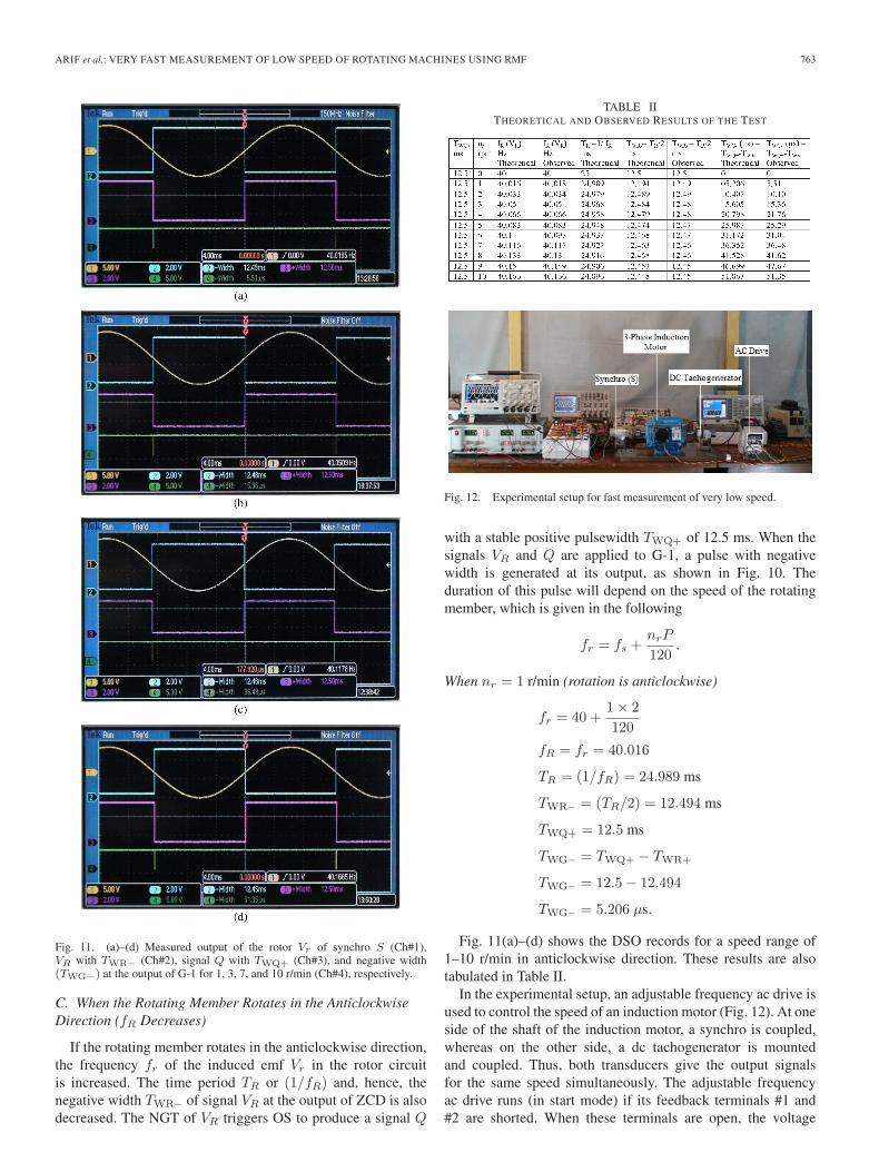
Fig. 11. (a)–(d) Measured output of the rotor Vr of synchro S (Ch#1),VR with TWR− (Ch#2), signal Q with TWQ+ (Ch#3), and negative width(TWG−) at the output of G-1 for 1, 3, 7, and 10 r/min (Ch#4), respectively.
C. When the Rotating Member Rotates in the AnticlockwiseDirection (fR Decreases)
If the rotating member rotates in the anticlockwise direction,the frequency fr of the induced emf Vr in the rotor circuitis increased. The time period TR or (1/fR) and, hence, thenegative width TWR− of signal VR at the output of ZCD is alsodecreased. The NGT of VR triggers OS to produce a signal Q
TABLE IITHEORETICAL AND OBSERVED RESULTS OF THE TEST
Fig. 12. Experimental setup for fast measurement of very low speed.
with a stable positive pulsewidth TWQ+ of 12.5 ms. When thesignals VR and Q are applied to G-1, a pulse with negativewidth is generated at its output, as shown in Fig. 10. Theduration of this pulse will depend on the speed of the rotatingmember, which is given in the following
fr = fs +nrP
120.
When nr = 1 r/min (rotation is anticlockwise)
fr = 40 +1 × 2120
fR = fr = 40.016
TR = (1/fR) = 24.989 ms
TWR− = (TR/2) = 12.494 ms
TWQ+ = 12.5 ms
TWG− = TWQ+ − TWR+
TWG− = 12.5 − 12.494
TWG− = 5.206 µs.
Fig. 11(a)–(d) shows the DSO records for a speed range of1–10 r/min in anticlockwise direction. These results are alsotabulated in Table II.
In the experimental setup, an adjustable frequency ac drive isused to control the speed of an induction motor (Fig. 12). At oneside of the shaft of the induction motor, a synchro is coupled,whereas on the other side, a dc tachogenerator is mountedand coupled. Thus, both transducers give the output signalsfor the same speed simultaneously. The adjustable frequencyac drive runs (in start mode) if its feedback terminals #1 and#2 are shorted. When these terminals are open, the voltage

764 IEEE TRANSACTIONS ON INSTRUMENTATION AND MEASUREMENT, VOL. 61, NO. 3, MARCH 2012
Fig. 13. (a)–(c) Measured output voltage of the dc tachogenerator for 1, 4,and 7 r/min (CH#1), respectively, and output voltage across terminals #1 and#2 (CH#2).
across them becomes equal to the internal source voltage(22.6 V), and the drive stops [23]. When the ac drive is setat 1 r/min, the induction motor runs at a speed of 1 r/min,and the mounted synchro and tachogenerator also crawl at1 r/min. Corresponding to this speed, a dc voltage of 24.8 mV,as per specification of the tachogenerator (2.42 V/ 100 r/min),is generated at its output and is measured at CH#1 of theDSO, whereas the voltage across terminals #1 and #2 of the acdrive remains zero (measured at CH#2), as shown in Fig. 13(a).When the feedback terminals of the ac drive open, the terminalvoltage rises [a step change of 22.6 V in Fig. 13(a)], the rotorspeed reduces quickly, and, finally, it stops. The tachogeneratortakes sufficiently large time to register the effects of speedvariation and to give the output voltage accordingly. Here, theoutput voltage of the tachogenerator takes 656 ms to becomezero. However, in case of the proposed method, it takes only12.5 ms, as shown in Fig. 11(a)–(d). It may be noted thatthe variation in the output voltage of tachogenerator is notsmooth at very low speed, and the noise level is quite high.
Fig. 14. Averaging circuit with amplifier.
Fig. 15. Waveforms to calculate the average value (Vdc) of pulses at theoutput of G-1.
TABLE IIIMEASURED OUTPUT VOLTAGE AND CURRENT
The results of the measurement by the dc tachogenerator fordifferent speeds are shown in the DSO records [Fig. 13(a)–(c)].
The output pulses from gate G-1 can also be used to generatea dc output voltage or a dc current. This dc output voltage ordc current may be used as feed-back signals for control appli-cations. The pulses from gate G-1 are applied to an amplifierwith averaging circuit (Fig. 14), which produces an averagedc voltage (Vdc). This average dc voltage for different speeds(Vdc) is calculated by (4) and (5), as described in Fig. 15.A current feed-back signal is also generated by connecting ahigh value of resistance in series with an ammeter of microam-pere range. The measured output dc voltages (Vdc) and currents(Idc) for 1–10 r/min are given in Table III. The waveforms arealso recorded for different low speeds (3, 5, and 8 r/min), asshown in Fig. 16(a)–(c)
Vdc =tonT
Vmax (4)
Vdc = ton · f · Vmax. (5)
ARIF et al.: VERY FAST MEASUREMENT OF LOW SPEED OF ROTATING MACHINES USING RMF 765
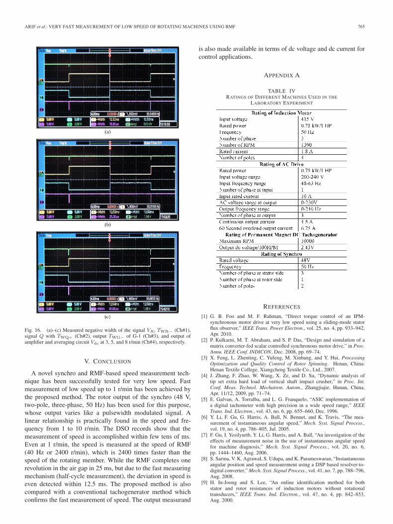
Fig. 16. (a)–(c) Measured negative width of the signal VR, TWR− (Ch#1),signal Q with TWQ+ (Ch#2), output TWG− of G-1 (Ch#3), and output ofamplifier and averaging circuit Vdc at 3, 5, and 8 r/min (Ch#4), respectively.
V. CONCLUSION
A novel synchro and RMF-based speed measurement tech-nique has been successfully tested for very low speed. Fastmeasurement of low speed up to 1 r/min has been achieved bythe proposed method. The rotor output of the synchro (48 V,two-pole, three-phase, 50 Hz) has been used for this purpose,whose output varies like a pulsewidth modulated signal. Alinear relationship is practically found in the speed and fre-quency from 1 to 10 r/min. The DSO records show that themeasurement of speed is accomplished within few tens of ms.Even at 1 r/min, the speed is measured at the speed of RMF(40 Hz or 2400 r/min), which is 2400 times faster than thespeed of the rotating member. While the RMF completes onerevolution in the air gap in 25 ms, but due to the fast measuringmechanism (half-cycle measurement), the deviation in speed iseven detected within 12.5 ms. The proposed method is alsocompared with a conventional tachogenerator method whichconfirms the fast measurement of speed. The output measurand
is also made available in terms of dc voltage and dc current forcontrol applications.
APPENDIX A
TABLE IVRATINGS OF DIFFERENT MACHINES USED IN THE
LABORATORY EXPERIMENT
REFERENCES
[1] G. B. Foo and M. F. Rahman, “Direct torque control of an IPM-synchronous motor drive at very low speed using a sliding-mode statorflux observer,” IEEE Trans. Power Electron., vol. 25, no. 4, pp. 933–942,Apr. 2010.
[2] P. Kulkarni, M. T. Abraham, and S. P. Das, “Design and simulation of amatrix converter-fed scalar controlled synchronous motor drive,” in Proc.Annu. IEEE Conf. INDICON, Dec. 2008, pp. 69–74.
[3] X. Feng, L. Zhenting, C. Yufeng, M. Xinbang, and Y. Hui, ProcessingOptimization and Quality Control of Rotor Spinning. Henan, China:Henan Textile College, Xiangcheng Textile Co., Ltd., 2007.
[4] J. Zhang, F. Zhao, W. Wang, X. Ze, and D. Su, “Dynamic analysis oftip set extra hard load of vertical shaft impact crusher,” in Proc. Int.Conf. Meas. Technol. Mechatron. Autom., Zhangjiajie, Hunan, China,Apr. 11/12, 2009, pp. 71–74.
[5] E. Galvan, A. Torralba, and L. G. Franquelo, “ASIC implementation ofa digital tachometer with high precision in a wide speed range,” IEEETrans. Ind. Electron., vol. 43, no. 6, pp. 655–660, Dec. 1996.
[6] Y. Li, F. Gu, G. Harris, A. Ball, N. Bennet, and K. Travis, “The mea-surement of instantaneous angular speed,” Mech. Syst. Signal Process.,vol. 19, no. 4, pp. 786–805, Jul. 2005.
[7] F. Gu, I. Yesilyurtb, Y. Li, G. Harris, and A. Ball, “An investigation of theeffects of measurement noise in the use of instantaneous angular speedfor machine diagnosis,” Mech. Syst. Signal Process., vol. 20, no. 6,pp. 1444–1460, Aug. 2006.
[8] S. Sarma, V. K. Agrawal, S. Udupa, and K. Parameswaran, “Instantaneousangular position and speed measurement using a DSP based resolver-to-digital converter,” Mech. Syst. Signal Process., vol. 41, no. 7, pp. 788–796,Aug. 2008.
[9] H. In-Joong and S. Lee, “An online identification method for bothstator and rotor resistances of induction motors without rotationaltransducers,” IEEE Trans. Ind. Electron., vol. 47, no. 4, pp. 842–853,Aug. 2000.

766 IEEE TRANSACTIONS ON INSTRUMENTATION AND MEASUREMENT, VOL. 61, NO. 3, MARCH 2012
[10] L. Rovati, M. Bonaiut, and P. Pavan, “Design of a high-performanceoptical system for angular position measurement: Optical and electronicstrategies for uncertainty reduction,” IEEE Trans. Instrum. Meas., vol. 54,no. 5, pp. 2075–2081, Oct. 2005.
[11] A. S. Morris, Measurement and Instrumentation Principles, 3rd ed.Burlington, MA: Butterworth-Heinemann, 2001.
[12] HD25A Absolute Industrial Rugged Metal Optical Encoder, USDigital Products, Vancouver, Washington. [Online]. Available:www.usdigital.com; [email protected]
[13] Computer Optical Products, Inc. (COPI), Emoteq Corporation,Tulsa, OK. [Online]. Available: http://alliedmotion.com
[14] M. Aiello, A. Cataliotti, and S. Nuccio, “An induction motor speed mea-surement method based on current harmonic analysis with the chirp-Ztransform,” IEEE Trans. Instum. Meas., vol. 54, no. 5, pp. 1811–1819,Oct. 2005.
[15] A. Piipo, M. Hinkkanen, and J. Luomi, “Signal injection in sensorlessPMSM drives equipped with inverter output filter,” IEEE Trans. Ind.Appl., vol. 44, no. 5, pp. 1614–1620, Sep./Oct. 2008.
[16] J. M. Aller, T. G. Habetler, R. G. Harley, and R. M. Tallam, “Sensor lessspeed measurement of ac machines using analytic wavelet transform,”IEEE Trans. Ind. Appl., vol. 38, no. 5, pp. 1344–1350, Sep./Oct. 2002.
[17] D. Shi, P. J. Unsworth, and R. X. Gao, “Sensorless speed measurementof induction motor using Hilbert transform and interpolated fast Fouriertransform,” IEEE Trans. Instrum. Meas., vol. 55, no. 1, pp. 290–299,Feb. 2006.
[18] S. I. Ahson and M. H. Ali, “A microprocessor-based scheme for torqueangle and speed measurement,” IEEE Trans. Ind. Electron., vol. IE-34,no. 2, pp. 135–138, May 1987.
[19] S. J. Arif and M. S. J. Asghar, “A rotating magnetic field based ultrafast transducer for the measurement of very low speed,” Patent Applica-tion 2183/DEL/2010A, Indian Official Journal of the Patent Office, issueno. 14/2011, p. 6126, Apr. 8, 2011.
[20] S. J. Arif and S. H. Laskar, “A rotating magnetic field based ultra fast mea-surement of speed,” Patent Application 777/DEL/2011A, Indian OfficialJournal of the Patent Office, issue no. 18/2011, p. 8219, May 6, 2011.
[21] I. J. Nagraj and D. P. Kothari, Electric Machines, 3rd ed. New Delhi,India: Tata McGraw-Hill, 1994.
[22] H. N. Norton, Handbook of Transducer for Electronic Measuring Systems.Englewood Cliffs, NJ: Prentice-Hall, 1969.
[23] PowerFlex4: Adjustable Frequency ac Drive. [Online]. Available:www.abpowerflex.com; www.rockwellautomation.com/literature
Syed Javed Arif received the B.Sc. (Engg.) degree inelectrical engineering and the M.Sc. (Engg.) degreein instrumentation and control from Aligarh MuslimUniversity (AMU), Aligarh, India.
He was an Electronics Engineer with AMU from1991 to 1997. Since 1997, he has been with thefaculty of the AMU, where he is currently an As-sistant Professor with the Department of ElectronicsEngineering. His area of interest is instrumentationand measurement.
M. S. Jamil Asghar (M’94) was born in Patna,India. He received the B.Sc. (Engg.) degree in elec-trical engineering, M.Sc. (Engg.) degree in powersystems, and Ph.D. degree in power electronics fromAligarh Muslim University, Aligarh, India.
He joined the Department of Electrical Engineer-ing, AMU, in 1983, where he is currently a Professor.He established the Centre of Renewable Energy,Department of Electrical Engineering, AMU, fromthe funds of UGC (Government of India). He haswritten a text book Power Electronics (Prentice-
Hall of India), and he is a chapter author of Power Electronics Handbook(Academic/Elsevier, CA, under a joint program of the University of WestFlorida, Pensacola, and University of Florida, Gainesville). He has successfullycompleted many government-funded research projects and has guided manyresearch thesis and 17 M.Tech. thesis. He is the holder of several patents. Hehas published more than 50 papers in refereed journals and conference pro-ceedings, including several single-authored papers in IEEE TRANSACTIONS.His research and teaching interests include power electronics, renewable energysystems, and electrical machines.
Dr. Asghar is a Fellow of Institution of Electronics and TelecommunicationEngineers (IETE), India.
Imdadullah received the B.Tech. degree in electri-cal engineering and the M.Tech. degree in powersystems and drives from Aligarh Muslim University(AMU), Aligarh, India, in 2003 and 2006.
He is currently an Assistant Professor in electricalengineering with the University Polytechnic, AMU,Aligarh, India. His areas of interests are renewableenergy and power systems and drives.