The European Guidelines for Self-Compacting Concrete - Anfah

[AL-Ridha, 3(5): May, 2014] ISSN: 2277-9655
Scientific Journal Impact Factor: 3.449 (ISRA), Impact Factor: 1.852
http: // www.ijesrt.com (C)International Journal of Engineering Sciences & Research Technology
[344-359]
IJESRT INTERNATIONAL JOURNAL OF ENGINEERING SCIENCES & RESEARCH
TECHNOLOGY
Effect of Fibrous Concrete Layers on Behavior of Self-Compacting Concrete Slabs under
Uniform Load Dr. Ahmed S. D. AL-Ridha
Highway and Transportation Department – College of Engineering – Al- Mustansiriya University –
Baghdad – Iraq
Abstract This research study the effect of using fibrous concrete layers on behavior of two way Self-Compacting
Concrete slabs with ratio (length/width) ≈1.618 [golden ratio] using steel fiber. The experimental work can be
divided in two groups, each group having steel fiber–volume fractions of 0.4% and 0.8%, moreover both groups
having two concrete slabs one with two fibrous layers (bottom + top) and the other with one fibrous layer (bottom),
in additional to concrete slab without steel fiber( reference slab). All the testing was done under uniform load.
The experimental work result found, that when using fibrous one layer (bottom) or fibrous two layers (bottom + top)
with having steel fiber –volume fraction of 0.4%, 0.8%, the ultimate strength is significantly increased and the mode
of failure changed from bending to shear. Also for the same amount of steel fiber, the effect of distribute in one layer
(bottom) was higher than the distribute in two layers (bottom + top)
Keywords: Concrete slabs, uniform load, fibrous concrete layers, Self Compact Concrete, steel fiber.
IntroductionSteel fibers reinforced concrete (SFRC) is a
composite material consisting of concrete matrix
containing a random dispersion of steel fiber [ACI
Committee 544)]
The use of fibers to reinforce a brittle
material can be traced back to Egyptian times when
asbestos fiber was used to reinforce clay pots about
5000 years ago [(Mehta, 2006)]. However, the
modern development of fiber reinforced concrete in
the concrete industry may have begun around the
early 1960s [(Li, 2002)]
Addition of steel fibers can increase
compressive, tensile, and flexural strengths of
concretes along with the post-cracking ductility.
Furthermore, the steel fibers raise the resistance of
concrete to cracking. The use of steel fiber increases
impact resistance and provides ductile failure under
compression, flexure and torsion, besides increase in
fatigue resistance [R. B. Abdul-Ahad and O. Q. Aziz.
1999].
In general, a comparison between SFRC and
plain concrete shows that SFRC exhibits superior
mechanical properties, such as increased flexural
capacity, toughness, post failure ductility and crack
control [Edgington et al., 1974]. In addition, it has
been reported [Ding, 2000] that fiber reinforcement
in concrete significantly increases the compressive
ductility, toughness and energy absorption at early
ages, and higher shear strength [F. Minelli, and F.
Vecchio,2006]. The improved of mechanical
properties of SFRC can be attributed to the localized
reinforcing effect of steel fibers enhanced by either
,(1)resistance to crack extension provided near a
crack tip because steel fibers possess much higher
strength than their surrounding concrete [F.
Parker,1974] or (2) after cracking , crack bridging
effect attributed to steel fiber transmitting stress
across the crack[Bekaert,1999].consequently, the
dependent on fiber matrix and steel fiber properties
(i.e texture ,strength and end shape),content ,and
orientation with respect to the direction crack
propagation would favor the use of the material for
ground slab application [Aldossari, 2014]
The use of fibers in industrial slabs allows
the transfer of forces through cracks and openings,
thus generating a ductile behavior. Because of the
capacity of large rotations with simultaneous
significant bearing capacity, investigations of SFC
slabs are necessary for the behavior in bending,
punching effect and crack openings [Ellouze et al,
2010]
In this research using Self-Compacting
Concrete (SCC) was developed in Japan in the late
1980's and allows concrete to be placed fully
[AL-Ridha, 3(5): May, 2014] ISSN: 2277-9655
Scientific Journal Impact Factor: 3.449 (ISRA), Impact Factor: 1.852
http: // www.ijesrt.com (C)International Journal of Engineering Sciences & Research Technology
[344-359]
compacted without segregation and with no
additional energy (vibration)[Ragab,2013], this type
of concrete that does not require external or internal
compaction, because it becomes leveled and
compacted under its self –weight. SCC can spread
and fill every corner of the formwork purely by
means of its self –weight, thus eliminating the need
of vibration or any type of compacting effort
[Okamura, 1998]
Experimental Work Materials
Cement
Ordinary Portland local cement (Type –I)
from Tasluja factory was used in all mixes
throughout this research.
Fine Aggregate
Fine aggregate (sand), which has been
selected for present work, was obtained from Al-
Ukhaidher area. The fine aggregate has 4.75mm
maximum size with rounded particle shape and
smooth texture and Specific gravity (2.6). The
obtained results from physical and chemical tests
indicate that the fine aggregate grading and the sulfate
content were within the Iraqi specification No.
45/1984. In all concrete batches the sand was dried in
air before being used.
Coarse Aggregate
Coarse aggregate were mostly of round shape
and maximum size of (10 mm) with Specific gravity
(2.63) was used. It was brought from AL-Nabai
region. The grading of coarse aggregate were within
the limits specified by ASTM C33.The grading of
coarse aggregate was within this specification, and it
has been found that the sulfate content was within the
Iraqi specification No. 45/1984 .
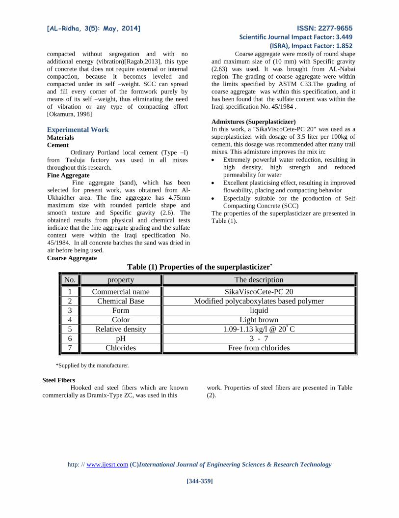
Admixtures (Superplasticizer)
In this work, a "SikaViscoCete-PC 20" was used as a
superplasticizer with dosage of 3.5 liter per 100kg of
cement, this dosage was recommended after many trail
mixes. This admixture improves the mix in:
Extremely powerful water reduction, resulting in
high density, high strength and reduced
permeability for water
Excellent plasticising effect, resulting in improved
flowability, placing and compacting behavior
Especially suitable for the production of Self
Compacting Concrete (SCC)
The properties of the superplasticizer are presented in
Table (1).
Table (1) Properties of the superplasticizer*
*Supplied by the manufacturer.
Steel Fibers Hooked end steel fibers which are known
commercially as Dramix-Type ZC, was used in this
work. Properties of steel fibers are presented in Table
(2).
No. property The description
1 Commercial name SikaViscoCete-PC 20
2 Chemical Base Modified polycaboxylates based polymer
3 Form liquid
4 Color Light brown
5 Relative density 1.09-1.13 kg/l @ 20° C
6 pH 3 - 7
7 Chlorides Free from chlorides

[AL-Ridha, 3(5): May, 2014] ISSN: 2277-9655
Scientific Journal Impact Factor: 3.449 (ISRA), Impact Factor: 1.852
http: // www.ijesrt.com (C)International Journal of Engineering Sciences & Research Technology
[344-359]
Table (2) Properties of steel fibers*
*Supplied by the manufacturer
Mixing water Ordinary potable water was used for mixing
and curing to all concrete mixes in this study
Limestone Powder (LSP)
This material is locally named as “Al-
Gubra”. It is a white grinding material from lime-
stones excavated from different regions in Iraq, and
usually used in the construction processes. In this
work, a fine limestone powder that grinded by
blowing technique, had been used.
Concrete mix
In this work, to produce a nonfibrous
concrete, the following mixing proportion was used:
[cement: Limestone Powder: sand: aggregate] was
[1:0.1:1.9:2] by weight and the water –cement ratio
was 0.44 with superplasticizer of 3.5 liter per 100kg
of cement. This mix was based on several trial mixes
in order to obtain the most suitable mix.
Steel Fiber Reinforced Concrete was
obtained by adding steel fibers with volume fractions
to the fresh nonfibrous concrete, then remixed. There
are three mixture of steel fiber reinforced concrete
depending on the volume fraction of steel fiber
(0.0%,0.4%and 0.8%)
This mixing has tended to British practice
which has generally relied to high sand content (more
than 50% by weight of aggregate) with maximum
aggregate size of 10 mm[Hannant1978]. The
workability of the mix and uniform dispersion of the
fibers, are important factors that affect the quality of
fibrous concrete.
Mixing procedure
The mixing procedure is an important factor
for obtaining the self-compact concrete which satisfy
criteria of filling ability, passing ability and
segregation resistance. The good dispersion of fibers
prevents fiber clumping. The concrete was mixed by
hand by using a pan. The interior surface of the pan
was cleaned and moistened before placing the
materials. The fresh concrete was mixed until a
homogeneous fresh concrete was obtained. To avoid
balling and to distribute the steel fibers uniformly, the
required amount of steel fibers was uniformly added
to the mix by hand sprinkling. The fresh concrete was
then mixed until a good dispersion of the fiber was
obtained.
This procedure is briefly stated in the following
points:
1. Initially the fine, filler and coarse aggregates
were poured and mixed for several minutes
in the pan and then the cement was added
.The materials were mixed until a uniform
color was obtained
2. Afterward 50% of the water of 0.4 w/c
ratio(which divided the w/c ratio=0.4+0.04)
was added to the mix and all components
were remixed for a few minutes
3. Then, the (superplasticizer +20% of the 0.4
w/c ratio were mixed together) and pouring
it into the pan and remixing ,after that the
mixture is left for about five minute
4. Then, the remaining 30% of the 0.4 w/c ratio
was added and mixed until a homogeneous
fresh concrete was obtained
5. Finally the 0.04of w/c ratio was added and
remixed
Commercial name Configuration Property Specifications
Dramix ZC 50/0.5
Hooked ends
Density 7860 kg/m3
Ultimate strength 1130 MPa
Modulus of Elasticity 200x103MPa
Strain at proportion limit
5650 x10-6
Poisson's ratio 0.28
Average length 50 mm
Nominal diameter 0.5 mm
Aspect ratio (Lf/Df) 100
[AL-Ridha, 3(5): May, 2014] ISSN: 2277-9655
Scientific Journal Impact Factor: 3.449 (ISRA), Impact Factor: 1.852
http: // www.ijesrt.com (C)International Journal of Engineering Sciences & Research Technology
[344-359]
6. For the mixes that contain steel fiber, to
avoid balling and to distribute the steel
fibers uniformly, the required amount of
steel fibers was uniformly added to the mix
by hand sprinkling. The fresh concrete was
then mixed until a good dispersion of the
fiber was obtained.
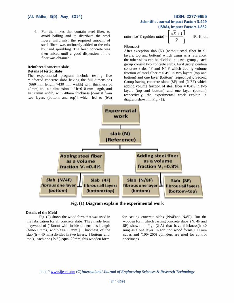
Reinforced concrete slabs
Details of tested slabs
The experimental program include testing five
reinforced concrete slabs having the full dimensions
[(660 mm length ×430 mm width) with thickness of
40mm] and net dimensions of b=610 mm length, and
a=377mm width, with 40mm thickness [consist from
two layers (bottom and top)] which led to (b/a)
ratio≈1.618 (golden ratio) =
2
15 [R. Knott.
Fibonacci]
After exception slab (N) (without steel fiber in all
layers, top and bottom) which using as a reference,
the other slabs can be divided into two groups, each
group consist two concrete slabs. First group contain
concrete slabs 4F and N/4F which adding volume
fraction of steel fiber = 0.4% in two layers (top and
bottom) and one layer (bottom) respectively. Second
Group having concrete slabs (8F) and (N/8F) which
adding volume fraction of steel fiber = 0.4% in two
layers (top and bottom) and one layer (bottom)
respectively, the experimental work explain in
diagram shown in Fig. (1).
Fig. (1) Diagram explain the experimental work
Details of the Mold
Fig. (2) shows the wood form that was used in
the fabrication for all concrete slabs. They made from
playwood of (18mm) with inside dimensions [length
(b=660 mm), width(a=430 mm)]. Thickness of the
slab (h = 40 mm) divided in two layers, ( bottom and
top ), each one ( h/2 ) equal 20mm, this wooden form
for casting concrete slabs (N/4Fand N/8F). But the
wooden form which casting concrete slabs (N, 4F and
8F) shown in Fig. (2-A) that have thickness(h=40
mm) as a one layer. In addition wood forms 100 mm
cubes and (100×200) cylinders are used for control
specimens.

[AL-Ridha, 3(5): May, 2014] ISSN: 2277-9655
Scientific Journal Impact Factor: 3.449 (ISRA), Impact Factor: 1.852
http: // www.ijesrt.com (C)International Journal of Engineering Sciences & Research Technology
[344-359]
Fig. (2) Details of wooden form used concrete slabs, and wooden cubic forms and cylinders
Details of Steel Reinforcement
All concrete slabs were reinforced with
deformed bars having nominal diameter of 5 mm,
they were used as a mesh with spacing of 70 mm
center to center in each way. The bars parallel to the
length were arranged in sequence below and up of the
bars parallel to the width, this type of arrangement
led to make the distance (d) was equal in each way as
shown in Fig. (3). All deformed bars having
Mpa 708Fy and Mpa 1164Fu .The deformed
bars were connected together by using (1 mm ) steel
wire.
Fig. (3) Details of mesh reinforcement
Details of fabrication and curing
For fabrication of a typical slab, the wooden
form was cleaned and oiled before casting. The
required reinforcement mesh was placed horizontally
using five supports (small piece of plain bars having
nominal diameter of 2mm), one in each corner and in
center, in order to keep the cover uniformly during
fabrication.
Each slab was cast with mixed according to
the mixing procedure mentioned before. For slab
(N/4F) and (N/8F), the fresh concrete was placed in
the wooden form of the slab by two layers (according
to the variation of volume fraction of steel fiber), each
layer (represent half of concrete slab) was hammered
by rubber driver, at the sides and the base of the
wooden until the casting was completed. The fresh
concrete of the top layer was placed in the wooden

[AL-Ridha, 3(5): May, 2014] ISSN: 2277-9655
Scientific Journal Impact Factor: 3.449 (ISRA), Impact Factor: 1.852
http: // www.ijesrt.com (C)International Journal of Engineering Sciences & Research Technology
[344-359]
form after period about five minute since completed
of casting fresh concrete of bottom layer. Also the
control specimens (cubes and cylinders) were casting
as the same method for each types of fresh concrete.
But the other slabs (N,4F,8F),the fresh concrete was
placed in the wooden form of the slab as a layer and
also were hammered by rubber driver, at the sides and
the base of the wooden until the casting was
completed.
The control specimens and wooden form
were covered with a plastic sheet to prevent
evaporation of water. After (24) hours, the slabs and
control specimens were stripped from the molds and
cured in a water bath for about one month. To keep
the temperature about 25ºto 30º, two heaters were
used which modified for ornamental fish ponds and
water pump to distributed the heat in the water bath.
Then they were taken out from the water bath, and
then the slabs, control specimens were tested.
Testing procedure
Slab specimens were placed on the steel
frame of the testing machine and covered with fine
sand and plate in order to distribute stress on testing
slab and adjusted so that the centerline, line of
supports, point load on the sand and dial gauges
were fixed at their correct and proper locations.
Loading was applied in small increments of (2kN)
(stress equal to load divided by area of the slab
[(2kN/(610mm×377mm)]). At each stress stage the
deflection readings at the center and at the support
region were recorded. After the first crack appeared
the cracking depth and cracking width were gradually
increased with increasing stress. The loading
increments were applied until failure occurred. Fig.
(4) shows details of the testing concrete slabs.
Nilon
Slab (660mm x 430mm x 40 mm)
Border (L-sec.) interior Dim.(610mmx377mm)
L-sec. (25mm x 25 mm x 2 mm)
Fine sand
Steel Structure Frame
Plate (610mm x 377 mm x 6mm)
3 Plate (60 mm x 60 mm x 350mm)
hole for dial gage 2
Rubber
Border with Dim. c/c (610mm x 377mm)
Sq. bar (10mm x10mm)

[AL-Ridha, 3(5): May, 2014] ISSN: 2277-9655
Scientific Journal Impact Factor: 3.449 (ISRA), Impact Factor: 1.852
http: // www.ijesrt.com (C)International Journal of Engineering Sciences & Research Technology
[344-359]
Steel Structure Frame
Plate (610mm x 377 mm x 60mm)
Fine sand (inside the border)
3 Plate (60 mm x 60 mm x 350mm)
Slab (660mm x 430 mm x 40 mm)
Dial gauge 2
Dial gauge 1
Front view
Border with interior Dim.(61cmx37.7cm)
Hydraulic JackLoad Cell
Reaction Frame
Dial gauge1
Dial gauge 2
Border with interior Dim. (610mm x 377mm)
Sq. bar (10mm x10mm)
Rubber
Side view
Fig. (4) Slab specimen setup
Experimental Results
The following paragraphs contain the result
of the standard tests that were carried out on the fresh
concrete, and hardened concrete.
Slump Flow Test and T50cm Test
The slump flow test is used to assess the
horizontal free flow of self-compacting concrete. It is
the most commonly used test, and gives a good
assessment of filling ability. It may give some
indication of resistance to segregation. T50cm test is
also the measure of the speed of flow and hence the
viscosity of SCC [EFNARC, 2002]. This test, which
was developed in Japan, was originally used to
measure underwater concrete and has also been used
to measure highly flowable concretes [Al-Jabri,
2005]. The slump flow test is used to determine
filling ability and can indicate segregation resistance
of SCC to an experienced user (Al-Jabri, 2005).
Table (3) shows the results of slump flow tests. The
values of (D) represent the maximum spread (slump
flow final diameter), while the values of T50
represent the time required for the concrete flow to
reach a circle with 50 cm diameter)[Fig.(5)]. Table
(3) shows that the results were acceptable with
criteria for Self-Compacting Concrete (JSCE, 1999),
and illustrated that the filling ability decreased when
adding steel fibers to the concrete.

[AL-Ridha, 3(5): May, 2014] ISSN: 2277-9655
Scientific Journal Impact Factor: 3.449 (ISRA), Impact Factor: 1.852
http: // www.ijesrt.com (C)International Journal of Engineering Sciences & Research Technology
[344-359]
Fig. (5) Slump flow test
Table (3) Slump Flow Test and Acceptance criteria for Self-Compacting Concrete
Testing of Hardened Concrete
Compressive Strength
The compressive strength test was carried out
according to BS 1881: part 116:1989. This test was
measured on 100 mm cubes using electrical testing
machine with capacity of 2000 kN.(Fig. (6a))
Splitting Tensile Strength
The splitting tensile strength test was performed
according to ASTM C496-86. (100×200)mm
cylindrical concrete specimens were used. (Fig. (6b))
Unit weight (density)
The unit weights of concrete, with three steel fiber
–volume fraction were measured (Fig. (6c)),
using the following equation.
WA
A
WW
WDensity
---- [1]
Where: AW = weight in air, WW = weight in water
The compressive strength, splitting tensile strength
and unit weight, were obtained by using 100 mm
cubes and (100mm×200mm) cylinder. The effect of
steel fiber was slightly significant in density.
However, the result of present study showed that
adding steel fiber significantly increased the
compressive strength. On the other hand the effect of
increasing steel fiber were very significant in splitting
tensile strength.
Acceptance criteria for Self-compacting
Concrete D (mm)
T50
(Sec.)
Vf
%
Typical range of values 630 6 0.0
T50cm slump flow Slump flow by
Abrams cone 620 7 0.4
Min.
(Sec.)
Max.
(Sec.)
Min.
(mm)
Max.
(mm)
610 9 0.8 T50=3 T50= 25 D=600 D=800

[AL-Ridha, 3(5): May, 2014] ISSN: 2277-9655
Scientific Journal Impact Factor: 3.449 (ISRA), Impact Factor: 1.852
http: // www.ijesrt.com (C)International Journal of Engineering Sciences & Research Technology
[344-359]
(Fig. 6a) Compressive strength test (Fig. 6b) Splitting tensile strength test
(Fig. 6c) Unit weight (density) test
Experimental Results for concrete slab
Effect of fibrous concrete layers
The effect of fibrous concrete layers on the
ultimate strength of concrete slab with groups (1)
and (2) that having steel fiber –volume fraction of
0.4% group (1) and 0.8% group (1), are shown in
Fig. (7) and Fig. (8) respectively. These slabs of
each group had one fibrous layer(bottom) and two
fibrous layers(bottom + top) in each group.
The percentage of increases in the ultimate
strength when using fibrous one layer (bottom) and
fibrous two layers (bottom + top), with steel fiber –
volume fraction of 0.4%, 0.8% according to
reference slabs (N) are shown in Table (4).This
table illustrates that when using fibrous concrete
layers(either one layer or two layers), the ultimate
strength is significantly increased. The percentage
of increases in ultimate strength value was increased
with increasing fiber contain.
The increase in ultimate capacity of slabs
with fibrous concrete layers , may be attributed to
the role of steel fibers in improving the properties of
reinforced concrete in resisting additional bending
and shear stress.
The higher percentage of increases in
ultimate stress when using fibrous concrete layers,
essentially one fibrous concrete layer , may be due
to the type of orientation of steel fiber, as most of
steel fiber were distributed horizontally with
vertically small slop because the small thickness
that contain steel fiber.

[AL-Ridha, 3(5): May, 2014] ISSN: 2277-9655
Scientific Journal Impact Factor: 3.449 (ISRA), Impact Factor: 1.852
http: // www.ijesrt.com (C)International Journal of Engineering Sciences & Research Technology
[344-359]
Table (4) Effect of fibrous concrete layer on ultimate strength of Self-Compacting
Concrete slabs with two steel fiber –volume fraction (Vf) %
Fig. (7) Effect of fibrous concrete layer on ultimate strength of Self-Compacting
Concrete slabs with steel fiber –volume fraction (Vf) =0.4%
Name Type of
layer
Vf
% cuf
MPa
ft
MPa
Density
Kg/m3
Pu
kN
Stress
(MPa)
Percentage
of increase
N All layer 0.0 30.5 3.2 2336 74 0.321781 -------
4F All layer 0.4 35.5 4.3 2377 126 0.547898 70.2
Vf =
0.4
%
N/4F Top layer 0.0 30.5 3.2 2336
104 0.452233 40.5 Bottom layer 0.4 35.5 4.3 2377
8F All layer 0.8 38.1 5.3 2405 206 0.887072 178
Vf =
0.8
%
N/8F Top layer 0.0 30.5 3.2 2336
148 0.643562 100 Bottom layer 0.8 38.1 5.3 2405
0
0.1
0.2
0.3
0.4
0.5
0.6
0.7
0.8
0.9
1
Ult
ima
te s
tress
(Mp
a)
Ultimate stress(Mpa) 0.321781 0.547898 0.452233
Ultimate load(kN) 74 126 104
N 4F N/4F

[AL-Ridha, 3(5): May, 2014] ISSN: 2277-9655
Scientific Journal Impact Factor: 3.449 (ISRA), Impact Factor: 1.852
http: // www.ijesrt.com (C)International Journal of Engineering Sciences & Research Technology
[344-359]
Fig. (8) Effect of fibrous concrete layer on ultimate strength of Self-Compacting
Concrete slabs with steel fiber –volume fraction (Vf) =0.8%
Effect of steel fiber distribution
The effect of steel fiber distribution using
the same amount of steel fiber, was studied in this
work. Fig. (9) shows the effect of distribution the
same amount of steel fiber on ultimate strength either
in two layers (top and bottom) with volume fraction
of steel fiber=0.4% such as concrete slab (4F) or in
one layer (bottom) with volume fraction of steel
fiber=0.8% such as concrete slab (N/8F), and the
percentage of increasing in ultimate strength
according to reference slabs (N) are shown in
Table (5).This table shows that the slab (N/8F)
given ultimate strength higher than the slab (4F), the
reason of this behavior may be that the effect of steel
on increasing tensile strength was very higher than
the effect of steel fiber on increasing compression
strength ,so that all the steel fiber in the slab (N/8F)
was available in one layer (bottom) which
represented the tension zone. The second reason
might be to that when the thicknesses which contain
steel fiber decreased, the type of orientation or the
angle of steel fiber with respect to horizontal plane
decreased. The small thickness make the almost (or
all) of steel fiber was distributed horizontally with
vertically small, this type of distribution increased
the effect of steel fiber.
Table (5) Effect of steel fiber distribution on ultimate strength of Self-Compacting
Concrete
Name Type of
layer
Vf
%
cuf
MPa
ft
MPa
Density
Kg/m3
Pu
kN
Stress
(MPa)
Percentage
of increase
N All layer 0.0 30.5 3.2 2336 74 0.321781 -------
4F All layer 0.4 35.5 4.3 2377 126 0.547898 70.2
N/8F Top layer 0.0 30.5 3.2 2336
148 0.643562 100 Bottom layer 0.8 38.1 5.3 2405
00.10.20.30.40.50.60.70.80.9
1
Ultim
ate
stre
ss(M
pa)
Ultimate stress(Mpa) 0.321781 0.887072 0.643562
Ultimate load(kN) 74 206 148
N 8F N/8F

[AL-Ridha, 3(5): May, 2014] ISSN: 2277-9655
Scientific Journal Impact Factor: 3.449 (ISRA), Impact Factor: 1.852
http: // www.ijesrt.com (C)International Journal of Engineering Sciences & Research Technology
[344-359]
Fig. (9) Effect of steel fiber distribution on ultimate strength of Self-Compacting
Concrete slabs
Load – deflection response
Fig (10) shows the stress –deflection curves
of the tested of concrete slab at the center of the slab
and support region at all stages of loading up to failure
The net deflection at center of the slab is obtained by
subtracting the deflection that measured by the dial
gauge at the support region [reading of dial gauge 2]
from the deflection that measured by the dial gauge at
mid span [reading of dial gauge 1] as shown in Fig.(4)
[at every stage of loading], this method is carried out
in this study because the deflection that was measured
at support region gives a large value corresponding to
the deflection of the concrete slabs. Fig. (10A) shows
that when using fibrous concrete layers (one or two
layers), the ultimate strength of slabs increases and the
deflection was decreased, these behaviors are present
for two steel fiber – volume fraction (Vf) (0.4% and
0.8%).
0
0.1
0.2
0.3
0.4
0.5
0.6
0.7
0.8
0.9
1
Ultim
ate
str
ess(
Mp
a)
Ultimate stress(Mpa) 0.321781 0.547898 0.643562
Ultimate load(kN) 74 126 148
N 4F N/8F

[AL-Ridha, 3(5): May, 2014] ISSN: 2277-9655
Scientific Journal Impact Factor: 3.449 (ISRA), Impact Factor: 1.852
http: // www.ijesrt.com (C)International Journal of Engineering Sciences & Research Technology
[344-359]
Fig. (10) stress-deflection curves for Self-Compacting Concrete slabs (N), (4F)
,(N/4F), (8F)and (N/8F)
0.00
0.05
0.10
0.15
0.20
0.25
0.30
0.35
0.40
0.45
0.50
0.55
0.60
0.65
0.70
0.75
0.80
0.85
0.90
0.95
1.00
Str
ess
MP
a
0 3 6 9 12 15 18 21 24 27 30 33Deflection (mm)
0.00
0.05
0.10
0.15
0.20
0.25
0.30
0.35
0.40
0.45
0.50
0.55
0.60
0.65
0.70
0.75
0.80
0.85
0.90
0.95
1.00
Str
ess
MP
a
0 3 6 9 12 15 18 21 24 27 30 33Deflection (mm)
0 3 6 9 12 15 18 21 24 27 30 33Deflection (mm)
0.0
11.5
23.0
34.5
46.0
57.5
69.0
80.5
92.0
103.5
115.0
126.5
138.0
149.5
161.0
172.5
184.0
195.5
207.0
218.5
230.0
Load
kN
0.0
11.5
23.0
34.5
46.0
57.5
69.0
80.5
92.0
103.5
115.0
126.5
138.0
149.5
161.0
172.5
184.0
195.5
207.0
218.5
230.0
Loa
d kN
Deflection of Slab N
Reading of dial gauge 1
Reading of dial gauge 2
Actual deflection
Deflection of Slab 4F
Reading of dial gauge 1
Reading of dial gauge 2
Actual deflection
Deflection of Slab N/4F
Reading of dial gauge 1
Reading of dial gauge 2
Actual deflection
Deflection of Slab 8F
Reading of dial gauge 1
Reading of dial gauge 2
Actual deflection
Deflection of Slab N/8F
Reading of dial gauge 1
Reading of dial gauge 2
Actual deflection
Deflection of ALL Slabs
Deflection of Slab N
Deflection of Slab 4F
Deflection of Slab 8F
Deflection of Slab N/4F
Deflection of Slab N/8F
A

[AL-Ridha, 3(5): May, 2014] ISSN: 2277-9655
Scientific Journal Impact Factor: 3.449 (ISRA), Impact Factor: 1.852
http: // www.ijesrt.com (C)International Journal of Engineering Sciences & Research Technology
[344-359]
Crack pattern and mode of failure
Fig. (11) shows the crack pattern for all
tested slab specimens, included reference concrete
slab(N) with two groups of fibrous concrete, that
having steel fiber –volume fraction of 0.4%, 0.8%,
(4F,N/4F)and(8F,N/8F) respectively, with one fibrous
layer(bottom) and two fibrous layers (bottom + top)
For slabs without steel fiber [reference concrete slab
(N)],the most cracks were enclosed after testing,
therefore many cracks cannot be recognized by eyes
and the crack was marked using Magnifying glass,
the mode of failure was bending.
When using fibrous concrete layers (two layers)
which had steel fiber –volume fraction equal to
0.4%[slab 4F], the number and width of the cracks
were increased, specially shear cracks which led to
failure of mode bending-shear.
On the other hand, when using fibrous concrete layers
(one or two layers) which had steel fiber –volume
fraction equal to 0.8%[slab (8F)and slab (N/8F] and
for slab(N/4F)which have fibrous concrete layers
(one layer) with steel fiber –volume fraction 0.4%,
the shear cracking width were extremely increased
and led to failure in shear mode.
The finding In the present study, that when using
fibrous concrete layers (one layer or two layers with
steel fiber), the mode of failure changed from
bending to shear, and the increasing of this effect
when using one fibrous concrete layer (bottom),
might be explained by that, when using fibrous
concrete layers (one layer or two layers with steel
fiber), the resistance of bending stress increased
larger than the resistance of shear stress. As any
orientation steel fiber in the bending region (at
center) will lead to increase resistance of bending
stress while near the support (shear region), the steel
fibers were parallel the support so they didn't increase
shear stress.
Fig. (11) Bottom crack patterns at failure for all concrete slabs

[AL-Ridha, 3(5): May, 2014] ISSN: 2277-9655
Scientific Journal Impact Factor: 3.449 (ISRA), Impact Factor: 1.852
http: // www.ijesrt.com (C)International Journal of Engineering Sciences & Research Technology
[344-359]
Conclusions 1. The result of present study showed that
when using fibrous concrete layers (one or
two layers), the ultimate strength was
significantly increased. This result for two
volume fraction of steel fiber 0.4%and 0.8%.
2. The effect of distribute steel fiber on
ultimate strength, in one layer (bottom)was
higher than the effect of distribute the same
amount of steel fiber , in two layers (bottom
+top)
3. When using fibrous concrete layers (one or
two layers), the deflection of slab specimen
are decreased. These behaviors were found
for two volume fraction of steel fiber
0.4%and 0.8%.
4. When using fibrous concrete layers (one or
two layers), the resistance of bending stress
increased larger than the resistance of shear
stress, therefore, the mode of failure changed
from bending to shear. this phenomenal
increased when using one fibrous concrete
layer (bottom)
Acknowledgements We thank the colleagues listed below for
their achievement search:
1. Lecturer Ali F. Atshan. Environmental
Department – College of Engineering – Al-
Mustansiriya University– Baghdad – Iraq.
2. Lecturer Ali Kadhim I. Highway and
Transportation Department – College of
Engineering - Al- Mustansiriya University –
Baghdad – Iraq.
3. Mr. Akram Hasan, member of staff structural
laboratory of the College of Engineering,
Al-Mustansiriya University– Baghdad – Iraq .
4. Ahmed Riyadh [son of my sister].
Reference [1] ACI Committee 544, “State-of-the-art report on
fiber reinforced concrete (544.1R-96)”,
American Concrete Institute, Detroit, 2009.
Cited by reference[2]
[2] Aldossari K. M, Elsaigh W. A, Shannag M. J "
Effect of Steel Fibers on Flexural Behavior of
Normal and High Strength" International
Journal of Civil, Architectural Science and
Engineering Vol:8 No:1pp22-26, 2014(paper3)
[3] Al-Jabri L A, . The Influences of Mineral
Admixtures and Steel Fibers on the Fresh and
Hardened Properties of SCC. M. Sc. Thesis ,
University of Al-Mustansirya University ,
Baghdad , 2005
[4] ASTM Designation C33-86,"Concrete
Aggregates" :1988,Annual Book of ASTM
Standards, American Society for Testing and
Materials, Philadelphia, Pennsylvania ,Section
4,V.04.02
[5] Bekaert, “Steel fibers for the pre-cast industry”,
Dramix, Bekaert, NV,1999. Cited by reference
[2]
[6] Ding Y, and Kusterle W (2000),“Compressive
stress–strain relationship of steel fiber-
reinforced concrete at early age”, Cem Concr
Res, Vol. 30, pp. 1573–1579. Cited by
Hassanpour M, Shafigh P, Mahmud H B.
Lightweight aggregate concrete fiber
reinforcement – A review. Construction and
Building Materials 37 (2012) 452–461
[7] Edgington J, Hannant DJ, Williams RIT. Steel
fibre reinforced concrete. Build Res Estab Curr
Pap, CP 1974;69(74):154–70. Cited
Hassanpour M, Shafigh P , Mahmud H B.
Lightweight aggregate concrete fiber
reinforcement – A review. Construction and
Building Materials 37 (2012) 452–461
[8] EFNARC, (2002), "Specification and Guidelines
for Self-Compacting Concrete", pp.32,
www.efranice.org . Cited by Al-Anbori Z. K. A.
"Effect of External Sulfate Attack on Self
Compacted Concrete".
Eng.&Tecg.jornal,Vol.31,part (A),No.6,2013
[9] Ellouze A., Ouezdou M., Karray M. A."
Experimental Study of Steel Fiber Concrete Slabs
Part I: Behavior under Uniformly Distributed
Loads" International Journal of Concrete
Structures and Materials, Vol.4, No.2, December
2010,pp113~118.
[10] F. Minelli, and F. Vecchio, “Compression field
modeling of fiber reinforced concrete members
under shear loading”, ACI Structural Journal,
Vol. 103, No. 2, 2006, pp. 244-252. cited by
reference[2]
[11] F. Parker, “Steel fibrous concrete for airport
pavement applications”, Technical Report S-74-
12, U.S. Army Engineer Waterways Experiment
Station. Federal Aviation Administration,
Washington DC, 1974. cited by reference[2]
[12] Hannant , D. J. , “ Fiber Cement and Fiber
Concrete ” , John , Wiley and Sons , Ltol. N. Y.
1978, 219 PP.
[13] Iraqi Specifications (45) "aggregate of the
natural sources used in concrete construction"
Central Organization for standardization and
quality control, Baghdad, 1980.
[14] JSCE, “Recommendation for Self-Compacted
Concrete”, Tokyo-Japan Society of Civil

[AL-Ridha, 3(5): May, 2014] ISSN: 2277-9655
Scientific Journal Impact Factor: 3.449 (ISRA), Impact Factor: 1.852
http: // www.ijesrt.com (C)International Journal of Engineering Sciences & Research Technology
[344-359]
Engineers, Concrete Engineering Series 31,
(1999). Cited by reference[3]
[15] Li VC. Large volume high performance
applications of fibers in civil engineering. J Appl
Polym Sci 2002; 83(3):660–86.Cited by
Hassanpour M, Shafigh P , Mahmud H B.
Lightweight aggregate concrete fiber
reinforcement – A review. Construction and
Building Materials 37 (2012) 452–461
[16] Mehta PK, Monteiro PJM. Concrete;
microstructure, properties, and materials. 3rd
ed. New York: McGraw-Hill; 2006. Cited by
Hassanpour M, Shafigh P , Mahmud H B.
Lightweight aggregate concrete fiber
reinforcement – A review. Construction and
Building Materials 37 (2012) 452–461 ]
[17] Okamura H., "Self-compacting High
Performance Concrete ", Concrete
International, Vol.19, No.7, pp.50-54, (1998).
[18] R. B. Abdul-Ahad and O. Q. Aziz. 1999. Flexural
Strength of Reinforced Concrete T-Beans with
Steel Fibers. Cement and Concrete
Compositions. Volume 21 Issue 4. pp 263-268.
Cited by Mello E, Ribellato C,
Mohamedelhassan E " Improving Concrete
Properties with Fibers Addition" International
Journal of Civil, Architectural Science and
Engineering Vol:8 No:3 pp8-13, 2014.
[19] R. Knott. Fibonacci and golden ratio formulae.
http://www.maths.surrey.ac.uk/hosted-
sites/R.Knott/Fibonacci/fibFormulae.html.
[20] Ragab K. S." Study Punching Shear of Steel
Fiber Reinforced Self Compacting Concrete
Slabs by Nonlinear Analysis" International
Journal of Civil, Architectural Science and
Engineering Vol.7 No.9 pp15-26, 2013
Copyright © 2022 FDOKUMEN