effect of extra cantilever slabs of variable span on the ...
11
Available online at www.ijrp.org International Journal of Research Publications EFFECT OF EXTRA CANTILEVER SLABS OF VARIABLE SPAN ON THE STRUCTURAL ELEMENTS OF A FLAT PLATE BUILDING Dipa Sarker a , Ariful Islam b , Mirajul Alam c , Mohammad Arman Ullah d a,b Lecturer, Department of Civil & Environmental Engineering, Fareast International University, Banani, Dhaka-1213, c,d Department of Civil Engineering, Ahsanullah University of Science & Technology,Tejgaon, Dhaka-1208, Abstract The flat plate system has been adopted in many buildings in Bangladesh specially in garments factory buildings. However, it is observed that extra cantilevers sides which are not conforming to the actual plan and design are constructed to take advantage of the extra floor space to meet the economical demands. Many structures in Bangladesh differ from their actual plan due to the extra cantilever portion provided by the developers. So the various effects that take place in the building due to this phenomenon are discussed in this research. The axial force, deflection, punching shear, horizontal & vertical displacement of columns has been analyzed for increasing cantilever of 2ft, 4ft, 6ft, 8ft and 10 ft respectively. Deflection at mid-point of a panel of a particular slab, column strip and middle strip are also determined. Percentage of increase in column load for 2ft, 4ft, 6ft, 8ft & 10 ft is compared and their variability is observed. Factor of safety is OK for a structure with no cantilever. For 2 ft. extra cantilever, the exterior column fails. For 4ft, 6ft, 8ft & 10ft, the factor of safety for exterior and corner column is unsafe and thus fails. But it does not affect much to the interior columns and they are found safe in every condition. It has been observed in all cases that corner and exterior columns are more susceptible to extra cantilevers than interior column. According to the punching shear check, no shear reinforcement is required for corner column and exterior column. Flat plates are also used by the engineers because it provides more space and stability. Structural engineers commonly use manual calculations for the analysis of flat plate structures. The software STAAD.Pro V8i has been used in this paper for the design and analysis of a six storied garments factory building. For the analysis, 3 load combinations are used in this paper. To understand the structural behavior of the slab due to increase in the cantilever portion of the slab, different parameters are evaluated using the software. The manual calculations for axial force, horizontal and vertical displacements, deflection and punching shear are also performed in order to compare them with the results obtained from STAAD Pro. The obtained results are plotted against the various load combinations for a graphical
-
Upload
khangminh22 -
Category
Documents
-
view
2 -
download
0
Transcript of effect of extra cantilever slabs of variable span on the ...
Available online at www.ijrp.org
International Journal of Research Publications
EFFECT OF EXTRA CANTILEVER SLABS OF VARIABLE
SPAN ON THE STRUCTURAL ELEMENTS OF A FLAT
PLATE BUILDING
Dipa Sarkera, Ariful Islamb, Mirajul Alamc, Mohammad Arman Ullahd
a,bLecturer, Department of Civil & Environmental Engineering, Fareast International University, Banani, Dhaka-1213, c,dDepartment of Civil Engineering, Ahsanullah University of Science & Technology,Tejgaon, Dhaka-1208,
Abstract
The flat plate system has been adopted in many buildings in Bangladesh specially in garments factory buildings. However,
it is observed that extra cantilevers sides which are not conforming to the actual plan and design are constructed to take
advantage of the extra floor space to meet the economical demands. Many structures in Bangladesh differ from their
actual plan due to the extra cantilever portion provided by the developers. So the various effects that take place in the
building due to this phenomenon are discussed in this research. The axial force, deflection, punching shear, horizontal &
vertical displacement of columns has been analyzed for increasing cantilever of 2ft, 4ft, 6ft, 8ft and 10 ft respectively.
Deflection at mid-point of a panel of a particular slab, column strip and middle strip are also determined. Percentage of
increase in column load for 2ft, 4ft, 6ft, 8ft & 10 ft is compared and their variability is observed. Factor of safety is OK for
a structure with no cantilever. For 2 ft. extra cantilever, the exterior column fails. For 4ft, 6ft, 8ft & 10ft, the factor of
safety for exterior and corner column is unsafe and thus fails. But it does not affect much to the interior columns and they
are found safe in every condition. It has been observed in all cases that corner and exterior columns are more susceptible
to extra cantilevers than interior column. According to the punching shear check, no shear reinforcement is required for
corner column and exterior column. Flat plates are also used by the engineers because it provides more space and stability.
Structural engineers commonly use manual calculations for the analysis of flat plate structures. The software STAAD.Pro
V8i has been used in this paper for the design and analysis of a six storied garments factory building. For the analysis, 3
load combinations are used in this paper. To understand the structural behavior of the slab due to increase in the cantilever
portion of the slab, different parameters are evaluated using the software. The manual calculations for axial force,
horizontal and vertical displacements, deflection and punching shear are also performed in order to compare them with the
results obtained from STAAD Pro. The obtained results are plotted against the various load combinations for a graphical

2
representation of effect of structural behavior of the columns and slabs. The analysis is done for a concrete structure and
slab thickness is also defined as per calculation.
Keywords: STAAD.Pro V8i, structural behavior, extra cantilever;
1. Introduction
From an aesthetic and economic point of view, the flat plate structure has an advantage over the slab systems because of the significant saving in construction work and aesthetically pleasing appearance. Nowadays flat
plate is not a new concept and many engineers had done researches on flat plate. Different researchers provide
different opinion on this. Like Shinde S.S &Patil P.S had apprehended in their research paper “Parametric Study On Slender Column For Flat Plate Structure”. They studied the effect on different column like corner column, edge column in a reinforced cement concrete structure. The research showed that design load
increases, buckling load decreases and slenderness ratio increases because of slender column. Thus in flat
plate structure, corner and edge columns are more sensitive to slender effect than that of inner column. A
corner column for all case needs more attention than edge and inner column. Woo-Seung shin and Jinkoo Kim
in their paper “Seismic Retrofit Of Flat Plate structures”. In that study flat plate structures designed only for gravity load were retrofitted against earthquake load using various methods and their seismic performances
were evaluated to verify the effect of the seismic retrofit. As part of a comprehensive investigation on the contribution of floor systems to the earthquake resistance of building structures, a series of in-planer shear
tests were performed on reinforced concrete flat plates. The tests were designed to study the effects of cyclic
loading, shear span variation and life gravity load on the behavior and strength of the plates. The paper by
H.Faruk Karadogan, Ti Huang, Le-Wu Lu and Masayoshi Nakashima in their paper “Behavior Of Flat Plate Floor Systems Under In-plane seismic loading” also describes the test specimens, setup and techniques and the behavior observed during the test. P M B Raj Kiran Nanduri, Dr. B Dean Kumar, Y. Chandra Sekhar, Dr.
B.L.P Swami apprehended in their paper “Comparative study of Wind Load Analysis of Flat Plate
Multistoried Frames With and Without Reinforced Concrete Filled Walls”. A comparison of the critical column axial forces, critical column moments, lateral drift due to static and wind load on the structures
located at Hyderabad at a basic wind speed of 44 m/s has been observed. In this research, the efforts will be to
study and reinvent knowledge on flat plate especially on the effect on flat plate structures due to increase of
the cantilever portions. It can be overcome by increasing lateral stiffness of structure. And to do that some retrofitting systems are proposed as in many studies and comparing between them to give a final decision. So
to give a final and economical decision about the design analysis can play important part as it is known that
there is a deep relation between design and analysis of a structure. Design and analysis of a structure gives a
gross idea about that structure by providing knowledge about its functionality, geometric property and
strength.
2. Methodology
2.1 STAAD Pro V8i AT A GLANCE
2.1.1 User Interface
Modes and Pages: The innovative tabbed, mode and page layout simplifies and sophisticated program to
assist the engineer to create, sort and access data whether creating a simple frame, a complex steel support
structure or an elegant towering sculpture. Full interface configuration using FPS and/or metric unit systems.
Graphical tools: Models can be created quickly and accurately using structural grids, tooltips to highlight
data, frame generators and a structure wizard for standard structural frames.

3
Visualization: From simple wire frames for speed, accuracy and ease of use to fully rendered 3D models
for clear mass distribution and presentation.
Editor: A color coded tool to check and organize the data, label with comments and organize to model
stage construction.
Section wizard: Calculate properties of build up sections, drawn freehand, parametrically defined, or
imported from a CAD drawing.
Meshing tools: Triangular or quadrilateral meshes created from zones within defined models or imported
from DXF files.
Load generators: Seismic UBC, IBC, ASME wind and snow, bridge loading.
2.1.2 Objects
Beams: Standard linear, curved and physical beams compression/tension only with databases of sections
from around the world.
Plates: 3 or 4 nodded 2D plates and surface objects (shear walls) with holes.
Solid: Solid 3D bricks from 4 to 8 nodes.
Supports: Foundation and multi linear springs one.
Specifications: Complete range of release definitions, including partial moment releases and non-linear
behavior such as one way or cracked. Master slave to model diaphragm actions on beam models.
Loads: Full range of loads for static and dynamic analysis which can be defined explicitly or calculated
using the wide range of load generators.
2.1.2 Analysis
Elastic: Traditional first order including iterative one way analysis.
P-Delta: Both large and small P-Delta including stress suffering effects.
Cable: Account for the changing stiffness of cables due to loading.
Imperfection: Account for imperfections in structural geometry.
Dynamic: Modal analysis including stress stiffening solution and steady state options, time history and
response spectrums.
Buckling: Identify the Eigen buckling factor.
Basic and advanced Solvers: The standard solver, the staple of STAAD for over 20 years is now
complemented by an advanced solver that can be up to 1000 times faster.
2.1.3 Code Checking and Design
• Steel, 37 codes from around the world including AISC 360-05.
• Concrete, 25 codes batch processed.
• Interactive RC design modes.
• Timber, 4 design codes supported.
• Aluminum, stainless steel, composite floors,
• And cold-forms design checks.
• Shear wall designs for US, Indian and British codes.

4
2.1.4 Post Processing
Pages: The STAAD. Pro interface is configured to suit the model to ease access to the required data.
Interactive graphics: Linked tables and windows to get direct feedback from one item in related
windows.
Output file: Simple clear information to verify the analysis.
User Report: Create high quality documents with company logos and diagrams taken directly from the
application. Even export to MS Word.
Contoured stress plots: Using automatic or user configured scales, colors and limits.
Animations: View displacements. Stress contours or mode shapes dynamically.
2.1.5 Interoperability
Bentley Structural: Two way link to support creating models with design and construction documents.
Bentley REBAR: Reinforced concrete designs passed into Bentley Rebar for complete scheduling and
detailing.
RAM Concept: Floor slabs can be identified and linked to RAM concept for full RC and PT design and
detailing in a state of the art application.
RAM Connection: Joints defined in the STAAD. Pro model with the forces calculated from the analysis
passed into the leading connection design application.
Auto Pipe: Pass the STAAD Pro structural steel frame into Auto PIPE to correctly account for the pipe
support stiffness and import the pipe engineers support reactions back into the model for an accurate design in
a fraction of the time of traditional methods.
STAAD Foundation: Import the STAAD. Pro support reactions and positions to design the structure
foundations.
Open STAAD: A complete set of functions that make Open STAAD an API from which data can be
extracted directly into applications such as MS Word or MS Excel or your very own application. You can
even drive STAAD. Pro creating models run the analysis and view the result with your own interface.
CAD, DXF: Use CAD models as the base wire frame, structural grid or outline of a complex deck that
needs to be meshed.
3. Results & discussions
The model without cantilever flat plate is analyzed first, according to this cantilever is provided only in one
direction and gradually increased the size of cantilever as 2 ft, 4 ft, 6 ft, 8 ft, 10 ft.
3.1 Column axial force
After applying cantilever flat plate, column axial force is gradually increased for 2 ft, 4 ft, 6 ft, 8 ft & 10 ft.

5
Fig. 1: Column Axial Force (Corner Column)
In this figure, the column axial force for corner column is plotted against all the combination load cases
and the variation of the axial force is seen for the main model i.e. 0 ft, and then for 2ft, 4ft, 6ft, 8ft, 10ft
respectively. Column Axial forces are shown in Y-axis and combination load cases are shown in X-axis.
Here load case 1, 2, 3 and 4 are EQ X+, EQ X-, EQ Z+ and EQ Z- respectively.
Fig. 2: Column Axial Force (Exterior Column)

6
In this figure, the column axial force for exterior column is plotted against all the combination load cases
and the variation of the axial force is seen for the main model i.e. 0 ft, and then for 2ft, 4ft, 6ft, 8ft, 10ft
respectively. Column Axial forces are shown in Y-axis and combination load cases are shown in X-axis.
Here load case 1, 2, 3 and 4 are EQ X+, EQ X-, EQ Z+ and EQ Z- respectively.
Fig. 3: Column Axial Force (Interior Column)
In this figure, the column axial force for interior column is plotted against all the combination load cases
and the variation of the axial force is seen for the main model i.e. 0 ft, and then for 2ft, 4ft, 6ft, 8ft, 10ft
respectively. Column Axial forces are shown in Y-axis and combination load cases are shown in X-axis.
Here load case 1, 2, 3 and 4 are EQ X+, EQ X-, EQ Z+ and EQ Z- respectively.
3.2 Column displacement
The axial force of interior column for combination load cases 11,12,13 is shown as bar charts for cantilever
slab increase of 0ft, 2ft, 4ft, 6ft, 8ft, 10ft respectively. The axial forces are plotted in Y-axis and the increased
cantilevers are shown in X-axis.
Combination load case 11= 1.4DL+1.7LL
Combination load case 12= 1.4DL+1.7LL+WLx
Combination load case 13= 1.4DL+1.7LL+EQx+WLx

7
Fig. 4: Displacement About Horizontal X Axis (Corner Column)
In this figure, the horizontal displacement (X-Axis) for corner column is plotted against all the
combination load cases and the variation of the horizontal displacement is seen for the main model i.e. 0 ft,
and then for 2ft, 4ft, 6ft, 8ft, 10ft respectively. Horizontal displacements are shown in Y-axis and combination
load cases are shown X-axis. Here load case 1, 2, 3 and 4 are EQ X+, EQ X-, EQ Z+ and EQ Z- respectively.
Fig. 5: Displacement About Horizontal Y Axis (Corner Column)
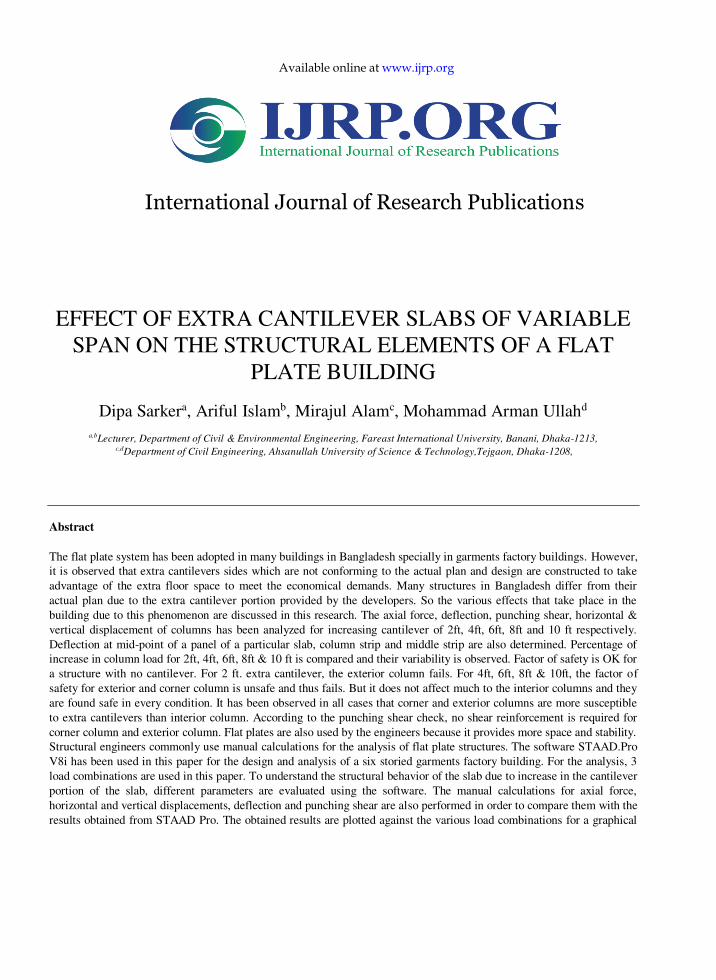
8
In this figure, the vertical displacement (Y-Axis) for corner column is plotted against all the combination
load cases and the variation of the vertical displacement is seen for the main model i.e. 0 ft, and then for 2ft,
4ft, 6ft, 8ft, 10ft respectively. Vertical displacements are shown in Y-axis and combination load cases are
shown in X-axis. Here load case 1, 2, 3 and 4 are EQ X+, EQ X-, EQ Z+ and EQ Z- respectively.
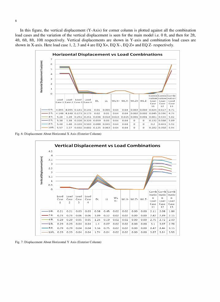
Fig. 6: Displacement About Horizontal X Axis (Exterior Column)
Fig. 7: Displacement About Horizontal Y Axis (Exterior Column)

9
In figure 6 & 7, the vertical displacement (X-Axis & Y-Axis) for exterior column is plotted against all the
combination load cases and the variation of the vertical displacement is seen for the main model i.e. 0 ft, and
then for 2ft, 4ft, 6ft, 8ft, 10ft respectively. Vertical displacements are shown in Y-axis and combination load
cases are shown in X-axis. Here load case 1, 2, 3 and 4 are EQ X+, EQ X-, EQ Z+ and EQ Z- respectively.
Fig. 8: Displacement About Horizontal X Axis (Interior Column)
Fig. 8: Displacement About Horizontal X Axis (Interior Column)

10
In figure 8 & 9, the vertical displacement (X-Axis & Y-Axis) for interior column is plotted against all the
combination load cases and the variation of the vertical displacement is seen for the main model i.e. 0 ft, and
then for 2ft, 4ft, 6ft, 8ft, 10ft respectively. Vertical displacements are shown in Y-axis and combination load
cases are shown in X-axis. Here load case 1, 2, 3 and 4 are EQ X+, EQ X-, EQ Z+ and EQ Z- respectively.
4. Conclusion
In this paper an extensive computational investigation has been executed on a 6 story flat plate factory
building to observe its behavioral characteristics for axial force, punching shear, deflection and horizontal &
vertical displacement for the case of extra cantilever slabs of different spans. Here both hand calculation and
Excel worksheet calculation was done to design the basic flat plate building with no cantilever slab. Then
software based analysis was done using the software STAAD/pro to check the effect of extra cantilever slabs
on the whole building and the results are tabulated and graphically presented. This study is done according to
the Bangladesh National Building code. In the conclusion here is the summary of the study:
(1) The corner and exterior columns are more susceptible to extra cantilever effect than the interior
column.
(2) The percentage of increase in column load gradually increases for corner column and exterior column
due to extra cantilevers of 2ft, 4ft, 6ft, 8ft, 10ft. On the other hand, the percentage of column load gradually
decreases for interior column due to the same extra cantilevers.
(3) Allowable punching shear (Va) is greater than the actual shear(Vu) for both corner and exterior
column. So, shear reinforcement is not required in corner column and exterior column. Punching shear
capacity increases after inclusion of the cantilever sides.
(4) Deflection for the columns in long direction decreased as the cantilever portion of slabs were increased
by 2ft, 4ft,6ft,8ft,10ft gradually. On the other hand, deflections for the columns in short direction increased as
the cantilever portion of slabs were increased by same amount.
(5) The bending moment of the exterior column decreased as the cantilever portion of slabs were increased.
(6) The axial force and displacements were highly varying for corner column and exterior column due to
increase in cantilever but it did not affect the interior column much.
5. Recommendations
As in this study is only for symmetrical building, there are also many scopes for further study covering
other possible cases. In this case following may take concern:
(1)In this study only finite element software STAAD-Pro is used. There are also some other finite element
software such as ETABS 9.6.0, ANSYS, ABAQUS etc to analyze this kind of study.
(2) This thesis is studied for a 6 story factory building. To make this study comprehensive, the analysis
may be done for high rise buildings and residential buildings too.
(3) Flat Slabs for cantilever greater than 10 ft. and varying slab thickness may be taken into account for
further studies.
(4) Material properties are kept constant for all the models for design purposes. For future studies, models
may be designed for steel structure instead of concrete structure.

11
References
Ahmed, F., Kumar, B., Chandrashekhar,Y. (2012) Comparative Analysis of Flat Plate Structures Under wind load, International Journal
of Engineering and Advanced Technology (IJEAT) ISSN: 2249 – 8958, Volume-2, Issue-1, October 2012
Borges, L. Guilherme, S. and Gomes, B. (2013) Punching Shear of reinforced flat plates with openings, ACI Structural Journal/July-
August 2013
Charlebois, K.(2011) Structural Design of a cantilevered building
Cheng, M. (2009) Punching shear strength and deformation capacity of fiber reinforced concrete slab-column connections under
earthquake type loading.
Erberik, M. and Elnashai, S.(2003) Seismic Vulnerability of Flat Plate Structures Mid-Americana Earthquake Center DS-9 Project(Risk
Assessment Modelling) University of Illinois at Urbana-Champaign
Lelekakis, S. George E., Birda , Athina T., Mitoulis, Stergios A (2006) Application of Flat Plate Structures in seismic regions, Aristotle
University of Thessaloniki, Department of Civil Engineering,
Moehle, J., Diebold, W. and Zee, H.(2004) Experimental Study of a Flat Plat Building Model
Nilson H. A., Darwin D., Dolan W. C., 2010-2011, “Design of Concrete Structures.”(Thirteenth Edition), McGraw Hill Richard, M. (1996) Shear flow past flat plates
Song, J. and Kim, J.(2012) Effective punching shear and moment capacity of flat plate-column connection with shear reinforcements for
lateral loading. International Journal of Concrete Structures and Materials Vol.6, No.1, pp.19~29, March 2012
Shin, Woo-seung (2013) Seismic Retrofit of flat plate structures, 1CS Structural Engining Inc., Sungnam 462-807, Korea
World Academy of Science, Engineering and Technology Vol:3 2009-11-21