Behavior of reinforced concrete segmental hollow core slabs ...
Upload
khangminh22Category
view
1download
0
UNIT II
LIMIT DESIGN FOR FLEXURE
DESIGN OF FLANGED BEAMS
INTRODUCTION
When there is a reinforced concrete slab, over a reinforced concrete
beam the slab and bean, can be designed and constructed in such a way that
they act together. The concrete in the slabs, which is on the compression side
of the beam (in the middle portions of continuous beams), can be made to
resist the compression forces, and the tension can be carried by the steel in
the tension side of the beam. These combined beam and slab units are called
flanged beams. They may be T or L beams, depending on whether the slab is
on both or only on one side of the beam .
One should be aware that continuous T or L beams act as flanged
beams only between the supports where the bending moments are
conventionally taken as positive and the slabs are on the compression side of
the beam. Over the supports, where the bending moments are negative, the
slabs are on the tension side and here the beam acts only as a rectangular
beam, with the tension steel placed in the slab portion of the beam. Thus at

places of negative moments these beams have to be designed as singly or
doubly reinforced rectangular beams as shown in figure.
In order to make the slab and beam act together, transverse steel should
be placed at the top of the slab with sufficient cover for the full effective
width of slab. This steel is also useful to resist the shear stresses produced by
the variation of compressive stress across the width of the slab.
The four main components that constitute these flanged beams (in
addition to the hanger bars) for which strength calculations are necessary:
o The compression flange
o Tension steel
o Transverse steel in the slab for integral action
o Stirrups for shear.

EFFECTIVE FLANGE WIDTH
An equivalent width of the slab with uniform stress distribution that can
be assumed to act along with the beam for strength calculation is called the
effective width of the flanged beam. The compressive stress in the flange just
above the rib is higher than that at some distance away from the rib as in
figure.
The nature of this variation is very indeterminate, and the effective
width concept that enables the use of an imaginary width of beam over which
a uniform compressive stress is assumed to act is very useful.
ACTION OF TWO-WAY SLABS
▪ When a slab simply supported on all the four sides is loaded, the
corners tend to curl and lift up. This is to compensate for the non-
uniform distribution of pressure exerted by the slab on the supporting
walls.
▪ This behavior can be easily demonstrated by supporting a rigid
cardboard with Ly less than 2Lx on its four sides and pressing it down
wards .

▪ In practice, the upward movement described above may be prevented
by a wall or such other construction at the edge of the slab.
▪ In such circumstances it is said that the corner is 'torsionally
restrained'. Unless top steel is provided for such slabs, these will crack
at the corners.
▪ These slabs also tend to carry loads by spanning diagonally across the
corners. Hence, in addition to the top steel along the diagonal, bottom
steel is also needed at the corners.
o Even though for both these purposes (Le. the curling effect and
diagonal transfer of load at corners) steel is needed diagonally, it
is more convenient to provide two-way steel in the x and y
directions at the top and bottom surfaces of the slab. The steel is
known as corner steel.

MOMENTSIN TWO-WAY SLABS SIMPLY SUPPORTED ON ALL SUPPORTS
For computation of moments in simply supported cases of two-way
slabs, Table 27 in Annexure D of IS 456 can be used. These are derived from
the Rankine-Grashoff formula.

2. Determination of a x
Having determined a the value of a can also be determined from the
relations
• NEGATIVE MOMENTS AT DISCONTINUOUS EDGES
Negative moments may be experienced at discontinuous edges since,
in practice, they are not supported on rollers but partially restrained at their
ends. The magnitude of this moment depends on the degree of fixity at the
edge of the slab and is indeterminate.

The usual practice is to provide at these edges top reinforcement for
negative moment equal to (0.042 w1 i.e. w However, IS 456, Clause D 1.6 of
Annexure D recommends provision of 50 per cent of steel provided at mid
span along these edges, and this negative steel has to extend into the span 0.1
times the span length, as indicated in Figure.
• CHOOSING SLAB THICKNESS
The following three equally important conditions regarding the minimum
thickness should be satisfied by the slab.
Condition 1: The minimum should be such that it is safe in compression.
Thus the depth is calculated for the greater value of the negative moment on
the short span denoted M Hence
Total thickness = d (short) + 0.5 + cover. The steel for the short span is
placed at the lowest layer so that for the long strip the total thickness = d
(long) + + + cover. An average of (d + ) may also be used for practical
design purposes.

Condition 2: The slab should satisfy the span/effective depth ratio to control
deflection. For this purpose the short span is considered in the calculation of
L/d ratios. The value of span/effective depth ratios of 28 for simply supported
slabs and 32 for continuous slabs may be adopted for initial trials.
Condition .3: The slab should be safe in shear without shear reinforcements
as in the case of one-way slabs.
• SELECTING DEPTH AND BREADTH OF SUPPORTING
BEAMS
The depth of beams used for supporting the slab should be sufficient to
justify the assumptions of unyielding supports. The empirical relation used in
Swedish Regulations between depth of beams and depth of slabs as given in
figure may be used for arriving at the preliminary depth of these beams. It
can be seen that the depth of beam necessary from this consideration lies
between 2.5 to 5.0 times the depth of slab, depending on the ratio of Ly to Lx.
It can be represented by the equation
Again the breadth b of the beam is to be selected to ensure adequate torsional
rigidity. An empirical relationship giving breadth as a function of the length
of short span can be derived as

Having selected these preliminary values for depth and breadth, they can be
later checked by other methods for deflection control and torsional strength.
• CALCULATION OF AREAS OF STEEL
The depth of slab selected from deflection criterion will be generally
greater than the minimum required from strength considerations. The areas of
steel are calculated on the assumption that the short span steel will be placed
below the long span steel.
At corners like C where the slab is discontinuous only on one side, half of
the above area is to be provided as corner steel in each of the layers. Corner
steel need not be provided in corners such as C which is continuous on all
sides.
• LOADS ON SUPPORTING BEAMS
According to IS 456, Clause 24.5, the total loads that act on the support
beams for two-way slabs may be assumed as the load within the respective
area of the slab bounded by the intersection of 450 line from the corners with
the median line of the panel parallel to the long side. As is well known from
yield line theory of the slabs, this is a good approximation if all the sides are
similarly supported, either as discontinuous or as continuous.

The total load so obtained can be converted to an equivalent distributed
load for design of these beams. As the intensity of the loads on the beam is
non-uniform along its length, being higher at the central portion than at the
ends some codes like BS 8110 make a further assumption and calculate the
equivalent load as if it is acting only on 3/4 of the length Lx and Ly.
• PROCEDURE FOR SAFETY AGAINST EXCESSIVE
DEFLECTION
As already explained, deflection of slabs is controlled by span/effective
depth ratio similar to the case of beams and one-way slabs. For two-way
slabs, the shorter span and the percentage of steel in that direction have to be
considered for this purpose. The correction factors to be used in basic span
depth ratios for slabs for deflection control have already been explained.
Methods for computation of deflection of slabs are generally used only under
special circumstances.
• PROCEDURE FOR DESIGN OF TWO-WAY SIMPLY-
SUPPORTED SLABS
Step 1: Assume a slab thickness with proper cover to steel. This is to be
based on (spanl effective depth) ratio of shorter span.
The minimum practical depth of slab is 90 to 100 mm. As the
percentage of steel in slabs is low compared to that in beams, a larger value
of L/d ratio than that of beams will be found to be acceptable for slabs. (The

correction factor is larger in slabs due to low percentage of steel used in
them.)
Usually, the following span/effective depth ratios may be assumed for
preliminary design of two-way slabs (15 456, Clause 24.1):
❖ Simply supported slabs = 28
❖ Continuous slabs = 32
Assume suitable concrete cover of at least 15 mm depending on the
environmental conditions.
STEP 2: Calculate the design load and the value of dead load and live load
for the slab:
w=(l.5LL+1.5DL)
Step 3: Calculate design moment. Determine ly/lx where l is the shorter span,
find the moment coefficients from Table 23 of IS 456, and calculate the
moments Mx and My.
Step 4: Calculate maximum shear and check shear stress in the slab. For
calculating the shear, assume shear based on load distribution of the beams or
use Table 12.3. For refined analysis, critical section may be assumed .
Step5: Calculate steel required in both directions. Check the value of Mx/bd2
It should not be greater than that allowed for compression failure in concrete.
(d is the centre of steel in the x-direction.) Calculate the area of reinforcement
required. Choose diameter and find the spacing. Check for maximum spacing

allowed: 3d or 450 mm. For slabs less than 300 mm, limit spacing to 200
mm. These steps should be carried out for both directions.
Step 6: Check for deflection. The span depth ratio for deflection is based on
lx and As1.
Step 7: Check for cracking minimum steel in both directions and spacing.
Step 8: Detail the steel preferably as given in simplified detailing of
reinforcement in slabs.
• PROCEDURE FOR DESIGN OF TWO-WAY RESTRAINED
SLABS (WITH TORSION AT CORNERS)
Step 1: Assume a slab thickness with proper cover to steel.
Step 2: Calculate the design load from dead and live loads:
w = (1.5 DL + 1.5 LL)
Step 3: Draw the slab pattern of each slab in plan and show which case in
Table 22 of JS 456 each of the slabs refers to. Find Ly/Lx for the slab.
Step 4: Write down the shear force coefficients on the assumptions based on
distribution of slab loads to supporting beams. Make approximate check for
shear.
Step 4(a): Determine the maximum moment for the middle strips in the long
and short directions. Make adjustment for the negative moments at
continuous edges of common spans if necessary.
(b): Take each panel, check depth for bending moment. ensure that MI(bd2) is
not greater than that allowed for both Ly and Lx, directions, and calculate the
steel required in each direction at mid-span and supports of the middle strip.
One may assume the average effective depth for both the directions for
calculation of steel area.

d = (h — cover — diameter of reinforcement)
Find the required spacings of steel.
(c): Calculate the nominal steel for the edge strips.
(d): Identify the corners to be provided with corner steel and calculate the
corner steel required. It is equal to 0.75 times the area of the maximum
positive steel and is to be provided over 0.2L the width at the corners.
(e): If the shear check in step 4 is critical, make a final check for shear, taking
the value of design shear strength as that allowed for the area of steel
provided at the edges and using the enhancement factor.
Step 5: Check the deflection (the span/depth ratio in short direction with the
corresponding percentage of steel).
Step 6: Check for cracking (the minimum steel in both directions). Check the
rule for spacing of steel.
Step 7: Detail the main steels (edge strip steels and corner steels) preferably
according to standard practice.
• CONCENTRATED LOAD ON TWO-WAY SLABS
As slabs are two-dimensional structures, concentrated load produces
saucer-shaped deformation. It is difficult to analyze this deformation. Hence
an equivalent plane structure analysis is used, which will always be
approximate. The bending moment and shear force due to concentrated loads
on one-way slabs are analyzed by the equivalent width method:
• METHODS BASED ON THEORY OF PLATES FOR
CONCENTRATED LOADS ON TWO-WAY SLABS (PIGEAUD
METHOD)
The two well-known methods based on theory of elasticity for
determination of bending moments in slabs due to concentrated loads, e.g.
wheel loads, are Pigeaud’s and Westergard’s methods. Of these, the former

method is more popular than the latter and is commonly used for design of
bridge slabs.
However, it should be remembered that the standard design curves
available for Pigeaud’s method are for loads placed at the centre of two-way
simply supported slabs as shown in Figure, and for other cases of loading and
support conditions of values from the curves have to be suitably modified.
DESIGN OF BENDING MEMBERS FOR SERVICEABILITY
REQUIREMENTS OF DEFLECTION AND CRACKING
INTRODUCTION
In addition to the two limit state condition (durability on exposure to
the environments and ultimate strength at overloads), reinforced concrete
structures must also satisfy the serviceability conditions under the action of
the dead and live toads that act normally on the structure.
Two of the important serviceability conditions are:
✓ 1.The member should not undergo excessive deformation (i.e. limit
state of deflection
✓ The crack width at the surface in the reinforced concrete member
should not be mocetjttt that which is norma allowed by codes of
practice (i.e. the limit state of cracking).

Even though other limit states like limit state of vibration can be
specified and are applicable to special structures such as bridges, The two
conditions above are generally accepted as very important conditions to be
satisfied by every structure under service loads. Codes also specify the partial
safety factors for load combinations under which these are to be checked.
According to IS 456, Table 18 the combinations of loads for serviceability
conditions should be the largest of the following:
❖ 1.0DL+1.0LL
❖ l.0DL+1.0WL
❖ 1.0DL+0.8LL+0.8WL(EL)
For control of defleceion, two methods are usually described in
codes of practices:
❖ The empirical method of keeping the span-effective depth ratios of the
members not more than those specified in the codes.
❖ The theoretical method of calculating the actual deflection and
checking it with the allowable deflection in codes of practice.
Similarly, for control of crack width two methods are
recommended:
i. The empirical method of detailing the reinforcements accord to
the provisions of the code regarding spacing of bars, minimum
steel ratios, curtailment and anchorage of bars, lapping of bars,
etc.
ii. The theoretical method of calculating the actual width of cracks
and checking whether they satisfy the requirements in the codes
for the given environmental conditions.

Greater attention to deflection and cracking of concrete structures has
to be given with the aid of modern methods of R.C. design structures, as
these methods allow higher stresses than the conventional method, both in
concrete and steel.
During the past few decades, the maximum allowable stresses have
nearly been doubled for steel and increased considerably for concrete. Thus,
whereas most of the steel used in older R.C.C. members were only of grade
Fe 250, in modem construction, steel of grades of Fe 415 and Fe 500 are very
commonly used. This necessitates better control of deflection and cracking
conditions.
DESIGN FOR LIMIT STATE OF DEFLECTION
Excessive deflection of beams and slabs is not only an eyesore in itself,
but it can also cause cracking of partitions. As given in 18 456, Clause 23.2,
the commonly accepted limits of allowable deflections are:
❖ A final deflection of span/250 for the deflection of horizontal bending
members like slabs and beams due to all loads so as not to be noticed
by the eye and thus is not an eyesore.
❖ A deflection of span/350 or 20 mm, whichever is less, for these
members, after the construction of the partitions and finishes etc., to
prevent damage to finishes and partitions.
Even though methods for estimating deflection by calculation, are available
the empirical method to limit deflection are enough for routine design of
slabs and beams.
EMPIRICAL METHOD OF DEFLECTION CONTROL IN BEAMS
One can roughly express the allowable deflection/span ratio of beams
in terms of length/depth ratio as can be shown by the following derivation.

Let the deflection of a simply supported beam under UDL be expressed by
the formula
This means that assuming certain terms as constants, the allowable
deflection/span ratio can be controlled by the span/depth ratio. This principle
is used for specifying the span/depth ratio for control of deflection in beams
and slabs.
PROCEDURE FOR CHECKING DEFLECTION
Step 1: Depending on condition of supports, choose the basic span/effective
depth ratio from Table 9.1 if the span is 10 m or less. If it is greater than 10
m, reduce the values as indicated in figure.
Step 2: Determine modification factor F which depends on the type of steel
used (corresponding to the service stress in steel) and the percentage of steel
required in the beam at the point of maximum deflection.

The modification factor F is to be obtained from IS 456 . This figure gives F
factor for different stress levels and percentages of tension steel. The value of
the stress in steel at working stress (for which deflection is to be determined)
is assumed to be 0.58 of the yield stress of steel.
Thus the steel stress which will depend on the actual area of steel
provided at the section is to be calculated from the following formula:
f = 0.58fy [As (required) ÷ As (provided)]
This equation is very useful for determining the value of F more accurately
than the one given in Fig. 4 of IS or when computer procedures are used for
checking the deflection. The service stress L is obtained more accurately
from the equation

In T beam the ratio of tensile steel to be used for determination of F is
to be based on the [ and the breadth of the flange and corrections of this is
made by the special factor of T beams, viz. F as given in step 4.
It should be remembered that with higher grades of steel used (i.e.
higher service stresses or with larger theoretical percentage of steel needed
for the beam) the value of the multiplying factor F becomes smaller, i.e. the
necessary depth for the same span increases.
Step 3: Determine the modification factor F corresponding to the percentage
of compression reinforcement provided at the point of maximum moment.
The larger the percentage of compression reinforcement, the larger will be the
factor F For T beams the width to be considered is the effective flange width.
The compression steel can include all bars in the compression zone. It
may be noted that increasing the percentage of compression steel is the best

method to control deflection in critical cases as it can be done without
decreasing the strain in tension steel required by limit state design.
The corresponding expression in 85 8110 (1985) is
Step 4: As the factors F and F for flanged beams are calculated with the
effective flange width (bf), a reduction factor F should be used to allow for
the reduced area of concrete in the tension zone. In normal rectangular beams
the concrete in the tension zone also contributes to the stiffness of the
member.
The reduction factor depends on the ratio of web width (bw) to effective
flange width (bf) as follows:
For bw/bf = 0.3 and below, the value of F3 = 0.8
For bf/bw= 1.0, the value ofF3 = 1.0
For intermediate values, the value of F3 is obtained by linear
interpolation

The equation for P3 according to both IS and 85 can be written as
Step 5: The final span depth ratio allowed is
Deflection Control in Slabs
At present, there are no accurate methods for
estimating deflection of slabs. The empirical procedure recommended for
control of deflection for slabs is the same as in beams, i.e. to limit the
span/depth ratio as indicated. The same modifying factors as given above are
used. In two- way slabs supported on all four sides, the shorter span of the
two-way slab is taken for calculation with the amount of reinforcements in
that direction at the centre of this span taken as the percentage of tension
reinforcement.

THEORY OF SINGLY REINFORCED MEMBERS IN BENDING
(LIMIT STATE OF COLLAPSE — FLEXURE)
INTRODUCTION
Beams and slabs carry loads by bending action. In the
limit state method, these members are first designed for strength and
durability, and their performance is then checked with regard to other limit
states of serviceability, e.g. deflection and cracking. Many of these formulae
are given in IS 456 Annexure .
Even though it may not be necessary for a designer to
know the derivation of all the formulae, it is advisable for the student who is
studying the subject for the first time to become familiar with these
derivations as it gives a better insight into the design process. For practical
designs, however, one may make use of the tables and charts in the “Design
Aids to IS 456 (1978)” published as SP16 by the Bureau of Indian Standards
or other publications.
ULTIMATE STRENGTH OF R.C. BEAMS (UMIT STATE OF
COLLAPSE BY FLEXURE)
The following assumptions are made for calculating
the ultimate moment of resistance or the strength at limit state of flexural
collapse of reinforced concrete beams (IS 456, Clause 38.1):
• Plane sections remain plane in bending up to the point of failure (i.e.)
strains are proportional to distance from the neutral axis).
• Ultimate limit state of bending failure is deemed to have been reached
when. the strain in concrete at the extreme bending compression fibre
reaches 0.0035.
• The stress distribution across the compression face will correspond to
the stress-strain diagram for concrete in compression. Any suitable
shape like parabolic, rectangular or any combinations of shapes that
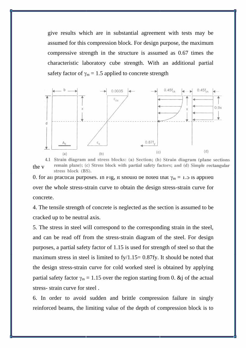
give results which are in substantial agreement with tests may be
assumed for this compression block. For design purpose, the maximum
compressive strength in the structure is assumed as 0.67 times the
characteristic laboratory cube strength. With an additional partial
safety factor of m = 1.5 applied to concrete strength
the values of the maximum concrete stress in a beam can be taken as equal to
0. for all practical purposes. In Fig, it should be noted that m = 1.5 is applied
over the whole stress-strain curve to obtain the design stress-strain curve for
concrete.
4. The tensile strength of concrete is neglected as the section is assumed to be
cracked up to be neutral axis.
5. The stress in steel will correspond to the corresponding strain in the steel,
and can be read off from the stress-strain diagram of the steel. For design
purposes, a partial safety factor of 1.15 is used for strength of steel so that the
maximum stress in steel is limited to fy/1.15= 0.87fy. It should be noted that
the design stress-strain curve for cold worked steel is obtained by applying
partial safety factor m = 1.15 over the region starting from 0. &j of the actual
stress- strain curve for steel .
6. In order to avoid sudden and brittle compression failure in singly
reinforced beams, the limiting value of the depth of compression block is to

be obtained according to IS 456 by assuming the strain of tension steel at
failure to be not less than the following:
BALANCED, UNDERREINFORCED AND OVERREINFORCED
SECTIONS
❖ Reinforced concrete sections in bending are assumed to fail when the
compression strain in concrete reaches the failure strain in bending
compression equal to 0.0035.
❖ Sections, in which the tension steel also reaches yield strain
simultaneously as the concrete reaches the failure strain in bending, are
called balanced sections. Sections, in which tension steel reaches yield
strain at loads lower than the load at which concrete reaches failure
strain, are called under reinforced sections.
❖ It should be remembered that yielding of steel does not mean ultimate
failure of the beam. When steel yields, there will be excessive
deflection and consequent cracking but complete rupture of steel takes
place at a much higher strain, of the order of 0.20 to 0.25 (i.e. 20 to 25
per cent elongation based on the original length) compared to the
actual steel yield strain of 0.0038.
❖ The latter is only of the same order as failure strain of concrete. The
ultimate failure of under reinforced beams in all practical cases is
therefore finally due to the concrete reaching the ultimate failure strain
of 0.0035.

❖ It is preferable that a beam be designed as an under reinforced beam,
where ‘failure’ will take place after yielding of steel, with enough
warning signals like excessive cracking and deflection taking place
before ultimate failure.
❖ R.C. sections, in which the failure strain in concrete is reached earlier
than the yield strain of steel is reached, are called over reinforced
sections. Such beams, if loaded to full capacity, will again fail by
compression failure of concrete but without warning. Such designs are
not recommended in practice.
EQUIVALENT COMPRESSION BLOCK IN CONCRETE
If an idealized stress-strain curve of concrete is used as in the third
assumption the magnitude of total compression which is given by the area
of the stress block in the beam will be as shown in Fig. and can be
expressed as

(USE OF DESIGN AID SP 16 WITHOUT CALCULATIONS)
The special publication No. 16 by Indian Standards Institution gives
charts and tables for quick design of R.C. sections. Charts 1 to 18 and Tables
Ito 4 are for singly reinforced beams. These charts and tables are derived
from which is
Charts Ito 18 have been prepared by assigning different values of M
per unit width and plotting d vs. p Tables 1—4 which cover a wider range
gives the value of Pt for various values of M/bd2
To determine the percentage of steel required for a given value of M, b,
d, fck, fy from Tables 1 to 4 of SP 16, proceed as follows:
• Calculate M/bd2
• Enter the table corresponding to the given value of fck and fy in
SP 16.
• Read off the percentage of steel required.
Most designers use this handbook method as it is also the easiest
method.
GUIDELINES FOR CHOOSING WIDTH, DEPTH AND
REINFORCEMENT OF BEAMS
The following guidelines may be used to arrive at the dimensions of
R.C. beams:
✓ The minimum percentage of tension steel used in beams should
be around 0.3 per cent. Usually, the depth of singly reinforced
beams is so arranged that the percentage of steel required is only
around 75 per cent of the balanced steel.

✓ At least two bars should be used as tension steel, and not more
than six bars should be used in one layer in a beam.
✓ The diameter of hanger bars should not be less than 10 mm and
that of main tension bars
✓ 12mm. The usual diameters of bars chosen for beams are 10, 12,
16,20,22,25 and 32mm. When using different sized bars in one
layer, place the largest diameter bars near the beam faces. The
areas of steel should be symmetrical about the centre line of the
beam.
✓ The width of the beam necessary for accommodating the
required number of rods will depend on the specification for
cover and minimum spacing. Table gives the required cover to
main steel for beams. Assuming the nominal cover of 20 mm for
mild steel environment and using 8 mm diameter stirrups the
clear cover to steel works out to 28 mm IS 456, Clause 26.3.1
gives the minimum distance between bars as the diameter of bar
or maximum size of aggregate plus 5 mm. The maximum size of
aggregates normally used in India is 20 mm so that clear
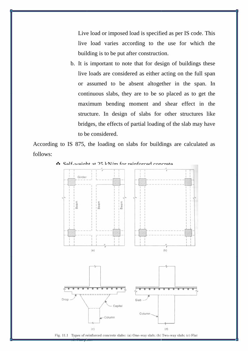
DESIGN OF ONEWAY SLAB
INTRODUCTION
Reinforced concrete solid slabs are constructed in one of the following ways
• One-way slabs
• Two-way slabs
• FIat slabs
• Flat plates.
❖ One-way slabs are those supported continuously on the two
opposite sides so that the loads are carried along one direction

only. The direction in which the load is carried in one-way slabs
is called the span. It may be in the long or short direction.
❖ One-way slabs are usually made to span in the shorter direction
since the corresponding bending moments and shear forces are
the least. The main reinforcements are provided in the span
direction.
❖ Steel is also provided in the transverse direction, to distribute
any unevenness that may occur in loading and for temperature
and shrinkage effects in that direction. This steel is called
distribution steel or secondary reinforcement. The main steel is
calculated from the bending moment consideration and under no
circumstances should it be less than the minimum specified by
the code. The secondary reinforcement provided is usually the
minimum specified by the code for such reinforcement.
❖ Two-way slabs are those slabs that are supported continuously
on all four sides and are of such dimensions that the loads are
carried to the supports along both directions.
❖ Flat slabs and flat plates are those multi span slabs which
directly rest on columns without beams. Flat slabs differ from
flat plates in that they have either drop panels (increased
thickness of slab) or column capitals in the regions of the
columns.
❖ Flat plates have uniform slab thickness, and the high shear
resistance around the columns are obtained usually by the
provision of special reinforcements called ‘shear-head
reinforcements’ placed in the slab around the columns.
LIVE LOAD ON SLABS IN BUILDINGS
a. Dead load of slabs consists of its own weight and in
addition, the weight of finishes, fixtures and partitions.
Live load or imposed load is specified as per IS code. This
live load varies according to the use for which the
building is to be put after construction.
b. It is important to note that for design of buildings these
live loads are considered as either acting on the full span
or assumed to be absent altogether in the span. In
continuous slabs, they are to be so placed as to get the
maximum bending moment and shear effect in the
structure. In design of slabs for other structures like
bridges, the effects of partial loading of the slab may have
to be considered.
According to IS 875, the loading on slabs for buildings are calculated as
follows:
❖ Self-weight at 25 kN/m for reinforced concrete.
❖ Finishes and partitions generally at 1.5 kN/m

STRUCTURAL ANALYSIS OF ONE-WAY SLABS WITH UDL
USING COEFFICIENTS
One. way slabs, because of their one-way action,
are analyzed as beams of unit width. However, codes allow the use of simple
coefficients for calculation of moments and forces in continuous beams and
slabs of uniform loading with more or less equal spans and continuous on at
least three spans.
Spans are considered as equal, if the differences in
span are not more than 15 per cent of the larger of the spans. These
coefficients for ultimate bending moments and shears are given in Tables 12
and 13 of IS 456 .It should be noted that when using this table, redistribution
of moments between sections is not allowed.

DESIGN FOR SHEAR IN SLABS
Normally the thickness of slabs is so chosen that the shear can be
resisted by concrete itself and the slab does not need extra shear
reinforcements. It is only in extreme situations where the thickness tends to
be very large that shear reinforcements are allowed to be used for slabs. Shear
tests on solid slabs have shown that when these shallow members ate less
than 300 mm thick, they have an increased shear resistance compared to
members such as beams which are 300 mm or more in depth. This shear
enhancement factor for shallow depths is given in IS 456, Clause 39.2 .
The enhanced shear is (kç), where k is called the shear enhancement
factor for slabs. According to the above table, k varies from 1.30 for slabs of
150mm or less to 1.00 for slabs of 300mm or more. BS 8110 also allows the
use of the shear enhancement factor and its value is given by the expression.
According to IS 456, the rules to be followed in the design of slabs for
shear are:
• No shear reinforcement should be provided for
slabs less than 200 mm thick. However, the
increased value of shear resistance in slabs can be
taken into account in design.

• It is preferable to design slabs without any extra
shear reinforcements.
• However, if found necessary, shear reinforcements
may be allowed to be provided in slabs which are
200 mm or more in thickness. The spacing of these
reinforcements can be increased to “d” instead of
“0.75d” as in beams.
• In no case, even with provision of shear
reinforcements, according to IS 456, Clause
40.2.3.1, should the maximum shear stress allowed
in slabs due to ultimate load exceed one-half that
allowed in beams as given in Table 20 of IS 456.
CONSIDERATIONS FOR DESIGN OF SLABS
➢ Choosing Span Effective Depth Ratio for Slabs
For a given type of support condition, the same span/depth basic ratio as
given for beams in IS 456 are applicable for slabs also. However, as the
percentage of reinforcements in slabs is generally low, the effective
span/depth ratios can be much larger than the basic ratios .
It should also be remembered that with heavy loadings when the
percentage of steel in slabs increases, this ratio will tend to be the same as in
beams. For the first trial, a convenient percentage of steel may be assumed
for the stabs and the span/effective depth ratio calculated.
Thus, assuming 0.3 per cent of steel, the correction factor F from Fig. 4
of 1S 456 will be 1.4, and the span/effective depth ratio for a continuous slab
will be of the order of 1.4 x 26 = 36. Because of these considerations. IS 456,
Clause 24.1 recommends the following span-overall depth factor for two-way
slabs using Fe 415 steel; up to 3.5 m span and loading class up to 3 kN/m2.

Concrete Cover
The nominal cover specified for slabs for different exposures is given
in Chapter 3. Also, a minimum cement content and maximum water cement
ratio are specified for different environment conditions. However, as
increased cover raises the dead load, the slab has to carry, one should be
judicious in the choice of cover. Strict maintenance of the chosen cover
during construction and using a good grade of concrete for the construction
will go a long way to ensure durability of slabs and reduce the dead load due
to cover.
Calculation of Steel Area In Practice
It should be noted that the depth of slab chosen for deflection
requirements will be usually greater than the depth required for balanced
design. Hence the area of steel required wi/I be less than the balanced
amount. The fundamental formula used for this purpose is
Any one of the procedures explained in Section 4.13 for determining
steel area for an under reinforced section may be used for the calculations.
The three other rules for choosing steel for slabs are the following [ 26.5.2]
• The diameter of steel should not exceed 1/8 total
thickness of slab
• The amount of steel area in either direction should
not be less than 0.12 per cent of the total sectional
area when using Fe 413 steel

• Spacing of main steel >3d or 300 mm; secondary
steel 5d or 450 mm.
DESIGN PROCEDURE
The procedure of design of one-way slabs is to consider them as
‘beams of one meter width in the short direction. The various steps in design
are as follows:
Part 1: Assume depth to take care of deflection and design sleet
Step 1: Assuming a suitable overall thickness for the slab, calculate the
factored loads (dead and live load) for design. This initial guess for thickness
of slab may be made from empirical relations between depth and span. The
allowable span/overall depth ratio of stabs may be taken as given in Section
11.5.1. The minimum depth for ease of construction is 100 mm. The factored
load is (1.5 DL + 1.5 LL). A suitable cover depending on exposure condition
should be assumed.
Step 2: Considering the slab as beam of one meter width and using effective
span, determine the maximum bending moments M for the ultimate factored
load. For continuous slabs, coefficients of Table 11.1 (IS 456 Table 7) may
be used for this purpose. Otherwise, any established elastic analysis may be
used. In the latter case redistribution of moments is also allowed.
Step 3: Using the formula M = KfCKbd2 and b = 1000 mm, find the minimum
effective depth required as in beams. Add cover and find the total depth of
slab from strength considerations. Check the depth with the depth assumed in
step 1. Generally, the depth from Step 1 will be more than that obtained from
the strength formula.

Step 4: Check the depth used for shear. As the actual percentage of steel at
supports is not known, the check is only approximate. A value of c
corresponding to the lowest percentage of steel in Table 13 of IS 456 may be
used for this purpose. This value can be increased by a factor k. The depth
used should be such that, in the final analysis, the slab is safe without any
shear reinforcements.
Step 5: As the depth selected is usually greater than the minimum depth d,
the tension steel required will be less than the balanced amount for the
section. Determine the steel required by a suitable formula or by use of SP 16
charts and tables.
Part 2: Check for cracking by obeying rules for detailing.
Step 6: Check whether this steel is not less than the minimum percentage of
the gross section specified for slabs, namely, 0.12 per cent with high yield
steel and 0.15 per cent with mild steel bars. Provide at least the specified
minimum. Table 11.3 may be used for this purpose. (IS 456, Clause 26.5.2.1)

Step 7: Choose a suitable diameter for the main reinforcement and determine
the spacing of steel. For crack control, this spacing should suit the bar
spacing rules for slabs. In general, the spacing of main steel should not
exceed three times effective depth or 300 mm whichever is smaller.
Step 8; Recheck for shear stresses, using the actual percentage of steel
available.
Step 9: Check the adopted depth for deflection using the empirical method .
Step 10: Provide necessary distribution (secondary) reinforcement. This too
should not be less than the specified per cent of the cross-sectional area of the
slab, namely, 0.12 per cent for high yield bars and 0.15 per cent for rolled
mild steel bars. This steel is usually placed over the main reinforcement bars
to maximize the effective depth for the main reinforcements and facilitate the
order of placing of steel. Check also the spacing of the secondary steel, so
that it does not exceed five times the effective depth or 450 mm.
Step 11: For the slab forming the top flange of a T or L beam, the transverse
reinforcement provided on the top surface should extend across the full
effective width of the flange. According to IS 456, Clause 23.1.1, this
transverse steel should not be less than 60 per cent of the main steel at mid-
span of the slab and according to BS8110 the amount should not be less than
0.15 per cent of the longitudinal cross-sectional area of the flange (both for
high yield steel and mild steel).
These steels are only for tying up the slabs with the beams, and not for
absorbing any stresses in the compression zone of T beams. When the slab is
spanning across T beams, the negative steel may be used for this purpose.

When the slab is spanning in the direction of the T beams, separate steel has
to be employed for this transverse steel to make the beam act as a T beam.
USE OF DESIGN AIDS SP 16
IS Publication SP 16 gives various tables and charts for rapid design of
slabs. One may use either tables 1 to 4 of SP 16, which are usually used for
design of singly reinforced beam sections by assuming b = 1000, or tables 5
to 44 giving the moment of resistance of slabs of specific thicknesses 10 to 25
cm for different values of fck and The tables are made for the standard 15 mm
clear cover to slab reinforcement.
The minimum steel ratio of 0.12 per cent for Fe 415 and 0.15 per cent
for Fe 250 with respect to gross area to be provided as distribution steel can
also be read off for the various thicknesses of these slabs.
CONCENTRATED LOAD ON ONE-WAY SLABS
The bending effects due to concentrated loads on one-way slabs are
usually analyzed by the effective width method .The corresponding effects on
two- way slabs are analyzed by Pigeaud’s method. It may be noted that even
though one-way slabs can also be analyzed by Pigeaud’s method, effective
width method is more commonly used for such slabs.

Some designers take a as the distributed width through the depth of the slab
also, in which case
Similarly, let e=y1 + 2 (wearing coat + effective depth). The first
method is more conservative and generally used for highway slabs. The
second method may be used in other safer situations. The effective width b is
then calculated by the expression given in IS 456, Clause 243.2.1 .

k = constant given in Table 14 of IS 456 depending on the ratio of the
width of the slab (B) to its effective span (L), and the nature of the slab
whether it is simply supported or continuous. (A value of k = 1.2 on either
side of toad width as shown in Fig may be assumed for alt one-way slabs.
x = distance of the centroid of load from the near support
Le= effective span
a = dispersed width of the contact area of the concentrated load parallel
to the supported edge. (Dispersion is taken at 45° through wearing coat only.)
Under no circumstances should the effective width exceed the actual
width of the slab, and when the concentrated load is close to an unsupported
edge of the slab, effective width should not exceed the above value or one-
half the above value plus the distance of the load from the unsupported edge,
whichever is less.
For determining the effective length of the load in the direction of the
span, the dispersion of the load along the bridge through full effective depth
of the slab is usually taken into account, thus assuming at 45° through both
the wearing coat and the effective depth.

Such dispersion is taken into account for each load when the loads are
placed one behind the other on the slab along the direction of the span.
When the effective widths and the effective lengths of loads as
calculated above overlap, for two or more loads, the effective widths for each
load should be considered separately and marked. If the effects overlap, the
slab should be designed for the combined effects of the two loads on the
overlapped portion.
DESIGN OF TWO-WAY SLABS
Slabs which are supported on unyielding supports like walls on all four
sides are called two-way slabs. The span in the larger direction is denoted by
ly and lx that in the shorter direction by ly The distribution of loads in the ly
and lx directions will depend on the ratio ly/lx When ly/lx > 2, it can be shown
that most of the loads are transmitted along the shorter directions and the slab
acts as a one-way slab.
Beam supports which are sufficiently stiff can be considered as
unyielding and slabs on these beams also act as two-way slabs. Beam

supports which deflect significantly under the loading from slabs, come under
slabs on flexible beams, and cannot be strictly classified as conventional two-
way slabs.
In these slabs the load distribution and bending moments produced are
different from slabs on unyielding supports.
The boundaries of a two-way slab can be fully restrained (continuous),
simply supported, or partially restrained at the edges as shown in Fig.

Copyright © 2022 FDOKUMEN