
Punching shear in concrete slabs - E-Periodica
23
Punching shear in concrete slabs Autor(en): Braestrup, M.W. Objekttyp: Article Zeitschrift: IABSE reports of the working commissions = Rapports des commissions de travail AIPC = IVBH Berichte der Arbeitskommissionen Band (Jahr): 28 (1979) Persistenter Link: http://doi.org/10.5169/seals-22903 PDF erstellt am: 11.07.2022 Nutzungsbedingungen Die ETH-Bibliothek ist Anbieterin der digitalisierten Zeitschriften. Sie besitzt keine Urheberrechte an den Inhalten der Zeitschriften. Die Rechte liegen in der Regel bei den Herausgebern. Die auf der Plattform e-periodica veröffentlichten Dokumente stehen für nicht-kommerzielle Zwecke in Lehre und Forschung sowie für die private Nutzung frei zur Verfügung. Einzelne Dateien oder Ausdrucke aus diesem Angebot können zusammen mit diesen Nutzungsbedingungen und den korrekten Herkunftsbezeichnungen weitergegeben werden. Das Veröffentlichen von Bildern in Print- und Online-Publikationen ist nur mit vorheriger Genehmigung der Rechteinhaber erlaubt. Die systematische Speicherung von Teilen des elektronischen Angebots auf anderen Servern bedarf ebenfalls des schriftlichen Einverständnisses der Rechteinhaber. Haftungsausschluss Alle Angaben erfolgen ohne Gewähr für Vollständigkeit oder Richtigkeit. Es wird keine Haftung übernommen für Schäden durch die Verwendung von Informationen aus diesem Online-Angebot oder durch das Fehlen von Informationen. Dies gilt auch für Inhalte Dritter, die über dieses Angebot zugänglich sind. Ein Dienst der ETH-Bibliothek ETH Zürich, Rämistrasse 101, 8092 Zürich, Schweiz, www.library.ethz.ch http://www.e-periodica.ch
-
Upload
khangminh22 -
Category
Documents
-
view
0 -
download
0
Transcript of Punching shear in concrete slabs - E-Periodica
Punching shear in concrete slabs
Autor(en): Braestrup, M.W.
Objekttyp: Article
Zeitschrift: IABSE reports of the working commissions = Rapports descommissions de travail AIPC = IVBH Berichte derArbeitskommissionen
Band (Jahr): 28 (1979)
Persistenter Link: http://doi.org/10.5169/seals-22903
PDF erstellt am: 11.07.2022
NutzungsbedingungenDie ETH-Bibliothek ist Anbieterin der digitalisierten Zeitschriften. Sie besitzt keine Urheberrechte anden Inhalten der Zeitschriften. Die Rechte liegen in der Regel bei den Herausgebern.Die auf der Plattform e-periodica veröffentlichten Dokumente stehen für nicht-kommerzielle Zwecke inLehre und Forschung sowie für die private Nutzung frei zur Verfügung. Einzelne Dateien oderAusdrucke aus diesem Angebot können zusammen mit diesen Nutzungsbedingungen und denkorrekten Herkunftsbezeichnungen weitergegeben werden.Das Veröffentlichen von Bildern in Print- und Online-Publikationen ist nur mit vorheriger Genehmigungder Rechteinhaber erlaubt. Die systematische Speicherung von Teilen des elektronischen Angebotsauf anderen Servern bedarf ebenfalls des schriftlichen Einverständnisses der Rechteinhaber.
HaftungsausschlussAlle Angaben erfolgen ohne Gewähr für Vollständigkeit oder Richtigkeit. Es wird keine Haftungübernommen für Schäden durch die Verwendung von Informationen aus diesem Online-Angebot oderdurch das Fehlen von Informationen. Dies gilt auch für Inhalte Dritter, die über dieses Angebotzugänglich sind.
Ein Dienst der ETH-BibliothekETH Zürich, Rämistrasse 101, 8092 Zürich, Schweiz, www.library.ethz.ch
http://www.e-periodica.ch
4 115
Punching Shear in Concrete Slabs
Poinçonnement des dalles en béton
Durchstanzen von Betonplatten
M.W. BRAESTRUPLie. techn.Structural Research Laboratory, TUCopenhagen Lyngby, Denmark
SUMMARYThe failure mechanism is examined, and various theories and design rules for centrical punching shearare reviewed. Based upon the classical theory of plasticity, an analytical solution is presented,describing the punching phenomenon in agreement with experimental evidence. Test results arecompared with strength predictions of building codes and of plastic analysis. It is concluded that, inspite of completely different basic concepts, the two methods are not incompatible. Excentricalpunching is briefly treated.
RESUMELe mécanisme de rupture est étudié et diverses théories et règles de calcul pour le poinçonnementcentrique sont évaluées. Fondée sur la théorie classique de plasticité, une solution analytique estprésentée, décrivant avec fidélité le phénomène de poinçonnement. Des résultats d'essais sont comparés
avec les prévisions de normes et de l'analyse plastique. Il y a lieu de constater que les deuxméthodes ne sont pas incompatibles, bien que basées sur des notions complètement différentes. Le
poinçonnement excentrique est enfin traité brièvement.
ZUSAMMENFASSUNGDer Bruchmechanismus für zentrisches Durchstanzen wird untersucht, und verschiedene dafürentwickelte Theorien und Berechnungsverfahren werden besprochen. Eine auf die klassische Plastizitätstheorie
sich stützende analytische Lösung wird angegeben, die das Durchstanzphänomen derVersuchserfahrung entsprechend beschreibt. Versuchsergebnisse werden mit rechnerischen Voraussagenvon Bemessungsvorschriften und von plastischer Berechnung verglichen. Es wird gefolgert, dass diezwei Methoden nicht unvereinbar sind, obwohl die Grundlagen sehr verschieden sind. ExzentrischesDurchstanzen wird kurz behandelt.

116 PUNCHING SHEAR IN CONCRETE SLABS
1. INTRODUCTION
Punching shear failure may occur in concrete slabs - prestressed or conventionallyreinforced - subjected to highly concentrated loads, e.g. impact loads or wheelloads on bridges, or at slender columns supporting flat slabs. The failure islocated in a surface running through the slab from the loaded area to the oppositeface (cf. Figure 1). The concrete body limited by the failure surface is simplypunched out. This type of failure is not much impeded by the main reinforcement,and will therefore tend to reduce the ultimate load to a value below the flexuralcapacity of the slab.
control surface
Fig.1 Punching shear failure
A decade of research has shown that the classical theory of plasticity may be used
as an efficient tool in the analysis of shear problems in concrete structures, cf.NIELSEN & al. [78.3] and BRAESTRUP & al. [78.1].
In the present paper, we shall briefly review some design rules and theories forpunching shear, and we shall present a theoretical approach based upon the theoryof plasticity. The design rules and the predictions of plastic analysis are compared
with some test results reported in the literature.
Fig.2 Punch load vs. main reinforcement. Fig.3 Failure of lightly reinforcedSimple and restrained slabs tested simple slab with 6" punch,by TAYLOR & HAYES [65.2] (From TAYLOR & HAYES [65.2])
4 M.W. BRAESTRUP 117
2. THE MECHANISM OF FAILURE
The failure of slabs subjected to concentrated loading is very dependent upon thesupport conditions, especially the degree of restraint against in-plane edgemovements. Thus the question of punching shear can hardly be separated from that ofcompressive membrane action (dome effect). This point is borne out nicely by atest series carried out by TAYLOR & HAYES [65.2],
They tested three series of square slabs, centrally loaded by square punches ofvarying size. The flexural reinforcement of the series corresponded to 0%, 1.57%,and 3.14%, respectively. The slabs were either simply supported or laterallyrestrained by a heavy welded steel frame. The unreinforced specimens, however, weretested in the restrained condition only.
The results corresponding to punches of sizes 2", 4", and 6" are shown on Figure 2.We have plotted the applied ultimate pressure a rendered nondimensional throughdivision by the cube strength f against the percentage of reinforcement. Itappears from the figure that not only are the strengths of the restrained specimensgenerally higher, they are also virtually independent of the amount of flexuralreinforcement, which is not the case for the simply supported slabs.
In a real slab subjected to punching at an interior point, lateral movements willbe restrained by the surrounding structure. Unfortunately, at most punching tests,care has not been taken to ensure similar conditions. Consequently, the ultimateload P may be expected to be approximately equal to the flexural capacityP,., Indeed, TAYLOR & HAYES [65.2] report that their unrestrained slabs withf lsxweak reinforcement were close to flexural failure.
The strength in flexure may be estimated by yield line theory, as done by GESUND& KAUSHIK [70.1]. They calculated the ratio P„ /P. for 106 alleged punching
X Py I ^ 2 I
tests and found an average of 1.015 with a standard deviation of 0.248. Later,GESUND & DIKSHIT [71.3] developed punching shear formulas based upon yield linetheory. The applicability of yield line theory was questioned by CLYDE & CARMICHAEL[74.5], who introduced considerations of the moment field (lower bound approach).The latter authors criticized the conventional test procedures, as did alsoCHRISWELL & HAWKINS [74.4],
The fact that so many flexural failures have been regarded as punching shear isprobably due to the deceiving aspect of the collapse mode. However, one lessonto be learned from plastic analysis is that the actual appearance of the failureis not important for the strength. In fact, the ultimate load can often bepredicted quite as well or even better by a completely different failure mechanism.
For weakly reinforced unrestrained slabs, the failure is accompanied by radialcracks and yielding of the main reinforcement, cf. Figure 3. The crushing of theconcrete around the load and the spalling at the opposite face may be explainedas secondary phenomena related to the rotational capacity in connection with theflexural failure mechanism. Consequently, failures involving yielding of the mainreinforcement shall not be regarded as punching.
Heavily reinforced thin slabs may collapse before yielding of the reinforcementby a mode involving crushing of the concrete without the formation of a punchingcone. Such slabs might be treated as overreinforced in flexure, and again the failure
is related to lack of rotational capacity.
As a consequence, we shall consider as punching shear failures, only collapse modescharacterized by the punching out of a concrete body in the direction of the loading,
the remainder of the slab remaining comparatively rigid.

118 PUNCHING SHEAR IN CONCRETE SLABS %
3. DESIGN RULES AND THEORIES
Most attempts to analyse the punching shear resistance of slabs are based uponthe procedure as follows:First a nominal shear stress is calculated, dividing the ultimate load P bythe area of a socalled control surface around the loaded area, cf. Figure 1. Thecontrol surface is a cylinder, the section being a certain critical perimeter oflength p and the height being defined as either the total slab depth h theeffective depth d or the internal moment lever arm z The shear stress tis then compared with a strength parameter for the concrete, usually some tensilestrength measure.
The method sketched above was introduced by TALBOT [13. 1] early in the century.TALBOT tested square footings, centrally loaded by square colomns of size a Ascritical perimeter he used a square with the side length a+2d and the depth ofthe control surface was taken as z TALBOT concluded from the tests that theultimate shear stress T P/4(a+2d)z was of the same order of magnitude as thatof simple beams without shear reinforcement.
TALBOT's method forms the basis of most building code regulations concerningpunching shear. In Section 7, we shall briefly review some examples, and comparethe predictions with test results.
The code rules differ considerably in the definition of the control surface andin the choice of concrete strength measure. Some of the codes have modified theformula by introducing empirical factors depending upon the slab depth and theamount of flexural reinforcement. Many such empirical design rules have beenformulated, and skall not be discussed here. References, reviews, and comparisonsmay be found in the reports from the ACI-ASCE Committee 326 [62.l], the ComitéEuropéen du Béton [66.2], and the ASCE-ACI Committee 426 [74.2], as well as inthe report by MOE [61.1], the paper by BERNAERT [65.l], and the thesis by ZAGHLOOL
[71.5]. Further contributions are contained in the ACI Shear Symposium Volume[74.1]. Some authors, e.g. AOKI & SEKI [71.2], take account of compressivemembrane effects, cf. also [74.2]. Excentrical punching is treated in Section 9.
Fig,4 Mechanical model of KINNUNEN & NYLANDER. (From REIMANN [63.3])

A M.W. BRAESTRUP 119
A derivation of a punching strength formula based upon a rational mechanicalmodel was attempted by KINNUNEN & NYLANDER [60.1], They tested circular slabs,loaded at the free edge, and centrally supported on a circular column. Thereinforcement was axisymmetrically disposed. Based upon test observations, anidealized model of the cracked state was proposed, cf. Figure 4. It consists ofa rigid central truncated cone, confined by a shear crack, and segmental slabportions separated by yield lines. The segments are supposed to be carried by acompressed conical shell between the column and the root of the shear crack.Punching failure is assumed to occur when the tangential compressive concretestrain at the column face reaches a certain critical value.
The model was modified for orthogonal, two-way reinforcement by KINNUNEN [63.2],and extended to slabs with shear reinforcement by ANDERSSON [63.1]. The theoryforms the basis for the Swedish code regulations [64.1], and has had a profoundinfluence upon European code considerations as well. Thorough reviews with designexamples are found in a CEB bulletin [66.2] and in the report by SCHAIDT & al.[70.3], The analysis leads to an iterative procedure which tends to be quitecomplicated, and a simplified version has recently been given by NYLANDER & KINNUNEN[76.7].
The collapse mode considered by KINNUNEN & NYLANDER is basically that of flexuralfailure. Indeed, for the tests of [60.1], GESUND & KAUSHIK [70.1] foundP /P 1.075 with a standard deviation of 0.159 This is bound up withtheS¥act inat the test slabs were provided with little or no lateral restraint.The theory has been modified by HEWITT & BATCHELOR [75.2], who introduce a"restraint factor", depending upon the boundary conditions, to take account ofdome effects. The authors report excellent agreement with test results.
The model of KINNUNEN & NYLANDER was critically reviewed by REIMANN [63.3], whoproposed a theory based upon a similar failure mechanism, replacing the compressed
conical shell by a yield hinge around the column. As critical parameter, REI-MANN considered the concrete stress (rather than the strain) in the circumferential
direction at the column face.
Another theoretical approach to the punching problem is due to LONG & BOND [67.1].The bending moments in the vicinity of the column are found by elastic analysis.Punching is considered to take place when the concrete stress reaches a criticalvalue, corresponding to a failure envelope for concrete under biaxial compression.When various "correction factors" are introduced, the predicted punching loadsagree well with test results. MASTERSON & LONG [74.9] extended the theory to cover
the effect of compressive membrane action. A simplified version of the methodhas been presented by LONG [75.4],
A common feature of the mechanical models reviewed above, is that they involveyielding of the reinforcement, combined with crushing of the concrete around thepunch (column) Thus they are related to flexural collapse.The fact that no attempt was made to analyse a proper shear failure mechanism isprobably due to the lack of a simple constitutive description of the resistanceof concrete to shearing deformation. The problem was attacked by BRAESTRUP & al.[76.2], using the modified Coulomb failure criterion, introduced by CHEN & DRUCKER[69. l] and described in the section below. The analysis is reviewed in Section 5,cf. also NIELSEN & al. [78.3],
MARTI & THUERLIMANN [77.4] (see also MARTI & al. [77.5]) also apply the Coulombfailure criterion, hut without a tension cut-off, cf. Sections 4 and 5.

120 PUNCHING SHEAR IN CONCRETE SLABS 1%
4. CONSTITUTIVE MODEL FOR CONCRETE
A plastic analysis of the punching problem may be based upon the failure mechanismsketched on Figure 1 and discussed in Section 2: A concrete plug is punched out inthe direction of the load, the rest of the slab remaining rigid. The deformationsare located in a rotationally symmetrical failure surface, in which the concreteis in a state of plane strain.
To calculate the ultimate punching load, we apply the work equation, i.e. equatethe external work done by the1 punching force with the internal work dissipatedin the failure surface. To determine the internal work, we introduce a constitutive
model for the concrete as follows:
The concrete is assumed to be a rigid, perfectly plastic materialwith the modified Coulomb failure criterion as yield condition andthe deformations governed by the associated flow rule (normalitycondition).
This assumption complies with the requirements of limit analysis. This means thata load found by equating the rates of external and internal work is an upperbound solution for the ultimate punching force.
The modified Coulomb failure criterion consists of two conditions:
t c - atanip (la)
and a f (lb)
Here T and a are shear and normal stress, respectively, on an arbitrarysection in the material, c is the cohesion, (p is the angle of internal friction,and f is the uniaxial tensile strength. The uniaxial compressive strength fis related to the cohesion through the formula
f 2c\/kc
(2)
where the parameter k is determined by the angle of friction:1+sintpl-siixp (3)
k<r2(e2)
ID
b) Yield locus in plane strainFig.5 Modified Coulomb criterion
a) Failure envelope

4 M.W. BRAESTRUP 121
The failure criterion is sketched in a CT,x-diagram on Figure 5a. The straightline, equation (la), corresponds to Coulomb sliding failure. The circular cut-off,representing equation (lb), is a modification introduced to take account of thelimited tensile strength of concrete.
The yield locus in the case of plane strain is shown on Figure 5b. The principalstresses are- and and the principal strain rates are termed and
The associated flow rule requires the vector ^ei'e2' to ke an outwardsdirected normal to the yield locus at the corresponding stress point (CT^jC^).At a corner, the vector (£^,6^) is confined by the normals to the adjacent partsof the locus.
This simple constitutive model describes the strength properties of concrete, andthe deformations at failure, by means of only three material parameters: The tensile
strength f the compressive strength f and the angle of friction ipThe elastic deformations are neglected, and unlimited ductility at failure isassumed. The latter assumption is rather unrealistic, and necessary modificationsare discussed in Section 8.
The unmodified Coulomb criterion, equation (la), used by MARTI & THUERLIMANN[77.4], contains only two parameters, e.g. the compressive and the tensilestrengths. Then the angle of friction is given by equation (3) with k f /fThus the criterion leaves no possibility of varying f independently of fwithout affecting the value of (p Further, with a reasonably small tensilestrength, the angle of friction must be fairly great (cf. Figure 5a), which isnot realistic in the presence of hydrostatic compression. For instance, a tensilestrength equal to 10% of the compressive strength corresponds to an angle offriction ip « 55°
Consider a kinematical discontinuity (failure surface) in the concrete. Figure 6bshows the intersection of the failure surface with the plane determined by thesurface normal n and the relative velocity vector v inclined at the anglea to the surface. The discontinuity is an idealization of a narrow region ofdepth A with a high, homogeneous strain rate v/A (Figure 6a) The rate ofinternal work dissipated per unit area of the failure surface is :
Wf A(Elal+e2a2)1"1tc-2"2
The principal strain rates are found to be:
1+sina) and
a) b)
n
2
Fig. 6 Failure surface in plain concretea) Narrow zone with high straining b) Kinematical discontinuity

122 PUNCHING SHEAR IN CONCRETE SLABS
According to the flow rule, the corresponding stresses are determined by pointB on the yield locus. Figure 5b. Inserting, we find W as a function of vand a:
Wj j v f^Ol-msina) for (p ^ a ;< it/2 (4)
The parameters I and m are defined as:
I 1 - (k-l)ft/fc and m 1 - (k+l)ft/fc (5),
where k is given by equation (3).
Equation (4) reduces to
Wj v f for a tt/2 (6)
and Wß v fc(l-sinip) for a cp (7)
The assumed yield criterion and the associated flow rule does not allow thesituation a < <p To describe such failure mechanisms,it will be necessary tointroduce a more sophisticated constitutive model for concrete.
A more detailed derivation of equation (4) is given in reference [76.2] or [78.3].
5. PLASTIC ANALYSIS
Consider a concrete slab of depth h supported along a circular perimeter withdiameter D and centrally loaded by a circular punch (or column) of diameterdp The applied load is P and the slab is Supposed to be reinforced in sucha manner that flexural failure is prevented. We assume that the reinforcement isable to resist axial forces only, i.e. dowel action is neglected. Then thereinforcement does not contribute to the internal work, and the work equation yields:
P v dA (8)
Here W. is given by equation (4) and the integral is taken over the entire failuresurface, sketched on Figure 7a. The generatrix is described by the function
r r(x), and we have:
drand tana —— r 'dxdA 2rr -22-
Fig.7a Failure surface Fig.7b Optimal generatrix
M.W. BRAESTRUP 123
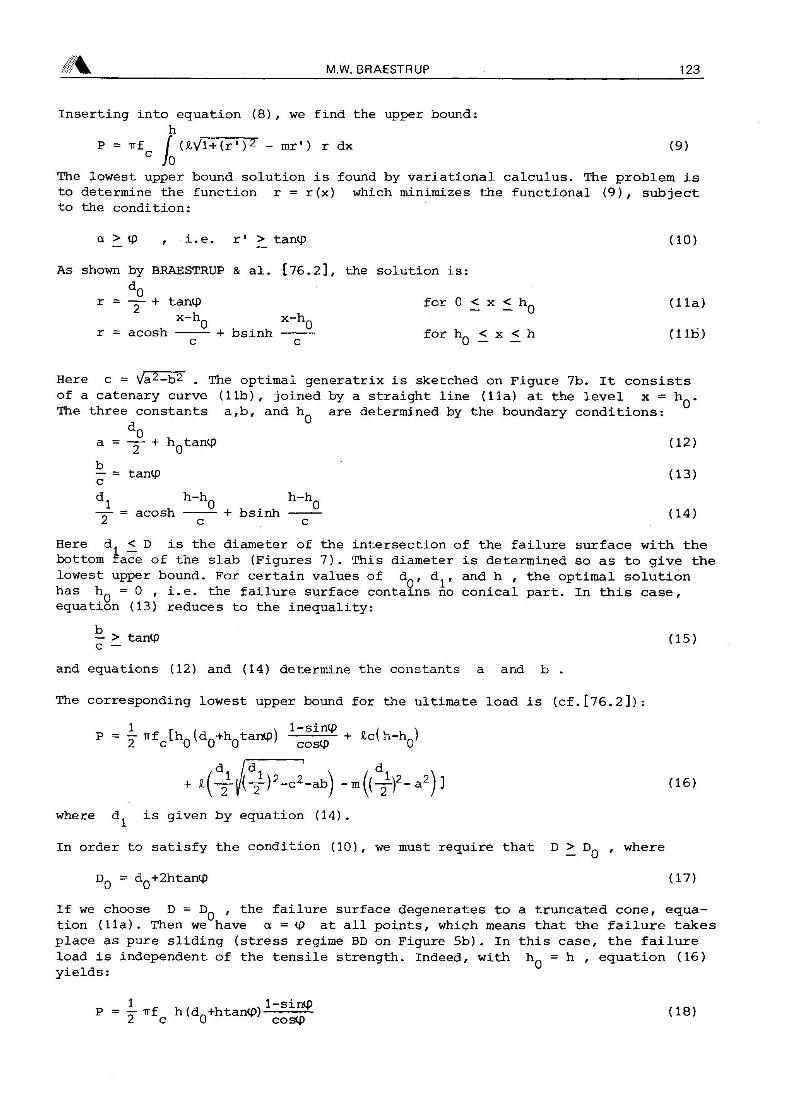
Inserting into equation (8), we find the upper bound:h
P irf («Vl+(r' )2 - mr') r dx (9)c J («Vl+(r-:
The lowest upper bound solution is found by variational calculus. The problem isto determine the function r r(x) which minimizes the functional (9), subjectto the condition:
a > cp i.e. r' >_ tancp (10)
As shown by BRAESTRUP & al. [76.2], the solution is:d0
r — + tancp for 0 < x < hp (11a)x-hQ x-hQ
r acosh + bsinh for fu < x < h (lit)c c 0 — —
Here c V/a2-b2 The optimal generatrix is sketched on Figure 7b. It consistsof a catenary curve (lib), joined by a straight line (11a) at the level x hp.The three constants a,b, and hp are determined by the boundary conditions:
d0a — + hptancp (12)
I* tancp (13)
di h_ho h_ho-r- acosh h bsinh (14)Ac c
Here d. <. D is the diameter of the intersection of the failure surface with thebottom face of the slab (Figures 7). This diameter is determined so as to give thelowest upper bound. For certain values of dp, d^, and h the optimal solutionhas hp 0 i.e. the failure surface contains no conical part. In this case,equation (13) reduces to the inequality:
I* > tancp (15)
and equations (12) and (14) determine the constants a and b
The corresponding lowest upper bound for the ultimate load is (cf.[76.2]):
p 7 *fc[ho(do+hotantp) + lc{h-ho]
/*,_ -X(16)<lf/(-T)2-c2-ab) -m((T")2"a2)]
where d^ is given by equation (14).
In order to satisfy the condition (10), we must require that D > Dp where
Dp dp+2htanlp (17)
If we choose D Dp the failure surface degenerates to a truncated cone, equation(11a). Then we have a cp at all points, which means that the failure takes
place as pure sliding (stress regime BD on Figure 5b) In this case, the failureload is independent of the tensile strength. Indeed, with hp h equation (16)yields:
P y irf h (dn+htancp)1
2 c 0 coscp(18)

124 PUNCHING SHEAR IN CONCRETE SLABS
Reference [76.2] describes an iterative procedure which determines the optimalupper bound solution for given geometrical quantities h, d^, and D and forgiven material properties f f and tp. The result is not very dependent uponthe angle of friction, and the conventional value cp 37 (corresponding to tarup0.75 and k 4) is used throughout. The solution, however, is very sensitive tothe ratio f /f For f 0 the lowest upper bound decreases with increasingdj which meanl that the^ptimal failure surface will extend all the way to thesupport. If we introduce a non-zero tensile strength, then the upper bound willbe a minimum for a finite value of d. Figure 8 shows examples of optimalgeneratrices corresponding to various relative punch diameters d^/h plotted fordifferent values of f The support diameter D is chosen sufficiently greatso as to not affect the solution. It appears that even a very small tensile strengthresults in a considerable contraction of the failure surface around the punch.
As a non-dimensional load parameter, we may take the quantity T/fc • where
Tn(dQ+2h)h
(19)
is the average shear stress on a control cylinder of depth h circumscribing theloaded area in the distance h (cf. Section 3).
For f 0 the theoretical load parameter is a function of the support diameterD and the punch diameter d^ When the support diameter increases towards infinity,the ultimate load approaches zero asymptotically.
For a finite tensile strength and a sufficiently great support diameter, the failuretakes place within the support (dj < D). Then the load parameter is a function ofthe punch diameter only. In reference [78.3],'the load parameter is plotted as afunction of d^ and D for zero and non-zero tensile strength (cf. also Figure 10
of the section below).
b)ft V250
c)f^ f /100c
Fig.8 Optimal failure surface generatrices for dg/h 0,1, and 2

4 M.W. BRAESTRUP 125
The analysis shows that if we have some tensile strength and a support diameterwhich is not too close to D given by equation (17), then the load parameteris almost constant. Thus a shear stress T defined by an expression similar toequation (19), seems to be an appropriate choice as a design variable.
MARTI & THUERLIMANN [77.4] consider a conical failure surface with the half angleip They find the upper bound solution:
Inserting equation (3), this is seen to be equivalent with equation (18)
In reference [78.2], conical failure surfaces with half angles a > tp wereanalysed. The solution was improved by adding a truncated cone with half angle cp
in such a way that the generatrix becomes a broken line. Still, a substantialimprovement is obtained with the optimal failure surface derived above (cf.[78.2]).
In the plastic analysis described in this section, it has been assumed that thepunching load was balanced by an annular reaction only. At a column supportinga flat slab, the punching force is due to loads on the slab. A distributed counter-pressure can easily be taken into account in the analysis, see [76.2]. The effectis very similar to that of a tensile strength of the same magnitude, cf. Figure 8.
The presence of a uniformly distributed shear reinforcement would have the sameeffect as a counterpressure. However, generally any shear reinforcement will beconcentrated in one or several rings around the punch. Then it will have noinfluence upon the shape of the generatrix, unless a more dangerous failure surfacecan be found which does not activate all or part of the reinforcement. The yieldforce of the active shear reinforcement will simply have to be added to thepunching load, equation (16).
6. EXPERIMENTAL VERIFICATION
The plastic analysis developed in the preceding section seems to offer asatisfactory description of punching failure, whether this is achieved by actual punching
of slabs, or by pulling out of a disc imbedded in a concrete block. Similarphenomena are also observed at the popouts produced by internal pressure near aconcrete surface, e.g. due to alkali-aggregate reactions, cf. BACHE & ISEN [68.1],
A striking feature of such failures is the extension of the failure surface, andthe thin, even razor-sharp edge of the punched-out body. This is most easilyappreciated at pull-out tests, where the failure surface is not disturbed by thepresence of reinforcement. Figure 9a shows a failure piece produced by HESS [75.1].The failure was obtained without any annular counterpressure, tension being appliedsimultaneously to two bolts imbedded in opposite faces of the specimen.
A test of this kind highlights the influence of the tensile strength. For f 0the theory predicts a splitting failure at the level of the imbedded disc, at anapplied force equal to zero. This is obviously at variance with experience.However, as shown in reference [76.2], a tensile strength equal to only 0.25% of thecompressive strength is sufficient to ensure realistic failure surfaces. Thisextremely low value indicates that the effectiveness of the tensile strength isvery small (cf. Section 8).
Figure 9b shows the generatrix corresponding to f f /400 and the same relativepunch diameter (<3q/1i 0.72) as for the specimen o? Figure 9a. The agreement
between predicted and observed shape is excellent.

126 PUNCHING SHEAR IN CONCRETE SLABS
Fig .9a)b)
fc
The fact that we have to introduce a diminutive tensile strength is of coursenot satisfactory. For the punching of slabs, where there is a well-defined maximum
extension of the failure surface, we may (conservatively) neglect the tensilestrength altogether. Provided the support diameter is not very great, this doesnot have any great influence upon the predicted ultimate load.
On Figure 10, we have calculated the load parameter for the restrained slabs tested
by TAYLOR & HAYES [65.2], and plotted it against the relative punch diameterd /h (d_ is taken as the diameter of the circle with the same perimeter as thesquare punch). For comparison are shown the theoretical curves corresponding tof f /400 and to f 0 In the former case, the tensile strength is sufficient
So ensure that tiie failure takes place within the support. In the lattercase, the support diameter D is put equal to the span of the square slabs. Figure10 also shows the results of the pull-out tests of HESS [75.1]. For these points,the curve corresponding to f^_ — 0 is without meaning, as the predicted loadwould be zero in that case.
The plot shows that the load parameter does not vary much with the punch diameter,a fact which is reflected by the common design rules (cf. Section 3). What littlevariation there seems to be, is to some extent described by the plastic analysis.
Fig.10Load parameteras function ofpunch diameterTests comparedwith theory.
Pull-out test, dg/h 0.72Failure piece (HESS [75.1])
f /400cPredicted shape, f
P/-h(d0+2h)fc0 TAYLOR S HAYES
A HESS
1
m
— oO
-0 ft-fc-AOO
S oft=0 D/h= 11.32
&
d0/h

4 M.W. BRAESTRUP 127
If we choose the support diameter D Dq as given by equation (17) then theload is determined by equation (18), i.e. independent of the tensile strength.Consequently, it is possible to measure the compressive concrete strength by meansof pull-out tests. This is the idea behind the Lok-test, developed by KIERKEGAARDHANSEN
[75.3]. The geometry of the test rig is very close to satisfying equation(17), but was designed empirically to give a good correlation between pull-outforce and compressive strength. The success is demonstrated on Figure 11, showingthe results of some tests carried out at the Structural Research Laboratory [74.3].The solid line represents the relationship predicted by equation (18), if we taketanip 0.60 to satisfy equation (17). As the angle of friction for concrete isslightly higher, the formula underestimates the pull-out strength somewhat (cf.JENSEN & BRAESTRUP [76.5],
Fig.11Results of pull-out tests (Lok-strengths)compared with concrete cylinder strengths(References [74.3] and [76.5])
P Mp©
©
©
©©
©
©
0©® ©
©© y
©&>
® /5 /é
$6) ,9 cm2
fc. kp/cm2
The applicability of the Lok-test to concrete quality control has been confirmedby field investigations, see LEKSOE & JENSEN [77.3].
The plastic analysis of the preceding section can also be applied to the radialpunching of circular cylinders. A preliminary investigation of this problem indicates
excellent agreement between the predicted and experimental loads, cf. HESS
& al. [78.2].
7. PREDICTIONS BASED ON BUILDING CODES
Below we shall briefly review four typical codes of practice for punching design.They are all based upon the notion of a control surface (cf. Section 3)
The Comité Euro-International du Béton and the Federation Internationale de laPrécontrainte recently completed a Model Code [78.4] for reinforced and prestress-ed concrete structures. The design shear stress is calculated as:
PT
K(l+50p)pdThe critical perimeter p is defined as the length of the shortest, convex curvewhich nowhere is closer than 0.5 d to the loaded area. The depth factor k ^ 1
is calculated as k 1.5 - d d being inserted in meters. The reinforcementfactor l+50p is determined by inserting p < 0.008 as the mean proportionalof the reinforcement ratios in the two orthogonal reinforcement directions. The1976 draft [76.3] for the Model Code contained the same formula, but the upperlimit for the benificial influence of the reinforcement was considerably higher.

128 PUNCHING SHEAR IN CONCRETE SLABS
a) b)
100
Prediction of CEB-FIP(kNl
1 1 1
© Elstner & Hognestadd Kinnunen & Nylander /9 Ba >e xx
©©
©
©©
©
x ©©
« ®,©
eD&
©®8
uJ iffDO
c
V3
0bser\ ed stre ngth100 200 300 400 500 600 k N]
Prediction of ACI 318-71Ik N]
® Elstner 8 HognestadKrnnunen & Nylande*
* Taylor S Hayes• Base
Observed strength100 200 300 tOO 500 600 700 IkN!
c) d)
Fig.12a) European Model Codeb) American building codeC) British code of practiced) Danish code of practice
Punching test results compared with building code predictions

A M.W. BRAESTRUP 129
The shear stress t is required to be inferior to 1.6 x t being the designconcrete shear strength, tabulated function of the characteristic compressivestrength f (proportional to fCK CK
ACI_318-71
The American building code ACI 318-71 [71.1] puts:P
T ~ 0.85 pd
where p is the minimum perimeter which approaches no closer than 0.5 d to theloaded area. Thus obviously the critical perimeter must have rounded corners, likein the case of CP 110 (below) and the CEB-FIP Model Code (above). Nevertheless,the Commentary on the building code shows critical perimeters with sharp corners,in the manner of DS 411 (below). The comparison calculations (cf. below) arecarried out using the minimum perimeter with rounded corners.
The shear stress t must be inferior to the shear strength of the concrete, whichis calculated as a function of the compressive strength f (proportional to v'fc)
CP_110
The British code of practice CP 110 [72.1] has
PT
5sPd
Here p is the smallest perimeter which nowhere is closer than 1.5 h to theloaded area. The factor Ç > 1 depends upon the slab depth, according to a tablein the code. The shear stress t is required to be inferior to the concrete shearstrength, which is tabulated in the code as a function of the compressive strengthand of the ratio of reinforcement.
DS_411
The Danish building code DS 411 [76.4] putsP
TPh '
where p is the perimeter of a figure similar to the loaded area in the distanced The shear stress t must be inferior to the tensile concrete strength whichis tabulated as a function of the compressive strength f^ (proportional to Vf
As mentioned in Section 2, many tests reported in the literature as punchingmay just as well be described as due to flexure. HESS [77.1] has made a criticalassessment of a great number of tests in order to exclude all the flexural failures.
On Figures 12, some of the remaining results are compared with the strengthgiven by the building codes described above.
The plots comprise some typical test series, viz.: ELSTNER & HOGNESTAD [56.1],KINNUNEN & NYLANDER [60.1], TAYLOR & HAYES [65.2], and BASE [66.2], The latterseries is reported on page 83 of the CEB Bulletin. In the analysis, average strengthsare used, rather than characteristic values. Cube strengths f are converted tocylinder strengths f by the formula f 0.8 f CU
c c cu
The figures show that DS 411 slightly overestimates the load-carrying capacity,whereas the other codes are rather conservative, especially ACI 318-71 and theCEB-FIP Model Code. The latter represents a change from the draft [76.3], whichwas more liberal, cf. HESS & al. [78.2],
28/9

130 PUNCHING SHEAR IN CONCRETE SLABS
8. PREDICTIONS BASED ON PLASTIC ANALYSIS
The upper bound solution derived in Section 5 is based upon the simplified constitutive
model introduced in Section 4, which assumes unlimited ductility of theconcrete. In reality, however, concrete is not a perfectly plastic material. Particularly
in tension, the behaviour is quite brittle. When applying plasticity toconcrete, it is therefore prudent to neglect the tensile strength. As explained inSection 6, this leads to unrealistic results for punching (pull-out) without asupport. The tensile strength which is necessary to explain the observed phenomais very small indeed, of the order of f f /400. This value is by no meansindicative of the true tensile concrete strength,cwhich is approximately 10% of thecompressive strength. This shows that what tensile strength the concrete may possess,it is very little effective, due to the brittleness and possibly a "zipper" effectat failure. Consequently, we shall as a rule take the tensile concrete strength tobe zero.
Also in compression, the ductility of concrete is quite limited, and we even havea falling branch on the stress-strain curve. Hence the redistribution of stresseswhich may be necessary to obtain the ultimate load predicted by plastic analysiscan only take place at the expense of losing strength. This observation suggeststhat we might take account of the lack of ductility simply by reducing the concretestrength measure. Consequently, we replace the uniaxial compressive concrete strengthby the effective strength f* where:
f* v f (20)c c
Here f is the conventional strength, measured e.g. by the standard cylinder test,and v is an empirical effectiveness factor describing the ductility of theconcrete. The effectiveness factor is evaluated by comparison with experimentalevidence
In addition to expressing the concrete ductility, the effectiveness factor willhave to describe all effects not explicitly accounted for in the theory, e.g. theinfluence of the neglected elastic deformations.
As seen from equation (16), the theoretical ultimate load is proportional to theconcrete strength f The value of v for a given test can therefore be calculated
as the ratio b§tween the observed and the predicted strengths. The resultwill of course depend upon the amount of tensile strength assumed in the analysis.
Fig .13Predictions based on plastic analysiscompared with punching test results ofELSTNER & HOGNESTAD [56.1]BASE [66.2]KINNUNEN & NYLANDER [60.1]TAYLOR & HAYES [65.2]DRAGOSAVIC & van den BEUKEL [74.6]KAERN & JENSEN [76.6](References [77.1] and [78.2])

% M.W. BRAESTRUP 131
HESS [77.1] (cf. also HESS & al. [78.2]) analysed 101 punching tests carried outby ELSTNER & HOGNESTAD [56. l], BASE [66.2], KINNUNEN & NYLANDER [60.l], TAYLOR &
HAYES [65.2], DRAGOSAVIC & van den BEUKEL [74.6], and KAERN & JENSEN [76.6], Assuming
f 0 he found an average value of v 0.86 with a coefficient of variationof 28%. For f f /400 the average is v 0.69 the coefficient of
variation again being 28%.
BRAESTRUP & al. [76.2] analysed 54 tests, mainly pull-out tests reported byKIERKEGAARD-HANSEN [75.3]. Assuming f f /400 the average was found to bev 0.83 with a coefficient of variation of 16%. Thus it seems that in pull-outtests, the concrete is more effective, probably due to the greater stiffness ofthe specimen.
There appears to be a significant variation of v with the concrete strength level:the stronger the concrete, the smaller the effectiveness factor. This trend
is to be expected, since v is principally a measure of ductility. The variationmay be described empirically by assuming f* to be proportional to VfInterestingly, the same empirical relationship is often used between the tensile andcompressive concrete strengths (cf. Section 7).
For all the 101 test results taken together, the best agreement is obtained withthe formula v 4.22/VÏ~ where f is measured in MPa. Introducing thisexpression, the variance for the effectiveness factor is reduced by 12%, cf. HESS& al. [78.2], For many of the individual test series, the variance is only half asgreat, indicating that much of the remaining scatter is due to difficulties incomparing different concrete strength measures.
For some of the experimental investigations, the concrete quality is given by thecube strength f and the results are analysed putting f 0.8 f Still,the values of f cover substantial variations in test procedures, regarding sizeof specimen, conSitions of curing, and rate of loading.
On Figure 13, the predicted strengths of all the 101 test slabs are plotted againstthe values actually obtained. The analysis is carried out assuming f 0 andf* 4.22Vf- For tests with square punches, the punch diameter d^ is taken astße diameter of the circle with the same perimeter. The support diameter for squareslabs is put equal to the span length. The slab depth is inserted as the totaldepth h In [78.2], similar plots are shown for the individual test series.Comparing Figure 13 with Figures 12, we note that the scatter is of the same order ofmagnitude as for the predictions based upon building code rules.
9. EXCENTRICAL PUNCHING
The heading actually covers two different problems: that of punching accompaniedby moment transfer, and that of punching near an edge or corner of the slab.
Many attempts have been made to modify the empirical formulas based upon a controlsurface to take account of load excentricities. In addition to the reports citedin Section 3, reference is made to the papers by HERZOG [74.8], DRAGOSAVIC & vanden BEUKEL [74.6], and van den BEUKEL [76.1], The idea is to introduce additionalshear stresses on the control surface, calculated assuming a linear variation inanalogy with the normal stresses in a beam due to the bending moment. The validityof this approach is to some extent supported by analysis based upon elastic thinplate theory, cf. MAST [70.2]. Still, the method is purely formal, and any elaboratecalculation of additional stresses is hardly justified, considering the ratherarbitrary choice of the control surface.

132 PUNCHING SHEAR IN CONCRETE SLABS 5%
Another semi-empirical method is the beam type analogy, cf. HAWKINS [74.7]. Theslab sections framing into the column are idealized as beam sections, presumedcapable of delivering bending moment, torque, and shear force at the controlsurface. A more rational approach is that of LONG [73.l], which is based upon elastic-plastic thin plate theory (cf. LONG & BOND [67.1]).
The plastic solution of Section 5 remains a valid upper bound also if the punchingforce at an interior slab point is accompanied by a bending moment. The questionis whether or not the presence of the moment will significantly reduce the ultimatepunching load. The moment is most effectively resisted by the main reinforcement,rather than by the concrete stresses in the failure surface. Therefore it wouldseem most reasonable to design the flexural reinforcement accordingly, and leavethe punching design unaffected.
In contrast, at edges and corners the mechanism of failure is completely different.Due to the lack of symmetry, the deformation is no longer constrained to beperpendicular to the slab. Thus the main reinforcement will generally contribute to theinternal work. Consequently, we would expect the resistance at edge and particularly
corner columns to be governed by the flexural capacity. Indeed, ZAGHLOOL [71.5]found that punching at edge columns is a secondary phenomenon, developing afteryielding of the reinforcement at the slab-column interface. Strength expressionsdepending primarily upon the amount of flexural steel were derived by beam typeanalogy. ANDERSSON [66.1] also found the shear stresses by beam type analogy andthe theory of elasticity. The failure criterion was related to the theory ofKINNUNEN & NYLANDER for interior columns (see Section 3), cf. also KINNUNEN [71.4].
Corner columns were investigated by INGVARSSON [77.2], who found that the shearfailure was analogous to diagonal tension failure in beams. A similar failuremechanism was studied by ZAGHLOOL & de PAIVA [73.2],
Punching at edge and corner columns is the subject of a research project just startedat the Structural Research Laboratory. The theoretical approach is based upon
the constitutive model outlined in Section 4, and due account is taken of theflexural reinforcement, cf. above. Some tests will be carried out to complementthe existing experimental evidence, which is rather meagre.
10. SUMMARY AND CONCLUSIONS,
In Section 2, we define punching as a proper shear failure mechanism, distinguishedfrom flexural collapse modes. The importance of lateral restraints is emphasized.
The commonly applied analyses of punching shear are reviewed in Section 3. Broadlyspeaking, two separate lines are followed. One considers the shear stress on a
nominal control surface around the loaded area. This is a purely empirical method
which has little relation to the actual punching phenomenon. The other approach
is more rational, in the sense that it starts out from the collapse mode observed
during tests. However, the considered failure mechanism is basically flexural.
Section 4 describes a constitutive model which may be used in the plastic analysisof a proper shear failure. The concrete is assumed to be a rigid, perfectly plasticmaterial with the modified Coulomb failure criterion as yield condition and theassociated flow rule.
An upper bound solution is derived in Section 5. The optimal shape of the failuresurface is determined by variational calculus. The solution agrees well withexperimental evidence, as shown in Section 6. The theory also explains the fact thatwith a suitable design of the test rig, it is possible to measure the compressiveconcrete strength by means of pull-out tests.
4 M.W. BRAESTRUP 133
In Section 7 and 8, the results of punching tests are compared with the strengthpredictions of building codes and of plastic analysis. Although the latter is basedupon concepts entirely different from those of the former, it confirms the applicability
of the nominal shear stress on a control surface as a design variable. Themain difference is that the compressive and not the tensile concrete strength is thegoverning material parameter. However, the effective concrete strength depends uponthe cylinder strength in much the same way as does the tensile strength. In bothcases, it is the ductility of the concrete which is the decisive factor. Whetherthis is expressed through an effective strength or through a tensile strength isto some extent a matter of taste.
Finally, Section 9 treats excentrical punching. It is suggested that moment transferat internal columns be considered separately from the punching. On the other hand,edge and corner columns require a different approach, mainly because of the lack oflateral restraint. Indications are that plastic analysis may provide solutions tothese problems as well.
REFERENCES
13.1 TALBOT,A.N.: Reinforced concrete wall footings and column footings. Urbana. University of Illinois,Engineering Experiment Station. Bulletin No. 67. 1931. pp 114.
56.1 ELSTNER, R.C. & HOGNESTAD, E.: Shearing strength of reinforced concrete slabs. Journal of the ACI.Proc.Vol. 53. Jul 1956. pp 29-58.
60.1 KINNUNEN, S. & NYLANDER, H.: Punching of concrete slabs without shear reinforcement. Stockholm.Royal Institute of Technology. Transactions No. 158. 1960. pp 112.
61.1 MOE, J.: Shearing strength of reinforced concrete slabs and footings under concentrated loads. Skokie, 111.Portland Cement Association, Development Department Bulletin D 47. 1961. pp 163.
62.1 ACI-ASCE Committee 326: Shear and diagonal tension. Part 3 - slabs and footings. Journal of the ACI.Proc. Vol. 58. Mar 1962. pp 353-396.
63.1 ANDERSSON, J.L.: Punching of concrete slabs with shear reinforcement. Stockholm. Royal Institute of Technology.Transactions No. 212. 1963. pp 59.
63.2 KINNUNEN, S.: Punching of concrete slabs with two-way reinforcement. Stockholm. Royal Institute of Technology.Transactions No. 198. 1963. pp 109.
63.3 REIMANN, H.: Zur Bemessung von dünnen Plattendecken auf Stützen ohne Kopf gegen Durchstanzen. Stuttgart.Otto Graf Institut. Thesis. 1963. pp 157.
64.1 Statens Betongkommitté: Förslag tili bestämmelser för dimensionering av betongplattor pä pelare jämte utdrag urkommentarer. Stockholm. AB Svensk Byggtjänst. Publikation Kl. 1964. pp 32. (English translation: Draft specificationsfor design of concrete slabs supported on columns. CEB Bulletin 57. Sep 1966. pp 108-140.)
65.1 BERNAERT, S.: Le poinçonnement des planchers-dalles. Etat de la question. Comité Européen du Béton. Bulletind'Information No. 50. Jul 1965. pp 53-101.
65.2 TAYLOR, R. & HAYES, B.: Some tests on the effect of edge restraint on punching shear in reinforced concreteslabs. Magazine of Concrete Research. Vol. 17. No. 50. Mar 1965. pp 39-44.
66.1 ANDERSSON, J.L.: Genomstansning av plattor understödda av pelare vid fri kant. Nordisk Betong, Vol. 10. No. 2.1966. pp 179-200. (English summary: Preliminary summary of punching of concrete slabs with edge columns. CEBBulletin 58. Oct 1966. pp 72-82.)
66.2 Comité Européen du Béton: Dalles, Structures Planes. Thème II: Poinçonnement. Bulletin d'Information No. 57.Sep 1966. pp 175.
67.1 LONG, A.E. & BOND, D.: Punching failure of reinforced concrete slabs. London. Institution of Civil Engineers.Proc. Vol. 37. 1967. pp 109-135.
68.1 BACHE, H.H. & ISEN, J.C.: Modal determination of concrete resistance to popout formation. Journal of the ACI.Proc. Vol. 65. Jun 1968. pp 445-456.
69.1 CHEN, W.-F. & DRUCKER, D.C.: Bearing capacity of concrete blocks or rock. Journal of the Engineering MechanicsDivision. Vol. 95, No. EM4. 1969. pp 955-978.
J*

70.1 GESUND, H. & KAUSHIK, Y.P.: Yield line analysis of punching failure in slabs. International Association forBridge and Structural Engineering. Proc. Vol. 30-1. 1970. pp 41-60.
70.2 MAST, P.E.: Stresses in flat plates near columns. Journal of the ACI. Proc.Vol. 67. Okt 1970. pp 761-768.70.3 SCHAIDT, W., LADNER, M. & ROESLI, A.: Berechnung von Flachendecken auf Durchstanzen. Wildegg. Technische
Forchungs- und Beratungsstelle der Schweizerischen Zementindustrie. 1970. pp 67.71.1 ACI Committee 318: Building code requirements for reinforced concrete (ACI 318-71). Detroit. American
Concrete Institute. 1971. pp 78. Commentary on building code requirements for reinforced concrete (ACI 318-71).ACI 1971. pp 96.
71.2 AOKI, Y. & SEKI, H.: Shearing strength and cracking in two-way slabs subjected to concentrated loads.Detroit. ACI Special Piblication SP-30. 1971. pp 103-126.
71.3 GESUND, H. & DIKSHIT, O.P.: Yield line analysis of the punching problem at slab/column intersections. Detroit.ACI Special Publication SP-30. 1971. pp 177-201.
71.4 KINNUNEN, S.: Försök med betongplattor understödda av pelare vid fri kant. Stockholm. National SwedishInstitute for Building Research. Report R2:1971. pp 103. (With English summary: Tests on concrete slabssupported on columns at free edges)
71.5 ZAGHLOOL, E.R.F.: Strength and behaviour of corner and edge column-slab connections in reinforced concreteflat plates. Calgary, Alberta. University of Calgary, Dept. of Civil Engineering. Ph.D. Thesis 1971. pp 366.
72.1 British Standards Institution: CP 110. The structural use of concrete. Part 1. Design, materials, andworkmanship. London. 1972. pp 153.
73.1 LONG, A.E.: Punching failure of slabs - transfer of moment and shear. Journal of the Structural Division.Vol. 99, No. ST4. Apr 1974. pp 665-685.
73.2 ZAGHLOOL, E.R.F. & de PAIVA, H.A.R.: Strength analysis of corner column-slab connections. Journal of theStructural Division. Vol. 99, No. STl. Jan 1974. pp 53-70.
74.1 American Concrete Institute: Shear in Reinforced Concrete. Detroit. ACI Special Publication SP-42. 1974. pp 949.74.2 ASCE-ACI Committee 426: The shear strength of reinforced concrete members - slabs. Journal of the Structural
Division. Vol. 100, No. ST8. Aug 1974. pp 1543-1591.74.3 BROENDUM-NIELSEN, T. & KRENCHEL, H.: Lok-styrkepr0vning af beton. Copenhagen. Technical University of Denmark.
Structural Research Laboratory. Sagsrapport S 3/69. 1974. pp 5.74.4 CHRISWELL, M.E. & HAWKINS, N.M.: Shear strength of slabs: basic principles and their relation to current methods
of analysis. ACI SP-42. Vol. 2. 1974. pp 641-676.74.5 CLYDE, D.H. & CARMICHAEL, D. : Lower bound flexural fields and slab shear. ACI SP-42. Vol 2. 1974. pp 769-784.74.6 DRAGOSAVIC, M. & van den BEUKEL, A.: Punching shear. Heron. Vol. 20, No. 2. 1974. pp 48.74.7 HAWKINS, N.M.: Shear strength of slabs with moments transferred to columns. ACI SP-42. Vol. 2. 1974. pp 817-846.74.8 HERZOG, M.: Wichtige Sonderfälle des Durchstanzens von Stahlbeton- und Spannbetonplatten nach Versuchen. Der
Bauingenieur. Vol. 49, No. 9. Sep 1974. pp 333-342.74.9 MASTERSON, D.M. & LONG, A.E.: The punching strength of slabs, a flexural approach using finite elements.
ACI SP-42. Vol. 2. 1974. pp 747-768.75.1 HESS, U. : Udtraekning af indst0bte inserts. Copenhagen. Danmarks Ingeni0rakademi Bygningsafdelingen, Ren og
Anvendt Mekanik. Rapport 75:54. Jan 1975. pp 25.75.2 HEWITT, B.E. & BATCHELOR, B. de V.: Punching shear strength of restrained slabs. Journal of the Structural
Division. Vol. 101, No.ST 9. Sep 1975. pp 1837-1853.75.3 KIERKEGAARD-HANSEN, P.: Lok-strength. Nordisk Betong. No. 3:1975. May 1975. pp 19-28.
75.4 LONG, A.E.: A two-phase approach to the prediction of punching strength of slabs. Journal of the ACI.Proc. Vol. 72, No. 2. Feb 1975. pp 37-45.
76.1 van den BEUKEL, A.: Punching shear at inner, edge and corner columns. Heron. Vol. 21, No. 3. 1976. pp 30.76.2 BRAESTRUP, M.W., NIELSEN, M.P., JENSEN, B.C. & BACH, F.: Axisymmetric punching of plain and reinforced concrete.
Copenhagen. Technical University of Denmark, Structural Research Laboratory. Report R 75. pp 33.76.3 Cometé Euro-International du Béton: Model Code for concrete structures. CEB Bulletin d'Information No 117-E
Dec 1976. pp 301.76.4 Dansk Ingeni0rforening: Code of practice for the structural use of concrete. 2. edition. Dansk Standard DS 411.
Copenhagen. Teknisk Forlag, Normstyrelsens Publikationer NP-116-T. Mar 1976. pp 63.Supplementary guide to code of practice for the structural use of concrete. 2. edition. Supplement to DanskStandard DS 411. NP-117-T. Mar 1976. pp 52.
76.5 JENSEN, B.C. & BRAESTRUP, M.W.: Lok-tests determine the compressive strength of concrete. Nordisk BetonqNo. 2:1976. pp 9-11.
76.6 KÄERN, J. & JENSEN, L.F.: Gennemlokning af jernbetonplader. Copenhagen. Danmarks Ingeni0rakademi, Bygnings-afdelingen, Ren og Anvendt Mekanik. Rapport 76:78. May 1976. pp 35.
76.7 NYLANDER, H. & KINNUNEN, S.: Genomstansning av betongplatta vid innerpelare. Brottstadieberäkning.Stockholm. Royal Institute of Technology, Division of Building Statics and Structural Engineering.Bulletin No. 118. 1976. pp 14.
77.1 HESS, U.: Gennemlokning af jernbetonplader. Copenhagen. Technical University of Denmark, Structural ResearchLaboratory. M.Sc.Thesis. Jan 1977.
77.2 INGVARSSON, H.: Betongplattors hällfasthet och armeringsutformning vid hörnpelare. Stockholm. Royal Instituteof Technology. Division of Building Statics and Structural Engineering. Bulletin No. 122. 1977. pp 143.(English summary: Concrete slabs supported on corner columns. Bulletin No. 129. 1977. pp 11.)
77.3 LEKSOE, S. & JENSEN, O.W.: Pr0vning af betonkonstruktioners styrke med Lok-test udstyr. Copenhagen.DSB, Tekniske Meddelelser fra Baneafdelingen. Vol. 7, No. 1. 1977. pp 12.
77.4 MARTI, P. & THUERLIMANN, B.: Fliessbedingungen für Stahlbeton mit Berücksichtigung der Betonzugfestigkeit.Beton- und Stahlbetonbau. Vol. 72, No. 1. Jan 1977. pp 7-12.77.5 MARTI, P., RITZ, P. & THUERLIMANN, B.: Prestressed concrete flat slabs. International Association for
Bridge and Structural Engineering. Surveys Sl/77. Feb 1977. pp 17.78.1 BRAESTRUP, M.W., NIELSEN, M.P. & BACH, F.: Plastic analysis of shear in concrete. Zeitschrift für
Angewandte Mathematik und Mechanik. Vol. 58. 1978. (in press)(Also: Danish Center for Applied Mathematics and Mechanics. Report No. 120. May 1977. pp 38.)
78.2 HESS, U., JENSEN, B.C., BRAESTRUP, M.W., NIELSEN, M.P. & BACH, F.: Gennemlokning af jernbetonplader.Copenhagen. Technical University of Denmark, Structural Research Laboratory. Report R 90. 1978. pp 63.
78.3 NIELSEN, M.P., BRAESTRUP, M.W., JENSEN, B.C. & BACH, F.: Concrete Plasticity. Beam shear - Punching shear -Shear in Joints. Copenhagen. Danish Society for Structural Science and Engineering. Special Publication.1978. (in press). (Preliminary Manuscript structural Research Laboratory. Dec 1976).
78.4 CEB-FIP: Code Modèle pour les structures en béton. Paris. Comité Euro-International du Béton. 1978. pp 336.