Tensioned Flat Slab Vs Conventional Slab - International ...
Upload
khangminh22Category
view
4download
0


History of SOG
Became common in early 1950’s
BRAB Report 1968
PT Introduction Mid 1960’s
HUD Approval 1968
PTI Research 1975 @ Texas A&M
1st PTI Design Manual 1980
2nd ED 1996
3rd ED 2004
PTI STD 2012
Wire Reinforcement Institute (WRI) updated 1996

Post-Tensioning Institute’s Slabs-On-Ground Design Publications
“2nd Edition Manual”
Published in 1996
“1st Edition Manual”
Published in 1980

Addendum #1 (May 2007)
The Addenda generally reduced the conservatism of the 3rd Edition by:
Providing clarification and guidance regarding new geotech provisions
Modified boundary conditions of new geotechnical provisions.
Changes to structural equations (Stiffness and Cracked Section).
3rd Edition Manual and
Standards
Addendum #2 (May 2008)

Includes both addenda and errata(three errata issued after publication of supplement)
3rd Edition Manual with 2008
Supplement

Building code requirements
IRC
20
15 IBC
20
15
Standards

Building Codes
ACI 318-05
R1.1.6 excludes residential post-tensioned SOG and
refers their design to PTI 3rd Edition
IBC 2006
For all practical purposes, only PTI and WRI methods are
acceptable for foundations on expansive soils (1805.8.2)
Moments, shears, deflections calculated for one method
can be used in the other
NFPA
Will be rarely used, CA recently reversed original
decision and will adopt I-codes

Since first publication of 3rd Edition, PTI also
released 4 Frequently Asked Questions documents
and 1 Technical Note applicable to slab-on-ground
design and construction.
FAQ No. 5 - Shrinkage and Temperature Reinforcement
FAQ No. 6 - Field Elongation Measurements
FAQ No. 7 - Soil Suction Profiles for Slab-on-Ground Applications
FAQ No. 8 - Back-Up Bars for Slab-on-Ground Applications
Tech Note 15 – Thicker is Weaker?

Foundation Based on Soil
Non Expansive PI<15-20 (Stable) Uniform thickness or shallow beams
Reinforced for crack control
PT average compression 50-75 psi
Moderate to High Expansive PI~20-50 PVR up to 4.5”
Uniform thickness
Waffle slab with beams
Both designed for expansive soil
Highly Expansive Treat soil to reduce movement or structurally suspended
foundation

Type of Structure on Foundation
Residential
Stiffness important
Warehouse
Stiffness less important
Crack control
Commercial
Stiffness important
Owner Expectations

FOUNDATION TYPES
Ribbed Foundation
Pros
Structurally efficient with less materials.
Does not rely on under slab fill for support (less earthwork).
Cons
Labor intensive.
Requires trenching into grade or forming fill.


FOUNDATION TYPES
Uniform Thickness Foundation
ProsDoes not require trenching into grade or forming fill
(some parts of country use 7.5 inch thick slab with no turn down).
ConsRequires more concrete and post-tensioning cables.
Requires significant earthwork.
Sloping sites present problems.


Design Principles
PTI Soil-Structure Interaction
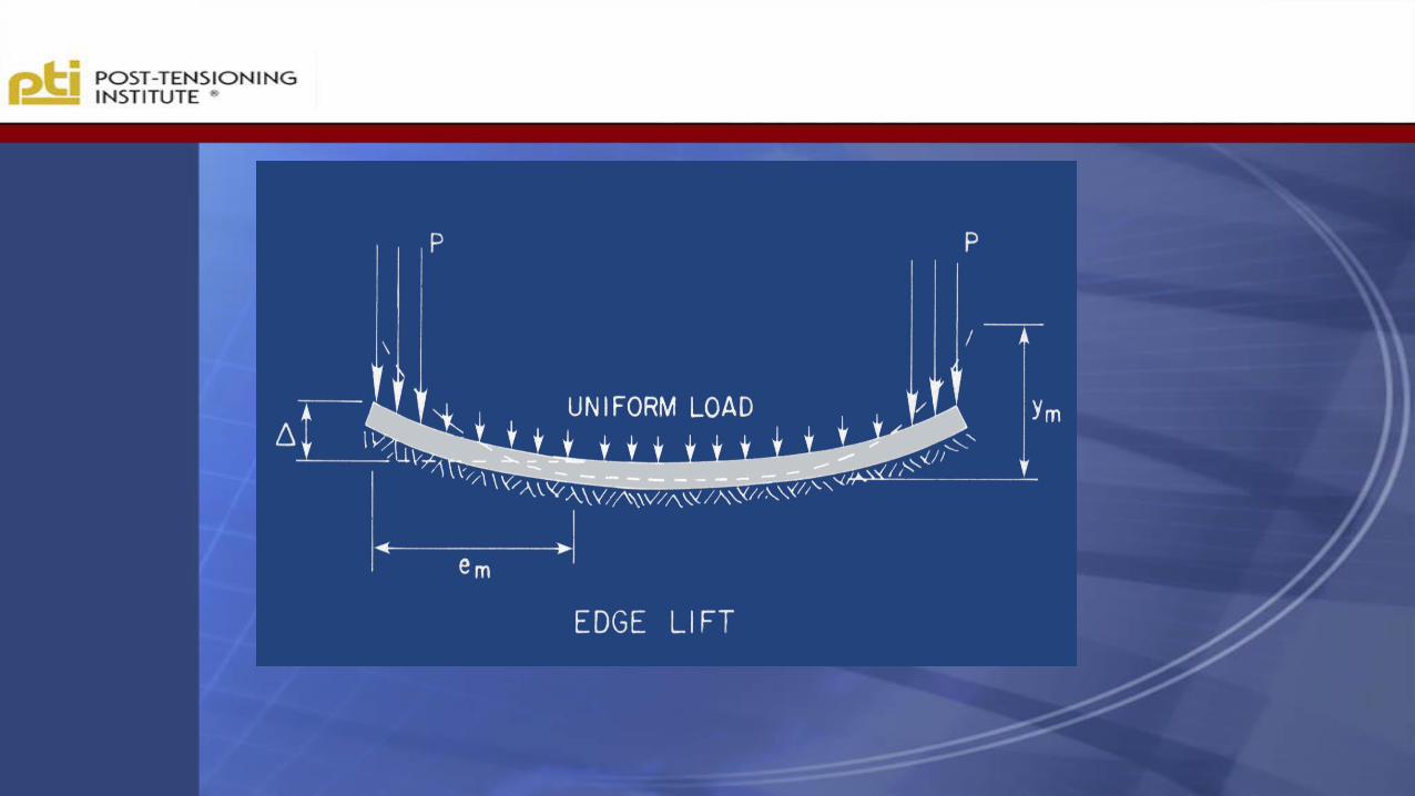
Edge Lift
Center Lift
Envelope Design for Cases in Between

Selection of Reinforcing System
Post-Tensioning
Uniform size and shape with minimum elevation
difference
Rebar
Unusual shapes, large slabs, with multiple
elevation changes

Important Items in Soils Report
PTI
Em Edge Lift
Center Lift
Ym Edge Lift
Center Lift
Q Allowable Bearing Pressure
?
PI
PVR
% Swell

Important Site Considerations
Pre-Vegetation
Tree Lines
Fence Lines
Roads, etc.
Slopes
Cut Fill
Drainage
Time of Construction
Landscaping
Soil Modification

In PTI 2nd and 3rd Edition Manuals, Pr
is calculated at mid-slab. Pr mid slab < Pr beta
Assumed prestress
distribution
b
Prestress force
Subgrade friction
In “Combined Standard” Pr is calculated at b
Prestress force

Slabs of Irregular Shapes
Shape Factor ~ 24
Overlapping Rectangles
Beam Continuity

Slabs of Irregular Shapes
Shape Factor ~ 24
Perimeter²
Area

(defined as perimeter2/area)
If the SF is greater than 24 then the designer should
consider:
Modifications to the foundation footprint
Use strengthened foundation system
Soil treatment to reduce shrink / swell potential
Use additional non-prestressed reinforcement
Provide additional beams
SHAPE FACTOR (SF)= Perimeter²
Area

1st & 2nd Ed of PTI&
3rd Ed of PTI
Slabs of irregular shapes
should be divided into
overlapping rectangles
and a separate design made
for each rectangle.
BRAB

Primary attention is given to the rectangle
that most reasonably represents the majority of
the actual foundation. Long, narrow rectangles are NOT
representative.


• Rectangle that is most representative
• Watch shape factor, especially over 30
• Add rebar if weird shape
• Avoid discontinuous beam
• Okay to slope beams
Summary

Loading
Live Loads
Uniform 40 + ADD’L
Dead Loads
Actual
Line Loads & Concentrated
Residential vs. Warehouse

Edge Load P (4.5.4.3)(6.1.4)
•Dead + Live load from
superstructure only (no
concrete)
•If P varies and ratio of
largest to smallest ≤ 1.25
use largest for design
•If P varies and ratio of
largest to smallest > 1.25
use largest for center lift and
smallest for edge lift
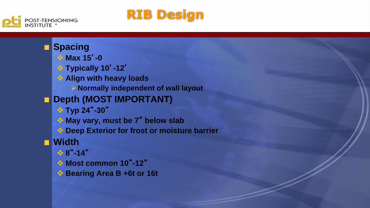
RIB Design
SpacingMax 15’-0
Typically 10’-12’
Align with heavy loads
Normally independent of wall layout
Depth (MOST IMPORTANT) Typ 24”-30”
May vary, must be 7” below slab
Deep Exterior for frost or moisture barrier
Width 8”-14”
Most common 10”-12”
Bearing Area B +6t or 16t

USE SOME COMMON SENSE(Good engineering judgment)

Beams are not required to be parallelor perpendicularor evenly spaced (Max. 15’ +/-)

In analysis, ratio of deepest to shallowest rib depth cannot exceed
1.2 (not new in combined standard but misunderstood).
The difference in the constructed ribs are not limited to the 1.2 ratio
Ma
xim
um
rib
de
pth
= 2
8”
Finished grade
Minimum rib depth = 24”

BEFORE
AFTER

Bending Moments PTI
Max Moment @ Beta
Allowables
Shear @ Beta
Allowables
Deflection
Allowables
3rd edition change from deflection to stiffness
ALLOWABLES FOR DESIGN ONLY AND NOT FOR ANALYSIS

Moment vs Slab Length

Allowable Concrete Stresses
Flexural
Tension 6√f’c
Compression 0.45f’c
Shear
vc = 1.7√f’c + 0.2fpShear should NOT control

Pre-stress Losses
15 KSI (Long Term Loss)
Strand ULT = 41.3K
Stress 80% MAX = 33K
Final After Losses = 27K
10 % Elongation Variance

Cracked Section Consideration
Designed as uncracked section
Minor cracking not uncommon and expected

Design Based on Uncracked Section
Similar to working-stress design of elevated
prestressed concrete members
Effects of cracking studied in detail in original research
(Ch. 5) and subsequent publications available through
PTI (Technical Note #6).
Effects of cracking generally inconsequential due to
Location of shrinkage cracks.
Increased soil support after flexural cracking.

Uniform Slab Conversion
Design as ribbed foundation. Convert to uniform
thickness with same I.
Not common in this area or highly expansive soils.
Has perimeter beam and typically 8”-10” thick.
Used in California and Arizona
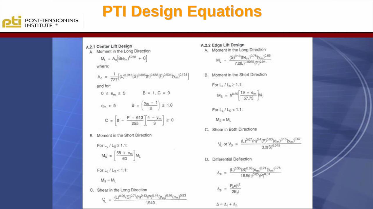
PTI Design Equations


Sub-Grade Friction
Depends on foundation type and surface material
Extremely important for large slabs and some
usages
Crack Control
Very important for exposed concrete surfaces

Sub-Grade Design
►WEIGHT OF THE SLAB “SLIDING” OVER SUBGRADE
►EDGES MOVE TOWARD THE CENTER
►MIDDLE IS POINT OF FIXITY

Design
REQUIRED AVERAGE COMPRESSION (P/A)GENERALLY 50 – 150 psi
AVERAGE TENDON FORCEGENERALLY 27 kips
SLAB THICKNESS4” – 7”
COEFFICIENT OF FRICTION• Slabs cast on polyethylene sheeting - 0.75• Slabs cast directly on a sand layer - 1.0• Slabs cast on a granular sub-base - 1.75• Slabs cast directly on plastic soil - 2.0• Slabs cast directly on asphalt - 3.25

MINIMIZE SUBGRADE DRAG

TOO LITTLE P/A
INADEQUAATE
AVERAGE
COMPRESSION
(TOO LITTLE P/A)
WILL ALLOW
CRACKS TO FORM

ADEQUATE P/A
ADEQUATE
AVERAGE
COMPRESSION
(P/A) WILL RESIST
CRACKING AND
CLOSE SHRINKAGE
AND TEMPERATURE
CRACKS.

bL/2
PRESTRESS FORCE
The prestress force in the concrete
(Pr) at Beta should be used to
determine the bending and shear
stresses.
The prestress force in the concrete
(Pr) at mid-slab should be used to
determine the minimum effective
prestress stress (50 PSI) or force
(0.05A)
slaber WPP
Where: Pe is the prestress force in the tendon after losses
is the subgrade friction coefficient
Wslab is the weight of slab from perimeter to b or midslab


CRACKS
(NOT ENOUGH P/A)
CONSTRUCTION AND
MAINTENANCE MANUAL FOR
POST-TENSIONED
SLAB-ON-GROUND
FOUNDATIONS

Beams, Slabs (Tolerances)
8.3.1.a- Ribbed Foundations
Rib Depth h: -1 in.; + 0.2h
Rib Width: -1 in.; + 2 in.
Slab Thickness:
Individual Location: -1/2 in. + 2 in.
Average Thickness: -1/4 in. + 1 in.


Poly/Cut Poly
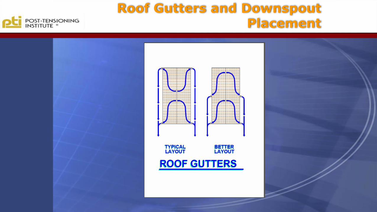
Roof Gutters and DownspoutPlacement

Undrained
Bathtub

Over Excavation and Backfill with Select fill “BATH TUB”

Over Excavation and Backfill with Select fill “BATH TUB”

Building Off of Moisture Conditioned Pad

When to use piers

Plumbing Problems and Moisture Problems with Foundation on Void Boxes


Previous Tree Rows and Uneven Soil Moisture Conditions


Incompatible Foundation Systems

Incompatible Foundation Systems

SANCTUARY CLASSROOM
BUILDING

Metal Building Type: Slab-On-Grade
P.I. = 20 – 30 4” S.O.G. Turned Down
P.V.R. < 1” Exterior Grade Beam
OFFICE WAREHOUSE
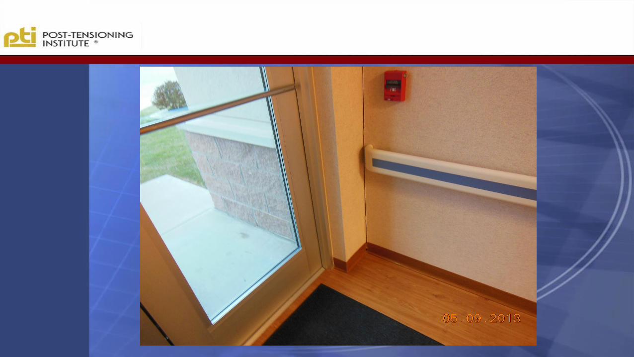


Movement Where
Partition Wall Meets
Exterior Wall

Effect of Post-Tensioning

Effect of Post-Tensioning cont.
CG

Tendon length
Tendons less than 15’-0 are
generally too short to stress
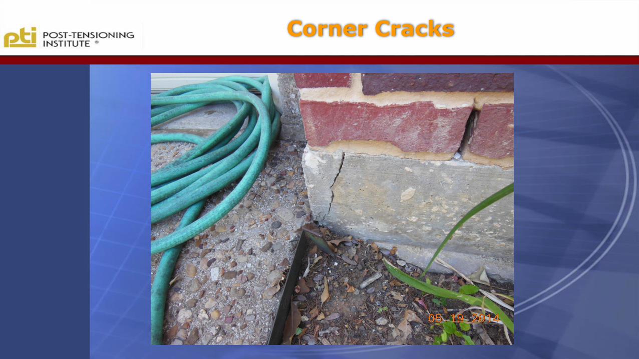
Corner Cracks

Corner Cracks

FOUNDATION MAINTENANCE

Questions?

Copyright © 2022 FDOKUMEN