Behavior of reinforced concrete segmental hollow core slabs ...
21
Structural Monitoring and Maintenance, Vol. 6, No. 4 (2019) 269-289 DOI: https://doi.org/10.12989/smm.2019.6.4.269 269 Copyright © 2019 Techno-Press, Ltd. http://www.techno-press.org/?journal=smm&subpage=7 ISSN: 2288-6605 (Print), 2288-6613 (Online) Behavior of reinforced concrete segmental hollow core slabs under monotonic and repeated loadings Ibrahim N. Najm a , Raid A. Daud b and Adel A. Al-Azzawi Civil Engineering Department, College of Engineering, Al -Nahrain University, Baghdad (Received July 9, 2019, Revised November 28, 2019, Accepted December 2, 2019) Abstract. This study investigated experimentally the response of thick reinforced concrete specimens having hollow cores with critical parameters. The investigation includes testing of twelve specimens that are solid and hollow-core slab models. Each specimen consists of two pieces, the piece dimensions are (1.2 m) length, (0.3 m) width and (20 cm) thickness tested under both monotonic and repeated loading. The test program is carried out to study the effects of load type, core diameters, core shape, number of cores, and steel fiber existence. Load versus deflection at mid span, failure modes, and crack patterns were obtained during the test. The test results showed that core shape and core number has remarkable influenced on cracking pattern, ultimate load, and failure mode. Also, when considering repeated loading protocol, the ultimate load capacity, load at yielding, and ductility is reduced. Keywords: monotonic load; repeated load; reinforced concrete; hollow- core slab 1. Introduction The building slabs might possibly exist in three constructional forms such as solid slabs, ribbed slabs, and voided or hollow-core slabs (HCS). Slabs with voids or cores required for electrical and mechanical purposes or for fire resistance as well as longitudinal cores of substantial dimensions reduces weight and costs. Basically, slabs with cores can be utilized as roof deck or furnish floor. Furthermore, these slabs meet modern standard as sound barriers which is able to prevent the sound of footsteps. Reinforced concrete slabs with voids are constructed through agreeing focuses: 1- The slab section (with hollow cores) is defined as I-section continuous part and considered as a ribbed slab with bottom and top flanges see Fig. 1. 2- The panel width is typically 2.4 m wide with standard span length normally 7 m. 3- The ratio of thickness to span: ℎ = 1 10 − 1 5 4- The restrictions of slab section (shown in Fig. 1) are based on ACI-318 (2014) code: - bw ≥ 100 mm - hw≤3.5 bw - s ≤ 800 mm - hf ≥ s/2 , hf ≥50 mm - bf = bw + dia. of core. - bw : web width Corresponding author, Professor, E-mail: [email protected] a M.Sc. Student b Lecturer , Ph.D.
-
Upload
khangminh22 -
Category
Documents
-
view
0 -
download
0
Transcript of Behavior of reinforced concrete segmental hollow core slabs ...
Structural Monitoring and Maintenance, Vol. 6, No. 4 (2019) 269-289
DOI: https://doi.org/10.12989/smm.2019.6.4.269 269
Copyright © 2019 Techno-Press, Ltd.
http://www.techno-press.org/?journal=smm&subpage=7 ISSN: 2288-6605 (Print), 2288-6613 (Online)
Behavior of reinforced concrete segmental hollow core slabs
under monotonic and repeated loadings
Ibrahim N. Najma, Raid A. Daudb and Adel A. Al-Azzawi
Civil Engineering Department, College of Engineering, Al-Nahrain University, Baghdad
(Received July 9, 2019, Revised November 28, 2019, Accepted December 2, 2019)
Abstract. This study investigated experimentally the response of thick reinforced concrete specimens having hollow cores with critical parameters. The investigation includes testing of twelve specimens that are solid and hollow-core slab models. Each specimen consists of two pieces, the piece dimensions are (1.2 m) length, (0.3 m) width and (20 cm) thickness tested under both monotonic and repeated loading. The test program is carried out to study the effects of load type, core diameters, core shape, number of cores, and steel fiber existence. Load versus deflection at mid span, failure modes, and crack patterns were obtained during the test. The test results showed that core shape and core number has remarkable influenced on cracking pattern, ultimate load, and failure mode. Also, when considering repeated loading protocol, the ultimate load capacity, load at yielding, and ductility is reduced.
Keywords: monotonic load; repeated load; reinforced concrete; hollow-core slab
1. Introduction
The building slabs might possibly exist in three constructional forms such as solid slabs, ribbed
slabs, and voided or hollow-core slabs (HCS). Slabs with voids or cores required for electrical and
mechanical purposes or for fire resistance as well as longitudinal cores of substantial dimensions
reduces weight and costs. Basically, slabs with cores can be utilized as roof deck or furnish floor.
Furthermore, these slabs meet modern standard as sound barriers which is able to prevent the
sound of footsteps. Reinforced concrete slabs with voids are constructed through agreeing focuses:
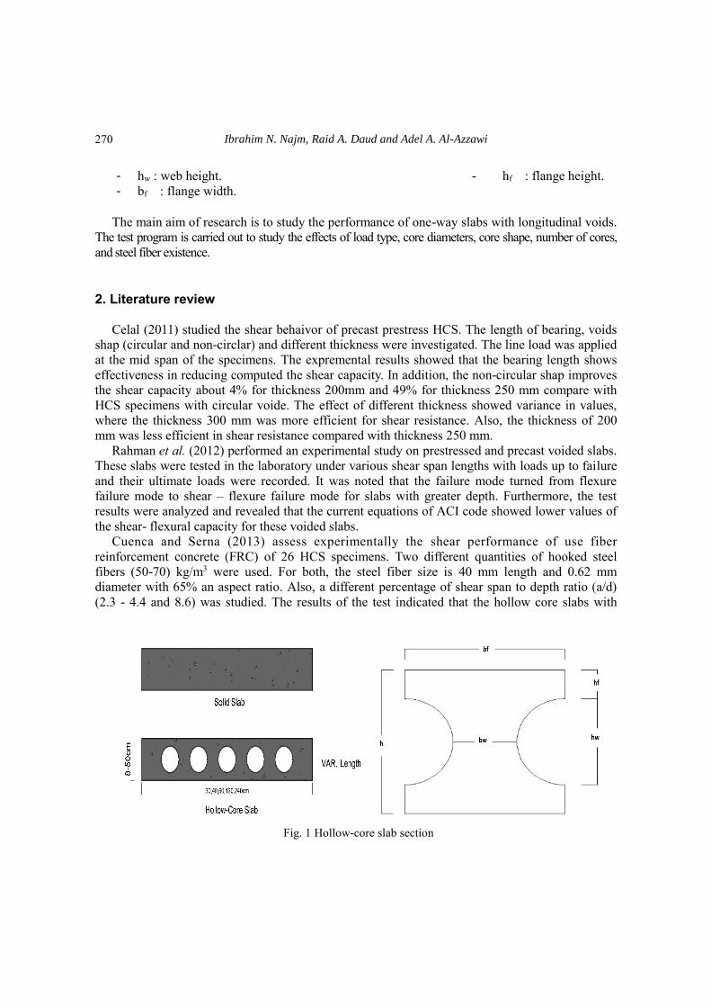
1- The slab section (with hollow cores) is defined as I-section continuous part and considered
as a ribbed slab with bottom and top flanges see Fig. 1.
2- The panel width is typically 2.4 m wide with standard span length normally 7 m.
3- The ratio of thickness to span: ℎ
𝐿=
1
10−
1
5
4- The restrictions of slab section (shown in Fig. 1) are based on ACI-318 (2014) code:
- bw ≥ 100 mm - hw≤3.5 bw
- s ≤ 800 mm - hf ≥ s/2 , hf ≥50 mm
- bf = bw + dia. of core. - bw : web width
Corresponding author, Professor, E-mail: [email protected] a M.Sc. Student b Lecturer , Ph.D.
Ibrahim N. Najm, Raid A. Daud and Adel A. Al-Azzawi
- hw : web height. - hf : flange height.
- bf : flange width.
The main aim of research is to study the performance of one-way slabs with longitudinal voids.
The test program is carried out to study the effects of load type, core diameters, core shape, number of cores,
and steel fiber existence.
2. Literature review
Celal (2011) studied the shear behaivor of precast prestress HCS. The length of bearing, voids
shap (circular and non-circlar) and different thickness were investigated. The line load was applied
at the mid span of the specimens. The expremental results showed that the bearing length shows
effectiveness in reducing computed the shear capacity. In addition, the non-circular shap improves
the shear capacity about 4% for thickness 200mm and 49% for thickness 250 mm compare with
HCS specimens with circular voide. The effect of different thickness showed variance in values,
where the thickness 300 mm was more efficient for shear resistance. Also, the thickness of 200
mm was less efficient in shear resistance compared with thickness 250 mm.
Rahman et al. (2012) performed an experimental study on prestressed and precast voided slabs.
These slabs were tested in the laboratory under various shear span lengths with loads up to failure
and their ultimate loads were recorded. It was noted that the failure mode turned from flexure
failure mode to shear – flexure failure mode for slabs with greater depth. Furthermore, the test
results were analyzed and revealed that the current equations of ACI code showed lower values of
the shear- flexural capacity for these voided slabs.
Cuenca and Serna (2013) assess experimentally the shear performance of use fiber
reinforcement concrete (FRC) of 26 HCS specimens. Two different quantities of hooked steel
fibers (50-70) kg/m3 were used. For both, the steel fiber size is 40 mm length and 0.62 mm
diameter with 65% an aspect ratio. Also, a different percentage of shear span to depth ratio (a/d)
(2.3 - 4.4 and 8.6) was studied. The results of the test indicated that the hollow core slabs with
Fig. 1 Hollow-core slab section
270
Behavior of reinforced concrete segmental hollow core slabs…
hooked steel fibers showed an increase in the failure load and much higher deflection capacity
than the hollow core slabs without hooked steel fibers.
Brunesi et al. (2014) scrutinized the shear strength capacity of prestressed concrete hollow core
slabs using three different approaches (experimental approach, analytical approach and numerical
approach). These specimens grouped according to thickness, void shape (circular and non-circular
holes), hole size ratios, arrangements of pre-stressed steel strands and initial pre-stress levels. After
that, the experimental data used to assess the traditional design codes. From finite element
approach, the detailed numerical model was verified with single precast prestressed hollow-core
slabs. The numerical results used to develop alternative design approach of Precast Prestressed
Hollow Core which failed by web-shear.
Lee (2014) studied the shear behavior of slabs with longitudinal hollow core through large
number of shear tests. The experimental results confirmed that the minimum shear reinforcement
requirement for deep slabs is too severe, and therefore the shear strength of slab is far high that
predicted by the equation in ACI 318 codes. Thus, a new simple shear strength model was
suggested; this model achieves safety on shear strength capacity for the slab’s depth up to 500 mm
deep.
Baran (2015) made a research focused on the flexural performance of hollow-core slabs. Both
empirical and numerical technique was adopted to predict the overall slab behavior. The results
indicated that a composite action was significant at the uncracked state levels. Both cracking
moment and initial stiffness of slabs was enhanced by installing a topping slab. In contrast, the
ultimate moment capacity was observed to be limited. the shear strength based on the ACI
code and AASHTO specifications is much higher than that obtained numerically.
Kankeris and Prakash (2016) studied the failure modes and response of slabs having hollow
cores. They included hybrid strengthening methods; externally bonded and near surface mounted
(NSM). The fiber reinforced polymer (FRP) bars was used in the experimental program. Seven
slab specimens were constructed and tested in laboratory after they were strengthened. Test results
revealed that the first strengthening method (bonded overlay) increased the flexural capacity by
89% with almost same ductility when compared to the reference slab. Whereas the second method
(NSM) FRP bar increased the capacity by about 100% with lesser ductility.
Al-Azzawi and Abed (2017) presented an investigation on the behavior of moderately thick
hollow core slabs with various variables. This study conducts cast and test of slabs having (2000
mm), (600 mm), and (250 mm) (length, width, theckness), respectively. Load deflection curves
were recorded. And the other part (numerical part), the (FE) procedure was utilized to show the
behavior of those slabs by employed ANSYS program. The FE analysis displayed a good
agreement as compared with the experimental results with a difference about (5% - 8.70%) in
ultimate loads and (0.7-9.29)% in deflection. A parametric study conducted by utilizing ANSYS
program to discuss the effects of concrete shape of the core, compressive strength, and size,
applied load protocol and steel reinforcement ratio effect
Dudnik et al. (2017) explored the affect of add steel fiber in concrete to resist the shear failure
at HCS specimens. The study conducts a series of HCS tests with different steel fiber ratio. The
steel fiber was used hooked ends with length 30 mm and diameter of 0.56 mm. The main variables
were the volume of steel fiber (0.38%, 0.5% and 0.76%), the thickness of HCS specimens (300
mm and 410 mm), and the shear span to depth percentage ratio (3 and 3.5). The test was done
under applied one line load near to the support with different shear span to depth percentage ratio.
The result of shear strength form equations of ACI 318M-14 compared with the experimental
result. The result showed the shear strength of the HCS specimens with a 300 mm thickness
271

Ibrahim N. Najm, Raid A. Daud and Adel A. Al-Azzawi
without steel fiber was 100% and 87% of the web shear cracking from ACI 318M-14, the
specimens with steel fiber increase in shear strength up to 30%. The shear strength of the HCS
specimens with a 410mm thickness without steel fiber was 70% of the web shear cracking
calculated according to ACI 314M-14. The specimens with steel fibers showed increase in shear
strength of about 55% to 90% compared with the HCS specimens without steel fiber. The steel
fiber generally enhances the ductility.
Prakashan (2017) tested four slabs having hollow cores in addition to a reference solid slab in
the laboratory. The flexural capacity of hollow core slabs was assessed using conventional flexural
capacity equation. The comparison among the specimens in terms of serviceability and load -
deflection response was conducted by using the test results. It was found that the ordinary flexural
capacity equation can be also applied to predict the flexural response of hollow core slab.
Wariyatno (2017) tested three specimens (a reference solid slab, slab having hollow cores
using PVC pipe to make longitudinal voids in “Type I” . Another void material was used to make
hollow cores in slab which is the Styrofoam and termed as “Type II”). It was concluded that the
voids in both slabs “Type I” & “Type II” cause a reduction in weight as compared to the solid slab
by about 24% and 25%, respectively. Flexural load capacity and stiffness of “Type II” ( hollow
core) slab is higher than the “TypeI” slab. However, hollow core slab “Type II” gives lower
flexural load capacity and stiffness than the slab without voids (solid) for different reinforcement
ratio. The failure mode is recognized as shear failure for both hollow core slabs, whereas, the
failure mode is recognized as flexure failure for solid slab.
Al-Azzawi and Abdul Al-Aziz (2017) and (2018) conducted an experimental program on
lightweight concrete hollow core slabs. They studied the effectiveness of void shapes, shear span
to effective depth percentage ratio. They tested seven slabs having hollow cores of (1.1 m) length,
(0.6 m) width and (0.12 m). The maximum weight reduction was 19.28% and 17.37% due to
aggregate type and cross section voids, respectively. The reduction in shear span to effective depth
percentage ratio showed increase in ultimate load, ductility and energy dissipation capacity. The
decrease of first cracking and ultimate loads of lightweight concrete solid slab was over (16.37%)
and (5%), respectively. The decrease of first cracking and ultimate loads of lightweight concrete
hollow core slab was (12.1%) and (5.2 %) respectively as compared to the solid slab.
Yousif et al. (2018) investigated experimentally the effectiveness of hollow length technique on
the shear resistance of the thick hollow core slabs. The reduction in the length of the longitudinal
voids and side longitudinal voids in the shear region was studied for the hollow core slabs. For
getting lightweight concrete type, the recycle material was used by changing crushed brick as an
aggregate instead of the gravel.
Based on previous studies, it can be concluded that the response of normal reinforced concrete
thick slab with hollow cores is still unwell understood. However, many above review of relevant
research tested hollow cores thin slabs. In this research, the one-way RC thick slabs with and
without longitudinal voids were adopted experimentally by creating circular and square voids at
middle plane of the cross section with varying void diameter.
3. Details of experimental test
Experimental program comprises casting twelve small-scale (1:4) one way solid and
hollow-core reinforced concrete thick slab specimens taking into consideration the scaling of steel
reinforcement by using quarter diameter of bar in the slab specimen. Sizes of voids, shape of voids,
272

Behavior of reinforced concrete segmental hollow core slabs…
loading type were investigated in experimental program as shown in Table 1. The value of shear
span effective depth ratio (a/d) is constant in all cases. In the monotonic test, loading was applied
with loading rate (2-2.5 kN/min). The repeated test, loading was applied based on a load protocol
suggested by FEMA 461(2007). In this adopted load protocol, the load is subjected in several
stages, the first stage consists of 10 cycles with amplitude ten percent of the deflection at failure in
the monotonic case. The second stage consists of 3 cycles with amplitude 1.2 times the deflection
amplitude in the first stage. In each of the subsequent steps, the 20 percent increasing in deflection
amplitude is applied three times at a frequency of 1 Hz until failure. The slabs are subjected to
two-line loads as shown in Fig. 2.
Table 1 Reinforced concrete slabs specimens
Slab No. Description Type of load
Slab-1 Solid slab Monotonic
Slab-2 Circular Hollow-core slab
(50 mm one core size) =
Slab-3 Circular Hollow-core slab
(100 mm one core size) =
Slab-4 Circular Hollow-core slab
(50 mm Two core size) =
Slab-5 Square Hollow-core slab (57 mm x 57 mm) =
Slab-6 Circular Hollow-core slab with S.F
(100mm one core size) =
Slab-7 Solid slab Repeated
Slab-8 Circular Hollow-core slab
(50 mm one core size) =
Slab-9 Circular Hollow-core slab
(100mm one core size) =
Slab-10 Circular Hollow-core slab
(50mm Two core size) =
Slab-11 Square Hollow-core slab (57 mm x 57 mm) =
Slab-12 Circular Hollow-core slab with S.F
(100 mm one core size) =
Fig. 2 Testing machine
273
Ibrahim N. Najm, Raid A. Daud and Adel A. Al-Azzawi
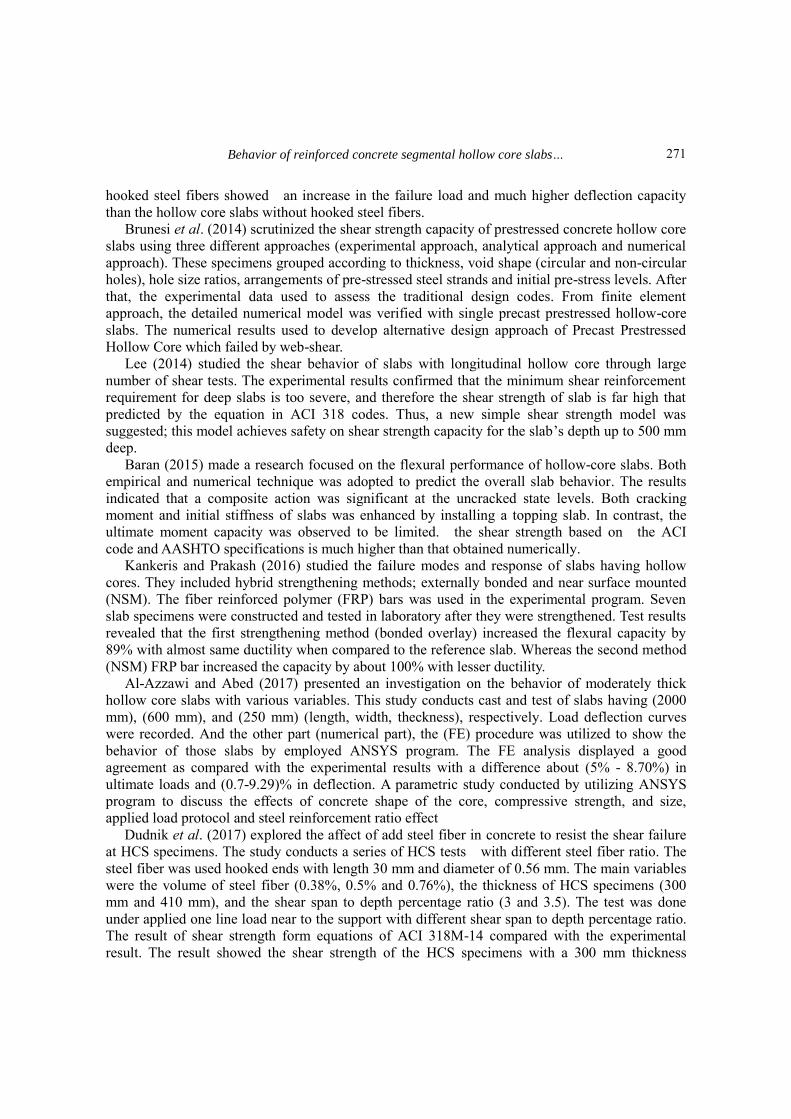
Table 2 Properties of materials
Properties of concrete material
Property Experimental ACI318M (2014)
Without
steel fibers
With
steel fibers
Compressive strength (ƒ'c)
(MPa) 37.865 42.7 -
Splitting tensile strength
( f 'ct ) (MPa) 4.78 7.196 3.09 (0.5√𝑓 ′𝑐 )
Modulus of rupture (f r )
(MPa) 6.8 9.046 3.83 (0.62√𝑓 ′𝑐 )
Modulus of elasticity (Ec)
(MPa)
-
29010.8
(4700√ 𝑓𝑐′ )
29926.2
(Wc1.50.043√ 𝑓𝑐′)
Properties of steel reinforcement material
Property Test results
Nominal diameter (mm) 8 10
Measured diameter (mm) 8.08 10.06
Yield stress (ƒy) (MPa) 589.91 524
Ultimate stress (ƒu) (MPa) 737.6 650
Modulus of elasticity (Ec)
(MPa) 200000 200000
3.1 Details of the slab specimens For the slab specimens, the properties of the hardened concrete and steel reinforcement which
used for manufacturing the prototype of these slabs are summarized in Table 2.
The nominal dimensions of slab specimens have two pieces with (1200 mm) in length, (300
mm) breadth and (200 mm) depth. These slabs have (1100 mm) clear span with constant shear
span effective depth percentage or ratio of (2.29). Two types of concrete are used (with steel fibers
and without steel fibers). The following slabs are tested: solid slab, two hollow core slabs with
circular void size (100 mm) with and without steel fibers, one hollow-core slab with circular void
size (50 mm), two hollow-cores slab with circular core size (50 mm), and one hollow-core slab
with square core size (57 mm x 57 mm). The hollow voids of these slabs are molded by using
(PVC) pipes and square plate longitudinal through slabs with (2 mm) thickness. The design of both
solid and voided slabs was conducted based on the ACI 318 code (2014). The main longitudinal
steel reinforcement consists 3 bars with (Ø10 mm) and spacing 100 mm. While the secondary
transverse reinforcement consists of 8 bars with (Ø8 mm) and spacing 150 mm. Also, concrete
cover is 20 mm as shown in Fig. 3.
Table 3 presents the mix proportions to produce 1 m3 of the concrete, the target 28-day cube
strengths and the measured cube strength of testing.
274

Behavior of reinforced concrete segmental hollow core slabs…
20
20
Shrinkage & Temperature # 8 mm @ 150 mm
Main Reinforcement 10 mm @ 100 mm ain
Reinforcement
20
0
600
75
125 50
100 100
50
75
100 50
100
57
57
121.5
(a)
(b)
(c)
(d)
(e)
Fig. 3 Cross sections of slabs (All dimensions in mm) (a) Solid slab (b), (c) & (d) Circular Hollow-core
slab with core diameter (50,100 mm) (e) Square Hollow-core slab with dimensions (57 x 57 ) mm
275
Ibrahim N. Najm, Raid A. Daud and Adel A. Al-Azzawi
Table 3 properties of mix design
Target
28-day
compressive
strength
Measured
concrete
strength of
testing
Cement
kg/m3
W/C Sand
Kg/m3
Coarse
aggregate
kg/m3
Super.
% by
wt. of
cement
Silica%
Rep.by
cement
Without
S.F
35 37.83 360 0.25 800 790 1.5 40
With
S.F
40 42.9 = = = = = =
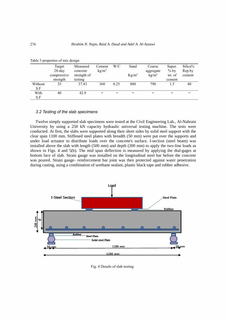
3.2 Testing of the slab specimens Twelve simply supported slab specimens were tested at the Civil Engineering Lab., Al-Nahrain
University by using a 250 kN capacity hydraulic universal testing machine. The tests were
conducted. At first, the slabs were supported along their short sides by solid steel support with the
clear span 1100 mm. Stiffened steel plates with breadth (50 mm) were put over the supports and
under load actuator to distribute loads over the concrete's surface. I-section (steel beam) was
installed above the slab with length (500 mm) and depth (200 mm) to apply the two-line loads as
shown in Figs. 4 and 5(b). The mid span deflection is measured by applying the dial-gages at
bottom face of slab. Strain gauge was installed on the longitudinal steel bar before the concrete
was poured. Strain gauge- reinforcement bar joint was then protected against water penetration
during casting, using a combination of urethane sealant, plastic black tape and rubber adhesive.
Fig. 4 Details of slab testing
276

Behavior of reinforced concrete segmental hollow core slabs…
(a) (b)
Fig. 5 (a) Photograph of the mold of hollow-core slab and (b) Photograph of hollow-core slab testing
setup
The strain gauges used were foil-type, three-wired temperature-compensating; with resistance of
120 Ω. The developments of cracks and load at failure were monitored with the deflections during
the experimental test. The applied load procedure for both monotonic case and repeated case was
described previously in section 3. The applied loads were recorded directly from the hydraulic load
actuator that has been adjusted using load cells, prior the test is started.
4. Experimental results and discussion The behavior of reinforced concrete segmental hollow core slabs in terms of the cracks pattern,
ultimate load and failure mode are investigated by testing twelve slab specimens. In particular, the
main parameters examined in the testing of slabs were the effect of load protocol (i.e., monotonic
and repeated loading), core shape, and core size and concrete type on the overall behavior.
4.1 Loads and crack pattern at failure The current tests recorded the concrete crack pattern developing on the lower surface slab
specimens at different applied load stages. For solid slab in monotonic test, cracks are initiated
earlier at about (35.73%) of ultimate load, while for solid slab in repeated test cracks are initiated
at about (39.28%) of ultimate load with same material properties and a/d percentage ratio. This is
attributed the fact that there is a gradual loss of stiffness for specimens resulting from repeated
loading causing reduction of ultimate loads in contrast, the crack loads do not influence.
For circular hollow core slabs with dia. =50 mm (one void size and two void size) cracks are
developed at about (42.04%) and (43.46%) respectively of the ultimate load in monotonic test. In
277
Ibrahim N. Najm, Raid A. Daud and Adel A. Al-Azzawi
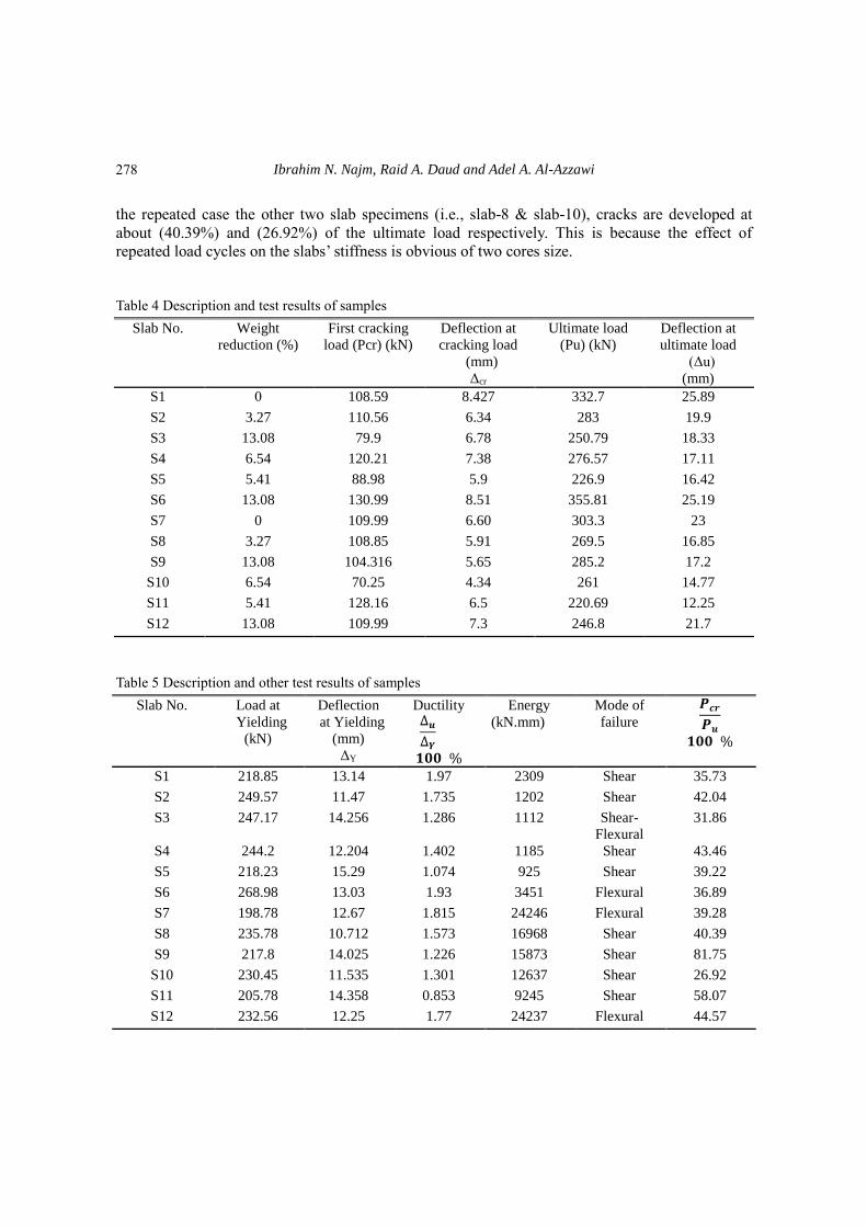
the repeated case the other two slab specimens (i.e., slab-8 & slab-10), cracks are developed at
about (40.39%) and (26.92%) of the ultimate load respectively. This is because the effect of
repeated load cycles on the slabs’ stiffness is obvious of two cores size.
Table 4 Description and test results of samples
Deflection at
ultimate load
(Δu)
(mm)
Ultimate load
(Pu) (kN)
Deflection at
cracking load
(mm)
Δcr
First cracking
load (Pcr) (kN)
Weight
reduction (%)
Slab No.
25.89 332.7 8.427 108.59 0 S1
19.9 283 6.34 110.56 3.27 S2
18.33 250.79 6.78 79.9 13.08 S3
17.11 276.57 7.38 120.21 6.54 S4
16.42 226.9 5.9 88.98 5.41 S5
25.19 355.81 8.51 130.99 13.08 S6
23 303.3 6.60 109.99 0 S7
16.85 269.5 5.91 108.85 3.27 S8
17.2 285.2 5.65 104.316 13.08 S9
14.77 261 4.34 70.25 6.54 S10
12.25 220.69 6.5 128.16 5.41 S11
21.7 246.8 7.3 109.99 13.08 S12
Table 5 Description and other test results of samples
𝑷𝒄𝒓
𝑷𝒖
𝟏𝟎𝟎 %
Mode of
failure
Energy
(kN.mm)
Ductility ∆𝒖
∆𝒀
𝟏𝟎𝟎 %
Deflection
at Yielding
(mm)
ΔY
Load at
Yielding
(kN)
Slab No.
35.73 Shear 2309 1.97 13.14 218.85 S1
42.04 Shear 1202 1.735 11.47 249.57 S2
31.86 Shear-
Flexural
1112 1.286 14.256 247.17 S3
43.46 Shear 1185 1.402 12.204 244.2 S4
39.22 Shear 925 1.074 15.29 218.23 S5
36.89 Flexural 3451 1.93 13.03 268.98 S6
39.28 Flexural 24246 1.815 12.67 198.78 S7
40.39 Shear 16968 1.573 10.712 235.78 S8
81.75 Shear 15873 1.226 14.025 217.8 S9
26.92 Shear 12637 1.301 11.535 230.45 S10
58.07 Shear 9245 0.853 14.358 205.78 S11
44.57 Flexural 24237 1.77 12.25 232.56 S12
278

Behavior of reinforced concrete segmental hollow core slabs…
For circular hollow core slab (dia. 100 mm core size without steel fibers) and square hollow
core slab with dimension (57 x 57) mm cracks are developed at about (31.86%) and (39.22%)
respectively in monotonic test. While the repeated test results showed that cracks developed at about
(81.75%) and (58.07%) respectively. The reason for that may be due to different core shapes
(circular and square).
On the other hand, the obvious difference in cracks percentage between circular hollow core
slab (dia. 50 mm) and circular hollow core slab (dia. 100 mm without steel fibers) of (1.5 litter by
weight of cement) due to core diameters or problem in test setup.
For circular hollow core slab (dia. 100 mm with steel fibers) cracks are initiated at about
(36.89%) of ultimate load in monotonic test. the same slab specimen under repeated loading,
cracks are developed at about (44.57%).
The crack patterns for the tested slabs are shown in the Figs. 6 to 17. The experimental results
and specimens’ description are summarized in Tables 4 and 5.
Fig. 6 Crack pattern at ultimate load for Solid (Slab-1) monotonic test
Fig. 7 Crack pattern at ultimate load for Solid (Slab-7) repeated test
Fig. 8 Crack pattern at ultimate load for HCCS (50mm One Core) (Slab-2) monotonic test
279
Ibrahim N. Najm, Raid A. Daud and Adel A. Al-Azzawi
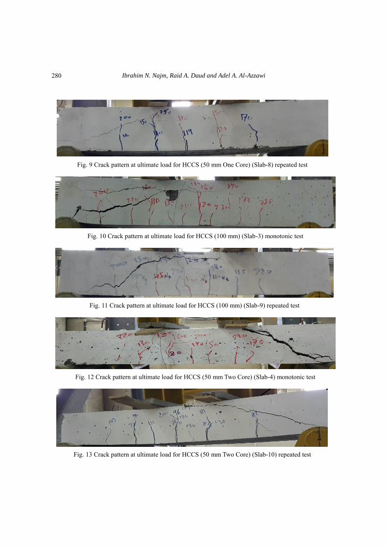
Fig. 9 Crack pattern at ultimate load for HCCS (50 mm One Core) (Slab-8) repeated test
Fig. 10 Crack pattern at ultimate load for HCCS (100 mm) (Slab-3) monotonic test
Fig. 11 Crack pattern at ultimate load for HCCS (100 mm) (Slab-9) repeated test
Fig. 12 Crack pattern at ultimate load for HCCS (50 mm Two Core) (Slab-4) monotonic test
Fig. 13 Crack pattern at ultimate load for HCCS (50 mm Two Core) (Slab-10) repeated test
280

Behavior of reinforced concrete segmental hollow core slabs…
Fig. 14 Crack pattern at ultimate load for HSCS dimensions (57x57) mm (Slab-5) monotonic test
Fig. 15 Crack pattern at ultimate load for HSCS dimension (57x57) mm (Slab-11) repeated test
Fig. 16 Crack pattern at ultimate load for HCCS (100 mm) with S. F (Slab-6) monotonic test
Fig. 17 Crack pattern at ultimate load for HCCS (100 mm) with S. F (Slab-12) repeated test
4.2 Loads at yielding and ductility In this study, the yielding loads, ultimate load, and ductility for tested specimens are measured
during both monotonic and repeated tests. In general, the specimens tested under repeated loading
show obvious decrease at yield load compared with ultimate load. This is due to that the loading
and reloading at stress level above the steel yielding strength of the specimen does not produce a
281

Ibrahim N. Najm, Raid A. Daud and Adel A. Al-Azzawi
significant reduction in the stiffness of the slab. Moreover, the slabs tested under repeated loading
had a ductility that is much smaller compared to that subjected to monotonic loading. Since
considerable vertical cracks occurred on the bottom surface of the specimens subjected to repeated
loading. The measured yield load, ultimate load, deflections and ductility are presented in Table 5.
For solid slab in repeated test, load at yielding decreases at about (9.2%) and ultimate load
decreases at about (7.9%), compared with solid slab in monotonic test. Also, ductility in repeated
test decreases by about (7.87%). Load- strain curve for solid slab in monotonic test is shown in Fig.
18.
For circular hollow core slab (slab-8), yielding load decreases at about (5.5%) as well as
ultimate load decreases at about (4.7%), compared with circular hollow core (slab-2). Ductility in
repeated test decreases at about (9.3%). Load - strain curve for circular hollow core slab in
monotonic test (slab-2) is shown in Fig. 19.
For comparison between (slab-3 and slab-9) in order to clarify the effect of load protocol on
100 mm circular hollow-core slab, seems the rate of decreasing in yielding load of (Slab-9) at
about (11.8%).
Fig. 18 Load strain curves for solid slab (S1)
Fig. 19 Load strain curves for (S2)
050
100150200250300350400
0 5000 10000 15000
Load
(K
N)
Micro strain in steel bars
S 1
Yield strain of steel
0
50
100
150
200
250
300
350
0 1000 2000 3000 4000
Load
(K
N)
Micro strain in steel bars
S 2 Yield strain of steel
282

Behavior of reinforced concrete segmental hollow core slabs…
Fig. 20 Load strain curves for slab (S3)
Fig. 21 Load strain curves for slab (S4)
In contrast, ultimate load increases at about (13.2%) of (slab-9). Furthermore, it was recognized
that ultimate load of the specimen under repeated load display higher than the specimen under
monotonic load, and did not agree with trend of other specimens. The reason for the
non-conformity of this specimen became obvious with unexpected shear failure mode. On the
other hand, ductility in repeated test decreases at about (4.7%). Load - strain curve for slab-3 is
shown in Fig. 20.
Another comparison between (slab-4 and slab-10) was conducted. The purpose of this
comparison is to illustrate the core number influence on overall performance of the hollow core
slab. The rate of decreasing in (slab-10) at about (5.6%) and (5.5%) of yielding load and ultimate
load, respectively, compared with (slab-4). The ductility reduces at about (7.2%). When tested
specimens with square hollow-core under monotonic and repeated loading (slab-5 and slab-11).
Load at yielding and load at ultimate capacity in (slab-11) decreases at about (5.7%) and (2.7%),
respectively. Because of repeated loading effect. Load - strain curves for specimens (slab 4) and
(slab5) is shown in Figs. 21 and 22.
0
50
100
150
200
250
300
350
0 1000 2000 3000 4000
Load
(K
N)
Micro strain in steel bars
S 3
Yield strain of steel
0
50
100
150
200
250
300
350
0 1000 2000 3000 4000
Load
(K
N)
Micro strain in steel bars
S 4
Yield steel of strain
283

Ibrahim N. Najm, Raid A. Daud and Adel A. Al-Azzawi
Fig. 22 Load strain curves for slab (S5)
Fig. 23 Load strain curves for solid slab (S6)
For comparison between circular hollow-core slab with S.F (slab-6 and slab-12) showed that
the specimen that subjected to repeated loading, decreased in yielding load and ultimate load at
about (13.5%) and (30%), respectively. Ductility in (slab-6 and slab-12) is about (1.93) and (1.77)
respectively. Load -strain curve of slab 6 is shown in Fig. 23.
4.3 Load-deflection curves
The specimens’ behaviors were evaluated in terms of load deflection performance. During the
monotonic tests, it was noticed that the load increased linearly with mid span deflection until
bottom steel bars yielded. After that, the load deflection curve exhibited nearly horizontal with an
increase in the deflection until the failure of specimens occurred. On the other hand, the results got
from these repeated tests were compared to the monotonic tests results.
Fig. 24 to Fig. 29 shows the load versus the monotonic and the repeated deflection curves for
the twelve tested slabs. Both solid slabs (slab1 & slab7) and circular hollow-core slab with S.F
0
50
100
150
200
250
300
350
0 2000 4000 6000 8000
Load
(K
N)
Micro strain in steel bars
S 5
Yield strain of steel
0 2000 4000 6000 8000
0
50
100
150
200
250
300
350
400
Load
(K
N)
Micro strain in steel bars
Yield strain of steel
S 6
284

Behavior of reinforced concrete segmental hollow core slabs…
(slab6 & slab12) showed relatively large deflection values before failing the specimens in
monotonic and repeated cases. The square hollow-core slabs showed lower load carrying capacity
as well as deflection at failure than other specimens. The ultimate load of slab 5 and slab 11 was
226.9 kN and 220.69 kN, respectively. This is because the main cracks occurs generally bellowing
the neutral axis at corners of the square hollow core. Thus, the slab response is dependent mainly
on the concrete strength. Also, a reduction in weight in (slab-5 and slab-11) is (5.4%). The shear
failure mode was happened for both slabs.
For comparison between solid (slab-1 and slab-7) and 50 mm circular hollow core (Slab-2 and
slab-8), ultimate load and deflection decreases in (slab-2) by about (13.46%) and (23.14%),
respectively. Also, ultimate load and deflection decreases in (slab-8) at about (3.76%) and
(26.74%), respectively. Reduction in weight is about (3.27%). Shear failure mode is observed for
both (slab-2 and slab-8).
Fig. 24 Load deflection curves for solid slab with Different Loading
Fig. 25 Load deflection curves for one core size 50 mm (HCS) with Different Loading
0
50
100
150
200
250
300
350
400
0 5 10 15 20 25 30
Load
(K
N)
Deflection (mm)
S7 Repeated
S1 Monotonic
0
50
100
150
200
250
300
0 5 10 15 20
Load
(K
N)
Deflection (mm)
S8 Repeated
S2 Monotonic
285

Ibrahim N. Najm, Raid A. Daud and Adel A. Al-Azzawi
Fig. 26 Load deflection curves for Two core size 50 mm (HCS) with Different Loading
Fig. 27 Load deflection curves for Square core dimensions (57 x 57) mm (HCS) with Different Loading
For slab3, slab9, slab4, and slab10, these specimens have same voided area but different in the
number and size of hollow core. The ultimate load carrying capacities of slab3, slab9, slab4, and
slab10with respect to control slabs (slab1 & slab7) decreased by 24.6%, 14.2%, 16.8%, and 21.3%,
respectively. The ultimate load obtained for slab3, slab9, slab4, and slab10 is 250.79 kN, 285.2kN,
276.57kN, and 261kN, respectively. The reduction in weight in four specimens is about (6.54%).
0
50
100
150
200
250
300
0 5 10 15 20
Load
(kN
)
Deflection (mm)
S10 Repeated
S4 Monotonic
0
50
100
150
200
250
300
0 2.5 5 7.5 10 12.5 15 17.5 20
Load
(K
N)
Deflection (mm)
S11 Repeated
S5 Monotonic
286

Behavior of reinforced concrete segmental hollow core slabs…
Fig. 28 Load deflection curves for one core size 100 mm (HCS) with Different Loading
Fig. 29 Load deflection curves for one core size 100 mm S.F (HCS) with Different Loading
5. Conclusions
The main task of this research was to investigate experimentally the response of reinforced
concrete solid and hollow-core slabs under monotonic and repeated loading. The test program is
carried out to study the effects of load type, core diameters, core shape, number of cores, and steel
fiber existence on slab behavior. Based on this study, the main conclusions emerged from
laboratory testing is given in the followings.
Reducing in stiffness resulting from repeated loading causing reduction of ultimate loads in
contrast, the crack loads do not influence.
0
50
100
150
200
250
300
0 5 10 15 20
Load
(K
N)
Deflection (mm)
S9 Repeated
S3 Monotonic
0
50
100
150
200
250
300
350
400
450
0 5 10 15 20 25 30
Load
(K
N)
Deflection (mm)
S12 Repeated
S6 Monotonic
287
Ibrahim N. Najm, Raid A. Daud and Adel A. Al-Azzawi
The loading and reloading at stress level above the steel yielding strength of the specimen
does not produce a considerable reduction in the slab stiffness.
Increasing the voids diameter leads to decreasing in crack loads and also ultimate loads
capacity of moderately thick hollow core slab.
The circular hollow core slab that contain steel fibers more ductile from the circular hollow
core slab without steel fibers. Existence the steel fiber leads to increasing in ultimate
strength and deflection resulting from monotonic and repeated loading.
The hollow core shape has remarkable influence on overall performance of the specimens.
On the other word, the square hollow-core slabs showed lower load carrying capacity as
well as deflection at failure than other specimens
Reducing in ductility when applied the specimens under repeated loading effects.
Acknowledgments
The research described in this paper was carried out at the laboratories of civil engineering
department, College of Engineering, Al-Nahrain University.
References
ACI318-14, (2014), “Building Code Requirements for Structural Concrete and Commentary”, American
Concrete Institute, Detroit, U.S.A.
AGENCY, F.E.M. (2007), Interm Testing Protocols for Determining the Seismic Performance
Characteristics of Structural and Nonstructural Components, Federal Emergency Management Agency
Washington, DC.
Al-Azzawi, A. and Abdul Al-Aziz, B. (2017), “Numerical analysis of reinforced lightweight aggregate
concrete hollow core slabs”, ARPN J. Eng. Appl. Sci., 12(6), 1743-1757.
Al-Azzawi, A. and Abdul Al-Aziz, B. (2018), “Behavior of reinforced lightweight aggregate concrete
hollow-core slabs”, Comput. Concrete, 21(2), 117-126.
Al-Azzawi, A.A. and Abed, S.A. (2017), “Investigation of the behavior of reinforced concrete hollow-core
thick slabs”, Comput. Concrete, 19(5), 567-577.
Baran, E. (2015), “Effects of cast-in-place concrete topping on flexural response of precast concrete
hollow-core slabs”, Eng. Struct., 98, 109-117.
Baran, E. (2015), “Effects of cast-in-place concrete topping on flexural response of precast concrete
hollow-core slabs”, Eng. Struct., 98(1), 109-117.
Brunesi, E., Bolognini, D. and Nascimbene, R. (2014), “Evaluation of the shear of precast-prestressed
hollow core slab: numerical and experimental comparison”, Mater. Struct., 48(5), 1503-1521.
Celal, M.S. (2011), “Shear Behavior of Precast/Prestressed Hollow-Core Slabs,” M.Sc. Thesis, Department
of Civil Engineering, University of Manitoba, Winnipeg, Manitoba.
Cuenca, E. and Serna, P. (2013), “Failure modes and shear design of prestressed hollow core slabs made of
fiber-reinforced concrete”, Compos. Part B, 45, 952-964.
Dudnik, V.S., Milliman, L.R. and Parra-Montesinos, G.J. (2017), “Shear behavior of prestressed
steel-fiber-reinforced concrete hollow-core slabs”, PCI J., 62(4), 58-72.
Kankeris, P. and Prakash, S. (2016), “Experimental evaluation of bonded overlay and NSM GFRP bar
strengthening on flexural behavior of precast prestressed hollow core slabs”, Eng. Struct., 120(1), 49-57.
Lee, D.H., Park, M.K., Oh, J.Y., Kim, K.S., Im, J.H. and Seo, S.Y. (2014), “Web-shear capacity of
prestressed hollow-core slab unit with consideration on the minimum shear reinforcement requirement”,
Comput. Concrete, 14(3), 211-231.
288

Behavior of reinforced concrete segmental hollow core slabs…
Prakashan, L.V., George, J., Edayadiyil, J.B. and George, J.M. (2017), “Experimental study on the flexural
behavior of hollow core concrete slabs”, Appl. Mech. Mater., 857, 107-112.
Rahman, M.K., Baluch, M.H., Said, M.K. and Shazali, M.A. (2012), “Flexural and shear strength of
prestressed precast hollow-core slabs”, Arabian J. Sci. Eng., 37(2), 443-455.
Wariyatno, N.G., Haryanto ,Y. and Sudiboyo, G.H. (2017), “Flexural behavior of precast how core slab
using PVC pipe and Styrofoam with different reinforcement”, Procedia Eng., 171, 909-916.
Yousif, N.S., Jarallah, H. Kh. And Abdul Kareem, H.I. (2018), “Improving the shear strength of lightweight
RC thick hollow core slab made of recycled materials”, Int. J. Eng. Technol., 7(4.20), 403-407.
TY
289