CHAPTER 7 POST-TENSIONED BEAM DESIGN STEP-BY ...
30
Post-Tensioned Parking Structure Using Beam Frames and One-Way Slabs (P466) Post-Tensioned Buildings www.PT-structures.com FOREWORD The example selected represents a frame of a one- way slab and beam construction—typical of parking structures, or floors, where span in one direction is two or more times the span in the orthogonal direc- tion, for which a beam and one-way slab will be ap- propriate. The beam frame selected has three spans, each with a different length. The third span is pur- posely selected to be short, compared to the other two. Also, the optimum post-tensioning for the de- sign is one with different amount of post-tensioning along the length of the structure, and variable profile from span to span. The objective in selecting a somewhat complex structure is to expose you to the different design sce- narios that you generally encounter in real life struc- tures, but are not featured in text books—in particu- lar, where span lengths in a continuous member are widely different. The example walks you through the 10 steps of de- sign of post-tensioned structures. Aspects of design conditions that are not covered in the design of the example selected, but are important to know, are introduced and discussed as comments or inserted examples. Design operations that are considered common knowledge, such as the calculation of moments and shears, once the geometry of a structure, its material and loading are known, are not detailed. You are re- ferred to your in-house frame programs. The design example covers side by side both the un- bonded and bonded (grouted) post-tensioning sys- tems, thus providing a direct comparison between the design processes of the two options. In addition, in parallel, the design uses the current American building codes (ACI-318 1 and IBC 2 ) along with the European Code (EC2 3 ). Where applicable, reference is made to the UK’s committee report TR43 4 . 1 ACI 318-11 2 IBC 12; International Building Code 2012 3 EN 1992-1-1:2004(E) 4 TR43-2005; Concrete Society, UK CHAPTER 7 POST-TENSIONED BEAM DESIGN STEP-BY-STEP CALCULATION PTB Chapter 7 IE.indd 1 12/14/13 3:01 PM
-
Upload
khangminh22 -
Category
Documents
-
view
0 -
download
0
Transcript of CHAPTER 7 POST-TENSIONED BEAM DESIGN STEP-BY ...

Post-Tensioned Parking Structure Using Beam Frames and One-Way Slabs (P466)
Post-Tensioned Buildings www.PT- structures.com
FOREWORD
The example selected represents a frame of a one-way slab and beam construction—typical of parking structures, or floors, where span in one direction is two or more times the span in the orthogonal direc-tion, for which a beam and one-way slab will be ap-propriate. The beam frame selected has three spans, each with a different length. The third span is pur-posely selected to be short, compared to the other two. Also, the optimum post-tensioning for the de-sign is one with different amount of post-tensioning along the length of the structure, and variable profile from span to span.
The objective in selecting a somewhat complex structure is to expose you to the different design sce-narios that you generally encounter in real life struc-tures, but are not featured in text books—in particu-lar, where span lengths in a continuous member are widely different.
The example walks you through the 10 steps of de-sign of post-tensioned structures. Aspects of design
conditions that are not covered in the design of the example selected, but are important to know, are introduced and discussed as comments or inserted examples.
Design operations that are considered common knowledge, such as the calculation of moments and shears, once the geometry of a structure, its material and loading are known, are not detailed. You are re-ferred to your in-house frame programs.
The design example covers side by side both the un-bonded and bonded (grouted) post-tensioning sys-tems, thus providing a direct comparison between the design processes of the two options. In addition, in parallel, the design uses the current American building codes (ACI-3181 and IBC2) along with the European Code (EC23). Where applicable, reference is made to the UK’s committee report TR434.
1 ACI 318-112 IBC 12; International Building Code 20123 EN 1992-1-1:2004(E)4 TR43-2005; Concrete Society, UK
CHAPTER 7
POST-TENSIONED BEAM DESIGNSTEP-BY-STEP CALCULATION
PTB Chapter 7 IE.indd 1 12/14/13 3:01 PM

Post-Tensioned Buildings7-2
The common method of analysis for beam frames and one-way slabs is the Simple Frame Method (SFM). While it is practical to use SFM in the environment of consulting firms for design of one-way slabs and beam frames, it becomes laborious if an optimum design for the post-tensioning is sought. The itera-tive nature of optimization for post-tensioning lends itself well to the application of computer programs, such as ADAPT-PT for expediency in design.
The hand calculations are supplemented by a com-puter run from ADAPT-PT for verification.
Two text fonts are used in the following. The numer-ical work that forms part of the actual calculations uses the font shown below:
This font is used for the numerical work of the design.
The following text font is used, wherever comments are made to add clarification to the calculations:
This font is used to add clarification to the calculations.
DESIGN STEPS1. GEOMETRY AND STRUCTURAL SYSTEM 1.1 Dimensions and Support Conditions 1.2 Effective Width of Flanges 1.3 Section Properties2. MATERIAL PROPERTIES 2.1 Concrete 2.2 Nonprestressed Reinforcement 2.3 Prestressing3. LOADS 3.1 Selfweight 3.2 Superimposed Dead Load 3.3 Live Load4. DESIGN PARAMETERS 4.1 Applicable Code 4.2 Cover to Rebar and Prestressing Strands 4.3 Allowable Stresses 4.4 Crack Width Limitation 4.5 Allowable Deflection5. ACTIONS DUE TO DEAD AND LIVE LOADS6. POST-TENSIONING 6.1 Selection of Design Parameters 6.2 Selection of Post-Tensioning Tendon Force and Profile 6.3 Selection of Number of Strands 6.4 Calculation of Balanced Loads 6.5 Determination of Actions due to Balanced (post-tensioning) Loads7. CODE CHECK FOR SERVICEABILITY
7.1 Load Combinations 7.2 Stress Check 7.3 Crack Width Control 7.4 Minimum Reinforcement 7.5 Deflection Check8. CODE CHECK FOR STRENGTH 8.1 Load Combinations 8.2 Determination of Hyperstatic Actions 8.3 Calculation of Design Moments 8.4 Strength Design for Bending and Ductility 8.5 One Way Shear Design9. CODE CHECK FOR INITIAL CONDITION 9.1 Load Combinations 9.2 Stress Check10. DETAILING
1 - GEOMETRY AND STRUCTURAL SYSTEM
The floor consists of a one-way slab supported on par-allel beams as shown in Fig. 1-1.
1.1 Dimensions and Support Conditions � Geometry is as shown in Fig. 1-1(a) and (b) � Beam cross section as shown in Fig. 1-1(c) � Total tributary width = 5 m typical � Columns extend below the deck only; first and last
columns are assumed hinged at the bottom.
FIGURE 1-1
PTB Chapter 7 IE.indd 2 12/14/13 3:01 PM
7-3Post-Tensioned Beam Design
End columns are assumed hinged and detailed as hinged at the connection to the footing, in order to reduce stresses and potential of cracking due to shrinkage and creep of concrete for the first elevated deck.
1.2 Effective Width of Flanges When hand calculation is used in analysis of flanged beams, an effective width is selected to account for the bending effects of the structure. ACI-318-115 ex-plicitly states that the effective width used for analy-sis of conventionally reinforced flanged beams does not apply when the same is post-tensioned, but does not clarify the alternative. Section 4.8.3 outlines the reason behind ACI-318’s standing and explains the applicable procedure. Briefly, for axial forces (post-tensioning) the entire cross-sectional area is effec-tive. But, for computation of flexural stresses in hand calculation a reduced flange width is applicable.
� For axial effects (precompression) use the entire tributary of the structure
� For bending effects use the “effective width” val-ue associated with the bending of the flanged beam.
Also, note that the effective width concept is associ-ated with the distribution of elastic stresses in the flange of a beam. It is applicable for “serviceability limit” design (SLS) of a post-tensioned member. For safety checks (ULS) the effective width does not apply.
Other codes and TR43 covered herein are also mute on the effective width of a post-tensioned flanged beam. For conventionally reinforced concrete, ACI 318-116 5 ACI 318-11, Section 18.1.36 ACI 318-11, Section 8.12.2
recommends the least of the following values for ef-fective width of an interior span in bending:
(i) eight times the flange thickness on each side of the stem,(ii) one quarter of the span, or (iii) the beam’s tributary.
Tributary width = 5000 mm(i) Sixteen times flange thickness plus stem width = 16*125 + 460 = 2460 mm(ii) One quarter of spanFor span 1 = (20*1000)/4 = 5000mmFor span 2 = (17*1000)/4 = 4250mmFor span 3 = (5*1000)/4 = 1250mm(iii) Tributary width = 5000 mmAssume the following:Spans 1 and 2: 2460 mmSpan 3: 1250 mm
1.3 Section PropertiesThe section properties for the axial effects are the same for all spans. For bending effects, however, due to differ-ent effective widths, the section properties differ. The section properties calculated are listed in Table 1.3-1.
I = Second moment of area (moment of inertia);Yt = distance of centroid to top fiber of section;Yb = distance of centroid to bottom fiber of section;Stop= section modulus for top fiber; (I/Yt); andSbot= section modulus for bottom fiber; (I/Ybot).
2 - MATERIAL PROPERTIES
2.1 ConcreteCylinder strength f’c ,fck (28 day) = 28 MPa
TABLE 1.3-1 Section Properties (T131SI)
PTB Chapter 7 IE.indd 3 12/14/13 3:01 PM

Post-Tensioned Buildings7-4
Weight = 24 kN/m3
Modulus of Elasticity = 4700 √f’c = 24870 MPa [ACI] = 22* 103* [(fck +8)/ 10] 0.3 7 [EC2, TR-43]; = 32308 MPa Creep coefficient t = 2 Material factor, γc = 1 – ACI, 1.50 [EC2, TR-43]Strength at transfer, fci = 20 MPa
The creep coefficient is used to estimate the long-term deflection of the slab.
2.2 Nonprestressed (Passive) Reinforcementfy = 460 MPa Elastic Modulus = 200000 MPaMaterial factor, γc = 1 [ACI]; 1.15 – [EC2, TR-43]Strength reduction factor (bending), φ = 0.9 [ACI]; = 1 [EC2, TR-43]
2.3 Prestressing: (Figs 2.3-1 through 2.3-4)Material—low relaxation, seven wire ASTM 416 strandNominal strand diameter = 13 mm Strand area = 99 mm2
Elastic Modulus = 200000 MPa Ultimate strength of strand (fpu) = 1860 MPaMaterial factor, γc = 1 [ACI]; 1.15 [EC2, TR-43]
System Unbonded System Angular coefficient of friction (µ) = 0.07Wobble coefficient of friction (K) = 0.003 rad/mAnchor set (wedge draw-in) = 6 mmStressing force = 80% of specified ultimate strengthEffective stress after all losses8 = 1200 MPa
Bonded SystemUse flat ducts 20x80mm; 0.35 mm thick metal sheet housing up to five strandsAngular coefficient of Friction (µ) = 0.2 Wobble coefficient of Friction (K) = 0.003 rad/mAnchor set (Wedge Draw-in) = 6 mmOffset of strand to duct centroid (z) = 3 mmEffective stress after all losses = 1100 MPa
Section through the bonded tendon duct in place is shown in Fig. 2.3-1 and 2.3-27 EN 1992-1-1:2004(E) Table 3.18 For hand calculation, an effective stress of tendon is used. The effective stress is the average stress along the length of a tendon after all immediate and long-term losses. The value selected for effective stresses is a conservative estimate. When “effective stress” is used in design, the stressed lengths of tendons are kept short, as it is described later in the calculations.
3 - LOADS
3.1 SelfweightSlab = 0.125 m*2400 kg/m3*5m*9.806/1000 = 14.71 kN/mStem = 0.635*0.460*2400*9.806/1000 = 6.87 kN/mTotal selfweight = 14.71 + 6.87 = 21.58 kN/m
FIGURE 2.3-1 Bonded Tendon Section
FIGURE 2.3-2
PTB Chapter 7 IE.indd 4 12/14/13 3:01 PM

7-5Post-Tensioned Beam Design
3.2 Superimposed Dead LoadFrom mechanical, sealant and overlay 0.5 kN/m2
= 0.5 kN/m2*5 m= 2.5 kN/mTotal Dead Load = 21.58 + 2.5 = 24.08 kN/m2
3.3 Live Load:9 2.5 kN/m2
Total live load = 2.5*5 = 12.5 kN/mMaxLL/DL ratio = 12.5/24.08 = 0.52 < 0.75 ∴ Do not skip live loading
Strictly speaking, live loads must be skipped (pat-terned) to maximize the design values. But, when the ratio of live to dead load is small (less than 0.75), it is adequate to determine the design actions based on full value of live loads on all spans (ACI-318-1110). This is specified for slab construction, but it is also used for beams.
4 - DESIGN PARAMETERS
4.1 Applicable CodesThe design is carried out according to each of the fol-lowing codes. Further, reference is made to the Commit-tee Report TR43, where appropriate.
� ACI 318-2011; IBC-2012 � EC2 (EN 1992-1-1:2004)
4.2 Cover to rebar and prestressing strandsUnbonded and bonded systemMinimum rebar cover = 40 mm top and bottom
The cover selected is higher than the minimum code requirement to allow for installation of top slab bars over the beam cage in the transverse direction to the beam.
Minimum prestressing CGS =70 mm
The cover and hence distance to the CGS (Center of Gravity of Strand) is determined by the require-ments for fire resistivity and positioning of tendons within the beam cage. The distance 70 mm selected is slightly higher than the minimum required. Its se-lection is based on ease of placement.
9 The live load assumed is somewhat high. The common value in the US, based on ASCE 07 is 2 kN/m2. Also, US codes allow reduction of live load under certain conditions. In this example, the higher value common in a number of world regions is used and the value is not reduced.10 ACI 318-11, Section 13.7.6
4.3 Allowable StressesA. Based on ACI 318-11/IBC 201211 Allowable stresses in concrete are the same for bonded and unbonded PT systems
� For sustained load conditionCompression = 0.45*f’c = 12.60 MPa
� For total load condition Compression = 0.60*f’c = 16.80 MPa
Tension: (Transition condition of design is targeted) The range for transition (moderate cracking) is as fol-lows: = 0.62*√f’c < stress ≤ 1.00*√f’c = 3.28 MPa < stress ≤ 5.29 MPa
For top fibers the lower value will be targeted, in or-der to limit crack width and improve durability. For the bottom fiber the higher value will be used, allow-ing for a wider crack width
� For initial conditionCompression = 0.60 f’ci = 0.6* 20 = 12 MPaTension = 0.25 √f’c = 1.12 MPa
For one-way systems, ACI 318-11 defines three con-ditions of design, namely uncracked (U), transition (T) and cracked (C). The three conditions are distin-guished by the magnitude of the maximum hypothet-ical tension stress in concrete at the farthest tension fiber. For the current design example the transition (T) condition is selected. For this condition, hypo-thetical tension stresses can exceed 0.62√f’c but not larger than 1.00√f’c However, since the surface of the parking structure being designed is exposed, the de-sign example uses a stress limit of 0.75√f’c for the top surface and the maximum value allowed by the code for the bottom surface. This is not a code re-quirement. Based on code, 1.00√f’c would have been acceptable. The selection of a lower value for the top surface is based on good engineering practice.
B. Based on EC212 EC2 does not specify “limiting” allowable stresses in the strict sense of the word. There are stress thresholds that trigger crack control. These are the same for both bonded and unbonded systems. For computed stressed below the code thresholds, the minimum reinforcement requirement provisions of EC2 suffices.
� For “frequent” load condition11 ACI 318-11, Sections 18.3 and 18.412 EN 1992-1-1:2004(E), section 7.2
PTB Chapter 7 IE.indd 5 12/14/13 3:01 PM
Post-Tensioned Buildings7-6
Concrete:Compression = 0.60*fck = 0.6*28 = 16.80 MPa Tension (concrete) Ft = fct,eff = fctm
13 Ft = 0.30*fck (2/3) = 0.30*28(2/3) = 2.77 MPa (Table 3.1, EC2)Tension (nonstressed steel) = 0.80*fyk = 0.8 *460 = 368 MPa Tension (prestressing steel) = 0.75*fpk = 0.75*1860 = 1395 MPa
� For “quasi-permanent” load conditionCompression = 0.45*fck =0.45*28 = 12.60 MPa Tension (concrete) = 2.77 MPa same as frequent load combination
Unlike ACI-318/IBC, provisions in EC2 permit14 overriding the allowable hypothetical tension stress in concrete, provided cracking is controlled not to exceed the allowable values.
� For “initial” load condition (Table 3.1; EC2)Tension (Unbonded) = fct,eff = fctm 0.30*fci (2/3) = 0.30*20 (2/3) = 2.21 MpaCompression15 = 0.60*fci = 0.6*20 = 12 MPa C. Based on TR-4316 Unbonded tendonsFor “frequent” load combinationTension = 1.35 fctm,fl fctm,fl = larger of (1.6- h/1000) fctm or fctm17 = larger of (1.6- 0.760) fctm or fctm = larger of 0.84*fctm or fctm fctm = 0.30*fck (2/3) (Table 3.1, EC2) = 0.30*28 (2/3) = 2.77 MPa Allowable tension stress = 1.35* 2.77 = 3.74 MPa
Bonded tendonsFor “frequent” load combinationFor the members with 0.2 mm allowable crack width, al-lowable tension stress without bonded reinforcement is:Tension = 1.65 fctm,fl = 1.65* 2.77 = 4.57 MPa For tension (with bonded reinforcement) Tension = 0.3fck = 0.30*28 = 8.40 MPa Compression = 0.6* fck = 0.6*28 = 16.80 MpaTR-43 specifies allowable concrete compressive stress-es for bonded PT systems, but is mute for unbonded 13 EN 1992-1-1:2004(E) , section 7.3.2(4)14 EN 1992-1-1:2004(E) , section 7.3.2(4)15 EN 1992-1-1:2004(E) , section 5.10.2.2(5)16 TR-43 Second Edition, Table 3. For tensile stress, stress limit without bonded reinforcement is considered.17 EN 1992-1-1:2004(E) , Eqn.3-23
systems. In practice, the same values are used for both systems.
For “quasi-permanent” load combination: Allowable tension stresses are the same as “frequent” load condition.Compression = 0.45* fck = 0.45*28 = 12.60 MPa
� For “initial” load condition18 Tension = 0.72 fctm fctm = 0.30*fci (2/3) (Table 3.1, EC2) = 0.30*20 (2/3) = 2.21 MPa Allowable tension stress = 0.72*2.21 = 1.59 MPa Compression = 0.50*fci = -10 MPa
4.4 Crack Width Limitation A. Based on ACI 318-11/IBC 2012Crack width control and limitation applies when member is designed for the “cracked” regime. No requirements are stipulated, if as in this example, the stresses are kept within the uncracked (U) or transition (T) regime.
B. Based on EC219 In EC2, the allowable crack width depends on whether the post-tensioning system used is “bonded,” or “un-bonded,” and the load combination being considered.Frequent load condition:
� Prestressed members with bonded tendons0.2 mm; to be checked for frequent load case
� Prestressed members with unbonded tendons0.3 mm; to be checked at quasi-permanent load case
C. Based on TR-4320 For all members = 0.2 mm
4.5 Allowable Deflection A. Based on ACI 318-11/IBC 201221 In all major codes, the allowable deflection is tied to (i) the impact of the vertical displacement on oc-cupants; (ii) the possible damage to installed non-structural objects such as partitions, glass, or floor covering; and (iii) functional impairment, such as proper drainage. Details of the allowable values, their measurement and evaluation are given in Chapter 4. For perception of displacement by sensitive persons, consensus is limit of L/240, where L is the deflection span. It is important to note that this is the displace-ment that can be observed by a viewer. 18 TR-43 Second Edition, Section 5.8.2.19 EN 1992-1-1:2004(E), Table 7.1N20 TR-43 Second Edition, Section 5.8.3.21 ACI 318-11, Section 18.3.5
PTB Chapter 7 IE.indd 6 12/14/13 3:01 PM

7-7Post-Tensioned Beam Design
� Since in this design example there is no topping on the finished slab, the applicable vertical displacement is the total deflection subsequent to the removal of forms.
� The deflection check for potential damage to non-structural elements is not applicable in this case, since the structure is a frame of an open parking structure.
� The drainage and ponding of water will be controlled through proper sloping of the floors.Total allowable deflection: L/240The frame will be provided with a camber to minimize the impact of deflection.
B. Based on EC222 The interpretation and the magnitude of allowable deflections in EC2 are essentially the same as that of ACI-318. The impact of vertical displacement on the function of the installed members and the visual im-pact on occupants determine the allowable values. The following are suggested values:
Deflection subsequent to finishing of floors from quasi-permanent combination: L/250The frame will be provided with a camber to minimize the impact of deflection.
C. Based on TR-4323 TR43 refers to EC2 for allowable deflections.
In summary, the allowable deflection from the two codes and the committee report are essentially the same. Conservatively, it can be summarized as follows:
Total deflection from quasi-permanent load combina-tion - L/250Where, L is the length of the span.
5. ACTIONS DUE TO DEAD AND LIVE LOADING
The structural system of the frame and its dead and live loading are shown in Figs. 5-1 through 5-3.
Actions due to dead and live loads are calculated for this example using a generic frame analysis program. The members are assumed prismatic and of uniform cross section throughout the length of each span. Spans 1 and 2 have the same geometry. Centerline to centerline distances are used for span lengths. No al-lowance is made in the hand calculation for stiffening of members over support. Some software accounts for 22 EN 1992-1-1:2004(E), Section 7.4.123 TR-43 Second Edition, Section 5.8.4.
FIGURE 5-1
FIGURE 5-2
FIGURE 5-3
PTB Chapter 7 IE.indd 7 12/14/13 3:01 PM

Post-Tensioned Buildings7-8
this stiffening and increase the moment of inertia of the beam over the support region [ADAPT-PT, 2012]. The centerline moments calculated are reduced to the face-of-support using the static equilibrium of each span.
The critical design moments are not generally at midspan. But, for hand calculation, the midspan location is selected. The approximation is acceptable when spans and loads are essentially uniform.
The computed moments from the frame analysis are reduced to the face of each support using statics of respective span. The face-of-support moments and the moments at midspan are summarized in Table 5-1.
6. POST-TENSIONING
6.1 Selection of Design ParametersUnlike conventionally reinforced members, where given geometry, boundary conditions, material prop-erties and loads result in a unique design, for post-tensioned members in addition to the above a mini-mum of two other input assumptions are required, before a design can be concluded. A common prac-tice is (i) to assume a level of precompression and (ii) target to balance a percentage of the structure’s dead load. In this example, based on experience the level of precompression suggested is larger than the minimum required by ACI-318 code (0.86 MPa). Oth-er major building codes do not specify a minimum precompression. Rather, they specify a minimum re-inforcement. Use the following assumption to initi-ate the calculations.
Minimum average precompression = 1.0 MPaMaximum average precompression = 2.0 MPaTarget balanced loading =60 % of total dead load
Based on experience for economy of design, a mini-mum precompression of 1.0 MPa over the entire sec-tion is assumed. ACI 318 stipulates a minimum of 0.86 MPa. In the manual calculation, the minimum precompression is used as an entry value (first trial) for design. The stipulation for a maximum precom-pression does not enter the hand calculation directly. It is stated as a guide for a not-to-exceed upper value. For deflection control the selfweight of the critical span is recommended to be balanced to a minimum of 60% of its selfweight [Aalami, et al, 2003]. Other spans need not be balanced to the same extent. As it will become apparent further in the calculations, for the current beam frame it is beneficial if the tendon exerts a downward force on the third span, as op-posed to an upward force in the critical (first) span.
Effective stress in prestressing strand:For unbonded tendons: fse = 1200 MPaFor bonded tendons: fse = 1100 MPa
The design of a post-tensioned member can be based either on the “effective force”, or the “tendon selec-tion” procedure. In the effective force procedure, the average stress in a tendon after all losses is used in design. In this case, the design concludes with the total effective post-tensioning force required at each location. The total force arrived at the conclusion of design is then used to determine the number of strands required, with due allowance for friction and long-term losses. This provides an expeditious and
TABLE 5-1 Moments at Face-of-Supports and Midspans (T132)
PTB Chapter 7 IE.indd 8 12/14/13 3:01 PM

7-9Post-Tensioned Beam Design
simple design procedure for hand calculations. In the “tendon selection” procedure, the design is based on the number of strands with due allowance for the immediate and long-term losses. In the following, the “effective force” method is used to initiate the design. Once the design force is determined, it is converted to the number of strands required.
The effective stress assumed in a strand is based on the statistical analysis of common floor slab dimen-sions for the following conditions (Fig. C6.1-1):(i) Members have dimensions common in building construction; (ii) Tendons equal or less than 38 m long stressed at one end. Tendons longer than 38m, but not exceed-ing 76m are stressed at both ends. Tendons longer than 76m are stressed at intermediate points to limit the unstressed lengths to 38m for one-end stressing or 76m for two-end stressing, whichever be appli-cable; (iii) Strands used are the commonly available 13 or 15 mm nominal diameter with industry common friction coefficients as stated in material properties section of this design example; and(iv) Tendons are stressed to 0.8fpu.
For other conditions, a lower effective stress is as-sumed, or tendons are stressed at intermediate points. In the current design, the total length of the tendon is 41 m. It is stressed at both ends. Detailed stress loss calculations, not included herein, indicate that the effective tendon stress is 1250 MPa for the unbonded system and also larger than assumed for the grouted system.
6.2 Selection of Post-Tensioning Tendon Force and ProfileThe design prestressing force in each span will be cho-sen to match a whole number of prestressing strands. The following values are used:
1. The effective force along the length of each tendon is assumed to be constant. It is the average of force distribution along a tendon.
Unbonded tendonsForce per tendon = 1200*99 mm2/1000 = 118.8 ≈ 119.0 kN/ tendon Use multiples of 119 kN when selecting the post-ten-sioning forces for design.
Bonded tendonsForce per tendons = 1100*99 mm2/1000
= 108.9 ≈ 109.0 kN/ tendon Use multiples of 109 kN when selecting the post-ten-sioning forces for design.
2. Tendon profiles are chosen to be simple parabola. These produce a uniform upward force in each span.
For ease of calculation the tendon profile in each span is chosen to be concave upward, simple pa-rabola from centerline to centerline of supports (Fig. C6.2-1). The position of the low point is selected such as to generate a uniform upward force in each span. The relationship given in Fig. C6.2-1 defines the pro-file. For exterior spans, where the tendon high points are not generally the same, the resulting low point will not be at midspan. For interior spans, where tendon high points are the same, the low point will coincide with midspan. Obviously, the chosen profile is an approximation of the actual tendon profile used in construction. Sharp changes in curvature associ-ated with the simple parabola profile assumed are impractical to achieve on site. The tendon profile at construction is likely to be closer to reversed parabo-la, for which the distribution of lateral tendon forces will be somewhat different as discussed henceforth. Tendon profiles in construction and the associated tendon forces are closer to the diagrams shown in Fig. C6.2-2.
6.3 Selection of Number of StrandsDetermine the initial selection of number of strands for each span based on the assumed average precompres-
FIGURE 6.2-1
PTB Chapter 7 IE.indd 9 12/14/13 3:01 PM
Post-Tensioned Buildings7-10
sion and the associated cross-sectional area of each span’s tributary. Then, adjust the number of strands selected, based on the uplift they provide.
Unbonded tendons1.0N/mm2*9.171e+5 mm2/1000 = 917.1 kN Number of strands = 917.1 kN/119 kN = 7.719 strands selected (8 strands would work too)Force in 9 strands = 9*119 = 1071 kN
Bonded tendonsNumber of strands = 917.1 kN/109 kN = 8.49 strands selected.It is noted that the number of strands required to satisfy the same criterion differs between the un-bonded and bonded systems. Due to higher friction losses, when using the bonded system, generally more strands are needed to satisfy the in-service condition of design. For brevity, without compromis-ing the process of calculation, in the following the same number of strands is selected for both systems.
6.4 Calculation of Balanced Loads Balanced loads are the forces that a tendon exerts to its concrete container. It is generally broken down to forces normal to the centerline of the member
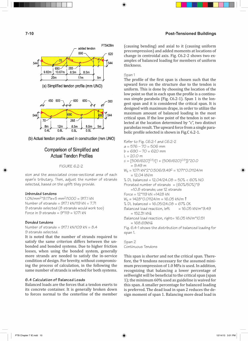
(causing bending) and axial to it (causing uniform precompression) and added moments at locations of change in centroidal axis. Fig. C6.2-2 shows two ex-amples of balanced loading for members of uniform thickness.
Span 1 The profile of the first span is chosen such that the upward force on the structure due to the tendon is uniform. This is done by choosing the location of the low point so that in each span the profile is a continu-ous simple parabola (Fig. C6.2-1). Span 1 is the lon-gest span and it is considered the critical span. It is designed with maximum drape, in order to utilize the maximum amount of balanced loading in the most critical span. If the low point of the tendon is not se-lected at the location determined by “c”, two distinct parabolas result. The upward force from a single para-bolic profile selected is shown in Fig.C 6.2-1.
Refer to Fig. C6.2-1 and C6.2-2a = 576 – 70 = 506 mmb = 690 – 70 = 620 mmL = 20.0 mc = [506/620]0.5/[1 + (506/620)0.5]}*20.0 = 9.49 mWb = 1071 kN*2*0.506/9.492 = 1071*0.01124/m = 12.04 kN/m% DL balanced = 12.04/24.08 = 50% < 60% NGProrated number of strands = (60%/50%)*9 =10.8 strands; use 12 strandsForce = 12*119 kN =1428 kNWb = 1428*0.01124/m = 16.05 kN/m ↑% DL balanced = 16.05/24.08 = 67% OKBalanced load reaction, left = 16.05 kN/m*9.49 = 152.31 kN↓Balanced load reaction, right= 16.05 kN/m*10.51 = 168.69kN↓Fig. 6.4-1 shows the distribution of balanced loading for span 1.
Span 2Continuous Tendons
This span is shorter and not the critical span. There-fore, the 9 tendons necessary for the assumed mini-mum precompression of 1.0 MPa is used. In addition, recognizing that balancing a lower percentage of selfweight will be beneficial to the critical span (span 1); the minimum 60% used as guideline is waived for this span. A smaller percentage for balanced loading is preferred. The dead load in span 2 reduces the de-sign moment of span 1. Balancing more dead load in
FIGURE 6.2-2
PTB Chapter 7 IE.indd 10 12/14/13 3:01 PM

7-11Post-Tensioned Beam Design
span 2 will not be beneficial to the design. Also note that the tendon low point is located at midspan.
Wb = 50%*24.08 kN/m =12.04 kN/m ↑a = Wb*L2/8*P = [(12.04*172)/(8*1071)]*1000 = 405 mmCGS =690 – 405 = 285 mmBalanced load reactions = 12.04 kN/m*8.5 m =102.34 kN ↓ (Left and Right)
Added Tendons
Reduction of tendons from 12 in span 1 to 9 in span 2 means that 3 tendons from span 1 terminate in span 2. The terminated three tendons are dead-ended in span 2. The dead-end is located at a distance 0.20L from the left support at the centroid of the beam section. The tails of the terminated tendons are assumed to be in the shape of a half parabola with its apex horizontal over the support and concave downward to the dead end. Hence, the vertical balanced loading of these ten-dons will be downward, with a concentrated upward force at the dead end (Fig. 6.4-2). The magnitude of the downward vertical force Wb is:
Wb = (2aP)/c2
a = 690 – 576 = 114 mmc = 0.20*17 = 3.4 mWb = (2aP)/c2 = (2*0.114 *3*119)/3.42) = 3*119*0.0197 = 7.04 kN/m ↓Concentrated force at dead end = 7.04*3.4 m = 23.94 kN ↑
Span 3The tendon profile in this span is chosen to be straight from the high point at the interior support, to the centroid of the section at the exterior support. The objective is to avoid uplift in the short span. As a matter of fact, for this beam a downward force in the third span would be beneficial to the design of the interior span, since in this span the distribution of dead load moment is all negative.
CGS left = 690 mmCGS right = 576 mmCGS center = (690 + 576)/2 = 633 mmVertical balanced loading forces are concentrated forces acting at the supports only, they are equal and opposite. Force is calculated using the tangent of the tendon slope for the small angle.Wb = 1071 kN*(690 – 576)/(5*1000) = 24.42 kN ↑(right); ↓ (left)
The complete tendon profile, effective force and bal-anced loading diagram is shown in Fig. 6.4-2.
Verify the computed balanced loading(i) Sum of vertical forces must add up to zero:
FIGURE 6.4-1
FIGURE 6.4-2
PTB Chapter 7 IE.indd 11 12/14/13 3:01 PM

Post-Tensioned Buildings7-12
-152.31 - 168.69 + 16.05 *20 - 102.34 + 23.94 - 7.04 *3.4 + 12.04*17 – 102.34 - 24.42 + 24.42 = 0.004 OK(ii) Sum of moments of the forces must be zero. Taking moments about the first support gives:-168.69*20 + 16.05 *202/2 – 102.34*20 –7.04 *3.4*(20+3.4/2) + 23.94 *23.4 + 12.04*17*(20+17/2) – 102.34*37 – 24.42*37 + 24.42*42 = 0.92 kN-m OK
The forces exerted by a tendon to its container (beam frame in this case) are always in static equi-librium, regardless of the geometry of tendon and the configuration of the member that contains the tendon. To guarantee a correct solution, it is critical to perform an equilibrium check for the balanced loads calculated (Fig. C6.4-2) before proceeding to the next step. And, that the concentrated forces over the supports are correctly computed and accounted for. In particular, the force due to the short length of the terminated strands in the second span must be included to satisfy equilibrium. If equilibrium is not satisfied, it becomes imperative to ensure that the results err on the conservative side.
6.5 Determination of Actions due to Balanced (Post-Tensioning) LoadsThe distributions of post-tensioning moments due to balanced loading are shown in Fig. 6.5-1. These actions are obtained by applying the balanced loads shown in Fig. 6.4-2(c) to the frame shown in Fig. 5-1. The mo-ments shown in the figure are those reduced to the face-of-support. Midspan moments are also shown in the figure.
Actions due to post-tensioning are calculated using a standard frame program. The input geometry and boundary conditions to the standard frame program are the same as used for the dead and live loads.
7 - CODE CHECK FOR SERVICEABILITY
7.1 Load Combinations The following lists the recommended load combinations of the building codes covered for serviceability limit state (SLS).
� [ACI, IBC]Total load condition: 1*DL + 1*LL + 1*PTSustained load condition: 1*DL + 0.3*LL + 1*PT24
� [EC2, TR43]Frequent load condition: 1*DL + 0.5*LL + 1*PTQuasi-permanent load condition: 1*DL + 0.3*LL + 1*PT
For serviceability, the actions from the balanced loads from post-tensioning (PT) are used. These are due to “balanced loading.” The background for this is explained in detail in reference [Aalami, 1990].
7.2 Stress CheckCritical Locations for Stress Check:
For hand calculation, the critical locations for stress check are selected based on engineering judgment. The selected locations may or may not coincide with the locations of maximum stress levels. This will in-troduce a certain degree of approximation in design, which reflects the common practice for hand calcula-tions. Computer solutions generally calculate stress-es at multiple locations along a span, thus providing greater accuracy.
By inspection, locations marked in Fig. 7.2-1 as sections A through E are considered critical for design. These 24 ACI-318 specifies a “sustained” load case, but does not stipulate the fraction of live load to be considered “sus-tained.” It is left to the judgment of the design engineer to determine the applicable fraction. The fraction selected var-ies between 0.2 and 0.5. The most commonly used fraction is 0.3, as it is adopted in this design example.
FIGURE 6.5-1
FIGURE 7.2-1
PTB Chapter 7 IE.indd 12 12/14/13 3:01 PM

7-13Post-Tensioned Beam Design
are the midspan locations and the face-of-support lo-cations of the first interior column.
The moment diagrams due to the combined action of dead and live loading (Fig. 5-2 and 5-3) and the mo-ment distribution due to post-tensioning (Fig. 6-5-1) are used to determine the design values at the se-lected locations.
Stresses:σ = (MD + ML + MPT)/S + P/AS = I/Yc
Where, MD, ML, and MPT are the moments across the entire tributary of the design strip. S is the section modulus of the cross-sectional area reduced through effective width defined for bending action; A is the area of the entire tributary; I is the second moment of area of the portion of the cross-section that is de-fined by the effective width for bending; and Yc is the distance of the centroid of the reduced section (de-fined for bending) to the farthest tension fiber of the section.
YT = 248 mm ; YB = 512 mmStop = 3.185e+10/248 = 1.284e+8 mm3
Sbot = 3.185e+10/512 =6.221e+7 mm3
A = 917100 mm2
P/A = -1428 *1000/917100 = -1.56 MPa
A. Based on ACI 318-11/IBC 2012 Stress checks are performed for the two load condi-tions of total load and sustained load. For allowable values see Section 4.3(A).
Point A � Total load combination
σ = (MD + ML + MPT)/S + P/AMD + ML + MPT = (636+330.10 – 434.80) = 531.30 kN-mTopσ = -531.30 *10002/1.284e+8 – 1.56 = -5.70 MPa Com-pression < -16.80 MPa OK Bottomσ = 531.30 *10002/6.221e+7 – 1.56 = 6.98 MPa Ten-sion > 5.29 MPa NGThe stress check is considered acceptable, since it re-fers to “total” load condition. The member will be con-sidered in “cracked” regime. Deflections have to be cal-culated using cracked sections
� Sustained load combinationσ = (MD + 0.3ML + MPT)/S + P/A
MD + 0.3 ML + MPT¬ = (636+0.3*330.10 – 434.80) = 300.23 kN-mTopσ = -300.23*10002/1.284e+8 – 1.56 = -3.90 MPa Compression < -12.60 MPa OKBottomσ = 300.23 *10002/6.221e+7 – 1.56 = 3.27 MPa Tension < 3.28 MPa OKSince the tensile stress does not exceed the thresh-old of “Transition,” the section is treated as uncracked. Otherwise deflections have to be calculated using cracked sections
B. Based on EC2Stress checks are performed for the two load con-ditions of frequent load and quasi-permanent load. The outcome will determine whether crack width needs to be controlled or not. See section on “Allow-able Stresses.”
Point A � Frequent load condition
σ = (MD +0.5 ML + MPT)/S + P/AStress thresholds: Compression = -16.80 Mpa ; Tension = 2.77 MPaMD + 0.5ML + MPT = (636 + 0. 5*330.10 – 434.80) = 366.25 kN-mTopσ = -366.25 *10002/1.284e+8 – 1.56 = -4.41 MPa Com-pression < -16.80 MPa OKBottomσ = 366.25 *10002/6.221e+7 – 1.56 = 4.32 MPa Ten-sion > 2.77 MPa Control cracking
� Quasi-permanent load conditionσ = (MD +0.3 ML + MPT)/S + P/AStress thresholds: Compression = - 12.60 Mpa; Tension = 2.77 MPaMD + 0.3ML + MPT = (636+0. 3*330.10 – 434.80) = 300.23 kN-mTopσ = -300.23*10002/1.284e+8 – 1.56 = -3.90 MPa Compression < -12.60 MPa OKBottomσ = 300.23 *10002/6.221e+7 – 1.56 = 3.27 MPa Tension > 2.77 MPa Hence control cracking25
C - Based on TR-43 For stress limits see Section 4.3(C) Design is based on 0.2mm crack width
25 EN 1992-1-1:2004(E) , Section 7.3.4
PTB Chapter 7 IE.indd 13 12/14/13 3:01 PM

Post-Tensioned Buildings7-14
TABLE 7.2-1. Sevice Extreme Fiber Stresses at Selected Points (T133)
PTB Chapter 7 IE.indd 14 12/14/13 3:01 PM

7-15Post-Tensioned Beam Design
At point A � Frequent load condition
σ = (MD +0.5 ML + MPT)/S + P/AStress limitsUnbonded tendons Compression = -16.80 Mpa; Tension = 3.74 MPa Bonded tendons Compression = -16.80 MpaTension for 0.2mm crack width; without bonded rein-forcement = 4.57 Mpa0.2mm crack witdth with bonded reinforcement =8.40 MPaMD + 0.5ML + MPT = (636+0. 5*330.10 – 434.80) = 366.25 kN-mTopσ = -366.25 *10002/1.284e+8 – 1.56 = -4.41 MPa Com-pression < -16.80 MPa OK
Bottomσ = 366.25 *10002/6.221e+7 – 1.56 = 4.32 MPa Tension > 3.74 MPa for unbonded tendon. Need to add non-pre-stressed reinforcment and control crack width. Tension = 4.32 MPa< 4.57 MPa OK for bonded tendon
� Quasi-permanent load conditionσ = (MD +0.3 ML + MPT)/S + P/AMD + 0.3ML + MPT = (636+0. 3*330.10 – 434.80) = 300.23 kN-mTopσ = -300.23*10002/1.284e+8 – 1.56 = -3.90 MPa Compression < -12.60 MPa OK
Since the tensile stresses at one or more locations ex-ceed the threshold for uncracked sections, rebar has to be provided in order to limit the crack width. For ACI-318 code, if the tensile stress exceeds the limit of 1√f’c, de-flections should be calculated using cracked sections.
7.3 Crack Width ControlA. Based on ACI 318-11/IBC 2012Since the tensile stress exceeds the limit for cracked sections, the section should be treated as cracked and the deflection should be calculated for cracked sec-tions.
B. Based on EC226
The allowable crack width for members reinforced with unbonded tendons (quasi-permanent load combination) is 0.3 mm, and for bonded tendon (frequent load combination) is 0.2 mm. Since in this 26 EN 1992-1-1:2004(E) , Section 7.3.3
example the maximum computed tensile stress ex-ceeds the threshold limit, crack width calculation is required based on section 7.3.4 of EC2 code. If the calculated crack width exceeds the threshold, EC2 recommends to limit the bar diameter and bar spac-ing to the values given in Table 7.2N or 7.3N of EC2 to limit the width of cracks
Using EC2, The crack width calculation for frequent load combination is explained in the following.
Point ACrack width, Wk = Sr, max ( εsm – εcm)27
εsm – εcm = [σs – kt *(fct,eff/ρp,eff)(1 + αe ρp,eff)]/Es ≥ 0.6 σs/EsWhere, αe = Es/Ecm = 200000/32308 = 6.19ρp,eff = (As + ξ1
2 A’p)/ Ac,eff As = 0 mm2 A’p = area of tendons within Ac,eff = 12 *99 = 1188 mm2 ξ1 = √ (ξ* φs/φp) ξ = 0.5 (From Table 6.2)φs = largest diameter of bar =22 mm φp = 1.75* 13 = 23 mm ξ1 = √ (0.5* 22/23) = 0.70Ac,eff = hc,eff*bwhc,eff = lesser of (2.5*(h-d), (h-x)/3 , (h/2)) = 4.33* 760/(4.33+4.41) = 377 mm d = 760- 40-22/2 = 709 mm hc,eff = lesser of (2.5*(760-709), (760-377)/3 , (760/2)) = 128 mmAc,eff = 128*460 =58880 mm2
ρp,eff = (0 + 0.702*1188)/ 58880 =0.00989 σs = (f/Ec)*Es f = tensile stress due to DL+0.3LL = (MD+0.3 ML)/S = (636+0.5*330.10)*10002/6.22*107 = 12.88 MPaσs = (12.88/32308)*200000 =79.73 MPakt = 0.4 (coefficient for long-term loading)fct,eff = fctm = 0.3 *(28)(2/3) = 2.77 MPa εsm – εcm = [σs – kt *(fct,eff/ρp,eff)(1 + αe ρp,eff)]/Es= [79.73– 0.4 *(2.77/0.00989)(1 + 6.19*0.00989)]/200000= -0. 000196 < 0.6*79.73/200000 = 0.000239 sr,max = 1.3*(h-x) =1.3* 383 = 498 mm Crack width, Wk = 498*0.000239 = 0.12 mm < 0.2 mm OKProvide minimum reinforcement for cracking. It is pro-vided with minimum rebar in 7.3.4.
27 EN 1992-1-1:2004(E) , Section 7.3.4
PTB Chapter 7 IE.indd 15 12/14/13 3:01 PM

Post-Tensioned Buildings7-16
Similarly the crack width calculation should be per-formed at B.
EXAMPLE 1To illustrate the procedure for crack control by way of addition of reinforcement, as recommended in EC2, as an example let the maximum tensile stress exceed the threshold value by a large margin.
Given: computed hypothetical farthest fiber tensile stress in concrete f = 20MPa
Required: reinforcement design for crack controlCalculate stress in steel at location of maximum con-crete stress: σs = (f/Ec)*EsWhere f is the hypothetical tensile stress in concrete at crack tip
σs = (20/32308)*200000 =123.81 MPa (this is a hypothetical value)Crack spacing can be limited by either restricting the bar diameter and/or bar spacing. Use the maximum bar spacing from Table 7.3 N for the σs of 123.81 MPa.From Table, for 160 MPa - 300 mm
Since it is less than the minimum steel stress, use the same spacing as 160 MPa. The maximum spacing for 12381 MPa is 300 mm. Note that based on the mag-nitude of the computed tensile stress in concrete the area of the required reinforcement for crack control is calculated separately.
C. Based on TR-4328 The allowable crack width for all members is 0.2 mm. Since in this example the maximum computed tensile stress at A exceeds the threshold limit for un-bonded tendon, crack width calculation is required based on EC2 section 7.3.4. From the crack width cal-culation performed at A for the EC2 code in B of this section, it is found that calculated crack width, 0.12 mm, is less than the allowable width of 0.2mm. If the calculated crack width exceeds the threshold, TR43 recommends either revise the design parameters (slab depth, prestress level etc) or add additional bonded reinforcement and recalculate crack width.
For bonded tendons, if the hypothetical tensile stress exceeds the threshold values, rebar needs to be add-ed to limit the cracking as follows:
Add 0.0025At rebar in tension zone as close to ex-28 TR-43, Second edition, Section 5.8.1 and 5.8.3
treme tension fiber as practical for every 1MPa of stress above the threshold up to the stress of 0.30fck. The addition of this rebar for overage of stress is deemed to satisfy the intent of crack control.
Since the maximum computed tensile stresses at the selected points are below the threshold for crack control, added rebar is not required. For complete-ness, the following example illustrates the proce-dure, should crack control become necessary.
EXAMPLETo illustrate the procedure for crack control rebar for bonded tendon, as an example let the maximum com-puted tensile stresses exceed the threshold value.
Given: Concrete strength: 28 MPa; threshold for crack control 3.5 MPa; computed hypothetical stresses: Top fiber: ft = -4.41 MPa compressionBottom fiber: fb = 4.33 MPa tensionMaximum allowable tension = 0.3fck = 8.4 MPa
Required: Determine (i) depth of neutral; (ii) area of ten-sion zone; (iii) percentage of rebar to be added using the area of tension zone. Rebar to be added: As = 0.0025*At*(4.33-3.5)Where, At = area of tension zoneDepth of neutral axis x = 4.33* 760/(4.33+4.41) = 377 mm At = 377*460 = 1.734e+05 mm2 As = 0.0025*1.734e+05*(4.33-3.5) = 360 mm2 No.of Bars = 360 /387 = 0.93 Use 1- 22 mm barsAs = 1 *387 = 387 mm2
7.4 Minimum ReinforcementThere are several reasons why the building codes specify a minimum reinforcement for prestressed members. These are:
Crack control: Bonded reinforcement contributes in reducing the width of local cracks. The contri-bution of bonded reinforcement to crack control is gauged by the strain it develops under service load. The force developed by bonded reinforcement in re-sisting cracking depends on the area of steel and its modulus of elasticity.
The area of reinforcement considered available for crack control is (As + Aps), where Aps is the area of bonded tendons. It is recognized that both bonded and unbonded prestressing provide precompres-sion. While the physical presence of an unbonded
PTB Chapter 7 IE.indd 16 12/14/13 3:01 PM

7-17Post-Tensioned Beam Design
tendon may not contribute to crack control, the con-tribution through the precompression it provides does. However, for code compliance and confor-mance with practice, the contribution of unbonded tendons is not included in the aforementioned sum.
Ductility: An underlying reason of ACI-318 require-ment of minimum bonded reinforcement for mem-bers reinforced with unbonded tendons is to enhance ductility at ULS. Current ACI-318/IBC does not specify a minimum of non-stressed bonded reinforcement for members reinforced with bonded tendons.
Use 22 mm bars (Area = 387 mm2; Diameter = 22 mm) for top and bottom, where required d = 760 – 40 - 22/2 = 709 mm
A. Based on ACI 318-11/IBC 201229
� Unbonded Tendon Minimum required, topAs = 0.004*Atens Atens is the area of the section between the tension fiber and the section centroid. The minimum rebar is required for members reinforced with unbonded tendons. The added rebar is to reduce the in-service crack width and enhance the ductility of the member for ultimate strength condition. Since the minimum rebar is intended to address the flexural perfor-mance of the member, the cross-sectional properties associated with the flexure are used for the determi-nation of its area.
Top bars at supports 1, 2 and 3As = 0.004*[125*2460 + (248 – 125)*460] = 1457 mm2 Number of Bars = 1457/387 = 3.76;Use 4 - 22 mm bars; As= 4 *387 = 1548 mm2 OKTop bar at support 4As = 0.004*[125*1250 + (310 – 125)*460] = 966 mm2 Number of Bars = 966/387 = 2.49;Use 3 - 22 mm bars; As = 3 *387 =1161 mm2 OKMinimum required at bottom for spans 1 and 2:As = 0.004*ATens= 0.004*(460*512) = 942mm2 Number of Bars = 942/387 =2.43; Use 3-22 mm bars; As = 3*387 = 1161 mm2 OKMinimum required at bottom for span 3As = 0.004*(460*450) = 828 mm2
Number of Bars = 828/387 = 2.14;Use 3-22 mm bars; As = 3*387 = 1161 mm2
29 ACI 318-11, Section 18.9
Since at midspan, the tension at service condition is at the top fiber, the minimum reinforcement calculated for the top will be used. In this case, 3-22mm will be adequate. HenceAs = 1161 mm2; use 3-22 mm bars at top of midspan
� Bonded (grouted) tendonsThere is no requirement for minimum reinforcement based on either geometry of the design strip, nor its hypothetical tensile stresses. The minimum require-ment is handled through the relationship between the cracking moment of a section and its nominal strength in bending. This is handled in the “strength” check of the member (section 8 of this example). The code check for strength adequacy after the initiation of first crack is handled in the strength design (ULS).
B. Based on EC230 EC2 specifies the same requirement for minimum reinforcement at supports and spans, and also for both unbonded and bonded tendons. Two checks apply. One is based on the cross-sectional geometry of the design strip and its material properties and the other on computed stresses. In the former, the minimum reinforcement applies to the combined contributions of prestressed and non-prestressed reinforcement. Hence, the participation of each is based according to the strength it provides, the pre-stressing steel is accounted for with higher values. The reinforcement requirement for crack control is handled separately.
� Unbonded and bonded tendonsSpansAsmin ≥ (0.26* fctm *bt*d/fyk) ≥ 0.0013* bt *d bt = 460 mmd = 760- 40-22/2 = 709 mmfctm = 0.3 *28(2/3) = 2.77 MPa(i) As = 0.26* fctm*bt*d/fyk = 0.26*2.77* 460*709/460 = 511 mm2
(ii) As = 0.0013*bt*d = 0.0013 *460*709 = 424 mm2
Therefore, As = 511 mm2
Contribution of reinforcement from bonded prestressingPoint AAps *(fpk/fyk) = 12* 99*1860/460 = 4804 mm2 > 511mm2
Points D & E:, Aps *(fpk/fyk) = 9* 99*1860/460 = 3603 mm2 > 511mm2
Hence, no additional bonded reinforcement is required.30 EN 1992-1-1:2004(E) , Section 9.2.1 and 7.3.2
PTB Chapter 7 IE.indd 17 12/14/13 3:01 PM

Post-Tensioned Buildings7-18
SupportsAsmin ≥ (0.26* fctm *bt*d/fyk) ≥ 0.0013* bt *dbt = mean width of the tension zonedepth of tension zone, (h-c) (Refer Fig.7.4-1)
= 2.91*760/ (2.91+10.78) = 162 mm (Consider point B)bt = [2460*125+ 460*(162-125)]/162 = 2003 mm d = 760- 40-22/2 = 709 mm (i) As = 0.26* fctm*bt*d/fyk = 0.26*2.77* 2003*709/460 = 2223 mm2
(ii) As = 0.0013*bt*d = 0.0013 *2003*709 = 1846 mm2 Therefore, As = 2223 mm2
Contribution of reinforcement from bonded Prestressing:Aps *(fpk/fyk) = 12* 99*1860/460 = 4804 mm2 > 2223mm2
Hence, no additional bonded reinforcement is required.
� Minimum reinforcement for crack control
In EC2 necessity of reinforcement for crack control is triggered, where computed tensile stresses exceed a code-specified threshold.
Since the hypothetical tensile stress of concrete ex-ceeds the threshold for crack control at point A, crack-ing reinforcement need to be provided.
At point AAsmin = kc k fct,eff Act /σsAct is the area of the concrete section in tension zone.ft = -4.41 Mpa (compression at top)fb = 4.33 MPa (tension at bottom)σs = fyk = 460 MPa fct,eff = fctm = 0.3 *(28)(2/3) = 2.77 MPak = 0.678 (interpolated for h=760 mm)(h – c) = 4.33*760/ (4.41+4.33) = 377 mm
Act = 377*460 =173420 mm2
k c = 0.4* [1-( σc /( k1 (h/h*) fct,eff)]σc = NED /bh = 1.56 MPah* = 760 mmk 1 = 1.5k c = 0.4* [1-( 1.56 /( 1.5 (760/760*) 2.77)] = 0.25Asmin = 0.25* 0.678* 2.77* 173420 /460 = 177 mm2 Provide one 22mm bar (As,prov = 1* 387 =387 mm2)Asmin,crack = 387 mm2
At point BAsmin = kc k fct,eff Act /σsAct is the area of the concrete section in tension zone.ft = 2.91 Mpa (tension at top, refer to Fig. 7.4-1) fb = -10.78 MPa (compression at bottom)
σs = fyk = 460 MPa fct,eff = fctm = 0.3 *(28)(2/3) = 2.77 MPak = 0.678 (interpolated for h=760 mm)Distance of neutral axis from top = 2.91*760/ (2.91+10.78) = 162 mmAct = 162*2460 =398520 mm2
k = 0.4* [1-( σc /( k1 (h/h*) fct,eff)]σc = NED /bh = 1.56 MPah* = 760 mmk 1 = 1.5k c = 0.4* [1-( 1.56 /( 1.5 (760/760*) 2.77)]= 0.25Asmin = 0.25* 0.678* 2.77* 398520 /460= 407 mm2
Provide 2-22mm bar (As,prov = 2* 387 =774 mm2)Asmin,crack = 774 mm2
C. Based on TR-43
� Unbonded Tendon
(i) Flexural un-tensioned reinforcement31 31 TR-43 2nd Edition, Section 5.8.7
FIGURE 7.4-1 Distribution of Stress over Section
FIGURE 7.4-2 Distribution of Stress over Section
PTB Chapter 7 IE.indd 18 12/14/13 3:01 PM
7-19Post-Tensioned Beam Design
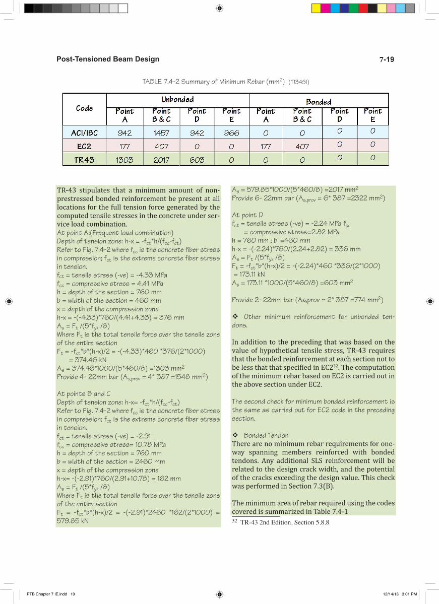
TR-43 stipulates that a minimum amount of non-prestressed bonded reinforcement be present at all locations for the full tension force generated by the computed tensile stresses in the concrete under ser-vice load combination.At point A:(Frequent load combination)Depth of tension zone: h-x = -fct*h/(fcc-fct)Refer to Fig. 7.4-2 where fcc is the concrete fiber stress in compression; fct is the extreme concrete fiber stress in tension.fct = tensile stress (-ve) = -4.33 MPa fcc = compressive stress = 4.41 MPah = depth of the section = 760 mm b = width of the section = 460 mm x = depth of the compression zoneh-x = -(-4.33)*760/(4.41+4.33) = 376 mm As = Ft /(5*fyk /8) Where Ft is the total tensile force over the tensile zone of the entire sectionFt = -fct*b*(h-x)/2 = -(-4.33)*460 *376/(2*1000) = 374.46 kN As = 374.46*1000/(5*460/8) =1303 mm2
Provide 4- 22mm bar (As,prov = 4* 387 =1548 mm2)
At points B and CDepth of tension zone: h-x= -fct*h/(fcc-fct)Refer to Fig. 7.4-2 where fcc is the concrete fiber stress in compression; fct is the extreme concrete fiber stress in tension.fct = tensile stress (-ve) = -2.91 fcc = compressive stress= 10.78 MPah = depth of the section = 760 mm b = width of the section = 2460 mm x = depth of the compression zoneh-x= -(-2.91)*760/(2.91+10.78) = 162 mm As = Ft /(5*fyk /8) Where Ft is the total tensile force over the tensile zone of the entire sectionFt = -fct*b*(h-x)/2 = -(-2.91)*2460 *162/(2*1000) = 579.85 kN
As = 579.85*1000/(5*460/8) =2017 mm2 Provide 6- 22mm bar (As,prov = 6* 387 =2322 mm2)
At point Dfct = tensile stress (-ve) = -2.24 MPa fcc = compressive stress=2.82 MPah = 760 mm ; b =460 mm h-x = -(-2.24)*760/(2.24+2.82) = 336 mm As = Ft /(5*fyk /8) Ft = -fct*b*(h-x)/2 = -(-2.24)*460 *336/(2*1000) = 173.11 kN As = 173.11 *1000/(5*460/8) =603 mm2 Provide 2- 22mm bar (As,prov = 2* 387 =774 mm2)
� Other minimum reinforcement for unbonded ten-dons.
In addition to the preceding that was based on the value of hypothetical tensile stress, TR-43 requires that the bonded reinforcement at each section not to be less that that specified in EC232. The computation of the minimum rebar based on EC2 is carried out in the above section under EC2.
The second check for minimum bonded reinforcement is the same as carried out for EC2 code in the preceding section.
� Bonded TendonThere are no minimum rebar requirements for one-way spanning members reinforced with bonded tendons. Any additional SLS reinforcement will be related to the design crack width, and the potential of the cracks exceeding the design value. This check was performed in Section 7.3(B).
The minimum area of rebar required using the codes covered is summarized in Table 7.4-132 TR-43 2nd Edition, Section 5.8.8
TABLE 7.4-2 Summary of Minimum Rebar (mm2) (T134SI)
PTB Chapter 7 IE.indd 19 12/14/13 3:01 PM

Post-Tensioned Buildings7-20
7.5 Deflection CheckRecognizing that (i) the accurate determination of probable deflection is complex [see Chapter 4, Sec-tion 4.10.6]; and (ii) once a value is determined, the judgment on its adequacy at design time is subjec-tive, and depends on unknown, yet important, pa-rameters such as age of concrete at time of installa-tion of nonstructural members that are likely to be damaged from large displacement. For hand calcu-lation deflection checks are generally based on sim-plified procedures. A rigorous analysis is initiated, only where the parameters of design and applied loads are more reliably known. In most cases, post-tensioned members are sized according to recom-mended span/depth ratios proven to perform well in deflection.33
The simplified procedure includes:(i) For visual and functional effects, total long-term deflection from the day the supports are removed not to exceed span/250 for EC2 or span/240 ACI-318. Camber can be used to offset the impact of dis-placement.(ii) Immediate deflection under design live load not to exceed span/500 for EC2 or span/480 for ACI-318.Both ACI 318/IBC and EC2, tie the deflection ad-equacy to displacement subsequent to the installa-tion of members that are likely to be damaged. This requires knowledge of construction schedule and release of structure for service. In the following the common design practice is followed.
For assessment of long-term displacement in the context of foregoing, ACI-318 recommends a multi-plier factor of 234.
The deflections are calculated using a frame analy-sis program for each of the load cases: dead, live, and post-tensioning. Gross cross-sectional area and linear elastic relationships are used. Since the stress level for which the design was carried out falls essentially in the transition regime, the elastically calculated deflections must be adjusted to allow for cracking at locations where cracking stresses are exceed the threshold of “uncracked” regime. Strictly speaking, a cracked deflec-tion calculation has to be performed,35 where stresses exceed the “transition” regime. However, for hand cal-culation, recognizing that the locations of probable 33 TR-43 2nd Edition, Section 5.8.4; ADAPT-TN29234 ACI multiplier 235 Compter programs, such as ADAPT Floor do cracked deflection calculation
cracks, as in this example are few, the option of “mag-nifying” elastic deformation by a factor that allows for cracking is used.
The critical location is in span 1. The values for span 1 from the frame analysis are:Span 1 DeflectionDead Load 27.8 mmPost-Tensioning -19.2 mmDead Load + PT 8.6 mmLive load deflection 14.5 mm The maximum stress under total loading at midspan is 6.98 MPa. Since this is greater than 0.62 √f’c, adjust-ment to the calculated deflection is required.
There are several options available to adjust elasti-cally calculated deflection values, if the computed tensile stresses exceed cracking. Among the most commonly used are: (i) substitution of the gross mo-ment of inertia (Ig), by an equivalent moment of in-ertia (Ie), followed by the magnification of the elasti-cally calculated deflection by the ratio of (Ig/Ie); and (ii) use of a bilinear deflection calculation, in which the amount of deflection prior to cracking is calcu-lated using Ig and the elastic solution, the deflection after the initiation of crack is calculated for the over-age of load, using the cracked moment of inertia (Icr).
For prestressed sections the equivalent moment of inertia is calculated using the following relationship [PTI design manual, 1990].
Ie = [1 – 0.30*(fmax– 0.5√f’c)/ 0.5√f’c]*Ig f’c is in MPa
Where, Ie is the effective moment of inertia; Ig is the moment of inertia based on the gross cross-section-al area. Initially, the relationship was proposed for fmax not exceeding √f’c. But, it is now used for values above √f’c.
The calculated maximum tensile stressfmax = 6.98 MPa.Reduction in moment of inertia due to cracking:Ie = [1 – 0.30*(fmax – 0.5√f’c)/0.5√f’c]*Ig = [1 – 0.30*(6.98-2.65)/2.65] *Ig = 0.51*IgHence deflection due to dead load and PT = 8.6/0.51 = 16.86 mmLive load deflection with cracking allowance = 14.5/0.51 = 28.43 mm
PTB Chapter 7 IE.indd 20 12/14/13 3:01 PM
7-21Post-Tensioned Beam Design
� Long-term deflectionMultiplier factor assumed for effects of creep and shrinkage on long-term deflection = 236 Load combination for long-term deflection, using a fac-tor of 0.3 for sustained “quasi-permanent” live load :
(1.0*DL + 1.0*PT + 0.3*LL)*(1 + 2)
Long-term deflection: (1 + 2)*(16.86 + 0.3*28.43) = 76.17 mmDeflection ratio = 76.17/(20000) = 1/263 < 1/250 OKInstantaneous deflection due to design live loadLive load deflection = 28.43 mm. Deflection ratio = 28.43/(20,000) = 1/703 OK
Deflection does not generally govern the design for members dimensioned within the limits of the rec-ommended values in ACI 318 and balanced with post-tensioning tendons within the recommended range [Aalami et al, 2003], and when subject to load-ing common in building construction. For such cases, deflections are almost always within the permissible code values, when design is performed within U or T stress values.
8. CODE CHECK FOR STRENGTH 8.1 Load Combinations (i) ACI-318/IBC
36 ACI- 318 multiplier factor
1.2*DL + 1.6*LL + 1*HYP 1.4*DL + 1*HYP (ii) EC2 1.35*DL + 1.5*LL + 1*Hyp (iii) TR43 1.35*DL + 1.5*LL + 0.9*Hyp
For strength combination, the hyperstatic (Hyp) ac-tions (secondary) due to prestressing are used. The background for this is explained in detail in Chapter 4, Section 4.11.2.
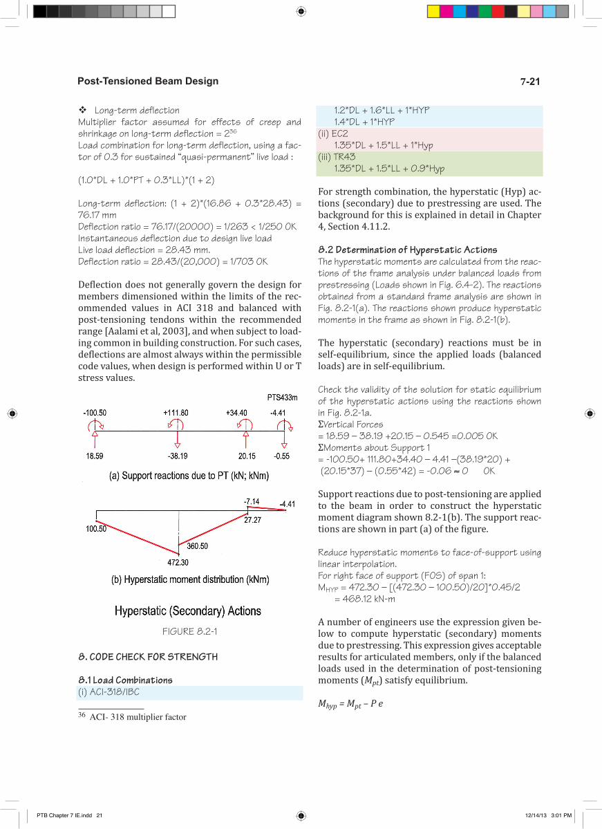
8.2 Determination of Hyperstatic ActionsThe hyperstatic moments are calculated from the reac-tions of the frame analysis under balanced loads from prestressing (Loads shown in Fig. 6.4-2). The reactions obtained from a standard frame analysis are shown in Fig. 8.2-1(a). The reactions shown produce hyperstatic moments in the frame as shown in Fig. 8.2-1(b).
The hyperstatic (secondary) reactions must be in self-equilibrium, since the applied loads (balanced loads) are in self-equilibrium.
Check the validity of the solution for static equilibrium of the hyperstatic actions using the reactions shown in Fig. 8.2-1a.ΣVertical Forces = 18.59 – 38.19 +20.15 – 0.545 =0.005 OKΣMoments about Support 1= -100.50+ 111.80+34.40 – 4.41 –(38.19*20) + (20.15*37) – (0.55*42) = -0.06 ≈ 0 OK
Support reactions due to post-tensioning are applied to the beam in order to construct the hyperstatic moment diagram shown 8.2-1(b). The support reac-tions are shown in part (a) of the figure.
Reduce hyperstatic moments to face-of-support using linear interpolation.For right face of support (FOS) of span 1:MHYP = 472.30 – [(472.30 – 100.50)/20]*0.45/2 = 468.12 kN-m
A number of engineers use the expression given be-low to compute hyperstatic (secondary) moments due to prestressing. This expression gives acceptable results for articulated members, only if the balanced loads used in the determination of post-tensioning moments (Mpt) satisfy equilibrium.
Mhyp = Mpt – P e
FIGURE 8.2-1
PTB Chapter 7 IE.indd 21 12/14/13 3:01 PM

Post-Tensioned Buildings7-22
Where Mhyp is the secondary moment, P is the post-tensioning force, and e is the eccentricity of the post-tensioning. The expression does not afford a validity check, such as the static equilibrium of all hyperstat-ic actions.
8.3 Calculation of Design Moments The design moment (Mu) is the factored combination of dead, live and hyperstatic moments.
� Using ACI/IBCDesign moments are:MU1 = 1.2*MD + 1.6*ML + 1.0*MHYPMU2 = 1.4*MD + 1.0*MHYP
The second combination governs, where dead loads are eight times or larger than live loads. This is rare. The moments shown in Fig. 8.2-1 are centerline mo-ments. These are reduced to the face-of-support in Table 8.3-1.
By inspection, the second load combination does not govern, and will not be considered in the following.
The factored moment computed for EC2 and TR43 are listed in the following table.
8.4 Strength Design for Bending and DuctilityThe strength design for bending consists of two pro-visions, namely
� The design capacity (Ф*Mn; R) shall exceed the demand. A combination of prestressing and non-prestressed steel provides the design capacity
� The ductility of the section in bending shall not be less than the limit set in the associated building code. The required ductility is deemed satisfied, if failure of a section in bending is initiated in post-elastic response of its tension reinforcement, as op-
posed to crushing of concrete. For the codes covered in this example this is achieved through the limita-tion imposed on the depth of the compression zone (see Fig. C-8.4-1 in Chapter 6). The depth of compres-sion zone is generally limited to 50% or less than the distance from the compression fiber to the farthest reinforcement (dr). Since the concrete strain (∊c) at crushing is assumed between 0.003 and 0.0035, the increase in steel strain (∊s) will at minimum be equal to that of concrete at the compression fiber. This will ensure extension of steel beyond its yield point (proof stress) and hence a ductile response.
For expeditious hand calculation, the flexural capac-ity of a post-tensioned member in common build-ing structures can be approximated by assuming a conservative maximum stress for prestressing ten-dons. For detailed application of the code-proposed formulas refer to Chapter 12 for the calculation of a section’s capacity both on the basis of strain com-patibility and approximate code formulas. For daily hand calculation in the a consulting office, unless a software is used use the following simple procedure.
There are two justifications, why the simplified method for ULS design of post-tensioned sections in daily design work are recommended. These are:(i) Unlike conventionally reinforced concrete, where at each section along a member non-prestressed reinforcement must be provided to resist the de-sign moment, in prestressed members this may not be necessary. Prestressed members possess a base capacity along the entire length of prestressing ten-dons (Fig. C-8.4-2b in Chapter 6). Non-prestressed reinforcement is needed only at sections, where the moment demand exceeds the base capacity of the section.(ii) In conventionally reinforced concrete, the stress used for rebar at ULS is well-defined in major build-ing codes. For prestressed sections, however, the
TABLE 8.3-1 Ultimate Design Moments (T135)
PTB Chapter 7 IE.indd 22 12/14/13 3:01 PM

7-23Post-Tensioned Beam Design
stress in tendon at ULS is oftentimes expressed in terms of an involved relationship—hence the ten-dency to use a simplified, but conservative scheme for everyday hand calculation. For repetitive work, computer programs are recommended.
Using strain compatibility procedure 37 the required re-inforcement for each of the three codes are calculated. The outcome is listed in Table 8.4-1.
Using strain compatibility procedure38 the required re-inforcement for each of the three codes are calculated. The outcome is as follows:
� Cracking moment larger than moment capac-ity: Where cracking moment of a section is likely to exceed its nominal capacity in flexure, reinforcement is added to raise the moment capacity. In such cases, the contribution of each reinforcement is based on the strength it provides. If the minimum value is ex-pressed in terms of cross-sectional area of reinforce-ment, the applicable value for this requirement is: (As + Aps* fpy/fy).
37 ADAPT-TN17838 ADAPT-TN178
A. Based on ACI 318-11/IBC 2012 � Bonded (grouted) tendons
ACI 318 39 /IBC stipulates that beams and one-way slabs reinforced with bonded tendons develop a nominal moment capacity at ULS not less than 1.2 times their cracking moment Mcr.
The necessity and amount of rebar is defined as a func-tion of cracking moment of a section (Mcr). For pre ACI-318 Section 9.5.2.3 stressed members
Mcr = (fr + P/A)*SWhere, fr is the modulus of rupture defined 40
fr = 0.625 √f’c = 0.625 √28 = 3.31 MPaP/A is the average precompression, and S the section modulus. The Table 8.4-2 summarizes the leading values and the outcome. The computation of the cracking mo-ment and the nominal capacity are given in the following table.
Since at the selected sections, the design capacity of the section with prestressing alone exceeds 1.2*Mcr, no additional rebar is required from this provision.
39 ACI 318-11 Section 18.8.240 ACI-318 Section 9.5.2.3
FIGURE C8.4-3
TABLE 8.4-2 Cracking Moment Values and the Respective Data (T138SI)
TABLE 8.4-1 Summary of Reinforcement for Strength Limit State (T136SI)
PTB Chapter 7 IE.indd 23 12/14/13 3:01 PM

Post-Tensioned Buildings7-24
In design situations like above, where the design is initiated by determination of whether a value is less or more than a target, it is advisable to start the check using a simplified, but conservative procedure. If the computed value is closer to the target than the ap-proximations in the simplified method, design check can be followed with a more rigorous computation.
Assume the following for simplified calculation:Strand CGS = 70 mmhence d = h (thickness) - 70Moment arm = 0.9dDesign force in strand = Aps*1860 MPa ; Ф = 0.9At midspan, with 12 strandsФ *Mn = 0.9* 12*99 *1860*0.9 *(760 – 70)/106
= 1234.99 kNm
Design moment at other locations are calculated in a similar manner.
B. Based on EC2
� Unbonded tendonsEC2 41 requires that for beams reinforced with un-bonded tendons the total amount of prestressed and nonprestressed shall be adequate to develop a fac-tored load at least 1.15 times the cracking load com-puted on the basis of the modulus of rupture of the section. In practice, this is taken as cracking moment of the section Mcr.
The necessity and amount of rebar is defined as a func-tion of cracking moment of a section (Mcr). For pre-stressed membersMcr = (fr + P/A)*SWhere, fr is the modulus of rupture42 fr = fctm = 0.3fck
(2/3) = 2.77 MPaP/A is the average precompression, and S the section modulus. The Table 8.4-3 summarizes the leading val-ues and the outcome.
Since at the selected sections, the design capacity of the section with prestressing alone exceeds 1.15*Mcr, no additional rebar is required from this provision.
In design situations like above, where the design is initiated by determination of whether a value is less or more than a target, it is advisable to start the check using a simplified, but conservative procedure. If the 41 EN 1992-1-1:2004 (E), Section 9.2.1.1(4)42 EN 1992-1-1:2004 (E), Section 7.1(3). Here tensile stress limit for uncracked section is used.
computed value is close to the target, design check can be followed with a more rigorous computation.Assume the following:Cover to strand CGS = 70 mm; hence d = h (thickness) - 70Moment arm = 0.9dDesign force in strand = Aps*1860 MPa/1.15; At midspan, with 12 strands, 1860 MPa strengthФ *Mn = 12*99 *(1860/1.15)*0.9 *(760 – 70)/106 = 1193.23 kNm
Design moment at other locations are calculated in a similar manner.
Strength computations performed herein were limited to points considered critical by inspection. When spans and loading are not regular, the selec-tion of critical points by inspection becomes diffi-cult. In such cases, stress and strength checks must be performed at a greater number of locations. Also, note that due to the contribution of tendon to ulti-mate strength, and change in drape of tendon along the length of a member, the most critical location for design is not necessarily the location of maximum moment.
The envelope of total reinforcement is given in Table 8.4-4.
8.5 One-Way Shear DesignThe shear design for the right support of span 1 will be followed in detail, since this is the most critical location. The procedure for the shear design of other locations is identical.
A. Based on ACI 318-11/IBC 2012Distribution of design shear is shown in Fig. 8.5-1. The
TABLE 8.4-3 Cracking Moment Values and the Respective Data for EC2
PTB Chapter 7 IE.indd 24 12/14/13 3:01 PM

7-25Post-Tensioned Beam Design
design shear (Vu) is computed from the results of the standard frame analysis performed for the loading con-ditions D, L and PT. The following combination was used:
The design starts with the calculation of vc, the code allowable shear stress contribution of concrete over the shear area of the section
Vu = 1.2*VD + 1.6*VL + 1.0*VHYPSpan 1bw = 460 mmd = 760 –40-22/2 =709 mmpoint of zero shear = 422.05*20/(422.05 + 555.87)= 8.63 mDesign at distance = column width/2 + dFor left support: 350/2 + 709 = 884 mmFor right support: 450/2 + 709 = 934 mmFor left support:Vu = -422.05*(8.63-0.884)/8.63 = -378.82 kN For right support:Vu = 555.87*(20-8.63-0.934)/(20-8.63) = 510.21 kN Hence, the right support governs.bw = 460 mmd = 0.8*h = 0.8*760 = 608 mm
Distance “d” can be calculated from the position of
reinforcement in the section. However, ACI-318-1143 stipulates that d need not be taken less than 0.8h. For hand calculation, this option is used conservatively.
dp = 690mm > 0.8h = 608mmConservatively assumed 608mmvcmin = 0.166*√28 = 0.88 MPavcmax = 0.420√28 = 2.22 MPavc 44 = 0.05*√f’c + 4.8*Vu*d/ MuThe term (Vu*d/ Mu) must be less than 1 or use 1.Vu*d/ Mu = 510.21*608/(1412.22*1000) = 0.22 < 1 OK vc = 0.05*√28 + 4.8*0.22 = 1.32 MPa > vc min = 0.88 MPa < vc max = 2.22 MPa Hence vc = 1.32 MPa governs the design
For this example the ultimate moment was taken at the face-of-support for brevity, while the shear check is done at a distance h/2 away from the support. This assumption is conservative and does not have a sig-nificant impact on the outcome of the calculation. In the general case, the value of Vu*d/ Mu varies along the length of the member. But, it is assumed constant for this expeditious hand calculation.vu = (510.21*1000)/(460*608) = 1.82 MPa > F vc = 0.75*1.32 = 0.99 MPaHence shear reinforcement is required by calculation.Assume 12 mm stirrups with two legs: Av = 2*129 = 258 mm2
The spacing, s, between the stirrups is given by:s = F*Av*fv/[bw (vu – F*vc)] = 0.75*258*460/[460*(1.82 – 0.99)] = 233 mmalso s<= 0.75*h = 0.75*760 = 570 mmand s <= 600mm45
43 ACI 318-11, Section 11.3.144 ACI 318-11, Section 11.3.245 ACI 318-11,Section 11.4.5.1
TABLE 8.4-4 Envelope of Reinforcement for Serviceability (SLS) and Strength Conditions (ULS) (T137SI)
FIGURE 8.5-1
PTB Chapter 7 IE.indd 25 12/14/13 3:01 PM

Post-Tensioned Buildings7-26
Select s = 230mm for the entire region where stirrups by calculation governs.Using similar triangles, the three regions for the calcu-lation of shear reinforcement are worked out and shown graphically in Fig. 8.5-2.For the first region Vu > = F*Vc = 460*608*0.99/1000 = 276.88 kNUse stirrups at 230mm spacing.For the second region Vu > = 0.5*F*Vc =0.5*460*608*0.99/1000 = 138.44 kNUse the minimum value specified by code.For the third region Vu < 0.5*F*Vc = 138.44 kNNo web shear reinforcement required by code. Conserva-tively, use the same stirrups at 570 mm spacing (s <= 0.75 h = 570 mm).For the region governed by the minimum rebar, the spac-ing shall be the smallest of the following:
In the following the three applicable code relation-ships 46 are rearranged to express them in terms of “s” spacing. The format of the relationships in the code is in terms of “Amin .” In this case, since we have already selected a two-legged 12mm bar, we work out the spacing that is appropriate for our selection. Hence, Amin = Av = 2*129 = 258 mm2.
(i) s = Av fv/(0.35 bw) = 258*460/(0.33*460) = 782 mm(ii) s = 80 *Av*(fv/fpu)*d*(bw/d)0.5 /Aps = 80*258 *( 460/1860)*608*(460/608)0.5/1188 = 2272 mm(iii) s = 16*Av*fv/(bw*f’c0.5 ) = 16*258*460/(460*280.5 ) = 780 mmAt the same time, spacing “s” shall not be more than 600 mm, nor 0.75*h=570 mm.Use 12 mm two-legged stirrups at 570 mm on spacing for this region.
B. Based on EC2VED =1.35*VD + 1.5*VL + 1.0*VHYPSpan 1bw = 460 mmd = 760 –40-22/2 =709 mmPoint of zero shear = 441.55*20/(441.55 + 583.62) = 8.61 mDesign at distance = column width/2 + dFor left support: 350/2 + 709 = 884 mmFor right support: 450/2 + 709 =934 mmFor the left support:VED = -441.55*(8.61-0.884)/8.61= -396.22 kN For the right support:
46 ACI 318-11,Sections 11.5.5.3 and 11.5.5.4
VED = 583.62*(20-8.61-0.934)/(20-8.61) = 535.76 kN Hence, the right support governs.VRd,c 47 = [ CRd,c* k*(100*ρ1* fck *)1/3+ k 1* σcp ]*bw *d but not less than (vmin + k 1* σcp) bw *d
Where, fck = 28 MPak = 1+ (200/d)1/2 = 1+(200/709)1/2 = 1.53 < 2.0ρ1 = Asl/ (bw d) = 9* 387/(460* 709) = 0.01068σcp = NED/AC = 1428*103/917100 = 1.56 MPa < 0.2*19 = 3.8 MPaCRd,c = 0.18/γc = 0.18/1.50 = 0.12k 1 = 0.15vmin = 0.035* k3/2* fck 1/2 = 0.035* 1.533/2* 281/2 = 0.35 MPaVRd,c = [ 0.12* 1.53*(100*0.01068* 28*)1/3+ 0.15* 1.56 ]*460 *709/1000 = 262.18 kN 47 EN 1992-1-1:2004 (E ) Section 6.2.2
FIGURE 8.5-2
FIGURE 8.5-3
PTB Chapter 7 IE.indd 26 12/14/13 3:01 PM

7-27Post-Tensioned Beam Design
VRd,cmin = (0.35 + 0.15* 1.56) 460 *709/1000 = 190.47 kNVRd,c = 262.18 kNVED > VRd,c , Shear reinforcement is required by calculation.Assume 12 mm stirrups with two legsAsw = 2*129 mm2 = 258 mm2
The spacing 48, s, between the stirrups is given by:s = (Asw /VRd,s)* z*fywd cotθ Where,Assume θ = 400, cot θ = 1.20VRd,s = VED - VRd,c = 535.76– 262.18 = 273.58 kNz = 0.9 d = 0.9*709 = 638 mms = [258 /(273.58*1000)]* 638*(460/1.15)*1.20 = 289 mmVRd,max 49 = αcw*bw* z* ν1*fcd /(cotθ +tanθ)Where,ν1 50 = 0.6[1-(fck/250)] = 0.53 since fywd > 0.8fykfcd = 19MPaαcw 51 = (1+ σcp/fcd) for σcp = 1.56MPa < 0.25fcd = 0.25*19 =4.75 MPaαcw = (1+ 1.56/19) = 1.08 αcw equation is as per σcp val-ues,
48 EN 1992-1-1:2004 (E ) Exp: 6.849 EN 1992-1-1:2004 (E ) Exp: 6.950 EN 1992-1-1:2004 (E ) Exp: 6.6N51 EN 1992-1-1:2004 (E ) Exp: 6.11aN
VRd,max52 = 1.08 *460* 638* 0.53*19 /(1.20 +0.84)
= 1564.59 kN > 273.58 kN OKSelect s = 280 mm s 53 <= 0.75 d (1+cotα)= 0.75* 709 = 532 mm for the entire region where stirrups by calculation governs.If VED < VRd,c , Use the minimum rebar specified by code 54.For the region governed by the minimum rebar, the spac-ing shall be the following:
In the following the applicable code relationship is re-arranged to express it in terms of “s” spacing. The format of the relationships in the code is in terms of “Amin .” In this case, since we have already selected a two-legged 12mm bar stirrups, we work out the spacing that is appropriate for our selection. Hence, Amin = Av = 2*129 = 258 mm2.
s = Asw*fyk/(0.08*√fck *bw) = 258* 460 /(0.08*√28 *460) = 609 mm At the same time, spacing “s” shall not be more than 532 mm.
52 EN 1992-1-1:2004 (E ) Exp: 6.953 EN 1992-1-1:2004 (E ) Exp: 9.6(N)54 EN 1992-1-1:2004 (E ) Exp: 9.4 &9.5(N)
FIGURE 10.1
PTB Chapter 7 IE.indd 27 12/14/13 3:01 PM

Post-Tensioned Buildings7-28
Use 12 mm two-legged stirrups at 530 mm on spacing for this region.
C. Based on TR-43 55
TR-43 refers to EC2 for one-way shear design. But TR-43 includes the safety factor, γp, in the calculation of 55 TR-43 Second Edition, Section 5.9.1 and 5.9.2.
σcp. Where γp equals 0.9 if the prestress effect is favor-able and 1.1 when it is unfavorable.
Precompresssion (σcp) enhances the shear capacity. Hence, in using the EC2 as outlined in the preceding, reduce the value of precompression by factor 0.9
9. CODE CHECK FOR INITIAL CONDITION
At stressing (i) concrete generally has not reached its design strength; (ii) prestressing force is at its high-est value; and (iii) live load generally envisaged to be counteracted by prestressing is absent. As a result, the stresses experienced by a member can fall outside the envelope of the limits envisaged for the in-ser-vice condition. Hence, post-tensioned members are checked for both tension and compression stresses at transfer of prestressing. Where computed compres-sion stresses exceed the allowable values, stressing is delayed until either concrete gains adequate strength or the member is loaded. Where computed tension stresses are excessive, ACI/IBC56 suggest adding non-prestressed reinforcement to control cracking.
9.1 Load CombinationsThe codes covered are not specific on the applicable load combination at transfer of prestressing. The fol-lowing is the combination generally assumed among practicing engineers.
56 ACI 318-11; Section 18.4
TABLE 9-1 Stresses at Transfer of Post-Tensioning (T139SI)
FIGURE 10-2
PTB Chapter 7 IE.indd 28 12/14/13 3:01 PM

7-29Post-Tensioned Beam Design
Load Case: 1.0*DL + 1.15*PTSpecification of this design example calls for tendons to be stressed with concrete cylinder strength is not less than 20 MPa. f’ci = 20 MPa
9.2 Stress Checkσ = ±(MD + 1.15*MPT)/S + 1.15*P/AS = I/Yc
9.3 Allowable Stresses A. Based on ACI 318-11; IBC 2012Tension = 0.25*√20 = 1.12 MPaCompression = 0.60*20 = -12 Mpa
B. Based on EC2Tension = fcteff = 2.21 MPaCompression = 0.60*20 = -12 Mpa
C. Based on TR-43Tension = 0.72fctm = 1.59 MPaCompression = 0.50*20 = -10 Mpa
Farthest fiber stresses are calculated in a similar man-ner to service condition as outlined earlier. The outcome is summarized in Table 9-1.
If in any of the above locations the stresses exceeded the allowable values the following would have been done.
If compression stresses exceed the allowable value, the design parameters must be modified to bring the stresses within the code limits. If tensile stresses exceed the allowable value, bonded additional rein-forcement (nonprestressed, or prestressed) shall be provided in the tensile zone to resist the total ten-sion force in concrete computed with the assump-tion of an uncracked section.
10. DETAILINGThe final tendon and reinforcement layout for the de-signed beam frame are shown in Fig. 10-1 through 10-3 for unbonded tendons.
REFERENCESAalami, B. O., and Jurgens, J. D. (2003), “Guidelines for the Design of Post-Tensioned Floors,” American Concrete Institute, Concrete International Journal, March 2003, pp. 77-83. (2003)
Aalami, B. O.(1998), “Hyperstatic (Secondary) Ac-tions in Prestressing and Their Computation”, Post-Tensioning Institute, Phoenix, PTI-TN6, pp10, De-cember 1998.
Aalami, B. O.(1993), “One-Way and Two-Way Post-Tensioned Floor Systems ”, Post-Tensioning Institute, Phoenix, PTI Technical Note 3, pp10, October 1993.
Aalami, B. O.(1989), “Design of Post-Tensioned Floor Slabs ”, Concrete International, ACI, June 1989, Vol.11, No 6, pp 59-67.
ACI 318 (2011), “Building Code Requirements for Structural Concrete”, American Concrete Institute, Farmington, MI, pp 503.
EN 1992-1-1:2004, “Eurocode 2: Design of Concrete Structures”, European Committee for Standardization.
TR-43, “Post-Tensioned Concrete Floors Design Hand-book-Second Edition”, The Concrete Society 2005.
ADAPT-PT (2012), “Software for Design of Floor Sys-tems and Beam Frames”, ADAPT Corporation, Red-wood City, CA, www.adaptsoft.com, 2012.
PTB Chapter 7 IE.indd 29 12/14/13 3:01 PM

Post-Tensioned Buildings7-30
FIGURE 7.SI.1 Beam and Slab Construction; Beam Released from Column;Tendons crossed and stressed on stem sides (California; Courtesy DES and ADAPT; P731)
FIGURE 7.SI.2 Beam and Slab Construction; Monolithic Beam-Column Connection;
A number of tendons are crossed over within the beam stem and raised to anchor at slab edge (California; Courtesy DES and ADAPT; P732)
PTB Chapter 7 IE.indd 30 12/14/13 3:01 PM