Beam-Forming-Aware Link-Adaptation for Differential Beam ...
Upload
khangminh22Category
view
1download
0

1
01 CONTENTS
02
16
11e-beam+ [F17]
Floor Members
Floor Joists – Supporting Floor Loads only 16
Floor Joists – For Tiled Floors or Floors Supporting Heavy Furniture 17
Floor Joists – Supporting Parallel Load Bearing Walls Over Openings 18
Lintels – In Single or Upper Storey Load Bearing External Walls 11
Lintels – In Lower Storey Load Bearing External Walls 12
Lintels – Supporting Truncated Girder Truss 14
Lintels – Supporting Strutting Beams 15
Wall Members
04
19
Roof Members
Floor Members
Rafters 4
Roof Beams 6
Counter Beams 8
Verandah Beams 9
Technical Information 03
Bearers – Supporting Floor Loads only 19
Bearers – Supporting Single or Upper Storey Load Bearing Walls 20
Bearers – Supporting Two Storey Load Bearing Walls 22
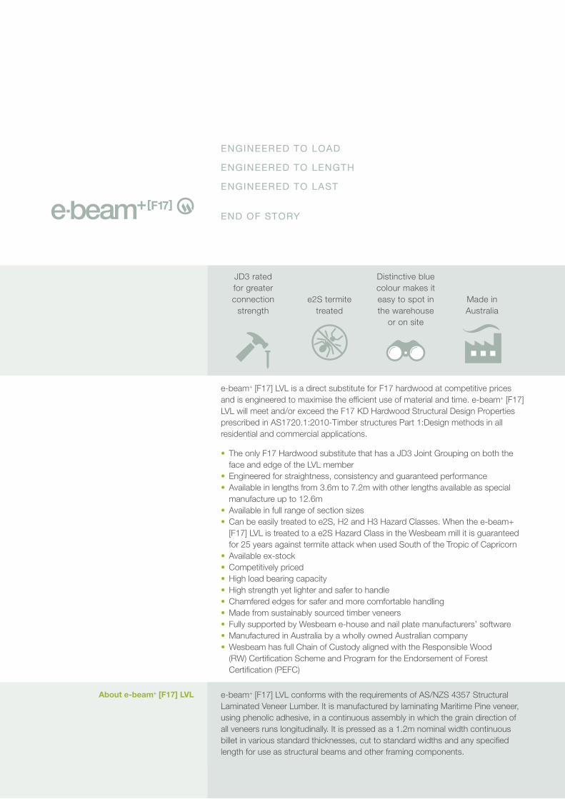
ENGINEERED TO LOAD
ENGINEERED TO LENGTH
ENGINEERED TO LAST
END OF STORY
e-beam+ [F17] LVL is a direct substitute for F17 hardwood at competitive prices and is engineered to maximise the efficient use of material and time. e-beam+ [F17] LVL will meet and/or exceed the F17 KD Hardwood Structural Design Properties prescribed in AS1720.1:2010-Timber structures Part 1:Design methods in all residential and commercial applications.
• The only F17 Hardwood substitute that has a JD3 Joint Grouping on both the face and edge of the LVL member
• Engineered for straightness, consistency and guaranteed performance• Available in lengths from 3.6m to 7.2m with other lengths available as special
manufacture up to 12.6m• Available in full range of section sizes• Can be easily treated to e2S, H2 and H3 Hazard Classes. When the e-beam+
[F17] LVL is treated to a e2S Hazard Class in the Wesbeam mill it is guaranteed for 25 years against termite attack when used South of the Tropic of Capricorn
• Available ex-stock• Competitively priced• High load bearing capacity• High strength yet lighter and safer to handle• Chamfered edges for safer and more comfortable handling• Made from sustainably sourced timber veneers• Fully supported by Wesbeam e-house and nail plate manufacturers’ software• Manufactured in Australia by a wholly owned Australian company• Wesbeam has full Chain of Custody aligned with the Responsible Wood
(RW) Certification Scheme and Program for the Endorsement of Forest Certification (PEFC)
About e-beam+ [F17] LVL e-beam+ [F17] LVL conforms with the requirements of AS/NZS 4357 Structural Laminated Veneer Lumber. It is manufactured by laminating Maritime Pine veneer, using phenolic adhesive, in a continuous assembly in which the grain direction of all veneers runs longitudinally. It is pressed as a 1.2m nominal width continuous billet in various standard thicknesses, cut to standard widths and any specified length for use as structural beams and other framing components.
Made in Australia
e2S termite treated
Distinctive blue colour makes it easy to spot in the warehouse
or on site
JD3 rated for greater connection
strength
03
Use of e-beam+ [F17] LVL Data The tables and other technical data provided in this publication are only applicable to e-beam+ [F17] LVL manufactured by Wesbeam. This data should not be used for look-alike or substitute products. Use of the e-beam+ [F17] LVL data for look-alike or substitute products can result in unsafe or unsatisfactory performance.
Basis for Design The design criteria used to develop the Span Tables contained in this brochure are based on the assumptions listed in AS1720.3: 2016-Timber structures Part 3:Design criteria for timber-framed residential buildings.
Design Loads The design loads used to determine member sizes listed in the Span Tables are as per AS1720.3: 2016-Timber structures Part 3:Design criteria for timber-framed residential buildings. The design loads include:
• Permanent loads• Imposed loads• Wind loads• Snow loads• Earthquake loads, and • Load combinations of the above loads
Design load limitations for each of the above load or load combination cases are also as per AS1720.3: 2016-Timber structures Part 3:Design criteria for timber-framed residential buildings.
Design Capacity Factor (ø) The capacity factor (ø) used to calculate the design capacity of a structural framing member listed in the Span Tables is taken from Table 2 in AS1720.1:2010-Timber structures Part 1:Design methods where for all LVL structural elements used in residential houses ø = 0.95.
Terminology, Definitions and Notations used in these Tables
The terminology, definitions and notations used in this brochure are similar to and consistent with those used and listed in AS1720.3: 2016-Timber structures Part 3:Design criteria for timber-framed residential buildings.
Using Multiple Sections The use of multiple sections where called for in the Span Tables is permitted using vertically nail laminated LVL. Multiple LVL members are to be fixed in accordance with Cl 2.3 of AS1684.2: 2010 Residential timber framed construction Part 2: Non-cyclonic areas.
Characteristic Design Values The characteristic design values for Wesbeam e-beam+ [F17] LVL are available on request from Wesbeam’s Technical Department. This service is available for professional design practioners.
The spans listed in this brochure for e-beam+ [F17] LVL manufactured by Wesbeam apply only when the moisture content of the LVL is below 15% in service and are for “on edge” orientation of the LVL section.
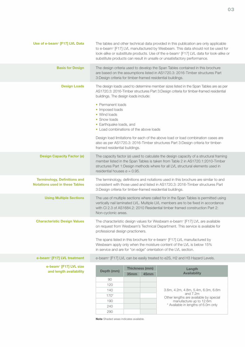
e-beam+ [F17] LVL treatment e-beam+ [F17] LVL can be easily treated to e2S, H2 and H3 Hazard Levels.
e-beam+ [F17] LVL size and length availability Depth (mm)
Thickness (mm) Length Availability 35mm 45mm
90
3.6m, 4.2m, 4.8m, 5.4m, 6.0m, 6.6m and 7.2m
Other lengths are available by special manufacture up to 12.6m
* Available in lengths of 6.0m only
120
140
170*
190
240
290
Note Shaded areas indicates available.
04
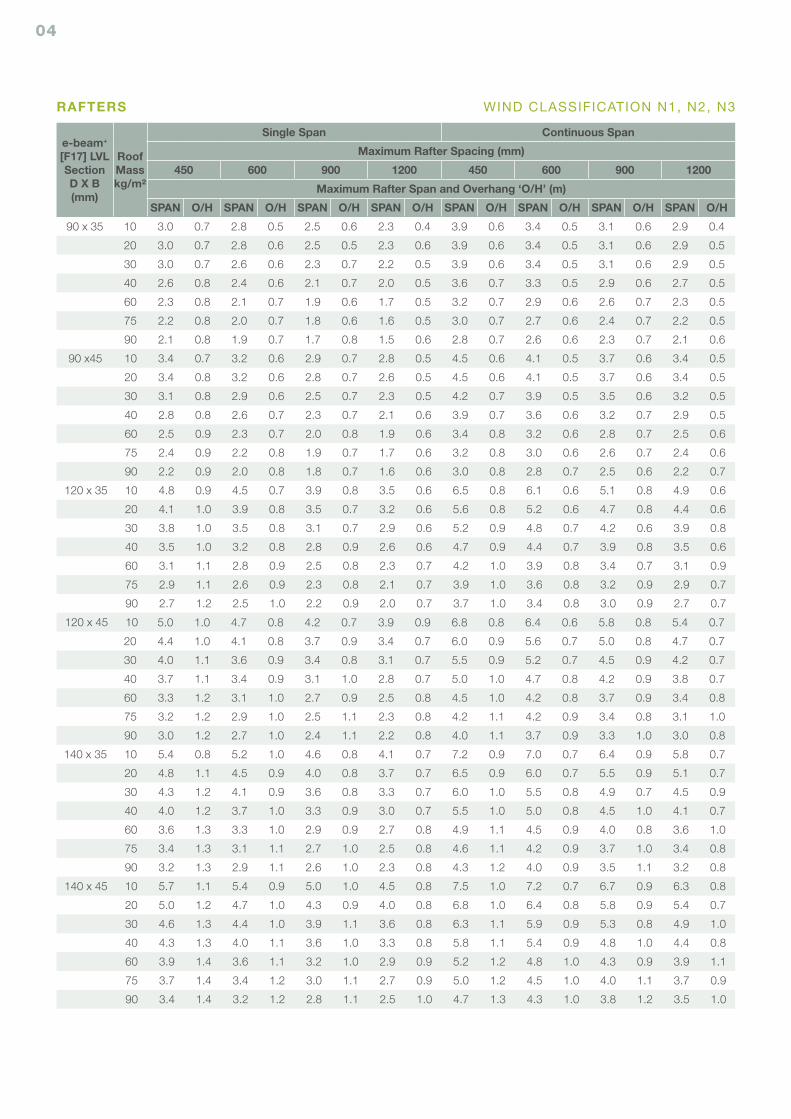
e-beam+ [F17] LVLSectionD X B(mm)
Roof Masskg/m²
Single Span Continuous Span
Maximum Rafter Spacing (mm)
450 600 900 1200 450 600 900 1200
Maximum Rafter Span and Overhang ‘O/H’ (m)
SPAN O/H SPAN O/H SPAN O/H SPAN O/H SPAN O/H SPAN O/H SPAN O/H SPAN O/H
90 x 35 10 3.0 0.7 2.8 0.5 2.5 0.6 2.3 0.4 3.9 0.6 3.4 0.5 3.1 0.6 2.9 0.4
20 3.0 0.7 2.8 0.6 2.5 0.5 2.3 0.6 3.9 0.6 3.4 0.5 3.1 0.6 2.9 0.5
30 3.0 0.7 2.6 0.6 2.3 0.7 2.2 0.5 3.9 0.6 3.4 0.5 3.1 0.6 2.9 0.5
40 2.6 0.8 2.4 0.6 2.1 0.7 2.0 0.5 3.6 0.7 3.3 0.5 2.9 0.6 2.7 0.5
60 2.3 0.8 2.1 0.7 1.9 0.6 1.7 0.5 3.2 0.7 2.9 0.6 2.6 0.7 2.3 0.5
75 2.2 0.8 2.0 0.7 1.8 0.6 1.6 0.5 3.0 0.7 2.7 0.6 2.4 0.7 2.2 0.5
90 2.1 0.8 1.9 0.7 1.7 0.8 1.5 0.6 2.8 0.7 2.6 0.6 2.3 0.7 2.1 0.6
90 x45 10 3.4 0.7 3.2 0.6 2.9 0.7 2.8 0.5 4.5 0.6 4.1 0.5 3.7 0.6 3.4 0.5
20 3.4 0.8 3.2 0.6 2.8 0.7 2.6 0.5 4.5 0.6 4.1 0.5 3.7 0.6 3.4 0.5
30 3.1 0.8 2.9 0.6 2.5 0.7 2.3 0.5 4.2 0.7 3.9 0.5 3.5 0.6 3.2 0.5
40 2.8 0.8 2.6 0.7 2.3 0.7 2.1 0.6 3.9 0.7 3.6 0.6 3.2 0.7 2.9 0.5
60 2.5 0.9 2.3 0.7 2.0 0.8 1.9 0.6 3.4 0.8 3.2 0.6 2.8 0.7 2.5 0.6
75 2.4 0.9 2.2 0.8 1.9 0.7 1.7 0.6 3.2 0.8 3.0 0.6 2.6 0.7 2.4 0.6
90 2.2 0.9 2.0 0.8 1.8 0.7 1.6 0.6 3.0 0.8 2.8 0.7 2.5 0.6 2.2 0.7
120 x 35 10 4.8 0.9 4.5 0.7 3.9 0.8 3.5 0.6 6.5 0.8 6.1 0.6 5.1 0.8 4.9 0.6
20 4.1 1.0 3.9 0.8 3.5 0.7 3.2 0.6 5.6 0.8 5.2 0.6 4.7 0.8 4.4 0.6
30 3.8 1.0 3.5 0.8 3.1 0.7 2.9 0.6 5.2 0.9 4.8 0.7 4.2 0.6 3.9 0.8
40 3.5 1.0 3.2 0.8 2.8 0.9 2.6 0.6 4.7 0.9 4.4 0.7 3.9 0.8 3.5 0.6
60 3.1 1.1 2.8 0.9 2.5 0.8 2.3 0.7 4.2 1.0 3.9 0.8 3.4 0.7 3.1 0.9
75 2.9 1.1 2.6 0.9 2.3 0.8 2.1 0.7 3.9 1.0 3.6 0.8 3.2 0.9 2.9 0.7
90 2.7 1.2 2.5 1.0 2.2 0.9 2.0 0.7 3.7 1.0 3.4 0.8 3.0 0.9 2.7 0.7
120 x 45 10 5.0 1.0 4.7 0.8 4.2 0.7 3.9 0.9 6.8 0.8 6.4 0.6 5.8 0.8 5.4 0.7
20 4.4 1.0 4.1 0.8 3.7 0.9 3.4 0.7 6.0 0.9 5.6 0.7 5.0 0.8 4.7 0.7
30 4.0 1.1 3.6 0.9 3.4 0.8 3.1 0.7 5.5 0.9 5.2 0.7 4.5 0.9 4.2 0.7
40 3.7 1.1 3.4 0.9 3.1 1.0 2.8 0.7 5.0 1.0 4.7 0.8 4.2 0.9 3.8 0.7
60 3.3 1.2 3.1 1.0 2.7 0.9 2.5 0.8 4.5 1.0 4.2 0.8 3.7 0.9 3.4 0.8
75 3.2 1.2 2.9 1.0 2.5 1.1 2.3 0.8 4.2 1.1 4.2 0.9 3.4 0.8 3.1 1.0
90 3.0 1.2 2.7 1.0 2.4 1.1 2.2 0.8 4.0 1.1 3.7 0.9 3.3 1.0 3.0 0.8
140 x 35 10 5.4 0.8 5.2 1.0 4.6 0.8 4.1 0.7 7.2 0.9 7.0 0.7 6.4 0.9 5.8 0.7
20 4.8 1.1 4.5 0.9 4.0 0.8 3.7 0.7 6.5 0.9 6.0 0.7 5.5 0.9 5.1 0.7
30 4.3 1.2 4.1 0.9 3.6 0.8 3.3 0.7 6.0 1.0 5.5 0.8 4.9 0.7 4.5 0.9
40 4.0 1.2 3.7 1.0 3.3 0.9 3.0 0.7 5.5 1.0 5.0 0.8 4.5 1.0 4.1 0.7
60 3.6 1.3 3.3 1.0 2.9 0.9 2.7 0.8 4.9 1.1 4.5 0.9 4.0 0.8 3.6 1.0
75 3.4 1.3 3.1 1.1 2.7 1.0 2.5 0.8 4.6 1.1 4.2 0.9 3.7 1.0 3.4 0.8
90 3.2 1.3 2.9 1.1 2.6 1.0 2.3 0.8 4.3 1.2 4.0 0.9 3.5 1.1 3.2 0.8
140 x 45 10 5.7 1.1 5.4 0.9 5.0 1.0 4.5 0.8 7.5 1.0 7.2 0.7 6.7 0.9 6.3 0.8
20 5.0 1.2 4.7 1.0 4.3 0.9 4.0 0.8 6.8 1.0 6.4 0.8 5.8 0.9 5.4 0.7
30 4.6 1.3 4.4 1.0 3.9 1.1 3.6 0.8 6.3 1.1 5.9 0.9 5.3 0.8 4.9 1.0
40 4.3 1.3 4.0 1.1 3.6 1.0 3.3 0.8 5.8 1.1 5.4 0.9 4.8 1.0 4.4 0.8
60 3.9 1.4 3.6 1.1 3.2 1.0 2.9 0.9 5.2 1.2 4.8 1.0 4.3 0.9 3.9 1.1
75 3.7 1.4 3.4 1.2 3.0 1.1 2.7 0.9 5.0 1.2 4.5 1.0 4.0 1.1 3.7 0.9
90 3.4 1.4 3.2 1.2 2.8 1.1 2.5 1.0 4.7 1.3 4.3 1.0 3.8 1.2 3.5 1.0
RAFTERS WIND CLASSIFICATION N1, N2, N3
05
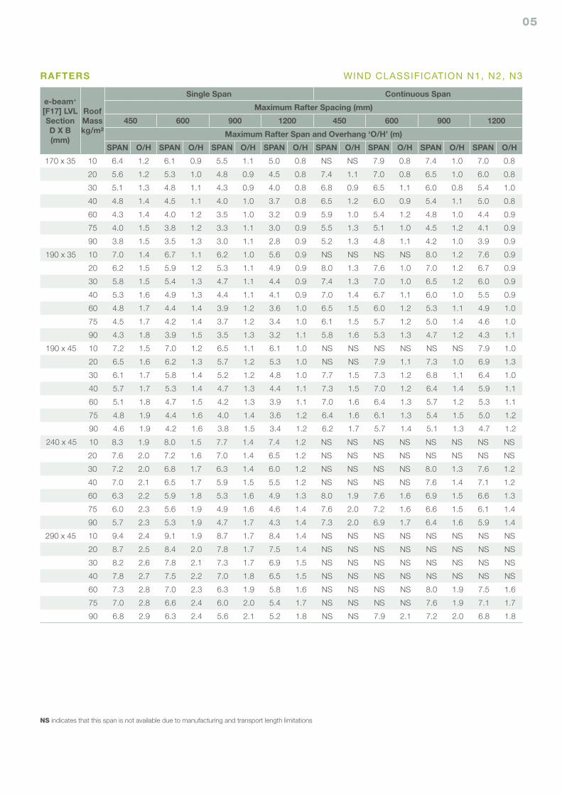
e-beam+ [F17] LVLSectionD X B(mm)
Roof Masskg/m²
Single Span Continuous Span
Maximum Rafter Spacing (mm)
450 600 900 1200 450 600 900 1200
Maximum Rafter Span and Overhang ‘O/H’ (m)
SPAN O/H SPAN O/H SPAN O/H SPAN O/H SPAN O/H SPAN O/H SPAN O/H SPAN O/H
170 x 35 10 6.4 1.2 6.1 0.9 5.5 1.1 5.0 0.8 NS NS 7.9 0.8 7.4 1.0 7.0 0.8
20 5.6 1.2 5.3 1.0 4.8 0.9 4.5 0.8 7.4 1.1 7.0 0.8 6.5 1.0 6.0 0.8
30 5.1 1.3 4.8 1.1 4.3 0.9 4.0 0.8 6.8 0.9 6.5 1.1 6.0 0.8 5.4 1.0
40 4.8 1.4 4.5 1.1 4.0 1.0 3.7 0.8 6.5 1.2 6.0 0.9 5.4 1.1 5.0 0.8
60 4.3 1.4 4.0 1.2 3.5 1.0 3.2 0.9 5.9 1.0 5.4 1.2 4.8 1.0 4.4 0.9
75 4.0 1.5 3.8 1.2 3.3 1.1 3.0 0.9 5.5 1.3 5.1 1.0 4.5 1.2 4.1 0.9
90 3.8 1.5 3.5 1.3 3.0 1.1 2.8 0.9 5.2 1.3 4.8 1.1 4.2 1.0 3.9 0.9
190 x 35 10 7.0 1.4 6.7 1.1 6.2 1.0 5.6 0.9 NS NS NS NS 8.0 1.2 7.6 0.9
20 6.2 1.5 5.9 1.2 5.3 1.1 4.9 0.9 8.0 1.3 7.6 1.0 7.0 1.2 6.7 0.9
30 5.8 1.5 5.4 1.3 4.7 1.1 4.4 0.9 7.4 1.3 7.0 1.0 6.5 1.2 6.0 0.9
40 5.3 1.6 4.9 1.3 4.4 1.1 4.1 0.9 7.0 1.4 6.7 1.1 6.0 1.0 5.5 0.9
60 4.8 1.7 4.4 1.4 3.9 1.2 3.6 1.0 6.5 1.5 6.0 1.2 5.3 1.1 4.9 1.0
75 4.5 1.7 4.2 1.4 3.7 1.2 3.4 1.0 6.1 1.5 5.7 1.2 5.0 1.4 4.6 1.0
90 4.3 1.8 3.9 1.5 3.5 1.3 3.2 1.1 5.8 1.6 5.3 1.3 4.7 1.2 4.3 1.1
190 x 45 10 7.2 1.5 7.0 1.2 6.5 1.1 6.1 1.0 NS NS NS NS NS NS 7.9 1.0
20 6.5 1.6 6.2 1.3 5.7 1.2 5.3 1.0 NS NS 7.9 1.1 7.3 1.0 6.9 1.3
30 6.1 1.7 5.8 1.4 5.2 1.2 4.8 1.0 7.7 1.5 7.3 1.2 6.8 1.1 6.4 1.0
40 5.7 1.7 5.3 1.4 4.7 1.3 4.4 1.1 7.3 1.5 7.0 1.2 6.4 1.4 5.9 1.1
60 5.1 1.8 4.7 1.5 4.2 1.3 3.9 1.1 7.0 1.6 6.4 1.3 5.7 1.2 5.3 1.1
75 4.8 1.9 4.4 1.6 4.0 1.4 3.6 1.2 6.4 1.6 6.1 1.3 5.4 1.5 5.0 1.2
90 4.6 1.9 4.2 1.6 3.8 1.5 3.4 1.2 6.2 1.7 5.7 1.4 5.1 1.3 4.7 1.2
240 x 45 10 8.3 1.9 8.0 1.5 7.7 1.4 7.4 1.2 NS NS NS NS NS NS NS NS
20 7.6 2.0 7.2 1.6 7.0 1.4 6.5 1.2 NS NS NS NS NS NS NS NS
30 7.2 2.0 6.8 1.7 6.3 1.4 6.0 1.2 NS NS NS NS 8.0 1.3 7.6 1.2
40 7.0 2.1 6.5 1.7 5.9 1.5 5.5 1.2 NS NS NS NS 7.6 1.4 7.1 1.2
60 6.3 2.2 5.9 1.8 5.3 1.6 4.9 1.3 8.0 1.9 7.6 1.6 6.9 1.5 6.6 1.3
75 6.0 2.3 5.6 1.9 4.9 1.6 4.6 1.4 7.6 2.0 7.2 1.6 6.6 1.5 6.1 1.4
90 5.7 2.3 5.3 1.9 4.7 1.7 4.3 1.4 7.3 2.0 6.9 1.7 6.4 1.6 5.9 1.4
290 x 45 10 9.4 2.4 9.1 1.9 8.7 1.7 8.4 1.4 NS NS NS NS NS NS NS NS
20 8.7 2.5 8.4 2.0 7.8 1.7 7.5 1.4 NS NS NS NS NS NS NS NS
30 8.2 2.6 7.8 2.1 7.3 1.7 6.9 1.5 NS NS NS NS NS NS NS NS
40 7.8 2.7 7.5 2.2 7.0 1.8 6.5 1.5 NS NS NS NS NS NS NS NS
60 7.3 2.8 7.0 2.3 6.3 1.9 5.8 1.6 NS NS NS NS 8.0 1.9 7.5 1.6
75 7.0 2.8 6.6 2.4 6.0 2.0 5.4 1.7 NS NS NS NS 7.6 1.9 7.1 1.7
90 6.8 2.9 6.3 2.4 5.6 2.1 5.2 1.8 NS NS 7.9 2.1 7.2 2.0 6.8 1.8
NS indicates that this span is not available due to manufacturing and transport length limitations
RAFTERS WIND CLASSIFICATION N1, N2, N3
06
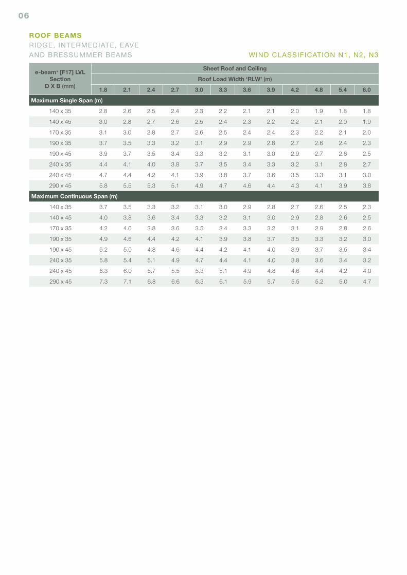
e-beam+ [F17] LVLSection
D X B (mm)
Sheet Roof and Ceiling
Roof Load Width ‘RLW’ (m)
1.8 2.1 2.4 2.7 3.0 3.3 3.6 3.9 4.2 4.8 5.4 6.0
Maximum Single Span (m)
140 x 35 2.8 2.6 2.5 2.4 2.3 2.2 2.1 2.1 2.0 1.9 1.8 1.8
140 x 45 3.0 2.8 2.7 2.6 2.5 2.4 2.3 2.2 2.2 2.1 2.0 1.9
170 x 35 3.1 3.0 2.8 2.7 2.6 2.5 2.4 2.4 2.3 2.2 2.1 2.0
190 x 35 3.7 3.5 3.3 3.2 3.1 2.9 2.9 2.8 2.7 2.6 2.4 2.3
190 x 45 3.9 3.7 3.5 3.4 3.3 3.2 3.1 3.0 2.9 2.7 2.6 2.5
240 x 35 4.4 4.1 4.0 3.8 3.7 3.5 3.4 3.3 3.2 3.1 2.8 2.7
240 x 45 4.7 4.4 4.2 4.1 3.9 3.8 3.7 3.6 3.5 3.3 3.1 3.0
290 x 45 5.8 5.5 5.3 5.1 4.9 4.7 4.6 4.4 4.3 4.1 3.9 3.8
Maximum Continuous Span (m)
140 x 35 3.7 3.5 3.3 3.2 3.1 3.0 2.9 2.8 2.7 2.6 2.5 2.3
140 x 45 4.0 3.8 3.6 3.4 3.3 3.2 3.1 3.0 2.9 2.8 2.6 2.5
170 x 35 4.2 4.0 3.8 3.6 3.5 3.4 3.3 3.2 3.1 2.9 2.8 2.6
190 x 35 4.9 4.6 4.4 4.2 4.1 3.9 3.8 3.7 3.5 3.3 3.2 3.0
190 x 45 5.2 5.0 4.8 4.6 4.4 4.2 4.1 4.0 3.9 3.7 3.5 3.4
240 x 35 5.8 5.4 5.1 4.9 4.7 4.4 4.1 4.0 3.8 3.6 3.4 3.2
240 x 45 6.3 6.0 5.7 5.5 5.3 5.1 4.9 4.8 4.6 4.4 4.2 4.0
290 x 45 7.3 7.1 6.8 6.6 6.3 6.1 5.9 5.7 5.5 5.2 5.0 4.7
ROOF BEAMSRIDGE, INTERMEDIATE, EAVE AND BRESSUMMER BEAMS WIND CLASSIFICATION N1, N2, N3
07
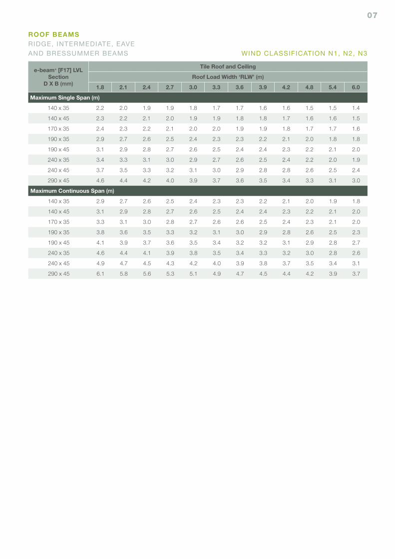
e-beam+ [F17] LVLSection
D X B (mm)
Tile Roof and Ceiling
Roof Load Width ‘RLW’ (m)
1.8 2.1 2.4 2.7 3.0 3.3 3.6 3.9 4.2 4.8 5.4 6.0
Maximum Single Span (m)
140 x 35 2.2 2.0 1.9 1.9 1.8 1.7 1.7 1.6 1.6 1.5 1.5 1.4
140 x 45 2.3 2.2 2.1 2.0 1.9 1.9 1.8 1.8 1.7 1.6 1.6 1.5
170 x 35 2.4 2.3 2.2 2.1 2.0 2.0 1.9 1.9 1.8 1.7 1.7 1.6
190 x 35 2.9 2.7 2.6 2.5 2.4 2.3 2.3 2.2 2.1 2.0 1.8 1.8
190 x 45 3.1 2.9 2.8 2.7 2.6 2.5 2.4 2.4 2.3 2.2 2.1 2.0
240 x 35 3.4 3.3 3.1 3.0 2.9 2.7 2.6 2.5 2.4 2.2 2.0 1.9
240 x 45 3.7 3.5 3.3 3.2 3.1 3.0 2.9 2.8 2.8 2.6 2.5 2.4
290 x 45 4.6 4.4 4.2 4.0 3.9 3.7 3.6 3.5 3.4 3.3 3.1 3.0
Maximum Continuous Span (m)
140 x 35 2.9 2.7 2.6 2.5 2.4 2.3 2.3 2.2 2.1 2.0 1.9 1.8
140 x 45 3.1 2.9 2.8 2.7 2.6 2.5 2.4 2.4 2.3 2.2 2.1 2.0
170 x 35 3.3 3.1 3.0 2.8 2.7 2.6 2.6 2.5 2.4 2.3 2.1 2.0
190 x 35 3.8 3.6 3.5 3.3 3.2 3.1 3.0 2.9 2.8 2.6 2.5 2.3
190 x 45 4.1 3.9 3.7 3.6 3.5 3.4 3.2 3.2 3.1 2.9 2.8 2.7
240 x 35 4.6 4.4 4.1 3.9 3.8 3.5 3.4 3.3 3.2 3.0 2.8 2.6
240 x 45 4.9 4.7 4.5 4.3 4.2 4.0 3.9 3.8 3.7 3.5 3.4 3.1
290 x 45 6.1 5.8 5.6 5.3 5.1 4.9 4.7 4.5 4.4 4.2 3.9 3.7
ROOF BEAMSRIDGE, INTERMEDIATE, EAVE AND BRESSUMMER BEAMS WIND CLASSIFICATION N1, N2, N3
08
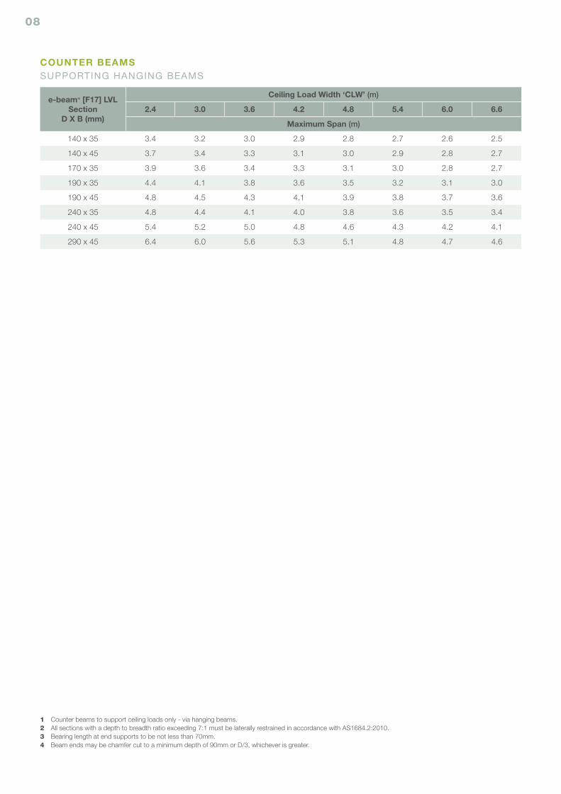
e-beam+ [F17] LVLSection
D X B (mm)
Ceiling Load Width ‘CLW’ (m)
2.4 3.0 3.6 4.2 4.8 5.4 6.0 6.6
Maximum Span (m)
140 x 35 3.4 3.2 3.0 2.9 2.8 2.7 2.6 2.5
140 x 45 3.7 3.4 3.3 3.1 3.0 2.9 2.8 2.7
170 x 35 3.9 3.6 3.4 3.3 3.1 3.0 2.8 2.7
190 x 35 4.4 4.1 3.8 3.6 3.5 3.2 3.1 3.0
190 x 45 4.8 4.5 4.3 4.1 3.9 3.8 3.7 3.6
240 x 35 4.8 4.4 4.1 4.0 3.8 3.6 3.5 3.4
240 x 45 5.4 5.2 5.0 4.8 4.6 4.3 4.2 4.1
290 x 45 6.4 6.0 5.6 5.3 5.1 4.8 4.7 4.6
COUNTER BEAMSSUPPORTING HANGING BEAMS
1 Counter beams to support ceiling loads only - via hanging beams.2 All sections with a depth to breadth ratio exceeding 7:1 must be laterally restrained in accordance with AS1684.2:2010.3 Bearing length at end supports to be not less than 70mm.4 Beam ends may be chamfer cut to a minimum depth of 90mm or D/3, whichever is greater.
09
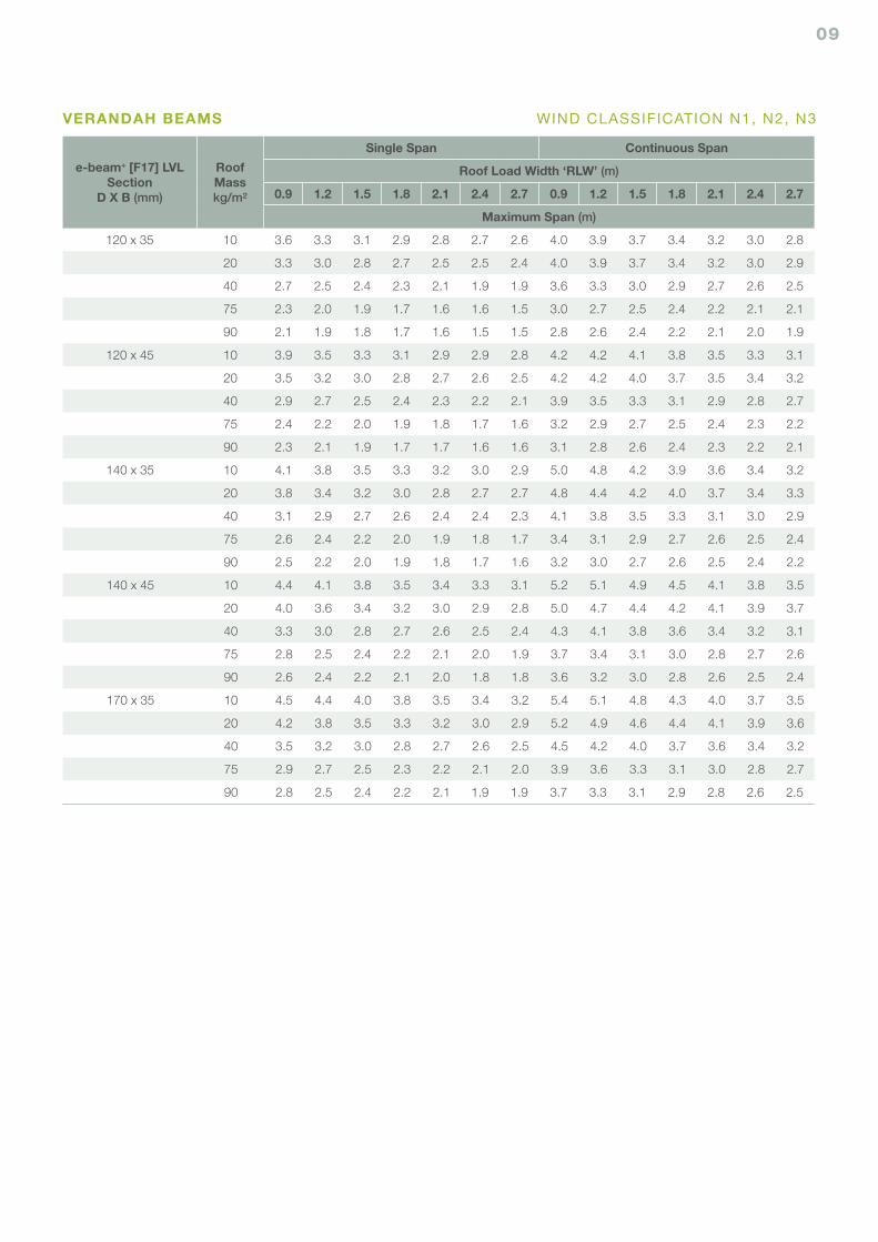
e-beam+ [F17] LVLSection
D X B (mm)
RoofMasskg/m²
Single Span Continuous Span
Roof Load Width ‘RLW’ (m)
0.9 1.2 1.5 1.8 2.1 2.4 2.7 0.9 1.2 1.5 1.8 2.1 2.4 2.7
Maximum Span (m)
120 x 35 10 3.6 3.3 3.1 2.9 2.8 2.7 2.6 4.0 3.9 3.7 3.4 3.2 3.0 2.8
20 3.3 3.0 2.8 2.7 2.5 2.5 2.4 4.0 3.9 3.7 3.4 3.2 3.0 2.9
40 2.7 2.5 2.4 2.3 2.1 1.9 1.9 3.6 3.3 3.0 2.9 2.7 2.6 2.5
75 2.3 2.0 1.9 1.7 1.6 1.6 1.5 3.0 2.7 2.5 2.4 2.2 2.1 2.1
90 2.1 1.9 1.8 1.7 1.6 1.5 1.5 2.8 2.6 2.4 2.2 2.1 2.0 1.9
120 x 45 10 3.9 3.5 3.3 3.1 2.9 2.9 2.8 4.2 4.2 4.1 3.8 3.5 3.3 3.1
20 3.5 3.2 3.0 2.8 2.7 2.6 2.5 4.2 4.2 4.0 3.7 3.5 3.4 3.2
40 2.9 2.7 2.5 2.4 2.3 2.2 2.1 3.9 3.5 3.3 3.1 2.9 2.8 2.7
75 2.4 2.2 2.0 1.9 1.8 1.7 1.6 3.2 2.9 2.7 2.5 2.4 2.3 2.2
90 2.3 2.1 1.9 1.7 1.7 1.6 1.6 3.1 2.8 2.6 2.4 2.3 2.2 2.1
140 x 35 10 4.1 3.8 3.5 3.3 3.2 3.0 2.9 5.0 4.8 4.2 3.9 3.6 3.4 3.2
20 3.8 3.4 3.2 3.0 2.8 2.7 2.7 4.8 4.4 4.2 4.0 3.7 3.4 3.3
40 3.1 2.9 2.7 2.6 2.4 2.4 2.3 4.1 3.8 3.5 3.3 3.1 3.0 2.9
75 2.6 2.4 2.2 2.0 1.9 1.8 1.7 3.4 3.1 2.9 2.7 2.6 2.5 2.4
90 2.5 2.2 2.0 1.9 1.8 1.7 1.6 3.2 3.0 2.7 2.6 2.5 2.4 2.2
140 x 45 10 4.4 4.1 3.8 3.5 3.4 3.3 3.1 5.2 5.1 4.9 4.5 4.1 3.8 3.5
20 4.0 3.6 3.4 3.2 3.0 2.9 2.8 5.0 4.7 4.4 4.2 4.1 3.9 3.7
40 3.3 3.0 2.8 2.7 2.6 2.5 2.4 4.3 4.1 3.8 3.6 3.4 3.2 3.1
75 2.8 2.5 2.4 2.2 2.1 2.0 1.9 3.7 3.4 3.1 3.0 2.8 2.7 2.6
90 2.6 2.4 2.2 2.1 2.0 1.8 1.8 3.6 3.2 3.0 2.8 2.6 2.5 2.4
170 x 35 10 4.5 4.4 4.0 3.8 3.5 3.4 3.2 5.4 5.1 4.8 4.3 4.0 3.7 3.5
20 4.2 3.8 3.5 3.3 3.2 3.0 2.9 5.2 4.9 4.6 4.4 4.1 3.9 3.6
40 3.5 3.2 3.0 2.8 2.7 2.6 2.5 4.5 4.2 4.0 3.7 3.6 3.4 3.2
75 2.9 2.7 2.5 2.3 2.2 2.1 2.0 3.9 3.6 3.3 3.1 3.0 2.8 2.7
90 2.8 2.5 2.4 2.2 2.1 1.9 1.9 3.7 3.3 3.1 2.9 2.8 2.6 2.5
VERANDAH BEAMS WIND CLASSIFICATION N1, N2, N3
10
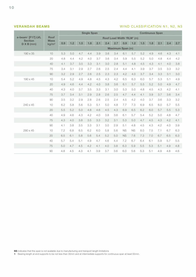
VERANDAH BEAMS
e-beam+ [F17] LVLSection
D X B (mm)
RoofMasskg/m²
Single Span Continuous Span
Roof Load Width ‘RLW’ (m)
0.9 1.2 1.5 1.8 2.1 2.4 2.7 0.9 1.2 1.5 1.8 2.1 2.4 2.7
Maximum Span (m)
190 x 35 10 5.3 5.0 4.7 4.4 3.9 3.6 3.4 6.1 5.7 5.2 4.9 4.6 4.3 4.1
20 4.8 4.4 4.2 4.0 3.7 3.6 3.4 5.9 5.5 5.2 5.0 4.8 4.4 4.2
40 4.1 3.7 3.5 3.3 3.1 3.0 2.8 5.1 4.8 4.5 4.3 4.1 4.0 3.8
75 3.4 3.1 2.9 2.7 2.6 2.5 2.4 4.4 4.1 3.9 3.7 3.5 3.3 3.2
90 3.2 2.9 2.7 2.6 2.5 2.3 2.3 4.2 4.0 3.7 3.4 3.3 3.1 3.0
190 x 45 10 5.4 5.2 4.9 4.8 4.5 4.3 4.2 6.5 6.3 6.0 5.7 5.3 5.1 4.9
20 4.9 4.6 4.4 4.2 4.0 3.8 3.6 6.1 5.7 5.5 5.2 5.0 4.9 4.7
40 4.3 4.0 3.7 3.5 3.3 3.1 3.0 5.3 5.0 4.8 4.5 4.3 4.2 4.1
75 3.7 3.4 3.1 2.9 2.8 2.6 2.5 4.7 4.4 4.1 3.9 3.7 3.6 3.4
90 3.5 3.2 2.9 2.8 2.6 2.5 2.4 4.5 4.2 4.0 3.7 3.6 3.3 3.2
240 x 45 10 6.2 5.8 5.6 5.3 5.1 5.0 4.8 7.7 7.3 6.9 6.5 6.0 5.7 5.5
20 5.5 5.2 5.0 4.8 4.6 4.5 4.3 6.9 6.5 6.2 6.0 5.7 5.5 5.3
40 4.9 4.6 4.3 4.2 4.0 3.8 3.6 6.1 5.7 5.4 5.2 5.0 4.8 4.7
75 4.3 4.0 3.8 3.5 3.3 3.2 3.1 5.3 5.0 4.7 4.5 4.3 4.2 4.1
90 4.1 3.8 3.5 3.3 3.1 3.0 2.9 5.1 4.8 4.5 4.3 4.2 4.0 3.9
290 x 45 10 7.2 6.8 6.5 6.2 6.0 5.8 5.6 NS NS 8.0 7.5 7.1 6.7 6.3
20 6.5 6.1 5.8 5.6 5.4 5.2 5.0 NS 7.6 7.3 7.0 6.7 6.5 6.3
40 5.7 5.4 5.1 4.9 4.7 4.6 4.4 7.2 6.7 6.4 6.1 5.9 5.7 5.5
75 5.0 4.7 4.5 4.2 4.1 4.0 3.8 6.3 5.9 5.5 5.3 5.1 4.9 4.8
90 4.8 4.5 4.3 4.1 3.9 3.7 3.6 6.0 5.6 5.3 5.1 4.9 4.8 4.6
NS indicates that this span is not available due to manufacturing and transport length limitations1 Bearing length at end supports to be not less than 30mm and at intermediate supports for continuous span at least 65mm.
WIND CLASSIFICATION N1, N2, N3
11
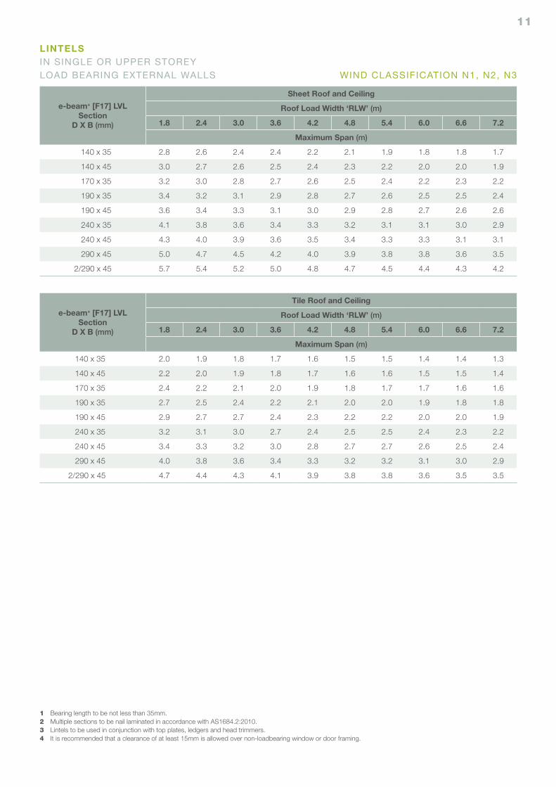
LINTELSIN SINGLE OR UPPER STOREY LOAD BEARING EXTERNAL WALLS
e-beam+ [F17] LVLSection
D X B (mm)
Sheet Roof and Ceiling
Roof Load Width ‘RLW’ (m)
1.8 2.4 3.0 3.6 4.2 4.8 5.4 6.0 6.6 7.2
Maximum Span (m)
140 x 35 2.8 2.6 2.4 2.4 2.2 2.1 1.9 1.8 1.8 1.7
140 x 45 3.0 2.7 2.6 2.5 2.4 2.3 2.2 2.0 2.0 1.9
170 x 35 3.2 3.0 2.8 2.7 2.6 2.5 2.4 2.2 2.3 2.2
190 x 35 3.4 3.2 3.1 2.9 2.8 2.7 2.6 2.5 2.5 2.4
190 x 45 3.6 3.4 3.3 3.1 3.0 2.9 2.8 2.7 2.6 2.6
240 x 35 4.1 3.8 3.6 3.4 3.3 3.2 3.1 3.1 3.0 2.9
240 x 45 4.3 4.0 3.9 3.6 3.5 3.4 3.3 3.3 3.1 3.1
290 x 45 5.0 4.7 4.5 4.2 4.0 3.9 3.8 3.8 3.6 3.5
2/290 x 45 5.7 5.4 5.2 5.0 4.8 4.7 4.5 4.4 4.3 4.2
e-beam+ [F17] LVLSection
D X B (mm)
Tile Roof and Ceiling
Roof Load Width ‘RLW’ (m)
1.8 2.4 3.0 3.6 4.2 4.8 5.4 6.0 6.6 7.2
Maximum Span (m)
140 x 35 2.0 1.9 1.8 1.7 1.6 1.5 1.5 1.4 1.4 1.3
140 x 45 2.2 2.0 1.9 1.8 1.7 1.6 1.6 1.5 1.5 1.4
170 x 35 2.4 2.2 2.1 2.0 1.9 1.8 1.7 1.7 1.6 1.6
190 x 35 2.7 2.5 2.4 2.2 2.1 2.0 2.0 1.9 1.8 1.8
190 x 45 2.9 2.7 2.7 2.4 2.3 2.2 2.2 2.0 2.0 1.9
240 x 35 3.2 3.1 3.0 2.7 2.4 2.5 2.5 2.4 2.3 2.2
240 x 45 3.4 3.3 3.2 3.0 2.8 2.7 2.7 2.6 2.5 2.4
290 x 45 4.0 3.8 3.6 3.4 3.3 3.2 3.2 3.1 3.0 2.9
2/290 x 45 4.7 4.4 4.3 4.1 3.9 3.8 3.8 3.6 3.5 3.5
1 Bearing length to be not less than 35mm.2 Multiple sections to be nail laminated in accordance with AS1684.2:2010.3 Lintels to be used in conjunction with top plates, ledgers and head trimmers.4 It is recommended that a clearance of at least 15mm is allowed over non-loadbearing window or door framing.
WIND CLASSIFICATION N1, N2, N3
12
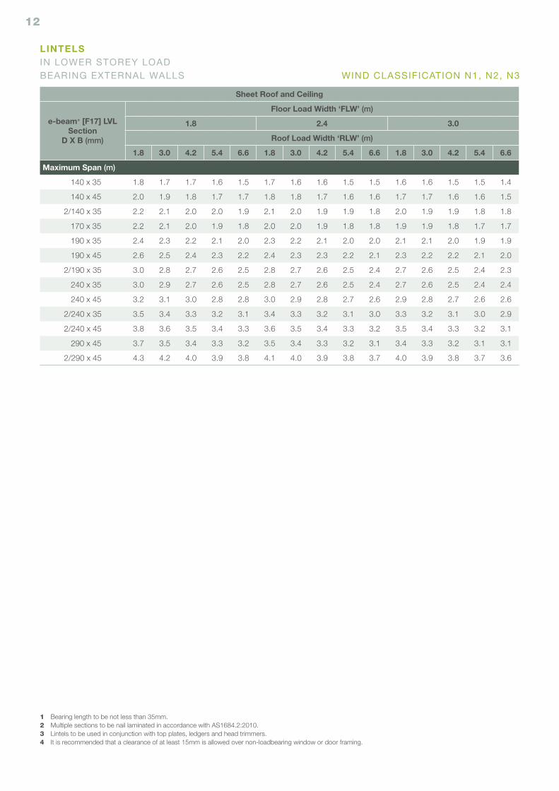
Sheet Roof and Ceiling
e-beam+ [F17] LVLSection
D X B (mm)
Floor Load Width ‘FLW’ (m)
1.8 2.4 3.0
Roof Load Width ‘RLW’ (m)
1.8 3.0 4.2 5.4 6.6 1.8 3.0 4.2 5.4 6.6 1.8 3.0 4.2 5.4 6.6
Maximum Span (m)
140 x 35 1.8 1.7 1.7 1.6 1.5 1.7 1.6 1.6 1.5 1.5 1.6 1.6 1.5 1.5 1.4
140 x 45 2.0 1.9 1.8 1.7 1.7 1.8 1.8 1.7 1.6 1.6 1.7 1.7 1.6 1.6 1.5
2/140 x 35 2.2 2.1 2.0 2.0 1.9 2.1 2.0 1.9 1.9 1.8 2.0 1.9 1.9 1.8 1.8
170 x 35 2.2 2.1 2.0 1.9 1.8 2.0 2.0 1.9 1.8 1.8 1.9 1.9 1.8 1.7 1.7
190 x 35 2.4 2.3 2.2 2.1 2.0 2.3 2.2 2.1 2.0 2.0 2.1 2.1 2.0 1.9 1.9
190 x 45 2.6 2.5 2.4 2.3 2.2 2.4 2.3 2.3 2.2 2.1 2.3 2.2 2.2 2.1 2.0
2/190 x 35 3.0 2.8 2.7 2.6 2.5 2.8 2.7 2.6 2.5 2.4 2.7 2.6 2.5 2.4 2.3
240 x 35 3.0 2.9 2.7 2.6 2.5 2.8 2.7 2.6 2.5 2.4 2.7 2.6 2.5 2.4 2.4
240 x 45 3.2 3.1 3.0 2.8 2.8 3.0 2.9 2.8 2.7 2.6 2.9 2.8 2.7 2.6 2.6
2/240 x 35 3.5 3.4 3.3 3.2 3.1 3.4 3.3 3.2 3.1 3.0 3.3 3.2 3.1 3.0 2.9
2/240 x 45 3.8 3.6 3.5 3.4 3.3 3.6 3.5 3.4 3.3 3.2 3.5 3.4 3.3 3.2 3.1
290 x 45 3.7 3.5 3.4 3.3 3.2 3.5 3.4 3.3 3.2 3.1 3.4 3.3 3.2 3.1 3.1
2/290 x 45 4.3 4.2 4.0 3.9 3.8 4.1 4.0 3.9 3.8 3.7 4.0 3.9 3.8 3.7 3.6
1 Bearing length to be not less than 35mm.2 Multiple sections to be nail laminated in accordance with AS1684.2:2010.3 Lintels to be used in conjunction with top plates, ledgers and head trimmers.4 It is recommended that a clearance of at least 15mm is allowed over non-loadbearing window or door framing.
LINTELSIN LOWER STOREY LOAD BEARING EXTERNAL WALLS WIND CLASSIFICATION N1, N2, N3
13
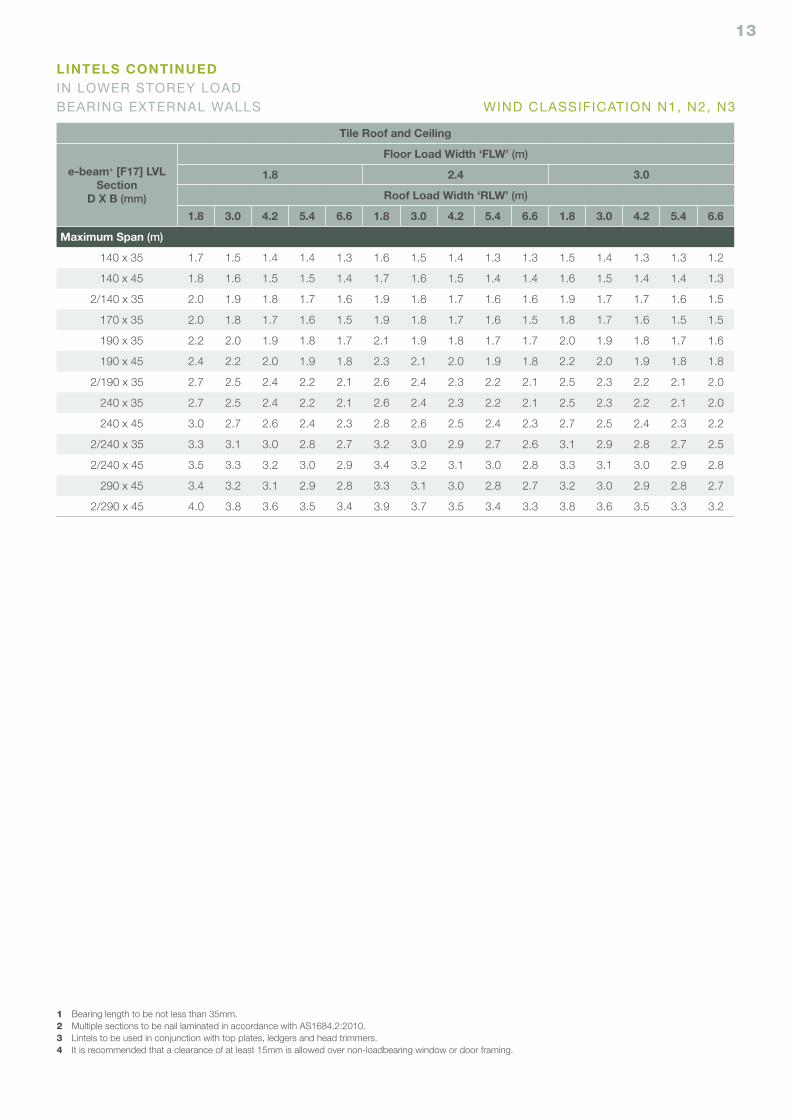
Tile Roof and Ceiling
e-beam+ [F17] LVLSection
D X B (mm)
Floor Load Width ‘FLW’ (m)
1.8 2.4 3.0
Roof Load Width ‘RLW’ (m)
1.8 3.0 4.2 5.4 6.6 1.8 3.0 4.2 5.4 6.6 1.8 3.0 4.2 5.4 6.6
Maximum Span (m)
140 x 35 1.7 1.5 1.4 1.4 1.3 1.6 1.5 1.4 1.3 1.3 1.5 1.4 1.3 1.3 1.2
140 x 45 1.8 1.6 1.5 1.5 1.4 1.7 1.6 1.5 1.4 1.4 1.6 1.5 1.4 1.4 1.3
2/140 x 35 2.0 1.9 1.8 1.7 1.6 1.9 1.8 1.7 1.6 1.6 1.9 1.7 1.7 1.6 1.5
170 x 35 2.0 1.8 1.7 1.6 1.5 1.9 1.8 1.7 1.6 1.5 1.8 1.7 1.6 1.5 1.5
190 x 35 2.2 2.0 1.9 1.8 1.7 2.1 1.9 1.8 1.7 1.7 2.0 1.9 1.8 1.7 1.6
190 x 45 2.4 2.2 2.0 1.9 1.8 2.3 2.1 2.0 1.9 1.8 2.2 2.0 1.9 1.8 1.8
2/190 x 35 2.7 2.5 2.4 2.2 2.1 2.6 2.4 2.3 2.2 2.1 2.5 2.3 2.2 2.1 2.0
240 x 35 2.7 2.5 2.4 2.2 2.1 2.6 2.4 2.3 2.2 2.1 2.5 2.3 2.2 2.1 2.0
240 x 45 3.0 2.7 2.6 2.4 2.3 2.8 2.6 2.5 2.4 2.3 2.7 2.5 2.4 2.3 2.2
2/240 x 35 3.3 3.1 3.0 2.8 2.7 3.2 3.0 2.9 2.7 2.6 3.1 2.9 2.8 2.7 2.5
2/240 x 45 3.5 3.3 3.2 3.0 2.9 3.4 3.2 3.1 3.0 2.8 3.3 3.1 3.0 2.9 2.8
290 x 45 3.4 3.2 3.1 2.9 2.8 3.3 3.1 3.0 2.8 2.7 3.2 3.0 2.9 2.8 2.7
2/290 x 45 4.0 3.8 3.6 3.5 3.4 3.9 3.7 3.5 3.4 3.3 3.8 3.6 3.5 3.3 3.2
1 Bearing length to be not less than 35mm.2 Multiple sections to be nail laminated in accordance with AS1684.2:2010.3 Lintels to be used in conjunction with top plates, ledgers and head trimmers.4 It is recommended that a clearance of at least 15mm is allowed over non-loadbearing window or door framing.
LINTELS CONTINUEDIN LOWER STOREY LOAD BEARING EXTERNAL WALLS WIND CLASSIFICATION N1, N2, N3
14
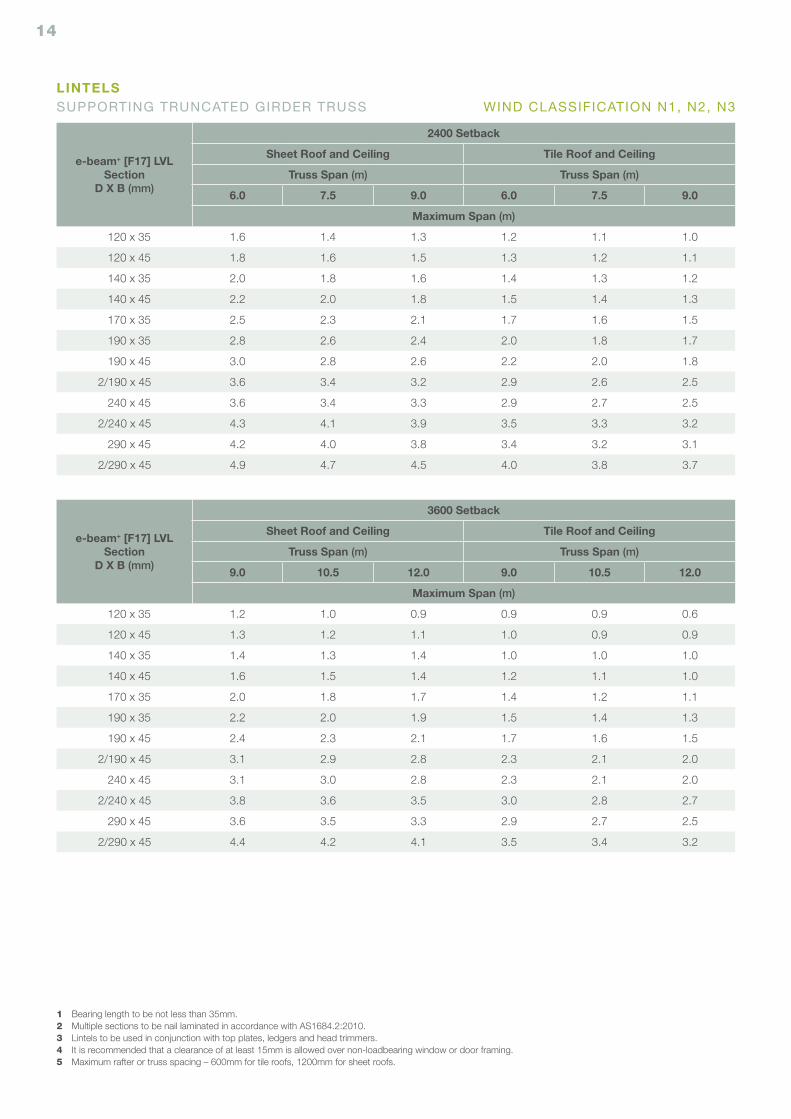
e-beam+ [F17] LVLSection
D X B (mm)
3600 Setback
Sheet Roof and Ceiling Tile Roof and Ceiling
Truss Span (m) Truss Span (m)
9.0 10.5 12.0 9.0 10.5 12.0
Maximum Span (m)
120 x 35 1.2 1.0 0.9 0.9 0.9 0.6
120 x 45 1.3 1.2 1.1 1.0 0.9 0.9
140 x 35 1.4 1.3 1.4 1.0 1.0 1.0
140 x 45 1.6 1.5 1.4 1.2 1.1 1.0
170 x 35 2.0 1.8 1.7 1.4 1.2 1.1
190 x 35 2.2 2.0 1.9 1.5 1.4 1.3
190 x 45 2.4 2.3 2.1 1.7 1.6 1.5
2/190 x 45 3.1 2.9 2.8 2.3 2.1 2.0
240 x 45 3.1 3.0 2.8 2.3 2.1 2.0
2/240 x 45 3.8 3.6 3.5 3.0 2.8 2.7
290 x 45 3.6 3.5 3.3 2.9 2.7 2.5
2/290 x 45 4.4 4.2 4.1 3.5 3.4 3.2
e-beam+ [F17] LVLSection
D X B (mm)
2400 Setback
Sheet Roof and Ceiling Tile Roof and Ceiling
Truss Span (m) Truss Span (m)
6.0 7.5 9.0 6.0 7.5 9.0
Maximum Span (m)
120 x 35 1.6 1.4 1.3 1.2 1.1 1.0
120 x 45 1.8 1.6 1.5 1.3 1.2 1.1
140 x 35 2.0 1.8 1.6 1.4 1.3 1.2
140 x 45 2.2 2.0 1.8 1.5 1.4 1.3
170 x 35 2.5 2.3 2.1 1.7 1.6 1.5
190 x 35 2.8 2.6 2.4 2.0 1.8 1.7
190 x 45 3.0 2.8 2.6 2.2 2.0 1.8
2/190 x 45 3.6 3.4 3.2 2.9 2.6 2.5
240 x 45 3.6 3.4 3.3 2.9 2.7 2.5
2/240 x 45 4.3 4.1 3.9 3.5 3.3 3.2
290 x 45 4.2 4.0 3.8 3.4 3.2 3.1
2/290 x 45 4.9 4.7 4.5 4.0 3.8 3.7
1 Bearing length to be not less than 35mm.2 Multiple sections to be nail laminated in accordance with AS1684.2:2010.3 Lintels to be used in conjunction with top plates, ledgers and head trimmers.4 It is recommended that a clearance of at least 15mm is allowed over non-loadbearing window or door framing.5 Maximum rafter or truss spacing – 600mm for tile roofs, 1200mm for sheet roofs.
LINTELSSUPPORTING TRUNCATED GIRDER TRUSS WIND CLASSIFICATION N1, N2, N3
15
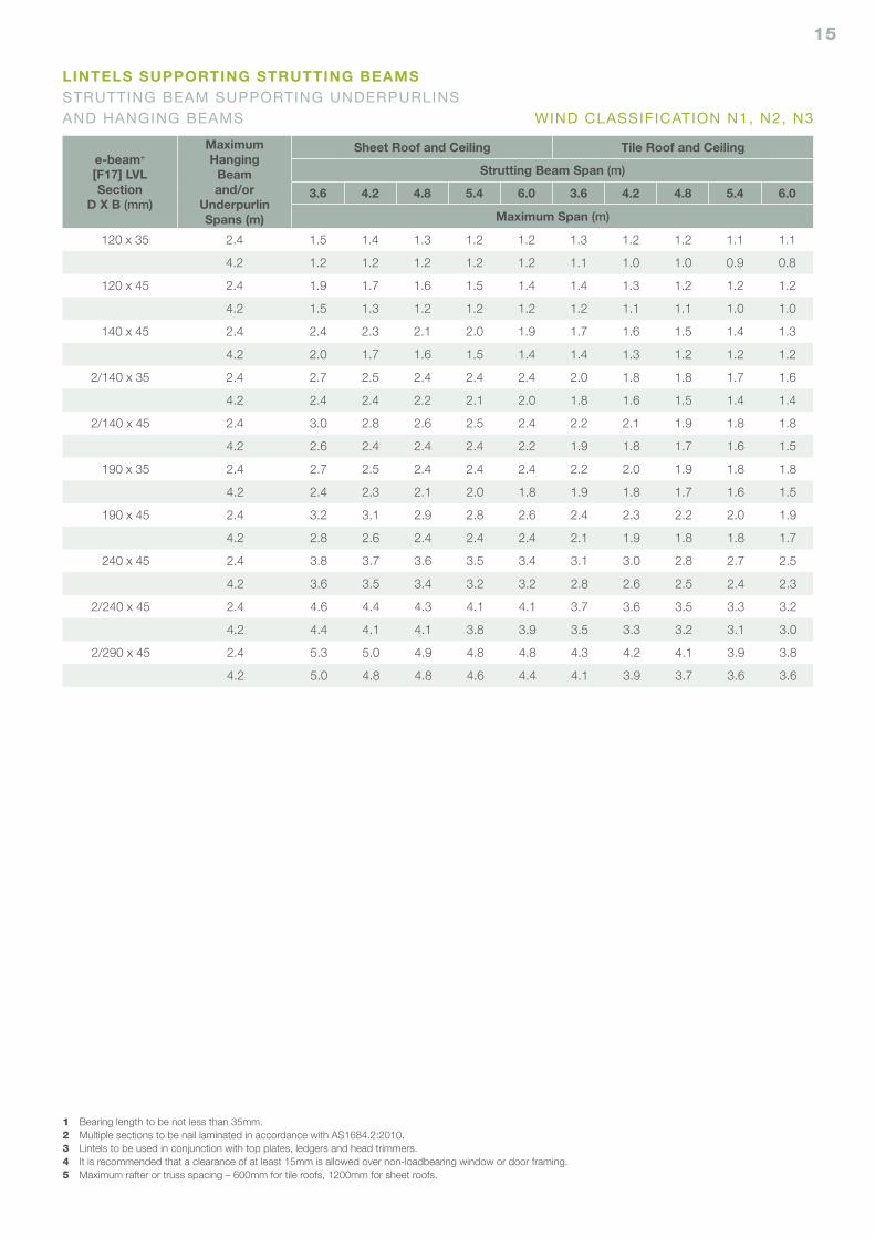
e-beam+ [F17] LVLSection
D X B (mm)
MaximumHanging
Beamand/or
UnderpurlinSpans (m)
Sheet Roof and Ceiling Tile Roof and Ceiling
Strutting Beam Span (m)
3.6 4.2 4.8 5.4 6.0 3.6 4.2 4.8 5.4 6.0
Maximum Span (m)
120 x 35 2.4 1.5 1.4 1.3 1.2 1.2 1.3 1.2 1.2 1.1 1.1
4.2 1.2 1.2 1.2 1.2 1.2 1.1 1.0 1.0 0.9 0.8
120 x 45 2.4 1.9 1.7 1.6 1.5 1.4 1.4 1.3 1.2 1.2 1.2
4.2 1.5 1.3 1.2 1.2 1.2 1.2 1.1 1.1 1.0 1.0
140 x 45 2.4 2.4 2.3 2.1 2.0 1.9 1.7 1.6 1.5 1.4 1.3
4.2 2.0 1.7 1.6 1.5 1.4 1.4 1.3 1.2 1.2 1.2
2/140 x 35 2.4 2.7 2.5 2.4 2.4 2.4 2.0 1.8 1.8 1.7 1.6
4.2 2.4 2.4 2.2 2.1 2.0 1.8 1.6 1.5 1.4 1.4
2/140 x 45 2.4 3.0 2.8 2.6 2.5 2.4 2.2 2.1 1.9 1.8 1.8
4.2 2.6 2.4 2.4 2.4 2.2 1.9 1.8 1.7 1.6 1.5
190 x 35 2.4 2.7 2.5 2.4 2.4 2.4 2.2 2.0 1.9 1.8 1.8
4.2 2.4 2.3 2.1 2.0 1.8 1.9 1.8 1.7 1.6 1.5
190 x 45 2.4 3.2 3.1 2.9 2.8 2.6 2.4 2.3 2.2 2.0 1.9
4.2 2.8 2.6 2.4 2.4 2.4 2.1 1.9 1.8 1.8 1.7
240 x 45 2.4 3.8 3.7 3.6 3.5 3.4 3.1 3.0 2.8 2.7 2.5
4.2 3.6 3.5 3.4 3.2 3.2 2.8 2.6 2.5 2.4 2.3
2/240 x 45 2.4 4.6 4.4 4.3 4.1 4.1 3.7 3.6 3.5 3.3 3.2
4.2 4.4 4.1 4.1 3.8 3.9 3.5 3.3 3.2 3.1 3.0
2/290 x 45 2.4 5.3 5.0 4.9 4.8 4.8 4.3 4.2 4.1 3.9 3.8
4.2 5.0 4.8 4.8 4.6 4.4 4.1 3.9 3.7 3.6 3.6
1 Bearing length to be not less than 35mm.2 Multiple sections to be nail laminated in accordance with AS1684.2:2010.3 Lintels to be used in conjunction with top plates, ledgers and head trimmers.4 It is recommended that a clearance of at least 15mm is allowed over non-loadbearing window or door framing.5 Maximum rafter or truss spacing – 600mm for tile roofs, 1200mm for sheet roofs.
LINTELS SUPPORTING STRUTTING BEAMSSTRUTTING BEAM SUPPORTING UNDERPURLINS AND HANGING BEAMS WIND CLASSIFICATION N1, N2, N3
16
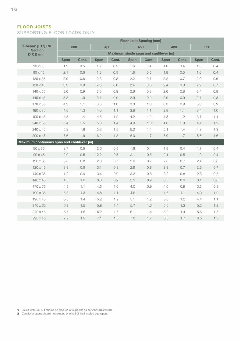
e-beam+ [F17] LVLSection
D X B (mm)
Floor Joist Spacing (mm)
300 400 450 480 600
Maximum single span and cantilever (m)
Span Cant. Span Cant. Span Cant. Span Cant. Span Cant.
90 x 35 1.9 0.5 1.7 0.5 1.6 0.4 1.6 0.4 1.5 0.4
90 x 45 2.1 0.6 1.8 0.5 1.8 0.5 1.8 0.5 1.6 0.4
120 x 35 2.9 0.8 2.3 0.8 2.2 0.7 2.2 0.7 2.0 0.6
120 x 45 3.3 0.9 2.6 0.8 2.4 0.8 2.4 0.8 2.2 0.7
140 x 35 3.6 0.9 2.8 0.9 2.6 0.8 2.6 0.8 2.4 0.8
140 x 45 3.8 1.0 3.1 0.9 2.9 0.9 2.9 0.9 2.7 0.8
170 x 35 4.2 1.1 3.5 1.0 3.3 1.0 3.3 0.9 3.0 0.9
190 x 35 4.5 1.3 4.0 1.1 3.8 1.1 3.8 1.1 3.4 1.0
190 x 45 4.8 1.4 4.5 1.2 4.2 1.2 4.3 1.2 3.7 1.1
240 x 35 5.4 1.5 5.0 1.4 4.9 1.3 4.8 1.3 4.4 1.2
240 x 45 5.8 1.6 5.3 1.5 5.2 1.4 5.1 1.4 4.8 1.3
290 x 45 6.6 1.9 6.2 1.8 6.0 1.7 5.9 1.7 5.6 1.6
Maximum continuous span and cantilever (m)
90 x 35 2.7 0.5 2.0 0.5 1.9 0.4 1.9 0.4 1.7 0.4
90 x 45 2.9 0.5 2.2 0.5 2.1 0.5 2.1 0.5 1.9 0.4
120 x 35 3.6 0.8 2.8 0.7 2.6 0.7 2.6 0.7 2.4 0.6
120 x 45 3.9 0.9 3.1 0.8 2.9 0.8 2.9 0.7 2.6 0.7
140 x 35 4.2 0.9 3.4 0.9 3.2 0.8 3.2 0.8 2.8 0.7
140 x 45 4.5 1.0 3.8 0.9 3.5 0.9 3.5 0.9 3.1 0.8
170 x 35 4.9 1.1 4.5 1.0 4.0 0.9 4.0 0.9 3.5 0.8
190 x 35 5.3 1.3 4.8 1.1 4.6 1.1 4.6 1.1 4.0 1.0
190 x 45 5.6 1.4 5.2 1.2 5.1 1.2 5.0 1.2 4.4 1.1
240 x 35 6.3 1.5 5.8 1.4 5.7 1.3 5.5 1.3 5.2 1.2
240 x 45 6.7 1.6 6.2 1.5 6.1 1.4 5.9 1.4 5.6 1.3
290 x 45 7.2 1.9 7.1 1.8 7.0 1.7 6.8 1.7 6.5 1.6
1 Joists with D/B > 4 should be blocked at supports as per AS1684.2:2010.2 Cantilever spans should not exceed one half of the installed backspan.
FLOOR JOISTSSUPPORTING FLOOR LOADS ONLY
17
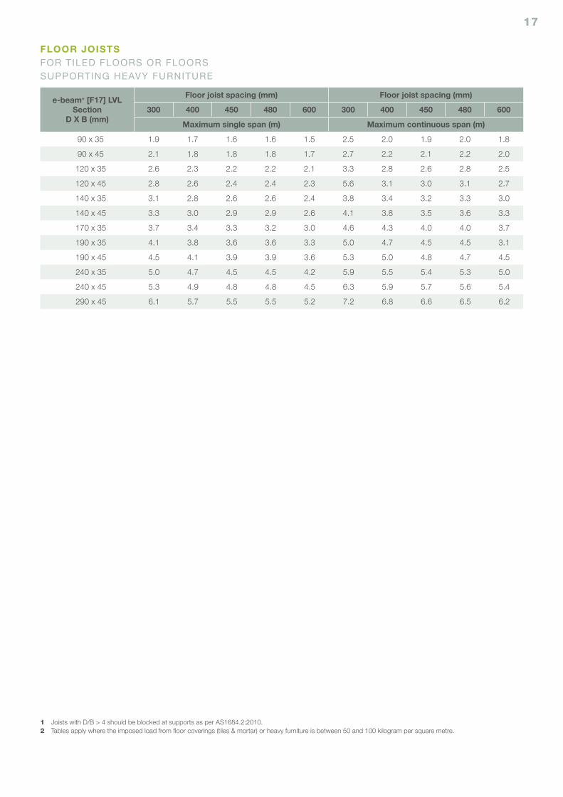
e-beam+ [F17] LVLSection
D X B (mm)
Floor joist spacing (mm) Floor joist spacing (mm)
300 400 450 480 600 300 400 450 480 600
Maximum single span (m) Maximum continuous span (m)
90 x 35 1.9 1.7 1.6 1.6 1.5 2.5 2.0 1.9 2.0 1.8
90 x 45 2.1 1.8 1.8 1.8 1.7 2.7 2.2 2.1 2.2 2.0
120 x 35 2.6 2.3 2.2 2.2 2.1 3.3 2.8 2.6 2.8 2.5
120 x 45 2.8 2.6 2.4 2.4 2.3 5.6 3.1 3.0 3.1 2.7
140 x 35 3.1 2.8 2.6 2.6 2.4 3.8 3.4 3.2 3.3 3.0
140 x 45 3.3 3.0 2.9 2.9 2.6 4.1 3.8 3.5 3.6 3.3
170 x 35 3.7 3.4 3.3 3.2 3.0 4.6 4.3 4.0 4.0 3.7
190 x 35 4.1 3.8 3.6 3.6 3.3 5.0 4.7 4.5 4.5 3.1
190 x 45 4.5 4.1 3.9 3.9 3.6 5.3 5.0 4.8 4.7 4.5
240 x 35 5.0 4.7 4.5 4.5 4.2 5.9 5.5 5.4 5.3 5.0
240 x 45 5.3 4.9 4.8 4.8 4.5 6.3 5.9 5.7 5.6 5.4
290 x 45 6.1 5.7 5.5 5.5 5.2 7.2 6.8 6.6 6.5 6.2
1 Joists with D/B > 4 should be blocked at supports as per AS1684.2:2010.2 Tables apply where the imposed load from floor coverings (tiles & mortar) or heavy furniture is between 50 and 100 kilogram per square metre.
FLOOR JOISTSFOR TILED FLOORS OR FLOORS SUPPORTING HEAVY FURNITURE
18
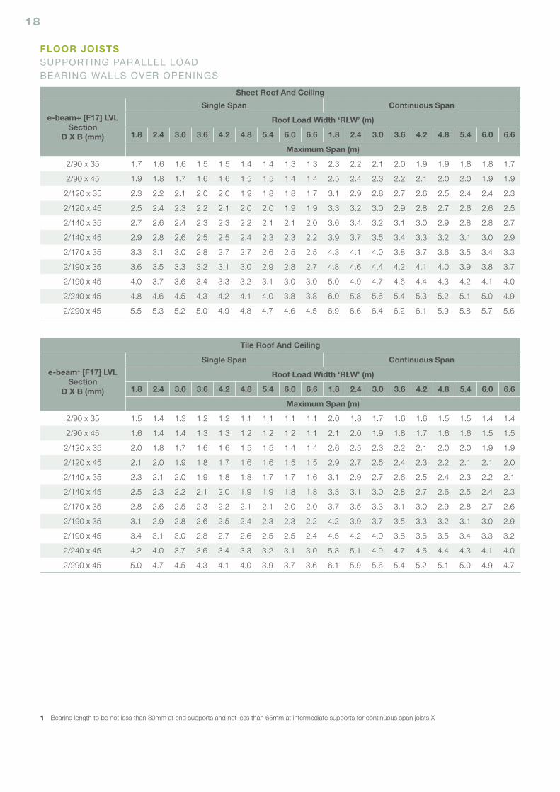
Tile Roof And Ceiling
e-beam+ [F17] LVLSection
D X B (mm)
Single Span Continuous Span
Roof Load Width ‘RLW’ (m)
1.8 2.4 3.0 3.6 4.2 4.8 5.4 6.0 6.6 1.8 2.4 3.0 3.6 4.2 4.8 5.4 6.0 6.6
Maximum Span (m)
2/90 x 35 1.5 1.4 1.3 1.2 1.2 1.1 1.1 1.1 1.1 2.0 1.8 1.7 1.6 1.6 1.5 1.5 1.4 1.4
2/90 x 45 1.6 1.4 1.4 1.3 1.3 1.2 1.2 1.2 1.1 2.1 2.0 1.9 1.8 1.7 1.6 1.6 1.5 1.5
2/120 x 35 2.0 1.8 1.7 1.6 1.6 1.5 1.5 1.4 1.4 2.6 2.5 2.3 2.2 2.1 2.0 2.0 1.9 1.9
2/120 x 45 2.1 2.0 1.9 1.8 1.7 1.6 1.6 1.5 1.5 2.9 2.7 2.5 2.4 2.3 2.2 2.1 2.1 2.0
2/140 x 35 2.3 2.1 2.0 1.9 1.8 1.8 1.7 1.7 1.6 3.1 2.9 2.7 2.6 2.5 2.4 2.3 2.2 2.1
2/140 x 45 2.5 2.3 2.2 2.1 2.0 1.9 1.9 1.8 1.8 3.3 3.1 3.0 2.8 2.7 2.6 2.5 2.4 2.3
2/170 x 35 2.8 2.6 2.5 2.3 2.2 2.1 2.1 2.0 2.0 3.7 3.5 3.3 3.1 3.0 2.9 2.8 2.7 2.6
2/190 x 35 3.1 2.9 2.8 2.6 2.5 2.4 2.3 2.3 2.2 4.2 3.9 3.7 3.5 3.3 3.2 3.1 3.0 2.9
2/190 x 45 3.4 3.1 3.0 2.8 2.7 2.6 2.5 2.5 2.4 4.5 4.2 4.0 3.8 3.6 3.5 3.4 3.3 3.2
2/240 x 45 4.2 4.0 3.7 3.6 3.4 3.3 3.2 3.1 3.0 5.3 5.1 4.9 4.7 4.6 4.4 4.3 4.1 4.0
2/290 x 45 5.0 4.7 4.5 4.3 4.1 4.0 3.9 3.7 3.6 6.1 5.9 5.6 5.4 5.2 5.1 5.0 4.9 4.7
Sheet Roof And Ceiling
e-beam+ [F17] LVLSection
D X B (mm)
Single Span Continuous Span
Roof Load Width ‘RLW’ (m)
1.8 2.4 3.0 3.6 4.2 4.8 5.4 6.0 6.6 1.8 2.4 3.0 3.6 4.2 4.8 5.4 6.0 6.6
Maximum Span (m)
2/90 x 35 1.7 1.6 1.6 1.5 1.5 1.4 1.4 1.3 1.3 2.3 2.2 2.1 2.0 1.9 1.9 1.8 1.8 1.7
2/90 x 45 1.9 1.8 1.7 1.6 1.6 1.5 1.5 1.4 1.4 2.5 2.4 2.3 2.2 2.1 2.0 2.0 1.9 1.9
2/120 x 35 2.3 2.2 2.1 2.0 2.0 1.9 1.8 1.8 1.7 3.1 2.9 2.8 2.7 2.6 2.5 2.4 2.4 2.3
2/120 x 45 2.5 2.4 2.3 2.2 2.1 2.0 2.0 1.9 1.9 3.3 3.2 3.0 2.9 2.8 2.7 2.6 2.6 2.5
2/140 x 35 2.7 2.6 2.4 2.3 2.3 2.2 2.1 2.1 2.0 3.6 3.4 3.2 3.1 3.0 2.9 2.8 2.8 2.7
2/140 x 45 2.9 2.8 2.6 2.5 2.5 2.4 2.3 2.3 2.2 3.9 3.7 3.5 3.4 3.3 3.2 3.1 3.0 2.9
2/170 x 35 3.3 3.1 3.0 2.8 2.7 2.7 2.6 2.5 2.5 4.3 4.1 4.0 3.8 3.7 3.6 3.5 3.4 3.3
2/190 x 35 3.6 3.5 3.3 3.2 3.1 3.0 2.9 2.8 2.7 4.8 4.6 4.4 4.2 4.1 4.0 3.9 3.8 3.7
2/190 x 45 4.0 3.7 3.6 3.4 3.3 3.2 3.1 3.0 3.0 5.0 4.9 4.7 4.6 4.4 4.3 4.2 4.1 4.0
2/240 x 45 4.8 4.6 4.5 4.3 4.2 4.1 4.0 3.8 3.8 6.0 5.8 5.6 5.4 5.3 5.2 5.1 5.0 4.9
2/290 x 45 5.5 5.3 5.2 5.0 4.9 4.8 4.7 4.6 4.5 6.9 6.6 6.4 6.2 6.1 5.9 5.8 5.7 5.6
1 Bearing length to be not less than 30mm at end supports and not less than 65mm at intermediate supports for continuous span joists.X
FLOOR JOISTSSUPPORTING PARALLEL LOAD BEARING WALLS OVER OPENINGS
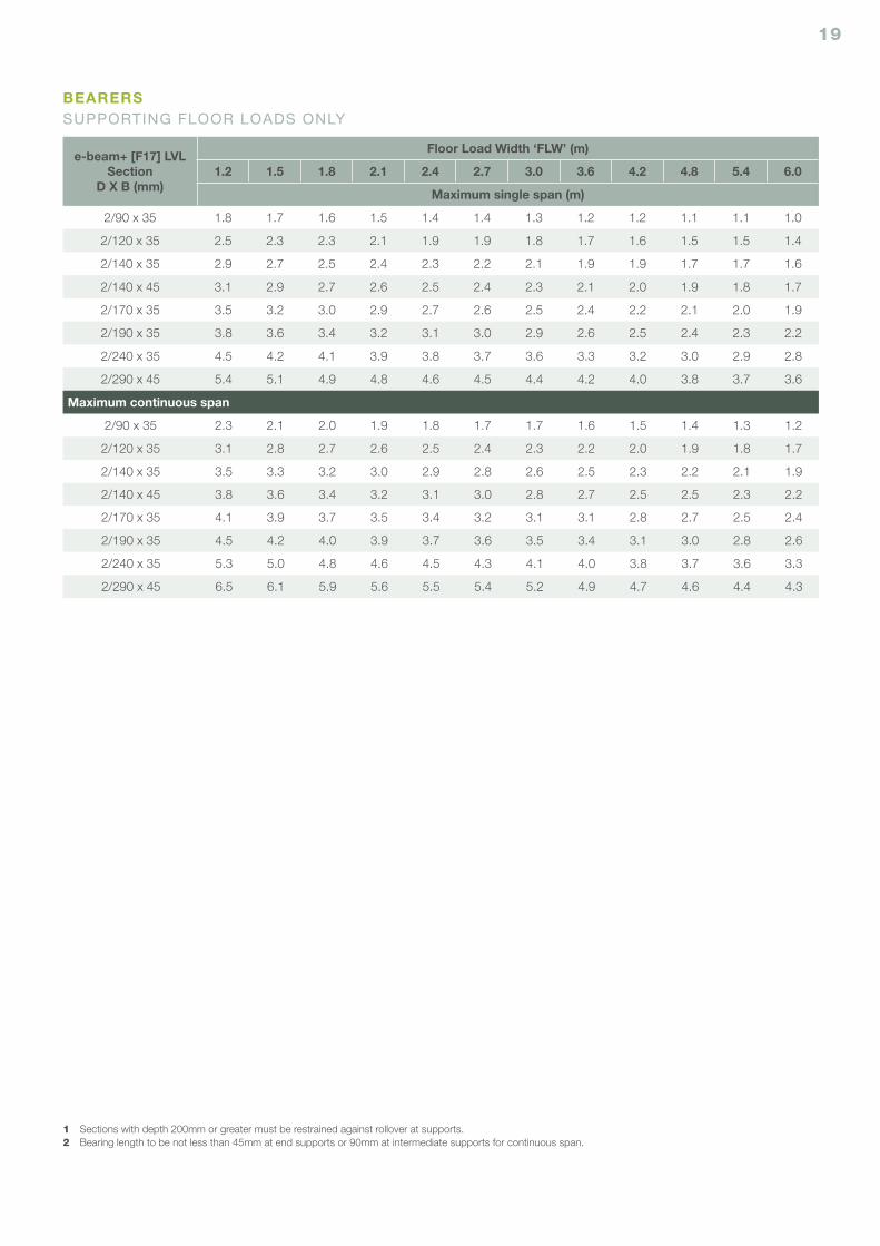
19
e-beam+ [F17] LVLSection
D X B (mm)
Floor Load Width ‘FLW’ (m)
1.2 1.5 1.8 2.1 2.4 2.7 3.0 3.6 4.2 4.8 5.4 6.0
Maximum single span (m)
2/90 x 35 1.8 1.7 1.6 1.5 1.4 1.4 1.3 1.2 1.2 1.1 1.1 1.0
2/120 x 35 2.5 2.3 2.3 2.1 1.9 1.9 1.8 1.7 1.6 1.5 1.5 1.4
2/140 x 35 2.9 2.7 2.5 2.4 2.3 2.2 2.1 1.9 1.9 1.7 1.7 1.6
2/140 x 45 3.1 2.9 2.7 2.6 2.5 2.4 2.3 2.1 2.0 1.9 1.8 1.7
2/170 x 35 3.5 3.2 3.0 2.9 2.7 2.6 2.5 2.4 2.2 2.1 2.0 1.9
2/190 x 35 3.8 3.6 3.4 3.2 3.1 3.0 2.9 2.6 2.5 2.4 2.3 2.2
2/240 x 35 4.5 4.2 4.1 3.9 3.8 3.7 3.6 3.3 3.2 3.0 2.9 2.8
2/290 x 45 5.4 5.1 4.9 4.8 4.6 4.5 4.4 4.2 4.0 3.8 3.7 3.6
Maximum continuous span
2/90 x 35 2.3 2.1 2.0 1.9 1.8 1.7 1.7 1.6 1.5 1.4 1.3 1.2
2/120 x 35 3.1 2.8 2.7 2.6 2.5 2.4 2.3 2.2 2.0 1.9 1.8 1.7
2/140 x 35 3.5 3.3 3.2 3.0 2.9 2.8 2.6 2.5 2.3 2.2 2.1 1.9
2/140 x 45 3.8 3.6 3.4 3.2 3.1 3.0 2.8 2.7 2.5 2.5 2.3 2.2
2/170 x 35 4.1 3.9 3.7 3.5 3.4 3.2 3.1 3.1 2.8 2.7 2.5 2.4
2/190 x 35 4.5 4.2 4.0 3.9 3.7 3.6 3.5 3.4 3.1 3.0 2.8 2.6
2/240 x 35 5.3 5.0 4.8 4.6 4.5 4.3 4.1 4.0 3.8 3.7 3.6 3.3
2/290 x 45 6.5 6.1 5.9 5.6 5.5 5.4 5.2 4.9 4.7 4.6 4.4 4.3
1 Sections with depth 200mm or greater must be restrained against rollover at supports.2 Bearing length to be not less than 45mm at end supports or 90mm at intermediate supports for continuous span.
BEARERSSUPPORTING FLOOR LOADS ONLY
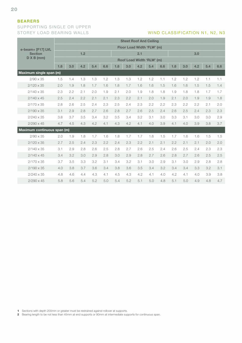
20
e-beam+ [F17] LVLSection
D X B (mm)
Sheet Roof And Ceiling
Floor Load Width ‘FLW’ (m)
1.2 2.1 3.0
Roof Load Width ‘RLW’ (m)
1.8 3.0 4.2 5.4 6.6 1.8 3.0 4.2 5.4 6.6 1.8 3.0 4.2 5.4 6.6
Maximum single span (m)
2/90 x 35 1.5 1.4 1.3 1.3 1.2 1.3 1.3 1.2 1.2 1.1 1.2 1.2 1.2 1.1 1.1
2/120 x 35 2.0 1.9 1.8 1.7 1.6 1.8 1.7 1.6 1.6 1.5 1.6 1.6 1.5 1.5 1.4
2/140 x 35 2.3 2.2 2.1 2.0 1.9 2.1 2.0 1.9 1.8 1.8 1.9 1.8 1.8 1.7 1.7
2/140 x 45 2.5 2.4 2.2 2.1 2.1 2.3 2.2 2.1 2.0 1.9 2.1 2.0 1.9 1.9 1.8
2/170 x 35 2.8 2.6 2.5 2.4 2.3 2.5 2.4 2.3 2.2 2.2 2.3 2.2 2.2 2.1 2.0
2/190 x 35 3.1 2.9 2.8 2.7 2.6 2.8 2.7 2.6 2.5 2.4 2.6 2.5 2.4 2.3 2.3
2/240 x 35 3.8 3.7 3.5 3.4 3.2 3.5 3.4 3.2 3.1 3.0 3.3 3.1 3.0 3.0 2.9
2/290 x 45 4.7 4.5 4.3 4.2 4.1 4.3 4.2 4.1 4.0 3.9 4.1 4.0 3.9 3.8 3.7
Maximum continuous span (m)
2/90 x 35 2.0 1.9 1.8 1.7 1.6 1.8 1.7 1.7 1.6 1.5 1.7 1.6 1.6 1.5 1.5
2/120 x 35 2.7 2.5 2.4 2.3 2.2 2.4 2.3 2.2 2.1 2.1 2.2 2.1 2.1 2.0 2.0
2/140 x 35 3.1 2.9 2.8 2.6 2.5 2.8 2.7 2.6 2.5 2.4 2.6 2.5 2.4 2.3 2.3
2/140 x 45 3.4 3.2 3.0 2.9 2.8 3.0 2.9 2.8 2.7 2.6 2.8 2.7 2.6 2.5 2.5
2/170 x 35 3.7 3.5 3.3 3.2 3.1 3.4 3.2 3.1 3.0 2.9 3.1 3.0 2.9 2.8 2.8
2/190 x 35 4.0 3.8 3.7 3.6 3.4 3.8 3.6 3.5 3.4 3.2 3.4 3.4 3.3 3.2 3.1
2/240 x 35 4.8 4.6 4.4 4.3 4.1 4.5 4.3 4.2 4.1 4.0 4.2 4.1 4.0 3.9 3.8
2/290 x 45 5.8 5.6 5.4 5.2 5.0 5.4 5.2 5.1 5.0 4.8 5.1 5.0 4.9 4.8 4.7
1 Sections with depth 200mm or greater must be restrained against rollover at supports.2 Bearing length to be not less than 45mm at end supports or 90mm at intermediate supports for continuous span.
BEARERSSUPPORTING SINGLE OR UPPER STOREY LOAD BEARING WALLS WIND CLASSIFICATION N1, N2, N3
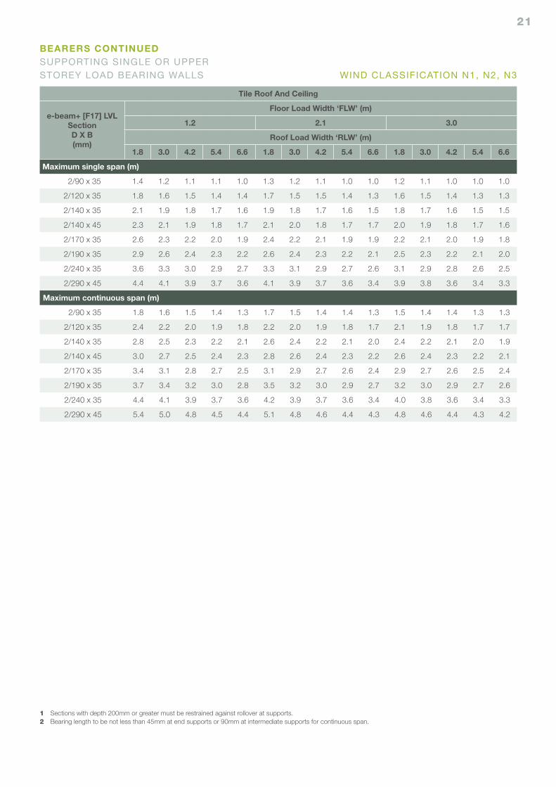
21
Tile Roof And Ceiling
e-beam+ [F17] LVLSectionD X B(mm)
Floor Load Width ‘FLW’ (m)
1.2 2.1 3.0
Roof Load Width ‘RLW’ (m)
1.8 3.0 4.2 5.4 6.6 1.8 3.0 4.2 5.4 6.6 1.8 3.0 4.2 5.4 6.6
Maximum single span (m)
2/90 x 35 1.4 1.2 1.1 1.1 1.0 1.3 1.2 1.1 1.0 1.0 1.2 1.1 1.0 1.0 1.0
2/120 x 35 1.8 1.6 1.5 1.4 1.4 1.7 1.5 1.5 1.4 1.3 1.6 1.5 1.4 1.3 1.3
2/140 x 35 2.1 1.9 1.8 1.7 1.6 1.9 1.8 1.7 1.6 1.5 1.8 1.7 1.6 1.5 1.5
2/140 x 45 2.3 2.1 1.9 1.8 1.7 2.1 2.0 1.8 1.7 1.7 2.0 1.9 1.8 1.7 1.6
2/170 x 35 2.6 2.3 2.2 2.0 1.9 2.4 2.2 2.1 1.9 1.9 2.2 2.1 2.0 1.9 1.8
2/190 x 35 2.9 2.6 2.4 2.3 2.2 2.6 2.4 2.3 2.2 2.1 2.5 2.3 2.2 2.1 2.0
2/240 x 35 3.6 3.3 3.0 2.9 2.7 3.3 3.1 2.9 2.7 2.6 3.1 2.9 2.8 2.6 2.5
2/290 x 45 4.4 4.1 3.9 3.7 3.6 4.1 3.9 3.7 3.6 3.4 3.9 3.8 3.6 3.4 3.3
Maximum continuous span (m)
2/90 x 35 1.8 1.6 1.5 1.4 1.3 1.7 1.5 1.4 1.4 1.3 1.5 1.4 1.4 1.3 1.3
2/120 x 35 2.4 2.2 2.0 1.9 1.8 2.2 2.0 1.9 1.8 1.7 2.1 1.9 1.8 1.7 1.7
2/140 x 35 2.8 2.5 2.3 2.2 2.1 2.6 2.4 2.2 2.1 2.0 2.4 2.2 2.1 2.0 1.9
2/140 x 45 3.0 2.7 2.5 2.4 2.3 2.8 2.6 2.4 2.3 2.2 2.6 2.4 2.3 2.2 2.1
2/170 x 35 3.4 3.1 2.8 2.7 2.5 3.1 2.9 2.7 2.6 2.4 2.9 2.7 2.6 2.5 2.4
2/190 x 35 3.7 3.4 3.2 3.0 2.8 3.5 3.2 3.0 2.9 2.7 3.2 3.0 2.9 2.7 2.6
2/240 x 35 4.4 4.1 3.9 3.7 3.6 4.2 3.9 3.7 3.6 3.4 4.0 3.8 3.6 3.4 3.3
2/290 x 45 5.4 5.0 4.8 4.5 4.4 5.1 4.8 4.6 4.4 4.3 4.8 4.6 4.4 4.3 4.2
1 Sections with depth 200mm or greater must be restrained against rollover at supports.2 Bearing length to be not less than 45mm at end supports or 90mm at intermediate supports for continuous span.
BEARERS CONTINUEDSUPPORTING SINGLE OR UPPER STOREY LOAD BEARING WALLS WIND CLASSIFICATION N1, N2, N3
22
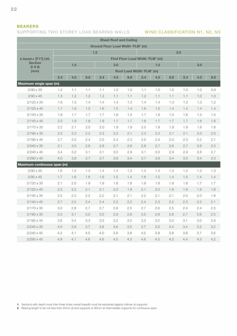
Sheet Roof and Ceiling
Ground Floor Load Width ‘FLW’ (m)
e-beam+ [F17] LVLSectionD X B(mm)
1.5 3.0
First Floor Load Width ‘FLW’ (m)
1.5 3.0 1.5 3.0
Roof Load Width ‘FLW’ (m)
2.4 4.5 6.6 2.4 4.5 6.6 2.4 4.5 6.6 2.4 4.5 6.6
Maximum single span (m)
2/90 x 35 1.2 1.1 1.1 1.1 1.0 1.0 1.1 1.0 1.0 1.0 1.0 0.9
2/90 x 45 1.3 1.2 1.2 1.2 1.1 1.1 1.2 1.1 1.1 1.1 1.0 1.0
2/120 x 35 1.6 1.5 1.4 1.4 1.4 1.3 1.4 1.4 1.3 1.3 1.3 1.2
2/120 x 45 1.7 1.6 1.5 1.6 1.5 1.4 1.6 1.5 1.4 1.4 1.4 1.4
2/140 x 35 1.8 1.7 1.7 1.7 1.6 1.5 1.7 1.6 1.5 1.6 1.5 1.5
2/140 x 45 2.0 1.9 1.8 1.8 1.7 1.7 1.8 1.7 1.7 1.7 1.6 1.6
2/170 x 35 2.2 2.1 2.0 2.0 1.9 1.9 2.0 1.9 1.9 1.9 1.8 1.8
2/190 x 35 2.5 2.3 2.2 2.3 2.2 2.1 2.3 2.2 2.1 2.1 2.0 2.0
2/190 x 45 2.7 2.5 2.4 2.5 2.4 2.3 2.5 2.4 2.3 2.3 2.2 2.1
2/240 x 35 3.1 3.0 2.8 2.8 2.7 2.6 2.8 2.7 2.6 2.7 2.6 2.5
2/240 x 45 3.4 3.2 3.1 3.1 3.0 2.9 3.1 3.0 2.9 2.9 2.8 2.7
2/290 x 45 4.0 3.8 3.7 3.7 3.6 3.4 3.7 3.6 3.4 3.5 3.4 3.3
Maximum continuous span (m)
2/90 x 35 1.6 1.5 1.4 1.4 1.4 1.3 1.4 1.4 1.3 1.3 1.3 1.3
2/90 x 45 1.7 1.6 1.6 1.6 1.5 1.4 1.6 1.5 1.4 1.5 1.4 1.4
2/120 x 35 2.1 2.0 1.9 1.9 1.8 1.8 1.9 1.8 1.8 1.8 1.7 1.7
2/120 x 45 2.3 2.2 2.1 2.1 2.0 1.9 2.1 2.0 1.9 1.9 1.9 1.8
2/140 x 35 2.5 2.3 2.2 2.2 2.1 2.1 2.2 2.1 2.1 2.0 2.0 1.9
2/140 x 45 2.7 2.5 2.4 2.4 2.3 2.2 2.4 2.3 2.2 2.3 2.2 2.1
2/170 x 35 3.0 2.8 2.7 2.7 2.6 2.5 2.7 2.6 2.5 2.4 2.4 2.3
2/190 x 35 3.3 3.1 3.0 3.0 2.9 2.8 3.0 2.8 2.8 2.7 2.6 2.5
2/190 x 45 3.6 3.4 3.3 3.3 3.2 3.0 3.3 3.2 3.0 3.1 3.0 2.9
2/240 x 35 4.0 3.9 3.7 3.8 3.6 3.5 3.7 3.5 3.4 3.4 3.2 3.2
2/240 x 45 4.3 4.1 4.0 4.0 3.9 3.8 4.0 3.9 3.8 3.8 3.7 3.6
2/290 x 45 4.9 4.7 4.6 4.6 4.5 4.3 4.6 4.5 4.3 4.4 4.3 4.2
1 Sections with depth more than three times overall breadth must be restrained against rollover at supports.2 Bearing length to be not less than 45mm at end supports or 90mm at intermediate supports for continuous span.
BEARERSSUPPORTING TWO STOREY LOAD BEARING WALLS WIND CLASSIFICATION N1, N2, N3
23
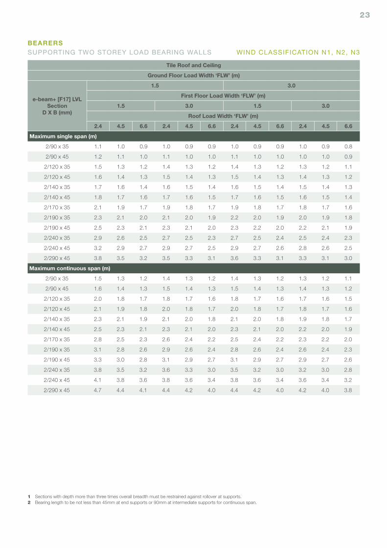
Tile Roof and Ceiling
Ground Floor Load Width ‘FLW’ (m)
e-beam+ [F17] LVLSection
D X B (mm)
1.5 3.0
First Floor Load Width ‘FLW’ (m)
1.5 3.0 1.5 3.0
Roof Load Width ‘FLW’ (m)
2.4 4.5 6.6 2.4 4.5 6.6 2.4 4.5 6.6 2.4 4.5 6.6
Maximum single span (m)
2/90 x 35 1.1 1.0 0.9 1.0 0.9 0.9 1.0 0.9 0.9 1.0 0.9 0.8
2/90 x 45 1.2 1.1 1.0 1.1 1.0 1.0 1.1 1.0 1.0 1.0 1.0 0.9
2/120 x 35 1.5 1.3 1.2 1.4 1.3 1.2 1.4 1.3 1.2 1.3 1.2 1.1
2/120 x 45 1.6 1.4 1.3 1.5 1.4 1.3 1.5 1.4 1.3 1.4 1.3 1.2
2/140 x 35 1.7 1.6 1.4 1.6 1.5 1.4 1.6 1.5 1.4 1.5 1.4 1.3
2/140 x 45 1.8 1.7 1.6 1.7 1.6 1.5 1.7 1.6 1.5 1.6 1.5 1.4
2/170 x 35 2.1 1.9 1.7 1.9 1.8 1.7 1.9 1.8 1.7 1.8 1.7 1.6
2/190 x 35 2.3 2.1 2.0 2.1 2.0 1.9 2.2 2.0 1.9 2.0 1.9 1.8
2/190 x 45 2.5 2.3 2.1 2.3 2.1 2.0 2.3 2.2 2.0 2.2 2.1 1.9
2/240 x 35 2.9 2.6 2.5 2.7 2.5 2.3 2.7 2.5 2.4 2.5 2.4 2.3
2/240 x 45 3.2 2.9 2.7 2.9 2.7 2.5 2.9 2.7 2.6 2.8 2.6 2.5
2/290 x 45 3.8 3.5 3.2 3.5 3.3 3.1 3.6 3.3 3.1 3.3 3.1 3.0
Maximum continuous span (m)
2/90 x 35 1.5 1.3 1.2 1.4 1.3 1.2 1.4 1.3 1.2 1.3 1.2 1.1
2/90 x 45 1.6 1.4 1.3 1.5 1.4 1.3 1.5 1.4 1.3 1.4 1.3 1.2
2/120 x 35 2.0 1.8 1.7 1.8 1.7 1.6 1.8 1.7 1.6 1.7 1.6 1.5
2/120 x 45 2.1 1.9 1.8 2.0 1.8 1.7 2.0 1.8 1.7 1.8 1.7 1.6
2/140 x 35 2.3 2.1 1.9 2.1 2.0 1.8 2.1 2.0 1.8 1.9 1.8 1.7
2/140 x 45 2.5 2.3 2.1 2.3 2.1 2.0 2.3 2.1 2.0 2.2 2.0 1.9
2/170 x 35 2.8 2.5 2.3 2.6 2.4 2.2 2.5 2.4 2.2 2.3 2.2 2.0
2/190 x 35 3.1 2.8 2.6 2.9 2.6 2.4 2.8 2.6 2.4 2.6 2.4 2.3
2/190 x 45 3.3 3.0 2.8 3.1 2.9 2.7 3.1 2.9 2.7 2.9 2.7 2.6
2/240 x 35 3.8 3.5 3.2 3.6 3.3 3.0 3.5 3.2 3.0 3.2 3.0 2.8
2/240 x 45 4.1 3.8 3.6 3.8 3.6 3.4 3.8 3.6 3.4 3.6 3.4 3.2
2/290 x 45 4.7 4.4 4.1 4.4 4.2 4.0 4.4 4.2 4.0 4.2 4.0 3.8
1 Sections with depth more than three times overall breadth must be restrained against rollover at supports.2 Bearing length to be not less than 45mm at end supports or 90mm at intermediate supports for continuous span.
BEARERSSUPPORTING TWO STOREY LOAD BEARING WALLS WIND CLASSIFICATION N1, N2, N3
24
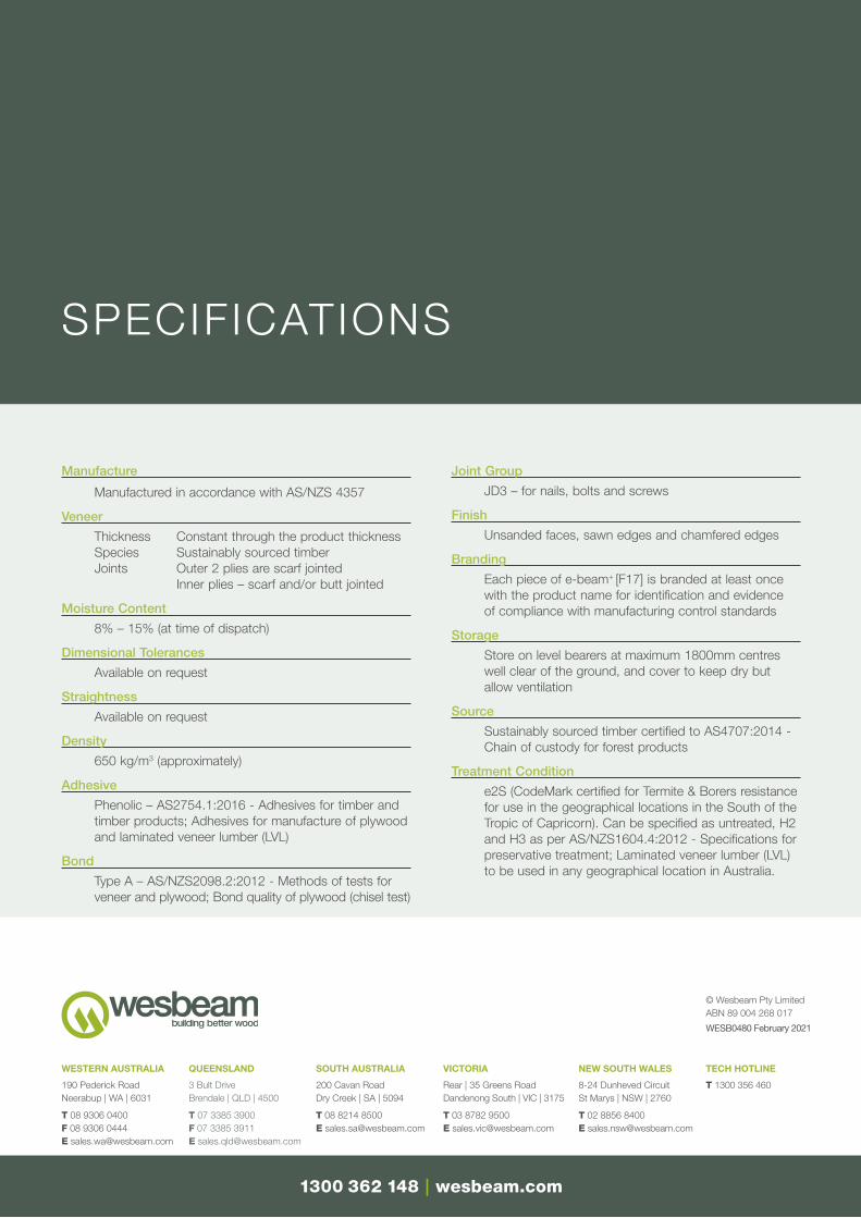
Manufacture
Manufactured in accordance with AS/NZS 4357
Veneer
Thickness Constant through the product thicknessSpecies Sustainably sourced timberJoints Outer 2 plies are scarf jointed Inner plies – scarf and/or butt jointed
Moisture Content
8% – 15% (at time of dispatch)
Dimensional Tolerances
Available on request
Straightness
Available on request
Density
650 kg/m3 (approximately)
Adhesive
Phenolic – AS2754.1:2016 - Adhesives for timber and timber products; Adhesives for manufacture of plywood and laminated veneer lumber (LVL)
Bond
Type A – AS/NZS2098.2:2012 - Methods of tests for veneer and plywood; Bond quality of plywood (chisel test)
Joint Group
JD3 – for nails, bolts and screws
Finish
Unsanded faces, sawn edges and chamfered edges
Branding
Each piece of e-beam+ [F17] is branded at least once with the product name for identification and evidence of compliance with manufacturing control standards
Storage
Store on level bearers at maximum 1800mm centres well clear of the ground, and cover to keep dry but allow ventilation
Source
Sustainably sourced timber certified to AS4707:2014 - Chain of custody for forest products
Treatment Condition
e2S (CodeMark certified for Termite & Borers resistance for use in the geographical locations in the South of the Tropic of Capricorn). Can be specified as untreated, H2 and H3 as per AS/NZS1604.4:2012 - Specifications for preservative treatment; Laminated veneer lumber (LVL) to be used in any geographical location in Australia.
SPECIFICATIONS
© Wesbeam Pty Limited ABN 89 004 268 017
WESB0480 February 2021
190 Pederick Road Neerabup | WA | 6031
T 08 9306 0400 F 08 9306 0444 E [email protected]
WESTERN AUSTRALIA
3 Bult Drive Brendale | QLD | 4500
T 07 3385 3900 F 07 3385 3911 E [email protected]
QUEENSLAND
200 Cavan Road Dry Creek | SA | 5094
T 08 8214 8500 E [email protected]
SOUTH AUSTRALIA
Rear | 35 Greens Road Dandenong South | VIC | 3175
T 03 8782 9500 E [email protected]
VICTORIA
8-24 Dunheved Circuit St Marys | NSW | 2760
T 02 8856 8400 E [email protected]
NEW SOUTH WALES
T 1300 356 460
TECH HOTLINE
1300 362 148 | wesbeam.com
Copyright © 2022 FDOKUMEN