LONG-SPAN GUARDRAIL SYSTEM FOR CULVERT APPLICATIONS
11
Transportation Research Record 1720 ■ 19 Paper No. 00 - 0598 Long-Span Guardrail System for Culvert Applications Ronald K. Faller, Dean L. Sicking, Karla A. Polivka, John R. Rohde, and Bob W. Bielenberg tive may not always be feasible because of costs in either purchasing additional right-of-way or increased earthwork requirements. For cross-drainage structures placed on traversable slopes, the preferred treatment is to adjust the structure length to intersect with the roadway embankment and adapt the bevel of the culvert’s inlet and outlet to the embankment’s slope. For smaller culverts with a single round pipe 1000 mm or less in diameter or multiple round pipes 750 mm or less in diameter, no additional treatment is required (1). However, for larger culvert openings wider than 1 m, steel bar grates or pipes are required to prevent a vehicle and its wheel assembly from significantly penetrating the opening, poten- tially resulting in vehicle instability or increased decelerations. Full-scale crash tests have shown that automobiles can safely tra- verse cross-grated culvert end sections located on slopes as steep as 1:3 and at speeds between 32.2 and 96.5 km/h using steel Schedule 40 pipes spaced 762 mm on center (2, 3). For larger culvert structures, extending the culvert or making it tra- versable is often not feasible. Therefore, the culvert obstruction must be shielded with an effective, crashworthy barrier system. Barrier systems used in these situations have included strong-post guardrails with steel posts bolted to the top of the concrete culvert, nesting of guardrail and reducing post spacing combined with the rigid steel post option, and using long, unsupported guardrail spans over the cul- vert (4–7 ). The use of barrier systems is often hindered by the shal- lowness of soil fill over the culvert. Crash testing has demonstrated that posts with shallow embedment depths can easily be pulled out of the ground, resulting in vehicle snagging or vaulting and causing potentially disastrous results (4). The Texas Transportation Institute (TTI) successfully developed and crash tested a design that alleviates the diminished performance of the guardrail with shallow embedded posts using a passenger-size sedan (4). This design involved welding base plates to the short W152 × 13.4 steel posts and bolting them to the top surface of the concrete culvert. For this design, the back side of the steel posts was placed approximately 483 mm from the traffic-side face of the culvert head- wall, allowing space for guardrail and post deflection during impact. This design sometimes required extending the culvert outward from the roadway, which increased the cost of the structure, especially in rehabilitation projects with no other culvert work required. In 1992, an alternative steel post design was developed for the Kansas Depart- ment of Transportation (KsDOT) to provide a stiffer barrier and reduced lateral deflection over the culvert (5). The successfully crash- tested design consisted of a nested W-beam, half-post spacing, and steel posts bolted to the top of the concrete culvert and installed next to the culvert headwall. For an impact with a passenger-size sedan, lateral dynamic guardrail deflections were reduced from 820 to 473 mm for the TTI design compared with the KsDOT design. These rigid steel post were severely deformed and often pulled loose R. K. Faller, K. A. Polivka, and B. W. Bielenberg, Midwest Roadside Safety Facility, University of Nebraska–Lincoln, 1901 Y Street, Building C, Lincoln, NE 68588-0601. D. L. Sicking and J. R. Rohde, Midwest Roadside Safety Facil- ity, University of Nebraska–Lincoln, W328.1 Nebraska Hall, Lincoln, NE 68588- 0529. A long-span guardrail for use over low-fill culverts was developed and suc- cessfully crash tested. The guardrail system was configured with 30.48 m of nested, 12-gauge W-beam rail and centered around a 7.62-m-long unsupported span. The nested W-beam rail was supported by 16 W152 × 13.4 steel posts and 6 standard CRT posts, each with two 150-mm × 200 × 360 mm wood block-outs. Each post was 1830 mm long. Post spac- ings were 1905 mm on center, except for the 7.62-m spacing between the two CRT posts surrounding the long span. The research study included computer simulation modeling with Barrier VII and full-scale vehicle crash testing, using 3/4-ton (680-kg) pickup trucks in accordance with the Test Level 3 (TL-3) requirements specified in NCHRP Report 350. Three full-scale vehicle crash tests were performed. The first test was unsuccessful because of severe vehicle penetration into the guardrail sys- tem. This penetration resulted from a loss of rail tensile capacity during vehicle redirection when the swagged fitting on the cable anchor assembly failed. A second test was performed on the same design, which contained a new cable anchor assembly. During vehicle redirection, the pickup truck rolled over and the test was considered a failure. The long-span sys- tem was subsequently redesigned to incorporate double block-outs on the CRT posts and crash tested again. Following the successful third test, the long-span guardrail system was determined to meet TL-3 criteria. Highway designers continually face the task of diverting water or runoff from one side of the road to the other. Cross-drainage struc- tures are commonly used in these situations and are designed to carry water underneath the roadway embankment. These structures gener- ally consist of small concrete or corrugated metal pipes, but often they may be multibarreled, concrete box culverts or structural plate pipes (1). For the smaller pipe structures, the inlets and outlets gen- erally consist of beveled or sloped end sections; however, for the larger box culverts, the end sections are constructed with concrete headwalls and wing walls. Consequently, these cross-drainage struc- tures may be a serious safety concern for motorists who inadvertently leave the roadway and impact or pass over these obstructions. Over the years, several alternatives have been used to prevent seri- ous accidents from impacts with these cross-drainage structures. These alternatives have included extending the culvert, using a tra- versable design, or shielding the structure. The preferred treatment for any obstacle is removal, eliminating the potential for an impact between a vehicle and hazard; however, removal is often not an option. If so, the obstruction must be placed as far from the roadway as possible, commonly at or beyond the clear zone. This alterna-
Transcript of LONG-SPAN GUARDRAIL SYSTEM FOR CULVERT APPLICATIONS
Transportation Research Record 1720 � 19Paper No. 00-0598
Long-Span Guardrail System for Culvert Applications
Ronald K. Faller, Dean L. Sicking, Karla A. Polivka, John R. Rohde, and Bob W. Bielenberg
tive may not always be feasible because of costs in either purchasingadditional right-of-way or increased earthwork requirements.
For cross-drainage structures placed on traversable slopes, thepreferred treatment is to adjust the structure length to intersectwith the roadway embankment and adapt the bevel of the culvert’sinlet and outlet to the embankment’s slope. For smaller culvertswith a single round pipe 1000 mm or less in diameter or multipleround pipes 750 mm or less in diameter, no additional treatment isrequired (1). However, for larger culvert openings wider than 1 m,steel bar grates or pipes are required to prevent a vehicle and itswheel assembly from significantly penetrating the opening, poten-tially resulting in vehicle instability or increased decelerations.Full-scale crash tests have shown that automobiles can safely tra-verse cross-grated culvert end sections located on slopes as steep as1:3 and at speeds between 32.2 and 96.5 km/h using steel Schedule40 pipes spaced 762 mm on center (2, 3).
For larger culvert structures, extending the culvert or making it tra-versable is often not feasible. Therefore, the culvert obstruction mustbe shielded with an effective, crashworthy barrier system. Barriersystems used in these situations have included strong-post guardrailswith steel posts bolted to the top of the concrete culvert, nesting ofguardrail and reducing post spacing combined with the rigid steelpost option, and using long, unsupported guardrail spans over the cul-vert (4–7 ). The use of barrier systems is often hindered by the shal-lowness of soil fill over the culvert. Crash testing has demonstratedthat posts with shallow embedment depths can easily be pulled out ofthe ground, resulting in vehicle snagging or vaulting and causingpotentially disastrous results (4).
The Texas Transportation Institute (TTI) successfully developedand crash tested a design that alleviates the diminished performanceof the guardrail with shallow embedded posts using a passenger-sizesedan (4). This design involved welding base plates to the short W152× 13.4 steel posts and bolting them to the top surface of the concreteculvert. For this design, the back side of the steel posts was placedapproximately 483 mm from the traffic-side face of the culvert head-wall, allowing space for guardrail and post deflection during impact.This design sometimes required extending the culvert outward fromthe roadway, which increased the cost of the structure, especially inrehabilitation projects with no other culvert work required. In 1992,an alternative steel post design was developed for the Kansas Depart-ment of Transportation (KsDOT) to provide a stiffer barrier andreduced lateral deflection over the culvert (5). The successfully crash-tested design consisted of a nested W-beam, half-post spacing, andsteel posts bolted to the top of the concrete culvert and installednext to the culvert headwall. For an impact with a passenger-sizesedan, lateral dynamic guardrail deflections were reduced from820 to 473 mm for the TTI design compared with the KsDOT design.These rigid steel post were severely deformed and often pulled loose
R. K. Faller, K. A. Polivka, and B. W. Bielenberg, Midwest Roadside Safety Facility, University of Nebraska–Lincoln, 1901 Y Street, Building C, Lincoln, NE 68588-0601. D. L. Sicking and J. R. Rohde, Midwest Roadside Safety Facil-ity, University of Nebraska–Lincoln, W328.1 Nebraska Hall, Lincoln, NE 68588-0529.
A long-span guardrail for use over low-fill culverts was developed and suc-cessfully crash tested. The guardrail system was configured with 30.48 mof nested, 12-gauge W-beam rail and centered around a 7.62-m-longunsupported span. The nested W-beam rail was supported by 16 W152 ×13.4 steel posts and 6 standard CRT posts, each with two 150-mm ×200 × 360 mm wood block-outs. Each post was 1830 mm long. Post spac-ings were 1905 mm on center, except for the 7.62-m spacing between thetwo CRT posts surrounding the long span. The research study includedcomputer simulation modeling with Barrier VII and full-scale vehiclecrash testing, using 3/4-ton (680-kg) pickup trucks in accordance withthe Test Level 3 (TL-3) requirements specified in NCHRP Report 350.Three full-scale vehicle crash tests were performed. The first test wasunsuccessful because of severe vehicle penetration into the guardrail sys-tem. This penetration resulted from a loss of rail tensile capacity duringvehicle redirection when the swagged fitting on the cable anchor assemblyfailed. A second test was performed on the same design, which containeda new cable anchor assembly. During vehicle redirection, the pickuptruck rolled over and the test was considered a failure. The long-span sys-tem was subsequently redesigned to incorporate double block-outs on theCRT posts and crash tested again. Following the successful third test, thelong-span guardrail system was determined to meet TL-3 criteria.
Highway designers continually face the task of diverting water orrunoff from one side of the road to the other. Cross-drainage struc-tures are commonly used in these situations and are designed to carrywater underneath the roadway embankment. These structures gener-ally consist of small concrete or corrugated metal pipes, but oftenthey may be multibarreled, concrete box culverts or structural platepipes (1). For the smaller pipe structures, the inlets and outlets gen-erally consist of beveled or sloped end sections; however, for thelarger box culverts, the end sections are constructed with concreteheadwalls and wing walls. Consequently, these cross-drainage struc-tures may be a serious safety concern for motorists who inadvertentlyleave the roadway and impact or pass over these obstructions.
Over the years, several alternatives have been used to prevent seri-ous accidents from impacts with these cross-drainage structures.These alternatives have included extending the culvert, using a tra-versable design, or shielding the structure. The preferred treatmentfor any obstacle is removal, eliminating the potential for an impactbetween a vehicle and hazard; however, removal is often not anoption. If so, the obstruction must be placed as far from the roadwayas possible, commonly at or beyond the clear zone. This alterna-
20 Paper No. 00-0598 Transportation Research Record 1720
when impacted by vehicles, significantly damaging the culvert andincurring expensive repairs.
To eliminate the need for a physical attachment to the concrete cul-vert and to develop a wood post guardrail option, the TTI designed acrashworthy system that included an unsupported guardrail segmentor long span across the culvert (6, 7). Designs were developed for3.81- and 5.72-m long, unsupported lengths of nested W-beamguardrail and successfully crash tested using passenger-size sedans.These designs are simpler and less expensive than the steel post alter-natives, which require an attachment to the top of the culvert. Thesedesigns also have been recommended for use with wood and steelpost guardrail systems because of the compatible strengths of woodand steel posts (6).
Although an improved and economical long-span guardrail systemwas developed to shield culvert obstructions, several state depart-ments of transportation encountered situations requiring unsupportedlengths exceeding 5.72 m and up to 7.62 m. In addition, the previouslydescribed designs were crash tested according to NCHRP Report 230evaluation criteria (8). Consequently, these existing designs can nolonger be used on federal-aid highways unless they meet currentimpact safety standards. Also, any new designs with unsupportedlengths exceeding 5.72 m must be crash tested.
RESEARCH OBJECTIVE
The objective of this research project was to develop a new guardrailsystem that could traverse culverts with an approximately 7.62-m-long span. The new guardrail system was designed to meet theNCHRP Report 350 Test Level 3 (TL-3) safety performance cri-teria (9). The study was performed by the Midwest RoadsideSafety Facility (MwRSF) in cooperation with the Midwest StatesRegional Pooled Fund Program, the Washington State Departmentof Transportation, CONTECH Construction Products, Inc., andLane Enterprises. Additional details on this study are presented intwo recently published MwRSF research reports (10, 11).
TEST REQUIREMENTS AND EVALUATION CRITERIA
Longitudinal barriers, such as long-span guardrail systems travers-ing culverts, must satisfy NCHRP Report 350 requirements beforeuse on new construction projects or as a replacement for existingdesigns not meeting current safety standards. According to TL-3,long-span guardrail systems must be subjected to two full-scalevehicle crash tests—(a) a 2000-kg pickup truck impacting at a speedof 100 km/h and at an angle of 25 degrees and (b) an 820-kg smallcar impacting at a speed of 100 km/h and at an angle of 20 degrees.W-beam barriers struck by small cars, however, have met safetyperformance standards, being essentially rigid with no significantpotential for occupant risk from vehicle pocketing or severe wheelsnagging on the post at the downstream end of the long span (12–14).Therefore, the 820-kg small car was not crash tested for this study.
Evaluation criteria for full-scale vehicle crash testing are basedon three appraisal areas—structural adequacy, occupant risk, andvehicle trajectory after collision. Criteria for structural adequacyevaluate the ability of the barrier to contain, redirect, or allow con-trolled vehicle penetration in a predictable manner. Occupant riskevaluates the degree of hazard to occupants of the impacting vehi-
cle. Vehicle trajectory after collision is a measure of the potentialfor a vehicle’s postimpact trajectory to result in subsequent multi-vehicle accidents. This criterion also indicates the potential safetyhazard for the occupants of other vehicles or the occupants of theimpacting vehicle when subjected to secondary collisions with otherfixed objects. These three evaluation criteria are described in greaterdetail in NCHRP Report 350. The full-scale vehicle crash tests wereconducted and are reported in accordance with Report 350 procedures.
LONG-SPAN GUARDRAIL DESIGN CONSIDERATIONS
The development of the long-span W-beam guardrail system con-sidered three key factors—vehicle capture, rail tensile capacity, andthe potential for pocketing and wheel snagging. For a long, unsup-ported length of guardrail extending across a culvert, vehicle captureis significant. Under NCHRP Report 230 guidelines, previous crashtesting of W-beam guardrails demonstrated that unsupported lengthsup to 5.72 m were possible. The problem of vehicle capture, how-ever, is intensified under NCHRP Report 350 guidelines because ofthe increased height of the center of mass for 3⁄4-ton (680-kg) pickuptrucks. For a long-span guardrail system, the rail tensile capacity alsois a key design factor. Higher tensile loads and longitudinal strain inthe rail will occur because dynamic lateral rail deflections are likelyto be larger than those observed during an impact into a guardrail sys-tem with standard post spacing. Nested W-beam or single thrie-beam, combined with increased thickness, was considered as a wayto provide the increased tensile capacity required. The final designconsideration was the potential for vehicle pocketing and wheelsnagging on the posts located on the downstream side of the unsup-ported length of guardrail. The post type, embedment depth, andspacing were selected to minimize vehicle pocketing and wheelsnagging. Computer simulation was used initially to investigate thesedesign considerations to ensure that the most cost-effective guardrailsystem was implemented.
COMPUTER SIMULATION MODELING
Computer simulation modeling with Barrier VII was performed toanalyze and predict the dynamic performance of various long-spanguardrail alternatives before full-scale vehicle crash testing (15).The simulations modeled a 2041-kg sedan and a 1996-kg pickuptruck impacting at a speed of 96.6 km/h and at an angle of 25 degrees.Computer simulations were conducted on four long-span W-beamguardrail alternatives, each involving 7.62-m open spans and dif-ferent total lengths of nested, 12-gauge rail centered about the freespan—19.05 m, 22.86 m, 26.67 m, and 30.48 m. Each installationwas evaluated in impacts with the 3/4-ton (680-kg) pickup and thefull-size sedan. Many simulations were conducted for each vehicle-system combination to determine the impact locations that maxi-mized wheel snagging and predicted strains in the W-beam railelements. The maximum longitudinal strain in the W-beam wasselected as the best indicator of rail rupture. Although the AASHTOM180 steel used in W-beam guardrails is a relatively ductile ma-terial and can sustain significant plastic strain without failure, full-scale crash tests have indicated that guardrails tend to fail at relativelylow plastic strains. The cross section of a W-beam rail element isreduced by approximately 15 percent at the rail splice. This cross-
Faller et al. Paper No. 00 -0598 21
sectional reduction tends to localize strain in the splice region andleads to rail rupture near the point that the full cross section beginsto yield. Full cross-sectional yield was therefore chosen as the limit-ing condition for the design of the long-span guardrail system. Thisyield would correspond to a limiting strain of approximately 0.0017.
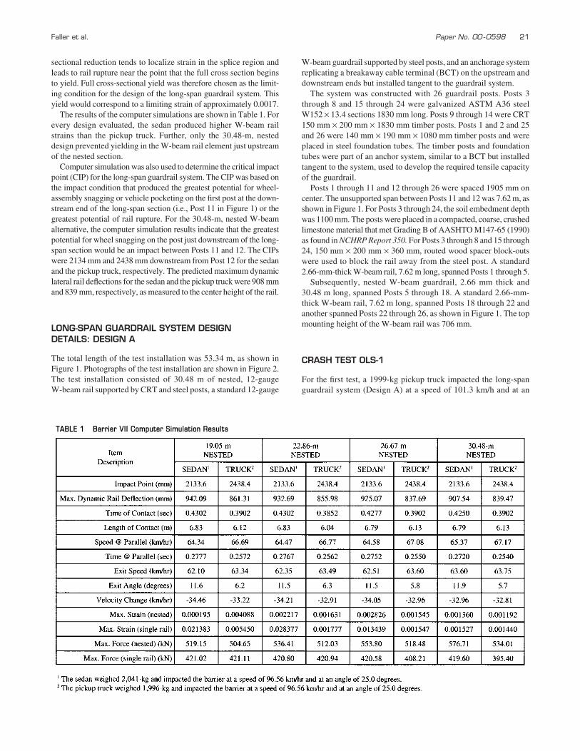
The results of the computer simulations are shown in Table 1. Forevery design evaluated, the sedan produced higher W-beam railstrains than the pickup truck. Further, only the 30.48-m, nesteddesign prevented yielding in the W-beam rail element just upstreamof the nested section.
Computer simulation was also used to determine the critical impactpoint (CIP) for the long-span guardrail system. The CIP was based onthe impact condition that produced the greatest potential for wheel-assembly snagging or vehicle pocketing on the first post at the down-stream end of the long-span section (i.e., Post 11 in Figure 1) or thegreatest potential of rail rupture. For the 30.48-m, nested W-beamalternative, the computer simulation results indicate that the greatestpotential for wheel snagging on the post just downstream of the long-span section would be an impact between Posts 11 and 12. The CIPswere 2134 mm and 2438 mm downstream from Post 12 for the sedanand the pickup truck, respectively. The predicted maximum dynamiclateral rail deflections for the sedan and the pickup truck were 908 mmand 839 mm, respectively, as measured to the center height of the rail.
LONG-SPAN GUARDRAIL SYSTEM DESIGNDETAILS: DESIGN A
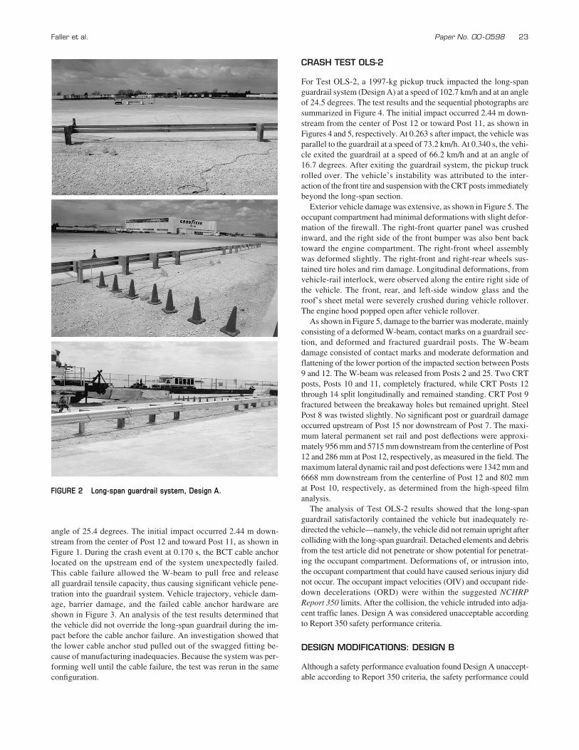
The total length of the test installation was 53.34 m, as shown in Figure 1. Photographs of the test installation are shown in Figure 2.The test installation consisted of 30.48 m of nested, 12-gauge W-beam rail supported by CRT and steel posts, a standard 12-gauge
W-beam guardrail supported by steel posts, and an anchorage systemreplicating a breakaway cable terminal (BCT) on the upstream anddownstream ends but installed tangent to the guardrail system.
The system was constructed with 26 guardrail posts. Posts 3through 8 and 15 through 24 were galvanized ASTM A36 steelW152 × 13.4 sections 1830 mm long. Posts 9 through 14 were CRT150 mm × 200 mm × 1830 mm timber posts. Posts 1 and 2 and 25and 26 were 140 mm × 190 mm × 1080 mm timber posts and wereplaced in steel foundation tubes. The timber posts and foundationtubes were part of an anchor system, similar to a BCT but installedtangent to the system, used to develop the required tensile capacityof the guardrail.
Posts 1 through 11 and 12 through 26 were spaced 1905 mm oncenter. The unsupported span between Posts 11 and 12 was 7.62 m, asshown in Figure 1. For Posts 3 through 24, the soil embedment depthwas 1100 mm. The posts were placed in a compacted, coarse, crushedlimestone material that met Grading B of AASHTO M147-65 (1990)as found in NCHRP Report 350. For Posts 3 through 8 and 15 through24, 150 mm × 200 mm × 360 mm, routed wood spacer block-outswere used to block the rail away from the steel post. A standard2.66-mm-thick W-beam rail, 7.62 m long, spanned Posts 1 through 5.
Subsequently, nested W-beam guardrail, 2.66 mm thick and30.48 m long, spanned Posts 5 through 18. A standard 2.66-mm-thick W-beam rail, 7.62 m long, spanned Posts 18 through 22 andanother spanned Posts 22 through 26, as shown in Figure 1. The topmounting height of the W-beam rail was 706 mm.
CRASH TEST OLS-1
For the first test, a 1999-kg pickup truck impacted the long-spanguardrail system (Design A) at a speed of 101.3 km/h and at an
TABLE 1 Barrier VII Computer Simulation Results
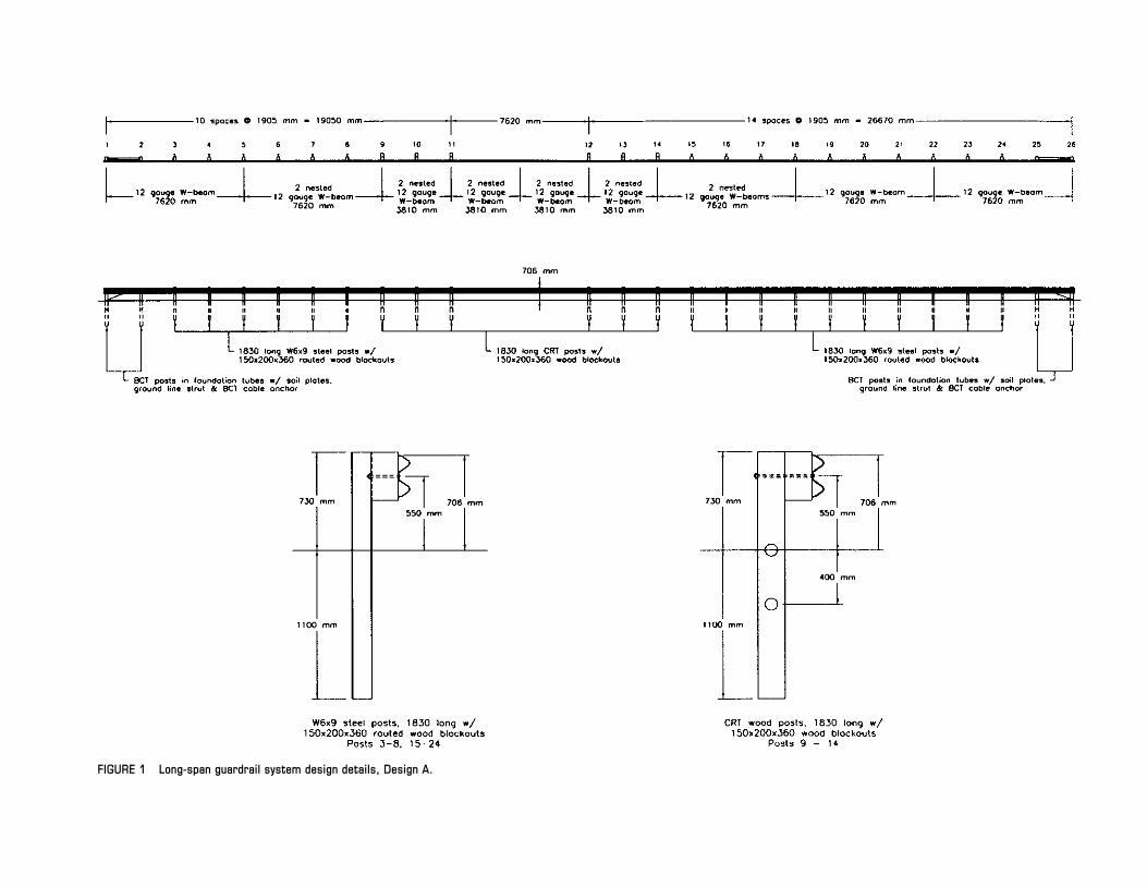
FIGURE 1 Long-span guardrail system design details, Design A.
Faller et al. Paper No. 00 -0598 23
angle of 25.4 degrees. The initial impact occurred 2.44 m down-stream from the center of Post 12 and toward Post 11, as shown inFigure 1. During the crash event at 0.170 s, the BCT cable anchorlocated on the upstream end of the system unexpectedly failed.This cable failure allowed the W-beam to pull free and release all guardrail tensile capacity, thus causing significant vehicle pene-tration into the guardrail system. Vehicle trajectory, vehicle dam-age, barrier damage, and the failed cable anchor hardware areshown in Figure 3. An analysis of the test results determined thatthe vehicle did not override the long-span guardrail during the im-pact before the cable anchor failure. An investigation showed thatthe lower cable anchor stud pulled out of the swagged fitting be-cause of manufacturing inadequacies. Because the system was per-forming well until the cable failure, the test was rerun in the same configuration.
CRASH TEST OLS-2
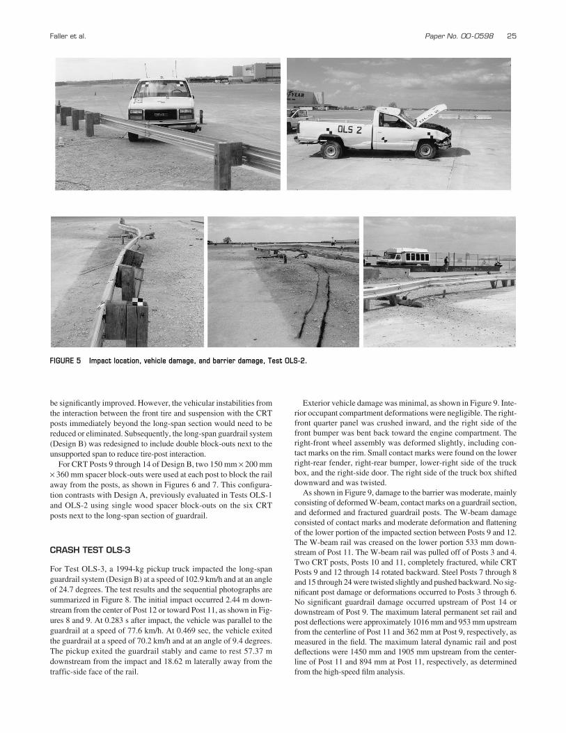
For Test OLS-2, a 1997-kg pickup truck impacted the long-spanguardrail system (Design A) at a speed of 102.7 km/h and at an angleof 24.5 degrees. The test results and the sequential photographs aresummarized in Figure 4. The initial impact occurred 2.44 m down-stream from the center of Post 12 or toward Post 11, as shown in Figures 4 and 5, respectively. At 0.263 s after impact, the vehicle wasparallel to the guardrail at a speed of 73.2 km/h. At 0.340 s, the vehi-cle exited the guardrail at a speed of 66.2 km/h and at an angle of16.7 degrees. After exiting the guardrail system, the pickup truckrolled over. The vehicle’s instability was attributed to the inter-action of the front tire and suspension with the CRT posts immediatelybeyond the long-span section.
Exterior vehicle damage was extensive, as shown in Figure 5. Theoccupant compartment had minimal deformations with slight defor-mation of the firewall. The right-front quarter panel was crushedinward, and the right side of the front bumper was also bent backtoward the engine compartment. The right-front wheel assemblywas deformed slightly. The right-front and right-rear wheels sus-tained tire holes and rim damage. Longitudinal deformations, fromvehicle-rail interlock, were observed along the entire right side ofthe vehicle. The front, rear, and left-side window glass and theroof’s sheet metal were severely crushed during vehicle rollover.The engine hood popped open after vehicle rollover.
As shown in Figure 5, damage to the barrier was moderate, mainlyconsisting of a deformed W-beam, contact marks on a guardrail sec-tion, and deformed and fractured guardrail posts. The W-beamdamage consisted of contact marks and moderate deformation andflattening of the lower portion of the impacted section between Posts9 and 12. The W-beam was released from Posts 2 and 25. Two CRTposts, Posts 10 and 11, completely fractured, while CRT Posts 12through 14 split longitudinally and remained standing. CRT Post 9fractured between the breakaway holes but remained upright. SteelPost 8 was twisted slightly. No significant post or guardrail damageoccurred upstream of Post 15 nor downstream of Post 7. The maxi-mum lateral permanent set rail and post deflections were approxi-mately 956 mm and 5715 mm downstream from the centerline of Post12 and 286 mm at Post 12, respectively, as measured in the field. Themaximum lateral dynamic rail and post defections were 1342 mm and6668 mm downstream from the centerline of Post 12 and 802 mmat Post 10, respectively, as determined from the high-speed filmanalysis.
The analysis of Test OLS-2 results showed that the long-spanguardrail satisfactorily contained the vehicle but inadequately re-directed the vehicle—namely, the vehicle did not remain upright aftercolliding with the long-span guardrail. Detached elements and debrisfrom the test article did not penetrate or show potential for penetrat-ing the occupant compartment. Deformations of, or intrusion into,the occupant compartment that could have caused serious injury didnot occur. The occupant impact velocities (OIV) and occupant ride-down decelerations (ORD) were within the suggested NCHRPReport 350 limits. After the collision, the vehicle intruded into adja-cent traffic lanes. Design A was considered unacceptable accordingto Report 350 safety performance criteria.
DESIGN MODIFICATIONS: DESIGN B
Although a safety performance evaluation found Design A unaccept-able according to Report 350 criteria, the safety performance could
FIGURE 2 Long-span guardrail system, Design A.
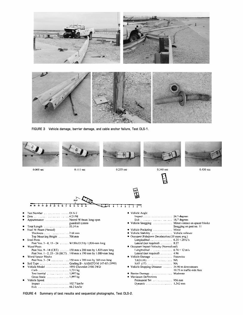
FIGURE 3 Vehicle damage, barrier damage, and cable anchor failure, Test OLS-1.
FIGURE 4 Summary of test results and sequential photographs, Test OLS-2.
Faller et al. Paper No. 00 -0598 25
be significantly improved. However, the vehicular instabilities fromthe interaction between the front tire and suspension with the CRTposts immediately beyond the long-span section would need to bereduced or eliminated. Subsequently, the long-span guardrail system(Design B) was redesigned to include double block-outs next to theunsupported span to reduce tire-post interaction.
For CRT Posts 9 through 14 of Design B, two 150 mm × 200 mm× 360 mm spacer block-outs were used at each post to block the railaway from the posts, as shown in Figures 6 and 7. This configura-tion contrasts with Design A, previously evaluated in Tests OLS-1and OLS-2 using single wood spacer block-outs on the six CRTposts next to the long-span section of guardrail.
CRASH TEST OLS-3
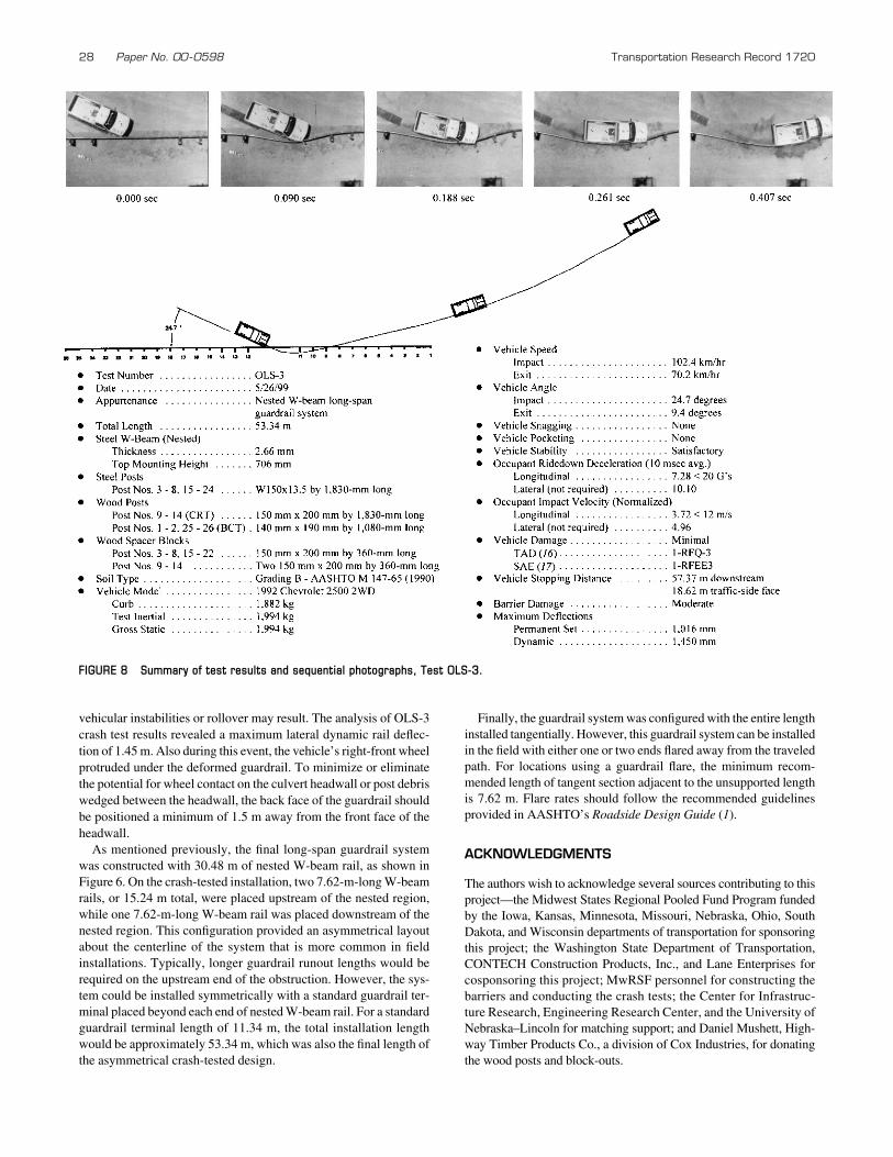
For Test OLS-3, a 1994-kg pickup truck impacted the long-spanguardrail system (Design B) at a speed of 102.9 km/h and at an angleof 24.7 degrees. The test results and the sequential photographs aresummarized in Figure 8. The initial impact occurred 2.44 m down-stream from the center of Post 12 or toward Post 11, as shown in Fig-ures 8 and 9. At 0.283 s after impact, the vehicle was parallel to theguardrail at a speed of 77.6 km/h. At 0.469 sec, the vehicle exitedthe guardrail at a speed of 70.2 km/h and at an angle of 9.4 degrees.The pickup exited the guardrail stably and came to rest 57.37 mdownstream from the impact and 18.62 m laterally away from thetraffic-side face of the rail.
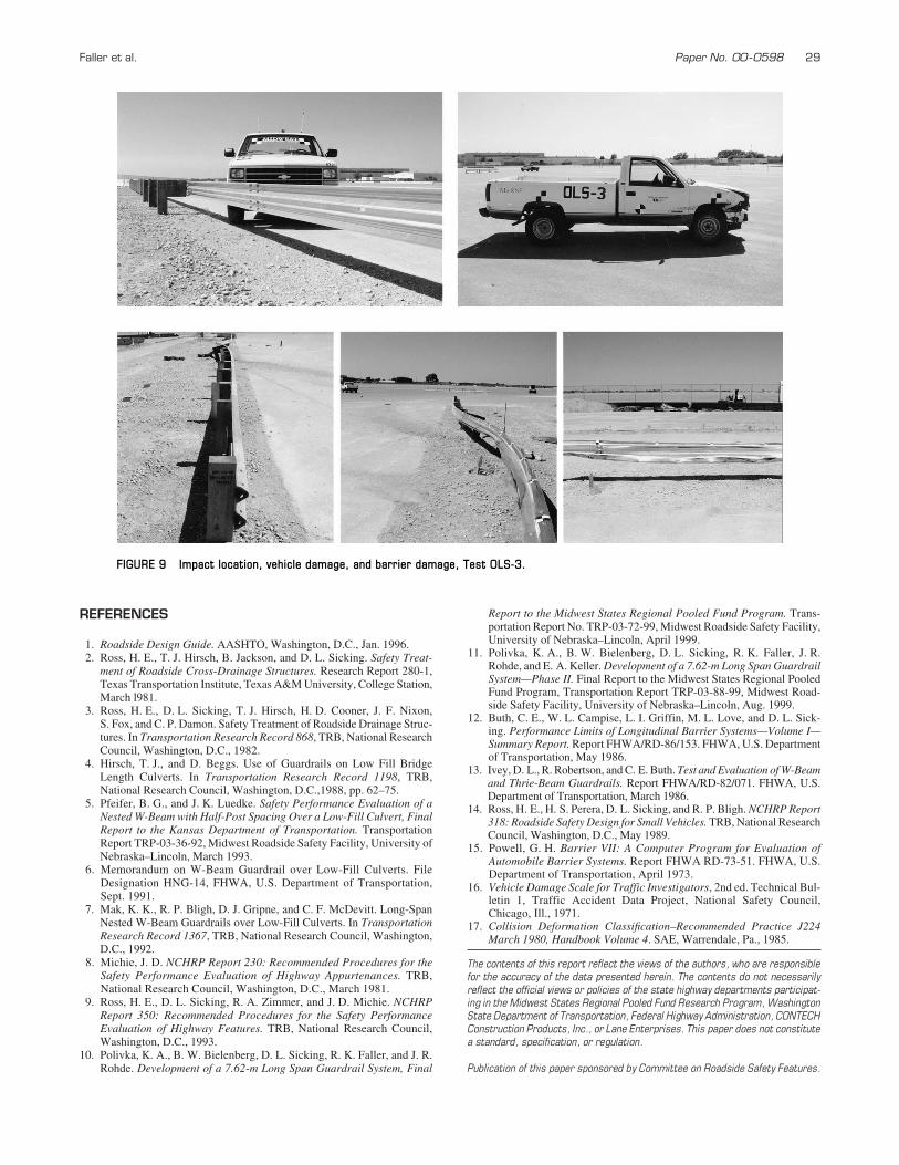
Exterior vehicle damage was minimal, as shown in Figure 9. Inte-rior occupant compartment deformations were negligible. The right-front quarter panel was crushed inward, and the right side of thefront bumper was bent back toward the engine compartment. Theright-front wheel assembly was deformed slightly, including con-tact marks on the rim. Small contact marks were found on the lowerright-rear fender, right-rear bumper, lower-right side of the truckbox, and the right-side door. The right side of the truck box shifteddownward and was twisted.
As shown in Figure 9, damage to the barrier was moderate, mainlyconsisting of deformed W-beam, contact marks on a guardrail section,and deformed and fractured guardrail posts. The W-beam damageconsisted of contact marks and moderate deformation and flatteningof the lower portion of the impacted section between Posts 9 and 12.The W-beam rail was creased on the lower portion 533 mm down-stream of Post 11. The W-beam rail was pulled off of Posts 3 and 4.Two CRT posts, Posts 10 and 11, completely fractured, while CRTPosts 9 and 12 through 14 rotated backward. Steel Posts 7 through 8and 15 through 24 were twisted slightly and pushed backward. No sig-nificant post damage or deformations occurred to Posts 3 through 6.No significant guardrail damage occurred upstream of Post 14 ordownstream of Post 9. The maximum lateral permanent set rail andpost deflections were approximately 1016 mm and 953 mm upstreamfrom the centerline of Post 11 and 362 mm at Post 9, respectively, asmeasured in the field. The maximum lateral dynamic rail and postdeflections were 1450 mm and 1905 mm upstream from the center-line of Post 11 and 894 mm at Post 11, respectively, as determinedfrom the high-speed film analysis.
FIGURE 5 Impact location, vehicle damage, and barrier damage, Test OLS-2.
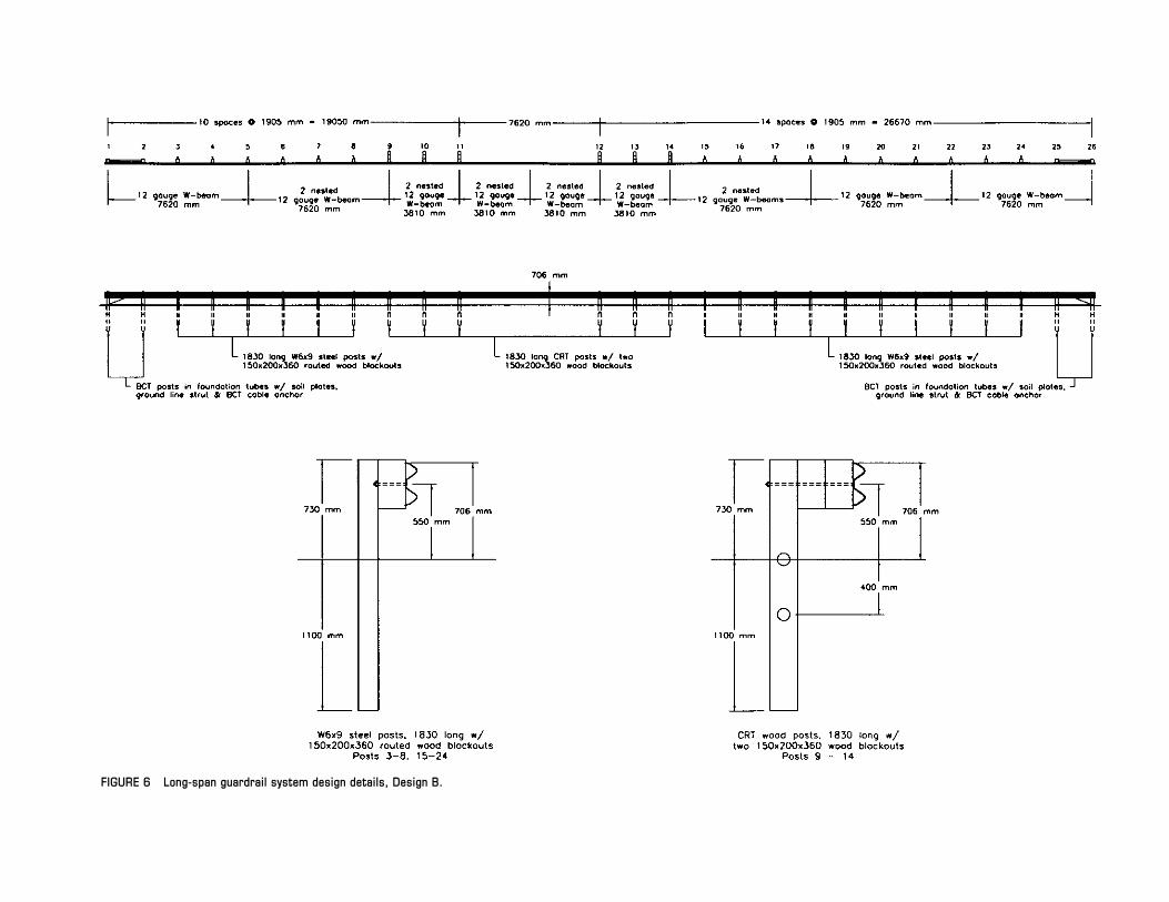
FIGURE 6 Long-span guardrail system design details, Design B.

Faller et al. Paper No. 00 -0598 27
The analysis of Test OLS-3 results showed that the long-spanguardrail adequately contained and redirected the vehicle with con-trolled lateral displacements of the guardrail. Detached elements anddebris from the test article did not penetrate or show potential forpenetrating the occupant compartment. Deformations of, or intru-sion into, the occupant compartment that could have caused seriousinjury did not occur. The vehicle remained upright during and afterthe collision. Vehicle roll, pitch, and yaw angular displacementswere noted, but deemed acceptable because they did not adverselyinfluence occupant risk safety criteria nor cause rollover. The OIVsand ORDs were within the suggested limits provided in Report 350.After the collision, the vehicle intruded slightly into adjacent trafficlanes but at an acceptable level. In addition, the vehicle’s exit anglewas less than 60 percent of the impact angle. Therefore, Test OLS-3
conducted on Design B of the long-span guardrail system wasacceptable according to NCHRP Report 350 criteria.
SUMMARY AND CONCLUSIONS
A long-span guardrail design for use over low-fill culverts was devel-oped and successfully underwent full-scale vehicle crash testing.The long-span guardrail system was configured with a 30.48-m-long,nested W-beam rail and incorporated an unsupported guardrail lengthequal to 7.62 m. Three full-scale vehicle crash tests were performedaccording to NCHRP Report 350 TL-3 safety performance criteria.The first crash test, Test OLS-1, failed because of severe vehiclepenetration into the guardrail system. This penetration resulted froma loss of rail tensile capacity during vehicle redirection because theswagged fitting on the cable anchor assembly failed.
A retest, Test OLS-2, was performed on the same design that hada new cable anchor assembly. During vehicle redirection, the pickuptruck rolled over; the test was deemed unacceptable according toTL-3 criteria. The analysis of Test OLS-2 results indicated that theinteraction of the impacting vehicle’s front tire and suspension withthe CRT posts immediately beyond the long-span section significantlycontributed to the vehicle’s instability.
Following an analysis of the second test, the long-span guardrailsystem was redesigned to include double block-outs on the CRT postsnext to the free span to reduce tire-post interaction. A retest, TestOLS-3, was performed with a 3⁄4-ton (680-kg) pickup truck on theguardrail system (Design B) and was deemed acceptable according toTL-3 criteria.
RECOMMENDATIONS
The Test OLS-3 results indicate that the long-span guardrail designis suitable for use on federal-aid highways. The research describedherein could be further developed using the test data to modify futuredesigns of different lengths. However, any design modificationsmade to the long-span guardrail system may require verification viafull-scale vehicle crash testing.
The long-span guardrail system (Design B), as shown in Figures 6and 7, was constructed with a rail splice at the midspan of the 7.62-munsupported length of nested W-beam. Because crash testing foundthis design acceptable if a reduced cross section exists in the steelsplice, other variations in splice location would also be acceptable,such as using a 7.62-m-long, nested rail in the unsupported region.For Design B, the length-of-need guardrail posts, Posts 3 through 8and 15 through 24, were configured using steel sections. However,acceptable performance would also be achieved by using any otherlongitudinal W-beam guardrail systems that comply with Report 350criteria.
The crash tests were performed on a test installation that did notinclude a concrete box culvert, headwall, and wing wall. In fieldapplications, a concrete headwall would typically extend above thelow-fill soil, run parallel to the roadway, and prevent the soil fromeroding over the culvert end. In this situation, if the headwall isplaced too close to the guardrail, the potential exists for the vehicle’swheel or fractured CRT posts to contact the headwall. If the wheel sig-nificantly contacts the headwall or post debris striking the headwall,
FIGURE 7 Long-span guardrail system, Design B.
28 Paper No. 00-0598 Transportation Research Record 1720
FIGURE 8 Summary of test results and sequential photographs, Test OLS-3.
vehicular instabilities or rollover may result. The analysis of OLS-3crash test results revealed a maximum lateral dynamic rail deflec-tion of 1.45 m. Also during this event, the vehicle’s right-front wheelprotruded under the deformed guardrail. To minimize or eliminatethe potential for wheel contact on the culvert headwall or post debriswedged between the headwall, the back face of the guardrail shouldbe positioned a minimum of 1.5 m away from the front face of theheadwall.
As mentioned previously, the final long-span guardrail systemwas constructed with 30.48 m of nested W-beam rail, as shown inFigure 6. On the crash-tested installation, two 7.62-m-long W-beamrails, or 15.24 m total, were placed upstream of the nested region,while one 7.62-m-long W-beam rail was placed downstream of thenested region. This configuration provided an asymmetrical layoutabout the centerline of the system that is more common in fieldinstallations. Typically, longer guardrail runout lengths would berequired on the upstream end of the obstruction. However, the sys-tem could be installed symmetrically with a standard guardrail ter-minal placed beyond each end of nested W-beam rail. For a standardguardrail terminal length of 11.34 m, the total installation lengthwould be approximately 53.34 m, which was also the final length ofthe asymmetrical crash-tested design.
Finally, the guardrail system was configured with the entire lengthinstalled tangentially. However, this guardrail system can be installedin the field with either one or two ends flared away from the traveledpath. For locations using a guardrail flare, the minimum recom-mended length of tangent section adjacent to the unsupported lengthis 7.62 m. Flare rates should follow the recommended guidelinesprovided in AASHTO’s Roadside Design Guide (1).
ACKNOWLEDGMENTS
The authors wish to acknowledge several sources contributing to thisproject—the Midwest States Regional Pooled Fund Program fundedby the Iowa, Kansas, Minnesota, Missouri, Nebraska, Ohio, SouthDakota, and Wisconsin departments of transportation for sponsoringthis project; the Washington State Department of Transportation,CONTECH Construction Products, Inc., and Lane Enterprises forcosponsoring this project; MwRSF personnel for constructing thebarriers and conducting the crash tests; the Center for Infrastruc-ture Research, Engineering Research Center, and the University ofNebraska–Lincoln for matching support; and Daniel Mushett, High-way Timber Products Co., a division of Cox Industries, for donatingthe wood posts and block-outs.
Faller et al. Paper No. 00 -0598 29
REFERENCES
1. Roadside Design Guide. AASHTO, Washington, D.C., Jan. 1996.2. Ross, H. E., T. J. Hirsch, B. Jackson, and D. L. Sicking. Safety Treat-
ment of Roadside Cross-Drainage Structures. Research Report 280-1,Texas Transportation Institute, Texas A&M University, College Station,March l981.
3. Ross, H. E., D. L. Sicking, T. J. Hirsch, H. D. Cooner, J. F. Nixon, S. Fox, and C. P. Damon. Safety Treatment of Roadside Drainage Struc-tures. In Transportation Research Record 868, TRB, National ResearchCouncil, Washington, D.C., 1982.
4. Hirsch, T. J., and D. Beggs. Use of Guardrails on Low Fill BridgeLength Culverts. In Transportation Research Record 1198, TRB,National Research Council, Washington, D.C.,1988, pp. 62–75.
5. Pfeifer, B. G., and J. K. Luedke. Safety Performance Evaluation of aNested W-Beam with Half-Post Spacing Over a Low-Fill Culvert, FinalReport to the Kansas Department of Transportation. TransportationReport TRP-03-36-92, Midwest Roadside Safety Facility, University ofNebraska–Lincoln, March 1993.
6. Memorandum on W-Beam Guardrail over Low-Fill Culverts. FileDesignation HNG-14, FHWA, U.S. Department of Transportation,Sept. 1991.
7. Mak, K. K., R. P. Bligh, D. J. Gripne, and C. F. McDevitt. Long-SpanNested W-Beam Guardrails over Low-Fill Culverts. In TransportationResearch Record 1367, TRB, National Research Council, Washington,D.C., 1992.
8. Michie, J. D. NCHRP Report 230: Recommended Procedures for theSafety Performance Evaluation of Highway Appurtenances. TRB,National Research Council, Washington, D.C., March 1981.
9. Ross, H. E., D. L. Sicking, R. A. Zimmer, and J. D. Michie. NCHRPReport 350: Recommended Procedures for the Safety PerformanceEvaluation of Highway Features. TRB, National Research Council,Washington, D.C., 1993.
10. Polivka, K. A., B. W. Bielenberg, D. L. Sicking, R. K. Faller, and J. R.Rohde. Development of a 7.62-m Long Span Guardrail System, Final
Report to the Midwest States Regional Pooled Fund Program. Trans-portation Report No. TRP-03-72-99, Midwest Roadside Safety Facility,University of Nebraska–Lincoln, April 1999.
11. Polivka, K. A., B. W. Bielenberg, D. L. Sicking, R. K. Faller, J. R.Rohde, and E. A. Keller. Development of a 7.62-m Long Span GuardrailSystem—Phase II. Final Report to the Midwest States Regional PooledFund Program, Transportation Report TRP-03-88-99, Midwest Road-side Safety Facility, University of Nebraska–Lincoln, Aug. 1999.
12. Buth, C. E., W. L. Campise, L. I. Griffin, M. L. Love, and D. L. Sick-ing. Performance Limits of Longitudinal Barrier Systems—Volume I—Summary Report. Report FHWA/RD-86/153. FHWA, U.S. Departmentof Transportation, May 1986.
13. Ivey, D. L., R. Robertson, and C. E. Buth. Test and Evaluation of W-Beamand Thrie-Beam Guardrails. Report FHWA/RD-82/071. FHWA, U.S.Department of Transportation, March 1986.
14. Ross, H. E., H. S. Perera, D. L. Sicking, and R. P. Bligh. NCHRP Report318: Roadside Safety Design for Small Vehicles. TRB, National ResearchCouncil, Washington, D.C., May 1989.
15. Powell, G. H. Barrier VII: A Computer Program for Evaluation ofAutomobile Barrier Systems. Report FHWA RD-73-51. FHWA, U.S.Department of Transportation, April 1973.
16. Vehicle Damage Scale for Traffic Investigators, 2nd ed. Technical Bul-letin 1, Traffic Accident Data Project, National Safety Council,Chicago, Ill., 1971.
17. Collision Deformation Classification–Recommended Practice J224March 1980, Handbook Volume 4. SAE, Warrendale, Pa., 1985.
The contents of this report reflect the views of the authors, who are responsiblefor the accuracy of the data presented herein. The contents do not necessarilyreflect the official views or policies of the state highway departments participat-ing in the Midwest States Regional Pooled Fund Research Program, WashingtonState Department of Transportation, Federal Highway Administration, CONTECHConstruction Products, Inc., or Lane Enterprises. This paper does not constitutea standard, specification, or regulation.
Publication of this paper sponsored by Committee on Roadside Safety Features.
FIGURE 9 Impact location, vehicle damage, and barrier damage, Test OLS-3.