Rehabilitation Opportunities For NBDOT Steel Culvert Type ...
Upload
khangminh22Category
view
1download
0
1
ANALYSIS AND DESIGN OF BOX CULVERT
Submitted in partial fulfilment of the requirements of the award of the degree of
Master of Technology
In
Civil Engineering
By
KULDEEP PARASHAR (18SOCE2010017)
Under the guidance of
DR. SUSHIL K. SINGH
SCHOOL OF CIVIL ENGINEERING
GALGOTIAS UNIVERSITY
GREATER NOIDA
May, 2020

2
ACKNOWLEDGEMENT
I am highly grateful to Prof. (Dr) Manju Dominic, Dean of the School of Civil Engineering
for giving me her advice and facilities for the successful completion of my project.
It gives me great pleasure to express my deep sense of gratitude and indebtedness to my
guide Dr. Sushil k. Singh, Asstt. Professor, School of Civil Engineering for his/her proper
guidance, valuable support and encouragement throughout the project. I am highly obliged
to him/her for providing me with this opportunity to carry out my ideas and work during
my project period and helping me to gain the successful completion of my Project.
My special thanks are going to all of the faculties and staff of the School of Civil
Engineering, Galgotias University, for encouraging me constantly to work hard in this
project. I pay my respect and love to my parents and all other family members and friends
for their help and encouragement throughout this course of project work.

3
CERTIFICATE This is to certify that the project work entitled "Analysis and design of box culvert" submitted
by Kuldeep Parashar(18SOCE2010017) to the School of Civil Engineering, Galgotias
University, Greater Noida, for the award of the degree of Master of Technology in Civil
Engineering is a bonafide work carried out by him/her under my supervision and guidance.
The present work, in my opinion, has reached the requisite standard, fulfilling the
requirements for the said degree.
The results contained in this report have not been submitted, in part or full, to any other
university or institute for the award of any degree or diploma.
(Mr Sushil k. Singh) (Prof. (Dr) Manju Dominic)
Asst. Professor Dean,
Guide School of Civil Engineering
External Examiner

4
DECLARATION
I declare that this written submission represents my ideas in my own words and where
others' ideas or words have been included, I have adequately cited and referenced the
original sources. I also declare that I have adhered to all principles of academic honesty
and integrity and have not misrepresented or fabricated or falsified any
idea/data/fact/source in my submission. I understand that any violation of the above will
be cause for disciplinary action by the Institute and can also evoke penal action from the
sources which have thus not been properly cited or from whom proper permission has not
been taken when needed.
Date: 10/05/2020 (Kuldeep Parashar) Place: AGRA 18SOCE2020004
5
ABSTRACT Box Culverts are required to be provided under earth embankment for crossing of water course
like streams, Nallas across the embankment as road embankment cannot be allowed to obstruct
the natural water way. The culverts are also required to balance the flood water on both sides
of earth embankment to reduce flood level on one side of road thereby decreasing the water
head consequently reducing the flood menace. Culverts can be of different shapes such as arch,
slab and box, etc. These can be constructed with different material such as masonry (brick,
stone etc.) or reinforced cement concrete. Since culvert pass through the earthen embankment,
these are subjected to same traffic loads as the road carries and therefore, required to be
designed for such loads. The size, invert level, layout etc. are decided by hydraulic
considerations and site conditions. The cushion depends on road profile at the culvert location.
The structural design involves consideration of load cases (box empty, full, surcharge loads
etc.) and factors like live load, effective width, braking force, dispersal of load through fill,
impact factor, co-efficient of earth pressure etc. Relevant IRC Codes are required to be referred
in the analysis and design of box culverts. The aim of this project is to model and analyse the
box culvert using STAAD PRO software. This software is an effective and user friendly tool
for three dimensional model generation, analysis and multi material design. The structural
elements of box culvert are designed to withstand maximum bending moment and shear force.
The results found from STAAD PRO are used for safe design of the box.
6
Acknowledgement Abstract Table of contents Acronym and Abbreviation CHAPTER :1 INTRODUCTION 1.1 General 1.2 Types of culvert 1.2.1 - Pipe culvert 1.2.2 -Pipe arch culvert 1.2.3 - Box culvert 1.2.4- Arch culvert 1.2.5- Bridge culvert 1.2.6- Metal box culvert
CHAPTER -2 LITERATURE REVIEW 2.1 Effects of the frictional force acting on the side walls of buried box Culvert
2.2-Behavior of a deep corrugated large span box culvert during Backfilling.
2.3-Analysis of box culvert -cost optimization for different aspect ratio of cells
2.4-Analysis and design of the railway box bridge. 2.5-Analytic study of box culvert to reduce bending moment and displacement values
2.6-Analysis and design of RCC box culvert 2.7-RCC box culvert -Methodology and designs including computer method
CHAPTER-3: - Materials & its properties 3.1- Soil 3.2- Cement 3.3- Water 3.4- Steel 3.5- Aggregates CHAPTER-4: - Analysis & design of the RCC Single cell Box-culvert 4.1 General 4.2- IS Codes 4.3- Material 4.4- Calculation of active earth pressure co-efficient 4.5- Design of box 4.5.1-Basic design data 4.5.2-Load calculation 4.5.3-Computation of bending moment. 4.5.4-Computation of bending moment & shear force 4.5.5-Check for base pressure. 4.5.6-Factored ULS loads & design reinforcement. 4.5.7-Factored SLS loads & design reinforcement. 4.5.8 -Annexure-A

7
ACRONYMS & ABBREVIATION
4.6 -Effective width calculation for live load. 4.7 -Staad output -Permanent loads (Member force, support reactions) -40Tn bogie load/70R eccentric loading (Memb. Fr)
4.8-Bending moment diagrams for various load cases 4.9- Bar detailing drawing. CHAPTER 5-Conclusion

8
IRC- Indian road congress
Ka - Active earth pressure co-efficient
Kah -Active earth pressure co-efficient (Horizontal)
Kav - Active earth pressure co-efficient (vertical)
K0-Earth pressure coefficient (at rest)
γ - density of concrete
Φ-Angle of friction
α-Angle which earth face of the wall makes with the vertical
β-Slope of earth fill
δ-Angle of friction between the earth and the earth fill
γsub- Submerged density of earth
P1- Earth- pressure at the center of the top slab
P2- Earth- pressure at the center of the bottom slab
HFL-High flood level
Heq-Equivalent height for the live load surcharge.
H1-Clear height between FRL & Top of box
H2-height between the FRL & Soffit of top slab.
H3-Height between the FRL & center of the Bottom slab
W/C-Thickness of the wearing coat
EP-Earth pressure
SBC-Safe bearing capacity of the soil (Box)
SLS-Serviceability Limit state
1-INTRODUCTION

9
1.1-GENERAL
Culvert is a tunnel carrying a stream under a road or railway. A culvert may act as a bridge for
traffic to pass on it. They are typically found in a natural flow of water and serves the purpose
of a bridge or a current flow controller.
Culverts are available in many and shape like round, elliptical, flat-bottomed, pear-shaped, and
box-like constructions. Culverts are by their load and water flow capacities, lifespan and
installation of bedding and backfill. The type is based on a number of factors including
hydraulic, upstream elevation, and roadway height and other conditions.
1.2-TYPES OF CULVERT:
• Pipe culvert (single or multiple)
• Pipe-Arch culvert (single or multiple)
• Box culvert (single or multiple)
• Arch culvert
• Bridge culvert
• Metal box culvert
1.2.1-PIPE CULVERT
Pipe culverts are the most common types of culverts due to competitive price and easy
installation. They are found in different shapes such as circular, elliptical and pipe arch.
Generally, their shapes depend on site conditions and constraints. Pipe culverts on a small scale
represent normal pipes like concrete pipes.

10
ADVANTAGES OF PIPE CULVERT
The main features of pipe culverts are:
• It can be constructed of any desired strength by proper mix design, thickness, and
reinforcement.
• They are economical.
• These pipes can withhold any tensile stresses and compressive stresses.
• The crossing of water is under the structure.
DISADVANTAGES OF PIPE CULVERT
The main disadvantage of pipe culvert is that it can be easily corroded at the crown because of
bacteria‘s organic matter and release of harmful gas, which is known as Crown corrosion.
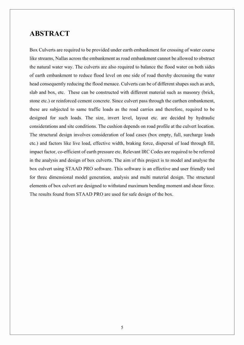
1.2.2-PIPE ARCH CULVERT (SINGLE OR MULTIPLE)
Arch culverts are suitable for large waterway opening where fishes can be provided with a
greater hydraulic advantage. Moreover, they provide low clearance and are definitely, much
artistic. Pipe arches are particularly useful for sites where headroom is limited and also have a
hydraulic advantage at low flows.
11
ADVANTAGES OF PIPE ARCH CULVERT
The features of pipe arch culverts are:
• Limited headroom condition
• Improved hydraulic capacity at a low flow
• Aesthetic shape and appearance
• Lightweight
• Easy to install
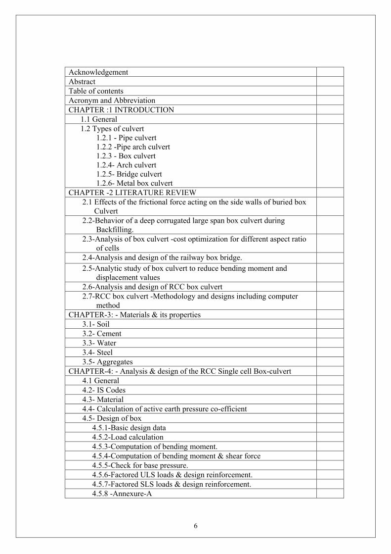
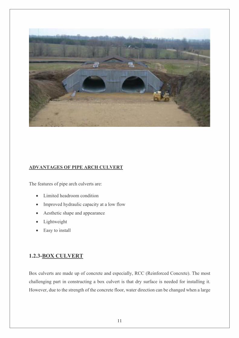
1.2.3-BOX CULVERT
Box culverts are made up of concrete and especially, RCC (Reinforced Concrete). The most
challenging part in constructing a box culvert is that dry surface is needed for installing it.
However, due to the strength of the concrete floor, water direction can be changed when a large
12
amount of water is expected. This feature makes box culverts, one of the most commonly found
types of the culvert.
ADVANTAGES OF BOX CULVERT
Box Culverts are economical for the reasons mentioned below:
• The box culvert is a rigid frame structure and very simple in construction
• It is Suitable for non-perennial streams where scrub depth is not significant but the soil
is weak.
• The bottom slab of the box culvert reduces pressure on the soil.
• Box culverts are economical due to their rigidity and monolithic action and separate
foundations are not required.
• It is used in special cases, weak foundation.

13
1.2.4-ARCH CULVERT
An arch culvert is made up of metal, stone masonry, concrete, RCC etc. Construction does not
take a lot of time and unlike box culvert, water diversion is not necessary, as it can be installed
without disturbing the water current. Thus, it can be termed as a Low Profile Culvert. This type
of culvert maintains the natural integrity of the wash bed.
The advantages of using arch culverts over traditional box culverts and pipe culverts are as
follows:
• Cost savings
• Accelerated construction schedule
• Greater hydraulic efficiency
• Pleasing aesthetics
• Design-build advantage

14
1.2.5-BRIDGE CULVERT
Bridge culverts serve a dual purpose. It acts both as a bridge and a culvert. Generally,
rectangular in shape, bridge culverts are constructed on rivers and canals. A foundation is laid
under the ground level and pavement surface is laid on top of the series of culverts. Generally,
we can term it as a Multi-Purpose culvert.
ADVANTAGES OF BRIDGE CULVERT
Following are the main features of bridge culvert:
• Extension of the network by acting as a repeater
• Very strong
• Allows traffic to pass on it
• Highly strong foundation
• Most expensive river crossings
1.2.6-METAL BOX CULVERT
The metal box culvert is the economic alternative of the bridge. These bridges are manufactured
from a standard structural plate or deep-corrugated structural plate. They are the perfect bridge
replacement maintaining the same road grade level.

15
ADVANTAGES OF METAL BOX CULVERT
The advantages are as follows:
• Durability
• Shorter construction period and easy installation
• Deformation ability
• Long service life
16
2-LITERATURE REVIEW
2.1-Junsuk Kang, Frazier Parker, Young J. Kang, and Chai H. Yoo published a paper in 2007
“ Effects of frictional forces acting on sidewalls of buried box culverts ”. They showed
the results of the effects of frictional forces acting on the sidewalls of buried box culverts
with the help of finite element method and detailed soil modelling. The possibility of
reducing earth pressure on deeply buried concrete box culverts by the imperfect trench
installation (ITI) method has been contemplated during the last several decades. The soil–
structure interaction at the box culvert–soil interface was found to have a significant effect on
total earth pressure acting on the bottom slab. Predictor equations for earth load reduction
rates were formulated for ITIs incorporating the optimum soft zone geometry based on the
finite element method. The analysis results indicated that modulus of elasticity of the
lightweight material is a major parameter affecting the earth load reduction rate. In addition,
the soil–structure interaction at the box culvert–soil interface was also found to have a
significant effect on the total earth pressure at the bottom slab depending upon the coefficient
of friction assumed. Hence, interface conditions were incorporated in the proposed equations
of the earth load reduction rate.
2.2-T.M. Elshimi, A.C. Mak, R.W.I. Brachman & I.D. Moore published a paper in 2011 on the
topic “Behaviour of a deep-corrugated large-span box culvert during backfilling”. In this
paper he presented results from a full-scale experiment of a 10-m-span deep-corrugated metal
box culvert. The culvert was instrumented and backfilled with compacted Granular A material
under controlled laboratory conditions to a cover depth of 1.5 m. Two and three-dimensional
finite element analyses were performed to model its behaviour during backfilling. The effect
of soil compaction on the culvert’s response during backfilling was also considered in the
model. The results showed that the maximum upward displacement during side backfilling of
the structure to a height of 1.8 m was only 3.2 mm and the maximum deformation measured in
a single lift occurred when the first lift of soil was placed over the crown. The three-
dimensional finite element analysis was able to calculate central deflections and maximum
bending moments within 5 and 6% of the measured values. The behaviour of a 10-m span deep-
corrugated metal box culvert measured in the laboratory during backfilling with well-graded
sand and gravel was reported. The box culvert deformations and bending moments were
17
calculated using two and three-dimensional finite element analysis and compared to the
measured values. For the particular conditions examined, the following can be concluded:
1. The behaviour of the box culvert during backfilling was successfully predicted using the
three-dimensional finite element analysis. Two-dimensional finite element analysis
successfully predicted the deformed shape and overestimated the bending moment of the box
culvert at the shoulder by about 20% of the average measured values.
2. Modelling the increase in lateral stresses due to soil compaction has a minor effect on the
response of long-span deep-corrugated metal box culvert during backfilling. The change in the
crown displacement due to compaction was less than 4% of the displacement calculated
without modelling compaction. The changes in the bending moment values at the crown and
the shoulder due to compaction were less than 7% of the moment calculated without modelling
compaction effects on lateral stresses.
3. The Canadian Highway Bridge Design Code moment equation overestimates the moment of
long-span metal box culverts especially for deep soil cover. At a soil cover of 1.5 m, The
Canadian Highway Bridge Design Code moment equation for the 10 m span test culvert
overestimated the measured moment by about 73%.
The results and conclusions are for the particular conditions, materials and construction
methods examined. Since backfilling was conducted without using a light weight dozer as
permitted by the manufacturer’s specifications, the potential effects of loading from permitted
construction equipment during backfilling should be considered.
2.3-M.G. Kalyanshetti, S.A. Gosavi published a paper in 2014 “Analysis of box culvert - cost
optimization for different aspect ratios of cell”. In this paper he presented about Reinforced
concrete box culvert that consists of top slab, bottom slab and two vertical side walls built
monolithically which form a closed rectangular or square single cell. By using one or more
intermediate vertical walls multiple cell box culverts is obtained. Multiple cell reinforced box
culverts are ideal bridge structure if the discharge in a drain crossing the road is large and if the
bearing capacity of the soil is low the single box culvert becomes uneconomical because of the
higher thickness of the slab and walls. In such cases, more than one box can be constructed
side by side monolithically. In conventional method thickness of box culvert is assumed and
18
later on check for thickness is taken. But this may leads to uneconomical design therefore an
attempt is made to evaluate optimum thicknesses for economical design. In the present work
12 m channel length is consider for analysis with 2m to 6m height variation which is again
divided into single cell, double cell and triple cell. IRC class AA tracked live load is considered.
The analysis is done by using stiffness matrix method and a computer program in C language
is developed for the cost evaluation. Study is carried out related to variation in bending
moment; subsequently cost comparison is made for different aspect ratios. The percentage
reduction in cost of single cell, double cell and triple cell based on optimum thicknesses are
presented. The optimum thicknesses presented over here are used to achieve the economical
design of box culvert. Based on these optimum thicknesses optimum cost per meter width of
single cell, double cell and triple cell is evaluated. The study reveals that the cost of box culvert
reduces if the optimum thicknesses which are presented in this study are considered.
From which he conclude that:-
• Top slab of box culvert is critical member which carries maximum bending moment.
• The bending moments of different members of box culvert are determined for various
aspect ratios and are presented in the form of charts. Using these charts bending moment
can be calculated for intermediate aspect ratios also. The charts can be used as a readily
reference for obtaining the bending moment for any different aspect ratio.
• In the conventional method of analysis thickness is approximately consider as L/20.
However the optimum thickness are different for different aspect ratios for 12m channel
length which is divided into single cell, double cell and triple cell they are in the range
of L/17 to L/18.5 for 12 m span, L/17.6 to L/21.5 for 6 m span & L/10 to L/20 for 4 m
span.
• Based on the optimum thicknesses evaluated for 12m channel length average
percentage cost reduction per meter width for single cell is 1.84%, for double cell 4.18%
and for triple cell 2.78%.
2.4-Mr. Afzal Hanif Sharif published his review report on “Analysis and design of railway
Box Bridge”. In which he analyse the railway box bridge with the help of staad pro software
then and designed all structural elements of box bridge. Then he checked the safety of the
bridge.
19
From this he concluded that Box Bridge is structurally very strong, rigid & safe. Box Bridge
does not need any elaborate foundation and can easily be placed over soft foundation by
increasing base slab projection to retain base pressure within safe bearing capacity of ground
soil. Box Bridge is easy to construct, practically no maintenance. It can have multi cell to match
discharge within smaller height of embankment. The designer has option to select the number
of cells with desired span to depth ratio suiting to hydraulic conditions at site.
2.5-Vasu Shekhar Tanwar, M. P. Verma and Sagar Jamle published a paper in 2018 on the
topic “Analytic Study of Box Culvert to Reduce Bending Moment and Displacement
Values”. In this work they tried to reduce the Bending Moment values and displacement values
in order to make structure more safe and reliable to construct and use. These are the following
cases of different types of loads which are acting on the box culvert.
Case-1: Dead load, live load, earth pressure acting from outside, no water pressure acting from
inside.
Case-2: Dead load, live load, earth pressure acting from outside, water pressure acting from
inside.
Case-3: Dead load, earth pressure acting from outside, no water pressure reacting from inside
without live load.
After the analysis they concluded that:-
• Displacement values and Bending moment values declined and gave a positive response
for structural change.
• Displacement declined in case 1 by 93.89% as the minimum value of displacement is
taken.
• Displacement declined in case 2 by 93.61% as the minimum value of displacement
• Displacement declined in case 3 by 92.56% as the minimum value of displacement
• Bending Moment declined in case 1 by 84.23% as the minimum value of Bending
Moment.
• Bending Moment declined in case 2 by 90.22% as the minimum value of Bending
Moment.
20
• Bending Moment declined in case 3 by 97.84% as the minimum value of Bending
Moment.
2.6-Neha Kolate1, Molly Mathew and Snehal Mali published a paper in 2014 on the topic
“Analysis and Design of RCC Box Culvert”. In this paper they analyse a box of 3m*3m.
Various load cases are calculated for the box and the box is checked for shear and shear
reinforcement provided on the site. Basically, there is no difference in design of single cell and
multi cell box having two, three or more cells. The bending moment is obtained by moment
distribution considering all the cells together for different combination of loading and design
of section accomplished for final bending moments for that member. Shear force and resulting
shear stress have to be checked for members independently.
After analysis and design they conclude that:-
• Box for cross drainage works across high embankments has many advantages compared
to slab culvert.
• Box culvert is easy to add length in the event of widening of the road.
• Box is structurally very strong, rigid & safe.
• Box does not need any elaborate foundation and can easily be placed over soft
foundation by increasing base slab projection to retain base pressure within safe bearing
capacity of ground soil.
• Box of required size can be placed within the embankment at any elevation by varying
cushion. This is not possible in case of slab culvert.
• Easy to construct, practically no maintenance, can have multi cell to match discharge
within smaller height of embankment.
• Small variation in co-efficient of earth pressure has little influence on the design of box
particularly without cushion.
• For culverts without cushion taking effective width corresponding to α for continuous
slab shall not be correct. It is likely to provide design moments and shear on lower side
hence not safe.
• For box without cushion braking force is required to be considered particularly for
smaller span culverts. Further for distribution of braking force effects the same effective
width as applicable for vertical application of live load shall be considered. If braking
force is not considered or distributed over the whole length of box (not restricted within
the effective width) shall be unsafe.
21
• 10. For box without cushion having low design moments and shear stress as compared
to the box having cushion. So steel required is less in the box with no cushion as
compared to cushion.
2.7-B.N. Sinha and R.P. Sharma published a paper in 2009 on the topic “RCC box culvert -
methodology and Designs including computer method”. In this paper they deals with box
culverts made of RCC, with and without cushion. The size, invert level, layout etc. are decided
by hydraulic considerations and site conditions. The cushion depends on road profile at the
culvert location. The scope of this Paper has been further restricted to the structural design of
box. The structural design involves consideration of load cases (box empty, full, surcharge
loads etc.) and factors like live load, effective width, braking force, dispersal of load through
fill, impact factor, co-efficient of earth pressure etc. Relevant IRC Codes are required to be
referred. The structural elements are required to be designed to withstand maximum bending
moment and shear force.
From this work they conclude that:-
• Box for cross drainage works across high embankments has many advantages compared
to a slab culvert.
• It is easy to add length in the event of widening of the road.
• Box is structurally very strong, rigid and safe.
• Box does not need any elaborate foundation and can easily be placed over soft
foundation by increasing base slab projection to retain base pressure within safe bearing
capacity of ground soil.
• Box of required size can be placed within the embankment at any elevation by varying
cushion. This is not possible in case of slab culvert.
• Right box can be used for flow of water in skew direction by increasing length or
providing edge beam around the box and it is not necessary to design skew box.
• Easy to construct, practically no maintenance, can have multi-cell to match discharge
within smaller height of embankment.
• Small variation in co-efficient of earth pressure has little influence on the design of box
particularly without cushion.
22
• For culverts without cushion (or little cushion) taking effective width as per provision
in IRC: 21-2000 corresponding to α for continuous slab shall not be correct. It is likely
to provide design moments and shear on lower side hence not safe.
• For box without cushion braking force is required to be considered particularly for
smaller span culverts. Further for distribution of braking force effects the same effective
width as applicable for vertical application of live load shall be considered. If braking
force is not considered or distributed over the whole length of box (not restricted within
the effective width) the design shall be unsafe.
• It may be seen that α affects effective width, mainly applicable for the top slab
(particularly for box without cushion) and braking force. As regards bottom slab and
top and bottom slabs of box with cushion due to dispersal of loads either through walls
or through fills effective width loses its applicability.
• The design of box is covered by three load cases dealt in this paper. The forth situation
when whole box is submerged under water, provide design moments etc. less than given
by the three load cases hence need not be considered.
• The design of box with cushion done by STAAD. Pro computer software compares
very close to manual design.

23
3-MATERIAL AND ITS PROPERTIES
3.1-SOIL Soil is a material composed of five ingredients — minerals, soil organic matter, living
organisms, gas, and water. Soil minerals are divided into three size classes — clay, silt,
and sand. The percentages of particles in these size classes is called soil texture. The
mineralogy of soils is diverse. A clay mineral called smectite can shrink and swell so much
upon wetting and drying that it can knock over buildings. The most common mineral in soils
is quartz. We are using here dry soil. Physical properties of soil include colour, texture,
structure, porosity, density, consistence, temperature, and air. Colours of soils vary widely
and indicate such important properties as organic matter, water, and redox conditions. Soil
texture, structure, porosity, density, and consistence are related with types of soil particles
and their arrangement. There are two types of soil particles—primary and secondary. Primary
particles include sand, silt, and clay, categorized on the basis of their effective diameter.
There are important differences in physical, chemical, and mineralogical properties of these
fractions. Their relative proportion in a soil is called soil texture. It is a fundamental property
of soil. It is not easily altered. There are 12 textural classes ranging from sand to clay. Soil
structure is the arrangement of soil particles into different geometric patterns. It is classified
into different types on shape, classes on size, and grades on stability. Soil structure is
amenable. Soil texture and structure together regulate porosity, density, compactness,
retention, and movement of water and air in soil. Soil temperature is slightly higher than air
temperature in a place.
3.2-CEMENT
Cement, one of the most important building materials, is a binding agent that sets and hardens
to adhere to building units such as stones, bricks, tiles, etc. Cement generally refers to a very
fine powdery substance chiefly made up of limestone (calcium), sand or clay (silicon), bauxite
(aluminium) and iron ore, and may include shells, chalk, marl, shale, clay, blast furnace slag,
slate. The raw ingredients are processed in cement manufacturing plants and heated to form a
rock-hard substance, which is then ground into a fine powder to be sold. Cement mixed with

24
water causes a chemical reaction and forms a paste that sets and hardens to bind individual
structures of building materials.
Cement is an integral part of the urban infrastructure. It is used to make concrete as well as
mortar, and to secure the infrastructure by binding the building blocks. Concrete is made of
cement, water, sand, and gravel mixed in definite proportions, whereas mortar consists of
cement, water, and lime aggregate. These are both used to bind rocks, stones, bricks, and other
building units, fill or seal any gaps, and to make decorative patterns. Cement mixed with water
silicates and aluminates, making a water repellent hardened mass that is used for water-
proofing.
3.3-WATER
Water as a raw material to make any kind of cementitious paste (be it plain cement
concrete/reinforced/or with additives/simple mortar paste). It is what helps initiate the
hydration reaction of the cement to turn that slurry of the mix to act as a binder between
all its constituents (bulk matter).Water in soil preparation in carious structures. Be it to
help compact soil to its densest underneath a road, or on the back side of a retaining wall,
foundations etc. Water as a curing compound. Water as a raw material during manufacture
of various civil materials. Say during quenching in TMT process of the reinforcements
etc. Or in standardised testing (as various test are performed under some or the other water
requirements. Water as a weathering action (opposing) force needs to be considered as
well. Say to estimate the damage to a steel structure in a heavy rainfall area, so we can
better judge the structures durability and take counter-measures. Or to say ground water
table rising up and compromising the strength of soil base and others.
3.4-STEEL
Steel is the most commonly used structural metal, due to its various properties like great
strength, good ductility and high strength, allowing easy fabrication. Due to its high strength
members of light sections can be used to carry a heavy load, which means there is considerable
reduction in dead load.

25
It is due to this reason, steel becomes an affordable material for making very long span
structures like auditoriums, sport halls etc. Due to their stiffness, steel members deflect to very
small extents often not needing special consideration. Steel allows itself to be worked easily in
the fabricating shop in various ways like, drilling, sawing, flame cutting etc. It allows joining
easily by welding. Steel is also comparatively cheaper to other metals. For instance, Aluminium
may cost 3 to 4 times more than the usual grades of steel. Steel allows easy erections and may
not need form work. Considerable part of the steel structure can be prefabricated accurately in
the workshop, away from the construction site.
Due to its relatively lower weight, steel allows making large span structures. It is worthy to
note that construction is fast with steel. For example, constructing a bridge over a busy road or
railway line can be done in the shortest duration of time, considerably minimizing the period
of obstruction. Steel also allows any later modifications like extensions easily.
Tensile Strength:
The stress applied to cause failure of the material is considerably greater than the yield stress.
Ductility:
Steel has this important property to undergo substantial deformation without fracture. At the
stage of failure, the strain may be 0.25 for mild steel, whereas this strain at failure will be less
in the case of high carbon steels. It may also be noted that the range of elastic strain is just a
small part of the total strain occurring as the material reaches the fracture stage.
3.5-AGGREGATES
Aggregates are inert granular materials such as sand, gravel, or crushed stone that, along with
water and Portland cement, are an essential ingredient in concrete. For a good concrete mix,
aggregates need to be clean, hard, strong particles free of absorbed chemicals or coatings of
clay and other fine materials that could cause the deterioration of concrete. Aggregates, which
account for 60 to 75 percent of the total volume of concrete, are divided into two distinct
categories--fine and coarse. Fine aggregates generally consist of natural sand or crushed stone
with most particles passing through a 3/8-inch sieve. Coarse aggregates are any particles
greater than 0.19 inch, but generally range between 3/8 and 1.5 inches in diameter. Gravels
constitute the majority of coarse aggregate used in concrete with crushed stone making up most
of the remainder. Natural gravel and sand are usually dug or dredged from a pit, river, lake, or
26
seabed. Crushed aggregate is produced by crushing quarry rock, boulders, cobbles, or large-
size gravel. Recycled concrete is a viable source of aggregate and has been satisfactorily used
in granular subbases, soil-cement, and in new concrete. After harvesting, aggregate is
processed: crushed, screened, and washed to obtain proper cleanliness and gradation. If
necessary, a benefaction process such as jigging or heavy media separation can be used to
upgrade the quality. Once processed, the aggregates are handled and stored to minimize
segregation and degradation and prevent contamination. Aggregates strongly influence
concrete's freshly mixed and hardened properties, mixture proportions, and economy.
Consequently, selection of aggregates is an important process. Although some variation in
aggregate properties is expected, characteristics that are considered include:
• grading
• durability
• particle shape and surface texture
• abrasion and skid resistance
• unit weights and voids
• absorption and surface moisture
Grading refers to the determination of the particle-size distribution for aggregate. Grading
limits and maximum aggregate size are specified because these properties affect the amount of
aggregate used as well as cement and water requirements, workability, pumpability, and
durability of concrete. In general, if the water-cement ratio is chosen correctly, a wide range in
grading can be used without a major effect on strength. When gap-graded aggregate are
specified, certain particle sizes of aggregate are omitted from the size continuum. Gap-graded
aggregate are used to obtain uniform textures in exposed aggregate concrete. Close control of
mix proportions is necessary to avoid segregation.
4.1
4.2
IRC - 5
IRC - 6
IRC - 112
4.3
4.4
30 deg
20 deg
0 deg
90 deg
2 t/m3
1 t/m3
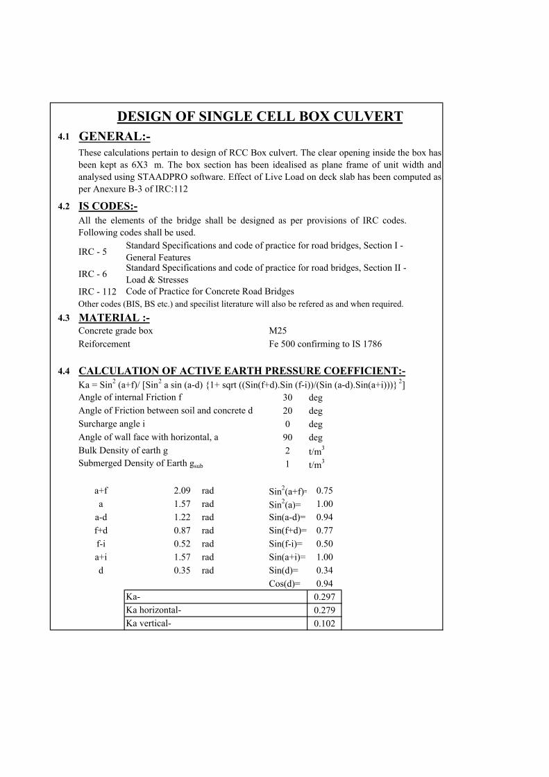
a+f 2.09 rad Sin2(a+f)= 0.75
a 1.57 rad Sin2(a)= 1.00
a-d 1.22 rad Sin(a-d)= 0.94
f+d 0.87 rad Sin(f+d)= 0.77
f-i 0.52 rad Sin(f-i)= 0.50
a+i 1.57 rad Sin(a+i)= 1.00
d 0.35 rad Sin(d)= 0.34
Cos(d)= 0.94
0.297
0.279
0.102Ka vertical-
GENERAL:-
Angle of wall face with horizontal, a
Bulk Density of earth gSubmerged Density of Earth gsub
Ka-
Ka horizontal-
Ka = Sin2 (a+f)/ [Sin2 a sin (a-d) {1+ sqrt ((Sin(f+d).Sin (f-i))/(Sin (a-d).Sin(a+i)))} 2]Angle of internal Friction f
Angle of Friction between soil and concrete d
Surcharge angle i
CALCULATION OF ACTIVE EARTH PRESSURE COEFFICIENT:-
DESIGN OF SINGLE CELL BOX CULVERT
Fe 500 confirming to IS 1786
These calculations pertain to design of RCC Box culvert. The clear opening inside the box hasbeen kept as 6X3 m. The box section has been idealised as plane frame of unit width andanalysed using STAADPRO software. Effect of Live Load on deck slab has been computed asper Anexure B-3 of IRC:112
All the elements of the bridge shall be designed as per provisions of IRC codes.Following codes shall be used.
Standard Specifications and code of practice for road bridges, Section I - General FeaturesStandard Specifications and code of practice for road bridges, Section II - Load & StressesCode of Practice for Concrete Road Bridges
Concrete grade box
Reiforcement
M25
Other codes (BIS, BS etc.) and specilist literature will also be refered as and when required.
MATERIAL :-
IS CODES:-

4.54.5.1
6 m3 m3 m0 degrees
272.311 m6.35 m
3 m
276.351 m
275.325 m
271.625 m
3.000 mm
0.35 m
6.35 m
20 kN/m3
10 kN/m3
10 kN/m3
4.5.2
1
22)a‐
1.026 m22 kN/m3
22.572 kN/m
3
44)a‐
DESIGN OF SINGLE CELL BOX
Submerged Density of fill/soil
LOAD CALCULATIONS:-
Self weight command has been applied in stad pro & resective bending moment and shear force has ben tabulated in the table below:-
SELF-WEIGHT:-
Density of water
Active earth pressure :- ,clause214.1.1.1ofIRC‐06‐EARTH PRESSURE CALCULATIONS:-
Cushion weight:-
Effective width of the live load (refer Annexure-A)
The above mentioned loading on the effective width in Staad pro & their respective bending moment n shear force has been tabulated below
LIVE LOAD CALCULATIONS:-Type of loading considered:- 40t bogie load/70R tracked vehicle
Wt of cushion
SUPER IMPOSED DEAD LOAD:-
Cushion heightAvg density of cushion
skew angleGLEffective span of boxTotal clear ht at entrance
DESIGN OF BOX :-
Wall Thickness (Assumed)Effective span of boxDry Density of fill/soil
BASIC DESIGN DATA:-Clear SpanMin ht at entranceMax clear ht at exit of box
FRLTop of boxFoundation lvlClear height

0.2797.37 kN/m2
+++
4)b‐0.500
13.21 kN/m2
+
++
5
1.2 m6.7 kN/m2
EP due to live load surcharge at re 12 kN/m2
H1 1.201 mH2 4.551 mH3 1.376 m FRL 276.351
H1= 1.201m Top of box= 275.325
P1
HFL
H4= 3.175m
H2= 4.551m
P2
Found'n lvl= 271.625
Earth Pressure at rest :- (Refer, cl 214.1.3 of IRC-06-2017)
Maximum water level is considered upto Sofffit of top flange of box. It is proposed to design the box for earth pressure only. Pressure diagram is shown below.
Active Earth pressure at P1=
Active Earth pressure at P2=
= (0.279 * 22 * 1.201(Pressure due dry soil at
center of top slab)
Active Earth pressure at P2=
(Pressure due dry soil abv HFL)
= (0.279 * 22 * 1.3768.45
Active Earth Pr Coeff. (Ka)
Earth Pr Coeff. At Rest(Ko)
(Pressure due submerged soil below HFL)
=0.279*10*(3.175)8.86
= 8.45+ 8.86 = 17.31 Kn/m2
Active Earth pressure at P2= Active Earth pressure at P2=
Earth pressure at rest P1= = (0.5 * 22 * 1.201)(Pressure due dry soil at
center of top slab)
Earth pressure at rest P2= (Pressure due dry soil abv HFL)(Pressure due submerged soil below
HFL)Earth pressure at rest P2= = (0.5 * 10 * 1.376) =0.5*10*(3.175)Earth pressure at rest P2= 15.14 15.88Earth pressure at rest P2= = 15.14+ 15.88 = 31.02 Kn/m2
=0.5 * 20 * Heq
Where:-
LIVE LOAD SURCHARGE CALCULATIONS:-Earth pressure due to live load surcharge (Refer,cl214.1.1.3ofIRC‐06‐2017)
Active EP due to live load surchar =0.279 * 20 * HeqEquival'nt height of soil for vehicular loading cl.214.1.1.3 ,IRC 06-2017
DrySoil
H3= 1.376m
SubmergedSoil
BOXCULVERTCROSS‐SECTION
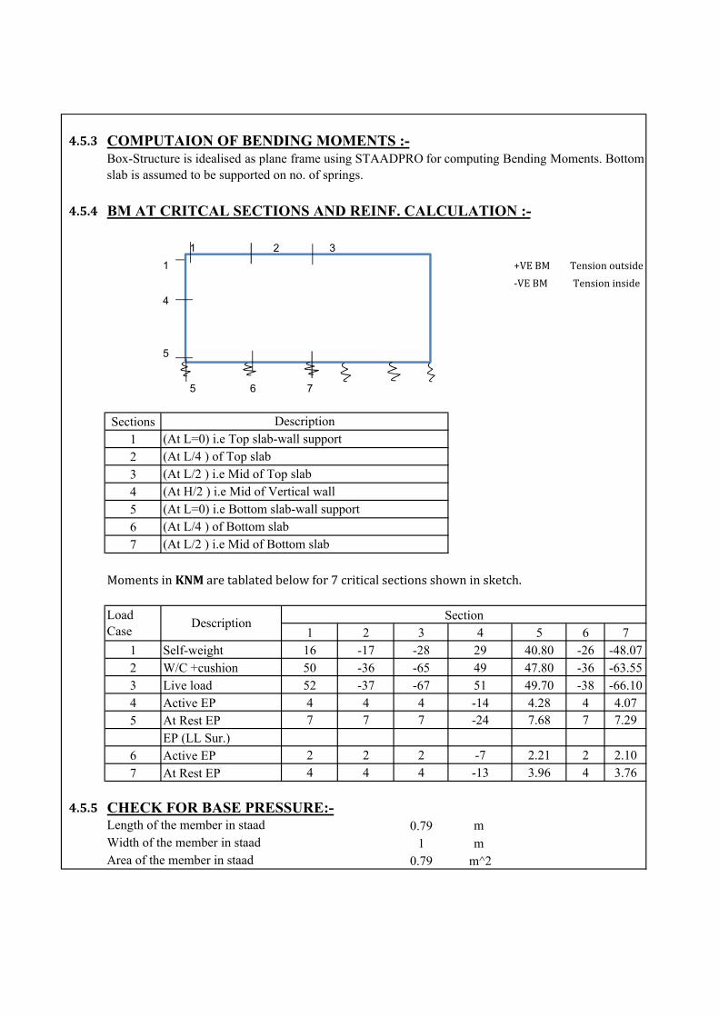
4.5.3
4.5.4
1 2 3
1 +VEBM
‐VEBM
4
5
5 6 7
Sections1234567
1 2 3 4 5 6 71 16 -17 -28 29 40.80 -26 -48.072 50 -36 -65 49 47.80 -36 -63.553 52 -37 -67 51 49.70 -38 -66.104 4 4 4 -14 4.28 4 4.075 7 7 7 -24 7.68 7 7.29
6 2 2 2 -7 2.21 2 2.10
7 4 4 4 -13 3.96 4 3.76
4.5.50.79 m
1 m 0.79 m^2
BM AT CRITCAL SECTIONS AND REINF. CALCULATION :-
MomentsinKNMaretablatedbelowfor7criticalsectionsshowninsketch.
CHECK FOR BASE PRESSURE:-
Tensionoutside
Tensioninside
Length of the member in staadWidth of the member in staadArea of the member in staad
COMPUTAION OF BENDING MOMENTS :-
Self-weightW/C +cushionLive loadActive EP
Section
At Rest EPEP (LL Sur.)Active EPAt Rest EP
Box-Structure is idealised as plane frame using STAADPRO for computing Bending Moments. Bottomslab is assumed to be supported on no. of springs.
Load Case
Description
Description(At L=0) i.e Top slab-wall support (At L/4 ) of Top slab (At L/2 ) i.e Mid of Top slab (At H/2 ) i.e Mid of Vertical wall (At L=0) i.e Bottom slab-wall support (At L/4 ) of Bottom slab (At L/2 ) i.e Mid of Bottom slab
Kn/m2
Kn/m2
4.5.6
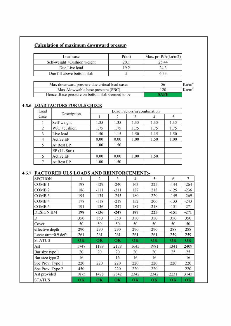
1 2 3 4 51 1.35 1.35 1.35 1.35 1.352 1.75 1.75 1.75 1.75 1.753 1.50 1.15 1.50 1.15 1.504 0.00 0.00 1.00 1.50 1.00
5 1.00 1.50
6 0.00 0.00 1.00 1.50
7 1.00 1.50
4.5.71 2 3 4 5 6 7
198 -129 -240 163 225 -144 -264186 -111 -211 127 213 -125 -236194 -134 -245 180 220 -149 -269178 -118 -219 152 206 -133 -243191 -136 -247 187 218 -151 -271
DESIGN BM 198 -136 -247 187 225 -151 -271
350 350 350 350 350 350 35050 50 50 50 50 50 50
effective depth 290 290 290 290 290 288 288Lever arm=0.9 deff 261 261 261 261 261 259 259
OK OK OK OK OK OK OK
1747 1199 2178 1645 1981 1341 240920 20 20 20 20 25 2516 16 16 16 16
Spc Prov. Type 1 220 220 220 220 220 220 220Spc Prov. Type 2 450 220 220 220 220Ast provided 1875 1428 2342 2342 2342 2231 3145
OK OK OK OK OK OK OK
56120
19.2
Bar size type 2
Calculation of maximum downward pressure
Hence ,Base pressure on bottom slab deemed to be SAFE
LOAD FACTORS FOR ULS CHECK
25.4424.3
5 6.33
Max downward pressure due critical load casesMax Alowwable base pressure (SBC)
COMB 2COMB 3COMB 4COMB 5
CoverD
Load case P(kn) Max. pr- P/A(kn/m2)Self-weight +Cushion weight
Due Live loadDue fill above bottom slab
20.1
At Rest EP
Self-weightW/C +cushionLive load
Active EP
At Rest EPEP (LL Sur.)
Active EP
Load Case
DescriptionLoad Factors in combination
FACTORED ULS LOADS AND REINFORCEMENT:-
STATUS
SECTIONCOMB 1
AstBar size type 1
STATUS
Rare1 Rare2 Quasi P
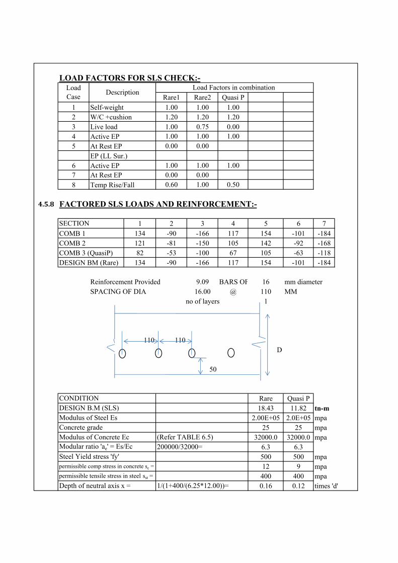
1 1.00 1.00 1.002 1.20 1.20 1.203 1.00 0.75 0.004 1.00 1.00 1.00
5 0.00 0.00
6 1.00 1.00 1.007 0.00 0.00
8 0.60 1.00 0.50
4.5.8
1 2 3 4 5 6 7
134 -90 -166 117 154 -101 -184121 -81 -150 105 142 -92 -168
COMB 3 (QuasiP) 82 -53 -100 67 105 -63 -118DESIGN BM (Rare) 134 -90 -166 117 154 -101 -184
Reinforcement Provided 9.09 BARS OF 16 mm diameterSPACING OF DIA 16.00 @ 110 MM
no of layers 1
110 110D
50
Rare Quasi P18.43 11.82 tn-m
2.00E+05 2.0E+05 mpa25 25 mpa
32000.0 32000.0 mpa6.3 6.3500 500 mpa12 9 mpa400 400 mpa0.16 0.12 times 'd'
COMB 1
At Rest EPEP (LL Sur.)
Self-weightW/C +cushionLive loadActive EP
LOAD FACTORS FOR SLS CHECK:-
Modulus of Steel EsConcrete gradeModulus of Concrete EcModular ratio 'ae' = Es/Ec
Steel Yield stress 'fy'
CONDITIONDESIGN B.M (SLS)
(Refer TABLE 6.5)200000/32000=
Load Case
DescriptionLoad Factors in combination
COMB 2
Temp Rise/Fall
Active EPAt Rest EP
FACTORED SLS LOADS AND REINFORCEMENT:-
SECTION
permissible comp stress in concrete sc =
permissible tensile stress in steel sst =
Depth of neutral axis x = 1/(1+400/(6.25*12.00))=

0.95 0.96 times 'd'350 350 mm2.2 2.2
1000 100050 50 mm200 200 kN/sqm32 32 kN/sqm
6.250 6.250292 292 mm
1828 1828 sqmm/m46.72 35.04 mm
3.40E+07 1.4E+07 mm^4
6.87E+08 7.5E+08 mm^47.21E+08 7.7E+08 mm^4
392.0 247.0 mpa11.9 5.4 mpa
Due to concrete above neutral axis
3,39,92,824+68,73,54,031=18.43*10000000*(292-46.72)/72,13,46,855*6.3
18.43*10000000*(46.72)/72,13,46,855
1000*46.72^3/12+1000*46.72*(46.72/2)^2
Leve arm j=Thickness 'h' =fct,effbtCmin' min cover to tension steelEs
350-50-16/29.09*pi*(16^2/4)0.16*292
mm
mm
Ecm=
Due to steel below neutral axis
Total moment of areastress in steel ssc =stress in concret scb =
6.25*1,828.00*(292-46.72)^2
Effective Depth 'd'AsDepth of neutral axis 'dc'Second moment of area of section
As, 191.25 mm > 110 mm Hence, Crack control deemed to be
Satisfied
As per Table 12.3 of IRC 112:2011, max spacing for stress of 247 mpa
Spacing requried:- 191.3
Actual spacing provided >110.0
1-0.16/3=
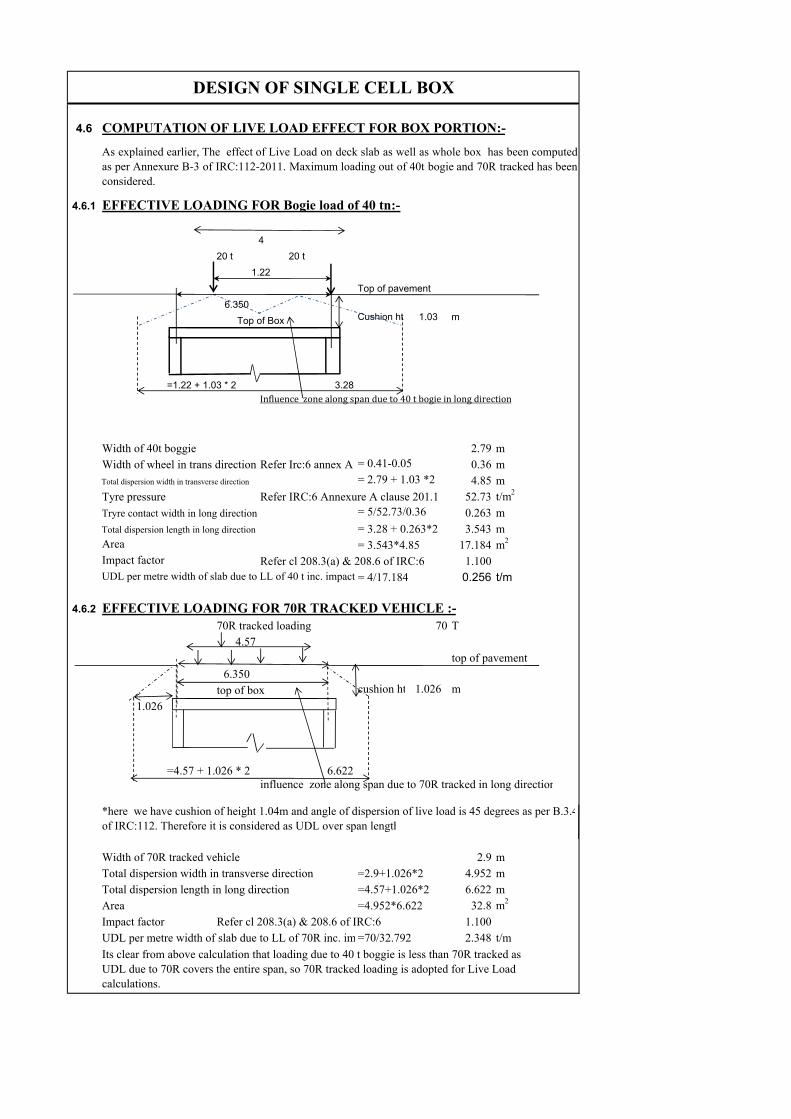
4.6
4.6.1
20 t 20 t
6.350Cushion ht 1.03 m
=1.22 + 1.03 * 2 3.28
2.79 m0.36 m4.85 m
52.73 t/m2
0.263 m3.543 m
17.184 m2
1.1000.256 t/m
4.6.2
70R tracked loading 70 T4.57
top of pavement6.350
top of box cushion ht 1.026 m
1.026
=4.57 + 1.026 * 2 6.622influence zone along span due to 70R tracked in long direction
Width of 70R tracked vehicle 2.9 mTotal dispersion width in transverse direction =2.9+1.026*2 4.952 mTotal dispersion length in long direction =4.57+1.026*2 6.622 mArea =4.952*6.622 32.8 m2
Impact factor Refer cl 208.3(a) & 208.6 of IRC:6 1.100UDL per metre width of slab due to LL of 70R inc. im =70/32.792 2.348 t/m
DESIGN OF SINGLE CELL BOX
EFFECTIVE LOADING FOR 70R TRACKED VEHICLE :-
Tryre contact width in long direction
Total dispersion length in long direction
AreaImpact factorUDL per metre width of slab due to LL of 40 t inc. impact
Refer cl 208.3(a) & 208.6 of IRC:6
= 5/52.73/0.36
= 3.28 + 0.263*2= 3.543*4.85
= 4/17.184
Influencezonealongspandueto40tbogieinlongdirection
Width of 40t boggieWidth of wheel in trans directionTotal dispersion width in transverse direction
Tyre pressure Refer IRC:6 Annexure A clause 201.1
= 0.41-0.05= 2.79 + 1.03 *2
Refer Irc:6 annex A
COMPUTATION OF LIVE LOAD EFFECT FOR BOX PORTION:-
EFFECTIVE LOADING FOR Bogie load of 40 tn:-
4
1.22
Top of Box
Top of pavement
*here we have cushion of height 1.04m and angle of dispersion of live load is 45 degrees as per B.3.4of IRC:112. Therefore it is considered as UDL over span length
Its clear from above calculation that loading due to 40 t boggie is less than 70R tracked as UDL due to 70R covers the entire span, so 70R tracked loading is adopted for Live Load calculations.
As explained earlier, The effect of Live Load on deck slab as well as whole box has been computedas per Annexure B-3 of IRC:112-2011. Maximum loading out of 40t bogie and 70R tracked has beenconsidered.
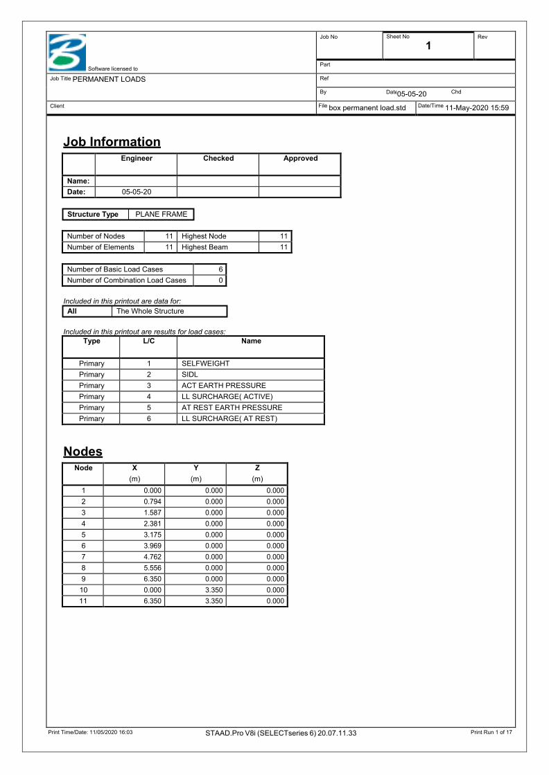
Print Time/Date: 11/05/2020 16:03 STAAD.Pro V8i (SELECTseries 6) 20.07.11.33 Print Run 1 of 17
Date
Software licensed to
Job No Sheet No
1 Rev
Part
Job Title PERMANENT LOADS Ref
By 05-05-20 Chd
Client File box permanent load.std Date/Time 11-May-2020 15:59
Job Information
Structure Type PLANE FRAME
Included in this printout are data for: All The Whole Structure
Included in this printout are results for load cases:
Nodes
Engineer Checked Approved
Name:
Date: 05-05-20
Number of Nodes 11 Highest Node 11 Number of Elements 11 Highest Beam 11
Number of Basic Load Cases 6 Number of Combination Load Cases 0
Type L/C Name
Primary 1 SELFWEIGHT Primary 2 SIDL Primary 3 ACT EARTH PRESSURE Primary 4 LL SURCHARGE( ACTIVE) Primary 5 AT REST EARTH PRESSURE Primary 6 LL SURCHARGE( AT REST)
Node X (m)
Y (m)
Z (m)
1 0.000 0.000 0.000 2 0.794 0.000 0.000 3 1.587 0.000 0.000 4 2.381 0.000 0.000 5 3.175 0.000 0.000 6 3.969 0.000 0.000 7 4.762 0.000 0.000 8 5.556 0.000 0.000 9 6.350 0.000 0.000
10 0.000 3.350 0.000 11 6.350 3.350 0.000

Print Time/Date: 11/05/2020 16:03 STAAD.Pro V8i (SELECTseries 6) 20.07.11.33 Print Run 2 of 17
Date
Software licensed to
Job No Sheet No
2 Rev
Part
Job Title PERMANENT LOADS Ref
By 05-05-20 Chd
Client File box permanent load.std Date/Time 11-May-2020 15:59
Beams
Section Properties
Materials
Releases There is no data of this type.
Supports
Beam Node A Node B Length (m)
Property β (degrees)
1 1 2 0.794 1 0 2 2 3 0.794 1 0 3 3 4 0.794 1 0 4 4 5 0.794 1 0 5 5 6 0.794 1 0 6 6 7 0.794 1 0 7 7 8 0.794 1 0 8 8 9 0.794 1 0 9 10 1 3.350 1 0
10 9 11 3.350 1 0 11 10 11 6.350 1 0
Prop Section Area (cm2)
Iyy
(cm4) Izz
(cm4) J
(cm4) Material
1 Prismatic General 3.5E+3 0.000 360E+3 0.000 MATERIAL1
Mat Name E (kN/mm2)
ν Density (kg/m3)
α (/°C)
1 STEEL 205.000 0.300 7.83E+3 12E -6 2 STAINLESSSTEEL 197.930 0.300 7.83E+3 18E -6 3 ALUMINUM 68.948 0.330 2.71E+3 23E -6 4 MATERIAL1 32.000 0.170 2.55E+3 0.000 5 CONCRETE 21.718 0.170 2.4E+3 10E -6
Node X (kN/mm)
Y (kN/mm)
Z (kN/mm)
rX (kN-m/deg)
rY (kN-m/deg)
rZ (kN-m/deg)
1 0.000 0.500 Fixed Fixed Fixed 0.010 2 0.000 1.000 Fixed Fixed Fixed 0.010 3 0.000 1.000 Fixed Fixed Fixed 0.010 4 0.000 1.000 Fixed Fixed Fixed 0.010 5 0.000 1.000 Fixed Fixed Fixed 0.010 6 0.000 1.000 Fixed Fixed Fixed 0.010 7 0.000 1.000 Fixed Fixed Fixed 0.010 8 0.000 1.000 Fixed Fixed Fixed 0.010 9 20.000 0.500 Fixed Fixed Fixed 0.010

Print Time/Date: 11/05/2020 16:03 STAAD.Pro V8i (SELECTseries 6) 20.07.11.33 Print Run 3 of 17
Date
Software licensed to
Job No Sheet No
3 Rev
Part
Job Title PERMANENT LOADS Ref
By 05-05-20 Chd
Client File box permanent load.std Date/Time 11-May-2020 15:59
Primary Load Cases
1 SELFWEIGHT : Selfweight
2 SIDL : Beam Loads
3 ACT EARTH PRESSURE : Beam Loads
4 LL SURCHARGE( ACTIVE) : Beam Loads
5 AT REST EARTH PRESSURE : Beam Loads
Number Name Type
1 SELFWEIGHT None 2 SIDL None 3 ACT EARTH PRESSURE None 4 LL SURCHARGE( ACTIVE) None 5 AT REST EARTH PRESSURE None 6 LL SURCHARGE( AT REST) None
Direction Factor Assigned Geometry
Y -1.000 ALL
Beam Type Direction Fa Da (m)
Fb Db Ecc. (m)
11 UNI kN/m GY -22.572 - - - -
Beam Type Direction Fa Da (m)
Fb Db Ecc. (m)
9 TRAP kN/m Y 7.372 0.000 8.446 0.175 - TRAP kN/m Y 8.446 0.175 17.304 3.350 -
10 TRAP kN/m Y 17.304 0.000 8.446 3.175 - TRAP kN/m Y 8.446 3.175 7.372 3.350 -
Beam Type Direction Fa Da (m)
Fb Db Ecc. (m)
9 UNI kN/m GX 6.696 - - - - 10 UNI kN/m GX -6.696 - - - -
Beam Type Direction Fa Da (m)
Fb Db Ecc. (m)
9 TRAP kN/m Y 13.211 0.000 15.136 0.175 - TRAP kN/m Y 15.136 0.175 31.011 3.350 -
10 TRAP kN/m Y 31.011 0.000 15.136 3.175 - TRAP kN/m Y 15.136 3.175 13.211 3.350 -
Print Time/Date: 11/05/2020 16:03 STAAD.Pro V8i (SELECTseries 6) 20.07.11.33 Print Run 4 of 17
Date
Software licensed to
Job No Sheet No
4 Rev
Part
Job Title PERMANENT LOADS Ref
By 05-05-20 Chd
Client File box permanent load.std Date/Time 11-May-2020 15:59
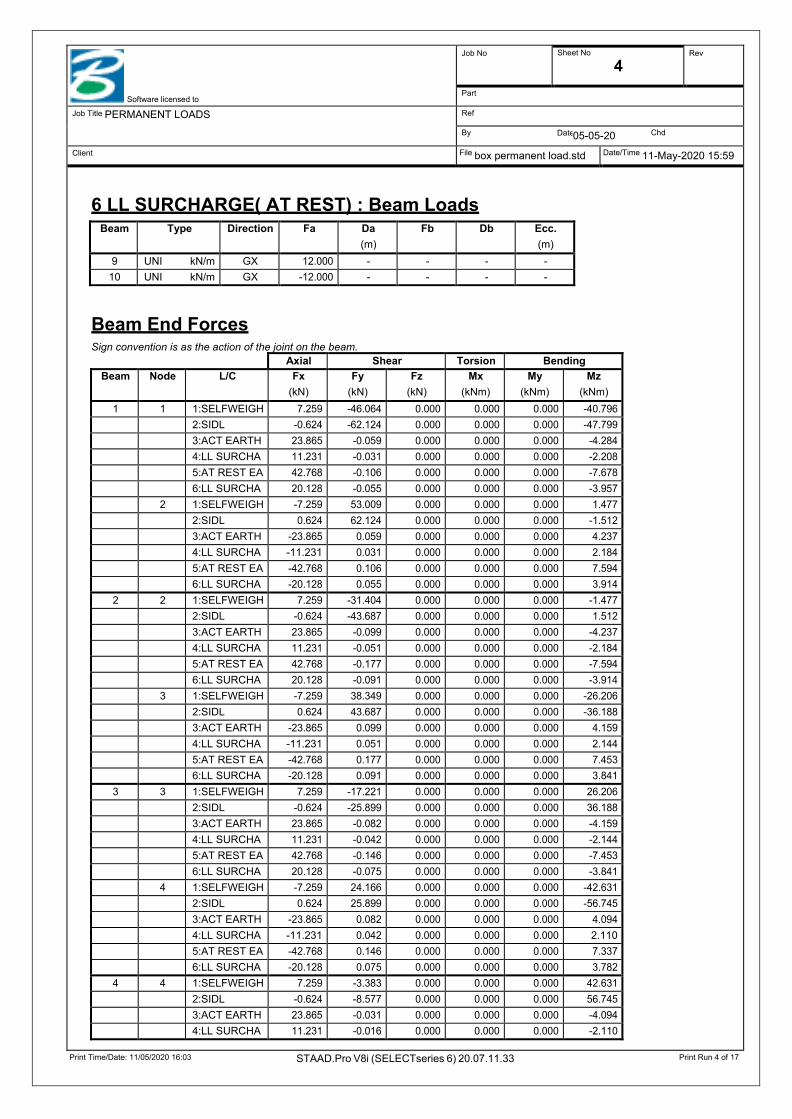
6 LL SURCHARGE( AT REST) : Beam Loads
Beam End Forces Sign convention is as the action of the joint on the beam.
Beam Type Direction Fa Da (m)
Fb Db Ecc. (m)
9 UNI kN/m GX 12.000 - - - - 10 UNI kN/m GX -12.000 - - - -
Axial Shear Torsion Bending Beam Node L/C Fx
(kN) Fy
(kN) Fz
(kN) Mx
(kNm) My
(kNm) Mz
(kNm) 1 1 1:SELFWEIGH 7.259 -46.064 0.000 0.000 0.000 -40.796
2:SIDL -0.624 -62.124 0.000 0.000 0.000 -47.799 3:ACT EARTH 23.865 -0.059 0.000 0.000 0.000 -4.284 4:LL SURCHA 11.231 -0.031 0.000 0.000 0.000 -2.208 5:AT REST EA 42.768 -0.106 0.000 0.000 0.000 -7.678 6:LL SURCHA 20.128 -0.055 0.000 0.000 0.000 -3.957 2 1:SELFWEIGH -7.259 53.009 0.000 0.000 0.000 1.477 2:SIDL 0.624 62.124 0.000 0.000 0.000 -1.512 3:ACT EARTH -23.865 0.059 0.000 0.000 0.000 4.237 4:LL SURCHA -11.231 0.031 0.000 0.000 0.000 2.184 5:AT REST EA -42.768 0.106 0.000 0.000 0.000 7.594 6:LL SURCHA -20.128 0.055 0.000 0.000 0.000 3.914
2 2 1:SELFWEIGH 7.259 -31.404 0.000 0.000 0.000 -1.477 2:SIDL -0.624 -43.687 0.000 0.000 0.000 1.512 3:ACT EARTH 23.865 -0.099 0.000 0.000 0.000 -4.237 4:LL SURCHA 11.231 -0.051 0.000 0.000 0.000 -2.184 5:AT REST EA 42.768 -0.177 0.000 0.000 0.000 -7.594 6:LL SURCHA 20.128 -0.091 0.000 0.000 0.000 -3.914 3 1:SELFWEIGH -7.259 38.349 0.000 0.000 0.000 -26.206 2:SIDL 0.624 43.687 0.000 0.000 0.000 -36.188 3:ACT EARTH -23.865 0.099 0.000 0.000 0.000 4.159 4:LL SURCHA -11.231 0.051 0.000 0.000 0.000 2.144 5:AT REST EA -42.768 0.177 0.000 0.000 0.000 7.453 6:LL SURCHA -20.128 0.091 0.000 0.000 0.000 3.841
3 3 1:SELFWEIGH 7.259 -17.221 0.000 0.000 0.000 26.206 2:SIDL -0.624 -25.899 0.000 0.000 0.000 36.188 3:ACT EARTH 23.865 -0.082 0.000 0.000 0.000 -4.159 4:LL SURCHA 11.231 -0.042 0.000 0.000 0.000 -2.144 5:AT REST EA 42.768 -0.146 0.000 0.000 0.000 -7.453 6:LL SURCHA 20.128 -0.075 0.000 0.000 0.000 -3.841 4 1:SELFWEIGH -7.259 24.166 0.000 0.000 0.000 -42.631 2:SIDL 0.624 25.899 0.000 0.000 0.000 -56.745 3:ACT EARTH -23.865 0.082 0.000 0.000 0.000 4.094 4:LL SURCHA -11.231 0.042 0.000 0.000 0.000 2.110 5:AT REST EA -42.768 0.146 0.000 0.000 0.000 7.337 6:LL SURCHA -20.128 0.075 0.000 0.000 0.000 3.782
4 4 1:SELFWEIGH 7.259 -3.383 0.000 0.000 0.000 42.631 2:SIDL -0.624 -8.577 0.000 0.000 0.000 56.745 3:ACT EARTH 23.865 -0.031 0.000 0.000 0.000 -4.094 4:LL SURCHA 11.231 -0.016 0.000 0.000 0.000 -2.110
Print Time/Date: 11/05/2020 16:03 STAAD.Pro V8i (SELECTseries 6) 20.07.11.33 Print Run 5 of 17
Date
Software licensed to
Job No Sheet No
5 Rev
Part
Job Title PERMANENT LOADS Ref
By 05-05-20 Chd
Client File box permanent load.std Date/Time 11-May-2020 15:59
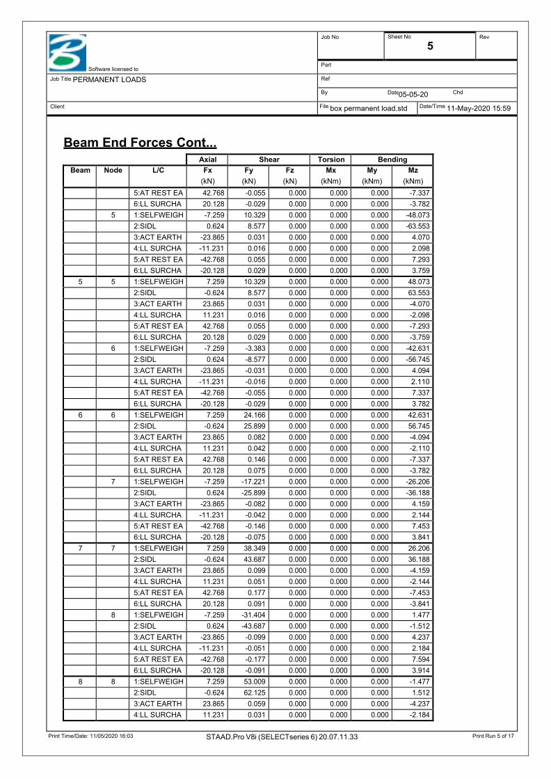
Beam End Forces Cont...
Axial Shear Torsion Bending Beam Node L/C Fx
(kN) Fy
(kN) Fz
(kN) Mx
(kNm) My
(kNm) Mz
(kNm) 5:AT REST EA 42.768 -0.055 0.000 0.000 0.000 -7.337 6:LL SURCHA 20.128 -0.029 0.000 0.000 0.000 -3.782 5 1:SELFWEIGH -7.259 10.329 0.000 0.000 0.000 -48.073 2:SIDL 0.624 8.577 0.000 0.000 0.000 -63.553 3:ACT EARTH -23.865 0.031 0.000 0.000 0.000 4.070 4:LL SURCHA -11.231 0.016 0.000 0.000 0.000 2.098 5:AT REST EA -42.768 0.055 0.000 0.000 0.000 7.293 6:LL SURCHA -20.128 0.029 0.000 0.000 0.000 3.759
5 5 1:SELFWEIGH 7.259 10.329 0.000 0.000 0.000 48.073 2:SIDL -0.624 8.577 0.000 0.000 0.000 63.553 3:ACT EARTH 23.865 0.031 0.000 0.000 0.000 -4.070 4:LL SURCHA 11.231 0.016 0.000 0.000 0.000 -2.098 5:AT REST EA 42.768 0.055 0.000 0.000 0.000 -7.293 6:LL SURCHA 20.128 0.029 0.000 0.000 0.000 -3.759 6 1:SELFWEIGH -7.259 -3.383 0.000 0.000 0.000 -42.631 2:SIDL 0.624 -8.577 0.000 0.000 0.000 -56.745 3:ACT EARTH -23.865 -0.031 0.000 0.000 0.000 4.094 4:LL SURCHA -11.231 -0.016 0.000 0.000 0.000 2.110 5:AT REST EA -42.768 -0.055 0.000 0.000 0.000 7.337 6:LL SURCHA -20.128 -0.029 0.000 0.000 0.000 3.782
6 6 1:SELFWEIGH 7.259 24.166 0.000 0.000 0.000 42.631 2:SIDL -0.624 25.899 0.000 0.000 0.000 56.745 3:ACT EARTH 23.865 0.082 0.000 0.000 0.000 -4.094 4:LL SURCHA 11.231 0.042 0.000 0.000 0.000 -2.110 5:AT REST EA 42.768 0.146 0.000 0.000 0.000 -7.337 6:LL SURCHA 20.128 0.075 0.000 0.000 0.000 -3.782 7 1:SELFWEIGH -7.259 -17.221 0.000 0.000 0.000 -26.206 2:SIDL 0.624 -25.899 0.000 0.000 0.000 -36.188 3:ACT EARTH -23.865 -0.082 0.000 0.000 0.000 4.159 4:LL SURCHA -11.231 -0.042 0.000 0.000 0.000 2.144 5:AT REST EA -42.768 -0.146 0.000 0.000 0.000 7.453 6:LL SURCHA -20.128 -0.075 0.000 0.000 0.000 3.841
7 7 1:SELFWEIGH 7.259 38.349 0.000 0.000 0.000 26.206 2:SIDL -0.624 43.687 0.000 0.000 0.000 36.188 3:ACT EARTH 23.865 0.099 0.000 0.000 0.000 -4.159 4:LL SURCHA 11.231 0.051 0.000 0.000 0.000 -2.144 5:AT REST EA 42.768 0.177 0.000 0.000 0.000 -7.453 6:LL SURCHA 20.128 0.091 0.000 0.000 0.000 -3.841 8 1:SELFWEIGH -7.259 -31.404 0.000 0.000 0.000 1.477 2:SIDL 0.624 -43.687 0.000 0.000 0.000 -1.512 3:ACT EARTH -23.865 -0.099 0.000 0.000 0.000 4.237 4:LL SURCHA -11.231 -0.051 0.000 0.000 0.000 2.184 5:AT REST EA -42.768 -0.177 0.000 0.000 0.000 7.594 6:LL SURCHA -20.128 -0.091 0.000 0.000 0.000 3.914
8 8 1:SELFWEIGH 7.259 53.009 0.000 0.000 0.000 -1.477 2:SIDL -0.624 62.125 0.000 0.000 0.000 1.512 3:ACT EARTH 23.865 0.059 0.000 0.000 0.000 -4.237 4:LL SURCHA 11.231 0.031 0.000 0.000 0.000 -2.184

Print Time/Date: 11/05/2020 16:03 STAAD.Pro V8i (SELECTseries 6) 20.07.11.33 Print Run 6 of 17
Date
Software licensed to
Job No Sheet No
6 Rev
Part
Job Title PERMANENT LOADS Ref
By 05-05-20 Chd
Client File box permanent load.std Date/Time 11-May-2020 15:59
Beam End Forces Cont...
Axial Shear Torsion Bending Beam Node L/C Fx
(kN) Fy
(kN) Fz
(kN) Mx
(kNm) My
(kNm) Mz
(kNm) 5:AT REST EA 42.768 0.106 0.000 0.000 0.000 -7.594 6:LL SURCHA 20.128 0.055 0.000 0.000 0.000 -3.914 9 1:SELFWEIGH -7.259 -46.064 0.000 0.000 0.000 40.796 2:SIDL 0.624 -62.125 0.000 0.000 0.000 47.799 3:ACT EARTH -23.865 -0.059 0.000 0.000 0.000 4.284 4:LL SURCHA -11.231 -0.031 0.000 0.000 0.000 2.208 5:AT REST EA -42.768 -0.106 0.000 0.000 0.000 7.678 6:LL SURCHA -20.128 -0.055 0.000 0.000 0.000 3.957
9 10 1:SELFWEIGH 27.781 7.259 0.000 0.000 0.000 -16.477 2:SIDL 71.666 -0.624 0.000 0.000 0.000 -49.890 3:ACT EARTH 0.000 -18.398 0.000 0.000 0.000 -3.951 4:LL SURCHA -0.000 -11.200 0.000 0.000 0.000 -2.157 5:AT REST EA -0.000 -32.970 0.000 0.000 0.000 -7.080 6:LL SURCHA 0.000 -20.073 0.000 0.000 0.000 -3.865 1 1:SELFWEIGH -57.094 -7.259 0.000 0.000 0.000 40.796 2:SIDL -71.666 0.624 0.000 0.000 0.000 47.799 3:ACT EARTH -0.000 -23.865 0.000 0.000 0.000 4.284 4:LL SURCHA 0.000 -11.231 0.000 0.000 0.000 2.208 5:AT REST EA 0.000 -42.768 0.000 0.000 0.000 7.678 6:LL SURCHA -0.000 -20.128 0.000 0.000 0.000 3.957
10 9 1:SELFWEIGH 57.094 -7.259 0.000 0.000 0.000 -40.796 2:SIDL 71.666 0.624 0.000 0.000 0.000 -47.799 3:ACT EARTH -0.000 -23.865 0.000 0.000 0.000 -4.284 4:LL SURCHA -0.000 -11.231 0.000 0.000 0.000 -2.208 5:AT REST EA 0.000 -42.768 0.000 0.000 0.000 -7.678 6:LL SURCHA -0.000 -20.128 0.000 0.000 0.000 -3.957 11 1:SELFWEIGH -27.781 7.259 0.000 0.000 0.000 16.477 2:SIDL -71.666 -0.624 0.000 0.000 0.000 49.890 3:ACT EARTH 0.000 -18.398 0.000 0.000 0.000 3.951 4:LL SURCHA 0.000 -11.200 0.000 0.000 0.000 2.157 5:AT REST EA -0.000 -32.970 0.000 0.000 0.000 7.080 6:LL SURCHA 0.000 -20.073 0.000 0.000 0.000 3.865
11 10 1:SELFWEIGH -7.259 27.781 0.000 0.000 0.000 16.477 2:SIDL 0.624 71.666 0.000 0.000 0.000 49.890 3:ACT EARTH 18.398 0.000 0.000 0.000 0.000 3.951 4:LL SURCHA 11.200 -0.000 0.000 0.000 0.000 2.157 5:AT REST EA 32.970 -0.000 0.000 0.000 0.000 7.080 6:LL SURCHA 20.073 0.000 0.000 0.000 0.000 3.865 11 1:SELFWEIGH 7.259 27.781 0.000 0.000 0.000 -16.477 2:SIDL -0.624 71.666 0.000 0.000 0.000 -49.890 3:ACT EARTH -18.398 -0.000 0.000 0.000 0.000 -3.951 4:LL SURCHA -11.200 0.000 0.000 0.000 0.000 -2.157 5:AT REST EA -32.970 0.000 0.000 0.000 0.000 -7.080 6:LL SURCHA -20.073 -0.000 0.000 0.000 0.000 -3.865

Print Time/Date: 11/05/2020 16:03 STAAD.Pro V8i (SELECTseries 6) 20.07.11.33 Print Run 7 of 17
Date
Software licensed to
Job No Sheet No
7 Rev
Part
Job Title PERMANENT LOADS Ref
By 05-05-20 Chd
Client File box permanent load.std Date/Time 11-May-2020 15:59
Beam Maximum Moments Distances to maxima are given from beam end A.
Beam Node A Length (m)
L/C d (m)
Max My (kNm)
d (m)
Max Mz (kNm)
1 1 0.794 1:SELFWEIGH Max +ve 0.000 0.000
Max -ve 0.000 0.000 0.000 -40.796 2:SIDL Max +ve 0.000 0.000 0.794 1.512 Max -ve 0.000 0.000 0.000 -47.799 3:ACT EARTH Max +ve 0.000 0.000 Max -ve 0.000 0.000 0.000 -4.284 4:LL SURCHA Max +ve 0.000 0.000 Max -ve 0.000 0.000 0.000 -2.208 5:AT REST EA Max +ve 0.000 0.000 Max -ve 0.000 0.000 0.000 -7.678 6:LL SURCHA Max +ve 0.000 0.000 Max -ve 0.000 0.000 0.000 -3.957
2 2 0.794 1:SELFWEIGH Max +ve 0.000 0.000 0.794 26.206 Max -ve 0.000 0.000 0.000 -1.477 2:SIDL Max +ve 0.000 0.000 0.794 36.188 Max -ve 0.000 0.000
3:ACT EARTH Max +ve 0.000 0.000
Max -ve 0.000 0.000 0.000 -4.237 4:LL SURCHA Max +ve 0.000 0.000
Max -ve 0.000 0.000 0.000 -2.184 5:AT REST EA Max +ve 0.000 0.000
Max -ve 0.000 0.000 0.000 -7.594 6:LL SURCHA Max +ve 0.000 0.000
Max -ve 0.000 0.000 0.000 -3.914 3 3 0.794 1:SELFWEIGH Max +ve 0.000 0.000 0.794 42.631
Max -ve 0.000 0.000
2:SIDL Max +ve 0.000 0.000 0.794 56.745 Max -ve 0.000 0.000
3:ACT EARTH Max +ve 0.000 0.000
Max -ve 0.000 0.000 0.000 -4.159 4:LL SURCHA Max +ve 0.000 0.000
Max -ve 0.000 0.000 0.000 -2.144 5:AT REST EA Max +ve 0.000 0.000
Max -ve 0.000 0.000 0.000 -7.453 6:LL SURCHA Max +ve 0.000 0.000
Max -ve 0.000 0.000 0.000 -3.841 4 4 0.794 1:SELFWEIGH Max +ve 0.000 0.000 0.794 48.073
Max -ve 0.000 0.000
2:SIDL Max +ve 0.000 0.000 0.794 63.553 Max -ve 0.000 0.000
3:ACT EARTH Max +ve 0.000 0.000
Max -ve 0.000 0.000 0.000 -4.094 4:LL SURCHA Max +ve 0.000 0.000
Max -ve 0.000 0.000 0.000 -2.110 5:AT REST EA Max +ve 0.000 0.000
Max -ve 0.000 0.000 0.000 -7.337 6:LL SURCHA Max +ve 0.000 0.000
Max -ve 0.000 0.000 0.000 -3.782

Print Time/Date: 11/05/2020 16:03 STAAD.Pro V8i (SELECTseries 6) 20.07.11.33 Print Run 8 of 17
Date
Software licensed to
Job No Sheet No
8 Rev
Part
Job Title PERMANENT LOADS Ref
By 05-05-20 Chd
Client File box permanent load.std Date/Time 11-May-2020 15:59
Beam Maximum Moments Cont...
Beam Node A Length (m)
L/C d (m)
Max My (kNm)
d (m)
Max Mz (kNm)
5 5 0.794 1:SELFWEIGH Max +ve 0.000 0.000 0.000 48.073 Max -ve 0.000 0.000
2:SIDL Max +ve 0.000 0.000 0.000 63.553 Max -ve 0.000 0.000
3:ACT EARTH Max +ve 0.000 0.000 Max -ve 0.000 0.000 0.794 -4.094 4:LL SURCHA Max +ve 0.000 0.000 Max -ve 0.000 0.000 0.794 -2.110 5:AT REST EA Max +ve 0.000 0.000 Max -ve 0.000 0.000 0.794 -7.337 6:LL SURCHA Max +ve 0.000 0.000 Max -ve 0.000 0.000 0.794 -3.782
6 6 0.794 1:SELFWEIGH Max +ve 0.000 0.000 0.000 42.631 Max -ve 0.000 0.000
2:SIDL Max +ve 0.000 0.000 0.000 56.745 Max -ve 0.000 0.000
3:ACT EARTH Max +ve 0.000 0.000
Max -ve 0.000 0.000 0.794 -4.159 4:LL SURCHA Max +ve 0.000 0.000
Max -ve 0.000 0.000 0.794 -2.144 5:AT REST EA Max +ve 0.000 0.000
Max -ve 0.000 0.000 0.794 -7.453 6:LL SURCHA Max +ve 0.000 0.000
Max -ve 0.000 0.000 0.794 -3.841 7 7 0.794 1:SELFWEIGH Max +ve 0.000 0.000 0.000 26.206
Max -ve 0.000 0.000 0.794 -1.477 2:SIDL Max +ve 0.000 0.000 0.000 36.188 Max -ve 0.000 0.000
3:ACT EARTH Max +ve 0.000 0.000
Max -ve 0.000 0.000 0.794 -4.237 4:LL SURCHA Max +ve 0.000 0.000
Max -ve 0.000 0.000 0.794 -2.184 5:AT REST EA Max +ve 0.000 0.000
Max -ve 0.000 0.000 0.794 -7.594 6:LL SURCHA Max +ve 0.000 0.000
Max -ve 0.000 0.000 0.794 -3.914 8 8 0.794 1:SELFWEIGH Max +ve 0.000 0.000
Max -ve 0.000 0.000 0.794 -40.796 2:SIDL Max +ve 0.000 0.000 0.000 1.512 Max -ve 0.000 0.000 0.794 -47.799 3:ACT EARTH Max +ve 0.000 0.000
Max -ve 0.000 0.000 0.794 -4.284 4:LL SURCHA Max +ve 0.000 0.000
Max -ve 0.000 0.000 0.794 -2.208 5:AT REST EA Max +ve 0.000 0.000
Max -ve 0.000 0.000 0.794 -7.678 6:LL SURCHA Max +ve 0.000 0.000
Max -ve 0.000 0.000 0.794 -3.957 9 10 3.350 1:SELFWEIGH Max +ve 0.000 0.000

Print Time/Date: 11/05/2020 16:03 STAAD.Pro V8i (SELECTseries 6) 20.07.11.33 Print Run 9 of 17
Date
Software licensed to
Job No Sheet No
9 Rev
Part
Job Title PERMANENT LOADS Ref
By 05-05-20 Chd
Client File box permanent load.std Date/Time 11-May-2020 15:59
Beam Maximum Moments Cont...
Beam Node A Length (m)
L/C d (m)
Max My (kNm)
d (m)
Max Mz (kNm)
Max -ve 0.000 0.000 3.350 -40.796 2:SIDL Max +ve 0.000 0.000 Max -ve 0.000 0.000 0.000 -49.890 3:ACT EARTH Max +ve 0.000 0.000 1.675 13.600 Max -ve 0.000 0.000 3.350 -4.284 4:LL SURCHA Max +ve 0.000 0.000 1.675 7.211 Max -ve 0.000 0.000 3.350 -2.208 5:AT REST EA Max +ve 0.000 0.000 1.675 24.372 Max -ve 0.000 0.000 3.350 -7.678 6:LL SURCHA Max +ve 0.000 0.000 1.675 12.922 Max -ve 0.000 0.000 3.350 -3.957
10 9 3.350 1:SELFWEIGH Max +ve 0.000 0.000
Max -ve 0.000 0.000 0.000 -40.796 2:SIDL Max +ve 0.000 0.000
Max -ve 0.000 0.000 3.350 -49.890 3:ACT EARTH Max +ve 0.000 0.000 1.675 13.600 Max -ve 0.000 0.000 0.000 -4.284 4:LL SURCHA Max +ve 0.000 0.000 1.675 7.211 Max -ve 0.000 0.000 0.000 -2.208 5:AT REST EA Max +ve 0.000 0.000 1.675 24.372 Max -ve 0.000 0.000 0.000 -7.678 6:LL SURCHA Max +ve 0.000 0.000 1.675 12.922 Max -ve 0.000 0.000 0.000 -3.957
11 10 6.350 1:SELFWEIGH Max +ve 0.000 0.000 0.000 16.477 Max -ve 0.000 0.000 3.175 -27.626 2:SIDL Max +ve 0.000 0.000 6.350 49.890 Max -ve 0.000 0.000 3.175 -63.879 3:ACT EARTH Max +ve 0.000 0.000 0.000 3.951 Max -ve 0.000 0.000
4:LL SURCHA Max +ve 0.000 0.000 0.000 2.157 Max -ve 0.000 0.000
5:AT REST EA Max +ve 0.000 0.000 6.350 7.080 Max -ve 0.000 0.000
6:LL SURCHA Max +ve 0.000 0.000 0.000 3.865 Max -ve 0.000 0.000
Print Time/Date: 11/05/2020 16:03 STAAD.Pro V8i (SELECTseries 6) 20.07.11.33 Print Run 10 of 17
Date
Software licensed to
Job No Sheet No
10 Rev
Part
Job Title PERMANENT LOADS Ref
By 05-05-20 Chd
Client File box permanent load.std Date/Time 11-May-2020 15:59
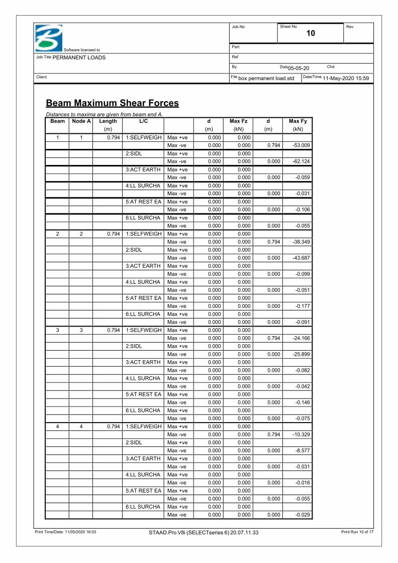
Beam Maximum Shear Forces Distances to maxima are given from beam end A.
Beam Node A Length (m)
L/C d (m)
Max Fz (kN)
d (m)
Max Fy (kN)
1 1 0.794 1:SELFWEIGH Max +ve 0.000 0.000
Max -ve 0.000 0.000 0.794 -53.009 2:SIDL Max +ve 0.000 0.000 Max -ve 0.000 0.000 0.000 -62.124 3:ACT EARTH Max +ve 0.000 0.000 Max -ve 0.000 0.000 0.000 -0.059 4:LL SURCHA Max +ve 0.000 0.000 Max -ve 0.000 0.000 0.000 -0.031 5:AT REST EA Max +ve 0.000 0.000 Max -ve 0.000 0.000 0.000 -0.106 6:LL SURCHA Max +ve 0.000 0.000 Max -ve 0.000 0.000 0.000 -0.055
2 2 0.794 1:SELFWEIGH Max +ve 0.000 0.000
Max -ve 0.000 0.000 0.794 -38.349 2:SIDL Max +ve 0.000 0.000
Max -ve 0.000 0.000 0.000 -43.687 3:ACT EARTH Max +ve 0.000 0.000
Max -ve 0.000 0.000 0.000 -0.099 4:LL SURCHA Max +ve 0.000 0.000
Max -ve 0.000 0.000 0.000 -0.051 5:AT REST EA Max +ve 0.000 0.000
Max -ve 0.000 0.000 0.000 -0.177 6:LL SURCHA Max +ve 0.000 0.000
Max -ve 0.000 0.000 0.000 -0.091 3 3 0.794 1:SELFWEIGH Max +ve 0.000 0.000
Max -ve 0.000 0.000 0.794 -24.166 2:SIDL Max +ve 0.000 0.000
Max -ve 0.000 0.000 0.000 -25.899 3:ACT EARTH Max +ve 0.000 0.000
Max -ve 0.000 0.000 0.000 -0.082 4:LL SURCHA Max +ve 0.000 0.000
Max -ve 0.000 0.000 0.000 -0.042 5:AT REST EA Max +ve 0.000 0.000
Max -ve 0.000 0.000 0.000 -0.146 6:LL SURCHA Max +ve 0.000 0.000
Max -ve 0.000 0.000 0.000 -0.075 4 4 0.794 1:SELFWEIGH Max +ve 0.000 0.000
Max -ve 0.000 0.000 0.794 -10.329 2:SIDL Max +ve 0.000 0.000
Max -ve 0.000 0.000 0.000 -8.577 3:ACT EARTH Max +ve 0.000 0.000
Max -ve 0.000 0.000 0.000 -0.031 4:LL SURCHA Max +ve 0.000 0.000
Max -ve 0.000 0.000 0.000 -0.016 5:AT REST EA Max +ve 0.000 0.000
Max -ve 0.000 0.000 0.000 -0.055 6:LL SURCHA Max +ve 0.000 0.000
Max -ve 0.000 0.000 0.000 -0.029

Print Time/Date: 11/05/2020 16:03 STAAD.Pro V8i (SELECTseries 6) 20.07.11.33 Print Run 11 of 17
Date
Software licensed to
Job No Sheet No
11 Rev
Part
Job Title PERMANENT LOADS Ref
By 05-05-20 Chd
Client File box permanent load.std Date/Time 11-May-2020 15:59
Beam Maximum Shear Forces Cont...
Beam Node A Length (m)
L/C d (m)
Max Fz (kN)
d (m)
Max Fy (kN)
5 5 0.794 1:SELFWEIGH Max +ve 0.000 0.000 0.000 10.329 Max -ve 0.000 0.000
2:SIDL Max +ve 0.000 0.000 0.000 8.577 Max -ve 0.000 0.000
3:ACT EARTH Max +ve 0.000 0.000 0.000 0.031 Max -ve 0.000 0.000
4:LL SURCHA Max +ve 0.000 0.000 0.000 0.016 Max -ve 0.000 0.000
5:AT REST EA Max +ve 0.000 0.000 0.000 0.055 Max -ve 0.000 0.000
6:LL SURCHA Max +ve 0.000 0.000 0.000 0.029 Max -ve 0.000 0.000
6 6 0.794 1:SELFWEIGH Max +ve 0.000 0.000 0.000 24.166 Max -ve 0.000 0.000
2:SIDL Max +ve 0.000 0.000 0.000 25.899 Max -ve 0.000 0.000
3:ACT EARTH Max +ve 0.000 0.000 0.000 0.082 Max -ve 0.000 0.000
4:LL SURCHA Max +ve 0.000 0.000 0.000 0.042 Max -ve 0.000 0.000
5:AT REST EA Max +ve 0.000 0.000 0.000 0.146 Max -ve 0.000 0.000
6:LL SURCHA Max +ve 0.000 0.000 0.000 0.075 Max -ve 0.000 0.000
7 7 0.794 1:SELFWEIGH Max +ve 0.000 0.000 0.000 38.349 Max -ve 0.000 0.000
2:SIDL Max +ve 0.000 0.000 0.000 43.687 Max -ve 0.000 0.000
3:ACT EARTH Max +ve 0.000 0.000 0.000 0.099 Max -ve 0.000 0.000
4:LL SURCHA Max +ve 0.000 0.000 0.000 0.051 Max -ve 0.000 0.000
5:AT REST EA Max +ve 0.000 0.000 0.000 0.177 Max -ve 0.000 0.000
6:LL SURCHA Max +ve 0.000 0.000 0.000 0.091 Max -ve 0.000 0.000
8 8 0.794 1:SELFWEIGH Max +ve 0.000 0.000 0.000 53.009 Max -ve 0.000 0.000
2:SIDL Max +ve 0.000 0.000 0.000 62.125 Max -ve 0.000 0.000
3:ACT EARTH Max +ve 0.000 0.000 0.000 0.059 Max -ve 0.000 0.000
4:LL SURCHA Max +ve 0.000 0.000 0.000 0.031 Max -ve 0.000 0.000
5:AT REST EA Max +ve 0.000 0.000 0.000 0.106 Max -ve 0.000 0.000
6:LL SURCHA Max +ve 0.000 0.000 0.000 0.055 Max -ve 0.000 0.000
9 10 3.350 1:SELFWEIGH Max +ve 0.000 0.000 0.000 7.259
Print Time/Date: 11/05/2020 16:03 STAAD.Pro V8i (SELECTseries 6) 20.07.11.33 Print Run 12 of 17
Date
Software licensed to
Job No Sheet No
12 Rev
Part
Job Title PERMANENT LOADS Ref
By 05-05-20 Chd
Client File box permanent load.std Date/Time 11-May-2020 15:59
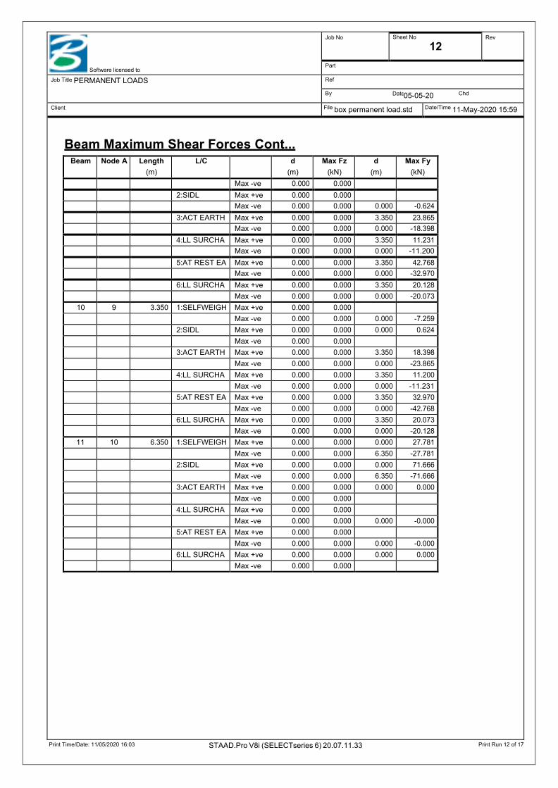
Beam Maximum Shear Forces Cont...
Beam Node A Length (m)
L/C d (m)
Max Fz (kN)
d (m)
Max Fy (kN)
Max -ve 0.000 0.000
2:SIDL Max +ve 0.000 0.000 Max -ve 0.000 0.000 0.000 -0.624 3:ACT EARTH Max +ve 0.000 0.000 3.350 23.865 Max -ve 0.000 0.000 0.000 -18.398 4:LL SURCHA Max +ve 0.000 0.000 3.350 11.231 Max -ve 0.000 0.000 0.000 -11.200 5:AT REST EA Max +ve 0.000 0.000 3.350 42.768 Max -ve 0.000 0.000 0.000 -32.970 6:LL SURCHA Max +ve 0.000 0.000 3.350 20.128 Max -ve 0.000 0.000 0.000 -20.073
10 9 3.350 1:SELFWEIGH Max +ve 0.000 0.000
Max -ve 0.000 0.000 0.000 -7.259 2:SIDL Max +ve 0.000 0.000 0.000 0.624 Max -ve 0.000 0.000
3:ACT EARTH Max +ve 0.000 0.000 3.350 18.398 Max -ve 0.000 0.000 0.000 -23.865 4:LL SURCHA Max +ve 0.000 0.000 3.350 11.200 Max -ve 0.000 0.000 0.000 -11.231 5:AT REST EA Max +ve 0.000 0.000 3.350 32.970 Max -ve 0.000 0.000 0.000 -42.768 6:LL SURCHA Max +ve 0.000 0.000 3.350 20.073 Max -ve 0.000 0.000 0.000 -20.128
11 10 6.350 1:SELFWEIGH Max +ve 0.000 0.000 0.000 27.781 Max -ve 0.000 0.000 6.350 -27.781 2:SIDL Max +ve 0.000 0.000 0.000 71.666 Max -ve 0.000 0.000 6.350 -71.666 3:ACT EARTH Max +ve 0.000 0.000 0.000 0.000 Max -ve 0.000 0.000
4:LL SURCHA Max +ve 0.000 0.000
Max -ve 0.000 0.000 0.000 -0.000 5:AT REST EA Max +ve 0.000 0.000
Max -ve 0.000 0.000 0.000 -0.000 6:LL SURCHA Max +ve 0.000 0.000 0.000 0.000 Max -ve 0.000 0.000

Print Time/Date: 11/05/2020 16:03 STAAD.Pro V8i (SELECTseries 6) 20.07.11.33 Print Run 13 of 17
Date
Software licensed to
Job No Sheet No
13 Rev
Part
Job Title PERMANENT LOADS Ref
By 05-05-20 Chd
Client File box permanent load.std Date/Time 11-May-2020 15:59
Beam Maximum Axial Forces Distances to maxima are given from beam end A.
Beam Node A Length (m)
L/C d (m)
Max Fx (kN)
1 1 0.794 1:SELFWEIGH Max +ve 0.000 7.259 Max -ve
2:SIDL Max +ve Max -ve 0.000 -0.624 3:ACT EARTH Max +ve 0.000 23.865 Max -ve
4:LL SURCHA Max +ve 0.000 11.231 Max -ve
5:AT REST EA Max +ve 0.000 42.768 Max -ve
6:LL SURCHA Max +ve 0.000 20.128 Max -ve
2 2 0.794 1:SELFWEIGH Max +ve 0.000 7.259 Max -ve
2:SIDL Max +ve
Max -ve 0.000 -0.624 3:ACT EARTH Max +ve 0.000 23.865 Max -ve
4:LL SURCHA Max +ve 0.000 11.231 Max -ve
5:AT REST EA Max +ve 0.000 42.768 Max -ve
6:LL SURCHA Max +ve 0.000 20.128 Max -ve
3 3 0.794 1:SELFWEIGH Max +ve 0.000 7.259 Max -ve
2:SIDL Max +ve
Max -ve 0.000 -0.624 3:ACT EARTH Max +ve 0.000 23.865 Max -ve
4:LL SURCHA Max +ve 0.000 11.231 Max -ve
5:AT REST EA Max +ve 0.000 42.768 Max -ve
6:LL SURCHA Max +ve 0.000 20.128 Max -ve
4 4 0.794 1:SELFWEIGH Max +ve 0.000 7.259 Max -ve
2:SIDL Max +ve
Max -ve 0.000 -0.624 3:ACT EARTH Max +ve 0.000 23.865 Max -ve
4:LL SURCHA Max +ve 0.000 11.231 Max -ve
5:AT REST EA Max +ve 0.000 42.768 Max -ve
6:LL SURCHA Max +ve 0.000 20.128 Max -ve
Print Time/Date: 11/05/2020 16:03 STAAD.Pro V8i (SELECTseries 6) 20.07.11.33 Print Run 14 of 17
Date
Software licensed to
Job No Sheet No
14 Rev
Part
Job Title PERMANENT LOADS Ref
By 05-05-20 Chd
Client File box permanent load.std Date/Time 11-May-2020 15:59
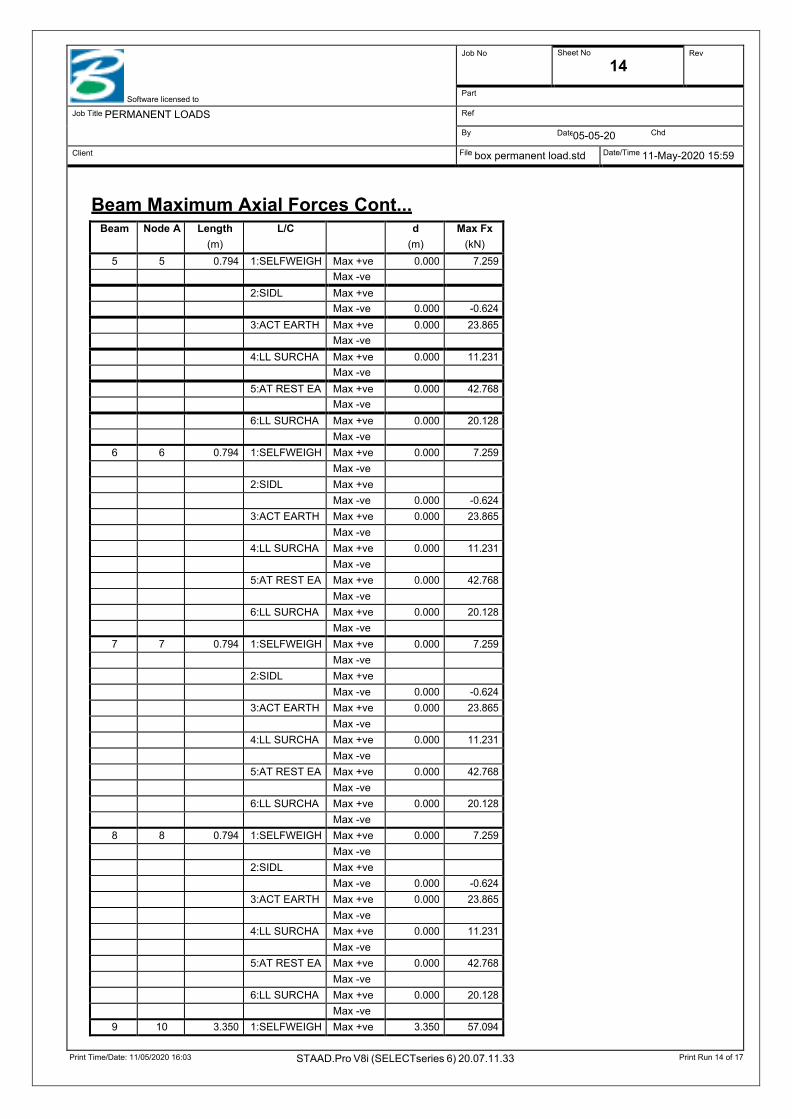
Beam Maximum Axial Forces Cont...
Beam Node A Length (m)
L/C d (m)
Max Fx (kN)
5 5 0.794 1:SELFWEIGH Max +ve 0.000 7.259 Max -ve
2:SIDL Max +ve Max -ve 0.000 -0.624 3:ACT EARTH Max +ve 0.000 23.865 Max -ve
4:LL SURCHA Max +ve 0.000 11.231 Max -ve
5:AT REST EA Max +ve 0.000 42.768 Max -ve
6:LL SURCHA Max +ve 0.000 20.128 Max -ve
6 6 0.794 1:SELFWEIGH Max +ve 0.000 7.259 Max -ve
2:SIDL Max +ve
Max -ve 0.000 -0.624 3:ACT EARTH Max +ve 0.000 23.865 Max -ve
4:LL SURCHA Max +ve 0.000 11.231 Max -ve
5:AT REST EA Max +ve 0.000 42.768 Max -ve
6:LL SURCHA Max +ve 0.000 20.128 Max -ve
7 7 0.794 1:SELFWEIGH Max +ve 0.000 7.259 Max -ve
2:SIDL Max +ve
Max -ve 0.000 -0.624 3:ACT EARTH Max +ve 0.000 23.865 Max -ve
4:LL SURCHA Max +ve 0.000 11.231 Max -ve
5:AT REST EA Max +ve 0.000 42.768 Max -ve
6:LL SURCHA Max +ve 0.000 20.128 Max -ve
8 8 0.794 1:SELFWEIGH Max +ve 0.000 7.259 Max -ve
2:SIDL Max +ve
Max -ve 0.000 -0.624 3:ACT EARTH Max +ve 0.000 23.865 Max -ve
4:LL SURCHA Max +ve 0.000 11.231 Max -ve
5:AT REST EA Max +ve 0.000 42.768 Max -ve
6:LL SURCHA Max +ve 0.000 20.128 Max -ve
9 10 3.350 1:SELFWEIGH Max +ve 3.350 57.094

Print Time/Date: 11/05/2020 16:03 STAAD.Pro V8i (SELECTseries 6) 20.07.11.33 Print Run 15 of 17
Date
Software licensed to
Job No Sheet No
15 Rev
Part
Job Title PERMANENT LOADS Ref
By 05-05-20 Chd
Client File box permanent load.std Date/Time 11-May-2020 15:59
Beam Maximum Axial Forces Cont...
Beam Node A Length (m)
L/C d (m)
Max Fx (kN)
Max -ve
2:SIDL Max +ve 0.000 71.666 Max -ve
3:ACT EARTH Max +ve 0.000 0.000 Max -ve
4:LL SURCHA Max +ve Max -ve 0.000 -0.000 5:AT REST EA Max +ve Max -ve 0.000 -0.000 6:LL SURCHA Max +ve 0.000 0.000 Max -ve
10 9 3.350 1:SELFWEIGH Max +ve 0.000 57.094 Max -ve
2:SIDL Max +ve 0.000 71.666 Max -ve
3:ACT EARTH Max +ve
Max -ve 0.000 -0.000 4:LL SURCHA Max +ve
Max -ve 0.000 -0.000 5:AT REST EA Max +ve 0.000 0.000 Max -ve
6:LL SURCHA Max +ve
Max -ve 0.000 -0.000 11 10 6.350 1:SELFWEIGH Max +ve
Max -ve 0.000 -7.259 2:SIDL Max +ve 0.000 0.624 Max -ve
3:ACT EARTH Max +ve 0.000 18.398 Max -ve
4:LL SURCHA Max +ve 0.000 11.200 Max -ve
5:AT REST EA Max +ve 0.000 32.970 Max -ve
6:LL SURCHA Max +ve 0.000 20.073 Max -ve
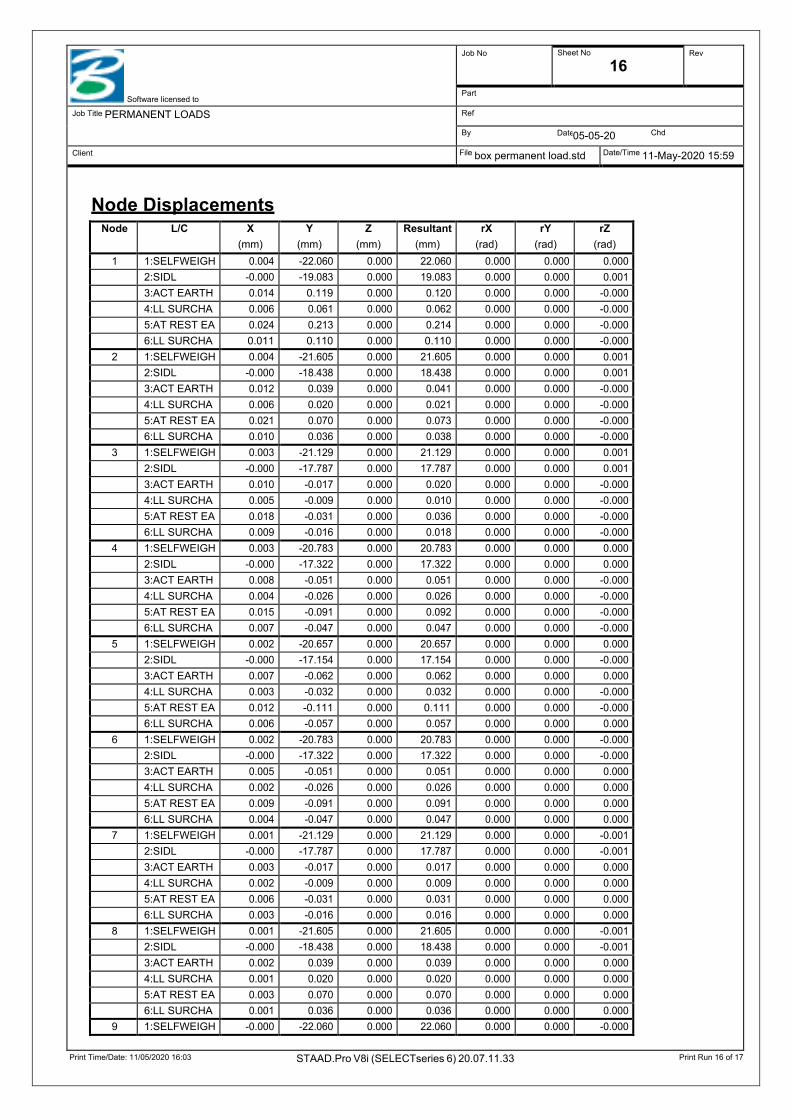
Print Time/Date: 11/05/2020 16:03 STAAD.Pro V8i (SELECTseries 6) 20.07.11.33 Print Run 16 of 17
Date
Software licensed to
Job No Sheet No
16 Rev
Part
Job Title PERMANENT LOADS Ref
By 05-05-20 Chd
Client File box permanent load.std Date/Time 11-May-2020 15:59
Node Displacements
Node L/C X (mm)
Y (mm)
Z (mm)
Resultant (mm)
rX (rad)
rY (rad)
rZ (rad)
1 1:SELFWEIGH 0.004 -22.060 0.000 22.060 0.000 0.000 0.000 2:SIDL -0.000 -19.083 0.000 19.083 0.000 0.000 0.001 3:ACT EARTH 0.014 0.119 0.000 0.120 0.000 0.000 -0.000 4:LL SURCHA 0.006 0.061 0.000 0.062 0.000 0.000 -0.000 5:AT REST EA 0.024 0.213 0.000 0.214 0.000 0.000 -0.000 6:LL SURCHA 0.011 0.110 0.000 0.110 0.000 0.000 -0.000
2 1:SELFWEIGH 0.004 -21.605 0.000 21.605 0.000 0.000 0.001 2:SIDL -0.000 -18.438 0.000 18.438 0.000 0.000 0.001 3:ACT EARTH 0.012 0.039 0.000 0.041 0.000 0.000 -0.000 4:LL SURCHA 0.006 0.020 0.000 0.021 0.000 0.000 -0.000 5:AT REST EA 0.021 0.070 0.000 0.073 0.000 0.000 -0.000 6:LL SURCHA 0.010 0.036 0.000 0.038 0.000 0.000 -0.000
3 1:SELFWEIGH 0.003 -21.129 0.000 21.129 0.000 0.000 0.001 2:SIDL -0.000 -17.787 0.000 17.787 0.000 0.000 0.001 3:ACT EARTH 0.010 -0.017 0.000 0.020 0.000 0.000 -0.000 4:LL SURCHA 0.005 -0.009 0.000 0.010 0.000 0.000 -0.000 5:AT REST EA 0.018 -0.031 0.000 0.036 0.000 0.000 -0.000 6:LL SURCHA 0.009 -0.016 0.000 0.018 0.000 0.000 -0.000
4 1:SELFWEIGH 0.003 -20.783 0.000 20.783 0.000 0.000 0.000 2:SIDL -0.000 -17.322 0.000 17.322 0.000 0.000 0.000 3:ACT EARTH 0.008 -0.051 0.000 0.051 0.000 0.000 -0.000 4:LL SURCHA 0.004 -0.026 0.000 0.026 0.000 0.000 -0.000 5:AT REST EA 0.015 -0.091 0.000 0.092 0.000 0.000 -0.000 6:LL SURCHA 0.007 -0.047 0.000 0.047 0.000 0.000 -0.000
5 1:SELFWEIGH 0.002 -20.657 0.000 20.657 0.000 0.000 0.000 2:SIDL -0.000 -17.154 0.000 17.154 0.000 0.000 -0.000 3:ACT EARTH 0.007 -0.062 0.000 0.062 0.000 0.000 0.000 4:LL SURCHA 0.003 -0.032 0.000 0.032 0.000 0.000 -0.000 5:AT REST EA 0.012 -0.111 0.000 0.111 0.000 0.000 -0.000 6:LL SURCHA 0.006 -0.057 0.000 0.057 0.000 0.000 0.000
6 1:SELFWEIGH 0.002 -20.783 0.000 20.783 0.000 0.000 -0.000 2:SIDL -0.000 -17.322 0.000 17.322 0.000 0.000 -0.000 3:ACT EARTH 0.005 -0.051 0.000 0.051 0.000 0.000 0.000 4:LL SURCHA 0.002 -0.026 0.000 0.026 0.000 0.000 0.000 5:AT REST EA 0.009 -0.091 0.000 0.091 0.000 0.000 0.000 6:LL SURCHA 0.004 -0.047 0.000 0.047 0.000 0.000 0.000
7 1:SELFWEIGH 0.001 -21.129 0.000 21.129 0.000 0.000 -0.001 2:SIDL -0.000 -17.787 0.000 17.787 0.000 0.000 -0.001 3:ACT EARTH 0.003 -0.017 0.000 0.017 0.000 0.000 0.000 4:LL SURCHA 0.002 -0.009 0.000 0.009 0.000 0.000 0.000 5:AT REST EA 0.006 -0.031 0.000 0.031 0.000 0.000 0.000 6:LL SURCHA 0.003 -0.016 0.000 0.016 0.000 0.000 0.000
8 1:SELFWEIGH 0.001 -21.605 0.000 21.605 0.000 0.000 -0.001 2:SIDL -0.000 -18.438 0.000 18.438 0.000 0.000 -0.001 3:ACT EARTH 0.002 0.039 0.000 0.039 0.000 0.000 0.000 4:LL SURCHA 0.001 0.020 0.000 0.020 0.000 0.000 0.000 5:AT REST EA 0.003 0.070 0.000 0.070 0.000 0.000 0.000 6:LL SURCHA 0.001 0.036 0.000 0.036 0.000 0.000 0.000
9 1:SELFWEIGH -0.000 -22.060 0.000 22.060 0.000 0.000 -0.000

Print Time/Date: 11/05/2020 16:03 STAAD.Pro V8i (SELECTseries 6) 20.07.11.33 Print Run 17 of 17
Date
Software licensed to
Job No Sheet No
17 Rev
Part
Job Title PERMANENT LOADS Ref
By 05-05-20 Chd
Client File box permanent load.std Date/Time 11-May-2020 15:59
Node Displacements Cont...
Node L/C X (mm)
Y (mm)
Z (mm)
Resultant (mm)
rX (rad)
rY (rad)
rZ (rad)
2:SIDL -0.000 -19.083 0.000 19.083 0.000 0.000 -0.001 3:ACT EARTH -0.000 0.119 0.000 0.119 0.000 0.000 0.000 4:LL SURCHA 0.000 0.061 0.000 0.061 0.000 0.000 0.000 5:AT REST EA 0.000 0.213 0.000 0.213 0.000 0.000 0.000 6:LL SURCHA -0.000 0.110 0.000 0.110 0.000 0.000 0.000
10 1:SELFWEIGH -0.000 -22.073 0.000 22.073 0.000 0.000 -0.000 2:SIDL 0.000 -19.105 0.000 19.105 0.000 0.000 -0.001 3:ACT EARTH 0.012 0.119 0.000 0.119 0.000 0.000 0.000 4:LL SURCHA 0.006 0.061 0.000 0.062 0.000 0.000 0.000 5:AT REST EA 0.021 0.213 0.000 0.214 0.000 0.000 0.000 6:LL SURCHA 0.011 0.110 0.000 0.110 0.000 0.000 0.000
11 1:SELFWEIGH 0.004 -22.073 0.000 22.073 0.000 0.000 0.000 2:SIDL -0.000 -19.105 0.000 19.105 0.000 0.000 0.001 3:ACT EARTH 0.002 0.119 0.000 0.119 0.000 0.000 -0.000 4:LL SURCHA 0.000 0.061 0.000 0.061 0.000 0.000 -0.000 5:AT REST EA 0.003 0.213 0.000 0.213 0.000 0.000 -0.000 6:LL SURCHA 0.000 0.110 0.000 0.110 0.000 0.000 -0.000

Print Time/Date: 11/05/2020 17:06 STAAD.Pro V8i (SELECTseries 6) 20.07.11.33 Print Run 1 of 5
Date
Software licensed to
Job No Sheet No
1 Rev
Part
Job Title Ref
By 10-MAY-20 Chd
Client File box LL - with 40t boggie lo Date/Time 11-May-2020 14:49
Job Information
Structure Type PLANE FRAME
Included in this printout are data for: All The Whole Structure
Included in this printout are results for load cases:
Nodes
Engineer Checked Approved
Name:
Date: 10-MAY-20
Number of Nodes 11 Highest Node 11 Number of Elements 11 Highest Beam 11
Number of Basic Load Cases -2 Number of Combination Load Cases 0
Type L/C Name
Primary 1
Node X (m)
Y (m)
Z (m)
1 0.000 0.000 0.000 2 0.794 0.000 0.000 3 1.587 0.000 0.000 4 2.381 0.000 0.000 5 3.175 0.000 0.000 6 3.969 0.000 0.000 7 4.762 0.000 0.000 8 5.556 0.000 0.000 9 6.350 0.000 0.000
10 0.000 3.361 0.000 11 6.350 3.361 0.000

Print Time/Date: 11/05/2020 17:06 STAAD.Pro V8i (SELECTseries 6) 20.07.11.33 Print Run 2 of 5
Date
Software licensed to
Job No Sheet No
2 Rev
Part
Job Title Ref
By 10-MAY-20 Chd
Client File box LL - with 40t boggie lo Date/Time 11-May-2020 14:49
Beams
Section Properties
Materials
Supports
Load Generators There is no data of this type.
Beam Node A Node B Length (m)
Property β (degrees)
1 1 2 0.794 1 0 2 2 3 0.794 1 0 3 3 4 0.794 1 0 4 4 5 0.794 1 0 5 5 6 0.794 1 0 6 6 7 0.794 1 0 7 7 8 0.794 1 0 8 8 9 0.794 1 0 9 10 1 3.361 1 0
10 9 11 3.361 1 0 11 10 11 6.350 1 0
Prop Section Area (cm2)
Iyy
(cm4) Izz
(cm4) J
(cm4) Material
1 Prismatic General 3.5E+3 0.000 360E+3 0.000 MATERIAL1
Mat Name E (kN/mm2)
ν Density (kg/m3)
α (/°C)
1 STEEL 205.000 0.300 7.83E+3 12E -6 2 STAINLESSSTEEL 197.930 0.300 7.83E+3 18E -6 3 ALUMINUM 68.948 0.330 2.71E+3 23E -6 4 MATERIAL1 32.000 0.170 2.55E+3 0.000 5 CONCRETE 21.718 0.170 2.4E+3 10E -6
Node X (kN/mm)
Y (kN/mm)
Z (kN/mm)
rX (kN-m/deg)
rY (kN-m/deg)
rZ (kN-m/deg)
1 0.000 0.500 Fixed Fixed Fixed 0.010 2 0.000 1.000 Fixed Fixed Fixed 0.010 3 0.000 1.000 Fixed Fixed Fixed 0.010 4 0.000 1.000 Fixed Fixed Fixed 0.010 5 0.000 1.000 Fixed Fixed Fixed 0.010 6 0.000 1.000 Fixed Fixed Fixed 0.010 7 0.000 1.000 Fixed Fixed Fixed 0.010 8 0.000 1.000 Fixed Fixed Fixed 0.010 9 2.000 0.500 Fixed Fixed Fixed 0.010
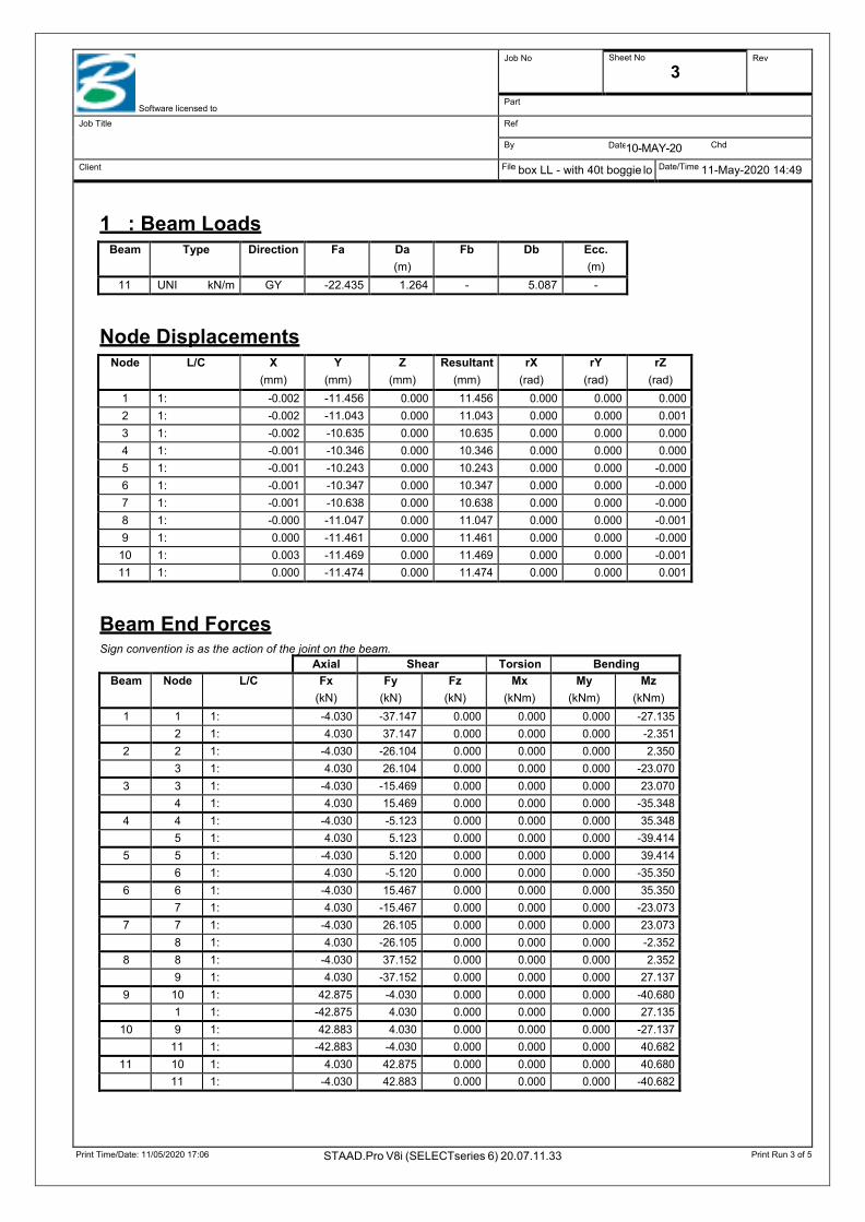
Print Time/Date: 11/05/2020 17:06 STAAD.Pro V8i (SELECTseries 6) 20.07.11.33 Print Run 3 of 5
Date
Software licensed to
Job No Sheet No
3 Rev
Part
Job Title Ref
By 10-MAY-20 Chd
Client File box LL - with 40t boggie lo Date/Time 11-May-2020 14:49
1 : Beam Loads
Node Displacements
Beam End Forces Sign convention is as the action of the joint on the beam.
Beam Type Direction Fa Da (m)
Fb Db Ecc. (m)
11 UNI kN/m GY -22.435 1.264 - 5.087 -
Node L/C X (mm)
Y (mm)
Z (mm)
Resultant (mm)
rX (rad)
rY (rad)
rZ (rad)
1 1: -0.002 -11.456 0.000 11.456 0.000 0.000 0.000 2 1: -0.002 -11.043 0.000 11.043 0.000 0.000 0.001 3 1: -0.002 -10.635 0.000 10.635 0.000 0.000 0.000 4 1: -0.001 -10.346 0.000 10.346 0.000 0.000 0.000 5 1: -0.001 -10.243 0.000 10.243 0.000 0.000 -0.000 6 1: -0.001 -10.347 0.000 10.347 0.000 0.000 -0.000 7 1: -0.001 -10.638 0.000 10.638 0.000 0.000 -0.000 8 1: -0.000 -11.047 0.000 11.047 0.000 0.000 -0.001 9 1: 0.000 -11.461 0.000 11.461 0.000 0.000 -0.000
10 1: 0.003 -11.469 0.000 11.469 0.000 0.000 -0.001 11 1: 0.000 -11.474 0.000 11.474 0.000 0.000 0.001
Axial Shear Torsion Bending Beam Node L/C Fx
(kN) Fy
(kN) Fz
(kN) Mx
(kNm) My
(kNm) Mz
(kNm) 1 1 1: -4.030 -37.147 0.000 0.000 0.000 -27.135
2 1: 4.030 37.147 0.000 0.000 0.000 -2.351 2 2 1: -4.030 -26.104 0.000 0.000 0.000 2.350
3 1: 4.030 26.104 0.000 0.000 0.000 -23.070 3 3 1: -4.030 -15.469 0.000 0.000 0.000 23.070
4 1: 4.030 15.469 0.000 0.000 0.000 -35.348 4 4 1: -4.030 -5.123 0.000 0.000 0.000 35.348
5 1: 4.030 5.123 0.000 0.000 0.000 -39.414 5 5 1: -4.030 5.120 0.000 0.000 0.000 39.414
6 1: 4.030 -5.120 0.000 0.000 0.000 -35.350 6 6 1: -4.030 15.467 0.000 0.000 0.000 35.350
7 1: 4.030 -15.467 0.000 0.000 0.000 -23.073 7 7 1: -4.030 26.105 0.000 0.000 0.000 23.073
8 1: 4.030 -26.105 0.000 0.000 0.000 -2.352 8 8 1: -4.030 37.152 0.000 0.000 0.000 2.352
9 1: 4.030 -37.152 0.000 0.000 0.000 27.137 9 10 1: 42.875 -4.030 0.000 0.000 0.000 -40.680
1 1: -42.875 4.030 0.000 0.000 0.000 27.135 10 9 1: 42.883 4.030 0.000 0.000 0.000 -27.137
11 1: -42.883 -4.030 0.000 0.000 0.000 40.682 11 10 1: 4.030 42.875 0.000 0.000 0.000 40.680
11 1: -4.030 42.883 0.000 0.000 0.000 -40.682
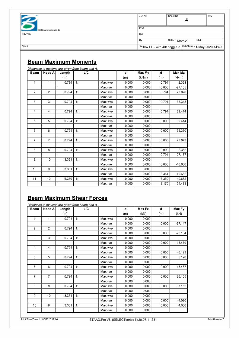
Print Time/Date: 11/05/2020 17:06 STAAD.Pro V8i (SELECTseries 6) 20.07.11.33 Print Run 4 of 5
Date
Software licensed to
Job No Sheet No
4 Rev
Part
Job Title Ref
By 10-MAY-20 Chd
Client File box LL - with 40t boggie lo Date/Time 11-May-2020 14:49
Beam Maximum Moments Distances to maxima are given from beam end A.
Beam Maximum Shear Forces Distances to maxima are given from beam end A.
Beam Node A Length (m)
L/C d (m)
Max My (kNm)
d (m)
Max Mz (kNm)
1 1 0.794 1: Max +ve 0.000 0.000 0.794 2.351 Max -ve 0.000 0.000 0.000 -27.135
2 2 0.794 1: Max +ve 0.000 0.000 0.794 23.070 Max -ve 0.000 0.000
3 3 0.794 1: Max +ve 0.000 0.000 0.794 35.348 Max -ve 0.000 0.000
4 4 0.794 1: Max +ve 0.000 0.000 0.794 39.414 Max -ve 0.000 0.000
5 5 0.794 1: Max +ve 0.000 0.000 0.000 39.414 Max -ve 0.000 0.000
6 6 0.794 1: Max +ve 0.000 0.000 0.000 35.350 Max -ve 0.000 0.000
7 7 0.794 1: Max +ve 0.000 0.000 0.000 23.073 Max -ve 0.000 0.000
8 8 0.794 1: Max +ve 0.000 0.000 0.000 2.352 Max -ve 0.000 0.000 0.794 -27.137
9 10 3.361 1: Max +ve 0.000 0.000
Max -ve 0.000 0.000 0.000 -40.680 10 9 3.361 1: Max +ve 0.000 0.000
Max -ve 0.000 0.000 3.361 -40.682 11 10 6.350 1: Max +ve 0.000 0.000 6.350 40.682
Max -ve 0.000 0.000 3.175 -54.483
Beam Node A Length (m)
L/C d (m)
Max Fz (kN)
d (m)
Max Fy (kN)
1 1 0.794 1: Max +ve 0.000 0.000
Max -ve 0.000 0.000 0.000 -37.147 2 2 0.794 1: Max +ve 0.000 0.000
Max -ve 0.000 0.000 0.000 -26.104 3 3 0.794 1: Max +ve 0.000 0.000
Max -ve 0.000 0.000 0.000 -15.469 4 4 0.794 1: Max +ve 0.000 0.000
Max -ve 0.000 0.000 0.000 -5.123 5 5 0.794 1: Max +ve 0.000 0.000 0.000 5.120
Max -ve 0.000 0.000
6 6 0.794 1: Max +ve 0.000 0.000 0.000 15.467 Max -ve 0.000 0.000
7 7 0.794 1: Max +ve 0.000 0.000 0.000 26.105 Max -ve 0.000 0.000
8 8 0.794 1: Max +ve 0.000 0.000 0.000 37.152 Max -ve 0.000 0.000
9 10 3.361 1: Max +ve 0.000 0.000
Max -ve 0.000 0.000 0.000 -4.030 10 9 3.361 1: Max +ve 0.000 0.000 0.000 4.030
Max -ve 0.000 0.000

Print Time/Date: 11/05/2020 17:06 STAAD.Pro V8i (SELECTseries 6) 20.07.11.33 Print Run 5 of 5
Date
Software licensed to
Job No Sheet No
5 Rev
Part
Job Title Ref
By 10-MAY-20 Chd
Client File box LL - with 40t boggie lo Date/Time 11-May-2020 14:49
Beam Maximum Shear Forces Cont...
Beam Maximum Axial Forces Distances to maxima are given from beam end A.
Reactions
Beam Node A Length (m)
L/C d (m)
Max Fz (kN)
d (m)
Max Fy (kN)
11 10 6.350 1: Max +ve 0.000 0.000 0.000 42.875 Max -ve 0.000 0.000 5.292 -42.883
Beam Node A Length (m)
L/C d (m)
Max Fx (kN)
1 1 0.794 1: Max +ve
Max -ve 0.000 -4.030 2 2 0.794 1: Max +ve
Max -ve 0.000 -4.030 3 3 0.794 1: Max +ve
Max -ve 0.000 -4.030 4 4 0.794 1: Max +ve
Max -ve 0.000 -4.030 5 5 0.794 1: Max +ve
Max -ve 0.000 -4.030 6 6 0.794 1: Max +ve
Max -ve 0.000 -4.030 7 7 0.794 1: Max +ve
Max -ve 0.000 -4.030 8 8 0.794 1: Max +ve
Max -ve 0.000 -4.030 9 10 3.361 1: Max +ve 0.000 42.875
Max -ve
10 9 3.361 1: Max +ve 0.000 42.883 Max -ve
11 10 6.350 1: Max +ve 0.000 4.030 Max -ve
Horizontal Vertical Horizontal Moment Node L/C FX
(kN) FY
(kN) FZ
(kN) MX
(kNm) MY
(kNm) MZ
(kNm) 1 1: 0.000 5.728 0.000 0.000 0.000 -0.000 2 1: 0.000 11.043 0.000 0.000 0.000 -0.000 3 1: 0.000 10.635 0.000 0.000 0.000 -0.000 4 1: 0.000 10.346 0.000 0.000 0.000 -0.000 5 1: 0.000 10.243 0.000 0.000 0.000 0.000 6 1: 0.000 10.347 0.000 0.000 0.000 0.000 7 1: 0.000 10.638 0.000 0.000 0.000 0.000 8 1: 0.000 11.047 0.000 0.000 0.000 0.000 9 1: -0.000 5.730 0.000 0.000 0.000 0.000
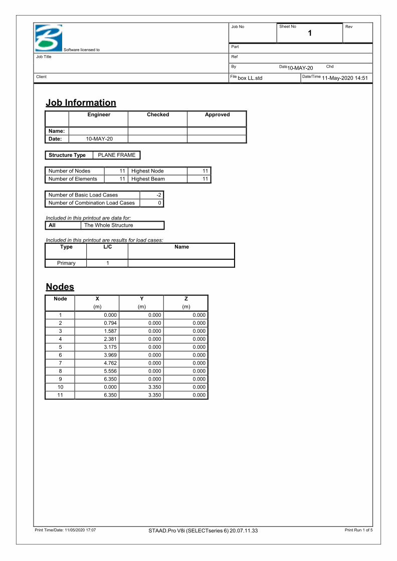
Print Time/Date: 11/05/2020 17:07 STAAD.Pro V8i (SELECTseries 6) 20.07.11.33 Print Run 1 of 5
Date
Software licensed to
Job No Sheet No
1 Rev
Part
Job Title Ref
By 10-MAY-20 Chd
Client File box LL.std Date/Time 11-May-2020 14:51
Job Information
Structure Type PLANE FRAME
Included in this printout are data for: All The Whole Structure
Included in this printout are results for load cases:
Nodes
Engineer Checked Approved
Name:
Date: 10-MAY-20
Number of Nodes 11 Highest Node 11 Number of Elements 11 Highest Beam 11
Number of Basic Load Cases -2 Number of Combination Load Cases 0
Type L/C Name
Primary 1
Node X (m)
Y (m)
Z (m)
1 0.000 0.000 0.000 2 0.794 0.000 0.000 3 1.587 0.000 0.000 4 2.381 0.000 0.000 5 3.175 0.000 0.000 6 3.969 0.000 0.000 7 4.762 0.000 0.000 8 5.556 0.000 0.000 9 6.350 0.000 0.000
10 0.000 3.350 0.000 11 6.350 3.350 0.000
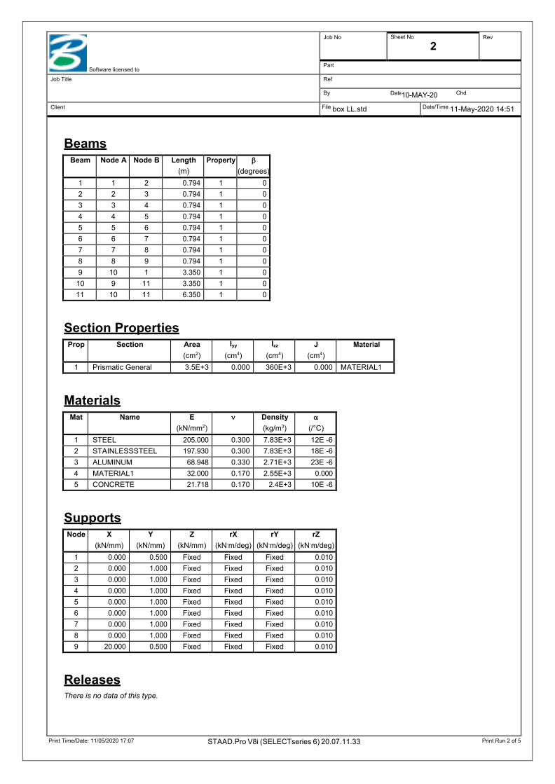
Print Time/Date: 11/05/2020 17:07 STAAD.Pro V8i (SELECTseries 6) 20.07.11.33 Print Run 2 of 5
Date
Software licensed to
Job No Sheet No
2 Rev
Part
Job Title Ref
By 10-MAY-20 Chd
Client File box LL.std Date/Time 11-May-2020 14:51
Beams
Section Properties
Materials
Supports
Releases There is no data of this type.
Beam Node A Node B Length (m)
Property β (degrees)
1 1 2 0.794 1 0 2 2 3 0.794 1 0 3 3 4 0.794 1 0 4 4 5 0.794 1 0 5 5 6 0.794 1 0 6 6 7 0.794 1 0 7 7 8 0.794 1 0 8 8 9 0.794 1 0 9 10 1 3.350 1 0
10 9 11 3.350 1 0 11 10 11 6.350 1 0
Prop Section Area (cm2)
Iyy
(cm4) Izz
(cm4) J
(cm4) Material
1 Prismatic General 3.5E+3 0.000 360E+3 0.000 MATERIAL1
Mat Name E (kN/mm2)
ν Density (kg/m3)
α (/°C)
1 STEEL 205.000 0.300 7.83E+3 12E -6 2 STAINLESSSTEEL 197.930 0.300 7.83E+3 18E -6 3 ALUMINUM 68.948 0.330 2.71E+3 23E -6 4 MATERIAL1 32.000 0.170 2.55E+3 0.000 5 CONCRETE 21.718 0.170 2.4E+3 10E -6
Node X (kN/mm)
Y (kN/mm)
Z (kN/mm)
rX (kN-m/deg)
rY (kN-m/deg)
rZ (kN-m/deg)
1 0.000 0.500 Fixed Fixed Fixed 0.010 2 0.000 1.000 Fixed Fixed Fixed 0.010 3 0.000 1.000 Fixed Fixed Fixed 0.010 4 0.000 1.000 Fixed Fixed Fixed 0.010 5 0.000 1.000 Fixed Fixed Fixed 0.010 6 0.000 1.000 Fixed Fixed Fixed 0.010 7 0.000 1.000 Fixed Fixed Fixed 0.010 8 0.000 1.000 Fixed Fixed Fixed 0.010 9 20.000 0.500 Fixed Fixed Fixed 0.010
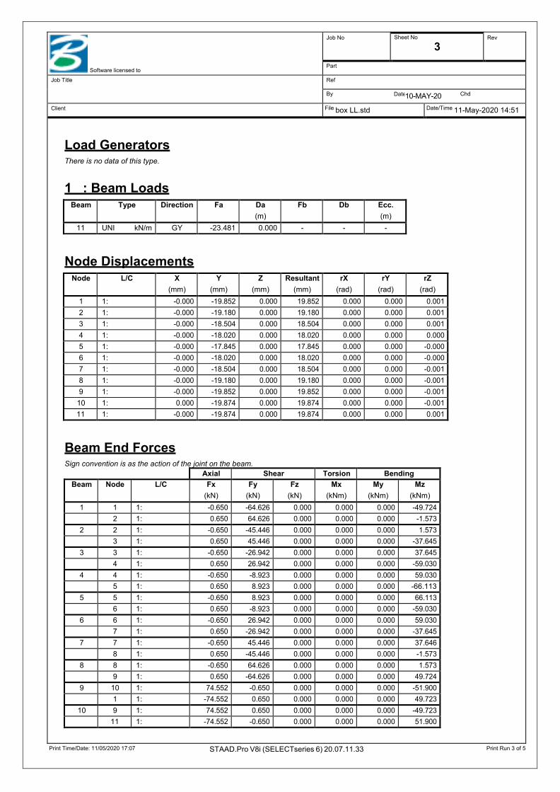
Print Time/Date: 11/05/2020 17:07 STAAD.Pro V8i (SELECTseries 6) 20.07.11.33 Print Run 3 of 5
Date
Software licensed to
Job No Sheet No
3 Rev
Part
Job Title Ref
By 10-MAY-20 Chd
Client File box LL.std Date/Time 11-May-2020 14:51
Load Generators There is no data of this type.
1 : Beam Loads
Node Displacements
Beam End Forces Sign convention is as the action of the joint on the beam.
Beam Type Direction Fa Da (m)
Fb Db Ecc. (m)
11 UNI kN/m GY -23.481 0.000 - - -
Node L/C X (mm)
Y (mm)
Z (mm)
Resultant (mm)
rX (rad)
rY (rad)
rZ (rad)
1 1: -0.000 -19.852 0.000 19.852 0.000 0.000 0.001 2 1: -0.000 -19.180 0.000 19.180 0.000 0.000 0.001 3 1: -0.000 -18.504 0.000 18.504 0.000 0.000 0.001 4 1: -0.000 -18.020 0.000 18.020 0.000 0.000 0.000 5 1: -0.000 -17.845 0.000 17.845 0.000 0.000 -0.000 6 1: -0.000 -18.020 0.000 18.020 0.000 0.000 -0.000 7 1: -0.000 -18.504 0.000 18.504 0.000 0.000 -0.001 8 1: -0.000 -19.180 0.000 19.180 0.000 0.000 -0.001 9 1: -0.000 -19.852 0.000 19.852 0.000 0.000 -0.001
10 1: 0.000 -19.874 0.000 19.874 0.000 0.000 -0.001 11 1: -0.000 -19.874 0.000 19.874 0.000 0.000 0.001
Axial Shear Torsion Bending Beam Node L/C Fx
(kN) Fy
(kN) Fz
(kN) Mx
(kNm) My
(kNm) Mz
(kNm) 1 1 1: -0.650 -64.626 0.000 0.000 0.000 -49.724
2 1: 0.650 64.626 0.000 0.000 0.000 -1.573 2 2 1: -0.650 -45.446 0.000 0.000 0.000 1.573
3 1: 0.650 45.446 0.000 0.000 0.000 -37.645 3 3 1: -0.650 -26.942 0.000 0.000 0.000 37.645
4 1: 0.650 26.942 0.000 0.000 0.000 -59.030 4 4 1: -0.650 -8.923 0.000 0.000 0.000 59.030
5 1: 0.650 8.923 0.000 0.000 0.000 -66.113 5 5 1: -0.650 8.923 0.000 0.000 0.000 66.113
6 1: 0.650 -8.923 0.000 0.000 0.000 -59.030 6 6 1: -0.650 26.942 0.000 0.000 0.000 59.030
7 1: 0.650 -26.942 0.000 0.000 0.000 -37.645 7 7 1: -0.650 45.446 0.000 0.000 0.000 37.646
8 1: 0.650 -45.446 0.000 0.000 0.000 -1.573 8 8 1: -0.650 64.626 0.000 0.000 0.000 1.573
9 1: 0.650 -64.626 0.000 0.000 0.000 49.724 9 10 1: 74.552 -0.650 0.000 0.000 0.000 -51.900
1 1: -74.552 0.650 0.000 0.000 0.000 49.723 10 9 1: 74.552 0.650 0.000 0.000 0.000 -49.723
11 1: -74.552 -0.650 0.000 0.000 0.000 51.900

Print Time/Date: 11/05/2020 17:07 STAAD.Pro V8i (SELECTseries 6) 20.07.11.33 Print Run 4 of 5
Date
Software licensed to
Job No Sheet No
4 Rev
Part
Job Title Ref
By 10-MAY-20 Chd
Client File box LL.std Date/Time 11-May-2020 14:51
Beam End Forces Cont...
Beam Maximum Moments Distances to maxima are given from beam end A.
Beam Maximum Shear Forces Distances to maxima are given from beam end A.
Axial Shear Torsion Bending Beam Node L/C Fx
(kN) Fy
(kN) Fz
(kN) Mx
(kNm) My
(kNm) Mz
(kNm) 11 10 1: 0.650 74.552 0.000 0.000 0.000 51.900
11 1: -0.650 74.552 0.000 0.000 0.000 -51.900
Beam Node A Length (m)
L/C d (m)
Max My (kNm)
d (m)
Max Mz (kNm)
1 1 0.794 1: Max +ve 0.000 0.000 0.794 1.573 Max -ve 0.000 0.000 0.000 -49.724
2 2 0.794 1: Max +ve 0.000 0.000 0.794 37.645 Max -ve 0.000 0.000
3 3 0.794 1: Max +ve 0.000 0.000 0.794 59.030 Max -ve 0.000 0.000
4 4 0.794 1: Max +ve 0.000 0.000 0.794 66.113 Max -ve 0.000 0.000
5 5 0.794 1: Max +ve 0.000 0.000 0.000 66.113 Max -ve 0.000 0.000
6 6 0.794 1: Max +ve 0.000 0.000 0.000 59.030 Max -ve 0.000 0.000
7 7 0.794 1: Max +ve 0.000 0.000 0.000 37.646 Max -ve 0.000 0.000
8 8 0.794 1: Max +ve 0.000 0.000 0.000 1.573 Max -ve 0.000 0.000 0.794 -49.724
9 10 3.350 1: Max +ve 0.000 0.000
Max -ve 0.000 0.000 0.000 -51.900 10 9 3.350 1: Max +ve 0.000 0.000
Max -ve 0.000 0.000 3.350 -51.900 11 10 6.350 1: Max +ve 0.000 0.000 6.350 51.900
Max -ve 0.000 0.000 3.175 -66.452
Beam Node A Length (m)
L/C d (m)
Max Fz (kN)
d (m)
Max Fy (kN)
1 1 0.794 1: Max +ve 0.000 0.000
Max -ve 0.000 0.000 0.000 -64.626 2 2 0.794 1: Max +ve 0.000 0.000
Max -ve 0.000 0.000 0.000 -45.446 3 3 0.794 1: Max +ve 0.000 0.000
Max -ve 0.000 0.000 0.000 -26.942 4 4 0.794 1: Max +ve 0.000 0.000
Max -ve 0.000 0.000 0.000 -8.923 5 5 0.794 1: Max +ve 0.000 0.000 0.000 8.923
Max -ve 0.000 0.000
6 6 0.794 1: Max +ve 0.000 0.000 0.000 26.942

Print Time/Date: 11/05/2020 17:07 STAAD.Pro V8i (SELECTseries 6) 20.07.11.33 Print Run 5 of 5
Date
Software licensed to
Job No Sheet No
5 Rev
Part
Job Title Ref
By 10-MAY-20 Chd
Client File box LL.std Date/Time 11-May-2020 14:51
Beam Maximum Shear Forces Cont...
Beam Maximum Axial Forces Distances to maxima are given from beam end A.
Beam Node A Length (m)
L/C d (m)
Max Fz (kN)
d (m)
Max Fy (kN)
Max -ve 0.000 0.000
7 7 0.794 1: Max +ve 0.000 0.000 0.000 45.446 Max -ve 0.000 0.000
8 8 0.794 1: Max +ve 0.000 0.000 0.000 64.626 Max -ve 0.000 0.000
9 10 3.350 1: Max +ve 0.000 0.000
Max -ve 0.000 0.000 0.000 -0.650 10 9 3.350 1: Max +ve 0.000 0.000 0.000 0.650
Max -ve 0.000 0.000
11 10 6.350 1: Max +ve 0.000 0.000 0.000 74.552 Max -ve 0.000 0.000 6.350 -74.552
Beam Node A Length (m)
L/C d (m)
Max Fx (kN)
1 1 0.794 1: Max +ve
Max -ve 0.000 -0.650 2 2 0.794 1: Max +ve
Max -ve 0.000 -0.650 3 3 0.794 1: Max +ve
Max -ve 0.000 -0.650 4 4 0.794 1: Max +ve
Max -ve 0.000 -0.650 5 5 0.794 1: Max +ve
Max -ve 0.000 -0.650 6 6 0.794 1: Max +ve
Max -ve 0.000 -0.650 7 7 0.794 1: Max +ve
Max -ve 0.000 -0.650 8 8 0.794 1: Max +ve
Max -ve 0.000 -0.650 9 10 3.350 1: Max +ve 0.000 74.552
Max -ve
10 9 3.350 1: Max +ve 0.000 74.552 Max -ve
11 10 6.350 1: Max +ve 0.000 0.650 Max -ve
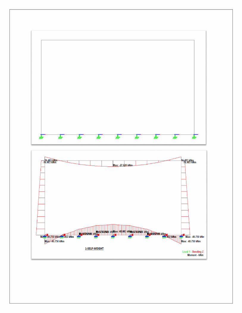
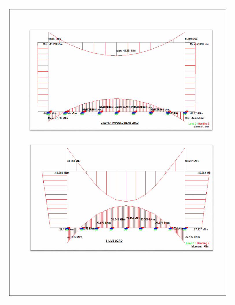
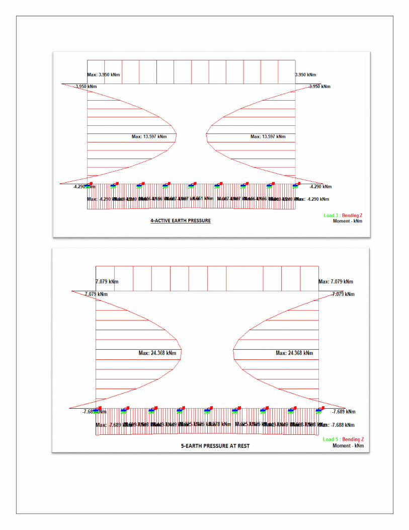


5-CONCLUSION
• The study shows that the maximum positive moment develop at the centre of top and
bottom slab for the condition that the sides of the culvert not carrying the live load and
the culvert is running full of water.
• The maximum negative moments develop at the support sections of the bottom slab for
the condition that the culvert is empty and the top slab carries the dead load and live
load.
• The maximum negative moment develop at the centre of vertical wall when the culvert
is running full and when uniform lateral pressure due to superimposed dead load acts
only.
• The maximum shear forces develop at the corners of top and bottom slab when the
culvert is running full and the top slab carries the dead and live load.
• The study shows that there is significant contribution to positive normal thrust at centre
of vertical wall due to superimposed dead load & live load and weight of side walls.
• The study shows that the multi celled box culverts are more economical for larger spans
compared to single cell box culvert as the maximum bending moment and shear force
values decreases considerably, thus requiring thinner sections.
Copyright © 2022 FDOKUMEN