Study on wind resistant design of super long-span bridges - E ...
7
Study on wind resistant design of super long- span bridges Autor(en): Sato, Hiroshi / Furuya, Nobuaki / Ogihara, Katsuya Objekttyp: Article Zeitschrift: IABSE reports = Rapports AIPC = IVBH Berichte Band (Jahr): 79 (1998) Persistenter Link: http://doi.org/10.5169/seals-59900 PDF erstellt am: 08.02.2022 Nutzungsbedingungen Die ETH-Bibliothek ist Anbieterin der digitalisierten Zeitschriften. Sie besitzt keine Urheberrechte an den Inhalten der Zeitschriften. Die Rechte liegen in der Regel bei den Herausgebern. Die auf der Plattform e-periodica veröffentlichten Dokumente stehen für nicht-kommerzielle Zwecke in Lehre und Forschung sowie für die private Nutzung frei zur Verfügung. Einzelne Dateien oder Ausdrucke aus diesem Angebot können zusammen mit diesen Nutzungsbedingungen und den korrekten Herkunftsbezeichnungen weitergegeben werden. Das Veröffentlichen von Bildern in Print- und Online-Publikationen ist nur mit vorheriger Genehmigung der Rechteinhaber erlaubt. Die systematische Speicherung von Teilen des elektronischen Angebots auf anderen Servern bedarf ebenfalls des schriftlichen Einverständnisses der Rechteinhaber. Haftungsausschluss Alle Angaben erfolgen ohne Gewähr für Vollständigkeit oder Richtigkeit. Es wird keine Haftung übernommen für Schäden durch die Verwendung von Informationen aus diesem Online-Angebot oder durch das Fehlen von Informationen. Dies gilt auch für Inhalte Dritter, die über dieses Angebot zugänglich sind. Ein Dienst der ETH-Bibliothek ETH Zürich, Rämistrasse 101, 8092 Zürich, Schweiz, www.library.ethz.ch http://www.e-periodica.ch
-
Upload
khangminh22 -
Category
Documents
-
view
5 -
download
0
Transcript of Study on wind resistant design of super long-span bridges - E ...
Study on wind resistant design of super long-span bridges
Autor(en): Sato, Hiroshi / Furuya, Nobuaki / Ogihara, Katsuya
Objekttyp: Article
Zeitschrift: IABSE reports = Rapports AIPC = IVBH Berichte
Band (Jahr): 79 (1998)
Persistenter Link: http://doi.org/10.5169/seals-59900
PDF erstellt am: 08.02.2022
NutzungsbedingungenDie ETH-Bibliothek ist Anbieterin der digitalisierten Zeitschriften. Sie besitzt keine Urheberrechte anden Inhalten der Zeitschriften. Die Rechte liegen in der Regel bei den Herausgebern.Die auf der Plattform e-periodica veröffentlichten Dokumente stehen für nicht-kommerzielle Zwecke inLehre und Forschung sowie für die private Nutzung frei zur Verfügung. Einzelne Dateien oderAusdrucke aus diesem Angebot können zusammen mit diesen Nutzungsbedingungen und denkorrekten Herkunftsbezeichnungen weitergegeben werden.Das Veröffentlichen von Bildern in Print- und Online-Publikationen ist nur mit vorheriger Genehmigungder Rechteinhaber erlaubt. Die systematische Speicherung von Teilen des elektronischen Angebotsauf anderen Servern bedarf ebenfalls des schriftlichen Einverständnisses der Rechteinhaber.
HaftungsausschlussAlle Angaben erfolgen ohne Gewähr für Vollständigkeit oder Richtigkeit. Es wird keine Haftungübernommen für Schäden durch die Verwendung von Informationen aus diesem Online-Angebot oderdurch das Fehlen von Informationen. Dies gilt auch für Inhalte Dritter, die über dieses Angebotzugänglich sind.
Ein Dienst der ETH-BibliothekETH Zürich, Rämistrasse 101, 8092 Zürich, Schweiz, www.library.ethz.ch
http://www.e-periodica.ch
397
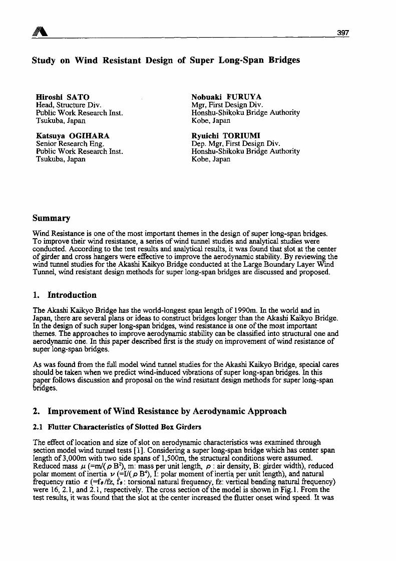
Study on Wind Resistant Design of Super Long-Span Bridges
Hiroshi SATOHead, Structure Div.Public Work Research Inst.Tsukuba, Japan
Nobuaki FURUYAMgr, First Design Div.Honshu-Shikoku Bridge AuthorityKobe, Japan
Katsuya OGIHARASenior Research Eng.Public Work Research Inst.Tsukuba, Japan
Ryuichi TORIUMIDep. Mgr, First Design Div.Honshu-Shikoku Bridge AuthorityKobe, Japan
Summary
Wind Resistance is one of the most important themes in the design of super long-span bridges.To improve their wind resistance, a series ofwind tunnel studies and analytical studies wereconducted. According to the test results and analytical results, it was found that slot at the centerofgirder and cross hangers were effective to improve the aerodynamic stability. By reviewing thewind tunnel studies for the Akashi Kaikyo Bridge conducted at the Large Boundary Layer WindTunnel, wind resistant design methods for super long-span bridges are discussed and proposed.
1. Introduction
The Akashi Kaikyo Bridge has the world-longest span length of 1990m. In the world and inJapan, there are several plans or ideas to construct bridges longer than the Akashi Kaikyo Bridge.In the design of such super long-span bridges, wind resistance is one of the most importantthemes. The approaches to improve aerodynamic stability can be classified into structural one andaerodynamic one. In this paper described first is the study on improvement ofwind resistance ofsuper long-span bridges.
As was found from the full model wind tunnel studies for the Akashi Kaikyo Bridge, special caresshould be taken when we predict wind-induced vibrations of super long-span bridges. In thispaper follows discussion and proposal on the wind resistant design methods for super long-spanbridges.
2. Improvement of Wind Resistance by Aerodynamic Approach
2.1 Flutter Characteristics of Slotted Box Girders
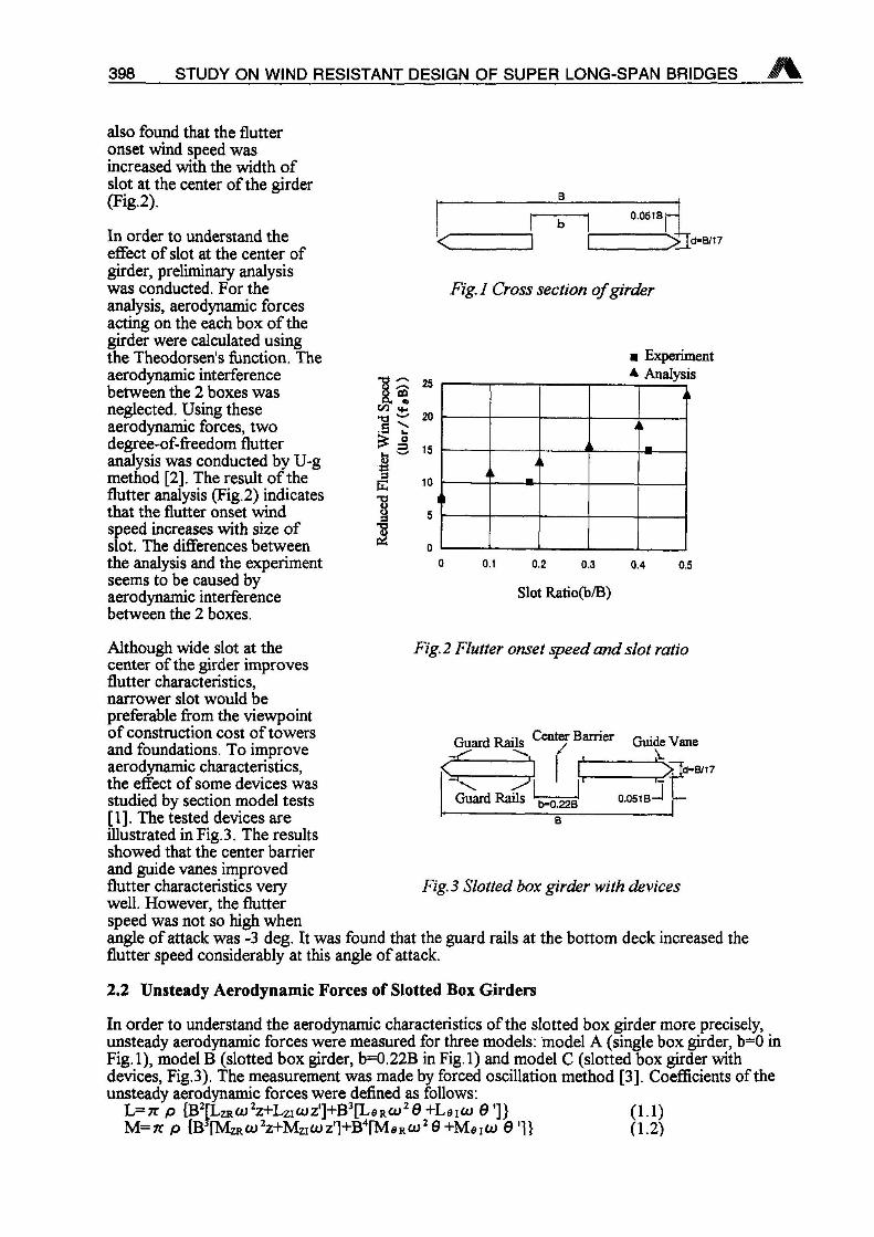
The effect of location and size of slot on aerodynamic characteristics was examined throughsection model wind tunnel tests [1], Considering a super long-span bridge which has center spanlength of3,000m with two side spans of 1,500m, the structural conditions were assumed.Reduced mass p (=m/(p B2), m: mass per unit length, p : air density, B: girder width), reducedpolar moment of inertia v (=I/(p B4), I: polar moment of inertia per unit length), and naturalfrequency ratio s (=fs/fz, fa : torsional natural frequency, fz: vertical bending natural frequency)were 16, 2.1, and 2.1, respectively. The cross section of the model is shown in Fig. 1. From thetest results, it was found that the slot at the center increased the flutter onset wind speed. It was
398 STUDY ON WIND RESISTANT DESIGN OF SUPER LONG-SPAN BRIDGES
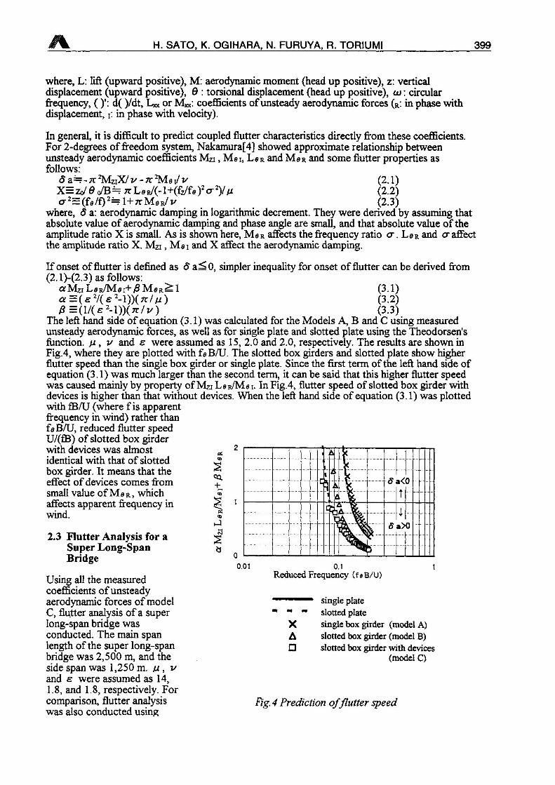
also found that the flutteronset wind speed wasincreased with the width ofslot at the center of the girder(Fig.2).
In order to understand theeffect of slot at the center ofgirder, preliminary analysiswas conducted. For theanalysis, aerodynamic forcesacting on the each box of thegirder were calculated usingthe Theodorsen's function. Theaerodynamic interferencebetween the 2 boxes wasneglected. Using theseaerodynamic forces, twodegree-of-ffeedom flutteranalysis was conducted by U-gmethod [2], The result of theflutter analysis (Fig.2) indicatesthat the flutter onset windspeed increases with size ofslot. The differences betweenthe analysis and the experimentseems to be caused byaerodynamic interferencebetween the 2 boxes.
c0.051BJ—
>rfd-B/i7
Fig. I Cross section ofgirder
Ol*T3
I3E
S 25CD
Ä 20Nuo3 15
10
s
Experimenta Analysis
0.1 0.2 0.3 0.4
Slot Ratio(b/B)
0.5
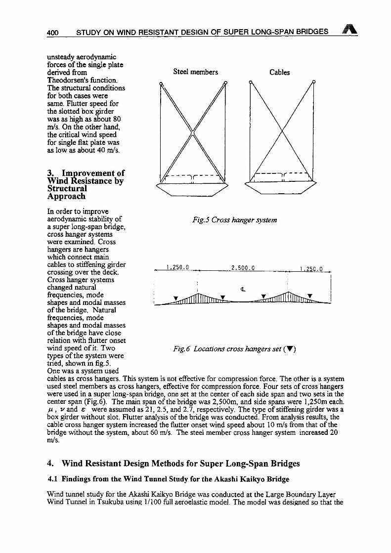
Although wide slot at thecenter of the girder improvesflutter characteristics,narrower slot would bepreferable from the viewpointof construction cost of towersand foundations. To improveaerodynamic characteristics,the effect of some devices wasstudied by section model tests[1]. The tested devices areillustrated in Fig. 3. The resultsshowed that the center barrierand guide vanes improvedflutter characteristics verywell. However, the flutterspeed was not so high whenangle of attack was -3 deg. It was found that the guard rails at the bottom deck increased theflutter speed considerably at this angle of attack.
2.2 Unsteady Aerodynamic Forces of Slotted Box Girders
In order to understand the aerodynamic characteristics of the slotted box girder more precisely,unsteady aerodynamic forces were measured for three models: model A (single box girder, b=0 inFig. 1), model B (slotted box girder, b=0.22B in Fig. 1) and model C (slotted box girder withdevices, Fig.3). The measurement was made by forced oscillation method [3], Coefficients of theunsteady aerodynamic forces were defined as follows:
L=7t p {B2[Lzr co 2Z+Lzi O) z']+B3[L e r cu2 0 +L a i to 0 ']} (1.1)
M=7r p {B [Mzrtu 2z+Mzico z'l+B4fMa R oj 2 0 +MeiO> 0 ']} (1.2)
Fig. 2 Flutter onset speed and slot ratio
Guard Rails ent/r Bamer Qiiide Vanet X
< 1 I ^Td-B/17^ r 1
ids 0.051 B-JGuard Rails ^
Fig.3 Slotted box girder with devices
M H. SATO, K. OGIHARA, N. FURUYA, R. TORIUMI 399
where, L: lift (upward positive), M: aerodynamic moment (head up positive), z: verticaldisplacement (upward positive), 0 : torsional displacement (head up positive), to : circularfrequency, )': d( )/dt, L» or M«: coefficients ofunsteady aerodynamic forces (R: in phase withdisplacement, i: in phase with velocity).
In general, it is difficult to predict coupled flutter characteristics directly from these coefficients.For 2-degrees of freedom system, Nakamura[4] showed approximate relationship betweenunsteady aerodynamic coefficients Mzi, Msi, L8R and M8R and some flutter properties asfollows:
0a=^-n,2MziX/i/-7r2M8i/v (2.1)X=Zo/0 o/B= 7T L s R/(-1+(fz/fa )2 cr2)/ v (2.2)a2=(f8/f)2= l+7rM8R/v (2.3)
where, ô a: aerodynamic damping in logarithmic decrement. They were derived by assuming thatabsolute value of aerodynamic damping and phase angle are small, and that absolute value of theamplitude ratio X is small. As is shown here, M8R affects the frequency ratio cr. L8R and cr affectthe amplitude ratio X. MZi, M8i and X affect the aerodynamic damping.
If onset of flutter is defined as Ô 0, simpler inequality for onset of flutter can be derived from(2.1)-(2.3) as follows:
a Mzi L8R/M«i+ßM8R^ 1 (3.1)a=(e7(e2-l))(7r//0 (3.2)iB=(l/(e2-l))(7r/v) (3.3)
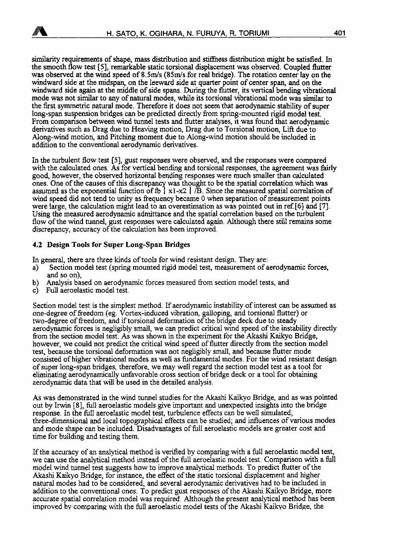
The left hand side of equation (3.1) was calculated for the Models A, B and C using measuredunsteady aerodynamic forces, as well as for single plate and slotted plate using the Theodorsen'sfunction, ß v and e were assumed as IS, 2.0 and 2.0, respectively. The results are shown inFig.4, where they are plotted with faB/U. The slotted box girders and slotted plate show higherflutter speed than the single box girder or single plate. Since the first term of the left hand side ofequation (3.1) was much larger than the second term, it can be said that this higher flutter speedwas caused mainly by property ofMZi L8R/M8i. In Fig.4, flutter speed of slotted box girder withdevices is higher than that without devices. When the left hand side of equation (3.1) was plottedwith fB/U (where fis apparentfrequency in wind) rather thanf8B/U, reduced flutter speedU/(fB) of slotted box girderwith devices was almostidentical with that of slottedbox girder. It means that theeffect of devices comes fromsmall value ofM8R, whichaffects apparent frequency inwind.
S<«.
+
2.3 Flutter Analysis for aSuper Long-SpanBridge
Using all the measuredcoefficients ofunsteadyaerodynamic forces of modelC, flutter analysis of a superlong-span bridge wasconducted. The main spanlength of the super long-spanbridge was 2,500 m, and theside span was 1,250 m. ß vand e were assumed as 14,1.8, and 1.8, respectively. Forcomparison, flutter analysiswas also conducted using
S
0.01Reduced Frequency (faB/U)
XA
single plateslotted platesingle box girder (model A)slotted box girder (model B)slotted box girder with devices
(model C)
Fig, 4 Prediction offlutter speed
400 STUDY ON WIND RESISTANT DESIGN OF SUPER LONG-SPAN BRIDGES
unsteady aerodynamicforces of the single platederived fromTheodorsen's function.The structural conditionsfor both cases weresame. Flutter speed forthe slotted box girderwas as high as about 80m/s. On the other hand,the critical wind speedfor single flat plate wasas low as about 40 m/s.
3. Improvement ofWind Resistance byStructuralApproach
In order to improveaerodynamic stability ofa super long-span bridge,cross hanger systemswere examined. Crosshangers are hangerswhich connect maincables to stiffening girdercrossing over the deck.Cross hanger systemschanged naturalfrequencies, modeshapes and modal massesof the bridge. Naturalfrequencies, modeshapes and modal massesof the bridge have closerelation with flutter onsetwind speed of it. Two Fig. 6 Locations cross hangers settypes of the system weretried, shown in fig. 5.One was a system usedcables as cross hangers. This system is not effective for compression force. The other is a systemused steel members as cross hangers, effective for compression force. Four sets of cross hangerswere used in a super long-span bridge, one set at the center of each side span and two sets in thecenter span (Fig.6). The main span of the bridge was 2,500m, and side spans were 1,250m each.
ß, v and e were assumed as 21, 2.5, and 2.7, respectively. The type of stiffening girder was abox girder without slot. Flutter analysis of the bridge was conducted. From analysis results, thecable cross hanger system increased the flutter onset wind speed about 10 m/s from that of thebridge without the system, about 60 m/s. The steel member cross hanger system increased 20m/s.
4. Wind Resistant Design Methods for Super Long-Span Bridges
4.1 Findings from the Wind Tunnel Study for the Akashi Kaikyo Bridge
Wind tunnel study for the Akashi Kaikyo Bridge was conducted at the Large Boundary LayerWind Tunnel in Tsukuba using 1/100 full aeroelastic model. The model was designed so that the
Steel members Cables
Fig. 5 Cross hanger system
I,250.0 2,500.0 1 .250.0
VrTTîTÏÏnTmrJL. ^TrfflfÏÏÏÏTîTm^
H. SATO, K. OGIHARA, N. FURUYA, R. TORIUMI 401
similarity requirements of shape, mass distribution and stiffness distribution might be satisfied. Inthe smooth flow test [5], remarkable static torsional displacement was observed. Coupled flutterwas observed at the wind speed of 8.5m/s (85m/s for real bridge). The rotation center lay on thewindward side at the midspan, on the leeward side at quarter point ofcenter span, and on thewindward side again at the middle of side spans. During the flutter, its vertical bending vibrationalmode was not similar to any of natural modes, while its torsional vibrational mode was similar tothe first symmetric natural mode. Therefore it does not seem that aerodynamic stability of superlong-span suspension bridges can be predicted directly from spring-mounted rigid model test.From comparison between wind tunnel tests and flutter analyses, it was found that aerodynamicderivatives such as Drag due to Heaving motion, Drag due to Torsional motion, Lift due toAlong-wind motion, and Pitching moment due to Along-wind motion should be included inaddition to the conventional aerodynamic derivatives.
In the turbulent flow test [5], gust responses were observed, and the responses were comparedwith the calculated ones. As for vertical bending and torsional responses, the agreement was fairlygood, however, the observed horizontal bending responses were much smaller than calculatedones. One of the causes of this discrepancy was thought to be the spatial correlation which wasassumed as the exponential function of fb | xl-x2 | /B. Since the measured spatial correlation ofwind speed did not tend to unity as frequency became 0 when separation of measurement pointswere large, the calculation might lead to an overestimation as was pointed out in ref.[6] and [7],Using the measured aerodynamic admittance and the spatial correlation based on the turbulentflow of the wind tunnel, gust responses were calculated again. Although there still remains somediscrepancy, accuracy of the calculation has been improved.
4.2 Design Tools for Super Long-Span Bridges
In general, there are three kinds of tools for wind resistant design. They are:a) Section model test (spring mounted rigid model test, measurement of aerodynamic forces,
and so on),b) Analysis based on aerodynamic forces measured from section model tests, andc) Full aeroelastic model test.
Section model test is the simplest method. If aerodynamic instability of interest can be assumed asone-degree of freedom (eg. Vortex-induced vibration, galloping, and torsional flutter) ortwo-degree of freedom, and if torsional deformation of the bridge deck due to steadyaerodynamic forces is negligibly small, we can predict critical wind speed of the instability directlyfrom the section model test. As was shown in the experiment for the Akashi Kaikyo Bridge,however, we could not predict the critical wind speed of flutter directly from the section modeltest, because the torsional deformation was not negligibly small, and because flutter modeconsisted ofhigher vibrational modes as well as fundamental modes. For the wind resistant designof super long-span bridges, therefore, we may well regard the section model test as a tool foreliminating aerodynamically unfavorable cross section of bridge deck or a tool for obtainingaerodynamic data that will be used in the detailed analysis.
As was demonstrated in the wind tunnel studies for the Akashi Kaikyo Bridge, and as was pointedout by Irwin [8], full aeroelastic models give important and unexpected insights into the bridgeresponse. In the full aeroelastic model test, turbulence effects can be well simulated;three-dimensional and local topographical effects can be studied; and influences ofvarious modesand mode shape can be included. Disadvantages of full aeroelastic models are greater cost andtime for building and testing them.
If the accuracy of an analytical method is verified by comparing with a full aeroelastic model test,we can use the analytical method instead of the frill aeroelastic model test. Comparison with a fullmodel wind tunnel test suggests how to improve analytical methods. To predict flutter of theAkashi Kaikyo Bridge, for instance, the effect of the static torsional displacement and highernatural modes had to be considered, and several aerodynamic derivatives had to be included inaddition to the conventional ones. To predict gust responses of the Akashi Kaikyo Bridge, moreaccurate spatial correlation model was required. Although the present analytical method has beenimproved by comparing with the full aeroelastic model tests of the Akashi Kaikyo Bridge, the
402 STUDY ON WIND RESISTANT DESIGN OF SUPER LONG-SPAN BRIDGES
verification of the method is necessary if the method is applied to super long-span bridges thathave longer span, inexperienced bridge deck configuration or inexperienced cable system.
4.3 Design Procedures for Super Long-Span Bridges
The procedure ofwind resistant design for super long-span bridges can be proposed as follows:a) Selection ofbridge deck cross section by section model testsb) Prediction and evaluation ofwind-induced deformation and vibration by the analytical
method that is the most reliable at that timec) Verification and improvement of the analytical method by comparing with a full aeroelastic
model testd) (in case of slight change ofbridge design) Prediction and evaluation of wind-induced
deformation and vibration by the verified analytical methode) (if the accuracy of the analytical model is not enough) Verification of the finalized bridge
design by a full aeroelastic model test
5. Concluding Remarks
(1) It was found that box girder with slot at the center had good flutter characteristics, and that itcould be improved by some devices like center barrier and guide vane. It seems that the slottedbox girder would be one of the possible stiffening girders for super long-span bridges. It was alsofound that cross-hangers were effective to increase flutter speed of super long-span bridges.
(2) Since super long-span bridges will have inexperienced span length, inexperienced bridge deckcross section or cable systems, full aeroelastic model tests will play an important roll in windresistant design of super long-span bridges. To overcome its disadvantage, namely greater costand time, section model tests can be used to select aerodynamically favorable cross section, andanalytical methods verified by the full aeroelastic model tests can be applied to predict andevaluate wind-induced response.
References
[1] Sato H., Toriumi R. and Kusakabe T., Aerodynamic characteristics of slotted box girders,Proceedings ofBridges into the 21st Century, 1995
[2] Bisplinghoff R. L., Ashley H., and Halfman R. L., Aeroelasticity, Addison Wesley.[3] Okubo, T., Narita N. and Yokoyama K., Some approaches for improving wind stability of
cable-stayed girder bridges, Proc. of the 4th International Conference on Wind Effects onBuildings and Structures, 1975
[4] Nakamura, Y., An analysis ofbinary flutter ofbridge deck sections, J. of Sound andVibration, 57(4), 1978
[5] Sumiyoshi Y., Endo T., Miyata T., Sato H. and Kitagawa M., Experiments for the AkashiKaikyo Bridge in a Large Boundary Layer Wind Tunnel, Proc. of International Seminar onUtilization ofLarge Boundary Layer Wind Tunnel, Tsukuba, Japan, 1993
[6] ESDU, Characteristics of atmospheric turbulence near the ground, Part III : variations inspace and time for strong winds (neutral atmosphere), 1975
[7] Irwin H.P.A.H., Wind tunnel and analytical investigations of the response ofLions' GateBridge to a turbulent wind, Laboratory Technical Report LTR-LA-210, National ResearchCouncil Canada, 1977
[9] Irwin P. A., Full aeroelastic tests, Aerodynamics ofLarge Bridges, A. A. Balkema,Rotterdam, Brookfield, 1992