Truss bridges
51
13.1 SECTION 13 TRUSS BRIDGES* John M. Kulicki, P.E. President and Chief Engineer Joseph E. Prickett, P.E. Senior Associate David H. LeRoy, P.E. Vice President Modjeski and Masters, Inc., Harrisburg, Pennsylvania A truss is a structure that acts like a beam but with major components, or members, subjected primarily to axial stresses. The members are arranged in triangular patterns. Ideally, the end of each member at a joint is free to rotate independently of the other members at the joint. If this does not occur, secondary stresses are induced in the members. Also if loads occur other than at panel points, or joints, bending stresses are produced in the members. Though trusses were used by the ancient Romans, the modern truss concept seems to have been originated by Andrea Palladio, a sixteenth century Italian architect. From his time to the present, truss bridges have taken many forms. Early trusses might be considered variations of an arch. They applied horizontal thrusts at the abutments, as well as vertical reactions, In 1820, Ithiel Town patented a truss that can be considered the forerunner of the modern truss. Under vertical loading, the Town truss exerted only vertical forces at the abutments. But unlike modern trusses, the diagonals, or web systems, were of wood lattice construction and chords were composed of two or more timber planks. In 1830, Colonel Long of the U.S. Corps of Engineers patented a wood truss with a simpler web system. In each panel, the diagonals formed an X. The next major step came in 1840, when William Howe patented a truss in which he used wrought-iron tie rods for vertical web members, with X wood diagonals. This was followed by the patenting in 1844 of the Pratt truss with wrought-iron X diagonals and timber verticals. The Howe and Pratt trusses were the immediate forerunners of numerous iron bridges. In a book published in 1847, Squire Whipple pointed out the logic of using cast iron in compression and wrought iron in tension. He constructed bowstring trusses with cast-iron verticals and wrought-iron X diagonals. *Revised and updated from Sec. 12, ‘‘Truss Bridges,’’by Jack P. Shedd, in the first edition. Copyrighted Material Copyright © 1999 by The McGraw-Hill Companies Retrieved from: www.knovel.com
Transcript of Truss bridges

13.1
SECTION 13TRUSS BRIDGES*
John M. Kulicki, P.E.President and Chief Engineer
Joseph E. Prickett, P.E.Senior Associate
David H. LeRoy, P.E.Vice PresidentModjeski and Masters, Inc., Harrisburg, Pennsylvania
A truss is a structure that acts like a beam but with major components, or members, subjectedprimarily to axial stresses. The members are arranged in triangular patterns. Ideally, the endof each member at a joint is free to rotate independently of the other members at the joint.If this does not occur, secondary stresses are induced in the members. Also if loads occurother than at panel points, or joints, bending stresses are produced in the members.
Though trusses were used by the ancient Romans, the modern truss concept seems tohave been originated by Andrea Palladio, a sixteenth century Italian architect. From his timeto the present, truss bridges have taken many forms.
Early trusses might be considered variations of an arch. They applied horizontal thrustsat the abutments, as well as vertical reactions, In 1820, Ithiel Town patented a truss that canbe considered the forerunner of the modern truss. Under vertical loading, the Town trussexerted only vertical forces at the abutments. But unlike modern trusses, the diagonals, orweb systems, were of wood lattice construction and chords were composed of two or moretimber planks.
In 1830, Colonel Long of the U.S. Corps of Engineers patented a wood truss with asimpler web system. In each panel, the diagonals formed an X. The next major step camein 1840, when William Howe patented a truss in which he used wrought-iron tie rods forvertical web members, with X wood diagonals. This was followed by the patenting in 1844of the Pratt truss with wrought-iron X diagonals and timber verticals.
The Howe and Pratt trusses were the immediate forerunners of numerous iron bridges.In a book published in 1847, Squire Whipple pointed out the logic of using cast iron incompression and wrought iron in tension. He constructed bowstring trusses with cast-ironverticals and wrought-iron X diagonals.
*Revised and updated from Sec. 12, ‘‘Truss Bridges,’’ by Jack P. Shedd, in the first edition.
Copy
right
ed M
ater
ial
Copyright © 1999 by The McGraw-Hill Companies Retrieved from: www.knovel.com

13.2 SECTION THIRTEEN
These trusses were statically indeterminate. Stress analysis was difficult. Latter, simplerweb systems were adopted, thus eliminating the need for tedious and exacting design pro-cedures.
To eliminate secondary stresses due to rigid joints, early American engineers constructedpin-connected trusses. European engineers primarily used rigid joints. Properly proportioned,the rigid trusses gave satisfactory service and eliminated the possibility of frozen pins, whichinduce stresses not usually considered in design. Experience indicated that rigid and pin-connected trusses were nearly equal in cost, except for long spans. Hence, modern designfavors rigid joints.
Many early truss designs were entirely functional, with little consideration given to ap-pearance. Truss members and other components seemed to lie in all possible directions andto have a variety of sizes, thus giving the impression of complete disorder. Yet, appearanceof a bridge often can be improved with very little increase in construction cost. By the1970s, many speculated that the cable-stayed bridge would entirely supplant the truss, excepton railroads. But improved design techniques, including load-factor design, and streamlineddetailing have kept the truss viable. For example, some designs utilize Warren trusses withoutverticals. In some cases, sway frames are eliminated and truss-type portals are replaced withbeam portals, resulting in an open appearance.
Because of the large number of older trusses still in the transportation system, somehistorical information in this section applies to those older bridges in an evaluation or re-habilitation context.
(H. J. Hopkins, ‘‘A Span of Bridges,’’ Praeger Publishers, New York; S. P. Timoshenko,‘‘History of Strength of Materials,’’ McGraw-Hill Book Company, New York).
13.1 SPECIFICATIONS
The design of truss bridges usually follows the specifications of the American Associationof State Highway and Transportation Officials (AASHTO) or the Manual of the AmericanRailway Engineering and Maintenance of Way Association (AREMA) (Sec. 10). A transitionin AASHTO specifications is currently being made from the ‘‘Standard Specifications forHighway Bridges,’’ Sixteenth Edition, to the ‘‘LRFD Specifications for Highway Bridges,’’Second Edition. The ‘‘Standard Specification’’ covers service load design of truss bridges,and in addition, the ‘‘Guide Specification for the Strength Design of Truss Bridges,’’ coversextension of the load factor design process permitted for girder bridges in the ‘‘StandardSpecifications’’ to truss bridges. Where the ‘‘Guide Specification’’ is silent, applicable pro-visions of the ‘‘Standard Specification’’ apply.
To clearly identify which of the three AASHTO specifications are being referred to inthis section, the following system will be adopted. If the provision under discussion appliesto all the specifications, reference will simply be made to the ‘‘AASHTO Specifications’’.Otherwise, the following notation will be observed:
‘‘AASHTO SLD Specifications’’ refers to the service load provisions of ‘‘Standard Spec-ifications for Highway Bridges’’‘‘AASHTO LFD Specifications’’ refers to ‘‘Guide Specification for the Strength Designof Truss Bridges’’‘‘AASHTO LRFD Specifications’’ refers to ‘‘LRFD Specifications for Highway Bridges.’’
13.2 TRUSS COMPONENTS
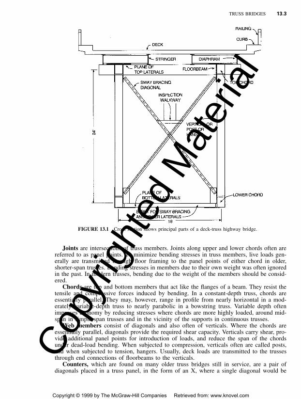
Principal parts of a highway truss bridge are indicated in Fig. 13.1; those of a railroad trussare shown in Fig. 13.2.
Copy
right
ed M
ater
ial
Copyright © 1999 by The McGraw-Hill Companies Retrieved from: www.knovel.com
TRUSS BRIDGES 13.3
FIGURE 13.1 Cross section shows principal parts of a deck-truss highway bridge.
Joints are intersections of truss members. Joints along upper and lower chords often arereferred to as panel points. To minimize bending stresses in truss members, live loads gen-erally are transmitted through floor framing to the panel points of either chord in older,shorter-span trusses. Bending stresses in members due to their own weight was often ignoredin the past. In modern trusses, bending due to the weight of the members should be consid-ered.
Chords are top and bottom members that act like the flanges of a beam. They resist thetensile and compressive forces induced by bending. In a constant-depth truss, chords areessentially parallel. They may, however, range in profile from nearly horizontal in a mod-erately variable-depth truss to nearly parabolic in a bowstring truss. Variable depth oftenimproves economy by reducing stresses where chords are more highly loaded, around mid-span in simple-span trusses and in the vicinity of the supports in continuous trusses.
Web members consist of diagonals and also often of verticals. Where the chords areessentially parallel, diagonals provide the required shear capacity. Verticals carry shear, pro-vide additional panel points for introduction of loads, and reduce the span of the chordsunder dead-load bending. When subjected to compression, verticals often are called posts,and when subjected to tension, hangers. Usually, deck loads are transmitted to the trussesthrough end connections of floorbeams to the verticals.
Counters, which are found on many older truss bridges still in service, are a pair ofdiagonals placed in a truss panel, in the form of an X, where a single diagonal would be
Copy
right
ed M
ater
ial
Copyright © 1999 by The McGraw-Hill Companies Retrieved from: www.knovel.com
13.4 SECTION THIRTEEN
FIGURE 13.2 Cross section shows principal parts of a through-truss railway bridge.Copy
right
ed M
ater
ial
Copyright © 1999 by The McGraw-Hill Companies Retrieved from: www.knovel.com

TRUSS BRIDGES 13.5
subjected to stress reversals. Counters were common in the past in short-span trusses. Suchshort-span trusses are no longer economical and have been virtually totally supplanted bybeam and girder spans. X pairs are still used in lateral trusses, sway frames and portals, butare seldom designed to act as true counters, on the assumption that only one counter acts ata time and carries the maximum panel shear in tension. This implies that the companioncounter takes little load because it buckles. In modern design, counters are seldom used inthe primary trusses. Even in lateral trusses, sway frames, and portals, X-shaped trusses areusually comprised of rigid members, that is, members that will not buckle. If adjustablecounters are used, only one may be placed in each truss panel, and it should have openturnbuckles. AASHTO LRFD specifies that counters should be avoided. The commentary tothat provision contains reference to the historical initial force requirement of 10 kips. Designof such members by AASHTO SLD or LFD Specifications should include an allowance of10 kips for initial stress. Sleeve nuts and loop bars should not be used.
End posts are compression members at supports of simple-span tusses. Wherever prac-tical, trusses should have inclined end posts. Laterally unsupported hip joints should not beused.
Working lines are straight lines between intersections of truss members. To avoid bendingstresses due to eccentricity, the gravity axes of truss members should lie on working lines.Some eccentricity may be permitted, however, to counteract dead-load bending stresses.Furthermore, at joints, gravity axes should intersect at a point. If an eccentric connection isunavoidable, the additional bending caused by the eccentricity should be included in thedesign of the members utilizing appropriate interaction equations.
AASHTO Specifications require that members be symmetrical about the central plane ofa truss. They should be proportioned so that the gravity axis of each section lies as nearlyas practicable in its center.
Connections may be made with welds or high-strength bolts. AREMA practice, however,excludes field welding, except for minor connections that do not support live load.
The deck is the structural element providing direct support for vehicular loads. Wherethe deck is located near the bottom chords (through spans), it should be supported by onlytwo trusses.
Floorbeams should be set normal or transverse to the direction of traffic. They and theirconnections should be designed to transmit the deck loads to the trusses.
Stringers are longitudinal beams, set parallel to the direction of traffic. They are used totransmit the deck loads to the floorbeams. If stringers are not used, the deck must be designedto transmit vehicular loads to the floorbeams.
Lateral bracing should extend between top chords and between bottom chords of thetwo trusses. This bracing normally consists of trusses placed in the planes of the chords toprovide stability and lateral resistance to wind. Trusses should be spaced sufficiently far apartto preclude overturning by design lateral forces.
Sway bracing may be inserted between truss verticals to provide lateral resistance invertical planes. Where the deck is located near the bottom chords, such bracing, placedbetween truss tops, must be kept shallow enough to provide adequate clearance for passageof traffic below it. Where the deck is located near the top chords, sway bracing should extendin full-depth of the trusses.
Portal bracing is sway bracing placed in the plane of end posts. In addition to servingthe normal function of sway bracing, portal bracing also transmits loads in the top lateralbracing to the end posts (Art. 13.6).
Skewed bridges are structures supported on piers that are not perpendicular to the planesof the trusses. The skew angle is the angle between the transverse centerline of bearingsand a line perpendicular to the longitudinal centerline of the bridge.
13.3 TYPES OF TRUSSES
Figure 13.3 shows some of the common trusses used for bridges. Pratt trusses have diag-onals sloping downward toward the center and parallel chords (Fig. 13.3a). Warren trusses,
Copy
right
ed M
ater
ial
Copyright © 1999 by The McGraw-Hill Companies Retrieved from: www.knovel.com

13.6 SECTION THIRTEEN
FIGURE 13.3 Types of simple-span truss bridges.
with parallel chords and alternating diago-nals, are generally, but not always, con-structed with verticals (Fig. 13.3c) to reducepanel size. When rigid joints are used, suchtrusses are favored because they provide anefficient web system. Most modern bridgesare of some type of Warren configuration.
Parker trusses (Fig. 13.3d ) resemblePratt trusses but have variable depth. As inother types of trusses, the chords provide acouple that resists bending moment. Withlong spans, economy is improved by creatingthe required couple with less force by spac-ing the chords farther apart. The Parker truss,when simply supported, is designed to haveits greatest depth at midspan, where momentis a maximum. For greatest chord economy,the top-chord profile should approximate aparabola. Such a curve, however, providestoo great a change in slope of diagonals, withsome loss of economy in weights of diago-nals. In practice, therefore, the top-chordprofile should be set for the greatest changein truss depth commensurate with reasonablediagonal slopes; for example, between 40�and 60 � with the horizontal.
K trusses (Fig. 13.3e) permit deeptrusses with short panels to have diagonals
with acceptable slopes. Two diagonals generally are placed in each panel to intersect atmidheight of a vertical. Thus, for each diagonal, the slope is half as large as it would be ifa single diagonal were used in the panel. The short panels keep down the cost of the floorsystem. This cost would rise rapidly if panel width were to increase considerably withincrease in span. Thus, K trusses may be economical for long spans, for which deep trussesand narrow panels are desirable. These trusses may have constant or variable depth.
Bridges also are classified as highway or railroad, depending on the type of loading thebridge is to carry. Because highway loading is much lighter than railroad, highway trussesgenerally are built of much lighter sections. Usually, highways are wider than railways, thusrequiring wider spacing of trusses.
Trusses are also classified as to location of deck: deck, through, or half-through trusses.Deck trusses locate the deck near the top chord so that vehicles are carried above the chord.Through trusses place the deck near the bottom chord so that vehicles pass between thetrusses. Half-through trusses carry the deck so high above the bottom chord that lateral andsway bracing cannot be placed between the top chords. The choice of deck or throughconstruction normally is dictated by the economics of approach construction.
The absence of top bracing in half-through trusses calls for special provisions to resistlateral forces. AASHTO Specifications require that truss verticals, floorbeams, and their endconnections be proportioned to resist a lateral force of at least 0.30 kip per lin ft, applied atthe top chord panel points of each truss. The top chord of a half-through truss should bedesigned as a column with elastic lateral supports at panel points. The critical buckling forceof the column, so determined, should be at least 50% larger than the maximum force inducedin any panel of the top chord by dead and live loads plus impact. Thus, the verticals haveto be designed as cantilevers, with a concentrated load at top-chord level and rigid connectionto a floorbeam. This system offers elastic restraint to buckling of the top chord. The analysisof elastically restrained compression members is covered in T. V. Galambos, ‘‘Guide toStability Design Criteria for Metal Structures,’’ Structural Stability Research Council.
Copy
right
ed M
ater
ial
Copyright © 1999 by The McGraw-Hill Companies Retrieved from: www.knovel.com

TRUSS BRIDGES 13.7
13.4 BRIDGE LAYOUT
Trusses, offering relatively large depth, open-web construction, and members subjected pri-marily to axial stress, provide large carrying capacity for comparatively small amounts ofsteel. For maximum economy in truss design, the area of metal furnished for members shouldbe varied as often as required by the loads. To accomplish this, designers usually have tospecify built-up sections that require considerable fabrication, which tend to offset some ofthe savings in steel.
Truss Spans. Truss bridges are generally comparatively easy to erect, because light equip-ment often can be used. Assembly of mechanically fastened joints in the field is relativelylabor-intensive, which may also offset some of the savings in steel. Consequently, trussesseldom can be economical for highway bridges with spans less than about 450 ft.
Railroad bridges, however, involve different factors, because of the heavier loading.Trusses generally are economical for railroad bridges with spans greater than 150 ft.
The current practical limit for simple-span trusses is about 800 ft for highway bridgesand about 750 ft for railroad bridges. Some extension of these limits should be possible withimprovements in materials and analysis, but as span requirements increase, cantilever orcontinuous trusses are more efficient. The North American span record for cantilever con-struction is 1,600 ft for highway bridges and 1,800 ft for railroad bridges.
For a bridge with several truss spans, the most economical pier spacing can be determinedafter preliminary designs have been completed for both substructure and superstructure. Oneguideline provides that the cost of one pier should equal the cost of one superstructure span,excluding the floor system. In trial calculations, the number of piers initially assumed maybe increased or decreased by one, decreasing or increasing the truss spans. Cost of trussspans rises rapidly with increase in span. A few trial calculations should yield a satisfactorypicture of the economics of the bridge layout. Such an analysis, however, is more suitablefor approach spans than for main spans. In most cases, the navigation or hydraulic require-ment is apt to unbalance costs in the direction of increased superstructure cost. Furthermore,girder construction is currently used for span lengths that would have required approachtrusses in the past.
Panel Dimensions. To start economic studies, it is necessary to arrive at economic pro-portions of trusses so that fair comparisons can be made among alternatives. Panel lengthswill be influenced by type of truss being designed. They should permit slope of the diagonalsbetween 40� and 60� with the horizontal for economic design. If panels become too long,the cost of the floor system substantially increases and heavier dead loads are transmitted tothe trusses. A subdivided truss becomes more economical under these conditions.
For simple-span trusses, experience has shown that a depth-span ratio of 1:5 to 1:8 yieldseconomical designs. Some design specifications limit this ratio, with 1:10 a common histor-ical limit. For continuous trusses with reasonable balance of spans, a depth-span ratio of1:12 should be satisfactory. Because of the lighter live loads for highways, somewhat shal-lower depths of trusses may be used for highway bridges than for railway bridges.
Designers, however, do not have complete freedom in selection of truss depth. Certainphysical limitations may dictate the depth to be used. For through-truss highway bridges,for example, it is impractical to provide a depth of less than 24 ft, because of the necessityof including suitable sway frames. Similarly, for through railway trusses, a depth of at least30 ft is required. The trend toward double-stack cars encourages even greater minimumdepths.
Once a starting depth and panel spacing have been determined, permutation of primarygeometric variables can be studied efficiently by computer-aided design methods. In fact,preliminary studies have been carried out in which every primary truss member is designed
Copy
right
ed M
ater
ial
Copyright © 1999 by The McGraw-Hill Companies Retrieved from: www.knovel.com

13.8 SECTION THIRTEEN
for each choice of depth and panel spacing, resulting in a very accurate choice of thoseparameters.
Bridge Cross Sections. Selection of a proper bridge cross section is an important deter-mination by designers. In spite of the large number of varying cross sections observed intruss bridges, actual selection of a cross section for a given site is not a large task. Forinstance, if a through highway truss were to be designed, the roadway width would determinethe transverse spacing of trusses. The span and consequent economical depth of trusses woulddetermine the floorbeam spacing, because the floorbeams are located at the panel points.Selection of the number of stringers and decisions as to whether to make the stringers simplespans between floorbeams or continuous over the floorbeams, and whether the stringers andfloorbeams should be composite with the deck, complete the determination of the crosssection.
Good design of framing of floor system members requires attention to details. In the past,many points of stress relief were provided in floor systems. Due to corrosion and wearresulting from use of these points of movement, however, experience with them has notalways been good. Additionally, the relative movement that tends to occur between the deckand the trusses may lead to out-of-plane bending of floor system members and possiblefatigue damage. Hence, modern detailing practice strives to eliminate small unconnectedgaps between stiffeners and plates, rapid change in stiffness due to excessive flange coping,and other distortion fatigue sites. Ideally, the whole structure is made to act as a unit, thuseliminating distortion fatigue.
Deck trusses for highway bridges present a few more variables in selection of crosssection. Decisions have to be made regarding the transverse spacing of trusses and whetherthe top chords of the trusses should provide direct support for the deck. Transverse spacingof the trusses has to be large enough to provide lateral stability for the structure. Narrowertruss spacings, however, permit smaller piers, which will help the overall economy of thebridge.
Cross sections of railway bridges are similarly determined by physical requirements ofthe bridge site. Deck trusses are less common for railway bridges because of the extra lengthof approach grades often needed to reach the elevation of the deck. Also, use of throughtrusses offers an advantage if open-deck construction is to be used. With through-trusses,only the lower chords are vulnerable to corrosion caused by salt and debris passing throughthe deck.
After preliminary selection of truss type, depth, panel lengths, member sizes, lateral sys-tems, and other bracing, designers should review the appearance of the entire bridge. Es-thetics can often be improved with little economic penalty.
13.5 DECK DESIGN
For most truss members, the percentage of total stress attributable to dead load increases asspan increases. Because trusses are normally used for long spans, and a sizable portion ofthe dead load (particularly on highway bridges) comes from the weight of the deck, a light-weight deck is advantageous. It should be no thicker than actually required to support thedesign loading.
In the preliminary study of a truss, consideration should be given to the cost, durability,maintainability, inspectability, and replaceability of various deck systems, including trans-verse, longitudinal, and four-way reinforced concrete decks, orthotropic-plate decks, andconcrete-filled or overlaid steel grids. Open-grid deck floors will seldom be acceptable fornew fixed truss bridges but may be advantageous in rehabilitation of bridges and for movablebridges.
Copy
right
ed M
ater
ial
Copyright © 1999 by The McGraw-Hill Companies Retrieved from: www.knovel.com

TRUSS BRIDGES 13.9
The design procedure for railroad bridge decks is almost entirely dictated by the proposedcross section. Designers usually have little leeway with the deck, because they are requiredto use standard railroad deck details wherever possible.
Deck design for a highway bridge is somewhat more flexible. Most highway bridges havea reinforced-concrete slab deck, with or without an asphalt wearing surface. Reinforcedconcrete decks may be transverse, longitudinal or four-way slabs.
• Transverse slabs are supported on stringers spaced close enough so that all the bending inthe slabs is in a transverse direction.
• Longitudinal slabs are carried by floorbeams spaced close enough so that all the bendingin the slabs is in a longitudinal direction. Longitudinal concrete slabs are practical forshort-span trusses where floorbeam spacing does not exceed about 20 ft. For larger spacing,the slab thickness becomes so large that the resultant dead load leads to an uneconomictruss design. Hence, longitudinal slabs are seldom used for modern trusses.
• Four-way slabs are supported directly on longitudinal stringers and transverse floorbeams.Reinforcement is placed in both directions. The most economical design has a spacing ofstringers about equal to the spacing of floorbeams. This restricts use of this type of floorsystem to trusses with floorbeam spacing of about 20 ft. As for floor systems with alongitudinal slab, four-way slabs are generally uneconomical for modern bridges.
13.6 LATERAL BRACING, PORTALS, AND SWAY FRAMES
Lateral bracing should be designed to resist the following: (1) Lateral forces due to windpressure on the exposed surface of the truss and on the vertical projection of the live load.(2) Seismic forces, (3) Lateral forces due to centrifugal forces when the track or roadway iscurved. (4) For railroad bridges, lateral forces due to the nosing action of locomotives causedby unbalanced conditions in the mechanism and also forces due to the lurching movementof cars against the rails because of the play between wheels and rails. Adequate bracing isone of the most important requirements for a good design.
Since the loadings given in design specifications only approximate actual loadings, itfollows that refined assumptions are not warranted for calculation of panel loads on lateraltrusses. The lateral forces may be applied to the windward truss only and divided betweenthe top and bottom chords according to the area tributary to each. A lateral bracing truss isplaced between the top chords or the bottom chords, or both, of a pair of trusses to carrythese forces to the ends of the trusses.
Besides its use to resist lateral forces, other purposes of lateral bracing are to providestability, stiffen structures and prevent unwarranted lateral vibration. In deck-truss bridges,however, the floor system is much stiffer than the lateral bracing. Here, the major purposeof lateral bracing is to true-up the bridges and to resist wind load during erection.
The portal usually is a sway frame extending between a pair of trusses whose purposealso is to transfer the reactions from a lateral-bracing truss to the end posts of the trusses,and, thus, to the foundation. This action depends on the ability of the frame to resist trans-verse forces.
The portal is normally a statically indeterminate frame. Because the design loadings areapproximate, an exact analysis is seldom warranted. It is normally satisfactory to makesimplifying assumptions. For example, a plane of contraflexure may be assumed halfwaybetween the bottom of the portal knee brace and the bottom of the post. The shear on theplane may be assumed divided equally between the two end posts.
Sway frames are placed between trusses, usually in vertical planes, to stiffen the structure(Fig. 13.1 and 13.2). They should extend the full depth of deck trusses and should be madeas deep as possible in through trusses. The AASHTO SLD Specifications require sway frames
Copy
right
ed M
ater
ial
Copyright © 1999 by The McGraw-Hill Companies Retrieved from: www.knovel.com

13.10 SECTION THIRTEEN
in every panel. But many bridges are serving successfully with sway frames in every otherpanel, even lift bridges whose alignment is critical. Some designs even eliminate sway framesentirely. The AASHTO LRFD Specifications makes the use and number of sway frames amatter of design concept as expressed in the analysis of the structural system.
Diagonals of sway frames should be proportioned for slenderness ratio as compressionmembers. With an X system of bracing, any shear load may be divided equally between thediagonals. An approximate check of possible loads in the sway frame should be made toensure that stresses are within allowable limits.
13.7 RESISTANCE TO LONGITUDINAL FORCES
Acceleration and braking of vehicular loads, and longitudinal wind, apply longitudinal loadsto bridges. In highway bridges, the magnitudes of these forces are generally small enoughthat the design of main truss members is not affected. In railroad bridges, however, chordsthat support the floor system might have to be increased in section to resist tractive forces.In all truss bridges, longitudinal forces are of importance in design of truss bearings andpiers.
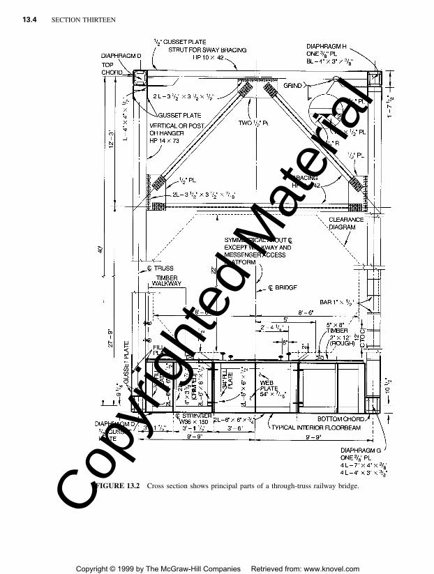
In railway bridges, longitudinal forces resulting from accelerating and braking may inducesevere bending stresses in the flanges of floorbeams, at right angles to the plane of the web,unless such forces are diverted to the main trusses by traction frames. In single-track bridges,a transverse strut may be provided between the points where the main truss laterals crossthe stringers and are connected to them (Fig. 13.4a). In double-track bridges, it may benecessary to add a traction truss (Fig. 13.4b).
When the floorbeams in a double-track bridge are so deep that the bottoms of the stringersare a considerable distance above the bottoms of the floorbeams, it may be necessary to raisethe plane of the main truss laterals from the bottom of the floorbeams to the bottom of thestringers. If this cannot be done, a complete and separate traction frame may be providedeither in the plane of the tops of the stringers or in the plane of their bottom flanges.
The forces for which the traction frames are designed are applied along the stringers. Themagnitudes of these forces are determined by the number of panels of tractive or brakingforce that are resisted by the frames. When one frame is designed to provide for severalpanels, the forces may become large, resulting in uneconomical members and connections.
13.8 TRUSS DESIGN PROCEDURE
The following sequence may serve as a guide to the design of truss bridges:
• Select span and general proportions of the bridge, including a tentative cross section.
• Design the roadway or deck, including stringers and floorbeams.
• Design upper and lower lateral systems.
• Design portals and sway frames.
• Design posts and hangers that carry little stress or loads that can be computed without acomplete stress analysis of the entire truss.
• Compute preliminary moments, shears, and stresses in the truss members.
• Design the upper-chord members, starting with the most heavily stressed member.
• Design the lower-chord members.
• Design the web members.
Copy
right
ed M
ater
ial
Copyright © 1999 by The McGraw-Hill Companies Retrieved from: www.knovel.com
TRUSS BRIDGES 13.11
FIGURE 13.4 Lateral bracing and traction trusses for resisting longitudinalforces on a truss bridge.
• Recalculate the dead load of the truss and compute final moments and stresses in trussmembers.
• Design joints, connections, and details.
• Compute dead-load and live-load deflections.
• Check secondary stresses in members carrying direct loads and loads due to wind.
• Review design for structural integrity, esthetics, erection, and future maintenance and in-spection requirements.
13.8.1 Analysis for Vertical Loads
Determination of member forces using conventional analysis based on frictionless joints isoften adequate when the following conditions are met:
1. The plane of each truss of a bridge, the planes through the top chords, and the planesthrough the bottom chords are fully triangulated.
2. The working lines of intersecting truss members meet at a point.
Copy
right
ed M
ater
ial
Copyright © 1999 by The McGraw-Hill Companies Retrieved from: www.knovel.com
13.12 SECTION THIRTEEN
3. Cross frames and other bracing prevent significant distortions of the box shape formedby the planes of the truss described above.
4. Lateral and other bracing members are not cambered; i.e., their lengths are based on thefinal dead-load position of the truss.
5. Primary members are cambered by making them either short or long by amounts equalto, and opposite in sign to, the axial compression or extension, respectively, resultingfrom dead-load stress. Camber for trusses can be considered as a correction for dead-loaddeflection. (If the original design provided excess vertical clearance and the engineers didnot object to the sag, then trusses could be constructed without camber. Most people,however, object to sag in bridges.) The cambering of the members results in the trussbeing out of vertical alignment until all the dead loads are applied to the structure (geo-metric condition).
When the preceding conditions are met and are rigorously modeled, three-dimensionalcomputer analysis yields about the same dead-load axial forces in the members as the con-ventional pin-connected analogy and small secondary moments resulting from the self-weightbending of the member. Application of loads other than those constituting the geometriccondition, such as live load and wind, will result in sag due to stressing of both primary andsecondary members in the truss.
Rigorous three-dimensional analysis has shown that virtually all the bracing membersparticipate in live-load stresses. As a result, total stresses in the primary members are reducedbelow those calculated by the conventional two-dimensional pin-connected truss analogy.Since trusses are usually used on relatively long-span structures, the dead-load stress con-stitutes a very large part of the total stress in many of the truss members. Hence, the savingsfrom use of three-dimensional analysis of the live-load effects will usually be relatively small.This holds particularly for through trusses where the eccentricity of the live load, and, there-fore, forces distributed in the truss by torsion are smaller than for deck trusses.
The largest secondary stresses are those due to moments produced in the members by theresistance of the joints to rotation. Thus, the secondary stresses in a pin-connected truss aretheoretically less significant than those in a truss with mechanically fastened or welded joints.In practice, however, pinned joints always offer frictional resistance to rotation, even whennew. If pin-connected joints freeze because of dirt, or rust, secondary stresses might becomehigher than those in a truss with rigid connections. Three-dimensional analysis will however,quantify secondary stresses, if joints and framing of members are accurately modeled. If thesecondary stress exceeds 4 ksi for tension members or 3 ksi for compression members, boththe AASHTO SLD and LFD Specifications require that excess be treated as a primary stress.The AASHTO LRFD Specifications take a different approach including:
• A requirement to detail the truss so as to make secondary force effects as small as practical.
• A requirement to include the bending caused by member self-weight, as well as momentsresulting from eccentricities of joint or working lines.
• Relief from including both secondary force effects from joint rotation and floorbeam de-flection if the component being designed is more than ten times as long as it is wide inthe plane of bending.
When the working lines through the centroids of intersecting members do not intersectat the joint, or where sway frames and portals are eliminated for economic or esthetic pur-poses, the state of bending in the truss members, as well as the rigidity of the entire system,should be evaluated by a more rigorous analysis than the conventional.
The attachment of floorbeams to truss verticals produces out-of-plane stresses, whichshould be investigated in highway bridges and must be accounted for in railroad bridges,due to the relatively heavier live load in that type of bridge. An analysis of a frame composedof a floorbeam and all the truss members present in the cross section containing the floorbeam is usually adequate to quantify this effect.
Copy
right
ed M
ater
ial
Copyright © 1999 by The McGraw-Hill Companies Retrieved from: www.knovel.com

TRUSS BRIDGES 13.13
Deflection of trusses occurs whenever there are changes in length of the truss members.These changes may be due to strains resulting from loads on the truss, temperature variations,or fabrication effects or errors. Methods of computing deflections are similar in all threecases. Prior to the introduction of computers, calculation of deflections in trusses was alaborious procedure and was usually determined by energy or virtual work methods or bygraphical or semigraphical methods, such as the Williot-Mohr diagram. With the widespreadavailability of matrix structural analysis packages, the calculation of deflections and analysisof indeterminant trusses are speedily executed.
(See also Arts. 3.30, 3.31, and 3.34 to 3.39).
13.8.2 Analysis for Wind Loads
The areas of trusses exposed to wind normal to their longitudinal axis are computed bymultiplying widths of members as seen in elevation by the lengths center to center of inter-sections. The overlapping areas at intersections are assumed to provide enough surplus toallow for the added areas of gussets. The AREMA Manual specifies that for railway bridgesthis truss area be multiplied by the number of trusses, on the assumption that the wind strikeseach truss fully (except where the leeward trusses are shielded by the floor system). TheAASHTO Specifications require that the area of the trusses and floor as seen in elevation bemultiplied by a wind pressure that accounts for 11⁄2 times this area being loaded by wind.
The area of the floor should be taken as that seen in elevation, including stringers, deck,railing, and railing pickets.
AREMA specifies that when there is no live load on the structure, the wind pressureshould be taken as at least 50 psf, which is equivalent to a wind velocity of about 125 mph.When live load is on the structure, reduced wind pressures are specified for the trusses plusfull wind load on the live load: 30 psf on the bridge, which is equivalent to a 97-mph wind,and 300 lb per lin ft on the live load on one track applied 8 ft above the top of rail.
AASHTO SLD Specifications require a wind pressure on the structure of 75 psf. Totalforce, lb per lin ft, in the plane of the windward chords should be taken as at least 300 andin the plane of the leeward chords, at least 150. When live load is on the structure, thesewind pressures can be reduced 70% and combined with a wind force of 100 lb per lin ft onthe live load applied 6 ft above the roadway. The AASHTO LFD Specifications do notexpressly address wind loads, so the SLD Specifications pertain by default.
Article 3.8 of the AASHTO LRFD Specifications establish wind loads consistent withthe format and presentation currently used in meteorology. Wind pressures are related to abase wind velocity, VB, of 100 mph as common in past specifications. If no better informationis available, the wind velocity at 30 ft above the ground, V30, may be taken as equal to thebase wind, VB. The height of 30 ft was selected to exclude ground effects in open terrain.Alternatively, the base wind speed may be taken from Basic Wind Speed Charts availablein the literature, or site specific wind surveys may be used to establish V30.
At heights above 30 ft, the design wind velocity, VDZ, mph, on a structure at a height, Z,ft, may be calculated based on characteristic meteorology quantities related to the terrainover which the winds approach as follows. Select the friction velocity, V0, and friction length,Z0, from Table 13.1 Then calculate the velocity from
V Z30V � 2.5 V ln (13.1)� � � �DZ 0 V ZB 0
If V30 is taken equal to the base wind velocity, VB, then V30 /VB is taken as unity. Thecorrection for structure elevation included in Eq. 13.1, which is based on current meteoro-logical data, replaces the 1⁄7 power rule used in the past.
For design, Table 13.2 gives the base pressure, PB, ksf, acting on various structural com-ponents for a base wind velocity of 100 mph. The design wind pressure, PD, ksf, for thedesign wind velocity, VDZ, mph, is calculated from
Copy
right
ed M
ater
ial
Copyright © 1999 by The McGraw-Hill Companies Retrieved from: www.knovel.com

13.14 SECTION THIRTEEN
TABLE 13.1 Basic Wind Parameters
Terrain
Opencountry Suburban City
V0, mph 8.20 10.9 12.0Z0, ft 0.23 3.28 8.20
TABLE 13.2 Base Pressures, PB for Base WindVelocity, VB, of 100 mph
Structuralcomponent
Windwardload, ksf
Leewardload, ksf
Trusses, Columns,and Arches
0.050 0.025
Beams 0.050 NA
Large FlatSurfaces
0.040 NA
2VDZP � P (13.2)� �D B VB
Additionally, minimum design wind pressures, comparable to those in the AASHTO SLDSpecification, are given in the LRFD Specifications.
AASHTO Specifications also require that wind pressure be applied to vehicular live load.
Wind Analysis. Wind analysis is typically carried out with the aid of computers with aspace truss and some frame members as a model. It is helpful, and instructive, to employ asimplified, noncomputer method of analysis to compare with the computer solution to exposemajor modeling errors that are possible with space models. Such a simplified method ispresented in the following.
Idealized Wind-Stress Analysis of a through Truss with Inclined End Posts. The windloads computed as indicated above are applied as concentrated loads at the panel points.
A through truss with parallel chords may be considered as having reactions to the toplateral bracing system only at the main portals. The effect of intermediate sway frames,therefore, is ignored. The analysis is applied to the bracing and to the truss members.
The lateral bracing members in each panel are designed for the maximum shear in thepanel resulting from treating the wind load as a moving load; that is, as many panels areloaded as necessary to produce maximum shear in that panel. In design of the top-chordbracing members, the wind load, without live load, usually governs. The span for top-chordbracing is from hip joint to hip joint. For the bottom-chord members, the reduced windpressure usually governs because of the considerable additional force that usually resultsfrom wind on the live load.
For large trusses, wind stress in the trusses should be computed for both the maximumwind pressure without live load and for the reduced wind pressure with live load and fullwind on the live load. Because wind on the live load introduces an effect of ‘‘transfer,’’ as
Copy
right
ed M
ater
ial
Copyright © 1999 by The McGraw-Hill Companies Retrieved from: www.knovel.com

TRUSS BRIDGES 13.15
FIGURE 13.6 Wind on a cantilever truss with curved topchord is resisted by the top lateral system.
described later, the following discussion is for the more general case of a truss with thereduced wind pressure on the structure and with wind on the live load applied 8 ft abovethe top of rail, or 6 ft above the deck.
The effect of wind on the trusses may be considered to consist of three additive parts:
• Chord stresses in the fully loaded top and bottom lateral trusses.
• Horizontal component, which is a uniform force of tension in one truss bottom chordand compression in the other bottom chord, resulting from transfer of the top lateral endreactions down the end portals. This may be taken as the top lateral end reaction timesthe horizontal distance from the hip joint to the point of contraflexure divided by thespacing between main trusses. It is often conservatively assumed that this point of contra-flexure is at the end of span, and, thus, the top lateral end reaction is multiplied by thepanel length, divided by the spacing between main trusses. Note that this convenient as-sumption does not apply to the design of portals themselves.
• Transfer stresses created by the moment of wind on the live load and wind on the floor.This moment is taken about the plane of the bottom lateral system. The wind force on liveload and wind force on the floor in a panel length is multiplied by the height of applicationabove the bracing plane and divided by the distance center to center of trusses to arriveat a total vertical panel load. This load is applied downward at each panel point of theleeward truss and upward at each panel point of the windward truss. The resulting stressesin the main vertical trusses are then computed.
The total wind stress in any main truss member is arrived at by adding all three effects:chord stresses in the lateral systems, horizontal component, and transfer stresses.
FIGURE 13.5 Top chord in a horizontal plane ap-proximates a curved top chord.
Although this discussion applies to a par-allel-chord truss, the same method may beapplied with only slight error to a truss withcurved top chord by considering the topchord to lie in a horizontal plane between hipjoints, as shown in Fig. 13.5. The nature ofthis error will be described in the following.
Wind Stress Analysis of Curved-Chord Cantilever Truss. The additional effects that shouldbe considered in curved-chord trusses are those of the vertical components of the inclinedbracing members. These effects may be illustrated by the behavior of a typical cantileverbridge, several panels of which are shown in Fig. 13.6.
As transverse forces are applied to the curved top lateral system, the transverse shearcreates stresses in the top lateral bracing members. The longitudinal and vertical componentsof these bracing stresses create wind stresses in the top chords and other members of themain trusses. The effects of these numerous components of the lateral members may bedetermined by the following simple method:
• Apply the lateral panel loads to the horizontal projection of the top-chord lateral systemand compute all horizontal components of the chord stresses. The stresses in the inclinedchords may readily be computed from these horizontal components.
Copy
right
ed M
ater
ial
Copyright © 1999 by The McGraw-Hill Companies Retrieved from: www.knovel.com

13.16 SECTION THIRTEEN
• Determine at every point of slope change in the top chord all the vertical forces acting onthe point from both bracing diagonals and bracing chords. Compute the truss stresses inthe vertical main trusses from those forces.
• The final truss stresses are the sum of the two contributions above and also of any transferstress, and of any horizontal component delivered by the portals to the bottom chords.
13.8.3 Computer Determination of Wind Stresses
For computer analysis, the structural model is a three-dimensional framework composed ofall the load-carrying members. Floorbeams are included if they are part of the bracing systemor are essential for the stability of the structural model.
All wind-load concentrations are applied to the framework at braced points. Because thewind loads on the floor system and on the live load do not lie in a plane of bracing, theseloads must be ‘‘transferred’’ to a plane of bracing. The accompanying vertical required forequilibrium also should be applied to the framework.
Inasmuch as significant wind moments are produced in open-framed portal members ofthe truss, flexural rigidity of the main-truss members in the portal is essential for stability.Unless the other framework members are released for moment, the computer analysis willreport small moments in most members of the truss.
With cantilever trusses, it is a common practice to analyze the suspended span by itselfand then apply the reactions to a second analysis of the anchor and cantilever arms.
Some consideration of the rotational stiffness of piers about their vertical axis is warrantedfor those piers that support bearings that are fixed against longitudinal translation. Such pierswill be subjected to a moment resulting from the longitudinal forces induced by lateral loads.If the stiffness (or flexibility) of the piers is not taken into account, the sense and magnitudeof chord forces may be incorrectly determined.
13.8.4 Wind-Induced Vibration of Truss Members
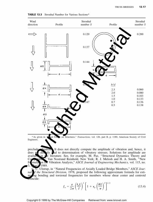
When a steady wind passes by an obstruction, the pressure gradient along the obstructioncauses eddies or vortices to form in the wind stream. These occur at stagnation points locatedon opposite sides of the obstruction. As a vortex grows, it eventually reaches a size thatcannot be tolerated by the wind stream and is torn loose and carried along in the windstream. The vortex at the opposite stagnation point then grows until it is shed. The result isa pattern of essentially equally spaced (for small distances downwind of the obstruction) andalternating vortices called the ‘‘Vortex Street’’ or ‘‘von Karman Trail.’’ This vortex street isindicative of a pulsating periodic pressure change applied to the obstruction. The frequencyof the vortex shedding and, hence, the frequency of the pulsating pressure, is given by
VSƒ � (13.3)
D
where V is the wind speed, fps, D is a characteristic dimension, ft, and S is the Strouhalnumber, the ratio of velocity of vibration of the obstruction to the wind velocity (Table 13.3).
When the obstruction is a member of a truss, self-exciting oscillations of the member inthe direction perpendicular to the wind stream may result when the frequency of vortexshedding coincides with a natural frequency of the member. Thus, determination of thetorsional frequency and bending frequency in the plane perpendicular to the wind and sub-stitution of those frequencies into Eq. (13.3) leads to an estimate of wind speeds at whichresonance may occur. Such vibration has led to fatigue cracking of some truss and archmembers, particularly cable hangers and I-shaped members. The preceding proposed use ofEq. (13.3) is oriented toward guiding designers in providing sufficient stiffness to reasonably
Copy
right
ed M
ater
ial
Copyright © 1999 by The McGraw-Hill Companies Retrieved from: www.knovel.com
TRUSS BRIDGES 13.17
TABLE 13.3 Strouhal Number for Various Sections*
Winddirection Profile
Strouhalnumber S Profile
Strouhalnumber S
0.120 0.200
0.137
0.144
0.145 b /d
2.5 0.0602.0 0.0801.5 0.1031.0 0.133
0.147 0.7 0.1360.5 0.138
* As given in ‘‘Wind Forces on Structures,’’ Transactions, vol. 126, part II, p. 1180, American Society of CivilEngineers.
preclude vibrations. It does not directly compute the amplitude of vibration and, hence, itdoes not directly lead to determination of vibratory stresses. Solutions for amplitude areavailable in the literature. See, for example, M. Paz, ‘‘Structural Dynamics Theory andComputation,’’ Van Nostrand Reinhold, New York; R. J. Melosh and H. A. Smith, ‘‘NewFormulation for Vibration Analysis,’’ ASCE Journal of Engineering Mechanics, vol. 115, no.3, March 1989.
C. C. Ulstrup, in ‘‘Natural Frequencies of Axially Loaded Bridge Members,’’ ASCE Jour-nal of the Structural Division, 1978, proposed the following approximate formula for esti-mating bending and torsional frequencies for members whose shear center and centroidcoincide:
2 2 1 / 2a k L KLnƒ � 1 � � (13.4)� � � � � �n p2� I �
Copy
right
ed M
ater
ial
Copyright © 1999 by The McGraw-Hill Companies Retrieved from: www.knovel.com
13.18 SECTION THIRTEEN
TABLE 13.4 Eigenvalue kn L and Effective Length Factor K
Support condition
kn L
n � 1 n � 2 n � 3
K
n � 1 n � 2 n � 3
�
3.927
4.730
1.875
2�
7.069
7.853
4.694
3�
10.210
10.996
7.855
1.000
0.700
0.500
2.000
0.500
0.412
0.350
0.667
0.333
0.292
0.259
0.400
where ƒn � natural frequency of member for each mode corresponding to n � 1, 2, 3, . . .knL � eigenvalue for each mode (see Table 13.4)
K � effective length factor (see Table 13.4)L � length of the member, inI � moment of inertia, in4, of the member cross sectiona � coefficient dependent on the physical properties of the member
� for bendingEIg /�A�� for torsion�EC g /� Iw p
�p � coefficient dependent on the physical properties of the member� P /EI for bending
� for torsionGJA � PIp
AECw
E � Young’s modulus of elasticity, psiG � shear modulus of elasticity, psi� � weight density of member, lb / in3
g � gravitational acceleration, in /s2
P � axial force (tension is positive), lbA � area of member cross section, in2
Cw � warping constantJ � torsion constantIp � polar moment of inertia, in4
In design of a truss member, the frequency of vortex shedding for the section is set equalto the bending and torsional frequency and the resulting equation is solved for the windspeed V. This is the wind speed at which resonance occurs. The design should be such thatV exceeds by a reasonable margin the velocity at which the wind is expected to occuruniformly.
13.9 TRUSS MEMBER DETAILS
The following shapes for truss members are typically considered:
H sections, made with two side segments (composed of angles or plates) with solid web,perforated web, or web of stay plates and lacing. Modern bridges almost exclusively useH sections made of three plates welded together.
Copy
right
ed M
ater
ial
Copyright © 1999 by The McGraw-Hill Companies Retrieved from: www.knovel.com

TRUSS BRIDGES 13.19
Channel sections, made with two angle segments, with solid web, perforated web, orweb of stay plates and lacing. These are seldom used on modern bridges.Single box sections, made with side channels, beams, angles and plates, or side segmentsof plates only. The side elements may be connected top and bottom with solid plates,perforated plates, or stay plates and lacing. Alternatively, they may be connected at thetop with solid cover plates and at the bottom with perforated plates, or stay plates andlacing. Modern bridges use primarily four-plate welded box members. The cover platesare usually solid, except for access holes for bolting joints.Double box sections, made with side channels, beams, angles and plates, or side segmentsof plates only. The side elements may be connected together with top and bottom per-forated cover plates, or stay plates and lacing.
To obtain economy in member design, it is important to vary the area of steel in accord-ance with variations in total loads on the members. The variation in cross section plus theuse of appropriate-strength grades of steel permit designers to use essentially the weight ofsteel actually required for the load on each panel, thus assuring an economical design.
With respect to shop fabrication of welded members, the H shape usually is the mosteconomical section. It requires four fillet welds and no expensive edge preparation. Require-ments for elimination of vortex shedding, however, may offset some of the inherent economyof this shape.
Box shapes generally offer greater resistance to vibration due to wind, to buckling incompression, and to torsion, but require greater care in selection of welding details. Forexample, various types of welded cover-plate details for boxes considered in design of thesecond Greater New Orleans Bridge and reviewed with several fabricators resulted in theobservations in Table 13.5.
Additional welds placed inside a box member for development of the cover plate withinthe connection to the gusset plate are classified as AASHTO category E at the terminationof the inside welds and should be not be used. For development of the cover plate withinthe gusset-plate connection, groove welds, large fillet welds, large gusset plates, or a com-bination of the last two should be used.
Tension Members. Where practical, these should be arranged so that there will be nobending in the members from eccentricity of the connections. If this is possible, then thetotal stress can be considered uniform across the entire net area of the member. At a joint,the greatest practical proportion of the member surface area should be connected to thegusset or other splice material.
Designers have a choice of a large variety of sections suitable for tension members,although box and H-shaped members are typically used. The choice will be influenced bythe proposed type of fabrication and range of areas required for tension members. The designshould be adjusted to take full advantage of the selected type. For example, welded platesare economical for tubular or box-shaped members. Structural tubing is available with almost22 in2 of cross-sectional area and might be advantageous in welded trusses of moderatespans. For longer spans, box-shape members can be shop-fabricated with almost unlimitedareas.
Tension members for bolted trusses involve additional considerations. For example, only50% of the unconnected leg of an angle or tee is commonly considered effective, becauseof the eccentricity of the connection to the gusset plate at each end.
To minimize the loss of section for fastener holes and to connect into as large a proportionof the member surface area as practical, it is desirable to use a staggered fastener pattern.In Fig. 13.7, which shows a plate with staggered holes, the net width along Chain 1-1 equalsplate width W, minus three hole diameters. The net width along Chain 2-2 equals W, minusfive hole diameters, plus the quantity S 2 /4g for each off four gages, where S is the pitchand g the gage.
Copy
right
ed M
ater
ial
Copyright © 1999 by The McGraw-Hill Companies Retrieved from: www.knovel.com

13.20 SECTION THIRTEEN
TABLE 13.5 Various Welded Cover-Plate Designs for Second Greater New Orleans Bridge
Conventional detail. Has been used extensively in the past. It may besusceptible to lamellar tearing under lateral or torsional loads.
Overlap increases for thicker web plate. Cover plate tends to curve up afterwelding.
Very difficult to hold out-to-out dimension of webs due to thickness toleranceof the web plates. Groove weld is expensive, but easier to develop coverplate within the connection to gusset plate.
The detail requires a wide cover plate and tight tolerance of the cover-platewidth. With a large overlap, the cover may curve up after welding. Grooveweld is expensive, but easier to develop cover plate within the connectionto the gusset plate.
Same as above, except the fabrication tolerance, which will be better withthis detail.
FIGURE 13.7 Chains of bolt holes used for determining thenet section of a tension member.
Copy
right
ed M
ater
ial
Copyright © 1999 by The McGraw-Hill Companies Retrieved from: www.knovel.com

TRUSS BRIDGES 13.21
Compression Members. These should be arranged to avoid bending in the member fromeccentricity of connections. Though the members may contain fastener holes, the gross areamay be used in design of such columns, on the assumption that the body of the fastener fillsthe hole. Welded box and H-shaped members are typically used for compression membersin trusses.
Compression members should be so designed that the main elements of the section areconnected directly to gusset plates, pins, or other members. It is desirable that membercomponents be connected by solid webs. Care should be taken to ensure that the criteria forslenderness ratios, plate buckling, and fastener spacing are satisfied.
Posts and Hangers. These are the vertical members in truss bridges. A post in a Warrendeck truss delivers the load from the floorbeam to the lower chord. A hanger in a Warrenthrough-truss delivers the floorbeam load to the upper chord.
Posts are designed as compression members. The posts in a single-truss span are generallymade identical. At joints, overall dimensions of posts have to be compatible with those ofthe top and bottom chords to make a proper connection at the joint.
Hangers are designed as tension members. Although wire ropes or steel rods could beused, they would be objectionable for esthetic reasons. Furthermore, to provide a slendernessratio small enough to maintain wind vibration within acceptable limits will generally requirerope or rod area larger than that needed for strength.
Truss-Member Connections. Main truss members should be connected with gusset platesand other splice material, although pinned joints may be used where the size of a boltedjoint would be prohibitive. To avoid eccentricity, fasteners connecting each member shouldbe symmetrical about the axis of the member. It is desirable that fasteners develop the fullcapacity of each element of the member. Thickness of a gusset plate should be adequate forresisting shear, direct stress, and flexure at critical sections where these stresses are maxi-mum. Re-entrant cuts should be avoided; however, curves made for appearance are permis-sible.
13.10 MEMBER AND JOINT DESIGN EXAMPLES—LFD AND SLD
Design of a truss member by the AASHTO LFD and SLD Specifications is illustrated in thefollowing examples, The design includes a connection in a Warren truss in which splicingof a truss chord occurs within a joint. Some designers prefer to have the chord run contin-uously through the joint and be spliced adjacent to the joint. Satisfactory designs can beproduced using either approach. Chords of trusses that do not have a diagonal framing intoeach joint, such as a Warren truss, are usually continuous through joints with a post orhanger. Thus, many of the chord members are usually two panels long. Because of limitationson plate size and length for shipping, handling, or fabrication, it is sometimes necessary,however, to splice the plates within the length of a member. Where this is necessary, commonpractice is to offset the splices in the plates so that only one plate is spliced at any crosssection.
13.10.1 Load-Factor Design of Truss Chord
A chord of a truss is to be designed to withstand a factored compression load of 7,878 kipsand a factored tensile load of 1,748 kips. Corresponding service loads are 4,422 kips com-pression and 391 kips tension. The structural steel is to have a specified minimum yieldstress of 36 ksi. The member is 46 ft long and the slenderness factor K is to be taken as
Copy
right
ed M
ater
ial
Copyright © 1999 by The McGraw-Hill Companies Retrieved from: www.knovel.com

13.22 SECTION THIRTEEN
FIGURE 13.8 Cross section of a truss chord with a box section.
unity. A preliminary design yields the cross section shown in Fig. 13.8. The section has thefollowing properties:
2A � gross area � 281 ing
I � gross moment of inertia with respect to x axisgx
4� 97,770 in
I � gross moment of inertia with respect to y axisgy
4� 69,520 in
w � weight per linear foot � 0.98 kips
Ten 11⁄4-in-dia. bolt holes are provided in each web at the section for the connections atjoints. The welds joining the cover plates and webs are minimum size, 3⁄8 in, and are clas-sified as AASHTO fatigue category B.
Copy
right
ed M
ater
ial
Copyright © 1999 by The McGraw-Hill Companies Retrieved from: www.knovel.com

TRUSS BRIDGES 13.23
Although the AASHTO LFD Specification specifies a load factor for dead load of 1.30,the following computation uses 1.50 to allow for about 15% additional weight due to paint,diaphragms, weld metal and fasteners.
Compression in Chord from Factored Loads. The uniform stress on the section is
ƒ � 7878/281 � 28.04 ksic
The radius of gyration with respect to the weak axis is
r � �I /A � �69,520/281 � 15.73 iny gy g
and the slenderness ratio with respect to that axis is
2KL 1 � 46 � 12 2� E� � 35 � � 126� ��r 15.73 Fy y
where E � modulus of elasticity of the steel � 29,000 ksi. The critical buckling stress incompression is
2F KLyF � F 1 �� � � �cr y 24� E ry (13.5)
36 2� 36 1 � (35) � 34.6 ksi� �24� E
The maximum strength of a concentrically loaded column is Pu � Agƒcr and
ƒ � 0.85F � 0.85 � 34.6 � 29.42 ksicr cr
For computation of the bending strength, the sum of the depth-thickness ratios for theweb and cover plates is
s 54 36 � 2.0625� 2 � � 2 � � 129.9�
t 2.0625 0.875
The area enclosed by the centerlines of the plates is
2A � 54.875(36 � 2.0625) � 1,862 in
Then, the design bending stress is given by
0.0641F S L��(s / t)y gF � F 1 �� �a y
EA�Iy
0.0641 � 36 � 3,507 � 46 � 12�129.9� 36 1 � (13.6)� �
29,000 � 1862�69,520
� 35.9 ksi
For the dead load of 0.98 kips / ft, the dead-load factor of 1.50, the 46-ft span, and afactor of 1/10 for continuity in bending, the dead-load bending moment is
Copy
right
ed M
ater
ial
Copyright © 1999 by The McGraw-Hill Companies Retrieved from: www.knovel.com

13.24 SECTION THIRTEEN
2M � 0.98(46) � 12 � 1.50/10 � 3733 kip-inDL
The section modulus is
3S � I /c � 97,770/(54/2 � 0.875) � 3507 ing gx
Hence, the maximum compressive bending stress is
ƒ � M /S � 3733/3507 � 1.06 ksib DL g
The plastic section modulus is
4Z � 2(33.125 � 0.875(54/2 � 0.875/2) � 2 � 2 � 2.0625 � 54/2 � 54/4 � 4598 ing
The ratio of the plastic section modulus to the elastic section modulus is Zg /Sg � 4,598/3,507 � 1.31.
For combined axial load and bending, the axial force P and moment M must satisfy thefollowing equations:
P MC� � 1.0 (13.7a)
0.85A F M (1 � P /A F )g cr u g e
P M� � 1.0 (13.8a)
0.85A F Mg y p
where Mu � maximum strength, kip-in, in bending alone� Sgƒa
Mp � full plastic moment, kip-in, of the section� ZFy
Z � plastic modulus � 1.31Sg
C � equivalent moment factor, taken as 0.85 in this caseFe � Euler buckling stress, ksi, with 0.85 factor � 0.85E� 2 / (KL /rx)2
The effective length factor K is taken equal to unity and the radius of gyration rx with respectto the x axis, the axis of bending, is
r � �I /A � �97,770/281 � 18.65 inx g g
The slenderness ratio KL /rx then is 46 � 12/18.65 � 29.60.
2 2F � 0.85 � 29,000� /29.60 � 278 ksie
For convenience of calculation, Eq. (13.7a) can be rewritten, for P � AgFc, 0.85Fcr � ƒcr,M � Sgƒb, and Mu � SgFa, as
ƒ ƒ Cc b� � � 1.0 (13.7b)
ƒ F 1 � P /A Fcr a g e
Substitution of previously calculated stress values in Eq. (13.7b) yields
28.04 1.06 0.85� � � 0.953 � 0.028
29.42 35.9 1 � 7878/(281 � 278)
� 0.981 � 1.0
Similarly, Eq. (13.8a) can be rewritten as
Copy
right
ed M
ater
ial
Copyright © 1999 by The McGraw-Hill Companies Retrieved from: www.knovel.com
TRUSS BRIDGES 13.25
ƒ ƒc b� � 1.0 (13.8b)
0.85F F Z /Sy y g
Substitution of previously calculated stress values in Eq. (13.8b) yields
28.04 1.06� � 0.916 � 0.022 � 0.938 � 1.0
0.85 � 36 36 � 1.31
The sum of the ratios, 0.981, governs (stability) and is satisfactory. The section is satisfactoryfor compression.
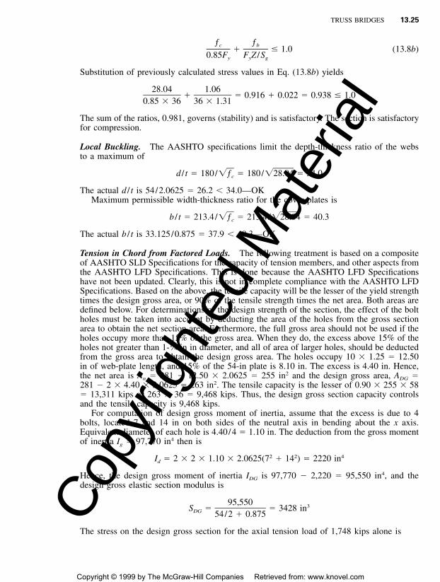
Local Buckling. The AASHTO specifications limit the depth-thickness ratio of the websto a maximum of
d / t � 180/�ƒ � 180/�28.04 � 34.0c
The actual d / t is 54/2.0625 � 26.2 � 34.0—OKMaximum permissible width-thickness ratio for the cover plates is
b / t � 213.4/�ƒ � 213.4/�28.04 � 40.3c
The actual b / t is 33.125/0.875 � 37.9 � 40.3—OK
Tension in Chord from Factored Loads. The following treatment is based on a compositeof AASHTO SLD Specifications for the capacity of tension members, and other aspects fromthe AASHTO LFD Specifications. This is done because the AASHTO LFD Specificationshave not been updated. Clearly, this is not in complete compliance with the AASHTO LFDSpecifications. Based on the above, the tensile capacity will be the lesser of the yield strengthtimes the design gross area, or 90% of the tensile strength times the net area. Both areas aredefined below. For determinations of the design strength of the section, the effect of the boltholes must be taken into account by deducting the area of the holes from the gross sectionarea to obtain the net section area. Furthermore, the full gross area should not be used if theholes occupy more than 15% of the gross area. When they do, the excess above 15% of theholes not greater than 1-1⁄4 in in diameter, and all of area of larger holes, should be deductedfrom the gross area to obtain the design gross area. The holes occupy 10 � 1.25 � 12.50in of web-plate length, and 15% of the 54-in plate is 8.10 in. The excess is 4.40 in. Hence,the net area is An � 281 � 12.50 � 2.0625 � 255 in2 and the design gross area, ADG �281 � 2 � 4.40 � 2.0625 � 263 in2. The tensile capacity is the lesser of 0.90 � 255 � 58� 13,311 kips or 263 � 36 � 9,468 kips. Thus, the design gross section capacity controlsand the tensile capacity is 9,468 kips.
For computation of design gross moment of inertia, assume that the excess is due to 4bolts, located 7 and 14 in on both sides of the neutral axis in bending about the x axis.Equivalent diameter of each hole is 4.40/4 � 1.10 in. The deduction from the gross momentof inertia Ig � 97,770 in4 then is
2 2 4I � 2 � 2 � 1.10 � 2.0625(7 � 14 ) � 2220 ind
Hence, the design gross moment of inertia IDG is 97,770 � 2,220 � 95,550 in4, and thedesign gross elastic section modulus is
95,550 3S � � 3428 inDG 54/2 � 0.875
The stress on the design gross section for the axial tension load of 1,748 kips alone is
Copy
right
ed M
ater
ial
Copyright © 1999 by The McGraw-Hill Companies Retrieved from: www.knovel.com
13.26 SECTION THIRTEEN
ƒ � 1748/263 � 6.65 ksit
The bending stress due to MDL � 3733 kip-in, computed previously, is
ƒ � 3733/3428 � 1.09 ksib
For combined axial tension and bending, the sum of the ratios of required strength todesign strength is
P M 6.65 1.09� � � � 0.208 � 1—OK
P M 36 36 � 1.31u p
The section is satisfactory for tension.
Fatigue at Welds. Fatigue is to be investigated for the truss as a nonredundant path structuresubjected to 500,000 cycles of loading. The category B welds between web plates and coverplates have an allowable stress range of 23 ksi. Maximum service loads on the chord are391 kips tension and 4,422 kips compression. The stress range then is
391 � (�4,422)ƒ � � 17.1 ksi � 23 ksisr 281
The section is satisfactory for fatigue.
13.10.2 Service-Load Design of Truss Chord
The truss chord designed in Art. 13.10.1 by load-factor design and with the cross sectionshown in Fig. 13.8 is designed for service loads in the following, for illustrative purposes.Properties of the section are given in Art 13.10.1.
Compression in Chord for Service Loads. The uniform stress in the section for the 4,422-kip load on the gross area Ag � 281 in2 is
ƒ � 4422/281 � 15.74 ksic
The AASHTO standard specifications give the following formula for the allowable axialstress for Fy � 36 ksi:
2F � 16.98 � 0.00053(KL /r ) (13.9)a y
For the slenderness ratio KL /ry � 35, determined in Art. 13.10.1, the allowable stress thenis
2F � 16.98 � 0.00053(35) � 16.33 ksi � 15.74 ksi—OKa
The allowable bending stress is ƒb � 20 ksi. Due to the 0.98 kips / ft weight of the 46-ft-long chord, the dead-load bending moment with a continuity factor of 1⁄10 is
2M � 0.98(46) � 12/10 � 2488 kip-inDL
For the section modulus Sgx � 97,770/27.875 � 3507 in3, the dead-load bending stress is
ƒ � 2488/3507 � 0.709 ksib
For combined bending and compression, AASHTO specifications require that the follow-ing interaction formula be satisfied:
Copy
right
ed M
ater
ial
Copyright © 1999 by The McGraw-Hill Companies Retrieved from: www.knovel.com

TRUSS BRIDGES 13.27
ƒ ƒ Cc b m� � (13.10)F F 1 � ƒ /F�a b c e
The coefficient Cm is taken as 0.85 for the condition of transverse loading on a compressionmember with joint translation prevented. For bending about the x axis, with a slendernessratio of KL /rx � 29.60, as determined in Art. 13.10.1, the Euler buckling stress with a 2.12safety factor is
2 2� E � � 29,000F� � � � 154 ksie 2 22.12(KL /r ) 2.12(29.60)x
Substitution of the preceding stresses in Eq. (13.10) yields
15.74 0.709 0.85� � � 0.964 � 0.034 � 0.998 � 1—OK
16.33 20 1 � 15.74/154
The section is satisfactory for compression.
Tension in Chord from Service Loads. The section shown in Fig. 13.8 has to withstand atension load of 391 kips on the net area of 263 in2 computed in Art. 13.10.1. It was deter-mined in Art. 13.10.1 that the capacity was controlled by the design gross section, and whileSLD allowable stresses are 0.50 Fu on the net section and 0.55 Fy on the design gross section,the same conclusion is reached here. The allowable tensile stress Ft is 20 ksi. The uniformtension stress on the design gross section is
ƒ � 391/263 � 1.49 ksit
As computed in Art. 13.10.1, the moment of inertia of the design gross section is 95,550in4 and the corresponding section modulus in Sn � 3,428 in3. Also, as computed previouslyfor compression in the chord, the dead-load bending moment MDL � 2,488 kip-in. Hence,the maximum bending stress is
ƒ � 2488/3428 � 0.726 ksib
The allowable bending stress Fb is 20 ksi.For combined axial tension and bending, the sum of the ratios of actual stress to allowable
stress is
ƒ ƒ 1.49 0.726t b� � � � 0.075 � 0.036 � 0.111 � 1—OK
F F 20 20t b
The section is satisfactory for tension.
Fatigue Design. See Art. 13.10.1.
13.11 MEMBER DESIGN EXAMPLE—LRFD
The design of a truss hanger by the AASHTO LRFD Specifications is presented subse-quently. This is preceded by the following introduction to the LRFD member design pro-visions.
Copy
right
ed M
ater
ial
Copyright © 1999 by The McGraw-Hill Companies Retrieved from: www.knovel.com
13.28 SECTION THIRTEEN
13.11.1 LRFD Member Design Provisions
Tension Members. The net area, An, of a member is the sum of the products of thicknessand the smallest net width of each element. The width of each standard bolt hole is takenas the nominal diameter of the bolt plus 0.125 in. The width deducted for oversize andslotted holes, where permitted in AASHTO LRFD Art. 6.13.2.4.1, is taken as 0.125 in greaterthan the hole size specified in AASHTO LRFD Art. 6.13.2.4.2. The net width is determinedfor each chain of holes extending across the member along any transverse, diagonal, orzigzag line, as discussed in Art. 13.9.
In designing a tension member, it is conservative and convenient to use the least net widthfor any chain together with the full tensile force in the member. It is sometimes possible toachieve an acceptable, but slightly less conservative design, by checking each possible chainwith a tensile force obtained by subtracting the force removed by each bolt ahead of thatchain (bolt closer to midlength of the member), from the full tensile force in the member.This approach assumes that the full force is transferred equally by all bolts at one end.
Members and splices subjected to axial tension must be investigated for two conditions:yielding on the gross section (Eq. 13.11), and fracture on the net section (Eq. 13.12). De-termination of the net section requires consideration of the following:
• The gross area from which deductions will be made, or reduction factors applied, asappropriate
• Deductions for all holes in the design cross-section
• Correction of the bolt hole deductions for the stagger rule
• Application of a reduction factor U, to account for shear lag
• Application of an 85% maximum area efficiency factor for splice plates and other splicingelements
The factored tensile resistance, Pr, is the lesser of the values given by Eqs. 13.11 and13.12.
P � � P � � F A (13.11)r y ny y y g
P � � P � � F A U (13.12)r u nu y u n
where �Pny nominal tensile resistance for yielding in gross section (kip)Fy � yield strength (ksi)Ag � gross cross-sectional area of the member (in2)
Pnu � nominal tensile resistance for fracture in net section (kip)Fu � tensile strength (ksi)An � net area of the member as described above (in2)U � reduction factor to account for shear lag; 1.0 for components in which force
effects are transmitted to all elements; as described below for other cases�y � resistance factor for yielding of tension members, 0.95�u � resistance factor for fracture of tension members, 0.80
The reduction factor, U, does not apply when checking yielding on the gross section becauseyielding tends to equalize the non-uniform tensile stresses over the cross section caused byshear lag.
Unless a more refined analysis or physical tests are utilized to determine shear lag effects,the reduction factors specified in the AASHTO LRFD Specifications may be used to accountfor shear lag in connections as explained in the following.
The reduction factor, U, for sections subjected to a tension load transmitted directly toeach of the cross-sectional elements by bolts or welds may be taken as:
Copy
right
ed M
ater
ial
Copyright © 1999 by The McGraw-Hill Companies Retrieved from: www.knovel.com
TRUSS BRIDGES 13.29
U � 1.0 (13.13)
For bolted connections, the following three values of U may be used depending on thedetails of the connection:
For rolled I-shapes with flange widths not less than two-thirds the depth, and structuraltees cut from these shapes, provided the connection is to the flanges and has no fewerthan three fasteners per line in the direction of stress,
U � 0.90 (13.14a)
For all other members having no fewer than three fasteners per line in the direction ofstress,
U � 0.85 (13.14b)
For all members having only two fasteners per line in the direction of stress,
U � 0.75 (13.14c)
Due to strain hardening, a ductile steel loaded in axial tension can resist a force greaterthan the product of its gross area and its yield strength prior to fracture. However, excessiveelongation due to uncontrolled yielding of gross area not only marks the limit of usefulness,it can precipitate failure of the structural system of which it is a part. Depending on the ratioof net area to gross area and the mechanical properties of the steel, the component canfracture by failure of the net area at a load smaller than that required to yield the gross area.General yielding of the gross area and fracture of the net area both constitute measures ofcomponent strength. The relative values of the resistance factors for yielding and fracturereflect the different reliability indices deemed proper for the two modes.
The part of the component occupied by the net area at fastener holes generally has anegligible length relative to the total length of the member. As a result, the strain hardeningis quickly reached and, therefore, yielding of the net area at fastener holes does not constitutea strength limit of practical significance, except, perhaps, for some built-up members ofunusual proportions.
For welded connections, An is the gross section less any access holes in the connectionregion.
Compression Members. Bridge members in axial compression are generally proportionedwith width/ thickness ratios such that the yield point can be reached before the onset of localbuckling. For such members, the nominal compressive resistance, Pn, is taken as:
�If � � 2.25, then P � 0.66 F A (13.15)n y s
0.88F Ay sIf � � 2.25, then P � (13.16)n �
for which:
2 FKl y� � (13.17)� �r � Es
where As � gross cross-sectional area (in2)Fy � yield strength (ksi)E � modulus of elasticity (ksi)K � effective length factorl � unbraced length (in)
rs � radius of gyration about the plane of buckling (in)
Copy
right
ed M
ater
ial
Copyright © 1999 by The McGraw-Hill Companies Retrieved from: www.knovel.com
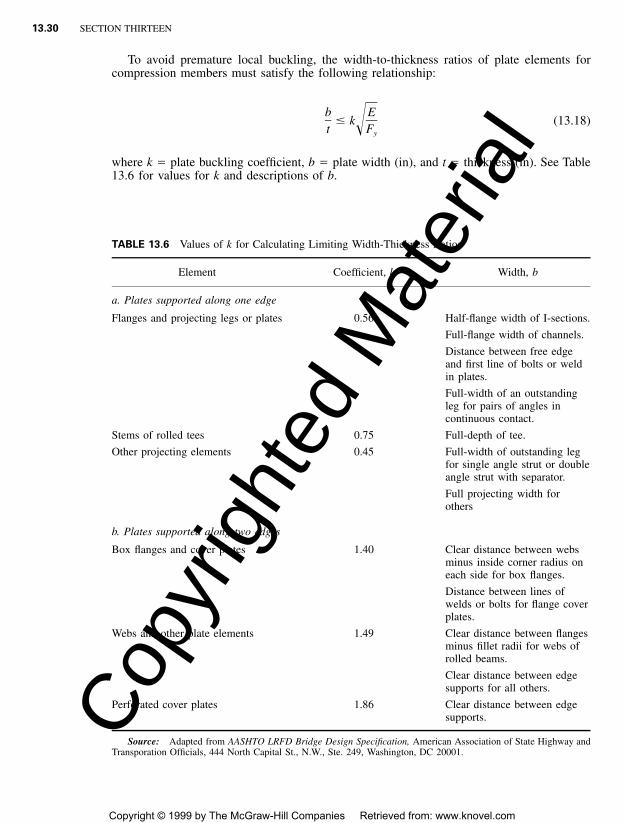
13.30 SECTION THIRTEEN
TABLE 13.6 Values of k for Calculating Limiting Width-Thickness Ratios
Element Coefficient, k Width, b
a. Plates supported along one edge
Flanges and projecting legs or plates 0.56 Half-flange width of I-sections.
Full-flange width of channels.
Distance between free edgeand first line of bolts or weldin plates.
Full-width of an outstandingleg for pairs of angles incontinuous contact.
Stems of rolled tees 0.75 Full-depth of tee.
Other projecting elements 0.45 Full-width of outstanding legfor single angle strut or doubleangle strut with separator.
Full projecting width forothers
b. Plates supported along two edges
Box flanges and cover plates 1.40 Clear distance between websminus inside corner radius oneach side for box flanges.
Distance between lines ofwelds or bolts for flange coverplates.
Webs and other plate elements 1.49 Clear distance between flangesminus fillet radii for webs ofrolled beams.
Clear distance between edgesupports for all others.
Perforated cover plates 1.86 Clear distance between edgesupports.
Source: Adapted from AASHTO LRFD Bridge Design Specification, American Association of State Highway andTransporation Officials, 444 North Capital St., N.W., Ste. 249, Washington, DC 20001.
To avoid premature local buckling, the width-to-thickness ratios of plate elements forcompression members must satisfy the following relationship:
b E� k (13.18)�t Fy
where k � plate buckling coefficient, b � plate width (in), and t � thickness (in). See Table13.6 for values for k and descriptions of b.
Copy
right
ed M
ater
ial
Copyright © 1999 by The McGraw-Hill Companies Retrieved from: www.knovel.com

TRUSS BRIDGES 13.31
Members Under Tension and Flexure. A component subjected to tension and flexure mustsatisfy the following interaction equations:
PuIf � 0.2, then(13.19)Pr
MP M uyu ux� � � 1.0� �2.0P M Mr rx ry
PuIf 0.2, then(13.20)Pr
MP 8.0 M uyu ux� � � 1.0� �P 9.0 M Mr rx ry
where Pr � factored tensile resistance (kip)Mrx, Mry � factored flexural resistances about the x and y axes, respectively (k-in)Mux, Muy � moments about x and y axes, respectively, resulting from factored loads (k-in)
Pu � axial force effect resulting from factored loads (kip)
Interaction equations in tension and compression members are a design simplification. Suchequations involving exponents of 1.0 on the moment ratios are usually conservative. Moreexact, nonlinear interaction curves are also available and are discussed in the literature. Ifthese interaction equations are used, additional investigation of service limit state stresses isnecessary to avoid premature yielding.
A flange or other component subjected to a net compressive stress due to tension andflexure should also be investigated for local buckling.
Members Under Compression and Flexure. For a component subjected to compressionand flexure, the axial compressive load, Pu, and the moments, Mux and Muy, are determinedfor concurrent factored loadings by elastic analytical procedures. The following relationshipsmust be satisfied:
PuIf � 0.2, then(13.21)Pr
MP M uyu ux� � � 1.0� �2.0P M Mr rx ry
PuIf 0.2, then(13.22)Pr
MP 8.0 M uyu ux� � � 1.0� �P 9.0 M Mr rx ry
where Pr � factored compressive resistance, �Pn (kip)Mrx � factored flexural resistance about the x axis (k-in)Mry � factored flexural resistance about the y axis (k-in)Mux � factored flexural moment about the x axis calculated as specified below (k-in)Muy � factored flexural moment about the y axis calculated as specified below (k-in)
� � resistance factor for compression members
The moments about the axes of symmetry, Mux and Muy, may be determined by either (1)a second order elastic analysis that accounts for the magnification of moment caused by thefactored axial load, or (2) the approximate single step adjustment specified in AASHTOLRFD Art. 4.5.3.2.2b.
Copy
right
ed M
ater
ial
Copyright © 1999 by The McGraw-Hill Companies Retrieved from: www.knovel.com

13.32 SECTION THIRTEEN
TABLE 13.7 Unfactored Design Loads
Load component
Axialtensionload, P,
kN
Bendingmoment,
Mx,kN-m
Bendingmoment,
My,kN-m
Dead load of structural components, DC 1344 0 �9.01
Dead load of wearing surfaces andutilities, DW
149 0 �1.07
Truck live load per lane, LLTR 32.9 0 35.8
Lane live load per lane, LLLA 82.4 0 90.0
Fatigue live load, LLFA 44.0, �1.10 0 15.0, �4.40
TABLE 13.8 AASHTO Load Factors
Type of factor Strength-I limit state* Fatigue limit state
Ductility, D 1.00 1.0Redundancy, R 1.05 1.0Importance, I 1.05 1.0 � DRI** 1.10 1.0Dead load, �DC 1.25 /0.90 —Dead load, �DW 1.50 /0.65 —Live load � impact, LL � I 1.75 0.75
* Basic load combination relating to normal vehicular use of bridge without wind.** 0.95 for loads for which a maximum load factor is appropriate; 1 / � 1.10 for loadsfor which a minimum load factor is appropriate.
13.11.2 LRFD Design of Truss Hanger
The following example, prepared in the SI system of units, illustrates the design of a tensilemember that also supports a primary live load bending moment. The existence of the bendingmoment is not common in truss members, but can result from unusual framing. In thisexample, the bending moment serves to illustrate the application of various provisions ofthe LRFD Specifications.
A fabricated H-shaped hanger member is subjected to the unfactored design loads listedin Table 13.7. The applicable AASHTO load factors for the Strength-I Limit State and theFatigue Limit State are listed in Table 13.8. The impact factor, I, is 1.15 for the fatigue limitstate and 1.33 for all other limit states.
For the overall bridge cross section, the governing live load condition places three lanesof live load on the structure with a distribution factor, DF, of 2.04 and a multiple presencefactor, MPF, of 0.85. For the fatigue limit state, the placement of the single fatigue truckproduces a distribution factor of 0.743. The multiple presence factor is not applied to thefatigue limit state.
The factored force effect, Q, in the member is calculated for the axial force and themoment in Table 13.7 from the following equation to obtain the factored member load andmoment:
Copy
right
ed M
ater
ial
Copyright © 1999 by The McGraw-Hill Companies Retrieved from: www.knovel.com

TRUSS BRIDGES 13.33
TABLE 13.9 Factored Design Loads (Nominal Force Effects)
Limit state
Axialtension
load, Pu,kN
Bendingmoment,
Mux,kN-m
Bendingmoment,
Muy,kN-m
Strength-I 2515 0 450Fatigue 28.2, �0.70 0 9.61, �2.82
FIGURE 13.9 Cross section of H-shaped hanger.
Q � [� DC � � DW � � (DF)(MPF)(LL I � LL )] (13.23)*DC DW LL�I TR LA
where DF is the distribution factor, MPF is the multiple presence factor, I is the impactfactor, and the other terms are defined in Tables 13.7 and 13.8. For example, for the axialload, Q is calculated as follows:
Q � 1.10[1.25 1344 � 1.50 149 � 1.75(2.04)(0.85)(32.9 1.33 � 82.4)]* * *
� 2515 kN
Table 13.9 summarizes the nominal force effects for the member.The preliminary section selected is shown in Fig. 13.9. The member length is 20 m, the
yield stress 345 MPa, the tensile strength 450 MPa, and the diameter of A325 bolts is 24mm. Section properties are listed in Table 13.10.
Tensile Resistance. The tensile resistance is calculated as the lesser of Eqs. 13.11 and13.12. From Eq. 13.11, gross section yielding, Pr � 0.95 � 345 � 26,456/1000 � 8671kN. From Eq. 13.12, net section fracture, assuming the force effects are transmitted to allcomponents so that U � 1.00, Pr � 0.80 � 450 � 20,072/1000 � 7226 kN. Thus, netsection fracture controls and Pr � 7226 kN.
Flexural Resistance. Because net section fracture controls, use net section properties forcalculating flexural resistance. Also, because Mx � 0, only investigate weak axis bending.The nominal moment strength, Mn, is defined by AASHTO in this case as the plastic moment.Thus, for an H-section about the weak axis, in terms of the yield stress, Fy, and sectionmodulus, S,
Copy
right
ed M
ater
ial
Copyright © 1999 by The McGraw-Hill Companies Retrieved from: www.knovel.com
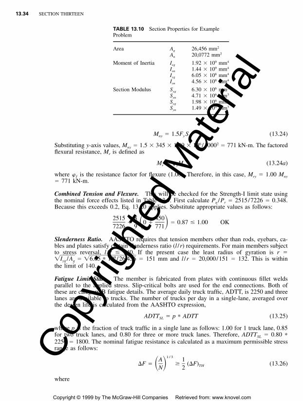
13.34 SECTION THIRTEEN
TABLE 13.10 Section Properties for ExampleProblem
Area Ag 26,456 mm2
An 20,0772 mm2
Moment of Inertia Ixg 1.92 � 109 mm4
Ixn 1.44 � 109 mm4
Iyg 6.05 � 108 mm4
Iyn 4.56 � 108 mm4
Section Modulus Sxg 6.30 � 106 mm3
Sxn 4.71 � 106 mm3
Syg 1.98 � 106 mm3
Syn 1.49 � 106 mm3
M � 1.5F S (13.24)ny y
Substituting y-axis values, Mny � 1.5 � 345 � 1.49 � 106 /10002 � 771 kN-m. The factoredflexural resistance, Mr is defined as
M � � M (13.24a)r ƒ n
where �ƒ is the resistance factor for flexure (1.00). Therefore, in this case, Mry � 1.00 Mny
� 771 kN-m.
Combined Tension and Flexure. This will be checked for the Strength-I limit state usingthe nominal force effects listed in Table 13.9. First calculate Pu /Pr � 2515/7226 � 0.348.Because this exceeds 0.2, Eq. 13.20 applies. Substitute appropriate values as follows:
2515 8 450� 0 � � 0.87 � 1.00 OK� �7226 9 771
Slenderness Ratio. AASHTO requires that tension members other than rods, eyebars, ca-bles and plates satisfy certain slenderness ratio (l /r) requirements. For main members subjectto stress reversal, l /r � 140. If the present case the least radius of gyration is r �
� 151 mm and l /r � 20,000/151 � 132. This is within8�I /A � �6.05 10 /26,456*yg g
the limit of 140.
Fatigue Limit State. The member is fabricated from plates with continuous fillet weldsparallel to the applied stress. Slip-critical bolts are used for the end connections. Both ofthese are category B fatigue details. The average daily truck traffic, ADTT, is 2250 and threelanes are available to trucks. The number of trucks per day in a single-lane, averaged overthe design life is calculated from the AASHTO expression,
ADTT � p ADTT (13.25)*SL
where p is the fraction of truck traffic in a single lane as follows: 1.00 for 1 truck lane, 0.85for two truck lanes, and 0.80 for three or more truck lanes. Therefore, ADTTSL � 0.80 *2250 � 1800. The nominal fatigue resistance is calculated as a maximum permissible stressrange as follows:
1 / 3A 1�F � (�F) (13.26)� � THN 2
where
Copy
right
ed M
ater
ial
Copyright © 1999 by The McGraw-Hill Companies Retrieved from: www.knovel.com
TRUSS BRIDGES 13.35
N � (365)(75)(n)(ADTT ) (13.27)SL
In the above, A is a fatigue constant that varies with the fatigue detail category, n is thenumber of stress range cycles per truck, and (�F )TH is the constant amplitude fatigue thresh-old. These constants are found in the AASHTO LRFD Specification for the present case asfollows: A � 39.3 1011 MPa3, n � 1.0, and (�F )TH � 110 MPa. Substitute in Eq. 13.26:*
1 / 31139.3 10 1*�F � � 43.0 MPa and (�F ) � 55 MPa� � TH365 75 1.0 1800 2* * *
Therefore, �F � 55 MPa. Next calculate the stress range for the force effects in Table 13.9.For the web-to-flange welds, which lie near the neutral axis, only the axial load is considered,and net section properties are used as the worst case:
28.2 � (�0.70)1000 � 1.44 MPa � 55 MPa OK*20,072
For the extreme fiber at the slip-critical connections, both axial load and flexure is considered,and gross section properties are used:
28.2 � (�0.70) 9.61 � (�2.82)3 610 � 10 � 7.37 MPa � 55 MPa OK* *626,456 1.98 10*
Thus, fatigue does not control and the member selection is satisfactory. A separate checkshows that the bolts are also adequate.
13.12 TRUSS JOINT DESIGN PROCEDURE
At every joint in a truss, working lines of the intersecting members preferably should meetat a point to avoid eccentric loading (Art. 13.2). While the members may be welded directlyto each other, most frequently they are connected to each other by bolting to gusset plates.Angle members may be bolted to a single gusset plate, whereas box and H shapes may bebolted to a pair of gusset plates.
A gusset plate usually is a one-piece element. When necessary, it may be spliced withgroove welds. When the free edges of the plate will be subjected to compression, they usuallyare stiffened with plates or angles. Consideration should be given in design to the possibilityof the stresses in gusset plates during erection being opposite in sense to the stresses thatwill be imposed by service loads.
Gusset plates are sometimes designed by the method of sections based on conventionalstrength of materials theory. The method of sections involves investigation of stresses onvarious planes through a plate and truss members. Analysis of gusset plates by finite-elementmethods, however, may be advisable where unusual geometry exists.
Transfer of member forces into and out of a gusset plate invokes the potential for blockshear around the connector groups and is assumed to have about a 30� angle of distributionwith respect to the gage line, as illustrated in Fig. 13.10 (line 1-5 and 4-6).
The following summarizes a procedure for load-factor design of a truss joint. Splices areassumed to occur within the truss joints. (See examples in Arts. 13.13 and 13.14.) Theconcept employed in the procedure can also be applied to working-stress design.
1. Lay out the centerlines of truss members to an appropriate scale and the members to ascale of 1⁄2 in � 1 ft, with gage lines.
2. Detail the fixed parts, such as floorbeam, strut, and lateral connections.3. Determine the grade and size of bolts to be used.
Copy
right
ed M
ater
ial
Copyright © 1999 by The McGraw-Hill Companies Retrieved from: www.knovel.com

13.36 SECTION THIRTEEN
FIGURE 13.10 Typical design sections for a gusset plate.
4. Detail the end connections of truss diagonals. The connections should be designed forthe average of the design strength of the diagonals and the factored load they carry butnot less than 75% of the design strength. The design strength should be taken as thesmallest of the following: (a) member strength, (b) column capacity, and (c) strengthbased on the width-thickness ratio b / t. A diagonal should have at least the major portionof its ends normal to the working line (square) so that milling across the ends will permitplacing of templates for bolt-hole alignment accurately. The corners of the diagonalshould be as close as possible to the cover plates of the chord and verticals. Bolts forconnection to a gusset plate should be centered about the neutral axis of the member.
5. Design fillet welds connecting a flange plate of a welded box member to the web plates,or the web plate of an H member to the flange plates, to transfer the connection loadfrom the flange plate into the web plates over the length of the gusset connection. Weldlengths should be designed to satisfy fatigue requirements. The weld size should beshown on the plans if the size required for loads or fatigue is larger than the minimumsize allowed.
6. Avoid the need for fills between gusset plates and welded-box truss members by keepingthe out-to-out dimension of web plates and the in-to-in dimension of gusset plates con-stant.
7. Determine gusset-plate outlines. This step is influenced principally by the diagonal con-nections.
8. Select a gusset-plate thickness t to satisfy the following criteria, as illustrated in Fig.13.10:
a. The loads for which a diagonal is connected may be resolved into components parallelto and normal to line A-A in Fig. 13.10 (horizontal and vertical). A shearing stressis induced along the gross section of line A-A through the last line of bolts. Equal tothe sum of the horizontal components of the diagonals (if they act in the same
Copy
right
ed M
ater
ial
Copyright © 1999 by The McGraw-Hill Companies Retrieved from: www.knovel.com

TRUSS BRIDGES 13.37
direction), this stress should not exceed Fy /1.35 , where Fy is the yield stress of�3the steel, ksi.
b. A compression stress is induced in the edge of the gusset plate along Section A-A(Fig. 13.10) by the vertical components of the diagonals (applied at C and D) andthe connection load of the vertical or floorbeam, when compressive. The compressionstress should not exceed the permissible column stress for the unsupported length ofthe gusset plate (L or b in Fig. 13.10). A stiffening angle should be provided if theslenderness ratio L /r � L / t of the compression edge exceeds 120, or if the�12permissible column stress is exceeded. The L /r of the section formed by the angleplus a 12-in width of the gusset plate should be used to recheck that L /r � 120 andthe permissible column stress is not exceeded. In addition to checking the L /r of thegusset in compression, the width-thickness ratio b / t of every free edge should bechecked to ensure that it does not exceed 348/ .�Fy
c. At a diagonal (Fig. 13.10),
V � V P (13.28)1 2 d
where Pd � load from the diagonal, kipsV1 � shear strength, kips, along lines 1-2 and 3-4
� AgFy /�3Ag � gross area, in2, along those linesV2 � strength, kips, along line 2-3 based on AnFy for tension diagonals or AgFa
for compression diagonalsAn � net area, in2, of the sectionFa � allowable compressive stress, ksi
The distance L� in Fig. 13.10 is used to compute Fa for sections 2-3 and 5-6.d. Assume that the connection stress transmitted to the gusset plate by a diagonal
spreads over the plate within lines that diverge outward at 30� to the axis of themember from the first bolt in each exterior row of bolts, as indicated by path 1-5-6-4 (on the right in Fig. 13.10). Then, the stress on the section normal to the axis ofthe diagonal at the last row of bolts (along line 5-6) and included between thesediverging lines should not exceed Fy on the net-section for tension diagonals and Fa
for compression diagonals.9. Design the chord splice (at the joint) for the full capacity of the chords. Arrange the
gusset plates and additional splice material to balance, as much as practical, the segmentbeing spliced.
10. When the chord splice is to be made with a web splice plate on the inside of a boxmember (Fig. 13.11), provide extra bolts between the chords and the gusset on eachside of the inner splice plate when the joint lies along the centerline of the floorbeam.This should be done because in the diaphragm bolts at floorbeam connections deliversome floorbeam reaction across the chords. When a splice plate is installed on the outerside of the gusset, back of the floorbeam connection angles (Fig. 13.11), the entire groupof floorbeam bolts will be stressed, both vertically and horizontally, and should not becounted as splice bolts.
11. Determine the size of standard perforations and the distances from the ends of themember.
13.13 EXAMPLE—LOAD FACTOR DESIGN OF TRUSS JOINT
The joint shown in Fig. 13.11 is to be designed to satisfy the criteria listed in Table 13.11.Fasteners to be used are 11⁄8-in-dia. A325 high-strength bolts in a slip-critical connection
Copy
right
ed M
ater
ial
Copyright © 1999 by The McGraw-Hill Companies Retrieved from: www.knovel.com

13.38 SECTION THIRTEEN
FIGURE 13.11 Truss joint for example of load-factor design.
TABLE 13.11 Allowable Stresses for Truss Joint,ksi*
Design section
Yield stress ofsteel, ksi
36 50
Shear on line A-A 15.4 21.4Shear on lines 1-2 and 3-4 20.8 28.9Tension on lines 2-3 and 5-5 36.0 50.0
* Figs. 13.10 and 13.11.
Copy
right
ed M
ater
ial
Copyright © 1999 by The McGraw-Hill Companies Retrieved from: www.knovel.com

TRUSS BRIDGES 13.39
with Class A surfaces, with an allowable shear stress Fv � 15.5 ksi assume 16 ksi for thisexample. The bolts connecting a diagonal or vertical to a gusset plate then have a shearcapacity, kips, for service loads
P � NA F � 16NA (13.29)v v v v
where N � number of bolts and Av � cross-sectional area of a bolt, in2. For load-factordesign, Pv is multiplied by a load factor. For example, for Group I loading,
1.5[D � (4/3)(L � I)] � 1.5(1 � R /3)P (13.30)v
where R � ratio of live load L to the total service load. Hence, for this loading, and loadfactor is 1.5(1 � R /3).
Diagonal U15-L14. The diagonal is subjected to factored loads of 2,219 kips compressionand 462 kips tension. It has a design strength of 2,379 kips. The AASHTO SLD Specifi-cations require that the connection to the gusset plate transmit 75% of the design strengthor the average of the factored load and the design strength, whichever is larger. Thus, thedesign load for the connection is
P � (2219 � 2379)/2 � 2299 kips � 0.75 � 2379
The ratio of the service live load to the total service load for the diagonal is R � 0.55.Hence, for Group I loading on the bolts, the load factor is 1.5(1 � R /3) � 1.775. For serviceloads, the 11⁄8-in-dia. bolts have a capacity of 15.90 kips per shear plane. Therefore, sincethe member is connected to two gusset plates, the number of bolts required for diagonalU15-L14 is
2299N � � 41 per side
2 � 1.775 � 15.90
Diagonal L14-U13. The diagonal is subjected to factored loads of a maximum of 3272kips tension and a minimum of 650 kips tension. It has a design strength of 3425 kips. Thedesign load for the connection is
P � (3272 � 3425)/2 � 3349 kips � 0.75 � 3425
The ratio of the service live load to the total service load is R � 0.374, and the load factorfor the bolts is 1.5(1 � 0.374/3) � 1.687. Then, the number of 11⁄8-in bolts required is
3349N � � 63 per side
2 � 1.687 � 15.90
Vertical U14-L14. The vertical carries a factored compression load of 362 kips. It has adesign strength of 1439 kips, limited by b / t at a perforation. The design load for the con-nection is
P � 0.75 � 1439 � 1079 kips � (362 � 1439)/2
Since the vertical does not carry any live load, the load factor for the bolts is 1.5. Hence,the number of 11⁄8-in bolts required for the vertical is
1079N � � 23 per side
2 � 1.5 � 15.90
Copy
right
ed M
ater
ial
Copyright © 1999 by The McGraw-Hill Companies Retrieved from: www.knovel.com

13.40 SECTION THIRTEEN
FIGURE 13.12 Cross section of chord cover-plate splice for example of load-factor design.
Splice of Chord Cover Plates. Each cover plate of the box chord is to be spliced with aplate on the inner and outer face (Fig. 13.12). A36 steel will be used for the splice material,as for the chord. Fasteners are 7⁄8-in-dia. A325 bolts, with a capacity for service loads of9.62 kips per shear plane. The bolt load factor is 1.791.
The cover plate on chord L14-L15 (Fig. 13.11) is 13⁄16 � 343⁄4 in but has 12-in-wideaccess perforations. Usable area of the plate is 18.48 in2. The cover plate for chord L13-L14 is 13⁄16 � 34 in, also with 12-in-wide access perforations. Usable area of this plate is17.88 in2. Design of the chord splice is based on the 17.88-in2 area. The difference of 0.60in2 between this area and that of the larger cover plate will be made up on the L14-L15 sideof the web-plate splice as ‘‘cover excess.’’
Where the design section of the joint elements is controlled by allowances for bolts, onlythe excess exceeding 15% of the gross section area is deducted from the gross area to obtainthe design area. (This is the designer’s interpretation of the applicable requirements forsplices in the AASHTO SLD Specifications. The interpretation is based on the observationthat, for the typical dimensions of members, holes, bolt patterns and grades of steel used onthe bridge in question, the capacity of tension members was often controlled by the designgross area as illustrated in Arts. 13.10.1 and 13.10.2. The current edition of the specificationsshould be consulted on this and other interpretations, inasmuch as the specifications are underconstant reevaluation.)
The number of bolts needed for a cover-plate splice is
17.88 � 36N � � 19 per side
2 � 1.791 � 9.62
Try two splice plates, each 3⁄8 � 31 in, with a gross area of 23.26 in2. Assume eight 1-in-dia. bolt holes in the cross section. The area to be deducted for the holes then is
22 � 0.375(8 � 1 � 0.15 � 31) � 2.51 in
Consequently, the area of the design net section is
2 2A � 23.26 � 2.51 � 20.75 in � 17.88 in —OKn
Tension Splice of Chord Web Plate. A splice is to be provided between the 11⁄4 � 54-inweb of chord L14-L15 and the 15⁄8 � 54-in web of the L13-L14 chord. Because of thedifference in web thickness, a 3⁄8-in fill will be place on the inner face of the 11⁄4-in web(Fig. 13.13). The gusset plate can serve as part of the needed splice material. The remainderis supplied by a plate on the inner face of the web and a plate on the outer face of thegusset. Fasteners are 11⁄8-in-dia. A325 bolts, with a capacity for service loads of 15.90 kips.Load factor is 1.791.
The web of the L13-L14 chord has a gross area of 87.75 in2. After deduction of the 15%excess of seven 11⁄4-in-dia. bolt holes, the design area of this web is 86.69 in2.
Copy
right
ed M
ater
ial
Copyright © 1999 by The McGraw-Hill Companies Retrieved from: www.knovel.com

TRUSS BRIDGES 13.41
FIGURE 13.13 Cross section of chord web-plate slice for example of load-factor design.
The web on the L14-L15 chord has a gross area of 67.50 in2. After deduction of the 15%excess of seven bolt holes from the chord splice and addition of the ‘‘cover excess’’ of 0.60in2, the design area of this web is 67.29 in2.
The gusset plate is 13⁄16 in thick and 118 in high. Assume that only the portion thatoverlaps the chord web; that is, 54 in, is effective in the splice. To account for the eccentricapplication of the chord load to the gusset, an effectiveness factor may be applied to theoverlap, with the assumption that only the overlapping portion of the gusset plate is stressedby the chord load.
The effectiveness factor Eƒ is defined as the ratio of the axial stress in the overlap dueto the chord load to the sum of the axial stress on the full cross section of the gusset andthe moment due to the eccentricity of the chord relative to the gusset centroid.
P /AoE � (13.31)ƒ P /A � Pey / Ig
where P � chord loadAo � overlap area � 54tAg � full area of gusset plate � 118te � eccentricity of P � 118/2 � 54/2 � 32 iny � 118/2 � 59 inI � 1183t /12 � 136,900t in4
Substitution in Eq. (13.31) yields
P /54tE � � 0.832ƒ P /118t � 32 � 59P /136,900t
The gross area of the gusset overlap is 13⁄16 � 54 � 43.88 in2. After deduction of the 15%excess of thirteen 11⁄4-in-dia. bolt holes, the design area is 37.25 in2. Then, the effective areaof the gusset as a splice plate is 0.832 � 37.25 � 30.99 in2.
In addition to the 67.29 in2 of web area, the gusset has to supply an area for transmissionof the 250-kip horizontal component from diagonal U15-L14 (Fig. 13.11). With Fy � 36ksi, this area equals 250/(36 � 2) � 3.47 in2. Hence, the equivalent web area from the L14-L15 side of the joint is 67.29 � 3.47 � 70.76 in2. The number of bolts required to transferthe load to the inside and outside of the web should be determined based on the effectiveareas of gusset that add up to 70.76 in2 but that provide a net moment in the joint close tozero.
The sum of the moments of the web components about the centerline of the combinationof outside splice plate and gusset plate is 3.47 � 0.19 � 67.29 � 1.22 � 0.66 � 82.09 �82.75 in3. Dividing this by 2.59 in, the distance to the center of the inside splice plate, yieldsan effective area for the inside splice plate of 31.95 in2. Hence, the effective area of the
Copy
right
ed M
ater
ial
Copyright © 1999 by The McGraw-Hill Companies Retrieved from: www.knovel.com
13.42 SECTION THIRTEEN
TABLE 13.12 Number of Bolts for Plate Development
Plate Area, in2 Bolts
Inside splice plate 31.95 41Outside splice plate 13.85 18Gusset plate on L14-L15 side (13.85 � 24.96 � 3.47) � 35.34 45Gusset plate on L13-L14 side (13.85 � 24.96) � 38.81 50
combination of the gusset and outside splice plates in 70.76 � 31.95 � 38.81 in2. This isthen distributed to the plates in proportion to thickness: gusset, 24.96 in2, and splice plate,13.85 in2.
The number of 11⁄8-in A325 bolts required to develop a plate with area A is given by
N � AF / (1.791 � 15.90) � 36A /28.48 � 1.264Ay
Table 13.12 list the number of bolts for the various plates.
Check of Gusset Plates. At Section A-A (Fig. 13.11), each plate is 128 in wide and 118in high, 13⁄16 in thick. The design shear stress is 15.4 ksi (Table 13.11). The sum of thehorizontal components of the loads on the truss diagonals is 1244 � 1705 � 2949 kips.This produces a shear stress on section A-A of
2,949ƒ � � 14.18 ksi � 15.4 ksi—OKv 132 � 128 � ⁄16
The vertical component of diagonal U15-L14 produces a moment about the centroid ofthe gusset of 1,934 � 21 � 40,600 kip-in and the vertical component of U13-L14 producesa moment 2,883 � 20.5 � 59,100 kip-in. The sum of these moments is M � 99,700 kip-in. The stress at the edge of one gusset plate due to this moment is
6M 6 � 99,700ƒ � � � 22.47 ksib 2 213td 2( ⁄16)128
The vertical, carrying a 362-kip load, imposes a stress
P 362ƒ � � � 1.74 ksic 13A 2 � 128 � ⁄16
The total stress then is ƒ � 22.47 � 1.74 � 24.21 ksi.The width b of the gusset at the edge is 48 in. Hence, the width-thickness ratio is b / t �
48/(13⁄16) � 59. From step b in Art. 13.12, the maximum permissible b / t is 348/ ��Fy
348/ � 58 � 59. The edge has to be stiffened. Use a stiffener angle 3 � 3 � 1⁄2 in.�36For computation of the design compressive stress, assume the angle acts with a 12-in
width of gusset plates. The slenderness ratio of the edge is 48/0.73 � 65.75. The maximumpermissible slenderness ratio is
2 2�2� E /F � �2� � 29,000/36 � 126 � 65.75y
Hence, the design compressive stress is
Copy
right
ed M
ater
ial
Copyright © 1999 by The McGraw-Hill Companies Retrieved from: www.knovel.com
TRUSS BRIDGES 13.43
2F Lyƒ � 0.85F 1 � (13.32)� � � �a y 24� E r236 48
� 0.85 � 36 1 �� � � �24� � 29,000 0.73
� 26.44 ksi � 24.21 ksi—OK
Next, the gusset plate is checked for shear and compression at the connection with di-agonal U15-L14. The diagonal carries a factored compression load of 2,299 kips. Shearpaths 1-2 and 3-4 (Fig. 13.10) have a gross length of 93 in. From Table 13.11, the designshear stress is 20.8 ksi. Hence, design shear on these paths is
13V � 2 � 20.8 � 93 � ⁄16 � 3143 kips � 2299 kips—OKd
Path 2-3 need not be investigated for compression. For compression on path 5-6, a 30�distribution from the first bolt in the exterior row is assumed (Art. 13.12, step 8d ). Thelength of path 5-6 between the 30� lines in 82 in. The design stress, computed from Eq.(13.32) with a slenderness ratio of 52.9, is 27.9 ksi. The design strength of the gusset platethen is
13P � 2 � 27.9 � 82 � ⁄16 � 3718 kips � 2299 kips—OK
Also, the gusset plate is checked for shear and tension at the connection with diagonalL14-U13. The diagonal carries a tension load of 3,272 kips. Shear paths 1-2 and 3-4 (Fig.13.10) have a gross length of 98 in. From Table 13.11, the allowable shear stress is 20.8ksi. Hence, the allowable shear on these paths is
13V � 2 � 20.8 � 98 � ⁄16 � 3312 kips � 3,272 kips—OKd
For path 2-3, capacity in tension with Fy � 36 ksi is
13P � 2 � 36 � 27 � ⁄16 � 1580 kips23
For tension on path 5-6 (Fig. 13.10), a 30� distribution from the first bolt in the exterior rowis assumed (Art. 13.12, step 8d ). The length of path 5-6 between the 30� lines is a net of83 in. The allowable tension then is
13P � 2 � 36 � 83 � ⁄16 � 4856 kips � 3272 kips—OK56
Welds to Develop Cover Plates. The fillet weld sizes selected are listed in Table 13.13 withtheir capacities, for an allowable stress of 26.10 ksi. A 5⁄16-in weld is selected for the diag-onals. It has a capacity of 5.76 kips / in.
The allowable compressive stress for diagonal U15-L14 is 22.03 ksi. Then, length of filletweld required is
7 122.03( ⁄8)23 ⁄8� 38.7 in
2 � 5.76
For Fy � 36 ksi, the length of fillet weld required for diagonal L14-U13 is
1 136( ⁄2)23 ⁄8� 36.1 in
2 � 5.76
Copy
right
ed M
ater
ial
Copyright © 1999 by The McGraw-Hill Companies Retrieved from: www.knovel.com
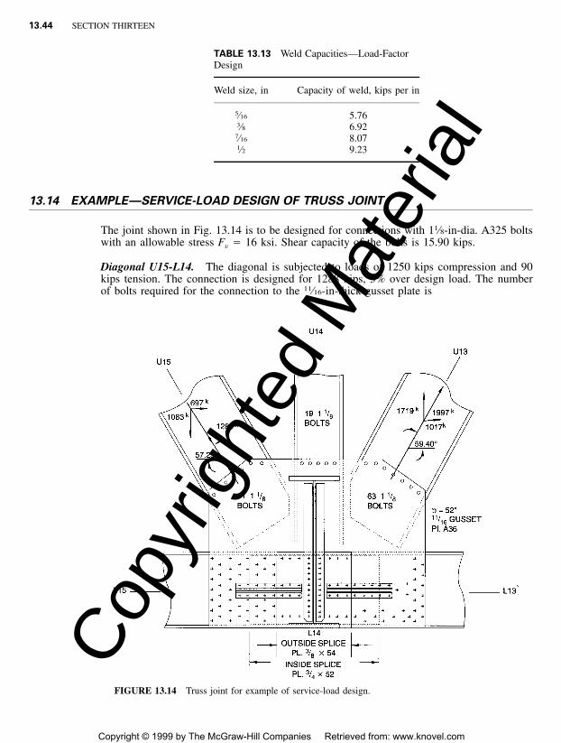
13.44 SECTION THIRTEEN
TABLE 13.13 Weld Capacities—Load-FactorDesign
Weld size, in Capacity of weld, kips per in
5⁄16 5.763⁄8 6.927⁄16 8.071⁄2 9.23
FIGURE 13.14 Truss joint for example of service-load design.
13.14 EXAMPLE—SERVICE-LOAD DESIGN OF TRUSS JOINT
The joint shown in Fig. 13.14 is to be designed for connections with 11⁄8-in-dia. A325 boltswith an allowable stress Fv � 16 ksi. Shear capacity of the bolts is 15.90 kips.
Diagonal U15-L14. The diagonal is subjected to loads of 1250 kips compression and 90kips tension. The connection is designed for 1288 kips, 3% over design load. The numberof bolts required for the connection to the 11⁄16-in-thick gusset plate is
Copy
right
ed M
ater
ial
Copyright © 1999 by The McGraw-Hill Companies Retrieved from: www.knovel.com

TRUSS BRIDGES 13.45
FIGURE 13.15 Cross section of chord cover-plate splice for example of service-load design.
N � 1288/(2 � 15.90) � 41 per side
Diagonal L14-U13. The diagonal is subjected to a maximum tension of 1939 kips and aminimum tension of 628 kips. The connection is designed for 1997 kips, 3% over designload. The number of 11⁄8-in-dia. A325 bolts required is
N � 1997/(2 � 15.90) � 63 per side
Vertical U14-L14. The vertical carries a compression load of 241 kips. The member is74.53 ft long and has a cross-sectional area of 70.69 in2. It has a radius of gyration r �10.52 in and slenderness ratio of KL /r � 74.53 � 12/10.52 � 85.0 with K taken as unity.The allowable compression stress then is
2F � 16.98 � 0.00053(KL /r)a (13.33)2� 16.98 � 0.00053 � 85.0 � 13.15 ksi
The allowable unit stress for width-thickness ratio b / t, however, is 11.10 � 13.15 and gov-erns. Hence, the allowable load is
P � 70.69 � 11.10 � 785 kips
The number of bolts required is determined for 75% of the allowable load:
N � 0.75 � 785/(2 � 15.90) � 19 bolts per side
Splice of Chord Cover Plates. Each cover plate of the box chord is to be spliced with aplate on the inner and outer face (Fig. 13.15). A36 steel will be used for the splice material,as for the chord. Fasteners are 7⁄8-in-dia. A325 bolts, with a capacity of 9.62 kips per shearplane.
The cover for L14-L15 (Fig. 13.14) is 13⁄16 by 343⁄4 in but has 12-in-wide access perfo-rations. Usable area of the plate is 18.48 in2. The cover plate for L13-L14 is 13⁄16 � 34 in,also with 12-in-wide access perforations. Usable area of this plate is 17.88 in2. Design ofthe chord splice is based on the 17.88-in2 area. The difference of 0.60 in2 between this areaand that of the larger cover plate will be made up on the L14-L15 side of the web platesplice as ‘‘cover excess.’’
Where the net section of the joint elements is controlled by the allowance for bolts, onlythe excess exceeding 15% of the gross area is deducted from the gross area to obtain thedesign gross area, as in load-factor design (Art. 13.13).
For an allowable stress of 20 ksi in the cover plate, the number of bolts needed for thecover-plate splice is
Copy
right
ed M
ater
ial
Copyright © 1999 by The McGraw-Hill Companies Retrieved from: www.knovel.com
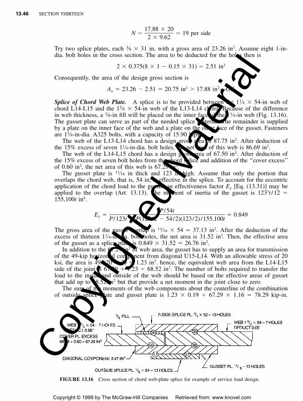
13.46 SECTION THIRTEEN
FIGURE 13.16 Cross section of chord web-plate splice for example of service load design.
17.88 � 20N � � 19 per side
2 � 9.62
Try two splice plates, each 3⁄8 � 31 in, with a gross area of 23.26 in2. Assume eight 1-in-dia. bolt holes in the cross section. The area to be deducted for the holes then is
22 � 0.375(8 � 1 � 0.15 � 31) � 2.51 in
Consequently, the area of the design gross section is
2 2A � 23.26 � 2.51 � 20.75 in � 17.88 in —OKn
Splice of Chord Web Plate. A splice is to be provided between the 11⁄4 � 54-in web ofchord L14-L15 and the 15⁄8 � 54-in web of the L13-L14 chord. Because of the differencein web thickness, a 3⁄8-in fill will be placed on the inner face of the 11⁄4-in web (Fig. 13.16).The gusset plate can serve as part of the needed splice material. The remainder is suppliedby a plate on the inner face of the web and a plate on the outer face of the gusset. Fastenersare 11⁄8-in-dia. A325 bolts, with a capacity of 15.90 kips.
The web of the L13-L14 chord has a design gross area of 87.75 in2. After deduction ofthe 15% excess of seven 11⁄4-in-dia. bolt holes, the net area of this web is 86.69 in2.
The web of the L14-L15 chord has a design gross area of 67.50 in2. After deduction ofthe 15% excess of seven bolt holes from the chord splice and addition of the ‘‘cover excess’’of 0.60 in2, the net area of this web is 67.29 in2.
The gusset plate is 11⁄16 in thick and 123 in high. Assume that only the portion thatoverlaps the chord web, that is, 54 in, is effective in the splice. To account for the eccentricapplication of the chord load to the gusset, an effectiveness factor Eƒ [Eq. (13.31)] may beapplied to the overlap (Art. 13.13). The moment of inertia of the gusset is 1233t /12 �155,100t in4.
P /54tE � � 0.849ƒ P /123t � P(123/2 � 54/2)(123/2) /155,100t
The gross area of the gusset overlap is 11⁄16 � 54 � 37.13 in2. After the deduction of theexcess of thirteen 11⁄4-in-dia. bolt holes, the net area is 31.52 in2. Then, the effective areaof the gusset as a splice plate is 0.849 � 31.52 � 26.76 in2.
In addition to the 67.29 in2 of web area, the gusset has to supply an area for transmissionof the 49-kip horizontal component from diagonal U15-L14. With an allowable stress of 20ksi, the area is 49/(20 � 2) � 1.23 in2. hence, the equivalent web area from the L14-L15side of the joint is 67.29 � 1.23 � 68.52 in2. The number of bolts required to transfer theload to the inside and outside of the web should be based on the effective areas of gussetthat add up to 68.52 in2 but that provide a net moment in the joint close to zero.
The sum of the moments of the web components about the centerline of the combinationof outside splice plate and gusset plate is 1.23 � 0.19 � 67.29 � 1.16 � 78.29 kip-in.
Copy
right
ed M
ater
ial
Copyright © 1999 by The McGraw-Hill Companies Retrieved from: www.knovel.com
TRUSS BRIDGES 13.47
TABLE 13.14 Number of Bolts for Plate Development
Plate Area, in2 Bolts
Inside splice plate 30.94 39Outside splice plate 14.70 19Gusset plate on L14-L15 side (14.70 � 22.88 � 1.16) � 36.42 46Gusset plate on L13-L14 side (14.70 � 22.88) � 37.58 48
Dividing this by 2.53, the distance to the center of the inside splice plate, yields an effectivearea for the inside splice plate of 30.94 in2. Hence, the effective area of the combination ofthe gusset and outside splice plates is 68.52 � 30.94 � 37.58 in2. This is then distributedto the plates as follows: gusset, 22.88 in2, and outside splice plate, 14.70 in2.
The number of 11⁄8-in-dia. A325 bolts required to develop a plate with area A and allow-able stress of 20 ksi is
N � 20A /15.90 � 1.258A
Table 13.14 lists the number of bolts for the various plates.
Check of Gusset Plates. At section A-A (Fig. 13.11), each plate is 134 in wide and 123 inhigh, 11⁄16 in thick. The allowable shear stress is 10 ksi. The sum of the horizontal compo-nents of the loads on the truss diagonals is 697 � 1017 � 1714 kips. This produces a shearstress on Section A-A of
1714ƒ � � 9.30 ksi � 10 ksi—OKv 112 � 134 � ⁄16
The vertical component of diagonal U15-L14 produces a moment about the centroid ofthe gusset of 1083 � 21 � 22,740 kip-in and the vertical component of U13-L14 producesa moment 1719 � 20.5 � 35,240 kip-in. The sum of these moments is 57,980 kip-in. Thestress at the edge of one gusset plate due to this moment is
6M 6 � 57,980ƒ � � � 14.09 ksib 2 211td 2( ⁄16)134
The vertical carrying a 241-kip load, imposes a stress
P 241ƒ � � � 1.31 ksic 11A 2 � 134 � ⁄16
The total stress then is 14.09 � 1.31 � 15.40 ksiThe width b of the gusset at the edge is 52 in. Hence, the width-thickness ratio is b / t �
52/(11⁄16) � 75.6. From step 8b in Art. 13.12, the maximum permissible b / t is 348 ��Fy
348/ � 58 � 75.6. The edge has to stiffened. Use a stiffener angle 4 � 3 � 1⁄2 in.�36For computation of the allowable compressive stress, assume the angle acts with a 12-in
width of gusset plate. The slenderness ratio of the edge is 52/1.00 � 52.0. The maximumpermissible slenderness ratio is
2 2�2� E /F � �2� � 29,000/36 � 126 � 552y
Hence, the allowable stress from Eq. (13.33) is
Copy
right
ed M
ater
ial
Copyright © 1999 by The McGraw-Hill Companies Retrieved from: www.knovel.com

13.48 SECTION THIRTEEN
TABLE 13.15 Weld Capacities—Service-LoadDesign
Weld size, in Capacity of weld, kips per in
5⁄16 3.463⁄8 4.157⁄16 4.841⁄2 5.54
2F � 16.98 � 0.00053 � 52 � 15.55 ksi � 15.40 ksi—OKa
Next, the gusset plate is checked for shear and compression at the connection with di-agonal U15-L14. The diagonal carries a load of 1,288 kips. Shear paths 1-2 and 3-4 (Fig.13.10) have a gross length of 105 in. The allowable shear stress is 12 ksi. Hence, theallowable shear on these paths is
11V � 2 � 12 � 105 � ⁄16 � 1733 kips � 1288 kips—OKd
Path 2-3 need not be investigated for compression. For compression on path 5-6, a 30�distribution from the first bolt in the exterior row is assumed (Art. 13.12, step 8d ). Thelength of path 5-6 between the 30� lines is 88 in. The allowable stress, computed from Eq.(13.33) with a slenderness ratio KL /r � 0.5 � 25/0.198 � 63, is 14.88 ksi. This permitsthe gusset to withstand a load
11P � 2 � 14.88 � 88 � ⁄16 � 1800 kips � 1288 kips
Also, the gusset plate is checked for shear and tension at the connection with diagonalL14-U13. The diagonal carries a tension load of 1,997 kips. Shear paths 1-2 and 3-4 (Fig.13.10) have a gross length of 102 in. The allowable shear stress is 12 ksi. Hence, theallowable shear on these paths is
11V � 2 � 12 � 102 � ⁄16 � 1683 kipsd
For path 2-3, capacity in tension with an allowable stress of 20 ksi is
11P � 2 � 20 � 21.6 � ⁄16 � 594 kips � (1997 � 1683)—OK23
For tension on path 5-6 (Fig. 13.10), a 30� distribution from the first bolt in the exterior rowis assumed (Art. 13.12, step 8d ). The length of path 5-6 between the 30� lines is a net of88 in. The allowable tension then is
11P � 2 � 20 � 88 � ⁄16 � 2420 kips � 1997 kips—OK
Welds to Develop Cover Plates. The fillet weld sizes selected are listed in Table 13.15 withtheir capacities, for an allowable stress of 15.66 ksi. A 5⁄16-in weld is selected for the diag-onals. It has a capacity of 3.46 kips / in.
The allowable compressive stress for diagonal U15-L14 is 11.93 ksi. Then, length of filletweld required is
Copy
right
ed M
ater
ial
Copyright © 1999 by The McGraw-Hill Companies Retrieved from: www.knovel.com

TRUSS BRIDGES 13.49
FIGURE 13.17 Skewed bridge with skew distance lessthan panel length.
7 111.93( ⁄8)23 ⁄8� 34.9 in
2 � 3.46
The allowable tensile stress for diagonal L14-U13 is 20.99 ksi. In this case, the requiredweld length is
1 120.99( ⁄2)23 ⁄8� 35.1 in
2 � 3.46
13.15 SKEWED BRIDGES
To reduce scour and to avoid impeding stream flow, it is generally desirable to orient pierswith centerlines parallel to direction of flow; therefore skewed spans may be required. Trussconstruction does not lend itself to bridges where piers are not at right angles to the super-structure (skew crossings). Hence, these should be avoided and this can generally be doneby using longer spans with normal piers. In economic comparisons, it is reasonable to assumesome increased cost of steel fabrication if skewed trusses are to be used.
If a skewed crossing is a necessity, it is sometimes possible to establish a panel lengthequal to the skew distance W tan �, where W is the distance between trusses and � the skewangle. This aligns panels and maintains perpendicular connections of floorbeams to thetrusses (Fig. 13.17). If such a layout is possible, there is little difference in cost and skewedspans and normal spans. Design principles are similar. If the skewed distance is less thanthe panel length, it might be possible to take up the difference in the angle of inclination ofthe end post, as shown in Fig. 13.17. This keeps the cost down, but results in trusses thatare not symmetrical within themselves and, depending on the proportions, could be veryunpleasing esthetically. If the skewed distance is greater than the panel length, it may benecessary to vary panel lengths along the bridge. One solution to such a skew is shown inFig. 13.18, where a truss, similar to the truss in Fig. 13.17, is not symmetrical within itself
Copy
right
ed M
ater
ial
Copyright © 1999 by The McGraw-Hill Companies Retrieved from: www.knovel.com
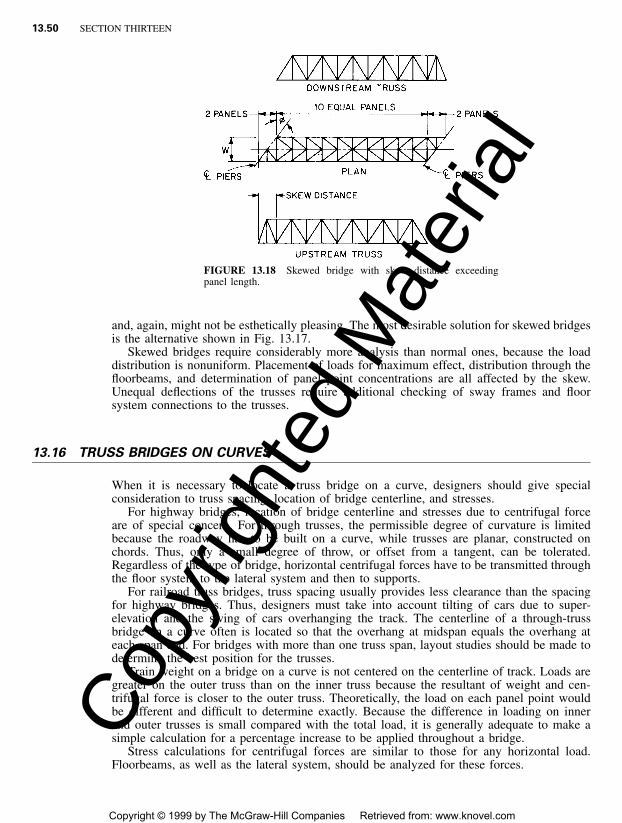
13.50 SECTION THIRTEEN
FIGURE 13.18 Skewed bridge with skew distance exceedingpanel length.
and, again, might not be esthetically pleasing. The most desirable solution for skewed bridgesis the alternative shown in Fig. 13.17.
Skewed bridges require considerably more analysis than normal ones, because the loaddistribution is nonuniform. Placement of loads for maximum effect, distribution through thefloorbeams, and determination of panel point concentrations are all affected by the skew.Unequal deflections of the trusses require additional checking of sway frames and floorsystem connections to the trusses.
13.16 TRUSS BRIDGES ON CURVES
When it is necessary to locate a truss bridge on a curve, designers should give specialconsideration to truss spacing, location of bridge centerline, and stresses.
For highway bridges, location of bridge centerline and stresses due to centrifugal forceare of special concern. For through trusses, the permissible degree of curvature is limitedbecause the roadway has to be built on a curve, while trusses are planar, constructed onchords. Thus, only a small degree of throw, or offset from a tangent, can be tolerated.Regardless of the type of bridge, horizontal centrifugal forces have to be transmitted throughthe floor system to the lateral system and then to supports.
For railroad truss bridges, truss spacing usually provides less clearance than the spacingfor highway bridges. Thus, designers must take into account tilting of cars due to super-elevation and the swing of cars overhanging the track. The centerline of a through-trussbridge on a curve often is located so that the overhang at midspan equals the overhang ateach span end. For bridges with more than one truss span, layout studies should be made todetermine the best position for the trusses.
Train weight on a bridge on a curve is not centered on the centerline of track. Loads aregreater on the outer truss than on the inner truss because the resultant of weight and cen-trifugal force is closer to the outer truss. Theoretically, the load on each panel point wouldbe different and difficult to determine exactly. Because the difference in loading on innerand outer trusses is small compared with the total load, it is generally adequate to make asimple calculation for a percentage increase to be applied throughout a bridge.
Stress calculations for centrifugal forces are similar to those for any horizontal load.Floorbeams, as well as the lateral system, should be analyzed for these forces.
Copy
right
ed M
ater
ial
Copyright © 1999 by The McGraw-Hill Companies Retrieved from: www.knovel.com

TRUSS BRIDGES 13.51
13.17 TRUSS SUPPORTS AND OTHER DETAILS
End bearings transmit the reactions from trusses to substructure elements, such as abutmentsor piers. Unless trusses are supported on tall slender piers that can deflect horizontally with-out exerting large forces on the trusses, it is customary to provide expansion bearings at oneend of the span and fixed bearings at the other end.
Anchoring a truss to the support, a fixed bearing transmits the longitudinal loads fromwind and live-load traction, as well as vertical loads and transverse wind. This bearing alsomust incorporate a hinge, curved bearing plate, pin arrangement, or elastomeric pads topermit end rotation of the truss in its plane.
An expansion bearing transmits only vertical and transverse loads to the support. It per-mits changes in length of trusses, as well as end rotation.
Many types of bearings are available. To ensure proper functioning of trusses in accord-ance with design principles, designers should make a thorough study of the bearings, in-cluding allowances for reactions, end rotations and horizontal movements. For short trusses,a rocker may be used for the expansion end of a truss. For long trusses, it generally isnecessary to utilize some sort of roller support. See also Arts. 10.22 and 11.9.
Inspection Walkways. An essential part of a truss design is provision of an inspectionwalkway. Such walkways permit thorough structural inspection and also are of use duringerection and painting of bridges. The additional steel required to support a walkway is almostinsignificant.
13.18 CONTINUOUS TRUSSES
Many river crossings do not require more than one truss span to meet navigational require-ments. Nevertheless, continuous trusses have made possible economical bridge designs inmany localities. Studies of alternative layouts are essential to ensure selection of the lowest-cost arrangement. The principles outlined in preceding articles of this section are just asapplicable to continuous trusses as to simple spans. Analysis of the stresses in the membersof continuous trusses, however, is more complex, unless computer-aided design is used. Inthis latter case, there is no practical difference in the calculation of member loads once theforces have been determined. However, if the truss is truly continuous, and, therefore, thetruss in each span is statically indeterminant, the member forces are dependent on the stiff-ness of the truss members. This may make several iterations of member-force calculationsnecessary. But where sufficient points of articulation are provided to make each individualtruss statically determinant, such as the case where a suspended span is inserted in a canti-lever truss, the member forces are not a function of member stiffness. As a result, live-loadforces need be computed only once, and dead-load member forces need to be updated onlyfor the change in member weight as the design cycle proceeds. When the stresses have beencomputed, design proceeds much as for simple spans.
The preceding discussion implies that some simplification is possible by using cantileverdesign rather than continuous design. In fact, all other things being equal, the total weightof members will not be much different in the two designs if points of articulation are properlyselected. More roadway joints will be required in the cantilever, but they, and the bearings,will be subject to less movement. However, use of continuity should be considered becauseelimination of the joints and devices necessary to provide for articulation will generallyreduce maintenance, stiffen the bridge, increase redundancy and, therefore, improve the gen-eral robustness of the bridge.Co
pyrig
hted
Mat
erial
Copyright © 1999 by The McGraw-Hill Companies Retrieved from: www.knovel.com