Movable Structures Chapter 2 – Bascule Bridges
14
Structure Inspection Manual Part 3 – Movable Structures Chapter 2 – Bascule Bridges August 2017 3-2-1 Table of Contents 3.2 Bascule Bridges ................................................................................................................. 2 3.2.1 Introduction................................................................................................................. 2 3.2.1.1 Counterweights ................................................................................................... 2 3.2.1.2 Single-Leaf Bascule ............................................................................................ 3 3.2.1.3 Double-Leaf Bascule ........................................................................................... 3 3.2.1.4 Deck Bascules .................................................................................................... 3 3.2.1.5 Through Bascules ............................................................................................... 3 3.2.2 Simple Trunnion Bascules .......................................................................................... 4 3.2.3 Rolling Lift Bascules – Scherzer Type ........................................................................ 6 3.2.4 Articulated Counterweight Bascules – Strauss Type ................................................... 8 3.2.4.1 Underneath Counterweight ............................................................................... 10 3.2.4.2 Vertical Overhead Counterweight ..................................................................... 10 3.2.4.3 Heel Trunnion ................................................................................................... 10 3.2.5 Articulated Counterweight Bascules – ABT Type ...................................................... 11 3.2.6 Bascules Without Counterweights ............................................................................ 11
-
Upload
khangminh22 -
Category
Documents
-
view
3 -
download
0
Transcript of Movable Structures Chapter 2 – Bascule Bridges

Structure Inspection Manual Part 3 – Movable Structures Chapter 2 – Bascule Bridges
August 2017 3-2-1
Table of Contents
3.2 Bascule Bridges ................................................................................................................. 2
3.2.1 Introduction ................................................................................................................. 2
3.2.1.1 Counterweights ................................................................................................... 2
3.2.1.2 Single-Leaf Bascule ............................................................................................ 3
3.2.1.3 Double-Leaf Bascule ........................................................................................... 3
3.2.1.4 Deck Bascules .................................................................................................... 3
3.2.1.5 Through Bascules ............................................................................................... 3
3.2.2 Simple Trunnion Bascules .......................................................................................... 4
3.2.3 Rolling Lift Bascules – Scherzer Type ........................................................................ 6
3.2.4 Articulated Counterweight Bascules – Strauss Type ................................................... 8
3.2.4.1 Underneath Counterweight ............................................................................... 10
3.2.4.2 Vertical Overhead Counterweight ..................................................................... 10
3.2.4.3 Heel Trunnion ................................................................................................... 10
3.2.5 Articulated Counterweight Bascules – ABT Type ...................................................... 11
3.2.6 Bascules Without Counterweights ............................................................................ 11
Structure Inspection Manual Part 3 – Movable Structures Chapter 2 – Bascule Bridges
August 2017 3-2-2
3.2 BASCULE BRIDGES
3.2.1 Introduction
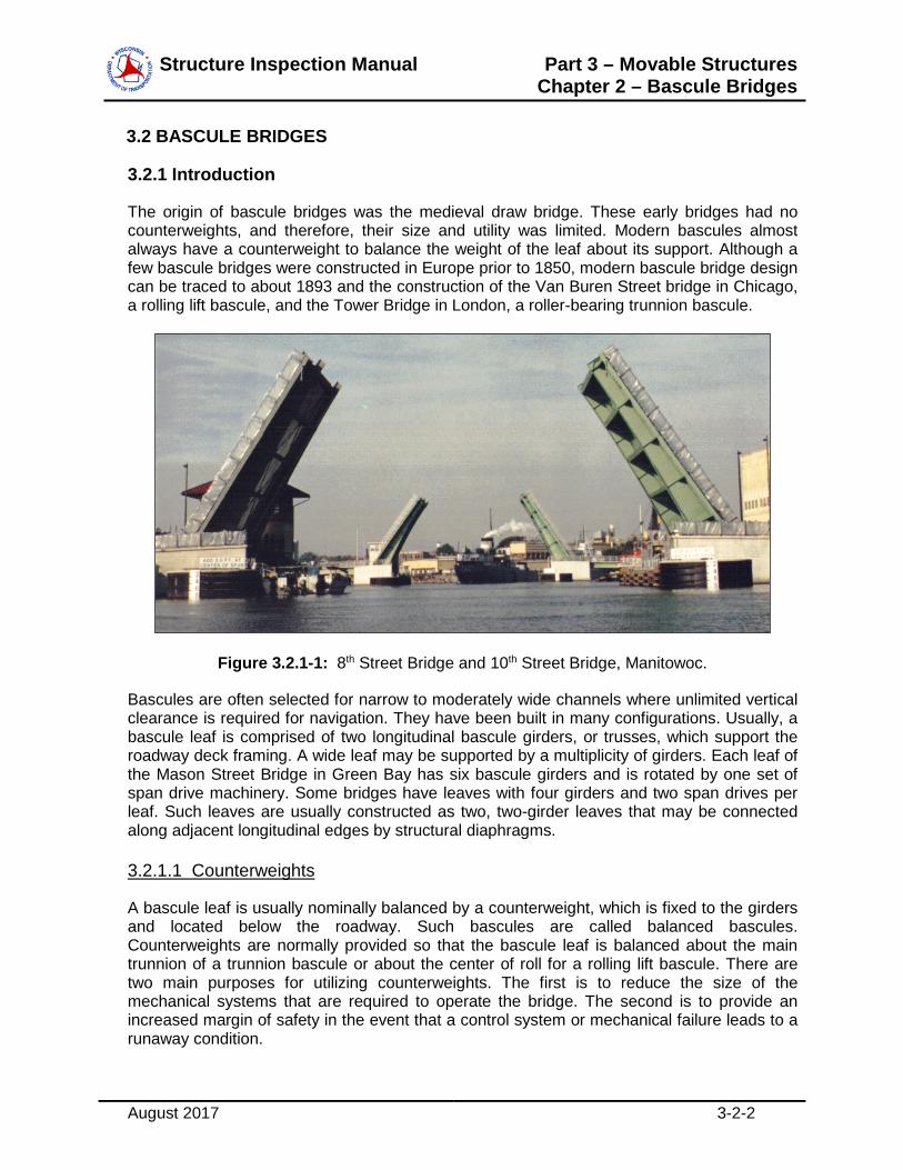
The origin of bascule bridges was the medieval draw bridge. These early bridges had no counterweights, and therefore, their size and utility was limited. Modern bascules almost always have a counterweight to balance the weight of the leaf about its support. Although a few bascule bridges were constructed in Europe prior to 1850, modern bascule bridge design can be traced to about 1893 and the construction of the Van Buren Street bridge in Chicago, a rolling lift bascule, and the Tower Bridge in London, a roller-bearing trunnion bascule.
Figure 3.2.1-1: 8th Street Bridge and 10th Street Bridge, Manitowoc.
Bascules are often selected for narrow to moderately wide channels where unlimited vertical clearance is required for navigation. They have been built in many configurations. Usually, a bascule leaf is comprised of two longitudinal bascule girders, or trusses, which support the roadway deck framing. A wide leaf may be supported by a multiplicity of girders. Each leaf of the Mason Street Bridge in Green Bay has six bascule girders and is rotated by one set of span drive machinery. Some bridges have leaves with four girders and two span drives per leaf. Such leaves are usually constructed as two, two-girder leaves that may be connected along adjacent longitudinal edges by structural diaphragms.
3.2.1.1 Counterweights
A bascule leaf is usually nominally balanced by a counterweight, which is fixed to the girders and located below the roadway. Such bascules are called balanced bascules. Counterweights are normally provided so that the bascule leaf is balanced about the main trunnion of a trunnion bascule or about the center of roll for a rolling lift bascule. There are two main purposes for utilizing counterweights. The first is to reduce the size of the mechanical systems that are required to operate the bridge. The second is to provide an increased margin of safety in the event that a control system or mechanical failure leads to a runaway condition.

Structure Inspection Manual Part 3 – Movable Structures Chapter 2 – Bascule Bridges
August 2017 3-2-3
Some bascules may also be constructed with little or no counterweight; they are termed partially balanced or unbalanced bascules. Unbalanced or partially balanced trunnion bascules are built at sites where the trunnions have to be located at an elevation not far above high water level and it is not feasible to construct a bascule pier with a counterweight chamber which can be kept dry or overhead counterweights are not architecturally acceptable. Because of the large forces required to equilibrate a leaf that is in a partially or fully open position, unbalanced or partially balanced bascules are moved by hydraulic cylinders. The larger machinery required by unbalanced leaves may be justified for short spans if the bridge can be configured so that the operating machinery is located at or above roadway level, thereby simplifying bascule pier construction and maintenance. However, if a large hollow pier is required to house the hydraulic machinery, then the rational for an unbalanced bascule with its higher first cost for machinery, higher operating and maintenance costs is questionable. An example of an unbalanced simple trunnion bascule is the South 8th Street Bridge in Sheboygan.
3.2.1.2 Single-Leaf Bascule
A single-leaf bascule has one leaf that spans the entire navigation channel. Only single sets of span drive and stabilizing machinery are required. However, the machinery may be significantly larger than that found on a double-leaf bascule spanning a channel of like width. Wind load moment on the bascule leaf, when it is in the open position, is approximately four (4) times the moment that would occur on each leaf of a double-leaf bascule.
3.2.1.3 Double-Leaf Bascule
A double-leaf bascule has two leaves that each spans half of the channel. The two leaves usually meet at the center of the navigation channel. The leaves of a double-leaf bascule will be approximately one-half the length of a single-leaf bascule leaf required to span the same channel. A double-leaf bascule requires span drive and stabilizing machinery for both leaves. A shear transfer device between mated girder ends of the two leaves when in the closed position is common to stiffen the deck and allow both leaves to share live load.
3.2.1.4 Deck Bascules
In deck bascules the bascule girders or trusses are located below the roadway surface. Most simple trunnion bascules are of this type. Rolling lift bascules and bascules with articulated counterweights are also common in this form.
3.2.1.5 Through Bascules
This category includes through-truss structures, such as Michigan Street in Sturgeon Bay. In this case the roadway deck is located at, or near, the bottom chord of the main trusses.
Also in this category are half-through girder structures, such as Eighth Street in Manitowoc and Tayco Street in Menasha. In this type of structure the bottom flanges of the floorbeams and the bottom flanges of the bascule girders are in nearly the same plane. The top flanges of the bascule girders are above the roadway deck.

Structure Inspection Manual Part 3 – Movable Structures Chapter 2 – Bascule Bridges
August 2017 3-2-4
3.2.2 Simple Trunnion Bascules
Figure 3.2.2-1 shows a single-leaf simple trunnion bascule (schematically) with the span drive machinery located on the bascule pier. The trunnions are usually inserted through the webs of the bascule girders or vertical/diagonal members of the trusses. The trunnions may rotate with the girders or the bascule girders may rotate about fixed trunnions. The leaves of trunnion bascules only rotate, they do not translate. Counterweights are usually fixed to the bascule girders so that the force required to move the leaf is minimized in all positions of opening. The balance principal requires that the trunnion axes should intersect (or nearly so) a line connecting the centers of gravity of the leaf and the counterweight.
The pinion shown in Figure 3.2.2-1 is the output of rotating span drive machinery and engages the rack to move the span. However, simple trunnion bascules may also be operated by hydraulic cylinders, which act linearly. The cylinders are mounted on the bascule piers and the piston rods are connected to the leaves in a manner such that extending or retracting the rods rotates the leaf. An example of a simple trunnion bascule with a hydraulic cylinder span drive is the South 8th Street Bridge at Sheboygan.
For the bridge of Figure 3.2.2-1, live load on the channel side of the axis of rotation is supported by the bascule girder spanning between the trunnion and the bearing on the rest pier. If the rear break in the deck is located on the shore side (rearward) of the trunnion, then when live load is between the trunnion and the rear break an uplift is created at the rest pier (if the live load moment exceeds the toe-heavy imbalance moment). This uplift is resisted by the span locks at the toe of the leaf, or tail locks, or by the locked span drive machinery.
Simple trunnion bridges are often built in double-leaf form, especially for highways. Midspan shear locks are necessary to keep the toes of the mating leaves in vertical alignment and transfer live loads between the leaves.

Structure Inspection Manual Part 3 – Movable Structures Chapter 2 – Bascule Bridges
August 2017 3-2-5
Figure 3.2.2-1: Single Leaf Simple Trunnion Bascule.

Structure Inspection Manual Part 3 – Movable Structures Chapter 2 – Bascule Bridges
August 2017 3-2-6
3.2.3 Rolling Lift Bascules – Scherzer Type
William Scherzer received a U.S. Patent for a rolling lift bascule in 1893, which became known as a rolling lift bridge, and that term is still used. The leaf motion is due to rotation about a horizontal axis, which simultaneously translates in the horizontal direction. Three common types of rolling lift bascules are depicted in Figure 3.2.3-1: View (a) the deck; View (b), the half-through plate girder (pony); and View (c), the through truss. Each of these types has variations.
Rolling lift bascule bridges of the Scherzer type are characterized by cylindrically curved parts of the bascule girders or trusses at the ends over the bascule piers. Because of their large size, these parts of the girders or trusses of the early Scherzer bridges were assembled from segments and the girders were called “segmental girders”, a term still in use. During bridge operation, the motion is rotation about an axis that translates. Each segmental girder may be viewed as a segment of a wheel. However, instead of rotating on an axle, these wheels are rigidly attached to the bascule leaf. As the wheels roll along the tracks, the bascule leaf rotates open or closed.
Figure 3.2.3-2 schematically depicts a single-leaf deck type Scherzer bascule. As the curved ends of the girders roll away from the channel the leaf tilts open to clear the channel. Slippage between the segmental girder treads and the tracks on which they ride is prevented by lugs or teeth that mechanically engage sockets. Typically, the protruding lugs are located on the track and the receiving holes or notches are in the segmental girder treads. Treads and tracks are described in more detail in Section 3.5.3.3 of this Part. The rack is shown located above the pinion, as is common on many newer Scherzers. However, on some older bridges the rack is located below the pinion.
Most double-leaf rolling lift bascule bridges in Wisconsin have center locks that are not mechanically operated. As with all double-leaf bascules, center locks are required to transfer vertical shear between the two leaves and to assure proper lateral and vertical alignment. Center locks are discussed in Section 3.5.3.3 of this Part.

Structure Inspection Manual Part 3 – Movable Structures Chapter 2 – Bascule Bridges
August 2017 3-2-7
Figure 3.2.3-1: Types of Scherzer Rolling Lift Bascules.

Structure Inspection Manual Part 3 – Movable Structures Chapter 2 – Bascule Bridges
August 2017 3-2-8
The tracks on which the bascule leaf rolls may be mounted directly on the substructures or they may be mounted on flanking spans. As shown in Figure 3.2.3-3, the Racine Street Bridge over the Fox River Canal in Menasha is unique in Wisconsin in that the leaf at left rolls back over the bascule abutment while the leaf at right rolls onto the flanking span.
Figure 3.2.3-3: Double-Leaf Rolling Lift Bascule, Racine Street Bridge in Menasha. Note: Left leaf rolls on a bascule abutment, right leaf rolls on a flanking span.
3.2.4 Articulated Counterweight Bascules – Strauss Type
Medium and long span simple trunnion deck bascules with the roadway profile close to the high-water level generally require bascule piers with counterweight pits. The walls of the bascule piers keep the water from entering the pits and so provide dry spaces for the counterweights as the bascule leaves rotate open. This is also the case for rolling lift deck bascules, but to a lesser extent. Counterweight pits can be avoided if the counterweights are located remote from the bascule girder, usually overhead.
Trunnion bascules may be balanced by counterweights that are not fixed to the bascule truss or girders. This concept is old, but U.S. Patents for bascules with remote counterweights were granted to Joseph B. Strauss around the year 1900 and bridges with his specific counterweight arrangements are often called Strauss bascules. Three common versions are shown in Figure 3.2.4-1. The distinguishing feature of all Strauss bascules is the parallelogram connecting the counterweight to the movable leaf. In all Strauss bascules the motion of the leaf is by rotation about a fixed horizontal axis.
In some situations, it is not the depth of the required pit but the front-to-back dimension of the pit that needs to be minimized, as in Figure 3.2.4-1 (a). In such cases articulating the
Flanking span

Structure Inspection Manual Part 3 – Movable Structures Chapter 2 – Bascule Bridges
August 2017 3-2-9
counterweight by suspending it from the leaf may be advantageous. In this section, three of the articulated counterweight trunnion bascules promoted by Strauss will be described.
Figure 3.2.4-1: Types of Strauss Bascule Bridges.

Structure Inspection Manual Part 3 – Movable Structures Chapter 2 – Bascule Bridges
August 2017 3-2-10
3.2.4.1 Underneath Counterweight
Figure 3.2.4-1 (a) depicts a single leaf Strauss trunnion bascule with an under-deck counterweight. The counterweight hangs from two trunnions and the direction of the vertical axis C-E of the counterweight is maintained by the link between the counterweight and the trunnion tower. The need for this link has often been questioned. One argument is that at a small angle of opening the friction in the counterweight trunnion bearings may not permit the hanger to rotate such that the axis C-E remains vertical. As the angle of opening increases the moment applied to the bearing would increase and when it exceeded the bearing friction moment the counterweight would swing free. This motion would cause a dynamic load on the leaf which may interfere with control of the moving leaf.
Excessive friction in the counterweight trunnion bearings is often due to improper lubrication. The bearing friction induces a bending moment in the counterweight hanger, which produces repetitive bending stresses for which the hangers were usually not designed. Hangers on some bridges have failed in fatigue, resulting in collapse of the leaves.
3.2.4.2 Vertical Overhead Counterweight
Instead of hanging the counterweight from the bascule girder below the deck, the counterweight may be positioned overhead as shown in Figure 3.2.4-1 (b). This is advantageous at sites where the road profile is located close to the high water level in the channel and the bascule pier cost must be minimized.
Again the balance principle requires that the line joining the center of gravity of the leaf at A with the hinge C should intersect the trunnion axis at B. Line C-E will remain parallel to B-D if the line D-E is parallel to B-C. Lines B-D and C-E need not be vertical; they just need to be parallel.
Vertical overhead counterweight type Strauss bascules were built across small rivers in remote areas where appearance was not a primary consideration. Operation is usually by rack and pinion with drive machinery mounted on the pier or, at sites subject to flooding, at the deck level bracketed from the approach structure.
3.2.4.3 Heel Trunnion
A single-leaf Strauss heel trunnion with overhead rotating counterweight frame (rocker) is shown in Figure 3.2.4-1 (c). The geometrical figure B1DEB2 is a parallelogram and the center of gravity of the counterweight at C is located so that the line B2C is parallel to the line between the center of gravity of the leaf at A and the heel trunnion B1. As a result, the ratio between the leaf dead load moment about B1 and the counterweight moment about B2 remains essentially constant during rotation of the leaf.
The Strauss leaf rotates about the heel trunnion B1 in response to a force transmitted to the leaf by the operating strut (a rack is fastened to the strut) which is hinged at the top chord joint D and engages the output pinion of the span drive machinery mounted on the counterweight support frame. The trunnions B1 B2 and D E are heavily loaded during motion. The reaction at the heel trunnion B1 may reverse direction, depending on the proportions of the structure, and this effect should be considered in evaluation of the heel trunnion bearings.

Structure Inspection Manual Part 3 – Movable Structures Chapter 2 – Bascule Bridges
August 2017 3-2-11
3.2.5 Articulated Counterweight Bascules – ABT Type
Another type of heel trunnion bridge with an articulated counterweight is the ABT bascule patented by Hugo Abt in the early 1920s. Figure 3.2.5-1 shows an ABT bascule in the closed and the open position.
An ABT bascule is distinguished by a pair of A-frames located at the heel of the leaf. At the apex of these A-frames is an axis about which the counterweight rotates. On each A-frame, between the two legs, is an inclined track. Riding on these two tracks is a carriage that supports the operating machinery. Two links connect the counterweight to the machinery carriage, and two links connect the bascule leaf to the machinery carriage. As the machinery carriage travels along the tracks, it allows the counterweight to swing downward, thereby pulling the bascule leaf upward.
There is only one ABT bascule in Wisconsin. It is a railway bridge over the Manitowoc River in Manitowoc. As of this writing (2013), it is not in active service.
Figure 3.2.5-1: Through-Truss ABT Bascule.
3.2.6 Bascules Without Counterweights
Simple trunnion bascules have been built without counterweights, with only partial counterweights, and with counterweights that are partially or wholly submerged when the leaf is open. For all three cases, the machinery must be able to develop a greater torque to rotate the leaf than if the leaf were balanced by “dry” counterweight. The rationale to use a bascule without a counterweight is that it is more cost-effective to install and operate larger machinery than to build a deep watertight pit to accommodate a counterweight when the leaf is in the fully-open position, or when the aesthetics of an overhead counterweight are deemed to be inappropriate for a particular site.

Structure Inspection Manual Part 3 – Movable Structures Chapter 2 – Bascule Bridges
August 2017 3-2-12
Because of the larger operating torque required to rotate the leaf, hydraulic cylinders are often used to power the span. One machinery arrangement for a single leaf simple trunnion bascule without a counterweight is shown in Figure 3.2.6-1. It is a simplified diagram of the South 8th Street Bridge in Sheboygan.
Referring to Figure 3.2.6-1, the bascule leaf is comprised of two girders with deck framing. There is no counterweight. Without the stiffness that is normally provided by the massive counterweight another method is required to keep the two bascule girders in the same plane. The required stiffness is provided by a torque tube that extends from the exterior of one girder to the exterior of the other girder. Two crank plates are welded to the torque tube at each bascule girder - one on each side of the web. A trunnion shaft passes through the bottom of each pair of crank plates and rests in trunnion bearings. The bascule girder rotates about these bearings.
Force to raise the leaf during opening and to retard the leaf during closing is provided by two hydraulic cylinders per bascule girder. The cylinders are mounted and rotate about pivots. One of the problems that arises with cylinders that are mounted rearward of the main trunnions, and at a small angle with the horizontal, is the physical interference between the cylinders and the end of the deck in the open position.
The size of the machinery required for this bridge is much greater than would be required for a balanced bascule span of like dimensions.

Structure Inspection Manual Part 3 – Movable Structures Chapter 2 – Bascule Bridges
August 2017 3-2-13
Figure 3.2.6-1: Bascule Without Counterweight – Hydraulic Cylinder Drive.
Structure Inspection Manual
[THIS PAGE INTENTIONALLY LEFT BLANK]