SEISMIC RETROFITTING TECHNOLOGIES FOR BRIDGES ...
12
SEISMIC RETROFITTING TECHNOLOGIES FOR BRIDGES TO REDUCE THE ENVIRONMENTAL IMPACT OF EARTHQUAKE ON EXISTING STRUCTURES 1 Benito PACHECO, 2 Kazuhiko KAWASHIMA, 3 Romeo ESTAÑERO 1 Professor and Director, Institute of Civil Engineering, UP Diliman 2 Professor, Department of Civil Engineering, Tokyo Institute of Technology 3 Professor (Ret), Department of Civil Engineering, De La Salle University Abstract: In the context of the Philippines and Japan, various technologies of seismic retrofitting of bridges are classified in this paper. The most commonly required retrofits are those of foundations, columns and piers, superstructure joints, and bearings. The prevalence of soft ground conditions in these Asian settings is emphasized; in this regard, retrofit of columns and piers is shown to be a practical compromise. The use of lead rubber bearings and sliding bearings is encouraged as a form of seismic isolation of the superstructure, to reduce the seismic force demands on the substructure in the first place. Key Words: seismic retrofit, foundation, liquefaction, jacketing, seismic isolation 1. GOALS, MEASURES, AND LIMITATIONS OF RETROFIT Seismic requirements for bridge design have been upgraded periodically to render the newer bridges less vulnerable to earthquake excitation; accordingly, retrofits have become necessary for many existing bridges that do not meet the new level of seismic design requirements. Yet, bridges can be retrofitted only when doing so is technically, economically and socially feasible; those that fail to satisfy these requirements are deemed to be better replaced with new bridges (Priestley, Seible and Calvi 1996). Observations of the nature of earthquake damages in the past are vital in the design of seismic retrofitting works. Following are some examples of damage in past earthquakes in the Philippines, Japan, and Taiwan. Many of the failures of bridge structures in the Philippines as a result of the 1990 Luzon earthquake were mainly due to lateral spreading of the ground due to soil liquefaction. Bridge foundations were affected and bridge decks were unseated from their bearings. Damage due to soil liquefaction is exhibited by the failure of the Magsaysay Bridge in Pangasinan, shown in Figure 1, and the Carmen Bridge, shown in Figure 2 (Pacheco 2000). In Japan while retrofitting works were initiated as early as 1971 (Kawashima 1990; and Kawashima, Unjoh and Mukai 1994), more recent ones were essentially a consequence of the 1995 Hyogo-ken Nanbu earthquake. The failures observed comprise mostly of the following (for detailed documentation, see Kawashima and Unjoh 1997): (1) shear failure at column mid-heights due to premature termination of longitudinal bars in concrete columns with insufficient development lengths at cut-off point (Figure 3); (2) flexural failure at base of reinforced concrete columns; (3) local buckling of web and flange plates
-
Upload
khangminh22 -
Category
Documents
-
view
3 -
download
0
Transcript of SEISMIC RETROFITTING TECHNOLOGIES FOR BRIDGES ...

SEISMIC RETROFITTING TECHNOLOGIES FOR BRIDGES TO REDUCE THE ENVIRONMENTAL IMPACT OF EARTHQUAKE
ON EXISTING STRUCTURES
1Benito PACHECO, 2Kazuhiko KAWASHIMA, 3Romeo ESTAÑERO
1Professor and Director, Institute of Civil Engineering, UP Diliman
2Professor, Department of Civil Engineering, Tokyo Institute of Technology
3Professor (Ret), Department of Civil Engineering, De La Salle University
Abstract: In the context of the Philippines and Japan, various technologies of seismic
retrofitting of bridges are classified in this paper. The most commonly required retrofits are
those of foundations, columns and piers, superstructure joints, and bearings. The
prevalence of soft ground conditions in these Asian settings is emphasized; in this regard,
retrofit of columns and piers is shown to be a practical compromise. The use of lead rubber
bearings and sliding bearings is encouraged as a form of seismic isolation of the
superstructure, to reduce the seismic force demands on the substructure in the first place.
Key Words: seismic retrofit, foundation, liquefaction, jacketing, seismic isolation
1. GOALS, MEASURES, AND LIMITATIONS OF RETROFIT
Seismic requirements for bridge design have been upgraded periodically to render the
newer bridges less vulnerable to earthquake excitation; accordingly, retrofits have become
necessary for many existing bridges that do not meet the new level of seismic design
requirements. Yet, bridges can be retrofitted only when doing so is technically,
economically and socially feasible; those that fail to satisfy these requirements are deemed
to be better replaced with new bridges (Priestley, Seible and Calvi 1996).
Observations of the nature of earthquake damages in the past are vital in the design of
seismic retrofitting works. Following are some examples of damage in past earthquakes in
the Philippines, Japan, and Taiwan. Many of the failures of bridge structures in the
Philippines as a result of the 1990 Luzon earthquake were mainly due to lateral spreading
of the ground due to soil liquefaction. Bridge foundations were affected and bridge decks
were unseated from their bearings. Damage due to soil liquefaction is exhibited by the
failure of the Magsaysay Bridge in Pangasinan, shown in Figure 1, and the Carmen Bridge,
shown in Figure 2 (Pacheco 2000).
In Japan while retrofitting works were initiated as early as 1971 (Kawashima 1990; and
Kawashima, Unjoh and Mukai 1994), more recent ones were essentially a consequence of
the 1995 Hyogo-ken Nanbu earthquake. The failures observed comprise mostly of the
following (for detailed documentation, see Kawashima and Unjoh 1997): (1) shear failure
at column mid-heights due to premature termination of longitudinal bars in concrete
columns with insufficient development lengths at cut-off point (Figure 3); (2) flexural
failure at base of reinforced concrete columns; (3) local buckling of web and flange plates

of steel columns accompanied by rupture of welds at their junctions in some cases; (4) soil
liquefaction resulting in settlement and tilting of foundations; (5) lateral spreading of
ground that caused movements of foundations; and (6) damage to bearings and unseating
prevention devices.
Figure 3 shows an example of reinforced concrete column failures in shear or in flexure.
Such observations resulted in the retrofit of more than 40,000 bridge columns and piers
that were evaluated to have the same deficiencies (Kawashima 2007). The 1995
earthquake caused much damage on the bearings, too, especially brittle failure in the steel
bearings.
Failures of many bridges in Taiwan resulting from the 1999 Chi Chi earthquake were a
direct result of a thrust-type faulting that caused large ground displacements. Unseating of
bridge decks was of destructive consequence so that some spans of multi-span bridges
collapsed; and piers were severely damaged (Figure 4; see also Kawashima and Shoji
2000; Hsu and Fu 2004; Chang et al, 2004).
Figure 1. Tilting of pier of Magsaysay
Bridge caused by soil liquefaction and
lateral spreading due to the 1990 Luzon
earthquake
Figure 2. Collapse of superstructure of
Carmen Bridge caused by soil liquefaction
and lateral spreading due to the 1990 Luzon
earthquake
Figure 3. Collapse of 18-span viaduct
section of Route 3, Kobe Line of Hanshin
Metropolitan Expressway due to the 1995
Figure 4. Failure of Wu-Shi bridge caused
by large fault displacement due to the 1999
Chi-Chi earthquake

Hyogo-ken Nanbu earthquake

Table 1. A Study of Bridge Deficiencies in the Philippines *
Item Type of Deficiency Frequency, %
1. Foundation Pile flexural strength
Pile shear strength
Soil liquefaction
Pile axial load strength
Footing flexural strength
Footing shear strength
Soil bearing pressure
40
24
20
19
8
4
4
2. Columns and piers Flexural strength
Shear strength
Confinement
Anchorage
80
14
11
5
3. Column cap beam Flexural strength
Shear strength
5
4
4. Pier bearings and abutment Bearing forces
Pier expansion joint displacement
Abutment expansion joint displacement
Abutment displacement
67
54
39
33
* Source: Angel Lazaro & Associates
As the justification for bridge retrofit is very much dependent upon the capacity-demand
(C/D) ratios of the various bridge elements, the extent of retrofitting works for a particular
bridge initially necessitates an accurate determination of the seismic demands. This is
complemented by an equally accurate assessment of the capacities of the various bridge
structural components to meet these demands. In the Philippines, as a consequence of the
1990 Luzon earthquake and as an aftermath of the 1995 Hyogo-ken Nanbu earthquake, a
major bridge retrofit program was initiated, too. For more than 350 bridges evaluated as
requiring retrofitting works, the more predominant bridge deficiencies for which the
capacity-demand (C/D) ratios were evaluated to be less than unity are given in Table 1
(courtesy of Angel Lazaro & Associates).
Thus, the retrofitting measures may cover: (1) foundations against soil liquefaction
(Figure5); (2) footings for shear and flexure; (3) abutments and approaches (Figure 6); (4)
columns and piers (Figures 7 and Figure 8); (5) cap beams of columns and piers; (6) cap
beam/column joint regions; (7) superstructure (Figure 9); and/or (8) isolators and dampers
(Figure 10). The seismic retrofit design is usually iterative, as any attempt to retrofit
certain components of a bridge may affect the seismic demands (hence put the capacity-
demand ratios in question) for other components. Research is ongoing to confirm the
performance of retrofitted bridges or bridge components, even as newer measures of
seismic retrofitting are being explored, developed, tested, and evaluated (Yashinsky 1998;
Kawashima 2007).
This paper briefly discusses various retrofitting measures. For their advantages and
disadvantages, applicability or suitability under certain site working conditions, retrofit
construction methods and procedures related thereto, and further information, the interested
reader may see the references cited at the end of this paper, and an extended version of this
paper in the accompanying CD of Kusakabe et al (2009).

2. RETROFIT OF FOUNDATIONS
Since the retrofit of a foundation is much more costly, and has more potentially negative
impact on the environment, than the retrofit of columns and piers, therefore a strategy of
seismic retrofit that does not require the retrofit of foundation should be sought first, before
considering the techniques that are cited in this section.
2.1 Considering Active Fault Crossings or Soft Alluvial Deposits
The most difficult (but the least common) situation for seismic retrofit design is the retrofit
for active fault crossing (Billings 2007). The expected fault displacements being large,
retrofitting in consideration of fault crossing involves any combination of the following
measures: continuity between adjacent spans; restrainer systems across the superstructure
joints; seismic isolation bearings; seat extensions; and strengthening of the foundations.

Figure 5. Seismic retrofit of a pile foundation by new piles and an extension of footing

The geotechnical and foundation-related deficiencies due to a design earthquake may in
fact be very varied in Asian countries like the Philippines and Japan, where alluvial
deposits or man-made sandy fills are frequently encountered at bridge sites, whether near to
or far from a fault zone (Towhata 2008, p34). Near the earthquake source, large ground
deformations may create the critical demand on foundations through instability of the
surrounding soils. In alluvial deposits or man-made sandy fills of low density, liquefaction
may cause the subsidence or the tilting of heavy foundations.
2.2 Considering Instability of Surrounding Soils
In unstable soil conditions, whole foundations have to be retrofitted in most cases. The
first option is to construct new piles by extending the existing footing. Figure 5 (as cited in
Kawashima 2007) shows an example. The other option is to improve the soils around the
foundation so that the level of seismic risk due to soil liquefaction can be mitigated.
However, this second option is often more costly and the net risk reduction is often more
difficult to ascertain.
As for abutments, liquefaction of sandy soil or sliding of soft clayey soils is a typical cause
of instability of the underlying ground. Bearings mostly suffer extensive damage. If the tilt
of the abutment is large, unseating of the deck from the abutment occurs. Retrofit may be
conducted by enlarging the footing and constructing new piles. Enhancement of soil
strength by soil replacement or cement mixing is also widely accepted for mitigating a tilt
that is resulting from instability of the underlying ground. Earth anchors are also used to
mitigate a tilt to the front direction.
Reconstruction of the approach slab whereby it is doweled into the abutment end (Figure 6)
may be expected to minimize the relative displacement that is due to lateral spreading of
the surrounding soil.
2.2 Considering Shear and Flexure Demand on Footings or Axial Demand on Piles
A need to retrofit footings may arise, too, from an increased seismic demand as a result of
the seismic retrofit of the columns and piers. For inadequacies in shear and flexure,
footing retrofit by concrete overlay may be used.
An alternative method of shear and flexural retrofit is to introduce prestressing forces into
the footing in the vertical and horizontal directions. Vertical prestressing enhances the
shear capacity while the lateral prestressing enhances both the shear and flexural capacities
of the footings. Prestressing strands are used for lateral prestress while aramid fiber
reinforced plastic rods are preferred for vertical prestressing. (Kato et al, 2001.)
Figure 6. Dowelling the approach slab into the abutment mitigates relative displacement
due to lateral spreading (courtesy of Angel Lazaro & Associates)

For more demanding situations, construction of a new footing surrounding the existing, as
shown in Figure 5 can accommodate this requirement.
For piles that are deficient in axial capacity, additional piles are generally driven around the
existing. Because space limitation under the deck makes driving of additional piles
difficult, a combination of new pile construction and soil improvement is sometimes
adopted. Where driving piles becomes difficult due to space limitations, additional pile
requirements can be attained with micropiles.
3. RETROFIT OF COLUMNS AND PIERS Reinforced concrete columns that were designed without taking into account the
importance of plastic deformation and ductility are commonly deficient in flexural
ductility, flexural strength, and/or shear strength under strong seismic excitation. In the
Philippines, for instance, it is noted in Table 1 that a large majority of the bridges that had
to be retrofitted were deficient in the columns or piers. Column or pier retrofit techniques
are usually accomplished by jacketing with steel (Figure 7 and Figure 8), reinforced
concrete, precast concrete segments, or composite materials such as fiberglass, carbon
fiber, and aramid fiber reinforced plastics.
Figure 7. Steel jacket retrofit at (a) Metropolitan Expressway and at (b) Hanshin
Expressway in 1989 which was effective during 1995 Hyogo-ken Nanbu earthquake
Figure 8. Steel jacketed piers of (a) Nagtahan Overpass (Manila) and (b) Ortigas Flyover
(San Juan-Pasig, Metro Manila)

Providing a jacket around an existing column that has insufficient ductility and strength
capacity is effective to prevent premature failure. The jacket resists not only tension and
compression but also shear of the column, as well as provides lateral confinement to the
core concrete. In the implementation of jacket retrofit, however, it must be noted that as
the jacket enhances the shear and flexural strength and the ductility of the columns, the
enhancement consequently also increases the moment and shear demand on the foundation.
Consequently, there are essentially two options. The first is to minimize the amount of
increase of moment and shear demand on the foundation. For this purpose, it is
recommended to provide a space between the jacket and the footing or the cap beam to
avoid excessive flexural and shear enhancement of the plastic hinge. The other option is to
allow a certain amount of increase of moment and shear demand on the foundation. If the
foundation has some excess of the moment and shear capacity, it is effective in restricting
the large plastic displacement of the column; otherwise some foundation retrofit may
become required at the same time. In either option, it is appropriate to avoid excessive
residual displacement of the column.
Figure 9. Typical unseating prevention devices for the superstructure [(1), (2), and (3) from
Kawashima et al 1994; (4) from Priestley et al 1996]
(a) RC Bracket (b) Steel Bracket
(1) Extension of Seat
(a) Cable Restrainer (b) Steel Chains (c) PC Strands
(2) Connection of Deck to Substructures
(a) Steel Decks (b) PC Decks
(3) Connection between Decks
(4) Device for Support Following Unseating at Internal Movement Joints
(a) RC Bracket (b) Steel Bracket
(1) Extension of Seat
(a) Cable Restrainer (b) Steel Chains (c) PC Strands
(2) Connection of Deck to Substructures
(a) Steel Decks (b) PC Decks
(3) Connection between Decks
(4) Device for Support Following Unseating at Internal Movement Joints
Reinforced concrete jacketing is generally cheaper than other retrofit measures, and it is
favorable in the retrofit of columns in water. However there is considerable increase in the
space occupied by the retrofitted columns. Precast concrete segment jacketing has an
advantage over reinforced concrete jacketing in reducing the construction period as well as
avoiding the drying-up of foundations; it is more expedient for columns that have the same
uniform size.
When retrofit can be conducted easily and quickly without interruption of traffic by using
composite materials, the use of materials such as carbon fiber-reinforced plastics, aramid
fiber-reinforced plastics and/or fiberglass can be justified from the total cost and
performance points of view. (Ogata et al 1999; Osada et al 1999)
Jacketing is more effective for circular than for rectangular columns. If using steel jacket
on rectangular column or pier, an elliptical section is recommended. Figure 8 shows
examples in the Philippines. A rectangular steel jacket is effective for enhancing the shear
and moment capacity of a rectangular column, but it cannot provide sufficient lateral
confinement in the critical region as the size of the column increases.
For column bents or framed piers, infill shear walls are found to be effective as well as
independent jackets of the columns, provided the seismic performance of the foundation is
carefully re-evaluated, too.
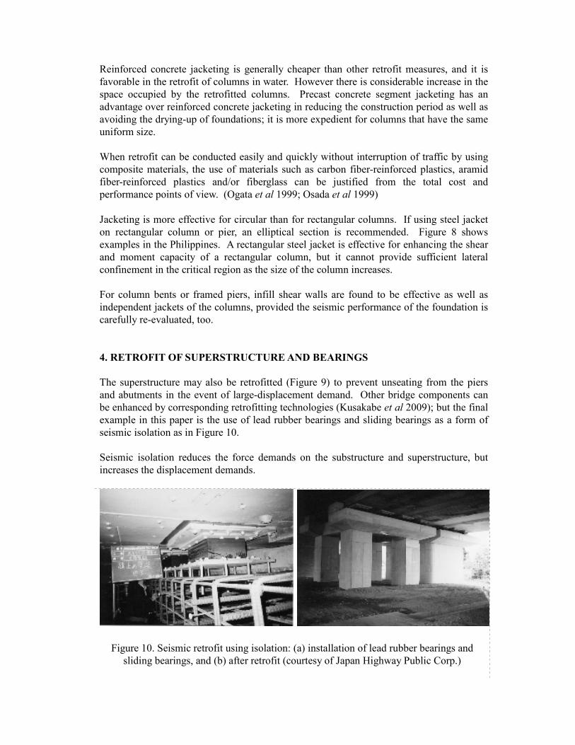
4. RETROFIT OF SUPERSTRUCTURE AND BEARINGS
The superstructure may also be retrofitted (Figure 9) to prevent unseating from the piers
and abutments in the event of large-displacement demand. Other bridge components can
be enhanced by corresponding retrofitting technologies (Kusakabe et al 2009); but the final
example in this paper is the use of lead rubber bearings and sliding bearings as a form of
seismic isolation as in Figure 10.
Seismic isolation reduces the force demands on the substructure and superstructure, but
increases the displacement demands.
Figure 10. Seismic retrofit using isolation: (a) installation of lead rubber bearings and
sliding bearings, and (b) after retrofit (courtesy of Japan Highway Public Corp.)

Seismic isolation may be justified as follows. Retrofits can be minimized if seismic forces
can also be minimized. If the seismic response of a bridge can be reduced, such as by
using isolators and/or dampers, to a level that does not require any direct retrofit of
structural components, there must be tremendous benefit in the cost and period of seismic
retrofit.
One the most important gains from the past earthquake damages is the increasing use of
seismic isolation devices for bridges. Japanese engineers are relying more on the use of
seismic isolation bearings for mitigating seismic vulnerability of bridges in their current
design. Vulnerable steel bearings are replaced with seismic isolation bearings that have
proven to be effective in reducing seismic forces in buildings.
Seismic isolation bearings are placed between the superstructure and the top of piers and/or
abutments. Under normal conditions, they behave like regular bearings but in the event of
a strong earthquake, they add flexibility to the structure by elongating its period and they
dissipate energy, allowing the superstructure to oscillate at a lower frequency than its piers.
Indeed, seismic isolation is effective not only for new bridges but also for existing ones.
Figure 10 shows an implementation of seismic isolation for retrofit. Because the existing
steel bearings were vulnerable to damage they were replaced with lead rubber bearings.
The existing steel bearings were made to carry the dead weight of the superstructure by
removing the stoppers so that they functioned as sliding bearings. The lead rubber bearings
were installed to provide the lateral restoring force and energy dissipation capability. Many
bridges in Japan supported on frame piers were retrofitted using this method.
ACKNOWLEDGEMENTS
This paper is based on the section contributed jointly by K. Kawashima, R. Estanero and B.
Pacheco to the book by Kusakabe et al (eds) 2009. The book writing was supported by the
Japan Society for the Promotion of Science and the Department of Science and Technology
of the Philippines through the JSPS Core University Program. Some of the data and
figures are courtesy of Angel Lazaro & Associates and Japan Highway Public Corporation.
REFERENCES
Billings, I. (2007) Design for active fault crossing. Seismic Bridge Design and Retrofit – Structural Solutions. International Federation for Structural Concrete, Lausanne,
Switzerland, fib Bulletin 39, 159-174.
Chang, K.C., Kuo, K. Y., Liu, K. Y., and Lu, C. H. (2004) On seismic retrofit strategies of
highway bridges – experiences learned from the Chi Chi earthquake. Proc. 11th World Conference on Earthquake Engineering, Paper No. 639, Vancouver, B.C., Canada.
Hsu, Y. T. and Fu, C. C. (2004) Seismic effect on highway bridges in Chi Chi earthquake.
Journal of Performance of Constructed Facilities. Volume 18, Number 1, 47-53.
Kato, S., Sato, H., Nakai, H. and Fujita, M. (2001) Seismic retrofit of Oga Bridge using
aramid fiber reinforced plastics. Civil Engineering Construction, 17-22.

Kawashima, K. (1990) Seismic design, seismic strengthening and repair of highway
bridges in Japan. Proc. 1st US-Japan Workshop on Seismic Retrofit of Bridges. Tsukuba Science City, Japan, 3-61.
Kawashima, K., Unjoh, S. and Mukai, H. (1994) Seismic strengthening of highway
bridges. Proc. 2nd US-Japan Workshop on Seismic Retrofit of Bridges. Earthquake Engineering Research Center, University of California, Berkeley, USA, Report No.
UCB/EERC 97/09, 1-36.
Kawashima, K. and Unjoh, S. (1997) The damage of highway bridges in the 1995 Hyogo-
ken Nanbu earthquake and its impact on Japanese seismic design. Journal of Earthquake Engineering, Volume 1, Number 3, 505-541.
Kawashima, K. and Shoji, G. (2000) Damage of transportation facility in the 1999 Kocaeli
and Duzce, Turkey earthquakes and the 1999 Chi-Chi, Taiwan earthquake. Proc. 34th Joint Meeting of US-Japan Panel on Wind and Seismic Effects, National Institute of Standards and Technology, Gaithersburg, MD, USA, UJNR, NIST Special Publication
904, 159-174.
Kawashima, K. (2007) Seismic retrofit. Seismic Bridge Design and Retrofit – Structural Solutions. International Federation for Structural Concrete, Lausanne, Switzerland, fib Bulletin 39, 247-296.
Kusakabe, O. et al (eds) (2009) Sustainable Civil Engineering, The University of the Philippines Press, Quezon City, Philippines. With accompanying CD.
Ogata, T. and Osada, K. (1999) Seismic retrofitting of expressway bridges. Cement and Concrete Composites, UK, Vol. 19, 185-192.
Osada, K., Yamaguchi, T. and Ikeda, S. (1999) Seismic performance and strengthening of
hollow circular RC piers having reinforced cut-off planes and variable wall thickness.
Concrete Res. and Tech., Vol. 10, No. 1, 13-24.
Pacheco, B. M. (2000). The damaging ‘S’ ways of an earthquake. Philippine Civil Engineering, Philippine Institute of Civil Engineers, Special Issue No. 1.
Priestley, N.M.J., Seible, F., and Calvi, M. (1996) Seismic Design and Retrofit of Bridges. John Wiley & Sons, New York.
Towhata, I. (2008) Geotechnical Earthquake Engineering. Springer, Heidelberg.
Yashinky, M. (1998) Performance of bridge seismic retrofits during Northridge earthquake.
Journal of Bridge Engineering. Volume 3, Number 1, 1-14.