standards for old bridges
74
I ,, . ii\ 49J Til\RltJJ49RTil\B49Jt BUREAU OF DESIGN BRIDGE DIVISION STANDARDS FOR OLD BRIDGES FROM 1965 TO 1972 VOLUME 5 NOVEMBER 1989 u
-
Upload
khangminh22 -
Category
Documents
-
view
1 -
download
0
Transcript of standards for old bridges

I ,, . ii\
~IJRRTffilffJ\J 49J Til\RltJJ49RTil\B49Jt BUREAU OF DESIGN
BRIDGE DIVISION
STANDARDS FOR OLD BRIDGES FROM 1965 TO 1972
VOLUME 5 NOVEMBER 1989
u


-.,/'
SECTION E- E
End Cop(Tjlp)
Limit of Rol/ing Meosur~men/
Normal Post Spocin9s ......, Normal Pos1 Spoc1n9 ___ _
~ Splice jSom~ 05 o~mng m po1opel lor spllces
..rt L1g1>1ing Pole
Normal Pas! Spac1n9 T
r - (Mox 8'-0") --.,.-- 1
across expo1ts1on ; oints 111 Supe1s1ruclu1e
1 01009 t. b;~::•::;en~--r13 _ _ 8_~~·,
9
• J ,'2 for spl1:~s at other loco l1ons
0 1
.
i,"- Bi •"' po•" J - >-
_::.--,on9 _____,n----'?4f ~ :-1 ~ ------i-_gj ; : : \J L
{ Post
,:r J '> 4 '2"0 o , 5e" woll ' 1-8 long rot~ r' ole t \ \_ Top splice l11be • H
10 I nd '-Bollom splice l11be --------------------;
J=L--------~d~~~~~=====~======::::::~Mu·~-· ~r- f Holes 1n I/le rolls may be field d11ll11d.
lns111t Assemb/y++
1_s1111 N~e~-----~,_..___ --....:;::-"-.::.-=-
L.~-=----=~·-=--~= 1. ' ' I 4 ff. Special In/st I I ( Roodw •y Item) ,
~ ---t_l!j-"!' Gvord Ro1'l and Term/no/ Section Bridge
Connection ore Roadway //ems.
f Ins er I Assembly for Term/no/ Section Bridge Connec.'.un shall be Type Ii (Cop Screwz 7a .,, o.r6", b• 7") as shown on Slondord Drawing BC-JJ4, and is .ncidentol to B11dge Rol'l1'ng
NOT£. Inlet placement nt It.• end of structure and the mod. f1colions 1equ.'r11d lo 11111 safety parapet ore shown Illus----
IN borseeq. spa.
Transilion Curb Block f
I
SECTION G-G
t TronsHir.1 Curb Block d•totl to be shoWfl on I/le design drawings whlln l'nlt1t Is required of iht1 end of the st1uc/111e
Anchor Bolts i"tl•t' 6• long. Four 1t1qukt1d per posl. For tkJ/olls see Standard Orowlnp BC-33
SECTION D-0
!'- J. 9•
SECTION F-F
DEVELOPED ELEVATION
PLAN
. ..... :. ..
<::> -· -
!!! .e .. . .ti~ ~ I , .. !?' I<) ...,
__§ .... ....
, .. ""
SECTION C- C SECTION B- B
NOTES Materials, workn:on,/lip and mtJ/hod of povmenl shall be ·n oo .,..·-1-1ce w1//I Speclfico/1ons Frirms 40e and 409
Ot1sign Spt1c1f1ct1tians : 011s1gn OiVtsion of 1969-A ASHO • Standard Specif i cations for Highway B11dges.
Shims and end cops shall be of opp1ovt1d olun:mum alloy. Shims s/lol/ be l/11s/I wi th bose of pos/ and .end cops shall be f/11.•h wi th roi~.
Anchor materials shall be gntvontle<' Cf'rforrr.ng"' IM 1t1ou.1eme.1ts of Form 409. Toggle oolfs tr.oy be cor'tr•<'IT p 1ott1d 10 cor.i'"' tr lo AS;-/.1 A/Ct>. Type TS, in lit111 of 90/vonizinr.
Mot111iols shall not . be po1n/11d.
Posis and pas/ anchor bolts shall bt1 normal lo 91od11 and roils, exc11pl curved 101'ls. shall be parallel to grade.
rt
lBt -•
I!
'~~ " <:
~ . r .., - A
5~·
I • II
4•
----~1-~~J-"~P.~o~ope_t __
SI DE VIEW OF POST
SECTfON A-A
Raf,' :.1/ C8s shall )8 /ocal8d b81W88r ,oos' r- nl sxpr11 .;•0n ;,,·nts nrd r! othllr loco/ · 1ns where r.1>cesso1y Pri/s s/lo// .).- rs 'org as prr1. cal. w.lh a m 1nimt•m of 11;,~ss post~ .islwBPn sp//c11~ , un/sss NlllJ, wise 1 PQt"'rttd foJ sxprmsion. l Roil $plicss t'ilo 11 bt1 localt1d ·'·O"trfntmL'm {ram (posts 8~C"tp/ as specif ed.
.~A L.'NG ANCHOR SYSTEJIS
."11P£AD£0 INSERT ANCHOR AS~'!MBLY
~£-:'TP:;l't. 0£Tl"LS /(frATIO.V OF 0 o:, i ~NO tXPAVSION JO'VT~
REFi:: ~C:"JCE DRAWl~IG~
~·Min
I I ,, ,, ,, II I\ _, .. _
I I I I 1 1 1 1 11 11 11 11 11 II II
, ,
FRONT VIEW OF POST
Commonwealth of Pennsylvan ia DEPARTMENT OF TRANSPORTATION
BUREAU OF DESIGN
STANDARD
ALUMINUM BRIDGE RAILING a
GUARD RAIL CONNECTION
Recobnd:d Jonuory 10, 1912 .;;r-K;t;.µ-Approved J onuory 10, 1972 Shi. -..!...Of_!_
- 41 r. µ c - BC 12 12. Deputy :h/'i1 Highway Enoineer • >J 1 thief BrldQ• Envlneer

SECTION E-E
End Cop ( Typ. )
~ "p Oroin Hole
,-:~-=~=-=-=-----L
r- seeNole l _ _L _______ _
' ---------
i 4 fl. Sp11ciol /,,,el I Rood way //1m )
i I G_._i __ .J' .j'- -L...
:f. Guo. :I Roil and Terminal Section Bridge Connection ore Roadway //ems.
+ Insert Assembly for Terminal Sec/ion Bridge Connection shall be Type B (Cop Scr•w•78•;f o•6~ b .. 7"')os shown on Slondor<' Orowing BC-~4, and is inciddnlol lo Bridge Rot'ling.
t
NOTE In/el placement of lhtl end of structure and the modif i cations r equired lo the safely parapet ore shown thus - - - ·- -
4 -/1'4 bars 9 eq.spa.
J Transition ~ Curb Block lf<
'
SECTION G-G
Transition Curb Block de/at/ lo be shown on I lle design drawings when in/el rsquired al /he tlf'ld of Ille sl ruclurs.
Anchor Bolls 1•1 x /~6· long. Four rsquired p11r post. For dsl01'ls sell Standard Orowing BC-.J l"
Same as o uponsion
Holes 111 the r olls may be fie ld drillt1d.
Limit of Ro//1119 Measurement
Normo/ Post Spoc1119s (Mox 8-0)
DEVELOPED
Normal Post S. ocm
roe splice pipe or lubtng 5 0. 0. x 14 min woll x 1~8· long.
ELEVATION Assembfrtt
SECTION D-0 ,._ .s· 9 "
. ...
SECTION C- C
NOTE S
:. .. ~ .. -
SECTION B -B
Materials, workmanship and method of poymt1r'/f ~ho,'l ;, • in accordance Wtlh Specif 1'co1tons Forms 40B and 409.
Oesign Spectficoltons Oes1gn Oiv1s1on of /S69 -AAS HO "Standard Specifications for Highway Br'dges '
Sl11el shall bs golvonirsd conforming !o IM rsqt 'remenls of Form 4 09. Toggls bolls may be codmiu n plolt1d lo confor'11 lo ASTM A/65, Typs TS, 111 lieu of go/vcnwng.
Materials shall not bs poinlsd.
Posis and oosl anchor boll~ shall b e f'Ormol to grade and roils, 11xcepl curved rolls , shall .Je p orollsl lo grade.
Shims and end cops shall .Je of approved sle11/ . Shims shall be '1ush with boss of pos, and end cops sh"ll be flush w//h roils
SEC°TION F-F • •••• N r..'
j.r-t L11;hl1n9 Pole
Normal Post S. cm
4
'' 1 1 I I 11
$ '' 11 11 , , , , II 11 Ii It 11
·1
~-------+-rt,., Anchor Bolls -I-------' 4•
/~ .J • Pora el
SIDE VIEW OF POST
SECTION A-A
Roil splices shall be localed be,ween posts "· expr1sion joints and al other loco/ions wfler11 necessary. Rf'il" shall be as long as procl1col, with o mmimum of lhrt1e po.•·s bel• een >p/ices, unless otherwise requtred for expansion (. Rf' ' spli.:11s shall IH 'ocoled l~O"minimum from f. Posi s 'xc11n. os sp11ciffed
RAILING ANCHOR SYSTEMS BC-331" THREAOEO INSERT ANCHOR ASSEMBLY BC-334 'IGHTING POLE ANCHORAGE BC- .J22 E~ECTRICAL OETAILS BC- 3 21 l.OCATION OF POSTS ANO EXPANSION JOINT;, DES. nwr;,
REFERENCE DRAWINGS
5' .
FRONT VIEW ' OF POST
Commonwealth of Pennsylvania DEPARTMENT OF TRANSPORTATION
BUREAU OF DE SIGN
STANDARD
STEEL BRIDGE RAILING 8
GUARD RAIL CONNECTION
Recommended Jonuory 10, 1972 Approved ~a~ua{o. 1s12 Shi . ...L Of .J_
c-..3t3 Deputy Chief Highway En ineer l.1\ ,\/ ~ *-' ~~
I Chief Bridge Engineer

~limit of Roiling meDs1Jr8m1nl
2'-0~ Normal Post S. oc1n
End Cops f Typ.J
SIJIJ Sid. Dwg. BC-318 for Guard Rall <-an -nee/Ian when specifitJd.
~ "o Oraln Halt ( Typ. law ond J
( Mox 8~0")
Holu 1n lhfl roils moy be flt1ld dfllled.
Anchor Bolls 1• + x 1~6· fang. Four rt1quirt1d ptJr Post. For dtJloils st1e Slondard Drawing BC-337.
~
SECTION 0-0
1'- 3 • Sidewalk
$ECTIC'N E-E
I /~ 6":!.
Normol Post Spoctng
l Splice ~Some os op1nif19 iii porap~f for spllc1s ocro's 11ponslon joi'nls ln sup1rslructur1
..i !t •for splices al oth1r locations.
Top splice tube , ,, 4~·o.o. • S8 " woll • 1-8 tang Boflom splic• tub1 3 s,
6•ao 1 ~- wall' t'- 3 "/ong
ELEVAT ION
"\ ' ~I
m1ggg - r :.."'" 0, <:>
--1. ' . ~j "'·
PLAN
I~ t-!t . , .. .,..
.. ....
"' .,..
J •• 8
r , L1ght1ng Pol •
Normol Post Spocmg
{Post
~
~ ~ ' ~ I ~ ~
Tangen/ P~"' .... .. \ ""1 [1 ' " '"' c 'l~ .
• 1 r Of\ .. :
E. '"!.. A
5~-
5 -
r7' ~ .. R
2~-
1---------+- £ t"• Anchar Bolls --4-----' 5'2 -
:1 I~ 3 " Parapet
S I DE VI EW OF PO ST
' ~$;~· -, ' I . \ ., - ,
FRONT
I I •I
:1: I I _,, .. _
e .,. 1 1 1 1 1 1 11
:1·: 11 11 11 1 1 ljl
V IEW OF POST
SECTION C-C SECT I O N B- B SECT I ON A-A
NOTES
Molt1rlo/s, ,..,,rkmons/lip, ond mel/lod of pnyme. • s/lo/I iM in occortf anct1 will> Specf"'-:ol ians Form' 408 8 4~9.
Dt1s1gn Spt1cifico 'ons: Design .Jlv1; 1n : ' 1969- AASi.'' "Stor.dNd Spt1cificotions fOI >fig/lwo)' Br/01< ·:
S/l/m ond tJnd cops s1, 'I bt1 of 01·prov11d alum/nm oltc;• S/llms s/lall bt1 flus/I w1~/I bas11 of po.</ and e.1d cops s/lall btl flus! will> ro1~s.
Anchor moleriols shall b~ 90/•<.1.'ud con:Jrming la 1htl rt1qu1: t1mfln,. of Farm 409. Toggle bof's may be codmiun, a/oled lo conform la ASTM A/65, T)'pe TS, .'n li6u of rolvanlzirg.
Mal11riols shall no/ bt1 prinltuf.
Prsts and post onc/lor bc.'ls s/lol/ be n 'mo! :o grodtJ and roils s/loll btJ poro/lt1f lo 9rodt1.
Rall .;p .. c1Js shall b: tac, 'lid b1Jlw11t1n posts of expansion joints ord o ol/111r lc~olions wl:ers nflcessor)'. Roils .!la// bt1 as long <'J prrct•col, will> o minimum of l/lrtJt1 posts bt1lwt1t1n sp/ict1s, 'n/sss olllt1r111• 11 requirrd for tJxponslon. l Roll splice shall be locolt1d 1'-6 "(±) f.·nm {. posts.
RAILING ANCHOR SYSTtf.IS BC-337 THRIIADIID INSIIRT ANCHOR ASSIIMBLY BC-334 LIGHTING POLE ANClfORAGII BC-3?2 cl/ICTR/c;AL DITA/LS BC-321 GI.JARD RA L CONN ro r'ARAPIIT W/SIDIIW~ LK BC-3/C l.OCAnON · F PO.t;TS ANiJ IIXl'ANS/ON JOINTS '!IS. DI ti.
REFER::.NCE DRAWINGS
Commonwealth of Pennsylvania DEPARTMENT OF TRANSPORTATION
BUREAU OF DESIGN
STANDARD
ALUMINUM BRIDGE RAILING
Deputy Chief Highway Engineer BC-314
Approved June I, 1972
L4"74.v.r-Shl . .lO!.l
'Ch1;1 Bridge Engineer

limit ol Roiling measurem~nl
f----=2-~~0::....,;"!=---i-~----------'N.~o~r~mo~J~A:J~st'.,..::'.S~Po~c~i~n:t__ _____ ~+--v>'-------~'r---+---------"M~o~rm:.=.ol'-'-Po-"'s~o.£!!!.f}___ _____ 4.~l··~M:::::or"!!'1Pos/Spo~n9 (M())( . 8~07
T~ splice p1oe or tvbing 5 0. 0. x 14"min wall x/~8"/ong Some as o~mn9 in para~/ !or spltC6S
across ~Apar.s1on ;amts m sup~rslruclurd
l ...,1'.____....,L.'.il----i-;_;_.o_:,,_ow_m_e-~d-ol_: _ _____________ --jr--\) ~~-1--~.;..,, ..... ..;lt!,.....!'..j"'"t> ~~~·-1o~r-sp_l_·c_e_s_o_1_0_1h_•_r_Jo_c_o_/1-on-s--------~---i1~ ~-+~-{-...Post
lb=========================================================J ~======~::1~::======~ b:===========================================================j Gui/er fine 11 11
See Sid Owg. 8 C-318 for Gvord Rot/ Con -neclio.1 when <pscif isd.
Holes in the roils may be field drilled. ELEVATION
Ta ~I amt ., ~
_ .. ~ 0
' i ..., ~ A
PLAN
'"R ( Typ.)
9 ,, .
\' , , I I ,,,
$1 I -
,, ..
'' 1 1 , , 1 I 1 I 11 lq
11 I 1 11
I• 11
1 1 11 I• 11 n ":.
~ "'Mtn Web
'a"R
~LF I - ~
,, . 1'. ;...------- __,.-( I " of> Anchor Bolls -1-----__J 6 "
Anchor Bolls 1·~ xt'-6" long. Fovr reqvired per Post. Fer details see Standard Orawing BC-337.
SECTI O N 0 - D
t'- 3 • Sidewalk
" I -~ .... ·~ .. . "'~
SECTION E-E
3•
SECTION C-C SE CTION B-B
NOTES Mater:"o/s, workmonsh,.?, ond method ttf ,Joymsnl >ho" /Je t? occflrd· ones wi th Speclficotio11s rorms 40C 8 "OS
Oesign Specificci ·'on> Oe•ign Oiv,; •cn of I 169 - 'IA!,H(' "S 1f'ndord Specifications for Hig.~woy BridgtH
Shims o,1d snd cops s/lo// bs of o?proved slflsl Sh'11, •/:<' :' bs flvs/I wilf> bnse of p?sl and end u•ps shall IJe i'.J>I" wHt .-11ils.
!itsel shot/ be go/vonizet: confcrming to //le re:;,.1 ·em3n/s of fo. ·m 409. Toggle bolls may be cot'.ni·•m plated lo .·onform lo ASTM Al65, Type TS, in llev of g?lvon1zin9.
Molert'o.'s shall no/ be pointed
Posis ond post onc/lor bolls silo/I be normal lo grade and roils s/loll be porollel lo grade.
Rot'l spl•'ces silo/I be /ocoled be/weer. posts a• expansion joints ond al ot/ltu loco/ions whers nl'cessory. Rot'ls sf<'ll !Je os long as procticol, will> a minimvm of three posts bel...,eM sp/'css, unlass otherwise reqvired for exponst'on. l Rot'l s,1/ice shot! iJe .'ocolo-' t'- 6" (±) from l posts.
4 •
f'. 3 • Poro et
SIDE VIEW OF POST
S E CTION A-A
RAILING ANCHOR SYSTEMS BC-337 THREAOEO INSERT ANCHOR ASSEMBO BC-334 L/,,HTING POLE ANCHORAGE BC-3 :.2 ELECTRICAL O":TAILS BC-321 <1/JARO r.1<IL C.JNN. TO PARAPE r W/SIOEW.' l BC-.l / B LOCAT.ON OF POSTS ANO EXPANSION . 'OINTS OES. OWG.
REFERENCE DRAW NGS
5 12 "
FRONT V I E W OF POST
Commonwealth of Pennsylvania DEPARTMENT OF TRANSPORTATION
BUREAU OF DESIGN
STEEL STANDARD
BRIDGE RAILING
Approved Juno I , 19 72
,.et? ?J1"«48t Sht . ...LOf ...L
Deputy C~ief H19hwoy En9ir eer

Typt! A Insert Assembly with ~ • p Cop Screw
Roadway Sidewollt
NOTE,
I !1 I I ! ~.L-- ---
Guard Roil and Terminal Section Bridge Connection ore Roadway Items.
PLAN
l'- 3 ~· 6 " 3 • /1-0"±
~&~· Connection-
I\ I_ l..C \ I \
~~ . . .., -· "'
.I. -"' ~t T . ~
'"' I .:.---. -· ">. >--~ ~i
-.:r- ~ ... --'I Guard
I 5• i 4•i .
Roil "' 4• _,
~ I 2~· -
S1dewo//t --:"\ .... . !
il ·""' f Guller line
. ~ '
ELEVATION
DETAIL A ( With Roadway Sidewalk)
--------------~------
B 0. R 'l.'ng. r rl ge 01'
()
i I
! I
.
•"'
·"'
TYPICAL SIDEWALK SECTION
. "> _,
"'
- Type A Insert Assembly w1)h ~ p Cop Screw
NOTE, Guard Roil and Terminal Ssclion Bridgs Conn11ction or11 Roadway Items.
PLAN
2 1- 0 " Z ( Bridge Roiling.
~ .. - )
Terminal Section Bridge i I ~c-";oo~ ~r
! I "
, >- - .
I -t- !.. .. ·"' -<II- !>-· i ">
I ----· -~ i~ +- !...,. ..,
·rs-.., ii . .
5• 4 • 4• I "' Guard J 2~· -.:.. Roil !l
~ ~I !:::'
I r Guller line ·"' :·· :~ ...
I ,, ·- . . •I' ~ .,.
ELEVATION
DETAIL B (Without Roadway Sidewalk )
THREADED INSERT ANCHOR ASSEMBLY P EDES TRIAN TRAFFIC BARRIER STEEL BR/OGE RAILING ALUMINUM BR/OGE RAILING
REFER E NCE DRAWINGS
BC-317 BC-315 BC-314
PLAN
2 '- 0 " :t
1
/ Bridge Roiling.
6 " i--=---
I , \
I I I i
·"'
~ f Guller Lin11
11""-VI . ' ELEVATION
DETAIL C (Without Terminal Section Bridge Connection)
Commonwealth of Pennsylvania DEPARTMENT OF TRANSPORTATION
BUREAU OF DESIGN
STANDARD
GUARD RAIL CONNECTIONS TO PARAPETS WITH SIDEWALKS
R•com,po:•d June), 1972 Approved June I, 1972
Q_~f4£41 ~ -i"'c..:hl~tf=..9.orl,.dQ.,•:i..rliE""n;"'1n~1:::.1_r - -0-tp_u_t .L.Cl....hlf..i .L.f c.H,..,i;•h.,,,•o:::.....E_in-e-er BC-318
Sh1.-Lo1-L

t~"cl
3'-o"
1-----+,------Steel or Cone. -------'----1 1• Beam
CONCRETE BARRIER
TYPICAL SECTION (Box Culverts, Slab Bridges
8 Like Structures )
#1.11• • P•L-;r; I"'LYCHIIIOIIII COIII"'IIATlON
TYPICAL SECTION (Metal Culverts)
METAL BARRIERS * As shown on the Oeslgn Drawings.
t'' ¢ holes for 7e "¢bolts '8 "91 holes for "4" 91 bolts
Bose Plate AxBxt
JOINT DETAIL
BASE PLATE DETAIL
Type of DIMENSION Rail A B t c
® a" II" 3" 4 134"
~ 7" 7" 1211 I~"
lJR 12 11 12" 3 II 4 2"
t.
1'-o"
~ .. ~~ ll:ldj .... ~ ..,'It~
Hex Nut 8 ''-~ .~.!>
Washer _ "-.. .=.----.,..'-!.'~, Bose IP. , ill..ll. \a .;:
' . ; , ·. •.
6 . ' . ' .
·• : ... ; ' .
' ·. . -'"1 • .. ~·; .• . :-
. ~ .;.,.....··. +--.f.___..l a.'·,~:-.-·.
ANCHOR BOLT DETAIL For alternate details of anchor systems, refer to Std. Dwg. BC-337.
NOTES
e MATERIALS AND WORKMANSHIP SHALL BE IN ACCORDANCE WITH SPECIFICATIONS FORM 408 a 409.
e THIS STANDARD DRAWING SHALL BE USED IN CONJUNCTION
~t~~D T~~I~p~gc~mA~T ~~~~~~R~OADWAY DRAWINGS FOR
e CONCRETE BARRIER-CONCRETE SHALL BE CLASS AA CEMENT CONCRETE.
e METAL RAIL OR BARRIER-ANCHOR BOLTS SHALL BE ACCURATELY SET BY TEMPLATE TO THE CORRECT ELEVATION AND ALIGNMENT AND SHALL BE SECURELY BRACED AGAINST DISPLACEMENT BEFORE THE SURROUNDING CONCRETE IS PLACED.
ONE LAYER OF 12 OUNCE DUCK. SWABBED WITH RED LEAD
~~;~!ETi~A-LL BE PLACED BF!TWEEN THE BASE PLATE AND
ANCHOR MATERIAL SHALL CONFORM TO ASTM DESIGNATION A36. AND SHALL BE GALVANIZED CONFORMING TO SECTION 1052.16. FORM 409.
FOR DETAILS OF ANCHOR SYSTEMS. REF£ R TO STD. DWG. BC. 337.
e FOR SPACING OF POSTS. /lEFER TO DESIGN DRAWINGS.
e REINFORCEMENT DETAILS SHOWN ON THIS STANDARD ARE FOR DESIGNERS' USE IN THE PREPARATION OF DESIGN DR~WINGS.
Commonwealth of Pennsylvania DEPARTMENT OF TRANSPORTATION
BUREAU OF DESIGN
STANDARD
STRUCTURE MOUNTED GUARD ·RAIL 8 BARRIERS
hlef Bridge Engineer

sllop~r field •4.
-:-
~ . DETAIL A
..
PLAN AT PIER SKEW ANGLES 5 75°
Pton of Abuf"'nenf slm/lc::t.-; see Jeclion ol- Abuhnenr i"or oerolls.
PLAN AT PIER SKEW ANGLES < 75°
-- ·i-- .,....._ ..
TY P. SECTION
Pion ol4bultnenl .5imi!or, see Section ot Abulrnenf KJr defal/s.
SKEW ANGLES 5 75°
PLANS AT ~IOEWALK
, '
"' II II ,, II II ll
SECTION D-0 (sEC. E- E SIMILAR)
LOW SIDE OF DAM
DETAIL C
- Bol!.l'!g
Tap Flq
~ ~'tP'::!-, ~
:· sororL
s~ . ~ s· Pi:.PF ~ ...
60° < B < 75° . · 45°< 13 <60° FOR SKEW ANGLES< 45~ 13 .45°MIN.
DETAIL 8
S!!:CTION AT SIDEWALK
. ,. SKEW ANGLES.. < 75°
. }
SludsL 1,"0 •1'0;--
-~- ~r- ·J·--c_ul bo;~ flos _q"rnln. tf neces.sory
SECTION A-A
/-Oiopn.
SECTION 8-8
Slvds' {i G'
cui bolt. rig /F nece.s.sory
$ECTWN AT A~UTMENt
STUD DETAIL
HIGH SIDE OF DAM
#Sb~nl bar.s
j~~~~C:,1;;.~~: ~ bor.s In ..slob
Pc21PF.5.5
;studs 5J~6·
-~ Stringer
l
DETAIL OF TEMPORARY ATTACHMENT FOR SHIPPING AND ERECTION OF DAM
The di-nen:>ibns a··~ "b" as .shoN!"f'are lb-ai?Ornnol ternpero."'u.~ ol't0d 0F. For oHJer temperature ~r 'bl t'lme o/' ctom erecltOn,these c1.'inen.s1~s shall be C::X:VW!i!?d os lbllo-'!".s:
a(inches)•200-IcE(T-r!>tJ)L .::r. fJ t•lnermolcoe/'fi'clenl· 0.00000105 b (inche>) • 4.00-1? e cr.. 63) L _Cir. t3 L = 'olol expanded leng:•n in F~.
£x.o-nole?: example J: T• 30" <. • 1001'.-ef !?• 90' rrt0G 0
1 L•IOO"eef 3=-90° a• 2.00 ·lc (O.{)()(X)()ri>5) (.30-r!>,S)IaO 0• ?.00 ·I? (0.00000105) (106: GCJ)IOO
• ?.00-.30 • 2.00 ·I?(·· ON'?) • • 2.30" - Soy 2 14 .t.?O" ·Soy!'?•
NOTES Moleriol.s and Ptorl:rnon.snt;o .shall be in occordo,...,ce ,,_,,-1hSpecilic::olion.s Forms 408 ond409.
• Sfruclurol .sfee/ .shall coniOrrn lo ASTM .436 Oe.signoltbn.
• ProviSions shed! be /Tloot? lo f::7s.'len 6oTh elements or ll?e darn Together Nifh boils l€:r sht;Dpti?g onct erecttOn purposes. A 'fer erection, ond alTer opening is odjusled for erectiOn 'e-n_oerature~ bolls shall be ren?oved. . Hates shol' be 171/ed Niih approved sealer.
• ExponJion 01::>m shall· be e~clecl' 1b l"o!IO.V roocl'way groa'e .oncl' CI'OJ<In.
• Concrele sholl be placed under the darn one/ vibro~ unli/ lhe concrete l,s forced lhrouqh !he ~"'~hdles • .Sin'J::.e o/T excess concreftr. Al'ler cCl"Crelt:!ha.s cured, /n.sp'i:!cl /he holes ond n:rnove u.'?sound concrel'e .. Clepn lhe hole.s · J.vllh on pir . ./ei.Qno' li'/1 .wilh on o,..oproveo' ""eo/er. .' ·
•,. Sleet .surl'oces ·'n con loci- ;,vilh concrete shall nal. 6e polnled.
• On" cool of'uspf,a/f cernenl poinf IliA -1 shot/ ~ applied fo s~e/ sur/Oce$ ,.;;:Cling. on concrele.
• The ffC!ips .sno/1 be pbced equally beiNeen .s~rirJ9er>; ,;I maximum 4CJ"Cti;p of'<4:(!).
Dirnenstbns o-;c o'eht:.:S shown th sec/Ibn or plan ore lypk:o/.
Fbr c/1/"nen~lon.s A, 8, x and Sl• rel(!tr lb Oestf7n 0/"''wti?g.s. A • dt:Sibnce ff'o7.7 lbp of" dec,/:; .s/Ob lo fop o.r .s 'ringer at q; Brg.s, or>d B • O'iSICN?<:e rrorn rop ol'o'iapnrogrn fo rqo of" srringer. '
Commonwealth of Pennsylvania DEPARTMENT OF TRANSPORTATION
BUREAU OF DESIGN
STANDARD
PLATE EXPANSION DAM FOR STEEL I-BM. BRIDGES

' \ see Oelo1~ ·o·~a,. si:t!w o":gtes > 76l
I 0 ·I
..
...
DETAIL"D: .. SKEW ANGLES> 75°
...........
·•
AT SIDEWALK
SECTION F- F
See Sheelt lbr Oe"-1-'-o_iA-'-.S _____ -~
I / I I /! I
/ 1/ / I 1 I
1 /Vj0/1
=.-d:_j_.£_4_!_!.;~-=--=--=-
••
TYPICAL SECTIONS
\
I· -tt-
Coof of Aaph0/1 atmen~ polniNA-J
PLAN
AT DIVISOR
,, II ~~
SECTION G- G
See Sl>eel t lbr ck1o1Z=.s ____ ---------1
. '
Sluas may be ben! orsnprler.sluet• rnoy be usea where cleo ranee 1$ /1mlleo' .
.· ·-·I .. /'
1
{ ·;
I I
Commonwealth of Pennsylvania. DEPARTMENT OF TRANSPORTATION
BUREAU OF DESIGN
.·
. STANDARD
PLATE EXPANSION DAM FOR SITEEL I-BM. BRIDGES
·•.
Slll..!.,t>t.L BC-361

PLAN ELASTOMERIC EXPANSION DAM
E=c-r'e "min.
E=C+~"max.
c
TYPE I
E=C+ 'a" min. E=Ct-~"max.
c
TYPE IT
TYPES OF ELASTOMERIC EXPANSION DAMS TYPICAL SECTION A-A
-114 Bars e 6" max under the
L notch (Number as required).
L /
I I t=-_j__
~· l i .#4 Bars @ !2"m~ betwee11. stringers
# 5 Bent bars placed parallel to /3 = Skew Angle /ongJ'ludinal bars in slab.
SECTION B-B
Thermal Movement
L = Total length of span or spans contributing to thermal movement, feet.
Values of A, B 8 C in inches, at temperature T°F =Nominal values of A, B 8 C, in inches,- (0. 000318)(L)(T-50)(Sin /3)
The following table showing the necessary dimensions shall be included on the shop drawings.
ELASTOMERIC EXPANSION SEAL
Movement Classification=--
Nominal Dimensions' B= __ C=_ D=_ F =- min., __ max.
Dimension A = __ (From Design Drawings)
TEMPERATURE A 8 c
E
DEGREES F Min. Max.
-to 0 10 20 30 40 50 * 60 70 80 90 /00
0
* Nominal Dimension
TABLE 1
N !::. A y (No. of
(inche$ (inches) (inches) Bars)
2 2 3 2 2~ 2~ 4 2 4 4 4 3 6'2 4 5 3 9 5'2 6 4
13 712 7 5
!::. - Movement Classification
JF5 Bent bars placed parallel to longitudinal bars in slab---~
E
A
~N-Bars@ equal spacing
~-1+---- Tooted Edges
~ TYPICAL SECTION AT PIER
OMIT I§ FOR TYPE I DAM (See Table 1 For A, y And N)
E
t----1-t--N- Bars@ equal spacing
TYPICAL SECTION AT ABUTMENT OMIT I§ FOR TYPE I DAM (See Table 1 For A, y And N)
Stringllr
NOTES
This Standard Drawing shall be used as a guide in the preparation of shop detail drawings.
All materials and workmanship shall be in accordance with Specifications Forms 408, 409 and the Special Provisions.
Elastomeric Expansion Seal shall be of a movement classification not less than the movement classification specified on the Design Drawings.
Dimensions B, C, D, E and F shall be shown on the Shop Drawings for the e/astomeric expansion seal meeting the movement classification requiremtmt.
Elastomeric Expansion Seal shall be designed for a live load = 100 lbs. /sq. in. plus 60% impact = 160 /bs./sq. in. The design span shall be assumed as A+ r'EJ(Movement Classification). The live load deflection shall not exceed 0ooo of the design span for e/astomeric expansion dam.
Commonwealth of Pennsylvania DEPARTMENT OF TRANSPORTATION
BUREAU OF DESIGN
STANDARD
REINFORCED ELASTOMERIC EXPANSION DAM
FOR STEEL I-BM. BRIDGES
Recomz~~,rs7o
Chief Bridge Engineer
Approvgd SEPT. lt:;70
&lawd <2 J Chief Highway Engineer
Sht..l.Of ~
BC-36

9"mox.---....._
1'-0"mox.----..... 2"
...; D
~" Recess in concrete
'----1--Coot of Asphalt CemMt Point WA-1 ~6
SECTION D-D
Bose ll. for Post for median barrier
~ "Recess in concrete
~-r--Eiostomeric
SECTION C-C (Studs Not Shown)
Expansion Seal
VALUES OF X ,INCHES , WHEN R = 2"
SKEW ANGLES /3 T
90 85 80 75 70 65 60 55 50 45 40 35 30 25
4" 0 0 0 0 3'4 I I 1'., 11:_. 11:_. I~ I~ 2 2
5" 0 0 0 34 I 1'4 I~ 13'4 2 2'., 2~ 2~ 2~ 3'
6" 0 0 3'4 I I~ I~ 2 ~"' 2!? 3'
"'"' 3'., 3~ 3'~
7" 0 0 I I~ 13'4 2~ 2!? 3' 3'~ 3'!? 4 4~ 4~ 4~ B" 0 0 I 11:_. 2 2~ 3 3~ 4 4~ 4~ 5 5~ 61? 9" 0 0 1'., 2 21? 3 31:_. 4 41:_. 5 51:_. 5~ 6 6~ 10" 0 0 11:_, 2 2~ 31? 4 4~ 5'., 5~ 6'., 6~ 7 7~
Divisor
X(For values qf X, see sketch and table on this sheet)
PLAN AT PIER (PI an At Abutment Simi lor)
~" ll. (Bent)
Bend or cut to fit and seal
Sealed miter joint
6"
1:_."/l.
Elostomeric Expansion Seal (TypJ
DETAIL AT SLOPED CURB a PARAPET
DETAIL AT DIVISOR
1'-o"mox.
9"max.
~ " Recess in concrete
Cut and buff corners to match
Sealed Miter Joints
DETAIL AT CURBS (Sidewalk a Divisor)
Commonwealth of Pennsylvania DEPARTMENT OF TRANSPORTATION
BUREAU OF DESIGN
STANDARD
REINFORCED ELASTOMERIC EXPANSION DAM
FOR STEEL I-BM. BRIDGES
Recommended SEPT.I8,1970 Approved SEPT. 18,1970
6 6t f#t;, e:L .lowd {!. Ju,az /chief Brld~e En~ineer Chief Hi~hway En~lnaar
Sht._g_Of .A_
BC-364

SldfJwallt
DETAIL AT SIDEWALK
~"Recess in cotll~ret.~---....
SECTION E-E (Studs Not Shown)
Slopld Curb
Parapet
PLAN WITH SIDEWALKS AT PIER (Plan Similar At Abutments)
Elastomeric Expansion Seal
For dimensions and details not shown, see sheets 182.
Sid1wallt
X (For values of X, see sketch and table on shset2)
E
~ "ll (Bent)
2"1t=======~~ In Elastomeric Expansion seal
DETAIL AT SIDEWALK
2"
Commonwealth of Pennsylvania DEPARTMENT OF TRANSPORTATION
SUREAU OF DESIGN
STANDARD
REINFORCED ELASTOMERIC EXPANSION DAM
FOR STEEL I-BM. BRIDGES
Recon:ended SEPT.I8,1970 Approved SEPT. 18, 1970
62_-J !Gt? tZ tn,d oL Sht.~Of~
--1, c"'h""le"'f =-Br!..:id"'9e""E""n ... 9&in~ee-r- --C~hi""ef:;uH .... i9"'"hw""a""y :w.Enm9<1l.ine_e_r - BC-364

'l
TYPE A
swmrnelrica/ -about ~ or ergs
TYPE B
EXP [Hex.Jorn Nul - ¢Hex. Nuf
FIXED BEARINGS I F & EXPANSION BEARINGS IE
Bevel Sole 12 Jbr;~Ciler.!J•
For 51mple spans up Jb SO Fl.
TYPE A
FIXED BEARINGS li F
!~"~ B .Siolled Hole~ ln Bronze Brg/2 fSot~IPIor I~"• Anchor Boll.$ f q;~ B Stolled 110/es for !~"-Anchor Boll.s
Hex.Nul ¢ l'h3/ier(CIIjiji«Y) ~ ....
"("long
TYPE A
BRONZE BRG t DETAIL
EXPANSION BEARINGS m E
TYPE B
1
SUI71171elricol aboo>'~OI erg.
4" Tmtn .. i
TYPE C
L.~_:'!!!?!!~fticol :obouf~~
TYPE 8 TYPE C
• 7he ~ion 8 .shall M cornBU~d u~ing tM C9<JOik>m 19 •(Bolf Dia ·~· • IJ"per -o ll oFexpancleo' l~ngH>Jbul no1 less lhon3" and .shall be .S,P*Icili't!a' on IM de,.ign drawing&.
• Minimum ....a.fJe of' t shall be (b•2)ar ( b • '""per -o H or ~xponaed 1engii'J) .whlcMver 1$ r;reolen
• Minimum value of' 6 &I'Jall be (~• ~·)
o Minimum value of'$ .v.DI be (b• ty")
Hex . ..lomNul · 1$ Hex. Nul
FIXED BEARINGS IF& EXPANSION BEARINGS I E
..., ~ TYPE A & B g~
NOTES • All rnoferiol.s ono' J11orl:1?7anshlp shall be 1.? occorot:J.?ce 1-lt,: ... ;, P.D.H. Fort77s
408 one/ 409, and 1gGG- -" N.S "Spec/-""icollo ""'"" /or Neloed Highway one/ .eoilway Brioqe.s. •
• De.s:g_ . .-, Spect'f"ico.~'/ons: Oest'qn .:J/v/.slon oJ' 1%S AASI-IO *Standard Specifico;lions ror Higwoy Bridg~s ~
o All Slee/.sha/1 conl"orm fo ASTM A3(;; De.signofte:n, excepfos nokd.
"'·- 0 r----a::.:: :::;; s _[_ \.. I L Tl I T2 lwl.lbs o The BrCY>ze Alloy self' lubricoled Beor,:;o Plofes .shall rneef lhe ASTt}f
Specif"/colion-s Bi?;? -A/loll 0 except /hOI o rnoxlrnurn ol"uplo i?[?%1eoc:t .will oe ol'owect. The lubricoled oreo .sho// CO/T?prise opproxtmofel~o~ ?6 o/'fhe beori'7g .surl'oce. Ploles .sha/1 be provicYed N/lh hol~.s clrll/edli? or.wlln lreppaned r"cesses O? lhe fqo onc!bol/0'7? Foces.lilledwifh a lubricaf/ng corn,oounct ..suilable lor lcY7g It~ serviCe.
so' 1250 ~ - -}-- +- If?
roo i!"Go -G"- -14 70 R70 G d I f(j,
80 1260 (j, d I 18 ~0 R'!JO <D " I a:J
100 RIOO (j, _l 8 J ?2
FIXED BEARINGS • I t :£ Ulll' -t Dimensions g ~
~.~1 '-0
T2f.yl.lbs (;_·:;_ 0
a::.::, ::li s 1, L Tl ::li
TYPE A
11z I I~ -· 1- H-II! I? !5
l'z I~ i 107 l'z I I~ I II~
1$ I~ 131
I~ : I~ 143
IIF
Dimensions
s I t. L I Tl. T2f..,-t.l~
• Roci:er~ ..shall be .shoo o.ss~rnbled one/ rnolch l??onted .fa insure .F~e rnovernenf or roc.Cer.s wilh pin.Jie.s i'? place.
o /ini.sh or con-locf surFace .sho/1 co.-,/orrn fo AASI-IO Arl ?. /0. <?S.
o ~ oF oil Bearings .sho/1 be lruly verlico/ ex' o lernperoiure or~';<" ur>aerf'ull c:teaO' looa.
o AnchorBo/r.s rnoy be .se•byfernplo'e orolhersuiloble 17?ean.s before conrele is p!acect, or may be set' ;/? preTorrneo holes onO' 9rcx.r'ed JJ./ti'h non- .shri-;~ rnorJor.
o Holes ,;-, rnosonry plale.s sho/1 be li"llea .w/lh bifurnt;..,ou.s .reolti?q rnolerio/ Cbss BF-1, exce,:>l as no/ea· ev> t'ne plans.
o Af eoch beortng. 0"7 oreo exfena/ng I· beyonD' masonry pbt'e ..rna// b poured ol leo..sf ~"'h;{Jh ona' o . .rrer curing grounO' ro a ~r-ue p/one onO' eleva/ion. ThJ:s oreo .sholl he- lhoroughly .s.wobbed p.;/11? reo le?Od poH->1. 0/?0' lhree /oyers Or /2 oz. duc.C .sno// be pbced ~'hereon, each loyer'.s ;qo ..rurroce having bee.,., lhorougn/y .s"'obbed .1</ifh reel /eoc/ pc:;,,~;,;. ?ne .shoe.s ..sho/1 be ser t~V"'J'/e rhe pothf t:.S we.l:
ro R 60 516 I? lj, I~ GG II 90 R'30IGI8 14 I !'z , ~~ 92 o Anchor 8oll.s shall be swedqe or approved l'ype ono· lobe sel ,;-, lhe
rnosonr!:l as specl~'ed on The plon.s.
~ __f?_~%t-~ 7 12 l'z It 75 f*t~+~ I 14 f /p+ /~ !:'? - i4 -~~ ~ 8~ 1?0 Rlf?O G. ,s·t IG if i~ -,or 80 R 80 r;, 7
TYPE B GO; RfiJO 5 G /d A ~~ ~ (?<it) R220 10 I II 20 I ?"I ?it 260
_7oj 1ilo "6- 7 I~ /p I~ 10:1 ~ R9¢0 l--'f2-+'? ro I Z41 Zit 272 G- I~ ~~
-~
...?Z ~-"'~; ~?r dO. Rda 7 (!;) 125 ~ R?GO .£.j.l? 340 ~/ioo ·;t Itt" 'I& ·----
(j, 7 (!;) ?80 R?80 10 I? 24 <?f, 2P a7o m R/00 6 ]_ ro t? tp 12s .300 rro- :ft ,~ r->u
R300 10; I? a; <?~ 2' 3!J5 tt?O R/20 (j, ? ~ R3(1;) " I t3 a; ~'~ 450 t;~ -1?140 8 tfw~ ~~Jii
... -·· II I 13 c-?~j-~-~ 470 9 .:J40' R$40
t"f6() R/60 8 9 !e I? .147 3ft) R3>0 II I -,j 2d ~ 2~ 4M 180 R/8) 8 9 ~j!~ _1_j_IG2 -"'DI R3{}0 II "13 .!KJ .3 8 S30 1W RX\? -6- -m ro e 2 178 400 I R«XJ II I 14 30' 3 ! .3 555
EXPANSION BEARINGS ill E * tU11 -t TYPE A TYPE 8 & c 00.. ., __
0 a:>:: :::!! b B , t L s Tl T2 wt.lbs b ~ L s Tl T2 Wl.lbs
50 R50 6 12 d 21~ 7' I' /p 112 G , 8 ld 7~ l'z ' I~ 1?8 GO RGO (j, I? 8 ?I~ 7? 1'. I? 120 (j, Cl '" _fl_ l't! I ~~~r~ 70 R 70' 6 I(! 6 21'4 7i' I? I? 1.35
!~ ~ 7~ l'z !'z !Gs
80 R80 6 14 8 23~ e-ll _ _/~ I> 1.5() (j, 6 c-?!2 ~ -~~ i ;~e-m-
~---~ g~ r-6'z 14 8'.. ?81 d'z 17 It /G6 .... G.- 6? ro ~J,t-;~ 1~7 100 RICXJ ~ .11... &I? t?-3¥ ~ It _ _li _1'33 ?t, ~ ro !;Jf It l'z t?f?l reo RI?O 7? 16
~· ?.Si --~ ..!'t !I ?II ~· 10 t?l ~ /~ 1'1 237 140 R/40 8 NJ 10 ?71 _1_0 ~-~- If -~ C3 IOl t?2 10 It I~ 2~
lfi/J RlfiJO 8 '20 10 ?.:')~ 10 lp i? 307 Cl I I ?3 10 l:i 1-! 310 ,00 Rl-50 8? (!I ~ 30~ 10~ I~ t• 33? 82 lit ?4 ;()!. 2 z 335 <IX) R200 9 n II .31" II 2 2 403 g 12 25 II t? z 345
?'20 RnO ~ 23 II~ .3?¥ liP -~ -?~ 480 ~ 12l· ?G /!~, ?~ 2'4 490
?<10 R?40 10 24 It? 33~ 12 ~ 2~ ~ 10 13 7? 1'2 -z~ z~ 533
* Bearings are de~ig_ned lbr a maximum ~ccenlric!fy of' l'z inches. Fa- larger eccenFriclfy ~cia! cte.sign i.s required. eccenlricify • .00437 L ror t.!mp.rt:Se and .~1.3 !Or lernp.IOII,.wheret. •ExponcleQ ~nqlh In reel.
APPROVED• JAN - 2 1968
~
DESIGN INFORMATION Allowoble Oestqn Slresses
?ens ion ond CQ7'?0re..s.sion due fo bending Beon"r-Jg on f"lal ~rl.s in conlacl Bearing on roc.terplo!e(Lbsperli?eorhcl?) searin9 on roci:erphle!Zbsper.-1heart/x:h) Beoring on self" luoricoled plole Bearlnq on Concrete A1a.$onry
Bearing I------··----------Bearings .U.lll¢ U- -·- -- ------
SIZE OF FILLET WELD
Thickness of Min.size of thicker port joined fillet weld
2'0,000 psi 2'3, (X)O psi
1,380 R (fbrR>tlt?f) 4,t380~ (RJrR >12~") 1,000 psi
?(X) psi 1,000 psi
0~weallh ofPen11~k \JO~ *' it/J~~ DEPARTMENT OF HIGHWAYS
BRIDGE DIVISION
STANDARD
STfEL I-BEAM BRIDGES
BEARINGS
SHEET_I _OF_z__ ST-Ill

PINTLE DETAIL
~de :sial --\
il81'(}$
\
Bevel Mas.~ fo grade (see /nslruellons)
TYPE A
EXPANSION BEARINGS N E
ALTERNATE PINTLE DETAIL
KEEPER II!. DETAIL FOR TYPE B BEARINGS
BRIDGE SEAT PLAN
TYPE B
BOLT DETAIL
EXPANSION BEARINGS NE * ~ I '
c I L I 1.
u "' Mark 1 s I w j, R I Tl T2 T3 H t.Lbs ""- c "'·-cr:<:
TYPE A 7~-Waf' 6 10 -~ ]!:3J;-??f, a 0 2 -~+." J!~ '?45
. /6(5 RIOO c 10 ..
<D G /.3~~ 2'2t' 8 a 2 " ?: 12a 2<55 . ISO T RISO[ 7 10 7 16l?s·i !Of g. 2 2 I 2 1.3~ 335
2CXJ R'?OO ' 7 II 7 18 ?7 12 10' 2'4 21< 2 1sa 410
'2.50 R'CSO : 6 12 8 ' 20 ""' 132 II 2'.! 2t 2, /6~ 535 7o<f ~<aoor-6 7 -,a + ~t c2 31 14 12 21. 2'!- 2~ 188;~ 3SO .e3So 8 14 I !?J 24 .33 IS 13 2~ .3 2~ ;g~t~ 400 R400 9 IG 8 26 ssT IG 14 2~ 31. ~ 21~ 980
TYPE B 75 R?S 6 10 r;, - j ,;o~t a I " ? ? ? ... l?i\o _1.7~-
~00 .RIOO 6 -~(i. 6 - 22 I f!); 8 ? ~ ~- IZ~ .310 '? .. 7 - r . ' __ , - -
~~ ~RI_{~ 10 -:- _.?~_lo_~L8 ? J. _f. a.so
-~ -----
_200+-R~ II 7
=~§I;;, 10 2~ 211 ~ 15~ 45~
-~~~}{~ _8 12 8 II 2~ 2~ -~t ~~tt~:-~ 13 8_ - ' 31 14 12 21/· if .. .!~ . -- - - i .ij ·,;, z~L.L f-4~ R.350 !?J 14 f!) 13_ ?II ~~ 400 , R400 eJ 16 9 - 35 16 14 c~ i .311 ~ ~· 1o7s-
*aeorlnos ore ~slg~d l"oromoxirnum lola/ E:ccenlrlcily E of'c• ,ror loijl_er Eccenfricilies, ..rpeclol desrgn is r~quirect. To/a/ t:Ccenlr/cilw E"• E"./•E":? _.__1 E/ • Eccenlr/cil'w oi68°FrseeSJ:elch) ® .. £2 • .004.37 L ror temperature rt$e · onct .00813 L !'or temperature foil, . .Beoe/ep' . ~<there L• Expanded /englh in !'eel. Mosonr~ ll : ...
~£1' _'l~er
INSTRUCTIONS
• Net(]hfs shown ,-,..., ibbles ore ·.7pproxiinole and ,"rJclude all materials such o.s ancho. .... bo/l.s, nuls, P.tasher.s or bronze brg plate.
• lfhcre t<o/111 exis'.s. ;yoe e ore (BrgslliE) and JYpe a (args fY E) shall be used on/!1 foroulskJ'e .stringers onO' lbr lhe .$lrtnger.s ocfJOcenf Ia lhe dlv/ded mea/on.
• Fixed beoring.s -Y>c:>/1 be ,ohced ol kw end or .spon .whenever il is pos.s •ole. • Thicl:nesses shown ore ol ~ bearings. • Olrnens!on.s gtVe'7 1/i lobles ore ;h Jhches excepf as noled.
• Otine.~.s/on.s shoNn ,;-, 1he ."'obles oroe lhe rn/'7/rn~/rn r~ot..;lred They .shall be redesigned lo su/1 !he beam f.'onge and n1usl be shown on rne C.''e..s,gn O'roP-ilngs.
• Beveled 1770.S0'7r!/ ,able .shall be u.seo only J-VI'ih _.olale ~xpa~.s1bn dC/1177, nhen roadway grocle G exceeO'.s !he value K. IA!here K • (?.GCJ-. OO~L) %, tn Nhtch L • lo/01 (/el'l•righl)expor>O'eQ' lenglh ,lee f.
EXAMPLE:
I•P.Chsed Joinf
70' ?Q'
ROOd/NOt..! Gra:::7e G • 1..30 % £ uenoie.s Exp. Brgs F O<"nofes Fix. Brgs
.. _..JQQ'
~.Darn
,<"rom ~quo'ion K•(?.~"-.(X)9<140)'i>•t~% Frorn£quohon K• (?.~8-.o:::>e•I70)%• 1.15% 70/oi Expono'ed Lenglh L • 70 • 70 •140 I !bioi Expanded Lenql"> L • .00 • 70 • 170
Since G < K O::>nolbevel rrx::Jsonry plale.s .Jince G > K Bevel rnosonru plale.s of' bearings ,£I(! c? or beonng.s E .3 ¢ E 4
• 7b de !ermine !he longiludino/ Ioree due lo l"riclion, I he l'ollowing coef'·i'c:ienl of' l"rklion may be osSU71ffi:
Type of brgs Coefficientoffriction IE 0.30
c_ __ ...cm:;;..:E~---~~----- --oii? -1 .lY E -· - 0~.30 r/R
rN-d!'nores rNeb.fP • 11~· rs -a'enofe.s r~ .fP • 1~·
·j I ;f 3.
WEB DETAIL
APPROVED• JAN - 2 1968
-:::u1 ~1.1-fr:-Citlefnalnter
APPROVED• JAN -Z1968
dirK~
o-n"Realth of P6lJ11 \)0~~ • ~.h.~~
DEPARTMENT OF HIGHWAYS BRIDGE DIVISION
STANDARD
STEEL I-BEAM BRIDGES
BEARINGS
SHEET_2_0F_2_ ST-Ill

Junction Box JB25
I~"-90~ long sw11~p elbow
I~ • Ga/v. sttl~l conduit ! 1" Ga/v. stt1t1/ conduit fOutltlt for Lumina1"rt1 )
;, C.
1-6
•r----------, . , r
~ MNumbtlr and sirtl of condu
i I : •L _________ j•
its
_j OS rtiQUITtld
TYPICAL INSTALLATION OF JUNCTION BOX JB25 CONDUITS 8 FITTINGS FOR UNOERBRIOGE LIGHTING Covt!r scr11ws shall btl mont!/
or stoinlt!ss stt1t1/ • Rt1ft1r to d11sign drawings frN loetlfian of auf/tits for futur11 Luminair11s.
Expansion shitlld
CONDUIT HANGER
6 ~ , .. -' ... ,:; "'I}
·o .{/
z;
,o )
... . .
•• ..,
A-A
JUNCTION BOX JB25 *
( 0-Z Electrical Mfg. Co., Inc.- 0-Z Cot. No. YUI80808} * i Hope Electrical Products Co.- Type H6200 OR APPROVED EQUAL ~ Spring City Electrical Mfg. Co.- Type I R
{
0-Z Electrical Mfg. Co., Inc.-Types AX and ** Appleton Electric Co. Spring City Electrical Mfg. Co.
OX in tandem } OR APPROVED EQUAL
{I) Providt! opt!ning in cancr11t11. Oistanct! "F" all around from edge of titling to inside of opening to be at least t" to provide far -'.,"maximum deflection.
(2) If tht! dt!flection which must be providt!d for is less than -'.," the sire of the opt!ning in the concrete may be reductld. Dimension "F" should equal deflection requirt!d + !, ·:
(3.) rh11 ':4X" portion of this complete assembly has bet!n approved by "Underwriters' Laboratories Inc. • for use with rigid condu1~ without external bonding jumpers per section 250-77 of tht! 1965 National Electric Code.
6 0 ~
0 t·' ..;
¢ -,
,:? ~~ - " 'D ·a~ . . "; v : -:; r-·c-
CONDUIT EXPANSION AND DEFLECTION JOINT FITTINGS **
" Bj 2<1>Ga/v~
c- tj B-1
CONDUIT
B..J
DETAILS
2"'1> Galv. steel -Conduit
AT ENDS OF BRIDGE
End of~ Parapet·
1
Conduit beyond concrete shall be coated 1n accordance with the Light1ng Specifications.
APPROVED: JAN - 2 1968 ------?H~fi~,:p
Chief Engineer
APPROVED• JAN - 21968
/!if J::Jaa Bridge Engineer
APPROe;~, 1 cal Engineer
on-wealth ofPen115"/i \JO~~ • ./'I>~~~
Department of Highways BRIDGE DIVISION
STANDARD ELECTRICAL DETAILS
FOR STRUCTURES
SHEET ..... I ...... OF ... J ... . ST-149
Bolt- j "Dio.
Washers serve as shims, as required
Inside face of Parapet
GUARD RAIL ANCHOR BOLT
I +I
I I
II I
" ' II I
DETAIL
SECTION E- E
NOTE' Guard roll and Bridge connection terminal ore Roadway Items.
,.._~"to ~·T-Conduit Fitting
~ d
·ti l~·, Drain Conduit at low end of Conduit run. Terminate 1" below bottom face of Slab.
DETAIL "X"
Ft;~;:;~~~t[~:/~ "min.
~Lighting -~le Anchor Bolts
PROTECTIVE WOOD BLOCK Hardwood liSe'' square
Protective wood blocks, with holes bored to fit bolt spacing and conduit, shall be pointed with two coots of Aluminum point before installation Wood blocks must be in place before roils ore installed.
Des.
-~ l ct ~
Ad'ustment shims if required
POST ANCHOR BOLT DETAIL
Location of 2" Golv. steel condwt (when specified)
SECTION D-D
Limit of Rol'ling Measurement
Normal Post Spocin s
~-rt Lighting Pole
Normal Post Spacing (Max. 8'-0")
2" fJolv. steel conduit
2 Steel L!
DEVELOPED ELEVATION All dimensions ore measured along inside face of Parapet
4"•4"•'2'•2~o" .n c4-l'' Anchor Bolts, Hex. N.
4"Thrctod each end, 2'1~ x ~6 spring lack washers, tap only
(!I • . . "' ~
!."' ~ _, .... . -<!
PLAN (Top of Parapet)
SECTION C- C SECTION B- B
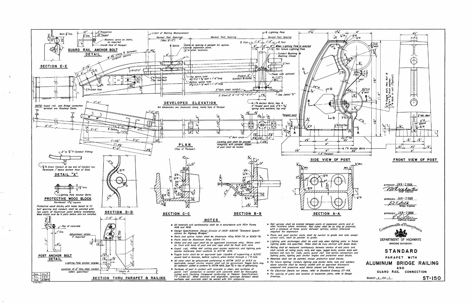
NOTES • All materials and workmanship shall be in accordance with PDH Forms
408 and 409.
• Design Specifications' Oesign Division of 1965- AASHO "Standard Specifi-cations for Highway Bridges."
• Roils and splice tu.bes shall be Aluminum Alloy 6061- T6 or 6062- T6. • Posts shall be Aluminum Alloy A344- T4. • Shims ondend cops
1
\sholl be on approved aluminum alloy. Shims shall be flush w1th base of post and end cops shall be flush with roils.
• Guard roil, roiling .and roiling post anchor materials and lighting pole anchor materials shall conform to ASTM A36.
• Toggle bolts shall be on approved type capable of supporting a 9,000 pound load in tension, before rupture, when tested through a 1"¢ hole.
• All steel shall be galvanized conforming to ASTM A123 or A/53 as opplicob(e. except anchor angles shall not be galvanized. Toggle bolts may be codmJum' plated to conform to ASTM Al65, 7ype TS, in lieu of galvanizing.
SIDE VIEW OF POST
SECTION A-A
• Roil splices shall be located between posts at expansion joints and at ot~er locatiOns where necessary. Rail tubes shall be as long as practical, with a mtmmum of three posts between splices, unless otherwise required for expansion.
• Posts and post anchor bolts shall be normal to grade and rails except curved rails, shall be parallel to grade.
• Lighting pole anchorages shall be used only when lighting poles or future lighting poles ore specified. Poles shall be truly vertical with bases level.
• Roiling shall be measured continuously between centers of end posts and shall include all railing posts, roils, end caps, toggle bolts, anchor bolts w1~h washers and nuts for roils, posts, guard rail end section connections and lighting poles, lighting pole anchor angles and protective wood blocks.
• Materials shall not be pointed, except protective wood blocks. • For future lighting' Conduit, lighting pole anchor bolts, nuts and washers
above concrete shall be heavily coated with on approved bitumostic compound and protective wood blocks placed and firmly secured.
• For Electrical Deto1ls not shown, refer to Standard Drawing ST-149.
Trc. SECTION Ckd.
THRU PARAPET a RAILING
• Surfaces of post in contact with concrete or steel, and surfaces of guard roll connection in contact with concrete shall be thoroughly coated with Caulking Compound conforming to Federal Specifications TT- C598 (2). After erection and alignment, openings between metal surfaces and concrete sh¢11 be sealed with this compound.
• For spacing of posts and location of expansion joints, refer to Design drawings.
'1·, II II II II I I _.,' ... _
II'! II II II
II' I II II II II I';
~~· 3~· ~~· 6"
FRONT VIEW OF POST
AfPROVED• JAN- 21968
~¥Quik CtiieEnoineer
APPROVED• JAN - 21968 ,6;;Uea.
Bridoe Enoineer
0\\wea\lh of Penns
(;o~~ • ')"l"<t/Ji<t
DEPARTMENT OF HIGHWAYS BRIDGE DIVISION
STANDARD PARAPET WITH
ALUMINUM BRIDGE RAILING AND
GUARD RAIL CONNECTION
SHEET_I _OF _j__ ST-150


Bar.s s 3 ana s4 to be .s;oac~o .svm,.lr/<:aiiV ~~ ., ~* Hcunche.s vory 1o Con?~.sale Jbr t'rrwgvloriFietJ " c017'76er.
TYPICAL SLAB PANEL
Bars 53 --n I I Bars 518 52 m Spocing
4"· 7 Zi" __ _!_5~ ~~0.47 •• 3 IE:_ 4'·11 7' • •6. 7'i • 0._50 a• 4 II' --- Ll__
~'i 7~· "5 (I 7• • 0.53 a• 4 10" 5'-5 71_ "5•6'2"•057"" 5 ,. 5~7 7 1r" •5 ~ 6" • tl62"' 5 ,. 5~10 tJ' •s., 7" -as!!"' 5 _!Q" __
6'7" -";- ~-.,-5. 6 1t"• QS7 •· ---·
6 ,. 6'-7 8" •sf~ 6' •0.62"" 7 ,.
-6:1o 8" •s • s'.'· (£,8•· 8 8" 7~0 8'2'. • 5 • 6 1z'· 0.57"" 7 ,. 7'-7 (jtz• •51' 6" •0.62"' L. 7--
7·-:'i! -·-d 1e• *s tis'i •0.6~"r 9 8$"-
n• moll. normal e/leclive spon perrnitled lor given relnForcernttn f bar~ .St ana' S ~
SLAB REINFORCEMENT
INSTRUCTIONS • Place Irons verse ~inforct!ment in deci slob parallel to ~ Srg.s for
&l:e~<~ angles 75" ana' more.lbr .sl=e1<1 angles leu than 75°/he bar.s &hall be placed normal to ~ of briCige and lenglh cui lo fil.
• 7b determine fhe required oreo of bar:s 51 ~ :5?:
a. For valu~s or see.. angles t8,1e.ss fhon 75'; use a reo of bars :shO"Vi in loble.
b. For values of sl=~w angles /8, 75" ana fJIY'aler, Increase area of" bars by COSt! c. f.J.
c. Spacing of bors shall be meosurt!CI otev>g <l of • briCige.
Ch Sl::eiV angles une/flr 75 •, a minimum or 3 • rll" 5 bars - 6"t sflo/1 be ploced ,;, top and baflom of the decl:: slob porollelib obul,..,l or pier join! o .. r !he tlno' supports.
TABLE I
CAMBER ' A ~ Up lo ,;;~f-t:t;·
~ Ov~r If to 3" I • 4-" Over3" t , , ..
H::>riofion in flonoe fhiel:nt!S& is not included in ":4: -"A· sho/1 be modil'ied for o ~on co..,. (sag J verlico/ curve.
TRANSVERSE CONSTR. JT DETAIL
41 r'~
_l i-*l(ttf5•ci?Ornl'er&
- 1\ ~':<l,G!Orov~ s~oter
J ? ~ (
~ SECTION A-A
OPEN JOINT DE TA1 L
SECTION C·C
t 0--1
· ~ l'Pr-t!m. £~p . .Jt Filler __ /
ELEVATION SECTION B-B
OPEN JOINT DETAIL
w w V- NOTCH DETAIL
DRIP NOTCH DETAIL
SLOPED CURB DETAIL
WoripNolch
#i. bor.s •!Sn?Ox.
SIDEWALK DETAIL
DETAiol 'x'
NOTES MATERIALS & WORKMANSHIP
, Afol~rlols anct worl=rncmship .shall be th occorot>nce Mtt"lh ~cllicoNtN,. FOrma 4W ono 40!1.
• Cess AA Cemenl C"on<:rele .sholl 6e u-a' ,;, oect: sla6,curb:s,siclewoll:.s ond parapets.
• ReinfOrcemenl Bors .shall confOrm tb lht1 re9uirernenl.s or .Sp«iRcolion& Form~ ~~cepl lhol.slruclurol grade bor.s .s/>Q/1 nol "- u.seo'. BOfW aholl ot!tlollt~a' ,;, occorcton<:,. 'Vilh ll>e current AC/ Manual or Stonoora Procllce For Deloi/ln9 Rt!inf"orcect Concrete Slrvclu~s. '2 "concrete cover shot/ be provla'tla' on relnlbre:•rnenf bar.s O>Cc~l Nhere noled olherMJlae.
DESIGN
• OesignSpeciflcolions: l)e.sign l)ivision of".t~AASHO, '".slonc:laro'~ili"ca!." lor Highluoy Briclges •• anc1 as suppl~n'lenleo' by lhe currenl Oestgn .tflt:>nuO/, Por14,.Sfruclures.
• live £000': HS?0·44
• OeOd Looct inclvde& ,30 lbs p~r sq. 1"1 ror l"ulure I«!Qring surYbc~ on !he ctecl: .sbb. !
• ~ LOOCI oF IS lbs per sq. 1"1 or decJ: oreo shall be con&tae~ in lhe ~ of beam!> ~<~hen the u.se of ~mont~nl Melol [)ec.t lbrrn5 i.s .specified.
Con-5/r. Jf
Stringer
-Reinforcen7#!1'>1 nol.sha.on
LONGITUDINAL CONSTR. JT DETAIL
APPROVED• DEC. 17, 1969
~f.i.~.~-APPROVED: DEC. 17. 1969
(j~~ Brld9ifl9iM•r
oll"'eallh ofPellllSJ'Ik \.)0~~ • ~~~
DEPARTMENT OF HIGHWAYS BRIDGE DIVISION
STANDARD
STEEL I--BEAM BRIDGES
DECK SLAB DETAILS
SHEET_I _OF_I_ ST-101

8 b ~ ~
~ :5
30
28
26
!
' I i I ' 1
i i I '
·~ I .z .3 .4 .5 .6 6~0" 1-rt 8-0'
STRINGER SP.I.C I NG
9-0
SUPERIMPOSED DEAD LOAD (XI PS PER LINEAR FOOl)
- 24WF68-+--+-- ~- -~-t+ -j -" r t~~ r~ t ~--1-- --t+ t .1--+--t-
~ --~- _J_ J .1-~ --1-- + l. I ' I I ~.;._-+ -~ v ·- t~:=t-~--1-z-
/ ---·-~ - -:-"·T
_;__.j..l --1 ~
'O'v v - 4o:; ~I '
}.! "3"' t f--L.; t
/ ~ !,, ~' -+-+-~ 8 v v 3&- ...... i j . , .. v . 34-
~~-~ j---i -r--~
4 v §~32 .. -~~- t'i._+-t-I -
2V v b-30.: ~~ - ~"--~- :""' t.;:- ~~
~ 28.-: I
ov v ...... . ~ ,._ ~ .... -~l"'ii"'"- .:""....., --~~
i:;-2 I v .::- 2 .... -~1!..:~~~ -~t-' 8 v .... 22- -!!..::- --~t::!.~~
-~foiii I ~ _zn.. ..... ""- -
16- v ~ 18-- - -- - ~ - - 1'""'1=111 ~~,.,;;.t'-- I
4v [....-8 -·jfj ..
~ "-= -~""" - -rs; ~ ---1 --1--- -- .... ~ - - -~ -· - , .... !-, -k v ~ - -~ ~ - -~~ -
j()' .-- !" i-... t--o .... ---• 1-- ..... ~
1--- -- .... t--"""'
3X' 3Xl 3Xi JXl l!Xl 3xi !Xi
!X~
!Xi
-1-p -~ NONE 4
. 2 .3 .4 .5 .6
SUPERIMPOSED DUO LOAO 011 PS PER Ll NEAR FOOT)
6-rt 1-rt 8-0'
STRINGER SPACING
9-0 .
i 0
B b ~
!i
i :5 ~
z
~ ~
z
z g;
c
I -- --18Wf45
[I __ !-+ f-- f-
i
38 / _,-/
_,..7 / 30 ~""'-36
34
32
,.---" 28- r--...._ v § 26- -~ """- -r-
? ......... b 24- ~ ~ ~
30
28
26
24
__,I-"" %
~ ...... i-22~ ~
v ~ zo- ~ ~ u..-18 iii v ~-16:- o;.;: -l""' !=;:
1-- ~ 14- r;;;; 1111! 1-- ~-12-
""' loa.. - -(.) 10-
22
20
18
I---f.- .- - ~ ~ - --r"'o ~lo.. ~---~~--
. I i-
' !
H-+
-~
..... ;;.- - ::"'~!!o!. ~ ~ ..... .;;;,;
~ ~ ._,
.;, ~ r--.;.; -- - ~
- --- - -~ t:_- - -- -~ -
""" .... :--~.- ...
-r-"""'
T"'~
i ~~ . r __;._ ltj
i
11!xi
11!xi
11!x!
''!xi 5!xi 11
!xt 5!x!
5!xt
NONE
.2 .3 .4 .5 .6. 6-rt 1-rt 8-0'
S!RINGER SPACING
9-rt
SUPERINPOS£D DE.ID LOAO (KIPS PER LINEAR FOOl)
27WF84
/ 0 ./
v 46- ~ 7 ./ / 44• .... av v ~ -~ 4Z
"' -- - I!.. 1' ::: 5 :~ v~ v 40· -1--t-
t"" ~ I"" ,..; -~ "' 2b-' l/~ -~:: ~ "- -- .... ~ ""'
~ at? __ ,.._.,__34·
...... ""--~ !""" """"
!""" -~I 8~ ~~- lZ- ""'
~ r"" !""" " ~ ~, t;/ . ~ -30 p: jlo.;;: ~ f!"- [.""'' .... ~ ~ !"" .... 1 ..., ze-
6 v . ::-26- ' ~ ~ ~ ~
""" !'~;.; I --
4 ·-:: v :;-24· s; ' r---::: ~
,... " t:S ~I ~,...< -i/ g;-22 ~ 2~ ./ ::! 2()- -~
r""' !""' ~ ··;,;;;.'-~ ["'ooo~
ov ~-"" """' s-,8;;, ~ ~ [""'I "" -.. I .16-
f:::' ~-.., ~ ~ ~ "' 8
81.-- ' _.,..
v fi;;; ~ ~ ..
' "" ,. ~8 6- ........ :.....- ........ I' -~ - _r--4v ....... .... ...... ~8 v r-. ~ :·::.'" 2 _.f.- ....,; 0 -8~
.2 .3 .4 .5 .6 l'rt 8'0'
s~r:~I~S~f.mDrliStl' STRINGER SPACIIIG
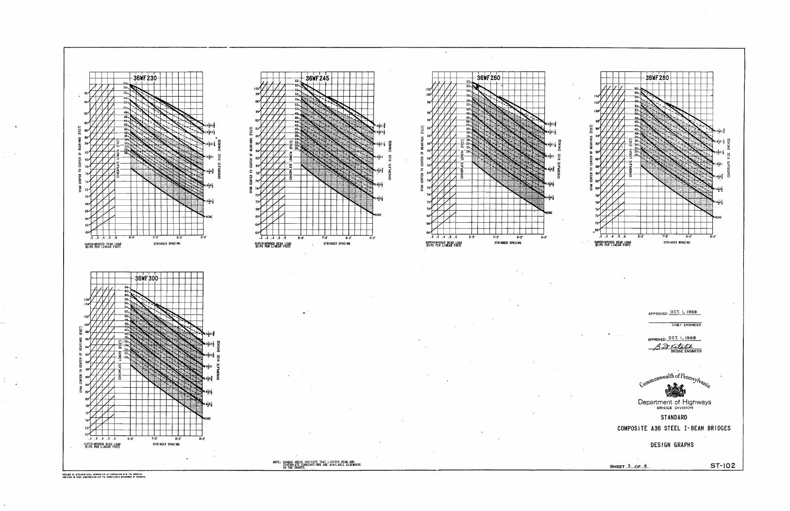
.!1M[; SHADED AREAS INDICATE THAT LIGHTER BEAN AND COVERPLATE COMB I NAT! Qlj$ ARE AVA I LISLE ELSEWHERE IN THE CIIARTS.
..
N ONE
i 0
·i!i ..
H-++ -L--- --21 Wf55 H . -~ -r------ -++- -r----~-+~~---~-+-+-1-~-+-+-~~-+~
I
.z .3 .4 .s .6 8'-0'
SUPERIMPOSED DUO LOAD (kIPS PER Llii£AR fOOl)
1'0' 1'0' STRIII6ER SPACING
§ 501-t~~~~-::;~~~~~ ~ .. ~~~~~~--.. ~~~~~ .. e ~ 4Z~~~~~--~~~~~
STRIII6E~ SPACING
.•
i 0
NOTES • For .spec/fico lions, nolfls, and 01-r de!alls, rerer ;b Sfd. OW(}.
ST-101. '
• f'ar selecflon of lhe m0$1" opporenf econorn/col beam, reFer lb .Sneef # ~
• Su_ottrirnpos.a deod load lncl<../f::::tes : .c'ulur. .veoring sur;0ctl, ( Nol oppltcoo~ t'l' d~l: slob 1~ ' dt!lslgned Nllh bllun7ir>ou.s ~rlhg .svl"'>"27ce O"'Jb .slrc.lc!V,.... unair 1'111.) , IVe/ghl of' railings, poropel.s, curb.3 or sloewoll:s, and any ~..,. dead loaa applied al'lerdec-t slab ho.s been cvr«l.di.sfr>'buh•O' eguatt,y lb olt.slringer.s, in ~~:O.S pel"' /ln. fl.
( ..
I .
Department of Highways BRIDGE DIVISION
STANDARD COMPOSITE A36 STEEL I-BEAM BRIDGES
DESIGN GRAPHS
SHEET.:: .. L.OI" .... !L ..
gagordon
Text Box
ST-102

E ~ ~ w z
~ ~
"' ~ ~ ~ u 0 ~
"' ~ ~
z g;
8 , ~ w z
~ ~
"' ~ ~ u
:= "' ~ z u
g;
SUPERIMPOSED DEAD LOAD (KIPS PER LINEAR FOOT)
SUPERIMPOSED DEAD LOAD (KIPS PER LINEAR FOOT)
PREPUEO BT 6ETNt(N(N STEH CORPORAIIO~ I~ COOPERHIO~ WITH THE AN[RICAH aSTITOl[ Of STEEl CONSTIIUCTIO~ fOR I~[ PEHNSTlVl~l! D(PlRIM(MT or HIGHUTS
N
;;;
STRINGER SPACING
~ lil 0
i:l ~
~
~
I
STRINGER SPACING
E ~ ~ w z
~ ~
~
"' ~ e 0 ~
"' ~ z ~
z g;
E ~ ~ w z
i ~
"' ~ ~ z ~ u 0 ~
"' ~ ~ ~ u
g;
SUPERIMPOSED DEAD LOAD (KIPS PER LINEAR FOOT)
SUPER I MPOSEO DEAD LOAD (KIPS PER LINEAR FOOT)
i 0
~ N
;;; IOXI! ~ lOX I I
rox!
STRINGER SPACING
14XI~
13' ~ 0
~ N ;;; ~
~ 8
STRINGER SPACING
E ~
~
~ ~
"' ~ ~
tl 0 ~
"' ~ ~ ~ ~
z g;
I" g ~ w z
~ ~
"' ~ z u 0 ~
"' ~ ~ z u z g;
SUPER I MPOSEO DEAD LOAD (KIPS PER LINEAR FOOT)
SUPERIMPOSED DEAD LOAD (KIPS PER LINEAR FOOT)
STRINGER SPACING
STRINGER SPACING
E ~
i ~
~ 0
i:l ~ ;;; "' ~ ~
z
§ ~
:= 8 "' ~
z u
~
13' ~ 0
N
;;; ~
j
SUPERIMPOSED DEAD LOAD (kiPS PER LINEAR FOOT)
r
STRINGER SPACING
APPROVED' OCT. I, 1968
CHIEF ENGINEER
APPROVED' OCT.(, 1968
"~ BRIDGE ENGINEER
ou.'liealth of Penns "li ~0~~ • ~~>-~,~
Department of Highways BRIDGE DIVISION
STANDARD
COMPOSITE A36 STEEL I-BEAM BRIDGES
DESIGN GRAPHS
i 0
N
~
I
SHEET ..... ?._ ... OF .. J?. ..... • ST-102
E b ~ ~
i l3 ~ ~ ~ z u
:= ~ w ~ z u z
~
B b ~ ~
s ::: l3 ~
~ e 0 ~
~ w ~ z
~
SUPERIMPOSED DEAD LOAD (KIPS PER LJ NEAR FOOT)
.2 .3 .4 .5 .6
SUPERIMPOSED DEAD LOAD (KIPS PER LINEAR FOOT)
PlltPAfl£0 IT ai:TIILEH[IISJE(L CO~PORUIO• Ill COOPERATIOM Willi THE .liiUJCAII tiiSTITUTt Of $f[(L COIISTIIUCTIOII FOR T~E PEIIIISTU/JIIA I)[PlRJJI(Itf OF HI&HWAYS.
STRINGER SPACING
STRINGER SPACING
8 b ~
i ~ z
~ 0
~ l3 N ~ ~
~ ~
~ e := ~ 8 ~ ~ e z
~
~ ~ 0
::: ;;;
i ~ 8
SUPERIMPOSED DEAD LOAD (K I PS PER LJ NEAR FOOT)
8'0"
STRINGER SPACING
NOTE' SHADED AREAS INDICATE THAT LIGHTER BEAM AND COVERPLATE COMB I NAT! ONS ARE AVAILABLE ELSEMHERE IN THE CHARTS.
i 0
~ N
~
I
E b ~ ~ z
s ::: l3 ~ ~ e 0 ~
~
z ~ u z
~
.2 .3 .4 .5 .6 6'0"
SUPERIMPOSED DEAO LOAD (KIPS PER LINEAR FOOT)
7'0" 8'0"
STRINGER SPACING
~ N
;;; ~
~ ~
E b ~ ~ z
s ::: l3 ~ ~ ~ e 0 ~
~ ~
z tJ
.2 .3 .4 .5 .6 6'0"
SUPERIMPOSED DEAD LDAD ()UPS PER LINEAR FOOT)
7'0" 6'0'
STRINGER SPACING
APPROVED' OCT. I, 1968
CHIEF ENGINEER
APPROVED' OCT. I, 1968
453-~ 7 BRIDGE ENGINEER
1*1*
14~XI~ i 0
-N
;;; w
I
Department of Highways BRIDGE DIVISION
STANDARD
COMPOSITE A36 STEEL I-BEAM BRIDGES
DESIGN GRAPHS
SHEET ... -~-----OF .... § ___ _ ST-102

l ., "' :.:
" ~I .. 0
2 I
I I
i 0
I 9
e !'-...
1r-... 1' r---~
......
"' r---~ "' ,....... r--- t--- r--- I'-
61:::, ~~- :::: "'· r,.,.,
----5 t=::: ~ r--:-..
·-t-1--
t- -f.-t-~
36Wf 230 TO 36WF300 36Wf 135 TO 36Wf 194 33WFII8 30WF99
10 k+"-~..+-1--1--!-!-1-lf-f-H ~-"-
0) e f::o:.~~-- :'::';!:>. ..... f.;. "' f"--.. 1---- 36WF230 T036WF300
~ r---. "' N ~"h-~"'t- 36Wfi35T036Wf194
¥ 1 i"--1-- 1--- K 1---- t"---t-- !~;~~e ,,. 6 r""-r--. r- '"i-- 1'-- r- ~ 270f84
i~ ~----~ ~f.- I--f- u~~~ .I&J 16WF36
::>
1---' 1--- -- t-=+::"-1-- I- Z7WF8f 24Wf68
·..I
"' >
•
2
I
0
----- --t- t--- 1-- i- 21WF55 IBI!f45 16Wf36
f-t-+ I
i
j 1-rr e-rr 9-rt
STRINGER SPACING
I. THE FOLLOWING INFORMATION IS KNOWN:
A. SPAN CENTER. TO CENTER Of BEARINGS• 55 FEET.
B. STRINGER SPACING•T-6'.
C. SUPERIMPOSED DEAD LOAD•0,45 KIPS PER LINEAR FOOT Of BEAM.
2. REFERRING TO THE ECONOMY GRAPH. IT IS FOUND THAT THE
300f99 GRAPH WILL PROBABLY YIELD THE MOST ECONOMICAL DESIGN.
3. ENTER THE 30Wf99 GRAPH AT 0. 45 KIPS PER ll NEAR FOOT Of
BEAM AND NOVE VERTICALLY TO THE 55-FOOT SPAN. MOVING
FROM THIS POINT HORIZONTALLY TO THE l'-6'STRINGER SPACING,
IT IS SEEN THAT THE COYERPLATE IS 14rX rx 43'·0"LONG.
NOTE THAT If THE SPAN HAD BEEN 48 rEEl THE DESIGN WOULD
HAVE BEEN IN THE SHADED UNECONOMICAL PORTION Of THE GRAPH,
INDICATING THAT A LIGHTER BEAM AND COVERPLATE COULD HAVE
BEEN USED.
4. FROM 9RAPHS, X= 5. 7, Y= 7. 7 AND Z= 12.8 ARE
FOUNO FOR A 30WF99 .AT A 7'-6 STRINGER
SPACING. USING 2-34"+ STUOS PER ROW OR 4"·4C 7.25
PI=I./6X=6.6, USE 6 12", ·lx~_55x 12 .IOSPACES @6 12=6511
P2= .96Y=7.4,, USE 1 12", ' 2 X9.~xl 2 = 18 SPACES® 1 12=135"
P3= .64Z=8.2, USE 8 '.2x5;xl2
N = ~u = 62 STUDS, 33 CHANNELS
16 SPACES @, 8 = 128"
TOTAL 328" ~ =:3:30" SAY O.K.
5, MOMENT Of INERTIA Ill' THE BEAM AND COVERPLATE SECTION (! 1)
IS fOUNO 8Y ENTERING THE 30.U99 MOMENTOf JNCRTIA GRAPH
WITH A COYERPlUE AREA Of 14.5 X .875- = 12. T SQUARE INCHES.
NOVE UP TO t • 0 LINE (ZERO SLAB AREA). ! 1•6000 IN. 4
STRINGER SPACING
SAMPLE DESIGN PROBLEM
6. MOMENT Of INERT lA Of THE COMPOSITE SEC II ON (!2) IS FOUND
BY MOV lNG UP TO ~ • 24 WHERE,
A= AREA OF STRUCTURAl PORT! ON Of SlAB
= 8" X 7 .s· X 12Y.•720 IN. 2
N • 30 FOR SUPERIMPOSED DEAD LOADS
6= !i8=24
12
• 14,300 IN. 4
L DEAD LOAD DEFLECTIONS ARE CALCULATED USING THESE MOMENTS
Of INERTIA AND COMPUTED OEAD LOADs' PER FOOT Of BEAM IN
THE EQUATION
~·.000115L'( ~ + ~)
WHERE'
L:> • TOTAL DEAD LOAD DEFLECTION AT~ Of BEAM /INCH[~
W1=COMPtiTED WEIGHT Of SLAB AND STEEL (KIPS PER LINEAR
FOOT Of BEAM) .
·~X .ISO KIPS/FT 3 (SLAB)+ .025 KIP!;/Fl.(HAUNCH)
+ .099 KIPS/FT.leEAN) + .043 KIPS/FT. (COVERPLATE)
•.962 KIPS/FT.
w2
•SUPERIMPOSED DEAD LOAD (KIPS PER LINEAR FOOT Of IE.IM)
• .450 KIPS/FT. .
! 1 A~O i 2 •MOMENTS OfiNERTIA AS fOONO IN STEPS 5 AND 6,
t-=.000115 x ss4 (• • ~ , 1.35:
SAY' lr
I. LIVE LOAD DEFLECTIONS DO NOT GOVERN ANY Of THESE DESIGNS
AND NEED NOT BE CALCULATED.
~ ~-------------------------------,_,._.0 II' •T•LI•I• SIUL COII'OtiT>OOI •• COOI'UIIIDII Jill IM[ JII(IIUI 1.SIITWTI«.5Uh tOI'SIIIKT•OIIfGIIM( r(IM$fLU.IUl0l'II111UT Of ll'"'lJ5
STRINGER SPACING
9. FINAL DESIGN'
TYPE OF SHEAR .SHEAR CONNECTOR PITCHES CONNECTORS
-PI P2 P3.
2.34X L95Y 1.28Z
1.56X 1.30Y .eez 1.·74X 1.44Y ·••z 1.16 X .98Y .84Z
.IL 2 ,2
I I
I "' i BEARING ! STill. m:•
L
NOTE: THE NUMBER OF SHEAR CONNECTORS BETWEEN POINT OF
MAXIMUM POSITIVE MOMENT AND ADJACENT SUPPORTS SHALL
NOT BE LESS THAN THAT REQUIRED BY THE FORMULA
N= Hi/f Qu,(SEE 1986-67 INTERIM SPECIFICATIONS)
16 SPACES AT a"= 12811
•
STUOS/ROW
3- 78" I) 2- 78" t 3-34 $ 2-34 '
PROPORTION
APRROVED: OCT. I, 1968
~1M-• CHIEF Etl(iliEER
COVER PLATE DETAIL
CHANNEL
84"-4C7.2~ e2-4c1.2~
s"- 4C7.25
4''-4C7.25
OF SPAN L
-
5 ,, ,~Wfl5
~ 10 -t, ii f-HH'-oi::-+36~F 135l-f-t--=1N:-1 • ,, ,J I »: 'r, ~ 33+ II ~~-t-+--t'-'-t--~ §~~~-,~~-~~~~-+~ ::: ..... ...
~ ... ~-- ..... ~-J.~,f-'"fo.cc+-+--+-l z ..... ..;. j!; sor-t-t-+-1-~~-r-+~~~_, ~:l-+-+-l--t21w'fe•t-+-+-+-l~
t-+-+'+-i;cc_-t2'wf5st-+-+-+'-"'--.l t -:.
'~
I-+--+-+-+--+''6Wr56+-+-~-f~-~
~-,Lrr,.-J~.L...J_-:-7-Lrr-'--''-.L.e,~_.,o·..L-'-.....ILJ9'0' STRINGER SPAC lNG
o\\wealth of Pe.rms '/, (JO~~ *' ~ ~~~~ Department of Highways
BRIDGE D1VISION
STANDARD
APPROVED: OC•T. I, 1968 COMPOSITE A36 STEEL I-BEAM BRIDGES
de#-~ BRIDGE ENGINEER SHEAR CONNECTORS
AND SAMPLE DESIGN PROBLEM
l
'\
SHEET ..... ~ •... OF .. 6 ST-102.

~------------------------------------------------
A·8o
500 1- r--16Wf36-~A·1o
0 •·60
1/ ~ :o '/, *'40
I 0 IX/ A·3o
l'lALL l 400
lL A I ~·20
1/// v I 300 0 VJ/V /
~ / I !if,
A·IO
ol.& VI ~ /V v H 2QQ
VJI/
v 100 0/
,..... A·o-
1-
0 0 12
AREA OF COVERPlAH (INCHES2)
52000 1-- 36Wfl35- 1-
48000
4400 0
0 ~·80 I I/ •·70
Of- I v. A·6o
4000
3600
•50
0 v.
'i'/ vl4o 3200
0 l'l'VV A·3o
~v: v 2800
0 ~ ~·20 ~/'v v 1-
2400
0~ v 1-A,:o v.; v 2000
oV /
v v I 1600
1200 0 /' ~·0
8000
4000
00 16 24
AREA OF COVERPLAH {INCHES2)
PHPII!EO er BETHLE~EII STEEL CORPORii!OH IN COOPERITIO~ WITH THE .liiERICAH I~STIIUJ( Of ST££t CO~STIIIJCTIO!I fOR TkE PE~NS1lYUII OEPIRTMEHT Of HIGHWAYS.
A 80
600
18WF 45-c Jf A:~ •·60
0 A·so
~·40
~·' 0 /;
500
I# / A·k-
0 v; v
~ I 400
I W,/ k.lo-
of#. fJ/ v ~ [/
300
200 0
- A·o
100 0 1-
12
AREA OF COVERPLAH {INCHES2)
5200 Of-!- 36WFI50 1-1--
4800 0
4400 0
4000 0
3600
3200
~ 2800
~ 2400
2000
1600
1200
800
0
0
0
0~
0
0
0
0
400 0
0
A·8o
A·1o /. h·6o
A·5o
v ~=~a vv
h·30
t% v v ~t/ v ·20
v.v v v "-10
1- I I-
I- ~·0 -
16 24
AREA OF COVERPLATE {INCHES2)
1--r-r-21 WFSS-r- 1-
1000 0
900 0
800
700
1; 600
~ 500
H 400
300
200
100
0
0
0 z: 0
~/'/ 0~ /
~ ov
I-0
oi-l-
0
A·80
h·70
~~·60 v t% l50
I'L =40
vA·3o "l v E%/
~-~·20
v A·IO 1-
1-
I ~·0
12
AREA OF COVERPLATE {INCHES2)
5200 0 1-1- 36WFI60 4800 0
4400 0
4000 0 v v 0 v. v 3600
0 v.:
v 3200
~/' v· v ~ v /
0~
~
~ 28000
~ 2400
20000 vv v
1600 ov
1200 0
aoo 0
400 0
0 0
v v
1-
16
1-1-
*•80
*•70
-~·60
*•50
..!~40 I
~·30 ,I ~·20
1•10
~·0
24
AREA Of COVERPL.I.TE lr NCHES2)
1300 0 24Wf68 )i7 A·~O / vh·?o
0 /. ~·50
I V A4o 1/ v~·4
•.k-0 v.
v v
1200
r Jooo
1000
v I ~ •·20
9000
8000 ~v, .-::::~
""' r-~
700 0 ~
H 6QQ 0~
500 ol/
400 0
300 0
:2000 1-
100 0
5200 ol- t-
4800 0
4400 0
4000 0
3600 0
3200 0
~ 2800
~ 2400
0 f'iV
0:%
2000 0
1600 0
1200 0 1-
800 0
400 0
0 0
V/
v
[..--1-
'-1-
12
AREA OF COVERPLATE {INCHES2)
36WFI70 H-,I •·8
/ •·70
~·60 A·5o
I
t/V ri.·40
vv v •·3 'L v
•2 v 1-
•I
)..--
>---1-A·o
1-
16 24
AREA OF COVERPLAH {INCHES 2J
~·10
k·o
16
5200 0
48000
4400 0
40000
36000
32000
~
~ 2800 ~
0
H 2400 0
2000 0
1600 0
1200 0
800 0
400 0
0
NOTE, A= AREA OF STRUCTURAL PORTION OF SLAB
t/ v v
v
~ ~
2600 0
2400 0
2200 0
2000 0
18000
1600 0
~ 14000
1200 0
1000 0
800 0~ t:::-
6000 f-'
400 0
2000
27WF84
v ~
/-. !-'::: ~%: V" 1-
~ I-
v 1-)..-- 1-
H-
t•80 r--•71)-
vv •·60
v ~·50 )..-- f•40
A·io
I •·20
I
1- •• :0 •
I
I ~·0
12 16
AREA OF COVERPLATE {INCHES2)
36WFI82 •·80 1-
v ··~0 r--I
1'--IL ......... 60
v •·50 1-/. v I
/'t·4ol-1,..-" ...... ~.J,-r-
/'/V / v v:
•jO-r--v v f/ - •10
1- II-v L
I- -w~ 1-
1-v
16 24 32
AREA Of COYERPLATE (INCHES2}
5200 0
4800 0
4400 0
4000 0
3600 0
32000
0 ~ 2800
~ 24000
2000 0
16000
12000
8000
4000
0
26ooo f-+-+-f-+-+- 3 0 W F 9 9 --+-+--J--+-+--1 r-t 24000 H-+-+-+-+-+--H-+-+-+-+
22ooof--+-+++-H-++++--H- ...; ... ~·:IQ [/.;,.- ].60
20000 10 .i.5o
1/v ,... \-: /-. ~·40
180oof---..l--++++-t--\-;l'l,.j/~471"'=-t:,.....--:l-.f'"i-'
v. V v H··3o 16000
v.:: /' 't, 14000 •••••• ~~~V-;.L ........ .
u ~~~./~~~+--~~~-+-~+--~~ 12ooo ~V.o/'i-:.fLiH"*4-I-++-t--H-±!:*i'" IOOOOV v ..- H"
eooo V 1-
6000 ·······················~.:::.····pf-
4000 1-"1==-ti--+1--+-+-+-H-+-+-+--M+--~~
2000 H-+-+-+-+-+--H-+-+-+--H+-~~
0~~-L~~~_L~~LJ~-L~
0 12 16
AREA Of COYERPLA.TE (INCHES2)
36WFI94 *"80 v •·70
vv ··~0 v j11•50
v I
v v ,-~·40 v: v I
•·30
v v v 1.\·20
3100 01-
2900 0
2700 0
250Q 0
2300
2100
~ 1900
.=. 1700
0
0
0
0 !J IW
A·80
33WF I 18 ~ A·\o' 1/ ~.ti fLV A :fa
I y ~~ v ~'G 1/,
1/ ~~0 1// 1/ 1/ v
fL /_ • .ra:: fh/1/ v I
f'l •• (o 'r// v 1500
1300 oiL v
1100 0
•• :;---1-0 1- It-900
700 0 v I
500 0 0 16 24
AREA Of COYERPLATE (INCHES 2)
APPROVED: OCT. I, 1968
CHIEF ENGINEER
:Z'V/ ...... I...- I APPROVED: OCT. I, 1968 v
v ,... 1!.10 v v 1- I
1-
v • I •·0
1-1-
v
16 24
AREA OF, COVERPlATE {INCHES2)
32
d~L~ > BRIDGE ENGINEER
ollwealth of Penns '!t
\)0~~ . * ~ "'<tQ,~ Department of Highways
BRIDGE DIVISION
STANDARD COMPOSITE STEEL I BEAM BRIDGES
MOMENT. OF INERTIA GRAPHS
SHEET ..... R ..... OF .J?. ST-102

62000 36WF230 5800 0
5400 0
sooo 0
4600 0 k"IL v
4200 0 v v
3800 0 //V v v
0 v v tL;...-' ,/ v ~.--v
3400
3000 0 v /
2600 0 ....... 1.--
o~--' / f-1-"
2200
1800 0 f-
14000 1-
0 1000 0 16 24
AREA OF COVERPLATE l!NCHES2}
c
PREPJREO 81 6ETHUHE~ STEEl CORPCRIIIO~ I~ COOPERITIO~ WITH THE l~[RICI~
I~STIIUI[ Of SIHt CO~SIIhJCIIO~ fC~ I~[ P(H~SilUHII O[PARl~[NI Of HJ6HWUS.
62000
58000
l·8o
··~0 I
H"~O
•·so
I •·40
'f:: •·30
I
4200 0
v.:
54000
50000
46000
38000
•·20 v 34000
• .~10 30000
_L _l
/
v 26000
A·o 22000
18000 v 14000
10000 32 0
36WF245 j_ 6200 0 36WF260
•·80
• .~70-/ I / ··60
··50 /./ / I VI/ •·40 / / ~
v / •·30 1/V./ / r
··~0 v ......
0 /
0 / /
/ v
0 vv / v
v /
oV v v / v /
S8000
S400
sooo
46000
4200
38000
3400
•·10 v / f-v
v r-30000
v .......
•·10 v
/ ........ v
f-
26000
22000 .......
/8000 1.--
1400 0
10000 16 24 32 0 16 24
AREA OF COVERPLATE (I NCHES 2 I AREA OF COVERPLATE liNCHES2)
NOTE: A= AREA OF STRUCTURAL PORTION OF SLAB
•, M~g~~~~so~FtU~miWF~~Rcm~~rE
•·80
•·'70 ··~0
v •·50
•·40
•·30
•·
1
20 I •·110
A·o
4600
4200
~ 3800
u 3400
6200 0 36WF280 . t·18o
v •·70 v I 0 v •·60
./ A·1so
./ v v
\·140 0 vv
1'111\30 0
v. v v v v v .k oL v v
v v 'I ov v v I v v f- A·IO
0 v f-.-
0 v •·0 f-
0 f-
62000
saooo
S4000
soooo
46000
4i0oo
i 38000
34000
30000
26000
22000
36WF300 t-t/ I>" A;8o
•·70 I
v •·60
v I
v ""'
A·so
v A·~o ./ v v v
•·30 v v I v •·20 v v J v v ,I
v v A•/0
v 111_
v v v
•·0 v r--v r--
v
58000
5400
50000
3000
2600
2200
1--/800 o~-" /8000
1400 0 14000
10000 1\looo 32 0 16 24 32 0 16 24 32
AREA OF COVERPLA TE tl NCHES2) AREA OF COVERPLATE (JNCHES21
APPROVED' OCT. I, 1968
CHIEF ENGINEER
APPROVED' OCT. I I 19 6 8
dd:~ BRIDGE ENGINEER
Department of Highways BRIDGE DIVISION
STANDARD COMPOSITE STEEL I BEAM BRIDGES
MOMENT OF INERTIA GRAPHS
SHEET .... § ..... OF ..... E'i ..... ST-102

....------------------------
E
f----+-----'-------+-~--+'-4~ -l---+--+-+-1 --1 j I j
•a~'
I I I I i I
.2 .3 .4 .5 .6
SUPERU4POSED DEAD LOAD (KIPS PER ll NEAR FOOD
i I I I
1...-1' / 58 y v I' 56 / v 4 1....-1 •/ § 2 Y' / b
i I !
6-0' 1-C! 8-0 9-0
STRINGER SPACING
24WF68 ~·FLANGE
I
...... .. -r--~ 42- - ...... -40-~ - -~ 38- - 1'- - - _I"
b 5 o_. /f ~- - -~ - ....... 36-
a v v _.........-;
6 v '_./ 4 v 2 v I
v ! / 0 _......v a v 6 I v vv, I v
v v 2
i---30
i
.2 .3 ,4 .5 .6
SUPERIMPOSED D"EAD LOAD (KIPS PER ll NEAR FOOD
34-
- 32
""" ~
28 l"""i
26
24 -
6-0'
N - ....... - - - _ ....... "" ----. ~ __ .., ""'-:: - -.... ~- roo. ~-_ ...... ....
- - ... t-.... - - :::Oh!.. ~ ... -r... "'"'~'"' - -r-- -~ -- _ .....
t-... -~ ..... !oro:- r--. ""'"" - -
"' - ..... --..... - -..... ~ -..... r--. ..... t-...
!""'jo..
7-(f 8-0 .. 9-0
STRINGER SPACING
10.125
I I
v 44 v 42 Y. 40 V.
B _....v b 3B
4v
~ 32 v ~
z 30
e 2a
1-1--~
z 26
z 2~ ~
22
20
1-
v v
1--
--v
j.--1-"
-1-
l
v 36
34
"" v ~ 32 b
/ ~ 30
~ 28-
v 3 26
~ 24-_... 8 22
20
1a
l--
1--I-
18WF45 1 7j" FLANGE
I
I
"'" I
-I""-~ ~ ~ - - - ......
"' ....... 1"--~ ~ -~ "' r--- .... ...:: - - -~ b. l"jo..
""" - -f=l! ...... f'jo.. -
~- - - - ,..; loo.. - -~lo., r""oojo..
" ~- "" --- - - --pll
""" - -~
'""" -. I-. ---- r--~ -f-- - 1---,....,.... - -~
""' ....
f'oo. '-,..
~ t.... I'-~
.2 .3 ,4 .5 6'0' 7C(f aco· 9'-0'
SUPERIMPOSED DEAD LOAD (KIPS PER Ll NEAR FOOT)
v I' 66 v /
64 v / /
v v B v lL
b
62
60
50
48
46
44
42
v / ~ 40 z B b 58
54
1-' / / v v §_Ja
/ v ~-36
v v g-34
32
56
52
50 v , ... v- v 30
48
~6 / v~-" 28-
/ v v 44
42 v 40 v _....).--'
v --
STRINGER SPACING
27WF84 10' FLANGE
-r-.. - 1' .,. -~ --- _f'
...... '""'r-..., --~
__ ,_ 'io....
~- i;,;: -- !"" ...... ·~~ -r- ~ioo... -r-
!""' "'---k~ ,;~ !J;;:_. l"o ~--~.: ..;.::"' '""'~
i-- ·-~ ...... -- .... "~,' --~ .... ""~ -- ..;;;; ":'f.'' -rs ...... r-,~ ,.. "" '''" . ""'~'--~ .... ~-~ ~ - ~ .,;;,:
...... ~ ~-···. .
-~~
""" -..... k ' 0~ t:-. .... ~
.....
I
~.--v "" 38
36
.2 .3 .4 .5 .6
SUPERIMPOSED DEAD LOAD (KIPS PER ll NEAR FOOT)
6-0' 7-rT 8-0 9-0
STRINGER SPACING
0.375
! i
y so ,. v 48 v
Vf ~ y
46
B b 44
, ... ~ 42 v v-l.----1'
y ~ 40
~ 3B ~
z 36 i v ,_vi e 34
~
z 32 u
30 , ... 28
26
24
1----Y J--
1.---v 1-
1- j..-1-
!
i
y
v
v v '
v
1--
.2 .3 .4 .5 .6
21WF55 I
afruNGE
40- -~ 38 r-.,_ r-... E t-.... - -!"'--~ 36- -34- - - ~ -'" -
..... !"o.. - - - _t--o ............ ~ 32-
~-30 -r"' 1'- I"" ~ - -
~ !;;;,: - "'""' - - - -~ -*-28 ·--- ~
"""" -~ ...... - -u -26
-~----- !" -..: _r----r- "' 24 -~ - -~ .... -22 t-- -~- -- ...... lo.. - -20- - - -F>- r~ - ....
""'r--. - - - ,.., r--. -r-I""' ...... -r-: f"l
r--~ r" r--Io;;.
6'-(f 'II 7'(f acrt g.(f
SUPERIMPOSED DEAD LOAO (KIPS PER ll NEAR FOOD
STRINGER SPACING
I/ 74
72 I
70 ·'v 68
B 66
'/ b 64 ~ ~ z 62
~ ~ 6 0
~ 58
56
~ S-4 ~
z 52
50
48
I/
v v /
v v
v I/ / v .. v
/: )' / v
v: / y v
/: y
I/ 54 ~ 52" """ 50
"""" "' 7 -!--. ('.. 48 .,, ···B:.-rs .. p... . .., -~
b f.- " r--
~-44 ' ~: I'
7 ~-42 5::: s.; ... /
~ -40
~--- ~-.... ~~3B ~ . -'.;; g-36 .... ""'-:-.;;
'/. 34 ..., ~ 32- ~..;~-.;; 30 ".._ ?'!~
/ '-" ""~ / ;,;..
I'
46 v >~-" .............. ~ v
44 ......-]
r v 42
40
30WF99 I of FLANGE
" ~ ~ ..... , ·-N .......
,_~ "- ....... I' """'r-....
J' ...... -!"o.. I' -- I
·.::":~ r-. ~ IO.ib> - ;;, .... ~
1-o... ~ ~ ...... k I> ',+ ' I;-;" ~ ......L. [\'; >>
r'"" ~
9.56
w
0
I 1.25
.2 .3 .4 .5 .6
SUPERIMPOSED DEAD LOAD (KIPS PER ll NEAR FOOD
6-0' 1-rr 8-0 9-0'
STRINGER SPACING
NOTES • FOR SPECIFICATIONS, NOTES, AND OTHU\ DETAILS, REFER TO STANDARD DRAWING
ST- 101.
• fOR SELECTION OF THE APPARENT MOST ECONOMICAL BEAM, REFER TO SHEET 4.
e SUPERIMPOSEO DEAD LOAD INCLUDES,
fUTURE WEARING SURfACE (NOT APPLICABLE IF DECK SUB IS DESIGNED WITH BITUMINOUS
WEARING SURFACE OR TO STRUCTURES UNDER fiLL). WEIGHT Of RAILINGS, PARAPETS,
CURBS OR Sl DEWALKS AND ANY OTHER DEAO LOAD APPL I EO AFTER DECK SLAB HAS BEEN
CURED, DISTRIBUTED EQUALLY TO ALL STRINGERS IN KIPS PER LINEAL fOOT.
• THE MININUN THICKNESS Of CDVERPLATE SHALL BE r. THE MAXIIo!UH THICKNESS SHALL
BE ONE AND ONE-HAlf TINES THE THICKNESS Of THE fLANGE TO WHICH IT !S ATTACHED,
EXCEPT AS LIMITEO BY THE FOLLO~ING STRESS RESTRICTIONS,
16)ff36 TO 33!(f I I B INCLUSIVE: DESIGN STRESS IS 27 KS I·, AND THE COVERPLATE
THICKNESS NAY NOT EXCEED r. 36)ff!35 TO 36Wf!94 INCLUSIVE: DESIGN STRESS IS 27 KSI FOR COVERPLATE
AREAS DENOTED BY SOLID LINES(-), AND THE COVERPLATE THICKNESS MAY NOT
EXCEED r. DESIGN STRESS IN THE COVERPLATES WITH AREAS DENOTED BY
DOT-DASH(-·-) LINES IS 25 KSI, AND THE COVERPLATE THICKNESS HAY NOT
EXCEED I r. 36)ff230 TO 36WF300 INCLUSIVE: DESIGN STRESS IS 25 KSI. AND THE
COVERPLATE THICKNESS HAY NOT EXCEED I f. • THE WIDTHS Of COVERPLATE SHALL BE EITHER MJNJNUH 211 NARROWER OR MINIMUM 211
WIDER THAN THE BEAN fLANGE. BUT IN NO CASE THE OVERHANG SHALL EXCEED 3 TINES
THE THICKNESS Of COVERPLATE AND NOT HORE THAN 311 •
• DISTANCE BETWEEN THE LINES Of FILLET WELDS CONNECTING COVERPLATES TO STRINGER
FLANGES, IN A DIRECTION TRANSVERSE TO THE LONGITUDINAL AXIS OF THE STRINGER.
SHALL NOT EXCEED 24 TINES THE THICKNESS Of COVERPLATE.
APPROVED: OCT. I 1968
APPROVED: OCT. I, 1968
6~~4'~ ( BRIDGE ENGINEER
DEPARTMENT OF HIGHWAYS BRIDGE DIVISION
STANDARD
COMPOSITE A441 STEEL I-BEAM BRIDGES
DESIGN GRAPHS
SHEET_( _0F_4 _ ST- I 0 3

64
62
60
16
76
B 1• b 72 ~ ~ z 70
v / v /
/ v 1/ / /
v v
v /
/ 60
56
/ ss-
v / 54-.,
/ 9 52,
, so,
/ ~
46,
v ~ 46,
/
I
33\1/F 118 ~ ' ' II~· FlANGE
~ '
"' ' 1!1... '-~ '~ ~ 'iO;,:, " !;>, '~ '·, ~::"-.. -~
ij'li :z-. r""'~· ..... ~ "'r.... ,r--,. - -~ I
'~ '""'~oo:.. l"' ~ ~~~'· .... / v / 8 <10.. ..·.
' r". -, 'I v 36, [:"'! - ~I!-..
~ 68
~ 66
~ 6 4 0 ~ 62 ~
~ 60
~ sa 56
54
52
50
46
46
v L / /
v / v y
/ v ,./) /
/ / v
/ / /
/
.2 .3 .4 .5 .6
SUPERINPOSEO OEAO LOAO (KIPS PER LINEAR FOOO
..... 36~~-- ,.,:"" t- ..,_ 34, r"' ...... :
~
"" .....;; ,-.:
N k; p.;;, [$ --~- .,.~
r-... '· ,.,.
r-:: ~ r---,,. :.:. """"" r-.. ~
.....
6-0" 7-0" c 6 0
STRINGER SPACING
I II 10 "'=" I
i""' L, -
.. '·.·~ '~~
~~. -· ~:.·
1·. ··7"' ·:; .....
'. 9-0
-~"'-' .1. 1oo /I/ V V. sa ~ .;;;,: .: ~ 36~F 170--96 vI I 66 :'lo~,., ~ ~ 12 flANGE r----
4 f"\· ~ r;:.; .... '~'-9s/fl-+t-V;I-htt-t'+--sz ~<~ "'~~ ... ~ "'" .._
60 I~ ....,. I_ ........
62 _.,{ ! 60 !
.2 .3 ,4 .5 .6
SUPERIHPOSEO DEAD LOAD (KIPS PER Ll NEAR fOOO
6-0"
P~(PU(O 8Y &U•lt•(~ STll, CJ~PO~Ii '' 'CC:P(~IT'~~ "''" 1•( IW(~•O~ •~STITU!( )I 11[(, ~J'S'IIu~T ~- 1;~ '•t '["\'.•" • ,,.,, .• !,. ;o w,(;.url
7-0" aco·
STRINGER SPACING
9'0"
IV 94 /I/ VI 66 ·~ 36\11
1
F 11
35-r--I I II 64' ~ ~ ~ 92
90
68
86
64
§ 62 ,
I
I
I
~ 80
:'i 78
~ 76 /
/~ II
v / / /
v /v 1/ ~ E 74
u 72
~ 70
~ 66
~ 66
/
v 1/
/ /
I
I V/ /
/ v / /
/ / v
/ v / v
/ v
rz" FLANGE
62 --~ ' --~ ...... '"' ~ " I\. ' :~
60
~ " ~ [\. ', ~ ' s 58
' ~ ... "" ~ ..... -~
w-56 -~
_., , .... ....._ i' ' ' ;:-54 "-..1~ '~ " ..... " ~ ....
52 b, ..... ~
' ~ ~ ·~!'-50 ~ ·--.K' "
__ , ...... t'-;;;;
I 48 ......... F\ ' "" ... 46 .... ......:
. .,.. ,I" -~I
44 1'- "'~.;' ·..;~ ~ ' "· 42 .... ~ 'r-. . ..... "' ~' .... ~I -40 ... ' .... ~ 1"-l II!.. ·--~ 36
--~~ ::-. .._ ,, ~ ""'~ ~-
36 '- :--~ ..... ~ r--. --~ . ........ ~ ... .... ..... ~" ' ~ '· 'so ""' ... .... ~-......
""~ ·,;.~ '-.,
"' ..... s ~ 64
62 " v 1'... ... '1!
""" -·r---
60
56
56
54
"'
/
/
v v / /
/
,2 .3 .4 .5 .6
SUPERINPOSEO OEAO LOAO (KIPS PER ll NEAR fOOO
,1 v V/
102 /I II I! 100 I II 96 v 96 II/ I VII
6-0"
70 ~ r--·, 66 ~ 66
64 f'i f',;;
62
60 ~ 56
94 I I II ·;.§_56 ..... 92
b _54
§ b 90
~ 88
~ 86
~ 84 ~
~ 82
~ 80 ~
~ 78
76
~ 74
72
70
66
66
64
62
I
/
/
v VI //
v / lL .L /'
v v /
v y
v· v
/ / / ~
/ ~ ~
v 0 u
/ / j
v / I/ / /
/ v
/ v
.2 .3 .4 .5 ,6
SUPERINPOSEO DEAD LOAO (KIPS PER Ll NEAR fOOO
52 ~ 50 '> .•• 46 ~ 46,
4h
42
40 ••.
' '
6-0"
....... ""' """' ! r-... i ..... .. , I
7-0" '. 6-0 '. 9-0
STRJ NGER SPACING
..... I -.:: r-... 36\1/f 182- -
:" 1 z~" flANGE - -s: ' -.;"'
·"" ~ '~ ,. ~~
:"'i; . ...:: ~~ ~"->"!..' ~ ~ t::" ~ 1'\, ~-~ 1.7'1 ~ ilL ""'i ~-- b ~
C'l 1 ...... N: .... ... -~ ..... ~~ r'-~ t'oo.. ~ .,,._
~ " .... !rot. "'-~ .... L"'· :·-~ ~ ·--. '- ·~ ~ I.""' ~
""'" "· ."'-io:> ~ ~ .... "' "S ." I
1'--. ' I'. ~- "'.;: ~
"- '··" ~ 1..-..... ~ . ·--~· "!!!I
'S: "' ' ;,.... .... "'" f:s ...... ~ --~ -...... r""~ I'- ~ '-- ....
" ~~ ~-~ 1'--. ' ~ ·~
....... 1'-o'-...... " I ' .....
,..,~,
! ! !
7-0" '. 8-0 '. 9-0
STRINGER SPACING
NOTE: SHADED AREAS INDICATE ThAT LIGHT[R BEAM AND COYERPLATE COMBINATIONS ARE AVAILABLE ELSEWHERE IN THE CHARTS.
20
16
.16
2.36 14
.22
20
16
16
2.38
14
96
96
94
92
90
66
§ 86 , 64
~
~ 82
15 60
~ 16
~ u 16
~ 74
~ 72
~ 70
66
66
64
62
60
58
56
yy vvvv LJ/V II
I
/ /V 1/ / / 1/ /./ /
v v / / / v / / //
v / / /
IV / /
I/ /
v // y / '/
A' ,/!" 1"" v :/ /
/:% .-/!I
sa,
66-..
64-..
62-..
60
§ 56 , 56
~ 54 ~
52, ~
~ so,
46.._
8 46-
44
42
40
36
..... ~ r-..
r~· ..... "" ~
~ .... .... ~ !'-... "" 1\o.. ~
~I'~....; ~ ~ " !'.. ~ ~ ....... ~ ..:..... ~:--..;
36\1/f ISO-12"flANGE-t--
"'"II ~ ;;- ~ -~ .... '....: ~
' I"' ...... ~ [' 'I!>.. ... ,. t-"'1
·~
r-t--
......
i"
... 22 . 20
.16 ..... ~ -~ -~ ":""~ I!\. ~ tL~ · ...... ... !l;l "
,.__
~ ..... ·;,;., ~
..... '
I~ ...... ~ ::-'- ~ ~
fot . ....
' r< -~
---~-- ~ ......... ' 'p,
"' ... .,. .... "' r-·
...... .....
" ~ ,,
:~
~ "'"'
~ ""~ ... ~
' .... I I
.. .16
2.38 .14
---... .... .,._ 8 ... ..... L:' ~' Ns
" .... .,, ,,,
!"' IL• '"·' ·::;_r! 4
~ i'•
N L·' ':'•,:', .,.~ 2
' ...... 0
_.2 .3 .4 .5 .6 6-0" 7-0" '-6-0 '. 9-0
SUPERIMPOSED DEAO LOAO (KIPS PER Ll NEAR FOOO
,r IV vv 72
106 I !I /V 70
/I V' 66 104
/I 66
64 102
100 // 62
I I I I v § 60
/ I/. I I b 58
,r :;-ss
;y v ~-54
1// II ~-sz It'/
ii-50 ~ 48
11' 84s y v 44
/V // 42
I //•/[ 40
98
96
s b 94
·~ 92
~ 90
~ 88 ~
~ 86
:= 84
A y / v
~
~ 82
v /!/. /V /!
60
~ 78
76 /'/ y 74 / v 72 // /, 70 '
y A' 'L
/1 I 66
66
~ '"" ~ '
~ ~
-...."'! "'~"> ·::.. ~~ \. F'\ ' > ~ ~ ~
' """ ~ .... .:--.
... " lill!. ~~ '~ ~ !i ' ~ ~ ~ !'
~ ... " IS: .........
" '
I ;
I
I
.2 .3 .4 .5 .6 '. 6-0
SUPER J HPOSED DEAD LOAD (KIPS PER LINEAR fOOO
STRINGER SPACING
I
" 36\llfl94
rzf FLANGE .... ----~ ..... '"r-... " ~ I
:-........_- r\:'- "' ~ .... ~ _ .... ·~ ~ rs.; ['- ""·
._,. '<;;: ' ~ .... ~ l"'o 22
:--- ~ I'' '"~ rq ~ ~· ... .20
""'- I' ~ ..... ..... -- ~ ' ~ ... ;.--~ ~ 16 .,
~ ·~ .... ~"'!:~ 16 ·, "'I~ 1"- ""-: ~
I
..... r...:: ~ ........ ~ · ... '
2.36
14
"-~ ['..; ., ~ ~~ I
~ :>-. 1''-~ f--.; L";:-. i'. ~ f'looi ro...: -.....
...... ..... ... '~~;;::_ ~ .......
' I' ' ~ :----
' '1-.... ~ t;>l! ... I' .-..; ~ ·~
''·· ! I N
I
I
7-0" '. 6-0 '. 9-0
STRINGER SPACING
u z
It v IV 100 lj II I
96 v /I 96 II Ill 94 I
92
90
s 68 _:;;
66
v /
/I/ I
I I I
/ I 1/ / / /
70 ·~ ~ sa-
l!!r.:-, ~~ 66~~., :.··-...: 64 f<C!'rx ~ 62• ·~ ' ·..: " so, ~ l' '-~ s 58 ...... "" ~ b-56 .... F\ ...
~ 54 ...
··~ " ..
~ sz ..... ~
I 36WF
1
I61o r-,--
~ 12" flANGE r-r-r-
,._ ~ .
... ~ ..... .... "' !';::, ~ !""'
~'· ' ' ..... - I" ..... z2
.... ~I' ..... zo
~ ~.;., ,.,.,. ~ ' I v / ~ so, ~ ~ f"" !looii ~ ~ ~ :::-• '
~-48
..... 18 ~
~ 64
: 82
~ E 60
u 16 0
~ 76
~ 74 z
~ 72
70
66
66
64
62
60
56
1/ I /
I
I
v 1/ / //
v / / /
v v
/
1/ / ~ ,. /
t;-46 ... ~",:, ~ u 44 ... ...
v / 42
~· ::S·
1/ 40, ,.. .. :"'i 36 &,.-.; ....
/ -~
/ / /
/ /
/ v
::\ ..,, ~ .... "' """'"' ~ l ·.-.. ~.,. R !S. ..... ~I ~ f', ~ ..... ~... .... ' ~;, < !", --~" .... •-._
- l'-1 ...... .~ .... ~ -~ ~ [;;;;:_
"" ..... s~r-.., 2 ~ ._: b: '~ •..-: ~N ~~ ..:
" ......... ~ ~ ~ ~ .... .
' ,._ l'oo!.; ~
~ [~;.;.:
' ".':: I:S ·!' ~ ' ...
...... -· .. · .... ' r--. """'"
..... !'.. .........
.2 .3 .4 .5 .6 6-0" 7-0" 6-0" 9-0"
SUPER I NPOSEO OEAO LOAO (KIPS PER LINEAR fOOO
STRINGER SPACING
APPROVED' OCT. I, 1968
7:12~dr· CHIEF ENGINEEfi
APPROVED: OCT. I, 1968
·6d-4:(4(ti BRIDGE ENGINEER
onwealth ofPenns_y!: CJO~~ • vq/)f<'l
DEPARTMENT OF HIGHWAYS BRIDGE DIVISION
STANDARD
.... Is
2.38
·····14
COMPOSITE A441 STEEL I-BEAM BRIDGES
DESIGN GRAPHS
5HEET_2_0F_4_ ST -I 03

.-----------------------------------------------------------------------------------------------------------------------------------------------------------------------
L
110 ~II ' ' 70-
~~~: -.:::--64
108
11ll I I,.; :::_62
;/'//I J; so
106
104
102 ;/1://i ~ 58
11~1'::: 56 roo vI y J A~ 54
'
~~~~52 ·~ ;; §-!~ 98
96 I A ;I •a, 94 II y 92 I II //1 / //'/./! 90
II .J ;( 88 A~
86
84
82
80
78
76
74
72
70
YA y I/ /i/ /r/ /1/1 // / },' / /VV
//1/ / ~/1/ /1/f A !
I
"' 42,
40
~ ~"" ,._'.'I
1'\. ... .... ... ~ ' ~ ... ...
~
~
' """ ... ~ .... ~
~
' ' ' 1'. '
' '=""'
' I ...... I !
I
I
I
I I
! ;
.2 .3 .4 .5 .6 6-0'
SUPER t MPOSED DEAD LOAD (KIPS PER L I HEAR FOOl)
;I/ I fl t/ )
120 Iii IV 11Y 118 Iii I
116 ~IV ) /,II ~
114 I 1:1 Ill
112 1 1/A I /l/V 110
il
72 ......
70 ~ ~ 68, ~~
E 6s ' ,;-64 ~ ~-~ " ;:-62
~ 1'. '< ~ 60
~_sa, ~ .. ~ ~ 3 56 ~ ~ &;-54
~. ~ ~52 ' 8 50 I';:; " ~ 1 I I 48
)I /I I' ~ -..: ~ 46
§ b 108
I );I "' ... [\: r, ljJL . A 42 ~~ ~· l'o
I /I / I ·~'
106 z
i 104
:5 102
! +-r-- -
36~wz3o 1
~ -...1-..~."l FLANGE ...
.;:.. '"!.. ~ ..... , ~---r-... ... ~ ... : .... ~ . ..,...._
' ''" ~ I'. ·~~-N ~ .... '~ 2
"'· -~ ..... ~ ~ ~ ~ "
.... -.....; I
~--ts.: .;;,. ' ...... 1
~ " ~ ~ ... ~I ...
' ['. ~ ;:-, ,...,
""" ...... ... ~ >':!! "' '!'I .. --~ r-... .... ~ ~~ .... ~ ~ ... :":-. I
.... ~ .... ~ -.·I' ';::I', i"' ~ '"' ' ' ' --~
- ~''
["'... ~ '~ !
,.,.., 1"11; ;o:,
~ ··' ~ I I ! I ...... I
! . I 1+: !
1·0' c 8 0 .. 9-0
STRINGER SPACING
36WF300 - -
rae" FLANGE-- -t-.... ' 8 I
' ·""'I i ~ L' ... I
I
' ~-~'~ :"Ill, .... ' ' I ·~ ' ~ :"'I ' ['.
' f' ' ~ ~:---; ~ ~ .... ~ ~ 1'. ....._ ~ r- 20
.... ... ::s; ... ..... ."tt " :sl ....:: ·"" ~ ~ I'~ ~ ~
.... ~
' ~ ' ~ I'\ ~ , ...... r-1
........ '~ ... ~. "~ I"' I 1 AI I I' ' ''""-' ~ ' --~ ·:::"~I ~
:a:: 100 2 ~ l .!I ~ 98 I v y ~ 96 I 11/'IV!
I/!/ X
/ v ••
~ 92
90 I i/ /1--1 /j 88 A' / 86
I
84
az .2 .3 .4 .5 .6
SUPERIMPOSED DEAD LOAD (KIPS PER Ll HEAR FOOl)
' I I
l
:
._ 6 0'
PUPU£0 BTUIKL[H£•SI!£l CORPOfiATIOW IW COOP(RATIOIIWITH IK[ I.M£RICU INSToiUI( Of STEEl COIISIIIIICTIOII roR IH( P(USilliWii O(PIIITII(Uor KIGHIAIS
... ~ ~ .... "' f~ --~ ' I'. 1'.;: '- .... ~ -... 't~,. I [".. ... ~ '~ ...... '~I"
to ~ 8 :0
..... ~~ ·~ '::""lo ... ~ :"'~ " ! ' " r..r-;-..,. I"
i k I
I
I c 1 rr ..
8·0 . ' 9·0
STRINGER SPACING
114
112
110
108
106
104
'§ 102
b tOO
II II/ ;I I I I
I IV Ill( ;'/ I I I I
v
I II . 70 ~
I 68 ...
v 66 ..... 1/ -e-s4 "'-b-s2 I I ' ~-so
~ v ~-58
t-~ 56
I I ;i 54 . ,
I / ~ 52 8 50
48 ~ ~ z 98
~ ljl 46'
~ 96 II I / : 94 I //
z 92 v ~ 90 II/ / /
I I /
IV ~ 88
~ 86
84 v / / 82 II 80
78
76
74
I
I
I v /
v
/ /
/ 1/
/ I
I /
72 .2 .3 .4 .5 .6
SUPERIHPOSED DEAD LOAD (Ill PS PER Ll HEAR fOOl)
44
42 \:: 40
....
'
.. 6·0
60
25
" <~
' ~
'
~
!\:
1'.
36WF245 f---.;::to... 16( FLANGE --r--
'~ I" :-... ' ~ ' ~
I
..... 'I ' i X: ~... ... "" ~ ~· ~ -..:"' ~ '-~, ..... r--
·~ "· ~ !'... ....... t-c~ c-···:"' ~ .'l" ,:-...· .... 20
'~ '" F~ --~ -~ ·~ I
" I''~ ~ """' .... [".. .·~
. -~~ ' r--•~ ,.... ..... ~-~ I
~- ~ '["!~;; ' I' $.. ,, 2 ~. 0 ~
: .... f\i t .. ." ~ ' N ~ .. .... I
' ' r" .... ..... ~ L> ~ ·"" ~: ·:-. ' ~I
....... . K"! "- ~ . '\:, ·"" ~ "· ['\: u
..... · ... ~ '~ L-... ~ k" !'\.. '~ ~~ I"
' ~ ~< ,,~ ...... 1?'': liS: I'
i'o... •. 'f"! ....... ...:\
I"
1·0' .. 8-0 . . 9·0
STRINGER SPACING
L L/800 L/ I 000 FT. IN. IN.
120 1.800 1.440
ItO 1.650 1.320
I 00 I. 500 1.200
90 1.350 1.080
as 1.275 1.020
80 1.200 .960
75 1.125 .900
·2105 ......... !~ ·················· ..... ;~. I~:~~ ~~:: :: 6o .... .'9ob"· .. ,.72o .....
5S .82S .660
10 50 . 750 .600
45 .675
40 .600 .480
35 .525 .420
30 .450 .360
25 .375 .30D
20 .300 .240
1.5 15 .225 .180
1.0
NOTE
I I I 36WF 260 -r--
VI ~""'; 801/ I 78/ I 761
T2 --'. 3,..--J;. ,rl_ 5-.+s ---.6,1;;, o-,-L--'---'-7,!-, rr,-1--.L--L.,-a 'n-o --'---'-.l.-,.J9 o
SUPERIHPOSED DEAD LOAD (KIPS PER L1 HEAR FOOl)
STRINGER SPACING
DEFLECTIONS ARE COHP\JTED FOR HS20-44 liVE LOAD,ASSUHING CONSTANT CROSS
SEC710N {Ell Of STRINGERS AND NODULUS OF ELASTICITY,E•29,000 KSI.
116
AI IV 72 ~ 36WF280 - r--
VY II 70
·~ l~ ~ 68 i6fFL .. NGE- - r--lj/ I -66 ' r" .... ~
II I I §_64 ... ~ -~ " :... l l IV b 62 .. ·" "' ~ ~ ~ I
114
v II t; so, ~ .... ' ~ ' ["'... I i II// I
~-sa
~ ~~ ~- ~ .... ~ I'; ....... ::_ss .. ~' I I I I =:54 ' t< ~ "l ·" ~ ' ~--~""I I I II ~ 52,
... ...... ' ~ ~ !'\.. ' ' v I s-so ... ~ ""' ' ~-.I'
I I I 48
r". ..... ;;: .... ' 46, ' ,ro.. ,:.. --~ '"'I'
112
110
108
E b 106 20 ~
i1 104 18
1/ I / llj ..... ' l'\: ' ' -::: ;.. ... _ ...... " ·"' lilo.. ~ II II 42
~ ' ~ .... " " i'c. I
"'-~ 102
:5 tOO w ;I ~~ ·.~ -~ " ' '' ~ I'' ~ 98
~ 96
~ 94
~ 92
90
88
86
84
82
80
II II I I I / II
V· 1/ / / 1/ // I I I
v
I
v I
1/
78 .2 .3 .4 .5 .6
SUPER I HPOSED DEAD LOAD (KIPS PER L1 HEAR fOOl)
.....
c 6 0'
~~ "~ ... ... ~ :--1' '~ ,,-~ iic' r"' .:"'
" "!S.:' ,_-:~ ' I'. --~ ~ ' ....... ~ ... :"> ! ..... ...._ I I i'o... I
' c 1 rr c 8 0
STRt NGER SPAC t NG
NOTE: SHADED AREAS INDICATE THAT LIGHTER SEAM ANO COVERPUTE COMBINATIONS ARE AVAILABLE ELSEWHERE IN THE CHARTS.
APPROVED' OCT. I, 1968
"--7;; ;; .. J ' . l. CHIEF ENGINEER
APPROVED' OCT. I' 196 8
....f, ~, \~:f;;:~?..:L BRIDGE ENGINEER
' r"-"'\1~ ~' [""!!
" !\.;"
" ··~ 'f:'S
""" ' ' I' ~
'r-... 'I"
I
c 9 0
DEPARTMENT .OF HIGHWAYS BRIDGE DIVISION
STANDARD
12 ~
10 § 8 0
COMPOSITE A441 STEEL I- BEAM BRIDGES
DESIGN GRAPHS AND
LIVE LOAD DEFLECTION GRAPH
5HEET_3_0F_4_ ST -I 0 3

u; w
"' " z
11
I
10 r-....
.......
.._,.. .......
....... .......
........ ........ ............. ........ .... .,.., ····""-
....... r-... .......
.......
........
........ ..... ........ ---r---. ............
..... ;::, r- .......
~ "j-...... ....... r-
.......
r-r-
r-....... 36WFZ30 TO 36WF300
36WF 135 TO 36Wf 194 33Wfl 18
30~F99
>< 6 .. r--. r- ~-- -+-r- r---. ---.: ::::::: ~~~~~~8 2JWF55
18WF45 1-- --1-0
w => 5 ..J I 6WF36
"' >
0 6-0"
I
1-Cf 8-0"
STRINGER SPACING
I. THE FOLLOWING INFORIU.TION IS KNOWN:
9-0"
A. SPAN CENTER TO CENTER Of BEARINGS • 6-t FEET.
B. STRINGER SPACING: 7'-6".
C. SUPERIMPOSED DEAD LOAD • 0.-40 Kl PS PER LINEAR FOOT OF BEA14.
0. T~O (1} TRAFFIC LANES SUPPORTEO BY FOUR (4} STRINGERS.
2. REFERRING TO THE ECONOMY GRAPH, IT IS FOUND THAT THE
30'if99 GRAPH WILL PROBABLY YIELD THE MOST ECONOMICAL DESIGN~
3. ENTER THE 30Wf99 GRAPH AT 0. 40 KIPS P£R LJ NEAR FOOT Of
BEAM AND MOVE VERTICALLY TO THE 64-FOOT SPAN. MOVING FROM
THIS POINT HORIZONTALLY TO THE 7'·6" STRINGER SPACING, JT
IS SEEN THAT THE AREA OF COYER PLATE IS I I SQUARE INCHES X
50'-6". USE PLATE 15" X 3/4" X 50'·6":
AREA : I I . 25 SQUARE INCHES
NAXINUN ALLOWABLE OVERHANG' 3 (PLATE THICKNESS)' 3(f')' 1 r fLANGE WIDTH: 10 r ALLOWABLE COVERPLATE ~lOTH' 10 f+ 1 (1 f}t5" OK.
NOTE THAT If THE SPAN HAD BEEN 52 fEET THE DESIGN WOULD
HAVE BEEN IN THE SHADED PORTION Of THE GRAPti, INDICATING
THAT A UGHTER BEAM AND COVERPLATE COULD HAVE BEEN USED.
-4. FROM GRAPHS, X::7.2 1 Y:: 9.4 AND z:: 16.0 ARE
FOUND FOR A 30WF99 AT A 7'- 6 STRINGER
SPACING. USING 2·34' ~ STUDS PER OR 4"-4[7.25
PI= 1.16X = 8.4, USE 8 12",
P2:: .96Y:: 9.0, USE g" 1
• 2 X~4 x 12 ::17SPACES@ 9 = 153
P3= .64Z::I0.2,USEIO", [email protected] =150 IO TOTAL 379.5"
N =l::!.i. = 75 STUDS 1 40 CHANNELS $Q"
64 x 12 = 384" SAY O.K. 2
PR[PU[D !I ![IHL[H[.SI[(LCOAPOAIIIOI IICOOP[RI!iOirWITH IH[ IJIUICll liST• lUI[ Of STEEl COIISIIIIICJoOIIfOR IH( PEUSilTUIIOEPUTII!IT Of HI&HWIIS
" 13 ~
11 ' ,I'...
' ..... r--""' ..
.. 8 0
w :::> ..J
"' >
1 6-0"
........
........
' ['.. .......
!'... ....... ........ I' .......
j'-... j'-... ---:---... j'-... ........ j'-... ........ r..... 36WF130 TO 36WF300
36Wf 135 TO 36Wf 194
33Wfll8 f' ... "' ... f'--............ ........ ! ....... r-
....... k ..... r-.... ........ ~ ---r-
r-r- --
;
1-Cf 8-0
STRINGER SPACING
'r-... ....... ....... r-....... r--r-
r-
-.
-30~F99
27Wf8-4
2-4Wf6B 21WF55 IBWF45 16WF36
9-0"
SAMPLE DESIGN PROBLEM
5. FOR NONENTS OF INERT I A. REFER TO STANOARO ORA WING ST ·I 0 2
SHEET NO. 5.
NONENT OF INERTIA OF THE BEAN ANO COVERPLATE SECTION (If),
IS FOUNO 81 ENTERING THE 30~F99 MOMENT OF INERTIA GRAPH
WITH A COVERPLATE AREA Of 11.25 SQUARE INCHES. MOVE UP
TO A. 0 Ll HE (ZERO SLAB AREA}. I I • 5900 I H. 6. NONENT OF INERTIA OF THE CONPOSITE SECTION (11) IS FOUNO
BY MOVING UP TO j:24 WHERE:
A .. AREA Of STRUCTURAL PORT I ON Of SLAB
= 8' X 7.5' X 12/", = 720 IN.2
H • 30 fOR SUPERIMPOSED DEAD LOADS
~, :Ifg-,14
12 = 13,800 IN. 4
1. DEAD LOAD DEFLECTIONS ARE CALCULATED USING THESE MOMENTS
Of I HERT I A AND COMPUTED DEAD LOADS PER FOOT Of BEAM IN
THE EQUATION.
o. •.000175L4(~ + !z.) r, r1
WHERE:
t::. ~ TOTAL DEAD LOAD DEflECT I ON AT <t. or BEAM \1 NCHES)
L .• SPAN CENTER TO CENTER OF BEARINGS (FEET}
w1• COMPUTED WEIGHT or SLAB AND STEEL (KIPS PER LINEAR
FOOT OF BEAN}
~-X .150 KIPS/FT3 (SLAB)
• .015 KIPS/FT. (HAUNCH} • .099 KIPS/FT. (BEAN}
+ .038 KIPS/FT. (COVERPLATE) "'.957 KIPS/FT.
"' w X
" z
N .. 0
w
14
!'.. 3
11\
I
10 \
91\.
B "
1
6[\.
:::> I ..J
5...._ "' >
4
3
1
I
10
9
8, 6·0 ..
w2 =SUPERIMPOSED DEAD LOAD (KIPS PER LINEAR fOOT Of BEAM)
•.40 KIPS/FT.
I I AND I 2 MOMENTS Of INERT lA AS fOUND I H STEPS 5 AND 6.
o. ·.0001T5 1644)(~ • ~)·1.48"
sn, 1 r
\
\ \
\ \.
" " " "
\: ~
'
l
\ !\
"\ 1"\ \ "\ I
[\. [\. [\.
1"\ "\.. " ~ " [\. !"\... 1"-I~ 1'\ ~ I' ....,
"'" !"- !"\... ..... 36Wf 230 T 0 36Wf 300
"-i. ' I" 36Wf 135 TO 36Wf 19-4
" "-.i !'... ~ }'., 1'--.. .._,.. 33Wfl 18
1'--. ...., 1"-. " ........ 30WF99
21/ /" r 1'4"r/J for*-"¢
= /"~1 ' f" c· l'~.;lror~· .. """· l2'L ~""" bm~ ;, n ;,'!~\;·
min. or CG?necfors all potnf fo.warct
fhe nearest bearings
SHEAR CONNECTORS DETAILS STUD DETAIL
TYPE OF SHEAR SHEAR CONNECTOR PITCHES. CONNECTORS
PI P2 P3 STUDS/ROW CHANNEL
2. 34X 1.95Y 1. 29Z 3- 7s"" ~ 814"-4C7.25
I. 56 X 1.30Y .86Z 2- 7a'" ~ 5 12"-4[7.25
I. 74X 1.44Y .96Z 3- 34" $ 6"- 4c7.25
..... ~ ....... ' j'-... 1.16X .96Y .64Z 2- 34' $ 4 11 -4[7.25
.I L 1 L .1 L
f' ........ ........ ........
........ :------. .......
I
I
. " 1·0 .. s-o
r---. ..... 24WF68 21WF55 IBWF45 16WF36
. . g-o'
_]_ t T t • ~ PROPORTION
!t BEARING ~ SIMM. ABT. ~
NOTE: THE NUMBER OF SHEAR CONNECTORS BETWEEN POINT OF
MAXIMUM POSITIVE MOMENT AND ADJACENT SUPPORTS SHALL
NOT BE LESS THAN THAT REQUIRED BY THE FORMULA
N= Hi/IP Qu.{SEE 1966-67 INTERIM SPECIFICATIONS)
STRINGER SPACING
8. CHECK LIVE LOAD DEFLECTION.
A. HAl I MUM ALLOWABLE DEFLECT I ON= ~
B. WHEEL LOAD DISTRIBUTION FACTOR fOR LIVE LOAD DEFLECTION
ASS,UMING UNIFORM PARTICIPATION Of All STRINGERS
-t--mW·r.o C. fINO MOMENT Of INERT lA fOR ll VE LOAD BY ENTERING THE
30Wf99 MOMENT Of INERTIA GRAPH WITH A COVERPLATE AREA
Of II . 25 SQUARE INCHES AND HOVING VERTICALLY TO t- 72
WHERE:
A • 8' X 1. 5' X 12:< .. 720 IN. 2
N • 10 fOR LIVE LOADS
1·20.000 IN.4
0. USING THE LIVE LOAD DEFLECTION NOMOGRAP1i, IT IS FOUND
THAT THE LIVE LOAD DEflECTION IS .65 INCHES.
E. ENTERING THE NOHOGRAPti H 64 FOOT SPAN, IT IS fOUND
THAT THE ALLOWABLE DEflECT I ON Of ~ IS GREATER THAN
.65 INCHES. THEREFORE THE DESIGN IS ACCEPTABLE.
9. FINAL DESIGN:
COVER PLATE DETAIL
APPROVED: OCT. I, 1968
I I,~ '/
CHIEF ENGINEER
OF SPAN L
......... ECONOMY
1
GRAPH -..... ..... ... II
... 'i .... I 0 ...... l"-!.3•-s;;J-.._, ... ........ 3.;;-., . ...
... ..... r.:-- ~.0 ..... 3~--1.: 1"-- ...... ·r:;_~~•o ... 3., ...
0 ... ...... r-..:t•s-.....
..... --J3·.-;-~3/' ..... ... ........ 3~~ .... ... -;-. ,.Js";}s"..J • ...
1'--- ... , .1-;;f~L'~ ... ... 1;'-~~J ' ... ... -1-!~so' .... ...
10
90
... ... 36Wfl50 ... --k -... ...
.... 36WFI35
... .....
... ..... ... ...
... 33~FII8
...
I'<"' .... ..... ... ..... -~+ ... _
301iF99 ...
1'- .... .... : 60
... ... ... 27W}"B-4 ,...._
50 ..... ~ .....
... ... ...... - 24168
40 ... __
30 6-0"
-r--
'~ .... ....
... 1r~fss
-!-18Wf45
... ... _
-.L 16~fa6
...
1'(f 8-0
STRINGER SPACING
..... ... ....., .....
... ... ...... -....
... ... ... ...
...
1'- --... ---- ...
.... '-...
... ...
... ...
... ...
... t---.
--...
...
-
DEPARTMENT OF HIGHWAYS BRIDGE DIVISION
STANDARD
COMPOSITE A441 STEEL I-BEAM BRIDGES LSEE COVER PLATE DETAIL APPROVED' OCT. I, 1968
t3. ;t-;<:.di::il BRIDGE ENGINEER
SHEAR CONNECTORS AND
SAMPLE DESIGN PROBLEM
5HEET_4 _0F_4_ ST -I 0 3

'
A:>rallel /r:; 10 ·, Toofh E xB_. Dom elect surfbce
Flo'<~~- §'"' -Bl _, \)~-1+ j
·~j
~ [ t Bridge seal ~ t:
ELEVATION SECTION A-A ELEVATION SECTION 8-B
SIZE
DETAILS AT rt/T EXP. DAM DETAILS AT CLOSED DECK JOINT
END DIAPHRAGMS
fbrallel to elect surface
ELEVATION SECTION C- C
DIAPHRAGMS AT DECK CONSTRUCTION JOINT
·E£f SECTION D-D
INTfRMEDIATE DIAPHRAGMS
\..E *) w ~ - __j
~!> ~'~ . angle b11 2~
* Weld both .sictes of'verfical ley ana' one sid<> or horizontal leg lo .<fringer web .
ALTERNATE INTERMEDIATE DIAPHRAGMS
END DIAPHRAGMS DIAPHRAGMS INTERMEOIAT£ AT PLATE AT CLOSED AT DECK DIAPHRAGMS CorW
OF_ EX~SION DAM DECK JOINT CONSTR.JOINT
tQ P'~ SIZE ~~ SIZE ~~ .SIZE ~rs SIZE ·~~ 241F 12W40 6 l!!l c 40 6 12HF40 6 12C 26 6-
t?:-WT 14W~ 6 16 C .fO 6 14HF <13 6 16 c j:J,IJI 6 $<)1/F: 14HF43 6 18 c 42.7 8 14W43 6 16 c 3.3.!1 ; 6
. ~3filr '-'~'~'1.6 8 18C t(!.7 8 181'1'45 8 /8 c <11:.7 8 !
·Je• 181'1'45 8 18C4?.7 8 181'1'45 8 NJ C41!.? ·~ ' I ~~·,' -
SKEW 90° TO 75°
SKEW UNDER 75° TO 60°
SKEW UNDER 45"
DI'API-IRAGM. TOW: STRINGER CONNECTION DETAilS
. ·'Y;.
DIAPHRAGM DE:l;AI LS. fOR Vt .. ~TRl"GERS . .
'l
•' ...
13"! ol Oeci:. Con.slr:Jf '3''! " ClosedJf 4'! of I? Exp . .!I
lro"t at Tooln Exp. Jl
tl_~q_~---r,_£Diaph.r.
f /Veld CQrin. ·~ lo Sl//lene,.. pr:Or lo weiCI/h!) Sl//Tener lo slriqger
B it e~rs
conn. /It -a" Brg Slitleners, lnlerm . .Siifl"ener.s, or Conn. ~s .Jtf'" (not sho;v.7)
**U.s<> 15 C 40 of ct-.c.c Chsed Jr
END DIAPHRAGMS &. DIAPHRAGMS AT DECK CONSTR.JOINT
SKEW 90° TO 75° SKEW UNDER 75° TO 60°
WeldConn./1! DETAIL A DETAIL 8 • to ..Jf/ll"ener
11'>1-.rrn. Sfirfener.s, or Conn. ;e.s dd"
(nol.shown)
INTERMEDIATE biAPHRAGMS
pr/or lo w~tdihg :>-,.,&---"7 Sfifr~ner fo Sfringsr
•' SKEW UNDER 60° TO 45° SKEW UNDER 45°
• DIAPHRAGM TO ~ GIRDER~SINGER
CONNECTION DET~ i
DIAPHRAGM DETAILS FOR It GIRDER STRINGERS
.....
/
INSTRUCTIONS • Diaphragm .spacing .shall nof exce«< ?6 h.
• RJr s.Cew ongle.s 75•and more. inlern.,u:llolft dia,Ohr'09"'.S may bt> placed parallel Ia 'E srg.s. RN' skeN QI79Ats =~ 75~ inlermediole crio,ohrogrns shall be ploceo' ~/ Ia sfring<>r.s ana sla99erecr wher-. proclico/. . ..
~ \ I . I
I
BRIDGE ENGINEER
onweallh of Pennsyli \)0~~ * t>~~~
· DEPARTMENT OF HIGHWAYS BRIDGE DIVISION
~TANDARD
'STEEL I-BEAM BRIDGES ',
STEEL DIAPHRAGMS
SH!E£1'-1 _OF_z_ ST-11 J
'· '
. '
I!

c" WAppr. Sealerl lr r~ r-- -- ____jr-=----lo.++---___;,!i--~
l lo.sea:.Cell Neopr.Sponge
------J ___ -- ----~{
~~.S #4nes f!Jtc": let. , i 0' norma!lo -().;: cJiophrogm 1
'O(S)f~ I L t ''~--
I"Cft»ectCe/1 1 bgl ,·Neopr.Sponge tt=:-+'-I 3,,"Prern.Ex . ~ /
:Join! Fil"/;r J
TY P. SECTION
1-----1
--- ---
.~
:1:
t j
TYPE A DIAPHRAGM
ReQulor .slab rv:inii:Jrcemenf
"~'-"" filii """" •c.nl•,..a bei~Ueen lonr;Nuctlnal .Sbb bar-s
~'4 Ties •t?":t~ normallo cllaDhraam
-- ---- ---- ---- ---- -----
.~.
:I: Lloped or 6leppw f
TYP. ELEVATION
FOR SPANS OR EXPANSiON LENGTH UP TO 50 FT
# . 4 L bors placed poral!ello ~ ond cenfereo beiween longiludinot slab bar.s
rcto.sect Cell L l.3~ Neopr.Sponge rf'T· · 34"PIY!m.Exp. L~
:Join/ Filler 1- IL ~
See Oelail ~ •
( €xp.or _Fix.s~
L Sloped or .slepped
~
f--- --- -----
-
-r1 " :1· l!: I· I
t ~ I
/
----- ------!>---~
~-----__J_ ..__ __ ~o.-----------·~ ------- --------
TYR SECTION TYP. ELEVATION
TYPE 8 DIAPHRAGM FOR SPANS OR EXPANSION LENGTH UP ro 70 FT
•
DETAIL 'A'
BEARING DETAILS TYPE A DIAPHRAGMS
MASONRY It DETAILS TYPE A DIAPHRAGMS
NOTES
1
'f .stringer
• Detoils shown on e!lher sectlo.-, are lf!plcol !'or both Olopnraqrns except .where nolect o!her~<J/.se.
APPROVED: DEC. 17, 1969
~~'dt+. ~NitER
A~ED· DEC.I7, 1969
~ 1 BRIDGE ENGINEER
on<4i'eallh of Perms \.JO~~ · • ~~t>~~~
DEPARTMENT .OF HIGHWAYS DIVISION OF BRIDGE ENGINEERING
STANDARD
STEEL I-BEAM BRIDGES
CONCRETE DIAPHRAGMS
5HEET_2_0F_2_ S T-1 II

[/~ ~" '-tO'es
F I X in il.''o.sor-_ ·y /~ ,'-SOle~~"~
/ [l-?;-~x3:S.tolleo'Hole.s : ~-----1--:~ /EXP in so·e ~ <' !Ccnge
177in,_;.tN_ S _ , . ·
Bevel Sole ~ 1
to grocte over /7~ 1,
LT~
' f- -- ·--i
• i-'ex .}./u~· 6 /ft/C/~ne-: 1• :J-' to oe C""t:.'.N.·· J..:J -;:'7ge-
~·~:~r-~J;:,~ ,~~-~~~~:~:~: . .;a~: our.~ec a o/ ·C.<.e j o· ,.,:.
Syrnrnelricol -about <t or ergs
4" E p [Hex.Jorn Nul -+-n,-;nj /_L ¢ Hex. Nuf
I t-(?-1 : .
,!..'I ..:;,I!) I
r-'---;--+--+-----'-='li""l''"'l .. ~j- -'I
-~I l-1
TYPE A TYPE 8
FIXED BEARINGS I F & EXPANSION BEARINGS IE
iS
For .:sirnj;e spon.s up 1? 60 Ff.
-·;-1<"'\bks <?Sole II!$Fionqe . .ror 11.i.~.4rx::hor Bolls 1$ 2"~ ]Hoes !"or t'z'"~AnchorBoll.s
( ;{j" -Hak's ii? Masonry ,€ !Or lt~·tPAnchorBOII.s ~ 1~ .. -tHole..s /or I~"""Ancror Bo/i.s
~~riEol 1
obovl ~of' ergs
F12
cov.~
i I
Nul lobe droJvn up finger) Hqhr fhen bocl:ed ofr 14 turn· and threaos of boll burred of' I" of Face of Nul i ,_ ___ Ll2 _ _J
Bevel Sole IP lo qrodeoverto;,
TYPE A
FIXED BEARINGS IT F
1g·'!. B Slotted Holes in Bronze Brg ~ (Sole~ for!'#,"¢ Anchor Boll.s f!~-~BS!olted J.loles for !~"t/IAnchor Boll.s
Hex. Nul¢ ~r(CI/jijiild) I::«Per.i,<t::• • , ·• -.rz -!'long
..3Side.s
llt, .. f/0/es in Masonry IE
'· forli," 0Anchor8olf.s ~ I a"•Hotes fbr ;~•Anchor Bolf.s.
TYPE A
TYPE 8
!-lex. Jam Nut {!/.lex. Nui
Cov.ll'
TYPE C
TYPE 8 TYPE C
• The ~!On 19 .shall he cornpuled u .. ing I'M ~llo"' l,j •(Soli Oia ·~· • (5"per A? ff ol' exponclet:/ltv?(lfll) lw! no1 le.ss /han~ • ond.shollbtl.,pec!li'edon l'he de~ign dra~<~ing&.
Minimum .-ohe oFt~/ be (b•2)or ( b • ~ • per 10 fl of' •~f1ona•d /englh) whlcl>e~r is greoler:
• lllinimum value oF h V.0/1 be (~• 4")
BRONZE BRG it DETAIL. • Minimum vatu• oF .S V.ON 0. (b• ty•)
E'X PANSION BEARINGS m E
fl-11&..1 LI."-W11" ... 'I
Hex. Vu"' -~ Plci.Stier
60• RGO 7o i R70 80: R(JO
~l ~--R80
tVl t CC-"·- c
I ; a:>< :::E b B
~0 R.50 G rc f-GO RrDO G -72
70 R 70, 6 I? _& ~dO 6 14
f--2Q· R!"G 6', 14 'R1oo f-~ 100 .!.1,--
/?() RI<'O 7? I~
140 1?140 d @ _ If>) RIGO d ro ,00 RICJQ ar 21
100 R200 9 i?" ?.10 R?20 9? c3 ?40 R?40 '10 '24
BEARINGS IF & BEARINGS IE
FIXED EXPANSION
' I I I -------·-
EXPANSION
TYPE A
TYPE A
TYPE 8
BEARINGS ill E
14 {~ !~ g? 14 I~ ·;~ ~2 16 I /p I lp lOB
* TYPE 8 & c
t, L s Tl T2 wt.lbs b t L s Tl T2jvlt.lbs
.f! 21~ 7~ J'z. II,> _!25 G Cl 18 7~ l'z I~ /74 _6 __ '?r~ ?'• - .~..~. l't_ _!?5 G " I<) '?! If! lz ~ 6 "?/~~ 7't l'r l't ~ -~- ~- ~ 7% r'e· ~~ 174
d 23~ .. 7? - )~ li __!_!!!__ _l;_ ~ ~-~ _!~ .!_~ I 19:? 8? ?.3' -~
,,. ll 197 G'z 8~ ro 1'2 I~ cw ~A *
--9~ 9f I~ I~ ?34 ~i -~ -~ _co? 7~ ro
e>~ ?S' e>t - .!'!.. ?.30 7~ 10 ?I ~ I~ l'r ?SO _IQ_ ~ .!0 J~ ~f ?67 Cl I(Yt ?? 10 I~ 1% ??G 10 ~ 10 I~ I~ ?9? d II - ?3 .0 If If 3?8
~ 3011 - tpf 1!. I. .357 d~ lit . 7!, "'* ? 2 3% l=t- -C
430 ~ ?S II ? 2 4?8 ~ I I 2 ? I? -2~ -
?~ $1~ m /It ~ P4 510 II~ ..3?~ ll'e 51? ~ I? 33~ 1'2 ~ ~ .5531 10 13 ?7 l'l l~ ?it 555
( * Beorinqs ore de-3,i?.ned ror a maximum eccenlricify of. 1'2 inc_hes, Eor la'"9"'1'" eccenfriclfy .special ctes~qn is required. ·
NOTES Afo/eriols orod .worl:rnon.s.n;o .sho/1 be .·r"J occordonce will? S~ti?Coh~ Forms 406 onct 408
• Dest(]n Soecih'colions: Oe.s;gn Oiv;$/on of" 1~65 4.4SJ..IO ~Jbnabro'" ~clf/cofion.s li-:-r 1-!igJ?way Bridges. k
• .411 .sfee:' shn/1 con.lbrrn lo A.STM A.5f.C Oes"qnol/on.
• Rronz~ bearing p ble .shall conlqrrn :l'o .secfian ..o.5.?.0g~ 1 .For/n 40!J.
RocJ;ers s/?cJII be .shoo ·f~.<:.ernblea' ona --nol'cl? rnor.Ced lo ;i?.suref~
• Focing oT bearing sur/bees sh0;; conl""orrry to ..fec.lion /063. ':?+tl~ ,:0....,., 1 - . ;
• Selling of' bearings shall conl'orrn to ..Jecllon K:J54.04(a'),~' ...,.. :~ ..
• Selfing of anchor boll.s .shall con/brYn tb .J'"Ciion I(J.5;/.t>f(6),.n;;rnt .
1-!o/e..s in masonry plofe..s shall ~ filled Nilh bilun?t~ .,.,o~ rnolerio! Clo.ss BF-1, except o.s noled on the dro~'~· ..
• Beort"ng oreos sho/1 be prepared o.s spec/1/ed /n Je<!'t;i::y? 10641. Form 400.
:Anchor boNs sho/1 be .s~-Vedge or approved lyoe one/ .shall 6e Sf!t'l ii? ,_ rnosonrt.,; o.s specilled on ll"1e drawings.
DESIGN INFORMATION AlloNOb/e Design Slresses
lens ion one' CO'?""?Dres.s/on due to 6enOt""ng Beori'ng on .r.bl .OClr/.s in conlacl Bearing on rocl:er ploie (Lbs perlheor inc!?) aeorin9 on rocf:er phle(Zb.s per linear inch) Bearing on Bronze Bearing pA::IIe
Becirinq on Concrete Ula.$onry
BeOring I - -- - ~- --- - - - - -Beoring.s I!, III¢ IY--·
SIZE OF FILLET WELD
Thickness of Min.size of thicker port joined fillet weld
'20,000 psi 2'3,000 psi
1, .380 R (!OrR 1l 4,<8~ (lbl"R>t?i 1,000-psi
oll-"'eallh ofPellll'!J'~ \)0~ .• i?JJ,~
DEPARTMENT OF HIGHWAYS BRIDGE DIVISION
·~ ... , i
STANDARD
STEEL I-BEAM BRIDGES I ,
APPIIOYIO• DEC. 17, 1969
,4.3-~w-,
BE A'RIN GS .t .,
ST-112 I"

N 1-- le'./c'
TYPE A
PINTLE DETAIL
TYPE A
I S"mmelricr:iil oboulif ol Brq5
( t:eeoer II: For F----J rype 8 Br-gs
l (Jee De:0:/)
TYPE B
r Round boffon> hoie loperea' hlbps'olled hole a.s .sho1<1n /"or Type B Brq.s
r !-%" 41,t.,t,k?s lor ;t..,•• 4nchor Bolls ~
l!h"~hble.s ror If>·Anchor Bolls
EXPANSION BEARINGS
ALTERNATE PINTLE DETAIL
~.J£(171rnelricol oboul I ct ol Brgs
TYPE B
TYPE A
NE
KEEPER !e. DETAIL FOR TYPE B BEARINGS
TYPE B
21/ 4<"
BOLT DETAIL
Svrnmelri'col oboul tt or arg5
TYPE A TYPE 8
FIX ED BEARINGS lY F For spons g'Y!o~r lhon fiji) reel
EX PANS ION BEARINGS NE * rt:T---~-
~~I Mark I s-~wl~Tc-f~-1-~-1 ~-I ;~T~ 2F~r: rt.Lbs TYPE A :ii "75, 6: IO~~t i 13( cc> 8 8 I ?_~ 2 •_ 2 j I?~ ?GS_
I R/00 <b • 10 G 13~ ??> 8 8 ? ? + 2 i 12~ 2CJS I RI!JO. 7-::!o__ -~!_if,;-~~ -;q; -:-~T-'~± ?_' ?_I i3~r--335 200 R?OO 7 II t 7 , 18 ?7 12 10 t ?~~~2 IS~ 430
- 250-tfsoi-~-8-- ro I "" 1i~ --~~ --:z;;; z<,. 2~ 1"-;, -535
~_o R30_oj 6 ~ 13 1 ~22 ~ _3_l_ t4 E~+\=1L-.?t,_m. ~ 350 i 1!350 8 /418 ~-h3~t IS l 13 2~ 3 j ?~ 1e~ 1
830 400 ! R4wt- 8 1 /6 ,,-7-26 3s 7G 14 ~-?'z 1 3>; 1 2? ~ e!!JO
TYPE 8 75 R7S 6 10 <0 I -120<! 8 6 ? ~J~ 100 RIOO 6 l!'f <0 - ?? I 8 8 ?
- --- I . ISO RiSO 7 10 7 -
' ?5: lOt 8 ? ? ~ ? ?00 R?OO 7 II 7 - ?7 1?-: 10 2~ 2~ 2 ----
R?SO 8 12 8 - ze 13!,' " 2~ :?t I "~ ?SO 300 --:em 8 13 8 - 31 I 14: I? 2~ 2~ 2!!
R3SO -
14 i 33 IS i 13 21t 8 l ?!, 1-359_ 9 " -400 R400 t:) It;, t:) - ! 35 16 14 2~ i 3~ i i!;
* aeanngs are d!'s~ lor a maximum Eccenlricily £• ?." ror forger Ecc~nfricilit!.s, speC/Of ~stgn ,:s required.
WEB DETAIL
NOMINAL WASHER DIMENSIONS SIZE OUTSIDE SIZE APPRO X
OF BOLT DIA QF H9J;_L HICKNESS I" 2~" I' • ·- --~~G~'· -
f----- !{if" 3" -- I{;;;---r---,,. r-------1--; ~ ,-- 3V-- --~~ r---··-j;; ~
FIX ED BEARINGS NF TYPE A & B
I?~ ?75 -· l;?~ 29£ 13~ 380
15'21 470 ItO~ §70 17fs 700
~~~ 000 205 r-;rua
I I Wt. Lbs t~ I
O"' Murk s w L \ Tl TZ R H ., .. TYPE A TYPE B a:><
75 R7S 0 8 1-5 8 2 2 r;, IO?s no 193 /0() .RivU i 8 jj ~ ? 7 io- /1/13 ?oo- ?O:i --------+-- I~
--- ---- -7 /I~ -~40 ---
ISO I P:50 :J It) z 2 ?43 i!OO R?UJ ?_:__ ~ ?0 .. 2'4 2 I ~e ?60 ?63
~· --~ 8- 3?3 ?50 R?SO 8 tO I(! !:3{, 3?0 301) P30C 8 II ?4 13 ?'4~·-e- 13{
-390 }_~3 ... -+ _ _____j__.:_
350 R35t) -i- 12 ~ 14 2z ?1
z i 0 --i4T 4Q)0- 4Q)3
400 P<J()i) 1:.3 -,~' -
1.5 z'<. 1 <:1 ~ 15~- Tio ·s?a
INSTRUCTIONS • Neights shown in fables ore opprox1mole and include all rnalerio/5 such as
anchor bolls, nuls, washers or bronZ'e brg plale_
• Nhere upliff ex/sis, Type 8 or c (Brgs f!T£) and Type B (Brgs IJ!J snail be used only ror oulside slrinqer.s
• • Fixed bearings shall be placed ol low end or span whenever il ,5 posst61e ._
• Thici::nesses shown ore ol <;!' beorlngs.
• Dimensions .shown i'n fobles ore in inches exceol as nol'ed-
• 0/rnensions sho;vn 1i? :1-obles ore /he rninirnurn requt'red. They shall be recte.slgnea to suif lhe beorn rfonge ana rnusl be sho""n on the desi9n o'rowin9s.
• 10 delerl77ine longitudinal rorce O'ue lo rriclion. the rol/owin9 coelli'cienl of' l'riclion 1770!1 be ossutned:
Type_of_ brg_s ___ , Caefficien of friction
• A.
Masonry !l -\ PeO'e.slol
~Brg.s-
APPROVED•
~·· ' '
1-
L ___ _
APPROVED• DEt:. 11 I'H;g
dit=K~
IE .Ul E , ~"'
' . ' ~~_; fht.·~-ul. .. ~ LL. - -+-" brq· (:
BRIDGE SEAT
0-30 0.10 0.30 riR
PLAN
0~wealth ofPenn~4 \.)0~~ * i?J),~
DEPARTMENT OF HIGHWAYS BRIDGE DIVISION
STANDARD
\.
STEEL I-BEAM BRIDGES
BEARINGS
SHEET 2 OF ~ ST-112

.-----------. ----------·- ·-·- -----
I
I •..
I I ! i / ________ . -:-::-:-:.::::-.:.:.: :~.:. -=-:~ -:,_-.. ------~.::....:.:..: .. : .. :::
i
I
\.
TYPICAL. PLAN- ClOSED JOINT~SKEW ANGLES 7 7~"
.... ,·
'r·
-.- ... :.;: --. ___,-'
·:· : . ,.·_.
--~~:'
., '·· ~ . "
' .. ')~.!·/ ~ .t. ,..:: \-
1..
·;-
JtJti)t <IS 5/)6CJ/)i!ft _ _
s,e ~tit;t A
(;
'TYPICAl SECTION CLOSEO JOINT IH P.lf R
: TYPtCAL-:SECTION . . ; .
Cl.O~tf~~JNT ~T-A;~T~I:~T ,.~! .·. . . ;:~ ·. i·:>r· ..
S4
.. ~-
. #-9 Df!tS p/IIC6tl pill,llllil. . JD illit~iYutlillllll/ _,lip /llirll~ 54 JJPWtHi'l U.ms. :· ·
. S'6'' . . ' . [7"":
NOT£: A
•.
··'
-- ~-m ---_ ___ -!_t?_tNr SPAN JOtNr SP4N 1. ENG Tit Olf TO TilL
I'IXEOENI) FXP. FNIJ _ fXP .. L(N6TI1 1'1 XFO ITNIJ lf'XP. ~w "Mix-. 55' 1"-p 1'-N Max. 55' t"-p 1'-1'1 0~9~ 55'~ 70' t"-p !':!" N 0~1!'1' 55' ltl90' 1"-p 111'-N
0~f'r~0' f1) 901 t".:.p tJ'-N'IF o~ .. , 9d ,., t£5' t'-N Pl f)qm
0•11r 90' ro IZ5' 1"-·N Pt. Oam Ovt•r 12.5' to 2 S 0' Pl. Oam Pl. 011m o~~r ti.F - · · Pl. IJom Pl. l)ap~
*Pl. Dam sl>o/1 bl' used '' OvPra/1 MJfl/rt or /ll:lllfml!'nf 11Ac4',1S 16'-o
SIMPLE SP!l.N
Ovl'r 250 Pt. 01f(>'l
CONTINIJOUS SPAN
JOINT AT AI3UTME"NT
' '/ Pllfl'i
T()T~J. TYI'£ or- ryP£ or IO.':.Al ~X.fJil!l~~N_ .. _ ~!!~5_. .JOINT BI?G~ exfir,~%~JTit ~~~---·-··· -~ _EJJP· 1•-N. /'l.J(· '- /4QX .!?0' (}!_H 5~!'!_!'_~-- _ . Fxp. _ . 1/1-N rJX />fQX. 90' /f1a;< 9o' Ptx. t~-P 6.1( Ma;r ~o·
.!J!r 9'!._~-~~~~~ f---~ ilK :~---_ Pl. IJrJt, hr Any
~./25" If_~--___ _ Pl. Oo!TI rzJ lf'_.xe__ MAA 125"
.MaJ<~.t_ ~----- ___ __!"ip Pl. Dam PJJ< over 90' DV~r 90't'D~1 ~!!£.:_ ______ Pl. Dam __ _ _!'!!!._____ lilly
~Y lf'xp. _1 _ _T_~aM __ ___ l?y _ __ fJ!'f/?...5' t1VIr2SO' Exp. T /Jam roc Ally
T-OqAI
1!1 (11/ J*-N Shall JJe ~sed for c tbfD/ e;rp. /#nlfll {lei'!" -t rigid-) t11' filii){ ss' (IIJ If N. S/Mj/ he used ffJt a -rorat exp. length ()eH + riglrt J tJf ove, 551 n. max . .90~
SIMPLE" 4NO/OR CONTINUOUS SPA-NS
JOINT AT PIER
JOINT ARRANGEMENTS ·p,P,emo/d6'rl EJrPtlnsum .!tJinr 17/ler, .N-'C/oSH C"/ N#Dpref/11 Sjlon.ae.
Pl. Dam"' Pltde £JrPanslon Oam, T Oom s Tooth FJI,Panslon Oom,
APPROVED, OCT. I, 196 §. ---·;· '.r(l ~-.·I(! -w-; .
· ChiJ fii\riHi
APPROVED· OCT I, 1968
t36t.t:;:t4;4 . -- ·Bridc;Jt Englnee~,
DEPARTMENT OF HIGHWAYS BRIDGE DIVISION
STANDARD
STEEL I-BEAM BRIDGES
CLOSED JOINT DE TAILS 8. JOINT ARRA NG'E MENT
SHEET_I_OF j_' ST-113.
J
' I,
I


see Delat~ ·o·ror .s l:e w ongtes ;; 75 •
au • "" ? ~
\ \
.5 .. q, ' , s>uc:s a .t-O 1 @ t:rot
AT SIDEWALK
DETAIL"D" SKEW ANGLES> 75°
See Sheel t tor Oelo/!.s
TYPICAL SECTIONS
SECTION F- F
PLAN
/
AT DIVISOR
,Approved .sealer
Normal _2.* 1
'lRecess I ln concrele l
T"'=-~=!;==rr=---1
Cool of Aspholf
·cemenf painfNA-1
,, " il
SECTION G- G
.See Sheel 1 'br De'oils
Sluas may be benf or snorter >!lfuas .mol:/ be usect 111here cleoronce 1.$ ll'rnlfed.
I
I I
I
.·
APPROVED• DEC. 17, 1969
'7r;;,;Z-nal,, ' :4... CHIEF ENGINEER
"BRRDGE ENGINEER
~o\\weallh ofPe1111~/~>: \)0~. * "'l)l'q
DEPARTMENT OF HIGHWAYS DIVISION OF BRIDGE ENGINEERING
STANDARD
STEEL I- BEAM BRIDGES
PLATE EXPANSION DAM
5HEET_2_0F_2_ ST-114

Sfue/6 to•.ot.J.l'"
l{!t• Ben
* J516"~holes in f'A!>nies ol" slrf<1qers $ dioph~ <:! 1~,;, • f34 • .SnJlted
. holes !n c:ips lor ~·• H. s. bolf.s
(Holes in flanges of .stringers tf diof.hrogm.s moy be .slotted 16,6 •l-1.-•for /otero/ actjusfmenf)
/
PLAN AT PIER SKEW ANGLES > 75 •
Pion ol .4bolrnenl simi/or, s~ .5eclion OIAbulrnenf lOr delails.
Clips spoceO' over £ belween .sl'rinQ~.s S 1uds sooced al {t poinls Je.~e~n clips
TYPICAL SECTION
PLAN AT PIER SKEW ANGLES < 75'
Plan of Ab!Arnenl ,,;mlhr, .see St!cllon a! Abulmen' for dwfoil~.
~ .. ~ .. ~.~n~~~.~ .. ~ .. ~~~~.~"~-~-------------------------------------·
I I
Toolh ; If
\ '
--~--/
SECTION E- E
j .~:; --T~~~~i ______ _
[I 1,
r :1
SECTION A-A
SECTION B-8
HIGH SIDE OF DAM
a .. ~irlioles @> 6"~
SECTION C- C SECTION D-D
Sluds spocE>d 1 Jl 1tf pvln-.s blw. c lips,aller:1Q.Jely
DETAIL A
SeeOeloi.'A
L, l, ~4-~·-. ?;rDmin. anchor boll~
(.sNedge or approved lypeJ -·- - .wi/h IVO.Sher~ I' 21,•GI )( ~~., "t)
bnct llex. Nul.s
SECTION AT ABUTMENT
NOTES • /140/eriols and PIOr.trnonship shall be in occorctonce wifh Spect/i'cotlons Forms
408 ond 40~.
• structurol sfeel shall conf'orrn lo ASTM A36 Oe.signofion.
• Sleel surfaces in confocl wlfh concrete shall not be pai'nled .
• One cool of"ospholl cemenl pain! JA./A-1 shall be oppl/ed fo sleel surfaces .sliding on concrete.
• Fa;.. .shipping and ereclion puroo.se.s /e~n::.>arory L s 4"x.3" .... /2" of rnoxlrnun? .s:.o C/c shall be bolted and J-VeldeO' ln sl?op o~ shown /f? De toll or Te-mporary Al/ochrnenl. Af"ler concre.~e nos se."". Orlg!e.s shall be ~moved by chpping connecllon welds andgrlncllng surf""oce.s .sl"77oo/h.
• Ex.oon.slon Clorn shall be erecled lo follow rooowoy grade one/ crown.
• Concrete shot/ bepbced under the darn ond vibroled until the concrete is fOrced through the ~"¢holes . ..Siril:e ofT excess concre"e. At-fer concrele /7os cured /n:specf the holes ond re,-nove un.souno' concre le. C leon ""'he roles ;,v -"//J on o/r jet ond fill wilh on approved .scol~r.
DESIGN INFORMATION
Expansion: Min. do (incn j • d • I? IE 7i:: L O• Q003?8L
Confroclion:Min . .d (hch) • o • I? € Tc L • 0. Q00606L
L • Expanded length In f't
o • L /250 1/?che>. buf nof /e.s.s /nan !"
Normal fetnpe--o."'"ure •68°.f:"
Ternoerature range '"' -10°F to.,. /10°F
7c a ~rnperolure chonge,42°F p:.se and 7..'3°,C" ;"o/.'
C • Ther-,..,a; coef""l'lcien.'· .. QOOO:.x ·~s 10~
Oe.sign Llve :..ood • IOO osi,. GO% ·....,_,,?Oc."' "'160 o.s;
Detlech"on ot· ."'"oofh .shot/ no! e)(ceed t. 1300 Pvl->ere t =conl"ilever.s,oon or -/oolh.
INSTRUCTIONS The N"Ciips shall be p!oc~'."l· equolly be .. ween .s-rlr?_oe ... s ol max . .s_poclng o/"4'-0.
• Oirnen.sion.s one/ de to.·. ·s soo.Nn /n sec "'"ior• or p.'on ore ly,o/col.
• For dimensions d, L!o,t.A.B,x ond !:1, re:'e"r lo de.s/gn dro,w>?gs. A •distance l"ron7 top o/' oec.c .slob /o lop of"" .stringer ol q;- beor/nq.s ond 8 :eli.$ lance lh;vn Jbp or diophrog,.,-, to lop ol' slr'nger. ·
SIZE OF FILLET WELD THICKNESS OF MIN. FILLET
THICKER PART,JOINED WELD To ·i'2·•· ~·nc.,,s,~e ..J/6"
r---dVer~"?" --;o·· 3" !4"
r- o~er ~· 1o ~~·- --s/6· r--o;;e;:. ,,.. 10 2(:· :--~~ ·- ~2\t io- 6• I '?"
CHIEF ENGINEER
APPROVED· DEC 17. 1969
t<ia:u-o BRIDGE ENGINEER
ol\wealth ofPennsy!t (,0~~ • "<'11),~
DEPARTMENT OF HIGHWAYS BRIDGE DIVISION
STANDARD
STEEL I-BEAM BRIDGES
TOOTH EX PANS ION DAM
5HEET_I_OF_3_ ST-115

{blJ..__'' ---------1
PLAN SECTION F-F
TOOTH PLATE DETAIL
SECTION AT Sl DEWALK
.fee .Sh.-elllbr clr!lotl.s
PLAN AT Sl DEWALK SKEW ANGLES > 75 o
SIDEWALK SKEW ANGLES< 75 o
. Q
. ---.. ;7." ; - .... - ... *I beep! OS nof¢cf
Sfuas '!Kit/t.:.,-O'f"'VIOI"'fe,.. $lua<s moy/:J8!uaQ ,.,,.,_ ~ t~llmdeci.
SfUb DETAIL
~ I I ....... \ ! :: ll I 1l II I il • u-' : i
SECTION G-G
sore" .. ,. .
~":t-<<75. 45·<-c <eo• ~ SKEWANGLES<45~CC·45.MIN.
DETAIL B
PLAN AT DIVISOR ALL SKEW ANGLES
SECTION AT DIVISOR SECTION· H-H
';'~i;r =-[I E~~~ l Coal oi'Aspholl cemenf po/nf NA-i
SECTION· J-J
SECTION K-- K
7l?e """"' or Jo lb,.. lernperarure at lime or Qt:om .-.cf!On on---l'p? fi.1•;r Jo {T) (inche.s) • Jo {68) -I:?~ (T·f$15) L
Jo{TJ (lnc~sJ ~ .4b I/:JrT0r~ltii/Uihtl-d'c:II:Jmre:f'IOn Jo {68) ( lnche.s) • • .Jo l"or 64'"F normal~"""~ as ...._, or> pi:N1
E • thermal coel'ficienl • a OI:JOoof;Sfr• L • lrllol <!'JCponded lt!nglh in IIHI'
£~, L • .300 f'l., T•40"F ond~•3"(.sl'>oNn on j>'t:m), tn.. ~i--.c:t --»• /'or 40 • F lernperQ~ oll1me ol' O'arn erection "'"~' 6e "'i"~.
DETAIL OF TEMPORARY ATTACHMENT FOR SHIPPING AND ERECTION OF DAM
-APPROVED; DEC. 17, 1969
~*"'t:tf_; CHIEF ENGINEER
APPROVED: DEC. 17, 1969
6~Mp ~ BRIDGE ENGINEER
o\l.weallh of Pe.n118"'1i \JO~~ I • ./'l><lJJ,~
DEPARTMENT OF HIGHWAYS BRIDGE DIVISION
'--
STEEL
TOOTH
STANDARD
I-BEAM BRIDGES
EX PANS ION DAM
SHEET_2_0F_3_ ST-115

.-------------------------------------
See Oeia// C "/or
~r--,
TYP. SECTION AT SIDEWALK
rr~_
DETAIL'C' SKEW ANGLES 5 75°
~1;;r ~
Coal oF A$pno cemenf pain WA-1
SECTION L- L
See Shee I t lor De/oils
PLAN
I
I I
I
!', I l;f,
/ / ) '
I I
I
APPROVED: DEC. 17, 1969
~'M-'*= CHIEF ENGINE11
APPROVED· DEC. 17, 19q9
d3~ BRIDGE ENGINEER
0~-weallh of Penn~& \P~~ • ~~~
DEPARTMENT OF HIGHWAYS DIVISION OF BRIDGE ENGINEERING
STANDARD
I
STEEL I- BEAM BRIDGES
TOOTH EXPANSION DAM
SHEET __ :3_0F_:3_ ST-115

\a,
I< !I.' ~~ ....
~li~[ ~ rr=~==~r=~==~~,~~
" ~II 1'-10'1~ II 1: ~ l?emtml/Jit' 6rttting
~~ ~ PLAN
- Shoulder SIDPe
SeCTION A-A
TYPE A SCUPP~R
PLAN
v iJN Conn. it
SECTION B-8
TYPE B SCUPPER
FIDW
!
8'-.,.f* /PIImiiVIIIIItl fNt~fing
PL. AN
SECTION C·C
TYPE C SCUPPER
NOTES
• '*"rHIIs ani ~Hrk111411Shlp s1111U Dll In accordanc t1 with Splclflc~>tlon~ l't~t/11 "109.
• AI/ plpnsha/1 bl su~urd 6"f lfHI plpl (AS TM IJ53). Pip~ )olnt.s Slltll/ /JI SCI6111t/llt11/llab/l lr-tPII ( AS71tt A338) or S'!P!!I wilding fittings (1157/f .423"11 /llr ustl with sttll/ pipe, t'Jt.Cipr as no'-'.
, • Scupp,, drain box tlhd grllt/ng matlri'al shall 011 ma//eab/1 iron {f 19 S TJtt 1141 6ttl.d' 35018)1 cui' still (AS TM 11.27 Grlldll 6.5-3.5) or ductfl6' /nm (IISrlf A.5;J6 Grade 60-40·18/ un/I,Ss welded construction 13 us1d1 in IN/tlch c•s• strut:tura/ S"I'IIN (ASrM A36) SIJIIII Dtl IISf!d.
• W•lding of cttsf maf•rllf/, INIII nor /Jtl ptltmltteiJ.
• All tnatlrltll$ S/ltl/1 /Jt1 galyani~t!d. Aftlr lr9ct/on J tlrlll.S 11p011 w/llelt 'lhj ga/YU/Zirtl 1/flS IIIlA dtltn4gtld $1/11/1 /JII ·CIIqned1 f/lln C#tlted W/1/J 4 giZIVtlf//~1/lg lflptlir Ct111lpt11111d COIIftlfPiillg 'ID l"ldlral Spt1Ci/'iC<V'it111 0-G-93.
• Zl st:upp611 drtlln llt1X and grating artl w#ldld1 IJII/dllti Sht1ll prtlcU9 f"'~a.lzlng.
SECTION -N~N
t---t--.S:,.- On Compos/,. Ct~Astruc'hitn Sl/lar Ct1nnect11rs m11sf"l" dlsignld a11d spac1t1 n> ~lear Sc11pp11r,
TYP. fO.R ALL. 'SCU·PPERS
APPROVED: OCT. I, 1958
~ · CHIEF ENGINEER
APPROVED: OCT. I, 1968
48--~ BRI
o\\"ealth ofPe.n.n~Ji \.)0~~ • "~,~.
DEPARTMENT OF HIGHWAYS BRIDGE DIVISION
STANDARD
STEEL I-BEAM BRIDGES BRIDGE DRAINAGE
SCUPPER DETAILS
SHEET-' OF.:.s_. ST-116
. ·~. ,. ! ~ 'l' ;

! ! '
' ' '
. '
------...-----=- =-r 1'--=-_,.
'-· ~- TTr -~:t -Ill :II
IIi II I I, 111
II;~ I'' ~~~~ I'' Ill
~' -- l II_ I I ' ' --- --.
~ INSTALLATION I INS.TAI..LATION .:0:. INSTALJ..ATlO~ .m. ..
~i
l..tJca.tl drain DI!J)( Qllf/ dllwiiSfJtJII'f'" on fflr sidll tJf pilr flil"' fiJttdwq fir railriJarl,
- Pipl Supf.ort Set~ IJIITai/ Z.
Class 8 Clmtlnt CMerl'tt' Splas/J 8!f1CK.
Ddflll frlr Surl'flcl /Jntln whl'l d/SCbilrgl in~ S!ilrti'Ldl'l!lli1 I$ not' poss Ill/ e,
•
PLAN SHOWING TYPICAL 'NSTALLATION OF SCUPPERS ELEVATION P-P
\ #128 a f>EL.>X SP£10£13 CORPORAl'! ON
Art~ • ...,_, , '"·
EL.f\i'AT\ON
o·ETAIL. X
' '
I ., !
. rtJr rnstrll/a1f(Jns r and .:zrl. t/()wn.sptJut may 1111 €611"''f1"1'r/ to Stcr m Dral1'11 if' practical, qnd derails of fht~.";c,tMnt~ctt"n shalt IJ, 111clt~dlr/ M Rotldway D1awJngS" Zf CtJIJIIfl&t/em -ro .st'or111 tlrttin iS lmpracffca/1 dt~WII$ptJU/' .SIJ«/1 tllscbatgfl oiT1'0 Spll.sll 11/oc~.
s; 1'-o" ~ r~';-----, \,1\~
:b' : ' ~ ' ' ' l==l===ii -----,---.-
' I
PL. AN
•
.. F~nd .e/1'8 frfJIII
f: , ~ sc11pper inrtJ btJ)(
\ I \ I ..,1
"
Plpl rNucer mqy be Stibsfl1VIPrl ljJr tlra:in /)())(.
EL.EVATlON
D ETAll Y
~ ~
~ , .. Ftlcft of CtMCffiN
~ ,·: : 1~-::::::-,J.. 6 11x.fli.x3s•rcut) ' .. '
t3x3
PlAN
'" '
DETAIL "l.
•
•
' !
I
I
' .. '
1
·Rl 6" (I $1tl. Pipl I '
I
~~~.-2'•· X it11 SftiiP ~~~ ~ Sttf. Pipe
.f-f-4~~ __.c ~..--; IJot~s
•
SECtiON R_-R - . ,''
.rnsf«l/qtfon :J1T $hill/ btl IISN In S!Jt:tnS tJYir str,tlPIS Q/Jd ()V'T lftJtifJd whirl dlst:bt'lr91 w~Jvlfl 1111t IJ# ~JII/k'flt~n•lltlr~ .
•
..
•
•
..
'·
1
•
APPROVED; 0 tT. I, 19'68
- 7lt/?lue&,d, ~ CHIEF ENGINEER
APPROVED· OCT. I, 191$8
·6(~ I BRIDGE ENGINEER
DEPARTMENT OF HIGHWAYS • BRIDGE DIVISION
STANDARD •
' . '
STEEL -I-BEAM BRIDGES BRIDGE DRAINAGE
DOWN SPOUTING DETAILS
SHEET 2 QF_,2:;;,......
<
' I

" ~ ...... ~ ~
" ~ ~ I "5,
D "6
.I
... --
BACK WALL (5: o·) REINFORCEMENT BARS
Wl W8 W9 W/0 WI/
~ "t ~ ~ l.j ~
l ~ " ~ c{5 d5 ""' ""' ·§ -~ -I; ""' "' ""' ""' "' " ~ Si I; ~ Si <.... Sl ~ v) ~ & -...) -...) g -....! 0
~ ~ ~ ~ 18" 6~0 "5 18" 4:10 "5 18" 6:6 "4 5 "5 5 24" 6~0 "6 24" 4~10 "6 24" 6:6 "4 5 "5 5
B
ABUTMENT TYPE I 3'0
gJ
~~ f ·;vs Bars K
I W8Bars
Approximate wntities p11r Ft. ·L.enath
~~~ j ~ . ..,. ~..a .., I!::;
~.,IJ -l;'l:i-...1 \) ~
028 19 028 20
ABUTMENT WPE ll
_W9Bars
6 dof' II ([ f' n wo or a join/
:i ~ .]" -"'--
r/ . J 11
WI, W4
2 w.
W.J
F7 F8
F2,F5 F4
Fl , F.J.
REINFORCEMENT ARRANGEMENi
INSTRUC:UQNS 0 Maximum Design Founrlalion Pressure ~II be shown on !he plan. 0 Special design is requirwi fOr f'ooling on 1-ock,pi/ft or pedesltlls
or fOr daign .dala oilier lhtm shown. . - :· .· -: .. ,.• o E £ • Fronf Face. R.r.·~r ~e._£.1: ~ £~ Fr:1r:e
'·j
DESIGN DATA 0 Coefficienl of' fhclion bel~n soil and bcis~ = 045 0 ' Fodor or saf'ely againsl sliding = 1.50 min .
0 Faclor or salify againsl overluming = 2.00min. 0 Weigh! aF backfft! makrial = 120 lbs/cu.fl
0 Weigh! of' ~le •ISOibs/cuf'l o Equivalent f'luid earlh ~ssu~ •.JSibs/sqrl.pr f'l. or rkp/11 0 · Liwlood Surcharg~ =2!0" equivalenl fill heighf. 0 Heigh! of' Backwa/1 •5 :.0~ o Total longltuCI!nal tbrce • Z ?S i:.j Linear 1'1 oppneo' ol
the brtdt:ii! seal e/evali'on, wh/cQ Is lhe force assumed · equ/vaknf lo fhe el'recf ol' frocfion, wino', l'rlcfi'on elc. 1'6rce.s opptiect in occoral:>nce ~<lifn AASHO .spec!li'i:ollons.
NOTES o.-. Milten'bis and workmanship shall be in accordance with Specifi- ·
cofion8 Form 408.
o Design Spebflcalions: Design Division of' 1965~AASHO 'Siandard S_p«ificafions FOr Highwqy Bridges•, and as supplemented by the Current Design Manual, Port 4, Structures,
0 Reinl'orccn>enf bor.s .shall conf'orm fo Roil Steel. Bille! steel. (lnknneciiole or hon::l grocit:). or Axle .slr!el (im'errnea'iO~ or··,. h&~rct (JI'OO'e), and ore detailed in accordance with Curren~ A C I Manual of Standard Practice for Detailing Reinforced Concrete Structures. Minimum lop shall be 30 diom11ters and minimum cover shall be 2" except as noted.
O' Closs AA Csment Conc~t1tt1 shall bs ussd in bockwol/s. All othsr concrste shall be Closs 8 Csmsnf Concrsts.
0 £xposed concrete edgss shall bs chomfersd l"x 1':
APPROVED: OCT. I, 1968
~ CHI(F ENGINEER
APPROVED• OCT. I, 1968
. &a:;~ ' BRIDGE ENGINEER
· 0~-wealth of Pa.nn~J, \)0~~ • J><11)1~
Department of Highways BRIDGE DIVISION
STANDARD
R. C. ABUTMENTS WITH BACKWALL
J '
K • ,. REINFORCEMENT AND BENDIN~ D!AGRAMS DETAIL AT CLOSED JT DETAILAT ~.'EXP. DA~ DETAIL AT TOOTH 'EXP.pAM SHEET. ___ LoF ____ ?_ ..
~~~----------------------~--------------------~------------~------------------~~------~~--------~~----~~~~--·
~ rl JY6Bors

.------------------·-- ·----
/'• .. ~ .,.,._., ... .0
'-'.-:
1 Bolfom of balfet
i r Top of balfer . ' I
-----4rem. Exp, Jf.
'z
Jf· ~~p·
,.dl!-.--'-
'2' Flush Etrp. Jl. *
* E •P· Jt. ~ b • -ifled provided earners ore adequately reinforced.
-- ~· Prem Exp Jt -Filler tn contact w!I!J Supentrucfute.
TYPICAL PLAN j3 L 75°
Filler 1ft contact with Superstructure.
'f1~5
~~
~" Prem. Exp. Jt. Filler on lop of Clleek 8 Bock Wall.
TYPICAL PLAN }3L75°
DETAIL A
Elev. min 6" hiq!Jer ___ _ Seat (Sie~P#d or with Pedeslals/1 than qutter elev,
Constr, Jt.
SECTION G-G
\..-----1----1
~ \,_-_;_ -_;~ -o_!_ ~t~;;~~ ----~
I I ~ ___ 1 I
I I I I I
Defat/ to provide min. t'-3" clear--
#4bOtS . @18" - \
#6 bars 1 as req'd.
-~
I --------, I I I
I I I I .1- __ J
I I I I
TYPICAL ELEVATION
A-A
tf3bars @18"
·· #5bors BockwaH Reinforcement ___ .J
SECTION B-B
ABUTMENTS WITH FLARED WINGS
DETAIL 8 DETAIL C
Elev. min. 6" hiqher thon fllllltlr elev.
Constr. Jt.
V-Notch ~"""'"""""'*'~ to match
Superstruct.
Constr. Jt. 8 V-Notch
Constr. Jt. if Exp. Jt is omtfted. *
- Constr. ,---(- L'"' "'_"'"'"-" l I 1
I t I
------, I -----,
TYPICAL ELEVATION
Soffer, indicated thus for c/orificolion only. (Typ.}
~~b:;;.d ~~~==::!::==!=;~ # 4bors @18"-
Abutment Stem Reinforcement
**' If less than 3'-o" to top .of footing, set Cantilever Parapet Wo/1 on footinq as shown on Std. Dwq. ST-122.
SECTION F-F
SECTION C-C
Boc/rwo/1 Reinforcement
SECTION 0'-D
ABUTMENTS WITH U-WINGS
~;t.5bors as req'd # 4 bars (I> 18"
DETAIL D
Top of batter (level}
Sluh@ Abut end-·
; ~ .!:! ' ~ ~
!Ia ~ Vertical or balfer j! ~ as required. l::j '-'
SECTION E-E
II Corbel
Bridqe Seal with Pedutals.
~Ft. with Closed Jls. ~"/Ft. with ll/T-Dom
Vtlrlicol or balltlr OS "q(/.
ABUT. SECTION
APPROVED: JUNE 12, 1969 . ;; - L ,,, __ ... ·_,''
CHIEf ENGINEER
APPROVED: JUNl 12, .1(.>9
6a--Ht;iLJt. BRIDGE ENGINEER
ol\<H"eallh ofPennsyJi 1\)0~~ • ..<IJJ,~
DEPARTMENT OF HIGHWAYS BRIDGE DIVISION
STANDARD
R.C. ABUTMENTS WITH BACK WALL
LAYOUT 8 DETAILS
SHEET_2_0F__L_ ST-121

"' ._ .... ...l.l..i....ot' ~ Maximum Design REINFORCEMENT BARS Approximate
;.: Quont1~ies per ;.: ;.: ~ Foundo/1on Pressure Fl F2 F3 F4 F5 F6 F? FB WI W2 W3 W4 W5 W6 W? Ft. Length c:: Ctj <>...: Tons per Sq. Ft.
'* <f "' <:f! '* ~ ;ft * .. ~ ~~ ::t: ~ ... * * * * $ Cll .g:t ... ...: ~ -<:: ~ ~ ~ ~ ~ ~ !:: ~
<.>, !:: ~ ~
l:; cil ~
~ .. ..,c:i 70tol Superstructure .. "' ~ ..
"' ~ .. "' g. .. ~ ~
.. "' ~ .. .. "' ~
.. "' .. "' "'
.. ... ~
.. ... ~
.. "' .. "' ... .. Cll "' c,~)i; .. ..
~ -~ -~ .s; -~ ·!'0 ~ ~ -~ ~ ~ ·!'0 ~ -!:: <:: -~ -~ -~ -!0 ~ ·!'0 ~ .<:: -~ ·!'0 ... ~ " ~ load (D.L.+ L.L.)Kips/Ft. K K -~ K M ~ <:: <l ~ <:: ... . .. ...
~ ~(l ~~ Cll ·.§ "l ~ <b "l g .. <> .. <> .. "l .. "l g g "l g .. c;; <> c;; <> ~ .... .... .... .... .... " .... " .... " .... .... .... " .... .... <> ~ ~ ~ ~ ~ " ~ ~ ~ ~ ~ ~ ~ " ~
~ .. ~ ... ~ 5.0 ?.0 9.0 /1.0 -01: ~ ~
10 I ?-9 1-9 2-0 1.68 1.95 2.22 2.48 #5 18" 7-5 #6 18" /0-0 9-4 #6 18" 7-3 6-7 - - - - - #5 18" 9-6 #5 12 #5 /8" 7-5 - - -- - - -- - - -- - - --1- - -- #5 18" 7-1 #4 6 #5 6 1.12 62
12 8-9 2-0 2-0 1.90 2.15 2.40 2.72 #6 18" 8-5 #6 18" 4-3 3-7 #7 18" 9-6 8-8 #5 '18" 3-3 12 #6 18" 8-5 - -- #6 18" 9-9 - - -- - - -- #5 18" 9-9 I 18" 7 7 1.36 82
14 9-6 2-0 2-0 2.12 2.34 2.59 2.83 #7 18" 9-2 #7 18" 4-9 3-11 #8 18" 9-9 8-10 #5 18" 3-3 /4 #5 18 11 9-2 #6 18" 6-0, #7 18" 11-9 -- - - -- #5 18" 11-9 + 18" 9 9 /.59 110
/6 10-3 2-3 2-0 2.42 2.65 2.88 3.10 #7 18" 9-11 #7 18" 5-0 4-2 #9 18" 5-9 4-6 - - - - - #5 18" 3-3 14 #6 18" 9-11 #6 18" 6-3 #7 18" /3-9 #9 /8" 9-3 - - -- #5 18" 13-9 #5 /8" /0 10 '/.84 132 18 11-6 2-6 2-3 2.43 2.63 2.33 3.03 #5 12" 11-2 #9 24" 6-9 5-6 #9 24" 6-0 4-9 #5 12" 1/-3 3-9 5-10 #6 24!' '4-0 /6 #6 12" 11-2 #6 12" 6-9 #8 24" 15-6 #9 24" 11-3 - - -- *6 24" 15-6 #6 24 11
II II 2.21 167 20 12-9 3-0 2-3 2.65 2.84 3.00 3./5 12-5 #9 6-9 5-6 #10 7-o 5-7 #6 13-3 4-5 7-2 4-0 /8 #6 12-5 #7 7-3 17-6 #/0 13-6 - - -- 17-6 12 12 2.53 205
22 13-9 3-6 2-6 2.85 3.00 3.16 3.3/ 13-5 #10 8-0 6-7 #10 7-3 5-10 #7 16-o 5-1 9-3 4-0 20 #6 13-5 #7 8-0 19-3 #10 15-3 - - -- 19-3 14 14 2.94 241
24 15-3 4-0 2-6 2.83 2.96 3.10 3.25 14-11 #10 8-0 6-7 #10 7-3 5-10 #8 11-0 5-3 3-3 4-0 22 #8 14- II #8 8-3 21-3 *'0 17-3 #8 12" 10-0 21-3 15 15 3.32 303
26 16-6 4-6 2-9 2.80 2.92 3.05 3.18 16-2 #/0 8-3 6-10 #/0 7-6 6-1 #9 12-3 5-11 3-10 4-0 22 #8 16-2 #9 8-9 23-0 #10 19-0 *9 I 12-0 23-0 /6 /6 3.80 353
28 17-9 5-0 2-9 2.75 2.87 2.98 3.10 17-5 #/0 8-3 6-10 #10 7-6 6-1 #/0 13-6 6-7 4-5 4-0 24 #9 17-5 #10 8-9 25-0 *'0 21-0 #10 t 14-3 25-0 17 17 4.19 427
30 I 19-0 5-6 3-0 2.70 2.81 2.91 3.02 #5 12" 18-8 #10 24" 8-6 7-1 #II 24" 8-0 6-5 #II 12" 14-6 7-3 4-9 #6 24" 4-0 #5 26 #10 12" /8-8 #10 12" 9-0 #8 24" 26-9 #II 24" 22-9 #II 12" 14-6 #6 24" 26~9 #6 24" 7-1 #4 /9 #5 19 4.73 510
1~6" DESIGN DATA Jj-w5 -~1~ .. -
• Coefficient of, friction between soil and base = 0.45. • 1 Mtlf#iols and workmanship shall be in accordance with Specifications
~- • Factor of safely against sliding = 1.50 miniml!m . ' Form 408.
_g':CI. • Factor of safety against overturning= 2.00 minimum. • , Design Specifico/ions • Design Division ·at /965- AASHO "Standard
3~ Weight of backfill material = 120 /bs./cu. ft. SfHICificotion For Highway Bridges: and as supplemented by the Curren/ 1---- • Design Manual, Pari 4, Structures.
·r • Weight of concrete = /50 lbs./cu. ft.
,.lnfa,-cemenf bll,-s shall confo,-m Ia Roil steel, Billet sleet (inlll.,.meditlle _..::;-F. F. • • Equivalent fluid earth pressure = 35 /bs./sq. ft. fHir fool of tjepth . H ha,-d g,-ade ) , Of' Axle sfHI (/ntennediate a,- hard grade), and ore delr!iled
"'~: End of wall or t of joint • Depth of Surcharge= 5~0" (3ft. Superslructure and 2ft. in accordance with Current A C I Manual of Standard Practice for Deloiling
'<:I<: live load Surcharge). Reinforced Concrete Structures. Minimum lap silo// be 3 0 diomBIBrs and ~'<: r
WI,W4 • Total longitudinal forct1• 2.25 k./Lineor fl applied al ihe br-idge minimum cover shall be 2" except as noted.
........ • All Concrete silo// be Class 8 Cement Concrete . -W4 ~~ seat elevation, which Is the force assumed Bquivolent Ia the effect 3" - W2 of traclion, wind, friclion etc. forctls applied in accordance with • Exposed concrete edges shall be chamfered I 'X 1': ...... __,____
AASHO Specifications. R.F. -- :t ••
~~ ' W3
/
• ' ~ ~' F7. . 6" ,.U +I )/ .I ,/
F7\ F8\ -f'-r-- ~I .
u ~ IU 1/ F8 INSTRUCTIONS
2"f;L';- F2,F3--~~.;.~:- ;---F5 l ~ 1 F2,F5 • Maximum Design Foundation Pressure shall be shown on the plan . ,Ft ~ F3 APPROVED: OCT. I, 1968
• Special design is required for fooling on rock, p1'les or pedestals /~~ ""-f . 0~ F/ or for design data other Ilion shown.
4" F6 "'/~6":t Top 4" "~<:~ F4 • F. F. = Front Foce, R. F.= Rear Face, E. F.= Each Face, CHIEF ENGINEER and Bollom
8 . OCT. I, 1968 APPROVED:
r:3_;}htc.T;;-a_ TYPICAL SECTION REINFORCEMENT ARRANGEMENT . BRIDGE ENGINEER
~
' 0nwealth ofPe1111~!J -
BENDING DIAGRAMS
1\.)0~~ w J,.o-<'11)1~
,.... Department of Highways
~ . BRIDGE DIVISION
, ~ ~12 H R L STANDARD n tO' Ia 16' 6" 10"
18'to 22' t'-o" 1'-8" .
f R
24'/o 3d !'- 6- 2'-6" R.C. ABUT.MENTS
I L WITHOUT BACKWALL K J K J REINFORCEMENT AND DETAILS
F2,F3 DOWELS F4 BARS W5 BARS
5HEET ...... ! ... oF ... ?.. ..... ST-122 ..

DETAIL A
~~~~----~-~~~r;~ I
1 _ '/'Pre111. E.xp. Jt. Filler in
c:.;r:toct wllh Superstructure
Beam Bridge With Cone. End Diaphragm
TYPICAL PLAN /3<75°
Seat f" / .Jt as specifi~d r Bridge
~ ~
~ Tr"•! tl'
; I
Constr..JI.
l -
See Detail B for .13 "'- 75.
0 -·-
R. C. Slab Bridge
I
~
I I
1---.J I
Beam Bridge With Cone. End Diaphragm R.C. Slab Bridge
SECTION G·G
TYPICAL ELEVATION
Opt. Keyed
Constr. Jt.
Abut. Stem - R~illiorcewii'nt
ABUTMENTS WITH FLARED WINGS
s~~ Detail C for /3 ~75.0
f.,. ,. . 2 Prem. Exp. Jt. 2 Pr~m. Exp. Jt. Ftllu.
Filln on top of in contact rnth Sup~rstructure. ~Uk~M .
Beam Bridge With Cone. End Diaphragm R. C. Slob Bridge
\:,I "I {I "'' "' .. ~, ~
<:> .. -l
'* II\ Ill
7· "' VeriiCOI or botler ~ as required. <J
SECTION E·E * Exp . .Jt. may be omill~d provid'd ·corn~rs or' od,quot~ly reinforced.
ru~ ~II \ \---
DETAIL B
El~v. min. 6 "higher than gutter ~lev.
SECTION F·F
~/·
DETAIL C
Conslr . .Jt. if Exp . .Jt. is omilfed. *
~
*l
* llf If less than 3'-o" to top of footing, set Cantilever Parapet Wall on fooling os shown in dashed line.
TYPICAL PLAN J3< 7 5°
Bridge Seat -,.
•
With Cone. End Diaphragm
.'--Slob
-.f . --
I; I, I[
II II
" IJ [[
I
R. C. Slab Bridge
TYPICAL ELEVATION
SECTION C-C
4#5bors--,~ ~8"
SECTION D-0
ABUTMENTS WITH U-WINGS
/
DETAIL D
APPROVED' JUNE t2 1969 . ·' 7
CHIEF ENGINEER
APPROVED: JUNE 12. 1969
A~e( ~ BRIDGE ENGINEER
o\\wealth ofPennsy.li (00~~ • l><?IJ,~
DEPARTMENT OF HIGHWAYS BRIDGE DIVISION
STANDARD
R.C. ABUTMENTS WITHOUT BACKWALL
LAYOUT 8 DETAILS
SHEET__2_0F-L- ST-122
" ~ " < <>
" ~ "' E "' "

SCHEME A SCHEME B
Continuous 2'x2' of No. 28 or No. 3A Aggregote.
. ~Cu. Yd. of No. 28 or No.3A
Aggregate at each hole.
SCHEME A SCHEME B
Encased port wrapped with !," Prem. Exp . .JI. Filler
. or No. ~A Aggregate.
\
Continuou6 2'x 2' of No. 28
6'' ; V. C. or Pl. C. c. Pipe.
Paved Gulfer or Slope Protection, if required
6"; Perf. V.C. or P. C:· C. Pipe
···~.;
INSTRUCTIONS
• Scheme A shall be used if discharge at front of wall is not objectionable, otherwise Scheme B shall be used.
• Spacing of weep holes shall not exceed fifteen ( 15) feet.
• Pipe shall H sloped minimum {,"per foot.
• When Pipes ore used to collect water olllle rear of abutments, wing walls .and retaining walls they shall be shown on o pion view of the bridg~ drawings, and the quantify shall appear in lh~ Estimaied Bridge • Quantities. Pi~W Uardrain Out/en carrying drainage collected from the l'tltlr of abutments, wing walls and r~taining walls to highway drainage system, shall H shm on q, plan vltlw of the bridge drawiligs and also oD the roadway plans.' Th~se pipes shaii~H (dentifitld on tii. ~ dmwings tis o Roadway Pay Item. For dtfails set Slltlfch •x• below. ' ·
ABUTMENr, WING a- .. HETA}NIN~ WALLS STUB ABUTMENT IN CUT
~ p/Pfs -sed in concrete walls or extending Hyond the front face of stub abutments and di$chol'fling inlo a dilr:h or onlo o paved slope shall H included in fhfl Estimattd Bridge Quonfifie•.
• 6•., Pttf. V.G: or P.C. C. Piptl• 6"" Porfotrlfed Vitrified Cloy or Porous Cement Concrete Pipe.
• .6 • ._ V. C. or Pl C. C. Pip~ • 6"- Vitrified Cloy or Plbin Cement Concrete Pipe.
~·chamfen
KEYED EXP. KEYED CONSTR. JOIN,-··· ., '~ --+
JOINT '· ,~· ..
INSTRUCTIONS
• Kqed joinn in top of expoeed woU BhaU be Rush to o depth of one fool.
• Prtwltle Consfnlcfloit .Jolnte of opprox. 30ft. • Provide Exponslon .Joints of opprt»l. 90ft • Flllsh ExpoM/on .Joint Blmllor to Keyed Exponslon
.Joint except omit key. • Wotersfop shall be stopped one fool from lop
of wall.
S.UBSTRUC TU HE 'DRAINAGE
SECTION. ELEVATION
ABUTMENT WITH BACKWALL
ANCHOR BOLT PLAN
INSTRUCTIONS
• Slttlw ang,. ;3 and the dMMMions re rpired fw, loco/ion of thtJ one/lor 6olts 61/tlll be shown on file pltJIIB.
• Concr~~ft in Btloring Pt!dtlsfals may be Closs AA, but will be paid far as Closs 8. ·
• RMnfort:-t moy btl omitted in 'ptldeBiale of dt~pllte 4 • tmd /-.
• Searing or~ a shall be prepored.os specified in Section 105 4. 04 (a) of Form 409, and selling of onc/>or bolts silo// conform to Section 1054.04(b) of Form 409.
LENGTH OF WING WALLS
In ,.,.,..,, Jlitlfl wHe ellol be of ellfWt:/ellf /tltfgflt to re,_
the roodllttl)' emiHI11k-' 10 llle rtltlflw.t/ exltlllf otld Ia fllnlleh promllott tJ(IoiMt t/INioll. IIIW wtlll ltlllfllhs eiHIN be t:Omputod lltllllfl t/le#ocfutll t:ontllflon Of tile elle. The fol'-lllfl method,. pnf#Deed here to oo.pultl the required IM(Iflle.
of ruBe 89_6.80 tu top offllllll 111t111 EiW.J [!MiA 6 11/(/ller Hlon ,.fUIIM
r--.............
806 --+-'<-It""''-\ 80$ _ ___,,.......,~,...
804---flt:--
803---1----''1--T--""'\
80~-L~-~~-~
801--~~----
8001----:::::t:li~~~==~-Z-~L.J
~dge of Blloulder '" toe of Nil .
(Adjusftld os Pnn:fical) rt Root!!!_tlt or t SlrHf!l __
$,...,~
I':""
SKETCH "X"
. ·~
APPROVED! OcT; I, 1968 \. r ~·I
CHIEF ENGINEER
11 I
APPROVED' OCT. I, 1968 --l . I
tfi.~.e'L-~ !!RIDGE ENGI~EER
I
o\\"ealth of Pa1111~k \.)0~~ *l ~~ Department of Highways
BRIDGE '*DIVISION
STA~ DARD
R. C. ABl)TMENTS (
MISCELLANEOUS DETAILS
SHEET ... .I.' OF ... J ST -123 -~

..----..-----------------·- -- --REINFORCED CONCRETE RETAINING WALLS
10 I 5-3 ~ _ 2-0ji.03 #5 !8-;; 4-1/ I #5 18" 10·0 9-5 - - -- - - - - - - #5 18" 9-5 #5 t-..:.:/2:::...t-__:_+..:::6:...:-~6 1-3 2=0TI.20 I I ~-- 6-21 #5 3-10 3-3 - - -- - - - - - - 3-3
14 7-6 1-3 2-0 /.38 ?-2 ! #5 3-10 3-3 - - - - - - - - 3-3
16 8-6 1-6 . 2-o 1.59. i 1 8-2 r#s 5-3 4-7 - 3-3
18 9-6 1-6 2-3 I 80 . -~ 9-2 I #5 4-1 3-6 - -- - - #5 18" 6-IC .6-3 3-3
2o I0-3 1-6 2-3 2.07 I 9-11 115 4-1 3-6 NT 9-6 8-8 3-3
22 /1-3 1-9 2-6 2.35 + 10-11 #5 4-4 3-9 - - -- -- -- #8 t 11-410-5 3-3
24 12-3 1-9 2-6 2.61 #5· 18" 11-11 #5 18" 4-4 3-9 - -- -- -- #9 18" 6-5 5-0 #5 18" 3-3
26 13-6 2-0 2-9 2. 78 #6' 24" 13-2 #6 24 5·2 4-6 #5 24 8-6 3-6 2 6 *8 12" 6-0 5·1 #6 24" 4-0
28 14-9 2-3 2-9 2. 92 #6 24" 14-5 #6 24" 5-2 4-6 #5 24" 9~ 4-0 2-6 #9 12" 6-6 5-5 #6 24" 4-0
8 #5
10 #5
12 #5
12 #5
14 -#5
18" 4-11 - -6-2 - -
7-2 #5 18" 4-6
8-2 -#5 5-6
9-2 -#6 6-6
#5 18" 9-9 - -
1/-9 - -
13-9 - -
15-6 - -
#5 18" 9-9
/1-9
/3-9
15-6
#5 18" 7-1 #4 6 #5 7
9
10
II
6
7
9
10
II 14 #6 9-11 #7 7-6 17-6 - - - - - -- 17-6 12 12
/6 #6 10-11 #8 8-3 19-3 - - - - - -- 19-3 14 14
/8 #8 18" 11-11 -#9 18" 8-9 #5 18" 21-3 #9 18" 10-6 - -- -#5' 18" 21-3 #5 18" 15 15
18 #6 12" 13-2 -#8 12" 9-3 #6 24" 23-0 #5 24" 12-3 #8 12" 9-0 #6 24" 23-0 #5 24" 16 16
20 #8 12" 14-5 #9 12" 9-9 -#6 24" 25-0 #5 24" 14-3 #9 12" 11-3 #6 24" 25-0 #5 24" 17 17
0.93 44 1.19 54
/.44 67
1.71 75
2.05 92
2.23 110
2. 71 132
3.04 172
3.50 /98
3.88 255 30 I 16-0 2-6 3-0 2. 98 #6 24" 15-8 #6 24" 5-5 4-9 #5 24" 9-6 4-3 2-9 #10 12" 7-6 6-/ o#6 24" 4-0 #5 22 #8 12" 15-8 #10 12" 10-6 #6 24" 26-9 #5 24" 16-0 -#:/0 12" 13-3 -#6 24" 26-9 #5 24" 7-1 #4 19 #5 19 4.40 310
10 I
12
14
16
18
20
22
24
26
28
30 I
TYPE II RETAINING WALLS FOR LEVEL FILL WITH 2 FOOT SI/RCHAifGE fi-3 1-0 2-0 1.13 #5 IBU 5-11 #5 18" /0·0 9-5 #5 18" 9-5 #5 10 #5 /8 11 5-11 / m- #5 18"
7-3 1-3 2-0 1.26 ' 6-11 #5 3-10 3-3 3-3 12 . -#5 6-11 - -- -- #5 18" 9-9 - - -- - - -- #5 18" 9-9
B-6 1-3 2-o 1.45 B-2 #6 s-3 4-7 - - - - - - - - - 3-3 12 #5 B-2 -#'5. !B" 5-3 I 11-9 11-9
9-6 t-6 2-o 110 9-2 -#5 3-lo 3-3 - - -- -- -- -#6 t8" 6-9 6-1 3-3 t4 tts 9-2 #7 6-3 I 13-9 - - -- - - t3-9
1o-6 1-6 2-3 z.o5 10-2 11s 4-1 3-6 NT 1 9-3 B-5 3-3 16 115 10-2 #B 7-o t 15-6 ...__ 15-6
11-6 1-6 2-3 2.33 11-2 #6 4-B 4-0 - - --· - - #8 11-4 10·5 3-3 16 #7 11-&-~ #9 7-9 -#5, 17-6 - - _ y-- - - -- 17-6
12-6 1-9 2-6 2.55 12-2 #6 4-11 4-3 - - - - #9 t 6-3 5-0 3-3 18 #7 12-2 #10 8-6 116 19-3 #9 /BiT 10-3 - - /9-3
15-6 1-9 2-6 2. To #5 10" 15-2 #7 IB" 6 5 5-s N!O IB" 7-o 5-7 *5 IB" 5-3 IB #9 IB" 15-2 o#ll 18" 9-o #6 IB" 21-5 lf.IO 18" 12-9 - - -- -#5 IB" 21-3 #-5 IB"
14-9 2-0 2-9 2.83 #6 24" 14-5 #6- 24" 5-2 4-6 #6 z~~· 9-0 3-6 3-0 -#9 12" 6 6 5-3 #6 24" 4-0 20 #8 12" 14-5 #9 12" 9-9 #6 24" 23-0 #6 24' 13-9 #9 !2" 11-3 #6 24" 23-0 #5 24"
16-0 2-6 2-9 2.90 116 24" 15-8 #6 24" 5·2 4-6 #-6 24" 9-9 4-.3 M #10 12~ 7-3 5-10 #6 24" 4-0 22 #9 12" 15-8 #10 12" 10-3 #6 24 25-0 #6 M" 15-9 *10 12" 13-3 #-6 24" 25-0 #5 24"
17-6 2-9 3-0 2.97 #6 24" 17-2 #6 24" 5-5 4-9 #7 24" IG-6 4-6 3-6 #II 12" 8-0 6-5 #6 24" 4-0 #5 24 fl9 12" 17-2 #II 12" 11-0 #-6 24 26-9 #7 24" 17-9 #II 12" 13-9 #6 24" 26-9 #5 24'
1:6"
~-~-J~r4~~-=W=5=========r--~ 'WY-""'-"' I
IT!. f.-- ~ i+-w1
n
12~ .._W2 1--F. F.
f---W4 R. F.--o ,_.-W3
~~ F2,F4- :,...-F3 '-F5 r ...-FI . \l_ 'e~l
4~'4'~-~F~6~@~~-~~6~r~m~p~--~~~.,-~! ~~ and 8oflom
8
TYPICAL SECTION
~!
!!.'
ifr,._ .. ~-. K _I
F3 Bors W5 Boys
' BENDING DIAGRAMS --- - -
t-----+---i--+-WI,W4
~-+-~-t-4--1---FI l-------l-----i--F3 (F4 for Hz/6to24)
REINFORCEMENT ARRANGEMENT
F2, F4 Dowels
DESIGI(_ /l-4'[~ • Cot1ffit:~~nt- i11 ;riction btltwt1t1n soil and bastl • 0.45 • Factor of soft1ty against sliding • 1.50 min. • Factor of saft1ly again_.! ovtlrlurning • 2.00'min. • Wt~ight of bacltfi/1 mall/rial ,. /20 lbs./cu. fl. . . " • Wt1ighl of concrt1lt1 • tsb lbs. /cu. fl. • Evuivoltlnt fluid t1orlh prfluur. • 35 lbs./Sfl. fl. ~¥r foal of dtlplh.
.. NOTES ) • Materials ond workmanship shall be in ocODrpance with
Specifications Form 408. o Dtlsign Sptlcificationl • Dt1sign Division of /965-~ASHO
•standard Sptlcification For Highway Britlgtls,.- on.d. <1s supplemented by the Current Design Manual, Port 4,- Struclurtls:-
• Relnforctlmtlnl bars shall conform to Rail slt1t1/, B//1111 .,,.1 finftlrmtldioftl or hard grod1), or Altltl RHI ( inllrmldlall or htlrd gradtl ), and ore detailed in accordance Wt~h Current A C I Manual of Stondord Practice for Detailing Reinforced Concrete Structures. Minimum lop shall be 30 diomel~r.; and minimum cover shall be 2"except as noted.
• All concrete shall be Class 8 Cement Concrete. • Exposed concrete edges shall be chamfered 1 "x 1':
/NSTRIICTIONS'.',,{\
"' Maximum Otlsign· Foundation PrtJssun shall btl siN1wn on lht1 plan.
"' Sptlcia/ dtiSifiTI is nlfiUirtld for foaling on roclt, piltls or pt1dt1stals or fo'l dt1sign datu olhtlr than shown.
"' T'yptl .II wall may btl ust1d for wing walls if condihons ar11 stmilar.
"' F. F. z Front Facti, R. F.= Rt1ar Face, E. F. z Each Foell.
7-1 #4 6 #5 6 1.00 47 7 7 1.25 57
9 9 1.52 70
10 10 1.78 89
II .I/ 2.13 107
12 12 2.43 135
14 14 2.82 174
15 15 3./6 223
/6 16 3.62 272
17 /7 4.01 318
7-1 -#4 /9 #5 19 4.56 384
APPROVED: 0 CT. I, 1968
'2U·~ CHIEF ENGINEER
APPROVED: OCT. I, 1968
/3&1..41<1 (4 ' ~BRIDGE ENGINEER
011-weallh ofPen11~11 \)0~~ '*' 1>~1~
Department of Highways BRIDGE DIVISION
STANDARD
.
R. C. RETAINING WALLS
SHEET ... L ... OF ... J .... ST-124

WING A
Arch or Pie (Typical J
PLAN
Place footings integrally tryp.)
WING B
PJ#6 bars Str.
DEVELOPED ELEVATION
P/#6 bars Str.
PLAN
F bars tiJ 1'-6
DEVELOPED ELEVATION
6"
P/*6 bars Sir.
PLAN
DEVELOPED
WING B
6"
ELEVATION .
£1,_ ____ _
..., Stream Bed Slope % ..,
I I 1 I 1 1
WING A
Pt*'6 bars Str.
PLAN
DEVELOPED
•
El, _____ _
-WING B
ELEVATtON. ·.:.i·-i:·
I I I I 1 I L-J--L-1----L..--J Maximum deslgn foundation : : y• : ! :
pressure z ______ Tons/sq. ft. L--1..-- _L __ --.1.--~
TYP. SECTION ~LONG ~ CULVERT Ptac. tooting: integrally
·-
~U__M_
P2 BARS
Rough Canstr. .faint
'IF5@16"
F Bars
TYP. WING WALL SECTION
TYP. HEAD WALL SECTION
INSTRUCTIONS I. Establish H and determlne A, 8, 0 and r from table I. 2. Establish La, lla, L b, lib from tab/~ Jr.
3. Maire Ha•lla+O, Hb•llb+O and dettlrmlne Ba, Bb,Ta and Tb. from tablt1 I.
4. For '!;inf Walls, 0 8 A to be pravithd as dtlftlrm/J fOr l*d Wall H. '·
5. If bearing . oapacify af ltiUIWfllion Is Ius 1/rtln triClitrHIIII ..., foundation pressure shown In Iaiiie /, revlu ltHIIing •s required and checlr lltlbi/ily af wall.
TABLE I H r
j~ F- bars Moxlmum O.sign z~ A 0 Fz Size Spc.'* lg'tll. '0 iound. Pressurtl 4' 0 2~0 6 3-3 #5 1'- 6 3'-6 .55 T. ... 5' 6 3'-9 .65 6' 6" 4~3 75 7' 9' 4~9 .85 8' 9" 5'-3 95 9' 0 1~0 5!9 -f:05
10' I 2!0 1'·0 6!3 3'-6 I. 15 II' I 2~6 1'-3 6~9 4'-6 1.20 12' I 1'-3 7!3 #5 1.26 13' 2 1'-3 7~6 #6 I 1.35 14' 2 ' 1~3 8!6 t 1.45 15' 2 2!6 1~6 9~0 4'-6 1.60 16' 3 3~0 1~6 9~6 5'·0 I 70 17' I I 1'-6 KJ!O 1 I. 90 18' I I 1~6 10~6 2.00 19' ' ' 1~6 I!!O ,. 215 20' 3 3~0 1'-6 11~6 '*" 1'-6 L5~_o 2.30 T/"'
TABLE n WING A
• Nal~(ia~ andwarluniJRsllip shall be in accordant/! with :.p,~cli•tc,cwo.,.,~ FOI'III 406.
• .. \:~: Dwi#n DM.if" o1196$-!A'!Jif01 _ _' lliii*IH/Iti/l~'filt' Nl(/ltwfly Brlt/gfltl, and as supplemented· by :,. ~ur.~tiJ- Oes;~;p Manuqf, ,-Par/4, Structures. . • ( e L.f8,i.iJ.I: --title'' . . ' 1·'f \. . • ,.,....,, . .-,. .. «11JJonnl fa the rtH~airements ' of .
Specifications Form 408, tlltCept lhat structural grath llfws not be used. Bars silo// be delal'led iti accordance with the ACI Manual of Standard Practice for Oelal'ling Reinforced Concrete Structures. 2"cancrele cover sho/1 bs provided on reinforcement bars except where noted olllsrwlse.
• All concrfllll :$/1111/ be Class 8 Ctlmsnl Concr•te. • £JqJD,Hd i;~,_ltl ~dge_s shot/ be chamfered l"~tl".
APPRO\IEO: MARCH 24. 1969
6er/4tuJI., I BRIDGE ENG!NEE~
o\\"'eallh ofPen118t>!J \)0~~ .. .r·l>~l~
Department of Highw~ys BRID'GE DIVISION
STANDARD METAL CULVERTS
END WALL DETAILS'
SHEET._i __ QF ... J._
J·:
gagordon
Text Box
ST-131

PLAN
i 1---i-------fo.L --·---'--· 1....-. Zl! L
SECTION A-A
DETAIL OF BOX AT GRADE
.... -... ---~
(j "t 1::
s~ ~ ~
\3
• To compuk the lenqlh L II is necessary Jb /k?d fhe c/lmension.s 8lt and B ~f. All oHJer dirnen.sions con be ea.sily obtoineo'.
• .c •.f"l:ew angle N'l •Narrnol slope oF/ill 8 •r;raaies/opeo/rooo'Naf:l S •Sfn:orn bed slo~
• v .. e value o/ 6 or S Nilh the proper .sign , •6 •Groce .skjoe up·OI>eOQ" ·6• o'olvn-al>ead •.S •Siream bed .sA::)oe doNn· toward /he right ·S • • ·loNOro the le/1 example: G • t o."5% • to.oo"8
.s.! '2. 76% • t0.0276
• f:'orot;LI. t BU. • .sin-G £1. _ ~:Z.%s -c.Lt~s-N
B Rl." .stn oG Lt ' ~::.~ oG U. • SN
• Foro<; lilt' B Ll. • .iln er.li/1. '(j.ff.~'o.s "GRi •S-N
Sill.• .sin OCR!.· t.:.t;s-.:;RI.·S·N
• The above equalti:Jn.s lbr lengll> ar~ nolaplicabte ior cvlverl <H1Cier rooclway on horizon/a/ or vvrlico/ curve.
LENGTH OF CULVERT
r" ,.. _(4bors ~
SECTION 8-B
•a e1:oJb l'w ben! in lie/a lo flllhe .5l>qDe ol' .slub r ryp.)
I
t:
P2\
pj
\PI
_1#4bari'S
SECTION C-C
r .. -,
i
J
, P2~
l'lhen K· 40 toG" K • o.wr "''to 10' K. Ollflr 10'
* ~·ct. II' Ptoles Glr'e useo * * Co.sl i6 inclua'ect in Hie pric11 o/ Concrete to which ottoched.
c. ,,., c.?"·!; c • .3'6
N
TYPICAL SECTIONS
\
KEYED EXPANSION JT DETAIL
Flush Exp. Jt .similar except on->if .t"et;
TYPICAL LAYOU~ OF WING WALLS I
I
~/
6"Apron ol Inlet~ Outlel wtlh GxG- 4 ga. steel J<lire rabr/c placed at cenler. Apron l& not requ/rea For .slr~o"" having rt>c.t bed.
KEYED CONSTR.JT DETAIL
NOTES • Afaleriols and ;vori:rnon.ship shall be in occorctonce w/lh
Specil'lcotions Form 40tJ.
• Oesiqn .specll'icolion.s : Oe.sign D/vi.slon ol" ~~~ AASNO :s-tonaora' Specili'collon.s /Or Highway Bri'd~.s •.and a.s supplernenleo' by lh~ Design Manual. Port4, Strucfure.s. .
• 1./ve ~oad, HS?0-44
e oead Load includes .30 16.s per .sq. 1"1 For Fulure wearing surroc~ on lhe ,q.o .slab ol" boxes olgroae.
• Closs A Cem. Cone . .shall be o.sed in enh"re hax and poropeT.s,(!fxcepf ClaoS.5AACemConc . .shall be u.sed in Jtp .sK>Crror baxe.s o1'9roaeJ. CIO.JS B Cern.Conc . .sholl be u.seO' In WirJ9WOI.S a~ opron.s .
• Reln/"on::emenl Bars shall conform lo lhe requlremenf.s orspeciliCollons Form 408 excepllhaf slruclura/ grade bars .shall nol bei../Sed.Bars .shQII be deloil~d /i? occoraonce wilh currenT ACI /Honuol or S.landord Proclil;e l&r Oeloillng Rein/"orced Concrele .5/ruc/ure.s. ?llconcrefe covQr shall be ;:JrOvlo'~d on relnl"orcern~nl bor.s except 4Jhere noled otherwise.
• AI on!/ time during ploc~rn~nf or#Je bocCf"ill, the <t"1"I"F•rence in rill elevations on lhe .sides .shall not ex.c~eo'? r~t. Ouring ccvnpocthn of' lhe boc.tfi"ll, lne wheels of" roll~r.s .shall not co,.,.,., c/gs~r· then one Fool lo lhe IOce or lhe .struc lure .
• Exposed concrete edg~.s .shall be c/Jorn/"ered !'x 1".
APPROVED' DEC. 17, 1969
~ .: ; 2---cl-u.e~ CHIEF ENGINEER
APPROVED· DEC. 17, 1969
Aa.aP-BRIDGE ENGINEER
0 \\-wealth ofPenns_yJ, \)0~~ • "<~I},~
DEPARTMENT OF HIGHWAYS BRIDGE DIVISION
STANDARD
R. C. BOX CULVERTS
DETAILS
ST-132

REINFORCED CONCRETE SINGLE CELL BOX CULVERTS ~ Dimensoona c REINFORCEMENT BARS Approx.
• i5. 'i · r ~ 1---.---.---..,..--,---,---..---,---"T"""---,---r~ ,Q.uonllltin :~ c!; :l--:-
1 "__,_n c-r-h e_s-r---1-
0
_! I-B..,.I-=!-B.,2-=I-B..,3~+-..,B4r0:+--,B5-=+-..,B6r-::+--B7r-::+--Br8-::-+-Br9-::.,.:i--Brl0-::.,.:'!, =.,... ~~ ;n. ft. " VI r E ~ £ r ~ ~ ~ c c .. -
CD0..J _~;: Tl T~ - ·- ., u • ·u • v • ·u • - ·u ~-- i·~~.,.; • u.. - w a b 19 = ~ : ::: :: ~ :: ~ ... 0 ... 0 N 0 N 0 .. ~ : a c:: I e ~ . ·- e;.a ~0. ~(j c;; : (/) :t u; : f/J ~ u; : c;; : u; : en : c;; : en : ~ ~88 &m.J
Dimensions c . REINI"ORCEMENT BARS Approx. t';- ._2t---r---r---r---r---r--..----r--"T"""---,--...---lQuontitiea
.~:re"": in luchu Bl 82 83 84 85 86 87 88 B9 810 l&.t--r--,-...,-,--j u ., per lin. ft. Cl) .. o .. o~ o o o aa 01 r r r .r S ·• ~ .... -'.~ Tl Tl w " b •., ~ • ·ij • -~ • ·~ • -~ • ·u • ·u • u • .f • u = E i'!~~~.z
~ e = 0 N 0 N 0 N 0 114 0 N 0 N 0 N 0 N 0 N 0 C ID ~~~~ ·-O..J
~ "0 * 1- o U'J IE en : c;; ~ c;; : u; ~ ;;; : u; ct 0 : c;; : u; ~ ~ ~~u !m
0 10 IO> /0 .3 3 .1' ~¢ t9 "4 ~ '~ ~ ·- 4 ,_, 't; 9> '4 ~ '*4 I~ .7<1 8() 0 /0 /0', 10 3 3 .!' •.f. 14 '.f. 7 •.;, !.f l_s N *4 l.f "? I~ ·~ 1-/ <~_s 7 "'~ 1-l I.~ J/6 2 4 101 ;o a 3 1' ·~ ;9 "4 9l "ID ~ - "4 t9 '10 -" "" ~ "I t!'J .7<1 1 \80 t-:2:-+-'-lo=-+"'~:7+-:-;o=+' -::3:-+--=:3:-+-..::I=-t-:._,-=+,c.,:c+."_,=:+-:7 ~ ,.., ~ t4 "" M ~ '7 ;<:; ~ ;o~'-+~;<5:+-:7+.,f-.4:t':U:o-t-+,7'.'r'O=+'Joc.3'!-4~
_1 ;o iiY; ld 3 3 .1' '4 1? '4 "~ '5 "~ 4 t7 on #" &~ - -~ '" .. .., 17 _1 .u 17.1 4 ;o .m ;o 3 3 f "4 16 ·.t 1~ •1 15 '5 1.s .. .., t5 •.;, 14 ·5 t5 ·~ :IS "" 16 1. ro '115 6 lor-~ 10 3 3 .1' 4 t7 "4 , 4'z '5 "~ "-I 17 'I '<~ "~ "¢ "~ ~4 17 .N 1 !7.1 ·- 6 10 ~ 10 3 .l r •-1 ;., •s 4 '7 to, ·~ tG. •-1 ~ '~ tG .. ~ 10. ·~ .,.'+::,.'!:.f.+':'/G:+~~,:-". ~'ll;-¥.1~3:!;2-1 8 10 tOi 10 .3 3 1' '" il1 ~4 10 ·~ tO - - *¢ a7 ~ 5 ,() "4 10 '4 21:1 .7# · 72 8 tO ,c> ;o 3 3 I '4- ~ *~ 7' *? 15 't. 15 '<~ ~ ..,_ IS "If. 15 •s ;>l 1t4 15 l.d'll 139
., 12 /0 10\ 10 .3 .J I "4 a? "4 to 'O. 10 *4 ro ':i 1 5 10 - "-' .t1 '.f a:> .7<1 2.Z ., 12 10 tlf /0 3 3 I 111- 13 '5 10~ "'~ t.3 "~ 1.3 '-1 13 ~ "t. 13 "If. 13 '5 ~ ~ 13 /. 145 >< I 6 10 tOi 10 3 J I 14 1/D '4 d 110 Ci '-I 1<0 "ii '5 <1 114 d "'¥ It; .74 1M ,. -I~ !OJ !?I 1<7,, 3 3 I "~ 15 G 7z "4 15 ~? 15 '4 _15 ~ "" 15 t If. 16 ~~ 7f "~ 15 /. /~
10 20 10 IOi 10 .3 J I '-1 .1B "4 ~ 1 7 !J '£ ld _),. 110 g ·--f---,,+,'!.4:f-"!J'+~:.4+;14'!+--+....:·f:74':+-:n_~il 0 20 II 13 11~ 3 .J I "-' t5 "10 7~ '5 15 '4 14 '4 15 •4 15 "7 15 *? ~ "4 /.4 /. IZJO 24 10 IO> 10 J J ./' "'<I t&. •.:· d 1 7 to, '"' .t; "~ .t; ~ 1 7 ~ 1S 110 "'.!!' 4 i..f. Ai .7<1 1/0 24 !Z l.f t?', 3 3 I *4 14 ""' 7 1 6 14 16 ;4 '4 14 ~ 'a 1-/ 1 7 14 •? 7 "" 1-l /.1 233 28 10 11 ;o 3 .s I '4 t4 •s 7 1 7 t4 'o; t4 "~ t4 ~ 1 7 14 '5 t4 •.s 7 •.f. 14 .7S. 125 28 1z; t5 14 3 3 .r ~'-'jj •'];· ''1.3~ 1.3 '4 13 •..f. 13 '8 13 ''T 1.3 ''T ta ., 13 t 218 32 /0 II! 'll 3 a I '"- 14 '!f' 7 17 14 1 7 I-I '¢ 14 ~ 17 1-1 .,G 14 •s 7 "" 14 .7~ IJ I 32 /J~ /Sl 14, .3 .3 1£ '.f. 12 5 12 14 ;: "'4 12 '-i 12 ~ •.1 IZ li7 12 "7 I? "¢ I? ' /. 221 36 10 I? 10 .3 a I 1¢ 14 '!f' 7 .. 7 14 1 7 l.f 4 14 '7 14 1 7 14 15 7 ""- 14 .77 IJ5 36 /~ 16 iG 3 3 I *<I I? 1 10 I? 17 lc "' I? "'-f IZ' "' 1'Z * 7 I? *7 I? "4 It t.J!7 234 40 JtJ! t?i !OJ .3 4 I 14 ;,3 75 10~ 7 13 'i 13 l*#' 13 .,7 1.3 17 13 ~ .;;~ ·~ 13 .61 145 40 1-lt 17 11 3 3 .II ~ I~ *G II! ''1 II 1 11 '.f. tli '.9 11. '7 Ill "7 ;/j "~ 1/1 245
0 10 IO'z I? .3 3 I 14 19 '-1 I'Jt 1 0. "' - 4 11!1 : #c; 9~ - '" !'J~ "4 11!1 M 9/ 0 10 .tll t? 3 ..3 I 114 17 1-f 8' #7 17 16 I? "I 17 #7 /7 7 17 "5 d~ ~ 17 I, J40 2 tO 10'. I? 3 3 I 4 19 l.f B'? 'G "' "¢ 1'!1 ' lc; '!lk 1'4' !J' 1 4 ttl ''oW 91 _.2 10 101 I? 3 J I "4 15 5 7~ '7 15 '~ 15 '4 15 17 I.J' ~ 15 "S 7' 4 15 L J6;_ 4 10 IO'z I? .J 3 I •4 I~ I-f 8 6 4 - - "4 A:; 'n li.f. 4' - - 1'4 8 '4 ~ r .~ 92 4 10 101 I? 3 3 I "4 /4 5 !l'. 17 14 #7 18 4 It/ "~ ld "<O 14 ".5 1!1 ,f 14 ~- r39
t--Srt~ ~ I? 3 3 I .f II$ '4 8 '5 8 - '4 110 'I l,f 8 f4 8 "4 1<0 .96 92 6 10 do I? 3 3 I "~ 16 5 7~ '7 15 "7 15 '¢ 15 ~ #c; 15 "S 15 'S 7' •il 15· . tJr"/60 8 10 10\ I? .3 .3 l "-f ?0 14 10 1G 10 '4 ?0 } f5 10 "4 10 "I ?0 .96 83 ic8+A"::0+'1:!1 +';170;-t-'3~-'_,:-f-'I'.-h,:_, 14 .,5 7 "7 14 "10 14 "<I 14 'c; 1-l ;5 1-/ f'5 7 ilif 14 _, /.23 /7/
., .-12. 10 1()1, I? 3 .3 I "4 19 1 4 !l'i ~~ ~ 11¢ 11!1 ~ 15 ~ "4 9' "4' 19 .96 86 J-;-;12~.:;.'0::-+:,:ll,;.?f-7.1?::-t-";3,+-':3,+~I;-+"_;4';+1:':;7-fi.;;71-.S'?I~*4==+~17:-t:."~7fl77-:b"<f'rt.:.,l7:+--.!~h":C:7+.'17~;i;7;+:17':-t."~IOf.8:7~t"i4;+:17':-i 'ji 1.2S 175 ,. f-_1.!_ .'9_ 101 I? 3 3 I 1'.(. tO, '-t 4 .,~ 6 - - "'4 IG 't\ *5 4 - - ,_, 8 4' ~ 0 .~ 98 :' 16. 10 m I? 3 4 I ¢ 13 15 lOt "4 15 lie; 15 1-f 13 •? 13 "7 I~ lie; c;~ t14 1.3 i , /.28 227
10 20 !Q :~I? 3 .3 .: "4 ~ . . ~.!10/ '7 ~! :- -~ ~1!1. ·--}--10 !l>a - - ts !'>'"I 10 ~ .16 Ill 2 ~9 II' /4 12 3 -'o.Jc+-"I=-f,.il-=+'t.-''4±5-+.:,7+"";:,·+,1-1,+:";:,8+-'1<1+"4:c.+.:,l4+-41--t:":=8+1¢'-+"i-:7+14'y.~<0+7::+#-::'4+14"':-l,..,; UO ZS/
24 10 tOI I? 3 3 I 4 17 15 di '7 17 "' t7 "'4 t7 -~ li7 !7 '.5 17 '5 "' *I 17 ,. : !2Z r2~4c'-+"l~i!~J.:..ct4.~'J+'-'Ii!~I+-"3-+.::.3-+_,.I"-4-:''<f'+#~-="'(."'+'T -'8 1-f "'S 14 '4' 14 ~ "'8 14 "8 14 "'.:; 7 *I # :; ~ 1.47 2'7 28 :o II I? 8 ~-· .f_ •.t 14 1 5 7 17 14 ~~ l.f. ~ 1-f .&:: 'ID t.f .,c; II 15 7 '"- 14 :; ~ , 7 139 2~ I.Jz 1.5 /Jz 3 .J .Jl '4 B 'S /j .i7 !3 "'9 1.3 lf4 13 l::: 1 1 /J "7 6 1.S /3 "'4 /_. 111 U /.S6 24J
32 r!Q _![j_ I? 3 3 I ;,4 1~ (5 ? '7 14 i? li "4 l.f -~ #7 t-1 ~., 14 "s 7 114' 14 "'~ 1~6 t-=32'=-f-'-14-'=-+-'-~"'~,!-'-H.':;~~3'-+' _,3'-+..,!"=-lb;~"-+!.""!.~±:==~r+"~.::: =~ ;'22 :: 1
1: G~ /.~! :.9'
1122 ;
7 ~~ :s
5 ~~ ,~~ /.~: c ~ 1.'9 2.52.
36. 1074 12_ a ~- ..L. "4 1-1 ".s 7 '7 1-f '7 1" "" 14 •7 1-1 •7 t4 •c; 7 ·~ 1-r c ~ . 1 62 36 JS 111.i ;sz 3 1 J "' "' • ., ,. 0 '· / • v • ,, ,. .. • ; ., I.M 2'7
40 toi 17. I? a a I "4 t3 •s "~ lo'773 >7 1a i~ Ia .. 7 ;a *7 t3 " 6~ "'4 t-5 ; ~ t.8ZI 11 74 40 t§f 111 111.:1 3 1 3 .II '4 12 -~ 12 "'4 12 ., 12 '<' 12 "'9 // "B /?!'s ;,z 114 12 f.; /.92 281 0 10 .O'z 10 3 J I '.f. A?\ 14 10'< 1G !Ol - "4 10~ 1 7 10\ - - '.5 IOi 1 1 tOt e"" .8. 07 0 10 . IOi I? 3 3 .l' *4 !~ 1.1 & '7 to; "G I~ "4 I<O "I ~ "7 t(D G 1<0 1.5 4 '.(. It; o- /.36 4(, 2 10 10~ !0 3 3 I ~{.!f!.z ~ JO)_~f§Jc::- - ".f tO}. '7 101 - - '.f /0 1 "I /Oz .f ~ .86 07 2 10 !Ol t? 3 .I I "4 Ali "5 4 '7 liD '7 It; 114 110 '4' ~ 17 16 1 7 1<0 ~5 & ".f !<; :Ei / . .36 190 4 10 IOz 10 3 J I '4 4S 1-f ~ ·~ ~ '..f. 18 ,>! •.5 18 '4 !II '.f. ld c lf. .16 87 t- 4 It f-'~~ 5 I 14 t7 15 af 1 7 17 #7 17 •4 17 '4 /7 ·~ 17 1 G /7 '.5 &~ 14 /7 ! 1.38 181 6. -'Jo tOt fo 3 3- -j- 14' 17 '4 8> ·~ 4> - - '1- 17 '5 "' - - '4 df ".(.' 17 '! .61 92 1-~- 10 1/ I? 3 .3 I 1 4 IG 1.5 d 14 I~ .. 6 110 "'4 /10 "# A:; *10 A:i '' It; "S d "4' 16 ~ j 1..38 /96 8 /0 IOzfO 3 .!::-1-£. ~ 1(4 ~ ~'-~ 8 - - 14 16 ob '5 d '4 CJ ""A:i :g ·" 9'? 8 10 II~ I? 3 .J ./' '4 /515 7~ 'd 15 1Ci 15.14 1.5 4 1.5 6 15 ., 1.5 #,3 7l ""' /.S l;!; /.39 200
12 I(/ II 10 3 3 ./ 1-f ~ ~~ !?Jf '7 ~~ "'4 !!!) )l ·~ !II~ .5 9i "'# I~ -~ i .1/1 Jl,f. 12 10' 12 I? 3 3 I •4 15 5 1i 18 tS 17 1.5 "4 1.5 '4 15 "? 15 ., IS "t; 7' ~'4 15 l: :IE 14/ 2/0 ! 16 m II .10 3 3' ./'- i¢,- 17 ~ -,% 1-, -81 - - 1# 17 .)i 17 8 1 '5 8' "'f 1;' ; :IE .81 /31 = 16 /Oi 13 !? 3 J I '4 t5 "5 7l 14 1.5 14 1.5 "I 15 "-I .15 14 1.5 7 /5 "G ~ "'~ 15 6 c i.47 230 CD 20 LtJ,.,J/j_ _j(! .3 ~. ./ •,.f. i4 -j;' 7 "? 14 1? /4 "'~ 14 1 7 14 'G l.f. 15 7 "I I# U c .89 U8 2 20 !If l.f~ I? 3 .J .I ~'4 14 1 5 7 1d /,f 114 14 "'4 14 ",f 14 '" 14 '7 14 11<0 7 ~ 14 ! ·li /.SG 2~/!
24 10~ t?f 10' J .3 PJ '4- 1~ '5 ~ 'd I~ 'a Ill. •4 .z, !:: '& 1~ '7 A> 15 d '4 Ill. : ·!' .96 ISS 24 1.1 IS !i! 3 a I "I t$ ·~ 72 ''J !5 "a 15 1 ¢ IS "4 ;5 "!1 15 •a ;s ""' ?i "'# 1$ ·:;:,!: 163 280 28 II 13 II 3 J I •-1 15 'S 7~ '8 15 '& 15 '4 15 -,;: '8 ;$ '7 /5 ~~ 7~ '# /.!!'. : ~ /.(}() 1{,] 28 N /&. 1.3 .3 a JJ -'4 14 "5 1~ '8 !4 •') 14- '4 t-1 "I .14 1 !1 II 18 14 .,.$' 1"- ~ 14 !! c: 1.78 27~ 32 /It ia~ I? .3 .3 I '.f. ;4 'II. l "fi' ~ '4 !_, •4 14 ~ 'i_ ~ 1? 14 1w 7 'I /,f ,! c /.'117 208 .32 HJ l(.z 14 3 3 1£ '4' !J 15 13 118 13 "9 13 "-I 1.! "4 I~ ".9 1./ 18 1! "5 13 '4' /3 5:;; 1.8'7' 1287 36 II' 14 1?, 3 3 Jl 14 IS 'S IS '<! IS 1!1 IS '4 15 '8 15 '8 15 '5 IS '.f 15. c: ·- 112 /50 36 I.Ji 17/ IS .3 .1 j£ 1¢ IZ 15 !Z ·~ 1r ''J IZ •4 /Z •4 n "S 12 8 IZ "'S 12 "'~ 12 e 202. 290 40 t:lr 1.5 /Jz .3 3 .Jl' '4 14 15 !.f.. 14 !.f. 18 !.f. 14 1.f. 18 14 1 4 /.f. 15 II- ".f. I~ ~ '?.lmtt! 183 40 ·;~ 14 1(. 3 .3 I 1 ¢ II. "$ liz '8 II 9 !It .f. 11/z 14' /1. '9 ttl '8 1/J "'5 I/J "'4 IIi j! ~ 2:12 ~10
t---lt--'-:··Q'+:.=,O'=t-,;_;;;O':">r:::,t?;f-;.3+.3~f-I;-+.,~4,_r.o'.;t+I~5,-+.:IO.:;.~,f.~-;,7~10:.;;i+=_"+:.;;_-+,..;.,_:,..+A:.;;O-,l,----+:,~7-t..::IOl~,~-~-:-+:,,;::5¥.tl~? .. ,.::.,..;.:..tl'~• S ~~8 135 _ 0 10 IQ.( I? 3 .J I •4 ~ '.f 8 7 ~ f7 liD "4 lei "'4 16 1 7 .t; 1 7 ~ 5 8 '4 !<:;, ;! ! lSI /8S
2 10 .ol I? 3 ~I •.;. .0' 5 lOt 7 IO'r- - *4 101 •7 101 - - 115 ..t:r."'-1;10', 'ii X, /.(18 /35 2 tO 11 I? .3 5 I "4' 1.5 '4 7' "7 ·~it7 t5 1 -t t.5 "4 15 '7 15 17 15 '.57~ "4 1.5 I! t.S2 /91 4 10 tO! I? 3 3 J •.;. It' 1 5 It! 17 ll't - -· ~ i!'; -y) "7 ll'r - - #,5 II~ "I •II~ 'ji" /.{)8 /05 4 /0 11 I? .3 3 .!' 14 /7 5 d' 16 t7 '7 17 *4 17 "4 r7 ""' t7 14 17 1 5 4'r "I 17 &_:!: /.52. 184 6 10 .Ot I? ~~ 4 I .(. II 115 II '7 II - - 1 4 II ~ lit; II - - 11.5 It "4. II i :1 /.(}8 JJ8 6 10 1/l I? 3 .j J 14 A;; 15 8 *a 110 17 1<0 "4 liD '4 /(; ~ I~ lit; / .. '5 C1 "<I liD ::.. /.54 /92
r-8 to tot 12 a a T <'.ift/•5-f-',;j *7 11 "" 11 ~-;,~ "7; ~ •5 11 q 11 -., 1.08 125 8 10 a I? .3 3 I 1 4 t& 1.5 9 .. 8 I& '6 14 "4 ld "<I 14 17 ~~ 10 1.1 1 10" 1 1a :!;; 1.56 zoz 12- .0 .tJ! I? 3 3 I_/;- /7 15 8~ 1 7 8~ - - 114 17 ~- "~ 8' -~ 8;, 114 17 u" /.06 /36 2 r~2 10 ll'~ I? 3 J .I "4 17 15 d~ 'd 17 '" 17 "4 17 1¢ 17 1 7 17 17 17 10 d'r "4 17 ~ e 1.58 2/Z
<D 16 'KJ- ii I? .i 3 I 1<1 1.5 '5 ?t 117 7'r '4 15 )i "<O 7'r - 15 7~ "4 15 :! :; /.fO 140 " 16 10, I.J{ I? 3 .3 I "'.f. 1¢ i"'s 7 f'(J I" 116 1-t •4 II ;~ 14 17 14 11 7 /" '"10 7 "4 I" I; i5. 1.64 257 .;; 20 10 I? I? 3 3 ! 1-/ A<; '.5 8 "8 liD 7 1., 114 IG _ . ..):.. .. c,y·iG ~It; "<O a ,_, ~ ~ ~ /./$ 176 2 20 .//' /4~ l'il 3 3_ .f_ "I 14 15 7 "!!J 14 1 4 14 "4 II 114 1-/ "4 14 7 /.., tO 7 •f' ;_, t!=! /.7/ 279
24 10 t?l ·i?--a- 3 I 4 14 •5 7 .. ~ l.f 1 7 14 ·~ 14 lt "7 M 11 7 1" •10 7 ~7 I!., 1.11 182 ~~cL~ ijj'j'iJ L_3_ L i4 '" "~ 7t ·~ ij •; is·~/$ "'" iS •; i5 •4 $ ~r!!+',;l~t~q--f-'1."'.8:":3-t-3:c'o"=~:-l 2l'_ ~ ~~ t? ~ a .r 4 15 "5 ~ ·~ ·s •a tts ., 15 . ~ "4 ;.s 17 '" 'c; 7? ,., 1.5 t-"' 1.20 J9J 28 .I~, #r~ _3 a .r ~4 ffi"" '?i "~ 15 •; 'jj ~.(-q •~ ;; '!1 ;s ... , 1s ""' Tz "" 15 2.10 ;'s 32 ll't 14 l?'t 3 3 I I 14 '5 7 1 CI N '4 14 '9 I# 'f:i 'd 14 '7 1-/ •<; 7 ".f. I# /.26 216 32 i4l 17 L! .. •. 3::-+-=~:-+-'::.z=--ti(f '8 •s -;/.3 ~ ~ fo:9· 13 -., I~ I"~ t.J '.9 !.J '8 /J '5 IJ 1-' 1.! Z.Jl 317 36 /1! 15 l1i 8 3 .Z ".f. 16 *5 liD •fi 10::. '9 ~ '.f. If. '' Ill. "8 !(, '5 110 ".f. Ill. · /.32. /85 36 !S} 18 IS .3 .3 ./[ "4 ;;.>. *$ 12 "4 12 '' 12, .(. 12 "4 12 "' 12 d8 IZ <~5 12 ,., 12 2~2 J8/ 40 tJ IS':;,tt-l.c-:'J;r2t--;;~;+~3c+·-'izrl.',~.-t-1;';4+.='S:+I4 7" 14 '' 14 "# 14 '4 14 *8 14 ".5 14' "4 14 !.'.(..() 22.5 40 lt. 14 f{. 3 .3 ./[ *4 12 *J' 12 .. , 12 '' IZ ~ 12 "<I It '9 li! '8 12 "5 12 <I 12 .2.~ 893 ~ 10 IO'z I? 3 J .I "4 10 1-i 10 "7 tO '-I .0 I 10 tf7 10 - #S 10 "I 10 /.2] /44 Q 10 tOt I? .3 3 I .f. 14 15 !'J '7 15 17 16 114 I<!} '~ 14 I& 18 ~~~ ~ "+ ld l.f4 18, r2 10 IO't t? 3 3 I "~ IO "4 10 #7 ,() - - ~,.(. 10 •1- 10 17 -tO - 15 10 ',f tO /.21 /44 2 10 It I? 3 .J I .f ~ *5 d '7 ~ 17 ~ "4 1.- ~ iflO #7 110 li(; d 1 -l liD /.J6 2/0
4 10 10', I? 3 3 ~I"¢ 13 1.5 13 '4 ti -- - '4 13 *.f. t~ "7 t~ - - 115 15 ll,f 1.5 1.23 132 4 tO II t'il ' .3 3 I '4 17 •c; ~~ '8 17 17 17 '4' 17 \-, '7 17 ~ 17 •10 d~ '4 17 /.36 18S 6 /0 101 ~ 3 3 I ii4 ,_,- .,~ 1.3 ~ I!J - 'I 1.3 "4' 13 #7 t3 - li.S 13 "I 13 1.21 /32 r-!- r.I~ 1,1 12 '! 3 I ".t 15 G 7' ~8 liS "7 1.5 •1 15 '(,) 1 7 IS '" 15 'ro 7' "4 15 /.38 ~()J 8 10 ~ t? .3 ·Tt-"I;-t"i47f,;';;,+.,5;+'=~~"7=+:;;~;+-+-_-t..,..:':.,-r.;l0;.t.;"i":lct':::~'<':-+.,C:6-t':,:7~+-+_-t.,i-.'5rl-'-,;;t,i:..f.7t't;;;!J+--~,:-=.2:=+1-'./3~7;;-i r-c 8 10 a t'Z .3 .a I •4 17 "tO &I '8 t7 '4 t7 "" 17 " 6 17 'tP 17 '7 4~ "4 17 1.'10 '225
I?_ tO tot I? 3 .3_ ~- _!;; t8 1
.5 'l' "8 14 17 18 '-1 18 "4 18 '6 18 ~~ 1<!1 ".S "'~'"7+~7.8;-t---t-'1;.-.2~1+':1.::,5;,7-H Ill ~12~..!:/0"='I~13~1'f-!-IZ7-J....=3c-f_,;.3:-f_.I~~-~4ttrp;+.'"~G~8',f*.f:'£;.-~;i':,8:-f!'I<O=-t;'i_l:-f!'l~=+---c~£-f"'i;";+l~~~~7;;.fA.0:11iit11 7;;+'"':717"4':;+/o';';(l;;t--+';l":4:;;-J9-';2;';S~9:i :' J6 10 II~ t? ~· .3 -I .,-_, 15 15 7~ "7 15 '7 15 "4 16 '.f. 15 "7 15 115 1$ 114 7~ ~ 15 /.2, J.7f. oc 16 12 1¢ t2 .3 .3 ../ "I 17 'l 41 *10 17 ff';• 17 "~ 17 ~ "' 17 "8 17 "7 61 "~ 11 158 2'6 CD 2.0 _/Q,.~ I? a 3 I ".f 17 '#c; 5~ 1<5 17 ~ /~ ~4 17 ~ 17 '" 17 "c; 17 •c; 4~ . ¥ 17 /.27 190 !::! 20 13 If/ /Jz 3 3 ./ r./ I.S '7 ?J "!I ;$ "~ 1~. f'/ /:f' .., "'J 15 "<!! /~ "7 7J "~ 15 /.7S 304
24 lOt t3 I? 3 3 I "'- 1/D 1.5 & "a IG 'a tj "'¢ I~ '4 IG " /~ "7 HO "<O d "4 liD 1.3Z 197 24 11J /tl 14J 3 3 II'. "'¢ 13 ".5 /3 •a 13 "'' IJ 114 1.3 Sl, "' 1.3 '6 /.3 "5 13 "4' 13 /.92. Z7Z 28 II 1-1 I? 3 3 I *..f. 15 1.5 ~ '11& 15 •a 15 "'<I 16 "4 15 "" 16 li7 16 "If. ~ .. , 15 /.37 200 28 !5 /? I~ 3 3 .Jr "4 i2 ~ 12 "'8 12 '9 IZ "4 /? '<: "'1 I? "'t! l.i' "'.S+L!/lt'±"'i':4'+::.:12'+--t-=2.~.D==5=:-t'3":'0':::~~ ~- 12 I-Ii !Zi J .3 I 11- 16 "5 TI- 1
!?) IS ·~ t5 ~ t5 V 16 '' 15 "7 16 '' 7S '+ 16 U·S 225 32 ;~ 14 t?i 3 .J I "4' IS' "'.:; 15 "9 15 'IP IS "'~ ;$ .... *;(} 15 "9 IS "G IS "4' 15 2..21 315 36 12~ IS tzJ .3 a JJ ·~ 1_, "S 14 "~ l.f. ~ 14 "~ 14 -., 14 "' l.f 17 14 •5 14 "~ 14 U6 220 36 It~ 11 14} 3 J I "4 I.J 1 7 tJ "II 14 '..:> 1.J ""' 13 110 13 "'B 14 117 13 "'"' iJ 2.!14 3S' 40 13 lSi I.H 3 .3 JJ .. ~ 15 '.5 IS !l> tr. 9 1.5 '-1 1.5 "' 15 "' 16 "'8 16 "5 1.5 "I 16 1.57 Z'2 40 /7J /~ ZtJ .3 .3 I "I IZ "T tZ· "4 12 "A:I 12 "I 12 ~0 li! 8 12 1 7 It "4 I,Z 2#9 367
* For boxes at grade (i.e. 0' fill) with 12 integral wearing surface (i.e. without bituminous wearing surface course), the values of Tr • tabulated values + 1z"
TYPICAL CROSS SECTIONS
.l/4:t T""-
.;-!J7,B8
w L
t'-B& TYPE I :z: as~
fo-BS • ~B3,M \. r;;82 rBI
w
. , ~-
1-/l ~~~t· ~~~·~~~o~,~~~------~L~-------+----~~w~;,
TYPE II ,...as :z:
r-85. • '-113. • ~.,r:_B2 -&1,
L.44t TWD. I Effectlive D th (·Typ.)
APPROVEDo ~· /
DEC. 17, 1969
1 .. c ,;. trA<-CHIEF ENGINEER
APPROVED: DEC. 17, ·1969
g;g-~ 1
BRIDGE ENGI~EER
011..,ealth ofPelJlJ~ \)0~~ • 4tJJ,~
DEPARTMENT OF HIGHWAYS IIRIDGIIE DIVISION
STANDARD
R. C. BOX CULVERTS
DESIGN /
ST-132


REINFORCED CONCRETE SINGLE CELL BOX CULVERTS Dimensions I . REINFORCEMENT BARS Approx. ; I ;::iul-----,.----,-----,---.,.---r---r----r---,---.-----,.----l Quantities
.;:J: :: in Inches Bl 82 83 84 Blj 86 87 88 89 1110 r f Ill " a IL.f-------,1---i),.. ~1--..,.-1,.+-.-.,.-+--,,-,.-+--.,.,+-j-lr-,.+--,-1-.,.+-.-j.,.:+--rl,·, -... _+---,-,, -,..+-.,-:.,.::-! ~ -pe~ ~n. t. 8 c: o • c c c I c c c c c: e .5 ~: Cti~ ....:.,.,; CD~ ~ Tl T2 w I a b • • . u • ·u • ·u • ·c:; • ·u • u • ·u • ' u • I ·u • u a t,)-. c ""Jl
:.... I a..~ N . & H g_ -~ . l -~ : .!:! 1 .~ I : -~ ' & -~ I & H . : -~ \ :. ~ ~ ~ §8 ~.g..J l o 0 * ~(j "' cn en tn , , en 0 (I) "' · cn VJ cn en . en cn ! en "' · 0 cn r en ~ uu
1 o 11} 14 12 3 3 I •4 ft. •r. .5 "'9 . 1r. •.s 1t. ·•4 lt. "'4 I 1t. •e lt. •e 1.::. •.::. 8 "'4 1,;, 2.18 359 1 2 12z 15/ 12} 3 3 f #.f. 14 #(. 7 ., !4 ~(J I¢·~ II---~ !,..C "9'14 "7 I~"" 1 .. ~ I~ 2.!16 4J0 I 4 12 141 12S 3 3 I •4 ;s '1 1J •a '15 "1 1s "'~ Iff '4 1s •1 ;s •1 ~~ •1 12 '4 1s 2.21 :J88 I 6 13 IS} 13 3 3 I ., 15 '1 1i 'IIJ IS '1 15 ·~ IS ·~ 15 "'4 '15 "7 15" *? 7J ... ., 1$ 2.41 433
a;! I:: ~~ ~~~ : ~ ~ ~ :; ;; .. ; ~~ ;;~~;?, ,;; :; ; :~ ; :; :~;;, :~: ~-'~'"'s+:.;.;c+~..,~+--+=~"':;"'!'-+':~="~~~ ao 20 !8 21l 191 3 3 .1 ~ 14 '8 1 •11 ' II- '111 # "'~ I~ '4 1-1- "ltJ N "'ltJ ,..C ~9 7 '.f N 13.56 741
24 192 23 Zli 3 3 I ~~ !5 •t. 15 'II 1!5 'II !5 '..f /5 i~ '$""~~$ 'I(} IS ' 15 ,_., 15 3.90 1:20 28 21 ,U ZJ' 3 3 .Jl "'~ 14 'o. II '11 ! 14 'II · 14 1-"-1 !4 ~~ /.t "'!/ l.f ~ ~ ~!J 1-l ".f !.f 4.21 (.65 32 22 2sJ zs; 3 3 Jt • ., /3 ., 13 •11 i IJ "11 1 1$ .. ., 13 ·~ 1.s "'11 14 ·~ 13 '9 1-' • ., 1-' 4.56 121 36 23 2t.t 271 3 3 JI '-I IZ 't. 12 '11 12 'II 12 '-I 12 '-I q II li' -'ltJ IZ '9 · 12 '.t 12 4.82 80(. 40 U ,27z 2' 3 3 JI "4 12 '1 1.2 *11 12 'II 12 ·~ 12 '-1 112 "'II li' "'-t> 12 '10 12 '"' 12 S.06 85/
• ! I I l
~~~- l2 1t. 21 1.5~ .,3, +-,3:-+-'/'=-!-o'-1~, I'-'=7±•::C7-l!t!.~'J,+.'fi:_,Vfi'-'=7:+;"!.C';'Ifl'-'7::+'::4:f'-'11::+.'i:~--f-'17':+.~;-:'!:l:f-'l?'=f-''f:"IIJ':--f'17'=f-f.9=f"3'SJ+.i'..f:+l-:':7+---t-':3;';.8;';8;f';';';;33:";;fl " 16 18 222 !?J 3- 3 / *.¢ 15 '7'7f 111 15 'II 15 '.f 1$ ... I:F "A:' if~/) I$ "d 7/ ~ /5 4.!16 728 !! 20 /9J: Uj l~i 3 3 I ·~ '1# 'l 7 'II 14 'II I~ '-1 14 "'-1 /~ 1 11 14 *1.::; • I~ '8 7 '.f 1-1 4.70 800
24 21 25 20z 3 3 I '4 12 '7 .:, 'II li! '11 It '4 li! ~~ I;' 1~ li' 'IIJ 12 '8 t. "'¢ I;? 5.11 8~f.
28 2:J 27Z 22 3 3 I '-1 ' IZ '1 t. *II I! *II 12 ·~ li! '-1 12 '11 12 110 12 '8 t. 1-l I? 5.56 880
r-· 1--+-+-f-+
* For bo~es at grade (i.e. 0' fill) with 12" integral wearing surface (i.e. without bituminous
we•ring surface course), the values of Tt • tabulated values + 1z"
I
• i_; Dimensions lit----,--,------,----,---..,.----,--RE_I,N_F_O_R_C_ErM_E_N_T_B_A_R_S-r----...,--~ Approx. ., • in Inches Quantities
.!!:Z: oiL ~ 81 82 1 83 84 B:S 86 87 88 89 810 .,~ per lin. ft. Ill • 1--,--,-----,.---,-----j- • ----r-::..1 t---.--;;;t---.~ ... ..-t-;-;;;t--,--;:-t-.-:;:t--r-=-f--.-:::f----:-:-f-..,..:,:-l 8.. g.~ o!ll ~ ~ 0: • ·!! .I ~ ·' ! .I ! ~ I ~ r !!:! ~ 1: ~~..: ' CD_. ~0 Tl T2 W a b lfi :: ·g :: ~ :! -~ ... o ,.. o ... , o ... o : ·g. :: f ~ : ·g ~ ~ ~ ~'=··~~§ * ~(:; u; : U) : (I) : Cii [A U) : u; l : (I) : en : u; I : en : ~ (.)8(.; Q::
0 I? 15 12 3 3 .T "¢ lfl "t. 9t :.t:> 19 "'9 19 "-1 I' '-1 I' "A:' 19 "'4 19 •.:; 'I "<I 19 2.43 410 . 2 13Z I~Z IZz 3 3 f "~ 17 '? i!i "'I" 17 '9 11 "..f 17 '4 17 "10 11. ·~ I? '? 8j "-1 17 2.67 490 4 13 ;st 14 3 3 I '4 17 '8 82 •;a 11 •.s 17 '4 11 '4 11 10 17 • 1 11 "8 Bf •4 17 2.66 514
_ 6 /4 lt.z !If 3 3 I "4 lt. '-' -' *10 10. '' II. '4 If. "'4 1.::. '9 If. ', If. '" 8 '4 If. 2.83 540 8 , 142 !?z l>i 3 3 l '-1 /!i '4 71. :0 15 '' IS "-1 IS '4- 15 '' 15 '' 15 "'9 ?z '4 15 3.00 51'.8
32 2JJ Z7i Z!e 3 3 }/" '4 !? 7 12 *II 12 'II 12 '4 !2 '-1 12 •11 I? ·~ 12 '10 /Z "¢ 12 5SJ 935
0 12~ .1&1 12 3 ' 3 2 /4 11t 12J 3 3 4 IJJ 14 /.J 3 3 6 l-It 19 1-f. 3 3 8 lt. zo: ;5 3 3
~ ~ 2 /IJ ;?3 I? 3 3 " I I 6 20 .?S 19 3 3 :;: 20 22 2? ?D2 3 3
I ~ 17 '1 '81 '10, 17 'I/) 11 '4 17 '¢, /? 'IO 17 'IJ 11 ~ tJJ "<~ 17 $.45 SS~
I '.t /~ 1? t-J 'II I.J 11.0 I~ 1¢. I~ 1 <! 13 11/J, !,J '' l3 '4 t.f ·~ /~ 4.57 814 I ·~ 12 '? <:: 11/ IR '10 12 ,_,. 12 9.12 'It!· 12 '' I? '8 t. '4 12 S./0 89S I • ., 12 ., t. 'II l.i! 'II 12 ·~ 'IR • ., 12 'IO 12 .,.. l.i! '" ~ '4 12 S.57 1003
TYPICAL CROSS SECTIONS
.L/4:1: TVD.
w L
1'-86 TYPE I :z: 86-'
-Blj "{_83,84"
w
' ~-
\,. r:-.82 .r81 ~ 82 85-"'
-·
L
.,-86 TYPE II 86
:J:
r
" .w.
r-85 / • '-93 ' ./ .r-82 81--,.
.LIIU TWD. J Effo<~ivo o, nthCTva.l
APPROVED: DEC. 17, 1969
~ CHIEF ENGINEER
APPROVED: DEC. 17, 1969
6~~"4? ~rl!:' ENGINEER
o\\""eallh ofPelJ11SJ>Ik \.)0~~ • ~~~
DEPARTMENT OF HIGHWAYS BRIDGE DIVISION
STANDARD
R. C. BOX CULVERTS
DESIGN
~ .. =••u·-~.~----------------------------------~----------~------------~-------------------------------------------------------------S-HE_n-=4~0-F=S~--------~S~T~-~~3~2~~~

REINFORCED CONCRETE SINGLE CELL BOX CULVERTS DimensiOns c REINFORCEMENT BARS Approx.
::0 ~ o f----,---.,---.------r---r----,--...,--,----r--1 Quantities .~:c :; ~ in Inches i Bl B2 B3 B4 B5 B6 87 BB 89 810 ., oer lin. fl.
: at ~ =1----------l o "> '---'-~_[·+--T-g-+-~-.[+·~. ~-go-. -~.-~+-~-g-+--..--.~+---..-~-+---..-~-+--.-~-1 ~ e ~ _. -~ U: Tl T2 w a b x_ S :! o ., ·o CP u :: -~ I :! ::: :! ·g :! ~ :: ·g ., ·g QJ ·g ~ ~
Q) ..... >. .... g_ -~ i g_ .... 8.. ,, ,~ i :~ ,~ ~~ .,"' "' a. ·- a. -~ a. -~ a. :::! o o ~ u cn en en en (/) (I) w w VI .,, ..,, cn (I) (I) en en en en r·.
.r:- Dimens1ons c REINFORCEMENT BARS Approx. :!: x C. :; i" r n c he • i f--B-1 -,-B2-.,--B3-,--B-4--r-B-5--,-B-6--,-B-7--,-B-8_::_,--8_9_,--B_IO_.,--.I Quoytiti~s u;" ~ u. 1---.--.--.--.--1- ~ o- : per tn. . .. c- 1 oV> ~ -~ g' -~ ~ ~ c ~ -~ r w ., -~.!! . ~_. -~~ Tl T2 W 1 0 b ~:: :! ·u Q) u ., ·o ., u ., ·u • ·u ., 'U • ·u • u • 0 ~ ~ ~f~ ~ e_!
G)- ~e - ~ -~ ~ N ~ -~ : -~ ~ -~ ~ -~ g, -~ &. -~ ~ -~ : t;m ~~d -;.g..J o o 1-0 en 0 CI'J UJ cn u> (I) VJ UJ 0 en VJ 0 "' en en en (I) cn en t!= u8 a::
~~ l---4-4--4-4--4-4--l--+-~-4-+-+--+-l--+-~-4-~4-~--l-+-~-+-~+-~~ ~ .. · .... r==jt==j ~--~-+--+-+--+-+---11--+-+--+-~+-~-4-+-+--+--ll---+-~-+-+-4-~--l-+-~~ :r-~P-~1 1---+--i--+---jf---l--+--+--+-+-l--+--+--+-+-+-+--+--+__.jf--+--l--+-+-11---+--+-__,:l f--4-+-~-r-+---l-~-+--l-+--l-~-4-l---+-+-+-4-t-+-+-+--I-.J---+-~-I~~I-'"'---11----1
~ ~ .. ~ ~ 1---+-+--+-+--+-+---ll---+--+--+-l----l--l--+--l--l--+--ll---+--l--+-+--l--l--+-+-~~£ ·~ l---4-4--4-4--4-+--f-+-~-4-+-+--+-f-+-~-4-~4-~--l-+--l--+-l--+-~ cVII-----11---~
l--+---+--r--r--r--r--l--+--l--+-+-+--r-4-+--l--+--11--+--r-+--+-~-+-+--t-~~E • ~ r--4--4--4--4--4--4---f-+-~-4--+-4--+--r-+-~-4--~4-~--l--+--l--+--~+-~ ~~r---1r-~ ~ ... 'I' u
l---+--+--+--+-~--+--4--+-4-~--1--+--r-t--r-+--r-1--t--l--t--r-+-~-t--~ ·- r--4--4--4--4--4--4---~+-~-4--+-4--+--r-+-~-4--~4-~--l--+--l--+--~+-~ ~~·-~--~--1 l----+--+--+--+-~--+--4--}-4--+--l--+--l--+--+-+-~-1--+--l--+--r-+--r-t--~ ~l r-~--4-~--4--+--4---f--+--t~--+-~-+--f--+-~-+--~4--t-4--+-~-+--f--+-~~~r-.....,r-~ ~-+--+--+--t-~--+--4--+-4-~--l~+--r-+--+-+-~-1--+-4--+--r-+--r-t--~1° ~ t==~==~==~==~==~==~===t=~==t=~==t=~~=t==t=t==t=~==t=~==t=~==t=~t=t==t=t=j~i+---lr-~
" :t ll r ; ~!+--1'----1 ~--~--+--+--+--+--+-~l--+--l--+--~4-~-4--t-+--+--l---+-~-4--+--l-~--l--+-~~; r--1--1--1--1--1--4---r-+-~-1--t--l--+--r-+--r-4--}-1-~--l--+--r-+--r-+-~ ~ ~~~-1'---i l---4--+--+--+--+--+---l--+--l--+--~4-~-4--+-4--+--l---+-~-4--t--l-~--ll---+-~~z r-~--4--+--4--+--4---~+--t-4--t-~-+--f--+-~-+--~~-+-4--+-~-+--~+-~ ~~~--r---1 l---+--+--+--+--+--+--4--t-4--+--ll---+-~-+--~4-~-4--+-4--+--r-+--l--+--~! ~ j~. r--1--1--+--4--1--4---~+-~-1--+-+--+--r-+--r-4--+-4-~--I--+--I--+--~+-~J ~l---1r-~ ~--~--+--+--+--+--+---l--+--l--+--~4-~-4--+-+--+--~+-~-1--+--l-~--ll---+-~di ··:-~-r---1
r---l--4--+--+--+--+---~+--+--+--l---4--+--l--+--+--+--~+--l---l--+-+--+~r-+-~I~ ~==j::j::j::j::j::j===t=j==t=j==t=jt=t==t=t==t=j==t=~==t=j==t==t=t==t=t=jf~~===~==~ ~--l--4--4--+--+--+---1---+--+--+--l---4--+--l--+--+--+--~+--l--4--+-4--+~~+-~~~ r--4--4--4--4--+--4---~4-~--l--+-4--+--r-+-~-4--~4-~--l--+--l--+--~+-~~~~~~--i
l---~~'+--+--~-+--~~--+-~-+--~4--+-4--+-~-+--f--+--t-+--t-~-t--l--t--t_, owJ..-.-+---~~--~-+--+--+--+--+--+-~~+-~-+--~+--+~--+-~-+~~+-~-+--~4--+~--+-~ ~~~·~~--~ -_:1! ! "' t::j::j::j::j::j::j::jt=i==t=i==t=j::t:j::t:j::t==t=i==t=1==t=j::t:j:=t=~i: !, ~ ~ :t=·~.j~==~ r--4--4--+--+--+--+---ll---+--l--+--r-4-~-1--+--l--+--r-+--r-+--t-1--r--l~+-~ ~a o a~,~~~--1 ~~ . . ~~ ~--~-4--+-+--+-+---ll--+--l--+-~4-~-4-+-+--+-l---+--l--4-+-1-~--lr-+-~ :: .: . ! ;•-+---l 1---+-4--+-+--+-+---ll--+--l--+-~+-~-4-+-+--+-l---+-+-4-+-1-~--l--+-~ t ·t · · _. r ~-J---11---~ 1---+--+--+--+--+--+---l--+--l--+--~+--+--+--+--l--+-+--+--+--+--l--+--r-+--+-~~ ~ ~ t.~--ir-~ Ho,,.;.l +--+-+--+-+--+-+--+-+-+--+--+-l----l--l---l-+--l--+-ll-+--r-+-1---l--+~ ~ J ~] f----1--1
'·l
.. ·- 4u
TYPICAL CROSS SECTIONS
.l/4% TvD.
/ • -89° • "T810 .;-87,88
, -~ v
• '--86
• ~Typ.
-.r """"'I ... !
1_ L[ .or
L
TYPE I
~83.84 .r81
- 89-' .. r
-~
w
:a: 86-' 1- •
T
a J. Typ. L .w. .,
• ! t
86 TYPE..ll,
X
_L/4t Two. _/
APPROVED' DEC. 17, 1969.
~-;//!~ CHIEF ENGINEER
APPROVED: DEC. 171 1969
6~ I BRIDGEE tfEER
011-weallh of Peh11~11 \JO~to: • """4,~
DEPARTMENT OF HIGHWAYS BRIDGE DIVISION
STANDARD
R C. BOX CULVERTS
DESIGN
' 'I I!
1~,-
·1 - ~.
;
J~ . , ST-13·2/ SHEET_5 _OF~
/./

FIXED ARCH
TYPICAL ARCH SECTION
Counmrforl (w/16n requirtld) lyp.
FIXED ARCH
TIED ARCH
I I or osreq'd,
'b . "
3 bars £.F. Intra. !J Extra.
SECTION A-A CANTILEVER WALL DETAILS·
(Arch rint; reinforce-men/ no! shown. )
-*' 4 (;a aflflt!oled iron wire ties (11 olt mtersections of lont;itudinol !J lronsverse bars and sloggeretl. (Tjlp.)
LAYOUT OF WING WALLS
~!oils shown art! typical and shall be modifit!d as required and to btl simple os po.<si/Jit!.
AASHO Arl. I. 5. 10 (8)
ELEVATION
TIED ARCH
,...-'--1--,----Ht--tt---,- ~ Cu. Yd. of No. 28 or No. 3A Aggregate ol eoch weep hole.
* 1'-3" minimum or os re'luired.
SECTION B-B SECTION D-D.
SECTION C-C
COUNTERFORT WALL DETAILS
T.YPICAL SPANDREL WALL DETAILS ( Showint; reinforcemt!f>l /Jor5 layout. )
NOTES 6 "OJI'OI7 ol inlet and Ofllltll silo// be provided with lied orchiS, for details- sr-1~2.
Trusstld bon in fill sl(l/) silo// /Je u >ed wllt:'n rt1qulrt1tf lo rtlsis/ dlogonol ltlnsion if ond w/ltlfl w:oll()m/col.
For Construction and Expmsiofl Joint delolls, Still ST-1~2.
APPROVED' DEC. 17, 1969
CHIEF ENGINEER
APPROVED: DEC. 17, 1969
;Sa-~ BRIDGE ENGINEER
011weallh ofPollllsy~ \)0~~ * <Q)I~
DEPARTMENT OF HIGHWAYS BRIDGE DIVISION
STANDARD
R. C. ARCH CULVERTS
DETAILS
SHEET-I _OF_I _ ST-133 -

gagordon
Text Box
ST-141

"ii?' l SHIMS
~ l=~:!:z:zz:z~
NEOPRENE LAYERS ,(TYI'} t,MAXIMUM THICKNESS= 5
8 (TYP)
T•I: t
ONE SHIM PAD MULTIPLE SHIM PAD
NOTE, PINS AND PLATE SUPPORTS SHALL BE SHOWN ON FABRICATORS' SHOP DRAWl NGS.
LAMINATED SHIM BEARING PADS
DESIGN CRITERIA
1- (A) 20J MAXIMUM SHEAR STRAIN. (B) MAXIMUM CHANGE IN TEMP. OF CONCRETE ~O'F. (C) THERMAL COEFFICIENT OF CONCRETE O.OOOOD6. ( 0) NEOPRENE TO BE ~0 OR 60 OUROHETER. 70 DUROMETER (NOMINAL) SHALL NOT BE USED.
TOTAL THICKNESS OF NEOPRENE MATERIAL:. . T,(IN INCH.) • :!:I • 0.018 x (BEAM LENGTH IN FT.)
2- D.L.+ L.l. bEARING PRESSURE: 700PSI MAXIMUM FOR MOULDED PADS. 600PSI MAXIMUM FOR PADS CUT TO SIZE AFTER FABRICATION 250 PSI MINIMUM (FOR DL ONLY)
INSTRUCTIONS: L•LENGTH(IN.); W•WIDTH(IN.); T•THICKNESS (IN.);(O.LJ•DEAOLOAD(LB.) (L.LJ•LIVE LOAO(LB.)
I. CHECK FOR BEARING HARON£SS:
COMP. STRESS (P.S.I. )JD.~+(~.LJ S PE FACTOR_ L W THIS SHAPE FACTOR HOT
HA -2(L•W)(t) TO EXCEED 7.0
COMP. STRAIN SHALL NOT EXCEED 1~1.
2. CHECK SLIPPAGE:
BEAM TRAVEL PAD CAN ABSORB WITHOUT SLIP (IN.)-~ X_!,!_ ~ l W K
{
IIO(HARDNESS Of ~C) K: I€0(HARDNESS Of fO)
BEAM TRAVEL THAT WILL OCCUR (IN+•O.OO~Cll (BEAM LENGTHIMFT.) A. TEMPERATURE RANGE FOR CONCRETE 70" f. e. LOWEST TEMPERATURE FOR SHEAR HCOULUS Of NEOPRENE O'f.
~EAM TRAVEt THAT WILL OCCUR MUST ~£ LESS THAN THE AMOUNT PAC CAN ABSORB.
3- MAX. SHIH THICKNESS TO BE W%0f A SINGLE NEOPRENE LAYER, BUT NOT MORE THAN~· AND NOT LESS THAN 1a.
ij- SELECTION Of NEOPRENE MATERIAL, NUMBER Of SHIMS ANO GENERAL PAD OESIGNS SHALL bE MADE TO PROVIDE THE LEAST .AMOUNT OF HORIZONTAL FORCE EXERTED BY THE BEARING TO THE SUBSTRUCTURE. COMPUTATIONS VERifYING THAT THIS CONDITION IS MET OR SHOWING THAT HORIZONTAL FORCE TRANSMITTED TO THE SUB-·sTRUCTURE tS !DT EliUSS 1 VE, SHALL BE SUBMITTED WITH EACH PAD DESiGN. DrS I GNS SHALL BE APPROVED
BY THE BRIDGE ENGINEER.
~ 1- FOR COMPRESSIVE STRESS/STRAIN CURVES & SHAPE FACTOR INFORMATION, REFER TO MANUFACTURERS'
RECOMMENDATIONS.
2_ STANDARD SPECIFICATIOHS fOR HIGHWAY BRIUGES 1969 EDITION bY A.A.S.H.O. WITH .... EXCEPTIONS AS NOTED
IN THE DESIGN CRITERIA.
DESIGNED : H. P. K. g. I. C. R
DRAWN : R.L.A.& F:C.F: a M.L.H.
CHECKED: H.P. K. &. I.C.R a H.L.S.
DATE I y'bl 12169
PLAN
REFER TO PDH STANDARDS SERIES ST-200
PREPARED BY DIVISION OF BRIDGE ENGINEERING
SPEC! FICATIONS
I. DESCRIPTION: LAMINATED METAL SHIM NEOPRENE BEARING PADS SHALL 6E FABRICATED TO THE DIMENSIONS AS SHOWN 0~ THE DESIGN DRAWINGS AND/OR APfROVEO SHOP DRAWINGS AND MIJST CONFORM TO THE REQUIREMENTS Of THE PRCtOSAL.
f~·R THE PURPOSE Of THESE SPECIfICATIONS THE oR I OGE ENGINEER SHALL MEAN THE CHIEF BRI OGE ENGINtER IN THE CENTRAL OFFICE.
2 • ~ COMPUTATIONS WILL BE REQUIRED FOR PAD DESIGNS. DESIGN£ cHALL BE IN ACCORDANCE WITH THE DESIGN CRITERIA,
3 • SHOP DRAWINGS: THE CONTRACTOR SHALL SUBMIT TWO SETS OF SHOP DRAWINGS AND COMPUTATIONS TO THE BRIDGE ENGINEER FOR APPROVAL, NINE SETS OF PRINTS AND ONE SET OF TRACINGS OR WHITE PRINTS OF A QUALITY SUITABLE FOR MICROFILMING, ACCORDING TO FORM 409/IOBO.I (C), .. • Of THE APPROVED DRAWINGS MUST BE fURNISHED TC TilE BRIDGE ENGINEER fOR HIS FILE AND OISTRIIIUTION THE COHTRACTOII SHALL NOT PROCEED WITH THE MANUFACTURE Of THE P•O~ UNTIL THE FINAL SHOP DRAWING~ HAVE BEEN APPROVED. THE PROCESS Of FABRICATION USED FOR THE SHIM PADS SHALL BE DESCRIBED ON THE ·sHOP DRAWINGS.
ij, MATERIALS: UNLESS OTHERWISE SPECIFIED MATERIALS SHALL CCHfORM TO THE FOLLOWING REQUIREMENTS: A. NON-CORROSIVE PLATES
I, STEEL ASTM A-2ij2, (COLO ROLLED) 2. STAINLESS ·sTEEL ASTM IE? OR ASTM 17E 3. ALUMINUM ASTH b209-ALLOY GSIIA TEMPER TC
B. PLATES FOR JACKETED SHIH FADS I, All MATERIAl CONFORMING TO I TEHS ~.A. I TO 3 2. CAR80N STEEL AISI C 1010 TO CI020; ASTM A-245 GRADE C AND D.
C. NEOPRENE LAYERS IN ACCORDANCE WITH SECTION 1080 OF SPECIFICATIONS FORM 409/1967 OR SUBSEQUENT REVISIONS.
0. TVPEi Of VUL~AMIZIOS A&IIHHES TO BE AHROVED 1Y TM£ EMGIMEEI
~. MANUFACTURE Of LAMINATED METAL SHIH NEOPRENE BEARING PADS:
A. GENERAL: PADS HAY bE MOULDED IN ACCORDANCE WITH DESIGN DIMENSIONS OR FABRICATED IN LARGE PIECES AND CUT TO SPECIFIED SIZE. PADS SHALL BE ASSEMBLED USING UNCURED NEOfRENE AS SPECIFIED ON THE SHOP DRAWINGS AND FULLY MOULDED IN ONE OPERATION STARTING WITH UNCURED STOCK (NEOPRENE) AND VULCANIZING BETWEEN BOHDED SURFACES.
B. CUTTING Of METAL PLATES: METAL PLATES FOR PAOS ASSEMBLED WITH UNCURED NEOPRENE MAY BE CUT WITH SHEARS. CUT EDGEr SHALL BE SMOOTH AND BURR REMOVED. ALL DEFORMATIONS OR ROUGH EDGES CAUSED BY CUTTING SHALL BE REMOVED.
C. PREPARATION ANO POSITIONING Of METAL PLATES: METAL SUHACES SHOULD BE.CLEANED Of All OIL, GREASE, RUST, SCALE, DIRT OR OTHER CONTAMINANTS THRU GRIT BLASTING ANO DEGREASED BEFORE AND AFTiR GRIT BLASTING.
ALUMINUM SURFACES SHALL, IN ADDITION TO BLASTING, BE PREPARED CHEMICALLY BY THE USE Of COifotERCIALLY AVAILABLE CONVERSION COATINGS. THE TVPE Jf COATING TO BE LISTED ON THE
SHOP DRAWING. THE SHIMS AND UNCURED NEOPRENE LAYERS SHALL BE POSITIONED ACCURATELY BY SUPPORTIN'
PINS OR ANY OTHER APPROVED METHODS AS SHOWN ON THE SHOP DRAWINGS. WHEN PIN SUPPORTS ARE USED FOR MULTIPLE SHIH PADS THE INTERMEDIATE SHIH PLATES SHALL BE SUPPORTED BY PINS ON SiOeS.Of TWE PAC. INTERIOR PINS SHALL NOT BE USED. TilE HOLES FORMED IN· THE FINISHED OUTER NEOPRENE LAYERS SHALL BE F I LIED, AFTER CURl NG ANO REMOVAL Of PINS, WITH A NEOPRENE COMPOUND CONTAINING A MINIMUM Of ~OJ NEOPRENE SOLIDS. THE SOLIDS SHALL BE Of THE SAME MAT:£RIAL AS THE NEOPRENE LAYERS OTHER METHODS Of FABRICATION MAY BE
USEO 1 F SHOIIN ON APPROVED SHOP PLANS. D. APPLICATION Of ADHESIVE:
APPLICATION SHALL BE MADE IN ACCORDANCE WITH THE MANUFACTUREilSIECOMHENOATIONS. WHEN SPRAYING Of ADHESIVES IT iS NECESSARY TO HAVE THE ADHESIVE REACH THE METAL PART WET·
E. DRYING Of ADHESIVES, HANDLING Of CEMENTED PARTS AND PREPARATION Of UNCURED NEOPRENE
c~:~~U~~~ll BE IN ACCORDANCE WITH GOOD PRACTICE AND AS RECOifotENOEO 8Y THE MANUFACTURER
Of THE VULCANIZING ADHESIVE. f. FABRICATION Of PADS:
PREPARED LAYERS Of NEOPRENE AND METAL SH IHS SHALL BE PLACED IN A PRESS AND SUBJECTED TO ·suFFICIENT PRESSURE AND TEMP. TO HAINTAI~ INTIMATE CONTACT Of THE '•TIRE SURFACE DURING VULCANIU!I(i VULCANIZATION SHALL CONFORM TO THE PREVAILING PRACTICE. CURED NEOPRENE SHALL CONfORM TO THE REQUIREMENTS Of ITEM ~C.
G. fiNISHING Of PADS: T~E FINISHED CUT PADS SHALL. BE MACHINED SHOOTH.ANO BUFFED. TO REMOVE ALL NICKS AND CUT MARKS CAUSED BY THE CUTTING OR TYE FABRICATION.PROCESS.ON.NEOPRENE.PAO. THE fiNAl PRODUCT SHALL HAVE A NEAT AND SMOOTH APPEARANCE. PADS FULLY MOULDED IN ONE OPERATION WIJH NEAT AND 'SMOOTH EOG~S ANO SIDES, NEEO.NOT BE MACHINED. PADS SHOWING UNBONDEO SURFACES AT ANY PLACE SHALL BE REJECTED UNLESS THEY ARE REbONOED
THROUGH VULCANIZING. H. FABRICATiON TOLERANCES:
THE NOMINAL THICKNESS OF A SINGLE NEOPRENE LAYER MAY VARY !,150 INCHES;NOMINAL TOTAL PAD THICKNESS MAY VARY! 116' INCH (TOTAL THICKNESS INCLUDES METAL SHIMS); NOMINAL PAD LENGTH AND WIDTH MAY VARY - 1
8" AND + 3a': NEOPRENE EDGES OF THE CUT PAD SHALL BE SMOOTH AND SHALL NOT SHOW NICKS
OR CUTS.
6. NOTICE OF FABRICATION• PENNSYLVANIA DEPARTMENT OF HIGHWAYS, BUREAU OF MATERIALS, TESTING
AND RESEARCH, BOX 2926, 1118 STATE STREET, HARRISBURG, PENNA. 17105, SHALL BE NOTIFIED IN WRITING TEN ( 10) DAYS IN ADVANCE Of THE SCHEOULEO FABRICATION (GIVING E'STIMATEO TIME AND OATE PLACE AND COMPLETION DATE Of THE FABRICATION.) . ,.
?. CERTIFICATION: All SHIPMENTS Of THIS MATERIAL MUST BE ACCOMPANIED BY A NOJARIZEO COPY OF THE CERTIFICATE Of COMPLIANCE EXECUTED ON FORM ij8Q (AVAILABLE AT. PENNSYLVANIA DEPARTMENT OF HIGHWAYS, HIGHWAY AND SAFETY BUILDING, HARRISBURG, PENNA.) AND SHALL BE GIVEN TO THE ENGINEER UPON ARRIVAL AT THE POINT Of DELIVEnY. THREE (3) COPIES OF THIS CERTIFICATE MUST BE FORWARDED TO THE PENNSYLVANIA DEPARTMENT OF HIGHWAYS, BUREAU OF MATERIALS, TESTING AND RESEARCH,
FORM ~0 ;HALL BE AMENDED WITH THE FOLLOWING STATEMENTS; "PADS ARE FABRICATED IN STRICT ACCORDANCE WITH THE APPROVED SHOP DRAWl NG II ___ IN THE PERIOD FROM ___ TO ___ ~
"SHIMS USEO ARE CONFORMING TO A.S.T.M. ____ •
"· INSPECTION: All PAOS HAY BE iNSPECTED BY THE ENGINEER AT THE FABRICA'Illlt'S PLANT; ~R, FINAL INSPECTION MAY BE MADE AT THE BRIOGE SITE PRIOR TO PLACING THE PADS IN THEIR PERMANENT POSITION. THE DEPARTMENT RESERVES THE RIGHT TO INSPECT THE COMPLETE PROCESS COVERING MANUfACTURE Of PAOS.
A.- NEOPRENE TEST PADS OF THE SAM£ MATERIAL US£0 IN THE FABRICATION Of THE BRIDGE PAOS, SHALL BE SUBMITTED TO THE DEPARTMENT IN ORDER THAT TEST SAMPLES AS REQUIRED MAY BE CUT FROM THESE PAOS.
ONE LAMINATED METAL SHIM NEOPRENE BEARING PAD OF ACTUAL SIZE WILL BE REQUIRED FOR EVERY TWENTY (20) SHIM PADS OR FRACTION THEREOF DELIVERED FOR EACH BRIDGE PROJECT, UNLESS OTHERWISE DIRECTED BY THE ENGINEER. THE FABRICATOR SHALL CERTIFY IN WRITING THAT THE NEOPRENE FOR THE ABOVE SAMPLES ARE FROM THE SAME BATCH-LOT AS THE DELIVERED BRIDGE BEARING PADS. ALL SAMPLES SHALL BE SUPPLIED AT NO COST TO THE DEPARTMENT, AND SHALL BE SUBMITTED FOR TESTING AT LEAST 30 DAYS BEFORE ERECTION
B. APPROVAL Of PLANT: OF SUPERSTRUCTURE.
TO QUALIfY fOR APPROVAL THE. PLANT DESIRING TO FASRICATE LAMINATED METAL SHIM BEARING PADS Will HAVE TO SUBMIT A WRITTEN OUTLINE OF THEIR FAbRICATION AND QUALITY CONTROL METHODS USED.
SAMPLES AND CERTIFICATION WILL BE REQUIRED FOR TESTING ANO APPROVAL IN ACCORDANCE WITH ITEMS 7, BA AND Q.
PADS WILL BE SUBJECT. TO REJECTION If THEY SHOW ANY SEPARATION.OR FAIL TO MEET THE REQUIREMEMTS Of TH~SE SPECIFICATIONS.
G. ~: THE FOLLOWING TESTS MAY BE MADE ON RANDOMLY SELECTED SAMPLES OR ON SAMPLES AS SPECIFIED ON THE SHOP DRAWING.
A. BOND TEST FOR LAMINATED NEOPRENE SHIM BEARING PADS, PTM 301. B. SHEAR DEFORMATION TEST FOR BEARING PADS, PTM 302. C. OTHER TESTS AS DESCRiBED IN SECTION lOBO OF SPECIFICATION FORM 409.
IO. ~· PLACEMENT OF PADS SHALL NOT BE STARTED UNLESS A VERIFIED COPY OF FORM 480 HAS BEEN RECEIVED AT THE PROJECT SITE FROM THE BUREAU OF MATERIALS, TESTING AND RESEI\RCH.
Approved, MARCH 3, 1970
""?.!! Zu~~ Chief Engineer
~ved,MARCH 3,1970
~h~noor
»Ol'-.IE~l TH or PENNBYL ~ Ol., - ;f47.(
DEPARTMENT OF HIGHWAYS BRIDGE UNIT
PRESTRESSED CONCRETE BRIDGE STANDARDS
LAMINATED METAL SHIM
NEOPRENE BEARING PAD FOR
PRESTRESSED CONCRETE BRIDGES
SHEET ... L.oF .... f.... ST-210

I"Premoujldtld <Jomf Hof'l. :_ Lirnifl?f !4w-Cut
BOX BEAM
4AI'J~- ----~-&f --Ja---~ SECTION THRU uOINT
(De foils of Uomf fOr 5;;; FJd box Beam Bndge. J Adj. Box 8eom and I-b<zom 8ridges Similar)
--- ----- t - - --
Porope&f Poropd : ----· -- ----
rPra="ld<d Vt non':~ f.--Formad Groove l Co.) Conhnuous fOr Ad/ flox
8eams. (b) o~r beams only fOr Curb
SpdBox and I~ isL I
\ I
I Closed Cell Foam ~ ~/-----·--,~,
, ' J i
BEAM BEAM i I SECTION B-8 I
.t. { _,_ A._ _/_ l , f , 5ECTION A-A
Pnz.(orrmcl Nrzcpre17€
Designed by : A. T. T. Drawn by :C.C.F. Trcx:;<Zd by :c. E.r. Chr<>cked b :I!.P.K./.C.S.,E.S.ff.,H.LS.
of Srol Groove
~-6r-in<1 !.•to 3 .. 45" 0
cham'tar 'Hom cvrb to curb in bridge slab. ·
.Seating Ledges
oF Basic Uoinf
T~PICAL .SECTION C-9 JOINT
D<?signed By:Div;s/on Of Bridge engineering, Cenfral Office~ ~.O.H.
PRE.FORME:D IJE.OPR.E.f..JE:.. COMPRE.SSIO_bj __ SEALS FOI<. BR.IDGE ..JOI>--JTS
eA COHffiE.SS!Oti SEAL FOR ~oATI'HI!iOOFUl'i A f:!HIXa:-JOINT AND
SEALINJ AGAINST INC(»(PRESSIBLE MATERIALS IS EFrECTIVE IP IT
SUSTAINS A POSITIVE PIW3SURF. AGAINST 'niE w,I.U.S OF niE JOINT.
TKE SEAL 14JST E \MER COMPRESSION AT AU. TIMl.S.
• THE POTENTIAL OF THE PREFORMED HEOFmllE COMPRESSION SEALS
IS LOOn» BY THE FACTORS *'1 AND ~2. A DESIGN l!'Xi!REER,
WHFH ~ THE SE.l.L-GROOVE WID'I'H, MUST CONSIDER TH!SE
2 FACTORS Ill RELATION TO THE WIDTH OF THE SEAlS.
+1-MIRJMll!: SEA.L-GRQOVE WIDTH MUST BE GR!.An:R '!'HAN THE ,a[)'M-! AT
WHICH THE COMPRESSED SEAL \I()ULD EXTRUDE. (THE COMPRESSED SEAL
WID'nl, WITHOUT EXTRUSION, IS T~ SW. OF THE 11J..U S :.NO wEBS OF
TilE SEA!..)
..... 2 MA.XDM4 SEAL-GROOVE ;o.'IDTH MUST BE LESS TI;AN THE NC)ITNAL SEAL
WIDTH. AIJ.DW FOR APPPDXIMATELY 25:1 PEW.AN~l:'" SET DJ TilE SEAL.
J-SE.U-GROOVE iiiDTH (AT TIME OF tiEAL INSTAlllTION) IS RFCCI!
ME};OED TO BE AT llAST W'l OF TilE HOMDIAL SEAL WIDTH. THI:.:
FACTOR HAS EEFN U~ED IN OOMFUTIP..'G THE VAI.l'F.:; :-;~v:J, IN
COLUMN 8, TABLE 1.
B - D!.SIGN
1-S!'.LECT WIDnl OF BASIC-JOIN': H':"' SKAPE rF SF.AL '.,r.w TAF.:F 1.
2-SHOW DETAILS ON THE CONSTRUCTION DRAII.1tliS OF TI-lE BASIC-JODIT,
'mE SA.'-clM' SEAL-GROOVE, THE fORY.ED SE4.L-GROOVE AND THE. SEAL.
C - DESCRIPTION: TJ!E SEALED-JOI1'T C:ONSISTS OF THE EAtiiC-JOH~T,
THE SEAL-GROOVE (SAW-elM' IN TJ-I.E SUB AND FORMED AT THE CURB
CIR SIDEIIIIA.:UC) At."D THE INSTAU.FD SEAL. THE SEALED-JOINT IS
CONSTRUCTED AT V4.PIOU5 ?-TAGFS OF DF.CY. CONSTRUCTION; n!ERf.
FORE All. OPERATIONS }lUST BZ. PRECISaY CONTIIOLJ.E[J.
D - CONSTRUCTia.
1-BA.SIC-JODIT IN SUB: PUC! nD STRIPS OF PR!XJULDED CLOSED
CELL FOA)!, OR APPROVED EQUAL, TO FORM 'nfE BASIC-JOINT AS
SP!ClnED ON THE CONSTRUCTION DIU. WOOS. THE D!P'nf OF THE UP
PER STII P IS ~UAL TO THE IEPTH OF THE SPECIFU:O SEAL, PLUS
J/4'". THIS UPPER STRIP -m..L BE RlHJ\'PD LATER. AT THE TDa;
OF CASTIIl1 cotiCRET:! ADJACENT 'ro THE .JOIHT, THt AMBIENT 1'91-
PERATURE MUST BE BETWEEN 35~ MINIMW. At-!D 9C 0 MAX!!I.t'lo!.
,a-sJ6lr.GIOOVE· SAW-cUT IN SLAB:
a - '!HE Sl.AL-GROOVE WIDTH IS THE AVERAGE iffl.IY£1-;, TO niF
UA.RIST l/16", OF THE BASIC-JOINT WIIml (USE AT LEAST
5 MIA.Sl1R!MEHTS AL()I; THl: DiTIRE LEOOTH) PLUS THE TloC
Sl.AL-SUTDC-LEOOl: W!ImfS. (S!X TTP. JT. DF.TAU).
PROCD:D WITH, SA.W-CUTTIJI}, AS SOON AS PRACTICAL, AFTFJl.
1m: SZAI.-GRI?O'fE WIDTH HAS BH,_ DETERMINED. COMPLETE I
SI.W-CUTTDC IN CI.'E CONTINUOUS Cf.t""RATION.
b- USE A HF.AVY-DUTY, OOUBI.E DlAMJHD-Bl.A.OED, SW'-PRO
I'ELLED OO!ICRETE SAW TO Ctrr THE SEAL-GROOVE DEF"ni IN
THE SLAB. (THE SEAL-GROOVE IN ntE CURB OR SIDE'ftA:UC
WILL BE FORMED LATER, WHEN THESE ARF CAST.)
BEniN EACH SAW-CUT AT THE CENTERLINF. ·: " .. :1-(•t. ST't.F
12''-i BEYOm~ THE GUTTER U%.
A 3" fiJNifi!J~ riJOZ.. CP.!Jll IN 11iE ~A;J-Ctrr, AND USE 'rnZ.
CI;JSF.I. AS A LEVER TO RRI:J.K THE CONCRFTE AT THE lFI'GEZ.
R.:'"J':CVt. TI-lE eiTE:t STRIP JF FOAJo! AND nfE BROKEN CaiChl::TI.
)-SEAL-GROOVE, FORMt.D W CURB OR SIDEfiALK:
a - INSTAll J-REMOIII.DF..D MATERIAL AND FOA¥. IN CURB OH SIDE-
WALK AS SHOWW ~ THE CONSTRl'CTict; DHAWII'CS.
b - CAST CURB OR S!DEWAI.K J.1TH FGHMED SEAL-GROOVl AS SHO.-:!':
ON niE CONSTRUCTICt< :_lP..A.;HJ:;;s.
I - INSTAlLATION" OF SEAL ("TOP" OF SEAL IS Y.A.RKEO).
1-.ll'l'ER CURB OR SIDEftALK CONCRETE IS CURED, !IDKIVE All FOREIG~·
MATERIAL, !NCLUDIMJ ANY SURPLUS (R»>NANTS OF) CONCRETE FROio!
!HE OROOfE. USE A STIFF BRCXw. OR CO~SED AIR TO ntOROt.CHLY
ClEAN THE SEAT .-GROOVE IN OOTH SLAB AND CURB OR SIDFWALX • '!'HE
GROOVF. SHOULD BE DRY OR DAMP-fRT.
2-SWAB A LUBRICANT-ADHESIVE m: TilE FACES OF THE GFOOVE. C:Qtif'Jv
WITH J.U. INSTRUCTIC'~::I SHTIFIF:r: eY '1m: AOHF.Sm' Y.At-11FAC'Tt!R;-·i·
(EXAHPU;: TEHFEP..ATUR.:. I.L~TATI~lt!S).
J-fi'HILE THJ:" ADHESIVE IS t.'ET, INSTALL THl SEAL. USE MAHUFACTUREJ.!:~'
RECOY.Y.E.'mE.D HAt.'D OR POiiER DRIVEN TOOLS TO THOROOOHLY INSERT 'IllF
SF.Al. (ASCERTAIN TIU.T THE ADHESIVE COVERS OOTH FACES Of 'nfE
GROOVl! Afi:L THAT 00: f"ULL I.m:<nf OF THE SEAL IS IN CONTACT .dTH
THl FACb.:> OF THE GROOVE.)
a - FOR CURB OR SIDEWALK INSTAUJ.TIOH, SEALS Y.AY Bl NOTCHED ON
TlfE BO'M'OM SURFACE TO PERMIT BENDilC. TKE TOP SURFACF OF
'I1iE SEAL MUST BE CONTINUOUS.
b - IF COMI'RESSION TOOLS ARE USED, THE SURFACE OF THE TOOLS '
KAT BE LUBRICATED WITH A SOAF-SUDS SOLUTION. 00 HOT
AllOW IJ.OOE AKJUNTS OF THE SUDS TO Fn'ETRATE mE FRESHt!
SWABBED GROOVE,
c - !QJ!Q! STRETCH WE SEAL DURDC INSTAIJ.A.TI<Jf. ntiS 'loOULD
CAUSE CONTRACTION I.A. TER AND A TENDDI'Cl TO P1JU. LOOSE FRCft
'rnE GIC.ICWE FACE.
d - ASCERTAIN THAT THE INSTALLED SEAL IS IN A SUBSTANTULLY
COMPRESSED CONDITION, THAT THE TOP OF 1m SEAL IS 4." Y.!N.,
~" Y..U:. BELOW THE PA~T SURFACE, AND TRA.T THE IHTER-
SECTION OF THE VERTICAL AND THE HORIZONTAL SEALS AT 'rnE
Gln'TER 1M IS WATERPROOF.
NOTE: IF KJRE f'RACTICAL, INSTALL THE SEAL IN Ti«J STAGES,
1-AFTm SEAL-GROOVE IN 'MiE SLAB HAS BEEN SAW-ctrr • FINISHED
AND CLEA.NF.D, INSTALL THE SEAL. CO!-:Fl.Y ~Til All INSTRUCTIOt::::
CONCERNII'C CLEANIMJ THE GROOVE, APFLYifo.'G TP.E ADHESIVE, A~'I.l
INSTAU.ItE THE SEAL.
2-INSTAIL PRU!OULDED MATERIAL AND FOAM IN THE C:IJRB OP SID~.-
\to\I..K AS SHO!Ii ON THE 001"\!>TRUCTION D?.A'1,1tES.
)-CAST THE CURB OR SIDEWALK, o{!TH THE fORMEV SEAL-GROOVE, AS
SHOWN ON THE CONSTRUC'TION DRAJilNGS.
1.-APIT.R TI!E CONCiU:.TE I~ CUP.ED, CLEAN n!E FORMF..D SEAL- GROOVE,
AF- ru 'I'HF 4.DHi- :;rv: Arm It.::>TAll 1'fiE. SEAL.
G E.NE.RAL IN5TRUCTION.S
• 7hz Sao/ .shall be of o fvprz. and ~i.Je os specif';"ed on this 5heef and ITI<Zef fhe currenfspeci/icafions !Or Pnz,COrmec/ Nzoprene Compnzssion Seal:;.
• Use of ofhe't( shapes ondjor special designs .shall be approved hy fhe Chief 13r/dge Enqine£r in .fhe Cenft-ol Off/ce .
• Tolaronce.s I fOr oufs;de and inside dimension~J wolf and web fhicknesses ore giv,z.n in fh~ spe.ciFicotlons.
• .SZ!ecf Shope of Seal as /!s~d in :fhe lob!e /Or cJo;hrs of Rd:= or of Abufmrznls v/11q!nq rzifharapproac/7 sla6s or .backwo//s.
• Do nof 51Zkcf sho~s or baste joinfs wh;ch require the joinf width 7b bz h'?JfZr fhon t~•af normal -km pz.rafvnz or eJ•af minimum Trzmp¢rolvrrz.
Nofe : 7he word • TOP • shall be morked on sealer of rnhzrva/s nof fo exceed 15'-0'~
5HAPt. M/3 _5HAPE c__
PREFORI1ED NEOPRENE TABLE #J
WIDJtOF THE.OR'L. TYPE EXR BA /C t.JT. WIDTH OF l!l JOINT ENG TH @ CONST. LEDGES ~ TI/1E
(£, ® @) ® .Fix 2" zxj=z· Exp Upto50' feu zxj=~· Exp. 50' to 51' 54" -zxf:J~~·-
Exp. 5T'to69' I' zx3c=k -----
-~~--;;·-EP. 09" fr.786' 2Xh•ltN ----- ---- ---- 1-2--;, zx-§=~;, E.xp. E6'fol19'
~-<:2_~£: .SHAPE OF
<fj{f71:80 SEAL
~ @
~~~. A --- ·-·-
:f ~ ~ ~ A ~{ ~-B' -----
~t-~~ 8
~~:t::'t, c --- ~ ~ -~ ~ D
~~~~ ----·
t. *Rocommendocl min. W!dfh or Sow-Cuf .Seal Groove af f;me of
instollohon of Sealer.
MIN. V0/05 * %
(/! ~
VAU,l_E;,Q.__!_NI/1BLE. . ARE;_t;3f',gQ OIV_THE FOLI,.._ QWffJ_G_[)_ATA AND ASSU/1PTIONS: e ?Ofal expansion kngfh as g~n in colvmn ®. . , • Ttzmprzrafv~ aff;ine of phcing concre+e oqjaetz.nf fo Bos;c t.Joinf, ( + 35o lo +9Q•).
Groove w;dfh compuhz.d fOr assumed femperafunz. range ofO•to1CO~ (/0°min. RiseJ 65"0 n70X. riSfLj ..3.5°min fa/IJ 90°moX. f0/1}.
• Assumed 75% compr~ssi.bilify of roam i,C /e.f"f ;h /3o.s;c t.Joinf. • Assumed 25% pz.rmamnf srzf based on nominal wtdfh of -Seal. e Mimmum w;dfh oF Seal Fully compressed fo he fh<z moxlinum number of webs In any
cross • =r.fti::>n. ( lOp and Boffom wo/ls nof cons;drzred). • robricat10n loleronce.s of the Ne.opnznrz Seal as c:kscrib<r.d th fhe currv.nf :specifieafions • No allowances hove been mod,z. fOr Consfn;cfion foltzra1102s. e 5eol:;: h01 ·;r.g a mimr.um p<Zrcent (%•) of Vvids as gtven m =lumn (/). • Seals designzd wif!J a paffern oF vo;ds which allows almost complek
closure of vc!/ds wdhouf over-sfroining fhe solrd mater/a/ (wails!/. ~bs) and also prevanfsup~./Ord protrusion oF fhe Seal.
• 706/e prepaJ?U/ {Or 90° s.kew bri0Jes.(,Foro/hzr ~ew.o_, fhe w;dfh of .Join-Is /:;ecomes less crifica/).
.,. l
\ :r-· )i
I ,:,
0~weallh ofPennsy/i '.JO~~ * ~-~~~
DEPARTMENT Of HIGHWAYS BRIDGE DIVISION
DECK uOINT FOR PREFORf1ED NEOPRENE COMPRESSION SEAL
PRE.STRE3SED CONCRETE bRIDGES
ST-211

GENE}i'AL CRACK CLASSIFICATIONS GENERAL OBSERVATIONS INSTRUCTIONS
• Craci:s moy b11 'nfirely i& be V!!ed a:5 a gwde /i? croci: eYalucd/o!7
@ Precasf concrele will crqc.l: due fo plq~f/c detf>1'"17701lon, siJrthiog.r, rarit~<~l~ ma/slvre, ternperalure e#ecl.s f' sr/-1!'5s'.s
Q)AII t:rQC'KS In pr(!'stress(!'d .bet7ms s/;>q# be reC'orde"d 017t?sfelch ondtl Torm ava//ah/e and two {2) copies mcttled
eliminoled ar b11 kepJ' ol o 171inimvn? i/ /Jeq,.,,s ore robr/coled ""' at?cordonce w/th appl:/. sl!op cfllt:.J/5. ol?tl' cur~nt s;m::ilktrfti¥1:..(/111 ctelails on shop drawin9.:s. shall be in accordance ~'!f); .P.O. H. Prestressed ~ndani") wtfll otlilifion.s ll?lltTr os de5ired bg d/fterenl plonls.) • Some crocA:s may appear eren il" concrete mi.rfvre,place~l7;f beam f'abricolion { aur/179 hare been core/V/(y done In aC'cordcmce wlfl! the. hte:5t proclt'c'e.
•·Lisled below orecerbtil cracJ:s, fhelr probflble Ct7u.ses t means or ellm/nqflan or cootro/. Note: To minimize crocii"J if i.S lmporhml lht~t slranfi.S' be re{eas-ed Wlfhlfl ~ hJI/ hour a;ffer steam Ct/rin5' has bel!'n Slol'f'6d { bef'ore /IJe kam has cooled. 11aintenonce ,f tile rt!lea!le control i11 =st lmporlqnf /Dr outdoor p/anf6
Tjtpei·Craci.-Appeors in ends of' beon?s IW]Ordl11ss al sf11w. lhese crocks are more {II'- cracK.) serel'e al ocvfe corner as compqred fo file o-b!vse c?mer. Beams
.showlnq these crqcb; ore generql(y fho~e .wd'n a h19h p11'1"Ct!'nh91!' o/ f?~slrll's.iPJp !'Y/~I!'mel# IJor a t:lt!MSI' 4't'.ntM~ ;Pal;l;r.Q.
Ct:luse-lligh sfress conc~nlroflan due to ilense arrangemenf orsfrcmds. · Possible une'j'tNII release or uniJt~lact!tl tbrc'll '"' 6..few ..,.,QI, Jbnperofure dT.cf.
Cure-Di5pl!'rse .strand pt?ff,rn; use o/ li!'Ss ecanomical.sfranct pqlfero; heavy end 9r1'cl l'dn!Orcemenf. (us.r c:r'~t"N' .s-;lr,nt:U, lbrlial un/Jontling)
ljpe 2-Crrx:J.-AIJOears af beam· note h. It l7'lQ)I oppeqr in NtNT/$ w!M o low or· ..?t9h (EA/rantcroti'J ~, gf' p~sf,.,ssinp ,-,i,~-mt:
Cou5e·Siri!'Ss concenrral/on t:Tve fo siJorp c!Jan9_t!S in se"c!tan, lem,Mrttfllre ond/or tmsian .5/rt!':sse.s , inadeqr.ute bond lengtll or ara:1 of rein'f steel, lempt!rolure e&cf ol notch.
~rt!! -Inartrqse bond· length of' re/17/orcin~ or greQ aT retnrarclnp. Corervl/y fJniPI fht! !?!'·Miron~ Cln9111' .,c;,eo, o/ pron'ctti7.!J a ~·y fooled beod. t/nbonding or pari or /'eim'Orclnf?(Nhl!'n permi#ei:l)may rec/vC'e crqcli'ing. Chan,gin!l. slronct releose St!tfvence ana' reducing time befiVt!e/7 adlln9 sf<MITI I defensmning ma!l be help/it/. (1/~e dra,Ped sfronc/'!!1, reko~e well aPoV<I s;>ec/f/ed re/eo5e slren9fh, porf/ql unlonc/t'ng)
ZVpe ZA·Crt:ICA. ·Crqcl:. 'gl!'neroi/J' qf fop o/ beqm near lhe chqn!?t!! in sec lion !"rom t~edsecl.crot:X) hollow beam to .solid beam at in.serf:s I l/r//r7!1 noo/' locations.
Caus~-Croci. mqy_ be ti1a'vced dve Ia .stress concenlraf'lon caused bf t7 comblnal/011 of chqnqes OT Section, tension .Stl'eS:Jt!'S ani:/.sfrt!'SSt!'S Ct:lt/St!!d thl'avgh handlln.f or fl!e beam or due lo stac!.il1j or llf'ling of'fhe bt!'am.
Cvre-Increqse top l'etnl"orciny; mo"e up c. g. or slrands. l/se less econom/cql strand patterns, drapedstrqno's. l?elocale 1/l"flrlf? hool:s fa be of' lea sf 12•awuy Tr0/71 chqnge o/ .section. l/s11 /aqd e'lvaljzer yo.te for 11/Nng b11oms . .Supervise caMiully lhe 4'/rrcfi-'?1 ell?d picivp ofoll'ams Qtui svpporl "-" ht~VIm' of beom.s.
Type .3-Croci;.-Crat:k at sharp polnf o/ .slewed end or bl!'oms (box beams). (sieweo' end cracJ:) .
Couse~Stl'ess concenfrqflon becous11 of dou .s!Ntnd S)'O~I?!Jj inel"recl/re mild 1'einrorcln9.
Cvre-filni:Jh ~u/lic~f end grid reln/orcln_f'; i:ll.:spl!'rse sfrond.s; drajJiiJ9; bond bl'eoJ:ing where permilfed.
!Jpe.3A·CrgcJ:-IIort~onlq/ crqcJ: close" to Jbp row of' .sfrand palfern. (llor!Z. end crt7C't)
Calls•·Same as /or type 3 1 anti lem,Perafurt! e/feaf (looropid C'oo/ off) Cure- Same Q$ for type 3 I TIINJ/sh sv.l'ricit!nl bond le~lh for bottom
t J'op .sfirrvps_ and /or vertical end /oce bars mainfdln spec/li"ed det:lrance /or bars in bill* head art!'Q. Shy w/#J1i1 ~l'ec/fi"ed steam cvl o/.f lime. ·
ljpe 4-Crac/..-Lafe"ra/ crqcJ: t7j)peors orer fop or -beam anywhere qlon,g {sl!rinl<.tlje crac.t) beam len9fh.
Cause-High cemenl f'aclor or curt'ny problems -nof releq.sin_f .slrona' wifhin Y, IJovr af'ler .sloppinq o/ curing. ·
Cure- l'(educftan or cement roc lor or immediale re/t>ase, orQs ofherwise ll!'commended.
/. 7jtpe 44-CrocK.- C'rqcJ: a;>pears of web or beam, continuoUs or nan ·c0/7flnllovs, 9eneralt'y (!loriz.5hrlnkf1!J'"rocJ:) above boltom slob or _boflom /lanje in prestressed I- beqms.
Coll5e.SOme as for type¢. Cure-Sqme QS f'or type 4, keeping fiJe beams wef during fhe fUll Ctll'lnf' period
7jtpe4B·Cracl- Croci. appears at botlom o/ bat- beoms.,neor tilt: cenler or beqms. @olt.Shrin~crt~c/:) confinuous or non-conllnvo~s.
Cause- 5o me as Tor rype ¢. Cure- 5Qme as :f'or lyp•¢.
Prepared b!f D/vi~t'on o/Brt'dge £n.tineerinj7 / PD. H.
7jpe¢C-Croc.C- Crod: appears lonr/fudlnal along lop or bar be<~ms. (;Gp lonyift.~tlliXll c~-tJve fo 't/1/MI"f:nfial in -ktnperafur6 during curing of' !he /;eoln;
shrlnk,je croci) 5/eel bon; 7bo close lo ~or .Oeam or 1/oafing of' void: Cure ·lise or ,f'fecliw ,6reqi1Jer luhs; proper bar cl~t~l'oncco.
secvril7g of' void. 7jlpe .f·C,I'YJOI:.- Croci. appears qf Junctions- incremt~nf~ of pours,.!Jenerally
{cottjoinfCn::lcK.) between bottom f'lanJ'e or sla.b and Wt!O qnd may be cont/nuov.5.
Calls~ l'rem111ure hardeninq o/ concrefe, dqe Ia delq'ls .O..Itueen incremenls of' pours.
Cure-Bdler /'abr/cation control, addt/ion o/ retarder in t:ancl'efe.
Type G·CmC'J:·Cracl:a,PptJrenf&.!sdiSt!oHm:dai.IK>n't;,.,.o/tfpe I to3 ar!er D~am (Pio5tic def'tJrma- IJo,; bt!msitJred~ra ,MriodDfl!me.Lengfl;r/'fiiTI~ frcmre/eo!Sefodisc~vety may Yor_y. iloncrt~cl:) O{use·Increase "" eoncref<!: .slress aavsed by crt!'ep and
p/<~slia def0rmal/ol7. Curt! -As lhis crqci.ing ls ar/"ecled by ft'me, kmpt!ralllte variqfions I /7(//71erolJ6
otller Yar/ables, t~eriou~ cage.., or crac£.in:J wl/1 hare to be invesii!Jal"ed qnd slvdit!d. IVo 2'_eneral cure Ct:Tn be recommended of lnis fim11 /'or #Jis fypl o/ c-rqc.J,. (lllorougiJ study of planf Dpt!rolion fi'/QJ lead fo recommendation ojC ch<ll7jt!! 1'11 o,Pt!rafional proCV!Idure which mayht!f,P to elim/nare. cracking)
75tpe 7- CrQci ·Croci ~o~ l?t' ckmkr ~/p. Ctk.tse -.&bar wont canlro!; ;ir?;;rrqD~~r wb.rolion, coli:/ joinfs of poorlg /ln/sht!¥1
br;f/am .s/ql>, gi11/i:lin~ o/ /Om~s while coJ>ci"V'fe /s sh'// In o semi·j>tbshi: ~-(~.--ol&" ~en, 11'Jdiym111f por /VOI'~mtm.5hjp)
CUIV1- ~ln6j11Ct'i<>n ol' /Jilt/, /OI'ms 1ntl f'OUring St!!fV'IlCe will l''"fJUinf C't!?Use
oni:l .suk~11t'nf curt!'.
Note:
@In precasf prestressed concrete ln..S crac.Cing can be eliminafed /n fiJe compression zane o/flle member.
©Acta'il/ona/ rein/Orclng will nof el/minale cracks 6uf onj' redvce :size or orqci.s.
@End· fens/on desiqn stress~ are no/ the primary cause or crqc,<s as cracks n?a)l appear in members !Nilh zero stresses.
® There t':; rery liffle known on ll';e eTT<!cf craak.s >1#11 ha~oe on ffit! lifo o.f a reti,£' aoncr<!le membtlr vnder ayellc loadin.!JS. The-rerare CI"'CKS shall be .i'<!pl TO Q min/mum.
®II" cqmber voriafion wllllin 6eqm.s of' one .sfrctclvre is .!lreof this m<~y /ndt'C'ole. thai concrete stren!?rh,I"<!I<!05e or tnsich .beum dlmenslo,s varg can$ttlera61e betJVeen se/5 or 6eamtS and /Mfc,crele sfren.!J f/1 inclico/ea' by cyltnder brea./3 may be mt~le&:~alng.
®It cracts are longer on ane s/de a"
hor/zon/QI camber Q,Ppears in lhe b=m ind/cql/ons are lhaf sf.ronds w~re nof rdeased sytnm~lri=lty.
® Craciing 11'l'!J' .6~ intiiiCei:l or ineort'oNd' e/vtP n:> .ropitl cooAn_p ol' di/hn!"n/' se-c~i:tl>.s o/' /he p~c4srf /J'Jt!'/17./ltN:
(/)Many small !Jars a~ mort' t'/kcliw in l?!'i:lucln? Cl't1el:s lhan kwer /af'r?'r /Jors f.trni.shi119 lhll' same Qreq o/' skel.
Crac.ts shown on bar beams may<lff"'<ll" qt similar locai'ion.s in .T- beams.
io the Burequ of Materials, Tesftng ana Research (MTR.).
@Beams hqrimJ craci3 e%Ct'<!dn}'_ rht' .~inension.s !ltr?n below /Or fhe fGI/owmq lg,Ms and /Or an'l .lgpe o/ c/'l!?d/nq olht'r 1/lan fhal showh, ~hell nol /Jt' dccepfed :i>r phjom~nl qnN.!I.S ~,P,Pf'1:711'QI for s/rudure ad~?WC!I m~ been refii~W and received /rom 11/e 8urequ of' MTR. 8~m5 wilhcra~.fs of' /he ltf;>es kiDIV, nofer~ tl!'l. file dil17"nslom!l qlvrn may /Je acc~;n'~<i /Dr 517Jpmenl a~ d/r"'ci~CI byln"! Eilft'neer, .Pr<Videtl all cracbs eJfceedinJ..004tnc/!t<Stll Wtdll> ore 5e0led as alreckd ~ the E"?inet!r will! an "lfi'IJ"'d e;>•X!f past~. and s.fe!f::he.s sv.bmillei:l to f/Je 8uYeau of MTP. ;5r lheir skd!f and reccrds.
Approved, 3 /;7 /70
~a..d:;;:_ ief En;ineer
Approved: 1/2 z)7o
/d~~~ ... ol\weallh of Pennsy!J
\)0~~ * 1><11)1~
Department of Highways BRIDGE UNIT
INSTRUCTIONS FOR
ACCEPTANCE OF PRESTRESSED Type tl Craci.s· In adtlthon .;. 1-h, okw.r, croci6 ma11 occur 1h .1'-/J•tM?.s ol locolton 8 or m lht!'
cos' ol p,..·potsf lt!'ns,onetl lvoms,s<>mllwlrltY t:kJsl!' 4> t'h11 sht!ofhii11J-CuH,11f sep<~mt:ll of;.;,, slront:l• mD!f noll' a dlr,ef mf/u#nl'f! "'n li'nd croclttnq 1n siMtfhf or drqf'l!'(l slrt3nd bt'tlms.
BEAMS WITH CRACKS.
CRACK CLASSIFICATION SHEET. _ _L_.OF.~.-- p - 8 0 0

TABLE r• For Sow Cut Grooves
Expansion Movement Nom. Width Thickness of Foam Seal Groove Remarks Lengths C/ossificolion of Seal Joint Filler ~~" Width ''all
Fix .Jt. 0.5" .l25"to 2.0" 0.5" 0.8 (N~'ff:%/"J Up to 50' 1.0" 2.0" 82.5" 0.375"or 05" 50'to65' 1.0 11 2.0" 0375
To be ** 65'to80' 1.0 11 2.5" 0.5" Computed by
80' to 100' 1.0" 2.5" 0.5" the Designer. ** *100' lo/50' 1.5" 3.5" 1.0"
~150 lo/60 1.5" 4.0" 1.0" See Example 1!_160' to 200' 1.5" 4.0 11 1.0" **
liE For Expansion Length above 100' Armored Preformed Neoprene Compression Dam under certain conditions might be more suitable because of considerably Iorge join/ opening of Sow Cui .Joint in cold weather.
A The development of 11Tab/e I" is based on design criteria as stated in the General Information on !his sheet.
** Foam .Join/ Ft'ller to be removed immediately offer Concrete hardens.
,----..,.-- Webs
Walls
TYPICAL JOINT DE TAlL TYPICAL CROSS SECTION OF SEAL
INFORMATION 8 CONSTRUCTION DETAILS TO BE SHOWN ON THE DESIGN DRAWINGS :
• Movement c/ossificolion of .Joint, (use Table I}.
• Selected type of seal (from Bulletin 15 liE liE liE J Wi~h Nominal Width as shown in Table I of this Sheet, with movement matching the join/ c/ossificolion (do not specify manufacturer and identification code}. ''other seals as listed in Bulletin 15, with movement copOCi~Y not less than tho/ specified, may be subslilu/ed for /he seal specified. In such even/ the Con/roc/or shall be responsible for any and all necessary revisions to /he drawings. This subs/1/u/lon is subject to the review ond approval of the Chief Bridge Engineer. All work and materials necessiloled by this substilulion shall be of no extra cos/ to the Deportment."
• Table showing width of Seal Groove a/ O"F lhru IOO"F for every IO"F.
• Width of Basic .Joint (Foam .Joint Filler thickness}, -use Table I of this sheet.
• Specify if Foam shall be removed offer concrete has hardened or nol,-use Table I of this sheet
• Recommended opening of joint for inslollollon of seal is 60% of seal's nominal width.
• Sec/ions with all necessary dimensions and lnformolion required to construe/ /he joint,-similor to those shown on sheet 2.
* ** Bulle/in 15 Is o /en/olive lis/ of commercial producers of construe/ion molerio/s approved by Penn Dots Bureau of Moleriols, Testing 8 Research, and con be purchased from PennDols Pub!ico/lon Deportment.
~YBROTMUIS,INC. ... IOI-8
EXAMPLE' Preformed Neoprene Compression Seal is to be used in o P/S Concrete Bridge
Deck .Joint with o /o/o/ expansion length of 130.' -Select o Seal, determine /he W!dlh of basic .JI. 8 seal groove and recommended opening for seat inslollolion.
f Brgs. I•
130'-o" f Brgs. 'I ~ee Typ .Jt. De/oil. .
1
EP-E F_ij SOLUTION
STEP I From Table I for Expansion Length of 130: find Movement Clossificolion 1.5;' Nominal Width of Seal 3.5" and Thickness of Foam .Joint Filler= 1.0'.'
STEP 2 Selection of Seal: With known Movement Clossificolion and Nominal Width go to Bulletin 15 and select one which has 3.5" Nominal Width of /he listed seals.
STEP 3 Delerminolion of Seal Groove Width "B" for every IO"F from O"F lhru IOO"F.
STEP4
NOTE
Wtdlh @ 0" F = 80% of Seals Nominal Wtdlh or= 0.8 x 3.5"= 2. 80" @ IOOF = 2.8"- 0.000006 x 130'x 12 X 10° = 2.8-0.0936 = 2.71
@ IOO"F= 2.8"-0000006 x 130' x 12 x/00"= 2.8- 0.936 = 1.864" A table, simmi'lor to Table II shown below, must be shown on Design Drawings.
Recommened Width of .Joint Opening (Groove} for Seal Ins/olio/ion = 60% of Seals Nominal Width or in this case "8 11
= 0.6x3.5"= 2.1 ~
If desired, detailed design computo/lons, concerning the above Example, could be obtained from the Division of Bndge Engineering.
TABLE II
Temp. (<>FJ.t.
0 10 20 30 40 50 60 70 80 90 100
Seal Groove Width "8" 2.80 2.71 2.61 2.52 2.43 2.33 2.24 2.14 2.05 1.96 1.86
• For lemperolures other /han /hose listed in /he /able, determine "B" by inlerpo/ollon.
-F Atmospheric temperature o/ lime of forming, or sowcul/ing /he Seal IJroove.
GENERAL INFORMATION
• This Standard consist of two (2} sheets:
-Sheet I, containing Design Information. -Sheet 2, containing Construction De/oils.
• The Standard shall be used as o guide, only, in /he preparation of Design Drawings. No reference shall be mode to this Standard on Design Drawings. In special cases and if suitable, /his Standard may be /is led in !he Supplemen/o/ Drawing Block for general information.
A Design Information • A Compression Seal for waterproofing o bridge join/ and sealing against incompressible materials
is effective if il sustains o positive pressure against /he walls of the joint. The Seal must be under compression ol all limes.
• The potential of /he Preformed Neoprene Compression Seals is limited by the Factors •t and •2. A Design Engineer, when computing /he Seal Groove Width, must consider these 2 Factors in relation to /he Width of the Seals.
•1 Minimum Width of Seal Groove must be greater !han /he width of /ololly compressed seal (width consisling of /he sum of walls and webs thicknesses only}.
• 2 Maximum Width of Seal Groove must equal or be less /han 80% of the Nominal Seal Width.
• The Seal shown on /his sheet is for general information only. Seals of other shapes may be used provided !hey are listed in /he current Bulle/in 15.
8 DESIGN ASSUMPTIONS-Used In The Preparation Of This Standard. l DESIGN CRITERIA: • Thermo! Coeficienl of Concrete = 0.000006/ •F. • Temperature Range = 0" F to + 100° F. • Temperature a/lime of pouring concrete adjacent to basic join/=+ 35"F to +90"F. • Compressibility of the Foam= 75%. • Minimum opening of basic join/ assumed ii6" if Foam .Join/ Filler is specified to be
removed immediately offer concrete hardens. • Design allowances for compressibility of /he seal= 20% ol 0" F. • To secure proper sowcu/1/ng, /he ledge width is preferred to be o minimum of 0. 4:' This
value was used in compullng the values shown in Table I. • The /empero/ure used in /his Standard is the atmospheric /emperolure measured in degrees
Fahrenheit as specified in Form 408, 1001. 3 (p} 4.o. • No allowances hove been mode for Construe/ion Tolerances.
2. COMPUTATIONS: See the Example.
Commonwealth of Pennsylvania DEPARTMENT OF TRANSPORTATION
BUREAU OF DESIGN
BRIDGE JOINT FOR PREFORMED NEOPRENE COMPRESSION SEAL
DESIGN INFORMATION FOR PRESTRESSED
CONCRETE BRIDGES
Approved _......::cM.:..;A.:..;Rc:C.:..;Hc_l"-,--'-'19'-'7-'3- Sht...Lof.£. Recommended MARCH I, 1973 ,.., __ -+ /"" ./r-- .
l"i..,-~,. ''-~-:0~ Chief Bridge Engineer Deputy Chief Highway Engineer BD-212

*SeoledEnd
Formed Groove
Limit of Sow-Cut
Constr. Jt.
I" Premoulded Exp. Jt. Filler
Box Beam
~ SECTION THRll .JOINT WITH SIDEWALK
(Details of Joint for Spread Box Beam, Adjacent Box Beam and I-Beam Bridges similar.)
Curb or Sidewalk
!'' Premoulded Jt. Material (a) Continuous for Adj. Box Bms. (b) Over beams only for Spread
Box and I-Beams.
SECTION A-A
Chamfer
For Alternate Detail, see below.
Cut to suit ond seal with Closed Cell Neap. Sponge
Seal
If necessary, cut as required to assure the stoy in place of the bent seal.
1" Premoulded Exp. Jt. Filler
P/S Concrete Beom
SECTION THRll JOINT WITH STANDARD Cl/RB
*Sealed End
Cut, bend as required, insert wedge (from some moteriol) and seal as recommended by Seal's manufacturer.
ALTERNATE DETAIL
Grind 's "to ~/ x 45• Chamfer from curb to curb in bridge slab offer sow-cuffing is completed.
IX.'-'XJ.----+-Preformed Neoprene Compression Seol
SECTION B-8
GENERAL NOTES 8 INSTRl/CTIONS
• Materials and workmanship shall be in accordance with Specifications Forms Forms 408 and 409.
•
•
•
•
The sealed joint is constructed at various stages of deck construction ; therefore all operations must be precisely controlled and executed as specified in Section 1008. 3 of Form 408.
Ascertain that the top of the installed seal is !4" minimum to ':!"maximum below the deck surface and that the Intersection of the vertical and the horizontal seals at the gutter line is waterproof.
Details shown on this sheet ore for joints at piers and for bridges with 90• skew or less. For joints at abutments and/or for sharp skews, modifications shall be mode, as required, by the designer and shall be shown on the Design Drawings.
Armored Preformed Neoprene Compression Dam similar to BC-363 may be specified providing the design is based on the criteria on this standard and details ond data are shown on the Design Drawings.
* Alternates for Sealed Ends
ALTERNATE ')!" ALTERNATE "8"
Poy limH of seal for Alternate A is extened by 6" for each Sealed End.
Cut and remove cross hatched area, then bend top over to seal end.
Cut out and remove seals' webs and replace with Closed Cell Neoprene Sponge.
Seal contact area with approved adhesive.
Commonwealth of Pennsylvania DEPARTMENT OF TRANSPORTATION
BUREAU OF DESIGN
BRIDGE JOINT FOR PREFORMED NEOPRENE COMPRESSION SEAL
CONSTRUCTION DETAILS FOR PRESTRESSED
CONCRETE BRIDGES
Recommended MARCH I, 1973 Approved MARCH I, 1973 Shl. £.Of.£..
~c;:~~~~ 7£er p;fu17-1~:~;~:~i~;Engineer BD-212

FENCE
DWG.NO. SHT,NO. APPO.DATE DESCRlPTION
·12-69
NOTE
THESE STANDARDS (EXCEPT ST-317) NAY BE REFERRED TO ON THE PLANS IN LIEU OF SHOWING SPECIFIC DETAILS, PROVIDED COORDINATING INFORI<IATION IS SHOWN ON THE PLANS.
T A B L E RAILING
DfQ.ND, ISIIJ:.li!>'•l .. --.,-~ DESCRIPTION
[ST.-311 ~{ · ~~6:1f.~S' :4iJ•.· 81fiiHiE RAILING 8 Guard ffa1l "·
. 1ST::~ I.! I ~fl'7;: · 6:i~~~~. 1S'tt£t llln~t~:~ ~lfG a &uud_'r'fat·l .
lsr-317 I ·~tt;Ati I'JH:>rru.Mt-TIIAFFic; BARRIER
0 F"' .. ,. '·"
-~ -~· lt
~· b~ ~~$
_. .... t~':' ,;~
-
·' ···T . ';.
~ 'f;.; ' ,:·.;; ... . T~
C 0 N iT. E N T S MISCELLANEOUS
. ~v ;r~~1 :ez . '! r; IIIO;,...'--.t--t--t---+-------_, . .--------.-:J
. :' .; i
APPROVED• JUNE 12, 1969
~-Adz. CHIEF ENGINEER
APPROVED· JUNE I 2, I 969
6{)-~ BRIDGE ENGINEER
otlwealth ofPenns"li \)0~~ • .,. t>qiJ,~
DEPARTMENT OF HIGHWAYS BRIDGE DIVISION
STANDARDS
FOR BRIDGE APPURTENANCES
TABLE OF CONTENTS
SHEET_I_OF_I_ ST-300

r----------------------------------------_;,_-----------------·--·-·" .. -···"·
' ~
L > , ... ~
i . ~
., c:,::. C.:l:l
:.a. "' 51z' 2'2 ! 2'2 5tz:
> ·~
9 Goge For Poropef Protective Fence I"Mesh}-
6'High
9 Goge For Sidewalk Protective Filnce 1" Mesh)-
8' High
Broce Roil (f14"Nom. Dio.)
Anchor Bolts 4-1" 1 x 1'-o•
Leve/ifl{l Pods sho/1 be poured integrol/y with Ptvopef tldges of Prlds sho/1 btl tool11d.
~ .. ~ . ....
I
·~1 ,.y ~ J.i ~ .... ~ "l!
~ ~-
~r~- ~ ~, ·:;. I-- .... ----;-c ~-~ "'>I -:.:..
:. .. "'
-·- ... ~ .... t.
,(t ·Ul4i ,io. 1 ~4" ~~-~ 1'2·1 ~ cw...z: L ,.. Llr ,., PLAN OF TOP OF PARAPET
8ndge Roiling
rSidewolk Protective
:r/ Fence
I S1dewolk
ALTERNATE SECTION X-X
Poroptlf Protectivtl Fence
1'16"~ holes for 4·1"~ x 1'·0" Anchor Bolts per post, 3~" Thrd., Hex Nut, Sq. Heod 8 2~·~ x 'S .. ·, Woshers.
Top of Poroptlf
INSIDE ELEVATION
9
!I I4'V
II 1--"l- i ~~ . ' ~o.."t"..
0,
I I f.......!!l.
2b i t'l' .1\ "' ,.. ,."''f ~
Poltl
I ,..~~-R
--f- --Ciiniir.-.if'.T- """'"------!
SECTION X-X
•
NOTES
Nomlol Post Spocing
Corntu Posts sho/1 btl p/oced of angle points in horizon to/ ond vertical alignment Of fence.
Porolltll to grode Barbed Selvoges
UTERI.ALS AND WORKIIANSHIP SHALL BE IN ACCORDANCE WITH SPECIFICATIONS FORNS 408 AND 409 .
ANCHOR IIATERIALS SHALL CONFORII TO ASTN DESIGNATION A36, AND SHALL BE GALVANIZED CONFORIIING TO SECTION I 052. 16 OF FORN 409.
IIATERIALS SHALL NOT BE PAINTED.
FENCE POSTS AND ANCHOR BOLTS SHALL BE TRULY VERTICAL. RAILS SHALL BE PARALLEL TO GRADE.
IF LIGHTING POLES ARE NOT INSTALLED, GAPS SHALL BE CLOSED WITH A SEPARATE PIECE OF FABRIC.
FOR ELECTRICAL DETAILS FOR STRUCTURES, REFER TO STD. DWG. ST ·321. FOR LIGHTING POLE ANCHORAGE OET AILS, REFER TO STO. OWG. ST ·322.
AT BRIDGE EXPANSION JOINTS, THE FABRIC AND RAILS SHALL BE FREE TO EXPAND OR CONTRACT.
FOR SPACING OF POSTS AND LOCATION OF EXPANSION JOINTS, REFER TO DESIGN DRAWINGS.
FENCE SHALL BE IIEASUREO CONTINUOUSLY BETWEEN CENTERS OF EHO I'O.STS AIID SHALL IIICLUCI£ ALL FENCE POSTS, RAILS,. ANCHOR BOLTS WITH WASHEIIS AND NUTS FOR FENCE POSTS 8 LIGHTING POLES~ LIGHTING POLE ANCHOR ANGLES, PROTECTIVE 11'000 BLOCKS, FABIIIc:; TRUSS RODS, ETC. NO DEDUCTION IN IIEASUREIIENT WILL BE IIADE FOR GAPS AT LIGHTING POLES.
End Post
APPROVED: JUNE 12. 1969
~_7 / I'"~··· -,~ CHIEF ENGINEER
AP~V:$-~969
I BRIDGE ENGINEER
011weallh ofPenns"li \)0~~ • .,r•l><?l}l~
DEPARTMENT OF HIGHWAYS BRIDGE DIVISION
STANDARD
PROTECTIVE FENCE
SHEET_I _OF_I_ ST-301

"f()!l M<>••a\
Tmned 8r01d
··------------li''"";
!....-.:~: Q! I ~~~d
r_j __ _ }\. -.J
lr-.::===-::J: 1~"-90? tong swtJep elbow ---l0- ___ .._
-- t!," Ga!v steel cond;,.ll 11 " Galv. stO'O'I conduit (Ouf/O't for luminairO' )
~ c
1-6
•,...---------, . I I
~ ~NumbO'r and sizO' of candu
: I : •L _________ _j•
its
_j
'YP1CAL iNSTALUH!ON Of ,IUNCTION BOX JB25 CONDUITS 8 FITT!fVGS FOR UNO£RBRIOG£ LIGHTING Cov•r scrO'ws shall bO' monO'I
to dasign drawings Ww /veafion of .?!.Jf!tJt~ for futur6 Luminair•s. siO'#I, flat head,
CONDUIT HANGER
r; ./ ) ,o
II • 'R
A-A
JUNCTION BOX JB25 (Section 718.7 (a) Form 408)
(lJ PravidO' apO'ning in cancr0'/0'. Distance "F" all around from edge of fitting to insidO' of opening to be at least 1"-to provide far ~ • maximum deflection.
(2.) If the deflection which must be provided for is IO'ss than ~ •; the size of the opO'ning in thO' concrete may be reducO'd. Dimension "F" should equal deflection required r ~ ·:
CONDUIT EXPANSION AND DEFLECTION
I I I I I I
-~-~-L... __
,, D
'...
JOINT FITTINGS
{
0-Z Electrical Mfg. Co./nc.- £AXOX-200N Appleton Electric Co. Spring Cily Electrical Mfg. Co.
} ;Or Approved Eq~a/.
/
'--t.,;·-
~
~ .[,
"' -, ;.. "' - "'
2"<1> Galv. steel Condull
2"<f> Galv. steel /Conduit----._
End of~ Parapet·
1
SLOPED CURB SECTION SIDEWALK" SECTION SECTION B·B
CONDUIT DETAILS AT ENDS OF BRIDGE
NOTES MatO'rials tmd worltmonship shall be in accordance with Specifications Forms 408 and 409.
Conduit beyond concrO'tO' Sholl bO' protO'cted as specified in section 1'18. 6 (CJ, Form 408.
APPROVED: JUNE 12. 196~
~ · Chief E!lllineer
APPROVED• JUNE 12, 1969
/);t,&/~ Bridge Engineer
APPROVED• JUN~ .
~ < i C01Efl9iMer
onweallh of Penns"ll \)0~~ * _,. . .,.~,~
Department of Highways BRIDGE DIVISION
STANDARD ELECTRICAL DETAILS
FOR STRUCTURES
SHEET .... J... ... OF .... l .. ST-321

Conduit Bushing 8 Bushing Closer Project3"
Conduit 8 Anchor Bolts
::: :·1:·::: 11111111 11
1 I \ 1 :
Ill/ \11
:} I \ ~~ m h IJI; ,II Loc/t"'OS ers,top '-' ,,, 2 Anh / 4 .. 4 ,,ln 2," only. I 111 1'1..:-..' C OT .e--S X X'2X ·0
" <= ;:;t:~ =~ R /o" · I " " 2; Golv. ~ i/~~ _ ~~,:), / ~ · mm. LSee D
1
etoil X Steel Cond~ _...-r ~
-::.::.::."' '<:::::-..: = ...--(t:==t
ELEVATION
PLAN
DETAIL
~"to :~_,• T-Condu/1 Fitting
~~ a
!Stt"min.
Lighting Po~-1f~ Anchor Bolts
PROTECnVE WOOD BLOCK Hardwood !ISS' square
Protective wood blocks with holes bored to fit bolt spacing and conduit, shall be pointed wilfl two coots of Aluminum point before installation.
For future lighting: Conduit, lighting pole anchor bolts, nuts and washers above concrete shall be protected as specified for conduHs in Section 710.6 (C) of Form 408. Protective wood bloclrs shall then be placed and firmly secured. Wood blocks shall be installed before fence/ raJ/mg.
Location of 2"; Golv. Steel Conduit
SECTION A-A
Sloped Curb or
_Si!!_e~f'!J _
* Leveling pod shall be poured integrally with parapet.
A
Edges of pod shall be tooled. Minimum height of leveling pod shall be '2 ·:
FENCE/RAILING DETAILS
AT LIGHTING POLE
Cond1111 Bushing 8 ___ '-Bushing Closer Proj.ct 3"
Conduit 8 Anchor Bolts
ELEVATION
Location of 2"; Go/~ Steel Conduit
SECTION 8-8
Sloped Curb or
_ Sidew!!_k Z
* Leveling pod shall be poured integrally with poropet.
~ PLAN
DETAIL 8
LIGHTING POLE USE
MOUNTING HEIGHTS
35'-o Max.
40'·0 to 55!0
Detail A
Detail B
NOTES
FOR PRESENT LIGHTING, TEMPLATE FU)!NISHED BY IIANUFACTURER FOR SETTING ANCHOR BOLTS SHALL BE USED.
ANCHOR MATERIALS SHALL CONFORII TO ASTII DESIGNATIO/I AJ6 AND SHALL BE GALVANIZED CONFORMING TO SECTION 1051./S OF FORII 401, EXCEPT ANCHOR ANGLES SHALL NOT BE GALVAIIIZEO.
MATERIALS SHALL NOT BE PAINTED EXCEPT PROTECTIVE fOOD BLOCKS.
LIGHTING POLE ANCHORAGES SHALL BE USED OIILY WHEN LIGHTING POLES OR FUTURE LIGHTING POLES ARE SPECIFIED. POLES SHALL BE TRULY VERTICAL WITH BASES LEVEL.
Edges of pod shall be tooled. Minimum height of leveling pod shall be '2 :•
APPROVED: JUNE 12. 1969
'-7zttZ , -~ </ ~vg Mt..t< .. CHIEF ENGINEER
APPROVED: JUNE 12. 1969
s ~ 14:t:J...;< BRIDGE ENGINEER
o-n""eallh ofPenn~IJ., ~0'{0.~ * i'il]l(f
DEPARTMENT OF HIGHWAYS BRIDGE DIVISION
STANDARD
LIGHTING POLE ANCHORAGE
SHI!ET _l_OF_I _ ST-322

I +I
I I
" ' " ' " '
--../'
SECTION
Bo/1-f'Oio. A" _2"P.reJP.cl. o
lf'ThrtLOI1
WO*i···ers 2~"; x J~"± serve OS S/ilmS, OS requ!fed.
Jns1de fnce of Parapet
GUARD
E-E
RAIL ANCHOR BOLT DETAIL
Holes 1n the roils may be field drilled.
Normal Post Spacing No_r_mol Post ~po~~~ps ~-(Mox. 8'-0") '
Top splice tube , ,
,.,-t Lighting Pole
---t~-'-'M"'orc::mc.:o:.:I_:Pos!_S'pocinq
\_ 4 'z"O.O x 58" wall x 1-8 long Bollom splice tub~ ,. -------------------1 376'0.0 x (,"wall x 1'-3 long
II" 4 I§_. ·-' , ~ '6
DEVELOPED ELF.VATION NOT£' Guard roll and 8fldge connection ~
~1e~~=o=od=w=o=~=:fl=e~m=s=·==~~~~~~~~~~JE~~~~~~;1;!~:=~~~~~~F===========~ f~~~=.::=t==========!~~~t=============~r=~~~~~~~-j=~~===1
POST ANCHOR BOLT DETAIL
SECTION D-D
!'-~· 9"
TYPICAL SLOPED CURB SECTION
i_ Splice for Roils (Optional)
PLAN
SECTION C-C
NOTES
SECTION B-8
Materials and worlrmonship shall be in accordance with Specifications Forms 408ond 409.
Design Specificolions: Design Division of 1965- A ASHO "Slondord Specifications for. Highway Bridgu.
Shims on.d end cops shall be of opprovtld aluminum alloy. Shims sholl be flush wilh bose of post and t!nd cops shall be flush with roils.
Anchor materials shall conform to ASTM Oesignolion A36, and shall be golvonlud conforming to St!clion 1052.16 of Form 409. Toggla bolts may be cadmium plated lo conform to ASTM Al65, Type TS, in lieu of galvanizing.
Mot11riols shall not btl poinled.
Posls and post anchor bolts shall be normal to grod11 ond roils, ~xcepf curved roils, shall ~e porollello grade.
\ I
I • • SIDE VIEW OF POST
SEC:TION A-A
For electrical Oeto1ls for Structurtls, rt1far to Std. Owg. ST-32 1. For Lighling Poltl Anchorogtl details, ref11r Ia Sid. Owg. ST-322. Roil splices shall btl locottld bt1IW1111n po811 at 11Jtp011$ion jo1ills and ol olh11r locations whBrll nec11ssory. Roils shall be as long as prolicol, w1Yh 0 minimum of lhri!B posls bB/w~en SpliCII$, uniiiSS O/hllrWi$11 r11quirt1d for uponsion. I. Roil splicBs shall btl locot,~~~,.~~o· minimum from f. posls IIXCep/ OS Specifitld.
For spacing of posts and loco/ion Df IIXPO!Ifion joinls, r11f11r lo Otlsign drowings.
Roiling shall btl m11osur11d conlintlously b;IIW88n ct1ilf11rs of 11nd posts and shall includll all roiling posls, roi(s, 11nd cops, /ogflll bolls,· tlllchor bDfls with woshtJrs and nuls for ro1'ls, posls, fiiiOrd roil t1nd 811Cfitlt1 conntlclions and lighling poles, lighling poltl anchor ongiBS tmd proltlclirr• wood bloelts.
,·, II II II II II\ _, '
1•1 1'1 1p 1,1 Ill I' I !11
:I: II II 1'1;
II
~~·
FRONT VIEW OF POST
APPROVED' JUNE 12 1 1969
~th tn-n;ineer
APPROVED: JUNE 12 1969
.&~U~ BrldQI EnQineer
otlwealth of Penns lo (00~~ w :>': "Q/)/~
DEPARTMENT OF HIGHWAYS BRIDGE DIVISION
STANDARD
ALUMINUM BRIDGE RAILING AND
GUARD . RAIL CONNECTION
SHEET _!_OF_!_ ST-312

SECTION E-E
01 I
" ' II I
. "' -· '
GUARD
Ad/ustm~nl shims if rttquirttd
POST ANCHOR BOLT DETAIL
Holes in the roils moy be field drilled.
SECTION D- D
1'- ,. 9"
TYPICA-l• ·SLOPED CURB SECTION
DEVELOPED ELEVATION
!. ..
~
SECTION C- C SECTION 8-B
NOTES Materials ond workmanship shall be in occordonce with Specifications Forms 408 ond 409.
Design Specificotions: Design Division of 1965- AASHO "Stondord Specifications for Highway Bridges."
Anchor moteriols shall conform to 14STM Designation A36,
Steel shall be galvanized conforming to Section 1052.16 of Form 4 0 9. Toggle bolls may be cadmium plated to conform to A~TM Al65, Type TS, in lieu of galvanizing.
Materials Sholl not be pointed.
Posts and post anchor bolls shall be normal to grade and roils, except curved roils, shall be parallel to grade.
Shtins and end cops sholl be of approved steel. Shims shall be flush wtth bose of post and end cops shall be flush with roils.
Normal Post Spoci'!l__
... SIDE VIEW OF POST
SECTION A-A
For Electrical Oeto!ls for Strucluru, refer to Sid. Owg. ST·321. For Lig/1/ing Pole Anchorage details, refer to Std. Owg. ST-322.
Rail splices silo// be located between posts ot expansion joints and at other locations' where necessary. Roils shall be as long as proclicol, with a minimum of three posts between splices, unless otherwise requi"d for expansion. f. Roil Splices shall be located 1~0· minimum from { Posts except as specified.
For spacing of posts and loco/ion of expansion joints, refer to O.esign Orowings.
Rolling shall be measured continuously betwein centers of end posts and shall include o/1 roiling posts, roih, end cops, toggle bolls, anchor bolls wdh washers ond nuts far rot'ls, posts, guord rail end section connections and lighting polu, lighling pole one/lor angles rnd protective wood blocks.
f----~, I' -r---- -1 :: \i
'I' ,, ljl 1·1 1'1 II II
FRONT VIEW OF POST
APPROVECo JUNE 12, 1969
~J41&; Chief EnQineer
APPROVED• JUNE 12, 1969
P44P
onweallh ofPennsy!J (JO~~ • ~-~1)1~
DEPARTMENT OF HIGHWAYS BRIDGE DIVISION
STANDARD
STEEL BRIDGE RAILING. AND
GUARD RAIL CONNECTION
SHEET_l_OF·_l_ ST- 313

>
I
> /
1-- ) L1m1r of Rqthna IT'easurement vt Lighting Pole i
II t1
4 !6 ~§ II
--"' /6
I .
~ '- 0 " " N S. 1----''"--~--t------------- or mol Post pacing __________ _,.+--,_ rz---------( Max. 8!..0") I
• I• Normal Post. Spacing ,, _ _ +- . ___ M_Ot:_m_a_I_A_o_st_S_,p_a_c ___ l_'n~g _____ _
i Spltce
r 1
/. ~"¢Dram Hole End Cops '-6 _" ;-T,. (Typ. low end)
(Typ J ~ .-- v ,, tl
""~ / I o ""~~- /1 '}~~~~
--~==
' ' tSomei as openmg in parapet for splices -~ acro~s expansion JOints in superstructure. l ~" fo} spl1ces at other locations
I
4 -I" t1> Anchor bolls ' , Top spltce tube , , - (Typ} :: ~-'ll£xp. J/. 4'2"00 x 58 " wall x 1-8 long
;f. Post
.c \-
11 :, f: Bottom splice tube c.·!) ll' ' I =~3;"~/6~"~0~D~x~'tl~"~w~a~I/~X~/~'-;3~'~' l~o~ng~===================
ik==========================="=·j· F====*" 1{:,1===== F= )'" <,_ 11 II f
Q_ __________________________ ~~~---G-u_tt_e_r_I_Jn_e ______________ ~~~-------~~~u:: ________ ~1 ~----~----------------------~-----------------------------------
0 0 I
0 0 '--
l\,r
Holes in the roils may be field drilled.
''
~ f
'
..
- "~-----·-· ..
~ \j
SECTION D-0
ELEVATION
I
0 0 I < I
0 0 I ·-· - ' > - ' ----<
'
I
3 " 8
3 "R-< 8 ' I.L!~--
I~j· 5" ~
2 8'----'---1
SECTION B-B !'- 3" Sidewalk
k---'--=-----~=--·- --··-
SECTION C- C
NOTES
'"D. 10.
4d·usf1T'ent S!iJIT'S
I I
- I i 4,
'-'----~ POST ANCHOR BOLT
DETAIL
;( requ;red
II II II fj
II II II
tJ
TYPICAL SIDEWALK SECTION
Materials and workmanship shall be in accordance with Specifications Forms 408 and 409.
Design Specifications: Design Division of 1965- AASHO "Standard Specifications for Highway Bridges."
Shims and end caps shall be of approved aluminum alloy. Shims shall be flush with base of post and end cops shall be flush with roils.
Anchor materials shall conform to AS T M Designation A 3 6, and shall be galvanized conforming to Section 1052.16 of Form 409. Toggle bolts may be codmivm plated to conform to ASTM Al65, Type TS, in liev qf qo!vonizing.
Materials shall not be painted.
Posts and post anchor bolts shall be normal to grade and roils silo// be parallel to grade.
1 I~ 3" Parapet
SIDE VIEW
I~"R.
'
OF POST
Mn I" I , 2
/
..
r ] / '/
SECTION A-A
For Electrical Details for Structures, refer to Std. Dwg. ST- 32 I. For Lighting Pole Anchorage details, refer to Std. Dwg. ST-322.
/
Roil splices shall be located between posts at expansion joints and ot other locations wllere necessary. Roils shall be os long as practical, with o minimum of three posts between splices, unless otherwise required for expansion. tf. Roil splices sllal/ be located 1~6" + from t. posts.
' ' For spacing of posts and location of expansion joints, refer to Design drowinqs.
Railing shall be measured conliMously between centqrs of end posts and snail include all railing posts, rails, end cops, toggle bolts, anchor bolts With washers and fll.lfS for posts and lighting poles 1 lighling poie anchor angles and protective wood blocks.
'I
•
•
I
r- ,-1 ' I I I I I I I I I 1'1 I I I I I I I I I I I ' 1 I;
I I
~"Min Web
I~" I~"
I~"
FRONT VIEW OF POST •
APPROVED: JUNE 12, 1969
,,,:j:;r~----·· Bridge Engineer
·DEPARTMENT OF HIGHWAYS BRIDGE DIVISION
STANDARD
ALUMINUM BRIDGE RAILING
SHEET I OF., I ST-314

~LtmJt of Rot/me measurement j..-t Lighting Poltl ~----24Ll"~----~~--~l·
2 ·~ 0 "t Normal Post Spoon ~~~~--r-------------~~(~M~m~.~8~~~0~/~~----------~--~r~------------,~ Normal Post Spocino Normal Post Spacing _
Top splice pipe or tubing 5"0.0. x 14"min. wall x/~8"/ong
4- /'4> Anchor bolts (Typ)
•
1 \.. Bot/om splice pipe or tubing <t £J(fJ. Jttt 3"0.0. x 'tJ"min.wo/1 x 1~3'' long.
~=~l!!===tl ~=================] lk=============================J 1111
<.. 1111 '--------~~--------------------'"' ll _________________________ i_ __ G_u_,,_,' __ "_n_~~---------~r, ----~"u"----~ ~ u I- ~ .••• ._,.~
HoltJs in the roils may be field drilled. ELEVATION
~I . -:!
Wt~Q !. ..
~
"' . ~
Mll!.stm~ st11ms J{ requ1red
POST ANCHOR BOLT DETAIL
PLAN
SECTION C-C SECTION 8-B
SECTION 0-0
14 1 ·-12-·- ---
~"R-
------ --Co;; sir. 'J/_7-- .l.:::----1
TYPICAl..· SIDEWALK SECTION
NOTES Materials and workmanship shall btl in occordonctl with' Sptlcificolions Forms 408 and 409.
Design Specifications: Design Division of 1965- AA SHO "Standard Specifications for Highway Bridges."
Anchor materials shall conform to ASTM Designation A36.
Steel shall be golvonized conforming fo Section 1052./6 of Form 409. Toggle bolls may be cadmium p/oftJd lo conform lo ASTM A/65, Type
TS, in lieu of go/van/zing.
Materials shall not be pointed.
Posts and post anchor bolls shall btl normal lo grodtJ and roils shall be parallel Ia grade :
Shims and tJnd cops Sholl OtJ of approved sftJtl!. Shims shall be flush with bose of post and end cops shall be flush with roils.
SIDE VIEW OF POST
SECTION A-A
For £/t1cfricol Dt1lr11ls for Sfrucfurtls, ~ftlr fa Std. Owg. ST-321.
For Lighting Poltl AnchorOIJtl delrJils, r11f11r to Sf d. Dwg. ST-322.
Roil splic11s shall be tocoftld bt!I.Wetln posts of uponsion joints and of ofhtlr loco/ions whertl nt~cessory. RoNs shall be as long as proc fico!, with o minimum of lhre11 posfl btlfWtJtln splictls, unless otherwise required for tlxponslon .. t. Roil splices shall be
/ocoftld 1'"6"± from t Posts.
For spacing of posts and location of t!Xponsion joints, refer to Dt1sign drawings.
Roiling sho/1 be measured continuously btlfwtltln CMitus of t1nd posts ond shall include all roiling posts, roils, 11nd cops, togg/11 bons, anchor bolls with washers and nuts .for posts and lighting poles, lighting pole anchor angles and proft~cfive wood blocks.
·~
r--·- 4~· .I I"
lb:::::: i :- ''1 ~~ \' 'IS~ II
<;;~ ld II
~~
~ I
l;j~ '
~~ ~a
) 11{ II II II
~ II
' ... II
~i 1'1 Ill
~It 1'1 ... .... ...... ~ .......
6 ,.., ....
-..... .,,., ctl t •. ~ ........... ~ ~ .. ~ ~'!-' ..... , ......
FRONT VIEW OF POST
APPROVED: JUNE 12. 196 9
~ ~L·;t_ ~ENGINEER
APPROVED' JUNE 12,1969
ilciir~ 1 BRIDGE ENGINEER
"wealth of Penns /, CP~\\\o • :Y l~111,~
DEPARTMENT OF HIGHWAYS BRIDGE DIVISION
STANDARD
STEEL BRIDGE RAILING
SHEEL.LOF_L_ ST-315

l ~--
In'
n - f11 I
f I II I IU I
+II Ill I
c, ..,
I II
I * II z-{Contl'lever parapet wall l ~ ~'"--==~= olloched to abutment ,------"\, · ~ bockwo/1 or to abutment
1
1
1~ stem if bockwo/1 is not provided.
/ L - - - - - - - - - - _jLo_- or-
Guard ro!'l and Bridge Connection Terminal ore Roadway Items.
ELEVATION
*
~-- 6'-3" Traffic
NOTES t Splice
* Delete if Sidewalk on approaches is over 4" high.
* * Chamfer Sidewalk to match sloped portion of parapet.
/Pedestrian Roiling or / ,Sidewalk Protective
Fence
Sidewalk
To match section on approaches.
SECTION 8-8
PLAN
DETAIL: A
Traffic
Inside face of Parapet
2" Pro 'eel ion 134'' Thread
Washers 2'4"¢ x 1~4 ± serve os shims, as required.
GUARD RAIL ANCHOR BOLT DETAIL
c, refer to ST-312 8 ST-313
SECTION A-A
'I
~: , II ~ / f"""'" """''" ~" } ~"' .., ,-----'\r-- olloched 1o abutment ~ ~ ~ r- bockwa/1 or to abutment -~~g-.; \._ _ _ _ _ stem if bockwo/1 is ~ t., ~-~ ....... ...... or not provtded. ~~~~ ...._
ELEVATION
1. p 3'-2" 3"
_For details refer to ST-312, ST-313, ST-314 or ST-315.
~Jt.@ Abut.
Sidewalk
k /"v p p 4" 3~?1." 3~1" 6~3" 6" 3~33J' 2~934' 5~1134' 8" 3!.0'' 2!.6'2' 5~R'i'
10" 12~8!9' 2~3'4' 5~5'4"
I *__.-i_.., * ~: ---• JL.--------·-----==-_._--Jf-----------'
NOTES
* If Sidewalk on approaches is raised, modify detail as shown thus-------.
* * Chamfer Sidewalk to match sloped portion of parapet.
See Sketch A. PLAN
DETAIL B
SKETCH A
II
" II
Traffic.
APPROVED: JUNE 12 1969 /
CHIEF ENGINEER
APPRJJED: JUNE 12, 1969
~~~ ~BRIDGE ENGINEER
011<H6 althofPenns 11 (JO~~ *' :>-: t>~/~
DEPARTMENT OF HIGHWAYS DIVISION OF BRIDGE ENGINEERING
STANDARD
PEDESTRIAN-TRAFFIC BARRIER
SHEET_I _OF_I _ ST-317
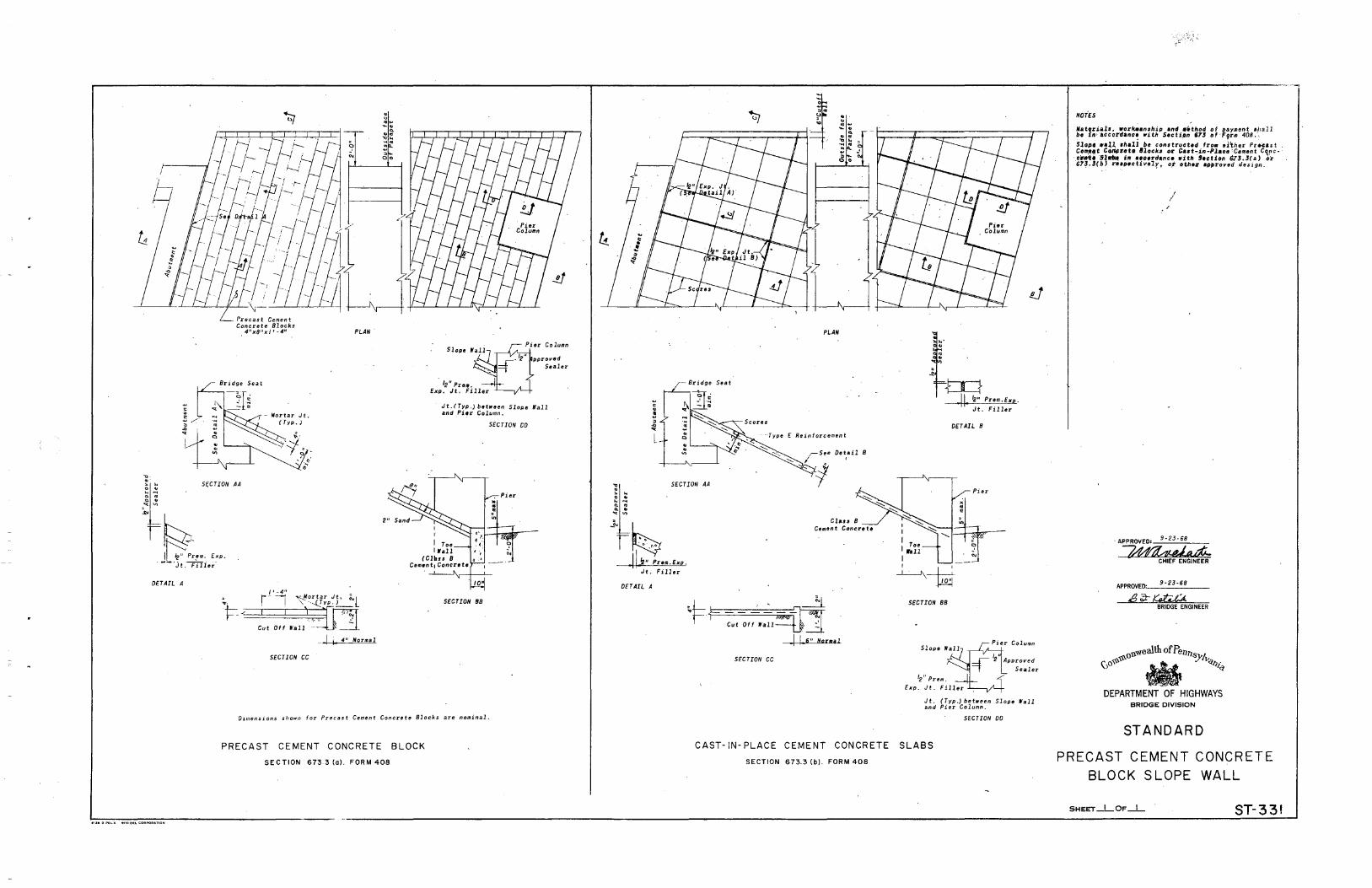
DETAIL A I' -4" , r- ----j ~ortar Jt, i!..l
1=-- ~- I j \:ffi '·';! Cut Off Wall ·- ·
[ j 4" Normal
SECTION CC
Slope pproved
Sealer
Jt.!Typ,) botwoen SloM Wall and _Pier Column.
SECTION CD
SECTION 88
D1mensions shown for Precast Cement Concrete Blocks are nominal.
PRECAST CEMENT CONCRETE BLOCK
SECTION 6733(o). FORM408
PLAN
Detail 8
i:~ SECTION AA . .. . ~ .. ~ " ~ " ~ "" "'
~~ II~" Prem.Exo.
J t. F i 11er
DETAIL A
Clau 8 Cement Concrete
'l=r--- · _:_-nl ' Cut Off Wall ~ ::
I I 6 11 N.ormal
SECTION CC
I I
I I Toe rau
I
~ "" . -
tr1 Jl ~" Prem.Exp.
Jt. Filler
DETAIL 8
r ~---
~-tri-SECTION 88
Jt. (Typ.) between Slope Wall and Pier Column.
SECTION DD
CAST-IN- PLACE CEMENT CONCRETE SLABS
SECTION 673.3 (b). FORM 408
NOTES
Nat,r.i.a~.s. _worlc•anship and •'thod of ~ayment •l1all be tt~•accordanc~ with Sectipn 67! of'F?rm 408.~
Slope waU rhall be con1tructod fro• ol~h 0r Pr•cast . COIJI!I'I!~ CO®rote lllock> or Cut~in-l'laco 'Cement C~rc.cr4U Sln. i" uoordance with Section 6l3.:J(a) or 67~.!(b) re•.oectivelr, of o&he.zo ·~t~roved clesi_gn.
' /
·APPROVED: g.zj-SB
~e,ii--cHIEF ENGINEER
APPROVED:: __ 9_-_2_3_-5_8;_, __
BRIDGE ENGINEER
DEPARTMENT OF HIGHWAYS BRIDGE DIVISION
STANDARD
PRECAST CEMENT CONCRETE
BLOCK SLOPE WALL
SHEET_I_OF_I_ ST- 3 31

Consfr. joint
End Closure required where form is cui on skew. See "Types of End Closures: shf.l.
Bent Jt. or L, size os rsquirsd
TYPICAL LONGITUDINAL SECTION DETAIL AT TRANSVERSE CONSTR. JT'S. AND METAL INTERIOR DIAPHRAGMS
DETAIL A
BliTT liNO€RFORM ANGLE CHANNEL PRE CLOSED
TYPES OF END CLOSURES
Tooth or olhsr fyptJ of tJJtponsion joint Plots, Tooth or other type of tJJtponsion joint
.----flii-End Closurs rBquired
siztJ os rsquirtJd
llss wood or mslo/ hNrfs __.----
DETAILS AT EXPANSION JOINTS
Beam or girdsr
TYPICAL HAUNCH DETAIL FOR STEEL BEAMS AND GIRDERS,
(Osfoil showr'ng support sysftJm for forms fo bs shown on fht1 shop drawings. Wsldt'ng fo f/ongss in fsnsion orsos will nof btJ ptJrmifftJd)
..!!.Q!li..'..
EXAMPLE•
GIVEN• Beam Spacing • 7''-11"% Beam Flange Width • 12" Slab Thiclrntlss, I• 8~• Gradl C Form
REQUIRED• Section Modulus, S ond Momtlnl of lnllrfia,l of. Fomr
SOLUTION• Design SfHIII, I• (7'~11")-(12"J-(2"} • 6'-9" or 81• From Tob/11 on Sht.2, far I• 81"
1•7'" s •. 2904 1•10" s •. $617'
S by inftlrpo/alion for I• B~~ • .S260 ln'Yfl. S for Grodl C Form-8.24)(.$26(1•.4042/n'Yft
I for I• 8~", •.4284 inYfl.
whllrfl form is cut on slrtlw. Sst1 "Types of End ClosurtJs .. (TYP.)
NATERIALS AND WORKMANSHIP SHALL BE IN ACCORDANCE WITH SPECIFICATIONS FORNS 408 AND 409, AND THE SPECIAL PROVISIONS.
THIS STANDARD SHALL BE USED AS A GUIDE IN THE PREPARATION OF SHOP DETAIL DRAWINGS.
HAUNCH DETAILS SHOWN ON THE DESIGN DRAWINGS SHALL BE NAINTAINED.
GAGE AND SIZE OF SUPPORTING ELEMENTS AND FORII SHALL BE SHOWN ON THE SHOP DRAWINGS. MININUN THICKNESS OF THE FORNS SHALL BE 22 GAGE,
Mdiiii969 ALL FORN SUPPORTS AND THEIR ATTACHNENT SHALL BE .DESIGNED TO CARRY DEAO· LOAD OF DECK SLAB PLUS 50 LBS. PER SQUARE FOOT FOR CONSTRUCTION LOADS.
ALL FORIIS SHALL BE S.ECURELY FASTENED TO FORM SUPPORTS AND SHALL HAVE A NININUN BEARING OF I INCH EACH SIDE.
FORN SHEETS SHALL BE ATTACHED PROJIPTLY TO AVOID HAZARDS THAT CAN RESULT FRON LATERAL NOVENENT OR SUDDEN UPLIFT.
ALL ATTACHMENTS SHALL BE NADE BY WELDS,BOLTS,CLIPS,OR OTHER APPROVED NEANS AND SHALL BE WATERTIGHT.
FIELD CUTTING OF FORMS, SUPPORTS AND CLOSURES SHALL BE PERFORJIED WITH SAW, SHEAR OR OTHER APPROVED NEANS.
WHEN TWIN BRIDGES ARE CONSTRUCTED ADJACENT TO EACH OTHER AND DIY;fDED BY AN OPEN OR A PREFORMED JOINT, NET AL FORNS IN THE C<\NTILEVER Ail£ A BETWEEN THE BRIDGES NAY BE USED ONLY WITH THE PERNISSfON OF THE CHIEF BRIDGE ENGINEER. .
· 0~1h ofPelllJ~ (JO~~ w it/JI~
DEPARTMENT OF HIGHWAYS DIVISION OF BRIDGE ENGIIii!IIIIIG
STANDARD
PERMANENT METAL DECK FORMS
SHDT_I_OP_L
J '
. ,I

~\;_:~::.:·:{~:~.·~~\~'· .=:•;:::~~:~i/\1:?~ ·:.~
Ben/ It or L. , size as required
~Oelo;;'s no! opplicob:e___/
lo P/S Box Beams
Weld Stirrup Lock lo hanger
/
/
STIRRUP LOCK
End Closure required where form is cui on skew. See *Types of End Closures; Shl.l
" .,. '5 ':·~
P .. '~
i···
~j ~
:~
~; • .4. ··b. ... t> II- "dll .
DETAIL AT CONCRETE DIAPHRAGM
Limit hllighl of support to ct11or ,
Weld anchors or11 cast-in-place
111 /he beam.
TYPICAL TRANSVERSE SECTIONS ATTACHMENT OF FORMS TO ~S I-BEAMS FOR VARIOUS
CONDITIONS. SIMILAR FOR P;S BOX BEAMS
... Use straight line interpolation for slab 'thickness between 8 112" and /0 11
•
The values of I shown in the table are based on the deflection reqtLirements in the Design Specifications. If economical and practical forms may be cambered to account for deflection or a portion thereof, in which case, values of I may be adjusted. ..
transverse reinforcemtml bors(TYP.)
:J:.<f!:.-·.j,.:. f,'J~.::=,.!ii-; .. ,
~:t
End Closurtl r11quir11d where form i:• cut on skew. S11e •ryplls of End Closur11s~ Shi.I(TYP.)
REQUIRED SECTION MODULUS AND MOMENT OF INERTIA OF FORM
s. Sect. Modulus ~~~ I, Nolfrent of Inertia
in.3 per ft. * .~ ~ in. 4 per ft. .. ~ ... .. .
t, Slab Thickness Q~ I, Slab Thicknes• 7" 10"
... 812" '"'"' !:. 8'' 10''
. 0574 .0714 36 oOJ71 .0376 .04J4
-067J .0838 39 .0471 .0478 >0551 . 0780 .0972 42 • 0589 .0598 .0690 .0897 .1116 45 .0724 .07J5 .0848 . 1020 ./270 48 .0879 ~0892 '1029 . /152 ./434 51 '1054 '1069 '12J4 . 129.1 '1607 54 .1251 ./269 .1465 ./439 ./791 57 '1471 ./'492 '1722 .1594 • 1984 60 • 1716 .. /741 -2009 .1757 • 2188 63 ./987 .2016 .2J26 ./928 .2401 66 -2284 .2317 ·2674 . 2108 .2674 69 .2610 ,2648 .3056 .2294 .2858 72 .2966 .3009 .3473 . 2490 .3101 75 .3352 .3401 .3925 .2694 .3354 78 .3770 .3825 .4414 .2904 .3617 81 .4222 .4284 -4943 . 3124 .3889 84 -4709 .4778 .5513 .3351 .4172 87 .5232 .5308 .6126 .3586 .4465 90 .5792 .5876 .6781 .3828 . 4767 93 .6604 .6700 .7732 .4080 .5080 96 .7498 .7607 -8779 -4339 5402 99 .8480 .8604 .9929
4606 .5735 102 .9556 .9695 I. 1188 .4881 .6077 105 /.0730 /.0886 /.2563 .5164 . 6429 108 1.2010 /.2/85 /.4062 .5455 .6792 Ill /.3402 /.3597 /.5693 .5754 .7164 114 /.4910 /.5/27 I .7457 .6060 .7546 117 /.6543 /.6784 /.9369 .6375 .7938 120 /.8306 /.8573 2.1433
* Use straight line interpolation for slab thickne•s between 7 11 and 10 11
, and multiply the values shown in the table by; /.00 for grades D and E I. 24 for grade C /.34 for grade 8 1.51 for grade A
® 1 = design span, in., shall be taken as clear distance between .the flangea of the •upporting beams minus two inches, mea•ured p•rallel to the form flutes.
DESIGN SPECIFICATIONS
PERNAHEHT IIETAL DECK FORIIS SHALL BE DESIGNED FOR THE DEAD• LOAD OF FOR/I, REIHFORCEIIEHT AND CONCRETE PLUS 50 POUNDS PER SQUARE FOOT FOR CONSTRUCTION LOAOS. THE FOLLOWING ALLOWABLE STRESSES SHALL BE USED IN THE DESIGN:
GRADE OF IIETAL FORII
A B c D E
YIELD (PSI) 33,000 J7. 000 40,000 50,000 80,000
ALLOWABLE STRESS (PSI) 2;,,900 26,800 29,000 ;,1,000 36,000
IIAXIIIUII DEFLECTION UNDER WEIGHT OF FIJRN, REIHFORCEIIEHT AND CONCRETE SHALL HOT EXCEED 11180 OF THE FOIIII SPAN OR 112-INCH. rHICHEVER IS LESS. IIAXIIIUII DEFLECTI0/1 UNDER 60 POUNDS PER SQUARE FOOT OF LIVE LOAD SHALL NOT EXCE:EO 11360 OF THE: FORII SPAN OR /14-INCH, IIHICHE:VER IS LESS •
THE IIINIIIUII THICKNE:SS OF THE FOIIII SHALL 8E 21 GAGE:
0~th ofPena~ \.)0~~ • i?JI,~
DEPARTMENT OF HIGHWAYS DMSION OF BRIDGE ENGINEERING
STANDARD
PERMANENT METAL DECK FORMS
SHEI!T _&_oF _g_ ST-332