Engineering and Design Standards and Construction Standards
59
Engineering and Design Standards and Construction Standards City of Deer Lodge 300 West Main Street Deer Lodge, MT 59722 (406) 846-3649 JULY 2, 2019
-
Upload
khangminh22 -
Category
Documents
-
view
4 -
download
0
Transcript of Engineering and Design Standards and Construction Standards

Engineering and Design Standards
and Construction Standards
City of Deer Lodge
300 West Main Street
Deer Lodge, MT 59722
(406) 846-3649 JULY 2, 2019


pg. i
i. TABLE OF CONTENTS ........................................................................................ i
I. GENERAL PROVISIONS ..................................................................................... 1
II. WATER SYSTEMS .............................................................................................. 7
III. SANITARY SEWER SYSTEMS ......................................................................... 13
IV. STORM WATER MANAGEMENT ...................................................................... 18
V. STREETS AND TRANSPORTATION ................................................................ 23
VI. EROSION AND SEDIMENTATION CONTROL .................................................. 32
VII. MODIFICATIONS TO MPWSS ........................................................................... 36
APPENDIX A – STANDARD DRAWINGS
WATER RELATED 2-1 – 2-4
SEWER RELATED 3-1 – 3-3
TRANSPORTATION RELATED 5-1 – 5-10

City of Deer Lodge, Montana ENGINEERING AND DESIGN STANDARDS AND CONSTRUCTION STANDARDS
pg. 1
I. GENERAL PROVISIONS
1. Purpose The purpose of these Engineering and Design Standards and Construction Standards is to promote maximum uniformity to engineering design and construction practices that will provide the City with complete, quality construction drawings and specifications. In turn, it is expected public infrastructure construction will have uniformity in materials and workmanship that will provide the City infrastructure that lasts well beyond its expected design life and does not require additional maintenance outside the standard maintenance associated with various components of infrastructure.
2. Adherence to Standards
It is the policy of the City and Public Works Department (PWD), that in most cases, adherence to these adopted standards will not create undue hardship or not be in the publics best interest. However, when unique circumstances make adherence to these standards impractical, or would create a condition detrimental to the public interest, the PWD will consider alternate solutions. Any alternate solutions must follow sound engineering and/or construction practices. The City Council will consider deviation requests from these standards, after review and recommendation from the Public Works Committee.
3. Adoption of Montana Public Works Standard Specifications
The City adopts the current edition of the MONTANA PUBLIC WORKS STANDARD SPECIFICATIONS (MPWSS). Modifications to the MPWSS are set forth in this document. These changes and/or additions shall in all cases either govern over the MPWSS where applicable or shall work in conjunction with the MPWSS where applicable.
4. Public Right-of Way Permit
All construction, excavation or other work on public or private property which will necessitate the use of the public right-of-way or easement shall require a Public Right-of-Way Permit issued by the Public Works Department. The work authorized by the Permit includes, but is not limited to, street construction and repair, water, sewer, and storm system construction and repair, utility connections and repair, landscaping, sidewalk, curbing and driveway construction and repair. Also included are any other uses of the public right-of-way where there is a possibility of creating a hazard. Examples of hazards are scaffolding, storage of materials or equipment, crane and equipment operations, demolition, sandblasting and painting operations, temporary construction or demolition dumpster placement and any other use deemed a hazard by the PWD. The Permit will not be issued until all insurance and bonding and their subcontractors shall be required to purchase an excavation permit. Improvements to boulevards in public right-of-way require approval from the City PWD. The adjacent property owner is responsible for all cost associated with construction and maintenance of any boulevard improvements that have been approved.
5. Interruption of Service
No person or part shall interrupt or restore municipal service or access to any customer or property without the express consent of the PWD.

City of Deer Lodge, Montana ENGINEERING AND DESIGN STANDARDS AND CONSTRUCTION STANDARDS
pg. 2
Any construction that will interrupt the normal operation of city sewer or water or transportation facilities, in which consent by PWD has been given requires notification to property owners and/or residents. The certification will identify the location, day, time, and duration of the street closer or service interruption. The Contractor shall notify the City Police and Fire Department at least forty-eight (48) hours prior to any street closures. The Fire Department will also be given said notice for water main interruptions.
6. Liability Insurance and Bonding.
a) Liability Insurance The Contractor shall procure and maintain, at the Contractor's expense, during the construction period, Contractor's Liability Insurance in accordance with the Supplementary Conditions to the General Conditions of the Montana Public Works Standard Specifications.
b) Bonding. The Property Owner/Developer will provide the City with a Performance
Bond equal to the value of the project for all public infrastructure construction required by a subdivision, development, or phased development. All construction work within the public 'right-of-way or easement (sidewalk and curb construction, storm drainage and sanitary sewer service line installation, repair, etc.) will require the Property Owner/Contractor to provide the City with a Performance Bond. Upon written acceptance of the project by the City, the Property Owner/Developer will be required to provide the City with a Maintenance Bond of 10% of the value of the work performed. The Maintenance Bond shall remain in full force throughout the one-year guarantee period. Contractors furnishing the City with an annual bond of $5,000 will not be required to furnish additional bonding if the $5,000 bond meets the requirements of these standards. Bonds may be in the form of a Surety Bond, a Certificate of Deposit (CD), a Certified Check or an irrevocable Letter of Credit issued by a bank licensed to do business in the state of Montana.
CONSTRUCTION DRAWINGS
1. Horizontal and Vertical Control Project control, benchmarks, and horizontal and vertical datums shall be clearly shown on the plans and shall include location, description, and elevation. A control point file is required so that the project can be oriented in the City's GIS database. A minimum of 4 control points shall be reported. The control point file can be a unique layer in the CAD drawing or a shape, text, or tabular file.
Horizontal Control: Any Local, State, or National Geodetic Survey (NGS) adopted system may be used. The system must be identified so that data can be easily convert from one system to another. Vertical Control: The North American Vertical Datum 1988 (NAVD 88), or the most current adopted NGS Vertical Datum for the United States and Territories, shall be used for the vertical control.

City of Deer Lodge, Montana ENGINEERING AND DESIGN STANDARDS AND CONSTRUCTION STANDARDS
pg. 3
Conversion from design coordinates to the above shall be provided on the plans and include the following information: a. Northing, Easting, and Orthometric Height control points.
b. Latitude, Longitude, and Ellipsoid Height of control points.
c. Geoid used.
d. Meridian Convergence Angle at control points.
e. Ground scale factor at control points.
2. All full-sized plans shall be on 24-inch by 36-inch plan sheets or 22-inch by 34-inch plan sheets. Reduced scale plans may be submitted for review if approved by the City PWD, but all plans for final approval (excepting the one required ½ size sheet) and all record drawings shall be full-sized. All plans submitted for review and approval will be stamped, signed, and dated by a professional engineer licensed in the State of Montana.
3. All drawings will have both plan and profile views of the proposed improvements. A general
location map shall be provided showing the relationship of each page to the overall development.
4. Project datum and benchmarks shall be clearly identified on the plans. 5. English units are required.
DRAWINGS SCALES
The following scales are required. Other scales will be considered on a case by case basis if all information can be clearly shown.
Plans View: 1” = 50’
Profile View, Horizontal: 1” = 50’ (or match plan view scale) Profile View, Vertical: 1” = 50’
Stational interview: 100 feet or 50 feet
DRAWING REQUIREMENTS
The following items will be required on all plans. Existing features should be shown dashed or with a lighter shading than proposed new features. All construction will be tied to the centerline of a City right-of-way, to the centerline of a City easement, to a platted property line, or to a section line.
1. Plan View
a. North Arrow.
b. Legends of Symbol
c. Property lines and ownership or subdivision information

City of Deer Lodge, Montana ENGINEERING AND DESIGN STANDARDS AND CONSTRUCTION STANDARDS
pg. 4
d. Street names and easements with width dimensions.
e. Project Stationing.
f. Limits of existing paved or graveled surfaces.
g. Monument boxes.
h. Culverts.
i. Existing and proposed utilities and structures, including:
• Line size and material where appropriate;
• Water lines (main lines and service lines), valves, and hydrants;
• Sanitary sewer lines (main lines and service lines) and manholes;
• Storm sewer lines, manholes, and inlets;
• Gas lines;
• Electric lines, poles, transformers;
• Telephone lines, manholes, junction boxes;
• Cable T.V. lines, junction boxes;
• Irrigation ditches and structures;
• Irrigation systems
• Fiber optic lines, manholes, junction boxes;
• Street lights;
• Proposed method of restoration of all disturbed during construction
2. Profile View
a. Vertical and horizontal grids to scales.
b. Final grade (solid).
c. Existing grade (dashed).
d. Existing utility lines where crossed.
e. Project Stationing.
f. Utility crossings.
UTILITY DRAWING REQUIREMENTS
1. The following general notes must be clearly identified:
a. All construction will conform to MPWSS, (Latest) Edition, and City Modifications to MPWSS
b. Any existing or new valves which control the City’s water supply shall be
operated by City personnel only.

City of Deer Lodge, Montana ENGINEERING AND DESIGN STANDARDS AND CONSTRUCTION STANDARDS
pg. 5
c. The Contractor shall notify the Water Department a minimum of 24-hours prior to beginning any work.
d. Contractor shall field-verify line and grade of existing connections.
2. Plans for water facilities shall show the following:
a. Size, type and structural class of proposed new water line(s), including
AWWA specifications.
b. Bedding class.
c. Existing water lines including size and material.
d. Proposed valves, fittings, fire hydrants, and service lines, with stationing.
e. Depth of cover from finish grade to proposed water line(s).
f. Requirements for pipe deflection, if necessary.
g. Type of joint restraint, if required.
h. Plan and Profile with other crossing utilities shown to scale in the profile.
i. Existing or proposed pressure reducing valves.
3. Drawings for sanitary sewer facilities shall show the following:
a. Size, type, and structural class of proposed new sewer line(s), including American Society for Testing and Materials (ASTM) specifications.
b. Plan and Profile of each proposed pipeline segment with all other crossing
utilities shown to scale in the profile.
c. Bedding class.
d. Existing sewer lines and manholes including size, material, field-verified invert elevations, and field-verified slopes.
e. Manholes with stationing and rim and invert elevations and grade of pipe.
f. Existing and proposed sewer service lines with size and stationing.
g. Existing and proposed cleanouts.
4. Drawings for storm sewer facilities shall show the following:
a. Size, type, and structural class of proposed new sewer line(s), including ASTM specifications

City of Deer Lodge, Montana ENGINEERING AND DESIGN STANDARDS AND CONSTRUCTION STANDARDS
pg. 6
b. Plan and Profile of each proposed pipeline segment with all other crossing utilities shown to scale in the profile.
c. Bedding class.
d. Manholes with stationing and rim and invert elevations and grade of pipe.
e. Inlets and inlet service lines with stationing and invert elevations.
f. Points of storm water discharge.
ROADWAY DRAWING REQUIREMENTS
1. Drawings for streets and roadways shall show the following:
a. Limit of cut or fill.
b. Existing and proposed utilities, including manholes and valves.
c. Plan and profile with all crossing underground utilities shown to scale in the profile.
d. Existing and finished grades, with finished grade slopes.
e. Vertical and horizontal curves, with curve data (min.):
• Horizontal curves – PI sta, curve deflection, R, L, PC and PT Stationing
• Vertical curves – PI sta and elev, K, L, Stations of PT’s
f. Profile of centerline.
g. Profiles of left and right curb lines, if they are not the same.
h. Any required utility adjustments.
i. Existing and proposed signs and pavement markings.
j. Top of curb elevations at P.C.s, P.T.s, and inlets.
k. Existing and proposed street monuments.
l. Typical roadway section(s), dimensioned and drawn to scale, showing:
• Right-of-way
• Backslopes
• Sidewalks
• Curb and gutter
• Structural section materials and depth
• Cross-slopes

City of Deer Lodge, Montana ENGINEERING AND DESIGN STANDARDS AND CONSTRUCTION STANDARDS
pg. 7
II. WATER SYSTEMS
1. Design Requirements Water systems shall be designed, constructed, and tested in accordance with the current editions of circular DEQ-1 – Montana Department of Environmental Quality-Standards for Water Works and the Montana Public Works Standard Specifications and these specifications.
2. Design Report
All water main extensions will require the Engineer of Record to submit a written report to the Public Works Department (PWD) addressing the fire and domestic flow requirements. For residential or non-residential developments that will utilize an average daily flow of less than 25,000 gallons at build-out, the report shall include data on test results at the nearest hydrant which shows the static pressure at zero flow from the hydrant and the residual pressure with available flow from the hydrant. At the discretion of the PWD, the Design Engineer may be required to conduct hydraulic modeling to demonstrate compliance with the flow and pressure requirements set forth in this section. For residential or non-residential developments that will utilize an average daily flow of 25,000 gallons or more at build-out, or that require utilization of a pressure booster pump(s), the report will be required by the PWD to include hydraulic modeling results that show the adequacy to meet fire and domestic flow and pressure requirements of this section. The normal operating range of pressure allowed for water system design is 50-110 psi or as approved by the PWD without the use of booster or fire pumps.
WATER MAINS
1. Design Considerations Hydraulic Analysis – The design of all water mains shall be based on a hydraulic analysis considering flow demands and pressure requirements. The main must be designed to maintain a minimum normal working pressure of 35 psi and maintain an absolute minimum pressure of 20 psi under all flow conditions. Maximum normal working pressures should not exceed 110 psi.
2. Fire Flows – All mains shall be designed to provide adequate fire flows unless
specifically waived by the PWD. The minimum required fire flow shall be 1500 gpm for residential housing or determined by the City Fire Chief at a minimum of twenty pounds per square inch residual pressure at the hydrant during flow in order to meet adopted codes.
3. Diameter – All water main piping shall be at least 8" diameter, unless otherwise
authorized by the PWD. Larger diameters will be required in order to maintain the minimum pressure requirements of Montana Circular DEQ-1 Standards for Water Works. The City also may require over sizing of mains to meet overall system requirement.
4. Materials
Piping - All water main piping material shall be AWWA C900, 235 psi (DR 18) unless specifically authorized by the City Public Works Department. Water mains larger than 12-inches will meet AWWA C905 pipe requirements.

City of Deer Lodge, Montana ENGINEERING AND DESIGN STANDARDS AND CONSTRUCTION STANDARDS
pg. 8
Acrylonitrile butadiene (NBR) gaskets will be required for water main installations in areas of known or suspected hydrocarbon contamination.
Fittings – All water main fittings, including tees, crosses, caps, plugs, reducers and elbows equal to or greater than 11-1/4° shall use mechanical joint restraints. All mechanical joint restraints shall be “Megalug,” “Uniflange” or approved equal. Joint restraint use shall be in addition to meeting thrust block requirements in accordance with MPWSS.
5. Installation
Existing Valve Operation – In order to isolate sections of the existing water system to allow for new construction, it will be necessary to operate existing system valves. The PWD must operate existing valves and notification and scheduling thereof must be coordinated with the PWD
Cover – The minimum cover for all water mains from top of pipe to final finished grade shall be 6½ - feet.
Encasement – All water main piping, fittings, valves, etc. (excluding PVC pipe) shall be encased in polyethylene wrap with a minimum thickness of 8 mils. All encasement shall be in accordance with AWWA C105 Standards.
Electrical Thawing – Conductive brass wedges shall be installed at all joints to provide for electrical thawing. Electrical continuity shall be provided at all flexible, dresser-type couplings.
Tracer – Ten-gauge copper coated tracer wire shall be installed along the top of the new PVC water main and shall be attached to all valve box risers. Six-inch wide detectable tape marked “WATER” shall be installed two feet below finished grade along the alignment of the new main and attached to all valve box risers. Cathodic Protection – Cathodic protection is required for all water main valves, fire hydrants and fittings.
Open Trenches – Trenches for the installation of water mains shall be properly backfilled as quickly as possible, but no more than 72 hours after initial excavation.
Protection of Mains – When working near and/or exposing existing City water mains and service lines, workers shall utilize hand-digging within 2' of mains in order to avoid damage to those pipes. If damage occurs, costs incurred by the City can be imposed.
6. Extension
Any extension of an existing City water main must be extended through the entire frontage length of the property to be served. Main extensions shall include all valves, pipe sizes, hydrants and appurtenances deemed necessary by the City.
Public mains must be connected, extended or looped in addition to the proposed extension to provide an adequate and functional water supply, and provide for future extensions to adjacent properties.

City of Deer Lodge, Montana ENGINEERING AND DESIGN STANDARDS AND CONSTRUCTION STANDARDS
pg. 9
7. Sewer Line Crossings Crossings - A minimum of 18" vertical separation is required when a water main or service connection crosses above or below a sanitary sewer, measured outside to outside of pipe. Please refer to MPWSS for further information on sewer line crossings.
Less than 18" vertical separation may be allowed when a gravity sewer at the crossing is made from a single 20' length of AWWA pressure pipe and the crossing is approximately 90°. Specific authorization from the Montana Department of Environmental Quality and the PWD is required for a vertical separation of less than 10-ft. No exception of the minimum 18" vertical separation requirement is permitted when the sewage pipe is a force main.
Parallel – A minimum of 10' horizontal separation is required when a water main and sanitary sewer are installed parallel.
8. Tapping City Water
The PWD shall tap all water mains for services up to 1-inch in size. Preparations for exposing the water main and preparing the water main for tapping, as well as scheduling for the PWD to make the tap are all responsibilities of the water main installer. The City PWD can be contacted at 406-846-2238, ext. 300. All taps require at least 48-hour notice and If a tap requires a main shutdown, 72-hour notice is required, and the contractor is required to notify the affected water users.
Any person desiring to make connection to the City’s water or sewer mains must make application in writing and pay for the cost of tapping and any associated system development fees set by the City of Deer Lodge. All taps shall be made using a Mueller or Ford style FS303 stainless steel saddle for AWWA C900, DR-14 Class 200 PVC pipe. Taps of sizes ¾" to 1" on water mains require the city to do a direct tap and provide a properly sized corporation valve. Special provisions apply for ¾" and 1" taps on 4" mains. For integrity of the main, these taps require the use of a properly sized tapping saddle, which is required to be purchased and supplied by the plumbing contractor.
Taps for sizes 1½" and 2" on all sizes and types of mains require a properly sized tapping saddle and corporation valve purchased and supplied by the plumbing contractor. Bronze or stainless-steel double strap or wide band tapping saddles are required on service lines up to 2" in diameter.
Taps of larger than 1" must be performed by a licensed, qualified contractor and require a tapping saddle, tapping valve and a valve box to be purchased and supplied by the plumbing contractor. All taps 4" and larger must be air tested prior to tapping.
On all taps that require a saddle the plumbing contractor must provide and install the saddle.
9. Valves
Valves shall be installed in the distribution system at sufficient intervals to facilitate system repair and maintenance as determined by the Public Works Department,

City of Deer Lodge, Montana ENGINEERING AND DESIGN STANDARDS AND CONSTRUCTION STANDARDS
pg. 10
but in no case shall there be fewer than one valve every 600'. Generally, there shall be two valves on each tee and three valves on each cross. All Gate Valves shall conform to AWWA C515 Standards and shall open CLOCKWISE. All Butterfly Valves shall conform to AWWA C504 Standards and shall open CLOCKWISE.
All Tapping Valves shall open COUNTER CLOCKWISE
All water valve boxes shall have a concrete collar installed after paving and final grade adjustment. All water valve boxes shall be aligned to allow a 4" diameter PVC pipe to be inserted in the valve box and centered over the valve nut.
All water valve boxes will not be extended more than 50% of the total adjusting range.
10. Fire Hydrants
Unless otherwise approved by the Fire Chief, the hydrants shall be spaced no further apart than one standard City block, which is approximately 500'. The Fire Chief reserves the right to require additional fire hydrants if the demand of the structure(s) requires more flow than the minimum spacing provides. The placement of all hydrants shall be subject to approval of the City Fire Chief and the PWD.
Fire hydrants shall be 250 psi, 5¼", 3-way, “Mueller Super Centurion 250”, or approved equal, conforming to AWWA C502 Standards. All hydrants shall be painted red above the ground line.
All hydrants shall be equipped with a #4 pentagon (1¼") operating stem nut and shall open in a CLOCKWISE direction. The direction of opening shall be indicated by a permanent arrow on the hydrant top.
All hydrants shall be designed for final grade of hydrant safety flanges set at 1 ½” to 3" above finished grade. Minimum cover depth on the hydrant lead shall be 6.5' with a maximum of 8.5’. All hydrants shall have a solid one-piece operating stem; the use of a hydrant extension will only be allowed with prior approval of the PWD and no other option exists. Pipe deflection on hydrant leads shall be minimal and shall not result in finished hydrant more than 1° out of plumb. The hydrant auxiliary valve shall be located in the street pavement or boulevard with a standard water valve and concrete collar. No valves or collars shall be located within the curb and gutter.
11. Water Vaults
All underground vaults and manholes associated with the City’s water system shall be constructed of pre-cast concrete sections meeting ASTM C478 or C858. Vault manhole covers shall have the word “water” cast into the top surface. All water vault manhole frames shall have a concrete collar patch poured after paving and final grade adjustment.
WATER SERVICE LINES
1. Materials

City of Deer Lodge, Montana ENGINEERING AND DESIGN STANDARDS AND CONSTRUCTION STANDARDS
pg. 11
All service lines shall be a minimum of 3/4" in diameter. All water service lines smaller than 4" diameter shall consist of Type K copper pipe meeting ASTM B88-62 from the main to the curb box. Poly pipe or PVC pipe maybe considered on a case-by-case basis in corrosive soil with approval from the Public Works Department.
All water service lines 4" diameter and larger shall consist of ductile iron pipe meeting AWWA C151, American National Standard for Ductile Iron pipe. Stainless steel inserts are required for all compression-type fittings. In accordance with Sections 1417 (a) and (b) of the Safe Drinking Water Act amendments of 1986 (Public Law 99-339), the use of solders and flux containing more than 0.2% lead and pipes and fittings containing more than 8% lead is prohibited in the installation and repair of residential or nonresidential plumbing connected to a public water supply system.
2. Installation
All water service lines must be so arranged that the supply to each separate house premises or buildings may be controlled by a separate shutoff valve and curb box placed within the right of way near the property to be served. One singular, identifiable entity will be responsible for all the water used through each service. All water service line connections to the water main must be made by a licensed plumber.
All individual condominiums and separate buildings, including manufactured homes, must be served by individual service line from the main. In the cases where individual service lines are not feasible, one service will be allowed with only one master meter that is the responsibility of the condominium associations or one individual for payment. Multiple meters that are read and billed by the City will not be allowed on a single service. In cases where the street is less than ten years old with a single service to the condominium lot, individual meters may be allowed with manifold and a master shutoff valve along with individual shutoff valves located within City ROW.
At all locations where water service lines are installed beneath new curb, the face of the curb shall be stamped with a “W” in lettering at least 3" tall, for marking the water service location. “Tunneling” under existing curbs, curb and gutter, etc is prohibited.
All services must be connected to a City main. Service lines may not be connected to fire hydrant leads. A tracer wire must be installed and tested for all poly pipe and PVC services.
3. Curb Stops and Boxes
Curb Stops – All curb stops shall have a bronze plug, tee head key with either a Minneapolis top thread or standard no thread, with a copper flare nut on both connections.
Curb Boxes – All curb boxes shall be extension-type having a minimum box length, fully retracted, of 6’. All curb boxes shall be Mueller or Ford or equal as approved by the Public Works Department. All curb boxes shall have screw-on or other type

City of Deer Lodge, Montana ENGINEERING AND DESIGN STANDARDS AND CONSTRUCTION STANDARDS
pg. 12
lid, which can be attached to the top of the riser. All curb boxes shall be within 1° of plumb and centered directly over the corporation stop nut. A 1" rigid pipe must be able to pass through the curb box and over the operating nut. The curb box will be part of the final inspection, by the PWD, for building permit or final approval of infrastructure construction.
4. Service Line Meters
Water meters, including meter remote read hardware, will be purchased by the property owner and will be installed by a licensed plumber. Meters will be Neptune T-10. Remote readout will be placed on the outside of the building at a location that is easily accessed by City personnel.
All meters must have valves upstream and downstream of the meter in order to isolate the meter for servicing. Meters and remote read hardware, are the property of the City.
All meters must be installed in a horizontal line at a minimum of 18" and a maximum of 4' from the floor, and a minimum of 6" from any wall. The meter must also be located close to a floor drain. All meters shall be located away from any electrical devices/equipment. All meters larger than 2" shall be either turbine or compound meters and shall be installed in accordance with the manufacturer’s recommendations, including a strainer and bypass with locking type valve.
5. Backflow Prevention
“Backflow” is defined as the undesirable reversal of water flow or the reversal of water flow containing other liquids, gases or other substances from a connected source that flows into the distribution pipes of the public water supply. The City may require, at its discretion, the installation of appropriate backflow protection devices on new or existing service lines when the water user is involved in water use practices that pose a threat to the City’s water system. All existing sources for water that are not part of the City ’s water system must be disconnected from the City’s system.

City of Deer Lodge, Montana ENGINEERING AND DESIGN STANDARDS AND CONSTRUCTION STANDARDS
pg. 13
III. SANITARY SEWER SYSTEMS
1. Design Requirements Sanitary sewer systems shall be designed, constructed, and tested in accordance with the current editions of Circular DEQ-2 – Montana Department of Environmental Quality – Design Standards for Wastewater Facilities and the Montana Public Works Standard Specifications.
2. Design Report
All sanitary sewer main extensions shall require the Design Engineer to submit a written report to the PWD which addresses the design requirements listed herein. The design report shall demonstrate that all sanitary sewer main extensions have adequate capacity to convey wastewater from the anticipated service area and meet the minimum flow velocities and/or flow depth requirements in Chapter 30 of MDEQ Circular-2. The design capacity should be based on 112 gpd per capita for single family residence and an average of 2.1 people per residence.
SANITARY SEWER MAINS
1. Design Considerations Slope – Gravity sewer mains shall be installed with slope adequate to maintain flow velocities of at least 2.0 feet per second (fps) when depth of flow is at 1/3 of the sewers main inside diameter, based on Manning’s equation with an “n” value of 0.013. Recommended minimum pipe slopes listed in Section 33.41 of Circular DEQ-2 will be considered adequate.
Capacity - Public sanitary sewers and appurtenances shall be designed to accommodate peak hourly flows, including an allowance for infiltration, while flowing no more than half full when no additional connections are possible and a quarter full when future growth is anticipated. The development must upsize the existing mains if the capacity of the sewer main is calculated to be three quarters full. The allowance for infiltration shall be 150 gallons per acre of coverage area per day or otherwise approved by Public Works Department.
Diameter – Gravity sewer mains shall have a minimum diameter of 8". Increasing the diameter in order to meet the minimum pipe slope requirements will not be allowed.
Manholes- Shall be a minimum for 48" less the 13' of bury for all manholes with bury depth greater than 13' a minimum of 60” manhole is required.
Flow Direction – On the infrastructure plans all sewer pipes shall be labeled as to the flow direction.
Accessibility - Sewer mains shall be installed in public right-of way where ever possible. Where mains cannot be installed in ROW a 20' wide exclusive easement with a 14' all- weather surface road must be constructed in the easement.

City of Deer Lodge, Montana ENGINEERING AND DESIGN STANDARDS AND CONSTRUCTION STANDARDS
pg. 14
2. Materials Gravity Piping – Gravity sewer main piping shall consist of any of the following materials:
a. PVC meeting ASTM D3034, SDR 35 & 26 (8" to 15").
b. PVC meeting ASTM D679, SDR 26 or ASTM F794 (18" and larger).
c. HDPE meeting ASTM D3350 and ASTM F714.
d. Concrete meeting ASTM C14, C76 or C655.
Other pipe materials specifically approved by the City PWD.
Pressure Piping – Pressure sewer piping (force mains) shall consist of PVC Pressure Pipe, ASTM D2241, Class 200 SDR-21, or AWWA C900 DR-18.
Manholes – All manholes shall be constructed using pre-cast RCP unless specifically allowed by the Public Works Department in writing. Structural strength shall withstand H-20 design load.
All manholes installed at outfall lines must have PVC liner installed to protect against H2S gas.
Manhole Ring and Cover – Manhole cover shall be stamped “Sewer”. The manhole ring/cover shall have an o-ring type gasket to protect the lid from inflow during storm events.
3. Installation
Alignment and Grade - Public sanitary sewers shall be installed with a straight alignment and grade between manholes as required in MPWSS. Location - Municipal wastewater system facilities shall be designed and constructed so that all such facilities are readily accessible for maintenance and repair. In addition, such facilities shall be situated so as to preclude the entrance of surface water into said facilities. All sewer mains shall be centered in the right-of-way or easement to the greatest extent possible.
Depth – Sanitary sewers shall be buried to a depth sufficient to prevent freezing and shall have a minimum depth of 4 feet. Shallower depths may be allowed by the City PWD if suitable pipe insulating provisions are provided.
4. Extension
Any extension of an existing City sanitary sewer main must be extended through the entire frontage length of the property to be served, with a standard manhole located at the terminus of the new sewer main. Sewer main extensions shall include all manholes, clean-outs and appurtenances deemed necessary by the City.
5. Water Line Crossings
Crossings - A minimum of 18" vertical separation is required when a sanitary sewer main crosses above or below a water main, measured outside to outside of pipe. Please refer to MPWSS for further information on water line crossings.

City of Deer Lodge, Montana ENGINEERING AND DESIGN STANDARDS AND CONSTRUCTION STANDARDS
pg. 15
Less than 18" vertical separation may be allowed when the gravity sewer at the crossing is made using a single 20' length of AWWA pressure pipe and the crossing is approximately 90° and the length of pipe is centered over the crossing. Specific authorization from the Montana Department of Environmental Quality and the City of Deer Lodge PWD is required for a vertical separation of less than 18". No exception of the minimum 18" vertical separation requirement is permitted when the sewage pipe is a force main.
Parallel – A minimum of 10' horizontal separation is required when a sanitary sewer main and water main are installed parallel.
SEWER SERVICE LINES
1. Materials Gravity Sewer Service Piping – Gravity sewer service piping shall consist of the following materials for the following situations:
PVC meeting ASTM D3034, SDR-35 & -26 or PVC Schedule 40 – Solvent Weld or SBR Gasket Joint for normal installations. PVC Schedule 40 or Cement Lined Ductile Iron for installation within 2' of a building foundation.
PVC Schedule 40 for water main or water service crossing.
PVC Schedule 40 with acrylonitrile butadiene (NBR) gaskets for installations in areas of hydrocarbon contamination.
Pressure Sewer Service Piping – Pressure sewer service lines shall consist of PVC Pressure Pipe, ASTM D2241, Class 200 SDR-21.
2. Installation
All sanitary sewer service lines must be so arranged that the discharge from each separately owned house premises, or buildings on separate lots is a separate service line that connects to the main. The owner of each house or premises is liable for the charges for the wastewater service provided by the city to that owner's house or premises.
Sewer service lines shall be installed with a minimum of 4' of cover from the top of service pipe to finished grade.
At all locations where sewer service lines are installed beneath new curb, the face of the curb shall be stamped with an “S” in lettering at least 3" tall, for marking the sewer service location. “Tunneling” of sewer service under curb, curb and gutter, sidewalks, etc. is prohibited.
3. Tapping City Sewer
Any person desiring to make connection to the city’s water or sewer mains must make application in writing and pay for the cost of tapping in accordance with City of Deer Lodge policy, resolution, or ordinance.

City of Deer Lodge, Montana ENGINEERING AND DESIGN STANDARDS AND CONSTRUCTION STANDARDS
pg. 16
All applications for service connection to the city's wastewater system must be made at the front counter at City Hall. Every such application must be made by the owner of the property to be served or the owner's authorized agent and must include the nature of wastewater discharged into the system.
4. Metering when not on City Water
For new city sewer services which do not use the city water system or whose water consumption or wastewater discharge is not otherwise metered, the Public Works Department shall require the installation of a suitable metering device in order to determine an equitable charge for sewer services.
LIFT STATION
1. Capacity The design capacity for a lift station shall be designed to a reasonable capacity based on similar flows from comparable zoned areas. The designer shall provide a table in the design report for the design capacity for each non-residential lot. Multi-family lots with a 4-plex or greater are also considered commercial lots. During the building review process a letter from an engineer must be submitted certifying that the sewer capacity is not greater than the original design capacity of the lot. If the capacity for the building is greater, additional capacity may be required.
2. Building
The building shall be constructed of masonry block or similar high durability construction material. The building style must be compatible with the surrounding environment. The developer must install and provide access to the building so maintenance equipment can access the building and wet well.
a. Landscaping All lift stations must have low-water/native vegetation and trees for the landscape screening with an irrigation system
b. Fencing
All lift stations must be fenced with an 8' high black vinyl coated chain link fence with 2-strand barbed wire top. A minimum of two lockable gates must be provided; one for pedestrian access and one double gate that is able to swing 180° for allowing maintenance equipment to access the site.
3. Wet Well
Must be lined with a PVC coating or approved equal by the Public Works Department.
4. Piping
All piping must be stainless steel within the wet well and ductile iron in the building. The pipe must also be configured to accommodate bypass pumping with a blind flanged tee after the last check valve.
All fittings must be located out from under the lift station slab or located within a grated trench. All fittings must be accessible without damaging the building.

City of Deer Lodge, Montana ENGINEERING AND DESIGN STANDARDS AND CONSTRUCTION STANDARDS
pg. 17
5. Valving All check valves must have external levers.
A three-way Dezerik plug valve must be installed at the point the two pumping lines join.
6. Safety
The wet well shall have a safety grate that is easily removable and integral to the hatch. The grate must be rated to at least 1000 lb. of loading. In addition to the hatch with a safety grate, removable handrails must also be supplied.
A compressor and two full-face masks with a minimum 50' hoses will be required for a fresh air supply. SCBA will not be acceptable as a fresh air supply.
7. Pumps
The pumps shall be Gorman-Rupp, Paco, Flyght or equal as approved by the PWD.
8. Telemetry The telemetry must be designed in accordance with the City Telemetry Design Standards. If no standards exist, coordinate with the PWD.
9. Pigging Stations
Any lift station with a force main of more than 2000' that does not have an existing flow of 50% of the design capacity must have pigging stations for cleaning of the force main.
10. Odor Control
All vents from the wet well or force main must have a carbon filter.
11. On Site Generator All lift stations must be supplied with an on-site generator. The generator must be a natural gas or diesel fuel unit located in a separate room within the building. An access door big enough to remove the generator for maintenance will be required.

City of Deer Lodge, Montana ENGINEERING AND DESIGN STANDARDS AND CONSTRUCTION STANDARDS
pg. 18
IV. STORM WATER MANAGEMENT
Storm drain systems shall be designed and constructed, in accordance with these engineering/design and construction standards and the Montana Department of Environmental Quality’s design circular DEQ-8, Montana Standards for Subdivision Storm Water Drainage, if the storm water system is associated with a subdivision development.
1. Storm Drainage Plans and Report
A Storm Drainage Plan shall be submitted for development or redevelopment that includes the creation of more than 5,000 square feet of new impervious surface area. A detailed stormwater report shall be prepared by a registered professional engineer. The storm water report shall contain the storm water calculations and a discussion of the design rationale. The plan shall include the following:
a. A map showing building site(s), open areas, drainage ways, ditches,
culverts, storm sewers, inlets, storage ponds, roads, streets, and any other infrastructure improvements which may affect drainage characteristics. The map shall also include identification of the various ground surfaces (i.e. vegetation, gravel, pavement) and their respective coverage (square feet).
b. Topographic contours (one-foot intervals) and sufficient spot elevation
data.
c. Description of the ultimate destination of stormwater runoff from the project and an evaluation of its impact on down slope drainage facilities.
d. Design calculations determining runoff quantities, storage requirements
and peak rates.
e. Description of water quality design method and calculations.
f. A storm drainage facilities operation and maintenance plan. The plan shall:
• Identify ownership of all facilities.
• Establish a schedule for maintenance activities necessary to keep the system operationally effective.
• Identify the responsible party in charge of the specific maintenance duties.
g. Details and specifications (including invert and other pertinent elevation
information) for all storm drainage improvements, such as storm sewer, manholes, inlets, discharge structures; and retention/detention pond dimensions and volume, side slope, and top, bottom, and maximum water surface elevations.
Pre-development and post-development runoff calculations for sizing drainage facilities shall include:
a. Depiction of the drainage area on a topographical map, with acreage indicated (the offsite contributing area must be included). Provide a pre-development topography and drainage basin map and a post-development topography and drainage basin map.

City of Deer Lodge, Montana ENGINEERING AND DESIGN STANDARDS AND CONSTRUCTION STANDARDS
pg. 19
b. The change in peak discharge and volume of surface water entering and leaving the subject property.
c. The capabilities of all downstream drainage systems within 1/4 mile of the
project site downstream boundary to handle the change in peak discharge and volume of surface water caused by the development.
d. In areas where ground water may be a factor, the analysis shall include the
effects of the ground water on the total storm drainage system proposed for the development.
2. Methods of Design
Storm Event Peak Rates and Volume. Two methods are to be used for determining peak storm water runoffs for the design of storm sewers, open channels and culverts. The Rational formula method is to be used to design storm sewer systems. Information on the Rational method is available in Chapter 7 of the MDT Hydrology Manual, including rainfall-intensity return periods. Use the one-hour precipitation return periods identified for station Butte – 8 miles south. When it is necessary to know the volume of water and discharge in addition to the peak rate of flow, the SCS TR-20 Hydrologic Analysis Model or pre-approved hydrologic simulation model will be used together with a detailed routing analysis. For flow routing through detention facilities models such as; SWMM, StormNet and HydroCAD are also acceptable methods.
Culverts and Open Channel Design. Culverts shall be designed in accordance with the U.S. Department of Transportation, Hydraulic Engineering Circular No. 5. Open channels shall be designed using the energy concept and the Manning Formula. Channels in earth shall have sides with a maximum slope of one-foot vertical rise for every two feet of horizontal distance. Steeper slopes will be permitted only if some type of bank protection is used to prevent erosion and sloughing of the sides into the bottom of the channel. Constructed and natural channels and culverts shall be designed with sufficient capacity to convey, at a minimum, the depth associated with the 100-year 24-hour design storm peak flow rate, assuming developed conditions for on-site tributary areas and existing conditions for any off-site tributary areas.
Storm Drain Systems and Inlets. The 10-year 24-hour design storm shall be used to size the enclosed storm sewer system and inlets.
3. General Design Requirements
a. All required stormwater retention/detention facilities must be constructed
and in operation prior to paving and building construction unless otherwise approved by the Department of Public Works.
b. The capacity of the downstream drainage course is required to be evaluated
for a minimum distance of 1/4 mile from the point of discharge of the development. The downstream conveyance system must be adequately sized to handle offsite peak flows conveyed through the development plus the onsite developed peak flow discharged to the drainage course from the

City of Deer Lodge, Montana ENGINEERING AND DESIGN STANDARDS AND CONSTRUCTION STANDARDS
pg. 20
controlling 10-year storm. This system should be shown on the drainage layout. The size of the controlled outlet shall be calculated for the total drainage basin when the total runoffs from both off-site and on-site areas are combined.
c. The limits of the FEMA mapped 100-year floodplain shall be required to be
delineated on the Final Plat as well as the engineering drawings for plat construction.
d. Arrows indicating drainage direction in all public and private property shall
be shown on the Construction Drawings for all hydraulic conveyance systems.
e. A topographical map sufficient in area to show all areas draining onto the
proposed land development must be submitted and show enough of abutting downstream properties to indicate natural or man-made drainage course into which the proposed land development is to drain. The direction of flow, acreage of areas contributing drainage to the development, the outline of the development, and location of intermittent streams or drainage courses which are within the site boundaries shall be indicated on this map.
f. Surface water entering the subject property shall be received at the
naturally occurring location, and surface water exiting the subject property shall be discharged at the natural location, with adequate energy dissipaters within the subject property to eliminate the potential for detriment to the existing downstream infrastructure.
4. Storm Sewer System – Minimum Requirements
a. Manhole Spacing – The maximum spacing between storm manholes shall
be 500 feet.
b. Minimum Pipe Size – The minimum diameter of any storm drain pipe shall be twelve inches except that a maximum length of sixty lineal feet of eight-inch diameter pipe may be used between inlets and manholes. The minimum size of any storm drain culvert is twelve inches.
c. Storm Drain Manhole Ring and Cover – The storm drain manhole ring and
cover shall be East Jordan Iron Works Model 3 772Z 1, or an approved equal. The cover shall be marked Storm.
d. Curbs and Gutters or Swales – Streets and roads shall be designed to
ensure proper drainage and curbs and gutters or swales shall be required in all subdivisions. Curbs and gutters of adjoining properties shall be extended to match any new curb and gutter. Gutter, ditch, and swale flow line grades shall be greater than 0.5%.
e. Culverts and Drainage Facilities – Culverts of adequate size shall be
provided and installed by the developed where drainage channels intersect any street right-of-way or easement. All culverts shall extend at least the

City of Deer Lodge, Montana ENGINEERING AND DESIGN STANDARDS AND CONSTRUCTION STANDARDS
pg. 21
width of the base of the fill. The amount of backfill to be placed over the culvert and a culvert's capacity shall be determined by a licensed professional engineer. This shall include arrangements for driveway culverts. Culverts larger than 24" shall have flared ends.
f. Drain Inlet Frame & Grate – The curb inlet frame and grate shall be Olympic
SM 49, East Jordan Iron Works combination of product numbers 7222M l or 7222M3 (Herringbone grate) or an approved equal.
g. "Beehive" Area Drain Frame & Grate – The beehive area drain frame and
grate shall be Neenah Foundry model R-2560-D6 "beehive grate with frame", East Jordan Iron Works 1 205-2 or an approved equal.
h. "Drive Over" Area Drain Frame & Grate – The drive over area drain frame
and grate shall be Neenah Foundry model R-2556-A Type C frame with Type G grate, East Jordan Iron Works model 1 848-G or an approved equal.
i. Sump Requirements for Catch Basins and Manholes – A 18" sump is
required for catch basins and drain inlets. A 24" sump is required for storm drain manholes.
5. Flow Control and Retention/Detention Pond Design Requirements.
This section outlines the requirements for sizing flow control facilities. The flow control standards are based on the Stormwater Management Manual for Eastern Washington and the Spokane County Stormwater Manual. Standard flow control facilities are detention, retention (natural depressions), and infiltration facility. Any other facility is considered a non-standard system and shall be evaluated individually by the City PWD. Flow control facilities are necessary to mitigate potential adverse impacts on down-gradient properties due to the increase in stormwater runoff caused by land development.
The peak rate of stormwater runoff from any proposed land development to any natural or constructed point of discharge downstream shall not exceed the pre-development peak rate of runoff. The post development volume of runoff can exceed the pre-development volume of runoff when the required down-gradient analysis demonstrates that there will be no adverse impacts on down gradient properties or existing natural and constructed conveyance systems.
6. Detention Facilities Minimum Requirements
Facility Volume The CN method requires the selection of, or the input of, a rainfall distribution and the precipitation associated with a design storm. The NRCS Type I 24-hour 10 and 100-year storm events are the design storms to be used for all flow control facilities that use a surface discharge. Detention ponds shall be sized using one of the following methods:
a. Sized to contain the difference between the post development and the pre-
development 24-hour storm events; or,

City of Deer Lodge, Montana ENGINEERING AND DESIGN STANDARDS AND CONSTRUCTION STANDARDS
pg. 22
b. Post development Level Pool Routing Method with a draw down time of 72 hours.
Setbacks When a detention facility is proposed upslope of developed property or at the top of a slope inclined 15 % or greater, the minimum setback from the slope must be greater than or equal to 50 feet or as determined by a licensed engineer with geotechnical experience.
Release Point Stormwater runoff from a developed site shall leave the site in the same manner and location as it did in the pre-developed condition. The distance between the outlet structure and the inlet into the detention facility shall be maximized.
Outflow Control Structures Control structures are manhole or catch basins with a restrictor device used for controlling outflow from a facility to meet a desired standard. Outflow structures are required for all stormwater detention facilities. The restrictor device is usually multiple orifices, consisting of two or more orifices and/or a weir section sized to meet performance requirements.
Runoff shall enter the detention facility through a conveyance system separate from the control and outflow conveyance system. The distance between the inlet and outlet shall be maximized to reduce sediment from accumulating in the outflow structure. The types of outflow control structures are listed below.
Multiple Orifice Restrictors
• In most cases, control structure need only two orifices: one at the bottom and one near the tip of the riser;
• Minimum orifice diameter is 3 inches; and,
• Orifice shall be constructed on a tee section or on a baffle.
Risers and Weir Restrictor
• Properly designed weirs maybe used as flow restrictors. However, they must be designed to provide for primary overflow of the developed 100-year peak flow discharging to the detention facility; and,
• The combined orifice and riser (or weir) over flow may be used to meet flow requirements. However, the design must still provide for primary overflow of the developed 100-year peak assuming all orifices are plugged.
Outflow Control Structure Minimum Requirements. The following minimum access requirements shall be met. Additional requirements are specified in Section 5. 8.
• An access road to the control structure is required for inspection and maintenance; and,
• Manhole and catch basin lids for control structure shall be locking and rim elevation shall match proposed finish grade.

City of Deer Lodge, Montana ENGINEERING AND DESIGN STANDARDS AND CONSTRUCTION STANDARDS
pg. 23
V. STREETS/TRANSPORTATION
OVERVIEW
1. Purpose
It is the purpose of this section to establish minimum standards for public and private transportation facilities for vehicles, public transit, pedestrians, and bicycles, hereafter constructed or improved as a condition of City approval of a development, or a transportation project constructed by the City of Deer Lodge. These standards are intended to implement City of Deer Lodge’s Growth Policy and to minimize total costs over the life of the transportation system.
Implementing these standards requires balancing of several policy concerns, including but not limited to:
a. providing a safe and efficient transportation system;
b. implementing the complete streets policy;
c. discouraging excessive speed; and
d. requiring no more right-of-way than necessary.
2. Definitions
Work and phrases in these standards have the same general meaning as those contained in the City of Deer Lodge Subdivision Regulations, the Zoning Ordinance of the City of Deer Lodge, and the MPWSS. If terms are conflicting or unclear, the PWD will clarify the meaning and intent.
3. Functional Classifications – Purpose
The purpose of a functional classification system for city roads is to define varying levels and types of transportation infrastructure and to provide for the safe and efficient movement of people and goods, while at the same time preserving residential areas and maintaining the economic vitality of commercial and industrial areas. The system classifies transportation facilities as either urban or rural roads. Within urban roads, they are further divided into arterials, collectors or local roads.
4. Functional Classifications – Urban Roads
Urban roads are classified as outlined below:
Major Arterial: The basic element of the City’s road system. All other functional classifications supplement the major arterial network. Access to a Major arterial is generally limited to intersections with other major arterials or to the interstate system. Direct access is minimal and controlled. The purpose of a major arterial is to serve the major centers of activity, the highest traffic volume corridors, and the longest trip distances in an urbanized area. This classification of roads carries a high proportion of the total traffic within an urban area. The intended function is to provide for the expedient movement of traffic. Posted speed limits on major arterials typically range from 35 mph to 70 mph and typically carry greater than 15,000 vehicles per day.

City of Deer Lodge, Montana ENGINEERING AND DESIGN STANDARDS AND CONSTRUCTION STANDARDS
pg. 24
Minor Arterial: Interconnects with and augments the Major arterial system. It also provides access to lower classifications of roads on the system and may allow for traffic to directly access destinations. They provide for movement within sub-areas of the city, whose boundaries are largely defined by the Major arterial road system. They serve through traffic, while at the same time provide direct access for commercial, industrial, office and multifamily development but, generally, not for single-family residential properties. The purpose of this classification of road is to increase traffic mobility by connecting to both the Major arterial system and also providing access to adjacent land uses. Posted speed limits on minor arterials typically range from 25 mph to 55 mph and can carry between 5,000 and 15,000 vehicles per day. Major Collector: Provides for land access and traffic circulation within and between residential neighborhoods, and commercial and industrial areas. It provides for the equal priority of the movement of traffic, coupled with access to residential, business and industrial areas. A collector roadway may at times traverse residential neighborhoods. Posted speed limits on collectors typically range from 25 mph to 45 mph and can carry between 3,500 and 5,000 vehicles per day. Minor Collector: Provides for land access and traffic circulation within and between residential neighborhoods, and commercial and industrial areas. Future growth of the City outside the subdivision will have limited use of the roadway. It provides for the equal priority of the movement of traffic, coupled with access to residential, business and industrial areas. Posted speed limits on collectors typically range from 25 mph to 45 mph and can carry between 1,500 and 3,500 vehicles per day. Local: Comprises all facilities not included in the higher systems. Its primary purpose is to permit direct access to abutting lands and connections to higher systems. Usually through-traffic movements are intentionally discouraged. Posted speed limits on local roads typically range from 20 mph to 30 mph and designed for less than 1,500 vehicles per day.
TRANSPORTATION DESIGN STANDARDS
1. Roadway Design & Technical Criteria This section sets forth the minimum design and technical criteria to be used in the preparation of all roadway plans. All roadway plans should be designed in conformance with these standards, the Americans with Disabilities Act (ADA).
2. Typical Section
Street typical sections and right-of-way will be provided as shown on the standard drawings for local road, minor collector, and major collector. The typical section for arterial streets will be designed based on site specific information and parameters associated with the corridor. At a minimum, minor arterial typical sections will include 11-ft driving lanes, 8-ft boulevards, and 6-ft sidewalks. At a minimum major arterial typical sections will include 12-ft driving lanes, 10-ft boulevards, and 6-ft sidewalks. All sidewalks will be concrete.
3. Drive Approach Standards – Curb Cut Requirements
Driveways along public and private roadways shall comply with City of Deer Lodge Standard Drawing. The purpose of these standards and requirements is to regulate

City of Deer Lodge, Montana ENGINEERING AND DESIGN STANDARDS AND CONSTRUCTION STANDARDS
pg. 25
and control the location, size, type, construction, maintenance and quantity of curb cuts, driveway aprons and sidewalk driveway crossings in the City of Deer Lodge from the standpoint of proper design, safe and efficient entry to and exit from City streets to private property, safety of vehicular traffic in the streets, and safety of pedestrian traffic on the sidewalk area.
4. Horizontal Alignment. Good engineering design uses minimum and maximum design
criteria only when site constraints prohibit otherwise.
Turning Radius: All roadways shall intersect at right angles as nearly as possible, with no roadways intersecting at an angle less than 75°.
Curb Return Radius: Minimum curb returns shall be as shown in Table 5-1. Larger radii may be permitted based on land use and engineering analysis.
Design Speed: Design speed shall be as shown in Table 5.2. The design speed is typically higher than or equal to the posted speed limit. The design speed determines various geometric design features of roadways.
Horizontal Curves: The minimum centerline radius for horizontal curves shall be as shown in Table 5.2.
TABLE 5-1. CURB RETURN RADIUS AT INTERSECTIONS*
Street Classification
Radius in Feet (1)
Local 10
Minor Collector 15
Major Collector 15
Arterial **
* Measured from back of curb ** Per AASHTO standards or approved engineering analysis (1) Minimum radius, may be larger based on engineering justification
Two streets meeting a third street from opposite sides shall meet at the same point, or their centerlines shall be off-set at least 125'.
Super-elevation: Super-elevation may be required for collector and arterial streets based upon design speed and horizontal geometry. Super-elevation shall be in accordance with the recommendations of AASHTO or other engineering guideline widely accepted by the engineering community.
Spiral Curves: Spiral curves shall not be used on roadways within the City of Deer Lodge (State Highways excluded).
Barricades: Wherever roadways terminate due to project phasing, subdivision boundaries, etc., barricades are required in accordance with the Manual of Uniform Traffic Control Devices (MUTCD).

City of Deer Lodge, Montana ENGINEERING AND DESIGN STANDARDS AND CONSTRUCTION STANDARDS
pg. 26
TABLE 5-2. STREET DESIGN STANDARDS/CRITERIA
STREET TYPE
DESIGN/STANDARD
CRITERIA
Arterial Collector
Ordinary
Local
Major Minor
Centerline radius on curves (Min.)
**
250’
200'
100'
Tangent length between reverse curves
**
150’
100'
50'
Stopping sight distance(min) (1) (1) (1) (1)
Angle at intersection centerline(max)
**
85°
75°
75°
Length of tangent at intersection
**
150’
100'
75'
Cul-de-sac length N/A N/A N/A 600'
Max. grade 6% 8% 10% 12%
Min. grade ** 0.5% 0.5% 0.5%
Max. grade within 75’ of intersection centerline
**
3%
4%
5%
Min. Design speed (mph) 40 35 25 20
K Factor (min) (1) (1) (1) (1)
Vertical Curve Required When Algebraic Difference in Grade Greater Than
1%
1%
1.5%
2%
Standard Street Crown 2% 3% 3% 3%
** All design criteria per AASHTO standards (1) Per AASHTO based on design speed
5. Vertical Alignment. Good engineering practice does not utilize minimum and
maximum design criteria unless site constraints dictate otherwise.
Changing Grades: Continuous grade changes, or “roller-coastering”, is not desirable in most cases and will not be allowed unless justified site conditions and sound engineering judgement. The limitation of grade breaks in lieu of vertical curves is identified in Table 5-2. Vertical Curves: All vertical curves shall be symmetrical. Design criteria for vertical curves are found in Table 5-2.
Intersections: The following additional criteria shall apply at intersections. a) The grade of the “through” street shall take precedence at intersections. At
intersections of roadways with the same classifications, the more important roadway, as determined by the PWD, shall have this precedence. Side streets

City of Deer Lodge, Montana ENGINEERING AND DESIGN STANDARDS AND CONSTRUCTION STANDARDS
pg. 27
shall be warped to match through streets within maximum grade identified in Table 5-2.
b) The elevation at the point of tangency (PT) of the curb return on the through street is always set by the grade of the through street in conjunction with normal pavement cross slope. Carrying the crown of the side street into the intersecting through street is not permitted. At an arterial-arterial intersection, a more detailed review on the entire intersection’s grades and geometrics shall be performed by the designer and submitted for review and approval.
Curb and Gutter: Minimum grade for all curb and gutter is 0.4%.
Connection with Existing Roadways: Connections with existing roadways shall be smooth transitions conforming to normal vertical curve criteria if the algebraic difference in grade (A) between the existing and proposed grade exceeds the difference identified in Table 5-2. When a vertical curve is used to make this transition, it shall be fully accomplished prior to the connection with the existing improvement. Field-verified slope and elevation of existing roadways shall be shown on the plans.
6. Roadway Drainage
Drainage systems shall be designed in accordance with Section IV of this document. Development plans, including a drainage report, for the drainage system are required for concurrent review with, and shall be considered a part thereof, of the roadway design.
Inlets: Inlets shall be located to intercept the major curb flow at the point curb flow capacity is exceeded by the storm runoff. Inlets should be aligned with lot lines wherever possible. Inlets shall also be installed to intercept cross-pavement flows at points of transition in super elevation. Due to the presence of pedestrian ramps, inlets are not allowed in the curb return, but will be located at the tangent points of the curb return.
Cross Slope: Except at intersections, or where super-elevation is required, roadways shall be level from top of curb to top of curb and shall have a crown cross-slope as identified in Table 5-2. Parabolic or curve crowns are not allowed. Maximum pavement cross slope allowed is 5% at intersection transitions. In no case shall the pavement cross slope at warped intersections exceed the grade of the through street. When warping side streets at intersections, the crown transition should be completed within 75' horizontally for local streets, 100' horizontally for collector streets, and 150' horizontally for arterial streets.
7. Roadway Specifications
Pavement Thickness: Pavement thickness design must be completed for all new or reconstructed roadways and shall be based on the current AASHTO Guide for Design of Pavement Structures, or the current Asphalt Institute Manual Series No. 1 (MS-1) for thickness design. The Pavement Design Report, based upon specific site soil data and design year traffic loading conditions, shall be prepared by a Professional Engineer and submitted to the PWD along with the plans and specifications for the project. The design shall be based on at least a 20-year performance period traffic volume; however, the minimum design lane 18,000-lb

City of Deer Lodge, Montana ENGINEERING AND DESIGN STANDARDS AND CONSTRUCTION STANDARDS
pg. 28
Equivalent Single Axle Load (ESAL) used in the pavement design shall not be less than 50,000-lb ESAL. The minimum asphalt pavement thickness for any new street or roadway shall be 3" and minimum of 8" of crushed base course will be provided.
Utility Trenches: Utility trenches, which include water and sewer services, cut through asphalt newer than 10 years shall be saw cut the entire width of the street and back filled with flowable fill material, complying with the requirements of Flowable Fill contained in the MPWSS. The intent is to protect the integrity of the roadway riding surface and eliminate the potential for roadway failure due to failure of trench backfill material under a roadway.
Prior to any street opening an application with a traffic control plan shall be submitted to the City PWD for review and approval. All street openings shall be for a maximum of 24 hours, unless there is written approval from the PWD. On collector or higher classified streets, the street opening will be limited to 8:30 AM to 4:30 PM. If a multiday closure is required, the trench shall be covered and protected to provide vehicular traffic. All street patches will provide a minimum 8” of crushed base course and 3” of asphalt concrete pavement. Match existing CBC and ACP depths if greater than the minimum.
For temporary patches, when hot mix asphalt is not available, shall be a minimum of 6" of compacted road mix. Cold mix asphalt can be used on a case-by-case basis as approved by the PWD. All temporary patches shall be replaced with hot mix asphalt as soon as hot mix asphalt pavement is available but no later than June 1.
No tunneling under sidewalks, curb and gutter will be allowed. If the excavation extends under the curb, gutter, and sidewalk, the curb, gutter or sidewalk shall be removed at the closest joint past the extent of the trench.
All utility trenches, including the curb, gutter, and sidewalk, shall be warranted by the person or contractor requesting the street opening for two years after acceptance by the public works department of the completed restoration to all portions of the right of way disturbed by the opening, including the road surface, curb and gutter, and sidewalk, and the proper disposal of all waste material.
8. Monumentation
Monuments in monument boxes shall be provided in new or reconstructed streets at all section corners, quarter corners, and sixteenth corners.
9. Traffic Calming
Traffic calming is defined as a “combination of mainly physical measures that reduce the negative effects of motor vehicle use, alter driver behavior, and improve conditions for non- motorized street users”. In simple terms, traffic-calming techniques are typically aimed at maintaining 85% percentile vehicle speed at or below the posted speed limit. If applied properly, these techniques result in a safe and pleasant environment for pedestrians and bicyclists. Traffic calming applied to roadway designs for new development should be evaluated on a case-by-case basis and if utilized should be appropriate for the intended function of each street or street segment. Streets designed to function as part of the major street system should be designed primarily to move traffic in an efficient, convenient, and safe manner. Local

City of Deer Lodge, Montana ENGINEERING AND DESIGN STANDARDS AND CONSTRUCTION STANDARDS
pg. 29
streets and residential collectors should be designed to provide access to properties while discouraging through-traffic and higher travel speeds that often accompany it. New street designs and developments should consider traffic calming strategies to reinforce the appropriate functions of the designed streets. These would include layout and connectivity of street systems and pedestrian/bicycle facilities, intersection treatments, and basic design standards for width, curvature, parking, and landscaping.
10. Utility Corridors Within New Subdivisions or Undeveloped Annexations
All new utility installations within the public ROW requires written approval from the PWD prior to installation, so as to assure that the new utilities do not incommode or endanger the public in the use of the street in accordance with MCA 69-4-101.
All new utilities shall be placed underground except where underground installation is not feasible as defined in MCA 69-4-102(2). Transformers and junction boxes maybe installed above ground in locations approved by the PWD. All new underground utilities installed parallel to City owned utilities within the public street right-of-way shall be located horizontally at least 5' away from the city owned utilities. If 5' cannot be maintained the utility must submit a deviation request to the PWD.
Utilities shall not be installed in street boulevards except above ground features such as Light Poles, Residential Transformers, and Secondary Pedestals, along with the associated wiring for these features, may be allowed providing that the placement of these features will not interfere with the planting, growth, and care of boulevard trees or impede traffic sight distance. Perpendicular crossings of the boulevard may be allowed if placed in such a manner not to prohibit the planting of boulevard. All utilities that are less the 4.5' in depth are encouraged to be installed in protective conduit whenever possible. The protective conduit will allow for the maintenance and replacement of the utility without damaging any boulevard trees. All utilities shall be installed at the required depth relative to the finished grade of the finished surface.
As part of any subdivision or development involving the extension of City Utilities, the developer shall provide engineered plans for all utilities including gas, power, phone, fiber, etc. on the infrastructure plans for review and approval. All applicable laws, rules and regulations of appropriate regulatory authority having jurisdiction over such facilities shall be observed.
11. Traffic Impact Studies
Private or public developments which contribute 200 or more vehicle trips per day to the City Street System shall have a Traffic Impact Study completed by an Engineer with adequate experience and expertise in transportation engineering. Such study shall indicate the expected increase in traffic movements on the existing roadways serving the development and shall determine existing conditions on roadways to be impacted by the development.

City of Deer Lodge, Montana ENGINEERING AND DESIGN STANDARDS AND CONSTRUCTION STANDARDS
pg. 30
The Traffic Impact Study should present an objective technical analysis in a straightforward and logical manner that leads the reviewer through the analytical process to the resulting conclusions and recommendations. Sufficient detail should be provided so that the reviewer is able to follow the path and methodology of the study. All assumptions should be clearly documented with published sources referenced as necessary. All Traffic Impact Studies shall be signed and stamped by a licensed Professional Engineer registered in the State of Montana.
At a minimum, the Traffic Impact Study should include the following information:
Introduction: Provide an introduction with an overview and discussion of the development proposal. Include a vicinity map detailing the property location, area of analysis, a conceptual site plan reflecting the boundaries of the development, and information detailing the designated zoning and physical features of the site and surrounding area.
Existing Conditions: Include a discussion about the existing transportation network, roadway geometrics, traffic data collection, crash analysis, existing Level of Service (LOS), and existing roadway capacity analysis. Also include a discussion about nearby land developments and known transportation improvements.
Future Conditions: Discuss the future transportation conditions for the anticipated date of project completion. Include ambient background traffic growth and anticipated future developments.
Proposed Condition: Discuss the proposed development characteristics and determine the number of anticipated trips and traffic distribution expected to occur as a result of the development. Provide a trip generation analysis to determine traffic attributable to the development using the most recent Institute of Transportation Engineering (ITE) Trip Generation Manual. Determine trip distribution and assignment to the roadway network using standard engineering practice and methodology contained in the ITE Trip Generation Manual. Assess the traffic impacts attributable to the development using the results from the trip generation and. Evaluate intersection LOS and roadway capacity analysis. Recommendations: Provide recommendations to remedy deficiencies in the transportation network caused by impacts from the development. These recommendations shall include the Engineer’s recommended location, nature and extent of proposed transportation improvements including bike and pedestrians associated with the development to ensure safe and efficient roadway operations and capacity, and compatibility with City standards and goals of the Greater City of Deer Lodge Area Transportation Plan.
Conclusion: Include a conclusion that provides a clear and concise description of the study findings and Engineer’s recommendations.
12. Signing and Pavement Marking Requirements
Street identification signs shall be installed at all new intersections in accordance with the Montana Public Works Standard Specifications (MPWSS), latest edition. All regulatory traffic control signs will be completed in accordance with

City of Deer Lodge, Montana ENGINEERING AND DESIGN STANDARDS AND CONSTRUCTION STANDARDS
pg. 31
the MUTCD. Stop signs shall be installed on local streets when they intersect with any collector or arterial streets.
All pavement markings shall be inlaid thermoplastic for all crosswalks, stop bars, words & symbols. Roadway centerlines, bike lanes, and outside lane lines, shall be epoxy paint. All pavement markings and reflective glass beads will be constructed in accordance with MPWSS.
Crosswalk markings should not be used indiscriminately. An engineering study should be performed before crosswalks are installed at locations away from traffic signals or stop signs. Mid-block crosswalks are discouraged.
13. Sidewalks
All sidewalk replacement or new sidewalk installation will be constructed in accordance with MPWSS.

City of Deer Lodge, Montana ENGINEERING AND DESIGN STANDARDS AND CONSTRUCTION STANDARDS
pg. 32
VI. EROSION AND SEDIMENTATION CONTROL
1. Overall Requirements The objective of the erosion and sediment control standards is to minimize erosion of disturbed areas during the construction of a project. Erosion and subsequent sediment transport can have a significant impact on the water quality of receiving surface waters. Sediment loads to surface waters increase turbidity, increase water temperatures, degrade fish habitat and spawning areas, and depress dissolved oxygen concentrations. Moreover, toxic substances, trace metals and nutrients which are absorbed to soil particles can be transported into surface waters as well. The addition of these substances to surface waters degrades the existing water quality.
No runoff containing sediment shall be permitted to flow off of any construction site. Sediment shall not be discharge into storm drainage systems, waterways or wetlands. The contractor shall provide and maintain the required sediment control barriers. The control barriers shall not be removed until all roadways have been paved and a permanent and stable vegetation cover has been established.
BMPs for erosion and sediment control are selected to meet the BMP objectives based on specific site conditions, construction activities, and cost-effectiveness. Since construction site conditions are constantly changing, different BMPs may be needed at different times during construction.
In most cases permanent BMPs can be implemented most effectively when they can be integrated into other aspects of the project design. This requires that stormwater control be considered early in the design process. Some BMPs can be incorporated into stormwater detention facilities with modest design refinements and limited increases in land area and cost.
2. Minimum Criteria for an Erosion Control Plan
An ESCP is required for land-disturbing activities which include, but are not limited to, excavation, planting, tilling, and grading, which disturbs the natural or improved vegetative ground cover so as to expose soil to the erosive forces of rain, stormwater runoff or wind. Any activity where the area disturbed exceeds five thousand (5,000) square feet provided it does not obstruct a watercourse and is not located in a floodplain.
3. Erosion and Sediment Control Plan (ESCP)
A professional with a good working knowledge of hydrology and ESCP practices, must prepare the ESCP. A copy of the ESCP must be located on the construction site or within reasonable access to the site. As site construction progresses, the ESC plan may require modification to reflect changes in site conditions.
In general, the ESCP will consist of a narrative and a drawing. The project designer may choose to have the narrative included on a drawing or issued as a report. The Montana Department of Transportation is a good source for erosion control details (the Montana Department of Transportation Erosion and Sediment Control Best Management Practices Manual). The ESCP must contain sufficient information to demonstrate to the PW Department that potential problems associated with

City of Deer Lodge, Montana ENGINEERING AND DESIGN STANDARDS AND CONSTRUCTION STANDARDS
pg. 33
erosion, sediment, and pollution have been adequately addressed for the proposed project. The drawings and notes should be clear and concise and describe when and where each BMP is to be implemented and details as necessary.
4. Best Management Practices For an ESCP
At a minimum, the following items shall be addressed in the ESCP:
1. Construction Sequence
a. Install temporary BMPs; constructing sediment trapping BMPs as one of the first steps prior to grading;
b. Stabilize roadway approaches and temporary access points with the
appropriate construction entry BMP;
c. Protect all permanent stormwater facilities utilizing the appropriate BMPs;
d. Install permanent ESC controls, when applicable; and,
e. Remove temporary ESC controls when:
• Permanent ESC controls, when applicable, have been completely installed;
• All land-disturbing activities that have the potential to cause erosion or
• sedimentation problems have ceased; and,
• Vegetation had been established in the areas noted as requiring vegetation on the accepted ESC plan on file with the City PWD.
2. Construction Access Route
a. Limit access for construction vehicles to one route whenever possible;
b. Stabilize the construction access routes to minimize the tracking of
sediment onto roadways;
c. Install temporary vehicle tracking approach at site entrance locations;
d. Inspect all roadways, at the end of each day, adjacent to the construction access route. If it is evident that sediment has been tracked offsite and/or beyond the roadway approach, removal and cleaning is required;
e. If sediment removal is necessary prior to street washing, it shall be
removed by shoveling or sweeping and transported to a controlled sediment disposal area;
f. If street washing is required to clean sediment tracked offsite, once
sediment has been removed, street wash wastewater shall be controlled by pumping back on-site or otherwise prevented from discharging into systems tributary to waters of the state; and, locate wheel washes or tire

City of Deer Lodge, Montana ENGINEERING AND DESIGN STANDARDS AND CONSTRUCTION STANDARDS
pg. 34
baths, if applicable to ESCP, on site. Dispose of wastewater into a separate temporary on-site treatment facility in a location other than where a permanent stormwater facility is proposed.
3. Protection of Inlets
a. Protect inlets, drywells, catch basins and other stormwater management
facilities from sediment, whether or not facilities are operable, so that stormwater runoff does not enter the conveyance system (both on and off site) without being treated or filtered to remove sediment;
b. Keep roads adjacent to inlets clean; sediment and street wash water shall
not be allowed to enter the conveyance system (both on and offsite) without prior treatment; and,
4. Run off from Construction Sites
a. Protect down-gradient properties, waterways, and stormwater facilities
from possible impacts due to increased flow rates, volumes, and velocities of stormwater runoff from the project site that may temporarily occur during construction;
b. Runoff from the construction site through the detention/retention storage
pond or swales shall be addressed in the construction sequence. No sediment laden water shall pass through the flow control system and discharge to an offsite storm conveyance system;
c. Construct stormwater control facilities (detention/retention storage pond or
swales) before grading begins. These facilities shall be operational before the construction of impervious site improvements; and,
d. Protect permanent infiltration facilities that are used for flow control during
construction.
5. Washout Site for Concrete Trucks and Equipment
a. Designate the location of a slurry pit where concrete trucks and equipment can be washed out. Slurry pits are not to be located in or upstream of a swale, drainage area, stormwater facility or water body, or in an area where a stormwater facility is existing or proposed.
6. Material Storage/Stockpile
a. Identify locations for storage/stockpile areas, within the proposed ESCP
boundaries, for any soil, earthen and landscape material that is used or will be used on-site;
b. Stockpile materials (such as topsoil) on-site, keeping off roadway and
sidewalks; and,

City of Deer Lodge, Montana ENGINEERING AND DESIGN STANDARDS AND CONSTRUCTION STANDARDS
pg. 35
c. Maintain on-site, as feasible, items such as gravel and a roll of plastic, for emergency soil stabilization during a heavy rain event, or for emergency berm construction.
7. Permanent BMPs
a. Include permanent BMPs, if necessary, in the ESCP to ensure the
successful transition from temporary BMPs to permanent BMPs; and,
b. Restore and rehabilitate temporary BMPs that are proposed to remain in place after construction as permanent BMPs.
8. Maintenance of BMPs
a. Inspect on a regular basis (at a minimum bi-weekly, and daily during/after
a runoff producing storm event) and maintain all ESC BMPs to ensure successful performance of the BMPs. Conduct maintenance and repair in accordance with individual ESC BMPs outlined in this section; and,
b. Remove temporary ESC BMPs within 30 days after they are no longer
needed. Permanently stabilize areas that are disturbed during the removal process.
5. Stormwater Pollution Prevention Plan
Construction sites or activities disturbing 1.0 acre or more or when stormwater discharge to state waters can occur, the MDEQ Requirements for the General Permit for Stormwater Discharges Associated with Construction Activity apply. Requirement associated with the General Permit and SWPPP can be found on DEQ’s website.

City of Deer Lodge, Montana ENGINEERING AND DESIGN STANDARDS AND CONSTRUCTION STANDARDS
pg. 36
VII. MODIFICATIONS TO MPWSS
SECTION 01400 – CONTRACTOR QUALITY CONTROL AND OWNER QUALITY ASSURANCE 3.1. A Add the following: The minimum quality control testing to be performed by the contractor
is identified below.
ASPHALT CONCRETE PAVEMENT
Test Specification/Material
Test Method Minimum Required Frequency
Asphalt Concrete Pavement (Base Course and Surface Course) Compaction of Asphalt Concrete Pavement
Mix design 1 submittal
Gradation 1 test/first day or 1/1000 TN
Asphalt Oil Content 1 test/first day or 1/1000 TN
Marshal Test 1 test/day or 1/1500 TN
Rice Specific Gravity (MPWSS 02510)
1 test/day or 1/1500 TN
In-Place Density/Thickness (MPWSS 02510)
1 core/day or 1core/500 TN
PORTLAND CEMENT CONCRETE
Test Specification/Material
Test Method Minimum Required Frequency
Portland cement Concrete
Mix design 1 Submittal
Portland Cement Concrete Pavement
Air, Slump, and 7-Day and 28-Day compression strength (MPWSS 025152)
Every 100 CY
Portland Cement Concrete Flatwork and Curb & Gutter
Air, Slump, and 7-Day and 28-Day compression strength (MPWSS 025152)
Every 50 CY
EARTHWORKS
Test Specification/Material
Test Method Minimum Required Frequency
Trench Backfill
Moisture-Density (MPWSS 02221)
1 Sub/soil type encountered 1 Submittal/borrow source
Trench Compaction
In-Place Density (MPWSS 02221/1.4) 97% Minimum
1 test/lift/200 LF
Trench Compaction (laterals outside the road template, structures, valves, hydrants and manholes)
In-Place Density (MPWSS 02221/1.4) 97% Minimum
1 test/for each 2ft of vertical depth/2ft from edge of structure, valve, hydrant, or manhole
Pipe Bedding
Type I Bedding gradation & Plasticity Index / Type II
1 Submittal

City of Deer Lodge, Montana ENGINEERING AND DESIGN STANDARDS AND CONSTRUCTION STANDARDS
pg. 37
Bedding Gradation (MPWSS 02221)
Subgrade and Embankment
Moisture-Density (MPWSS 02230)
1 Submittal per soil type encountered / 1 Submittal per borrow source
Compaction of subgrade under curbs, gutters, and sidewalks
In-Place Density (MPWSS 02230/1.3) 95% Minimum
1 test/lift/200 LF (C & G) or 1 test/lift/1000 SF (flatwork)
Compaction of subgrade and embarkment for roadways
In-Place Density (MPWSS 02230/1.3) 95% Minimum
1 test/lift/4000 SF
Sub Base Course
Gradation – Moisture Density – Fractured Faces (Crushed) – LA Abrasion, LL, PL, and PI (MPWSS 02234)
1 Submittal
Compaction of Sub Base Course for roadways
In-Place Density (MPWSS 02234/1.3) 95% Minimum
1 test/lift/4000 SF
Crushed Base Course
Gradation – Moisture Density – Fractured Faces (Crushed) – LA Abrasion, LL, PL, and PI (MPWSS 02235)
1 Submittal
Compaction of crushed base course under curbs, gutters, and sidewalks
In-Place Density (MPWSS 02235/1.3) 95% Minimum
1 test/lift/200 LF (C & G) or 1 test/lift/1000 SF (flatwork)
Compaction of crushed base course for roadways
In-Place Density (MPWSS 02235/1.3) 95% Minimum
1 test/lift/4000 SF


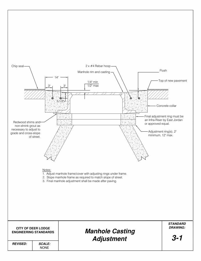
Top of new pavement
Flush
Concrete collar
Final adjustment ring must bean Infra-Riser by East Jordanor approved equal.
14"1/4" min1/2" max
Notes:1. Adjust manhole frame/cover with adjusting rings under frame.2. Slope manhole frame as required to match slope of street.3. Final manhole adjustment shall be made after paving.
Redwood shims andnon-shrink grout as
necessary to adjust tograde and cross-slope
of street.
Manhole rim and casting
STANDARDDRAWING:
Manhole Casting Adjustment
SCALE:
REVISED:
3-1
Chip seal
Adjustment ring(s), 2"minimum, 12" max.
2 x #4 Rebar hoop
3 1/2"
3"3"