surface engineering measurement for standards for inorganic ...
264
NATL INST. OF STAND & TECH A 111 Ob <13fl74fi NIST PUBLICATIONS Surface Engineering Measurement Standards for Inorganic Materials Stanley J. Dapkunas LLSl 2.005 Nisr National Institute of Standards and Technology Technology Administration U.S. Department of Commerce Special Publication 960-9
-
Upload
khangminh22 -
Category
Documents
-
view
1 -
download
0
Transcript of surface engineering measurement for standards for inorganic ...

NATL INST. OF STAND & TECH
A 111 Ob <13fl74fi
NIST
PUBLICATIONS
Surface EngineeringMeasurementStandards for
Inorganic Materials
Stanley J. Dapkunas
LLSl
2.005
NisrNational Institute of
Standards and TechnologyTechnology Administration
U.S. Department of Commerce
Special
Publication
960-9


NIST Recommended Practice Guide
Special Publication 960-9
Surface EngineeringMeasurementStandards for
Inorganic Materials
U.S. Department of CommerceCarlos Gutierrez, Secretary
Technology Administration
Phillip J. Bond, Under Secretary for Technology
National Institute of Standards and Technology
Hratch G. Semerjian, Acting Director
Stanley J. Dapkunas
Materials Science and
Engineering Laboratory
April 2005

Certain commercial entities, equipment, or materials may be identified in this
document in order to describe an experimental procedure or concept adequately.
Such identification is not intended to imply recommendation or endorsement by
the National Institute of Standards and Technology, nor is it intended to imply
that the entities, materials, or equipment are necessarily the best available for the
purpose.
National Institute of Standards and Technology
Special Publication 960-9
Natl. Inst. Stand. Technol.
Spec. Publ. 960-9
252 pages (April 2005)
CODEN: NSPUE2U.S. GOVERNMENT PRINTING OFFICEWASHINGTON: 2005
For sale by the Superintendent of Documents
U.S. Government Printing Office
Internet: bookstore.gpo.gov Phone:(202) 512-1800 Fax:(202)512-2250
Mail: Stop SSOP, Washington, DC 20402-0001
ii

Acknowledgements
This Recommended Practice Guide has benefited from the assistance of several
individuals at the National Institute of Standards and Technology (NIST) and ASMInternational, and specifically members of the ASM International Surface Engineering
Committee. Staffs of the NIST Research Library and the National Center for Standards
and Certification at NIST, in particular, were critical in providing access to standards
described in this publication. Ed Mai of the NIST Administrative Services Division
gave valuable advice on formatting and information presentation that makes this
document accessible. His design of Figure 1 is greatly appreciated.
In addition to members of the Editorial Committee, Bill Scott and Fran Cverna of the
ASM International staff provided valuable perspectives.
Photomicrographs in Figure 1 were originally published by ASM International. These
illustrations of surface conditions clarify the organization of this Guide. Sources of the
photomicrographs are as follows:
Bare Material - ASM Micrograph Center On-Line Photo CS 1376
Heat Treated - ASM Micrograph Center On-Line, Photo 0027
Oxidized - ASM Micrograph Center On-Line CS 1079
Carburized - ASM Micrograph Center On-Line Photo 0001
Decarburized - ASM Micrograph Center On-Line Photo 0030
Aluminized - ASM Handbook Volume 5, Surface Engineering, 1994, page 614,
Figure 3DChromized - ASM Metals Handbook, 8th Edition, Atlas of Microstructures of
Industrial Alloys, 1972, page 13, Photo 83
Electroplated - ASM Metals Handbook, 8th Edition, Atlas of Microstructures of
Industrial Alloys, 1972, Photo 1877
Galvanized/clad - ASM Metals Handbook, 8th Edition, Atlas of Microstructures of
Industrial Alloys, 1972, Photo 72
Physical Vapor Deposition - ASM International, Journal of Thermal Spray Technology,
Vol. 6, No. 1, March 1988, page 37, Figure 5
Thermal Sprayed - ASM International, Journal of Thermal Spray Technology, Vol. 6,
No. 1, March 1988, page 37, Figure 4
Figure 2. Applicability of Coating Thickness Measuring Methods, is reprinted, with
permission, from ASTM B 659-90(2003) Standard Guide for Measuring Thickness of
Metallic and Inorganic Coatings, copyright ASTM International, 100 Barr Harbor Drive,
West Conshohocken, PA 19428.

iv

Preface
Surface engineering of materials is important in applications as diverse as medical
implants and gas turbines. Historically, a coating or cladding was added to a surface, or
a surface was treated, to enhance properties or performance. However, increasingly, heat
treated, implanted, coated and clad surfaces are viewed as part of a materials system
where the substrate and surface complement each other in achieving a performance goal
for a component. The integration of the surface and substrate as an engineered system
creates a situation where failure of the surface may, in effect, be failure of the system
and thus characterization of surfaces and measurement of surface properties are
important to the design, maintenance, and analysis of the whole system.
The advantages of engineered surfaces have stimulated development of surface treatment
and coating processes as well as materials and, consequently, commerce. Commerce in
engineered materials depends upon the ability to specify and measure composition,
microstructure, dimensions and properties as well as performance in applications
of interest.
The intent of this Guide is to give the materials community a resource for identifying
standard methods which are used to measure surface properties and to characterize
surface engineered materials.
This Guide has been prepared with the support of the Ceramics Division of the National
Institute of Standards and Technology and the cooperation of the Surface Engineering
Committee ofASM International.
Specific thanks are due the Editorial Committee which oversaw this effort. Members of
that committee include:
Professor Christopher C. Berndt, James Cook University, School of Engineering,
Queensland, Australia; previously of Stony Brook University, Department of Materials
Science and Engineering, Stony Brook, NY
Dr. Debra Kaiser, Chief, Ceramics Division, NIST, Gaithersburg, MD
Mr. Steven Lampman, ASM International, Materials Park, OH
Dr. James Treglio, Molecular Metallurgy, Inc., El Cahon. CA
ASM International generously provided the illustrative photomicrographs in Figure 1
,
Quick Guide to Surface Measurement Standards. Sources of specific photomicrographs
are provided in the Acknowledgements section of this document.
ASTM International generously provided Figure 2, Applicability of Coating Thickness
Measuring Methods. The source of Figure 2 is ASTM B 659-90 (2003) Standard Guide
for Measuring Thickness of Metallic and Inorganic Coatings.
More information on the SP 960 series can be found on the Internet at
http://www.nist.gov/practice guides. This website includes a complete list of NISTPractice Guides and ordering information.
v

VI

Table of Contents
Preface v
List of Figures viii
1. Introduction 1
2. Organization of the Guide and Locating Standards 4
2. 1 Organization of the Guide 4
2.2 Locating Standards 5
3. General Standards for Surface Engineering Measurement . .10
3.1 Terminology 10
3.2 Laboratory Accreditation 12
3.3 Sampling 21
4. Surface Inspection and Product Quality 25
4. 1 General (bare and coated) 25
4.2 Products (bare and coated) 42
4.2.1 Fasteners 42
4.2.2 Sheet and Structural Steel 51
4.2.3 Castings 57
4.2.4 Other 58
5. Surface Finish Evaluation 62
5. 1 General (bare and coated) 62
5.2 Methods for Specific Products and Processes 66
6. General Product Quality Standards for Specific Coating Processes 72
6. 1 Anodic Coatings 72
6.2 Conversion Coatings 73
6.3 Galvanized Coatings 75
6.4 Electroplated Coatings 76
6.5 Diffusion Coatings 80
6.6 Physical Vapor Deposition (PVD) 82
6.7 Thermal Spray Deposition 83
6.8 Glass and Enamel Coatings 85
7. Standards for Measurement of Surface Treatment Depth
Coating Thickness and Mass 88
7.1 Surface Treatment Depth 88
7.2 Coating Thickness 97
7.3 Coating Mass 725
8. Standards for Analysis of Microstructure 136
8.1 Metallography 136
8.2 Porosity and Defect Measurement of Coatings 141
9. Standards for Measurement of Composition and Crystal Structure . .... .148
9.1 Composition 148
9. 2 Crystal Structure 752
10. Standards for Residual Stress and Hardness Measurement 753
10. 1 Residual Stress 753
10.2 Indentation Hardness Measurements 755
70.3 Other Hardness Measurements .778

Table of Contents
77. Standards for Mechanical Properties and Adhesion of Coatings 787
77.7 Mechanical Properties 787
77.2 Adhesion 787
72. Standards for Measurement of Corrosion, Wear and Thermal
Properties 797
72.7 Bare 797
72.2 Coated 798
73. Surface Engineering Measurement Standards 270
73. 7 ASME (American Society of Mechanical
Engineers) Standards 270
73.2 ASTM International (American Society for
Testing and Materials) Standards 270
73.3 ISO (International Organization for
Standardization) Standards 27773.4 Military and Industry Standards 222
73.5 SAE (Society of Automotive Engineers) Standards 223
14. Index 226
List of Figures
Figure 1. Quick Guide to Surface Measurement Standards 6
Figure 2. Applicability of Coating Thickness Measuring Methods 97
viii

Introduction
1. Introduction
This Guide is intended to aid the technical and scientific community in the evaluation
of engineered surfaces by identifying standard methods for measurement of pertinent
properties and characteristics. Methods included in this Guide are for use with inorganic
materials, i.e., metals and ceramics, used in structural, i.e., load bearing, applications.
"Surface Engineering" has been defined as the treatment of the surface and near surface
regions of a material to allow the surface to perform functions that are distinct from
those functions demanded from the bulk of the material 1. "Surface Engineering" has
also been expanded to include consideration of the design of the surface and substrate as
a system2 .Engineered surfaces typically provide wear, corrosion or thermal protection
and may be created by techniques such as heat treatment to modify microstructure,
implantation to modify composition, or coating and cladding where a very different
material is applied to a surface. Generally, an engineered surface enhances the
performance of a load bearing substrate. This is in contrast to a functional surface,
like a printed circuit, which is supported by a substrate.
Surface engineering is critical to the technical and/or economic success of many
technologies. For example, gas turbines rely on coatings for corrosion and thermal
protection to achieve durability and high efficiency, reciprocating engines rely on treated
and coated surfaces for wear resistance, and medical implants are coated to improve
bone adherence and biocompatibility.
There are several reasons to evaluate engineered surfaces:
to ascertain conformance to specifications;
• to monitor process control by regular measurement of selected properties such as
hardness or finish;
• to assess relevant properties in the development of materials or processing methods
• to ascertain performance through exposure to, or operation in, the intended
application, followed by measurement or characterization of attributes such as
extent of corrosive penetration or wear; and,
• to predict performance through exposure in an environment which simulates the
intended application, again, followed by evaluation of appropriate attributes.
Addressing these three purposes requires property measurement or characterization by
methods that not only meet the needs of the party conducting the measurement but also
are satisfactory to the user or purchaser of the material or component of interest.
Therefore, it is often necessary for organizations that develop, or provide, and purchase,
or use, materials and components to agree on a commonly accepted method of
measurement. Obviously, the availability of commonly accepted measurement methods
facilitates commerce by removing ambiguities that may arise when the same nominal
property is determined by unique or unusual techniques.
Furthermore, some properties are so broadly useful, because they provide a commondenominator for comparing materials, that considerable effort has been invested in their
consistent measurement. Hardness, for example, is a useful property for comparing
1

Introduction
materials or for determining the effect of different heat treatments on a single material.
The value of consistent and valid measurement of such properties has led to the
development of standard test methods, i.e., "standards". Standards specify measurement
details such as specimen design, test apparatus and calibration, test procedures, data
reporting, limits of applicability, and uncertainty.
Standard measurement methods are an important component in engineering design and
construction. For example, standard test methods may be codified, that is, made part of
a system of principles or rules. ASTM (formerly the American Society for Testing and
Materials) standards for property measurement are included in the ASME (American
Society of Mechanical Engineers) Boiler and Pressure Vessel Code, which is a basis
for design and fabrication.
The widespread use of standards and the value they bring to commerce in materials and
components has necessitated the formation of organizations whose function is to foster
development of standard measurement methods. These standards organizations can
be civilian and voluntary, as is ASTM, or governmental, as is the JIS (Japan Institute
of Standards).
The organizations which have accepted responsibility for standards development also
make the standards available for interested parties and update the standards, as
appropriate. The standards are usually up-dated with significant contribution and
review by the technical community concerned.
In the United States, standards organizations with an interest in surface engineering
measurements include ASTM, SAE (Society of Automotive Engineers), ASMEInternational (American Society of Mechanical Engineers) and ANSI (American
National Standards Institute). These organizations develop consensus standards through
the efforts of volunteers, often with scientific support from NIST (the National Institute
of Standards and Technology).
The DOD (Department of Defense), NASA ( National Aeronautics and Space
Administration) and other government agencies conduct research on engineered surfaces
and can establish test methods which amount to standards. These test methods address
those agencies' specific needs but may eventually be adopted by ASTM or other
standards organizations.
International standards are generally developed through the cooperative efforts of
national or regional standards organizations and reflect the methods developed for those
bodies' standards. The ISO (International Organization for Standardization) is the most
notable international organization active in the development of methods for measurement
of material properties.
This Guide includes few standards for measurement of corrosion, friction, wear and
abrasion. Standards in these fields that are included focus on evaluation of specific
surface conditions. The large number of corrosion and wear standards based on
corrodent or wear mechanism warrant separate compilation, as has been done in the
2

Introduction
"Friction and Wear Testing Source Book of Selected References from ASTM Standards
and ASM Handbooks". That Source Book was issued jointly by ASTM International
and ASM International in 1997 and is available from those organizations.
Lastly, it is important to note that "standards", i.e., standard test methods, are well
considered approaches to property measurement or material characterization and are the
consensus opinion of experienced practitioners and researchers. As such, they are a
means for those inexperienced in a specific field to quickly gain knowledge of what is
regarded as a reputable measurement technique. Standard test methods do not always
include state-of-the-art techniques or address applications which are still in the research
stage and subject to rapid change.
This Guide does not provide details included in the standards identified and should not
be viewed as a substitute for those standards. Standards should be purchased from the
issuing organization at the following addresses:
ASTM100 Barr Harbor Drive
West Conshocken, PA 19428-2959
ASMEThree Park Avenue
New York, NY 10016-5990
ISO
Case postale 56
CH-1211
Geneva 20
Switzerland
SAE International
400 Commonwealth Drive
Warrendale, PA 15096-0001
ASM Handbook, Volume 5, Surface Engineering, Copyright 1994 by ASMInternational, Materials Park, Ohio 44073-0002
http://www.1wi.co.ukyj32/unprotected/band_l/surfaceengineering.htm
3

Organization of the Guide and Locating Standards
2. Organization of the Guide and Locating Standards
2.1 Organization of the Guide
This Guide is organized to enable rapid identification of standard measurement methods
("standards") appropriate to the user's interests.
The Guide includes standards appropriate for the following surface conditions:
• bare surfaces which have the same composition, phase and structure from surface
to interior;
• treated surfaces wherein the base material has been subjected to conditions which
change surface composition, structure, phase, or properties; and,
• coated surfaces wherein the base material has had specific additional material
deposited on its surface, often significantly increasing the base material's
dimensions.
Treated surfaces are those that have been subjected to processes such as carburization,
decarburization, nitridation, surface implantation, surface heat treatments and abrasive
blast hardening or cleaning.
Coated surfaces are those that have been covered with material having composition and
properties significantly different from the base material. Coating processes include
electroplating, physical vapor deposition, thermal spray and galvanizing, for example.
The greatest part of this document consists of summaries of over 200 standards.
A summary of each standard is provided in a template that includes the following
information, as appropriate:
• Standards Identification including issuing organization, standard identification
number and standard title;
• General Description including an overview of the method and the contents of the
standard;
• Intended Application including the stated purpose for which the standard was
developed;
• Specimen Requirements including the size, condition or other characteristics
necessary or valid use of the method;
• Data Produced including the nature of the data produced (visual or instrument
generated numeric, for example) and further refinements or calculations
necessary, and,
• Limits of the method including inappropriate application, accuracy, precision or
safety concerns.
The templates are within Sections 3 through 12 of this Guide.
Within each Section or Sub-section, standards are in the following order:
• ASME Standards,
• ASTM Standards,
• ISO Standards,
4

Locating Standards
• Military and Industry Standards, and
• SAE Standards.
Sections 3 through 12 are organized as follows:
• general aspects of surface inspection and product evaluation (Sections 3,4 and 5),
• standards specific to selected coating processes (Section 6), and
• standards for measurement of specific characteristics or properties (Sections 7
through 12).
This Guide also has the following features which support Sections 3 through 12:
• Figure 1 . Quick Guide to Surface Measurement Standards which progresses in
increasing detail from "Surface Condition" to "Property of Interest" to
"Measurement method" to the "Appropriate Section" which includes relevant
standards;
• Section 13. Surface Engineering Measurement Standards, a compilation of titles of
all standards in Sections 3 through 12, organized by issuing organizations and those
organizations' alpha-numeric identification;
• Section 14. Index, a comprehensive compilation of key words associated with each
standard;
• Figure 2. Applicability of Coating Thickness Measuring Methods, which is
included in Section 7 and provides an ASTM summary of methods for measuring
thickness by several methods.
2.2 Locating Standards
There are four routes for locating a standard of interest:
• Surface Condition Based
Figure 1 ,Quick Guide to Surface Measurement Standards, gives a rapid, although
not comprehensive, route to a relevant standard by starting with the surface condition
illustrated and proceeding through the property of interest to measurement method to
the section in which the standard(s) are located;
• Property or Characteristic Based
Proceeding directly to Sections 3 through 12 will enable browsing through standards
which address general issues such as terminology or accreditation, properties or
characteristics, material, or measurement method;
• Standard Based
Section 13, the compilation of standards in Sections 3 through 12, enables the user
to proceed directly to the summary of the standard of interest when the standard is
known; and,
• Key Words
Standards can also be accessed by use of the alphabetized Index in Section 14. The
Index is based on key words descriptive of the content of each standard.
Also, Figure 2, Applicability of Coating Thickness Measuring Methods, can be used
within Section 7 to focus on useful methods and the Index can be used to quickly
identify standards with similar purposes or methods issued by different organizations.
Sections 3 through 12 also enable comparison of standards issued by different
organizations.
5

Organization of the Guide and Locating Standards
Figure 1. Quick Guide to Surface Measurement Standards
Surface Condition
Bare
Property Method
Specifications
Geometrical Product Specifications (GPS)
Acceptance standards. Visual
Surface defects, fasteners
Section Page
Surface chemistry
Surface
profile &texture
Surface defects
Terminology
Depth profiling (AES)
Glow discharge optical
Emission spectroscopy
Visual
Profilometry
Scanning Tunnel Micros.
Focussing microscope
Replica
Classification
Liquid penetrant
Infrared
Eddy current
Acoustic emission
Etch
Replica
Magnetic particle
Cleanliness
- Visual
- Tape
- Bresle
- Conductometric
- Refractometric
- Titimetric
Gloss
- Goniophotometry
Oxide finger penetration
- Microscopy
Microstructure
Hardness
Residual stress
Microscopy
Comparison testers
Scratch testers
Indentation testers
(7 types
)
Scleroscope
Files
Hole-drilling strain gages
X-ray diffraction
4.1
4.1
4.2
4.1,
4.2
4.1
4.2
8.1
10.1
25
25
42
148
25,
42
25
25
42
136
136
10.2. 3 155ff
153
6

Locating Standards #
Figure 1. Quick Guide to Surface Measurement Standards (cont'd)
Surface Condition Page
3.2 12
1 Case depth.
7.1 88
Heat Treated
- Hardness
i Surface temper 4.2 42
- Etch inspection
Oxidized
Carburized
Decarburized
Anodized
Aluminized
Oxide thickness
Microscopy
Carburization depth
- Hardness
- Microscopy
Decarburization depth
- Hardness
- Microscopy
- Chemical
Sampling
Thickness
Gravimetric
Split beam microscopy
Specification
Coating thickness
Microscopy
7.2 97
7.1
7.1
3.3
7.2
6.5
7.2
21
97
80
97
Chromized Contractor accreditation
Coating thickness
- Microscopy
3.2
7.2
7

Organization of the Guide and Locating Standards
Figure 1. Quick Guide to Surface Measurement Standards (cont'd)
Surface Condition Property Method Section Page
Electroplated Sampling 3.2 12
Contractor accreditation 3.3 21
Coating thickness 7.2 97
- Coulometric
- Magnetic
- Acid dissolution
- Beta backscatter
- X-ray spectrometry
- Interference microscopy
- Microscopical
- Eddy current
- Profilometric
- Radial sectioning
Coating mass, X-ray fluorescence
Grinding damage
Interfacial width, sputter depth profiling
Porosity, Gold
- Acid vapor
- Paper electrography
- Gel-bulk electrography
- Sulfurous acid/sulfur dioxide
- Flowers of sulfur
Gross defects & mechanical damage
- Polysulfide immersion
Hardness
Ductility
Knoop
Vickers
- Bend test
Adhesion
Corrosion site characterization
- Interference microscopy
Hydrogen embrittlement
- Electronic
7.3
4.1
9.1
8.2
8.2
10.2
11.1
11.2
12.2
12.2
125
25
148
141
141
155
181
187
198
198
8

Locating Standards
Figure 1. Quick Guide to Surface Measurement Standards (cont'd)
Surface Condition Property Method Section Page
Galvanized/ M fiBfet i Case study practices 6.3 75
Clad E I Coating mass measurement 7.3 125
- Gravimetric
- X-ray fluorescence
- Triple spot
Composition 7.3 125
Physical
Vapor
Deposited
- Triple spot
TiN Specification
Contractor accreditation
Coating thickness
- Microscopical
- Radial sectioning
6.6
3.2
7.2
82
J2
97
Thermal Contractor accreditation 3.2 12Sprayed
Specifications 6.7 83
Thickness 7.2 97
- Radial sectioning
Phase content, hydroxyapatite 9.2 152
- X-ray diffraction
Shear strength 11.1 181
- Mechanical
Tensile strength 11.1 181
- Mechanical
Fatigue strength 11.1 181
- Mechanical
Adhesion/cohesion strength 11.2 187
- Mechanical
Abrasion resistance 11.2 187
- Taber Abraser
9

General Standards for Surface Engineering
3. General Standards for Surface Engineering Measurement
3.1 Terminology
ASTM A 902
Standard Terminology Relating to Metallic Coated Steel Products
General Description Data Produced
This Standard is a compilation of 47
definitions of terms related to metallic
coatings used in the steel industry.
The Standard also includes
recommended key words for ASTMCommittee A-5 Standards.
Not applicable/specified.
Intended Application Specimen Requirement Limits
Clarity of terminology
used in coated steel
product descriptions.
Not specified. Not specified.
ISO 2079
Surface Treatment and Metallic Coatings - General Classification of Terms
General Description Data Produced
This document provides general terms
and definitions for several surface
treatments and identifies relevant
ISO standards for those treatments.
Terms and definitions are provided in
English, French, Russian and
German.
Not specified.
Intended Application Specimen Requirement Limits
Intended to clarify
relevant standards.
Not specified. Not specified.
10

Terminology
ISO 2080
Electroplating and Related Processes - Vocabulary
General Description Data Produced
This Standard provides definitions of
804 terms used in electroplating and
related processes such as metal
finishing. Definitions are in English,
French, Russian and German.
Not specified.
Intended Application Specimen Requirement Limits
Intended to clarify
relevant standards.
Not specified. Not specified.
SAE AS 4194
Sheet and Strip Surface Finish Nomenclature
(Aerospace Standard)
General Description Data Produced
Defines nomenclature for two surfaces
(2D and 2B) of sheet and two
surfaces (No. 1 and No. 2) of strip
material and bright annealed finish.
Not specified/applicable.
Intended Application Specimen Requirement Limits
Provides explanations of
terms used to describe
surface finish of iron,
nickel, cobalt and
titanium base alloys
used in aerospace
applications.
Not specified/applicable. Not specified/applicable.
11

General Standards for Surface Engineering
3.2 Laboratory Accreditation
SAE AS 7101
National Aerospace and Defense Contractors Accreditation Program (NADCAP)General Requirements for Materials Test Laboratory Accreditation Program
(Aerospace Standard)
General Description Data Produced
Establishes the minimumrequirements for materials testing
laboratories accredited by NADCAP.Test methods for metallic materials are
specified by reference to SAE, ASTM,military, ISO and ANSI documents.
Methods referenced include those for:
chemical, mechanical, metallography
and microhardness, hardness,
corrosion, mechanical test specimen
preparation, differential thermal
analysis, heat treating, X-ray
diffraction and fastener testing.
Document includes definitions,
and survey requirements.
Not specified/applicable.
Intended Application Specimen Requirement Limits
Intended to give
guidance for manyaspects of a testing
laboratory required
for accreditation.
Not specified/applicable. Not specified/applicable.
12

Laboratory Accreditation
SAE AS 7109
National Aerospace and Defense Contractors Accreditation
Program Requirements for Coatings
(Aerospace Standard)
General Description Data Produced
This Standard establishes
requirements for suppliers of coating
services to be accredited by the
National Aerospace and Defense
Contractors Accreditation Program
(NADCAP). It does not include
measurement methods but serves as
the basic document for accompanying
Aerospace Standards for specific
types of coatings which include
measurement or testing requirements.
Not specified.
Intended Application Specimen Requirement Limits
Coating supplier
accreditation.
Not specified. Not specified.
13

General Standards for Surface Engineering
SAE AS 7109-1
National Aerospace and Defense Contractors Accreditation
Program Requirements for Thermal Spray
(Aerospace Standard)
General Description Data Produced
This Standard is a supplement to SAEAS 7109 addressing: OXY/Fuel
Powder and Wire Spray, Plasma
Thermal Spray, HVOF/D-Gun Spray,
Low Pressure Plasma Spray (LPPS)
and Electric Arc Wire Spray.
Accreditation requirements for the
following applications are included:
High/low Temperature Hard Coatings,
Anti-fretting Coatings, Thermal Barrier
Coatings, Abrasive Seal Coatings,
Abradable Coatings, Dimensional
Build-up Coatings and High
Temperature LPPS Coatings. Aspects
addressed include: Technical
Experience, Process Planning,
Manufacturing, Material Powder/Wire
Control, Cleaning, Masking, Grit
Blasting, Spray Booths, Oxy/Fuel,
Plasma Thermal Spray, HVOF/D-Gun,LPPS, Electric Arc Wire, Process
Gases, De-mask/Clean, Supplemental
Heat Treating, Sealing Sprayed
Coatings, Inspection and Compliance.
Characterization and measurementare covered in the "Inspection"
section.
Not specified.
Intended Application Specimen Requirement Limits
Coating supplier
accreditation.
Not specified. Not specified.
14

Laboratory Accreditation
SAE AS 7109-2
National Aerospace and Defense Contractors Accreditation
Program Requirements for Vapor Deposit
(Aerospace Standard)
General Description Data Produced
This Standard supplements SAEAS 7109, specifically addressing
physical vapor deposition (PVD, Class
A) which includes sputter and electron
beam deposition and chemical vapor
deposition (CVD, Class B). Thefollowing aspects of accreditation are
described: Technical Experience,
Manufacturing, Material Control,
Vapor Process Operation Sheet,
Part Treatment, Cleaning, Masking,
Surface Preparation, Chambers/PumpSystems, Process Gases,
Supplementary Chemical Treatment,
Inspection and Compliance.
Characterization and measurement
are included in the "Inspection"
section.
Not specified.
Intended Application Specimen Requirement Limits
Coating supplier
accreditation.
Not specified. Standard methods for
characterization or
inspection are
not specified.
15

General Standards for Surface Engineering
SAE AS 7109-3
National Aerospace and Defense Contractors Accreditation
Program Requirements for Cementation
(Aerospace Standard)
General Description Data Produced
This Standard supplements SAEAS 7109, specifically addressing pack
processes (Class A) which includes
above pack and in-pack deposition,
and slurry processes (Class B).
The following aspects of accreditation
are included: Technical Experience,
Process Planning, Manufacturing,
Material Control, Cleaning, Masking,
Grit Blasting, Packing/Furnace
Loading, Coating/ Thermal Treatment,
De-mask/Clean, Supplementary
Chemical Processing, Inspection and
Compliance. Characterization and
measurement are included in the
"Inspection" section.
Not specified.
Intended Application Specimen Requirement Limits
Coating supplier
accreditation.
Not specified. Standard methods for
characterization or
inspection are
not specified.
16

Laboratory Accreditation
SAE AS 7109-4
National Aerospace and Defense Contractors Accreditation
Program Requirements for Stripping
(Aerospace Standard)
General Description Data Produced
This Standard supplements SAEAS 7109, specifically addressing
stripping of coated material.
Stripping methods addressed include:
electrolytic, mechanical (grit blast,
grinding, machining) water jet, molten
salt and chemical. The following
aspects of accreditation are included:
Equipment and Facilities, Process
Planning, Manufacturing, Material
Control, Stripping, Water Jet, Molten
Salt, Chemical, Process Control
Laboratory Procedures (Solution
Analysis), Post Strip Cleaning, Bake
Embrittlement Relief and Compliance.
Not applicable/specified.
Intended Application Specimen Requirement Limits
Coating supplier
accreditation.
Not specified. Not specified.
17

General Standards for Surface Engineering
SAE AS 7109-5
National Aerospace and Defense Contractors Accreditation
Program Requirements for Coating Evaluation Laboratory Practices
(Aerospace Standard)
General Description Data Produced
This Standard supplements SAEAS 7109, specifically addressing
coating evaluation. Specific details of
evaluation methods are not described
but appropriate references to other
documentation (e.g. ASTM) are
included. The Standard covers those
aspects of evaluation which must be
addresses to warrant accreditation,
including: Personnel, Procedures,
Equipment and Facilities, Quality
Assurance-Lab Specific, Round Robin
Programs, Hardness Testing,
Metallography and Thickness,
Mechanical Testing, Heat treating of
Specimens, Specimens (such as per
ASTM C 633), Replacement Testing
and Retesting, Test Reports/
Certificates, Tensile Testing, BendTesting and Nonstandard Compliance.
Not specified.
Intended Application Specimen Requirement Limits
Coating supplier
accreditation.
Not specified. Not specified.
18

Laboratory Accreditation #
SAE AS 7109-6
National Aerospace and Defense Contractors Accreditation
Program Requirements for Plating of Coated Parts Laboratory Practices
(Aerospace Standard)
General Description Data Produced
This standard is a supplement to SAEAS 7109, specifically addressing
plating of coated parts. The document
calls out aspects of plating which must
be addressed to meet accreditation
requirements. These aspects are
included: Equipment and Facilities,
Part Processing Control, Cleaning
Procedures, Masking, Lot Integrity,
Housekeeping, Test and Inspection,
Process Control Laboratory
Procedures (Solution Analysis) and
Compliance. Test and Inspection
specifies the use of procedures in the
following ASTM Standards:
B 244, B 487, B 499, B 504,
B 530, B 567 and B 568.
Not specified.
Intended Application Specimen Requirement Limits
Coating supplier
accreditation.
Not specified. Not specified.
19

Genera! Standards for Surface Engineering
SAE AS 7109-7
National Aerospace and Defense Contractors Accreditation
Program Requirements for Heat Treating for Suppliers of Coatings
(Aerospace Standard)
General Description Data Produced
This Standard is a complement to
SAE AS 7109, specifically addressing
heat treating during the coating
process. This standard does not
include surface related measurement
or testing and is included only for
completeness in the AS 7109 series.
Not specified.
Intended Application Specimen Requirement Limits
Coating supplier
accreditation.
Not specified. Not specified.
20

3.3 Sampling
ASTM B 602
Standard Test Method for Attribute Sampling of Metallic and Inorganic Coatings
General Description Data Produced
This Method gives sampling plans
intended for use in the inspection of
coatings for conformance to ASTMspecifications. The plans are based on
inspection by attributes. That is, the
article is inspected and classified as
either conforming to a requirement
placed on it or not conforming. TheMethod includes a general description
of the approach, ordering information,
formation of inspection lot,sampling,
inspection and lot disposal,
and drawing of samples.
Varies with specification.
Intended Application Specimen Requirement Limits
Sampling inspection
permits the estimation of
the overall quality of a
group of product articles
through the inspection of
a relatively small numberof product items drawn
from the group. Theselection of a sampling
plan provides purchasers
and sellers a means of
identifying the minimumquality levels that are
considered satisfactory.
Varies with specification. Sampling plans yield
estimates of the quality
of product, thus the
results of the inspection
are subject to error.
Through the use of
sampling plans, the risk
of error is knownand controlled.
21

Genera! Standards for Suff&ee Engineering
ASTM B 697
Standard Guide for Selection of Sampling Plans for Inspection of
Electrodeposited Metallic and Inorganic Coatings
General Description Data Produced
This Guide provides guidance in the
selection of sampling plans to
determine whether submitted lots of
coated products comply with the
specifications applicable to the
coatings. A sampling plan guides the
examination of a relatively small part
of the articles in a lot. That
examination allows a decision as to
whether the lot does or does not
conform to specifications. Thesampling plans are attribute plans.
Each examined article is classified as
conforming or not conforming to each
coating requirement and the numberof nonconforming articles compared to
a maximum allowable number.
Supplements ASTM B 602.
Number of articles with acceptable
properties.
Intended Application Specimen Requirement Limits
Acceptance sampling is
used when a decision
must be made about
what to do with a
quantity of articles.
Used where cost of
inspection is high and
consequences of
accepting a
nonconforming article
are not serious; or,
where 100% inspection
is boring or fatiguing
and likely to result in
errors; or, wheninspection requires a
destructive test.
Varies with property or
characteristic of interest.
It is important that the
inspection lot be
homogeneous; i.e., that
the articles in the lot be
from the same supplier,
single finishing line,
finished at the
same time, etc.
22

Sampling
ASTM B 762
Standard Test Method of Variables Sampling of Metallic and Inorganic Coatings
General Description Data Produced
This Method gives sampling plans for
inspection of coatings on products for
the purpose of deciding whether lots
of the coated articles conform to
specifications for the coatings. Acharacteristic of the coating on drawn
articles is measured and the values
obtained are used to estimate the
number of articles in the lot that do not
conform to a numerical limit.
Number of articles in a lot that do not
conform to a numerical limit.
Intended Application Specimen Requirement Limits
Acceptance testing of
lots of coated articles.
Varies with property or
characteristic of interest.
A variables plan requires
that: the characteristic of
interest is measurable;
the test method gives a
numerical measure of
the characteristic; the
specification places a
numerical limit on the
measured value;
variation of the
characteristic from article
to article be normally
distributed; and, each
article is tested in the
same way. If one or
more of the above
conditions are not met,
an attributes plan must
be used; e.g., ASTMB 602 or ASTM B 697.
23

eneral Standards for Surface Engineering
ISO 4519Electrodeposited Metallic Coatings and Related Finishes - Sampling
Procedures for Inspection by Attributes
General Description Data Produced
This Standard establishes sampling
plans and procedures for inspection of
electrodeposited metallic coatings
using attributes of those materials.
The procedures described may be
applied to finished products or
materials processing. The sampling
plans are based on acceptable quality
levels (AQLs) of 1 .5 and 4.0%. Thestandard includes definitions, defect
classifications, acceptance and
rejection responsibilities, sample
selection methods and plans, detailed
guidance on determination of
acceptability and procedures for
drawing random samples. This
standard is based on ISO 2858.
Varies with property of interest.
Intended Application Specimen Requirement Limits
Provides a basis for
purchase specifications
and may be applied to
related finishes. This
standard supports
determination of lot
acceptability by the use
of a sampling plan.
Not specified. The plans are intended
primarily for examination
of continuing series of
lots but may be used for
examination of isolated
lots. This standard is not
applicable to sampling
and testing of
electroplated mechanical
fasteners
(See ISO 3269).
24

General (bare and coated)
4. Surface Inspection and Product Quality
4.1 General (bare and coated)
ASTM B 866
Standard Test Method for Gross Defects and Mechanical Damage in Metallic
Coatings by Polysulfide Immersion
General Description Data Produced
This Method describes a technique for
determining gross defects and/or
mechanical damage to metallic
coatings on copper or copper alloy
substrates. The Method is useful for
techniques where the coatinq doesnot tarnish in an alkaline polysulfide
solution. Suitable coatings include
gold, nickel, tin, tin-lead, palladium or
their alloys. The Method consists of
immersing the test area in a solution
of alkaline sodium sulfite for 60 s at
74 °C and examining the test area for
signs of copper reaction products
using a 10x microscope. The Methodgives polysulfide solution preparation,
test procedure and examination
and evaluation guidelines.
Visible indications of defects.
Intended Application Specimen Requirement Limits
Intended to ascertain the
presence of defects from
processing andmechanical damagefrom use as manifested
by exposure of copperunder plate or copperbasis metal.
Clean surfaces. Method is relatively
insensitive to the
presence of small pores.
ASTM B 809 should be
used instead. Method is
not recommended for
prediction of product
performance or
simulation of field failure
mechanisms. Generally,
corrosion products less
than 0.05 mm (0.002 in.)
in diameter are not
counted in the evaluation.
Work should be performed
in a fume hood.
25

Surface inspection and Product Quality
ASTM B 877
Standard Test Method for Gross Defects and Mechanical Damage in Metallic
Coatings by the Phosphomolybdic Acid (PMA) Method
General Description Data Produced
This test standard gives equipment
and methods for using phosomolybdic
acid (PMA, a solid complex of
molybdenum trioxide and phosphoric
acid) to detect gross defects and
mechanical damage in gold, silver or
palladium coatings over substrates of
nickel, copper or copper alloys. Thetest consists of removing oxides in the
defect area by exposure to
hydrochloric acid fumes and applying
a drop of PMA with an applicator to
the area in question. PMA contact with
exposed under plate or substrate
causes the molybdenum trioxide
to turn blue.
Visible indications of defects.
Intended Application Specimen Requirement Limits
To determine the
presence of mechanical
damage, wear-through
and other gross defects
in the coating. Intended
for the evaluation of
individual samples, one
at a time, with a
microscope at 10x
to 30x.
Thoroughly cleaned,
particle free surfaces.
A test area of less than
2 mm allows
examination by
microscope. Test areas
may require masking to
prevent PMA reaction
with exposed base
metal edges.
This is essentially a
pass/fail test. It may not
be suitable for someprecious metal alloy
coatings that contain
significant concentrations
of non-precious metals
(e.g., nickel or copper).
PMA reacts with tin, lead
and tin-lead solder. Test
is relatively insensitive to
small pores. Test not
recommended for
prediction of product
performance. Test is
destructive and tested
pieces should not be
put into service.
26

General (bare and coated)
ISO 3274
Geometrical product Specifications (GPS) - Surface Texture: Profile Method -
Nominal Characteristics of Contact (stylus) Instruments
General Description Data Produced
This Standard defines profiles and the
general structure of contact (stylus)
instruments for measuring surface
roughness and waviness. Instrument
properties and basic specifications for
profile meters and profile recorders
are included. It influences chain link 5
for roughness, waviness and primary
profiles in the GPS matrix model.
Not specified/applicable.
Intended Application Specimen Requirement Limits
The primary purpose is
to enable comparison of
similar surfaces or the
comparison of results
from different measuring
instruments.
Not specified/applicable. Not specified/applicable.
27

Surface Inspection and Product Quality
ISO 4288
Geometrical Product Specification (GPS) - Surface Texture: Profile Method -
Rules and Procedures for the Assessment of Surface Texture
General Description Data Produced
This Standard specifies the rules for
comparison of the measured values
with the tolerance limits for surface
texture parameters defined inlSO
4287, ISO 12085, ISO 13565-2 and
ISO 13565-3. It includes: parameter
estimation, rules for comparison
(areas to be inspected, 16% rule,
max. -rule, uncertainty), parameter
estimation, rules and procedures for
inspection, and a "Simplified
procedure for roughness inspection".
Numeric values of roughness.
Intended Application Specimen Requirement Limits
Influences chain links 3
and 4 of ISO standards
for roughness and
primary profiles in the
GPS matrix model.
Not specified/applicable. Not useful for
descriptions of surface
defects.
28

General (bare and coated)
ISO 8502Preparation of Steel Substrates Before Application of Paints and Related
Products - Tests for the Assessment of Surface Cleanliness
Part 1: Field test for soluble iron corrosion products
Part 2: Laboratory determination of chloride on cleaned surfaces
Part 3: Assessment of dust on steel surfaces prepared for painting (pressure-
sensitive tape method)Part 4: Guidance on the estimation of the probability of condensation prior to paint
application
Part 5: Measurement of chloride on steel surfaces prepared for painting (ion
detection tube method)
General Description Data Produced
This comprehensive standard describes
eight methods for the quantitative
determination of surface contaminants
on blast cleaned steel, prior to paint or
other coating application. Both field
and laboratory measurement methodsare included.
Part 1 describes a semi-quantitative
method for analysis of ferrous ions by
swabbing the test surface with water
soaked cotton and analyzing the washliquid with an indicator strip.
Part 2 describes a technique for
determination of chloride by water
washing and subsequent titration with
mercury nitrate.
Part 3 describes a method for analysis
of dust contamination by controlled
application of transparent pressure
sensitive tape to the test surface
followed by analysis of the removedtape for adherent particle size andquantity, using a hand lens andcomparator charts included in
the standard.
Part 4: Guidance on the estimation of
the probability of condensation prior to
paint application based on relative
humidity and steel surface temperature.
Part 5 describes a field test in whichwater-soluble chlorides are washedfrom the surface and the wash liquid
analyzed to determine the chloride ion
concentration using a detection tubecontaining silver chromate in a sandcarrier. The color change of the tubecontents with immersion in different
known chloride ion concentrations
serves as the calibration for the
field test.
Data collected varies with method but
generally consists of concentration of
contaminant per unit volume which is
converted to contaminant per unit
surface area.
29

Surface ins : . jet Quality
ISO 8502, ContinuedPreparation of Steel Substrates Before Application of Paints and Related
Products - Tests for the Assessment of Surface Cleanliness
Part 6: Extraction of soluble contaminants for analysis - The Bresle methodPart 8: Field method for the refractometric determination of moisture
Part 9: Field method for the conductometric determination of water-soluble salts
Part 10: Field method for the titimetric determination of water-soluble chloride
Part 12: Field method for the titimetric determination of water-soluble ferrous ions
General Description Data Produced
Part 6 describes the fabrication and use
of an adhesive patch applied to the test
surface into which a suitable solvent for
analysis of the contaminant in question
is injected. The solvent is repeatedly
injected and removed with a syringe andthe solvent subsequently analyzed to
ascertain the contaminant level. Themethod is suitable for field use.
Part 8 describes the measurement of
moisture, generally from condensation,
on a surface to which an adhesive patch
described in Part 6 is used to contain a
mixture of monoethylene glycol andwater. The mixture is repeatedly injected
and removed followed by measurementof the glycol mass fraction in a
refractometer.
Part 9 describes a field test for water
soluble salts using the technique of
Part 6. The change in conductivity of the
test water due to solution of salts from
the surface is measured and used to
calculate the surface density of the
salts.
Part 10 describes a field method in
which the procedure of Part 6 is used to
inject water containing sodium fluoride
and hydrogen fluoride. The water acts
as a solvent for chloride on the surface.
The chloride concentration is
determined by titration with mercuric
nitrate.
Part 12 describes the use of the
technique in Part 6, or another
appropriate method, to removecontaminants from the surface andacidifying the solution with phosphoric
acid. The ferrous ion concentration is
determined by titration with a dichromatesolution.
Data collected varies with method but
generally consists of concentration of
contaminant per unit volume which is
converted to contaminant per unit
surface area.
30

General (bare and coated)
ISO 8502, Continued
Intended Application Specimen Requirement Limits
Intended to determine
whether a mechanically
blast cleaned surface, or
a surface between
coating applications,
meets cleanliness
specifications required to
achieve coating
performance goals.
Not specified. Not specified.
ISO 8785
Geometrical Product Specification (GPS) - Surface Imperfections - Terms,
Definitions and Parameters
General Description Data Produced
This Standard defines terms used to
describe different types of surface
imperfections and includes illustrative
drawings. The document provides a
common vocabulary for use in manytypes of technical publications and
drawings. Fifty-five imperfections are
described. Dents, warts and blisters
are typical imperfections described
in English and French.
Not applicable.
Intended Application Specimen Requirement Limits
Technical documentsand specifications.
Not applicable. Defined imperfections
are not related to surface
roughness.
31

Surface Inspection and Product Quality
ISO 11562
Geometrical Product Specifications (GPS) - Surface tTexture: Profile Method -
Metrological Characteristics of Phase Correct Filters
General Description Data Produced
This Standard specifies the
metrological characteristics of phase
correct filters for measurement of
surface profiles, particularly how to
separate the long and short wavecontent of a surface profile. Thedocument includes definitions of
relevant terms, characteristics of
phase correct profile filters (including
transmission characteristics of long
and short wave profile components),
limits of error of phase correct filters,
and criteria for selection of phase
correct filters. The relation of this
standard to the GPS matrix model
is provided.
Roughness profile.
Intended Application Specimen Requirement Limits
Influences links 2 and 3
in the chains of
standards for primary
profile in the GPSmatrix model.
Not specified/applicable. Not specified.
32

General (bare and coated)
ISO 12085
Geometrical Product Specification (GPS) - Surface Texture: Profile Method -
Motif Parameters
General Description Data Produced
This Standard defines terms used in
the determination of surface texture by
the motif method and the motif
method, including a calculation
method for combination of motifs.
Annexes provide information on the
relation between motif parameters
(roughness profile, waviness profile
and primary profile) and function of
surfaces as well as the relation of the
standard to the GPS matrix model.
Quantifiable roughness profile
representation.
Intended Application Specimen Requirement Limits
Influences links 2, 3 and
4 of the surface texture
chain of standards on
roughness and waviness
profile in the GPSmatrix model.
Not specified/applicable. Not specified.
33

Surface Inspection and Product Quality
ISO 13565-1
Geometrical Product Specifications (GPS) - Surface Texture: Profile Method -
Surfaces Having Stratified Functional Properties
Part 1: Filtering and general measurement conditions
General Description Data Produced
This Standard describes a filtering
method for description of surfaces that
have deep valleys underlying a finely
finished plateau with a small amount
of waviness. ISO 11562, by
comparison, describes a reference
line undesirably influenced by the
presence of valleys. ISO 13565-1
provides a filtering approach that
suppresses the valley influence on the
reierence line, i nis oianaara
addresses surfaces common in
internal combustion cylinder liners.
The filtering process to determine the
roughness profile, selection of cut-off
wavelength and the evaluation length
and relation to the GPS matrix
model are included.
Quantifiable roughness profile
representation.
Intended Application Specimen Requirement Limits
This Standard influences
links 2 and 3 in the chain
of standards for
roughness profile in the
GPS matrix model.
Not specified. Not specified.
34

Genera! (bare and coated)
ISO 13565-2
Geometrical Product Specifications (GPS) - Surface Texture: Profile Method -
Surfaces Having Stratified functional Properties
Part 2: Height characterization using the linear material ratio curve
General Description Data Produced
This document defines parameters
based on the linear material ratio
curve for the evaluation of the valley
suppressed roughness profile defined
in ISO 13565-1. The Standard
includes determination of parameters,
covering roughness profile, calculating
equivalent straight line, and
calculation of parameters for
the material ratio curve.
Quantifiable roughness profile
representation.
Intended Application Specimen Requirement Limits
This Standard addresses
chain link 2 for
roughness profile in the
General GPS matrix.
Not specified. Not specified.
35

Surface Inspection and Product Quality
ISO 13565-3
Geometrical Product Specifications(GPS) - Surface Texture: Profile Method -
Surfaces Having Stratified Functional Properties
Part 3: Height characterization using the material probability curve
General Description Data Produced
This Standard gives a method for
calculation of parameters used to
numerically characterize two
components, a coarse valley texture
and a fine plateau texture, through the
generation of a material probability
curve, determination of its linear
regions and linear regressions
through these regions.
Quantifiable roughness profile
representation.
Intended Application Specimen Requirement Limits
The parameters are
intended to aid in
assessing tribological
behavior of, for example,
lubricated sliding
surfaces and to control
manufacturing
processes.
Not specified. Not specified.
36

General (bare and coated)
SAE J358
Nondestructive Tests (SAE Information Report)
General Description Data Produced
This Information Report identifies
several techniques and associated
SAE documents applicable for the
detection and in some cases
measurement of, defects which maybe surface related. A table is included
which provides physical principles of
the techniques, appropriate materials
to be inspected, applications,
advantages and limitations. Infrared,
magnetic particle, eddy current,
penetrating radiation, ultrasonic,
acoustic, and leakage techniques
are briefly described.
Not specified.
Intended Application Specimen Requirement Limits
Information purposes. Not specified. Not specified.
SAE J359
Infrared Testing (SAE Information Report)
General Description Data Produced
This is a very brief description of the
infrared technique for nondestructive
testing. This does not contain
significant detail regarding technique
or capabilities.
Not specified.
Intended Application Specimen Requirement Limits
Information purposes. Not specified. Not specified.
37

SAE J420
Magnetic Particle Inspection (SAE Information Report)
General Description Data Produced
This is a very brief description of the
use of magnetic particle inspection to
nondestructively identify surface and
near surface defects and
discontinuities in ferromagnetic
materials such as iron and steel.This
technique aids in visual inspection and
may be enhanced through the use
of long wavelength ultraviolet light.
Not specified.
Intended Application Specimen Requirement Limits
Not specified. Not specified. Not specified.
SAE J425Electromagnetic Testing by Eddy-Current Methods (SAE Information Report)
General Description Data Produced
This Report gives very general
descriptions on the uses of eddy
current testing, a nondestructive
technique, for inspection of surface
defects, principles of operation and
procedures. The Report is not
intended to give detailed guidance.
ASTM Standards and other
documents are identified as sources
of additional information.
Data varies with instrument design
and manufacturer.
Intended Application Specimen Requirement Limits
General information. Surface free of loose
scale and other material.
Hot rolled material with
thin, tight scale - seamsas shallow as 0.25 mm(0.010 in.) are detected.
Polished (ground)
surfaces- seams and
cracks as shallow as
0.025 mm (0.001 in.)
are detected.
38

General (bare and coated)
SAE J426
Liquid Penetrant Test Methods (SAE Information Report)
General Description Data Produced
This Report provides a brief
description of the principle of the use
of liquid penetrant inspection. In this
technique, a liquid is applied to a
surface and excess fluid removed and
remaining penetrant trapped in
surface imperfections such as cracks
or pores is detected when a "developer"
is applied. The developer shows the
presence of remaining liquid. Short
descriptions of types of penetrants,
developers and methods of penetrant
removal are provided. Related SAEand ASTM documents are listed.
Visible indications of surface
discontinuities.
Intended Application Specimen Requirement Limits
General information. Clean parts without paint
or other surface coatings
which can maskimperfections of interest
on metal or other non-
porous materials.
Not specified.
39
Surface Inspection and Product Quality
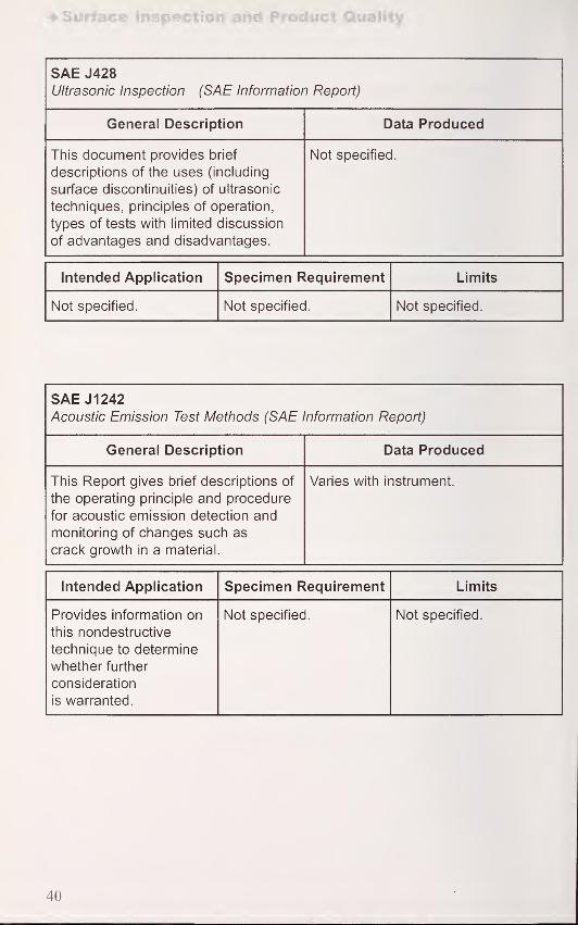
SAE J428
Ultrasonic Inspection (SAE Information Report)
General Description Data Produced
This document provides brief
descriptions of the uses (including
surface discontinuities) of ultrasonic
techniques, principles of operation,
types of tests with limited discussion
of advantages and disadvantages.
Not specified.
Intended Application Specimen Requirement Limits
Not specified. Not specified. Not specified.
SAE J 1242
Acoustic Emission Test Methods (SAE Information Report)
General Description Data Produced
This Report gives brief descriptions of
the operating principle and procedure
for acoustic emission detection and
monitoring of changes such as
crack growth in a material.
Varies with instrument.
Intended Application Specimen Requirement Limits
Provides information on
this nondestructive
technique to determine
whether further
consideration
is warranted.
Not specified. Not specified.
40

General (bare and coated)
SAE AMS 2440AInspection of Ground, Chromium Plated Steel Parts
(Aerospace Material Specification)
General Description Data Produced
This Specification covers the
requirements, procedures, and
acceptance/rejection criteria for
inspecting ground chromium plated
surfaces for grinder induced damageto the chromium plate substructure.
Examples of damage revealed by
fluorescent dye inspection
are provided.
Visual appearance of cracks whenviewed with black light.
Intended Application Specimen Requirement Limits
Not specified. Specimens should be
temper etch inspected
and magnetic particle
inspected prior to plating.
Ground plated parts are
cleaned and dried to
remove any material that
would interfere with the
inspection.
Inspection shall be
conducted by certified
inspectors (STN-TC-1A,
Level II). Questionable
inspections shall be
resolved by a Level III
penetrant inspector.
Procedure is as specified
in ASTM E-1417. Temperetch is per AMS 2649
and magnetic particle
inspection is per
ASTM E 1444.
41

4.2 Products (bare and coated)
4.2.1 Fasteners
ASTM F 788/F 788MStandard Specification for Surface Discontinuities of Bolts, Screws, and Studs,
Inch and Metric Series
General Description Data Produced
This Specification establishes
allowable limits for various types of
surface discontinuities that result from
manufacture of bolts, nuts screws and
studs. The specification covers metric
series with nominal diameters of 4mmand greater and minimum tensile
strengths of 800 MPa and inch series
with nominal diameters of No. 5
(0.1250 in.) and larger and with
specified minimum tensile strengths of
90,000 psi and greater. TheSpecification describes types of
discontinuities, limits of size and
location permitted, inspection and
evaluation. Inspection is visual with
magnification to 10x allowed.
Visible evidence of surface defects.
Intended Application Specimen Requirement Limits
Intended for
establishment of
purchase specifications.
Not specified. Not specified.
42

Products (bare and coated)
ASTM F812/F 812MStandard Specification for Surface Discontinuities of Nuts, Inch and Metric
Series
General Description Data Produced
This Specification establishes
allowable limits for various types of
surface discontinuities that result from
manufacture of metric series nuts with
nominal diameters 5 mm and larger
and inch series nuts with nominal
diameters 0.250 inch and larger.
Types of discontinuities are described,
limits on discontinuity size and
location provided, test method
(ASTM F 606) for strength of nuts
specified, visual inspection and
evaluation procedures described.
Visible evidence of surface defects.
Intended Application Specimen Requirement Limits
Intended for
establishment of
purchase specifications.
Not specified. The limits established for
metric nuts with nominal
diameters of 5 mm to
24 mm are essentially
identical to those in
ISO/DIS 6157/11. There
are no ISO standards for
nuts greater than 24 mm.
43

Surface Inspection and Product Quality
ISO 4042
Fasteners - Electroplated coatings
General Description Data Produced
This is a broad Standard which
addresses the dimensional requirements
for coating thickness for steel and
copper alloy fasteners and gives
recommendations for hydrogen
embrittlement relief for high tensile
strength or hardness and for surface
hardened fasteners. The following
issues are addressed: dimensional
requirements before and after
electroplating, situations which call for
hydrogen embrittlement relief, corrosion
protection, coating thickness
requirements and measurement.Ordering requirements and surface
coating designation systems are
identified. Annexes address: hydrogen
embrittlement relief; salt spray corrosion
protection performance; guidance for
procedures to accommodate thick
coatings; determination of batch
average thickness; designation code for
coatings; and, surface areas of bolts,
screws and nuts.
Measured characteristics or
performance required by
specifications.
Intended Application Specimen Requirement Limits
Provides a basis for
description of and
specification of threaded
fasteners coated by
electroplating. It mayalso be applied to non-
threaded parts such as
washers and pins.
Varies with property
measured.
Recommended coatings
may be applied to screws
that cut their own threads
(wood screws, self tapping
screws, etc.) with
maximum batch average
thickness given in the
standard ignored unless
otherwise specified.
Hydrogen embrittlement is
a major issue highlighted.
Note is made that
complete elimination of
hydrogen embrittlement
cannot be assured andalternative procedures to
those in the standard
should be evaluated,
as appropriate.
44

Products (bare and coated)
ISO 6157-1
Fasteners - Surface Discontinuities
Part 1: Bolts, screws and studs for general requirements
General Description Data Produced
This Standard details the causes,
appearance and limits for the following
surface discontinuities: quench cracks,
forging cracks, forging bursts, shear
bursts, raw material seams and laps,
voids, folds and tool marks. It applies
to bolts, screws and studs with
nominal thread diameters 5 mm and
larger, product grades A and B and
property classes up to and including
10.9 unless otherwise specified in
product standards or purchasing
agreements.
Varies with technique.
Intended Application Specimen Requirement Limits
Establishes limits for
surface discontinuities.
Product of interest must
be sufficiently clean to
be examined visually or
non-destructively (e.g.,
eddy current or magnetic
method). Secondary
samples examined by
cross-sectioning if first
examination indicates
surface discontinuities.
Limits (size of
discontinuity) vary with
type and size of item.
45

Surface Inspection and Product Quality
ISO 6157-2
Fasteners - Surface Discontinuities
Part 2: Nuts
General Description Data Produced
This Standard details the causes,
appearance and limits of the following
surface discontinuities: quench cracks,
forging and inclusion cracks, cracks in
the locking element of all - metal
prevailing torque type nuts, cracks in
the washer ring of nuts with captive
washers, shear bursts, bursts, seams,
folds, voids and tool marks. It applies
tn niitQ with nnminal thrppd rliamptprc;iu i iuio vviui iiuiiiiiiai ii ii cau uiaiiicicio
from 5 mm through 39 mm, product
grades A and B and all property
classes according to ISO 898-2 and
ISO 898-6 unless otherwise agreed to
in product standards or
purchasing agreements.
Varies with technique.
Intended Application Specimen Requirement Limits
Establishes limits for
surface discontinuities.
Product of interest shall
be sufficiently clean to
be examined visually at
10x magnification and
with appropriate
nondestructive methods.
ISO 10484, Widening
test on nuts, and ISO
10485, Cone proof load
on nuts are identified as
destructive or referee
tests when necessary.
Limits (size of
discontinuity) vary with
type and size of item.
46

Products (bare and coated)
ISO 6157-3
Fasteners - Surface Discontinuities
Part 2: Bolts, screws and studs for special requirements
General Description Data Produced
This Standard details the causes,
appearance and limits of the following
surface discontinuities: quench cracks,
forging cracks, forging bursts for
hexagonal head and circular head
screws, shear bursts for hexagonal
and circular head screws, forging
cracks in socket head screws, raw
material seams and laps, voids, folds,
tool marks, laps on the thread, and
damages. It applies to bolts, screws
and studs with nominal thread
diameters of 5 mm and larger; product
grads A and B, nominal lengths I < 10d;
property class 12.9 or property
classes 8.8, 9.8, 10.9 when so
specified or agreed to in
purchasing agreements.
Varies with technique.
Intended Application Specimen Requirement Limits
Establishes limits for
surface discontinuities.
Surface coating shall be
removed before
inspection by visual or
nondestructive test.
Destructive testing by
sectioning at 90°
through the discontinuity
shall be conducted whennondestructive or visual
examination indicates
defective products.
Limits (size of
discontinuity) vary with
type and size of item.
47

Surface Inspection and Product Quality
SAE J121
Decarburization in Hardened and Tempered Unified Thread Fasteners
(SAE Recommended Practice)
General Description Data Produced
This Recommended Practice
describes measurement classification
and specification of decarburization of
hardened and tempered steel bolts,
screws, studs etc. Microscopic
examination of polished and etched
cross-sections and microhardness
(Knoop ouug, vicKers Urn ouug)
measurements are interpreted with
respect to cross-section
decarburization to establish Class Cand Class D inch series threaded
products. Definitions of degrees
of decarburization are provided.
Microstructure or microhardness
indicative of carbon content changes.
Intended Application Specimen Requirement Limits
Microscopic examination
is intended for inspection
purposes, hardness is
intended or reference
purposes.
Metallographically
prepared cross-sections
of fasteners.
Not intended to cover
steel products which are
carburized to achieve
special properties.
48

Products (bare and coated)
SAE J 122
Surface Discontinuities on Nuts (SAE Recommended Practice)
General Description Data Produced
This Practice defines, illustrates and
specifies allowable limits for eight
types of discontinuities on metric
series nuts 6.3 mm to 25 mm and inch
- series nuts 0.250 in. to 1 in. which
are primarily intended for automotive
assemblies. Inspection procedures
and a sampling plan are included.
Varies with inspection technique,
generally visual.
Intended Application Specimen Requirement Limits
General information
and inspection.
Representative
lot samples.
Does not include
sampling requirements.
SAE J123
Surface Discontinuities on Bolts, Screws, and Studs in Fatigue Applications
(SAE Recommended Practice)
General Description Data Produced
This document defines, illustrates and
specifies allowable limits for surface
discontinuities (cracks, seams, bursts,
voids, laps, folds, tool marks, nicks
and gouges) in bolts, screws and
studs primarily intended for
automotive applications subjected to
severe dynamic stresses (fatigue)
where high strength fasteners with
fatigue resistance is required.
Sampling plans for visual and
microscopic inspection are appended.
Observable discontinuities which
determine acceptance or rejection of
batch.
Intended Application Specimen Requirement Limits
Intended for visual
inspection of batches of
fasteners, and
metallographic
examination for laps
and seams.
As-manufactured items. Defect limitations are
provided primarily as
location and orientation
specific features.
49

Surface Inspection and Product Quality
SAE J1061
Surface Discontinuities on General Application Bolts, Screws, and Studs
(SAE Recommended Practice)
General Description Data Produced
This Practice defines, illustrates and
specifies allowable limits for surface
discontinuities on bolts, screws and
threads in sizes through 24 mm or
1 in. in diameter, lengths to 150 mm or
6 in. with minimum specified tensile
strengths of 900 MPa or 120,000 psi
and greater intended for use in
automotive assemblies. Brief
descriptions of inspection and
sampling are included.
Varies with inspection method.
Intended Application Specimen Requirement Limits
General information
and guidance.
Samples representative
of the lot(s) of interest.
Does not include
sampling requirements.
50

Products (bare and coated)
4.2.2 Sheet and Structural Steel
ASTM D 4417
Standard Test Methods for Field Measurement of Surface Profile of
Blast-Cleaned Steel
General Description Data Produced
This method describes measurement
of the surface profile of abrasive
cleaned steel using:
a. visual comparison with materials of
known profile depths;
b. measurement of the surface with a
fine pointed probe;
c. micrometer measurement of a
replica of the surface.
Method (a) is a visual examination
with 5x or 10x optical magnification
and comparison to prepared surfaces.
Method (b) provides a dial gage
reading.
Method (c) provides a micrometer
reading.
Intended Application Specimen Requirement Limits
Specification
acceptance.
Flat, clean surfaces. For 37 |um to 135 \xrr)
peak to height
correlation coefficients
of: 0.75 visual,
0.99 - probe,
0.93 - tape have been
determined. Moreextensive descriptions
of repeatability,
reproducibility and
precision are provided.
51

Surface Inspection and Product Quality
ASTM E 430
Standard Test Methods for Measurement of Gloss of High-Gloss Surfaces by
Goniophotometry
General Description Data Produced
Two test methods for measuring the
reflection characteristics responsible
for the glossy appearance of high
gloss surfaces are covered. These
methods evaluate surface
characteristics at specular angles of
30° and 20° using commercial
instruments. Details of the apparatus
and sources, other ASTM methods
and guides relevant to the
measurement, calibration standards,
preparation and standardization of the
apparatus, procedure, calculation of
gloss and other parameters, reporting,
precision and bias are included.
Instrument readings of parameters at
various angles and use of these
readings to calculate relevant
characteristics.
Intended Application Specimen Requirement Limits
Measurement of
properties for
automotive, architectural
or other applications to
facilitate different
components to be
specified with matching
glossy appearance.
Originally applied to
bright metals, nowapplied to automotive
and other finishes.
Flat and at least 70 mm(2.75 in.) in the smallest
dimension.
Not suitable for diffuse
finish surfaces or
measurement of color.
52

Products (bare and coated)
ASTM E 1418
Standard Test Methods for Visible Penetrant Examination Using the
Water-Washable Process
General Description Data Produced
This Method describes the use of a
water washable visible penetrant for
detection of surface discontinuities
that are open such as cracks, laps
and isolated pores. The Method can
be used for non-porous metallic and
nonmetallic materials. A liquid
penetrant is applied to a surface,
allowed to enter discontinuities,
washed off with water and a developer
applied to draw remaining penetrant
out. The Method includes descriptions
of reagents and penetrants, procedure,
a flow sheet for the general
procedure, personnel qualification
and requalification requirements.
Visible discontinuities.
Intended Application Specimen Requirement Limits
Used for the production
examination of large
volumes of parts or
structures where the
emphasis is on
productivity.
Surface should be
cleaned of grease, dirt
and loose debris.
Users and suppliers mayrequire the certification
of examination staff per
identified AS NT, MIL
STD or ANSIrecommended practices.
In some cases test
pieces with real or
simulated discontinuities
of the smallest expected
features may be
required.
53

Surface inspection and Product Quality
SAE J810
Classification of Common Surface Imperfections in Sheet Steel
(SAE Information Report)
General Description Data Produced
This Report provides illustrations of
26 common surface imperfections in
sheet steel which can be seen with
the naked eye. The imperfections are
defined, photographically and
schematically illustrated, and
causes identified.
Not specified.
Intended Application Specimen Requirement Limits
Defect/imperfection
description for purposes
of classification.
Not specified. Not specified.
54

Products (bare and coated)
SAE J911
Surface Roughness and Peak Count Measurement of Cold Rolled Steel Sheet
(SAE Recommended Practice)
General Description Data Produced
This Practice provides guidance on
the measurement of the Roughness
Average (Ra) and Peak Count (PC)
on the surface of cold-rolled steel. Thedocument relies on ASME B 46.1 for
instrumentation specifics. Definitions,
equipment, test conditions, materials,
procedures and calibration are
included. Technique is stylus based.
Data produced varies with instrument.
Intended Application Specimen Requirement Limits
General information
and guidance.
Specimens
representative of the
material as produced
and removed from an
area at least 50 mm(2 in.) from the coil edge.
Rolling direction should
be identified and the
sample be flat and
roughly 150 mm (6 in.)
long parallel to the rolling
direction and 100 mm(4 in.) wide.
The instrument should
be calibrated for average
surface roughness with a
nominal Ra value in the
range, typically, of
0.25 jim to 2.5 urn
(10 nm to 100 fiin.).
The standard value for
the peak count level
should be 1 .25 (am
(50 |ain.) and the
standard filter cutoff
length for average
roughness and peak
count measurements on
cold-rolled steel should
be 0.8 mm (nominally
0.03 in.).
55

Surface Inspection and Product Quality
SAE AMS 2649BEtch Inspection of High Strength Steel Parts
(Aerospace Material Specification)
General Description Data Produced
This Specification establishes the
requirements for detection of
overheating by grinding or machining
of high strength low alloy steel (tensile
strength of 1z41 Mra (1oU ksi) and
higher) and of carburized material in
the heat treated condition. The
procedure consists of cleaning,
etching and visually inspecting for
color changes/ variations.
Acceptance criteria are included.
Visual indications of overheating.
Intended Application Specimen Requirement Limits
Intended for the
inspection of bare
material and carburized
parts.
Guidance for cleaning,
including Government
documents specifying
chemicals, is provided.
SAE ARP 1923
Qualification and
Certification of Etch
Inspectors are included
by reference.
56

Products (bare and coated)
4.2.3 Castings
ASTM A 802/A 802MStandard Practice for Steel Castings, Surface Acceptance Standards, Visual
Examination
General Description Data Produced
This Practice covers the acceptance
criteria for steel castings using visual
examination and comparing surface
texture, roughness and discontinuities
to Steel Castings Research and Trade
Association graded reference
comparators.
Surface texture, nonmetallic
inclusions, gas porosity, solidification
discontinuities, sand expansion
discontinuities, metal inserts, thermally
cut surfaces, mechanically prepared
surfaces, welded surfaces.
Intended Application Specimen Requirement Limits
Quality control (QC),
specification acceptance.
Not specified. This technique
is qualitative.
ISO 11971
Visual Examination of Surface Quality of Steel Castings
General Description Data Produced
This Standard provides comparisons
of standards prepared by the Bureau
de Normalisation des Industries de la
Founderie (BNIF) and Steel Castings
Research and Trade Association
(SCRATA) for the visual inspection of
surface roughness and surface
discontinuities on steel castings.
Not applicable.
Intended Application Specimen Requirement Limits
Purchase specifications. Not applicable. Qualitative descriptions
of surface roughness are
determined.
57

Surface Inspection and Product Quality
4.2.4 Other
ISO 14104
Gears - Surface Temper Etch Inspection After Grinding
General Description Data Produced
This Standard describes the cleaners,
etchants and procedures used to
determine and evaluate localized
overheating on ground steel surfaces.
The method is applicable to gears,
shafts, splines and bearings. A surface
temper classification system is
provided which is based on the visual
appearance of the etched surface.
ISO 14104 was prepared by TheAmerican Gear Manufacturers
Association (AGMA) as
ANSI/AGMA 2007-B92.
Visual indication of tempering.
Intended Application Specimen Requirement Limits
Qualitative indication of
tempering due to surface
grinding suitable for
process control and
purchase specifications.
Debris free degreased
surface.
Not applicable to nitrided
or stainless steels.
Approximately 0.003 mmof stock is removed
by nitric acid etching
each time the process is
performed and mayrequire masking of close
tolerance areas. Users
are advised to set their
own reference
standards.
58

Products (bare and coated)
ISO 13665
Seamless and Welded Steel Tubes for Pressure Purposes - Magnetic Particle
Inspection of the Tube Body for the Detection of Surface Imperfections
General Description Data Produced
This document specifies requirements
for magnetic particle particle
inspection of seamless and welded
steel tubes according to four different
acceptance levels. The Standard
includes: Method of test, Evaluation of
indications, Acceptance criteria
and Reporting requirements.
Visual indication.
Intended Application Specimen Requirement Limits
Intended to be used to
detect surface
imperfections on outer
surfaces of tubes as
required by product
standards.
Surface should be clean
and free of matter which
would interfere with
indicating particles.
Type and dimension of
imperfections detected
are dependent on tube
manufacturing process
and surface finish.
SAE J349
Detection of Surface Imperfections in Ferrous Rods, Bars, Tubes and Wires
(SAE Information Report)
General Description Data Produced
This information Report provides a
brief description of techniques for
detecting surface imperfections and
associated SAE documents which
provide more detail. Destructive and
non-destructive methods of measuring
(quantifying) imperfections
are also identified.
Inspection of features which are open
to the surface of ferrous bars, tubes,
wires; including, seams, laps, pits,
scratches, nicks, gouges.
Intended Application Specimen Requirement Limits
Information only. Not specified. Applicable only to
features open to the
surface of the article
inspected.
59

Surface Inspection and Product Quality
SAE AMS 2633BUltrasonic Inspection (Aerospace Material Specification)
General Description Data Produced
This document covers ultrasonic
inspection of tubular, centrifugaily-
cast, corrosion resistant steel
cylinders. Applicable ASTM. MIL-STD,
ANSI, ASNT and ATA documents as
are equipment couplants. reference
standards, procedures, and
QA provisions.
Varies with instrument.
Intended Application Specimen Requirement Limits
Typically used to locate
defects such as cracks,
voids, spongy areas.
OD and ID surfaces
machined to be not
rougher than 3.2 urn
(125 uin.) (per ANSIB46.1). Surface
discontinuities remaining
after surface preparation
shall not be removed
before ultrasonic
inspection. Surfaces
shall be free of loose
scale, particles, oil.
grease or other foreign
materials.
Not applicable to
austenitic alloys where
grain boundaries maymask results. Personnel
shall be certified per
MIL-STD-410.
60

Products (bare and coated)
SAE AMS 2647BFluorescent Penetrant Inspection Aircraft and Engine Component Maintenance
(Aerospace Material Specification)
General Description Data Produced
This specification is an extensive
guide to the inspection of aircraft and
engine components for defects
present at an exposed surface using
fluorescent penetrant(s). TheSpecification describes, in detail,
procedures for surface preparation,
cleaning, defect calibration standards,
inspection process, equipment
requirements, quality assurance
provisions, definition of terms, safety,
applicable SAE, ASTM, MIL-STD,
ATA, AIA specifications including
personnel requirements.
Visual signs of defects.
Intended Application Specimen Requirement Limits
Intended for the
detection of defects by
maintenance and
overhaul facilities in the
inspection of aircraft and
engine components and
associated accessories
when fluorescent
penetrant inspection is
specified, but not limited
to such applications.
Comprehensive
guidance is provided for,
primarily, cleaning to
remove contaminants
which can impede
inspection.
Considerations for
coatings and platings
are included.
Defect calibration
standards cover cracks
in the range of 0.38 mmto 6.35 mm (0.015 in.
to 0.250 in.) in five
size groups.
61

Surface Finish Evaluation
5. Surface Finish Evaluation
5.1 General (bare and coated)
ASTM E 1813
Standard Practice for Measuring and Reporting Probe Tip Shape in Scanning
Probe Microscopy
General Description Data Produced
This Practice provides a method for
measuring the size and shape of a
stylus used in scanning probe
microscopy (see ASTM F 1438, for
example). Sample shapes and probe
characterizers are used for gaining
data required for stylus measurement.
The Practice includes descriptions of
probe and characterizer shapes,
procedure and information on
analytical probe approximations.
Data can be numeric or graphic.
Intended Application Specimen Requirement Limits
Probe shape and
orientation data are
necessary for
determination of which
data can reliably be
extracted from a scan.
Not specified. Precision can be
affected by characterizer
roughness and
instrument factors.
62

General (bare and coated)
ASME B46.1-2002
Surface Texture (Surface Roughness, Waviness, and Lay)
(American National Standard)
General Description Data Produced
ASME B46.1 is a comprehensive
primer on surface texture and has
been updated since its introduction in
1940. The current Standard includes
the following sections: Terms Related
to Surface Texture; Classification of
Instruments for Surface Texture
Measurement; Terminology and
Measurement Procedures for Profiling,
Contact, Skidless Instruments;
Measurement Procedures for Contact,
Skidded Instruments; Measurement
Techniques for Area Averaging;
Nanometer Surface Texture and Step
Height Measurements by Stylus
Profiling Instruments; Nanometer
Surface Roughness as Measured with
Phase Measuring Interferometric
Microscopy; Filtering of Surface
Profiles; Terminology and Procedures
for Evaluation of Surface Textures
Using Fractal Geometry;
Specifications and Procedures for
Precision Reference Specimens; and
Specifications and Procedures for
Roughness Comparison Specimens.
Non-mandatory Appendices Athrough I provide valuable
supporting information.
Data produced varies with instrument.
Intended Application Specimen Requirement Limits
Intended to provide a
comprehensive, current
standard for surface
texture measurement.
Surface must be clean of
any material which would
interfere with a
measurement.
Sources of uncertainty
are identified for the
techniques.
63

Surface Finish Evaluation
ISO 4287
Geometrical Product Specifications (GPS) - Surface Texture: Profile Method -
Terms, Definitions and Surface Texture Parameters
General Description Data Produced
This Standard specifies terms,
definitions and parameters for the
determination of surface roughness,
waviness and primary profile by
profiling methods.
Not specified/applicable.
Intended Application Specimen Requirement Limits
This document underlies
other standards which
describe GPS in detail.
Not specified/applicable. Not specified/applicable.
ISO 8501-1
Preparation of Steel Substrates Before Application of Paints and Related
Products - Visual Assessment of Surface Cleanliness
General Description Data Produced
This is an Informative Supplement
which provides photographic
examples of the change of
appearance imparted to steel whenblast-cleaned with different abrasives
to remove rust (Grade C) to
preparation grade Sa3, prior to
painting. Procedure for use of the
comparison photographs is provided.
Visual comparison.
Intended Application Specimen Requirement Limits
Pre-painting inspection. Steel panels. Qualitative analysis.
64

General (bare and coated)
SAE J448a
Surface Texture (SAE Standard)
General Description Data Produced
This document defines terms used in
describing surface texture, establishes
classifications for degrees of
roughness and waviness for lays and
gives symbols indicating surface
characteristics in drawings.
The document does not specify
surfaces for specific application,
means of processing or any other
surface characteristics such as
luster, appearance, properties
or performance.
Not specified.
Intended Application Specimen Requirement Limits
General information. Not specified. Not specified.
SAE J449aSurface Texture Control (SAE Recommended Practice)
General Description Data Produced
This Practice describes the use of
control specimens that are used to
facilitate inspection of surfaces
prepared at different geographic
locations. The document is succinct,
giving an outline of steps for control
of surface texture.
Comparison of test pieces with control
samples varies with inspection
method.
Intended Application Specimen Requirement Limits
General information. Roughness and
waviness heights are
identified for specific
control specimens.
Not specified.
65

Surface Finish Evaluation
5.2 Methods for Specific Products and Processes
ASTM F 1438
Standard Practice for Determination of Surface Roughness by Scanning
Tunneling Microscopy for Gas Distribution System Components
General Description Data Produced
This Method defines the analysis of
surface texture using scanning
tunneling microscopy (STM) in air or
inert liquids; includes interferences,
apparatus, sampling, calibration,
conditioning, procedure, calculations,
and interpretation of data. STM is a
non-contact method that can
measure surface features in
the nanometer range.
Primary data from the test method is
graphical.
Intended Application Specimen Requirement Limits
Used where surface
texture is a selection
criteria.
Intended for use on
stainless steel with
surfaces smoother than
Ra = 0.25 |nm. Does not
cover steels with an
oxide layer too thick to
permit tunneling.
Repeatability standard
deviation (RSD) for
successive results
obtained by the sameoperator in the sameapparatus with the samesample:
Zmax 39 % RSDRa 31 % RSD
66

Methods for Specific Products and Processes;,[m
ISO 8503
Preparation of Steel Substrates Before Application of Paints and Related
Products - Surface Roughness Characteristics of Blast-Cleaned Steel
Substrates
Part 1: Specifications and definitions for ISO surface profile comparators for
the assessment of abrasive blast-cleaned surfaces
General Description Data Produced
ISO 8503 addresses the
characterization of steel surfaces
which have been blast cleaned with
either shot abrasives or grit abrasives
prior to painting or application of other
coatings. Part 1 specifies the
requirements for ISO surface profile
comparators which are intended for
visual or tactile comparison with
blasted steel surfaces. Thecomparators are made by forming
positive replicas (of electroformed
nickel, for example) from mild steel
master coupons. Separate
comparators, with four roughnessespaph art* rt^m lirt^H fnr Qhnt or nrittJaL/ll, Clio ICLjUlltSU lUI ollUl Ul yMl
blasted surfaces. Nominal
roughnesses for shot blasted
comparators are 25 (am, 40 |am, 70 |am
and 100 (am. Nominal roughnesses for
grit blasted comparators are 25 (am,
60 jam, 100 (am and 150 |am. Test
pieces are rated fine, medium or
coarse when matched to the
appropriate comparator.
Not specified.
Intended Application Specimen Requirement Limits
Process control and
specification compliance
on-site before application
of paints or other
coatings.
Comparators should be
treated as an instrument
and maintained in a
clean, grease free
condition.
Supports accompanying
standards and, where
appropriate, may be
used to assess surfaces
cleaned by other types
of blast-cleaning. Maybe used on surfaces
not to be painted.
67

Surface Finish Evaluation
ISO 8503
Preparation of Steel Substrates Before Application of Paints and Related
Products - Surface Roughness Characteristics of Blast-Cleaned Steel
Substrates
Part 2: Method for the grading of surface profile of abrasive blast-cleaned
steel - Comparator procedure
General Description Data Produced
Part 2 gives the procedure for
comparing the surface of the test
piece with each of the four blasted
areas on the comparator using visual
technique (hand lens up to 7x)
or tactile technique.
Visual or tactile comparison.
Intended Application Specimen Requirement Limits
Process control and
specification compliance
on site before application
of paints or other
coatings.
Dust and debris
free surface.
Qualitative evaluation of
fine, medium or coarse
roughness.
68

Methods for Specific Products and Processes
ISO 8503
Preparation of Steel Substrates Before Application of Paints and Related
Products - Surface Roughness Characteristics of Blast-Cleaned Steel
Substrates
Part 3: Method for the calibration of ISO surface profile comparators and for
the determination of surface profile - Focusing microscope procedure
General Description Data Produced
Part 3 addresses the measurement of
surface roughness using a microscope
either directly on the test piece or
replica, or comparator described in
Part 1. The method consists of making
a series of maximum peak-to-valley
measurements by measuring the
distance of microscope stage or
objective lens travel from focus on a
peak to focus on a valley. Thetechnique requires a microscope with
a graduated vernier scale with a scale
value of not more than 1 \im.
Numerical peak-to-valley values.
Intended Application Specimen Requirement Limits
Calibration of
comparators and test
piece measurement.
Dust and debris free
surface.
The technique is
applicable for
determination of surface
profile within the range
for maximum peak-to-
valley of 20 u.m to
200 urn. Themicroscope's acceptable
depth of field is 2 ^m.
69

Surface Finish Evaluation
ISO 8503
Preparation of Steel Substrates Before Application of Paints and Related
Products - Surface Roughness Characteristics of Blast-Cleaned Steel
Substrates
Part 4: Method for the calibration of ISO surface profile comparators and for
the determination of surface profile - Stylus instrument procedure
General Description Data Produced
Part 4 addresses the measurement of
surface roughness using a stylus with
a diamond tip of radius 5 ± 1|um.
The method is applicable to the
measurement of comparators
(Part 1) or to test pieces or replicas.
Procedures and calculation
are included.
Numerical peak-to-valley values.
Intended Application Specimen Requirement Limits
Calibration of
comparators and test
piece measurement.
Dust and debris free
surface.
Qualitative evaluation of
fine, medium or coarse.
70

Methods for Specific Products and Processes
ISO 8503
Preparation of Steel Substrates Before Application of Paints and Related
Products - Surface Roughness Characteristics of Blast-Cleaned Steel
Substrates
Part 5: Replica tape method for the determination of the surface profile
General Description Data Produced
Part 5 addresses the use of a replica
tape in measuring surface roughness.
Procedures for use of the tape, and
a micrometer gage, for the
measurement are given.
Numerical peak-to-valley values.
Intended Application Specimen Requirement Limits
For on-site measurementof surface profiles before
application of paint
or other coatings.
Dust and debris free
surface.
Applicable within the
range of profiles cited
for a given grade or
thickness of replica tape,
typically peak-to-valley
profiles of 20 |im
to 115 jim.
71

General Product Quality Standards
6. General Product Quality Standards for Specific Coating Processes
6.1 Anodic Coatings
ISO 7599
Anodizing ofAluminum and its Alloys - General Specifications for Anodic
Coatings on Aluminum
General Description Data Produced
This Standard gives general
specifications for anodic coatings on
aluminum. It defines characteristic
properties, lists test methods (ISO
Standards) for thickness and massper unit area, quality of sealing,
appearance and color, corrosion
resistance, resistance to crazing by
deformation, fastness to light and
ultraviolet radiation, light reflection
properties, electrical breakdown
potential, and continuity of the
coating. A classification system for
anodic coatings is provided based
on minimum average thickness
in micrometers.
Varies with property of interest.
Intended Application Specimen Requirement Limits
Intended to provide a
broad inventory of test
methods useful in
specifying a product or
material. The Standard
is applicable mainly to
coatings of aluminum
oxide which are formed
on aluminum by an
electrolytic oxidation
process in which the
aluminum acts as
the anode.
Varies with property
measured.
Not applicable to:
(a) non-porous coatings
of the barrier type
(b) oxide coatings
intended to prepare the
substrate for subsequent
application of organic
coatings or electrode
position of metals;
(c) "Hard anodized"
coatings where wear
and abrasion resistance
are the primary
characteristics.
72

Conversion Coatings
6.2 Conversion Coatings
ISO 3613Chromate Conversion Coatings on Zinc, Cadmium, Aluminum-Zinc Alloys andZinc-Aluminum Alloys - Test Methods
General Description Data Produced
This Standard gives methods for
determination of: the presence of
colorless chromate conversion
coatings; presence and quantity of
hexavalent chromium and colored
coatings; total chromium content per
unit area; mass per unit area of
colorless and colored coatings,
satisfactory adhesion of chromate
conversion coatings and quality of
chromate coating. The test methodsare generally spot tests or absorption
cell measurement with procedures
and test solution preparation provided.
Adhesion testing is conducted by
rubbing the coating with paper and
examining for evidence of coating
rubbed off. Corrosion resistance is
by ISO 9227-salt spray tests.
Color changes indicate presence of
species of interest or absorption cell
changes for quantitative measures.
Intended Application Specimen Requirement Limits
Provides a basis for
purchase specifications.
Clean grease free
surfaces.
Methods are applicable
to (1) colorless andcolored chromate
conversion coatings
containing tri- andhexavalent chromiumproduced by chemical or
electrochemical
processes and (2) only
to chromate coatings
that are free from anysupplementary coatings
such as oil, water or
solvent-based polymers
or wax. Substances or
procedures are specified
that can be injurious to
health. Adequate safety
precautions are required.
73

General Product Quality Standards
ISO 4520
Chromate Conversion Coatings on Electroplated Zinc and Cadmium Coatings
General Description Data Produced
This Standard specifies the
requirements for chromate conversion
coatings on zinc and cadmiumintended to give protection against
corrosion. A method of application
is described in general terms, a
classification/designation system
is provided and requirements for
corrosion resistance based on
classification/ designation.
Adhesion properties are to be
determined by ISO 3613.
Varies with property of interest.
Intended Application Specimen Requirement Limits
Provides a basis for
purchase specifications.
Varies with property
measured.
Finishes for giving
particular colors only or
specifically to improve
paint adhesion are not
covered in this standard.
74

Galvanized Coatings
6.3 Galvanized Coatings
ASTM A 896
Standard Practice for Conducting Case Studies on Galvanized Structures
General Description Data Produced
This Practice gives procedures for
conducting case-studies on
permanent galvanized structures.
The document gives
recommendations for visual
inspection, general procedure, data to
be collected and appropriate forms to
be completed. General surveys and
accurate monitoring of thickness are
covered. For accurate measurement,
method B 499 using an electronic
magnetic-flux gage is recommended.
For general surveys, a hand held
magnetic gage using the magnetic
attraction principle in accordance
with ASTM E 376 is identified.
Coating thickness.
Intended Application Specimen Requirement Limits
Determination of the
condition of galvanized
coatings on buildings,
bridges, industrial and
other structures.
Surfaces clean of debris. Method B 499 can
achieve accuracies of
± 3 to ± 5% using
commercial instruments.
75

General Product Quality Standards
6.4 Electroplated Coatings
ISO 1456
Metallic Coatings - Electrodeposited Coatings of Nickel Plus Chromium and of
Copper Plus Nickel Plus Chromium
General Description Data Produced
This Standard specifies the
requirements for decorative,
electroplated nickel plus chromium,
and copper plus nickel plus chromium
coatings on iron, steel, zinc alloys,
copper and copper alloys and
aluminum and aluminum alloys to
provide an attractive appearance
and enhanced corrosion resistance.
Coating designations which are
appropriate to various service
conditions are given in terms of
thickness and type. Methods of
measurement of cracks and pores
in chromium coatings, ductility of
electrodeposited nickel, and sulfur
content of electrodeposited nickel
are detailed. Other property
measurements are identified by
reference to ISO or ASTM Standards.
Varies with property of interest.
Intended Application Specimen Requirement Limits
Provides a basis for
purchase specifications.
Varies with property
measured.
Does not apply to
surface condition of
substrate metal prior to
coating. Does not apply
to coatings on sheet,
strip or wire in the non-
fabricated form or to
threaded fasteners
or coil springs.
76

Electroplated Coatings
ISO 1458
Metallic Coatings - Electrodeposited Coatings of Nickel
General Description Data Produced
This Standard gives requirements for
nickel electrodeposited coatings that
are applied to iron, steel, zinc alloys,
copper and copper alloys, aluminum
and aluminum alloys for decorative
and corrosion resistance purposes.
Copper plus nickel coatings applied to
iron, steel and zinc alloys are also
included. Service condition numbers
and coating designations are defined.
Requirements for appearance, local
thickness, adhesion, ductility,
corrosion resistance, stress relief
treatments, hydrogen embrittlement
relief treatments and sampling are
included. ISO thickness measurementmpthnrlQ prp rpfprpnpprl Di iptilitv iqMICH lUUo ul C I CI CI CI IL/CU , l_/ U O 1 1 1 I I y Io
determined by bending the coated test
piece over a mandrel. Sulfur content
of nickel coatings is determined by
combustion and iodate titrimetry or by
sulfide formation and iodate titrimetry.
Varies with property of interest.
Intended Application Specimen Requirement Limits
Provides a basis for
purchase specifications.
Clean, grease free
surfaces.
The standard does not
specify the surface
condition required by the
substrate prior to
coating, and is not
applicable to coatings on
sheet strip or wire in the
non-fabricated form nor
to threaded fasteners
or coil springs.
77

General Product Quality Standards
ISO 2081
Metallic Coatings - Electroplated Coatings of Zinc on Iron or Steel
General Description Data Produced
This Standard specifies requirements
for a range of electroplated coatings
of zinc for the protection of iron and
steel against corrosion in various
service environments. Information
which must be supplied to an
electroplater, a classification code,
heat treatment including hydrogen
pmhrittlpmpnt rplipf and simnlp tpst
methods for thickness and adhesion
measurement (by hand burnishing)
are provided. Relevant ISO Standards
for specification or measurementof some properties are cited.
Quantitative measures of coating
thickness are specified. Qualitative
measures of adhesion.
Intended Application Specimen Requirement Limits
Provides a basis for
purchase specifications
including heat treating
requirements before
and after plating.
Base metal surface
requirements are
qualitative. Plated
surfaces should be
free of visible defects.
This Standard does not
apply to: sheet, strip or
wire in the unfabricated
form; close-coiled
springs; other than
protective or decorative
purposes. Surface
condition of base metal
is not specified. Theimportance of conversion
coatings is recognized
but those coatings are
described in ISO 4520.
78

Electroplated Coatings
ISO 2082
Metallic Coatings - Electroplated Coatings of Cadmium on Iron or Steel
General Description Data Produced
This Standard specifies requirements
for a range of electroplated coatings
of cadmium for the protection of iron
and steel against corrosion in various
service environments. Information
which must be supplied to an
electroplater, a classification code,
heat treatment including hydrogen
embrittlement relief, and simple test
methods for thickness and adhesion
measurement (by hand burnishing)
are provided. Relevant ISO Standards
for specification or measurement of
some properties are cited. This
standard is very similar to ISO 2081
.
Quantitative measures of coating
thickness are specified. Qualitative
measures of adhesion.
Intended Application Specimen Requirement Limits
Provides a basis for
purchase specifications
including heat treating
requirements before
and after plating.
Base metal surface
requirements are
qualitative. Plated
surfaces should be
free of visible defects.
This Standard does not
apply to: sheet, strip or
wire in the unfabricated
form; close-coiled
springs; other than
protective or decorative
purposes. Surface
condition of base metal
is not specified.Theimportance of conversion
coatings is recognized
but those coatings are
described in ISO 4520.
Purchasers must specify
the classification code
required, not only
ISO 2082.
79

General Product Quality Standards
6.5 Diffusion Coatings
ASTM B 874
Standard Specification for Chromium Diffusion Coating Applied by PackCementation Process
General Description Data Produced
This Specification gives requirements
for chromium diffusion of metals by
the pack cementation process. A brief
description of the process, definition
of terms used in the process,
classification by base metal category,
ordering and processing requirements,
test methods and sampling
requirements. Test methods are
referenced for coating thickness
(ASTM C 664, B 487) decarburization
(E 1077), chromium content (E 766).
Varies with property of interest.
Intended Application Specimen Requirement Limits
This Specification can
be used in establishing
specifications for
purchase of coated
materials and
components.
Not specified. Diffusion thickness
requirements are as
follows:
Class I (carbon base)
0.0762 mm*(0.003 in.) min.
Class II (low alloys)
0.0762 mm(0.003 in.) min.
Class III (stainless
steels) 0.0508 mm(0.002 in.) min.
Class IV (nickel base
alloys) 0.0254 mm(0.001 in.) min.
The outer 1 5% of the
coating shall contain
20% chromium
by weight.
* SI (metric) units are calculated because the original standard included only customary
units
80

Diffusion Coatings
ASTM B 875
Standard Specification for Aluminum Diffusion Coating Applied by PackCementation Process
General Description Data Produced
This Specification gives requirements
for aluminum diffusion of metals by
the pack cementation process. A brief
description of the process, definition
of terms used in the process,
classification by base metal category,
ordering and processing requirements,
test methods and sampling
requirements. Test methods are
referenced for coating thickness
(ASTM C 664, B487), aluminum
content to be measured by beta
backscatter or X-ray fluorescence.
Varies with property of interest.
Intended Application Specimen Requirement Limits
This Specification can
be used in establishing
specifications for
purchase of coated
materials and
components.
Not specified. Diffusion thickness
requirements are as
follows:
Class 1 (carbon and low
alloy) 0.127 mm*(0.005 in.) min.
Class II (stainless steels)
0.0762 mm(0.003 in.) min.
Class III (nickel base
alloys) 0.0254 mm(0.001 in.) min.
The outer 15% of the
coating shall contain
28% aluminum by
weight, minimum.
* SI (metric) units are calculated because the original standard included only customary
units
81

General Product Quality Standards
6.6 Physical Vapor Deposition (PVD)
AMS 2444ACoating, Titanium Nitride Physical Vapor Deposition
(Aerospace Material Specification)
General Description Data Produced
This document provides requirements
for the application and properties of
titanium nitride coating on metallic
parts applied by physical vapor
deposition. Coatings covered are
divided into three classes:
Class 1-1.27 |im to 3.81 urn
(0.00005 in. to 0.00015 in.) thick;
Class 2 - 2.54 (am to 6.10
(0.00010 in. to 0.00024 in.) thick; and,
Class 3 - 6.35 |am to 12.70 (am
(0.00025 in. to 0.00050 in.) thick.
Processing requirements, properties,
quality, quality assurance, preparation
for delivery and surface roughness
suggestions are included. Property
measurement methods are identified
by reference to ASTM Standards,
including: for thickness ASTM B 487,
B 499, B568, E 376, E 1182; for
hardness E 92 and E 384. Aqualitative adhesion test using a tape
pull-off method is described.
Varies with property or characteristic
of interest.
Intended Application Specimen Requirement Limits
Provides information
useful in purchase
specification.
Varies with property or
characteristic of interest.
Useful for identifying
those properties and
characteristics important
to PVD materials and
methods of
measurement.
82

Thermal Spray
6.7 Thermal Spray
ISO 2063
Metallic and Other Inorganic Coatings - Thermal Spraying - Zinc Aluminum andTheir Alloys
General Description Data Produced
This Standard gives general information
useful to thermal spray materials users.
The standard applies to thermal sprayed
coatings of zinc or aluminum deposited
on iron and steel for corrosion
protection. A classification schemefor zinc, aluminum or Zn-AI alloy
coatings based on thickness is included.
The standard addresses surface
preparation, extent of thickness
measurement required based on
surface area, measurement method by
reference to ISO 2178 and ISO 1463.
Adhesion testing by a "Grid test"
wherein a hand scribed grid allows
delamination of the coating with tape
pull off, and a "Tensile" method similar
to ASTM C 633, is included.
Measure of coating thickness
and adhesion.
Intended Application Specimen Requirement Limits
Provides some basis for
material specification.
Varies with property
measured.
The standard does not
apply to coatings other
than zinc or aluminum.
Application of aspects of
the standard to other
metals may be adopted by
agreement of interested
parties. The standard
does not apply to repairs
of damaged metal areas.
The method of thermal
spray (plasma, flame, cold
spray, etc) is not specified.
The tensile adhesion test
is not claimed to be
reproducible, requiring the
same operation in the
same facility to
have consistency.
83

General Product Quality Standards
MILITARY STANDARDMIL-STD 1687A(SH)
Thermal Spray Processes for Naval Ship Machinery Applications
General Description Data Produced
This Standard addresses manyaspects of the deposition of materials
for the repair and corrosion protection
nf Naval QhinhnarH maphinprvUl INavdl ol lipuvJcll U 1 1 laUl III Id y.
Evaluation of deposits and
deposit/substrate systems by
metallographic analysis for oxide
and porosity content, bond strength
by ASTM C 633, and bend tests
are identified.
Data varies with test.
Intended Application Specimen Requirement Limits
Intended to provide
guidance for shipboard
machinery repair.
Bend tests are
conducted on nominally
2 in. x 3 in. x 0.50 in.
thick (5.18 cm x 7.62 cmx 1 .17 cm)* panels.
Coating thicknesses are
to be 0.008 ± 0.002 in.
(0.0203 cm ±
0.00508 cm)* unless
otherwise specified by
the manufacturer.
Not specified.
* SI (metric) units are calculated because the original standard included only customary
units
84

Glass and Enamel Coatings
6.8 Glass and Enamel Coatings
ASTM C 536
Standard Test Method for Continuity of Coatings in Glassed Steel Equipment
by Electrical Testing
General Description Data Produced
This method covers the detection of
discontinuities in the glass coating
applied to steel equipment where the
discontinuities would result in early
failure due to chemical attack of the
metal substrate. The test consists of
sweeping the surface of the glass
with a point or brush type probe and
observing discharges between the
probe and the metal substrate. The
metal substrate is connected to the
ground side of a voltage generator,
the probe to the other side.
The voltage used is 5000 V at
2.5 mA and may be from stationary
AC or portable DC. Equipment
suppliers are identified.
A visible and audible spark forms at
discontinuities in the glass coating.
Intended Application Specimen Requirement Limits
The test is applicable to
manufacturing and
inspection testing as
well as field testing.
Clean dry surfaces. The method
is qualitative.
85

# General Product Quality Standards
ASTM C 537
Standard Test Method for Reliability of Glass Coatings on Glassed Steel
Reaction Equipment by High Voltage
General Description Data Produced
This Method covers the detection of
discontinuities in the glass coating as
areas of the coating where the glass
may be thin enough to result in
premature failure in service where
highly corrosive conditions can cause
severe damage to the exposed metal
substrate. The test consists of
sweeping the surface of the glass
with a point or brush type probe and
observing discharges between the
pi UUC cX\ IU lilt; IlltJldl oUUoll ale. 1 lie
metal substrate is connected to the
ground side of a voltage generator,
the probe to the other side. The DCvoltage used is up to 20,000 Vat 2.5 mA. Equipment supplier
is identified.
A visible and audible spark forms at
discontinuities in the glass coating.
Intended Application Specimen Requirement Limits
The test is intended to
provide information
which allows repair
of the coating before
leaving the
manufacturing facility.
Clean dry surfaces. The method is
qualitative. Voltage
levels can be preset
based on desired
minimum thickness of
glass. Testing can create
punctures in the glass
coating when the glass
thickness is insufficient
to withstand the applied
voltage. Those punctures
can be repaired by
additional glass
application before the
equipment leaves the
manufacturing facility.
86

Glass and Enamel Coatings #
ASTM C 743
Standard Test Method for Continuity of Porcelain Enamel Coatings
General Description Data Produced
This Method permits the detection of
discontinuities and areas of light
coverage (thin coatings) in porcelain
enamel coatings on metal substrates.
The technique is similar to ASTMC 536 and ASTM 537 which are
intended for thicker glass coatings.
An AC or DC high voltage discharge
instrument with a continuously
variable output voltage over the range
of at least kV to 4 kV which can be
set to 0.1 kV is required. A calibration
curve of enamel thickness vs.
discharge arcing voltage is
established per Annex A1 . A test
probe of 100 mesh wire gauze is
passed over the surface at selected
voltages. An arc between probe and
base metal will occur at
discontinuities, indicating failure.
The test can be used to indicate
UlcocllL/t; Ul UcltJUlo U|Jol I IU lilt? Udoc
metal and enamel surface, areas of
light coverage, or compliance with
a specification. Procedures are
given and equipment suppliers
are identified.
A visible and audible spark.
Intended Application Specimen Requirement Limits
Material evaluation or
specification compliance.
Clean dry surfaces. Arc formation can be
calibrated to coating
thickness for specific
material and equipment.
87

Standards for Measurement of Surface Treatment Depth
7. Standards for Measurement of Surface Treatment Depth, Coating
Thickness and Mass
7.1 Surface Treatment Depth
ASTM B 721
Standard Test Method for Microhardness and Case Depth of PowderMetallurgy (P M) Parts
General Description Data Produced
This method describes the
measurement of Knoop or Vickers
microhardness on the polished cross-
section of a powder metallurgy part,
including the hardened surface, to
develop a hardness vs depth curve
used to define the transition from case
hardened to core material. Casedepth and effective case depth
determinations are described. Method
includes summary of microhardness
and case depth measurements,
surface preparation, procedure
reporting, precision and bias. This is
intended to be a companion to ASTMTest Method E 384. Test Method
for Microhardness of Materials.
Microhardness as a function of
distance from surface.
Intended Application Specimen Requirement Limits
Measurement of proper
hardness and thickness
of the case to meetengineering function.
Metallographic specimen
with edge retention and
for densities below
6.6 g/cm3. vacuum
impregnation with resin
or epoxy to support
the structure.
Interlaboratory
measurements of an
unknown sample after
measurement of test
blocks with knownhardnesses were
conducted. For a
laboratory to duplicate
any of the other
laboratories. 95% of the
readings should be
within 5.3 HRC: for six
reading averages,
within 2.2 HRC.

Surface Treatment Depth
ASTM E 1077
Standard Test Methods for Estimating the Depth of Decarburization of Steel
Specimens
General Description Data Produced
This document describes screening
methods, microscopical methods,
microindentation hardness methods
and chemical analysis methods to
determine the depth of decarburization
of steels. Sampling, procedures for
the methods, reporting, precision
and bias are included.
Carbon content as a function of depth
from the surface determined by
chemical analysis, microstructural
change or microhardness change with
depth, both reflecting decarburization.
Intended Application Specimen Requirement Limits
The methods may be
used to qualify material
for shipment, machining
guidance, or to assess
the effect of processing.
Varies with method. For 20 or more
measurements
decarburization depths
can be estimated to
within 0.025 mm(0.001 in.) with a relative
accuracy of 10% to 20%with microscopical
methods. Estimates of
total or effective
decarburization by
microindentation at
a given location are
generally accurate within
0.025 mm (0.001 in.).
89

Standards for Measurement of Surface Treatment Depth
ISO 2639
Steels - Determination and Verification of the Depth of Carburized andHardened Cases
General Description Data Produced
This Standard defines case-hardened
depth and gives methods for its
determination. The depth is
determined by measurement of a
hardness gradient on a cross-section
perpendicular to the surface,
naraness may De measurea oy
Vickers or Knoop methods, upon
agreement of the parties concerned.
The procedure for determination of
case-hardened depth, verification of
the measurement and reporting
are included.
Microhardness as a function of
distance from the surface.
Intended Application Specimen Requirement Limits
Applicable for
measurement of
carburized and
carbonitrided cases and
parts heat treated to a
final hardness of less
than 450 HV 1 at a
distance of three times
the case hardened depth
from the surface or by
special agreement
between parties.
Polished cross-sections. Case hardened depth is
defined as the
perpendicular depth
between the surface
and the layer having a
Vickers hardness of
550 HV 1 in accordance
with ISO 6507-1 or
equivalent Knoophardness in accordance
with ISO 4545.
90

Surface Treatment Depth
ISO 3754
Steel - Determination of Effective Depth of Hardening After Flame or
Induction Hardening
General Description Data Produced
This Standard defines the effective
depth of flame or induction hardening
by measurement of Vickers hardness
on a polished cross-section
perpendicular to the hardened
surface. Effective depth is defined as
the distance from the surface where
the Vickers hardness under a load of
9.8 N is equal to the "hardness limit".
The hardness limit is defined as
0.80x minimum surface hardness,
expressed in mm.
Microhardness as a function of
distance from the surface.
Intended Application Specimen Requirement Limits
Suitable for
measurement of
hardness where a cross-
section can be removed.
Polished cross-sections. Applies to hardened
layers with a depth
greater than 0.3 mm and
parts which in the
surface hardened
condition, have a
hardness less than the
hardness limit-1 00 at a
distance 3x the effective
depth of hardening.
91

Standards for Measurement of Surface Treatment Depth
ISO 4970
Steel - Determination of Total or Effective Thickness of Thin
Surface-Hardened layers
General Description Data Produced
This Standard specifies a
micrographic method and a
microhardness method for measuring
the total effective thickness of
sunace-naraenea layers less man0.3 mm in thickness. These layers
may be obtained by mechanical
or thermochemical methods.
Procedures for the micrographic
and microhardness are given in
general terms.
Microhardness as a function of
distance from surface or
microstructural variation resulting
from hardening treatment.
Intended Application Specimen Requirement Limits
Not specified. Metallographic
specimens suitable for
visual microstructural
analysis or
microhardness
measurements.
Not applicable to thin
layers not continuous
with the base metal.
Thicknesses greater
than 0.3 mm are covered
by ISO 2639, Steel-
Determination and
verification of the
effective depth of
carburized and hardened
cases, and ISO 3754,
Steel-Determination of
effective depth of
hardening after flame or
induction hardening.
92

Surface Treatment Depth
SAE J419
Methods of Measuring Decarburization
(SAE Recommended Practice)
General Description Data Produced
This document describes typical
methods for measurement of the
extent of decarburization (loss of
carbon from the surface) of ferrous
materials. The methods described
are: microscopic examination of the
microstructure of a metallographic
specimen; measurement of hardness,
including cross-section microhardness
traverse, longiiuainai iraverse ana
measurement of file hardness; and
chemical analysis including analysis
of machining chips and electron
microprobe.
Definitions and illustrative micrographs
are included.
Images of microstructure which
illustrate changes due to carbon loss,
hardness measurements which reflect
change in carbon content and
qualatative differences in hardness
manifested by changes in
resistance to filing.
Intended Application Specimen Requirement Limits
To determine suitablity of
material for intended
purpose, process
evaluation, acceptance
testing.
Metallographic sections
typically normal to the
surface with edge
protection and retention.
Hardness measurementsare made on specimens
hardened by quenching
with minimumcarbon loss.
Accuracy of method
used is dependent on
degree of
decarburization, base
carbon content and
microstructure.
Metallographic and
hardness methods are
inaccurate for small
amounts of
decarburization in high
carbon (above 0.06%),
high hardness steels.
93

Standards for Measurement of Surface Treatment Depth
SAE J423Methods of Measuring Case Depth (SAE Standard)
General Description Data Produced
This Standard addresses techniques
of measuring the case depth of
ferrous material. The case is muchharder than the core material as a
result of carburizing, nitriding,
carbonitriding, cyaniding, induction
or flame heating or another process
in which chemical composition or
mechanical properties or both are
affected by the process. Chemical
methods, including analysis of
machining chips or microprobe
analysis of prepared cross-sections,
arp Hpsrribpd Mpchaniral (hardnpss^
measurements and visual techniques
(observation of cut or fractured and
etched cross-sections) and
microscopic methods are
described in detail.
Information or data relating
composition or hardness to distance
from surface.
Intended Application Specimen Requirement Limits
Specification
acceptance, process
evaluation.
Varies with technique. Case depths measured
by different methods can
vary significantly.
94

Surface Treatment Depth
SAE ARP 1341
Determining Decarburization and Carburization in Finished Parts of Carbon
and Low-Alloy Steels
(Aerospace Recommended Practice)
General Description Data Produced
This Practice addresses determination
of decarburization and carburization
for heat treated carbon and low-alloy
steel parts other than those case
hardened. The Practice includes
visual inspection of metallographic
specimens and microhardness survey.
ASTM E 3 and E 407 are the
metallographic references. ASTME 384 is the microhardness guide.
Criteria for determination of
(1) complete decarburization by
visual examination and (2) total
decarburization (complete plus
partial) by microhardness of
(a) hardened and (b) hardened
and tempered are provided.
Microhardness values determined
from indent traverses perpendicular to
the surface and visual interpretation of
microstructure at 100x.
Intended Application Specimen Requirement Limits
Inspection for
acceptance.
Metallographic
specimens may be
prepared from a part
after complete heat
treatment or from
separate samples
processed with the part,
having identical surface
treatment and from the
same heat, preferably.
Not applicable to raw
material or case
hardened parts.
95

Standards for Measurement of Surface Treatment Depth
SAE ARP 1820
Chord Method of Evaluating Surface Microstructural Characteristics
(Aerospace Recommended Practice)
General Description Data Produced
This Practice describes a
metallographic preparation technique
in which a simple disc specimen which
has been subjected to the sametreatment as a batch of identical
material is polished on a chord of
its circular cross-section to provide
a magnified cross-section for
microstructural and microhardness
assessment of thin layers of
decarburization and intergranular
oxidation. The Practice is intended for
hardened steel and gives procedures
tot naraness assessments toi aepin
of partial decarburization, severity of
partial decarburization, carburization
and nitriding, and recommendedrejection criteria for the preceeding
conditions as well as depth
of intergranular oxidation.
Microhardness as a function of
distance from surface.
Intended Application Specimen Requirement Limits
It is useful for process
control in heat treatment
of steel parts and maybe useful for evaluation
of plated coatings.
Disc or disc-sector
specimens 3 mm to
6 mm (0.125 in. to
0.250 in.) thick, 6 mmto 12 mm (0.250 in. to
0.50 in.) radius of samealloy as parts at issue
with texture of
circumferential surface
approximately 0.8 fim
(32 (uin.). Surfaces must
be free of carburization,
nitriding, decarburization
and intergranular
oxidation before use.
Limits (rejection criteria)
are based on achieving,
for high strength steels
(maximum tensile
strength of greater than
1520 MPa (220,000 psi))
optimum fatigue
performance of surfaces
which are shot peened
and for low strength
steels (maximum tensile
strength less than
1520 MPa (220,000 psi))
what is commonlyachievable in modern
protective atmosphere
furnaces.
96

Coating Thickness
7.2 Coating Thickness
Figure 2. Applicability of Coating Thickness Measuring Methods
Substrates
Coatings
Copper Nickel
Chro-
mium
Auto-
cata-
lytic
Nickel Zinc
Cad-
mium Gold
Palla-
dium
Magnetic
steel
(including
corrosion-
resisting
steel)
CM CM^ CM CeM* CM BCM BM BM
Non-
magnetic
stainless
steels
c pe c BC B B
Copper and
alloys
C only
on
brass
and
Cu-Be
CM^ c C BC B B
Zinc and
alloys
C ft A AM^ D Dd DD
Aluminumand alloys
BC BCM^ BC BCB BC BC B B
Magnesiumand alloys
B BM^ B B B B B B
Nickel c c r RC R B
Silver R ri\/|/4DIVI" RI—
>
R R R
Glass
sealing
nickel-
cobalt-iron
alloys UNSNo. K94610
M M CBKAAV> IV
1
M BM BM BM
Nonmetals BCE° BCM^ BC BCe BC BC B E
Titanium B BM^ BC6 BEA 'B B B B B
^Method is sensitive to permeability variations of the coating.
^Method is sensitive to variations in the phosphorus content of the coating.
Qvlethod is sensitive to alloy composition.
^Method is sensitive to conductivity variations of the coating.
97

Standards for Measurement of Surface Treatment Depth
Figure 2. Applicability of Coating Thickness Measuring Methods (cont'd)
Coatings
Substrates
Rhodium Silver Tin Lead
Tin-Lead
Alloys
Non-
Metals
Vitreous
and Porcelain
Enamels
Magnetic
steel
(including
corrosion-
resisting
steel)
BM BCM BCM BCM BC C C M BM M
Non-
magnetic
stainless
steels
B BCED BC BC B^CC BE E
Copper and
alloys
B BC BC BC BC CC BE E
Zinc and
alloys
R R RD R RF
Aluminum
and alloys
B BC BC BC Bc C c E E
Magnesiumand alloys
B B B B Bc E
Nickel B BC BC BC B^CC BE
Silver dL i->B° bb b
oiass
sealing
nickel-
cobalt-iron
alloys UNSNo. K94610
bM bM nyDM bCM B^ C° M nybM
Nonmetals B BC BC BC Bc Cc
Titanium B B B B Bc BE
Note: B = Beta backsetter; C = Coulometric; E = Eddy current; and M = Magnetic
Note: Figure 2, Applicability of Coating Thickness Measuring Methods, is reprinted, with
permission, from ASTM B 659-90(2003) Standard Guide for Measuring Thickness of
Metallic and Inorganic Coatings, copyright ASTM International, 100 Barr Harbor Drive,
West Conshohocken, PA 19428.
98

Coating Thickness
ASTM B 244
Standard Test Method for Measurement of Thickness ofAnodic Coatings on
Aluminum and of Other Nonconductive Coatings on Nonmagnetic Basis Metals
with Eddy-Current Instruments
General Description Data Produced
Coating thickness is determined with
an electromagnetic instrument that
measures changes in apparent
impedance of the coil inducing the
eddy currents in the basis metal.
Thp mpthod uspful for mpa^urino1 1 1 \D 1 1 1 \J \J IO UOUI Ul Ivl 1 1 IGUOUI II iy
the thickness of anodic coatings
on aluminum alloys but chemical
conversion coatings are too thin to
be measured with this method.
Includes apparatus, list of instrument
suppliers, factors affecting accuracy,
calibration, procedure, reporting.
Coating thickness.
Intended Application Specimen Requirement Limits
Nondestructive
measurement of
thickness of a
nonconductive coating
on a nonmagnetic
basis metal.
Calibration standard
required.
Uncertainty for a single
measurement of a thin
coating is constant and
independent of coating
thickness and is not less
than 0.5 |um.
For thicknesses greater
than 25 fim, uncertainty
is proportional to coating
thickness.
Coating thickness can be
determined within 10%or 1 (am, whichever is
greater, of the
true thickness.
99

Standards for Measurement of Surface Treatment Depth
ASTM B 487
Standard Test Method for Measurement of Metal and Oxide Coating Thickness
by Microscopical Examination of a Cross-Section
General Description Data Produced
Local thickness measurement of
metal and oxide coatings using an
optical microscope on a mounted,
ground and polished cross-section.
Provides factors influencing the
measurement, guidance on
preparation and measurement of
cross-sections, procedure, reporting,
precision and bias.
Numerical value of coating thickness.
Intended Application Specimen Requirement Limits
Suitable for acceptance
testing.
Polished cross-section
through oxide/coating
and substrate. Cross-
section perpendicular to
coating, surface flat,
entire width of coating in
focus at magnification
used for measurement,
coating cross-section.
Thickness can be
determined to within
1 jam or 10% whichever
is greater of the actual
coating thickness. Themethod is capable of
giving an absolute
measuring accuracy of
0.8 |am and for
thicknesses greater than
25 urn a reasonable
error is of the order
of 5% or better.
100

Coating Thickness
ASTM B 499
Standard Test Method for Measurement of Coating Thickness by the Magnetic
Method: Nonmagnetic Coatings on Magnetic Basis Metals
General Description Data Produced
The thickness of nonmagnetic
coatings on magnetic substrates is
measured with instruments which
measure the magnetic attraction
between a magnet and the substrate
as influenced by the thickness of
nonmagnetic coatings on magnetic
substrates; or the reluctance of a
magnetic flux path passing through
the coating and the substrate.
Standard includes factors influencing
accuracy, instrument calibration,
procedure, reporting, precision and
bias. Method is nondestructive.
Coating thickness.
Intended Application Specimen Requirement Limits
Suitable for specification
acceptance testing and
SPC/SQC. Method
requires same magnetic
properties in calibration
specimen substrate as
in the test specimen.
Substrate (basis metal)
thickness affects
measurement and is
dependent on specific
instrument. Roughness,
curvature, edge effects
are important.
Measurementuncertainty may be less
than 10% at 95%confidence level
consistently. Uncertainty
may be greater for
coating thicknesses
less than 25 |nm.
101

Standards for Measurement of Surface Treatment Depth
ASTM B 504
Standard Test Method for Measurement of Thickness of Metallic Coatings by
the Coulometric Method
General Description Data Produced
The thickness of metallic coatings is
determined by electrochemically
stripping an approximately 0.1 cm2
test area and either calculating the
amount of material removed based on
the amount of electricity used or by
calibration against standards with
known coating thicknesses. Standard
includes factors affecting accuracy,
calibration of instrument, procedure,
precision and bias, electrolytes, and
measurable coating/substrate
combinations suitable for this method.
Coating mass interpreted as coating
thickness.
Intended Application Specimen Requirement Limits
Useful where a small
spot of coating can
be destroyed.
This localized test maynot measure variations in
coating or alloying
between coating
and substrate.
Uncertainty of less than
10% may be achieved.
The uncertainty may be
greater for thicknesses
less than 1 |am or
greater than 50 jam.
102

Coating Thickness
ASTM B 530
Standard Test Method for Measurement of Coating Thickness by the Magnetic
Method: Electrodeposited Nickel Coatings on Magnetic and Nonmagnetic
Substrates
General Description Data Produced
This is a nondestructive technique
for measuring the thickness of
electrodeposited nickel using the
principle of magnetic attraction for up
to 50 (im for magnetic substrates and
25 |am for nonmagnetic substrates.
Reluctance gage measurements for
coating thicknesses of up to 1 mmor more can be made on both types
of coating/substrates. Calibration,
procedure, reporting, precision
and bias are included.
Coating thickness as provided on
specific instruments.
Intended Application Specimen Requirement Limits
Specification
acceptance.
The magnetic properties
of the coating and
substrate should be the
same as the instrument
calibration standard.
Uncertainty of less than
10% may be achieved.
The uncertainty may be
greater for thicknesses
less than 25 |um.
103

Standards for Measurement of Surface Treatment Depth
ASTM B 555
Standard Guide for Measurement of Electrodeposited Metallic Coating
Thickness by the Dropping Test
General Description Data Produced
This is a destructive test which
consists of measuring the time it takes
to dissolve an electroplated surface
with drops of corrosive solution
applied at a constant rate until the
substrate is exposed, assuming the
time is proportional to the coating
thickness. This method is suitable
for an approximate determination.
iiioiuuco laoiuio diicouiiy doouidoy,
apparatus, reagents and materials,
test solutions for cadmium, zinc, tin
and copper, procedure, computation
of thickness, reproducibility and
accuracy. End point is determined
visually and is operator dependent.
Time to penetrate through the coating
converted to coating thickness.
Intended Application Specimen Requirement Limits
Approximate
determination of coating
thickness.
A clean surface is
required and calibration
against a specimen of
the same composition to
reduce uncertainty.
Reproducibility for a
single operator is
estimated to be
± 2 drops (equivalent
to 1.2 s) or ±5%,whichever is greater.
104

Coating Thickness
ASTM B 556
Standard Guide for Measurement of Thin Chromium Coatings by Spot Test
General Description Data Produced
This is a destructive test wherein a
drop of hydrochloric acid is placed
on a thin electrodeposited chromium
coating on nickel or stainless steel
and the time to penetrate the
chromium is measured. The time
to penetrate is proportional to the
thickness of the coating. The method
is not as accurate as ASTM B 504.
The guide includes: test solutions,
preparation of test area, procedure,
calculation of thickness as a
function of temperature.
Time to penetrate the coating
converted to thickness.
Intended Application Specimen Requirement Limits
Approximate
determination of
thickness of decorative
coatings up to 1 .2
in thickness.
A clean surface is
required on which a
6 mm diameter ring of
paraffin or wax is formed
to retain the acid.
Accuracy is about ± 20%for thicknesses up
to 1.2 urn.
105

Standards for Measurement of Surface Treatment Depth
ASTM B 567
Standard Test Method for Measurement of Coating Thickness by the Beta
Backscatter Method
General Description Data Produced
This is a nondestructive method
wherein beta particles from a
radioisotope impinge the test piece
through a mask which controls the
area exposed and the back scattered
beta particles are counted and
interpreted as coating thickness. Thearea exposed and the back scattered
beta particles are used to measure
the mass of the coating per unit area
which is used to calculate thickness
when the coating density is known.
Metallic and nonmetallic coatings on
metallic and nonmetallic substrates
can be measured when the atomic
numbers of the coating and substrate
differ by at least 5 for most
applications. The test method
includes terminology, summary of the
test method, instrumentation, factors
affecting measurement accuracy,
instrument calibration, referee test,
procedure reporting and
precision and bias.
Coating thickness determined by
calculation from density and measuredbackscattered radiation.
Intended Application Specimen Requirement Limits
Suitable for specification
acceptance if mass per
unit area is specified.
Not suitable if thickness
is specified and density
of the coating material
varies or is unknown.
The method is sensitive
to thickness of thin
substrates. Sensitivity is
reflective of saturation
thickness which depends
on energy of the isotope
and density of material.
Coating thickness can
be determined with an
uncertainty of less than
10% at 95% confidence
level.
106

Coating Thickness
ASTM B 568
Standard Test Method for Measurement of Coating Thickness by X-ray
Spectrometry
General Description Data Produced
This is a nondestructive technique for
measuring the thickness of metallic
and nonmetallic coatings. Incident
radiation from X-ray tubes or
radioisotopes causes emission of
secondary radions characteristic ofthe
elements comprising the coating and
the substrate. Secondary radiation is
analyzed by wavelength dispersion or
energy dispersion. Measurement of
the intensity of the coating material's
emission or substrate's emission and
subsequent absorption by the coating
are compared to standards of the
same material combination. Themethod includes: summary ofthe
method, factors affecting accuracy,
instrument calibration, standardless
techniques, referee test, procedure,
precision and bias.
Coating thickness determined by
X-ray emission or absorption
compared to emission or absorption
of a standard.
Intended Application Specimen Requirement Limits
Measures coating
substrate combinations
not readily measured by
other techniques.
Addresses electroplated
coatings.
Reference materials of
the same density,
composition, voids and
porosity needed.
Coating thicknesses of
0.01 |am to 75 |am can
be measured.
Uncertainty of less than
10% at 95% confidence
level can be determined.
Uncertainty may be
greater than 10% with
coating thicknesses
less than 1 |um.
107

Standards for Measurement of Surface Treatment Depth
ASTM B 588Standard Test Method for Measurement of Thickness of Transparent or OpaqueCoatings by Double-Beam Interference Microscope Technique
General Description Data Produced
This is a nondestructive method for
measuring the thickness of transparent
coatings (e.g., anodic coatings on
aluminum) by use of a double beaminterference microscope. The top
surface of the coating and the substrate
surface are located with white light
interference fringe group(s) and the
elevation difference determined by
counting the number of monochromatic
fringes by which the white light fringes
are displaced. The number of fringes
multiplied by half the light wavelength is
the coating thickness. Opaque coatings
are destructively measured by stripping
the coating and similarly measuring the
number of fringes between surfaces.
The method includes apparatus, sample
preparation for destructive technique,
thickness measurement, accuracy
requirement, precision and bias.
Fringes which are counted and
interpreted as film or coating thickness.
Intended Application Specimen Requirement Limits
Suitable for specification
acceptance.
Surface(s) must besufficiently mirrorlike to
form recognizable
fringes.
Transparent coatings 1 |im
to 1 |um can be
measured. Opaquecoatings 0.1 (am to 10 |um
can be stripped and
measured. Transparent
coatings 0.2 \im to 10 jam
can be stripped and
measured. Transparent
coating thickness on a
metal substrate can be
determined either within
± 0.2 jam or within 5% of
the thickness, whichever is
greater. A metal coating on
a metal substrate can be
determined to either within
0.1 |um or within 5% of the
coating thickness,
whichever is greater.
108

Coating Thickness
ASTM B 659
Standard Guide for Measuring Thickness of Metallic and Inorganic Coatings
General Description Data Produced
This guide provides a brief overview of
methods for measuring the thickness
of metallic and inorganic coatings
applied by electrodeposition,
mechanical methods, vacuumdeposition, anodic oxide and chemical
conversion which are addressed by
ASTM standards. ASTM standardsand mrrDcnnnHinn IQO ctanHarHcclIIU UUI 1 cbpUl IUII ly IOW olallUdlUo
are referenced. A table showing the
applicability of various coating
thickness measuring methods for
combinations of coating materials
and substrates is included.
Not included.
Intended Application Specimen Requirement Limits
Acceptance testing. Not included. Generally,
measurements with an
uncertainty of less than
10% of the coating
thickness are included.
109

Standards for Measurement of Surface Treatment Depth
ASTM B 681
Standard Test Method for Measurement of Anodic Coatings on Aluminum andOther Transparent Coatings on Opaque Surfaces Using the Light-Section
Microscope
General Description Data Produced
This Method covers a procedure for
the nondestructive measurement of
transparent coatings on reflective,
opaque substrates. A beam of light
(preferably filtered or monochromatic)
approximately 1 |um in width by 1 mmin length, is reflected off the specimen
surface at an incident angle of 45°.
The displacement between the rays
reflected off the coating surface and
the coating-substrate interface is
related mathematically to the coating
thickness. The method provides
apparatus requirements,mpaci irpmpnt nrnrpHi irp r^ilihratinn
calculations and precision and bias
information. The microscope should
have a magnification range from
100x to 500x, and a filar micrometer
eyepiece capable of measuring object
distances in the range of 1 (am to
40 m with an accuracy of ± 0.2 |um.
Distance between coating surface and
coating-substrate interface used to
calculate coating thickness.
Intended Application Specimen Requirement Limits
Suitable for quality
control and acceptance
testing.
The coating must be
between 2 |am to 40 (am
in thickness and its index
of refraction must be
known. Coating and
substrate must be
sufficiently smooth
and clear.
Single operator
repeatability is ± 0.2 (am.
Reproducibility is
± 0.5 |am by different
operators using different
instruments. Accuracies
of ± 1 (am can be
achieved using the
calibration procedures
specified.
110

Coating Thickness
ASTM C 664
Standard Test Methods for Thickness of Diffusion Coating
General Description Data Produced
Two test methods are provided.
Method A, determination of
dimensional change thickness,
defined as the difference in thickness
before and after coating utilizes a
machinist's type micrometer reading
to 0.0025 mm (0.0001 in).
Method B, determination of total
coating thickness, defined as the
distance between the observably
unaffected substrate and the exterior
of the coating, utilizes an optical
microscope to measure features
on a polished cross-section.
Thickness is measured.
Intended Application Specimen Requirement Limits
Quality control and
acceptance testing.
Method A requires a
surface free of debris.
Method B requires a
polished cross-section.
Method A has a
precision of ± 0.005 mm(0.0002 in.).
Method B has a
precision of ± 0.0025 mm(0.0001 in.).
Ill

Standards for Measurement of Surface Treatment Depth
ASTM E 376
Standard Practice for Measuring Coating Thickness by Magnetic-Field or
Eddy-Current (Electromagnetic) Examination Methods
General Description Data Produced
This Practice is a general description
of the issues pertinent to the use of
magnetic-field or eddy-current
measurement of coating thickness.
Both techniques are non-destructive.
Factors which can interfere with the
measurements are enumerated.
Magnetic gages are designed to
measure thickness of a non-magnetic
coating on a magnetic substrate as
well as nickel on magnetic or non-
magnetic substrates. Eddy current
gages can only be used if the
electrical conductivity of the coating
and substrate differ significantly.
The Practice includes descriptions
of the phenomena on which thempociirpmpntc arp h^SPd factors
interfering with the measurements,
items which should be agreed upon
by contractual parties using the
methods, calibration and
standardization, procedure, reporting,
precision and bias.
Can vary with instrument but generally
parameter measured is compared to a
standard material.
Intended Application Specimen Requirement Limits
Used in specification
compliance assessment.
Specimens should be
clean and preferably flat.
Detailed specimen
requirements vary with
material combination,
and instrument.
Generally, measurementshould be conducted
such that the coating
thickness can be
determined within ± 10%of its true thickness or
within ± 2.5 urn or
± 0.0001 in, whichever is
the greater. Qualification/
certification of non-
destructive testing (NDT)
personnel may be
required in contractual
agreement.
112

Coating Thickness
ASTM E 1182
Standard Test Method for Measurement of Surface Layer Thickness by Radial
Sectioning
General Description Data Produced
This Method describes a technique
wherein a cylindrical or spherial tool is
used to grind through the coating into
the substrate. A microscope is used to
measure the dimensions of the crater
at the surface and at the coating/
substrate interface. The measured
properties are used to calculate the
coating thickness.
Measurement of dimensions of
exposed surface edge and
substrate/surface layer interface,
together with dimensions of the
cylinder or sphere used to wear
through the surface layer, are used to
calculate thickness of surface layer.
Intended Application Specimen Requirement Limits
Quality control
measurement, research,
development and
materials acceptance of
surface layers applied for
corrosion, wear
resistance or other
purposes. This method is
used for evaluation of
PVD (physical vapor
deposited) coatings.
Specimen surfaces to be
worn should be
representative of
product. Surfaces should
be cleaned before
testing. Cleaning
solvents should not alter
the coated surface.
Suitable for
measurement of surface
layers 0.05 um to
200 um in thickness.
Thicker layers should be
measured by other
methods, e.g., ASTMB 487. This method shall
not be used for layers
thinner than 0.5 um if
other suitable methods
are available. Relative
precision decreases with
decreasing layer
thickness. For platings
greater than 12 um thick,
95% repeatability and
reproducibility becomerelatively constant at
± 4 to 5% of the
coating thickness.
113

Standards for Measurement of Surface Treatment Depth
ISO 1463
Metallic and Oxide Coatings - Measurement of Coating Thickness -
Microscopical Method
General Description Data Produced
This Standard is an excellent guide
to measurement of local thickness
of metallic coatings, oxide layers
and porcelain or vitreous enamel
coatings by use of optical microscopy
and polished cross-sections.
The Standard includes factors
affecting measurement uncertainty,
specimen preparation, measurement
method, reporting, uncertainty, use
of tapered cross-sections and
measurement of tooth-constructed
coatings. Typical etchants and their
application are listed.
Numeric measure of dimensions.
Intended Application Specimen Requirement Limits
Routine analysis. Polished metallographic
specimens.
Appropriate methods will
allow coating thickness
to be measured to within
1 |am or 10%, whichever
is greater, of the actual
coating thickness.
Absolute measurement
uncertainty of 0.8 u.m
possible. Careful
preparation and suitable
instruments give a
capability of
measurement uncertainty
of 0.4 i^m under
reproducible conditions.
114

Coating Thickness *
ISO 2128
Anodizing ofAluminum and its Alloys - Determination of Thickness ofAnodic
Oxide Coatings - Non-destructive Measurement by Split Beam Microscope
General Description Data Produced
This method consists of using a split
beam microscope which directs
parallel beams of light onto the
transparent coating on a reiiecuve
substrate. Luminous lines from the
coating surface reflection and from the
coating- substrate interface reflection
are observed at the ocular. Themeasured distance between the lines
is used to calculate coating thickness.
Distance measured with microscope,
with magnification and refractive index
data used to calculate oxide coating
tnicKness.
Intended Application Specimen Requirement Limits
Measurement of oxide
coating thickness.
Oxide coating should not
be opaque and the
surface should not be
severely pitted.
Useful for industrial
aluminum oxide coatings
greater than 10 |nm thick
or for smooth coatings
greater than 5 |iim thick.
115

Standards for Measurement of Surface Treatment Depth
ISO 2177
Metallic Coatings - Measurement of Coating Thickness - Coulometric Methodby Anodic Dissolution
General Description Data Produced
This Standard describes measurementof coating thickness by anodic
dissolution of the metallic coating on
a substrate based on knowledge of
the area being dissolved, current
density, time of dissolution and
integrated quantity of electricity used.
Measurements and calculations are
based on comparison with control
specimens of known thickness in the
same test conditions. The Standard
includes information on suitable
electrolytes, factors affecting
measurement accuracy, procedure,
expression (calculation) of results,
reporting, types of instruments
and uncertainty.
Electrochemical data used in
calculation of thickness.
Intended Application Specimen Requirement Limits
Routine analysis. Specimens must be
clean of any material
which can interfere with
material dissolution,
including corrosion
products, conversion
coatings and passive
layers.
The method can provide
coating thickness
measurements within
10% of true thickness.
Special equipment is
required for coatings
greater than 50 urn or
less than 0.2 (im. Themethod is only
applicable to conductive
coatings.
116

ISO 2178
Nonmagnetic Coatings on Magnetic Substrates - Measurement of Coating
Thickness - Magnetic Method
General Description Data Produced
This Standard specifies the method
for use of commercially available
(generally) instruments which
determine the thickness of non-
magnetic coatings, including enamel,
on magnetic substrates. Instruments
measure either the magnetic attraction
between a permanent magnet (probe)
and the magnetic substrate, as
influenced by the coating thickness,
or the reluctance of a magnetic flux
path passing through the coating and
the substrate. The Standard includes
descriptions of factors affecting
accuracy, instrument calibration
and procedure.
Instrument specific read-out.
Intended Application Specimen Requirement Limits
Nondestructive thickness
measurement, generally.
Specimens should be
generally flat with
measurements not madenear edges or abrupt
changes in surface
contour.
Calibration standards as
similar to the test piece
as practical are desired.
The coating thickness
should be determinable
to within 10% of its true
thickness or to within
1 .5 ^irn, whichever
is greater.
117

Standards for Measurement of Surface Treatment Depth
ISO 2361
Electrodeposited Nickel Coatings on Magnetic and Nonmagnetic Substrates -
Measurement of Coating Thickness - Magnetic Method
General Description Data Produced
This Standard specifies the method
of use of instruments which measure
the thickness of nickel coatings on
magnetic (Type A) and non-magnetic
(Type B) substrates. Instruments use
euner ine magnetic auracnon Deiween
a permanent magnet and the coating/
substrate combination, or the
reluctance of a flux path passing
through the coating and the substrate.
Factors affecting measurementaccuracy and procedure are included.
Instrument specific.
Intended Application Specimen Requirement Limits
Routine measurement. Test specimens should
be similar to calibration
standards.
Instruments using
magnetic attraction
principle can measure
Type A coatings up to
50 urn thick and Type Bcoatings up to 25 urn
thick. Instruments using
the reluctance principle
can measure thicknesses
of Types A and B up to
1 mm. Measurement of
thickness should be
determined to within
10% of true thickness or
within 1.5 |am, whichever
is greater.
118

Coating Thickness
ISO 3497
Metallic coatings - Measurement of Coating Thickness - X-ray
Spectrometric Methods
General Description Data Produced
This Standard specifies methods for
measuring the thickness of metallic
coatings by the use of spectrographic
techniques which provide mass per
unit area data that is converted to
linear thickness when coating density
is known. Incident radiation from
either radioisotopes or X-ray tubes
impinges the test piece. Secondary
radiation from coating and substrate
is measured and compared to
radiation from calibration standards.
The Standard includes descriptions
of the principles of operation and
apparatus, factors affecting
measurement results, instrument
calibration, measurement procedure,
reporting and ranges of thickness
that can be measured for commoncoating materials and substrates.
Instrument specific read-out.
Intended Application Specimen Requirement Limits
Non-destructive
thickness measurementsincluding the evaluation
of PVD (physical vapor
deposited) coatings.
Standards as similar to
test pieces as practical.
The uncertainty should
be better than 10%.
Measuring ranges for
substrate/coating
systems vary with
measurable thicknesses
generally between 7 jam
(palladium on titanium)
to 60 jam (tin on
copper or nickel).
119

Standards for Measurement of Surface Treatment Depth
ISO 3543
Metallic and Nonmetallic Coatings - Measurement of Thickness -
Beta Backscatter Method
General Description Data Produced
This Standard describes the use of
backscattered beta radiation to
measure the thickness of metallic and
nonmetallic coatings on metallic and
nonmetallic substrates. The technique
is appropriate where coating and
substrate have appropriately different
atomic numbers or equivalent atomic
numbers. In that case the intensity ofi| 1 1 ii 'III 1 J. XI 1
the backscatter will be between that
of the substrate and the coating and
can be used to determine coating
thickness. Principle of operation,
apparatus description, factors affecting
measurement uncertainty, calibration
and procedure are included.
Varies with instrument.
Intended Application Specimen Requirement Limits
Non-destructive
thickness
measurements,
generally.
Test specimens should
be clean and have
oxides or conversion
coatings removed.
Calibration specimens
should be of samecurvature and
composition and density.
Coating thickness should
be measurable to
within 10% of the
true thickness.
120

4>
ISO 3868
Metallic and Oher Non-Organic Coatings - Measurement of Coating
Thickness - Fizeau Multiple-Beam Interferometry Method
General Description Data Produced
This Standard provides a method for
measurement of the thickness of
highly reflective coatings up to 2 in
thickness using Fizeau multiple-beam
interferometry. In this method, a
monochromatic light beam of known
wavelength is reflected back and forth
between the specimen surface, which
includes a step between the substrate
surface and the exposed (top) coating
surface, and a superimposed
transparent mirror (Fizeau plate). Aninterference fringe pattern is formed
in the air wedge between the slightly
inclined plate and the specimen
surface. The fringe spacing and shape
are viewed and measured through a
microscope with a filar micrometer
eyepiece to calculate the step height
between the exposed surfaces.
The Standard includes factors
affecting the measurement accuracy
and measurement procedure.
Instrument calibration is not required.
Micrometer eyepiece measurements
of a visual image of interference
fringes.
Intended Application Specimen Requirement Limits
Accurate measurementwhere a portion of the
coating can be removed
or a portion of the
substrate not coated.
Clean, relatively flat
and smooth specimens.
A highly reflective
coating of aluminum or
silver on the test piece
may be required.
The technique provides
an absolute measure of
the vertical surface
variation ranging from
0.002 urn to 2 |am.
Precision is normally
± 0.001 jam in the range
0.002 urn to 0.01 |um
using the fringe-line
width method, and
normally ± 0.003 (j,m
in the 0.01 jam to
2 |am range.
121

Standards for Measurement of Surface Treatment Depth
ISO 4518
Metallic coatings - Measurement of Coating Thickness - Profilometric Method
General Description Data Produced
This Standard specifies a method for
the measurement of metal coating
thickness by the measurement of the
step height from the exterior surface
of the coating to the surface of the
substrate which has been revealed by
removal of the coating or masking
during coating deposition. Step height
is measured by use of an electronic
stylus instrument, a type generally
used to measure surface roughness,
or by use of an electronic inductive
comparator equipped with styli.
The Standard provides: operational
instrument, factors affecting accuracy,
calibration requirements, and
measurement procedure.
Instrument generated coating
thickness and edge build-up
readings.
Intended Application Specimen Requirement Limits
Accurate measurementwhere a portion of the
coating can be removed
or masked. This method
is used for the evaluation
of PVD (physical vapor
deposited) coatings.
Clean relatively flat well
prepared step.
Preferably, four well
defined circles are
prepared by coating
removal within a 1 cmby 1 cm square. If a
portion of the substrate
is masked prior to
coating, the area for
measurement shall be
sufficiently small (1 mmto 2 mm diameter) to
preclude edge build-up.
The measurementshould be determinable
to within 10% or
± 0.005 fam, whichever is
greater. Electronic stylus
instruments cover a
thickness range of
0.005 \xm to 250 urn.
Electronic inductive
comparators cover
the range of 1 ^mto 1000 (am.
122

Coating Thickness
ISO 4522-1
Metallic Coatings - Test Methods for Electrodeposited Silver and Silver
Alloy Coatings
Part 1: Determination of coating thickness
General Description Data Produced
This brief Standard lists techniques
for gravimetric and chemical analysis
methods of determination of thickness
of silver coatings. Microscopical
method (ISO 1463), Coulometric
method (ISO 2177), magnetic method
(ISO 2178), X-ray spectrometric
method (ISO 3497), Beta backscatter
method (ISO 4543), Interferometric
method (ISO 3868) and Profilometric
method (ISO 4518) are identified
for reference.
Calculation from mass measurementsfor gravimetric and chemical methods.
Intended Application Specimen Requirement Limits
Measurement of
thickness of coatings for
engineering, decorative
or protective purposes.
Varies with technique. Not specified.
123

Standards for Measurement of Surface Treatment Depth
ISO 2064
Metallic and Other Inorganic Coatings - Definitions and Conventions
Concerning the Measurement of Thickness
General Description Data Produced
This Standard defines what is meant
by the term "minimum thickness"
when used in specifications for
metallic and related coatings;
specifically, it is defined as a local
thickness over a small area. It also
specifies some general rules to be
followed in the measurement of
minimum thickness of coatings.
Not specified.
Intended Application Specimen Requirement Limits
Clarification of terms
used in specifications.
Not specified. Articles with less than
1 cm2 of significant
surfaces shall have the
number of single
measurements madeagreed upon by the
parties concerned.
Articles with more than
1 cm2 of significant
surfaces shall have up
to five distributed
measurements madein this reference area,
and the number of
measurements shall
be agreed upon by
the parties concerned.
124

Coating Mass
7.3 Coating Mass
ASTM A 90/A 90MStandard Test Method for Weight (Mass) of Coating on Steel Articles with Zinc
or Zinc-Alloy Coatings
General Description Data Produced
This Method details procedures for
acidic dissolution of zinc and its alloys
from steel products with mass/area
determined by mass difference.
The Method includes reagents,
hazards, sampling, procedure,
calculation and reporting.
Coating mass per unit area.
Intended Application Specimen Requirement Limits
Comparison with
specification
requirements.
Sheet- 3330 mm2
(5.08 in. 2)
wire- 305 mm to 609 mm(12 in. to 24 in.) in
length;
other articles- 2000 mm2
(3 in. 2 ) minimum;
threaded articles- portion
without thread.
Repeatability=
15.24 g/m2 (0.049 oz/ft2 )*
Reproducibility^
18.66 g/m2 (0.06 oz/ft2 )*
precision not
determined.
* SI (metric) units are calculated because the original standard included only customary
units
125

Standards for Measurement of Surface Treatment Depth
ASTM A 309
Standard Test Method for Weight and Composition of Coating on Terne Sheet
by the Triple Spot Test
General Description Data Produced
This Method describes methods for
determining the mass and tin content
of terne (80% Pb, 20% Sn) on steel
sheet using three acids for stripping
the coating. The method includes
fJI UUCUUI tJo, ICaycillo, allU Ul ICI 1 MUCH
analysis for stripping with sulfuric acid,
electrolytic stripping with hydrochloric
acid and sodium hydroxide, silver
nitrate, hydrochloric acid and
antimony trichloride, hydrobromic
acid-bromine solution.
Coating mass per unit area, percent
tin in coating.
Intended Application Specimen Requirement Limits
Comparison with
specification
requirements.
Specimens not less than
2000 mm2(3 in. 2
)
in area.
The sulfuric acid
technique is not
recommended for tin
determination but yields
coating weights which
agree to within
3.11 g/m2 (0.01 oz./ft. 2 )*
between replicate
samples and between
laboratories. The HCI
and antimony trichloride
method yields a coating
weight which agrees to
within 3.11 g/m2
(0.01 oz./ft. 2 )* between
laboratories and
between replicate
specimens. Tin values
are found to be within
3% for the hydrobromic
acid-bromine solution
method.
* SI (metric) units are calculated because the original standard included only customary
units
126

-;
ASTM A 428/A 428MStandard test Method for Weight (Mass) of Coating on Aluminum Coated Iron
or Steel Articles
General Description Data Produced
This Method describes techniques for
chemical stripping of aluminum from
iron and steel with mass of coating
determined by mass difference. TheMethod includes details on reagents,
procedure calculation, sampling
and reporting.
Coating mass per unit area.
Intended Application Specimen Requirement Limits
Comparison with
specification
requirements.
Sheet- 2000 mm2(3 in.
2)
minimum;
Wire- 300 mm (12 in.)
minimum;
Other articles- 2000 mm2
(3 in.2
);
Threaded articles-
portion without thread.
Repeatabilitys
9.5 g/m2 (0.031 oz/ft2)
for sheet
Reproducibility=
10.4 g.m2 (0.034 oz/ft2)
for sheet
Precision not determined.

Standards for Measurement of Surface Treatment Depth
ASTM A 630
Standard Test Methods for Determination of Tin Coating Weights for
Electrolytic Tin Plate
General Description Data Produced
This document describes four
methods for the determination of tin
coating weights for electrolytic tin
plate. The methods remove the tin,
and/or its alloys by electrolytic or acid
dissolution. The four methods are:
A. Bendix Test Method which
determines tin coating weights onsteel plate by dissolution of tin from
a tin plate anode in a dilute HCIsolution. B. Constant Current,
Electrolytic Method referee method)may be used to determine not only the
total tin coating weight but also that
part which is free tin and that which is
alloyed by stripping the tin anodically
at constant current in HCI electrolyte.
C. Stellar's Method determines the
total weight of tin carried by a unit
area of tin plate by dissolution in HCI.
D. Titration Method determines tin
coating weight by dissolution of tin
in HCI which is hastened by placing
the sample in a platinum basket.
Procedures, reagents and calculations
for each method are provided.
Data produced varies with method.
Methods A, C, D require titration andcalculation of mass of dissolved tin.
Method B requires measurement of
time required for stripping at constant
current used to calculate mass.
Intended Application Specimen Requirement Limits
Specification
conformance and
process control.
Sheet samples:
Method A- disks
57.33 ± 0.02 mm(2.257 ± 0.001 in.) in
diameter; Method B-
Willey & Kunzeprocedure, same as
Method A; Stannomatic
procedure, disk at least
5.08 cm (1.50 in.) in
diameter; Method C- test
specimen area of
25.807 cm2(4 in. 2 );
commonly used MethodD is same as Method A.
Methods have different
reported limits,
precluding comparison.
128

A 754/A 754MStandard Test Method for Coating Weight (Mass) of Metallic Coatings on Steel
by X-ray Fluoresence
General Description Data Produced
1 lllo IVICll IUU UUVtJIo IMC Uot? Ul A 1 dy
fluoresence for on-line measurement
of mass of Sn, Zn, Al-Zn coatings
on steel sheet using X-ray tubes
and isotopes and includes: basic
principle, factors affecting accuracy
calibration, procedure.
Onatinn mace npr 1 1 nit area
Intended Application Specimen Requirement Limits
On-line measurement of
coatings on continuous
production lines using
direct measurement of
intensity of fluoresecent
X-rays emitted by the
coating or attenuation of
fluorescent X-rays
emitted by the coating as
they pass through the
coating. This method is
used for evaluation of
PVD (physical vapor
deposited) coatings.
On-line processing. Requires calibration
curve of same materials,
adequate counting
time, ability of detector to
discriminate between
coating and substrate
signals.
129

Standards for Measurement of Surface Treatment Depth
ASTM B 137
Standard Test Method for Measurement of Coating Mass Per Unit Area on
Anodically Coated Aluminum
General Description Data Produced
This Method details the destructive
Hptprmination of thp ma^ of anodicvj LV-/I 1 1 III IC4LI KJ ( 1 KJ 1 LI ! \J IIIC400 Ul Ul IVJUIO
coating on aluminum and its alloys.
The method consists of disolving the
coating from a known surface area
in a phosphoric-chromic acid
solution maintained at 100 °C
and measuring the weight loss.
Coating mass per unit area.
Intended Application Specimen Requirement Limits
Suitable for quality
control since the mass is
an approximation of
coating thickness whenthe density of the
coating is known.
Clean surface about
75 mm square.
Uncertainty of less
than 10% possible.
130

ASTM B 767
Standard Guide for Determining Mass Per Unit Area of Electrodeposited andRelated Coatings by Gravimetric and Other Chemical Analysis Procedures
General Description Data Produced
This guide describes the general
method(s) for determining mass per
unit area of coatings which can be
removed from substrates. This is
not appropriate for thin coatings over
small areas. Method consists of
weighing sample before and after
removing coating and measuring area
from which coating is removed.
Guide includes apparatus, specimen
preparation, measurement of coated
area, gravimetric determination,
procedure and extensive list of
reagents for removal of metal layers.
Mass and area used to calculate
average mass per unit area.
Intended Application Specimen Requirement Limits
Acceptance testing. Specimens with sufficient
mass and area which
can be measured to give
adequate accuracy.
Procedures cannot be
used when coating
cannot be separated
from the substrate.
131

Standards for Measurement of Surface Treatment Depth
ASTM D 5723
Standard Practice for Determination of Chromium Treatment Weight on Metal
Substrates by X-ray Fluorescence
General Description Data Produced
This document describes the use of
X-ray fluorescence to determine the
weight of chromium coating on metal
substrates. The method consists of
exposing the sample to primary
radiation which causes the chromium
in the coating to fluoresce. Thefluorescence (secondary) radiation
intensity is a quantitative measure of
the mass of chromium. The measured
intensity of the secondary radiation
is compared to that obtained from
calibration samples of known massper unit area. The calibration samples
should span the expected values to
be measured. A commercial
instrument supplier is identified, as
are sources of calibration standards.
Chromium fluorescence intensity
readings which are used to calculate
coating weight.
Intended Application Specimen Requirement Limits
Generally, intended for
determination of coating
weight of chromium
treatments on metal
substrates.
Flat, clean specimens. Not specified.
132

Coating Mass
ASTM E 1659
Standard Test Methods for Coating Weight and Chemical Analysis of
Zinc-Nickel Alloy Electrolytically Coated on Steel Sheet
General Description Data Produced
Methods are described for
determination of mass and nickel
content for zinc-nickel coatings on
steel. A gravimetric method where the
coating is removed with hydrochloric
acid is given for coating masses fromOA rtlm2. A ^ r\ 1mZ A \t~\rr\ i r~* ?^V\czr\rr\\\r\n
y/III IU HD y / III. MlUllllL. dUbUipilUII
spectrometry analysis is conducted on
the solution used in the gravimetric
test and results compared with data
from a standard solution to determine
nickel concentrations from
11.0% to 13.5%.
Measurement of mass and instrument
data.
Intended Application Specimen Requirement Limits
These are intended to be
referee methods for
specification compliance
testing.
Test pieces should be
obtained in accordance
with ASTM A 917. Test
specimens are 50 mm± 5 mm squares. Onespecimen is required for
each side to be tested.
Multi-laboratory
comparisons of
gravimetric method for
20 g/m2 coating showeda 2 standard deviation of
0.337 g/m2; 30 g/m2
showed a 2 standard
deviation value of
2.074 g/m2. Nickel
analysis on 20 g/m2
material showed a 2
standard deviation value
of 0.081% for an
average 11.34% nickel
material; 30 g/m2
showed a 2 standard
deviation of 0.141% for
an 11.76% average
nickel content.
133

Standards for Measurement of Surface Treatment Depth
ISO 2106Anodizing ofAluminum and its Alloys - Determination of Mass per Unit Area
(Surface Density) of Anodic Oxide Coatings - Gravimetric Method
General Description Data Produced
This destructive method of
Uclcl 1 1 III IdllUI 1 Ul ell IUUIZ.CJU llldbo
consists of dissolving the anodized
coating from the substrate using a
mixture of phosphoric acid and
chromium trioxide at 100 °C for at
least 10 min and weighing the sample
before and after removal.
Mass per unit area.
Intended Application Specimen Requirement Limits
Coating thickness can be
calculated if density is
known. Coating density
can be calculated if
thickness is known.
Coating must be free of
oil and grease. Massshould not exceed
100 g. Area should be
between 0.08 dm2 and
1 dm2.
Suitable for most
aluminum alloys except
those with copper
contents greater than
6%. Estimation of
thickness is more
accurate for coatings of
10 jam and less
in thickness.
134

Coating Mass #
ISO 3892
Conversion Coatings on Metallic Materials - Determination of Coating Massper Unit Area - Gravimetric Methods
General Description Data Produced
This Standard specifies gravimetric
methods for determination of massper unit area for: phosphate coatings
on iron and steel; phosphate coatings
on zinc and cadmium; phosphate
coatings on aluminum and its alloys;
cnromaie coaxings on zinc ana
cadmium; and, chromate coatings on
aluminum and its alloys. Reagents for
dissolution of coatings, specimen
surface areas required for adequate
accuracy, procedures and safety
warnings are provided.
Measured mass loss due to coating
dissolution and measured surface
area are used to calculate coating
mass per unit area.
Intended Application Specimen Requirement Limits
Determination of
conformity to product
specification.
Test pieces should have
a maximum mass of
200 g. Total surface
areas should be between
400 cm2 for expected
coating mass per unit
area of less than 1 g/m2
and 25 cm2 for expected
coating mass per unit
area of greater
than 50 g/m2.
Under optimum
conditions, the
measurementuncertainty of the
methods is within 5%.
The methods do not
indicate the presence of
bare spots or sites with
thicknesses less than
specified. The values
obtained are meanthicknesses over the
measured area.
The methods are
applicable to coatings
free of supplementary
coatings such as oil,
water or solvent-based
polymers, or wax.
135

Standards for Analysis of Microstructure
8. Standards for Analysis of Microstructure
8.1 Metallography
ASTM B 797
Standard Test Method for Surface Finger Penetration Depth of Interparticle
Oxide Networks in Powder Forged (P/F) Steel Parts
General Description Data Produced
This Method describes the
metallographic examination of a
cross-section of the surface and
interior of powder forged steel parts.
Surface finger oxide penetration is
measured at 400x on polished but
unetched specimens. Interparticle
oxide network concentration is
measured at 200x to 400x on polished
and unetched specimens. The Method
includes sampling, procedure,
examples of metallographically
prepared oxide finger penetration
and oxide network concentration,
and reporting.
Metallographic images.
Intended Application Specimen Requirement Limits
Oxide finger penetration
and interparticle oxide
networks are used to
evaluate processing.
Results of tests may be
used to qualify parts.
Specimens should be
from each critical area
on a part. Polished
surfaces shall be parallel
to the forging direction.
Edge rounding is
to be avoided.
Not specified.
136

ASTM E 3
Standard Guide for Preparation of Metallographic Specimens
General Description Data Produced
This Guide provides general
guidelines for preparation of
specimens for metallographic
examination of structure. It provides
guidance for coated materials and
identifies other pertinent ASTMstandards. The Guide includes
specimen selection, size and cutting;
cleaning and mounting; edge retention
methods; grinding and polishing;
procedures for porous or otherwise
unusual materials.
Visual image of microstructure.
Intended Application Specimen Requirement Limits
Study of structure and
composition of metals
and alloys by light or
electron microscopy.
Varies with subject of
analysis.
Not specified.

Standards for Analysis of Microstructure
ASTM E 562
Standard Test Method for Determining Volume Fraction by Systematic Manual
Point Count
General Description Data Produced
This Method describes how to
manually count points in a polished
microstructure to enable the statistical
estimation of the volume fraction of
an identifiable constituent or phase.
Point grids are provided and the
procedure for using these grids or
eyepiece reticle. The Method includes
description of apparatus (including
grid configurations), sample selection
and preparation, procedure,
calculation of volume percentage
estimate and percent relative
accuracy, reporting,
precision and bias.
Count of grid points which can be
used to calculate volume fraction.
Intended Application Specimen Requirement Limits
Quantitative analysis
of microstructure.
Polished, opaque cross-
section.
Precision and relative
accuracy are a function
of the procedure
including sample
preparation, point
density of the grid,
magnification used and
calculation methods.
138

Metallography
ASTM E 1920
Standard Guide for Metallographic Preparation of Thermal Sprayed Coatings
General Description Data Produced
This Guide provides guidance for
the preparation of thermal sprayed
coatings. The Guide is general and
does not address specific coating
or substrate materials. Selection of
specimens, sectioning, cleaning,
mounting, grinding, polishing and
reporting are included. Microstructural
features which this guide addresses
include: unmelted particles, linear
detachment, porosity, contamination,
coating thickness, interfacial
contamination and integrity.
Visual image of the microstructure.
Intended Application Specimen Requirement Limits
Evaluation to ensure
coating integrity and
adherence to substrate.
Specimens to be
mounted should be no
larger than 12 mm x
25 mm (0.50 in. x 1.0 in.)
Quantitative analysis can
be influenced by
preparation technique.
139

Standards for Analysis of Microstructure
ISO 3057
Non-Destructive Testing - Metallographic Replica Techniques of Surface
Examination
General Description Data Produced
This Standard specifies techniques
of surface examination in which
transparent nitrocellulose varnish
or plastic material is used to record
metallurgical and mechanical in
homogeneities in a metal surface.
The Standard includes surface
preparation, including metallographic
preparation techniques, application of
the replicate, removal of the replicate,
mounting and examination.
Visual information.
Intended Application Specimen Requirement Limits
Analysis of
metallographic, fracture
and service effected
surfaces where access
is restricted.
Surface must be clean,
degreased and dry.
Not specified.
140

Porosity and Defect Measurement of Coatings
8.2 Porosity and Defect Measurement of Coatings
ASTM B 735
Standard Test Method for Porosity in Gold Coatings on Metal Substrates by
Nitric Acid Vapor
General Description Data Produced
This Method provides a means of
determining the amount of porosity in
gold coatings on electrical contacts.
It is a severe, destructive test,
applicable to curved surfaces.
Test materials are suspended in
a closed container which is at low
relative humidity (60% max) and
above a container of nitric acid.
Adequate specimen exposure to
nitric acid for times of over an hour,
depending on gold thickness, is
followed by oven drying and counting
corrosion product sites using 10x
magnification. Corrosion products are
the result of nitric acid fume reaction
with copper, nickel or their alloys
used as substrates.
Number of corrosion sites in a given
surface area for coatings less than
0.6 jam (25 jain.) in thickness. Gives
quantitative descriptions of pore
density up to about 100/cm2.
Intended Application Specimen Requirement Limits
Designed to show if
porosity level is greater
or less than a value
considered acceptable
for a specific application.
Clean and dry complex
shapes are acceptable.
The test is too severe for
use on coatings less
than 0.6 |um (25 (iin.) in
thickness. Not suitable
for coatings less noble
than gold or platinum,
such as palladium and
its alloys or gold-flashed
palladium or its alloys.
Not intended for
prediction of electrical
performance of contacts
unless correlation with
service performance is
established.
Tested parts are not to
be put into service.
141

Standards for Analysis of Microstructure
ASTM B 741
Standard Test Method for Porosity in Gold Coatings on Metal Substrates by
Paper Electrography
General Description Data Produced
This Method describes a technique
for determining the porosity of gold
coatings on electrical contacts which
are made of copper, nickel, or their
alloys. The test consists of pressing
dye transfer paper which has been
saturated with an appropriate
electrolyte against the test piece and
applying a low voltage across the
paper, coating and substrate.
Products of the reaction between the
substrate and the electrolyte, through
pores in the coating, stain the paper.
The test takes about one minute.
Procedures for preparing the
electrolyte are given. Reaction stains
on the paper are counted using 10x
magnification. Highly sensitive.
Indicated spots per unit area or
per contact.
Intended Application Specimen Requirement Limits
Intended to showwhether the porosity
level is greater than a
level, which by
experience, is deemedacceptable.
Clean and dry and
generally flat or gently
curved surfaces.
Intended to be
quantitative for pore
densities up to about
1007cm2;qualitative
above this level. Test is
destructive; specimens
should not be put
into service.
142

Porosity and Defect Measurement of Coatings
ASTM B 765
Standard Guide for Selection of Porosity Tests for Electrodeposits and Related
Metallic Coatings
General Description Data Produced
This Guide provides general
information on ASTM Standards for
the detection, identification andmeasurement of porosity. The tests
consist of exposing coated materials
to corrosive environments wherereaction of the corrodant with the
substrate (basis metal or interlayer)
through intrinsic porosity or gross
defects or mechanical damage in the
coating produces a corrosion product
at the defect site. Some of the
products occur on the coating andothers on a gel or paper coating.
Visual inspection is by unaided
eye or by 10x microscopy.
Visual indication of defect in coating.
Intended Application Specimen Requirement Limits
Process control or
assessment of protection
afforded by the coating.
Intrinsic porosity test
methods apply to
coatings of gold, silver,
nickel, tin-nickel, tin, tin-
lead, copper, palladium
and chromium on
substrates of copper andits alloys, nickel, iron or
steel and silver; although
not all coatings on all
substrates. Tests for
gross defects andmechanical damageapply to coatings of gold,
nickel, tin-nickel, tin, tin-
lead, palladium andsilver on copper and its
alloys, nickel, iron or
steel and aluminum;
although not all coatings
on all substrates.
Varies with method,
generally.
Clean surfaces.
Does not apply to
thermal sprayed,
sputtered, ion
bombardment or
processes whereparticles are discretely
deposited on a
substrate.
Does not apply to
coatings with controlled
porosity.
143

Standards for Analysis of Microstructure
ASTM B 798
Standard Test Method for Porosity in Gold or Palladium Coatings on Metal
Substrates by Gel-Bulk Electrography
General Description Data Produced
This Method is an electrographic
technique wherein the test piece is
made the anode in a cell containing
a semisolid electrolyte of gelatin,
conducting salts and an indicator.
Application of current causes
substrate metal ions to pass through
continuous pores in the coating.
Cation reaction with the indicator
produces a colored reaction productat
pore sites. Individual sites are counted
using low power magnification through
the clear gel in the cell. The test is
suitable for gold coatings on silver,
IllUlxtJI, Ui OUjjpcl dllU lib dllUyo dllU
palladium on nickel, copper and its
alloys. The test procedure includes
electrolyte preparation. The test is
conducted for 20 s at a current
density of 0.78 mA/cm2(5 mA/in. 2
),
2.0 V to 2.5 V, at 23 °C.
Count of pores per unit area or
per contact.
Intended Application Specimen Requirement Limits
Intended for the
inspection of electrical
contacts by providing a
quantitative description
of porosity as numberof pores per unit area
or per contact.
Clean specimens free of
debris.
This is a destructive test.
Tested parts may not be
used in service. Not
sensitive to small pores.
Useful for pore densities
up to about 25/cm 2.
144

Porosity and Defect Measurement of Coatings *
ASTM B 799
Standard Test Method for Porosity in Gold and Palladium Coatings by
Sulfurous Acid/Sulfur-Dioxide Vapor
General Description Data Produced
This is a destructive test wherein test
pieces are exposed to sulfur dioxide
emitted from sulfurous acid above
which the pieces are suspended.
Reaction of the sulfur dioxide with the
substrate produces corrosion products
at pores in the coating. Spots are
counted with low power magnification.
The method is suitable for coatings
with greater than 95% gold or
palladium on substrates of copper,
nickel and their alloys. Tests should be
conducted in a fume hood. Exposures
of 2 h for gold thicknesses of 1 .25 jam
or greater; 90 min for thicknesses less
than 1.25 jam. Exposures of 60 min
are required for palladium coatings.
Count of pores per unit area or
per contact.
Intended Application Specimen Requirement Limits
Intended for the
inspection of electrical
contacts by providing a
quantitative description
of porosity as numberof pores per unit area
or per contact.
Clean specimens free of
debris.
Generally, corrosion
products less than
0.05 mm (0.002 in.)
in diameter are not
counted. Suitable for
pore densities up to
about 100/cm2.
145

Standards for Analysis of Microstructure
ASTM B 809
Standard Test Method for Porosity in Metallic Coatings by Humid Sulfur Vapor
("Flowers-of-Sulfur")
General Description Data Produced
This Method describes methods
and equipment for determining
(qualitatively) the porosity of metallic
coatings on silver, copper or copper
alloys, where the pores penetrate to
the substrate. In this Method, the test
piece is suspended above a source
of sulfur vapor in an environment of
controlled humidity at 50 °C for hours
or days. Reaction of the sulfur with the
ouuoii ate, ai luudiiui io vviidtJ oudiniy
porosity allows penetration, produces
"flowers of sulfur". Visual examination
is conducted at 10x magnification.
Pore sizes less than 0.05 mm(0.002 in.) in diameter are
not counted.
Visible indications of defects.
Intended Application Specimen Requirement Limits
Intended for
determination of coating
quality and thus as a
measure of deposition
process control.
Particularly intended for
determination of quality
of underplates of nickel
or nickel alloy in finish
systems with 1 .2 \iir\
(50 |ain.) thick or less top
layers above the nickel.
Clean surfaces. Highly sensitive to
exposed copper but
nickel underplates are
not attacked below
100 °C and if free of
pores will not allow
identification of pores in
an overplate. Not
recommended for
product performance
prediction unless
correlation with service
experience is
established.
146

Porosity and Defect Measurement of Coatings
ASTM E 2109
Test Methods for Determining Area Percentage Porosity in Thermal Sprayed
Coatings
General Description Data Produced
This document gives procedures
for conducting porosity ratings on
metallographic specimens of thermal
sprayed coatings using both direct
visual comparison to standard images
and automatic image analysis
equipment. Specimens are prepared
per ASTM E 1920 without
specification of coating or substrate
material. Visual comparison images
are provided together with
descriptions of apparatus, sampling,
specimen preparation, test
procedures, statistical analysis
methods, reporting,
precision and bias.
Images analyzed manually or
by automated techniques.
Intended Application Specimen Requirement Limits
Intended for monitoring
effects of process
variables and suitability
for purpose.
Specimens should
include approximately
25 mm (1.0 in.) of
coating length. Multiple
specimens may be
prepared to evaluate
homogeneity.
Precision and bias can
be affected by specimen
preparation and analysis
technique.
147

Standards for Measurement of Composition
9. Standards for Measurement of Composition and Crystal Structure
9.1 Composition
ASTM E 673
Standard Terminology Relating to Surface Analysis
General Description Data Produced
This is a compilation of definitions
of over 150 terms used in surface
analysis. The terms apply to Auger
electron spectroscopy, X-ray
photoelectron spectroscopy, ion-
scattering spectroscopy, secondary
ion mass spectrometry and
energetic ion analysis.
Not specified.
Intended Application Specimen Requirement Limits
Surface analysis,
generally.
Not specified. Not specified.
148

ASTM E 1127
Standard Guide for Depth Profiling in Auger Electron Spectroscopy
General Description Data Produced
This Guide gives detailed instructions
for chemical analysis as a function
of depth from a surface using Auger
electron spectroscopy (AES).
Guidelines are given for depth
profiling using ion sputtering,
angle lapping and cross-sectioning.
Mechanical cratering and non-
destructive depth profiling
are described.
Chemical composition as a function
of distance from the surface.
Intended Application Specimen Requirement Limits
Chemical analysis
generally.
Instrument dependent
size requirements,
cleanliness.
Destructive analysis is
conducted by ion
sputtering for depths less
than 1|am or angle
lapping or mechanical
cratering for depths
greater than about 1 ^mand subsequently using
Auger Electron
Spectroscopy (AES)
at different distances
from the surface.
Nondestructive depth
profiling with AES is
based on varying the
effective electron escape
depth from the test piece
and is limited to the
outermost 2 nm to 5 nm.
149

Standards for Measurement of Composition
ASTM E 1438
Standard Guide for Measuring Widths of Interfaces in Sputter Depth Profiling
Using SIMS
General Description Data Produced
This Guide provides a method for
determining the width of interfaces
from SIMS (secondary ion massspectroscopy) sputtering data.
Interface widths are calculated from
plots of SIMS secondary ion intensity
versus time. Procedure and
apparatus are included.
SIMS intensity versus ion
bombardment time where the time
required for the signal of one of the
major elements of the layer overlying
the interface to be reduced from 84%to 16% of its average intensity in the
overlying layer is used to
calculate thickness.
Intended Application Specimen Requirement Limits
Primarily intended to
provide a method for
checking on proper or
consistent instrument
performance.
Not specified. This method does not
apply to analyses of data
from specimens without
interfaces such as ion-
implanted material.
150

:
ISO 14606
Surface Chemical Analysis - Sputter Depth Profiling - Optimization Using
Layered Systems as Reference Materials
General Description Data Produced
This document gives guidance on the
optimization of sputter depth profiling
parameters using appropriate single
layered and multilayered reference
materials to optimize depth resolution
in Auger electron spectroscopy (AES),
X-ray photoelectron spectroscopy
(XPS) and secondary ion massspectroscopy (SIMS).
Instrument specific.
Intended Application Specimen Requirement Limits
Chemical analysis,
generally.
Not specified. Not specified.
ISO 14707
Surface chemical analysis - Glow discharge optical emission spectrometry
(GD-OES) - Introduction to use
General Description Data Produced
This document provides guidelines
applicable to bulk and depth profiling
GD-OES analyses. Principle of
operation, apparatus description,
procedure, steps for determination of
quantitative analysis are included.
Instrument specific.
Intended Application Specimen Requirement Limits
Chemical analyses as
a function of depth.
Flat round or rectangular
specimens with a width
of 10 mm to 100 mm.
The specimen area
analyzed is typically
2.5 mm to 8 mm.Layer thicknesses
amenable to GD-OESdepth profiling range
from a few nanometers
to approximately
100 jim.
151

Standards for Measurement of Composition
9.2 Crystal Structure
ASTM F 2024
Standard Practice for X-ray Diffraction Determination of Phase Content of
Plasma Sprayed Hydroxyapatite Coatings
General Description Data Produced
This Practice provides detailed
guidance for the use of the Reference
Intensity External Standard Model
to determine the weight percent of
the crystalline phases hydroxyapatite
(HA), beta-tricalcium phosphate
(B-TCP) and calcium oxide (CaO)
in plasma sprayed HA on metallic
substrates. The Practice wasdeveloped for plasma sprayed
coatings with HA contents of at least
50% of the total coating. The Practice
includes a description of the external
standard technique, experimental
procedure, reporting,
precision and bias.
X-ray diffraction pattern which is
compared to an external standard
to quantitatively determine
phase content.
Intended Application Specimen Requirement Limits
For detailed analysis of
the form and purity of
calcium phosphate to
enable reproducible
clinical trials of biological
implants and for
determination of effects
of phases on
biocompatibility.
Specimens for X-ray
diffraction analysis
should be flat, 2.5 cm x
2.5 cm x 0.6 cm (1 x 1 x
0.125 in.) to be analyzed
on a substrate.
The coating should be
at least 44 jum thick to
ensure opaqueness to
the X-ray beam.
Effective particle size
and variation in surface
roughness in the alpha-
corundum external
standard must be
less than 5 fim.
Reproducibility is of the
order of ± 3% for HAcontent of plasma
sprayed coatings.
152

Residual Stress Measurement
10. Standards for Residual Stress and Hardness Measurement
10.1 Residual Stress Measurement
ASTM E 837
Standard Test Method for Determining Residual Stresses by the Hole-Drilling
Strain Gage Method
General Description Data Produced
This Method gives the procedure for
determining the residual stresses
near the surface of an isotropic,
linear-elastic material by measuring
changes in strain, using a strain gagerosette, as affected by drilling a small
hole in the material in the center of
the rosette. Drilled hole diameters
and depths are a function of rosette
size. Procedure, instrumentation,
stress calculation, specimenpreparation, reporting, precision
and bias are included.
Instrument readings converted
to strain and via elastic modulus
to stress.
Intended Application Specimen Requirement Limits
Determination of residual
stresses which can affect
the performance of a
component or structure.
A clean, degreased
surface for strain gageattachment. Abrading or
grinding the surface mayalter surface stresses.
Stresses should not vary
significantly with depth
and not exceed one-half
the yield strength. Bias
can be expected to not
exceed ± 1 0% if
conditions specified
herein are followed. If a
significant non-uniform
stress distribution is
unrecognized the error
may be more than 10%,usually an under
estimate of the maximumstress. Round robin
testing showed a
standard deviation of
14 MPa (2.0 ksi)for
carbon steel and 12 MPa(1 .7 ksi) for stainless
steel, both about the
mean values measured.
153

andards for Residual Strc
ASTM E 1426
Standard Test Method for Determining the Effective Elastic Parameter for
X-ray Diffraction Measurements of Residual Stress
General Description Data Produced
This Method describes how to
determine the effective elastic
parameter, Eeff ,
using mechanical
loading techniques. Eeff
is related
to Poisson's ratio and relates
macroscopic stress to the strain
measured in a particular
crystallographic direction in
polycrystalline samples. The Method
includes apparatus and specimen
descriptions, calibration of the
specimen, X-ray diffraction technique,
calculation of Eeffj
precision and bias.
Diffraction data related to stress
through calculation.
Intended Application Specimen Requirement Limits
Used in the X-ray
diffraction measurementof residual and
applied stress.
Test specimens should
be fabricated from
material with
microstructure as similar
as possible to the
material in which
residual stress is to be
measured. Guidelines for
length to width to
thickness ratios are
provided for rectangular
specimens in tensile or
bending. Surfaces maybe electropolished or
as-rolled sheet or plate
and of a size to
accommodatestrain gage(s).
Precisions of 2% to 3%were reported in a three
laboratory round robin.
154

ess Measurement
10.2 Indentation Hardness Measurements
ASTM A 833
Standard Practice for Indentation Hardness of Metallic Materials
General Description Data Produced
This practice consists of using a
hammer to manually strike a
calibration bar which in turn strikes a
Brinell ball that makes an impression
in the test piece. The impact force on
the calibration bar is assumed to be
the same as the impact force on the
test piece. The size of the Brinell ball
indentation on the test piece and the
calibration bar are compared to
ascertain the hardness of the test
piece. The hardness of the calibration
bar is determined independently in
a hardness testing machine. ThePractice includes apparatus, test
parts, verification of apparatus and
calibration of comparative bars,
procedure and reporting.
The diameter of the impression is
measured with a microscope and
used to calculate hardness.
Intended Application Specimen Requirement Limits
This Practice is intended
for measurement of the
hardness of large parts
or stationary structures
not suitable for hardness
testing machine use.
The specimen should be
of sufficient thickness
such that a bulge does
not form on the side
opposite the impression,
and that the test piece
be stable with a surface
sufficiently smooth to
measure the impression
with a microscope.
The comparative bar
impression should not
exceed 4.2 mm.Accuracy can be
improved if the
comparative bar has a
hardness within thirty
Brinell (HB) numbers
of the part tested.
155

Standards for Residual Stress and Hardness
ASTM B 277
Standard Test Method for Hardness of Electrical Contact Materials
General Description Data Produced
This Method identifies other ASTMstandards suitable for measurement
of hardness of electrical contacts.
Those standards include E 10, E 18,
E 384. Aspects of those standards
which affect measurement of electrical
contacts are identified. The Method
includes sampling, procedure,
reporting, precision and bias.
Hardness numbers read from a
testing machine.
Intended Application Specimen Requirement Limits
Measurement of
hardness of metallic
electrical contacts.
Specimens should be
thick enough to not flow
during indentation or of
phase sizes sufficiently
large that microhardness
measurements do not
represent an average
hardness.
Precision and bias are
as identified in
referenced standards.
156

Indentation Hardness Measurement
ASTM B 294
Standard Test Method for Hardness Testing of Cemented Carbides
General Description Data Produced
This Method addresses measurement
of hardness of cemented carbides
using the Rockwell A scale in the
range of Rockwell A80 and above.
This generally follows ASTM E 18.
The Method includes apparatus, test
specimens, procedure, reporting,
precision and bias, and information
of standard test blocks and
indenter selection.
Hardness numbers read from
a testing machine.
Intended Application Specimen Requirement Limits
Measurement of
hardness as an
indication of wear
resistance and
toughness.
Minimum thickness of
1.6 mm (0.0625 in.),
surface roughness with
Ra less than or equal to
0.2 fim (8 |ain.), surfaces
flat and parallel to one
part per hundred for
general practice, radius
of curvature not less
than 15 mm.Mounted carbides are
to be removed from
steel bodies.
The repeatability limit is
0.3 HRA (Hardness,
Rockwell A scale). Therepeatability standard
deviation is 0.1 HRA.The reproducibility limit
between or amonglaboratories is 0.4 HRA.The reproducibility
standard deviation
is 0.14 HRA.
157

Standards for Residual Stress and Hardness
ASTM B 578
Standard Test Method for Microhardness of Electroplated Coatings
General Description Data Produced
This Method provides guidance for the
measurement of microhardness of the
cross-section of electroplated metallic
coatings using a Knoop indenter at
test loads of 0.245 N (25 gf) or
0.981 N (100 gf), for soft (50 to
300 HK) and hard (greater than
300 HK) coatings. The Method
includes special requirements,
preparation of test specimens,
procedure (based on ASTM E 384),
reporting, use of test coupons and
precision and bias.
Measurement of indent diagonals
interpreted as microhardness.
Intended Application Specimen Requirement Limits
Property measurementfor acceptance or
suitability for purpose.
Metallographic specimen
with 38 |um thick (min)
soft coating and 25 (xm
thick (min) hard coating
overplated with 12 \im
coating of similar
hardness as test coating.
Precision and bias are
not provided. Reference
hardness specimens of
electroformed nickel with
certified hardness
readings are available
from the National
Institute of Standards
and Technology (NIST).
158

Indentation Hardness Measurement
ASTM B 647
Standard Test Method for Indentation Hardness ofAluminum Alloys by Meansof a Webster Hardness Gage
General Description Data Produced
This method addresses the use of the
Webster, Model B, portable handheld
hardness gage. This gage provides a
numerical hardness value reflecting
the penetration of a hardened steel
indenter into the test piece.
The Method includes apparatus, test
parts or specimens, calibration of the
device, procedure, reporting, precision
and bias. The device is operated
like a pair of pliers.
Webster hardness number as
read from gage.
Intended Application Specimen Requirement Limits
Intended for the in-situ
determination of
hardness of fabricated
parts and test specimens
for production control.
Material between 1 mm(0.040 in.) and 6 mm(0.250 in.) in thickness
and with a clear flat area
of 25 mm x 25 mm(1 in. x 1 in.) at an edge,
with surfaces essentially
parallel, clean and
lightly polished and
3 mm (0.125 in.) from
edge of part or
specimen.
Useful for material in the
range of 3003-0 to
7075-T6;
e.g., Rockwell 5 HRE(Hardness Rockwell E
scale) to 110 HRE.
159

Standards for Residual Stress and Hardness
ASTM B 648
Standard Test Method for Indentation Hardness ofAluminum Alloys by Meansof a Barcol Impressor
General Description Data Produced
This Method addresses the use of
a Barcol Impressor, Model 934-1,
a portable device, to measure the
hardness of aluminum alloys. The
device is operated by applying hand
pressure on the housing and
measuring the penetration of a
hardened steel indenter into the test
piece. The Method includes
apparatus, test parts or specimens,
calibration, procedure, reporting, effect
of curvature and precision and bias.
Barcol hardness number as read
from gage.
Intended Application Specimen Requirement Limits
Intended for the in-situ
determination of
hardness of fabricated
parts and test specimens
for production control.
Test material should be
clean and smooth at
least 1.5 mm (0.0625 in.)
thick and large enough
to ensure a minimumdistance of 3 mm(0.125 in.) in any
direction from the
indenter point
to the edge.
Greater variation than
standard fixed frame
hardness testers.
Three readings on
homogeneous materials
are needed to maintain a
variance-of-average of
0.28 at an 80 Barcol
reading. Six readings at
a 50 Barcol reading are
required for the samevariance-of-average.
160

Indentation Hardness Measurement
ASTM B 724
Standard Test Method for Indentation Hardness ofAluminum Alloys by Meansof a Newage, Portable, Non-Caliper-Type Instrument
General Description Data Produced
This Method addresses the use of a
Newage portable hardness instrument
which provides readout values
numerically equivalent to Rockwell B
scale as determined by ASTM E 18.
The depth of penetration of a carbide
tipped indenter between preload and
full load is an indication of the
hardness value. The Method includes
apparatus, hazards, test piece
requirements, instrument calibration,
test procedure, interpretation of
results, precision and bias.
Hardness numbers are read from the
instrument and are related to but not
necessarily identical to Rockwell B
when conducted in accordance with
ASTM E 18. Values obtained with the
Newage instrument are reported as
HRBN (Hardness Rockwell BN scale).
Intended Application Specimen Requirement Limits
Intended for quality
assurance and
production control.
It is not intended to
be an independent
material-acceptance
test.
Intended for thicknesses
greater than 1 .50 mm(0.0625 in.) which does
not deflect during test
and which does not
produce a bulge on its
reverse side. Surface
should be clean, free of
mechanical damage or
processing defects. Asurface finish of 3.2 |um
or finer is recommended.
Single operator, single
instrument, same day
relative precision for
HRBN of aluminum alloy
with HRB of 55 was± 1.4, with HRB of 75 it
was ±1.1, and with HRBof 84 it was ± 0.8. More
extensive repeatability
and reproducibility
information are
included.
161

Standards for Residual Stress and Hardness
ASTM C 1326
Standard Test Method for Knoop Indentation Hardness of Advanced Ceramics
General Description Data Produced
This Method, in great detail, describes
the measurement of the Knoophardness of advanced ceramics
using a calibrated machine to force
a diamond indenter into a polished
surface of the material and measuring
the long diagonal of the indentation
with an optical microscope. The
Knoop indentation is shallower than a
Vickers indentation and may be useful
in evaluating coating hardness. TheR I i| 1 * 1 1 1 A.' £' A.' £.
Method includes identification of
factors which can interfere with the
measurement, apparatus and
specimen descriptions, indentation
measurement, hardness calculation,
reporting, precision and bias.
Hardness calculated from the ratio
of the applied load to the projected
area of the permanent impression
in the test piece.
Intended Application Specimen Requirement Limits
One of many properties
used to characterize
ceramics.
Specimens should have
a surface roughness less
than 0.1 jam rms and be
ten times as thick as the
indentation depth,
generally at least
0.50 mm. Porosity can
affect the measurement.
Precision and bias
depend on adherence to
the procedure and
instrument and
material factors.
162

Indentation Hardness f •
ASTM C 1327
Standard Test Method for Vickers Indentation Hardness ofAdvanced Ceramics
General Description Data Produced
This Method provides detailed
guidance on the measurement of
the Vickers hardness of advanced
ceramics, complementing ASTMC-1 326-99 which addresses the use
of a Knoop indenter. The Method
includes descriptions of apparatus,
factors which affect measurements,
specimen requirements, procedure
and measurement, hardness
calculation, illustrations of acceptable
and unacceptable indentations,
reporting, precision and bias.
Hardness calculated from the ratio
of the applied load to the area of
contact of the four faces of the
undeformed indenter.
Intended Application Specimen Requirement Limits
Measurement of one
property used to
characterize advanced
ceramics.
Generally, specimens
should be over 0.50 mmthick with a surface
roughness of less than
0.1 f^m rms, unless
examination of surface
treatment or coating
precludes grinding
and polishing.
Precision and bias
depend on adherence to
procedure, material and
instrument factors.
Within laboratory
hardness repeatabilities
of indentations made at
9.81 N on tungsten
carbide test blocks
showed 1 .2% coefficient
of variation and between
laboratory repeatabilities
of 6.1% for indents madeby the organizing
laboratory.
163

Standards for Residual Stress and Hardness
ASTM E 10
Standard Test Method for Brinell Hardness of Metallic Materials
General Description Data Produced
The Brinell hardness number (HBW)is determined by measuring the
indentation of a tungsten carbide
ball of known diameter at a specified
load into the test piece using a testing
machine. The method is suitable for
materials with a Brinell hardness
(HBW) not exceeding 650. Three test
methods are included: Test Method
A- test procedure; Test Method
B- verification of testing machines;
Method C- calibration of
standardized test blocks.
Hardness is calculated from and
is proportional to the quotient
obtained by dividing the test force
by the curved surface area of
the indentation.
Intended Application Specimen Requirement Limits
Provides empirical data
which can be correlated
with strength, wear
resistance or other
properties and may be
useful in quality control
and material selection.
The test piece should
not exhibit bulging on the
reverse side opposite the
indentation: generally
interpreted as requiring a
thickness of ten times
the indentation depth.
The center of the
indentation should be at
least 2.5 times the
diameter of the
indentation and the
surface should be
smooth enough to
see the edge of
the indentation.
Precision and bias for
the test method are not
specified. Conversion to
other hardness scales
is to be avoided.
164

Indentation Hardiness Measurement
ASTM E 18
Standard Test Methods for Rockwell Hardness and Rockwell Superficial
Hardness of Metallic Materials
General Description Data Produced
The Rockwell hardness of a material
is determined by measuring the
indentation of a diamond
spheroconical or tungsten carbide
or steel spherical indenter under
specified conditions into a surface in
two operations (loads) and to measure
the difference in depth of the
indentation under the specified
conditions of preliminary and total test
forces. The Rockwell superficial
hardness test is the same but with
lower loads. Three test methods are
included: Test Method A- General
Description and Test Procedure; Test
Method B- Verification of Machines;
Method C- Calibration of
Standardized Test Blocks.
Hardness number read from
testing machine.
Intended Application Specimen Requirement Limits
This is an empirical test
which provides hardness
data which may correlate
with strength or other
properties and may be
useful in quality control
and material selection.
This test is considered
satisfactory for
acceptance of
commercial shipments.
Information is provided
on test piece thickness
and surface condition.
Generally, thickness
should be greater than
ten times the depth of
indentation with a
diamond indenter and
15 times the depth of
indentation with a
ball indenter.
None specified.
165

Standards for Residual Stress and Hardness
ASTM E 92
Standard Test Method for Vickers Hardness of Metallic Materials
General Description Data Produced
The Vickers hardness is determined
using a calibrated machine to force
a square base diamond pyramid
indenter into the test piece with a
predetermined force and measuring
the diagonals of the impression with
an optical microscope after the force
is removed. The Vickers hardness
number, HV, is related to the applied
force and the surface area of the
permanent impression. Three test
methods are included:
Method A - General Method and Test
Procedure; Method B - Verification
of Testing Machine; Method C -
Calibration of Standard
Hardness Test Blocks.
Hardness number calculated
from applied force and
measured impression.
Intended Application Specimen Requirement Limits
This test provides
hardness data which
may be used for
correlations with material
properties.
The thickness of the test
piece should be at least
1 .5 times the length of
the diagonal. Thesurface shall be
prepared such that the
ends of the diagonals
are clearly defined. Thecenter of an indentation
shall not be closer than
2.5 times the diagonal of
the impression from the
test piece edge.
Under optimum
conditions of procedure
and equipment, the
accuracy can be
expected to be the
equivalent of 4% of the
Vickers hardness
number of the
standardized reference
test blocks.
166

Indentation Hardness Measurement
ASTM E 103
Standard Test Method for Rapid Indentation Hardness Testing of Metallic
Materials
General Description Data Produced
This Method is an alternative to ASTME 10 and employs commercially
available portable testers. This is
not considered a standard Brinell
hardness test method. The Method
includes: Part A - General Description
and Test Procedure;
Part B - Verification of Testing
Machines; Part C - Calibration of
Reference Test Blocks.
Varies with device.
Intended Application Specimen Requirement Limits
The method is used
where hardness
measurements must be
made rapidly; as in
inspection of production
output.
The thickness of the test
piece must be at least
10 times the depth of
the indentation and the
surface must be clean
and in such condition
that test results are not
compromised. Thecenter of the indentation
should be at least
2.5 times the depth of
the indentation from the
edge of the test piece.
Test results are not
comparable between
equipment from different
manufacturers.
167

Standards for Residual Stress and Hardness
ASTM E 110
Standard Test Method for Indentation Hardness of Metallic Materials by
Portable Hardness Testers
General Description Data Produced
This is a short, general description of
portable devices which attach to the
test piece and use spring or hydraulic
force, rather than dead weights, to
apply the load necessary to makea Brinell, Rockwell or Vickers
type indentation.
Varies with device.
Intended Application Specimen Requirement Limits
These devices are used
principally for testing
articles too large or
awkward to be evaluated
in conventional,
stationary hardness
testing machines.
Not specified. Precision of the method
is not established
because of the wide
variety of portable
testers. Precision of
a given test can
be determined.
168

Indentation Hardness Measurement
ASTM E 140
Standard Hardness Conversion Tables for Metals Relationship Among Brinell
Hardness. Vickers Hardness. Rockwell Hardness. Superficial Hardness. KnoopHardness and Scleroscope Hardness
General Description Data Produced
This document contains nine
conversion tables relating hardness
scales for steels (primarily), stainless
steels, copper, cartridge brass,
unalloyed white cast iron and
wrought aluminum alloys.
Equations for conversion
between scales are included.
Varies with method, generally read
off instrument.
Intended Application Specimen Requirement Limits
These tables should be
used when it is
impossible to test a
material under the
conditions specified.
Varies with method. Converted values should
be considered
approximate.
169

Standards for Residual Stress and Hardness
ASTM E 384
Standard Test Method for Microindentation Hardness of Materials
General Description Data Produced
E 384 is the Standard Test Method
on which several other methods are
based. It provides the basic
information for Knoop and Vickers
indentation tests at loads in the range
of 1 gf to 1000 gf. This method
includes formulas for calculation of
hardness numbers, description of
apparatus, specimen requirements,
procedure, reporting, factors affecting
precision and bias, verification
methods for testing machines and
indenters, calibration of standardized
hardness test blocks, results of
interlaboratory tests of
microindentation measurement,
recommendations for light force
testing, HK and HV values for
a 1 gf test load.
Optical measurement of diagonal
used with applied force to
calculate hardness.
Intended Application Specimen Requirement Limits
Hardness can be
correlated with material
properties such as
strength and wear
resistance.
Microindentation tests
can be applied to test
pieces too small for
conventional macro-
indentation tests or for
the examination of
phases or aspects
of a material.
Preferably flat polished
specimens free of
defects or material which
can affect measurementof indentation diagonals,
particularly tips.
Specimens should be
prepared in accordance
with ASTM E 3.
Precision and bias
depend on adherence
to test procedure,
instrumental and
material factors and
measurement errors.
The Method includes
results of interlaboratory
tests and analysis of test
parameter variations
which produce a 1%error in hardness.
170

Indentation Hardness Measurement
ISO 3878
Hardmetals - Vickers Hardness Test
General Description Data Produced
This is a succinct Standard describing
the method for determining the
Vickers hardness of hardmetals.
Hardmetals are not defined, The test
force applied shall be in the range of
9.807 N (HV 1) to 490.3 N (HV 50).
the preferred force being 294.2 N
(HV30).
Optical measurements of indentation
dimensions (diagonals) used to
calculate a hardness number.
Intended Application Specimen Requirement Limits
Hardness
measurements.
generally.
Polished, clean surface
free of contaminants,
lubricants and oxides.
The test piece shall be at
least 1 mm thick and the
thickness of material
removed from the
surface shall not be less
than 0.2 mm.
The device for diagonal
(d) measurement shall
have the following
accuracy:
d < 100 urn; ± 0.2um
100 m < d < 200 urn;
± 1.0um
d > 200 urn; ± 0.5 urn
The arithmetical meanof the hardness values
measured shall be
reported to the
nearest 10 HV,
171

Standards for Residual Stress and Hardness
ISO 4498-2
Sintered Metal Materials, Excluding Hard Metals - Determination of
Apparent Hardness
Part 2: Case-hardened ferrous materials, surface enriched by carbon or
carbon and nitrogen
General Description Data Produced
This brief Standard specifies methods
of hardness testing surfaces of
sintered metals which have non-
uniform hardness to a depth of 5 mmbelow the surface and "therefore
applies to materials in which the
hardness is obtained essentially by
surface enrichment by carbon and
nitrogen, for example by carburizing,
carbonitriding, nitrocarburizing or
sulphidizing." Vickers (HV 5) or
Rockwell (HR 15 N) hardness tests
are specified. Five indentations are to
be made and reported hardness shall
be the arithmetical mean of the four
highest readings rounded to the
nearest whole number,
Readings as obtained for Vickers or
Rockwell hardness measurementsspecified in ISO/ R 146, Verification of
Vickers hardness testing machines;
ISO/R 1024, Rockwell superficial
hardness test (N and T scales) for
steel; and ISO 6507/1, Metallic
materials-Hardness test-Vickers
test-rart \. MV o to hv 1UU.
Intended Application Specimen Requirement Limits
Not specified. The sintered metal
surface shall be clean,
smooth and flat.
Not specified.
172

Indentation Hardness Measurement
ISO 4545
Metallic Materials - Hardness Test - Knoop Test
Part 1: Test method
General Description Data Produced
This Standard specifies the method
for conduct of a Knoop hardness test
for metallic materials at forces up to
and including 9.807 N. The document
accompanies ISO 4546, Metallic
materials-Hardness test-Verification of
Knoop hardness testing machines and
ISO 10250 Metallic materials- Tables
of Knoop hardness values for use in
tests made on flat surfaces.
Descriptions of apparatus, test pieces,
test procedure and reporting
are included.
Optical measurements of indentation
dimensions used to calculate
a hardness number.
Intended Application Specimen Requirement Limits
Microhardness
measurements,
generally.
Polished, clean surface
free of contaminants and
oxides.
There is no general
process of accurately
converting Knoophardness values into
other hardness scales or
tensile strength. A strict
comparison of hardness
values is only possible
at identical test forces.
173

Standards for Residual Stress and Hardness
ISO 6507-1
Metallic Materials - Vickers Hardness Test
Part 1: Test method
General Description Data Produced
This Standard specifies the method for
conduct of a Vickers hardness test at
test forces of: greater than or equal to
49.03 N; greater than or equal to
1.961 N and less than 49.03 N; and,
greater than or equal to 0.09807 Nand Ipqq than 1 QR1 M ThiQ 9tanHarrldl IU Icoo II I d I I I ,3U I IN. I I Ho Old I ludl U
accompanies ISO 6507-2 Metallic
materials - Vickers hardness test -
Part 2: Verification of testing machines
and ISO 6507-3, Metallic materials -
Vickers hardness test -Part 3:
Calibration of reference blocks.
Optical measurements of indentation
dimensions used to calculate
a hardness number.
Intended Application Specimen Requirement Limits
Microhardness
measurements where
lengths of indentation
diagonals are between
0.020 mm and
1.400 mm.
Polished, clean surface
free of contaminants
and oxides.
Uncertainty is dependent
on two categories of
parameters, the testing
machine and the
application of the
method. Uncertainty
may approach 10%of the measured
hardness value.
174

Indentation Hardness Measurement
ISO 14577-1
Metallic Materials - Instrumented Indentation Test for Hardness andMaterials ParametersPart 1: Test method
General Description Data Produced
ISO 14577 - Part 1 specifies the
method for instrumented indentation
measurement of Martens hardness
(HM), indentation hardness (HIT),
indentation modulus (EIT), indentation
creep (CIT), indentation relaxation
(RIT), plastic and elastic parts of the
indentation work. In this method,
displacement of the indenter
(indentation) and force are measuredduring the complete cycle of increasing
and removal of the load. Optical
measurement of the indent is not
necessary. Ranges of application
are: macro (2N < F < 30 kN), micro
(2N > F; h > 0.2 |am), nano (h < 0.2 lum),
where F is the applied force and h is
the depth of the indent. This Standard
is accompanied by Part 2 - Verification
and calibration of testing machines and
Part 3 - Calibration of testing blocks.
Indentation force and indenter
displacement with time used to
calculate material properties.
Intended Application Specimen Requirement Limits
Determination of
material properties.
The contact area should
be free of fluids or
lubricants and dust
particles. Surface finish
has a significant effect on
test results due to asperity
contact at very shallow
indentation depths. Thestandard provides
guidelines of permissible
roughness for different
materials and test forces.
The test piece thickness
should be at least 10x the
indentation depth or 3x
the indentation diameter,
whichever is greater.
Coating thickness should
be considered to be the
test piece thickness.
Type A uncertainties
include: zero point
assignation, measurementof force and displacement,
fitting of the force removal
curve, thermal drift rate,
and contact area due to
surface roughness.
Type B uncertainties
include force and
displacement, testing
machine compliance,
indenter area function
calibration values,
calibration drift due to
uncertainty in temperature
of testing machine and
time since last calibration,
and tilt of test surface.
175

Standards for Residual Stress and Hardness
ISO 14705Fine Ceramics (Advanced Ceramics, Advanced Technical Ceramics) - Test
Method for Hardness of Monolithic Ceramics at Room Temperature
General Description Data Produced
This Standard describes the methodsfor determining the Vickers or Knoophardness of monolithic fine ceramics
at room temperature by microscopical
measurement of diagonals of indentations
made with diamond indenters using a
loading device which controls appliedload
and load duration. The Standard includes
definitions and physical principles for eachmethod; sample calculations based on
applied load and measured indentation
diagonal lengths, diamond indenter
requirements, measurement procedures
including examples of acceptable andunacceptable indentations, andillustrations of crosshair measurementsof indentation diagonals.
Optical measurements of indentation
dimensions used with the measuredindentation load to calculate a
hardness number.
Intended Application Specimen Requirement Limits
Intended for measurementof hardness of ceramics
where indentation is formed
by micro cracking andmicro fracture, besides
plastic deformation.
Polished, smooth, clean
surface free of
contaminants and oxides.
Vickers and Knoop test
piece thickness shall be
at least 0.5 mm; and, for
Vickers, at least 1.5 times
the diagonal of the
indentation and 2 times
the crack length.
Vickers indentations are
less likely to cause cracks
in fine ceramics than Knoopindentations. Conversion
between these hardness
scales shall not be made.Distance between centers
of Vickers indentations andthe test piece edge shall be
at least 2.5 times the meandiagonal of the indentation
and 5 times the meanlength of the crack from
indentation tips. The distance
between the centers of
adjacent indentations shall
be at least 4 times the
mean diagonal of the
indentation and 5 times the
mean length of the crack.
Five valid indentations are
required. Knoop indentations
should be at least 1.5 times
the long diagonal distance
from the test piece edge.
Knoop indentations should
be separated by at least
1.5 times the long
diagonal length.
176

Indentation Hardness Measurement
SAE J417
Hardness Tests and Hardness Number Conversions
(SAE Information Report)
General Description Data Produced
Approximate conversion values giving
relationships between Vickers, Brinell,
Rockwell, and Scleroscope hardness
values and approximate
corresponding tensile strengths of
steels are included. Information on
surface preparation, specimen
thickness, effect of curved surfaces
ana recommenaaxions tot KocKwensurface hardness testing for case
hardened parts are also included.
Test methods for Vickers, Brinell,
Rockwell, Rockwell Superficial
and Shore are provided.
See ASTM E 140-02.
Data may be read from instrument test
to enable calculation of hardness.
Intended Application Specimen Requirement Limits
Material evaluation,
generally.
Requirements for
surface smoothness and
cleanliness, specimen
thickness, proximity to
edges and surface
treatment vary
with method.
Conversion from one
hardness scale to
another should be
conducted with caution,
particularly for surface
treated materials.
177

Standards for Residual Stress and Hardness
10.3 Other Hardness Measurement Methods
ASTM G 171
Standard Test Method for Scratch Hardness of Materials Using a Diamond Stylus
General Description Data Produced
This method describes determination
of the scratch hardness, the resistance
of a solid surface to penetration by a
moving stylus of given tip radius under
a constant normal force and speed. Themethod is applicable to metals, ceramics,
polymers and coated materials and maybe indicative of resistance to surface
damage. It is not intended to measurecoating adhesion or for use with other
than the specific hemispherically tipped
conical styli described. Included are
apparatus, calibration, procedure,
calculation of scratch hardness numberand stylus drag coefficient, reporting,
and factors affecting precision and bias.
Measurement of the scratch width andthe normal force applied to the stylus
are used to calculate the "scratch
hardness number".
Scratch width is measured and with
normal force used to calculate
scratch hardness number.
Intended Application Specimen Requirement Limits
Intended to complementquasi-static hardness
measurements. In
principle, it is a moreappropriate measureof the resistance of a
material to damageprocesses like two
body abrasion.
The surface of the test
piece should not be such
that scratch edges are
indistinct or such that the
stylus skips. The surface
should be free of
preparation artifacts.
Surfaces of 0.02 jum to
0.05 |um Ra are typical
of polished surfaces.
Interlaboratory tests on
repeatability andreproducibility showedbetween laboratory
scratch hardness of brass
to be 1.13 (± 0.08) GPawith 200 g load and
200 \im radius diamond
stylus. Does not measurea single material property.
Correlations of scratch
hardness number with
other material
characteristics dependson the extent to which the
response of the surface in
use is controlled by the
same combination of
properties which
determine the scratch
hardness number.
178

Other Hardness Measurement Methods
ASTM E 448Standard Practice for Scleroscope Hardness Testing of Metallic Materials
General Description Data Produced
This Practice describes the scleroscope
apparatus for measuring hardness and
the procedure for its use. The practice
applies to Scleroscope Models C and Dmanufactured by the Shore Instrument
and Manufacturing Company. Basic
operation consists of dropping a
diamond-tipped "hammer" onto the
test piece and measuring the rebound
of the hammer. The rebound height is
a measure of hardness, reported as a
Scleroscope hardness number HSc or
HSd. The Practice includes: Part A
-
General Description of Instruments and
Test Procedure; Part B - Verification of
Scleroscope Hardness Instruments;
Part C - Calibration of Standardized
Hardness Test Blocks.
A Scleroscope hardness number is read
from the instrument. The instrument
scale is determined by dividing into
100 units the rebound of the hammerfrom a quenched to maximum hardness
and untempered tool steel test block
of AISI W-5.
Intended Application Specimen Requirement Limits
The Scleroscope can be
used in situations whereinstrument portability
is required.
Small specimens may be
evaluated by clamping in
a stand. Large specimensmay be evaluated by
mounting the instrument
in a stand. Thin strips
0.13 mm to 0.38 mm(0.005 in. to 0.015 in.),
depending on the material
may be tested in the
stand. Model C may be
used free hand for testing
specimens with a
minimum mass of 2.3 kg
(5 lb.). Surface finish is
important. A No. 125
machined surface,
minimum, is required for
metals of "intermediate"
hardness. Indentations
can be made within
6 mm (0.250 in.) of an
edge when proper
clamping is used. Test
should not be made on
magnetized material.
Under optimumconditions, accuracy can
be expected to be
3 Scleroscope points
from the mean of the
spread in Scleroscope
hardness numbersmarked on standardized
reference test blocks.
179

Standards for Residual Stress and Hardness
SAE J864Surface Hardness Testing with Files
(SAE Recommended Practice)
General Description Data Produced
This Practice describes the technique
for subjective evaluation of the
hardness of iron and steel parts. ThePractice includes required apparatus,
condition of the surface to be tested,
procedure and sources of files.
Subjective feel of operator.
Intended Application Specimen Requirement Limits
The method is useful in
production control for
identification of
inconsistent surface
conditions and where
conventional indentation
testing of hardness of
sintered parts is
inappropriate.
Smoothness of test
piece and "prover"
(standard for
comparison) should
be same.
Not quantitative.
180

Standards for Mechanical Properties
11. Standards for Mechanical Properties and Adhesion of Coatings
11.1 Mechanical Properties
ASTM B 489
Standard Practice for Bend Test for Ductility of Electrodeposited andAutocatalytically Deposited Metal Coatings on Metals
General Description Data Produced
This Practice describes a test
procedure for determination of the
ductility of electrodeposited or
autocatalytically deposited metal
coatings on metal substrates by
bending strips of test material over
round mandrels of successively
smaller diameter. Mandrel diameters
are from 6 mm to 50 mm, in 3 mmsteps. Mandrels are held in a vise and
specimens bent with coating outward
until legs are parallel. If examination
at 10x does not reveal cracks in the
coating, a new specimen is bent
over the next smaller mandrel.
Elongation is calculated from
measured deposit and substrate
thickness and diameter of smallest
diameter mandrel which did
not cause cracking.
Intended Application Specimen Requirement Limits
Intended to determine
coating resistance
to cracking during
distortion.
Flat 10 mm wide and not
less than 150 mm long,
cut from plated or coated
article, no closer than
25 mm from edges.
Alternative substrates
allowed where base
metal thickness and
temper affect
bending test.
Largest source of error
is detection of crack
initiation.
181

Standards for Mechanical Properties
ASTM B 490
Standard Practice for Micrometer Bend Test for Ductility of Electrodeposits
General Description Data Produced
This Practice describes a method
of measuring the ductility of
electrodeposits with low ductility.
This is a semi-quantitative method
wherein a foil of the test material
is bent between the closing jaws
of a micrometer until cracks
appear or fracture occurs.
Elongation is calculated from
measured foil thickness and
distance between jaws whencracks are formed.
Intended Application Specimen Requirement Limits
A useful method for
controlling someelectroplating solutions
and evaluating response
to moderate stress, as in
bolting parts together.
Deposits are removed
from a substrate and are
typically 25 |um to 40 jam
thick foils. Specimens
are cut from the center
of the foil removed
from the substrate.
Elongations calculated
using either formula
provided bears no simple
relation to ductility
obtained from tension
or other tests.
182

Mechanical Properties
ASTM F 1044Standard Test Method for Shear Testing of Calcium Phosphate Coatings andMetallic Coatings
General Description Data Produced
This Method describes shear testing
of calcium phosphate and metallic
coatings applied to metallic
substrates. It assesses adhesion of
coatings to substrates or the cohesive
strength of a coating, parallel to the
substrate surface. Two tests are
described: (1) for calcium phosphate
or metal coatings- a coated and an
uncoated surface bonded together by
thermo- mechanical means or by a
polymeric adhesive are loaded in
shear using a tensile machine; (2) for
metal coatings only-a lap shear test
on porous coated area utilizing
polymeric adhesive or bone cement
and a test jig in a tensile machine.
Gripping device details are included.
Load at separation is used to calculate
adhesive or cohesive strength.
Intended Application Specimen Requirement Limits
Recommended for shear
testing under uniaxial
stress. Useful for
comparative evaluations
and for certain quality
control. Aids
development of load
bearing medical implant
applications.
Aligned interface test
method substrates
should have a nominal
cross-sectional area of
2.84 cm 2. Lap shear
specimens should have
substrates 7.62 cm x
2.54 cm (3 in. x 1 in.)
with a 2.54 cm x
2.54 cm (1 in. x 1 in.
overlap test area).
Does not provide
intrinsic property values
for utilization directly in
making calculations.
Minimum bulk shear
strength of 34.5 MPa(5000 psi) is required.
Testing to be conducted
at room temperature.
Repeatability testing of
plasma sprayed titanium
alloy with mean shear
strength of 29.6 MPa(4292 psi) was found to
have a standard
deviation of 4.81 MPa(698 psi). Reproducibility
standard deviation wasfound to be 5.03 MPa(729 psi).
183

Standards for Mechanical Properties
ASTM F 1147
Standard Test Method for Tension Testing of Calcium Phosphate andMetallic Coatings
General Description Data Produced
This Method addresses tension testing
of calcium phosphate and metallic
porous coatings on dense metal
substrates. It assesses adhesion to
substrates or internal cohesion of a
coating in tension normal to the surface
plane. A coated specimen is bonded
to an uncoated grip with polymeric
adhesive (calcium phosphate and metal)
or by sintering (metal). Loading is
performed in a testing machine and
an axial force pulls the parallel faces
of specimen substrates apart.
Similar to ASTM C 633.
Load at separation is used to calculate
adhesive or cohesive strength.
Intended Application Specimen Requirement Limits
Useful for comparing
adhesive or cohesive
strengths of coatings or
effects of processing
methods.
Substrates should have a
nominal cross-sectional
area of 5.07 cm2.
Does not provide an
intrinsic material value
for utilization directly in
making calculations.
Polymeric adhesive must
have a minimum bulk
tensile strength of
34.5 MPa (5000 psi).
Sintered Co-Cr-Mo
coatings on the samesubstrate alloy
demonstrated a meantensile strength of
29.8 MPa (4325 psi).
These coatings had a
repeatability standard
deviation of 4.23 MPa(613 psi) and a
reproducibility standard
deviation of 5.32 MPa(772 psi).Test intended for
room temperature use.
Eccentric loading
introduces bending
stresses in the coating.
184

ASTM F 1160
Standard Test Method for Shear and Bending Fatigue Testing of
Calcium Phosphate
General Description Data Produced
This test method describes the
determination of the shear and
bending fatigue performance of
plasma sprayed coatings intended for
medical implants. The procedure wasdeveloped and is pertinent to plasma
sprayed titanium and plasma sprayed
hydroxyapatite coatings. The shear
fatigue mode evaluates the cohesive
and adhesive properties of the coating
on the metallic substrate. The bending
mode evaluates adhesion as well as
the effect of the coating on the
substrate. The Method includes
descriptions of test equipment and
specimens, adhesives for bonding
coating to test fixture (shear), test
procedure, stress calculations,
reporting precision and bias.
Cycles to failure at a predetermined
stress, a predetermined number of
visible cracks at a specified
magnification, a crack of certain
dimensions, or complete separation
of the coating from substrate.
Intended Application Specimen Requirement Limits
To aid in the
development of material
for use in load bearing
implant applications as
a guide to the selection
of coated materials
under conditions of
repeated stress.
Shear test specimens
must have a cross-
sectional area of
nominally 2.85 cm2
(0.44 in. 2 ) to which the
coating is applied.
Bending fatigue
specimens of various
designs are allowed but
general requirements
pertaining to failure in
the test section and
constant stress in flat
tapered beam designs.
Not intended for
evaluation of
components
or devices.
185
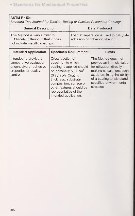
Standards for Mechanical Properties
ASTM F 1501
Standard Test Method for Tension Testing of Calcium Phosphate Coatings
General Description Data Produced
This Method is very similar to
F 1147-99, differing in that it does
not include metallic coatings.
Load at separation is used to calculate
adhesion or cohesion strength.
Intended Application Specimen Requirement Limits
Intended to provide a
comparative evaluation
of cohesive or adhesive
properties or quality
control.
Cross-section of
specimen to which
coating is applied should
be nominally 5.07 cm2
(0.78 in. 2 ). Coating
thickness, substrate
composition, surface or
other features should be
representative of the
intended application.
The Method does not
provide an intrinsic value
for utilization directly in
making calculations such
as determining the ability
of a coating to withstand
specified environmental
stresses.
186

Adhesion
11.2 Adhesion
ASTM B 571
Standard Practice for Qualitative Adhesion Testing of Metallic Coatings
General Description Data Produced
This Practice provides general
guidance for evaluating the adhesion
of, primarily, electroplated coatings
to substrates. Methods described
include: bend tests, burnishing tests,
chisel-knife tests, draw tests, file tests,
grind-saw tests, heat-quench tests,
impact tests, peel tests and scribe-grid
tests. A table of adhesion tests
appropriate for various coating
materials is provided as well as a
temperature test guide for various
coatings and substrates.
Varies with test method.
Intended Application Specimen Requirement Limits
Production control and
acceptance inspection.
Varies with test method,
but generally should
reflect condition of
material in intended
application.
Qualitative nature of the
tests precludes precision
and bias statements.
187

Standards for Mechanical Properties
ASTM C 633
Standard Test Method for Adhesion or Cohesion Strength of
Thermal Spray Coatings
General Description Data Produced
This Method describes the
measurement of the degree of
adhesion of a coating to a substrate
or the cohesive strength of a coating
when subjected to a tensile force
normal to the surface. The test
consists of adhesively bonding test
fixtures to the underside of the
substrate and to the top side of the
coating and applying tensile loading
in a testing machine. The test is
performed at ambient temperatures
due to elevated strength limitations of
common adhesives. The degree of
cohesion or adhesion is calculated by
dividing the maximum load sustained
by the cross-sectional area of the
specimen. The Method includes
testing machine and fixture
descriptions, adhesive material and
test specimen requirements,
procedure, calculation and
interpretation of results and reporting.
Adhesive or cohesive strength.
Intended Application Specimen Requirement Limits
Recommended for
quality control,
acceptance testing,
process/procedure and
material development.
Not intended to provide
an intrinsic value for
calculation purposes.
Coatings should be at
least 0.38 mm (0.015 in.)
thick applied to test
fixtures of not less than
23 mm (0.9 in.) and not
more than 25 mm(1.0 in.) in diameter.
Application of this test
should have tolerances
and interpretation of
adherence set and
agreed upon by
purchaser and
manufacturer.
188

Adhesion
ASTM D 4541
Standard Test Method for Pull-Off Strength of Coatings Using
Portable Adhesion Testers
General Description Data Produced
This Method covers the measurement
of the force and, by calculation, the
stress (pull-off strength) of coatings.
A loading fixture is affixed to a coating
on a substrate using an adhesive. Thefixture, with adhesive bonded coating
attached, is pulled from the substrate
using a portable device which can be
mechanically or hydraulically loaded.
The device gradually applies force
normal to the surface until the coating
is detached. The pull-off strength is
calculated based on the maximumindicated load, instrument calibration
data and original surface stressed.
Four commercially available
instruments are described.
The Method includes: Apparatus,
Test Preparation, Test Procedure,
Calibration and Interpretation of
Results, Reporting, Precision and
Bias. The principle of operation
is similar to ASTM C 633.
Pull-off strength calculated from
instrument readings and measured
area of separation.
Intended Application Specimen Requirement Limits
Intended to determine
acceptance per specified
properties as measured
by this method.
The Method is not
specifically intended for
a given material.
Referenced documents
address testing of paints
and varnishes.
Nature of failure must be
reported, i.e., whether in
adhesive, coating
system or substrate.
Precision of
measurements
determined in intra- and
inter- laboratory studies
show coefficient of
variation of types I, II,
and III instruments to be
12.2% for intralaboratory
measurement and 20.6%
for interlaboratory
measurement.
189

Standards for Mechanical Properties
Industry Standard Scratch Adhesion Test
General Description Data Produced
This Practice provides a quantitative
value of coating adhesion for standard
PVD (physical vapor deposition)
coatings. A diamond stylus 0.2 mm in
diameter is run against the surface at
fixed speed of 100 mm/min and a load
increasing at the rate of 100 N/min.
Two values are recorded: the load at
which delamination of the coating is
first observed, and the load at which
the coating is completely removed
from the wear track.
Quantitative adhesion.
Intended Application Specimen Requirement Limits
Production control and
acceptance inspection.
Flat, highly polished
sample.
Results are very
dependent on
substrate.
190

Bare
12. Standards for Measurement of Corrosion, Wear and Thermal
Properties
12.1 Bare
ASTM C 177
Standard Test Method for Steady-State Heat Flux Measurements and Thermal
Transmission Properties by Means of the Guarded-Hot-Plate Apparatus
General Description Data Produced
This Method establishes the criteria
for measurement of the one
dimensional steady state heat flux
through flat, homogeneousspecimens. General guidelines for
design of the apparatus and testing
are given The test consists of heating
nnp qiHp nf a flat Qnprimpn with aUl lc olUc Ul a Mai oJJcUII I Id I Willi a
resistance heater in a carefully
insulated arrangement and limiting
heat flux to the thickness of the
specimen with temperatures
measured on both sides of the
specimen. This is a primary method of
measurement. ASTM C 1043, C 1044
and C 1045 accompany this Method.
The apparatus may be designed to
operate in controlled environments or
at elevated or reduced temperatures.
Heat input and specimen
temperatures are measuredand used to calculate thermal
transmission properties per
ASTM C 1045.
Intended Application Specimen Requirement Limits
Laboratory measurementof heat flux which
enables calculation
of conductivity.
Specimen size is
determined by heater
size and other
experimental
considerations.
Specimen conductance
should be less than
16 W/(m2 K). Layer
structures with
inhomogeneities normal
to the heat flux direction
can be measured.
Inhomogeneities in the
heat flux direction can
yield results that are
location specific and are
inappropriate for
this apparatus.
191

Standards for Measurement of Corrosion
ASTM C 1043
Standard Practice for Guarded-Hot-Plate Design Using Circular
Line-Heat Sources
General Description Data Produced
This Practice covers the design of a
circular line-heat-source guarded hot
plate for use in accordance with
ASTM test Method C 177-Test
Method for Steady State Heat Flux
Measurements and Thermal
Transmission Properties by Means of
the Guarded Hot Plate Apparatus.
The Practice provides: guidance in
determining the mean temperature
of the meter plate, information and
calculation procedures for (1) control
of edge heat loss or gain, (2) location
and installation of line-heat sources,
(3) design of the gap between the
meter and guard plates, (4) location
of heater leads for the meter plate.
Provides detailed design data for
fabrication of a device which performs
in accordance with ASTM C 177.
Intended Application Specimen Requirement Limits
Supports fabrication of a
guarded hot plate for
measurement of thermal
transmission properties.
Specimen size is
determined by heater
size and other
experimental
considerations.
The line-heat-source
guarded hot plate has
been used over a meantemperature range of
-10 °C to +65 °Cwith
circular metal plates and
a single line-heat source
in the meter plate.
However, the practice
does not preclude
(1 ) lower or higher
temperatures, (2) line-
heat sources other than
circular, (3) plate
geometries other than
circular, (4) the use of
plated fabricated from
ceramics, composites or
other materials, (4) the
use of multiple line-heat
sources in both the
meter and guard plates.
192

Bare
ASTM C 1044
Standard Practice for using a Guarded-Hot-Plate Apparatus or Thin-Heater
Apparatus in the Single-Sided Mode
General Description Data Produced
This Practice covers the determination
of the steady-state heat flow through
the meter section of a specimen whena guarded hot plate apparatus or
thin-heater apparatus is used in the
single-sided mode. This Practice
supplements ASTM C 177 or
ASTM C 1114 for testing a single
specimen. Procedure, heat flow
calculation, and sources of
experimental error are included.
Thermal transmission properties
are determined in accordance
with ASTM C 177.
Intended Application Specimen Requirement Limits
Supports operation of
the guarded hot plate
apparatus in the single
sided mode for the
determination of thermal
transmission properties.
Specimen size is
determined by heater
size and other
experimental
considerations.
The Practice requires
that the cold plates of
the apparatus have
independent temperature
controls.
193

Standards for Measurement of Corrosion
ASTM C 1045
Standard Practice for Calculating Thermal Transmission Properties UnderSteady-State Conditions
General Description Data Produced
This Practice gives a uniform
procedure for calculating thermal
transmission properties of a material
or system from data generated by
steady state, one dimensional test
methods used to determine heat flux
and surface temperatures. It is
intended to eliminate the need for
similar calculation sections in
ASTM C 177 and other Standards and
allow concentration on measurementdetails rather than calculation details.
Apparent thermal conductivity is
obtained as a function of temperature
with data obtained from ASTM C 177
or other test methods.
Intended Application Specimen Requirement Limits
Supports operation of
the guarded hot plate
apparatus in the single
sided mode for the
determination of thermal
transmission properties.
Specimen size is
determined by heater
size and other
experimental
considerations.
ASTM C 177 shall be
considered the final
authority for materials
having flat geometry;
C 335 shall be used for
materials having a
cylindrical geometry.
194

Bare
ASTM E 1461
Standard Test Method for Thermal Diffusivity by the Flash Method
General Description Data Produced
This comprehensive test Method
details measurement of thermal
diffusivity using the laser flash
method. In brief, the material of
concern is heated on one side (front
face) with a laser or flash lamp and
the temperature rise on the opposite
side (back face) is measured.
Thermal conductivity can be
calculated using diffusivity results,
specific heat capacity and density.
Document includes interferences,
detailed description of apparatus
requirements, specimen requirements,
calibration and verification, procedure,
calculation, precision ana uias
statement. Measurements may be
conducted at elevated temperature
or in other non-ambient conditions
using an appropriate environmental
chamber.
Temperature and time data measured
on the back face of the specimen is
used to calculate thermal diffusivity.
Intended Application Specimen Requirement Limits
General measurement of
thermal diffusivity of
homogeneous solids.
The method has been
used for composite and
layered materials.
Specimens are typically
a circular disk with a
front face area less than
the energy beam, usually
6 mm to 18 mm in
diameter. Thicknesses
are typically 1 mm to
6 mm. Sample faces
should be flat and
parallel within 5% of their
thickness with uniform
surfaces. Translucent or
reflective materials maybe coated.
Non-homogenousmaterials may have heat
flow patterns which mayrender diffusivity values
inaccurate, but still
useful for limited
comparisons. Precision
of ± 5% can be attained
for diffusivity.
195

Standards for Measurement of Corrosion
ISO 8302Thermal Insulation
Related Properties
Determination of Steady-State Thermal Resistance andGuarded-Hot-Plate Apparatus
General Description Data Produced
This is an extensive Standard detailing the
use of the guarded hot plate to measure
the steady-state heat transfer through flat
slab specimens and the calculation of heat
transfer properties. This is an absolute,
or primary, method of measurement since
only measurements of length; temperature
and electrical power are required. Aflat
specimen, which may be layered, is
heated on one side and temperature
on the opposite side is measured. All
measurements are conducted in an
apparatus which controls heat flow.
The technique is sensitive to specimen
dimensions, finish and homogeneity.
The limit for thermal resistance may be
as low as 0.02 m2 K/W but accuracy over
the full range may not be achieved.
The Standard includes detailed information
on instrumentation and calculation of heat
transfer properties. Temperature limits
are not specified.
Test data consists of measured specimen
dimensions, temperatures on either side
of the test specimen and electrical power
input. These data are used to calculate
thermal resistance.
Intended Application Specimen Requirement Limits
The Standard is intended
to provide the means for
determining the steady
state heat transfer
properties of flat slab
specimens.
Specimen size
requirements maylimit the utility of this
method for evaluation
of materials typically
manufactured for somehigh temperature
applications.
Specimens should typically
be homogeneous.
Homogeneous porous
specimens should have
inhomogeneities smaller
than one-tenth of the
specimen thickness.
Specimen dimensions
should be 0.2 m to 1 mdiameter or square.
Samples should be
representative of the bulk
material, which maydetermine specimen size.
Specimen flatness is
important. Specimen
thickness is limited by
contact resistances and
thickness measurement
accuracy.
Accuracy is a function
of apparatus design,
instrumentation and
specimen type. When this
standard is followed, the
method is capable of
measuring heat transfer
properties accurate to
within ± 2% when the
mean temperature of the
test is near room
temperature. Accuracy
of ± 5% should be
obtainable anywhere
within the full operating
range of the apparatus.
Reproducibility should
be better than ± 1%.
196

SAE AMS-STD-753Corrosion-Resistant Steel Parts: Sampling, Inspection and Testing for
Surface Passivation
(Aerospace Material Specification)
General Description Data Produced
This Standard is adopted from
Mil-STD-753C. It describes methods
of sampling and testing for surface
passivity of steels with chromium
contents in excess of 10.5%.
Five test methods are listed for the
determination of free iron or other
anodic surface contaminants: water
immersion, high humidity, copper
sulfate, potassium ferricyanide-nitric
acid solution and salt spray
(ASTM B 117). Determination
of presence of free iron is
by visual inspection.
Evidence or indication of no
surface contaminants.
Intended Application Specimen Requirement Limits
The standard is intended
to test for the
effectiveness or need
for passivation.
No surface
contaminants.
The. copper sulfate test
is not recommended for
use on martensitic 400
series alloys or lower
chromium grades (less
than 16%) of ferritic 400
series alloys.Thepotassium ferricyanide
test is more sensitive to
the presence of free iron
than the copper sulfate
test and is
recommended for use
only on austenitic AISI
200 and 300 series
alloys when the
determination of trace
amounts of free iron
is required.
197

Standards for Measurement of Corrosion
12.2 Coated
ASTM B 651
Standard Test Method for Measurement of Corrosion Sites in Nickel Plus
Chromium or Copper Plus Nickel Plus Chromium Electroplated Surfaces with
Double-Beam Interference Microscope
General Description Data Produced
This Method allows the measurementof average dimensions and number of
corrosion sites in decorative coatings
electroplated onto steel. Corrosion pit
lateral dimensions are measured
optically with magnifiers or
microscopes. Depths are measured
with an interference microscope.
Coating thickness is measured on a
metallographically prepared cross-
section. The Method includes
descriptions of the apparatus,
specimen preparation, procedures
for measurement of crack and pit
depth and average number,
reporting, precision and bias.
Numeric values for number of pits
and cracks as well as pit and
crack dimensions.
Intended Application Specimen Requirement Limits
For comparing the
relative corrosion
resistance of different
electroplating systems
and for comparing the
corrosiveness of different
environments.
Clean surfaces. Precision can be as
good as ± 1^im. Bias can
be as good as ± 1fim.
198

Coated
ASTM F 326
Standard Test Method for Electronic Measurement for Hydrogen Embrittlement
from Cadmium-Electroplating Processes
General Description Data Produced
This Method describes the use of a
metal-shelled vacuum probe to
evaluate electrodeposited cadmiumcharacteristics, principally porosity,
relative to hydrogen permeation.
The Method includes detailed
descriptions of the apparatus,
reagents, preparation and calibration
of the apparatus, procedure and
calculations. It is useful particularly
when hydrogen embrittlement, as of
high strength steels, may be an issue
due to limits of hydrogen bake-out
after plating caused by cadmiumplate low permeability.
Hydrogen pressure and cell current
used to calculate hydrogen
permeability of cadmium plate.
Intended Application Specimen Requirement Limits
The test provides a
quantitative "control
number" for cadmiumplate porosity which can
be used as a process
control or as a process
development research
tool. This method is used
in conjunction with stress
rupture or other tests
when intended to control
a critical process.
Unpainted bare steel
prepared as in
production process
of interest.
The Method specifies an
"acceptable zone" of
time in seconds for
hydrogen pressure to
drop to half its value
during post plate baking.
199

Standards for Measurement of Corrosion
ASTM F 1978
Standard Test Method for Measuring Abrasion Resistance of Metallic Thermal
Spray Coatings by Using the Taber Abraser
General Description Data Produced
This Method quantifies the loss of
mass of plasma sprayed coatings
when evaluated on the Taber Abraser
with a 250 g mass. The specimen
is rotated under a pair of abrasive
wheels which gives rolling and rubbing
wear. The Method includes description
of the apparatus and supplier,
specimen, procedure, calculation
of mass loss per rotational cycle,
reporting and information on
precision and bias determined
in an interlaboratory study.
Cumulative mass loss.
Intended Application Specimen Requirement Limits
Characterizing coatings
used on surgical
implants.
Flat specimens either
round with a 10 cmdiameter and at least
0.16 cm (0.0625 in.)
thick; or 10 cm (4 in.)
squares, samethickness, both with a
0.64 cm (0.250 in.) hole
in the center. Coatings
representative of that
used in the intended
implant. Six specimens,
generally, required
per material.
Flat, rigid specimens
which do not react
significantly with rinsing
water and do not have
phase transformations
or chemical reactions
between room
temperature and 100 °C
in air. An interlaboratory
study (ILS) of a 100
cycle test showed a
repeatability of 0.012 g
and a reproducibility of
0.017 g for a material
with an average weight
loss of 0.504 g.
More extensive ILS
data is provided.
200

Coated
ISO 4536
Metallic and Non-Organic Coatings on Metallic Substrates - Saline Droplets
Corrosion Test (SD Test)
General Description Data Produced
This standard describes the procedure
for evaluation of coatings, particularly
conversion coatings, to ascertain
corrosion resistance. A spray of
aqueous saline solution is applied to
test specimens to create discrete
droplets on the surface. Specimens
are evaluated visually after exposure
in a chamber with relative humidity
controlled according to a specification.
Data produced may be visual
appearance after test or after removal
of corrosion product, number and
distribution of corrosion defects, time
lapsed before signs of corrosion are
observed.
Intended Application Specimen Requirement Limits
Intended for the
evaluation of corrosion
resistance where the
droplets may be a moresevere condition than a
continuous moving
moisture film.
Clean specimens which
can be of complex
shapes.
Criteria for evaluation of
test results will be given
in a product
specification. Results of
this test should not be
regarded as a guide to
corrosion resistance in
all environments.
201

Standards for Measurement of Corrosion
ISO 4538
Metallic coatings - Thioacetamide Corrosion Test (TAA test)
General Description Data Produced
This Standard is intended to assess
the corrosion resistance of metal
surfaces in atmospheres containing
volatile sulphides. Test specimens are
exposed to vapors from thioacetimide
in an atmosphere of 75% relative
humidity maintained by the presence
of a saturated solution of sodium
acetate. The test is conducted in a
chamber for a duration of generally
less than 2 weeks with visual
inspection hourly or daily.
Descriptions of apparatus and
procedures are included.
Product specifications determine
evaluation criteria which may be
appearance after test, time to first
signs of corrosion, or number and
distribution of corrosion defects.
Methods for assessment of defects
are specified in ISO 1462.
Intended Application Specimen Requirement Limits
Intended to accompanya coating or product
specification for
assessment of tarnish-
preventing treatments
on silver or copper
and the detection of
discontinuities in
precious metal coatings
on these materials.
Product specification
may specify test sample
or product to be tested.
Samples shall be clean
and cut edges protected.
Type and number of test
specimens, exposure
period, failure criteria are
not included in this
Standard but should be
included in the product
specification.
202

Coated
ISO 8993
Anodized Aluminum and Aluminum Aloys - Rating System for the Evaluation
of Pitting Corrosion - Chart Method
General Description Data Produced
This Standard describes the method
for a rating system that defines levels
of pitting corrosion. Test materials are
cleaned to reveal corrosion pits.
Cleaned surfaces are compared to
illustrative charts included in the
standard. Seven alphabetic levels of
percentage of area of defects are
illustrated in the charts, each with six
sub-levels. Designations range from
an "A" rating for no defects to an "HTto "H6" rating for greater than 0.5%area of defects. This Standard is
similar in purpose to ISO 8994.
Data consists of a visual or electronic
comparison with charts included in
the Standard.
Intended Application Specimen Requirement Limits
The rating system is
applicable to pitting
corrosion resulting from
accelerated tests,
exposure to corrosive
environments and
practical service tests.
Corrosion products or
deposits are removed
from the subject surface
by abrasion with a fine
pumice slurry, dipping in
30% nitric acid for 5 min
to 10 min, or by
dissolving the anodic
coating in a hot
phosphoric acid-chromic
acid mixture.
Only accounts for pitting
corrosion of the basis
metal resulting from
penetration of the
protective anodic
coating.
203

Standards for Measurement of Corrosion
ISO 8994
Anodized Aluminum and Aluminum Alloys - Rating System for the Evaluation
of Pitting Corrosion - Grid Method
General Description Data Produced
This Standard describes the method
for a rating system that defines levels
of pitting corrosion. Test materials are
cleaned to reveal corrosion pits.
A transparent grid of at least
5,000 mm2 with 5 mm x 5 mm grid
squares is placed over the area of
interest and the percentage of squares
containing a pit determined. Thepercent containing pits is converted to
a rating number. Grid ratings range
from for no grid squares with pits to
40 for 5.01% and greater of grid
squares with defects. This Standard
is similar in purpose to ISO 8993.
Data consists of a count to determine
percent of grid squares with defects.
Intended Application Specimen Requirement Limits
The rating system is
applicable to pitting
corrosion resulting from
accelerated tests,
exposure to corrosive
environments and
practical service tests.
The system is frequently
used for rating short
term corrosion tests of
thin anodic coatings
used in the automotive
industry.
Corrosion products or
deposits are removed
from the subject surface
by abrasion with a fine
pumice slurry, dipping in
30% nitric acid for 5 min
to 10 min, or by
dissolving the anodic
coating in a hot
phosphoric acid-chromic
acid mixture.
Only accounts for pitting
corrosion of the basis
metal resulting from
penetration of the
protective anodic
coating.
204

Coated
ISO 4540
Metallic Coatings - Coatings Cathodic to the Substrate - Rating of
Electroplated Test Specimens Subjected to Corrosion Tests
General Description Data Produced
This Standard specifies a method of
evaluating the condition of
electroplated test specimens that
have been exposed to corrosive
environments for test purposes.
The method is applicable only to
decorative and protective coatings
that are cathodic to the substrate;
i.e., nickel plus chromium or copper
plus nickel plus chromium on steel
or zinc die castings. The method
provides a rating system that assigns
a rating which (a) describes the
appearance as affected by corrosion
of the substrate and, (b) describes
the appearance as affected by
corrosion of the coating itself.
Levels of protection rating from 10
(no defects) to (greater than 50%area covered with defects) are
assigned by comparing the test piece
with dot charts and photographs
included in the standard.
Visual examination and comparison
with included charts and photographs
gives numeric ratings. The rating
number assigned to the ability to
protect the substrate is called the
"protection" rating. The numberassigned to describe the overall
appearance is called the
"appearance" rating.
Intended Application Specimen Requirement Limits
Intended to describe the
condition of electroplated
coatings.
Specimens are typically
1 cm x 1 5 cm test
panels. Specimens
should not be cleaned
before inspection
if possible.
Not intended for use with
anodic sacrificial
coatings such as zinc
and cadmium on steel.
Defects to be taken into
account include only
those that can be seen
by the unaided eye.
205

Standards for Measurement of Corrosion
ISO 4541Metallic and Other Non-Organic Coatings - Corrodkote Corrosion Test
(CORR test)
General Description Data Produced
This Standard provides guidance on
assessment of corrosion resistance of
metallic coatings by the Corrodkote
procedure. The procedure consists of
preparing a slurry of copper nitrate
trihydrate, iron chloride hexahydrate
and ammonium chloride with ceramic
grade kaolin. The saturated kaolin is
brushed onto the test surface.
The slurry layer (0.08 mm to 0.2 mmthick) is allowed to dry before the
test specimen is placed in a humidity
chamber with temperature controlled to
38 °C. Test cycle time is typically 16 h.
Slurry is reapplied after each cycle.
After humidity chamber exposure,
specimens are cleaned, removing
corrosion products.
The points of coating failure are
identified by exposure to a mediumwhich is corrosive to the basis metal,
such as ISO 3768, but not the coating.
Evaluation typically consists of visual
appearance after testing, appearanceafter removal of corrosion products,
number and distribution of corrosion
defects assessed per ISO 1462,
for example.
Descriptions of appearance of surface
and quantitative evaluation by a
method such as ISO 1462.
Intended Application Specimen Requirement Limits
The method andevaluation criteria may be
used in product or
purchase specifications.
The method is primarily
applicable to copper-
nickel-chromium or
nickel- chromiumelectroplated parts.
Type and number of
specimens are
determined by relevant
product or purchase
specification. Specimensshould be solvent
cleaned before testing
with a material which is
non-corrosive and doesnot create a protective
film. Specimens may be
cut from sheet material
but cut edges should
be protected.
Test results should not be
regarded as a direct
guide to the corrosion
resistance of the tested
materials in all
environments.
Relative ranking in
the test may not bethe same as ranking
in service.
206

Coated
ISO 9227
Corrosion Tests in Artificial Atmospheres - Salt Spray Tests
General Description Data Produced
This Standard specifies the procedure for
determining the corrosion resistance of
metallic materials, including those with
inorganic or organic coatings. The test
consists of spraying neutral salt solution
(NSS), or acetic acid salt (ACSS) solution,
or copper accelerated acetic acid solution
(CASS) on specimens in a salt spray
cabinet with controlled temperature anddetermining extent of corrosion after a
predetermined exposure time. TheStandard provides details of solution
preparation and a salt spray cabinet
design. Reference specimens are required
for each test. Supercedes ISO 3768.
Test data consists of appearance before
and after removing corrosion products,
number and distribution of corrosion
defects which may be assessed by ISO1462 or ISO 4540, elapsed time before
appearance of corrosion, mass change,
change in mechanical properties,
alteration revealed by microscopic
examination.
Intended Application Specimen Requirement Limits
The Standard is intended
to assess the corrosion
resistance of metallic
materials with or without
permanent or temporary
corrosion protection. TheStandard may be included
in a specification. Useful
for detecting discontinuities
such as pores and other
defects in certain metallic,
anodic oxide andconversion coatings.
The NSS applies to metals
and their alloys, certain
metallic coatings (anodic
and cathodic), certain
conversion coatings, certain
anodic oxide coatings, andorganic coatings on metallic
materials. The AASS is
useful for testing decorative
coatings of copper+nickel+
chromium or nickel+
chromium. The CASS is
useful for testing decorative
coatings of copper+nickel+
chromium or nickel+
chromium. It is also useful
for testing anodic coatings
on aluminum.
Detailed requirements for
reference specimens of
CR4 grade steel according
to ISO 3574 are provided.
Test specimen number,
size, shape andarrangement in the spray
cabinet shall be agreed
upon by participating
parties. Specimens shall
be cleaned in such a wayas to remove contaminants
but not affect the surface
adversely.
Test results shall not beregarded as a direct guide
to the corrosion resistance
of tested materials in all
environments. Test
performance should not
be taken as a direct guide
to performance in service.
207

Standards for Measurement of Corrosion
ISO 10289
Methods for Corrosion Testing of Metallic and Other Inorganic Coatings on
Metallic Substrates - Rating of Test Specimens and Manufactured Articles
Subjected to Corrosion Tests
General Description Data Produced
This Standard supersedes ISO 1460
and provides guidance for rating
coatings that provide corrosion
protection to a substrate or provide
visual effects. The performance rating
includes a protection rating and an
appeal dl lUc Idllliy. Illc JJI UltJUllUI 1
rating is a simple numerical rating
while the appearance rating mayinclude specific defects along with
a numerical rating designating the
intensity. Types of defects are
identified, the method of inspection
of defects are identified.
Visual observation of corrosion sites
or products which are given
numeric values.
Intended Application Specimen Requirement Limits
Intended for evaluation
of the condition of test
materials or articles
exposed to corrosive
test conditions or
other purposes.
Product specification
may specify test sample
or product to be tested.
Samples shall be clean
and cut edges protected.
Generally qualitative
assessment.
208

SAE J400
Test for Chip Resistance of Surface Coatings
(SAE Recommended Practice)
General Description Data Produced
This Practice describes the use of a
"Gravelometer" which projects sized
gravel against a flat test panel to
assess the resistance to chipping of
organic surface coatings used in
automotive applications. Equipment is
described and equipment supplier
identified. Test procedure including
evaluation based on an SAE Chipping
Rating Standard (EA-400) is provided.
Assessment of coating
material damage.
Intended Application Specimen Requirement Limits
This test provides a
means of evaluating
automotive coatings
and coating systems
and has been
correlated with
field results.
Test panels should be
10.16 cm x 30.48 cm(4 in. x 12 in.) and
typically 20 gage
(0.091 cm (0.0359 in.))
material with typical
preliminary surface
treatment such as
phosphatizing
or anodizing.
Exact counting and
visual comparison
techniques are used to
establish a rating which
should not differ by
more than one
number-letter
rating in a test
sequence.
209

Surface Engineering Measurement Standards
13. Surface Engineering Measurement Standards
13.1 ASME (American Society of Mechanical Engineers) Standards
B46.1 Surface Texture (Surface Roughness, Waviness, 63
and Lay) American National Standard
13.2 ASTM International (American Society for Testing and Materials)
Standards
A 90/A 90M Standard Test Method for Weight (Mass) of Coating on 1 25
Steel Articles with Zinc or Zinc-Alloy Coatings
A 309 Standard Test Method for Weight and Composition of 1 26
Coating on Terne Sheet by the Triple Spot Test
A 428/A 428M Standard Test Method for weight (Mass) of Coating on 127
Aluminum Coated Iron or Steel Articles
A 630 Standard Test Methods for Determination of Tin Coating 128
Weights for Electrolytic Tin Plate
A 754/A 754M Standard Test Method for Coating Weight (Mass) of 1 29
Metallic Coatings on Steel by X-ray Fluoresence
A 802/A 802M Standard Practice for Steel Castings, Surface 57
Acceptance Standards, Visual Examination
A 833 Standard Practice for Indentation Hardness of 155
Metallic Materials
A 896 Standard Practice for Conducting Case Studies on 75
Galvanized Structures
A 902 Standard Terminology Relating to Metallic Coated Steel 1
Products
B 137 Standard Test Method for Measurement of Coating Mass 130
Per Unit Area on Anodically Coated Aluminum
B 244 Standard Test Method for Measurement of Thickness of 99
Anodic Coatings on Aluminum and of Other Nonconductive
Coatings on Nonmagnetic Basis Metals with Eddy-Current
Instruments
B 277 Standard Test Method for Hardness of Electrical 156
Contact Materials
210

B 294 Standard Test Method for Hardness Testing of 157
Cemented Carbides
B 487 Standard Test Method for Measurement of Metal and 100
Oxide Coating Thickness by Microscopical
Examination of a Cross-Section
B 489 Standard Practice for Bend Test for Ductility of 181
Electrodeposited and Autocatalytically Deposited
Metal Coatings on Metals
B 490 Standard Practice for Micrometer Bend Test for 182
Ductility of Electrodeposits
B 499 Standard Test Method for Measurement of Coating 101
Thickness by the Magnetic Method: Nonmagnetic
Coatings on Magnetic Basis Metals
B 504 Standard Test Method for Measurement of Thickness of 102
Metallic Coatings by the Coulometric Method
B 530 Standard Test Method for Measurement of Coating 103
Thickness by the Magnetic Method: Electrodeposited
Nickel Coatings on Magnetic and Nonmagnetic Substrates
B 555 Standard Guide for Measurement of Electrodeposited 104
Metallic Coating Thickness by the Dropping Test
B 556 Standard Guide for Measurement of Thin Chromium 105
Coatings by Spot Test
B 567 Standard Test Method for Measurement of Coating 106
Thickness by the Beta Backscatter Method
B 568 Standard Test Method for Measurement of Coating 107
Thickness by X-ray Spectrometry
B 571 Standard Practice for Qualitative Adhesion Testing of 187
Metallic Coatings
B 578 Standard Test Method for Microhardness of 158
Electroplated Coatings
B 588 Standard Test Method for Measurement of Thickness of 108
Transparent or Opaque Coatings by Double-Beam
Interference Microscope Technique
211

Surface Engineering Measurement Standards
B 602 Standard Test Method for Attribute Sampling of 2
1
Metallic and Inorganic Coatings
B 647 Standard Test Method for Indentation Hardness of 159
Aluminum Alloys by Means of a Webster Hardness Gage
B 648 Standard Test Method for Indentation Hardness of 1 60
Aluminum Alloys by Means of a Barcol Impressor
B 651 Standard Test Method for Measurement of Corrosion Sites 198
in Nickel Plus Chromium or Copper Plus Nickel Plus
Chromium Electroplated Surfaces with Double-Beam
Interference Microscope
B 659 Standard Guide for Measuring Thickness of Metallic and 109
Inorganic Coatings
B 681 Standard Test Method for Measurement of Anodic Coatings 110
on Aluminum and Other Transparent Coatings on Opaque
Surfaces Using the Light-Section Microscope
B 697 Standard Guide for Selection of Sampling Plans for 22
Inspection of Electrodeposited Metallic and
Inorganic Coatings
B 721 Standard Test Method for Microhardness and Case 88
Depth of Powder Metallurgy (P/M) Parts
B 724 Standard Test Method for Indentation Hardness of 161
Aluminum Alloys by Means of a Newage, Portable,
Non-Caliper-Type Instrument
B 735 Standard Test Method for Porosity in Gold Coatings on 141
Metal Substrates by Nitric Acid Vapor
B 741 Standard Test Method for Porosity in Gold Coatings on 142
Metal Substrates by Paper Electrography
B 762 Standard Test Method of Variables Sampling of 23
Metallic and Inorganic Coatings
B 765 Standard Guide for Selection of Porosity Tests for 143
Electrodeposits and Related Metallic Coatings
B 767 Standard Guide for Determining Mass Per Unit Area of 131
Electrodeposited and Related Coatings by Gravimetric
and Other Chemical Analysis Procedures
212

ASTM International
Standard Test Method for Surface Finger Penetration 136
Depth of Interparticle Oxide Networks in
Powder Forged (P/F) Steel Parts
Standard Test Method for Porosity in Gold or 144
Palladium Coatings on Metal Substrates by
Gel-Bulk Electrography
Standard Test Method for Porosity in Gold and Palladium 145
Coatings by Sulfurous Acid/Sulfur-Dioxide Vapor
Standard Test Method for Porosity in Metallic Coatings 146
by Humid Sulfur Vapor ("Flowers-of-Sulfur")
Standard Test Method for Gross Defects and 25
Mechanical Damage in Metallic Coatings by
Polysulfide Immersion
Standard Specification for Chromium Diffusion 80
Coating Applied by Pack Cementation Process
Standard Specification for Aluminum Diffusion 81
Coating Applied by Pack Cementation Process
Standard Test Method for Gross Defects and 26
Mechanical Damage in Metallic Coatings by the
Phosphomolybdic Acid (PMA) Method
Standard Test Method for Steady-State Heat Flux 1 9
1
Measurements and Thermal Transmission Properties by
Means of the Guarded-Hot-Plate Apparatus
Standard Test Method for Continuity of Coatings in 85
Glassed Steel Equipment by Electrical Testing
Standard Test Method for Reliability of Glass Coatings on 86
Glassed Steel Reaction Equipment by High Voltage
Standard Test Method for Adhesion or Cohesion 188
Strength of Thermal Spray Coatings
Standard Test Methods for Thickness of Diffusion Coating 1 1
1
Standard Test Method for Continuity of 87
Porcelain Enamel Coatings
213

Surface Engineering Measurement Standards
C 1043 Standard Practice for Guarded-Hot-Plate Design 192
Using Circular Line-Heat Sources
C 1044 Standard Practice for using a Guarded-Hot-Plate 193
Apparatus or Thin-Heater Apparatus in the
Single-Sided Mode
C 1045 Standard Practice for Calculating Thermal Transmission 194
Properties Under Steady-State Conditions
C 1326 Standard Test Method for Knoop Indentation 162
Hardness ofAdvanced Ceramics
C 1327 Standard Test Method for Vickers Indentation 163
Hardness ofAdvanced Ceramics
D 4417 Standard Test Methods for Field Measurement of 5
1
Surface Profile of Blast-Cleaned Steel
D 454 1 Standard Test Method for Pull-Off Strength of 1 89
Coatings Using Portable Adhesion Testers
D 5723 Standard Practice for Determination of Chromium 132
Treatment Weight on Metal Substrates by
X-ray Fluorescence
E 3 Standard Guide for Preparation of Metallographic Specimens 137
E 10 Standard Test Method for Brinell Hardness of 164
Metallic Materials
E 18 Standard Test Methods for Rockwell Hardness and 165
Rockwell Superficial Hardness of Metallic Materials
E 92 Standard Test Method for Vickers Hardness of 166
Metallic Materials
E 103 Standard Test Method for Rapid Indentation Hardness 167
Testing of Metallic Materials
E 1 10 Standard Test Method for Indentation Hardness of 168
Metallic Materials by Portable Hardness Testers
E 140 Standard Hardness Conversion Tables for Metals 169
Relationship Among Brinell Hardness, Vickers Hardness,
Rockwell Hardness, Superficial Hardness,
Knoop Hardness and Scleroscope Hardness
214

ASTM International
E 376 Standard Practice for Measuring Coating Thickness by 112
Magnetic-Field or Eddy-Current (Electromagnetic)
Examination Methods
E 384 Standard Test Method for Microindentation 1 70
Hardness of Materials
E 430 Standard Test Methods for Measurement of Gloss of 52
High-Gloss Surfaces by Goniophotometry
E 448 Standard Practice for Scleroscope Hardness 179
Testing of Metallic Materials
E 562 Standard Test Method for Determining Volume Fraction by 138
Systematic Manual Point Count
Standard Terminology Relating to Surface Analysis 148
Standard Test Method for Determining Residual Stresses by 153
the Hole-Drilling Strain Gage Method
Standard Test Methods for Estimating the Depth of 89
Decarburization of Steel Specimens
Standard Guide for Depth Profiling in Auger 149
Electron Spectroscopy
Standard Test Method for Measurement of Surface 1 1
3
Layer Thickness by Radial Sectioning
Standard Test Methods for Visible Penetrant 53
Examination Using the Water-Washable Process
Standard Test Method for Determining the Effective Elastic 1 54
Parameter for X-ray Diffraction Measurements of
Residual Stress
Standard Guide for Measuring Widths of Interfaces in 150
Sputter Depth Profiling Using SIMS
Standard Test Method for Thermal Diffusivity by the 195
Flash Method
Standard Test Methods for Coating Weight and Chemical 133
Analysis of Zinc-Nickel Alloy Electrolytically Coated on
Steel Sheet
215

Surface Engineering Measurement Standards
E 1 8 1 3 Standard Practice for Measuring and Reporting
Probe Tip Shape in Scanning Probe Microscopy
E 1920 Standard Guide for Metallographic Preparation of
Thermal Sprayed Coatings
E 2 1 09 Test Methods for Determining Area Percentage Porosity
Thermal Sprayed Coatings
F 326 Standard Test Method for Electronic Measurement for
Hydrogen Embrittlement from Cadmium-
Electroplating Processes
F 788/F 788M Standard Specification for Surface Discontinuities of
Bolts, Screws, and Studs, Inch and Metric Series
F 812/F812M Standard Specification for Surface Discontinuities of
Nuts, Inch and Metric Series
F 1044 Standard Test Method for Shear Testing of Calcium
Phosphate Coatings and Metallic Coatings
F 1147 Standard Test Method for Tension Testing of Calcium
Phosphate and Metallic Coatings
F 1160 Standard Test Method for Shear and Bending Fatigue
Testing of Calcium Phosphate
F 1438 Standard Practice for Determination of Surface
Roughness by Scanning Tunneling Microscopy for
Gas Distribution System Components
F 1501 Standard Test Method for Tension Testing of
Calcium Phosphate Coatings
F 1978 Standard Test Method for Measuring Abrasion
Resistance of Metallic Thermal Spray Coatings by
Using the Taber Abraser
F 2024 Standard Practice for X-ray Diffraction Determination
of Phase Content of Plasma Sprayed Hydroxyapatite
Coatings
G 1 7 1 Standard Test Method for Scratch Hardness of
Materials Using a Diamond Stylus
216

13.3 ISO (International Organization for Standards) Standards
1456 Metallic Coatings - Electrodeposited Coatings of Nickel Plus 76
Chromium and of Copper Plus Nickel Plus Chromium
1458 Metallic Coatings - Electrodeposited Coatings of Nickel 77
1460 See 10289 208
1463 Metallic and Oxide Coatings - Measurement of 114
Coating Thickness - Microscopical Method
2063 Metallic and Other Inorganic Coatings - Thermal Spraying - 83
Zinc, Aluminum and Their Alloys
2064 Metallic and Other Inorganic Coatings - Definitions and 124
Conventions Concerning the Measurement of Thickness
2079 Surface Treatment and Metallic Coatings - 10
General Classification of Terms
2080 Electroplating and Related Processes - Vocabulary 1
1
2081 Metallic Coatings - Electroplated Coatings of Zinc on 78
Iron or Steel
2082 Metallic Coatings - Electroplated Coatings of Cadmium on 79
Iron or Steel
2 106 Anodizing ofAluminum and its Alloys - Determination of 134
Mass per Unit Area (Surface Density) ofAnodic Oxide
Coatings - Gravimetric Method
2128 Anodizing ofAluminum and its Alloys - Determination of 115
Thickness ofAnodic Oxide Coatings - Non-Destructive
Measurement by Split Beam Microscope
2 1 77 Metallic Coatings - Measurement of Coating Thickness - 116
Coulometric Method by Anodic Dissolution
2 1 78 Nonmagnetic Coatings on Magnetic Substrates - 117
Measurement of Coating Thickness - Magnetic Method
2361 Electrodeposited Nickel Coatings on Magnetic and 118
Nonmagnetic Substrates - Measurement of
Coating Thickness - Magnetic Method
217

Surface Engineering Measurement Standards
2639 Steels - Determination and Verification of the Depth of 90
Carburized and Hardened Cases
3057 Non-Destructive Testing - Metallographic Replica 140
Techniques of Surface Examination
3274 Geometrical Product Specifications (GPS) - Surface 27
Texture: Profile Method - Nominal Characteristics of
Contact (Stylus) Instruments
3497 Metallic Coatings - Measurement of Coating Thickness - 119
X-ray Spectrometric Methods
3543 Metallic and Nonmetallic Coatings - Measurement of 120
Thickness - Beta Backscatter Method
3613 Chromate Conversion Coatings on Zinc, Cadmium, 73
Aluminum-Zinc Alloys and Zinc-Aluminum Alloys -
Test Methods
3754 Steel - Determination of Effective Depth of Hardening After 9
1
Flame or Induction Hardening
3868 Metallic and Other Non-Organic coatings - Measurement of 121
Coating Thickness - Fizeau Multiple-Beam Interferometry Method
3878 Hardmetals - Vickers Hardness Test 1 7
1
3892 Conversion Coatings on Metallic Materials - Determination of 135
Coating Mass per Unit Area - Gravimetric Methods
4042 Fasteners - Electroplated Coatings 44
4287 Geometrical Product Specifications (GPS) - Surface Texture: 64
Profile Method - Tenns, Definitions and Surface Texture Parameters
4288 Geometrical Product Specification (GPS) - Surface Texture: 28
Profile Method - Rules and Procedures for the
Assessment of Surface Texture
4498-2 Sintered Metal Materials, Excluding Hard Metals - 1 72
Deteraiination ofApparent Hardness
Part 2: Case-hardened ferrous materials, surface enriched
by carbon or carbon and nitrogen
4518 Metallic Coatings - Measurement of Coating Thickness - 122
Profilometric Method
218

ISO
4519 Electrodeposited Metallic Coatings and Related Finishes - 24
Sampling Procedures for Inspection by Attributes
4520 Chromate Conversion Coatings on Electroplated 74
Zinc and Cadmium Coatings
4522-1 Metallic Coatings - Test Methods for Electrodeposited Silver 123
and Silver Alloy Coatings
Part 1 : Determination of coating thickness
4536 Metallic and Non-Organic Coatings on Metallic Substrates - 201
Saline Droplets Corrosion Test (SD Test)
4538 Metallic Coatings - Thioacetamide Corrosion Test (TAA Test) 202
4540 Metallic Coatings - Coatings Cathodic to the Substrate - Rating of 205
Electroplated Test Specimens Subjected to Corrosion Tests
4541 Metallic and Other Non-Organic Coatings - Corrodkote 206
Corrosion Test (CORR Test)
4545 Metallic Materials - Hardness Test - Knoop Test 173
Part 1 : Test method
4970 Steel - Determination of Total or Effective Thickness of 92
Thin Surface-Hardened Layers
6157-1 Fasteners - Surface Discontinuities 45
Part 1 : Bolts, screws and studs for general requirements
6157-2 Fasteners - Surface Discontinuities 46
Part 2: Nuts
6157-3 Fasteners - Surface Discontinuities - 47
Part 2: Bolts, screws and studs for special requirements
6507- 1 Metallic Materials - Vickers Hardness Test 1 74
Part 1 : Test method
7599 Anodizing ofAluminum and its Alloys - General Specifications 72
for Anodic Coatings on Aluminum
8302 Thermal Insulation- - Determination of Steady-State Thermal 196
Resistance and Related Properties - Guarded-Hot-Plate Apparatus
8501-1 Preparation of Steel Substrates Before Application of Paints and 64
Related Products - Visual Assessment of Surface Cleanliness
219

Surface Engineering Measurement Standards
8502-1 Preparation of Steel Substrates Before Application of Paints and 29
Related Products - Tests for the Assessment of Surface Cleanliness
Part 1 : Field test for soluble iron corrosion products
8502-2 Preparation of Steel Substrates Before Application of Paints and 29
Related Products - Tests for the Assessment of Surface Cleanliness
Part 2: Laboratory determination of chloride on cleaned surfaces
8502-3 Preparation of Steel Substrates Before Application of Paints and 29
Related Products - Tests for the Assessment of Surface Cleanliness
Part 3: Assessment of dust on steel surfaces prepared for
painting (pressure-sensitive tape method)
8502-4 Preparation of Steel Substrates Before Application of Paints and 29
Related Products - Tests for the Assessment of Surface Cleanliness
Part 4: Guidance on the estimation of the probability of
condensation prior to paint application
8502-5 Preparation of Steel Substrates Before Application of Paints and 29
Related Products - Tests for the Assessment of Surface Cleanliness
Part 5: Measurement of chloride on steel surfaces prepared for
painting (ion detection tube method)
8502-6 Preparation of Steel Substrates Before Application of Paints and 30
Related Products - Tests for the Assessment of Surface Cleanliness
Part 6: Extraction of soluble contaminants for analysis -
The Bresle method
8502-8 Preparation of Steel Substrates Before Application of Paints and 30
Related Products - Tests for the Assessment of Surface Cleanliness
Part 8: Field method for the refractometric determination
of moisture
8502-9 Preparation of Steel Substrates Before Application of Paints and 30
Related Products - Tests for the Assessment of Surface Cleanliness
Part 9: Field method for the conductometric determination of
water-soluble salts
8502-10 Preparation of Steel Substrates Before Application of Paints and 30
Related Products - Tests for the Assessment of Surface Cleanliness
Part 10: Field method for the titimetric determination of
water-soluble chloride
8502-12 Preparation of Steel Substrates Before Application of Paints and 30
Related Products - Tests for the Assessment of Surface Cleanliness
Part 12: Field method for the titimetric determination of
water soluble ferrous ions
220

ISO
8503-1 Preparation of Steel Substrates Before Application of Paints and 67
Related Products - Surface Roughness Characteristics of
Blast-Cleaned Steel Substrates
Part 1 : Specifications and definitions for ISO surface profile
comparators for the assessment of abrasive blast-cleaned surfaces
8503-2 Preparation of Steel Substrates Before Application of Paints and 68
Related Products - Surface Roughness Characteristics of
Blast-Cleaned Steel Substrates
Part 2: Method for the grading of surface profile of abrasive
blast-cleaned steel - Comparator procedure
8503-3 Preparation of Steel Substrates Before Application of Paints and 69
Related Products - Surface Roughness Characteristics of
Blast-Cleaned Steel Substrates
Part 3: Method for the calibration of ISO surface profile
comparators and for the determination of surface profile -
Focusing microscope procedure
8503-4 Preparation of Steel Substrates Before Application of Paints and 70
Related Products - Surface Roughness Characteristics of
Blast-Cleaned Steel Substrates
Part 4: Method for the calibration of ISO surface profile
comparators and for the determination of surface profile -
Stylus instrument procedure
8503-5 Preparation of Steel Substrates Before Application of Paints and 71
Related Products - Surface Roughness Characteristics of
Blast-Cleaned Steel Substrates
Part 5: Replica tape method for the determination of the
surface profile
8785 Geometrical Product Specification (GPS) - Surface 31
Imperfections - Terms, Definitions and Parameters
8993 Anodized Aluminum and Aluminum Alloys - Rating System for 203
the Evaluation of Pitting Corrosion - Chart Method
8994 Anodized Aluminum and Aluminum Alloys - Rating System for 204
the Evaluation of Pitting Corrosion - Grid Method
9227 Corrosion Tests in Artifical Atmospheres - Salt Spray Tests 207
10289 Supersedes 1460 208
Methods for Corrosion Testing of Metallic and Other Inorganic
Coatings on Metallic Substrates - Rating of Test Specimens and
Manufactured Articles Subjected to Corrosion Tests
221

Surface Engineering Measurement Standards
11562 Geometrical Product Specifications (GPS) - Surface Texture: 32
Profile Method - Metrological Characteristics of Phase Correct Filters
1 1971 Visual Examination of Surface Quality of Steel Castings 57
12085 Geometrical Product Specification (GPS) - Surface Texture: 33
Profile Method - Motif Parameters
13565-1 Geometrical Product Specifications (GPS) - Surface Texture: 34
Profile Method; Surfaces Having Stratified Functional Properties -
Part 1 : Filtering and general measurement conditions
13565-2 Geometrical Product Specifications (GPS) - Surface Texture: 35
Profile Method; Surfaces Having Stratified Functional Properties -
Part 2: Height characterization using the linear material ratio curve
13565-3 Geometrical Product Specifications (GPS) - Surface Texture: 36
Profile Method; Surfaces Having Stratified Functional Properties -
Part 3: Height characterization using the material probability curve
13665 Seamless and Welded Steel Tubes for Pressure Purposes - 59
Magnetic Particle Inspection of the Tube Body for the
Detection of Surface Imperfections
14104 Gears - Surface Temper Etch Inspection After Grinding 58
14577-1 Metallic Materials - Instrumented Indentation Test for 175
Hardness and Materials Parameters
Part 1 : Test method
14606 Surface Chemical Analysis - Sputter Depth Profiling - 151
Optimization Using Layered Systems as Reference Materials
14705 Fine Ceramics (Advanced Ceramics, Advanced Technical 176
Ceramics) - Test Method for Hardness of Monolithic
Ceramics at Room Temperature
14707 Surface Chemical Analysis - Glow Discharge Optical Emission 151
Spectrometry (GD-OES) - Introduction to use
13.4 Military and Industry Standards
MTL-STD-1687A (SH) Thermal Spray Processes for Naval Ship 84
Machinery Applications
Industry Standard Scratch Adhesion Test 190
222

SAE
13.5 SAE (Society of Automotive Engineers) Standards
J121 Decarburization in Hardened and Tempered Unified 48
Thread Fasteners (SAE Recommended Practice)
J122 Surface Discontinuities on Nuts (SAE Recommended Practice) 49
J123 Surface Discontinuities on Bolts, Screws, and Studs in 49
Fatigue Applications (SAE Recommended Practice)
J349 Detection of Surface Imperfections in Ferrous Rods, 59
Bars, Tubes and Wires (SAE Information Report)
J358 Nondestructive Tests (SAE Information Report) 37
J359 Infrared Testing (SAE Information Report) 37
J400 Test for Chip Resistance of Surface Coatings 209
(SAE Recommended Practice)
J417 Hardness Tests and Hardness Number Conversions 177
(SAE Information Report)
J419 Methods of Measuring Decarburization 93
(SAE Recommended Practice)
J420 Magnetic Particle Inspection (SAE Information Report) 38
J423 Methods of Measuring Case Depth (SAE Standard) 94
J425 Electromagnetic Testing by Eddy-Current Methods 38
(SAE Information Report)
J426 Liquid Penetrant Test Methods (SAE Information Report) 39
J428 Ultrasonic Inspection (SAE Information Report) 40
J448a Surface Texture (SAE Standard) 65
J449a Surface Texture Control (SAE Recommended Practice) 65
J810 Classification of Common Surface Imperfections in 54
Sheet Steel (SAE Information Report)
J864 Surface Hardness Testing with Files 180
(SAE Recommended Practice)
223

Surface Engineering Measurement Standards
J911 Surface Roughness and Peak Count Measurement of
Cold Rolled Steel Sheet (SAE Recommended Practice)
J1061 Surface Discontinuities on General Application Bolts, 50
Screws, and Studs (SAE Recommended Practice)
J1242 Acoustic Emission Test Methods (SAE Information Report) 40
AMS 2440A Inspection of Ground, Chromium Plated Steel Parts 41
(Aerospace Material Specification)
AMS 2444A Coating, Titanium Nitride Physical Vapor Deposition 82
(Aerospace Material Specification)
AMS 2633B Ultrasonic Inspection (Aerospace Material Specification) 60
AMS 2647B Fluorescent Penetrant Inspection Aircraft and Engine 61
Component Maintenance (Aerospace Material Specification)
AMS 2649B Etch Inspection of High Strength Steel Parts 56
(Aerospace Material Specification)
AMS-STD-753 Corrosion-Resistant Steel Parts: Sampling, Inspection and 197
Testing for Surface Passivation
(Aerospace Material Specification)
ARP 1341 Determining Decarburization and Carburization in Finished 95
Parts of Carbon and Low-Alloy Steels
(Aerospace Recommended Practice)
ARP 1820 Chord Method of Evaluating Surface Microstructural 96
Characteristics (Aerospace Recommended Practice)
AS 4194 Sheet and Strip Surface Finish Nomenclature 11
(Aerospace Standard)
AS 7101 National Aerospace and Defense Contractors Accreditation 12
Program (NADCAP) General Requirements for Materials Test
Laboratory Accreditation Program (Aerospace Standard)
AS 7109 National Aerospace and Defense Contractors Accreditation 13
Program Requirements for Coatings (Aerospace Standard)
AS 7109-1 National Aerospace and Defense Contractors Accreditation 14
Program Requirements for Thermal Spray
(Aerospace Standard)
224

AS 7109-2 National Aerospace and Defense Contractors Accreditation 15
Program Requirements for Vapor Deposit
(Aerospace Standard)
AS 7109-3 National Aerospace and Defense Contractors Accreditation 16
Program Requirements for Cementation
(Aerospace Standard)
AS 7109-4 National Aerospace and Defense Contractors Accreditation 17
Program requirements for Stripping (Aerospace Standard)
AS 7109-5 National Aerospace and Defense Contractors Accreditation 18
Program Requirements for Coating Evaluation Laboratory
Practices (Aerospace Standard)
AS 7109-6 National Aerospace and Defense Contractors Accreditation 19
Program Requirements for Plating of Coated Parts Laboratory
Practices (Aerospace Standard)
AS 7109-7 National Aerospace and Defense Contractors Accreditation 20
Program Requirements for Heat Treating for Suppliers of
Coatings (Aerospace Standard)
225

Index
14. Index
Subject
AStandard Page
Abrasion resistance
Thermal spray metallic coatings ASTM F 1978 200
Accreditation
Cementation SAE AS 7109-3 16
Coating evaluation laboratory practices SAE AS 7109-5 18
Coating stripping SAE AS 7109-4 17
Coating supplier SAE AS 7109 13
Materials test laboratory SAE AS 7101 12
Plating coated parts SAE AS 71 09-6 19
Thermal spray SAE AS 7109-1 14
Vapor deposit SAE AS 71 09-2 15
Acedic Acid Salt Solution (ACSS) ISO 9227 207
Adhesion testing of coatings
Adhesion strength ASTM C 633 188
Grid test ISO 2063 83
Portable testers ASTM D 4541 189
Qualitative measurement ASTM B 571 187
Paper Test ISO 3613 73O "1 / " J \Scribe (grid) ISO 2063 O 1
83
Tape test SAE AMS 2444A 82
Aluminizing, See Aluminum diffusion coating
Aluminum
Anodically coated.
mass measurement ASTM B 137 130
Anodically coated,
specifications ISO 7599 72
thickness measurement ASTM B 244 99
Transparent anodic coating thickness ASTM B 681 110
Aluminum diffusion coating
Standard specification ASTM B 875 81
Supplier accreditation SAE AS 7109-3 16
Aluminum hardness
Webster ASTM B 647 159
Barcol Impressor ASTM B 648 160
Newage non-caliper ASTM B 724 161
226

index
Aluminum-zinc coating
Mass of, on steel ASTM A 754 129
Anodic coating
Corrosion evaluation
Mass
Thickness
Transparent, thickness
ISO 8993
ISO 8994
ISO 9227
ASTM B 137
ISO 2106
ASTM B 244
ASTM B 681
ISO 2128
203
204
207
130
134
99
110
115
Appearance rating, coatings ISO 10289
ISO 4540
208
205
Attribute sampling, Metallic and inorganic coatings
Auger electron spectroscopy (AES)
Autocatalytically deposited coatings, ductility of
ASTM B 602
ASTM E 1127
ASTM B 489
21
149
181
B
Bend test
Metal coating ductility
Electrodeposited foil ductility
Bendix test method, electrolytic tin
coating weight
Beta backscatter, coating thickness measurement
ASTM B 489
ASTM B 490
ASTM A 630
ASTM B 567
ISO 3543
181
182
128
106
120
Blast cleaned steel, See also Geometrical Product Specification
Surface profile
Bond strength, See also Adhesion testing of coatings
Thermal spray coatings
Bresle method
for extraction of soluble surface contaminants
ISO 8503-2
ASTM C 633
ISO 8502-6
71
188
30
Brinell hardness, See Hardness
Metals ASTM E 10 164
227

Index
c
Cadmium coating,
Thickness measurement ASTM B 555 104
Hydrogen embrittlement from ASTM F 326 1 99
Calcium phosphate coating
Shear testing ASTM F 1 044 1 83
Tension testing ASTM F 1 147 1 84
ASTM F 1501 186
Phase content by X-ray diffraction ASTM F 2024 1 52
Carburization
Depth measurement SAE ARP 1341 95
ISO 2639 90
Case depth
Powder metallurgy parts ASTM B 72 1 88
Methods of measurement SAE J423 94
Steel, carburized and hardened cases ISO 2639 90
ISO 3754 91
ISO 4970 92
Case studies, galvanized structure ASTM A 896 75
Castings, steel, visual examination of surface quality ISO 11971 57
Cathodic coatings ISO 4540 205
Cemented carbides, hardness ASTM B 294 157
Ceramic, See also Calcium phosphate, Hydroxyapatite
Hardness, Knoop ASTM C 1326 162
ISO 14705 176
Hardness, Vickers ASTM C 1 327 1 63
ISO 14705 176
Chart method of corrosion evaluation ISO 8993 203
Chemical and compositional analysis, See also Surface analysis
Depth profiling, AES ASTM E 1 127 149
Interface width using SIMS ASTM E 1438 150
Terne sheet ASTM A 309 126
Zinc-nickel on steel sheet, nickel by
Atomic absorption ASTM E 1659 133
228

Index
Chemical vapor deposition Supplier accreditation, See Accreditation
Chip resistance of surface coatings SAE J400 209
Chloride on surface measurement
Bresle method ISO 8502-6 30
Conductometric ISO 8502-9 30
Ion detection tube method ISO 8502-5 29
Laboratory determination ISO 8502-2 29
Titrimetric Method ISO 8502-12 30
Chromate conversion coating ISO 3613 73
ISO 4520 74
Chromium coating
Pack cementation,
Accreditation SAE AS 7 1 09-3 1
6
Specification ASTM B 874 80
Plated and ground, inspection SAE AMS 2440A 4
1
Thickness, electrodeposited ASTM B 556 105
Weight, by X-ray fluorescence ASTM D 5723 132
Chromizing, See also Chromium coating, Pack cementation
Classification, conversion coatings ISO 4520 74
Coating, supplier accreditation SAE AS 7109 13
Coating adhesion strength, See Adhesion testing of coatings
Coating attribute sampling ASTM B 602 21
Coating continuity
Glassed steel ASTM C 536 85
Porcelain enamel ASTM C 743 87
Coating ductility
Metal coating ASTM B 489 181
Metal foil ASTM B 490 182
Coating evaluation, laboratory practices SAE AS 7109-5 18
Coating mass determination
Anodically coated aluminum ASTM B 137 130
ISO 2106 134
Beta backscatter method ASTM B 567 1 06
Chromate coating ISO 3613 73
229

Index
Chromium treatment on metal substrate,
X-ray fluorescence method
Conversion coatings
Electrolytic tin plate
Metallic coating on steel, X-ray fluorescence,
on-line
Terne sheet
Zinc-nickel alloy on steel sheet,
chemical stripping
Zinc, zinc alloy on iron and steel
Coating stripping, See also Accreditation,
Coating mass, Coating thickness
Coating thickness measurement
Anodic coatings on aluminum on opaque surfaces,
light section microscope
Anodic coatings on aluminum,
Eddy-current method
Split-beam microscope
Cadmium on iron or steel
Chromium over nickel and stainless steel,
spot test
Coating on metallic substrate, magnetic-field or
eddy-current methods
Definitions and conventions
Diffusion coating, micrometer and
microscopical
Electrodeposited silver and silver alloys
Electrodeposited zinc, cadmium, copper and
tin coatings, dropping test
Fasteners-electroplated coatings
Galvanized structures
Metal and oxide, microscopical method
Metallic, coulometric method
anodic solution,electrochemical stripping
Metallic and inorganic coatings, standard guide
Metallic and non-metallic,
beta backscatter method
Metallic and non-Organic,
Fizeau multiple-beam Interferometry
Metallic and some nonmetallic coatings,
X-ray spectrometry method
ASTMD 5723 132
ISO 3892 135
ASTMA 630 128
ASTMA 754 129
ASTMA 309 126
ASTME 1659 133
ASTMA90 125
ASTMB681 110
ASTM B 244 99
IS02128 115
ISO 2082 79
ASTM B 556 105
ASTM E 376 112
ISO 2064 124
ASTM C 664 111
ISO 4522-1 123
ASTM B 555 104
ISO 4042 44
ASTM A 896 75
ASTM B 487 100
ISO 1463 114
ASTM B 504 102
ISO 2177 116
ASTM B 659 109
ASTM B 567 106
ISO 3543 120
ISO 3868 121
ASTM B 568 107
ISO 3497 119
230

Nickel on magnetic and nonmagnetic
substrates, magnetic method ASTM B 530 103
ISO 2361 118
Nonmagnetic on magnetic metals,
magnetic method ASTM B 499 101
ISO 2178 117
Trancrtfirpnt mft?t1 nviHp anH mptallip matinee1 laliSUal Gill lllCldl UA1UC clllLl lllLltllllC vUdlllllio,
double beam interference microscope ASTM B 588 108
1 1 s
Zinc, electroplated ISO 2081 78
Cohesion strength, thermal spray coatings ASTM C 633 188
Cold shuts, See Surface discontinuities
Composition, See Chemical and compositional analysis
Conductometric determination of water soluble salts ISO 8502-9 30
Constant current test method for tin coating mass ASTM A 630 128
Conversion coating, chromate ISO 3613 73
lOW '-tJZ.KJ 74/ i
Mass per unit area ISO 3892 135
Copper Accelerated Acedic Acid Test (CASS) ISO 9227 207
Copper, coating thickness measurement /\o 1 1V1 D JJJ 1 OAi yj'-t
copper, eieciropidieu
corrosion site measurement ASTM B 651 198
Coulometric method, thickness measurement ASTM B 504 102
Coating composition, See Chemical and compositional analy:>is
Corrodkote corrosion test ISO 4541 206
Corrosion evaluation,
anodized aluminum TCf| OQQ'2
ISO 8994 204
ISO 9227 207
grid method ISO 8994 204
Corrosion rating, coatings ISO 10289 208
231

Index
Corrosion site measurement, See also Electrography
Electroplated surfaces ASTM B 651 198
Corrosion test,
metallic substrates ISO 4536 201
metallic coatings ISO 4538 202
ISO 4541 206
ISO 10289 208
salt spray ISO 9227 207
Cracks, See Surface discontinuities
Crystallographic phase, See Phase content
D
Decarburization depth
Steel ASTM E 1077 89
Threaded fasteners SAE J121 48
Methods of measuring SAE J419 93
SAE ARP 1341 95
Depth profiling
Auger electron spectroscopy ASTM E 1127 149
Depth of hardening, steel, flame or
induction hardened ISO 3754 91
Designation, electroplated coatings ISO 1456 76
Diffusion coating
Aluminum specification ASTM B 875 81
Chromium specification ASTM B 874 80
Thickness measurement ASTM C 664 111
Dimensions, See also Coating thickness, Case depth,
Decarburization depth, Surface roughness,
Surface texture
Ductility
Metal coatings ASTM B 489 181
Metal foils ASTM B 490 182
Dust, on steel ISO 8502-3 29
232

Index
Eddy current measurement
Coating Thickness ASTM B 244 99
ASTME 376 112
Testing Generally SAE J425 38
Electrolytic tin plate ASTM A 630 128
Electrical contact materials,
Hardness measurement ASTM B 277 156
Electrodeposited coatings, See also Porosity measurement,
Corrosion tests ISO 4540 205
ISO 4541 206
Designation ISO 1456 76
Ductility ASTM B 489 181
Gross defects ASTM B 765 143
Mass per unit area ASTM B 767 131
Mechanical damage ASTM B 765 143
Porosity test selection ASTM B 765 143
Requirements ISO 1456 76
ISO 1458 77
ISO 2081 78
ISO 2082 79
Stripping methods ASTM B 767 131
Thickness ASTM B 530 103
Vocabulary ISO 2080 11
Electrography
Paper ASTM B 741 142
Gel-bulk ASTM B 798 144
Electrical testing
Glassed steel coating continuity ASTM C 536 85
Porcelain enamel continuity ASTM C 743 87
Etch inspection
Steel, after grinding and machining SAE AMS 2649B 56
Gears, after grinding ISO 14104 58
F
Fasteners-electroplated coatings ISO 4042 44
233

Index
Field testing and measurement, See also Case studies, Portable
Hardness testing, Replica
Adhesion, coating, portable testing ASTMD 4541 189
Glassed steel coating continuity ASTM C 536 85
Surface profile ASTM D 44 1 7 51
Fizeau multiple-beam interferometry for
coating thickness ISO 3868 121
Flame hardening depth ISO 3754 91
Flash method for thermal diffusivity ASTM E 1461 195
Flowers of sulfur, coating porosity test ASTM B 809 146
Fluorescent penetrant inspection SAE AMS 2647B 61
Galvanized structures ASTM A 896 75
Gears, surface temper etch inspection
after grinding
Gel-bulk electrography. for
porosity measurement
Geometrical product specification (GPS)
Surface imperfections, terms.
definitions parameters
Surface texture: profile method
Metrological characteristics of
phase correct filters
Motif parameters
Rules and procedures for
assessment of texture
Stylus characteristics
Terms, definitions, surface
texture parameters
Surfaces having stratified functional properties-
Part 1 -filtering and general
measurement conditions
Part 2- height characterization using
linear material ratio curve
Part 3- height characterization using
the material probability curve
ISO 14104
ASTM B 798
ISO 8785
ISO 11562
ISO 12085
ISO 4288
ISO 3274
ISO 4287
ISO 13565-1
ISO 13565-2
ISO 13565-3
58
144
31
32
33
28
27
64
34
35
36
234

Index
Glassed steel
Coating continuity
Reliability by high voltage
Gloss measurement by goniophotometry
Gold coating, porosity tests
Goniophotometry, for gloss measurement
Gouges, See Surface discontinuities
Grid method of corrosion evaluation
Grinding damage, chromium plated steel
Gross defects in coatings, test for
Guarded hot plate
H
Hardness
Carburization
Conversion tables, metallic materials
Decarburization measurement
Method
Barcol Impressor, aluminum alloys
Brinell, metallic materials
Files, testing with
Instrumented
Knoop
Advanced ceramics
Electroplated coatings
Metallic materials
Martens
Microindentation
ASTM C 536 85
ASTM C 537 86
ASTM E 430 52
ASTM B 735 141
ASTM B 741 142
ASTM B 798 144
ASTM B 799 145
ASTM E 430 52
ISO 8994 204
SAEAMS2440A 41
ASTM B 765 143
ASTM B 866 25
ASTM B 877 26
ASTM C 177 191
SAE ARP1341 95
ASTM E 140 169
SAE J4 1 7 177
SAE J4 1 9 93
SAE ARP 1341 95
ASTM B 648 160
ASTM E 10 164
SAEJ864 180
ISO 14577 175
ASTM C 1326 162
ISO 14705 176
ASTM B 578 158
ISO 4545 173
ISO 14577 175
ASTM E 384 170
235

Index
Newage non-caliper type, aluminum alloys ASTM B 724 161
Portable indentation metallic materials ASTM E 1 10 168
Rapid indentation, metallic materials ASTM E 103 167
Rockwell
Cemented carbides ASTM B 294 157
Electrical contact materials ASTM B 277 156
Metallic materials ASTM E 18 165
Superficial, metallic materials ASTM E 18 165
Scleroscope, metallic materials ASTM E 448 179
Scratch ASTM G 171 178
Vickers
Advanced ceramics ASTM C 1327 163
ISO 14705 176
Hard metals ISO 3878 171
Metallic materials ASTM E 92 166
Metallic materials, method ISO 6507-1 174
Webster Hardness Gage, aluminum alloys ASTM B 647 159
Hole drilling, residual stress analysis ASTM E 837 153
Humid sulfur vapor porosity test ASTM B 809 146
Hydrogen embrittlement, from cadmium electroplating ASTM F 326 199
Hydrogen detection, in cadmium electroplating ASTM F 326 199
Hydroxyapitite, see calcium phosphate
Phase content by X-ray diffraction ASTM F 2024 1 52
Indentation hardness, See Hardness
Induction hardening, steel
Infrared testing
Inspection
Electrodeposited coatings, inspection
by attributes
Etch of high strength steel parts
Metallic and inorganic coatings,
attribute sampling
Metallic and inorganic coatings,
sampling plan selection
ISO 3754 91
SAE J359 37
ISO 4519 24
SAE AMS 2649B 56
ASTM B 602 21
ASTM B 697 22
236

Index
Instrumented Indentation Hardness. See Hardness
Interference microscope
Interferometrv. Fizeau
Interparticle oxide networks,
pow der forged steel
Ion detection tube, for measurement of chloride
Ion sputtering
ASTM B 588
ISO 3868
ASTM B 797
ISO 8502-5
ASTM E 1127
108
121
136
29
149
K
Knoop hardness. See Hardness
Laps. See Surface discontinuities
Lav. See Surface texture
Lead-tin coating
Liquid penetrant testing
ASTM A 309
ASTM E 1418
SAE J426
126
53
39
M
Magnetic method, coating thickness ASTM B 499
ASTM E 376
101
112
Magnetic panicle inspection
Discontinuities
Steel tube imperfections
Martens Hardness. See Hardness
Mass per unit area. See Coating mass measurement
Gravimetric procedure
SAE J420
ISO 13665
ASTM B 767
59
131
237

index
Mechanical damage of coatings, tests for ASTM B 765 1 43
ASTM B 866 25
ASTM B 877 26
Metallic coatings terminology ASTM A 902 1
Metallographic specimen preparation
General ASTM E 3 137
Replica techniques ISO 3057 140
Thermal spray coatings ASTM E 1920 139
Microhardness
Decarburization measurement,
threaded fasteners SAE J 1 2 1 48
Electroplated coatings ASTM B 578 158
Microindentation hardness ASTM E 384 170
Powder metallurgy parts case depth ASTM B 721 88
Surface hardened layer thickness ISO 4970 92
Microscopical measurement, thickness ASTM B 487 100
Microstructure, See also Metallographic specimen preparation
Area percentage porosity,
thermal spray coatings ASTM E 2109 147
Chord method for surface microstructure SAE ARP1820 96
Decarburization depth, steel ASTM E 1077 89
SAEJ419 93
SAE ARP 1341 95
Decarburization measurement,
threaded fasteners SAE J 1 2 1 48
Metallographic preparation,
thermal spray coatings ASTM E 1920 139
Point count analysis ASTM E 562 138
Replica techniques ISO 3057 140
Surface hardened layer thickness ISO 4970 92
Volume fraction determination ASTM E 562 138
Moisture,
Condensation on steel ISO 8502-4 29
Refractometric determination ISO 8502-8 30
N
NADCAP (National Aerospace and Defense Contractors
Accreditation Program), See Accreditation
238

Index
Neutral Salt Solution (NSS) ISO 9227 207
Nickel, electrodeposited
Coating thickness ASTM B 530 103
Corrosion site measurement ASTM B 651 198
Requirements ISO 1458 77
Nicks, See Surface discontinuities
Nitric acid vapor test for porosity ASTM B 735 141
Nomenclature
Sheet and strip surface finish SAE AS 4 1 94 11
Nondestructive examination (NDE)
Acoustic emission SAE J 1242 40
Fluorescent penetrant SAE AMS 2647B 6
1
Infrared testing SAE J3 5 9 37
Magnetic particle inspection SAE J420 38
ISO 13665 59
Nondestructive tests SAE J358 37
Surface defects by visible penetrants ASTM E 1418 53
SAE J426 39
Ultrasonic inspection SAE J428 40
Nonmagnetic coating thickness measurement ASTM B 499 101
Nonmetallic coating thickness measurement ASTM B 567 106
ASTM B 568 107
O
On-line coating mass measurement ASTM A 754 129
Oxide coating thickness ASTM B 487 100
ISO 1463 114
Oxide finger penetration, powder forged steel ASTM B 797 136
P
Pack cementation
Aluminum, specification ASTM B 875 8
1
Chromium, specification ASTM B 874 80
Supplier accreditation SAE AS 7 1 09-3 1
6
239

Paint, chip resistance SAE J400 209
Painted steel ISO 8502 29
Palladium coating
Porosity ASTM B 798 144
ASTMB 799 145
Paper electrography for porosity measurement ASTM B 741 142
Performance rating, coating ISO 10289 208
Phase content, hydroxyapatite ASTM F 2024 152
Physical vapor deposition
Coating thickness
Profilometry ISO 4518 122
Radial sectioning ASTM E 1 1 82 113
Supplier accreditation SAE AS 7 1 09-2 1
5
X-ray spectroscopy ISO 3497 1 1
9
Pitting corrosion evaluation, anodized aluminum ISO 8993 203
ISO 8994 204
Plating porosity, See Porosity
Plating supplier accreditation SAE AS 7109-6 19
Phosphomolybdic acid (PMA) test B 877 26
Pits, See Surface discontinuities
Point count, systematic, microstructural analysis E 562 138
Polysulfide immersion test B 866 25
Porosity
Flowers of sulfur method ASTM B 809 1 46
Gold coatings, nitric acid vapor ASTM B 735 141
Gold coatings, paper electrography ASTM B 741 142
Gold and palladium coatings,
gel-bulk electrography ASTM B 798 144
humid sulfur vapor method ASTM B 809 146
phosphomolybdic acid, (PMA) method ASTM B 877 26
polysulfide immersion method ASTM B 866 25
sulfurous acid/sulfur-dioxide vapor ASTM B 799 145
surface, isolated, visible penetrant examination ASTM E 1418 53
240

Index
test selection for coatings ASTM B 765 143
thermal spray coatings, area percentage ASTM E 2109 147
Pore corrosion test ASTM B 735 141
ASTM B 799 145
ASTM B 809 146
Portable hardness testing
Barcol Impressor ASTM B 648 1 60
Indentation ASTM E 1 1 168
Newage non-caliper ASTM B 724 161
Webster ASTM B 647 159
Powder metallurgy parts
Case depth ASTM B 721 88
Oxide finger penetration ASTM B 797 136
Protection rating, coating ISO 10289 208
Pull-off strength, See Adhesion testing
Rapid indentation hardness, See Hardness
Metallic materials ASTM E 103 167
Reliability
Glass coatings on steel
Replica
Surface profile measurement
Metallographic examination
Reflection, See Gloss
ASTM C 537
ASTM D 4417
ISO 3057
86
51
140
Residual stress
Hole-drilling strain-gage method
X-ray diffraction method, effective elastic parameter
Rockwell, See Hardness
Roughness, See Surface texture
ASTM E 837
ASTM E 1426
153
154
241

Index
Saline droplets test
Salt spray tests
Sampling
Coating attribute
Electrodeposited coating, inspection by
attribute
For surface passivation
Selection of sampling plan
Variables sampling
Scanning probe microscopy, tip shape
Scanning tunneling microscopy,
surface roughness by
Scleroscope hardness, See Hardness
Scratches, See Surface discontinuities
Scratch hardness, See Hardness
Seams, See Surface discontinuities
Stellar's test method, See also Coating mass
Shear testing
Calcium phosphate and metallic coatings
SIMS, secondary ion mass spectrometry
Soluble contaminants analysis
Specifications
Aluminum diffusion coating
Anodized aluminum
Chromium diffusion coating
Specimen preparation
Metallographic
Sputter depth profiling
ISO 4536 201
ISO 9227 207
ASTM B 602 21
ISO 4519 24
SAEAMS-STD-753 197
ASTM B 697
ASTM B 762
ASTM E 1813
ASTM F 1438
ASTM A 630
ASTM F 1044
ASTM E 1438
ISO 8502-6
ASTM B 875
ISO 7599
ASTM B 874
ASTM E 3
ASTM E 1127
ASTM E 1438
ISO 14606
22
23
62
66
128
183
150
30
81
72
80
137
149
150
151
242

Index
Standards
ASME, The American Society of Mechanical Engineers
B46.1 63
r\o 1 1V1, 111C .rVlllcl ICall oUClCiy 1U1 ICMlllg culCl IvlctlCllalj
A 00/A QOM 1 9S1 Z J
1 9£IZO
A 498/A 4?fiM 1 971Z /
A £^0 1 78IZO
A 7S4/A 7S4M/\ / Jt/ /A. / JHIVI 1 9QIZ7
A 809/A 809M S7J 1
r\ ODD 1 SS1 JJ
A 8Q£ 7S/ J
A Q09 11 u
R 1 ^71 j / 1 ^01 JUR 944 QQ
R 777 1 S£1 JO
R 9Q4 1 S71 J /
R 487 1 00
R 48Q 1 81101
R 4Q0 1 891 oz
R 4QQ 1 011 u 1
R S04 1 091UZ
R 5^0 1 0^1 Uj
R SSS 1 04
R SS£ 1 OS1 UJ
R S£7D JO /1 0£1UO
R S£8D JOO 1 07
R S71D J / 1 1 8710/
R S78D J / O 1 S81 JO
R S88D JOO 1 081 uo
R £09D OUZ 9 1z 1
R £47 1 SOIJ7
R £48 1 £01 OUR £S 1Jj OJ 1 1 Q8
R £SQD DJ7 1 OQ1 yjy
R £81O Oo 1 1 11 1 u
R £Q7D oy 199ZZ
R 79
1
8800
B /z4 1 £ 1lot
B 735 141
B 741 142
B 762 23
B 765 143
B 767 131
B 797 136
B 798 144
243

Index
R 7QQD 1 yy 1 A ^14j
R 800 1 4A
R 866D OUU 7 <»Z J
R 874 finoU
R 87SID O / J fi io J
R 877DO// ZDr 1 77 1 Q
1
C 536 8^O J
r 537 8£SO
r 633 1 fifiloo
r 664 I 1 1I I 1
r 743 87o /
r 1043 1 7Z
r 1044 1 Q3
C 1045 1 Q41 yH
r 1 396 1 (\11 OZ
r 1 397 10j
D 441 7 « 1J 1
D 4541 1 8Q
n 5793 1 39IjZ
1 371 j /
F 1 1 641 04F 1 8J_/ 1 o 1 6*\
F Q9Lj yL 1 00
F 103 1 671 /
F 1 1 1 68i oo
F 1 40 1 601 Oy
F 376 1 1 91 1 z
F 384 1 70
F 430 ^9JZ
F 448 1 7Q1/7
F 569JC JDZ 1 381 JO
F 673 1 48IH-O
F 837JC OJ /1 ^3
F 1 077Jd 1U / /8Q
F 1 1 97JC LIZ./ 1 40
F 1 1 8?£ 11 OZ I 1 3II j
F 1 41 8JC 1H10 53
F 1 496C 1H-ZO 1 541 JlF 1 438JC ItJO 1 501 jUF 1 461JC IH-O
1
1 0517J
F 1 650jc lojy 1 331jj
F 1 8 1 3JC 101 J 69OZ
JC iyzu 1 'JO
E2109 147
F 326 199
F788 42
244

Index
F812/F812M 43
F 1044 183
F 1147 184
F 1160 185
F 1438 66
F 1501 186
F 1978 200
F2024 152
G171 178
Industry Standard Scratch Adhesion Test 190
ISO, International Organization for Standardization1 /ir/:1456 761 A Z. O 11
146U, See 1U289 1AO2081 A CI1463 1 14
2063 O 183
2064 124
2079 1 A101AOA2080 1 1
11
208
1
78
2082 79
21 06 1 1 A134
^ 1 ^ o2128 115
2177 116
2178 117
23611 1 o118
2639 90
3057 140
3274 27
3497 119
3543 120
3613 73
3754 91
3868 121
3878 171
3892 135
4042 44
4287 64
4288 28
4498 172
4518 122
4519 24
4520 74
4522-1 123
4536 201
245

Index
4538 ZUz4540 2054541tjt i ZUo4545
1 /3
r J/ / U 9Z61 57 1 4561 57-7UIJ / -z 4o
U 1 J 1 J /I "7
4 /
6507-1 1 "7 /I
1 /4
7599 "7"")
/z
830? i19o8501-1oju 1 1 04
zy850?-? z98507-3 zv8507-4 ±y850?-5OJUZ J z9850? 6OJUZ-U 3U8507-8OJUZ-O jU850? -QOJUZ 7 JU8507-1OJUZ 1 u 3HjU8507-1 ?OJUZ - 1 z jU8503-1OJUJ 1 /
8503-? OO8503-3OJUJ-
J
oy8503-4OJUJ T /u
8503-5 7 1/ 1
8785o / OJ 3 1J 1
8993 ?03ZUj8QQ4 ZU4Q??72/ZZ, / ZU /
10?8Q QnnprcpHpc 1460iuzo7, 5>upciscuca n-ou ZUo1 1 56? 30jZ1 1 Q71117 / 1 J /
1 ?0851 ZUO J ^ 2J J
1 3565 11 JJOJ- 1 j41 3565 ?1 J JOJ-Z J J
1 3565 31 J JOJ-J JO1 36651 JUUJ jV1 41 041 1 1 ut COJO14S77 1L^tD 1 /-I 1 /j
14606 151
14705 176
14707 151
Military Standard
MIL-STD-1687A (SH)
246

Index
SAE, Society of Automotive Engineers
T1 91 48
T1 11J 1 Z.Z 49
T1 *)% 49
H49 59
J JJO 37
HS9 37
T400 209
T41 7 177
T41 9 93
T420 38
94
38
39
T428 40
65
T449a 65
JOIW 54
T864 180
T0 1 1Jyll 55
T1061 50
T1 742 40
AMS 7440A 41
AMS 7444A 82
AMS 2633R 60
AMS 7647R 61
AMS 2649R 56
AMS-STD-753 197
ARP 1 341 95
ARP 1 870 96
AS 41 94 11
AS 7101 12
AS 7109aj / i \jy 13
AS 71 09-1/vkj / i \jy i 14
AS 7109-2/Vo / i \jy z 15
AS 71 HQ ^ 16
AS 7109-4 17
AS 7109-5 18
AS 7109-6 19
AS 7109-7 20
Steel castings
Visual examination, surface
acceptance standards ASTM A 802 57
Visual examination of surface quality ISO 11971 57
247

Index
Steel, hardened cases
Depth of
Total effective thickness of
Steel substrates
Stress analysis by hole drilling
Stylus, characteristics for surface texture
Measurement
Sulfurous acid/sulfur-dioxide vapor test
for porosity
Surface analysis (chemistry, composition)
Depth profiling
Glow discharge optical emission
Spectrometry (GD-OES)
Interface width using SIMSSputter depth profiling
Terminology
Surface cleanliness
Chloride on surfaces
Dust
Ferrous ions ISO 8502-12
Moisture measurement
Moisture condensation
Soluble iron
Visual assessment
Water soluble salts
Surface density, See Coating mass
Surface discontinuities
Ferrous rods, bars, tubes, wires
Imperfection classification, sheet steel
Imperfections in seamless and welded steel
tubes, magnetic particle inspection
Specification for bolts, screws, studs
Specification for nuts
ISO 2639 90
ISO 4970 92
ISO 8502 29ff
ASTME 837 153
ISO 3274 27
ASTM B 799 145
ASTME1127 149
ISO 14707 151
ASTM E 1438 150
ISO 14606 151
ASTM E 673 148
ISO 8502-2,5,6,10 29.30
ISO 8502-3 29
30
ISO 8502-8 30
ISO 8502-4 29
ISO 8502-1 29
ISO 8501-1 64
ISO 8502-9,10,12 30
SAE J349 59
SAE J810 54
ISO 13665 59
ASTM F 788 42
SAE J123 49
SAE J1061 50
ISO 6157-1 45
ISO 6157-3 47
ASTM F 812 43
SAE J 122 49
ISO 6157-2 46
248

Index
Ultrasonic inspection for
Visible penetrant examination
SAE J428
ASTME 141
40
53
Surface hardened layers, See Steel, hardened cases
Surface passivation SAE AMS-STD-753 1 97
Surface finger oxides ASTM B 797 136
Surface imperfections, See Surface discontinuities, Geometrical Product Specification
Surface morphology, See Surface roughness, Surface texture
Surface profile measurement, See also Surface texture
Steel, blast cleaned, field measurement
Scanning probe microscopy tip for
Surface quality
Visual examination, steel castings
Visual examination, acceptance standards
Surface roughness, See Surface texture
Blast cleaned steel, surface profile determination
Comparator specifications and
definitions
Comparator procedure for
surface profile
Comparator calibration,
focusing microscope
Comparator calibration,
stylus procedure
Replica tape method
Cold rolled steel sheet
Scanning tunneling microscopy for
Surface standards, steel castings
Surface temper, etch inspection after grinding
Surface texture,
See also Geometrical product specification
ASTM D 4417
ASTME 1813
ISO 11971
ASTM A802
ISO 8503-1
ISO 8503-2
ISO 8503-3
ISO 8503-4
ISO 8503-5
SAE J911
ASTM F 1438
ASTM A 802
ISO 14104
ASME B46.1
ISO 4287
ISO 4288
SAE J448a
51
62
57
57
67
68
69
70
71
55
66
58
58
63
64
28
65
Surface texture control SAE J449a 65
249

Index
1
Tane nressnre sensitive fnr dust on steel ISO 8502-3 29
Terminology,
General classification of terms ISO 2079 10
Metallic coatings ASTM A 902 10
Sheet and strip surface finish SAE AS4194 ] 1
Surface analysis ASTM E 673 148
Vocabulary, electroplating ISO 2080 11
Tension testing
Calcium phosphate and metallic coatings ASTM F 1147 184
Calcium phosphate coatings ASTM F 1501 186
Terne sheet, See Coating mass measurement
Texture, See Surface profile, Surface texture
Thermal rondnetivitv ASTM C 1 77£ X 1VX 1 / / 191
ASTM C 1043X V L_J X 1VX X \J F _J 192
Thermal diffnsivitvX llvl 111U1 VJ. 1 X J- LX l> 1 V 11 V ASTM E 14611 XU X 1V1 X—/ X i W X 195
Thermal resistance ASTM C 177 191
ASTM C 1043 192
ASTM C 1 044 193
ASTM C 1045 194
ISO 8302 196
Thermal snrav coatings
Abrasion resistance, Taber Abraser ASTM F 1978 200
Adhesinn/eohesion measurement ASTM C 633 188
Metallographic preparation ASTM E 1920 139
Military standard MIL-STD-1687A(SH) 84
Percentage porosity determination ASTM E 2109 147
Phase content, hydroxyapatite ASTM F 2024 152
Supplier accreditation, See Accreditation
Zinc, aluminum and their alloys ISO 2063 83
Thickness, See Coating thickness
Thioacetamide corrosion test (TAA) ISO 4538 202
Tin coating, mass measurement ASTM A 754 129
Tin plate, mass measurement ASTM A 630 128
250

Index
Titanium nitride,
physical vapor deposition specification SAE AMS 2444A 82
Titration test method for coating mass ASTM A 630 128
Titrimetric determination
Ferrous ions ISO 8502-12 30
Chloride ISO 8502-10 30
Triple spot test for coating mass ASTM A 309 126
U
Ultrasonic inspection for surface discontinuities SAE J428 40
Variables sampling of metallic and
inorganic coatings
Vickers hardness
Advanced ceramics
Metallic materials
Hard metals
Test method
Visual inspection,
Surface, steel castings
Comparison, surface profile
Vocabulary, See Terminology
Volume fraction, microstructural constituent
ASTM B 762
ASTM C 1327
ASTM E 92
ISO 3878
ISO 6507-1
ASTM A 802
ASTM D 4417
ASTM E 562
23
163
166
171
174
57
51
138
W
Waviness, See Surface texture
Webster Hardness Gage ASTM B 647 1 59
251

X
X-ray diffraction
Effective elastic parameter for residual
stress measurement
Phase content, hydroxyapatite
ASTM E 1426
ASTM F 2024
154
152
X-ray fluorescence
Mass of metallic coating on steel
Coating thickness by X-ray spectrometry
Chromium treatment weight
ASTM A 754
ISO 3497
ASTM D5723
129
119
132
X-ray spectrometry,
Coating thickness measurement
Coating mass measurement by
X-ray fluoresence
ASTM B 568
ISO 3497
ASTM A 754
107
119
129
Zinc, zinc alloys on steel
Mass, acid stripping
Mass, X-ray fluorescence
Mass, composition
Specifications
Thermal spray
ASTM A 90
ASTM A 754
ASTM E 1659
ISO 2081
ISO 2063
125
129
133
78
83
Thickness ASTM B 555 104
252